iQ Monozukuri SCREW TIGHTENING Startup Manual (System)
244
iQ Monozukuri SCREW TIGHTENING Startup Manual (System)
-
Upload
khangminh22 -
Category
Documents
-
view
0 -
download
0
Transcript of iQ Monozukuri SCREW TIGHTENING Startup Manual (System)

iQ Monozukuri SCREW TIGHTENINGStartup Manual (System)


SAFETY PRECAUTIONS(Always read these precautions before using this system.)
Before installation, operation, maintenance, or inspection of the system devices used in this system, thoroughly read thorough and understand this manual and all the relevant manuals and handle the product correctly. Before using the product, become familiar with the devices, safety information, and precautions.
In this manual, the safety precautions are ranked as " WARNING" and " CAUTION".
Note that the caution level may lead to a serious accident according to the circumstances.Always follow the instructions of both levels because they are important to personal safety.
Please save this manual to make it accessible when required and always forward it to the end user.
[MOUNTING PRECAUTIONS]
WARNING
Make sure to shut off all phases of the power supply externally before attempting installation or wiring work.Failure to do so may cause an electric shock or damage to the product.
Make sure to install all terminal covers before turning on the power or performing operations after installation or wiring work.Failure to do so may cause an electric shock.
Tighten the screws within the specified torque range.Undertightening can cause the product to drop, short circuit, or malfunction.Overtightening cause the product to drop, short circuit, or malfunction due to the damage of the screws and/or module.
Do not directly touch any conductive parts and electronic components of the module.Doing so can cause a module malfunction or failure.
Connectors for wiring must be crimped or pressed with the tool specified by the manufacturer, or must be correctly soldered.Incomplete connections may cause a short circuit, fire, or malfunction.
When using an SD memory card, fully insert it into the SD memory card slot.After the insertion, check that the SD memory card has been inserted completely.Poor contact may cause system malfunctions.
WARNINGIndicates that incorrect handling may cause hazardous conditions, resulting in
death or severe injury.
CAUTIONIndicates that incorrect handling may cause hazardous conditions, resulting in
minor or moderate injury or property damage.
A - 1

[MOUNTING PRECAUTIONS]
[STARTUP/MAINTENANCE PRECAUTIONS]
CAUTION
Install the system devices used in this system securely.
When drilling screw holes or wiring, make sure that cutting and wiring debris do not enter the ventilation slits of electrical products such as a programmable controller, GOT, and power supply. Doing so may cause a fire, module failures, or malfunctions.
Install an SD memory card, USB memory, and barcode reader securely to their prescribed connectors.Any installation failures, floating parts, or tilted installation of them can cause system malfunctions.
Perform class D grounding (Grounding resistance: 100 Ω or less) to the grounding terminals on the programmable
controller, GOT, control panel, and others using a wire of 2 mm2 or thicker.Do not use common grounding with heavy electrical systems.
Connect the AC and DC power supply wiring to the dedicated terminals shown in the electrical diagrams.Incorrect connections will burn out the programmable controller.
Do not wire vacant terminals externally.Doing so may damage the product.
Connect cables so that hands or feet will not be caught.Doing so can cause a fall or an injury or damages of the product.
WARNING
Do not directly touch any conductive parts of the product during power-on.Doing so may cause an electric shock, malfunctions, or failures.
Before cleaning or retightening terminals, shut off all phases of the power supply externally.Failure to do so may cause an electric shock.Failure to do so can cause the module to fail or malfunction.
CAUTION
Do not disassemble or modify the product.Doing so can cause a failure, malfunction, or fire.(For repair of the product, please contact your local sales office.)
Do not directly touch any conductive parts and electronic components of electrical devices.Doing so may cause an electric shock, malfunctions, or failures.
Always turn off the power before installing or removing electrical devices.Failure to do so may cause device failures or malfunctions.
Never use the product in areas with excessive dust, greasy fumes, conductive dusts, corrosive gas (Salt air, Cl2, H2S, SO2 or NO2), flammable gas, vibration or impacts, or expose the product to high temperature, condensation, or rain and wind.If the product is used in such conditions, electric shocks, fire, malfunctions, deterioration, or damage may occur.
Do not drop the system devices used in this system or subject them to strong shock.Doing so may damage the products.
Do not press the GOT display section with a pointed material such as a pen or driver.Doing so can cause a damage or failure of the display section.
A - 2

[STORAGE AND DISPOSAL PRECAUTIONS]
[PRECAUTIONS ON INTRODUCTION OF USER PROGRAMS]
[PRECAUTIONS FOR HANDLING SD MEMORY CARDS]
[OTHER PRECAUTIONS (REQUESTS)]
CAUTION
Operate and store the product in an environment without direct sunlight, high temperature, dust, humidity, and vibrations.
When disposing of the system devices used in this system, treat them as industrial waste.When disposing of batteries, separate them from other wastes according to the local regulations.
Dispose of used batteries promptly. Keep them away from children. Do not disassemble used batteries or do not dispose of the batteries in fire.
WARNING
If this system is customized by users, each function of the SCREW TIGHTENING Application may delay or stop its processing.On each user's responsibility, customize the SCREW TIGHTENING Application and its functions and check the operation of them.
Do not change values of the devices used in this system from a user program.Doing so may cause malfunctions.
CAUTION
Be careful not to touch an SD memory card with hands because the card terminal is bare. Failure to do so may cause malfunctions or failures.
When removing the SD memory card, open the SD memory card cover and make sure that the Access LED is off. Failure to do so may corrupt files.
CAUTION
This system has been created as a general-purpose product for general industries, and has not been designed or created to be incorporated in a device or system used in purposes related to human lives.
When using this system with other products, please confirm the standard and the code, or regulations with which users should follow.Moreover, please confirm the compatibility of this system to the system, machine, and apparatus with which users use.
For the safety precautions of the system devices manufactured by other companies and used in this system, refer to the product manuals supplied with the devices.
If in doubt at any stage during the installation of the system, always consult a professional electrical engineer who is qualified and has specialized knowledge in electricity (knowledge that electrical workers have or equivalent knowledge). If in doubt about the operation or usage of this system, please consult your local Mitsubishi Electric representative.
Do not modify, delete, or add contents in this manual. The contents, specification, and others in this manual may be changed for improvement without any notice.The information in this manual has been carefully checked and is believed to be accurate; however, if you have noticed a doubtful point, a doubtful error, and others, please contact your local Mitsubishi Electric representative.
A - 3

SYSTEM APPLICATION
The Mitsubishi SCREW TIGHTENING Control Package has been designed and manufactured for the purpose of being used in general industries.MITSUBISHI SHALL HAVE NO RESPONSIBILITY OR LIABILITY (INCLUDING, BUT NOT LIMITED TO ANY AND ALL RESPONSIBILITY OR LIABILITY BASED ON CONTRACT, WARRANTY, TORT, PRODUCT LIABILITY) FOR ANY INJURY OR DEATH TO PERSONS OR LOSS OR DAMAGE TO PROPERTY CAUSED BY the PRODUCT THAT ARE OPERATED OR USED IN APPLICATION NOT INTENDED OR EXCLUDED BY INSTRUCTIONS, PRECAUTIONS, OR WARNING CONTAINED IN MITSUBISHI'S USER, INSTRUCTION AND/OR SAFETY MANUALS, TECHNICAL BULLETINS AND GUIDELINES FOR the PRODUCT.
• Nuclear Power Plants and any other power plants operated by Power companies, and/or any other cases in which the public could be greatly affected if any failure or malfunction occurs in the product.
• Railway companies or Public service purposes, and/or any other cases in which establishment of a special quality assurance system is required by the purchaser or end user.
• Aircraft or Aerospace, Medical applications, Train equipment, transport equipment, Incineration and Fuel devices, Vehicles, Manned transportation, Equipment for Recreation and Amusement, and Safety devices, and/or other applications where there is a significant risk of injury to the public or property.
Notwithstanding the above, restrictions Mitsubishi may in its sole discretion, authorize the use of the product in one or more of the Prohibited uses, provided that the usage of the product is limited only for the specific uses agreed to by Mitsubishi and provided further that no special quality assurance or fail-safe, redundant or other safety features which exceed the general specifications of the products are required. For details, please consult your local Mitsubishi Electric representative.
A - 4

SAFETY PRECAUTIONS.........................................................................................................................A - 1
SYSTEM APPLICATION ..........................................................................................................................A - 4
INTRODUCTION ......................................................................................................................................A - 5
CONTENTS ..............................................................................................................................................A - 5
RELEVANT MANUALS.............................................................................................................................A - 9
REFERENCE MANUALS BY PURPOSE...............................................................................................A - 11
TERMS ...................................................................................................................................................A - 12
REQUESTING AND REGISTERING A LICENSE KEY..........................................................................A - 15
1. SYSTEM CONSTRUCTION
1.1 Entire System Configuration ............................................................................................................ 1 - 1
1.1.1 Software and database components .................................................................................... 1 - 3
1.2 Data and Signal Exchanges ............................................................................................................ 1 - 4
1.3 Operating Environment.................................................................................................................... 1 - 5
1.4 Steps Before Operation ................................................................................................................... 1 - 6
2. SYSTEM CONFIGURATION
2.1 List of System Devices .................................................................................................................... 2 - 1
2.1.1 Products in the iQ Monozukuri SCREW TIGHTENING Control Package ............................ 2 - 1
2.1.2 Product to be prepared by users .......................................................................................... 2 - 2
2.1.3 Product to be prepared by users (depends on the system configuration) ............................ 2 - 7
2.1.4 Precautions for use............................................................................................................... 2 - 7
2.2 Files in DVD-ROM ........................................................................................................................... 2 - 8
3. DESIGNING CONTROL PANEL AND OPERATION PANEL
3.1 Layout Example ............................................................................................................................... 3 - 1
3.2 Circuit Design Example ................................................................................................................... 3 - 3
3.3 Building a Control Panel and Operation Panel ................................................................................ 3 - 5
3.3.1 Building a control panel (chassis) ......................................................................................... 3 - 5
3.3.2 Building an operation panel (chassis)................................................................................... 3 - 8
3.4 Installing a Programmable Controller System ............................................................................... 3 - 11
3.4.1 Entire system configuration ................................................................................................ 3 - 11
INTRODUCTION
Thank you for purchasing the SCREW TIGHTENING Control Package.
This manual, "iQ Monozukuri SCREW TIGHTENING Startup Manual (System)" describes the information on the
operation panel design, assembly procedures, system configurations, installation, test operations, and
troubleshooting of the SCREW TIGHTENING Application required for constructing a SCREW TIGHTENING
Application system.
Before using this product, please read this manual and the relevant manuals carefully and develop familiarity with
the functions and performance of the SCREW TIGHTENING Application to design the product correctly.
CONTENTS
A - 5

3.4.2 I/O interface of a programmable controller ......................................................................... 3 - 12
3.4.3 Precautions on system configuration.................................................................................. 3 - 12
3.4.4 Checking serial number and function version..................................................................... 3 - 13
3.4.5 Connecting the modules ..................................................................................................... 3 - 14
3.4.6 Mounting on a DIN rail ........................................................................................................ 3 - 15
3.5 Installing a GOT............................................................................................................................. 3 - 18
3.5.1 I/O interface of a GOT ........................................................................................................ 3 - 18
3.5.2 Installing the GOT............................................................................................................... 3 - 19
3.5.3 Confirming of versions and conforming standards ............................................................. 3 - 20
3.6 Wiring the Control Panel and Operation Panel .............................................................................. 3 - 21
3.6.1 Wiring.................................................................................................................................. 3 - 21
4. INSTALLATION TO WORK TABLES
4.1 Installing the Control Panel and Operation Panel ............................................................................ 4 - 1
4.2 Installing Barcode Readers.............................................................................................................. 4 - 2
4.2.1 Barcode reader manufactured by DENSO WAVE INCORPORATED.................................. 4 - 3
4.2.2 Barcode reader manufactured by Cognex Corporation ........................................................ 4 - 4
4.3 Installing Electric Screwdrivers ........................................................................................................ 4 - 5
4.3.1 ASLINK-compatible electric screwdriver............................................................................... 4 - 5
4.3.2 Non ASLINK-compatible electric screwdriver ....................................................................... 4 - 6
4.3.3 Externally connected electric screwdriver............................................................................. 4 - 6
4.4 Installing POKAYOKE Terminals ..................................................................................................... 4 - 7
4.4.1 Push-button type................................................................................................................... 4 - 8
4.4.2 Lever type ........................................................................................................................... 4 - 10
4.4.3 Transparent type................................................................................................................. 4 - 12
4.4.4 Door type ............................................................................................................................ 4 - 16
4.4.5 Small door type (Horizontal metal arm) .............................................................................. 4 - 20
4.4.6 Ultra-compact touch type.................................................................................................... 4 - 24
4.5 Wiring AnyWireASLINK ................................................................................................................. 4 - 27
4.5.1 Precautions for wiring ......................................................................................................... 4 - 28
4.5.2 Use of two-wire type terminals and four-wire type terminals .............................................. 4 - 29
4.5.3 Cables................................................................................................................................. 4 - 30
4.5.4 Terminator for AnyWireASLINK.......................................................................................... 4 - 30
4.5.5 Attaching the link connector................................................................................................ 4 - 31
4.6 Installing Other External Signal I/O Devices.................................................................................. 4 - 34
4.7 Ethernet Connection ...................................................................................................................... 4 - 34
5. SYSTEM SETTING
5.1 Starting up the Programmable Controller ........................................................................................ 5 - 1
5.2 Installing Sequence Programs......................................................................................................... 5 - 1
5.2.1 Preparing a GX Works2 project ............................................................................................ 5 - 2
5.2.2 Reading a project.................................................................................................................. 5 - 2
5.2.3 IP address setting ................................................................................................................. 5 - 3
5.2.4 Registering a license key...................................................................................................... 5 - 4
5.2.5 Customizing the project ........................................................................................................ 5 - 5
5.2.6 Writing the project................................................................................................................. 5 - 6
5.3 Starting up the GOT......................................................................................................................... 5 - 7
5.4 Installing Screen Data...................................................................................................................... 5 - 7
A - 6

5.4.1 Preparing a GT Designer3 project ........................................................................................ 5 - 7
5.4.2 Reading a project ................................................................................................................. 5 - 7
5.4.3 IP address setting................................................................................................................. 5 - 8
5.4.4 Setting the FTP server function ............................................................................................ 5 - 9
5.4.5 Setting the GOT MES interface function ............................................................................ 5 - 10
5.4.6 Customizing the project ...................................................................................................... 5 - 11
5.4.7 Writing the project............................................................................................................... 5 - 11
5.5 Registering a License of the GOT MES Interface Function........................................................... 5 - 12
5.6 Inserting an SD Memory Card ....................................................................................................... 5 - 14
5.7 Starting up the SCREW TIGHTENING System............................................................................. 5 - 15
5.8 Language Setting........................................................................................................................... 5 - 16
5.9 Clock Setting.................................................................................................................................. 5 - 17
5.10 Logging in as a Local Manager...................................................................................................... 5 - 18
5.11 System Setting............................................................................................................................... 5 - 19
5.12 ASLINK Connected Device Setting ............................................................................................... 5 - 21
5.12.1 Electric screwdriver setting................................................................................................. 5 - 22
5.12.2 Screw shelf setting ............................................................................................................. 5 - 23
5.12.3 Terminal LED color setting ................................................................................................. 5 - 24
5.12.4 Writing start addresses...................................................................................................... 5 - 24
5.12.5 Reflecting to the system ..................................................................................................... 5 - 27
5.13 Electric Screwdriver Setting........................................................................................................... 5 - 28
5.14 RUN State Indicator Setting........................................................................................................... 5 - 30
6. OPERATION CHECK
6.1 Checking with the Inspection Function ............................................................................................ 6 - 1
6.1.1 Electric screwdriver inspection ............................................................................................. 6 - 1
6.1.2 Screw shelf inspection.......................................................................................................... 6 - 2
6.1.3 Other devices inspection ...................................................................................................... 6 - 3
6.2 Checking with the Alarm Function ................................................................................................... 6 - 4
6.2.1 Pop-up display...................................................................................................................... 6 - 4
6.2.2 Current alarms...................................................................................................................... 6 - 5
6.2.3 Alarm history......................................................................................................................... 6 - 6
6.3 Checking with the System Alarm Function ...................................................................................... 6 - 7
6.3.1 Pop-up display...................................................................................................................... 6 - 7
6.3.2 System alarm........................................................................................................................ 6 - 8
6.4 Checking with the Free Operation Function .................................................................................... 6 - 9
6.5 Troubleshooting ............................................................................................................................. 6 - 10
6.5.1 Troubleshooting by symptom ............................................................................................. 6 - 10
6.5.2 List of error messages ........................................................................................................ 6 - 15
7. USER CUSTOMIZATION
7.1 User Program .................................................................................................................................. 7 - 2
7.1.1 Specifications and restrictions .............................................................................................. 7 - 2
7.1.2 Adding a user program ......................................................................................................... 7 - 6
7.2 User Screen..................................................................................................................................... 7 - 7
7.2.1 Specifications and restrictions .............................................................................................. 7 - 7
7.2.2 Adding a user screen............................................................................................................ 7 - 8
A - 7

7.3 Torque Check (Sample)................................................................................................................. 7 - 19
7.4 Externally Connected Electric Screwdriver .................................................................................... 7 - 24
7.5 Coordinated Production with External Devices Function............................................................... 7 - 26
APPENDICESAppendix.1 Specifications of the Programmable Controller App- 1
Appendix.1.1 General specifications..................................................................................................App- 1
Appendix.1.2 Specification of the CPU module .................................................................................App- 2
Appendix.1.3 Battery replacement procedure....................................................................................App- 7
Appendix.1.4 Specifications of the power supply module..................................................................App- 8
Appendix.1.5 Specifications of the END cover ................................................................................App- 10
Appendix.1.6 Specifications of the AnyWireASLINK master module...............................................App- 12
Appendix.1.7 Specifications of the output module ...........................................................................App- 15
Appendix.1.8 Specifications of the DC I/O conversion module........................................................App- 17
Appendix.1.9 Specifications of the connection cable for the DC I/O conversion module ................App- 18
Appendix.2 Specifications of the GOT App- 20
Appendix.2.1 General specifications................................................................................................App- 20
Appendix.2.2 Specifications of the GT2715-XTBA ..........................................................................App- 21
Appendix.2.3 Specifications of the GT2512-STBA ..........................................................................App- 24
Appendix.2.4 Battery replacement procedure..................................................................................App- 27
Appendix.3 Restoration Function App- 29
Appendix.3.1 Creating restoration data ...........................................................................................App- 29
Appendix.3.2 Restoration.................................................................................................................App- 30
Appendix.4 Devices Disclosed to Users App- 32
Appendix.4.1 M device.....................................................................................................................App- 32
Appendix.4.2 D device .....................................................................................................................App- 37
Appendix.5 External Interface App- 52
Appendix.5.1 List of interfaces.........................................................................................................App- 52
Appendix.5.2 Details of external interfaces......................................................................................App- 53
Appendix.5.3 Operation image ........................................................................................................App- 67
A - 8

RELEVANT MANUALS
(1) SCREW TIGHTENING Application
(2) Programmable controller-related manuals
(3) GOT-related manuals
Manual name Description
iQ Monozukuri SCREW TIGHTENING
Startup Manual (Database)
<BCN-EP2005-0011>
Information on the procedures for starting up and setting a database server required to
construct a database for the SCREW TIGHTENING Application
iQ Monozukuri SCREW TIGHTENING
Operating Manual
<BCN-EP2005-0012>
Information on the procedures, system configurations, functions, and troubleshooting
of the SCREW TIGHTENING Application
iQ Monozukuri SCR Information editing Tool
Instruction Manual
<BCN-EP2005-0017>
Information on how to use the SCR Information editing Tool required to set the system
and database of the SCREW TIGHTENING Application
Manual name Description
MELSEC-L CPU Module User's Manual
(Function Explanation, Program Fundamentals)
<SH-080889ENG, 13JZ35>
Information on the functions and devices of the CPU module and programming
MELSEC-L CPU Module User's Manual
(Hardware Design, Maintenance and Inspection)
<SH-080890ENG, 13JZ36>
Information on the specifications of the hardware, such as CPU modules and power
supply modules, maintenance and inspection of the system, and troubleshooting
required to use LCPU
MELSEC-L CPU Module User's Manual
(Built-In Ethernet Function)
<SH-080891ENG, 13JZ37>
Information on the Ethernet function of the CPU module
MELSEC-L CPU Module User's Manual
(Built-In I/O Function)
<SH-080892ENG, 13JZ38>
Information on the general-purpose I/O functions, interrupt input function, pulse catch
function, positioning function, and high-speed counter function of the CPU module
MELSEC-L I/O Module User's Manual
<SH-080888ENG, 13JZ34>Information on the specifications and troubleshooting of the I/O module
MELSEC-Q/L AnyWireASLINK Master Module User's
Manual
<SH-081094ENG, 13JZ70>
Functions and programming of the LJ51AW12AL AnyWireASLINK master module
MELSEC-Q/L Programming Manual
(Common Instruction)
<SH-080809ENG, 13JW10>
Usage of sequence instructions, basic instructions, and application instructions for the
L series
GX Works2 Version 1 Operating Manual
(Common)
<SH-080779ENG, 13JU63>
Functions that are common to simple projects and structured projects, including
system configuration, parameter settings, and operation methods for online functions
of GX Works2
Manual name Description
GOT2000 Series User's Manual
(Hardware)
<SH-081194ENG, 1D7MJ5>
Hardware details of the GOT2000 series, such as specifications, wiring, installation,
and maintenance
GOT2000 Series User's Manual
(Utility)
<SH-081195ENG, 1D7MJ6>
Information on the functions of the GOT2000 series, such as the GOT basic setting,
extended function setting, maintenance, monitoring, and data control that can be set or
operated on each utility screen
GOT2000 Series MES Interface Function Manual For GT
Works3 Version1
<SH-081228ENG>
Information on the specifications and settings of the MES interface function of
GOT2000 series
GT Designer3 (GOT2000) Screen Design Manual
<SH-081220ENG, 1D7ML9>Basic operations for drawing, data transfer, and common settings in GT Designer3
A - 9

(4) FA Integrated Software-related manuals
(5) Manuals of products manufactured by Anywire CorporationRefer to the product manual supplied with the product used.
(6) Barcode reader-related manual
(a) Manuals of products manufactured by DENSO WAVE INCORPORATEDRefer to the product manual supplied with the product used.Or download the corresponding manual PDF from the website of DENSO WAVE INCORPORATED.
www.denso-wave.com
(b) Manuals of products manufactured by Cognex CorporationRefer to the product manual supplied with the product used.Or download the corresponding manual PDF from the website of Cognex Corporation.
www.cognex.com
(7) Electric screwdriver-related manual
(a) Manuals of products manufactured by NITTO KOHKI CO., LTD.Refer to the product manual supplied with the product used.Or download the corresponding manual PDF from the website of NITTO KOHKI CO.,LTD.
www.nitto-kohki.co.jp/e(For electric screwdrivers interlocking with other FA devices, contact NITTO KOHKI CO., LTD. from the above website.)
Manual name Description
iQ AppPortal Installation Instructions
<BCN-P5999-0635>Information on the operating environment and installation procedure of iQ AppPortal
iQ AppPortal Operating Manual
<SH-081623ENG>Information on the functions and how to use of iQ AppPortal
A - 10

REFERENCE MANUALS BY PURPOSE
The following table lists the reference manuals for the SCREW TIGHTENING Application by purpose.
: Detailed description, : Overview only, Empty: No description
*1 Select and refer to the manuals that describe the corresponding functions/products among the programmable controller-related
manuals.
*2 Select and refer to the manuals that describe the corresponding functions/products among the GOT-related manuals.
*3 Select and refer to the manuals that describe the corresponding functions/products among the AnyWire product manuals.
*4 Select and refer to the manuals that describe the corresponding functions/products among the barcode reader-related manuals.
*5 Select and refer to the manuals that describe the corresponding functions/products among the electric screwdriver-related
manuals.
Purpose
iQ Monozukuri SCREW
TIGHTENING Startup
Manual (System)
iQ Monozukuri SCREW
TIGHTENING Startup
Manual (Database)
iQ Monozukuri SCR
Information editing Tool
Instruction Manual
iQ Monozukuri SCREW
TIGHTENING
Operating Manual
When users want to know the entire system
configuration
When users want to know all functions of the
system
When users want to know the startup procedure of
the system
When users want to know the control panel *1
When users want to know the programmable
controller system*1
When users want to know the operation panel *2
When users want to know GOTs *2
When users want to know POKAYOKE terminals *3
When users want to know address writers *3
When users want to know AnyWireASLINK *1, *3
When users want to know barcode readers *4
When users want to know electric screwdrivers *5
When users want to know other devices
When users want to know the personal computer
for database server
When users want to know the database
When users want to know the personal computer
for the tool
When users want to know the SCR Information
editing Tool
When users want to know assembly work step
instructions
When users want to know the GOT MES interface
function*2
When users want to know user customization *1, *2
When users want to know the backup/restoration
function*2
When users want to know screen operations
When users want to know maintenance and
inspections*1, *2, *3, *4, *5
A - 11
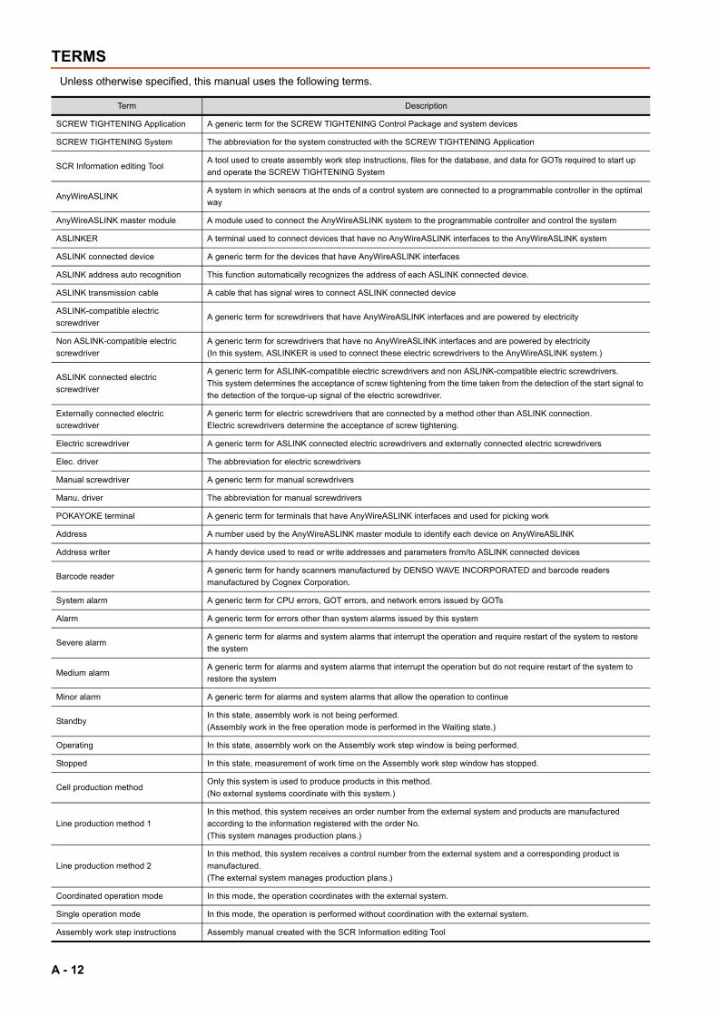
TERMS
Unless otherwise specified, this manual uses the following terms.
Term Description
SCREW TIGHTENING Application A generic term for the SCREW TIGHTENING Control Package and system devices
SCREW TIGHTENING System The abbreviation for the system constructed with the SCREW TIGHTENING Application
SCR Information editing ToolA tool used to create assembly work step instructions, files for the database, and data for GOTs required to start up
and operate the SCREW TIGHTENING System
AnyWireASLINKA system in which sensors at the ends of a control system are connected to a programmable controller in the optimal
way
AnyWireASLINK master module A module used to connect the AnyWireASLINK system to the programmable controller and control the system
ASLINKER A terminal used to connect devices that have no AnyWireASLINK interfaces to the AnyWireASLINK system
ASLINK connected device A generic term for the devices that have AnyWireASLINK interfaces
ASLINK address auto recognition This function automatically recognizes the address of each ASLINK connected device.
ASLINK transmission cable A cable that has signal wires to connect ASLINK connected device
ASLINK-compatible electric
screwdriverA generic term for screwdrivers that have AnyWireASLINK interfaces and are powered by electricity
Non ASLINK-compatible electric
screwdriver
A generic term for screwdrivers that have no AnyWireASLINK interfaces and are powered by electricity
(In this system, ASLINKER is used to connect these electric screwdrivers to the AnyWireASLINK system.)
ASLINK connected electric
screwdriver
A generic term for ASLINK-compatible electric screwdrivers and non ASLINK-compatible electric screwdrivers.
This system determines the acceptance of screw tightening from the time taken from the detection of the start signal to
the detection of the torque-up signal of the electric screwdriver.
Externally connected electric
screwdriver
A generic term for electric screwdrivers that are connected by a method other than ASLINK connection.
Electric screwdrivers determine the acceptance of screw tightening.
Electric screwdriver A generic term for ASLINK connected electric screwdrivers and externally connected electric screwdrivers
Elec. driver The abbreviation for electric screwdrivers
Manual screwdriver A generic term for manual screwdrivers
Manu. driver The abbreviation for manual screwdrivers
POKAYOKE terminal A generic term for terminals that have AnyWireASLINK interfaces and used for picking work
Address A number used by the AnyWireASLINK master module to identify each device on AnyWireASLINK
Address writer A handy device used to read or write addresses and parameters from/to ASLINK connected devices
Barcode readerA generic term for handy scanners manufactured by DENSO WAVE INCORPORATED and barcode readers
manufactured by Cognex Corporation.
System alarm A generic term for CPU errors, GOT errors, and network errors issued by GOTs
Alarm A generic term for errors other than system alarms issued by this system
Severe alarmA generic term for alarms and system alarms that interrupt the operation and require restart of the system to restore
the system
Medium alarmA generic term for alarms and system alarms that interrupt the operation but do not require restart of the system to
restore the system
Minor alarm A generic term for alarms and system alarms that allow the operation to continue
StandbyIn this state, assembly work is not being performed.
(Assembly work in the free operation mode is performed in the Waiting state.)
Operating In this state, assembly work on the Assembly work step window is being performed.
Stopped In this state, measurement of work time on the Assembly work step window has stopped.
Cell production methodOnly this system is used to produce products in this method.
(No external systems coordinate with this system.)
Line production method 1
In this method, this system receives an order number from the external system and products are manufactured
according to the information registered with the order No.
(This system manages production plans.)
Line production method 2
In this method, this system receives a control number from the external system and a corresponding product is
manufactured.
(The external system manages production plans.)
Coordinated operation mode In this mode, the operation coordinates with the external system.
Single operation mode In this mode, the operation is performed without coordination with the external system.
Assembly work step instructions Assembly manual created with the SCR Information editing Tool
A - 12

Operator A type of users who can perform operations and configure settings required for work input and assembly
ManagerA type of users who can configure system settings besides the operations and settings that can be performed and
configured by operators
Local manager A type of users who can configure system settings without connections to the database
Start signal A signal to be output from an electric screwdriver while it is rotating
Torque-up signal A signal to be output from an electric screwdriver while its torque is being amplified
Reverse signal A signal to be output from an electric screwdriver while it is reversing
Screw tightening process A work step for tightening screws with electric screwdrivers or manual screwdrivers
Screw loosening process A work step for loosening tightened screws with electric screwdrivers or manual screwdrivers
Screw retightening process A work step for retightening tightened screws with manual screwdrivers
Screen touching process A step of touching the screen after completion of work
Marking check process A work step for checking and marking products
Parts take-out process A work step for taking out parts from screw shelves
External InputAn external switch on the "Assembly work step" window used to proceed the process without touching switches on the
GOT screen
Screw tightening OK In this state, screw tightening has been normally completed.
Screw tightening NG In this state, screw tightening has not been normally completed.
RUN state indicator A three-color stack light that indicates the operating state of this system
Indicator for screw tightening check A two-color stack light that indicates if the screw tightening process has succeeded or failed
Indicator light A generic term for RUN state indicators and indicators for screw tightening check
OK buzzer
This buzzer sounds in the following cases.
• When screw tightening is OK
• At completion of work for one item
• At completion of assembly work for one product
NG buzzer
This buzzer sounds in the following cases.
• When screw tightening is NG
• When a torque-up signal has not been detected after 10 seconds or longer from the start of the forward rotation of
an electric screwdriver
• When an electric screwdriver rotates in the forward rotation during screw loosening process
• When an error has occurred in the communication with the database
Assembly work step information A generic term for screw tightening work information obtained from the database when an order No. is input
Screw information A generic term for information used at the screw box verification
Screw tightening informationA generic term for information of screws used for each work item in assembly work
(screw type, screw code, number of screws)
Screw tightening time information A generic term for information of screw tightening time per screw
Screw tightening OK data informationA generic term for information that is sent to the database when screw tightening is OK in assembly work
(work date and screw tightening time)
Screw tightening NG data informationA generic term for information that is sent to the database when screw tightening is NG in assembly work
(work date and screw tightening time)
Work start informationA generic term for information that is sent to the database when assembly work for one product is started in assembly
work
Work record informationA generic term for information that is sent to the database when assembly work for one product is completed in
assembly work
Item completion information
A generic term for information that is sent to the database when assembly work for one item is completed in assembly
work
(work start date, work start time, work completion date, and work completion time)
Work completion information
A generic term for information that is sent to the database when assembly work for one product is completed in
assembly work
(work start date, work start time, work completion date, and work completion time)
Work pause informationA generic term for information that is sent to the database when an operator selected to forcibly stop assembly work
(pause start date, pause start time, pause end date, and pause end time)
Work retry informationA generic term for information that is sent to the database when an operator selected to retry assembly work
(pause start date, pause start time, pause end date, and pause end time)
Torque check information A generic term for information that is sent to the database at torque check.
Electric screwdriver type Model information of an electric screwdriver or a bit attached on the edge of the electric screwdriver
Term Description
A - 13

Electric screwdriver codeThis identification code is used to identify an electric screwdriver or a bit attached on the edge of the electric
screwdriver.
Screw type Model information for a screw
Screw code This identification code is used to identify screws.
Screw color Display color of a screw No. lamp
Image templateAn excel file (template) of image data to be used in assembly work step instructions. Import this file to the assembly
work step instructions.
Factory ID This identification ID is used to identify a factory in work sites
Equipment ID This identification ID is used to identify equipment in the factory
Work table ID This identification ID is used to identify a work table in the equipment
Operator ID This identification ID is used to identify an operator.
Skill This item shows the degree of the operator's skill. Select one from "Ordinary" and "Skillful".
Manager A type of operators. Select one from "Operator" or "Manager".
Order No. This identification number is used to identify a control number, planned quantity, and assembly manual sub number.
Control No. This identification number is used to identify a model.
ID No. This identification number is used to identify a manufactured product.
Planned quantity Number of parts to be manufactured.
Completed parts The number of completed parts to the planned quantity.
Manual No. This identification number is used to identify an assembly manual.
Manual sub No. Revision number of the assembly manual
Image dataGOT image data included in assembly work step instructions
Create this data with assembly work step instructions and send it to GOTs.
Comment dataGOT comment data included in assembly work step instructions
Create this data with assembly work step instructions and send it to GOTs.
Data for GOTs A generic term for image data and comment data
Address area
Address area of AnyWireASLINK occupied by this system
For electric screwdrivers, 0 to 39 are occupied. (Four addresses are required for each electric screwdriver.)
For screw shelves, 40 to 189 are occupied. (Five addresses are required for each screw shelf.)
Address mismatchIn this state, the address of an ASLINK connected device connected to the AnyWireASLINK master module and the
address set in the settings of this system are not consistent.
Unauthorized address deviceAmong the ASLINK connected devices connected to the AnyWireASLINK master module, this device has an address
other than the addresses set for this system.
User screen A generic term for screen data added by the user customization function
User program A generic term for sequence programs added by the user customization function
User device Devices that users can freely use at the user customization of this system
Devices disclosed to users
Among the devices occupied by this system, the applications of these devices are disclosed to users.
Users can access the devices disclosed to users from user programs and refer to information of the system and
perform some operations on this system.
Term Description
A - 14

REQUESTING AND REGISTERING A LICENSE KEY
To use the "SCREW TIGHTENING Application", register a license key to the CPU module.Before starting up the system, follow the "License Key Request Instructions" supplied with the SCREW TIGHTENING Control Package to get a license key.
(1) The following information is required to request a license key.
• Application information (product name, model, and product ID)This information is described in the "License Certificate" supplied with the SCREW TIGHTENING Control Package.
• Hardware information (model and serial number)The model and serial number of the CPU module to be used. For how to check the serial number, refer to the following.
3.4.4 Checking serial number and function version
(2) Register the license key to the CPU module at the installation of a sequence program.
For the details, refer to the following.
5.2 Installing Sequence Programs
(3) Attach the "iQ Monozukuri seal" on the CPU module for which a license key has been registered.
• The "iQ Monozukuri seal" is supplied with the SCREW TIGHTENING Control Package.
• For the position to attach the seal, refer to the following.
Position where the seal is attached(On the top of the CPU module)
A - 15

A - 16
1
NS
TR
UC
TIO
N
1. SYSTEM CONSTRUCTION
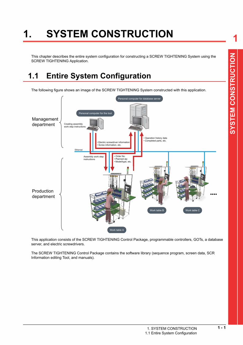
This chapter describes the entire system configuration for constructing a SCREW TIGHTENING System using the SCREW TIGHTENING Application.
1.1 Entire System Configuration
The following figure shows an image of the SCREW TIGHTENING System constructed with this application.
SY
ST
EM
CO
This application consists of the SCREW TIGHTENING Control Package, programmable controllers, GOTs, a database server, and electric screwdrivers.
The SCREW TIGHTENING Control Package contains the software library (sequence program, screen data, SCR Information editing Tool, and manuals).
Personal computer for database server
Personal computer for the tool
• Electric screwdriver information• Screw information, etc.
• Operation history data• Completed parts, etc.
Ethernet
Work table A
Work table B Work table C
••••
Assembly work step instructions
Management department
Production department
Creating assembly work step instructions
• Order No.• Planned qty• Model/type, etc.
1. SYSTEM CONSTRUCTION1.1 Entire System Configuration
1 - 1

The following figure shows the entire system configuratio
1 - 2 1. SYSTEM CONSTRUCTION1.1 Entire System Configuration
f this application.
n oPOINTPOINTPOINT
For the details of each device, refer to the following.
2. SYSTEM CONFIGURATION
Personal computer for database server
Personal computer for the tool
Ethernet
•••••
Control panel
Input switch Buzzer
RS-232GOT
Ethernet
AnyWireASLINK
Barcode reader
RS-232
ASLINK filter
24 V DC power supply
POKAYOKE terminal
AnyWireASLINK
Terminator for AnyWireASLINK
Terminator for AnyWireASLINK
ASLINK-compatible
electric screwdriver
Non ASLINK-
compatible electric
screwdriver
Work table A
ASLINKER
Programmable controller system
Terminal block
Operation panel
Three-color stack light
Two-color stack light
Work table B
Work table C
Power supply box
1
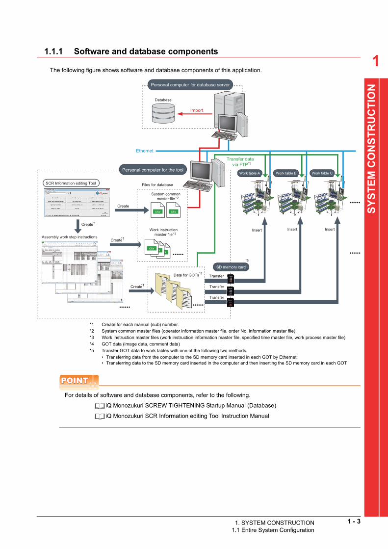
1.1.1 Software and database componentsThe following figure shows software and database components of this application.
SY
ST
EM
CO
NS
TR
UC
TIO
N
*1 Create for each manual (sub) number.
*2 System common master files (operator information master file, order No. information master file)
*3 Work instruction master files (work instruction information master file, specified time master file, work process master file)
*4 GOT data (image data, comment data)
*5 Transfer GOT data to work tables with one of the following two methods.
• Transferring data from the computer to the SD memory card inserted in each GOT by Ethernet• Transferring data to the SD memory card inserted in the computer and then inserting the SD memory card in each GOT
POINTPOINTPOINT
For details of software and database components, refer to the following.
iQ Monozukuri SCREW TIGHTENING Startup Manual (Database)
iQ Monozukuri SCR Information editing Tool Instruction Manual
Personal computer for database server
Database
SCR Information editing Tool
Personal computer for the tool
Assembly work step instructions
Work table CWork table BWork table A
SD memory card
Insert InsertInsert
Transfer
Transfer
Transfer
Create
Create
Create
*5
*5
Ethernet
Import
••••••
••••••
••••••
••••••
Files for database
*1
*1
*2
*3
Create*1
Data for GOTs*4
••••••
System common master file
Work instruction master file
Transfer data via FTP
1. SYSTEM CONSTRUCTION1.1 Entire System Configuration
1 - 3

1 - 4 1. SYSTEM CONSTRUCTION1.2 Data and Signal Exchanges
1.2 Data and Signal Exchanges
The following figure shows an overview of data and signal exchanges among modules.
POINTPOINTPOINT
For the details of data and signal exchanges, refer to the following.
3. DESIGNING CONTROL PANEL AND OPERATION PANEL
4. INSTALLATION TO WORK TABLES
Personal computer for database server
Input switch
Buzzer
GOT
Barcode reader
POKAYOKE terminal
ASLINK-compatible
electric screwdriver
Non ASLINK-
compatible electric
screwdriver
CPU module
AnyWireASLINK master module
Output module
<Barcode>
<Image/comment data> <Work instructions>
<Production volume>
<Screen operation>
<ON/flashing command>
<Buzzer sound>
<Input signal>
<Signal detection>
<Control signal>
<Output signal>
<Terminal control>
00
00
-00
00
-00
ab
cd
ef
00
00
-00
00
-00
OF
F
RU
N
ON
ST
AR
T
oo
oo
o
oo
00
00
-00
00
-00
ab
cd
ef
00
00
-00
00
-00
OF
F
RU
N
ON
ST
AR
T
oo
oo
o
oo
Personal computer for the tool
<Screen display command>
Three-color stack light
Two-color stack light
<Electric screwdriver control>
<Power supply output>

1
SY
ST
EM
CO
NS
TR
UC
TIO
N
1.3 Operating Environment
This application requires personal computers for a database server and the tool.
(1) Operating environment of a personal computer (The environments not specified below are unsupported.)
*1 Used for browsing manuals.
*2 Used for the SCR Information editing Tool and the restoration function of the GOT.
*3 Used for the backup function of the GOT.
*4 Required only for the personal computer for database server.
*5 Used to install and customize sequence programs.
*6 Used to install and customize screen data.
(2) System requirements for OSs
Personal computerA personal computer capable of running the following OSs (For system requirements of the OSs, refer
to (2).)
OS
Windows® 8.1 (Operating System, Pro Operating System, Enterprise Operating System)
Windows® 8 (Operating System, Pro Operating System, Enterprise Operating System)
Windows® 7 (Professional Operating System, Ultimate Operating System, Enterprise Operating
System)
Disk drive DVD drive*1*2
InterfaceSD memory card*2 SDHC-compliant
USB*3 USB1.1 or later
Database management
systemMicrosoft® SQL Server®*4 SQL Server® 2012 Express
Application
MELSOFT GX Works2*5 Version 1.555D or later
MELSOFT GT Designer3 (GOT2000)*6 Version 1.155M or later
Microsoft® Excel®*2 Excel® 2010, Excel® 2013
Application (recommended) Adobe® Reader®*1
CAUTIONThe maximum size of the database for SQL Server 2012 Express is 10 GB (10,240 MB).Manage data in the database not to exceed the maximum size.
OS CPU Memory Disk space
Windows® 8.1, Windows® 8, Windows® 764 bits
1 GHz or more2 GB or more Free space: 20 GB or more
32 bits 1 GB or more Free space: 16 GB or more
1. SYSTEM CONSTRUCTION1.3 Operating Environment
1 - 5

1 - 6 1. SYSTEM CONSTRUCTION1.4 Steps Before Operation
1.4 Steps Before Operation
The following figure shows the steps required to construct the SCREW TIGHTENING System with this application.For the details of each process, refer to the corresponding pages.
CAUTION Before wiring and installing devices, always power off the system.
Design a system.
Build a control panel and an operation panel.
Ethernet connection
ODBC setting
Set the DB connection service.
Generate a database.
Wire the control panel and operation panel.
Install sequence programs.
Install a programmable controller and others in the control panel.
Install GOTs and others in the operation panel.
Install the control panel and operation panel at a work table.
Install electric screwdrivers and POKAYOKE terminals at
the work table.
Wire the electric screwdrivers and POKAYOKE terminals.
Install other devices at the work table.
Import the files for the database.
Install the DB connection service.
Install screen data.
Register a license of the GOT MES interface function.
Start up the system.
Start up the personal computer for the tool.
Transfer data for GOTs.
Create assembly work step instructions.
Create files for the database and data for GOTs.
Start up the personal computer for the database
server.
iQ Monozukuri SCREW TIGHTENING
Startup Manual (Database)
3.1 Layout Example
3.2 Circuit Design Example
3.3 Building a Control Panel
and Operation Panel
3.4 Installing a
Programmable
Controller System
3.5 Installing a GOT
3.6 Wiring the Control
Panel and Operation
Panel
4.1 Installing the Control
Panel and Operation Panel
4.2 Installing Barcode
Readers
4.3 Installing Electric
Screwdrivers
4.4 Installing POKAYOKE
Terminals
4.5 Wiring AnyWireASLINK
4.6 Installing Other External
Signal I/O Devices
4.7 Ethernet Connection
5.1 Starting up the Programmable
Controller
5.4 Installing Screen Data
5.5 Registering a License of the
GOT MES Interface Function
5.6 Inserting an SD Memory
Card
iQ Monozukuri SCR Information
editing Tool Instruction Manual
5.2 Installing Sequence Programs
5.3 Starting up the GOT

1
SY
ST
EM
CO
NS
TR
UC
TIO
N
Turn on the power.Set the display language and clock.
Register each information.
Configure the RUN state indicator setting.
Configure the electric screwdriver setting.
Configure the ASLINK setting.
Inspection
Test operation
Delivery of the system
Has an error occurred?
No
YesTroubleshooting
Start up the system.
5.7 Starting up the SCREW TIGHTENING System
5.8 Language Setting
5.9 Clock Setting
5.11 System Setting
5.12 ASLINK Connected Device Setting
5.13 Electric Screwdriver Setting
5.14 RUN State Indicator Setting
6.1 Checking with the Inspection Function
6.2 Checking with the Alarm Function
6.4 Checking with the Free Operation Function
6.5 Troubleshooting
5.10 Logging in as a Local Manager
1
. SYSTEM CONSTRUCTION1.4 Steps Before Operation1 - 7

1 - 8 1. SYSTEM CONSTRUCTION1.4 Steps Before Operation

2
NF
IGU
RA
TIO
N
2. SYSTEM CONFIGURATION
This chapter describes the system devices used in the SCREW TIGHTENING Application.
2.1 List of System Devices
The following tables list the system devices of this application.
2.1.1 Products in the iQ Monozukuri SCREW TIGHTENING Control Package
Check that all the products in the following table are included in a package.For quantities, refer to "Before Using the Product" (BCN-EP2005-0004) included in the package.
SY
ST
EM
CO
Component Model Manufacturer RemarksBefore Using the Product BCN-EP2005-0004
Mitsubishi Electric
Corporation
END-USER SOFTWARE LICENSE
AGREEMENTBCN-EP2005-0001
License Certificate BKO-CF2015H**
A number that comes in ** of "H**" depends on the
number of purchased licenses.
• 1 license: H01
• 5 licenses: H02
• 10 licenses: H03
• 15 licenses: H04
• 20 licenses: H05
• 25 licenses: H06
License Key Request Instructions BCN-EP2005-0002 REQUESTING AND REGISTERING A
LICENSE KEYiQ Monozukuri seal BD996D089
Installation DVD
AP10-SCRAA-DVD 2.2 Files in DVD-ROM
2. SYSTEM CONFIGURATION2.1 List of System Devices
2 - 1

2 - 2 2. SYSTEM CONFIGURATION2.1 List of System Devices
2.1.2 Product to be prepared by users
Purchase the following products.
Component Model Manufacturer Remarks
Power supply module
Select one of the
following.
• L61P
• L63P
• L63SP
Mitsubishi Electric
Corporation
CPU module Select one of the
following.
• L02CPU
• L02CPU-P
• L06CPU
• L06CPU-P
• L26CPU
• L26CPU-P
• L26CPU-BT
• L26CPU-PBT
Mitsubishi Electric
Corporation
Use the module with a serial number (first five digits)
of "18102" or later.
3.4.4 Checking serial number and function
version
AnyWireASLINK master module
LJ51AW12ALMitsubishi Electric
CorporationFor connection to the AnyWireASLINK system
Output module
LY40NT5PMitsubishi Electric
Corporation
Output 16 points
(10.2 V DC to 28.8 V DC)
SD memory card
Select one of the
following.
• NZ1MEM-2GBSD
• NZ1MEM-4GBSD
• NZ1MEM-8GBSD
• NZ1MEM-16GBSD
Mitsubishi Electric
Corporation
For reading image data and comment data created
with the SCR Information editing Tool
Connection cable for DC I/O conversion
module
FA-SCBL10FMV-M
Mitsubishi Electric
Engineering Company
Limited.
For connection between a MELSEC-LCPU built-in I/O
connector and a connector/terminal block converter
module
Length: 1 m

2
SY
ST
EM
CO
NF
IGU
RA
TIO
N
DC I/O conversion module
FA-TBS40P
Mitsubishi Electric
Engineering Company
Limited.
General-purpose screw terminal for wiring external I/O
devices
GOT
Select one of the
following.
• GT2715-XTBA
• GT2512-STBA
Mitsubishi Electric
Corporation
Operation panel for SCREW TIGHTENING
Application
• GT2715-XTBA: XGA (15 inches)
• GT2512-STBA: SVGA (12 inches)
License of the GOT MES interface
functionGT25-MESIFKEY
Mitsubishi Electric
Corporation
ASLINKER
BL287SB-02F-CC20
Anywire Corporation
Two point inputs
(NPN type)
ASLINKER
BL287XB-02F-CC20One point input, one point output
(NPN type)
POKAYOKE terminal
(1)POKAYOKE
terminal modelsAnywire Corporation
Up to 30 terminals can be connected in this
application.
φ28 pipe installation fitting for a
transparent type terminal
A027-T14PHP28-H1
Anywire Corporation
For installing transparent type picking sensors (14 cm)
A027-T07PHP28-H1 For installing transparent type picking sensors (7 cm)
Protective fitting-free mounting screw set
(five screws)A027-TSM4-5P
Mounting screws for transparent type picking sensor
fittings
Cable with connectors on both ends A0102-CND-**
Anywire Corporation
For connecting ultracompact touch type terminals
each other
(A number that comes in ** depends on the length of
the cable used.)
Transmission cable A0102-CNE-20 For ultracompact touch type terminals
Wiring duct A092-DM For installing ultracompact touch type terminals
[H] holder
φ28 pipe installation holder lower
tightening type
(including 5 pieces)
A027-HP28-5P
Anywire Corporation
A holder attached to a terminal depends on the type of
the terminal used. Use the proper holder depending
on the pipe.
For details, refer to the product manual supplied with
the product used.
[H1] holder
φ28 pipe installation holder back
tightening type
(including 5 pieces)
A027-HP28-H1-5P
[SUS] holder
SUS pipe installation holderA027-HP-SUS2
Component Model Manufacturer Remarks
2. SYSTEM CONFIGURATION2.1 List of System Devices
2 - 3

Terminator for AnyWireASLINK
BT0 Anywire Corporation Terminator for AnyWireASLINK
4-core flat cable
FK4-125-100 Anywire CorporationTransmission cable for AnyWireASLINK (100 m per
roll)
Insulation displacement connector
LP4-WR-10P
Anywire Corporation
LP connector for AnyWireASLINK
(For FK4-125-100)
LP4-WW-10P
LP connector for AnyWireASLINK
(For ASLINKER and ultracompact touch type
terminals)
24 V DC power supply - -90 W (input: 85 to 265 V AC, output: 24 V DC, 3.8 A)
Example: KHNA90F-24 (COSEL CO.,LTD.)
ASLINK filter
ANF-01 Anywire Corporation For 24 V DC
Address writer
ARW-02AS Anywire CorporationAddress writer for setting addresses of ASLINKER
and POKAYOKE terminals
Insulation displacement tool for LP
connector
LP-TOOL Anywire CorporationFor tool exclusive to insulation displacement
connectors (LP4-WR-10P, LP4-WW-10P)
ASLINK-compatible electric screwdriver
(2)Electric
screwdriver interlocking
with other FA device
NITTO KOHKI CO.,
LTD.
Up to 10 electric screwdrivers can be connected in
this application.Non ASLINK-compatible electric
screwdriver
(3)Electric
screwdrivers with screw
tightening counter
NITTO KOHKI CO.,
LTD.
SPC conversion code -NITTO KOHKI CO.,
LTD.
Required to use SPC type electric screwdrivers as
standard type ones.
Component Model Manufacturer Remarks
(This figure shows LP4-WR-10P.)
24V0V
PO
WE
R IN
24V0V
SL
AV
E
12
34
MODE DATA
R W
MODESELECT
POWERCLEAR
POWERFLICK
EX
SENSE
TIME
COLOR
CLOSE
ADR
OPEN
2 - 4 2. SYSTEM CONFIGURATION2.1 List of System Devices

2
SY
ST
EM
CO
NF
IGU
RA
TIO
N
Electric screwdriver connector RM12BRD-7SHIROSE ELECTRIC
CO., LTD.
For separating power signals of electric screwdrivers
Required for the number of electric screwdrivers (I/O
lines)
Terminal block - - -
Relay - -
For power control of electric screwdrivers
Required for the number of electric screwdrivers
Example: G3RV (OMRON)
Barcode reader• AT26Q-SM(R)
• AT21Q-SM(R)
(Body color: Black)
DENSO WAVE
INCORPORATED
Wired type (RS-232C)
[Accessories]
• Interface cable
• AC adapter• AT25Q-SM(R)
• AT20Q-SM(R)
(Body color: White)
Barcode reader
DMR-8050-0100
Cognex Corporation
Wired type
DM100-PWR-000 24 V DC power supply
DM8000-RS232-02 RS-232 cable (5 m)
Personal computer for database server - - For the operating environment for the personal
computers, refer to the following.
1.3 Operating EnvironmentPersonal computer for the tool - -
Ethernet hub - -For connecting CPU modules, GOTs, personal
computer for database server, and Ethernet hubsEthernet cable
(Twisted pair cable with shields)- -
Ferrite core - -
For Ethernet cables
Example: ZCAT3035-1330 (TDK Corporation)
or a ferrite core having equivalent damping
characteristics
External power supply - - -
Noise filter - -
For external power supply
Example: RSHN-2003 (TDK-Lambda Corporation)
or a ferrite core having equivalent damping
characteristics
Surge protection device - - -
Component Model Manufacturer Remarks
2. SYSTEM CONFIGURATION2.1 List of System Devices
2 - 5

2 - 6 2. SYSTEM CONFIGURATION2.1 List of System Devices
(1) POKAYOKE terminal models
Product name Model
Lever switch type terminal (Selection of one color from seven colors) BL227XB-K02V-P
Pushbutton switch type terminal (Selection of one color from seven colors) BL227XB-K02VN-P
Lever switch type terminal (RGB each color independent ON/OFF) BL227XB-K06M-P
Pushbutton switch type terminal (RGB each color independent ON/OFF) BL227XB-K06MN-P
LED indication:
Stationery type
Photoelectric transmission type (Dust-proof: 140 mm long, selection of one color
from seven colors)
BL227PB-T14P02V-P (light emission)
BL227XB-T14P02V-C (light reception)
LED indication:
Stationery type
Photoelectric transmission type (Dust-proof: 70 mm short, selection of one color
from seven colors)
BL227PB-T07P02V-P (light emission)
BL227XB-T07P02V-C (light reception)
Door opening/closing
+ LED indication: Stationary type
Lever switch type
Detection function of forcibly open
selection of one color from seven colors
BL227XB-F04V-P
Small door type terminal, 2-point output type (with break open detection function,
horizontal metal arm, RGB each color independent ON/OFF)BL227XB-R2K08MN-P
Ultracompact touch type terminal (Selection of one color from seven colors) B292XB-02VL
(2) Electric screwdriver interlocking with other FA device
Model Remarks
DLV30LL-ASL(DJE) Lever start, 1.2 to 3.0 N•m, 650 rpm
DLV30SL-ASL(DJE) Lever start, 1.2 to 3.0 N•m, 1200 rpm
DLV30HL-ASL(DJE) Lever start, 1.2 to 3.0 N•m, 2000 rpm
DLV45LL-ASL(DKE) Lever start, 2.0 to 4.5 N•m, 650 rpm
DLV45SL-ASL(DKE) Lever start, 2.0 to 4.5 N•m, 1200 rpm
DLV70LL-ASL(DKE) Lever start, 3.8 to 7.0 N•m, 650 rpm
DLV30LP-ASL(DJE) Push to start, 1.2 to 3.0 N•m, 650 rpm
DLV30SP-ASL(DJE) Push to start, 1.2 to 3.0 N•m, 1200 rpm
DLV30HP-ASL(DJE) Push to start, 1.2 to 3.0 N•m, 2000 rpm
DLV45LP-ASL(DKE) Push to start, 2.0 to 4.5 N•m, 650 rpm
DLV45SP-ASL(DKE) Push to start, 2.0 to 4.5 N•m, 1200 rpm
DLV70LP-ASL(DKE) Push to start, 3.8 to 7.0 N•m, 650 rpm
(3) Electric screwdrivers with screw tightening counter
Model Remarks
DLV30LL-SPC Lever start, 1.2 to 3.0 N•m, 650 rpm, 100 V AC specifications
DLV30SL-SPC Lever start, 1.2 to 3.0 N•m, 1200 rpm, 100 V AC specifications
DLV30HL-SPC Lever start, 1.2 to 3.0 N•m, 2000 rpm, 100 V AC specifications
DLV45LL-SPC Lever start, 2.0 to 4.5 N•m, 650 rpm, 100 V AC specifications
DLV45SL-SPC Lever start, 2.0 to 4.5 N•m, 1200 rpm, 100 V AC specifications
DLV70LL-SPC Lever start, 3.8 to 7.0 N•m, 650 rpm, 100 V AC specifications
DLV30LP-SPC Push to start, 1.2 to 3.0 N•m, 650 rpm, 100 V AC specifications
DLV30SP-SPC Push to start, 1.2 to 3.0 N•m, 1200 rpm, 100 V AC specifications
DLV30HP-SPC Push to start, 1.2 to 3.0 N•m, 2000 rpm, 100 V AC specifications
DLV45LP-SPC Push to start, 2.0 to 4.5 N•m, 650 rpm, 100 V AC specifications
DLV45SP-SPC Push to start, 2.0 to 4.5 N•m, 1200 rpm, 100 V AC specifications
DLV70LP-SPC Push to start, 3.8 to 7.0 N•m, 650 rpm, 100 V AC specifications

2.1.3 Product to be prepared by users (depends on the system configuration)
Purchase the following products according to the system configuration.
2
SY
ST
EM
CO
NF
IGU
RA
TIO
N
2.1.4 Precautions for use
(1) Always insert a filter (ANF-01) between the AnyWireASLINK master module and the cables that supply drive power (24 V DC, 0 V) to the module.
(2) When installing the filter, connect the LINE side (Terminal 1 and 2) of the filter to the terminal, and connect the LOAD side (Terminal 3 and 4) to the power supply.
(3) Connect one terminator in one AnyWireASLINK master module system, and at the cable end farthest from the module.
(4) For the total length of transmission cables, refer to the following.
4.5.1 Precautions for wiring
(5) Up to 30 POKAYOKE terminals can be connected to one AnyWireASLINK master module in this system.
(6) The maximum connectable number of terminals is limited not only by the maximum connectable number of AnyWireASLINK master modules but also by the supply current from an external power source.Do not allow the total current consumption of terminals to exceed the supply current from the external power source.
(7) Setting the arm (door) motion time to "0" (Delay time: 0 second) may cause operators' hands to be caught.Set the arm (door) motion time to "1" (Delay time: 1 second) or longer and adjust the door opening/closing position setting depending on the system in use.
(8) The number of colors output from a two-color stack light is limited to two (example: red and green).
(9) OUT0 to OUT6 and IN6 of the CPU module are exclusive to the indicator lights, buzzers, and external input switches of this system. Do not connect other devices to them.
Component Model Manufacturer Remarks
Two-color stack light - - Example: MPS-202-RG (PATLITE Corporation)
Three-color stack light - - Example: MPS-302-RYG (PATLITE Corporation)
Input switch - - -
Buzzer - - -
DIN rail - - -
Leakage breaker - - -
2. SYSTEM CONFIGURATION2.1 List of System Devices
2 - 7

2 - 8 2. SYSTEM CONFIGURATION2.2 Files in DVD-ROM
2.2 Files in DVD-ROM
The following table describes the structure of the files in the "Installation DVD" supplied with the SCREW TIGHTENING Control Package.
Folder File name
Description Required applicationPOINTPOINTPOINT
"MELSOFT iQ AppPortal" is the application integrated management software which manages assets, including projects and libraries, in a group for each purpose.Use this software to manage projects and related files for each application.
• For the operating environment and how to install the software, refer to the following.
iQ AppPortal Installation Instructions
• For the functions and how to use the software, refer to the following.
- AP10-SCR002AA.txtThis text file shows the version of the SCREW TIGHTENING
Application supported by this installation DVD.-
Manual
Chinese
bcnep20050013*.pdf
Manuals in Simplified Chinese
("*" indicates the version of each manual.)Adobe Reader
bcnep20050014*.pdf
bcnep20050015*.pdf
bcnep20050018*.pdf
readme.txt Details of the manuals -
English
bcnep20050010*.pdf
Manuals in English
("*" indicates the version of each manual.)Adobe Reader
bcnep20050011*.pdf
bcnep20050012*.pdf
bcnep20050017*.pdf
readme.txt Details of the manuals -
Japanese
bcnep20050007*.pdf
Manuals in Japanese
("*" indicates the version of each manual.)Adobe Reader
bcnep20050008*.pdf
bcnep20050009*.pdf
bcnep20050016*.pdf
readme.txt Details of the manuals -
Tools
SCRInfoSet - SCR Information editing Tool Microsoft® Excel®
SCRLicRegSupport - SCR license key registration support tool Microsoft® Excel®
SCRDbSupport - Database support Tool -
ServerSetting SCR_ServerSetting.sql Files for database server setting -
Project
AP10-SCR002AA-
L02_*.****.gxw
Project for L02CPU
(*.**** indicates the version of the project.)GX Works2
AP10-SCR002AA-
GT2715X_*.****.gtx
Project for GT2715-XTBA
(*.**** indicates the version of the project.)GT Designer3
AP10-SCR002AA-
GT2512S_*.****.gtx
Project for GT2512-STBA
(*.**** indicates the version of the project.)
MELSOFT iQ AppPortal -Installer for the application integrated management software
"MELSOFT iQ AppPortal"MELSOFT iQ AppPortal
iQ AppPortal Operating Manual
Installing "MELSOFT iQ AppPortal" stored in the installation DVD registers all the data included in this package to "iQ Monozukuri Folder" in "MELSOFT iQ AppPortal".The following data in the zip format is registered in "iQ Monozukuri Folder". Decompress the file to be used as needed.
• SCR Information editing Tool (SCRInfoSet.zip)• SCR license key registration support tool (SCRLicRegSupport.zip)• Database support Tool (SCRDbSupport.zip)• Files for database server setting (ServerSetting.zip)

3. DESIGNING CO
3
3. DESIGNING CONTROL PANEL AND OPERATION PANEL
This chapter describes the procedure for building a control panel and an operation panel for the SCREW TIGHTENING Application.
DE
SIG
NIN
G C
ON
TR
OL
PA
NE
L A
ND
OP
ER
AT
ION
PA
NE
L
3.1 Layout Example
The following figures show layout examples of the control panel and operation panel.
(1) Control panel
Main power supply Cable clamp for lead-in wireInstallation hole: 4-φ10 hole
Internal layout
Terminal layout
TE1
TE3
TE2
(Unit: mm)
NTROL PANEL AND OPERATION PANEL3.1 Layout Example
3 - 1

3 - 2 3. DESIGNING CONTROL PANEL AND OPER3.1 Layout Example
(2) Operation panel
(a) When using the GT2715-XTBA
(b) When using the GT2512-STBA
(Unit: mm)
Installation hole: 4-φ6 hole
Internal layoutCable clamp for lead-in wireExternal input switch
Terminal layout
(φ22, green)IDEC: HW1B-M110G
(Unit: mm)
Installation hole: 4-φ6 hole
Internal layoutCable clamp for lead-in wireExternal input switch
Terminal layout
(φ22, green)IDEC: HW1B-M110G
ATION PANEL

3. DESIGNING CO
3.2 Circuit Design Example
The following figures show design examples of electrical circuits.
(1) Entire electrical circuit
Single-phase
3
DE
SIG
NIN
G C
ON
TR
OL
PA
NE
L A
ND
OP
ER
AT
ION
PA
NE
L
*1 This is a power supply box for connecting non ASLINK-compatible electric screwdrivers. For a design example of an electrical
circuit in the power supply box, refer to the following.
(2) Power supply box for non ASLINK-compatible electric screwdrivers
100 to 240 V AC
NFB
CP1
CP2
GOT1
L +V
-V
P24V
24 V DC power supply
N24V
P24V
N24VN
GT2715-XTBA/GT2512-STBA
INPUT100-240 V AC
LG
FG
LINPUT100-240 V AC
N
LG
FGE
E
E
P24V
N24V
Ethernet
P24V
N24VExternal input switch
PLC1
L61P LJ51AW12ALL06CPU LY40NT5P
24 V0 VDPDNLG
Main power supply
CP4
TE1L N
E
RS-232
Ethernet
E
PS1TE2
CP3 CON2
E
AC adapter Barcode reader
P24V
N24VEthernet hub
HUB1
TE4
Ethernet
P24VN24V
FA-SCBL10FMV-M
P24V
External relayCR2
External relayCR1
24 V
0 V PENF1
ANF-01
FA-TBS40P
P24V
N24V
Non ASLINK-compatible electric screwdriverCR2
TE3
CR1
CON1
E
Three-color stack light
Two-color stack light
LowerMiddle
Upper
BuzzerGreen
Red
1
2
ASLINK-compatible electric screwdriver
POKAYOKE terminal
POKAYOKE terminal
ASLINKER2 input 1, output 1
ASLINKER1 input 2
BlackRed
WhiteBrown
Terminator for AnyWireASLINK
*1
LED lamp
Black
Red
White
Brown
LY40NT5P18-point screw terminal block
BlackYellow
WhiteGreen
BlackYellow
WhiteGreen
BlackYellow
WhiteGreen
BlackYellow
WhiteGreen
BlackYellow
WhiteGreen
NTROL PANEL AND OPERATION PANEL3.2 Circuit Design Example
3 - 3

3 - 4 3. DESIGNING CONTROL PANEL AND OPER3.2 Circuit Design Example
(2) Power supply box for non ASLINK-compatible electric screwdrivers
LED lamp
Non ASLINK-compatible electric screwdriver
Electric screwdriver connector
1 2 3 4 5 6 PE
Blue Yellow White Orange Gray Black Green
Brown Black Blue Brown Black Blue Brown Black Blue Brown Black
TE3
E
N1 Y01 P24V IN0 N24V P24V IN1 N24V P24V IN N24V P24V OUT E
ASLINKER1 input 2
ASLINKER2 input 1, output 1
BlackRed
WhiteBrown
N
Y01
24 V0 VDPDN
24 V0 VDPDN
BlackRed
WhiteGreen
BlackRed
WhiteGreen
ATION PANEL

3. DESIGNING CO3.3 Bu
3
OL
PA
NE
L A
ND
OP
ER
AT
ION
PA
NE
L
3.3 Building a Control Panel and Operation Panel
Build and place a control panel in which a programmable controller system is to be installed and an operation panel in which a GOT is to be installed based on the following specifications.
3.3.1 Building a control panel (chassis)
To build a control panel described in "3.1 Layout Example", use the following information as a guide.
(1) Size
(2) Installing a DIN rail
(Unit: mm)
Install a DIN rail in the control panel based on th
ollowing information. R e fT
DES
IGN
ING
CO
N
(a) Installation position of the programmable controllerTo ensure good ventilation and ease module change, provide clearance between the module top/bottom and structures/parts as shown below.
*1 When using connectors for external devices, provide clearance of 80 mm or more.
Door
Programmablecontroller
*1
50 mmor more
50 mmor more
30 mm or more
30 mm or more
Controlpanel
20 mmor more
NTROL PANEL AND OPERATION PANELilding a Control Panel and Operation Panel
3 - 5

3 - 6 3. DESIGNING CONTROL PANEL AND OPER3.3 Building a Control Panel and Operation Pa
(b) Layout of programmable controller system components inside the control panel
(c) Interval between DIN rail mounting screwsTo ensure the strength of a DIN rail, tighten DIN rail mounting screws (Products to be prepared by users) within 30 mm away from the both edges of the DIN rail and at 200 mm-interval between the screws.
(d) Applicable DIN rail model (IEC 60715)
(Unit: mm)
DIN rail
35 mm
30 mm or less
P = 200 mm or less
PPP30 mm or less
DIN rail mounting screws (Products to be prepared by users)
• TH35-7.5Fe
• TH35-7.5Al• TH35-15Fe(e) DIN rail stopper
Use a stopper that is attachable to the DIN
l. raiATION PANELnel

3. DESIGNING CO3.3 Bu
(f) Sizes of mounting and installation holes for a power supply lamp, main power supply, and cable clamp
Make holes on the doors and right side and
ft side of the control panel chassis as shown below. leControl panel cutout dimensions
3
DE
SIG
NIN
G C
ON
TR
OL
PA
NE
L A
ND
OP
ER
AT
ION
PA
NE
L
(Unit: mm)
70 × 50 square hole
4-φ4.5 hole
(Hole)
φ22.3 hole
4-φ10 hole
2-φ6 hole
(Hole)
40 × 38 square hole
NTROL PANEL AND OPERATION PANELilding a Control Panel and Operation Panel
3 - 7

3 - 8 3. DESIGNING CONTROL PANEL AND OPER3.3 Building a Control Panel and Operation Pa
3.3.2 Building an operation panel (chassis)
To build an operation panel described in "3.1 Layout Example", use the following information as a guide.
(1) Size
(a) When using the GT2715-XTBA
(b) When using the GT2512-STBA
(Unit: mm)
(Unit: mm)
ATION PANELnel

3. DESIGNING CO3.3 Bu
(2) Installing a DIN rail
Install a DIN rail in the operation panel based on
e following information.3
DE
SIG
NIN
G C
ON
TR
OL
PA
NE
L A
ND
OP
ER
AT
ION
PA
NE
L
th
For the details of the interval between DIN rail mounting screws and applicable DIN rail model and DIN rail stopper, refer to the following.
3.3.1 Building a control panel (chassis)
(3) Installation position of the GOTTo install the GOT, some distance is required between the GOT and the other devices.Depending on the units and cables used for the GOT, the distance more than the described dimensions may be required.Install the GOT with consideration of the connector dimensions and the cable bend radius.For the cable pull-out distance from the bottom of the GOT, refer to the following.
Appendix.2.2 Specifications of the GT2715-XTBA
Appendix.2.3 Specifications of the GT2512-STBA
NTROL PANEL AND OPERATION PANELilding a Control Panel and Operation Panel
3 - 9

3 - 10 3. DESIGNING CONTROL PANEL AND OPER3.3 Building a Control Panel and Operation Pa
(a) Sizes of mounting and installation holes for the GOT, startup switch, and cable clamp
Make holes on the doors and right side and
ttom of the operation panel chassis as shown below. bo• Operation panel cutout dimensions (whe
sing the GT2715-XTBA) n u• Operation panel cutout dimensions (when using the GT2512-STBA)
(Unit: mm)
4-φ4.5 hole
70 × 50 square hole
4-φ6 hole
φ22.3 hole
(Hole)
(Hole)
383.5 × 282.5 square hole
(Unit: mm)
4-φ4.5 hole
70 × 50 square hole
4-φ6 hole
φ22.3 hole
(Hole)
(Hole)
332 × 228 square hole
ATION PANELnel

3. DESIGNING CO3.4 In
3
NIN
G C
ON
TR
OL
PA
NE
L A
ND
OP
ER
AT
ION
PA
NE
L
3.4 Installing a Programmable Controller System
3.4.1 Entire system configuration
The following figure shows the entire system configuration of the programmable controller system to be installed in the control panel.Installing a programmable controller in the control panel with full consideration of operability, maintainability, and environment resistance.
1) 2) 3) 4)
7)
5)
9) 9) 9) 9)8)
6)7) 7)
DE
SIG
No. Name Remarks1) Power supply module MELSEC-L series power supply module (AC input)
2) CPU module MELSEC-L series programmable controller
3) AnyWireASLINK master module Master module for MELSEC-L series AnyWireASLINK system
4) Output module MELSEC-L series output module
5) 24 V DC power supply
6) DC I/O conversion module General-purpose screw terminal for wiring external I/O devices
7) Terminal block For 24 V DC power supply
8) ASLINK filter (ANF-01) For 24 V DC power supply
9)
Circuit protector (CP1)
Circuit protector (CP2)
Circuit protector (CP3)
Circuit protector (CP4)
NTROL PANEL AND OPERATION PANELstalling a Programmable Controller System
3 - 11

3 - 12 3. DESIGNING CONTROL PANEL AND OPER3.4 Installing a Programmable Controller Syste
3.4.2 I/O interface of a programmable controller
5) 1) 4)2) 3)
3.4.3 Precautions on system configuration
(1) Rated output current (5 V DC)
No. Name Standard Use
1) Ethernet connector 10Base-T/100Base-TX• For connection with the GOT
• For connecting a personal computer
2) Connector for external devices 40-pin (Male)For connection with the DC I/O conversion module
(indicator lights, buzzers, and external input switches)
3)AnyWireASLINK transmission
line terminalAnyWireASLINK
For connecting POKAYOKE terminals, ASLINKER, and ASLINK-compatible
electric screwdrivers
4) Output terminal block 18-point screw terminal block For power control of electric screwdrivers
5) USB interface (Device)USB2.0
Connector shape: Mini-BFor connecting a personal computer
Configure a system so that the total current cons
ption may not exceed 5 V DC, the rated output current of the umpower supply module. ( Appendix.1 Specifications of the Programmable Controller)
(2) For the power capacity
A shortage of the power capacity may result dep
ding on the combination of connected modules and the ennumbers of connected modules. When connecting the modules, be sure to consider the power capacity. If there is a shortage of the power capacity, consider the combination of modules to be connected.(3) Installation environment
Install the programmable controller according to
e installation environment shown in the general thspecifications. ( Appendix.1 Specifications of the Programmable Controller)Do not install the programmable controller to the place where:
• An ambient temperature is outside the range
to 55°C; of 0• Ambient humidity is outside the range of 5 to 95%RH;• Condensation occurs due to rapid temperature change;• Corrosive gas or combustible gas is present;• Conductive powder such as dust and iron powder, oil mist, salinity, or organic solvent is filled;• The programmable controller is exposed to direct sunlight;• A strong electric field or strong magnetic field is generated; and• The programmable controller is subject to vibration and shock.ATION PANELm

3. DESIGNING CO3.4 In
3.4.4 Checking serial number and function version
The serial number and function version of the module can be checked any of on:
• the rating plate, or
• Serial No. display board(1) Checking on the rating plate
The rating plate is located on the side of the mod
e.3
D O
PE
RA
TIO
N P
AN
EL
ul
(2) Checking on the serial No. display board
111110000000000 -AFunction versionSerial number
Relevant regulationstandards
N
The serial No. display board is located on the fro face (bottom) of the module.DE
SIG
NIN
G C
ON
TR
OL
PA
NE
L A
nt
L06CPU-AP010
111110000000000- A
Serial number Function version
NTROL PANEL AND OPERATION PANELstalling a Programmable Controller System
3 - 13

3 - 14 3. DESIGNING CONTROL PANEL AND OPER3.4 Installing a Programmable Controller Syste
3.4.5 Connecting the modules
The following describes the procedure for connecting modules.
POINTPOINTPOINT
To prevent consumption of the CPU module battery, the battery connector is disconnected at shipment. Connect the battery connector before using the CPU module for the first time.
Appendix.1.3 Battery replacement procedure
CAUTIONShut off the external power supply for the system in all phases before connecting or disconnecting modules.
(1) Connecting modules
1. To release the module joint levers located at the
(2) Disconnecting modules
top and bottom of the module:Slide the levers toward the front side of the module until they click.
2. Insert the connector of the power supply module into that of the CPU module so that they are securely engaged.
3. To lock the module joint levers:Slide the levers toward the back side of the module until they click.Make sure that the modules are securely connected.
Release
Lock
Disconnect the modules in the reverse manner o
1). f (POINTPOINTPOINT
• Failure to securely lock the module joint levers until they click may cause malfunction, failure, or drop of the module.
• The metal parts of a module (such as the back side) may be heated to a high temperature immediately after the power is turned off. Therefore, be careful not to burn yourself when disconnecting a module.
ATION PANELm

3. DESIGNING CO3.4 In
(3) Illustration of module connection
The following figure shows the connection order
modules.3
DE
SIG
NIN
G C
ON
TR
OL
PA
NE
L A
ND
OP
ER
AT
ION
PA
NE
L
of
3.4.6 Mounting on a DIN rail
The following shows the procedure for mounting modules on a DIN rail.
The following shows the procedure using the programmable controller system. A 24 V DC power supply, terminal blocks, and circuit protectors can be mounted by the same procedure.
The following figure shows DIN rails in the control panel and operation panel in yellow.
POINTPOINTPOINT
The procedure for using a DIN rail stopper is an example. When fixing the modules, refer to the manual for the DIN rail stopper used.
Power supply module CPU module Output module
END cover
AnyWireASLINK master module
Control panel Operation panel
NTROL PANEL AND OPERATION PANELstalling a Programmable Controller System
3 - 15

3 - 16 3. DESIGNING CONTROL PANEL AND OPER3.4 Installing a Programmable Controller Syste
(1) Mounting procedure
1. Pull down DIN rail hooks on the back of the modules until they click.
2. Hang the upper tabs of the modules on a DIN rail, and push the modules in position.
3. Lock the DIN rail hooks to the DIN rail to secure the modules in position.Pull the hooks up until they click.If the hooks are beyond the reach, use a tool such as a driver.
4. Loosen the screw on DIN rail stopper.
5. Hitch the bottom hook of the DIN rail stopper to the bottom of the DIN rail.Hitch the hook according to the orientation of the arrow on the front of the stopper.
6. Hitch the upper hook of the DIN rail stopper to the top of the DIN rail.
Hitch the hook tobottom of the DIN rail.
Hitch the hook totop of the DIN rail.
ATION PANELm

3
SIG
NIN
G C
ON
TR
OL
PA
NE
L A
ND
OP
ER
AT
ION
PA
NE
L
POINTPOINTPOINT
Do not slide modules from the edge of the DIN rail when mounting them. Doing so may damage the metal part located on the back of the module.
(2) Removal procedure
7. Slide the DIN rail stopper up to the left side of the modules.
8. Hold down the DIN rail stopper in the opposite direction of the arrow marked on the stopper, and tighten the screw on the stopper with a driver.
9. Attach a DIN rail stopper on the right of the modules with the same procedure. Use the stopper carefully when attaching on the right side of an END cover, because the stopper should be attached top side down.
DIN railstopper
DIN rail
DIN railstopper
DIN rail
DIN railstopper
DIN rail
(Right side)
E
Remove the modules from the DIN rail in the rev3. DESIGNING CO3.4 In
se manner of (1).
D
er
NTROL PANEL AND OPERATION PANELstalling a Programmable Controller System
3 - 17
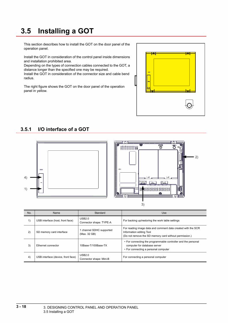
3 - 18 3. DESIGNING CONTROL PANEL AND OPER3.5 Installing a GOT
3.5 Installing a GOT
This section describes how to install the GOT on the door panel of the operation panel.
Install the GOT in consideration of the control panel inside dimensions and installation prohibited area.Depending on the types of connection cables connected to the GOT, a distance longer than the specified one may be required.Install the GOT in consideration of the connector size and cable bend radius.
The right figure shows the GOT on the door panel of the operation panel in yellow.
3.5.1 I/O interface of a GOT
1)
3)
4)
2)
No. Name Standard Use
1) USB interface (host, front face)USB2.0
Connector shape: TYPE-AFor backing up/restoring the work table settings
2) SD memory card interface1 channel SDHC supported
(Max. 32 GB)
For reading image data and comment data created with the SCR
Information editing Tool
(Do not remove the SD memory card without permission.)
3) Ethernet connector 10Base-T/100Base-TX
• For connecting the programmable controller and the personal
computer for database server
• For connecting a personal computer
4) USB interface (device, front face)USB2.0
Connector shape: Mini-BFor connecting a personal computer
ATION PANEL

3. DESIGNING CO
3
EL
3.5.2 Installing the GOT
The following shows the procedure for installing the GOT.
POINTPOINTPOINT
A battery has been installed in the battery cover as standard. Before using the GOT, connect the connectors of the GOT and the battery.
Appendix.2.4 Battery replacement procedure
1. Insert the GOT rear face into the panel opening.
N
LPA
NE
L A
ND
OP
ER
AT
ION
PA
2. While positioning a fitting on the mounting hole of the GOT, tighten a screw within the specified torque range (0.36 N·m to 0.48 N·m).Tightening the screw with a torque exceeding the specified torque range may deform the GOT front panel, causing the protective sheet to become crinkled.
Panel opening
GOT
DE
SIG
NIN
G C
ON
TR
O
NTROL PANEL AND OPERATION PANEL3.5 Installing a GOT
3 - 19

3 - 20 3. DESIGNING CONTROL PANEL AND OPER3.5 Installing a GOT
3.5.3 Confirming of versions and conforming standards
The GOT hardware version, BootOS version, function version, and conforming standards can be confirmed at the rating plate on the GOT rear face.
QR code
Conforming standard
MAC addressGOT serial number
Function versionBootOS versionHardware versionManufacturing date
Manufacturing year(lower two digits of the year of grace)
Manufacturing month(1 to 9: manufacturing month, X: October, Y: November, Z: December)
MODEL
DATE
MADE IN JAPAN
SERIALMAC ADD. 123456789012POWER
GRAPHIC OPERATION TERMINALPASSED
IN
2013-0900013910AA00000-A
MAX 100VA100-240VAC 50/60Hz
0 0 0 1 3 9 1 0 A A 0 0 0 0 0 - A
ATION PANEL

3. DESIGNING CO3.6 Wir
3.6 Wiring the Control Panel and Operation Panel
When the installation in the control panel and operation panel has been completed, perform wiring based on the circuit design diagram introduced in "3.2 Circuit Design Example".
3
3.6.1 Wiring
(1) Wiring
The following figure shows an example of wiring
r this system in which the GOT is housed in the operationDE
SIG
NIN
G C
ON
TR
OL
PA
NE
L A
ND
OP
ER
AT
ION
PA
NE
L
fopanel and the CPU module is housed together with the 24 V DC power supply for POKAYOKE terminals in the control panel.
0000-0
000-0
0abcdef
0000-0
000-0
0
OF
F
RU
N
ON
ST
AR
T
ooooo
oo
0000-0
000-0
0abcdef
0000-0
000-0
0
OF
F
RU
N
ON
ST
AR
T
ooooo
oo
100 to 240 V AC
Operation panel
Control panel
Three-color stack light
Two-color stack light
Input switch Buzzer
RS-232 GOT
Programmable controller system
Barcode reader
ASLINK filter
24 V DC power supply
POKAYOKE terminal
AnyWireASLINK
Terminator for AnyWireASLINK
Power supply box
ASLINK-compatible
electric screwdriver
Non ASLINK-
compatible electric
screwdriver
Terminal block
CON
ASLINKER
LED lamp
NTROL PANEL AND OPERATION PANELing the Control Panel and Operation Panel
3 - 21

3 - 22 3. DESIGNING CONTROL PANEL AND OPER3.6 Wiring the Control Panel and Operation Pa
(2) Precautions for wiring
The following describes the precautions for wirin
o power supply modules. g t• Wire the power supply of the programmable c
troller or GOT, I/O power supply, and dynamic power supply onas shown below to separate the systems.• Considering the rated current and inrush current of the power supply module, connect a breaker having appropriate sensing property or an external fuse causing proper blowout. (When using a single programmable controller, connecting a breaker around 10 A or an external fuse is recommended.)
• To minimize a voltage drop, use thick power cables up to 2 mm2, twist the cables closely, and connect the modules with the shortest distance.
• Do not install the power cables together with the main circuit (high voltage and high current) cables, I/O signal cables, and common cables. Keep a distance of 100 mm or more between them.
• If there is much noise due to a lightning surge or other causes, connect an isolation transformer.(For measures against noise of the products manufactured by other companies, refer to the product manuals supplied with the devices.)
• After wiring, always attach the included terminal cover to the power supply module and do not touch any terminal while the power is on or the module is operating.
• Use a Class 2 power supply for a module using a DC power supply.• Configure a system so that the total current consumption may not exceed 5 V DC, the rated output current of
the power supply module. For the specifications of the power supply module, refer to the following.
Appendix.1.4 Specifications of the power supply module
• Due to noise caused by lightning surge, a momentary power failure may be detected or the CPU module may be reset. As measures against the noise, connect a surge absorber for lightning as shown below.
Separate the ground for the lightning surge absorber (E1) and ground for the programmable controller or GOT (E2).Select an appropriate lightning surge absorber that does not exceed the maximum allowable circuit voltage of the surge absorber even when the power supply voltage has increased to the maximum.
Programmablecontroller
orGOT
Isolationtransformer
I/O powersupply
Motor power supply
I/O equipment
Motor equipment
Mainpowersupply
Relayterminal
block
Inside a control panel
Programmablecontroller/GOT power supply
100 V AC200 V AC
T1
Surge absorber for lightning
Programmablecontroller
orGOT
AC
E2
E1
ATION PANELnel

• Always use a solderless terminal for wiring to t
3. DESIGNING CO3.6 Wir
terminal block on a power supply module. To prevent a short
3
EL
hewhen screws come loose, always use a solderless terminal with insulation sleeve of 0.8 mm or less in thickness. Up to two solderless terminals can be connected to one terminal block.
TerminalscrewTerminal
screwSolderless terminal
Solderless terminal
When wiring one cableto one terminal
When wiring two cablesto one terminal
6.2 mm or less
6.2 mm or less
φ3.2
φ3.2
TIO
N P
AN
• Use UL-approved solderless terminals and, for processing, use a tool recommended by their manufacturer.• Tighten the terminal screws of the power supply module within the range of 0.66 to 0.89 N·m).• Use the following wire to the power supply module.
Applicable solderless terminal
RAV1.25-3, V2-S3.3, V2-N3A, FV2-N3A
PE
RA
Applicable wire size Material Temperature rating
0.75 to 2 mm2 (18 to 14 AWG) (stranded) Copper 75°C or more
• Inputting a signal with a different voltage may
use malfunction of the module and failure of the externalDE
SIG
NIN
G C
ON
TR
OL
PA
NE
L A
ND
O
cadevices.
• Use an online UPS (uninterruptible power supply) with a power distortion factor of 5% or less or a line interactive UPS. If a standby UPS is used, use a Mitsubishi low-capacity UPS "FREQUPS FW-F series" (hereinafter FW-F series). (Example: FWF10-0.3K/0.5K)
• Select a power supply having enough power for a power supply module. (For an AC power supply module, the power capacity should be twice or more as great as the current consumption of the power supply module, and four times or more for a DC power supply module.)
(3) GroundingObserve the following:• Provide independent grounding when possible. Ground the FG and LG terminals to the protective ground
conductor dedicated to the programmable controller (ground resistance: 100 Ω or less).• If independent grounding cannot be provided, employ (2) Shared grounding shown below.
• Use thick cables up to 2 mm2. Reduce the distance between the ground point and the programmable controller/GOT as long as possible to shorten the ground cable.
Programmablecontrolleror GOT
Equipment
(2) Shared grounding ... Allowed
Programmablecontrolleror GOT
Equipment
Grounding
(3) Common grounding ... Not allowed
Programmablecontrolleror GOT
Equipment
Grounding
(1) Independent grounding ... Recommended
NTROL PANEL AND OPERATION PANELing the Control Panel and Operation Panel
3 - 23

3 - 24 3. DESIGNING CONTROL PANEL AND OPERATION PANEL3.6 Wiring the Control Panel and Operation Panel

4.1 Instal
4
INS
TAL
LA
TIO
N T
O W
OR
K T
AB
LE
S
4. INSTALLATION TO WORK TABLES
This chapter describes how to install the control panel, operation panel, barcode readers, electric screwdrivers, and POKAYOKE terminals to work tables.
4.1 Installing the Control Panel and Operation Panel
The bottoms of the control panel and operation panel have installation holes.
3.3.1 Building a control panel (chassis)
3.3.2 Building an operation panel (chassis)
(1) Control panel
(2) Operation panel
(a) When using the GT2715-XTBA
(b) When using the GT2512-STBA
To prevent accidents caused by dropping and toppling over of the control panel and operation panel, secure them on a workbench or floor with bolt nuts and in a horizontal position.
Installation hole: 4-φ10 hole
Installation hole: 4-φ6 hole
Installation hole: 4-φ6 hole
4. INSTALLATION TO WORK TABLESling the Control Panel and Operation Panel
4 - 1

4 - 2 4. INSTALLATION TO WORK TABLES4.2 Installing Barcode Readers
4.2 Installing Barcode Readers
Use the following barcode readers for this application.
• DENSO WAVE INCORPORATED: AT26Q-SM(R), AT
-SM(R), AT21Q-SM(R), AT20Q-SM(R) 25Q• Cognex Corporation: DMR-8050-0100POINTPOINTPOINT
For the latest information on the products, refer to the website of each manufacturer.
• DENSO WAVE INCORPORATED: www.denso-
ve.com wa• Cognex Corporation: www.cognex.comConnect a barcode reader to the GOT with the RS-232 interface cable supplied with the barcode reader.
Set the barcode reader according to the GOT settings.The following table lists the barcode reader settings at the GOT side.
CAUTION
• Handle only the connector when unplugging the DC power supply from the jack. Pulling on the cable risks damaging the internal conductors.
• Avoid unnecessary connection and disconnection. Excessive wear can lead to faulty connections.
• Use only the AC adapter provided.
Item Settings
Baud rate 9600 bps
Data length 8
Stop bit 1
Parity Even
Header None
Terminator CR
Input completion notification Disable
RS-232
GOTBarcode reader

4
INS
TAL
LA
TIO
N T
O W
OR
K T
AB
LE
S
4.2.1 Barcode reader manufactured by DENSO WAVE INCORPORATED
According to the following procedure, configure the settings using the 2D code symbols on the User's Manual supplied with the barcode reader.
1. Scan the "Start setting" 2D code symbol in "Menu control (Starting/Ending the Setting Procedure and Reverting to Defaults)".
2. Scan the "All defaults" 2D code symbol in "Menu control (Starting/Ending the Setting Procedure and Reverting to Defaults)".
3. Scan the "Start setting" 2D code symbol in "Menu control (Starting/Ending the Setting Procedure and Reverting to Defaults)".
4. Scan the "9600 bps" 2D code symbol in "Transmission speed".
5. Scan the "Even parity" 2D code symbol in "Parity".
6. Scan the "End setting" 2D code symbol in "Menu control (Starting/Ending the Setting Procedure and Reverting to Defaults)".
Start setting
All defaults
Start setting
9600 bps
Even parity
End setting
4. INSTALLATION TO WORK TABLES4.2 Installing Barcode Readers
4 - 3

4 - 4 4. INSTALLATION TO WORK TABLES4.2 Installing Barcode Readers
4.2.2 Barcode reader manufactured by Cognex Corporation
According to the following procedure, configure the settings using the 2D code symbols on the User's Manual supplied with the barcode reader.
1. Scan the "Reset Scanner to Factory Defaults" 2D code symbol in "Product Settings".
2. Scan the "Enable QR Code" 2D code symbol in "Symbology Settings".
3. Scan the "9600 BPS" 2D code symbol in "RS-232 Baud Rate".
4. Scan the "Even" 2D code symbol in "RS-232 Parity Settings".
5. Scan the "Databit 8" 2D code symbol in "RS-232 Databit Settings".
6. Scan the "Stopbit 1" 2D code symbol in "RS-232 Stopbit Settings".
7. Power off and on the barcode reader to enable the setting.
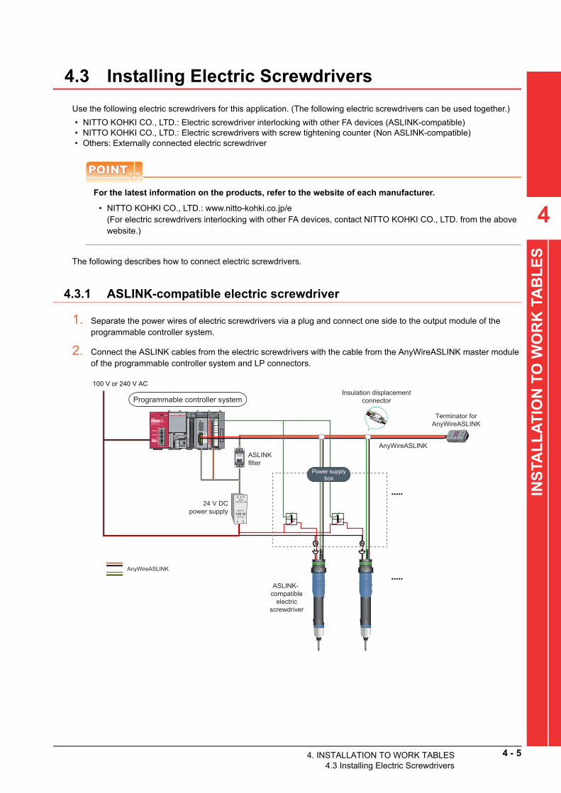
4.3 Installing Electric Screwdrivers
Use the following electric screwdrivers for this application. (The following electric screwdrivers can be used together.)
• NITTO KOHKI CO., LTD.: Electric screwdriver interloc
g with other FA devices (ASLINK-compatible) kin• NITTO KOHKI CO., LTD.: Electric screwdrivers with screw tightening counter (Non ASLINK-compatible)• Others: Externally connected electric screwdriverPOINTPOINTPOINT
For the latest information on the products, refer to the website of each manufacturer.
• NITTO KOHKI CO., LTD.: www.nitto-kohki.co.jp
4INS
TAL
LA
TIO
N T
O W
OR
K T
AB
LE
S
/e(For electric screwdrivers interlocking with other FA devices, contact NITTO KOHKI CO., LTD. from the above website.)
The following describes how to connect electric screwdrivers.
4.3.1 ASLINK-compatible electric screwdriver
1. Separate the power wires of electric screwdrivers via a plug and connect one side to the output module of the programmable controller system.
2. Connect the ASLINK cables from the electric screwdrivers with the cable from the AnyWireASLINK master module of the programmable controller system and LP connectors.
100 V or 240 V AC
Programmable controller system
ASLINK filter
24 V DC power supply
AnyWireASLINK
ASLINK-compatible
electric screwdriver
Insulation displacement connector
AnyWireASLINK
•••••
•••••
Terminator for AnyWireASLINK
Power supply box
4. INSTALLATION TO WORK TABLES4.3 Installing Electric Screwdrivers
4 - 5

4 - 6 4. INSTALLATION TO WORK TABLES4.3 Installing Electric Screwdrivers
4.3.2 Non ASLINK-compatible electric screwdriver
1. Connect the cable from the AnyWireASLINK master module of the programmable controller system and the cable from ASLINKER with LP connectors.
2. Separate the connectors on the edges of the cables from the electric screwdrivers into power wires and signal wires.
3. Connect one side of the separated power wires to the output module of the programmable controller system.
4. Connect the separated signal wires to the ASLINKER input/output wires.
4.3.3 Externally connected electric screwdriver
1. Externally connected electric screwdrivers do not control the ON/OFF status of the power supply from the programmable controller system.Connect the electric screwdrivers to the power supply (100 V AC or 200 V AC) without through a programmable controller system.
2. The programmable controller system controls OK/NG signals from electric screwdrivers.Add the I/O modules to the programmable controller system and customize user programs as needed.
POINTPOINTPOINT
For user customization of externally connected electric screwdrivers, refer to the following.
7.4 Externally Connected Electric Screwdriver
100 V or 240 V AC
Programmable controller system
ASLINK filter
24 V DC power supply
AnyWireASLINK
Non ASLINK-compatible
electric screwdriver
Insulation displacement connector
AnyWireASLINK
CONCON
•••••
•••••
LED lamp LED lamp0000-0000-00abcdef
0000-0000-00
OFF
RUN
ON
START
ooooo
oo
0000-0000-00abcdef
0000-0000-00
OFF
RUN
ON
START
ooooo
oo
ASLINKER
Two point inputs
One point input, one point output
Terminator for AnyWireASLINK
Power supply box

4
INS
TAL
LA
TIO
N T
O W
OR
K T
AB
LE
S
4.4 Installing POKAYOKE Terminals
The following figure shows the system configuration of POKAYOKE terminals in this application.
The methods for connecting POKAYOKE terminals are described by type on the next page or later.
Programmable controller system
ASLINK filter
AnyWireASLINK
Insulation displacement connector
AnyWireASLINK
24 V DC power supply
POKAYOKE terminal
Terminator for AnyWireASLINK
4. INSTALLATION TO WORK TABLES4.4 Installing POKAYOKE Terminals
4 - 7

4 - 8 4. INSTALLATION TO WORK TABLES4.4 Installing POKAYOKE Terminals
4.4.1 Push-button type
Install POKAYOKE terminals where the following environmental conditions are satisfied. This type of terminals does not have protective structures.
• The body is isolated from direct vibration and shock.
• Terminals are not directly exposed to dust particles.• Conductors such as metal chippings and spatters do not directly reach terminals.• No condensation• The atmosphere contains neither corrosive gas nor flammable gas nor sulfur.• High-voltage and large-current cables are far away.• Cables and controllers such as servo amplifiers and inverters that generate high frequency noises are far away.(1) Part namesBL227XB-K02VN-P, BL227XB-K06MN-P
(2) Model
(3) Mounting on pipesPush-button type terminals can be mounted on φ28 pipes.
CAUTION• Do not apply excessive force or impact on the pickup confirmation switch. Otherwise the
switch may be damaged. (0.49 G or smaller)• Do not install terminals at a site with continuous vibrations.
BL227XB-K02VN-PInput 1 point Pickup confirmation input (Push button)
Output 1 point One color selection type light
BL227XB-K06MN-PInput 1 point Pickup confirmation input (Push button)
Output 3 point RGB combination type light
Transmission line connection connector
Pickup indicator lightPush-button switch
Pipe installation holder
Hexagon socket head bolt
Input indicator (IN/ALM)Address setting port (R/W)
Transmission indicator (LINK)
Hexagon socket head bolt (M6 × 15)
Fit a boss of the fitting B in the hinge section of the terminal.
Attach the fitting B to the pipe, and engage the terminal and the fitting B.
Slide the terminal to adjust its position.
After the positioning of the terminal, permanently fix the terminal with the supplied bolt.
Tab of the terminal
Terminal
Hinge section
Fitting B
Groove of the fitting B
Tightening torque of M6 bolt: 1.5 to 2 N•m
One bolt supplied with a terminal
(4) How to connectConnect the link connector at the end of the cable jutting out from the back of the module to a pressure-welded link connector at a position on the main cable.
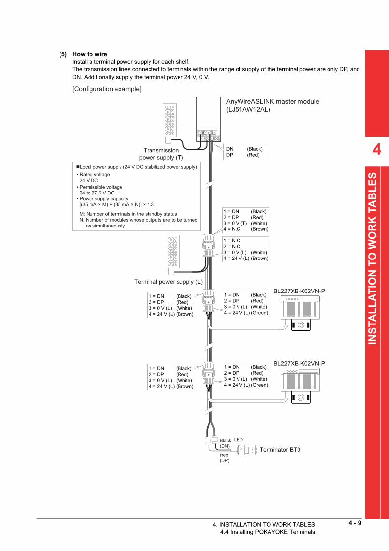
(5) How to wireInstall a terminal power supply for each shelf.The transmission lines connected to terminals within the range of supply of the terminal power are only DP, and DN. Additionally supply the terminal power 24 V, 0 V.
4
INS
TAL
LA
TIO
N T
O W
OR
K T
AB
LE
S
Terminal power supply (L)
1 = DN (Black)2 = DP (Red)3 = 0 V (T) (White)4 = N.C (Brown)
1 = DN (Black)2 = DP (Red)3 = 0 V (L) (White)4 = 24 V (L) (Brown)
1 = N.C2 = N.C3 = 0 V (L) (White)4 = 24 V (L) (Brown)
• Permissible voltage24 to 27.6 V DC
• Rated voltage24 V DC
• Power supply capacity
M: Number of terminals in the standby statusN: Number of modules whose outputs are to be turned
on simultaneously
[Configuration example]
DN (Black)DP (Red)
BL227XB-K02VN-P
BL227XB-K02VN-P
AnyWireASLINK master module(LJ51AW12AL)
LED
Terminator BT0Red (DP)
Black (DN)
Transmission power supply (T)
Local power supply (24 V DC stabilized power supply)
[(35 mA × M) + (35 mA × N)] × 1.3
1 = DN (Black)2 = DP (Red)3 = 0 V (L) (White)4 = 24 V (L) (Green)
1 = DN (Black)2 = DP (Red)3 = 0 V (L) (White)4 = 24 V (L) (Brown)
1 = DN (Black)2 = DP (Red)3 = 0 V (L) (White)4 = 24 V (L) (Green)
4. INSTALLATION TO WORK TABLES4.4 Installing POKAYOKE Terminals
4 - 9

4 - 10 4. INSTALLATION TO WORK TABLES4.4 Installing POKAYOKE Terminals
4.4.2 Lever type
Install POKAYOKE terminals where the following environmental conditions are satisfied. This type of terminals does not have protective structures.
• The body is isolated from direct vibration and shock.
• Terminals are not directly exposed to dust particles. (This condition should be satisfied because terminals do not haveprotective structures.)• Conductors such as metal chippings and spatters do not directly reach terminals.• No condensation• The atmosphere contains neither corrosive gas nor flammable gas nor sulfur.• High-voltage and large-current cables are far away.• Cables and controllers such as servo amplifiers and inverters that generate high frequency noises are far away.
(1) Part namesBL227XB-K02V-P, BL227XB-K06M-P
(2) Model
(3) Mounting on pipesLever type terminals can be mounted on φ28 pipes.
CAUTION• Do not apply excessive force or impact on the pickup confirmation switch. Otherwise the
switch may be damaged. (0.49 G or smaller)• Do not install terminals at a site with continuous vibrations.
BL227XB-K02V-POne-bit input Pickup confirmation input (lever)
One-bit output One color selection type light
BL227XB-K06M-POne-bit input Pickup confirmation input (lever)
Three-bit output RGB combination type light
Transmission line connection connector
Pickup indicator light
Lever switch
Pipe installation holder
Hexagon socket head bolt
Transmission indicator (LINK)
Address setting port (R/W)Input indicator (IN/ALM)
Hexagon socket head bolt (M6 × 15)One bolt supplied with a terminal
Fit a boss of the fitting B in the hinge section of the terminal.
Attach the fitting B to the pipe, and engage the terminal and the fitting B.
Slide the terminal to adjust its position.
After the positioning of the terminal, permanently fix the terminal with the supplied bolt.
Tab of the terminal
Terminal
Hinge section
Fitting B
Groove of the fitting B
Tightening torque of M6 bolt: 1.5 to 2 N•m

(4) How to connectConnect the link connector at the end of the cable jutting out from the back of the module to a pressure-welded link connector at a position on the main cable.
(5) How to wireInstall a terminal power supply for each shelf.The transmission lines connected to terminals within the range of supply of the terminal power are only DP, and DN. Additionally supply the terminal power 24 V, 0 V.
4
INS
TAL
LA
TIO
N T
O W
OR
K T
AB
LE
S
Transmission power supply (T)
Local power supply for shelves (L)
1 = DN (Black)2 = DP (Red)3 = 0 V (T) (White)4 = N.C (Brown)
1 = N.C2 = N.C3 = 0 V (L) (White)4 = 24 V (L) (Brown)
Local power supply (24 V DC stabilized power supply)
• Permissible voltage24 to 27.6 V DC
• Rated voltage24 V DC
• Power supply capacity
M: Number of terminals in the standby statusN: Number of modules whose outputs are to be turned
on simultaneously
[Configuration example]
DN (Black)DP (Red)
BL227XB-K02V-P
AnyWireASLINK master module(LJ51AW12AL)
LED
Terminator BT0Red (DP)
Black (DN)
BL227XB-K02V-P
[(35 mA × M) + (35 mA × N)] × 1.3
1 = DN (Black)2 = DP (Red)3 = 0 V (L) (White)4 = 24 V (L) (Brown)
1 = DN (Black)2 = DP (Red)3 = 0 V (L) (White)4 = 24 V (L) (Green)
1 = DN (Black)2 = DP (Red)3 = 0 V (L) (White)4 = 24 V (L) (Brown)
1 = DN (Black)2 = DP (Red)3 = 0 V (L) (White)4 = 24 V (L) (Green)
4. INSTALLATION TO WORK TABLES4.4 Installing POKAYOKE Terminals
4 - 11

4 - 12 4. INSTALLATION TO WORK TABLES4.4 Installing POKAYOKE Terminals
4.4.3 Transparent type
Install POKAYOKE terminals where the following environmental conditions are satisfied. This type of terminals does not have protective structures.
• The body is isolated from direct vibration and shock.
• Conductors such as metal chippings and spatters do not directly reach terminals.• No condensation• The atmosphere contains neither corrosive gas nor flammable gas nor sulfur.• High-voltage and large-current cables are far away.• Cables and controllers such as servo amplifiers and inverters that generate high frequency noises are far away.(1) Part names
(2) Model
BL227PB-T14P02V-P (light emission) One-bit output One color selection type light
BL227XB-T14P02V-C (light reception)One-bit input Pickup confirmation input
One-bit output One color selection type light
BL227PB-T07P02V-P (light emission) One-bit output One color selection type light
BL227XB-T07P02V-C (light reception)One-bit input Pickup confirmation input
One-bit output One color selection type light
Spare
Setting port
Lightemittingsection(5 axes)
Pickup indicator light(Selected color)
Transmission indicator LINK (Green)
Installation hole(2 holes)
Transmission indicator LINK (Green)
Setting port
Pickup indicator light(Selected color)
Installation hole(2 holes)
Input indicator I/O (Orange)
Lightreceivingsection(5 axes)
BL227PB-T14P02V-P (Light emitting side)A green sticker is on the side surface of the sensor.
BL227XB-T14P02V-C (Light receiving side)A pink sticker is on the side surface of the sensor.
Transmission line connection connector (DP, DN, 24 V, 0 V)
Transmission line connection connector (DP, DN, 24 V, 0 V)
ALM (Red) ALM (Red)

4
AL
LA
TIO
N T
O W
OR
K T
AB
LE
S
(3) Mounting on pipesTransparent type terminals can be mounted on φ28 pipes using the optional pipe installation holder (A027-T14PHP28-H1) and screw set (A027-TPSM4-5P).The module protective fittings (A027-T14PC) can also be used.
(a) Mounting on the pipe installation holder
The above figures show the BL227PB-T14P02V-P. The BL227XB-T14P02V-C and BL227PB-T14P02V-P are bilaterally symmetrical.
Without protective fittings With protective fittings
2-M4 × 20(Screw set)
BL227PB-T14P02V-P
2-M4(Screw set)
A027-T14PHP28-H1(Pipe installation holder)
BL227PB-T14P02V-P
A027-T14PC
A027-T14PHP28-H1
2-M4 × 20(Screw set)
2-M4(Screw set)
T
INS
(b) Mounting on a pipeThe above figure shows the terminal with protective fittings installed.
Hexagon socket head bolt (attachment)M6 × 15Tightening torque: 1.5 to 2 N•m
4. INSTALLATION TO WORK TABLES4.4 Installing POKAYOKE Terminals
4 - 13

4 - 14 4. INSTALLATION TO WORK TABLES4.4 Installing POKAYOKE Terminals
(4) Detection and adjusting optical axesThis module turns on (input indication: ON) when "the light is blocked".Oppose the light emitting/receiving terminals to adjust the optical axes to the position where the input indication is lost.Because a misadjustment of the position of the optical axis causes the same status as the status that blocking light causes, the input indicator turns on.After an adjustment, block the light with your hand to check if the indicator turns on (input indication: ON).
3M4321
3M4 3 2 1
3M4321
3M4321
Set each terminal to face each other to align optical axes as shown above.
The opposite alignment shown above is not acceptable.
(5) How to connectConnect the link connector at the end of the cable jutting out from the back of the module to a pressure-welded link connector at a position on the main cable.

(6) How to wireInstall a terminal power supply for each shelf.The transmission lines connected to terminals within the range of supply of the terminal power are only DP, and DN. Additionally supply the terminal power 24 V, 0 V.
BL22
B-T14P02V-P BL227XB-T14P02V-C4
INS
TAL
LA
TIO
N T
O W
OR
K T
AB
LE
S
CAUTION
Laying transmission lineKeep high voltage lines and power lines away from the transmission line.Use one transmission cable for one AnyWire system. Do not connect cables for two or more systems.Either case may cause malfunctions.
DN
0V
DP
24V
Black (DN) Red (DP)
The farthest end of the transmission line
3 M
3 M
When using a dedicated flat cable FK4-125-100
7P
Terminator BT0
AnyWireASLINK transmission line
DN (Black)
DP (Red)
0 V (White)24 V (Brown)
[Wiring example]
This drawing shows an example of wiring that enables efficient supply of power.
Transparent distance: Max. 1 m
1 = DN (Black)2 = DP (Red)3 = 0 V (L) (White)4 = 24 V (L) (Green)
Junction of the link connector and the dedicated flat cable
1 = DN (Black)2 = DP (Red)3 = 0 V (L) (White)4 = 24 V (L) (Green)
4. INSTALLATION TO WORK TABLES4.4 Installing POKAYOKE Terminals
4 - 15

4 - 16 4. INSTALLATION TO WORK TABLES4.4 Installing POKAYOKE Terminals
4.4.4 Door type
Install POKAYOKE terminals where the following environmental conditions are satisfied. This type of terminals does not have protective structures.
• The body is isolated from direct vibration and shock.
• Conductors such as metal chippings and spatters do not directly reach terminals.• No condensation• The atmosphere contains neither corrosive gas nor flammable gas nor sulfur.• High-voltage and large-current cables are far away.• Cables and controllers such as servo amplifiers and inverters that generate high frequency noises are far away.CAUTION
• Do not install terminals vertically.• Do not apply excessive force or impact on the pickup confirmation switch. Otherwise the
switch may be damaged. (0.49 G or smaller)• Do not install terminals at a site with continuous vibrations.
(1) Part namesBL227XB-F04V-P
DP: RedDN: Black
24 V: Green0 V: White
Arm
Pickup indicator light
Address setting port (R/W)
Transmission line connection connector
Hexagon socket head bolt
Pipe installation holderTransmission indicator (LINK)
Input indicator (IN/ALM)
Lever switch
(2) ModelBit operation
BL227XB-F04V-PInput 2 point Switch input/break open detection
Output 2 point One color selection type light/Door opening/closing
(3) Mounting on pipesDoor-type terminals can be mounted on φ28 pipes.
Hexagon socket head bolt (M6 × 15)One bolt supplied with a terminal
Tab of the terminalTerminal
Hinge section
Fitting B
1) Fit a boss of the fitting B in the hinge section of the terminal.
2) Attach the fitting B to the pipe, and engage the terminal and the fitting B.Inserting the tab of the terminal into the groove of the fitting B temporarily fixes them.
3) Slide the terminal to adjust its position.
4) After the positioning of the terminal, permanently fix the terminal with the supplied bolt.
Tightening torque of M6 bolt: 1.5 to 2 N•m
Groove of the fitting B

(4) How to connectConnect the link connector at the end of the cable jutting out from the back of the module to a pressure-welded link connector at a position on the main cable.
(5) How to wireInstall a terminal power supply for each shelf.The transmission lines connected to terminals within the range of supply of the terminal power are only DP, and DN. Additionally supply the terminal power 24 V, 0 V.
4
INS
TAL
LA
TIO
N T
O W
OR
K T
AB
LE
S
Transmission power supply (T)Terminal power supply (L)
1 = DN (Black)2 = DP (Red)3 = 0 V (T) (White)4 = N.C (Brown)
1 = N.C2 = N.C3 = 0 V (L) (White)4 = 24 V (L) (Brown)
Local power supply (24 V DC stabilized power supply)
• Permissible voltage24 to 27.6 V DC
• Rated voltage24 V DC
• Power supply capacity
M: Number of terminals in the standby statusN: Number of modules whose outputs are to be turned
on simultaneously
[Configuration example]
DN (Black)DP (Red)
AnyWireASLINK master module(LJ51AW12AL)
LED
Terminator BT0Red (DP)
Black (DN)
ADDRESS No.
BL227XB-F04V-P
ADDRESS No.
BL227XB-F04V-P
[(19 mA × M) + (522 mA × N)] × 1.3
1 = DN (Black)2 = DP (Red)3 = 0 V (L) (White)4 = 24 V (L) (Brown)
1 = DN (Black)2 = DP (Red)3 = 0 V (L) (White)4 = 24 V (L) (Green)
1 = DN (Black)2 = DP (Red)3 = 0 V (L) (White)4 = 24 V (L) (Brown)
1 = DN (Black)2 = DP (Red)3 = 0 V (L) (White)4 = 24 V (L) (Green)
4. INSTALLATION TO WORK TABLES4.4 Installing POKAYOKE Terminals
4 - 17

4 - 18 4. INSTALLATION TO WORK TABLES4.4 Installing POKAYOKE Terminals
(6) Pickup confirmation switchThe pickup confirmation switch lever can be tilted in any direction.Tilt the pickup confirmation switch lever at least approximately 30° or more to turn on without fail.
CAUTION
If an impact of 0.49 G or greater is exerted on the pickup confirmation switch, the switch may be damaged.Do not exert a stress such as "twisting" and "a pull in the downward direction".Otherwise the pickup confirmation switch may be damaged.
ADDRESS No.
(7) How to attach a doorWhen a plate is attached to an arm, it becomes the door that covers the screw shelf.As the plate, a light and strong material such as a plastic board is suitable.The following figure and table show an example of materials and the size operated with this terminal.
E
4014
F
(138)4-φ5 t
Straight type
600210
3400250300300200360
E F t
Permissible size of plastic board (unit: mm)
Recommended material for doors
Straight type : Plastic board of 3 mm thickDensity : 500 g/mm2 or less
Standard tightening torque of M4 truss head screws: 1.27 N•m
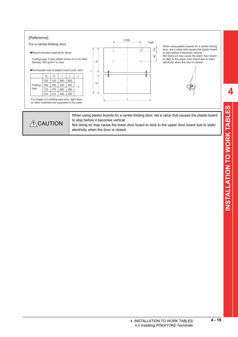
4
S
4014
(138)
G
H
I
J
Recommended material for doors
Folding-type: Foam plastic board of 3 mm thickDensity: 500 g/mm2 or less
Permissible size of plastic board (unit: mm)
4-φ5
600
3
120 120
200210 210
260
440
G H I J t
Folding-type
400150 150 320300170 170 360
[Reference]
For a center-folding doorWhen using plastic boards for a center-folding door, set a value that causes the plastic board to stop before it becomes vertical.Not doing so may cause the lower door board to stick to the upper door board due to static electricity when the door is closed.
For hinges of a folding-type door, light resin or other materials are supposed to be used.
E
INSTA
LL
AT
ION
TO
WO
RK
TA
BL
CAUTION
When using plastic boards for a center-folding door, set a value that causes the plastic board to stop before it becomes vertical.Not doing so may cause the lower door board to stick to the upper door board due to static electricity when the door is closed.
4. INSTALLATION TO WORK TABLES4.4 Installing POKAYOKE Terminals
4 - 19

4 - 20 4. INSTALLATION TO WORK TABLES4.4 Installing POKAYOKE Terminals
4.4.5 Small door type (Horizontal metal arm)
Install POKAYOKE terminals where the following environmental conditions are satisfied. This type of terminals does not have protective structures.
• The body is isolated from direct vibration and shock.
• Conductors such as metal chippings and spatters do not directly reach terminals.• No condensation• The atmosphere contains neither corrosive gas nor flammable gas nor sulfur.• High-voltage and large-current cables are far away.• Cables and controllers such as servo amplifiers and inverters that generate high frequency noises are far away.CAUTION
• Do not install terminals vertically.• Do not apply excessive force or impact on the pickup confirmation switch. Otherwise the
switch may be damaged. (0.49 G or smaller)• Do not install terminals at a site with continuous vibrations.
(1) Part namesBL227XB-R2K08MN-P
(2) Model
Input indicator (IN)
Setting port (R/W)Transmission indicator (LINK) Alarm indicator (ALM)
Hexagon socket head bolt
Installation holder
Arm
Push-button switch
Pickup indicator light
Bit operation
BL227XB-R2K08MN-PInput 2 points Switch input/break open detection
Output 4 points RGB combination type light/Door opening/closing
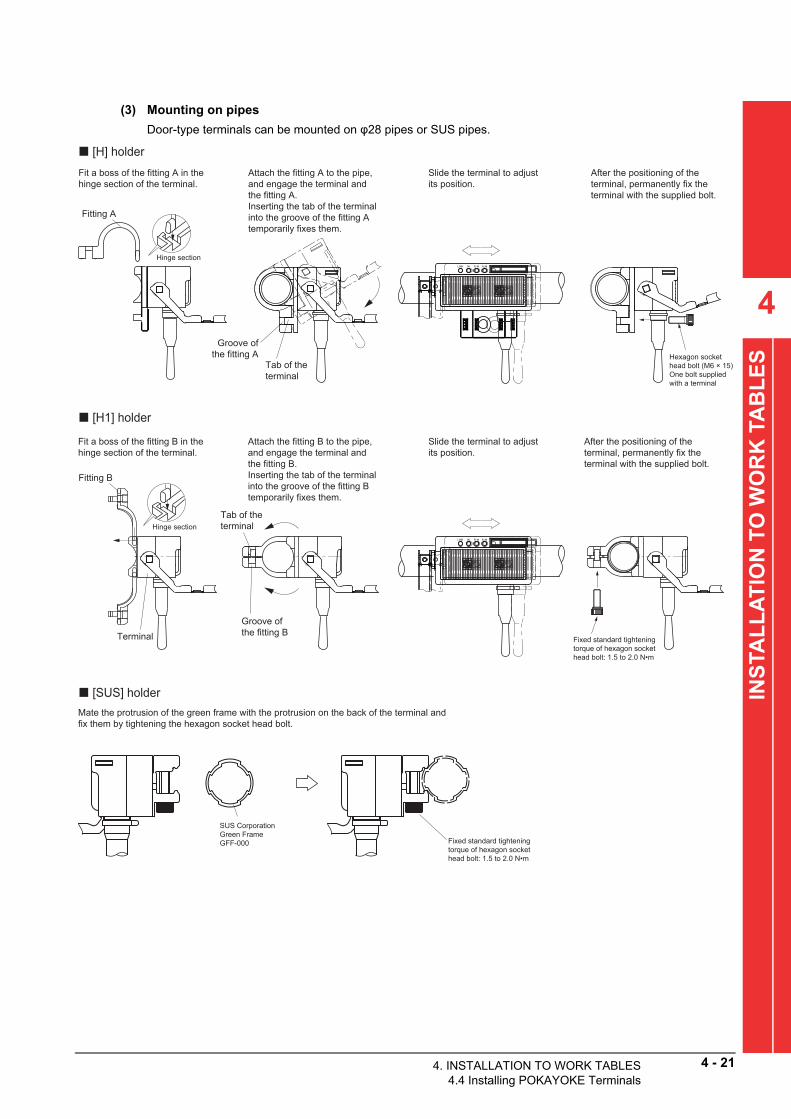
(3) Mounting on pipes
Door-type terminals can be mounted on φ28 pip
or SUS pipes.4
INS
TAL
LA
TIO
N T
O W
OR
K T
AB
LE
S
es
[SUS] holder
Hinge section
Fitting A
[H] holder
Hinge section
Fitting B
Terminal
[H1] holder
Fit a boss of the fitting A in the hinge section of the terminal.
Attach the fitting A to the pipe, and engage the terminal and the fitting A. Inserting the tab of the terminal into the groove of the fitting A temporarily fixes them.
Slide the terminal to adjust its position.
After the positioning of the terminal, permanently fix the terminal with the supplied bolt.
Fit a boss of the fitting B in the hinge section of the terminal.
Attach the fitting B to the pipe, and engage the terminal and the fitting B. Inserting the tab of the terminal into the groove of the fitting B temporarily fixes them.
Slide the terminal to adjust its position.
After the positioning of the terminal, permanently fix the terminal with the supplied bolt.
Fixed standard tightening torque of hexagon socket head bolt: 1.5 to 2.0 N•m
Mate the protrusion of the green frame with the protrusion on the back of the terminal and fix them by tightening the hexagon socket head bolt.
SUS CorporationGreen Frame GFF-000 Fixed standard tightening
torque of hexagon socket head bolt: 1.5 to 2.0 N•m
Hexagon socket head bolt (M6 × 15) One bolt supplied with a terminal
Groove of the fitting A
Tab of the terminal
Groove of the fitting B
Tab of the terminal
4. INSTALLATION TO WORK TABLES4.4 Installing POKAYOKE Terminals
4 - 21

4 - 22 4. INSTALLATION TO WORK TABLES4.4 Installing POKAYOKE Terminals
(4) How to connect
Connect the link connector at the end of the cab
jutting out from the back of the module to a pressure-welded le link connector at a position on the main cable.(5) How to wire
Install a terminal power supply for each shelf.
The transmission lines connected to terminals within the range of supply of the terminal power are only DP and DN. Additionally supply the terminal power 24 V, 0 V.0 VA
24 VA
AnyWireASLINK master
Transmission power supply
24 V DC
For FK4-125-100
1 = DN (Black) 2 = DP (Red) 3 = 0 VA 4 = 24 VA
1 = DN (Black) 2 = DP (Red) 3 = 0 VA (White) 4 = 24 VA (Brown)
Local power supply for shelves

(6) How to attach a door
Attach a board on the door to expand the dimen
ns of the door. sioAs the board, a light and strong material such as a plastic board is suitable.The following figure and table show an example of materials and the size operated with this terminal.4
INS
TAL
LA
TIO
N T
O W
OR
K T
AB
LE
S
Installation hole
Door
Size of installation holesThread diameter: M4
Fixing screw (attachment) Truss head screw: M4 × 10 Tightening torque: 1.27 N•m
t
Straight type 200100 3
E t
Permissible size of plastic board (unit: mm)
Recommended material for doors
Straight type: Plastic board of 3 mm thick
E
4014
F
2-φ5 (42)
Note: 0.1 × 0.2 × 500 = 10 g
Door processing example
Density: 500 g/m2 or less
F
4. INSTALLATION TO WORK TABLES4.4 Installing POKAYOKE Terminals
4 - 23

4 - 24 4. INSTALLATION TO WORK TABLES4.4 Installing POKAYOKE Terminals
4.4.6 Ultra-compact touch type
Install POKAYOKE terminals where the following environmental conditions are satisfied. This type of terminals does not have protective structures.
• The body is isolated from direct vibration and shock.
• Conductors such as metal chippings and spatters do not directly reach terminals.• No condensation• The atmosphere contains neither corrosive gas nor flammable gas nor sulfur.• High-voltage and large-current cables are far away.• Cables and controllers such as servo amplifiers and inverters that generate high frequency noises are far away.(1) Part names
(2) ModelBit operation
B292XB-02VLInput 1 point Touch input
Output 1 point One color selection type light
Detection surface
Setting port (R/W)
Approx. 5 mm
ALM displayIN display
LINK display
Model label side
POKAYOKE terminal body
Transmission cable Extension cable
Red (DP)
Black (DN)
Red (DP)
Black (DN)
Connection connector (T)
Connection connector (R)
Connection at connector (R) side
Connection at connector (R) side
Connection at connector (T) side

4
INS
TAL
LA
TIO
N T
O W
OR
K T
AB
LE
S
(3) How to installUltracompact touch type terminals can be mounted on wiring ducts.
(4) How to connectConnect the link connector at the end of the cable jutting out from the module to a pressure-welded link connector at a position on the main cable.
Wiring duct (cover)
Wiring duct (cover)
Red
Black
Transmission cable
R side
T side
Model label side
Extension cable
B292XB-02VL
B292XB-02VL
R side
T side
Model label side
Wiring duct (base)
Front
4. INSTALLATION TO WORK TABLES4.4 Installing POKAYOKE Terminals
4 - 25

4 - 26 4. INSTALLATION TO WORK TABLES4.4 Installing POKAYOKE Terminals
(5) How to wireInstall a terminal power supply for each shelf.The transmission lines connected to terminals within the range of supply of the terminal power are only 0 V, DP, and DN. Additionally supply the terminal power 24 V, 0 V.
(a) For two-wire transmission cables
(b) For four-wire transmission cables
Master module
FK2-125-100
LP2-BR-10PTrunk line link connector
Pin alignment of the link connector
Transmission trunk side POKAYOKE transmission sidePin No. Description Line color
BlackRedDP
DN12
Pin No. Description Line colorBlackRedDP
DN12
LP connectors (link connector) are gender-neutral connectors. Connecting the same type connectors allow users to easily "connect" and "branch" link connector pins.
LP2-PWH-10PCrimp type link connector at the POKAYOKE transmission side
Master module
FK4-125-100
LP4-WR-10P
Pin alignment of the link connector
Transmission trunk side POKAYOKE transmission sidePin No. Description Line color
BlackRed
WhiteBrown
DPDN1
234
Pin No. Description Line colorBlackRedDP
DN
--
--
12
24 V0 V 3
4
LP2-WW-10PCrimp type link connector at the POKAYOKE transmission side
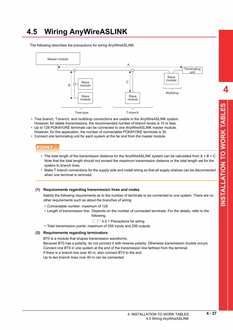
4
AL
LA
TIO
N T
O W
OR
K T
AB
LE
S
4.5 Wiring AnyWireASLINK
The following describes the precautions for wiring AnyWireASLINK.
• Tree branch, T-branch, and multidrop connections are usable in the AnyWireASLINK system.However, for stable transmissions, the recommended number of branch levels is 10 or less.
• Up to 128 POKAYOKE terminals can be connected to one AnyWireASLINK master module.However, for this application, the number of connectable POKAYOKE terminals is 30.
• Connect one terminating unit for each system at the far end from the master module.
POINTPOINTPOINT
• The total length of the transmission distance for the AnyWireASLINK system can be calculated from A + B + C.Note that the total length should not exceed the maximum transmission distance or the total length set for the system to branch lines.
• Make T branch connections for the supply side and install wiring so that all supply shelves can be disconnected when one terminal is removed.
(1) Requirements regarding transmission lines and nodes
Master module
Terminatingunit
Slavemodule
Slavemodule
Tree-type
Multidrop
Slavemodule
Slavemodule
T-branch
A
BC
T
Satisfy the following requirements as to the num r of terminals to be connected to one system. There are noNS
beother requirements such as about the branches of wiring.
I
• Connectable number: maximum of 128 • Length of transmission line: Depends on the number of connected terminals. For the details, refer to thefollowing.
4.5.1 Precautions for wiring• Total transmission points: maximum of 256 inputs and 256 outputs
(2) Requirements regarding terminators
BT0 is a module that shapes transmission wave
ms. forBecause BT0 has a polarity, do not connect it with reverse polarity. Otherwise transmission trouble occurs.Connect one BT0 in one system at the end of the transmission line farthest from the terminal.If there is a branch line over 40 m, also connect BT0 to the end.Up to two branch lines over 40 m can be connected.4. INSTALLATION TO WORK TABLES4.5 Wiring AnyWireASLINK
4 - 27

4 - 28 4. INSTALLATION TO WORK TABLES4.5 Wiring AnyWireASLINK
4.5.1 Precautions for wiring
The AnyWireASLINK system transfers signals and supplies power to slave modules by using two types of transmission cables (DP, DN).
(1) Total length of transmission cablesThe total length of transmission cables (including trunk and branch lines) per one AnyWireASLINK master module depends on the maximum power supply current value of the transmission cables.
*1 The power supply current of the transmission cables is the total current consumption of connected POKAYOKE terminals. Refer
to the following list and calculate the total current consumption.
Wire diameter of transmission
cables (DP, DN)
Power supply current of transmission cables
(maximum value)*1Total length of transmission cables
1.25 mm2
2 A 50 m or less
1 A 100 m or less
0.5 A 200 m or less
Product name ModelConsumption current
(DP-DN side)
Electric screwdriver interlocking with other FA devices (2)Electric screwdriver interlocking
with other FA device6 mA
ASLINKER (input 2 points) BL287SB-02F-CC20 3.4 mA
ASLINKER (input 1 point, output 1 point) BL287XB-02F-CC20 3.5 mA
Lever switch type terminal (Selection of one color from seven colors) BL227XB-K02V-P 6 mA
Pushbutton switch type terminal (Selection of one color from seven
colors)BL227XB-K02VN-P 6 mA
Lever switch type terminal (RGB each color independent ON/OFF) BL227XB-K06M-P 6 mA
Pushbutton switch type terminal (RGB each color independent ON/
OFF)BL227XB-K06MN-P 6 mA
LED indication:
Stationery type
Photoelectric transmission type (Dust-proof: 140 mm long, selection of
one color from seven colors)
BL227PB-T14P02V-P (light emission) 2.5 mA
BL227XB-T14P02V-C (light reception) 2.5 mA
LED indication:
Stationery type
Photoelectric transmission type (Dust-proof: 70 mm short, selection of
one color from seven colors)
BL227PB-T07P02V-P (light emission) 2.5 mA
BL227XB-T07P02V-C (light reception) 2.5 mA
Door opening/closing
+ LED indication: Stationary type
Lever switch type
Detection function of forcibly open
selection of one color from seven colors)
BL227XB-F04V-P 6 mA
Small door type terminal, 2-point output type (with break open detection
function, horizontal metal arm, RGB each color independent ON/OFF)BL227XB-R2K08MN-P 6 mA
Ultracompact touch type terminal (Selection of one color from seven
colors)B292XB-02VL 6 mA
(2) Calculation exampleCalculate the total length of transmission cables for when the following POKAYOKE terminals are connected.• Pickup side: 30 pushbutton switch type terminals (Selection of one color from seven colors)• Supply side: 30 door type terminals, 2-point output type (with break open detection function)
BL227XB-K02VN-P (0.006) × 30 + BL227XB-F04V-P (0.006) × 30 = 0.360Thus, the total length of the transmission cables is up to 200 m.
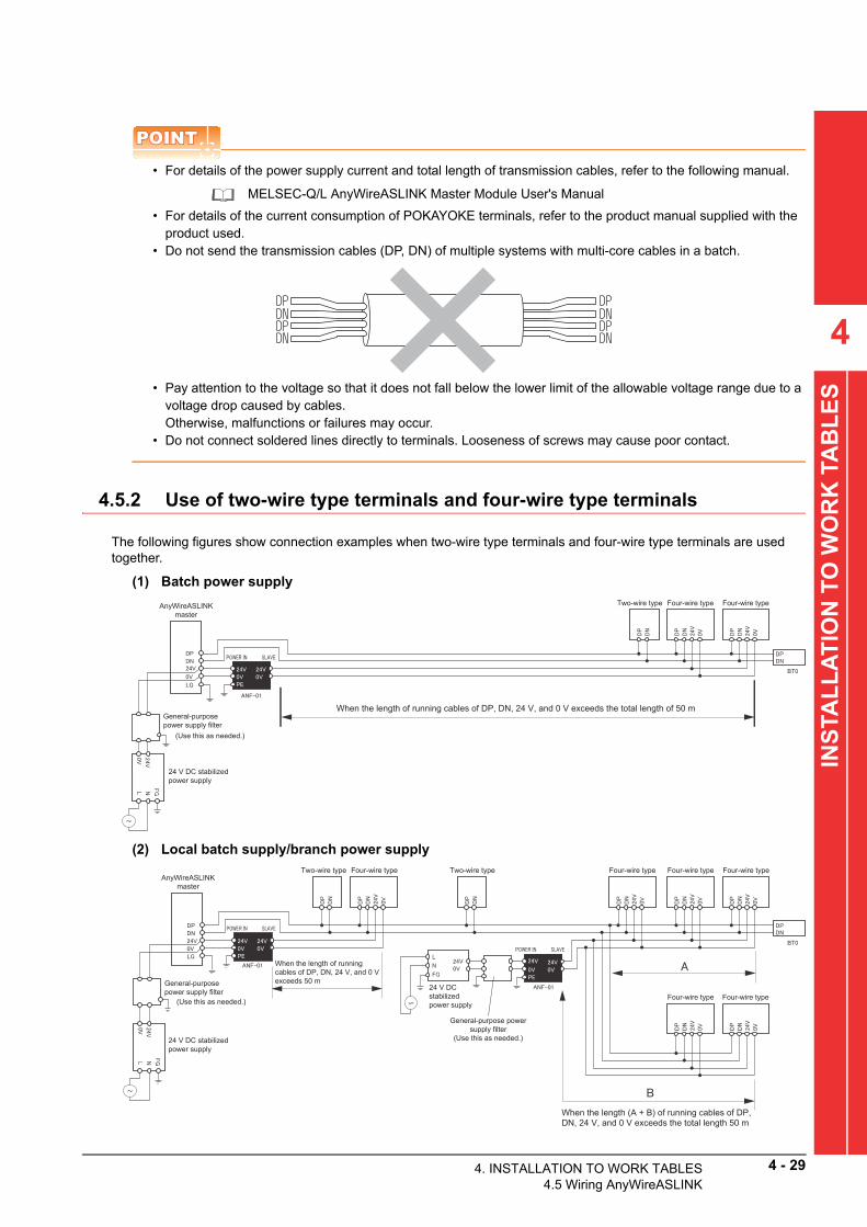
4
TAB
LE
S
POINTPOINTPOINT
• For details of the power supply current and total length of transmission cables, refer to the following manual.
MELSEC-Q/L AnyWireASLINK Master Module User's Manual
• For details of the current consumption of POKAYOKE terminals, refer to the product manual supplied with the product used.
• Do not send the transmission cables (DP, DN) of multiple systems with multi-core cables in a batch.
• Pay attention to the voltage so that it does not fall below the lower limit of the allowable voltage range due to a voltage drop caused by cables.Otherwise, malfunctions or failures may occur.
• Do not connect soldered lines directly to terminals. Looseness of screws may cause poor contact.
INSTA
LL
AT
ION
TO
WO
RK
4.5.2 Use of two-wire type terminals and four-wire type terminalsThe following figures show connection examples when two-wire type terminals and four-wire type terminals are used together.
(1) Batch power supply
(2) Local batch supply/branch power supply
Two-wire type Four-wire type Four-wire typeAnyWireASLINK master
(Use this as needed.)
When the length of running cables of DP, DN, 24 V, and 0 V exceeds the total length of 50 mGeneral-purpose power supply filter
24 V DC stabilized power supply
AnyWireASLINK master
(Use this as needed.)
Two-wire type Two-wire typeFour-wire type Four-wire type Four-wire type Four-wire type
Four-wire type Four-wire type
When the length of running cables of DP, DN, 24 V, and 0 V exceeds 50 m
When the length (A + B) of running cables of DP, DN, 24 V, and 0 V exceeds the total length 50 m
General-purpose power supply filter
24 V DC stabilized power supply
24 V DC stabilized power supply
General-purpose power supply filter
(Use this as needed.)
4. INSTALLATION TO WORK TABLES4.5 Wiring AnyWireASLINK
4 - 29
4 - 30 4. INSTALLATION TO WORK TABLES4.5 Wiring AnyWireASLINK
4.5.3 Cables
(1) 4-core flat cable
Model Details
FK4-125-10016 AWG (1.25 sq × 4 cores), insulating coating outer diameter: φ2.5±0.1 mm
(Conductor resistance: 0.015 Ω/m, permissible current: 12.7 A), 100 m winding
(2) LP connector (Pressure welding connector)
Model Details
LP4-WR-10PFor 4-core flat cable (1.25 sq)
(Coating outer diameter: φ2.54, cover: white, body: red), pin protector type
LP4-WW-10PFor ASLINKER and ultracompact touch type terminals
(Coating outer diameter: φ1.1 to 1.4, cover: white, body: white)
(3) Pressure welding tool for LP connector
4.5.4 Terminator for AnyWireASLINK
Model Details
LP-TOOLAlthough an LP connector can be pressure welded using a tool such as pliers, a dedicated tool is
recommended for steady working.
CAUTION Insert an ASLINK filter between the 4-core flat cable and 24 V DC power supply.
Model Product specifications Dimension (mm)
BT0Transmission wave shaping module (with polarity) cable
connection (attachment holder included)44×24.5×12
CAUTION
The terminator (BT0) is a module used to stabilize transmission waveforms.Connect the terminator to the end of the transmission line farthest from the master module.Be aware that BT0 has a polarity. (The LED turns on in correct polarity.)A misconnection may cause malfunctions or failures.

4.5.5 Attaching the link connector
The following describes how to attach the link connector with the LP4-WR-10P as an example.To perform pressure welding to the link connector, use the dedicated tool (LP-TOOL: Anywire Corporation).
CAUTION
• Do not make a reverse connection or a short circuit in connection work.A misconnection may cause malfunctions or failures.
• Do not pull cables when making connections.Do not secure cables with stress exerted on them. Doing so may cause poor contact.
4
K T
AB
LE
S
(1) List of component parts
Connector cover Flat cableConnector body
Pin No. displayEnd surface
r
No. displayp y
R
WO
(2) Pressure welding at the flat cable end(a) Setting the flat cable on the connector cover
1) Check the pin numbers shown on the g
oves on the inner *1INS
TAL
LA
TIO
N T
O
rosurface of the connector cover and the cable orientation.(The black line is positioned on the hinge side of the connector cover.)Be aware that transmissions are not made with the reverse orientation.2) Slide the flat cable so that the cable end contacts with the end
face of the connect cover.*1
3) Fold the cover into two in such a way that the cover sandwiches the wires.
4) Secure the tip of the small hooks into the fixing hole.
Small hooks
Check that the small hooks have been fixed in the holes.
4. INSTALLATION TO WORK TABLES4.5 Wiring AnyWireASLINK
4 - 31

4 - 32 4. INSTALLATION TO WORK TABLES4.5 Wiring AnyWireASLINK
(b) Engaging the connector body to the connector coverPush the four electrodes standing on the connector body into the four holes on the connector cover.
Connector body
Hole on the connector bodyLarge hooks
Connector body
Electrodes
Connector cover
Holes for electrodes
(c) Pressure weldingPlace a production tool such as pliers on the top face of the connector cover and the knurled part on the back of the connector body, and push the connector cover into the connector body.
Check that with snaps, all the four large hooks of the connector cover (two on each side) are securely engaged into the connector body holes.
The appearance should be as shown below
fter all the steps have been completed. a(3) Pressure welding at a position between flat cable ends
(a) Cut off the end face of the connector cover using a tool such as a nipper.
[Front view] [Side view]
Cut
(b) Check the pin numbers shown on the grooves on the internal surface of the connector cover and the flat cable orientation, and set the flat cable. (The black line is positioned on the hinge side of the connector cover.)

4
INS
TAL
LA
TIO
N T
O W
OR
K T
AB
LE
S
(c) Perform steps (a)-3), (a)-4), (b), and (c) for pressure welding at the flat cable end.
The appearance should be as shown below after all the steps have been completed.
Utilizing the combinations (of pressure welding at flat cable ends and at positions between the ends) allows three types of connections.
POINTPOINTPOINT
Pin alignment of the link connector
Cable colors of the flat cable for wiring and the link connector cable attached to each type of POKAYOKE terminal are partially different.
The link connector is a gender-neutral connector.
Pin No. Description
Cable color
Flat cable for wiring
Cable attached to ASLINK-
compatible electric
screwdriver
Cable attached to
ASLINKER
Cable attached to
POKAYOKE terminal
1 DN Black Black Black
2 DP Red Yellow Red
3 0 V White White White
4 24 V Brown Green Green
[Addition] [T-shape branching] [H-shape branching]
[Example of T-shape branching connection]
4. INSTALLATION TO WORK TABLES4.5 Wiring AnyWireASLINK
4 - 33

4 - 34 4. INSTALLATION TO WORK TABLES4.6 Installing Other External Signal I/O Device
4.6 Installing Other External Signal I/O Devices
To connect indicator lights, buzzers, and external input devices to the CPU module in this application, connect terminals to the DC I/O conversion module (FA-TBS40P) connected to the CPU module with the supplied conversion cable (FA-SCBL10FMV-M).
The following table shows the DC I/O conversion module terminals to which indicator lights, buzzers, and external input switches are connected.
For the external I/O of the CPU module and the connection specifications of the DC I/O conversion module and conversion cable, refer to the following.
• External I/O of the CPU module: 3.6.1 Wiring• Connection specifications of the DC I/O conversion module (FA-TBS40P):
Appendix.1.8 Specifications of the DC I/O conversion module• Connection specifications of the conversion cable (FA-SCBL10FMV-M):
Appendix.1.9 Specifications of the connection cable for the DC I/O conversion module
Device nameTerminal or pin for connection
DC I/O conversion module CPU module side
Three-color
stack light
Upper lamp 33
39 or 40
OUT2
OUTCOM
Middle lamp 32 OUT1
Lower lamp 31 OUT0
Two-color
stack light
Green lamp 36 OUT5
Red lamp 37 OUT6
Buzzer34 OUT3
35 OUT4
External input switch 21 19 or 20 IN6 INCOM
4.7 Ethernet Connection
The following figure shows an Ethernet connection image for this application.
Personal computer for database server
Personal computer for the tool
Ethernet
Operation panelControl panel
GOTProgrammable controller system
Follow the above image and connect the personal comp
r for the database server, personal computer for the tool, utecontrol panel (programmable controller system), and operation panel (GOT) with Ethernet cables.CAUTION• Use twisted pair cables with shields as Ethernet cables.• Attach ferrite cores on both sides of an Ethernet cable.
s

5
5
SY
ST
EM
SE
TT
ING
5. SYSTEM SETTING
This chapter describes the system setting of the SCREW TIGHTENING Application.
5.1 Starting up the Programmable Controller
Power on and start the programmable controller.
5.2 Installing Sequence Programs
The following shows the procedure for installing sequence programs in the programmable controller.
POINTPOINTPOINT
For details of the operations on GX Works2, refer to the following.
GX Works2 Version 1 Operating Manual (Common)
CAUTION
Restrictions are applied to the following functions of GX Works2 in the SCREW TIGHTENING Control Package project.
Function Description
Write to PLC
You cannot write only the execution program. (Write the program together with its
source information.)
You cannot write data to SD memory cards.
Write to IC Memory Card
Not availableWrite to IC Memory Card
(Edit and Data Copy)
Verify with PLC You cannot display details of verification results of the SCREW TIGHTENING
Application program "SCR002AA". (You can display only a list of verification results.)Verify
Device Display
You cannot use these functions for the SCREW TIGHTENING Application program
"SCR002AA".Batch Device Display
Display Compile Result
PrintYou cannot use the device display.
Print Preview
User Library You cannot register data in the user library.
CopyYou cannot use these functions for the SCREW TIGHTENING Application program
"SCR002AA".
5. SYSTEM SETTING.1 Starting up the Programmable Controller
5 - 1

5 - 2 5. SYSTEM SETTING5.2 Installing Sequence Programs
5.2.1 Preparing a GX Works2 project
Copy the following file in the "Project" folder on the installation DVD to the personal computer and clear the read-only attribute of the copy.
• AP10-SCR002AA-L02_*.****.gxw (*.**** indicates the
rsion.) ve5.2.2 Reading a project
Open the SCREW TIGHTENING Control Package project on GX Works2.
POINTPOINTPOINT
• When the following window appears, select all the items and click the [OK] button.
• The CPU type of the SCREW TIGHTENING Control Package project stored in the installation DVD is "L02/L02-P". To use other CPU types, change the PLC type.
• If the PLC type is changed to "L26-BT/L26-PBT", change "Start XY" of the PLC parameter [I/O Assignment] as follows.
1. Run "GX Works2" from the Start menu of Windows.
2. Click [Project] → [Open] in the menu.
3. The "Open" window appears.
4. Select the copy of the file on the installation DVD and click the [Open] button.
5. The SCREW TIGHTENING Control Package project is opened.
Click.
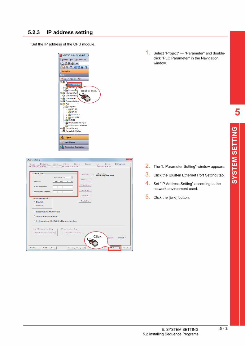
5
SY
ST
EM
SE
TT
ING
5.2.3 IP address setting
Set the IP address of the CPU module.
1. Select "Project" → "Parameter" and double-click "PLC Parameter" in the Navigation window.
2. The "L Parameter Setting" window appears.
3. Click the [Built-in Ethernet Port Setting] tab.
4. Set "IP Address Setting" according to the network environment used.
5. Click the [End] button.
Double-click.
Click.
5. SYSTEM SETTING5.2 Installing Sequence Programs
5 - 3

5 - 4 5. SYSTEM SETTING5.2 Installing Sequence Programs
5.2.4 Registering a license key
A license key can be registered in the CPU module by writing the license key and product ID to the following devices.
*1 Follow the "License Key Request Instructions" supplied with the SCREW TIGHTENING Control Package to get a license key.
*2 This information is described in the "License Certificate" supplied with the SCREW TIGHTENING Control Package.
Information to be registered Write target device
License key (64 characters)*1 ZR550 to ZR565
Product ID*23-digit number ZR566
9-digit number ZR567 to ZR568
Write the license information to the devices by one of the
llowing two methods. fo(1) Using a ladder program
Add a ladder program in the program "KEY_LD"
.Refer to the following example and create a ladder program.11AA12AB13AC14AD21BA22BB23BC24BD31CA32CB 33CC34CD41DA42DB43DC44DD
MOV H11AA ZR550
MOV H12AB ZR551
Snip
123-123456789
Product ID (example)License key (example)
SM400
MOV H43DC ZR564
MOV H44DD ZR565
MOV K123 ZR566
DMOV K123456789 ZR567

(2) Using an in-line ST box
Add an ST program in the in-line ST box in the p
gram "KEY_ST".5
SY
ST
EM
SE
TT
ING
roRefer to the following example and create an ST program.
5.2.5 Customizing the project
Customize the project as needed.
POINTPOINTPOINT
For details of user customization, refer to the following.
7.1 User Program
11AA12AB13AC14AD21BA22BB23BC24BD31CA32CB 33CC34CD41DA42DB43DC44DD 123-123456789
Product ID (example)License key (example)
MOV(TRUE, H11AA, ZR550);MOV(TRUE, H12AB, ZR551);MOV(TRUE, H13AC, ZR552);MOV(TRUE, H14AD, ZR553);MOV(TRUE, H21BA, ZR554);MOV(TRUE, H22BB, ZR555);MOV(TRUE, H23BC, ZR556);MOV(TRUE, H24BD, ZR557);MOV(TRUE, H31CA, ZR558);MOV(TRUE, H32CB, ZR559);MOV(TRUE, H33CC, ZR560);MOV(TRUE, H34CD, ZR561);MOV(TRUE, H41DA, ZR562);MOV(TRUE, H42DB, ZR563);MOV(TRUE, H43DC, ZR564);MOV(TRUE, H44DD, ZR565);MOV(TRUE, K123, ZR566);DMOV(TRUE, K123456789, ZR567);
SM400
5. SYSTEM SETTING5.2 Installing Sequence Programs
5 - 5

5 - 6 5. SYSTEM SETTING5.2 Installing Sequence Programs
5.2.6 Writing the project
Write the SCREW TIGHTENING Control Package project with GX Works2.
POINTPOINTPOINT
Convert and compile all the projects to complete the compilation in advance.
1. Select "Connection Destination" → "Current
Connection" and double-click "Connection1" in the Navigation window.2. The "Transfer Setup" screen appears.
3. Configure the following settings and click the [OK] button.
• PC side I/F: Serial USB• PLC side I/F: PLC Module• Other Station Setting: No Specification
4. Click [Online] → [Write to PLC] in the menu.
5. The "Online Data Operation" screen appears.
6. Click the [Parameter+Program] button.
7. Click the [Execute] button.
Double-click.
Click.
Click.

5
SY
ST
EM
SE
TT
ING
5.3 Starting up the GOT
Power on and start the GOT.
5.4 Installing Screen Data
The following shows the procedure for installing screen data in the GOT.
POINTPOINTPOINT
For details of the operations on GT Designer3, refer to the following.
GT Designer3 (GOT2000) Screen Design Manual
5.4.1 Preparing a GT Designer3 project
In the "Project" folder on the installation DVD, select one of the following files appropriate to the GOT used, copy the selected file to the personal computer, and then clear the read-only attribute of the copy.
• GT2715-XTBA: XGA (15 inches)
AP10-SCR002AA-GT2715X_*.****.gtx *1
• GT2512-STBA: SVGA (12 inches)
AP10-SCR002AA-GT2512S_*.****.gtx *1
*1 "*.****" indicates the version of the project.
5.4.2 Reading a project
Open the SCREW TIGHTENING Control Package project on GT Designer3.
1. Run "GT Designer3" from the Start menu of
Windows.2. Click [Project] → [Open] in the menu.
3. The "Open Project" window appears.
4. Select the copy of the file on the installation DVD and click the [Open] button.
Click.
5. SYSTEM SETTING5.3 Starting up the GOT
5 - 7

POINTPOINTPOINT
The message about the protection on scripts/object scripts is displayed. Click the [OK] button.
5.4.3 IP address setting
Set the IP address of the GOT.
5. The "User Authentication" window appears.
6. Enter the following information and click the [OK] button.
• User name: "Developer2"• Password: "2LDEVSCR"
7. The SCREW TIGHTENING Control Package project is opened.
Click.
5 - 8 5. SYSTEM SETTING5.4 Installing Screen Data
1. Click [Common] → [Controller Setting] in the menu.
2. The "Controller Setting" window appears.
3. Click "Controller Setting" → "CH1: MELSEC-L".
4. Set "Detail Setting" and "Ethernet Setting" according to the network environment used.
5. Click the [OK] button.
Click.
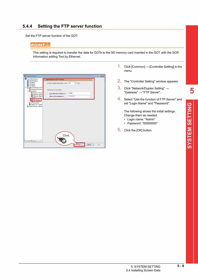
5.4.4 Setting the FTP server function
Set the FTP server function of the GOT.
POINTPOINTPOINT
This setting is required to transfer the data for GOTs to the SD memory card inserted in the GOT with the SCR Information editing Tool by Ethernet.
5
SY
ST
EM
SE
TT
ING
1. Click [Common] → [Controller Setting] in the menu.
2. The "Controller Setting" window appears.
3. Click "Network/Duplex Setting" → "Gateway" → "FTP Server".
4. Select "Use the function of FTP Server" and set "Login Name" and "Password".
The following shows the initial settings.Change them as needed.• Login name: "Admin"• Password: "00000000"
5. Click the [OK] button.
Click.
5. SYSTEM SETTING5.4 Installing Screen Data
5 - 9

5 - 10 5. SYSTEM SETTING5.4 Installing Screen Data
5.4.5 Setting the GOT MES interface function
Configure the settings to connect the GOT to the database server.
1. Click [Common] → [MES Interface] in the menu.
2. The "MESInterface" window appears.
3. Click the server service in "Server service settings" of "MES interface setting" in the [Setting] tab.Click.
4. Configure the following settings and click the [OK] button.
POINTPOINTPOINT
• Set the same value for "Port No." and "Service port", the setting item of the DB connection service setting tool.• Set the values of "Connection timeout" and "DB access timeout", the setting item of the DB connection service
setting tool, to satisfy the following condition.
Item Settings
Server service name Set "SQL_SV".
IP address
Set each item according to the personal computer for the database server,
the settings used when the database management system was installed, and
the network environment.
Port No. (1024 to 65535)
User name
Password
Confirm password
Data source name Set the name of the ODBC data source to be accessed.
Database type Select "SQL Server 2000/2005/2008/2008R2/2012/2014".
Access error notification setting Set whether to notify access errors.
Connection timeout (1 to 180)Set the timeout time (unit: second) on the GOT in the communication
between the GOT and database server.
Connection timeout setting value ≤ DB ac
ss timeout setting value ce• For details of the setting items of the DB conne
n service setting tool, refer to the following. ctioiQ Monozukuri SCREW TIGHTENING Startup Manual (Database)

5
SY
ST
EM
SE
TT
ING
5.4.6 Customizing the project
Customize the project as needed.
POINTPOINTPOINT
For details of user customization, refer to the following.
7.2 User Screen
5.4.7 Writing the project
Write the SCREW TIGHTENING Control Package project to the GOT.
1. Click [Communication] → [Write to GOT] in the menu.
2. The "Communication Configuration" window appears.
3. Check that "PC side I/F" is "USB" and click the [OK] button.
4. The "Communicate with GOT" window appears.
5. Click the [GOT Write] tab to check that the settings have been configured as follows.
• [PC] Write Data: "Package Data"• [GOT] Destination Drive:
"C:Built-in Flash Memory"
6. Click the [GOT Write] button.
7. The window shown on the left appears.
8. Enter the following information and click the [OK] button.
Password: "NEJISHIMEDSP"
Click.
Click.
Click.
5. SYSTEM SETTING5.4 Installing Screen Data
5 - 11
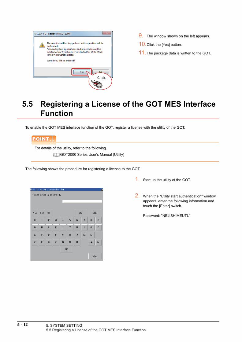
5.5 Registering a License of the GOT MES Interface Function
To enable the GOT MES interface function of the GOT, register a license with the utility of the GOT.
POINTPOINTPOINT
For details of the utility, refer to the following.
GOT2000 Series User's Manual (Utility)
The following shows the procedure for registering a license to the GOT.
9. The window shown on the left appears.
10.Click the [Yes] button.
11.The package data is written to the GOT.
1. Start up the utility of the GOT.
2. When the "Utility start authentication" window appears, enter the following information and touch the [Enter] switch.
Password: "NEJISHIMEUTL"
Click.
5 - 12 5. SYSTEM SETTING5.5 Registering a License of the GOT MES Interface Function

5
SY
ST
EM
SE
TT
ING
3. Touch the [Ext. func. set] tab and [License management].
4. The "License management" screen appears.
5. Touch the "License number" entry area of "MES interface function".
6. A keyboard appears at the bottom of the screen. Enter a license number and touch the [Enter] switch.
7. Touch the [Regist] switch on the "License management" screen to register the entered license number.
8. Touch the [×] switch to close the screen.
5. SYSTEM SETTING5.5 Registering a License of the GOT MES Interface Function
5 - 13

5 - 14 5. SYSTEM SETTING5.6 Inserting an SD Memory Card
5.6 Inserting an SD Memory Card
Insert an SD memory card in the GOT.
POINTPOINTPOINT
Select one of the following procedures depending on the method for transferring files for the GOT created with the SCR Information editing Tool.
• When using an SD memory card to transfer the filesInsert the SD memory card where the files have been transferred by executing [Transfer to SD Memory Card] of the SCR Information editing Tool in the GOT.
• When transferring the files by EthernetInsert an SD memory card in the GOT, and execute [File Transfer] of the SCR Information editing Tool.For details of file transfer, refer to the following.
iQ Monozukuri SCR Information editing Tool Instruction Manual
1. Make sure that the power to the GOT is off.
2. Open the SD memory card cover as shown in the left figure.
3. After making sure that the SD memory card access LED is off with the SD memory card cover 90 degrees or more open, insert the SD memory card in the SD memory card interface with its front side facing up.
4. Push and close the SD memory card cover until it clicks.
5. After the SD memory card cover is closed, the access to the SD memory card is allowed.
SD memory card access LED
Open the SD memory card cover 90 degrees or more.

5.7 Sta
5
SY
ST
EM
SE
TT
ING
5.7 Starting up the SCREW TIGHTENING System
Start up the SCREW TIGHTENING System.
1. Set the RUN/STOP/RESET switch of the LCPU in the RUN state.
2. Turn on the main power supply switch on the control panel to power on the GOT.
POINTPOINTPOINT
Power on the programmable controller and other devices first, and then power on the GOT.
3. The power supply lamp on the left of the GOT on the operation panel door turns on and the iQ Monozukuri logo appears on the GOT screen.
4. At the first startup of the SCREW TIGHTENING System, the "Language Setting" window appears.
5.8 Language Setting
5. The home screen of the SCREW TIGHTENING System appears.
5. SYSTEM SETTINGrting up the SCREW TIGHTENING System
5 - 15

5 - 16 5. SYSTEM SETTING5.8 Language Setting
5.8 Language Setting
Set a display language for the SCREW TIGHTENING System.
1. Touch at the upper right corner of the home screen.
2. The "Language Setting" window appears.
3. Touch one of the language switches.

5
SY
ST
EM
SE
TT
ING
5.9 Clock Setting
Set the clock of the SCREW TIGHTENING System.
POINTPOINTPOINT
Synchronization of the time with the SNTP server
The function to synchronize the time with the SNTP server can be used by changing the following settings at
installation of screen data ( 5.4 Installing Screen Data).
1. Touch at the upper right corner of the home screen.
2. The "Clock Setting" window appears.
3. Set year, month, date, hour, minute, and second values with the [] and [] switches.
4. Touch the [Set] switch to set the clock.
• [Common] → [GOT Setup] → [Basic Setting] →
ime Setting] in the GT Designer3 menu [T5. SYSTEM SETTING5.9 Clock Setting
5 - 17

5 - 18 5. SYSTEM SETTING5.10 Logging in as a Local Manager
5.10 Logging in as a Local Manager
Log in to the SCREW TIGHTENING System as a local manager.
POINTPOINTPOINT
• To log in to the system as a local manager, start with the non-login status.• The "Name" field in the "operator check" window displays "LocalManager" when an operator has logged into
the system as the local manager.• Log out in the "Work Input" screen. For details, refer to the following.
iQ Monozukuri SCREW TIGHTENING Operating Manual
1. Touch at the upper left corner of the home screen.
2. The "operator check" window appears.
3. Press and hold down the "Name" field (for two seconds).
4. The "password input" window for a local manager appears.
5. Enter the following password and touch the [ENT] switch.
Password: "SCR12345"
6. The icon at the upper left corner of the home screen will change.

5
SY
ST
EM
SE
TT
ING
5.11 System Setting
Configure the settings related to the entire SCREW TIGHTENING System.
1. Touch the [Setting] switch in the home screen and [System Setting] in the sub menu.
2. The following screen appears. Change the settings as needed.
(1) Measured screw tightening time displaySelect whether or not to display the measured screw tightening time on the Assembly work step screen.• [Yes]: The time will be displayed in green at normal completion of screw tightening, or displayed in red at
completion of screw tightening with an error.• [No]: The time will not be displayed at normal completion of screw tightening, or displayed in red at
completion of screw tightening with an error.
(2) Screw tightening completion displaySelect whether or not to display the [Complete screw tightening] switch on the Assembly work step screen.Touching the [Complete screw tightening] switch completes screw tightening even if no electric screwdrivers have been connected.
(a) Sending to database when the complete screw tightening switch is pressedSelect whether or not to send data to the database even when screw tightening is completed with the [Complete screw tightening] switch just as at normal completion of screw tightening.This item can be selected only when "Screw tightening completion display" has been set to "Yes".
5. SYSTEM SETTING5.11 System Setting
5 - 19

5 - 20 5. SYSTEM SETTING5.11 System Setting
(3) OK data collectionSelect whether or not to send OK data at completion of screw tightening to the database.(This setting cannot be changed when no operator ID or order No. is set.)• [Enable]: OK data will be sent to the database.• [Disable]: OK data will not be sent to the database.
(4) Tightening time correctionSelect whether to enable or disable the tightening time correction function.(This setting cannot be changed when no operator ID or order No. is set.)• [Enable]: The [Tightening time correction] switch is displayed on the Assembly work step screen.• [Disable]: The tightening time correction cannot be executed.
POINTPOINTPOINT
When work is started with the tightening time correction function set to "Enable", the state of each indicator is as follows.
• The RUN state indicator indicates the "Waiting" state.• The indicator for screw tightening check flashes in green at a low speed.
(5) Hold screw box verification results (previous)Select whether or not to hold screw box verification results on the "Verify Screw Box" screen.• [Enable]: Positions of screw boxes are recorded. If the positions have not been changed from the last
verification, the screw box verification at the start of work can be omitted.• [Disable]: Positions of screw boxes are not recorded. Verification of screw boxes at the start of work are
required every start of screw tightening.
(6) Screw box verification touch operationSelect whether to enable or disable the screw box verification with touch operations.• [Enable]: Screw box verifications can be executed with a barcode reader or touch operations.• [Disable]: Screw box verifications can be executed only with a barcode reader.
(7) Start-up operation mode (This setting is available only for the line production method 1 and line production method 2.)Select the operation mode at the system startup.• [Coordinated operation]: Assembly work coordinates with the external system.• [Single operation]: Assembly work is performed without coordination with the external system.
3. Touch the [Register] switch to register the changed settings to the system.(Touching the [Cancel changes] switch discards the changed settings and returns to the status before the change.)

5
SY
ST
EM
SE
TT
ING
5.12 ASLINK Connected Device Setting
Set the connections of ASLINK connected devices (electric screwdrivers and POKAYOKE terminals) and assign their start addresses.
1. Touch the [Setting] switch in the home screen and [ASLINK Setting] in the sub menu.
2. The following screen appears.
3. Set each item according to the procedures described in the next section or later.
POINTPOINTPOINT
All assignable start addresses are fixed values regardless of types of electric screwdrivers and terminals.The following tables list screwdriver numbers/screw shelf numbers and their start addresses.
(1) List of start addresses for electric screwdrivers
(2) List of start addresses for screw shelves
Screwdriver No. 1 2 3 4 5 6 7 8 9 10
Start
address
ASLINK-compatible electric screwdriver 0 4 8 12 16 20 24 28 32 36
Non ASLINK-
compatible
electric
screwdriver
Two-point input
ASLINKER0 4 8 12 16 20 24 28 32 36
One-point I/O
ASLINKER2 6 10 14 18 22 26 30 34 38
Externally connected electric screwdriver - - - - - - - - - -
Screw shelf No. 1 2 3 4 5 6 7 8 9 10
Start address 40 45 50 55 60 65 70 75 80 85
Screw shelf No. 11 12 13 14 15 16 17 18 19 20
Start address 90 95 100 105 110 115 120 125 130 135
Screw shelf No. 21 22 23 24 25 26 27 28 29 30
Start address 140 145 150 155 160 165 170 175 180 185
5. SYSTEM SETTING5.12 ASLINK Connected Device Setting
5 - 21

5 - 22 5. SYSTEM SETTING5.12 ASLINK Connected Device Setting
5.12.1 Electric screwdriver setting
Register types of electric screwdrivers to be used.
POINTPOINTPOINT
The start address of each of non ASLINK-compatible electric screwdrivers is displayed in two sections (upper/lower) of an "Address" display area.
• The start address with the green background is for a two-point input ASLINKER.• The start address with the gray background is for a one-point I/O ASLINKER.
1. Touch the "Type" entry area of a screwdriver No. to set the connection setting.
2. Enter the type of the electric screwdriver to be connected in the "value input" window.
0: Not used1: ASLINK-compatible electric screwdriver
4.3.1 ASLINK-compatible electric screwdriver
2: Non ASLINK-compatible electric screwdriver
4.3.2 Non ASLINK-compatible electric screwdriver
3: Externally connected electric screwdriver
4.3.3 Externally connected electric screwdriver
3. The start address for the ASLINK connected device is displayed in the "Address" display area.

5
SY
ST
EM
SE
TT
ING
5.12.2 Screw shelf setting
Register types of terminals to be used on screw shelves.
POINTPOINTPOINT
Check the model of each POKAYOKE terminal corresponding to each terminal type on the "Model information" window.The "Model information" window appears when the [Model information] switch is touched.
1. Touch the "Type" entry area of a screw shelf No. to set the connection setting.
2. Enter the type of the terminal to be connected in the "value input" window.
0: Not used1: POKAYOKE terminal (1 light)2: POKAYOKE terminal (RGB)3: POKAYOKE terminal (1 light + door type)4: POKAYOKE terminal (RGB + door type)
3. The start address for the ASLINK connected device is displayed in the "Address" display area.
5. SYSTEM SETTING5.12 ASLINK Connected Device Setting
5 - 23

5 - 24 5. SYSTEM SETTING5.12 ASLINK Connected Device Setting
5.12.3 Terminal LED color setting
Set the LED color for each terminal.
5.12.4 Writing start addresses
Write the start addresses assigned in "5.12.1 Electric screwdriver setting" and "5.12.2 Screw shelf setting" to the ASLINK connected devices connected to the system.
1. Touch the [LED color setting] switch.
2. The "LED color setting" window appears.
3. Touch the switch of a color you want to set.
Use an address writer (ARW-02AS) to write the addresse
to the ASLINK connected devices. s The following describes the procedure of writing addresses with the address writer.POINTPOINTPOINT
For details of how to set addresses, refer to the product manual supplied with the address writer.
(1) Part names
MODE DATA
R W
MODESELECT
POWERCLEAR
POWERFLICK
EX
SENSE
TIME
COLOR
CLOSE
ADR
OPEN
1)
2)
3)
4)
5)
6)
7)
8) 9)
No. Name Description No. Name Description
1) POWER/CLEAR Power ON/OFF button 6) + Setting value change button
2) POWER LEDThis LED turns on when the writer is powered
on and turns off when the writer is powered off.7) - Setting value change button
3) MODE SELECT Read/write target item selection button 8) R(READ)Touching this button reads the currently-
selected item.
4) Item LED A lamp of the currently-selected item turns on. 9) W(WRITE)Touching this button writes the currently-
selected item and current setting value.
5)7-segment display
area
This area displays a value of the currently-
selected item.

5
ET
TIN
G
(2) Startup procedure
(3) Writing addressesWrite the address as assigned in "5.12.1 Electric screwdriver setting" and "5.12.2 Screw shelf setting".
1. Press the POWER/CLEAR button to power on the address writer.
2. When the writer has been powered on, a beep is made and the POWER LED turns on.
Simultaneously, the current firmware version is displayed in the 7-segment display area for a few seconds.
3. Holding down the POWER/CLEAR button powers off the writer and the POWER LED turns off.
MODE DATA
MODESELECT
POWERCLEAR
MODE DATA
MODE POWER
POWERFLICK
EX
SENSE
TIME
COLOR
CLOSE
ADR
OPEN
S
SYS
TE
M
1. Press the MODE SELECT button several timesuntil the ADR (Green) item LED turns on.
Indications by the item LED and 7-segment display are as shown below.
2. Set a value with the "+ button" and "- button".
3. Bring the address writer close to the light emitting/receiving window of the ASLINK connection device, and press "W (WRITE)" button.
When the write operation has normally been completed, the normal sound "beep" is made. When the write operation has failed, the error sound "bleep, bleep, bleep" is made.
MODE DATA
MODESELECT
POWERCLEAR
ON
R W
MODESELECT
POWERCLEAR
2.
3.
5. SYSTEM SETTING5.12 ASLINK Connected Device Setting
5 - 25

5 - 26 5. SYSTEM SETTING5.12 ASLINK Connected Device Setting
POINTPOINTPOINT
Errors at writing addresses
When an error has occurred at the execution of a write operation, press the W button one more time to perform the write operation again.While an error has occurred, the mode cannot be changed unless the POWER/CLEAR button is pressed to return the state of the writer to the one indicated before the occurrence of the error.When an error has occurred, the 7-segment display area indicates as shown below.
POINTPOINTPOINT
(1) Precautions for using transparent type POKAYOKE terminals
Current operation mode Only Err flashes.
Make sure to set the same start address to tra
parent-type terminals that are used in a pair. nsIf the start address values are different, proper operations are not performed.(2) Precautions for using door-type POKAYOKE terminalsSet the following items for door-type POKAYOKE terminals as necessary.
(a) Arm (door) motion time settingThe pickup indicator light and the arm (door) work in an interlocked manner. When the pickup indicator light is turned on (output is turned on), the arm moves upward, and when the light is turned off (output is turned off), the arm automatically moves downward after a certain length of time. (There is no interlock between inputs from the pickup confirmation switch and the arm.)The delay time between the instant when the light is turned off and the instant when the arm (door) starts to move down can be selected from 10 values.
(b) Door opening/closing position settingThe arm lifting angle is set at seven levels up to approximately 180°.An adjustment can be performed to prevent the door from hitting a shelf or workpiece.
For details of the above settings, refer to the produ
anual supplied with the terminal. ct mCAUTION
• Because the written addresses are enabled when writing is complete, the POKAYOKE terminal doors may open or close. Make sure to ensure safety before writing addresses.
• Do not change the addresses during the check operation.Doing so may change the outputs to ASLINK connected devices (lamps and opening/closing of terminal doors).
• Set addresses so that each terminal has a different address. Otherwise transmission trouble occurs.
• Setting the arm (door) motion time to "0" (Delay time: 0 second) may cause operators' hands to be caught. Set the arm (door) motion time to "1" (Delay time: 1 second) or longer and adjust the door opening/closing position setting depending on the system in use.

5
SY
ST
EM
SE
TT
ING
5.12.5 Reflecting to the system
When "5.12.4 Writing start addresses" has been completed, the changed settings are reflected to the system.
1. Touch the [Register] switch of "ASLINK Setting".(Touching the [Cancel changes] switch discards the changed settings and returns to the status before the change.)
2. The ASLINK outputs temporarily turn off.
3. The changed settings are registered to the system.
4. The addresses of the ASLINK connected devices connected to the system are written to the AnyWireASLINK master module by the "address auto recognition function" of the AnyWireASLINK master module.
POINTPOINTPOINT
For the "address auto recognition function" of the AnyWireASLINK master module, refer to the following.
MELSEC-Q/L AnyWireASLINK Master Module User's Manual
5. The ASLINK outputs return to the ON state.
5. SYSTEM SETTING5.12 ASLINK Connected Device Setting
5 - 27

5 - 28 5. SYSTEM SETTING5.13 Electric Screwdriver Setting
5.13 Electric Screwdriver Setting
Configure the settings related to the electric screwdrivers to be connected.
1. Touch the [Setting] switch in the home screen and [Electric Screwdriver Setting] in the sub menu.
2. The following screen appears.
POINTPOINTPOINT
• The connection status of each electric screwdriver displayed on this screen is based on the electric screwdriver type registered in "5.12 ASLINK Connected Device Setting".
• "ASLINK-compatible electric screwdriver color" and "Non ASLINK-compatible electric screwdriver color" cannot be set for externally connected electric screwdrivers.
3. Touch the "Electric screwdriver code" entry area of a screwdriver No. to set the connection setting.
4. Enter the electric screwdriver code (000 to 999) of an electric screwdriver to be connected in the "value input" window.
POINTPOINTPOINT
When the value input window is displayed, a barcode reader can be used to read the barcode of an electric screwdriver code.

5
SY
ST
EM
SE
TT
ING
POINTPOINTPOINT
ASLINK-compatible electric screwdriver color setting
• When an ASLINK-compatible electric screwdriver has been connected, set the color of the LED built in the electric screwdriver.(Select one of seven colors of green, blue, yellow, purple (magenta), sky blue (cyan), red, and white as the LED color.)
Non ASLINK-compatible electric screwdriver color setting
• When a non ASLINK-compatible electric screwdriver has been connected, set the display color on the GOT screen.
5. Touch the [Screw color] switch.
6. The "Screw color setting" window appears.
7. Touch the switch of the color you want to set to an electric screwdriver connected to the system.(Changing a screw color also changes a corresponding ASLINK-compatible electric screwdriver color.)
8. When an ASLINK-compatible electric screwdriver is connected, touch the [ASLINK-compatible electric screwdriver color] switch.
9. The "ASLINK-compatible electric screwdriver color setting" window appears.
10.Touch the switch of the color you want to set to an electric screwdriver connected to the system.
11.When a non ASLINK-compatible electric screwdriver is connected, touch the [Non ASLINK-compatible electric screwdriver color] switch.
12.The "Non ASLINK-compatible electric screwdriver color setting" window appears.
13.Touch the switch of the color you want to set to an electric screwdriver connected to the system.
14.Touch the [Register] switch to register the changed settings to the system.(Touching the [Cancel changes] switch discards the changed settings and returns to the status before the change.)
5. SYSTEM SETTING5.13 Electric Screwdriver Setting
5 - 29

5 - 30 5. SYSTEM SETTING5.14 RUN State Indicator Setting
5.14 RUN State Indicator Setting
Configure the settings related to RUN state indicators.
1. Touch the [Setting] switch in the home screen and [RUN State Indicator Setting] in the sub menu.
2. The following screen appears.
3. Select whether or not to operate each indicator to correspond with each state with the [Enable] and [Disable] switches.
4. Select and touch one of the [Upper], [Middle], and [Lower] switches for the indicator position of the three-color stack light for each state.
5. Select and touch one of the [Low-speed flash], [High-speed flash], and [ON] switches for the indicator status of the indicator at each position.
6. Touch the [Register] switch to register the changed settings to the system.(Touching the [Cancel changes] switch discards the changed settings and returns to the status before the change.)
POINTPOINTPOINT
If several states simultaneously occur at the same indicator position, the indicator will operate with the priority of each state.The following shows the priority of each state.
(Priority: low) State on the left < State on the right (Priority: high)

6
OP
ER
AT
ION
CH
EC
K
6. OPERATION CHECK
This chapter describes how to check the settings and operation of the SCREW TIGHTENING System.
6.1 Checking with the Inspection Function
This section describes how to check the operation with the inspection function of the SCREW TIGHTENING System.
6.1.1 Electric screwdriver inspection
1. Touch the [Inspection] switch in the home screen and [Electric Screwdriver Inspection] in the sub menu.
2. The following screen appears.
3. Touch the [Enable] switch of "Electric screwdriver inspection mode".
4. Touch the [Electric screwdriver No.] switch to select an electric screwdriver to be an inspection target (multiple screwdrivers can be selectable).(As soon as "Electric screwdriver inspection mode" is enabled, all the connected electric screwdrivers will be selected as inspection targets.)
POINTPOINTPOINT
• Power will be supplied to the electric screwdrivers selected as inspection targets and the [Supply power] lamps will turn on.
• The [ASLINK-compatible electric screwdriver color] lamp turns on when a non ASLINK-compatible electric screwdriver is selected as an inspection target. (The lamp turns on in the color set in "5.13 Electric Screwdriver Setting".)
• The inspection function cannot be used for externally connected electric screwdrivers.
5. Operate the electric screwdriver to check if "Start signal", "Torque-up signal", and "Reverse signal" are properly detected.
6. OPERATION CHECK6.1 Checking with the Inspection Function
6 - 1

6 - 2 6. OPERATION CHECK6.1 Checking with the Inspection Function
6. Touch each switch of "ASLINK-compatible electric screwdriver color" to check each LED color of the electric screwdriver. When the [Set color] switch is touched, the LED turns on in the color set in "5.13 Electric Screwdriver Setting".(The LED colors can be set only to ASLINK-compatible electric screwdrivers.)
7. To end the check, touch the [Disable] switch of "Electric screwdriver inspection mode".
6.1.2 Screw shelf inspection
1. Touch the [Inspection] switch in the home screen and [Screw Shelf Inspection] in the sub menu.
2. The following screen appears.
3. Touch the [Enable] switch of "Screw shelf inspection mode".
4. Touch the [Output] switch corresponding to a screw shelf No. to select a screw shelf to be an inspection target (multiple screw shelves can be selectable).
POINTPOINTPOINT
• The outputs of the screw shelves selected as inspection targets to terminals turn on.• To turn off the outputs to the terminals, touch the [Output] switch again.• When inputs from the terminals are detected, the [Input] lamp corresponding to the "screw shelf No." turns on.
5. Check if the screw shelf operates properly. (opening/closing of doors, LED, and input detection)
6. Touch each switch of "Terminal LED Color" to check the LED color of each terminal. When the [Set color] switch is touched, the LED turns on in the color set in "5.12 ASLINK Connected Device Setting".(The LED color setting can be applied to only RGB display type terminals.)
7. To end the check, touch the [Disable] switch of "Screw shelf inspection mode".
CAUTIONThe doors of door-type terminals open or close when terminal outputs turn on/off.Make sure to ensure safety before inspections.

6
OP
ER
AT
ION
CH
EC
K
6.1.3 Other devices inspection
1. Touch the [Inspection] switch in the home screen and [Other Devices Inspection] in the sub menu.
2. The following screen appears.
3. Touch the [Enable] switch of "Other devices inspection mode".
4. Touch the [ON] and [OFF] switches of "Indicator for screw tightening check" for each color to check that the indicator properly turns on.
5. Touch the [ON] and [OFF] switches of "RUN state indicator" at each step to check that the indicator properly turns on.
6. Touch the [Output] switch of "OK buzzer" to check that OK buzzer properly sounds.
7. Touch the [Output] switch of "NG buzzer" to check that NG buzzer properly sounds.
8. Scan a barcode with a barcode reader and check that correct character strings are displayed in the "Barcode data" area.
9. Operate external switches and check that the [Input signal ON] lamp properly turns on.
10.To end the check, touch the [Disable] switch of "Other devices inspection mode".
6. OPERATION CHECK6.1 Checking with the Inspection Function
6 - 3

6 - 4 6. OPERATION CHECK6.2 Checking with the Alarm Function
6.2 Checking with the Alarm Function
This section describes how to check the operation with the alarm function of the SCREW TIGHTENING System.This function displays errors of the SCREW TIGHTENING System as alarms.This function displays the alarms that have occurred or those that have already been solved in a list.
POINTPOINTPOINT
Up to 512 alarms can be saved into an SD memory card.(When the number of alarms exceeds the maximum number of alarms, the alarms will overwritten with new alarms from the oldest one.)
For details of each alarm, refer to "6.5 Troubleshoo
g". tin6.2.1 Pop-up display
The alarm that has occurred pops up on the top of the GOT screen.
POINTPOINTPOINT
• When multiple alarms have occurred, only the latest alarm is displayed.• When a system alarm and an alarm occur simultaneously, a priority is given to the system alarm (only the
system alarm is displayed).

6.2.2 Current alarms
This screen lists the alarms that have occurred.
6
OP
ER
AT
ION
CH
EC
K
1. Touch the [Alarm] switch on the home screen.Or touch the [Current Alarms] switch on the "Alarm History" screen or "System Alarm" screen.
2. The following screen appears.
3. Check the alarm details and eliminate the alarm causes.
4. To reset all the alarms, press and hold down the [Reset alarm] switch (for two seconds).
POINTPOINTPOINT
Up to 512 alarms can be displayed. When the number of alarms exceeds the maximum number of alarms, the alarms will be deleted from the oldest one.
6. OPERATION CHECK6.2 Checking with the Alarm Function
6 - 5
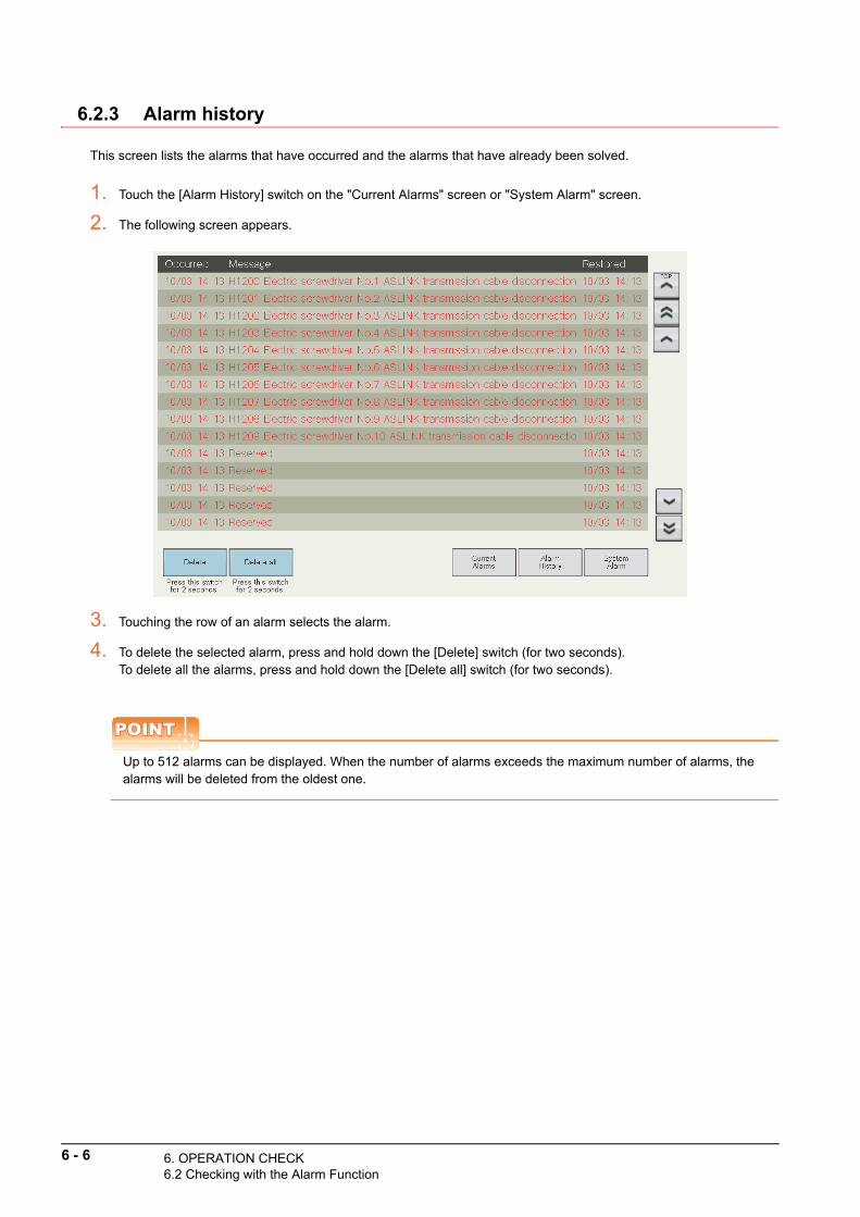
6 - 6 6. OPERATION CHECK6.2 Checking with the Alarm Function
6.2.3 Alarm history
This screen lists the alarms that have occurred and the alarms that have already been solved.
1. Touch the [Alarm History] switch on the "Current Alarms" screen or "System Alarm" screen.
2. The following screen appears.
3. Touching the row of an alarm selects the alarm.
4. To delete the selected alarm, press and hold down the [Delete] switch (for two seconds).To delete all the alarms, press and hold down the [Delete all] switch (for two seconds).
POINTPOINTPOINT
Up to 512 alarms can be displayed. When the number of alarms exceeds the maximum number of alarms, the alarms will be deleted from the oldest one.

6.3
6.3 Checking with the System Alarm Function
This section describes how to check the operation with the system alarm function of the SCREW TIGHTENING System.This function displays GOT errors, CPU errors, and network errors as system alarms.This function displays the system alarms that have occurred or those that have already been solved in a list.
POINTPOINTPOINT
Up to 512 system alarms can be stored into an SD memory card.(When the number of alarms exceeds the maximum number of alarms, the alarms will overwritten with new alarms from the oldest one.)
For details of each system alarm, refer to the follow
.6
OP
ER
AT
ION
CH
EC
K
ing
GOT2000 Series User's Manual (Utility)
6.3.1 Pop-up display
The system alarm that has occurred pops up on the bottom of the GOT screen.Touching the pop-up display resets the system alarm.
POINTPOINTPOINT
• When multiple system alarms have occurred, only the latest system alarm is displayed.• When a system alarm and an alarm occur simultaneously, a priority is given to the system alarm (only the
system alarm is displayed).
6. OPERATION CHECK Checking with the System Alarm Function
6 - 7

6 - 8 6. OPERATION CHECK6.3 Checking with the System Alarm Function
6.3.2 System alarm
This screen lists the system alarms that have occurred and the system alarms that have already been solved.
1. Touch the [System Alarm] switch on the "Current Alarms" screen or "Alarm History" screen.
2. The following screen appears.
3. Touching the row of a system alarm selects the system alarm.
4. To delete the selected alarm, press and hold down the [Delete] switch (for two seconds).To delete all the alarms, press and hold down the [Delete all] switch (for two seconds).
POINTPOINTPOINT
• Up to 512 system alarms can be displayed. When the number of system alarms exceeds the maximum number of system alarms, the system alarms will be deleted from the oldest one.
• The system alarms cannot be reset on this screen. Touch the pop-up display ( 6.3.1 Pop-up display) displayed at the bottom of the GOT screen.

6.4
6.4 Checking with the Free Operation Function
This section describes how to check the operation with the free operation function of the SCREW TIGHTENING System.
6
OP
ER
AT
ION
CH
EC
K
1. Touch the [Free Operation] switch on the home screen.
2. The following screen appears.
3. Touch the [Enable] switch of "Free operation mode".
4. Operate the connected electric screwdrivers to check if the electric screwdrivers properly operate.
POINTPOINTPOINT
• The free operation cannot operate multiple electric screwdrivers simultaneously. Once an electric screwdriver starts operating, power supply to the other electric screwdrivers will stop.
• When an externally connected electric screwdriver is operated, power supply to the other electric screwdrivers will continue.
5. When door-type screw shelves have been used, touch the [Open] and [Close] switches to check if the doors properly open and close.
6. To end the operation check, touch the [Disable] switch of "Free operation mode".
6. OPERATION CHECKChecking with the Free Operation Function
6 - 9

6 - 10 6. OPERATION CHECK6.5 Troubleshooting
6.5 Troubleshooting
For the troubleshooting for when an error has occurred in the SCREW TIGHTENING System, use one of the following methods.
• Searching for a recovery method from the function or
nected device where the error has occurred con6.5.1 Troubleshooting by symptom
• Searching for a recovery method from the error message or alarm history displayed on the GOT screen
6.5.2 List of error messages
6.5.1 Troubleshooting by symptom
Troubleshooting related to the CPU module and GOT
Troubleshooting related to electric screwdrivers
Symptom Check detail Corrective action
The version mismatch screen
appears.
(The versions of the CPU
module and the GOT are
mismatched.)
Are the version of the sequence program in the CPU
module and the version of the screen data in the GOT
matched?
When the versions are different, reinstall the ladder
program to the CPU module or the screen data to the
GOT from the installation DVD.
The application version
mismatch screen appears.
Are the versions of applications installed in the CPU
module and GOT matched?
When the versions are different, reinstall the ladder
program to the CPU module or the screen data to the
GOT from the installation DVD.
Have the CPU module and GOT been restarted after
the installation of the projects in the CPU module and
GOT?
When they have not been restarted, restart them.
The CPU module has an error.
Has a license key been registered?
When no license key has been registered, follow the
installation procedure and register a license key in the
CPU module.
Is the combination of the serial number of the CPU
module and the license key correct?
• Register a license key in the CPU module with a serial
number used to request the license key.
• If an error occurs even when a license key has been
registered in the CPU module with a serial number
used to request the license key, contact the following.
Please send all inquiries concerning the License Key
Request form to:
iQ Monozukuri Office, Nagoya Works, Mitsubishi Electric
Corporation
Symptom Check detail Corrective action
Power is not supplied to an
electric screwdriver.
Has the plug of the electric screwdriver been properly
inserted?Check the connection of the plug.
Have the terminals of the electric screwdriver and
output module been correctly wired?Check the wiring.
Has the wiring between the electric screwdriver and
output module not been disconnected?Check for a disconnection of wiring.
Is the electric screwdriver not faulty? When it is faulty, replace it with a new one.
Is the output module not faulty? When it is faulty, replace it with a new one.
When non ASLINK-compatible
electric screwdrivers have been
used, start signals, reverse
signals, and torque-up signals
cannot be correctly acquired.
Have ASLINKER and electric screwdrivers been
correctly wired?Check the wiring.
Has the wiring between ASLINKER and electric
screwdrivers not been disconnected?Check for a disconnection of wiring.
Is the electric screwdriver not faulty? When it is faulty, replace it with a new one.
Is ASLINKER not faulty? When it is faulty, replace it with a new one.
When non ASLINK-compatible
electric screwdrivers have been
used, the lamps connected to
ASLINKER do not turn on.
Have ASLINKER and lamps been correctly wired? Check the wiring.
Has the wiring between ASLINKER and lamps not
been disconnected?Check for a disconnection of wiring.
Are the lamps not faulty? When it is faulty, replace it with a new one.
When ASLINK-compatible
electric screwdrivers have been
used, the LEDs of an electric
screwdriver do not turn on.
Is the electric screwdriver not faulty? When it is faulty, replace it with a new one.

6
OP
ER
AT
ION
CH
EC
K
Troubleshooting related to POKAYOKE terminals
Troubleshooting related to the barcode reader
Symptom Check detail Corrective action
The LINK lamp does not flash.
Has the POKAYOKE terminal been correctly wired? Check the wiring.
Has the wiring of the POKAYOKE terminal not been
disconnected or short-circuited?Check for a disconnection of wiring.
Is the pin assignment of the link connector correct? Review the pin assignment of the link connector.
Is the wiring of the 24 V DC external power supply for
the terminal blocks of the master module and slave
module correct?
Check the wiring of the 24 V DC external power supply.
Is the POKAYOKE terminal not faulty? When it is faulty, replace it with a new one.
The LEDs of the POKAYOKE
terminals or opening/closing of
terminal doors do not correctly
function.
Are the models of the POKAYOKE terminals installed
on the screw shelf and the terminal types set on the
"ASLINK Setting" screen matched?
Check the models and terminal types of the POKAYOKE
terminals.
When a transparent-type
terminal has been used, the
LEDs of the terminal do not turn
off.
When an output of a screw shelf No. is turned on in
the "Screw Shelf Inspection" screen, does a
corresponding LED of the terminal turn on?
Adjust the optical axis of the infrared light emitting/
received from/at the transparent-type terminal.
Has the light emission terminal been connected? Connect the light emission terminal.
Are the addresses of the light emission terminal and
light reception terminal matched?
Match the addresses of the light emission terminal and
light reception terminal.
When a transparent-type
terminal has been used, the
LEDs of the light emission
terminal do not turn on.
Has the light emission terminal been connected? Connect the light emission terminal.
Are the addresses of the light emission terminal and
light reception terminal matched?
Match the addresses of the light emission terminal and
light reception terminal.
When a transparent-type
terminal has been used, the
terminal does not detect objects
such as inserted hands.
Does the LED of the transparent-type terminal turn
on?
Adjust the amount of the infrared light emitting/received
from/at the transparent-type terminal.
When a door-type terminal has
been used, the door does not
open and close.
Are the arm lifting angle and lowering angle of the
door-type terminal correct?
(Use the address writer to check them.)
Adjust the arm lifting angle and lowering angle of the door-
type terminal.
(Set a value larger than the arm lowering angle for the
arm lifting angle.)
When door-type terminals have
been used, a voltage drop error
occurs after the batch ON/OFF
is performed on the "Screw
Shelf Inspection" screen.
Does the total power consumption of the devices
connected to the 24 V DC external power supply
exceed the maximum output power?
• Replace the power supply with a new one that has
larger maximum output power.
• Do not perform the batch ON/OFF of door-type
terminals.
When door-type terminals have
been used, the doors of door-
type terminals interfere with
each other after the batch ON/
OFF is performed on the
"Screw Shelf Inspection".
-
• Set screw shelves to prevent the doors from being
interfered with each other.
• Adjust the opening/closing angles of the door-type
terminals.
Symptom Check detail Corrective action
Power is not supplied to the
barcode reader.
Has the AC adopter of the barcode reader been
correctly connected?Check the connection of the plug.
Is the barcode reader not faulty? When it is faulty, replace it with a new one.
A read barcode or 2D code is
not reflected on the GOT
screen.
Have the barcode reader and the RS-232 connector
of the GOT been correctly connected?Check the wiring.
Have the wiring of the barcode reader and RS-232
connector of the GOT not been disconnected?Check for a disconnection of wiring.
6. OPERATION CHECK6.5 Troubleshooting
6 - 11

6 - 12 6. OPERATION CHECK6.5 Troubleshooting
Troubleshooting related to external input devices
Troubleshooting related to indicator lights
Troubleshooting related to the buzzer
Symptom Check detail Corrective action
An external input switch does
not function when it is powered
on.
Does the GOT display the "Assembly work step"
screen or the "Other Devices Inspection" screen?
Switch the display of the GOT to the "Assembly work
step" screen or the "Other Devices Inspection" screen.
(External input switches do not function on the screens
other than above.)
Has the external input switch been correctly wired? Check the wiring.
Have the wiring of the external input switch not been
disconnected?Check for a disconnection of wiring.
Is the external input switch not faulty? When it is faulty, replace it with a new one.
Symptom Check detail Corrective action
An indicator does not turn on.
Has the indicator been correctly wired? Check the wiring.
Has the wiring of the indicator not been
disconnected?Check for a disconnection of wiring.
Is the indicator not faulty? When it is faulty, replace it with a new one.
The RUN state indicator do not
operate in the way set on the
"RUN State Indicator Setting"
screen.
Has the indicator been correctly wired? Check the wiring.
Is the indicator not faulty? When it is faulty, replace it with a new one.
The LED colors for screw
tightening OK and screw
tightening NG have been
switched.
Has the indicator been correctly wired? Check the wiring.
Is the indicator not faulty? When it is faulty, replace it with a new one.
Symptom Check detail Corrective action
The buzzer does not sound.
Has the buzzer been correctly wired? Check the wiring.
Has the wiring of the buzzer not been disconnected? Check for a disconnection of wiring.
Is the buzzer not faulty? When it is faulty, replace it with a new one.
The sounds of the OK buzzer
and NG buzzer have been
switched.
Has the buzzer been correctly wired? Check the wiring.
Is the buzzer not faulty? When it is faulty, replace it with a new one.

6
OP
ER
AT
ION
CH
EC
K
Troubleshooting related to the screen display and operationsSymptom Check detail Corrective action
The "Work Table Setting"
screen, "ASLINK Setting"
screen, "Electric Screwdriver
Setting" screen, "System
Setting" screen, and "RUN
State Indicator Setting" screen
cannot be switched to other
screens.
Has the setting in the screen been changed?
• Touch the [Register] switch to confirm the changes.
• Touch the [Cancel changes] switch to discard the
changes.
The background of an electric
screwdriver code is red on the
"Electric Screwdriver Setting"
screen.
Has the electric screwdriver code with the red
background already been registered?
When it has already been registered, change the electric
screwdriver code.
(Electric screwdrivers operate properly even though their
codes overlap each other.)
The free operation mode cannot
be enabled on the "Free
Operation" screen.
Has any major alarm occurred?
Clear the major alarm.
(When a major alarm has occurred, the free operation
mode cannot be enabled.)
The "Free Operation" screen
cannot be switched to other
screens.
Has the free operation mode been enabled?
Disable the free operation mode.
(When the free operation mode has been enabled, the
screen cannot be switched to other screens.)
The electric screwdriver
inspection mode cannot be
enabled on the "Electric
Screwdriver Inspection" screen.
Has any major alarm occurred?
Clear the major alarm.
(When a major alarm has occurred, the electric
screwdriver inspection mode cannot be enabled.)
The "Electric Screwdriver
Inspection" screen cannot be
switched to other screens.
Has the electric screwdriver inspection mode been
enabled?
Disable the electric screwdriver inspection mode.
(When the electric screwdriver inspection mode has been
enabled, the screen cannot be switched to other screens.)
Electric screwdriver numbers
cannot be switched or
deselected on the "Electric
Screwdriver Inspection" screen.
Are the electric screwdrivers operating?
Stop the electric screwdrivers.
(While the electric screwdrivers are operating, the electric
screwdriver numbers cannot be switched or deselected.)
The screw shelf inspection
mode cannot be enabled on the
"Screw Shelf Inspection"
screen.
Has any major alarm occurred?
Clear the major alarm.
(When a major alarm has occurred, the screw shelf
inspection mode cannot be enabled.)
The "Screw Shelf Inspection"
screen cannot be switched to
other screens.
Has the screw shelf inspection mode been enabled?
Disable the screw shelf inspection mode.
(When the screw shelf inspection mode has been
enabled, the screen cannot be switched to other screens.)
When terminal LED colors were
switched on the "Screw Shelf
Inspection" screen, the changes
are not reflected to the
POKAYOKE terminals.
Have RGB display type terminals been used? Use RGB display type POKAYOKE terminals.
Is the terminal type setting correct?Set a correct terminal type according to the model of the
POKAYOKE terminal.
The other devices inspection
mode cannot be enabled on the
"Other Devices Inspection"
screen.
Has any major alarm occurred?
Clear the major alarm.
(When a major alarm has occurred, the other devices
inspection mode cannot be enabled.)
The "Other Devices Inspection"
screen cannot be switched to
other screens.
Has the other devices inspection mode been
enabled?
Disable the other devices inspection mode.
(When the other devices inspection mode has been
enabled, the screen cannot be switched to other screens.)
The "Security Level
Authentication" window
appeared when the screen was
switched to a setting screen.
Has anyone logged into the system? Log in to the system.
The "Security Level
Authentication" window
appeared when the screen was
switched to the "Verify Screw
Box" screen.
Has the operator logged into as a manager or local
manager?Log into the system as a manager or local manager.
The message "The backup
processing has failed." is
displayed in the "Backup/
Restoration" screen.
Is the "Installation of USB memory" lamp in the screen
on?When the lamp is off, insert the USB memory again.
Is the USB memory faulty? When it is faulty, replace it with a new one.
Is the free space in the USB memory sufficient?Secure the free space of 10 MB or more in the USB
memory.
6. OPERATION CHECK6.5 Troubleshooting
6 - 13

Troubleshooting related to the database
The message "The restoration
processing has failed." is
displayed in the "Backup/
Restoration" screen.
Is the "Installation of USB memory" lamp in the screen
on?When the lamp is off, insert the USB memory again.
Is the USB memory faulty? When it is faulty, replace it with a new one.
Have the following backup files been stored in the
USB memory?
• SCR_Backupall.G2P
• SCR_Backupa2.G2P
When they have not been stored in the USB memory,
replace the USB memory with the one that stores the
backup files.
Symptom Check detail Corrective action
A server communication error
and alarm are displayed and the
operation is interrupted.
Has a license for the GOT MES interface function
been registered?
Start up the utility of the GOT and touch the [Ext. func. set]
tab and [License management] to register a license for the
GOT MES interface function.
Is the database server operating?Start up the personal computer for the database server to
operate the database server.
Has the database server been installed?Install the database server on the personal computer for
the database server.
Is the connection setting of the database server
correct?Check the connection setting of the database server.
Is the network between the GOT and the personal
computer for the database server disconnected?Check the wiring of the network.
An operator entered his/her
operator ID but was not able to
log in to the database server.
Has the operator ID been registered in the database
server?
• Register the operator information with the SCR
Information editing Tool.
• Enter the registered operator ID to log in to the
database server.
Has the operator code appropriate to the factory ID,
equipment ID, and work table ID been registered?
• Register the operator assignment with the SCR
Information editing Tool.
• Check the work table settings.
The input order No. is not
accepted.
Has the order No. been registered in the database
server?
• Register the order No. information with the SCR
Information editing Tool.
Has the order No. appropriate to the factory ID,
equipment ID, and work table ID been registered?
• Register the order No. information with the SCR
Information editing Tool.
• Check the work table settings.
Are the set number of work tables and the set work
number correct?Check the work table settings.
Symptom Check detail Corrective action
6 - 14 6. OPERATION CHECK6.5 Troubleshooting

6.5.2 List of error messages
The following table lists the error messages and the recovery methods.
Error messages displayed on the GOT screen[Alarm level]Severe: Errors that interrupt the operation and require the restart of the system for recoveryMedium: Errors that interrupt the operation and do not require the restart of the system for recoveryMinor: Errors that do not interrupt the work
6
OP
ER
AT
ION
CH
EC
K
Error
codeError name
Alarm
levelError details and cause Corrective action
H1199 CPU STOP state Severe The CPU module is in the STOP state. Clear the STOP state of the CPU module.
H1200
Electric screwdriver No.1
ASLINK transmission cable
disconnection
Severe
• The wiring of the electric screwdriver has
been disconnected.
• An ASLINK-compatible electric
screwdriver or ASLINKER is faulty.
• The configuration of the electric
screwdriver has changed after the ASLINK
address auto recognition.
• Check for disconnections of the whole
transmission cables.
• Review the pin assignment of the link
connector.
• Check the wiring of signal wires of the master
module terminal block.
• After the configuration of electric screwdrivers
is changed, perform the ASLINK address auto
recognition.
• When the ASLINK-compatible electric
screwdriver or the LINK LED of ASLINKER
does not flash, check for the wiring around the
device.
H1201
Electric screwdriver No.2
ASLINK transmission cable
disconnection
H1202
Electric screwdriver No.3
ASLINK transmission cable
disconnection
H1203
Electric screwdriver No.4
ASLINK transmission cable
disconnection
H1204
Electric screwdriver No.5
ASLINK transmission cable
disconnection
H1205
Electric screwdriver No.6
ASLINK transmission cable
disconnection
H1206
Electric screwdriver No.7
ASLINK transmission cable
disconnection
H1207
Electric screwdriver No.8
ASLINK transmission cable
disconnection
H1208
Electric screwdriver No.9
ASLINK transmission cable
disconnection
H1209
Electric screwdriver No.10
ASLINK transmission cable
disconnection
6. OPERATION CHECK6.5 Troubleshooting
6 - 15

H1216
Screw shelf No.1 ASLINK
transmission cable
disconnection
Severe
• The wiring of the screw shelf has been
disconnected.
• Any of POKAYOKE terminals on the screw
shelf is faulty.
• The configuration of the screw shelf has
changed after the ASLINK address auto
recognition.
• Check for disconnections of the whole
transmission cables.
• Review the pin assignment of the link
connector.
• Check the wiring of signal wires of the master
module terminal block.
• After the configuration of the screw shelf is
changed, perform the ASLINK address auto
recognition.
• When the LINK LED of the POKAYOKE
terminal does not flash, check the wiring
around the device.
H1217
Screw shelf No.2 ASLINK
transmission cable
disconnection
H1218
Screw shelf No.3 ASLINK
transmission cable
disconnection
H1219
Screw shelf No.4 ASLINK
transmission cable
disconnection
H1220
Screw shelf No.5 ASLINK
transmission cable
disconnection
H1221
Screw shelf No.6 ASLINK
transmission cable
disconnection
H1222
Screw shelf No.7 ASLINK
transmission cable
disconnection
H1223
Screw shelf No.8 ASLINK
transmission cable
disconnection
H1224
Screw shelf No.9 ASLINK
transmission cable
disconnection
H1225
Screw shelf No.10 ASLINK
transmission cable
disconnection
H1226
Screw shelf No.11 ASLINK
transmission cable
disconnection
H1227
Screw shelf No.12 ASLINK
transmission cable
disconnection
H1228
Screw shelf No.13 ASLINK
transmission cable
disconnection
H1229
Screw shelf No.14 ASLINK
transmission cable
disconnection
H1230
Screw shelf No.15 ASLINK
transmission cable
disconnection
H1231
Screw shelf No.16 ASLINK
transmission cable
disconnection
H1232
Screw shelf No.17 ASLINK
transmission cable
disconnection
H1233
Screw shelf No.18 ASLINK
transmission cable
disconnection
H1234
Screw shelf No.19 ASLINK
transmission cable
disconnection
H1235
Screw shelf No.20 ASLINK
transmission cable
disconnection
H1236
Screw shelf No.21 ASLINK
transmission cable
disconnection
Error
codeError name
Alarm
levelError details and cause Corrective action
6 - 16 6. OPERATION CHECK6.5 Troubleshooting

6
OP
ER
AT
ION
CH
EC
K
H1237
Screw shelf No.22 ASLINK
transmission cable
disconnection
Severe
• The wiring of the screw shelf has been
disconnected.
• Any of POKAYOKE terminals on the screw
shelf is faulty.
• The configuration of the screw shelf has
changed after the ASLINK address auto
recognition.
• Check for disconnections of the whole
transmission cables.
• Review the pin assignment of the link
connector.
• Check the wiring of signal wires of the master
module terminal block.
• After the configuration of the screw shelf is
changed, perform the ASLINK address auto
recognition.
• When the LINK LED of the POKAYOKE
terminal does not flash, check the wiring
around the device.
H1238
Screw shelf No.23 ASLINK
transmission cable
disconnection
H1239
Screw shelf No.24 ASLINK
transmission cable
disconnection
H1240
Screw shelf No.25 ASLINK
transmission cable
disconnection
H1241
Screw shelf No.26 ASLINK
transmission cable
disconnection
H1242
Screw shelf No.27 ASLINK
transmission cable
disconnection
H1243
Screw shelf No.28 ASLINK
transmission cable
disconnection
H1244
Screw shelf No.29 ASLINK
transmission cable
disconnection
H1245
Screw shelf No.30 ASLINK
transmission cable
disconnection
H1249ASLINK transmission cable
short-circuit errorSevere
• The ASLINK wiring has been short-
circuited.
• The current consumption has exceeded
the maximum power supply current.
• Check for the short-circuit of wiring and
miswiring.
• Review the pin assignment of the link
connector.
• Check the cable length, terminal models, and
the number of connected devices so that the
total current consumption of all the slave
modules does not exceed the power supply
current for the transmission cable of the master
module.
H1250ASLINK transmission cable
voltage drop errorSevere
• The voltage of the 24 V DC external power
supply is insufficient.
• The ASLINK wiring is not correct.
• Adjust the power supply voltage of the 24 V DC
external power supply so that it is within the
rated voltage (21.6 to 27.6 V DC).
(Recommended voltage: 26.4 V DC)
• Check for short-circuits and disconnections of
wiring.
• Review the pin assignment of the link
connector.
• Check the wiring of the 24 V DC external power
supply of the terminal blocks of the master
module and slave modules.
H1251ASLINK connected device
parameter setting errorSevere
• The addresses of the ASLINK connected
devices have been duplicated.
• The addresses of the ASLINK connected
devices have not been set.
• Malfunctions of the ASLINK connected
devices have been detected.
• An ASLINK connected device has
detected an error.
• A user program made an unauthorized
access to an ASLINK connected device.
• Check the addresses of the ASLINK connected
devices.
• Remove the ASLINK connected devices with
the addresses outside the range used by this
system.
• Remove the ASLINK connected device that
has detected a malfunction.
• Remove the ASLINK connected device that
has detected an error.
• After the configuration of the electric
screwdriver or screw shelf is changed, perform
the ASLINK address auto recognition.
• Check the user program.
Error
codeError name
Alarm
levelError details and cause Corrective action
6. OPERATION CHECK6.5 Troubleshooting
6 - 17

H1252Electric screwdriver No.1
address mismatch
Severe
• The system has detected a device with an
incorrect address in the address area used
by electric screwdrivers.
• ASLINK connected devices with the same
start addresses as the specified
addresses of electric screwdrivers have
not been connected.
• Check the address settings of ASLINK-
compatible electric screwdrivers and
ASLINKER.
• After the configuration of electric screwdrivers
is changed, perform the ASLINK address auto
recognition.
H1253Electric screwdriver No.2
address mismatch
H1254Electric screwdriver No.3
address mismatch
H1255Electric screwdriver No.4
address mismatch
H1256Electric screwdriver No.5
address mismatch
H1257Electric screwdriver No.6
address mismatch
H1258Electric screwdriver No.7
address mismatch
H1259Electric screwdriver No.8
address mismatch
H1260Electric screwdriver No.9
address mismatch
H1261Electric screwdriver No.10
address mismatch
H1268Screw shelf No.1 POKAYOKE
terminal address mismatch
Severe
• The system has detected a device with an
incorrect address in the address area used
by screw shelves.
• ASLINK connected devices with the same
start addresses as the specified
addresses of screw shelves have not been
connected.
• Check the address settings of the POKAYOKE
terminals.
• After the configuration of the screw shelf is
changed, perform the ASLINK address auto
recognition.
H1269Screw shelf No.2 POKAYOKE
terminal address mismatch
H1270Screw shelf No.3 POKAYOKE
terminal address mismatch
H1271Screw shelf No.4 POKAYOKE
terminal address mismatch
H1272Screw shelf No.5 POKAYOKE
terminal address mismatch
H1273Screw shelf No.6 POKAYOKE
terminal address mismatch
H1274Screw shelf No.7 POKAYOKE
terminal address mismatch
H1275Screw shelf No.8 POKAYOKE
terminal address mismatch
H1276Screw shelf No.9 POKAYOKE
terminal address mismatch
H1277
Screw shelf No.10
POKAYOKE terminal address
mismatch
H1278
Screw shelf No.11
POKAYOKE terminal address
mismatch
H1279
Screw shelf No.12
POKAYOKE terminal address
mismatch
H1280
Screw shelf No.13
POKAYOKE terminal address
mismatch
Error
codeError name
Alarm
levelError details and cause Corrective action
6 - 18 6. OPERATION CHECK6.5 Troubleshooting

6
OP
ER
AT
ION
CH
EC
K
H1281
Screw shelf No.14
POKAYOKE terminal address
mismatch
Severe
• The system has detected a device with an
incorrect address in the address area used
by screw shelves.
• ASLINK connected devices with the same
start addresses as the specified
addresses of screw shelves have not been
connected.
• Check the address settings of the POKAYOKE
terminals.
• After the configuration of the screw shelf is
changed, perform the ASLINK address auto
recognition.
H1282
Screw shelf No.15
POKAYOKE terminal address
mismatch
H1283
Screw shelf No.16
POKAYOKE terminal address
mismatch
H1284
Screw shelf No.17
POKAYOKE terminal address
mismatch
H1285
Screw shelf No.18
POKAYOKE terminal address
mismatch
H1286
Screw shelf No.19
POKAYOKE terminal address
mismatch
H1287
Screw shelf No.20
POKAYOKE terminal address
mismatch
H1288
Screw shelf No.21
POKAYOKE terminal address
mismatch
H1289
Screw shelf No.22
POKAYOKE terminal address
mismatch
H1290
Screw shelf No.23
POKAYOKE terminal address
mismatch
H1291
Screw shelf No.24
POKAYOKE terminal address
mismatch
H1292
Screw shelf No.25
POKAYOKE terminal address
mismatch
H1293
Screw shelf No.26
POKAYOKE terminal address
mismatch
H1294
Screw shelf No.27
POKAYOKE terminal address
mismatch
H1295
Screw shelf No.28
POKAYOKE terminal address
mismatch
H1296
Screw shelf No.29
POKAYOKE terminal address
mismatch
H1297
Screw shelf No.30
POKAYOKE terminal address
mismatch
H1301ASLINK configuration update
incorrectly executedSevere
• The SET switch of the AnyWireASLINK
master module was pressed.
• The GOT has recovered from the ASLINK
transmission cable voltage drop error.
Touch the [Register] switch on the "ASLINK
Setting" screen of this system.
H1302AnyWireASLINK master
module errorSevere
• No AnyWireASLINK master module has
been installed.
• The AnyWireASLINK master module has
errors.
• Install an AnyWireASLINK master module.
• Check the installation status of the
AnyWireASLINK master module.
• Replace the AnyWireASLINK master module
with a new one.
H1303Screw shelf setting shortage
errorSevere
The screw shelves required for the assembly
work have not been set on the "ASLINK
Setting" screen.
Set the screw shelves required for the assembly
work on the "ASLINK Setting" screen.
Error
codeError name
Alarm
levelError details and cause Corrective action
6. OPERATION CHECK6.5 Troubleshooting
6 - 19

H1304ASLINK address auto
recognition errorSevere
An error has occurred in the AnyWireASLINK
master module during ASLINK address auto
recognition.
Eliminate the error of the AnyWireASLINK master
module and restart this system.
H1305CPU-GOT communication
errorSevere
Communications cannot be established
between the CPU module and GOT for 60
seconds or longer.
• Check the wiring between the CPU module and
GOT.
• Reset alarms on the "Current Alarms" screen.
M1400Target electric screwdriver
code unregisteredMedium
Electric screwdriver codes required for the
assembly work have not been set in this
system.
• Set the electric screwdrivers required for the
assembly work on the "Electric Screwdriver
Setting" screen.
• Check the details of the assembly manual.
• Check the electric screwdriver codes in the
database.
M1401Target screw code
unregisteredMedium
A screw code required for the assembly work
has not been set in this system.
• Check the details of the assembly manual.
• Check the screw code in the database.
M1402Operator check Server
communication errorMedium
A communication error occurred in the
operator ID inquiry on the "Work Input"
screen.
Eliminate the communication error and retry.
M1403Work step information check
Server communication errorMedium
A communication error occurred in the
assembly work step information inquiry on
the "Work Input" screen.
• Eliminate the communication error and retry.
• Reset alarms on the "Current Alarms" screen.
M1404Screw information check
Server communication errorMedium
A communication error occurred in the screw
information inquiry on the "Work Input"
screen.
• Eliminate the communication error and retry.
• Reset alarms on the "Current Alarms" screen.
M1405
Screw tightening information
check Server communication
error
Medium
A communication error occurred in the screw
tightening information inquiry on the
"Assembly work step" screen.
Reset alarms on the "Current Alarms" screen.
M1407Production results check
Server communication errorMedium
A communication error occurred on the
"Assembly work step" screen in a production
volume inquiry when the production of one
product is completed.
Reset alarms on the "Current Alarms" screen.
M1408Work start information report
Server communication errorMedium
A communication error occurred during the
work start information transmission on the
"Assembly work step" screen.
Reset alarms on the "Current Alarms" screen.
M1410
Screw tightening NG data
information report Server
communication error
Medium
A communication error occurred during the
screw tightening NG data information
transmission on the "Assembly work step"
screen.
Reset alarms on the "Current Alarms" screen.
M1416
Torque check information
report Server communication
error
MediumA communication error occurred during the
torque check information transmission.Reset alarms on the "Current Alarms" screen.
M1418 Item type error MediumAn improper item type has been set in the
assembly work step instructions.
• Pause the assembly work and reset the alarm
in the "Current Alarms" screen.
• Check the details of the assembly manual.
M1430GOT SD memory card
insertion errorMedium
• No SD memory card has been inserted in
the GOT.
• The SD memory card cover is open.
• Insert an SD memory card in the GOT.
• Close the SD memory card cover of the GOT.
Error
codeError name
Alarm
levelError details and cause Corrective action
6 - 20 6. OPERATION CHECK6.5 Troubleshooting

6
OP
ER
AT
ION
CH
EC
K
L1500Screw shelf No.1 door forcibly
opened
MinorThe door of a door-type terminal was forcibly
opened.Close the forcibly opened door.
L1501Screw shelf No.2 door forcibly
opened
L1502Screw shelf No.3 door forcibly
opened
L1503Screw shelf No.4 door forcibly
opened
L1504Screw shelf No.5 door forcibly
opened
L1505Screw shelf No.6 door forcibly
opened
L1506Screw shelf No.7 door forcibly
opened
L1507Screw shelf No.8 door forcibly
opened
L1508Screw shelf No.9 door forcibly
opened
L1509Screw shelf No.10 door
forcibly opened
L1510Screw shelf No.11 door
forcibly opened
L1511Screw shelf No.12 door
forcibly opened
L1512Screw shelf No.13 door
forcibly opened
L1513Screw shelf No.14 door
forcibly opened
L1514Screw shelf No.15 door
forcibly opened
L1515Screw shelf No.16 door
forcibly opened
L1516Screw shelf No.17 door
forcibly opened
L1517Screw shelf No.18 door
forcibly opened
L1518Screw shelf No.19 door
forcibly opened
L1519Screw shelf No.20 door
forcibly opened
L1520Screw shelf No.21 door
forcibly opened
L1521Screw shelf No.22 door
forcibly opened
L1522Screw shelf No.23 door
forcibly opened
L1523Screw shelf No.24 door
forcibly opened
L1524Screw shelf No.25 door
forcibly opened
L1525Screw shelf No.26 door
forcibly opened
L1526Screw shelf No.27 door
forcibly opened
L1527Screw shelf No.28 door
forcibly opened
L1528Screw shelf No.29 door
forcibly opened
L1529Screw shelf No.30 door
forcibly opened
Error
codeError name
Alarm
levelError details and cause Corrective action
6. OPERATION CHECK6.5 Troubleshooting
6 - 21

L1540 Incorrect screw pickup Minor
On the "Assembly work step" screen, screws
were picked up from a screw shelf where the
lamp of the POKAYOKE terminal did not turn
on.
Pick up screws from the screw shelf where the
lamp of the POKAYOKE terminal is on.
L1543No electric screwdriver type
settingMinor
No electric screwdrivers have been
connected or no electric screwdriver types
have been set on the "ASLINK Setting"
screen.
Connect electric screwdrivers and set the types of
the electric screwdrivers on the "ASLINK Setting"
screen.
L1544 No terminal type setting Minor
No terminals have been connected or no
terminal types have been set on the "ASLINK
Setting" screen.
Connect terminals and set the types of the
terminals on the "ASLINK Setting" screen.
L1545No work step information for
the work tableMinor
The data for GOTs in the SD memory card
cannot be read.
• Check the data for GOTs in the SD memory
card.
• Check the structure of files and folders in the
SD memory card.
L1546
Out-of-range address device
ASLINK transmission cable
disconnection error
Minor
A disconnection has occurred in the ASLINK
connected device with the address out of the
range used by this system.
• Check for disconnections of the whole
transmission cables.
• Check the wiring of signal wires of the master
module terminal block.
• After the configuration of electric screwdrivers
is changed, perform the ASLINK address auto
recognition.
• When the ASLINK-compatible electric
screwdriver or the LINK LED of ASLINKER
does not flash, check for the wiring around the
device.
L1550GOT SD memory card
capacity shortageMinor
The remaining capacity of the SD memory
card is less than 1 KB.
Replace the SD memory card with a new one that
has sufficient free capacity.
L1560
Operating mode change
requirement communication
error
Minor
The system received an operation mode
change request while it was unable to accept
requests from the external system.
• Check that assembly work is not being
performed.
• Check that inspections are not being
performed.
• Check that settings are not being configured.
• Check that the free operation is not being
performed.
• Check that the operation mode is not being
switched in the "Work Input" screen.
L1561
Operator ID change
requirement communication
error
Minor
The system received an operator information
change request while it was unable to accept
requests from the external system.
• Check that the operation mode is "Coordinated
operation".
• Check that the production method is "Line
production method 1" or "Line production
method 2".
• Check that assembly work is not being
performed.
• Check that inspections are not being
performed.
• Check that settings are not being configured.
• Check that the free operation is not being
performed.
• Check that the operation mode is not being
switched in the "Work Input" screen.
L1562
Assembly procedure
information change
requirement communication
error
Minor
The system received an assembly
information change request while it was
unable to accept requests from the external
system.
• Check that the operation mode is "Coordinated
operation".
• Check that the production method is "Line
production method 1" or "Line production
method 2".
• Check that assembly work is not being
performed.
• Check that inspections are not being
performed.
• Check that settings are not being configured.
• Check that the free operation is not being
performed.
• Check that the operation mode is not being
switched in the "Work Input" screen.
Error
codeError name
Alarm
levelError details and cause Corrective action
6 - 22 6. OPERATION CHECK6.5 Troubleshooting

6
OP
ER
AT
ION
CH
EC
K
L1563
External additional information
record requirement
communication error
Minor
The system received an external additional
information registration request while it was
unable to accept requests from the external
system.
• Check that the operation mode is "Coordinated
operation".
• Check that the production method is "Line
production method 1" or "Line production
method 2".
• Check that assembly work is not being
performed.
• Check that inspections are not being
performed.
• Check that settings are not being configured.
• Check that the free operation is not being
performed.
• Check that the operation mode is not being
switched in the "Work Input" screen.
L1564Operation starting requirement
communication errorMinor
The system received an assembly work start
request while it was unable to accept
requests from the external system.
• Check that the operation mode is "Coordinated
operation".
• Check that the production method is "Line
production method 1" or "Line production
method 2".
• Check that assembly work is not being
performed.
• Check that inspections are not being
performed.
• Check that settings are not being configured.
• Check that the free operation is not being
performed.
• Check that the operation mode is not being
switched in the "Work Input" screen.
L1565Operation discontinuing
requirement errorMinor
The system received an assembly work
pause request while it was unable to accept
requests from the external system.
• Check that the operation mode is "Coordinated
operation".
• Check that the production method is "Line
production method 1" or "Line production
method 2".
• Check that assembly work is not being
performed.
• Check that inspections are not being
performed.
• Check that settings are not being configured.
• Check that the free operation is not being
performed.
• Check that the operation mode is not being
switched in the "Work Input" screen.
Error
codeError name
Alarm
levelError details and cause Corrective action
6. OPERATION CHECK6.5 Troubleshooting
6 - 23

6 - 24 6. OPERATION CHECK6.5 Troubleshooting

7. USER CUSTOMIZATION
Users can customize the system of the SCREW TIGHTENING Application by the following methods.
• Creating new sequence programs/screen data and ad
g them to the sequence programs/screen data included in7
US
ER
CU
ST
OM
IZA
TIO
N
dinthe application
• Changing the screen data for the standard functions according to the user's system configuration
CAUTION
If the SCREW TIGHTENING Application is customized by users, each function of the SCREW TIGHTENING Application may delay or stop its processing.On each user's responsibility, customize the SCREW TIGHTENING Application and its functions and check the operation of them.
7. USER CUSTOMIZATION
7 - 1

7 - 2 7. USER CUSTOMIZATION7.1 User Program
7.1 User Program
To add user-specific sequence programs in the SCREW TIGHTENING Application, use GX Works2 and add the user programs.
7.1.1 Specifications and restrictions
The following describes the specifications and restrictions on the addition of user programs.
(1) Project
CAUTION
• Except for user devices and devices disclosed to users, do not change values in user programs. Otherwise, it may lead to malfunctions.
• When you use labels in user programs, change the device range in "Device/Label Automatic-Assign Setting" on GX Works2 within the range of the user devices.
• For the other settings, follow the specifications and restrictions below. Otherwise, it may lead to malfunctions.
The following table lists the specifications and re
ictions on projects. strItem Specifications and restrictions
Project type Structured project (Do not change this setting.)
Label Use (Do not change this setting.)
PLC series LCPU (Do not change this setting.)
PLC type
Select one of the following.
• L02CPU
• L02CPU-P
• L06CPU
• L06CPU-P
• L26CPU
• L26CPU-P
• L26CPU-BT
• L26CPU-PBT
(2) Parameter
The following table lists the specifications and re
ictions on the parameters. str(a) PLC parameter
Parameter name Item Specifications and restrictions
PLC System
Timer Limit Setting Do not change this setting.
Common Pointer Do not change this setting.
Interrupt Program/Fixed
Scan Program Setting
When selecting "High speed execution", do not use the index (Z) in interrupt programs/
fixed scan programs.
PLC File File Register Do not change this setting.
PLC RAS Constant Scanning Do not change this setting.
Boot File - Do not change this setting.

7
SE
R C
US
TO
MIZ
AT
ION
Program
Program Name
• SCREW TIGHTENING Application program: KEY_ST (Do not change this setting.)
• SCREW TIGHTENING Application program: KEY_LD (Do not change this setting.)
• SCREW TIGHTENING Application program: SCR002AA (Do not change this
setting.)
• User program: USRPRG01 (Do not change this setting.)
(Programs can be added until the number of programs reaches the number that GX
Works2 allows besides these programs.)
Execute Type
• KEY_ST: Initial (Do not change this setting.)
• KEY_LD: Initial (Do not change this setting.)
• SCR002AA: Scan (Do not change this setting.)
• USRPRG01: Scan (Do not change this setting.)
(Any execution type can be selected for added programs other than above.)
Executing order
• KEY_ST: 1 (Do not change this setting.)
• KEY_LD: 2 (Do not change this setting.)
• SCR002AA: 3 (Do not change this setting.)
• USRPRG01: 4 (Do not change this setting.)
(Any execution order (≥ 5) can be selected for added programs other than the above.)
SFC - Do not change this setting.
Device
Device PointsDo not change this setting.
For user devices, refer to "(3)Device".
Local Device Do not use local devices.
Latch
Include the following range in "Latch (2)".
• Latch Relay (L): 0 to 1999
• File Register (ZR): 0 to 119999
Index (Z)
This SCREW TIGHTENING Application also uses the index.
When using the index (Z) in an interrupt program or a fixed scan program, execute the
saving/restoration processing in the user program.
I/O Assignment
I/O Assignment
Do not change the setting values of the following modules.
• CPU (Built-in I/O function): 0000
• LJ51AW12AL: 0010
• LY40NT5P: 0030
Switch Setting
Do not change the setting values of the following modules.
• CPU (Built-in I/O function)
• LJ51AW12AL
• LY40NT5P
Built-in Ethernet
Port Setting-
Do not change any settings other than below.
• IP Address Setting
Built-in I/O
Function Setting
Input Signal
Do not change any settings other than below.
• Xn0 to Xn5
• Xn7 to XnF
Output SignalDo not change any settings other than below.
• Yn7
Parameter name Item Specifications and restrictions
U
(b) Network parameterNo restrictions are applied.
(c) Remote passwordDo not change the setting values of the following modules.• CPU (Built-in I/O function)
7. USER CUSTOMIZATION7.1 User Program
7 - 3

7 - 4 7. USER CUSTOMIZATION7.1 User Program
(3) Device
(a) User device
The following table lists the ranges of the de
es that users can freely use at the user customization of this vicsystem.Device name BaseNo. of
pointsUser device Device name Base
No. of
pointsUser device
Input relay X 16 8K
X0 to X5, X7 to X0F,
X40 to X0FFF,
X1200 to X1FFF
Retentive timer ST 10 0K -
Output relay Y 16 8KY7, Y40 to Y0FFF,
Y1200 to Y1FFFCounter C 10 1K C500 to C1023
Internal relay M 10 12K M9000 to M12287 Data register D 10 12K D9000 to D12287
Latch relay L 10 8K L2000 to L8191 Link register W 16 8K W1000 to W1FFF
Link relay B 16 8K B1000 to B1FFF Link special register SW 16 2K -
Annunciator F 10 2K F1024 to F2047 Index Z 10 20 Z0 to 19
Link special relay SB 16 2K - File register ZR 10 64K ZR30000 to ZR65535
Edge relay V 10 2K V1024 to V2047Extended data
registerD 10 0K -
Step relay S 10 8K S2000 to S8191Extended link
registerW 16 0K -
Timer T 10 2K T500 to T2047 Pointer P 10 4K P200 to P4095
(b) Devices disclosed to usersAmong the devices occupied by this system, the applications of some devices are disclosed to users.Users can access the devices disclosed to users from user programs and refer to information of the system and perform some operations on this system.For the list of devices disclosed to users, refer to the following.
Appendix.4 Devices Disclosed to Users
(4) Device comments, statements, and notes
No restrictions are applied.

(5) Device/label automatic-assign settingWhen you use labels in user programs, change the device range in "Device/Label Automatic-Assign Setting" on GX Works2 within the range of the user devices. The following figure shows a setting example.
7
(6) OthersLA1S extension base units (LA1S65B, LA1S68B
nd LA1S51B) cannot be used.US
ER
CU
ST
OM
IZA
TIO
N
, a
7. USER CUSTOMIZATION7.1 User Program
7 - 5

7 - 6 7. USER CUSTOMIZATION7.1 User Program
7.1.2 Adding a user program
The following describes the procedure for adding a user program.
(1) Preparing a GX Works2 project
5.2.1 Preparing a GX Works2 project
(2) Reading a project
5.2.2 Reading a project
(3) Adding a user program
Add a user program to the SCREW TIGHTENIN
Application. G1. In the SCREW TIGHTENING Application project, you can find "USRPRG01", a user program.
2. Add a sequence program to the existing program "USRPRG01" or create program data for the user program.
CAUTION
• "SCR002AA" in POU is the system programs of the SCREW TIGHTENING Application. Users cannot browse or edit them.
• "USRPRG01" contains the sample program for the torque check function. Delete this program when it is not used.
• The following shows the number of available steps in the user program.• L02CPU/L02CPU-P: 5K steps• L06CPU/L06CPU-P: 45K steps• L26CPU/L26CPU-P/L26CPU-BT/L26CPU-PBT: 245K steps
(4) Writing the project
5.2.6 Writing the project

7.2 User Screen
To add user-specific screens to the SCREW TIGHTENING Application, use GT Designer3 and add the screens.
7.2.1 Specifications and restrictions
The following describes the specifications and restrictions on the addition of user screens.
(1) System
CAUTION
• Except for user devices, do not change values in user programs. Otherwise, it may lead to malfunctions.
• For the other settings, follow the specifications and restrictions below. Otherwise, it may lead to malfunctions.
The following table lists the specifications and re
ictions on the system.7
MIZ
AT
ION
str
Item Specifications and restrictions
GOT setting Environmental Setting
Do not change any settings other than "startup logo".
(Do not change the settings of overlap window 4 and 5
that can be used in user screens.)
Controller setting
CH1
Set "Detail Setting" and "Ethernet Setting" according to
the network environment used.
(Do not change any settings other than the above.)
Network/duplication settingDo not change this setting.
Use the buffer memory module No. switching
Peripheral device setting Barcode ReaderStandard I/F (RS232)
(Do not change this setting.)
Interface connection list
Standard I/F setting I/F-3
Do not change this setting.Standard I/F setting I/F-4
RS232 setting
TO
(2) ProjectThe following table lists the user areas related to
rojects.US
ER
CU
S
pItem User area
ScreenBase screen 0 to 29999
Window screen 0 to 29999
Comment Comment group No. 0 to 399
Alarm
Alarm ID 0 to 29999
Alarm Common Setting
Do not change this setting.System Alarm Observation
Alarm Popup Display
(3) Device
The following table lists the user devices.
Device name User device
GOT bit register (GB) GB64 to GB24999
GOT word register (GD) GD0 to GD24999
(4) Security
Settings other than below cannot be configured.
• Adding users at the Developer1 or lower level
s• Changing passwords for users at the Developer1 or lower levels7. USER CUSTOMIZATION7.2 User Screen
7 - 7

7 - 8 7. USER CUSTOMIZATION7.2 User Screen
7.2.2 Adding a user screen
The following describes the procedure for adding a user screen.
(1) Preparing a GT Designer3 project
5.4.1 Preparing a GT Designer3 project
(2) Reading a project
5.4.2 Reading a project

(3) Adding a user screen
Add a user screen to the SCREW TIGHTENING
pplication.7
US
ER
CU
ST
OM
IZA
TIO
N
ASelect where to add the screen from one of the positions shown with red frames in the figure below.
Electric Screwdriver Setting
RUN State Indicator Setting
Home Work Input
Verify Screw Box
Electric Screwdriver Inspection
Work Table Setting
Current Alarms
Alarm History
System Alarm
Free Operation
Backup/Restoration
Assembly work step
Tightening time correction
Screw Shelf Inspection
Other Devices Inspection
ASLINK Setting
System setting
Language Setting
Operator Check
Clock Setting
Work Input
Inspection
Screen
Switch in the home screen/main menu
Torque Check
Explanatory note
Free Operation
User Screen
Verify Screw Box
Setting
Alarm
Torque Check Sample screen
User customizationmain screen 1
User customizationmain screen 2
UserHome screen
SCREW TIGHTENINGHome screen
User customizationfree-use screen 1
User customizationfree-use screen 2
User customizationfree-use screen 3
::
7.3 Torque Check
(Sample)
7. USER CUSTOMIZ7.2 User
ATIONScreen
7 - 9

7 - 10 7. USER CUSTOMIZATION7.2 User Screen
(a) User customization main screenThis screen is switched from the SCREW TIGHTENING home screen or main menu.
This screen consists of a user customization main screen (B-30700 or B-30800*1) and a user-edited base
screen (B-90 or B-100*1).
*1 Available only when the GT2715-XTBA is used.
Follow the steps below to set switches used to switch a screen to the user customization main screen and create user-edited base screens.
B-30800B-30700
B-100(Called from B-30800)
B-90(Called from
B-30700)
1. Double-click the switch (for B-30700 or B-30800) on the base screen (B-30000: Home) to open the setting dialog box.
2. Change "Trigger Type" to "Ordinary" in the "Trigger" tab.
3. Open the comment list of the comment group No. 400 and change the comments of the following comment numbers to the text to be displayed on the switch in the base screen (B-30000: Home).
• Comment No. 8: For B-30700• Comment No. 9: For B-30800
For B-30800
For B-30700

7
US
ER
CU
ST
OM
IZA
TIO
N
4. Double-click the switch (for B-30700 or B-30800) on the base screen (B-30051: Footer) to open the setting dialog box.
5. Change "ON/OFF" of the device "GB40" in the "Trigger" tab to "ON".
6. Open the comment list of the comment group No. 400 and change the comments of the following comment numbers to the text to be displayed on the switch in the base screen (B-30051: Footer).
• Comment No. 114: For B-30700• Comment No. 116: For B-30800
7. Change the comments of the following comment numbers to the text to be displayed as the title in the user-edited base screen (B-90 or B-100).
• Comment No. 113: For B-90• Comment No. 115: For B-100
For B-30800
For B-30700
7. USER CUSTOMIZATION7.2 User Screen
7 - 11

POINTPOINTPOINT
User customization main screen
• Refer to the following for the specifications and restrictions on the creation of this screen.
7.2.1 Specifications and restrictions• The following shows the editable areas (X, Y) in the user-edited base screen (B-90 or B-100).
B-90: (0, 0) to (1024, 646)B-100: (0, 0) to (800, 494)
8. Double-click the user-edited base screen (B-90 or B-100) to open the editor screen.
9. Edit the user-edited base screen.
7 - 12 7. USER CUSTOMIZATION7.2 User Screen

(b) User customization free-use screenThis screen can be switched from the user home screen.Follow the steps below to create a user customization free-use screen and add a switch used to switch the screen to the user home screen.
7
US
TO
MIZ
AT
ION
1. Create a new base screen (Ex. B-10: User customize 01) for the user customization free-use screen.
2. Add a switch used to switch the screen to the base screen (B-1: User home screen) on the created user customization free-use screen.
• Base screen (B-30050: Header01) 3. Add a header on the created user customization free-use screen.
The following three types of headers are available.For the functions and how to add each of the headers, refer to the following.
• Base screen (B-30054: Header03)
• Base screen (B-1: User home screen)
C
USE
R
Screen No./screen name Login status Current alarms How to addBase screen (B-30050: Header01) Displayed DisplayedCall the base screen (B-30050: Header01) from the user
customization free-use screen.
Base screen (B-30054: Header03) Displayed Not displayedCall the base screen (B-30054: Header03) from the user
customization free-use screen.
Base screen (B-1: User home screen) Displayed Not displayedCopy the base screen (B-1: User home screen) and
paste it in the user customization free-use screen.
4. To display a title in the base screens (B-30050: Header01) and (B-30054: Header03), add a "Comment Display (Simple Comment)" object.
For the coordinates and size of the object to be added, refer to the following.
GOT Upper left coordinates (X, Y) Size (width, height)
GT2715-XTBA (128,12) (737, 25)
GT2512-STBA (128, 8) (545, 25)
7. USER CUSTOMIZATION7.2 User Screen
7 - 13

7 - 14 7. USER CUSTOMIZATION7.2 User Screen
POINTPOINTPOINT
For user customization free-use screen
• Refer to the following for the specifications and restrictions on the creation of this screen.
7.2.1 Specifications and restrictions
5. Double-click the added "Comment Display (Simple Comment)" object and open the setting dialog box.
6. Change "Comment Group No." and "Comment No." to the ones for the comment to be displayed as a title.
7. Change the settings of "Size/Alignment" as shown on the left.
(c) User home screenThis screen is the home screen for the user customization free-use screens and can be switched from the SCREW TIGHTENING home screen.Follow the steps below to set a switch used to switch the screen to the created user customization free-use screen.
1. Double-click the switch (for B-10: User customize 01) on the base screen (B-1: User home screen) to open the setting dialog box.
2. Change "Trigger Type" to "Ordinary" in the "Trigger" tab.
B-10: For User customize 01

7
US
ER
CU
ST
OM
IZA
TIO
N
POINTPOINTPOINT
User home screen
• Do not give functions other than the function that switches a screen to the SCREW TIGHTENING home screen and user customization free-use screens to this screen. However, when you create only one user customization free-use screen, this screen can be used as the user customization free-use screen.
• Although you can change the position, size, and style of the switches in this screen, do not delete the [SCREW TIGHTENING] switch.
(4) Adding commentsTo add comments, create a new comment group and set the following in the property.
3. Change "Group No." and "Comment No." in the "Text" tab to the ones for the comment to be displayed on the switch.
CAUTIONThe following shows available memory capacity for user screens:
• GT2715-XTBA: ROM 47 MB, RAM 98 MB• GT2512-STBA: ROM 22 MB, RAM 50 MB
Item Settings
Group No. Within the range of user areas ( (2)Project)
KANJI Region
Column 1 Japan
Column 2 Japan
Column 3 China(GB)-Mincho
Prioritize comment group setting over the language
switch setting in GOT Environmental SettingNot selected
7. USER CUSTOMIZATION7.2 User Screen
7 - 15

7 - 16 7. USER CUSTOMIZATION7.2 User Screen
(5) Adding alarms
The following describes the procedure for addin
larms. g a(a) Adding alarms in the existing user alarm observation settingAdd alarm messages in the existing comment group "499 SCR_Alarm message" and set the following items.
Increase the number of alarms by the number of alarms added in the existing user alarm observation setting "30000 SCR_Alarm" and set the following items.
Item Settings
Comment No. 500 to 999
Comment
Column 1 Alarm messages in Japanese
Column 2 Alarm messages in English
Column 3 Alarm messages in Chinese (Simplified)
Attributes
Text Black
Invert No
Blink None
Style Regular
Solid No set
High Quality Font
12dot Gothic
Not selected12dot Mincho
16dot Gothic
16dot Mincho
Item Settings
Device Optional
Alarm Range ON
Basic Alarm Comment No. Comment No. of the added alarm message
Upper Comment No.
Major alarm 300
Medium alarm 200
Minor alarm 100
ResetYES
0
Level
Major alarm 3
Medium alarm 2
Minor alarm 1
Group 1
(b) Creating a new user alarm observation settingCreate a new comment group and user alarm observation setting for the added alarms within the range of
the user areas ( (2)Project).

(6) Specifying users who can switch the screensWhen the following settings are applied, the user customization main screen and user customization free-use screens can limit users who can switch the screens.
7
N
1. Right-click the base screen to limit users and select [Screen Property] from the menu.The "Screen Property" dialog box appears.
2. Change the value of "Security" in the "Basic" tab according to the table below.
US
ER
CU
ST
OM
IZA
TIO
Value of "Security" Transition conditionScreen transition in each login status (: Switchable, : Not switchable)
Non-login status Operator Local manager Manager
0 Not limit
1Operator or higher
level
2Local manager or
higher level
3 Only manager
7. USER CUSTOMIZATION7.2 User Screen
7 - 17

7 - 18 7. USER CUSTOMIZATION7.2 User Screen
(7) Customizing the Other Devices Inspection screenYou can delete the inspection items for unused devices and change the position of the items by the following procedure.
1. Delete the unnecessary inspection items from the base screen (B-5: Customize inspection) displaying the preview of the base screen (B-30320: Other devices inspection).
• Preview of the base screen (B-30320: Other devices inspection)
Base screen (B-5: Customize inspection) •(e)
(d)
(c)
(b)
(a)
(e)
(d)
(c)
(b)
(a)
(a) Indicator for screw tightening check
(b) RUN state indicator
(c) Buzzer
(d) Barcode reader
(e) External input
2. Modify the layout of the objects in the base screen (B-5: Customize inspection) and adjust the screen layout.
(8) Writing the project
5.4.7 Writing the project

7.3 Torque Check (Sample)
The following describes how to use the sample program and sample screen used to add the torque check function using a torque checker in this system.
POINTPOINTPOINT
The sample program and sample screen are created under the following specifications.
• A torque checker in the serial connection is use
d.• The serial communication module (LJ71C24-R2) is added in the programmable controller system.• The torque checker is connected to the channel 1 of the serial communication module (LJ71C24-R2).• Touching the [Torque Check] switch in the sub menu [Inspection] switches the screen to the "Torque Check"screen.• The torque check function operates only when the "Torque Check" screen is displayed.
(1) Adding the serial communication module (on GX Works2)
Configure the following settings on GX Works2.
7
US
ER
CU
ST
OM
IZA
TIO
N
1. Right-click "Intelligent Function Module" under "Project" in the Navigation window, and select [New Module] from the menu.
2. The "New Module" dialog box appears.
3. Enter or select the following items.• Module Type: "Serial Communication
Module"• Module Name: "LJ71C24-R2"• Mounted Slot No.: "2"• Specify start XY address: Selected,
"0040"
4. Click the [OK] button.
7. USER CUSTOMIZATION7.3 Torque Check (Sample)
7 - 19

5. "0040: LJ71C24-R2" is added under "Intelligent Function Module" of "Project" in the Navigation window.
6. Double-click "Switch Setting" under "0040: LJ71C24-R2".
7. The "Switch Setting 0040: LJ71C24-R2" dialog box appears.
8. Change the following items for CH1.• Data Bit: "8"• Communication rate setting: "2400bps"• Communication protocol setting:
"Nonprocedural protocol"(Do not change any settings other than the above.)
9. Click the [OK] button.
10.Double-click "Various_Control_Specification" of "0040: LJ71C24-R2".
7 - 20 7. USER CUSTOMIZATION7.3 Torque Check (Sample)

(2) Modifying the sample program (on GX Works2)
11.The "0040: LJ71C24-R2[]-Various_Control_Specification" window appears.
12.Change the following items for CH1.• For designation of communication
control-Word/byte units designation: "1: Byte Unit"
• For data reception-Receive complete code designation: "13(Dh)"
(Do not change any settings other than the above.)
The user program "USRPRG01" contains the sa
le program for the torque check function.7
mpModify the sample program on GX Works2 as needed.
(3) Modifying the sample screen (on GT Designer3)
N
Set sub menus and modify the sample screen o T Designer3.TIO
n G
The sample torque check screen consists of the base screen (B-30330) and the user editing base screen (B-4).
A
USE
R C
US
TO
MIZ
Follow the steps below to set the switch used to switch a screen to the Torque Check screen in the Inspection sub menu and modify the user-edited base screen (B-4).
B-30330
B-4(Called from B-30330)
7. USER CUSTOMIZATION7.3 Torque Check (Sample)
7 - 21

7 - 22 7. USER CUSTOMIZATION7.3 Torque Check (Sample)
1. Double-click the switch (for B-30330) on the base screen (B-30063: Sub menu3) to open the setting dialog box.
2. Change "ON/OFF" of the device "GB40" in the "Trigger" tab to "ON".
3. Change "Comment No." to "248" in the "Text" tab.
(Change the above setting for "Lamp OFF", "Lamp ON", and "When switch does not work".)
4. Double-click the user-edited base screen (B-4) to open the editor screen.
5. Modify the screen as needed.
For B-30330

7
US
ER
CU
ST
OM
IZA
TIO
N
(4) How to use the torque check (sample) function
1. Touch [Inspection] in the main menu and [Torque Check] in the sub menu.
2. The following screen appears.
3. Touch the [Enable] switch of "Torque check mode".
4. Touch [Electric screwdriver No.] switches to select check target electric screwdrivers.
POINTPOINTPOINT
Power will be supplied to the electric screwdrivers selected as check targets and the [Supply power] lamps will turn on.
5. Use the electric screwdrivers and torque checker to measure torque values.
6. Torque values are displayed in the "Torque check value" column and torque check results will be sent to the database server.When all the torque check results of the electric screwdrivers selected as check targets have been sent, the [Torque check information report sent] lamp will turn on.
7. To end the check, touch the [Disable] switch of "Torque check mode".
CAUTIONThis function is provided as a sample.When applying this function on user's systems, customize the SCREW TIGHTENING Application and its functions and check the operation of them on each user's responsibility.
7. USER CUSTOMIZATION7.3 Torque Check (Sample)
7 - 23

7 - 24 7. USER CUSTOMIZATION7.4 Externally Connected Electric Screwdriver
7.4 Externally Connected Electric Screwdriver
Externally connected electric screwdrivers connected by the methods other than the ASLINK connection determine the acceptance of screw tightening and input the results in this system.
To use the externally connected electric screwdrivers, follow the specifications below and create a user program.
(1) Externally connected electric screwdriver settingSwitch whether to use externally connected electric screwdrivers by changing the setting value of ZR232.(When this setting is not changed in the user program, Not used ("0") is set.)
• "0": Not used
• "1": UsedPOINTPOINTPOINT
ZR232 is referred to only in one scan after the programmable controller enters the RUN state. When this setting is changed in the user program, restart the CPU module.
(2) Interface with externally connected electric screwdrivers
POINTPOINTPOINT
(1) When an electric screwdriver that can detect reverse signals is connected as an externally connected electric screwdriverThis system receives "Electric screwdriver OK signal" and "Electric screwdriver NG signal".When a reverse signal is detected during screw tightening, turn on "Electric screwdriver NG signal".
(2) When an externally connected electric screwdriver is connected and used as multiple electric screwdrivers in the assembly work step instruction(When a controller of the electric screwdriver has a program function and torque values can be switched with the program numbers)Refer to the electric screwdriver No. (electric screwdriver code) according to the ON timing of the electric screwdriver operable signal and create a user program to set program numbers in the controller of the target electric screwdriver.
No. Signal/data IN/OUT Data type Device Description
1Electric screwdriver
operable signalOUT BIT M8680
This signal turns on when an electric screwdriver is
specified as the electric screwdriver used for the item in the
assembly work step instruction.
2 Electric screwdriver No. OUT WORD D8269The electric screwdriver No. specified in the assembly work
step instruction is set.
3 Electric screwdriver code OUT WORD D8262The electric screwdriver code specified in the assembly
work step instruction is set.
4Electric screwdriver OK
signalIN BIT M8681 This signal turns on when the screw tightening result is OK.
5Electric screwdriver NG
signalIN BIT M8682 This signal turns on when the screw tightening result is NG.
6
Electric screwdriver
operable signal in the free
operation mode
OUT BIT M8683This signal turns on when the electric screwdriver is ready
to operate in the free operation mode.

7.4
7
US
ER
CU
ST
OM
IZA
TIO
N
(3) Timing chart of when screw tightening is OK
*1 If a ready signal (operable signal) is required for the externally connected electric screwdriver (controller) used, turn on/off the
signal at the above timing.
(4) Timing chart of when screw tightening is NG
*1 If a ready signal (operable signal) is required for the externally connected electric screwdriver (controller) used, turn on/off the
signal at the above timing.
(5) Timing chart in the free operation mode
*1 If a ready signal (operable signal) is required for the externally connected electric screwdriver (controller) used, turn on/off the
signal at the above timing.
Application setting
Application setting
Application setting Electric screwdriver operable signal
Application setting Electric screwdriver No.
Application setting Electric screwdriver code
Externally connected electric screwdriver setting (Electric screwdriver ready signal)*1
Externally connected electric screwdriver setting Electric screwdriver OK signal
Externally connected electric screwdriver setting Electric screwdriver NG signal
Electric screwdriver OK signal
Electric screwdriver NG signal
Application setting Electric screwdriver operable signal
Application setting Electric screwdriver No.
Application setting
Application setting
Application setting
Electric screwdriver code
Externally connected electric screwdriver setting (Electric screwdriver ready signal)*1
Externally connected electric screwdriver setting Electric screwdriver OK signal
Externally connected electric screwdriver setting Electric screwdriver NG signal
Electric screwdriver OK signal
Electric screwdriver NG signal
Externally connected electric screwdriver setting (Electric screwdriver ready signal)*1
Application setting Electric screwdriver operable signal
Application setting
Externally connected electric screwdriver setting Electric screwdriver OK signal
Externally connected electric screwdriver setting Electric screwdriver NG signal
Electric screwdriver operable signal in the free operation mode
7. USER CUSTOMIZATION Externally Connected Electric Screwdriver
7 - 25

7 - 26 7. USER CUSTOMIZATION7.5 Coordinated Production with External Devi
7.5 Coordinated Production with External Devices Function
The SCREW TIGHTENING Application has external interfaces that are used for the operation coordinated with the external system devices.When external interfaces are used, this application can be controlled from the external system without using the Work Input screen.
To use the external interfaces, follow the specifications below and create a user program.
(1) Production method
This system has multiple production methods. T
specifications and operations of interfaces depend on the heproduction method used.The production method can be switched by changing the setting value of ZR230.(When this setting is not changed in the user program, Cell production method ("0") is set.)*1 When no order numbers are registered, work record is not recorded.
POINTPOINTPOINT
ZR230 is referred to only in one scan after the programmable controller enters the RUN state. When a customized program is written, restart the CPU module.
(2) Interface specificationsFor the details of the interfaces, refer to the following.
Appendix.5 External Interface
Production
method
Setting
value of
ZR230
Description
Start
notification
method
ID
generation
Registration of
order numbers to
the database
Work No.
Cell production
method0
In this method, the Work Input screen is used instead of
external interfaces. (External interfaces can be used to
notify the work status.)
Work Input
screenApplication Required Available
Line production
method 11
In this method, this application receives order numbers
from external interfaces and performs assembly work by
the number of parts registered in each order number.
(Use this method to manage production plans with this
application.)
Order No. Application Required Available
Line production
method 22
In this method, this application receives control numbers
from external interfaces and performs assembly work
registered in each control number for one product.
(Use this method to manage production plans with the
external system.)
Control No.External
systemOption*1 Unavailable
ces Function

A
EN
DIC
ES
APPENDICES
Appendix.1 Specifications of the Programmable Controller
Appendix.1.1 General specifications
PP
A
*1 Do not use or store the programmable controller under pressure higher than the atmospheric pressure of altitude 0m. Doing somay cause malfunction. When using the programmable controller under pressure, please consult your local Mitsubishi Electric
representative.
*2 This indicates the section of the power supply to which the equipment is assumed to be connected between the public electrical
power distribution network and the machinery within premises.
Category II applies to equipment for which electrical power is supplied from fixed facilities. The surge voltage withstand level for
up to the rated voltage of 300 V is 2500 V.
*3 This index indicates the degree to which conductive material is generated in terms of the environment in which the equipment is
used.
Pollution level 2 is when only non-conductive pollution occurs. A temporary conductivity caused by condensing must be expected
occasionally.
Item Specifications
Operating ambient
temperature0 to 55°C
Storage ambient
temperature-25 to 75°C
Operating ambient
humidity5 to 95% RH, non-condensing
Storage ambient
humidity
Vibration resistance
Compliant with JIS
B 3502 and IEC
61131-2
FrequencyConstant
accelerationHalf amplitude Sweep count
Under
intermittent
vibration
5 to 8.4 Hz - 3.5 mm10 times each in X,
Y, and Z directions8.4 to 150 Hz 9.8 m/s2 -
Under
continuous
vibration
5 to 8.4 Hz - 1.75 mm
-8.4 to 150 Hz 4.9 m/s2 -
Shock resistance Compliant with JIS B 3502 and IEC 61131-2 (147 m/s2, 3 times each in X, Y, and Z directions)
Operating
atmosphereNo corrosive gases
Operating altitude*1 0 to 2000 m
Installation location Inside a control panel
Overvoltage
category*2II or less
Pollution degree*3 2 or less
Equipment class Class I
App - 1

App - 2
Appendix.1.2 Specification of the CPU module
The following shows the specifications of the CPU module using the L06CPU as an example.
Part names
Battery holder(bottom surface)
13)
15)
5)
8)
9)
6)
7)
11) 10) 3) 2) 4) 17) 12) 14) 16)
18)
1)
No. Name Description
1)
MODE LED
- Indicates the mode of the CPU module. *1
On (green) Normal operation mode
Flashing (green)Forced mode (Flashes when the forced on/off function for external I/O or the executional conditioned
device test function is active.*1)
RUN LED
- Indicates the operating status of the CPU module.
On (green) Operating normally
Flashing (green)Write to PLC is executed when the CPU module is in the STOP state, and the module is switched to RUN
without resetting.
Off Stopped, or a stop error is detected.
BAT. LED
- Indicates the battery status or latch data backup status of the CPU module. *1
On (green) Restoration of latch data backup to the standard ROM is completed (5 seconds).
Flashing (green) Latch data backup to the standard ROM is completed.
Flashing (yellow) A battery error occurs.
Off Operating normally
ERR. LED
- Indicates the error detection status of the CPU module.
On (red) A continuation error is detected.
Flashing (red) A stop error is detected, or the CPU module is reset.
Off Operating normally
I/O ERR. LED
- Indicates the error detection status of the built-in I/O function.
On (red) An error occurs in the built-in I/O function.
Off Operating normally
USER LED
- Indicates the status of the annunciator (F). *1
On (red) The annunciator (F) is on.
Off The CPU module is operating normally or the annunciator (F) is inactive.

A
AP
PE
ND
ICE
S
*1 For details on LED when using each function, refer to description of the function in the following manual.
MELSEC-L CPU Module User's Manual (Function Explanation, Program Fundamentals)
2) 100M LED
- Indicates the data transmission speed over Ethernet.
On (green) Communicates at 100 Mbps.
Off Communicates at 10 Mbps, or no connection is established.
3) SD/RD LED
- Indicates the data send/receive status over Ethernet.
On (green) Data is being sent or being received.
Off No data is sent or received.
4)
IN 0 to IN F LED
- Indicates the input status.
On (green) The input signal is on.
Off The input signal is off.
OUT 0 to OUT 7 LED
- Indicates the output status.
On (green) The output signal is on.
Off The output signal is off.
5) SD LED
- Indicates the status of an SD memory card. (Also used in the data logging function.*1)
On (green) An SD memory card is being used.
Flashing (green) An SD memory card is being prepared.
Off No SD memory card is used.
6)RUN/STOP/RESET
switch
- A switch to control the operating status of the CPU module
RUN Indicates the operation execution of a program.
STOP Indicates the operation stop of a program.
RESETIndicates that the CPU module is reset. Refer to the following.
MELSEC-L CPU Module User's Manual (Hardware Design, Maintenance and Inspection)
7) SD memory card lock switch A switch to stop card access while an SD memory card is being inserted or removed
8) SD memory card slot A slot where an SD memory card is inserted
9) USB connector A connector to connect to USB-compatible peripherals (Connector type: miniB)
10) Built-in Ethernet portA connector to connect to Ethernet devices. (RJ45 connector) Use a twisted pair cable for Ethernet to
connect an Ethernet device.
11) Serial number display Indicates the serial number printed on the rating plate.
12) Module joint lever A hook to fix a module joint
13) Display unit hook A hook to fix a display unit to the CPU module
14) Battery connector pinA pin to connect a lead wire of the battery (To save the battery, the lead wire is removed from the
connector before shipment.)
15) Display unit dummy cover A dummy cover used when no display unit is connected
16) Battery A battery for backup when using the standard RAM or the backup power function
17) Connectors for external devices (40 pins) A connector to connect I/O signal wires to/from external devices
18) DIN rail hook A hook used to mount the module to a DIN rail
No. Name Description
App - 3

App - 4
External dimension diagrams
70954
94
0
45(4
5)
4
DIN rail center
(Unit: mm)
Hardware specifications
Item Specifications
Control method Stored program repeat operation
I/O control modeRefresh mode (The direct access input/output is available by specifying the direct
access input/output (DX, DY).)
Programming language (sequence control language)Function block, relay symbol language, MELSAP3 (SFC), MELSAP-L,
structured text (ST), logic symbolic language
Processing speed
(sequence instruction)
LD X0 9.5ns
MOV D0 D1 19ns
Constant scan 0.5 to 2000 ms (Setting is available in increments of 0.5 ms by parameter.)
Program size 60K steps (240K bytes)
Memory capacity
Program memory (drive 0) 240K bytes
Memory card (RAM) (drive 1) -
Memory card (ROM) (drive 2) Capacity of the inserted SD memory card (SD/SDHC)
Standard RAM (drive 3) 768K bytes
Standard ROM (drive 4) 1024K bytes
Number of storable files
Program memory 124 files
Memory card (RAM) -
Memory card
(ROM)
SD Root directory: 511 files (maximum), Subdirectory: 65533 files (maximum)
SDHC Root directory: 65534 files (maximum), Subdirectory: 65533 files (maximum)
Standard RAM4 files (each one of the following files: file register file, local device file,
sampling trace file, and module error collection file)
Standard ROM 256 files
Maximum number of intelligent function
module parameters
Initial setting 4096 parameters
Refresh 2048 parameters
Number of writes to program memory 100000 times (maximum)
Number of writes to standard ROM 100000 times (maximum)
Built-in I/O function Specifications of the external I/O interface
Built-in Ethernet functionRefer to the following.
MELSEC-L CPU Module User's Manual (Built-In Ethernet Function)

A
AP
PE
ND
ICE
S
Clock function
Displayed informationYear, month, date, hour, minute, second, and day of the week
(automatic leap year adjustment)
Accuracy
0°C: -2.96 to +3.74s (TYP. +1.42s) per day
25°C: -3.18 to +3.74s (TYP. +1.50s) per day
55°C: -13.20 to +2.12s (TYP. -3.54s) per day
Allowable momentary power failure time Depends on the power supply module used.
Internal current
consumption (5 V DC)
With display unit 1.06 A
Without display unit 1.00 A
External dimensions
H 90 mm
W 70 mm
D 95 mm
Weight 0.37 kg
Item Specifications
Specifications of the external I/O interface
(1) Input specifications
The following shows a temperature derating curve for the input signal.
Item Specifications
Signal nameHigh-speed input (IN0 to IN5) Standard input (IN6 to INF)
24 V input Differential input 24 V input
Rated input voltage24 V DC (+20%/-15%, ripple ratio
within 5%)
EIA Standard RS-422-A Differential
line driver level (AM26L31
(Manufactured by Texas Instruments
Incorporated) or equivalent)
24 V DC (+20%/-15%, ripple ratio
within 5%)
Rated input current 6.0 mA (TYP.) (at 24 V DC) 4.1 mA (TYP.) (at 24 V DC)
ON voltage/ON current 19.0 V or higher/5.0 mA or higher 19.0 V or higher/3.5 mA or higher
OFF voltage/OFF
current8 V or lower/1.5 mA or lower 8 V or lower/1.0 mA or lower
Input resistance 3.8 kΩ 5.6 kΩ
Response
time
On 10 µs or less 100 µs or less
Off 10 µs or less 100 µs or less
Withstand voltage 510 V AC for 1 minute between input terminal and internal power supply (altitude: 0 to 2000 m)
Insulation resistance 10 MΩ or higher between input terminals and internal power supply (500 V DC insulation resistance tester)
Wiring method for
commonIndependent common - 10 points/common
60
4
0 10 20 30 40 50
10
16
55
14
6
12
8
Ambient temperature (°C)
Input voltage: 24 V DC
Input voltage: 28.8 V DC
(16 points, 55°C)
(8 points, 55°C)
(16 points, 45°C)
2
0
Input voltage: 26.4 V DC
Sim
ulta
neou
s on
poi
nts
(poi
nt)
App - 5

App - 6
(2) Output specifications
Item Specifications
Signal name Output (OUT0 to OUT7)
Rated load voltage 5 to 24 V DC
Rated load current 0.1 A/point
Maximum voltage
drop at ON0.2 V (TYP.)
Leakage current at
OFF0.1 mA or lower
Response
time
On 1 µs or less (rated load, resistive load)
Off 1 µs or less (rated load, resistive load)
Withstand voltage 510 V AC for 1 minute between output terminal and internal power supply (altitude: 0 to 2000 m)
Insulation resistance 10 MΩ or higher between output terminals and internal power supply (500 V DC insulation resistance tester)
Wiring method for
common8 points/common (Sink type)

A
PE
ND
ICE
S
Appendix.1.3 Battery replacement procedure
Data in the memory is backed up for a while by a capacitor even after the battery is removed from the CPU module.However, replace the battery quickly because the data may be erased after the backup power time (three minutes) is elapsed.
(1) Pre-procedurePerform the following before replacing the battery.• Back up the program and data.• Supply power to the CPU module for 10 minutes or longer.
(2) Replacement procedure
1. Remove a CPU module from the DIN rail and
AP
open the battery holder located at the bottom of the CPU module.
2. Take out the battery from the battery holder. (The battery connector is disconnected at shipment.)
3. Connect the lead connector of the new battery to that of the CPU module. Then, store them in the battery holder. Fix the connectors to the connector stopper of the holder.
4. Close the battery holder and mount the CPU module to the DIN rail.
Connector ofbattery
Connector ofCPU module
Connector
Connector stopper
App - 7

App - 8
Appendix.1.4 Specifications of the power supply module
The following shows the specifications of the power supply module using the L61P as an example.
Part names1)
2)
3)
4)
5)
6)
No. Name Description
1) POWER LED
Indicates the power supply status.
On (green): The module is operating normally.
Off: Power is not supplied, power has failed, or the hardware has failed.
2) FG terminal Ground terminal connected to the shield pattern of the printed-circuit board (M3.5)
3) LG terminalGround terminal for the power supply filter. For AC input, it has one-half the potential of the input voltage.
(M3.5)
4) Power input terminals
Input terminals for power (M3.5)
For the power supply to be connected, refer to the following.
MELSEC-L CPU Module User's Manual (Hardware Design, Maintenance and Inspection)
5) Serial number display Displays the serial number printed on the rating plate.
6) DIN rail hook A hook used to mount the module to a DIN rail
External dimension diagrams
4510995
4
94
0
45(4
5)
(Unit: mm)
DIN rail center

A
AP
PE
ND
ICE
S
Specification list
Item Specifications
Input power supply 100 to 240 V AC (-15% to +10%)
Input frequency 50/60 Hz (-5% to +5%)
Input voltage distortion Within 5%
Maximum input apparent power 130 VA
Maximum input power -
Inrush current 20 A, within 8 ms
Rated output current (5 V DC) 5 A
External output voltage -
Overcurrent protection (5 V DC) 5.5 A or more
Overvoltage protection 5.5 to 6.5 V
Efficiency 70% or more
Allowable momentary power failure time Within 10 ms
Withstand voltage2300 V AC per minute (altitude 0 to 2000 m)
Between the input and LG batched terminal and the output and FG batched terminal
Insulation resistance
10 MΩ or higher by 500 V DC insulation resistance tester
(Between the input and LG batched terminal and the output and FG batched terminal, between the input
terminal and the LG terminal, between the output terminal and the FG terminal)
Noise immunity• By noise simulator of 1500 Vp-p noise voltage, 1 µs noise width, and 25 to 60 Hz noise frequency
• Noise voltage IEC 61000-4-4, 2 kV
Operation indication LED (Normal: On (green), Error: Off)
Fuse Built-in (User-unchangeable)
Terminal screw size M3.5
Applicable wire size 0.75 to 2 mm2
Applicable solderless terminalRAV1.25-3.5, RAV2-3.5, thickness 0.8 mm or less
Two solderless terminals can be connected to one terminal.
Applicable tightening torque 0.66 to 0.89 N·m
External
dimensions
H 90 mm
W 45 mm
D 95 mm
Weight 0.32 kg
Details on items in specificationsThis section describes details on the items in the specifications.
(1) Overcurrent protectionOvercurrent protection works as a protection function to shut off the circuit and stop the system when the current exceeding the specified value flows into the 5 V DC circuit.The POWER LED of the power supply module turns off due to no voltage supply when this function is activated.To restart the system, shut off the power and remove the cause of the problem, such as insufficient current or short-circuit.After the cause is removed, wait for a few minutes and then supply power to the system again. When the output current is back to normal, the system starts initially.
(2) Overvoltage protectionOvervoltage protection works as a protection function to shut off the circuit and stop the system when the voltage of 5.5 V DC or higher is applied to the 5 V DC circuit.The POWER LED of the power supply module turns off when this function is activated.To restart the system, shut off the power, wait for a few minutes, and then supply power to the system again.Then, the system starts initially.If the system does not restart and the POWER LED remains off, replace the power supply module.
App - 9

App - 10
(3) Allowable momentary power failure timeThe system detects an input voltage down and stops its operation when a momentary power failure occurs.Allowable momentary power failure time is the period of time that the system can continue its operation after power is restored.If power fails exceeding this period of time, the system can either continue its operation or start initially,depending on the load of the power supply module. When the system continues its operation, the operation will be the same as that of the system returned within the allowable momentary power failure time.
(4) Inrush currentInrush current is the maximum, instantaneous input current drawn into the circuits immediately after power-on.If power is supplied to the system immediately after shut-off, an inrush current of more than the specified value may flow.Wait for 5 or more seconds after shut-off and then supply power to the system again.When selecting a fuse or breaker for the external circuit, consider blowouts, sensing property, and descriptions in this section.
(5) Input voltageInput voltage is a voltage required for the power supply module to operate normally. If the input voltage is out of the specified range, an error is detected and the system may stop.
Appendix.1.5 Specifications of the END cover
Part names
*1 Do not remove this label because it is for maintenance.
1)
*1
1)
No. Name Description
1) Module joint levers Levers for connecting two modules

A
AP
PE
ND
ICE
S
External dimension diagrams
Specifications
Item Specifications
External dimensions
H 90 mm
W 13 mm
D 95 mm
Internal current consumption 0.04 A
Weight 0.06 kg
13954
94
0
45(4
5)
4
(Unit: mm)
DIN rail center
App - 11

App - 12
Appendix.1.6 Specifications of the AnyWireASLINK master module
The following shows the specifications of the AnyWireASLINK master module LJ51AW12AL.The general specifications of the LJ51AW12AL is the same as the ones of the programmable controller.
( Appendix.1.1 General specifications)
Part namesThe following table lists part names of the AnyWireASLINK master module.
5)
5) 5)
6)
4)
2)
3) 3)
5)1)
No. Name Description
1) LED display
The module status is indicated by the LEDs.
LED name Description
RUN LED (green)
Indicates the operating status of the master module.
ON: Operating normally
OFF: Master module error, 5 V DC power off, or CPU module stop error
LINK LED (green)
Indicates whether data link can be performed in the master module.
Flashing: Data link can be performed.
OFF, ON: Data link cannot be performed.
SET LED (green)
Indicates the address detection status of the master module.
ON: Automatic address detection in progress
OFF: Operating normally
Flashing: Writing in the EEPROM
ALM LED (red)
Indicates the alarm status of the master module.
ON: DP/DN disconnection, no response from the slave module
Slow flashing (one-second intervals): DP/DN short
Fast flashing (0.2-second intervals): 24 V DC is not being supplied or the voltage is low.
OFF: Operating normally
2)SET switch (Automatic
address setting switch)Switch for automatic detection of the slave module ID (address)
3)Transmission cable terminal
blockA terminal block of the AnyWireASLINK
4) Serial number display Displays the serial number printed on the rating plate
5) Module joint lever A lever for connecting modules
6) DIN rail hook A hook for mounting a module to a DIN rail

A
AP
PE
ND
ICE
S
External dimension diagrams
28.595104.5
4
94
0
45(4
5)
4
DIN rail center
(Unit: mm)
Specifications
Item Specifications
Transmission clock 27.0 kHz
Maximum transmission distance (total
length)200 m*2
Transmission system DC power supply transmission total frame cyclic system
Connection type Bus topology (multidrop system, T-branch system, tree branch system)
Transmission protocol Dedicated protocol (AnyWireASLINK)
Error control Checksum, double-check system
Number of connected I/O points Up to 512 points (256 input points/256 output points)
Number of connectable modules Up to 128 (varies depending on the current consumption of each slave module)
RAS functionDisconnected transmission cable location detection function, transmission cable short detection
function, transmission cable voltage drop detection function
Transmission cable (DP, DN)
• UL-listed general-purpose 2-wire cable (VCTF, VCT 1.25 mm2, 0.75 mm2, rated temperature 70°C
or higher)
• UL-listed general-purpose wire (1.25 mm2, 0.75 mm2, rated temperature 70°C or higher)
• Dedicated flat cable (1.25 mm2, 0.75 mm2, rated temperature 90°C)
Power cable (24 V, 0 V)
• UL-listed general-purpose 2-wire cable (VCTF, VCT 0.75 mm2 to 2.0 mm2, rated temperature 70°C
or higher)
• UL-listed general-purpose wire (0.75 mm2 to 2.0 mm2, rated temperature 70°C or higher)
• Dedicated flat cable (1.25 mm2, 0.75 mm2, rated temperature 90°C)
Transmission cable supply current*1When using a 1.25 mm2 cable: Up to 2 A
When using a 0.75 mm2 cable: Up to 1.2 A
Maximum number of writes to EEPROM Up to 100000 times
App - 13

*1 Refer to the table below for information about the relationship among the total length, the wire diameter of transmission cables
(DP, DN), and the transmission cable supply current.
On some slave modules with cables, the wire diameter of the integrated transmission cables (DP, DN) is 0.75 mm2 or less.
However, they can be used without any problem, provided that the wire diameter of transmission cables (DP, DN) meets the
following requirements.
*2 For slave modules with integrated transmission cables (DP, DN), the length of the transmission cables (DP, DN) is ncluded in the
total length.
Power supply
Internal current
consumption (5 V DC)
Voltage: 5 V DC ±5%
Current consumption: Up to 0.2 A
External power supply
Voltage: 21.6 to 27.6 V DC (24 V DC -10% to +15%), ripple voltage 0.5 Vp-p or lower
Recommended voltage: 26.4 V DC (24 V DC + 10%)
Module current consumption: 0.1 A
Transmission cable supply current: Up to 2 A*1
Number of occupied I/O points 32 points (I/O assignment: intelligent 32 points)
External dimensions 90.0 mm(H) × 28.5 mm(W) × 104.5 mm(D)
Weight 0.2 kg
Wire diameter of transmission
cables (DP, DN)
Transmission cable supply current
Total length of 50 m or
less*2
eTotal length of 50 m to
100 m*2
Total length of 100 m to
200 m*2
1.25mm2 MAX 2A MAX 1A MAX 0.5A
0.75mm2 MAX 1.2A MAX 0.6A MAX 0.3A
Item Specifications
App - 14

A
AP
PE
ND
ICE
S
Appendix.1.7 Specifications of the output module
The following shows the specifications of the output module LY40NT5P.The general specifications of the LY40NT5P is the same as the ones of the programmable controller.
( Appendix.1.1 General specifications)
Part namesThe following table lists part names of the output module.
1)1)2)
3)4)
5)
1)6)
No. Name Description
1) Module joint levers Levers for connecting two modules
2) I/O indicator LED
Indicates the I/O status.
• On (green): The I/O signal is on.
• Off: The I/O signal is off.
3) Terminal block A 18-point screw terminal block for connecting I/O signal wires of external devices
4) Terminal coverA cover used to prevent an electric shock at power-on.
A sheet is attached on the cover to record the signal names of the devices assigned to the terminals.
5) DIN rail hook A hook used to mount the module to a DIN rail
6) Serial number display Indicates the serial number printed on the rating plate.
External dimensions
28.5117
95
4 490
45(4
5)
4
(Unit: mm)
DIN rail center
App - 15

App - 16
Specifications
(1) Transmission specifications
*1 For details of the protection function, refer to the following.
MELSEC-L I/O Module User's Manual*2 Precautions
• Always use solderless terminals of 0.8 mm or less in thickness for wiring to the terminal block. Up to two solderless terminals can be connected to one terminal block.
• Do not use solderless terminals with insulation sleeve to the terminal block. To prevent short-circuits when screws come loose, it is recommended to cover the wire connection part of the solderless terminals with mark tubes or insulation tubes.
• Use the following wires to the terminal block.
• Use UL-approved solderless terminals (R1.25-3).• Tighten the terminal block screws within the following tightening torque range.
• For how to wire the terminal block, refer to the following.
MELSEC-L CPU Module User's Manual (Hardware Design, Maintenance and Inspection)
Item Specifications
Number of output points 16 points
Rated load voltage 10.2 V DC to 28.8 V DC
Maximum load current 0.5 A/point, 5 A/common
Maximum inrush current Current is limited by the overload protection function.
Leakage current at OFF 0.1 mA or less
Maximum voltage drop at ON 0.2 V DC (TYP.) 0.5 A, 0.3 V DC (MAX.) 0.5 A
Response timeOFF to ON 0.5 ms or less
ON to OFF 1 ms or less (rated load, resistance load)
Surge suppressor Zener diode
Fuse None
External power supplyVoltage 12/24 V DC (ripple rate: 5% or less) (Allowable voltage range: 10.2 to 28.8 V DC)
Current 9 mA (at 24 V DC)
Withstand voltage 510 V AC, 1 minute (altitude: 2000 m)
Isolation resistance 10 MΩ or more by isolation resistance tester
Noise immunityBy noise simulator of 500Vp-p noise voltage, 1 μs noise width
and 25 to 60 Hz noise frequency
Protection degree IP2X
Common terminal arrangement 16 points/common (common terminal: TB18)
Number of occupied I/O points 16 points (I/O assignment: output 16 points)
Protection function*1Overload protection function Limited current when detecting overcurrent: 1.5 A (MIN.)/point, activated to each point
Overheat protection function Activated to each point
External interface 18-point screw terminal block (M3 × 6 screws)*2
5 V DC internal current consumption 100 mA (TYP. all points ON)
Weight 0.15 kg
Applicable wire size Material Temperature rating
0.3 to 0.75 mm2 (22 to 18 AWG) (stranded)
External diameter: 2.8 mm or lessCopper 75°C or more
Screw Tightening torque range
Terminal block screw (M3 screw) 0.42 to 0.58 N•m
Terminal block mounting screw (M3.5 screw) 0.66 to 0.89 N•m

A
AP
PE
ND
ICE
S
Appendix.1.8 Specifications of the DC I/O conversion module
The following shows the specifications of DC I/O conversion module FA-TBS40P.
General specifications
*1 Do not use or store in a pressurized environment greater than the atmospheric pressure at an altitude of 0 m.
*2 Indicates how an assumption has been made on the point at which the devices are connected from the public power grid to the
machinery and equipment inside the facilities.
*3 This is a guideline indicating the extent to which conducting substances are found in the environment in which the devices are
used.
Item Specifications
Operating Surrounding
air temperature0 to 55°C
Storage ambient
temperature-25 to 75°C
Operating ambient
humidity5 to 95% RH, no condensation
Storage ambient humidity 5 to 95% RH, no condensation
Vibration resistance
Compliant standards JIS B 3502, IEC61131-2
Frequency Acceleration Amplitude Sweep count
Under intermittent
vibration
10 to 57 Hz - 0.075 mm 10 times each in X, Y,
and Z axis directions57 to 150 Hz 9.8 m/s2 (1G) -
Under continuous
vibration
10 to 57 Hz - 0.035 mm-
57 to 150 Hz 4.9 m/s2 (0.5G) -
Shock resistance Conforms to JIS B 3502 and IEC 61131-2 (147 m/s2 (15G), 3 times each in X, Y, and Z axis directions)
Operating atmosphere There should be no corrosive gases.
Operating altitude*1 2,000 m or lower
Installation location Inside control panel
Overvoltage category*2 II or lower
Pollution level*3 2 or lower
External dimension diagrams
(Unit: mm)
148139
φ4.5 2 40
21
47.8
Sim
ple
lock
(120
°)
7.0
124.
5
40(5
)
App - 17

App - 18
Specifications
*1 Evaluation for UL certification is conducted under resistance load conditions.
Appendix.1.9 Specifications of the connection cable for the DC I/O conversion module
The following shows the specifications of the FA-SCBL10FMV-M connection cable for the DC I/O conversion module.
External dimension diagrams
Item Specifications
Number of I/O points 40 points
Rated voltage 24 V DC (CLASS 2)
Maximum usage voltage 48 V DC (CLASS 2)
Maximum usage current*1 Signal: 1 A
Terminal block
Terminal block
screws
M3 screw, Number of terminals: 40P, 7 mm pitch, with screw retention/drop prevention mechanism
Terminal screw tightening torque range: 43 to 58 N·cm (4.4 to 5.9 kgf·cm)
Applicable wire Applicable wire: 0.3 to 1.25 mm2
Module mounting
Mounting
screws
M4 × 0.7 mm × 25 mm or greater
Tightening torque range: 78.8 to 118 N·cm (8 to 12 kgf·cm)
DIN rail Applicable DIN rail: TH35-7.5Fe, TH35-7.5Al (conform to IEC 60715)
Dielectric withstand voltage 500 V AC for 1 minute
Insulation resistance (initial) 10 MΩ or more by 500 V DC insulation resistance tester
Weight About 190 g
Cable length
300
47
300
With M4 round solderless terminalFG FG
CON1
Programmable controller side
CON2
View
40(B20)
39(A20)
2(B1)
1(A1)
B20
A20
B1
A1
View
(Unit: mm)
With M4 round solderless terminal

A
AP
PE
ND
ICE
S
Specifications
Item Specifications
Connector on the programmable
controller side1473381-1: Tyco Electronics Japan G.K.
Connector on the conversion
module sideD7940-7500SC, D3448-7940: 3M Japan Limited
Cable Round forty-core cable, Cable color: Pearl gray
Conductor configuration 28 AWG (0.08 mm2)
Cable length 1.0 m
Solderless terminal M4 (DAIDO SOLDERLESS TERMINAL MFG.CO.,LTD.: RAV1.25-S4)
Mass Approx. 160 g
Delivery date : Stock production
App - 19

App - 20
Appendix.2 Specifications of the GOT
Appendix.2.1 General specifications
*1 The operating ambient temperature indicates the temperature inside the enclosure of the control panel to which the GOT is
installed.
*2 Do not use or store the GOT under a pressure higher than the atmospheric pressure at altitude 0 m.
Doing so may cause a malfunction.
Air purging by applying pressure to the control panel may create clearance between the surface sheet and the touch panel. This
may cause the touch panel to be not sensitive enough or the sheet to come off. the screen, making you difficult to use the touch
panel, or the sheet may come off.
*3 This indicates the section of the power supply to which the equipment is assumed to be connected between the public electrical
power distribution network and the machinery within the premises.
Category II applies to equipment for which electrical power is supplied from fixed facilities.
The withstand surge voltage for the equipment with the rated voltage up to 300 V is 2500 V.
*4 This indicates the occurrence rate of conductive material in an environment where a device is used. Pollution degree 2 indicates
an environment where only non-conductive pollution occurs normally and a temporary conductivity caused by condensation shall
be expected depending on the conditions.
Item Specifications
Operating ambient
temperature*10 °C to 55 °C
Storage ambient
temperature-20°C to 60°C
Operating ambient
humidity10% RH to 90% RH, non-condensing
Storage ambient
humidity10% RH to 90% RH, non-condensing
Vibration resistance
Compliant with JIS
B3502 and
IEC61131-2
Frequency Acceleration Half amplitude Sweep count
Under
intermittent
vibration
5 to 8.4 Hz - 3.5 mm10 times in each X,
Y, or Z direction8.4 to 150 Hz 9.8 m/s2 -
Under
continuous
vibration
5 to 8.4 Hz - 1.75 mm
-8.4 to 150 Hz 4.9 m/s2 -
Shock resistant Compliant with JIS B 3502 and IEC 61131-2 (147 m/s2(15G), 3 times in each X, Y, or Z direction)
Operating
atmosphereNo greasy fumes, corrosive gas, flammable gas, excessive conductive dust, and direct sunlight (as well as at storage)
Operating altitude*2 2000 m or less
Installation location Inside control panel
Overvoltage
category*3II or less
Pollution degree*4 2 or less
Cooling method Self-cooling
GroundingGrounding with a ground resistance of 100 Ω or less.
If impossible, connect the ground cable to the control panel.

A
AP
PE
ND
ICE
S
Appendix.2.2 Specifications of the GT2715-XTBA
The following shows the specifications of the GT2715-XTBA.
Part names
5)
6)
3)4)
1)2)
18)19)7)7) 7) 17)
20)
24)23)
22)21)
8) 9)7) 7)7)
7) 7)
10)
11)12)
13)14)15)16)
No. Name Description
1) Display section Displays the utility and the user-created screen.
2) Touch panel For operating the touch switches in the utility and the user-created screen
3)USB interface
(Host/front)
For connecting a USB mouse and a USB keyboard, transferring data, and storing data (Connector shape: TYPE-
A)
4)USB interface
(Device/front)For connecting a personal computer (Connector shape: Mini-B)
5) POWER LED
Lit in blue: Power is properly supplied.
Lit in orange: Screen saving
Blink in orange and blue: Backlight failure
Not lit: Power is not supplied.
6) Human sensor A sensor for sensing the movement of people
7) Unit installation fitting Mounting fixtures for fixing the GOT to the control panel
8) Reset switch Hardware reset switch
9) S.MODE switch Used for OS installation at the GOT startup
10)SD memory card access
LED
ON: SD memory card installed
Blink: SD memory card accessed
OFF: SD memory card not installed or SD memory card installed but removal possible
11) SD memory card interface For installing an SD memory card
12) SD memory card cover
Has the function to switch the access to the SD memory card between enabled and disabled states.
When the cover is opened: Access prohibited
When the cover is closed: Access allowed
13) Battery Space for housing the battery
14) Side interface For installing a communication unit
15)USB interface
(Host/back)
For connecting a USB mouse and a USB keyboard, transferring data, and storing data (Connector shape: TYPE-
A)
16)Cable clamp mounting
hole
Cable clamp mounting hole as a precaution against a disconnection of the USB cable (Recommended product:
RSG-130-V0 of KITAGAWA INDUSTRIES CO.,LTD.)
17)
Terminating resistor
setting switch
(Inside the cover)
Switches the terminating resistor for the RS-422/485 communication port between used and unused states (initial
setting (unused))
18)Auxiliary extension
interfaceFor installing an option unit
19) Extension interface For installing a communication unit or an option unit
20)Vertical installation arrow
markFor the vertical installation, install the GOT so that the arrow points upward.
21) Power terminal Power input terminal, LG terminal, FG terminal
22) Ethernet interface For communicating with a controller or connecting a personal computer (Connector shape: RJ-45 (modular jack))
23) RS-232 interface For communication with a controller (Connector shape: D-sub 9-pin (male))
24) RS-422/485 interface For communication with a controller (Connector shape: D-sub 9-pin (female))
App - 21

App - 22
External dimensions
Performance specificationsItem Specifications
Display section*1 *2
Display device TFT color LCD
Screen size 15"
Resolution XGA: 1024 × 768 dots
Display size 304.1 (W) × 228.1 (H) mm
Number of displayed
characters
16-dot standard font: 64 characters × 48 lines (two-byte characters)
12-dot standard font: 85 characters × 64 lines (two-byte characters)
Display color 65536 colors
Brightness adjustment 32 levels
Backlight LED (Not replaceable)
Backlight life*4 Approx. 60000 h (operating ambient temperature: 25°C, display intensity: 50%)
Touch panel*3
Type Analog resistive film
Key size Minimum 2 × 2 dots (per key)
Simultaneous press Up to two points
Life 1 million touches or more (Operating force: 0.98 N or less)
Human sensorDetection length 1 m
Detection temperature Temperature difference between human body and ambient air: 4°C or higher
User memory capacityUser memory capacity Memory for storage (ROM): 57 MB, Memory for operation (RAM): 128 MB
Life (number of write times) 100000 times
Built-in clock precision ±90 seconds/month (Ambient temperature: 25°C)
BatteryGT11-50BAT lithium battery
Life Approx. 5 years (Ambient temperature: 25°C)
397
322
300
20
322
1010
6
60 46
10 10382
281
(Unit: mm)

A
AP
PE
ND
ICE
S
*1 As a characteristic of liquid crystal display panels, bright dots (always lit) and dark dots (never lit) may appear on the panel.
Since liquid crystal display panels comprise a great number of display elements, the appearance of bright and back dots cannot
be reduced to zero.
Individual differences in liquid crystal display panels may cause differences in color, uneven brightness and flickering.
Note that these phenomena are characteristics of liquid crystal display panels and it does not mean the products are defective or
damaged.
*2 Flickering may occur due to vibration, shock, or the display colors.
*3 When a stylus is used, the touch panel has a life of 100 thousand touches. The stylus must satisfy the following specifications.
• Material: polycarbonate resin• Tip radius: 0.8 mm or more
*4 To prevent the display section from burning in and lengthen the backlight life, enable the screen save function and turn off the
backlight.
*5 To conform to IP67, close the USB environmental protection cover by pushing the [PUSH] mark firmly. (To conform to IP2X, open
the USB environmental protection cover.)
Note that the structure does not guarantee protection in all users' environments. The GOT may not be used in an environment
where the GOT is exposed to oil or chemicals for a long time, or where oil mist fills the air.
Built-in interface
RS-2321 channel Transmission speed: 115200, 57600, 38400, 19200, 9600, 4800 bps
Connector shape: D-sub 9-pin (male)
RS-422/4851 channel Transmission speed: 115200, 57600, 38400, 19200, 9600, 4800 bps
Connector shape: D-sub 9-pin (female)
Ethernet1 channel Data transfer method: 10BASE-T, 100BASE-TX
Connector shape: RJ-45 (modular jack)
USB (Host)2 channels (front face, rear face)
Maximum transfer rate: High-Speed 480 Mbps, Connector shape: USB-A
USB (Device)1 channel (front face)
Maximum transfer rate: High-Speed 480 Mbps, Connector shape: USB Mini-B
SD memory card 1 channel, SDHC compliant (maximum 32 GB)
Extension interface For installing a communication unit or an option unit
Auxiliary extension
interfaceFor installing an option unit
Side interface For installing a communication unit
Buzzer output Single tone (tone and tone length adjustable)
POWER LED 2 colors (blue and orange)
Productive structure Outside the enclosure: IP67F*5, Inside the enclosure: IP2X
External dimensions 397 (W) × 300 (H) × 60 (D) mm
Panel cut dimensions 383.5 (W) × 282.5 (H) mm
Weight (excluding a fitting) 4.5 kg
Compatible software package GT Works3 Version 1.112S or later
Item Specifications
App - 23

App - 24
Appendix.2.3 Specifications of the GT2512-STBA
The following shows the specifications of the GT2512-STBA.
Part names1)2)
5)
22)
17)
7)
16)
9)
10)11)
12)13)
14)
21) 20)
6) 6)
6) 6)
3)4)
15)
19)
18)
8)
No. Name Description
1) Display section Displays the utility and the user-created screen.
2) Touch panel For operating the touch switches in the utility and the user-created screen
3)USB interface
(Host/front)
For connecting a USB mouse and a USB keyboard, transferring data, and storing data (Connector shape: TYPE-
A)
4)USB interface
(Device/front)For connecting a personal computer (Connector shape: Mini-B)
5) POWER LED
Lit in blue: Power is properly supplied.
Lit in orange: Screen saving
Blink in orange and blue: Backlight failure
Not lit: Power is not supplied.
6) Unit installation fitting Mounting fixtures for fixing the GOT to the control panel
7) Reset switch Hardware reset switch
8) S.MODE switch Used for OS installation at the GOT startup
9)SD memory card access
LED
ON: SD memory card installed
Blink: SD memory card accessed
OFF: SD memory card not installed or SD memory card installed but removal possible
10) SD memory card interface For installing an SD memory card
11) SD memory card cover
Has the function to switch the access to the SD memory card between enabled and disabled states.
When the cover is opened: Access prohibited
When the cover is closed: Access allowed
12) Battery Space for housing the battery
13) Side interface For installing a communication unit
14)USB interface
(Host/back)
For connecting a USB mouse and a USB keyboard, transferring data, and storing data (Connector shape: TYPE-
A)
15)Cable clamp mounting
hole
Cable clamp mounting hole as a precaution against a disconnection of the USB cable (Recommended product:
RSG-130-V0 of KITAGAWA INDUSTRIES CO.,LTD.)
16)
Terminating resistor
setting switch
(Inside the cover)
Switches the terminating resistor for the RS-422/485 communication port between used and unused states (initial
setting (unused))
17) Extension interface For installing a communication unit or an option unit
18)Vertical installation arrow
markFor the vertical installation, install the GOT so that the arrow points upward.
19) Power terminal Power input terminal, LG terminal, FG terminal
20) Ethernet interface For communicating with a controller or connecting a personal computer (Connector shape: RJ-45 (modular jack))
21) RS-232 interface For communication with a controller (Connector shape: D-sub 9-pin (male))
22) RS-422/485 interface For communication with a controller (Connector shape: D-sub 9-pin (female))
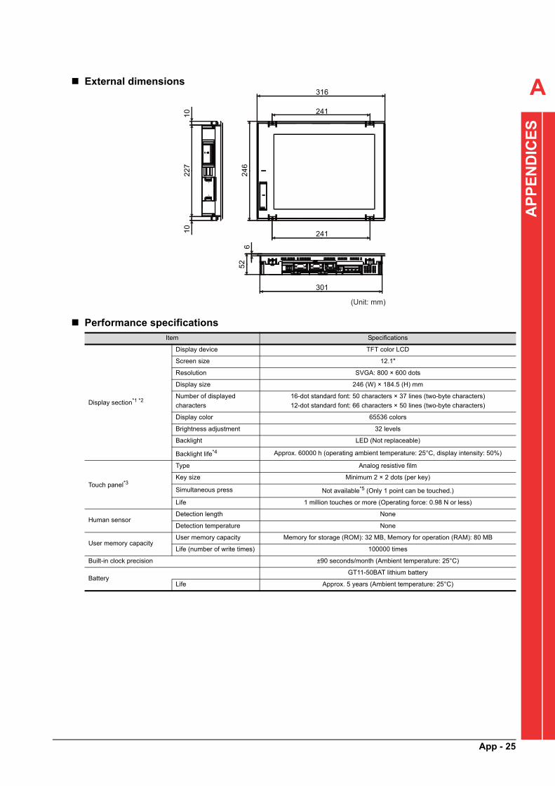
A
AP
PE
ND
ICE
S
External dimensions
Performance specificationsItem Specifications
Display section*1 *2
Display device TFT color LCD
Screen size 12.1"
Resolution SVGA: 800 × 600 dots
Display size 246 (W) × 184.5 (H) mm
Number of displayed
characters
16-dot standard font: 50 characters × 37 lines (two-byte characters)
12-dot standard font: 66 characters × 50 lines (two-byte characters)
Display color 65536 colors
Brightness adjustment 32 levels
Backlight LED (Not replaceable)
Backlight life*4 Approx. 60000 h (operating ambient temperature: 25°C, display intensity: 50%)
Touch panel*3
Type Analog resistive film
Key size Minimum 2 × 2 dots (per key)
Simultaneous press Not available*5 (Only 1 point can be touched.)
Life 1 million touches or more (Operating force: 0.98 N or less)
Human sensorDetection length None
Detection temperature None
User memory capacityUser memory capacity Memory for storage (ROM): 32 MB, Memory for operation (RAM): 80 MB
Life (number of write times) 100000 times
Built-in clock precision ±90 seconds/month (Ambient temperature: 25°C)
BatteryGT11-50BAT lithium battery
Life Approx. 5 years (Ambient temperature: 25°C)
316
246
10
10
526
241
241
301
(Unit: mm)
227
App - 25

*1 As a characteristic of liquid crystal display panels, bright dots (always lit) and dark dots (never lit) may appear on the panel.
Since liquid crystal display panels comprise a great number of display elements, the appearance of bright and back dots cannot
be reduced to zero.
Individual differences in liquid crystal display panels may cause differences in color, uneven brightness and flickering.
Note that these phenomena are characteristics of liquid crystal display panels and it does not mean the products are defective or
damaged.
*2 Flickering may occur due to vibration, shock, or the display colors.
*3 When a stylus is used, the touch panel has a life of 100 thousand touches. The stylus must satisfy the following specifications.
• Material: polycarbonate resin• Tip radius: 0.8 mm or more
*4 To prevent the display section from burning in and lengthen the backlight life, enable the screen save function and turn off the
backlight.
*5 If you touch two points or more simultaneously on the touch panel, a touch switch near the touched points may operate
unexpectedly. Do not touch two points or more simultaneously on the touch panel.
*6 To conform to IP67, close the USB environmental protection cover by pushing the [PUSH] mark firmly. (To conform to IP2X, open
the USB environmental protection cover.)
Note that the structure does not guarantee protection in all users' environments. The GOT may not be used in an environment
where the GOT is exposed to oil or chemicals for a long time, or where oil mist fills the air.
Built-in interface
RS-2321 channel Transmission speed: 115200, 57600, 38400, 19200, 9600, 4800 bps
Connector shape: D-sub 9-pin (male)
RS-422/4851 channel Transmission speed: 115200, 57600, 38400, 19200, 9600, 4800 bps
Connector shape: D-sub 9-pin (female)
Ethernet1 channel Data transfer method: 10BASE-T, 100BASE-TX
Connector shape: RJ-45 (modular jack)
USB (Host)2 channels (front face, rear face)
Maximum transfer rate: High-Speed 480 Mbps, Connector shape: USB-A
USB (Device)1 channel (front face)
Maximum transfer rate: High-Speed 480 Mbps, Connector shape: USB Mini-B
SD memory card 1 channel, SDHC compliant (maximum 32 GB)
Extension interface For installing a communication unit or an option unit
Auxiliary extension
interfaceNone
Side interface For installing a communication unit
Buzzer output Single tone (tone and tone length adjustable)
POWER LED 2 colors (blue and orange)
Productive structure Outside the enclosure: IP67F*6, Inside the enclosure: IP2X
External dimensions 316 (W) × 246 (H) × 52 (D) mm
Panel cut dimensions 302 (W) × 228 (H) mm
Weight (excluding a fitting) 2.4 kg
Compatible software package GT Works3 Version 1.122C or later
Item Specifications
App - 26

A
EN
DIC
ES
Appendix.2.4 Battery replacement procedure
The following explains the procedure for replacing the battery. (Described with the GOT rear face facing up.)Replace the battery within 5 minutes.
(1) Pre-procedurePerform the following before replacing the battery.• Connect the battery connector to the GOT connector.• Leave the GOT on for more than 10 minutes.
(2) Replacement procedure
1. Make sure that the GOT power is off.
AP
P
2. The battery is stored inside the SD memory card cover on the side of the GOT.Open the SD memory card cover as shown in the left figure.
3. After removing the battery from the battery holder of the GOT, unplug the battery connector from the GOT connector.
4. Insert the battery connector to the GOT connector.
SD memory card cover
Connector
Battery
SD memory card cover
Black cableBattery
Connector
Red cable
SD memory card cover
Black cableBattery
Connector
Red cable
App - 27

5. After installing the battery to the battery holder of the GOT, close the SD memory card cover until it clicks.
6. Turn on the GOT.
7. Check that the battery condition is normal with the utility.For details of the battery status display, refer to the following.
GOT2000 Series User's Manual (Utility)
• Utility startup password: "NEJISHIMEUTL"
SD memory card cover
Connector
Battery
App - 28

A
AP
PE
ND
ICE
S
Appendix.3 Restoration Function
Create GOT screen restoration data in advance so that users can restore the GOT screen data even if the data has been deleted accidentally due to an incorrect operation by a user.
Appendix.3.1 Creating restoration data
The following describes the procedure for creating restoration data.
1. Run "GT Designer3" from the Start menu of Windows and open the SCREW TIGHTENING Control Package project.
2. Insert an SD memory card in the personal computer.
3. Click [Communication] → [Write to Memory Card] in the menu.
4. The "Communicate with Memory Card" window appears.
5. Select the following items and click the [Memory Card Write] button.• Destination Memory Card: A drive where
the SD memory card has been inserted• GOT Startup Method: "Install on the
specific drive first"• Install Destination Drive: "C:Built-in Flash
Memory"
6. A confirmation message will appear.Click the [Yes] button.
7. The restoration data is created in the SD memory card.
App - 29

App - 30
Appendix.3.2 Restoration
The following describes the restoration procedure.
(1) Insert the SD memory card in which the restoration data has been stored in the GOT of the operation panel.The following describes how to insert the SD memory card.
1. Make sure that the power to the GOT is off.
2. Open the SD memory card cover as shown in the left figure.
3. After making sure that the SD memory card access LED is off with the SD memory card cover 90 degrees or more open, insert the SD memory card in the SD memory card interface with its front side facing up.
4. Push and close the SD memory card cover until it clicks.
5. After the SD memory card cover is closed, the access to the SD memory card is allowed.
SD memory card access LED
Open the SD memory card cover 90 degrees or more.

A
(2) Install the GOT screen data.AP
PE
ND
ICE
S
POINTPOINTPOINT
When the system management authentication window appears, enter the following information and touch the [Enter] key.
• Password: "NEJISHIMEDSP"
1. Turn on the power to the control panel while holding down the installation switch (S.MODE switch) on the GOT rear face.
2. The message "Install now..." is displayed.It takes a few minutes to complete the installation.
3. The message "Installation has been completed" is displayed.Touch the [OK] switch.
4. The GOT automatically restarts.
5. The "Touch panel calibration" screen is displayed.Follow the instructions on the screen and adjust coordinates.
6. The GOT automatically restarts.
7. The "Clock setting" screen is displayed.Configure the time setting and touch the [OK] switch.
8. The GOT automatically restarts.
9. The startup screen of the SCREW TIGHTENING System appears. The data installation has completed.
Installation switch(S.MODE)
App - 31

App - 32
Appendix.4 Devices Disclosed to Users
Appendix.4.1 M device
The following table lists the M devices disclosed to users (M8000 to M8999) in the devices occupied by this application.
(1) For reading
Device Purpose
M8000 Electric screwdriver start signal (Screwdriver No.1)
M8001 Electric screwdriver start signal (Screwdriver No.2)
M8002 Electric screwdriver start signal (Screwdriver No.3)
M8003 Electric screwdriver start signal (Screwdriver No.4)
M8004 Electric screwdriver start signal (Screwdriver No.5)
M8005 Electric screwdriver start signal (Screwdriver No.6)
M8006 Electric screwdriver start signal (Screwdriver No.7)
M8007 Electric screwdriver start signal (Screwdriver No.8)
M8008 Electric screwdriver start signal (Screwdriver No.9)
M8009 Electric screwdriver start signal (Screwdriver No.10)
M8010 Reserved for the system
M8011 Reserved for the system
M8012 Reserved for the system
M8013 Reserved for the system
M8014 Reserved for the system
M8015 Reserved for the system
M8016 Electric screwdriver torque-up signal (Screwdriver No.1)
M8017 Electric screwdriver torque-up signal (Screwdriver No.2)
M8018 Electric screwdriver torque-up signal (Screwdriver No.3)
M8019 Electric screwdriver torque-up signal (Screwdriver No.4)
M8020 Electric screwdriver torque-up signal (Screwdriver No.5)
M8021 Electric screwdriver torque-up signal (Screwdriver No.6)
M8022 Electric screwdriver torque-up signal (Screwdriver No.7)
M8023 Electric screwdriver torque-up signal (Screwdriver No.8)
M8024 Electric screwdriver torque-up signal (Screwdriver No.9)
M8025 Electric screwdriver torque-up signal (Screwdriver No.10)
M8026 Reserved for the system
M8027 Reserved for the system
M8028 Reserved for the system
M8029 Reserved for the system
M8030 Reserved for the system
M8031 Reserved for the system
M8032 Electric screwdriver reverse signal (Screwdriver No.1)
M8033 Electric screwdriver reverse signal (Screwdriver No.2)
M8034 Electric screwdriver reverse signal (Screwdriver No.3)
M8035 Electric screwdriver reverse signal (Screwdriver No.4)
M8036 Electric screwdriver reverse signal (Screwdriver No.5)
M8037 Electric screwdriver reverse signal (Screwdriver No.6)
M8038 Electric screwdriver reverse signal (Screwdriver No.7)

A
AP
PE
ND
ICE
S
M8039 Electric screwdriver reverse signal (Screwdriver No.8)
M8040 Electric screwdriver reverse signal (Screwdriver No.9)
M8041 Electric screwdriver reverse signal (Screwdriver No.10)
M8042 Reserved for the system
M8043 Reserved for the system
M8044 Reserved for the system
M8045 Reserved for the system
M8046 Reserved for the system
M8047 Reserved for the system
M8050 Screw shelf input signal (Screw shelf No.1)
M8051 Screw shelf input signal (Screw shelf No.2)
M8052 Screw shelf input signal (Screw shelf No.3)
M8053 Screw shelf input signal (Screw shelf No.4)
M8054 Screw shelf input signal (Screw shelf No.5)
M8055 Screw shelf input signal (Screw shelf No.6)
M8056 Screw shelf input signal (Screw shelf No.7)
M8057 Screw shelf input signal (Screw shelf No.8)
M8058 Screw shelf input signal (Screw shelf No.9)
M8059 Screw shelf input signal (Screw shelf No.10)
M8060 Screw shelf input signal (Screw shelf No.11)
M8061 Screw shelf input signal (Screw shelf No.12)
M8062 Screw shelf input signal (Screw shelf No.13)
M8063 Screw shelf input signal (Screw shelf No.14)
M8064 Screw shelf input signal (Screw shelf No.15)
M8065 Screw shelf input signal (Screw shelf No.16)
M8066 Screw shelf input signal (Screw shelf No.17)
M8067 Screw shelf input signal (Screw shelf No.18)
M8068 Screw shelf input signal (Screw shelf No.19)
M8069 Screw shelf input signal (Screw shelf No.20)
M8070 Screw shelf input signal (Screw shelf No.21)
M8071 Screw shelf input signal (Screw shelf No.22)
M8072 Screw shelf input signal (Screw shelf No.23)
M8073 Screw shelf input signal (Screw shelf No.24)
M8074 Screw shelf input signal (Screw shelf No.25)
M8075 Screw shelf input signal (Screw shelf No.26)
M8076 Screw shelf input signal (Screw shelf No.27)
M8077 Screw shelf input signal (Screw shelf No.28)
M8078 Screw shelf input signal (Screw shelf No.29)
M8079 Screw shelf input signal (Screw shelf No.30)
M8080 Reserved for the system
M8081 Reserved for the system
M8090 Electric screwdriver connection (Screwdriver No.1)
M8091 Electric screwdriver connection (Screwdriver No.2)
M8092 Electric screwdriver connection (Screwdriver No.3)
M8093 Electric screwdriver connection (Screwdriver No.4)
M8094 Electric screwdriver connection (Screwdriver No.5)
Device Purpose
App - 33

M8095 Electric screwdriver connection (Screwdriver No.6)
M8096 Electric screwdriver connection (Screwdriver No.7)
M8097 Electric screwdriver connection (Screwdriver No.8)
M8098 Electric screwdriver connection (Screwdriver No.9)
M8099 Electric screwdriver connection (Screwdriver No.10)
M8100 Reserved for the system
M8101 Reserved for the system
M8102 Reserved for the system
M8103 Reserved for the system
M8104 Reserved for the system
M8105 Reserved for the system
M8106 Screw shelf connection (Screw shelf No.1)
M8107 Screw shelf connection (Screw shelf No.2)
M8108 Screw shelf connection (Screw shelf No.3)
M8109 Screw shelf connection (Screw shelf No.4)
M8110 Screw shelf connection (Screw shelf No.5)
M8111 Screw shelf connection (Screw shelf No.6)
M8112 Screw shelf connection (Screw shelf No.7)
M8113 Screw shelf connection (Screw shelf No.8)
M8114 Screw shelf connection (Screw shelf No.9)
M8115 Screw shelf connection (Screw shelf No.10)
M8116 Screw shelf connection (Screw shelf No.11)
M8117 Screw shelf connection (Screw shelf No.12)
M8118 Screw shelf connection (Screw shelf No.13)
M8119 Screw shelf connection (Screw shelf No.14)
M8120 Screw shelf connection (Screw shelf No.15)
M8121 Screw shelf connection (Screw shelf No.16)
M8122 Screw shelf connection (Screw shelf No.17)
M8123 Screw shelf connection (Screw shelf No.18)
M8124 Screw shelf connection (Screw shelf No.19)
M8125 Screw shelf connection (Screw shelf No.20)
M8126 Screw shelf connection (Screw shelf No.21)
M8127 Screw shelf connection (Screw shelf No.22)
M8128 Screw shelf connection (Screw shelf No.23)
M8129 Screw shelf connection (Screw shelf No.24)
M8130 Screw shelf connection (Screw shelf No.25)
M8131 Screw shelf connection (Screw shelf No.26)
M8132 Screw shelf connection (Screw shelf No.27)
M8133 Screw shelf connection (Screw shelf No.28)
M8134 Screw shelf connection (Screw shelf No.29)
M8135 Screw shelf connection (Screw shelf No.30)
M8136 Reserved for the system
M8137 Reserved for the system
Device Purpose
App - 34
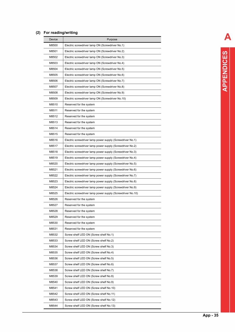
A
AP
PE
ND
ICE
S
(2) For reading/writing
Device Purpose
M8500 Electric screwdriver lamp ON (Screwdriver No.1)
M8501 Electric screwdriver lamp ON (Screwdriver No.2)
M8502 Electric screwdriver lamp ON (Screwdriver No.3)
M8503 Electric screwdriver lamp ON (Screwdriver No.4)
M8504 Electric screwdriver lamp ON (Screwdriver No.5)
M8505 Electric screwdriver lamp ON (Screwdriver No.6)
M8506 Electric screwdriver lamp ON (Screwdriver No.7)
M8507 Electric screwdriver lamp ON (Screwdriver No.8)
M8508 Electric screwdriver lamp ON (Screwdriver No.9)
M8509 Electric screwdriver lamp ON (Screwdriver No.10)
M8510 Reserved for the system
M8511 Reserved for the system
M8512 Reserved for the system
M8513 Reserved for the system
M8514 Reserved for the system
M8515 Reserved for the system
M8516 Electric screwdriver lamp power supply (Screwdriver No.1)
M8517 Electric screwdriver lamp power supply (Screwdriver No.2)
M8518 Electric screwdriver lamp power supply (Screwdriver No.3)
M8519 Electric screwdriver lamp power supply (Screwdriver No.4)
M8520 Electric screwdriver lamp power supply (Screwdriver No.5)
M8521 Electric screwdriver lamp power supply (Screwdriver No.6)
M8522 Electric screwdriver lamp power supply (Screwdriver No.7)
M8523 Electric screwdriver lamp power supply (Screwdriver No.8)
M8524 Electric screwdriver lamp power supply (Screwdriver No.9)
M8525 Electric screwdriver lamp power supply (Screwdriver No.10)
M8526 Reserved for the system
M8527 Reserved for the system
M8528 Reserved for the system
M8529 Reserved for the system
M8530 Reserved for the system
M8531 Reserved for the system
M8532 Screw shelf LED ON (Screw shelf No.1)
M8533 Screw shelf LED ON (Screw shelf No.2)
M8534 Screw shelf LED ON (Screw shelf No.3)
M8535 Screw shelf LED ON (Screw shelf No.4)
M8536 Screw shelf LED ON (Screw shelf No.5)
M8537 Screw shelf LED ON (Screw shelf No.6)
M8538 Screw shelf LED ON (Screw shelf No.7)
M8539 Screw shelf LED ON (Screw shelf No.8)
M8540 Screw shelf LED ON (Screw shelf No.9)
M8541 Screw shelf LED ON (Screw shelf No.10)
M8542 Screw shelf LED ON (Screw shelf No.11)
M8543 Screw shelf LED ON (Screw shelf No.12)
M8544 Screw shelf LED ON (Screw shelf No.13)
App - 35

M8545 Screw shelf LED ON (Screw shelf No.14)
M8546 Screw shelf LED ON (Screw shelf No.15)
M8547 Screw shelf LED ON (Screw shelf No.16)
M8548 Screw shelf LED ON (Screw shelf No.17)
M8549 Screw shelf LED ON (Screw shelf No.18)
M8550 Screw shelf LED ON (Screw shelf No.19)
M8551 Screw shelf LED ON (Screw shelf No.20)
M8552 Screw shelf LED ON (Screw shelf No.21)
M8553 Screw shelf LED ON (Screw shelf No.22)
M8554 Screw shelf LED ON (Screw shelf No.23)
M8555 Screw shelf LED ON (Screw shelf No.24)
M8556 Screw shelf LED ON (Screw shelf No.25)
M8557 Screw shelf LED ON (Screw shelf No.26)
M8558 Screw shelf LED ON (Screw shelf No.27)
M8559 Screw shelf LED ON (Screw shelf No.28)
M8560 Screw shelf LED ON (Screw shelf No.29)
M8561 Screw shelf LED ON (Screw shelf No.30)
M8562 Reserved for the system
M8563 Reserved for the system
M8564 Screw shelf door open/close (Screw shelf No.1)
M8565 Screw shelf door open/close (Screw shelf No.2)
M8566 Screw shelf door open/close (Screw shelf No.3)
M8567 Screw shelf door open/close (Screw shelf No.4)
M8568 Screw shelf door open/close (Screw shelf No.5)
M8569 Screw shelf door open/close (Screw shelf No.6)
M8570 Screw shelf door open/close (Screw shelf No.7)
M8571 Screw shelf door open/close (Screw shelf No.8)
M8572 Screw shelf door open/close (Screw shelf No.9)
M8573 Screw shelf door open/close (Screw shelf No.10)
M8574 Screw shelf door open/close (Screw shelf No.11)
M8575 Screw shelf door open/close (Screw shelf No.12)
M8576 Screw shelf door open/close (Screw shelf No.13)
M8577 Screw shelf door open/close (Screw shelf No.14)
M8578 Screw shelf door open/close (Screw shelf No.15)
M8579 Screw shelf door open/close (Screw shelf No.16)
M8580 Screw shelf door open/close (Screw shelf No.17)
M8581 Screw shelf door open/close (Screw shelf No.18)
M8582 Screw shelf door open/close (Screw shelf No.19)
M8583 Screw shelf door open/close (Screw shelf No.20)
M8584 Screw shelf door open/close (Screw shelf No.21)
M8585 Screw shelf door open/close (Screw shelf No.22)
M8586 Screw shelf door open/close (Screw shelf No.23)
M8587 Screw shelf door open/close (Screw shelf No.24)
M8588 Screw shelf door open/close (Screw shelf No.25)
M8589 Screw shelf door open/close (Screw shelf No.26)
M8590 Screw shelf door open/close (Screw shelf No.27)
Device Purpose
App - 36

A
AP
PE
ND
ICE
S
Appendix.4.2 D device
The following table lists the D devices disclosed to users (D8000 to D8999) in the devices occupied by this application.
(1) For reading
M8591 Screw shelf door open/close (Screw shelf No.28)
M8592 Screw shelf door open/close (Screw shelf No.29)
M8593 Screw shelf door open/close (Screw shelf No.30)
M8594 Reserved for the system
M8595 Reserved for the system
M8600 Reserved for the system
M8601 Disclosed-to-users output enable signal
M8610 Torque check record registration request signal
M8611 Torque check record registration in progress signal
M8612 Torque check record registration completion signal
M8613 Torque check record registration error completion signal
M8700 Disclosed-to-users barcode reader enable signal
M8701 Disclosed-to-users barcode reader reading completion signal
M8702 Disclosed-to-users barcode reader reading request signal
M8800 Print function start signal
M8801 Print function end signal
M8802 Print execution signal
M8805 Torque check function in execution signal
M8806 Reserved for the system
Device Purpose Remarks
D8099 Electric screwdriver in use (power-on)
On: In use, Off: Not used
(Bit 0: No.1, Bit 1: No.2, Bit 2: No.3, Bit 3:
No.4, Bit 4: No.5, Bit 5: No.6, Bit 6: No.7, Bit
7: No.8, Bit 8: No.9, Bit 9: No.10)
D8100
Date (YYYYMMDD) ASCII codeD8101
D8102
D8103
D8104
Time (HHMMSS) ASCII codeD8105
D8106
D8107 Reserved for the system
D8108 Reserved for the system
D8110
Factory ID ASCII codeD8111
D8112
D8113
Equipment ID ASCII codeD8114
D8115
D8116
Device Purpose
App - 37

D8117
Work table ID ASCII codeD8118
D8119
D8120
D8121
Operator code ASCII codeD8122
D8123
D8124
D8125 Skill ASCII code ("0": Ordinary, "1": Skillful)
D8126 Manager ASCII code ("0": Operator, "1": Manager)
D8127
Order No. ASCII code
D8128
D8129
D8130
D8131
D8132
D8133
D8134
Control No. ASCII code
D8135
D8136
D8137
D8138
D8139
D8140
D8141
D8142
D8143
D8144
D8145
D8146
D8147
D8148
D8149
Device Purpose Remarks
App - 38
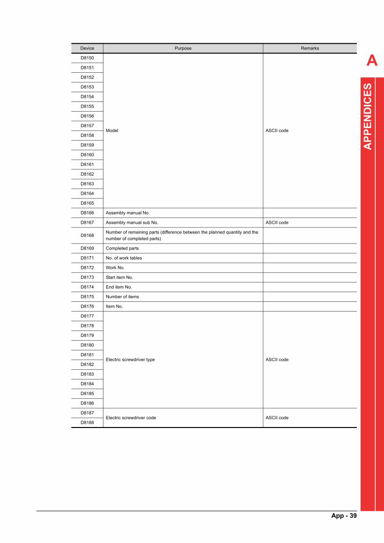
A
AP
PE
ND
ICE
S
D8150
Model ASCII code
D8151
D8152
D8153
D8154
D8155
D8156
D8157
D8158
D8159
D8160
D8161
D8162
D8163
D8164
D8165
D8166 Assembly manual No.
D8167 Assembly manual sub No. ASCII code
D8168Number of remaining parts (difference between the planned quantity and the
number of completed parts)
D8169 Completed parts
D8171 No. of work tables
D8172 Work No.
D8173 Start item No.
D8174 End item No.
D8175 Number of items
D8176 Item No.
D8177
Electric screwdriver type ASCII code
D8178
D8179
D8180
D8181
D8182
D8183
D8184
D8185
D8186
D8187Electric screwdriver code ASCII code
D8188
Device Purpose Remarks
App - 39

D8189
Screw type ASCII code
D8190
D8191
D8192
D8193
D8194
D8195
D8196
D8197
D8198
D8199
D8200
D8201
D8202
D8203
D8204Screw code ASCII code
D8205
D8206 Work type
D8207 Number of markings in an item
D8208 Number of screws in an item
D8209 Total number of screws in an assembly manual
D8210 Standard work time
D8211 Availability of cancel
D8212 Screw tightening sequence number in an item
D8213 Lower limit of screw tightening time
D8214 Upper limit of screw tightening time
D8215 Screw tightening sequence number in an assembly manual
D8217
ID No. ASCII code
D8218
D8219
D8220
D8221
D8222
D8223
D8224
D8225
D8226
D8227
D8228
D8229
D8230
D8231
D8232
Device Purpose Remarks
App - 40

A
AP
PE
ND
ICE
S
D8233
Work start date (YYYYMMDD) ASCII codeD8234
D8235
D8236
D8237
Work start time (HHMMSS) ASCII codeD8238
D8239
D8240 Production serial number
D8242Standard time accumulated from the start of work (unit: second) 2 words
D8243
D8244Actual time accumulated from the start of work (unit: second) 2 words
D8245
D8246 Number of OK screws from the start of work
D8247 Number of NG screws from the start of work
D8248 Planned quantity
D8249 Reserved for the system
D8250
Work start date (YYYYMMDD) by item ASCII codeD8251
D8252
D8253
D8254
Work start time (HHMMSS) by item ASCII codeD8255
D8256
D8257 Screw tightening time
D8258 Number of OK screws from the start of work by item
D8259 Number of NG screws from the start of work by item
D8260 Remaining time (unit: second)
(Difference between the accumulated standard time and accumulated actual
time)
2 wordsD8261
D8262 Electric screwdriver code Binary code
D8263 Screw code Binary code
D8264Production serial numbers ASCII code
D8265
D8266Actual time (unit: second) by item 2 words
D8267
D8300 Electric screwdriver code (Screwdriver No.1)
D8301 Electric screwdriver code (Screwdriver No.2)
D8302 Electric screwdriver code (Screwdriver No.3)
D8303 Electric screwdriver code (Screwdriver No.4)
D8304 Electric screwdriver code (Screwdriver No.5)
D8305 Electric screwdriver code (Screwdriver No.6)
D8306 Electric screwdriver code (Screwdriver No.7)
D8307 Electric screwdriver code (Screwdriver No.8)
D8308 Electric screwdriver code (Screwdriver No.9)
D8309 Electric screwdriver code (Screwdriver No.10)
D8310 Reserved for the system
D8311 Reserved for the system
Device Purpose Remarks
App - 41
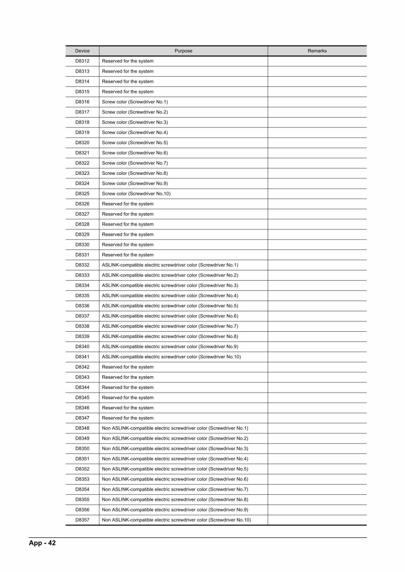
D8312 Reserved for the system
D8313 Reserved for the system
D8314 Reserved for the system
D8315 Reserved for the system
D8316 Screw color (Screwdriver No.1)
D8317 Screw color (Screwdriver No.2)
D8318 Screw color (Screwdriver No.3)
D8319 Screw color (Screwdriver No.4)
D8320 Screw color (Screwdriver No.5)
D8321 Screw color (Screwdriver No.6)
D8322 Screw color (Screwdriver No.7)
D8323 Screw color (Screwdriver No.8)
D8324 Screw color (Screwdriver No.9)
D8325 Screw color (Screwdriver No.10)
D8326 Reserved for the system
D8327 Reserved for the system
D8328 Reserved for the system
D8329 Reserved for the system
D8330 Reserved for the system
D8331 Reserved for the system
D8332 ASLINK-compatible electric screwdriver color (Screwdriver No.1)
D8333 ASLINK-compatible electric screwdriver color (Screwdriver No.2)
D8334 ASLINK-compatible electric screwdriver color (Screwdriver No.3)
D8335 ASLINK-compatible electric screwdriver color (Screwdriver No.4)
D8336 ASLINK-compatible electric screwdriver color (Screwdriver No.5)
D8337 ASLINK-compatible electric screwdriver color (Screwdriver No.6)
D8338 ASLINK-compatible electric screwdriver color (Screwdriver No.7)
D8339 ASLINK-compatible electric screwdriver color (Screwdriver No.8)
D8340 ASLINK-compatible electric screwdriver color (Screwdriver No.9)
D8341 ASLINK-compatible electric screwdriver color (Screwdriver No.10)
D8342 Reserved for the system
D8343 Reserved for the system
D8344 Reserved for the system
D8345 Reserved for the system
D8346 Reserved for the system
D8347 Reserved for the system
D8348 Non ASLINK-compatible electric screwdriver color (Screwdriver No.1)
D8349 Non ASLINK-compatible electric screwdriver color (Screwdriver No.2)
D8350 Non ASLINK-compatible electric screwdriver color (Screwdriver No.3)
D8351 Non ASLINK-compatible electric screwdriver color (Screwdriver No.4)
D8352 Non ASLINK-compatible electric screwdriver color (Screwdriver No.5)
D8353 Non ASLINK-compatible electric screwdriver color (Screwdriver No.6)
D8354 Non ASLINK-compatible electric screwdriver color (Screwdriver No.7)
D8355 Non ASLINK-compatible electric screwdriver color (Screwdriver No.8)
D8356 Non ASLINK-compatible electric screwdriver color (Screwdriver No.9)
D8357 Non ASLINK-compatible electric screwdriver color (Screwdriver No.10)
Device Purpose Remarks
App - 42
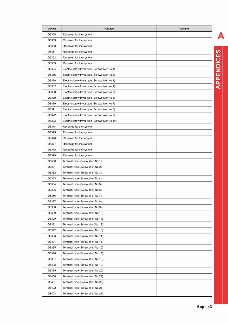
A
AP
PE
ND
ICE
S
D8358 Reserved for the system
D8359 Reserved for the system
D8360 Reserved for the system
D8361 Reserved for the system
D8362 Reserved for the system
D8363 Reserved for the system
D8364 Electric screwdriver type (Screwdriver No.1)
D8365 Electric screwdriver type (Screwdriver No.2)
D8366 Electric screwdriver type (Screwdriver No.3)
D8367 Electric screwdriver type (Screwdriver No.4)
D8368 Electric screwdriver type (Screwdriver No.5)
D8369 Electric screwdriver type (Screwdriver No.6)
D8370 Electric screwdriver type (Screwdriver No.7)
D8371 Electric screwdriver type (Screwdriver No.8)
D8372 Electric screwdriver type (Screwdriver No.9)
D8373 Electric screwdriver type (Screwdriver No.10)
D8374 Reserved for the system
D8375 Reserved for the system
D8376 Reserved for the system
D8377 Reserved for the system
D8378 Reserved for the system
D8379 Reserved for the system
D8380 Terminal type (Screw shelf No.1)
D8381 Terminal type (Screw shelf No.2)
D8382 Terminal type (Screw shelf No.3)
D8383 Terminal type (Screw shelf No.4)
D8384 Terminal type (Screw shelf No.5)
D8385 Terminal type (Screw shelf No.6)
D8386 Terminal type (Screw shelf No.7)
D8387 Terminal type (Screw shelf No.8)
D8388 Terminal type (Screw shelf No.9)
D8389 Terminal type (Screw shelf No.10)
D8390 Terminal type (Screw shelf No.11)
D8391 Terminal type (Screw shelf No.12)
D8392 Terminal type (Screw shelf No.13)
D8393 Terminal type (Screw shelf No.14)
D8394 Terminal type (Screw shelf No.15)
D8395 Terminal type (Screw shelf No.16)
D8396 Terminal type (Screw shelf No.17)
D8397 Terminal type (Screw shelf No.18)
D8398 Terminal type (Screw shelf No.19)
D8399 Terminal type (Screw shelf No.20)
D8400 Terminal type (Screw shelf No.21)
D8401 Terminal type (Screw shelf No.22)
D8402 Terminal type (Screw shelf No.23)
D8403 Terminal type (Screw shelf No.24)
Device Purpose Remarks
App - 43

D8404 Terminal type (Screw shelf No.25)
D8405 Terminal type (Screw shelf No.26)
D8406 Terminal type (Screw shelf No.27)
D8407 Terminal type (Screw shelf No.28)
D8408 Terminal type (Screw shelf No.29)
D8409 Terminal type (Screw shelf No.30)
D8410 Reserved for the system
D8411 Reserved for the system
D8412 Reserved for the system
D8413 Reserved for the system
D8414 Reserved for the system
D8415 Reserved for the system
D8416 Reserved for the system
D8417 Reserved for the system
D8418 Reserved for the system
D8419 Screw shelf LED color
D8420 RUN state indicator setting (Waiting)
D8421 RUN state indicator setting (Operating)
D8422 RUN state indicator setting (Paused)
D8423 RUN state indicator setting (Minor alarm)
D8424 RUN state indicator setting (Medium alarm)
D8425 RUN state indicator setting (Major alarm)
D8427 Reserved for the system
D8428 Reserved for the system
D8429 Reserved for the system
D8430 Reserved for the system
D8431 Reserved for the system
D8432 Reserved for the system
D8433 Reserved for the system
D8434 Reserved for the system
D8435 Reserved for the system
D8436 Reserved for the system
D8437 Reserved for the system
D8438 Reserved for the system
D8439 Reserved for the system
D8440
Factory ID ASCII codeD8441
D8442
D8443
Equipment ID ASCII codeD8444
D8445
D8446
D8447
Work table ID ASCII codeD8448
D8449
D8450
Device Purpose Remarks
App - 44

A
AP
PE
ND
ICE
S
(2) For reading/writing
D8451 No. of work tables
D8452 Work No.
D8453 Reserved for the system
D8454 Reserved for the system
D8455 Reserved for the system
D8456 Reserved for the system
D8457 Reserved for the system
D8458 Reserved for the system
D8459 Reserved for the system
D8460 Correction of standard work time (%)
D8461 Reserved for the system
D8462 Reserved for the system
D8463 Reserved for the system
D8464 Reserved for the system
D8465 Reserved for the system
D8466 Reserved for the system
D8467 Reserved for the system
D8468 Reserved for the system
D8469 Reserved for the system
Device Purpose Remarks
D8500 Electric screwdriver lamp ON (Screwdriver No.1)
For ASLINK-compatible electric
screwdrivers
(0: Off, 1: On in red, 2: On in green, 3: On in
yellow, 4: On in blue, 5: On in purple, 6: On
in light blue, 7: On in white)
For non ASLINK-compatible electric
screwdriver colors
(0: Off, 1 to 7: On)
D8501 Electric screwdriver lamp ON (Screwdriver No.2)
D8502 Electric screwdriver lamp ON (Screwdriver No.3)
D8503 Electric screwdriver lamp ON (Screwdriver No.4)
D8504 Electric screwdriver lamp ON (Screwdriver No.5)
D8505 Electric screwdriver lamp ON (Screwdriver No.6)
D8506 Electric screwdriver lamp ON (Screwdriver No.7)
D8507 Electric screwdriver lamp ON (Screwdriver No.8)
D8508 Electric screwdriver lamp ON (Screwdriver No.9)
D8509 Electric screwdriver lamp ON (Screwdriver No.10)
D8510 Reserved for the system
D8511 Reserved for the system
D8512 Reserved for the system
D8513 Reserved for the system
D8514 Reserved for the system
D8515 Reserved for the system
D8520
Torque check work start date (YYYYMMDD) ASCII codeD8521
D8522
D8523
D8524
Torque check work start time (HHMMSS) ASCII codeD8525
D8526
Device Purpose Remarks
App - 45
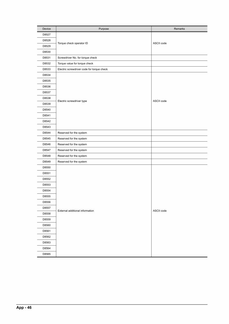
D8527
Torque check operator ID ASCII codeD8528
D8529
D8530
D8531 Screwdriver No. for torque check
D8532 Torque value for torque check
D8533 Electric screwdriver code for torque check
D8534
Electric screwdriver type ASCII code
D8535
D8536
D8537
D8538
D8539
D8540
D8541
D8542
D8543
D8544 Reserved for the system
D8545 Reserved for the system
D8546 Reserved for the system
D8547 Reserved for the system
D8548 Reserved for the system
D8549 Reserved for the system
D8550
External additional information ASCII code
D8551
D8552
D8553
D8554
D8555
D8556
D8557
D8558
D8559
D8560
D8561
D8562
D8563
D8564
D8565
Device Purpose Remarks
App - 46

A
AP
PE
ND
ICE
S
D8566
Reserved for the system ASCII code
D8567
D8568
D8569
D8570
D8571
D8572
D8573
D8574
D8575
D8576
D8577
D8578
D8579
D8580
D8581
D8600 Torque value for OK information registration Measured torque value for nut runner
D8700 Number of bites read by barcode reader (disclosed to users)
D8701
Data read by barcode reader (disclosed to users)
D8702
D8703
D8704
D8705
D8706
D8707
D8708
D8709
D8710
D8711
D8712
D8713
D8714
D8715
D8716
D8717
D8718
D8719
D8720
D8721
D8722
D8723
D8724
D8725
D8726
D8727
D8728
Device Purpose Remarks
App - 47

D8729
Data read by barcode reader (disclosed to users)
D8730
D8731
D8732
D8733
D8734
D8735
D8736
D8737
D8738
D8739
D8740
D8741
D8742
D8743
D8744
D8745
D8746
D8747
D8748
D8749
D8750
D8751
D8752
D8753
D8754
D8755
D8756
D8757
D8758
D8759
D8760
D8761
D8762
D8763
D8764
D8765
D8766
D8767
D8768
D8769
D8770
D8771
D8772
D8773
D8774
Device Purpose Remarks
App - 48

A
AP
PE
ND
ICE
S
D8775
Data read by barcode reader (disclosed to users)
D8776
D8777
D8778
D8779
D8780
D8781
D8782
D8783
D8784
D8785
D8786
D8787
D8788
D8789
D8790
D8791
D8792
D8793
D8794
D8795
D8796
D8797
D8798
D8799
D8800
D8801
D8802
D8803
D8804
D8805
D8806
D8807
D8808
D8809
D8810
D8811
D8812
D8813
D8814
D8815
D8816
D8817
D8818
D8819
D8820
Device Purpose Remarks
App - 49

D8821
Data read by barcode reader (disclosed to users)
D8822
D8823
D8824
D8825
D8826
D8827
D8828
D8829
D8830
D8831
D8832
D8833
D8834
D8835
D8836
D8837
D8838
D8839
D8840
D8841
D8842
D8843
D8844
D8845
D8846
D8847
D8848
D8849
D8850
D8851
D8852
D8853
D8854
D8855
D8856
D8857
D8858
D8859
D8860
D8861
D8862
D8863
D8864
D8865
D8866
Device Purpose Remarks
App - 50

A
AP
PE
ND
ICE
S
D8867
Data read by barcode reader (disclosed to users)
D8868
D8869
D8870
D8871
D8872
D8873
D8874
D8875
D8876
D8877
D8878
D8879
D8880
D8881
D8882
D8883
D8884
D8885
D8886
D8887
D8888
D8889
D8890
D8891
D8892
D8893
D8894
D8895
D8896
D8897
D8898
D8899
CAUTION
• Do not access the "Reserved for the system" devices from a user program. Doing so may cause malfunctions.
• Devices unlisted in the tables within the range of the devices disclosed to users are not used.
Device Purpose Remarks
App - 51
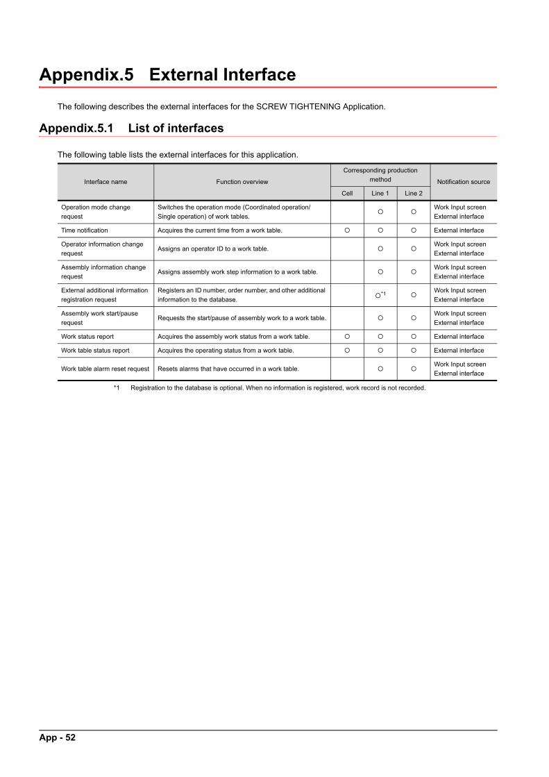
App - 52
Appendix.5 External Interface
The following describes the external interfaces for the SCREW TIGHTENING Application.
Appendix.5.1 List of interfaces
The following table lists the external interfaces for this application.
*1 Registration to the database is optional. When no information is registered, work record is not recorded.
Interface name Function overview
Corresponding production
method Notification source
Cell Line 1 Line 2
Operation mode change
request
Switches the operation mode (Coordinated operation/
Single operation) of work tables.
Work Input screen
External interface
Time notification Acquires the current time from a work table. External interface
Operator information change
requestAssigns an operator ID to a work table.
Work Input screen
External interface
Assembly information change
requestAssigns assembly work step information to a work table.
Work Input screen
External interface
External additional information
registration request
Registers an ID number, order number, and other additional
information to the database.*1
Work Input screen
External interface
Assembly work start/pause
requestRequests the start/pause of assembly work to a work table.
Work Input screen
External interface
Work status report Acquires the assembly work status from a work table. External interface
Work table status report Acquires the operating status from a work table. External interface
Work table alarm reset request Resets alarms that have occurred in a work table. Work Input screen
External interface

A
ICE
S
Appendix.5.2 Details of external interfaces
The following describes the details of the external interfaces for this application.
Operation mode change request
(1) FunctionThis interface switches the operation mode of work tables.
• Single operation mode: Signals from the exter
l system are not accepted.ND
na• Coordinated operation mode: Signals from the external system are accepted.
E
(When the application is started, the setting in th ork Input screen is reflected.) P e WP
A (2) Condition*1 The operating conditions of the single operation mode are the same as those of the coordinated operation mode.
( = Requests can be accepted., = No requests can be accepted.)
Production method
Cell
Line production method 1/Line production method 2
Operation mode
Single
operation
Coordinated operation
No statusDuring
inspection
During setting
or backup/
restoration
During ASLINK
update
During free
operation
During
assembly work
Operation mode being
switched in the "Work
Input" screen
*1
(3) Data
No. Signal/data IN/OUT Data type Device Description
1 Request mode IN WORD D8658Specify the request mode (0: Single operation mode, 1: Coordinated
operation mode) while the mode change request signal is on.
2Mode change request
signalIN BIT M8620
Turn on this signal at the request.
Turn off this signal after the mode change accept signal turns on.
3Mode change accept
signalOUT BIT M8621
This signal turns on at the normal completion or error operation.
This signal turns off when the mode change request signal is off.
4Mode change error
completion signalOUT BIT M8622
This signal turns on at the error completion.
This signal turns off when the mode change request signal is off.
5 Mode status OUT WORD D8268The request mode (0: Single operation mode, 1: Coordinated
operation mode) is set at the normal completion.
6Mode change
unacceptable signalOUT BIT M8623
This signal turns on while the mode change is disabled (during
assembly work and others).
(4) OperationWhen the mode change request signal is turned on, the operation mode is switched to the mode set as the request mode.At the error completion, the previous status is held.
App - 53
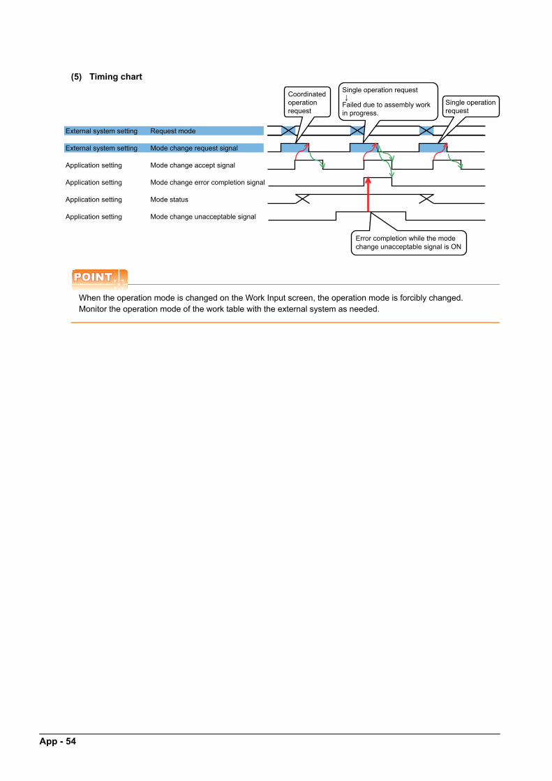
App - 54
(5) Timing chart
POINTPOINTPOINT
When the operation mode is changed on the Work Input screen, the operation mode is forcibly changed.Monitor the operation mode of the work table with the external system as needed.
External system setting Request mode
External system setting Mode change request signal
Application setting Mode change accept signal
Application setting Mode change error completion signal
Application setting Mode status
Application setting Mode change unacceptable signal
Single operation request↓
Error completion while the mode change unacceptable signal is ON
Single operation request
Coordinated operation request
Failed due to assembly work in progress.

A
Time notification(1) FunctionThis interface acquires the current time from a work table.
S
APP
EN
DIC
E
(2) Condition( = Requests can be accepted., = No requests can be accepted.)
Production method
Cell
Line production method 1/Line production method 2
Operation mode
Single
operation
Coordinated operation
No statusDuring
inspection
During setting
or backup/
restoration
During ASLINK
update
During free
operation
During
assembly work
Operation mode being
switched in the "Work
Input" screen
(3) Data
No. Signal/data IN/OUT Data type Device Description
1 Time OUTWORD(9)
ASCII: 18 characters
D8100 to
D8106The current time (YYYYMMDDhhmmss) is set.
(4) OperationThe time is updated every second in work tables. (Even though an error has occurred on the work table, it is not notified.)Use this interface to compare the time acquired from a work table at the one-second or longer cycle with the previously acquired value.• When the acquired time differs from the previous value: Determine that the communication has been
established.• When the acquired time is the same as the previous value: Determine that the communication has been
disconnected and change the mode of the external system to 0 (single operation mode).
(5) Timing chart
POINTPOINTPOINT
When the communication has been disconnected, provide the retry processing as needed.
Communication establishment status
External system setting KeepAlive
Application setting Time
Communication disconnection status
External system setting
External system setting KeepAlive
Application setting Time
Communication is disconnected.↓
Screw tightening equipment error
Mode status(External system)
App - 55
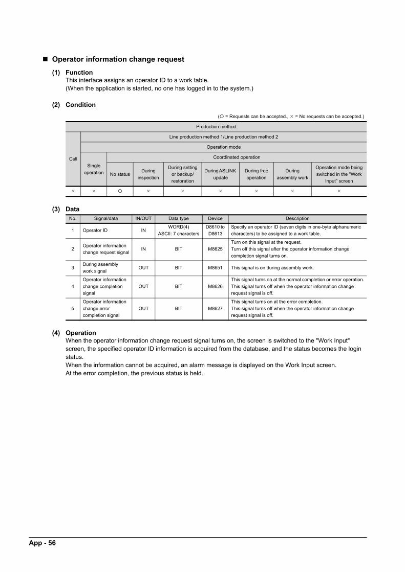
App - 56
Operator information change request
(1) FunctionThis interface assigns an operator ID to a work table.(When the application is started, no one has logged in to the system.)
(2) Condition
( = Requests can be accepted., = No requests can be accepted.)
Production method
Cell
Line production method 1/Line production method 2
Operation mode
Single
operation
Coordinated operation
No statusDuring
inspection
During setting
or backup/
restoration
During ASLINK
update
During free
operation
During
assembly work
Operation mode being
switched in the "Work
Input" screen
(3) DataNo. Signal/data IN/OUT Data type Device Description
1 Operator ID INWORD(4)
ASCII: 7 characters
D8610 to
D8613
Specify an operator ID (seven digits in one-byte alphanumeric
characters) to be assigned to a work table.
2Operator information
change request signalIN BIT M8625
Turn on this signal at the request.
Turn off this signal after the operator information change
completion signal turns on.
3During assembly
work signalOUT BIT M8651 This signal is on during assembly work.
4
Operator information
change completion
signal
OUT BIT M8626
This signal turns on at the normal completion or error operation.
This signal turns off when the operator information change
request signal is off.
5
Operator information
change error
completion signal
OUT BIT M8627
This signal turns on at the error completion.
This signal turns off when the operator information change
request signal is off.
(4) OperationWhen the operator information change request signal turns on, the screen is switched to the "Work Input" screen, the specified operator ID information is acquired from the database, and the status becomes the login status.When the information cannot be acquired, an alarm message is displayed on the Work Input screen.At the error completion, the previous status is held.

A
AP
PE
ND
ICE
S
(5) Timing chart
POINTPOINTPOINT
• The operator that has logged in to the system is forcibly logged out and the specified operator ID is used to log in to the system.
• Specifying "NULL" to the operator ID clears the operator information and logs out the operator that has logged in to the system.
• Specifying the following operator ID allows the operator to log in to the system without accessing the database.
No. Operator ID Type of user Skill Operator name
1 FFFFFFF Manager Skillful User001
2 FFFFFFE Manager Ordinary User002
3 FFFFFEF Operator Skillful User003
4 FFFFFEE Operator Ordinary User004
Normal completion
External system setting Operator ID
External system setting Operator information change request signal
Application setting During assembly work signal
Application setting Operator information change completion signal
Application setting Operator information change error completion signal
Error completion (No corresponding data)
External system setting Operator ID
External system setting Operator information change request signal
Application setting Operator information change completion signal
Application setting Operator information change error completion signal
Acquiring data from the database is attempted.↓
Acquisition error (No corresponding data)
App - 57

App - 58
Assembly information change request
(1) FunctionThis interface assigns assembly work step information to a work table.(When the application is started, no information is assigned to work tables.)
(2) Condition
( = Requests can be accepted., = No requests can be accepted.)
Production method
Cell
Line production method 1/Line production method 2
Operation mode
Single
operation
Coordinated operation
No statusDuring
inspection
During setting
or backup/
restoration
During ASLINK
update
During free
operation
During
assembly work
Operation mode being
switched in the "Work
Input" screen
(3) Data
(a) Line production method 1
(b) Line production method 2
No. Signal/data IN/OUT Data type Device Description
1 Order No. INWORD(7)
ASCII: 13 characters
D8616 to
D8622
Specify an order number (13 digits in one-byte
alphanumeric characters) to be assigned to a work table.
2During assembly work
signalOUT BIT M8651 This signal is on during assembly work.
3Assembly information
change request signalIN BIT M8630
Turn on this signal at the request.
Turn off this signal after the assembly information
change completion signal turns on.
4Assembly information
change completion signalOUT BIT M8631
This signal turns on at the normal completion or error
operation.
This signal turns off when the assembly information
change request signal is off.
5
Assembly information
change error completion
signal
OUT BIT M8632
This signal turns on at the error completion.
This signal turns off when the assembly information
change request signal is off.
No. Signal/data IN/OUT Data type Device Description
1 Control No. INWORD(16)
ASCII: 32 characters
D8623 to
D8638
Specify a control number (32 digits in one-byte
alphanumeric characters) to be assigned to a work table.
2 Sub No. INWORD(1)
ASCII: 2 charactersD8639
Specify a sub number (two digits in one-byte
alphanumeric characters) to be assigned to a work table.
3During assembly work
signalOUT BIT M8651 This signal is on during assembly work.
4Assembly information
change request signalIN BIT M8630
Turn on this signal at the request.
Turn off this signal after the assembly information
change completion signal turns on.
5Assembly information
change completion signalOUT BIT M8631
This signal turns on at the normal completion or error
operation.
This signal turns off when the assembly information
change request signal is off.
6
Assembly information
change error completion
signal
OUT BIT M8632
This signal turns on at the error completion.
This signal turns off when the assembly information
change request signal is off.

A
ICE
S
(4) OperationWhen the assembly information change request signal turns on, the screen is switched to the "Work Input" screen and the information of the specified order No. or control No./sub No. is acquired from the database and registered in the work table.When the information has been registered, the existing information is overwritten with the new information.When no corresponding data is found in the database, the existing information is cleared.At the error completion, the previous status is held.
AP
PE
ND
(5) Timing chartFor line production method 1
External system setting Order No.
Application setting During assembly work signal
External system setting Assembly information change request signal
Application setting Assembly information change completion signal
Application setting Assembly information change error completion signal
For line production method 2
External system setting Control No.
External system setting Sub No.
Application setting During assembly work signal
External system setting Assembly information change request signal
Application setting Assembly information change completion signal
Application setting Assembly information change error completion signal
App - 59

App - 60
External additional information registration request
(1) FunctionThis interface registers the ID No., external additional information, and order number to the database.(When the application is started, they have not been registered.)
(2) Condition
( = Requests can be accepted., = No requests can be accepted.)
Production method
Cell
Line production method 1/Line production method 2
Operation mode
Single
operation
Coordinated operation
No statusDuring
inspection
During setting
or backup/
restoration
During ASLINK
update
During free
operation
During
assembly work
Operation mode being
switched in the "Work
Input" screen
(3) Data
No. Signal/data IN/OUT Data type Device Description
1 ID No. INWORD(16)
ASCII: 32 characters
D8640 to
D8655
Specify an ID No. (32 digits in one-byte alphanumeric
characters) to be registered in the database.
2 External additional information INWORD(16)
ASCII: 32 characters
D8550 to
D8665
Specify the external additional information (32 digits
in one-byte alphanumeric characters) to be
registered in the database. (Specify "NULL" when the
information is not required.)
3 Order No. INWORD(7)
ASCII: 13 characters
D8616 to
D8622
Specify an order number (13 digits in one-byte
alphanumeric characters) to be registered in the
database. (Specify "NULL" when the information is
not required.)
4 During assembly work signal OUT BIT M8651 This signal is on during assembly work.
5External additional information
registration request signalIN BIT M8635
Turn on this signal at the request.
Turn off this signal after the external additional
information registration completion signal turns on.
6External additional information
registration completion signalOUT BIT M8636
This signal turns on at the normal completion or error
operation.
This signal turns off when the external additional
information registration request signal is off.
7
External additional information
registration error completion
signal
OUT BIT M8637
This signal turns on at the error completion.
This signal turns off when the external additional
information registration request signal is off.
(4) OperationWhen the external additional information registration request signal turns on, the screen is switched to the "Work Input" screen and the specified ID No., external additional information, and order number are registered in the database.When the information has been registered, the existing information is overwritten with the new information.At the error completion, the previous status is held.

A
AP
PE
ND
ICE
S
(5) Timing chart
External system setting ID No.
External system setting External additional information
External system setting Order No.
Application setting During assembly work signal
External system setting
Application setting
Application setting External additional information registration error completion signal
External additional information registration completion signal
External additional information registration request signal
App - 61

App - 62
Assembly work start/pause request
(1) FunctionThis interface requests the start/pause of assembly work to a work table.
(2) Condition
( = Requests can be accepted., = No requests can be accepted.)
Production method
Cell
Line production method 1/Line production method 2
Operation mode
Single
operation
Coordinated operation
No statusDuring
inspection
During setting
or backup/
restoration
During ASLINK
update
During free
operation
During
assembly work
Operation mode being
switched in the "Work
Input" screen
(3) Data
*1 Used only when the production method is the line production method 1.
*2 Used only at the work start request.
No. Signal/data IN/OUT Data type Device Description
1 Work start request signal IN BIT M8640
Turn on this signal at the start of the request.
Turn off this signal after the assembly start accept completion
signal turns on.
2Work pause request
signalIN BIT M8641
Turn on this signal at the pause request.
Turn off this signal after the assembly pause accept completion
signal turns on.
3Planned production
quantity*1, *2IN WORD(1) D8656
Specify the planned production quantity (3 digits in one-byte
numerical characters). Users cannot set a value exceeding the
planned quantity registered in the database.
4Work item start request
No.*2IN WORD(1) D8657
Specify a work item No. (3 digits in one-byte numerical characters)
to start.
5 Accept completion signal OUT BIT M8642
This signal turns on at the normal completion or error operation.
This signal turns off when the work start request signal/work
pause request signal is off.
6Accept error completion
signalOUT BIT M8643
This signal turns on at the error completion.
This signal turns off when the work start request signal/work
pause request signal is off.
7 Work ready signal OUT BIT M8650 This signal turns on when the assembly work is ready.
8During assembly work
signalOUT BIT M8651 This signal is on during assembly work.
(4) OperationWhen the work start request signal turns on, the screen is switched to the "Assembly work step" screen and assembly work is started.When the work pause request signal turns on, assembly work is paused and the screen is switched to the "Work Input" screen.At the error completion, the previous status is held.

A
AP
PE
ND
ICE
S
(5) Timing chart
Assembly work start request
External system setting Work start request signal
Application setting Accept completion signal
Application setting Accept error completion signal
Application setting Work ready signal
Application setting During assembly work signal
Assembly work pause request
External system setting Work pause request signal
Application setting Accept completion signal
Application setting Accept error completion signal
Application setting During assembly work signal
Error completion while During assembly work signal is ON
Error completion while Work ready signal is OFF
Error completion while During assembly work signal is OFF
App - 63
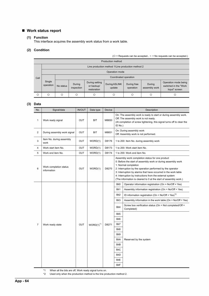
App - 64
Work status report
(1) FunctionThis interface acquires the assembly work status from a work table.
(2) Condition
( = Requests can be accepted., = No requests can be accepted.)
Production method
Cell
Line production method 1/Line production method 2
Operation mode
Single
operation
Coordinated operation
No statusDuring
inspection
During setting
or backup/
restoration
During ASLINK
update
During free
operation
During
assembly work
Operation mode being
switched in the "Work
Input" screen
(3) Data
*1 When all the bits are off, Work ready signal turns on.
*2 Used only when the production method is the line production method 2.
No. Signal/data IN/OUT Data type Device Description
1 Work ready signal OUT BIT M8650
On: The assembly work is ready to start or during assembly work.
Off: The assembly work is not ready.
(At completion of screw tightening, this signal turns off to clear the
ID No.)
2 During assembly work signal OUT BIT M8651On: During assembly work
Off: Assembly work is not performed.
3Item No. during assembly
workOUT WORD(1) D8176 1 to 200: Item No. during assembly work
4 Work start item No. OUT WORD(1) D8173 1 to 200: Work start item No.
5 Work end item No. OUT WORD(1) D8174 1 to 200: Work end item No.
6Work completion status
informationOUT WORD(1) D8270
Assembly work completion status for one product
0: Before the start of assembly work or during assembly work
1: Normal completion
2: Interruption by the operation performed by the operator
3: Interruption by alarms that have occurred in the work table
4: Interruption by instructions from the external system
(The information is cleared to 0 at the start of assembly work.)
7 Work ready state OUT WORD(1)*1 D8271
Bit0 Operator information registration (On = No/Off = Yes)
Bit1 Assembly information registration (On = No/Off = Yes)
Bit2 ID information registration (On = No/Off = Yes)*2
Bit3 Assembly information in the work table (On = No/Off = Yes)
Bit4Screw box verification status (On = Not completed/Off =
Completed)
Bit5
Reserved by the system
Bit6
Bit7
Bit8
Bit9
BitA
BitB
BitC
BitD
BitE
BitF

A
Work table status report(1) FunctionThis interface acquires the operating status from a work table.
S
APP
EN
DIC
E
(2) Condition( = Requests can be accepted., = No requests can be accepted.)
Production method
Cell
Line production method 1/Line production method 2
Operation mode
Single
operation
Coordinated operation
No statusDuring
inspection
During setting
or backup/
restoration
During ASLINK
update
During free
operation
During
assembly work
Operation mode being
switched in the "Work
Input" screen
(3) Data
No. Signal/data IN/OUT Data type Device Description
1 Operating status information OUT WORD(1) D8272
Bit0 Operating status (On = Operating/Off = Waiting)
Bit1Inspection status (On = Inspection in progress/Off =
Inspection not in progress)
Bit2Free operation status (On = Free operation in
progress/Off = Free operation not in progress)
Bit3Setting status (On = Setting in progress/Off = Setting
not in progress)
Bit4
Reserved by the systemBit5
Bit6
Bit7Major alarm status (On = Occurred/Off = Not
occurred)
Bit8Medium alarm status (On = Occurred/Off = Not
occurred)
Bit9Minor alarm status (On = Occurred/Off = Not
occurred)
BitA
Reserved by the system
BitB
BitC
BitD
BitE
BitF
App - 65

App - 66
Work table alarm reset request
(1) FunctionThis interface resets the alarms (except for system alarms) that have occurred in the work table.
(2) Condition
( = Requests can be accepted., = No requests can be accepted.)
Production method
Cell
Line production method 1/Line production method 2
Operation mode
Single
operation
Coordinated operation
No statusDuring
inspection
During setting
or backup/
restoration
During ASLINK
update
During free
operation
During
assembly work
Operation mode being
switched in the "Work
Input" screen
(3) Data
No. Signal/data IN/OUT Data type Device Description
1 Alarm reset request signal IN BIT M8645 Turn on this signal at the request.
2 Reset accept signal OUT BIT M8646 This signal turns on when the request is accepted.
(4) OperationTurning on the alarm reset request signal resets the alarms that have occurred in the work table.
(5) Timing chart
POINTPOINTPOINT
Alarms that cannot be cleared by the alarm reset operation may have occurred even when the completion signal is on.
External system setting Alarm reset request signal
Application setting Reset accept signal

A
AP
PE
ND
ICE
S
Appendix.5.3 Operation image
The following figures show the images of the operation when this application is used with the external interfaces.
(1) Timing chart of when the work is started
Work table Work table Work table Work table
<No workpiece> Workpiece to be assembled Workpiece to be assembled Workpiece to be assembled
GOT
Waiting
GOTGOT
Waiting
GOT
Waiting During assembly work
During assembly work
Work table status
1) Waiting for workpieces 2) Waiting for the start of work 3) During assembly work 4) Waiting for workpieces to be transported
External system setting Control No.
External system setting Sub No.
External system setting ID No.
External system setting External additional information
External system setting Order No.
External system setting Work item start request No.
External system setting
Application setting
Application setting
External system setting
Application setting
During assembly work
Application setting Work ready signal
External system setting Work start request signal
Application setting During assembly work signal
Application setting
Application setting
During assembly work
Work table Work table Work table Work table
<No workpiece> Workpiece to be assembled Workpiece to be assembled Workpiece to be assembled
GOT
Waiting
GOT
Waiting
GOT
Waiting During assembly work
1) Waiting for workpieces 2) Waiting for the start of work 3) During assembly work 4) Waiting for workpieces to be transported
Assembly request
Assembly work error completion signal
Assembly work completion signal
External additional information registration completion signal
External additional information registration request signal
Assembly information change error completion signal
Assembly information change completion signal
Assembly information change request signal
External system setting Control No.
External system setting Sub No.
External system setting ID No.
External system setting External additional information
External system setting Order No.
External system setting Work item start request No.
External system setting
Application setting
Application setting
External system setting
Application setting
During assembly work
Application setting Work ready signal
External system setting Work start request signal
Application setting During assembly work signal
Application setting
Application setting Assembly work error completion signal
Assembly work completion signal
External additional information registration completion signal
External additional information registration request signal
Assembly information change error completion signal
Assembly information change completion signal
Assembly information change request signal
App - 67

App - 68
(2) Timing chart of when the work is paused
When the work is paused in the middle
During assembly work
Application setting Work ready signal
External system setting Work start request signal
External system setting Work pause request signal
Application setting During assembly work signal
Application setting Assembly work completion signal
Application setting Assembly work error completion signal
During assembly work
REVISIONS
© 2017 MITSUBISHI ELECTRIC CORPORATION
Revision date Manual number Revision
January 2017 BCN-EP2005-0010-A First edition
This manual confers no industrial property rights or any rights of any other kind, nor does it confer any patent licenses.
Mitsubishi Electric Corporation cannot be held responsible for any problems involving industrial property rights which may
occur as a result of using the contents noted in this manual.

WARRANTYPlease check the following product warranty details before using this Control Package.
(1) Software included in this Control PackageCheck "END-USER SOFTWARE LICENSE AGREEMENT" (BCN-EP2005-0001) included in the package.
(2) Hardware included as a system component of this systemCheck the product warranty details of each hardware.
Adobe Reader is either a registered trademark or a trademark of Adobe Systems Incorporated in the United States and
other countries.
Anywire, AnyWireASLINK, and POKAYOKE terminal are either registered trademarks or trademarks of Anywire
Corporation.
Ethernet is a registered trademark of Fuji Xerox Co., Ltd. in Japan.
Microsoft, Microsoft Excel, SQL Server, and Windows are either registered trademarks or trademarks of Microsoft
Corporation in the United States and other countries.
QR Code is either a registered trademark or a trademark of DENSO WAVE INCORPORATED in the United States, Japan,
and other countries.
The SD and SDHC logos are trademarks of SD-3C, LLC.
All other company names, system names, and product names used in this manual are generally
either registered trademarks or trademarks of their respective companies.
The trademark symbols (™, ®) may not be described in this manual.


BCN-EP2005-0010-A(1701)CDS
Specifications subject to change without notice.
When exported from Japan, this manual does not require application to theMinistry of Economy, Trade and Industry for service transaction permission.