KP-M20/M30 - AV-iQ
22
KP-M20/M30 B/W CCD Camera Operation Guide
-
Upload
khangminh22 -
Category
Documents
-
view
0 -
download
0
Transcript of KP-M20/M30 - AV-iQ

KP-M20/M30 B/W CCD Camera Operation Guide

Table of Contents
1. General 1 ・・・・・・・・・・・・・・・・・・・・・・・・・・・・・・・・・・・・・・・・・・・・・・・・・・・・・
・・・・・・・・・・・・・・・・・・・・・・・・・・・・・・・・・・・・・・・・・・・・・・・・・
・・・・・・・・・・・・・・・・・・・・・・・・・・・・・・・・・・・・・・・・・・・・・・・
・・・・・・・・・・・・・・・・・・・・・・・・・・・・・・・・・・・・・・・・・・・・・・・・・・
・・・・・・・・・・・・・・・・・・・・・・・・・・・・・・・・・・・・・・・・・・・・・・・・・
・・・・・・・・・・・・・・・・・・・・・・・・・・・・・・・・・・・・・・・・・・・・・・・・
・・・・・・・・・・・・・・・・・・・・・・・・・・・・・・・・・・・・・・・・・・・・・・・・
・・・・・・・・・・・・・・・・・・・・・・・・・・・・・・・・・・・・・・・・・・・・・・
・・・・・・・・・・・・・・・・・・・・・・・・・・・・・・・・・・・・・・・・・・・・・・・
・・・・・・・・・・・・・・・・・・・・・・・・・・・・・・・・・・・・・・・・・・・・・・・・・・・・・
・・・・・・・・・・・・・・・・・・・・・・・・・・・・・・・・・・・・・・・・・・・・・・・
・・・・・・・・・・・・・・・・・・・
2. Composition 1
3. Specifications 1
4. Adjustment 3
5. Timing chart 5
6. External view 10
7. External sync 11
8. Connect cables 12
9. Optical system 13
10. Optional 14
11. Notes to users 17
Attachment : Spectral sensitivity characteristic 19

1. General
The KP-M20/M30 are compact, lightweight, black and white cameras. The KP-M20 uses the
atest high grade 1/2-inch image size CCD and the KP-M30 uses the high grade 1/3-inch image
size CCD. The total pixel number of each CCD is 410,000(490,000 for CCIR).
Type: KP-M20N:EIA
KP-M20P:CCIR
KP-M30N:EIA
KP-M30P:CCIR
2. Composition
1) Black and white camera (With IR cut filter) 1 ・・・・・・・・・・
・・・・・・・・・・・・・・・・・・・・・・・・・・・・・・・・・・・・・
・・・・・・・・・・・・
・・・・・・・・
・・・・・・・・・・・・・・・・
・・・・
・・・・・・・・・・・・・・
・・・・・・・・・・・・・・・・・・
・・・・・・・・・・・・・・・・
・・・・・・
・・・・・・・・
・・・・・・・・
・・・・・・・・・・・・・・・
2) Operation manual 1
3. Specifications
(1) Imaging device Interline CCD No. of total pixels KP-M20N/M30N EIA :811(H)×508(V)
KP-M20P/M30P CCIR:795(H)×596(V)
Pixel size KP-M20N EIA:8.4(H)×9.8(V)μm
KP-M20P CCIR:8.6(H)×8.3(V)μm
KP-M30N EIA:6.35(H)×7.4(V)μm
KP-M30P CCIR:6.5(H)×6.25(V)μm
No. of effective pixels KP-M20N/M30N EIA :768(H)×494(V)
KP-M20P/M30P CCIR:752(H)×582(V)
(2) Sensing area KP-M20N EIA :6.45(H)×4.84mm(1/2 inch size)
KP-M20P CCIR:6.47(H)×4.83mm(1/2 inch size)
KP-M30N EIA :4.88(H)×3.66mm(1/3 inch size)
KP-M30P CCIR:4.89(H)×3.64mm(1/3 inch size)
(3) TV format EIA/CCIR
(4) Lens mount C-mount
(5) Flange focal distance 17.526mm(Not adjustable)
(6) Hor. Scanning freq. EIA:15.734KHz CCIR:15.625KHz
(7) Vert. Scanning freq. EIA:59.94Hz CCIR:50Hz
(8) Sync system Internal/external (automatic switching)
1

(9) Internal synchronization scanning system
2:1 interlaced
3. Specifications
The horizontal number: 525 lines (CCIR: 625lines)
fV=2fH/525 (CCIR: 625 lines)
(10) External synchronization I/O External switch selection. Set to Input at the factory.
Input: HD/VD 4~6Vp-p Negative Frequency deviation: ±1%
Impedance: 75 Ω or high impedance. (Switch selection)
Output: HD/VD 4~5Vp-p Negative
Impedance: 100Ω
(11) Video output 1.0Vp-p 75Ω unbalanced ・・・・・・・・・・・・・
・・・・・・・・・・・・・・・
・・・・・・・・・・・・・・・
・・・・・・・・・
・・・・・・・・・・・・・・・・・・・・・・
・・・・・・・・
・・・・・・・・・
・・・・・・・・・・・・・・・・・・
・・・・・・・・・・・
・・・・・・
・・・・・
・・・・・・・・・・・・・・
・・・・・・・・
・・・・・・・・・・・・・・・・
・・・・・・・・・・・・・・・・・・・・・・・
Video component: 0.7Vp-p
Sync component: 0.3Vp-p Negative
(12) Resolution EIA: 570 TV lines (H) /485TV lines (V) CCIR: 560 TV lines (H) /575TV lines (V)
(13) Sensitivity 200Lx,F4 3200K Min Gain
(14) Min. illumination 0.3Lx,F1.4 AGC, Gamma ON
(15) S/N 60dB Min Gain
(16) Electronic shutter 1/10000s, 1/4000s, 1/2000s, 1/1000s, 1/500s, 1/250s, 1/120s(CCIR),
1/100s(EIA), 1/60s(EIA), 1/50s(CCIR)
OFF: Normal exposure
External switch can be set. The Factory setting is OFF.
(17) Integration mode Field or frame External switch can be set.
The Factory setting is Frame.
(18) Gamma Gamma=1.0 or correction External switch can be set. The Factory setting is Gamma=1.0.
(19) Gain selection AGC or Manual Gain setting External switch setting The Factory setting is Manual Gain.
(20) Power requirement DC12V±1V
(21) Power consumption 1.4W approx. (22) Ambient temperature and humidity Operating: -10~50 RH90% or less
Storage: -20~60 RH70% or less
Caution : For continued stable operation, the camera should be used under 40 or less when it is used continuously for extended period of time.
(23) Anti-vibration 98m/s2 (10 to 60Hz,amplitude: 0.98mm
constant 60 to 200Hz amplitude: variable)
(10 to 150Hz sweep: 1min, XYZ, 30min.)
(24) Resistance to shock 686 m/s2 (Drop test, once each top, bottom, left and right) (25) Dimensions 29(W)×29(H)×38.5(D)mm
(26) Mass 55g approx. 2
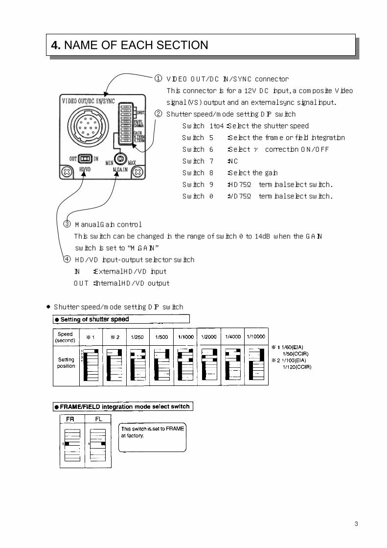
4. NAME OF EACH SECTION
① VIDEO OUT/DC IN/SYNC connector
This connector is for a 12V DC input, a composite Video
signal (VS) output and an external sync signal input.
② Shutter speed/mode setting DIP switch
Switch 1to4:Select the shutter speed
Switch 5 :Select the frame or field integration
Switch 6 :Select γ correction ON/OFF
Switch 7 :NC
Switch 8 :Select the gain
Switch 9 :HD75Ω terminal select switch.
Switch 0 :VD75Ω terminal select switch.
③ Manual Gain control
This switch can be changed in the range of switch 0 to 14dB when the GAIN
switch is set to “M.GAIN” ④ HD/VD input-output selector switch
IN :External HD/VD input
OUT :Internal HD/VD output
Shutter speed/mode setting DIP switch
3

4. NAME OF EACH SECTION
4

5. Timing chart
HD
91
140
7722
311
756
140
B1
B40
D1
D18B1B2
B1
B40
69.8
4nse
c
Optically
black
H register
transfar stop Dummy
H register
Photosensing period
768
H B
LK15
4 (1
0.76
us)
211.
48us
704.
93us
635.
36us
756
Output video period
63.5
us91
0
CCD pixel and
Hregister array
CCD output signal
Composit video signal
KP-M20N/M30NCCD OUTPUT WAVE TIMING CHART
B3
811
5

5. Timing chart
91
140
9122
310
741
140
B1
B40
D1
D18B1B2
B1
B40
70.4
8nse
c75
2
H B
LK16
7 (1
1.77
us)
211.
48us
704.
93us
765.
36us
741
64us
908B3
795
HD
KP-M20P/M30PCCD OUTPUT WAVE TIMING CHART
CCD pixel and
Hregister array
CCD output signal
Composit video signal
Optically
black
H register
transfar stop
Dummy
H register
Photosensing period
Output video period
6

5. Timing chart
11H
9H
KP-M20N/M30N Timing Chart
Video out
VD
BLK
494
492
5
3
1
11
9
7
17
15
13
21
19
CCD out
68
1
20H
HD
490
488
23
25
27
[ODD Field]
XSG
CCD Read out
10H+42.3uS
486
7

8
11H
9H
KP-M20N/M30N Timing Chart
Video out
VD
BLK
493
CCD out
20H
HD
491
489
6
4
2
12
10
8
18
16
14
22
20
24
[EVEN Field]
26
68
2
XSG
CCD Read out
9.5H+47.4uS
487
5. Timing chart

9
17.5H
7.5H
KP-M20P/M30P Timing Chart
Video out
VD
BLK
582
CCD out
25H
HD
580
578
[ODD Field]
614
1
5
3
1
11
9
7
17
15
13
XSG
CCD Read out
14.5H+43.5uS
5. Timing chart

10
5. Timing chart
17.5H
7.5H
KP-M20P/M30P Timing Chart
Video out
VD
BLK
581
CCD out
614
2
25H
HD
579
577
[EVEN Field]
6
4
2
12
10
8
18
16
14
XSG
CCD Read out
14H+48.6uS

6. External View
11
Mass:approx. 55g
Color:BLACK

When operating the camera by external drives signals, connect sync drive signals (HD, VD) to the DC
IN l sync mode to the external
sync mode.
Horizontal and vertical drive signal inputs
CCIR: f(V) = 50 Hz (f(V) = f(H) ÷ 312.5)
V I
12
/SYNC connector, then the mode is automatically switched from the interna
HD EIA: f(H) = 15.734 kHz ±1 % CCIR: f(H) = 15.625 kHz ±1 %
VD EIA: f(V) = 59.94 Hz (f(V) = f(H) ÷ 262.5)
Input level HD 4 to 6 Vp-p negative
D 4 to 6 Vp-p negative
nput impedance 1 kΩ
7. External synchronization (2:1 interlaced)
T=1/f(H)
Vertical drive signal (VD) HD)
Set HD and VD fallings edges to the same phase (0 ± 5 µs)
HD and VD phase relationship
Horizontal drive signal (
Drive signal input waveform
VD
HD
Approx. 6.7 s
2~6Vp-p
µ Approx. 0.6ms(EIA); 0.5ms(CCIR)
2~6Vp-p
T=1/f(V)

HD/VD
8. CONNECTION OF OPTIONS
Signal connection to DC IN/SYNC connector.
Signal connection to each pin
PIN NO. Internal sync mode External sync mode
1 GND GND
2 +12V +12V
3 VIDEO(GND) VIDEO(GND)
4 VIDEO(Signal) VIDEO(Signal)
5 - H D(GND)
6 (H ) HD l) D OUT (Signa
7 (V ) VD l) D OUT (Signa
8 - GND
9 - -
10 - -
11 - -
12 - VD(GND)
13

1)Flange focal ・ Image size: 1/3-inch ・ The flange focal distance is 17.526mm(in air).
Note: rface of the lens to the end of the screw side is
8mm or less.
2) Optical filler
IR cut filter removal a) Remove two screb) Remove the IR cuc) Reinstall and secu Caution Prior to removing
* e focal poiW
・ Flange focal distance cannot be adjusted.
Select such a lens as the length (A) from the flange su
This camera is provided with an IR cut filter.
IR cut filter IRC65 Dimensions: 14 x Part code: XMD0
9. Optical system
The flange will recommend th
(1)
ws (1) shown in Fig., and filter holder (2) will come off. t filter (3) from filter frame (4). re filter holder (2) with two screws (1).
the optical filter, be sure to turn off the power.
nt shortens by about 0.3mm when IR cutting filter is removed.
14
0 12 x 1.0t 006
e dummy glass of the optional to be installed.
(2) (3)
(4)

1)Tripod adaptor TA-F30 (23885AX)
2)12-pin plug HR10A-10P-12S(01) Product code: 23810AX
15
3)Junction box JU-F30 Product code: 23884AX
10. Optional
1 2 3 4 5 6
7 8
9 10 12 11
Viewed from this side

4)Dummy glass ARC1214 Parts code: XMD0009
5)Camera cables
Mould type Assy type Shielded type
2m C-201KSM(23861AX) C-201KS(23856AX) C-201KSS(23872AX)
5m C-501KSM(23862AX) C-501KS(23857AX) C-501KSS(23873AX)
10m C-102KSM(23863AX) C-102KS(23858AX) C-102KSS(23874AX)
Specify assembly or shielded type at time of order.
(): Product code
・Voltage drop due to a cable is about 0.01V per meter.
・The H phase delays by about 5ns per meter.
・ Attenuation of video signal due to used cable Attenuation due to optional cables C-501KSM and C-102KSM is shown below. Attenuation is proportionate to the cable length. Characteristic impedance is kept at constant even at cable length change.
Cable Attenuation at 4MHz Attenuation at 7MHz
70dB/Km
Attenuation at
12MHz
90dB/Km
10. Optional
1 2 3 4 5 6
7 8
9 10 12 11
(RED) WHT YEL (ORN)
(WHT)
(BLK)
BRN GRY
BLU YEL
YEL
WHT
length 50dB/Km
1m 0.05 0.07 0.09
2m 0.1 0.14 0.18
5m 0.25 0.35 0.45
Attenuation due
to cable length(dB)
10m 0.5 0.7 0.9
The video bandwid 20/M30is up to approximately 12.5 MHz.
16
th obtained by the KP-M

11. Notes to users
Co pply.
Us e.
Pr ower cable are correct ,
referring to the connection diagram
To protect CCD (sensor)
Do not touch the glass surface of the CCD sensor to avoid det on in picture q
and s
If the glass surface of the sensor should become dusty or dirty , remove dust or di lly with a
cotton-tipped applicator. Do not wipe the surface with dry clo per tissue to avoid possible
Protection of camera
Do not use or store the camera under direct sunlight , at a place exposed to rain or snow , or at a
place where flammable or corrosive gas is present.
When housing the camera in a camera case , use the utmost care regarding rise of internal
temperature.
hen casing the camera , the temperature normally rises by 10 to 20 , compared with the outside air
temperature. The camera operates in the temperature range from -5 to 45. If the camera is used
or left in high temperature environment for hours , the life of the camera may be shortened.
Do not drop the camera. Do not apply strong shock or vibration to the camera.
Before connecting or disconnecting a connector , turn off the camera and be sure to hold connector
body to connect or disconnect the connector.
Mutual interference noise can occur if multiple cameras are arranged in close proximity. Separate
the cameras to the extent possible.
are installed directly into other equipment , external noise can prevent a normal
ample care when installing and arranging.
regions using 50 Hz power line frequency , flicker can appear on the monitor screen from light
nt or mercury. In such cases , release the auto electronic shutter.
17
Power supply
nnect a 12V DC voltage (11 to 13V) from an external regulated DC power su
e a stable power supply without ripple and nois
ior to turning on the power switch , check that the polarities of the p
eriorati uality due to dirt
cratches.
rt carefu
th or pa
damage to the glass surface by static electricity.
W
Camera arrangement
When camera units
picture. In such cases , shield the camera units.
The camera can be damaged by static electricity. Use
Auto electric shutter
In
sources such as fluoresce

11. Notes to users
Phenomena inherent to CCD imaging device
oming
In through
ntire
of camera , the more this fixed pattern noise appears.
hen fine patterns are shot , moire may be displayed.
he CE mark is required when exporting to Europe. Obtain the necessary authorization for the
ustomer’s system. Enclose the camera in a shielded case and use shielded cable.
18
Following are phenomena inherent to a CCD imaging device , and not defects.
Smear and blo
When strong light (lamp , fluorescent lamp , reflected light , etc.) is shot , pale bands are displayed
vertically above and below the light.
this case , change the angle of the camera so that such strong light does not enter the camera
the lens.
Fixed pattern noise
When the camera is operated in a high temperature , fixed pattern noise may appear on the e
screen.
The higher the sensitivity
Moire
W
T
c

Spectral sensitivity (typical example)
P-M30
19
KP-M20
K

Caution
The specifications of this equipment are subject to change without notice for improvement.
placing your order , be sure to confirm that these specifications are the latest ones.
Hitachi Denshi guarantee that the equipment shipped from our factory conforms to the Hitachi
Denshi’s standard warranty conditions and perform quality control within the range necessary to
Perform the warranty.
Prior to
Warranty and After-sales Service 1) The guarantee period is one year after the date of purchase. However, the defects due to
erroneous use or intentional act are excluded.
2) Defect occurring after expiration of the guarantee period will be repaired at cost to the customer if it is possible to restore the intended function.
3) Our standard Warranty scope pertains only to the camera unit. Secondary losses to a user's system, possibly attributable to malfunction of the camera, are outside the scope of this
Warranty. Further, Hitachi bears no liability to reimburse or otherwise compensate for costs
incurred in dismantling and reassembling an affected system.
4) Hitachi bears no liability to reimburse or otherwise compensate for loss or damage to business,software, database or other property possibly attributable to malfunction of the camera.
5) Hitachi Kokusai Electric is not liable for the losses caused when the equipment is used in a system used for business trades, production process, medical fields, crime prevention
applications, etc.
6) The parts used in the equipment have their respective lives. The lives of such parts will be shortened under environments of high temperature or high humidity.
When stable operation is required for a long time, it is recommended to perform periodic
maintenance and inspection every one or two years.