Foglight™ for Exchange 5.6.9 - User and Reference Guide - Dell
Upload
khangminh22Category
view
2download
0
OpenCIM
OpenCIM Offline,OpenCIM Introand
OpenFMS
Computer Integrated Manufacturing
for Industrial Training Applications
Software Version 2.5
User ManualCatalog No. 100094 Rev. C


Copyright 2002 by Intelitek Inc.OpenCIM User ManualCat.# 100094 Rev.CJanuary 2002
All rights reserved. No part of this publication may be stored in a retrieval system, or reproducedin any way, including but not limited to photocopy, photography, magnetic or other recording,without the prior agreement and written permission of the publisher. Program listings may beentered, stored and executed in a computer system, but not reproduced for publication.
This manual is designed to provide information about the OpenCIM, OpenFMS, OpenCIMOffline and OpenCIM Intro systems and software. Every effort has been made to make this bookcomplete and as accurate as possible. However, no warranty of suitability, purpose or fitness ismade or implied. Intelitek Inc. is not liable or responsible to any person or entity for loss ordamage in connection with or stemming from the use of OpenCIM, OpenFMS, OpenCIMOffline, OpenCIM Intro and/or the information contained in this publication
Intelitek Inc. bears no responsibility for errors which may appear in this publication and retainsthe right to make changes to the software and manual without prior notice.
INTELITEK INC.444 East Industrial Park DriveManchester NH 03109-537Tel: (603) 625-8600Fax: (603) 625-2137
e-mail: [email protected]
web site: www.intelitek.com


User Manual OpenCIM0201 Table of Contents
i
Table of Contents
1 Introduction
About CIM.......................................................................................................................... 1-1About OpenCIM................................................................................................................. 1-2About This Manual............................................................................................................. 1-2
How This Manual is Organized ................................................................................ 1-2Who Should Use This Manual ........................................................................................... 1-3
How to Use This Manual .......................................................................................... 1-4
2 System Overview
OpenCIM Description ........................................................................................................ 2-1Unique Features ........................................................................................................ 2-1OpenCIM Additional Software Packages ................................................................. 2-2
Production Operations ........................................................................................................ 2-3OpenCIM Sample Application: The Covered Box ................................................... 2-3
Components of the OpenCIM Cell..................................................................................... 2-4Stations ............................................................................................................................... 2-5Material Flow in the OpenCIM Cell................................................................................... 2-6
Templates .................................................................................................................. 2-8Storage ...................................................................................................................... 2-9ACL Robots and Controllers................................................................................... 2-11Processing Machines............................................................................................... 2-12
CIM Control ..................................................................................................................... 2-12CIM Definition Modules......................................................................................... 2-15The CIM Manager................................................................................................... 2-15The Station Manager............................................................................................... 2-16PC Requirements in OpenCIM ............................................................................... 2-16Graphic Tracking .................................................................................................... 2-18
Device Drivers.................................................................................................................. 2-19ACL Device Driver ................................................................................................. 2-20CNC Machine Device Driver.................................................................................. 2-20PLC Device Driver.................................................................................................. 2-21Quality Control Device Drivers .............................................................................. 2-22
OpenCIM Communication Network ................................................................................ 2-23LAN ........................................................................................................................ 2-23RS232...................................................................................................................... 2-24Inputs/Outputs......................................................................................................... 2-25
Integration......................................................................................................................... 2-25

User Manual OpenCIM0201 Table of Contents
ii
3 Safety
General Safety Rules .......................................................................................................... 3-1Robot and ACL Controller Safety ...................................................................................... 3-2CNC Machine Safety.......................................................................................................... 3-2ASRS Safety....................................................................................................................... 3-3
ASRS Carousel ......................................................................................................... 3-3ASRS2 ....................................................................................................................... 3-3
Conveyor and PLC Safety .................................................................................................. 3-3
4 Installation
Hardware Installation ......................................................................................................... 4-1Conveyor and Pallets................................................................................................. 4-1Robots and Robot Controllers................................................................................... 4-2ASRS......................................................................................................................... 4-2Barcode Reader ......................................................................................................... 4-2Pneumatic Devices.................................................................................................... 4-2Palletizing Racks and Buffers ................................................................................... 4-3Templates .................................................................................................................. 4-3
Wiring................................................................................................................................. 4-3Network..................................................................................................................... 4-3
Software Installation........................................................................................................... 4-4Network Setup........................................................................................................... 4-4Software for CIM Manager PC ................................................................................. 4-5Software for Workstation PCs .................................................................................. 4-7Other Software .......................................................................................................... 4-8ACL Controller Configuration.................................................................................. 4-8
Robot Positions................................................................................................................... 4-9System Check ....................................................................................................................4-10
5 Preparing for Production: CIM Utility Programs
Machine and Process Definitions ....................................................................................... 5-2Machine Definition Form.......................................................................................... 5-2Machine Process Table ............................................................................................. 5-3
Part Definition .................................................................................................................... 5-8Part Definition Form ................................................................................................. 5-9Part Table ................................................................................................................ 5-10
Storage Definition ............................................................................................................ 5-17Storage Manager Form............................................................................................ 5-17Storage Data Table.................................................................................................. 5-18
MRP.................................................................................................................................. 5-22About MRP ............................................................................................................. 5-22About OpenCIM MRP............................................................................................ 5-22Customer Order Form ............................................................................................. 5-23Manufacturing Order Form..................................................................................... 5-25Purchase Order Form .............................................................................................. 5-29

User Manual OpenCIM0201 Table of Contents
iii
Reports.............................................................................................................................. 5-32Part Definition Report............................................................................................. 5-33Subpart Report ........................................................................................................ 5-34Manufacturing Order Report................................................................................... 5-35Machine Report....................................................................................................... 5-36Process Report......................................................................................................... 5-37ASRS Report........................................................................................................... 5-38Analysis Report....................................................................................................... 5-39Location Status Report............................................................................................ 5-40A-Plan Report ......................................................................................................... 5-41Purchase Order Report ............................................................................................ 5-42User-Defined Report ............................................................................................... 5-42
6 Operating the CIM
CIM Manager ..................................................................................................................... 6-2Modes of Operation .................................................................................................. 6-2CIM Manager Control Bar ........................................................................................ 5-3Views ........................................................................................................................ 6-5
CIM Scheduler.................................................................................................................. 6-14Menu Options.......................................................................................................... 6-15How to Create a Planned Production Schedule ...................................................... 6-15
Graphic Display and Tracking.......................................................................................... 6-16Tool Bar of Graphic Display................................................................................... 6-17Views ...................................................................................................................... 6-19
CIM Cell Startup .............................................................................................................. 6-21Operation in Simulation Mode................................................................................ 6-21Operation in Real Mode.......................................................................................... 6-21
7 OpenCIM Setup
Virtual CIM Setup .............................................................................................................. 7-1File Menu .................................................................................................................. 7-1Viewing..................................................................................................................... 7-3Edit Menu: New Object ............................................................................................ 7-4Configuration Parameters ......................................................................................... 7-8Edit Menu: Additional Options............................................................................... 7-13Create Menu............................................................................................................ 7-14View Menu.............................................................................................................. 7-15Limitations .............................................................................................................. 7-15Tutorial.................................................................................................................... 7-15Stage 1: Designing the CIM Cell ............................................................................ 7-16Stage 2: Operating the CIM Cell............................................................................. 7-21
8 OpenCIM Device Drivers
Overview of Device Drivers............................................................................................... 8-1Device Driver Control Panel .............................................................................................. 8-1

User Manual OpenCIM0201 Table of Contents
iv
Modes of Operation............................................................................................................ 8-2Device Driver Loading Options ................................................................................ 8-3
The CNC Device Driver ..................................................................................................... 8-4Running the CNC Device Driver .............................................................................. 8-5Downloading G-Code ............................................................................................... 8-6The CNC Control Panel ............................................................................................ 8-7
The ACL Device Driver ..................................................................................................... 8-9The ACL User Interface.......................................................................................... 8-10Closing the ACL Control Panel .............................................................................. 8-13
Quality Control Device Drivers........................................................................................ 8-14The QC Control Panel............................................................................................. 8-16QC Device Settings................................................................................................. 8-18
ViewFlex Device Driver................................................................................................... 8-20Adjustments ............................................................................................................ 8-20User Interface .......................................................................................................... 8-21Sample Script .......................................................................................................... 8-22
The ULS Device Driver.................................................................................................... 8-23Downloading Print Files ......................................................................................... 8-23User Interface .......................................................................................................... 8-23Control Modes ........................................................................................................ 8-25
The PLC Device Driver .................................................................................................... 8-28PLC Messages......................................................................................................... 8-29The PLC Control Panel ........................................................................................... 8-30Simulating a Conveyor............................................................................................ 8-33
9 OpenCIM Programming
ACL Programming for OpenCIM ...................................................................................... 9-1The Pick-and-Place Strategy ..................................................................................... 9-1Overview of a Pick-and-Place Command................................................................. 9-3Teaching Robot Positions ......................................................................................... 9-4Writing ACL Source Code........................................................................................ 9-6QC Programs........................................................................................................... 9-19ACLoff-line Utilities............................................................................................... 9-21Adding a New Pick-and-Place Operation ............................................................... 9-24
CNC Programming for OpenCIM .................................................................................... 9-28CNC Script Language ............................................................................................. 9-28CNC Script Language Commands .......................................................................... 9-34
DownloadD() ................................................................................................. 9-34Draw()............................................................................................................ 9-35Draw2().......................................................................................................... 9-36PulsBit()......................................................................................................... 9-37SendMsg() ..................................................................................................... 9-39SetBit()........................................................................................................... 9-40Wait()............................................................................................................. 9-43WaitBit()........................................................................................................ 9-44

User Manual OpenCIM0201 Table of Contents
v
WaitBitZ() ..................................................................................................... 9-46WaitFile()....................................................................................................... 9-48WaitString() ................................................................................................... 9-49SendString()................................................................................................... 9-50MSDOS()....................................................................................................... 9-51MSWINDOWS() ........................................................................................... 9-51ABORT() ....................................................................................................... 9-52
Interfacing a Robot with a CNC machine......................................................................... 9-53Writing ACL Programs that Talk to a CNC Machine............................................. 9-55One Robot Tending Two Machines ........................................................................ 9-61ACL Controller Backup and Restore ...................................................................... 9-61
Optimizing the Scheduling in OpenCIM.......................................................................... 9-63Benefits of the Optimization Approach .................................................................. 9-67
Experimenting with Production Strategies Using the A-Plan .......................................... 9-68A-Plan Commands .................................................................................................. 9-68
10 Inside OpenCIM
OpenCIM Loader: DD Loader.EXE................................................................................. 10-1Loader Command Lines .......................................................................................... 10-2
OpenCIM Directory Structure .......................................................................................... 10-4MAP.INI ......................................................................................................................... 10-12SETUP.CIM ................................................................................................................... 10-14DEVICE.DMC ............................................................................................................... 10-17INI Files .......................................................................................................................... 10-18VC2_WM.DBF .............................................................................................................. 10-29OpenCIM Database Structure......................................................................................... 10-31Application to Report File Cross Reference................................................................... 10-37Software Backup............................................................................................................. 10-38
11 Errors and Troubleshooting
Device Error Handling...................................................................................................... 11-1Where the Problem Occurred ........................................................................................... 11-2What the Problem Is ......................................................................................................... 11-2How To Proceed ............................................................................................................... 11-3
How to Recover a Failed Device ............................................................................ 11-4Troubleshooting................................................................................................................ 11-5Error Messages ................................................................................................................. 11-8Contacting Technical Support ........................................................................................ 11-13
12 Glossary
Abbreviations ................................................................................................................... 12-1Terminology ..................................................................................................................... 12-3
13 Intelitek Software Licensing


User Manual 1-1 OpenCIM0201 Introduction
1
Introduction
About CIMTo stay competitive, factories are increasingly automating their production lines with ComputerIntegrated Manufacturing (CIM) systems. A CIM cell is an automated assembly line that uses anetwork of computers to control robots, production machines, and quality control devices. TheCIM cell can be programmed to produce custom parts and products.
CIM provides many advantages:
• Computer integration of information gives all departments of a factory rapid access to thesame production data.
• Accessibility of production data results in faster response to change, which in turn shortenslead times, increases the company’s responsiveness to customer demands and competition,and improves due-date reliability.
• Computer aided scheduling optimizes the use of the shop floor. This improves theutilization of machine tools, and reduces work-in-progress and lead times.
• Real-time production data can be used to optimize the production processes to improvequality, using techniques such as statistical process control.
• Computer analysis and prediction of material requirements for production can reduceinventory levels and lead times. Integration with suppliers and customers can provide evengreater benefits.
• Downloading machining instructions, including tool changes, from CAM (computer aidedmanufacturing) systems to CNC machines (computer numerically controlled) reducesmachine setup times and increases machine utilization.
The trend among manufacturers today is to produce smaller batches of more varied products.Without CIM automation, this trend would result in higher costs associated with increasedsetup time and additional labor.
There is a shortage of qualified CIM technicians and engineers. Manufacturers demandgraduates who understand the integration of all elements of a CIM. Intelitek’sOpenCIM system addresses this need by providing an industrial-level training system for theeducational environment.

User Manual 1-2 OpenCIMIntroduction 0201
About OpenCIMOpenCIM is a system which teaches students the principles of automated production usingrobotics, computers, and CNC machines. It also allows advanced users to search for optimalproduction techniques by experimenting with different production techniques.
OpenCIM offers a simulation mode in which different production strategies can be testedwithout actually operating the CIM equipment.
OpenCIM provides a realistic, expandable environment through interfaces to third partyhardware (CNC machines, robots, peripheral equipment, etc.). Students can learn first-handhow other disciplines such as Production Scheduling, Manufacturing Resource Planning(MRP), Order Entry Systems, and Database Management Systems (Xbase) can be used tooptimize the production process.
In this version of OpenCIM, three additional OpenCIM products are also available:
• OpenFMS – for a small CIM system which may include a single robot and one or two CNCmachines.
• OpenCIM Offline – a simulation only version of OpenCIM.
• OpenCIM Intro – an offline version which does not include the Setup Module.
About This ManualThis manual is a complete reference guide to the OpenCIM system. It explains how to install,configure and operate the OpenCIM software. Indications as to which information is notrelevant to the additional OpenCIM products are provided in the appropriate sections.
This manual includes complete details on how to produce custom parts, add your owncomputer-controlled equipment, and how to interface with other software.
How This Manual is Organized
Chapter 1 Introduction to OpenCIM and this User Manual.
Chapter 2 Overview of the OpenCIM system and software.
Chapter 3 Safety.
Chapter 4 Installation of the OpenCIM hardware and software.
Chapter 5 Preparation for Production: OpenCIM modules:MRP (Customer, Manufacturing and Purchase Orders), Part Definition,Storage Definition, Machine Definition.
Chapter 6 Operating the System: OpenCIM modules:CIM Manager, CIM Scheduler, Graphic Display and Tracking.
Chapter 7 OpenCIM Setup: Virtual CIM Setup module.(Not applicable to OpenCIM Intro.)
Chapter 8 OpenCIM Device Drivers.(Not applicable to OpenCIM Offline and OpenCIM Intro.)
User Manual 1-3 OpenCIM0201 Introduction
Chapter 9 OpenCIM Programming.
Chapter 10 Inside OpenCIM: Software and File information.
Chapter 11 Troubleshooting.
Chapter 12 Glossary.
Chapter 13 Intelitek Software Licensing.
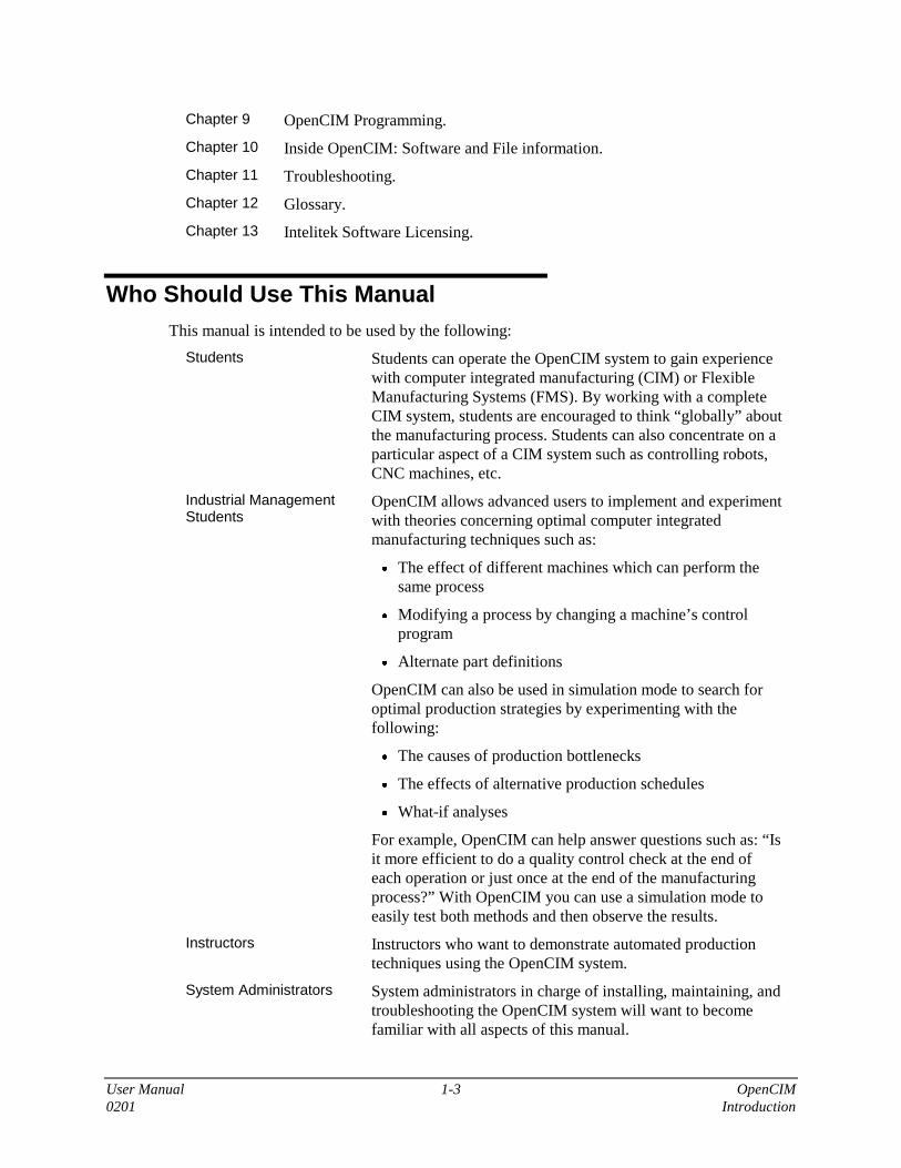
Who Should Use This ManualThis manual is intended to be used by the following:
Students Students can operate the OpenCIM system to gain experiencewith computer integrated manufacturing (CIM) or FlexibleManufacturing Systems (FMS). By working with a completeCIM system, students are encouraged to think “globally” aboutthe manufacturing process. Students can also concentrate on aparticular aspect of a CIM system such as controlling robots,CNC machines, etc.
Industrial ManagementStudents
OpenCIM allows advanced users to implement and experimentwith theories concerning optimal computer integratedmanufacturing techniques such as:
• The effect of different machines which can perform thesame process
• Modifying a process by changing a machine’s controlprogram
• Alternate part definitions
OpenCIM can also be used in simulation mode to search foroptimal production strategies by experimenting with thefollowing:
• The causes of production bottlenecks
• The effects of alternative production schedules
• What-if analyses
For example, OpenCIM can help answer questions such as: “Isit more efficient to do a quality control check at the end ofeach operation or just once at the end of the manufacturingprocess?” With OpenCIM you can use a simulation mode toeasily test both methods and then observe the results.
Instructors Instructors who want to demonstrate automated productiontechniques using the OpenCIM system.
System Administrators System administrators in charge of installing, maintaining, andtroubleshooting the OpenCIM system will want to becomefamiliar with all aspects of this manual.

User Manual 1-4 OpenCIMIntroduction 0201
How to Use This ManualThe OpenCIM software can be operated and used fully without OpenCIM hardware. Therefore,the emphasis in this manual is placed on the use of the software.
This manual assumes all users are familiar with the following topics:
• Safety and basic operating procedures associated with robots, CNC machines, and all otherequipment in the CIM environment.
• Basic operation of MS-Windows.
System administrators and advanced users should be familiar with the following topics:
• Robotic programming using the ACL language
• Controlling and operating machines (e.g., CNCs)
• RS232 communications
• PC LAN administration, operation, and troubleshooting
• Setting up programmable logic controllers (PLCs)
Even if you will not be using the software in conjunction with an actual OpenCIM system, allusers should read the background information in Chapters 1 and 2, and the safety guidelines inChapter 3.
The installation instructions in Chapter 4 are intended for instructors and technical personnelwho will be handling software and hardware installation.
Chapters 5 and 6 are organized to help all users begin using the OpenCIM system as quickly aspossible. The material is presented in the order required to prepare and operate theOpenCIM system, and “Procedures” guide you through the basic steps of software operation.
Chapter 7 presents the Virtual CIM module, and teaches you how to set up the CIM by meansof a graphic editor. Chapters 8 and 9 allow advanced users to do their own productionexperiments beyond the scope of the sample applications in order to explore new CIMtechniques. Chapter 10 provides details about the OpenCIM software, files and directorystructure. These chapters provide the information necessary for customizing the OpenCIMenvironment.
Detailed information on error handling and troubleshooting is provided in Chapter 11, whileChapter 12 presents explanations of abbreviations and terminology used in the OpenCIMsystem. The OpenCIM software is protected by a licensing agreement. Full details on Inteliteksoftware licensing are provided in Chapter 13.

User Manual 2-1 OpenCIM0201 System Overview
2
System Overview
This chapter describes the hardware and software components which comprise an OpenCIMcell. It discusses each component individually and also how all components work together.
OpenCIM Description
Unique Features
This section gives the background for understanding what is special about OpenCIM and basicoperations performed in the OpenCIM system.
OpenCIM software provides unique industrial capabilities not found in other educational CIMs:
• OpenCIM “feels” familiar to first-time users because it is based on the standard WindowsGraphic user interface.
• OpenCIM allows for targeted training at a given station or device.
• OpenCIM is realistic because it uses equipment found in actual industrial CIMs.
• OpenCIM resembles industrial CIMs in its ability to grow by using distributed processingat each production station. Distributed processing also makes for a more robust system.Even if the PC performing the central manager function goes down, each machine can stillbe operated in a stand-alone mode.
• OpenCIM uses a sophisticated network of PCs which allows various devices to performmultiple operations simultaneously. This network also allows CIM devices to communicatewith each other.
• OpenCIM provides you with a powerful, yet flexible report generator. This utility programallows you to access nine types of predefined reports or gives you the option of creatingyour own user-defined reports.
• OpenCIM uses the latest object oriented techniques in:
• Defining the CIM Layout: Click on a Graphic object and drag it to the appropriatelocation on the CIM layout screen (e.g. Drag a robot in order to place it beside a CNCmachine).
• Defining an Object’s Properties: Click on an object to set its properties, e.g. the type ofparts a machine can handle.
• Graphic Production Tracking: Uses Graphic objects to simulate CIM operation onscreen.

User Manual 2-2 OpenCIMSystem Overview 0201
• OpenCIM is more comprehensive than other limited function CIMs. It can use a variety ofequipment including:
• A variety of robots
• Processing machines
• Quality control devices (machine vision, laser scan meter, height gauge, CMM, caliper)
• Automated storage and retrieval systems (ASRS)
• Peripheral devices (barcode scanner, X-Y table, electric screwdriver, laser engraver, etc.)
• Custom devices by allowing you to easily set up your own device interfaces
• OpenCIM offers Graphic production tracking allowing you to observe each productionoperation on a central display.
• OpenCIM provides an open environment for advanced users who want to:
• Add their own devices
• Design their own products
• Interface their own software (e.g. MRP and cost analysis)
• Analyze CIM production data
• OpenCIM is a robust system that enables recovery from errors without the need to reset theentire CIM cell.
OpenCIM Additional Software Packages
OpenFMS
OpenFMS is designed for use with flexible manufacturing systems. OpenFMS includes all thesoftware modules and features of OpenCIM, and is intended to support systems with one robottending one or two machines and quality control devices.
The following items are not included in the Virtual FMS Setup module, nor can they beconfigured for online operation.
Included in OpenFMS Not included in OpenFMS
All types of robots
Slidebases, linear conveyors, XY and linearpositioning tables
Closed loop conveyor
ASRS-36 and all smaller storage device andpart feeders
ASRS2 and ASRS carousel
All CNC machines Laser engraver
ViewFlex machine vision system, electroniccalipers, laser scan meter
Coordinate measuring machine, electronicheight gauge, barcode reader
Automatic gluing application;Automatic screw driving application
Hydraulic robot and pressing station;Pneumatic part feeding/sorting station;Process control station

User Manual 2-3 OpenCIM0201 System Overview
OpenCIM Offline
OpenCIM Offline is the simulation version of OpenCIM. The user can design and run anunlimited variety of CIM or FMS cells in simulation mode.
It does not support hardware or online operation.
Device drivers are not included in this package.
OpenCIM Intro
OpenCIM Intro is similar to the OpenCIM Offline package but does not include the VirtualCIM Setup module.
The user can run all the demo CIM systems included in the software and can performmanufacturing management (such as part definition, storage management, MRP, reports), butcannot modify the CIM cell configurations.
Production OperationsThe following operations are performed in the CIM cell when producing a product:
• Supplied parts (raw materials) are loaded into storage locations.
• Manufacturing orders are generated by the CIM Manager or by an external productionscheduling package such as Fourth Shift or MAPICS.
• Parts are removed from the ASRS and transported on the conveyor to production stations.
• Robots take parts from the conveyor and move them to various production machines(e.g. CNC machines) at a station (machine tending).
• Typical production tasks include:
• Processing in a CNC machine
• Assembling two or more parts
• Quality control tests
• Robots return processed parts to the conveyor for transportation to the next station.
• Finished products are removed (unloaded) from the cell.
OpenCIM Sample Application: The Covered Box
The following “Covered Box” sample application is used in this manual to demonstrate theconcepts of the OpenCIM system. The steps shown below are explained in more detail as eachtopic is introduced later in this manual.
The sample application produces a simple, covered box from a small, solid cube and a matchingcover. Each component part is assumed to be in place on a separate template in the ASRS.

User Manual 2-4 OpenCIMSystem Overview 0201
Covered Box
Cube Cover
CNC MillingOperation
AssemblyOperation
Figure 2-1: Part Definition Tree for Sample Application
The following steps detail the process of making a covered box:
1. The ASRS robot takes a solid cube and a cover from a storage cell and places them onseparate pallets on the conveyor.
2. When the cover arrives at the assembly station, the assembly robot places it in a rack untilthe matching box arrives.
3. When the cube arrives at a CNC station, the CNC robot places the cube into a millingmachine. The CNC machine reams out the center of the cube to form a box.
4. The CNC robot places the box on the conveyor.
5. When the box arrives at the assembly station, the robot places it on a rack. When all theparts required for the assembly are on their rack, the robot places the base part (box) on thejig. The robot then retrieves the matching cover from the rack and places it on the box. Therobot places the covered box on the conveyor.
6. When the covered box arrives at the ASRS, the robot places the finished product in astorage cell.
Components of the OpenCIM CellThis section describes the elements of the OpenCIM cell. The topics covered include thephysical configuration of the cell, material flow, control and production devices andcommunication networks. The emphasis is on the role each component plays in the integratedsystem, rather than on providing a detailed description of the component. Later chapters coverOpenCIM software in greater detail. Consult the appropriate user’s manuals for details abouteach hardware component.
CIM cells are composed of the following basic elements:
Conveyor Device that transports parts from station to station.
Production (Work)Stations
Locations around the cell where parts are processed and stored bymachines and robots. Robots move parts between the conveyorand station machines.
CIM Manager The PC that contains the CIM Manager software whichcoordinates the functioning of all devices in the cell using a LAN.
Station Manager A PC that controls the different devices at a station and has acommunication link with the CIM Manager. Device control isperformed by OpenCIM device drivers that run on this PC. Adevice driver controls the operation of a device at the station inresponse to commands from the CIM Manager and other CIMelements.

User Manual 2-5 OpenCIM0201 System Overview
Other Software Tools OpenCIM Modules: Virtual CIM Setup, CIM Manager (withintegrated Part Definition, Machine Definition, StorageDefinition, MRP, Scheduler-Gantt, Reporter, Graphic Trackingmodules).
Third Party Software: Other production related software thatinterfaces to OpenCIM such as Production Scheduling,Manufacturing Resource Planning (MRP and MRP-II), OrderEntry Systems, Data Base Management Systems (Xbase), etc.
Typically, a separate PC is dedicated to running or controlling each of the above elements.While two or more functions can be combined on a PC, the following discussion assumes theuse of dedicated PCs.
StationsThe OpenCIM cell is composed of a set of stations located around a conveyor as shownschematically in the figure below:
Figure 2-2: Schematic Example of an OpenCIM Cell
Each station is controlled by a Station Manager PC. A CIM Manager PC coordinates theactivities of all stations. The number of stations may vary from cell to cell. A typicaleducational OpenCIM cell ranges from up to eight stations arranged around one conveyor to asfew as a single station consisting of a robot tending a machine. The software can be adapted tomore stations and conveyors.

User Manual 2-6 OpenCIMSystem Overview 0201
Production commands are sent from the CIM Manager computer to the device drivers via theStation Manager PC. Status messages generated by devices are interpreted by the device driverand sent back to the CIM Manager.
Just as each industrial cell is an individual application of CIM technology, every OpenCIM cellhas its own configuration. Generally, the following stations are usually found:
ASRS Station Automated Storage and Retrieval System. An automaticwarehouse which supplies raw materials to the OpenCIM cell,stores parts in intermediate stages of production, and holdsfinished products.
Machine Station Station where materials are shaped, formed, or otherwiseprocessed (e.g. using a CNC machine or laser engraver).
Assembly Station A station where parts are put together. The resulting new partis called an assembly. Peripheral equipment and devices at anAssembly Station include an automatic screwdriver, Welder,X-Y table, part feeders, various robot grippers, etc.
QC Station Quality Control. Inspection of parts using machine vision,laser scan meter, height gauge, continuity tester, CMM,caliper or other QC machines.
Various functions may be combined at one station, such as quality control and assembly.
Stations contain devices that perform production activities such as material processing orinspection. The following elements are generally present at a station:
Robot A device which moves parts around a station (e.g. inserts partsinto a CNC machine) and/or performs assembly operations.
Robot Controller For example, an ACL controller which controls the robot andcertain optional peripheral devices (e.g. X-Y table, barcodescanner).
Station Manager PC A Station Manager PC where the device drivers are located that:
• Translate OpenCIM production messages and commandsto/from each station device (e.g. the ACL controller).
• Provide a user interface for controlling station devices bymanually sending OpenCIM commands (e.g. to CNCmachines or an ACL controller).
• Function as a terminal for devices that use an RS232interface for setup and programming (such as the ACLcontroller).
Machine A device that processes parts at a station. CNC machines such aslathes and mills process parts according to user-supplied G-codeprograms.
Robot Peripheral A peripheral device which aids the robot in material handlingtasks (e.g. a linear slidebase that supports a robot, an X-Y table,a tool adapter, various grippers such as pneumatic or suctionmodels, etc.).

User Manual 2-7 OpenCIM0201 System Overview
An example of an OpenCIM cell is shown schematically in the following figure:
Figure 2-3: Sample OpenCIM Cell

User Manual 2-8 OpenCIMSystem Overview 0201
Material Flow in the OpenCIM CellMaterial handling tasks can be divided into two groups:
Primary Material Handling Transportation of parts between stations.
Secondary MaterialHandling
Handling of parts within a station, such as placing a templateon the conveyor, removing a part from a feeder, inserting a partin a CNC machine or assembling parts.
In an OpenCIM cell, the primary material handling tasks are usually performed by theconveyor. A robot (in combination with its peripherals) performs the secondary materialhandling tasks at each station.
When a robot removes a template from the conveyor, it typically places it on a buffer. (A bufferis a tray designed to hold a template when it is removed from the conveyor. The standard bufferis attached to the outer rim of the conveyor.) Once the template is on the buffer, the robot canremove a part from the template and take it to a station device.
The following scenario describes the basic flow of parts within the CIM cell:
• In response to production orders, the CIM Manager issues instructions to release parts fromthe ASRS and move them from station to station for processing.
• A robot at each station takes parts from the conveyor and places them in station machines.
• After a part has been processed at the station, the robot places the part back on theconveyor where it moves to the next station according to its production plan.
Templates
Templates are plastic trays which can hold various types of parts. They allow parts to betransported on the conveyor.
Figure 2-4: An Empty Template
A template contains a matrix of holes in which pins are placed to fit the dimensions of a part.Each arrangement of pins defines a unique template type. Each part may only be held by itsassigned template. The handle, located on top of or in front of the template, facilitates graspingby a robot’s gripper.
An optional barcode sticker on the side of the template shows the template’s ID code. Whenbarcodes are used, a barcode reader can verify the identity of each template inserted or removedfrom the ASRS.

User Manual 2-9 OpenCIM0201 System Overview
Storage
An ASRS station is typically used as the main source of raw material for the cell. The ASRScan also serve as a warehouse for parts in various stages of production. Storage cells in theASRS contain templates, either empty or loaded with parts. A CIM cell may contain anynumber of ASRS stations.
Part feeders can also be used to supply raw materials at various stations around the cell.
The ASRS2 model is specifically designed to work in the OpenCIM environment. This unitcontains a dedicated cartesian robot with an additional rotary axis that moves between two setsof storage racks. Each rack has a set of shelves divided into storage cells that are designed tohold part templates. The robot, which is controlled by a standard ACL Controller-B, movestemplates between the conveyor and storage cells.
Figure 2-5: The ASRS2 Robotic Storage Station
The ASRS carousel is a three-tier rotating warehouse which is tended by a robot, andcontrolled by an ACL controller.
The ASRS36 is a cartesian robot with an additional rotary axis. It has a set of storage racks(divided into six levels with six cells each). The robot, which is controlled by a standard ACLController-A, moves the parts between the shelves and the conveyor.
The ASRS rack has a small number of cells, and is designed for use in a Micro-CIM work cell.

User Manual 2-10 OpenCIMSystem Overview 0201
Conveyor and Pallets
A pallet is a tray which travels on the CIM conveyor and is designed to carry a template. Totransport a part to another station, a robot places the template carrying the part on a pallet onthe conveyor. The OpenCIM conveyor carries pallets in a continuous circuit from station tostation. The conveyor is controlled by a PLC (programmable logic controller).
Each pallet has an ID number which is magnetically encoded in a bar on the pallet. In normalcell operation, each pallet is stopped briefly when it arrives at a station so that its magnetic codecan be read. If the PLC determines that the pallet is needed at this station, it informs the CIMManager. The pallet remains at this station until the CIM Manager sends a release command.While a pallet is stopped, the conveyor continues to transport other pallets which are movingbetween stations.
The location at which a pallet is stopped is called a conveyor station. Each OpenCIM stationhas its own conveyor station, which contains two pneumatically operated pallet stops, amagnetic pallet-arrival sensor, a magnetic pallet-in-place sensor and a set of magneticpallet-code sensors.
Figure 2-6: Pallet at Conveyor Station
Piston stops at each conveyor station can be raised to hold a pallet in place while the conveyorcontinues to cycle past the stations. The PLC controls the operation of these pneumaticallydriven piston stops, using input from pallet detection sensors located at the conveyor station.
The PLC keeps track of pallets which are empty and those which are carrying parts. It sends thedestination station of each pallet to the PLC (default destination for each pallet is #99, allowingthe pallet to continuously circle on the conveyor). Magnetic code readers at each station enablethe PLC to identify the pallet ID numbers. Through a look-up-table the CIM Manager caninstruct the PLC:
If ... Then the PLC stops the pallet if ...
Pallet is empty A template containing a part is ready to be picked up at thisstation.
Pallet carries an emptytemplate
A part with no template needs to be picked up at this station.
Pallet carries a templatewith a part
This part needs to be delivered to this station.
If the part carried by the pallet does not require processing at the station, the pallet is allowed tocontinue on the conveyor.
Even though a pallet may be needed at a station, the CIM Manager may direct the PLC torelease it if the robot that handles templates at this station is busy. Otherwise, a bottleneckcould occur on the conveyor since other pallets would not be able to pass until the robotbecomes available. The PLC would then stop the next appropriate pallet and try again.

User Manual 2-11 OpenCIM0201 System Overview
If the robot is free it is instructed to remove the template containing the part from the pallet andplace it on a station buffer. The empty pallet is then released and can continue on the conveyor,ready to pick up another template.
Conveyor Lights
Red and green lights at each conveyor station indicate the following:
Green On Station is idle waiting for a pallet to arrive.
Red On A pallet has been stopped for use at this station.
Flashing Red An error has been reported at this station by an OpenCIMdevice driver (e.g. robot impact, Emergency button pressed).
Flashing Red at AllStations
All stations have stopped because someone has pressed theEmergency Stop Button.
ACL Robots and Controllers
CIM robots move parts within a station (secondary material handling) and perform assemblyoperations. Robots vary in speed, payload, accuracy, range of movements (degrees of freedom),working envelope (horizontally or vertically articulated), and drive mechanism (DC servo, ACservo or pneumatic).
The following Intelitek robots are capable of performing machine tending and assembly tasks.Each of these robots connects to an ACL controller.
• SCORBOT-ER 5, SCORBOT-ER 5plus
• SCORBOT-ER 7
• SCORBOT-ER 9
• SCORA-ER 14
• PERFORMER-MK3
• Performer-SV3 with Controller-BRC

User Manual 2-12 OpenCIMSystem Overview 0201
Figure 2-7: Robot, Controller, Teach Pendant, and Station Manager PC
The controller for Intelitek robots runs ACL programs which tell the robot what path to followand what to do once it reaches a destination. This controller contains the power supply for therobot. It moves the robot by controlling the power to the motors inside the robot.
The controller is a stand-alone real-time device with multitasking capabilities which allowssimultaneous and independent operation of several ACL programs. This multitasking abilityallows the controller to function as a controller for a robot and peripheral devices (e.g. barcodereader, X-Y table) simultaneously. Peripheral CIM devices connect to the controller’s auxiliaryI/O ports and RS232 ports. All ports (robot, I/O, RS232) can be controlled using ACLprograms.
Processing Machines
Processing machines process parts according to processing programs stored in their memory.The CIM Manager keeps track of the programs that reside in a machine’s memory anddownloads a new program to process an upcoming part as needed.
OpenCIM can interface to machines that use either I/O lines or an RS232 interface to controloperations such as opening/closing a door, turning on/off the machine, etc. Status lines reportinformation, such as whether a door is open or closed and when a process is finished.
CIM ControlTo understand how the OpenCIM cell is controlled, it is necessary to look at its controlelements, the communication channels that each element uses to control the devices, and thenetwork that links the various control elements as an integrated whole.

User Manual 2-13 OpenCIM0201 System Overview
The OpenCIM system consists of various software modules which perform command, control,and monitoring functions:
• Virtual CIM Setup Software
• CIM Manager Software with integrated modules (Storage Definition, Machine Definition,Part Definition, MRP, etc.)
• Device Managers (device drivers located on Station PC)
• Conveyor Manager (PLC device driver located on a Station PC)
• Graphic Tracking (integrated in CIM Manager and/or as external module)
OpenCIM uses a distributed control strategy as follows:
• Each Station Manager PC runs a set of device drivers that control the devices at its station.
• A PLC controls the operation of the conveyor.
• The CIM Manager provides the highest level of control and integrates the activities of theentire cell. It sends command messages to the various device drivers via the network. Theseunits attempt to execute the command and respond with status messages describing theresults.
The following figure illustrates the flow of information in the OpenCIM system.

User Manual 2-14 OpenCIMSystem Overview 0201
Figure 2-8: OpenCIM Software Model - Information Flow

User Manual 2-15 OpenCIM0201 System Overview
CIM Definition Modules
The CIM Manager maintains the OpenCIM database which contains information on thephysical and communication configuration of the cell, inventory of raw materials and parts,manufacturing processes, part definitions, and orders. Interactive software lets you define:
• The layout of machines and stations in the CIM cell.
• Machines and the production processes they can perform
• The bill of materials used to produce each part.
• An order which specifies the parts you want to produce.
• The contents of all storage locations.
The CIM Definition modules also allow you to back up and restore the above information.
The CIM Definition modules are usually run on the same PC used for the CIM Manager. Eachof these modules creates data files in a DBF format. These files can be viewed and edited witha dBASE editor. They can also be modified by a user-supplied application (e.g. using an MRPprogram to create an order file).
The CIM Manager
The CIM Manager performs the following basic functions:
Evaluates the ProductionPlan
Fills in details in the production plan on how to produce theparts submitted in an order.
Execute Production Plan Controls and monitors the CIM equipment to produce theparts as specified in the production plan.
The CIM Manager program provides centralized control of on-line production activities. Itsends commands to station devices and receives responses which enable it to track the flow ofparts during production.
After the production plan has been prepared, you can issue commands to start and stopproduction from the CIM Manager. When you start production, the CIM Manager beginssending commands over the LAN to Station Manager PCs in order to:
• Direct the flow of parts between stations on the conveyor.
• Gather at a station (e.g. in a storage rack) the parts that are needed in order to perform anassembly operation.
• Synchronize processes which can be performed concurrently and those which must beperformed consecutively.
The CIM Manager runs a virtual machine that corresponds to each physical machine in theCIM. This virtual machine keeps track of the status and parts queue at the physical machine.The CIM Manager uses this information to decide when to send routing messages to bring partsto the machine.

User Manual 2-16 OpenCIMSystem Overview 0201
The Station Manager
A Station Manager PC can be connected to a variety of robots and machines. It runs a separatedevice driver in order to communicate with the controller for each device connected to this PC.These device drivers run simultaneously in individual windows using the multitaskingcapabilities of MS-Windows. A PC running a set of OpenCIM device drivers is said to beacting as a station manager. These OpenCIM device drivers perform the following functions:
• Translate OpenCIM commands into instructions understood by station devices.
• Translate status information from a device into OpenCIM messages and relay thesemessages to the appropriate OpenCIM entities.
• Allow the user to interactively control devices such as CNC machines, robots, and otherstation devices.
• Download G-code programs to a CNC machine.
If desired, the station computer can be used to operate the station as a stand-alonemanufacturing cell. Each device driver on a station PC has a control panel which provides thiscapability.
PC Requirements in OpenCIM
The OpenCIM system provides great flexibility in the way in which PCs are used around thecell. You can control the degree of distributed processing in the OpenCIM environment basedon how you assign the following software modules to PCs:
• CIM Manager
• Device Manager (i.e. OpenCIM device drivers)
• Graphic Tracking
In a busy CIM cell, performance is enhanced by installing most of the above software moduleson a separate PC. In this scenario, each station would have a dedicated Station Manager PC. ALAN is used to connect all of the PCs that are running OpenCIM software. The OpenCIMsoftware modules use this LAN to exchange information.
At the other extreme, all of the above OpenCIM software modules could be loaded on one PC(high performance). Multiple OpenCIM software modules can run on the same PC in the multi-tasking environment provided by Windows. In this case, inter-module communication isinternal, where services are provided by the operating system. When a single PC is used, noLAN is required, although Network Settings for the PC still have to be configured for TCP/IP.
Intermediate configurations are also possible. For example, one PC may be used to run both theCIM Manager module as well as the PLC device driver. A single Station Manager PC may beconnected to devices at different stations.

User Manual 2-17 OpenCIM0201 System Overview
Conveyor
StationManager
ConveyerManager
(PLC Device Driver)
ManagerCIM
StationManager
(Device Drivers:Robot, CNC, etc.)
(Device Drivers:
Robot, QC, etc.)
LAN
GraphicTracking
Figure 2-9: OpenCIM Modules Distributed Among PCs
Conveyor
Station ManagerConveyor Manager (PLC Device Driver)
(Device Drivers: Robot, CNC, QC, etc.)
CIM Manager
Graphic Tracking
Figure 2-10: OpenCIM Modules Concentrated in One PC
Minimum PC requirements for a dedicated CIM Manager PC are:
• Pentium III 500 MHz PC
• 64 MB RAM
• CD ROM drive
• Windows 98, 2000
• 2 GB hard disk
• SVGA 17" monitor

User Manual 2-18 OpenCIMSystem Overview 0201
• Fully Windows compatible LAN interface card
• USB port
• Two available RS232 ports
Minimum PC requirements for dedicated Station Manager PCs and a Conveyor Manager PCare:
• Pentium III 500 MHz PC
• 32 MB RAM
• CD ROM drive
• Windows 98, 2000
• 2 GB hard disk
• SVGA 15" monitor
• Fully Windows compatible LAN interface card
• USB port
• Two available RS232 ports
• An additional expansion slot
�Note
If a PC is used for multiple functions, the PC must be powerful enough to keep up with flowof information in the OpenCIM real-time environment. For example, a very highperformance PC would be required to simultaneously run the CIM Manager program,control the conveyor, function as a Station Manager, and show the Graphic productiondisplay in real-time.
Graphic Tracking
The Graphic Display and Tracking module provides a graphic display of a working OpenCIMcell, showing the progress of a part as it travels on the conveyor from station to station. Thescreen display includes detailed representations of station elements such as computers,controllers, CNC machines, and robots as shown in the following figure. This module updatesits display in response to real-time status messages emanating from the CIM Manager andactive device drivers.
The Graphic Tracking PC can be used in the following ways:
• In real-time mode, to observe the flow of parts around the CIM cell.
• In simulation mode, to observe the results of different production strategies on-screenwithout actually operating the CIM equipment.
• The Graphic Display of a working OpenCIM cell is displayed in the CIM Managerwindow. It can also be displayed on another PC in three different 3D views at the sametime on the same screen.
User Manual 2-19 OpenCIM0201 System Overview
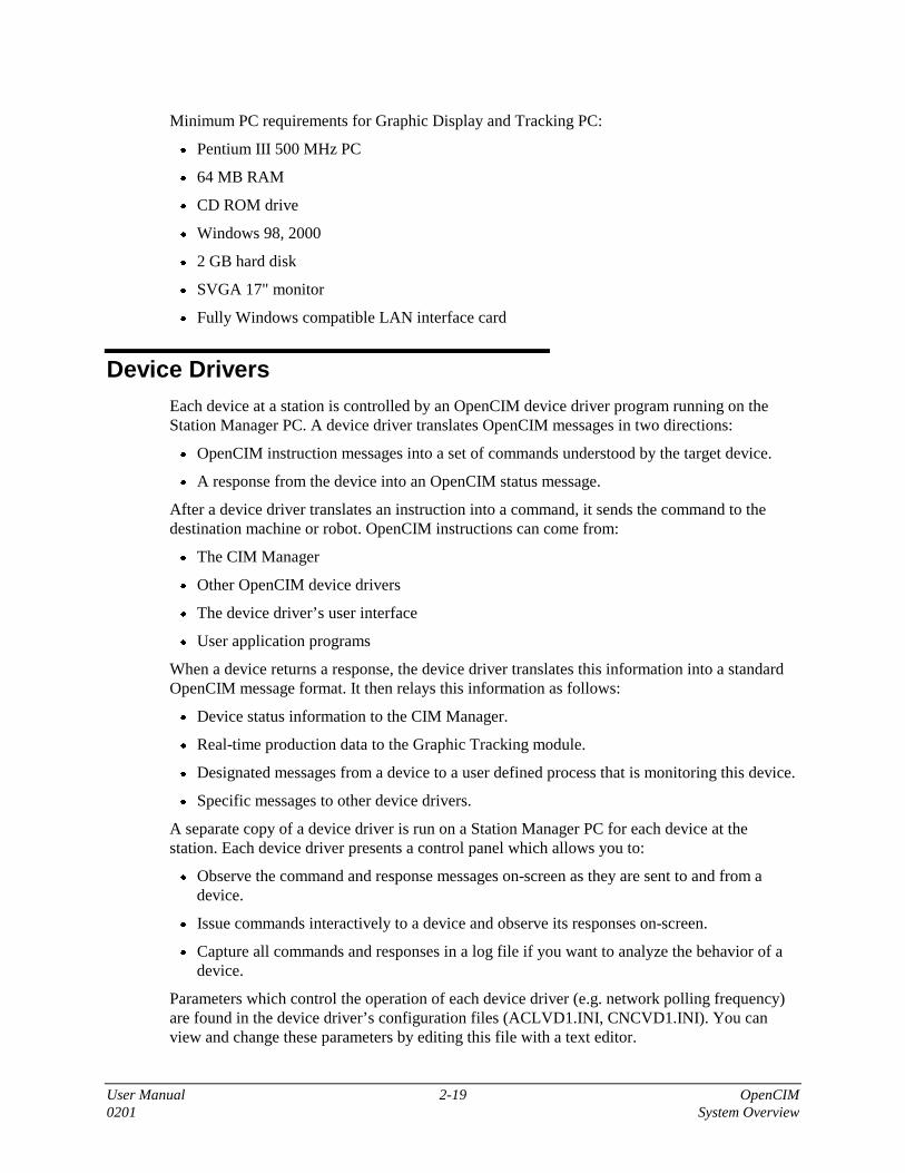
Minimum PC requirements for Graphic Display and Tracking PC:
• Pentium III 500 MHz PC
• 64 MB RAM
• CD ROM drive
• Windows 98, 2000
• 2 GB hard disk
• SVGA 17" monitor
• Fully Windows compatible LAN interface card
Device DriversEach device at a station is controlled by an OpenCIM device driver program running on theStation Manager PC. A device driver translates OpenCIM messages in two directions:
• OpenCIM instruction messages into a set of commands understood by the target device.
• A response from the device into an OpenCIM status message.
After a device driver translates an instruction into a command, it sends the command to thedestination machine or robot. OpenCIM instructions can come from:
• The CIM Manager
• Other OpenCIM device drivers
• The device driver’s user interface
• User application programs
When a device returns a response, the device driver translates this information into a standardOpenCIM message format. It then relays this information as follows:
• Device status information to the CIM Manager.
• Real-time production data to the Graphic Tracking module.
• Designated messages from a device to a user defined process that is monitoring this device.
• Specific messages to other device drivers.
A separate copy of a device driver is run on a Station Manager PC for each device at thestation. Each device driver presents a control panel which allows you to:
• Observe the command and response messages on-screen as they are sent to and from adevice.
• Issue commands interactively to a device and observe its responses on-screen.
• Capture all commands and responses in a log file if you want to analyze the behavior of adevice.
Parameters which control the operation of each device driver (e.g. network polling frequency)are found in the device driver’s configuration files (ACLVD1.INI, CNCVD1.INI). You canview and change these parameters by editing this file with a text editor.

User Manual 2-20 OpenCIMSystem Overview 0201
ACL Device Driver
The ACL device driver communicates with an ACL controller that controls robots (includingthe ASRS2). This device driver receives command messages from the CIM Manager to performrobot operations (and other ACL tasks). The ACL device driver translates these requests intocommands to run the corresponding ACL programs residing in the ACL controller. When thecontroller has finished moving the robot, it sends a confirmation message back to the devicedriver which forwards it to the CIM Manager. The ACL device driver uses an RS232 port onthe Station Manager PC to communicate with the ACL controller.
The primary operation performed by a robot is pick-and-place: taking a part from one location(source) and placing it at another location (target). For example, a common pick-and-placeoperation involves taking a part from a template and placing it in a CNC machine. Thecoordinates for each pick-and-place operation are defined in advance and assigned a LocationID. The CIM Manager sends a pick-and-place command to the controller which includes twoLocation IDs (source and target).
The actual path a robot follows when moving from a source location to a target is defined in anACL program residing in the ACL controller. The CIM is not involved with the complexities ofrobot movement; it only sends pick-and-place commands which specify the action to take, nothow to take it.
The ACL device driver can also activate user-supplied ACL programs residing in the controller.These programs are commonly used to control peripheral devices attached to the ACLcontroller. For example, a barcode scanner can be attached to an RS232 port or a CNC machinecan be connected to a set of I/O ports on the controller.
CNC Machine Device Driver
OpenCIM uses a CNC device driver to interface with any CNC machine that uses I/O lines oran RS232 interface to receive commands and report machine status. This device driver can beadapted to work with any such CNC machine using a built-in language to write short interfaceroutines. The CNC device driver can control a machine, read the status of a machine, sendstatus messages to other CIM entities, and download G-code programs to the machine using anRS232 interface.
The normal sequence of events is:
• The CIM Manager instructs the robot to load a part into the CNC machine.
• The CNC device driver receives a command to process a part.
• The device driver activates the appropriate output line to turn on the machine.
• The device driver waits for the operation to complete by monitoring a status line.
• The device driver sends a status message back to the CIM Manager.
• The CIM Manager instructs the robot to remove the part in the CNC machine.
The following sample scenario demonstrates the role of the CNC device driver:
1. The CIM Manager sends a command to the CNC device driver to download a G-code fileneeded to machine an upcoming part.

User Manual 2-21 OpenCIM0201 System Overview
2. When a robot is ready to insert a part into the CNC machine, its ACL program sendscommands to the CNC machine to:
• Open the door of the CNC machine
• Open the chuck/vice of the CNC machine
3. The robot inserts the part into the chuck/vice. The ACL program sends commands to theCNC machine to:
• Close the chuck/vice of the CNC machine
• Close the door of the CNC machine
4. The CIM Manager waits for status lines to indicate that the part is in place ready to bemachined.
5. The CIM Manager sends a signal to the CNC machine (via the CNC device driver) to beginmachining the part.
6. The CNC device driver waits for a status line to indicate that the machining operation iscomplete.
7. The CNC device driver sends an “Operation Complete” status message to the CIMManager. The Manager in turn sends a command to the ACL controller to signal the robotthat it can now remove the part from the CNC machine.
8. The ACL program sends commands to the CNC device driver to:
• Open the chuck
• Open the door
9. The ACL program directs the robot to remove the part. It then sends a status message to theCIM Manager signaling that the unloading is finished.
The CNC device driver can communicate with a machine using either an RS232 interface or aspecial I/O board in the Station Manager PC. For an I/O interface, each status line andcommand line for a machine is connected to this board.
In most cases the CNC device driver uses the ACL device driver and controller to communicatewith the machine on RS232 and I/O level.
Since CNC machines from different manufacturers have different sets of status lines andcommand lines, the CNC device driver uses a flexible control language called the CNCLanguage Interpreter (CLINT) for interacting with the machine. This language allows you toadapt the device driver to the features and wiring configuration of a specific machine by writinga set of customized routines. When a part arrives at a CNC machine, the CNC device driverreceives a command to run the corresponding CLINT routine to process this part.
PLC Device Driver
The PLC device driver communicates with the programmable logic controller which directs theoperation of the conveyor. This device driver receives messages from the CIM Manager aboutthe contents and destination of the pallets traveling on the conveyor. The PLC device drivertranslates these messages into commands understood by the PLC.

User Manual 2-22 OpenCIMSystem Overview 0201
When the PLC detects a pallet arriving or leaving a station, it sends a status message to the PLCdevice driver on a station PC. This device driver in turn translates the message into a standardOpenCIM format. It then broadcasts the message to the CIM Manager, the Graphic Trackingmodule, and any user applications which have registered for this type of message.
The control panel of the PLC device driver lists the destination of each pallet and can showwhich pallet is at each station. It also lets you interactively issue commands to stop a pallet at astation.
The PLC is normally connected to one of the Station Manager PCs (using an RS232connection). This PC communicates with the CIM Manager PC using the LAN.
OpenCIM can accommodate any type of PLC. If a PLC cannot support the pallet look-up tablein its memory, this information is stored on the PLC Manager PC. However, better performanceresults when the look-up table is stored in the PLC. This arrangement eliminates the serialcommunication overhead associated with performing frequent look-ups every time a palletpasses a station.
Quality Control Device Drivers
OpenCIM uses a set of device drivers to communicate with different types of quality controldevices such as:
• Vision Systems (Viewflex, ROBOTVISIONpro)
• Coordinate Measuring Machine (CMM)
• Laser scan meters, barcode readers, calipers
These device drivers receive instructions from the CIM Manager to perform a predefinedquality control check on a part. These instructions specify the type of test to perform and therange of acceptable results. The quality control tests for each part are defined according to theinstructions for each quality control device.
A quality control device driver translates OpenCIM messages into commands understood by itsassociated quality control device. The device driver can communicate with quality controldevices attached to either a Station Manager PC or ACL controller via an RS232 interface orI/O port. When the quality control device performs a test, it sends the result back to the qualitycontrol device driver on the Station Manager PC. The device driver translates the message intoa standard OpenCIM format. It then sends this status message to the CIM Manager.
The control panel of each quality control device driver lets you observe the results of eachquality control test. It also allows you to interactively issue commands to a quality controldevice or send status messages to the CIM Manager.

User Manual 2-23 OpenCIM0201 System Overview
OpenCIM Communication NetworkThis section describes in detail each of the following communication networks: I/O, RS232,and LAN.
Conveyor
Novell ServerOrganizational
PCFourth Shift PC Gateway
AS 400MAPICS
PCGraphic TrackingReport Generator
RS232
PCComunication PLC
Comunication AGV
PCStation ManagerUser Interface to ASRS
PCProcess & QC StationStatistical Process Control
ACLCont.
ASRS
PLC ACL ACLCont. Cont.
XY QC
Robot Robot
PartFeed Tools
Robot
PCStation ManagerOpen - CIM Software
ACL ControllerProcessing
Station Manager
CNC LSM Robot CNC
PC
ACLCont.
CNC QC
LAN
AGV
Leqend
LAN
RS232
I/O
Wireless RS232
PCCIM Manager
Figure 2-11: Communication Networks Used in OpenCIM
LAN
The CIM Manager and device drivers exchange command and status messages via theOpenCIM Network. This network is based on the Windows TCP/IP communication protocol.Each module (manager, device drivers) in the TCP/IP protocol has two communication sockets,the server and the client. A socket represents an endpoint for communication between processesacross a network. Both the server and the client have an IP address and a port number that areunique. The OpenCIM Network transparently delivers the message to the destinationapplication whether it is running on the same PC or on a PC connected via a LAN.
OpenCIM uses a LAN to exchange information between software modules running on separatecomputers. When the following software modules are configured to run on separate PCs, theLAN allows them to exchange commands and status information in real-time:
• The CIM Manager software
• The Device Driver softwares

User Manual 2-24 OpenCIMSystem Overview 0201
• The Graphic Tracking PC
• Any PCs running user supplied applications that are interfaced to OpenCIM
OpenCIM uses the LAN to:
• Send commands from the CIM Manager to Device Drivers (e.g. data such as part ID #, taskto perform, machine to use, etc.)
• Send real-time production status messages from Device Drivers to the CIM Manager.
• Allow Device Drivers to retrieve control programs (e.g. G-code) stored on the server.
• Send real-time production status messages to the Graphic Tracking software.
• Transfer CIM messages between different device drivers.
• Transfer CIM messages between devices and a user application running on a networkedPC.
• Perform central backup and restore of all PCs attached to the LAN.
OpenCIM can use any LAN using a TCP/IP protocol which is supported by Windows forWorkgroups to transfer files and send real-time messages. For example, an existing NovellLAN could be used to communicate with a remote PC running the Graphic Tracking module.
RS232
An RS232 interface (also known as a serial port or com port on a PC) is a low-speed datacommunications port that typically transmits and receives information at the rate of 300-19,200bits per second (bps). Data is transmitted serially, i.e. one bit at a time. There is a separate linefor transmitting and receiving data.
The following OpenCIM devices use RS232 connections:
StationManager PCs
Station Manager PCs use RS232 to:
• Download Programs to Processing machines
• Pass OpenCIM messages to/from an ACL controller
• Provide a terminal interface for programming ACL controllers
• Pass OpenCIM messages to/from other station devices such as QCsystems.
PLC The PLC Manager PC uses RS232 to:
• Send pallet destination information to the PLC
• Send commands to the PLC
• Receive status messages from the PLC
PeripheralDevices
Peripheral devices can be attached to the RS232 ports of an ACLcontroller (e.g. barcode reader).

User Manual 2-25 OpenCIM0201 System Overview
Inputs/Outputs
I/O connections can be used to turn production devices on and off, and to transmit binaryinformation about the status of a device. A separate wire carries each I/O signal. I/Oconnections use a low voltage DC signal. The exact voltage depends on the specifications of thedevices being connected.
I/O connections are used for signaling purposes only. An output signal should never be used todirectly drive a piece of electrical equipment. In this case, an output signal should be bufferedthrough a relay or other device to prevent overloading the circuit.
The following CIM devices use I/O connections:
• PLC (to raise and lower piston stops)
• Magnetic sensors at conveyor stations used to send pallet IDs to the PLC
• Processing machines (to operate the machine and report its status)
• Devices attached to an ACL controller’s I/O ports (e.g. an automatic screwdriver, apneumatic gripper for a robot, etc.)
IntegrationIn the previous sections you were given an overview of the entire cell. This section describesthe integration of various systems and devices by considering the sequence of events when apart moves from station to station for processing.
When the user activates a production order, the CIM Manager builds a production plan. Thisplan includes the parts to be processed, the stations where they are to be processed, and theproduction activities they will undergo.
In the sample scenario presented below, a cube moves from storage in the ASRS to a CNCstation where it is machined into a box. The table below provides a step-by-step description ofthe flow of information throughout the CIM associated with making a box. Note that operationswhich are listed in the same grid take place concurrently.
Message Source MessageDestination
Message Content(Command messages in normal typeface)
(Status messages in italics)
ASRS Station
CIM Manager ⇒PLC Stop the next empty pallet that arrives at the ASRSstation.
PLC ⇒CIM Manager Empty pallet has arrived at the ASRS station.
CIM Manager ⇒Robot Controller Use robot to remove a template with a cube fromstorage and place it on the pallet..
Robot Controller ⇒CIM Manager Template is in place on pallet.
CIM Manager ⇒PLC Release this pallet from the ASRS station. Stopthis pallet when it arrives at the CNC station.

User Manual 2-26 OpenCIMSystem Overview 0201
Message Source MessageDestination
Message Content(Command messages in normal typeface)
(Status messages in italics)
PLC ⇒CIM Manager Pallet with cube has arrived at the CNC station.
CNC Station
CIM Manager ⇒Robot Controller Use robot to remove template from pallet andplace it on buffer of CNC Station.
Robot Controller ⇒CIM Manager Template with part is waiting on buffer of CNCstation.
CIM Manager ⇒PLC Release pallet from CNC station.
CIM Manager ⇒Robot Controller Use robot to place part in CNC machine.
Robot Controller ⇒CIM Manager Part is in CNC machine.
CIM Manager ⇒CNC Machine Use the CNC machine to ream a hole in the cubeto form a box.
CNC Machine ⇒CIM Manager Process complete. Box ready.
CIM Manager ⇒Robot Controller Use robot to place box on template in buffer.
CIM Manager ⇒PLC Stop next empty pallet at CNC station.
Robot Controller ⇒CIM Manager Box is in place on template.
PLC ⇒CIM Manager Empty pallet has arrived at CNC station.
CIM Manager ⇒Robot Controller Use robot to place template with box on pallet.
Robot Controller ⇒CIM Manager Template is in place on pallet.
CIM Manager ⇒PLC Release pallet from the CNC station. Stop thispallet when it arrives at the Assembly Station ...
User Manual 3-1 OpenCIM0201 Safety
3
Safety
�Warning!
Do not approach any OpenCIM equipment before reading the safety guidelines in thischapter.
The OpenCIM cell is a complex system containing many different machines, each potentiallydangerous if proper safety practices are not followed. Certain safe operating practices apply toall, while others are device specific. This chapter presents the general rules, followed by a briefdiscussion of the safety requirements of each component.
The User’s Manuals for all robots and CNC machines contain full descriptions of the safetyprocedures and warnings for these devices. The user is strongly urged to read these manualsbefore working with the devices.
General Safety RulesThe following rules should be followed when in the vicinity of all moving machinery in theCIM cell such as robots, ASRS, or conveyor.
�Warning!
Exercise caution whenever you are in the area of the CIM cell.
• Be sure you know the location of the ON/OFF switch, and any emergency shutoff switches,on the following equipment:
• Robot controller
• Pallet conveyor
• CNC machines
• Be alert since any idle piece of equipment could start up suddenly. All CIM machinery canbe turned on and off unexpectedly via computer control.
• Exercise special caution in the vicinity of robots since they can start up without notice andmove in unexpected ways.
• Members of a group should be careful not to crowd too close around moving equipmentwhen observing the activities at a given station.
• Do not come near a moving device when it is in operation. Be careful that hair, clothes(especially loose sleeves) and jewelry are kept away from the mechanism.
• Do not stick your fingers into a device while it is in operation; they may get caught in themechanism.
• Keep the work area clean and free of clutter.

User Manual 3-2 OpenCIMSafety 0201
• Do not exceed the loading capacity of a device.
• Turn off a device before attempting adjustments, performing maintenance or measuring apart.
Robot and ACL Controller SafetyExtreme caution must be exercised in the use of OpenCIM robots. Recklessness may causephysical harm to the operator and other people in the vicinity.
• Set up a protective screen or guardrail around the robot.
• Make sure the robot base is properly bolted to a table or pedestal. Otherwise, the robot maybecome unstable and topple during operation.
• Do not use physical force on the robot arm to change its position, or for any other reason.
• Be sure the robot arm has sufficient space in which to operate freely, especially duringhoming.
• Before connecting any input or output to the controller, and before approaching or handlingthe robot, make that the controller’s main power switch is turned off.
• Before opening the controller housing, be sure to unplug the controller power cable fromthe AC power outlet. It is not sufficient to switch off the power; the power supplies insidethe controller still contain dangerously high voltages.
• Before removing any fuses, be sure to turn off the controller and unplug the controllerpower cable from the AC power outlet.
�Note
To immediately abort all running programs and stop movement of all axes (e.g. robots):
• Press the Abort or Emergency Stop key on the teach pendant, or
• Use the ACL command A <Enter>, or
• Press the controller’s red Emergency button.
CNC Machine SafetyThe following are general safety instructions for the use of CNC machines. Be sure you adhereto the safety rules for the specific machines included in your cell.
• Always wear safety goggles when near the machine. Be aware that some materials, such asthe brass bars, spray chips while being processed. Make sure all persons near the machineare protected.
• Keep children and visitors away. Set up the machine so that children or visitors unfamiliarwith the machine cannot start it. Protect the machine against unintentional use by removingthe switch key.
• Chuck parts and tools firmly and safely.
• Perform measuring and chucking work only when the machine is at a standstill.
User Manual 3-3 OpenCIM0201 Safety
• Remove adjusting key and wrenches even when the machine is not being used. Neverattach chuck keys to a machine with a chain or similar connector.
• Always work with sharp tools.
ASRS Safety
ASRS Carousel
• Do not place your hand or any other object in or near the main drive belt, located under thelowest level of the ASRS carousel, while the device is operating. The belt is extremelydangerous and can cause severe injury.
• Make sure that the carousel has been disconnected from the AC power supply beforeapproaching the motor and belts.
ASRS2
• Do not enter the robot’s working envelope or touch the robot when the system is inoperation.
• Use caution when moving the ASRS2 robot by means of the teach pendant.
• To halt movement of the ACL robot which tends the ASRS2 unit, do any of the following:
• Press the Abort or Emergency Stop key on the teach pendant, or
• Press the controller’s red Emergency button, or
• Use the ACL command A <Enter>.
�Note
Opening any of the plexiglass doors which enclose the ASRS2 will automatically andimmediately halt all movement of the ASRS robot. Upon closing the door, movement willresume.
Conveyor and PLC Safety• Be sure you know the location of the conveyor’s power ON/OFF switch. To immediately
stop the conveyor, simply shut off this switch.
• Keep hands and objects away from the conveyor drive unit.
• Do not tamper with the conveyor motor. Do not remove the conveyor motor covers underany circumstances
• Do not touch or tamper with the power supply inside the PLC near the conveyor motors.
• Do not tamper with the switch and connector box for the 100/110/220/240/380VAC powersupply (depending on device).


User Manual 4-1 OpenCIM0201 Installation
4
Installation
The OpenCIM system is normally installed in the following order:
1. Hardware assembly
2. Wiring connections (including network hardware)
3. Software installation (including software protection keys and network setup)
4. Teaching of robot positions
5. Checking and adjustment of devices (for standalone and system operation)
OpenCIM hardware configurations vary. This chapter presents the basic guidelines for setting upCIM equipment. Additional installation instructions will be provided separately for the specificequipment and configuration of your OpenCIM cell.
Hardware InstallationBefore installing the OpenCIM, examine it for signs of shipping damage. If any damage isevident, contact your freight carrier, and begin appropriate claims procedures.
Make sure you have received all the items listed on the shipment's packing list. If anything ismissing, contact your supplier.
For personal safety and sufficient access to the stations from all open sides, a free area of at leastone meter around each station is recommended.
Be sure you comply with all safety guidelines and warnings in the user manuals supplied with therobot, controller and other devices.
Some stations may have tables with slotted surfaces or predrilled holes to facilitate the mountingof the robots and devices.
Conveyor and Pallets
Refer to the instructions provided with your conveyor and/or OpenCIM cell.
Set up the conveyor within reach of the power supply and the air supply.
Assemble the conveyor and attach the conveyor buffers at each station.
Make sure the conveyor is assembled so that it moves clockwise or counterclockwise dependingon your specific system layout.

User Manual 4-2 OpenCIMInstallation 0201
Place the pallets supplied with the system anywhere along the conveyor with the arrow on thepallet pointing in the direction of movement of the conveyor.
Robots and Robot Controllers
For detailed instructions on connecting the robot and controller, refer to the User’s Manualsupplied with the robot/controller. In addition, refer to the instructions provided with yourOpenCIM cell.
The basic steps for installing an ACL robot and controller for use in the OpenCIM cell are.
1. Open the controller, and install the auxiliary (multi-port) communication card in thecontroller, according to the instructions in the User's Manual supplied with the robot /controller.
2. If the station contains an I/O box, connect it to the ACL controller (e.g., Controller - TypeA), as follows.
• Make sure the ribbon cable is plugged into the I/O box connector marked for the controllerat the station (e.g., Controller - Type A).
• Thread the ribbon cable from the I/O box through one of the open slots on the controller'srear panel.
• Plug the ribbon cable connector into the I/O connector, which is located between thecontroller's power/motor switches and transformer.
3. Connect the robot to the controller.
4. Connect the teach pendant to the controller.
ASRS
Most ASRS systems are pre-assembled units that have to be placed near a conveyor station sothat pallets can be loaded/unloaded. If you customize the ASRS make sure that the tending robotcan reach all relevant elements and optimize the layout with respect to the tending time of therobot.
Refer to the instructions provided with your ASRS and/or OpenCIM cell.
Barcode Reader
The standard Barcode Reader is normally mounted within robot reach on the conveyor next to theASRS stop station in order to check outgoing and incoming template IDs. It requires a 5.6VDCpower supply and a RS232 connection either to the Station PC or to the robot controller.
Refer to the instructions provided with your barcode reader and/or OpenCIM cell.
Pneumatic Devices
Pneumatic devices in a station (pneumatic door, fixtures, caliper, air blows, etc.) includingposition sensors are normally interfaced through the I/Os of the robot controller. They can also be

User Manual 4-3 OpenCIM0201 Installation
controlled by a separate PLC if requested by the customer. In any case, pneumatic devices requirethe appropriate supply of compressed and conditioned air.
Refer to the instructions provided with the specific device and/or OpenCIM cell.
Palletizing Racks and Buffers
Normally, buffers are mounted on the conveyor but, for a specific station layout, it is possible toattach them to a table. Palletizing racks are used as a flexible storage that can be adapted tovarious parts by using sets of different sized pins. Make sure the pins are arranged identically foreach part of the same type in the palletizing rack.
Refer to the instructions provided with the OpenCIM cell.
Templates
Templates are used to transport parts within the system. Templates which have a grid of holestogether with different sized pins allow flexible adjustment for different parts in a similar way tothe palletizing racks. Make sure the pins are arranged identically on all templates which will holdidentical parts.
Refer to the instructions provided with the OpenCIM cell.
WiringWiring depends on the actual stations, machines and devices included in your OpenCIMinstallation. Most systems are installed by a trained engineer who will supply you with specificwiring documentation (communication layout) to enable you to easily understand and maintainthe system.
Refer to the documentation and wiring instructions provided with the OpenCIM cell.
Network
It is possible to operate the OpenCIM on any desktop or laptop PC – which complies with therequired hardware specifications – in which a network board (adapter) has been installed,providing that you have installed the software driver which enables the adapter to work withWindows for Workgroups (see “Network Setup” below.) Network wiring, which is documentedin the communication layout, is performed through a hub.

User Manual 4-4 OpenCIMInstallation 0201
Software Installation
Network Setup
Once Windows has been installed and all PC devices (CD ROM drive, mouse, graphic card,network card, etc.) have been set up on each PC that is to be used in the OpenCIM network, dothe following:
1. Define the Network Workgroups and computer names. Computer names are case-sensitive. Itis recommended that you use names such as these:
Network Workgroup CIM
CIM Manager PC CIM-MANAGER
Station PCs CIM-PC1, CIM-PC2, etc. on which the logical workstations(WS1, WS2, etc.) of the CIM are located
2. Set the TCP/IP network protocol as your communication protocol. Select the IP address asfollows: If your network Workgroup is part of a global network (i.e. is connected to a server)choose the option: Obtain an IP address automatically.If your network workgroup is local (i.e. not connected to a server) set the IP address, forexample, as 200.1.1.1 and increment the last digit for each additional PC.For all PCs in the CIM, specify the same subnet mask, for example, 255.255.0.0 For details,contact your network administrator.
3. If you are using more than one PC, it is a good idea to verify that the PCs are connected tothe network. Click the Network Neighborhood icon on the PC desktop to see the names of theconnected PCs. If you don’t see the PC names, wait a few seconds and press F5. If the namesstill do not display, check the network setup again.

User Manual 4-5 OpenCIM0201 Installation
Software for CIM Manager PC
The following procedure describes how to install one of the OpenCIM products. You can cancelthe setup process at any time by pressing Cancel.
�
Notes
The software will be installed in the path C:\program files\intelitek\opencim. If youalready have a previous version of the software in a directory of this name, select adifferent directory name for the new installation.
Installation of multiple products on the same PC is permitted provided that you have alicense for each product.
1. Close all open applications.
2. Insert the OpenCIM software CD into the CD ROM drive.
• Autorun begins the installation process as soon as you insert the CD unless you hold theSHIFT key while you insert the CD.
• If you have turned off Autorun, you must specify the CD ROM drive from which to runthe installation setup file which will begin the installation. From the Windows Startmenu, choose Run. Enter:
x:\install\setup [where x represents the CD ROM drive].
3. In the Welcome screen of the Installation Wizard, choose Next.
4. In the Installation Selection Window, select the OpenCIM product that you want to installand then choose Next.
Figure 4-1: Installation Selection Window
�
Note
The WorkStation Environment option is used (by Intelitek technical support personnel) toinstall system components necessary to run device drivers from a PC which is not the CIMManager PC. See Software for WorkStation PCs below.

User Manual 4-6 OpenCIMInstallation 0201
5. Review the Intelitek software license agreement. You must accept the terms of this agreementin order to complete the installation. If you do not accept the agreement, you cannot proceedwith the installation. To accept, choose I accept, and then choose Next to open the UserInformation Window.
Figure 4-2: User Information Window
6. Enter the User Name, Company, and the Serial number printed on the CD. The serial numberis made up of 12 characters in the following format: XXXX-XXXX-XXXX. If you are usingthe product for evaluation, type Evaluation in the Serial field.
7. Choose Next. The Intelitek Software License window is displayed.
Figure 4-3: Software License Window

User Manual 4-7 OpenCIM0201 Installation
8. Each OpenCIM package has its own license; the licenses are not interchangeable (e.g., theOpenCIM Offline will not work with the license for OpenCIM). The label with the CD-Keyon the CD indicates the product name.
9. Full details on Intelitek software licensing are provided in Chapter 13. Follow the necessaryinstructions for the licensing procedure you require (registering your software, transfering alicense from one PC to another PC, returning a license to Intelitek so you can retrieve itlater.)
10. To install the OpenCIM package in the default installation directoryc:\program files\intelitek\opencim, choose Next.Alternatively, choose Browse, select a different installation directory, and then chooseNext.
11. Choose Next to start the installation.
12. When prompted, restart your computer to complete the installation.
The product currently installed is indicated by the unique name in the screen title bars. Theproduct name can also be found in the About option of the Help menu.
Software for Workstation PCs
In order to be able to use OpenCIM modules on a station PC, you must install specific filesfrom the OpenCIM installation CD. From the Installation Selection Window (described inSoftware for CIM Manager PC), select the WorkStation Environment option.
To use OpenCIM modules on a station PC, be sure to do the following:
In Manager PC
Allow all workstations in the local network to access the Manager PC Drive in which OpenCIMis installed by sharing the drive. For example, to share drive C:
1. Select My Computer.
2. Right-click Drive C:
3. Select sharing.
4. From the dialog box, select share as and click OK.
In Station PCs
Map the drive of the Manager PC (where the OpenCIM software is installed) through thenetwork, as follows:
1. Select and right-click My Computer.
2. Select Map Network Drive.
3. Select a free drive and write the path for the Manager’s drive C.For example: Drive E:, path, \\Manager\C.
4. Check Reconnect at Logon and click OK.
User Manual 4-8 OpenCIMInstallation 0201
Other Software
An OpenCIM system can include many devices which require additional software (e.g., VisionSystems, CNC machines, CAD/CAM, etc.).
Refer to the documentation and software installation instructions provided with each device.
ACL Controller Configuration
The following procedure is valid only for ACL controller types A and B. For other controllers,refer to the documentation and software installation instructions provided with each device.
At each station which contains an ACL controller, you will need to configure the controller anddownload the file ALL.CBU from the Station Manager PC to the ACL controller. This filecontains all programs, positions and parameters required for controller operation in theOpenCIM environment.
From the ATS main screen:
1. Press <Ctrl>+F1 to configure the controller.
2. Press Y to confirm the prompt to configure the controller.
You are then prompted by a short series of Controller Configuration options.
Refer to the ATS Reference Guide provided with your ACL controller for complete instructionson configuring the controller.
Once you have confirmed the configuration, ATS will perform the configuration procedure. Youcan ignore the message about the missing SETUP.PAR parameter file.
When the > prompt appears, press [Shift]+F10. The ATS Backup Manager screen opens.
Make the following selections and entries:
• Backup directory: C:\opencim\microcim\ws1\robot1
Make sure the path correctly shows the working directory defined during the configuration, asshown in this example.
• Backup / Restore: ALL
Use the arrow keys to highlight ALL and press [Enter].
• During Restore: ERASE.
Use the arrow keys to highlight ERASE and press [Enter].
• File name: all
Type ALL and press [Enter].
Press [Enter] again. Press F5 to RESTORE from disk.
Press Y to confirm all prompts to overwrite and erase.

User Manual 4-9 OpenCIM0201 Installation
Robot PositionsThe actual location of robot positions will differ depending on the actual stations, machines anddevices included in the OpenCIM installation. You will therefore need to record (teach) newcoordinates for the positions which were downloaded to the controller.
The following procedure is valid only for ACL controller types A and B. For other controllers,refer to the documentation and software installation instructions provided with each device.
Refer to documentation and position teaching instruction supplied with your OpenCIMinstallation. In addition, refer to the User’s Manual supplied with the robot/controller.
The teaching of robot positions is performed from ATS. You must home the robot before youteach positions.
1. Enter the ACL command: RUN HOMES
2. Wait until the robot has completed the homing twice.
All positions used in the OpenCIM belong to the vector CIM[n]. The size of the vector can varyfrom station to station. The standard size is n = 500. To teach the robot the positions required forthe application, you must attach this vector to the teach pendant.
3. Enter the ACL command: ATTACH CIM
4. When you have finished recording the positions, use the ATS Backup Manager to save theprograms, positions and parameters to disk. Save each item as a separate file.
5. Make the following selections and entries:
• Backup directory:C:\opencim\microcim\ws1\robot1 (forexample)Backup / Restore: ALLFile name: all
Press [Enter] again. Press F3 to SAVE to disk
• Backup / Restore: PROGRAMSFile name: programs
Press [Enter] again. Press F3 to SAVE to disk.
• Backup / Restore: POSITIONSFile name: position
Press [Enter] again. Press F3 to SAVE to disk.
• Backup / Restore: PARAMETERSFile name: paramete
Press [Enter] again. Press F3 to SAVE to disk.

User Manual 4-10 OpenCIMInstallation 0201
System CheckThe system check depends on the actual stations, machines and devices included in theOpenCIM installation.
Refer to documentation and instructions supplied with your OpenCIM installation.
Check the hardware and device drivers and make sure they are functioning properly:
• Power Supply
• Conveyor
• Robots (Use the ACL program DEBUG)
• PLC (Device Driver)
• ACL (Device Driver)
• CNC (Device Driver)
• Vision-QC (Device Driver)
• Pneumatic Devices (using the appropriate Device Driver)

User Manual 5-1 OpenCIM0201 Preparing for Production: CIM Utility Programs
5
Preparing for Production:
CIM Utility Programs
This chapter describes the CIM Utility Programs which are used for preparing the OpenCIMsystem for production. These programs, which are an integral part of the CIM Manager softwareand are listed in the Utility Programs menu, allow you to view and edit the following CIMentities:
Machine Definitions and their associated production processes
Part Definitions
Storage Definitions
MRP: Customer Orders, Manufacturing Orders and Purchase Orders
You can use these programs to view some existing sample definitions to assist you in makingyour own.
This chapter also discusses the Report Generator which is provided with OpenCIM.
Report Generator. Allows you to generate predefined or customized reports forviewing and printing.
As you read through this chapter, it is recommended that you perform the “Procedures.” Thesetutorials will help you become familiar with using the OpenCIM software.
The examples shown in this manual are from the OpenCIM Simulation DEMO icon group. You,however, will probably work from the OpenCIM icon group which was specifically created foryour installation.
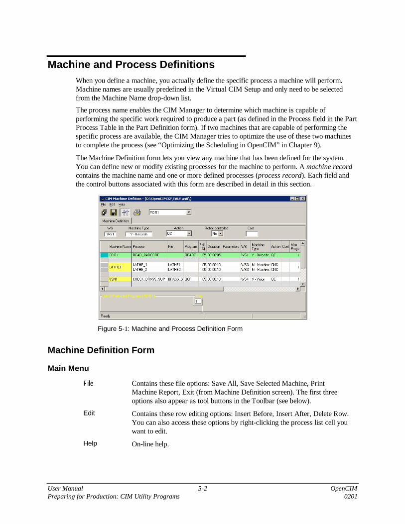
User Manual 5-2 OpenCIMPreparing for Production: CIM Utility Programs 0201
Machine and Process DefinitionsWhen you define a machine, you actually define the specific process a machine will perform.Machine names are usually predefined in the Virtual CIM Setup and only need to be selectedfrom the Machine Name drop-down list.
The process name enables the CIM Manager to determine which machine is capable ofperforming the specific work required to produce a part (as defined in the Process field in the PartProcess Table in the Part Definition form). If two machines that are capable of performing thespecific process are available, the CIM Manager tries to optimize the use of these two machinesto complete the process (see “Optimizing the Scheduling in OpenCIM” in Chapter 9).
The Machine Definition form lets you view any machine that has been defined for the system.You can define new or modify existing processes for the machine to perform. A machine recordcontains the machine name and one or more defined processes (process record). Each field andthe control buttons associated with this form are described in detail in this section.
Figure 5-1: Machine and Process Definition Form
Machine Definition Form
Main Menu
File Contains these file options: Save All, Save Selected Machine, PrintMachine Report, Exit (from Machine Definition screen). The first threeoptions also appear as tool buttons in the Toolbar (see below).
Edit Contains these row editing options: Insert Before, Insert After, Delete Row.You can also access these options by right-clicking the process list cell youwant to edit.
Help On-line help.

User Manual 5-3 OpenCIM0201 Preparing for Production: CIM Utility Programs
Toolbar
Saves all machine records to disk.
Saves the selected machine record to disk.
Automatically resizes the columns to accommodate long values (when thewindow is maximized).
Print machine report.
Select a machine from the machine name drop-down list. The names thatappear in the list are defined in the Virtual CIM Setup. For furtherinformation, see “Edit Menu: New Object” in Chapter 7.
Machine Process Table
The data fields above the table are also displayed as columns in the table. Their descriptions areprovided below.
MachineName
A descriptive name which uniquely identifies the machine. You canedit/examine the record for a specific machine by selecting that machinename from the drop-down list in the toolbar. All machines that are defined inthe Virtual CIM Setup appear in this list.
PROCESS The name of a production process that can be performed by this machine. AProcess Name can only be used once for a given machine.
The name should be easily recognizable to CIM users and may contain thecharacters A–Z, 0–9 and underscore ( _ ), but no spaces.
This Process Name is assigned to a part in the Part Definition form (in theProcess field of the Part Processes Table).
Assigning a process to a part instead of a machine can have advantages whenthere are two or more machines capable of performing the same process.Having more than one machine capable of performing a given process allowsthe CIM Manager to select the machine which can process a part mostefficiently and redirect production if one machine fails.
� NoteFor different machines that can perform the same process, you shouldenter the same process name. Likewise, do NOT use the same process nameto refer to processes on different machines which do not perform the sameoperation on the same part.
The following reserved words cannot be used as Process names:ALLOC GET PACKASSEMBLY GET_FIX PLACEBASE MAKE PROCESSCNC MOVE QCDELIVER NEXT RENAMEEND_ASSEMBLY NOP TARGETFREE ONFAIL TRANSFER

User Manual 5-4 OpenCIMPreparing for Production: CIM Utility Programs 0201
File A file containing the G-code program or other program associated with thisprocess. This file name can include a valid DOS directory path. If no pathis specified, the CIM Manager expects to find this file in the currentworking directory associated with the device driver for this machine.A file can contain one machine control program. Different machines thatperform the same process will have their respective control programs storedin different files.
Program The name of the machine control program associated with the process beingdefined. This Program Name is used by an ACL controller which isoperating a machine.
Fail(%) Your estimate of the number of rejected parts that will result when thisprocess is run on this machine (0 - 100%). The CIM Manager takes thisvalue into consideration when simulating a quality control process.
Duration The number of minutes this process takes to produce one part. The CIMManager takes this value into consideration when choosing among multiplemachines that can run the same process. Format is hh:mm:ss
Parameters This string of arguments is passed to a machine control program associatedwith this process.
Ws The workstation in which the machine is placed. Automatically displayedby the system (as defined in the Virtual CIM Setup).
Machine Type The type of machine selected. Automatically displayed by the system (asdefined in the Virtual CIM Setup).
Action Type A label that defines the characteristics associated with a process. Select oneof these Action Types (in the data field above the table):
Action Type Description
Assembly A process which involves the assembly of two or moresubparts.
QC A process involving a test that reports a Pass/Fail result tothe CIM Manager. If the result is Fail, the rejected part isredone. A quality control process requires an ONFAIL entryin the Part Processes table in the Part Definition form see“Part Definition” below.
CNC A process which has G-Code program(s) associated with it.The CIM Manager downloads the G-code file specified in theFile field to the CNC machine (unless this file is alreadyresident in the CNC machine).
Process A basic machine operation which does not require anyspecial action beforehand or afterwards. Runs the ACLprogram specified in the Program field.
Place A robot operation used for non-standard operations performedby a robot. The File and Program fields will be blank.

User Manual 5-5 OpenCIM0201 Preparing for Production: CIM Utility Programs
Robot-controlled
Specifies if a robot is needed to perform the process. For example, if awelding action is performed by a robot, specifying YES signals the CIMManager that the robot is in use and is not free to perform anotheroperation. This option is available only if the machine selected can use arobot to perform a task, and if the Action Type is Process.
Cost per Hour Estimated hourly cost to run this machine. The CIM Manager uses this asone of the criteria in order to decide on the optimum production method.
List of Preloaded Programs
Tasks are control programs that can be downloaded to a machine (e.g., G-code to a CNCmachine). The CIM manager keeps track of which programs currently reside in a machine’smemory. If a certain process requires a machine control program that is not resident, the CIMManager instructs the CNC device driver to download it to the machine.
MaxPreloadedPrograms
The number of control programs that can reside in a machine’s memory atone time. Once this number is exceeded, the CIM Manager beginsoverwriting programs in the machine’s memory when it needs to downloada new program.
List ofPreloadedPrograms
The current status of control programs that are loaded in the machine’smemory. This box is for information purposes only; it cannot be used tochange the programs residing in a machine.
How to Define a Machine
The procedures presented below refer to an OpenCIM sample application for producing a simple,covered box (product). When defining the process for the covered box, two processes need to bedefined: CNC milling and assembly.

User Manual 5-6 OpenCIMPreparing for Production: CIM Utility Programs 0201
�
�
�
Procedure
A. Defining the Milling Process
1. In the Machine Definition form, select “MILL1” from the Machine Namedrop-down list; this is the name for the milling machine, as defined in theVirtual CIM Setup. The MILL1 record becomes the current record andappears in green in the Machine Process Table. The record contains theprocess(es) defined for the machine. The workstation is shown as WS2, themachine type as M-MACHINE, the action type as CNC, and Robot-controlled as No and gray.
2. In the Process column, type in the Process Name MILL2. (You will need tomake sure—either now or later—that MILL2 appears in the Process field inthe Part Process Table in the Part Definition form).
3. In the File column, type in GCODE.NC, for example, as the name of the G-code program file that contains the instructions for this type of process.
4. In the Duration column, type in the amount of time it takes the mill toperform this operation, e.g., thirty seconds.
5. Your screen should now look like this:
6. Click to save the currently displayed information to the database.
7. You can now generate and view a Machine or Process Report by usingthe Report Program.
8. Continue with the procedure “Defining the Assembly” to define the otherprocess which is required to produce the covered box.

User Manual 5-7 OpenCIM0201 Preparing for Production: CIM Utility Programs
�
�
�
Procedure
�Note The assembly operation is usually performed by a jig device(such as a pneumatic jig) not a machine.
B. Defining the Assembly Process
1. In the Machine Definition form, select JIGXY4, from the Machine Namedrop-down list; this is the name of the device that performs assemblyoperations, as defined in the Virtual CIM Setup. The JIGXY4 recordbecomes the current record and appears in green in the Machine ProcessTable. The workstation is shown as WS3, the machine type as J-JIG, theaction type as ASSEMBLY, and Robot-controlled as NO and gray.
2. In the Process column, type in the Process Name ASSY. (You will need tomake sure—either now or later—that ASSY appears in the Process field inthe Part Process Table in the Part Definition form.)
3. In the Duration column, type in the amount of time it takes the mill toperform this operation, e.g., 12 seconds.
4. Your screen should now look like this:
5. Click to save the information to the database.
6. You can now generate and view a Machine or Process Report by using theReport Program.
�
Note
These procedures represent a simplified example. When defining more complicatedapplications, entries to other fields will also be required.

User Manual 5-8 OpenCIMPreparing for Production: CIM Utility Programs 0201
Part DefinitionA product is manufactured from a group of subparts (bill of materials) that are put togetheraccording to a specified set of machine processes. Starting with a set of raw materials (suppliedparts), you define parts at the intermediate stages of production required to assemble a finalproduct.
The Part Definition screen, or form, allows you to enter the bill of materials and the associatedproduction processes used to produce a part. Using the Part Definition form, you can either:
• Modify/view the production process for an existing product.
• Describe the production process for a new product.
Defining a new product involves the following steps:
• Drawing a part definition tree.
• Setting up all machine processes necessary to produce a product and all its subparts.
• Determining what new template designs are required to handle all the parts involved and assignthese designs template ID numbers.
• Determining the types of racks that can hold each subpart.
The Part Definition form for Product (or Phantom) parts lets you create, view, or modify thecurrent part (either a product or its subparts). A part record contains all the fields shown on thePart Definition form below. Each field and the control buttons associated with this form aredescribed in detail in this section.
Figure 5-2: Part Definition Form for Product or Phantom Part
If you define the part as Supplied, the Part Process table will be replaced by a section containingdata regarding the supplier and supplied material, as shown below:

User Manual 5-9 OpenCIM0201 Preparing for Production: CIM Utility Programs
Figure 5-3: Part Definition Form for Supplied Part
Part Definition Form
Main Menu
File Contains these file options: New Part, Save Current Part, Save All,Print, Exit (from Part Definition screen). The first five options alsoappear as tool buttons in the Toolbar (see below).
Edit Contains these row and part editing options: Insert Before, Insert After,Copy Part, Paste Part, Delete Row, Delete Part. You can also accessthese options by right-clicking the process list cell you want to edit.
Help On-line help.
Toolbar
Defines new part
Saves all part records to database.
Saves the selected part record to database.
Automatically resizes the columns to accommodate long values (whenthe window is maximized).
Prints part report.
Selects a predefined part from the part name drop-down list.
Selects a predefined part ID from the part ID drop-down list.

User Manual 5-10 OpenCIMPreparing for Production: CIM Utility Programs 0201
Part Table
Part Type Select one of the following types for this part:
Product A part that can be ordered from the CIM. The final part at thetop of the part definition tree is always defined as a product.Part is the product that is produced by the CIM system. In someindustrial software, the term “MAKE” is often used to refer tothe product.
Supplied A part received from an outside source, i.e. a part not producedby the CIM, therefore it does not require a process definition.Supplied parts do not contain any entries in their Part Processtables. A supplied part is found only at the bottom of the PartDefinition tree. In some industrial software, the term “BUY” isoften used to refer to the supplied part.
Phantom A part or subpart which has failed QC. This definition allowsthe CIM Manager to issue instructions on how to handle arejected part. Phantom parts cannot be ordered.
Product Part Data
Part Name A string which uniquely identifies this part (i.e. two parts cannot have the samename). The name should be easily recognizable to CIM users. The string maycontain the characters A–Z, 0–9 and underscore ( _ ), but no spaces.
Part ID A numeric value (1 – 999) which uniquely identifies this part (i.e. two partscannot have the same ID). This Part ID can be used with devices which requirea numeric part identifier. For example, the ACL controller uses the Part ID toactivate the appropriate control program to handle this part.
Subpart The name of a material used to produce the current part.
A subpart must be defined in its own Part Definition record. A subpart caneither be a raw material (i.e. a Supplied Part) or a part produced by the CIM(i.e. a Phantom Part or a Product).
Some rows in the Part Process table require a Subpart name while others donot. A Subpart name is required in the following circumstances:
• A Subpart name is required in row 1 of the Subpart column.
• A Subpart name is required for each part that is included in an assembly.
• A Phantom Subpart name is required after each quality control test in orderto associate a name with the ONFAIL exception handler.
After the first row, a subpart name is not required if the process being per-formed operates on the same part that was listed in the previous row. Forexample, the first row could specify the name of a cube that is to be machinedinto a box. The second row specifies a process that drills a hole in the box. Inthis case, the subpart field of the second row would be blank because the drilloperates on the same subpart specified in row one.

User Manual 5-11 OpenCIM0201 Preparing for Production: CIM Utility Programs
If you need more than one of a subpart, add a separate row to the Part Processtable for each unit.
A circular definition error will result if you enter a subpart name that matchesthe name of the part being defined (i.e. Subpart = Part). This error will alsooccur if any of the subparts in turn contain a subpart that matches the PartName being defined.
Process Enter the name of a production process that has been defined in the Processfield of the Machine Definition screen.
If this process exists on more than one machine, the CIM Manager selects themachine to use according to its production strategy (e.g. minimize cost,minimize production time, etc.).
Parameters The Parameters field specifies how to carry out this process when it isperformed for the current part.
For quality control devices, the parameter string is used to specify the type of QC test and therange of acceptable values.
For a machine that performs assembly operations, the parameter string specifies where to put thepart that is being added to the assembly. If this target location contains compartments, you canadd an optional index for the compartment number.
The table below details how parameters are used by several devices:
Device Example Description Note
ROBOT-VISIONpro
1, 4 type of test,minimum value,[maximum value]
If maximum value isomitted, the minimumvalue represents the singleacceptable value.
Laser ScanMeter
1,150,160
type of test,minimum value,[maximum value]
If maximum value isomitted, the minimumvalue represents the singleacceptable value (with atolerance of ±5%).
AssemblyMachine
BOX, 2 target location,[target index]
Places subpart assemblyBOX in location #2.
The following system variables can be used in the Process definition.
Variable Description
$PARTID Part ID as defined in the Part Definition form.
$TEMPLATEID The Template ID (six digits) defined in the StorageDefinition form.
$TEMPLATETYPE The Template Type (two digits) defined in the StorageDefinition form.
$PRIORITY The Priority defined in the Manufacturing Order.
$DURATION The Duration defined in the Machine Definition form.

User Manual 5-12 OpenCIMPreparing for Production: CIM Utility Programs 0201
Sequence This field lets you specify whether this process must be performed in theorder in which it appears in the Part Process table. This field must contain aT (true).
Description A description of the part being defined that explains what it is and where it isto be used.
TemplateType
The Template type (01 – 99) whose pin arrangement can accommodate thispart.
Rack/FeederTypes
If this part is to be stored temporarily in a rack during processing, specifywhich types of racks are capable of accommodating this part (Rack Type >200). Rack types are defined in the Virtual CIM Setup. You can specifymultiple rack types in this field; each one separated by a comma (e.g. 201,202, 203). Selections are made by choosing from a drop-down list or bytyping in the entry.
Supplied Part Data
When you select Supplied as the Part Type, the Part Process table is replaced by a form thatallows you to define the supplied part.
Part Name A string which uniquely identifies this part (i.e. two parts cannot have thesame name). The name should be easily recognizable to CIM users.The string may contain the characters A–Z, 0–9 and underscore (_), but nospaces.
Part ID A numeric value (1 – 999) which uniquely identifies this part (i.e. two partscannot have the same ID). This Part ID can be used with devices that require anumeric part identifier. For example, the ACL controller uses the Part ID toactivate the appropriate control program to handle this part.
SupplierName
The name of the supplier from whom the raw material / supplied part ispurchased.
SupplierCatalogNumber
The supplier’s catalog number for the raw material / supplied part.
MinimumOrder
The smallest quantity of this part which can be purchased from the supplier ata time.
Safety Stock The number of units of this material / part required by the CIM cell toguarantee production without interruption.
Cost The cost of one unit of the raw material / supplied part.
Supply time(days)
The amount of time it takes the supplier to deliver this material / part to theCIM cell.
Description A description of the part being defined that explains what it is and where it isto be used.
TemplateType
The Template type (01 – 99) whose pin arrangement can accommodate thispart.

User Manual 5-13 OpenCIM0201 Preparing for Production: CIM Utility Programs
Rack/FeederTypes
If this part is to be stored in a feeder, specify which types of feeder are capableof accommodating this part (Feeder Type > 100). Feeder types are defined inthe Virtual CIM Setup. You can specify multiple feeder types in this field;each one separated by a comma (e.g. 101, 102, 103). Selections aremade by choosing from a drop-down list or by typing in the entry.
Similarly, if this part is to be stored temporarily in a rack during processing,specify which types of racks are capable of accommodating this part. SeeRack Type definition above.
How to Define a Part
In order to define a part, it is important that you understand the entire operation. A part is onlythe starting point. This part (supplied, raw material) moves within the CIM system according to apredefined path, the part is processed (with another part) and the product is then created.
In order to define a part, you need to:
• Define the supplied material(s)
• Define the process that must be performed on the material(s)
• Define how to assemble the parts (processed and supplied materials)
These concepts can be better explained by referring back to the OpenCIM sample application ofproducing a simple, covered box from a small, solid cube and a matching cover. From thisexample we can determine that:
Raw Material #1 Box
Raw Material #2 Cover
Product Covered_Box
�
�
�
Procedure
Defining the RawMaterial(s)
1. In the Part Type form, select Supplied parts.
2. From Main Menu select FILE | NEW PART or click the “New” button onthe toolbar.
3. In the Part Name field, select BOX (the solid cube from which the box willbe milled) from the drop-down list.
4. In the Part ID field, enter a unique ID for this raw material; for example, 1.
5. In the Template Type field, enter an identifying number for the type oftemplate which will be dedicated to carrying this part; e.g., 01. (This datawill be read and used by the Storage Definition program.)
6. In the Rack/Feeder Type, select the type of rack that will be used to hold thispart at the workstation; e.g., Rack 201. If a rack or a feeder is not used,leave the field blank.
The remaining fields are not required to enable production; they are used toprovide statistical data.
7. Click “Save” to save the part.
8. Click “New” and repeat steps #2 – 6 for the other raw material which willbe used in the assembly: COVER. Your screen should now look like this:

User Manual 5-14 OpenCIMPreparing for Production: CIM Utility Programs 0201
9. Continue on to the procedure “Defining the Product” as described below.
When to Define a Subpart (New Part)
Use the following criteria to help determine when to create a subpart at an intermediate stage ofproduction (by entering a name in the Subpart field):
• Define a new subpart if it is needed in the production of other products.
• Define a new subpart to enable an order to be placed for this part (e.g. for use as a spare part).
• Define a new subpart if it requires a different template type.
• Define a new subpart if it is to be used in the assembly of some other product.
How to Define an Assembly Process
An assembled part (assembly) always has at least two rows. The Subpart name specified in row 1is referred to as the original material.
The assembly is always performed at or by a machine (such as a pneumatic vise), which is oftendefined as JIG in the list of Machine Names in the Machine Definition form.
The process for the subpart in the second row must be defined in the Machine Definition form asAction Type Assembly.
�
�
�
Procedure
Defining the Product
1. In the Part Type form, select Product parts.
2. From Main Menu select FILE | NEW PART or click the “New” button onthe toolbar.
3. In the Part Name field, enter COVERED_BOX (the name of the product).

User Manual 5-15 OpenCIM0201 Preparing for Production: CIM Utility Programs
4. In the Part ID field, enter a unique ID for this product; for example, 3 oraccept the default ID number.
5. Select the Subpart cell. Choose BOX from the drop-down list and typeMILL2 as the Process.
6. Add a new process row by right-clicking on any cell into the current row andchoose Insert After from the edit menu. In the second row in subpart field,choose COVER from drop down list and type ASSY as the Process.
7. In the Template Type field, enter an identifying number for the type oftemplate which will be dedicated to carrying this part; e.g., 01. (This datawill be read and used by the Storage Definition program.)
8. It is not necessary to specify a Rack/Feeder type for the final product.
9. Your screen should now look like this:
10.Click to save .
11.You can now generate and view a Part Definition Report by using theReport Program.
�
Note
The above listed procedures represent a simplified example. When defining morecomplicated parts it may be necessary to:
• Enter products in the Subpart column of the Part Process Table.
• Use only predefined process names in the Process column of the Part Process Table.
• Add parameters.

User Manual 5-16 OpenCIMPreparing for Production: CIM Utility Programs 0201
How to Define Quality Control Processes
Whenever you include a quality control process in a Part Definition, you must make provisionsfor how to handle the rejected part if it fails the quality control test by defining a special part(quality control exception handler). While a rejected part is being processed, the CIM Managerbegins producing a replacement part.
Figure 5-4: Including a Quality Control Check in a PartDefinition
Table Entry Explanation
PROCESS | VIEWFLEX Quality Control Test
SUBPART | REJECTED Quality Control Test Failed (exception handler)
PROCESS | SCREWING Quality Control Test Passed (continue from here)
The following procedure details the steps involved in handling rejected parts:
�
�
�
Procedure
Setting Up the QCException Handler
1. In the Process column of the Part Process table in the Part Definition form,enter a quality control test, i.e., a process whose Action Type is defined asQC in the Machine Definition form, for example: Viewflex.
2. In the next row of the table, in the Process column, enter ONFAIL.
3. In the Subpart column of this row, enter a unique name for the part, e.g.Rejected, and make sure it has been defined as a Phantom part.
4. Click Save when you are finished.
5. For all subsequent rows in the Part Process table, assume that the part haspassed the quality control test. Continue defining the normal productionsteps for this part.

User Manual 5-17 OpenCIM0201 Preparing for Production: CIM Utility Programs
Storage DefinitionThe CIM Manager must keep track of which parts are in storage and which templates areavailable to move these parts from station to station on the conveyer. You can use the StorageDefinition form to:
• Update the contents (part and/or template) of storage locations.
• Create/modify template codes.
Figure 5-5: Storage Manager Form
Storage Manager Form
The Storage Manager administrates all types of materials used in an OpenCIM cell. There arethree types of Storage: ASRS (automated storage and retrieval system), Rack and Feeder.
ASRS The ASRS is the main storage device in an OpenCIM cell. It serves as awarehouse for parts in various stages of production. ASRS cells containtemplates, either empty or loaded with parts.
Rack This type of storage can contain parts in any stage of production. Templatescannot be stored in racks.
Feeder Contains raw material only.
Main Menu
File Contains these file options: Save to DataBase, Reset Storage, Create DefaultStorage, Clear Temporary Storage, Initialize Storage, Exit (from StorageManager screen). These options also appear as tool buttons in the Toolbar(see below).
Edit Contains these part editing options: Add Part to Storage, Delete Part fromStorage.
Help On-line help.

User Manual 5-18 OpenCIMPreparing for Production: CIM Utility Programs 0201
Toolbar
Saves the current Storage configuration to the database.
Adds a new row in the ASRS block. This is used when the location of thepart within the ASRS is not important.
Deletes a row from the ASRS block.
Resets storage or default storage. Restores a predefined configuration of thestorage from the backup database file.
Creates default storage. Creates a backup database file of the currentstorage configuration.
Clears temporary storage. Removes any part or template from TemporaryStorage devices.
Initializes storage. Removes all parts from all devices leaving them emptyof parts. Deletes ALL storage data from database.
�
Note
When you activate Initialize Storage, you must close the Managerwindows and reopen it again in order to update the storage database.
�
Note
All devices that do not contain a part or a template at the beginning or at the end of acomplete production round are considered temporary storage devices. (e.g. robot,buffer, machine, conveyor pallets, etc.).
Storage Data Table
The storage devices that appear in the Storage Type column are defined in the Virtual CIMSetup. For further information, see “Edit Menu: New Object” in Chapter 7.
ASRS Definition
Click EDIT in the leftmost column of the ASRS row to display the ASRS Storage Definitionform:
Figure 5-6: ASRS Definition Form
Use the following edit options to configure the ASRS:

User Manual 5-19 OpenCIM0201 Preparing for Production: CIM Utility Programs
Edit Cell Edits the selected cell. You can fill the cell with a defined part on a templateor fill the cell with an empty template. You also can edit a cell by double-clicking on any cell to open the Cell Edit form.
Delete Part Deletes the part placed in the template leaving it empty.
Clear Cell Clears the contents of the current cell (i.e. erases both template and partfrom this cell).
TemplateDefinition
Opens the Templates form where you can define a new template type ordelete an existing one.
The standard Windows options (copy, paste, undo, redo, etc.) are also available.
How to Modify the Contents of an ASRS Storage Cell
Whenever you add or remove a part or a template from a storage cell, use the Storage Definitionform to register the change. The following three procedures explain how to:
• Add a part to storage cell
• Add a blank template to a cell
• Clear the contents of a cell
�
�
�
Procedure
Inserting a Part in aStorage Cell
1. Move the cursor to the desired cell and double-click it.
2. Select the part to add from the Part name list box.
3. Click to save this change.
�
�
�
Procedure
Inserting a BlankTemplate in aStorage Cell
1. Move the cursor to the desired cell and double-click it.
2. Select the Template number from the Template list box. If the template is notdefined, proceed to define it.
3. Click to save the change.
�
�
�
Procedure
Clearing a StorageCell
1. Move the cursor to the desired cell.
2. Click , the Clear Cell button.
3. Click to save the change.
How to Define a Template
Templates are special trays that can be customized with an array of pins to hold different parts.Each part has a unique template type that can hold it. A specific type of template can holdvarious types of parts that fit into its pin arrangement.

User Manual 5-20 OpenCIMPreparing for Production: CIM Utility Programs 0201
Each template has a specific six-digit type number (standard series starting with 010001 to010040 and ending with 090001 to 090040) that identifies it. This number appears on an optionalbarcode sticker that is affixed to the side of the template that faces the barcode scanner if abarcode check is requested.
The first (leftmost) two of the six digits represent the template type number. All six digits areused as an ID number for the specific template.
�
�
�
Procedure
Adding a Template Code
1. Enter the Template Definition in the ASRS form by clicking theTemplate Definition button.
2. Click , the Add a new template button.
3. Type the template’s two-digit number.
4. Click to save the change.
Feeder Definition
Click EDIT in the leftmost column of the FDR row to display the Feeder Definition form:
Figure 5-6: Feeder Definition Form
During OpenCIM production operations, the message Part not currently availablemay be displayed. This indicates that the part feeder, or the ASRS, has run out of the required part.
Part Name The names of all the parts that have been associated with the specified type offeeder, as defined in the Part Definition form.
Type The number that identifies a certain type of feeder, as defined in the VirtualCIM Setup.
Capacity The number of units of this type of part / material which can be placed into thefeeder, as defined in the Virtual CIM Setup.
Quantity The number of units currently loaded in the feeder. You must manually updatethe value of this field whenever you add parts to or remove parts from thefeeder. The CIM Manager automatically updates this field during production.
Exits and saves any changes.
Exits without saving any changes.

User Manual 5-21 OpenCIM0201 Preparing for Production: CIM Utility Programs
Rack Definition
Click EDIT in the leftmost column of the RACK row to display the Rack Definition form:
Figure 5-7: Rack Definition Form
Part Name This list contains the names of all the parts that are associated with thespecified type of feeder, as defined in the Part Definition form.
Type The number that identifies a certain type of rack, as defined in the VirtualCIM Setup.
Capacity The number of units of this type of part / material which can be placed inthe rack, as defined in the Virtual CIM Setup.
Quantity The number of units currently loaded in the rack. You must manuallyupdate the value of this field whenever you add parts to or remove partsfrom the rack. The CIM Manager automatically updates this field duringproduction.
Exits and saves any changes.
Exits without saving any changes.

User Manual 5-22 OpenCIMPreparing for Production: CIM Utility Programs 0201
MRP
About MRP
Material Requirements Planning (MRP) enables manufacturers to calculate the materialrequirements from a list of items they intend to sell. MRP provides a tool for floor control, masterproduction scheduling and capacity planning. Manufacturing Resource Planning (MRP II)coordinates and integrates manufacturing resources together with engineering, marketing andfinancial resources.
About OpenCIM MRP
The OpenCIM MRP program is used to create and define three types of orders:
• Customer Orders: products ordered
• Manufacturing Orders: items to be produced
• Purchase Orders: items to be purchased from suppliers
In general, OpenCIM MRP allows you to create a list of customers and define the productsordered by each customer. Once Customer Orders are created, the MRP program automaticallycreates a Manufacturing Order and a Purchase Order. You can view and modify or simply acceptthe Manufacturing Order, or define a completely new one. When the Manufacturing Order issubmitted, the MRP creates an A-Plan file, or production work order. (For further details, see“A-Plan Report” later in this chapter.) In addition, the MRP creates a Purchase Order for itemsthat must be supplied to the CIM. The OpenCIM Report Generator can be used to display andprint the Purchase Order.
The following figure is a flow-chart of the MRP program.
Figure 5-8: MRP Flow Chart

User Manual 5-23 OpenCIM0201 Preparing for Production: CIM Utility Programs
Customer Order Form
When you first activate the MRP, the Customer Order form appears. You can switch to the otherorder forms (Manufacturing and Purchase) by clicking the appropriate tab.
A customer order is a list of the parts (products) ordered by a customer. The Customer Orderform shown below lets you create, view and modify a list of customers and their orders.
Parts must be defined in the Part Definition form before they can be ordered by customers.
Figure 5-9: Customer Order Screen
Toolbar
The following buttons apply only to the Customer Order table. Any changes you make usingthese buttons will not be stored in the database until you click Save.
Adds a blank row to the Order table.
Saves the selected Customer Order to the database.
Automatically resizes the columns to accommodate long values (when thewindow is maximized).
Adds a new customer to the customer list.
Edits the information of the selected customer.
Creates the selected customer order and saves it to the database.
� Note You can only order parts that have been defined as typeProduct or Supplied. Phantom parts cannot be ordered.

User Manual 5-24 OpenCIMPreparing for Production: CIM Utility Programs 0201
Order List
RequiredQuantity
The number of units required by the customer.
Priority The priority of this order (1–9). A priority of 1 is most urgent, 9 is leasturgent. The CIM manager program uses this priority value to determinethe sequence in which to produce orders. Different parts may have thesame priority.
Due Date The shipping deadline for the part. MRP will generate a ManufacturingOrder and Purchase Order that will ensure completion of the part by theend of the day preceding the deadline.
� Note In a commercial CIM environment, this deadline is normallyexpressed as a specific date and time. In an educationalCIM environment, the Due Date is relative to the time anorder is submitted. A relative time allows the same order tobe resubmitted day after day without the need to edit thedate field.
How to Define a Customer
When you define a Customer, you are defining the name of the customer for whom a finishedproduct or products will be made by the CIM cell.
�
�
�
Procedure
Defining a NewCustomer
1. In the Customer Order form, click New Customer. The Customer Data boxopens.
2. In the Customer Data box, fill in the Name of the customer, and othercustomer information (e.g., address or phone number). Click Save. The boxcloses and this customer’s name is added to the Customer List.
3. If you want to make any changes to specific customer information, select thecustomer from the list, click Edit Customer and make the desired changes.

User Manual 5-25 OpenCIM0201 Preparing for Production: CIM Utility Programs
How to Define a Customer Order
When you define a customer order, you are defining the type and quantity of finished products fora specific customer.
�
�
�
Procedure
Defining a CustomerOrder
1. Add a new customer order to the list by clicking New Order.
2. Right-click in the Customer column to open the customer list. Select thedesired customer.
3. Right-click in the Part name column to open the part list. Select the desiredpart, for example: COVERED_BOX.
4. In the Required Quantity field, enter the number of units ordered by thecustomer, in this case 3.
5. In the Due Date field enter a value, in this case 2 (i.e., the part is to becompleted in two days). This causes the MRP to instruct the CIM to beginproduction immediately.
6. Click Save to save the order for this customer.
7. To order more parts for the same customer in the same order, insert a newline by right-clicking on the last cell in the order and choosing Insert After.Repeat steps 2-6.
8. When you have finished filling in the order for a specific customer, createthe order by clicking on MRP.
Manufacturing Order Form
A manufacturing order specifies the type and quantity of parts to be produced by the CIM cell ona specific day.
The Manufacturing Order form shown can be generated by the MRP program according to thecustomer orders currently in the system. You can view and modify or simply accept theManufacturing Order, or define a completely new one.
You can define an order at any time, but you must finish defining all machine processes andsubparts used in the order before you submit the order for production.
Each row in the Manufacturing Order table represents a total quantity of a particular part whichneeds to be manufactured on the specified date, so that all customer orders are filled.

User Manual 5-26 OpenCIMPreparing for Production: CIM Utility Programs 0201
Figure 5-10: Manufacturing Order Screen
Tool Bar
You can switch to the other order forms by clicking the appropriate tab.
The following buttons apply only to the Manufacturing Order table. Any changes you make usingthese buttons will not be stored on disk until you click Save.
Adds a blank row to the Order table.
Saves the selected Customer Order to the database.
Auto-resizes the part list columns.
Prints the Manufacturing report.
Prints the A-Plan report for the last manufacturing order created. (For furtherdetails, see “A-Plan Report” later in this chapter.)
Creates the selected manufacturing order, its A-Plan and saves it to thedatabase.

User Manual 5-27 OpenCIM0201 Preparing for Production: CIM Utility Programs
The fields described below compose the Manufacturing Order table:
Part Name The name of the products to be manufactured. This field corresponds tothe Part field on the Part Definition form. Right-click in the Part Namecolumn to open the product list.
� Note You can only order parts that have been defined as typeProduct. Products that have been defined as type Phantomor Supplied cannot be ordered.
Total Quantity The total number of units ordered which must be manufactured on thespecified day.
InitialQuantity
The number of parts to be extracted from the ASRS when productionbegins. The initial quantity is a number that can range from 1 (one) up tothe value of the total quantity. Usually the value is 1 or 2. This field allowsyou to optimize the manufacturing process. (Refer to “Optimizing theScheduling in OpenCIM” in Chapter 8 for more details).
Priority The priority of this order (1-9). A priority of 1 is most urgent, 9 is leasturgent. The CIM Manager uses this priority value to determine thesequence in which to produce orders.
Due Date The shipping deadline for the part, as generated by the MRP.
� Note In a commercial CIM environment, this deadline isnormally expressed as a specific date and time. In aneducational CIM environment, the Due Date is relative tothe time an order is submitted. A relative time allows thesame order to be resubmitted day after day without the needto edit the date field.

User Manual 5-28 OpenCIMPreparing for Production: CIM Utility Programs 0201
How to Create or Modify a Manufacturing Order
A Manufacturing Order is created automatically by clicking the MRP button in the CustomerOrder form.
The following procedure explains how to edit or create a Manufacturing Order.
�
�
�
Procedure
Editing andSubmitting aManufacturing Order
1. Select the order date (number) from the Order List.
2. Click the desired row in the Part Name column and open the product list.Select the product required by the customer.
3. In the Total Quantity field, enter the number of items that need to beproduced, in this case 5.
4. In the Initial Quantity field, enter the number of parts to be extracted fromthe ASRS when production begins, normally 1 or 2.
5. In the Priority field, enter 1 (indicating the highest priority).
In the Due Date field enter a value which is one greater than the valuein the Order List, in this case 2, indicating that the product will bemanufactured today, ready for shipment tomorrow.
�Note To order other products at this time, add a new line by right-clicking the last cell in the order, choosing Insert After, andrepeating steps 2-6.
6. Click Save to save the entries without changing the last submittedproduction plan (A-Plan).
7. Click the MO icon to submit this order and create a new production plan.
You can now operate the CIM Manager and start production.
How to Submit an Order
Before you click MO and submit the manufacturing order, make sure that the following CIMdefinitions are up to date:
• Machines and Processes
• Parts
• Storage
After setting up these CIM elements, you can initiate production. You will receive an errormessage if you try to submit an order when any one of the following conditions exists:
• An undefined part is referenced on the Manufacturing Order form.
• An undefined subpart is referenced in a Part Process table.
• An undefined machine process is referenced in a Part Process table.

User Manual 5-29 OpenCIM0201 Preparing for Production: CIM Utility Programs
Purchase Order Form
A purchase order is a list of the parts that need to be supplied to the CIM cell so that it cancomplete the Customer Order.
The Purchase Order form shown below can be generated by the MRP program according to thecustomer orders currently in the system. You can view and modify or simply accept the PurchaseOrder, or define a completely new one.
The Purchase Order form lets you create, view and modify a list of suppliers.
Parts must be defined in the Part Definition form before they can be ordered from suppliers.
Each row in the Purchase Order table represents a total quantity of a particular part which needsto be purchased by a specified date, so that all customer orders are filled.
Figure 5-11: Purchase Order Screen
Toolbar
You can switch to the other order forms by clicking the appropriate tab above the table.
The following buttons apply only to the Purchase Order table. Any changes you make using thesebuttons will not be stored on disk until you click Save.
Adds a blank row to the Purchase Order table.
Saves the selected purchase order in database.
Auto-resizes the part list columns.
Allows you to add a new supplier to the Supplier list.
Allows you to edit the information of the selected supplier.
Creates the selected purchase order and saves it in the database.

User Manual 5-30 OpenCIMPreparing for Production: CIM Utility Programs 0201
The following fields compose the Purchase Order table.
Part Name The name of the part you want supplied. This field corresponds tothe Part field on the Part Definition screen.
� Note You can only order parts that have been defined as typeSupplied.
Quantity The number of units you want to receive from the supplier.
Cost The cost per unit, as defined in the Part Definition form.
Due Date The date on which the part must be received from the supplier.
� Note In a commercial CIM environment, this deadline is normallyexpressed as a specific date and time. In an educational CIMenvironment, it is an advantage to have the Due Time relativeto the time an order was submitted. A relative time allows thesame order to be resubmitted day after day without the needto edit this field each time.
Send Date The deadline for sending the Purchase Order to the supplier. Calculated bysubtracting from the Due Date the time required by the Supplier (as definedin the Part Definition form).
How to Define a Supplier
When you define a Supplier, you are defining the name of the supplier who will provide parts forthe CIM cell.
�
�
�
Procedure
Defining a NewSupplier
1. In the Purchase Order form, click New Supplier to open the Supplier Databox.
2. In the Supplier Data box, fill in the Name of the Supplier, and other Supplierinformation (e.g., address or phone number). Click Save. The box closesand this supplier’s name is added to the Supplier List.
3. If you want to make any changes to specific supplier information, select theSupplier from the list, click Edit Supplier and make the desired changes.

User Manual 5-31 OpenCIM0201 Preparing for Production: CIM Utility Programs
How to Create or Modify a Purchase Order
The following procedure explains how to edit or create a Purchase Order.
�
�
�
Procedure
Defining a CustomerOrder
1. Add a new purchase order to the list by clicking New Order.
2.Click the desired row in the Supplier column and open the supplier list.Select the name of the desired Supplier.
3. Click the desired row in the Part name column and open the part list. Selectthe desired part, for example: BOX.
4. In the Required Quantity field, enter the number of items ordered by theSupplier, in this case 3.
5. In the Due Date field enter a value, in this case 2 (i.e., the part is to becompleted in two days). This causes the MRP to instruct the CIM to beginproduction immediately.
6. Click Save to save the order for this Supplier.
�Note To order other products at this time, add a new line by right-clicking on the last cell in the order, choosing Insert After, andrepeating steps 2-6.
7. If you want to order more parts in the same order, add a new line by rightclicking on the last cell in the order, choose Insert After and repeat steps 2-6.
8. After you have finished filling in the order for a specific customer, create theorder by clicking MRP.
9. Click the PO button to activate the Report Generator, which will display orprint the Purchase Order.
How to Send a Purchase Order
When you click PO the MRP program prompts you to enter the date or dates for which you toprint out Purchase Orders.
Since you do not want to send orders too far in advance (which will commit the purchase), andsince you do not want to send a number of orders day after day, the MRP allows you toconsolidate your orders for a period of time, say a week.
Once the dates are entered, the OpenCIM Report Generator menu appears on the screen. Refer to“Purchase Order Report” later in this chapter.

User Manual 5-32 OpenCIMPreparing for Production: CIM Utility Programs 0201
ReportsOpenCIM provides a powerful, yet flexible report generator. This utility program allows you toview and print information from the various OpenCIM databases. You can access nine types ofpredefined reports, or you can create your own user-defined reports. The predefined reports thatcan be generated are:
Figure 5-12: OpenCIM Report Generator Dialog Box
The following procedure details the steps involved in generating a report.
�
�
�
Procedure
Generating aReport
1. Select Report Generator from Utility Program in CIM Manager Main Menu; theOpenCIM Report Generator dialog box appears.
2. Select the requested report.
3. Click the Print button. The desired report will appear on the screen. If you want toprint it on a printer, click the printer button on the report screen.
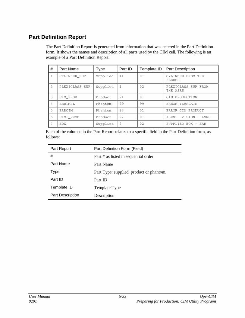
User Manual 5-33 OpenCIM0201 Preparing for Production: CIM Utility Programs
Part Definition Report
The Part Definition Report is generated from information that was entered in the Part Definitionform. It shows the names and description of all parts used by the CIM cell. The following is anexample of a Part Definition Report.
# Part Name Type Part ID Template ID Part Description
1 CYLINDER_SUP Supplied 11 01 CYLINDER FROM THEFEEDER
2 PLEXIGLASS_SUP Supplied 1 02 PLEXIGLASS_SUP FROMTHE ASRS
3 CIM_PROD Product 21 01 CIM PRODUCTION
4 ERRTMPL Phantom 99 99 ERROR TEMPLATE
5 ERRCIM Phantom 93 01 ERROR CIM PRODUCT
6 CIM1_PROD Product 22 01 ASRS - VISION - ASRS
7 BOX Supplied 2 02 SUPPLIED BOX + BAR
Each of the columns in the Part Report relates to a specific field in the Part Definition form, asfollows:
Part Report Part Definition Form (Field)
# Part # as listed in sequential order.
Part Name Part Name
Type Part Type: supplied, product or phantom.
Part ID Part ID
Template ID Template Type
Part Description Description

User Manual 5-34 OpenCIMPreparing for Production: CIM Utility Programs 0201
Subpart Report
The Subpart Report is generated from information that was entered in the Part Process Table inthe Part Definition form. The Subpart Report is a Bill of Material. It shows all the subpartswhich comprise the finished product. The following is an example of a Subpart Report.
Part Name Sub-Part Name ManufacturingProcess Name
Manufacturing Parameters
CIM_PROD PLEXIGLASS_SUP
READC $TEMPLATETYPE
ERRTMPL ONFAIL ASRS
CYLINDER_SUP ASSEMBLY
VISION 1
ERRCIM ONFAIL TRASH1
TARGET RACK1
CIM1_PROD BOX
READC $TEMPLATETYPE
ERRTMPL ONFAIL ASRS
VISION 1
ERRCIM ONFAIL TRASH1
Each of the columns in the Subpart Report relates to a specific field in the Part Definition form.
Subpart Report Part Process Table (Field)
Part Name Part Name.
Sub-Part Name The column “Subpart” in the Part Process Table.
ManufacturingProcess Name
The column “Process” in the Part Process Table.
ManufacturingParameters
The column “Parameters” in the Part Process Table for eachcorresponding process for a particular subpart.

User Manual 5-35 OpenCIM0201 Preparing for Production: CIM Utility Programs
Manufacturing Order Report
The Manufacturing Order Report displays all production orders for a particular date.
The report is generated from the information that was entered in the Manufacturing Order form.The following is an example of a Manufacturing Order Report.
Date Part Name Total Numberof Ordered Parts
InitialNumberto Produce
Priority Final StorageLocation(if not ASRS)
2 CIM_PROD PLEXIGLASS_SUP 5 7
Each of the column headings in the Order Report relates to a specific field in the ManufacturingOrder form, as follows:
Manufacturing Order Report Manufacturing Order Form
Part Name The column “Part”.
There can be more than one part listed.
Total Number of PartsOrdered
The column “Total Qty”.
Each Total Qty listed corresponds to a specific part ordered.
Initial Number to Produce The column “Initial Qty”.
Each Initial Qty listed corresponds to a specific part ordered.
Priority The column “Priority”.
The Priority level (from 1 - 9) listed corresponds to a specificpart ordered.
Final Storage Location (if notASRS)
Refers to the final storage location listed in the column “Note”(for a specific part).

User Manual 5-36 OpenCIMPreparing for Production: CIM Utility Programs 0201
Machine Report
The Machine Report lists the names of all machines in the OpenCIM cell. This report isgenerated from the information that was entered in the Machine Definition form. Following is anexample of a Machine Report.
# Machine Name Cost Per Hour MaximumNumber ofPreloadedPrograms
Program #1 Program #2 Program #3
1 ASMBUF 1.5
2 RDR1 3
3 VSN1 1
4 MILL1 27 2 M:GC
Each of the columns in the Machine Report relates to a specific field in the Machine Definitionform, as follows:
Machine Report Machine Definition Form (Field)
# The sequential number of the machine as listed.
Machine Name Machine Name
Cost Per Hour Cost Per Hour, in the Machine Process table.
Maximum Numberof Preloaded Programs
Max Preloaded Programs
Program 1Program 2Program 3
List of Preloaded Programs

User Manual 5-37 OpenCIM0201 Preparing for Production: CIM Utility Programs
Process Report
The Process Report shows the user-defined name (Process Name field) of each machine in theOpenCIM and the processes performed by the machine. This report is generated from informationthat was created from the Machine Process Table in the Machine Definition form. The followingis an example of a Process Report.
# Machine Name Process Name Process Type Program File Name
1 RDR1 READC QC
2 VSN1 VISION QC
3 MILL1 MILL-CUBE CNC
Each of the columns in the Process Report relates to a specific field in the Machine Definitionform, as follows:
Process Report Machine Process Table (Field)
# The sequential number of the machine as listed.
Machine Name Machine Name.
Process Name The column “Process” in the Machine Process Table.
Process Type The column “Action Type” in the Machine Process Table.
Program File Name The column “File” in the Machine Process Table.

User Manual 5-38 OpenCIMPreparing for Production: CIM Utility Programs 0201
ASRS Report
The ASRS Report shows the contents of the ASRS. It is generated from information that wasentered in the Storage Definition form. The following is an example of an ASRS Report.
Name Index Part Name Part ID Status Template #
ASRS 1 PLEXIGLASS_SUP 0 Part on Template 010001
ASRS 2 EMPTY 0 Empty Template 010003
ASRS 3 EMPTY 0 Empty Empty
ASRS 4 PLEXIGLASS_SUP 0 Part on Template 010004
ASRS 5 PLEXIGLASS_SUP 0 Part on Template 010005
ASRS 6 PLEXIGLASS_SUP 0 Part on Template 010006
Each of the column headings in the ASRS Report relates to a specific field in the StorageDefinition form, as follows:
ASRS Report Storage Definition Form (Field)
Name Name of storage location
Index The number displayed in parentheses below the ASRS grid; e.g.,ASRS (15). This is an internal index used in communication betweenthe CIM Manager and the ASRS robot controller (and not the Index ofthe graphically displayed ASRS cell.)
Part Name The name of the part residing in the current storage cell as defined inthe Part Definition form (refer to cell in grid).
Part ID Part ID, as defined in the Part Definition form.
Status Status of the storage cell (Empty, Empty Template or Part onTemplate).
Template Number The six-digit template number.

User Manual 5-39 OpenCIM0201 Preparing for Production: CIM Utility Programs
Analysis Report
The Analysis Report is detailed information on the status of the entire system and is geared forthe more experienced user. The report contains a Log file summary – the start and the finish ofeach action. See below for an example of an Analysis Report.
Part Name Device Action Sub Part Name Target Index Status Time
PLEXIGLASS_S ROBOT1 Pick &Place
TEMPLATE#010001 RDR1 Start 11:13:48
ROBOT1 Pick &Place
TEMPLATE#010001 RDR1 Finish 11:13:50
RDR1 READC PLEXIGLASS_SUP Finish 11:13:52
ROBOT1 BASE TEMPLATE ASMBUF Start 11:13:52
ROBOT1 BASE TEMPLATE ASMBUF Finish 11:13:54
CYLINDER_SUP ROBOT1 PACK CYLINDER_SUP/1.1 PLEXIGL 1 Start 11:13:55
ROBOT1 PACK CYLINDER_SUP/1.1 PLEXIGL 1 Finish 11:13:56
The following is a description of each of the columns in the Analysis Report:
Heading Description
Part Name The name of the part as defined in the Part Definition form or in the VirtualCIM Setup.
Device The name of the robot, machine or conveyor that performs the operation, asdefined in the Machine Definition form.
Action Robot: (pick-and-place)
Assembly: (base and pack)
Conveyor: (deliver) or machine (the name of process as defined in theMachine Process Table).
Subpart Name Robot: the number of a template or the name of a part.
Machine: the name of a part or material.
Target Where the process should be performed.
Index Indicates the exact location on a device which has more than one locationfor a part.
Status The status of the action (start or finish).
Time The time the action started or the time the action was completed.

User Manual 5-40 OpenCIMPreparing for Production: CIM Utility Programs 0201
Location Status Report
The Location Status Report is a detailed listing of every location defined in the CIM system. Thisreport is used by the system administrator or the more experienced user for debugging the system.
There is more than one type of location.
• Locations defined in the Virtual CIM Setup. Every ASRS compartment, every station on theconveyor, places on a buffer and places inside the machine.
• Every template, a part of an assembly (e.g. one part is on top of another part), a gripper on arobot, every part in the system.
The Location Status Report enables you to know exactly what and where something is in thesystem at a given time. The following is an example of a Location Status Report.
Location ID Index Part Name Status #1 #2 Template Number Type
ROBOT1 11 1 EMPTY Empty 0 0 EMPTY R
VSN1 12 1 EMPTY Empty 0 0 EMPTY V
CNV1 1 1 EMPTY Empty 0 0 EMPTY C
CNV1 1 2 EMPTY Empty 0 0 EMPTY C
ASRS 3 1 PLEXIGLASS_SUP Part on Template 0 0 TEMPLATE #010001 A
The following is a description of each of the columns in the Location Status Report :
Heading Description
Location The name of the location.
ID The location ID (numeric) as defined in the Virtual CIM Setup.
Index Indicates the exact location on a device which has more than onelocation for a part..
Part Name The name of the part in this location as defined in the Part Definitionform.
Status Status of the specified location (Empty, Part on Template, EmptyTemplate or Part).
Template Number The number of the template at this location.
Type The type of device as defined in the Virtual CIM Setup.

User Manual 5-41 OpenCIM0201 Preparing for Production: CIM Utility Programs
A-Plan Report
The A-Plan Report is a detailed description of the manufacturing process to be performed by theCIM system. The A-Plan is created when you click MO in a completed Manufacturing Orderform. The A-Plan is a table of sequential instructions which the CIM Manager executes in orderto produce the products being ordered.
This report is intended for the more experienced user. See “Experimenting with ProductionStrategies Using the A-Plan” in Chapter 8 for detailed information on how the part will beproduced.
The following is an example of an A-Plan Report.
Part # Process Subpart Target Index Duration Parameters
CIM_PROD/1 1 MAKE CIM_PROD/1.1 1 4,1,1,p,1,00:00:00
CIM_PROD/1.1 1 GET PLEXIGLASS_SUP ASRS
CIM_PROD/1.1 2 READC 00:00:00 $TEMPLATETYPE
CIM_PROD/1.1 3 ONFAIL ERRTMPL/1.1 ASRS

User Manual 5-42 OpenCIMPreparing for Production: CIM Utility Programs 0201
Purchase Order Report
As explained earlier in this chapter, clicking on the PO icon in the MRP program activates theReport Generator, which will display or print the Purchase Order.
You can also generate a Purchase Order directly from the Report Generator menu, withoutactivating the MRP program. When Purchase Order is selected, a submenu allows you to print ordisplay either all or some of your purchase orders.
Figure 5-13: Generating Purchase Order Report
User-Defined Report
The User-Defined Report allows you to design and customize a report to the exact specificationsof your CIM system. You can create an unlimited number of User-Defined Reports.
The Report Generator program employs Seagate (Microsoft) Crystal Report (also available inVisual Basic) to generate the OpenCIM reports. The Crystal Report program necessary to createyour own user-defined report is not included with the OpenCIM software and must be purchasedseparately. Refer to the documentation provided by the Microsoft Visual Basic Crystal Report forinstructions on how to create a report.

User Manual 6-1 OpenCIM0201 Operating the CIM
6
Operating the CIM
This chapter describes the CIM modules that are used for operating the OpenCIM system andcontrolling production. These icons comprise the second OpenCIM group after installation iscomplete.
Activates the CIM Manager program.
Activates the graphic display and tracking of the CIM cell.
Activates the Loader, which loads the station device driver programs. For fullinformation on the OpenCIM Device Drivers, refer to Chapter 8.
Other icons that pertain to these modules will be introduced and discussed in the relevantsections.

User Manual 6-2 OpenCIMOperating the CIM 0201
CIM ManagerThe CIM Manager program centrally controls all the activities of the OpenCIM cell.
Figure 6-1: CIM Manager Screen
Modes of Operation
The CIM Manager can operate in either of two modes:
Simulation Mode: the CIM Manager does not communicate with device drivers. This mode doesnot require either hardware or device drivers.
Real Mode: the CIM Manager communicates with all device drivers, whether or not hardware isin use. This mode requires that all device drivers which are needed for a specific application(for a specific product order) be loaded, so that the CIM Manager can transmit and receivemessages.
Since the CIM Manager affects operation of the CIM cell hardware by communicating with thedevice drivers (and not directly with the hardware), the CIM Manager can operate in real modeeven if the hardware has not been activated, or even if no hardware exists.
CIM ManagerMode of Operation
Device Driver Hardware
Simulation Not required. Not required
Real Mode All device drivers must beloaded.
Not required.Hardware may be activated, or itmay be simulated by the devicedrivers, at some or all stations.

User Manual 6-3 OpenCIM0201 Operating the CIM
CIM Manager Control Bar
Green button. Loads the production work order (A-Plan). Openscommunication channel. This sends a command to reset (INIT)all device drivers. The run arrow turns green, indicating that it isavailable for use. The production plan will appear in the ProgramView screen.
Figure 6-2: Production Control Bar
Green arrow. Starts executing the A-Plan. CIM productionbegins. The pause button turns blue and the emergency buttonturns red, indicating that they are available for use.
Blue bars. Halts operation at any time; causes the CIM Managerto stop sending commands to the device drivers and then waituntil the Resume button (which has turned red) is pressed. Alldevice drivers complete the current command.
�Note
CIM devices do not stop immediately when you click the Pausebutton. Each device will complete its current operation before itstops.
Resumes operation after production has been paused.
Red button. Stops production. It can be used as emergency button
Resets storage or default storage. Restores a predefinedconfiguration of the storage from the backup database file.
Enters the CIM modes dialog box

User Manual 6-4 OpenCIMOperating the CIM 0201
CIM Modes Dialog Box
Figure 6-3: CIM Modes Dialog Box
CIM Mode REAL In this mode there is message interchange between Manager andDevice Drivers.
SIMULATION The production runs on the Manager. There is no messageinterchange between any devices. You can set the production speed for thesimulation, where 1 is the slowest and 100 is the fastest.
Tracking Mode Tracking Mode must be activated in order to generate a planned schedule forthe current order. This schedule is normally produced and displayed when theCIM Manager is operating in Simulation mode (see “CIM Scheduler” later inthis chapter for further information).
GraphicDisplay
Specifies whether or not status messages are sent from the devices inoperation to the Graphic Display module so that the display is updatedaccordingly.
�Note
If the Graphic Display is not activated on any PC, click No, otherwise themanager will work very slowly.
UpdateProcess Time
Updates the duration of any process defined in Machine Definition. Theduration is the actual time that a machine has taken to complete a process.

User Manual 6-5 OpenCIM0201 Operating the CIM
To begin producing an order, do the following:
�
�
�
Procedure
Starting Production
1. Start all OpenCIM device drivers by clicking on the DD Loader icon ateach Station Manager PC. (Skip this step if you intend to work inSimulation mode.)
2. Select either Real Mode or Simulation Mode from the CIM Modes dialogbox.
3. Reset the Storage by clicking the Refresh Storage icon .
4. In the CIM Manager, click the Green button.
5. Click the Run button to start executing the production plan.
�
Note
For safety reasons, when operating the CIM in Real Mode, you must use the actualhardware EMERGENCY buttons to halt the system in an emergency.
Views
During the manufacturing process, you can track production by looking at up to eight differentview screens.
• Program
• Order
• Storage
• Device
• Log
• Pallet
• Leaf (only after Run is pressed)
• Event (only after Run is pressed)
• Message History
Click the appropriate icon on the control bar to open the desired View screen, or select the desiredView from the alphabetical list in the Window drop-down menu. Alternatively you can replacethe Graphic Display in the lower half of the Manager with the desired View screen (with theexception of Log and Event) by clicking the appropriate tab.

User Manual 6-6 OpenCIMOperating the CIM 0201
Order View
The Order View is a copy of the Manufacturing Order. It is the most basic of the available views.
Figure 6-4: Order View
The following is an explanation of each column in the Order View.
No. Line number from Manufacturing Order.
PART Name of part; as defined in Part Definition Form used in ManufacturingOrder.
Total Total number of parts to be produced, as defined in Manufacturing Order.
Done Number of parts that have been completed. Updated during production.
Fails Number of parts that have failed inspection. Updated during production.
In Process Number of parts that are being manufactured. Updated during production.
Storage View
The Storage View resembles the Location Status Report (see Chapter 5). This view is a detailedlisting of every location defined in the CIM system.
Figure 6-5: Storage View

User Manual 6-7 OpenCIM0201 Operating the CIM
The following is an explanation of each column in the Storage View.
Storage A list of all the locations in the CIM cell.
Index Indicates the exact location on a device which has more than one location fora part. For example, the conveyor (CVN1) has three indices, one for eachstation; the robot identified as ROBOT2 has only one index; the ASRS1 hasan index for each of its cells.
Status Graphic illustration of the contents of the location, as defined in the PARTand TEMPLATE columns. For example, MILL1 has a part named BOX.
PART Status of the specified location: either Empty or the Name of the part if itexists at the location.
TEMPLATE Status of the specified location: either Empty or the ID of the template if itexists at the location.
Device ID Device ID number defined in the Virtual CIM Setup (or assigned by theCIM Manager during production).
Program View
The Program View is a copy of the A-Plan, or production work order. You can track the currentstatus of production by watching the Program View. This screen shows the commands that theCIM Manager executes to produce an order. These commands are executed in bottom-up order.
Figure 6-6: Program View
The following is an explanation of each column in the Program View screen.
Level This hierarchy number indicates the level in the Part Definition tree foreach ordered product. Operations at the same level can occur in parallel(except an ONFAIL process).
Part Unique name used to identify the subpart currently under production.
Action The A-Plan command or user-defined process that the CIM Managerexecutes to produce a part.
Subpart The part or object which the A-Plan action operates on.

User Manual 6-8 OpenCIMOperating the CIM 0201
Target The destination where this subpart is to be delivered.
# Parameters used by this command or process.
P1 - Pn Shows the current production status. The number of shaded Partcolumns corresponds to the total number of parts ordered.
When a part is being produced, one of the following symbols appears atthe current stage of production:
↵ Command sent, waiting for acknowledgment.
ON Device has begun processing this part (device driver hasresponded with Start message).
OFF Device finished processing this part (device driver has respondedwith Finish message).
� The blue box indicates operation completed (device driver hasresponded with End message).
WAIT CIM Manager is waiting for another operation to completebefore sending this command.
Device View
The Device View is a complete list of every robot and machine (including QC devices) in theCIM cell and a description of the current action being performed by each.
Figure 6-7: Device View

User Manual 6-9 OpenCIM0201 Operating the CIM
The following is an explanation of each column in the Device View.
DEVICE Name of the device or machine, as defined in the Virtual CIM Setup.
Status When a part is being produced, one of the following symbols appears at thecurrent stage of production:
RUN Command sent, waiting for acknowledgment.
Start Device has begun processing this part (device driver has respondedwith Start message).
Finish Device finished processing this part (device driver has respondedwith Finish message).
End Device ended processing this part (device driver has responded withEnd message).
Stop Device is ready for next command.
Load Device is loading the processing program from the Backup or theDatabase.
ACTION The movement or operation command which is currently being executed bythe device. For robots, the action is commonly the placement of a part. Formachines, the action is usually the name of the process (as defined in theMachine Definition form).
Station The number which identifies the workstation where the device is located.
ID The Device ID number, as defined in the Virtual CIM Setup.
Log View
The Log View is a transcript of the Leaf View. It details all messages which have been sent andreceived by the CIM Manager.
Figure 6-8: Log View
Each line in the Log View will have one of the following status reports:
• Activated: CIM Manager has determined that a command can be sent to a machine (e.g., arobot or CNC machine).

User Manual 6-10 OpenCIMOperating the CIM 0201
• In Process: command has been sent to the machine; for example: GET part from device A(source) and PUT part in device B (target).
• Start: Operation has started. Source device may now receive its next command (i.e., another“Activate”). Used, for example, to notify CIM Manager that a pallet can be released from aconveyor station.
• Finish: Operation has been completed. Target device may now receive its next command (i.e.,another “Activate”).
• Done (End). The machine is now ready to receive its next command.
Figure 6-9: Log View Flow Chart - Example forACL Device Driver
You can control the amount of information that is displayed by editing the CIM Manager INI file.By default, the system is set to display only IN PROCESS and DONE messages, which allowyou to see which commands have been sent and which have been executed.
Pallet View
The Pallet View is a complete list of every pallet in the CIM cell and a description of its currentstatus.
Figure 6-10: Pallet View

User Manual 6-11 OpenCIM0201 Operating the CIM
The following is an explanation of each column in the Pallet View.
No. Identification number of the pallet
Status Describes the status of
Ready Pallet has not yet reached a station.
Pass Pallet is moving; has passed through the last station.
Stop Pallet has been stopped at a station to be unloaded.
Stop[Free] Pallet has been stopped at a station to be loaded.
Released Pallet has been released from a station.
To Station Number of the next workstation which pallet will reach. If pallet status isFree, the destination is Station 999.
PART Name of part or subpart being carried by pallet.
Product Name of final product to which part belongs.
Template Identification number of the template being carried by the pallet.
Last Station Number of the last workstation which pallet has passed through.
Sim Place “Simulated position”; a sector location on the conveyor, as used in thesimulated graphic display.
Leaf View
The Leaf View provides a detailed description of the production activities of the CIM cell,describing the current operation being performed on each item and the operation that willimmediately follow.
Figure 6-11: Leaf View
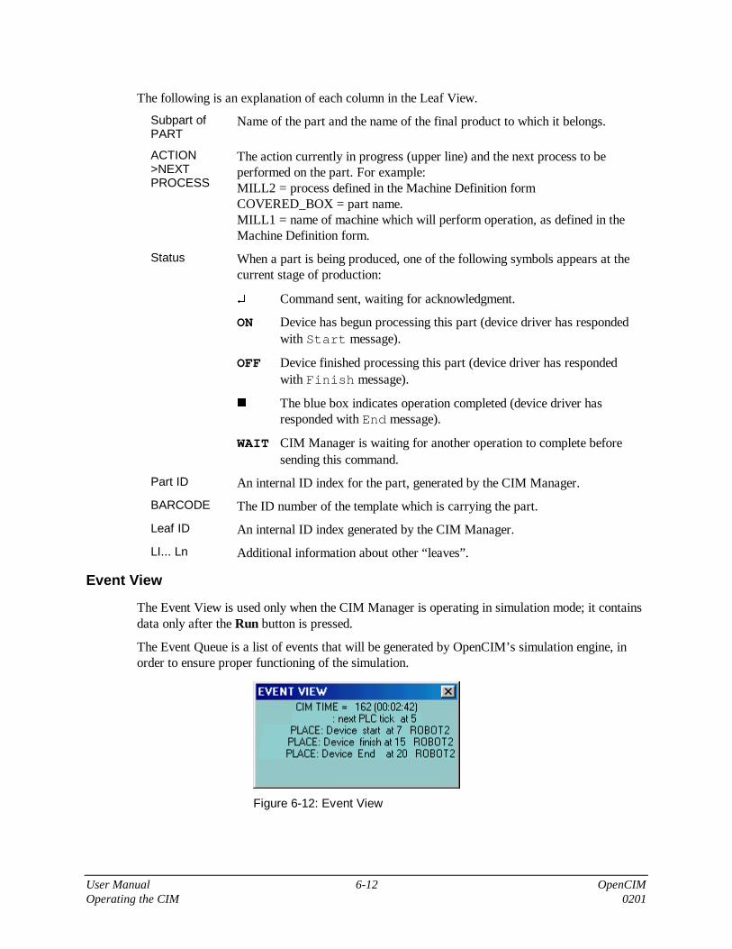
User Manual 6-12 OpenCIMOperating the CIM 0201
The following is an explanation of each column in the Leaf View.
Subpart ofPART
Name of the part and the name of the final product to which it belongs.
ACTION>NEXTPROCESS
The action currently in progress (upper line) and the next process to beperformed on the part. For example:MILL2 = process defined in the Machine Definition formCOVERED_BOX = part name.MILL1 = name of machine which will perform operation, as defined in theMachine Definition form.
Status When a part is being produced, one of the following symbols appears at thecurrent stage of production:
↵ Command sent, waiting for acknowledgment.
ON Device has begun processing this part (device driver has respondedwith Start message).
OFF Device finished processing this part (device driver has respondedwith Finish message).
� The blue box indicates operation completed (device driver hasresponded with End message).
WAIT CIM Manager is waiting for another operation to complete beforesending this command.
Part ID An internal ID index for the part, generated by the CIM Manager.
BARCODE The ID number of the template which is carrying the part.
Leaf ID An internal ID index generated by the CIM Manager.
LI... Ln Additional information about other “leaves”.
Event View
The Event View is used only when the CIM Manager is operating in simulation mode; it containsdata only after the Run button is pressed.
The Event Queue is a list of events that will be generated by OpenCIM’s simulation engine, inorder to ensure proper functioning of the simulation.
Figure 6-12: Event View

User Manual 6-13 OpenCIM0201 Operating the CIM
For example:
CIM TIME = 162 (02:42) Indicates amount of time that has passed (162seconds, or 2 minutes, 42 seconds) since the Runbutton was pressed.
PLACE: Device start at 7 ROBOT2...PLACE: Device finish at 15 ROBOT2
Indicates Robot 2 will send a Start message in 7seconds and a Finish message in 15 seconds.
Message History
Figure 6-13: Message History Dialog Box
The Message History View allows you to view three types of messages:
External Messages: All messages that the CIM Manager sends to drivers via the TCP/IP protocoland vice versa.
Internal Messages: Enables you to check CIM Manager setup parameters, e.g. path to databasefiles, path to utilities, simulation speed, etc.
CIM Warnings: All warnings issued by the CIM Manager. The last message is highlighted inyellow. When a warning message is issued, the Message History dialog box opens. The mostfrequently issued warning message is: “Part not currently available. Update storage”.

User Manual 6-14 OpenCIMOperating the CIM 0201
CIM SchedulerThe CIM Scheduler allows you to view various production schedules and determine the mostefficient one. The Scheduler is a Gantt utility that displays the exact timing and scheduling of thedifferent phases of production.
Figure 6-13: CIM Scheduler-Gantt Chart
The Scheduler can display two kinds of production schedules:
• Planned: This schedule is normally produced and displayed when the CIM Manager isoperating in Simulation mode. Tracking mode must be activated from the CIM Mode dialogbox (see “CIM Mode Dialog Box” earlier in this chapter).
• Actual: This schedule is normally produced and displayed when the CIM Manager is operatingin Real mode. The Tracking mode is deactivated.
The left side of the Scheduler screen is a textual description, while the right side is a graphicrepresentation (Gantt chart) of the production schedule.
Click and drag on the vertical lines in the table to increase and decrease column widths.

User Manual 6-15 OpenCIM0201 Operating the CIM
Menu Options
The following options are available in the Display menu:
On Line,
Off Line
• When the Scheduler operates on-line, it displays data from the CIMManager. (No data is displayed until the CIM Manager commencesproduction.)
• When the Scheduler operates off-line, it displays information fromManager.
Data is displayed as either Actual or Planned, depending on the definition inthe [Scheduler] section of the CIM Manager’s INI file.
Shows the activities of machines and the parts they process.
Shows the progress of parts, and the machines which process them.
Displays current order on the screen.
DisplayOptions
Figure 6-14: Scheduler Display Options
Zoom: Value of time interval compression in Gantt chart display.
Show: Checked items are displayed in the textual display.
How to Create a Planned Production Schedule
To create a planned production schedule, do the following:
�
�
�
Procedure
Generating aPlanned ProductionSchedule
1. Activate the CIM Manager
2. From the CIM Modes Dialog Box, activate the tracking mode.
3. Reset storage.
4. Activate the CIM Scheduler.
5. Click Start.
6. Click Run. Wait for the CIM Manager to complete an entire productioncycle.
� Tip:To speed up the simulation, change the value of the simulation speedin CIM Modes Dialog Box.
After you have generated a planned schedule, you can run the CIM Manager in real mode inorder to track and display the actual schedule, and see how it compares with the plannedschedule.

User Manual 6-16 OpenCIMOperating the CIM 0201
Graphic Display and TrackingThe OpenCIM Graphic Display module shows a real-time, 3D animation of the operations beingperformed in the CIM cell in both Simulation and Real mode.
As each device performs an operation, its device driver transmits status messages to the CIMManager reporting the outcome. For example:
• A device driver responds to a command sent from the CIM Manager.
• A device driver responds to a command sent from another device driver (e.g. when a CNCdevice driver responds to commands sent by a robot’s ACL device driver to open and close itsdoor).
• The PLC device driver sends a Pass message indicating that a pallet that is not needed at thisstation has just gone by. Pass messages are generated only to allow the Graphic Trackingmodule to update its conveyor display, and are not used by the CIM Manager or any otherCIM entity.
The CIM Manager relays these messages to the Graphic Tracking module, which then updates itsdisplay accordingly. For example, it can show:
• Parts as they move from device to device (e.g. a robot picking up a part from a template andputting it in a CNC machine).
• Pallets moving around the conveyor.
The Graphic Tracking module can display the movement of pallets on the conveyor based onthe status messages it receives as each pallet passes a conveyor station. The Graphic Trackingmodule estimates the position of pallets as they travel between stations and updates its displayaccordingly. It synchronizes its display with the actual pallet position every time a palletpasses a conveyor station.
Figure 6-15: Graphic Display on Manager

User Manual 6-17 OpenCIM0201 Operating the CIM
Tool Bar of Graphic Display
CIM Explore. Displays the names of any CIM cells created by the user.
Save.
Group. Creates a Window group.
Setup. Creates or overwrites the SETUP.CIM file.
Load. Creates WSn.INI files for each station.
New Object. Opens dialog box with all available objects.
Delete Object. Deletes currently selected object.
Drag Object. Allows dragging of object from one location to another.
Show Name. Shows name of the object.
Show ID. Shows ID of the object.
Show Position. Shows coordinates (from bottom left corner).
Redirect.
Camera Top.
Drag 3D Frame.
About.
The Graphic Display of a working OpenCIM cell is displayed in the CIM Manager window and itcan also be displayed on another PC in three different 3D views in the same time on the samescreen as shown in the figure below:

User Manual 6-18 OpenCIMOperating the CIM 0201
Figure 6-16: Graphic Display
Following is the correct procedure for graphically tracking production.
�
�
�
Procedure
Graphic Tracking ofProduction
1. Click Graphic Display.
2. Open the CIM Manager. Click the Green Load button. Click Run (Greenarrow).
3. Now you can observe the operations performed in the CIM cell in bothGraphic Displays: the Manager and in the 3D views.

User Manual 6-19 OpenCIM0201 Operating the CIM
Views
The Graphic Display module offers two types of views:
• An overhead view
• An elevated side view
�NoteWhen the Simulation window opens, it always displays the view that was displayed whenyou last closed either the Graphic Display or the Virtual CIM Setup window.
To manipulate the views, do the following
�
�
�
Procedure
Manipulating theGraphic Display
1. To change the angle of the overhead scene, place the cursor on the verticalscroll bar and drag it up and down. (It is recommended that you click on thevertical scroll bar up and down arrows.)
2. To rotate the scene, place the cursor anywhere on the screen and:
• Click the right mouse button and drag to the right to rotate the displaycounterclockwise.
• Click the right mouse button and drag to the left to rotate the displayclockwise.
3. To zoom the scene, place the cursor anywhere on the screen and:
• Click the right mouse button and drag up to zoom in.
• Click the right mouse button and drag down to zoom out.
�
�
�
Procedure
Changing the Focusof the GraphicDisplay
1. Click on View | Redirect Camera.
2. Click any object in the scene. It now becomes the center point for thedisplay manipulation. The view changes to an overhead scene (if it is notalready), which you can now manipulate, as described above.

User Manual 6-20 OpenCIMOperating the CIM 0201
The Text menu allows you to select the kind of captions you want to include in the graphicdisplay. Only one kind of text can be selected at a time.
None No text. Select None to remove the currently displayed caption. You may thenselect another kind of text. (Note that there is no checkmark in the menu toindicate your selection.)
Name Name of machines and devices.
Ext. ID External ID number, as defined in the Virtual CIM Setup.
Pallets Displays the ID number of the pallets.
Templates Displays the ID number of the templates.
Parts Displays the ID number of the parts.
The File menu offers the following options:
Open Loads a new graphic CIM cell. Do not use.
Exit Quits the Graphic Display module.

User Manual 6-21 OpenCIM0201 Operating the CIM
CIM Cell Startup
Operation in Simulation Mode
To start the CIM cell do the following:
1. From the OpenCIM DEMO group, click CIM Manager and then Graphic Display.
2. From the Manager Control Bar, click on Default Storage.
3. Optionally, click the Scheduler Gantt.
4. Click the Green Load button to start, and then, to commence production, click Run.
Operation in Real Mode
�Warning!
Before starting actual production, make sure you are in compliance with all the safetymeasures detailed in Chapter 3.
1. Remove any templates on the conveyor and at station buffers.
2. Remove any parts left at stations: in a robot’s gripper, in a machine and on storage racks.
3. Load parts into the ASRS and into any feeders.
4. Turn on all hardware: PCs, controllers, CNC machines, etc.
5. Make sure all PCs have been activated.
6. At each Station Manager PC, click Load Station.
7. Choose the mode in which you want to load the DDs and click the Green button.
8. At each station, home the robot and initialize all equipment.
9. Start the Graphic display in PC Graphic.
10. At the CIM Manager PC do the following:
• Click CIM Manager.
• Optionally, click the Scheduler.
• Click the Green Load button, and then, to commence production, click Run.
�Note
You can turn on OpenCIM workstation PCs and hardware in any order. Thereis no mandatory boot-up sequence. You can also reboot a PC as long as it isnot in the middle of an operation or communicating with the CIM Manager. Ifyou reset a PC, you do not need to reset other workstation PCs connected to theOpenCIM network. When the PC boots up, its applications will resumecommunication with other PCs on the OpenCIM network.


User Manual 7-1 OpenCIM0201 OpenCIM Setup
7
OpenCIM Setup
�
Note
This chapter is not applicable to OpenCIM Intro.
Virtual CIM SetupThe Virtual CIM Setup is an interactive graphic module that allows you to createa simulated CIM cell. The Virtual CIM may contain the actual elements andconnections of a real CIM installation, or it may define a theoretical CIM.
The first part of this chapter presents the menus and screen elements of the Virtual CIM Setupmodule. You are then encouraged to perform the “Tutorial,” which will enable you to practiceusing this module and create a Virtual CIM.
Click the Virtual CIM Setup icon to open the Setup screen. A number of menus are available.However, many menu items will not be available until a setup has been created or loaded.
File Menu
New Opens the New OpenCIM Item box, which prompts you for the name of theCIM cell you want to create.
The name you provide will become a subdirectory of your OpenCIM installationdirectory (e.g. C:\OPENCIM32\cellname). Do not use a name that alreadyappears in the OpenCIM installation directory.
Open Opens the Select Item menu. By default, this menu displays the manufacturer-supplied DEMO. It also displays the names of any CIM cells created by the user.
If you click on DEMO, the Scene Window will appear on the screen, as shown inthe following figure.

User Manual 7-2 OpenCIMOpenCIM Setup 0201
Figure 7-1: DEMO Virtual CIM Setup
� Note
When the Scene window opens, it will always display the view that was displayedfor the particular setup (e.g., DEMO) when you last closed the Virtual CIMSetup module or the Layout you have saved using the Save layout option.
Save Saves the current placement of all objects in the CIM cell.
Exit Exits the Virtual CIM Setup module. You will be prompted to save the currentplacement of objects.
�Tip
To delete a Virtual CIM cell setup, highlight the name of the cell in the Select Itemmenu and press Delete.You cannot delete a cell that is currently open. When you delete a cell from theSelect Item menu, the subdirectory and all files in it will be deleted.

User Manual 7-3 OpenCIM0201 OpenCIM Setup
Viewing
The Virtual CIM Setup module uses the same method as the Graphic Display module formanipulating the view of the CIM cell.
�
�
�
Procedure
Manipulating theGraphic Display
1. To change the angle of the overhead scene, place the cursor on the verticalscroll bar and drag it up and down.
2. To rotate the scene, place the cursor anywhere on the screen and:
• Click the right mouse button and drag to the right to rotate the displaycounterclockwise.
• Click the right mouse button and drag to the left to rotate the displayclockwise.
3. To zoom the scene, place the cursor anywhere on the screen and:
• Click the right mouse button and drag up to zoom in.
• Click the right mouse button and drag down to zoom out.
�
�
�
Procedure
Changing the Focusof the GraphicDisplay
1. Click on View|Redirect Camera.
2. Click any object in the scene. It now becomes the center point for thedisplay manipulation. The view changes to an overhead scene (if it is notalready), which you can now manipulate, as described above.

User Manual 7-4 OpenCIMOpenCIM Setup 0201
Edit Menu: New Object
Once you have defined a name for your new CIM cell, select Edit | New Object to open thismenu:
Figure 7-2: Object Item List
The CIM Setup menu is a list containing all the elements which can be included in the VirtualCIM Setup.
Double click on the [+] button of a category in order to expand its list of elements.
After you select an object, move the cursor into the graphic scene. The cursor changes to a cube.Point and click on the location where you want to place the object. You may need to wait amoment for it to appear; do not double-click.
Conveyor
Since the Virtual CIM conveyor is the most difficult of the elements to place in the scene, thissection contains detailed, procedural instructions for creating a conveyor.
If you are replicating an actual CIM cell, you will need to know the exact dimensions of theconveyor.
1. From the CIM Setup menu, select General | Conveyor. You will be prompted to selectNormal or Enlarged.
• If Conveyor Type Normal (default) is selected, each grid represents about 20 cm. Atypical OpenCIM conveyor measures 3 m x 4 m (with straight segments of 1.40m) whichcan fit onto this grid.
• If Conveyor Type Enlarged is selected, the grid resolution is increased, which allows youto place a larger conveyor (8 m x 10 m) into the CIM cell.
A grid will appear on the screen. The set of numbers displayed on the left are the screen pixelcoordinates of the cursor, while the numbers on the right are metric coordinates (in meters).

User Manual 7-5 OpenCIM0201 OpenCIM Setup
�Note
When creating a conveyor, use the mouse buttons as follows:
• Click with the right mouse button and drag to select menu options.
• Point and left-click to place objects on the grid.
2. To select the starting point of the conveyor, do the following.
Place the cursor on the grid and right-click to open this icon menu:
The key icon is used to mark the starting point of the conveyor.
The spectacles icon opens another icon menu. Do not attempt tomanipulate the displayed values. These settings are for technicalsupport personnel only.
The grid icon toggles the grid display on and off.
Drag and select the key icon. A wand-pointer appears on the screen. Use this cursor to clickon a starting point for the conveyor. It should be placed on the right side of the grid, asshown in Figure 7-3: Adding Conveyor Segments. A red dot appears on the grid.
Since the conveyor movement is normally counterclockwise, the conveyor segments are addedin the counterclockwise direction.
3. To create the conveyor, do the following:
Again click on the right mouse button. An icon menu will open.
The first six icons represent segments of the conveyor. Segments areadded and connected in consecutive order.
To insert a straight segment, select either the horizontal or verticalbar. Using the left mouse button, place the pointer on the squarewhose upper left hand corner marks the end of the segment you wantto add. Note the placement of the cursor in the figure below in orderto align the segment at the bottom with the segment at the top.
The white curved arrow in the blue circle is used to reverse thedirection of conveyor movement. When this icon is selected, conveyormovement is clockwise, and the segments will be added accordingly.
Undo. The green curved arrow cancels the last segment(s) added tothe conveyor. Undo is available after the first segment has beenplaced on the grid.
OK. This button will appear when you have completely connected allsegments of the conveyor.
The spectacles icon opens another icon menu. Do not attempt tomanipulate the displayed values. These settings are for technicalsupport personnel only.

User Manual 7-6 OpenCIMOpenCIM Setup 0201
Using the icon menu, select and connect each segment of the conveyor.
Figure 7-3: Adding Conveyor Segments
�Tips
Avoid using too many UNDOs while drawing the conveyor; a faulty display may result.
When drawing the conveyor, do not extend the straight segments too close to the edge.Allow enough room for the corner segments.
4. When you have completed drawing the conveyor, click on the OK button. A chain of dotswill appear in the conveyor.
5. To place stations around the conveyor, do the following:
Click on the right mouse button. An icon menu will appear.
Select the Station icon (S in red circle). Then point and click on one of the dots in theconveyor. By default, the system automatically assigns numbers to the stations in the order ofcreation. Therefore, place the first station just beyond the starting point of the conveyor, andadd stations in consecutive order around the conveyor. You will be prompted to accept orchange the station number. Repeat this step for each conveyor station.
�Tip
The first station should immediately follow the starting point of the conveyor, inaccordance with the counterclockwise or clockwise movement of the conveyor. Additionalstations should be placed consecutive in the same direction until you reach the startingpoint again. It is recommended that you plan your conveyor in advance to determine thecorrect location for each station.
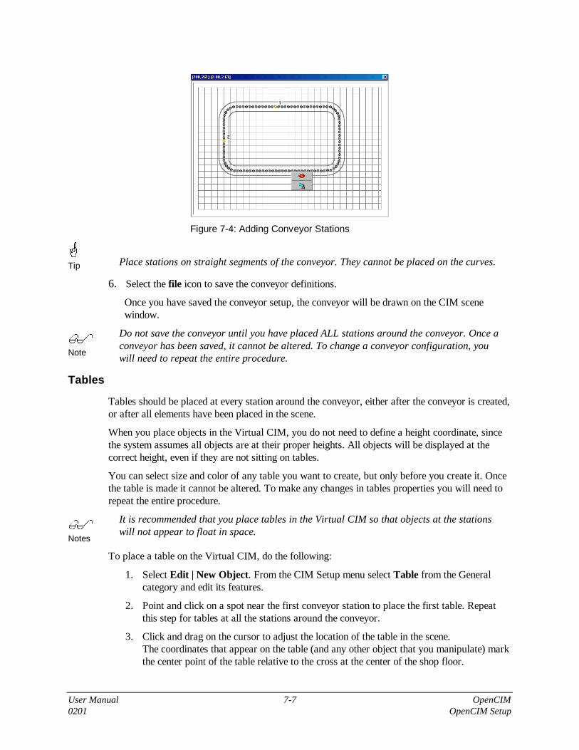
User Manual 7-7 OpenCIM0201 OpenCIM Setup
Figure 7-4: Adding Conveyor Stations
�Tip Place stations on straight segments of the conveyor. They cannot be placed on the curves.
6. Select the file icon to save the conveyor definitions.
Once you have saved the conveyor setup, the conveyor will be drawn on the CIM scenewindow.
�Note
Do not save the conveyor until you have placed ALL stations around the conveyor. Once aconveyor has been saved, it cannot be altered. To change a conveyor configuration, youwill need to repeat the entire procedure.
Tables
Tables should be placed at every station around the conveyor, either after the conveyor is created,or after all elements have been placed in the scene.
When you place objects in the Virtual CIM, you do not need to define a height coordinate, sincethe system assumes all objects are at their proper heights. All objects will be displayed at thecorrect height, even if they are not sitting on tables.
You can select size and color of any table you want to create, but only before you create it. Oncethe table is made it cannot be altered. To make any changes in tables properties you will need torepeat the entire procedure.
�Notes
It is recommended that you place tables in the Virtual CIM so that objects at the stationswill not appear to float in space.
To place a table on the Virtual CIM, do the following:
1. Select Edit | New Object. From the CIM Setup menu select Table from the Generalcategory and edit its features.
2. Point and click on a spot near the first conveyor station to place the first table. Repeatthis step for tables at all the stations around the conveyor.
3. Click and drag on the cursor to adjust the location of the table in the scene.The coordinates that appear on the table (and any other object that you manipulate) markthe center point of the table relative to the cross at the center of the shop floor.

User Manual 7-8 OpenCIMOpenCIM Setup 0201
Figure 7-5: Adding Tables
Robots
As indicated at the beginning of this chapter, after the conveyor is created, you should add theASRS, robots, machines and other devices.
By default the system automatically assigns numbers to the robots (and all other objects) in theorder of creation. You should therefore place your first robot (either the ASRS2 or an ASRStending robot) at Station 1, the second robot at Station 2, and so on.
Point and click on a spot at the first station to place the first robot. Repeat this step for eachstation around the conveyor.
Double-click on a robot to open its Configuration Parameters menu.
As you can see, the Robot Configuration Parameters menu differs from the Table ConfigurationParameters menu. Each object in the Virtual CIM has a particular Configuration Parametersmenu. The following section describes all items that may appear in this menu.
Configuration Parameters
Whenever you double-click on an object in the Virtual CIM, the object’s ConfigurationParameters menu appears.
The following figure shows some of the variations of the Configuration Parameters menu. (Notethat only one menu can be opened at a time.)
Once defined and saved, these parameters are written to OpenCIM INI files, as described inChapter 10.

User Manual 7-9 OpenCIM0201 OpenCIM Setup
Figure 7-6: Parameter Configuration Menus
The following is a list and description of all parameters that can be defined. The parameters formany objects do not normally require manipulation. The Tutorial at the end of this chapterdemonstrates the recommended sequence and actions for setting object parameters.
Menu Item Description
Capacity Defines the number of items that the device can hold.
You must define a value for feeders, racks and trash bin; for most otherobjects you can accept the system-defined value.
When selecting new objects, select Buffer 2 for a buffer whose capacity istwo items, and select Buffer 1 for a buffer that can contain only one item.The capacity parameter is thus already defined as 2 and 1, respectively.
Figure 7-7: Defining Capacity

User Manual 7-10 OpenCIMOpenCIM Setup 0201
CommPort For ACL device drivers, the settings must be as follows:BaudRate = 9600Parity = NoneDataBits = 8StopBits = 1XonXoff = No
These are the standard RS232 settings for communicating with ACLcontrollers (both Controller-A and Controller-B). These settings should notbe changed since they match the fixed settings in the controller.
For the PLC device driver, the settings will be one of the following:
OMROM PLC Allen-Bradley PLCBaudRate = 9600 BaudRate = 9600Parity = Even Parity = NoneDataBits = 7 DataBits = 8StopBits = 2StopBits = 1XonXoff = No XonXoff = No
These are the RS232 parameters used by the PLC device driver when itcommunicates with the PLC. You must set these parameters to match theRS232 settings on the PLC.
Connectivity Connects all objects and their associated device drivers.
Also connects robots to all objects which are physically within their reachand to all objects which can be connected by means of an RS232 cable.
When you click on Connectivity, the Connections menu opens.
Figure 7-8: Defining Connections
One or more connections can be added or deleted at a time.
• To make a connection, highlight the device driver name(s) for the selectedobject, click Add, and then OK.
• To remove a connection, highlight the device driver name(s) for theselected object, click Remove, and then OK.
Active Connections: A list of all connections that have already beenestablished between this and other objects.

User Manual 7-11 OpenCIM0201 OpenCIM Setup
Possible Connections: A list of all objects to which this object can beconnected. For robots, this list will also display all devices that are inphysical reach of the robot (i.e., that are in the Work Volume of the robot),and all objects that can be connected by means of an RS232 cable.
Possible Connections for Robots will also display all the ACL devicedrivers within the CIM cell, since robot controllers can communicate withany PC in the CIM cell. Normally, you should select only one ACL devicedriver per robot. Do not select ACL device drivers that are not intended forthis robot.
If you want to connect an object (not a device driver) to the robot, and theobject is not within reach of a robot, reposition it on the screen until you seethe object’s name appear in the list of possible connections.
Conversely, if you move an object too far away from a robot, the connectionwill be severed. A warning will prompt you to reposition the objects andreestablish the connections, if desired.
Figure 7-9: Robot Connections
�Tip
To see which device driver belongs to an object, click on the object. Fromthe object’s Parameter Configuration menu, select Connectivity|OK. Aline connecting the object and its associated device driver appears on thescreen . (Alternately, click on a device driver to find its associated device.)
Green lines show the connections between device drivers and theirassociated objects. Red lines show the physical connections between robotsand other objects; i.e., devices that are within the robot’s reach.
Green lines indicate which software is running on a PC. Click on a PC. Tosee the green lines, select Show Connection from the ParameterConfiguration menu.

User Manual 7-12 OpenCIMOpenCIM Setup 0201
Figure 7-10: Workstation Connections
External ID Unique numerical Device ID that identifies each device in the system. Thesoftware defines IDs automatically in sequence as the devices are created inthe Virtual CIM. You can, however, modify this ID in order to structure thenumbering of the devices, for example, in relation to the station they arelocated in (see example in the tutorial).
Location Identifies the location of a feeder when it is placed and used within anASRS unit. (In an actual CIM cell, a feeder can only be placed on an ASRScarousel, not in the ASRS2.)
Properties Defines the Workstation (WSn) at which the object’s device driver isconnected and running.
Also defines the INI file associated with the object’s device driver. This INIfile contains the definitions and parameters for the object and is invoked bythe device driver’s Loader command line.
Figure 7-11: Defining Workstation for Device Driver
Once Properties have been defined for a device driver, other options in theParameter Configuration menu become available.

User Manual 7-13 OpenCIM0201 OpenCIM Setup
QC Report The Quality Control device driver allows you to write the results of a QCtest to an ASCII text file that can be input to a spreadsheet program.
• Delete on Start. This switch controls whether a new quality control reportfile will be created each time this device driver is activated. If checked(Yes), the previous file is deleted; if not checked (No), results areappended to the existing report file.
Figure 7-12: Defining Quality Control Report
Rotate Rotates a displayed object to any degree. Useful, for example, to properlyattach buffers to the conveyor, or to logically orient a PC in the VirtualCIM display.
Sub Type System-defined parameter. Normally, you do not need to manipulate thisparameter.
Variables The default values for the variables used by the CNC script.
Write Load Creates the WSn.INI file for the particular workstation.
Edit Menu: Additional Options
Setup IDs Allows you to change the ID number of a device. Double-click onthe highlighted line, and enter a new number at the prompt.
Figure 7-13: Edit Setup IDs Menu

User Manual 7-14 OpenCIMOpenCIM Setup 0201
Once you have changed an ID, be sure to select Create Menu |Setup and Create Menu | ACL DMC File in order for the changeto take effect.
New Object Allows you to create a new object from the New Object Menu.
Delete Object Allows you to delete an object in the Virtual CIM cell.
Drag Object Allows you to pick an object and drag it through the cell.
Create Menu
Windows Groups The system automatically creates a Windows program group thatcontains all the icons you need in order to operate the CIM celldefined by the Virtual CIM Setup.
Setup Prompts you to confirm the overwrite of the SETUP.CIM file. Forfull details, refer to Chapter 10.
Loader Section Creates a file WSn.INI for each station (e.g. WS2.INI).
Figure 7-14: Program Group Created by Virtual CIM Setup
ACL DMC File Prompts you to confirm the overwrite of the DEVICE.DMC file. Forfull details, refer to Chapters 8 and 10.
ACL Programs Creates a subdirectory named ROBOTn on every workstation atwhich a robot is defined. The files in this directory provide the basisfor ACL programming, and can be edited by the user. Refer to thesection on ACL programming in Chapter 8.

User Manual 7-15 OpenCIM0201 OpenCIM Setup
View Menu
The options in this menu are similar to those in the View menu of the Graphic Display andTracking module. For full details, refer to Chapter 6.
Show Names Displays the names of all devices in the scene.
Show IDs Displays the device ID numbers.
Show Positions Displays the position coordinates of all devices.
Drag 3D Frame Allow you to drag the cell.
Camera Top Displays the overhead view of the scene.
Redirect Camera Allows you to select a different focal point in the scene.
Scene Origin Displays the scene origin, e.g. coordinate 0,0 of the room.
Limitations
The Virtual CIM Setup allows you to construct all sorts of CIM cells, although someconfigurations would be difficult, or even impossible, to actually operate. To ensure your successin operating a Virtual CIM cell, create your cell in accordance with the following guidelines:
• Use only one conveyor in the cell.
• Use no more than eight stations around the conveyor.
TutorialIn this tutorial you will learn to create and run an OpenCIM cell which contains three stations.
• In the first stage you will create a graphic CIM cell using the Virtual CIM module.
• In the second stage you will define and operate the CIM cell using the CIM Definition andCIM Operation modules. You will also use the Graphic Display module to view your CIMcell in operation.

User Manual 7-16 OpenCIMOpenCIM Setup 0201
Stage 1: Designing the CIM Cell
�
�
�
Procedure
Setting up the VirtualCIM Cell
Following is the recommended sequence for setting up the Virtual CIM Cell:
1. Plan and document your CIM system before starting.
2. Define the conveyor and the location of the workstations.
3. Place tables at the stations.
4. Place an ASRS device at a workstation (station 1 is recommended).
5. Place robots at the stations.
6. Place CNC and any other machines at the stations.
7. Place buffers at the workstations.
8. Place PCs at the workstations.
9. Define the device drivers for the workstations.
10. Define all connections and properties for each device driver.
11. Create the Setup, Map and Icon Group for this CIM cell.
This section will guide you through a complete procedure for creating an OpenCIM cell using theVirtual CIM Setup module.
1. From the OpenCIM ver 2.3 group, click the Virtual CIM Setup icon.
2. Select File | New. Enter the name CIM-1 for the cell. Click OK.
3. The Scene Window appears. Maximize the window.
4. Select Edit | New Object. In the New Objects box, double-click General to expand thatcategory, and then select Conveyor. In the Conveyor Type box, select Normal and click OK.
5. The Conveyor grid appears. Click the right mouse button. Drag the mouse and select the keyicon.
6. A wand appears. Bring the wand into the lower right side of the grid and click the left button.A red dot appears; this is the conveyor starting point.
7. Click the right mouse button. Drag and select the vertical segment. Point the cursor to a spotabove the starting point and click.
8. Click the right mouse button. Select an arc-up-and-left segment. (The conveyor is created inthe direction of movement; normally counter-clockwise.)
9. Continue selecting and adding segments to the conveyor until it is complete. Use the greencurved arrow to UNDO any mistakes. (Avoid using too many UNDOs.)
10. When the conveyor is complete, click the right mouse button and then OK.
11. Click the right mouse button and select S to create a station. Point to a location just above thestarting point of the conveyor (not on the curve). Click the left mouse button. Accept theprompt for Station number 1.

User Manual 7-17 OpenCIM0201 OpenCIM Setup
12. Repeat the previous step for two more stations. Add the stations in consecutive order aroundthe conveyor.
13. When all three stations are marked around the conveyor, click the right mouse button andselect the file icon from the pop-up menu to save the conveyor. Confirm the Save prompt.
14. The grid closes, and a cube cursor appears on the screen. Bring the cursor to the center of thescreen and click. The conveyor appears in the Scene Window. The red cross marks the centerof the shop floor. Click on the conveyor and drag with the left mouse button to center theconveyor on the floor.
15. Select File | Save to save your work.
16. Select Edit | New Object | Storage | ASRS36.
17. Click the left mouse button near Station 1. The ASRS36 appears on the screen. (This objectis the robot that has a storage rack with 36 shelves.)
18. Click on the ASRS36. The object’s parameter configuration submenu opens. Select Rotate.Enter –90. The lower small frame should be outside the conveyor. Adjust the orientation andposition of the ASRS36.
19. Add Tables for the workstations.
20. Add objects to Stations 2 and 3.
• At Station 2, select Robots | ER 9, and enter 1.0 (meters) at the prompt for LSB (robot willbe mounted on a linear slidebase).
• At Station 3, select Robots | ER 14, and cancel at the prompt for LSB.
During the selection and placement of new objects, wait for the cursor to settle in place.Avoid double-clicking.
Your screen should now look like this:
21. Using the same procedure you used for placing robots at stations, add the following objectsto the CIM cell:
At Station 2: CNC Mill.
At Station 3: Jig-XY, Screwdriver, and Vision Camera.

User Manual 7-18 OpenCIMOpenCIM Setup 0201
As you work, rotate and reposition the objects on the shop floor. Use Redirect View andZoom to help you with the placement of objects.
Save your work regularly when creating the CIM cell.
22. Add station buffers (Buffer 2) around the conveyor, in the following order:
• Station 1
• Station 2
• Station 3
23. Select Edit | Delete Object and click on the buffer you placed at Station 1. The buffer will beerased. (The ASRS36 does not require a buffer, but a temporary buffer was created atStation 1 causing the buffers at the other stations will be named BFFR2 and BFFR3,respectively.)
24. Rotate the buffer at Station 3 90°. Adjust the location of other buffers, so that they are“attached” to the conveyor and within reach of the robot at the station.
25. At station 3 add a Rack, Feeder and Trash. The following figure will guide you in properlyplacing all the objects at this station.
26. Save your work at this point.
27. Add workstations (PCs) for each station. Start with the Manager PC and then continue withthe Station PC’s for Station 1, 2 and 3.
28. Scale Tables for the workstations and arrange them as shown in next figure:

User Manual 7-19 OpenCIM0201 OpenCIM Setup
29. Add device drivers near the PC at each station:
• For each robot at the station (including the ASRS36): add an ACL device driver.
• For a CNC machine (lathe/mill): add a CNC device driver.
• For the Vision Camera: add a RVP device driver.
• For the Conveyor: add a PLC device driver. Place it at Station 1.
The Jig-XY and Screwdriver are controlled by the ACL controller (and its device driver), and donot require device drivers of their own.
30. For each device driver, you will need to sets its properties and connections. Click on eachobject in order to open the corresponding parameter configuration menu, and do thefollowing:
• Click on Properties. Select the number of the workstation at which the device driver isrunning (e.g., WS1 for ASRS36 and PLC).
• Click on the device driver and enter the commport settings
• Click on Connectivity:
• Connect the PLC device driver (PLCVD1) to the conveyor (CNV1).
• Connect each ACL device driver (ACLVDn) to its corresponding robot (ROBOTn).
• Connect each CNC device driver (CNCVDn) to its corresponding CNC machine(MILLn or LATHEn).
31. For each robot, select Connectivity and make the connections to all objects which arephysically within its reach. Connect each robot to the conveyor station (CNV1#n), the stationbuffer (BFFRn) and all machines and devices at its station. Make sure the appropriate devicedriver is connected to the robot. If you unable to make a connection, move the robot anddevice closer to each other, and try again.

User Manual 7-20 OpenCIMOpenCIM Setup 0201
32. Connect the Screwdriver and the Vision Camera to the Jig-XY only.
33. For the Feeder:
• SubType : Set to 101.
• Capacity: Set to 10.
34. For the Rack:
• SubType: Set to 201.
• Capacity: Set to 9.
35. From the Create menu, do the following:
• Select Loader Section.
• Select Setup. Click OK at the prompt to overwrite the SETUP.CIM file.
• Select ACL DMC File.
• Select ACL Programs.
• Select Windows Group. This will create a new program group which contains all the iconsneeded to prepare and operate the Virtual CIM cell which you have just created. TheWindows Group looks like this:
36. Save and exit the Virtual CIM Setup module.

User Manual 7-21 OpenCIM0201 OpenCIM Setup
Stage 2: Operating the CIM Cell
This part of the tutorial will give you practical experience in using the CIM operation modules.
The following steps all relate to the CIM-1 program group which you have created in the VirtualCIM Setup.
1. Click on CIM Manager.
2. From Utility Programs, select Machine Definition. In the Machine Definition form, do thefollowing:
• From the Machine Name list, select MILL1.
• Make the following entries:
• Process Name: PROG_BOX1
• File Name: 1.GC
• Program: leave blank
• Duration: 00:00:25
• Click Save.
• Close the Machine Definition Module
3. From Utility Programs, select Part Definition. In the Part Definition screen, do thefollowing:
• Select supplied parts.
• Select New to define a new part.
• Make the following entries:
• Part Name: CUBE.
• Part ID: 77
• Template Type: 01
• Click Save, and check the Errors box. The message Save done indicates there are noerrors.
• Select Product parts
• Select New to define a new product part.
• Make the following entries:
• Part Name: BOX.
• Part ID: 75
• Sub part: CUBE
• Process: PROG_BOX1
• Template Type: 01

User Manual 7-22 OpenCIMOpenCIM Setup 0201
• Click Save, and check the Errors box. The message Save done indicates there are noerrors.
• Close the Parts Definition module.
4. From Utility Programs, select Storage Manager.
• Click on Edit ASRS.
• Choose any cell in the grid.
• Select CUBE from the Part Name drop-down list and click OK.
• Repeat these steps three more times for other cells.
• Close the Storage Definition module to automatically update the storage database.
5. Click the Create Storage icon to save this storage definition as the default.
6. From Utility Programs select MRP.
• Select Create a new customer, CUST-A.
• Create two orders for this customer, each one for two parts, but for different supplydates.(To see a list of parts which can be ordered, open the drop-down list when the cursoris on the Part Name field. Click to select a part.) For example:
Part Name: BOX
Required: 2
Priority: 1
Due Date: 2
Part Name: BOX
Required: 2
Priority: 1
Due Date: 4
• Save the order. Click MRP. This runs the MRP program, which creates aManufacturing Order.
• Select Manufacturing Order. The Manufacturing Order screen is displayed.
• Select a Manufacturing Order (from the list of numbers), and click MO to submit themanufacturing order. This creates an A-Plan (production work order) for the order.
• Close the MRP module.
7. Select Reports Generator from the Utility Programs menu.
• Select Part Report. Click Print Report to display the report on the screen. You mayalso select Subparts, Process, Analysis and A-Plan to view other reports.
• Close the Reports Generator module.
8. Click the CIM Modes icon. The CIM Modes dialog box opens.
• Select Simulation mode and enter the simulation speed, for example x5.
• Select No in Send message to Graphic Display option. (This option refers to theexternal graphic display only; the internal graphic display of the CIM Manager isalways active.)
• Click the green button to execute (i.e., load the Manufacturing Order).
• Click the green Run button to activate (i.e., run the production cycle.)

User Manual 7-23 OpenCIM0201 OpenCIM Setup
• Congratulations. Your CIM cell is in operation! Look at the Order View, DeviceView, Program View and Pallets View and follow the progress of the production.
• Acknowledge the messages “Part has been Finished.” and “Order Finished.”
• Close the production by clicking the red button.
9. You will now repeat the production cycle, and view it through the Graphic Displaymodule.
10. Open the CIM Modes dialog box. Select Yes in Send message to Graphic Display optionand save it. Make sure that you activate the external Graphic Display (see step 13)otherwise the CIM will run slowly.
11. Click the Default or Reset Storage icon.
12. Click the Graphic Display icon from CIM-1 Window Group. The CIM Simulation screenwill appear. You will see the CIM cell you created by means of the Virtual CIM Setup inthree different 3D views.
13. Return to the CIM Manager screen:
• Click the green button to execute (i.e., load the Manufacturing Order).
• Click the green Run button to activate (i.e., run the production cycle.)
• You also can see your CIM cell in operation by means of the Graphic Display.


User Manual 8-1 OpenCIM0201 OpenCIM Device Drivers
8
OpenCIM Device Drivers
�Note
This chapter is not applicable to OpenCIM Offline and OpenCIM Intro.
Overview of Device DriversDevice drivers are the link between the CIM Manager and the devices in the CIM cell. Thedevice drivers are used to perform the following functions:
• Relay command and status messages during production between a device and theOpenCIM network.
• Simulate a device.
• Test a device.
OpenCIM device drivers can run on both Station Manager PCs and the CIM Manager PC,depending on the configuration of the CIM system.
Device Driver Devices Controlled
CNC A single CNC machine.
ACL Devices connected to and controlled by an ACL controller;e.g., robot, automatic screwdriver, barcode reader.
Quality Control ROBOTVISIONpro, Laser Scan Meter, ViewFlex.
ULS Laser Engraver.
PLC The CIM conveyor.
Device Driver Control PanelDevice drivers are loaded automatically by the virtual loader, DDLoader.EXE, which isactivated whenever a CIM Manager or Start Station icon is activated. This program loads alldevice drivers from command lines found in the [Loading] section of the device driver’s INIfile. Refer to Chapter 10 for more details on the loader program.
All device drivers have the following features:
• A Control Panel for manually sending commands to the device and for viewing statusinformation.
• A Virtual Device Driver (status) window for displaying status information, errormessages, and responses from the device (when appropriate).

User Manual 8-2 OpenCIMOpenCIM Device Drivers 0201
When a device driver is loaded its Virtual Device Driver (status) window and its Control Panelappear on the screen. For example:
Figure 8-1: Device Driver Control Panel (ACL)
Close the status window in order to close the device driver.
�
Note
The device driver Control Panel is discussed in detail in the section on the ACL devicedriver. The discussion there is applicable to all other device drivers.
Modes of OperationLike the CIM Manager, the device drivers can operate in either Simulation Mode or Real Mode.In addition, Manual Mode allows you to interact with the software and hardware.
In order to operate a device driver (DD) in Real Mode, check the Load column next to the desireddriver(s). Similarly, to operate a device driver in simulation mode, check the Simulation columnnext to the desired driver(s).
Figure 8-2: DD Loader (WS2)

User Manual 8-3 OpenCIM0201 OpenCIM Device Drivers
Real Mode Normal operating mode. The device driver is ready to communicate with boththe CIM Manager and the physical device (or its controller).
The message Connected OK is displayed after the device driversuccessfully receives the first message from the device (either on a serial portor a PC I/O card).
In Real Mode, all communications between the device and other CIM entitiesoccur automatically. However, it is also possible to manually send commandsto the device using the Control Panel.
SimulationMode
In Simulation mode, the device driver receives commands as usual from theCIM Manager and emulates a device by automatically responding with theappropriate status messages. The device driver does not actually communicatewith the physical device.
The quality control device drivers randomly return either a successful orunsuccessful status message based on the parameter FailPercent. Allother device drivers always return a successful status message in Simulationmode.
Manual Mode In Manual mode, the device driver receives commands as usual from the CIMManager while you interactively emulate the device using the device driver’sControl Panel. The device driver does not generate status messagesautomatically; they are generated only when you manually make selectionsfrom the Control Panel.
In Manual mode the device driver does not actually communicate with thephysical device. (See the specific section about each device driver for detailson how to use the Control Panel to send responses back to the CIM Manager.)
StandaloneMode
The Standalone mode enables you to input manager specific commands andexecute them directly to the controller without any intervention from othersystem components.
Device Driver Loading Options
Normally device drivers are started from the Loader program that reads device driver commandlines from an INI file. For example:
Load2=C:\OPENCIM32\BIN\ACLDriver.EXE ACLVD1.INI 21 /COM:1 /CLoad3=C:\OPENCIM32\BIN\CNCDriver.EXE CNCVD1.INI 23 /COM:2 /C
If you are activating a device driver in standalone mode, cancel the TCP/IP Network Messagingbetween the ACLDD and the manager. To do so:
From the DD Control Panel, select OPERATION MENU. Select TCP/IP status and clickUNABLE.

User Manual 8-4 OpenCIMOpenCIM Device Drivers 0201
Once a device driver has been loaded, you cannot change its control mode. You must exit thedevice driver and restart it in the desired mode.
Real Mode This mode is the default if no special mode switches are specified on thecommand line that invokes the device driver.
SimulationMode
Use the /SIMULATION switch on command line that invokes the devicedriver.
Manual Mode Use the /Com:0 switch on command line that invokes the device driver.
StandaloneMode
The Standalone mode enables you to input manager specific commands andexecute them directly to the controller without any intervention from othersystem components.
If a device driver is unable to open an RS232 port in order to communicate with its device, itdisplays the following message in the Control Mode box:
Cannot Open Com:n
This error message indicates that the device driver could not open the serial port on the StationManager PC. Possible causes include:
• The port is in use by another application.
• The port number is invalid.
• One of the serial port parameters is invalid.
The CNC Device DriverThe CNC Device Driver interfaces between the OpenCIM system and various types of machinessuch as a lathe or milling machine.
It receives command messages from the CIM Manager, adjacent robots, and other CIM devices.In response, it runs the corresponding CNC script program which operates the machine. Thedevice driver responds with status messages about the CNC machine to CIM elements whichhave registered for these messages.
The CNC Device Driver performs the following functions:
Device Driver Function By Using
• Sends commands to a CNC machine ⇒ the CNC Script Interpreter
• Tests and debugs Command Interpreter programs ⇒ the CNC Control Panel
• Sends CNC status messages to other CIM elements ⇒ the OpenCIM Network
• Loads G-code programs into a CNC machine ⇒ an RS232 connection
The CNC Device Driver controls machines connected in either of the following ways:
• A machine connected to an internal I/O controller board in the Station Manager PC
• A machine connected to an ACL controller

User Manual 8-5 OpenCIM0201 OpenCIM Device Drivers
An internal I/O board maps 16 CNC control lines to two output ports on the PC. It also maps 16CNC status lines to two input ports on the PC. These I/O port addresses are stored in the fileCNCVD1.INI.
A CNC machine that receives commands via an RS232 interface can be connected to a serial porton an ACL controller. You can write an ACL program to control the machine and activate thisprogram by sending commands to the ACL device driver using the CNC script language.
Running the CNC Device Driver
Loading the CNC Device Driver
CNC device drivers are loaded automatically by the DD Loader, DDLoader.EXE. This programloads all device drivers from command lines found in the [Loading] section of the local INI file.To manually start a CNC device driver from the Program Manager (e.g. to run the CNC ControlPanel for troubleshooting), select the icon for the appropriate CNC machine.
The following examples assume that the CNC device driver is being invoked from the [Loading]section of the CNCVD1.INI parameter file.
For example, to run the CNC Device Driver for CNC machine # 23, use:
Load4=C:\OPENCIM32\BIN\CNCDriver.EXE CNCVD1.INI 23 COM:3
CNC Device Driver Status Window
The Status window appears while a device driver is running. It displays status and errormessages, debug information, and output from the following sources:
• CNC script programs
• ACL programs
• Quality control devices
• PLC programs
Generating a CNC Log File
The CNC log file facilitates debugging and troubleshooting. It captures the results of eachoperation performed by the device driver that are displayed in the Status window. Thisinformation is written to a file called CNC_DeviceID.PRT where DeviceID is the 3-digitdevice ID number of the CNC machine (e.g. CNC_023.PRT).

User Manual 8-6 OpenCIMOpenCIM Device Drivers 0201
17:21:48.72 PULSBIT( 0x500, 0x0, "00001000", 500 )
17:21:49.33 --- OPEN DOOR ---
17:21:49.44
17:21:49.44 --- DOOR IS OPENED ---
17:21:49.55 WAITBIT( 0x500, "00000010", 10000 )
17:21:49.66 --- Condition is true ---
17:21:56.52 PULSBIT( 0x500, 0x0, "00010000", 500 )
17:21:57.13 --- CLOSE DOOR ---
17:21:57.23
17:21:57.23 --- DOOR IS CLOSED ---
17:21:57.34 WAITBIT( 0x500, "00000100", 10000 )
17:21:57.45 --- Condition is true ---
Figure 8-3: Sample CNC Log File

User Manual 8-7 OpenCIM0201 OpenCIM Device Drivers
The log information includes each CNC script command executed, display messages,OpenCIM network (DDE) messages received and sent, and error messages. Even messages thathave scrolled off the screen are recorded. Each entry in the log file is time stamped to the nearest1/100 of a sec.
The log file is placed in the same directory as the CNCVD1.INI file after the device driver hasbeen closed.
The log file is saved as ASCII text. You can use any text editor to examine and print its contents.
�Note
The log file is overwritten each time you save it. If you want to preserve the previouscontents, rename the file CNC_DeviceID.PRT first.
Downloading G-Code
A CNC device driver downloads a G-code file to machine in response to a command from theCIM Manager (in preparation for running a CNC process).
The device driver uses one of the following download mechanisms depending on which youspecify:
• A download utility that you supply called from a specified batch file (recommended)
• The built-in downloader of the CNC device driver
This section discusses how to use a utility program that you supply to download G-code. Thismethod is usually preferable to using the device driver's internal downloader because a utilityprogram provided by the CNC manufacturer can take advantage of all of a machine's features(e.g. providing error correction during the download).
The commands required to invoke a machine's downloader are inserted into a DOS batch file. Thelast command in this batch file creates a flag file which signals that the download is complete.The CNC device driver automatically deletes this flag file each time it invokes the batch file.
To build this batch file and direct the device driver to use it, do the following:

User Manual 8-8 OpenCIMOpenCIM Device Drivers 0201
�
�
�
Procedure
Creating a Utility forDownloading G-code
1. Write a batch file named CNCL.BAT which calls the utility downloader asshown in the following example:
DLOADG.EXE %1 %2ECHO Task Loaded > C:\OPENCIM32\WS3\TASK.CNC
2. When the CNC device driver calls this batch file, it specifies the followingtwo parameters (which appear on the first line of the batch file above):
• The G-code file to download (which includes the full DOS path)
• The memory region within the CNC's RAM that stores this G-codeprogram.
3. Define the following parameter entries in the[CNCDriverDefinitions] section of the INI file for this CNCdevice driver:
Loader = C:\CNC_L.BATTaskLoadedMark = C:\OPENCIM32\WS3\TASK.CNC
When these parameters are defined, they tell the device driver to use thespecified download utility program instead of its internal downloader.
4. Set up a PIF file to run the downloader batch file in a DOS box in awindow (i.e. not Full Screen). To prevent communication errors, make thisa high priority task.
� Warning!
Do not set this task to have exclusive control because this might causeproblems with other device drivers running on this PC.
The CNC Control Panel
The CNC Control Panel is a feature of the CNC Device Driver that allows you to perform thefollowing functions:
• Run CNC programs interactively.
• Control CNC operations by setting bits on the Output Panel.
• Read the status of the CNC machine by examining bits on the input panel.

User Manual 8-9 OpenCIM0201 OpenCIM Device Drivers
Figure 8-4: CNC Device Driver Control Panel
Running CNC Programs Interactively
The CNC Control Panel allows you to run CNC programs created with the CNC ScriptInterpreter and view the results.
To run a Command Interpreter program using the Control Panel, do the following:
�
�
�
Procedure
Running a CommandInterpreter Program
1. Determine the parameter(s), if any, that are to be passed into the program.Type these value(s) in the box labeled CNC Command Parameters (e.g. 500for a 500 millisecond delay)
2. Use the mouse to scroll through the CNC Command List in order to find aprogram. Double-click on a program name to run that program.
If the CNC machine is connected to the I/O board in the PC, you can observe the effects of aprogram by observing the line indicators in the PC-Inputs and PC-Outputs panels in the ControlPanel. In addition, status messages and instructions generated by the program appear in theStatus window.
PC-Input/Output Panel
To display the PC-Input/Output Panel, select from the main menu Operation | Input/Output.
Output Panel
The Output panel allows you to observe and set the state (On or Off) of 16 CNC control lines.Control lines may be hard-wired to specific CNC functions. Alternatively, the CNC machine maybe configured to activate a certain G-code program associated with a control line. Check thedocumentation of your CNC machine for specifics on the use of each control line.
The PC-Output panel allows you to set CNC control lines on and off by clicking bits in theappropriate output port. The layout of the panel reflects the way the control lines are mapped tobits in two designated PC output ports. By using a mouse to click on the bits in the panel, you can:
• Toggle the state of a control line.

User Manual 8-10 OpenCIMOpenCIM Device Drivers 0201
• Pulse a control line by clicking its bit, waiting the desired interval, and clicking it againto restore it to its original state.
Input Panel
The Input panel allows you to observe the state (On or Off) of 16 CNC status lines. Status linesmay be hard-wired to specific CNC components. Alternatively, the CNC machine may use aG-code program to set the state of a status line. Check the documentation of your CNC machinefor specifics on the meaning of each status line. The layout of the panel reflects the way the statuslines are mapped to bits in two designated PC input ports.
The PC-Input panel displays the state of CNC status lines. It cannot be used to change the valueof a status line. Only the CNC machine can change the value of a status line.
Program History List
You can view a list of programs that were run by clicking on the drop-down list box labeled“Task History”.
Closing the Control Panel
It is a good idea to close the Control Panel in order to prevent others from tampering with it whilethe CNC machine is active. Use one of the following standard Windows methods for closing awindow:
• Double-click the control bar in the X of the Control Panel window.
• Click the control bar and select Close.
• Press [Alt + F4] while in the Control Panel window.
�Warning!
You should always close the Control Panel if you are going to leave the CIM unattended.Otherwise someone might cause damage if they inadvertently activate a machine (such asa CNC machine) by making selections on the Control Panel (e.g. by clicking on theOutput panel or by selecting a task which starts the machine).
The ACL Device DriverThe ACL device driver relays messages between the OpenCIM network and the devices attachedto an ACL controller such as:
• An Intelitek robot
• An automatic screwdriver
• A barcode scanner
• An X-Y table
This device driver receives command messages from the CIM Manager and adjacent CNCmachines. In response, it runs the corresponding ACL program residing in the controller. TheACL device driver communicates with the controller using an RS232 port on the StationManager PC.

User Manual 8-11 OpenCIM0201 OpenCIM Device Drivers
The ACL device driver performs the following functions:
• Activates ACL programs
• Receives status messages from ACL programs and relays them to the appropriate CIMentity
• Allows you to interactively operate robots and peripheral devices attached to an ACLcontroller
• Allows you to test and debug ACL programs by sending commands from the ControlPanel
• Emulates a robot in Simulation mode
The primary ACL command is to run a set of pick-and-place programs which direct a robot tomove a part from one location to another at a station. ACL programs can also direct a robot toperform other tasks such as assembly operations or they can control peripheral ACL devices suchas an automatic screwdriver.
The ACL User Interface
The ACL User Interface is a feature of the ACL Device Driver. It allows you to perform thefollowing functions:
• Simulate a robot.
• Issue ACL commands interactively.
• Debug ACL pick-and-place programs by running them interactively.
• Test a robot and its positions and programs by issuing a series of pick-and-placecommands stored in file.
• Create a file of pick-and-place commands.
Figure 8-5: ACL Control Panel
Control Modes for the ACL Device Driver
The ACL device driver, like all other device drivers, can pass actual messages or can generatesimulated messages. In Real Mode, the device driver relays messages between the OpenCIM

User Manual 8-12 OpenCIMOpenCIM Device Drivers 0201
system and an ACL controller. In one of the simulation modes, the ACL device driver can be usedto emulate a robot or to test a robot.
The following list shows the messages that can appear in the Control Mode box on the ControlPanel. In each mode, the device driver treats command messages the same whether they originatefrom the CIM Manager or from selections you make from the device driver's Control Panel.
The activation examples show command lines from the Loader's INI file used to start the devicedriver in the designated mode. Bold command line switches highlight the specific switch used toinvoke that mode.
Real Mode Normal operating mode. The device driver relays command messages to theACL controller from the CIM Manager, CNC machines, etc. In turn, itbroadcasts status messages from the controller to the OpenCIM network.
Activation: ACLDriver.EXE ACLVD3.INI 31 /COM:1
Real Mode:Connected OK
The ACL device driver shows that it has received the first message from theACL controller on the serial port.
Cannot OpenCom:n
The ACL device driver could not open its serial port on the Station ManagerPC.
SimulationMode
The ACL device driver receives commands as usual but emulates a robot and abarcode reader by generating status messages automatically.
In this mode, the device driver does not actually communicate with the ACLcontroller; only with the CIM Manager (and other devices that send itcommands).
Activation: ACLDriver.EXE ACLVD3.INI 31 /COM:1 /SIMULATION
Manual Mode The ACL device driver receives commands as usual but only generates statusmessages when you double click on a line in the Task History box.
In this mode, the device driver does not actually communicate with the ACLcontroller; only with the CIM Manager (and other devices that send itcommands).
Activation: ACLDriver.EXE ACLVD3.INI 31 /COM:0
StandaloneMode
The Standalone mode enables you to input manager specific commands andexecute them directly to the controller without any intervention from othersystem components.
ACL Commands
You can use the ACL Control Panel as a limited terminal to send commands to a controller.Commands that you type in the text box labeled “Send to Controller” are sent out the PC’s serial portwhen you press [Enter]. Responses from the controller are displayed in the status window of thedevice driver. This capability is useful for testing and debugging individual ACL programs.
Task History List
The Task History box shows the last several commands sent to the controller. You can scroll thebackground to see commands that have scrolled off the screen.

User Manual 8-13 OpenCIM0201 OpenCIM Device Drivers
Testing Pick-and-Place Commands
The pick-and-place buttons of the Control Bar allow you to send commands to the robot to moveparts around the station. These buttons are described below:
Enter P/PCommand
Allows you to manually send a pick-and-place command to the robotinstead of the command being sent by the CIM Manager. Selecting thisbutton presents you with the Run ‘Pick-and-Place’ dialog box .This dialogbox requests the following six parameters:
• Part ID - Number of the part/template to be moved (template = 0)
• Source ID - Device ID of source location where the robot is to pick upthe part/template. Located next to the Source ID field is a drop-down listthat allows you to select the Source ID by name and not by index.
• Source Index - Compartment number if source location is divided intocells. Located to the right of the Source Index field is another field thatdisplays the number of the compartment.
• Target ID - Device ID of target location where the robot is to place thepart/template. Located next to the Target ID field is a drop-down list thatallows you to select the Target ID by name and not by index.
• Target Index - Compartment number if target location is divided intocells. Located to the right of the Target Index field is another field thatdisplays the number of the compartment.
• Note - Can be used to send special instructions to assembly programs oruser-developed programs.
� Note
The names and the range that appear in the Pick-and-Place dialog boxare taken from the INI file used by this device driver.
Figure 8-6: Run ‘Pick-and-Place’ Dialog Box

User Manual 8-14 OpenCIMOpenCIM Device Drivers 0201
Play fromP/P File
Begins executing a series of pick-and-place commands stored in a specialtext file designated for this robot, ACL_xxx.PNP. The xxx is the deviceID of this robot (found in the title bar of the Control Panel). Thesecommands are sent one at a time.
This file can be used to thoroughly test a robot’s ability to retrieve anddeliver parts from every device at a station. Pick-and-place commandsinvolving every device can be stored in the pick-and-place file. Playing thisfile would then allow you to observe if the robot was able to properlyaccess every device.
% Completefrom P/P File
This display activates when you select the Play button. It shows whatpercentage of the pick-and-place file has already been executed.
Save P/PCmds
Saves a pick-and-place text file containing all pick-and-place commandsfound in the Task History box. This file is saved in the current workingdirectory under the name ACL_xxx.PNP.
Close P/PFile
Terminates the playback of a pick-and-place file.
Closing the ACL Control Panel
You can close the Control Panel window in order to prevent others from tampering with it whilethe robot is turned on. Use one of the following standard Windows methods for closing a window:
• Double click the control bar in the X of the Control Panel window.
• Click the control bar and select Close.
• Press [Alt + F4] while in the Control Panel window.
�Warning!
You should always close the Control Panel if you are going to leave the CIM unattended.Otherwise someone might cause damage if they inadvertently activate the robot by makingselections on the Control Panel (e.g. by clicking on the Play From P/P File button) .

User Manual 8-15 OpenCIM0201 OpenCIM Device Drivers
Quality Control Device DriversA quality control device driver interfaces between the OpenCIM network and a quality controldevice such as:
• ROBOTVISIONpro
• Laser scan meter
A device driver communicates with a QC device using an RS232 connection.
Figure 8-7: A QC Device Driver Passing Messages to and from a QC Device
The QC device driver receives a command message from the CIM Manager specifying the type ofquality control test to run. It then performs the following steps:
• Activates the specified test on the QC device (e.g. a Scan command for aROBOTVISIONpro system).
• Receives the test result from the device.
• Compares the result to a range of acceptable values specified in the command message.
• Sends a pass/fail status message back to the CIM Manager.
• If the result is fail, the CIM Manager:
• Disposes of the defective part as specified by an ONFAIL process in the Part Definitiontable.
• Automatically reproduces the part.
Each QC test is defined as a separate process in the Machine Definition module. The test typeand acceptable range of test results may be specified in the Parameters field of the Part Definitiontable.
If the quality control device is connected to an ACL controller (e.g. a barcode reader), the nameof the ACL program that activates this device should be specified in the Program field of theMachine Process table in the Machine Definition module.

User Manual 8-16 OpenCIMOpenCIM Device Drivers 0201
�Tips
It is possible to use a robot as a quality control device. You can write special ACLprograms which perform quality control tests such as:
• Have a robot try to place a part in a mold. If the part is too big, you can detect thecollision. If it is too small, you can detect free play when the robot tries to move thepart after it has placed it in the mold.
• You can measure the dimensions of a part by reading the span of the robot's gripperwhen it is holding the part.
The following table shows how to set up test parameters for each type of QC device driver:
QC Device Test Type Acceptable Range of Values
ROBOTVISIONproCamera
The system scans a partlooking for an object(s) thatwas defined as a Pattern ID inthe ROBOTVISIONprosoftware. (e.g. Are threescrews in place?)
The number of objects theROBOTVISIONpro system shouldfind. If the minimum and maximumvalues are the same, the systemmust find this exact number inorder for the part to pass the test.
Laser Scan Meter Checks the diameter of acylinder. Test type = 1.
Minimum and maximum valuesrepresent the tolerance surroundingthe desired diameter.
There is a customized version of the quality control device driver for each of the quality controldevices listed above. Since these three device drivers are essentially similar except for the internalmessage format used to communicate with the quality control device, this section discusses theoperation of all three. In this discussion, these device drivers are interchangeable and are referredto simply as the quality control device driver. All QC device drivers “look” the same to the CIMManager, i.e. it sends the same type of command message to each type and receives the same typeof pass/fail status message from each.
A quality control device driver performs the following functions:
• Activates a test on a quality control device.
• Receives status messages from a quality control device and sends to the CIM Manager.
• Allows you to test and debug a quality control device by sending commands from theControl Panel.
• Emulates a quality control device in Simulation mode.

User Manual 8-17 OpenCIM0201 OpenCIM Device Drivers
The QC Control Panel
The QC Control Panel is a feature of the QC device driver. It allows you to perform the followingfunctions:
• Determine the control mode the device driver is running in
• Simulate the test results from a QC device
• Monitor test results in real-time
• Test the QC device by manually issuing command messages to it and observing theresults
Figure 8-8: Control Panel for aQuality Control Device Driver
Control Modes for Quality Control Device Drivers
A QC device driver, like all other device drivers, can pass actual messages or can generatesimulated messages. In Real Mode, the device driver relays messages between the OpenCIMsystem and the quality control device. In one of the simulation modes, the QC device driver canbe used to emulate a quality control device or to test a device. For more details, refer to “DeviceDriver Loading Options.”
The table below shows the messages that can appear in the Control Mode box on the ControlPanel. In each mode, the device driver treats command messages the same whether they originatefrom the CIM Manager or from selections you make from the device driver's Control Panel.
The activation examples show command lines from the Loader's INI file used to start the devicedriver in the designated mode. Bold command line switches highlight the specific switch used toinvoke that mode.
Real Mode Normal operating mode. The device driver relays command messages to theQC device from the CIM Manager. In turn, it broadcasts pass/fail statusmessages from the device to the OpenCIM network.
Activation: LSMDriver.EXE LSMVD1.INI 13 /COM:2
Real Mode:Connected OK
The QC device driver shows that it has received the first message from theQC device on the serial port.
Cannot OpenCom:n
The QC device driver could not open its serial port on the Station ManagerPC.

User Manual 8-18 OpenCIMOpenCIM Device Drivers 0201
SimulationMode
The QC device driver receives commands as usual but emulates a qualitycontrol device by generating pass/fail status messages automatically based onthe value in the Fail % field.
In this mode, the device driver does not actually communicate with the QCdevice; only with the CIM Manager.
Activation: LSMDriver.EXE LSMVD1.INI 13 /COM:2 /SIMULATION
Manual Mode The QC device driver receives commands as usual but only generatespass/fail status messages when you click on the Success or Fail buttons.
In this mode, the device driver does not actually communicate with the QCdevice; only with the CIM Manager.
Activation: LSMDriver.EXE LSMVD1.INI 13 /COM:0
StandaloneMode
The Standalone mode enables you to input manager specific commands andexecute them directly to the controller without any intervention from othersystem components.
Controlling a QC Device from the Control Panel
The buttons on the Control Panel allow you to send commands to the quality control device andstatus messages to the CIM Manager. These buttons are described below.
Check Activates a test on the quality control device. This button only functions inReal Mode. It is useful for testing communications with the quality controldevice. The response from the device appears in the device driver's Statuswindow.
This button resends the last command message from the CIM Manager asshown in the fields Low, High, and Type described below. If no commandmessage has yet been received, the default values are:
Type = 1, High = 0, Low = 0
Success Generates a status message to the CIM Manager indicating that a partpassed its quality control test. Used in Manual mode.
Fail Generates a status message to the CIM Manager indicating that a part failedits quality control test. Used in Manual mode.
The following fields on the Control Panel show the parameters associated with the last commandthat was sent to the quality control device. These values are used when you select the Checkbutton (described above) to manually send a command to the device.
Low The minimal acceptable test value.
High The maximum acceptable test value.
Type An ID number specifying which sort of quality control tests the deviceshould perform.
The Fail % field allows you to control how the device driver responds when it is operating in asimulated mode:
User Manual 8-19 OpenCIM0201 OpenCIM Device Drivers
Fail % Used only in Simulation mode. Randomly determines how often thesimulated test result will be Success or Fail (0% = always successful,100% = always failure). Pass/fail results are generated randomly.
The default failure percentage is read from the parameterSimulationFailPercent in the device driver's INI file. Changing thisvalue on the Control Panel affects the current session but does not save thenew value to the INI file.
QC Device Settings
Each quality control device driver uses a duplicate set of INI file parameter settings shown in thefollowing figure. These settings relate to:
• Format of a quality control log file
• Running the device driver in Simulation mode
• RS232 communication settings
• Appearance of the device driver's Control Panel on screen
When you want to simulate the operation of a QC device, the QC device driver providessimulated test results to the CIM Manager stating whether a part passed or failed a QC test. Theparameter SimulationFailPercent allows you to set the default failure percentage that aQC device driver uses when running in Simulation mode.
The following sections discuss particular settings for each type of quality control device driver.
ROBOTVISIONpro Settings
The ROBOTVISIONpro device driver works best with v2.3 or later of the ROBOTVISIONprosoftware. Use the parameter Snap = Yes to indicate version 2.3 or later.
You can use the Frame parameter to specify the frame area in the camera's field of view wherethe ROBOTVISIONpro system should scan for objects.
When you train the ROBOTVISIONpro to recognize a new object, the ROBOTVISIONprosoftware assigns a unique Pattern ID. Use this number as the test type when setting up theParameter field in the Part Definition table.
Laser Scan Meter Settings
A laser scan meter is a straightforward quality control device that performs only one type of test.Use a test type of 1 for this device when entering values in the Parameter field of the MachineProcess table or the Part Definition table.

User Manual 8-20 OpenCIMOpenCIM Device Drivers 0201
[General]
CimSetupPath=C:\OPENCIM\SETUP\SETUP.CIM
[LSMDriverDefinitions]
QCReport = Yes
QCReportTemplateFile = VC2_QC.INI
QCReportFileName =
QCReportFileMarker =
QCReportFileDeleteOnStart =
SimulationFailPercent = 20
BaudRate=9600
Parity=None
DataBits=8
StopBits=1
XonXoff=No
MainWindowBkgndColors=40,150,100
MainWindowTextColors=100,50,200
Figure 8-9: Sample INI File Settings for a Laser Scan Meter

User Manual 8-21 OpenCIM0201 OpenCIM Device Drivers
ViewFlex Device DriverThe ViewFlex Device Driver interfaces between the OpenCIM network and the Vision MachineSystem as a quality control device.
Each quality control test is defined as a separate process in the Machine Definition module. Thequality control test consists of three parts:
• File – the Script File (.bas) that contains the Program (Function) to be executed.
• Program – the Function from the File that returns the results of the quality control processto the OpenCIM Manager as Pass/Fail or Error.
• Fail %. Simulate test results (only in Simulation Mode) by determining the Pass/Failaccording to the percentage of failure that was input.
The ViewFlex Device Driver performs the following functions:
• Activates a test on the Vision Machine System.
• Receives status messages from the Vision Machine System and sends to the OpenCIMManager. (OpenCIM Messages in the ViewFlex.)
• Allows you to test and debug the Vision Machine System by sending commands from theWindows dialog box.
• Emulates the Vision Machine System in Simulation mode.
Adjustments
ViewFlex.exe
After the ViewFlex Device Driver is installed, copy ViewFlex.exe to the OpenCIM \Bin folder.
ViewFlex.ini
ViewFlex.ini includes the directory in which the script files are located:
[Device Driver Definitions]
ScriptPath= E:\opencim32\cimcell\WSn
where WSn is the workstation folder in which the QC camera is placed in Virtual CIM.

User Manual 8-22 OpenCIMOpenCIM Device Drivers 0201
User Interface
Figure 8-10: ViewFlex Control Panel
Control Modes
The control modes that the ViewFlex Device Driver can run in are:
• On-Line (Real): Allows the ViewFlex Device Driver to wait for the following commandsfrom the OpenCIM Manager: Snap, Load Script, Execute Program Script, and SendResults.
• Manual: Allows you to test the ViewFlex Device Driver by manually issuing thecommands Pass/Fail and observing the results.
The following buttons are available only in Manual Mode, after a request from the CIMManager:
Send Pass.
Send Fail.
• Simulation: Allows you to simulate test results by determining the Pass/Fail according tothe percentage of failure programmed into the CIM Manager.
• Debug: Allows you to inspect every step of the script running the ViewFlex Device Driver,by simulating what will happen when in Real Mode.

User Manual 8-23 OpenCIM0201 OpenCIM Device Drivers
The following buttons are available only in Debug Mode:
Open File: loads the script.
Run Script: runs the selected script.
Step-By-Step: runs each command line of the script individually.
Sample Script
A model is the pattern for which you are searching, and the image from which it is extracted. Thefollowing script is a sample for testing Pass/Fail models. The program attempts to find the “x”object (X.mod). If found, Fail is sent (QCR="Fail"). If the object is not found, the programattempts to find the “v” object (V.mod). If found, Pass is sent (QCR="Pass"). If neither is found,Error is sent (QCR="Error").
Function QCR() As String
Dim x As Integer
I_IMAGE1$ = Insptr.ImgGetCur
Insptr.ImgSetCurrent I_IMAGE1$, R_Def$, ALL_BANDS
' X.mod is a Model Search of object for Fail sign
M_X_MOD$ = Insptr.PatLoad("C:\OpenCIM32\MICROUSA\WS3\X.mod")
Insptr.PatSetCur M_X_MOD$
Insptr.ImgConvertType(TO_8U)
Insptr.MeasNew()
x=Insptr.PatFind
If x=1 Then
QCR="Fail"
Else
' V.mod is a Model Search of object for Pass sign
M_Y_MOD$ = Insptr.PatLoad("C:\OpenCIM32\MICROUSA\WS3\V.mod")
Insptr.PatSetCur M_Y_MOD$
x=Insptr.PatFind
If x=1 Then
QCR="Pass"
Else
QCR="Error"
End If
End If
Insptr.PatClose
Insptr.ImgClose
Insptr.MeasClose
Insptr.CloseAll
End Function

User Manual 8-24 OpenCIMOpenCIM Device Drivers 0201
The ULS Device DriverThe ULS device driver operates the ULS Laser Engraver. In the same way that the CNC devicedriver controls all operations of a CNC machine, the ULS device driver controls all operations ofthe Laser Engraver.
The ULS device driver communicates with the Laser Engraver via parallel and RS232 links. Ituses the parallel connection in order to download the appropriate engraving program (CorelDrawor Freehand file) to the device. The serial RS232 is used to establish communications between thelaser machine and the ULS device driver so that programs from the laser machine’s memory canbe selected and messages transmitted to and from the device driver.
When a part is to be placed on the laser table, the CIM Manager sends a message to the device todescend to the lowest level and then rise to the loading level. The robot always picks & places apart from/to the same level.
� Warning!
Do not place any objects in the laser machine’s front cabinet. When the table descends to itslowest level, it could crash into objects that may have been placed there.
Downloading Print Files
The laser has two connectors at the back: a 9-pin connector from the device driver, and an LPTport for connecting to the computer from which the CorelDraw or Freehand files are downloaded.
The laser has two methods of file storage: “one file” saves only one file to the memory and whena new file is downloaded it replaces the old one; when “multiple files” are stored in the lasermemory, each file is numbered sequentially according to the download order.
� Warning!
Working with “multiple files” in on-line mode could cause the wrong file to be activated.
In one file mode, the fileload.bat file enables the CIM Manager to automatically download thespecific file that is required for the process and later activate other files as ordered by the CIMManager.
User Interface
When you activate the ULS device driver, you are reminded to set the machine’s Z axis zeropoint.

User Manual 8-25 OpenCIM0201 OpenCIM Device Drivers
At this point, the laser’s focal length should always be 2 inches. This ensures that the laser isfocused and produces maximum efficiency.
To manually set the zero point:
1. Press the Z button from the main menu on the machine or from the file display menu.
2. Select the Focal Length option.
3. Place the gauge on the table (if a template is always used, place the gauge on thetemplate).
� Warning!
To prevent impact, be careful not to raise the table with the gauge directly under the lenscarriage.
4. Raise the table carefully to the position where the upper chamfered part of the gauge liesfirmly against the side of the focus lens carriage.
5. Continue raising the table to the point where the gauge tilts outwards.
6. Gently lower the table to the exact point where the gauge straightens, i.e., it is aligned withthe side of the carriage. This is the zero point of the laser engraver and theloading/unloading position of the robot.
7. Select the Set Focal Length option and confirm to set the zero point.
8. Once you have set the zero point, click OK in the ULS device driver to display this screen.
From the File menu, these options are available:
Download File – Downloads file to the laser machine.
Select File – Selects a file for engraving.

User Manual 8-26 OpenCIMOpenCIM Device Drivers 0201
Clear All Files – Deletes all engraving programs from the laser machine.
Properties – Displays the properties of the communications port.
Log File – If checked, creates a log file of all the messages sent during a session.
Exit – Exits the device driver.
From the Operation menu, you can specify the TCP/IP status between the CIM Manager and thedevice driver.
The device driver can be in one of three states: Ready (yellow), Disabled (red), Working (green).
Control Modes
Like all the device drivers, the ULS device driver can operate in Real, Simulation and Manualmodes; it can also be operated in standalone mode.
Real Mode Normal operating mode. The device driver relays command messages to theLaser Engraver from the CIM Manager. In turn, it broadcasts start/finish/endstatus messages from the device to the CIM Manager.
In the CIM Manager Part Definition, the user specifies the name of theengraving program as the “filename” and the Z-axis as the “parameter”. Thecurrent Z-axis is displayed during operation.

User Manual 8-27 OpenCIM0201 OpenCIM Device Drivers
SimulationMode
The device driver emulates real mode by communicating with the CIMManager. The Laser Engraver is disabled in this mode.
Manual Mode In this mode, each command received from the CIM Manager (displayed inthe Action field) must be confirmed by the user (click Do).

User Manual 8-28 OpenCIMOpenCIM Device Drivers 0201
StandaloneMode
In this mode, the user is in direct control of the laser machine without anyinterference from the CIM Manager. It is therefore the user’s responsibility toverify that the laser is operational.
The button can be pressed at any stage during the operation.

User Manual 8-29 OpenCIM0201 OpenCIM Device Drivers
The PLC Device DriverThe PLC device driver relays messages between the OpenCIM network and the programmablelogic controller which controls the operation of the conveyor. These messages pertain to themovement of pallets on the conveyor.
This device driver runs on a PLC Manager PC which is usually designated as workstation 99.This PC is connected to the PLC via an RS232 link.
The PLC device driver:
• Receives a command message and tells a PLC control program to execute the correspondingfunction.
• Receives status messages from PLC control programs and broadcasts them on the OpenCIMnetwork.
• Allows you to test and debug PLC control programs by sending commands from the ControlPanel.
• Emulates pallets traveling on a conveyor in Simulation mode.
The PLC continually broadcasts the status of pallets on the conveyor as they move past stations.This flow of status messages enables you to see a real-time display of the conveyor in the GraphicTracking module or on the Control Panel of the PLC device driver.
You can manually rearrange pallets on the conveyor while the CIM is running. However, if youmanually change a pallet’s payload, an error will eventually result since the payload in the CIMManager’s database will no longer correspond.
The PLC operates in a demanding real-time environment. It tracks the status and destination ofevery pallet on the conveyor without requiring constant communication with the CIM Manager.Each time a pallet arrives at a station, the PLC functions autonomously to stop the pallet; identifyit; decide if this pallet is needed at this station, and if so, alert the CIM Manager. This sequenceof events is continuous and is multiplied by the number of stations in the CIM.
In order to give the best possible response time, the PLC functions independently of the CIMManager. When the CIM Manager needs a pallet at a station, it sends a command message to thePLC. The CIM Manager then waits for the PLC to inform it that the pallet has arrived. The PLCholds the pallet at the station until the CIM Manager sends a release command.
The CIM Manager does not track the continuous flow of pallets as they move around theconveyor. As with other devices, the CIM Manager specifies what it wants but does not getinvolved in the details of how to carry out the request.

User Manual 8-30 OpenCIMOpenCIM Device Drivers 0201
PLC Messages
The PLC device driver receives the following command messages from the CIM Manager andrelays them to the PLC. These commands correspond to the buttons on the PLC Control Panel.
Commands tothe PLCDevice Driver Description
GetFree Orders the PLC to stop the next empty pallet at the specified station. Usedwhen a part (or empty template) needs to be picked up at this station(including the ASRS station).
Release The CIM Manager allows a needed pallet continue on the conveyor if thestation is busy when the pallet arrives. Releasing the pallet prevents atraffic jam on the conveyor. This can occur if the robot that loads/unloadspallets is busy or if a pallet cannot be unloaded because the buffers arefull. The pallet's destination remains unchanged.
Pallet Carrying Template - If the pallet's destination = this station, it willbe stopped the next time it comes around to this station.
Empty Pallet - If the pallet's destination = 99, the next empty pallet toarrive at this station will be stopped.
Deliver Orders the PLC to stop the specified pallet at the specified station. TheCIM Manager issues this command in order to assign a destination to apallet at the time it is loaded with a template (i.e. every pallet carrying atemplate should have a destination).
Free Release a pallet that was unloaded at this station. Flag it as available(i.e. destination = 99). This command is similar to Release except that thepallet's destination is changed to 99 to indicate that the pallet is empty andavailable.
The following status messages from the PLC are forwarded to the CIM Manager by the PLCdevice driver:
• A pallet carrying a template for this station has arrived.
• An empty pallet has stopped to pick up a template.
If the Graphic Tracking module is running, a Pass message can be generated each time a palletpasses through a station where it was not needed. These messages keep the real-time conveyordisplay updated. However, if the frequency of these messages slows down the system, you canimprove performance by disabling them.
The following sample scenario demonstrates the role of the PLC device driver in relayingcommand and status messages between the CIM Manager and the PLC. This scenario assumesthat a part is being picked up from the ASRS station 1 and delivered to production station 2.

User Manual 8-31 OpenCIM0201 OpenCIM Device Drivers
Message
(Command messages in bold)(Status messages in italics)
Description
GetFreeStop an empty pallet at station 1
The CIM Manager sends a command to the PLC tostop the next empty pallet that arrives at the specifiedstation.
Empty pallet has arrived atstation 1
The PLC responds with a status message when anempty pallet has arrived.
DeliverStop loaded pallet at station 2
After the ASRS robot loads a part template on thepallet, the CIM Manager sends a command to the PLCspecifying that the PLC should stop this pallet atstation 2. The PLC releases the pallet from the ASRSstation 1.
Loaded pallet has arrived atstation 2
The PLC sends a status message to the CIM Managerwhen the pallet arrives at the station.
FreeAllow empty pallet to leavestation 2
After a robot removes the template from the pallet, theCIM Manager sends a command to the PLC to releasethis empty pallet. This empty pallet is now tagged asavailable (i.e. destination = 99). It circulates on theconveyor until the CIM Manager sends a request to thePLC for an empty pallet (return to step 1).
The PLC Control Panel
The PLC Control Panel is a feature of the PLC device driver. It allows you to perform thefollowing functions:
• Monitor the location and destination of every pallet on the conveyor.
• Test the PLC and conveyor by manually issuing command messages to the PLC.
• Simulate the movement of pallets on the conveyor.
• Determine the control mode the device driver is running in.

User Manual 8-32 OpenCIMOpenCIM Device Drivers 0201
Figure 8-11: PLC Control Panel
Pallet Status Display
The Pallet Status display shows the status, location, and destination station for each pallet on theconveyor. This display is updated each time the PLC stops a pallet and identifies it at a station.
A code of 99 indicates an empty pallet that is available for use, i.e. it has no destination. Thestatus of a pallet (listed in the Status column) can be one of the following:
Pallet Status Description
Run This is the default condition for all pallets when the CIM starts up. Thisstatus remains in effect until a pallet passes its first station and an updatemessage from the PLC is received. If the Run status for a pallet neverchanges, this indicates that the pallet is not currently present on theconveyor.
The Run status can also be assigned as a result of a Free command. Thepallet retains this status only until it reaches the next station at which time itchanges to either Pass or Arrive.
A pallet with a Run status has a destination of 99, i.e. no destination hasbeen assigned to it.
Arr(Arrive)
Assigned to an empty pallet that is being held at a station waiting to beloaded. The pallet is stopped at the station as a result of a GetFreecommand.
Stp(Stop)
Indicates that a loaded pallet has arrived at its destination.

User Manual 8-33 OpenCIM0201 OpenCIM Device Drivers
Rls(Release)
A pallet required by this station has arrived, but the station is too busy todeal with the pallet. Usually this occurs as a result of a busy robot or whenall the station’s buffers are full.
Rather than hold up traffic on the conveyor, the pallet continues on theconveyor. If the pallet is carrying a template for this station, it will bestopped the next time it comes around. If the pallet is empty, the next emptypallet will be stopped in its stead.
The Release status changes to either Pass or Arrive when the pallet reachesthe next station.
Pss(Pass)
Indicates that the pallet just passed through a station that was not itsdestination.
Controlling Pallets from the Control Panel
The buttons at the bottom of the Control Panel allow you to send commands to control themovement of pallets on the conveyor. The buttons described below correspond to the commandsthat the CIM Manager sends to the PLC device driver.
Before using these buttons, you must first select a station. In order to select a station for theoperations shown below, use the list box of station numbers found along the right-hand edge ofthe Control Panel.
Deliver Stops the specified pallet when it arrives at the specified station. Select thedesired pallet by clicking on the line with the correct pallet ID. Then select astation before using this button.
GetFree Stops the next empty pallet that arrives at the specified station. Select thedesired station before using this button.
Free Allows a pallet that was unloaded at this station to continue on the conveyorand flags it as available (i.e. assigns the pallet’s destination station = 99).Select the desired station before using this button.
Release Lowers the piston at the specified station to allow a pallet that is justpassing through this station to continue moving along the conveyor. Youcan also use this button to allow a needed pallet to pass if the station iscurrently busy. Select the desired station before using this button.
It is NOT recommended to manually select GetFree or Deliver while the CIM is running in RealMode. If you do, the CIM Manager will receive an unexpected status message indicating thearrival of a pallet that did not actually arrive. The CIM Manager will attempt to recover from thissituation by issuing a Free command for this pallet.
Pallet Command Box
You can use the PLC Control Panel as a limited terminal to send commands to a controller.Commands that you type in the Pallet Command Box are sent out via the PC’s serial port whenyou press [Enter]. Responses from the PLC are displayed in the Status window of the devicedriver.
This capability, which should only be used by PLC programmers, is useful for testing anddebugging PLC control programs.

User Manual 8-34 OpenCIMOpenCIM Device Drivers 0201
Simulating a Conveyor
When you want to run a CIM simulation, the PLC device driver can simulate the operation ofpallets moving along the conveyor (when running in Simulation mode or Manual mode). You canset the following parameters in the appropriate INI file in order to customize the simulation of theconveyor:
• The number of pallets traveling on the conveyor (SimulationStations)
• The number and order of stations around the conveyor (SimulationPallets)
• The distance between stations (SimulationPosPerStation)
• The direction in which the conveyor moves (SimulationDirection)

User Manual 9-1 OpenCIM0201 OpenCIM Programming
9
OpenCIM Programming
ACL Programming for OpenCIMIn the course of production, OpenCIM uses a set of ACL programs which control the movementof robots and the operation of peripheral devices connected to an ACL controller. When you wantto teach a robot (or other device) to perform a new task or to achieve better performance at atask, you need to edit or create ACL programs. This need arises when you:
• Install a new device at a station
• Move a device or a robot to a new location
• Add or change a process or part definition (in the Machine Definition or Part Definitionutility programs) that relies on an ACL program
• Add or change robot tasks or parameters. For example: speed (slow, medium, fast) or theway the robot moves (linear, circular, etc.).
• Add or change the parameters of the devices attached to the ACL controller.
This section describes how to write ACL programs in the OpenCIM environment. Theseprograms direct a robot (or other device attached to an ACL controller) to:
• Move an object from place to place (pick-and-place operation)
• Perform certain system functions (e.g. how to react in case of a robot collision)
• Perform some other production process (e.g. bar code, pneumatic screwdriver, CNCinterface, etc.)
The Pick-and-Place Strategy
OpenCIM uses the pick-and-place strategy to minimize the number of custom ACL programsrequired to transfer parts between locations at a station.
Having fewer programs yields several benefits:
• Less programming effort to write the original programs
• Fewer changes to be made in the event devices are added, deleted, or moved
• Fewer problems and easier to debug since all GET and PUT programs share a commonstructure
• Requires less memory in the ACL controller

User Manual 9-2 OpenCIM0201 OpenCIM Programming
Instead of writing individual ACL programs to move a part between two locations (apoint-to-point approach), the pick-and-place strategy provides a more systematic method thatrequires only two programs for each location, a GET and PUT. A GET program picks up a partfrom a location. A PUT program places a part at a specific location. GET and PUT programs fordifferent locations are designed to work together to allow the robot to take a part from anylocation (GET) and deliver it to any other location (PUT).
For example, if there are six locations at a station, it would require 30 point-to-point programs tocover all the possible combinations of moving a part between any two locations. Thepick-and-place approach requires only 12 programs (6 GETs and 6 PUTs).
A Free Movement Zone is the key to getting GET and PUT programs to work together. This zoneis a region approximately ½ meter above work surface in which the robot can move freely andquickly between locations without encountering any obstacles.
The first operation in a GET or PUT program is to move the robot in a straight line to a positiondirectly above the location where it is needed. From there, a program uses a set of detailed ACLcommands to maneuver the robot arm to a point where it can pick up or place a part at a specificlocation. When a GET or PUT begins executing, it assumes that the robot arm is in the FreeMovement Zone waiting for a command.
A typical pick-and-place scenario is shown in the figure below. In this scenario, the CIMManager sends a command to move a part from buffer 2 to a ROBOTVISIONpro camera for aquality control test. This pick-and-place command is sent to the ACL device driver. The devicedriver in turn sends commands to the ACL controller to run the corresponding GET and PUTprograms described below.
Figure 9-1: Robot Movements Controlled by Separate GET and PUT Programs
GET (from buffer 2)
1. Move the empty robot arm in a straight line through the Free Movement Zone to a pointdirectly above the buffer.
2. Lower the arm and grab the part from the template sitting in the buffer.
3. Raise the arm back up to the Free Movement Zone directly above the buffer.

User Manual 9-3 OpenCIM0201 OpenCIM Programming
PUT (under the camera)
1. Move the robot arm holding the part through the Free Movement Zone to a point above theROBOTVISIONpro camera's viewing area.
2. Lower the arm and set the part within the camera's field of view.
3. Raise the arm back up to the Free Movement Zone directly above the camera.
At end of the GET, the robot is holding the part in the Free Movement Zone while it waits for thePUT program to begin executing.
At the end of the PUT, the robot is empty and it waits in the Free Movement Zone for the nextGET operation.
Overview of a Pick-and-Place Command
The CIM Manager tells a robot to move a part/template from one device at a station to anotherby sending a pick-and-place command to the appropriate ACL device driver. The device drivertells the controller to run the ACL programs GET and PUT that are associated with the locationsspecified in the pick-and-place message.
Each device has a GET program associated with it which tells a robot how to move in order topick up a part at this location. Similarly, each device has a PUT program which tells a robot howto place a part at this location. The names of these ACL programs take the form of GTxxx andPTxxx, where xxx is the ID of the device.
The device driver tells the controller to run the appropriate GTxxx and PTxxx that are associatedwith the locations specified in a pick-and-place command.
Each GET program is dedicated to picking up an object from a single location. Each PUTprogram is dedicated to delivering an object to a single location.
In order to move a part from any location at a station to any other location, all GET and PUTprograms are designed to be used together in any combination.
For example, to move a template from the ASRS to a pallet waiting on the conveyor, apick-and-place command would specify running the following ACL programs:
• GT002 - Take template from ASRS (002 = ASRS device ID)
• PT001 - Put template on conveyor pallet (001 = device ID for conveyor)
Note that the device IDs for GET and PUT are different. If they were the same this would meanthat the robot was returning the part/template to the same location where it had just picked it up.
All GET and PUT programs for a robot must be designed to work together. This entails that:
• They read the same set of pick-and-place parameters (stored in global variables).
• When a program ends, it must leave the robot in a position that enables it to move in anysubsequent direction (since you do not know at the time of writing the programs where thenext GET or PUT will send the robot).
• They use the same synchronization mechanism which allows a GET program to activate anyPUT program.

User Manual 9-4 OpenCIM0201 OpenCIM Programming
Teaching Robot Positions
The path that a robot follows is made up of points called robot positions. These positions can be“taught” using a teach pendant or in ACL's Direct Manual mode using the ATS utility. Thecoordinates associated with these positions are normally stored in an array called CIM[ ] byconvention. See the ACL documentation for a complete discussion of how to teach robotpositions.
�Tip
When planning robot movements, take into consideration obstacles caused by parts underproduction. For example, after placing a part, the robot may not be able to retrace itsmovements without colliding with the part it just placed.
Also note that the same part at the same location may require two different robot positionsbefore and after an assembly operation.
Response Messages from ACL Programs to the CIM Manager
The programs GET and PUT send status messages to the CIM Manager via the ACL devicedriver as described in the table below.
The code that actually sends these messages is contained in the macros .START, .END, .FINISHfound in the example programs PROGRAM_GET XXX and PROGRAM_PUT XXX. Your onlyconcern regarding response messages is to put these macros in the proper place when writingyour own GET and PUT programs.
StatusMessage Description
Start The GET program sends a Start message to report that the robot has graspedthe part/template and has moved clear of the source device. This Start messageindicates that the source device can continue with other processing even whilethe robot continues to move.
The Start message can speed up time critical operations in the CIM. Forexample, strategic placement of the Start message can be used to expedite theflow of pallets on the conveyor. As soon as a robot has lifted a template from apallet, the GET program sends a Start message. The CIM Manager can thenrelease the pallet even while the robot continues to move the template.
The Start message is sent by the macro .START.
Finish The PUT program sends a Finish message to report that the robot has placedthe part/template at the destination device. The Finish message indicates that thedestination device can now proceed to process the part/template even while therobot continues to move back to its idle position.
The Finish message can be used to speed up time-critical operations in a mannersimilar to the Start message. For example, as soon as a robot has placed atemplate on a conveyor pallet and moved out of the way, the PUT program cansend a Finish message. The CIM Manager can then release the pallet even whilethe robot continues to move to its final resting position.
The Finish message is sent by the macro .FINISH.

User Manual 9-5 OpenCIM0201 OpenCIM Programming
End The PUT program sends an End message to report that the robot has completedthis pick-and-place operation and is now available for the next command.
The End message is sent by the macro .END.
The macros for all three messages, Start, Finish, and End, take care of returning the commandsequence number stored in the parameter variable $ID. This value allows the CIM Manager toidentify the source of the message.
�Tip
In order to avoid delaying the conveyor unnecessarily, send the Start and Finish messages assoon as possible when writing GET and PUT programs that deal with moving a part templateto/from a conveyor pallet.
For most other devices, the Finish and End messages typically come one right after the other atthe end of the PUT program.
You can monitor the progress of ACL programs at run-time by looking at the Program, Leaf orDevice Views in the CIM Manager program. When a robot is performing a pick-and-placecommand, the following messages let you follow the progress of the GET and PUT programs asthey execute.
Run-TimeMessage Description
“ON” The Start macro in the GET program has executed.
“OFF” The Finish macro in the PUT program has executed.
BlueBox
The End macro in the PUT program has executed.
Pick-and-Place Parameters
The CIM Manager sends a set of parameters to an ACL device driver whenever it issues apick-and-place command. The device driver in turn activates the PCPLC program in the ACLcontroller which receives these parameters and assigns them to the following global variables:
Pick &PlaceParameter Description
$ID A sequence number generated by the CIM Manager for each command (apick-and-place command in this case). Whenever an ACL program sends astatus message, it includes this command ID so that the status message can beassociated back to the original command.
PART The ID number of the part that the robot is to handle. This number correspondsto the Part ID field on the Part Definition form. For each type of part, theinstructions for how the robot is to grasp the part are stored in an array(e.g. CIM[ ]). The part ID can be used to calculate an index into this array.
A template is identified with a Part ID of zero.
$DEV1 The device ID of the source location where the robot will pick up thepart/template.

User Manual 9-6 OpenCIM0201 OpenCIM Programming
Pick &PlaceParameter Description
INDXG For a source device that has multiple compartments (e.g. a storage rack), thisparameter specifies in which compartment (or buffer) the robot will find thepart/template.
$DEV2 The device ID of the target location where the robot will place the part/template.
INDXP For a target device that has multiple compartments (e.g. a storage rack), thisparameter specifies in which compartment (or buffer) the robot should place thepart/template.
$NOTE For pick-and-place operations that are generated automatically when an order issubmitted, the $NOTE parameter is reserved for future use.
This parameter is available for user-defined purposes to send special instructionsto a GET or PUT program.
When a pick-and-place operation appears in the Part Definition table, the $NOTE
parameter contains the contents of the Parameter field from this table. You cantherefore write ACL programs which recognize this parameter. It is yourresponsibility to put the corresponding code in ACL programs that reacts to thisparameter.
For example, if a part is particularly delicate, you can use $NOTE to signal theGET and PUT programs to move more slowly and grip the part less tightly.
Writing ACL Source Code
The Robot programs are comprised of all the associated programs necessary to run the robot.The Robot programs are divided into individual programs as follows:
• Get and Put programs of each device
• Quality Control programs of each peripheral QC device (e.g. Bar code)
• Process (PRL programs) programs of each peripheral machine (e.g. automatic screwdriver,CNC machine)
Structure of the ACL Program
File Description
DEVICE.DMC Located in the Setup directory. This file assigns numbers to names.
CIMSYS.DMC Located in the LIB/ACL directory. This file contains system macros.
CIMSYS.SYS Located in the LIB/ACL directory. This file contains system programs.
All of the following files are located at the current directory of ROBOTn:
WSn.DNL Includes all of the files that are to be downloaded from your station PCto the ACL controller.

User Manual 9-7 OpenCIM0201 OpenCIM Programming
PROLOGn.DNL In this file you modify system programs, such as Global Systemvariables (e.g. SPSA - speed slow group A), predefined positions or anyother settings that need to be predefined for that station. This filecontains all the documentation for positions and I/O.
GET/PUT.DNL Pick-and-place programs.
QC.QCL Quality Control programs.
PROCESS.PRL Process programs.
EPILOGn.DNL In this file you modify Initialization System programs.
You can manage all of your Robot programs through the Robot Programs window. Any editingchanges, however small, should be made to the original DNL, QCL or PCL files.
Device Definition
The Setup directory contains a file which defines numbers to their ACL logical name. This fileincludes all the devices in the system. For example:
#IFNDEF _DEVICE_DMC#DEFINE _DEVICE_DMC#DEFINE CNV1 001#DEFINE ASRS 003#DEFINE ASMBUF 004#DEFINE BFFR1 005#DEFINE FDR1 006#DEFINE TRASH1 007#DEFINE RACK1 008#DEFINE RDR1 009#DEFINE LATHE1 010#DEFINE MILL1 011
#ENDIF
ACL Macro Programs
The ..\LIB\ACL directory contains the file CIMSYS.DMC. This file includes the systemprograms and macros which you will use in writing your own ACL programs:
• Part ID Group (PID)
• Robot Movements
• Synchronization
• Open/ Close Gripper
• Speed
• GET/ PUT Programs
• QC Programs
• Process Programs

User Manual 9-8 OpenCIM0201 OpenCIM Programming
The following listing is the source code of CIMSYS.DMC. This file contains system programs,macros, and global variable definitions that are needed when writing your own ACL programs.
; E S H E D R O B O T E C
;
; OpenCIM-ACL Program
;
; This Is The Cim Macro File
; For All Stations
;Global definitions
#IFNDEF _CIMSYS_DMC
#DEFINE _CIMSYS_DMC
#DEFINE _CIMSYSM_DMC
;Part macro
#MACRO PID ; part id 1=1..10 2=11..20 etc.
SET PID = PART - 1
SET PID = PID / 10
SET PID = PID +1
#ENDM
;Group B movement macros
#IF .__GROUP_B
;Check if Group B is Define
#MACRO MOVEDB
MOVED .1 .2
#ENDM
#MACRO MOVEB
MOVE .1 .2
#ENDM
#ELSE
#MACRO MOVEDB
#ENDM
#MACRO MOVEB
#ENDM
#ENDIF
;Synchronize macros
#MACRO STARTSYNC
SET $SYNC = 0
#ENDM
#MACRO SYNC ;Should be at the beginning of
;all the put programs.
WAIT $SYNC = 1 ;Wait to the end of get.
SET $SYNC = 0
#ENDM
#MACRO ENDGET ;At the end of all the get programs.
SET $SYNC = 1 ;Can start the put program.
#ENDM
;Gripper macros
#MACRO OPEN ;Open the gripper.
GOSUB OGRIP
#ENDM
#MACRO CLOSE ;Close the gripper.

User Manual 9-9 OpenCIM0201 OpenCIM Programming
GOSUB CGRIP
#ENDM
;Speed macros
#MACRO FAST ;Set group A and B speed to fast.
.FASTA
.FASTB
#ENDM
#MACRO MEDIUM ;Set group A and B speed to medium.
.MEDIUMA
.MEDIUMB
#ENDM
#MACRO SLOW ;Set group A and B speed to slow.
.SLOWA
.SLOWB
#ENDM
#MACRO FASTA ;Set group A speed to fast.
SPEEDA SPFA
#ENDM
#MACRO MEDIUMA ;Set group A speed to medium.
SPEEDA SPMA
#ENDM
#MACRO SLOWA ;Set group A speed to slow.
SPEEDA SPSA
#ENDM
#IF .__GROUP_B
;Check if group B is define.
#MACRO FASTB ;Set group B speed to fast.
SPEEDB SPFB
#ENDM
#MACRO MEDIUMB ;Set group B speed to medium.
SPEEDB SPMB
#ENDM
#MACRO SLOWB ;Set group B speed to slow.
SPEEDB SPSB
#ENDM
#ELSE
#MACRO FASTB ;Set group B speed to fast.
#ENDM
#MACRO MEDIUMB ;Set group B speed to medium.
#ENDM
#MACRO SLOWB ;Set group B speed to slow.
#ENDM
#ENDIF
;Programs macros (for GTxxx and PTxxx).
#MACRO PROGRAM ;The header of all the programs.
PROGRAM .1
DEFINE $I
#ENDM

User Manual 9-10 OpenCIM0201 OpenCIM Programming
#MACRO PROGRAM_GET ;The header of get programs.
PROGRAM GT.1
DEFINE $I
SET $I = 1
.STARTSYNC
#ENDM
#MACRO PROGRAM_PUT ;The header of put programs.
PROGRAM PT.1
DEFINE $I
SET $I = 1
#ENDM
#MACRO END_GET ;The tail of get programs.
.ENDGET
END
#ENDM
#MACRO END_PUT ;The tail of put programs.
END
#ENDM
;Controller D.D protocol macros
#MACRO GETID ;Get ID from D.D to $ID
LABEL 11
READ "?%ID?" $ID
IF $ID = 0 ;Check if the ID is zero (invalid).
GOTO 11
ENDIF
SET $I = 1
#ENDM
#MACRO GETIDL ;Get local ID for a not PCPLC program.
LABEL 11
DEFINE $IDL ;$IDL hold the local ID (instead of $ID).
READ "?%ID?" $IDL
IF $IDL = 0 ;Check if the ID is zero (invalid).
GOTO 11
ENDIF
DEFINE $I
SET $I = 1
#ENDM
#MACRO GETPAR ;Get Parameter from D.D.
PEND $PDF FROM $PDD
PRINTLN
READ "?%PAR?" .1
PRINTLN
POST 1 TO $PDD
#ENDM
;Controller manager protocol macros for global ID
#MACRO START ;Send start to manager.
PEND $PDF FROM $PDD
PRINTLN
PRINTLN "%START" $ID
PRINTLN
POST 1 TO $PDD
#ENDM

User Manual 9-11 OpenCIM0201 OpenCIM Programming
#MACRO FINISH ;Send finish to manager.PEND $PDF FROM $PDD
PRINTLN
PRINTLN "%FINISH" $ID
PRINTLN
POST 1 TO $PDD
#ENDM
#MACRO END ;Send end to manager.
PEND $PDF FROM $PDD
PRINTLN
PRINTLN "%END" $ID .1 .2
PRINTLN
POST 1 TO $PDD
#ENDM
#MACRO QC ;Send quality control result to manager.
PEND $PDF FROM $PDD
PRINTLN
PRINTLN "%QC" $ID .1 .2
PRINTLN
POST 1 TO $PDD
#ENDM
#MACRO ERROR ;Send robot error message to manager.
PEND $PDF FROM $PDD
PRINTLN
PRINTLN "%ERROR " $ID .1 .2
PRINT .3
PRINT ".4 .5 .6 .7 .8 .9"
PRINTLN
POST 1 TO $PDD
#ENDM
;Controller manager protocol macros for local ID
#MACRO STARTL ;Send start of local program to manager.
PEND $PDF FROM $PDD
PRINTLN
PRINTLN "%START" $IDL
PRINTLN
POST 1 TO $PDD
#ENDM
#MACRO FINISHL ;Send finish of local program to manager.
PEND $PDF FROM $PDD
PRINTLN
PRINTLN "%FINISH" $IDL
PRINTLN
POST 1 TO $PDD
#ENDM
#MACRO ENDL ;Send end of local program to manager.
PEND $PDF FROM $PDD
PRINTLN
PRINTLN "%END" $IDL .1 .2
PRINTLN
POST 1 TO $PDD
#ENDM
#MACRO QCL ;Send quality control result of local
;program to manager.

User Manual 9-12 OpenCIM0201 OpenCIM Programming
PEND $PDF FROM $PDDPRINTLN
PRINTLN "%QC" $IDL .1 .2
PRINTLN
POST 1 TO $PDD
#ENDM
#MACRO ERRORL ;Send robot error message of
;local program to manager.
PEND $PDF FROM $PDD
PRINTLN
PRINTLN "%ERROR " $IDL .1 .2
PRINT .3
PRINT ".4 .5 .6 .7 .8 .9"
PRINTLN
POST 1 TO $PDD
#ENDM
;Controller Other Devices protocol macros
#MACRO STOP ;Stop a device (like conveyor) or pcplc process.
STOP GT.1
STOP PT.1
#ENDM
#MACRO CNCREQ ;Request from VC2_CNC
PEND $PDF FROM $PDD
PRINTLN
PRINTLN "%CNCREQ .1 .2 .3 .4 .5 .6 .7 .8 .9"
PRINTLN
POST 1 TO $PDD
#ENDM
#MACRO CNCSTR ;String to VC2_CNC
PEND $PDF FROM $PDD
PRINTLN
PRINTLN "%CNCSTR .1 .2 .3 .4 .5 .6 .7 .8 .9"
PRINTLN
POST 1 TO $PDD
#ENDM
#ENDIF
The file WS1.DNL contains sample ACL source code. This is the type of file you would editwhen you want to change the way a robot moves.
ACL System Programs
The .\LIB\ACL directory contains the file CIMSYS.SYS. This file includes system programsfor:
Name Identity(TP Run #)
Explanation
HOMES 1 Prepares the robot to work in the OpenCIM environment.
CIM 2 Reserved for future use.
RESET 3 Resets the variables and the programs.
CLEAR 4 Reserved for future use.

User Manual 9-13 OpenCIM0201 OpenCIM Programming
Name Identity(TP Run #)
Explanation
CIMP 5 Attaches the vectors CIM and CIMB to the teach pendant.
USER1 6 User-defined program.
USER2 7 User-defined program.
USER3 8 User-defined program.
USER4 9 User-defined program.
INIT 10 Reserved for future use.
OGRIP 11 Opens the gripper.
CGRIP 12 Closes the gripper.
DIAG 13 The ACL device driver runs this program when it receives an asterisk(*) from the controller (Diagnostic).
PCPLC 14 The ACL device driver runs this program in order to downloadOpenCIM parameters to the ACL controller (Pick-and-Place).
$REST 15 The system reset program.
AUTO 16 This program runs each time the device driver is loaded and the ACLcontroller is turned on.
INITC 17 This program is activated each time you load the ACL device driver.
�Note
If you want to modify one of the ACL System program files, enter these changes in the uniquePROLOGn.DNL file only.
ACL Variables
In the ACL controller there are three types of global variables and two types of local variables.
The global variables are:
• ACL Controller System Variables
Variable Description
IN[16] Input statusENC[6] EncoderTIME TimeLTA Last time for group ALTB Last time for group BMFLAG Motion BitmapERROR ErrorOUT[16] Output statusANOUT[6] Direct analog current to axis
For more information refer to the ACL Reference Guide.

User Manual 9-14 OpenCIM0201 OpenCIM Programming
• ACL Controller User Variables (OpenCIM System Variables)
Variable Description
ERRPR Error programERRLI Error line$SYNC Synchronization$PDD Pend/ post printing to ACL programs$PDF Pend/ post printing to ACL programsSPFA Speed fast group ASPMA Speed medium group ASPSA Speed slow group ASPFB Speed fast group BSPMB Speed medium group BSPSB Speed slow group B$ID ID message number from the ACL device driverPART Part numberPID Part ID group$DEV1 Get device number$DEV2 Put device numberINDXG Get device indexINDXP Put device index$NOTE Note numberP1 Last position in the device group AP2 Position before P1P3 Position before P2P4 Position before P3P5 Position before P4P6 Position before P5P7 Position before P6P8 Position before P7P9 Position before P8P10 Position before P9TB Time needed for group BNEWB New group B positionLASTB Last group B positionKB Time constant variable for group B$NEW Temporary new position for group B$LAST Temporary last position for group BPB1 Last position in the device group BPB2 Position before PB1PB3 Position before PB3

User Manual 9-15 OpenCIM0201 OpenCIM Programming
• ACL Controller User Variables (OpenCIM User Variables)
� Note
From the ATS, type LISTVAR to display a list of variables.
The local variables are:
• OpenCIM Local System Variables (ACL Controller Variables)
Variable Description
$I
$IDL $ID Local
• OpenCIM User-Defined Local Variables (ACL Controller Variables)
If you want to modify one of the ACL System program files, enter these changes in the uniquePROLOGn.DNL file only (e.g. If you want to change the SPFA, go to the EPILOGn.DNL fileand type SETSPFA=80).
PROLOG (PROLOGn.DNL)
In the PROLOGn.DNL file you can modify system programs, such as Global System variables(e.g. SPSA - speed slow group A), predefined positions or any other settings that need to bepredefined for a particular station.
The following examples show how the PROLOGn.DNL file can be modified:
Modify Operating System Programs
; ********* HOME ************
PROGRAM HOMES /Y
* HOMING THE ROBOT
HOME
* HOMING THE L.S.B
HHOME 7
END
Define Positions
The principle here is to have fewer positions for better performance and faster backup/restore.
Definition of a CIM position vector: P= lower point, P+10= highest point.
In the file PROLOG.DNL, all the positions are as follows:
1. Divide all of the positions into groups of 10 (ten).
2. The template positions 1 through 20 are for conveyors and buffers (e.g. conveyor 1/11, firstbuffer 2/12, etc.).
3. Put=Get + 100
4. The last two spaces are used for OPENSPACE and OPENSPACE FOR TEMPLATE.

User Manual 9-16 OpenCIM0201 OpenCIM Programming
Example of how to define a position:
;********** POINTS **********DIMP CIM[xxx]
; CIM:; 1..9 P1 TEMPLATE; 10..19 P2 TEMPLATE; 21..29 P1 GET PART FROM BFFR1; 31..39 P2 GET PART FROM BFFR1; 41..49 P1 GET PART FROM; 51..59 P2 GET PART FROM; 61..69 P1; 71..79 P2; 81..89 P3; 90..91; 92..93; 101..109 P1; 111..119 P2; 121..129 P1 PUT PART AT BFFR1; 131..139 P2 PUT PART AT BFFR1; 141..149 P1 PUT PART AT ASMBUF; 151..159 P2 PUT PART AT ASMBUF; 161..169 P2 OPENSPACE; 171..179 P1 OPENSPACE FOR TEMPLATE; 181..189 FREE; 191..199 FREE
GET/PUT Programs
The GET/PUT.DNL files contain the pick-and-place programs.
GET/PUT Program Structure
The following table shows the sample GET and PUT programs found in the file *.DNL. Thecustomization instructions explain how to add your own code to complete these programs.
Example Programs Customization Instructions
.PROGRAM_GET xxx ⇒ Replace the xxx with the device ID as defined inDEVICE.DMC.
; move robot ⇒ Insert a command to quickly move the robot to a pointabove the source device (in the Free Movement Zone).
; grab part/template ⇒ Insert commands to lower the robot arm to the sourcedevice and grab the part/template. Use the part ID andindex parameters (PART, INDXG) as needed to grab theobject.
; move robot ⇒ Insert commands to move clear of the source device.
.START ⇒ This macro informs the CIM Manager that the sourcedevice is free.
; move robot ⇒ Insert commands to continue moving the robot to a pointabove the source device (in the Free Movement Zone)where the PUT program will take over.
.END_GET ⇒ This macro activates the PUT program.

User Manual 9-17 OpenCIM0201 OpenCIM Programming
.PROGRAM_PUT xxx ⇒ Replace the xxx with the device ID as defined inDEVICE.DMC.
.SYNC ⇒ This macro waits for the GET program to finish movingthe robot that is carrying the part/template into position.
; move robot ⇒ Insert a command to quickly move the robot to a pointabove the target device (in the Free Movement Zone).
; move robot ⇒ Insert commands to lower the robot arm to the targetdevice. Use the part ID and index parameters (PART,INDXP) as needed to set the part/template in its place.
; deliverpart/template
⇒ Insert commands to move clear of the target device.
.FINISH ⇒ This macro informs the CIM Manager that the part is inplace and the target device is ready to be activated.
; move robot ⇒ Insert commands to move the robot to its standard idleposition (in the Free Movement Zone).
.END ⇒ This macro informs the CIM Manager that the robot isready to perform the next GET operation.
.END_PUT ⇒
The following figure shows an example of GET and PUT programs after customization.
.PROGRAM_GET .ASRS
.FAST
MOVED CIM[11]
.SLOW
.OPEN
MOVED CIM[1]
.CLOSE
MOVED CIM[11]
.START
.END_GET
.PROGRAM_PUT .ASRS
.SYNC
.FAST
MOVED CIM[11]
.SLOW
MOVED CIM[1]
.OPEN
MOVED CIM[11]
.FINISH
.END
.END_PUT
Figure 9-2: Sample GET and PUT Programs After Customization

User Manual 9-18 OpenCIM0201 OpenCIM Programming
Synchronizing the GET and PUT
The ACL device driver activates the appropriate GET and PUT programs simultaneously. Sincea robot must first pick up a part before it can place it, the GET program must execute before thePUT program. A synchronization mechanism is used to suspend the PUT program until the GETprogram is finished.
The synchronization mechanism is handled automatically with macros if you base your ACLprograms on the sample GET and PUT programs found in CIMACL.DNL. The following samplecode shows the synchronization code after macro expansion.
PROGRAM GT001 - Get Template from Conveyor
*******************************************
Set $SYNC = 0. ; causes PUT program to wait
.
.
Set $SYNC = 1 ; activates PUT program
End
PROGRAM PT001 - Put Template in Buffer
****************************************
Wait $SYNC = 1 ; wait for GET program to set activate flag
Set $SYNC = 0 ; reset the activate flag
.
.
Figure 9-3:Synchronization Example for GET & PUT (Object Code)

User Manual 9-19 OpenCIM0201 OpenCIM Programming
QC Programs
The ACL can only hold integers. If you want to test integer quality control, you can send yourQC result to the ACL device driver (Barcode) once. If you want to test a decimal number youneed to send it string by string.
Integer Quality Control
ACL SourceFormat*.QCL Format
ATS / ACL Controller*.CBU Format
.PROGRAM QC
.GETIDLPROGRAM QC***************LABEL 11READ “?%ID?”
$IDLIF
$IDL = 0GOTO 11
ENDIFSET $I = 1
1. Receives the “ID” message numberfrom the ACL device driver.
.
.
.
.
.
.
2. Process to read the QC test.
SET QCRES = xx.QCL QCRES
END
SET QCRES = xxPEND$PDF FROM
$PDDPRINTLNPRINTLN“%QC” $IDL
QCRESPRINTLNPOST1 TO $PDD
ENDIFEND
3. This variable receives the QC result.You send the result to the ACLdevice drivers.
4.
I. The CIM Manager sends two values(a package), a higher limit and alower limit. Each package has itsown sequence # so that it can beidentified by the ACL device driver.These are the values that you definedin the Part Definition form and in thefield parameters.
II. The ACL device driver sends thesequence # for the package via theRS232 link to the ACL controller.
III.The ACL controller runs a QC testand receives a value. This value issent back to the ACL device driver.
IV.The ACL device driver verifies that
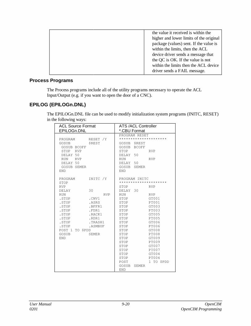
User Manual 9-20 OpenCIM0201 OpenCIM Programming
the value it received is within thehigher and lower limits of the originalpackage (values) sent. If the value iswithin the limits, then the ACLdevice driver sends a message thatthe QC is OK. If the value is notwithin the limits then the ACL devicedriver sends a FAIL message.
Process Programs
The Process programs include all of the utility programs necessary to operate the ACLInput/Output (e.g. if you want to open the door of a CNC).
EPILOG (EPILOGn.DNL)
The EPILOGn.DNL file can be used to modify initialization system programs (INITC, RESET)in the following ways:
ACL Source FormatEPILOGn.DNL
ATS /ACL Controller*.CBU Format
PROGRAM RESET /YGOSUB $RESTGOSUB BCOFFSTOP RVPDELAY 50RUN RVPDELAY 50GOSUB SEMER
END
PROGRAM INITC /YSTOPRVPDELAY 30RUN RVP.STOP .CNV1.STOP .ASRS.STOP .BFFR1.STOP .FDR1.STOP .RACK1.STOP .RDR1.STOP .TRASH1.STOP .ASMBUFPOST 1 TO $PDDGOSUB SEMEREND
PROGRAM RESET*********************GOSUB $RESTGOSUB BCOFFSTOP RVPDELAY 50RUN RVPDELAY 50GOSUB SEMEREND
PROGRAM INITC*********************STOP RVPDELAY 30RUN RVPSTOP GT001STOP PT001STOP GT003STOP PT003STOP GT005STOP PT005STOP GT006STOP PT006STOP GT008STOP PT008STOP GT009STOP PT009STOP GT007STOP PT007STOP GT004STOP PT004POST 1 TO $PDDGOSUB SEMEREND

User Manual 9-21 OpenCIM0201 OpenCIM Programming
ACLoff-line Utilities
OpenCIM requires the use of the ACLoff-line utility program version 1.65 or later. The followingACL features are used when writing structured ACL code for OpenCIM:
• Symbolic constants (#DEFINE)
• User defined macros (#MACRO, #ENDM)
• Include files (#INCLUDE)
• Download Flags• # IF
• # IFDEF
• # IFNDEF
• # ELSE
• # ENDIF
• Parameter passing using global variables
• Synchronization between programs running simultaneously
• Using the ACLoff-line utility program to send ACL source code to the ACL controller
You should be familiar with the system information contained in the include files CIMSYS.SYSand CIMSYS.DMC before you start writing your own ACL programs for the OpenCIMenvironment. This file contains system macros, programs, and global variable definitions whichperform the following functions:
• Synchronize the running of GET and PUT programs
• Start and end GET and PUT programs
• Error handling
• Send status messages to the CIM Manager, to a CNC machine, and to other CIM entities
�Caution
You should NOT edit the CIMSYS.SYS or CIMSYS.DMC files without guidance fromIntelitek technical support.
The program DOWNLOAD.EXE sends ACL source code files to the controller. While it issending programs to the ACL controller, this downloader checks syntax and substitutes theprogram code associated with #DEFINE, #MACRO, and #INCLUDE. These three languagedirectives function similarly to their counterparts in C or Assembly language. For more details,see the ACLoff-line program User’s Manual and the ACL Reference Guide.
�Note
You must run the DOWNLOAD utility program on the Station Manager PC that is connectedto the controller in order to download programs (because the downloader requires an RS232connection to the controller). However, the ACL source code files can reside on any PCaccessible via the network.
Before trying to download code with the DOWNLOAD utility, be sure to close the ACLdevice driver for this controller. Otherwise, a conflict will occur when the ACL program triesto open the same serial port as the device driver.

User Manual 9-22 OpenCIM0201 OpenCIM Programming
Robot Programs
The Robot Programs consist of all the relevant programs necessary to run the robot. Theseprograms are divided into two categories: generic and unique, “generic” referring to the fact thatthe program can be used by all the robots and “unique” referring to programs that are specific forthe robot at that station.
The Robot Programs are located in two places:
• Generic C:\OPENCIM\LIB\ACL
• Unique C:\OPENCIM\WSN\ROBOT
The following tables describe the file name conventions used for the ACL system programs andsample applications supplied with OpenCIM. You should use these naming conventions in yourown programming to simplify technical support. You can use the ACL off-line utility, the RobotPrograms window or the text editor of your choice to edit these files.
We recommend that you use a Robot Programs window when editing these files. Save the files inASCII format.
�Tip
It is recommended that you add a Robot Programs program group on a Station ManagerPC. This group should contain the following icons, as shown in the figure below.
• ATS: Terminal emulation program which allows you to interact with the ACL controllerconnected to a Station Manager PC.
• Download: Sends ACL programs from a Station Manager PC to an ACL Controller.
• Download Report:
• Notepad WS1: Allows easy editing of a station’s configuration file.
• Additional Notepads: for editing other .DNL files.
Figure 9-4: Robot Programs Group Window

User Manual 9-23 OpenCIM 2.30201 OpenCIM Programming
Generic Robot Programs
FileExtension Meaning
*.DNB DowNload - ACL source Blocks that are later copied to the DNL.
*.DMC Defines & MaCros - An include file (library file) containing user-supplieddefines and macros. The contents of this file are inserted in a DNL file atthe point specified by an INCLUDE command.
*.SYS All of the SYStem programs necessary to operate and communicate in theOpenCIM environment.
*.QCB All the Quality Control Block programs and Communication Blockprograms necessary for peripheral devices that connect directly to the ACLcontroller.
*.PRB All the Process Block programs necessary to Communicate with devices(e.g. CNC machine).
*.DLD DownLoad utilities.
Unique Robot Programs
FileExtension Meaning
*.DNL DowNLoad - ACL source code file that is sent to an ACL controller usingthe ACL Downloader.
*.QCL This file is copied from a QCB file. After the original file is modified to theediting application, the file is then unique to the specific QC device.
*.PRL This file is copied from a PRB file. After the original file is modified to theediting application, the file is then unique to the specific process activation(e.g. a program that speaks through I/O with a CNC machine).
�
�
�
Procedure
Editing andDownloading a RobotProgram Separately
1. In the Robot Programs window, select the Edit icon for the file youwant to edit; the file is displayed.
2. Edit the file.
3. Select the Download icon for the file you just edited; the file isdownloaded to the controller.
4. Select the Download Report icon . Verify that the file ends with>>>>>END DOWNLOAD FILE! “Device file name”

User Manual 9-24 OpenCIM0201 OpenCIM Programming
�
�
�
Procedure
Downloading All ofthe Robot Programsat One Time
� Note
If any Robot program files need to be edited, edit them before downloading.
In the Robot Programs window, select the Download Station icon ;the files for the entire station are downloaded to the controller. When the filesare downloaded together, they are sent in the following order:
1. CIMSYS.SYS
2. PROLOGn.DNL
3. DEVICES.DNL, DEVICES.QCL and DEVICES*.PCL
4. EPILOGn.DNL
You should not edit ACL object code by using the ATS utility or by backing up a program froma controller and modifying it. Either of these methods would result in an ACL file that is verydifficult to maintain.
Editing ACL object code (i.e. an *.CBU file) from the controller results in a program which is outof sync with the original DNL file. This code is harder to read since all #DEFINE, #MACRO,and #INCLUDE statements have been expanded in the controller and all remarks have beendeleted.
Note that the ATS utility can still be used for the following functions in the OpenCIMenvironment:
• Configure the controller
• Back up and restore robot positions and downloaded ACL programs
• Teach robot positions
• Test a robot
• Debug ACL programs by running them manually
Adding a New Pick-and-Place Operation
When you add a new device at a station (e.g. CNC machine, storage rack, assembly jig, etc.), youmust write two new ACL programs (GTxxx and PTxxx) that enable a robot to pick up anddeliver parts (or templates) from this device.
A program which directs a robot to pick up a part/template from a specific location is calledGTxxx. The xxx represents the unique three-digit device ID for a source location that is foundin the file SETUP.CIM.
Similarly, a program which directs a robot to deliver a part/template to a specific location iscalled PTxxx. Once again, xxx represents a unique device ID, this time for the target location.
For each pick-and-place operation, the CIM Manager sends a set of parameters to the ACLcontroller. The ACL program PCPLC reads these parameters from the ACL device driver and

User Manual 9-25 OpenCIM0201 OpenCIM Programming
assigns them to a set of global variables. These variables are used to pass the parameters to theappropriate GET and PUT programs.
A GET program’s main function is to pick up a part/template, which involves the following:
• Direct the robot to grasp a part/template
• Move the robot to a safe position; clear of the source device
• Send a Start status message
• Continue moving the robot to an intermediate point from which it can reach any device
• Activate the PUT program
A PUT program’s main function is to place a part/template in a designated location. Thisoperation involves the following steps:
• Wait for an activation signal from a GET program
• Move the robot to the target location
• Set the part/template down at the target location
• Move the robot clear of the target device
• Send a status message that the part/template is in place and ready to be processed
• Move the robot to safe position from which it can reach any device
• Send a status message that the robot is ready to perform the next operation
To write a set of GET and PUT programs for a new device that has been defined in SETUP.CIM,follow the steps outlined below:
Summary Details
1. Add the device to thefile DEVICE.DMC(connects the name ofthe device and the # ofthe device).
1. Use a text editor to insert a symbolic constant into the fileDEVICE.DMC. For example:
#DEFINE ASRS 002
In this example, 002 is the device ID (3 digits required) andASRS is the symbolic name you will use throughout yourACL programs to refer to this device.It is much easier to maintain ACL programs that usesymbolic constants (e.g. .ASRS) instead of literal deviceIDs (002). If a device ID ever changes, it is only necessaryto make the change in one place, i.e. in the fileDEVICE.DMC.
You should observe the following conventions whenassigning device IDs in order to simplify technical support:
001 Pallet at this conveyor station002 ASRS (or other central storage)
2. Copy the files from..\LIB\ACL to..WSn\ROBOTn
1. If you have a workstation with an ACL robot then add thedirectory ROBOTn.

User Manual 9-26 OpenCIM0201 OpenCIM Programming
Summary Details
2. Copy the files from ..\LIB\ACL as follows:
2.1. If the Type (FLD #5) from SETUP.CIM is:A, B, C, D, F, K, L, Q, J, M, S, X, Y, Z, then copyfrom: to:
..\LIB\ACL\WS.BLK ..\WSn\ROBOTn\WSn.DNL
..\LIB\ACL\PROLOG.BLK ..\WSn\ROBOTn\PROLOGn.DNL
..\LIB\ACL\EPILOG.BLK ..\WSn\ROBOTn\EPILOGn.DNL
..\LIB\ACL\CONFIG.DLD ..\WSn\ROBOTn\CONFIG.DLD
Refer to “OpenCIM Setup File: SETUP.CIM” for moreinformation.(Physical Name is FLD #3, Logical Name is FLD #4)
Rules for Creating DNL Files
2.2 If the Object Type in the SETUP.CIM (FLD #5) is:A, B, C, D, F, K, L, J, Q, M, S, X, Y, Z, then copyfrom: to:
..\LIB\ACL\[FLD #3].DNB ..\WSn\ROBOTn\[FLD #4].DNL
2.3 If FLD #5 is: L, Q or Y, then copyfrom: to:
..\LIB\ACL\[FLD #3].QCB ..\WSn\ROBOTn\[FLD #4].QC
2.4 If FLD #5 is: D or M, then copyfrom: to:
..\LIB\ACL\[FLD #3].PRB to ..\WSn\ROBOTn\
3. Create two new icons:to edit the DNL and todownload the DNL.
1. From the Robot Programs window, drag an icon; a new iconappears.
2. Select the new icon (click once) and press [Alt + Enter]; theProgram Item Properties dialog box appears.
3. Type in the name of the new device in the Description field.4. Type in the name of the new device in the command line for
the Edit icon or type in the new Download file name for theDownload icon.
5. Select OK.
4. Editing the DNL, QCLand PRL files.
1. From the Robot Programs window, select the icon of the fileyou want to edit; the file is displayed.
2. Type in the positions. Verify that the new positions you areentering do not already exist and that all the details of theposition can be found in PROLOG.DNL.
3. Set the accurate speed.
Replace the xxx in the first line of the GET and PUTprograms with the device name that was defined inDEVICE.DMC. Note the period preceding “.PROGRAM”and the space and the period preceding the device name (theleading period indicates a macro or symbolic constant). Forexample:

User Manual 9-27 OpenCIM0201 OpenCIM Programming
Summary Details
Generic Unique
.PROGRAM_GET xxx � .PROGRAM_GET .ASRS
.
.
.PROGRAM_PUT xxx � .PROGRAM_PUT .ASRS
5. Use standard ACLprocedures for teachinga robot to grab andrelease a part from thesource and targetlocations.
1. Use a teach pendant (or other means) to train the robot howto move and grasp.
2. Enter the coordinates of the source and target locations in theappropriate array.
3. Determine how the robot should grip the part/template.4. Fill in the appropriate robot movement commands in the
GET and PUT programs.If the location has multiple compartments (or buffers), you canuse the variables INDXG and INDXP to help calculate thearray index for CIM[ ] (the array that contains all robotpositions). These index parameters specify the cell locationwhen dealing with a storage rack or ASRS.
When a robot wants to insert (or remove) a part in a CNC machine, it must tell the machine whento open its door and chuck so the robot can enter the machine. The GET and PUT programsassociated with a CNC machine must communicate with CNC script programs that open andclose the door and chuck on the machine.
Robot Errors
Crash
When the ACL controller detects that a robot has collided with something, it responds as follows:
• The controller goes into COFF mode (Controller Off) and immediately stops all motors onthis robot.
• The controller immediately terminates all programs which are trying to move this robot. Ifany subsequent program attempts to move this robot, it will terminate with a run-time error.
• The ACL device driver automatically executes the DIAG program. (This program should isloaded at initialization time as part of CIMSYS.SYS.)
• The DIAG program sends a status message to the CIM Manager to reports the collision. See“Sample ACL Programs,” for a listing of the DIAG program.
The CIM Manager displays the Device Error screen to alert the operator.
Emergency
Refer to your system user manual for details.

User Manual 9-28 OpenCIM0201 OpenCIM Programming
CNC Programming for OpenCIM
CNC Script Language
Introduction
The CNC Script Language is a language which allows you to write programs to control a CNCmachine. These programs can initiate machine operations by turning the machine’s control lineson and off. Programs receive information from the machine via status lines. These control linesand status lines are connected to a station manager PC via an interface board. This board mapsthe control lines to output ports on the PC, and maps the status lines to input ports. Each linecorresponds to a bit in an I/O port. CNC script programs communicate with a CNC machine byreading and writing these bits.
The CNC Script Interpreter is part of the CNC Device Driver. When the CNC Device Driverreceives a system message containing a CNC command, it finds the corresponding program in thefile CNC_SCR.DBF and runs it.
Language Overview
The following table lists the commands and parameter variables in the CNC Script Interpreter:
Code Function
V1 - V16 Parameter variables read at initialization time.
P1 - P8 Parameter variables containing values passed to CNC scriptprograms at run time.
BV0, BV1 Current value of the two output ports.
PORT0, PORT1 PC I/O port addresses mapped to CNC control and status lines.
SetBit( ) Modifies the bits of the specified output port.
Wait( ) Suspends program execution for a specified duration.
WaitBit( ) Suspends execution until the specified bit(s) are set to one oruntil the specified bit pattern appears on an input port.
WaitBitLow( ) Suspends execution until the specified bit(s) are set to zero oruntil the specified bit pattern appears on an input port.
PulsBit( ) Turns on the designated bits of an output port for a specifiedduration.
Draw( ) Prints a line to the screen.
Draw2( ) Prints two lines to the screen.
SendMsg( ) Sends a predefined message to another CIM entity.
DownLoadD( ) Sends a G-Code program to the CNC machine via RS232.
SendStr( ) Sends a string to the specified OpenCIM device (e.g. robot).

User Manual 9-29 OpenCIM0201 OpenCIM Programming
Code Function
WaitStr( ) Suspends execution until the specified string arrives from theOpen–CIM-CIM network.
WaitFile( ) Suspends execution until the specified file is created.
MSDOS( ) Performs any MS-DOS command.
MSWINDOWS( ) Launches any MS-WINDOWS executable file.
ABORT( ) Unconditionally aborts the current CNC device driver program.
Initialization Parameter Variables
The CNC Script Interpreter supports up to 16 general purpose parameter variables and twospecial purpose variables which are defined at initialization time. The general purpose variablescontain values that are 0 to 80 bytes long. These variable names, V1 - V16, are fixed. Thetwo special purpose variables, PORT0 and PORT1, contain the addresses of I/O ports used tointerface to the CNC machine.
The CNC Device Driver assigns the values of the parameter variables V1-V16, PORT0, andPORT1 at initialization time. It reads these values from the section[CNCDriverDefinitions] in the file CNC.INI.
These variables are global to all CNC script programs. Their values do not change duringexecution of a script program.
General purpose variables can contain the following types of values:
VariableType
Range Example
Integer Integers range in value from0 - 2,147,483,647
V8 = 60000
String A set of ASCII characters enclosed in quotationmarks. A string can range in length from 0 - 80characters.
V1 = ”Door Open”
Bit Mask A string of 8 ASCII text characters enclosed inquotation marks. Each character is either 0 or 1.
V16 = ”01000111”
The following table describes the special purpose variables:
Variable Description Default Value
PORT0 The address of the first input and output ports onthe PC used to communicate with a CNC machine.
0x500(for both input andoutput ports)
PORT1 The address of the second PC input and output portson the PC used to communicate with a CNCmachine.
0x501(for both input andoutput ports)

User Manual 9-30 OpenCIM0201 OpenCIM Programming
Passing Run-Time Parameters to Programs
Up to eight run-time parameters can be passed to a CNC script program. Each parametercontains a value that is 0 to 80 bytes long. The parameter names, P1-P8 are fixed.
You specify a string of parameter values when you invoke a CNC script program. Parameters inthis string are separated by commas. The first value in the string is assigned to the parametervariable P1, the second to P2, etc. The parameter string can be a maximum of 32 characters long(including the comma separators). The rules regarding parameter values described in the previoussection also apply to run-time parameter values.
The following sample parameter string contains both numeric and string values:
1000,Please wait,60,Finished
The way in which you specify the parameter string depends on which of the following methodsyou are using to invoke the CNC script program:
Network Message A CIM message sent to a CNC Device Driver contains two strings,the name of the CNC script program immediately followed by itsparameter string.
CNC Control Panel The string containing the list of parameters is specified in theParameters window of the Control Panel.
The CNC Device Driver initializes the values of run-time parameters read from the file CNC.INI.
The values of run-time parameter variables do not change after they have been passed into aCNC script program.
System Variables
System variables BV0 and BV1 are used to read the current value of their respective output portsduring execution of a script program. These variables are global to all CNC script programs for adevice driver.
These system variables are assigned in the device driver's INI file in the section[CNCDriverDefinitions]. These 8-bit values, which range from 0–255 are assumed tobe the initial state of the control lines of a CNC machine when the system is turned on.
The following table shows the CNC script system variables and their default values (i.e. thevalues used if no assignment appears in CNC.INI):
System Variable Description Default Value
BV0 The current status (Port Value) of output port # 0. 0
BV1 The current status (Port Value) of output port # 1. 0
Command Arguments and Syntax
Numeric command arguments can take one of the following forms:
Integer 0 - 2147483647
Parameter Variable V1 - V16, P1 - P8

User Manual 9-31 OpenCIM0201 OpenCIM Programming
Spaces that appear in a command’s argument list are ignored. Case is not significant in thespelling of command names or for variable names in the argument list. The following examplesare equivalent:
SetBit(PORT1, BV1, &, V16)
SetBit (PORT1,BV1,&,V16)
Editing CNC Script Language Programs
All CNC script programs for a station (those that you write and those that come with the system)are stored in the script file CNC_SCR.DBF. More than one CNC device driver can share thesame script file. This file normally resides either:
• On the server in a subdirectory designated for this station
• On the station manager PC running the CNC Device Driver
Use a dBASE editor to write your CNC programs to the appropriate CNC_SCR.DBF file. If aCNC device driver is running, you must close it before you begin editing its CNC_SCR.DBF file.Otherwise you will get an Access Denied error message.
Enter the name of each CNC script program in the REQUEST column. A program name can beup to 32 characters long. It can contain any combination of letters, numbers, spaces, andpunctuation.
The ACTION column contains the CNC script commands that comprise a program. There is nolimit on the number of commands contained in a program.
The RETURN column is reserved for internal use. Do not enter any values in this column.
This file uses the following format:
REQUEST | ACTION | RETURN |
Program Name 1 | script command 1 | |
| script command 2 | |
| script command 3 | |
| script command 4 | |
| script command 5 | |
End | | |
Program Name 2 | script command 1 | |
| script command 2 | |
| : | |:
When the CIM Manager wants to run a CNC program, it issues a Run command to theappropriate CNC Device Driver at a station. The device driver finds the program in the fileCNC_SCR.DBF and executes it.

User Manual 9-32 OpenCIM0201 OpenCIM Programming
Request ActionReturn
go in RS232 receive pulsbit( port0, bv0, "00000001", 500 )
Draw("-- go to RS232 receive --")
end
go in auto pulsbit( port0, bv0, "00000010", 500 )
draw("-- go in auto --")
end
start for 0001 pulsbit( port0, bv0, "00000100", 500 )
draw("-- start for 0001 --" )
draw2( v16, "-- machine is running -- " )
end waitbit( port0, "00000001", 10000 )
open door pulsbit( port0, bv0, "00001000", 500 )
draw( "-- open door --" )
draw2( v16, "-- door is opened --" )
end waitbit( port0, "00000010", 10000 )
close door pulsbit( port0, bv0, "00010000", 500 )
draw( "-- close door --" )
draw2( v16, "-- door is closed --" )
end waitbit( port0, "00000100", 10000 )
open clamping device pulsbit( port0, bv0, "00100000", 500 )
draw( "-- open clamping device -- " )
draw2( v16, "-- clamping device is opened" )
end waitbit( port0, "00001000", 10000 )
close clamping device pulsbit( port0, bv0, "01000000", 500 )
draw( "-- close clamping device --" )
draw2( v16, "-- clamping device is closed" )
end waitbit( port0, "00010000", 10000 )
feedhold pulsbit( port0, bv0, "10000000", 500 )
draw2( "-- feedhold --", "*** ALARM ***" )
end waitbit( port0, "00100000", 10000 )
start for 0002 pulsbit( port1, bv0, "00000001", 500 )
draw( "-- start for 0002 --" )
draw2( v16, "-- machine is running --" )
end waitbit( port0, "00000001", 10000 )
pinole out pulsbit( port1, bv0, "00000010", 500 )
draw( "-- pinole out --" )
draw2( v16, "-- pinole is out --" )
end waitbit( port0, "01000000", 10000 )
pinole in pulsbit( port1, bv0, "00000100", 500 )
draw( "-- pinole in --" )
draw2( v16, "-- pinole is in --" )
end waitbit( port0, "10000000", 10000 )
Figure 9-5: Sample CNC Programs in the file CNC_SCR.DBF

User Manual 9-33 OpenCIM0201 OpenCIM Programming
CNC Script Error Messages
The error messages listed below appear in the CNC Status window when the CNC ScriptInterpreter encounters an invalid statement.
"(" expected OR ")" expected• A parenthesis surrounding the command's argument
list is missing.
End of program not found• No End statement was found for the current
program in the Request column ofCNC_SCR.DBF.
Invalid command name• The command name is not valid. Check the spelling.
Program not found• The program name is not valid. Check the spelling.
Invalid system variable -Use BV0 or BV1
Invalid bit mask• The bit mask must be an 8-character string
composed of 1s and 0s.
Invalid port address - UsePORT0 or PORT1 parametervariable
• Replace the invalid address with the variablePORT0 or PORT1.
ORCheck the value assigned to parameter variablesPORT0 and PORT1 in CNC.INI.
Unexpected number of arguments• There are either too few or too many values in the
argument list for this command.
Unexpected string in argument• An argument contains a string value instead of a
numeric value.
Unrecognized bitwise operator• A character other than &, |, ^, or ~ was specified as
a bitwise operator.

User Manual 9-34 OpenCIM0201 OpenCIM Programming
CNC Script Language Commands
DownloadD()
DownLoadD( ) Sends a G-Code file to the CNC machine via RS232
Name: DownLoadD(FileName, MemArea)
Inputs: FileName • Full DOS path of G-code programto be sent to the CNC machine
• 0 - 9999
MemArea • Region in the CNC machine'smemory where this program is tobe loaded
• 1 - 5
Purpose
Normally a G-code file is assigned to a CNC process in the Machine Definition module. In thiscase, the CIM Manager takes care of automatically downloading this file prior to invoking theprocess and the DownLoadD( ) command is not needed. You should only use theDownLoadD( ) command if you cannot set up a downloading batch file.
Function
The DownLoadD( ) command sends the G-code file FileName to the CNC machine usingthe RS232 port specified in the device driver's command line. For machines capable of retainingmore than one program, you can specify the memory region where the current program is toreside.
If the parameters Loader and TaskLoadedMark have been defined, the device driver usesthe batch file specified by Loader to perform the download (recommended). Otherwise, thedevice driver's internal downloader is used.
Examples
DownLoadD(C:\OPENCIM\WS3\MILLPART.G, 1)
This statement sends the file MILLPART.G to memory region 1 in the CNC machine.
DownLoadD(P1, P2)
When testing a machine, the following statement receives the G-code file and memory region thatwere defined in the Parameter field of the device driver's Control Panel.

User Manual 9-35 OpenCIM0201 OpenCIM Programming
Draw( )
Draw( ) Prints a line to the screen
Name: Draw(line_of_text)
Inputs: line_of_text • String to display in the CNCStatus window
• 0 - 80 characters
Purpose
Viewing status messages during the operation of a CNC machine can be helpful introubleshooting problems and verifying the proper functioning of the machine. Messages can alsoinstruct the operator of the machine when a manual procedure must be performed.
These messages can be particularly helpful when dealing with machines which have either nodisplay of their own or only a very limited status panel.
Function
The Draw( ) command prints the string line_of_text in the CNC Status window. Thiswindow appears on the PC running the CNC Device Driver. The Draw( ) command prints eachstring on a new line.
The message string can be from 0 - 80 characters long. This argument can consist of either astring literal enclosed in quotation marks (e.g. “Drilling in progress”) or a parametervariable (V1 - V16, P1 - P8).
Examples
Draw(P3)
Draw(V5)
Draw(“Door Open”)

User Manual 9-36 OpenCIM0201 OpenCIM Programming
Draw2( )
Draw2( ) Prints 2 lines to the screen
Name: Draw2(text_line_1, text_line_2)
Inputs: text_line_1 • First string to display in theCNC Status window
• 0 - 80 characters
text_line_2 • Second string to display in theCNC Status window
• 0 - 80 characters
Purpose
When there is more than one line of text to display, it is convenient to use the Draw2( ) commandto print two lines of text with one command call. Using the Draw2( ) command is also faster thanmaking two successive calls to the Draw( ) command. This can be an advantage when running ina busy, real-time environment.
Function
The Draw2( ) command prints the strings text_line_1 and text_line_2 in the CNCStatus window. This window appears on the PC running the CNC Device Driver. The Draw2( )command prints each string on a new line.
Each message string can be from 0 - 80 characters long. These arguments can consist of either astring literal enclosed in quotation marks (e.g. “Machine overheated!”) or a parametervariable (V1 - V16, P1 - P8).
Examples
Draw2(P3, V2)
Draw2(V16, V5)
Draw2(“Part ready”, P8)

User Manual 9-37 OpenCIM0201 OpenCIM Programming
PulsBit( )
PulsBit( ) Turns on the designated bits of an output port for a specified duration
Name: PulsBit(portn, mask1, mask2, time_to_puls)
Inputs: portn • Address of the output port to bemodified
• 0x0000 -0xFFFF
mask1 • An 8-character string containing1’s and 0’s representing a bitmask. All bits set to 1 are heldhigh for the duration oftime_to_puls.
• “00000000” -“11111111”V1 - V16P1 - P16
mask2 • An 8-character string containing1’s and 0’s representing a bitmask. All bits set to 1 are heldhigh for the duration oftime_to_puls.
• “00000000” -“11111111”V1 - V16P1 - P16
time_to_puls • Number of milliseconds to pauseprogram execution while assertingthe specified high bits
• CNCDriverTimer- 2147483647
V1 - V16P1 - P16
Purpose
Some operations of a CNC machine are time-based as opposed to operations that signal theircompletion via a status line. The PulsBit( ) command provides a convenient way ofexecuting an operation for a specified time period.
For example, after a part has been machined, it may be necessary to rinse it with water for 30seconds before removing it from the CNC machine. The PulsBit( ) command can be used toturn on the bit which controls the rinse cycle for the required period of time.
Function
The PulsBit( ) command gives you the means to control CNC operations for a specifiedperiod of time. It turns on the designated bits of an output port for a specified duration.
The portn argument specifies the output port which contains the bit(s) that operate the controlline(s) you are interested in.
mask1 can be set to either:
• The current value of the output port, BVn
• An absolute bit mask value (see description of mask2 below)
You specify which ctrl lines should be pulsed on and off by constructing a bit mask, mask2. Themask2 argument is an 8-character string composed of 1’s and 0’s in ASCII text. This argumentcan consist of either a string literal enclosed in quotation marks (e.g. “10000000”) or aparameter variable (V1 - V16, P1 - P8).

User Manual 9-38 OpenCIM0201 OpenCIM Programming
The PulsBit( ) command performs a bitwise OR operation between mask1 and mask2. Itassigns the result to the output port for time_to_puls milliseconds. It then resets the port toits original value. The minimum TIME_TO_WAIT is the value of the parameterCNCDriverTimer found in CNC.INI.
The following table shows all the possible ways that PulsBit( ) can affect a single bitposition of an output port when mask1 = BVn:
PulsBit( )
Starting Value ofan Output Port Bit(mask1 = BVn)
Corresponding Bitin Bit Mask(mask2)
Control Line DuringExecution ofPulsBit( )
Control Line AfterExecution ofPulsBit( )
0 0 0 - Off 0 - Off
0 1 1 - On 0 - Off
1 0 1 - On 1 - On
1 1 1 - On 1 - On
Examples
PulsBit(PORT0, BV0, “10000000”, 30000)
This example turns on control line # 7 that is connected to the PC’s output port 0 for 30 seconds.The remaining bits in the port retain their current values during and after execution ofPulsBit( ) since their values in the bit mask are 0.
PulsBit(PORT1, BV1, V5, 100000)
The bits in output port 1 are ORed with the bit mask in variable V5. The result is written tooutput port 1 and the corresponding control lines are set on and off for 100 seconds. Afterwards,the original value of output port 1 is restored.
PulsBit(PORT1, BV1, P4, P7)
The bits in output port 1 are ORed with the bit mask in parameter variable P4. The result iswritten back to output port 1 and the corresponding control lines are set on and off for a period ofP7 milliseconds. Afterwards, the original value of output port 1 is restored.

User Manual 9-39 OpenCIM0201 OpenCIM Programming
SendMsg( )
SendMsg( ) Sends a predefined message to another CIM entity
Name: SendMsg(msg_to_send)
Inputs: msg_to_send • Index to predefined messagesstored in VC2_WM.DBF
• 0 - 9999
Purpose
In a CIM environment, a CNC machine must report its status to other CIM entities such as:
• The CIM Manager which handles production scheduling and tracking
• Devices which are dependent on this machine (e.g. the robot that tends the machine)
• The Graphic Production Module which displays the machine’s status
The SendMsg( ) command informs these entities when the CNC machine has completedprocessing a part, when there is a problem that causes an alarm condition, etc. This commanduses a set of predefined messages to perform this function. Each message has an associated IDand destination device address.
You can generate real-time status messages by inserting the SendMsg( ) command throughout aprogram.
You can add your own custom messages to the message file. For example, this capability isuseful if you are programming a robot to tend this CNC machine. You could define a message tonotify the robot when the machine is ready to receive a part and another message to inform therobot that the part is ready to be picked up. You would use the SendMsg( ) command to sendthese messages.
Function
The SendMsg( ) command sends predefined real-time status messages to any CIM entity. Theargument msg_to_send specifies the ID number of a message stored in the fileVC2_WM.DBF. This ID number is sufficient to deliver the message because there is adestination address associated with each message in this file.
Examples
SendMsg(2582)
This statement finds the message with the ID number of 2582 in the file VC2_WM.DBF. It thensends this message to the destination device listed in this message record.
SendMsg(P4)
SendMsg(V12)
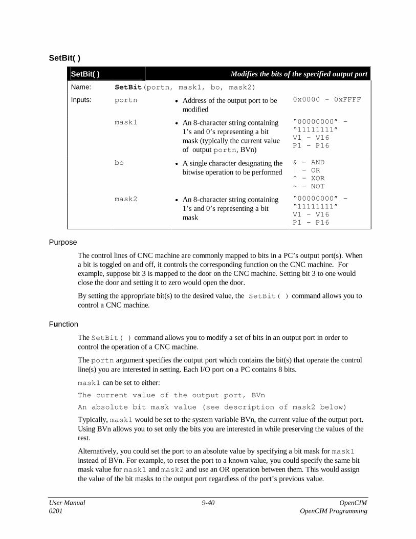
User Manual 9-40 OpenCIM0201 OpenCIM Programming
SetBit( )
SetBit( ) Modifies the bits of the specified output port
Name: SetBit(portn, mask1, bo, mask2)
Inputs: portn • Address of the output port to bemodified
0x0000 - 0xFFFF
mask1 • An 8-character string containing1’s and 0’s representing a bitmask (typically the current valueof output portn, BVn)
“00000000” -“11111111”V1 - V16P1 - P16
bo • A single character designating thebitwise operation to be performed
& - AND| - OR^ - XOR~ - NOT
mask2 • An 8-character string containing1’s and 0’s representing a bitmask
“00000000” -“11111111”V1 - V16P1 - P16
Purpose
The control lines of CNC machine are commonly mapped to bits in a PC’s output port(s). Whena bit is toggled on and off, it controls the corresponding function on the CNC machine. Forexample, suppose bit 3 is mapped to the door on the CNC machine. Setting bit 3 to one wouldclose the door and setting it to zero would open the door.
By setting the appropriate bit(s) to the desired value, the SetBit( ) command allows you tocontrol a CNC machine.
Function
The SetBit( ) command allows you to modify a set of bits in an output port in order tocontrol the operation of a CNC machine.
The portn argument specifies the output port which contains the bit(s) that operate the controlline(s) you are interested in setting. Each I/O port on a PC contains 8 bits.
mask1 can be set to either:
The current value of the output port, BVn
An absolute bit mask value (see description of mask2 below)
Typically, mask1 would be set to the system variable BVn, the current value of the output port.Using BVn allows you to set only the bits you are interested in while preserving the values of therest.
Alternatively, you could set the port to an absolute value by specifying a bit mask for mask1instead of BVn. For example, to reset the port to a known value, you could specify the same bitmask value for mask1 and mask2 and use an OR operation between them. This would assignthe value of the bit masks to the output port regardless of the port’s previous value.
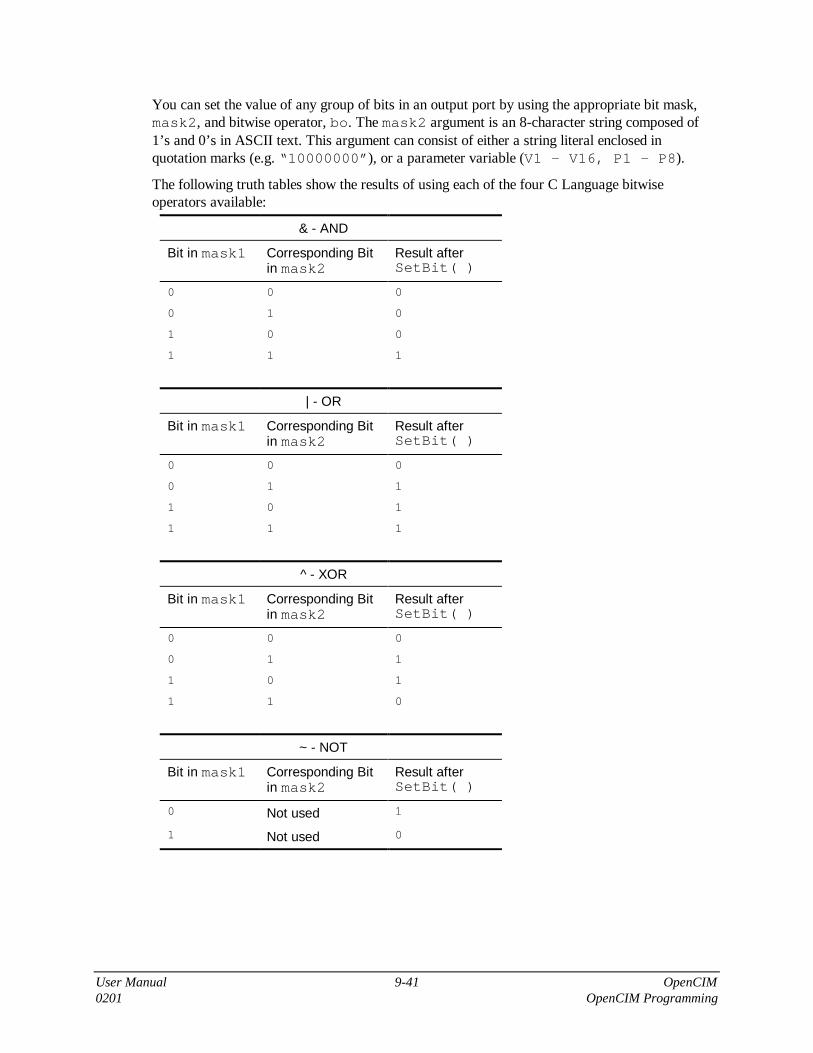
User Manual 9-41 OpenCIM0201 OpenCIM Programming
You can set the value of any group of bits in an output port by using the appropriate bit mask,mask2, and bitwise operator, bo. The mask2 argument is an 8-character string composed of1’s and 0’s in ASCII text. This argument can consist of either a string literal enclosed inquotation marks (e.g. “10000000”), or a parameter variable (V1 - V16, P1 - P8).
The following truth tables show the results of using each of the four C Language bitwiseoperators available:
& - AND
Bit in mask1 Corresponding Bitin mask2
Result afterSetBit( )
0 0 0
0 1 0
1 0 0
1 1 1
| - OR
Bit in mask1 Corresponding Bitin mask2
Result afterSetBit( )
0 0 0
0 1 1
1 0 1
1 1 1
^ - XOR
Bit in mask1 Corresponding Bitin mask2
Result afterSetBit( )
0 0 0
0 1 1
1 0 1
1 1 0
~ - NOT
Bit in mask1 Corresponding Bitin mask2
Result afterSetBit( )
0 Not used 1
1 Not used 0

User Manual 9-42 OpenCIM0201 OpenCIM Programming
Examples
SetBit(PORT0, BV0, |, “10000000”)
This example turns on control line # 7. This control line is connected to the PC’s output port 0.The OR truth table indicates that when the mask contains a 1 in a given position, that bit will beset to 1 regardless of the bit’s initial value in the output port.
SetBit(PORT1, BV1, &, V16)
The bits in output port 1 are ANDed with the bit mask in variable V16. The result is written backto output port 1 and the corresponding control lines are set on and off accordingly.
SetBit(PORT1, BV1, ^, P8)
The bits in output port 1 are XORed with the bit mask in parameter variable P8. The result iswritten back to output port 1 and the corresponding control lines are set on and off accordingly.

User Manual 9-43 OpenCIM0201 OpenCIM Programming
Wait( )
Wait( ) Suspends program execution for a specified duration
Name: Wait(time_to_wait)
Inputs: time_to_wait • Number of milliseconds tosuspend program execution
• CNCDriverTimer- 2147483647,
V1 - V16,P1 - P16
Purpose
After performing an operation on a CNC machine, it is sometimes desirable to pause for a whilebefore continuing with the next operation. For example, it may be necessary to wait 2 minutesafter a certain procedure to allow a part to cool down before a robot extracts it from the CNCmachine. In this case the command Wait(120000) can provide the required delay before theCNC script program signals the CIM Manager that the part is ready.
Function
When the CNC Script Interpreter encounters the Wait( ) command, it pauses for the indicatedamount of time before executing the next program statement. The argument time_to_waitspecifies the number of milliseconds the interpreter waits before resuming execution. Thisargument can be either an integer or a parameter variable (V1 - V16, P1 - P16). The minimumtime_to_wait is the value of the parameter CNCDriverTimer found in CNC.INI.
Examples
Wait(2000)
This statement causes the CNC Script Interpreter to pause for 2 seconds.
Wait(V16)
Wait(P8)
The length of the pause resulting from each of these two statements depends on the values ofvariables V16 and P8.

User Manual 9-44 OpenCIM0201 OpenCIM Programming
WaitBit( )
WaitBit( ) Suspends execution until the specified bit(s) are set to one or until thespecified bit pattern appears on an input port
Name: WaitBit(portn, mask, time_to_wait)
Inputs: portn • Address of the output port to bemodified
• 0x0000 -0xFFFF
mask • An 8-character string containing1’s and 0’s representing a bitmask
• “00000000” -“11111111”,V1 - V16,P1 - P16
time_to_wait • Maximum number ofmilliseconds to suspend programexecution while waiting for a bitpattern
• CNCDriverTimer- 2147483647,
V1 - V16,P1 - P16
Purpose
After performing an operation on a CNC machine, it is frequently necessary to wait for a statusline to signal that the operation was successfully performed. Status lines from a CNC machineare connected to an I/O board which maps each line to a bit in a PC input port.
By examining the value of these input port bits, it is possible to determine information about amachine such as:
Status Line Example
An operation is completed. Bit 0Drilling in progress = 0Hole drilled = 1
An alarm condition has occurred. Bit 1Normal temperature = 0Machine overheated = 1
The position of a component on a CNC machine. Bit 2Door open = 0Door closed = 1
The WaitBit( ) command allows you to read a set of status lines in order to monitor theoperation of a CNC machine.
Function
The WaitBit( ) command monitors an input port, portn. It compares the value of this portwith the bit mask argument, mask. This command waits for the specified interval for one of thefollowing conditions to be true:
• An exact match occurs between all 8 bits of the input port and the bit mask.

User Manual 9-45 OpenCIM0201 OpenCIM Programming
• A bit equal to 1 in mask matches up with the corresponding bit equal to 1 in the output port.For example, bits 7 and 5 below meet this condition:
• 10100000 � mask11110000 � BVn
When one of these conditions is true, the Command Interpreter prints in the Status window:
--- Condition is true ---
It then proceeds to execute the next command.
The WaitBit( ) command monitors the port for the period of time specified in the argumenttime_to_wait (in milliseconds). This argument can be either an integer or a parametervariable (V1 - V16, P1 - P16). The minimum time_to_wait is the value of theparameter CNCDriverTimer found in CNC.INI.
If neither of the above conditions occurs during this interval, the command times out. The CNCScript Interpreter aborts program execution and generates the error messageWM_CIMDDE_CNCERROR. The CNC Device Driver relays this error message back to theCIM Manager.
Examples
WaitBit(PORT1, “1000001”, 2000)
This statement causes the CNC Script Interpreter to check port 1 for up to 2 seconds. If statuslines 0 and 7 in this port are high, the condition is true and execution resumes with the nextCLINT statement. If this match does not occur within 2 seconds, an error is generated.
WaitBit(PORT0, V3, P2)
The variables PORT0 and V3 contain the address of the input port and the bit mask respectively.Variable V3 is assigned its value at initialization time from the file VC2_CNC.INI. The time outinterval, P2, is specified at run time when this program is invoked.
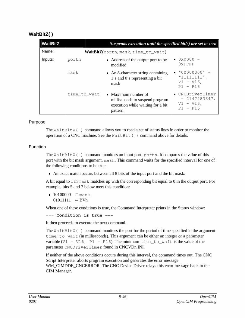
User Manual 9-46 OpenCIM0201 OpenCIM Programming
WaitBitZ( )
WaitBitZ Suspends execution until the specified bit(s) are set to zero
Name: WaitBitZ(portn, mask, time_to_wait)
Inputs: portn • Address of the output port to bemodified
• 0x0000 -0xFFFF
mask • An 8-character string containing1’s and 0’s representing a bitmask
• “00000000” -“11111111”,V1 - V16,P1 - P16
time_to_wait • Maximum number ofmilliseconds to suspend programexecution while waiting for a bitpattern
• CNCDriverTimer- 2147483647,
V1 - V16,P1 - P16
Purpose
The WaitBitZ( ) command allows you to read a set of status lines in order to monitor theoperation of a CNC machine. See the WaitBit( ) command above for details.
Function
The WaitBitZ( ) command monitors an input port, portn. It compares the value of thisport with the bit mask argument, mask. This command waits for the specified interval for one ofthe following conditions to be true:
• An exact match occurs between all 8 bits of the input port and the bit mask.
A bit equal to 1 in mask matches up with the corresponding bit equal to 0 in the output port. Forexample, bits 5 and 7 below meet this condition:
• 10100000 � mask01011111 � BVn
When one of these conditions is true, the Command Interpreter prints in the Status window:
--- Condition is true ---
It then proceeds to execute the next command.
The WaitBitZ( ) command monitors the port for the period of time specified in the argumenttime_to_wait (in milliseconds). This argument can be either an integer or a parametervariable (V1 - V16, P1 - P16). The minimum time_to_wait is the value of theparameter CNCDriverTimer found in CNCVDn.INI.
If neither of the above conditions occurs during this interval, the command times out. The CNCScript Interpreter aborts program execution and generates the error messageWM_CIMDDE_CNCERROR. The CNC Device Driver relays this error message back to theCIM Manager.

User Manual 9-47 OpenCIM0201 OpenCIM Programming
Examples
WaitBitZ(PORT1, “10000001”, 2000)
This statement causes the CNC Script Interpreter to check port 1 for up to 2 seconds. If statuslines 0 and 7 in this port are low, the condition is true and execution resumes with the nextCLINT statement. If this match does not occur within 2 seconds, an error is generated.
WaitBitZ(PORT0, V3, P2)
The variables PORT0 and V3 contain the address of the input port and the bit mask respectively.Variable V3 is assigned its value at initialization time from the file CNCVDn.INI. The time outinterval, P2, is specified at run time when this program is invoked.
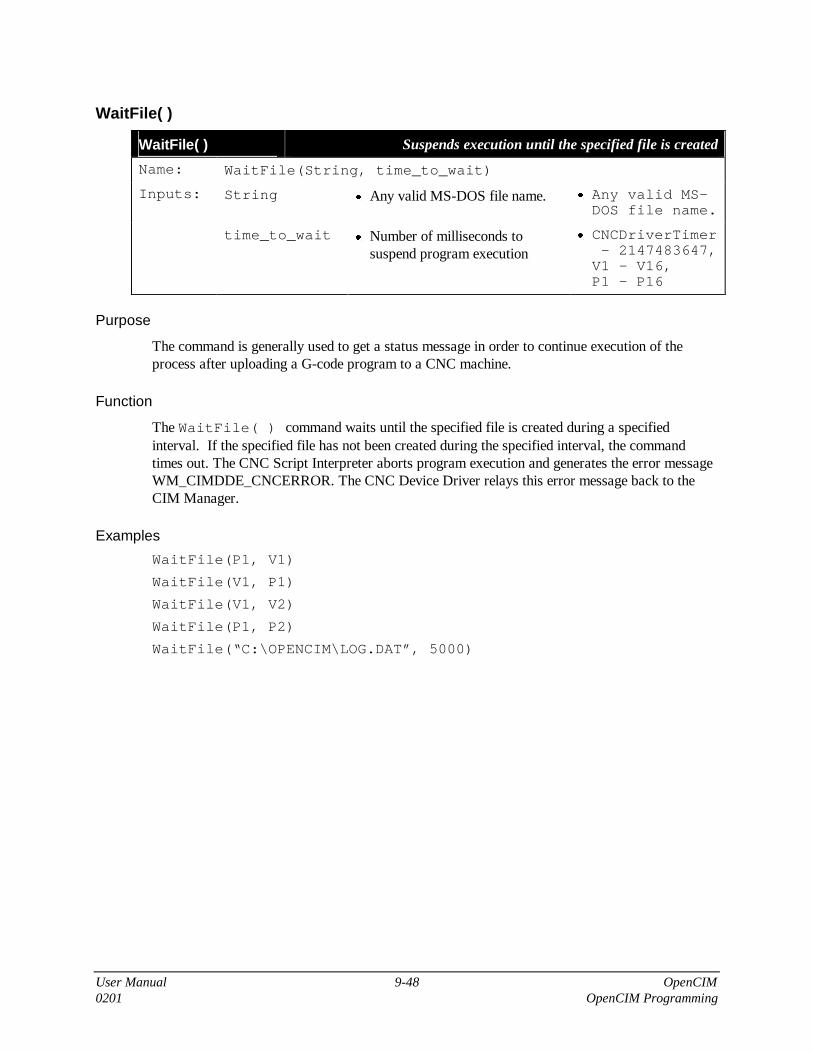
User Manual 9-48 OpenCIM0201 OpenCIM Programming
WaitFile( )
WaitFile( ) Suspends execution until the specified file is created
Name: WaitFile(String, time_to_wait)
Inputs: String • Any valid MS-DOS file name. • Any valid MS-DOS file name.
time_to_wait • Number of milliseconds tosuspend program execution
• CNCDriverTimer- 2147483647,
V1 - V16,P1 - P16
Purpose
The command is generally used to get a status message in order to continue execution of theprocess after uploading a G-code program to a CNC machine.
Function
The WaitFile( ) command waits until the specified file is created during a specifiedinterval. If the specified file has not been created during the specified interval, the commandtimes out. The CNC Script Interpreter aborts program execution and generates the error messageWM_CIMDDE_CNCERROR. The CNC Device Driver relays this error message back to theCIM Manager.
Examples
WaitFile(P1, V1)
WaitFile(V1, P1)
WaitFile(V1, V2)
WaitFile(P1, P2)
WaitFile(“C:\OPENCIM\LOG.DAT”, 5000)

User Manual 9-49 OpenCIM0201 OpenCIM Programming
WaitString( )
WaitString( ) Suspends execution until the specified string arrives from Network
Name: WaitString(String, time_to_wait)
Inputs: String • A string that specifies thebeginning or end of an operation.
• Any stringthat containsan address inthe OpenCIMenvironment.
time_to_wait • Number of milliseconds tosuspend program execution
• CNCDriverTimer- 2147483647,
V1 - V16,P1 - P16
Purpose
After performing an operation on a CNC machine, it is usually necessary to wait for a statusmessage in order to confirm that the operation was performed successfully.
Function
The WaitString( ) command waits for a string during a specified interval. If the CNCdevice driver doesn’t receive the string during the specified interval, the command times out. TheCNC Script Interpreter aborts program execution and generates the error messageWM_CIMDDE_CNCERROR. The CNC Device Driver relays this error message back to theCIM Manager.
Examples
WaitString(V1, V2)
WaitString(V1, P1)
WaitString(P1, V1)
WaitString(“Test is done”, 10000)

User Manual 9-50 OpenCIM0201 OpenCIM Programming
SendString( )
SendString( ) Sends a string to the specified OpenCIM device ( e.g. to a robot)
Name: SendString(Address, String)
Inputs: Address • Name of the workstation inthe OpenCIM environment.
• Any of the OpenCIMpredefined commands.
String • String to be sent to be sent tothe defined address
• Any string that contains anaddress in the OpenCIMenvironment.
Purpose
When a program is to be run in the ACL controller, a string (recognizable by the ACL controller)is sent to the ACL controller and the address tells the controller where to send the string.
Function
The SendString( ) command sends predefined commands to any CIM entity.
Examples
SendString(P1, P2)
SendString(V1, V2)
SendString(V1, P1)
SendString(“WS0 DDE ACL 25”, “RUN SSCNC”)
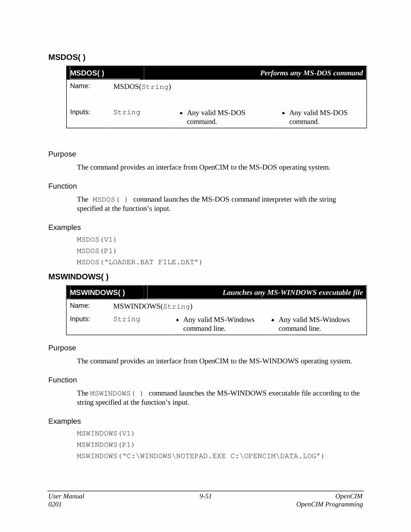
User Manual 9-51 OpenCIM0201 OpenCIM Programming
MSDOS( )
MSDOS( ) Performs any MS-DOS command
Name: MSDOS(String)
Inputs: String • Any valid MS-DOScommand.
• Any valid MS-DOScommand.
Purpose
The command provides an interface from OpenCIM to the MS-DOS operating system.
Function
The MSDOS( ) command launches the MS-DOS command interpreter with the stringspecified at the function’s input.
Examples
MSDOS(V1)
MSDOS(P1)
MSDOS(“LOADER.BAT FILE.DAT”)
MSWINDOWS( )
MSWINDOWS( ) Launches any MS-WINDOWS executable file
Name: MSWINDOWS(String)
Inputs: String • Any valid MS-Windowscommand line.
• Any valid MS-Windowscommand line.
Purpose
The command provides an interface from OpenCIM to the MS-WINDOWS operating system.
Function
The MSWINDOWS( ) command launches the MS-WINDOWS executable file according to thestring specified at the function’s input.
Examples
MSWINDOWS(V1)
MSWINDOWS(P1)
MSWINDOWS(“C:\WINDOWS\NOTEPAD.EXE C:\OPENCIM\DATA.LOG”)

User Manual 9-52 OpenCIM0201 OpenCIM Programming
ABORT( )
ABORT( ) Unconditionally aborts the current CNC Device Driver program
Name: ABORT( )
Purpose
Using this command is the only way to abort a CNC Device Driver program without the CIMManager.
Function
The ABORT( ) command unconditionally aborts the current CNC Device Driver program.
Examples
ABORT( )

User Manual 9-53 OpenCIM0201 OpenCIM Programming
Interfacing a Robot with a CNCMachine
When a robot inserts a part into a CNC machine, it must coordinate its movements with theoperation of the machine using a CNC synchronization mechanism. This mechanism is usedwhen a robot sends a command message to a CNC machine telling it to perform a certainfunction. The robot then waits for a response. Only after the CNC responds does the robot’s ACLprogram continue execution.
The following scenario describes how a typical robot and CNC machine interact when the robotinserts and removes a part from the machine:
• The robot waits while the CNC machine opens its door and vise.
• The robot enters the machine. It holds the part in place while the machine clamps the part inits vise.
• The robot exits the machine and signals the CIM Manager that the CNC machine is ready tobe activated.
• The robot waits outside the machine until it receives a signal from the CIM Manager that themachine is finished.
• The CNC opens its door and waits until the robot has grasped the part before it opens itsvise.
• The robot removes the part and takes it to the next location.
While the CIM Manager could conceivably coordinate the above interaction between a robot anda CNC machine, it is more efficient for the ACL controller to do this. This section describes howto write ACL programs that communicate with script programs found in the CNC device driver.(You should already be familiar with OpenCIM ACL programming before continuing. See “ACLProgramming for OpenCIM” for more information.)
The CNC synchronization mechanism is actually a specific case of how you can send commandand status messages to perform OpenCIM operations.
It is possible to have two robots attached to a single ACL controller. In this case, you would usethe ACL system file, CIMSYSM instead of CIMSYS. You would also need to adjust the samplecode presented in this section to distinguish between the two robots. These changes are beyondthe scope of this discussion.
The following diagram illustrates the sequence of commands that are executed when a robotinserts a part into a CNC machine. The commands shown in step 2 below are generated by therobot’s PUT program for the CNC machine.

User Manual 9-54 OpenCIM0201 OpenCIM Programming
Command Sequence:
�. When the production plan calls for machining a part, the CIM Managersends a single command telling the tending robot to insert the part in the CNCmachine.
�. The PUT program in the robot's ACL controller sends a series ofcommands to open and close the door and the vise on the CNC machine so therobot can insert the part.
�. When the robot signals that the part is in place, the CIM Manager sendsan activate command to the CNC machine.
Figure 9-6: Sequence of Commands when a Robot Tends a CNC Machine
The following table describes the dialog that occurs between a robot and its CNC machine. Thistable shows the sequence of CNC commands generated by the PUT and GET programs thatinsert and remove a part from a machine.
Robot Action RobotRequest
CNCResponse
PUT Part into CNC Machine
Robot brings part to entrance of CNC machine and waitsfor door to open.
Open Door Door Open
Robot enters CNC machine with part and waits for vise toopen.
Open Vise Vise Open
Robot places part in vise and waits for vise to close. Close Vise Vise Closed
Robot releases part, withdraws from CNC, and waits fordoor to close.
Close Door Door Closed

User Manual 9-55 OpenCIM0201 OpenCIM Programming
Robot Action RobotRequest
CNCResponse
Robot signals CIM Manager that part is ready to bemachined. The CIM Manager turns on the CNC machine.
(The robot does NOT directly turn on the CNC machine bysending an activate command. Instead, the CIM Managersends the activate CNC command message to the machineso that it can take care of downloading the G-code neededto process this part.)
GET Part from CNC Machine
Robot moves to entrance of CNC and waits for door toopen.
Open Door Door Open
Robot enters CNC, grasps part, and waits for vise to open. Open Vise Vise Open
Robot removes part from CNC machine.
Writing ACL Programs that Talk to a CNC Machine
The CNC synchronization mechanism is used when a robot must order a CNC machine toperform an operation and wait until the machine signals that it has completed the operation. Theprevious table shows the sequence of events in a set of PUT and GET programs thatcommunicate with a CNC machine. The sample ACL code shown in this section demonstrateshow to write these programs and implement the CNC synchronization mechanism.
You must code this synchronization mechanism into each of the following programs. Note theorder in which programs are activated as shown in the figure below.
ACLController
The PUT and GET programs which tell the robot how to insert and removeparts from a CNC machine.
CNC DeviceDriver
CNC script programs (executed by the CNC device driver) which areactivated by a robot request. For example:
OPEN DOOR, CLOSE DOOR, OPEN VISE, CLOSE VISE
ACLController
A group of short ACL programs which set a semaphore variable thatannounces that the CNC machine has completed the requested operation(e.g. DROPN - door open, DRCLS - door closed, VCOPN - vise open,VCCLS - vise closed).

User Manual 9-56 OpenCIM0201 OpenCIM Programming
Figure 9-7: Sequence of Program Activation During CNC Synchronization
Sequence of Program Activation
1. RUN GTxxxRUN PT001
Pick-and-place command from the CIM Manager runs theACL program PT001 to insert a part into the CNC machine.(The constant .CNC1 equals 001, the device ID of themachine.)
2. .CNCREQ .CNC1OPEN DOOR
Activates CNC script program OPEN DOOR in CNC devicedriver #1.
3. SENDSTR(V1,"RUN DROPN")
Sends an acknowledgment by running the ACL programDROPN. This line sends a run command to the ACL devicedriver whose address is specified in variable V1.
4. SETDOOR = OPEN
Causes the program PT001 to resume.
The following ACL statement sends a command to a CNC machine:
.CNCREQ .CNC1 OPEN DOOR
The macro and symbolic constant in this statement expand to:
PRINTLN "%CNCREQ 001 OPEN DOOR "

User Manual 9-57 OpenCIM0201 OpenCIM Programming
Each item in this statement is explained below:
ACL Statement that Requests a CNC Operation
PRINTLN This ACL command sends a message to the robot's ACL devicedriver via a serial connection between the ACL controller and theStation Manager PC.
%CNCREQ This string signals the ACL device driver that the rest of thismessage is a command intended for a CNC machine. The ACLdevice driver interprets and formats the message accordingly.
001 The device ID of the CNC machine that the robot is tending; usedas part of the destination address.
OPEN DOOR This string is the name of the script program which the CNCdevice driver will execute. The robot waits until this scriptprogram sends a response message indicating that it has finishedperforming the requested CNC operation. You can check the nameof CNC script programs by looking at the Command List on theCNC Control Panel.
When an ACL program needs to activate an operation on another device and wait for anacknowledgment, it can use the CNC synchronization mechanism. The sample ACL code belowdemonstrates an efficient way to implement this mechanism:
::SET DOOR = 0 The global variable DOOR represents the status of the door on
the CNC machine. It can have one of the following values:
0 - Door status is about to change. CNC request is pending.OPEN - Door is open.CLOSE - Door is closed.
The variable DOOR is used as a semaphore to signal that theCNC machine has completed the requested operation (i.e. when aresponse has been received from the CNC machine). Thisvariable is reset to 0 here to indicate that a CNC request ispending.
.CNCREQ .CNC1 OPEN DOOR
This line uses an ACL macro (explained above) to send thecommand message "OPEN DOOR" to CNC machine #1.
WAIT DOOR = OPEN
::
This line suspends execution of this ACL program until anacknowledgment is received from the CNC machine.(Note that this line does NOT assign the value of OPEN to thevariable DOOR. The string DOOR = OPEN is a logicalcondition which must be satisfied before the WAIT statementallows execution to continue.)

User Manual 9-58 OpenCIM0201 OpenCIM Programming
In this example, the CNC machine signals that the door is open by sending a command to theACL device driver to run a short ACL program, DROPN. This program sets the global variableDOOR equal to OPEN. This assignment satisfies the WAIT condition and execution continues.
�Tip
The WAIT statement is more efficient than using a polling loop to continually check thevalue of the variable DOOR. Unlike a loop, this statement suspends execution of theprogram until the condition is satisfied. Suspending execution allows other active ACLprograms to run faster.
The following is a set of sample ACL programs: GET, PUT, DROPN, DRCLS, VCOPN, andVCCLS. These programs insert and remove a part from a machine using the CNCsynchronization mechanism (the CNC synchronization code is highlighted):
.PROGRAM_GET .CNC1
.OPEN
.FAST
MOVED CIM[260]
MOVED CIMB[260]
MOVED CIM[260]
JAW 50
SET DOOR = 0
.CNCREQ .CNC1 OPEN DOOR
WAIT DOOR = OPEN
.MEDIOM
MOVED CIM[261]
SPLINE CIM 262 263
.MEDIOM
MOVED CIM[288]
.SLOW
MOVED CIM[289]
.CLOSE
SET VISE = 0
.CNCREQ .CNC1 OPEN VISE
WAIT VISE = OPEN
.MEDIOM
MOVED CIM[288]
.MEDIOM
MOVED CIM[262]
.FAST
.START
MOVED CIM[261]
MOVED CIM[260]
.END_GET
PROGRAM DROPN
SET DOOR = OPEN
END
PROGRAM DRCLS
SET DOOR = CLOSE
END
PROGRAM VCOPN
SET VISE = OPEN
END

User Manual 9-59 OpenCIM0201 OpenCIM Programming
PROGRAM VCCLS
SET VISE = CLOSE
END
.PROGRAM_PUT .CNC1
.SYNC
.FAST
MOVELD CIM[260]
IF PART = 2
ORIF PART =4
GOSUB GIJIN
ENDIF
MOVED CIM[260]
MOVED CIMB[260]
SET DOOR = 0;
.CNCREQ .CNC1 OPEN DOOR
WAIT DOOR = OPEN
.MEDIOM
MOVED CIM[261]
SPLINE CIM 262 263
SET VISE = 0
.CNCREQ .CNC1 OPEN VISE
WAIT VISE = OPEN
.MEDIOM
MOVED CIM[268]
.SLOW
MOVED CIM[269]
JAW 50
.MEDIOM
MOVED CIM[270]
.SLOW
.CLOSE
MOVED CIM[271]
SET VISE = 0
.CNCREQ .CNC1 CLOSE VISE
WAIT VISE = CLOSE
.MEDIOM
MOVED CIM[270]
MOVED CIM[262]
.FAST
MOVED CIM[261]
MOVED CIM[260]
MOVED CIMB[1]
SET DOOR = 1
.CNCREQ .CNC1 CLOSE DOOR
WAIT DOOR = CLOSE
.FINISH
.OPEN
.END
.END_PUT

User Manual 9-60 OpenCIM0201 OpenCIM Programming
Using CNC Script Programs to Respond to an ACL Program
When a CNC script program has completed an operation requested by an ACL program, it mustsend back an acknowledgment to the ACL program. The following script statement sends thisacknowledgment and is explained below:
SENDSTR (V1, "RUN DROPN")
SENDSTR Sends the acknowledgment message to the robot's ACL devicedriver using the OpenCIM network.
V1 A script parameter variable containing the destination address ofthe robot which is to receive this acknowledgment. This variableis assigned in a parameter file (e.g. CNC1.INI) when the CNCdevice driver starts up.
"RUN DROPN" A command to run the ACL program DROPN which sets asemaphore variable indicating that the CNC door is open. ThisACL program name corresponds to the operation beingperformed. For example: DRCLS - door closedVCOPN - vise open
The following sample CNC script program shows how this statement appears at the end of thescript after the requested operation has completed:
PROGRAM OPEN DOOR
PULSBIT(PORT0,BV0,"00001000",600)
DRAW( --- OPENING THE DOOR --- )
WAITBIT( PORT0, "00000010", 20000 )
DRAW( --- DOOR IS NOW OPEN --- )
SENDSTR( V1, "RUN DROPN" )
END
Figure 9-8: Sample CNC Script Program that Sends an Acknowledgment to a Robot
Writing Portable CNC Script Programs
If you have multiple CNC machines which use the same commands, you can reuse the same CNCscript file (e.g. CNC_SCR.DBF) to control these machines. Follow the example below whichshows how to write portable CNC scripts using a parameter variable to specify a destinationaddress:
Portable: SENDSTR (V1, "DROPN")
Not Portable: SENDSTR(WS3 ACL43, “DROPN”)
Use a text editor to assign V1 in a parameter file (e.g. CNC1.INI) as follows:
::V1 = ACL43::

User Manual 9-61 OpenCIM0201 OpenCIM Programming
The elements in this example are explained below:
WS3 The name of the Station Manager PC (as found in the file SETUP.CIM)running the CNC device driver. Substitute the appropriate workstationnumber for the 3 in this example.
ACL The type of communication channel used to send messages to this device.Use ACL for any device attached to an ACL controller.
43 The device ID that indicates which device driver is to receive this message.Substitute the device ID of the robot which tends this machine for the 43 inthis example.
One Robot Tending Two Machines
If a single robot is tending two CNC machines, make the following adjustments to the sampleprograms shown in this section:
• In the ACL controller, use two separate global variables, DOOR1 and DOOR2, for eachmachine (instead of the single variable DOOR).
• Use two separate ACL programs, DRON1 and DRON2, to set these variables (instead of thesingle program DROPN).
The OPEN DOOR script programs on the CNC machines would call their associated ACLprogram, DRON1 or DRON2.
ACL Controller Backup and Restore
Because there is always a chance that system files could be altered or destroyed, we recommendkeeping backup files of your OpenCIM system. Should your OpenCIM system crash and need tobe replaced, the backup files can be used to restore the system. These procedures should only beperformed by the system supervisor.
The Backup procedure involves three stages:
1. Back up the ACL controllers to the Station Manager PCs
2. Back up the Station Manager PCs to the CIM Manager PC
3. Back up the CIM Manager PC to diskettes.
�Note
Do not perform Backup procedures while the OpenCIM is running because currentlyrunning programs may be aborted and data files may be in an unstable state.
Always keep robot positions, ACL programs and parameters on disk.
Back up and restore the entire system regularly to ensure good backup at all times.

User Manual 9-62 OpenCIM0201 OpenCIM Programming
How to Back Up an ACL Controller
An entire backup of the ACL controller includes all robot parameters, positions and programs.
To back up the controller, do the following:
�
�
�
Procedure
Backing Up the ACLControllers
1. From the ATS main screen on the Station Manager PC, press [Shift+ F10] for Backup. The Backup Manager screen appears.
2. Make sure the Backup Directory field is correct before proceeding.
3. Select “Parameter” in Backup/Restore.
4. Type Parameter in the File Name field and press [Enter].
5. Press [F3] for backup; a warning message appears stating that Allrunning programs will be aborted. Are yousure (Y/N)?
6. Type Y; asterisks appear and move across the bottom of the screenrepresenting a time bar. When the time bar lapses, Done appearson the screen confirming that the backup copy has been completedsuccessfully.
7. Press [Enter] until the cursor selects “Positions” inBackup/Restore.
8. Type Position in the File Name field and press [Enter].
9. Repeat steps 5 and 6 for the backup of Positions.
10. Press [Enter] until the cursor selects “Programs” inBackup/Restore.
11. Type Programs in the File Name field and press [Enter].
12. Repeat steps 5 and 6 for the backup of Programs.
13. Press [Enter] until the cursor selects “All” in Backup/Restore.
14. Type All in the File Name field and press [Enter].
15. Repeat steps 5 and 6 for the backup of All.
16. Verify that all the backup files you copied can be found in the WSnRobotn directory. The backup file extension is .CBU (e.g.POSITION.CBU).

User Manual 9-63 OpenCIM0201 OpenCIM Programming
Optimizing the Scheduling in OpenCIMThis section explains how the OpenCIM system determines which part to take out of the storageand when, and which part will go to be processed in a specific machine and when.
A few criteria exist to determine the efficiency of any CIM system. Such criteria are known as“target functions” of the different algorithms (or of the system). For example:
• Minimum delay in fulfilling orders (delivery time).
• High utilization rate of the machines
• Minimal cost of the manufacturing process.
At the end of this section we will see how the performance of the OpenCIM system can bealtered, so the system performance becomes optimal according to one of the three criteria (listedabove) or a combination of them (the Optimization Approach).
There are two types of scheduling methods. In the first method, the schedule is defined in advanceand a detailed schedule is set for each machine. In the second method, a set of rules is defined,according to which the system acts, and during run-time decisions are made according to this setof rules. The Optimization Approach used by the OpenCIM, implements this second methodwhich enables the system to overcome failures, imprecision and inaccurate assumptions, and stillprovides you with an efficient system.
The order of operation (timing) performed by the CIM is controlled by the CIM optimizingmechanisms, which run concurrently and make decisions based on real-time situations in the workcell. You can manipulate the behavior of the CIM by changing any one mechanism, or acombination of any of these optimizing mechanisms. These optimizing mechanisms are:
• In each manufacturing order line (in the order definition), for each type of part you can decidehow many parts of this type will be released from storage at the beginning of themanufacturing process (in order to fill the buffers = Initial Quantity).
• The release time of each additional part from the ASRS is not set in terms of time, but ratherin terms of the work (part) progress. For example, an additional similar part is fed to thesystem only when the previous part has reached a certain stage in its production plan. Thisstage is marked by adding the command NEXT in the definition of the part productionprocess. The default used for a production plan is that the system will begin to feed the nextpart after the last manufacturing process defined for each part. The default can be changedby adding the command NEXT in the Process column in the Part Process Table (in the PartDefinition form).
• Each machine has a queue of parts waiting to be processed by the machine. When themachine is free it selects one of these parts according to a certain rule. The rules will bechosen from the following list :
1. A part that belongs to the order line with the highest priority level.
2. Shortest Process Time (SPT): a part whose process time in this machine is the shortest.
3. FIFO (First In First Out)

User Manual 9-64 OpenCIM0201 OpenCIM Programming
Example
This example demonstrates how to use the NEXT command to set the release time of the partsfrom storage.
We will examine part P1, whose manufacturing process requires the use of three machines, M1,M2, and M3, and the process time of each machine is 2, 7 and 3 minutes respectively.
The “schedule” for the part is represented as follows (neglecting the transfer times between themachines):
M1 M2 M3Time
(Minutes)
Parts
P1
2 9 12
Figure 9-9: Schedule for Part
If a new part is released every time a part will finish its process at M1, there will be anaccumulation of parts in front of M2, due to its longer process time. Alternatively, if a new partis released every time a part finishes its process at M2, no queues will be created at any place inthe system, since the process at M2 is the longest. Also, releasing a new part only after the end ofthe last process defined for the part will prevent an accumulation of parts.
The problem in this case is that machine M1 will remain idle until the end of the part process inM2, and even worse, M2, which forms the bottleneck in this example, will remain idle in betweenparts. The solution is to release more than one part the first time, in order to fill the buffers foreach of the machines.
In our example, releasing two parts in the beginning of production, and releasing one additionalpart each time a part finishes its process at M2, will give maximal throughput of the productionline (since machine M2, which forms the bottleneck, will always be busy), also minimizes the in-process stock and leaves a free time-slot for machines M1 and M3 to work on other parts with alower priority from the same production process. It can then be seen that the location of theNEXT command immediately after the longest process results in maximal utilization of thesystem. On the other hand, locating the NEXT command at the end of the production process willresult in a system which uses more parts in the buffer, thus continuing to deliver good throughputeven in cases of failure, inaccurate data or a combination of simultaneous production of differenttypes of parts having different priority levels.
The timing for parts of different types (it is possible that they share the same machines for part oftheir production process) uses the same mechanism for each part, and in addition uses themachine queue mechanism, in order to decide which part will be processed first in a certainmachine. As a simple example, the machine queue mechanism will choose a part having a higherpriority level.

User Manual 9-65 OpenCIM0201 OpenCIM Programming
In the following figure, a further example of the process scheduling is given (the same examplebut with a different level of detail). Part P1 is the part described above, and part P2 is processedby machines M1 (3 minutes process time) and M4 (2 minutes process time). The order includedfour parts of each type and the initial quantity of both parts is two (2). Part P1 is defined with ahigher priority than part P2. The user did not use the NEXT command for either part, so thesystem is using the default of putting the NEXT command after the last process defined for eachpart.
Figure 9-10: Process Scheduling
P1.1 is the first part of type P1.P1.2 is the second part of type P1.P2.1 is the first part of type P2.P2.2 is the second part of type P2.
Time Machine Description
0 M1 CIM Manager invoked. 2 parts of type P1 and 2 parts of type P2were sent from storage. M1 selects 1 of the 4 parts based onpriority level (P1.1) to begin processing.
2 M1 Finished processing P1.1 and selects one of the 3 parts remaining inthe buffer (based on the highest priority level) to begin processing(P1.2).
M2 P1.1 is sent from M1, for processing.
4 M1 Finished processing P1.2 and selects from the queue, based onpriority level one of the two remaining parts (P2.1) to beginprocessing.
M2 P1.2 is sent from M1 to wait in the buffer of M2.
7 M1 Finished processing P2.1. Part P2.2 is selected from the queue tobegin processing.
M4 P2.1 is sent from M1 to begin processing.
9 M2 Finished processing P1.1 and begins to process P1.2.
M3 P1.1 is sent from M2 to begin processing.
M4 Finished processing P2.1 (the last process) so, the NEXT commandis performed and P2.3, is waiting on the buffer of M1
10 M1 Finished processing P2.2 and P2.3 is selected from the queue tobegin processing.
M4 P2.2 is sent from M1 to begin processing.

User Manual 9-66 OpenCIM0201 OpenCIM Programming
Time Machine Description
12 M3 Finished processing P1.1.
M4 Finished processing P2.2. The NEXT command is activated andpart P1.3 is waiting on the buffer of M1.
13 M1 Finished processing P2.3 and P1.3 is selected from the queue tobegin processing.
M4 P2.3 is sent from M1 to begin processing.
14 M1 The NEXT command is performed, so P2.4, is waiting on thebuffer.
15 M1 Finished processing P1.3 and P2.4 is selected from the queue tobegin processing.
M2 P1.3 is sent from M1 to wait in the buffer of M2.
M4 Finished processing P2.3. The NEXT command is activated andP2.4 is waiting on the buffer of M1.
16 M2 Finished processing P1.2 and P1.3 is selected from the queue tobegin processing.
M3 P1.2 is sent from M2 to begin processing.
18 M1 Finished processing P2.4. The machine remains idle because thereare no parts waiting in its queue.
M4 P2.4 is sent from M1 to begin processing.
19 M1 Receives P1.4 which was released from the ASRS as a result of theNEXT command and begins processing.
M3 Finished processing P1.2. The NEXT command is performed, soP1.4, is released from the ASRS and sent to M1 for processing.You can eliminate the inactive time period (Time 18) by increasingthe initial quantity for part P1.
20 M4 Finished processing P2.4. The NEXT command is not performedbecause all 4 parts of type P2 are ready.
21 M1 Finished processing P1.4.
23 M2 Finished processing P1.3 and P1.4 is selected from the queue tobegin processing.
M3 P1.3 is sent from M2 to begin processing.
26 M3 Finished processing P1.3. The NEXT command is not performedbecause all four parts of type P1 are being, or have been processed.
�
Note
The system works in parallel on orders with both high and low priority, taking intoconsideration that orders with high priority are treated first.

User Manual 9-67 OpenCIM0201 OpenCIM Programming
Benefits of the Optimization Approach
The Optimization Approach offers the following benefits:
• The system continues to follow the priority you define for each part even though the system isrequired to work on many parts, from different priority levels.
• The Optimization Approach handles incomplete or incorrect predicted process time in acompetent manner (i.e. the NEXT command is actually executed when the machine finishesprocessing the part and not according to some precalculated time).
• The Optimization Approach implemented in the CIM environment can handle differentcombinations of parts, in different quantities and priority levels that need to be produced in aproficient manner.
• In the example illustrated above (in “Optimizing the Scheduling in OpenCIM”) thetransmission time was neglected. However, the OpenCIM system still takes the transmissiontime into account through the use of its optimization mechanisms. This can become asignificant point when CIM systems have short process times and the transmission timecannot be overlooked.
• Machines, robots, storage locations and even conveyors have their own priority queue whichyou can control in order to increase the performance of the production schedule (e.g. in theexample given above, we assumed that all four parts were sent to machine 1 simultaneouslybecause we ignored the transmission time. However, in the real CIM, the optimizationmechanisms insure that machine 1 will work on the part with the highest priority levelbecause the ASRS will know to send the part with the highest priority level from the fourparts that it was ordered to release by the CIM Manager).
The Optimization Approach is completely distributed. Each machine can continue to workindependently as long as there are parts in its queue. Computational overload does not occur onany of the station PCs, even with very large CIM cells.

User Manual 9-68 OpenCIM0201 OpenCIM Programming
Experimenting with ProductionStrategies Using the A-Plan
The A-Plan is a table of sequential instructions which the CIM Manager executes in order toproduce the products being ordered. It is created when you submit an order. You can also edit thistable manually with a dBASE editor.
Just as you can compile and run a program without ever examining the associated assembly code,so you can submit an order and run the OpenCIM production line without dealing with theA-Plan. However, advanced users may want to understand the mechanics of OpenCIMproduction in order to optimize certain critical areas. This section explains the structure of theA-Plan and how to modify it.
The A-Plan is based on processes and operations that have been set up in the Part Definitiontable. For each ordered part, the A-Plan lists the procedures required to produce that part.
The relationship between the Part Definition table and the A-Plan is similar to the relationshipbetween source code written in a high-level programming language and the resulting assemblylanguage output after compilation. Dealing with the source code is the easiest way to understandand change a program. However, dealing with the assembly language output might be appropriatefor advanced users who need to optimize certain critical areas or who want to understand morefully what is happening at the hardware level. Similarly, the Part Definition table provides anoverview of the CIM production process while the A-Plan lists the underlying details.
In addition to user-defined processes, the A-Plan includes the intervening steps required to moveparts from machine to machine and from station to station. When an order is submitted, the OrderEntry module automatically creates the A-Plan by combining the appropriate material handlingcommands (described below) with the user-defined processes from the Part Definition table.
A-Plan Commands
The following discussion of the A-Plan assumes that:
• The default storage device is a single ASRS used to house empty templates, raw materials,and finished parts.
• The default assembly device is a jig machine which is used to hold parts that are in theprocess of being put together by a robot.
The list below shows each command that can appear in the A-Plan table. Related commands aregrouped together. These groups are labeled in the Purpose column.
Purpose A-PlanCommand
Description
Loop for ProducingMultiple Parts of theSame Type
MAKE Defines the beginning of a loop used to produce thenumber of products ordered.
NEXT Marks the point at which production of the nextordered part begins. Note that production of the nextpart may begin before the current part has finished.

User Manual 9-69 OpenCIM0201 OpenCIM Programming
Purpose A-PlanCommand
Description
Template Commands DELIVER Tells the PLC to stop a specific template at a station.
FREE Releases an empty template so it can be returned tothe ASRS.
Assemble Two Parts BASE Commands a robot to place the first part to beassembled in a jig. The CIM Manager waits for allsubparts that belong to this assembly to arrive beforeplacing the base part in the jig.
PACK Commands a robot to place a subsequent part to beassembled onto the base part in the jig. The CIMManager waits for the Base command to finish before itstarts executing a Pack command.
ENDPACK Signals the end of an assembly operation.
Storage Commands GET Reserves a part that is being stored in the ASRS.
STORE Sends a part to the ASRS (or other storage location)to be stored.
RENAME Assigns the name shown in the Part field to a finishedpart. This command appears in theA-Plan immediately after the last user-defined processfrom a Part Definition table has been performed.
Robot Commands PLACE Commands a robot to move a part or template fromone location at a station to another (i.e. apick-and-place operation). This command is used toinsert parts into devices such as a laser scan meter orrobot vision system. However, it is NOT used whenplacing a part in an assembly jig (see Base/Packabove) or a CNC machine (see Load below).
LOAD Uses a robot to insert a part into a CNC machine anddownloads the appropriate G-code to the machine ifrequired. The Load command is similar to thePlace command with the added feature that itensures the required G-code is downloaded..
UNLOAD Removes a part from a CNC machine. The Unloadcommand is similar to the Place command.
Comment Line NOP This line is ignored. It can be used for addingcomments or blank lines to the A-Plan.
User-DefinedProcess
ProcessName
Executes the process as defined in the MachineProcess table. Each user-defined process that appearsin a Part Definition table for this product also appearsin the A-Plan table.

User Manual 9-70 OpenCIM0201 OpenCIM Programming
The following A-Plan commands shown in detail are representative of how to interpret the othercommands.
MAKE
Format MAKE <ttl qty> <initial qty> <subsqnt qty><priority type> <priority #>
Description Defines the beginning of a loop used to produce the quantity ordered foreach line in the Order table.
SUBPART Name of the product being ordered. This name ismade unique by a suffix which identifies the positionof this part in the Part Definition tree.
Target Sequential number that corresponds to a line numberin the Order table. This number is incremented by onefor each occurrence of a Make command in theA-Plan table.
<ttl qty> Total number of products to be produced.
<initial qty> Number of parts produced in parallel when productionof this part first begins.
<subsqnt qty> Number of parts produced in parallel after the initialquantity has been completed.
<prioritytype>
Priority method used to determine which part ordergets produced first. Valid methods are:P - Produce orders with the highest priority first.D - Try to finish all parts by their Due Time.B - Consider both priority and due time whendetermining the sequence of production.
<priority #> Priority of this order (1 - 9). A priority of 1 is mosturgent, 9 is least urgent. When <priority type>is set to either P or B, the CIM Manager uses<priority #> to determine the sequence in whichto produce orders.
Example MAKE BOX/1.1 3 2,1,1,P,1
Note See the NEXT command.

User Manual 9-71 OpenCIM0201 OpenCIM Programming
GET
Format GET <subpart> <storage location>
Description Reserves a part in a storage location that is needed to produce the currentorder. The default storage location is the ASRS. Parts can also be stored ina storage rack, a part feeder, or some other designated location. If no part isavailable, a warning message appears on the CIM Manager screen and aWait status symbol on the Production screen.
<subpart> The subpart in a storage location that isbeing reserved.
<storage location> The place in the CIM cell from where youwant to order the part. If this field is omitted,the ASRS is assumed.
Example
Note See also STORE and RENAME.
You can view/edit a table of A-Plan commands that is created when you submit an order. Partsthat have a 1 in the # column can be produced in parallel (except for a part associated with anONFAIL process). The commands in this table are executed from top to bottom.
Processes that have a blank entry in their Subpart column operate on the last subpart listedpreviously. For example, in the figure below, processes 3, 4, and 5 all operate on the BOXsubpart shown in line 2. Processes 7 and 8 operate on COVER/1.1 shown in line 6.
Robot pick-and-place operations are not shown in the A-Plan table. The CIM Manager implicitlyperforms these operations when it needs to move a part from one station location to another.
Figure 9-11: A-Plan Table

User Manual 9-72 OpenCIM0201 OpenCIM Programming
You can track the current status of production by watching the Program View screen on the CIMManager PC. This screen shows the commands that the CIM Manager executes to produce anorder.
Figure 9-12: Program View Showing A-Plan Used to Produce anOrder
The elements of the Program View screen are described in detail in Chapter 6.
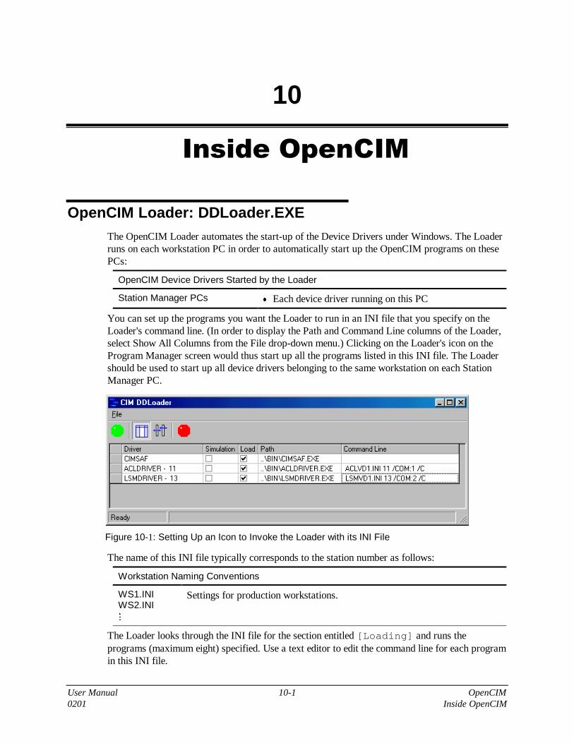
User Manual 10-1 OpenCIM0201 Inside OpenCIM
10
Inside OpenCIM
OpenCIM Loader: DDLoader.EXEThe OpenCIM Loader automates the start-up of the Device Drivers under Windows. The Loaderruns on each workstation PC in order to automatically start up the OpenCIM programs on thesePCs:
OpenCIM Device Drivers Started by the Loader
Station Manager PCs • Each device driver running on this PC
You can set up the programs you want the Loader to run in an INI file that you specify on theLoader's command line. (In order to display the Path and Command Line columns of the Loader,select Show All Columns from the File drop-down menu.) Clicking on the Loader's icon on theProgram Manager screen would thus start up all the programs listed in this INI file. The Loadershould be used to start up all device drivers belonging to the same workstation on each StationManager PC.
Figure 10-1: Setting Up an Icon to Invoke the Loader with its INI File
The name of this INI file typically corresponds to the station number as follows:
Workstation Naming Conventions
WS1.INIWS2.INIM
Settings for production workstations.
The Loader looks through the INI file for the section entitled [Loading] and runs theprograms (maximum eight) specified. Use a text editor to edit the command line for each programin this INI file.

User Manual 10-2 OpenCIM0201 Inside OpenCIM
The following example of an INI file shows the command lines invoked by the Loader
[General]CimSetupPath = ..\SETUP\SETUP.CIM
M
[Loading]Load1 =..\BIN\ACLDriver.EXE ACLVD3.INI 31 /COM:2Load2 =..\BIN\ RVPDriver.EXE RVPVD1.INI 33 /COM:1
Loader Command Lines
Each device (or controller) that is connected to a Station Manager PC requires a separate devicedriver running on that PC. It is possible to have a controller attached to a Station Manager PCthat supports multiple devices (e.g. a robot and a bar code reader attached to an ACL controller).In this case, only one device driver is required (e.g. an ACL device driver). In this section, theterm device can also refer to a controller with multiple devices.
The list below shows the name of the program that corresponds to each OpenCIM device driver:
• ACL device driver: ACLDriver.EXE
• CNC device driver: CNCDriver.EXE
• Laser Scan Meter device driver: LSMDriver.EXE
• ROBOTVISIONpro device driver: RVPDriver.EXE
• PLC device driver: PLCDriver.EXE
• ULS Device Driver ULSDriver.EXE
• ViewFlex Device Driver VFDriver.EXE
The table below describes the command line switches you can specify when you invoke a devicedriver or program module. These switches let you specify the device, data files, and control modethat apply to a program.
All device drivers share the following command line format:
xxxDriver.EXE IniFile DevID /COM:n [/Simulation]
(where xxx is the type of device driver).

User Manual 10-3 OpenCIM0201 Inside OpenCIM
IniFile The name of the initialization file containing parameter definitions forthis particular device. These parameter definitions override globalvalues set in the file OPENCIM.INI
DevID The unique ID number of the device as defined in the Setup program.This number is used to identify the device when communicating withthe CIM Manager or with another CIM device (e.g. a CNC machinebeing tended by this robot).
If more than one device is attached to a controller, you can specify theID of any one of these devices (e.g. the robot's ID in the case of anACL controller).
COM:n The RS232 port on the Station Manager PC that the device driveruses to communicate with the device. Com ports 1 - 4 are supported.Com parameters (baud rate, parity, etc.) can be assigned in theinitialization file IniFile, in the section for this device. Forexample:
[CNCDriverDefinitions]
A port value of 0 (zero) indicates that the device driver is to operatein Manual mode.
/Simulation This optional switch starts up the device driver in Simulation mode.In this mode, the device driver emulates a robot by automaticallygenerating status messages in response to command messages.
You can invoke a device driver in any one of the following ways:
• Use the OpenCIM Loader to automatically start up a set of device drivers listed in the[Loading] section of an INI file.
• In the Windows Program Manager, click on an icon which is defined to run the device driver.
• In the Windows Program Manager, select File, Run and enter the device driver commandline.

User Manual 10-4 OpenCIM0201 Inside OpenCIM
OpenCIM Directory StructureEach PC on which the OpenCIM software has been installed has the same directory structure.The figure below shows the OPENCIM directory structure (path listing) before any CIM systemis created by the Virtual CIM Setup.
Figure 10-2: OpenCIM Directory Structure
Folders with data that is relevant only to a specific station (e.g. WS1, WS2, …) can be located onthe CIM Manager PC (if you want to centralize the system data) or on that station PC. It isrecommended to use the first structure, i.e. data is kept in a single location which facilitatesbackup.

User Manual 10-5 OpenCIM0201 Inside OpenCIM
For every cell created by the Virtual CIM Setup, a subdirectory, which contains the followingsubdirectories, is created:
Subdirectory Description
DATA Contains data files that change during the normal operation of the CIM.
DOC Contains all documentation relevant to this particular system.
LOG Contains a log of the system.
SETUP Contains all the files that change when setting up the CIM cell.
WS0 Workstation Manager.
WSn Contains all data files that are unique to this station.
VC2_WM.DBF OpenCIM network messages file.
CIMCELL.INI
VC2.INI
CIMCELL.O2B
CIMCELL.O2C
CIMCELL.O2P
These files contain graphic information of the cell.
The WSn subdirectories represent each of the workstations in the CIM cell. A WSn subdirectoryis created in two phases. First the subdirectory is created in the CIM Manager and then it iscopied to the Station Manager. A subdirectory is created for each machine at that workstation.
A system with three workstations (WS1, WS2, WS3) may be set up as follows, for example:
• The WS1 subdirectory contains all INI files, DBF files and GRP files that are unique toworkstation #1. ROBOT 1 contains all the ACL programs specific to workstation #1.
• The WS2 subdirectory contains all INI files, DBF files and GRP files that are unique toworkstation #2. ROBOT 2 contains all the ACL programs specific to workstation #2.GCODE contains all the G-code programs necessary for the CNC machine.
• The WS3 subdirectory contains all INI files, DBF files and GRP files that are unique toworkstation #3. PLC contains all PCL programs.
The table below lists the files found in a typical OpenCIM system, grouped by subdirectory. Thesubdirectory generically called CIMCELL represents a typical CIM cell.
File Type Description
ACL Subdirectory containing a library of generic ACL source code, utilityprograms, and parameter files.
CIMSYS.DMC Source code of standard ACL system programs for a single robotattached to an ACL controller.
CIMSYSM.DMC Source code of standard ACL system programs for multiple robotsattached to the same ACL controller.
DOWNLOAD.EXE ACLoff-line downloader utility program that sends DNL files to anACL controller.

User Manual 10-6 OpenCIM0201 Inside OpenCIM
File Type Description
SEND.EXE Utility program to send a command to an ACL controller.TERM_ACL.EXE ATS terminal emulation program used to interact with an ACL
controller.SETUP.DIR A data file used by the TERM_ACL program.ASRSB.PRBASRSSQ.PRBBELT.PRBLSB100CM.PRBLSB150CM.PRBLSB20.PRBNOCONECG.PRBNOCONECT.PRBROTARY_B.PRBSERVOG_C.PRBXYTAB.PRBSCC_BELT.PRB
ACL parameter files.
SETUP.PAR Location of the Robot parameters.ATS.BAT Batch file to load the TERM_ACL.EXE.TERM.MAC
ONOFF.CBU On/Off program for the controller.PAR.CBU File containing parameters for the controller.PAR14.CBU File containing parameters for Robot ER 14.PAR9.CBU File containing parameters for Robot ER 9.PARMK2.CBU File containing parameters for Robot MK2.
BIN Subdirectory containing OpenCIM program files (EXE, DLL, HLP,ICO, TRK, VBX).
C4DLL.DLL Object code files containing a shared library of Windows programsCIMSHED.DLL
DBCREATER.DLL
ERSCPW32.DLL
SCPBW32.DLL
SCPBW32A.DLL
SCPW32.DLL
SCPW32A.DLL
VBC4DLL.DLL
LICMANAGER.INI
OPENCIM.HLP Help fileACLDRIVER.EXE The ACL device driver.APLAN.EXE The A-Plan program.

User Manual 10-7 OpenCIM0201 Inside OpenCIM
File Type Description
CHECKCOMMUNICATION.EXE
Utility program for testing TCP/IP communications.
CIMREPORT.EXE Report Generator programCIMSAF.EXE OpenCIM safety device driverCIMSETUP.EXE Virtual CIM Setup programCIMSIMUL.EXE Graphic Display Program LoaderCNCDRIVER.EXE CNC device driverDBTOOL.EXE Edits database filesDDLOADER.EXE Loader program for device driversLICMANAGER.EXE License programLSMDRIVER.EXE Laser Scan Meter device driverMACHINEDEFINITION.EXE
Machine Definition module
MANAGER.EXE CIM Manager moduleMRP.EXE MRP modulePARTDEFINITION.EXE Part Definition modulePLCDRIVER.EXE PLC device driverRVPDRIVER.EXE ROBOTVISIONPro Device DriverSCHEDULER.EXE Scheduler ModuleSCRIPTER.EXE Activates Graphic Display commandsSTORAGEMANAGER.EXE Storage manager moduleULSDRIVER.EXE Laser Engraver Device Driver
CIMCELL Generic name for a subdirectory containing all data for one particularCIM cell, as created by the Virtual CIM Setup.
CIMCELL/ DATA
Subdirectory containing data files used by the OpenCIM system.(*.DBF is a file in dBASE format).
ORDER.CFG Internal configuration parameters used by the Order Entry module.APLAN.DBF A-Plan commands generated by last order submitted.BACK.DBF The REF.BAT batch file uses this data file to restore
STORAGE.DBF.CIMREP.DBF Report format specificationsLEAFPART.DBF Internal information used by the CIM Manager to display active
production operations in Leaf View.MACHINE.DBF List of machines as defined in the Machine Definition.ORDER.DBF Records that appear in the Order table.PART_DEF.DBF Records that appear on the Part Definition screen.PART_PRC.DBF Records that appear in the Part Process table.

User Manual 10-8 OpenCIM0201 Inside OpenCIM
File Type Description
PROCESS.DBF Records that appear in the Machine Process table in the MachineDefinition module.
REPORT.DBF Records that appear in the Report table.SCHEDULER.BDF Information used by the scheduler.STORAGE.DBF Contents of all storage devices.TEMPLET.DBF Conveyor template definitions as assigned in the Storage Definition
module.ANALYSIS.RPTAPLAN.RPTASRS.RPTLOCATION.RPTMACHINE.RPTORDER.RPTPART.RPTPROCESS.RPTSTORAGE.RPTSUBPART.RPT
Listing of files for the Report Generator. Each file is namedaccording to the report and/or application it applies to.
MACH_MAC.CDXP_DEF_AP.CDXPROC_AP.CDXPDEF_PAR.CDXPROC_PAR.CDXP_DEF_OR.CDXMACH4TAG.CDXP_PRC_AP.CDXORDER_AP.CDXPART4TAG.CDXPARTD_AS.CDX
dBASE index files automatically generated by the programs whichupdate the associated DBF files.
CIMCELL/ LOG
Subdirectory containing LOG files for the system.
CIMCELL/ SETUP
Subdirectory containing installation and configuration related files.
MAP.INI Data file that associates PC network file names with workstationnumbers. Also used to assign multiple devices to a single devicedriver.
SETUP.CIM Configuration data file; contains all devices and their associatedparameters.
DEVICE.DMC Assignment of device names to ACL program numbers.OPENCIM.INI Default device driver parameters.FDR1.INI File containing the configuration of the feeder.RACK1.INI File containing the configuration of the rack.CONPALET.INI File containing the minimum number of empty pallets running in the
conveyor.

User Manual 10-9 OpenCIM0201 Inside OpenCIM
File Type Description
CIMCELL/ WS0
Subdirectory containing files for the CIM Manager PC.
CIM.LOG OpenCIM network messages file for this station.CIM.PRT File containing a listing of all messages (LOG file).WS0.INI Parameters passed into the CIM Manager at initialization time.CIM.PNP Pick-and-place file.CIM.LOG File containing the leaf view (LOG file).ERROR.LOG Error graphic file
CIMCELL/ WSn
Subdirectory containing files for a typical workstation.
ACLVD1.INI ACL Virtual driver.VC2_QC.INI Format settings for quality control report.$ACL_011.PRT File containing ACL device driver protocol.$LSM_009.PRT File containing LSM device driver protocol.LSMVD1.INI LSM Virtual device driver INI file.$PLC_001.PRT File containing PLC device driver protocol.PLCVD1.INI PLC virtual device driver.WS1.INI Typically used to pass command line parameters to the Loader
program used to start each device driver at this station in Real mode.ACL_011.PNP Pick-and-place file.
CIMCELL/ WSn
/ ROBOTn
Subdirectory containing files for the ACL controller at Station n.
REPORT.DLD Log file showing the commands executed during the last ACLdownload (see the ACLoff-line manual).
WS2.DNLTRASH1.DNLBFFR1.DNLRDR1.DNLRACK1.DNLCNV1.DNLEPILOG1.DNLPROLOG1.DNLFDR1.DNLASMBUF.DNLASRS.DNL
Listing of all the download Robot programs for this station.
RVPCOM2V.QCLRVPCOMOV.QCLRVPCOM1V.QCL
Listing of all download Quality Control Robot programs.

User Manual 10-10 OpenCIM0201 Inside OpenCIM
File Type DescriptionRVPCOM.QCL
SETUP.DIR Data file used by the TERM_ACL program.
LIB Subdirectory containing preconfigured setup files for commonmachines, stations, ACL programs, etc. (library of ACL programs).
README.TXT File associated with file extension.
LIB/ ACL
Subdirectory containing a library of unique ACL source code, utilityprograms, and parameter files.
ER.QCBCMM.QCBHG.QCBRVPCOM.QCBCALIPER.QCBLSM.QCBSQC.QCBPC50.QCBSQCRS.QCB
Listing of the Quality Control block programs and Communicationblock programs necessary for peripheral devices that connect directlyto the ACL controller.
ASRSSQR.DNBASRSSOM.DNBASRSCRC.DNBRACK.DNBBUFFER.DNBREADER.DNBEPILOG.DNBLSRSCN.DNBCONVEYOR.DNBWSMN.DNBFEEDER.DNBLATHE.DNBWS.DNBTRASH.DNBMILL.DNBCNV1.DNBASRST.DNBSPARE.DNBPROLOGM.DNBPROLOG.DNB
Listing of the download ACL source blocks that are later copied tothe DNL.
CNC.PCBLATHE.PCBMILL.PCB
Listing of the Process block programs necessary to communicate withdevices (e.g.CNC machine).
CIMSYS.SYS System program necessary to operate and communicate in theOpenCIM environment.
README.ACL File extension in the OpenCIM environment.CONFIG.DLD Download utility.
LIB/ QC
Subdirectory containing examples of Quality Control INI files.
VC2_QC.INI

User Manual 10-11 OpenCIM0201 Inside OpenCIM
File Type Description
LIB/ SCR
Subdirectory containing all the CNC script and BATCH fileexamples.
SCRLAB.DBF
SCRILAB.DBF
SCRTIL.DBF
SCRSITIL.DBF
CNC_L.TIL Example file from the Tilburg system.CNC_LSI.TIL Example file from the Tilburg system.SCRPRJ.DBF
VC2_WM.EXP
CNC_L.LAB
EXAMPLE.DBF
CNC_L.BAT
CNC_SCR.DBF
CNCSCRSI.KCL Example file from the King College system.CNCSCRSI.DBF

User Manual 10-12 OpenCIM0201 Inside OpenCIM
MAP.INIThe setup file MAP.INI performs the following functions:
• Contains the TCP/IP configuration of the manager and all device drivers in an OpenCIM cell.This information is required by each OpenCIM in order to enable communication with otherOpenCIM entitities.
• Allows two or more devices to use the same device driver to send and receive messages
A typical MAP.INI has the following format:
[Redirect]
53=51
23=21
24=21
[COMMMANAGER]
RemoteIP=200.1.1.1
RemotePort=700
[COMMACL11]
RemoteIP=200.1.1.1
RemotePort=711
[COMMLSM13]
RemoteIP=200.1.1.1
RemotePort=713
[COMMACL21]
RemoteIP=200.1.1.1
RemotePort=721
[COMMACL24]
RemoteIP=200.1.1.1
RemotePort=724
When a device driver starts, it must access MAP.INI in order to be able to communicate withother device drivers and the CIM Manager. On each Station Manager PC the file path toMAP.INI is contained in the parameter variable CimMapPath in the [Networking]section of the INI file for this station.
�
Note
To guarantee proper operation of OpenCIM, be sure that the file MAP.INI is accessible toall device drivers. To be sure that the MAP.INI file is accessible, do the following:
� Open any device driver
� Check if the MAP.INI file is updated by editing the TCP/IP configurations of the DDopened
You can use any ASCII text editor (e.g. Windows Notepad) to modify MAP.INI. The two typesof entries in this file are described below.

User Manual 10-13 OpenCIM0201 Inside OpenCIM
Since only one device can be assigned to a device driver on a command line, an ID entry inMAP.INI is used to assign other devices to this device driver. For example, a bar code reader(device 13) and a robot (device 11) may be connected to the same ACL controller and thus sharethe same ACL device driver for passing OpenCIM messages. The following command lineassigns the robot to the ACL device driver:
ACLDriver.EXE ACLVD1.INI 11,13 /COM:2
The following MAP.INI entry allows the bar code reader to share the use of this device driver:
[REDIRECT]
13=11
13 A device that is sharing the use of a device driver.
11 The primary device that is assigned to a device driver on the command linethat invokes the device driver.

User Manual 10-14 OpenCIM0201 Inside OpenCIM
SETUP.CIMSETUP.CIM is an ASCII file which defines all devices found in the OpenCIM system. The file islocated in the path C:\OPENCIM32\sys_name\SETUP. The fields in this file are separated bya space.
The SETUP.CIM file for the CIMLAB4 Virtual CIM is shown below.
5
51 1 ER5P ROBOT1 R 1 0 0 0 0 0
52 2 ER9 ROBOT2 R 1 0 0 0 0 0
53 3 ER5P ROBOT3 R 1 0 0 0 0 0
54 4 ER7 ROBOT4 R 1 0 0 0 0 0
0 0 PLANE PLANE 0. 0. 0.
1 2 CNV1 CNV1 C 4 0 0 0 4 ROBOT1 0 ROBOT2 0 ROBOT3 0 ROBOT4 0 0
55 4 ERXY XYJIG J 1 0 0 0 1 ROBOT4 0 0
2 1 RNDAS RNDAS1 A 54 0 0 0 1 ROBOT1 0 0
3 1 READER RDR1 Y 1 0 0 0 1 ROBOT1 0 0
4 2 MILL_S MILL1 M 1 0 0 0 1 ROBOT2 0 0
5 2 M2AS BFFR1 B 2 0 0 0 1 ROBOT2 0 0
6 2 M2AS BFFR2 B 2 0 0 0 1 ROBOT2 0 0
7 3 LATH_S LATHE1 M 1 0 0 0 1 ROBOT3 0 0
8 3 M2AS BFFR3 B 2 0 0 0 1 ROBOT3 0 0
9 4 M2AS BFFR4 B 2 0 0 0 1 ROBOT4 0 0
10 4 FEEDER FDR1 F 1 201 0 20 1 ROBOT4 0 0
11 4 RACK RACK1 K 9 101 0 0 1 ROBOT4 0 0
12 4 RACK RACK2 K 2 102 0 0 1 ROBOT4 0 0
13 4 TRASH TRASH1 X 1 0 0 0 1 ROBOT4 0 0
14 4 JIG JIG1 J 1 0 0 0 1 ROBOT4 0 0
17 4 VISION VSN1 V 1 0 0 0 1 XYJIG 0 0
16 4 SCREWD SDRV1 D 1 0 0 0 1 XYJIG 0 0
51 1 ER5P ROBOT1 R 1 0 0 0 0 0
52 2 ER9 ROBOT2 R 1 0 0 0 0 0
53 3 ER5P ROBOT3 R 1 0 0 0 0 0
54 4 ER7 ROBOT4 R 1 0 0 0 0 0
60 0 SPARE CONPALET O 16 1 0 0 0 0
60 0 SPARE CONPALET O 16 1 0 0 0 0

User Manual 10-15 OpenCIM0201 Inside OpenCIM
Fld # Field Name Type # Width Remarks
1 Device ( Object/Location ) ID(Do not skip numbers, make all IDs sequential)
Numeric 3
2 Station Number Numeric 2
3 Physical Name (for graphic display) Character 20
4 Logical Name Character 20
5 Type:A: ASRSB: BufferC: ConveyorD: Device (e.g. screwdriver)F: FeederH: ReservedI: StationJ: JigK: RackL: Laser Scan Meter
M: MachineO: ConpalletP: PartQ: Quality Control
R: Robot
S: User DefinedU: UndefinedV: VisionX: TrashY: BarcodeZ: AGV
Character 1
6 Capacity Numeric 2
7 Subtype (type of objects it can hold) or Connectivity(used with Feeder, Rack, Conpallet and Buffer)
Numeric 3
8 Location ID (for graphic display) Numeric 3
9 Location Position (for graphic display) Numeric 2
10 Number of Robots(that can access this device)
Numeric 2
11 Robot's Name Character 20 Multiple field
12 Robot's Position Numeric 2 Multiple field
13 Steady Flag Logical 1

User Manual 10-16 OpenCIM0201 Inside OpenCIM
The following is an example of a SETUP.CIM file.
1
11 1 SQRAS SQRAS1 R 1 0 0 0 0 0
211 1 ASRS ASRS1 A 72 0 0 0 1 SQRAS1 0 0
21 2 ER9 ROBOT5 R 1 0 0 0 0 0
31 3 MK3 ROBOT3 R 1 0 0 0 0 0
41 4 ER14 ROBOT4 R 1 0 0 0 0 0
0 0 PLANE PLANE 0. 0. 0.
1 1 CNV1 CNV1 C 4 0 0 0 4 SQRAS1 0 ROBOT5 0 ROBOT3 0 ROBOT4 0 0
12 1 READER RDR1 Y 1 0 0 0 1 SQRAS1 0 0
24 2 PCMILL PCMILL1 M 1 0 0 0 1 ROBOT5 0 0
23 2 PCTURN PCTURN1 M 1 0 0 0 1 ROBOT5 0 0
33 3 WELDST WELDST1 D 1 0 0 0 1 ROBOT3 0 0
49 4 CMM CMM1 Q 1 0 0 0 1 ROBOT4 0 0
47 4 VISION VSN1 V 1 0 0 0 1 ROBOT4 0 0
44 4 RACK RACK1 K 1 101 0 0 1 ROBOT4 0 0
45 4 RACK RACK2 K 1 102 0 0 1 ROBOT4 0 0
43 4 JIG JIG1 J 1 0 0 0 1 ROBOT4 0 0
48 4 TRASH TRASH1 X 1 0 0 0 1 ROBOT4 0 0
22 2 M2AS BFFR1 B 2 0 0 0 1 ROBOT5 0 0
32 3 M2AS BFFR2 B 2 0 0 0 1 ROBOT3 0 0
42 4 M2AS BFFR3 B 2 0 0 0 1 ROBOT4 0 0
46 4 FEEDER FDR1 F 1 103 0 0 1 ROBOT4 0 0
50 0 SPARE CONPALET O 16 1 0 0 0 0

User Manual 10-17 OpenCIM0201 Inside OpenCIM
DEVICE.DMCThe DEVICE.DMC file in the SETUP directory defines numbers for the ACL logical name ofevery device in the system.
The DEVICE.DMC file for the CIMLAB4 Virtual CIM is shown below.
#IFNDEF _DEVICE_DMC
#DEFINE _DEVICE_DMC
#DEFINE CNV1 001
#DEFINE RNDAS1 002
#DEFINE BFFR1 005
#DEFINE BFFR2 006
#DEFINE BFFR3 008
#DEFINE BFFR4 009
#DEFINE FDR1 010
#DEFINE RACK1 011
#DEFINE RACK2 012
#DEFINE TRASH1 013
#DEFINE ROBOT1 051
#DEFINE ROBOT2 052
#DEFINE ROBOT3 053
#DEFINE ROBOT4 054
#DEFINE ROBOT5 055
#DEFINE MILL1 004
#DEFINE LATHE1 007
#DEFINE JIG1 014
#DEFINE SDRV1 016
#DEFINE VSN1 015
#DEFINE RDR1 003
#ENDIF
For an explanation of this file and how to edit it, refer to “Writing ACL Source Code” inChapter 8.

User Manual 10-18 OpenCIM0201 Inside OpenCIM
INI FilesOpenCIM uses a set of INI files to set configuration parameters for the following programs:
• Each OpenCIM device driver
• The CIM Manager
• The OpenCIM Loader
• The Storage Definition module
OpenCIM parameter settings for the above programs are stored in a set of text files: *.INI.These files use the same structure as standard Windows INI files such as WIN.INI. Theseprograms read their respective INI files at initialization time. If you make a change to aprogram’s INI file after it has started, you must end the program and restart it for the change totake effect.
Default values for all devices are stored in the file OPENCIM.INI. Settings for individualdevices can be made in a local INI file which is specified on the device driver loader’scommand line. If the same parameter appears in both OPENCIM.INI and a device driver's localINI file, the local setting takes precedence. All parameters must appear in either OPENCIM.INIor in a local INI file.
The (OPENCIM32\CIMLAB4\SETUP\) OPENCIM.INI file for the CIMLAB4 setup is shownbelow.
[General]CimSetupPath=..\SETUP\SETUP.CIMCimSetupDir=..\SETUPCimLibDir=..\LIBCimDataDir=..\DATACimWorkDir=..\dataCimReportDir=..\DATA
[Networking]CimMapPath=..\SETUP\MAP.INITimer=300AttemptsCount=3PassCount=3OffDelay=3EchoFilter=1124
[Simulation]PCPLC=20,7,15
[ASRS1]NumberOfRows=6NumberOfCols=6NumberOfGrids=2FirstGridWithMinIndex=BottomLocationMinIndexGrid=LeftBottomDirectionIncIndexGrid=Right
[WndStatus]PROGDEF=0ORDERDER=0STRGDEF=0DEVICEDEF=0

User Manual 10-19 OpenCIM0201 Inside OpenCIM
LOGDEF=0PALLETEDEF=0LEAFDEF=0EVENTDEF=0MANAGERDEF=0HYSTORYDEF=0
[CIMMODES]TRACKINGMODE=0UPDATEDURATION=0SENDTOGRAPH=0SIMULATION=1CIMSPEED=1
[DDFileName]CNV1=..\CIMLAB4\WS1\PLCVD1.INISQRAS1=..\CIMLAB4\WS1\ACLVD1.INIRDR1=..\CIMLAB4\WS1\LSMVD1.INIROBOT5=..\CIMLAB4\WS2\ACLVD5.INIPCTURN1=..\CIMLAB4\WS2\CNCVD1.INIPCMILL1=..\CIMLAB4\WS2\ CNCVD2.INIROBOT3=..\CIMLAB4\WS3\ACLVD3.INIROBOT4=..\CIMLAB4\WS4\ACLVD4.INIVSN1=..\CIMLAB4\WS4\RVPVD1.INICMM1=..\CIMLAB4\WS4\LSMVD2.INI
You can use some combination of the parameter file strategies listed below when deciding howto organize INI files for your system:
• Put all default parameter settings in OPENCIM.INI. Then write a separate INI file for eachdevice driver that contains only those parameters that deviate from the default.
• Have a separate INI file for each device driver containing all the parameters for that device.Use OPENCIM.INI only for global parameters.
• Have a separate INI file for each Station Manager PC (e.g. WS1.INI) which contains theparameters for all devices at that station. These files would also contain the command linesused by the Loader to start each device driver at a station. Use OPENCIM.INI only forglobal parameters.
To set up or edit an INI file, use a text editor (e.g. Windows Notepad) that can save files inASCII format. The file is divided into sections with the title of each section enclosed inbrackets, for example [Networking]. A program searches for the sections that apply to itand reads the associated parameter settings. Keep the following considerations in mind whenediting an INI file:
• Only lines that begin with valid parameter names are read (i.e. only parameters that belongin that section), all other lines are ignored. If you misspell a parameter name, it will beignored.
• A leading space at the beginning of a line will cause that line to be ignored.
• Do not insert the same parameter more than once in a section (there is no guarantee as towhich value will be used).
• You can insert blank lines in an INI file to group related parameters and to set off sections.

User Manual 10-20 OpenCIM0201 Inside OpenCIM
• You can create a comment line by inserting an extra character at the beginning of a line (byconvention the semicolon, ;). For example, if you want to try a new text color but also keepthe original value for reference, you could do the following:
;MainWindowTextColors = 0,255,0MainWindowTextColors = 0,255,255
The table below lists all OpenCIM parameters that you can set. Note that some of the values inthe table are internal system parameters which should only be changed under the direction ofIntelitek technical support. The table is divided into the following sections:
INI Parameter Description
Default Settings (OPENCIM.INI)[General] The parameters in this section define the
OpenCIM directory structure on the centralserver PC.
CimLibDir = C:\OPENCIM32\LIB Location of the original OpenCIM data andprogram files. These data files can be copied tothe SETUP directory to restore the system toits original state.
CimDataDir = C:\OPENCIM32\DATA Location of data files which define theOpenCIM configuration (e.g. machineprocesses, part definitions, etc.).
CimWorkDir = C:\OPENCIM32\data Location of data files, including log files,which are updated during OpenCIMproduction.
CimReportDir = C:\OPENCIM32\DATA Location of report output. Other softwareapplications can interface here to pick upOpenCIM production data.
[Networking]
CimMapPath =..\BIN\MAP.INI The location of the OpenCIM map file whichcontains:
• The name of all workstation PCs.
• A list of all devices which share the use of adevice driver (e.g. a robot, and an automaticscrewdriver all connected to the same ACLcontroller).

User Manual 10-21 OpenCIM0201 Inside OpenCIM
INI Parameter Description
Timer = 1000 The frequency at which a program checks itsmailslot for messages to transmit or receive.The CIM Manager must check its mailslotmore frequently than the programs with whichit communicates (device drivers or StorageDefinition module).
CIM Manager: 200 - 600 ms
Device drivers: 400 - 1000 ms
Reserved for Intelitek technical support useonly.
PassCount = 3 Number of Timer intervals to wait before aretry is sent. For example:
Timer = 1000, PassCount = 3 →delay before retry is 3000 ms
Reserved for Intelitek technical support useonly.
OffDelay = 3 Number of milliseconds a device driver waitsfor confirmation from the CIM Manager that ithas received a shutdown notification message.A value of 0 (zero) causes the device driver notto send a shutdown message.
ASRS Device Driver Settings[Structure]
NumberOfRow = 6
NumberOfCols = 6
NumberOfGrids = 2
FirstGridWithMinIndex = BottomLocationMinIndexGrid = LeftUpDirectionIncIndexGrid = Right

User Manual 10-22 OpenCIM0201 Inside OpenCIM
ACL Device Driver Settings[General]
CimSetupPath = ..\SETUP\SETUP.CIM Tells the device driver where to find thefollowing important OpenCIM setup files:
• OPENCIM.INI: Contains default parametersettings for all device drivers. The fileOPENCIM.INI must appear in the samedirectory as the setup file named in thissetting.
• SETUP.CIM: Lists all physical devices andtheir IDs. The name SETUP.CIM is thedefault name for this file.
This parameter setting must appear in eachlocal INI file. It is not needed inOPENCIM.INI.
[ACLDriverDefinitions]
ACLDriverPromptNum = 3 Number of times the device driver sends aquery to an ACL controller to invoke thecontroller's command prompt, ">". Reservedfor Intelitek technical support use only.
BaudRate = 9600Parity = NoneDataBits = 8StopBits = 1XonXoff = Yes
These are the standard RS232 settings forcommunicating with an ACL controller. Theyshould not be changed since they match thefixed settings in the controller.

User Manual 10-23 OpenCIM0201 Inside OpenCIM
MainWindowBkgndColors = 0,0,0MainWindowTextColors = 0,255,0
MainWindowBkgndColors = 0,0,0MainWindowTextColors = 0,255,0Color settings for the background and textcolors in the device driver's Status window.When a Station Manager PC is running severaldevice drivers simultaneously, theseparameters allow you to set each one to adifferent color in order to distinguish betweenthem.
The three numbers represent a color using theRGB color scheme (Red, Green, Blue). Valuesrange from 0–255. A 0 (zero) indicates theabsence of red, green, or blue, respectively,and 255 signifies a primary color at fullintensity. For example:
Green =0,255,0White = 255,255,255Black = 0,0,0
Do not set the text color to the same value asthe background color. This combination wouldcause the text to become invisible.
CNC Device Driver Settings[General]
CimSetupPath=C:\OPENCIM32\SETUP\SETUP.CIM
See this parameter in the ACL section above.
[CNCDriverDefinitions]
CNCScriptFilePath = CNC_SCR.DBF
CNCScriptDebugFilePath = CNC_SCRS.DBFThese files contain the CNC script programswhich appear in the CNC Command List onthe Control Panel.
This first parameter specifies a file that is usedwhen the CNC device driver is operating inReal Mode. The second parameter is analternate file used when the device driver isoperating in Simulation or Manual mode.
The file name is mandatory. If no path isspecified, the current working directory is usedas defined by the device driver's /C commandline switch.
MainWindowBkgndColors = 0,0,0
MainWindowTextColors = 255,255,255See these parameters in the ACL sectionabove.

User Manual 10-24 OpenCIM0201 Inside OpenCIM
; --- CNC Variables ---
V1 = ACL21V2 =V3 =V4 =V5 =V6 =
M
V16 =
Parameter variables used by CNC scriptprograms. These variables are used to writeportable CNC script programs. For furtherinformation, see “CNC Device Driver” inChapter 8.
BV0 = 0BV1 = 0
These 8-bit values, which range from 0-255,are assumed to be the initial state of the controllines of a CNC machine when the system isturned on.
PORT0 = 0x500PORT1 = 0X501
I/O port addresses on a Station Manager PCthat are mapped to the status and control linesof a CNC machine using a special interfacecard. These values should match the jumpersettings on the I/O card.
CNCDriverDebuggerTimer = 100 Refresh interval (in milliseconds) for displayof input port values on the CNC Control Panel.
Reserved for Intelitek technical support useonly.
CNCDriverTimer = 10 This is an internal timer (in milliseconds) usedduring communications.
Reserved for Intelitek technical support useonly.
CNCIdleProcTimer = 10 Polling interval (in milliseconds) for checkingthe alarm status of a CNC machine.
Reserved for Intelitek technical support useonly.
CNCIdle = CNCIDLE(port0, "00000010") This setting checks for an alarm condition onthe specified input port. If the value of theinput port matches this mask, the CNC devicedriver sends the following alarm message tothe CIM Manager:
WM_CIMDDE_CNCERROR with the errorvalue = CNCALARM
BaudRate = 9600Parity = NoneDataBits = 8StopBits = 1XonXoff = No
RS232 parameters used by the CNC devicedriver when it downloads G-code to a CNCmachine. You must set these parameters tomatch the RS232 settings on the CNCmachine.

User Manual 10-25 OpenCIM0201 Inside OpenCIM
Loader = C:\CNC_L.BATTaskLoadedMark =C:\OPENCIM\WS3\TASK.CNC
Include the Loader parameter when you wantto use your own program to download G-codeto a CNC machine (instead of using the devicedriver's built-in downloader).
The Loader file name must be a batch file.The last command in this file should create theflag file specified in TaskLoadedMark. Thisflag file signals that the download is complete.The device driver automatically deletes thisflag file each time it invokes the Loaderbatch file.
LSM Device Driver Settings[General]
CimSetupPath=C:\OPENCIM\SETUP\SETUP.CIM See this parameter in the ACL section above.[LSMDriverDefinitions]
QCReport = No Enables/disables creation of a log file forcapturing results from this quality controldevice. If set to No, all other QC reportparameters below are ignored.
QCReportTemplateFile = VC2_QC.INI Name (including path) of the file that definesthe format of the quality control log file.
QCReportFileName = Name (including path) of the quality controllog file itself.
QCReportFileMarker = A flag file (including path) which indicatesthat the quality control log file has beenupdated. A user application can delete this flagfile after processing the log file. The next timethe flag file appears, the application knows thatthere is new log file data to process.
QCReportFileDeleteOnStart = This switch controls whether a new qualitycontrol log file will be created each time thisdevice driver starts up. If Yes, the previous logfile is deleted. If No, results are appended tothe existing log file.
SimulationFailPercent = 20 When the device driver is operating insimulation mode, this value determines whatpercentage of the simulated quality controltests are randomly reported as failures. Thissetting provides the default value that appearsin the Fail % box on the QC Control Panel.The range is 0–100 (0 = test always passes,100 = test always fails).

User Manual 10-26 OpenCIM0201 Inside OpenCIM
BaudRate=9600Parity=NoneDataBits=8StopBits=1XonXoff=No
RS232 parameters used by the QC devicedriver when it communicates with thecontroller for the quality control device. Youmust set these parameters to match the RS232settings on the device’s controller.
MainWindowBkgndColors=40,150,100MainWindowTextColors=100,50,200
See these parameters in the ACL section above.
ROBOTVISIONpro Device Driver Settings[General]
CimSetupPath=C:\OPENCIM\SETUP\SETUP.CIM See this parameter in the ACL section above.[RVPDriverDefinitions]
Frame=1 Frame number as defined on the FrameDefinition screen in the Setup menu of theROBOTVISIONpro software. See theROBOTVISIONpro documentation for details.
Snap=No For older versions (prior to v2.3) of theROBOTVISIONpro software, set this value toYes. For v2.3 and later, set it to No. For bestresults, use only v2.3 and later.
BaudRate=9600Parity=NoneDataBits=8StopBits=1XonXoff=No
RS232 parameters used by the QC devicedriver when it communicates with thecontroller for the quality control device. Youmust set these parameters to match the RS232settings on the device's controller.
MainWindowBkgndColors=150,150,150MainWindowTextColors=255,255,255
See these parameters in the ACL sectionabove.
SimulationFailPercent=50 See this parameter in the Laser Scan Metersection above.
QCReport=YesQCReportTemplateFile=VC2_QC.INIQCReportFileName=QCReportFileMarker=QCReportFileDeleteOnStart=
See these parameters in the Laser Scan Metersection above.
ViewFlex Device Driver Settings[General]
ScriptPath= e:\opencim32\cimcell\ws3

User Manual 10-27 OpenCIM0201 Inside OpenCIM
ULS Device Driver Settings[General]
CimSetupPath=..\CIMLAB8\SETUP\SETUP.CIM
[Networking]
CimMapPath=..\CIMLAB8\SETUP\MAP.INI
[CNCDriverDefinitions]
BaudRate = 9600Parity = NoneDataBits = 8StopBits = 1XonXoff = No
RS232 parameters used by the CNC devicedriver when it downloads G-code to a CNCmachine. You must set these parameters tomatch the RS232 settings on the CNCmachine.
; --- CNC Variables ---
V1 = ACL71V2 =V3 =V4 =V5 =V6 =
M
V16 =
Parameter variables used by CNC scriptprograms. These variables are used to writeportable CNC script programs. For furtherinformation, see “ULS Device Driver” inChapter 8.
BV0 = 0BV1 = 0
These 8-bit values, which range from 0-255,are assumed to be the initial state of the controllines of a CNC machine when the system isturned on.
PORT0 = 0x500PORT1 = 0X501
I/O port addresses on a Station Manager PCthat are mapped to the status and control linesof a CNC machine using a special interfacecard. These values should match the jumpersettings on the I/O card.
[DEBUG]
Protocol=YES
PLC Device Driver Settings[General]
CimSetupPath=C:\OPENCIM32\SETUP\SETUP.CIM See this parameter in the ACL section above.[PLCDriverDefinitions]
Type = OMRON The type of PLC being used. This valuedetermines what communications protocol isused between the device driver and the PLC.
SimulationStations = 3,6,1,2,4,5,7 In Simulation or Manual mode, this parametersets the order in which the stations appear.

User Manual 10-28 OpenCIM0201 Inside OpenCIM
SimulationPallets = 8 In Simulation mode or Manual mode, thisparameter specifies the number of palletstraveling on the simulated conveyor.
SimulationPosPerStation = 3,3,3,3,3,3,3 In Simulation or Manual mode, this parameterspecifies the distance between each station asmeasured in pallet lengths, i.e. the number ofpallets that would fit on the simulatedconveyor between two stations. The position ofeach number here corresponds to the order ofstations as listed in the parameterSimulationStations. For example, thedistance between stations 4 and 5 below is 8pallets long:
SimulationStations = 3,6,1,2,4,5,7
SimulationPosPerStation = 3,5,7,4,8,3,5SimulationDirection = L In Simulation or Manual mode, this parameter
specifies the direction in which the simulatedconveyor travels.
L = ClockwiseR = Counter-clockwise
BaudRate = 9600Parity = EvenDataBits = 7StopBits = 2XonXoff = No
RS232 parameters used by this device driverwhen it communicates with the PLC. You mustset these parameters to match the RS232settings on the PLC.
MainWindowBkgndColors = 150,0,170MainWindowTextColors = 0,0,0
See these parameters in the ACL sectionabove.

User Manual 10-29 OpenCIM0201 Inside OpenCIM
VC2_WM.DBFThe VC2_WM.DBF (Virtual Controller Series 2, Windows Messages Database File) containsthe following fields:
DDE_CHNNL The type of device driver that sends this message. This value mustbe one of the following (in lower case):• dde_acl• dde_cnc• dde_plc• dde_cim• dde_rvp• dde_olmt• dde_asrs• dde_lsm
WM_INPUT The ID of the message to be sent.
NAME_WS Name of destination workstation that is to receive this message (asspecified in the file MAP.INI).
NAME_DDE The type of device that receives this message (e.g. dde_cim forthe CIM Manager).
WM_ This number identifies the type of message being sent.
ID_DEVICE Device ID of the receiver as specified in the file SETUP.CIM. If adevice does not appear in SETUP.CIM, this value will be 0 (e.g.the CIM Manager, the Graphic Tracking Module, an ASRS).
NOTE A description of this message (free text).
�Note
The term DDE stands for MS-Windows Dynamic Data Exchange. OpenCIM devicedrivers do not currently use DDE but this term remains in the above field names forbackward compatibility.
The following table shows the standard OpenCIM messages contained in VC2_WM.DBF:
External CIMMessage
Message Description
2225 Robot Start from ACL
2226 Robot Finish from ACL
2230 Robot End from ACL
2335 Pallet Stop from PLC
2336 Pallet Pass from PLC
2337 Error from PLC
2338 Arrive Free Pallet from PLC
2229 Error from ACL

User Manual 10-30 OpenCIM0201 Inside OpenCIM
External CIMMessage
Message Description
2339 Complex Pass Message from PLC to OLMT
2580 CNC End from CNC
2576 CNC Error from CNC
2581 CNC Start from CNC
2582 CNC Finish from CNC
2138 ACL to CNC Request
2137 ACL to CNC String
2195 QC Result
2358 Device is ready
2583 CNC Task is loaded
2359 Device is unavailable

User Manual 10-31 OpenCIM0201 Inside OpenCIM
OpenCIM Database StructureThe OpenCIM database is compatible with the Xbase database management programs (e.g.dBASE, FoxPro and Clipper).
The OpenCIM database consists of the following files:
File Description
PART_DEF.DBFPART_PRC.DBF
Created by the Part Definition program.
MACHINE.DBFPROCESS.DBF
Created by the Machine Definition program.
TEMPLATE.DBF Created by the Storage Definition program.
STORAGE.DBF Created by the CIM Manager and is maintained by the StorageDefinition program.
ORDER.DBF Created by the Order Entry program.
APLAN.DBF Created by the Order Entry program through the APLAN.EXEprogram.
CIMREP.DBFLEAFPART.DBF
Created by the CIM Manager.
The following tables describe the structure of the files that compose the OpenCIM database.
Fld # Field Name Type Width
PART_DEF.DBF File Structure
1 PART Character 20
2 DESCRIPT Character 40
3 ID Numeric 4
4 TEMPLATES Character 15
5 RACKS Character 15
6 SETUPTIME Numeric 8
7 LEADTIME Numeric 8
8 PRODUCT Logical 1
9 SUPLIED Logical 1
10 PHANTOM Logical 1
11 COST Numeric 6
12 SUPLIER Character 30
13 SUPTIME Numeric 8
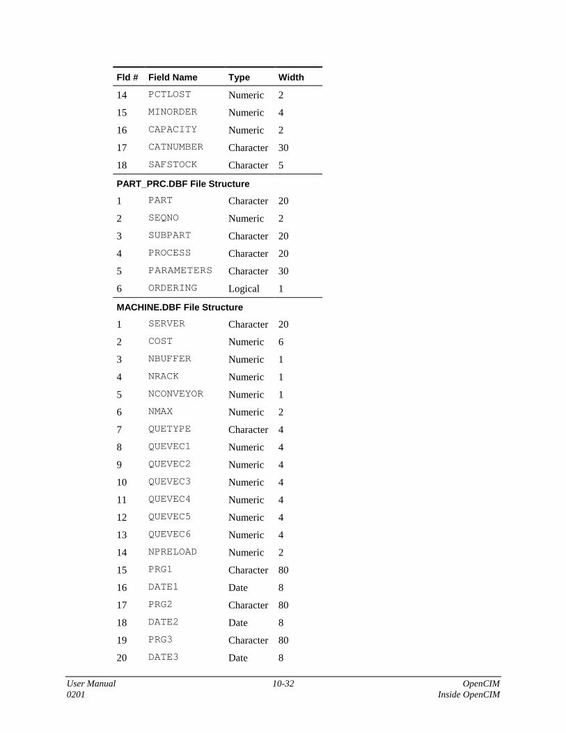
User Manual 10-32 OpenCIM0201 Inside OpenCIM
Fld # Field Name Type Width
14 PCTLOST Numeric 2
15 MINORDER Numeric 4
16 CAPACITY Numeric 2
17 CATNUMBER Character 30
18 SAFSTOCK Character 5
PART_PRC.DBF File Structure
1 PART Character 20
2 SEQNO Numeric 2
3 SUBPART Character 20
4 PROCESS Character 20
5 PARAMETERS Character 30
6 ORDERING Logical 1
MACHINE.DBF File Structure
1 SERVER Character 20
2 COST Numeric 6
3 NBUFFER Numeric 1
4 NRACK Numeric 1
5 NCONVEYOR Numeric 1
6 NMAX Numeric 2
7 QUETYPE Character 4
8 QUEVEC1 Numeric 4
9 QUEVEC2 Numeric 4
10 QUEVEC3 Numeric 4
11 QUEVEC4 Numeric 4
12 QUEVEC5 Numeric 4
13 QUEVEC6 Numeric 4
14 NPRELOAD Numeric 2
15 PRG1 Character 80
16 DATE1 Date 8
17 PRG2 Character 80
18 DATE2 Date 8
19 PRG3 Character 80
20 DATE3 Date 8

User Manual 10-33 OpenCIM0201 Inside OpenCIM
Fld # Field Name Type Width
21 PRG4 Character 80
22 DATE4 Date 8
23 PRG5 Character 80
24 DATE5 Date 8
25 LASTLOADED Numeric 1
PROCESS.DBF File
1 SERVER Character 20
2 ACTIONYPE Character 12
3 PROCESS Character 20
4 FILE Character 80
5 PROGRAM Character 20
6 ARGCNT Character 20
7 PARAMETERS Character 40
8 FAILPRCNT Numeric 2
9 DURATION Character 8
10 NEED ROBOT Character 3
TEMPLATE.DBF File Structure
1 BAR_CODE Character 6
STORAGE.DBF File Structure
1 SERVERID Numeric 4
2 SERVER Character 20
3 INDEX Numeric 3
4 TYPE Character 1
5 SUBTYPE Numeric 3
6 STATUS Numeric 1
7 PARTID Numeric 4
8 PARTNAME Character 20
9 PARTPOS Numeric 4
10 TEMPLTID Numeric 4
11 TEMPLATE Character 20
12 TEMPLTPOS Numeric 4

User Manual 10-34 OpenCIM0201 Inside OpenCIM
ORDER.DBF File Structure
1 SEQNO Numeric 2
2 PART Character 20
3 ITEMS Numeric 3
4 FIRSTDO Numeric
5 NEXTDO Numeric 2
6 PRIORITY Numeric 2
7 TARGET Character 20
8 NOTE Character 40
9 DUEDATE Date 8
10 DUETIME Character 8
11 DONE Numeric 3
12 FAIL Numeric 3
13 INPROCESS Numeric 3
14 EXPDATE Date 8
15 EXTIME Character 8
APLAN.DBF File Structure
1 PART Character 20
2 SEQNO Numeric 2
3 PROCESS Character 20
4 SUBPART Character 20
5 TARGET Character 20
6 INDEX Character 20
7 DURATION Character 8
8 PARAMETER Character 80
CStOrder.DBF File Structure
1 CUSTNAME Character 20
2 PART Character 20
3 ITEMS Numeric 3
4 DONE Numeric 3
5 PRIORITY Numeric 2
6 DUEDATE Date 10
7 DUEPERIOD Character 8

User Manual 10-35 OpenCIM0201 Inside OpenCIM
8 MANINDEX Numeric 8
Customer.DBF File Structure
1 CUSTNAME Character 20
2 DESC Character 80
3 ADDRESS Character 40
4 PHONE Character 25
5 FAX Character 25
6 EMAIL Character 25
Orderlist.DBF File Structure
1 SEQNO 2
2 PCONTROL Character 1
3 DESC Character 80
PURCHASE.DBF File Structure
1 SUPPLIER Character 20
2 PART Character 20
3 SPART Character 20
4 ITEMS Numeric 3
5 COST Numeric 6
6 DUEDATE Numeric 6
7 SENDDATE Numeric 6
SUPPLIER.DBF File Structure
1 SUPPLIER Character 20
2 DESC Character 80
3 ADDRESS Character 40
4 PHONE Character 25
5 FAX Character 25
6 EMAIL Character 25
REPORT.DBF File Structure
1 NAME Character 20
2 REPORTNAME Character 120
3 DESTINATION Character 30
4 NOTE Character 80
SCHEDULER.DBF File Structure
1 PART Character 20

User Manual 10-36 OpenCIM0201 Inside OpenCIM
2 PROCESS Character 20
3 MACHINE Character 20
4 ORDERNUMB Numeric 3
5 PLNSTART Character 8
6 PLNFINISH Character 8
7 PLDURATION Character 8
8 ACTSTART Character 8
9 ACTFINISH Character 8
10 ACTDURATION Character 8
11 STATUS Numeric 2
LEAFPART.DBF File Structure
1 ID Numeric 2
2 NAME Character 20
3 ORDER_NO Numeric 3
4 IDLIST Character 80
5 ACTION_POS Numeric 3
6 ACTION_SUB Numeric 3
7 ACTION_TYPE Numeric 3
8 STATUS Numeric 1
CIMREP.DBF File Structure
1 CODE Character 20
2 ORDER Character 20
3 ORDERSEQ Character 20
4 PART Character 20
5 PARTID Numeric 4
6 DEVICE Character 20
7 DEVICEID Numeric 4
8 ACTION Character 20
9 ACTIONID Numeric 4
10 SUBPART Character 20
11 SUBPARTID Numeric 4
12 WHICYH Character 20
13 INDEX Numeric 3
14 STATION Character 20

User Manual 10-37 OpenCIM0201 Inside OpenCIM
15 TIME Character 8
16 DATE Date 10
17 DURATION Character 8
Application to Report FileCross Reference
Application Database File Name Report Name Report TemplateFile Name
Part Definition PART_DEF.DBFPART_PRC.DBF
Part ReportSubpart Report
part.rptsubpart.rpt
Machine Definition MACHINE.DBFPROCESS.DBF
Machine ReportProcess Report
machine.rptprocess.rpt
Order Entry ORDER.DBF Order Report order.rpt
Storage Definition(ASRS)
STORAGE.DBF AS/RS Report ASRS.rpt
CIM Manager(Created by)
CIMREP.DBF Analysis Report Analysis.rpt
CIM Manager andASRS
STORAGE.DBF Location StatusReport
Location.rpt
APLAN.DBF Aplan Report Aplan.rpt

User Manual 10-38 OpenCIM0201 Inside OpenCIM
Software BackupSince system files could be altered or destroyed, it is recommend that you keep backup files ofyour OpenCIM system. The backup files can be used to restore the system if necessary.
The backup procedure involves three stages:
1. Back up the ACL controllers to the Station Manager PCs (detailed in Chapter 8).
2. Back up the Station manager PCs to the CIM Manager PC.
3. Back up the CIM Manager PC to diskettes or to another PC’s hard disk.
�Notes
These procedures should be performed by the system supervisor only.
Do not perform Backup procedures while the OpenCIM is running because currentlyrunning programs may be aborted and data files may be in an unstable state.
Always keep robot positions, ACL programs and parameters on disk.
Backup and restore the entire system regularly to ensure good backup at all times.
The following procedure backs up a cimcell directory.
�
�
�
Procedure
Backing up theOpenCIM System
1. Back up the ACL controllers to a backup folder in each WSn folder inthe Manager PC.
2. Place all relevant data of a Cimcell under its folder in the Manager PC.
3. Compress the cimcell folder using Winzip.
4. Make copies of the compressed folder to 1.44” diskettes and keep themaway from the Manager PC.
It is recommended that you also make separate backup files of the following items:
Robot Points Robot point coordinates are associated with the station PCconnected to an ACL controller. These points can changewhenever a new product is defined, an existing productdefinition changes, or a robot (or any other device) is moved.
Gcode and processprograms files
These files contain the process program of the CNC machinesor/and other processing machines.
QC script files These files contain the Quality Control procedures.

User Manual 11-1 OpenCIM0201 Errors and Troubleshooting
11
Errors and Troubleshooting
In this chapter you will learn about:
• Handling device errors
• Troubleshooting the PCs, LAN and the hardware in the OpenCIM environment
• Contacting Intelitek for assistance
Device Error HandlingThe Device Error screen appears whenever a problem is detected with a specific machine or arobot. This screen allows you to determine how to deal with an error without having to reset theentire CIM.
Figure 11-1: Device Error Screen
Device errors can be caused by various factors, including:
• Robot collision
• Device breakdown
• Defective part which does not properly fit into a machine or robot
• Machine running out of supplies for a given process
The Device Error screen gives you complete information about what was happening at the timethat the problem occurred. It identifies the current part that was being processed (currentprocess) when the error occurred. You can then choose what to do in order to recover from theerror.

User Manual 11-2 OpenCIM0201 Errors and Troubleshooting
This screen is divided into the following sections:
• Where the problem occurred (top)
• What the problem is (middle)
• How to proceed (bottom)
Where the Problem OccurredStation The name of the workstation PC where the problem occurred (e.g. WS 03).
Part The ID of the current part that was being processed when the error occurred.
Device The name of the robot or machine that experienced the problem.
Next Process The name of the process that was to be performed on the Next Machine(described below). By examining the Process table for the current part, youcan determine exactly where the production process was interrupted (selectthe current part on the Part Definition form).
Order ID The entry in the Order table that was interrupted by the error.
NextMachine
The name of the next machine that was to process the current part. Thisinformation is especially useful when a robot error occurs. The NextMachine field tells you where the robot was supposed to deliver the currentpart when the error occurred.
Action The CIM production command (A-plan action) that was being carried outwhen the error occurred.
What the Problem IsAll fields described in this section are optional. For a given error message, only those fields forwhich information is available will display.
ErrorMessage
The text of the error message generated by the control program (e.g. ACLprogram, G-code, etc.) that was running when the error occurred.
Error No. The error code returned by the control program.
ProgramName
The name of the program that was running when the error occurred.
Program ID The ID number of the control program.
Program Line#
The line in the control program that generated the error.
SourceLocation
The place where the current part resided prior to the error. This fieldconsists of a location ID followed by an index number if appropriate (e.g. aslot number in a rack).
TargetLocation
The place where the current part was to go next if the error had notoccurred. This field consists of a location ID followed by an index numberif appropriate (e.g. a slot number in a rack).

User Manual 11-3 OpenCIM0201 Errors and Troubleshooting
How to ProceedIn order to continue operation, two tasks must be accomplished:
• The part should be placed where the next process assumes the part is to be found.
• The proper messages must be sent to the CIM Manager so that it can activate the nextprocess.
In most cases, the safest and easiest way to accomplish these tasks is to:
1. Remove the source of the problem.
2. Cause the device to repeat the operation. This is done by sending the device the appropriatecommand from the device driver. Then the CIM Manager ignores the reported error becausethe problem for the device has already been corrected.
Ignore Process successfully completed; ignore the error and resume production.
If the current process was successfully completed (with or without help fromthe operator), clicking the Ignore button causes the CIM Manager to ignorethe cause of the error and proceed with normal processing of the current part.
� Caution
Before you select Ignore, make sure that:
1. The current part has not been damaged as a result of theerror.
2. The cause of the error will not recur.
3. The current part is in the proper position to be handled by thenext process.
Retry Reserved for future use.
Fail Reserved for future use.

User Manual 11-4 OpenCIM0201 Errors and Troubleshooting
How to Recover a Failed Device
If a device fails to operate (for example a CNC machine), the CIM-Device Error! screen appears.To recover:
�
�
�
Procedure
Recovering a FailedDevice
1. Go to the device that has failed (CNC, ACL, QC or PLC) and abort allprograms.
2. Find the problem and correct it.
3. Return to the CIM Manger PC and select “Ignore” in the CIM DeviceError! screen. The manager assumes that the last operation wascompleted and continues on to the next operation.
Example 1: While running the application, a robot goes into impactprotection and the CIM-Device Error! screen appears on your CIM MangerPC.
1. Go to the ACL device driver’s control panel and type A (forAbort).
2. Type Run Initc to initialize all relevant ACL programs.
3. Verify that the robot is in free space and then type Run Homes.Wait until the robot has finished homing.
4. Return to the CIM Manger PC and select “Ignore” in the CIMDevice Error! screen.
5. Using the P/P command, run the last pick-and-place command. Thecorrect parameters are listed in the Task History box located on theACL control panel.
Example 2: While running the application, the CNC fails and the CIM-Device Error! screen appears on your CIM Manger PC.
1. Go to the CNC device driver.
2. Find the problem in the CNC machine and correct it.
3. Load the machine again (manually) with its supplied part.
4. Prepare the machine for Cycle Start.
5. Return to the CIM Manger PC and select “Ignore” in the CIMDevice Error! screen
6. Using the CNC device driver, return to the last operation (normallyOperate0). Wait until the CNC finishes its G-code.
7. Return manually to the last OpenCIM operation using that devicedriver.

User Manual 11-5 OpenCIM0201 Errors and Troubleshooting
TroubleshootingIf the installation and startup procedures detailed in your system user manual were closelyfollowed, your OpenCIM system will give you reliable service. If a problem should occur, thefirst step in the troubleshooting procedure is to identify the problem and its source.
The OpenCIM system has been designed to simplify troubleshooting procedures by using theCIM-Device Error! dialog box.
When troubleshooting, pay careful attention to the following general warnings:
�Warning
• Have all personnel remain clear of the robot envelope, CNC machines, QualityControl machines and all other equipment when power is applied. The problemmay be intermittent and sudden unexpected robot or equipment motion couldresult in injury.
• Have someone ready to operate an emergency “Stop” switch in case it becomesnecessary to shut off power to the robot’s CNC machines, QC machines, etc.
• Never reach into a machine or robot to actuate a switch because unexpectedmachine or robot motion could occur, causing injury.
• Remove all electrical power at the main, and turn off all switches before checkingelectrical connections or any inputs/outputs which could cause robot or machinemotion.
There are several cases of alteration that can occur to the OpenCIM programs, including extremeenvironmental conditions, electromagnetic interference, improper grounding, improper wiringconnection and unauthorized tampering. If you suspect the memory of the PC has been altered,scan the disk with the appropriate utility.
Problem Solution
1. If you receive one of thefollowing messages:General Protection Error...Assertion Failed...An Error has occurred inyour application...
• Reset your PC, and perform a disk scan.
2. OpenCIM tells you that ithas received an unknownmessage.
• This is not a real problem. This occurs when someoneclicks the mouse on one of the OpenCIM device driversand activates a procedure.
3. The system is running butthe robot is not responding.
• Verify that the ACL controller is in the CON mode.
• Verify that ACL Controller-A is in Motors ON.
• Try to run the failed command again from the controlpanel of the ACL device driver.
• Verify that your MAP.INI is correct.

User Manual 11-6 OpenCIM0201 Errors and Troubleshooting
Problem Solution
4. While the system isrunning, a pallet stops inthe wrong destination ordoes not stop in the correctposition.
• Turn the PLC off and then turn it on again.Verify for each pallet, that it stops and releases at eachstation.
• Start the PLC device driver. Place only one pallet on theconveyor and follow the report on the PLC device drivercontrol panel.Verify that the correct pallet ID is reported for eachstation as the pallet passes.Repeat the same test for each pallet.
• Using the control panel, deliver one of the pallets to oneof the stations and release it (refer to “The PLC DeviceDriver” for more details on operating the PLC devicedriver).
5. The system is running butthe PLC is not responding.
• Verify that the PLC is on.
• Verify that you are able to operate the PLC from thecontrol panel.
• Verify that your MAP.INI is correct.
6. The system is running butthe RVP is not responding.
• Verify that your MAP.INI is correct.
• Verify that the RVP is in the automatic mode and youreceived the prompt >.
7. The system is running butthe CNC does not respond.
• Try to operate the CNC machine from own board.
• Verify that the CNC is in the mode designated by yoursystem user’s manual.
• Try to operate the CNC machine from the CNC devicedriver.
• Verify that your MAP.INI is correct.
8. You try to run the systemand the yellow Waitmessage appears (afterwaiting there is still nochange).
• Verify that your MAP.INI is correct.
• Check the OpenCIM Debug dialog box. If “Error 8” isdisplayed then reboot your PC.
9. One of the OpenCIMapplications is unable tolocate one of its sourcefiles in the setup directory.
• Using the File Manager, verify that the directoryOPENCIM32 (on the main PC) is a shared directory.
• Verify that your PC is connected to the main PCaccording to your identification in all your local INI files.

User Manual 11-7 OpenCIM0201 Errors and Troubleshooting
Problem Solution
10. The barcode fails a goodtemplate.
• If your barcode is operated by an ACL controller, verifythat in your Part Definition form you entered thefollowing:PROCESS column : READCPARAMETERS column: $TEMPLATETYPE
11. The CIM Manager isrunning, but gets stuckafter the CNC process.
• In the Machine Definition form, verify that the field “Listof Preloaded Programs” is not empty.
12. The ACL driver can notestablish communicationwith the robot.
• Verify that the ACL controller is on.
• Verify that the motors are on.
• Verify that no other application is using the same COMport (e.g. ATS, ACL Off line).
• Exit Windows and start the ATS using the correct COMport. If the problem still exists, refer to the ATS manual.
• Start Windows and then start the ACL device driver.
• If the problem still exists, exit the device driver and verifythe COM port in the ACL.INI file.
13. A device driver is unable toopen an RS232 port inorder to communicate withits device, and displays thefollowing message in theControl Mode box:Cannot Open Com:n
This error message indicates that the device driver could notopen the serial port on the Station Manager PC. Possiblecauses include:
• The port is in use by another application.
• The port number is invalid.
• One of the serial port parameters is invalid.

User Manual 11-8 OpenCIM0201 Errors and Troubleshooting
Error MessagesSeveral errors shown in the list below are related to setup problems. The Virtual CIM Setupstores its information in the file SETUP.CIM.
Code Description and Solution
9001 Undefined Part
Set up this part using the Part Definition module.
9002 Internal Error
• Call Intelitek technical support.
9003 A Start Operation message was received when no operation was requested.
9004 A Finish Operation message was received when no operation was requested.
9005 An End Operation message was received when no operation was requested.
• Check the ACL program or CNC script associated with the current process thatmay be sending an erroneous Start, Finish, or End message. OR
• Someone has manually triggered a Start, Finish, or End message by running aprogram from the Control Panel of either the ACL or CNC device driver.
9006 Unrecognized device, location, or part.
• Define the unrecognized device or location using the Setup module. OR
• Define an unrecognized part using the Part Definition module.
9007 Cannot perform this process. Either the process definition or device definition ismissing.
• Define the unrecognized process using the Machine Definition module. OR
• Define the unrecognized device using the Setup module.
9008 Start message received from an unrecognized device.
9009 Finish message received from an unrecognized device.
9010 End message received from an unrecognized device.
9011 Error message received from an unrecognized device.

User Manual 11-9 OpenCIM0201 Errors and Troubleshooting
Code Description and Solution
• Someone has manually triggered a Start, Finish, End or Error message byrunning a program from the Control Panel of either the ACL or CNC devicedriver. OR
• Check if the ACL program or CNC script that sent the message is using aninvalid device ID ($ID). OR
• Incorrect assignment of a device to a device driver in the file VC2.MAP. OR
• The device ID on the device driver command line is incorrect. OR
• Define the unrecognized device using the Setup module. OR
9012 This location has not been assigned to a robot.
• Use the Setup program to make this assignment.
9013 The file SETUP.CIM is missing from the working directory.
• Copy a backup version of this file to the working directory. OR
• Run the Setup module to create a new setup file from scratch.
9014 Unable to transfer this part to its next destination.
• No path has been defined between the part's current location and its nextdestination. Use the Setup module to link these two locations. OR
• Internal Error. Call Intelitek technical support.
9015 Cannot move part because its destination location is already occupied.
• Internal Error. Call Intelitek technical support.
9016 The robot has received a command to continue an operation that it has not started.
• Add the Move command to the Part Definition table to have the robot grab thepart first.
9017 Invalid Storage Device. A request was received to retrieve a part from a location thatis not a storage device.
• Use the Setup module to define the target device as a storage device. OR
• Use the Part Definition module to change the target device to be a valid storagedevice.
9018 This part is not available to the current process.
Check the Part Definition table.
9019 A quality control result was received when no QC test was requested.
• Check if an ACL program or CNC script is sending an incorrect message. OR
• Someone has manually triggered a quality control result by running a programfrom the Control Panel of either the ACL or CNC device driver.

User Manual 11-10 OpenCIM0201 Errors and Troubleshooting
Code Description and Solution
9020 Reserved for future use.
9021 An unexpected status message was received. There was no corresponding commandmessage sent.
• Check if an ACL program has assigned an invalid value to the variable $ID (thetask ID). OR
• Check if a CNC program has assigned an invalid value to the variable $ID. OR
• Device driver internal error. Call Intelitek technical support.
9022 Reserved for future use.
9023 Invalid storage index.
• Use the Setup module to increase the value of the Capacity field for this storagedevice. OR
• Use the Part Definition module to ensure that the storage index specified in theParameter field of the Part Definition table is within the range of the Capacityfield for this device.
9024 Part is not available at this storage location.
• Use the Storage Definition module to update the storage contents. OR
• Abort this order if there are not enough parts to complete it.
9025 Invalid location index for a machine.
• Use the Setup module to increase this machine’s part capacity. OR
• Internal Error. Call Intelitek technical support.
9026 Undefined process.
• Add this process to a suitable machine using the Machine Definition module. OR
• Modify the Part Definition table to use a valid process.
9027 No template buffer has been defined for this station.
• Use the Setup module to add a buffer.
9028 Process cannot be performed because the machine is not defined in the fileSETUP.CIM.
• Use the Part Definition module to specify a different process in the PartDefinition table. OR
• Use the Setup module to define this machine.
9029 Inconsistent value in the inventory database file STORAGE.DBF.

User Manual 11-11 OpenCIM0201 Errors and Troubleshooting
Code Description and Solution
• Rebuild the storage data by adding the “/INIT” switch to the CIM Managercommand line (CIM.EXE). OR
• Check the CIM Manager’s INI file (usually OPENCIM.INI) to ensure that theparameter CimDataDir in the [General] section is the same as that in theINI file for the Storage Definition module.
• If you want to restore a known good copy of the file STORAGE.DBF, click onthe Refresh Storage icon on the Program Manager screen (or manually copy thisfile from a backup).
9030 Machine not defined in file SETUP.CIM.
• Use the Machine Definition module to set up this machine.
9031 The requested G-code task has not been assigned to a CNC machine.
• Use the Machine Definition module to assign this task to this CNC machine.
9032 Reserved for future use.
9033 Reserved for future use.
9034 Unexpected ONFAIL process.
• Use the Part Definition module to edit the Part Definition table so that ONFAILonly appears immediately after a quality control process.
9035 No ONFAIL process immediately after a quality control test.
• Use the Part Definition module to edit the Part Definition table so that ONFAILappears immediately after this quality control process.
9036 Reserved for future use.
9037 Error in A-Plan Place command.
• Internal Error. Call Intlitek technical support.
9038 Error in A-Plan Next command.
• Internal Error. Call Intelitek technical support.
9039 Reserved for future use.
9040 The parameter ConPallet (maximum # of pallets) is not defined in the fileSETUP.CIM.
• Add ConPallet assignment to SETUP.CIM.
9041 Cannot start the CIM Manager because it is already running on this PC.
• Switch to the window in which the CIM Manager is running.
9042 Reserved for future use.
9043 Invalid status message. Received an unexpected quality control result from a non-QCdevice.

User Manual 11-12 OpenCIM0201 Errors and Troubleshooting
Code Description and Solution
• Check an ACL program or CNC script that might be sending an incorrectmessage.
9044 Reserved for future use.
9045 Invalid status message. A bar code result was received when no operation wasrequested. Result ignored.
• Someone has manually triggered a bar code result by running a bar code programfrom an ACL Control Panel. OR
• Check an ACL program or CNC script that might be sending an incorrectmessage.
9046 Machine queue overflow - Too many parts are waiting to use this machine.
Use the Order Entry module to decrease the initial quantity ordered for parts that usethis machine.
9047 Reserved for future use.
9048 No status message was received after a command was sent because this device driverwas reset.
• Select how you would like to continue from the options shown on the DeviceError screen.
9049 No status message was received after a command was sent because this device driveris not running.
• Select how you would like to continue from the options shown on the DeviceError screen.
9050 DBF handler error - Request to use an inactive field.
• Internal Error. Call Intelitek technical support.
9051 DBF handler error - Record number less than 1.
• Internal Error. Call Intelitek technical support.

User Manual 11-13 OpenCIM0201 Errors and Troubleshooting
Contacting Technical SupportIf you need to contact Intelitek or your local distributor for assistance, please fill out a photocopyof the “Problem Report Form” below and fax it to us. Contact information of authorizeddistributors can be found at http://www.intelitek.com/contact/index.html
To Intelitek - Technical Support Department Fax:
From: ___________________________________________ Date: ________________
Company: ____________________ Fax: _______________ Tel #: ________________
Problem Report Form1. Product name:______________________________________________________________________
2. Installed at:________________________________________________________________________
3. Serial numbers of all relevant Intelitek elements: ___________________________________________
____________________________________________________________________________________
4. Date of purchase or invoice number: ____________________________________________________
5. Version number and date of every Intelitek software used (the information appears on the first screen ofevery software supplied on diskettes, and through the ACL command VER regarding EPROMs):
software: version: date:
software: version: date:
software: version: date:6. Detailed descriptions of the problem, including (but not only) all the steps which led up to the problem
arising, since the start-up of the system (attach more pages if necessary):
____________________________________________________________________________________
____________________________________________________________________________________
____________________________________________________________________________________
____________________________________________________________________________________
7. Error messages as they appear on the display (PC screen, TP LCD, PLC LEDs, etc.):
____________________________________________________________________________________
____________________________________________________________________________________
8. List all changes introduced to the system since the last time the system worked properly:
____________________________________________________________________________________
____________________________________________________________________________________
9. For robots: List of accessories and I/Os connected to controller and type of gripper attached to arm: __
____________________________________________________________________________________
Attach a printout of all the control parameters.
10. For computers: Computer type, DOS version and manufacturer:______________________________
11. List of cards added (LAN, modem, etc): _________________________________________________
Attach a printout of the AUTOEXEC.BAT and CONFIG.SYS file.


User Manual 12-1 OpenCIM0201 Glossary
12
Glossary
Abbreviations
Abbreviation Explanation
ACK Acknowledge
ACL Advanced Control Language
AGV Autonomous Guided Vehicle
ASRS Automated Storage and Retrieval System
ATS Advanced Terminal Software
BMP BitMaP (the file extension representing the Windows native bitmappicture format)
bps bits per second
CIM Computer Integrated Manufacturing
CNC Computer Numerically Controlled
DBF Database File (in dBASE format)
DD Device Driver
FIFO First In, First Out
FMS Flexible Manufacturing System
GT Get part (robot operation)
LAN Local Area Network
LIFO Last In, First Out
LSM Laser Scan Meter
MRP Material Resource Planning
NACK Negative Acknowledgment
PLC Programmable Logic Controller
PP Pick-and-Place (robot operation)
PT Put Part (robot operation)

User Manual 12-2 OpenCIM0201 Glossary
Abbreviation Explanation
QC Quality Control
RV Robot Vision
TCP/IP Transmission Control Protocol - Internet Protocol
WMF Windows Meta Format (the file extension representing the Windowsnative vector picture format)
WS Workstation

User Manual 12-3 OpenCIM0201 Glossary
Terminology
Term Explanation
ACL Robotic programming language used to control robots andperipheral equipment attached to Intelitek’s ACL controllers(Advanced Control Language).
ACL Controller A multitasking computer used to direct the operations of arobot(s) and peripheral devices in real-time.
ASRS A robotic storage device used to store and dispense parts in aCIM cell.
Assembly A part which has been put together from two or more subparts.
ATS A PC based terminal emulation program used to program anACL controller (Advanced Terminal Software).
Baud Rate An RS232 parameter specifying the speed of the serialconnection.
Bill of Materials A structured list of all the materials or parts needed to produce aparticular finished product or subpart.
Buffer A buffer is a tray designed to hold a template when it isremoved from the conveyor. It is attached to the outer rim of theconveyor at a station.
CIM Manager The central control program of OpenCIM. This program directsproduction in the CIM cell using a variety of communicationnetworks. It also allows the user to set up and define CIMelements.
Com Port See RS232.
Control Program A program which manages the operation of a CIM device suchas a robot (ACL program), a CNC machine (G-code), a camera(ROBOTVISIONpro program), etc. A control programcommunicates with the OpenCIM system via a device driver ata Station Manager PC. The computer which executes a controlprogram can reside in: A separate controller unit (e.g. an ACLcontroller) In the device itself (e.g. a CNC machine withembedded controller) A separate PC controlling the device (e.g.a PC attached to a ROBOTVISIONpro camera)
DBF A file extension indicating “Data Base File” (i.e. in dBASEformat).

User Manual 12-4 OpenCIM0201 Glossary
Term Explanation
Device Driver A program which knows how to communicate with a givenpiece of equipment that is connected to a PC. It translatescommands from other programs into a format understood by thedevice. It also translates information coming from the deviceinto a format understood by other programs. OpenCIM usesdevice drivers to communicate with robot controllers, CNCmachines, and quality control devices.
Download The act of sending a file(s) from one computer system toanother.
Feeder A device which dispenses parts at station (typically to a robot).
FMS Flexible Manufacturing System; refers to either a CIM cell or astation in a CIM cell.
Free MovementZone
A region approximately ½ meter above the work surface inwhich the robot can move freely and quickly between locationswithout encountering any obstacles. See also Pick-and-Place.
G-Code A program that directs the operation of a CNC machine. Seealso Control Program.
Group A, B Used in the context of programming robot positions using ACL.A group refers to a set of axes of movement that apply to adevice (e.g. robot, X-Y table). The device can move along allaxes in its group simultaneously.
GT The name of a generic ACL program used to direct a robot topick up a part at a designated location.
Home a Robot A procedure used to reset a robot to known starting position.
INI File A text file containing settings for various OpenCIM parameters.Parameters are grouped into sections. The structure ofOpenCIM INI files is similar to that of other standard WindowsINI files such as WIN.INI.
I/O (Input / Output) A low voltage connection used for binary signaling betweendevices (i.e. on or off). An input is used to read the status of adevice. An output is used to turn a designated operation on oroff.
Load An operation which uses a robot to insert a part into a CNCmachine.
Loader A program which automates the start-up of the OpenCIMsystem under Windows based on command line parametersfound in an INI file.
Machine A CIM device (other than a robot) which performs productionprocesses (e.g. CNC machine, laser scan meter, etc.).

User Manual 12-5 OpenCIM0201 Glossary
Term Explanation
Machine Tending A device (e.g. a robot) which delivers and retrieves parts from amachine.
Material See Part.
Order Instructs the CIM system which part(s) to produce and in whatquantity.
Pallet A tray which travels on the conveyor and is designed to carry atemplate.
Part An entity which moves between stations and machinesaccording to a predefined path, or process. Three types of partscan be defined: supplied, phantom, and final product.
Part Family A group of parts which are handled the same way by a robot(i.e. the same ACL program can be used to pick-and-place partsin the same family).
Pick-and-Place The primary robot function which involves taking a part fromone location (source) and placing it at another location(destination). The pick-and-place strategy minimizes thenumber of ACL programs required to move parts between twolocations at a station. Each location has a GET and PUTprogram associated with it. The GET program “picks” up a partfrom the location. The PUT program “places” a part at thislocation. All GET and PUT programs for a robot are designed towork together to transfer a part from any location to any otherlocation.
PLC A device having several electrical inputs and outputs. A PLCswitches its outputs on and off in response to the state of itsinputs and the programming of its embedded computer. In theOpenCIM system, a PLC is used to control the conveyor.
Points See Position.
Position The path a robot follows is made up of a set of predefinedpoints. Each point along this path is called a robot position. Thecoordinates of each point are “taught” by using a teach pendantor by running a special ACL program while leading the robot“by the nose” and recording each stopping point along the path.
Process A production activity (e.g. lathing, milling, assembly, QCcheck, etc.) performed by a machine on a part.
Processed Material A part which results from the processing of a raw material.
Product Something that is manufactured by the CIM cell. The CIMbegins production in response to orders placed for products.

User Manual 12-6 OpenCIM0201 Glossary
Term Explanation
PT The name of a generic ACL program used to direct a robot toplace a part at a designated location.
Quality Control Any process used to check whether a part is satisfactory or not.
Rack A set of storage compartments used at some stations to storeparts either before or after they are processed at that station.Each type of rack is assigned an ID number. Each compartmentin a rack is identified by a unique number.
Raw Material See Supplied Part.
RS232 A common, low speed communication protocol which allows awide variety of devices to communicate with each other(typically in the range of 300 - 19,200 bps). On a PC, RS232ports are referred to as COM1 - COM4.
Robot A device that moves parts from place to place at a station. Somerobots are also capable of assembling parts.
Robot Vision A quality control device which optically scans a part todetermine if it is satisfactory.
Serial Port See RS232.
Slidebase A peripheral device which enlarges the working envelope of arobot by allowing it to move along a rail. The slide base givesthe robot an additional degree of freedom.
Station A location adjacent to the CIM conveyor which containsproduction and/or storage equipment.
Subpart A part which undergoes some sort of processing in order to beincluded in a higher level part.
Supplied Part A part which is the starting point for making a product. Thispart (or material) is purchased and inserted into a CIM storagelocation. It will later be processed by the CIM cell.
Template Plastic trays which can hold various types of parts. They allowparts to be transported on the conveyor.
Unload An operation which uses a robot to remove a part from a CNCmachine.
Working Envelope The entire area in which a robot can reach.
Xbase Any database management program that is compatible with thedBASE standard for file formats and commands.

User Manual 13-1 OpenCIM0201 Intelitek Software Licensing
13
Intelitek Software Licensing
The software is protected by a licensing agreement. Once installed, you can use the fullyoperational software for a 30-day evaluation period. To continue using the software after thisperiod, you need an unlock code from Intelitek.
To obtain an unlock code, you need to complete three steps:
1. Install the software from the CD.
2. Send the CD key and the PC-specific code to Intelitek.
3. Upon receipt of the unlock code, enter it in the Registration dialog box.
The sections below provide detailed instructions on how to use the software license.
• Register your software and receive a PC-specific unlock code for each license purchased.
• Protect your license.
• Transfer a license from one PC to another PC.
• Return a license to Intelitek, so you can retrieve it later.
• Frequently asked questions.
Register your software and receive a unlock code
• During the software installation, you will be prompted to enter the CD key. This number isfound on the CD case. (Make sure to keep the CD key in a safe place.)
• The installation procedure generates a PC-specific code. This code is found in theRegistration dialog box.
• To receive the unlock code for the software you installed, you must send Intelitek both theCD key and the PC-specific code. The Registration dialog box provides several methodsfor obtaining the unlock code.
• Automatic from Intelitek website
• If Internet access is available on the PC, do the following:In the Registration dialog box, select Get Unlock Code and select FromIntelitek.com. The software will automatically connect to Intelitek’s website. Theunlock code will automatically be installed on your PC and you will see a messagethat the software is now licensed.

User Manual 13-2 OpenCIM0201 Intelitek Software Licensing
• If you have Internet access, but not on the same computer on which the software isinstalled, do the following:Using your Internet browser, go to:http://www.intelitek.com/support/software-licenses/index.htmlEnter your CD key and the PC-specific code as instructed.The unlock code will be displayed automatically.Enter the unlock code in the Registration dialog box and select Unlock.
• Email (uses Intelitek’s software licensing service).In the Registration dialog box, select Get Unlock Code and select By Email.
• If email is available on the PC, a new email message containing all required detailswill open. Fill in the requested user information (optional), and click Send. Thelicensing service will send back an unlock code.Enter the unlock code in the Registration dialog box and select Unlock.
• If you have email service, but not on the same computer on which the software isinstalled, a Notepad window containing all required details will open. Fill in therequested user information (optional), and then transfer the text/file to your emailprogram.
Send to: [email protected] line: Intelitek Software License
To ensure automatic processing, use this exact subject line and do not edit theautomatically generated text in the message. You may add text and comments tothe end of the message.
Once you receive the unlock code, enter it in the Registration dialog box and selectUnlock.
• Fax or Phone: If you do not have Internet or Email service, select Get Unlock Codeand select By Fax or Phone. A Notepad window containing all required details willopen. Fill in the requested user information (optional), and then print out the document.Contact your local dealer or Intelitek with the printed information.
Protect your license
Every unlock code is unique. It will become invalid (and cause the software to stop functioning)when you change a physical component in your PC (e.g., hard disk, network card, CPU), formatyour disk, or install a new operating system.
• If you want to upgrade your PC and keep your software operational, you must firsttransfer the license (unlock code) to another PC.
• Once you have upgraded your system, reinstall the software (if necessary) and transfer thelicense back.
If you do not have a PC available for the temporary transfer operation, return the license toIntelitek. You will be able to retrieve the license by following the standard procedure forobtaining the unlock code.

User Manual 13-3 OpenCIM0201 Intelitek Software Licensing
Transfer a license from one PC (source) to another PC (target)
• On the target PC install the software and get the PC-specific code from the Registrationdialog box.
• On the source PC, open the Registration dialog box. Enter the PC-specific code of thetarget PC and Select Transfer. The software on the source PC will generate a new unlockcode for the target PC and will remove the license from the source PC.
• On the target PC, enter the new unlock code in the Registration dialog box.
Return a license to Intelitek, so you can retrieve it later
Use this procedure when you need to remove a software license and do not have a target PCavailable.
• From the Registration dialog box, select Remove the License and click Remove. Thesoftware will generate a unique Remove code.
• Send the Remove code and your CD key to Intelitek using one of the methods describedabove (email, website, fax/phone). We will confirm the codes and update our licensingregistration records.
• When you are ready to retrieve your license, install the software (if necessary) and followthe instructions for obtaining an unlock code.
FAQs – Frequently Asked Questions
What is a CD key?
This is the code on a label on the CD. It allows Intelitek to track software that has beenpurchased.
What do I do if I do not have a CD key?
When prompted to enter the CD key during the software installation, enter the word“evaluation”. This will allow you to install the software for a trial period.
What is a PC-specific code?
This is a code generated by the software. It is unique for each PC and each installation of thesoftware. This code allows Intelitek to generate the unlock code for the PC on which youinstalled the software. The PC-specific code is displayed in the Registration dialog box.
What is an unlock code?
This is a code that allows you to use the software after the evaluation period expires. You needto send your CD key and PC-specific code to Intelitek. We will reply with the unlock code forthe software you purchased.
How do I install and register the software on more than one PC?
Repeat the procedure for obtaining an unlock code as many times as necessary.
Alternately, install the software on all PCs and make a note of the PC-specific code generatedon each PC. You can then send us one email or fax listing all the PC-specific codes. You willreceive unlock codes for each PC. (Note: this will be handled manually by our technicalsupport and may take several days).

User Manual 13-4 OpenCIM0201 Intelitek Software Licensing
Why should I give you my personal details when I request the unlock code?
This will allow us to keep you informed about products, upgrades and services available foryour system and software. It will also allow us to help you in case of a lost license.
How can I recover the unlock code after a disk crash or other system failure?
Once you have restored and reactivated your PC, reinstall the software. If it resumes operationin Evaluation mode, follow the procedure for obtaining an unlock code. Include a commentexplaining why you need a new unlock code. (Note: this will be handled manually by ourtechnical support and may take several days).
How can I extend the evaluation period?
The 30-day evaluation period begins as soon as the software is installed. Reinstalling thesoftware on the same PC will not renew the evaluation period.
Under certain circumstances we will extend your evaluation period. Use the Get unlock codeoption in the Registration dialog box to request a time extension. Be sure to send us your CDkey, PC-specific code, and the reason for your request.
After approving your request we will send you an unlock code that will extend the evaluationperiod. When you receive the unlock code, do the following:
• Enter it in the Registration dialog box.
• Select the option to Extend the Evaluation Period.
• Select Unlock.
Copyright © 2022 FDOKUMEN