Welch Allyn® Surveyor™S4 Mobile Monitor User Manual
93
Welch Allyn ® Surveyor ™ S4 Mobile Monitor User Manual Manufactured by Welch Allyn, Inc Skaneateles Falls, NY U.S.A. CAUTION: United States federal law restricts this device to sale by or on the order of a physician.
-
Upload
khangminh22 -
Category
Documents
-
view
0 -
download
0
Transcript of Welch Allyn® Surveyor™S4 Mobile Monitor User Manual

Welch Allyn®
Surveyor™S4 Mobile Monitor
User Manual
Manufactured by Welch Allyn, Inc Skaneateles Falls, NY U.S.A.
CAUTION: United States federal law restricts this device to sale by or on the order of a physician.

© 2020 Welch Allyn This document contains confidential information that belongs to Welch Allyn, Inc. No part of this document may be transmitted, reproduced, used, or disclosed outside of the receiving organization without the express written consent of Welch Allyn, Inc Software: V1.2.X Welch Allyn is a registered trademark of Welch Allyn, Inc. Surveyor™ and VERITAS are trademarks of Welch Allyn,
Inc. Clorox Healthcare® is a registered trademark of The Clorox Company. All other trademarks and registered trademarks are the property of their respective owners. The information in this document is subject to change without notice.
PATENT/PATENTS hillrom.com/patents May be covered by one or more patents. See above Internet address. The Hill-Rom companies are the proprietors of European, US, and other patents and pending patent applications. Hillrom Technical Support For information about any Hillrom product, contact Hillrom Technical Support at 1.888.667.8272, [email protected].
9515-190-51-ENG Rev G Revision date: 2020-07
901140 TELEMETER, PATIENT MONITORING
and EU IMPORTER
Welch Allyn, Inc. 4341 State Street Road Skaneateles Falls, NY 13153 USA
Welch Allyn Limited Navan Business Park, Dublin Road, Navan, Co. Meath C15 AW22 Ireland
Authorized Australian Sponsor Welch Allyn Australia Pty. Ltd. Unit 4.01, 2-4 Lyonpark Road Macquarie Park NSW 2113 Phone 800 650 083
hillrom.com Welch Allyn, Inc. is a subsidiary of Hill-Rom Holdings, Inc.

Page | 1
Product License
This product and its accompanying software are subject to Welch Allyn’s End User License Agreement. By using this product and its accompanying software, you agree to the terms and conditions specified therein.
Open-Source Software
Welch Allyn uses a variety of software and components created by the open-source community. The use of open-source software and components is essential to creating robust, high quality products, as these have been under constant scrutiny and review by the open-source community. Upon explicit written request, Welch Allyn will make available to customers the source code for open-source components used in this product within three years after the purchase of the product. Welch Allyn may charge a fee for delivering such source code. Permission to use, copy, modify, and/or distribute this software for any purpose with or without fee is hereby granted, provided that the above copyright notice and this permission notice appear in all copies.
Additional Notices
Portions of this product incorporate software and components that are copyrighted by their respective owners including:
Linux Operating System Kernel Licensed under the GNU General Public License version 2 (GPLv2). Copyright (C) 1989, 1991 Free Software Foundation, Inc. All rights reserved.
BusyBox Utilities Licensed under the GNU General Public License version 2 (GPLv2). See http://www.busybox.net/license.html All rights reserved.
Linux WLAN Driver SD8787 Licensed under the GNU General Public License version 2 (GPLv2). © Marvel® Technology Group, Ltd. All rights reserved
wpa_supplicant Copyright (c) 2003-2013, Jouni Malinen <[email protected]> and contributors. This software may be distributed, used, and modified under the terms of BSD license. All rights reserved.
Dropbear SSH Copyright (c) 2002-2013 Matt Johnston Portions copyright (c) 2004 Mihnea Stoenescu All rights reserved.

Page | 2
QT Framework © 2013 Digia Plc and/or its subsidiary(ies) and other contributors. License under GNU Lesser General Public License version 2.1 (LGPLv2.1).
SOFTWARE IS PROVIDED BY THE COPYRIGHT HOLDERS AND CONTRIBUTORS "AS IS" AND ANY EXPRESS OR IMPLIED WARRANTIES, INCLUDING (BUT NOT LIMITED TO) THE IMPLIED WARRANTIES OF MERCHANTABILITY AND FITNESS FOR A PARTICULAR PURPOSE, ARE DISCLAIMED. IN NO EVENT SHALL THE COPYRIGHT OWNER OR CONTRIBUTORS BE LIABLE FOR ANY DIRECT, INDIRECT, INCIDENTAL, SPECIAL, EXEMPLARY, OR CONSEQUENTIAL DAMAGES (INCLUDING, BUT NOT LIMITED TO, PROCUREMENT OF SUBSTITUTE GOODS OR SERVICES; LOSS OF USE, DATA, OR PROFITS; OR BUSINESS INTERRUPTION), HOWEVER CAUSED AND ON ANY THEORY OF LIABILITY; WHETHER IN CONTRACT, STRICT LIABILITY, OR TORT (INCLUDING NEGLIGENCE OR OTHERWISE); ARISING IN ANY WAY OUT OF THE USE OF THIS SOFTWARE, EVEN IF ADVISED OF THE POSSIBILITY OF SUCH DAMAGE.

Page | 3
TABLE OF CONTENTS 1. NOTICES .......................................................................................................................................................... 6
MANUFACTURER’S RESPONSIBILITY ........................................................................................................................................ 6 RESPONSIBILITY OF THE CUSTOMER ........................................................................................................................................ 6 EQUIPMENT IDENTIFICATION ................................................................................................................................................. 6 COPYRIGHT AND TRADEMARK NOTICES ................................................................................................................................... 6 OTHER IMPORTANT INFORMATION ......................................................................................................................................... 7 NOTICE TO EU USERS AND /OR PATIENTS ................................................................................................................................ 7
2. WARRANTY INFORMATION .............................................................................................................................. 8 YOUR WELCH ALLYN WARRANTY ........................................................................................................................................... 8
3. USER SAFETY INFORMATION ............................................................................................................................ 9 WARNINGS ..................................................................................................................................................................... 9 POWER SUPPLY WARNINGS ................................................................................................................................................ 10 ACCESSORIES, CABLES, AND EXTERNAL CONNECTIONS WARNINGS .............................................................................................. 11 DEFIBRILLATION AND ELECTROSURGERY WARNINGS ................................................................................................................ 11 ECG WARNINGS ............................................................................................................................................................... 11 SPO2 WARNINGS ............................................................................................................................................................. 12 CAUTIONS ....................................................................................................................................................................... 14
4. EQUIPMENT SYMBOLS AND MARKINGS ......................................................................................................... 15 5. GENERAL CARE .............................................................................................................................................. 17
PRECAUTIONS FOR S4 ........................................................................................................................................................ 17 PRECAUTIONS FOR LI-ION BATTERY CHARGER, AC POWER PACK AND CORD ................................................................................ 17 INSPECTION PRIOR TO CLINICAL USE ..................................................................................................................................... 17 CLEANING AND DISINFECTING .............................................................................................................................................. 18 DISINFECTING AGENTS ........................................................................................................................................................ 18 CLEANING AND DISINFECTING THE S4 MONITOR ...................................................................................................................... 18 CLEANING AND DISINFECTING THE LI-ION BATTERY CHARGER ...................................................................................................... 19 CLEANING SENSORS AND OTHER ACCESSORIES ......................................................................................................................... 19 MAINTENANCE ................................................................................................................................................................. 20
6. ELECTROMAGNETIC COMPATIBILITY (EMC) ...................................................................................................... 23 GUIDANCE AND MANUFACTURER’S DECLARATION: ELECTROMAGNETIC EMISSIONS ....................................................................... 24 GUIDANCE AND MANUFACTURER’S DECLARATION: ELECTROMAGNETIC IMMUNITY ....................................................................... 24 GUIDANCE AND MANUFACTURER’S DECLARATION: ELECTROMAGNETIC IMMUNITY ....................................................................... 25 RECOMMENDED SEPARATION DISTANCES BETWEEN PORTABLE AND MOBILE RF COMMUNICATIONS EQUIPMENT AND THE EQUIPMENT . 26 REGULATORY AND RADIO COMPLIANCE .................................................................................................................... 27
7. INTRODUCTION ............................................................................................................................................. 31 GENERAL INFORMATION ..................................................................................................................................................... 31 INDICATIONS FOR USE ....................................................................................................................................................... 31 DEVICE DESCRIPTION ......................................................................................................................................................... 32 SYSTEM OVERVIEW ........................................................................................................................................................... 32 AVAILABLE CONFIGURATIONS .............................................................................................................................................. 32 WIFI INDICATOR ............................................................................................................................................................... 34 DISPLAY SCREEN ............................................................................................................................................................... 35 NURSE CALL/CONTROL BUTTON .......................................................................................................................................... 36 CARRYING POUCH ............................................................................................................................................................. 36 BATTERY CHARGER ............................................................................................................................................................ 37
8. UNPACKING AND SET UP ............................................................................................................................... 38

TABLE OF CONTETNTS
Page | 4
BATTERY INSTALLATION ...................................................................................................................................................... 39 9. PATIENT PREPARATION FOR QUALITY ECG ....................................................................................................... 40
QUALITY ECG DATA ACQUISITION........................................................................................................................................ 40 SKIN PREPARATION ........................................................................................................................................................... 40 ELECTRODE PLACEMENT ..................................................................................................................................................... 41 ELECTRODE LOCATIONS FOR 12-LEAD ECG ............................................................................................................................ 41 USING THE LEADFORM 12-LEAD CABLE ................................................................................................................................ 42 ELECTRODE LOCATIONS FOR 5-WIRE CABLE ........................................................................................................................... 43 ELECTRODE LOCATIONS FOR 3-WIRE CABLE ........................................................................................................................... 44 PACEMAKER PATIENTS ....................................................................................................................................................... 44 CHECKING ECG ELECTRODE AND LEAD WIRE SIGNAL QUALITY................................................................................................... 45
10. OPERATION ............................................................................................................................................... 46 POWERING ON THE S4 ....................................................................................................................................................... 46 SCREEN TIME-OUT & REACTIVATION .................................................................................................................................... 46 ON SCREEN QUICK SETUP GUIDE ......................................................................................................................................... 46 POWERING OFF THE S4 ...................................................................................................................................................... 47 MAIN SCREEN .................................................................................................................................................................. 48 DEVICE/PATIENT STATUS AREA............................................................................................................................................ 49 LOCK ICON ....................................................................................................................................................................... 49 TIME OF DAY .................................................................................................................................................................... 49 BATTERY LEVEL INDICATOR ................................................................................................................................................. 50 CENTRAL STATION SLOT NAME + UNIT ID & BED ID ............................................................................................................... 50 MONITORING STATUS ........................................................................................................................................................ 50 PATIENT HOOKUP DISPLAY & LEAD QUALITY INDICATORS ......................................................................................................... 51 PATIENT DEMOGRAPHICS SCREEN ........................................................................................................................................ 52 PATIENT DEMOGRAPHICS DISPLAY ........................................................................................................................................ 52 MONITORING MENUS ........................................................................................................................................................ 55 HEART RATE DISPLAY ......................................................................................................................................................... 58 PRINTING ........................................................................................................................................................................ 59 TOOLKIT .......................................................................................................................................................................... 60 WAVEFORM GAIN (AMPLITUDE) .......................................................................................................................................... 62 POWER OFF – SUSPEND MONITORING .................................................................................................................................. 63
11. CONFIGURING THE S4 ................................................................................................................................ 66 HOST SETTINGS ................................................................................................................................................................ 68 NETWORK SETTINGS .......................................................................................................................................................... 68 WIFI DIAGNOSTICS............................................................................................................................................................ 69
12. ECG MONITORING ..................................................................................................................................... 71 POWER-ON ..................................................................................................................................................................... 71 PATIENT PREP .................................................................................................................................................................. 71 PATIENT CABLE HOOKUP .................................................................................................................................................... 71 CONFIRM GOOD SIGNAL .................................................................................................................................................... 72 NEW PATIENT MONITORING ............................................................................................................................................... 72 SAME PATIENT MONITORING .............................................................................................................................................. 73 CONFIRM MONITORING ACTIVE ........................................................................................................................................... 73 ENDING A MONITORING SESSION ......................................................................................................................................... 74
13. SPO2 MONITORING ................................................................................................................................... 76
OVERVIEW ....................................................................................................................................................................... 76 SPO2 MONITORING PROCEDURE ......................................................................................................................................... 76 PULSE RATE (PR) VALUE ..................................................................................................................................................... 77

TABLE OF CONTETNTS
Page | 5
SIGNAL QUALITY INDICATOR ................................................................................................................................................ 78 PLETH WAVEFORM ............................................................................................................................................................ 78 SIGNAL STATUS MESSAGES .................................................................................................................................................. 78 FACTORS AFFECTING SPO2 SIGNAL QUALITY .......................................................................................................................... 79
14. PRODUCT SPECIFICATIONS ......................................................................................................................... 81 GENERAL ......................................................................................................................................................................... 81 ENVIRONMENTAL .............................................................................................................................................................. 81 POWER REQUIREMENTS & BATTERY ..................................................................................................................................... 82 ECG SPECIFICATIONS ......................................................................................................................................................... 82 SPO2 SPECIFICATIONS ........................................................................................................................................................ 83 WIRELESS NETWORK SPECIFICATIONS ................................................................................................................................... 83
15. TROUBLESHOOTING .................................................................................................................................. 85 POWER AND BATTERY ........................................................................................................................................................ 85 DISPLAY AND TOUCHSCREEN ............................................................................................................................................... 85 ECG TRACE ..................................................................................................................................................................... 85 PULSE OXIMETRY (SPO2) ................................................................................................................................................... 86 NETWORK TRANSMISSION .................................................................................................................................................. 87 ERROR MESSAGES ............................................................................................................................................................. 89
16. REORDERING ACCESSORIES & CONSUMABLES ............................................................................................ 90 POWER ACCESSORIES ......................................................................................................................................................... 90 MOUNTS / HOLDERS .......................................................................................................................................................... 90 ECG ACCESSORIES ............................................................................................................................................................. 90 SPO2 ACCESSORIES ........................................................................................................................................................... 91

Page | 6
1. NOTICES
Manufacturer’s Responsibility
Welch Allyn, Inc (Welch Allyn) is responsible for the effects on safety and performance of the Surveyor™ S4 mobile monitor, only if:
WARNING: Only Welch Allyn authorized service providers should perform servicing of the S4 to ensure that the correct maintenance and calibration procedures are followed and that the S4 returns to proper operation. Refer to Section 1 for a list of technical support and service providers.
• The mobile monitor is used in accordance with the instructions for use. • The mobile monitor is correctly maintained according to the standards authorized by Welch Allyn using
original spare parts. • The mobile monitor is used with original accessories and supplies that are in compliance with the standard
specifications described in this manual. • The electrical installation of the relevant room complies with the requirements of appropriate regulations.
Responsibility of the Customer
The user of this mobile monitor is responsible for ensuring the implementation of a satisfactory maintenance schedule. Failure to do so may cause undue failure and possible health hazards. This manual must be kept in a safe place to prevent its deterioration and/or alteration. The user and Welch Allyn authorized personnel must have access to this manual at any time. The user of this mobile monitor must periodically check the accessories, their functionality and integrity.
Equipment Identification
Welch Allyn equipment is identified by a serial and reference number on the back of the mobile monitor. Care should be taken so that these numbers are not defaced.
The device product label is applied showing the unique identification numbers along with other important information printed on the label.
The serial number format is as follows:
YYYWWSSSSSSS
YYY = First Y is always 1 followed by two-digit Year of manufacture
WW = Week of manufacture
SSSSSSS = Sequence number of manufacture
The product label and UDI label (when applicable) are applied to the back of the device. The Lithium Ion Battery label is applied to the battery compartment.
Copyright and Trademark Notices
This document contains information that is protected by copyright. All rights are reserved. No part of this document may be photocopied, reproduced, or translated into another language without prior written consent of Welch Allyn.

NOTICES
Page | 7
Other Important Information
The information in this document is subject to change without notice.
Welch Allyn makes no warranty of any kind with regard to this material including, but not limited to, implied warranties of merchantability and fitness for a particular purpose. Welch Allyn assumes no responsibility for any errors or omissions that may appear in this document. Welch Allyn makes no commitment to update or to keep current the information contained in this document.
Notice to EU Users and /or Patients
Any serious incident that has occurred in relation to the device, should be reported to the manufacturer and the competent authority of the Member State in which the user and/or patient is established.

Page | 8
2. WARRANTY INFORMATION
Your Welch Allyn Warranty
WELCH ALLYN, INC(hereafter referred to as “Welch Allyn”) warrants that components within Welch Allyn products (hereafter referred to as “Product/s”) will be free from defects in workmanship and materials for the number of years specified on documentation accompanying the product, or previously agreed to by the purchaser and Welch Allyn, or if not otherwise noted, for a period of twelve (12) months from the date of shipment.
Consumable, disposable or single use products such are warranted to be free from defects in workmanship and materials for a period of 90 days from the date of shipment or the date of first use, whichever is sooner.
Reusable product such as, but not limited to, BATTERIES, PATIENT CABLES, LEAD WIRES, MAGNETIC STORAGE MEDIUMS, CARRY CASES or MOUNTS, are warranted to be free from defects in workmanship and materials for a period of 90 days. This warranty does not apply to damage to the Product/s caused by any or all of the following circumstances or conditions:
a) Freight damage; b) Supplies, accessories and internal parts NOT approved by Welch Allyn; c) Misapplication, misuse, abuse, and/or failure to follow the Product/s instruction sheets and/or information
guides; d) Accident; e) A disaster affecting the Product/s; f) Alterations and/or modifications to the Product/s not authorized by Welch Allyn; g) Other events outside of Welch Allyn’s reasonable control or not arising under normal operating conditions.
THE REMEDY UNDER THIS WARRANTY IS LIMITED TO THE REPAIR OR REPLACEMENT WITHOUT CHARGE FOR LABOR OR MATERIALS, OR ANY PRODUCT/S FOUND UPON EXAMINATION BY WELCH ALLYN TO HAVE BEEN DEFECTIVE. This remedy shall be conditioned upon receipt of notice by Welch Allyn of any alleged defects promptly after discovery thereof within the warranty period. Welch Allyn’s obligations under the foregoing warranty will further be conditioned upon the assumption by the purchaser of the Product/s (i) of all carrier charges with respect to any Product/s returned to Welch Allyn’s principal place or any other place as specifically designated by Welch Allyn or an authorized distributor or representative of Welch Allyn, and (ii) all risk of loss in transit. It is expressly agreed that the liability of Welch Allyn is limited and that Welch Allyn does not function as an insurer. A purchaser of a Product/s, by its acceptance and purchase thereof, acknowledges and agrees that Welch Allyn is not liable for loss, harm, or damage due directly or indirectly to an occurrence or consequence there from relating to the Product/s. If Welch Allyn should be found liable to anyone under any theory (except the expressed warranty set forth herein) for loss, harm, or damage, the liability of Welch Allyn shall be limited to the lesser of the actual loss, harm, or damage, or the original purchase price of the Product/s when sold.
EXCEPT AS SET FORTH HEREIN WITH RESPECT TO REIMBURSEMENT OF LABOR CHARGES, A PURCHASER’S SOLE EXCLUSIVE REMEDY AGAINST WELCH ALLYN FOR CLAIMS RELATING TO THE PRODUCT/S FOR ANY AND ALL LOSSES AND DAMAGES RESULTING FROM ANY CAUSE SHALL BE THE REPAIR OR REPLACEMENT OF DEFECTIVE PRODUCT/S TO THE EXTENT THAT THE DEFECT IS NOTICED AND WELCH ALLYN IS NOTIFIED WITHIN THE WARRANTY PERIOD. IN NO EVENT, INCLUDING THE CLAIM FOR NEGLIGENCE, SHALL WELCH ALLYN BE LIABLE FOR INCIDENTAL, SPECIAL, OR CONSEQUENTIAL DAMAGES, OR FOR ANY OTHER LOSS, DAMAGE, OR EXPENSE OF ANY KIND, INCLUDING LOSS OF PROFITS, WHETHER UNDER TORT, NEGLIGENCE OR STRICT LIABILITY THEORIES OF LAW, OR OTHERWISE. THIS WARRANTY IS EXPRESSLY IN LIEU OF ANY OTHER WARRANTIES, EXPRESS OR IMPLIED, INCLUDING, BUT NOT LIMITED TO THE IMPLIED WARRANTY OF MERCHANTABILITY AND THE WARRANTY OF FITNESS FOR A PARTICULAR PURPOSE.

Page | 9
3. USER SAFETY INFORMATION
WARNING:
Means there is the possibility of personal injury to you or others.
CAUTION:
Means there is the possibility of damage to the mobile monitor.
NOTE:
Provides information to further assist in the use of the mobile monitor.
NOTE: This manual may contain screen shots and pictures. Any screen shots and pictures are provided for reference only and are not intended to convey actual operating techniques. Consult the actual screen in the host language for specific wording.
WARNINGS
• This manual gives important information about the use and safety of this mobile monitor. Deviating from operating procedures, misuse or misapplication of the mobile monitor, or ignoring specifications and recommendations could result in increased risk of harm to users, patients and bystanders, or damage to the mobile monitor.
• Users are expected to be licensed clinical professionals knowledgeable about medical procedures and patient
care, and adequately trained in the use of this mobile monitor. The S4 mobile monitor captures and presents data reflecting a patient’s physiological condition that when reviewed by a trained physician or clinician can be useful in determining a diagnosis; however, the data should not be used as a sole means for determining a patient’s diagnosis.
• Before attempting to use this device for clinical applications, the operator must read and understand the contents
of the user manual and other accompanying documents. Inadequate knowledge or training could result in increased risk of harm to users, patients and bystanders, or damage to the mobile monitor. Contact Welch Allyn for additional training options.
• Operation of the equipment beyond its specified ranges, or beyond normal physiological conditions of human
subjects, may cause inaccurate results.
• A possible explosion hazard exists. Do not use the device in the presence of a flammable anesthetic mixture. Do not mount any part of the device closer than 25 cm from outlets of flammable gases, including oxygen.
• For proper operation and the safety of users or patients and bystanders, equipment and accessories must be
connected only as described in this manual.
• Repairs and modification must be made by authorized and trained technical personnel. Unauthorized modifications and repairs will void the S4 warranty and may pose a danger to patients and users.
• If additional devices beyond the S4 are connected to the patient, leakage currents could add up and should be
accounted for.
• The S4, as all medical equipment or systems, requires special precautions regarding EMC, and should be installed and put into service according to the EMC information provided in the installation procedure to obtain a sufficient degree of immunity as well as not to create disturbance to other equipment. Refer to the specific EMC instructions in this manual.
• The quality of the signal produced by the device may be adversely affected by the use of other medical

USER SAFETY INFORMATION
Page | 10
equipment, including but not limited to defibrillators, electrosurgery equipment and ultrasound machines. Do not use the S4 system in the presence of imaging equipment such as magnetic resonance imaging (MRI) and tomography systems. Simultaneous operation may damage the device or lead to erroneous results.
• There is no known safety hazard if other equipment, such as pacemakers or other stimulators, is used
simultaneously with the device; however, disturbance to the signal may occur.
• Portable and mobile RF communications equipment may affect medical electrical equipment or systems as well as the S4 and its accessories. Do not operate the S4 near sources of high frequency emissions (e.g. microwaves). Unauthorized wireless devices, such as personal access points and WiFi hotspots including those available on personal smartphones, may also interfere with the operation of the system.
• A mobile monitor is not intended to replace clinical assessments. It is important that a qualified individual
regularly supervise the patient.
• The S4 is restricted to use on one patient at a time.
Power Supply Warnings
• Only use the recommended batteries. Use of alternate batteries may damage the device or cause other hazards.
• Only charge Welch Allyn Rechargeable Battery (Welch Allyn Re-Order Number 4800-018) in the Welch Allyn Li-Ion Battery Charger. Attempting to charge unauthorized batteries may result in damage to the unauthorized battery and/or the Li-Ion Battery Charger.
• The S4 is a battery operated device that transmits data reflecting a patient’s physiological condition to a
receiving device. During operation failure, data transmission and LCD information will cease to occur. In the case of battery depletion, replace the batteries on the device to resume monitoring. In mission critical conditions, it is advisable to have a backup device available.
• Only use the Welch Allyn-provided external battery charger and adapter with the S4. Ensure that the
electrical installation also complies with local safety requirements for the environment where it is used.
• Regularly check all cables for damage and proper connection. Do not use equipment with a damaged cable.
• The S4 contains an internal battery. The following precautions should be taken regarding the internal battery:
o Do not immerse in water. o Do not heat or throw in fire. o Do not leave in conditions over 60 ºC. o Do not crush or drop. o Only use the approved batteries. o Follow the instructions in the disposal section of this manual when taken out of service.
• The S4 rechargeable battery must be initially fully charged prior to use.

USER SAFETY INFORMATION
Page | 11
• When the S4 initially powers on, the screen will illuminate if the batteries are installed properly and charged.
Remove the S4 from service and contact Welch Allyn if the screen does not activate when new or fully charged batteries are initially installed.
• AA batteries are known to leak their contents when stored for an extended period of time in unused equipment.
Always remove the batteries after completing operating the mobile monitor. Always place rechargeable batteries in the battery charger when not in use. This ensures that the batteries are recharged for the next time the mobile monitor is operated.
• There is a potential pinch hazard when applying the battery compartment cover to the device that could result in
minor injury. Care should be taken to avoid entrapment of fingers when performing this operation.
Accessories, Cables, and External Connections Warnings
• The S4 is designed to meet applicable specifications when using Welch Allyn-approved patient cables and accessories. Use of non-approved cables and accessories may result in reduced performance or electromagnetic interference, and may pose possible patient and user safety concerns.
• Do not use excessive force on any of the connection cables and handle all accessories with care.
• Conductive parts of the ECG patient cables, electrodes, and associated connections of Defibrillator-proof type
CF applied parts, including the neutral conductor of the patient cable and electrode should not come into contact with other conductive parts including earth ground.
• To avoid the possibility of serious injury or death during patient defibrillation, do not come into contact with
mobile monitor or patient cables.
• Accessories may be provided with separate user manuals. Read these manuals thoroughly and refer to them for specific functions. It is recommended to keep all manuals together.
• To avoid potential for spread of disease or infection, single-use components and accessories (e.g., electrodes,
disposable SpO2 sensors, pouches, etc.) must not be reused. To maintain safety and effectiveness, ECG electrodes and sensors must not be used beyond their expiration date or useful life.
• All accessories including cables, connectors and other patient-applied parts supplied with the S4 do NOT
contain any latex. If the patient develops an allergic reaction or rash, immediately remove the accessory and inform Welch Allyn.
Defibrillation and Electrosurgery Warnings
• The S4 has not been designed for use together with electrosurgery equipment.
• The S4 is defibrillator protected in compliance with IEC 60601-2-25 and/or IEC 60601-2-27 standards if used with Welch Allyn-approved patient cables. Defibrillation while using non-approved patient cables may damage the device beyond repair and cause a safety hazard to the patient.
ECG Warnings
• Excessive patient movement could interfere with the operation of the system.
• Proper clinical procedure must be employed to prep the electrode and sensor sites, and to monitor the patient for excessive skin irritation, inflammation, or other adverse reactions. Electrodes and other sensors that are intended for short-term use should be removed from the patient promptly following use.

USER SAFETY INFORMATION
Page | 12
• 12-lead ECGs acquired through the S4 with 10-wire cable will normally use a modified lead system with the
limb electrodes positioned on the torso. Although this is a generally accepted practice (e.g., in stress testing), the different electrode positions can cause morphology changes on the ECG, thus influencing their interpretation. Most frequently seen differences are a vertical and rightward axis shift, minor changes of evidence of old inferior infarction and changes in the T-wave in the limb leads. It is recommended that you place the electrodes as close as possible to the normal limb positions avoiding the possibility of causing artifact. The right arm and left arm electrodes should be placed on the clavicles as close as possible to the arms. The left leg electrode should be placed as close as possible to the left leg without subjecting it to the possibility of motion artifact.
• During periods of lead fail and when a reduced lead set is used for the S4, 12-lead ECG interpretation cannot be
reliably used in determining a diagnosis.
• When using the 3-wire or 5-wire ECG cables, it is not possible to acquire a 12-lead ECG with the S4.
The following warnings concern the pacemaker pulses management performed by Surveyor Central:
• Rate meters may continue to count the pacemaker rate during occurrences of cardiac arrest or some arrhythmias. Do not rely entirely upon heart rate meter ALARM SIGNALS. Keep pacemaker PATIENTS under close surveillance. See this manual for disclosure of the pacemaker pulse rejection capability of this instrument.
• With the Surveyor S4 when used with the 4-wire, 5-wire or 10-wire ECG cable, all pacemaker spikes are rejected per the IEC 60601-2-27 standard (0.1 - 2 ms duration, 2 - 700 mV amplitude). Signals are recognized as pacemaker spikes when they have a slew rate over 4 V/s, as measured according to the IEC 60601-2-27 standard. Abnormally high or wide pacemaker spikes might be recognized as QRS if their amplitude and pulse width exceed these values.
• With the Surveyor S4 when used with the 3-wire ECG cable, pacemaker spikes are not rejected consistently. For this reason, do not rely upon heart rate meter ALARM SIGNALS, when using a 3-wire cable.
• Welch Allyn does not claim, verify, or validate support for all available pacemakers.
SpO2 Warnings
• Use only pulse oximetry sensors, cables, and accessories specifically intended for this patient monitor. Unapproved components may result in injury, degraded performance and/or device malfunction. Refer to Chapter 17, REORDERING ACCESSORIES & CONSUMABLES, for a list of compatible oximetry sensors, cables, and accessories.
• Use only pulse oximetry sensors specified for the correct patient mode and for the correct application position.
• Check the application site of the pulse oximetry sensor no less frequently than every 4 hours to evaluate the
condition of the patient’s skin, moving the sensor to an alternate site as necessary.
• Reposition the sensor at least once every 24 hours to allow the patient’s skin to breathe.
• Apply pulse oximetry sensors as directed in the Instructions for Use provided with the sensor to avoid possible tissue damage or inaccurate measurement due to errors such as use of an inappropriate sensor for the application, incorrect placement, wrapping too tightly, or other.
• Do not sterilize or immerse pulse oximetry sensors in liquid.
• Always clean and/or disinfect reusable sensors between patients.

USER SAFETY INFORMATION
Page | 13
• Shield the sensor application site from excessive ambient light as necessary when used in the presence of strong light sources such as surgical lights, xenon light sources, ambient photodynamic therapy (e.g. Bilirubin lamps), fluorescent lights, infrared heating lamps, and direct sunlight, to avoid potential interference that may affect the operation of the SpO2 function.
• Factors that may cause inaccurate readings and alarms, decreased perfusion, and or low signal strength include:
Interfering substances: o Carboxyhemoglobin may erroneously increase SpO2 reading. o Methemoglobin (MetHb), which usually represents less than 1% of the total Hgb, but in the case of
methemoglobinemia that can be congenital or induced by some IV dyes, antibiotics (such as sulphas) inhaled gases etc., this level increases sharply and thus can confound the SpO2 reading.
o Intravascular dyes (e.g. methylene blue, indocyanine green, indigo, carmine, fluorescein, etc…) introduced into the bloodstream.
Physiological conditions: o Cardiac arrest o Hypotension o Shock o Severe vasoconstriction o Severe anemia o Hypothermia o Venous pulsations o Ventricular septal defects (VSDs) o Extremes in systemic vascular resistance Sensor placement: o Incorrect sensor placement o Co-placement of the sensor on a limb where a blood pressure cuff and/or supplemental tape is used o Poor sensor fit
• Certain conditions such as physical movement (patient and imposed motion), diagnostic testing, low perfusion,
electromagnetic interference, electrosurgical patient monitors, dysfunctional hemoglobin, and inappropriate positioning of the pulse oximeter sensor may result in pulse oximetry readings that are unreliable.
• If the accuracy of a measurement seems incorrect, first check the patient’s vital signs, and then check for
conditions that may cause inaccurate SpO2 readings. If the problem is still not resolved, check the monitor, cable, and/or sensor for proper functioning.
• A pulse oximeter is not an apnea monitor. A pulse oximeter should be considered an early warning device. As a
trend toward patient deoxygenation is indicated, blood samples should be analyzed by a laboratory CO-oximeter to completely understand the patient’s condition. Check that the pulse oximetry waveform is physiological in shape.
• Do not use sensors and/or cables showing signs of physical damage, as these may produce erroneous
measurements.
• Pulse oximetry performance may be compromised by excessive motion including tremors or shivering.
• Nail polish and/or artificial fingernails can affect the accuracy of pulse oximetry and should be removed.
• Pulse rate measurement is based on the optical detection of a peripheral flow pulse. While a pulse rate does assist with the detection or absence of a peripheral pulse, the pulse oximeter should not be used as a replacement or substitute for ECG-based arrhythmia analysis.
• In certain situations such as low perfusion or weak signal strength, such as with patients who have pigmented or
thick skin, inaccurate SpO2 measurements may be reported. Verification of oxygenation should be made

USER SAFETY INFORMATION
Page | 14
through other means, particularly in patients with chronic lung disease, prior to instituting any therapy or intervention.
• Always monitor ECG for arrhythmia detection purposes. Pulse rate calculated from pulsatile SpO2 waveform
may differ significantly from heart rate measured by the ECG.
Cautions
• This device must be installed as part of a system in conjunction with the Surveyor Central Station and in accordance to guidance and minimum characteristics per requirements provided by Welch Allyn for deployment of the system on the hospital/clinic’s IT network. Refer to those requirements as well as Manufacturer Disclosure Statement for Medical Device Security (MDS2) statements provided by Welch Allyn before deploying and using the system.
• The device and patient cable should be cleaned between each use. Cleaning must be performed with the system
turned off and battery removed. Let all parts dry well before turning the power back on.
• Prevent liquids from penetrating the system, components, or the monitor. Do not spray the system with liquid cleaning agents. Do not allow the system, components or accessories to become in contact with unknown substances which may compromise its mechanical or electrical integrity. If liquids have penetrated the system, open by authorized personnel for inspection and let dry completely.
• Do not attempt to clean the mobile monitor or patient cables by submersing into a liquid, autoclaving, or steam
cleaning as this may damage equipment or reduce its usable life. Wipe the exterior surfaces with a warm water and mild detergent solution and then dry with a clean cloth. Use of unspecified cleaning/disinfecting agents, failure to follow recommended procedures, or contact with unspecified materials could result in increased risk of harm to users, patients and bystanders, or damage to the mobile monitor.
• No user-serviceable parts inside. Screw removal by authorized service personnel only. Damaged or suspected
inoperative equipment must be immediately removed from use and must be checked/repaired by authorized service personnel prior to continued use.
• The S4 accommodates single-use or rechargeable internal batteries. If the rechargeable battery appears to
become defective, refer to Welch Allyn Technical Support.
• Do not pull or stretch patient cables as this could result in mechanical and/or electrical failures. Patient cables should be stored off of the floor away from bedrails and wheels to avoid cable damage. Roll the patient cables into a loose loop prior to storage.
• When necessary, dispose of the mobile monitor, its components and accessories (e.g., batteries, cables,
electrodes), and/or packing materials in accordance with local regulations.
• Check that all operating and environment conditions such as ambient temperature meet the device’s specifications. Allow the device to stabilize within its intended operating environment for a minimum of two hours prior to use.
• Do not exert excessive pressure on the touchscreen LCD or use a sharp or hard object with it. Excessive
pressure may permanently damage the display.
• This device is not recommended for use in the presence of imaging equipment such as Magnetic Resonance Imaging (MRI) and Computed Tomography (CT) devices, etc.

Page | 15
4. EQUIPMENT SYMBOLS AND MARKINGS
Indicates compliance to applicable European Union directives
Do not dispose as unsorted municipal waste. Requires separate handling for waste disposal according to local requirements as per 2012/19/EU.
IPX4
Indicates the device has been tested for safety and shall have no harmful effect from water splashing against the enclosure from any direction
Defibrillator-proof type CF applied part
CAUTION The caution statements in this manual identify conditions or practices that could result in damage to the equipment or other property, or loss of data.
WARNING The warning statements in this manual identify conditions or practices that could lead to illness, injury, or death. In addition, when used on a patient applied part, this symbol indicates defibrillation protection is in the cables. Warning symbols will appear with a grey background in a black and white document.
Power input
Follow instructions/directions for use (DFU) -- mandatory action. A copy of the DFU is available on this website. A printed copy of the DFU can be ordered from Hillrom for delivery within 7 calendar days.
Product reference
Serial number
This end up
Keep away from sunlight
Fragile, handle with care
Keep dry
Temperature limitation
Nurse Call/Control Button
The illuminated LED below this icon indicates the Power On/Off status
The illuminated LED below this icon indicates the status of the WiFi connection
Speaker (RESERVED FOR FUTURE USE)
Patient Cable Input

EQUIPMENT SYMBOLS AND MARKINGS
Page | 16
Non-ionizing electromagnetic radiation
Medical Device
Model Identifier
Rechargeable battery symbol
Batch code Do not use if package is damaged
Production date Humidity limitation
Atmospheric pressure limitation Consult instructions for use
Manufacturer Authorized representative in the European
Community
Global Trade Item Number • The device is UL recognized:
UL-recognized device in the USA and Canada.
Direct Current
Australian Communications and Media Authority (ACMA) Radio Compliance Mark (RCM).
MR Unsafe items should not enter the MRI scanner room. Patients with MR Unsafe devices should not be scanned.

Page | 17
5. GENERAL CARE
Precautions for S4
• Power off and remove the battery from the S4 before inspecting or cleaning. • Protect the S4 from water and other liquids. • Never immerse the S4 in water or other fluids. • Do not drop the S4 or subject to shock and/or vibration. • Do not use organic solvents, ammonia-based solutions, or abrasive cleaning agents that may damage
equipment surfaces. Precautions for Li-Ion Battery Charger, AC Power Pack and Cord
• Remove the AC Power Pack and AC power cord from the Li-Ion Battery Charger before inspecting or cleaning.
• Protect the AC Power Pack, AC power cord and the Li-Ion Battery Charger from water or other liquids. • Never immerse the AC Power Pack, AC power cord or the Li-Ion Battery Charger in water or other fluids. • Do not subject the AC Power Pack or the Li-Ion Battery Charger to shock and/or vibration. • Do not use organic solvents, ammonia-based solutions, or abrasive cleaning agents that may damage
equipment surfaces. Inspection Prior to Clinical Use
Inspect your equipment prior to clinical operation. Do not use the equipment and contact an authorized service representative for servicing if there are concerns about integrity of the system.
• Verify that all cables and connectors are securely seated.
• Check the case and chassis of the S4, AC Power Pack, AC power cord or the Li-Ion Battery Charger for
any visible damage.
• Inspect the S4 touchscreen and controls for proper function and appearance.
• Inspect the Li-Ion Battery Charger indicator LEDs for proper operation and indication of battery charging and AC connection.
• Inspect patient accessories for any visual damage.
• S4 patient input connector - Verify the pins on the patient input connector are all present and are not bent or
damaged in any way. The recessed area for the patient connector should be free from debris and clean. Use compressed air to remove any debris that has entered into the connector area.
• S4 display – Verify there are no deep scratches or physical damage to the S4 mobile monitor’s display.
Inspect the display bezel to ensure it is firmly adhered to the device housing. Contact Welch Allyn Technical Support if the display or display bezel require replacement.
• S4 battery door – Verify the S4’s battery door for proper opening and closing. Inspect the plastic door
assembly for signs of excessive wear or cracking, including the door seal to prevent fluid ingress. Replace the battery door assembly if necessary.

GENERAL CARE
Page | 18
• S4 Battery Compartment – Inspect the S4’s battery spring contacts and the battery door latching mechanism for signs of excessive wear. If the battery compartment has been damaged, contact Welch Allyn Technical Support for assistance.
• Battery Charger bays – Inspect the Li-Ion Battery Charger’s spring contacts and latching mechanisms for
signs of excessive wear. If a battery bay is damaged, contact Welch Allyn for replacement.
• Rechargeable Li-Ion Battery – Follow the instructions and note the cautions labeled on the rechargeable battery. Contact Welch Allyn for replacement.
• AC Power Pack – Inspect the Li-Ion Battery Charger connector on the power pack to ensure adequate
contact to the Li-Ion Battery Charger. Inspect the AC Power Cord connector on the power pack to ensure adequate contact to the AC Power Cord.
• AC Power Cord – With the cord unplugged from AC power, visually and mechanically inspect the AC
Power Cord connectors and along its cable length for cracks in the insulating jacket or other abnormalities that would inhibit its function. Contact Welch Allyn for replacement.
• Device Labeling – Inspect the device labeling for signs of wear and legibility. If the labeling is no longer
clear and legible, contact Welch Allyn Technical Support for assistance. Cleaning and Disinfecting
This section describes the procedures for cleaning and disinfecting the S4, its sensors and accessories.
WARNING: Follow these instructions to clean and disinfect the S4 and its accessories. Improper cleaning may cause damage that is not immediately apparent, leading to possible safety hazards, device malfunction, and/or spread of infectious agents between persons.
Disinfecting agents
The S4 and its Li-ion battery charger are compatible with the following disinfectants:
• Clorox Healthcare® Bleach Germicidal Wipes (use according to instructions on product label), or • a soft, lint-free cloth dampened with a solution of sodium hypochlorite (10% household bleach and water
solution) minimum 1:500 dilution (minimum 100 ppm free chlorine) and maximum 1:10 dilution as recommended by the APIC Guidelines for Selection and Use of Disinfectants.
Cleaning and disinfecting the S4 monitor
WARNING: Do not immerse the S4 in water or any other fluids. The S4 is not designed to be immersed in liquid and doing so may result in liquid entering the device leading to possible safety hazards and/or device malfunction.
CAUTION: Do not steam autoclave, gas sterilize, or irradiate the S4 as these may result in damage to the device.
WARNING: Ensure the battery door is securely in place when cleaning the S4 to avoid risk of liquid entering into the device which may lead to a possible hazard and/or device malfunction.
To clean the S4:
1. Switch off the touchscreen display. If on, press the Nurse Call button once to turn off the display
2. Disconnect patient cables from the S4.

GENERAL CARE
Page | 19
3. If the S4 is configured with the SpO2 option, install the SpO2 port plug in the SpO2 port.
Press the SpO2 port plug into the SpO2 port until the top of the plug is flush with the top surface of the S4. Do not apply excessive force. If the plug resists complete insertion, check the port for obstructions and/or check the port plug to ensure it has not been deformed.
4. Thoroughly wipe the surface of the S4 with a clean, lint-free cloth dampened with water for general cleaning, or use one of the above recommended agents for disinfection.
WARNING: Do not oversaturate the cleaning cloth. Liquid pooling on the device may enter into the device possibly leading to a safety hazard and/or device malfunction.
5. Dry the device with a clean, soft, dry, lint-free cloth.
Cleaning and disinfecting the Li-ion battery charger
WARNING: Do not immerse the battery charger in water or any other fluids. The charger is not designed to be immersed in liquid and doing so may result in liquid entering the device leading to possible safety hazards and/or device malfunction.
CAUTION: Do not steam autoclave, gas sterilize or irradiate the battery charger as these may result in damage to the device.
1. Disconnect the AC power cord from the mains supply.
2. Thoroughly wipe the surface of the battery charger with a clean, lint-free cloth dampened with water for general cleaning, or use one of the above recommended agents for disinfection.
WARNING: Do not oversaturate the cleaning cloth. Liquid pooling on the device may enter into the device possibly leading to a safety hazard and/or device malfunction.
3. Dry the device with a clean, soft, lint-free cloth.
4. Allow the equipment to dry for 2 hours before reconnecting to the mains supply.
Cleaning sensors and other accessories
The S4 is compatible with a number of sensors and accessories, each with unique cleaning needs. Follow the cleaning instructions provided in the directions for use shipped with those items.
WARNING: Do not reuse sensors or accessories indicated as single-patient use; as this may facilitate the spread of infectious agents between persons.

GENERAL CARE
Page | 20
WARNING: Always clean and/or disinfect reusable sensors and accessories between patients to reduce the risk of spreading infectious agents between persons.
Maintenance
The following table shows the recommended maintenance procedures for the S4, patient accessories, Li-Ion Battery Charger, AC Power Pack and AC Power Cord. The S4 should be serviced once a year by a Welch Allyn authorized service technician; however, it is good practice to periodically ensure the mobile monitor is in proper working order. This can be performed by a clinician or biomed at the hospital or healthcare delivery organization familiar with the S4 mobile monitor, ECG signal acquisition, as well as general maintenance/calibration of biomedical equipment.
To accomplish these steps in their entirety and verify the correct operation of the system, appropriate patient simulators or other equipment may be required. Refer to the service manual for further details. Upon request, Welch Allyn can supply a service manual that includes test instructions as well as a list of spare parts that must be used with the S4.
Functionality Procedure
Mechanical Integrity Check for cracks, abrasive edges and other signs of damage.
ECG • Connect ECG leads to Patient Simulator. • Start a new monitoring session. • Verify that waveforms for all leads are properly shown on the LCD.
Li-Ion Battery Charger, AC Power Pack, AC Power Cord
• Check for cracks, abrasive edges and other signs of damage. • Check that all connectors and AC cord length is unbroken and smooth along its
length. • Verify proper LED indicators during battery charging.
ECG Cables Approved Cleaning Agents • Enzymatic detergent such as ENZOL (US) or CIDEZYME (outside the US). • Distilled water. • Disinfectant solution (such as CIDEX OPA, or a 10% solution of household
bleach (5.25% sodium hypochlorite) in distilled water). • Soft, lint-free cloths and/or soft-bristled brushes. • Protective gloves and eyewear.
Procedure
1. Disconnect the mobile monitor from its power source. 2. Put on gloves and protective eyewear. 3. Prepare the detergent according to the manufacturer's instructions, and also
the disinfectant solution, in separate containers. 4. Apply detergent to product using a soft, lint-free cloth. If material is dried on,
allow to sit for 1 minute. Do not immerse cable ends or lead wires in liquid as it can cause corrosion.
5. Wipe smooth surfaces with the cloth. 6. Use a soft-bristle brush on visibly soiled areas and irregular surfaces. 7. Remove detergent from product using cloth dampened in distilled water. 8. Repeat as necessary. 9. Apply disinfectant solution on affected area using a soft cloth. Allow product to
sit for 5 minutes. 10. Wipe excess solution and clean product again with cloth dampened in distilled
water. 11. Allow 2 hours for drying.
WARNING: Only Welch Allyn authorized service providers should perform servicing of the S4 to ensure that the correct maintenance and calibration procedures are followed and that the S4 is returns to proper operation. Refer to Section 1for a list of technical support and service providers.

GENERAL CARE
Page | 21
WARNING: Do not use the S4 mobile monitor and/or its accessories and parts beyond their product life or past their expiration date, since performance of these may be degraded leading to inaccurate or misleading results and/or materials may break down over time releasing substances that may be harmful.
Battery life and charge time
The S4 may be powered using either of one (1) Rechargeable Li-Ion Battery Pack, or three (3) AA batteries. A full recharge of the battery pack may take up to 8 hours. As the battery pack ages, its ability to store charge is gradually reduced. If the battery pack no longer provides the run time needed, it should be replaced. (See table below in Chapter 15 – Power Requirements & Battery for operation time)
WARNING: Remove the batteries if the S4 will not be used for an extended period to avoid possible leakage of harmful substances from the battery.
WARNING: Use only APPROVED BATTERIES as listed in the Accessories section. Use of unapproved batteries may cause a hazard and/or damage the S4, and will void the warranty.
NOTE: Excessive wireless network traffic and network dropouts may affect the battery life. Product life
The S4 has a defined product life of 5 years excluding accessories, cables and batteries. As required, product service, accessories and spare parts are available through Welch Allyn or its authorized partners. Using the mobile monitor or its accessories and components beyond their defined life may lead to damage to the equipment or a safety hazard to the user.
Decommissioning and Disposal
Disposal must be in accordance with the following steps:
1. Follow cleaning and disinfection instructions per instructions in this user manual section.
2. Delete all existing data related to patients/hospital/clinic/doctor. Data backup may be performed prior to deletion.
3. Segregate material in preparation for the recycling process
• Components are to be disassembled and recycled based on type of material
o Plastic to be recycled as plastic waste o Metal to be recycled as Metals
• Includes loose components containing more than 90% metal by weight • Includes screws and fasteners
o Electronic components, including the power cord, to be disassembled and recycled as Waste of Electrical and Electronic Equipment (WEEE)
o Batteries to be dismantled from the device and recycled as per WEEE

GENERAL CARE
Page | 22
Users must adhere to all federal, state, regional, and/or local laws and regulations as it pertains to the safe disposal of medical devices and accessories. If in doubt, the user of the device shall first contact Hillrom Technical Support for guidance on safe disposal protocols.
Page | 23
6. ELECTROMAGNETIC COMPATIBILITY (EMC)
When using the mobile monitor, assess the electromagnetic environment affected by surrounding devices.
An electronic device may either generate or receive electromagnetic interference. Testing for electromagnetic compatibility (EMC) has been performed on the mobile monitor according to the applicable international standards.
The mobile monitor should not be used adjacent to or stacked with other equipment. If the mobile monitor is used in this manner, verify the mobile monitor operates in an acceptable manner in the configuration in which it will be used.
Fixed, portable, and mobile radio frequency communications equipment may affect the performance of medical equipment. See the appropriate EMC table for recommended separation distances between the radio equipment and the mobile monitor.
The use of accessories, transducers, and cables other than those specified by Welch Allyn may result in increased emissions or decreased immunity of the equipment.

ELECTROMAGNETIC COMPATIBILITY (EMC)
Page | 24
Guidance and Manufacturer’s Declaration: Electromagnetic Emissions
The equipment is intended for use in the electromagnetic environment specified in the table below. The customer or the user of the equipment should ensure that it is used in such an environment.
Emissions Test Compliance Electromagnetic Environment: Guidance
RF Emissions CISPR 11
Group 1 The S4 uses RF energy only for its internal function. Therefore, its RF emissions are very low and are not likely to cause any interference in nearby electronic equipment.
RF Emissions CISPR 11
Class A The S4 is suitable for use in all establishments other than domestic and those directly connected to the public low-voltage power supply network that supplies buildings used for domestic purposes. Harmonic Emissions
IEC 61000-3-2 Not Applicable
Voltage Fluctuations/ Flicker Emissions IEC 61000-3-3
Not Applicable
Guidance and Manufacturer’s Declaration: Electromagnetic Immunity
The equipment is intended for use in the electromagnetic environment specified in the table below. The customer or the user of the equipment should ensure that it is used in such an environment.
Immunity Test IEC 60601 Test Level Compliance Level Electromagnetic Environment: Guidance
Electrostatic discharge (ESD) EN 61000-4-2
+/- 6 kV contact +/- 8 kV air
+/- 6 kV contact +/- 8 kV air
Floors should be wood, concrete, or ceramic tile. If floors are covered with synthetic material, the relative humidity should be at least 30%.
Electrical fast transient/burst EN 61000-4-4 (for battery recharger)
+/- 2 kV for power supply lines +/- 1 kV for input/output lines
+/- 2 kV for power supply lines +/- 1 kV for input/output lines
Mains power quality should be that of a typical commercial or hospital environment.
Surge IEC 61000-4-5 (for battery recharger)
+/- 1 kV differential mode +/- 2 kV common mode
+/- 1 kV differential mode +/- 2 kV common mode
Mains power quality should be that of a typical commercial or hospital environment.
Voltage fluctuations and Interruptions
<5% UT for 0.5 cycles 40% UT for 5 cycles 70% UT for 25 cycles <5% UT for 5s
<5% UT for 0.5 cycles 40% UT for 5 cycles 70% UT for 25 cycles <5% UT for 5s
Note that monitoring is interrupted at the level “< 5% UT for 5s”, but equipment remains safe (as specified in EN 60601-1-2).
Power frequency (50/60 Hz) magnetic field IEC 61000-4-8
3 A/m 3 A/m Power frequency magnetic fields should be at levels characteristic of a typical location in a typical commercial or hospital environment.
NOTE: UT is the AC Mains voltage prior to application of the test level.

ELECTROMAGNETIC COMPATIBILITY (EMC)
Page | 25
Guidance and Manufacturer’s Declaration: Electromagnetic Immunity
The equipment is intended for use in the electromagnetic environment specified in the table below. The customer or the user of the equipment should ensure that it is used in such an environment.
Immunity Test IEC 60601 Test Level
Compliance Level
Electromagnetic Environment: Guidance
Conducted RF EN 61000-4-6
3 Vrms 150 kHz to 80 MHz
3 Vrms 150 kHz to 80 MHz
Portable and mobile RF communications equipment should be used no closer to any part of the equipment, including cables, than the recommended separation distance calculated from the equation applicable to the frequency of the transmitter.
Recommended separation distance
d = 1.2
d = 1.2 80 MHz to 800 MHz
d = 800 MHz to 2.5 GHz
Where P is the maximum output power rating of the transmitter in watts (W) according to the transmitter manufacturer and d is the recommended separation distance in meters (m).
Field strengths from fixed RF transmitters, as determined by an electromagnetic site surveya, should be less than the compliance level in each frequency rangeb.
Interference may occur in the vicinity of equipment marked with the following symbol:
Radiated RF IEC 61000-4-3
3 V/m 80 MHz to 2.5 GHz
3 V/m 80 MHz to 2.5 GHz
a. Field strengths from fixed transmitters, such as base stations for radio (cellular/cordless) telephones and land mobile radios, amateur radios, AM and FM radio broadcast, and TV broadcast cannot be predicted theoretically with accuracy. To assess the electromagnetic environment due to fixed RF transmitters, an electromagnetic site survey should be considered. If the measured field strength in the location in which the equipment is used exceeds the applicable RF compliance level above, the equipment should be observed to verify normal operation. If abnormal performance is observed, additional measures may be necessary, such as reorienting or relocating the equipment.
b. Over the frequency range 150 kHz to 80 MHz, field strengths should be less than [3] V/m.

ELECTROMAGNETIC COMPATIBILITY (EMC)
Page | 26
Recommended Separation Distances Between Portable and Mobile RF Communications Equipment and the Equipment
The equipment is intended for use in the electromagnetic environment in which radiated RF disturbances are controlled. The customer or the user of the equipment can help to prevent electromagnetic interference by maintaining a minimum distance between portable and mobile RF communications equipment (transmitters) and the equipment as recommended in the table below, according to the maximum output power of the communications equipment.
Rated Maximum Output Power of Transmitter (W)
Separation Distance According to Frequency of Transmitter (m)
150 KHz to 80 MHz 80 MHz to 800 MHz 800 MHz to 2.5 GHz
d = 1.2 d = 1.2 d = 2.3
0.01 0.12 m 0.12 m 0.23 m
0.1 0.38 m 0.38 m 0.73 m
1 1.2 m 1.2 m 2.3 m
10 3.8 m 3.8 m 7.3 m
100 12.0 m 12.0 m 23.0 m
For transmitters rated at a maximum output power not listed above, the recommended separation distance d in meters (m) can be estimated using the equation applicable to the frequency of the transmitter, where P is the maximum output power rating of the transmitter in watts (W) according to the transmitter manufacturer.
NOTE: At 80 MHz and 800 MHz, the separation distance for the higher frequency range applies.
NOTE: These guidelines may not apply in all situations. Electromagnetic propagation is affected by absorption and reflection from structures, objects, and people.

ELECTROMAGNETIC COMPATIBILITY (EMC)
Page | 27
Regulatory and Radio Compliance Federal Communications Commission (FCC)
This device complies with part 15 of the FCC Rules. Operation is subject to the following two conditions: • This device may not cause harmful interference. • This device must accept any interference received, including interference that may cause undesired operation.
This equipment has been tested and found to comply with the limits for a Class B digital device, pursuant to Part 15 of FCC Rules. These limits are designed to provide reasonable protection against harmful interference in a residential installation. This equipment generates, uses, and can radiate radio frequency energy. If not installed and used in accordance with the instructions, it may cause harmful interference to radio communications. However, there is no guarantee that interference will not occur in a particular installation. If this equipment does cause harmful interference to radio or television reception, which can be determined by turning the equipment off and on, the user is encouraged to try and correct the interference by one or more of the following measures:
• Reorient or relocate the receiving antenna • Increase the distance between the equipment and the receiver • Connect the equipment to an outlet on a circuit different from that to which the receiver is connected • Consult the dealer or an experienced radio/TV technician for help
The user may find the following booklet prepared by the Federal Communications Commission helpful: The Interference Handbook This booklet is available from the U.S. Government Printing Office, Washington, D.C. 20402. Stock No. 004-000-0034504. Welch Allyn is not responsible for any radio or television interference caused by unauthorized modification of the devices included with this Welch Allyn product, or the substitution or attachment of connecting cables and equipment other than specified by Welch Allyn. The correction of interference caused by such unauthorized modification, substitution, or attachment will be the responsibility of the user.
This device is equipped with Transmitter Module with FCC ID:RYYWYSAAVDX7.
CAUTION: Changes or modifications not expressly approved by the party responsible for compliance could void the user’s authority to operate the equipment.
This device with transmitter module has been tested to SAR and complies with FCC exposure requirements for portable devices. SAR testing has been done at a distance of 10 mm from the face and 0 mm from the body.

ELECTROMAGNETIC COMPATIBILITY (EMC)
Page | 28
Industry Canada (IC) Emissions RF Radiation Hazard Warning
Using higher gain antennas and types of antennas not certified for use with this product is not allowed. The device shall not be co-located with another transmitter.
Cet avertissement de sécurité est conforme aux limites d'exposition définies par la norme CNR-102 at relative aux fréquences radio.
This device complies with RSS 210 of Industry Canada.
Operation is subject to the following two conditions: (1) this device may not cause interference, and (2) this device must accept any interference, including interference that may cause undesired operation of this device.
L’utilisation de ce dispositif est autorisée seulement aux conditions suivantes: (1) il ne doit pas produire de brouillage et (2) l’ utilisateur du dispositif doit étre prêt à accepter tout brouillage radioélectrique reçu, même si ce brouillage est susceptible de compromettre le fonctionnement du dispositif.
This Class B digital apparatus complies with Canadian ICES-003.
Cet appareil numérique de la classe B est conform à la norme NMB-003 du Canada.
This device is equipped with Transmitter Module with IC:4389B-WYSAAVDX7. This device with transmitter module has been tested to SAR and complies with IC exposure requirements for portable devices. SAR testing has been done at a distance of 10 mm from the face and 0 mm from the body.
Cet appareil avec module émetteur a été testé pour les taux d'absorption spécifique (DAS) et est conforme aux normes d'exposition d'IC pour les appareils portables. Tests de DAS ont été réalisés à une distance de 10 mm du visage et du corps 0 mm.

ELECTROMAGNETIC COMPATIBILITY (EMC)
Page | 29
European Union Czech Welch Allyn tímto prohlašuje, ze tento WLAN device je ve shodě se základními
požadavky a dalšími příslušnými ustanoveními směrnice 2014/53/ES. Danish Undertegnede Welch Allyn erklærer herved, at følgende udstyr WLAN device
overholder de væsentlige krav og øvrige relevante krav i direktiv 2014/53/EF Dutch Bij deze verklaart Welch Allyn dat deze WLAN device voldoet aan de essentiële
eisen en aan de overige relevante bepalingen van Richtlijn 2014/53/EC. English Hereby, Welch Allyn, declares that this WLAN device is in compliance with the
essential requirements and other relevant provisions of Directive 2014/53/EC. Estonian Käesolevaga kinnitab Welch Allyn seadme WLAN device vastavust direktiivi
2014/53/EÜ põhinõuetele ja nimetatud direktiivist tulenevatele teistele asjakohastele sätetele.
Finnish Welch Allyn vakuuttaa täten että WLAN device tyyppinen laite on direktiivin 2014/53/EY oleellisten vaatimusten ja sitä koskevien direktiivin muiden ehtojen mukainen.
French Par la présente, Welch Allyn déclare que ce WLAN device est conforme aux exigences essentielles et aux autres dispositions de la directive 2014/53/CE qui lui sont applicables
German Hiermit erklärt Welch Allyn die Übereinstimmung des Gerätes WLAN device mit den grundlegenden Anforderungen und den anderen relevanten Festlegungen der Richtlinie 2014/53/EG. (Wien)
Greek ΜΕ ΤΗΝ ΠΑΡΟΥΣΑ Welch Allyn ΔΗΛΩΝΕΙ ΟΤΙ WLAN device ΣΥΜΜΟΡΦΩΝΕΤΑΙ ΠΡΟΣ ΤΙΣ ΟΥΣΙΩΔΕΙΣ ΑΠΑΙΤΗΣΕΙΣ ΚΑΙ ΤΙΣ ΛΟΙΠΕΣ ΣΧΕΤΙΚΕΣ ΔΙΑΤΑΞΕΙΣ ΤΗΣ ΟΔΗΓΙΑΣ 2014/53/ΕΚ
Hungarian Alulírott, Welch Allyn nyilatkozom, hogy a WLAN device megfelel a vonatkozó alapvetõ követelményeknek és az 2014/53/EC irányelv egyéb elõírásainak.
Italian Con la presente Welch Allyn dichiara che questo WLAN device è conforme ai requisiti essenziali ed alle altre disposizioni pertinenti stabilite dalla direttiva 2014/53/CE.
Latvian Ar šo Welch Allyn deklarē, ka WLAN device atbilst Direktīvas 2014/53/EK būtiskajām prasībām un citiem ar to saistītajiem noteikumiem.
Lithuanian Šiuo Welch Allyn deklaruoja, kad šis WLAN device atitinka esminius reikalavimus ir kitas 2014/53/EB Direktyvos nuostatas.
Malti Hawnhekk, Welch Allyn, jiddikjara li dan WLAN device jikkonforma mal-htigijiet essenzjali u ma provvedimenti ohrajn relevanti li hemm fid-Dirrettiva 2014/53/EC
Portuguese Welch Allyn declara que este WLAN device está conforme com os requisitos essenciais e outras disposições da Directiva 2014/53/CE.
Slovak Welch Allyn týmto vyhlasuje, ze WLAN device spĺňa základné požiadavky a všetky príslušné ustanovenia Smernice 2014/53/ES.
Slovene Šiuo Welch Allyn deklaruoja, kad šis WLAN device atitinka esminius reikalavimus ir kitas 2014/53/EB Direktyvos nuostatas.
Spanish Por medio de la presente Welch Allyn declara que el WLAN device cumple con los requisitos esenciales y cualesquiera otras disposiciones aplicables o exigibles de la Directiva 2014/53/CE
Swedish Härmed intygar Welch Allyn att denna WLAN device står I överensstämmelse med de väsentliga egenskapskrav och övriga relevanta bestämmelser som framgår av direktiv 2014/53/EG.

ELECTROMAGNETIC COMPATIBILITY (EMC)
Page | 30
International Radio Compliance
Australia Australian Communications and Media Authority (ACMA) Radio Compliance Mark (RCM).
Morocco AUTHORIZED BY MOROCCO ANRT Approval number: MR 17831 ANRT 2018 Date of approval: 26-OCT-2018

Page | 31
7. INTRODUCTION
General Information
This user manual provides information for users of the Welch Allyn Surveyor S4 mobile monitor, the Li-Ion Battery charger, and its related components. It is written for clinical professionals expected to have a working knowledge of medical procedures and terminology as required for monitoring cardiac patients.
The Surveyor S4 mobile monitor is a small, lightweight device designed to acquire an ECG or an ECG and SpO2 and transmit this data to a Surveyor Central Monitoring station.
This user manual explains:
• Relevant safety cautions, warnings and notices. • How to configure, use and maintain the S4 mobile monitor as well as its components and accessories. • How to change the device configuration to adapt to the hospital IT network environment. • How to properly acquire and transmit patient ECG signals to a Surveyor Central Station.
Please also refer to the Surveyor Central Station user manual for additional information.
NOTE: This manual may contain renderings of various display screens. Any screen images are provided for reference only and are not intended to convey actual operating techniques.
Indications For Use
The Surveyor S4 Mobile Monitor is indicated for use:
• The Surveyor S4 Mobile Monitor is indicated for use to acquire, analyze and output multi-lead ECG and SpO2 signals. The Welch Allyn Surveyor S4 mobile monitor facilitates the monitoring of ECG and SpO2 parameters when used in conjunction with alarm annunciating devices such as the Surveyor Central Station for telemetric monitoring.
• The Surveyor S4 processes Heart Rate, arrhythmias such as, but not limited to, Ventricular Tachycardia, Ventricular Fibrillation, Heart Rate, and ST segment deviation by utilizing Welch Allyn VERITASTM ECG algorithm.
• The Surveyor S4 can deliver data from a 3/5-lead cable and diagnostic 12-lead ECG data to a receiving Surveyor Central station.
• The Surveyor S4 Mobile Monitor is indicated for use as a mobile radio transceiver, allowing the patient to be ambulatory within the range of a Wi- Fi information infrastructure.
• The Surveyor S4 Mobile Monitor is indicated for use in adults, adolescents and children. • The Surveyor S4 Mobile Monitor is a prescription device intended to be used by knowledgeable healthcare
professionals within a healthcare or clinical setting. It is not intended as a sole means of diagnosis.
WARNING: The Surveyor S4 mobile monitor by itself is not intended to be used as a vital signs physiological monitor.
CAUTION: The Surveyor S4 is has not been designed for direct cardiac applications involving direct contact with a patient’s heart.
CAUTION: The Surveyor S4 has not been designed to be used together with electrosurgery equipment.

INTRODUCTION
Page | 32
CAUTION: The Welch Allyn Li-ion Battery Charger and Battery Pack are not intended for unauthorized batteries or chargers.
Device Description The Surveyor™ S4 Mobil Monitor is a battery operated patient worm transceiver that operates within IEEE 802.11 Wi-Fi technology, which utilizes the Surveyor™ Central Station as the primary monitoring display and alarm source. The Surveyor S4 provides continuous data acquisition for the following parameters:
• Electrocardiography (ECG) including heart rate and ECG waveforms (3,4, or 5 lead, and diagnostic quality 12 lead)
• Saturation percentage or peripheral oxygen) SpO2, including SpO2 plethysmogram waveform and pulse rate
The Surveyor S4 transmitter has a touch sensitive, color display allowing for operational conveniences such as a battery level indicator, Wi-Fi Signal Strength and Surveyor Central Station slot information. While in normal operation, the display has the ability to show physiological waveforms, measured parameters, demographic data and other status information. System Overview
The S4 mobile monitor provides a means to acquire and transmit simultaneous ECG and SpO2 data to a Surveyor Central Station monitoring system while allowing the patient to be ambulatory within the range of the WiFi network.
The S4 uses three (3) AA alkaline batteries or one (1) rechargeable battery pack. The rechargeable battery may only be charged by the Surveyor Battery Charger.
The following equipment is necessary to use the S4:
• One (1) Rechargeable Li-Ion Battery Pack or three (3) AA batteries with battery tray. • Surveyor Central Station monitoring system. • Applicable patient cable, lead wires and electrodes. • Carrying pouches. • Customer provided 802.11 g/n 2.4 GHz wireless access points and network infrastructure.
Available configurations The S4 is offered in the following, factory-set parameter configurations:
• 3/5-wire ECG
• 3/5-wire ECG with Welch Allyn SpO2
• 10-wire ECG
• 10-wire ECG with Welch Allyn SpO2
The configuration of any specific S4 can be identified by observing the connector sockets along the top of the S4 housing, as shown in this figure: 1

INTRODUCTION
Page | 33
Figure 1 - The three available parameter configurations of the S4 can be identified by the sensor connector sockets along the top surface of the monitor.
ECG
3/5- Wire ECG

INTRODUCTION
Page | 34
3/5-wire ECG
When configured with the 3/5-wire ECG port, the S4 provides cardiac monitoring using a shielded 3-wire or 5-wire ECG cable.
10- wire ECG
When configured with the 10-wire ECG port, the S4 mobile monitor provides cardiac monitoring using one of the following cable options:
• LeadForm 5-wire ECG cable, or
• LeadForm 10-wire ECG cable, which provides diagnostic-quality 12-lead ECG capability.
Welch Allyn SpO2
When configured with Welch Allyn SpO2, the S4 provides monitoring of functional oxygen saturation using the pulse oximetry method, and pulse rate. Reusable and disposable sensor options are available.
Operating controls and indicators
The operating controls and indicators of the S4 are shown in the following diagram:
Wi-Fi indicator
Display screen
Nurse call / control button
Power indicator
Speaker
WiFi Indicator
This blue LED will flash once every 5 seconds when the S4 is connected to the Surveyor Central station and transmitting data. If there are issues with connecting to the WiFi access point, this LED will flash twice a second.

INTRODUCTION
Page | 35
Display Screen
Screen allows for display of icons, menus, waveforms and other device, patient and status information.
The S4 uses a touchscreen user interface for operator interaction which allows control over the device via selection of menu items and icons as well as entry of relevant configuration and patient information by pressing on the screen.
The S4 provides haptic feedback by means of slight vibration of the device so as to confirm to the user data entry via the touchscreen.
The S4 device has an embedded accelerometer which senses the position of the S4 display and will automatically rotate the display 180 degrees to show the correct orientation depending on how it is held.

INTRODUCTION
Page | 36
Nurse Call/Control Button
By pressing this button once, the patient can generate a call message on the Surveyor Central station. This can be used as a nurse call or event marker function by the patient.
By pressing and holding this button, the operator can activate the LCD and choose to cancel the Patient Call and subsequently interact with the device’s on-screen menus using the touchscreen.
When the LCD is on and in the main menu, pressing the button once will cause the LCD to be turned off. Pressing the button when in the configuration menus will NOT turn off the display.
When the S4 is off with batteries installed (typically after a manual power off function), pressing this button once turns on the device.
Speaker
Reserved for future functionality.
Power Indicator
This green LED will flash when the S4 is on. Carrying Pouch
WARNING: The S4 is not intended to be worn directly against the patient’s skin, but rather should be worn outside the patient’s garments, and within a disposable pouch.
The pouch is designed to fit the contours of the S4 and accommodate extended wearing of the device while the patient is ambulatory or stationary. The transparent film allows viewing of the screen and operation of the nurse call button.
CAUTION: Pouch is designed for single patient use, and should NOT be reused.
Tie-On Pouch Ref #: 8485-029-51

INTRODUCTION
Page | 37
Battery Charger
The Li-Ion Battery Charger charges up to five (5) rechargeable Li-Ion Batteries. The five bay Battery Charger is powered by the AC Power Pack. To prepare the Li-Ion Battery Charger first, plug the AC Power Cord into the AC Power Pack. Next, plug the AC Power Pack’s captive cable into the Li-Ion Battery Charger. Last, plug the AC power cord’s AC connector into an active AC power source.
WARNING: To avoid the risk of electric shock, the battery charger must be connected to a supply mains with protective earth.
To charge up to five (5) rechargeable Li-Ion batteries, load a battery into an open battery bay. The battery fits snugly in its charging bay in only one orientation. It snaps in place when slid down onto the charging contacts on the battery bay.
As shown in the diagram below, the LEDs on the battery charger indicate the status of battery charging: green indicates the battery is fully charged; orange indicates that the battery is charging; flashing orange indicates that there is an error in battery charging. If the flashing orange persists, remove the battery, repower the battery charger and reinsert the battery. If the orange LED continues to flash, check the battery and contact Welch Allyn Technical Support.

Page | 38
8. UNPACKING AND SET UP
Checking Contents
Your S4 is shipped with the following components:
• Surveyor S4 Mobile Monitor
• Li-ion rechargeable battery
• AA battery tray (installed in the battery compartment of the S4)
• CD-ROM containing the S4 User Manuals
The following optional S4 accessories are available separately:
• Pouch Options: o Disposable Tie-On Pouch
• Li-ion Battery Charger Components, including:
o Five (5) Bay Battery Charger o AC Power Pack and Cord

UNPACKING AND SETUP
Page | 39
Battery Installation
NOTE: If using the S4 rechargeable Li-ion battery, ensure it is fully charged prior to first use.
The battery compartment is accessible via the removable battery door.
1. Remove the battery door by firmly pinching the grips located on each side of the door and remove.
2. Load the battery into the battery compartment:
If using the S4 rechargeable Li-ion battery:
a. Ensure the AA battery tray has been removed from the battery compartment.
b. Align the battery above the metal contacts in
the compartment.
c. Insert the battery into the compartment and slide to lock it mechanically in place.
Do not apply excessive force. The battery is designed to lock in only when in the correct orientation.
OR If using AA alkaline batteries:
a. Use of the AA battery tray is recommended. Insert the tray into the battery compartment, and slide to lock it into place.
b. Insert three (3) AA alkaline batteries,
aligning them with the positive (+) and negative (-) indicators in the battery compartment.
3. Replace the battery door. As shown below, position the hinged corners first, then rock the lid down until the battery door locks snap the grips into place.
Page | 40
9. PATIENT PREPARATION FOR QUALITY ECG
Quality ECG Data Acquisition
Obtaining quality ECG data is important in continuous ECG monitoring. A quality ECG signal depends largely on the patient prep and electrode placement. Good contact between the electrodes and the patient's skin and correct placement of the electrode can help ensure obtaining quality ECG data.
A good quality ECG contains:
• Clearly discernible P waves, QRS complexes, and T waves. • Steady, even, crisp baseline. • Absent of respiratory variability, artifact, noise, and other interference.
A good quality ECG may enhance the performance of the arrhythmia algorithm and may lessen false erroneous alarm notifications.
A poor quality ECG may be caused by many factors:
• Poor site preparation. • Poor electrode application or failure to refresh electrodes regularly. • Patient movement. • Interference by other equipment in the room. • Poor quality ECG becomes synonymous with artifact and interference in the ECG waveforms.
A poor quality ECG may manifest in several ways:
• Fast baseline artifact. • Erratic baseline. • Sharp “spikes.” • Rolling, wandering waveforms as seen with patient breathing patterns. • Difficult to discern P waves or atrial fib waves from noise. • Inability to discern P waves, QRS complexes, T waves.
Artifact and interference in the ECG waveforms may be caused by using accessories, lead wires, and ECG cables other than those specified to work with the S4. Always use accessories, lead wires, ECG cables, and other accessories specified to work with the S4.
Skin Preparation
In continuous ECG monitoring, the goal of skin preparation is to minimize the contact resistance between the patient’s skin and the ECG electrode. Follow the facility’s standard of care when preparing the patient’s skin for ECG electrode placement and ECG monitoring.
To prepare the patient’s skin for electrode placement:
1. Explain the procedure to the patient. 2. Maintain patient privacy during skin prep and electrode placement. 3. Locate the correct anatomical landmarks for electrode placement. 4. Clip or shave excess hair in the areas marked for electrode placement. 5. Remove residual skin oils, creams, and lotions by gently abrading the skin with a small gauze pad.
NOTE: With elderly or frail patients take care to not abrade the skin causing discomfort or bruising. Clinical discretion should always be used in patient preparation.

PATIENT PREPARATION FOR QUALITY ECG
Page | 41
Electrode Placement
To apply electrodes:
1. Use pre-gelled, Ag/AgCl disposable electrodes.
a. Do not use electrodes after their expiration date, or if the gel has dried out. • Store electrodes in an air tight container. • Electrodes dry out if not stored properly leading to loss of adhesion and conductivity.
b. Always use the same electrodes. Do not mix electrode brands or types. Using different types of electrodes may cause baseline artifact and noise in the ECG tracing.
2. Apply the electrodes in the following manner:
a. Attach the electrode to the ECG lead wires prior to attaching the electrode to the patient’s chest. b. Place the electrode in the properly prepared, correct location by using a circular motion on the
electrode adhesive area. c. Gently press the electrode adhesive to the patient’s skin until the entire outer surface of the electrode is
adhered to the patient’s chest. d. Once the electrode adhesive is attached, gently press on the gel area to ensure proper gel to chest
contact. Avoid dislodging the gel as the displaced gel can increase baseline artifact and noise in the ECG tracing.
e. Test for firm electrode contact by slightly tugging on the electrode to check for adhesion among the entire electrode surface. If the electrode moves freely, change the electrode. If the electrode does not move easily, a good adhesive contact has been obtained.
Refer to the Electrode Location section below for further details on correct anatomical landmarks for electrode placement.
Best Practice Recommendation: Change electrodes as per hospital standard of care, or at least every 24 hours to enhance patient skin care and the acquisition of quality ECG data. Clinical discretion should always be used in patient preparation.
Pacemaker Patients
The S4 contains special circuitry to detect pacemaker spikes up to 2 ms duration. The spike detection points are transmitted with the ECG samples to the Surveyor Central for processing.
Electrode Locations for 12-Lead ECG
• Your S4 should be already configured with the 12-lead, 10-wire Signal Acquisition Module and the 12-lead LeadForm ECG cable set.
• The LeadForm patient cable consists of lead wires and connector block that connects to the 10-wire ECG
port of the S4. Each lead wire terminates in a snap connector.
• Before attaching electrodes, review this chapter carefully regarding skin preparation and electrode placement. Attach electrodes per these recommendations.
• Insert the 10-wire ECG connector into the S4.

PATIENT PREPARATION FOR QUALITY ECG
Page | 42
Using the LeadForm 12-Lead Cable The S4 may be used for continuous simultaneous monitoring of 12 vectors of ECG. The S4 sends the 12-lead ECG data to the Surveyor Central Station where Arrhythmia and ST analysis is performed. Refer to the Arrhythmia and ST sections in the Surveyor Central user manual for further details.
The following diagram describes the recommended electrode placement for using the S4 in a continuous monitoring mode.
IEC AHA Lead Placement R (red) RA (white) Just below the right clavicle. L (yellow) LA (black) Just below the left clavicle. N (black) RL (green) On the sternum F (green)* LL (red)* Lower left side of body, as close to hip as possible, on
the iliac crest (original Mason-Likar position) or lowest rib on the left side of chest (modified Mason- Likar position)
C1 (white) V1 (brown) 4th intercostal space, right sternal border. C2 (yellow) V2 (yellow) 4th intercostal space, left sternal border. C3 (green) V3 (green) Midway between C2/V2 and C4/V4. C4 (brown) V4 (blue) 5th intercostal space, mid-clavicular line. C5 (black) V5 (orange) Left anterior axillary line at C4/V4 level. C6 (purple) V6 (purple) Mid-axillary line at C4/V4 and C5/V5 levels.
Electrode Locations: Continuous 12-Lead Monitoring
For accurate V-lead placement and monitoring, it is important to locate the 4th intercostal space. The 4th intercostal space is determined by first locating the 1st intercostal space.

PATIENT PREPARATION FOR QUALITY ECG
Page | 43
Because patients vary with respect to body shape, it may be difficult to palpate the 1st intercostal space with accuracy. Thus, locate the 2nd intercostal space by first palpating the little bony prominence called the Angle of Louis, where the body of the sternum joins the manubrium.
This rise in the sternum identifies where the second rib is attached, and the space just below it is the 2nd intercostal space. Palpate and count down the chest until the 4th intercostal space is located.
NOTE AND CAUTION: Placement of the Left Leg (LL)* electrode in the original Mason-Likar position increases the similarity of the acquired ECG with a standard 12-lead ECG and is therefore recommended; however, clothing may interfere with this position and increase the amount of artifact. The modified position may decrease the sensitivity of inferior ECG leads and cause axis shift with respect to the standard 12-lead ECG. Accurate skin preparation and suitable clothing are the most important factors in excessive artifact prevention.
NOTE: The Right Leg (RL) electrode may be positioned in any location least subject to motion artifact according to clinician preference and specific patient requirements.
Electrode Locations for 5-Wire Cable
5-Wire Lead Placement (AHA) 5-Wire Lead Placement (IEC) • Place the RA (white) electrode under the patient’s
right clavicle, at the midclavicular line within the rib cage frame.
• Place the LA (black) electrode under the patient’s left clavicle, at the midclavicular line within the rib cage frame.
• Place the LL (red) electrode on the patient’s lower left abdomen within the rib cage frame.
• Place the RL (green) electrode on the patient’s lower right abdomen within the rib cage frame.
• Place the V (brown) electrode in one of the V-lead positions (V1 – V6) depicted in the following section.
• Place the R (red) electrode under the patient’s right clavicle, at the midclavicular line within the rib cage frame.
• Place the L (yellow) electrode under the patient’s left clavicle, at the midclavicular line within the rib cage frame.
• Place the F (green) electrode on the patient’s lower left abdomen within the rib cage frame.
• Place the N (black) electrode on the patient’s lower right abdomen within the rib cage frame.
• Place the C (white) electrode in one of the C-lead (C1 – C6) positions depicted in the following section.

PATIENT PREPARATION FOR QUALITY ECG
Page | 44
Electrode Locations for 3-Wire Cable
3-Wire Lead Placement (AHA) 3-Wire Lead Placement (IEC) • Place the RA (white) electrode under the patient’s
right clavicle, at the midclavicular line within the rib cage frame.
• Place the LA (black) electrode under the patient’s left clavicle, at the midclavicular line within the rib cage frame.
• Place the LL (red) electrode on the patient’s lower left abdomen within the rib cage frame.
• Place the R (red) electrode under the patient’s right clavicle, at the midclavicular line within the rib cage frame.
• Place the L (yellow) electrode under the patient’s left clavicle, at the midclavicular line within the rib cage frame.
• Place the F (green) electrode on the patient’s lower left abdomen within the rib cage frame.
Pacemaker Patients
Pacemaker patients may require a modified electrode placement based on the physical location of the patient’s pacemaker generator device. Do not place an ECG electrode directly over the pacemaker generator as this may lead to artifact and noise on the ECG tracings.
Best Practice Recommendation: Place the electrode patches 3 – 5 inches away from the pacemaker generator area. For example, if the pacemaker generator is located in the left subclavian area, relocate the Left Arm electrode closer in towards the center of the chest.
Use the following lead placement for monitoring a pacemaker patient using 5-wire cable:
5-Wire Lead Placement for Pacemaker Patients (AHA) 5-Wire Lead Placement for Pacemaker Patients (IEC)

PATIENT PREPARATION FOR QUALITY ECG
Page | 45
Checking ECG Electrode and Lead Wire Signal Quality
Once the patient has been properly prepared, the electrodes have been attached in the correct anatomical location, and the patient ECG cable is connected to the S4, the S4’s ECG screen displays the patient’s ECG tracings.
Check to ensure the ECG tracing is free of artifact and noise with a clean ECG baseline as patient condition permits.
Refer to the Operation chapter of this user manual to check the quality and waveforms for each lead. If the ECG contains artifact or noise, review the steps for proper electrode site preparation and placement and repeat these steps to obtain proper ECG signals.

Page | 46
10. OPERATION
Powering On the S4
• To power ON the S4, place batteries in the unit as described in Chapter 90. • Press the Nurse Call / Control button. • The power and WiFi LEDs will illuminate and then flash. • The display will show the Welch Allyn logo momentarily and then display the main screen.
Screen Time-Out & Reactivation
• To preserve power and to protect against accidental activation of menus, the display will dim after 30 seconds of inactivity and will go blank after another 30 seconds.
• To reactivate the display, press and hold the control button until the screen is activated. Press the on-screen button to cancel the Nurse Call function and activate the main screen.
On Screen Quick Setup Guide
• When the S4 first powers up, it may display an on screen, quick setup guide to assist in performing a monitoring session.
• The quick setup screen will only be displayed if the S4 detects an “All Leads Fail” condition implying that no patient is connected.
• To exit the quick setup guide, press the exit button:

OPERATION
Page | 47
Powering Off the S4
To power OFF the S4, you can either remove the batteries or access the shutdown menu from the settings menu*. In the latter case, the shutdown menu also stops any active monitoring session on the Surveyor Central Station.
NOTE: Removing the battery when a monitoring session is active will generate an alarm at the Central Station.
*NOTE: The shutdown menu is a protected function and requires the Administrative passcode.
WARNING: Powering off the monitor will terminate the monitoring of the patient and cease all alarms. Ensure that the patient is properly discharged or otherwise cared for prior to stopping the monitoring session.

OPERATION
Page | 48
Main Screen
The following diagram shows the general layout of the S4’s main functional screens:
Device/Patient Status Area
Command Buttons
The top portion of the Main Screen is the Device/Patient Status Area. The remainder of the Main Screen shows one of the following functional displays:
• Patient Hookup display, which is used to guide the positioning of sensor on the patient, and provides the
operator with quick indication sensor connection quality,
• Waveform display, showing traces from of the physiological parameters,
• Parameter Numerics display, showing numeric values calculated from the physiological parameters,
• Patient Demographics display, showing information about the currently associated patient, as well as
• various command and option selection screens.
NOTE: The Parameter Numerics display is only available when a patient monitoring session is in progress to the Surveyor Central station.
Command buttons appear along the bottom of the screen, as appropriate to each display screen.

OPERATION
Page | 49
Device/Patient Status Area
The top portion of the LCD screen shows status information regarding the current state of the device and the patient. It automatically cycles between Device Status (1), and Patient Status displays (2a, 2b, or 2c) described below:
(1) Device Status The following information is shown: • Lock Icon, showing whether configuration functions are accessible, • WiFi signal strength indicator, • battery status indicator, • slot name, unit ID, and bed ID assigned to this S4, • current monitoring status, and • current time of day.
(2a) Patient Status – Patient Monitoring Active The Status Area shows the current time of day and the patient’s name or ID, depending on settings.
(2b) Patient Status – Blind Session Active When patient demographics are not available for a monitoring session, the Status Area displays “[Blind Session]” in place of the patient’s name/ID.
(2c) Patient Status – Unable to Connect A red background in the Status Area with the message “Trying to connect to Central…” indicates that the S4 is not connected to the Central Station, and is attempting to establish a connection.
WARNING: If the phrase “EMULATION ACTIVE” appears in the Status Area, this indicates that the S4 is not acquiring physiological signals from the patient, but rather is generating sample data from an internal source. Contact your Welch Allyn representative to have your S4 reconfigured for use with patients.
Lock Icon
Certain configuration functions of the S4 are not directly accessible to the operator, except when a passcode has been entered. The lock icon indicates whether the unit is locked and requires the correct passcode to access these locked configuration functions. Once the passcode has been entered, this icon changes to the unlocked icon that depicts the passcode has been correctly entered and the configuration functions are accessible. The device will relock when the LCD turns off either automatically or manually.
Locked – Configuration functions are not currently accessible. A passcode is required to access them.
Unlocked – Configuration functions are currently accessible. Once unlocked, the configuration functions are accessible only until the LCD display is turned off, either manually by command, or automatically by timeout.
The S4 is factory shipped with passcode 7865, but may be changed as described in Chapter 0.
Time of Day
The current time of day is displayed on the top of the status area. The current date and time is synchronized between the S4 and the Central Station. The time information is maintained by the S4 even if the connection between the

OPERATION
Page | 50
Central Station is disrupted or the battery removed. The time information is resynchronized on the next connection to the Central Station.
Battery Level Indicator The battery level indicator in the Device/Patient Status Area displays one of the following symbols depending on the status of the S4’s battery:
The battery is fully charged.
The battery is partially charged.
Low Battery – There are 30 minutes or less of battery power available. A low battery status is also communicated to the Central Station. Critically Low Battery – There is 1 minute or less of battery power available, after which the monitoring will be suspended, and the S4 will power off.
Central Station Slot Name + Unit ID & Bed ID The slot name is provided by the Central Station once the S4 device has established communication. The Unit ID and Bed ID are configuration settings which define the monitoring slot on the Central Station.
Monitoring Status Monitoring statuses are:
• SUSPENDED – The S4 is currently not monitoring a patient, but the monitoring slot is still associated with
a patient; the patient name or ID is alternated with the status. • MONITORING – The S4 is currently monitoring a patient and data is transmitting to the Central Station;
the patient name or ID is alternated with the status. • DISCHARGED – The previously monitored patient is discharged and the S4 is now available to start a new
monitoring session for a new patient.

OPERATION
Page | 51
Patient Hookup Display & Lead Quality Indicators
The displayed picture of the patient torso is an aid in determining the exact positioning of the ECG leads.
The hookup display also allows the operator to ensure quality electrode connection.
The connection quality between the ECG electrode and patient skin is noted by the color of the small circle positioned on the torso shown on the screen. Green indicates a good quality connection; red indicates bad quality or no connection. Note that the number of electrode locations will change depending on the type of cable defined or detected.
All leads OK All leads disconnected
V6 lead in failure
Tapping on any location of the picture of the torso will bring up the patient demographics window.
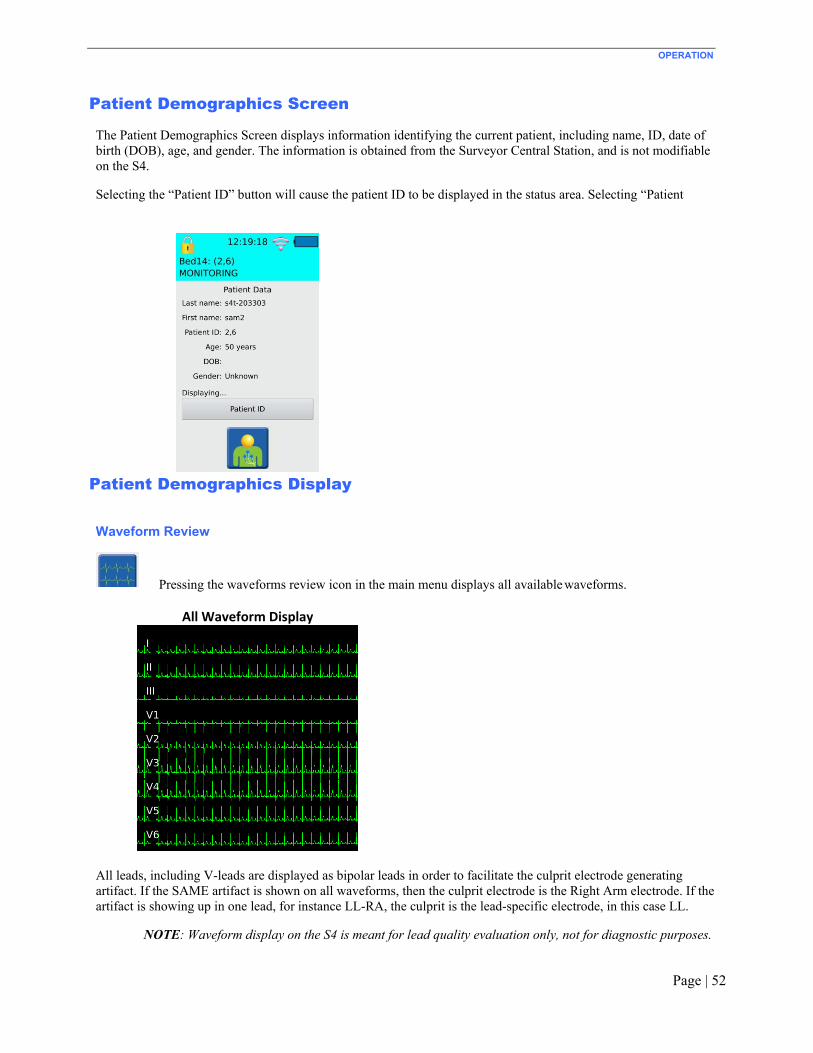
OPERATION
Page | 52
Patient Demographics Screen The Patient Demographics Screen displays information identifying the current patient, including name, ID, date of birth (DOB), age, and gender. The information is obtained from the Surveyor Central Station, and is not modifiable on the S4.
Selecting the “Patient ID” button will cause the patient ID to be displayed in the status area. Selecting “Patient
Patient Demographics Display Waveform Review
Pressing the waveforms review icon in the main menu displays all available waveforms.
All Waveform Display
All leads, including V-leads are displayed as bipolar leads in order to facilitate the culprit electrode generating artifact. If the SAME artifact is shown on all waveforms, then the culprit electrode is the Right Arm electrode. If the artifact is showing up in one lead, for instance LL-RA, the culprit is the lead-specific electrode, in this case LL.
NOTE: Waveform display on the S4 is meant for lead quality evaluation only, not for diagnostic purposes.

OPERATION
Page | 53
Pressing anywhere on the waveforms displays the first set of waveforms. If 10-wire, 12-lead monitoring cables are being used, additional presses will display the remaining sets of waveforms. For 10-wire.
First Set of Waveforms Display Second Set of Waveforms Display
Third Set of Waveform Displays
As depicted below, one or more waveforms are shown as a square wave if the patient connection is not properly in place. When all leads are in failure mode, the “ALL FAIL” message is shown. Otherwise, the name of the leads in failure are specifically shown.

OPERATION
Page | 54
All Leads in Failure V6 in Failure

OPERATION
Page | 55
Monitoring Menus
When initially powered on, the S4 will attempt to connect to the Central Station. Once a connection has been established, ECG monitoring can begin.
To start monitoring, press the monitoring start icon (1) as shown below.
Main Screen with Monitoring Start Icon
Monitoring Screen Options
In the monitoring screen, there are a number of choices:
1) Return to the main screen. 2) Start monitoring the same patient as before. 3) Monitor a new patient with a new profile.
NOTE: If the monitoring session is started from the Surveyor Central while this screen is open, the S4 may still display these options until this screen is closed by pressing any of the icons or pressing the control button. In such cases, the status area will correctly display that the S4 is actively monitoring a patient.
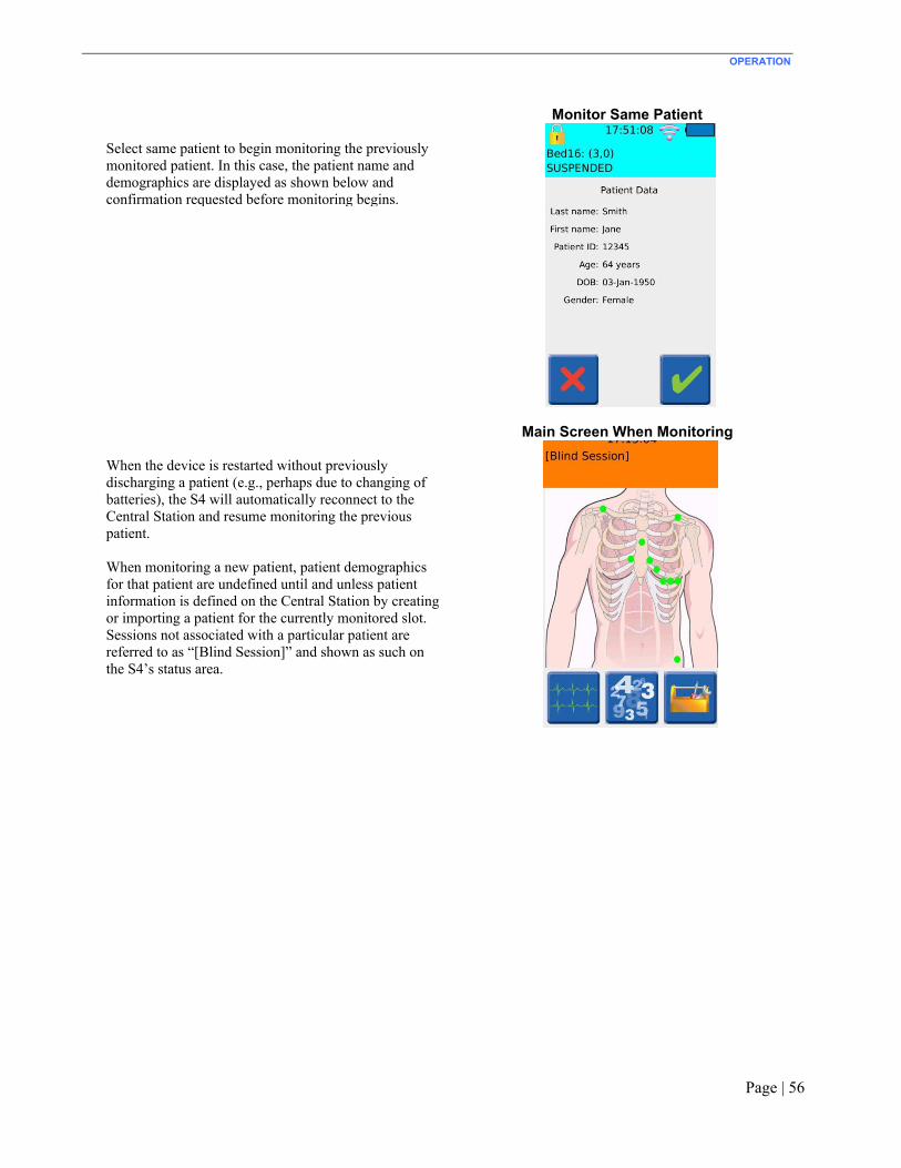
OPERATION
Page | 56
Monitor Same Patient
Select same patient to begin monitoring the previously monitored patient. In this case, the patient name and demographics are displayed as shown below and confirmation requested before monitoring begins.
Main Screen When Monitoring
When the device is restarted without previously discharging a patient (e.g., perhaps due to changing of batteries), the S4 will automatically reconnect to the Central Station and resume monitoring the previous patient.
When monitoring a new patient, patient demographics for that patient are undefined until and unless patient information is defined on the Central Station by creating or importing a patient for the currently monitored slot. Sessions not associated with a particular patient are referred to as “[Blind Session]” and shown as such on the S4’s status area.

OPERATION
Page | 57
Monitor New Patient
To start monitoring a new patient, you first have to select a monitoring profile. Profiles are defined at the Central Station and include alarm limits and other settings appropriate for a type of patient. The “_factory” profile is the default profile shipped with the Central Station. Other profiles can be defined by the Central Station administrator. Profiles are communicated from the Central Station to the S4 and are available as a list of drop-down menu items at the new patient monitoring screen.
Once monitoring of a new patient begins, patient demographics for that patient are undefined until and unless patient information is defined on the Central Station by creating or importing a patient for the currently monitored slot. Sessions not associated with a particular patient are referred to as “[Blind Session]” and shown as such on the S4’s status area.
NOTE: It is not possible to define or update patient demographics on the S4. Patient demographics must be defined and updated on the Central Station.

OPERATION
Page | 58
Heart Rate Display
When the S4 is in an active monitoring session, it is possible to display the patient’s heart rate by pressing the numeric icon (1) as shown below.
Heart Rate Numerics Icon
This will show the patient’s current heart rate as reported by the Central Station.
NOTE: By design, no other parameters or alarms are shown on the S4’s display. Refer to the Central Station user manual for relevant parameters, alarms and other information available there.
To return to the main screen, press the main screen icon with the patient hookup icon (1) shown below.
Main Screen Patient Hookup Icon

OPERATION
Page | 59
Printing
During a monitoring session, it is possible to print a report directly on the Central Station from the S4. To do this, select the waveforms display icon (1) and then the print icon (2) as shown below. When using specified 10-wire ECG, the printed report is a 12-lead ECG. When using the shielded 3-wire or 5-wire cable the report is a rhythm report.
Select the waveforms icon Select the print icon
Print in Process Screen
The “Print in progress…” message is displayed and the print icon is unavailable until the printing process is complete.

OPERATION
Page | 60
Toolkit
To access special functions and configuration of the S4, tap on the toolkit icon (1) shown below.
Toolkit Icon
Toolkit Screen
In this screen, it is possible to:
1) Adjust the waveform gain. 2) Adjust the waveform speed. 3) Return to the main menu. 4) Set or change configuration. 5) Suspend monitoring and power off.

OPERATION
Page | 61
Additionally, in the setup screen it is also possible to define:
• If 3-wire cable has been detected, define the
lead to be monitored, whether Lead I, Lead II or Lead III.
• If 10-wire cable has been detected, allow the user to select 5-wire or 10-wire monitoring depending on the type of LeadForm cable being used.

OPERATION
Page | 62
Waveform Gain (Amplitude)
Waveform Gain Screen
The waveform gain can be set to 1/2x, 1X or 2X.
Waveform Speed
Waveform Speed Screen
The waveform speed can be set to slow, normal or fast.
NOTE: Waveform gain and speed are not in a particular scale such as mm/mV and only representative. Waveforms displayed on the S4 LCD display are for lead quality check purposes and not intended for diagnostic measurements. Refer to the Central Station and its user manual for scaled display and measurement of ECG waveforms.

OPERATION
Page | 63
Power Off – Suspend Monitoring
Suspend monitoring and turn off the S4 by pressing the suspend monitoring icon (1) as shown below.
Power Off Icon

OPERATION
Page | 64
Passcode Entry Screen
Suspending an active monitoring session is a password- protected function which requires the entry of the administrative passcode. The S4 is factory shipped with passcode 7865. Refer to your facility’s administrator for additional information.
If the wrong passcode is entered, the “Unlock failed” message is displayed and the correct passcode must be entered for access to this screen. Alternatively, this operation may be cancelled.

OPERATION
Page | 65
Power Off Confirmation Screen
It is highly recommended to suspend monitoring in this way instead of removing the battery, to avoid a “No patient monitoring” nuisance alarm on the Central Station. The Central Station will stop displaying data for this patient, but the patient slot will still remain associated with the patient. Monitoring can be resumed with the same patient later, if needed. The S4 will turn off after having completed the “suspend monitoring” action. This action requires confirmation as shown.
CAUTION: Powering off the S4 during an active monitoring session that is a “blind session” will end the session and will not save the monitored data on the Central Station.

Page | 66
11. CONFIGURING THE S4
This chapter describes how to configure the S4 including changing the settings during the operation as well as general configuration for setup of the S4.
Toolkit Screen
Passcode Entry Screen
Select the configuration icon on the toolkit screen to access the configuration settings of the S4.
NOTE: This particular screen is a password- protected function and only available through a passcode. The S4 is factory shipped with passcode 7865. Refer to your facility’s administrator for additional information.
Upon entry of the passcode, the menus for this screen will be available. If the wrong passcode is entered, the “Unlock failed” message is displayed and the correct passcode must be entered to enter this screen. Alternatively, this operation may be cancelled.

CONFIGURING THE S4
Page | 67
Configuration Settings Screen
Upon successful entry of the passcode, the S4 is unlocked and the configuration settings screen is displayed as shown.
NOTE: The device will remain in this unlocked state (as shown by the unlock icon in the main screen’s status area) until the monitor’s display turns off again.
NOTE: The configuration settings screen is displayed on the S4 only in landscape mode.
NOTE: Configuration changes cannot be saved while an active monitoring session is in progress.

CONFIGURING THE S4
Page | 68
Host Settings
Host Settings Screen
The settings for the Central Station including its IP address, and the unit and bed ID for this particular S4, as well as base IP port and IP port number are defined here. If you are uncertain about these settings, please consult Welch Allyn or your IT Network Administrator.
Network Settings
The network settings of the S4 are configured as shown below.
Network Settings Screen
Available settings include:
• IP Address Method: Whether dynamically assigned by the network through a DHCP service or manually assigned here to a static address. If “Manual” is selected, the IP address, subnet mask and gateway address must be defined.
• WiFi Network Security: The S4 supports any of WPA-PSK-AES, WPA-PSK-TKIP, WPA2-PSK-AES, or WPA2-PSK-TKIP authentication and encryption methods.
• SSID & Passkey: The SSID and Passkey of the WiFi network that will be used for telemetry transmission. The passkey may be entered as text or hexadecimal digits.
If you are uncertain about these settings, please consult Welch Allyn or your IT Network Administrator.
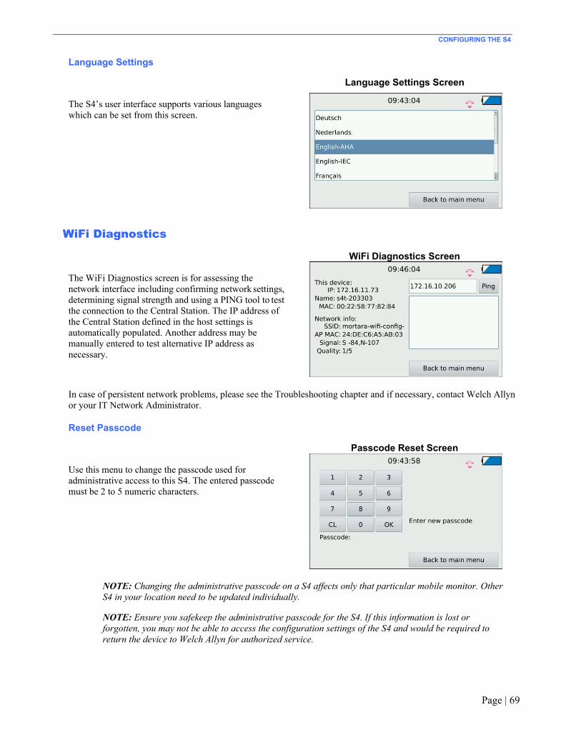
CONFIGURING THE S4
Page | 69
Language Settings
Language Settings Screen
The S4’s user interface supports various languages which can be set from this screen.
WiFi Diagnostics
WiFi Diagnostics Screen
The WiFi Diagnostics screen is for assessing the network interface including confirming network settings, determining signal strength and using a PING tool to test the connection to the Central Station. The IP address of the Central Station defined in the host settings is automatically populated. Another address may be manually entered to test alternative IP address as necessary.
In case of persistent network problems, please see the Troubleshooting chapter and if necessary, contact Welch Allyn or your IT Network Administrator.
Reset Passcode
Passcode Reset Screen
Use this menu to change the passcode used for administrative access to this S4. The entered passcode must be 2 to 5 numeric characters.
NOTE: Changing the administrative passcode on a S4 affects only that particular mobile monitor. Other S4 in your location need to be updated individually.
NOTE: Ensure you safekeep the administrative passcode for the S4. If this information is lost or forgotten, you may not be able to access the configuration settings of the S4 and would be required to return the device to Welch Allyn for authorized service.

CONFIGURING THE S4
Page | 70
Hardware Diagnostics
HW Diagnostics Screen
This hardware diagnostics screen provides an easy method for service personnel to check the basic functionality of the device including the built-in accelerometer, touch screen, general-purpose input/output as well as analog-to-digial converters plus battery voltage level and charging status.
S4 Version
S4 Version Screen
This screen displays the current version of the S4 software as well as the device serial number. In case of problems or issues, it may be necessary to share this information with Welch Allyn.
SAM Version
SAM Version Screen
This screen displays the current version of the Signal Acquisition Module (SAM) including module number and part number, as well as hardware and software version plus serial number. In case of problems or issues, it may be necessary to share this information with Welch Allyn.

Page | 71
12. ECG MONITORING
To perform ECG monitoring on a patient using the S4 and Surveyor Central Station: Power-On
1. Insert freshly charged rechargeable or brand new disposable batteries in the device.
2. Press the Nurse Call / Control button to power up the S4. Patient Prep
3. Prep the patient and place electrodes per clinical guidelines and provided instructions.
Patient Cable Hookup
4. Attach the patient cable to the electrodes on the one end, and to the S4 on the other end. The example here demonstrates the 10-wire LeadForm cable; use the hook-up appropriate to your available patient cable.

ECG MONITORING
Page | 72
Confirm Good Signal
5. Confirm that all leads are OK (i.e., green dots in the electrode placements as shown on the LCD). Select the waveforms icon to view and confirm good signal on all leads.
New Patient Monitoring
6. Select the start monitoring icon.
To start monitoring a new patient, select the new patient icon, confirm a profile and select OK. Confirm that the status is indicated as “Monitoring” and the session labeled as a “[Blind Session]”.
To define patient demographics, create patient demographics or import patient demographics for the slot associated with this telemetry session.

ECG MONITORING
Page | 73
Same Patient Monitoring
7. To resume monitoring the previous patient, select same patient and confirm the patient name and press OK.
Confirm that the status is indicated as “Monitoring” and the session labeled with the correct patient demographics.
Confirm Monitoring Active
8. Confirm that the monitoring session is active on the Central Station or by confirming the heart rate shown on the S4 display.

ECG MONITORING
Page | 74
Ending a Monitoring Session
NOTE: Monitoring sessions are typically managed at the Central Station and ended there though it can be done on the S4 by removing the battery or by following the Ending a Monitoring Session procedure.
9. To end a monitoring session, press and hold the patient call button until the LCD activates. Press the
“Abort Call and resume” icon on the display to cancel the nurse call and activate the screen.
Select the settings icon.
Press the power down icon.

ECG MONITORING
Page | 75
Enter the administrative passcode.
Press OK to confirm.
The S4 will turn off (including the LCD and indicator LED’s) and stop monitoring the patient. This will also dismiss the patient on the Central Station.

Page | 76
13. SPO2 MONITORING
The Surveyor S4 Mobile Monitor optionally includes Welch Allyn’s pulse oximetry parameter. Overview
S4 Mobile Monitors equipped with pulse oximetry can monitor functional oxygen saturation of arterial hemoglobin, displaying numeric values for % SpO2, pulse rate in beats/min (bpm), and a graphical trace of the associated plethysmogram (“pleth”) waveform. The pleth waveform corresponds to but is NOT proportional to the arterial pressure waveform.
Pulse oximetry monitoring works by shining light of two different wavelengths through the patient's tissues at the site where the SpO2 sensor is applied (such as a fingertip) and measuring the absorption of the light by the hemoglobin in the patient's arterial blood, which relates to the amount of oxygen in the blood. The signal acquired from the sensor also varies according to pulsatile blood flow caused by the beating of the heart, making possible detection and calculation of pulse rate.
SpO2 monitoring procedure
1. Ensure that the SpO2 port plug has been removed from the SpO2 port. With your finger placed in the indentation in the SpO2 port plug, slide the plug out of the S4’s SpO2 port.
2. Connect a sensor and, if needed, an extension cable to the S4.
WARNING: Use only cables and sensors approved for use with the S4. Other cables and sensors have not been not tested for safety and accuracy with the S4. Their use may lead to patient injury and/or incorrect measurements.
Refer to Section 17, REORDERING ACCESSORIES & CONSUMABLES, for a list of approved sensors and cables.
WARNING: Use a SpO2 sensor that is appropriate for the size and weight of the patient to avoid potential measurement inaccuracies. Refer to the instructions accompanying the sensor.
Consider also the patient’s weight, level of activity, adequacy of perfusion, whether sterility is required, and the anticipated duration of monitoring.

SPO2 MONITORING
Page | 77
3. Apply the sensor to the patient.
Follow the Instructions for Use accompanying the sensor.
WARNING: Misapplication of the SpO2 probe with excessive pressure for prolonged periods can induce pressure injury.
4. Activate the S4’s display by pressing and holding the control button for 2 seconds.
5. Navigate to the Patient Hookup screen.
This screen displays a SpO2 signal quality indicator as shown in the accompanying figure.
6. Adjust the sensor placement until a good quality signal is indicated.
The signal quality indicator appears as a colored square in the lower left corner. A green square indicates a good quality signal, a yellow square indicates a low quality signal, while a red square indicates a lack of signal from which SpO2 can be calculated. These are further described later in this chapter.
7. Begin or resume the monitoring session.
SpO2 Display
Functional oxygen saturation (% SpO2)
Whenever an adequate signal is being acquired from the SpO2 sensor, the S4 calculates and continuously updates the % SpO2 on the Numerics screen, as shown to the right. Note that the Numerics screen is available only when an active monitoring session is in progress to the Surveyor Central station.
The % SpO2 value is updated every second, representing an average that reaches a stable value within 10 seconds of an oxygen saturation change.
Percent SpO2 values are held on the display for no longer than 30 seconds after the loss of signal or another condition where the S4 is unable to calculate SpO2 values. When this happens, a question mark is displayed.
Pulse Rate (PR) value
Whenever an adequate signal is being acquired from the SpO2 sensor, the S4 calculates and continuously updates the PR, as shown also in the above example.
The PR value is updated every second from qualified pulsatile data collected and averaged over 12-16 beats. Pulse Rate values are held on the display for no longer than 30 seconds when the S4 becomes unable to continue updating the value, such as due to a loss of signal from the sensor.
When the S4 is unable to calculate a PR value, dashes are displayed in this indicator.
WARNING: Do not use PR as a substitute for Heart Rate (HR) since PR is measured at the patient’s periphery and may not adequately reflect the condition of the heart, particularly when arrhythmia is present. Use ECG to monitor HR.

SPO2 MONITORING
Page | 78
Signal quality indicator
A signal quality indicator appears as a colored dot below to the PR value on the Numerics screen, as in the example above, as well as in the lower left corner of the Hookup screen. The Signal Quality Indicator provides information about the condition of SpO2 signal being received from the sensor, as follows:
SQI color Signal condition
Green Good signal
Yellow Signal is either weak and/or degraded by noise such as motion artifact. Percent SpO2 and PR value displayed may potentially be inaccurate.
Red The signal is missing or inadequate for SpO2 to be calculated from it.
A description of factors affecting signal quality, and measures that may be taken to improve it is provided further on in this chapter.
Pleth waveform
The S4 displays a trace of the pleth waveform on the Waveform Review screen, as shown here.
The pleth waveform is normalized, so that the amplitude of the pleth wave is continuously and automatically adjusted to fill the available display space. Consequently, the pleth waveform cannot be used to assess the strength of the signal from the sensor. However, by observing the shape of the pleth waveform, the clinician is able to judge the sensor placement with respect to noise.
Signal status messages
Above the pleth waveform, the S4 may display additional status messages as follows:
Message Description
LOW QUALITY The SpO2 signal is degraded due to noise, interference, or low signal strength. The following section lists factors that may be considered to improve signal quality.
NOISE The SpO2 signal is degraded due to noise and/or motion artifact so that calculation of % SpO2 and PR values is not possible.
CHECK SENSOR A physiological signal is not recognized from the sensor. The sensor may have been removed from the patient.
NO SENSOR The probe has become disconnected from the S4.
SENSOR ERROR A fault in the SpO2 sensor has been detected.
INITIALIZING This message appears briefly when SpO2 monitoring is first initiated.

SPO2 MONITORING
Page | 79
Message Description
COMM. ERROR Data is not being received from the SpO2 sensor. This may be result of a sensor fault, or a technical fault in the S4.
A description of factors affecting signal quality, and measures that may be taken to improve it is provided further on in this chapter.
SpO2 tones
The S4 does not provide any tones associated with the SpO2 parameter. SpO2 alarms
The S4 does not provide any local alarm features. Rather, alarms are asserted at the Surveyor Central Station. Refer to the User Manual for the Surveyor Central Station for further information.
Factors affecting SpO2 signal quality
There are a number of factors that affect the quality of the signal acquired from the SpO2 sensor that, in turn, affect the ability of S4 to measure SpO2 accurately. In the event of difficulty obtaining SpO2 readings and/or indications of low signal quality consider the following possible factors:
• Improper sensor placement/application can affect performance. Follow the instructions for use provided with sensors.
• Nail polish, inks, tattoos, or contaminants on the patient’s skin at the sensor application site could affect the quality of the signal detected by the sensor. Poor signal quality (indicated by the signal quality indicator) may result in inaccurate readings. Consider removing these substances or use an alternate measurement site.
• Bright lights in the vicinity of the measurement site can interfere with the SpO2 sensor’s light detector, and thereby its ability to detect the physiological signals. Consider redirecting these external light sources, or covering the measurement site. Also check that the sensor has not been damaged.
• Excessive motion by the patient distorts the signal acquired by the sensor reducing its ability to detectthe pulsatile signal caused by the patient’s blood flow. When this condition is detected, the S4 displays the message “NOISE” in the SpO2 parameter display area. Consider instructing the patient to keep the sensor site still, or using an alternate measurement site.
• Carboxyhemoglobin is not distinguishable from oxygenated hemoglobin by the pulse oximeter, leadingto overestimation of the SpO2. If carbon monoxide poisoning is suspected, do not use a pulse oximeter to measure functional oxygen saturation.
• Intravenous dyes and elevated levels of methemoglobin can cause inaccurate readings.
Refer also to Section 16, TROUBLESHOOTING, for suggestions on dealing with common SpO2 related problems.

SPO2 MONITORING
Page | 80
SpO2 functional verification
Some models of commercially available functional testers and/or patient simulators can be used to verify the functionality of the S4’s pulse oximetry functions, including sensors and cables. However, such units cannot be used as basis for evaluating the accuracy of the SpO2 measurements.
SpO2 calibration
The SpO2 measurement system incorporates automatic calibration mechanisms. No other calibration is required. SpO2 accuracy testing
This section summarizes the test methods used to establish SpO2 accuracy for the S4.
A clinical study was performed in accordance with ISO 80601-2-61, section 201.12.1.101.2. A radial arterial cannula was placed in either the left or right wrist of each subject. Blood gas analysis was performed using an ABL-90 multi-wavelength oximeter to determine oxyhemoglobin saturation (SaO2). Healthy, non-smoking, non-anemic (hemoglobin ≤ 10 gm•dl-1) individuals aged 21-49 were enrolled in the study.
Each subject had two control blood samples taken at the beginning of each experiment, while breathing room air. Hypoxia was then induced to different and stable levels of oxyhemoglobin saturation (between 70-100%) by having subjects breathe mixtures of nitrogen, room air, and carbon dioxide. Each plateau level of oxyhemoglobin saturation was maintained for at least 30 seconds or until reference pulse oximeters readings were stable. Two arterial blood samples were then obtained, approximately 30 seconds apart. Each stable plateau therefore was maintained for at least 60 seconds with SpO2 fluctuating by less than 2-3%. The plateaus were nominally at 100%, room air saturation, 93%, 90%, 87%, 85%, 82%, 80%, 77%, 75% and 70%. A total of 25 samples were obtained at the saturation plateaus across this span. At least 200 data points were collected for each type of oximeter and probe combination studied.
Pulse oximeter data was taken as 5 second averages corresponding to the point of arterial blood analysis. Results were calculated as hemoximeter data (SaO2) vs. pulse oximeter bias (SpO2 - SaO2), and ARMS was calculated as:
𝐴 = ∑ 𝑆𝑝𝑂 − 𝑆𝑎𝑂 2𝑛

Page | 81
14. PRODUCT SPECIFICATIONS
General
Instrument Type Digital mobile monitor with ECG and optional SpO2.
Dimensions 5.5” × 3.1” × 1.3” (139 × 79 × 33 mm)
Input Channels Continuous 12-lead signal acquisition and transmission with 10-wire LeadForm cable Continuous 7-lead signal acquisition and transmission with 5-wire cables
ECG Leads Transmitted 10-wire: I, II, III, aVR, aVL, aVF, V1, V2, V3, V4, V5 and V6 5-wire: I, II, III, aVR, aVL, aVF, V 3-wire: I, II or III
Device Classification Defibrillator-proof Type CF, battery operated
Special Functions Lead impedance check, ECG display, lead fail, battery notification, multi-purpose call; 10-wire
Defibrillator Protection Complies with IEC 60601-2-25 (with 10-wire cable) and/or IEC 60601-2-27
Function Keys Control button; touchscreen menu navigation
Display type High definition, antiglare Color TFT-LCD with LED backlight and resistive touch panel
Display size 4.3 inches (11 cm) diagonal, active area
Display resolution 480 × 800 pixels
Environmental
Temperature Operating temperature: +10° to +40° C (+50° to +104° F) Storage temperature: -40° to +70° C (-40° to +158° F)
Humidity Operating humidity: 10% to 95% RH, non-condensing Storage humidity: 10% to 95% RH, non-condensing
Altitude Operating & Storage: 62 kPa to 106 kPa corresponds to an approx. altitude range of -380 m to 4000 m (-1250 ft to 13000 ft)
Cooling Passive (no fan)
Weight 300 g (10.6 oz) with rechargeable battery pack
IP classification IPX4 – This device is protected against harmful effects of water splashed from any direction per IEC 60529.

PRODUCT SPECIFICATIONS
Page | 82
Power Requirements & Battery
Disposable Battery Type Three (3) AA alkaline batteries
Disposable Battery Run-Time 16 hours (when configured with ECG only) 12 hours (when configured with ECG and SpO2)
Rechargeable Battery Type Rechargeable Lithium-ion battery pack
Rechargeable Battery Run-Time 24 hours (when configured with ECG only) 20 hours (when configured with ECG and SpO2)
Battery Charging Time 8 hours
ECG Specifications
ECG 12-lead ECG with specific 10-wire ECG 7-lead ECG with specific 3/5-wire ECG
Simultaneous Leads Available 10-wire: I, II, III, aVR, aVL, aVF, V1, V2, V3, V4, V5, V6 5-wire: I, II, III, aVR, aVL, aVF, V 3-wire: I, II or III
Acquisition Rate: 40,000 samples/s. for pacemaker detection, 500 samples/s. for analysis
Resolution: .117µV originally, reduced to 2.5 µV for processing and transmission
Dynamic Range ± 350mV
ECG Gain ½x, 1x, 2x
Trace Speed slow, normal, fast
CMRR: According to applicable standards (IEC 60601-2-25 and/or IEC 60601-2-27)
Pacemaker Spikes When used with 4-wire, 5-wire or 10-wire ECG cable detect and report pacemaker spikes up to 2 ms duration with 1 samples precision
Max. Auxiliary Patient Current:
< 10 µA
Frequency Response: 0.05 to 150 Hz
Input Impedance: >2.5 MΩ at 10 Hz
Electrodes: Compatible with Ag/AgCl disposable electrodes
HR Report from the Central Station
Less than one second. Heart rate is only available when the S4 is actively communicating with the Central Station.
Minimum QRS Amplitude: 160 µV
Recovery from Defibrillation Discharge
Less than 5 seconds, compliant with IEC 60601-2-25 and/or IEC 60601-2-27.

PRODUCT SPECIFICATIONS
Page | 83
SpO2 specifications
Technology Welch Allyn SpO2
Method Absorption – Spectrophotometric (dual wavelength) (Functional oxygen saturation of arterial hemoglobin)
Patient populations Child (greater than 2 through 12 years of age) Adolescent (greater than 12 through 21 years of age) Adult (greater than 21 years of age)
Parameters % SpO2
Pulse rate Plethysmogram
Resolution SpO2:
PR:
1 % SpO2
1 bpm
Range SpO2:
PR:
30 – 100 %, calibrated range 70-100% 30 – 240 bpm
Accuracy (RMS) 70% to 100% SpO2: FingerClip type sensor: 2.1%
SoftTip type sensor: 1.3% Disposable Wrap type sensor: 3.0%
Less than 70% SpO2: Unspecified
PR: ±3 bpm
Update interval 1 second Numeric values held < 30 seconds
Wavelength *
Red: Infrared:
660 nm, nominal 890 nm, nominal
Optical output power Red:
Infrared:
0.5 mW – 4.5 mW 0.5 mW – 3.0 mW
* This information may be useful for clinicians performing photodynamic therapy. Wireless Network Specifications
Wireless protocol 802.11 g/n 2.4 GHz Disable 802.11b support on WLAN infrastructure. If 802.11b support is required, do not specify any 802.11b data rate as mandatory.
Frequency Range 2400.96 MHz to 2482.56 MHz
802.11g supported rates 6, 9, 12, 18, 24, 36, 48, 54 Mbps
802.11n supported rates MCS0 through MCS7 6.5, 13, 19.5, 26, 39, 52, 58.5, 65 Mbps
Transmit Power 15 dBm Configure WLAN APs maximum transmitting power to 15 dBm

PRODUCT SPECIFICATIONS
Page | 84
Channels 1 to 13 supported.
Need to configure used channels on devices prior to installation (default is 1, 6, 11)
If dynamic channel selection on WLAN infrastructure is enabled, channels change will cause short data gaps. Reduce the number of channel changes per day.
Wireless security protocols WPA2-PSK-AES WPA2-PSK-TKIP (supported but not recommended) WPA-PSK-AES (supported but not recommended) WPA-PSK-TKIP (supported but not recommended)
P h HEX kWMM / QoS Yes Device uses class AC_VI (Video)
SSID Requirements Dedicated SSID is required. Hidden SSID not supported. SSID can be up to 32 ASCII characters long, per 802.11.
SSID prioritization and minimum bandwidth configuration on WLAN infrastructure is recommended.
Period Session Timeout or similar policies should be disabled or excluded in the SSID dedicated to the S4: these policies might cause data gaps of a few seconds whenever the AP terminates the session.
Dedicated Monitoring VLAN is recommended.
IP address assignment Static or DHCP
IP protocols and ports UDP: one port per device, according to the system configuration (i.e. 20100, 20101, 20102, etc…). Actual ports will be communicated upon definition of the system configuration;
SSH
ICMP and mDNS for management and service
Maximum devices per Access Point
16
Data Rate (payload) Outbound: up to 140 kbps (depending on configuration) Inbound: < 16 kbps
Minimum RSSI / SNR -75 dBm in the coverage area
Minimum SNR 20 dB in the coverage area

Page | 85
15. TROUBLESHOOTING
The following table provides guidance for investigating issues that may occur during operation of the S4. Contact Welch Allyn Technical Support and Service by calling 1.888.667.8272 (US & Canada) or +1-414-354-1600 (Worldwide) or via e-mail at [email protected] for further assistance.
Power and Battery
Symptom Possible Causes Suggested Resolution
The S4 is not working and display does not light up.
Internal system failure.
Power cycle the S4 with fresh batteries and try again. If problems persist, stop using the S4 and contact Welch Allyn Technical Support.
Battery will not hold charge. Replace the battery according to instructions in
the General Care & Maintenance chapter.
Display and Touchscreen
Symptom Possible Causes Suggested Resolution
The touchscreen is not working properly.
Touchscreen failure.
Power cycle the S4 and try again. If problems persist, stop using the S4 and contact Welch Allyn Technical Support.
The display is not working properly.
Display failure.
Power cycle the S4 and try again. If problems persist, stop using the S4 and contact Welch Allyn Technical Support.
ECG Trace
Symptom Possible Causes Suggested Resolution
ECG signal is noisy.
Excessive patient movement. Confirm electrode site preparation; confirm correct ECG positioning, move electrodes if needed.
Electrical noise from auxiliary equipment.
Isolate the patient from auxiliary equipment, if possible.
Bad electrode contact.
Check to make sure electrodes are still securely attached to the patient, and reattach if necessary. Remember the importance of good skin preparation techniques.

TROUBLESHOOTING
Page | 86
Pulse oximetry (SpO2)
Symptom Possible causes Suggested remedies
Signal Quality Indicator is yellow. SpO2 values continue to be shown.
The physiological signal sensed by the SpO2 sensor is weak
Check patient status. Consider dark skin pigmentation, low perfusion, venous pulsation, dysfunctional hemoglobins as potential factors. Remove nail polish from sensor site. Confirm the fit of the sensor at the measurement site – not too loose, nor too tight that circulation may be affected in the extremity. Try alternate measurement sites.
Intermittent dropouts of pleth waveform and SpO2 values
Circulation is being cutoff at the SpO2 measurement which is distal to a NIBP cuff
Select an alternate measurement site for NIBP or SpO2.
Inaccurate values Interfering substances in the patient’s bloodstream
Check the patient condition for carboxyhemoglobin, methemoglobin, intravascular dyes, or similar.
Physiological conditions Check the patient condition for cardiac arrest, hypotension, shock, severe vasoconstriction, severe anemia, hypothermia, venous pulsations, ventral septal defects, extremes in systemic vascular resistance, or similar.
Cannot obtain SpO2 reading
The signal sensed by the SpO2 sensor is so weak that it is not recognized as physiological
Refer the row further above for possible ways to improve signal strength.
Excessive artifact on the sensor signal makes it impossible to calculate SpO2
Refer the row below describing “’NOISE’ status message”.
No signal is being received from the sensor
Refer to the row further below describing “Pleth waveform is a square wave”
Electromagnetic interference from external equipment
Do not use the S4 with electrosurgery equipment. Check the immediate area of the S4 for other electronic equipment. Increase the separation distance between them. Consider discontinuing their use if not needed for patient care.
“NOISE” status message Excessive patient movement Advise patient to keep the measurement site still. Select an alternate measurement site less prone to movement.
External light source produces interference at the sensor
Redirect the external light source away from the measurement site. Cover the sensor site.
No signal is being received from the sensor
Confirm the sensor has not been damaged. Replace if necessary. Confirm the sensor and/or extension cable being used are one of those recommended in this manual for use with the S4.

TROUBLESHOOTING
Page | 87
Symptom Possible causes Suggested remedies
Pleth waveform is a square wave
A physiological signal is not being detected by the sensor
Confirm that the sensor is still applied to the patient. Confirm connections of sensor and extension cable to the S4.
Sensor and/or extension cable is damaged
Replace sensor and/or extension cable
Network Transmission
Symptom Possible Causes Suggested Resolution
1. "No ECG Monitoring" alarm.
2. “Trying to connect to Central" error message displayed.
3. X symbol on WiFi signal indicator.
4. Fast blinking blue LED.
5. "AP MAC: Not- Associated" in the WiFi diagnostic screen.
6. Invalid IP address if configured for DHCP.
7. Inability to ping in WiFi diagnostic screen.
Incorrect WLAN configuration (e.g., SSID, Security protocol, Passkey, Passkey type).
Check WiFi network settings; contact your IT Network Administrator to correct issues.
WLAN infrastructure issues (e.g. device placed on black list).
Check WiFi network settings; contact your IT Network Administrator to correct issues.
1. "No ECG Monitoring" alarm and no traces on the Central Station.
2. “Trying to connect to Central" error message displayed.
3. Normal symbol on WiFi signal indicator.
4. Slow blinking blue LED.
5. Network info correctly populated in WiFi diagnostic screen.
6. Invalid IP address if configured for DHCP.
7. Inability to ping in WiFi diagnostic screen.
Incorrect LAN configuration (Method, IP, Subnet, Gateway).
Check LAN network settings; contact your IT Network Administrator to correct issues.
LAN infrastructure issues (e.g. DHCP server is not providing an IP address).
Check LAN IPv4 network settings; contact your IT Network Administrator to correct issues.

TROUBLESHOOTING
Page | 88
Symptom Possible Causes Suggested Resolution
1. "No ECG Monitoring" alarm and no traces on the Central Station.
2. “Trying to connect to Central" error message displayed.
3. Normal symbol on WiFi signal indicator.
4. Slow blinking blue LED.
5. Network info correctly populated in WiFi diagnostic screen.
6. Valid IP address if configured for DHCP.
7. Ping successful for some IP addresses in WiFi diagnostic screen.
Incorrect Host/Central stations configuration.
Check S4 Host settings and/or Central Station configuration.
Mismatch between Unit/Bed ID and Base Port configuration on S4 and Central stations.
Check S4 Host settings and/or Central Station configuration.
Surveyor Central Station is not running.
Check Central Station configuration.
Security router not correctly configured.
Check Security router configuration and status.
LAN infrastructure issues (i.e. ports not routed to Security router, disconnected cables).
Check LAN IPv4 network settings; contact your IT Network Administrator to correct issues.
Any of the following:
1. Intermittent traces on Central Station, intermittent "No ECG Monitoring" alarm.
2. Intermittent "Trying to connect to Central" error in top bar.
3. X or low signal symbol on WiFi signal indicator.
4. Intermittent fast blinking blue LED.
5. Intermittent "AP MAC: Not-Associated" in WiFi diagnostic screen, low signal, high noise, low quality indexes.
6. Intermittent Valid IP address if configured for DHCP.
7. Inconsistent Ping results in WiFi diagnostic screen.
Poor WLAN network coverage.
Check IT Network Administrator to correct issues.

TROUBLESHOOTING
Page | 89
Error Messages
Message Possible Causes Suggested Resolution
Trying to connect to Central...
Not able to connect to the Surveyor Central Station.
Check network settings and access of WiFi network. Also refer to the Network Transmission items above.
Message Possible Causes Suggested Resolution
The configured slot is already used by another device.
Selected slot for the Surveyor Central Station is currently in use.
Select a different slot for this monitor.
Unlock failed. Incorrect passcode used. Enter the correct passcode.
Enter New Passcode.
Mismatch of passcodes entered. Ensure that the configuration passcode entered as
well as the confirmation passcode values match.
ECG Frontend calibration failed, restart the device. If the problem persists contact service.
Calibration of the ECG frontend failed.
Power the system on and off. Contact Welch Allyn if the problem persists.
Unable to open ECG Frontend, restart the device. If the problem persists contact service.
Interface to the ECG frontend failed.
Power the system on and off. Contact Welch Allyn if the problem persists.

Page | 90
16. REORDERING ACCESSORIES & CONSUMABLES
Use the following Welch Allyn part numbers to obtain spare parts or to reorder accessories: Power accessories
Description Part Numbers
BATTERY LI-ION 7.4V 1600mAh 4800-018
CONVENIENCE TRAY, FOR AA ALKALINE BATTERIES 8364-005-50
KIT, CHARGER, LI-ION-5, US/CAN 41000-035-50
KIT, CHARGER, LI-ION-5, INTN'L 41000-035-51
KIT, CHARGER, LI-ION-5, AUSTRALIA 41000-035-52
KIT, CHARGER, LI-ION-5, UK 41000-035-53
AC POWER SUPPLY, FOR CHARGER KIT 4101-012
Mounts / holders
TIE-ON DISPOSABLE POUCH - BOX 100** 8485-029-51
ECG accessories
ECG cable, LeadForm, 10-wire, snap ends, AHA, 60 cm (24”) length 9293-061-50
ECG cable, LeadForm, 10-wire, snap ends, IEC, 60 cm (24”) length 9293-061-51
ECG cable, LeadForm, 10-wire, snap ends, AHA, 97 cm (38”) length 9293-061-52
ECG cable, LeadForm, 10-wire, snap ends, IEC, 97 cm (38”) length 9293-061-53
ECG LEAD SET 5 WIRE CLIP ENDS AHA GRAY 9293-059-60
ECG LEAD SET 5 WIRE CLIP ENDS IEC GRAY 9293-059-61
ECG LEAD SET 5 WIRE SNAP ENDS AHA GRAY 9293-059-62
ECG LEAD SET 5 WIRE SNAP ENDS IEC GRAY 9293-059-63
ECG LEAD SET 3 WIRE CLIP ENDS AHA GRAY 9293-059-50
ECG LEAD SET 3 WIRE CLIP ENDS IEC GRAY 9293-059-51
ECG LEAD SET 3 WIRE SNAP ENDS AHA GRAY 9293-059-52
ECG LEAD SET 3 WIRE SNAP ENDS IEC GRAY 9293-059-53
HOOKUP KIT MONITORING 10E SINGLE** 9294-009-50
MONITORING SNAP ELECTRODES CASE 300 108070

REORDERING ACCESSORIES & CONSUMABLES
Page | 91
SpO2 accessories
Reusable SpO2 Finger Clip Sensor; 90 cm cable 9293-064-55
Reusable SpO2 Large SoftTip® Sensor; 90 cm cable 9293-064-51
Reusable SpO2 Medium SoftTip® Sensor; 90 cm cable 9293-064-52
ReusableSpO2 Small SoftTip® Sensor; 90 cm cable 9293-064-53
Disposable SpO2 Wrap, Adult, 24/box; 45 cm cable 9293-064-50
Disposable SpO2 Wrap, Pediatric, 24/box; 45 cm cable 9293-064-57
SpO2 Extension Cable, 120 cm 9293-064-54
SpO2 Port Plugs, 10/bag 8364-035-51 Other
S4 USER MANUAL 9515-190-51-CD
* Technical Service Installation Required.
** This item is intended for single patient use. Items warranted to be free of defects in workmanship and materials for a period of 90 days or first use, whichever comes first.
To order additional supplies, contact your Welch Allyn Customer Service Representative.