A Text-book of Plane Surveying - Compleat Surveyor
523
This is a reproduction of a library book that was digitized by Google as part of an ongoing effort to preserve the information in books and make it universally accessible. https://books.google.com
-
Upload
khangminh22 -
Category
Documents
-
view
0 -
download
0
Transcript of A Text-book of Plane Surveying - Compleat Surveyor

This is a reproduction of a library book that was digitized by Google as part of an ongoing effort to preserve the information in books and make it universally accessible.
https://books.google.com


ENGINEEftfM/1
UBRARV

I


A TEXT-BOOK
PLANE SUEVEYING
BY
WILLIAM Gr RAYMOND, C.E.
oEoBER AoERICAN SOCIETY OF CIVIL ENGINEERS; PROFESSOR OF GEODESY,
ROAD ENGINEERING, AND TOPOGRAPHICAL DRAWING, IN THE
RENSSELAER POLYTECHNIC INSTITUTE
NEW YORK -:- CINCINNATI -:- CHICAGO
AMERICAN BOOK COMPANY

Copye1ght, 1896, by
AMERICAN BOOK COMPANY.
Raymond's pl. sdrv.
w. p. I
PREFACE.
This book has been prepared to meet the needs of those
beginning the study of surveying. The subject treated is a
simple one, and an effort has been made to make its presen
tation clear. The book is a text-book, not a treatise, and it
is hoped that the teachers who use it will find it possible to
devote their lecture work to amplification, rather than to
explanation, of the matter it embraces.
So far as seemed necessary the plan of giving first the
general method and then the details has been adopted, at
the risk of some repetition, because I believe this to be the
clearest method of presentation. A special effort has been
made to render clear and comprehensible those points which
an experience of fourteen years of practice and teaching has
indicated to be the ones presenting the greatest difficulties
to students. Simpler matters have been left to the student
to work out from suggestions. The book can be read under
standing^ by any one who has completed Trigonometry,
two formulas only being given whose derivation requires
anything beyond. These may be derived by the teacher for
such students as are sufficiently advanced.
Particular attention is called to the systematic arrangement
of computations in Chapter VI. ; to the article on the slide
rule ; to the discussion of practical surveying methods in
Book II. ; to the full treatment of coordinates ; to the large
number of examples ; and to the use of the terms " latitude
difference " and " longitude difference " for the old terms
"latitude" and "departure."
3

4 PREFACE.
The whole general scheme of terms is thought to be much
more logical than that heretofore in use ; and in this I have
the support of Professors Merriman and Brooks, who have
adopted practically the same nomenclature in their " Hand
book for Surveyors," recently issued.
The logarithmic tables are from Professor C. W. Crockett's
"Trigonometry," and are particularly suitable for surveyors'
use.
I am indebted to many persons and books for valuable
assistance. Especial acknowledgment is due to Professor H.
I. Randall of the University of California, who drew Plate IV.;
to Mr. J. J. Ormsbee, Mining Engineer, who drew Plate V. ;
to Mr. John H. Myers, Jr., A.B., C.E., for the problems on
coordinates and for many suggestions; and to Professors R. S.
Woodward of Columbia, and Frank O. Marvin of the Uni
versity of Kansas, for valuable suggestions. Mr. E. R. Cary,
C. E., Instructor in Geodesy, Rensselaer Polytechnic Institute,
has given much help in the preparation of examples.
I also acknowledge my indebtedness to the following
instrument makers for the use of cuts : Messrs. Buff & Berger,
Boston, Mass.; W. & L. E. Gurley, Troy, N. Y.; Keuffel &
Esser Company, New York ; G. N. Saegmuller, Washington,
D. C; L. Beckman, Toledo, O. ; Mahn & Co., St. Louis, Mo.;
F. E. Brandis, Sons & Co., Brooklyn, N. Y. The principal
instrument cuts, furnished by the Messrs. Gurley, Keuffel &
Esser, andoMahn & Co., will be known by the firm name on the
cut. Those of Buff & Berger are Figs. 19, 20, 48, 107, 148,
151, and 153. G. N. Saegmuller furnished Fig. 54. All of
the cuts used are covered by copyright.
The book is submitted to my fellow teachers and students
of surveying in the hope that it may prove useful to them in
their work.
Troy, N. Y., august. 1896. WILLIAM G. RAYMOND.
CONTENTS.
BOOK I. PRINCIPAL INSTRUMENTS AND ELEMENTARY
,Apt« OPERATIONS.
Introduction 9
I. Measurement of Level and Horizontal Lines . . 13
Instruments used . 0 . . n 13
Methods 18
Errors Involved 22
II. Vernier and Level Rubble 31
Vernier ........... 31
Level Bubble 35
III. Measuring Differences of Altitude, or Leveling . 40
Instruments .......... 40
Use of the Level , . .50
Adjustments of the Level ....... 63
Minor Instruments ........ 72
Leveling with the Barometer ...... 74
IV. Determination of Direction and Measurement of
Angles. 77
The Compass .77
Compass Adjustments 79
Use of the Compass .83
Magnetic Declination SO
The Transit 95
Use of the Transit 100
Adjustment of the Transit ....... 108
The Solar Transit 110
Adjustments of the Solar Transit 122
Saegmuller S-lar Attachment 123
Meridian and Time by Transit and Sun .... 125
V. Stadia Measurements 127
VT. Land Survey Computations 141
Balancing the Survey 144
Supplying Omissions 149
Areas . . . . . . . . . . .152
Co-rdinates . . . . . . . . . .150
Dividing Land . . . . . . .103
Model Examples . . . . . . . .105
The Planimeter 172
The Slide Rule . . .179
6 CONTENTS.
BOOK II. GENERAL SURVEYING METHODS.
CHAPTER PAGE
VII. Land Surveys 201
Surveying with the Chain alone 204
Farm Surveys 208
United States Public Land Surveys 219
City Surveying 230
VIII. Curves 238
IX. Topographical Surveying . . . . • . . . 244
Top-graphy 244
Simple Triangulation 253
Mapping 261
The Plane Table 268
X. Earthwork Computations 275
Ordinary Methods 275
Estimating Volumes from a Map 281
XI. Hydrographic Surveying 287
Soundings 289
The Sextant 294
Measuring Vel-city and Discharge 298
Direction of Current 304
XII. Mine Surveying 305
Surface Surveys 305
Underground Surveys 308
Connecting Surface and Underground Work . . . 316
Mapping the Survey 320
APPENDIX.
I. Problems and Examples 322
Chapter I 322
Chapter III 324
Chapter IV .324
Chapter V 326
Chapter VI 326
Coordinates 328
Chapter VIII 335
Chapter IX 336
Chapter X 338
Chapter XI 339
Chapter XII 340
II. The Judicial Functions of Surveyors .... 341
III. The Ownership of Surveys, and what constitutes a
Survey and Map 351
IV. Geographical Positions of Base Lines and Meridians
in Public Surveys 357
V. Tables 361
Index 0 471

(
BOOK I.
PRINCIPAL INSTRUMENTS AND ELEMENTARY
OPERATIONS.


p
INTRODUCTION.
1. Preliminary conceptions. An ellipse of axes AB and CD
(Fig. 1), being revolved around its shorter axis CD, will gener
ate the surface of an oblate
spheroid of revolution.
If we imagine the sea to
extend underneath the sur
face of the earth so that the
visible solid portions of the
earth will be, as it were,
floating on a ball of water,
the shape of that ball will
be, approximately, that of an
oblate spheroid of revolution.
The surface of this ball is called the mean surface of the earth.
The shorter axis is that connecting the poles ; the longer is
the diameter of the circle called the equator. In the case of
the earth these two axes do not differ much in length, and
hence the earth is usually spoken of as a "sphere slightly
flattened at the poles." It may seem strange to the student
that a difference of twenty-seven miles should be spoken of as
a slight difference. But when it is said that this difference
is about one third of one per cent of the length of the longer
axis, the meaning is clearer.
The lengths of the two axes according to the latest deter
minations1 are:
Shorter or polar axis .... 41,709,790 feet.
Longer or equatorial axis . . 41,852,404 feet.
1 Clarke's spheroid of 1880. The values as found for Clarke's spheroid of 1866
are those generally used by geodesists. They are: shorter, 41,710,242 feet ; longer,
41,852,124 feet.
9
10 INTRODUCTION.
If a plane is passed through an oblate spheroid of revolu
tion, parallel to its shorter axis, it will cut from the spheroid
an ellipse. If passed parallel to the longer axis, it will cut a
circle. So with the earth : a plane passed parallel to the polar
axis cuts from the mean surface of the earth an ellipse, while
one passed parallel to the equator cuts a circle. Hence me
ridians of longitude are ellipses, and parallels of latitude are
circles.
The surface of the sea, or that surface extended as before
mentioned, forms what is called a level surface, and a line
lying in this surface is a level line.
A line perpendicular to this surface at any point is a verti
cal line for that point. (A plumb line at any point is a vertical
line for that point.)
A line perpendicular to a vertical line is a horizontal line.
A tangent to the earth's mean surface at any point is per
pendicular to the vertical line at that point, and hence is a hori
zontal line for that point.
An inclined line is a straight line that is neither vertical
nor horizontal.
A vertical plane at any point is a plane including the verti
cal line at that point.
A horizontal plane at any point is a plane perpendicular to
the vertical line at that point.
A vertical angle is an angle formed by lines in a vertical
plane.
A horizontal angle is an angle formed by lines in a horizon
tal plane.
At any point on the earth's surface there can be but one
vertical line, but there may be an indefinite number of horizon
tal lines ; there can be but one horizontal plane, but there may
be an indefinite number of vertical planes.
If water collects upon the earth's surface in some depression
above the mean surface, as in a lake or pond, or even as in a
small glass, and if the water is still, its surface will be nearly
parallel to that portion of the mean surface of the earth that
is vertically below it ; hence it will be a level surface, and a
line drawn on it will be a level line. Such a line will be longer
than the corresponding line drawn on the mean surface of the

SURVEYING DEFINED. 11
earth between the verticals through the extremities of the
upper line.
The visible solid parts of the earth above the mean sur
face and the invisible solid parts below, make up a very
irregular body. It is customary to speak of the visible parts
of the earth's surface, both fluid and solid, as the "surface
of the earth." In the definition in Art. 2, however, this
term must be understood to mean not only the visible parts
of the earth's crust, but also those parts that must be reached
in connection with the operations of mining, bridge build
ing, or other engineering works that extend below the visi
ble surface.
2. Surveying defined. Surveying is the art of finding the
contour, dimensions, position, etc., of any part of the earth's
surface, and of representing on paper the information found.
The operations involved are the measurement of distances,
— level, horizontal, vertical, and inclined,— and of angles, —
horizontal, vertical, and inclined; and* the necessary drawing
and computing to represent properly on paper the information
obtained by the field work.
The drawn representation is called a map. It may be a
map showing by conventional signs the shape of that part of
the earth's surface that has been measured ; or it may be simply
an outline showing the linear dimensions of the bounding lines,
together with the angles that they make with the meridian, or
with each other, and sometimes the position within the tract of
structures, roads, or streams.
A map of the former kind is called a topographical map,
and the operations necessary to its production constitute a
topographical survey.
A map of the latter kind is a land map, and the operations
necessary to produce it constitute a land survey.
Either one of these surveys is a geodetic survey, if the tract
is so large that the curvature of the earth's surface must be
taken into account. This limit is supposed to be reached
when the tract is greater than one hundred square miles, but
many surveys of tracts of much greater area than this are made
without considering the mean surface to be other than plane.
12 INTRODUCTION.
Such surveys are of course inaccurate, but may be sufficiently
correct for the purpose they are to serve.
A plane survey is one made on the assumption that the
mean surface of the earth is a plane, above which is the irreg
ular visible surface broken by hills and valleys. Almost all
land surveys are plane surveys. Only plane surveys will be
considered in this book.
In plane surveying all measurements are referred to a plane.
In geodetic surveying all measurements are referred to a
sphere, or spheroid, according to the area covered and the
accuracy desired.
It must be borne in mind that no physical measurements
are exact. The art of surveying makes it possible to deter
mine that a field of land contains a certain area, more or less,
that a mountain is so many feet high, more or less, that a mine
is so many feet deep, more or less, etc. That is to say, it is
physically impossible to measure exactly either distance or
angles. The precision attainable or desirable in any survey
ing operations will be discussed elsewhere in this book.
CHAPTER I.
MEASUREMENT OF LEVEL AND HORIZONTAL LINES.
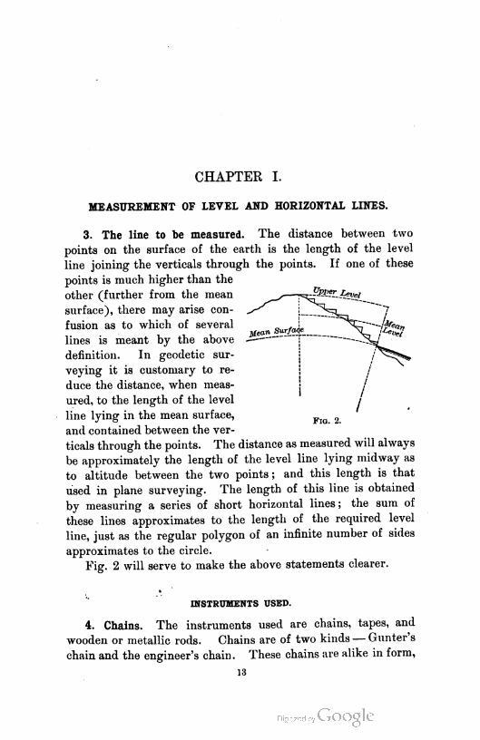
3. The line to be measured. The distance between two
points on the surface of the earth is the length of the level
line joining the verticals through the points. If one of these
points is much higher than the
other (further from the mean ,—**z~&*afyvet
surface), there may arise con
fusion as to which of several
lines is meant by the above
definition. In geodetic sur
veying it is customary to re
duce the distance, when meas
ured, to the length of the level
line lying in the mean surface,
and contained between the ver
ticals through the points. The distance as measured will always
be approximately the length of the level line lying midway as
to altitude between the two points ; and this length is that
used in plane surveying. The length of this line is obtained
by measuring a series of short horizontal lines ; the sum of
these lines approximates to the length of the required level
line, just as the regular polygon of an infinite number of sides
approximates to the circle.
Fig. 2 will serve to make the above statements clearer.
F1g. 2.
INSTRUMENTS USED.
4. Chains. The instruments used are chains, tapes, and
wooden or metallic rods. Chains are of two kinds — Gunter's
chain and the engineer's chain. These chains are alike in form,
13
14 MEASUREMENT OF LEVEL AND HORIZONTAL LINES.
but vary in the length of the links and the length of the entire
chain. In Gunter's chain the links are 7.92 inches long, and
in the engineer's chain they are 12.00 inches, or one foot, long.
With this exception, one description will apply to both.
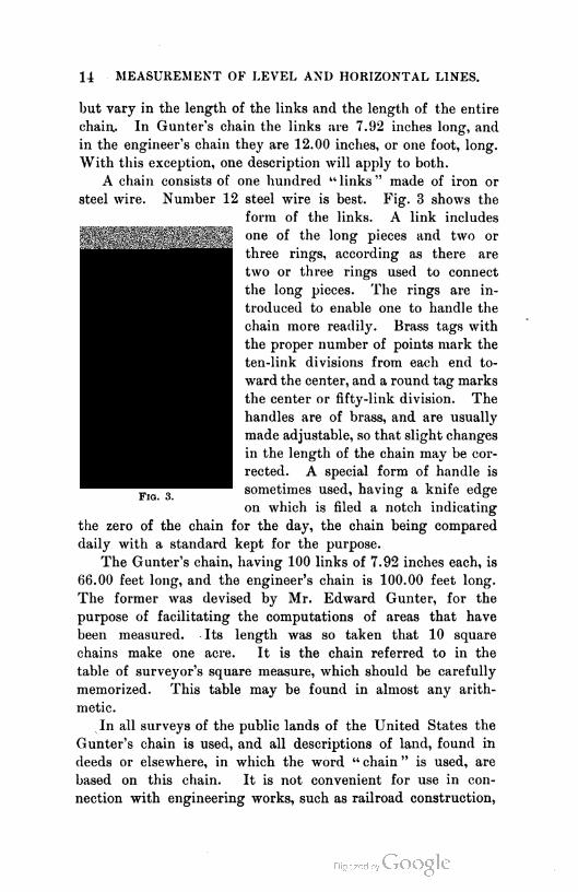
A chain consists of one hundred "links" made of iron or
steel wire. Number 12 steel wire is best. Fig. 3 shows the
form of the links. A link includes
one of the long pieces and two or
three rings, according as there are
two or three rings used to connect
the long pieces. The rings are in
troduced to enable one to handle the
chain more readily. Brass tags with
the proper number of points mark the
ten-link divisions from each end to
ward the center, and a round tag marks
the center or fifty-link division. The
handles are of brass, and are usually
made adjustable, so that slight changes
in the length of the chain may be cor
rected. A special form of handle is
sometimes used, having a knife edge
on which is filed a notch indicating
the zero of the chain for the day, the chain being compared
daily with a standard kept for the purpose.
The Gunter's chain, having 100 links of 7.92 inches each, is
66.00 feet long, and the engineer's chain is 100.00 feet long.
The former was devised by Mr. Edward Gunter, for the
purpose of facilitating the computations of areas that have
been measured. Its length was so taken that 10 square
chains make one acre. It is the chain referred to in the
table of surveyor's square measure, which should be carefully
memorized. This table may be found in almost any arith
metic.
In all surveys of the public lands of the United States the
Gunter's chain is used, and all descriptions of land, found in
deeds or elsewhere, in which the word " chain " is used, are
based on this chain. It is not convenient for use in con
nection with engineering works, such as railroad construction,
INSTRUMENTS USED. 15
canal building, bridge building, etc., where the unit of meas
ure is the foot, and hence in such work the engineer's chain
is used.
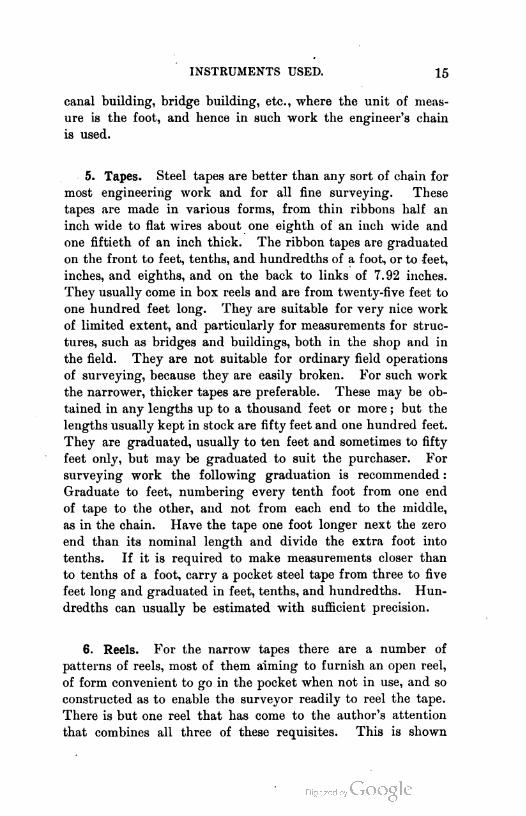
5. Tapes. Steel tapes are better than any sort of chain for
most engineering work and for all fine surveying. These
tapes are made in various forms, from thin ribbons half an
inch wide to flat wires about one eighth of an inch wide and
one fiftieth of an inch thick. The ribbon tapes are graduated
on the front to feet, tenths, and hundredths of a foot, or to feet,
inches, and eighths, and on the back to links of 7.92 inches.
They usually come in box reels and are from twenty-five feet to
one hundred feet long. They are suitable for very nice work
of limited extent, and particularly for measurements for struc
tures, such as bridges and buildings, both in the shop and in
the field. They are not suitable for ordinary field operations
of surveying, because they are easily broken. For such work
the narrower, thicker tapes are preferable. These may be ob
tained in any lengths up to a thousand feet or more ; but the
lengths usually kept in stock are fifty feet and one hundred feet.
They are graduated, usually to ten feet and sometimes to fifty
feet only, but may be graduated to suit the purchaser. For
surveying work the following graduation is recommended :
Graduate to feet, numbering every tenth foot from one end
of tape to the other, and not from each end to the middle,
as in the chain. Have the tape one foot longer next the zero
end than its nominal length and divide the extra foot into
tenths. If it is required to make measurements closer than
to tenths of a foot, carry a pocket steel tape from three to five
feet long and graduated in feet, tenths, and hundredths. Hun
dredths can usually be estimated with sufficient precision.
6. Reels. For the narrow tapes there are a number of
patterns of reels, most of them aiming to furnish an open reel,
of form convenient to go in the pocket when not in use, and so
constructed as to enable the surveyor readily to reel the tape.
There is but one reel that has come to the author's attention
that combines all three of these requisites. This is shown

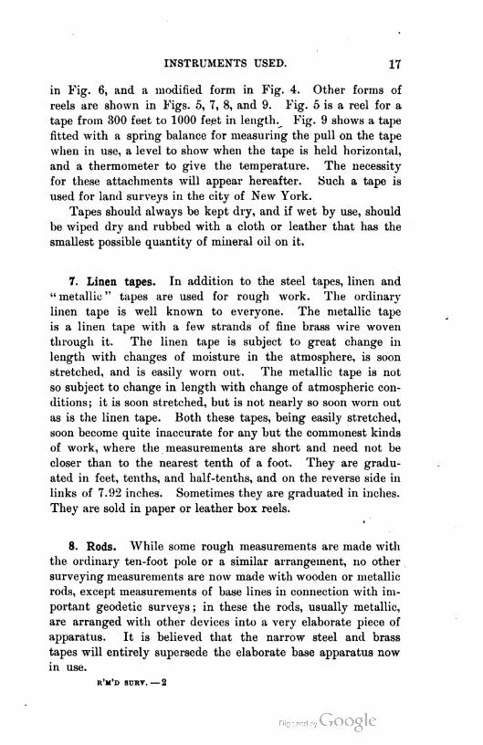
INSTRUMENTS USED. 17
in Fig. 6, and a modified form in Fig. 4. Other forms of
reels are shown in Figs. 5, 7, 8, and 9. Fig. 5 is a reel for a
tape from 300 feet to 1000 feet in lengthy Fig. 9 shows a tape
fitted with a spring balance for measuring the pull on the tape
when in use, a level to show when the tape is held horizontal,
and a thermometer to give the temperature. The necessity
for these attachments will appear hereafter. Such a tape is
used for land surveys in the city of New York.
Tapes should always be kept dry, and if wet by use, should
be wiped dry and rubbed with a cloth or leather that has the
smallest possible quantity of mineral oil on it.
7. Linen tapes. In addition to the steel tapes, linen and
" metallic " tapes are used for rough work. The ordinary
linen tape is well known to everyone. The metallic tape
is a linen tape with a few strands of fine brass wire woven
through it. The linen tape is subject to great change in
length with changes of moisture in the atmosphere, is soon
stretched, and is easily worn out. The metallic tape is not
so subject to change in length with change of atmospheric con
ditions; it is soon stretched, but is not nearly so soon worn out
as is the linen tape. Both these tapes, being easily stretched,
soon become quite inaccurate for any but the commonest kinds
of work, where the measurements are short and need not be
closer than to the nearest tenth of a foot. They are gradu
ated in feet, tenths, and half-tenths, and on the reverse side in
links of 7.92 inches. Sometimes they are graduated in inches.
They are sold in paper or leather box reels.
1
8. Rods. While some rough measurements are made with
the ordinary ten-foot pole or a similar arrangement, no other
surveying measurements are now made with wooden or metallic
rods, except measurements of base lines in connection with im
portant geodetic surveys ; in these the rods, usually metallic,
are arranged with other devices into a very elaborate piece of
apparatus. It is believed that the narrow steel and brass
tapes will entirely supersede the elaborate base apparatus now
in use.
r'm'd surv. — 2
18 MEASUREMENT OF LEVEL AND HORIZONTAL LINES.
9. Pins. These are used with the chain for the purpose of
marking chain lengths. They are about fourteen inches long,
made of steel or iron wire somewhat less than a quarter of an inch
thick (No. 4 to No. 6 wire gauge) with a ring at one end into
which is fastened a strip of cloth to insure ready finding of
the pin when stuck in tall grass or brush. The other end
is pointed. Eleven of these pins constitute a set. They are
usually carried on a ring like a large key ring, or loose in
the hand.
10. Range poles. Poles are used to range out the line to
be measured. They are usually of wood, round or hexagonal,
six to eight feet long, tapering from the bottom to the top,
shod with a pointed iron shoe, and painted red and white in
alternate strips one foot long. Gas pipe is sometimes used,
but is not recommended, because, while it does not break, and
while from its weight such a pole is easily balanced on its
point, it is also very easily bent, and very difficult to straighten,
and is too heavy to be handled with ease. A good pole for nice
work in cities or on railway surveys is made of hexagonal steel
about three eighths to five eighths of an inch thick, painted
like the wooden poles, and pointed at one end.
METHODS.
11. Preliminary statement. The accurate measurement of
a line on a comparatively level piece of ground is a task diffi
cult for a beginner and not simple for an expert chainman,
however easy it may seem. The method of doing this work
on ordinary farm surveys, where the smallest unit of measure
is the link (7.92 inches), and where an error of one in three
hundred to one in five hundred may be tolerated, will be
described ; and the errors incident to this method with the
necessary corrections, as well as the more precise methods
applied to city work, will then be discussed.
12. Chaining. It will be noticed when the chain is received
from the maker that it is so folded together as to be compact
in the center of the bundle and somewhat bulky at the ends, in
METHODS. 19
shape not unlike an hour glass. This results from doing up
the chain as follows : Take the two links at the center of the
chain in the left hand, with the fifty-link tag on the left. Take
the right hand ends of the pair of links next but one to those
in the left hand, in the right hand, and lay the right hand pair
and the intermediate pair in the left hand diagonally across the
pair already there. In like manner proceed to the ends of the
chain, being careful always to place the new links diagonally
across the links already in the left hand and always diagonally
the same way. It is better, however, to do up the chain from
one end instead of from the middle. The method is the same
except that the two end links are first taken in the left hand,
the handle end to the right. A little more time is required,
but the chain is more readily loosened for service.
It will be assumed that the ground on which the line is to
be measured is comparatively level, and that the ends of the
line are visible, one from the other. If there is no visible
object to mark the further end of the line, a range pole is
placed there, toward which the measurement is to be made.
If the rear end of the line is also marked, the head chainman
will be able, without difficulty, to put himself in approximate
line, thus saving time. The strap with which the chain is
fastened is removed, and, if the chain has been done up from
the middle, the two handles are taken in the left hand of the
forward chainman and the chain bundle in the right hand,
allowing a few links next the handles to fall off. The chain
bundle is then thrown out in a direction opposite to that in
which the measurement is to be made, the chainman retaining
the handles in his left hand. The chain should be thrown
with sufficient force to straighten it out. The forward man,
usually called the "head chainman," then takes the forward
end of the chain and the pins, and starts toward the further
end of the line, while the rear chainman allows the chain to
slip through his hands to see that it is not kinked or bent. If
he finds any bends he straightens them. If the chain has been
done up from one end, it should be laid down near the starting
point with one handle uppermost, the latter to be taken by the
head chainman, who moves off toward the further end of the
line. The rear chainman allows the chain to slip through his
20 MEASUREMENT OF LEVEL AND HORIZONTAL LINES.
hands as before. The chain gets enough rough service that
can not be avoided, without subjecting it to the additional un
necessary wear arising from throwing it out forcibly, to be
kinked or caught in the brush or other obstruction.
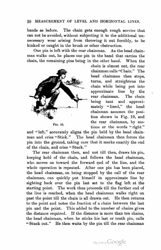
One pin is left with the rear chainman. As the head chain-
man walks out, he places one pin in the hand that carries the
chain, the remaining pins being in the other hand. When the
and "left," accurately aligns the pin held by the head chain-
man and cries "Stick." The head chainman then forces the
pin into the ground, taking care that it marks exactly the end
of the chain, and cries " Stuck."
The- rear chainman then, and not till then, draws his pin,
keeping hold of the chain, and follows the head chainman,
who moves on toward the forward end of the line, and the
whole operation is repeated. After one pin has been placed,
the head chainman, on being stopped by the call of the rear
chainman, can quickly put himself in approximate line by
sighting back over the pin last set to the flag left at the
starting point. The work thus proceeds till the further end of
the line is reached, when the head chainman walks right on
past the point till the chain is all drawn out. He then returns
to the point and notes the fraction of a chain between the last
pin and the point. This added to the number of chains gives
the distance required. If the distance is more than ten chains,
the head chainman, when he sticks his last or tenth pin, calls
" Stuck out." He then waits by the pin till the rear chainman
Fig. 10.
chain is almost out, the rear
chainman calls "Chain." The
head chainman then stops,
turns, and straightens the
chain while being put into
approximate line by the
rear chainman. The chain
being taut and approxi
mately " lined," the head
chainman assumes the posi
tion shown in Fig. 10, and
the rear chainman, by mo
tions or the words " right "

METHODS. 21
comes up with the pins he has collected, which should, with
the pin he started with, be ten. He counts them, as does the
head chainman, as a check, and they note one " tally." At any
time the number of tallies plus the number of pins in the rear
chainman's hands gives, in tens of chains and chains, the
distance that has been measured.
13. Hints. The following hints may be of service to be
ginners :
The rear chainman should not use the pin to brace himself.
He should hold the outside edge of the handle flush with
the rear side of the pin, without moving the pin.
He should not stop the head chainman with a jerk.
He should not sit down on the ground while holding the pin.
Motions and words should be sharp and distinct.
Motions and instructions should be proportionate to the dis
tance that the pin is to be moved ; for example, the arms should
not be swung wildly when the pin is to be moved an inch.
The head chainman should see that the rear chainman is
looking when he tries to straighten the chain.
The chain should not be jerked in straightening it ; it
should be straightened by an undulatory motion.
In straining the chain, the head chainman should pull
steadily.
Attention to these matters will greatly facilitate the work.
14. Chaining on slopes. In chaining up or down hill, one
end of the chain is raised till both ends are as nearly as
possible in a horizontal line.
If the slope is so steep that one end of a full chain cannot be
raised enough to bring both ends in a horizontal line, the chain
is " broken," that is, the distance is measured by using a part
of the chain at each measurement. To do this, the chain should
be carried out as if a full chain were to be used, the head chain-
man returning to such a point on the chain (preferably a ten-
link point) that the portion of chain between himself and the
rear chainman may be properly leveled. A measurement is
made with this portion, then with the next succeeding portion,
and so on till the whole chain has been used. Care must be

22 MEASUREMENT OF LEVEL AND HORIZONTAL LINES.
taken not to get the pin numbering confused. The rear chain-
man should have but one pin for the whole chain.
The high end of the chain is transferred to the ground in
one of several ways, according to the precision desired. If the
work is to be done with care, a plumb line is used. If an error
of a tenth of a link in each chain is not important, a pin may be
dropped from the high end, and stuck in the ground where it is
seen to fall. The pin should be dropped ring down. A small
pebble will serve the purpose for rough work. In careful work
the plumb bob should not be dropped and the pin placed in the
hole made ; but it should be noticed where the bob will drop,
and the ground should be made smooth with the foot, and the
bob swung down till it is still and just clearing the ground ;
then it should be carefully lowered till it touches. The chain-
man should then lower his grasp on the string, hand over hand,
keeping the bob steadily in its place, and place a pin in the
ground at the point of the bob. The pin should be put in the
ground in an inclined position across the line, so that the point
where it enters the ground is that covered by the bob. The
position should then be checked. In place of a pin a small
wire brad may be used and left in the ground.
In chaining up hill, the rear chainman must hold the bob
directly over the pin which has been set in an inclined position,
and must at the same time align the head chainman and see
that he sticks at a moment when the bob is directly over the
point. It will be at once inferred that it is easier to measure
down hill correctly than up hill. Therefore, where close work
is required on inclined ground, the measurements should always,
if possible, be made down hill.
ERRORS 'NVOLVED.
15. Classes. The errors involved in the method of chaining
just described, whether the work is done with a chain or a tape,
are of two classes : (a) constant or cumulative errors, and (6)
accidental or compensating errors.
(a) Cumulative errors are such as occur each time in the
same direction. They are not necessarily equal, but may be so.
Thus a line so long as to require that a chain one inch too short
shall be applied to it ten times, will be recorded ten inches too
ERRORS INVOLVED. 23
long, the error of the chain being added each time the chain is
applied. In this case the errors are equal.
(J) Compensating errors are such as tend to balance ; that
is, they are as likely to be in one direction as in another. Thus
the error that may be made in setting the pin, if it is attempted
to set it just right, will be a compensating error, for it will be
set ahead of the true point about as often as it will be set behind
it. Error in plumbing is of the same character.
16. Causes. Cumulative errors arise from five causes :
(a) erroneous length of chain, (6) errors in judgment in mak
ing the chain horizontal in chaining up or down hill, (c) erro
neous alignment of the chain, (d) failure to straighten the
chain for each measurement, (e) sag of the chain when not
supported throughout its length.
Compensating errors arise from accidental inaccuracies in
setting the pin, and from irregularities in the pull exerted on the
chain or tape. They are remedied by care, and, in fine work,
by measuring the pull on the tape by a spring balance.
Erroneous length of chain may arise from any one of six
causes.
(1) One or more links may be bent, making the chain too
short. The remedy is to see that the links are straight or to
use a tape.
(2) Mud or grass may get in the links and rings with the
same effect. The remedy is obvious.
(3) A bent link that has been straightened has been per
manently lengthened, thus making the chain too long. The
remedy is to compare the chain or tape frequently with a
standard tape kept for this purpose. If the chain is found to be
slightly too long, it may be adjusted by the nuts at the handle,
or if such a handle as is described in Art. 4 is used, the stand
ard length of the chain for the day may be marked on the handle.
(4) The links and rings wear, thus making the chain too
long. While the wear is slight, it may be adjusted at the
handle. When it becomes excessive, it must be known and
allowed for as hereafter described.
(5) The chain may be lengthened by too hard pulling, but
this does not often occur. The remedy is the same as in (3).
24 MEASUREMENT OF LEVEL AND HORIZONTAL LINES.
(6) The chain may be too long or too short according as
the temperature is higher or lower than that for which the
chain is standard. The remedy is to know the temperature at
which the chain is standard and that at which the work is
done and make the necessary correction to the recorded
measurements.
In general it may be said that erroneous length of chain
may be corrected by adjusting the handles, or by comparing
the tape or chain with a standard and correcting the records
taken according to the errors found. It should be carefully
noted that, in measuring the distance between two points, a
long chain gives the distance too short and a short chain
gives the distance too long, while in laying out a line of
given length the errors are just reversed. Failure to appre
ciate this difference often causes confusion and error, and
hence the student should thoroughly fix it in mind. Since
similar figures are in area as the squares of their homologous
sides, the erroneous area of a field determined from measure
ments with an erroneous chain, will be to the true area as the
square of the nominal length of the chain is to the square of its
true length.
17. Temperature. The coefficient of expansion of steel is
about 0.0000065. (Tapes and chains being alike subject to this
error, this discussion will do for both.) A tape or chain will
expand or contract sixty-five ten-millionths of its length for
each Fahrenheit degree change of temperature. Thus a line
about ten chains long, if measured in the summer with the
chain at a temperature of, say, 80° F., the chain being stand
ard at a temperature of 62° F., will be recorded 0.117 links
too short ; while the same line measured with the same chain
in midwinter with the chain at a temperature of 0° F., will be
recorded 0.403 links too long, making a total difference of 0.52
links between the two measurements. This is an error of one
in two thousand for the extreme difference in temperature of
80° F.
It is thus seen that for all ordinary work the tempera
ture correction may be neglected ; but in city work where an
inch in frontage may be worth several thousand dollars, it is
ERRORS INVOLVED. 25
very necessary that the temperature be determined and the
standard temperature of the tape known. The tape shown in
Fig. 9 is adjustable for the effect of temperature. A scale
numbered to correspond to the thermometer readings indicates
the proper setting of the adjusting screw. The spring balance
insures a constant pull.
18. Sag. The effect of sag in shortening a tape that is un
supported except at the ends is given by the following formula
in which I is the unsupported length of the tape, w the weight
of a unit of length, and P the pull in pounds.
This formula the student will have to accept until he has
studied the elements of Mechanics and Calculus. It assumes
that the tape is supported only at the ends, and that it is stand
ard for no pull when supported its entire length. If the tape
is standard for a pull of PQ pounds, substitute in the formula
for P the difference P — P0.
If the tape is applied n times in measuring a line and each
time is supported only at the ends, and the pull is always the
same, the correction for the whole line is n times the above
expression.
The formula gives the difference between the length of the
curve of the unsupported tape and its chord. The real dis
tance measured is the chord, while the distance read is the
length of the curve or of the whole tape. It is evident, there
fore, that the distance is read too long, and hence the formula
is a negative correction.
19. Pull. If the chain were of constant cross section as is
a tape, the amount that the chain would stretch for a pull of
P pounds would be given by the following formula in which
I is the length of the chain in inches, S is the area of its cross
section in square inches, and E is the modulus of elasticity of
the metal of which it is made :
= PI
1 This formula has been developed by Prof. J. B. Johnson.
26 MEASUREMENT OF LEVEL AND HORIZONTAL LINES.
E for steel is variable, but may be taken at 28,000,000.
There is no such thing as a perfectly elastic material. If there
were, the amount that a given length of the material would be
stretched by varying pulls would be proportional to the pulls,
and supposing the piece to be of unit cross section, as one square
inch, the pull that would stretch it by its own length is known
as E, the modulus of elasticity. For any other than a unit cross
section the stretch for a given pull will be inversely propor
tional to the cross-sectional area. Hence the formula. The
lengthening effect of a given pull on a tape would be as in
the formula. In the case of a chain, the effect would be some
what greater, owing to the elongation of the rings.
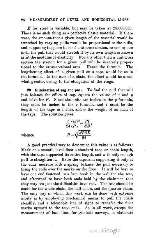
20. Elimination of sag and pull. To find the pull that will
just balance the effect of sag, equate the values of x and y
and solve for P. Since the units are inches in the y formula,
they must be inches in the x formula, and I must be the
length of the tape in inches, and w the weight of an inch of
the tape. The solution gives
A good practical way to determine this value is as follows :
Mark on a smooth level floor a standard tape or chain length,
with the tape supported its entire length, and with only enough
pull to straighten it. Raise the tape, and supporting it only at
the ends, measure with a spring balance the pull necessary to
bring the ends over the marks on the floor. It will be best to
have one end fastened in a firm hook in the wall for the test,
and afterward to have both ends held by the chainmen, that
they may see just the difficulties involved. The test should be
made for the whole chain, the half chain, and the quarter chain.
The only way in which this work can be done with extreme
nicety is by employing mechanical means to pull the chain
steadily, and a telescopic line of sight to transfer the floor
marks upward to the tape ends. As in all work, except the
measurement of base lines for geodetic surveys, or elaborate
I (wW= PI ,
24 VP/ ~ SE'
whence
ERRORS INVOLVED. 27
triangulation surveys of cities, the chain or tape is to be held
in the hands of the chainmen, it will be unnecessary, except for
comparisons, to resort to the nicer methods. Experiments of
the kind noted above will demonstrate that the whole chain
should never be used unsupported, and that the tape is by far
the most satisfactory measuring instrument. In rough work,
where a precision of one in five hundred, or even one in five
thousand, as a maximum limit, is sufficient, the chain may be
used. In close work requiring a precision of one in five
thousand and upward, the tape should invariably be used.
21. Alignment. Errors due to inaccuracy of alignment of
the chain are usually not great. In ordinary work no great
pains need be taken to align the chain within an inch or two,
except where stakes are to be driven on the line. In close
work, of course, the chain should be correctly aligned.1
22. Slope. In chaining on slopes, errors of judgment in
making the chain horizontal are eliminated by the use of a
level tube fastened to one end of the chain, which tube, if
properly adjusted, will indicate when the chain is horizontal.
This is rarely used with a chain, but frequently with a tape.
Much can be done without such a level by having a third man
stand on one side of the chain and compare the parallelism of
the chain and the horizon, or the horizontal lines of some
building. If there is no horizontal line visible, he can still
judge better from the side as to the horizontality of the tape,
than can the chainmen at the ends. It is almost always true
that the lower end of the chain is not raised high enough,
because a horizontal line on a hillside extending in the direction
of the slope, always appears to dip into the hill. Hand levels
(see Art. 52) carried by the chainmen are of great service in
hilly country. The effect of neglecting the slope entirely,
which is also the correction to be applied if the line has been
measured on the slope instead of in horizontal lines, is given
in Appendix, Table I., page 361.
1 Let the student compute the error arising in a ten-chain line from placing the
end of the chain first six inches on one side of the line and then six inches on the
other side, throughout the measurement.

28 MEASUREMENT OF LEVEL AND HORIZONTAL LINES.
It will be seen that the error caused by neglecting a slope
of five in one hundred is about one in one thousand, while a
slope of ten in one hundred, which is not unusual in hilly
country, causes an error of one in two hundred. Fifty feet
in one hundred is about the steepest slope met with in nature,
aside from rock cliffs, and the error here is more than one in ten.
On a slope where close work is required, it is considered
best to measure along tbe slope, keeping the tape or chain sup
ported throughout its entire length, and making the necessary
reductions when the line has been measured. The reduction
can be made exactly by the use of a table of versed sines if the
angle of slope is known. It may be approximately obtained
from Table I., page 361, by interpolating for the small angles,
or it may also be approximately obtained by the use of the fol
lowing formula when the rise in a tape length or in the entire
line, if it is of uniform slope, is known :
The square of the rise divided by twice the known side, be it
base or hypotenuse, gives the difference between the base and
hypotenuse.
Demonstration : Let B be the base, H the hypotenuse, and
R the rise ; C being the difference between B and H. Then
B = H -- C and H= B + C. Assuming H known, there is
written
H2 - (ff- C)2 = B?;
whence C = ^ ~*'— 0
-A M
Neglecting C2 as a very small quantity, there results
Similarly if B is known, there may be written
+ Gy-B2=R?,
IB
and as before, neglecting C2, there results
B?C =
2B
Hence the rule already given
ERRORS INVOLVED. 29
23. Precision to be obtained. In measuring lines the degree
of precision obtainable should be known by the surveyor. The
author suggests the degrees of precision mentioned below as
those that should be attained ordinarily before the surveyor
can say he is doing good work. The figures given do not
refer to the absolute lengths of the lines, involving a knowl
edge of the absolute length of the chain or tape, but merely to
the probable error of the mean of two measurements of the
same line made with the same tape under different conditions.
Not all conditions of work are covered ; but only such as
usually exist. The surveyor will be able to judge as to how
closely the conditions under which he is working at any time
correspond to those given.
In good, fairly level ground, good work will be represented
by differences between two measurements of one in twenty-five
hundred, and excellent work by differences of one in five thou
sand, assuming the work to be done with a chain. These
differences give the probable error of the mean value as one in
seventy-five hundred and one in fifteen thousand, and the prob
able error of a single determination rather better than j-qq-q and
®n hilty ground, rough and covered with brush, one
in one thousand might be considered good and one in five
hundred passable, where the land is not of great value. These
differences give the probable errors of mean and single meas
urement as t0 Tiroo and 2i5W t0 TiroiT respectively. It
should be remembered that the value of the land measured, or
the object of the survey, is a better basis for judgment as to
passable work than the conditions under which the work is
done.
In work in large cities the author thinks that a precision of
one in fifty thousand should be obtained. That is, it is thought
that the probable error of the mean of two measurements should
not be greater than one in fifty thousand. This will require
that the same line measured under totally different conditions
as to weather should be recorded, after the necessary correc
tions for pull, grade, and temperature have been made, both
times alike, within about one in seventeen thousand, or, in
round numbers, three tenths of a foot in a mile.
When but two observations of a quantity have been taken,
30 MEASUREMENT OF LEVEL AND HORIZONTAL LINES.
the probable error of the mean is ^ D, where D is the differ
ence of values determined. The probable error of either of
the observations is 0.47 D or, roughly, £ D. (See any treatise
on Least Squares.) This supposes that all cumulative errors
and mistakes have been eliminated by correction and that only
accidental errors remain.
The following are the requirements for securing a precision
of one in five thousand and one in fifty thousand. For inter
mediate standards, the requirements will lie between those
mentioned :
For a precision of one in five thousand, using a tape, no cor
rections for sag, grade, pull, or small changes of temperature
need be made. The tape may be stretched by hand, the pull
and horizontality being estimated by the tapemen. The plumb
line will be used on uneven ground as in close chaining. The
temperature of the air may be compared with that for which
the tape is standard, and a corresponding correction deduced.
For a precision of one in fifty thousand, the temperature of
the tape should be known within a degree or two Fahrenheit ;
the slope should be determined by measuring over stakes whose
elevations have been determined by a level, or by measuring
on ground whose slope is known. The pull should be known
to the nearest pound, and hence should be measured with
spring balances. If the tape is held on stakes, the sag cor
rection must be considered. The work may be done in any
ordinary weather, but is best done on cloudy days, so that the
temperature of the tape may be more constant. In sunny
weather the mercurial thermometers attached to the tape may
indicate a very different temperature from that of the tape. If
the absolute length of the tape is not known, of course the
absolute length of the line is not determined.
CHAPTER II.
VERNIER AND LEVEL BUBBLE.
24. Before proceeding with a description of surveying in
struments, it is necessary to describe two important attach
ments common to almost all such instruments. These are the
vernier and the level bubble.
VERNIER.
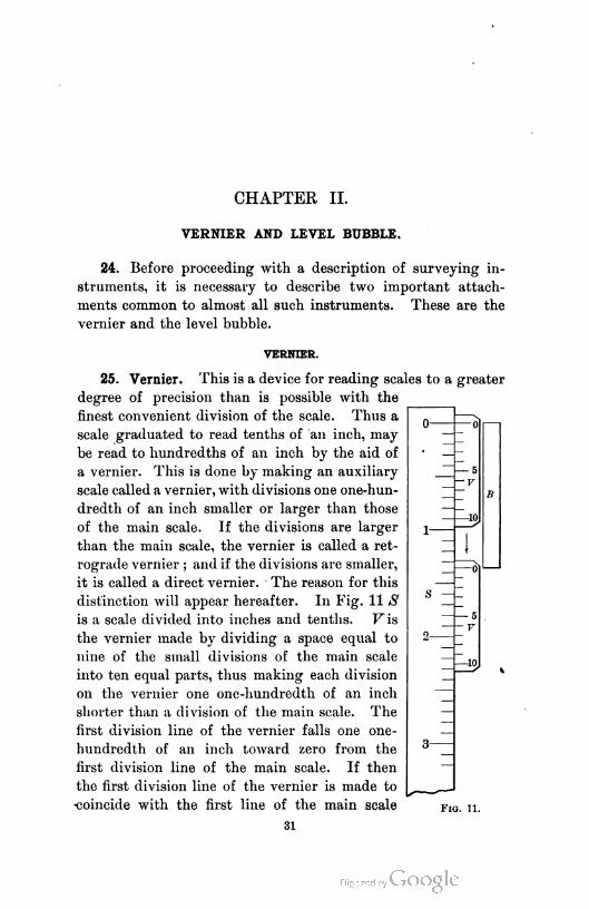
25. Vernier. This is a device for reading scales to a greater
degree of precision than is possible with the
finest convenient division of the scale. Thus a
scale graduated to read tenths of an inch, may
be read to hundredths of an inch by the aid of
a vernier. This is done by making an auxiliary
scale called a vernier, with divisions one one-hun
dredth of an inch smaller or larger than those
of the main scale. If the divisions are larger
than the main scale, the vernier is called a ret
rograde vernier ; and if the divisions are smaller,
it is called a direct vernier. The reason for this
distinction will appear hereafter. In Fig. 11 S
is a scale divided into inches and tenths. Fois
the vernier made by dividing a space equal to
nine of the small divisions of the main scale
into ten equal parts, thus making each division
on the vernier one one-hundredth of an inch
shorter than a division of the main scale. The
first division line of the vernier falls one one-
hundredth of an inch toward zero from the
first division line of the main scale. If then
the first division line of the vernier is made to
-coincide with the first line of the main scale F1g. n.
31
3:> VERNIER AND LEVEL HUBBLE.
the vernier will have been moved one one-hundredth of
an inch. Similarly the second division of the vernier is two
one-hundredths of an inch toward zero from the second line
of the main scale, and hence if the vender is moved along
till the second line of the vernier coincides with the second
division of the scale, the movement has been two one-hun
dredths of an inch, and so on. If the vernier is moved till the
zero is opposite some other division of the .scale than the zero
division, the first line of the vernier will be one one-hundredth
short of the line of the main scale next ahead of the zero of
the vernier ; the second line of the vernier will be two one-
hundredths short of the second line of the main scale, and so
on. If the vernier is moved along a little further till, say, the
fourth line of the vernier has been brought into coincidence
with the fourth line of the main scale ahead, the vernier has
been moved a further distance of four one-hundredths of an
inch. Hence to tell how far the zero of the vernier has moved
from the zero of the main scale, note the inches and tenths on
the scale from zero to the zero of the vernier, and get the frac
tional tenth expressed in hundredths by looking along the ver
nier and finding the division that coincides with a division of
the main scale. This vernier is called direct, because in read
ing it one looks forward along the vernier in the direction in
which the vernier has moved.
Let it be recpiired to read the length of the bar B. Place
one end of it opposite the zero of the main scale and vernier.
It will be noticed that the other end is opposite a point on
the main scale between one and three tenths inches, and one
and four tenths inches. Move the vernier till the zero is
opposite this end of the bar. To read the length of the bar,
read on the main scale one and three tenths inches and look
along the vernier and find that the sixth division coincides
with a division of the scale and that therefore the length of the
bar is one and thirty-six one-hundredths inches. It will be
observed that the divisions of the vernier are one tenth of one
tenth of an inch smaller than the divisions of the scale. That is,
the value of the smallest division on the main scale divided by
the number of divisions of the vernier gives the smallest reading
that may be had with the vernier. This is called the least count.
VERNIER. 33
t
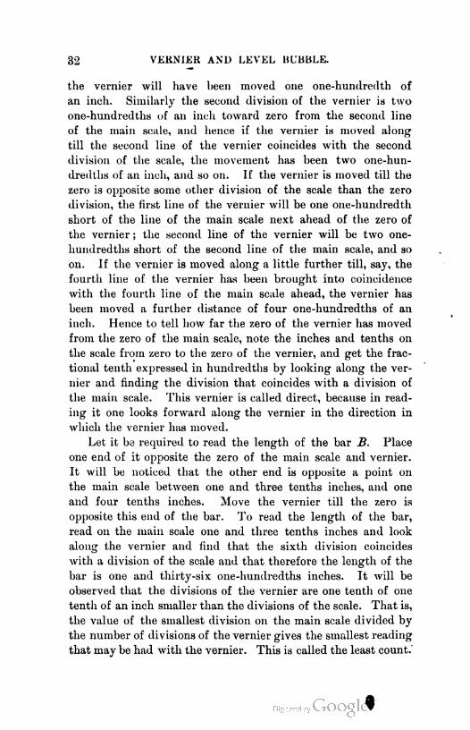
In the retrograde vernier a space equal to a given number
of divisions of the main scale is divided into a number one less
on the vernier. Thus for a vernier reading to hundredths of
an inch with a scale graduated to tenths, eleven divisions of
the scale will be divided on the vernier into ten
spaces, making each division one tenth of one
tenth of an inch longer than those of the scale.
The vernier is therefore placed as shown in Fig.
12, back of the zero of the scale instead of ahead
of it, as in the direct vernier. " Back " and
" ahead " are used with reference to the direction
in which measurements are to be made. From
the portion of the scale extended above the zero
in the figure, it will be seen that the first line of
the vernier is back of the first line of the scale by
one one-hundredth of an inch, the second line by
two one-hundredths, and so on. The principle
of operation is the same as in the direct vernier,
except that one must look backward along the
vernier to find the coinciding line.
A vernier to read angles is generally used when
the angles are to be read to the nearest minute or
less. The principle of construction is the same
as for linear verniers. A vernier to read minutes
will usually occur with a circle graduated to read
t half degrees. If a space equal to twenty-nine of
such divisions is divided on a vernier into thirty
equal parts, each division of the vernier will be one thirtieth
of thirty minutes, or one minute, less than a division of the
main scale, and the instrument is said to read to minutes. If
a circle is to be read to the nearest twenty seconds, it is
usually divided into twenty minute spaces, and a vernier must
then have sixty divisions, since
n 3 '
n = 60 divisions.
That is, fifty-nine parts of the scale must be divided on the
vernier into sixty parts, making each part of the vernier one
r'm'd surt. — 3
F1g. 12.

34VERNIER AND LEVEL BUBBLE.
sixtieth of twenty minutes, or one third of a minute, less than
a division of the main scale. Figures 13, 14, and 15 show
three double verni
ers. They are called
double, because there
are really two verni
ers in each figure, one
on each side of the
vernier zero. They are thus arranged so that angles may be
read in either direction, the circle graduations being numbered
both ways for the same purpose. The student should deter
mine whether the first two are direct or retrograde, the least
count of each, and their readings. The third is a peculiar
Fro. 13.
Fig. 14.
pattern found ordinarily only on compasses. It is a double
vernier, direct as to division (though it is sometimes made ret
rograde), and the lower left-hand and upper right-hand por
tions form one vernier. It is used where there is lack of space
to make the ordinary form. To read an angle measured to the
right, read on the scale
to the last division be
fore reaching the zero
of the vernier, follow
to the right along the
vernier, noting the
lower line of figures for a coinciding line, and if none is found,
pass to the extreme left end of the vernier and look along
toward the right, noting the upper line of figures till a coin
ciding line is found. Thus the reading of the vernier in the
figure is 355° 20', or 4° 40'.
LEVEL BUBBLE. 35
LEVEL BUBBLE.
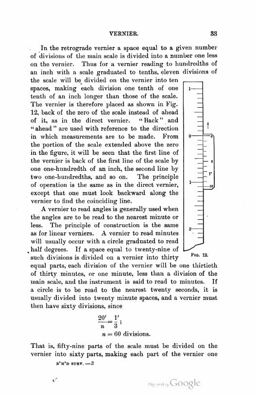
26. Description. The spirit level consists of a glass tube
almost filled with ether, the remaining space being filled with
the vapor of ether. The bubble of vapor will always seek the
highest point in the tube. If the tube were perfectly cylindri
cal, the bubble would occupy the entire length of the tube when
the tube is horizontal, and the same thing would be true if the
tube were but slightly inclined to the horizon, thus making it
impossible to tell when the tube is in a truly horizontal posi
tion. The tube is, therefore, ground on the inside so that a
longitudinal section will show a circular arc. A line tangent
to this circle at its middle point, or a line parallel to this tan
gent, is called the axis of the bubble tube. This axis will be
horizontal when the bubble is in the center of its tube. Should
the axis be slightly inclined to the horizon, the bubble will move
toward the higher end of the tube, and if the tube is ground to
the arc of a circle, the movement of the bubble will be propor
tional to the angle made by the axis with the horizon. There
fore, if the tube is graduated into divisions, being a portion of
the circumference of a very large circle (so large in fact that
the arc of a few seconds is quite an appreciable length), it
will be possible to determine, within the limits of the tube,
the angle that the axis may make at any time with the hori
zon, provided the angular value of one of the divisions of the
tube is known. This is done by simply noting how many
divisions the center of the bubble has moved from the center
of the tube.
It will be evident that divisions of uniform length will cover
arcs of less angular value as the radius of the tube increases,
and also that the bubble with a given bubble space will become
more elongated as the radius is increased. Therefore the bub
ble is said to be sensitive in proportion to the radius of curva
ture of the tube, and this is also indicated by the length of the
bubble. The length of the bubble, however, will change with
change of temperature, becoming longer in cold weather and
shorter in warm weather. In the best class of tubes there is a
partition near one end, with a small hole in it at the bottom, so
that the amount of liquid in the main tube may be regulated,
36 VERNIER AND LEVEL BUBBLE.
thus regulating the size of the bubble. This is necessary,
because independently of the effect of long radius a longer
bubble is more sensitive than a shorter one. A bubble should
settle quickly, but should also move quickly and easily.
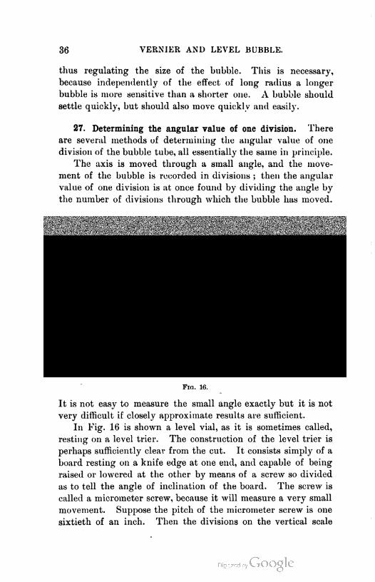
27. Determining the angular value of one division. There
are several methods of determining the angular value of one
division of the bubble tube, all essentially the same in principle.
The axis is moved through a small angle, and the move
ment of the bubble is recorded in divisions ; then the angular
value of one division is at once found by dividing the angle by
the number of divisions through which the bubble has moved.
ilflHHHHHfl
0 ' 2 - -
/ Miiiiiiiiiiiiiiiiiiiiiiiiiiiiiiiiiiiiiiiiiiiiiiiiiiiiiiiaiiiiiiiiiiiiiiiiiniiiiiiii :iiiiiiiiiiiiiiiiiiiiiiiiiiiiiiiiiiiiiiiiii!iiiiiii||iiiiiih wmmm
Fig. 16.
It is not easy to measure the small angle exactly but it is not
very difficult if closely approximate results are sufficient.
In Fig. 16 is shown a level vial, as it is sometimes called,
resting on a level trier. The construction of the level trier is
perhaps sufficiently clear from the cut. It consists simply of a
board resting on a knife edge at one end, and capable of being
raised or lowered at the other by means of a screw so divided
as to tell the angle of inclination of the board. The screw is
called a micrometer screw, because it will measure a very small
movement. Suppose the pitch of the micrometer screw is one
sixtieth of an inch. Then the divisions on the vertical scale
LEVEL BUBBLE 37
attached to the movable board will be one sixtieth of an inch ;
so that a single revolution of the screw will move the scale past
the edge of the screw head by one division. If the circum
ference of the disk head of the screw is divided into one hun
dred parts, and the screw is turned only so much as will cause
one division on the disk to pass the scale, the board has been
moved vertically through one one-hundredth of one sixtieth of
an inch. If now the length of the bar from pivot to screw is
known, the angular movement of the bar may be computed.
Thus, if the length of the bar is eighteen inches, and the bar is
raised so that one division of the scale passes the micrometer
head, and so that in addition ten divisions of the micrometer
head pass the scale, the linear elevation of the end of the bar is
H x To incn = 0-018+ inch.
Since there are 200,265 seconds in an arc equal in length to
radius, there results the proportion, in which x is the angle
in seconds,
x = 0.018+
206265 18
Whence x = 206.265 seconds.
If now a bubble tube were resting on the bar, and the run of
the bubble were observed, for the above movement, to be ten
divisions, the value of one division would be 20.6 seconds.
Example. In the above example it is f-und that the run of the bubble is
one inch. Find the radius of curvature -f the bubble tube.
Other methods of finding the angular value of a division of
the tube will be suggested in the problems on Chapters III.
and IV.
Many of the level vials found on compasses, and on the
lower plates of many other instruments, are not graduated, are
ground to short radii, and not uniformly, and hence are not
fit for accurately leveling the instruments to which they are
attached ; but such bubbles are cheaper than others, and when
placed on a compass or other instrument not intended for high-
class work, they are sufficiently precise for the purpose for
which they are used.

38 VERNIER AND LEVEL BUBBLE.
28. Principles. The proper adjustment of a bubble on an
instrument so that one can determine when the instrument
is level, depends on the following principles :
I. If a frame carrying a bubble tube, and resting on two sup
ports that lie in a level line, is reversed end for end on the sup
ports, the bubble will occupy the same position in the tube for both
positions of the frame.
In Fig. 17 it is seen that the axis of the tube makes the
same angle with the horizon in both positions, and the same
end is higher.
Conversely, if a frame to which a bubble tube is rigidly
attached is reversed on two supports, and the bubble occupies
the same position in its tube
for both positions of the
frame, the supports lie in a
level line, or, as is usually
said, are level. It should
be noted in the above that
the bubble is not necessarily
in the center of the tube,
but merely retains the same position in the tube for the direct
and reversed positions of the frame.
If the axis of the tube in the foregoing cases is parallel to
the line joining the supports, the bubble will lie in the center
of the tube, and if not parallel, the deviation of the bubble
from the center of the tube will be that due to the angle
between the line of support and the axis of the tube. If in the
latter case the bubble is brought to the center of the tube, the
line of supports will make an angle with the horizon (be out of
level) equal to that between the axis of the tube and the line
of supports. If now the frame carrying the level is reversed,
the movement of the bubble will be twice that due to the angle
between the axis and the line of supports.1 If the tube is now
raised at one end, or lowered at the other, till the bubble has
moved halfway back to its former position, the axis of the
tube is made parallel to the line of support. The line of
support may now be made level by raising the lower, or low-
1 Let the student make a diagram showing this.
LEVEL BUBBLE. 39
ering the higher, support till the bubble stands in the center
of its tube.
If two levels are attached to a plate at right angles to each
other and parallel to the plate, the plate will be level when
both bubbles are centered. If the tubes are not parallel to the
plate, it will be difficult to determine when the plate is level, as
the position of each bubble for level plate must be determined
by trial. If the tubes are so fastened to the plate as to permit
of being adjusted, their parallelism may be tested and, if neces
sary, corrected by the method of this article.
II. If a frame carrying a level tube is revolved about a verti
cal axis, the bubble will maintain a constant position in its tube.
For the axis of the tube maintains a constant angle with
the horizon.
Conversely, if a frame carrying a bubble tube is revolved
about an axis, and the bubble remains in one position in the
tube, the axis of revolution is vertical. If the constant posi
tion occupied by the bubble is the center of its tube, the tube is
horizontal, and consequently perpendicular to the axis of revo
lution.
CHAPTER III.
MEASURING DIFFERENCES OF ALTITUDE, OR LEVELING.
29. General principle. It will be evident that if by any
means a line of sight may be made to revolve about a vertical
axis to which it is perpendicular, it will describe a horizontal
plane. Omitting consideration of the curvature of the earth,
a rod graduated from the bottom up, and held at any point on
the ground, will be cut by this horizontal plane at a distance
above the ground equal to the height of the line of sight
above the ground at the point where the rod is held. The dis
tance above the bottom of the rod, as indicated by the gradua
tions on the rod, is called the reading of the rod. If the eleva
tion of the line of sight above some assumed base or datum, as
sea level, is known, the rod reading subtracted from that eleva
tion will give the elevation of the point where the rod is held,
referred to the same base. Conversely, if the elevation of the
point where the rod is held is known, and it is required to find
the elevation of the line of sight, it is done by adding the rod
reading to the elevation of the point. While there are many
details to be considered, such as the curvature of the earth, the
adjustment of instruments, atmospheric conditions, etc., the
above contains the essential principle of leveling.
INSTRUMENTS.
30. General description of level. Any instrument used for
the purpose of securing a horizontal line of sight may be called
a leveling instrument; or, as is more usual, simply a level.
There are three comparatively common forms of levels, shown
in Figs. 18-20.
40

Flu. lft


INSTRUMENTS. 43
Fig. 20 is a precise level, or level of precision. Fig. 18 is
known as a Y level. Fig. 19 is a dumpy level. The most
common of these is the Y level, so called because the telescope
rests in Y-shaped supports. The instrument consists essentially
of a telescopic line of sight and an attached bubble tube, whose
axis may, by adjustment, be made parallel to the line of sight,
so that when the bubble is in the center of its tube it will be
known that the line of sight is horizontal. These are com
bined with a leveling head which contains the vertical axis, and
screws on to a tripod. A sectional view of a Y level is shown
in Fig. 21.
The dumpy level is so called because of its short telescope
with large aperture.
The precise level is simply a modification of the Y level,
so improved as to make it capable of doing work to a greater
degree of precision than can be obtained by the use of either
the Y or the dumpy level. The dumpy level is sufficiently
precise for all work that does not require the precise level,
and it is considerably cheaper than a Y level of the same make.
From the standpoint of the optician, the Y level is the more
perfect instrument, because of its many easy adjustments ; but
this very feature is to some extent an undesirable one from the
standpoint of the engineer, who wants, for all ordinary work,
an instrument with few parts to get out of adjustment. The
dumpy level can not be so easily and exactly adjusted for col-
limation as the Y level, but, as has been before stated, it is
sufficiently precise for all work not requiring a precise level.
It is used almost altogether by English engineers, having been
invented by an Englishman named Gravatt, whence the level is
frequently called the- Gravatt level.
31. Telescope.1 The telescope of the level consists of a bar
rel in which slide two tubes. One of these tubes is the eye
piece tube carrying the eyepiece lenses LLLL, Fig. 21, and
the other is the objective tube carrying the objective, or object
glass 0. The objective tube is moved in and out by means of
a pinion, which works in a rack attached to the sliding tube.
The tube is made to move in the axis of the barrel by having
1 For a discussion of the principles of telescopes see any good book on Physics.
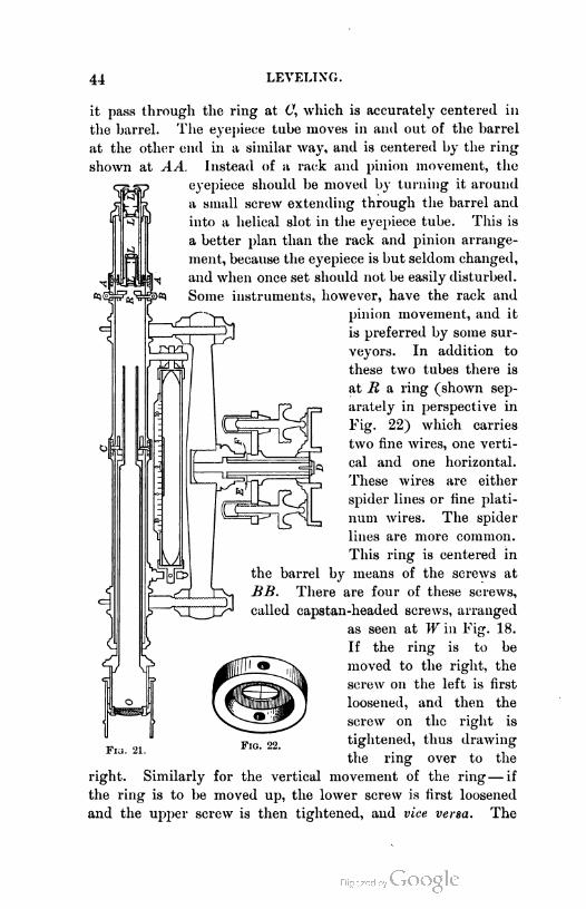
44 LEVELING.
it pass through the ring at C, which is accurately centered in
the barrel. The eyepiece tube moves in and out of the barrel
at the other end in a similar way, and is centered by the ring
shown at AA. Instead of a rack and pinion movement, the
eyepiece should be moved by turning it around
a small screw extending through the barrel and
into a helical slot in the eyepiece tube. This is
a better plan than the rack and pinion arrange
ment, because the eyepiece is but seldom changed,
and when once set should not be easily disturbed.
Some instruments, however, have the rack and
pinion movement, and it
is preferred by some sur
veyors. In addition to
these two tubes there is
at R a ring (shown sep
arately in perspective in
Fig. 22) which carries
two fine wires, one verti
cal and one horizontal.
These wires are either
spider lines or fine plati
num wires. The spider
lines are more common.
This ring is centered in
the barrel by means of the screws at
BB. There are four of these screws,
called capstan-headed screws, arranged
as seen at Win Fig. 18.
If the ring is to be
moved to the right, the
screw on the left is first
loosened, and then the
screw on the right is
tightened, thus drawing
the ring over to the
movement of the ring— if
Fig. 22.
right. Similarly
the ring is to be
for the vertical
moved up, the lower screw is first loosened
and the upper screw is then tightened, and vice versa. The

INSTRUMENTS. 45
difference between this telescope and the ordinary or Galilean
telescope, is in the introduction of these wires and a difference in
eyepiece necessitated by them. In the ordinary telescope, such
as is found in field glasses, there are no wires and it is impossi
ble to say to what particular point in an object looked at the
axis of the telescope is directed. Moreover, it is useless to
put such wires in a field glass, since no image of the object
looked at is formed in the tube of the telescope. With an
angle-measuring instrument, or any instrument that must be
pointed to a definite point, it is indispensable that the exact
point to which the axis of the telescope is directed be known.
It is perhaps inaccurate to say that the direction of the axis
must be known, for any other fixed line in the telescope would
do as well, provided the adjustments hereafter to be described
could be made with that fixed line. It is more convenient to
have the fixed line at least very close to the axis of the tele
scope, for reasons that will appear.
The imaginary line joining the optical center of the object
glass and the intersection of the cross wires is known as the
line of collimation, and this is the line that is directed to the
precise spot toward which it is desired to point the telescope ;
or rather, in the level, it is the line that indicates the point
towards which the telescope is directed.
The area seen at one time through the telescope, or rather
the angle between the rays of light from the extreme edges
of this area, measured at the instrument, is known as the
field of view. This field of view is larger as the magnifying
power of the telescope is smaller, and varies from about one
and one half degrees to about fifty minutes. The former is
for the commoner kinds of surveyor's transits, and the latter
corresponds to a magnifying power of about thirty-five diam
eters, or about what is found in the better leveling instruments.
An image of an object within the field of view is formed at
a point back of the object glass, and the glass is moved in or
out till this image falls in the plane of the wires. This is
called focusing the objective. The point in the image covered
by the intersection of the wires is that toward which the
telescope is directed.
It would be practically impossible to tell when the focusing
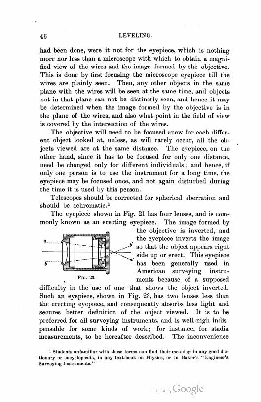
46 LEVELING.
had been done, were it not for the eyepiece, which is nothing
more nor less than a microscope with which to obtain a magni
fied view of the wires and the image formed by the objective.
This is done by first focusing the microscope eyepiece till the
wires are plainly seen. Then, any other objects in the same
plane with the wires will be seen at the same time, and objects
not in that plane can not be distinctly seen, and hence it may
be determined when the image formed by the objective is in
the plane of the wires, and also what point in the field of view
is covered by the intersection of the wires.
The objective will need to be focused anew for each differ
ent object looked at, unless, as will rarely occur, all the ob
jects viewed are at the same distance. The eyepiece, on the
other hand, since it has to be focused for only one distance,
need be changed only for different individuals ; and hence, if
only one person is to use the instrument for a long time, the
eyepiece may be focused once, and not again disturbed during
the time it is used by this person.
Telescopes should be corrected for spherical aberration and
should be achromatic.1
The eyepiece shown in Fig. 21 has four lenses, and is com
monly known as an erecting eyepiece. The image formed by
the objective is inverted, and
the eyepiece inverts the image
so that the object appears right
side up or erect. This eyeliiece
has been generally used in
American surveying instru
ments because of a supposed
that shows the object inverted.
Fig. 23, has two lenses less than
F1g. 23.
difficulty in the use of one
Such an eyepiece, shown in
the erecting eyepiece, and consequently absorbs less light and
secures better definition of the object viewed. It is to be
preferred for all surveying instruments, and is well-nigh indis
pensable for some kinds of work ; for instance, for stadia
measurements, to be hereafter described. The inconvenience
1 Students unfamiliar with these terms can find their meaning in any good dic
tionary or encyclopaedia, in any text-book on Physics, or in Baker's "Engineer's
Surveying Instruments."

INSTRUMENTS. 47
attending the use of a telescope
largely imaginary. A few hour
its use as natural as the use of a
and precise levels are almost
while the Y level, the most
commonly used in . this coun
try, is almost always erect
ing. As has already been
stated, there now seems to be
little reason for the existence
of the Y level.
32. Leveling Rods. There
are three common patterns of
leveling rods and an innum
erable number of uncommon
ones. The three common
patterns are shown in Figs.
24, 25, and 26. Each of
these is made in two pieces
about seven or less feet long.
The New York rod (Fig. 24)
and the Philadelphia rod
(Fig. 25) differ in that the
Philadelphia rod is so gradu
ated as to be easily read at
ordinary distances by the lev-
eler, while with the New York
rod the target must be set and
the reading taken and called
out by the rodman. The tar
get of the New York rod is
provided with a direct vernier,
usually placed below the cen
ter of the target. This causes
some confusion to the begin
ner, who has been taught to
read the scale at the zero of
the vernier and the fractional
that shows objects inverted is
s with an inverting glass makes
,n erecting glass. Dumpy levels
always inverting instruments ;
Fig. 24. Fig. 25. Fig. 26.
reading by looking along tho
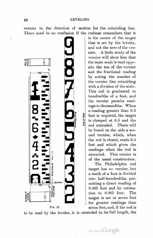
48 LEVELING.
C CO
itI
1
8
G
\
2
vernier in the direction of motion for the coinciding line.
There need be no confusion if the rodman remembers that it
is the center of the target
that is set by the leveler,
and not the zero of the ver
nier. A little study of the
vernier will show him that
the main scale is read oppo
site the ten of the vernier
and the fractional reading
by noting the number of
the vernier line coinciding
with a division of the scale.
This rod is graduated to
hundredths of a foot, and
the vernier permits read
ings to thousandths. When
a reading greater than 6.5
feet is required, the target
is clamped at 6.5 and the
rod extended. There will
be found on the side a sec
ond vernier, which, when
the rod is closed, reads 6.5
feet and which gives the
readings when the rod is
extended. This vernier is
of the usual construction.
The Philadelphia rod
target lias no vernier, but
a tenth of a foot is divided
into half-hundredths, per
mitting a direct reading of
0.005 foot and by estima
tion to 0.001 foot. The
target is set at seven feet
for greater readings than
seven feet, and, if the rod is
to be read by the leveler, it is extended to. its full length, the
Fig. 27.
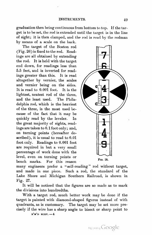
INSTRUMENTS. 411
graduation then being continuous from bottom to top. If the tar
get is to be set, the rod is extended until the target is in the line
of sight; it is then clamped, and the rod is read by the rodman
by means of a scale on the back.
The target of the Boston rod
(Fig. 26) is fixed to the rod. Read
ings are all obtained by extending
the rod. It is held with the target
end down, for readings less than
5.5 feet, and is inverted for read
ings greater than this. It is read
altogether by vernier, the scales
and vernier being on the sides.
It is read to 0.001 foot. It is the
lightest, neatest rod of the three,
and the least used. The Phila
delphia rod, which is the heaviest
of the three, is the most used be
cause of the fact that it may be
quickly read by the leveler. In
the great majority of sights, read
ings are taken to 0. 1 foot only ; and,
on turning points (hereafter de
scribed), it is usual to read to 0.01
foot only. Readings to 0.001 foot
are required in but a very small
percentage of work done with the
level, even on turning points or
bench marks. For this reason
many engineers prefer a " self-reading " rod without target,
and made in one piece. Such a rod, the standard of the
Lake Shore and Michigan Southern Railroad, is shown in
Fig. 27.
It will be noticed that the figures are so made as to mark
the divisions into hundredths.
With a target rod, much better work may be done if the
target is painted with diamond-shaped figures instead of with
quadrants, as is customary. The target may be set more pre
cisely if the wire has a sharp angle to bisect or sharp point to
e'm'd surv. — 4
Fig. 28.
50 LEVELING.
cover, than if it is to be made coincident with the edge of
a dark surface. Professor Baker finds that at 300 feet the
error of setting a quadrant target may be about 0.002 of a foot
or more while that of setting a diamond-shaped target may be
a little over 0.001 of a foot. Such a target is shown in Fig. 28.
USE OF THE LEVEL.
33. Adjustment. The level has been said to be an instru
ment for securing a horizontal line of sight. It will be evident
from the construction of the ordinary leveling instruments that
this may be accomplished with those instruments if the line of
collimation and bubble axis are made parallel ; because, if this
condition exists, and the bubble is brought to the center of the
tube, the line of sight will be horizontal.
This introduces the idea of adjustment, and the adjustment
of the level consists essentially in making the line of collima
tion and the bubble axis parallel. There are other adjustments
for convenience, but this is the only necessary one. The gen
eral discussion of the adjustments will be deferred till the
use of the adjusted level in doing simple leveling has been
explained.
34. Setting up. To "set up" the level is to place it in
position for leveling, including making the line of sight hori
zontal. The level is an instrument that is rarely set "online,"
except in making certain adjustments. It is placed in that
position that will command the greatest possible number of
points whose elevations are to be determined. To set up,
plant the legs firmly in the ground with the leveling plates
approximately horizontal. Focus the eyepiece on the wires.
Bring the telescope and attached level over one set of diagon
ally opposite leveling screws and, by the screws, bring the
bubble to the center of its tube. Perform the same operation
over the other set of screws. This will to some extent disturb
the former work. Therefore turn the telescope again over the
first set of screws and relevel ; again over the second set, etc.,
till the instrument is level over both sets. If the instrument
is in adjustment, the line of sight will now be horizontal in
whatever direction it is pointed.

USE OF THE LEVEL.51
35. Differential leveling. To determine the difference in
elevation between two points, both of which are visible from
a possible position of the level, set up the level in a position
such that a rod held on either point will be visible. Turn the
telescope toward one point and read a rod held there by a rod-
man. The rodman will then carry the rod to the other point,
and the telescope will be directed toward that point and the
rod read. The difference in readings will evidently be the
difference of elevation required. Care must be taken to see
that the bubble is in the center of its tube when each reading
is taken.
If the elevation above some base surface of one of the
points is known, the difference of elevation applied to the
known elevation gives the elevation of the second point. This
operation is capable of further analysis, thus : The rod reading
on the point of known elevation, added to the known eleva
tion, will give the elevation of the line of sight, and is there
fore called a plus sight. The rod reading on the second point
subtracted from the elevation of the line of sight will give
the elevation of the second point. This reading is, there
fore, called a minus sight. From these considerations the fol
lowing definitions are formulated :
A plus sight, or reading, is any reading taken on a point
of known or assumed elevation for the purpose of determining
the elevation of the line of sight.
A minus sight, or reading, is any reading taken for the
purpose of determining the elevation of the point on which
the rod is read.
A very bad custom of calling plus sights, "backsights,"
and minus sights, "foresights," has prevailed in the past.
It has been a source of confusion to the beginner and is
illogical. It probably arose from the fact that the work in
leveling is considered to proceed from the point of known
elevation toward the point of unknown elevation, and that,
therefore, plus sights are taken in a backward direction, and
minus sights in a forward direction. This is not always true,
as will appear later, and hence the nomenclature, " backsight "
and " foresight " is ill-chosen. It is, moreover, true that when
a minus sight is taken in what may be considered a backward
52 LEVELING.
direction, the beginner becomes confused and applies the wrong
sign. Hence the terms should be abandoned.
If consideration of curvature is neglected, the instrument
should be set midway between the two points, in order to do
correct work. It will be apparent that if this is done, the
amount of the curvature of the earth, for half the distance
between the two points will be added in the plus sight, and
subtracted in the minus sight ; that is, each reading will be
too great by the curvature. The amount of this curvature is
about 8 inches in one mile and varies with the square of the
distance. The student may determine the effect on a rod
reading when the rod is held 528 feet from the instrument
and when held 279 feet away. Three hundred feet is about
as great a distance as will permit a definite reading of the rod
with the average level ; though in work requiring no great
exactness, much longer sights may be taken.
If the points whose difference in altitude is required are so
located that rod readings can not be had on both from one posi
tion of the instrument, an intermediate point is chosen that
may be used with the first one, and the readings are taken
on the first and on the intermediate point. The difference
in altitude between the first and intermediate point is thus
obtained. The level is then moved to a position between the
intermediate and final point, and their difference of altitude is
determined. The two differences added or subtracted, as the
case may be, will give the required difference. It may be neces
sary to introduce several intermediate points. The work is sim
ply a succession of operations like those of the first case.
It is unnecessary to determine the differences of altitude of
each set of intermediate points, as the difference between the
sum of all the plus sights and the sum of all the minus sights
will give the difference of altitude of the first and final point.
The student should show this.
The intermediate points that are chosen should, if the work
is to be well done, be firm, definite points, as the projecting
part of a firm rock, the top of a peg firmly driven in the
ground, etc.
When extensive differential leveling operations are to be
carried on, requiring close work (as the careful determination
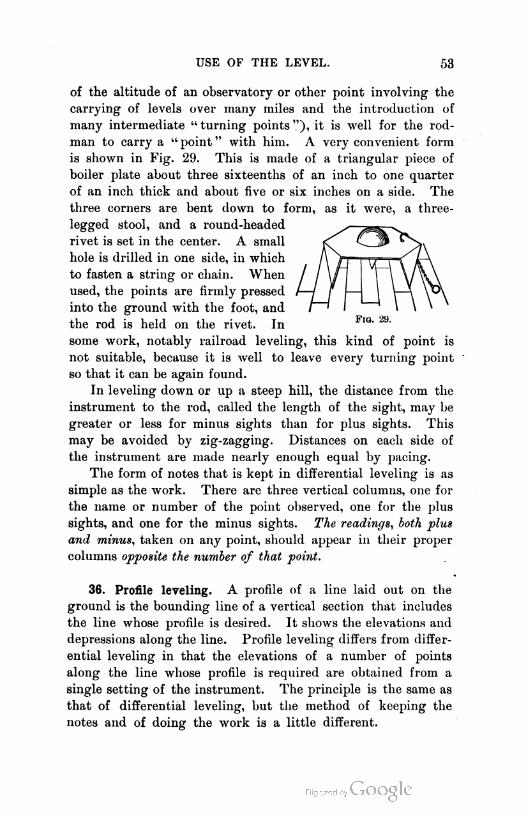
USE OF THE LEVEL. 53
of the altitude of an observatory or other point involving the
carrying of levels over many miles and the introduction of
many intermediate " turning points "), it is well for the rod-
man to carry a " point " with him. A very convenient form
is shown in Fig. 29. This is made of a triangular piece of
boiler plate about three sixteenths of an inch to one quarter
of an inch thick and about five or six inches on a side. The
three corners are bent down to form, as it were, a three-
legged stool, and a round-headed
rivet is set in the center. A small
hole is drilled in one side, in which
to fasten a string or chain. When
used, the points are firmly pressed
into the ground with the foot, and
the rod is held on the rivet. In
some work, notably railroad leveling, this kind of point is
not suitable, because it is well to leave every turning point
so that it can be again found.
In leveling down or up a steep hill, the distance from the
instrument to the rod, called the length of the sight, may be
greater or less for minus sights than for plus sights. This
may be avoided by zig-zagging. Distances on each side of
the instrument are made nearly enough equal by pacing.
The form of notes that is kept in differential leveling is as
simple as the work. There are three vertical columns, one for
the name or number of the point observed, one for the plus
sights, and one for the minus sights. The readings, both plus
and minus, taken on any point, should appear in their proper
columns opposite the number of that point.
36. Profile leveling. A profile of a line laid out on the
ground is the bounding line of a vertical section that includes
the line whose profile is desired. It shows the elevations and
depressions along the line. Profile leveling differs from differ
ential leveling in that the elevations of a number of points
along the line whose profile is required are obtained from a
single setting of the instrument. The principle is the same as
that of differential leveling, but the method of keeping the
notes and of doing the work is a little different.

LEVELING.
The line whose profile is required
Fio. 30.
is first marked out on the
ground by stakes or
other marks placed at
such intervals as may
be necessary. These in
tervals are usually reg
ular, and in railroad
surveys are generally
one hundred feet. In
city streets the interval
may be fifty feet. In
other surveys the inter
val may be less or more,
according to the nature
of the survey. The
object is usually to re
produce to scale on
paper, the profile de
sired. For this purpose
profile paper is gener
ally used, on which the
notes are plotted, as
will be described later.
Fig. 30 shows a
map of a line whose
profile is desired, which
may be assumed to be
the center line of a
road. It also shows in
exaggerated form, and
to no scale, the position
of the level along the
road, both in plan and
elevation.
The process of lev
eling is as follows :
Some convenient
point is chosen as a
" bench mark," either
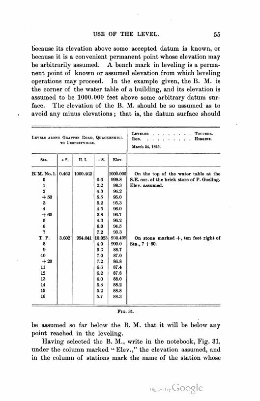
USE OF THE LEVEL. 55
because its elevation above some accepted datum is known, or
because it is a convenient permanent point whose elevation may
be arbitrarily assumed. A bench mark in leveling is a perma
nent point of known or assumed elevation from which leveling
operations may proceed. In the example given, the B. M. is
the corner of the water table of a building, and its elevation is
assumed to be 1000.000 feet above some arbitrary datum sur
face. The elevation of the B. M. should be so assumed as to
avoid any minus elevations ; that is, the datum surface should
Levels along Geafton Road, Quaokenk1l1.
to Ceopseyv1lle.
Sta. + S. II. I. -S. Elev.
B.M. No.l. 0.462 1000.462 1000.000 On the top of the water table at the
0 0.6 999.8 S.E. cor. of the brick store of P. Gosling.
1 2.2 98.3 Elev. assumed.
2 4.3 96.2
+ 60 5.5 95.0
3 5.2 95.3
4 4.5 96.0
+ 60 3.8 96.7
5 4.3 96.2
6 6.0 94.5
7 7.2 93.3
T. P. 3.602- 994.041 10.023 900.439 On stone marked +, ten feet right of
8 4.0 990.0 Sta., 7 + 80.
9 5.3 88.7
10 7.0 87.0
+ 20 7.2 86.8
11 6.6 87.4
12 6.2 87.8
13 6.0 88.0
14 5.8 88.2
15 5.2 88.8
16 5.7 88.3
l.evelee touceda.
Rod H1gg1ns.
March 24, 1895.
F1g. 31.
be assumed so far below the B. M. that it will be below auy
point reached in the leveling.
Having selected the B. M., write in the notebook, Fig. 31,
under the column marked "Elev.," the elevation assumed, and
in the column of stations mark the name of the station whose

56 LEVELING.
elevation is given, in this case B. M. No. 1. On the right-hand
page write a description of the B. M. so clear and full that
another, coming to the place long after, may determine with
certainty the exact spot used.
Set up the level at a point convenient to the B. M. and to
as much of the line as possible, remembering that it is better
to make sights to turning points approximately equal. Hav
ing the level set up, read the rod held on the B. M., and
record the reading in the column marked " +S.," and add it
to the elevation of the B. M. to get the height of the line of
collimation, which record in the column headed " H. I." (height
of instrument). The rod is now held on station 0, and is read,
and the reading is recorded in the column of minus sights, op
posite station 0. It should be noted that it is usually the ele
vation of the ground that is wanted, and not that of the top
of the stake that marks the station. Therefore, the rod is held
on the ground, and not on the stake. The rod is usually read
at station points only to the nearest tenth, as it would be folly
to try to determine the elevation of rough ground to hundredths.
Points used as B. M.'s are usually read to hundredths or thou
sandths. Hundredths are generally close enough.
The rod is now carried to station 1 and read, and the read
ing is recorded in the column headed " — S.," opposite sta
tion 1. The leveler, if he is quick, may make the subtraction
of the minus sight on one station while the rodman is passing
to the next station, and he should practice doing this. He
may check his work at noon or night, or at any other time
when the survey is, for any reason, temporarily stopped. The
rod is now read on station 2, and recorded as before. Between
station 2 and station 3 there is a decided change in slope, and
the rod is held at the point of change, the rodman either meas
uring the distance from station 2 to the point or estimating it
by pacing, according to the importance of exactness in the par
ticular survey. He calls out the " plus " as (in this case) " plus
fifty," and the leveler records the distance as shown in the
notes, and then reads the rod and records the reading opposite
the recorded distance in the — S. column.
It will be noticed that a number of minus sights have been
taken with the instrument pointing backward with reference

USE OF THE LEVEL. 57
to the direction of progress. It is these sights that are some
times confused with " backsights " when the terms " backsight "
and " foresight " are used.
Thus the work proceeds till the rod is about as far beyond
the instrument as it was in the beginning back of it. Not
more than three hundred to five hundred feet on either side of
the instrument should be used, if fairly good work is to be
done. A point is then selected that is tolerably permanent, as a
solid stone or a peg driven into the ground. This point need
not be on the line that is being leveled, and, indeed, should not
be there, if the line is the center of a traveled road.
The rod is held on the peg, which is called a turning point,
or simply "peg," and is read to the same unit as on the B. M.,
and the reading is recorded in the column of — S., opposite the
station T. P. The elevation is then worked out at once, and
the level is carried beyond the peg a convenient distance and
again set up. A reading is then taken on the rod held on the
peg, is recorded in the column +S., and is added to the eleva
tion of the peg to get a new height of instrument, which is
noted in the proper column opposite the station from which it
was determined. A description of the peg is written on the
right-hand page, so that it may be again found, if wanted within
a reasonable length of time. The work then proceeds as be
fore. After an interval of, say, half a mile or a mile, a perma
nent B. M. is established. It may be used as a turning point,
or merely determined as is any station, except that the reading
will be taken to the unit used for B. M.'s. All points that
are likely to be wanted again should be very fully described.
Sketches are valuable helps to words in making descriptions.
There are many hints that could be given to facilitate the
work of leveling ; but they would occupy too much space, and
the beginner will have to learn details from experience. One
point may be mentioned : Never clamp the spindle. It is un
necessary to do this except rh adjusting.
Other forms of notes are sometimes used by engineers.
Some of them have station numbers and elevation in adjacent
columns ; others have a separate column for minus sights on
turning points, and others a separate column for elevations of
turning points, etc.
58 LEVELING.
37. Making the profile. The profile is made by plotting
to scale the elevations of the points, at the proper horizontal
distance apart, and connecting the plotted points by a line.
Profile paper is generally used for this purpose. One form of
ruling for such paper, known as Plate A, is shown in Fig. 32.
There are three common forms, known as Plate A, Plate B,
and Plate C. Plate A has four horizontal divisions and twenty
vertical divisions to an inch. Plate B has four by thirty divi
sions per inch ; and Plate C five by twenty-five divisions.
Profile paper comes in rolls twenty inches wide, or in sheets.
If profile paper is used, a convenient elevation is assumed
for the bottom horizontal line, and a value is assigned to the
space between successive lines. For railroad profiles it is
usual to assume one foot as the value of the smallest inter
val ; the paper is so ruled that the five-feet and twenty-five-
feet, or fifty-feet lines are accentuated. A smaller value
may be assumed for the smallest interval when it is necessary
to work to a large scale and to show minute irregularities.
It is usual, also, in railroad work to assume the value of the
interval between successive vertical lines to be one hundred
feet or "one station." Each tenth station is then accentuated
by the riding. This scale may also be increased, if necessary.
The scales, both horizontal and vertical, having been assumed,
it is only necessary to find the position, horizontally and verti
cally, that will correctly represent any point whose elevation
and distance or station from the beginning are known, and to
make a small dot at that place. So with the other points.
These dots may then be connected with a smooth line without
angles. It may be necessary, occasionally, to make angles, as
at the bottom of a steep-sided, narrow ravine ; but ordinarily
such angles do not occur in nature.
The following method of making the profile, assuming the
scale as small as described for railroad work, is rapid. The
elevation of the first station is called, and a point is made on
the paper ; the elevation of the second station is called, the
pencil is put down on the paper in the proper place, and a line
is drawn back to the first point without making a decided dot
at the second station. The line is drawn freehand. The work
then proceeds in this way. It seems unnecessary to say that
USE OF THE LEVEL. 59
turning points are not plotted, unless they happen to be crit
ical points on line at the ground level — a rare occurrence.
The notes in Fig. 31 are shown plotted in Fig. 32.
If profile paper is not used, a base line of assumed eleva
tion is drawn on a piece of paper, the horizontal distances to
the points whose elevations have been determined are laid out
to scale, and perpendiculars are erected on which are laid off,
to vertical scale, the elevations of the points above that as
sumed for the base line. The points thus formed are connected
by a line.
-
|
— - — -
-
|
— -
' - -
—
:^—i = EE
-
■
EE EE
EE
EE
=— =
— =EE
EE
0 10
F1g. 32.
A convenient scale for city streets is :
Horizontal, 1 inch to 100 feet.
Vertical, 1 inch to 10 feet.
Where such a scale is used, it will generally be better to con
nect the points found by ruled lines.
The vertical scale is usually exaggerated, except in pro
files made for detail plans of buildings or other works. This
60 LEVELING.
is necessary to make the irregularities appeal properly to the
eye, since the vertical distances are so small, compared with
the horizontal ones, that when a long horizontal distance is
laid out to small scale, what would be considered appreciable
variations in altitude on the ground, will, if drawn to the same
scale as the horizontal distances, appear insignificant on the
drawing.
38. Leveling over an area. Sometimes it is required to
determine the elevations of a number of points in a compara
tively small area, as when a city block is to be graded and the
quantity of earth to be removed or supplied is required. In
this case, it is customary to divide the block into rectangles or
squares, of, say, twenty feet on a side. The elevations of all
the corners of these squares or rectangles are determined, and
after the grading is done, the same squares are reproduced
from reference stakes, previously set outside the work, and the
elevations of the corners are again determined. The differ
ence of elevation at any corner, before and after grading,
shows the depth of material that has been cut away or filled
in. Thus there will be a number of truncated prisms, the
lengths of whose edges and the area of whose right sections
are known, and hence the volume may be computed.
In such a case as this, after determining the elevation of the
line of collimation, readings are taken to as many corners as
may be seen before the instrument is moved. The work is pre
cisely the same as profile leveling, except that consecutive read
ings are not necessarily along any one line.
39. Errors. In engineering work the level is more used
than any other surveying instrument, and to describe the de
tails of its use in the various surveys in which it finds a place
would be beyond our purpose. These properly belong to a
description of the methods of laying out and executing such
engineering works. Some hints as to errors arising through
carelessness will be given. A discussion of minute errors in
volved is necessary only in a treatment of precise leveling.
To avoid errors of adjustment, the effect of the earth's cur
vature and refraction, see that plus and minus sights are of

USE OF THE LEVEL. 61
equal length. See that the turning points are firm so that there
may be no settlement between sights. They should also be
such that the rod may be sure to rest on the same point each
time.
The bubble should be in the middle of the tube when the
reading is taken ; therefore, observe just before and after the
F1g. 33.
reading to see that the bubble has not moved. On unstable
ground, throwing the weight of the body from one foot to the
other may throw the bubble out. Fine work can not be done
on soft ground. A mirror similar to that on the precise level
may be attached to a dumpy or Y level, so that the bubble may
be observed as the reading is taken. Unequal heating of dif
ferent parts of the bubble tube will cause the bubble to move
toward -the warmer part. This may be shown by resting the
finger lightly on the tube, to one side of the bubble.
Ordinary work must be done in all kinds of weather, and
no great precaution can be taken to avoid the effect of the sun
on the instrument.
The rod should be held vertical. To accomplish this on
nice work a " rod level " is used. Fig. 33 shows one form of
such a level. It is held against one corner of the rod. Wav
ing the rod back and forth, from and toward the instrument,
is recommended in the absence of the rod level. When this is
done, the lowest reading observed is used. This serves very
well when the reading is several feet ; but if it is near the bot
tom of the rod, and the rod is resting on the middle of its base,
a considerable error may be introduced.1 If the rod is rested
only on its front edge, the method is correct.
The resultant error in leveling a long line will be propor
tional to some function of the distance or the number of set
1 Let the student show why.

62 LEVELING.
tings of the instrument, or both. It is common to say it is
proportional to the square root of the distance. With readings
taken carefully to thousandths of a foot, excellent work with
ordinary levels would be indicated by a difference of 0.01 foot
to twenty-four settings of the instrument ; that is, if a line of
levels is run for twelve settings of average length, and rerun
in the opposite direction, the difference in elevation of the
starting point, as assumed at the start and as found at the fin
ish, should not be greater than 0.01 foot. If it is as much as
0.04 foot, the work, if errors of this amount are important,
should be rerun. The object of the leveling is a better guide
to a decision as to what is good work than any arbitrary limit.
The author's students ran a line of levels from San Jose\
California, to Mount Hamilton, a distance of twenty-seven
miles, and were required to repeat the work if the error of any
day's run proved to be more than 0.01 foot for twelve settings
of the instrument in advance. The difference in altitude was
about 4200 feet ; and at one or two places along the line, dif
ferences of as much as 0.1 foot were observed, while the dif
ference between the elevation of the mountain, as determined
by the advance work and that determined by the back
ward work, was 0.023 foot. This indicates the compensating
character of the errors of observation. The compensation was
probably partly due to the fact that the different stretches were
run by different men, since it seemed that one man had a tend
ency to make errors in one direction and another to make them
in the opposite direction. The work was done by running a
half day ahead, and then rerunning the same stretch backward.
40. Curvature and refraction. The effect of curvature and
refraction is shown as follows : In the exaggerated figure let A
be a point in the line of sight of a
level telescope. Let FD be a normal
to the earth's surface, at some distance
K, — approximately equal to AB,
GF, or AD, — from the instrument.
The level line through A cuts the
normal at B, while the horizontal
fio. 34. line of sight cuts it at D. DB is
ADJUSTMENTS OF THE LEVEL. 63
then the correction for curvature for the distance K. Radius
CA being taken equal to GC, we have by geometry and a small
approximation that the student may discover,
LB =^
The effect of curvature is to make the rod read high and hence
to make the point F seem low.
Refraction has the opposite effect, that is, the point E is seen
in the line AD. The ray of light from any distant object is
bent to a curve that is irregular because of the irregularities in
the atmosphere, but which is almost always concave toward the
earth's surface, and which is considered for average conditions
to be the arc of a circle of diameter about seven times that of
the earth. Therefore the effect of refraction is to reduce the
correction for curvature by about one seventh.
It is not likely that this value is even closely approximate
so near the ground as leveling work is done. The combined
effect of curvature and refraction is about 0.001 foot in 220
feet, and varies as the square of the distance.
41. Reciprocal leveling. So long as plus and minus sights
are at equal distances, no error arises in the work because of
curvature and refraction or lack of adjustment of the instru
ment. It not infrequently happens that sights must be made
of unequal lengths, as in crossing a wide river. The following
method avoids the errors of curvature, refraction, and adjust
ment. Establish a peg near each end of the long sight. From
a point near one peg read a rod on both pegs. Move the
instrument near the other peg and again read on both. The
mean of the two differences of elevation obtained will be the
correct difference.1
ADJUSTMENTS OF THE LEVEL.
42. Focusing the eyepiece. The first adjustment (so called)
in any instrument having a telescopic line of sight is the careful
focusing of the eyepiece on the wires. If this is not done,
there will appear to be a movement of the wire over the image
1 The student should show this with a diagram.
64 LEVELING.
as the eye is moved a little up or down or to the right or left.
This is due to the fact that the wire and image are not in the
same plane. The eyepiece is best set by turning the telescope
toward the sky and moving the eyepiece till the wires appear
sharp and black.
43. Adjustments named. In addition to this focusing of
the eyepiece, which can hardly be called an adjustment, the
adjustments of the level that the surveyor is usually called
upon to make are three in number :
(1) The collimation adjustment, which consists in making
the line of collimation parallel to the axis of the telescope tube.
(2) The bubble adjustment, which consists in making the
bubble axis parallel to the line of collimation.
(3) The Y adjustment, which consists in making the axis
of the Y supports that carry the telescope and attached bubble,
at right angles to the vertical axis of the instrument, so that
the level when leveled in one position may be turned on the
spindle 180° and still be level.
The first two are essential to correct work. The third is
merely for convenience.
44. Collimation adjustment. To make the first adjustment,
set up the instrument and note whether the vertical wire will
coincide with some vertical line, as a plumb line or the edge of a
building. If not, loosen all four adjusting screws that hold the
wire ring, and turn the ring till the condition described is ful
filled. Set the screws and unfasten the clips that hold the
telescope in the Y's, and, by means of the leveling screws and
the horizontal motion of the instrument about its vertical axis,
bring the intersection of the wires to cover a minute distant
point. Clamp the horizontal motion and make the coincidence
of the wires and point more perfect by the slow-motion screw.
Carefully turn the telescope over in the Y's, not end for end,
and note whether the intersection of the wires still covers the
point. If not, move the ring that carries the wires, by the
capstan-headed screws, until the error seems to be one half
corrected. This is done by correcting first one wire, then the
other. Reset the wires on the point, by the leveling screws
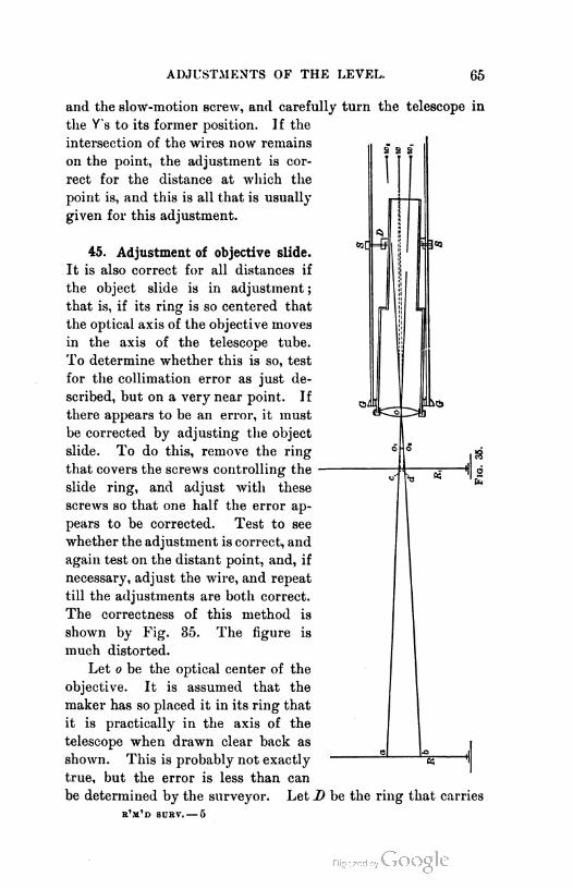
ADJUSTMENTS OF THE LEVEL. 65
and the slow-motion screw, and carefully turn the telescope in
the Y's to its former position. If the
intersection of the wires now remains
on the point, the adjustment is cor
rect for the distance at which the
point is, and this is all that is usually
given for this adjustment.
45. Adjustment of objective slide.
It is also correct for all distances if
the object slide is in adjustment ;
that is, if its ring is so centered that
the optical axis of the objective moves
in the axis of the telescope tube.
To determine whether this is so, test
for the collimation error as just de
scribed, but on a very near point. If
there appears to be an error, it must
be corrected by adjusting the object
slide. To do this, remove the ring
that covers the screws controlling the
slide ring, and adjust with these
screws so that one half the error ap
pears to be corrected. Test to see
whether the adjustment is correct, and
again test on the distant point, and, if
necessary, adjust the wire, and repeat
till the adjustments are both correct.
The correctness of this method is
shown by Fig. 35. The figure is
much distorted.
Let o be the optical center of the
objective. It is assumed that the
maker has so placed it in its ring that
it is practically in the axis of the
telescope when drawn clear back as
shown. This is probably not exactly
true, but the error is less than can
be determined by the surveyor. Let D be the ring that carries
r'm'd surv.— 5

66 LEVELING.
the object slide. It is adjusted by the screws SS. It is shown
much out of the center of the tube. Let wl be a wire supposed
not to be in the center of its tube, that is, out of adjustment.
The outer end of the objective tube slides in the fixed ring Gr.
If the instrument is perfectly made, it is evident that, if the
objective could be brought to the plane of this ring G, the
optical center would be in the axis of the telescope tube. When
the glass is focused on a very distant object, the objective ap
proximates to the plane of the ring, and hence the optical cen
ter is nearly in the axis of the tube, but not necessarily exactly
so. In the case presented, it could not be just in the axis.
If the telescope is directed to a distant object, as a rod
It, the point a of the rod, that will appear to be covered by the
intersection of the wires, will be found in the line joining the
intersection of the wires with the optical center of the objec
tive. If the telescope is turned upside down, the wire will
move to w2, and the point that will seem to be covered will
be the point b, found as was a. If now the optical center is in
the axis of the telescope, and the wire is moved to the position
w in the prolongation of the line joining the point midway
between a and b and the optical center, it will be in the center
of the tube and in adjustment. If the optical center is not
exactly in the center of the tube, the position of the wire when
moved to read halfway between a and b will not be the center
of the tube but will be very near it, depending on the error of
the objective. It will be off center about the same amount
that the optical center is off. Let it be assumed that the
optical center is right, and that therefore the wire is now
right. Make the telescope again normal.
Let the glass be focused on a near object, as a rod at Rv
Let it be supposed that in throwing the glass out for this
purpose o moves to ov The reading on the rod will be c,
obtained by producing the line wov Invert the telescope, and
the reading will be d. If the ring D is now moved, the object
slide will swing about GrGr as a pivot, and o2 will be moved
toward ov It is evident that, if this movement is enough to
make the wire read halfway between c and d, the objective is
centered. If it was right for the distant rod, it may now be
assumed to be right for all intermediate distances, since it is
ADJUSTMENTS OF THE LEVEL. 67
supposed that the maker has made the tube true in form. If
this is doubted, it may be tested in the same manner for any
distance. Since the objective was not exactly centered for the
distant rod, the wire was not exactly adjusted, and hence if the
test is not made again on the distant rod, a slight error will be
discovered which is to be corrected by moving the wire, and
the test must again be made on the near rod, which will also
probably show some error of objective which must be corrected.
By continual approximations the work is completed.
Because the wire is not quite centered the first time, the work
may be hastened by adjusting the slide for about or quite the
whole error instead of half the error. Each wire is adjusted
separately, and the objective slide first in one direction and
then in the other at right angles thereto. It is well to note
that this adjustment of the objective is seldom made because it
is seldom necessary. It may be considered to be necessary only
when the instrument has been taken apart or has had extraor
dinarily severe usage. When it is not necessary, the adjust
ment of the line of collimation is a very simple matter. In
some makes of instruments the object slide is permanently
adjusted, and hence no provision is made for its adjustment
by the engineer.
46. Bubble adjustment. The second adjustment is made in
either of two ways. The first depends on the equality of di
ameter of the rings of the telescope tube that rests in the Y's.
Since by the first adjustment the line of collimation has been
made to coincide with the axis of the tube, it is parallel to the
axis of the Y's, if the rings mentioned are equal in diameter.
If now the attached bubble tube is made parallel to the axis
of the Y's, it will be parallel to the line of collimation. To
test it, set up the instrument, and, having leveled over both
sets of screws, unfasten the clips and level more carefully over
one set. Remove the telescope very carefully from the Y's and
turn it end for end and replace. If the bubble returns to the
center of its tube, the tube is parallel to the axis of the Y's. If it
does not, bring it halfway to the center by the adjusting screws
at the end of the bubble tube. The adjustment is now com
plete if the instrument has not been moved in making it.

68 LEVELING.
Test it by releveling and turning end for end in the Y's, as
before.1
47. The "peg" method. This method is considered better
by almost all engineers, and is as follows : Set the instrument
in a fairly level plot of ground midway between two stakes that
have been driven firmly into the ground, from two hundred
to four hundred feet apart. Read a rod on each stake. (Re
member to have the bubble always in the center of its tube
when a reading is taken.) Since the rods are at equal dis
tances from the instrument, errors of reading due to errors
of adjustment will disappear in subtracting, and hence the
difference in readings will give the true difference in elevation
of the two stakes. The instrument is now removed to a point
in line with the two stakes, but beyond one of them. Some
engineers take the instrument beyond one stake a distance
equal to one tenth of the distance between the stakes. Others
set the instrument at one of the stakes so that the eye end of
the instrument in swinging around will just clear a rod held on
the stake. The procedure, adopting the first method, will be
explained, and the student may work out the process for
the second method. It will be supposed that the instrument
has been set up beyond one stake a distance equal to one tenth
of that between the stakes, and with one diagonally opposite
pair of leveling screws in line with the stakes. Any other
proportion would do as well.
After leveling, with the telescope pointing in the line of the
stakes, a reading is taken on the near stake. If there were no
curvature of the earth, the difference in level of the two stakes
applied to the reading on the first would give the reading that
should be obtained on the second, provided the line of collima-
tion is horizontal, that is, parallel to the axis of the bubble tube.
Since there is the earth's curvature to consider, even if the
instrument is in adjustment, the rod at the distant stake will
read more than above noted, by the amount of the earth's
curvature, less the effect of refraction.2 Therefore, to obtain
the proper reading for the distant rod there must be added
1 The principle -n which this adjustment depends is stated in Art. 28.
2 See Art. 40.
ADJUSTMENTS OF THE LEVEL. 69
to the reading on the near rod, the difference of elevation plus
the correction for curvature for the given distance.
The target is then set at this reading and the rod is held on
the distant stake. If the level, when sighted to the rod, reads
above the target, the line of collimation is not parallel to the
bubble tube, but points up. If it reads below the target, it points
down. The amount of error in reading is the amount that the
line of collimation points up or down in the distance between the
stakes. In the distance from the level to the distant stake, it
points up or down eleven tenths of this apparent error. The
proportion will vary with the varying proportions of the dis
tances from stake to stake and stake to instrument. Hence to
get a horizontal line from the instrument to the far rod, set the
target in the line of collimation and then raise or lower it, as
the case may be, by an amount equal to eleven tenths of the
apparent error, and point the telescope to it by manipulating
the leveling screws.
The line of collimation now being horizontal, the bubble tube
will be parallel to it if the tube is adjusted with reference to the
telescope so that the bubble comes to the center. This is done,
as explained in the first method, by the screws at -one end of the
tube. The test should be again made to see that no movement
has taken place during the operation. It is sometimes stated
that the adjustment may be made by moving the bubble or the
wire. This is not correct, as will be evident from the preceding
discussion of collimation adjustment. If the objective is perma
nently adjusted by the maker, the second adjustment by revers
ing in the Y's may be made first, and the peg method may follow,
adjusting the wire.
48. Lateral adjustment. In many old levels, the telescope
is free to turn in the Y's. If this is the case, and the axis of
the bubble tube is not in the vertical plane through the line
of collimation, and the telescope tube becomes turned a little,
the line of collimation will not be horizontal when the bubble
is in the center of its tube. To test this, level the instrument
and turn the telescope slightly in the Y's. If the bubble re
mains in the center of its tube, the adjustment is perfect, and
nothing need be done. If not, adjust the tube laterally by the
70 LEVELING.
lateral adjusting screws at one end of the tube. Most levels
have a little pin in one of the clips that fits in a notch cut in
a ring on the telescope and prevents the telescope from turning
in the Y's. Nevertheless, it is well to know that the adjustment
is not much out.
49. Y Adjustment. The third adjustment depends on Prin
ciple II. stated in Art. 28. It is performed as follows : The test
consists in carefully leveling the instrument over both sets of
screws and more carefully over one set, and then swinging the
telescope around 180° on the vertical axis and noting whether the
bubble remains in the center of the tube. If not, the axis of
the instrument is not vertical, and the axis of the Y's is not per
pendicular to it. To correct the error, that is, to make the axis
of the Y's perpendicular to the vertical axis of the instrument,
move one of the Y's up or down (as may appear necessary by
the position assumed by the bubble) by manipulating the large
capstan nuts that hold the Y to the bar, till the bubble has
moved halfway back to the center of its tube. The axis of
the Y's is then perpendicular to the vertical axis of the instru
ment, provided no movement has taken place. To test, relevel
and reverse the telescope and make any further correction neces
sary, and test again until the work is complete.
In making any of the adjustments it is practically impos
sible to manipulate the adjusting screws without to some extent
disturbing the instrument. Therefore, an adjustment is rarely
made perfectly the first time, and must always be tested and
repeated till complete. If an instrument is badly out of adjust
ment, it will be advisable first to adjust it approximately all
round, and then readjust more carefully.
50. To adjust the dumpy level. Reference to the cut of
the dumpy level will show that the axis of the telescope is
made by the maker perpendicular to the vertical axis of revo
lution. It is not supposed that this condition will change.
It will also be noticed in the cut that there are no adjusting
screws for the object slide. It is permanently adjusted. This
is true of all the engineering instruments made by the maker
of this level. Therefore, since the axis of the telescope is
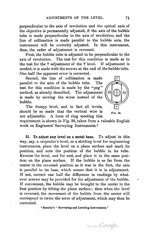
ADJUSTMENTS OF THE LEVEL. 71
perpendicular to the axis of revolution and the optical axis of
the objective is permanently adjusted, if the axis of the bubble
tube is made perpendicular to the axis of revolution, and the
line of collimation is made parallel to the bubble axis, the
instrument will be correctly adjusted. In this instrument,
then, the order of adjustment is reversed.
First, the bubble tube is adjusted to be perpendicular to the
axis of revolution. The test for this condition is made as in
the test for the Y adjustment of the Y level. If adjustment is
needed, it is made with the screws at the end of the bubble tube.
One half the apparent error is corrected.
Second, the line of collimation is made
parallel to the axis of the bubble tube. The
test for this condition is made by the "peg"
method, as already described. The adjustment
is made by moving the wires instead of the
bubble.
The dumpy level, and in fact all levels,
should be so made that the vertical wire is
not adjustable. A form of ring meeting this
requirement is shown in Fig. 36, taken from a valuable English
work on Engineers' Surveying Instruments.1
51. To adjust any level on a metal base. To adjust in this
way, say, a carpenter's level, or a striding level for engineering
instruments, place the level on a plane surface and mark its
position, and note the position of the bubble in its tube.
Reverse the level, end for end, and place it in the same posi
tion on the plane surface. If the bubble is as far from the
center in the reversed position as it was in the first, the axis
is parallel to its base, which means that it is in adjustment.
If not, correct one half the difference in readings by what
ever screws may be provided for the adjustment of the bubble.
If convenient, the bubble may be brought to the center in the
first position by tilting the plane surface ; then when the level
is reversed, the movement of the bubble from the center will
correspond to twice the error of adjustment, which may then be
corrected.
1 Stanley's " Surveying and Leveling Instruments."
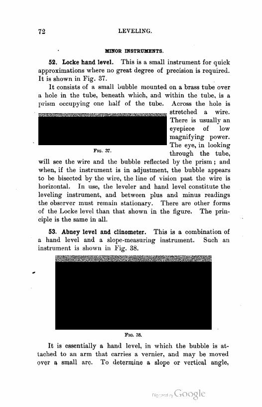
72 LEVELING.
MINOR INSTRUMENTS.
52. Locke hand level. This is a small instrument for quick
approximations where no great degree of precision is required.
It is shown in Fig. 37.
It consists of a small bubble mounted on a brass tube over
a hole in the tube, beneath which, and within the tube, is a
prism occupying one half of the tube. Across the hole is
will see the wire and the bubble reflected by the prism ; and
when, if the instrument is in adjustment, the bubble appears
to be bisected by the wire, the line of vision past the wire is
horizontal. In use, the leveler and hand level constitute the
leveling instrument, and between plus and minus readings
the observer must remain stationary. There are other forms
of the Locke level than that shown in the figure. The prin
ciple is the same in all.
53. Abney level and clinometer. This is a combination of
a hand level and a slope-measuring instrument. Such an
instrument is shown in Fig. 38.
Fig. 38.
It is essentially a hand level, in which the bubble is at
tached to an arm that carries a vernier, and may be moved
over a small arc. To determine a slope or vertical angle,
Fig. 37.
stretched a wire.
There is usually an
eyepiece of low
magnifying power.
The eye, in looking
through the tube,
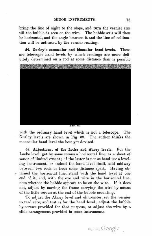
MINOR INSTRUMENTS. 73
bring the line of sight to the slope, and turn the vernier arm
till the bubble is seen on the wire. The bubble axis will then
be horizontal, and the angle between it and the line of collima-
tion will be indicated by the vernier reading.
54. Gurley's monocular and binocular hand levels. These
are telescopic hand levels by which readings are more defi
nitely determined on a rod at some distance than is possible
Fig. 39.
with the ordinary hand level which is not a telescope. The
Gurley levels are shown in Fig. 39. The author thinks the
monocular hand level the best yet devised.
55. Adjustment of the Locke and Abney levels. For the
Locke level, get by some means a horizontal line, as a sheet of
water of limited extent ; if the latter is not at hand use a level
ing instrument, or indeed the hand level itself, held midway
between two rods or trees some distance apart. Having ob-
' tained the horizontal line, stand with the hand level at one
end of it, and, with the eye and wire in the horizontal line,
note whether the bubble appears to be on the wire. If it does
not, adjust by moving the frame carrying the wire by means
of the little screws at the end of the bubble mounting.
To adjust the Abney level and clinometer, set the vernier
to read zero, and test as for the hand level; adjust the bubble
by screws provided for that purpose, or adjust the wire by a
slide arrangement provided in some instruments.
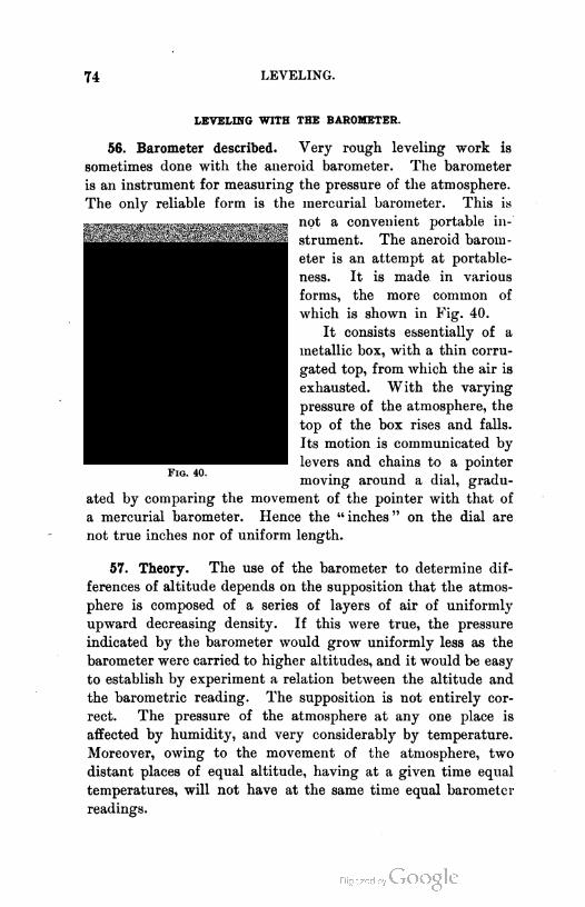
74 LEVELING.
LEVELING WITH THE BAROMETER.
56. Barometer described. Very rough leveling work is
sometimes done with the aneroid barometer. The barometer
is an instrument for measuring the pressure of the atmosphere.
The only reliable form is the mercurial barometer. This is
not a convenient portable in
strument. The aneroid barom
eter is an attempt at portable-
ness. It is made in various
forms, the more common of
which is shown in Fig. 40.
It consists essentially of a
metallic box, with a thin corru
gated top, from which the air is
exhausted. With the varying
pressure of the atmosphere, the
top of the box rises and falls.
Its motion is communicated by
levers and chains to a pointer
moving around a dial, gradu
ated by comparing the movement of the pointer with that of
a mercurial barometer. Hence the " inches " on the dial are
not true inches nor of uniform length.
57. Theory. The use of the barometer to determine dif
ferences of altitude depends on the supposition that the atmos
phere is composed of a series of layers of air of uniformly
upward decreasing density. If this were true, the pressure
indicated by the barometer would grow uniformly less as the
barometer were carried to higher altitudes, and it would be easy
to establish by experiment a relation between the altitude and
the barometric reading. The supposition is not entirely cor
rect. The pressure of the atmosphere at any one place is
affected by humidity, and very considerably by temperature.
Moreover, owing to the movement of the atmosphere, two
distant places of equal altitude, having at a given time equal
temperatures, will not have at the same time equal barometer
readings.

THE BAROMETER. 75
It is therefore difficult to establish a relation between the
altitude and the barometer readings. It has been attempted
by many persons, with the result that there are many formulas
for determining the differences in altitude from the readings of
the barometer. These formulas do not differ so much in method
of deduction as in the experimental constants used. Perhaps
one of the best is that developed by Mr. William Ferrall.1
Modified by omitting the terms for correcting for humidity
and latitude, which are small in effect, and one or two other
still smaller terms, this formula is
H= 60521.5 log + 0.001017 Qt + t' - 64°)^,
in which H is the difference in altitude of two points where
observations are taken, B and Bx are the barometer readings at
the lower and higher points respectively, and t and t' are the
Fahrenheit temperatures at the two points.
58. Barometric tables. It is convenient in tabulating this
formula for practical use to consider that t + t' is 100°, and
that H is the difference in altitude between two points whose
altitudes above a given datum are to be directly determined
from the tables. Thus if t + t' = 100°, and the given datum is
such that the barometer reading is 30 inches, the formula is
H= 60521.5 ( 1 + .001017 x 36 ) flog ^- - log ~)
V B1 B J
= 62737 log - 62737 log^-
x>j B
30Tables may be constructed for the quantity 62737 log -—,
B
with B as the argument, and such a table would be entered
twice, once for each barometer reading, and the difference of
the tabular values found would be the value of H if *+£' = 100°
and there is no correction for humidity. Table III., page 362,
is such a table. For other than a mean temperature of 50°, and
for average hygrometric conditions, a correction is to be applied
to the result. This correction is a linear function of the value
of H already found such that
1 See Appendix, 10, " United States Coast and Geodetic Survey Report " for 1881.

76 LEVELING.
in which A1 and A2 are the values from Table III., and C is the
temperature and humidity correction coefficient. Values of C
are given in Table II., page 361.
59. Practical suggestions. The aneroid barometer should
be frequently compared with a mercurial barometer, and the
errors of reading at different parts of the scale should be noted.
This can be well done only under the bell of an air pump.
The scale of altitudes on some barometers is useless. -
Some barometers are marked " compensated," meaning that
no temperature corrections need be applied. This is a mistake.
The temperature corrections should always be applied.
Always read the barometer when it is horizontal. Carry it
in a strong case, and do not let the warmth of the body affect
it. Do not use it for altitudes just before or after, or during
a storm.
In determining the difference of altitude of two widely
separated points, stop once or twice for a half hour or so on
the journey between the points, note the reading of the ba
rometer at the beginning and end of the stop, and thus try
to determine whether the atmospheric conditions are changing
and, if so, at what rate. A correction can thus be determined
for the first reading, on the supposition that the observed change
has taken place also at the starting point. Tap the box gently
before reading.
60. Accuracy of the method. If barometer readings are
taken simultaneously daily at two widely separated stations for
from one to six years, the utmost that can be expected is an
error of about one half of one per cent, though occasional
results are much closer. Single observations taken on the same
day with the same or compared barometers and at distances of
a few hours' walk will give results with errors of from one per %
cent to three per cent and more. An error in temperature of
live degrees will cause an error in result of one per cent or
more. Single observations taken a day or more apart and
at stations a day's journey or more apart can not be depended
on to give results much closer than the nearest ten per cent,
though they will frequently do better than this and sometimes
worse.

CHAPTER IV.
DETERMINATION OF DIRECTION AND MEASUREMENT OF
ANGLES.
61. Instruments mentioned. In almost all surveys it is
necessary to measure distances and angles.
Angles are measured by means of one of several instru
ments, according to the character of the work. The most
commonly used are the compass and the transit.
The compass is an instrument for determining directions
and, indirectly, angles ; while the transit is an instrument for
determining angles and, indirectly, directions.
Almost all of the old land surveys of this country have
been made with the compass as the angle-measuring instru
ment ; and while this instrument has been, to a great extent,
supplanted by the transit, there are still a great many com
passes sold annually. As a discussion of the compass will
make clearer some surveying methods, it will be here described.
Mention must be made of the sextant, which is an angle-meas
uring instrument whose use in surveying is confined to certain
particular operations, as in exploratory surveying or in the
location of soundings taken off shore. A description of this
instrument is given on pages 294-298.
Mention should also be made of the solar compass and
transit, instruments for determining the true meridian by an
observation on the sun. The solar transit is described on
pages 116-126.
THE COMPASS.
62. Description. The compass consists of a line of sight
attached to a graduated .circular box, in the center of which
is hung, on a pivot, a magnetic needle.
77

78 - DIRECTION AND ANGLES.
At any place on the earth's surface, the needle, if allowed
to swing freely, will assume a position in what is called the
magnetic meridian of the place. If, then, the direction of any
line is required, the compass may be placed at one end of the
line and the line of sight may be made to coincide with the line.
The needle lying in the magnetic meridian, and the zero of
the graduations of the circular needle box being in the line of
sight, the angle that the line on the ground makes with the
magnetic meridian is read on the graduated circle. If the
|T|S magnetic meridian coincided everywhere with the true
I meridian, or even if the angle between them were con
stant, the compass would be a far more valuable instru
ment than it is. The compass, however, has its field, and
in that field is a very valuable tool. A very good form
of compass is shown in Fig. 41.
It is sometimes set on a tripod head and sometimes
on a jacob staff, which is a single-pointed staff with a
Fig. 41.
head fitted to receive the compass. The sights SS are attached
to the main plate of the instrument by the screws seen below the
plate. The level vials encased in brass tubes are fastened to the
plate by screws passing through the plate from below, by which
screws the bubbles may be adjusted parallel to the plate. The
needle iV- rests on a steel pivot that is screwed into the plate,
and the needle is lifted from the pivot, when not in use, by the
ring It operated by a lever, which is in turn moved by the
screw whose head is seen just below the plate directly in front.
On the left is a marker M used to keep track of the chaining.
Next to this is an arc A and a vernier, moved by the tangent
screw V. The arc is attached to the plate, and the vernier to
COMPASS ADJUSTMENTS. 79
an arm that is fastened to the compass box, which box may be
thus turned through a small angle by the tangent screw. This
vernier is called a declination vernier. Its use will appear later.
The compass box is graduated from the north and south points
in each direction 90°. When the zero of the vernier coincides
with the zero of the arc A, the line of zeros of the compass box
is coincident with the line of sight. The spring catch C holds
the compass on the tripod head, and the clamp K, acting on a
concealed spring that encircles the tripod head, serves to clamp
the instrument so that it will not revolve about the vertical
axis. There is a small coil of wire seen on one end of the
needle. This counteracts the magnetic force that would other
wise cause the needle to dip. This means that the direction of
magnetic force or magnetic pull is not horizontal, but is inclined,
and if the needle is free to dip, it will lie in the direction of
magnetic pull. This vertical component of magnetic force that
causes the dip, 'varies in different places, and the little coil of
wire may be moved nearer to, or further from, the pivot to allow
for this variation.
Since only horizontal angles are measured with the compass
and used in land surveying, it is necessary to have the plates
horizontal, and the sights vertical when working. This is
accomplished by means of a ball and socket joint attached to the
tripod head, and the bubbles on the plate. The plate having
been leveled, the joint is clamped by simply screwing tight the
milled head by which the spindle is attached to the head of the
tripod.
COMPASS ADJUSTMENTS.
63. Requirements mentioned. To determine properly the
direction of lines with the compass, it is necessary (1) that the
plate be level, the sights vertical with their line passing through
the zeros of the graduated box when the zeros of the vernier
and arc A coincide ; (2) that the needle be straight ; (3) that
the pivot be in the center of the circle.
64. Plate bubbles. The instrument is readily leveled if the
bubbles are parallel to the plate and the plate perpendicular to
the vertical axis. Test the parallelism of the bubbles and plate
80 DIRECTION AND ANGLES.
by the method of Art. 28, and correct, if necessary, by the
screws already mentioned. In doing this the plate is reversed
on the vertical axis. It is assumed that the plate is perpendicu
lar to the vertical axis. If not, it must be made so by the
maker.
65. Sights. To test the perpendicularity of the sights,
turn the leveled instrument on a suspended plumb line and see
whether the line traverses the slits in the standards, turning
each end separately to the plumb line. If the sights are found
to be out of plumb, they may be adjusted by removing them and
filing the bottoms till they are found to be correct. With
proper care they should not get out, and this is not a common
error. Strips of paper may be inserted under one edge, if the
surveyor prefers this to riling.
To determine whether the plane of the sights includes the
line of the zeros when the vernier is set to read zero, stretch two
fine threads through the slits in the sights and, looking down,
see whether the plane of the threads includes the line of zeros of
the graduated box. If not, the error should be corrected by the
maker. The error may be allowed for, however, by moving the
vernier till the zeros are in the plane of the threads, or parallel
to it, noting the angle that has been turned, and seeing that
thereafter the vernier is set at this angle when working. If
the line of sights fails to pass through the center by one tenth
of an inch, the error in the direction of a line ten feet long will
be about three minutes, and will be less as the line is longer.
66. Needle and pivot. If the needle is straight and the
pivot is in the center, the two ends will read 180° apart. If
both of these conditions are not fulfilled, the two ends will
read other than 180° apart. If it is observed that one of
these faults exists, the instrument should first be tested to
determine which one. This is done by turning the plates on
the vertical axis and noting whether the difference in the two
end readings remains constant: if so, the needle is bent; if not,
the pivot is not in the center, and the needle may or may not
be bent. If the needle is found to be bent, remove the glass
cover from the box by unscrewing it, take the needle from the
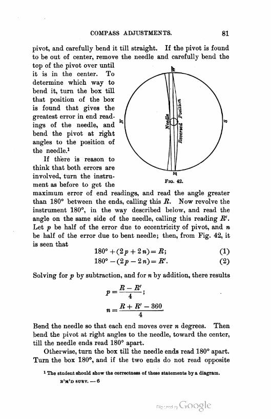
COMPASS ADJUSTMENTS. 81
pivot, and carefully bend it till straight. If the pivot is found
to be out of center, remove the needle and carefully bend the
top of the pivot over until
it is in the center. To
determine which way to
bend it, turn the box till
that position of the box
is found that gives the
greatest error in end read
ings of the needle, and
bend the pivot at right
angles to the position of
the needle.1
If there is reason to
think that both errors are
involved, turn the instru
ment as before to get the
maximum error of end readings, and read the angle greater
than 180° between the ends, calling this R. Now revolve the
instrument 180°, in the way described below, and read the
angle on the same side of the needle, calling this reading R' .
Let p be half of the error due to eccentricity of pivot, and n
be half of the error due to bent needle; then, from Fig. 42, it
is seen that
180°+(2j9 + 2n)=.R; (1)
180°-(2p-2w)=.R'. (2)
Solving for p by subtraction, and for n by addition, there results
R-R'
P = —a 5
F1g. 42.
TO =R+R' - 360
Bend the needle so that each end moves over w degrees. Then
bend the pivot at right angles to the needle, toward the center,
till the needle ends read 180° apart.
Otherwise, turn the box till the needle ends read 180° apart.
Turn the box 180°, and if the two ends do not read opposite
1 The student should show the correctness of these statements by a diagram.
r'm'd suttv. — 6
82 DIRECTION AND ANGLES.
divisions, bend the ends through half the difference between
the first and second positions. The needle is now straight, and
the pivot may be tested and corrected as above described.
The instrument may be revolved 180° by noting an object
to which it points when first set and then revolving till the
sights again point to the same object.
If the needle is sluggish in its movement, it may be due to
one or both of two causes. The pivot may be blunt, or the
needle may have lost some of its magnetic strength. Take the
needle off the pivot and examine the pivot. If it is found
blunt, unscrew it and carefully grind it down on a fine oilstone.
If the pivot seems perfect, the trouble is with the needle. Lay
the needle down and rub each end from the center out with
that end of a bar magnet which attracts the end of the needle
that is being rubbed. In passing the magnet back from end to
center, raise it some distance above the needle ; otherwise the
backward movement will tend to counteract the rubbing. The
needle may also be remagnetized by placing it in the magnetic
field of a strong electro-magnet, as a dynamo. If placed on the
magnet in a wrong direction, the south end will, when replaced,
point north. To correct this, replace the needle on the magnet
in the opposite direction.
Two needles at the same place may not point in the same
direction. This will probably be due to the fact that their
magnetic axes do not coincide with their geometric axes. This
seems to be unavoidable. For this reason the needle should be
narrow and deep rather than flat and wide. There is a differ
ence of opinion about this, based on difference of manufacturing
processes.
The angle between the true meridian and the magnetic
meridian should be determined by the instrument that is to be
used in a given piece of work.
The glass cover of the compass box may become electrified
by rubbing, and attract the needle. This is remedied by touch
ing the glass with the moistened finger.
When the compass is being moved, the needle should always
be lifted from the pivot. When put away, the needle should
be allowed to swing to the magnetic meridian and then lifted.
It retains its magnetic strength longer in the meridian.
USE OF THE COMPASS. 83
USE OF THE COMPASS.
67. Bearing. The use of the compass is to determine the
directions, or, technically, the bearings of lines ; or to mark out
lines whose bearings are given.
The bearing of a line is the horizontal angle between a ver
tical plane including the line, and the meridian plane through
one end of the line, and is measured from the north or south
points 90° each way. Thus the bearing of a line extending in a
direction midway between the north and east, would be N. 45°
E. or S. 45° W., according to the end from which the bearing
is read. This gives rise to two terms, forward bearing and
back bearing, the forward bearing being the bearing in the
direction in which the survey is being run, and the back bear
ing being that read in the reverse direction. These two bear
ings (omitting the effect of convergence of the meridians of
the two ends of the line, which is an inappreciable amount in
an ordinary compass survey) should be numerically equal, but
with opposite letters to express the direction. The bearings
are never read, east so many degrees south or north, or west so
many degrees north or south ; but always from the north or
south points.
68. To determine the bearing of a line. Set the compass over
one end, level the plates, lower the needle, turn the north end
of the compass box toward the distant end of the line, and
bring the line of sights carefully in the direction of the line.
If the declination vernier reads zero, the north end of the
needle will show the bearing of the line.
69. To lay out a line of given bearing. Set the compass over
a point on the line, level the plates, drop the needle, turn the
compass on its vertical axis till the north end of the needle
reads the given bearing. The line of the sights is now in the
required line, which may be ranged out.
70. To run a traverse. This is to determine the lengths and
bearings of a series of connected lines. These may form the
sides of a farm, or inclose a pond, or be the center line of a
crooked road. If there are no natural objects to mark the
angle points, flags are set at those points by a flagman, the
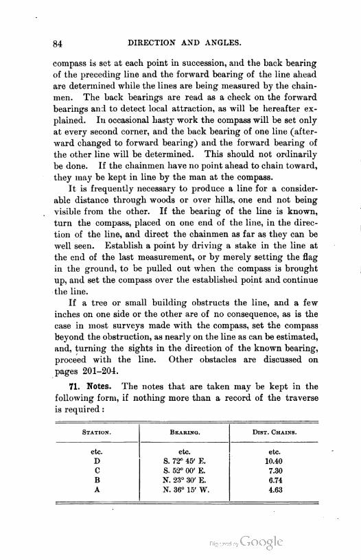
84 DIRECTION AND ANGLES.
compass is set at each point in succession, and the back bearing
of the preceding line and the forward bearing of the line ahead
are determined while the lines are being measured by the chain-
men. The back bearings are read as a check on the forward
bearings and to detect local attraction, as will be hereafter ex
plained. In occasional hasty work the compass will be set only
at every second corner, and the back bearing of one line (after
ward changed to forward bearing) and the forward bearing of
the other line will be determined. This should not ordinarily
be done. If the chainmen have no point ahead to chain toward,
they may be kept in line by the man at the compass.
It is frequently necessary to produce a line for a consider
able distance through woods or over hills, one end not being
visible from the other. If the bearing of the line is known,
turn the compass, placed on one end of the line, in the direc
tion of the line, and direct the chainmen as far as they can be
well seen. Establish a point by driving a stake in the line at
the end of the last measurement, or by merely setting the flag
in the ground, to be pulled out when the compass is brought
up, and set the compass over the established point and continue
the line.
If a tree or small building obstructs the line, and a few
inches on one side or the other are of no consequence, as is the
case in most surveys made with the compass, set the compass
beyond the obstruction, as nearly on the line as can be estimated,
and, turning the sights in the direction of the known bearing,
proceed with the line. Other obstacles are discussed on
pages 201-204.
71. Notes. The notes that are taken may be kept in the
following form, if nothing more than a record of the traverse
is required :
Station. Bearing. Dist. Chains.
etc. etc. etc.
DS. 72n 45' E.
10.40
C S. 52° 00' E. 7.30
B N. 23° 30' E. 6.74
A N. 36° 15' W. 4.63
USE OF THE COMPASS. 85
The notes read up the page so that the line may appear to be
ahead as one walks along with the open notebook. Other
notes are usually required, as distances to points passed, fences
crossed, roads and streams crossed, distances right or left to
objects near the line, as will be hereafter described. In such
cases, a sketch of the work with all the necessary measurements
marked on it is the best possible form of notes to take in the
field. This may afterwards be converted into the form shown
on page 229. The name and date of survey should always be
recorded on every page of the notebook used and the names of
those engaged on the work should be entered at least once.
72. Angles. To determine the angle formed by two lines at
their point of intersection, set the compass over the point of
intersection and read the bearing of each line. From these bear
ings determine the angle. There will always be two supplemen
tary angles. If the lines are conceived to be run from the end
of one to the point of intersection, to the end of the second,
and so on, as in running a traverse, the angle between the
prolongation of line one, and line two, measured in the direc
tion in which the line is conceived to bend, is called the deflec
tion angle, or, in a closed survey, the exterior angle. Some
examples in converting bearings to angles, and the reverse, will
be found in the problems in the Appendix, pages 324, 325.
73. Cautions. It is better to keep the north end of the
compass box ahead, and to read the north end of the needle.
The north end of the needle is distinguished either by its
peculiar shape or by the fact that the coil of wire is on the
other end. The north end of the compass box is distinguished
by a peculiar figure, usually a conventional fleur de lis. If the
south end of the box is ahead, read the south end of the needle.
Care should be exercised in the use of the compass, both in
directing the sights and in reading the needle; and the
beginner should be particularly careful to read from the
north or south point according to which is nearer the north
end of the needle. Greater differences in results may be
expected from different instruments used by the same man,
than from the same instrument used by different men, if the
men use care in their work.
86 DIRECTION AND ANGLES.
MAGNETIC DECLINATION.
74. Declination denned. Thus far all bearings have been
assumed to be taken with reference to the magnetic meridian.
If the magnetic meridian and the true meridian were coinci
dent at all places on the earth's surface, or if at one place the
angle between them were constant, the determination of the
true bearing of a line by the compass would be comparatively
simple. The needle, however, points to the true north at very
few places on the earth's surface, and the angle that the mag
netic meridional plane makes at any point with the true me
ridional plane is called the magnetic declination.
75. Variations of declination. The declination is subject
at every place to changes, called variations of the declina
tion. These are : secular variation, annual variation, lunar
inequalities, and diurnal variation. There are also irregular
variations due to magnetic storms. The annual variation and
the lunar variation are both very small and may be neglected
entirely. The diurnal variation is nothing at about 10.30 A.M.
and 8.00 p.m., and varies between these hours, the north end
being furthest east at about 8 o'clock in the morning and fur
thest west at about 1.30 in the afternoon. The total move
ment is from five to ten minutes, and the corrections to be
applied are as in the Appendix, Table V., page 364. It will
be noticed that the variation changes with the seasons. It also
varies slightly with the latitude, and the corrections in the table
are about a mean for the United States for the latitudes given.
The secular variation is by far the most important. It is
supposed to be periodic in its character, requiring from two
hundred to four hundred years to make a complete cycle.1
The needle in Paris in 1580 pointed about 9° or 10° east of
north, while in 1800 it pointed a little more than 22° west of
north. The change seems to have been fairly but not abso
lutely uniform in rate. The rate of change seems to differ
with difference of place, and also with time at the same place.
It is almost nothing for a few years when the needle is near its
extreme position in either direction ; and again, while at one
1 For an extended article on this subject see " United States Coast and Geodetic
Survey Report" for 1882.

MAGNETIC DECLINATION 87
place the declination may vary from one side of the meridian
to the other, at another place the entire movement is on one
side.
76. Determination of the declination. Since it is the mag
netic meridian that is given by the needle, and since this is not
a fixed direction, it should always be required to reduce the
magnetic bearings of lines run with the compass to the true
bearings. This was not done in the old land surveys made in
this country, and the declination was not noted. . The result is
that it is difficult, to rerun the old lines, as will hereafter
appear. From what has been said about secular variation, it
will readily be seen that the declination must be known for the
place of the survey for the time of the survey. In this country
it is sufficient to determine the declination each year for a
given place. It is done by the surveyor in the manner to be
hereafter described. From observations conducted over a num
ber of years in many of the cities of this country, Mr. Charles
Schott, of the Coast Survey, has deduced empirical formulas
for different places for determining the declination at those
places, which formulas will give approximately correct results
for a number of years to come. These formulas are given in
the Appendix, Table VIII., pages 368—370. The use of such
formulas is not advisable except to check, in a general way,
the results of the observations of the surveyor, who should
always, in going to a new place, determine the declination for
himself.
A line connecting points having the same magnetic declina
tion is called an isogonic line, and the line joining points of
no declination is an agonic line. In Plate VI., at the end of
the book, taken from the report of the Coast Survey for 1888
and 1889, an agonic line is seen extending from near Charles
ton, S.C., to the upper end of Lake Huron, and passing through
or near Huntington, W.Va., Newark and Toledo, O., and Ann
Arbor, Mich. All points to the east of this line have west
declination, and all points to the west have east declination.
Moreover, this line is moving westward, and hence west decli
nations are increasing and east declinations diminishing. The
dedication for a given place may be determined approximately

MAGNETIC DECLINATION. 89
from this chart, though, from the extreme irregularity of the
lines in those portions of the country where observations have
been most frequent, as, for instance, in Missouri, it will be seen
that too much reliance can not be placed on the correctness of
the lines. Figure 43 is a chart on a very small scale, showing
in a general way the declination at all points on the earth.
The declination is determined by the surveyor by first
determining a true meridian and then setting the compass
over the southern end of a line in this meridian and reading
the bearing of the line. This is, in amount, the declination.
The direction is, however, reversed, since there is read the
bearing of the true meridian referred to the magnetic meridian,
instead of that of the magnetic meridian referred to the true
meridian. The zeros of the declination vernier and its arc
should coincide, or the reading will be erroneous. To read
the declination more precisely than can be done on the circle,
which is graduated only to half degrees, bring the plane of
the sights carefully into the meridian, and then move the
vernier by the tangent screw till the needle reads zero, or
north. The reading of the vernier will be the declination.
If now the vernier is left set at this reading, a survey may
be conducted by the compass and referred to the true meri
dian, without mental reduction, as the compass will give the
true bearing of the lines at once.
77. Determination of the true meridian. The only real diffi
culty in finding the declination lies in determining the true
meridian. This is done in several ways, one of which, very old
and only roughly approximate, is to mark on the ground or on
a flat surface, the extremities of the shadows cast by a vertical
rod or other object when the sun is at equal altitudes above
the eastern and western horizons. This is done by noting the
shadow at about 9 or 10 o'clock in the morning and draw
ing a circle through the extremity of the shadow, taking the
foot of the rod as a center, and then marking the point on this
circle that is just touched by the shadow in the afternoon.
The point midway between the two positions of the extremity
of the shadow and the center of the circle lies in the meridian.
The better way to determine the meridian is by an observa
90 DIRECTION AND ANGLES.
tion on the star Polaris, or, as it is usually called, the North
Star. This star is not directly at the north pole, but is at
present about one and one quarter degrees from the pole, about
which it seems to" revolve in 23 hours and 56 minutes, thus
bringing it to the meridian twice every day. It is approxi
mately on the meridian when a plumb line traverses the pole
star and the star next the end of the handle of the dipper, or
Zeta Ursse Majoris, that is, the star Zeta in the constellation of
the Great Bear, which is the name of the constellation includ
ing the dipper. The stars in every constellation are lettered
or numbered. Polaris is known as Alpha Ursse Minoris, or
Alpha of the constellation of the Lesser Bear.
Two thirds of a minute, 1895, after both of these stars are
covered by the plumb line, Polaris is on the meridian. For
each year after 1895 add 0.35 minutes. It is not best to ob
serve the star at culmination, that is, on the meridian, because
at that time its motion is all horizontal, giving a considerable
error for a small error in time of observation. It is better to
observe the star at the time when it is furthest east or west,
or, as is said, when it is at eastern or western elongation. The
method of observation is essentially the same in both cases.
Suspend a plumb line from a beam or overhanging limb which
is high enough so that a line of sight to the star, from a point
twenty feet or more to the south, will pass below the point of
suspension. This will- usually require a plumb line at least
twenty feet long, the length depending on the latitude ; the ele
vation of the pole above the horizon being equal to the latitude
of the place. The top of the plumb line should be illuminated
with a light screened from the observer. Select a point south of
the plumb line, approximately in the meridian and such that the
star may be seen just below the top of the string ; and drive
two stout stakes in an east and west line, making sure that
the meridian will fall between the stakes. Drive the stakes till
their tops are in a level line and then nail to their tops a stiff,
smooth board. Take off one of the sights of the compass and
rest it on this board. It may be necessary to set it in a block
because of the pins on the bottom. At a little before the time
of culmination or elongation, whichever is to be observed, bring
the sight " into line " with the plumb line and the star.

MAGNETIC DECLINATION. 91
Keep it in line by moving the sight till the time of culmina
tion or elongation, and then mark on the board the position
of the sight. The work may now be left for the night. The
next morning at a little after 10 o'clock, set up the compass
over the point occupied the previous night by the sight, and
turn the sights on the point over which the plumb line was
suspended. If culmination has been observed, the compass is
now pointing in the meridian, and the needle reading will give,
in amount, the magnetic declination for that place.
78. Azimuth at elongation. If elongation has been ob
served, the true bearing of the star at elongation, called the
" azimuth " at elongation,
must be determined, and a
bearing equal to this must
be set off to get the true
meridian. The explanation
of how this is done is as
follows : The angle that is
required is the angle between
the vertical plane including
the pole and the position of
the observer, and the vertical
plane through the latter point
and the star at elongation.
This latter plane is tangent to
the circle of apparent revolu
tion of the star. If, then, the
observer were on the equator,
the required angle would be
equal to the pole distance of
the star. As the position of
the observer is moved to the
north, the plane becomes tan
gent to the circle of revolution
at a point above a horizontal
line through the pole. There
fore, as the latitude of the
observer is increased, the angle between the two planes is also
Fig. 44.

92 DIRECTION AND ANGLES.
increased. These two planes, extended to the celestial sphere,
will cut from that sphere two arcs which, with the arc of the
meridian of the star from pole to star, will form a spherical
triangle. The arcs are the arcs zenith-pole, zenith-star, and
pole-star ; the triangle formed being zenith-pole-star, right-
angled at star. In Fig. 44 the points are lettered Z, P, and S.
The plane of the terrestrial equator extended to the celestial
sphere cuts from that sphere the celestial equator, and the
zenith of the place of observation is north of that equator by
an arc equal to the latitude of the place. Therefore, the pole
is distant from the zenith by an arc equal to the colatitude.
On the celestial sphere the term "declination" is used instead of
" latitude," and hence the star is distant from the pole by an arc
equal to the codeclination of the star. In the figure the arcs
are shown. Calling codeclination of the pole star the pole-
distance, and letting if> represent the latitude, there results at
once from the principles of trigonometry the relation
,. . , .. sine pole distancesine azimuth at elongation = -—: -.
cosine 9
The declination of Polaris is constantly increasing, and will
continue to increase until the star is within about thirty min
utes of the pole, when it will begin to decrease. Table IV.
Appendix, page 364, gives the polar distance of Polaris for a
number of years.
The latitude of the place may be taken from a good map,
an error of a degree of latitude involving in the territory below
50° north latitude an error of 2J' in latitude 50°, in latitude
40°, 1' in latitude 30°, and in latitude 20°.
The calculation of the time of elongation involves a knowl
edge of astronomical terms that it is not thought wise to
include here, and hence the times of elongation are given in
Table VI. Appendix, page 365, for the year 1897, with rules for
determining the time for other years and other latitudes than
those for which the table was computed.
The method of determining the meridian just given is suffi
ciently precise for compass work. A more precise method will
be given in the discussion of the transit. As has been said,
almost all of the original surveys made in the eastern part
MAGNETIC DECLINATION. 93
of this country were made with the magnetic compass. Many
of them were made and recorded with reference to the mag
netic meridian, without recording the magnetic declination at
the place at the time of the survey ; and hence, if it were re
quired to retrace one of the old surveys, all but one of whose
corners had been lost, it would be found to be a difficult thing
to do. The method of procedure will be discussed further on.
79. Local attraction. The needle may be drawn from its
mean position for a given locality by the attraction of large or
small masses of iron or other magnetic substances. These may
be either minerals hidden in the ground or manufactured arti
cles, as agricultural implements in a barn near by, railroad
rails, nails in an adjacent house, etc. The chain used in the
survey may influence the needle if brought too near, while keys
in the pocket of the observer, or steel wire in the rim of a stiff
hat, and steel button molds on a coat have been known to give
trouble.
Local attraction may be very troublesome, and must be
carefully looked out for. It may be discovered and allowed
for by simply occupying every corner of a survey, and reading
the bearing of each line back as well as forward. It will be
evident that at any one station where the compass is set, the local
attraction, if any exists, will affect by the same amount all
readings taken from that point ; and hence, if the bearings of
two lines meeting at a point are both determined at that point,
the angle of intersection is correctly deduced, even though
there is local attraction and neither bearing is correctly deter
mined. If the bearing of a line is determined from each end,
and it is found that the two readings are not numerically the
same, and it is certain that the bearings are correctly read,
there is probably local attraction at one end or the other, or
possibly at both ends.
If now another line is set off from one end of the first line,
and the bearing of the new line is read at both ends, and the
readings are found to agree, the local attraction affected the
reading of the first line at the other end. If trouble is en
countered on the second line, a third line may be set off from
the other end of the first line, the same observations being

91 DIRECTION AND ANGLES.
made as on the second line. If the auxiliary lines are
properly chosen, one will usually be sufficient. If it is feared
that local attraction exists, the best method is to read the
bearings of all lines at each end, determining the angles be
tween adjacent lines from the bearings taken at their points of
intersection. One line may then be assumed to be correctly
read, or the true bearing may be determined, and the bearings
of the others may be computed from the series of angles.
80. Special forms of compasses. Some compasses are made
with an additional full circle of 360° and a vernier reading
to minutes, with suitable clamps and tangent screws ; but it
Fig. 45.
may be said that the precision obtained in pointing with
the open sights is hardly sufficient to warrant this. If angles
are required to be read to single minutes, it is better to use a
transit.
The prismatic compass is a very convenient instrument
to use on exploratory work. It has folding sights, and, by
means of the prism, may be read while being pointed, which
is a convenience when the instrument is held in the hand in
stead of being mounted on a jacob staff or tripod. It is usually
held in the hand, though it may be used either way. The in
strument is shown in Fig. 45.

THE TRANSIT. 95
THE TRAHSIT.
81. Description. The instrument most used by surveyors
and engineers for measuring horizontal angles, and, with cer
tain attachments, for measuring vertical angles and distance,
and for leveling, is called a transit.
The transit consists of a telescope attached to a pointer
which may be moved around a graduated circle. There are suit
able attachments for controlling the motion of the telescope
and the pointer, and for enabling the graduated circle to be
made horizontal. The pointer may be clamped to the gradu
ated circle, and they may be revolved together. If this is
done, and the telescope is pointed to a given object, and the
graduated circle is clamped so that it will not revolve, and if
the pointer is then undamped from the circle, the pointer and
telescope may be turned together till the telescope points to a
second object. The number of degrees of the circle over which
the pointer has passed will be the angle subtended, at the point
where the transit is placed, by the two objects seen through
the telescope.
The pointer is the zero mark of a vernier. There are usu
ally two double verniers placed 180° apart.
In the transit shown in Fig. 46, T is the telescope which
may, by means of the horizontal axis A, be revolved in a
vertical plane.
The horizontal axis rests in bearings at the top of the stand
ards X, which are rigidly attached to the circular plate that
carries the vernier V.
On this plate are set two level tubes which, when adjusted
to be parallel to the plate, will show whether the plate is level.
This plate is made by the maker perpendicular to the axis on
which it revolves, and hence, when the plate is level, the axis
of revolution is vertical. This axis is conical, and fits inside a
conical socket which is the inside of the conical axis of the plate
that carries the graduated circle. This latter conical axis re
volves in a socket that connects the top and bottom plates of
the leveling head. The upper plate is leveled by the leveling
screws L. The lower plate of this leveling head screws on to
the tripod. The clamp C fastens together the vernier plate

9G DIRECTION AND ANGLES.
(sometimes called the alidade-) and the plate carrying the
graduated circle. The latter plate is called the limb. When
the two plates are clamped together, the vernier plate may still
F1g. 46.
be moved a small amount, relatively to the limb, by means of
the tangent screw S. This is for the purpose of setting the
vernier at a given reading, or pointing the telescope at a point,
THE TRANSIT. 97
more precisely than would be ordinarily possible by simply
turning the alidade by the hand. The collar K surrounds the
spindle of the limb, and by the clamp screw C may be fastened
to that spindle. The lug M, which is attached to the collar,
being held by the spring in the barrel P and the opposing
screw <S", in turn fastened to the upper leveling plate, prevents
the revolution of the limb, when the collar is clamped to its
axis. The limb may, however, be moved a small amount by
the tangent screw *S" working against the pressure of the
spring in the barrel P.
Some instruments when put away in the box in which they
are kept when not in use, are separated into two parts. The
upper part of the instrument is separated from the leveling
head, and the two parts are placed separately in the box.
Others are so made as to be put away in one piece, being
merely unscrewed from the tripod and screwed to a board
that slides into the box.
There are various forms of transits and various patterns
for the different parts, according to the ideas of the different
makers. A careful examination of an instrument should be
made before putting it to use, that the user may become per
fectly familiar with its construction.
The circles are usually so graduated that angles may be read
to minutes. Many instruments are graduated to read 30 sec
onds, some to read 20 seconds, and a few to read 10 seconds.
For ordinary land surveying, single minutes are sufficiently
precise, while for fine city surveying 20 seconds, or even 10
seconds, is not too fine.
The telescope is essentially the same as that used in the
level, but is shorter and usually of lower magnifying power.
It should be inverting, but is usually an erecting glass. The
use of the inverting glass is growing. There is a proper rela
tion between the magnifying power of the telescope and the
least count of the vernier used ; and it is not necessarily the
best instrument that has the smallest count vernier, for the rea
son that the magnifying power of the telescope may be such
that a movement of several of the smallest units that can be
read by the vernier may give no perceptible lateral motion to
the line of collimation. The power of the telescope and the
r'm'd surt. 7

98 Direction and angles.
least count of the vernier should be so adjusted to each other that
a barely perceptible movement of the vernier will cause a barely
perceptible movement of the line of collimation. The same is
true of the magnifying power and the level under the telescope.
Methods of testing these relations will suggest themselves.
The verniers are usually read with small magnifying glasses
known as reading glasses.
In order that the transit may be set precisely over a point
on the ground, there is fastened to the center of the lower part
of the leveling head a ring or hook, from which may be sus
pended a plumb line. A sectional view of the lower part of the
transit in Fig. 46 is shown in Fig. 47. It will be seen that the
Fig. 47.
upper leveling plate U—in some forms four arms instead of
a plate— is attached to the socket in which the vertical axis re
volves, and that to this upper plate are attached the nuts in
which the leveling screws work. These leveling screws rest in
little cups, that in turn rest on the lower leveling plate L.
The ball and socket joint that permits the leveling of the instru
ment is separate from the lower leveling plate, and is not quite
so large as the hole in the center of that plate. There is an
extension plate to this ball and socket joint that extends under
the lower leveling plate. When the leveling screws are tight
ened, this extension plate binds against the leveling plate, and

THE TRANSIT.99
the instrument can not be shifted on the lower plate. If the
leveling screws are loosened, the upper part of the instrument
may be shifted laterally on the lower plate by an amount de
pending on the relative diameters of the ball joint and the hole
in the center of the lower plate. The device is called a shifting
center and is found in all modern transits.
82. The tachymeter. Such a transit as has been described,
while still in very general use, is being rapidly displaced by
the complete engineer's transit, or tachymeter. This instru
ment consists of such a transit as has been described, with the
following attachments :
(1) A level under the telescope, making the transit a good
leveling instrument.
(2) A vertical circle or arc, by which vertical angles may be
read.
(3) A gradienter attachment by which very small vertical
angles may be set off, as so many feet rise or fall in one hundred.
(4) A pair of horizontal wires in the telescope, known as
stadia wires.
There are various other attachments for special purposes
that will be found described in instrument makers' catalogues,
but which it is not necessary to mention here. There are also
special forms of transits for use underground. One form of
the complete instrument is shown in Fig. 48.
The level under the telescope and the vertical circle are
readily recognized. The gradienter and slow-motion screw, for
vertical motion of telescope, is shown at G. The telescope is
clamped in vertical motion by the clamp C. It may then be
moved slowly a small amount by the slow-motion screw. The
head of this screw is graduated with reference to the pitch of
the screw, so that a single revolution of the head corresponds to
an angular motion of the telescope of one foot in one hundred, or
half a foot in one hundred. In the figure, the head is graduated
in the latter way, as is indicated by the double row of figures.
The use of the gradienter is chiefly in setting out grades.
Many transits are fitted with the slow-motion screw without
the gradienter head. All makers make both the plain and com
plete transits. : ,
100 DIRECTION AND ANGLES.
USE OF THE TRANSIT.
83. Carrying the transit. While in use, the transit is not
removed from the tripod when it is carried from one point to
another; but is carried with the tripod on the shoulder of the
F1g. 48.
" transitman.'' The plumb bob is carried in the pocket without
removing the string from the instrument. Before the transit

USE OF THE TRANSIT. 101
can be properly set up and the angles measured, the various
parts must be in proper adjustment. The discussion of the
adjustments will, however, be deferred till the use of the ad
justed transit has been described.
84. "Setting up" the transit. To "set up" the transit
over a point, let the plummet swing free, grasp in one hand
the uppermost leg of the tripod, and plant it firmly in
the ground. Next grasp the other two legs, one in each
hand, and place them symmetrically about the point so that
the plumb bob covers the point as nearly as may be.
The plates should be at the same time observed and made
approximately level. It should be noticed that a sidewise
motion of a leg changes the level of the plates without much
disturbing the plumb bob, and that a radial motion changes
the level of the plates to a less degree, but does disturb the
plumb bob. It is necessary to become expert in setting the
transit, as much time may be lost by awkward work in setting
up. After the transit is set approximately over the point,
press the legs firmly into the ground so as to bring the bob
more nearly over the point and to make the instrument firmer.
Finish centering by the adjustable or shifting center, by loos
ening all the leveling screws and moving the whole upper
part of the instrument till it is centered. If there is no ad
justable center, the instrument must be centered by manipu
lating the legs. When the instrument is finally centered, level
the limb by the leveling screws. To do this, place one plate
bubble parallel to one set of opposite leveling screws; then
the other bubble will be parallel to the other set. Level one
bubble at a time and note that leveling one will, to a slight
extent, disturb the other, which must then be leveled again.
If the lower plate is not fairly level, "leveling up" will dis
turb the centering of the plumb bob, which must then be cor
rected. Continue till both bubbles are in the centers of the
tubes. Set the vernier that is to be used at the proper reading
(this will often be zero), and the instrument is set up.
85. To produce a straight line with the transit. Set the
instrument over one extremity of the line, and with the limb
free to turn, turn the telescope on the other extremity or on

102 DIRECTION AND ANGLES.
a point in the line. Clamp all motions except the vertical
motion of the telescope, and, with either of the horizontal tan
gent screws, but preferably with the lower screw, bring the line
of collimation to bisect exactly the distant point. Transit the
telescope and set a point beyond it at any desired place, in the
line of collimation. This point will, if the instrument is in
adjustment, be in the straight line produced. If it is feared
that the transit is slightly out of adjustment, unclamp the limb,
turn the instrument till the line of collimation again cuts the first
point, clamp and set precisely, and then transit and set a new
point beside the first one set ; the point midway between the two
set will be a point in the continuation of the straight line. This
is called " double centering," and is the same operation as the test
of the adjustment of the vertical wire, to be hereafter explained.
The method of ranging out a number of points in a straight line
in the same direction will be apparent without explanation.
86. To measure an angle with the transit. Set the instru
ment over the vertex of the angle, with the vernier at zero.
With the lower motion bring the line of collimation to bear
approximately on one of the distant points, clamp, and with
the lower tangent screw make an exact bisection. Loosen
the alidade and bring the line of collimation approximately
to the second point, clamp, and complete the bisection with
the upper tangent screw. Read the vernier. The reading
will be the angle sought. This assumes the numbering to
extend both ways from 0° to 360°. It is, of course, unneces
sary to set the vernier at zero. When the instrument has
been set on the first point, a reading may be taken and
noted and subtracted from the reading found on pointing the
telescope to the second point. In this case the vernier may
pass the 360° point, and it will then be necessary to add 360°
to the final reading before subtracting the first.
87. Azimuth. The azimuth of a line is the horizontal angle
the line makes with a reference line, as a meridian. It differs
from bearing, in that it is measured continuously from 0° to
360°. If the azimuth of a point is mentioned, there is implied
another point and a meridian through it from which the azi
muth is measured.

USE OF THE TRANSIT. 103
In making surveys with the transit, except possibly city
surveys and others where angles are to be repeated several
times, it is better to use azimuths than bearings. It is neces
sary, however, in writing descriptions of property, to reduce
the azimuths to bearings.
It is customary to reckon azimuths from the south point
around by way of the west, north, east, south, 360°. This is
the practice of astronomers and geodesists. It is believed to
be more convenient for the surveyor to begin with zero at the
north point and read to the right 360°. The reason for this
will appear in Chapter VI.
88. Traversing. The method of traversing with the transit
is as follows : In Fig. 49, let it be required to determine the
F1o. 49.
lengths and azimuths of the courses of the crooked road A, B,
C, D, etc. It will be assumed that the magnetic meridian SN
is the meridian of the survey. Set the transit over a tack in a
stake driven at A, and, with the vernier set at zero, turn the
telescope by the lower motion in the direction AN as defined
by the needle, and clamp the lower motion. For the purpose
of again using this line, if necessary, set a stake in the line
AN, some distance toward N, and put a tack in it in the exact
line. This is necessary because the needle would not give the
direction twice alike to the nearest minute, which is desired in
transit work. Unclamp the alidade and turn the telescope
toward a point in the first turn of the road, as B. Clamp the
alidade and set a stake at B. In most transit work all stakes
marking stations to be occupied by the transit are " centered "
by setting a tack in the precise line. Read and record the
vernier and the needle. They should agree within the limit of
precision of the needle reading. The angle read is that which
has been turned to the right, and in the figure is greater than
270°. (The mistake of reading the wrong circle must be
104 DIRECTION AND ANGLES.
avoided. The needle reading may be recorded as bearing or
may be mentally reduced to azimuth and so recorded. If the
compass box is graduated continuously 360°, the needle will
give azimuths at once.)
Measure AB, and, while this is being done, take the
transit to B and set up over the tack that has been put
in the stake. AVith the same vernier used at A (let it
be called vernier A") bring the instrument to read the azi
muth AB plus 180°, which is the "back azimuth" of AB.
Point the telescope to A by using the lower motion, clamp,
and make the exact pointing with the lower tangent screw.
By so doing the instrument is oriented; that is, the zeros
of the limb are made parallel to their positions at A. (The
telescope has not been transited, and, if the alidade is now
undamped and the telescope turned in azimuth just 180°,
the line of sight will be in AB prolonged, the vernier will
read the azimuth of AB, and the zeros of the limb will be
seen to lie in the meridian of the survey. This intermediate
step is not usually taken separately in practice, but is intro
duced here for the clearer understanding of the method.)
With the alidade undamped, turn the telescope in the
direction of the next point, as C. Clamp the alidade, set a
stake and tack at C, and read and record the vernier and needle.
The reading of the vernier will be the azimuth of BC referred
to AN, and the needle should read the same or the correspond
ing bearing. Measure BC, take the transit to C, set the vernier
at the back azimuth of BC, and proceed as at B. Thus con
tinue the work till the traverse is complete.
89. Transit vs. compass. The form for the field notes of
the survey just outlined is the same as for a compass traverse,
except that azimuths instead of bearings are recorded and
another column is used in which to record the needle readings
as a future evidence of the correctness of the work. Any land
survey may be made with the transit, the object being, of
course, the same as if made with the compass. The essential
difference is that the work is done with a greater degree of
precision with the transit and azimuths are used instead of
bearings. One difference that should also be noted is this :

USE OF THE TRANSIT. 105
the use of the compass makes every line independent of every
other line, so far as direction is concerned, since the direction
of each line is determined independently by the needle. With
the transit this is not so. An error in one line is carried through
the remainder of the survey ; and, being an angular error, the
error of position of the final point of the survey is much greater
than it would be if there were an error in the direction of but
one line of the survey. It may be said, however, that with the
needle check always applied, there is very little probability of
an error of this kind, and the use of the transit is advised in all
work of importance. Where speed and roughly approximate
results are the chief requisites, the compass is the better instru
ment to use, unless the measurements may be made with the
stadia, in which case the transit still remains the better tool. The
two may be combined. The directions may be determined with
the compass attached to the transit, and the distances read with
the stadia, thus securing a maximum economy of time. In this
case the stakes would not be centered with tacks, one or two
inches making little error in such work, since the compass may not
be read to less than five minutes, and this by estimation. Five
minutes of arc means 0.15 of a foot in one hundred feet. More
over, the distances, if read by the stadia, may not be determined
closer than the nearest half foot or possibly the nearest foot.
90. Determining the meridian. In many surveys it is not
necessary or common to determine the meridian before the
survey is made. One line of the survey, usually the first run,
is assumed as a meridian, and the direction in which the survey
proceeds along this line is assumed as zero azimuth. The
azimuths of all lines of the survey are then determined with
reference to this one line. If, for any reason, it is desired to
know the true bearing or azimuth of the lines of the field or
survey, an observation for the meridian is made, and, when the
meridian is determined, the angle that it makes with one side
of the survey is found with the transit, and all the azimuths
are corrected by this angle to make them read from the true
meridian. The method of determining the meridian with the
transit is the same as with the compass, except for the differ
ence in pointing.

106 DIRECTION AND ANGLES.
The time of the elongation of Polaris is determined, and a
few minutes before that time the transit is set up over a stake
in an open space where the star may be observed. As this
observation is usually made at night, it is necessary to make
some provision for illuminating the wires in the transit so that
they may be seen. This is usually done by throwing a faint
light into the object end of the telescope by holding a piece
of paper a little to one side and before it, and a lamp — a bull's
eye is best—behind it so as to get a reflection of light from
the paper in the telescope. It is troublesome to do this, and it
takes two or three observers. A better way is to have a re
flector like one of those in Fig. 50, which fits on to the object
end of the telescope and is illuminated by a lamp
held back of the observer.
A still better way, when the
instrument is made for it,
is to have the horizontal axis
FlG- 50, of the transit hollow, with a
small mirror near the center of the telescope. A small bull's-
eye lamp is placed on a stand that is fastened to the standards
and throws a beam of light upon the mirror, by which it is
reflected to the wires. The light must not be too strong or
the star will be indistinct. This is particularly true when,
as may be the case, another and less bright star than Polaris
is used.
The transit being set up and provision being made for illu
minating the wires, the telescope is turned on the star and both
plates are clamped. The vertical wire is then made to cover the
star as nearly as possible and is made by the tangent screw of
the alidade to follow the star as it seems to move to the right
or left, that is, in azimuth, until it seems to be stationary in
azimuth and to be moving only vertically. The telescope is
then plunged and a point set in the ground some distance away
and left till morning.
The setting of the point requires some patience. Perhaps
the best way to accomplish this is to provide a box open on two
sides. Cover one side with thin tissue paper, and place a
candle in the box. This improvised lantern may be approxi
mately set from the transit in the proper line, and the point to
USE OP THE TRANSIT. 107
drive the stake may be determined by holding a plumb line in
front of the box, the papered side being turned toward the
transit. This line will be put in position from the instrument
and the stake driven. The stake will then be centered by the
use of the line, and a tack driven. On the next day at about 10
o'clock the transit is set over the point occupied the previous
evening; and the azimuth of Polaris at elongation, which has been
previously computed as explained on page 364, is turned off from
the line of stakes to the right, if western elongation has been
observed, and to the left, if eastern elongation has been observed.
Another stake is now set in the line thus determined and the
line defined by the point occupied by the transit, and the last
stake will be the true meridian.
With the instrument set on this line the reading of the
needle will give the magnetic declination in amount, but with
the opposite sign. That is to say, the needle will read the mag
netic bearing of the true meridian ; and if the magnetic meridian
lies west of the true meridian, thus making the declination west,
the needle will read the bearing of the true meridian as east.
91. Needle checks on azimuths. In making surveys, if the
compass box is not provided with a declination plate or ver
nier, on which the declination may be set off so that the needle
will read north when pointing in the true meridian, it is often
convenient to make the meridian of the survey, the magnetic
meridian of the place, to facilitate checking by the needle the
angles measured with the transit. It is inconvenient to do this
even then, because the compass is graduated from two points
90° each way, while for azimuths, the transit is graduated con
tinuously through 360°. This difficulty is obviated by making
a similar graduation on the compass box. If one has a transit
that is not graduated in this way, he may graduate a paper
ring and paste it on the glass cover of the box. The gradua
tions need be only to degrees. It will be found that such a
check on angle measurements is very valuable. If the ring has
been properly set, and if the magnetic meridian has been chosen
as the meridian of the survey, the reading of the compass
should always agree practically with that of the transit. If,
instead of the magnetic meridian some arbitrary meridian has
108 DIRECTION AND ANGLES.
been assumed as the meridian of the survey, the paper circle
should be placed so that the needle will read zero when the
telescope is pointed in the direction of the assumed zero azi
muth, the vernier of the transit reading zero. The needle
check is good to the nearest five minutes except where there
is local attraction.
Some transits have the graduations of the limb numbered
as are those of the compass box. This is an old method. It
is better to provide continuous numbering on the compass box.
ADJUSTMENT OF THE TRANSIT.
92. Requirements. The transit is used for measuring hori
zontal angles, that is, angles subtended at a given point by
the vertical planes through the two other observed points.
If these two other points are not in the same horizontal plane,
the vertical motion of the telescope must be used to bring the
line of sight down from the higher point to the horizontal
plane of the instrument and the line of sight of the lower point
up to the same plane. Now, the line of collimation is the line
in the instrument that is directed to the distant point, and the
line that is revolved down or up, as the case may be, to the
horizontal plane of the instrument, which is the horizontal
plane through the center of the horizontal axis. It is evident
that this line must revolve in a vertical plane, to properly pro
ject the distant points into the horizontal plane of the instru
ment. It will also be evident that the vertical axis of the
transit must be truly vertical in order that the line of sight
when projected into the horizontal plane of the instrument and
then turned in azimuth, may move in a horizontal plane. If
the axis of revolution is not vertical, the lateral motion of the
instrument will be in an inclined plane. In order that these
necessary conditions may obtain, certain adjustments of the
instruments must be properly made. Every adjustment con
sists of two parts : the test to determine the error, and the
rectification of the error found.
93. The plate bubbles. If the plate bubbles are perpen
dicular to the axis of revolution, that axis will be vertical when
both bubbles are in the centers of their respective tubes. The

ADJUSTMENT OF THE TRANSIT. 109
test is made and the adjustment is performed as described for
the compass. If one bubble gets broken, the other may be used
for both, by first leveling with the bubble in one position and
then in another, 90° from the first, exactly as in setting up the
level, and by repeating the operation till the axis is vertical.
But two operations would be necessary were it not for the
fact that the second leveling will, to some extent, disturb the
first.
The adjustment being made, all points of the instrument
will revolve in horizontal planes if the bubbles are both in the
centers of their tubes. This adjustment should be tested
every day, although it will probably be found correct for a
considerable number of days in succession. If the transit is
out of adjustment all around, it is better to make each adjust
ment approximately in order and then carefully repeat them
all.
94. To make the line of collimation revolve in a vertical
plane when the telescope is turned on its horizontal axis. This
adjustment consists of several parts. One of these is to make
the axis of revolution of the telescope horizontal. If the in
strument is provided with a striding level, this part may be
performed first. If not, as is usually the case, it must be done
last, and possibly at the expense of repeating some of those
adjustments that have preceded it. It will be assumed that no
striding level is used.
If the line of collimation is not perpendicular to the axis of
revolution of the telescope, it will describe, in revolving, the
surface of a cone, whose axis is the horizontal axis of revo
lution of the telescope ; and if the line of collimation is per
pendicular to the axis and the axis is not horizontal, the line
of collimation will describe, on -being revolved, an inclined
instead of a vertical plane. The student should make a mental
picture of these conditions.
The intersection of the wires should be in the line of motion
of the optical center of the objective ; for, if not, then the line
of collimation will not be fixed in its position in the telescope
tube, and, if made perpendicular to the axis of revolution for
one distance, it would not be so for some other distance that
110 DIRECTION AND ANGLES.
would require a shifting of the object slide for new focusing.
The- object slide should move parallel to, if not absolutely coin
cident with, the axis of the telescope tube, in order that the
line of collimation may be made perpendicular to the horizontal
axis of revolution. Theoretically, its line of motion should
pass through the horizontal axis. In the instrument shown in
Fig. 48 the objective is permanently adjusted in motion by the
maker. In some other instruments, however, this is not the
case.
The two wires are adjusted separately, and it is not unusual
to omit the adjustment of the horizontal wire. This should
not be omitted if the instrument is to be used for leveling or
for measuring vertical angles. The first adjustment of the
vertical wire is to make it vertical. This can be done only
approximately, if the horizontal axis has not been previously
adjusted.
I. To make the vertical wire vertical. Carefully focus the
eyepiece, level the instrument, turn the telescope on a sus
pended plumb line, and observe whether the vertical wire
coincides or is parallel with it. The corner of a plumb build
ing will sometimes answer the purpose if the wind interferes
too much with the swinging plumb line. If the wire is found
to be out of plumb, it should be made plumb by loosening all
four of the capstan-headed screws that hold the ring carry
ing the wire, and by moving the ring around by the screws
till the wire is vertical. The holes by which the adjusting
screws pass through the telescope tube are slotted for this
purpose.
The remaining part of the adjustments will be described as
it is considered best to make them in the complete transit or
tachymeter. (See Art. 114, page 127.) The adjustments that
are to be made when only the plain transit is to be adjusted
are those of Art. 93 and numbers I., III., and IV., of this
article.
II. To make the line of collimation parallel to or coincident
with the geometric axis of the telescope. Construct of wood a
pair of Y standards fastened to a firm block of wood and with
such a distance between them that the telescope tube may,
after being removed from its standards, rest in the Y's near its

ADJUSTMENT OF THE TRANSIT. Ill
X,
ends. Having made the vertical wire vertical as described in
the last adjustment, remove the telescope with its horizontal
axis from the standards, and rest it in the Y supports. Now
adjust the wires (and the object slide if it is adjustable
and needs it) in precisely the same manner as described in the
first adjustment of the level. If the geometric axis of the tele
scope has been made exactly perpendicu
lar to the horizontal axis, and the two are
coincident where they cross, the line of
collimation is now perpendicular to the
horizontal axis. The foregoing adjust
ment is, in all good instruments, sufficient
for the horizontal wire. After replacing
the telescope in its standards, the vertical
wire is tested and, if necessary, corrected
as explained in III.
III. If the line of collimation as de
fined by the optical center of the objective
and the vertical wire (which is the wire
most used in the transit) is not perpen
dicular to the horizontal axis of revolu
tion, and the instrument is set over the
middle one of three points that are in a
straight line, the conditions will be as
shown in Fig. 51. AB is the axis of rev
olution, CI the line of collimation, show
ing only the object end to avoid confu
sion ; the latter makes with the axis the
angle a. Pv 0, and Pv are the three
points in a straight line, the instrument
being centered over C. XXX is a line
drawn perpendicular to the axis of revo
lution. The error of perpendicularity is
the angle /3 = 90° — «. The instrument is shown with the
line of collimation directed toward the point Pv
If now the telescope is revolved, the axis of revolution
remaining in the same straight line, the line of collimation will
take the position CP3, making with the line CP2, an angle
equal to 2 /3. Since the lens can not be moved, the wire must
P.1
F1g. 51.
'•ft

112 DIRECTION AND ANGLES.
\ !
P
i
be moved so that the line of collimation will fall in the line
CX found by taking a point halfway between P3 and P2.
Since the wire is nearer the observer than the lens, the wire
must be moved in a direction opposite to that in which the
forward end of the line of collimation is to be moved. With
erecting instruments, since points that are really on the left or
right appear so, this rule would be
s*\ followed. With inverting instru-
/ ments, in which an object on the
right of the line of collimation ap
pears to be on the left, and vice
versa, if the line should apparently
be moved to the left, it should
really be moved to the right ; and
hence the wire should be moved
in the direction in which it ap
pears that the correction should be
made.
If the position of P2, and hence
also that of X, is not known, the
explanation is as follows : If, while
the line of collimation is pointing
to P3, a point is established there,
and the instrument is then turned
on its vertical axis in the direction
indicated by the arrow till the line
of collimation again points to Pv
' \ \ the line of collimation and its axis
I I i \ of revolution have been turned in
, i \ azimuth through an angle equal to- / jp 'x, P* 180° -2/8, and would be in the
Fio -l position shown at A1 Bv in Fig.
52. The angle between the new
and former positions of the axis of revolution will be 2 /3. If
now the line of collimation is revolved on its axis, it will fall
in the line CP4 as much to the right of CP2 as it was before
to the left ; and the angle between its two positions pointing
to P3 and P4, will be 4/3; and hence, if P2 had not been
established, but only Pv C, P3, and P4, the instrument would

ADJUSTMENT OF THE TRANSIT. 113
be corrected by shifting the wire till the line of collimation
should fall on X2 one fourth the distance from Pi to P3. It
should be noted that unless the axis of revolution has been
made horizontal, the points Pv P3, and Pi should all be in
about the same horizontal plane ; that is, comparatively level
ground should be used for this adjustment.
From the foregoing explanation there results the fol
lowing rule for making this adjustment of the vertical
wire, or, as it is usually called, the adjustment of the line
of collimation :
Set the instrument over a point in a comparatively level
stretch of ground. After leveling, establish a point about two
hundred feet in one direction and turn the line of collimation
on this point, clamping all motions except the vertical motion
of the telescope. Transit the telescope and set a point in the
opposite direction, directly in the line of collimation. Loosen
one clamp for motion in azimuth and turn the instrument in
azimuth till the line of collimation cuts the first point, and
clamp all motions except the vertical motion of the telescope.
Transit the telescope, and set a point by the side of the sec
ond point. If the adjustment is perfect, the second and third
points will coincide. If they do not, move the vertical wire to
one side, loosening first one screw and then tightening the
opposite, till the line of collimation cuts a point one fourth
the distance from the third point toward the second. Repeat
the test for a check.
It will usually be found necessary to perform the opera
tion more than once. All bisections should be made with
the greatest possible precision, using the clamps and slow-
motion screws of all motions except the vertical motion of the
telescope.
The horizontal wire will probably not be appreciably dis
turbed by this adjustment, but may be tested as before. If it
is found necessary to correct it, the vertical wire must again
be tested as above. If the instrument is to be used for
leveling or for reading vertical angles, it is just as neces
sary as in the level that the horizontal wire be properly
adjusted so that the line of collimation shall be correct for
all distances.
r'm'd surv. — 8
114 DIRECTION AND ANGLES.
IV. The adjustment of the axis of revolution of the tele
scope is made in any one of several ways. Two will be
given.
(1) Hang a long plumb line from some tall and firm sup
port, as a second-story window sill. Having set up the transit
a short distance, say twenty feet, from the line, turn the line of
collimation, as defined by the intersection of the wires, on a
point in the line near its upper end, and clamp azimuth motion.
Swing the telescope vertically, noting whether the intersection
of the wires remains on the plumb line. If not, raise or lower
one end of the axis of revolution of the telescope till the inter
section of the wires will follow the plumb line.
(2) Set up the instrument near some tall building or other
high object, setting the intersection of the wires on some well-
defined point near the top, and clamp the azimuth motion.
Plunge the telescope downward and set a point on the ground
near the building or object. Reverse in azimuth, transit the
telescope, and set again on the point near the top and clamp in
azimuth. Drop the telescope, and see whether the intersection
of the wires falls on the same point as before near the bottom.
If it does, the axis is horizontal and needs no adjustment. If
not, set a point midway between the two points at the bottom
and adjust the axis by raising or lowering one end till the wire
will cut that point when plunged from the upper point. The
student will be able to make a diagram showing the correctness
of these methods and will be able to tell whether the axis is
moved in the second adjustment, so as to make the line of
collimation cut a point one fourth the distance from the second
to the first lower point or one half that distance. Unless this
adjustment is very badly out, the vertical wire will not be
again disturbed. If thought necessary, the screws may again
be loosened and the vertical wire may be made truly vertical,
after which the adjustments for collimation must again be
tested. The instrument as a transit is now adjusted.
95. Level under the telescope. To use the transit as a
level, the level under the telescope must be adjusted by the
peg method as described for the leveling instrument in Chap
ter III., adjusting the bubble, not the wire.
ADJUSTMENT OF THE TRANSIT. 115
96. Vertical circle. If the transit has a vertical circle, that
should be adjusted so as to read 0° when the bubble under the
telescope is in the center of its tube, after the last-mentioned
adjustment for leveling has been made. For this purpose the
vernier of the vertical circle is adjustable. To make the
adjustment, loosen the small screws that fasten the vernier
to the standard and slide the vernier along as is indicated
by the position of the zero of the circle till the zeros of scale
and vernier coincide, the bubble being in the center of its
tube.
97. Eyepiece. After the wires have been adjusted they
may not appear in the center of the field of view. This is
because the eyepiece is not properly centered. There need
be no inaccuracy in work done with the transit if this is not
corrected, but better seeing will result if it is corrected. This
may be done by moving the ring through which the eyepiece
slides, just as the wire ring was moved, there being a set
of screws for this purpose next back of the wire screws.
In the instrument shown in Fig. 48, this adjustment is per
manently made. In such an instrument, the horizontal wire
may usually be adjusted with sufficient precision for ordi
nary work by merely bringing it by eye to the center of
the field of view. The vertical wire is then adjusted as de
scribed in Art. 94, III., and it is unnecessary to remove the
telescope from the standards for the adjustment of the line
of collimation. In inverting instruments, in which the field
of view is limited by the eyepiece itself, this may not be true
unless the eyepiece is in adjustment. It usually is.
98. Eccentricity. There may exist errors of graduation ;
but such as are likely to occur in modern machine-graduated
instruments cannot be detected by ordinary means. The cen
ter of the graduated circle may not lie in the axis of rota
tion, and the line joining the zeros of the verniers may not
pass through the center of the graduated circle. If the latter
condition exists, the verniers will not read 180° apart, except
possibly at some one point in case the first condition also
obtains. The second condition simply means that the verniers
are not 180° apart, and no error will result from this cause if
116 DIRECTION AND ANGLES.
the same vernier is read for both pointings for the measure
ment of an angle. If the second condition exists and the first
does not, the angular distance between verniers will be the
same for all parts of the circle ; while, if the first condition
exists, the angular distance for different parts of the circle will
not be constant. These two facts furnish methods of testing
for eccentricity that will be evident to the student who is
familiar with the discussion of eccentricity in the compass.
THE SOLAR TRANSIT.
99. What it is. The solar transit consists of a transit with
an attachment for determining the true meridian by an obser
vation on the sun. The solar transit and the solar compass,
essentially the same as the solar part of the solar transit,
have been extensively used in laying out the public lands of
the United States. The solar compass was invented by Wil
liam A. Burt of Michigan, and has become known as Burt's
solar compass. The United States Land Office has specified
that the work of subdividing the public lands must be done
with solar instruments or transits. The solar compass is not
now much used. When a solar instrument is used, it is usually
the solar transit.
100. Fundamental conception. Before describing the solar
transit, it will be necessary to explain the conceptions on which
its action is based. For this purpose let the student imagine
a celestial sphere, concentric with the earth and of infinite
radius. This is not quite true to fact, but will assist the un
derstanding of the following statements :
Let it be imagined that the equatorial plane and the axis
of the earth are extended till one cuts from the celestial sphere
a circle, called the celestial equator, and the other cuts the
celestial sphere in two points that may be known as the north
and south poles. Imagine further the meridian plane of the
place of the reader extended to the celestial sphere. It will
cut from that sphere a meridian circle. Let the earth be con
ceived to be very small as compared with the celestial sphere,
so that points on its surface are practically at the center of the

THE SOLAR TRANSIT. 117'
sphere. If the reader imagines himself to be at the equator,
the zenith will be the intersection of the celestial meridian and
equator. If he now imagines that he moves north, his zenith
point will move north by an angular amount equal to the lati
tude he covers. Moreover, his horizon, which at the equator
included the poles, will be depressed below the north pole by
an equal angular amount. Hence the altitude of the north
pole will at any place indicate the latitude of the place, the
angular distance from the pole to the zenith will be the co-
latitude ; the angular distance zenith-equator will be the lati
tude, and the angular distance equator-south horizon will be
the colatitude.
It is well known that, because of the inclination of the
ecliptic to the earth's axis, the sun is below the celestial
equator for six months of the year and above it for six
months. The amount that it is above or below it is con
stantly changing, and the angular distance of the sun from the
celestial equator at any moment is known as the declination of
the sun for that moment. It is the same as terrestrial latitude.
Let it be forgotten for a time that the sun is fixed and that
it is the revolution of the earth on its axis that causes the sun
to appear to rise in the east and set in the west, and let it be
imagined that the sun does the moving just as it appears to
do. Then, if the sun were to maintain a constant declination
for a whole day, its path in the heavens would correspond to
a parallel of latitude above or below the equator by the amount
of the sun's declination for the day. On the 21st of June it
would correspond to the extension of the Tropic of Cancer, and
on the 21st of December to the extension of the Tropic of
Capricorn.
If a pointer of any kind should be directed from the center
of the celestial sphere toward the sun at any time during the
day under consideration, it would make with the equatorial
plane an angle equal to the declination, and with the polar
axis an angle equal to the codeclination. If now this pointer
is revolved about the polar axis, keeping the angle between
them constant, the pointer will at all times point to some point
in the path of the sun for the day ; and if it is revolved just
as fast as the sun moves, it will all day point to the sun.
118 DIRECTION AND ANGLES.
101. Description. The solar attachment consists essentially
of an axis that is made to be parallel with the earth's axis, and
a line of sight (pointer) that is set at an angle to the instru
mental polar axis equal to the codeclination of the sun for the
time of observation.
Fig. 53.
In Fig. 53 the polar axis is marked. It is made at right
angles to the telescope tube, and hence if the telescope tube is
THE SOLAR TRANSIT. 119
brought into the plane of the equator as shown, and is also
in the meridian plane, the polar axis must be parallel to the
terrestrial or celestial polar axis, or, as is commonly said, it
must be pointing to the pole. If now the arm marked AB,
which carries a line of sight, is brought to a zero reading
on the declination arc, it will be perpendicular to the polar
axis and practically coincident with the equatorial plane. If
the sun is for the day on the equator, the line of sight, on
being revolved about the polar axis, will cut from the celestial
sphere the path of the sun, or it can be at any time turned
on the sun. If the sun is a few degrees above the equator and
its declination is set off on the declination arc, with the arc in
the position shown in the figure, and the line of sight is then
revolved about the polar axis, it will cut from the celestial
sphere a circle parallel to the equator which will be for the
day the path of the sun. So, as before, the line of sight may
be at any time turned on the sun by simply revolving it about
the polar axis. If now the whole transit is revolved in azi
muth so that the polar axis no longer points to the pole, the
line of sight will not, on being revolved, cut from the heavens
the path of the sun and can not be set on the sun at any time
by merely revolving it about the polar axis. There may be
one instant at which it can be thus set.
102. Method of use. This, then, furnishes the key to the
method of use of the instrument, which is as follows : The
direction of the meridian plane being unknown and desired, set
off on the vertical circle of the instrument the colatitude of the
place, so that the polar axis, when in the meridian, may point
to the pole. Set off on the declination arc the declination for
the time of the observation. Now with the plates level, so that
revolution about the vertical axis may be only in azimuth,
revolve the instrument in azimuth and the line of sight about
the polar axis till the sun is found to be in the line of sight.
When this occurs, the polar axis and telescope lie in the merid
ian, and the instrument may be clamped and the line ranged
out. There is a small circle which will then give the time of
day, which was of course known beforehand, in order to com
pute the declination.
120 DIRECTION AND ANGLES.
The declination is found in the " Nautical Almanac " 1 for
the longitude of Greenwich and for noon of each day in the
year, and with the hourly change. The longitude of the place
being known, the declination for the time and place may be
readily computed. It must be remembered that in most places
standard time, which probably is not the same as local time, is
used and, if very different from local time, allowance must be
made. A difference of fifteen minutes will not ordinarily make
any appreciable error in the resulting work. The latitude and
longitude may be taken from any good map, or the latitude
may be observed by measuring on a previous night the altitude
of Polaris at culmination, and adding or subtracting from the
result the pole distance of the star. See Table IV., page 364.
It may also be observed with the solar transit, as will be
explained later.
The line of sight AB consists of a lens at A and a small
silver disk at B. The line of sight is directed toward the sun
by bringing the image of the sun formed by the lens into the
center of a square ruled on the opposite silver plate. In order
that the line of sight may be used when the sun is below the
equator, there is a lens in each end, and a silver plate opposite
each lens. If the declination were south, the declination arc
would be reversed from the position shown in the cut; and
the lens in B and the plate in A would be used.
103. Limitations. Since there is a horizontal, that is, azi
muth, and a vertical component to the sun's motion, except just
at noon, when the motion appears to be all in azimuth, the
image of the sun will appear to move off the square on the
disk, if it is left stationary for a time, in a diagonal direction,
and can be kept in the square only by revolving the line of
sight about the polar axis and shifting the arm on the declina
tion arc, the polar axis being in the meridian. Just at noon,
however, the motion of the sun is apparently all horizontal, and
since at noon the line of sight will be in the same vertical plane
as the polar axis and telescope, the sun's image will move out
of the square horizontally or between two of the lines, so that
lThe "Nautical Almanac" is published by the Navy Department at Washing
ton. The portion relating to the sun's declination is published separately by W. &
L. E. Gurley and by G. N. Saegmuller, and perhaps by other instrument makers.

THE SOLAR TRANSIT. 121
it could be kept in the square for a little time by moving the
polar axis a little in azimuth. At this time, therefore, the
meridian cannot be correctly determined. It can not be well
done within one or two hours either side of noon.
104. Latitude. For the same reason, since at noon the
exact meridian is not needed to get the sun in the line of sight,
this is the time to observe for latitude, as follows :
Set up the instrument a little before noon. Set off the co-
latitude (as nearly as known) on the vertical circle, and the
declination for noon on the declination arc. Now bring the
sun's image upon the silver disk between the horizontal lines
by using the azimuth motion of the transit and the vertical
circle tangent screw. The image will appear to get lower as
the sun goes higher. Keep the image in the square on the
disk till it appears to begin to move upward. The sun is then
at its highest point ; and if the declination has been properly
set off and the plates carefully leveled, the vertical circle will
read the colatitude of the place.
The solar transit may then be used at noon for finding lati
tude, and between 8 o'clock and 10.30 o'clock A.M. and 1.30
o'clock and 5 o'clock p.m. for determining a meridian. It
could be used earlier and later but for refraction, which is of
unknown and very irregular amount near the horizon.
105. Refraction. Thus far nothing has been said of refrac
tion. It must always be considered in setting off the declina
tion. The effect of refraction has been discussed in the chapter
on leveling. It there appears that the object is always seen
higher than it really is. Hence, hi the sun's declination is
north, and the exact amount is set off on the declination arc,
and the polar axis is brought into the meridian, and the line of
sight pointed toward the sun, the sun's image would not be
formed exactly in the little square, because the sun's rays would
seem to come from a higher point than its true place. It is true
that for small differences, like that of refraction or small errors
in setting the latitude, the sun's image may be brought on the
square by slightly turning the instrument in azimuth, thereby
destroying the correctness of the determination of meridian.
Hence it is necessary to know and correctly set off the latitude

122 DIRECTION AND ANGLES.
and the declination corrected for refraction. The correction for
refraction is greatest near the horizon, and is nothing at the
zenith. Since it always makes a luminous body appear higher
than it is, the correction must be added to north declinations
and subtracted from south declinations so as to result in set
ting the line of sight to point higher than if the correction
were not applied. The corrections to be used are as given in
Appendix, Table VII., page 366.
ADJUSTMENTS OF THE SOLAR TRANSIT.
106. Named. The adjustments of the solar apparatus are
simple. They consist in making the lines of collimation paral
lel to each other and at right angles to the polar axis when the
declination arc reads zero ; and in making the polar axis perpen
dicular to the telescope. The transit is supposed to be adjusted.
107. Lines of Collimation. These are made parallel by mak
ing each line parallel to the edges of the blocks containing
them. To do this, remove the bar carrying the line of collima
tion, and replace it with a bar called an adjuster, which is sim
ply a table upon which to rest the lines of collimation while
adjusting. Rest the bar containing the lines of collimation on
the adjuster, and, by any means, bring the sun into one line of
collimation. Quickly turn the bar over (not end for end). If
the image still falls in the square, the line of collimation is par
allel to the two edges of the blocks. If not, move the silver
disk through one half the apparent error of position of the sun's
image and try again till complete. Turn the bar end for end,
and adjust the other line of collimation. The two now being
parallel to the blocks are parallel to each other. Remove the
adjuster, and replace the bar on the instrument.
108. Declination vernier. Bring the declination vernier to
read zero, and, by any means, bring the sun into one line of
collimation. Quickly and carefully revolve the bar on the
polar axis, and note whether the sun is in the other line of col
limation. If so, the vernier is in adjustment. If not, move
the arm till the image is centered, and note the reading of the
vernier. Adjust the vernier by loosening it and moving it one
half the apparent error. Test again.
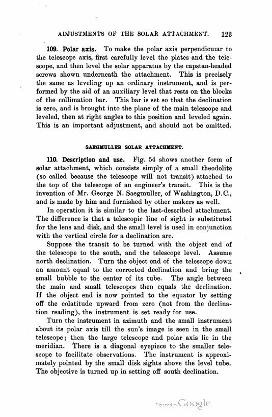
ADJUSTMENTS OF THE SOLAR ATTACHMENT. 123
109. Polar axis. To make the polar axis perpendicular to
the telescope axis, first carefully level the plates and the tele
scope, and then level the solar apparatus by the capstan-headed
screws shown underneath the attachment. This is precisely
the same as leveling up an ordinary instrument, and is per
formed by the aid of an auxiliary level that rests on the blocks
of the collimation bar. This bar is set so that the declination
is zero, and is brought into the plane of the main telescope and
leveled, then at right angles to this position and leveled again.
This is an important adjustment, and should not be omitted.
SAEGMULLER SOLAR ATTACHMENT.
110. Description and use. Fig. 54 shows another form of
solar attachment, which consists simply of a small theodolite
(so called because the telescope will not transit) attached to
the top of the telescope of an engineer's transit. This is the
invention of Mr. George N. Saegmuller, of Washington, D.C.,
and is made by him and furnished by other makers as well.
In operation it is similar to the last-described attachment.
The difference is that a telescopic line of sight is substituted
for the lens and disk, and the small level is used in conjunction
with the vertical circle for a declination arc.
Suppose the transit to be turned with the object end of
the telescope to the south, and the telescope level. Assume
north declination. Turn the object end of the telescope down
an amount equal to the corrected declination and bring the
small bubble to the center of its tube. The angle between
the main and small telescopes then equals the declination.
If the object end is now pointed to the equator by setting
off the colatitude upward from zero (not from the declina
tion reading), the instrument is set ready for use.
Turn the instrument in azimuth and the small instrument
about its polar axis till the sun's image is seen in the small
telescope ; then the large telescope and polar axis lie in the
meridian. There is a diagonal eyepiece to the smaller tele
scope to facilitate observations. The instrument is approxi
mately pointed by the small disk sights above the level tube.
The objective is turned up in setting off south declination.

Fig. 04.
124

MERIDIAN AND TIME BY TRANSIT AND SUN. 125
111. Adjustments. The adjustments of this instrument are
two : the adjustment of the polar axis, and that of the line of
collimation and small bubble. The first is performed, after the
transit has been carefully adjusted, by making the main tele
scope level, then leveling the small telescope over one set of
capstan-headed screws at the base of the attachment and adjust
ing, and then over the other precisely as in adjusting the plate
bubbles of the transit, correcting first by screws and next by
tipping the small telescope. The second adjustment is per
formed indirectly by making the two lines of collimation par
allel. Measure the distance between the centers of the two
horizontal axes and draw on a piece of paper two parallel
lines the same distance apart ; tack this up at some distance
from the instrument and about on the same level, with the
lines horizontal. Make the two bubbles parallel by making both
level, with the telescopes pointing toward the paper. Set the
line of collimation in the large telescope on the lower line on
the paper and adjust the wires of the small telescope until the
line of collimation of the small telescope cuts the upper line.
MERIDIAN AND T'ME BY TRANSIT AND SUN.
112. Meridian. If the sun's altitude at any moment is
measured with the transit, its azimuth at the same moment
may be computed if its declination and the lati
tude of the place of observation are known.1
For in the spherical triangle pole-zenith-sun, the
three sides will be known and the angle Z (the
azimuth) may be computed.
By Trigonometry if s = ^ (a + i + e),
sin1 z — \/s^n (s — ^) sin (s — c)
2 * sin b sin c
Fig. 55.from which, if h = declination, if> = latitude, and
h = altitude, and if s' = £ (pole dist. ( = 90° ± 8) + ij> + h),
sin$Z=yJ.sin (s' — i£) sin (s' — K)
cos cfi cos h
1 The same is true of any kn-wn star.
(1)

126 DIRECTION AND ANGLES.
Set up the transit at a convenient hour, over a tack in a
stake and, with vernier at zero, set a stake some distance away,
approximately north, and set the line of collimation on this
with the lower motion. Unclamp the alidade and turn the
line of collimation toward the sun and measure its altitude,
at the same moment clamping the alidade. A small piece of
red glass placed inside the cap of the eyepiece will enable the
observer to look at the sun; or, with the eyepiece drawn fully
out, the image of sun and wires may be received on a card held
just back of the eyepiece. To observe most accurately, bring
the horizontal and vertical wires tangent to the sun's image, cor
rect the altitude by the sun's semi-diameter, =0° 16', and the
observed azimuth by 16' x sec h. The observed altitude must
be corrected for refraction. The corrections given in Table IV.,
page 364, for Polaris, will answer if the column of latitude is
taken as altitude. Substitute the corrected altitude, the latitude,
and the declination, in Equation 1, and solve for Z. The dif
ference between the observed azimuth of the sun and Z is the
azimuth of the line of stakes, from which the meridian may be
laid off.1
113. Time. The angle at P in Fig. 55 is called t, the hour
angle. It is given by
. . sin Z cos hsmt= - (2)
cos o
Reduced to time, it is the true sun time, before or after noon,
of the observation. This must be corrected by the equation of
time (difference between true sun time and mean time) found
in the " Nautical Almanac " to give mean local time. This must
again be corrected by the difference between mean local and
standard time. The result compared with the observed time
of observation will give the error of the watch used.
1 Let the student show the error in azimuth resulting from an error of 0° 01'
in either latitude or altitude by computing Z f-r values of ip differing by 0° 01'
and the same for values of h. This should be done for latitudes near 30° and
50° and altitudes of 10° and 60° to show the effect of variations in these quanti
ties. Practically the same errors arise with the solar transit for like errors of
latitude and declination.

CHAPTER V.
STADIA MEASUREMENTS.
114. Defined. The stadia is a device for reading distances
by means of a graduated rod and auxiliary wires in a telescope.
In many farm surveys where the ground is very rough and not
very valuable, the measurements may be made with the stadia.
When so made, they will probably be somewhat more accurate
than if made with a chain or tape with the care that would
ordinarily be taken in the kind of work mentioned. In fact,
with the use of care and judgment, the stadia will serve for
almost all farm surveys.
The stadia is the best distance measurer for extensive topo
graphical surveys. The discussion of the stadia that follows
will perhaps indicate its limitations. The term " stadia " has
been very loosely used in this country. The word is the plural
of the Latin word "stadium," which means a standard of meas
ure. " Stadia " was the word adopted by the Italian engineer
Porro (who invented the method to be described) to indicate
the rod used by him in the application of his method. The
English have retained this use of the word and apply the word
" tacheometer " to the transit equipped with the additional
wires used in the method. "Tacheometer" means quick
measurer, and is applied by at least one American manufac
turing firm to their high-class instruments that are equipped
with vertical circle, level to telescope, and stadia wires. The
word as used by them is "tachymeter." As generally used in
this country the word " stadia " means the combination of in
strument and rod, but it is thought that it should be applied
to the rod only, and the word " tacheometer " or " tachymeter "
is a very suitable word to apply to the complete transit in
strument equipped for stadia work. Such a transit should
127
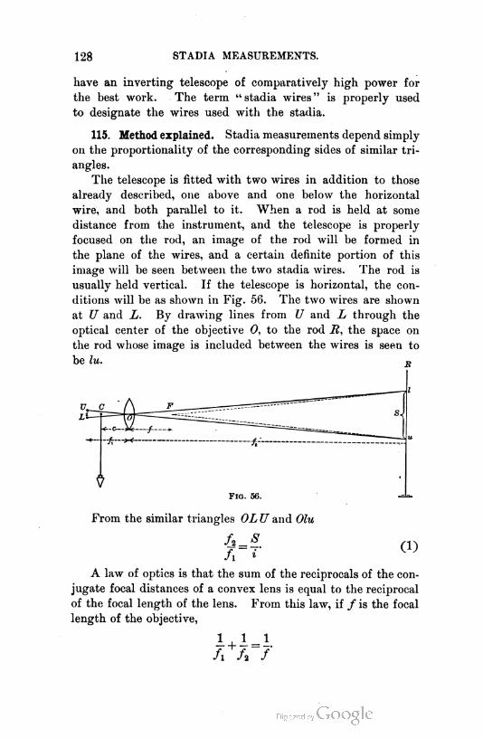
128 STADIA MEASUREMENTS.
have an inverting telescope of comparatively high power for
the best work. The term " stadia wires " is properly used
to designate the wires used with the stadia.
115. Method explained. Stadia measurements depend simply
on the proportionality of the corresponding sides of similar tri
angles.
The telescope is fitted with two wires in addition to those
already described, one above and one below the horizontal
wire, and both parallel to it. When a rod is held at some
distance from the instrument, and the telescope is properly
focused on the rod, an image of the rod will be formed in
the plane of the wires, and a certain definite portion of this
image will be seen between the two stadia wires. The rod is
usually held vertical. If the telescope is horizontal, the con
ditions will be as shown in Fig. 56. The two wires are shown
at U and L. By drawing lines from U and L through the
optical center of the objective 0, to the rod M, the space on
the rod whose image is included between the wires is seen to
be lu. r>
From the similar triangles OL U and Olu
(1)
fx
A law of optics is that the sum of the reciprocals of the con
jugate focal distances of a convex lens is equal to the reciprocal
of the focal length of the lens. From this law, if / is the focal
length of the objective,
1 + 1 = 1.
fx h f
SPACING OF THE WIRES. 129
Whence 1=^ L (2)
fx fU
Equating this value of — with that obtained from (1), there
results 0'x
= (3)
This is the distance from the objective to the rod. It is usual
to require the distance from the point over which the transit is
set, to the rod. If the distance from the objective to the center
of the horizontal axis, which is vertically over the plumb line,
is represented by c, the total distance required is
D = £s+(J+c). (4)
If, then, a graduated rod is held at an unknown distance
from the instrument, the distance will become known by multi
plying the space intercepted on the rod by the ratio of / to i
and adding to the product the constant quantity (/+c)•
f116. Spacing of the wires. The value of -t must be known.
Sometimes the wires are made so that the space between them
is adjustable. This is not considered by the author as good
practice. The wires should be fixed. They are attached to
the same ring that carries the cross wires, and should be spaced
at equal distances from the horizontal wire. This is not neces
sary, but is very convenient in reading, because it will occa
sionally happen that but one stadia wire and the horizontal
wire can be read. This is likely to occur in brushy country,
but should not be permitted when it is possible, at an expense
commensurate with the importance of the work, to avoid it.
In case it should occur, it is convenient to have the wires
equally spaced, because the reading of one wire multiplied by
two will give a sufficiently accurate determination of the dis
tance. In case the wires are not equally spaced, separate
values of the intervals may be determined for the wires.
fIt is thought best to have the ratio j = 100 for convenience.
If one is introducing stadia wires in his transit, he will find
r'm'd surv. — 9
130 STADIA MEASUREMENTS.
that it is practically impossible to accomplish this result accu
rately himself. It can rarely be done outside of the maker's
shop. However, it is not absolutely necessary to make this
ratio 100, as the rod may be graduated to suit the instrument.
117. To approximate the value of /. Focus the telescope
on a distant point (theoretically the point should be infinitely
distant, as a star) and measure the distance from the center of
the objective to the plane of the wires. This is the value of /.
118. The value of c. This is not quite constant in most in
struments, since the objective is moved in and out in focusing
for different distances. For almost all work done by the stadia
the error from this cause will not exceed one tenth of an inch,
which is inappreciable compared with the smallest unit readings
taken by this method. Single distances may not be read in
careful work much closer than the nearest half foot ; and, in
a very large percentage of work done with the stadia, the dis
tances are read only to the nearest yard or meter.
The value of e may be determined by focusing on an object
at, say, two hundred feet distance, and measuring the distance
from the objective to the center of the horizontal axis. In some
inverting instruments the focusing of the image on the wires is
accomplished by moving the eyepiece and wires together, instead
of the objective. In such an instrument c is a constant.
f f119. The value of — and (f+ c). If the value of -. is not
/ i
known, it may be determined as follows : Select a strip of level
ground, drive a stake and center it with a tack. Set the tran
sit over this point. From this point measure two distances,
say, one hundred feet and two hundred feet. Hold a rod at
each of the two distant points, and note the space intercepted
on the rod at each point.
In each of these equations, D and <S are known, and hence
D = + i/+«),
(6)
(5)
and (/ + c) may be found.
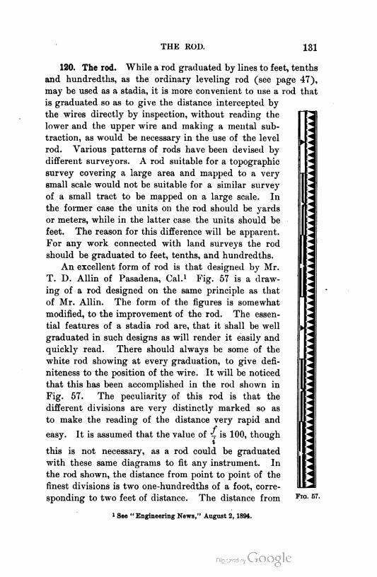
THE ROD. 131
120. The rod. While a rod graduated by lines to feet, tenths
and hundredths, as the ordinary leveling rod (see page 47),
may be used as a stadia, it is more convenient to use a rod that
is graduated so as to give the distance intercepted by
the wires directly by inspection, without reading the
lower and the upper wire and making a mental sub
traction, as would be necessary in the use of the level
rod. Various patterns of rods have been devised by
different surveyors. A rod suitable for a topographic
survey covering a large area and mapped to a very
small scale would not be suitable for a similar survey
of a small tract to be mapped on a large scale. In
the former case the units on the rod should be yards
or meters, while in the latter case the units should be
feet. The reason for this difference will be apparent.
For any work connected with land surveys the rod
should be graduated to feet, tenths, and hundredths.
An excellent form of rod is that designed by Mr.
T. D. Allin of Pasadena, Cal.1 Fig. 57 is a draw
ing of a rod designed on the same principle as that
of Mr. Allin. The form of the figures is somewhat
modified, to the improvement of the rod. The essen
tial features of a stadia rod are, that it shall be well
graduated in such designs as will render it easily and
quickly read. There should always be some of the
white rod showing at every graduation, to give defi-
niteness to the position of the wire. It will be noticed
that this has been accomplished in the rod shown in
Fig. 57. The peculiarity of this rod is that the
different divisions are very distinctly marked so as
to make the reading of the distance very rapid and
feasy. It is assumed that the value of J- is 100, though
i
this is not necessary, as a rod could be graduated
with these same diagrams to fit any instrument. In
the rod shown, the distance from point to point of the
finest divisions is two one-hundredths of a foot, corre
sponding to two feet of distance. The distance from Fio. 57.
1 See " Engineering News," August 2, 1894.

132 STADIA MEASUREMENTS.
point to point of the larger divisions shown on the right of
the rod, is one tenth of a foot, corresponding to ten feet dis
tance. On the left side of the rod the half-foot
points stand out plainly, corresponding to fifty
feet distance, and each whole foot is also plainly
seen, giving one hundred feet distance. These
whole feet are again marked in sets of three,
giving three hundred feet distance. To read
the rod, set the upper wire on some fifty-foot
point and then run down the rod to the lower
wire, taking in at once all the three-hundred-
foot spaces, adding the hundreds and the final
fifty, then the tens, and lastly the single units.
Another good rod for long-distance work,
is shown in Fig. 58. The manner of reading
this rod is seen from the figures at the side of
the rod. This rod is better suited for yard or
meter units than the Allin rod, and the author
has used it with feet units with success.
121. Inclined readings. It has been assumed
Fio. 58. thus far that all readings taken with the stadia
are horizontal. It will be evident that there will probably
be more readings that are inclined than horizontal. When
the readings are inclined, the formulas already derived must be
modified.
Fig. 5iJ.
In Fig. 59 let the distance from I to A be required. If the
rod were held perpendicular to the line of sight, the reading
EF would at once give the inclined distance IC, which then

INCLINED READINGS. 133
multiplied by the cosine of the angle a would give the required
horizontal distance. The angle « is determined by setting the
horizontal cross wire on a point on the rod as much above A as
the center of the telescope is above the ground at i", and then
reading the vertical circle of the transit. The rod is usually
held vertical. Therefore, the reading obtained will be DB. If
the angles at F and F are considered right angles, an approxi
mation sufficiently exact for the purpose, FF is given by
EF=DB cos a. (7)
If, then, R is the reading DB, the distance IC is given by
10= (B cos a + (f+ c). (8)
But it is the distance IGr that is required.
IGr = IC cos a,
= Ir cos2 a+(f+e) cos a. (9)
i
From this equation the distance is obtained. If it were neces
sary to perform this multiplication for every sight taken, very
much of the usefulness of the stadia would be offset by this
great labor. The value of (/+<?) varies from, say, nine inches
to fifteen inches or more, according to the construction of the
instrument. Where such an error is unimportant, the final
term may be neglected. For vertical angles between five de
grees and six degrees, the exact angle depending on the value
of Cf+e), this term is just balanced by the difference between
f f4 R and v R cos2 a ; hence for angles near this value no correc-
i i
tion need be applied, and the distance may be recorded as read.
For the more ready computation of the results, tables have
been computed giving the value of ^ R cos2 a, for R = 1, and
angles from 0° to 30°. Such a table is Table XIV., Appendix,
pages 380-382. To explain the use of the table, suppose a reading
of 1.52 feet, usually read at once 152 feet, is had with a vertical
angle of 5° 30'. Under 5° 30' Hor. Dist. find 99.08, which
multiply by 1 . 52, and add the correction found at the bottom
of the page for c, which is (/+ c). This multiplication may
134 STADIA MEASUREMENTS.
be hastened by the use of a slide rule,1 which is an instrument
that every surveyor should own and use. The column in the
table headed Diff. Elev. is used when it is desired to know the
elevation of the position of the rod above the instrument.
122. Difference of elevation. In Fig. 59, since the instru
ment is directed to a point on the rod as much above A as the
center of the instrument is above the ground at / (found by
standing a rod alongside the instrument), the difference in
elevation between the ground at I and at A will be CO; and
CG = 1C sin a
f=^ R cos a sin « + (f + c) sin a
t s
==/jBsh^a + (/+c)s.na (10)
For any reading and vertical angle the value of CG is found
from the table in the same way as was the horizontal distance.
123. Diagram. A still more rapid method of reducing the
observations is by means of diagrams. Omitting the second
term in equation (9), the distance for any given vertical angle
is proportional to the reading. To make a diagram to give
the correction to apply to the readings to get the required dis
tance, considering only the first term, a distance equal to the
longest probable reading is laid off along one side of a sheet
of cross-section paper ruled to tenths of inches or other small
units. Suppose the distance to be 1000 feet. A space of ten
inches may then be laid off, making the scale of distance 100
feet to an inch. Select an angle, as, say, 10°, and find from
Table XIV. the true distance for a reading of 1000 feet and a
vertical angle of 10°. The difference between this value and
1000 feet will be the correction to apply to the reading to -get
the true distance.
At the extremity of the distance line AB, Fig. 60, lay off
at right angles to AB, and to a scale of, say 10 feet to an inch,
the correction just found for the distance and angle. Sup
pose the point found is O. Draw from C to A a straight line.
1 See Chapter VI.

DIAGRAM. 135
Since the correction for this angle of 10° will be proportional
to the reading, the correction for any other reading than 1000
feet will be given by the ordinate to the line just drawn at
the proper distance from A. This will be evident from the
similarity of the triangles involved. Thus the correction for
any reading, as say 450 feet, is found by looking along AB to
the 450-foot point, and taking to the scale of 10 feet to an inch
U. 0 100 200 300 400 500 600 700 800 900 1000
F1g. 61.
the ordinate at the 450-foot point to the 10° line. A similar
line should be drawn in a similar manner for all other angles.
It will be sufficiently exact to draw the lines for degrees only,
estimating the minutes by eye.
A diagram for differences in elevation may be made in
the same manner (see Fig. 61), except that it will be neces
sary to draw the ten-minute lines, as the elevations may not be
estimated with sufficient exactness without these lines.
It should be noticed that the lines marked 1°, 2°, 3°, etc.,
do not make with the horizontal line angles of 1°, 2°, 3°, etc.,
but are drawn to the points found by laying off on the vertical
the correction to the reading for the given angle, as found in
the tables or as worked out from the equations. For the dif
ferences in elevation, the differences as found in the table for
the given distance and angles are laid off on the extreme ver
tical line. The ten-minute lines may ordinarily be drawn with
sufficient exactness by dividing the space between two adjacent
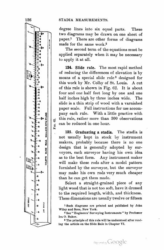
STADIA MEASUREMENTS.
degree lines into six equal parts. These
two diagrams may be drawn on one sheet of
paper.1 There are other forms of diagrams
made for the same work.2
The second term of the equations must be
applied separately when it may be necessary
to apply it at all.
124. Slide rule. The most rapid method
of reducing the differences of elevation is by
means of a special slide rule3 designed for
this work by Mr. Colby of St. Louis. A cut
of this rule is shown in Fig. 62. It is about
four and one half feet long by one and one
half inches high by three inches wide. The
slide is a thin strip of wood with a varnished
paper scale. Full instructions for use accom
pany each rule. With a little practice with
this rule, rather more than 300 observations
can be reduced in one hour.
125. Graduating a stadia. The stadia is
not usually kept in stock by instrument
makers, probably because there is no one
design that is generally adopted by sur
veyors, each surveyor having his own idea
as to the best form. Any instrument maker
will make these rods after a model pattern
furnished by the surveyor, but the surveyor
may make his own rods very much cheaper
than he can get them made.
Select a straight-grained piece of any
light wood that is not too soft, have it dressed
to the required length, width, and thickness.
These dimensions are usually twelve or fifteen
1 Such diagrams are printed and published by John
Wiley and Sons, New York.
2 See " Engineers' Surveying Instruments " by Professor
Ira O. Baker.
8 The principle of this rule will be understood after read
ing the article on the Slide Rule in Chapter VI,
GRADUATION. 137
feet by three to four inches by seven eighths of an inch. The
wood is generally made uniform in dimensions throughout, but
may be made thinner toward the top and may be shod with a
strip of iron or brass at the bottom. Some prefer to have no top
or bottom, but to have the rod graduated symmetrically from
the center out to the ends, so that whichever end is turned up
the reading is made equally well. There seems to be no great
advantage in this. The rod shown in Fig. 57 is three inches
wide inside of the side strips.
Give the rod three light coats of white paint, letting each
coat become thoroughly dry before the next is put on. After
the final coat is dry, graduate the rod. To do this, set up the
transit that is to be used with the rod, on a level strip of
ground, and, having determined the value (/ + c), lay this
distance off in front of the point of the plumb bob. From the
point thus obtained, measure carefully with a steel tape dis
tances of one hundred feet, two hundred feet, three hundred
feet, and more if desired. (If the rod is to be graduated to
yards or meters, the distances should be one hundred, two
hundred, and three hundred, of the units to be used.) Hold
the blank rod at these distances and carefully mark with a
hard pencil the points cut by the two wires at the different
distances.
The spaces cut should, of course, be strictly proportional
to the distances ; but owing to inaccuracies of observation
they may not be exactly so. Measure the several spaces inter
cepted and divide the three-hundred space by three, the two-
hundred space by two, and average the quotients with the
one-hundred space to determine the average space intercepted
at one hundred feet. These spaces should be measured with
great care, using either a good steel tape or a standard draughts
man's scale. This value of the space intercepted at one hun
dred feet having been determined, it is divided into as many
equal parts as may be required, and the rod is spaced off for
the diagrams that have been selected for use. The diagrams
are then laid out in pencil and are painted on the rod, with
black paint. A good quality of paint should be used, one
that will dry with a dead rather than a glossy, surface, that is,
the oil should be " killed " with turpentine,
138 STADIA MEASUREMENTS.
The rod should then be allowed to dry. When it is
thoroughly dry, strips of hard wood, about one eighth to one
fourth of an inch wider than the rod is thick, are screwed to
the edges of the rod. These strips, which are about a quarter
of an inch thick, are to protect the graduated surface of the
rod. They are very necessary to a rod that is to be much
used. The rod should be shod with brass or iron about one
eighth of an inch thick, at both ends if it is to be used either
end up, and at the bottom if it is to have a bottom.
For some kinds of work rods are graduated to read directly
from the instrument without the introduction of the (/ + c)
correction. This is done by measuring the distances one hun
dred, two hundred, three hundred, or more, units from the
plumb bob, noting the spaces intercepted at these distances,
taking a mean value for one hundred units, and graduat
ing the rod by this. The readings will be correct on such a
rod for but one distance. If the rod is graduated by meas
uring from the instrument a distance which is assumed to be
about a mean of those that will be read with the rod, and divid
ing the space intercepted into the required number of units, the
readings taken thereafter will be correct only for the distance
for which the rod was graduated. The space intercepted will al
ways be that between the dotted lines radiating from F, Fig. 56.
It will be observed that, with a rod graduated as first de-
fscribed, it is not necessary that ~ should be one hundred, or any
other definite quantity, since the actual space intercepted at
one hundred feet may be divided into one hundred units, and
the rod may then be read as easily as if it had been graduated
fto hundredths of a foot and — were equal to one hundred.
f 1-L. is equal to one hundred of the units used. It is frequently
i
convenient to use a level rod for single measurements (as the
crossing of a stream on a survey in which the stadia is not be
ing regularly used), or to be able to graduate rods directly in
feet and hundredths instead of taking the trouble to graduate
them as has been described, it being often practical to use such
rods for a time as level rods. For these reasons, and others,
fit is thought best to make i equal .

SMITH'S OBSERVATIONS. 139
126. Smith's observations. It is possible for the maker to
do this for the conditions of atmosphere obtaining at the time
of the setting.
Mr. L. S. Smith, C. E., has recently shown1 that system
atic errors are introduced into work when it is assumed that
a wire interval determined at any one time is correct for all
future work. This is due to the fact that the effect of refrac
tion is a variable quantity depending on the relative tempera
tures of air and ground. The effect of refraction is very much
greater near the ground than a few feet above. It is much
greater at noon than before or after. The effect varies for
different distances. It is also shown that observers have dif
ferent " personal equations."
It follows from the above, that to secure the best results
with the stadia, and indeed to avoid cumulative errors, the rod,
if graduated by the first method, should be graduated with a unit
obtained as the average result of a series of observations at vary
ing distances, at all hours of the day, for several days.
Also if a wide difference occurs in climatic or temperature
conditions between those obtaining when the rod is graduated
and those at the time of any survey, the rod should be regradu-
ated for the particular survey, or a factor applied to the results.
This factor should be determined as noted below.
It is also shown by these conclusions and the above result
of them that it is better to graduate the rod to standard units
and depend on the maker to place the wires at the interval
fIt will be sufficient for many surveys to consider this as
correct and to use the reduction tables or diagrams at once.
But if close work is to be done, it will be better to deter
mine the wire interval by observations at all hours of the
working day, and on several days, so that the average result
shall conform to the average to be expected from the average
conditions to prevail during the survey.
/Thus it will be found that wires set apart will intercept
on the rod held at distances of 100 + (/+ c), 200 + (/+ c),
etc., from the instrument, varying lengths, from possibly a
1 Bulletin of the University of Wisconsin, Engineering Series, Vol. I. No. 5.
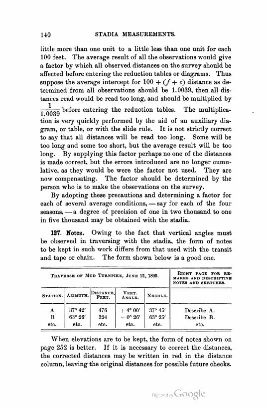
140 STADIA MEASUREMENTS.
little more than one unit to a little less than one unit for each
100 feet. The average result of all the observations would give
a factor by which all observed distances on the survey should be
affected before entering the reduction tables or diagrams. Thus
suppose the average intercept for 100 + (/+<?) distance as de
termined from all observations should be 1.0039, then all dis
tances read would be read too long, and should be multiplied by
- QQgy before entering the reduction tables. The multiplica
tion is very quickly performed by the aid of an auxiliary dia
gram, or table, or with the slide rule. It is not strictly correct
to say that all distances will be read too long. Some will be
too long and some too short, but the average result will be too
long. By supplying this factor perhaps no one of the distances
is made correct, but the errors introduced are no longer cumu
lative, as they would be were the factor not used. They are
now compensating. The factor should be determined by the
person who is to make the observations on the survey.
By adopting these precautions and determining a factor for
each of several average conditions, — say for each of the four
seasons, — a degree of precision of one in two thousand to one
in five thousand may be obtained with the stadia.
127. Notes. Owing to the fact that vertical angles must
be observed in traversing with the stadia, the form of notes
to be kept in such work differs from that used with the transit
and tape or chain. The form shown below is a good one.
Traverse of Mud Turnp1ke, June 21, 1895.
Stat1on. Az1muth.D1stance,
Feet.
Vert.
Angle.Needle.
A 37° 42' 476 + 4° 00' 37° 45' Describe A.
B 63° 26' 324 - 0° 26' 63° 25' Describe B.
etc. etc. etc. etc. etc. etc.
R1ght page for re
marks AND DESCRIPTIVE
NOTES AND SKETCHES.
When elevations are to be kept, the form of notes shown on
page 252 is better. If it is necessary to correct the distances,
the corrected distances may be written in red in the distance
column, leaving the original distances for possible future checks.

CHAPTER VI.
LAND SURVEY COMPUTATIONS.
128. General considerations and definitions. It will be evi
dent that, if the lengths and bearings of all the sides of a
closed field have been determined, these lengths may be repro
duced to scale on paper, with the proper bearings referred to a
meridian line drawn on the paper. It will be further evident
that, if these lines and bearings have been correctly determined
and have been laid off consecutively, joining end to end, they
should form a closed figure similar to the field on the ground.
A survey of a closed field rarely " closes " on the drawing
board, owing to the facts that distances can not be exactly
measured, that the various sides, offering different obstacles
will not be measured with the same proportionate error, that
if a compass is used, the bearings are ordinarily determined
only to the nearest quarter degree, and that even if a transit is
used, these bearings are not exactly determined. If the draw
ing is done with the aid of a protractor, the survey may close
on the drawing, even though there is some error, because the
errors are too small to show with the scale used. It is there
fore necessary to resort to computation to determine just what
the error of closure is.
To balance a survey is to determine the error of closure
and, if it is not greater than is allowable, to distribute a quan
tity equal to the error, but of opposite sign, among the several
sides, changing the notes accordingly, so that the survey shall
" balance " or close. This is necessary because a description of
a piece of property appearing in a deed ought to be such that
it will indicate a possible closed tract, and such descriptions
are, or should be, made from surveyors' notes. Before de
scribing the method of doing this, it will be necessary to
explain a few terms.
141

142 LAND SURVEY COMPUTATIONS.
The latitude of a point is its perpendicular distance from
an assumed base parallel.
The longitude of a point is its perpendicular distance from
an assumed base meridian.
The latitude of a line is the latitude of its middle point.
The longitude of a line is the longitude of its middle point.
The perpendicular distance of the final end of a given line
from a latitude parallel through its initial end is the latitude
difference of the line.
The perpendicular distance of the final end of a given line
from the meridian through its initial end is the longitude
difference.
In Fig. 63 the latitude difference of the line AB is BD ;
the longitude differ
ence is CB. If a is
the bearing of the
line,
BD= CA = l cos a
CB = l sin a
Therefore the lati
tude difference is
equal to the length
of the line multiplied
by the cosine of the
bearing ; and the
longitude difference
equals the length of the line multiplied by the sine of the bearing.
The latitude and longitude differences of the line BE are
respectively :
BF = V cos ft
FE = V sin /S.
The latitude and longitude of the point B, referred to the
meridian and parallel through A, are respectively AC and BC.
The latitude and longitude of the point E, referred to the same
meridian and parallel, are respectively AC + BFand CB + FE.
Latitude differences measured north are considered positive,
and those measured south negative. Longitude differences
F-o. 63.
ERROR OF CLOSURE. 143
measured east are considered positive, and those measured west
negative.
North latitudes are likewise positive, and south latitudes
negative. East longitudes are positive, and west longitudes
negative.
The latitude and longitude differences of the line EG are
respectively — EH and + HG. The latitude and longitude
of the point G are respectively :
Lat. = AC+BF-EH= GM,
Long. = CB + FE + HG = AM.
Similarly the latitude and longitude of the point / are
respectively :
Lat. = AC+BF-EH- GJ= -MJ= - KI,
Long. = CB +FE + HG-JI = + AK.
From the above discussion the method of determining the
latitude and longitude of any point in a traverse will readily
be seen.
The latitude of any point in a traverse is the latitude of the
initial point of the traverse plus the algebraic sum of the latitude
differences of all the courses of the traverse to the given point.
The student may formulate a similar statement for the lon
gitude of a point in a traverse.
In the figure the latitude and longitude of the initial point
are zero. In some cases this may not be so.
Since in a closed traverse the initial and final points are
coincident, their latitudes and longitudes must be the same,
and hence the algebraic sum of the latitude differences and
the algebraic sum of the longitude differences should each
equal zero.
129. Error of closure. If the latitude and longitude dif
ferences of the courses are computed, and the algebraic sum of
each equals zero, the field closes ; otherwise it does not.
If the field does not close, and if it is drawn on paper
by laying off from a meridian and parallel the latitudes and
longitudes of the several corners, in order, it will be found
that the last point, which should be coincident with the first,
is some distance from it. This distance is known as the
144 LAND SURVEY COMPUTATIONS.
error of closure, and is the hypotenuse of a right triangle,
whose two sides are the error in latitude and the error in lon
gitude. Its length, therefore, is the square root of the sum of
the squares of the errors of the latitude and longitude. If
this error is very small, or nothing at all, it indicates that the
angles of the field have been correctly determined (though the
bearings may none of them be right), and that if one is wrong,
all are wrong by an equal amount. It also indicates that the
lengths of the sides have been measured correctly so far as
their relative lengths are concerned, though, perhaps, their
true lengths have not been determined. The correctness of
the bearings depends, if a compass has been used, on the cor
rectness with which the declination has been determined ; and
the determination of the true length of the lines depends on
the length of the chain or tape and the precision with which it
has been handled.
It is usually assumed, however, that the constants of the
compass and chain have been correctly determined, and that,
therefore, the error of closure is a true measure of the pre
cision of the survey. If a transit has been used to measure
angles, from which the bearings of the sides have been com
puted, the error will be almost wholly due to erroneous meas
urement. The surveyor should know whether the error of
closure is such as to be the result of justifiable or unjustifiable
lack of precision in the work, or gross error. It may be said
in this connection that, in ordinary farm surveying, an error of
one in five hundred, obtained by dividing the error of closure
by the total perimeter of the field, is tolerable, and that the
precision should be, for good farm work, as high as one in two
thousand, or better.
BALANCING THE SURVEY.
130. Fundamental hypotheses. If a compass is used, the
method of correcting the notes is based on the supposition that
any errors are due as much to inaccuracy of angle measure
ment as to a lack of precision in measuring lines. This does
not mean that the error of closure due to any one line is as
much owing to erroneous linear measurement as to erroneous

BALANCING THE SURVEY. 145
determination of bearing ; but that it is probable that in a
line in which an error of bearing would tend to produce the
observed error of closure, such an error has been made, and
little or no error in measurement of length ; while in a line in
which an error of length would tend to produce the observed
error of closure, such an error in length has been made with
little or no error in bearing. This means that a line whose
bearing is about normal to the line which represents the error
of closure, would be corrected in bearing and not in length ;
while a line that is parallel to the direction of the line repre
senting the error of closure, would be corrected in length
and not in bearing. Lines whose bearings are intermediate
between those mentioned would be corrected in both bearing
and length, the greater portion of the error being given to
bearing or length in proportion to the effect that each would
have on the error of closure ; thus, if the bearing of the line
were nearly normal to the line representing the error of
closure, it would be corrected more for bearing than for
length, and if nearly parallel to that line it would be corrected
mostly in length.
The plausibility of the supposition that errors of closure
are due as much to errors in bearing as to errors in length, is
clear when it is remembered that in using the compass, bear
ings are not read with greater precision than to the nearest
quarter degree, thus making possible an error of from nothing
to seven and one half minutes. The error resulting from an
error in bearing is proportional to the length of the line on
which the error is made, and an error of seven minutes gives an
erroneous position for the end of a line of one foot in five hun
dred, or as much as would be allowed in measurement of lines.
It is assumed that errors in length will be proportional to
the lengths of the lines measured, although it is more probable
that they are proportional to the difficulties involved in the
measurement, and to the lengths.
131. The method explained. If the assumptions are all
true, it will follow that the error of closure should be distrib
uted among the several sides of the field in proportion to their
several lengths. The demonstration of this is as follows :
r'm'd SUEV. — 10
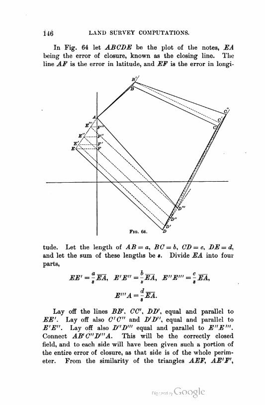
146 LAND SURVEY COMPUTATIONS.
In Fig. 64 let ABCDE be the plot of the notes, EA
being the error of closure, known as the closing line. The
line AF is the error in latitude, and EF is the error in longi
tude. Let the length of AB = a, BC = b, CD = c, DE = d,
and let the sum of these lengths be *. Divide EA into four
parts,
EE' = -EA, E'E"=-EA, E"E"' = -EA,s s s
E"'A = -EA.s
Lay off the lines BB', CC', DD\ equal and parallel to
EE'. Lay off also CC" and D'D", equal and parallel to
E'E". Lay off also D"D"' equal and parallel to E"E"'.
Connect AB'C"D"'A. This will be the correctly closed
field, and to each side will have been given such a portion of
the entire error of closure, as that side is of the whole perim
eter. From the similarity of the triangles AEF, AE'F',

BALANCING THE SURVEY. 147
AJ2"F", etc., it will be seen that the same proportion of the
error of latitude and the error of longitude has been given to
each side, whence the following rule :
Rule : Correct the latitude difference and longitude differ
ence of each course by an amount determined by the propor
tion; the required correction in latitude (or longitudeo) is to the
total error in latitude (or longitude) as the length of the course
in question is to the entire perimeter of the field.1
It will be observed that the courses nearly parallel to HA
have been corrected mostly in length, while those nearly
normal to HA have been corrected mostly in bearing.
From the corrected latitude and longitude differences new
bearings and lengths are computed.
132. The practice. This method is not strictly followed in
practice. It is, as has been seen, based on certain assumptions
as to the probable mode of occurrence of the errors. In a
given case it may be that the surveyor knows, or is reasonably
certain, that a greater portion of the error is due to the diffi
culty encountered in measuring one side, and in such a case
he would give the greater portion of the error to that side.
In determining that this is true, he must first ascertain the
direction of the closing line to see whether the line supposed
to be difficult to measure is parallel or nearly parallel to the
closing line, so that an error in measurement would be respon
sible for the resulting closing line. It may be that it is believed
that the error is not confined to one course but is distributed
over all the courses, though not in the proportion of their
lengths, as some may have offered greater difficulties to meas
urement than others. If this is so, the error is distributed in
the following manner :
Rule : Determine by judgment which line has offered the
least difficulties to measurement and number this line 1. Give
to each of the other sides a number that shall represent its rela
tive difficulty of measurement, as 2, 3, 2£, etc. Multiply each
length by its number and find the sum of the multiplied lengths.
Distribute the total errors of latitude and longitude by the follow-
1 Least square demonstration of this rule will be found in Wright's "Adjust
ment of Observations."
148 LAND SURVEY COMPUTATIONS.
ing proportion : The correction to the latitude (or longitudeo)
difference of any course is to the total error in latitude (or
longitude) as the multiplied length of the course is to the sum
of the multiplied lengths.
This is termed weighting the courses in proportion to their
probable error, and results in distributing the whole error in pro
portion to the difficulties encountered and the lengths of the lines.
When the lines are all of equal difficulty of measurement,
or when one who knows nothing of the field work balances the
survey, the first method should be used. In case the person
making the survey also balances it (as should always be the
case, when possible), the second method should be followed.
The original notes of the survey should not be destroyed.
The new latitude and longitude differences and lengths and
bearings of courses may be written in the notebook in red ink
over the originals. The originals may be useful in the future
in determining how the corrections were made. It is not com
mon to correct the observed bearings and lengths to correspond
to the corrected latitude and longitude differences ; but it is
well to do this.
133. When a transit is used. In case there is no reason to
believe there is any error in bearings, as when a transit is used
for determining angles, and therefore the entire error of closure
is due to lack of uniformity in measurement, the survey should
be balanced in such a manner that only the lengths shall be
corrected. No satisfactory rule has yet been devised to accom
plish this, and it must usually be done by trial.
If the field is rectangular and one side may be taken parallel
to the meridian of the survey, or assumed so for the purpose,
the following rule accomplishes the desired result :
Rule: The correction in latitude (or longitude) difference
for any course is to the total error in latitude (or longitude) as
the latitude (or longitude) difference of the course is to the arith
metical sum of the latitude (or longitude) differences.
It is believed that the student can demonstrate the correct
ness of this rule for the assumed conditions, if he remembers
that the sides must be corrected in length only, their directions
remaining unchanged.

SUPPLYING OMISSIONS. 149
SUPPLYING OMISSIONS.
134. Necessity, for. At times it is impossible to measure
the length of a line ; at other times it is impracticable to deter
mine directly its bearing ; and sometimes it is impossible to
do either. Moreover, it may happen that the length of one
line and the bearing of another have not been determined. If
any one of these conditions prevails, it becomes necessary to
supply the omission in the notes. To do this leaves the work
without a check, as all the errors are thrown into the quantity
that is supplied ; hence no omission that can in any way be
supplied in the field, should be permitted.
The cases that may occur are the following :
I. The length of one side may be wanting.
II. The bearing of one side may be wanting.
III. The bearing and length of one side may be wanting.
IV. The bearing of one side and the length of another may
be wanting.
V. The lengths of two sides may be wanting.
VI. The bearings of two sides may be wanting.
135. General discussion. It should be clear from what has
preceded, that the algebraic sums of the latitude and longitude
differences of the known sides are respectively equal to the
latitude and longitude differences necessary to close the field
(but are of opposite signs), or to the latitude and longitude
differences of the wanting sides plus the errors in latitude and
longitude of the known sides. Since there is no means of
determining these errors, the sums are taken as the latitude
and longitude differences of the defective sides.
It is therefore possible to write two independent equations
as follows :
I. The algebraic sum of the products of the lengths of the
defective courses by the cosines of their respective bearings
equals the algebraic sum of the latitude differences of the
known sides, but has the opposite sign.
II. The algebraic sum of the products of the lengths of the
defective courses by the sines of their respective bearings
equals the algebraic sum of the longitude differences of the
known sides, but has the opposite sign.
150 LAND SURVEY COMPUTATIONS.
Having but two equations, there can be but two unknown
quantities, and these may be as in Art. 134.
If Zj and l2 and 0X and 02 are the lengthos and bearings of
the defective sides, and if 2 is taken as a sign indicating the
algebraic sum of any series of quantities, as in this case the
latitude and longitude differences, and L and M represent lati
tude and longitude differences respectively, the above two
equations may be written as follows :
lx cos + 12 cos #2 = — 22/, (1)
Zjsinflj + tjsinfl^ (2)
These are, of course, equivalent to the following general
equations :
2i =0,
136. Cases L, II., and III. These are most readily solved by
applying equations (1) and (2). If but one quantity is want
ing, as the length or bearing of a side, either equation (1) or
equation (2) will solve, one of the left-hand terms becoming
part of the right member.
If both the length and bearing of one side are wanting, one
of the left-hand terms in e^ch equation becomes part of the
right member, and equation (2) may be divided by equation
(1), giving
- 1Mtan 0=
-22/
Having 0V the length is found by substituting in either equation.
The signs of the sums of the known differences will indi
cate the direction of the defective side.
137. Cases IV., V., and VI. The author thinks the remain
ing cases are better solved by special methods as follows :
Case IV. 1. The two imperfect sides are adjacent. With
the algebraic sums of the known latitude and longitude dif
ferences, compute the length and bearing of a closing side.
This side will form with the two defective sides a triangle in
which two sides and one angle are known.1 The triangle may
then be solved, giving the required quantities.
1 The student should draw a diagram showing this.

SUPPLYING OMISSIONS. 151
2. The defective sides are not adjacent. Imagine some of
the sides shifted till the defective sides are adjacent and pro
ceed as before. Thus, in Fig. 65,
the defective sides are BE and
AB. If the side AE is imagined
shifted parallel to itself to the po
sition BE, a closing line BE may a
be computed, and this will form
with EB and EE (= AB) a tri
angle.
Case V. Treat in the same way
as Case IV. In the triangle that
results there will be known the
three sides. This case is inde
terminate if the defective sides are
parallel, unless the area is known.
Case VI. is solved in the same way, and in this case there is
known in the triangle one side and all the angles.
Cases IV. and VI. are not determinate unless enough is
known of the field to show which of two angles that correspond
to a given sine or cosine is the correct one to use. This will
be evident from the following algebraic discussion of Cases
IV., V., VI.
138. Algebraic solution. Let the sum of the known latitude
differences be denoted by L and the sum of the longitude dif
ferences by M. Then for these cases may be written,
lx cos 0l + l2 cos 02 = — L, (3)
lx sin 91 + l2 sin 02 = — M. (4)
In Case IV. let there be wanting lx and 02. Solving (3)
for cosine 02 and (4) for sine 0V squaring and adding and then
solving for lv there results
?j= ± -I?+ (L cos 0X+Msin Wtf- (X cos 0X +Msin 0{).
It is evident that there are here two values for lv If the proper
value may be determined by a knowledge of the field, 02 may be
found by substitution in either (3) or (4).
For Case V. there will be wanting in (3) and (4) lx and l¥

152 LAND SURVEY COMPUTATIONS.
Solve each for lv equate the resulting expressions, solve for lv
and derive
_ Mcos 0X — L sin 0X _ Ifcos 01 — L sin 01
2 — sin 0X cos 02 — cos 0X sin 02 sin (0X — #2)
from which it is seen that the value is indeterminate when
01 = 02, or the defective sides are parallel.
For Case VI. there will be wanting 0X and 02. Solve equa
tion (3) for cos 0X and equation (2) for sin 0y Square both
resulting equations and add, getting
L cos 02 + Msin 02 = -1
Let the right-hand member be represented by P. Then
ifVI - cos2 ^2 = P - L cos 02;
square, and solve for cos 0V deriving
a PL± M-VM2 + I?-P*cos<?2= wvi? '
from which it is evident that there are two values, the correct
one to be determined by a knowledge of the survey. In the
algebraic solutions, careful attention must be paid to the signs
of the trigonometric functions. Since no bearing is greater
than 90°, the signs, according to usual trigonometric concep
tions, would all be positive ; but in equations (3) and (4)
those signs must be used that will produce the proper sign for
the latitude and longitude differences ; thus, for a S.E. bearing,
the cosine would be negative and the sine positive.
AREAS.
139. Double longitudes. When the survey has been bal
anced, the area may be computed. This is usually done by the
use of a formula involving the products of the latitude differ
ence and double longitude of each side of the survey. The
double longitude of a line is simply twice its longitude, or the
sum of the longitudes of its ends. The latitude differences are
taken from the table of corrected latitude differences that has
AREAS. 153
been prepared in balancing the survey. There must be found
a convenient method for determining the double longitudes.
In Fig. 66 let IFS be the reference meridian, the longitude
differences of the various sides being as shown, with the signs
prefixed to each. It is evident that the double longitudes
of the first and last courses will be numerically equal to their
respective longitude differences, but the sign of the D.L. of the
final course will be opposite to that of its longitude difference.
The D.L. of any other course, as BC, is the sum of the longi
tudes of its extremities.
D.L. of BC= bB + cC= d1 + d1 + (- d2).
In words, the D.L. of BC is the D.L. of AB plus the longi
tude difference of AB, plus the longitude difference of BC.
Again, the D.L. of CD is
cC+ (- dD") = [d, + (- rf2)] + [<*, + (- d2) + (- tf3)]
= [dj-l- dx + (- d„)] + (- d2) + (- d3),
or the D.L. of CD equals the D.L. of BC plus the longitude
difference of BC plus the longitude difference of CD.
From the result of this investigation may be formulated the
Rule : The double longitude of any course is equal to the
double longitude of the preceding course, plus the longitude differ
ence of that course, plus the longitude difference of the course
itself.
In applying this rule, due attention must be paid to the
signs of the quantities. This rule applies to the first course
as well as to the others, if the preceding course is considered
to be zero.
To determine the D.L. of the various courses, select one
course as the first. Its longitude difference is its D.L. To
this add its longitude difference and the longitude difference of
the second course, and obtain the D.L. of the second course ;
to this add the longitude difference of the second course and
the longitude difference of the third course, and obtain the
D.L. of the third course, etc. The correctness of the work
is proved if the D.L. of the final course is found numerically
equal to its longitude difference.
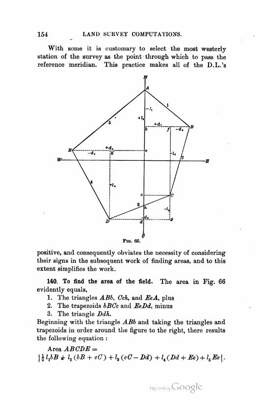
154 LAND SURVEY COMPUTATIONS.
With some it is customary to select the most westerly
station of the survey as the point through which to pass the
reference meridian. This practice makes all of the D.L.'s
F1o. 66.
positive, and consequently obviates the necessity of considering
their signs in the subsequent work of finding areas, and to this
extent simplifies the work.
140. To find the area of the field. The area in Fig. 66
evidently equals,
1. The triangles ABb, Cch, and EeA, plus
2. The trapezoids bBCe and EeDd, minus
3. The triangle Ddh.
Beginning with the triangle ABb and taking the triangles and
trapezoids in order around the figure to the right, there results
the following equation :
Area ABCDE =
\ I IJ>B J- l2 (bB + cC) + l3 (cC- Dd) + l^Bd + Ee) + lbEe J .
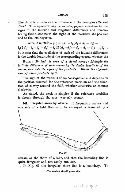
AREAS. 155
The third term is twice the difference of the triangles cCh and
Ddh.1 This equation may be written, paying attention to the
signs of the latitude and longitude differences and remem
bering that distances to the right of the meridian are positive
and to the left negative,
Area ABCDE = \\- - h (di + di ~ d*) ~
ls(2d1- d2-d2 - dz) + lt (2 (c^-c^) - da - da - rf4) - lhdh \.
It is seen that the coefficient of each of the latitude differences
is the double longitude of the corresponding course, whence the
Rule : To find the area of a closed survey : Multiply the
latitude difference of each course by the double longitude of the
course, and note the signs of the products. Divide the algebraic
sum of these products by 2.
The sign of the result is of no consequence and depends on
the position assumed for the reference meridian and the direc
tion of survey around the field, whether clockwise or counter
clockwise.
As stated, the work is simpler if the reference meridian
is chosen through the most westerly corner.
141. Irregular areas by offsets. It frequently occurs that
one side of a field that is to be surveyed is bounded by a
Fig. 67.
stream or the shore of a lake, and that the bounding line is
quite irregular and not easily run out.
0 In Fig. 67 the irregular shore line is a boundary. To
!The student sh-uld pr-ve this.

150 LAND SURVEY COMPUTATIONS.
determine the area, two auxiliary courses, AB and BC, are run
and used with the remaining sides to compute the area on their
left. Left and right refer to the direction in which the lines are
run. The additional area between these lines and the shore is
obtained by measuring offsets normal to these lines. These
offsets are measured to the points of change of direction of the
shore, and their lengths and distances from A, B, or C, are
noted. The area is then computed by considering the portions
between the shore and base line and two adjacent offsets to be
trapezoids or triangles. When the curve of the shore is such
that the offsets may be taken at regular intervals along a base
line, the area is found by applying the following rule :
Rule : To the half sum of the initial and final offsets add
the sum of all the intermediate offsets, and multiply the result
by the common distance between offsets.1
If the offsets are taken at irregular distances, the area may
be found as described in Art. 146.
COORDINATES.
142. Definitions. It is becoming common to call the lati
tude and longitude of a point the " coordinates " of the point.
The base parallel and meridian are known as the " coordi
nate axes," and their intersection as the " origin of coordinates."
The coordinates of the origin are evidently both zero. As
with latitudes and longitudes, ordinates measured east, or to
the right from the reference meridian, are considered positive;
those measured west, or left, are negative ; those measured
north, or up from the base parallel, are positive; and those
south, or down, are negative.
It is not uncommon to speak of the latitude ordinates as
" ordinates," and the longitude ordinates as " abscissas."
In the city of New York, and in some other cities, many
corners to public property, and many or all private property
corners, are located by coordinates, the well-established line of
some important thoroughfare being taken as a reference me
ridian, the origin and meridian being marked by monuments.
1 The student will be able to show the truth of this rule.
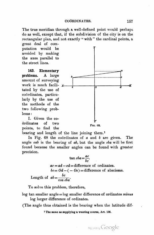
COORDINATES. 157
The true meridian through a well-defined point would perhaps
do as well, except that, if the subdivision of the city is on the
rectangular plan, and not exactly " with " the cardinal points, a
great deal of com
putation would be
avoided by making
the axes parallel to
the street lines.
143. Elementary
problems. A large
amount of surveying
work is much facili
tated by the use of
coordinates, particu
larly by the use of
the methods of the
two following prob
lems :
I. Given the co
ordinates of twor
F1g. 68.
points, to find the
bearing and length of the line joining them.1
In Fig. 68 the coordinates of a and b are given. The
angle cab is the bearing of ab, but the angle cba will be first
found because the smaller angles can be found with greater
precision.
tan cba=ac
To
ac = ad— cd= difference of ordinates.
bc= Od — (— Oe) = difference of abscissas.
Length of ab =—
cos cba
To solve this problem, therefore,
log tan smaller angle = log smaller difference of ordinates minus
log larger difference of ordinates.
(The angle thus obtained is the bearing when the latitude dif-
1 The same as supplying a wanting course, Art. 136.

158 LAND SURVEY COMPUTATIONS.
ference is the greater, and is the complement of the bearing
when the longitude difference is the greater.)
log length = log greater difference of ordinates minus log cos of
angle found.
The letters to affix to the bearing may be determined by
inspection of the coordinates of the points.
T
T
Fig. 69.
II. Given the bearings of two lines and the coordinates
of a point on each, to find the location, i.e. the coordinates,
of the point of intersection of the lines.1
The coordinates of a and b are given, and the bearings of
the lines as and br. By Problem I. find the bearing of ab and
the logarithm of its length. From the known bearings of the
three sides of the triangle abc, the three angles may be found
and the triangle solved for either ac or be. From the deter
mined length of either be or ac and its bearing, its latitude and
1 This problem is the same as supplying tw- wanting lengths.
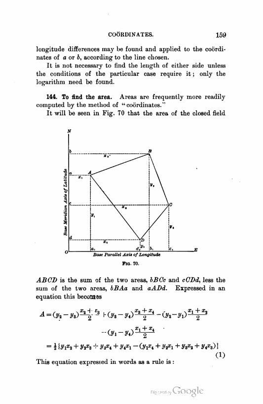
COORDINATES. 159
longitude differences may be found and applied to the coordi
nates of a or b, according to the line chosen.
It is not necessary to find the length of either side unless
the conditions of the particular case require it ; only the
logarithm need be found.
144. To find the area. Areas are frequently more readily
computed by the method of "coordinates."
It will be seen in Fig. 70 that the area of the closed field
ABCD is the sum of the two areas, bBCc and cCDd, less the
sum of the two areas, bBAa and aADd. Expressed in an
equation this becoM3s
- 1 {#1*2 + y& + Vixi + ypi - (.Vixi + y^i + y&2 + nx») i
(i)
This equation expressed in words as a rule is :
1G0 LAND SURVEY COMPUTATIONS.
Rule: To determine the area of a closed field when the
coordinates of its corners are known : Number the corners consec
utively around the field. Multiply each ordinate by the following
abscissa and sum the products. Multiply each ordinate by the
preceding abscissa and sum the products. One half the difference
of the two sums, subtracting the second from the first, is the area
of the field.
Equation (1) may be written,
4 = RVi Oa - xi) + Vi O3 ~ xi) + V3(xi - x%) + 2/i(.xi -*»)}• (2)
This equation expressed in words as a rule is :
Rule : To determine the area of a closed field when the
coordinates of its corners are known : Number the corners consec
utively around the field. Multiply each ordinate by the difference
between the following and preceding abscissas, always subtracting
the preceding from the following. One half the sum of the product
is the area required.
The second rule ordinarily involves less work than the first,
but there are certain cases in which the first is used- to better
advantage.
145. To make the coordinates all positive. The method of
determining the coordinates will perhaps suggest itself to the
student. To lessen the danger of making errors in signs
it will be better to arrange the axes so that the field shall
lie wholly within the northeast quadrant. All the coordinates
will then be positive. This may be done as follows : Deter
mine in the usual way the latitudes and longitudes of the cor
ners of the field with reference to the meridian and parallel
through one corner, preferably the most westerly corner. If
the most westerly corner is chosen, the longitudes will all be
positive without further arrangement. To make the latitude
ordinates all positive, add to each latitude a quantity equal to
the greatest southern latitude. This will move the reference
parallel to the most southern point. If considered more con
venient, any round number, as 100, greater than the most
southern latitude, may be added. An inspection will ordina
rily be sufficient to enable the computer to assume beforehand
proper coordinates for the first corner.

COORDINATES. 161
146. Elongated areas by offsets. A special case, in which
the application of this method of coordinates is advantageously
used, is the determination of elongated, irregular areas, the
measurements for which consist of offsets at unequal intervals
along a straight line. In this case, the line from which the
offsets are measured is assumed as the reference parallel.
Thus, in Fig. 71, it is required to determine the area between
the line AH, the irregular line abcdefgh, and the two end off-
--b "
c
^)/
'A
A
\v*k
V.
E
0
V,\.
1i
:c O 1F V-,H
—-av- "
-^9-10
F1g. 71.
sets. The corners of the closed field are A abcdefghH and
their coordinates are as shown in the figure. xx and yx and x2
and y10 are zero. The equation that would be written, follow
ing the second rule of Art. 144, would be as follows :
^ = i O2 ~ ^lo) + Vi Os - xv> + V3 - *2> + Vi O5 - x3)
+ y$ 09 - xi) + y9 O10 - xs) + V10 Cxi - %) i -
yx and yw being zero, the first and last terms will disappear ;
xx and x2 being zero, the second term becomes y2x3< an(^ *ne
third term y3£4. What is, perhaps, a less confusing system of
writing these quantities is to write each ordinate and its cor
responding abscissa in the form of a fraction, connecting each
ordinate with the abscissas whose difference is to be taken as a
multiplier. Thus, calling the x's ordinates and the y's abscissas,
The downward lines to the right show the following or
positive abscissas, and the downward lines to the left show the
r'm'd surv. — 11

162 LAND SURVEY COMPUTATIONS.
preceding or negative abscissas. The lines may be omitted
as soon as the student becomes thoroughly familiar with the
work. This arrangement applies to any closed field and not
alone to the elongated strip last described, though it is particu
larly applicable to that method since the quantities may be
arranged for computation as they are taken in the field. Ap
plications of the coordinate method of surveying will be found
in the problems, pages 328->-335.
Sin. +
147. Zero azimuth. It is thought that the reason for sug
gesting that zero azimuth shall be the north point, will now be
clear. Since north latitude and east longitude are considered
positive, and south lati
tude and west longitude,
negative, a system of
azimuths should be so
arranged that the signs
of the trigonometric
functions of any azi
muth shall agree with
the signs of the corre
sponding latitude and
longitude differences.
Fig. 72 shows the ar
rangement of signs of
coordinates, and the
correspondence of the signs of the trigonometric functions.
There is thus no necessity actually to convert azimuth into
bearing in order to determine the signs of the latitude and
longitude differences, nor to carry in mind any other than the
ordinary scheme of signs given in any work on Trigonometry.
The signs of the coordinates could, of course, be changed to
suit a south zero azimuth, but the custom among all people to
look to the north as the orienting point, and the long use of
the signs given for coordinates, seems to make it better for the
surveyor to use the north as zero azimuth. Were it merely a
matter of changing technical terms used only by the surveyor,
such as changing " departure " to "longitude difference," the
case would be different.

DIVIDING LAND. 163
DIVIDING LAND.
148. Occurrence of the problem. It sometimes becomes nec
essary to divide a field into two or more parts of equal or known
areas. This occurs when one man, as John Jones, sells to an
other, as Paul Smith, x acres to be laid off in the northeast
corner of Jones's field. It also occurs in the division of inherited
lands among the heirs, and in the determination of lands sold
for taxes. When the taxes are not paid on a given piece of
land, the land is sold to the lowest bidder. This means that
the land is put up at auction for the taxes and expenses of sale,
and that the person who agrees to take the least part of the
whole piece, and pay therefor the taxes and expense of sale, is
given a title to that portion of the land that he agrees to take.
This title is redeemable by the original owner within a certain
time, specified by law, after the expiration of which time, if the
title has not been redeemed, it becomes vested in the purchaser
forever. In any case that may arise the original tract will be
fully known, either by previous surveys or by surveys made at
the time and for the
purpose of the subdi
vision. It will also be
known in what way the
land is to be divided,
and the problem then
becomes simply one of
Geometry or Trigonom
etry.
149. Solution of the
problem. The method
of solving two common
problems will be given,
and others may be
readily devised, on which the student may test his ingenuity.
I. It is required to lay off from a given field A acres by a
line beginning at a given point in a given side. Plot the field
to scale. Let Fig. 73 represent the field so plotted. Let m be
the given point. Imagine the line mD to have been run to the
F1g. 73.
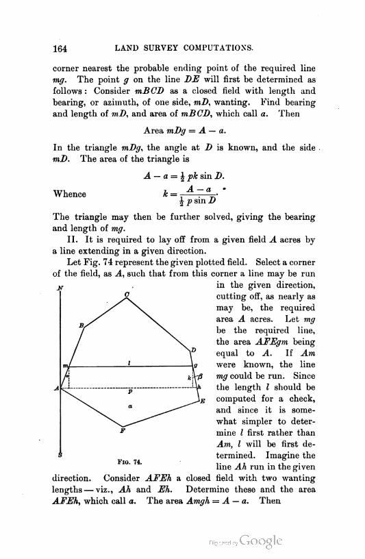
164 LAND SURVEY COMPUTATIONS.
corner nearest the probable ending point of the required line
mg. The point g on the line DE will first be determined as
follows : Consider mBCD as a closed field with length and
bearing, or azimuth, of one side, mD, wanting. Find bearing
and length of mD, and area of mBCD, which call a. Then
Area mDg = A — a.
In the triangle mDg, the angle at D is known, and the side
mD. The area of the triangle is
Whence
A — a = ^ pk sin D.
A — ak =
J p sin D
The triangle may then be further solved, giving the bearing
and length of mg.
II. It is required to lay off from a given field A acres by
a line extending in a given direction.
Let Fig. 74 represent the given plotted field. Select a corner
of the field, as A, such that from this corner a line may be run
in the given direction,
cutting off, as nearly as
may be, the required
area A acres. Let mg
be the required line,
the area AFEgm being
equal to A. If Am
were known, the line
mg could be run. Since
the length l should be
computed for a check,
and since it is some
what simpler to deter
mine l first rather than
Am, l will be first de
termined. Imagine the
line Ah run in the given
direction. Consider AFEh a closed field with two wanting
lengths — viz., Ah and Eh. Determine these and the area
AFEh, which call a. The area Amgh = A — a. Then
Fig. 74.

MODEL EXAMPLES. 165
l-^k = A-a, (1) I = p - k (tan « + tan #). (2)
Li
a and /3 are known from the bearings.
Whence k = -— —5. (3)tan a + tan p v '
Substitnting in (1), ?+* x — f ^ = A - «.
Whence Z = ± Vjd2 - 2 (J. - a) (tan a + tan /3) . (4)
I being known, k is determined from (1), or (3), and Am, or
hg, from the small right triangles. In the field, find the point
m, and run I on the given bearing to its intersection with DE
at g. See that the length agrees with the computed length,
and that gE as measured agrees with gE as computed.
MODEL EXAMPLES.
150. Logarithms. When formerly, in land surveying, bearings were
read only to quarter degrees, there were published for convenience what
were known as traverse tables. These were nothing more nor less than
tables of natural sines and cosines of the angles from 0° to 90° for every
quarter-degree multiplied by 1, 2, 3, 4, etc., to 10, and in some tables to 100.
The use of such a table made it unnecessary to multiply the sines and
cosines of the bearings to get the latitude and longitude differences, since
for each digit in the number expressing the length of the course the differ
ences could be read from the table and brought to the right amount by
moving the decimal point. The several quantities were then added.
With modern methods of work the compass is read to the nearest five
minutes, and when a transit is used the angles are determined to minutes.
Such a table as has been described then becomes useless. The proper table
to use is one of logarithmic sines and cosines. A single computation involv
ing not more than two or three figures can perhaps be more quickly per
formed without the use of logarithms, but any series of computations or a
single computation involving five or more figures can be more quickly
performed by logarithms. This does not mean that one unaccustomed to
the use of logarithms can work with them so fast as without, but a very
little practice with them will in any case substantiate the above claim. The
student should familiarize himself with a good set of logarithmic tables.1
The question will arise whether four-place, five-place, six-place, or seven-
place tables should be used. The decision must be based on the size of the
1The tables of Bremicker or Vega are recommended for work requiring great
precision. Gauss or Crockett are recommended for five-place tables.
166 LAND SURVEY COMPUTATIONS.
quantities involved in the computation and the precision required in the
result. A four-place table will give results correct to three significant
figures and almost correct to four significant figures, probably within one or
two units in the extreme end of the table. A five-place table will give
results correct to four significant figures and within one or two units in the
end of the table, to five significant figures, and so on. For very many sur
veying computations four-place tables are good enough, but for the general
use of surveyors five-place tables are considered better, and for use in
connection with very accurate city surveys, six-place tables will not be too
extensive, though almost all cases may be solved properly by the use of five-
place tables. For general field use five-place tables are ample. Logarithmic
tables should have auxiliary tables of proportional parts for quickly getting
the logarithm of a number greater than any given in the table and for
getting the number corresponding to a logarithm not in the table. Such
tables, with proportional parts in the trigonometric functions for tenths
of minutes instead of for seconds, will be found on pages 420-464, taken
from Crockett's Trigonometry.
151. Example stated. The notes of the courses of a survey are as
follows :
N. 69° E. .
S. 19° E. .
S. 27° W.
N. 71° W.
N. 19° W.
437.0 ft.
236.0 ft.
244.0 ft.
324.0 ft.
183.5 ft.
1424.5
It is required to balance the survey and determine the area of the field.
This example will be worked out in detail as a model for the student. He
is advised to note carefully the systematic arrangement of the work, as by
such system much time is saved. It is a case from practice.
152. Balancing. Letting L represent latitude differences and M longi
tude differences, the computation is arranged as shown on page 167.
Explanation. — We first write the logarithm of the length of the course,
and above it the logarithmic cosine of the bearing, and below it the loga
rithmic sine. The logarithm of L is then obtained by adding up, and the
logarithm of M by adding down. The L'a and M's are then taken out and
placed in their respective columns with their signs, and each column added
algebraically, giving the result — 4.9 in L and + 7.9 in M. The error of clo
sure is then found. In the example given it is entirely too large, and the
field should be rerun. The errors in L and M are now distributed among the
courses in proportion to the length of the sides. It is not necessary to be
exact about this, and it is done by inspection. Thus437
is a little less than1424.5
one third, hence the first corrections are 1.5 in L and 2.5 in M. The other
fractions are treated in the same way, the second being somewhat less than
one sixth, etc. If the corrections thus determined do not sum up exactly to

MODEL EXAMPLES. 167
Computat1ons for the Harr1ngton Survey.
Quant1ty. Logs. L M dL'a and dM's. Quant1ty. Lous.
L 2.19481 + 156.6
cos 69° 9.55433 + 158.1
437.0 2.64048
+ 43, x 4.9 = 1.51424.5
435.2 2.63872
sin 68° 42' 9.96927
405.5 2.60799
158.1 2.19893
tan 68° 42' 0.40906
sin 69° 9.97015 +405.5
M 2.61063 + 408.0 x 7.9 = 2.6
L 2.34858 - 223.1
cos 19° 9.97567 - 222.3
236.0 2.37291
+ 14223465x4-9 = °-8
x 7.9 = 1.8
sin 19° 9.51264 + 75.5
M 1.88556 + 76.8
-
L 2.33727 - 217.4
cos 27° 9.94988 - 216.6
244.0 2.38739
+ 244 x 4.9 = 0.81424.6
sin 27° 9.65705 - 112.1
M 2.04444 - 110.8 x 7.9 = 1.3
L 2.02319 + 105.5
cos 71° 9.51264 + 106.6
324.0 2.51055
+ 1424.5 x 4-9 = 1"1
x 7.9 = 1.8
sin 71° 9.97567 - 308.2
M 2.48622 - 306.4
L 2.23931 + 173.5
cos 19° 9.97567 + 174.2
183.5 2.26364
+ 183-6 x 4.9 = 0.71424.5
sin 19° 9.51264 - 60.7
M 1.77628 - 69.7 x 7.9 = 1.0
-440.5 +484.8
+ 435.6 -476.9
-4.9 +7.9
Error of closure = V4.92 + 7.92 = 9.4 ± =
1424.5
the respective total corrections, some one or more of them is slightly altered
to make the sum correct ; thus, in the above example the corrections first
written for the fourth L and the fifth M were 1.2 and 1.1 respectively, and
these were changed to 1.1 and 1.0 to make the sums equal 4.9 and 7.9
respectively. The balanced L's and M's are now written in the column of
L's and M's under the old L's and over the old M's. The lengths and bear
ings are now inconsistent with the balanced L's and M's, and should be
corrected to be consistent. This is done in this example for the first course
168 LAND SURVEY COMPUTATIONS.
only. The tangent of the bearing is —, hence write the log M and subtract
L
the log L and get log tan. Above log M write log sin and, subtracting
up, get log length.
This completes the balancing.
153. Areas by latitude differences and double longitudes. From the
balanced L's and M's the double longitudes are computed, and from the
L's and D's, as we may call the double longitudes, the double areas are com
puted. The work is systematized as in the following table :
Logs. Double Areas.
M of the First course is its D = 405.5 2.60799
+ M = + 405.5 + L 2.19893
+ M = + 75.5 4.80692 + 64110
Second course D = + 886.5 2.94768
+ M -- + 75.5 - L 2.34694
+ M- - 112.1 5.29462 - 197069
Third course D = + 849.9 2.92937
+ M = - 112.1 - L 2.33566
+ M = - 308.2 5.20503 - 184089
Fourth course D + 429.6 2.63306
+ M = - 308.2 + L 2.02776
+ M = - 60.7 4.G6082 + 45795
Fifth course D—+ 60.7 1.78319
+ L 2.24105
4.02424 + 10574
- 381158
+ 120479
2)200679
43560)130339.5
2.992+ acres.
It is believed that the work is self-explanatory.
The results of the foregoing computations are usually tabulated in
the following form :
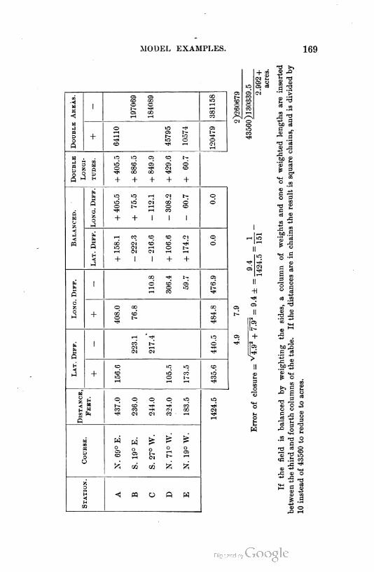
MODEL EXAMPLES. 169
2Po
a
m
« g
2HU
<J«1M
zo
H•ti-i
5
-J
a
oO
1n 1n q CO
1ri có a» 05 do CO -<* Co CO<* CO CO -*
+ + + + +
1n
1n Co CO1H OrH cc
CO CIlO CorH Co
+ I
CD COrH oCI rH
+ +
O COrH OrH CO
CO COo r~
r-ICN
© © q q 1n 1n
CO -* -* CO -*CO eo -* Co CO Co
CN Co CO - rH
CO S
rH GO
P_ 5h
^ cocm e
T3 t->
mco-*
q©
CO
q
-H
OS
II
+
o
T3CD
IrH £
c CDC93
=3 3 T3
MH H
.5t) oc *•
2 * §co mca co
rC "*<0 *• MH
CO O
* - -o
<u or^ tH

170 LAND SURVEY COMPUTATIONS.
154. Areas by coordinates. We shall next work out by coordinates the
area of the field just determined. The work is the same up to and including
the determination of the balanced Z's and M's. An inspection of these
demonstrates that the first corner is the most westerly corner, and that the
fourth corner is the most southerly, and that it is 283.9 feet south of the
first. Therefore if it is desired to make all coordinates positive, the refer
ence meridian will be passed through the first corner, and the origin of coor
dinates will be taken on this meridian 300 feet south of the first corner. The
coordinates of the corners and the area of the field are then found as in the
table, in which the y's are the latitude ordinates and the x's are the longitude
ordinates.
Corner
No.
Loos. DlFF. X'S
300.0 2.47712
2.53757 - 344.8 =2 -5
5.01469
+ 158.2
458.1 2.66096
2.68214 +481.0=3-1
5.34310
-222.3
235.8 2.37254
1.56348 - 36.6=4-2
3.93602
-216.6
19.2 1.28330
2.62356 -420.3=5-3
3.90686
+ 106.6
125.8 2.09968
+ 174.2
300.0
2.56691 -368.9 = 1-4
4.66659
X
0.0
405.5
405.5
+ 75.5
481.0
-112.1
368.9
308.2
60.7
-60.7
0.0
Double Areas.
Sq. Feet.
+ 103440
+220341
- 8630
- 8070
- 46408
+ 323781
- 63108
2)260673
43560)130336.5
2.992+ acres.
Rather more work is required by this method than by the method of
double longitudes. This is not the case when the corners have been de
termined by random lines rather than by a continuous traverse around the
field.
When the coordinates of the corners are alone known, the method just
given is by far the quickest, since it would be necessary to compute the X's
and M's for each side before the D's could be obtained or the areas, just as
it was here necessary to compute the coordinates from the L's and M 'a.
MODEL EXAMPLES. 171
155. Supplying an omission. I. In the example already used, let the
bearing and length of the second course be wanting. Adding the origi
nal L's and ATs, we get
Course. L M
1 + 156.6 + 408.0
2
3 -217.4 -110.8
4 + 105.5 - 306.4
5 + 173.5 - 59.7
+ 435.6 - 476.9
- 217.4 + 408.0
+ 218.2 - 67.9
There is then to be added south latitude and east longitude in order to
close the field, and hence the line to be supplied runs southeast.
The tangent of its bearing is
Loos.
tan0 = i™ L83187 +
218.2 2.33885 \
Log tan 6 9.49302
Log sin 6 9.47300
e = i7° 17' +.
Log length 2.35887 length = 228.5.
The whole error of closure being thrown into this course, its bearing and
length have been materially altered.
II. Let the lengths of sides one and two be wanting. Adding the
original L's and M'a, we get
Course. L M
1 + 156.6 + 408.0
2
3 - 217.4 - 110.8
4
5 + 173.5 - 59.7
+ 330.1 + 408.0
-217.4 - 170.5
+ 112.7 + 237.5
It is seen that southwest bearing must be that of the closing line. Its
bearing and length are obtained as in the last example.
Logs.
tan 0 = 2^ 2.37566112.7 2.05192
Log tan 6 0.32374 6 = 64° 37' S.W.
Log sin 6 9.95591
Log length 2.41975 length = 262.9.
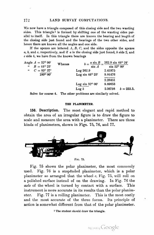
172 LAND SURVEY COMPUTATIONS.
We now have a triangle composed of this closing side and the two wanting
sides. This triangle1 is formed by shifting one of the wanting sides par
allel to itself. In this triangle there are known the bearing and length of
the closing side just found and the bearings of the two other sides, and
hence there are known all the angles and one side.
If the apexes are lettered A, B, C, and the sides opposite the apexes
a, b, and c. respectively, and if a is the closing side just found, b side 2, and
c side 4, we have from the known bearings
Angle A = 52° 00' Whence b = " si" B - 262.9 sin 44° 24'" 5=44° 23' "'"Ct sin A ~ sin 52° 00'
" C = 83c 37' Log 262.9 2.41975
180° 00' Log sin 44° 23' 9.84476
2.26451
Log sin 52° 00' 9.89653
Log b 2.36798 b = 233.3.
Solve for course 4. The other problems are similarly solved.
THE PLANIMETER.
156. Description. The most elegant and rapid method to
obtain the area of an irregular figure is to draw the figure to
scale and measure the area with a planimeter. There are three
kinds of planimeters, shown in Figs. 75, 76, and 77.
F1g. 75.
Fig. 75 shows the polar planimeter, the most commonly
used. Fig. 76 is a suspended planimeter, which is a polar
planimeter so arranged that the wheel c, Fig. 75, will roll on
a polished surface instead of on the drawing. In Fig. 76 the
axle of the wheel is turned by contact with a surface. This
instrument is more accurate in its results than the polar planim
eter. Fig. 77 is a rolling planimeter. This is the most costly
and the most accurate of the three forms. Its principle of
action is somewhat different from that of the polar planimeter.
1 The student should draw the triangle.
THE PLANIMETER. 173
The polar planimeter, the one most used, consists of two
arms, h and j, one of which, j, is of fixed length, and the other
is adjustable through the frame shown on the left. There is a
clamp back of the point g and a slow-motion screw / for setting
the adjustable arm to the required length. The arm j is piv
oted at k, and directly over k, on the frame, is a single gradua
tion which indicates the length of the adjustable arm. There
Fig. 77.
is also a wheel c, whose axis of revolu
tion is parallel to the arm h, and, in the dis
cussion that follows, will be considered a part of
that arm. The wheel is so mounted as to be almost
frictionless. The disk l records entire revolutions of
the wheel, while by the vernier m the fractional rev
olutions are read.
157. Use. The point e is fixed in the drawing board pref
erably outside of the figure to be measured. The tracer d is

174 LAND SURVEY COMPUTATIONS.
then placed on a point in the circumference of the figure,
and the wheel c is read. The wheel could be set to zero, but
this is not easy to do, and hence it is read at whatever it hap
pens to be. The tracer d is now moved carefully around the
circumference and stopped at the beginning point. The wheel
is again read, and the difference of the two readings indicates
the number of revolutions made by the wheel. The instru
ment is so made that if the tracer is moved clockwise, the
wheel will roll in the direction of its graduation, and hence
the final reading will be greater than the initial reading, and
vice verm. The wheel by its vernier reads to thousandths of
a revolution. The principle of the instrument is such that
the distance rolled by the wheel, or the number of revolutions
times the circumference in inches, multiplied by the length of
the arm in inches, is the area in square inches bounded by the
path of the tracer d. The arm h is generally so set that ten
times the number of revolutions is the area. If other units, as
tenths of a foot, are used for the above-named linear units, the
area will be given in square units of the same kind. In any
event, it is the area of the drawing that is measured. If this
drawing has been made to a scale of say forty feet to an inch,
a square inch of paper is equivalent to sixteen hundred square
feet, and the area given by the instrument must be multiplied
by this quantity to get the area in square feet. If the fixed
point is placed inside of the area to be measured so that the
tracer d in circumscribing the required area makes a complete
revolution about e, there must be added to
/ 7 the result in square inches a certain con-
Lf-O stant area— a constant for each instru-
!\/\ ment— called the area of the zero circum-
i (\\ ference.
j / /ft 158. Theory. The following is a dis-
| / / /^ip\o' cussion of the theory of the instrument,
i / // written for those who are not familiar with
\\£r the principles of the Calculus.
« In the figures that follow, the essential
Fio. 78. parts of the instrument are lettered as in
Fig. 75. The instrument is so constructed that neither d nor

THE PLANIMETER. 175
c can cross j. In circumscribing an area, the curved path of d
may be conceived as divided into an infinite number of infini
tesimal portions, each a straight line.
Each of the small portions may be conceived as made up of
two parts or component motions, one radial with reference to
e, and the other circumferential.
With the radial motion the value of the angle ifi is constantly
changing, while with the circumferential motion the value of $
and the length of the line ed remains fixed. In Fig. 78 the
component motions sd and sd\ and their resultant motion dd',
are shown greatly enlarged. It will be evident, that, in cir
cumscribing a closed figure, each minute movement of d toward
e will have its corresponding movement from e with the same
value of ij>. Each element of right-hand circumferential motion
will have its corresponding element of left-hand circumferential
motion ; but, since d will be farther from e for one than for the
other, these corresponding elements will
not be made with equal values of if>.
When the plane of the wheel c,
Fig. 79, passes through «, the angle dee
is a right angle, and, if d is revolved
about e with ifi constant, there will be no
rolling of the wheel e, because the direc
tion of motion of all points of the in
strument about e is circumferential, and
the radius of motion of the point c is
ec, and this is normal to the axis of the
wheel, and hence the motion of the wheel
is parallel to its axis, and the wheel simply slips and makes
no record. The path described by d for the particular value
of ij> that brings about the above result, is known as the zero
circumference. Its radius, ed, may be easily shown to be
Fig. 79.
6 = cos'1 ?.
3
(1)
(2)
It will be evident that if d could be moved outward till c
should fall in the line ek, and then rotated clockwise, the
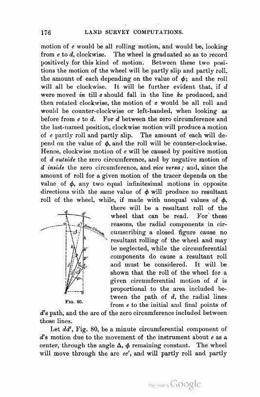
176 LAND SURVEY COMPUTATIONS.
motion of c would be all rolling motion, and would be, looking
from c to d, clockwise. The wheel is graduated so as to record
positively for this kind of motion. Between these two posi
tions the motion of the wheel will be partly slip and partly roll,
the amount of each depending on the value of <f>; and the roll
will all be clockwise. It will be further evident that, if d
were moved in till o should fall in the line ke produced, and
then rotated clockwise, the motion of c would be all roll and
would be counter-clockwise or left-handed, when looking as
before from c to d. For d between the zero circumference and
the last-named position, clockwise motion will produce a motion
of c partly roll and partly slip. The amount of each will de
pend on the value of <fi, and the roll will be counter-clockwise.
Hence, clockwise motion of c will be caused by positive motion
of d outside the zero circumference, and by negative motion of
d inside the zero circumference, and vice versa; and, since the
amount of roll for a given motion of the tracer depends on the
value of <f>, any two equal infinitesimal motions in opposite
directions with the same value of <f> will produce no resultant
roll of the wheel, while, if made with unequal values of 0,
there will be a resultant roll of the
wheel that can be read. For these
reasons, the radial components in cir-
^ cumscribing a closed figure cause no
N resultant rolling of the wheel and may
be neglected, while the circumferential
components do cause a resultant roll
and must be considered. It will be
shown that the roll of the wheel for a
given circumferential motion of d is
proportional to the area included be
tween the path of d, the radial lines
from e to the initial and final points of
d's path, and the arc of the zero circumference included between
those lines.
Let dd', Fig. 80, be a minute circumferential component of
d's motion due to the movement of the instrument about e as a
center, through the angle A, <f> remaining constant. The wheel
will move through the arc cc', and will partly roll and partly
F1g. 80.
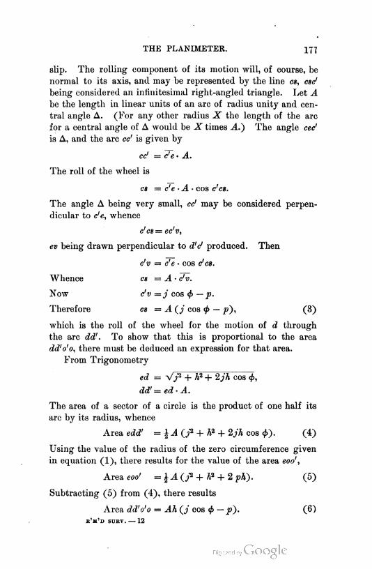
THE PLANIMETER. 177
slip. The rolling component of its motion will, of course, be
normal to its axis, and may be represented by the line cs, esc'
being considered an infinitesimal right-angled triangle. Let A
be the length in linear units of an arc of radius unity and cen
tral angle A. (For any other radius X the length of the arc
for a central angle of A would be X times A.") The angle cec'
is A, and the arc cc' is given by
cc1 = c'e - A.
The roll of the wheel is
cs = c'e - A- cos c'es.
The angle A being very small, cc' may be considered perpen
dicular to c'e, whence
c'es = ec'v,
ev being drawn perpendicular to d'e1 produced. Then
c'v = c'e - cos c'es.
Whence cs = A - c'v.
Now c'v = j cos <f> — p.
Therefore cs = A cos ^> — p), (3)
which is the roll of the wheel for the motion of d through
the arc dd'. To show that this is proportional to the area
dd'o'o, there must be deduced an expression for that area.
From Trigonometry
ed = Vy2 + h? + 2jh cos <j>,
dd' = ed- A.
The area of a sector of a circle is the product of one half its
arc by its radius, whence
Area edd' = \A (j» + h? + 2jh cos <£). (4)
Using the value of the radius of the zero circumference given
in equation (1), there results for the value of the area eoo',
Area eoo' =%A(j* + h'i + 2pK). (5)
Subtracting (5) from (4), there results
Area dd'o'o = Ah (/ cos </> — p). (6)
r'm'd surv. — 12
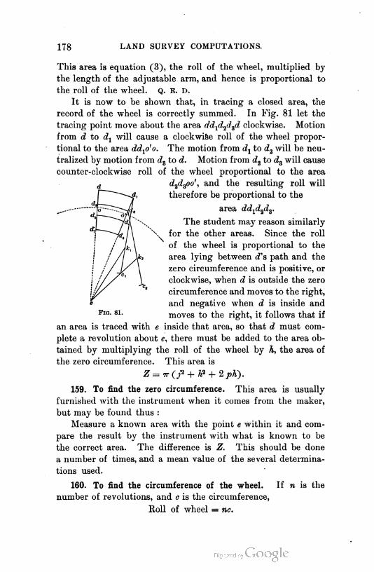
178 LAND SURVEY COMPUTATIONS.
This area is equation (3), the roll of the wheel, multiplied by
the length of the adjustable arm, and hence is proportional to
the roll of the wheel. Q. E. d.
It is now to be shown that, in tracing a closed area, the
record of the wheel is correctly summed. In Fig. 81 let the
tracing point move about the area dd^d^d clockwise. Motion
from d to d1 will cause a clockwise roll of the wheel propor
tional to the area ddxo'o. The motion from d1 to d2 will be neu
tralized by motion from d3 to d. Motion from d2 to d3 will cause
counter-clockwise roll of the wheel proportional to the area
d2d3oo', and the resulting roll will
therefore be proportional to the
area dd-^d^d^.
The student may reason similarly
\ for the other areas. Since the roll
of the wheel is proportional to the
area lying between cTs path and the
zero circumference and is positive, or
clockwise, when d is outside the zero
circumference and moves to the right,
and negative when d is inside and
FlG- 81- moves to the right, it follows that if
an area is traced with e inside that area, so that d must com
plete a revolution about e, there must be added to the area ob
tained by multiplying the roll of the wheel by A, the area of
the zero circumference. This area is
Z = Tr(f + h? + 2 pK).
159. To find the zero circumference. This area is usually
furnished with the instrument when it comes from the maker,
but may be found thus :
Measure a known area with the point e within it and com
pare the result by the instrument with what is known to be
the correct area. The difference is Z. This should be done
a number of times, and a mean value of the several determina
tions used.
160. To find the circumference of the wheel. If n is the
number of revolutions, and c is the circumference,
Roll of wheel = nc.
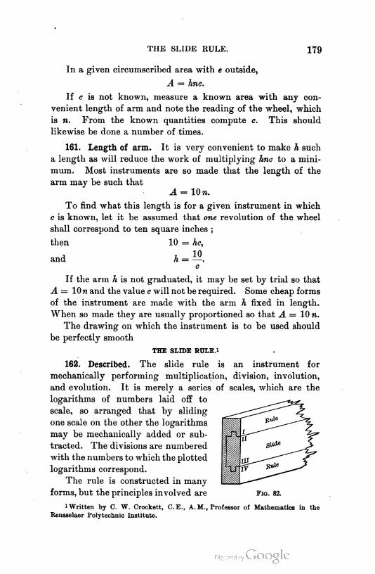
THE SLIDE RULE. 179
In a given circumscribed area with e outside,
A = hnc.
If c is not known, measure a known area with any con
venient length of arm and note the reading of the wheel, which
is n. From the known quantities compute c. This should
likewise be done a number of times.
161. Length of arm. It is very convenient to make h such
a length as will reduce the work of multiplying hne to a mini
mum. Most instruments are so made that the length of the
arm may be such that
A = lOra.
To find what this length is for a given instrument in which
c is known, let it be assumed that one revolution of the wheel
shall correspond to ten square inches ;
then 10 = he,
and h = —.
c
If the arm h is not graduated, it may be set by trial so that
A = lOn and the value e will not be required. Some cheap forms
of the instrument are made with the arm h fixed in length.
When so made they are usually proportioned so that A = 10 n.
The drawing on which the instrument is to be used should
be perfectly smooth
THE SLIDE RUXE.1
162. Described. The slide rule is an instrument for
mechanically performing multiplication, division, involution,
and evolution. It is merely a series of scales, which are the
logarithms of numbers laid off to
scale, so arranged that by sliding
one scale on the other the logarithms
may be mechanically added or sub
tracted. The divisions are numbered
with the numbers to which the plotted
logarithms correspond.
The rule is constructed in many
forms, but the principles involved are F1g. 82.
1Written by C. W. Crockett, C.E., A. M., Professor of Mathematics in the
Rensselaer Polytechnic Institute.
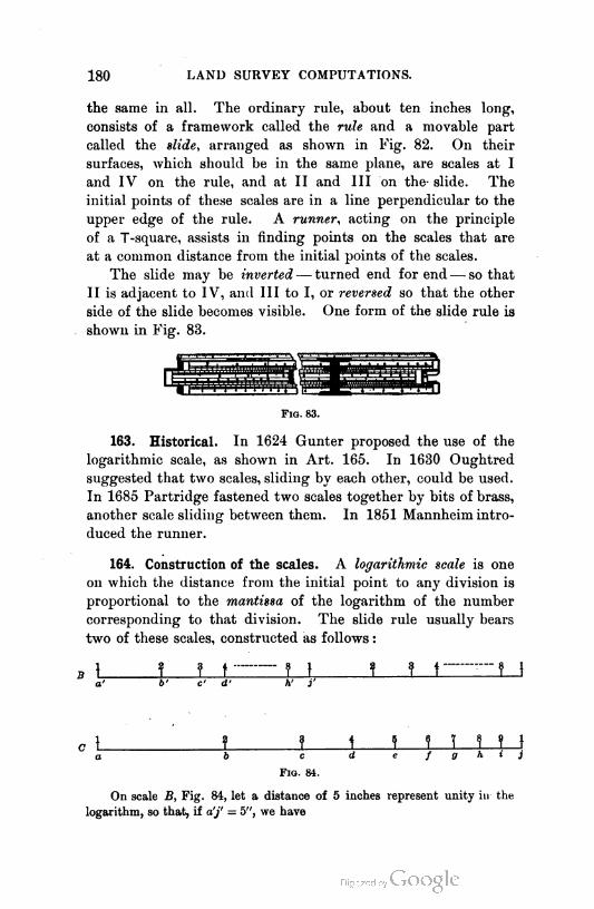
180 LAND SURVEY COMPUTATIONS.
the same in all. The ordinary rule, about ten inches long,
consists of a framework called the rule and a movable part
called the slide, arranged as shown in Fig. 82. On their
surfaces, which should be in the same plane, are scales at I
and IV on the rule, and at II and III on the slide. The
initial points of these scales are in a line perpendicular to the
upper edge of the rule. A runner, acting on the principle
of a T-square, assists in finding points on the scales that are
at a common distance from the initial points of the scales.
The slide may be inverted— turned end for end— so that
II is adjacent to IV, and III to I, or reversed so that the other
side of the slide becomes visible. One form of the slide rule is
shown in Fig. 83.
Fio. 83.
163. Historical. In 1624 Gunter proposed the use of the
logarithmic scale, as shown in Art. 165. In 1630 Oughtred
suggested that two scales, sliding by each other, could be used.
In 1685 Partridge fastened two scales together by bits of brass,
another scale sliding between them. In 1851 Mannheim intro
duced the runner.
164. Construction of the scales. A logarithmic scale is one
on which the distance from the initial point to any division is
proportional to the mantissa of the logarithm of the number
corresponding to that division. The slide rule usually bears
two of these scales, constructed as follows :
? 1 \ \ I 1 T t
c d e f g h i j
Fig. 84.
On scale B, Fig. 84, let a distance of 5 inches represent unity hi the
logarithm, so that, if a'j' = 5", we have
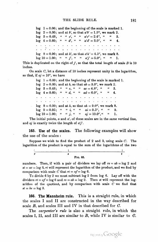
THE SLIDE RULE. 181
log 1 = 0.00; and the beginning of the scale is marked 1.
log 2 = 0.30; and at b', so that a'V = 1.5", we mark 2.
log 3 = 0.48; " " c', " " a'c' = 2.4", " " 3.
log 4 = 0.60; " " d', " " a'd' = 3.0", " " 4.
log 8 = 0.90; and at h', so that a'h' = 4.5", we mark 8.
log 10 = 1.00; " " f, " " a'/ =5.0", " « 1.
This is duplicated on the right of/, so that the total length of scale B is 10
inches.
On scale C, let a distance of 10 inches represent unity in the logarithm,
so that, if aj = 10", we have
log 1 = 0.00 ; and the beginning of the scale is marked 1.
log 2 = 0.30; and at b, so that ab = 3.0", we mark 2.
log 3 = 0.48; " " c, " " ac = 4.8", " " 3.
log 4 = 0.60; " " d, " " ad = 6.0", " " 4.
log 8 = 0.90; and at h, so that ah = 9.0", we mark 8.
log 9=0.95; " " i, " " ai = 9.5", " " 9.
log 10 = 1.00; " " j, " " aj = 10.0"," " 1.
The initial points, a and a', of these scales are in the same vertical line,
and aj is exactly twice the length of a'j'.
165. Use of the scales. The following examples will show
the use of the scales :
Suppose we wish to find the product of 2 and 3, using scale C. The
logarithm of the product is equal to the sum of the logarithms of the two
r s t
F1o. 85.
numbers. Then, if with a pair of dividers we lay off rs = ab = log 2 and
st = ac — log 3, rt will represent the logarithm of the product, and we find by
comparison with scale C that rt = af = log 6.
To divide 6 by 2 we must subtract log 2 from log 6. Lay off with the
dividers rt = af= log 6 and rs = ab = log 2. Then st will represent the log
arithm of the quotient, and by comparison with scale C we find that
st = be = log 3.
166. The Mannheim rule. This is a straight rule, in which
the scales I and II are constructed in the way described for
scale B, and scales III and IV in that described for C.
The carpenter s rule is also a straight rule, in which the
scales I, II, and III are similar to B, while IV is similar to C.
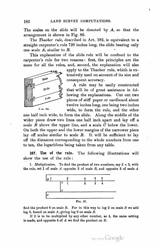
182 LAND SURVEY COMPUTATIONS.
The scales on the slide will be denoted by A, so that the
arrangement is shown in Fig. 86.
The Thacher rule, described in Art. 182, is equivalent to a
straight carpenter's rule 720 inches long, the slide bearing only
one scale A, similar to B.
This explanation of the slide rule will be confined to the
carpenter's rule for two reasons : first, the principles are the
same for all the rules, and, second, the explanation will also
apply to the Thacher rule, which is ex
tensively used on account of its size and
consequent accuracy.
A rule may be easily constructed
that will be of great assistance in fol
lowing the explanations. Cut out two
pieces of stiff paper or cardboard about
twelve inches long, one being two inches
wide, to form the rule, and the other
one half inch wide, to form the slide. Along the middle of the
wider piece draw two lines one half inch apart and lay off a
scale B above the upper line, and a scale C below the lower.
On both the upper and the lower margins of the narrower piece
lay off scales similar to scale B. It will be sufficient to lay
off the distances corresponding to the whole numbers from one
to ten, the logarithms being taken from any table.
167. Use of the rule. The following illustrations will
show the use of the rule :
1. Multiplicati-n. To find the product of two numbers, say 2x3, with
the rule, set 1 of scale A opposite 2 of scale B, and opposite 3 of scale A
b}ai
I|
6 81 1
* 11 1 1
3 4
A
2
c
Fig. 87.
find the product 6 on scale B. For in this way to log 2 on scale B we add
log 3, found on scale A, giving log 6 on scale B.
If 2 is to be multiplied by any other number, as 4, the same setting
is made, and opposite 4 of A we find the product on B.

THE SLIDE RULE. 183
If any constant number b is to be multiplied by a series of numbers, so
that we wish to find the value of bx for different values of x— opposite b of
B, set 1 of A and opposite x of A read the product bx on B. This operation
may be stated as follows, reading vertically, the lines B and A representing
the two scales used :
B. Opp. b. Read bx.
A. Set 1. Opp. x.
2. Division. To divide a number by another, as 8 2, set 2 of A oppo
site 1 of B, and opposite 8 of A read the quotient 4 on B. For in this way
2 31 1
f1 1 1
1 6
1
2 8
A
C
F1g. 88.
we take away log 2 from log 8 on scale A and then find the number on B
that corresponds to the remainder.
To divide 6 by 2 we could use the same setting, reading the quotient on
B opposite 6 of A.
To divide a series of numbers x by a constant number a, opposite 1 of
B set a of A, and opposite x of A read the quotient x -4- a on B.
B. Opp. 1. Read x a.
A . Set a. Opp. x.
3. Proportion. An expression in the form —, as - * -, may be written
jjx3. Opposite 4 of B set 2 of A, and the index (1) of A will be opposite
4-
F1g. 89.
the quotient 4 -+- 2 on B ; then opposite 3 of yl read the result 6 on B, for in
this way we add log 3 to the logarithm of the quotient.
If a and b are constants and x a variable, we may use the following
bxsetting for — , reading vertically :
B. Opp. b. Read bx h- a.
A. Set a. Opp. x.
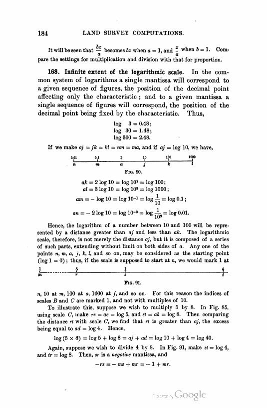
184 LAND SURVEY COMPUTATIONS.
It will be seen that — becomes bx when a = 1, and - when 5 = 1. Com-
a a
pare the settings for multiplication and division with that for proportion.
168. Infinite extent of the logarithmic scale. In the com
mon system of logarithms a single mantissa will correspond to
a given sequence of figures, the position of the decimal point
affecting only the characteristic ; and to a given mantissa a
single sequence of figures will correspond, the position of the
decimal point being fixed by the characteristic. Thus,
log 3 = 0.48 ;
log 30 = 1.48;
log 300 = 2.48.
If we make aj = jk = kl = nm = ma, and if aj = log 10, we have,
0.01 0.1 1 10 100 1000i i '
m a j k I
FiO. 90.
ak = 2 log 10 = log 102 = log 100;
al = 3 log 10 = log 10' = i0g 1000 ;
am = - log 10 = log 10-1 = log A = log 0.1 ;
an = - 2 log 10 = log 10■2 = log — = log 0.01.
Hence, the logarithm of a number between 10 and 100 will be repre
sented by a distance greater than aj and less than ak. The logarithmic
scale, therefore, is not merely the distance aj, but it is composed of a series
of such parts, extending without limit on both sides of a. Any one of the
points n, m, a, j, k, l, and so on, may be considered as the starting point
(log 1 = 0); thus, if the scale is supposed to start at n, we would mark 1 at
L_ __J 1 t_m r s t
Fig. 91.
n, 10 at m, 100 at a, 1000 at j, and so on. For this reason the indices of
scales B and C are marked 1, and not with multiples of 10.
To illustrate this, suppose we wish to multiply 5 by 8. In Fig. 85,
using scale C, make rs = ae = log 5, and st = ah = log 8. Then comparing
the distance rt with scale C, we find that rt is greater than aj, the excess
being equal to ad = log 4. Hence,
log (5x8)= log 5 + log 8 = aj + ad = log 10 + log 4 = log 40.
Again, suppose we wish to divide 4 by 8. In Fig. 91, make st = log 4,
and tr = log 8. Then, sr is a negative mantissa, and
— rs = — ms + mr = — 1 + mr.

THE SLIDE RULE. 185
By comparison with scale C we find that mr is the mantissa of log 5, so
that the quotient is 0.5.
169. Sequence of figures. In operations with the slide rule,
we use the mantissas of the logarithms of the quantities in
volved, and the distances found represent the mantissas of the
results. We find, therefore, the sequence of figures in the
result, the position of the decimal point being determined
either by special rules or by rough computation.
170. Shifting the slide. As we use the mantissas only, and
as the addition or subtraction of the distance between the
indices of the seales would affect the characteristic alone, we
can change the position of the slide, by bringing one index into
the position previously occupied by another index, without
affecting the sequence of figures in the result.
171. Use of the runner.
Let us find the value of 2 x 3 x 4. Opposite 2 of B set 1 of A, and 3
of A will be opposite 6 ( = 2 x 3) on B. Instead of reading this number,
set the runner over 3 of A. Bring 1 of A to the runner, and now read the
final result 24 on B opposite 4 of A.
In order that the runner may be used, without intermediate reading, it
is necessary that the result should be found on the rule.
172. Squares and square roots.
The distance on C representing log 2 ( = 3.0") is just twice that repre
senting log 2 ( = 1.5") on B. Hence, if x is any number, log x on C is twice
log x on B. If the initial points of the two scales are in the same vertical
line, any number x on C will correspond to its square, x2, on B ; for
log x on C = 2 log x on B = log x2 on B.
Conversely, any number on B will correspond to its square root on C.
1. Squares. To find the square of any number, find the number on C,
and the corresponding number on B will be its square.
2. Square roots. To find the square root of any number, find the num
ber on B, and the corresponding number on C will be its square root. To
avoid artificial rules it is necessary to know approximately the first figure of
the root. Divide the numbers into sections of two digits each, commencing
at the decimal point, as in arithmetic, and call the first section at the left
that contains a significant figure the left section. If this left section is 10
or greater, the first figure of the root will be 3 or greater, and if it is
less than 10, the first figure of the root will be 3 or less. In the car
penter's rule the middle index of B corresponds to 3.16+ on C since

186 LAND SURVEY COMPUTATIONS.
VlO = 3.1622 + . Therefore, if the left section is less than 10, the number
whose square root is required is found on the left scale of B, and if greater
than 10, it is found on the right scale of B.1
173. General statement of problems. If a and b are con
stants, and a; is a variable number, the following expressions
may be solved, each with one setting, with the carpenter's or
with the Thacher rule, the slide being in the position indicated
and the result being read on the scale named :
SLIDE DIRECT. SLIDE INVERTED.
Expeess1on.
bx
Read on Expeess1on.
ba
Read on
1.* = T
Rule (B). 8. y=r Rule (B).
2.
b*x
Rule (C). 9.
_b*a
Rule (C).
3.» =T
Wx
Rule (B). 10. y x Rule (B).
4. y=^ Rule (C). 11. Rule (C).
5._ ax
Slide (A). 12.ba
Slide (A).
6. Slide (A). 13. Slide (A).
7. y- 6a "_ax\
Slide (A).
In these expressions either a or b may be equal to unity.
174. Slide direct.
, bx1. a = —
9 a
.: log y = (log b - log a) + log x*
From log b we must take a.way log a, and then add log x to the differ
ence. Hence log x must be found on the same scale as log a, the result
being read on the scale on which log b was found (see Fig. 89). Reading
vertically, we have
B. Opp. b. Read y.
A. Set a. Opp. x.
A.
C.
1 Or the number is found on the left scale of B when there is an odd number of
digits to the left or an odd number of ciphers to the right of the decimal point;
otherwise it is found on the right scale of B.
* The quantity in the parentheses will, in every case, indicate the setting.

THE SLIDE RULE. 187
Ex. 6 = 3, a = 2, x = 4, y = 6 ;
x = 6, y = 9 ;
z = 8, y = 12.
.-- logy = !{(>g&-loga) + logi}.
Use the same setting as in the preceding case, but read the result on C
instead of on B (see Art. 172).
B. Opp. b.
A. Set a. Opp. X.
A.
C. Read y.
Note that the square roots are always read on C.
When a number on C is to be compared with a number on A, it will be
more convenient, in the carpenter's rule, to use the scale A that is adjacent
to C. Thus, in this case we would find x on the lower scale of the slide.
With this caution, the upper scale of the slide will be used in all the
settings.
.-. logy = (logft2 — log a)+ logr.
Since b is squared, we find b on C, so that the number opposite to it on
B is 62.
B. Read y.
A. Set a. Opp. x.
A.
C. Opp. 6.
Ex. 6 = 3, a = 2; x = 4, jr = 18;
x = 6, y = 27 ;
i = 8, y = 36.
.- - log y = \ {(log 62 - log a) + log
A . Set a. Opp. x.
A.
C. Opp. 6. Read y.
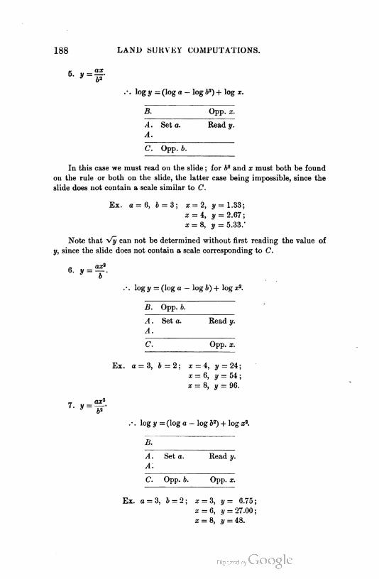
188 LAND SURVEY COMPUTATIONS.
5. « =—y 62
--- log y = (log a - log 62) + log x.
B. Opp. x.
A. Set a. Read y.
A.
C. Opp. 6.
In this case we must read on the slide ; for 62 and x must both be found
on the rule or both on the slide, the latter case being impossible, since the
slide does not contain a scale similar to C.
Ex. a = 6, 6 = 3; x = 2, y = 1.33;
x = 4, y = 2.67;
x=S, y = 5.33.-
Note that Vy can not be determined without first reading the value of
y, since the slide does not contain a scale corresponding to C.
.-. log y = (log a — log b) + log z2.
B. Opp. b.
A. Set a. Read y.
A.
C. Opp. x.
Ex. a = 3, 6 = 2; x = 4, y = 24;
x = 6, y = 54 ;
x = 8, y = 96.
.- . log y = (log a — log 52) + log x2.
B.
Set a. Head
a:
c. Opp. 6. Opp. x.
Ex. a = 3, 6 = 2; x = 3, y = 6.75;
x = 6, y- 27.00 ;
x = 8, y = 48.
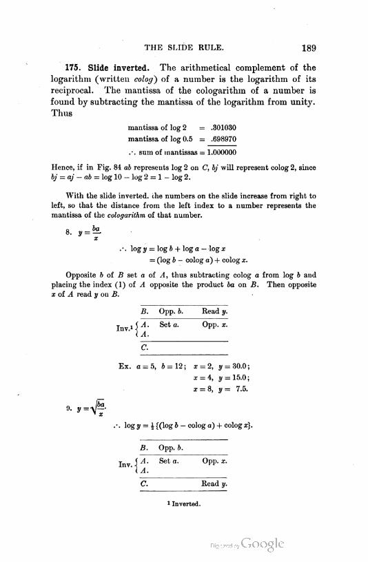
THE SLIDE RULE. 189
175. Slide inverted. The arithmetical complement of the
logarithm (written colog) of a number is the logarithm of its
reciprocal. The mantissa of the cologarithm of a number is
found by subtracting the mantissa of the logarithm from unity.
Thus
mantissa of log 2 = .301030
mantissa of log 0.5 = .698970
.-. sum of mantissas = 1.000000
Hence, if in Fig. 84 ab represents log 2 on C, bj will represent colog 2, since
bj = aj — ab = log 10 — log 2 = 1- log 2.
With the slide inverted, the numbers on the slide increase from right to
left, so that the distance from the left index to a number represents the
mantissa of the cologarithm of that number.
8. y = *Z
x
- -. log y = log b + log a — log x
= (log b - colog a) + colog x.
Opposite 6 of B set a of A, thus subtracting colog a from log 6 and
placing the index (1) of A opposite the product ba on B. Then opposite
x of A read y on B.
Inv.1 •
B. Opp. b. Read y.
A.
A.
Set a. Opp. x.
C.
Ex. a = 5, 6 = 12; x = 2, ^ = 30.0;
x = 4, y = 15.0 ;
9. y=V~-" T.
x = 8, y= 7.5.
log y = £ {(log 6 — colog a) + colog x}.
B. Opp. 6.
Inv.A. Set a. Opp. x.
a Read
1 Inverted.

190 LAND SURVEY COMPUTATIONS.
10. yx
log y = (log ft2 — colog a) + colog z.
B. Read y.
Inv.It
Set a. Opp. x.
C. Opp. ft.
Ex. a = 15, ft = 2; x = 3, y = 20.0
11. y ='6%
z
a: = 5, y = 12.0
- = 8, y= 7.5
log y = J {(l-g ft2 — colog a) + colog x}.
B.
Inv.Set a. Opp. x.
C. Opp. ft. Read y.
In the other two cases the result must be read on the slide, so that the
distances from the left index (1) will be the mantissas of the cologarithms of
the corresponding numbers, while the distances on the rule will correspond
to the mantissas of the l-garithms.
12. y = —
■ colog y = colog a + colog ft — colog x
= (colog a — log ft) + log x1.
Inv.
B. Opp. ft.
A.
A.
Seta. Read y.
C. Opp. x.
Ex. a = 5, ft=12; z=2, !/ = 15.00;
z = 4, y= 3.75;
z = 5, y= 2.4.
13- y = ^-
.*. colog 2/ = colog a + colog ft2 — colos? z2
= (colog a — log ft3) + log x2.
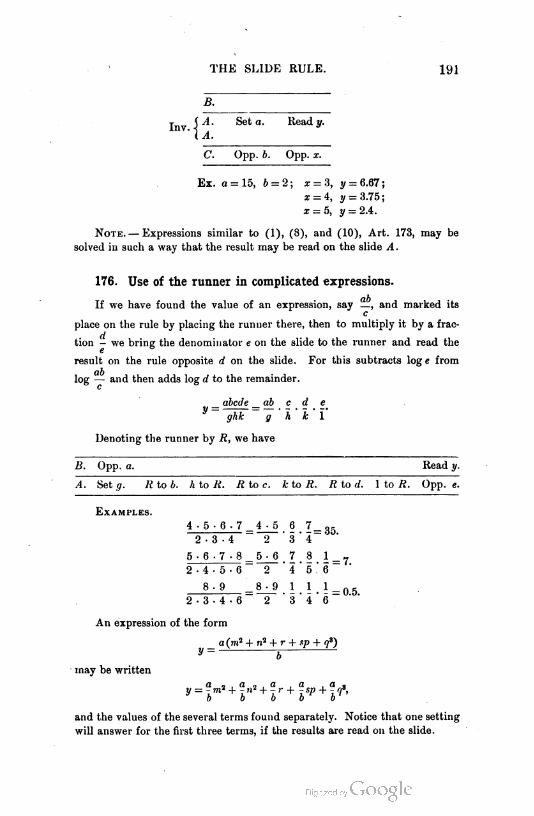
THE SLIDE RULE. 191
B.
HI
Set a. Read y.
c. Opp. b. Opp. x.
Ex. a = 15, b = 2 ; z = 3. = 6.67;
x = 4, y = 3.75;
x = 5, y = 2A.
Note. — Expressions similar to (1), (8), and (10), Art. 173, may be
solved in such a way that the result may be read on the slide A.
176. Use of the runner in complicated expressions.
If we have found the value of an expression, say —, and marked itsc
place on the rule by placing the runner there, then to multiply it by a frac
tion - we bring the denominator e on the slide to the runner and read the
result on the rule opposite d on the slide. For this subtracts log e from
log — and then adds log d to the remainder.
abode ab c d e
ghk g
hokol
Denoting the runner by R, we have
B. Opp. a. Read y.
A. Set g. R to b. h to R. R to c. k to R. R to d. 1 to R. Opp. «.
Examples.
4- 5-6-7 = 4- 5 6 7=g.2-3-4 2 - 3 o 4
5- 6.7-8 5-6 7 8 1
2-4-5-6 2 45
8-9 1 i.Uo.5.
2-3-4-6 2 3 46
An expression of the form
may be written
_ a (m2 + n2 + r + sp + qs)
V — j
y = -m2 + -n2 + -r-f -sp + -1f,b b b b b
and the values of the several terms found separately. Notice that one setting
will answer for the first three terms, if the results are read on the slide.
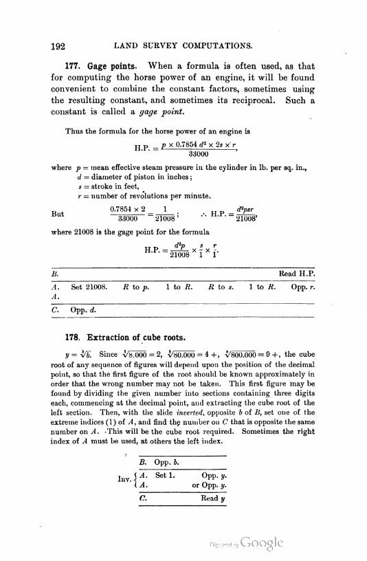
192 LAND SURVEY COMPUTATIONS.
177. Gage points. When a formula is often used, as that
for computing the horse power of an engine, it will be found
convenient to combine the constant factors, sometimes using
the resulting constant, and sometimes its reciprocal. Such a
constant is called a gage point.
Thus the formula for the horse power of an engine is
p _ p x 0.7854 d2 x 2s x r
33000
where p = mean effective steam pressure in the cylinder in lb. per sq. in.,
(/ = diameter of piston in inches ;
s = stroke in feet,
r = number of revolutions per minute.
0.7854 x 2 _ _J_ . . _ rf>r
33000 21008' 21008'
where 21008 is the gage point for the formula
w v — d2P * r- 21008 x 1 x f
B. Read H.P.
A.
A.
Set 21008. R to p. 1 to R. R to s. 1 to R. Opp. r.
C. Opp. d.
178. Extraction of cube roots.
y = $T). Since \/«.000 = 2, \/80.000 = 4 +, ^800000 = 9 +, the cube
root of any sequence of figures will depend upon the position of the decimal
point, so that the first figure of the root should be known approximately in
order that the wrong number may not be taken. This first figure may be
found by dividing the given number into sections containing three digits
each, commencing at the decimal point, and extracting the cube root of the
left section. Then, with the slide inverted, opposite b of B, set one of the
extreme indices (1) of A, and find the number on C that is opposite the same
number on A. -This will be the cube root required. Sometimes the right
index of A must be used, at others the left index.
B. Opp. b.
A. Set 1. Opp. y.
A. or Opp. y.
a. Read y
THE SLIDE RULE. 193
179t Slide reversed. The reverse of the slide sometimes
has along one edge a scalo of logarithmic sines and along the
other a scale of logarithmic tangents, the scales being so ar
ranged that the numbers (degrees) increase from left to right
when, the slide being reversed, the corresponding edge of the
slide is adjacent to B.
180. Scale of logarithmic sines, S.
If we reverse the slide and place S adjacent to B so that their initial
points coincide, we find that the beginning of B corresponds to 0° 34' + on
S, the middle index of B to 5° 44' +, and the right index of B to 90°; for
log sin 0° 34' + = 8.00 ( = - 2),
log sin 5° 44' + = 9.00 ( = - 1 ),
log sin 90° = 0.00,
unity in the characteristic being represented by the same distance on 5 and
on B.
In this position the natural sine of an angle may be found by reading
the number on B corresponding to the angle on S.
The distance from the beginning of 5 to any division, in the direction
of increasing numbers, represents the mantissa, or the mantissa + 1, of the
logarithmic sine of the angle corresponding to that division ; and the dis
tance from any division to the other end (90°) of S represents the mantissa,
or the mantissa + 1, of the cologarithm of the sine.
In expressions containing cos x, since cos x = sin (90° — x), we may sub
tract the angle x from 90° and then use the sine of the remainder, finding
it on S.
1. a = c sin x.
.- . log a = log c + log sin x = log c — colog sin x.
Opposite c of B set the beginning of S, and opposite x of S read a on
B, for this adds log sin x to log c. If x should fall outside of the rule, we
would set the right end of S opposite c of B, and then opposite x of S read
a on B, for this subtracts colog sin x from log c.
2. b = c cos x.
.-. log 6 = logc + log sin (90° — x) = logc — colog sin (90° — x),
and the methods given for the multiplication of a sine by a- numbe»
(a = c sin x) are applicable, using 90° - x instead of x.
3. c = a + sin x.
. - . log c = log a — log sin x = log a + colog sin x.
Opposite a of B set x of S, and opposite the end of S read c on B ; for
this subtracts log sin x from log a when we read opposite the left end, and
adds colog sin x to log a when we read opposite the right end.
r'm'd surv. — 13

194 LAND SURVEY COMPUTATIONS.
4. c = b + cos x. -
:. log c = log b — log sin (90° — x) = log b + colog siu (90° — x),
and the methods for c = a -*- sin x are applicable, using 90° — x instead of x.
5. a = c sin x + sin z.
.-. log a = log c — log sin z + log sin x.
Opposite c of B set z of <S, and opposite x of S read a on if; for this
first subtracts log sin z from log c, and then adds log sin x to the remainder.
If x falls outside the rule, set the runner over the end of S that is in the
rule, shift the slide until the other end of S comes to the runner, and then
opposite x of S read a on B.1
The expression for a becomes c sin x when z = 90°, and c -+- sin z when
x = 90°. Compare the setting just given with those for c sin x and a -=- sin x.
6. sin x = a sin z c.
.-. log sin x = log sin z — log c + log a.
Opposite c of B set z of S, and opposite o of B read z on S ; for this
subtracts logc from log sin z, and adds logo to the remainder.
This becomes sin x = a + c when z = 90°.
7. cos x = b -" c.
.-. log sin (90° — x) = log 6 — log c
= log sin 90° — log c + log 6.
Opposite c of B set 90° of S, and opposite 6 of B read 90° — x on 5.
181. Scale of logarithmic tangents, T.
If we reverse the slide and place T adjacent to B so that their initial
points coincide, we find that the beginning of B corresponds to 0°34'-f on
T, the middle index of B to 5° 42' + , and the right index to 45° ; for
log tan 0° 34' + = 8.00 ( = - 2),
log tan 5°42'+ = 9.00( = - 1),
log tan 45° = 0.00.
Unity in the characteristic, therefore, corresponds to the same distance on
r, A, and S.
In this position the natural tangent of an angle less than 45° may be
found by reading the number on B opposite the given angle on T. To find
•the tangent of an angle greater than 45°, invert the slide so that T is adja
cent to C, their ends coinciding, and read the number on B corresponding
to the complement of the angle on T.
The distance from the beginning of T to any division, in the direction
of increasing numbers, represents the mantissa, or the mantissa + 1, of the
logarithmic tangent of the angle corresponding to that division ; while the
1 In all cases when the result cannot be read, the slide is shifted over the length
of its scales, since this merely changes the characteristic.

THE SLIDE RULE. 195
distance from that division to the end (45°) of the scale represents the man
tissa, or the mantissa + 1, of the cologarithm of the tangent
Since tan z = 1 + cotz. we have
log tan x = colog cot x
and colog tan x = log cot x.
Hence the distance that represents log tan x also represents colog cot x, and
that representing colog tan x also represents log cot x.
When x is greater than 45°, subtract x from 90° and use the cotangent
of the remainder instead of tan x, and the tangent of the remainder instead
of cot x.
1. a = b tan x.
x < 45°. .-. log a = log b + log tan x = log b — colog tan x.
Opposite b of B set the end of T, and opposite x of T read a on B ; for
this adds log tan x to log b when the left end is used, and subtracts colog tan
x from log b when the right end is used.
x > 45°. /. log a = log b + log cot (90° - z)
= log 6 - log tan (90° - z)
= log b + colog tan (90° - z).
Opposite 6 on B set 90° — x of T, and opposite the end of T read a on
B; for this subtracts log tan (90° — z) from log b when the left end is used,
and adds colog tan (90° — z) to log b when the right end is used.
2. b — a tan z.
x < 45°. .-. log 6 = log a — log tan z = log a + colog tan z.
Opposite a of B set z of T and opposite the end of T read b on B ; for
this subtracts log tan z from, or adds colog tan z to, log a when we read
opposite the left or the right end respectively.
x > 45°. /. log b = log a - log cot (90° - z)
= log a + log tan (90° - z)
= log a — colog tan (90° — z).
Opposite a of B set the end of T and opposite 90°— z of T read 6 on B ;
for this adds log tan (90° — z) to, or subtracts colog tan (90° — z) from,
log a when we use the left or the right end respectively.
3. 6 = a cot z.
.'. 6 = a ■+■ tan z,
and the settings given under (2) are used.
4. 6 = a -=- cot z. '
.-. 6 = a tan z,
and the settings given under (1) are used.
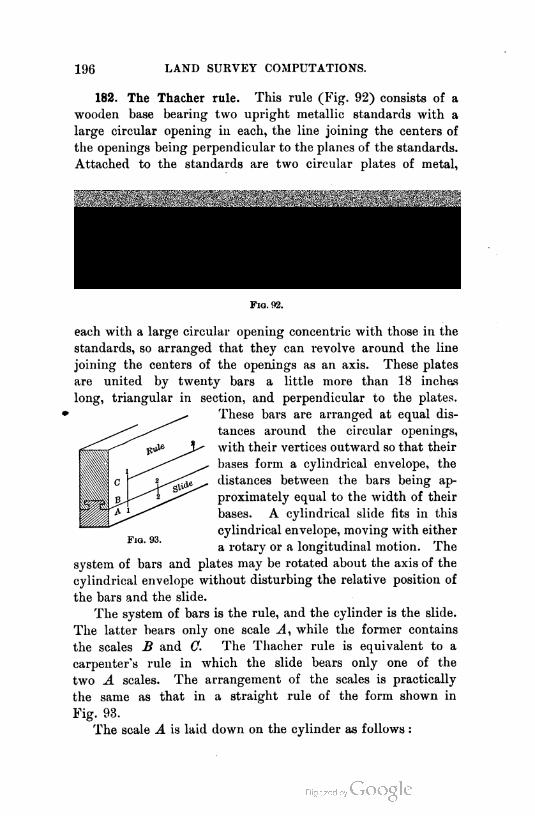
196 LAND SURVEY COMPUTATIONS.
182. The Thacher rule. This rule (Fig. 92) consists of a
wooden base bearing two upright metallic standards with a
large circular opening in each, the line joining the centers of
the openings being perpendicular to the planes of the standards.
Attached to the standards are two circular plates of metal,
Fig. 02.
each with a large circular opening concentric with those in the
standards, so arranged that they can revolve around the line
joining the centers of the openings as an axis. These plates
are united by twenty bars a little more than 18 inches
long, triangular in section, and perpendicular to the plates.
These bars are arranged at equal dis
tances around the circular openings,
with their vertices outward so that their
bases form a cylindrical envelope, the
distances between the bars being ap
proximately equal to the width of their
bases. A cylindrical slide fits in this
cylindrical envelope, moving with either
a rotary or a longitudinal motion. The
system of bars and plates may be rotated about the axis of the
cylindrical envelope without disturbing the relative position of
the bars and the slide.
The system of bars is the rule, and the cylinder is the slide.
The latter bears only one scale A, while the former contains
the scales B and C. The Thacher rule is equivalent to a
carpenter's rule in which the slide bears only one of the
two A scales. The arrangement of the scales is practically
the same as that in a straight rule of the form shown in
Fig. 93.
The scale A is laid down on the cylinder as follows :

THE SLIDE RULE. 197
Let M and N be two logarithmic scales 360 inches long, and let each be
divided into forty equal parts, a, b, a', V, — . Draw forty equidistant
elements on a cylinder and lay off on them the segments of the scales as
shown in Fig. 95, which represents the development of the cylinder. Then
the scales will read continuously from left to right.
The twenty bars are graduated on each side and bear two different
m ' g 1 6 1 i h 1 I 1
N 1 »' 1 b' 1 1 fc' " 1 I' 1
F1g. 94.
scales. The one nearer the cylindrical slide B is constructed in the same
way as that on the slide. The outer one C is formed by dividing a loga
rithmic scale 720 inches long into eighty equal parts and placing them in
order above a, b, ••; k, I; a', V, k/, V.
The Thacher rule gives results that should never be in
error by more than one unit in the fourth significant figure,
while the fifth figure can often be found with only a small
error. The error should not exceed one
part in ten thousand, so that this rule is
intermediate in accuracy between a four-
and a five-place logarithmic table.
183. Settings for the Thacher rule.
The settings given for the carpenter's rule
will answer for the Thacher rule.1 All
the cases that can be solved with a single
setting of the instrument have been men
tioned. Problems that can not be solved
with one setting may sometimes be easily
computed by the use of the runner, and
sometimes by computing the different
parts of the expression, reading the results, and then combining
them with the aid of the rule.
184. Fuller's slide rule. This rule is shown in Fig. 96.
The hollow sleeve 0, which bears the graduations, is capable
of sliding along and revolving about the continuous cylinder
HH, the latter being held by the handle attached to it. F is
1 Mr. Thacher has devised two simple statements that give the settings for all
the expressions in Art. 173 with the exception of the third.
i h. 1 11 1
1 l 1 a'

198 LAND SURVEY COMPUTATIONS.
a fixed index fastened to H, and by moving the sleeve, any
division of the scale may be made to coincide with F. The
cylinder H is hollow, forming a guide for the motion of a third
cylinder that is attached to the flange G, its axis being coinci
dent with the common axis of O and S. A and B are two
indices fixed to and moving with (?, the distance AB being
Fig. 96.
equal to the axial length of the scale. This scale, 500 inches in
length, is wrapped on the sleeve C in the form of a helix, its
beginning being at the end towards G. Stops are provided,
so that the indices may be readily made to coincide with the
beginning of the scale.
To illustrate the use of the indices,1 suppose that we wish to find the
value of a x b. Move the sleeve C until a is opposite F, and then by mov
ing G, place A at the beginning of the scale ; the distance from A to F,
along the helix, will be log a. Move the sleeve C, being careful not to
change the relative positions of G and //, until b is opposite A ; then the
distance along the helix from the beginning of the scale to A is log b.
Hence the distance from the beginning of the scale to F, along the helix, is
log b + log a = log ab, so that the product will be found on the scale op
posite F.
185. The Mannheim rule. With the Mannheim rule (Art.
166) we can find with one setting the value of any expression
in a fractional form with two factors in the numerator and one
in the denominator, one of the numbers being variable and one
or all of the numbers being squared, and also the value of the
square root of such an expression, the result being always read
on the rule.
The carpenter's and the Thacher rules do not possess this
power, since the slide does not bear a scale similar to G.
1 This is intended only to illustrate the principle -f the instrument.
BOOK II.
GENERAL SURVEYING METHODS.
100

I
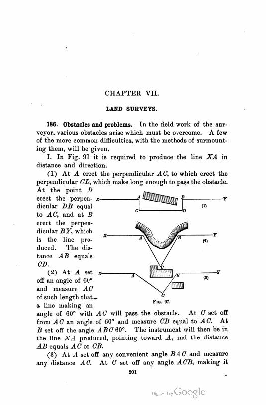
CHAPTER VII.
LAND SURVEYS.
186. Obstacles and problems. In the field work of the sur
veyor, various obstacles arise which must be overcome. A few
of the more common difficulties, with the methods of surmount
ing them, will be given.
I. In Fig. 97 it is required to produce the line XA in
distance and direction.
(1) At A erect the perpendicular AC, to which erect the
perpendicular CD, which make long enough to pass the obstacle.
At the point D
erect the perpen
dicular DB equal
to AC, and at B
erect the perpen
dicular BY, which
is the line pro
duced. The dis
tance A B equals
CD.
(2) At A set
off an angle of 60°
and measure AC
of such length that—
a line making an
angle of 60° with AC will pass the obstacle. At C set off
from an angle of 60° and measure CB equal to AC. At
B set off the angle ABC 60°. The instrument will then be in
the line XA produced, pointing toward A, and the distance
AB equals AC ox CB.
(3) At A set off any convenient angle BA C and measure
any distance AC. At C set off any angle ACB, making it
201
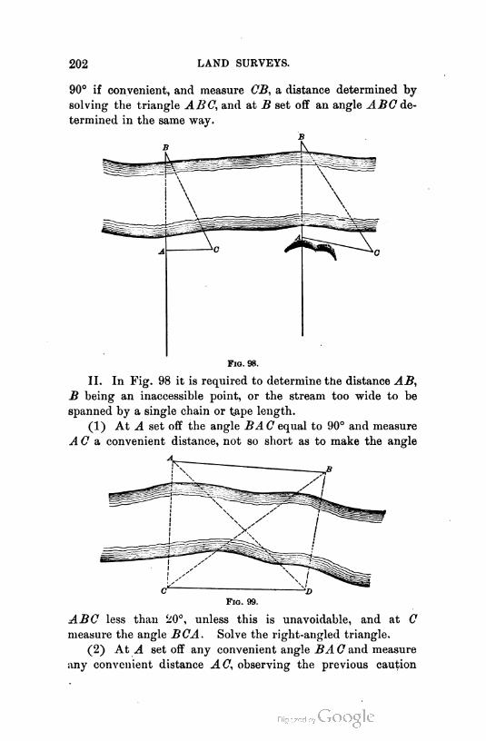
202 LAND SURVEYS.
90° if convenient, and measure CB, a distance determined by
solving the triangle ABC, and at B set off an angle ^rede
termined in the same way.
Fig. 98.
II. In Fig. 98 it is required to determine the distance AB,
B being an inaccessible point, or the stream too wide to be
spanned by a single chain or tape length.
(1) At A set off the angle BAG equal to 90° and measure
AC & convenient distance, not so short as to make the angle
Fig. 99.
ABC less than 20°, unless this is unavoidable, and at C
measure the angle BCA. Solve the right-angled triangle.
(2) At A setoff any convenient angle BA C and measure
any convenient distance AC, observing the previous caution
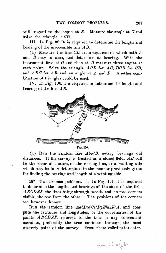
TWO COMMON PROBLEMS. 203
with regard to the angle at B. Measure the angle at C and
solve the triangle ACB.
III. In Fig. 99, it is required to determine the length and
bearing of the inaccessible line AB.
(1) Measure the line CD, from each end of which both A
and B may be seen, and determine its bearing. With the
instrument first at C and then at D measure three angles at
each point. Solve the triangle ACD for AC, BCD for CB,
and ABC for AB, and an angle at A and B. Another com
bination of triangles could be used.
IV. In Fig. 100, it is required to determine the length and
bearing of the line AB.
Fig. 100.
(1) Run the random line AbcdB, noting bearings and
distances. If the survey is treated as a closed field, AB will
be the error of closure, or the closing line, or a wanting side
which may be fully determined in the manner previously given
for finding the bearing and length of a wanting side.
187. Two common problems. I. In Fig. 101, it is required
to determine the lengths and bearings of the sides of the field
ABCDEF, the lines being through woods and no two corners
visible, the one from the other. The positions of the corners
are, however, known.
Run the random line AabBedCefBgFhikFlA, and com
pute the latitudes and longitudes, or the coordinates, of the
points ABCDEF, referred to the true or any convenient
meridian, preferably the true meridian through the most
westerly point of the survey. From these coordinates deter
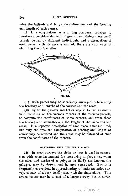
204 LAND SURVEYS.
mine the latitude and longitude differences and the bearing
and length of each course.
II. If a corporation, as a mining company, proposes to
purchase a considerable tract of ground containing many small
parcels owned by different individuals, and a description of
each parcel with its area is wanted, there are two ways of
obtaining the information.
Fiq. 101.
(1) Each parcel may be separately surveyed, determining
the bearings and lengths of the courses and the areas.
(2) By far the quicker and better way is to run a random
field, touching on the various corners of the various parcels,
to compute the coordinates of these corners, and from these
the bearings, or azimuths, and the length of the sides and the
areas. If a separate description of each piece is not required,
but only the area, the computation of bearing and length of
course may be omitted and the areas may be obtained at once
from the coordinates of the corners.
SURVEYING WITH THE CHAIN ALONE.
188. In most surveys the chain or tape is used in connec
tion with some instrument for measuring angles, since, when
the sides and angles of a polygon (a field) are known, the
polygon may be drawn and its area computed. But it is
frequently convenient in approximating to make an entire sur
vey, usually of a very small tract, with the chain alone. This
entire survey may be a part of a larger survey, but is, never
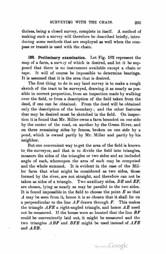
SURVEYING WITH THE CHAIN, 205
theless, being a closed survey, complete in itself. A method of
making such a survey will therefore be described briefly, intro
ducing some methods that are employed as well when the com
pass or transit is used with the chain.
189. Preliminary examination. Let Fig. 102 represent the
map of a farm, a survey of which is desired, and let it be sup
posed that there is no instrument available except a chain or
tape. It will of course be impossible to determine bearings.
It is assumed that it is the area that is desired.
The first thing to do in any land survey is to make a rough
sketch of the tract to be surveyed, drawing it as nearly as pos
sible in correct proportion, from an inspection made by walking
over the field, or from a description of the field taken from the
deed, if one can be obtained. From the deed will be obtained
only the description of the boundary ; and the other features
that may be desired must be sketched in the field. On inspec
tion it is found that Mr. Miller owns a farm bounded on one side
by the center of the road, on another by the Green River, and
on three remaining sides by fences, broken on one side by a
pond, which is owned partly by Mr. Miller and partly by his
neighbor.
But one convenient way to get the area of the field is known
to the surveyor, and that is to divide the field into triangles,
measure the sides of the triangles or two sides and an included
angle of each, whereupon the area of each may be computed
and the whole summed. It is evident in the case of the Mil
ler farm that what might be considered as two sides, those
formed by the river, are not straight, and therefore can not be
taken as sides of a triangle. Two auxiliary sides, DE and EF,
are chosen, lying as nearly as may be parallel to the two sides.
It is found impossible in the field to choose the point E so that
A may be seen from it, hence it is so chosen that it shall lie on
a perpendicular to the line A F drawn through F. This makes
the triangle AFE a right-angled triangle, and hence AE need
not be measured. If the house were so located that the line BF
could be conveniently laid out, it might be measured and the
two triangles ABF and BFE might be used instead of AFE
and AEB.

206 LAND SURVEYS.
190. Survey. To begin the survey, select a point, F, in the
center of the road, and, placing a flag in the fence at B, or
merely sighting along the fence, if it is straight, locate a point
in the center of the road at A, in Ba prolonged. Measure
FA. Measure AB. If the fence aB is not straight, or is a
PUYALLUP CO., WASHINGTON.
Note: Surveyed by A.B. Wood w1th chain only*
Oct.s, I88i. Scale; Scha1ns per 1nch.
FlQ. 102.
rough rail fence, so that it is not convenient to measure on the
line AB, measure along a parallel line offsetting a short dis
tance from the fence, making no note of the offset, but record
ing merely the length AB and the distance from A to a. Meas
ure along the line BC. or on a small offset parallel to it toward
C, until the pond is reached. Note the distance, and erect a
SURVEYING WITH THE CHAIN. 207
perpendicular offset long enough to permit a line parallel to
BC to pass the pond. At the extremity of this offset erect a
perpendicular which will be parallel to BC, and measure along
the perpendicular far enough to clear the pond, and then, by a
process like that just used, get back on the line CB. When
measuring along the parallel line, take offsets to the pond as
often as may be necessary, noting the distance to each offset
and the length of the offset. Having reached 0, measure
along the line CB to B, then along BE to E, noting the dis
tance to and the length of each offset that it appears necessary
to take to correctly locate the river; and having reached E,
measure EF, noting similarly the offsets and also the distance
to the fence at the roadside.
Perhaps the ordinary method of procedure now would be to
measure the diagonals BB and BE ; then the field would be
divided into four triangles, ABE, BCD, BEB, and AEF, the
areas of which could be computed, and to their sum, the area
between the lines BE and EF and the river (computed as
described in Chapter VI.) could be added, and the area of the
entire field would thus be obtained. The line BB would be a
difficult one to run, because both B and B being lower than the
ground between them, the line must be ranged out, and, more
over, the intervening woods make it even more difficult to
determine. If the woods were thick, it could be obtained only
by running a trial line and correcting that to the true line.
Moreover, the method above described gives no check on the
work ; and the constant thought of the surveyor should be,
" Where can I find a check on my work ? " Not more than one
check on one piece of work is, however, necessary ; though, if
more may be obtained without waste of time, they may some
times prove advantageous.
Having measured the boundary of the field, it is probably
best now to measure the line AC, finding by trial the points
at which perpendiculars to this line will pass through F, B, E,
and B. Measure these perpendiculars, and now four sides of
the boundary are the hypotenuses of right-angled triangles,
of which the other two sides are known. The other two sides
are sides of trapezoids, or may be considered the hypotenuses
of right triangles. The computed value of each of the sides of

208 LAND SURVEYS.
the boundary should agree with its measured length. If it
does not, there is an error in the measurement of either the
line AC, one or more of the perpendiculars, or one or more of
the sides of the boundary. If all is right except one side, the
error is in that side. The work should then be remeasured in
so far as it may be found wrong. If this latter method is not
adopted, a rough check may be had on the former method by
measuring the angles made by the sides. These should meas
ure on a drawing the same as found in the field.
The work necessary to obtain the area of the farm is now
completed. If it is desired to locate the drives, buildings, and
other objects within the inclosure, it may be done by running
auxiliary lines at known angles and from known points on the
various sides. For instance, a line could be run from E, at
right angles to EF, and at stated points on this auxiliary line
offsets could be measured to the corners of the objects it is
desired to locate ; or if it were the driveway, the offsets could
be taken at frequent noted intervals to the sides of the drive.
As the point D can not be seen from the line AC, a point may
be chosen at random, as near as possible to the proper position,
and a perpendicular run out to a point opposite D, whereupon
the length of the perpendicular and the distance that the point
on AC must be shifted to be in its proper place become known.
191. Notes. The measurements should be written on the
sketch, which must be made large enough to permit this to be
done without confusion. It is believed that no form of notes
for such work is so good as a sketch on which all information
is written. For the auxiliary lines locating drives, etc., the
sketch would consist of a straight line, with distances to offsets
marked along it, and offsets and objects offsetted to sketched
in with dimensions. These need not be to any scale.
FARM SURVEYS.
192. Classes. All land surveys may be divided into three
classes, — original surveys, resurveys, and location surveys.
These surveys are made with a compass or transit. The sur
veys of former years, in the older settled portions of the United

FARM SURVEYS. 209
States, were all made with the compass, and almost always with
reference to the magnetic meridian.
193. Original surveys. Original surveys are those made for
the purpose of mapping a field whose boundaries are marked in
some way, for determining its area, and for making a descrip
tion from which it could be again laid out if the boundaries
should be destroyed. Thus, Mr. Brown may own a farm, a
portion of which is timber land, which Mr. Black wishes to
buy. The boundaries are sufficiently marked by the edges of
the growth of timber. After the timber is gone, however,
there will be nothing to mark the boundaries, unless the tract
is fenced. There is no way in which Mr. Black may know how
many acres he is to buy, unless the tract is surveyed. Neither
can Mr. Brown give Mr. Black a deed to the property that
would contain a definite description from which the tract could
be laid out on the ground. A surveyor is called in and shown
the tract and asked to make a survey of it, to compute the
acreage, and to write a description of the plot.
194. Making an original survey. At the corners that are
shown him he sets monuments, preferably of stone. Too many
surveyors set merely small stakes, which soon rot or are pulled
out. These monuments are "witnessed" by trees, or other
natural objects near by, whose positions relative to the corner
are observed and noted. The witness points are marked as
indicated in Art. 196. The surveyor then determines the
bearing and length of each side, usually beginning at one
corner and working round the field in one direction till he
closes on the corner from which he started. He keeps notes of
the work in a notebook, preferably in the form shown on page
229, or on a sketch, which is afterwards " written up " in the
form just mentioned, and from the notes he " tables " the sur
vey and computes the area as explained in Chapter VI.
195. Making the map. He may, and usually does, make a
map of the survey. This map should conform to the require
ments stated in the Appendix, page 355. The easiest and most
rapid method of plotting the map is by " latitudes and longi
tudes." Two reference lines at right angles are drawn, and
k'm'd sUHV. — 14
210 LAND SURVEYS.
one is assumed as the meridian and the other as a line of zero
latitude. The total latitudes and longitudes of the corners are
determined from the tabling work, and are laid off from these
base lines. The latitudes are measured from the zero parallel,
and the longitudes from the meridian. It will be convenient
to make the reference meridian pass through the most westerly
point of the survey. This is not necessary. To avoid negative
signs for latitude, compute all latitudes as if the reference par
allel were through the same point as the meridian ; then add
to all latitudes a sum equal to the greatest negative latitude;
or assume the latitude of the most westerly point to be so large
that there shall be no negative latitudes.
When the corners are all plotted they are connected by
right lines, and the outline is complete. It remains to number
the corners, to write the bearings and lengths along the sides,
and to put on the necessary descriptive matter. The work
should all be done with the utmost neatness, the lettering being
preferably the simple Roman, the most effective and most diffi
cult letter that is made.
196. Description. Having made the map, the surveyor writes
a description, somewhat in the following form :
Beginning at a post marked B.I., at the S.E. corner of the
land of Joseph Brown, from which post a hard maple tree, 8
inches in diameter, bears S. 10° W. 10 links, and a white ash,
12 inches in diameter, bears N. 70° W. 50 links, both of which
trees are blazed and marked B.l.B.T. (Black 1 Bearing Tree),
and running thence N. 10° 30' W. along the easterly line of
said Joseph Brown, six and forty-two one-hundredths ( 6^ff )
chains to a post marked B.2., from which post a hickory tree,
10 inches in diameter and marked B.2.B.T. bears S. 68° W.
30 links ; thence N. 84° W. seven and fifty one-hundredths
('i5o°o) chains to a stone about 12 inches long and 6 inches
square, set flush with the ground and marked B.3., from which
stone a beech tree, 15 inches in diameter and marked B.3.B.T.
bears, etc., thence, etc., to
the point of beginning, containing acres, more or
less.
The surveyor usually does his tabling and writes his descrip
FARM SURVEYS. 211
tions in a book which he keeps for the purpose, for future
reference. Copies are made, and, with a tracing of the map,
are furnished the person for whom the survey is made. This
is the simplest kind of land surveying.
197. Resurveys. These are far more difficult than original
surveys. A resurvey consists in tracing on the ground an
original survey, from a description similar to that just given.
The difficulties arise from the destruction of monuments and
from errors in original work, from change in declination of
the needle (if the surveys were run by the magnetic compass
and referred to the magnetic meridian), from insufficient data
in the original description, such as failure to state whether the
survey is referred to the true or magnetic meridian, failure to
state the declination on which the survey was made, lack of
bearing trees or other reference points, etc., and from conflict
ing testimony of interested owners as to where the corners
were. It is impossible to point out all the difficulties that
will be encountered by a surveyor in his attempt to reestab
lish the monuments of an old survey. The more of this work
that he does, the more firmly will it be impressed upon him
that the only kind of corners to establish are those that will be
as nearly as possible permanent, and that minuteness of detail
and accuracy in all descriptions are well worth the time they
take.
198. Reasons for a resurvey. A resurvey becomes necessary
for various reasons. Among others might be the following,
referring to the original survey previously described: After
Mr. Black has owned the wood lot for a number of years, and
perhaps has cleared it, and it has descended to his son and his
son's son, and the corners are mostly obliterated, it is sold to
Mr. Johnson who, desiring to fence it off, and, moreover, to
see whether the land he is paying for is all there, employs a
surveyor to "run it out," giving him the description written by
the original surveyor as he finds it in his deed, with possibly
some errors in copying.
199. Procedure. If the surveyor can recover a single line of
the original survey, and the notes are correct, his work will be
212 LAND SURVEYS
comparatively easy. (He simply has to establish a series of
lines of given bearing and length.) He therefore endeavors
to do this. If this can not be done, the next best thing is to
recover any two corners and determine in the field the bearing
and length of the line joining them. From the original notes
he will then compute the bearing and length of this line, and
the angle made with it by one of the sides of the field joining
it, and he then can lay off this angle from his field-determined
line and locate that side. As there will be four sides joining
the line between the two corners, it will be seen that the sur
veyor has a good beginning for his work.
200. Change of declination. It might seem that if he could
find but one corner, he could run out the field, knowing the
bearings. This would be true if he knew also the declination
on which the original survey was made and the declination at
the time of his resurvey.
The following consideration will explain this : Let it be
assumed that the original survey was made with reference to
the magnetic meridian and that the declination at that time
was east 10°. Then, any line that is recorded due north will
be 10° east of north. Any line recorded due south will be 10°
west of south, etc. That is, all the points of the compass are
turned 10° to the right. Let it be assumed that the declina
tion at the time of the resurvey is 8° east. A line recorded
as due north will be 8° east of north, and a line recorded as
due south will be 8° west of south. The points of the compass
have been turned back two degrees to the left. And hence, if
a line were run out with the original bearing, it would lie two
degrees to the left of the true place. It would be necessary to
run the line with a bearing two degrees to the right of its
originally recorded bearing. Thus, if its original bearing were
north, it must be rerun with the needle reading N. 2° E.
Hence, the following rule is serviceable :
Rule : To rerun lines recorded by their magnetic bearings,
change the bearings by an amount equal to the change in declina
tion and in a direction opposite to that change — that is, left or
right.
If the compass has a declination vernier, that vernier may
FARM SURVEYS. 213
be set so that the compass, when the line of sight is pointing in
a known bearing, as magnetic north, shall read a bearing as
many degrees to the right or left of the known magnetic bear
ing as the declination has changed to the right or left. It
must be remembered that, in using the declination vernier, the
compass box moves with reference to the line of sight. In the
above case it should read N. 2° W., when the sights are point
ing to magnetic north. Hence, to be able to retrace the survey
with a compass, using the original bearings, the following rule
is serviceable :
Rule : Set the declination vernier so that the compass shall
read magnetic bearings erroneously by an amount equal to and in
the direction (left or right) of the change in declination.
To find the change in declination, if it is not known, deter
mine the bearing of a line of the original survey and compare
this with the bearing recorded. The difference is the change
in declination in amount and in opposite direction (left or
right).
If one line can not be found, but two corners may be, con
nect the two corners by a random line as described in Art. 186.
Find the bearing of the closing line and compare it with the
bearing of the same line computed from the original notes.
201. Transit or compass. When a transit is used, or in
deed a compass, the angles at the corners of the field may be
determined from the recorded bearings and, when one side has
been recovered, the angles and distances may be measured, to
recover the other sides. This does away with all consideration
of, or change in, declination. It is by far the better method to
pursue with lands of any considerable value. The angles de
termined from compass readings can not be depended on to
minutes, and may be found to vary five or ten minutes. It
would be well if, when a transit is first used on a resurvey, the
corrected bearings and distances could be introduced in a cor
rection deed which could be filed with the proper authority.
If angles are to be used, and one side can not be directly re
covered, but a closing line joining two corners is determined,
proceed as follows : Over one known corner, set the line of
214 LAND SURVEYS.
sight in the closing line mentioned, and turn off an angle deter
mined, by computation from the description, to be the angle
between this line and a side adjacent to the corner occupied.
This should give the direction of that side. Measure the
recorded length of that side, and look about over a consider
able area for evidences of the corner. Look for recorded wit
ness trees, or their stumps. Carefully shovel off the top of the
soil — do not dig it up by spadefuls. A careful shoveling will
frequently reveal the hole formerly occupied by a stake, now
rotted entirely away, with evidences of the decayed wood.
Continue the work till all corners are found or satisfactorily
relocated. The only thing that can absolutely insure the correct
ness of the resurvey is the fending of the old corners.
202. Report. Upon the completion of the resurvey, the
surveyor should report to his employer just what he finds. It
is not his business to decide controversies. He may advise,
just as an attorney would do ; but he has no authority to cor
rect errors or to establish corrected corners as the corners.1
His business is to make an examination, to reset lost corners in
their original positions, if he can find them, and to report his
method of procedure and the reasons for his action to his em
ployer, who may then take such action as he chooses. A neat
and explicit map should accompany the report. The surveyor
may possibly be assisted in his work by an understanding of the
principles of Art. 204, deduced from many court decisions.2
203. Application of coordinates. In all of this work the
coordinate system is very helpful. Usually the true corners
of a tract of land can not be occupied by the instrument, nor
can the lines be seen throughout their length. If it is known
where the corners are, and it is desired to make a survey for a
map or a description, a random survey is made with corners as
near as practicable to the true corners. This survey is bal
anced and the coordinates of its corners are determined. From
such of the corners as are near true corners, angles or azimuths,
'See "Judicial Functions of Surveyors," by Judge Cooley, Appendix, pages
341-350.
2 These and many other decisions may be found in a valuable " Manual of
Land Surveying," by Hodgman and Bellows.
FARM SURVEYS. 215
and distances to the true corners are noted, and from these the
coordinates of the true corners are determined. From these
coordinates, lengths and bearings of true lines may be found.
If the survey is for the purpose of relocating lost corners,
and the bearings of the lines and at least one point in each are
known, the corners may be located even though the lines can
not be occupied by the instrument, provided the corners and
known points are accessible. This would be done by running
a random survey as before with pointings to the known points
(and such corners as are known) then finding the coordinates
of the known points, and by Problem II., Art. 143, the coor
dinates of the wanting corners. Knowing now the coordinates of
the points in the random survey and those of the true corners,
by Problem I., Art. 143, find the bearing and distance from a
corner of the random to the nearest wanting true corner, and
locate the corner.1
204. Principles for guidance in resurveys. I. Construing de
scriptions. The following principles have been applied to the
construing of descriptions that are inconsistent, obscure in
meaning, or imperfect.
(1) The description is to be construed favorably to the
purchaser, unless the intent of both parties can be certainly
ascertained. If that intent can be ascertained, the description
will be construed accordingly.
(2) The deed must be construed according to the condi
tions existing, and in the light of the facts known and in the
minds of the parties, at the time the instrument was drawn.
(3) Every requirement of a description must be met, if pos
sible. Nothing is to be rejected if all requirements are mutually
consistent.
(4) If some parts are evidently impossible and, by rejecting
such parts, the remainder forms a perfect description, such
impossible parts may be rejected.
(5) A deed is to be construed so as to make it effectual
rather than void.
1 For model example, applied to city property, see Appendix, page 328. The stu
dent may tell how to proceed if the bearings and lengths are all given, with but two
earners known, and lines so grown over or occupied by structures that they can not
be run out directly without great labor.

216 LAND SURVEYS.
(6) If land is described as that owned and occupied by an
individual, the actual line of occupation is a requirement or call
to be met in the location.
(7) A line described as running a definite distance to a
definite known line or object, will be construed as running to
that object, whatever distance is required. If the known
object is uncertain as to position, the written distance may be
used.
(8) The terms " northerly," " southerly," " easterly," and
" westerly," are to be construed, in the absence of other infor
mation, as meaning due north, south, east, and west.
(9) When a definite quantity of land is sold and nothing
appears to indicate its form — as, for instance, ten acres in the
northeast corner of B's land, the land will be laid out as a
square, unless this is manifestly impossible.
(10) A description by " metes and bounds " will convey all
the land within the boundaries, be it more or less than the area
mentioned in the deed.
(11) Property described as bounded by a highway extends
to the center of the highway, unless specifically noted other
wise.
(12) A description by metes and bounds, followed by a
statement that the land described is a particular well-known
parcel, will be construed to convey the well-known parcel,
though the metes and bounds do not fulfill the necessary
conditions.
II. Water boundaries. (1) Local laws of different states
give different constructions to the word " navigable " and the
surveyor must examine the laws of the state in which he
works. The United States statutes provide as follows for the
streams within the area known as the public lands :
" All navigable rivers, within the territory occupied by the
public lands, shall remain and be deemed public highways ;
and, in all cases where the opposite banks of any streams not
navigable belong to different persons, the stream and the bed
thereof shall become common to both."
(2) Grants of land bordering on navigable streams carry
only to high-water mark, while on non-navigable streams they
carry to the center, or "filum aquae,"
FARM SURVEYS. 217
(3) The common law holds those streams only to be navi
gable in which the tide ebbs and flows. The civil law con
siders a stream navigable that is capable of being used as a
commercial highway.
The courts of Pennsylvania, North Carolina, South Carolina,
and Alabama follow the civil law, while those of Maine, New
Hampshire, Massachusetts, Connecticut, New York, Maryland,
Virginia, Ohio, Illinois, Indiana, and Michigan follow the
common law.
(4) The bank is the continuous margin where vegetation
ceases. The shore is the sandy space between it and low-
water mark.
(5) A description reading "to the bank," or "along the
bank," is construed to mean "the bank," and to include no
portion of the stream.
(6) Islands in rivers fall under the same rule as the land
under water, and belong to one adjoining proprietor or the
other— unless previously lawfully appropriated— according
as they are on one side of the center or the other. The filum
aquiE is midway between lines of ordinary low-water mark,
without regard to the position of the main channel.
(7) Riparian rights, unless expressly limited, extend to
the middle of the navigable channel.
(8) In some states the tide lands are held to belong in
alienably to the people of the state and may not be sold to
individuals. In others a different policy has been pursued.
(9) A boundary by the shore of a millpond carries to low-
water mark.
(10) Boundary lines of lots fronting on a river extend into
the river at right angles to the thread of the stream, without
regard to the form of the bank.
(11) Land made by the drying up of a lake or the deposit
of alluvium along a river accrues to the adjacent owners and
should be so distributed among them that each will receive
such a portion of the made area as his former frontage on the
water was of the entire former frontage. If, however, the
water front is the valuable item, as it would be along a navi
gable river or lake in a city, the new frontage is to be dis
tributed according to the old frontages.
218 LAND SURVEYS.
III. Special field rules. (1) Monuments control courses
and distances. That is, if the location of an original monu
ment can be certainly ascertained and the recorded distance
does not reach that monument, the line must, nevertheless, be
run to the monument. In the absence of sufficient evidence to
determine the monument, the description will govern. (The
surveyor should use every effort to find evidence as to the
location of the lost corner.)
(2) Adverse possession of land for a definite period of
time (varying in different states), even without color of title,
constitutes title in fee ; but the possession must be adverse ;
that is, the true line must be known to the parties or the line
of occupation must be acquiesced in by them. If the true
boundary is unknown, and each claims to own only to the true
line, no adverse possession can arise.
(3) Boundaries and monuments may be proved by any
evidence that is admissible in establishing any other facts.
(4) A resurvey after original monuments have been lost is
for the purpose of finding where they were, and not where they
should have been. ■ -
(5) Purchasers of town lots have a right to locate them
according to the stakes which they find planted and recognized,
and no subsequent survey can be allowed to unsettle them.
The question afterwards is not where they should have been,
but where they were planted with authority, and where lots
were purchased and taken possession of in reliance on them.
(6) Of two surveys that disagree, made many years apart
— the monuments being lost — the original survey will be pre
ferred, particularly if the line of the first survey has remained
unquestioned for many years.
(7) When streets have been opened and long acquiesced
in, in supposed conformity to a plot, they should be accepted
as fixed monuments in locating lots or blocks contiguous
thereto.
(8) A beginning corner is of no greater dignity or impor
tance than any other corner.
(9) A call for a lot hy a name or number that it bears on
a mentioned plot will prevail over courses and distances, and
sometimes over monuments.

UNITED STATES LAND SURVEYS. 219
205. Location surveys. These consist in laying out on the
ground lines previously determined by computation or draw
ing. Such surveys are not infrequently connected with either
original surveys or resurveys. Surveys for the partition and
division of land are of this class. If Joseph Brown sells to
John Black five acres of land in the shape of a square, one
corner and the direction of one side being fixed, the location of
the sides and corners would be a location survey. Such surveys
are comparatively simple, involving sometimes the running of
one or more trial lines for data to compute the location. Many
complex problems, however, arise.
UNITED STATES PUBLIC LAND SURVEYS.
206. Value and character of work. The original surveys
for the subdivision of the public lands of the United States
are location surveys. The method adopted, imperfectly as the
work has been done, has been of incalculable value in definitely
describing each separate tract or parcel of land sold to individ
uals, and in providing that lines once established by the United
States deputy surveyors shall remain as the lines they purport
to be, even though found to be improperly placed. The latter
provision has been of particular value in making the land lines
permanent. The work of subdividing the public lands is almost
completed, and hence the work of the surveyor of the future
will be largely resurveying, that is, relocating corners that have
been or are supposed to be lost, and dividing into smaller par
cels the areas already located.
If the original surveys had been properly executed, the
work would not be difficult. In some instances the work was
most wretchedly done, either willfully or through ignorance ;
and the corners, when established, were placed far from their
proper positions. The notes have generally been returned in
a form indicating correct work ; and hence has arisen more or
less difficulty in relocating the corners.
207. General scheme of subdivision. Certain points have
been selected in different parts of the country through which true
north and south lines, called " principal meridians," have been
run and marked out on the ground. Intersecting these prin
220 LAND SURVEYS.
cipal meridians at the initial point are run parallels of lati
tude, known as "base lines." On either side of these meridians
the land is laid out in approximately square parcels, six miles
on a side, called "townships." A tier of these townships run
ning north and south is called a "range." The townships are
described as being " Township No. south or north of a
named base line and range No. east or west of a named
principal meridian. " This definitely locates every township.
The lines that divide the ranges are called "range lines,"
and those that divide a southern from a northern township are
called " township lines." Each township is further divided
into thirty-six " sections," each approximately one mile square.
These sections are numbered from one to thirty-six. Each
section, then, is definitely located by its number, township, and
range. The sections have been further divided into quarter
sections as, the northeast quarter, the southwest quarter, etc.
Sometimes the sections have been divided into halves, described
as the north half or the east half, etc. The Government does
not divide the land into smaller divisions than quarter sections,
but it sells less areas than this, and, in such cases, and when
original purchasers sell a portion of their purchase, it is usual
to sell a quarter of a quarter, or half of a quarter, or even a
quarter of a quarter of a quarter section ; and the method of
describing these fractional portions is the same as that used to
describe the quarter sections. The description would be writ
ten as follows for the piece described : The N. E. ^ of the
S. W. £ of Sec. 26, Tp. 8 N., R. 4 E., Mt. Diablo Meridian.
The positions of the meridians being chosen more or less at
random and at different times, as the necessity for surveys in
different localities developed, it is to be expected that the
surveys extending east from one meridian will not close with
regular full sections or townships on the surveys extended
west from the next easterly meridian. The same is true of
tiers of townships extended north and south from adjacent base
lines. The result is fractional townships and sections. Some
times these are larger than the standard division, sometimes
smaller. If very much larger, the surplus in a township is
divided into lots which are numbered. These lots are made to
contain as nearly as possible 160 acres. There are other
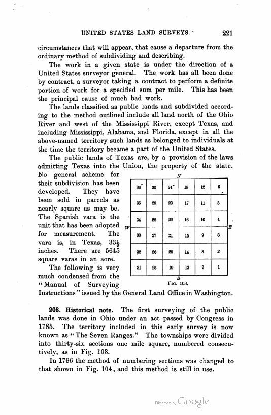
UNITED STATES LAND SURVEYS. 221
circumstances that will appear, that cause a departure from the
ordinary method of subdividing and describing.
The work in a given state is under the direction of a
United States surveyor general. The work has all been done
by contract, a surveyor taking a contract to perform a definite
portion of work for a specified sum per mile. This has been
the principal cause of much bad work.
The lands classified as public lands and subdivided accord
ing to the method outlined include all land north of the Ohio
River and west of the Mississippi River, except Texas, and
including Mississippi, Alabama, and Florida, except in all the
above-named territory such lands as belonged to individuals at
the time the territory became a part of the United States.
The public lands of Texas are, by a provision of the laws
admitting Texas into the Union, the property of the state.
No general scheme for
their subdivision has been
developed. They have
been sold in parcels as
nearly square as may be.
The Spanish vara is the
unit that has been adopted w,
for measurement. The
vara is, in Texas, 33^
inches. There are 5645
square varas in an acre.
The following is very
much condensed from the
" Manual of Surveying
Instructions " issued by the General Land Office in Washington.
36" 30 24" 18 12 6
35 29 23 17 11 5
31 28 22 16 10 1
33 27 21 15 9 3
32 26 20 11 8 2
31 25 19 13 7 1
s
F1g. 103.
208. Historical note. The first surveying of the public
lands was done in Ohio under an act passed by Congress in
1785. The territory included in this early survey is now
known as "The Seven Ranges." The townships were divided
into thirty-six sections one mile square, numbered consecu
tively, as in Fig. 103.
In 1796 the method of numbering sections was changed to
that shown in Fig. 104 , and this method is still in use.
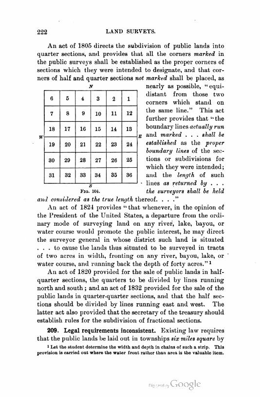
222 LAND SURVEYS.
An act of 1805 directs the subdivision of public lands into
quarter sections, and provides that all the corners marked in
the public surveys shall be established as the proper corners of
sections which they were intended to designate, and that cor
ners of half and quarter sections not marked shall be placed, as
n nearly as possible, "equi
distant from those two
corners which stand on
the same line." This act
further provides that " the
boundary lines actually run
E and marked . . . shall be
established iis the proper
boundary lines of the sec
tions or subdivisions for
which they were intended;
and the length of such
- lines as returned by . . .
F1g. 101. the surveyors shall be held
and considered as the true length thereof. . . ."
An act of 1824 provides "that whenever, in the opinion of
the President of the United States, a departure from the ordi
nary mode of surveying land on any river, lake, bayou, or
water course would promote the public interest, he may direct
the surveyor general in whose district such land is situated
... to cause the lands thus situated to be surveyed in tracts
of two acres in width, fronting on any river, bayou, lake, or
water course, and running back the depth of forty acres."1
An act of 1820 provided for the sale of public lands in half-
quarter sections, the quarters to be divided by lines running
north and south ; and an act of 1832 provided for the sale of the
public lands in quarter-quarter sections, and that the half sec
tions should be divided by lines running east and west. The
latter act also provided that the secretary of the treasury should
establish rules for the subdivision of fractional sections.
209. Legal requirements inconsistent. Existing law requires
that the public lands be laid out in townships six miles square by
1 Let the student determine the width and depth in chains of such a strip. This
provision is carried out where the water front rather than area is the valuable item.
6 5 i 3 2 1
7 8 9 10 11 12
18 17 16 15 14 13
19 20 21 22 23 24
30 29 28 27 26 25
31 32 33 34 35 36
UNITED STATES LAND SURVEYS. 223
lines running due north and south, and others east and west,
also that the township shall be divided into thirty-six sections,
by two sets of parallel lines, one governed by true meridians
and the other by parallels of latitude, the latter intersecting
the former at right angles, at intervals of one mile ; and each
of these sections must contain, as nearly as possible, six hundred
and forty acres. These requirements are manifestly impossible
because of the convergency of the meridians, and the discrep
ancies will be the greater as the land divided is farther north.
The law also provides that the work of subdivision shall be so
performed as to throw all shortages or surplus into the northern
and western tiers of sections in each township. To harmonize
these various requirements as much as possible, the following
methods have been adopted by the general land office.
210. Principal reference lines. Initial points are established
astronomically under special instructions. From the initial
point a " principal meridian " is run north and south. Through
the initial point a "base line" is run as a parallel of latitude
east and west.1 On the principal meridian and base line the
section and quarter corners, and meander corners at the inter
section of the line with all streams, lakes, or bayous, prescribed
to be meandered, will be established. These lines may be run by
solar instruments, but methods involving the use of the transit
with observations on Polaris at elongation are now preferred.2
211. Standard parallels. — Such parallels, called also cor
rection lines, are run east and west from the principal merid
ian as parallels of latitude at intervals of twenty-four miles
north and south of the base line. " Where standard parallels
have been placed at intervals of thirty or thirty-six miles, re
gardless of existing instructions, and where gross irregularities
require additional standard lines, from which to initiate new, or
upon which to close old, surveys, an intermediate correction line
should be established to which a local name may be given, e.g.,
'Cedar Creek Correction Line'; and the same will be run, in
all respects, like the regular standard parallels."
1 A list of base lines and principal meridians will be found in the Appendix,
pages 357-360.
2 See the " Manual of Surveying Instructions " for detail of methods.

224 LAND SURVEYS.
212. Guide meridians. Guide meridians are extended north
from the base line, or standard parallels, at intervals of twenty-
four miles east and west from the principal meridian.
When existing conditions require the guide meridians to
be run south from a standard parallel or a correction line,
they are initiated at properly established closing corners
on the given parallel. This means that they are begun
from the point on the parallel at which they would have
met it if they had been ran north from the next southern
parallel. The point is obtained by computation, and is less
than twenty-four miles from the next eastern or western
meridian by the convergence of the meridians in twenty-four
miles.
In case guide meridians have been improperly located too
far apart, auxiliary meridians may be run from standard corners,
and these may be designated by a local name, e.g., " Grass Val
ley Guide Meridian."
213. Angular convergence of two meridians. This is given
by the equation
0 = m sin L, (1)
where to is the angular difference in
longitude of the meridians, and L is
the mean latitude of the north and
south length under consideration.
The linear convergence in a given
length I is
c = I sin 0. (2)
The derivation of equation (1) is as
follows, assuming the earth to be a
sphere, which will introduce no error
of consequence in this work. In the
figure, R is the mean radius, r is the
radius of a parallel, S and S' are
tangents to the two meridians. The angle 0 between these
is the angular convergence of the meridians in the latitude L.
to is the difference in longitude.
UNITED STATES LAND SURVEYS. 225
r — R cos L.
S = R cot L.
(3)
(4)
S and S' may be considered as radii of the arc AB, which has
also the radius r. Since a given length of arc subtends angles
inversely proportional to the radii with which it may be drawn,
whence 6 = m sin L, which was to be found.
Since the distance between meridians is usually given in
miles, this must be reduced to degrees. This is done by first
finding the linear value of one degree for the mean latitude,
using the value of r given in equation (3). To make (3)
and (4) strictly correct, the normal at A should be used instead
of R ; but the mean radius will give results sufficiently close
for land surveying. See Tables IX. and X., pages 371, 372, for
values of 6 and length of 1' of longitude in various latitudes.
214. Township exteriors. Each twenty-four mile " square "
block is, when practicable, subdivided into townships at one
time, the work being done as follows :
Beginning with the southwestern township, the meridional
boundaries or range lines are first run, and on these are estab
lished the section and quarter corners. These are run as true
meridians from south to north. Next the east and west lines,
or township lines, are run from east to west between corre
sponding corners of the range lines. On each such township
line the section and quarter corners are established at full
distances from the eastern range line of each range, the short
age being thrown into the most westerly half mile in each
range. A random line is run from east to west, temporary
corners being set at correct distances. The distance north or
south by which the random line fails to reach the proper corner
is observed, and from this and the known length and bearing
of the random line a correct bearing is determined and the
correct line run eastward, on which are placed the permanent
corners. If a random line fails to meet the required corner by
more than three chains, it must be rerun. Deviations from the
foregoing methods are sometimes made necessary by the topo
graphical features of the territory.
6? _ r _ R cos L
m S R cot Ij
(5)
r'm'd surv. — 15
226 LAND SURVEYS.
215. Subdivision of townships. Each township is next sub
divided into sections as follows :
Beginning on the south line of the township, at the corner
common to sections 35 and 36, run northerly parallel to the
eastern range line of the range in question, one mile, setting a
quarter corner at the half mile. Establish the corner common
Toumsh ip No. B North , Range No. 9 West, of a Principal MeridianEast
; * 7UJ34 2 i 1 .1 4- " 40 I 4a
Ise^j^ag8^
j-H SO 1
Set. 7 _
Ha
79 5-
SO
Sei IS
j 63611 oO 8- !
m
M
3 " "«40
West
8 Set. 8 jj
! West
-f—-¥~ I
West]
Sed.9
640
Wesi,
"" 640 "
i Welti
West]
80j--
§ SsLiL Sslf—Seci 11_
6p) -vTb ""o}6
"SetLJ 1
Fvi 80 iMSei 19
Y„\ 637180 "1t-
---I ! .*a 8» i °
S
Seb.30
638.68
Sep. SI
639.56" fc-
1OjOO
g Seel 20__£oio >
Westl
soioo
g SecLjfi j
1 I
80)-0TlV.sf|
fc-|g Seel 1S_ g—w~-E>
! K,West
80j--
Seel 27
6io
Wes;
80joo
Jg SedjB jtg_ Seel 28_ *:lg Seci S7__*
° 6$) > 8 " 6^~
' West
80|-0 80|-0II
%_Se^SS__\
%_ BecYlk _>-SB
See, 22_
640
! Westl
! Weft8-|00
g _SecL SU3 640 £
_ West
Westl
Sec.
Sec,
"SeA.
tit-'Sec.
6i-"
West]
00
11 t
West)
Sec, 13 gr & b s
43 g Seel
te
West
g Sec135_g""~<S40
8-f0
MO
I
West\
WestsoIoo
g Seel 36__g]
64-
«s.e.
Sec. eFirst
Sec. 5
'.o WestStandardSec. U
ParallelSec. 3
NorthSec. 2 Sec. 1
The above plot represents a theoretical township with perfect subdivisions,
contiguous to the north side of a Standard Parallel ; in assumed Latitude
ht lS'N., and longitude 100°00' W. of Gr. Area 23021,. 16 A.
F1g. 106.
to sections 25, 26, 35, and 36, and run east on a random line to
the corner common to sections 25 and 36 on the range line, set
ting at the half mile a temporary quarter corner. From the
observed failure to meet the corner on the range line, compute
the bearing of a true line, and run this from the corner west,

UNITED STATES LAND SURVEYS. 227
setting the permanent quarter corner at the middle point of
the line.
Proceed thus with each succeeding section to the north
till section 1 is reached. From the corner common to sections
1, 2, 11, and 12, the meridional line is run to the section corner
on the next township line, by a random line corrected back ; but
the quarter corner is set at forty chains from the south end so
as to throw whatever discrepancy there may be into the north
half mile. In ease the township is the most northerly of a
twenty-four mile block, the line between sections 1 and 2 is not
run to the corner on the correction line, but is run parallel to the
range line, to an intersection with the correction line where a
closing corner is established and its distance from the section
corner noted.
This process is repeated for each tier of sections until the
fifth tier is completed. The east and west lines of the sixth
tier are run from east to west as random lines and corrected
back, but the quarter corner is set just forty chains from the
eastern boundary so as to throw the discrepancies into the
most westerly half miles. Fig. 106 represents a township with
perfect subdivisions. The directions written along the various
lines indicate the directions in which they are run. Probably
no townships that have been surveyed are like that in the
figure, all of them being more or less distorted by inaccuracies,
and some of them being very much distorted. When very bad
work is discovered in time to correct it, before such alteration
will interfere with acquired rights of individuals, the correc
tions may be made under rules prescribed by the General
Land Office.
When individuals have bought the land, the corners as
actually set must remain the corners, however erroneously
placed.
216. Meandering a stream. This consists in running lines
along its bank to determine its direction and length. The left
and right banks of a stream refer to the banks as they would
be to one passing down stream.
The " Instructions " provide for the meandering of naviga
ble streams and those whose width is three chains and upward.

228 LAND SURVEYS.
They are to be meandered on both banks. Lakes, deep ponds,
bayous, etc., of twenty-five acres or more are also meandered.
Corners called " meander corners " are established wherever a
meander crosses standard base lines, township lines, or section
lines.
A meander of tidal waters follows the high water line.
217. Corners. Stones, posts, trees, and earth mounds are
used to mark the corners. The kind of corner post depends on
the material afforded by the country. The " Instructions "
designate the kinds of corners to be established and the method
of marking them.
When it is impossible to establish a corner in its proper
place, auxiliary corners are established within twenty chains of
the true place, on each of the lines approaching the corner.
These corners are called " witness corners." The center quarter
corner of a section is located by connecting the opposite north
and south quarter corners by a straight line, and placing the
center corner at the middle of this line. Exceptions that will
suggest themselves are necessary in the northern and western
tiers of sections.
Any person having to do with surveys of lands that have
been subdivided as part of the public lands, should procure
the " Instructions " and study them carefully. These instruc
tions have varied from time to time and it is well to consult
those in force at the time the original surveys in hand were
made.1
218. Notes. The following sample page of the field notes
prescribed in the instructions is given as an excellent form of
notes for any land survey. For field purposes the author pre
fers a sketch on which all notes are made, and from which each
night the field book may be written up in the form given.
Variations in items noted and in nomenclature will suggest
themselves to the maker of other kinds of surveys.
1 He will also be much helped by a book entitled " Manual of Land
Surveying " by Hodgman and Bellows. This work contains the gist of many
court decisions and instructions, resulting from many years' experience in this
work. Dorr's " Surveyor's Guide " will also be found to contain many practical
suggestions.
UNITED STATES LAND SURVEYS. 229
6th Gu1de Mer1d1an East, through Tps. 13 N., between Rs.
24 and 25 E.
Survey commenced August 29, 1890, and executed with a W. & L. E. Gur-
ley light mountain transit, No. —, the horizontal limb being provided
with two opposite verniers reading to 30" of arc.
I begin at the Standard Corner of Township 13 North, Ranges 24 and 25
East, which I established August 29, 1890. Latitude 45° 34'.5 N., longi
tude 107° 24' W.At this corner, at 8h 54™ p.m., by my watch, which is 3m 49s fast of local
mean time, I observe Polaris at eastern elongation in accordance with
instructions in the manual, and mark the point in the line thus deter
mined by a tack driven in a wooden plug set in the ground, 5.00 chs.
north of my station.
August 29, 1890.
August 30: At 6'> 30"" a.m., I lay off the azimuth of Polaris, 1° 49' .5 to
the west, and mark the True Mer1d1an thus determined by a cross on
a stone firmly set in the ground, west of the point established last night.
The magnetic bearing of the true meridian is N. 18° 05' W., which re
duced by the table on page 100 of the Manual gives the mean mag. decl.
18° 02' E.
From the standard cor. I run
North, bet. Sees. 31 and 36.
Descend over ground sloping N. W.
Creek 10 Iks. wide in ravine, 45 ft. below the Tp. cor., course N. 32° W.
To edge of table land, bears N. E. and S. W. ; thence over level land.
Bluff bank, bears N. 58° W. and S. 58° E. ; descend abruptly 40 ft.
Bottom of ravine, course S. 58° E. ; ascend 50 feet to
Edge of table land, bears S. 58° E. and N. 58° W. ; thence over level land.
Difference between measurements of 40.00 chs., by two sets of chainmen,
is 18 Iks. ; position of middle point
By 1st set, 40.09 chs.
By 2d set, 39.91 chs. ; the mean of which is
Set a limestone, 16x7x5 ins., 11 ins. in the ground, for J sec. cor.,
marked J on W. face, and raise a mound of stone, 2 ft. base, 14 ft.
high, W. of cor.
Stream, 6 Iks. wide, in ravine 15 ft. deep, course N. 60° W.
Enter heavy oak timber, bears E. and W.
An oak, 30 ins. diam., on line, I mark with 2 notches on E. and W. sides.
Creek, 20 Iks. wide, 1 ft. deep, course N. 83° W.
Right bank of creek, begin very steep rocky ascent.
Top of ridge, 250 ft. above creek, bears N. 80° W. and S. 80° E.
Begin descent.
Difference bet. measurements of 80.00 chs., by two chainmen, is 22 Iks. ;
position of middle point
By 1st set, 79.89 chs.
By 2d set, 80.11 chs. ; the mean of which is
The point for sec. cor., 150 ft. below top of ridge, falls on a flat rock in
place, 10 ft. E. and W. by 6 ft. N. and S., on which I
Cut a cross (x) at the exact cor. point, for cor. of sees. 25, 30, 31, and 30,
marked with 5 grooves on N. and 1 groove on S. sides ; from which
An oak, 10 ins. diam., bears N. 22° E., 54 Iks. dist., marked T. 13
N., R. 25 E., S. 30, B. T.A dogwood, 5 ins. diam., bears S. GH° E., 40 Iks. dist., marked T.
13 N., R. 25 E., S. 31, B. T.An ash, 13 ins. diam., bears S. 51° W., 37 Iks. dist., marked T. 13
N., R. 34 E., S. 36, B. T.An oak, 9 ins. in diam., bears N. 34° W., 42 Iks. dist., marked T.
13 N., R. 24 E., S. 25, B. T.
Land, level and mountainous.
Soil, gravel and rock ; 4th rate.
Timber, oak.
Mountainous or heavily timbered land, 33.00 chs.

230 LAND SURVEYS.
CITY SURVEYING.
219. Precision required. Surveying to determine land lines
in a town or city does not differ in principle from surveying
for similar purposes in the country. The difference lies in the
degree of precision required. In the country a square foot of
land is worth from one cent to, perhaps, in extreme cases, five
or ten cents. In the heart of a great city it may be worth
many dollars, and a single inch frontage of a lot one hundred
feet deep may be worth several hundred dollars. The brick
wall of a modern office building of ten or more stories, built an
inch over the line of the owner's land, would be a costly wall
to move, and an error so locating it would virtually place the
owner at the mercy of the possessor of the adjoining property.
It is therefore readily seen that an error in closure of one in
three hundred, or one in five hundred, which may be tolerated
in farm surveying, would be altogether out of the question in
surveys in the heart of a great city.
In such situations a precision of one in fifty thousand
should be secured. In villages and small towns a precision
of one in five thousand will frequently be sufficiently close,
though, if the place has "prospects," it may be well to
make closer surveys. The methods of making measure
ments to the various degrees of precision required are noted
in Chapter I.
To lay off an angle so that the position of a line may not
depart from its true position by more than of its length,
requires that the angle have no greater error than about four
seconds. A transit reading to thirty seconds will nearly accom
plish this if the angle is measured three times before reading,
the reading being divided by three.
An instrument reading to twenty seconds will ordinarily do
a little better than the requirement, and an instrument read
ing to ten seconds will usually accomplish the required result
with a single measurement of the angle, though it should
always be measured more than once, if for no other reason
than to secure a check on the work. Of course the magnify
ing power of the telescope must correspond to the fineness of
the graduations.
CITY SURVEYING. 231
It has been stated that angles are read. Bearings are not
used, nor are regular traverses run out in city surveys. Bear
ings are usually worked up from the angles for all the lines of
a survey, in order to compute the latitudes and longitudes for
determining the error of the survey. Azimuth would do as well.
220. Extent of survey. City land surveys are usually, ex
cept where " additions " are being laid out, of small extent,
covering perhaps a single lot of 25 feet by 100 feet, more or
less. In a well-monumented city the entire survey may be
confined to the block in which the lot lies. In more cases, it
will be necessary to go several blocks away to obtain monu
ments for determining the necessary lines. In cities that have
been laid out with irregular lines, it may often be necessary to
carry the lines and measurements over the roofs of the solid
blocks of buildings in order to determine the angle points in
the side lines of the lots. Each case involves new difficulties
that the surveyor must meet by exercising his ingenuity.
Many difficulties are solved by the proper use of the coordinate
system, following the general methods outlined in Art. 203.
221. Instruments. A surveyor who undertakes to do city
work should be supplied with the best instruments for meas
uring lines and angles. The tape mentioned in Chapter I., as
used in New York City, is a very good tool. It should not be
used, however, until it has been tested by the surveyor himself
to verify the " pull scale " for various temperatures. The city
surveyor should have, in his office, a standard length marked
out on the floor, or some other place not subject to change, by
which standard he may test his tapes. The United States Coast
and Geodetic Survey Department in Washington, D.C., will
test tapes sent there for that purpose, and will report the tem
perature, pull, etc., for which they are standard, and their con
stants. For this service a very small fee is required.
The city surveyor's transit should be of high magnifying
power, and should read to thirty seconds and preferably to
twenty seconds or even ten seconds. It should be well made,
and of a pattern to insure stiffness and permanency of adjust
ment. A good form is shown in Fig. 107.

F1g. 107.
233

CITY SURVEYING. 233
The compass being of little use in city surveying, the space
usually occupied by the compass box is used to form the base
of the horseshoe-shaped standards. The transit is made with
either three or four leveling screws. The advantage of three
screws is wider leveling base, and therefore, with given pitch
of thread, a finer adjustment of the horizontal plate for a given
turn of the screw. The author prefers four screws, perhaps
because he has never become accustomed to the use of three.
222. Description of a city lot. The description of a city lot
as found in a deed is either by " lot and block " or by " metes
and bounds."
By the former method it will be described as "Lot No. of
BlockNo of the original survey of the city of "
Or, "Lot No of Block No of. 's
addition to the city of. as the same is shown
and delineated on a certain map entitled (Then follows the title
of the map) filed in the office of the recorder of
county, -_(I'L0I'!:'l)-_ ?*!?)-_.
By the method of metes and bounds it will be described as :
"Beginning at a point in the (N., S., E., or
W.) line of. street distant thereon
(Direction),. (Distance) feet from the cor
ner formed by the intersection of the said line of
street, and running thence along the said
line of. street feet, thence at an an
gle of degrees (Direction written
easterly, northerly, etc.) feet ; thence at an angle
of degrees (Direction) feet ;
thence at an angle of. degrees (Direc
tion) feet to the point of beginning." To this will
sometimes be added : " being Lot No of block No ,"
etc., as was written above.
223. Finding a city lot. If the description is by lot and
block, it will be necessary to refer to the map of the survey
mentioned for the data as to the widths of streets, angles in the
lines, and positions of lots, before the survey can be begun.
The map should also show the character and position of mon
uments located at the time of the original subdivision of the
23-4 LAND SURVEYS.
tract. This it will rarely do if the survey is an old one, and
it may not do so even if the survey is a late one.1
It will often happen that even though the map shows the
positions of the monuments that originally marked the lines,
those monuments are not now to be found. In such cases, the
best that can be done is to find any monuments having any
bearing on the survey in question, and further to note existing
lines of permanent improvements that have been long in place,
and to endeavor to reconcile these with the figures shown on
the map. This work requires the best judgment of the sur
veyor, for it will almost always be found that the discrepancies
are considerable. This is not so true in the centers of very
large cities, for here surveys have been gone over and over by
most careful workmen, and the lines have become pretty defi
nitely fixed ; but in smaller and newer cities there is an endless
amount of difficulty.
224. Marking corners. When the boundaries of the re
quired lot are finally fixed up'on, each corner is marked. If the
ground is open, a stake with a small tack may mark each corner,
if the marking is for temporary use.
The marking may be a mark made on a building or in the
stone flagging of the sidewalk, or otherwise. A sketch of the
lot with a note of the marks made and a certificate of survey
should be furnished the person for whom the survey is under
taken.
225. Discrepancies. If any discrepancies are discovered,
they should not be " fudged in " and hidden, but mention
should be made of just what is found. If discrepancies are
found, the surveyor's work is doubled, for he must be sure the
apparent errors are not in his own work. If the discrepancies
found are small, no greater than the surveyor would expect to
find in repeating his own work — that is, if they are within the
limit of precision required— no note need be made of them.
When, for instance, a block that is recorded 500 feet long
is found to be 500.04 feet long, and it is required to lay out
a lot in any portion of the block, the measurement from one
end of the block to locate the lot should be to the recorded
1 Consult Appendix, page 354.

CITY SURVEYING. 235
measurement as 500.04 is to 500. Such discrepancies may be
thus distributed.
If the street lines on both sides of the block are well de
fined, and the block is found to overrun or fall short of the
recorded length, and if the description of the lots sold has
been only by lot and block, the error should ordinarily be di
vided proportionally among the various lots. If the descrip
tion is by metes and bounds, it is more difficult to say what to
do, and the best the surveyor can do is to report what he finds
and ask his employer for further instructions. He must, in no
case, locate the lot in what he thinks should be its proper place
and attempt to defend such an action as the only proper course.
Such procedure has proved a source of much litigation for the
owner and loss of reputation to the surveyor.
If the description is by metes and bounds only, the surveyor
must determine the starting point by finding the street line on
which it lies and the other street line which, with the former,
forms the intersection from which the beginning point is
located. This is frequently difficult to do because of lack of
monuments or marks. When it is accomplished, the surveyor's
work is clear : he follows the description. If he finds discrep
ancies, he reports what he finds. If the description is both by
metes and bounds and by block and lot, it is more difficult
properly to locate discrepancies, and such as are found must be
reported. The interpretation of the deed would perhaps
usually be the intent of the buyer and seller, if that could
be discovered. The surveyor must remember that he has no
right to interpret the deed. That is the business of a court.
Descriptions in deeds are often inconsistent in themselves and
indicate impossible plots.
226. Planning additions. Whenever possible, additions
should be so laid out that the streets may be continuations of
those in the adjacent subdivided portion of the city. Not
enough consideration has been given in the past to this impor
tant feature. Unless the ground is very irregular and the
addition is a remote suburb, the subdivision should be rectan
gular. If the ground is irregular and on the extreme outskirts
of the city, in a part that will probably never be thickly built
236 LAND SURVEYS.
up, it may be laid out in curved lines to conform more nearly
to the surface of the ground, involving less work in grading
streets and lots, and making the tract more beautiful. In such
cases the tract will not be cut up into very small lots. No lot
should have less than one hundred feet front, and it may be
said that such subdivision should not ordinarily be undertaken
if the lots are to be less than one acre in area.
In planning a curved subdivision, the streets should usu
ally be located so as to give good drainage to the lots. This
will generally mean that the streets will occupy the lower
ground. To do this work most satisfactorily, a contour map
of the tract is desirable. This is made as described in Chap
ter IX.
227. Making the survey and map for an addition. The first
step in subdividing an addition is to make a complete survey of
the entire tract, using the same care as for city work. Many
discrepancies of greater or less amounts will be found. The
descriptions of the tract are probably from old farm surveys.
If no greater discrepancies are found than might be expected
from such work, and the corners are well established, no
trouble need arise. The new distances and angles are the
ones that will be recorded on the map that is to be made.
The surveyor will carefully note the intersection of the bound
ary with the street lines of the adjoining tract, and the direc
tions of those lines. The survey will be very carefully
balanced and mapped.
Probably the best method of making the original map is
to divide the sheet into squares of, say, one hundred to one
thousand units on a side— the number will depend on the size
and scale of the map. One of the lines of division will be
assumed as the reference meridian, and another, at right angles,
as the base parallel. Their intersection may be taken as the
origin or may be given any arbitrary number of hundreds as its
coordinates. Each of the corners of the squares will then have
for its ordinates quantities expressed in whole hundreds. The
coordinates of any point in the survey being determined, it is
at once known what square the point falls in, and the point
may be measured in from a corner of that square, and be cer
CITY SURVEYING. 237
tainly within reach of a single rule length. If the map is small,
this method has no advantage over a single meridian on which
latitude ordinates are measured and perpendicular to which
longitude ordinates are measured.
A system of subdivision will then be planned and drawn
on the map,1 and then located on the ground. The data for
placing the street lines on the ground will not be scaled from
the map, but will always be computed. The coordinate system
is recommended for this work.
The location on the ground consists in placing monuments
at all intersections of street lines. These are sometimes placed
at the intersection of center lines and sometimes at the block
corners. Neither practice is good. Probably the best place
to locate them is in the sidewalk area, at a given offset, say five
feet, from the property line. They are less likely to be dis
turbed here than elsewhere. If the addition is to be laid out
on curved lines, the monuments should mark the intersections
of street lines and the points on the arcs where the radii change.
For methods of locating curves, see Chapter VIII.
The monuments should be of stone, durable in quality and
about two feet long, with the top dressed to about six inches
square and the bottom left rough. The top face should be
smooth, with a hole drilled in its center, in which is set with
lead a copper bolt with a cross marked in its head. The stone
should be set below the disturbing action of frost. A piece of
iron pipe may reach to the surface of the ground and terminate
with a cast cover. Where stone is costly, concrete may be
used, formed of sand and cement, inside of a piece of stove pipe.
The copper bolt should be set as before. Other forms may
suggest themselves to the surveyor.
A carefully constructed map finishes the work. This map
should show the position of each monument, preferably by giv
ing its coordinates referred to some origin, the relation of the
monuments to the property lines, and such further information
as is indicated in the Appendix, page 355. If curves are used,
the coordinates of the centers and beginning and ending points
of the curves should be noted.
1 See an excellent paper by J. Stiibben, of Cologne, Germany, in Vol. XXIX.,
" Transactions American Society Civil Engineers."

CHAPTER VIII.
CURVES.
228. Use of curves. When a road, railroad, or canal is
built, the center line is laid out on the ground. The center
line is, in the case of a railroad, always a series of straight
lines connected by arcs of circles to which the straight lines
are tangent. In the case of a canal or wagon road, this is not
always true, as the
line is sometimes
irregular, following
more closely the con
formation of the
ground than does a
railroad. It would
be better if canals
and wagon roads
were always laid out
as railroads are. In
the case of wagon
roads, the radii of
connecting curves
may, of course, be
short. Many park
roads and suburban streets are located as arcs of circles and
straight line tangents. Park drive curves are often irregular
and sometimes are successive arcs of varying radii, known as
compound curves. Railroad curves are frequently compound
curves.
229. Principles. Only the fundamental principles of the
laying out of these curves will be here given. The straight
238

PRINCIPLES OF CURVES. 239
lines are called technically "tangents." The curves are known
by the angle subtended at the center by a chord of one hundred
feet. Thus, if such a chord subtends 4°, the curve is known
as a 4° curve. Any two tangents not parallel intersect at
some point, and the angle at the point, between one tangent
produced and the other tangent, measured in the direction in
which the line is to bend, is known as the intersection angle.
Curves are measured in chords of one hundred feet. This dis
tance is a " station," whether used on curve or tangent.
A curve four hundred feet long means a curve of four
stations. It does not mean that the arc is just four hun
dred feet long, but that there are four chords, each of one
hundred feet. In Fig. 108, two tangents, A V and VB, are
connected with a curve of radius R. AB is known as the long
chord, C. BE is the middle ordinate, M. AV=VB is the
tangent distance, T. VE is the external distance, E. From
the figure it is evident that
7=jStaniA, (1) M= R vers JA, (3)
C=27isin|-A, (2) 2?= li ex seelA. (4)
External secant is a trigonometrical function not commonly
mentioned in Trigonometry, but very useful in handling curves.
It is the "secant minus one." In the above equations it will
be seen that the radius R is used, while it has been said that
curves are known by their "degrees." If AB is one hundred
feet, A becomes B, the degree of the curve, and from (2)
For any other curve of degree B',
R _sinij)'
o"o R'~ sin 12)o
For small angles it may be assumed that the sines vary as the
angles ; whence
R _\B' 8inl°_ jyR'~ ID sin 1° _ Bo ^}
The radius of a 1° curve is 5729.65 feet. Except in close land
240 CURVES.
surveys or surveys of city streets, the radius may be taken as
5730.00 feet. In using curves in land surveys, the term "de
gree " should be abandoned and all circles designated by their
radii. Since the values of all the functions given in equations
(1), (2), (3), (4), vary directly as Jt, A remaining constant,
these functions will all, assuming the correctness of equation
(7), vary inversely as D. They would vary exactly in this
way if the one hundred feet that measures D were measured
on the arc instead of as a chord. This will be clear from the
principles of Geometry. The length of a curve for a given
value of A and D is in stations,
and in feet measured in chords of one hundred feet,
£ = 100|. (9>
It is frequently required in practice, to know the values T
and E for given or assumed values of A and D. If a table is
made of values of these quantities for a great number of val
ues of A and for D = 1°, the value of T or E for any other
value of D would be at once obtained by dividing the value
found in the table opposite the given A, by the given value
of D. In practical railroad work this method may be used
for curves of less than 8° or 10° without serious error. For
sharper curves than these the quantities should be computed
by equations (1), (2), (3), and (4). If, however, the sharper
curves are measured in fifty-foot chords, up to say 14° to 16°
curves, and in twenty-five-foot chords thereafter, the approxi
mate method may be used up to at least 20° curves or 24°
curves without serious error. This means that a 14° curve
will be defined as one in which a chord of fifty feet subtends
at the center an angle of 7°. A 20° curve is one in which a
twenty-five-foot chord subtends an angle of 5° ; etc.
230. Laying out the curve. The point at which the curve
is to begin is known when the point V and the tangent distance
T are known. For the latter, A and D must be known. Let
the point of beginning, called the P. C. (point of curve), be A.
A transit is set at A, Fig. 109, an angle = \D turned from the
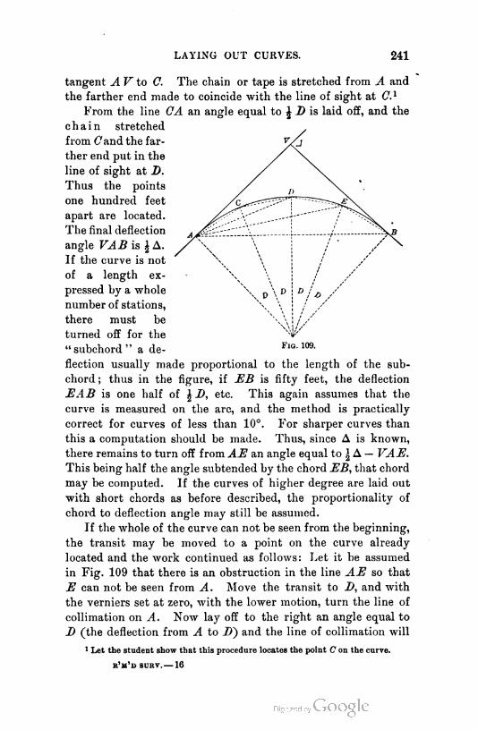
LAYING OUT CURVES. 241
tangent A V to C. The chain or tape is stretched from A and
the farther end made to coincide with the line of sight at C.1
From the line CA an angle equal to \ D is laid off, and the
chain stretched
from Cand the far
ther end put in the
line of sight at D.
Thus the points
one hundred feet
apart are located.
The final deflection
angle VAB is \ A.
If the curve is not
of a length ex
pressed by a whole
number of stations,
there must be
turned off for the
" subchord " a de
flection usually made proportional to the length of the sub-
chord ; thus in the figure, if EB is fifty feet, the deflection
EAB is one half of \ B, etc. This again assumes that the
curve is measured on the arc, and the method is practically
correct for curves of less than 10°. For sharper curves than
this a computation should be made. Thus, since A is known,
there remains to turn off from AE an angle equal to \ A — VAE.
This being half the angle subtended by the chord EB, that chord
may be computed. If the curves of higher degree are laid out
with short chords as before described, the proportionality of
chord to deflection angle may still be assumed.
If the whole of the curve can not be seen from the beginning,
the transit may be moved to a point on the curve already
located and the work continued as follows: Let it be assumed
in Fig. 109 that there is an obstruction in the line AE so that
E can not be seen from A. Move the transit to Z>, and with
the verniers set at zero, with the lower motion, turn the line of
collimation on A. Now lay off to the right an angle equal to
D (the deflection from A to 2)) and the line of collimation will
1 Let the student show that this procedure locates the point C on the curve.
r'm'o surv.— 16
F1g. 109.

242 CURVES.
lie in the tangent to the curve at D. Transit the telescope
and deflect to the right for the station E, etc., as usual. Not
much more than 90° of an arc should be located from one
point.1
Points occupied by the transit are usually solid "hubs"
driven flush with the ground with a small tack to mark the
exact point. The other points are, in railroad and common
road surveys, merely marked with stakes. In close land sur
veys and city work, each point should be marked with hub and
tack.
231. Location by chain alone. A method for locating arcs
approximately by the use of the chain or tape is as follows,
and is known as the method by " chord off
sets " :
In Fig. 110, A V is a tangent to which a
curve of degree D is to be joined at A. If
AB is one station,
Bb = 100 sin £ D.
Imagine the curve continued back one sta
tion to E. eE = Bb, and /, in EA produced,
is distant from b by an equal amount, therefore
fB = 2 Bb.
Bb is known as the tangent offset t, and fB is
the chord offset = 2 1. To locate the curve,
swing the chain from A and place the farther
end of it a distance t from the tangent. Stretch
p\" the chain from B in line with AB and make a
F1q. no. mark at c. Swing the chain about B till cC
equals 2t. Proceed in the same manner for
the remainder of the curve. If the curve begins with a frac
tional station, the tangent offset for the fractional station may
be computed and laid off ; and for the remainder of a full sta
tion back of A, the same thing may be done. The direction of
the chord of a full station on the curve is now determined, and
the work may proceed as usual.
1 Let the student draw a figure of a curve carrying it to the half circle and show
why the 180° point could not be definitely located from the beginning.
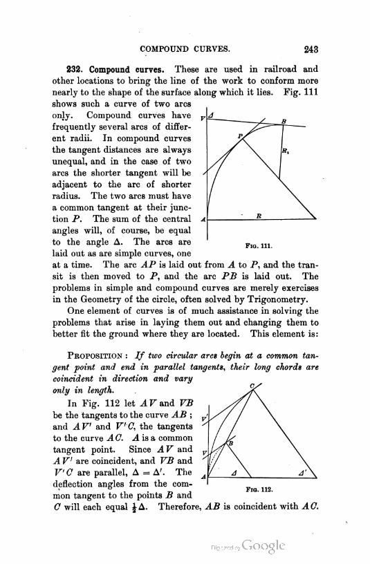
COMPOUND CURVES. 243
Fig. 111.
232. Compound curves. These are used in railroad and
other locations to bring the line of the work to conform more
nearly to the shape of the surface along which it lies. Fig. Ill
shows such a curve of two arcs
only. Compound curves have
frequently several arcs of differ
ent radii. In compound curves
the tangent distances are always
unequal, and in the case of two
arcs the shorter tangent will be
adjacent to the arc of shorter
radius. The two arcs must have
a common tangent at their junc
tion P. The sum of the central
angles will, of course, be equal
to the angle A. The arcs are
laid out as are simple curves, one
at a time. The arc AP is laid out from A to P, and the tran
sit is then moved to P, and the arc PB is laid out. The
problems in simple and compound curves are merely exercises
in the Geometry of the circle, often solved by Trigonometry.
One element of curves is of much assistance in solving the
problems that arise in laying them out and changing them to
better fit the ground where they are located. This element is:
Proposition : If two circular arcs begin at a common tan
gent point and end in parallel tangents, their long chords are
coincident in direction and vary
only in length.
In Fig. 112 let AV and VB
be the tangents to the curve AB ;
and AV and V-C, the tangents
to the curve A C. A is a common
tangent point. Since AV and
AV are coincident, and VB and
V'C are parallel, A = A'. The
deflection angles from the com
mon tangent to the points B and
C will each equal J A. Therefore, AB is coincident with A C.
Fig. 112.
CHAPTER IX.
TOPOGRAPHICAL SURVEYING.
TOPOGRAPHY.
233. Methods of representing surface form. A topographical
map is a map showing the conformation of the surface of the
area of land mapped.
F1g. 113.
A topographical survey is a survey conducted for the pur
pose of obtaining information for the production of a topo
graphical map of the area surveyed.
244

TOPOGRAPHY. 245
There are two common ways of representing the conforma
tion of any small portion of the earth's surface.
(1) By means of hachures or, as more commonly called,
hill shading or hatching. Fig. 113 is an example of this
method. It is evident that it is little better than sketching,
since it gives no definite notion of the height of the hills or the
rate of slope of the surface. It is now employed only for the
Fig. 114.
purpose of making pictures to be intelligible to those not ac
quainted with technical methods for representing surfaces, and
to convey to them as well as to trained surveyors, a general
notion of the conformation of the surface where no definite
information is required.
(2) By means of contours, or lines of equal elevation.
Fig. 114 is an example of this method.
The word " contour " as used in surveying means a line all

246 TOPOGRAPHICAL SURVEYING.
points of which have the same elevation above or below some
assumed level surface, as sea level. Let the student imagine
some section of country with which he is familiar covered
with water so deep that the tops of the highest hills are
just in the surface of the water. Let it be imagined that
the water flows away till the surface has dropped five feet ver
tically. The intersection of the water surface and the land
surface would be a five-foot contour line. Let the surface drop
five feet more, and there would result another five-foot contour
line. The contour line may then be said to be a level line
lying wholly in the surface of the earth.
The contours of a theoretically perfect conical hill would
be a series of circles having their centers in the axis of the
cone. A contour map of such a hill would be a series of con
centric circles. This is seen from Fig. 115. If it is assumed
that the base of the hill has an
elevation of one hundred feet
above some datum, then the
contour map showing " ten-foot
contours" would be as in the
lower part of the figure. The
-100 horizontal distance between any
two contours shown will indi
cate the rate of slope of the sur
face. The direction of steepest
slope is always in the direction
of the common perpendicular to
two consecutive contours. If
two contours of the same eleva
tion were to be found on a map
running together and continu
ing as a single line and then separating again, there would be
indicated a perfect knife-edge ridge or hollow. Since such a
thing does not exist in nature, no such representation can be
found on a correct contour map. Moreover, except in the case
of an overhanging bluff or a cave, contours of the same or of
different elevations could not cross, and hence a correct contour
map will not show contour lines crossing. A contour JLine that
closes upon itself indicates a peak higher than the surrounding

TOPOGRAPHY. 247
ground or a hole without an outlet. Since any contour line,
except one that closes on itself as above described, must con
tinue indefinitely, closing on itself somewhere, to be sure, no
contour line can begin or end within the border of a map
unless it closes on itself. With the exception noted, all con
tours must appear first in the border of the map and disappear
in the same or another edge. When contours cross a stream,
it is customary in mapping to run them up to one bank and
stop them, beginning again on the opposite bank. This merely
means that the portions that run up the banks of the stream
and unite in the bed, are omitted. In some cases, however,
the contours are carried across the stream.
A contour map is thus seen to show with definiteness the
conformation of the surface.
A b c D E F
234. Field methods for small area. There are various ways
of making topographical surveys, according to the use to which
the information obtained is to be put, or the extent of terri
tory to be mapped. A more or less precise and extensive
topographical survey is required when a large and important
building is to be erected, when a
park is to be laid out, or any land
scape gardening done, when a rail
road, canal, or road is to be built,
or when a system of irrigation or
drainage is to be planned.
When the area to be mapped
is small, as a city lot, or block,
or a very small farm, the follow
ing method is used :
The area is divided into squares or rectangles of from
twenty feet to one hundred feet on a side, stakes being driven
at each corner. The stakes along one edge will usually be
lettered and along another edge they will be numbered. Any
interior stake would then be known by its number in its
lettered row : thus, stake X (Fig. 116) would be known as
stake Da. Levels are now taken at all corners and any points
of abrupt change of slope not at a corner. From the level notes
the contours are obtained, as described below. Contours are
Fig. 116.
248 TOPOGRAPHICAL SURVEYING.
usually named with their elevations above the assumed datum.
Thus, there would be the 110-foot contour, the 112-foot con
tour, etc. In work covering small areas it will usually be
necessary to locate contours with vertical intervals of from one
foot to five feet. In one map the interval between contours will
be uniform.
235. Contour map. To draw the contour map from the
notes that have been taken, lay out in pencil, on paper, to scale,
a map of the squares that have been used in the field. Note
lightly in pencil the elevations of the points where levels have
been taken. Assume that the slope along any line is uniform
from one known elevation to the next. If the contours are
being drawn with an interval of two feet, for instance, and if
either of the known elevations is an even two feet, as 112 feet
or 114 feet, then a contour line passes through the known
elevation point. If not, and this will be the usual case, the
point where the contour crosses the line between the two points
of known elevation must be found by interpolation. When
found, the point is numbered with the elevation of the line
passing through it, and other points are found. This is done
over the whole map, and finally points of equal elevation are
connected, giving contour lines.
The lines will not usually be drawn straight between points,
but will be curved, either from a knowledge of the ground or,
in the absence of such information, so as to form no angles, but
to make smooth, curved lines. Sometimes a profile of each line
is drawn in pencil, as indicated for line Gr, and on this profile
are noted the points having elevations of required contours.
These are projected down on to the line, giving the points on
the line intersected by the given contours. The contour lines
are inked in in black or brown or red, according to the purpose
of the map. The outside lines of the square are inked in black.
The contour lines are numbered with their elevations usually at
every fifth contour or at the even tens.
236. Field methods for large area. When the area is large,
as a farm of twenty or more acres, or even less, or a city or
county, or a portion of a given valley, the following method is
adopted :
TOPOGRAPHY. 249
Points are located, more or less at random, over the area to
be mapped, and their elevations are obtained. The points are
then mapped, and it is assumed that the slope is uniform
between those that are adjacent ; and the positions of contours
between points are determined by interpolation, as was done
with the squares. Equal elevations are then connected by
curved lines, which are the contour lines. Sketches are made
in the field to assist in shaping the contours.
237. Transit and stadia method. In the field the points
are located by "polar coordinates" ; that is, by direction and
distance from a known point. This work, as well as the
determination of elevations, is best done with a transit and
stadia.
The field work is as follows : A starting point, as the inter
section of two streets, the corner of a farm, or simply an
arbitrary spot, is established by driving a firm stake that will
not be easily disturbed. The transit is set over this point with
vernier reading zero, and the instrument is pointed, by the
lower motion, in the direction of the meridian. This may be
the true meridian previously determined, the magnetic merid
ian as shown by the needle, or an arbitrary meridian assumed
for the purpose of the survey. If either of the latter, a stake
is driven a distance away, so that the direction may be again
accurately found. It is assumed that the true meridian will
have been so marked as to be found again. The elevation of
the point over which the instrument is set, if not known,
is assumed and written in the notebook. A traverse line is
now run, noting the azimuths of all courses, as described in
Chapter V.
The distances are measured with the stadia and recorded in
the book. The vertical angles are also noted. Vertical angles
and distances are read from both ends of any course as a check.
The traverse line is chosen with a view to obtaining from each
station the largest possible number of pointings to salient
features of the area to be surveyed, and, while the instrument
is set at any station and before the traverse line is completed,
these are taken. These additional pointings are usually
called "side shots." For each pointing the distance, azimuth,

250 TOPOGRAPHICAL SURVEYING.
and vertical angle are read. These readings will locate the
point and determine its elevation.
After the instrument has been oriented at any station, a
rod is held alongside and the height of the axis of the tele
scope is noted in the book as a heading to the notes taken
from that station. While this is being done, another rodman
(there are usually two or more) selects, by the direction of the
person in charge of the survey or by his own judgment, a
second point to be occupied by the transit. He drives a stake
and marks it Hi (Stadia Station 1). The rodmen are provided
with hatchets for the purpose of making and driving stakes
and clearing away trifling obstructions to sight. If there is
much clearing to do, axmen are employed.
The rodman holds his rod vertical and just behind the
stake from the instrument, with its edge turned toward the
observer. The observer directs, by the upper azimuth motion,
the line of collimation to the edge of the rod, making the exact
bisection by the tangent screw. He then reads the azimuth
and calls it to the recorder, who records it. He also reads the
needle, and this is likewise recorded, to serve as a witness
should an error be discovered in mapping the work. Having
read the azimuth, the observer signals the rodman, who turns
the graduated side of the rod toward the observer. The latter
turns the middle horizontal wire to a point on the rod corre
sponding to the height of the instrument, using the clamp
and slow motion screw of the vertical motion. He then notes
the lower wire to see whether it is near a fifty or hundred
graduation, makes it coincide with such graduation, and reads
the distance. He again brings the horizontal wire to the proper
height and signals that he is through. He then reads the
vertical angle, which is recorded.
While this is being done, the rodman who was at the instru
ment selects by direction or judgment a point for a side shot, and
stands there with the graduated side of the rod toward the ob
server. The observer now unclamps the upper motion, and does
not, as a rule, clamp it again till he leaves the station. He
turns the line of sight on the rod, and after reading the distance
he reads the azimuth— the needle is neglected on side shots—
and vertical angle as already described for the stadia station,

TOPOGRAPHY. 251
and signals that he is through. The rodman who set the
station has now found a point, and his rod is observed as last
described, and the work continues in this way, observing first on
one rod and then on another, according to which is first ready.
The points that are selected for side shots are such as will
enable contours to be well drawn on a map on which those
points are plotted. They should be therefore along ridges and
hollows at all changes of the slope. They should be taken
frequently along a stream to locate its course. It is usually
required to obtain information for the mapping of artificial
structures, as roads, fences, houses, etc. Therefore pointings
should be taken to all fence corners and angles, to enough
corners of all buildings to enable the building to be mapped,
and to a sufficient number of points in all roads. If it is de
sired to indicate wooded lands, then pointings must be taken
around the edges of timber. While all this is being done, the
recorder is recording the notes and endeavoring to keep a
sketch on the right-hand page of the book to assist the mem
ory in mapping.
After all the side shots from have been taken, the in
strument is moved to Hj and a rodman goes to EIq- The
instrument is oriented on EJq, the edge of the rod being first
sighted. The needle is read and recorded, as well as the dis-
- tance and vertical angle. After one of the rodmen, who has
come up to the station, has noted the height of the instrument,
he goes ahead to select a new stadia station, which is estab
lished and located as was \3V and the work proceeds. Instead
of requiring a rodman to be at the instrument each time a
new point is occupied, the recorder or observer may carry a
light graduated rod with which to determine the height of
the transit. It is convenient to have the five-foot point of
the stadia painted red to expedite the setting of the wire
on the proper point for the determination of the vertical
angle.
The form of notes used in stadia surveying is given on
page 252. The left page of the notebook is represented. The
right page is used for sketching and for additional notes de
scriptive of the stations occupied or observed. The sketch
should be as full as possible and neatly drawn.
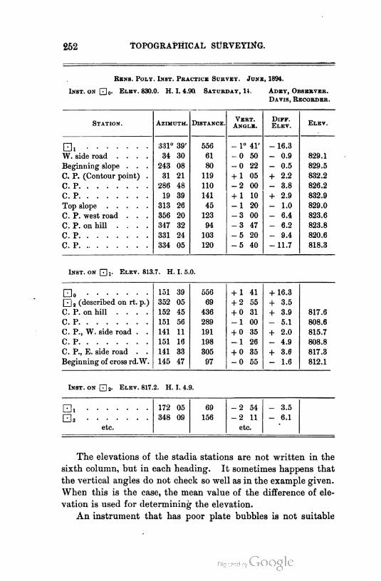
252 TOPOGRAPHICAL SURVEYING.
Rkns. Poly. Inst. Practice Survey. June, 1894.
Inst, on |j]-- Elev. 830.0. H. I. 4.90. Saturday, 14. Adey, Observer.
Davis, Recorder.
Station. Azimuth. Distance.Vert.
Angle.
DiFF.Elev.
Elev.
□ i331° 39'
34 30
243 08
31 21
286 48
19 39
313 26
356 20
347 32
331 24
556
61
80
119
110
141
45
123
94
103
120
- 1° 41'
-0 50
-0 22
+ 1 05
-2 00
+ 1 10
-1 20
-3 00
-3 47
-5 20
-5 40
- 16.3
W. side road ....
Beginning slope . . .
C. P. (Contour point) .
- 0.9 829.1
829.5
832.2
826.2
832.9
829.0
823.6
823.8
820.6
818.3
- 0.5
+ 2.2
CP
- 3.8
+ 2.9
- 1.0
C. P. west road . . .
C. P. on hill ....
CP
- 6.4
- 6.2
- 9.4
Inst. on0!. Elev. 813.7. H. I. 5.0.
- 11.7
□ o556
69
436
289
191
198
305
97
+ 1 41
+ 2 55
+ 0 31
-1 00
+ 0 35
-1 26
+ 0 35
-0 55
+ 16.3
+ 3.5
+ 3.9
Qj2 (described on rt. p.) 352 05
152 45
151 56
141 11
151 16
141 33
145 47
C. P. on hill .... 817.6
808.6
815.7
808.8
817.3
812.1
CP - 5.1
+ 2.0C. P., W. side road . .
CP - 4.9
+ 3.6C. P., E. side road . .
Beginning of cross rd.W. - 1.6
Inst- on 02- Elev. 817.2. H. I. 4.9.
□i 0 172 05 69 -2 54 - 3.5
□a 0 348 09 156 -2 11 - 6.1
etc. etc.
The elevations of the stadia stations are not written in the
sixth column, but in each heading. It sometimes happens that
the vertical angles do not check so well as in the example given.
When this is the case, the mean value of the difference of ele
vation is used for determining the elevation.
An instrument that has poor plate bubbles is not suitable

SIMPLE TRIANGULATION. 253
for stadia work. To secure good work with such an instrument
it is necessary to use the telescope bubble for leveling it.
If it is necessary to correct the horizontal distance, it is
done by the use of the table in Appendix, page 380. The dif
ferences in elevation are obtained from the same table, a dia
gram, or Colby's slide rule.
SIMPLE TRIANGULATION.
238. When used. If the area to be surveyed covers sev
eral square miles, or is an elongated strip, as a narrow valley,
it is best to hang the topography on a system of triangles.
Unless this area is extensive, as a large county or a state, these
triangles may be considered plane triangles, the curvature of
the earth being neglected. In case the triangles are to be con
sidered as plane, it will be best to assume for the meridian of
the survey a true meridian near the middle of the area, east
and west. The process of laying out such a system of triangles
is as follows :
239. Measuring the base line. A fairly level stretch of
ground is selected, if possible, near the middle of the area to
be mapped, and a line of from one thousand feet to a half
mile long, or longer, is measured very carefully. This line is
called the base line. Its ends are marked with substantial
monuments of stone or with solid stakes. If the survey is of
sufficient importance to warrant the permanent preservation of
the system of triangles for future reference, the monuments
that mark the base line, and those that mark the apexes of
triangles, should be stones not less than six inches square
in cross section and two feet long. In the top face, which
should be dressed, there is drilled a hole large enough to take
a half-inch copper bolt, which is leaded in. The head of the
bolt is marked with a cross to determine the exact point, and
the stone is set deep enough to be beyond the disturbing action
of frost. The point may be carried to the surface by " plumb
ing," and a temporary point set for use. The location of each
monument should be fully described with reference to sur
rounding objects of a permanent character, so that it may be
readily found at a future date. If no permanent objects that
254 TOPOGRAPHICAL SURVEYING.
can be used are to be found, then constructions of stone, brick,
or timber are built nearly on the surface of the ground, and
the point is described with reference to these. Such precau
tions are usually necessary only for extensive geodetic surveys.
The measurement of the base line for the surveys of smaller
areas, which are the only surveys to be described here, should
be made with a precision of from one in five thousand to one
in fifty thousand, according to the scale of the map that is to
be made, the area surveyed, and the importance of the work.
The two ends of the base line being determined and marked,
the transit is set over one end, and a line of stakes ranged out
between the two ends. The alignment is made as perfect as
possible, and the stakes are set as nearly as practicable at
single tape lengths apart, center to center, or at half or quar
ter tape lengths. These stakes are made quite firm in the
ground, and should be not less than two inches square in sec
tion. For high-class work the stakes should have on their
tops tin or zinc strips on which to mark the measurements
with fine scratches.
The measurements are then made, the temperature, pull,
and grade elements being noted, and the distance between sup
ports. The requisites for securing the required degree of pre
cision are mentioned in Chapter I. If the absolute length of
the tape at some standard temperature and pull is unknown,
of course the absolute length of the line remains undetermined.
For a precision of one in one million, which is attempted in the
measurement of base lines for extensive geodetic surveys, as of
a state or continent, much more refined methods than those
described are necessary. These methods properly belong to
the subject of geodetic surveying.
240. Measuring the angles. After the base line is estab- ,
lished and measured, or even while it is being measured, prom
inent points in the area are chosen as " triangulation stations,"
that is, apexes of triangles. These are so chosen that no angle
shall be less than 30 degrees, nor more than 120 degrees. The
first point is chosen, as nearly as possible, in a line at right
angles to the base line at its middle point. A second point
may be chosen opposite the first one, and the others are then

SIMPLE TR1ANGULATI0N. 255
located with reference to these and to one another. When
these stations are established, signals are erected over them.
For work of the magnitude here considered, these may be simply
wooden poles, about one and one half inches in diameter, to
which a flag of some white and dark cloth is tacked to make
the signal more easily found. Such signals are usually called
flags. A transit is then set over one extremity of the base line,
and the angles formed at that point by lines to the adjacent
stations are measured. When all of these angles have been
measured, the transit is moved to the other extremity of the
base line, and similar measurements are made there, and subse
quently at each triangulation station. There are two methods
for measuring angles, called respectively the method by repeti
tion and the method by continuous reading.
In the first method, each angle is measured separately a
number of times, and the mean result is taken. The process is
as follows : With vernier at 0° 00',1 set by lower motion on the
left-hand station. v
Unclamp above, set on right station.
Unclamp below, set on left station.
Unclamp above, set on right station.
Continue as many times as may be necessary to use practically
the whole circle of 360°, and finally read. Divide the reading
by the number of repetitions for the value of the angle.
Reverse the telescope and repeat the above operation from
right to left. The readings are taken in both directions to
eliminate errors due to clamping and unclamping and personal
mistakes in setting. They are taken with the telescope both
direct and reverse, to eliminate errors of adjustment. They
are made to include the whole circle to eliminate errors of
graduation. Both verniers are usually read to eliminate the
effect of eccentricity of verniers.
When such an instrument as the engineer's transit is used,
this method is the simplest and probably the best.
The second method, by continuous reading, differs from
the first in that each angle is not measured independently of
1 Any other setting could be used, tut it is considered better in this method to
set at zero.
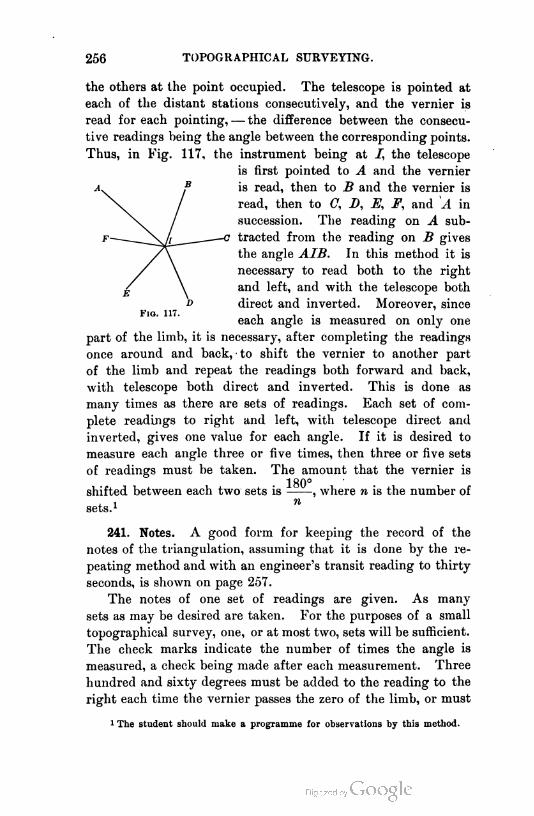
256 TOPOGRAPHICAL SURVEYING.
the others at the point occupied. The telescope is pointed at
each of the distant stations consecutively, and the vernier is
read for each pointing, — the difference between the consecu
tive readings being the angle between the corresponding points.
Thus, in Fig. 117, the instrument being at i", the telescope
is first pointed to A and the vernier
is read, then to B and the vernier is
read, then to C, D, E, F, and A in
succession. The reading on A sub-
—c tracted from the reading on B gives
the angle AIB. In this method it is
necessary to read both to the right
and left, and with the telescope both
direct and inverted. Moreover, since
"" " each angle is measured on only one
part of the limb, it is necessary, after completing the readings
once around and back, - to shift the vernier to another part
of the limb and repeat the readings both forward and back,
with telescope both direct and inverted. This is done as
many times as there are sets of readings. Each set of com
plete readings to right and left, with telescope direct and
inverted, gives one value for each angle. If it is desired to
measure each angle three or five times, then three or five sets
of readings must be taken. The amount that the vernier is
180°shifted between each two sets is , where n is the number of
sets.1 n
241. Notes. A good form for keeping the record of the
notes of the triangulation, assuming that it is done by the re
peating method and with an engineer's transit reading to thirty
seconds, is shown on page 257.
The notes of one set of readings are given. As many
sets as may be desired are taken. For the purposes of a small
topographical survey, one, or at most two, sets will be sufficient.
The check marks indicate the number of times the angle is
measured, a check being made after each measurement. Three
hundred and sixty degrees must be added to the reading to the
right each time the vernier passes the zero of the limb, or must
1 The student should make a programme for observations by this method.

SIMPLE TRIANGULATION. 257
Saturday, June 24, 1894. a.m.
Instrument on A1 A.
Station
Observed.Vernier A B Mean Reading.
Computation
AND
Mean Angle.
A B . . . . 0° 00' 00" -30" 359° 59' 45" 15 01 45
360
✓✓✓✓✓✓
360
360
Inst, direct . . 735 01 45
359 59 45
AC.... 15° 02' 00" 01' 30" 15° 01' 45"
6)375 02 00
62° 30' 20"
AC.... 15° 02' 00" 01' 30" 15° 01' 45" 15 01 45
360
360✓✓✓✓✓✓
Inst, reversed . 360
360
735 01 45
359 58 15
A B . . . . 359° 58' 30" 58' 00" 359° 58' 15"
6)375 03 30
62° 30' 35"
be subtracted from the readings to the left. The latter process
brings the same result as adding to the initial reading.
If the method of continuous reading is used, the form of
record shown on page 258 is considered good.
The readings are begun on the line AB of the triangu-
lation system, and carried to the right and then back, the
readings taken to the right being recorded down the page, and
the reverse readings up the page. Such a series, when complete,
forms a set from which a value of each angle is determined.
Provision is made in the form given, for three sets of readings,
while but one complete set is shown. The mean of the three
determinations of each angle would be taken. The errors are
purposely shown large. With a transit reading to thirty sec
onds, there will usually be no appreciable difference in vernier
readings, and it is always possible with a little practice to read
the vernier by estimation to one half of its least count.
A third method of measuring angles, which may be called
a combination of the first two, saves some time, and gives
results as good as the class of work warrants. It consists in
1 Triangulation stati-n.
r'm'd surv. — 17

258 TOPOGRAPHICAL SURVEYING.
Saturday, June 24, 1894. a.m.
Instrument on A A.
Telesc-pe.Stati-nObserved.
Vernier A BMean Reading
fr-m AB.Mean Angl-with AB.
M-an Angle.
Direct . .
Inverted .1
000° 00' 00"
359 59 30
-00' 30"
59 00
-000° 00' 15"
— 45" -000° 00' 30"
B 2
3
Direct . .
Inverted .1
62 30 30
62 30 00
30 00
29 30
62 30 15
62 29 4562 30 30 62" 30' 30"
C 2
3
1111 06 30
111 06 30
06 00
06 00
111 06 15
111 06 15111 06 45 48 36 15
D 2
3
1183 48 00
183 48 00
47 30
47 30
183 47 45
183 47 45183 48 15 72 41 30
E 2
3
1278 12 00
278 12 30
11 30 278 11 45
278 12 15278 12 30 94 24 15
F 2
3
12 00
1359 59 30
359 59 30
59 00
59 00
359 59 15
359 59 15359 59 15 81 46 45
359 59 15
B 2
3
measuring each angle a stated number of times, reading, meas
uring the succeeding angle the same number of times, reading,
and continuing. After all the angles are read successively to
the right, the telescope is inverted and pointed on the right
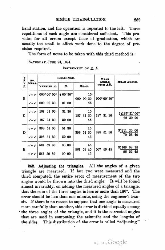
SIMPLE TRIANGULATION'. 259
hand station, and the operation is repeated to the left. Three
repetitions of each angle are considered sufficient. This pro
vides for all errors except those of graduation, which are
usually too small to affect work done to the degree of pre
cision required.
The form of notes to be taken with this third method is :
Saturday, June 24, 1894.
Instrument on A A.
|Stat-on. READINGS. Mean
Angle
with AB.Meas.
NO.Mean Angle.
Vernier A. B. Mean.
B
000° 00' 00"
000 00 30
4 00' 30"
01 00
15"
000 00 30
45
000° 00' 30"
187 31 00
187 31 30
31 30 15
C
32 00
187 31 30
45
187 31 303)187° 31' 00"
62 30 20
398 51 00
398 51 30
51 30 153)211 20 00
70 26 40D
52 00
398 51 30
45
398 51 30
567 59 30
567 59 30
00 00
00 00
453)169 08 15
56 22 45E 567 59 45
45
567 59 45
242. Adjusting the triangles. All the angles of a given
triangle are measured. If but two were measured and the
third computed, the entire error of measurement of the two
angles would be thrown into the third angle. It will be found
almost invariably, on adding the measured angles of a triangle,
that the sum of the three angles is less or more than 180°. The
error should be less than one minute, using the engineer's tran
sit. If there is no reason to suppose that one angle is measured
more carefully than another, this error is divided equally among
the three angles of the triangle, and it is the corrected angles
that are used in computing the azimuths and the lengths of
the sides. This distribution of the error is called "adjusting"
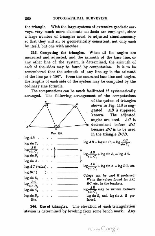
260 TOPOGRAPHICAL SURVEYING.
the triangle. With the large systems of extensive geodetic sur
veys, very much more elaborate methods are employed, since
a large number of triangles must be adjusted simultaneously
so that they will all be geometrically consistent, not only each
by itself, but one with another.
243. Computing the triangles. When all the angles are
measured and adjusted, and the azimuth of the base line, or
any other line of the system, is determined, the azimuth of
each of the sides may be found by computation. It is to be
remembered that the azimuth of any line xy is the azimuth
of the line yx + 180°. From the measured base line and angles,
the lengths of each side of the system may be computed by the
ordinary sine formula.
The computations can be much facilitated if systematically
arranged. The following arrangement of the computations
of the system of triangles
shown in Fig. 118 is sug
gested. AB is supposed
known. The adjusted
angles are used. AC is
determined before BC,
because BC is to be used
in the triangle BCD.
AB
Fig. 118.
log^B .
log sin Cl
AB
log sin Bj
log sin A
log A C (value)
l-g BC ( )
log sin D1
. BCl0*rin-D; ■
log sin C2
log sin B2 . .
Etc.
log AB — log sin C, = log
log
log
AB
sin C,
AB
sin Ci
sin C,
+ log sin By = log A C.
+ log sin A = log BC, etc.
Cologs can be used if preferred.
Write the values found for A C,
BC, etc., in the brackets.
ABlog-; may be written between
'sinCi
log sin jB, and log sin A if
ferred.
pre-
244. Use of triangles. The elevation of each triangulation
station is determined by leveling from some bench mark. Any

MAPPING. 261
station may now serve as a beginning point for the topograph
ical survey. The transit being set over Station X is oriented
on Station Y by bringing the vernier to read the azimuth of
the line XY, and setting the line of collimation on Y by the
lower motion. The stadia traverse and work then begin. The
azimuth work may always be checked in the field by occupying
each triangulation station as it is reached, and determining the
azimuth of one of the triangle sides radiating from the station
occupied. If this agrees with the known azimuth, the work is
correct. If it does not agree within one or two minutes, the
work should be rerun.
The elevations also serve to check the vertical angles.
MAPPING.
245. The triangles. If the topographical survey has been
based on a system of triangles, these triangles are first drawn.
To draw them, assume one station as the origin of the survey,
and, knowing the lengths and azimuths of all the sides, compute
the latitude and longitude of each station with reference to the
assumed origin. Proceed then to plot the stations by latitudes
and longitudes. It will be usual to assume one end of the base
line as the origin, and the direction of the base line as that of
the reference meridian. If, however, the work is referred to
another meridian, that should be chosen as the meridian of
reference for the computing and plotting.
The lines may also be drawn by means of a protractor ; but
this, while quicker and sufficiently precise, if a large protractor
is used, for much work, is of course not so accurate as latitudes
and longitudes.
Another method is to use the dividers and the lengths of
the triangle sides, describing arcs whose intersections locate
the triangulation stations.
246. Outline of method for topography. A stadia line is first
plotted to see that it closes properly. When this has been
satisfactorily done, the side shots are plotted. Then the con
tours are drawn and all other objects that it is desired to map.
If preferred, of course the detail work can begin before the

262 TOPOGRAPHICAL SURVEYING.
completion of the mapping of the side shots, and it is perhaps
better to draw in buildings and other structures as soon as the
points locating them are plotted.
247. The stadia line. The best method for plotting the
stadia lines is by latitudes and longitudes, the computations for
which are made with sufficient exactness by a diagram or by
the trigonometer shown in Fig. 119. The arm is set to the
3
. 1 1/o- ' l/o- i si- /A^/ «-o° /(
0 30 tO 5- 60 7(/ "VttO 9- 1--f 1010-
AYso
Vf
90%
70
60
50
7
80
S
o
E
*<
70
7 60J
/
/"A50
to -$/ to
30
20
10
/
'9/ 30
20
10
": A
V
V
K0 30 40 F 60 60 70 8- 90 100
F1g. 119.
proper azimuth and the length of sight is noted on the arm.
The latitude and longitude differences are then read on the
cross-section scale.1
If the latitudes and longitudes of the triangulation stations
have been determined, it will be known on the completion of
computations for any one stadia line whether or not that line
is correct. If it does not close on the proper triangulation
station, and the error is small, that error may be distributed
1 The degree numbering should be continued on this figure to 360°, and the signs
for latitude and longitude differences, marked on each quadrant of numbers. Let
the student show how this numbering should be placed, and write the proper signs.

MAPPING. 263
among the various courses, as in a land survey. If the error is
great, it must be found. If the azimuths were checked in the
field, the error must be in distance. Note the direction of the
closing line and see whether it corresponds to any course. If
it does, the error is probably in that course, and it should be re-
measured. If it does not correspond to any one course, there
is probably more than one error. In case of error of geograph
ical position due to mistakes in measurement, the elevations
will not check unless the error is made on practically level
ground; hence if no field check of azimuths has been possible
and the elevations check while geographical posi
tions do not, the error is in azimuth.
surveyors' supplies. The paper protractor should be about
fourteen inches in diameter and graduated to quarter degrees.
248. Side shots. It may be prepared for use in mapping
side shots as follows, see Fig. 121 : 1
Number the graduations from zero to the right 360°. Draw
through the zero and the 180° points and the center a straight
line, and continue the line to the end of the sheet. The edges
are trimmed true and square, and not less than an inch of
paper is left outside the printed circle. With a pair of dividers
such as may be had
from any dealer in
F1g. 120.
1 Modification of a form suggested by Prof. J. B. Johnson.
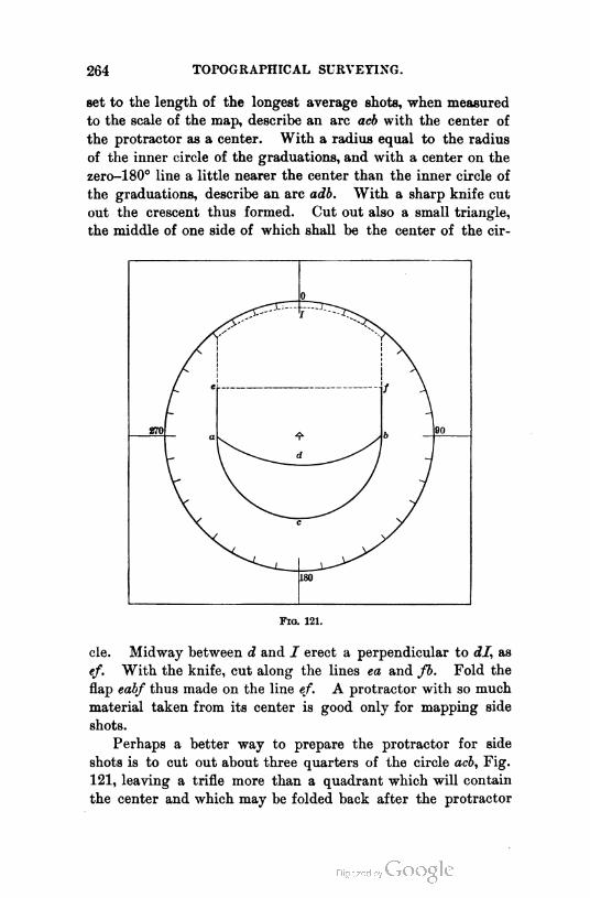
264 TOPOGRAPHICAL SURVEYING.
set to the length of the longest average shots, when measured
to the scale of the map, describe an arc acb with the center of
the protractor as a center. With a radius equal to the radius
of the inner circle of the graduations, and with a center on the
zerc—180° line a little nearer the center than the inner circle of
the graduations, describe an arc adb. With a sharp knife cut
out the crescent thus formed. Cut out also a small triangle,
the middle of one side of which shall be the center of the cir-
180
Fig. 121.
cle. Midway between d and I erect a perpendicular to dl, as
ef. With the knife, cut along the lines ea and fb. Fold the
flap eabf thus made on the line ef. A protractor with so much
material taken from its center is good only for mapping side
shots.
Perhaps a better way to prepare the protractor for side
shots is to cut out about three quarters of the circle acb, Fig.
121, leaving a trifle more than a quadrant which will contain
the center and which may be folded back after the protractor

MAPPING. 265
is oriented on a point. This form will give a somewhat larger
opening for plotting the shots. If a field map is to be made
from which a finished map is to be traced, it may be made on
the protractor sheet, or larger sheets may be had with a pro
tractor printed on them. The azimuths may be transferred
over the sheet with a parallel ruler.
To use the protractor, draw a meridian through each stadia
station. With the flap unfolded, center and orient the protrac
tor, weight it down, and fold back the flap. Paste under the
zero of the scale that is to be used, a small piece of drawing
paper, or other firm paper, through which, at the zero gradu
ation, a fine needle is passed. The needle is stuck into the
drawing at the station, and the rule may then be revolved about
it as a center. The edge of the scale is brought to each azimuth
in succession, and the distance is scaled at once and marked on
the paper. If the point is merely taken for the purpose of
obtaining elevations, its elevation is noted on the map when it
is plotted. Otherwise, the name of the object is marked or the
object is sketched in. In case the distance is so great that the
point falls under the paper of the protractor, a mark is made
with the name or elevation of the point and, when all the other
points are plotted, the protractor is lifted and this point put
in. With the aid of the sketches and the assumption that
the slope is regular between adjacent plotted points, the con
tours and other objects are now drawn in. The triangulation
stations, if there are any, should be inked in before any stadia
plotting is done. The stadia lines are not drawn nor are the
stadia stations inked. Buildings, fence lines, etc., should be
inked before the contours are drawn, to prevent confusion. It
is not customary, except in maps of small scale, to run contours
across a road, or stream, or through a building.
249. Colby's protractor. A very convenient form of pro
tractor for this work is Colby's, shown in Fig. 122. It is made
in three pieces. The largest piece is the limb L, L, Z, gradu
ated from 0° to 360°, with fifteen-minute divisions ; E, E, are
projections, upon which weights are placed. The limb has
four indexes B, B, B, B, 90° apart, by which the protractor is
oriented. A, A, A, is the alidade, fitted to revolve inside the

266 TOPOGRAPHICAL SURVEYING.
limb. 0, C, are indexes carried by the alidade, 180° apart.
To the bar _Z>, of the alidade is attached the scale S, by the
small screws and nuts iV, N". The scale has its zero mark in
the middle, and is graduated both ways. It can be taken off
by unscrewing the nuts iV, and a scale of different denomi
nation may be substituted when desired.
250. Ockerson's protractor. Another cheaper form is shown
in Fig. 123. It is centered with a needle point, about which
it will revolve. A meridian is drawn through the point over
which the protractor is to be set, and the graduations are such
that, if a given azimuth is brought to the meridian line, the
diameter, on which is a scale for plotting the points, is in the
given azimuth. The protractor was designed by Mr. J. A.
Ockerson for use in the Mississippi River surveys.
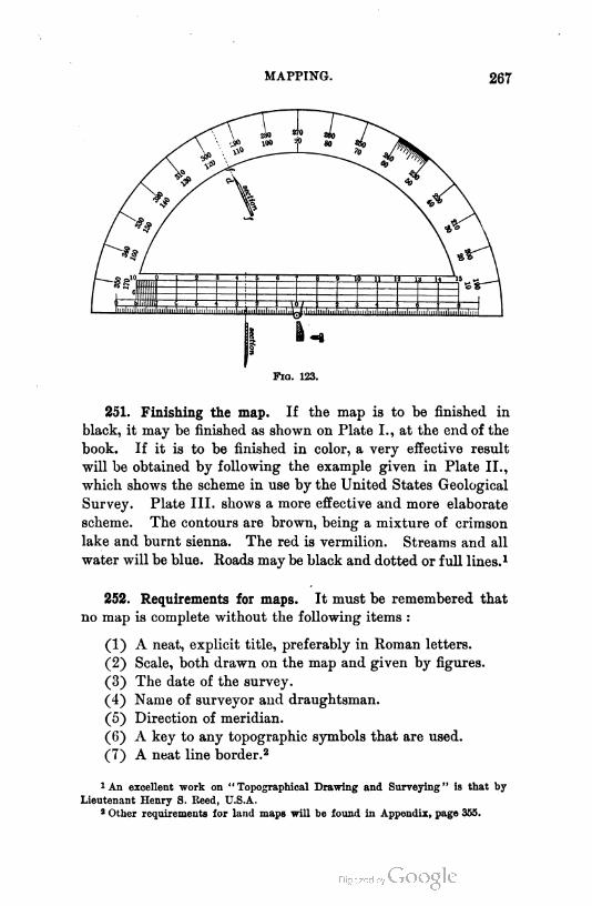
MAPPING. 267
251. Finishing the map. If the map is to be finished in
black, it may be finished as shown on Plate I., at the end of the
book. If it is to be finished in color, a very effective result
will be obtained by following the example given in Plate II.,
which shows the scheme in use by the United States Geological
Survey. Plate III. shows a more effective and more elaborate
scheme. The contours are brown, being a mixture of crimson
lake and burnt sienna. The red is vermilion. Streams and all
water will be blue. Roads may be black and dotted or full lines.1
252. Requirements for maps. It must be remembered that
no map is complete without the following items :
(1) A neat, explicit title, preferably in Roman letters.
(2) Scale, both drawn on the map and given by figures.
(3) The date of the survey.
(4) Name of surveyor and draughtsman.
(5) Direction of meridian.
(6) A key to any topographic symbols that are used.
(7) A neat line border.2
1 An excellent work on "Topographical Drawing and Surveying" is that by
Lieutenant Henry S. Reed, U.S.A.
3 Other requirements for land maps will be found in Appendix, page 355.
268 TOPOGRAPHICAL SURVEYING.
If contours are drawn, these should be numbered, to make
the map intelligible. It is necessary to number only every
fifth or tenth line, which should also be drawn a little heavier
than the others.
253. Scale. The scale of the map will depend on the terri
tory covered and the use to which the map is to be put. A
survey of a city lot may be mapped on a scale of, say, fifty feet
per inch. The topographical maps of the United States Geo
logical Survey are on a scale of about one mile per inch. A
railroad preliminary survey may be mapped on a scale of from
one thousand feet per inch, for ordinary purposes, to one hun
dred feet per inch, for close detailing. The maps of the United
States Coast and Geodetic Survey and of the United States
Geological Survey are mapped to a "natural scale," that is,
a given distance on the map is some round fraction of the dis
tance it represents, as or j^J^, etc. Maps of land sur
veys, or others made to show to non-technical persons, should
be made at so many feet, or chains, or miles, to the inch ; and
the top of the map should be north. Maps of large territories,
mainly for the use of those who are conversant with surveying
methods, may be made with advantage to the natural scale.
The original map may be copied by tracing on cloth or on
paper, and transferring to other drawing paper.
THE PLANE TABLE.
254. Description. Detail topographical surveys are some
times made with the plane table , indeed, this is the standard
instrument of the United States Coast Survey for such work,
and is also largely used by the United States Geological Survey.
The plane table consists essentially of a drawing board
with a suitable leveling device, mounted on a tripod, and a
ruler for drawing. The ruler is attached to a line of sight,
usually telescopic, but sometimes merely open sights, like those
of the compass. The combined ruler and telescope is called
the alidade. Fig. 124 is a complete plane table. Clips for
holding the paper are shown, as well as the alidade, compass
box, and levels, and a device for setting a point on the paper
over a point on the ground. The plane table is, in its ordinary

THE PLANE TABLE. 269
form, a very awkward instrument, and is used very little out
side the two surveys mentioned. A much simpler form of
leveling head than that generally used is one invented by Mr.
Fig. 124.
W. D. Johnson, and this device has been approved by the
topographers of the United States Geological Survey. It is
shown in Fig. 125. By loosening the wing nut d, the table
may be leveled, and when leveled, the nut d is tightened.
When the nut g is loosened,
the table may be turned in azi- £
muth without disturbing its hori-
zontality. The whole arrange
ment is very light. It does not
permit of as close leveling as
does the ordinary form with
leveling screws, and should not
be used where contours are to
be carefully determined by vertical angles. In making a map
of a park showing the location of each tree, bush, etc., for
planning new work, and when work may be, without loss,
performed on pleasant days and omitted on wet or damp days,
270 TOPOGRAPHICAL SURVEYING.
the plane table may be used with advantage, and, aside from
the United States Coast and Geological Surveys, it is for this
class of work that it is most used. The author prefers for
contour work to use the transit and stadia. If the advantage
of mapping at once in the field is desired, it may be obtained
by having an assistant and a light drawing board. It is be
lieved that a lack of notes is rather a disadvantage than, as
is generally assumed, an advantage.
255. Use. The plane table is used for the immediate map
ping of a survey made with it, no notes of angles being taken,
but the lines being plotted at once on the paper. The simplest
case is the location of a number of places from one point by
azimuth and distance. The table is set up so that some con
venient point on the paper is over a selected spot on the ground,
and clamped in azimuth. The ruler is then brought to the
point on the paper and swung about it till the line of sight
which is parallel in azimuth to the ruler1 is directed toward
a point that is to be located. A scale for the drawing is deter
mined, and a line is drawn along the ruler and made to scale,
equal to the distance to the desired point, which distance is
found by measurement or by the stadia. The point is then
located. A similar procedure locates other points. This is
called the method of radiation. If a plane table is set up in
the interior of a field all of whose corners are visible from the
position of the table, the corners may be thus located and con
nected and a map of the field is at once obtained. There is
evidently nothing by which to determine the area except to
scale the map for additional data or to use a planimeter.
Traversing may be performed with the plane table as fol
lows : If it is a field that is to be " run out," set the table over
one corner, choosing a point on the paper to represent that
corner in such position that the drawing of the field to the scale
selected will come on the board. In the four-sided field shown
in Fig. 126, it would be necessary to occupy but two corners
to map the field, though it would be better for a check to
occupy the third. The figure shows the field and, to a very
exaggerated scale, the plane table.
1 It is only necessary that the two shall have a fixed angle in azimuth.

THE PLANE TABLE. 271
The table is first set over B and a point b marked on the
paper directly over B. The instrument being clamped, the
alidade is brought to bear on A, and a line is drawn to scale
equal to BA, which is found by measurement or by stadia.
The alidade is then directed to C, and the line be is drawn
to scale. The table is then removed to C, and so set up that
the point c shall be over the point C and the line cb in the
direction CB. This is hard to do with the plane table. If
Fig. 126.
the scale is large, it must be done ; but if the scale is very
small, the following is a sufficiently close approximation : Set
the table level, with c over C and with cb approximately in line
with CB. Loosen the azimuth motion and, with the alidade
on the line cb, bring the line of sight on B. Clamp in azimuth,
arid the table is set. The point c is not exactly over C, but
the error will be inappreciable.
The table being set over C and oriented on CB, turn the
alidade toward D and draw cd. da may now be connected,
giving the entire field. It will be better to occupy D and see
whether the line DA will pass through a on the paper, and
whether the length da equals to scale the length DA.
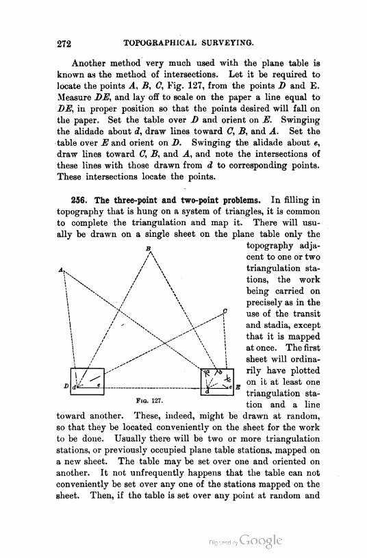
272 TOPOGRAPHICAL SURVEYING.
Another method very much used with the plane table is
known as the method of intersections. Let it be required to
locate the points A, B, C, Fig. 127, from the points D and E.
Measure DE, and lay off to scale on the paper a line equal to
DE, in proper position so that the points desired will fall on
the paper. Set the table over B and orient on E. Swinging
the alidade about d, draw lines toward C, B, and A. Set the
table over E and orient on D. Swinging the alidade about e,
draw lines toward C, B, and A, and note the intersections of
these lines with those drawn from d to corresponding points.
These intersections locate the points.
B
A
/ \
256. The three-point and two-point problems. In filling in
topography that is hung on a system of triangles, it is common
to complete the triangulation and map it. There will usu
ally be drawn on a single sheet on the plane table only the
topography adja
cent to one or two
triangulation sta
tions, the work
being carried on
precisely as in the
use of the transit
and stadia, except
that it is mapped
at once. The first
sheet will ordina
rily have plotted
on it at least one
triangulation sta
tion and a line
toward another. These, indeed, might be drawn at random,
so that they be located conveniently on the sheet for the work
to be done. Usually there will be two or more triangulation
stations, or previously occupied plane table stations, mapped on
a new sheet. The table may be set over one and oriented on
another. It not unfrequently happens that the table can not
conveniently be set over any one of the stations mapped on the
sheet. Then, if the table is set over any point at random and
4
Fig. 127.
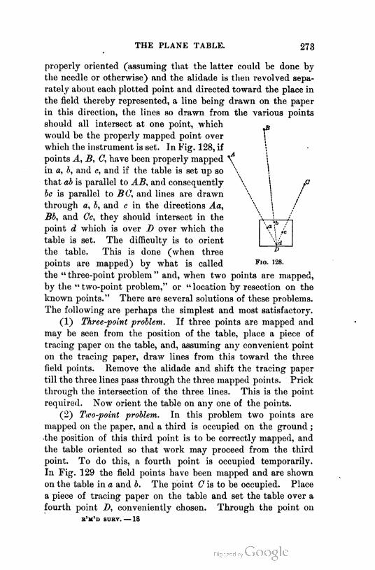
THE PLANE TABLE. 273
properly oriented (assuming that the latter could be done by
the needle or otherwise) and the alidade is then revolved sepa
rately about each plotted point and directed toward the place in
the field thereby represented, a line being drawn on the paper
in this direction, the lines so drawn from the various points
should all intersect at one point, which „
would be the properly mapped point over '
which the instrument is set. In Fig. 128, if 0
points A, B, C, have been properly mapped \ l
in a, b, and c, and if the table is set up so \ I
that ab is parallel to AB, and consequently \ j p
be is parallel to BG, and lines are drawn \ I
through a, b, and c in the directions Aa, \ 1
Bb, and Cc, they should intersect in the \ [ '
point d which is over D over which the -?i .
table is set. The difficulty is to orient
the table. This is done (when three D
points are mapped) by what is called FiG- 128-
the " three-point problem " and, when two points are mapped,
by the " two-point problem," or " location by resection on the
known points." There are several solutions of these problems.
The following are perhaps the simplest and most satisfactory.
(1) Three-point problem. If three points are mapped and
may be seen from the position of the table, place a piece of
tracing paper on the table, and, assuming any convenient point
on the tracing paper, draw lines from this toward the three
field points. Remove the alidade and shift the tracing paper
till the three lines pass through the three mapped points. Prick
through the intersection of the three lines. This is the point
required. Now orient the table on any one of the points.
(2) Two-point problem. In this problem two points are
mapped on the paper, and a third is occupied on the ground ;
the position of this third point is to be correctly mapped, and
the table oriented so that work may proceed from the third
point. To do this, a fourth point is occupied temporarily.
In Fig. 129 the field points have been mapped and are shown
on the table in a and b. The point C is to be occupied. Place
a piece of tracing paper on the table and set the table over a
fourth point D, conveniently chosen. Through the point on
e'm'd surv. — 18

274 TOPOGRAPHICAL SURVEYING.
Fio. 129.
the tracing paper that is over D draw lines toward A, B, and 0.
Estimate the distance DC, and lay it off to scale to c' . Set c'
over C and orient on
D. Draw lines toward 9r~
A and B, and note the
intersection of these
lines with those al
ready drawn from d' .
The figure a'b'c'd' will
be similar to the fig
ure ABCD. It will,
however, not be drawn
to the proper scale
since the distance DC
was only estimated.
Therefore, a'b' will be
longer or shorter than it should be to represent properly the
line AB to the scale that it is proposed to use. Let it be
supposed to be shorter. Remove the alidade and shift the
tracing paper till a' is over a, and the line a'b'
is coincident with ab. Construct a quad
rilateral on ab similar to a'b'c'd'. This will
give the quadrilateral abed, and c is properly
located relatively to a and b. The point is
pricked through into the drawing, and the
table is set up with c over C and oriented on
any one of the other points, and the work proceeds. The trac
ing paper may be dispensed with, the drawing work being
thereby somewhat increased. This method is seen to be
merely a modification of the three-point problem.
257. Adjustments. The bubbles for leveling the table are
adjusted to be parallel to the base of the alidade. This is- done
by the method already given for adjusting a level having a
plane metallic base. See Art. 51.
The line of collimation and the axis of the telescope bubble
are made parallel by the "peg" adjustments as applied to the
transit.
The horizontal axis is adjusted like that of the transit.
a '
r/
lc / d'
1 sK d
Fio. 130.
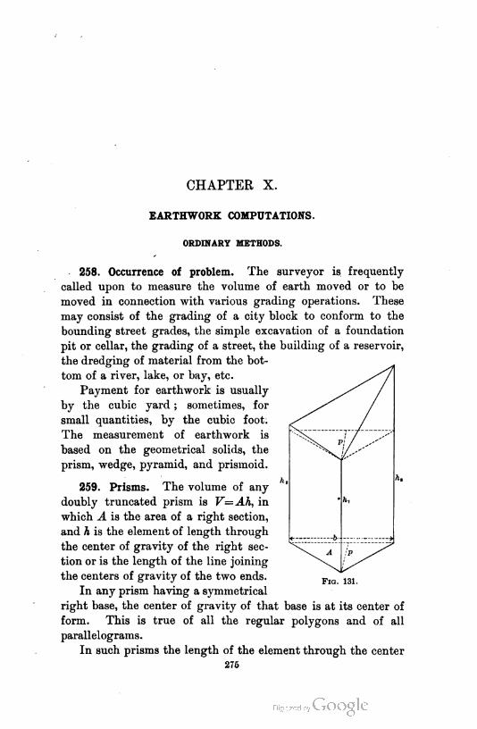
CHAPTER X.
EARTHWORK COMPUTATIONS.
ORDINARY METHODS.
258. Occurrence of problem. The surveyor is frequently
called upon to measure the volume of earth moved or to be
moved in connection with various grading operations. These
may consist of the grading of a city block to conform to the
bounding street grades, the simple excavation of a foundation
pit or cellar, the grading of a street, the building of a reservoir,
the dredging of material from the bot
tom of a river, lake, or bay, etc.
Payment for earthwork is usually
by the cubic yard ; sometimes, for
small quantities, by the cubic foot.
The measurement of earthwork is
based on the geometrical solids, the
prism, wedge, pyramid, and prismoid.
259. Prisms. The volume of any
doubly truncated prism is V=Ah, in
which A is the area of a right section,
and A is the element of length through
the center of gravity of the right sec
tion or is the length of the line joining
the centers of gravity of the two ends.
In any prism having a symmetrical
right base, the center of gravity of that base is at its center of
form. This is true of all the regular polygons and of all
parallelograms.
In such prisms the length of the element through the center
F1g. 131.
276
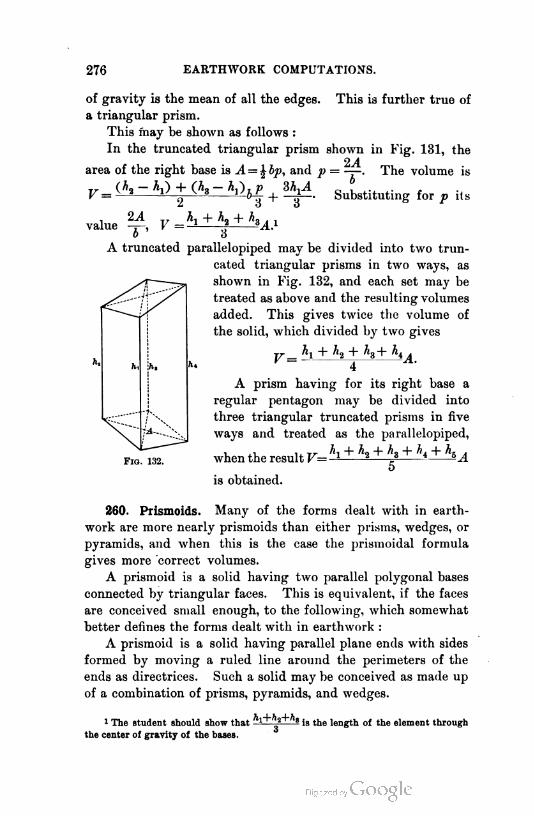
276 EARTHWORK COMPUTATIONS.
of gravity is the mean of all the edges. This is further true of
a triangular prism.
This may be shown as follows :
In the truncated triangular prism shown in Fig. 131, the
2Aarea of the right base is A= % bp, and p = —. The volume is
r, + (*,-*•)»£ + ?M Substituting for p ils
value 24, V=h* + h> + k*Ai
o 6
A truncated parallelopiped may be divided into two trun
cated triangular prisms in two ways, as
shown in Fig. 132, and each set may be
treated as above and the resulting volumes
added. This gives twice the volume of
the solid, which divided by two gives
A prism having for its right base a
regular pentagon may be divided into
three triangular truncated prisms in five
ways and treated as the parallelopiped,
when the result VJi + h + h + h + hA
o
is obtained.
A.
F1g. 132.
260. Prismoids. Many of the forms dealt with in earth
work are more nearly prismoids than either prisms, wedges, or
pyramids, and when this is the case the prismoidal formula
gives more correct volumes.
A prismoid is a solid having two parallel polygonal bases
connected by triangular faces. This is equivalent, if the faces
are conceived small enough, to the following, which somewhat
better defines the forms dealt with in earthwork :
A prismoid is a solid having parallel plane ends with sides
formed by moving a ruled line around the perimeters of the
ends as directrices. Such a solid may be conceived as made up
of a combination of prisms, pyramids, and wedges.
1 The student should show that ^a+^s js tjje iength of the element through
the center of gravity of the bases.
ORDINARY METHODS. 277
261. Prismoidal formula. If a single expression can be
found giving the volume of a prism, pyramid, and wedge, it
will give the volume of a prismoid, since such a solid is made
up of the above three elementary solids, all having, in any
given case, equal heights.
In the right
prism
pyramid
wedge
Ah
Ahv= <
3
Ah
2
which may be
written
(A1 + A2 + 4Am)
- (Ax + A2 + 4 AJ
in which Ax is one base, A2 is the other base, and Am is a section
midway between the two end bases and parallel to them.
The single expression thus found is called the prismoidal
formula, and is the correct formula for finding the volumes of
prismoids.
Am is not a mean of A1 and A2, but each of its linear dimen
sions is a mean of the corresponding dimensions of A1 and A2.
This formula is applicable to the sphere and all the regular
solids of revolution.1
262. Approximations. To avoid the labor involved in com
puting the volume of prismoids by the prismoidal formula, one
of two assumptions is frequently made. These are :
A + A(1) The volume of a prismoid is —L_L—?A, called the
method of average end areas.
(2) The volume of a prismoid is hAm, called the method
of mean areas.
The error of the first assumption is twice that of the second
and of the opposite sign. To show this, let av av and am be
homologous sides of the similar end and middle sections of a
given prismoid.2 Then since the areas of similar figures are as
1 Let the student show the truth of this statement for the sphere and both
spheroids of revolution.
2 Prismoid end areas are not necessarily similar. They are here assumed to be
so for simplicity.
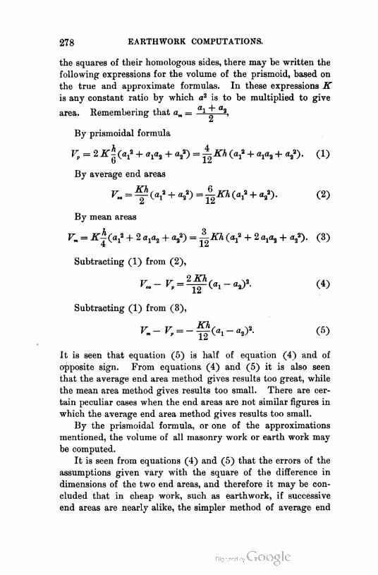
278 EARTHWORK COMPUTATIONS.
the squares of their homologous sides, there may be written the
following expressions for the volume of the prismoid, based on
the true and approximate formulas. In these expressions K
is any constant ratio by which a2 is to be multiplied to give
area. Remembering that am = Ul — a\
By prismoidal formula
Vp = 2 K\(V + axH + a2*) = ±Kh (a,* + a,a2 + a2*). (1)
By average end areas
V„ = ~(V + «22) = ^Kh (a> + a*). (2)
By mean areas
Vm = K±(a? + 2 a,a2 + a/) = AKh (V + 2 axa2 + a/). (3)
Subtracting (1) from (2),
K = ^(ai-a2y. (4)
Subtracting (1) from (3),
Vm- Vp = -^Cai-a2y. (5)
It is seen that equation (5) is half of equation (4) and of
opposite sign. From equations (4) and (5) it is also seen
that the average end area method gives results too great, while
the mean area method gives results too small. There are cer
tain peculiar cases when the end areas are not similar figures in
which the average end area method gives results too small.
By the prismoidal formula, or one of the approximations
mentioned, the volume of all masonry work or earth work may
be computed.
It is seen from equations (4) and (5) that the errors of the
assumptions given vary with the square of the difference in
dimensions of the two end areas, and therefore it may be con
cluded that in cheap work, such as earthwork, if successive
end areas are nearly alike, the simpler method of average end
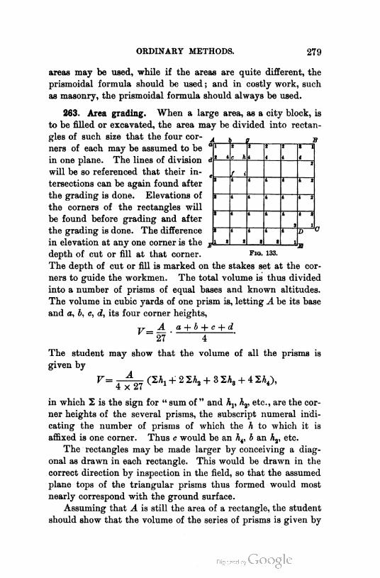
ORDINARY METHODS. 279
areas may be used, while if the areas are quite different, the
prismoidal formula should be used ; and in costly work, such
as masonry, the prismoidal formula should always be used.
263. Area grading. When a large area, as a city block, is
to be filled or excavated, the area may be divided into rectan
gles of such size that the four cor
ners of each may be assumed to be
in one plane. The lines of division
will be so referenced that their in
tersections can be again found after
the grading is done. Elevations of
the corners of the rectangles will
be found before grading and after
the grading is done. The difference
l '7 (r l1 2 i 2
1
2 2 1
i2 i e h
2
f i2
Ii 4 * 2
2 i t 1 2
2 i 1 2
2 - iS 1
D
I *2 2 2
1 m
V=
depth of cut or fill at that corner. Fro- 133.
The depth of cut or fill is marked on the stakes set at the cor
ners to guide the workmen. The total volume is thus divided
into a number of prisms of equal bases and known altitudes.
The volume in cubic yards of one prism is, letting A be its base
and a, b, c, d, its four corner heights,
A a + b + c + d
27 4
The student may show that the volume of all the prisms is
given by
V= ^-^7 + 2 2A2 + 3 2A3 + 4 2A4),
in which 2 is the sign for " sum of " and hv hv etc., are the cor
ner heights of the several prisms, the subscript numeral indi
cating the number of prisms of which the h to which it is
affixed is one corner. Thus c would be an A4, b an hv etc.
The rectangles may be made larger by conceiving a diag
onal as drawn in each rectangle. This would be drawn in the
correct direction by inspection in the field, so that the assumed
plane tops of the triangular prisms thus formed would most
nearly correspond with the ground surface.
Assuming that A is still the area of a rectangle, the student
should show that the volume of the series of prisms is given by
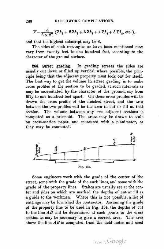
280 EARTHWORK COMPUTATIONS.
V=A
(2^ + 22A2 + 3 2A3 + 4 1\ + 5 2A5, etc.),
6 x 27
and that the highest subscript may be 8.
The sides of such rectangles as have been mentioned may
vary from twenty feet to one hundred feet, according to the
character of the ground surface.
264. Street grading. In grading streets the sides are
usually cut down or filled up vertical where possible, the prin
ciple being that the adjacent property must look out for itself.
The best way to get the volume in street grading is to make
cross profiles of the section to be graded, at such intervals as
may be necessitated by the character of the ground, say from
fifty to one hundred feet apart. On these cross profiles will be
drawn the cross profile of the finished street, and the area
between the two profiles will be the area in cut or fill at that
section. The volume between any two adjacent sections is
computed as a prismoid. The areas may be drawn to scale
on cross-section paper, and measured with a planimeter, or
they may be computed.
Some engineers work with the grade of the center of the
street, some with the grade of the curb lines, and some with the
grade of the property lines. Stakes are usually set at the cen
ter and sides on which are marked the depths of cut or fill as
a guide to the workmen. Where this is not possible, a list of
cuttings may be furnished the contractor. Assuming the grade
of the property line to be used in Fig. 134, the depths of cut
to the line AB will be determined at such points in the cross
section as may be necessary to give a correct area. The area
above the line AB is computed from the field notes and used
is
Fig. 134.
ORDINARY METHODS. 281
in getting the volume. The volume of the cutting below the
line AB is a constant per unit of length of street, and may be
readily computed for any given stretch. The slide rule is very
useful in saving time in all volumetric computations.
265. Excavation under water. When excavation under
water is to be measured, it may be done by sounding on
known lines, both before and after the excavating is done,
and the volume is computed as in surface grading. This is
not always the best method. The material is usually meas
ured after removal. If it is placed in scows, the displacement
of the scow for each load is obtained, and this, divided by
the specific gravity of the material, gives the volume in the
scow. It is necessary to observe the displacement of the scow
for no load, and subtract this from the observed displacement
for a given load.
The displacement is obtained by measuring the model lines
of the vessel at varying depths, and computing the volume for
these depths by the prismoidal formula. These volumes may
be plotted on cross-section paper by laying off the depths to
scale on one side of the paper, and at these points laying off
the computed volumes to scale perpendicular to this axis of
depths. A curve may now be drawn through the points thus
plotted. Ordinates to this curve, at any scaled depth, will be
to scale the volume for that depth.
To observe the displacement correctly, the water in the hold
must be at the level obtaining when the displacement of the
empty vessel was noted. The depth of the vessel in the water
is best noted at four symmetrically situated points, and the
mean is taken.
ESTIMATING VOLUMES FROM A MAP.
266. A reservoir. Fig. 135 is a contour map of a portion
of a valley or ravine that it is proposed to convert into a stor
age reservoir by the construction of a dam across the narrow
part shown. It is required to determine the capacity of the
reservoir. At the location of the dam, its top width and side
slopes being determined, the lines representing the top, and

282 EARTHWORK COMPUTATIONS.
what will be contour lines of the finished surface, may be drawn
on the map as indicated. The intersection of any contour with
the corresponding contour of the
finished dam will be a point where
dam will join the side of
ie valley, and a line, abc,
connecting such points of in
tersection will indicate the
of the proposed struc-
e, or will be a line
no cut or fill, that
is, a "grade line."
The storage space
may be conceived
to be divided
into a series
of horizontal
layers whose
top and bot
tom areas are
the closed fig
ures formed
by correspond
ing contours
of surface and
dam. These
areas may be meas
ured with a plani-
meter. The vol
ume of any layer is
obtained by averag
ing its two end areas
and multiplying by
its height, which is
the contour interval.
If h is that interval,
the volume of a series
of layers would be
given by
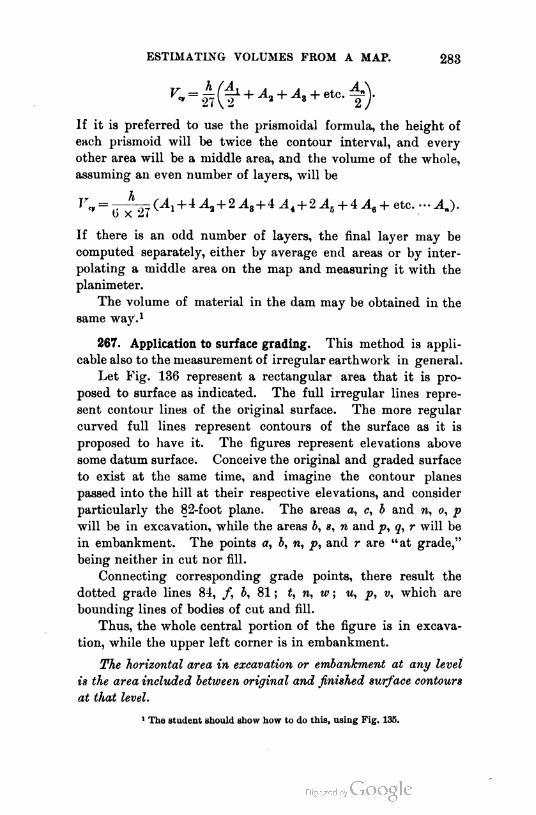
ESTIMATING VOLUMES FROM A MAP. 283
If it is preferred to use the prismoidal formula, the height of
each prismoid will be twice the contour interval, and every
other area will be a middle area, and the volume of the whole,
assuming an even number of layers, will be
Vm = (Ai + i A2 + 2 As+4 At+ 2 A6 + 4 A6 + etc. - AJ.
If there is an odd number of layers, the final layer may be
computed separately, either by average end areas or by inter
polating a middle area on the map and measuring it with the
planimeter.
The volume of material in the dam may be obtained in the
same way.1
267. Application to surface grading. This method is appli
cable also to the measurement of irregular earthwork in general.
Let Fig. 136 represent a rectangular area that it is pro
posed to surface as indicated. The full irregular lines repre
sent contour lines of the original surface. The more regular
curved full lines represent contours of the surface as it is
proposed to have it. The figures represent elevations above
some datum surface. Conceive the original and graded surface
to exist at the same time, and imagine the contour planes
passed into the hill at their respective elevations, and consider
particularly the 82-foot plane. The areas a, c, b and n, o, p
will be in excavation, while the areas b, s, n and p, q, r will be
in embankment. The points a, b, n, p, and r are "at grade,"
being neither in cut nor fill.
Connecting corresponding grade points, there result the
dotted grade lines 84, /, b, 81 ; t, n, w ; u, p, v, which are
bounding lines of bodies of cut and fill.
Thus, the whole central portion of the figure is in excava
tion, while the upper left corner is in embankment.
The horizontal area in excavation or embankment at any level
is the area included between original and finished surface contours
at that level.
' The student should show h-w to d- this, using Fig. 135.

284 fcARTIlWORK COMPUTATION'S.
To get the volume of any single body of cut or fill, measure
successive areas with the planimeter, and assume these to be
end areas of figures that are as nearly prLsinoids as anything
else, with altitudes equal to the contour interval. If the pris-
moidal formula is to be used for computing the volume, the
77 78 79
FiO. 136.
altitude of a single prismoid is taken as twice the contour
interval, that is, two layers are taken to make one prismoid.
The volumes may be computed by the formulas of the last
article. Assuming average end areas, the small body of cut on
the right is found to have areas :
At elevation 81, 00.
At elevation 82, acb.
At elevation 83. def.
At elevation 84. 00.
Volume = i + acb + def + y) = ^ (acb +

ESTIMATING VOLUMES FROM A MAP. 285
The portion of fill between this cut and the large central
body of cut has areas:
At 88-foot level, 00.
At 87-foot level, ghi.
At 86-foot level, klm.
etc., etc.
268. Application to structures. One example of the appli
cation of this method of estimating volumes to regular struc
tures built on irregular ground will be given. The form of the
680 670 660 650
Fig. 137.
structure is not presented as an example of good engineering,
but merely to show the method of estimating volumes.
A small reservoir is to be built on a hillside, and will be
partly in excavation and partly in embankment. Fig. 137
shows such a case. The contours, for the sake of simplicity,
are spaced five feet apart. The top of the reservoir (shown by
286 EARTHWORK COMPUTATIONS.
the heavy lines making the square) is 10 feet wide, and at
an elevation of 660 feet. The reservoir is 20 feet deep, with side
slopes— both inside and outside — of two to one, making the
bottom elevation 640 feet, and 20 feet square, the top being 100
feet square on the inside. The dotted lines are contours that
would be invisible if both original surface and completed reser
voir were supposed to exist at the same time. The areas of fill
all fall within the broken line marked abcdefghik, and the cut
areas all fall within the broken line marked abcdefgo. These
broken lines are grade lines. The areas of fill and cut are
readily traced by following the closed figures formed by con
tours of equal elevation:
At 640-foot level area in fill is pst.
At 650-foot level area in fill is Imnuvxl.
At 650-foot level area in cut is 1 2 3 Ma; 1.
The other areas are easily traced. In the figures given, the
lines have all been drawn in black for printing. In practice
they should be drawn in different colors to avoid confusion.

CHAPTER XI.
HYDROGRAPHIC SURVEYING.
269. Definition. A hydrographic survey is a survey having
to do with any body of water. A topographic survey may be,
and frequently is, partly a hydrographic survey.
270. Objects. A hydrographic survey may be undertaken
for any one of the following purposes :
(1) To determine the topography of a portion of the bed of
the bay, or harbor, or river, in order that it may be
mapped for the information of seamen. In this case it is
necessary merely to locate the channels, dangerous rocks, and
shoals.
(2) To determine definitely the configuration of a small
portion of the bed of the sea, a bay, harbor, or river, for the
purpose of planning works to rest on or in the bed, such as
lighthouses, sea walls or docks, bridge piers, etc., or to esti
mate the quantities of materials to be moved by dredging or
blasting, for the improvement of the channels or harbor.
(3) To determine the flow of a given river or estuary and
the direction of the currents, for the purpose of studying the
physics of the stream or for planning waterworks or drainage
systems.
(4) To secure the necessary information for planning the
improvement of marshy shores of a lake or stream by lowering
the water level or otherwise.
271. Work of the surveyor. The survey ends with the
determination of the required information. The planning of
the works and their execution is hydraulic engineering. The
laying out of the plan on the ground requires the methods of
the surveyor. The work of the surveyor, then, is to make a
287
288 HYDROGRAPHIC SURVEYING.
topographical map of the area to be covered, to compute mate
rial moved, to determine cross sections of streams, their ve
locities, their discharge, the direction of their currents, and the
character of their beds, and to lay out projected improvements.
272. General statement of methods. The configuration or
topography of the bed of a body of water is determined by
sounding, that is, measuring the depth of water. If many points
are observed, a contour map of the bottom may be drawn, the
water surface being the plane of reference.
The cross section of a stream is determined by taking
soundings along a fixed transverse line.
The velocity of flow of a stream is determined by noting
how long a float requires to drift a known distance, or by
the use of a current meter.
Since the velocity is not the same at all parts of a given
cross section, many determinations for velocity must be made
before an average for the whole cross section can be obtained.
The discharge of a large stream like the Mississippi, Mis
souri, Ohio, or Hudson River is determined by measuring a
cross section and finding the velocity of flow past it. The
discharge of a small stream, like any one of the thousands
of creeks, is obtained by weir measurements. A weir is a
notch cut in a dam. A dam is constructed across the stream,
and a notch is built in it, through which the water flows.
From the known size of the notch and the depth of water
flowing over it, the flow may be calculated by methods that
are explained in full in any work on hydraulics. Insignificant
streams may be measured by any simple means that may
occur to the surveyor.
The direction of surface currents may be determined by
means of floats. Subcurrents are best determined by means
of the direction meter.
The character of the bed of a body of water may be ascer
tained by securing samples in a cup attached to the sounding
lead, or by putting tallow in a cavity in the bottom of the lead.
Some of the bottom will adhere to the tallow. If the character
of the bed for some distance below the bottom is required, as
when bridge piers are to be founded on firm bottom which is
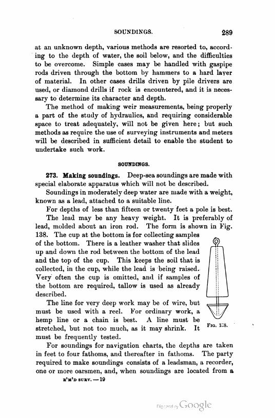
SOUNDINGS. 289
at an unknown depth, various methods are resorted to, accord
ing to the depth of water, the soil below, and the difficulties
to be overcome. Simple cases may be handled with gaspipe
rods driven through the bottom by hammers to a hard layer
of material. In other cases drills driven by pile drivers are
used, or diamond drills if rock is encountered, and it is neces
sary to determine its character and depth.
The method of making weir measurements, being properly
a part of the study of hydraulics, and requiring considerable
space to treat adequately, will not be given here ; but such
methods as require the use of surveying instruments and meters
will be described in sufficient detail to enable the student to
undertake such work.
SOUNDINGS.
273. Making soundings. Deep-sea soundings are made with
special elaborate apparatus which will not be described.
Soundings in moderately deep water are made with a weight,
known as a lead, attached to a suitable line.
For depths of less than fifteen or twenty feet a pole is best.
The lead may be any heavy weight. It is preferably of
lead, molded about an iron rod. The form is shown in Fig.
138. The cup at the bottom is for collecting samples
of the bottom. There is a leather washer that slides
up and down the rod between the bottom of the lead
and the top of the cup. This keeps the soil that is
collected, in the cup, while the lead is being raised.
Very often the cup is omitted, and if samples of
the bottom are required, tallow is used as already
described.
The line for very deep work may be of wire, but
must be used with a reel. For ordinary work, a
hemp line or a chain is best. A line must be
stretched, but not too much, as it may shrink. It
must be frequently tested.
For soundings for navigation charts, the depths are taken
in feet to four fathoms, and thereafter in fathoms. The party
required to make soundings consists of a leadsman, a recorder,
one or more oarsmen, and, when soundings are located from a
e'm'd scrv. — 19
290 HYDROGRAPHIC SURVEYING.
boat, one or two observers to read the angles. If the boat is
located by angles read on shore, there must be one or more
observers on shore.
The leadsman casts the lead and announces the depths. For
this purpose the line is graduated by suitable tags, so that the
depths can be readily determined. In still, deep water the boat
may be stopped while the sounding is being takes and recorded,
but more often it is not stopped. The'leadsman stands in the
bow of the boat and throws his lead ahead, so that, as he judges,
it will be on the bottom and the line will be vertical when the
boat is over it. He will become expert at this after a time.
The recorder notes the number of the sounding and the depth
that the leadsman gives him.
The method of using rods will be obvious.
The reference plane for depths is the surface of the water,
and as this is continually changing, except in still ponds or
lakes, it is necessary to know the stage of the water at the time
the soundings are taken. This is done by establishing a gage
in the vicinity of the work. The soundings on all navigation
charts are referred to mean low tide. The zero of the gage
should be set, if possible, at this elevation. The gage may be
a graduated board nailed to a pile in a pier in the vicinity of
the work and read at hourly intervals during the progress of
the sounding. Gages for rivers are frequently inclined, being
laid along the shore at right angles to the stream, and the
points of equal differences of altitude are determined by level
ing. A tide gage that is to remain permanently in place should
be self-registering. Such a gage may consist essentially of a
float protected by a surrounding house or tube, and attached
by suitable mechanism to a pencil that has a motion propor
tional to the rise and fall of the float. The pencil bears against
a piece of graduated paper fastened to a drum that is revolved
by clockwork. There will thus be drawn on the paper a pro
file in which the horizontal units are time, and the vertical
units are feet, rise, and fall. The stage of the tide for any
instant can be read from the profile.
274. Locating the soundings. (1) The soundings may be
located by two angles read simultaneously from the opposite
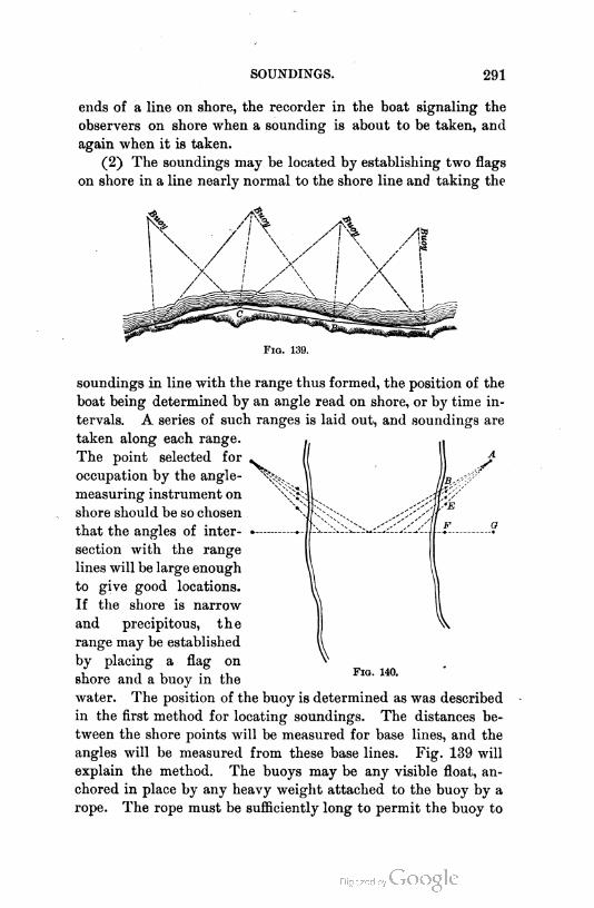
SOUNDINGS. 291
ends of a line on shore, the recorder in the boat signaling the
observers on shore when a sounding is about to be taken, and
again when it is taken.
(2) The soundings may be located by establishing two flags
on shore in a line nearly normal to the shore line and taking the
F1g. 139.
soundings in line with the range thus formed, the position of the
boat being determined by an angle read on shore, or by time in
tervals. A series of such ranges is laid out, and soundings are
taken along each range.
A
V
The point selected for
occupation by the angle-
measuring instrument on
shore should be so chosen
that the angles of inter
section with the range
lines will be large enough
to give good locations.
If the shore is narrow
and precipitous, the
range may be established
by placing a flag on
shore and a buoy in the
water. The position of the buoy is determined as was described
in the first method for locating soundings. The distances be
tween the shore points will be measured for base lines, and the
angles will be measured from these base lines. Fig. 139 will
explain the method. The buoys may be any visible float, an
chored in place by any heavy weight attached to the buoy by a
rope. The rope must be sufficiently long to permit the buoy to
F1g. 140.

292 HYDROGRAPHIC SURVEYING.
be seen at high tide. At low tide the position of the buoy will
not be certain, for obvious reasons. A good kind of buoy is a
tapering spar of wood. If it is not readily visible, a flag may
be set in the end.
(3) If many soundings are to be taken at different tuLjsop
one cross section of a river, they may be located byHu,*.
them at the intersection of a series of ranges so laid out>C,mJ
have their intersections on the required cross section. Fig. 140
will sufficiently explain.
(4) Again, the soundings may be located by stretching a
rope or wire across the channel and taking them at marked
F1g. 141.
intervals along the line. This method is adapted to narrow
channels, and is used somewhat in connection with measure
ment of materials dredged in such channels.
(5) Again, they may be located by measuring in the boat,
at the time the soundings are taken, two angles to three known
points on shore. The angles are measured with a sextant.
There are several methods of obtaining from the data thus
secured the location of the point where the sounding is taken.
The problem to be solved is known as the "three-point prob
lem."
The most convenient way to plot the point on a map on
which have been already plotted the known shore points, is by
the use of a three-arm protractor, shown in Fig. 141. The two
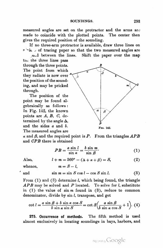
SOUNDINGS. 293
measured angles are set on the protractor and the arms arc
made to coincide with the plotted points. The center then
gives the required position of the sounding.
If no three-arm protractor is available, draw three lines on
p "dt, .. of tracing paper so that the two measured angles are
-un-i between the lines. Shift the paper over the map
til* the three lines pass
through the three points.
The point from which
they radiate is now over
the position of the sound
ing, and may be pricked
through.
The position of the
point may be found al
gebraically as follows :
In Fig. 142, the known
points are A, B, C, de
termined by the angle A,
and the sides a and b.
The measured angles are
a and 8, and the required point is P.
and CPB there is obtained
Fig. 142.
From the triangles APB
PB
Also,
whence,
and
a sin l _ b sin m
sin a sin 8
(A + a + p) = S,l + m = 360°
m = S — l,
sin m = sin S cos l — cos S sin l
(1)
(2)
(3)
From (1) and (3) determine l, which being found, the triangle
APB may be solved and P located. To solve for l, substitute
in (1) the value of sin m found in (3), reduce to common
denominator, divide by sin l, transpose, and get
, 7 a sin 8 + b sin a cos S , 0f a sin Bcot l = f-^ — = cot SI —
b sin a sin is \b sin « cos £
+ 1)0 (4)
275. Occurrence of methods. The fifth method is used
almost exclusively in locating soundings in bays, harbors, and
294 HYDROGRAPHIC SURVEYING.
off the seacoast. The others are used in connection with river
and small lake surveys.
276. Survey of a harbor, river, etc. In making a complete
map of a harbor, coast, or river, a system of triangles of greater
or less extent is laid out. The triangulation stations thus
locate the prominent points. These points are then used as a
basis for locating the soundings. If too far apart, other points
are located along shore by running a traverse between triangu
lation stations. Such a traverse is usually run in any event to
determine the detail configuration of the shore line and the
topography adjacent thereto. This work is best done with the
transit and stadia or with the plane table.
The map is finished like any topographical map. The
contour lines of the bottom are frequently drawn as dotted
lines to a depth of four fathoms, and beyond that depth the
soundings are given in figures expressing fathoms and quarters.
Charts of the various harbors and many portions of the coast
of this country are published by the United States Coast and
Geodetic Survey, and may be purchased for a small price. On
these charts are located buoys and beacons. These are estab
lished to denote shoals and rocks, and are so arranged that in
entering a harbor a red buoy with even number is to be passed
on the right; a black buoy with odd number is to be passed on
the left, and buoys with red and black stripes may be passed
on either the right or the left. Buoys in channels are painted
with black and white vertical stripes.
Beacons and buoys are different things. A beacon is a per
manent fixed signal, usually on a shoal or dangerous rock ;
while a buoy is a float of some kind, anchored by a chain. It
is used to denote either danger or channel.
THE SEXTANT.
277. Description. It has been said that when the angles
are read in the boat, they are measured with a sextant. The
sextant is shown in Fig. 143. It consists of an arc of sixty
degrees, but, from the principle of the instrument, reading
angles up to one hundred and twenty degrees. lis a mirror
attached to the movable arm that carries the vernier V. The

THE SEXTANT. 295
arm is centered under the mirror. This mirror is called the
index glass. The vernier reads to ten seconds. H is another
glass, called the horizon glass. Its lower portion is a mirror,
and its upper portion is unsilvered. GG are colored glasses
to protect the eye when making observations on the sun. They
may be turned back out of the way when not needed.
278. Use. To use the sextant to measure an angle between
two terrestrial objects, hold the plane of the arc in the plane of
F1o. 143.
the observer's eye and the two points. The telescojje should be
directed toward the fainter object. It may be necessary to hold
the sextant upside down to do this. Swing the vernier arm till
the image of the second point reflected from I to H to the
telescope is seen superimposed on the fainter object seen
directly. Clamp the vernier, bring the images into exact
coincidence, using the tangent screws, and read the vernier.
The reading is the angle sought. It will be observed that the
angle read is not horizontal, unless the distant points are in
the same level with the observer. It requires some practice
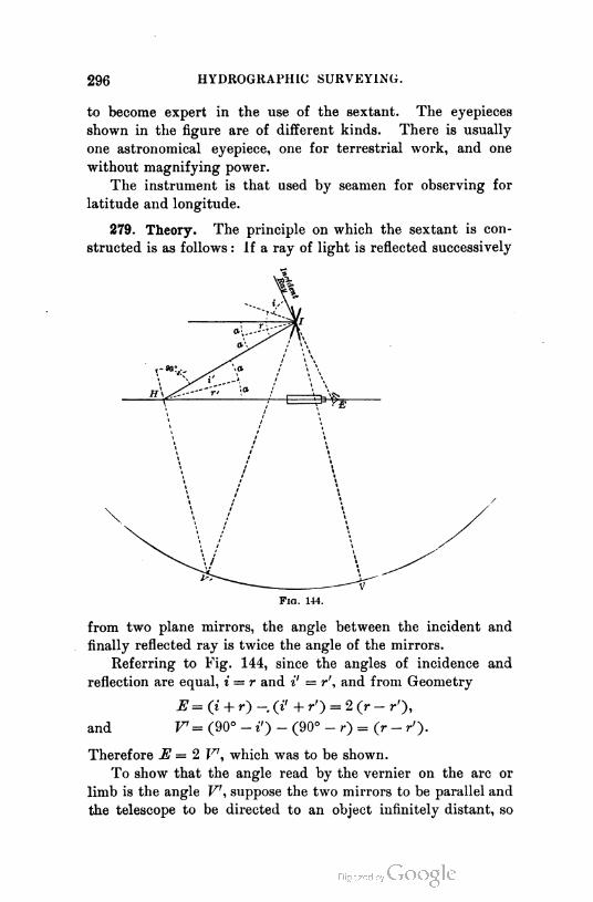
296 HYDROGKAPHIC SURVEYING.
to become expert in the use of the sextant. The eyepieces
shown in the figure are of different kinds. There is usually
one astronomical eyepiece, one for terrestrial work, and one
without magnifying power.
The instrument is that used by seamen for observing for
latitude and longitude.
279. Theory. The principle on which the sextant is con
structed is as follows : If a ray of light is reflected successively
Fio. 144.
from two plane mirrors, the angle between the incident and
finally reflected ray is twice the angle of the mirrors.
Referring to Fig. 144, since the angles of incidence and
reflection are equal, i = r and i' = r', and from Geometry
E= (i + r) - (t' + r') = 2 (r - r'),
and F= (90° - i') - (90° -r) = (r-r').
Therefore E =2 V, which was to be shown.
To show that the angle read by the vernier on the arc or
limb is the angle V, suppose the two mirrors to be parallel and
the telescope to be directed to an object infinitely distant, so
THE SEXTANT. 297
that the rays from it are parallel. An image of the object will
be seen in the same line as the object, or will appear superim
posed on the object. This will be evident from the equality of
the angles a. The vernier will then be in the position V and
this point of the arc is graduated zero. If now the vernier
is moved to another point V for the purpose of getting the
reflection of a second point to cover the direct image of the
first point, the angle VIV will equal that at V, the angle
of the mirrors. It is, however, the angle at E that is required,
and this is twice the angle through which the vernier has
moved. Hence the arc VV, instead of being numbered to
give the angle V, is numbered to give at once the angle E.
That is, each degree is marked two degrees, etc.
280. Adjustments. There are four adjustments of the sextant:
(1) To make the index glass perpendicular to the plane of
the limb.
(2) To make the horizon glass perpendicular to the limb.
(3) To make the line of collimation of the telescope parallel
to the plane of the limb.
(4) To make the vernier read zero when the mirrors are
parallel.
(1) Bring the vernier to about the middle of the arc. Hold
the eye at about the upper Q- of Fig. 143, and observe the arc
near the zero point directly, and the reflected image of the
other end of the arc in the index glass. If the glass is perpen
dicular to the plane of the limb, the reflected and direct por
tions will seem to form one continuous arc. Adjust the glass,
if necessary, by means of the screws at its base. It may be
necessary to place slips of thin paper under the base.
(2) Direct the telescope toward a star or other very distant
object and note whether the direct and reflected images seem,
when the vernier is moved, to separate or overlap laterally.
If they do not, the horizon glass is in adjustment. The adjust
ment is made, when necessary, by the screws of the glass.
(3) Place the sextant on a plane surface and direct the tel
escope to a point not far away. Place the two peep sights
shown in Fig. 143 on the extreme ends of the limb and note
whether the line of sight through them coincides in elevation
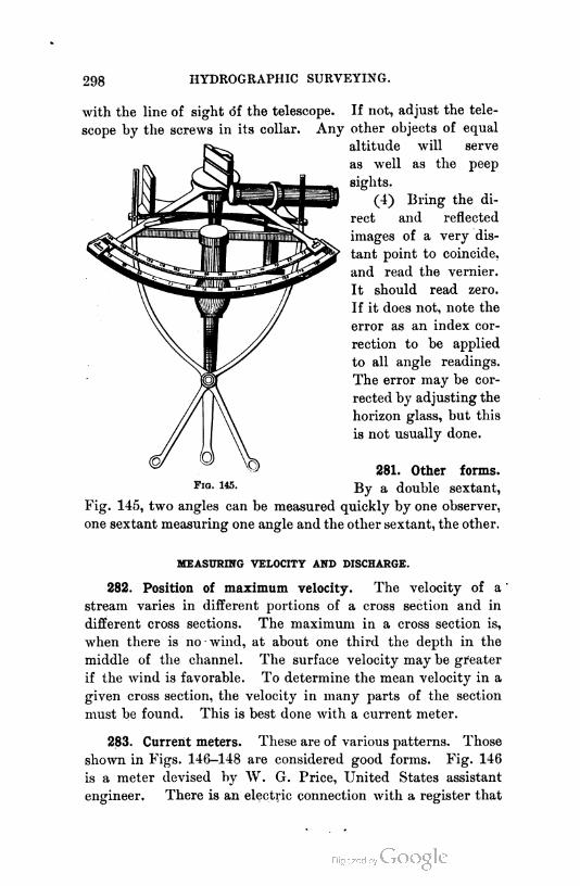
298HYDROGRAPHIC SURVEYING.
with the line of sight of the telescope. If not, adjust the tele
scope by the screws in its collar. Any other objects of equal
altitude will serve
as well as the peep
sights.
(4) Bring the di
rect and reflected
images of a very dis
tant point to coincide,
and read the vernier.
It should read zero.
If it does not, note the
error as an index cor
rection to be applied
to all angle readings.
The error may be cor
rected by adjusting the
horizon glass, but this
is not usually done.
281. Other forms.
By a double sextant,
Fig. 145, two angles can be measured quickly by one observer,
one sextant measuring one angle and the other sextant, the other.
F1g. 145.
MEASURING VELOCITY AND DISCHARGE.
282. Position of maximum velocity. The velocity of a
stream varies in different portions of a cross section and in
different cross sections. The maximum in a cross section is,
when there is no wind, at about one third the depth in the
middle of the channel. The surface velocity may be greater
if the wind is favorable. To determine the mean velocity in a
given cross section, the velocity in many parts of the section
must be found. This is best done with a current meter.
283. Current meters. These are of various patterns. Those
shown in Figs. 146—148 are considered good forms. Fig. 146
is a meter devised by W. G. Price, United States assistant
engineer. There is an electric connection with a register that
299

300 HYDROGRAPHIC SURVEYING.
indicates the number of revolutions of the wheel. The number
of revolutions per second is a function of the velocity of the
current through the meter.
Fig. 147 is a modification of the Price meter, called an
audible, or acoustic, meter, and for streams is probably as con
venient as any form yet devised. It is so constructed that at
each tenth or twentieth revolution a small gong is struck, and
the sound is carried through a rubber tube to the ear of the
observer above in a boat. This meter requires no registering
apparatus at all. It is not recommended for deep-sea work,
in which a strong, heavy instrument is needed, since it is very
light.
Fig. 148 is a different form of meter with electric register
ing attachment.
284. Use of the meter. In use the meter is simply held in
different positions in a cross section whose velocity is required,
and in each position the number of revolutions per second is
noted. The position of the meter is located by any one of
many possible methods that will suggest themselves to the
surveyor. The number of revolutions per second bears some
relation to the velocity of the current going through the
propeller-like wheel of the meter, and the determination of this
relation is called "rating the meter." Every meter must be
rated before the velocity of current corresponding to an
observed velocity of wheel can be told.
285. Rating the meter. The meter is rated by moving it
through still water at a known rate and noting the revolutions
per second. By moving it at different velocities it will become
apparent that the velocity is not strictly proportional to the
speed of the wheel but bears a relation that must be expressed
by an equation. From a number of observations at different
velocities, a diagram may be drawn that will give the velocity
corresponding to any observed speed of the wheel. This is
done as follows: The meter is moved over a known distance
and a stop watch is used to determine the time occupied. The
distance divided by the time in seconds gives the velocity in
feet per second. The number of revolutions made during the
time is recorded, and this divided by the time gives the number
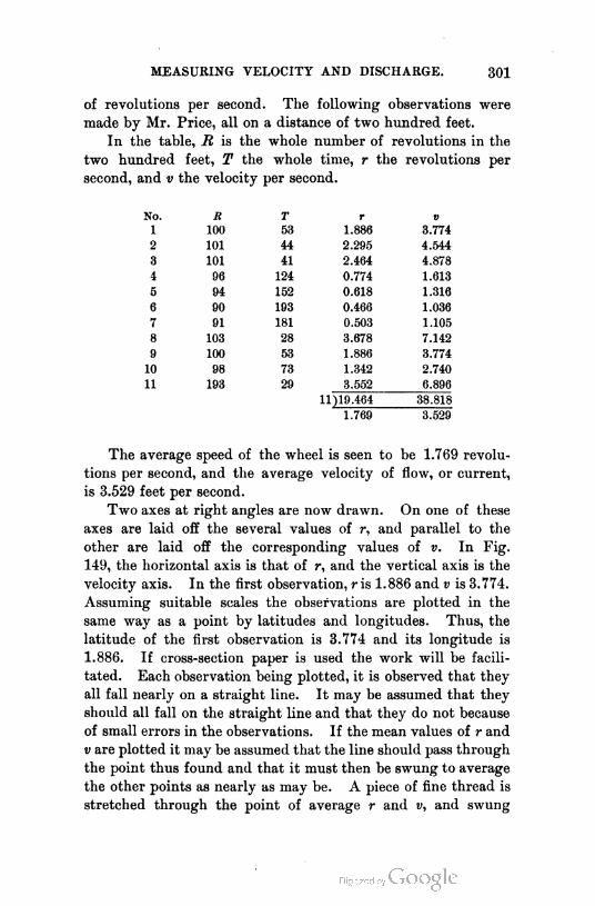
MEASURING VELOCITY AND DISCHARGE. 301
of revolutions per second. The following observations were
made by Mr. Price, all on a distance of two hundred feet.
In the table, R is the whole number of revolutions in the
two hundred feet, T the whole time, r the revolutions per
second, and v the velocity per second.
No. R T r 0
1 100 53 1.886 3.774
2 101 44 2.295 4.544
3 101 41 2.464 4.878
4 96 124 0.774 1.613
5 94 152 0.618 1.316
6 90 193 0.466 1.036
7 91 181 0.503 1.105
8 103 28 3.678 7.142
9 100 53 1.886 3.774
10 98 73 1.342 2.740
11 193 29 3.552 6.896
11)19.464 38.818
1.769 3.529
The average speed of the wheel is seen to be 1.769 revolu
tions per second, and the average velocity of flow, or current,
is 3.529 feet per second.
Two axes at right angles are now drawn. On one of these
axes are laid off the several values of r, and parallel to the
other are laid off the corresponding values of v. In Fig.
149, the horizontal axis is that of r, and the vertical axis is the
velocity axis. In the first observation, r is 1.886 and v is 3.774.
Assuming suitable scales the observations are plotted in the
same way as a point by latitudes and longitudes. Thus, the
latitude of the first observation is 3.774 and its longitude is
1.886. If cross-section paper is used the work will be facili
tated. Each observation being plotted, it is observed that they
all fall nearly on a straight line. It may be assumed that they
should all fall on the straight line and that they do not because
of small errors in the observations. If the mean values of r and
v are plotted it may be assumed that the line should pass through
the point thus found and that it must then be swung to average
the other points as nearly as may be. A piece of fine thread is
stretched through the point of average r and and swung

302 HYDROGRAPHIC SURVEYING.
around till it seems to the eye to average the other points.
This line is that on which it is most probable that the observa-
Axis of Revolutions per Second.
Fig. 149.
tions should all fall, and hence if it is drawn and the meter is
held in a running stream and the revolutions per second are
MEASURING VELOCITY AND DISCHARGE. 303
noted, the corresponding velocity may be determined by laying
off the observed r on its axis and measuring the corresponding
v up to the line. If a horizontal line is drawn on the diagram
through b, where the line cuts the axis of v, it will be seen that
for any value of r the corresponding value of v is r tan a + bo.
If b represents bo, we may write
v = r tan a + b.
From the values of the average r and v in the example given
v = 1.904 r + 0.16.
In its general form this equation is
v = ar + b,
and this is known in Analytical Geometry as an equation of a
straight line. This equation is the general equation of the rela
tion between v and r. The rating of the meter then consists
in finding values for a and b from observations that give v and
r. Since there are two unknown quantities, two independent
observations should be sufficient ; but since no observation can
be perfect, many are taken, and mean values are determined for
a and b. This may be done analytically by the method of Least
Squares.
286. Rod floats. A very good method of obtaining veloci
ties, when a current meter is not available, is to observe the
velocities of rod floats in various parts of the stream. For this
purpose two ranges are established on shore, one above and one
below the section in which it is desired to measure the velocity.
The ranges are laid out normal to the stream. A transit is
placed on each range, and the rod is started just above the
upper range. The transit man on the upper range signals the
lower observer when the rod is about to cross the upper range,
and just as it crosses ; and the lower observer reads an angle to
the rod at the instant it crosses the upper range. The opera
tion is repeated when the rod crosses the lower range, the lower
observer making the signals, and the upper observer reading
the angle to the rod. Each notes the time of crossing the
range on which he is stationed. In this way the path of
the rod and the time it takes to travel that path are known.
The rod may be of wood, or it may be a long cylindrical tin
can. In either case it should be weighted so as to remain
304 HYDROGRAPHIC SURVEYING.
vertical and just clear the bottom. The velocity of the float
will then be approximately that of the vertical filament of the
stream in which it floated. The immersion of the rod should
be about nine tenths of the depth of the stream. If this rule is
observed, the mean velocity in the vertical filament will be given
by Vm = T0 [1 - 0.116 (VZ> - 0.1)]1 in which V0 is the observed
velocity of the rod, and D is the ratio of the depth of the water
below the bottom of the rod to the total depth of the water.
In small streams, wires or ropes graduated with tags may
be stretched across the stream at the upper and lower ends of
the stretch of river to be observed, and the time of passing of
the float under each wire or rope may be observed.
By observing the velocities in many vertical filaments, the
mean velocity of the section may be determined. It would not
be a mean of the several observed velocities unless all "fila
ments " had equal areas. The mean velocity is that which multi
plied by the area will give the discharge, hence it is ^^^^6.
287. The discharge. To get the discharge, simply multiply
the mean velocity of each filament by its cross-sectional area,
and add the products. If the velocity is determined by meter,
the work need be done in but one cross section ; if by rod
floats, it will usually be best to measure two or more sections,
preferably at the quarter points of the stretch, from which to
get a mean section.
DIRECTION OF CURRENT.
288. How determined. It is sometimes necessary to know
the direction of both surface and subsurface currents. The
necessity may arise in the determination of the proper place to
discharge sewage, or in surveys for the improvement of har
bors and the approaches thereto. The surface currents may be
determined by watching floats. The subsurface currents are
best found by a direction meter. This is a form of meter that
not only gives velocities, but also shows the direction of the
current in which it is placed. It was devised by Messrs.
Ritchie and Haskell. It is said to be one of the best forms of
meters for measuring currents alone.
1 Francis's " Lowell Hydraulics."
CHAPTER XII.
MINE SURVEY'NG.
SURFACE SURVEYS.
289. Coal mines. The surface surveys in connection with
coal mining operations consist in making land surveys of the
property that may be owned by the mining company, and locat
ing all shafts, tunnel openings, buildings, railways, roads, and
other structures. In addition to this it is well, if the area
owned is extensive, to make a complete topographical survey
of the property. Frequently a mining company mines coal
under the lands of many small holders and pays a royalty for
the coal so mined. It is therefore necessary to know the posi
tions of the land lines of all owners under whose land it is
probable that operations may extend. The location of these
lines is best performed by careful stadia surveys— reading the
stadia to the smallest possible unit. (There may be cases of
sufficient importance to warrant most careful transit and tape
work.) The topographical survey may be carried on at the
same time. Indeed, the location of the land lines becomes
merely an incident in the topographical survey. The positions
of the corners are determined by computing their latitudes and
longitudes.
Among other points that will be located in the topograph
ical survey or land survey will be the positions of exploration
drill holes that have been put down in advance of mining oper
ations for the purpose of locating veins, or beds, as they are
frequently called. The entire survey may or may not be hung
on a system of triangles. If it is of any considerable extent,
it is best to reference it thus for the sake of the checks it
gives on the field work, even though not more than two or
bVu surv. —21? 2Q£

306 MINE SURVEYING.
three triangles are used. The whole work, except the side
shots, is best plotted by latitudes and longitudes, these being
computed with sufficient accuracy for this purpose by the aid
of a trigonometer. The side shots, except those to land corners,
may be plotted with a protractor. The surface map should
show all outcroppings of mineral.
290. Metal mines. Surface surveys for metal mines may be
of the same character as those for coal mines, but in the United
States there are certain laws governing the size and form of
mining claims that are located on public land, and the method
of surveying them.
291. Form of mining claim. By the provisions of these
laws, a mining claim may not exceed fifteen hundred feet in
length along the vein nor six hundred feet in width (three
hundred feet each side of the vein). It may be of any length
or width less than these limits, according to local custom ; but
no rule may be made that will compel the claim to be less than
twenty-five feet on each side of the vein. The side lines need
not be straight or parallel, but the end lines must be both.
The miner has the right to follow the vein he has discovered
into the ground to any depth, even should it depart so much
from the vertical as to pass beyond the vertical planes through
the side lines ; but he may not mine beyond the vertical planes
through the end lines.
When claims intersect, the subsequently located claim is
said to conflict with the previous one and carries with it only
the area that is not in conflict. The foregoing rules apply
to what are called lode claims.
A " lode " is the name sometimes given to a vein of ore.
A " placer " claim is a claim taken for the purpose of ob
taining gold or silver or other metal from the surface materials,
as in washing gold from a river bed or from gravel in the mines
worked by hydraulic process in California. Such a claim may not
exceed twenty acres, and, if located on surveyed lands, its lines
must conform to the legal subdivisions. A placer claim carries
no right to mine beyond the vertical planes through its bound
ing lines. It carries the right to mine a vein discovered within

SURFACE SURVEYS. 307
its boundaries after the claim is located, but not if the vein is
known to exist when the claim is located, unless specially
mentioned.
292. Surveying the claim. When a miner has found a vein
of ore, he has a claim staked out on the ground, conforming to
the legal requirements, using a width and length that he thinks
best. He also posts the notices required by law. This survey
may be made by any surveyor. After the miner has expended
five hundred dollars in working his claim he is entitled to
have it deeded to him by the government. This deed is
called a "patent," and the claim is said to be "patented."
For the purpose of this patent, a survey is made, from which
to write a description. This final survey, on which the deed
to the miner is based, must be made by a United States offi
cer, known as a United States deputy mineral surveyor. Such
officers are under bonds of ten thousand dollars, and are re
quired to pass an examination before receiving their licenses.
They make the final survey and tie it to a corner of the
public surveys or to a special mineral survey monument, and
return to the surveyor general of the state the notes, with
an affidavit that the required five hundred dollars have been
expended on the mine.
The form of field notes and the instructions issued to United
States deputy mineral surveyors by the surveyor generals of the
various mining states may be had on application to the surveyor
general's office.
293. Surface monuments. The surface monuments of a
mine that is to be worked for any length of time should be of
a permanent character. At least two of them should be
located near the entrance to the mine, and these two should
be particularly permanent, for use in connecting the under
ground and surface surveys. These may be auxiliary monu
ments located for the express purpose of connecting the two
surveys. They may be built of stone or brick, with a properly
centered copper bolt to mark the exact spot. The bolt may
be removable for the purpose of substituting a signal. These
monuments must be constructed with a view to being proof
308 MINE SURVEYING.
against disturbance by frost, or travel, or by the operations
about the mine. A true north and south line permanently
monumented is perhaps the best base for all surveys.
UNDERGROUND SURVEYS.
294. General statement. Underground surveys consist of
traversing, leveling, and sometimes measuring volumes. The
necessary traverses are run to determine the location of the
various portions of the mine, so that a map or a plan of the
mine can be made. Leveling is done to determine the relative
elevations of the different parts of the mine, the grade of the
tunnels or drifts, the direction and amount of dip of the vein,
etc. The quantity of ore mined is sometimes determined by
measuring the volume excavated in the mine, and the meas
urement of the quantity of ore " in sight " is usually by the
volumetric method. The ore mined is usually measured by
weight after it is brought out of the mine.
The only differences between underground and surface
surveys are due to the difficulties encountered in working in
dark, cramped passages. These necessitate certain modifica
tions in surface methods to make them applicable to under
ground work.
295. Definitions. The following are a few definitions of
technical terms used in mining.1 There are many others that
the mining surveyor must know.
Shaft. A pit sunk from the surface.
Adit. A nearly horizontal passage from the surface, by
which a mine is entered and through which the water that
collects in it is removed. In the United States an adit is
usually called a tunnel, though the latter, strictly speaking,
passes entirely through a hill, and is open at both ends.
Drift. A horizontal passage underground. A drift follows
the vein, as distinguished from a cross-cut, which intersects it,
or a level or gallery, which may do either.
Level. A horizontal passage or drift into or in a mine. It
1 Taken from " A Glossary of Mining and Metallurgical Terms " by R. W. Ray
mond, mining engineer.

UNDERGROUND SURVEYS. 309
is customary to work mines by levels at regular intervals in
depth, numbered in their order below the adit or drainage level.
Cross-cut. A level driven across the course of a vein.
Winze. An interior shaft, usually connecting two levels.
Strike. The direction1 of a horizontal line, drawn in the
middle plane of a vein or stratum, not horizontal.
Dip. The inclination of a vein or stratum below the hori
zontal. The dip is necessarily at right angles2 with the strike
or course, and its inclination is steeper than that of any other
line drawn in the plane of the vein or stratum.
Pitch. The inclination of a vein, or of the longer axis of
an ore body.
Incline or Slope. A shaft not vertical ; usually on the dip
of a vein.
Stope. To excavate ore in a vein by driving horizontally
upon it a series of workings, one immediately over the other,
or vice versa. Each horizontal working is called a stope (prob
ably a corruption of step), because when a number of them are
in progress, each working face being a little in advance of
the next above or below, the whole face under attack as
sumes the shape of a flight of steps. The process is called
overhand stoping, when the first stope is begun at a lower
corner of the body of ore to be moved, and, after it has ad
vanced a convenient distance, the next is commenced above it,
and so on. When the first stope begins at an upper corner,
and the succeeding ones are below it, it is underhand stoping.
The term " stoping " is loosely applied to any subterranean ex
traction of ore except that which is incidentally performed in
sinking shafts, driving levels, etc., for the opening of the mine.
296. Location and form of station marks. In underground
work, stations can not be stakes driven in the floor of the mine.
The reasons are obvious. Where the roof is solid rock, holes
may be drilled in it and wooden plugs inserted, in which may be
driven a nail or tack. A good form is a horseshoe nail with
flattened head, in which is cut a triangular hole with an apex of
the triangle toward the head end of the nail. Such a nail
1 Azimuth.
2 That is, the direction of the vertical plane in which the amount of the dip is
measured is at right angles.
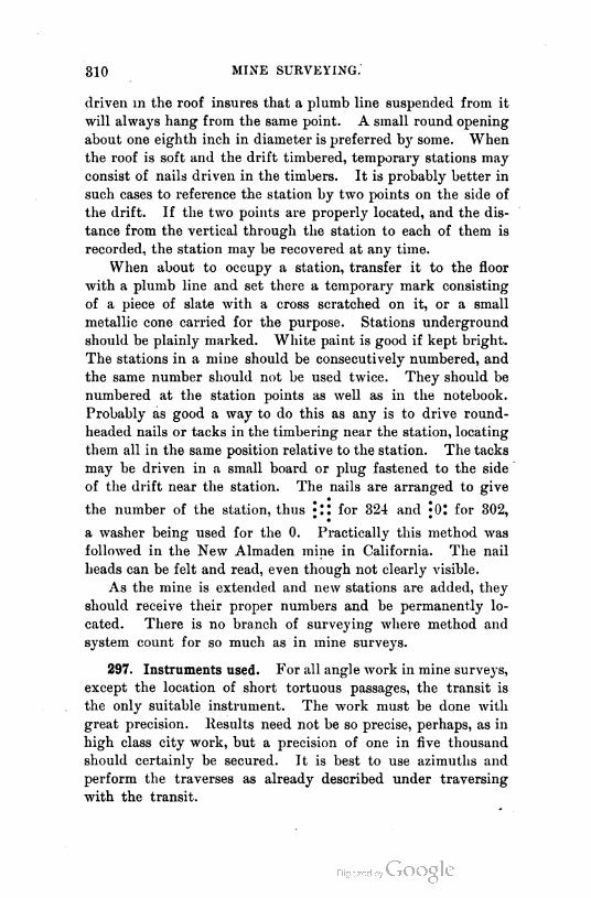
310 MINE SURVEYING.
driven in the roof insures that a plumb line suspended from it
will always hang from the same point. A small round opening
about one eighth inch in diameter is preferred by some. When
the roof is soft and the drift timbered, temporary stations may
consist of nails driven in the timbers. It is probably better in
such cases to reference the station by two points on the side of
the drift. If the two points are properly located, and the dis
tance from the vertical through the station to each of them is
recorded, the station may be recovered at any time.
When about to occupy a station, transfer it to the floor
with a plumb line and set there a temporary mark consisting
of a piece of slate with a cross scratched on it, or a small
metallic cone carried for the purpose. Stations underground
should be plainly marked. White paint is good if kept bright.
The stations in a mine should be consecutively numbered, and
the same number should not be used twice. They should be
numbered at the station points as well as in the notebook.
Probably as good a way to do this as any is to drive round-
headed nails or tacks in the timbering near the station, locating
them all in the same position relative to the station. The tacks
may be driven in a small board or plug fastened to the side
of the drift near the station. The nails are arranged to give
the number of the station, thus for 324 and *0: for 302,
a washer being used for the 0. Practically this method was
followed in the New Almaden mine in California. The nail
heads can be felt and read, even though not clearly visible.
As the mine is extended and new stations are added, they
should receive their proper numbers and be permanently lo
cated. There is no branch of surveying where method and
system count for so much as in mine surveys.
297. Instruments used. For all angle work in mine surveys,
except the location of short tortuous passages, the transit is
the only suitable instrument. The work must be done with
great precision. Results need not be so precise, perhaps, as in
high class city work, but a precision of one in five thousand
should certainly be secured. It is best to use azimuths and
perform the traverses as already described under traversing
with the transit.
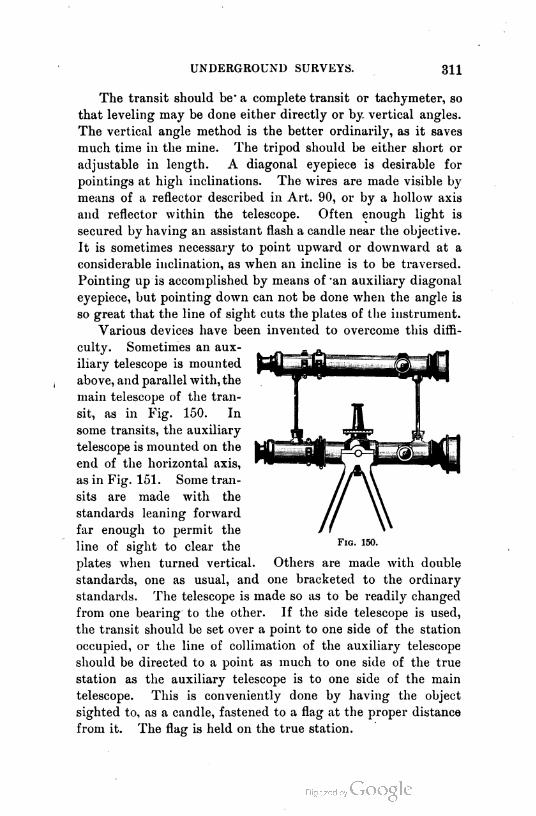
UNDERGROUND SURVEYS. 311
The transit should be - a complete transit or tachymeter, so
that leveling may be done either directly or by vertical angles.
The vertical angle method is the better ordinarily, as it saves
much time in the mine. The tripod should be either short or
adjustable in length. A diagonal eyepiece is desirable for
pointings at high inclinations. The wires are made visible by
means of a reflector described in Art. 90, or by a hollow axis
and reflector within the telescope. Often enough light is
secured by having an assistant flash a candle near the objective.
It is sometimes necessary to point upward or downward at a
considerable inclination, as when an incline is to be traversed.
Pointing up is accomplished by means of oan auxiliary diagonal
eyepiece, but pointing down can not be done when the angle is
so great that the line of sight cuts the plates of the instrument.
Various devices have been invented to overcome this diffi
culty. Sometimes an aux
iliary telescope is mounted
above, and parallel with, the
main telescope of the tran
sit, as in Fig. 150. In
some transits, the auxiliary
telescope is mounted on the
end of the horizontal axis,
as in Fig. 151. Some tran
sits are made with the
standards leaning forward
far enough to permit the
line of sight to clear the
plates when turned vertical. Others are made with double
standards, one as usual, and one bracketed to the ordinary
standards. The telescope is made so as to be readily changed
from one bearing to the other. If the side telescope is used,
the transit should be set over a point to one side of the station
occupied, or the line of collimation of the auxiliary telescope
should be directed to a point as much to one side of the true
station as the auxiliary telescope is to one side of the main
telescope. This is conveniently done by having the object
sighted to, as a candle, fastened to a flag at the proper distance
from it. The flag is held on the true station.

Fig. 151.
312

UNDERGROUND SURVEYS. 313
For tortuous passages in which a transit can not be set up,
so crooked that one end can not be seen from the other,
resort is had to what is sometimes called a German dial, and a
hanging clinometer. One of the best forms of the dial is shown
in Fig. 152.1
The compass is hung on a wire or line stretched from one
station to the next, and as it levels itself like a mariner's com
pass, it may be properly read. The bear
ings are not depended on, but angles are
read. Passages so tortuous as to require
the use of such methods are not usually
of great length, and the resulting errors
are small. They are not likely to occur
in coal mines, but occur frequently in
quicksilver mines, and sometimes in gold
and silver mines. Coal mines usually
involve fewer irregularities of alignment than any other class
of mines.
The linear measurements are made with a steel tape. In
some cases of long, straight drifts, a long tape, two hundred
feet, or three hundred feet, may be used to advantage ; but
usually a tape either fifty feet or one hundred feet long is best.
The tape should be as long as possible, and no more stations
should be used than seem necessary. It is very necessary to
expedite work in a mine, because mining work in a drift must
be largely suspended while the survey is in progress. The
flat wire tapes are best for mine work, since they are not so
easily broken as the ribbon tapes. A pocket tape, graduated to
hundredths of feet, may be carried for the necessary plus meas
urements at stations.
If a level rod is used, it must be a short rod. Bench marks
are best placed on the side of the drifts where they will not be
disturbed.
298. Devices for making stations visible. The object ob
served at a station is usually a plumb line made visible by
holding a piece of oiled paper or milk glass behind it and a
candle behind the transparency. The plumb line may be illu-
1 From Brough's " Treatise on Mine Surveying."

814 MINE SURVEY TNG.
minated by holding a light in front of it, shielded from the
observer.
Another method is to sight the flame of a candle or lamp,
properly centered over the station. Another way is to use
a plummet lamp, which is a
lamp made in the form of a
plummet. Perhaps the neatest
method, at least in coal mines,
is to use a second and third
tripod on which can be mounted
a target lamp, such as is shown
in Fig. 153. The lamp is be
hind the target from the ob
server, and the target may be
accurately centered over the
station point. The target and
transit are interchangeable on
the tripods, the particular form
shown being used with a special
transit that is interchangeable
above the leveling screws.
The method of use is some
what as follows : The back
station is occupied by a target,
as is also the forward station,
and that at which the obser
vation is to be made is occu
pied by the transit. When
the observation is complete,
the tripod at the back station
is carried to the next forward
station, the others remaining
in place. The back lamp
is placed on the tripod that
was occupied by the transit
while the latter is being carried to the tripod occupied by
the previous forward lamp, which in turn is carried to the
next forward station. The lamps should neither of them be
moved till the observations at the station occupied by the
Fig. 153.

UNDERGROUND SURVEYS. 315
transit are complete. This is a very expeditious method
of work.1
The entire angular work may be done first, and the linear
measurements made afterward, or vice versa, or the two may be
carried on at the same time. The latter method will probably
consume more of the miner's time, since the linear work would
retard the angle work. The linear work may be carried on
without seriously interfering with the work of the mine. The
extent or character of the work will guide the surveyor in
choosing his methods. When lateral drifts depart at frequent
intervals from one . long tunnel or drift, the stations at the
angle points of the main drift should be first located and the
substations to be used in running the lateral drifts should be
set in the line of the main drift. This may be done at the
time the angles of the main drift are measured. In this case,
the angle work should be done first.
When an extensive survey of a mine is to be made, the sur
veyor should go through the mine and lay out his programme
of work as closely as may be. It will almost always be possible
to mark out the main stations before taking the transit into the
mine, or at least before setting it up.
299. Notes. In an underground traverse in which notes
are to be taken at intervals along each course to objects on
the sides, a good form is as follows : Prepare the page of the
notebook by ruling a column down the center, in which to
write distances and azimuths, and leave the sides to note the
objects measured to, and such other information as need be
recorded. The form would be similar to that shown on page
229, except that the column for distances would also contain
the azimuths and would be in the middle of the page instead
of at one side. Notes taken on the right of a line that is run
out should be noted on the right of the column, and those
taken on the left should be recorded on the left.
1 An important point in favor of the three-tripod system, when long tapes are
used for measuring, is that all ordinary distances may be measured from center of the
telescope to center of back-sight or fore-sight flame, the vertical angle being read and
noted. Having then the length of the line of sight and its angle, the true horizontal
distance between stations is easily calculated. Oftentimes this is a much safer course
than to rely on presumably horizontal measurements along the floor of the gangways.
J. J. Ormsbee, Mining Engineer.
316 MINE SURVEYING.
A line should be drawn across the page between each two
courses.
For the purpose of computation of latitudes and longitudes,
the azimuths and distances may be copied in more compact
form in the office notebook.
If elevations are carried by vertical angles, a good form
is that given in Art. 127 for traversing with the transit and
stadia, with sufficient vertical space given each course to write
the details of the line along the side or right-hand page under
remarks. The center line up the middle of the right-hand
page may be used to represent the transit line, and the objects
may be sketched to scale on this page. There should always
be two sets of notes in existence, kept in different places, and
when not in use they should be stored in fire-proof vaults.
CONNECTING SURFACE AND UNDERGROUND WORK.
300. When the mine is entered by a tunnel. In order that
the underground workings may be plotted with reference to the
surface lines, or even so that they may be properly oriented, it
is necessary to connect the underground surveys with those
on the surface. The simplest case occurs when the mine is
entered by an adit or drift. From a point in the surface sur
vey, located conveniently for the purpose, run a traverse into
the drift.
301. When there are two shafts. If the mine is entered by
shafts, and there are two or more of these some distance apart,
the surface and underground surveys are connected by running
a traverse on the surface and another underground between the
shafts. The azimuth of the line joining the shafts is computed
from the surface survey ; and that of the same line underground,
from the underground survey, a zero azimuth being assumed for
this purpose. The two computed azimuths will differ by the angle
between the true zero and the assumed zero, and the assumed
underground azimuths may be corrected accordingly. The pre
cise points at the shafts are made the same by using plumb
lines. In deep shafts the lines are best made of piano wire,
and the plummet must weigh from ten to twenty-five pounds.
CONNECTING SURFACE AND UNDERGROUND WORK. 317
The line is first lowered with a light bob, and the heavy one
is attached at the bottom. The line may be lowered by a
reel. Signals may be given for lowering or raising by tapping
on the guides or pipes in the shaft. Wherever possible, this is
an excellent method, since small errors of position of the bobs
are not multiplied.
Another method, that may be applied in shallow mines, is
to use the transit and auxiliary telescope, either setting the
points in the bottom in line with a given line on top, or
setting the transit in the bottom by trial, so that the line of
collimation may be in line with a surface line. Perhaps a
better way than the latter is to set the transit on the bottom
and, with the horizontal motion clamped, set two points in a
line on opposite sides of the shaft at the surface, which line
is produced into the mine as the first course of the traverse.
The points located on the surface are afterward connected
with the surface survey. This method of using the transit
and auxiliary telescope is adapted only to shallow shafts that are
tolerably free from smoke. The better method is that using
the plummets. Work may be carried from one level to another
through winzes and air shafts by the same method. As high
vertical angles occur in this work, double centering is an abso
lute essential to correct work.
Levels are carried down the shafts by measuring with a
steel tape, or, what is the same thing, by lowering a weighted
wire and then measuring the wire. If the tape is used,
and is shorter than the shaft, it is first hung on a nail near
the surface, the elevation of the nail being determined by
leveling. The reel and observers are then slowly lowered
in the cage until the tape is all paid out, when a second nail
is driven at a measured distance from the first. A piece of
white cloth is fastened to this second nail, to make it visible ;
and the cage is raised, the tape unhooked, the cage again
lowered to the second nail, and the operation repeated from
there down. A nail is left for a bench mark opposite each
level.
302. When the mine is entered by one shaft. To connect
a surface survey with an underground survey through a single

318 MINE SURVEYING.
deep shaft is the most difficult task the mining surveyor will
encounter. If the mine is of small extent and the shaft shal
low, it may be done with the transit and auxiliary telescope,
as already described under the preceding article. But if the
shaft is deep, it can not be done this way. The method is to
use two plumb lines. The utmost care is necessary in their
use, for from a base line from six to twelve feet long must be
produced a survey one or two or more miles long. It may be
necessary to drive a second shaft a mile or two distant, and it
must be driven to meet an underground drift. An error of
one tenth of an inch in a base line ten feet long will cause a
shaft two miles distant to be driven nearly nine feet out of
place. Two methods of using two plumb lines have given
satisfactory results.
(1) In Fig. 154, Mand M' are surface monuments, and AB
the two plumb
lines. The dis
tance AB is care
fully measured,
and the distance
MA and MB and
the angles at M.
The azimuth of
AB is then deter
mined. T is the
transit set in the
mine below. The
angles at T, and
the distances AT
and BT are meas
ured. The triangle TAB is then solved, from which the azi
muth of TD becomes known.
(2) This method is probably not so good as the second,
which consists in suspending the plumb lines so that the
transit may be set up in line with them below. The diffi
culty in all this work is that the plumb lines are never still,
but continually oscillate. The mean position of the line is
best determined by placing a fine scale behind it and noting
the amplitude of the vibrations. The transit is pointed to the
Fig. 154.

CONNECTING SURFACE AND UNDERGROUND WORK. 319
mean position. The oscillations are not in a straight line, but
are more or less elliptical; hence the scale must be placed a
little behind the wire, but should be as close as possible to it,
in order to avoid parallax. The transit is set up in the mine
as close to the nearest line as possible (this will be from ten
to fifteen feet distant), and each line is separately observed
and the transit gradually brought by trial into line with the
mean positions of both wires. The two plummets should hang
in water, or, better, in some more viscous liquid, as oil, or even
molasses. The oscillations will be slow, a line three hundred
and twenty-five feet long requiring about ten seconds for one
complete vibration in air. Of course the cages can not be in
use during the operation.
The points from which the bobs are suspended must be
as firm as possible and as well defined, so that the line join
ing them may be connected with the surface surveys. Two
transits are really required to insure good work. One is
left on the surface with an observer to see that there is no
movement of the points of suspension during the operation,
and to note what change, if any, takes place. It must be
known that the lines do not hang against any projections on
the sides of the shaft. This may be told, in some instances,
by looking up the shaft ; in others, by passing a candle or other
light slowly around the wire at the bottom, and observing from
the top that it is visible throughout the motion. In case
neither method is practicable, a system of movements of the
wire may be arranged. When the observer below is ready, he
will signal by rapping on the pipes or guides, and the observer
above will, at agreed intervals of time, move the wire out one
inch, two inches, etc. The observer below notes whether cor
responding movements take place there.
On account of the stoppage of machinery this connection
of surface and underground surveys is an expensive operation.
It should nevertheless, in important cases, be performed several
times, and a mean of the results taken for the first course of
the underground traverse. When the bottom of the shaft can
be seen from the top, a method used at the Severn tunnel will
give good results. A wire is stretched from one side of the
shaft, about one hundred or more feet into the drift, and accu

320 MINE SURVEYING.
rately aligned for the few feet visible by a transit on the sur
face. In the case of the Severn tunnel the wire was stretched
over horizontal screws, the wire lying in the groove between
the threads. The wire was then moved laterally for aligning
by turning the screws.
MAPPING THE SURVEY.
303. Metal mines. Three maps are necessary for a com
plete representation of a mine with many levels running in
different directions — (1) the plan ; (2) a longitudinal sec
tion ; (3) a transverse section. Such a set of maps is shown
in Plate IV. at the back of the book. The notes taken by the
surveyor should be such as to enable him to make these three
maps. These maps may be in addition to one of the surface
survey, and, if so, there would be four maps necessary for a
complete representation of a mining property. It is usual to
tint the portions shown on the plans as worked, and the differ
ent levels are sometimes tinted with different colors to distin
guish them. If several lodes are shown on one map, it will be
better to color each lode, working with a single color to dis
tinguish it from the other lodes.
304. Coal mines. The representation of a coal mine is
usually a simpler matter than the mapping of a metal mine.
The coal ordinarily lies in beds nearly horizontal, and the work
ings may often be represented by a plan alone, the different
levels being distinguished by colors, and the elevations being
written in. It is customary to show on the map the direction
and amount of dip of the seams. There are a number of sym
bols used to represent various objects ; but the practice is not
uniform. Arrows may be used to show the direction of air
currents, blue for inlets, and red for outlets, etc. The plan
should show all the details of the mine, all stop walls, all doors,
all sumps or reservoirs, all pumps or machinery, the location of
faults, etc.
It is extremely necessary that complete, correct maps should
be kept up, so that if any connections are to be made, they may
be correctly directed. Very serious accidents have occurred
from incorrect maps of mines.

MAPPING THE SURVEY. 321
305. Scale. The state of Pennsylvania provides that there
shall be kept at each mine a plan on a scale of one to twelve
hundred, or one hundred feet per inch, for the use of the state
inspector. The English law requires the plan to be on a scale
of twenty-five inches per mile, or about one half that required
in this country. Other countries require different scales.
The maps of the mining claims made by the deputy mineral
surveyors are to a scale of two hundred feet to the inch. This
would seem to be large enough for working drawings, except for
details of structures.
As in the case of notes, two maps should be in existence
and kept in different places. A good example of a coal mine
map is shown in Plate V. at the back of the book.
306. Problems. The problems that arise in mining survey
ing call for some ingenuity in handling Trigonometry and
Descriptive Geometry, although they may all be solved without
a knowledge of the latter subject by name.
Some problems, such as seeking a lost vein, require more the
principles of Geology than those of Mathematics.
The commonest problems are the following :
(1) The determination of the course and distance from a
point in one compartment of a mine to a point in another com
partment. By course is meant azimuth and vertical angle.
This includes such problems as the determination of the dis
tance and direction to run a tunnel to tap a shaft.
(2) Knowing the strike and dip of a vein, to determine the
length of a shaft or drift started at a given point and run in a
given direction to meet the vein, or to determine the direction
to run a tunnel from a given point so as to cut the vein in the
shortest possible distance, and to find the distance required.
It is believed that the student can solve such problems as
are given in the Appendix, page 340, if he remembers that the
pitch or dip is always measured in a vertical plane normal to a
horizontal element of the vein, and that the strike is the direc
tion of such horizontal element.
r'm'd surv. — 21
APPENDIX.
I. PROBLEMS AND EXAMPLES.
CHAPTER I.
The problems in the use of the chain may be solved on the blackboard
with string and chalk.
1. To range out a line between two points on opposite sides of a hill :
Mark the points so that they will be visible from the top of the hill. Two
men with range poles then place themselves near the top of the hill,
facing each other, so that each can see one end of the line. They then
alternately align each other with the visible ends of the line until both
are in the line. The same principle is used in "fudging" one's self into
line between two distant visible points.
2. To range a line across a deep ravine or valley : The inability to do
this by eye alone arises from the fact that the eye can not carry a vertical
line on a hillside, nor can it be sure of transferring a point vertically down
ward, even in level country. The observer stands on one side of the valley,
swinging a plummet over a point in the line to be ranged. He places
his eye in line with the plumb line and a distant point in the line to be
ranged, and, casting his eye down the plumb line, directs the placing of a
flag held by an assistant in the valley.
3. To erect a perpendicular to a line : A triangle whose sides are in the
ratio 4, 5, 6, is a right triangle. Hence, fasten one end and the thirty-link
division at one point in the line and the ten-link division at another point.
Carry the eighteen-link division out till the three portions of the chain
used form a triangle. If the line is to be erected at a given point, the
method will suggest itself to the student.
4. Using the chain and pins in the way a string and pencil or a pair of
dividers would be used on the drawing board, perform the above problem in
a different way.
5. To drop a perpendicular on a line from a given point : Run an
inclined line from the point to the given line, erect a perpendicular to the
latter, and produce it till it intersects the inclined line. The required
822
PROBLEMS AND EXAMPLES. 323
perpendicular is parallel to the perpendicular erected, and the consideration
of the similar figures will enable the student to solve.
6. To run a line parallel to a given line : Erect two equal perpendiculars
to the given line. If the parallel is to pass through a given point, drop a
perpendicular from the point to the line and erect a perpendicular to this at
the point. Otherwise : The diagonals of a parallelogram bisect each other.
7. To measure an angle with a chain : In an isosceles triangle of legs a,
included angle A, and base b, 2 a sin \ A = b.
8. To lay out a given angle : Reverse the process just suggested.
9. A line is measured with a chain that is afterward found to be one
link too long, and is found to be 10.36 chains long. What is its true
length?
10. A line is measured with a 100-foot tape and found to be 723.36 feet
long. The tape is afterward found to be 0.02 foot short. What is the true
length of the line ?
11. A triangular field is measured with a chain that is afterward found
to be one link too long. The sides as measured are 6 chains, 4 chains, and
3 chains, respectively. What is the resulting area and what is the true
area?
12. An irregular field is measured with a chain three links short. The
area is found to be 36.472 acres. What is the true area?
13. A 100-foot tape is standard length for a pull of 10 pounds, when
supported its entire length, and at a temperature of 62° F. A line is
measured and found to be 1000.00 feet long. The tape is of steel, has a
cross section of 0.002 square inch, and weighs 0.00052 lb. per inch. In
the measurement it is at a temperature of 80° F., and is unsupported except
at the ends. The pull is 25 pounds. What is the true length of the line ?
14. A steel tape weighs 0.0061 pounds per lineal foot. It is 100 feet long
and is standard for no pull when entirely supported, at 62° F. It has a
cross section of 0.002 square inch. What pull must be exerted to keep
the tape standard length if it is supported only at its ends, the temperature
remaining unchanged ?
15. A line is measured along the surface on a hillside. The first 300
feet has a vertical angle of 3°, the next 250 feet has a vertical angle of 4° 30',
and the last 700 feet has a vertical angle of 1°. What is the true length of
the line ?
16. A similar line, of equal surface lengths, is measured, and the rise
per hundred feet of each stretch is found to be respectively 5 feet, 8 feet,
and 1J feet. What is the true length of the line?
17. Measure a line of about 1000 feet or more in length, at least twice
with a chain and twice with a tape, and determine the difference of measure
ment. Do this, if possible, over two lines of about equal length, but offering
very unequal difficulties to measurement, and note the differences.

324 APPENDIX.
CHAPTER III.
1. Determine the angular value of one division of each bubble avail
able in the school collection of levels. The method is in brief as follows :
Hold a rod at a known distance ; read the rod and bubble with the bubble
near one end of its tube, and then read with the bubble near the other
end. By the differences of readings and the known distances, determine
the value of one division. If there are any striding levels, use these as
described for the level with metal base.
2. Other exercises with the level will suggest themselves to the student
or teacher. A considerable amount of differential and profile leveling
should be done, and profiles drawn. The leveling should always be
checked by rerunning in the opposite direction.
CHAPTER IV.
1. Radiating from a point A, are eight lines of bearings as follows :
AB, N. 53° 45' W. AF, S. 86° 45' E.
A C, N. 36° 42' W. A G, S. 24° 36' E.
AD, N. 18° 34' E. A H, S. 20° 30' W.
AE, N. 34° 28' E. A I, S. 36° 20' W,
Required the angles between the following bracketed lines — always
considering the smaller angle :
\ab \ab \ab \ab \ab \ab \ab
}ac Tad \ae \af \ag \ah \ai
{ac \ac {ac {ac {ac {ac
(AD (AE (AF (AG \aH [AI
\AD \AD \AD \AD \AD
(AE (AF (AG (AH ( AI
\AE \AE \AE \AE
(AF (AG (AH (AI
\AF \AF {AF
(AG \AH (AI
\AG {AG
(AH \AI
\AH
(AI
2. A traverse is run with the following bearings : N. 42° E., N. 36° E.,
S. 1° W., N. 50° W. Determine the interior angles. If the traverse is of
a closed field, what should be the sum of the interior angles ?
PROBLEMS AND EXAMPLES. 325
3. A traverse is run with the following azimuths, zero azimuth being
north : 42°, 144°, 181°, 230°. What are the bearings?
4. Another is run with the following azimuths : 306° 15', 18° 34', 93° 15',
200° 30'. What are the bearings?
5. What are the azimuths of the following lines of Example 1: AC,
AE, AG, All
6. Determine the exterior or deflection angles in Example 4.
7. Let the eight lines of Example 1 be the first eight consecutive courses
of a traverse. Determine the deflection angles.
8. The magnetic declination at a given place is found to be 10° 30' E.
What will be the bearing of the true north ? the true south ? the true east ?
the true west?
9. The magnetic declination is 7° 10' W. What will be the bearings of
the four true cardinal points ?
10. A line of an old survey is recorded as N. 18° E. mag. bear. It now
reads N. 16° 30' E. What has been the change in declination in direction
and amount ?
11. A line of an old survey is recorded as N. 36° 15' E. mag. bear. It
now reads N. 34° 30' E., and the magnetic declination is now 10° 30' W.
What was the declination at the time of the original survey ?
12. A line of an old survey is recorded as N. 36° 15' E. mag. bear., and
the declination is recorded as having been 10° 30' W. at the time of the sur
vey. The declination is now 12° 00' W. What magnetic bearing should
the line now show ?
13. A line of an old survey is recorded as S. 26° 00' E. mag. bear., dec
lination 10° 30' W. The declination is now 9° W. What magnetic bear
ing should be used to retrace the line?
14. The magnetic declination is 10° 30' E. If the declination vernier is
attached to the south side of the compass box, in what direction and by
what amount should it be moved so that true bearings may be read by the
needle ? With sights pointed to the magnetic north, what would the needle
read after moving the vernier ?
15. A line of an old survey is recorded as N. 30° 15' E. mag. bear. The
declination is now 4° W., and the same line reads N. 30° E. It is desired
t- set the declination vernier so that the remainder of the survey may be
retraced by the recorded bearings. The vernier being attached to the south
side of the compass box, what is its movement in amount and direction?
16. Suppose, in the above example, the former bearing had been S. 26°
W., and the present bearing S. 26° 30' W. What would be the movement
of the vernier?
17. Is it necessary in the foregoing examples to know the present decli
nation ?
18. Determine the angular value of the plate bubbles and the telescope
bubble of each transit in the school collection. Do this work as suggested
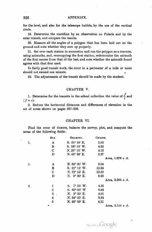
326 APPENDIX.
for the level, and also for the telescope bubble, by the use of the vertical
circle.
19. Determine the meridian by an observation on Polaris and by the
solar transit, and compare the results.
20. Measure all the angles of a polygon that has been laid out on the
ground and note whether they sum up properly.
21. Set over each station in succession and run the polygon as a traverse,
using azimuths, and, reoccupying the first station, redetermine the azimuth
of the first course from that of the last, and note whether the azimuth found
agrees with that first used.
In fairly good transit work, the error in a perimeter of a mile or more
should not exceed one minute. ,
22. The adjustments of the transit should be made by the student.
CHAPTER V.
f1. Determine for the transits in the school collection the value of 4 and
if+c).
2. Reduce the horizontal distances and differences of elevation in the
set of notes shown on pages 337-338.
CHAPTER VI.
Find the error of closure, balance the survey, plot, and compute the
areas of the following fields :
Sta. Bear1ng. Cha1ns.
1. A S. 51° 10' E. 5.05
B S. 58° 10' W. 4.63
C N. 29° 15' W. 4.16
D N. 45° 30' E. 2.87
Area, 1.676 + A.
2, A N. 84° 00' W. 9.04
B S. 21° 15' W. 12.34
C X. 72° 15' E. 12.92
D X. 9° 30' E. 6.68
Area, 9.264 + ^1.
3. 1 S. 7° 25' W. 4.35
2 S. 62° 05' W 6.94
3 . N. 2° 35' E. 4.01
4 N. 34° 25' E. 3.64
5 N. 83° 00' E. 4.51
• Area, 3.124 + A.

PROBLEMS AND EXAMPLES. 327
Sta. Bearing. Chains.
1 S. 62°15'E. 5.12
2 S. 71°15'E. 4.66
8 S. 5° 30' W. 12.00
4 S. 80° 15' W. 12.46
5 N. 2° 15' E. 9.46
0 N. 25° 45' E. 9.40
Area, 17.683 + A.
Sta. Azimuth. Chains.
10 107° 15'
16.40
2 196° 15' 24.10
S 246° 05' 19.60
4 13° 55' 37.00
Area, 48.36 + A.
6. The latitudes and longitudes of a series of points are as follows,
measured in chains :
( Latitude + 13.63
< Longitude + 10.20
< Latitude + 1.26
( Longitude + 5.10
( Latitude - 3.30
i Longitude + 7.20
(Latitude - 3.30
i Longitude - 6.60
( Latitude 4- 7.10
i Longitude - 10.20
Find the area included by the broken line joining the points. (Shift the
coordinate axes so that the co-rdinates are all positive.)
7. The foll-wing offsets were taken on the sides of a line indicated, at
points 100 feet apart. Required the area between extreme boundaries.
L. DiST. R.
137.4 0 55.1
93.5 100 76.5
49.3 200 83.3
78.2 300- 79.9
102.0 400 69.7
100.5 500 59.5
96.6 600 83.3
144.2 700 70.5
111.9 800 54.4
71.4 900 101.2
Area, 153,085 square feet.

328 APPENDIX.
8. The following offsets were taken on one side of a base line, to deter
mine the area between it and an irregular boundary line. The distances
are all from zero :
Distance. Offset.
Feet. Feet.
0 20.7
202 31.5
358 42.6
825 53.2
984 36.1
1223 40.7 Area, 49,698.25 sq. ft.
9. In Example 1, let it be supposed that the second course is wanting.
Supply it.
10. In Example 2, let it be supposed that the bearing of the second
course and the length of the third course are wanting. Supply them.
11. In the third example, let it be supposed that the bearings of the sec
ond and fourth courses are wanting. Supply them.
12. In the fifth example, let it be assumed that the lengths of the second
and fourth courses are wanting. Supply them.
13. The wheel of a planimeter has a circumference of 2.26 inches.
What should be the length of tracer that the number of revolutions multi
plied by 10 shall give in square inches the area circumscribed ?
14. An area is circumscribed by a planimeter with the fixed point
inside, and the resulting reading is found to be 11.26 square inches. The
area is known to be 120 square inches. What is the area of the zero cir
cumference ?
COORDINATES.'
Model Example.
1. To determine the coordinates of the corners Abcdef (Fig. 155) and
plot the survey, the corner e and bearing fe being unknown, but point e' in
prolongation of fe and bearing of de, as well as other corners, known :
Run the random traverse ABCDEF. Make a rough sketch of the
traverse and place on it lengths of lines and angles measured. (Note that
angles and not azimuths or bearings are read. This is careful work where
angles are repeated several times, and hence it is impracticable to read
azimuths.) Balance the angles so that their sum will be " twice as many right
angles less four as the figure has sides," distributing any error equally
among the various angles. In the example the angles "close."
1 The problems here given were furnished the author by Mr. John H. Myers, Jr.,
A.B., C.E., Assistant Engineer Department of Public Works, Brooklyn, N.Y. The
examples are from practice in New York City and were treated as here indicated.
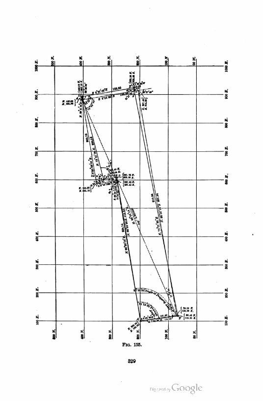
ti si>i 95
I M
|
1 i I §
1
M
fci*1t!*
|i
§
si
jr. 4ojsa 1 / r]*-
\ VsTi
M
j1. ""•{'.o!
•i
si
1f
\\\
\\\§
\\,
\
i
\
\ A \\
u M
g \*\ \
-|\»\ $
..to*-
\
\:
\\
\:
1
l1tn fas1.re1r.e>§
o.t»l/ 5
J 282. WW.15BT.42S.
\\
i
r. :
*\\*
Stti
«>...( J(
6)
K.!
» \\\v
m
*\
§
sis* 1M .1*5
$
M
Hi\ \ 1
M
n \
n \
\ \
S n I
M
n
\
1-55^ v_df
i
V
i
i\ ft3» \\ ( 70.33 N.
Jov 1118-M
^l^Sfe-^f ir.jr )118.ss a.
sit
§
fco •: sj
i 1i § I s S
Flo. 155.
820
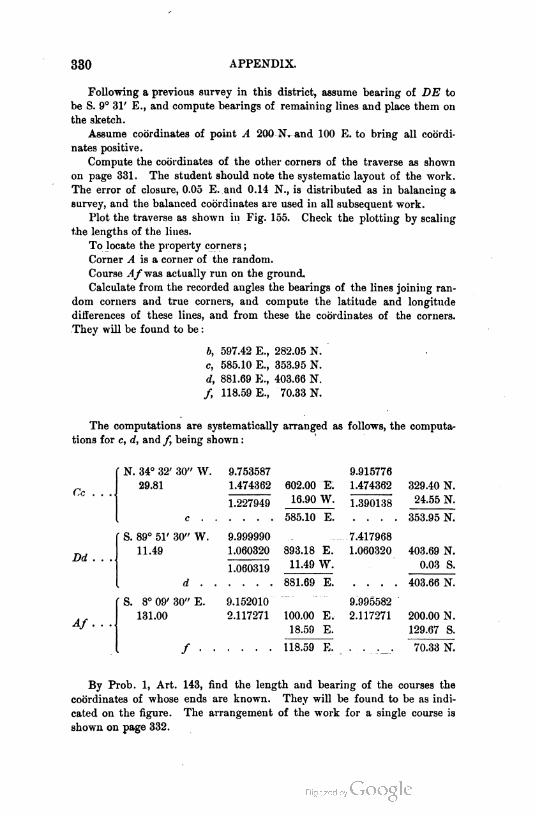
330 APPENDIX.
Following a previous survey in this district, assume bearing of DE to
be S. 9° 31' E., and compute bearings of remaining lines and place them on
the sketch.
Assume coordinates of point A 200 N. and 100 E. to bring all coordi
nates positive.
Compute the coordinates of the other corners of the traverse as shown
on page 331. The student should note the systematic layout of the work.
The error of closure, 0.05 E. and 0.14 N., is distributed as in balancing a
survey, and the balanced coordinates are used in all subsequent work.
Plot the traverse as shown in Fig. 155. Check the plotting by scaling
the lengths of the lines.
To locate the property corners ;
Corner A is a corner of the random.
Course Afwas actually run on the ground.
Calculate from the recorded angles the bearings of the lines joining ran
dom corners and true corners, and compute the latitude and longitude
differences of these lines, and from these the coordinates of the corners.
They will be found to be :
b, 597.42 E., 282.05 N.
c, 585.10 E., 353.95 N.
d, 881.69 E., 403.66 N.
/, 118.59 E., 70.33 N.
The computations are systematically arranged as follows, the computa
tions for c, d, and /, being shown :
Cc . . .
Dd . . .
Af ...
N. 34° 32' 30" W. 9.753587 9.915776
29.81 1.474362 602.00 E. 1.474362 329.40 N.
1.22794916.90 W.
1.39013824.55 N.
c .... 585.10 E. .... 353.95 N.
S. 89° 51' 30" W. 9.999990 7.417968
11.49 1.060320 893.18 E. 1.060320 403.69 N.
1.06031911.49 W. 0.03 S.
d - - . . . . 881.69 E. . . . . 403.66 N.
S. 8° 09' 30" E. 9.152010 9.995582
131.00 2.117271 100.00 E. 2.117271 200.00 N.
18.59 E. 129.67 S.
/. . . . 118.59 E. 70.33 N.
By Prob. 1, Art. 143, find the length and bearing of the courses the
coordinates of whose ends are known. They will be found to be as indi
cated on the figure. The arrangement of the work for a single course is
shown on page 332.
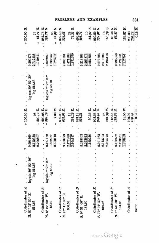
PROBLEMS AND EXAMPLES. 331
©©CN
+
ira Ki
X1-1 ti00 ~CM
+
bb os.Co.
m so. o ».CO ®.
OS Oi.-* CN Co,
CO 5C
+ +
OS >fc © ^ OS CO <S. CO5>1^ H®. "O®. ,_| <-».-* O,
CO ccO <S. co
CD CO.CO SB.
CO ao
Coco
OCO
©CN1—lr~
a oi
oCO
S s
§ «fCJ ^
be
oqQo
CO IS. 90
CO* ©5o o1ra co
os 50CO COT*H COT*t CN05 1-iOS 1>OS CN
bCO
oo >»a so.9 oGO *—*
boo
o r~co >raCN OSlO OI
05 2Sa> CO
os 1-1
boo
bX)O
+
- OSr~ rHC1 CO
-S .3OQ
boo
E COOS COrH COCO r~OS r~co -*
OS CN
W W W W
co © IN. CO cs. co M. CO ts.© q CS. 1—1 1H CS. co lO W&.
oi tfi co Ml d co e*iO <s. a e& CX CO Co Co.CO ts. CN co ce. as cs.
CS COOS -0Ol COCO r~COOS rjn
OS Co
CO CO us- CNeo CO CO
- >a© 1—t 1—1
CO 00 CO noas
CO co r~i~CO . Wco CO r~ > OS CO OS 1rj
1-1 CO o r~ CS a CN CNCN CN CN . °i OS rH as 1—1 rH
ai CN CN os oi oi OS CN oi
CO COCO r~CO CO00 CO^ COCN CN
01 oi
S <*. ICS
8 S
C5k
O IS.o srH W.
as i~CO
CS 1—(OS OS
os oi
Co "-1oo 1n•O CO-0 OSCO Co1-H r-"
os oi
to "CO ..
a m
CJ CO
C3
:oO
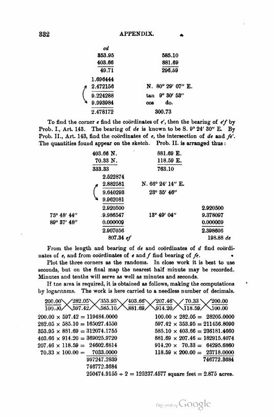
332 APPENDIX.
c
cd
353.95 585.10
403.66 881.69
49.71 296.59
1.696444
2.472156 N. 80° 29' 07"
9.224288 tan 9° 30' 53"
9.993984 cos do.
2.478172 300.73
To find the corner e find the coordinates of «', then the bearing of e'f by
Prob. I., Art. 143. The bearing of de is known to be S. 9° 24' 30" E. By
Prob. II., Art. 143, find the coordinates of e, the intersection of de and fe'.
The quantities found appear on the sketch. Prob. II. is arranged thus :
403.66 N.
70.33 N.
333.33
2.522874
2.882581
(
75° 48' 44"
89° 37' 48"
9.640293
9.962081
2.920500
9.986547
0.000009
2.907056
807.34 ef
881.69 E.
118.59 E.
763.10
N. 66° 24' 14" E.
23° 35' 46"
13° 49' 04"
2.920500
9.378097
0.000009
2.398606
198.88 de
From the length and bearing of de and coordinates of d find coordi
nates of e, and from coordinates of e and f find bearing of fe. •
Plot the three corners as the randoms. In close work it is best to use
seconds, but on the final map the nearest half minute may be recorded.
Minutes and tenths will serve as well as minutes and seconds.
If tne area is required, it is obtained as follows, making the computations
by logantnms. The work is here carried to a needless number of decimals.
200,00\ /282.05V /353.95\/403.66V/207.46\/ 70.33 \ /200 .00
i/^597.42/\585.10/\881.69/\914.20/\ll8.59/\:100.J0.
200.00
282.05
353.95
403.66
207.46
70.33
x 597.42
x 585.10 :
x 881.69 :
x 914.20 :
x 118.59 :
X 100.00 :
585.10/
: 119484.0000
: 165027.4550
: 312074.1755
: 369025.9720
: 24602.6814
7033.0000
997247.2839
746772.3684
250474.9155 0
100.00 x 282.05 :
597.42 x 353.95 :
585.10 x 403.66 :
881.69 x 207.46 :
914.20 x 70.33 :
118.59 x 200.00 :
100.00
: 28205.0000
= 211456.8090
: 236181.4660
: 182915.4074
: 64295.6860
: 23718.0000
746772.3684
2 = 125237.4577 square feet = 2.875 acres.
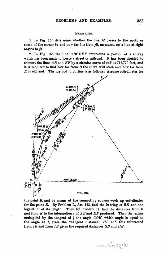
PROBLEMS AND EXAMPLES. 333
Examples.
1. In Fig. 155 determine whether the line fd passes to the north or
south of the corner b; and how far b is from fd, measured on a line at right
angles to fd.
2. In Fig. 156 the line ABCDEF represents a portion of a survey
which has been made to locate a street or railroad. It has been decided to
connect the lines AB and EF by a circular curve of radius 716.779 feet, and
it is required to find how far from B the curve will start and how far from
E it will end. The method in outline is as follows: Assume coordinates for
the point B, and by means of the connecting courses work up coordinates
for the point E. By Problem I., Art. 143, find the bearing of BE and the
logarithm of its length. Then by Problem II. find the distances from B
and from E to the intersection I of AB and EF produced. Then the radius
multiplied by the tangent of J the angle GOH, which angle is equal to
the angle at 7, gives the "tangent distance" HI, and this subtracted
from IB and from IE gives the required distances GB and HE.

334 APPENDIX.
3. Fig. 157 illustrates the location of two piers, B and C, for the
approach to a bridge. The piers were on a curve and were located by
the usual method of running railway curves, the necessary deflections and
M j.T distances being
5 00 00 ,i WOO 00"
shown in the fig
ure. As the
points B and C
would have to be
removed during
/i
the construction of the piers, it
became necessary to so " reference "
them that they could easily and
quickly be recovered at any time.
This was done by placing two or more
points on the radial lines through the
centers of the piers, since the intersec
tions of these lines with the lines AB
and AC would determine the points B
/, and C. If the ground had been solid, the
^ instrument c-uld have been set at B and at
>* C, and, by turning off the proper angles from
A, the radial lines BO and CO could easily have
been established. This, however, it was impos
sible to do, as the ground was so swampy as to
render the instrument too unsteady for good work.
The following method was therefore adopted :
Beginning at A, a random traverse Abcf was run
on firm ground, and the angles and distances were
measured as shown. The distances from b and from
c at which the radial lines BO and CO would intersect
this traverse were then calculated, points were set at e
and d, and the angles beB and cdC were measured to see
whether their actual and calculated values agreed. This
having been done, the instrument was set at e and at d,
and by backsighting on B and C and reversing, any num
ber of points could be established on the radial lines BO
and CO. The points B and C are thus referenced. The prob
lem for the student is therefore to calculate the distances be
and cd. It will be well to use the tangent AX as a meridian
and to make the coordinates of A 00 N and 00 E. (Problem II.,
Art. 143.)
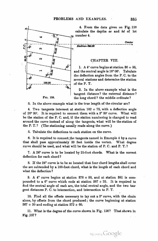
PROBLEMS AND EXAMPLES. 335
Fig. 158.
4. From the data given on Fig. 158
calculate the depths ac and bd of lot
number 4.
Center
Radius=ziT.O0 °
CHAPTER VIII.
1. A 4° curve begins at station 36 + 50,
and the central angle is 16° 00'. Tabulate
the deflection angles from the P. C. to the
several stations and determine the station
of the P. T.
2. In the above example what is the
tangent distance? the external distance?
the long chord ? the middle ordinate ?
3. In the above example what is the true length of the circular arc?
4. Two tangents intersect at station 182 + 75, with a deflection angle
of 26° 30'. It is required to connect them with a 3° 30' curve. What will
be the station of the P. C. and, if the station numbering is changed to read
around the curve instead of along the tangents, what will be the station of
the P. T. ? (The stationing usually reads along the curve.)
5. Tabulate the deflections to each station on the curve.
6. It is required to connect_the tangents named in Example 4 by a curve
that shall pass approximately 39 feet inside the vertex. What degree
curve should be used, and what will be the station of P. C. and P. T. ?
7. A 24° curve is to be located by 25-foot chords-
deflection for each chord ?
What is the correct
8. If the 24° curve is to be so located that four chord lengths shall cover
the arc subtended by a 100-foot chord, what is the length of each chord and
what the deflection ?
9. A 4° curve begins at station 376 + 50, and at station 381 is com
pounded to a 6° curve which ends at station 387 + 25. It is required to
find the central angle of each arc, the total central angle, and the two tan
gent distances P. C. to intersection, and intersection to P. T.
10. Find all the offsets necessary to lay out a 3° curve, with the chain
alone, by offsets from the chord produced ; the curve beginning at station
367 + 30 and ending at station 372 + 60.
11. What is the degree of the curve shown in Fig. 156? That shown in
Fig. 157?

336 APPEND'X.
CHAPTER IX.
1. By leveling, the elevations given in the following table were found at
the points indicated. The tract is in the form of a square six hundred feet
on a side and divided into one-hundred-foot squares. Draw the map to a
scale of 100 feet per inch, locating five-foot contours.
Station. Elevation. Station. Elevation.
A, 153.0 B„ 154.5
A, 155.5 B, 159.6
As 158.0 B, 163.7
A3 158.5 Bs 166.5
A, 156.4 B, 165.5
A4 152.8 B5 156.0
As 149.5 B6 155.5
C0 155.4 Do 155.3
c, 162.1 D0 + 80 160.5
C5 169.0 Di 160.0
c3 173.7 Ds 170.2
C3 + 50 175.5 Ds 180.1
c< 170.4 D3 + 50 192.2
C4 + 20 166.0 D4 178.5
C4+ 60 167.0 D5 168.7
c5 164.8 D6 161.5
159.4
E0 158.2 F„ 157.5
164.2 Fi 162.3
Ea 168.8 F2 165.5
E3 175.0 F2 + 50 166.0
E3 + 20 176.0 1 F3 165.5
Ej + 60 172.5 F3 + 50 164.0
E< 172.5 F4 164.9
E5 166.0 F5 163.1
- E6 161.5 F6 158.5
Go 154.5 G3 + 40 155.5
159.6 G4 159.0
Ga 161.0 G5 157.5
Gs 159.5 G6 155.0
0C+ 50 154.0 3*4-15 181.8
2fl + 40 167.5 4, + 75 170.8
3C + 80 182.0 4C + 10 170.0
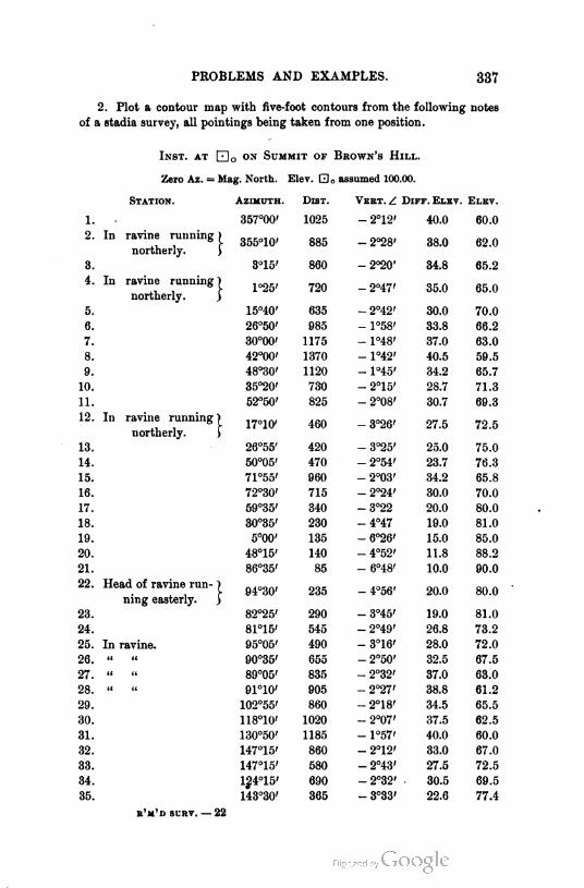
PROBLEMS AND EXAMPLES. 337
2. Plot a contour map with five-foot contours from the following notes
of a stadia survey, all pointings being taken from one position.
Inst, at Q]0 on Summit of Brown's Hill.
Zer- Az. = Mag. N-rth. Elev. Q0 assumed 100.00.
Station. Azimuth. Dist. Vert. Z Diff.Elev. Elev.
1. 357°00' 1025 - 2°12' 40.0 60.0
2. In ravine running )
northerly. J355°10' 885 -2°28' 38.0 62.0
3. 3°15' 860 - 2°20' 34.8 65.2
4. Id ravine running 1
northerly. >1°25' 720 - 2°47' 35.0 65.0
5. 15°40' 635 - 2°42' 30.0 70.0
6. 26°50' 985 - 1°58' 33.8 66.2
7. 30°00' 1175 - 1°48' 37.0 63.0
8. 42°00' 1370 - 1°42' 40.5 59.5
9. 48°30' 1120 - 1°45' 34.2 65.7
10. 35°20' 730 - 2°15' 28.7 71.3
11. 52°50' 825 - 2°08' 30.7 69.3
12. In ravine running >
northerly. f17°10' 460 - 3°26' 27.5 72.5
13. 26°55' 420 - 3°25' 25.0 75.0
14. 50°05' 470 - 2°54' 23.7 76.3
15. 71°55' 960 - 2°03' 34.2 65.8
16. 72°30' 715 - 2°24' 30.0 70.0
17. 59°35' 340 -3°22 20.0 80.0
18. 30°35' 230 -4°47 19.0 81.0
19. 5°00' 135 - 6°26' 15.0 85.0
20. 48°15' 140 - 4°52' 11.8 88.2
21. 86°35' 85 - 6°48' 10.0 90.0
22. Head of ravine run- }
ning easterly. j94°30' 235 - 4°56' 20.0 80.0
23. 82°25' 290 - 3°45' 19.0 81.0
24. 81°15' 545 - 2°49' 26.8 73.2
25. In ravine. 95°05' 490 - 3°16' 28.0 72.0
26. ci 90°35' 655 - 2°50' 32.5 67.5
27. u t' 89°05' 835 - 2°32' 37.0 63.0
28. u 91°10' 905 - 2°27' 38.8 61.2
29. 102°55' 860 - 2°18' 34.5 65.5
30. 118°10' 1020 - 2°07' 37.5 62.5
31. 130°50' 1185 - 1°57' 40.0 60.0
32. 147°15' 860 - 2°12' 33.0 67.0
33. 147°15' 580 - 2°43' 27.5 72.5
34. 124°15' 690 -2°32' 30.5 69.5
35. 143°30' 365 - 3°33' 22.6 77.4
b'm'd surv. — 22
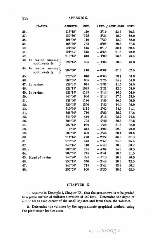
338 APPENDIX.
Station. Azimuth.
36. 118°45'
37. 130°30'
38. 194°00'
39. 168°50'
40. 191°55'
41. 191°5j'
42. 219°45'
43. In ravine running) 99q-1,,southwesterly. } zzy 10
44. In ravine running) 232Og0,
southwesterly. J
45. ' 223°25'
46. 203°35'
47. In ravine. 229°35'
48. 224°15'
49. In ravine. 229°15'
50. 343°00'
51. 33F00'
52. 320°05'
53. 315°30'
54. 326°30'
55. 343°20'
56. 300°05'
57. 287°15'
58. 2°30'
59. 300°30'
60. 274°45'
61. 276°55'
62. 340°45'
63. 285°30'
64. 262°55'
65. Head of ravine 240°20'
66. 253°45'
67. 243°00'
68. 255°55'
DiST. Vbet. z. Dut. Elev. Elev.
420 - 3°14' 23.7 76.3
125 - 5°33' 12.0 88.0
140 -7°30 18.0 82.0
755 - 2°28' 32.5 67.5
615 - 2°49' 30.4 69.6
815 - 3°58' 21.8 78.2
840 - 4°00' 23.6 76.4
425 - 4°05' 30.0 70.0
710 - 3°01' 37.5 62.5
640 - 3°00' 33.7 66.3
835 - 2°25' 35.2 64.8
945 - 2°31' 41.5 58.5
1025 - 2°21' 42.0 58.0
1185 - 2°13' 46.0 54.0
960 - 2°12' 37.0 63.0
1180 - 1°59' 40.5 59.5
1350 - 1°52' 44.0 56.0
1115 - 2°01' 38.9 61.1
780 - 2°22' 32.2 67.8
440 - 3°16' 25.2 74.8
795 — 2°20' 32.5 67.5
930 - 1°58' 31.8 68.2
315 - 4°01' 22.0 78.0
300 - 3°55' 20.4 79.6
770 - 2°27' 33.0 67.0
470 - 2°59' 24.5 75.5
140 - 5°43' 13.8 86.2
175 - 4°37' 14.0 86.0
275 - 3°51' 18.5 81.5
225 - 5°10' 20.0 80.0
570 - 2°W 28.0 72.0
715 - 2°42' 33.8 66.2
900 - 2°25' 38.0 62.0
CHAPTER X.
1. Assume in Example 1, Chapter IX., that the area shown is to be graded
to a plane surface of uniform elevation of 160 feet. Determine the depth of
cut or fill at each corner of the small squares and from these the volumes.
2. Determine the volumes by the approximate graphical method, using
the planimeter for the areas.
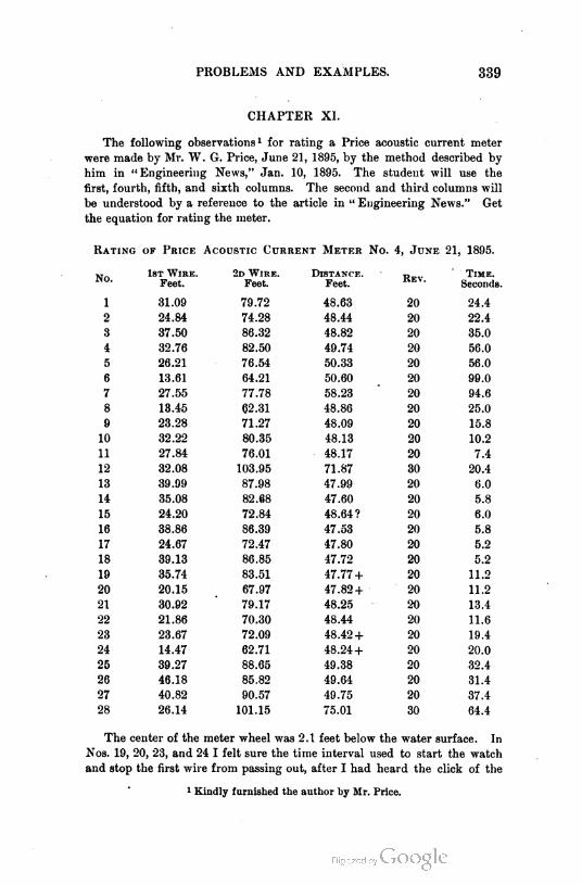
PROBLEMS AND EXAMPLES. 339
CHAPTER XI.
The following observations1 for rating a Price acoustic current meter
were made by Mr. W. G. Price, June 21, 1895, by the method described by
him in " Engineering News," Jan. 10, 1895. The student will use the
first, fourth, fifth, and sixth columns. The second and third columns will
be understood by a reference to the article in " Engineering News." Get
the equation for rating the meter.
Rating of Price Acoustic Current Meter No. 4, June 21, 1895.
No.1st Wire.
Feet.
2d Wire. Distance.Rev.
Time.
Feet. Feet. Sec-nds.
1 31.09 79.72 48.63 20 24.4
2 24.84 74.28 48.44 20 22.4
3 37.50 86.32 48.82 20 35.0
4 32.76 82.50 49.74 20 56.0
5 26.21 76.54 50.33 20 56.0
6 13.61 64.21 50.60 20 99.0
7 27.55 77.78 58.23 20 94.6
8 13.45 62.31 48.86 20 25.0
9 23.28 71.27 48.09 20 15.8
10 32.22 80.35 48.13 20 10.2
11 27.84 76.01 48.17 20 7.4
12 32.08 103.95 71.87 30 20.4
13 39.99 87.98 47.99 20 6.0
14 35.08 82.68 47.60 20 5.8
15 24.20 72.84 48.64? 20 6.0
16 38.86 86.39 47.53 20 5.8
17 24.67 72.47 47.80 20 5.2
18 39.13 86.85 47.72 20 5.2
19 35.74 83.51 47.77 + 20 11.2
20 20.15 67.97 47.82 + 20 11.2
21 30.92 79.17 48.25 20 13.4
22 21.86 70.30 48.44 20 11.6
23 23.67 72.09 48.42 + 20 19.4
24 14.47 62.71 48.24 + 20 20.0
25 39.27 88.65 49.38 20 32.4
26 46.18 85.82 49.64 20 31.4
27 40.82 90.57 49.75 20 37.4
28 26.14 101.15 75.01 30 64.4
The center of the meter wheel was 2.1 feet below the water surface. In
Nos. 19, 20, 23, and 24 I felt sure the time interval used to start the watch
and stop the first wire from passing out, after I had heard the click of the
1 Kindly furnished the auth-r by Mr. Price.
340 APPENDIX.
meter, was longer than the time consumed for the same purpose at the end
of the run. I therefore put a + mark to indicate that the distance was too
small. No. 15 was doubtful, as the skiff rocked during the trip. The six
columns are an exact copy of the field notes.
CHAPTER XII.
1. From the following data of the survey of a tunnel and shaft for a
connection, determine the azimuth, length, and grade of the connecting
drift. First draw a map of the survey and indicate the connecting drift.
From a monument at the mouth of the tunnel run in the tunnel, azimuth
36° 30', 436 feet, vert. Z + 1° 00' ; thence azimuth 52° 10', 200 feet, vert. Z
+ 1° 10', to point near breast of tunnel.
From the monument at the mouth of the tunnel run on the surface,
azimuth 86° 30', 232 feet, vert. Z - 3° 30' ; thence azimuth 40° 20', 636 feet,
vert. + 13° 50', to center of shaft 110 feet deep.
2. The strike of a vein of ore observed on the point of an outcrop is
N. 36° W. or S. 36° E. The dip of the vein is found to be 13° from the
vertical and to the northeast (right angle to the strike). From a point
which bears from the before-mentioned point of outcrop N. 36° E. 300 feet,
vert. Z — 15° a cross-cut tunnel is to be driven level and in a direction
S. 55° W. How long must it be to reach the vein ? What will be the
difference if the tunnel is run on a one-per-cent grade ?
3. If, in the above example, the tunnel is to run S. 60° W., how long
must it be ?
4. How long must it be, if the dip is to the southwest, the tunnel being
run S. 54° W. ?
5. How long must it be, if the dip is to the southwest and the tunnel is
.run S. 50° W.?
6. In Example 4 what would be the azimuth, grade, and length of the
shortest tunnel that could be run to reach the vein ?
THE JUDICIAL FUNCTIONS OF SURVEYORS. 341
II. THE JUDICIAL FUNCTIONS OF SURVEYORS.1
By Just1ce Cooley op the M1ch1gan Supreme Court.
When a man has had a training in one of the exact sciences, where
every problem within its purview is supposed to be susceptible of accurate
solution, he is likely to be not a little impatient when he is told that, under
some circumstances, he must recognize inaccuracies, and govern his action
by facts which lead him away from the results which theoretically he ought
to reach. Observation warrants us in saying that this remark may frequently
be made of surveyors.
In the state of Michigan all our lands are supposed to have been sur
veyed once or more, and permanent monuments fixed to determine the
boundaries of those who should become proprietors. The United States, as
original owner, caused them all to be surveyed once by sworn officers, and
as the plan of subdivision was simple, and was uniform over a large extent
of territory, there should have been, with due care, few or no mistakes; and
long rows of monuments should have been perfect guides to the place of any
one that chanced to be missing. The truth unfortunately is that the lines
were very carelessly run, the monuments inaccurately placed ; and, as the
recorded witnesses to these were many times wanting in permanency, it is
often the case that when the monument was not correctly placed it is im
possible to determine by the record, with the aid of anything on the ground,
where it was located. The incorrect record of course becomes worse than
useless when the witnesses it refers to have disappeared.
It is, perhaps, generally supposed that our town plots were more accu
rately surveyed, as indeed they should have been, for in general there can
have been no difficulty in making them sufficiently perfect for all practical
purposes. Many of them, however, were laid out in the woods ; some of
them by proprietors themselves, without either chain or compass, and some
by imperfectly trained surveyors, who, when land was cheap, did not appre
ciate the importance of having correct lines to determine boundaries when
land should become dear. The fact probably is that town surveys are quite
as inaccurate as those made under authority of the general government.
It is now upwards of fifty years since a major part of the public surveys
in what is now the state of Michigan were made under authority of the
United States. Of the lands south of Lansing, it is now forty years since
the major part were sold and the work of improvement begun. A genera
tion has passed away since they were converted into cultivated farms, and
few, if any, of the original corner and quarter stakes now remain.
The corner and quarter stakes were often nothing but green sticks driven
into the ground. Stones might be put around or over these if they were
handy, but often they were not, and the witness trees must be relied upon
after the stake was gone. Too often the first settlers were careless in fixing
1 A paper prepared for the Michigan Society of Surveyors and Engineers.
342 APPENDIX.
their lines with accuracy while monuments remained, and an irregular
brush fence, or something equally untrustworthy, may have been relied
upon to keep in mind where the blazed line once was. A fire running
through this might sweep it away, and if nothing were substituted in its
place, the adjoining proprietors might in a few years be found disputing
over their lines, and perhaps rushing into litigation, as soon as they had
occasion to cultivate the land along the boundary.
If now the disputing parties call in a surveyor, it is not likely that any
one summoned would doubt or question that his duty was to find, if pos
sible, the place of the original stakes which determined the boundary line
between the proprietors. However erroneous may have been the original
survey, the monuments that were set must nevertheless govern, even though
the effect be to make one half-quarter section ninety acres and the one
adjoining but seventy; for parties buy or are supposed to buy in reference
to those monuments, and are entitled to what is within their lines, and no
more, be it more or less. Mcloer v. Walker, 4 Wheaton's Reports, 444 ;
Land Co. v. Saunders, 103 U. S. Reports, 316; Cottingham v. Parr, 93 111.
Reports, 233; Bunton v. Cardwell, 53 Texas Reports, 408; Watson v. Jones,
85 Penn. Reports, 117.
While the witness trees remain there can generally be no difficulty in
determining the locality of the stakes. When the witness trees are gone,
so that there is no longer record evidence of the monuments, it is remark
able how many there are who mistake altogether the duty that now devolves
upon the surveyor. It is by no means uncommon that we find men whose
theoretical education is supposed to make them experts, who think that
when the monuments are gone the only thing to be done is to place new
monuments where the old ones should have been, and where they would
have been if placed correctly. This is a serious mistake. The problem is
now the same that it was before, — to ascertain, by the best lights of which the
case admits, where the original lines were. The mistake above alluded to is
supposed to have found expression in our legislation ; though it is possible
that the real intent of the act to which we shall refer is not what is com
monly supposed.
An act passed in 1869, Compiled Laws, § 593, amending the laws respect
ing the duties and powers of county surveyors, after providing for the case
of corners which can be identified by the original field notes or other un
questionable testimony, directs as follows :
" Second. Extinct interior section-corners must be reestablished at the
intersection of two right lines joining the nearest known points on the
original section lines east and west and north and south of it.
" Third. Any extinct quarter-section corner, except on fractional lines,
must be reestablished equidistant and in a right line between the section
corners ; in all other cases at its proportionate distance between the nearest
original corners on the same line."
The corners thus determined, the surveyors are required to perpetuate
by noting bearing trees when timber is near.
THE JUDICIAL FUNCTIONS OF SURVEYORS. 343
To estimate properly this legislation, we must start with the admitted
and unquestionable fact that each purchaser from government bought such
land as was within the original boundaries, and unquestionably owned it up
to the time when the monuments became extinct. If the monument was
set for an interior-section corner, but did not happen to be " at the intersec
tion of two right lines joining the nearest known points on the original
section lines east and west and north and south of it," it nevertheless deter
mined the extent of his possessions, and he gained or lost according as the
mistake did or did not favor him.
It will probably be admitted that no man loses title to his land or any
part thereof merely because the evidences become lost or uncertain. It may
become more difficult for him to establish it as against an adverse claimant,
but theoretically the right remains ; and it remains as a potential fact so
long as he can present better evidence than any other person. And it may
often happen that, notwithstanding the loss of all trace of a section corner
or quarter stake, there will still be evidence from which any surveyor will be
able to determine with almost absolute certainty where the original boundary
was between the government subdivisions.
There are two senses in which the word " extinct " may be used in this
connection : one the sense of physical disappearance ; the other the sense of
loss of all reliable evidence. If the statute speaks of extinct corners in the
former sense, it is plain that a serious mistake was made in supposing that
surveyors could be clothed with authority to establish new corners by an
arbitrary rule in such cases. As well might the statute declare that if a
man lose his deed he shall lose his land altogether.
But if by extinct corner is meant one in respect to the actual location
of which all reliable evidence is lost, then the following remarks are
pertinent :
(1) There would undoubtedly be a presumption in such a case that the
corner was correctly fixed by the government surveyor where the field notes
indicated it to be.
(2) But this is only a presumption, and may be overcome by any satis
factory evidence showing that in fact it was placed elsewhere.
(3) No statute can confer upon a county surveyor the power to "estab
lish " corners, and thereby bind the parties concerned. Nor is this a ques
tion merely of conflict between state and federal law ; it is a question of
property right. The original surveys must govern, and the laws under
which they were made must govern, because the land was bought in refer
ence to them ; and any legislation, whether state or federal, that should
have the effect to change these, would be inoperative, because disturbing
vested rights.
(4) In any case of disputed lines, unless the parties concerned settle the
controversy by agreement, the determination of it is necessarily a judicial
act, and it must proceed upon evidence, and give full opportunity for a hear
ing. No arbitrary rules of survey or of evidence can be laid down whereby
it can be adjudged.
344 APPENDIX.
The general duty of a surveyor in such a case is plain enough. He is
not to assume that a monument is lost until after he has thoroughly sifted
the evidence and found himself unable to trace it. Even then he should
hesitate long before doing anything to the disturbance of settled possessions.
Occupation, especially if long continued, often affords very satisfactory evi
dence of the original boundary when no other is attainable ; and the sur
veyor should inquire when it originated, how, and why the lines-were then
located as they were, and whether a claim of title has always accompanied
the possession, and give all the facts due force as evidence. Unfortunately,
it is known that surveyors sometimes, in supposed obedience to the state
statute, disregard all evidences of occupation and claim of title, and
plunge whole neighborhoods into quarrels and litigation by assuming to
" establish " corners at points with which the previous occupation can not
harmonize. It is often the case that where one or more corners are found
to be extinct, all parties concerned have acquiesced in lines which were
traced by the guidance of some other corner or landmark, which may or
may not have been trustworthy ; but to bring these lines into discredit when
the people concerned do not question them not only breeds trouble in the
neighborhood, but it must often subject the surveyor himself to annoyance
and perhaps discredit, since in a legal controversy the law as well as com
mon sense must declare that a supposed boundary line long acquiesced in is
better evidence of where the real line should be than any survey made after
the original monuments have disappeared. Stewart v. Carlelon, 31 Mich.
Reports, 270 ; Diehl v. Zanger, 39 Mich. Reports, 601 ; Dupont v. Starring,
42 Mich. Reports, 492. And county surveyors, no more than any others, can
conclude parties by their surveys.
The mischiefs of overlooking the facts of possession must often appear
in cities and villages. In towns the block and lot stakes soon disappear ;
there are no witness trees and no monuments to govern except such as have
been put in their places, or where their places were supposed to be. The
streets are likely to be soon marked off by fences, and the lots in a block
will be measured off from these, without looking farther. Now it may per
haps be known in a particular case that a certain monument still remaining
was the starting point in the original survey of the town plot ; or a surveyor
settling in the town may take some central point as the point of departure
in his surveys, and assuming the original plot to be accurate, he will then
undertake to find all streets and all lots by course and distance according
to the plot, measuring and estimating from his point of departure. This
procedure might unsettle every line and every monument existing by acqui
escence in the town ; it would be very likely to change the lines of streets,
and raise controversies everywhere. Yet this is what is sometimes done ;
the surveyor himself being the first person to raise the disturbing questions.
Suppose, for example, a particular village street has been located by
acquiescence and use for many years, and the proprietors in a certain block
have laid off their lots in reference to this practical location. Two lot
owners quarrel, and one of them calls in a surveyor that he may be sure

THE JUDICIAL FUNCTIONS OF SURVEYORS. 345
that his neighbor shall not get an inch of land from him. This surveyor
undertakes to make his survey accurate, whether the original was, or not,
and the first result is, he notifies the lot owners that there is error in the
street line, and that all fences should be moved, say, one foot to the east.
Perhaps he goes on to drive stakes through the block according to this con
clusion. Of course, if he is right in doing this, all lines in the village will
be unsettled ; but we will limit our attention to the single block. It is not
likely that the lot owners generally will allow the new survey to unsettle
their possessions, but there is always a probability of finding some one dis
posed to do so. We shall then have a lawsuit; and with what result?
It is a common error that lines do not become fixed by acquiescence
in a less time than twenty years. In fact, by statute, road lines may be
come conclusively fixed in ten years ; and there is no particular time that
shall be required to conclude private owners, where it appears that they
have accepted a particular line as their boundary, and all concerned have
cultivated and claimed up to it. McNamara v. Seaton, 82 111. Reports, 498 ;
Bunce v. Bidwell, 43 Mich. Reports, 542. Public policy requires that such
lines be not lightly disturbed, or disturbed at all after the lapse of any con
siderable time. The litigant, therefore, who in such a case pins his faith on
the surveyor, is likely to suffer for his reliance, and the surveyor himself to
be mortified by a result that seems to impeach his judgment.
Of course nothing in what has been said can require a surveyor to
conceal his own judgment, or to report the facts one way when he believes
them to be another. He has no right to mislead, and he may rightfully
express his opinion that an original monument was at one place, when at
the same time he is satisfied that acquiescence has fixed the rights of parties
as if it were at another. But he would do mischief if he were to attempt
to "establish" monuments which he knew would tend to disturb settled
rights ; the farthest he has a right to go, as an officer of the law, is to ex
press his opinion where the monument should be, at the same time that he
imparts the information to those who employ him, and who might otherwise
be misled, that the same authority that makes him an officer and entrusts
him to make surveys, also allows parties to settle their own boundary lines,
and considers acquiescence in a particular line or monument, for any con
siderable period, as strong, if not conclusive, evidence of such settlement.
The peace of the community absolutely requires this rule. Joyce v. Williams,
.26 Mich. Reports, 332. It is not long since that, in one of the leading cities
of the state, an attempt was made to move houses two or three rods into
a street, on the ground that a survey under which the street had been lo
cated for many years had been found on more recent survey to be erroneous.
From the foregoing it will appear that the duty of the surveyor where
boundaries are in dispute must be varied by the circumstances. (1) He
is to search for original monuments, or for the places where they were
originally located, and allow these to control if he finds them, unless he has
reason to believe that agreements of the parties, express or implied, have
rendered them unimportant. By monuments in the case of government sur
346 APPENDIX.
veys, we mean, of course, the corner and quarter stakes : blazed lines or
marked trees on the lines are not monuments; they are merely guides or
finger posts, if we may use the expression, to inform us with more or less
accuracy where the monuments may be found. (2) If the original mon
uments are no longer discoverable, the question of location becomes one of
evidence merely. It is merely idle for any state statute to direct a surveyor
to locate or "establish" a corner, as the place of the original monument,
according to some inflexible rule. The surveyor, on the other hand, must
inquire into all the facts; giving due prominence to the acts of parties con
cerned, and always keeping in mind, first, that neither his opinion nor his
survey can be conclusive upon parties concerned; second, that courts and
juries may be required to follow after the surveyor over the same ground,
and that it is exceedingly desirable that he govern his action by the same
lights and rules that will govern theirs. On town plots if a surplus or defi
ciency appears in a block, when the actual boundaries are compared with
the original figures, and there is no evidence to fix the exact location of
the stakes which marked the division into lots, the rule of common sense
and of law is that the surplus or deficiency is to be apportioned between the
lots, on an assumption that the error extended alike to all parts of the
block. O'Brien v. McGrane, 29 Wis. Reports, 446 ; Quinnin v. Reixers, 46
Mich. Reports, 605.
It is always possible when corners are extinct that the surveyor may
usefully act as a mediator between parties, and assist in preventing legal
controversies by settling doubtful lines. Unless he is made for this purpose
an arbitrator by legal submission, the parties, of course, even if they consent
to follow his judgment, can not, on the basis of mere consent, be compelled
to do so; but if he brings about an agreement, and they carry it into effect
by actually conforming their occupation to his lines, the action will conclude
them. Of course it is desirable that all such agreements be reduced to
writing; but this is not absolutely indispensable if they are carried into
effect without.
Meander Lines. — The subject to which allusion will now be made is
taken up with some reluctance, because it is believed the general rules are
familiar. Nevertheless it is often found that surveyors misapprehend them,
or err in their application; and as other interesting topics are somewhat
connected with this, a little time devoted to it will probably not be altogether
lost. The subject is that of meander lines. These are lines traced along
the shores of lakes, ponds, and considerable rivers as the measures of
quantity when sections are made fractional by such waters. These have
determined the price to be paid when government lands were bought, and
perhaps the impression still lingers in some minds that the meander lines
are boundary lines, and all in front of them remains unsold. Of course this
is erroneous. There was never any doubt that, except on the large navi
gable rivers, the boundary of the owners of the banks is the middle line of
the river; and while some courts have held that this was the rule on all
fresh-water streams, large aud small, others have held to the doctrine that

THE JUDICIAL FUNCTIONS OF SURVEYORS. 347
the title to the bed of the stream below low-water mark is in the state,
while conceding to the owners of the banks all riparian rights. The prac
tical difference is not very important. In this state the rule that the center
line is the boundary line is applied to all our great rivers, including the
Detroit, varied somewhat by the circumstance of there being a distinct
channel for navigation in some cases with the stream in the main shallow,
and also sometimes by the existence of islands.
The troublesome questions for surveyors present themselves when the
boundary line between two contiguous estates is to be continued from the
meander line to the center line of the river. Of course the original survey
supposes that each purchaser of land on the stream has a water front of the
length shown by the field notes ; and it is presumable that he bought this
particular land because of that fact. In many cases it now happens that
the meander line is left some distance from the shore by the gradual change
of course of the stream or diminution of the flow of water. Now the divid
ing line between two government subdivisions might strike the meander
line at right angles, or obliquely ; and in some cases, if it were continued in
the same direction to the center line of the river, might cut off from the
water one of the subdivisions entirely, or at least cut it off from any privi
lege of navigation, or other valuable use of the water, while the other might
have a water front much greater than the length of a line crossing it at
right angles to its side lines. The effect might be that, of two government
subdivisions of equal size and cost, one would be of very great value as
water front property, and the other comparatively valueless. A rule which
would produce this result would not be just, and it has not been recognized
in the law.
Nevertheless it is not easy to determine what ought to be the correct
rule for every case. If the river has a straight course, or one nearly so,
every man's equities will be preserved by this rule : Extend the line of divi
sion between the two parcels from the meander line to the center line of
the river, as nearly as possible at right angles to the general course of the
river at that point. This will preserve to each man the water front which
the field notes indicated, except as changes in the water may have affected
it, and the only inconvenience will be that the division line between differ
ent subdivisions is likely to be more or less deflected where it strikes the
meander line.
This is the legal rule, and it is not limited to government surveys, but
applies as well to water lots which appear as such on town plots. Bay City
Gas Light Co. v. The Industrial Works, 28 Mich. Reports, 182. It often
happens, therefore, that the lines of city lots bounded on navigable streams
are deflected as they strike the bank, or the line where the bank was when
the town was first laid out.
When the stream is very crooked, and especially if there are short
bends, so that the foregoing rule is incapable of strict application, it is
sometimes very difficult to determine what shall be done ; and in many
cases the surveyor may be under the necessity of working out a rule for

348 APPENDIX.
himself. Of course his action can not be conclusive; but if he adopts one
that follows, as nearly as the circumstances will admit, the general rule
above indicated, so as to divide, as near as may be, the bed of the stream
among the adjoining owners in proportion to their lines upon the shore, his
division, being that of an expert, made upon the ground and with all avail
able lights, is likely to be adopted as law for the case. Judicial decisions,
into which the surveyor would find it prudent to look under such circum
stances, will throw light upon his duties and may constitute a sufficient guide
when peculiar cases arise. Each riparian lot owner ought to have a line on
the legal boundary, namely, the center line of the stream, proportioned to
the length of his line on the shore ; and the problem in each case is, how
this is to be given him. Alluvion, when a river imperceptibly changes its
course, will be apportioned by the same rules.
The existence of islands in a stream, when the middle line constitutes
a boundary, will not affect the apportionment unless the islands were sur
veyed out as government subdivisions in the original admeasurement.
Wherever that was the case, the purchaser of the island divides the bed of
the stream on each side with the owner of the bank, and his rights also
extend above and below the solid ground, and are limited by the peculiari
ties of the bed and the channel. If an island was not surveyed as a govern
ment subdivision previous to the sale of the bank, it is of course impossible
to do this for the purposes of governmental sale afterwards, for the reason
that the rights of the bank owners are fixed by their purchase : when mak
ing that, they have a right to understand that all land between the meander
lines, not separately surveyed and sold, will pass with the shore in the gov
ernment sale ; and having this right, anything which their purchase would
include under it can not afterward be taken from them. It is believed, how
ever, that the federal courts would not recognize the applicability of this
rule to large navigable rivers, such as those uniting the Great Lakes.
On all the little lakes of the state which are mere expansions near their
mouths of the rivers passing through them— such as the Muskegon, Pere
Marquette, and Manistee — the same rule of bed ownership has been judi
cially applied that is applied to the rivers themselves ; and the division lines
are extended under the water in the same way. Rice v. Ruddiman, 10
Mich. 125. If such a lake were circular, the lines would converge to the
center ; if oblong or irregular, there might be a line in the middle on which
they would terminate, whose course would bear some relation to that of the
shore. But it can seldom be important to follow the division line very far
under the water, since all private rights are subject to the public rights of
navigation and other use, and any private use of the lands inconsistent with
these would be a nuisance, and punishable as such. It is sometimes im
portant, however, to run the lines out for some considerable distance, in
order to determine where one may lawfully moor vessels or rafts, for the
winter, or cut ice. The ice crop that forms over a man's land of course
belongs to him. Lorman v. Benson, 8 Mich. 18 ; People's Ice Co. v. Steamer
Excelsior, recently decided.

THE JUDICIAL FUNCTIONS OF SURVEYORS. 349
What is said above will show how unfounded is the notion, which is
sometimes advanced, that a riparian proprietor on a meandered river may
lawfully raise the water in the stream without liability to the proprietors
above, provided he does not raise it so that it overflows the meander line.
The real fact is that the meander line has nothing to do with such a case,
and an action will lie whenever he sets back the water upon the proprietor
above, whether the overflow be below the meander lines or above them.
As regards the lakes and ponds of the state, one may easily raise ques
tions that it would be impossible for him to settle. Let us suggest a few
questions, some of which are easily answered, and some not :
(1) To whom belongs the land under these bodies of water, where they
are not mere expansions of a stream flowing through them ?
(2) What public rights exist in them V
(3) If there are islands in them which were not surveyed out and sold by
the United States, can this be done now ?
Others will be suggested by the answers given to these.
It seems obvious that the rules of private ownership which are applied to
rivers can not be applied to the Great Lakes. Perhaps it should be held that
the boundary is at low-water mark, but improvements beyond this would
only become unlawful when they became nuisances. Islands in the Great
Lakes would belong to the United States until sold, and might be surveyed
and measured for sale at any time. The right to take fish in the lakes, or
to cut ice, is public like the right of navigation, but is to be exercised in such
manner as not to interfere with the rights of shore owners. But so far as
these public rights can be the subject of ownership, they belong to the state,
not to the United States ; and, so it is believed, does the bed of a lake also.
Pollard v. Hagan, 3 Howard's U. S. Reports. But such rights are not gener
ally considered proper subjects of sale, but, like the right to make use of the
public highways, they are held by the state in trust for all the people.
What is said of the large lakes may perhaps be said also of many of the
interior lakes of the state ; such, for example, as Houghton, Higgins, Che
boygan, Burt's, Mullet, Whitmore, and many others. But there are many
little lakes or ponds which are gradually disappearing, and the shore pro
prietorship advances pari passu as the waters recede. If these are of any
considerable size — say, even a mile across — there may be questions of con
flicting rights which no adjudication hitherto made could settle. Let any
surveyor, for example, take the case of a pond of irregular form, occupying
a mile square or more of territory, and undertake to determine the rights
of the shore proprietors to its bed when it shall totally disappear, and he
will find he is in the midst of problems such as probably he has never
grappled with, or reflected upon before. But the general rules for the exten
sion of shore lines, which have already been laid down, should govern such
cases, or at least should serve as guides in their settlement.1
1 Since this address was delivered, some of these questions have received the
attention of the Supreme Court of Michigan in the cases of Richardson v. Prentiss,
48 Mich. Reports, 88, and Backus v. Detroit, Albany Law Journal, vol. 26, p. 428.
350 APPENDIX.
Where a pond is so small as to be included within the lines of a private
purchase from the government, it is not believed the public have any rights
in it whatever. Where it is not so included, it is believed they have rights
of fishery, rights to take ice and water, and rights of navigation for business
or pleasure. This is the common belief, and probably the just one. Shore
rights must not be so exercised as to disturb these, and the states may pass
all proper laws for their protection . It would be easy with suitable legislation
to preserve these little bodies of water as permanent places of resort for the
pleasure and recreation of the people, and there ought to be such legislation.
If the state should be recognized as owner of the beds of these small
lakes and ponds, it would not be owner for the purpose of selling. It would
be owner only as a trustee for the public use ; and a sale would be incon
sistent with the right of the bank owners to make use of the water in its
natural condition in connection with their estates. Some of them might be
made salable lands by draining ; but the state could not drain, even for this
purpose, against the will of the shore owners, unless their rights were appro
priated and paid for.
Upon many questions that might arise between the state as owner of the
bed of a little lake and the shore owners, it would be presumptuous to
express an opinion now, and fortunately the occasion does not require it.
I have thus indicated a few of the questions with which surveyors may
now and then have occasion to deal, and to which they should bring good
sense and sound judgment. Surveyors are not and can not be judicial offi
cers, but in a great many cases they act in a quasi judicial capacity with the
acquiescence of parties concerned ; and it is important for them to know by
what rules they are to be guided in the discharge of their judicial functions.
What I have said can not contribute much to their enlightenment, but I
trust will not be wholly without value.
THE OWNERSHIP OF SURVEYS, ETC. 351
III. THE OWNERSHIP OF SURVEYS, AND WHAT CONSTITUTES
A SURVEY AND MAP.1
There seems to be a difference of opinion among surveyors as to how
much of the information obtained, and how much of the work done in mak
ing a survey shall be furnished to the individual for whom the survey is
made. Many surveyors keep what are called "private notes." All men
doing business as surveyors keep notes of all surveys in a convenient form
for ready reference. The extent to which these notes are private has not
been rightly comprehended by all surveyors, and hence has resulted the
difference of opinion mentioned.
This article is an attempt to present a side of this question that has not
heretofore been fully considered. An endeavor has also been made to point
out to the young surveyor a line of action expedient for him to follow, which
will at the same time be found advantageous to the community in which he
works.
In this discussion the question arises at once, " What constitutes a sur
vey?" and the answer obviously depends on the object of the survey. This
discussion will be confined to land surveys ; that is, to surveys made for the
purpose (1) of subdividing a large tract of land into smaller parcels to be
sold ; (2) of determining the boundary of a tract the description of which is
known ; (3) of determining the description when the boundaries are known.
The principle to be enunciated applies to any other survey as well, be it
railroad, canal, bridge, or topographical survey. Indeed, it is well under
stood in all such surveys, but seems to be ignored by many engineers having
to do with land surveys.
A survey is the operation of finding the contour, dimensions, position,
or other particulars of any part of the earth's surface, . . . tract of land,
etc., and representing the same on paper.
In making a survey it is necessary to set certain points, called monu
ments or corners, and to determine a description of these points. These
items therefore become a part of the survey. Then a map must be drawn.
This map, to be a faithful representation of the ground and the work done,
should, together with the notes, show all of the items mentioned.
The object of establishing monuments or corners and describing them
is twofold : (1) to mark on the ground the boundaries of the tract, and
(2) to secure definite information as to its location with reference to other
points or tracts, so that from this information the land may at a future
time be found. For a complete survey, therefore, the corners must be fixed,
information that will preserve their location must be obtained, and the facts
must be delineated on a map with accompanying notes.
To whom belongs this survey? It would appear to be evident that it
belongs to the individual who pays to have it made. It is not readily seen in
1 A paper prepared by the author for " The Polytechnic," the student journal of
the Rensselaer Polytechnic Institute, from which it is taken.

352 APPENDIX.
what way the survey, or any part of it, becomes the sole property of the sur
veyor. He may keep a copy of his notes to facilitate his future work ; but he
has not the shadow of a claim to a single note, the time for taking which
has been paid for by his employer. If his charge for his work is on a time
basis, there can be no question as to the correctness of the above statements.
If he contracts to do the work for a definite sum for the entire job, he may
take as much time as he likes, and may keep as many private notes as he
desires ; but he is bound in honor to return to his employer the complete
survey; and, if he does so, the private notes would thereafter be of no
great assistance to him in securing further employment, particularly when
it is remembered that men of repute do not bid against each other for
professional work. His reputation for accuracy and honesty will be a far
more potent factor in securing employment than any set of private notes
fairly obtained.
It is true that a great many surveyors hold a different opinion, and
purposely return their maps and notes in such condition, that, while they
may serve the purpose for which they are primarily made, they do not tell
the whole story, nor enough to make it easy for another surveyor to relocate
the tract surveyed. When this is done, the person ordering the survey does
not receive what he pays for. Something is withheld. It seems to need no
argument to show that this is radically wrong.
But there is another reason for condemning this practice. The correct
and permanent location of all public land lines, as streets, alleys, etc., as
well as the permanent location of party lines between private owners, is a
matter of the gravest importance, and no information that will at all serve
to fix such lines in their correct positions for all time, should be withheld
from the owner who pays for the survey, be it private citizen, municipality,
county, or state.
The records of monuments and street lines made by a city engineer are
no more his private property than are the records in the offices of the clerk,
auditor, or treasurer, the property of the individuals who held office at the
time the records were made. The correctness of the position assumed has
been indicated by court decisions.
A great deal of laxity is shown in the conduct of offices of city engineers
and county surveyors. The methods of regulating the pay of these officers
has doubtless had much to do with this. It is frequently the case that
the surveyor receives no salary, but is allowed to collect certain specified
fees for work performed, and this gives color to his claim that his work
is private and belongs to him. That this is not true concerning the public
work he does is evident from what has preceded. That the records of work
done for private citizens are not the property of the public needs no demon
stration; but such work belongs to those citizens for whom it was done.
A different policy should be pursued with regard to these offices. In
every case such an office should be a salaried one, with such salaried assistants
as may be necessary. Certain fees should be prescribed for performing the
various kinds of work that the surveyor may be called upon to do within the
THE OWNERSHIP OF SURVEYS, ETC. 353
limits of the territory of the political division whose servant he is. These
fees should cover all work connected with public construction and public or
private land lines, and should be returned to the public treasury.
Their amount may be regulated, from time to time, so that they shall
aggregate a sum sufficient to pay the expenses of the office. They should, of
course, not cover work of a private character not having to do with land
lines. But the entire public is interested in the permanency of land lines,
and all records concerning them made by a public official should become
public property. The permanency of land lines is too important a matter
to be subject to avaricious and jealous rivalry; and all the surveyors in a
given district should cooperate to preserve, in their correct places, all lines
within the district.
To this end, the returns of every surveyor made to the owner should be
thoroughly complete. Maps made for filing as public records should be so
finished as to enable any surveyor to relocate the land without the least
uncertainty as to the correctness of his work. That this is done in very
few instances is well known to every surveyor who has had occasion to
examine public records for data for surveys which he has been called upon
to make.
Because of the fact that in most cases neither owners nor attorneys
have been fully posted as to what constitutes a complete description, suffi
cient for relocation, and because surveyors have been willing to let matters
stand as they were, great carelessness has arisen in the practice of making
and filing maps for record.
While in some states good laws exist prescribing what shall appear on
a map before it will be received as a public record, in more states there is
nothing whatever to guide either owner, surveyor, attorney, or recorder
in the matter. In the county records in such states, anything that is made
up of lines and figures and labeled " this is a map," is considered a sufficient
basis for a correct description and location of the property it purports to
represent— no matter whether it is drawn by hand, photo-lithographed, or
simply printed with "rule" and type. The records are full of auctioneers'
circulars, manufactured in a printing office from information coming from
nobody knows where, filed at the request of the auctioneer's clerk, with no
name of owner or other interested party attached, except as the name of the
auctioneer appears in the accompanying advertisement. Further than this,
these maps are frequently purposely distorted to create a favorable impres
sion of the property to be sold. Wide streets are shown where only narrow
ones exist, streets appear opened for the full width where they have been
opened for but half their width, subdivisions are indicated as rectangles
that really may not be even parallelograms, etc. Such maps as these
frequently form the only basis for the description and location of the prop
erty they are supposed to represent. Such misrepresentations are bad, very
bad for those who buy; but is the information given by these circulars
much worse than that furnished by many of the maps made by surveyors
and filed at the request of the owners?
r'm'd scrv. — 23
354 APPENDIX.
On these plots, if of " additions," we find lines indicating the boundaries
of blocks and lots, all of which blocks and lots are numbered; the names of
streets appear in neat letters; a few dimensions, possibly all linear dimen
sions, will be given; the streets or blocks may be delicately tinted, and
the whole set off with a fine border and title. As an exhibition of the
draughtsman's skill, these maps are perhaps valuable. As a source of in
formation as to the location of the lines they purport to show, they are
worth little more than the auctioneer's circular. Perhaps they have a few
more figures, and the presumption may be a little stronger that the figures
are correct.
Examine one of these maps closely. There will be found no evidence
that a monument has been set in the field ; not an angle is recorded,
though the lines may cross at all sorts of angles ; and dimensions are given
that do not agree among themselves, so that the angles can not be cal
culated. There will be found no name signed except, possibly, that of the
surveyor, who thus advertises what we shall charitably call his stupidity.
Frequently no monuments are set except small stakes at the corners
of the blocks ; but even the fact that such stakes have been set is not
recorded on the plot. One who is acquainted with the practice of surveyors
in a given district knows at what points to look for such stakes, and if they
have been set and not pulled out to make room for a fence post or building,
he may succeed in finding them. Some surveyors are accustpmed to set
stakes a certain distance away from the point the stake is supposed to mark,
but no mention of this fact appears on the map. In fact, the map is so
drawn that no one but the surveyor who made it can write a description of
any one of the parcels of land shown, or correctly locate it on the ground.
Furthermore, the surveyor himself finds it impossible, after the lapse of a
few years and the destruction of his "private marks," to rerun any one of
the lines exactly as originally laid out.
It is easy to see to what this leads —impossible descriptions of property,
giving opportunity for differences in judgment as to interpretation of what
was intended; disputes as to position of party lines; costly litigation and
expensive movement of structures begun or completed ; and the actual
shifting of lines back and forth by different surveyors, or even by the same
surveyor, honestly trying to locate the lines properly.
The writer has seen enough trouble of this sort to indicate to him that
a radical change is needed in the field work and mapping of cities, towns,
and additions, not to mention farms and other tracts of land that it may be
necessary to lay out and describe. So long as fallible man is responsible for
the accuracy of surveys, maps, and descriptions of properties, so long will
there be errors; but that it is possible greatly to reduce their number by
proper regulation the writer is fully persuaded. What we have been de
scribing are not maps at all, or at most they are very imperfect maps, and
"what constitutes a map?" thus seems to be a very pertinent question.
A map of a city, town, or addition, or other tract of land, serving as a
basis for the description of property, should furnish all the information

THE OWNERSHIP OF SURVEYS, ETC. 355
necessary for the proper description and location of the various parcels
shown, and also of the whole piece. It should further show the exact loca
tion of the whole tract relatively to the lands immediately adjoining ;
particularly should this be done when an offset or angle in a street line
occurs. To accomplish these things, there should appear on the map the
following items :
(1) The lengths of all lines shown.
(2) The exact angle made by all intersecting lines.
(3) The exact position and character of all monuments set, with notes of
reference points.
(4) The number of each block and lot.
(5) The names of all streets, streams or bodies of water, and recognized
land marks.
(6) The scale.
(7) The direction of the meridian and a note as to whether the true or
magnetic meridian is shown. (It should be the true meridian.)
(8) The angles of intersection made by the lines of adjoining property
with the boundaries of the tract mapped.
(9) The exact amount of offset in lines that may extend from the out-
side through the tract mapped.
(10) A simple, complete, and explicit title, including the date and the
name of the surveyor.
All this is necessary to make the map valuable for description and loca
tion of the property it represents.
Of course monuments will not be shown if none have been set, and very
frequently none are set, either from carelessness on the part of the surveyor,
or an unwillingness on the part of the owner to pay their cost. Monuments of
a permanent character should be set at each corner of a tract surveyed, and
at least two, visible the one from the other, should be on the line of each
street. If these monuments are not placed on the center lines of the streets,
they should be at uniform distances from the center or property lines. If
placed with reference to the center line they should all be on the same side
of the center. In streets extending east and west the monuments should all
be on the north of the center, or they should all be on the south, and at
uniform distances. In streets extending north and south the monuments
should all be on the east of the center or all on the west. Uniformity in
such practice saves a vast amount of time.
Monuments may be set at uniform distances from the block lines, in the
sidewalk area, and this is an excellent practice. The stakes or monuments
set at the corners of the blocks in additions, or town sites, should never be
the only stakes or monuments set in the tract.
That the map may be reliable there should appear on it the following :
(1) The certificate of the surveyor that he has carefully surveyed the
356 APPENDIX.
land, that the map is a correct representation of the tract, and that he has
set monuments (to be described) at the points indicated on the map.
(2) The acknowledged signature of all persons possessing title to any of
the land shown in the tract, and, if possible, signatures of adjoining owners.
(3) If of an addition, the acknowledged dedication to public use forever
of all areas shown as streets or roads.
(4) If a street of full width, whose center line is a boundary of the tract,
is shown, the acknowledged signature of the owner of the adjoining property,
unless his half of the street has been previously dedicated.
It has been already stated that, in some states, a map may be filed at the
request of any person, and without signature. This practice frequently
leads to trouble. The writer knows of cases in which owners of large
tracts of land have had those tracts subdivided and have taken land of
adjoining non-resident owners for street purposes without the consent or
knowledge of those owners. When, at a later day, the owners of the land
so taken have objected and attempted to close half of the street, trouble of
a serious character has arisen. The same trouble has occurred where
streets have been run through narrow gores of land and have subsequently
been completely closed, leaving houses built on the mapped property with
out outlet. Time and again have cases of this sort come to the knowledge
of the writer.
Having pointed out certain evils, it remains to suggest a remedy. It lies
in the enactment of laws governing these matters. There should be in
cluded in the statutes of every state a law explicitly defining what shall
appear on every map filed for reference, and making it a misdemeanor to
file a map that does not strictly conform to the requirements. In the
absence of such laws it is believed that the young surveyor can assist
greatly in a much-needed reform, by following the principles suggested in
this paper as the correct ones, and avoiding the errors here indicated.
It is hoped that those graduates of our engineering schools who drift into
this class of work will be guided by a higher principle than that which
actuates the surveyor who covers up his tracks, at the expense of his em
ployer, in order to secure a monopoly of the business of the locality. The
young surveyor can spend his energies to greater advantage in devising new
and better methods of work, than in inventing ways for hiding information
that belongs to his employer. Certainly a thorough education should so
broaden the young man's views as to make it impossible for him to be
controlled by those meaner instincts which, if indulged, lead ever to narrow
the vision and prevent one from perceiving the greater problems that con
tinually present themselves for solution.

GEOGRAPHICAL POSITIONS OF BASE LINES, ETC. 357
IV. GEOGRAPHICAL POSITIONS OF BASE LINES AND PRINCI
PAL MERIDIANS GOVERNING THE PUBLIC SURVEYS.
The system of rectangular surveying, authorized by law May 20, 1785,
was first employed in the survey of United States public lands in the state
of Ohio.
The boundary line between the states of Pennsylvania and Ohio, known
as " Ellicott's line," in longitude 80° 32' 20" west from Greenwich, is the
meridian to which the first surveys are referred. The townshivs east of the
Scioto River, in the state of Ohio, are numbered from south to north, com
mencing with No. 1 on the Ohio River, while the ranges are numbered from
east to west, beginning with No. 1 on the east boundary of the state, except
in the tract designated " U. S. military land," in which the townships and
ranges are numbered, respectively, from the south and east boundaries of
said tract.
During the period of one hundred and nine years since the organization
of the system of rectangular surveying, numbered and locally named prin
cipal meridians and base lines have been established, as follows:
The f1rst principal meridian begins at the junction of the Ohio and Big
Miami rivers, extends north on the boundary line between the states of
Ohio and Indiana, and roughly approximates to the meridian of longitude
84° 48' 50" west from Greenwich. The ranges of the public surveys in the
state of Ohio, west of the Scioto River, are, in part, numbered from this
meridian. For further information in regard to numbering of townships
and ranges of the early surveys in Ohio, the reader is referred to the state
map prepared in the General Land Office.
The second principal meridian coincides with 86° 28' of longitude west
from Greenwich, starts from a point two and one half miles west of the
confluence of the Little Blue and Ohio rivers, runs north to the northern
boundary of Indiana, and, with the base line in latitude 38° 28' 20", governs
the surveys in Indiana and part of those in Illinois.
The third principal meridian begins at the mouth of the Ohio River and
extends north to the northern boundary of the state of Illinois, and with
the base line in latitude 38° 28' 20", governs the surveys in the state east
of the third principal meridian, with the exception of those projected from
the second principal meridian, and the surveys on the west, to the Illinois
River. This meridian is nearly coincident with 89° 10' 15" of west longi
tude from Greenwich.
The fourth principal meridian begins at a point on the right bank of the
Illinois River, in latitude 40° 00' 30" north, and longitude 90° 28' 45" west
from Greenwich, and with the base line running west from the initial point,
governs the surveys in Illinois west of the Illinois River and west of that
part of the third principal meridian which lies north of the river.
The fourth principal meridian also extends north through Wisconsin
and northeastern Minnesota, and, with the south boundary of Wisconsin as

358 APPENDIX.
its base line, governs all the surveys in the former and those in the latter
state lying east of the Mississippi River, and the third guide meridian west
(of the fifth principal meridian system), north of the river.
The fifih principal meridian starts from the old mouth of the Arkansas
River, and with the base line running west from the old mouth of the
St. Francis River, governs the surveys in Arkansas, Missouri, Iowa, North
Dakota; those in Minnesota, west of the Mississippi River and west of the
third guide meridian north of the river ; and in South Dakota all east of
the Missouri River, and the surveys on the west side of the river to a limit
ing line following the third guide meridian (of the sixth principal meridian
system), White River, and the west and north boundaries of the Lower Brule
Indian Reservation. This meridian is nearly coincident with 91° 03' 42"
longitude west from Greenwich.
The sixth principal meridian, which is approximately the meridian of
97° 23' west longitude from Greenwich, extends from the base line coinci
dent with the north boundary of Kansas in latitude 40° north, south through
the state to its south boundary, in latitude 37° north, and north through
Nebraska to the Missouri River; and governs the surveys in Kansas and
Nebraska; the surveys in Wyoming, except those referred to the Wind
Hirer meridian and base line, which intersect in latitude 43° 01' 20" north,
and longitude 10S° 48' 40" west from Greenwich; the surveys in Colorado,
except those projected from the New Mexico and Ute meridians, the latter
intersecting its base line in latitude 39° 06' 40" north and longitude
108° 33' 20" west from Greenwich ; and the surveys in South Dakota
extended, or to be extended, over the tract embracing the Pine Ridge and
Rosebud Indian reservations.
In addition to the above-mentioned numbered principal meridians,
other principal meridians with local names have been established as
follows :
The Michigan meridian, in longitude 84° 22' 24" west from Greenwich,
with a base line in latitude 42° 26' 30" north (eight miles north of Detroit),
governs the surveys in Michigan.
The Tallahassee meridian, in longitude 84° 16' 42" west from Greenwich,
runs north and south from the initial point on the base line at Tallahassee,
in latitude 30° 28' north, and governs the surveys in Florida.
The Saint Stephen's meridian, in longitude 88° 02' west from Greenwich,
begins at the initial point (Ellicott's corner), on the base line, in latitude
31° north, extends south to Mobile Bay and north to latitude 33° 06' 20",
and governs the surveys in the southern district of Alabama, and in Pearl
River district lying east of the river and south of the Choctaw base line, in
latitude 31° 52' 40" north, in the state of Mississippi.
The Huntsville meridian begins on the northern boundary of Alabama,
in latitude 34° 59' north, longitude 86° 34' 45" west from Greenwich, extends
south to latitude 33° 06' 20" north, and governs the surveys in the northern
district of Alabama.
The Choctaw meridian begins on the Choctaw base line, latitude 31°
GEOGRAPHICAL POSITIONS OF BASE LINES, ETC. 359
54' 40" north, longitude 90° 14' 45" west from Greenwich, runs north to the
south boundary of the Chickasaw cession, in latitude 34° 19' 40" north, and
governs the surveys east and west of the meridian, and north of the base
line.
The Chickasaw meridian begins on the north boundary of Mississippi
in latitude 34° 59' north, longitude 89° 15' west from Greenwich, extends
south to latitude 33° 48' 45" north, and governs the surveys in north
Mississippi.
The Washington meridian begins on the base line in latitude 31° north,
longitude 91° 9' 15" west from Greenwich, extends north to the Mississippi
River, and governs the surveys in the southwestern angle of the state of
Mississippi.
The Saint Helena meridian begins at the initial point of the Washington
meridian, in latitude 31° north, and longitude 91° 09' 15" west of Greenwich,
extends south to the Mississippi River, and governs the surveys in the
Greensburg and southeastern districts of Louisiana, east of the Mississippi
River.
The Louisiana meridian, in longitude 92° 24' 15" west of Greenwich,
extends from the Gulf of Mexico to the north boundary of Louisiana, and
with the base line through the initial point, conforming to the parallel of
31° north latitude, governs all the surveys in the state west of the Missis
sippi River.
The New Mexico meridian, in longitude 106° 53' 40" west from Green
wich, extends through the territory, and with the base line, in latitude 34°
15' 25" north, governs the surveys in New Mexico, except those in the north
west corner of the territory, referred to Navajo meridian and base line,
which have their initial point in latitude 35° 45' north, longitude 108° 32'
45" west from Greenwich.
The Salt Lake meridian, in longitude 111° 54' 00" west from Greenwich,
has its initial point at the corner of Temple Block, in Salt Lake City, Utah,
extends north and south through the territory, and, with the base line,
through the initial, and coincident with the parallel of 40° 46' 04" north
latitude, governs the surveys in the territory, except those referred to the
Uintah meridian and base line projected from an initial point in latitude 40a
26' 20" north, longitude 109° 57' 30" west from Greenwich.,
The Boise' meridian, longitude 116° 24' 15" west from Greenwich, passes
through the initial point established south 29° 30' west, nineteen miles
distant from Boise City, extends north and south through the state, and,
with the base line in latitude 43° 46' north, governs the surveys in the state
of Idaho.
The Mount Diablo meridian, California, coincides with the meridian of
121° 54' 48" west from Greenwich, intersects the base line on the summit of
the mountain from which it takes its name, in latitude 37° 51' 30" north,
and governs the surveys in the state of Nevada, and the surveys of all
central and northern California, except those belonging to the Humboldt
meridian system.
360 APPENDIX.
The Humboldt meridian, longitude 124° 08' west from Greenwich, inter
sects the base line on the summit of Mount Pierce, in latitude 40° 25' 12"
north, and governs the surveys in the northwestern corner of California,
lying west of the Coast range of mountains, and north of township 5 south,
of the Humboldt meridian system.
The San Bernardino meridian, California, longitude 116° 56' 15" west
from Greenwich, intersects the base line on Mount San Bernardino, latitude
34° 07' 10" north, and governs the surveys in southern California, lying
east of the meridian, and that part of the surveys situated west of it which
is south of the eighth standard parallel south, of the Mount Diablo meridian
system.
The Willamette meridian, which is coincident with the meridian of 122°
44' 20" west from Greenwich, extends south from the base line, in latitude
45° 31' north, to the north boundary of California, and north to the inter
national boundary, and governs all the public surveys in the states of
Oregon and Washington.
The Black Hills meridian, longitude 104° 03' west from Greenwich, with
the base line in latitude 443 north, governs the surveys in the state of South
Dakota, north and west of White River, and west of the Missouri River
(between latitudes 45° 55' 20" and 44° 17' 30"), the north and west bounda
ries of the Lower Brule1 Indian Reservation, and the west boundary of range
79 west, of the fifth principal meridian system.
The Montana meridian extends north and south from the initial monu
ment on the summit of a limestone hill, eight hundred feet high, longitude
111- 38' 50" west from Greenwich, and with the base line on the parallel of
45° 46' 48" north latitude, governs the surveys in the state of Montana.
The Gila and Salt River meridian intersects the base line on the south
side of Gila River, opposite the mouth of Salt River, in latitude 33° 22' 40"
north, longitude 112° 17' 25" west from Greenwich, and governs the surveys
in the territory of Arizona.
The Indian meridian, in longitude 97° 14' 30" west from Greenwich,
extends from Red River to the south boundary of Kansas, and with the
base line in latitude 34° 30' north, governs the surveys in the Indian Terri
tory, and in Oklahoma Territory all surveys east of 100° west longitude from
Greenwich.
The Cimarron meridian, in longitude 103° west from Greenwich, extends
from latitude 36° 30' to 37° north, and with the base line in latitude 36°
30' north, governs the surveys in Oklahoma Territory west of 100° west
longitude from Greenwich.
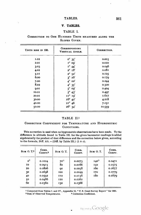
TABLES. 361
V. TABLES.
TABLE I.
Correct1on to One Hundred Un1ts measured along the
Slopes G1ven.
Un1ts r1se 1n 100.Correspond1ng
Vert1cal Angle.Correct1on.
1.02 o° 35' 0.005
2.01 1° 09- 0.020
3°3 1° 44' 0.046
4.02 2° 18' 0.081
5.01 2° 52' 0.125
6.00 3° 26' 0.179
7.00 4° 00' 0.244
8.02 4° 35' 0.320
9.015° 09' 0.404
10.01 5° 43' 0.497
20.01 11° 19' 1.617
30.00 1 6° 42' 4.218
40.00 21° 48 7.151
50.00 26° 34' 10.559
TABLE II.'
Correct1on Coeff1c1ent for Temperature and Hygrometr1c
Cond1t1ons.
This correction is used when no hygrometric observations have been made. To the
difference in altitude found in Table III. for the given barometer readings is added
algebraically the product of that difference and the correction below given, according
to the formula, Diff. Alt. = (Diff. by Table III.) (1 + c).
Sum O. T.2CORR.
COEFF.8Sum O. T.
CORR.
COEFF.Sum O. T.
CORR.
COEFF.
0° 0.1024 700 0.02731400
0.0471
10 O.O9I5 80 O.OI66 150 0.0575
20 O.0806 90 O.OO58 160 0.0677
30 O.0698 100 O.OO49 170 0.0779
40 O.O592 110 O.OI56 180 0.0879
5° O.O486 120 0.0262
60 O.O380 130 O.O368
1 Computed from Tables I. and IV., Appendix 10, " U. S. Coast Survey ReporI" for 1881.
a Sum of Observed Temperatures. 8 Correction Coefficient.

362 APPENDIX.
TABLE III."
Barometr1c Elevat1ons.
Giving altitudes above arbitrary sea level (barometer reading 30 inches)
for various barometer readings B.
To determine difference of elevation of two points having barometer
readings B and Bv take from the table the altitudes corresponding to B
and Bv and correct their difference by Table II. The corrected difference
is the quantity required.
A.
Feet.
27.336
27,090
26,846
26,604
26,364
26,126
25,890
25,656
25.424
25.194
24,966
24,740
24,516
24,294
24.073
23.854
23.637
23,421
23.207
22,995
22,785
22,576
22,368
22, [62
21,958
2'. 757
2'. 557
21,358
2 1 , 1 60
20,962
20,765
DlFF.
FOR .01.
Feet.
— 24.6
24.4
24.2
24.O
23.8
23.6
23-4
23.2
23.0
22.8
22.6
22.4
22.2
22.1
21.9
21.7
21.6
21.4
21.2
21.0
20.9
20.8
20.6
20.4
20.1
20.0
19.9
19.8
19.8
-19.7
Inches.
14.0
14. 1
14.2
H-3
14.4
H.5
14.6
H.7
14.8
14.9
15.0
15.2
'5-3
15-4
•5-5
15.6
"5-7
15.8
15.9
16.0
16. 1
16.2
16.3
'6.4
16.5
16.6
16.7
16.8
16.9
17.0
A.
Feet.
20,765
20,570
20,377
20,186
9,997
9,809
9,623
9,437
9,252
9,068
8,886
8,705
8,525
8,346
8,168
7,992
7,817
7.643
7,470
7,298
7,127
6,958
6,789
6,621
6,454
6,288
6,124
5,961
5,798
5,636
5,476
DlFF.
FOR .01
Feei.
9-5
9-3
9.1
8.9
8.8
8.6
8.6
8-5
8.4
8.2
8.1
8.0
7-9
7.8
7.6
7-5
7-4
7-3
7-2
7-"
6.9
6.9
6.8
6.7
6.6
6.4
6-3
6-3
6.2
6.0
Inches.
7.0
7'
7-2
7-3
7-4
7-5
7.6
7-7
7.8
7- 9
8.0
8.1
8.2
8- 3
8.4
8.5
8.6
8.7
8.8
8.9
9.0
9'
9.2
9- 3
6.4
9-5
9.6
9-7
9.8
9-9
20.0
A.
Feet.
5,476
5,316
5,157
4,999
4,842
4,686
4,531
4,377
4,223
4,070
3.918
3.767
3.617
3.468
3.319
3.172
3,025
2,879
2,733
2,589
2,445
2,302
2,160
2,018
',877
1,737
1,598
',459
1,321
1,184
1,047
1 Taken from Appendix 10, " U. S. Coast and Geodetic Survey Report " for 1881.
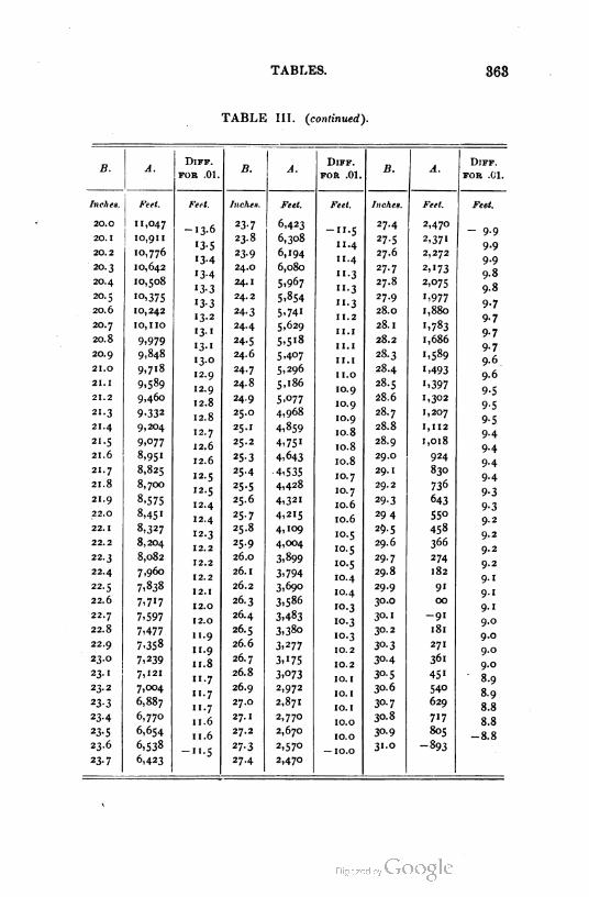
TABLES. 363
TABLE III. (continued).
B. A.DlFF.
FOR .01.B. A.
DlFF.
FOR .01.B. A.
DlFF.
FOR .01.
Inches. Feet. Feet. Inches. Feet. Feet. Inches. Feet. Feet.
20.0
20.I
20.2
20.3
20.4
2O.5
20.6
11,047
IO,9II
10,776
10,642
10,508
-13-623- 7
23.8
6,423
6,308
6,194
6,080
5.967
5,854
5-741
5,629
5,5'8
-"-5
11.4
11. 4
".3
".3
".3
11. 2
1 1.1
11. 1
11. 1
11.0
10.9
10.9
10.9
10.8
10.8
10.8
10.7
10.7
10.6
10.6
10.5
10.5
10.5
10.4
10.4
10.3
10.3
10.3
10.2
10.2
10. 1
10. 1
10. 1
10.0
10.0
27.4 2,470- 9.9
9.9
9.9
9.8
9.8
9-7
9-7
9-7
9-7
9.6
9.6
9-5
9-5
9-5
9.4
'3-5
'3-4
13-4
133
'3-3
23- 9
24.0
24.1
24.2
27-5
27.6
27.7
27.8
27.9
28.O
28.I
28.2
28.3
28.4
28.5
28.6
28.7
28.8
28.9
29.O
29. 1
29.2
2,37"
2,272
'°.37S
10, 242
10,110
2,173
2,075
'-977
1,880
20.713-2
24- 3
24.4
24.5
24.6
1,783
1,68620.8 9,979
9,848
9,718
•3-1
I3-I
13.0
12.9
12.9
12.8
12.8
12.7
12.6
12.6
12.5
12.5
12.4
12.4
12.3
12.2
12.2
12.2
12. 1
12.0
12.0
11. 9
11.9
11. 8
11. 7
11. 7
11. 7
11. 6
11.6
-11. 5
20.9
21.0 24- 7
24.8
24.9
25.0
25.1
25.2
5-407
5,296
5,186
1,589
',493
',397
1,302
1,207
1,112
1,018
924
830
736
643
55°
458
366
21. 1
21.2
21.3
21.4
21.5
21.6
9,589
9,460 5-°77
4,968
4,859
4,75'
4,643
-4,535
4,428
4,321
4,215
4,109
4,004
3,899
3,794
3,690
3,586
3,483
3,38o
3,277
3,175
3,073
2,972
2,871
2,770
2,670
2.57o
2,47°
9-332
9,204
21.7
9,077
8,951
8,825
8,700
25- 3
25.4
9-4
9-4
9.421.8
8,575
8,45'
8,327
8,204
8,082
7,960
7,838
7,717
7,597
7,477
7,358
7,239
7,121
7,004
6,887
6,770
6,654
6,538
6,423
25-5
25.69-3
9-3
9.2
9.2
9.2
9.2
9.1
9.1
9.1
9.0
9.0
9.0
9.0
8.9
8.9
8.8
8.8
-8.8
21.9
22.0 25-7
25.8
25.9
26.0
26. 1
26.2
26.3
26.4
26.5
26.6
26.7
26.8
26.9
27.0
27.1
27.2
29- 3
29 4
29.5
29.6
29.7
29.8
29.9
30.0
30.1
30.2
30.3
3°-4
22.1
22.2
22.3
22.4
22.5
22.6
22.7
22.8
22.9
23.O
274
182
9'
00
-9'
181
23- 1
23.2
30- 5
30.6
271
361
45'
540
629
717
805
-893
23- 3
23-4
23-5
23.6
30-7
30.8
23-7
27-3
27.4— 10.0
3°-9
31.0

364 APPENDIX.
TABLE IV.
Polar Distance of Polaris. F-r January 1 -f years named.
1894 1897 1900 1903 1906 1909 1912 1915 1918 1921
1° 1543' 1° 14.50' ' 13-55- 1° 12.62' i° 11.68' 1° 10.75' i° 09.82' i° 08.88- i° 07.97- i° 07.03'
„. . . , , . sin p-lar distancenin of azimuth at ei-ngati-n = ......
0 c-sine latitude
Latitude = altitude of P-laris at culminati-n ± p-lar distance —refracti-n c-rrec
ti-n given bel-w.
Latitud-. C-rr-cti-n, Minutes. Latitude. C-rrecti-n, Minutes.
200 2.60 5°° 0.80
1-65 60 --5540 113
TABLE V.1
Amount and Variation of thf. Magnetic Needle from its
Mean Daily Position.
The letters E and W indicate which side -f the mean p-siti-n the needle p-ints.
Seas-n and P-siti-n in Latitude.L-cal M-an Time; M-rning H-urs.
7h 8" 9h
December, January, February : / / / / / /
1.1 E 1.9 E 2.2 E 1.5 E 0.1 W 1.8 \V
Latitude 250 t- 370 0.1 W 0.1 E 1.0E 2.0 E 2.2 E 1.1 E 0.5 w
March, April, May :
Latitude 370 t- 49° 2.6 E 3-8 E 44 E 3-5 E 1.2 E 1.6 E 3-8 w
June, July, August :
2.8 E 3-3 E 2.6 E 1.1 E 0.6 W 1.9 w
Latitude 37° t- 49° 4.0 E 5.6 E 5-7 E 4-5 E 1.7 E 1.6 E 4.1 w
Latitude 250 t- 370 24 E 4.0 E 4.2 E 2.9 E 0.5 E 1.6 W 2.8 W
September, Oct-ber, N-vember:
X 8 E 2.6 E 3-i E 2.5 E 1.0 E 1-5 E 3-3 W
2.1 E 2.6 E 2.1 E 0.6 E 0.9 W 2.1 W
S-as-n and P-siti-n in Latitude.
December, January, February:
Latitude 370 t- 490 ....
Latitude 250 t- 37° ... .
March, April, May:
Latitude 370 t- 490 ....
Latitude 250 t- 370 . . . .
June, July, August :
Latitude 370 t- 490 ....
Latitude 25° t- 370 . . . .
September, Oct-ber, N-vember :
Latitude 370 t- 490 ....
Latitude 250 t- 370 ....
L-cal Mean Time; Aft-rn--n H-urs.
-h .h 2h3"
4h 5h 6"
/ / 1 / / 1
X 8 W
0.5 W
2.9 w
1.5 w
2.8 W
1.8 W
2.1 W 1.3 w
1.0 w
0.7 w
0.4 w
0.2 w
0.1 w1.6 W
3-8 W
19W
4.8 w
2.6 W
4.6 W
2.8 W
3-8 W
2.4 W
2.5 w 14 w
0.9 w
0.7 w
0.5 w1.6 W
5.6 W
3.2 W
5.6 W
3.1 W
4.6 W
24 W
3.0 W 1.4 w
0.8 w
0.6 w
0.4 w?8W 1.5 w
3-3 W
2.1 W
4.0 W
2.3 w
34 w
1.9 w
2.3 W 1.2 w
0.7 w
0.6 w
0.4 w
0.1 W
1.2 w 0.2 w
1 Fr-m "Manual -f Instructi-ns " issued by th- U. S. Land Offic- t- Survey-rs G-n-rai.
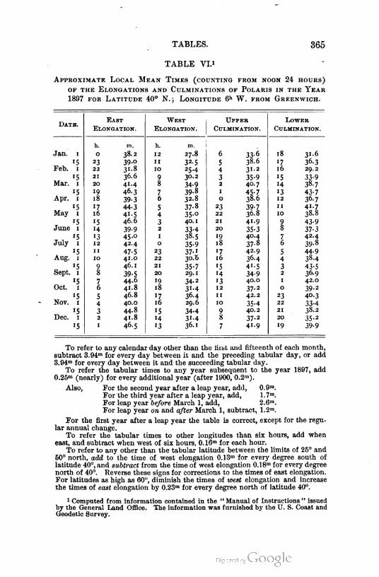
TABLES. 365
TABLE VL'
Approx1mate Local Mean T1mes (count1ng from noon 24 hours)
op the Elongat1ons and Culm1nat1ons of Polar1s 1n the Year
1897 for Lat1tude 40° N. ; Long1tude 6h W. from Greenw1ch.
Date.East West Upper Lower
Elongat1on. Elongat1on. Culm1nat1on. Culm1nat1on.
h. m. h. m.
Jan. 1 0 38.2 12 27.8 6 33-6 18 31-6
15 23 39-o 11 32-5 5 38.6 17 36-3
Feb. 1 22 3'-8 10 25.4 4 31.2 16 29.2
'5 21 36.6 9 30.2 3 35-9 "5 33-9
Mar. 1 20 41.4 8 34-9 2 40.7 H 38.7
•5 19 46-3 7 39-8 1 45-7 13 43-7
Apr. 1 18 39-3 6 32.8 0 38.6 12 36-7
'5 17 44-3 5 37-8 23 39-7 11 41.7
May 1 16 4"-5 4 35-o 22 36.8 10 38.8
T '5 '5 46.6 3 40.1 21 41.9 9 43-9
June 1 H 39-9 2 33-4 20 35-3 8 37-3
T , '513 45.0 1 38. s 19 40.4 7 42.4
July 1 12 42.4 0 35-9 18 37-8 6 39-8
'5 11 47- S 23 37-1 17 42.9 S 44-9
Aug. 1 10 41.0 22 30.6 16 36.4 4 38-4
9 46.1 21 35-7 15 41-5 3 43-5
Sept. 1 8 39-5 20 29.1 14 34-9 2 36-9
„ '5 7 44.6 19 34-2 13 40.0 1 42.0
Oct. 1 6 41.8 18 31-4 12 37-2 0 39-2
„ 's 5 46.8 17 36-4 11 42.2 23 40-3
Nov. 1 4 40.0 16 29.6 10 35-4 22 33-4
15 3 44.8 15 34-4 9 40.2 21 38.2
Dec. 1 2 41.8 14 31-4 8 37-2 20 35-2
'5 1 46.5 13 36.1 7 41.9 19 39-9
To refer to any calendar day other than the rust and fifteenth of each month,
subtract 3.94m for every day between it and the preceding tabular day, or add
3.94m for every day between it and the succeeding tabular day.
To refer the tabular times to any year subsequent to the year 1897, add0.25m (nearly) for every additional year (after 1900, 0.2m).
Also, For the second year after a leap year, add, 0.9m.
For the third year after a leap year, add, 1.7m.
For leap year before March 1, add, 2.6m.
For leap year on and after March 1, subtract, 1.2m.
For the first year after a leap year the table is correct, except for the regu
lar annual change.
To refer the tabular times to other longitudes than six hours, add when
east, and subtract when west of six hours, 0. 16m for each hour.
To refer to any other than the tabular latitude between the limits of 25° and
60° north, add to the time of west elongation 0.13m for every degree south of
latitude 40°, and subtract from the time of west elongation 0.18m for every degree
north of 40°. Reverse these signs for corrections to the times of east elongation.
For latitudes as high as 60°, diminish the times of west elongation and increase
the times of east elongation by 0.23m for every degree north of latitude 40°.
1 Computed from information contained in the " Manual of Instructions " issued
by the General Land Office. The information was furnished by the U. S. Coast and
Geodetic Survey.
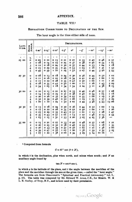
366 APPENDIX.
TABLE VII.1
Refraction Corrections to Declination of the Sun.
The hour angle is the time either side of noon.
Lati- HourAngle.
Declinations.
T'DE.
4-20° +10° +5° 0° -5° -10' -15° —20'
- '
25 OO
b.
0
2
3
4
5
0 05
0 08
0 10
0 14
0 18
0 29
0 59
0 15
0 19
0 24
0 21
0 25
0 30
0 27
0 3'
0 37
0 53
' 52
0 33
0 38
0 40
0 46
0 48 0 57
0 54 i 05
O 12 0 44 0 53 1 04
' 3«
1 18
0 23
0 49
0 35 0 45 1 03 1 16 1 52
1 10 1 24 2 07 2 44 3 46 5 43
27 3°
30 OO
0
2
3
0 08
0 11
0 17
0 28
0 54
0 13
0 16
0 22
0 18
0 22
0 28
0 24
0 28
0 30 0 36
0 41
0 50
0 44 0 52 1 02
1 100 34 0 49 1 00
1 11
« 43
0 35
0 50
0 42 1 00
1 26
1 26
4 0 35 0 42 1 00
1 54
2 09
8 155 1 05 1 18 ' 34 2 24 3 " 4 38
0
2
3
4
5
0 10
0 14
0 20
0 15
0 19
0 26
0 21 0 27
0 31
0 33
0 38
0 40
0 46
0 48 0 57 1 08
1 180 25
0 32
0 54 1 05
1 19
1 57
0 39 0 47 0 55 1 06 1 36
0 32 0 39 0 46 0 52 1 06 1 19 ' 35 2 29
13 061 00 1 10 1 24 1 52 2 07 2 44 3 46 5 43
32 30 0
2
3
4
0 13
0 17
0 23
0 35
« °3
0 18
0 22
0 29
0 43
» «5
0 24
0 28
0 30
0 35
0 36
0 42
0 51
' «32 20
0 44 0 52 1 02
1 11
1 14
0 50 1 00 1 26
i 470 35 0 43 1 01
1 27
' 13
1 46
1 28
0 51 1 01 2 13
7 36
2 54
5 1 31 1 53 3 °5 4 25
35 00 0
2
3
4
5
0 15
0 20
0 26
0 21
0 25
0 27
0 32
0 33
0 38
0 40
0 46
0 48 0 57 1 08
1 18
1 21
0 55 1 05
1 21
1 59
' 35
0 33 0 39
0 56
0 47 0 56 1 07 1 38 2 00
0 39 0 47 1 07 1 20 1 36
3 29
2 32
10 16
3 25
1 07 1 20 ' 38 2 00 2 34 5 '4
1 C-mputed from formula
C = 57"c-t (S + JV).
In which S is the declinati-n, plus when n-rth, and minus when s-uth; and N an
auxiliary angle f-und by
tan N= c-t * cos t,
in which ifi is the latitude of the place, and ( the angle between the meridian -f the
place and the meridian thr-ugh the sun at the given time, —called the " hour angle."
The formulae are fr-m Chauvenet's " Spherical and Practical Astr-n-my," vol. I.,
p. 171. The table was c-mputed by Mr. Edward W. Arms, C.E., f-r Messrs. \V. &
L. E. Gurley, -f Tr-y, N.Y., and is here used by their permissi-n.
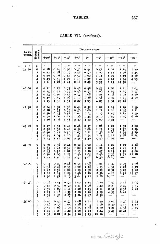
TABLES. 367
TABLE VIT. (continued).
Lat1
tude.
37 3°
40 00
42 30
45 00
47 3°
50 00
52 30
55 °°
h.
0
2
3
4
5
o
2
3
4
5
o
2
3
4
5
o
2
3
4
5
o
2
3
4
5
o
2
3
4
5
o
2
3
.4
5
0
2
3
4
5
Decl1nat1ons.
+20° + 15° + 1OC+5° 0° -5° 1-° -15° —2-°
0 18 0 24 0 30 0 36 0 44 0 52 1 02 1 '4 I 29
0 22 0 28 0 35 0 42 0 5° I 00 1 12 1 26 1 45
0 29 0 36 0 43 0 52 1 02 I 14 1 29 1 49 2 16
0 43 0 51 1 01 1 13 1 27 I 49 2 '4 2 54 4 05
1 II 1 26 1 44 2 10 2 49 3 55 6 '5 14 58 —
0 21 0 27 0 33 0 40 0 48 0 57 1 08 1 21 1 03
0 25 0 32 0 39 0 46 0 52 1 06 1 •9 1 35 1 57
0 33 0. 40 0 48 0 57 1 08 1 21 1 38 2 02 2 36
0 47 0 55 1 06 1 "9 1 36 1 58 2 3° 3 21 4 59
I '5 1 3' 1 5' 2 20 3 °5 4 25 7 34 25 18 —
0 24 0 30 0 36 0 44 0 52 1 02 1 '4 1 29 1 49
0 28 0 35 0 39 0 5° 1 00 1 12 1 26 1 45 2 11
0 36 0 43 0 52 1 02 1 '3 1 29 1 49 2 l7 2 59
0 5° - 1 00 1 11 1 26 1 44 2 10 2 49 3 55 6 16
I 16 1 36 1 58 2 30 3 22 5 00 9 24 —
0 27 0 33 0 40 0 48 0 57 1 08 1 21 1 39 2 02
0 32 0 39 0 46 0 52 1 06 1 19 1 35 1 57 2 29
0 40 0 47 0 56 1 07 1 21 1 38 2 00 2 34 3 29
0 54 1 04 1 16 1 33 1 54 2 24 3 11 4 38 8 1SI 23 1 41 2 °5 2 41 3 40 5 40 12 02 —
0 30 0 36 0 44 0 52 1 02 1 '4 1 29 1 49 2 18
0 35 0 42 0 5° 1 00 1 12 1 26 1 45 2 01 2 5"
0 43 0 51 1 01 1 '3 1 28 1 47 2 '5 2 56 4 08
0 56 1 09 1 23 1 40 2 °5 2 40 3 39 5 37 11 18
I 27 1 46 2 12 2 52 4 01 6 30 16 19 —
0 33 0 40 0 48 0 57 1 08 1 21 1 39 2 02 2 36
0 38 0 46 0 55 1 06 1 18 1 35 1 57 2 28 3 '9
0 47 0 56 1 06 1 '9 1 36 2 29 2 31 3 23 5 02
I 02 1 14 1 29 I 48 2 16 2 58 4 18 6 59 19 47
I 3° 1 5' 2 "9 3 04 4 22 7 28 24 10 —
0 36 0 44 0 52 1 02 1 14 1 29 1 49 2 18 3 05
0 43 0 5° 0 59 1 11 1 26 1 42 2 23 2 49 3 55
0 50 1 00 1 11 1 26 1 45 2 11 2 5" 2 58 6 22
I °5 1 18 1 35 2 10 2 28 3 19 4 53 8 42 —
I 34 1 56 2 27 3 16 4 47 8 52 —
0 40 0 48 0 57 1 08 1 21 1 39 2 02 2 36 3 330 46 0 55 1 °5 1 18 1 34 1 56 2 3° 3 '5 4 47
0 55 1 06 1 '9 1 35 1 58 2 30 3 21 4 58 9 19
I 10 1 23 1 42 2 06 2 43 . 3 44 5 49 12 41-—
I 37 2 01 2 34 3 28 5 •5 10 18 —
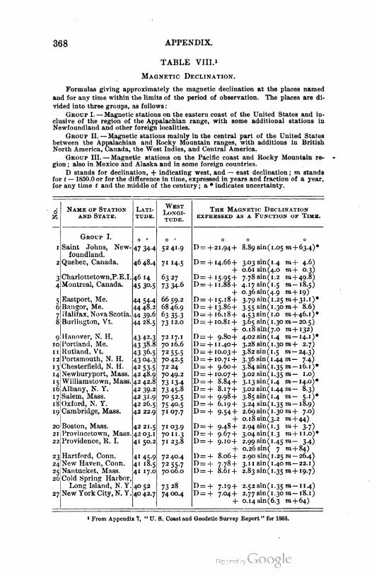
368 APPENDIX.
TABLE VIII.1
Magnet1c Decl1nat1on.
Formulas giving approximately the magnetic declination at the places named
and for any time within the limits of the period of observation. The places are di
vided into three groups, as follows :
Group I. — Magnetic stations on the eastern coast of the United States and in
clusive of the region of the Appalachian range, with some additional stations in
Newfoundland and other foreign localities.
Group II. — Magnetic stations mainly in the central part of the United States
between the Appalachian and Rocky Mountain ranges, with additions in British
North America, Canada, the West Indies, and Central America.
Group III. — Magnetic stations on the Pacific coast and Rocky Mountain re
gion ; also in Mexico and Alaska and in some foreign countries.
D stands for declination, + indicating west, and — east declination ; m stands
for t — 1850.0 or for the difference in time, expressed in years and fraction of a year,
for any time t and the middle of the century ; a * indicates uncertainty.
Name of Stat1on Lat1West
Long1
tude.
The Magnet1c Decl1nat1on
and State. tude. EXPRESSED AS A FUNCTION OF TIoE.
Group I. - • - • O 0 -
I Saint Johns, New 47 34-4 5241.9 D = + 21.94+ 8.89 sin (1.05 m+ 63.4)*
foundland.
2 Quebec, Canada. 46 48.4 71 H-S D = + 14.66 + 3.03sin(1.4 to + 4.6)
+ 0.61 sin (4.0 771 + 0.3)
3 Charlottetown.P.E.I. 46 14 63 27 D= + 15-95 + 7.78sin(1.2 7)1 + 49. 8)
4 Montreal, Canada. 45 3°-5 73 34-6 D = + 11.88 +
+
4.17sin(1.5 m— 18.5)
o.36sin(4.9 m+19)
5Eastport, Me. 44 54-4 66 59.2 D = + 15-18 + 3.79sin(1.25m+31.1)*
6 Bangor, Me. 4448.2 68 46.9 D= + 13-86+ 3.55 sin(1.3om+ 8.6)
7 Halifax, Nova Scotia. 44 39-6 63 35-3 D = + 16.18+ 4-53Sin(1.o m+46.1)*
8 Burlington, Vt. 4428.5 73 12-o D= + 10.81 +
+
3.65 sin(1.30m — 20.5)
o.18sin(7.o 7)1+132)
9 Hanover, N. H. 43 42-3 7217-1 D= + 9-8o+ 4.02Sin(1.4 to — 14.1)*
ro Portland, Me. 43 38.8 70 16.6 D = + 11.4°+ 3.28 sin(1,30 m+ 2.7)
11 Rutland, Vt. 43 36-5 72 55-5 D= + 10.03 + 3.82sin(1.5 m— 24.3)
12 Portsmouth, N. H. 43 04-3 70 42.5 D= + 10.71 + 3.36sin(1.44m- 7.4)
3.84sin(1.35 to — 16.1)*13 Chesterfield, N. H. 42 535 72 24 D= + 9.60+
14 Newburyport, Mass. 4248.9 7049.2 D= + 10.07 + 3.02 sin ( 1 .35 to — 1 .0)
3.13sin(1.4 to— 14.0)*•5 Williamstown, Mass. 42 42.8 73 13-4 D = + 8.84+
16 Albany, N. Y. 42 39.2 73 45-8 D= + 8.17 + 3.02 sin(1.44 711— 8.3)
3.85Sin(1.4 m— 5.1)*'7 Salem, Mass. 42 31-9 7°52-5 D = + 9.98 +
18 Oxford, N. Y. 42 26.5 75 40.5 D = + 6.19 + 3.24 sin(1.35TO-18.9)
19 Cambridge, Mass. 42 22.9 7107.7 D = + 9-54+ 2.69 sin (1.30 to + 7.0)
+ o.18sin(3.2 TO + 44)
20 Boston, Mass. 4221.5 71 °3-9 D = + 9.48 + 2.94 sin (1. 3 7o+ 3.7)
3.04sin(1.3 ?)i+u.o)*21 Provincetown, Mass. 42 03.1 70 11. 3 D= + 9.67 +
22 Providence, R. I. 41 50.2 71 23.8 D= + 9.10+
+
2.99 sin(1.45m- 3.4)
0.26 sin ( 7 to + 84)
23 Hartford, Conn. 41 45.9 72 40.4 ]) = + 8.06+ 2.90 sin(1.25 771 — 26.4)
24 New Haven, Conn. 41 18.5 72 55-7 D= + 7-78 + 3. 11 sin(1.4om — 22.1)
25 Nantucket, Mass. 41 17.0 70 06.0 D = + 8.61 + 2.83 sin(1.35 m+ 19.7)
26 Cold Spring Harbor,
Long Island, N. Y.
New York City, N.Y.
4052 73 28 D = + 7-'9 + 2.52 sin(1.35 m— 1 1.4)
27 4042.7 7400.4 D = + 7.04+ 2.77 sin(1.30977,-18.1)
+ o.14sin(6.3 m+ 64)
1 From Append1x T, " TJ. 8. Coast and GeodeIic Survey Keport " for 1888.

TABLES. 369
281
29
30
3'
32
33
34
35
36
37
Name of Stat1on
and State.
Bethlehem, Pa.
Huntingdon, Pa.
New Brunswick, N.J,
Jamesburg, N. J.
Harrisburg, Pa.
Hatboro, Pa.
Philadelphia, Pa.
Chambersburg, Pa.
Baltimore, Md.
Washington, D. C.
Lat1
tude.
38lCape Henlopen, Del,
39I Williamsburg, Va.
40: Cape Henry, Va.
41jNewbern, N. C.
42 Milledgeville, Ga.
43'diarleston, S. C.
44lSavannah, Ga.
45 Paris, France.
46
47
St. George's, Ber
muda
Riode Janeiro, Brazil
Group II.
1 : York Factory, Brit
ish North America
Fort Albany, British
North America,
f Duluth, Minn., and
\ Superior City, Wis.
Sault Ste. Marie,
Mich.
Pierrepont Manor,
N. Y.
Toronto, Canada.
Grand Haven, Mich.
Milwaukee, Wis.
Buffalo, N. Y.
Detroit, Mich.
Ypsilanti, Mich.
Erie, Pa.
Chicago, 111.
Michigan City, Ind.
Cleveland, O.
Omaha, Neb.
Beaver, Pa.
40 36.4
4°340 29.9
40 21
40 15.9
40 12
39 56-9
39 55
39 17-8
38 53-3
3846.7
37 1 6-2
36 55-6
35o6
33 °4-2
3246.6
32 04.9
West
Long1
tude.
48 50.2
32 23
-2254.
56 59-9
52 22
46 45-5
46 39-9
46 29.9
43 44-5
43 39-4
43 °5-2
43 °2-5
4252.8
42 20.0
42 14
42 07.8
41 50.0
41 43-4
41 3°-4
41 15-7
4044
75 22.9
78 02
74 26.8
74 27
76 52.9
75 07
75 °9-o
77 4°
76 37.0
77 00.6
75 °5 o
7642.4
7600.4
7702
83 12
79 55-8
81 05.5
2 20.2E
6442
43 09-5
92 26
92 04.5 \
92 04.2 )
84 20. 1
76 03.0
79 23.5
86 12.6
87 54-2
78 53-5
83 03.0
83 38
8005.4
87 36.8
86 54.4
81 41.5
95 56-5
80 20
The MagnetIc Decl1nat1on
expressed as a Funct1on op T1me.
D = + 5-4° +D = + 3-76 +
D = + 5-" +D = + 6.034-
D = + 2-93 +
D = + 5-17 +
4-
D = + 5-364-
+
D = + 2-79 +
+
D= + 3.204-
D = + 2-73 +
+
D = 4- 4.014-
D= + 2-33 +
D = + 2.424-
D = + 0.634-
D= — 3.104-
D= — 1.824-
D = — 2.134-
3.13sin(1
2.93 s1n (1
2.94 sin ( 1
2.94 sin(1
2.98 sin(1
3.16 sin(1
0.22 sin (4
3.17sin(1
0.19 sin (4
3.10 sin(1
o.20sin(4
2.57sin(1,
2.57sin(1,
0.14 sin(1
3.22 sin(1
2.56 sin(1
2.25 sin(1
2.56 sin(1
2.53 sin(1.
2-75 sin(1.
2.55sin(1.
,55 m -38.3)
48 ni-35.2)
30 m+ 4.2)
40 m — 22.4)
50 1n + 0.2)
.54TO-16.7)
1 TO4-157)
,50 TO — 26.1)
.0 TO -f- 146)
- 55 TO- 3O.6)
.6 to+124)
-45 TO— 21. 2)
.45 TO — 21.6)
2 TO 4- 27)
-35 TO-25.2)
,5 TO-38.I)
,47 TO -30.6)
45 TO— l8.2)*
40 TO — 61.9)*
40 TO— 1 2.1 )*
40 TO — 4O.5)*
: 4- 6°-479 4- 16°.oo2 sin (0.765 to
4- 1180 46'.5 4- [0.85 - 0.35 sin
(0.69 n)] sin [(4.04 + 0.0054 n
+ .000035 n2)o]
4- 6.954-0.0145 m-fo.00056 m2*
+ 2.194-9.91 sin(o.8oTO— 10.4)*
D =
D=
D=
D=
I) =
D =
+ 7-344- 16.03 sin(1. 10 m — 97.9)
4-15.784- 6.95 sin(1.20 TO-99.6)*
— 7.704- 2.41 sin(1.4 1n— 120.0)*
4- 1-544- 2.70sin(1.45 m— 58.5)
+ 5-95 +4- 3-604-
4-
4-95 +
4.124-
3.664-
0.974-
1.204-
2.174-
3-77 +3-23 +
0.474-
9.304-
1.41 +
= +
= 4-
= 4-
3.78sin(1.4 m
2.82 sin (1.4 to
0.09 sin (9.3 to
0.08 sin (19 m
0.0380 to 4- 0.00
3.60 sin (1.45 m
3.47 sin (1.4 to
2.21 sin(1.5 m
3.40 sin (1.40 to
2.69 sin( 1.5 m
2.48 sin(1.45 m
2.42 sin (1.4 m
2.39 sin (1.30 m
3.34 sin (1.30??!
2.72 sin(1.40 to
— 22.2)
-44-7)+ 136)
+ 247)
1 20 TO2
-64.5)*
-27.8)
-15-3)
-4.1)
-27-3)
-62.5)
-48.O)
-'4.8)
-54-7)-39-6)
k'm'd surv. — 24
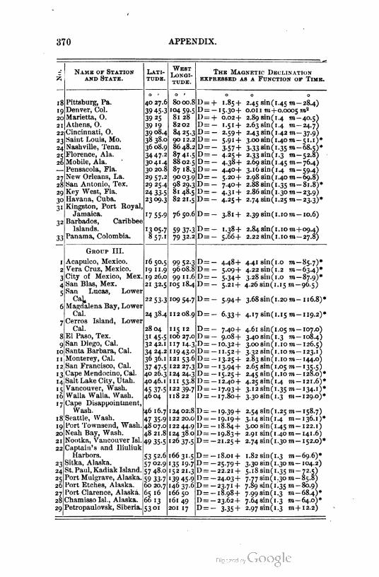
370 APPENDIX.
Name of Stat1on
and State.
Lat1
tude.
West
Long1
tude.
The Magnet1c Decl1nat1on
expressed as a Funct1on of T1me.
18
'920|
21
22
23
*4|
25
26
27
28
29
3°
3
32
33
Pittsburg, Pa.
Denver, Col.
Marietta, O.
Athens, O.
Cincinnati, O.
Saint Louis, Mo.
Nashville, Tenn.
Florence, Ala.
Mobile, Ala.
Pensacola, Fla.
New Orleans, La.
San Antonio, Tex.
Key West, Fla.
Havana, Cuba.
Kingston, Port Royal,
Jamaica.
Barbados, Caribbee
Islands.
Panama, Colombia.
40 27.6]
39 45-3
39 25
39 '939 08.4
38 380
36 08.9
34 47-2
3° 41-4
30 20.8|
2957.2
29 25.4
24 33-5
23 °9-3
17 55-9
1305.7
857.1
8000.8
104 59.5
81 28
8202
84 25.3
90 12.2
86 48.2!
8741
88 02.5
87 18.3
9003.9
98 29.3
81 48.5
82 21.5
76 50.6
59 37-379 322
+ 1-85 +
-15-30+
+ 0.02 +
- 1.51 +
- 2.59 +
- 5-91 +
- 3-57 +- 4-25 +
- 4-38+
- 4-40+
- 5-20+
- 7.40+
- 4-3' +
- 4-25 +
2.45 sin(1.45 m-
0.0 1 1 to +0.0005
2.89 sin( 1.4 m-
2.63sin(1.4 m-
2.43 sin (1.42 m-
3.00 sin (1.40m-
3.33 sin(1.35»i-
2.33 sin (1.3 m-
2.69 sin (1.45 to-
3.16sin(1.4 m-
2.98 sin ( 1.40 m-
2.88 sin (1.35 m-
2.86 sin(1.30 m-
2.74s^1(1.25 to-
-28.4)
m2
-40-5)
-24.7)
-37-9)
-51.1)*
-68.5)*
-52.8)
-76.4)
-59-4)-69.8)
-81.8)*
-23.9)
-23-3)*
D=— 3.81+ 2.39 sin(1.1om — 10.6)
D=— 1.38+ 2.84sin(1.1om-)-09.4)
D=— 5 .66 -j- 2.22 sin(1. 10 m— 27.8)
Group III.
1 Acapulco, Mexico. 16 50.5
2 Vera Cruz, Mexico. 191 1.9
3 City of Mexico, Mex. 19 26.0
4 San Bias, Mex. 21 32.5
San Lucas, Lower
CaL. 22 53.3
Magdalena Bay, Lower
Cal. 24 38.4
Cerros Island, Lower
Cal. 28 04
El Paso, Tex. 31 45.5
9|San Diego, Cal. 3242,
10 Santa Barbara, Cal. 34 24.2
1 1 1 Monterey, Cal . 36 36. 1
12 San Francisco, Cal. 37 47-5
13 Cape Mendocino, Cal. 40 26.3
14 Salt Lake City, Utah. 40 46. 1
15 Vancouver, Wash. 45 37.5
16 Walla Walla, Wash. 4604
17 Cape Disappointment,
Wash. 46 16.7
18 Seattle, Wash. 47 35.9
19 Port Townsend, Wash. 4807.0]
20 Neah Bay, Wash. 48 21.8
21 Nootka, Vancouver Isl. 49 35.5
22 Captain's and lliuliuk
Harbors. 53 52.6
23 Sitka, Alaska. 57 02.9
24 St. Paul, Kadiak Island. 57 48.0
25 Port Mulgrave, Alaska. 59 33.7
26 Port Etches, Alaska. 60 20.7
27 Port Clarence, Alaska. 65 16
28 Chamisso Isl., Alaska. 66 13
29 Petropaulovsk, Siberia. 53 01
99 52-3
9608.8
99 1 1.6
105 18.4
109 54.7
1 12 08.9
115 12
106 27.01
117 14-3
1 19 43.0,
121 53.6j122 27.3
12424.3
1n 53.8
12239.7
118 22
12402.8
122 20.oj
122 44.9
I24 38.o|
26 37-5
16631.5
135 '9-7
5221.3
139 45-9
46 37-6
166 50
61 49
201 17
D=— 4.48+ 4-41sin(1.o m— 85.7)*
D=— 5.09+ 4.22sin(1.2 to —63.4)*
D=— 5.34+ 3.28sin(1.o to — 87.9)*
D=— 5.21+ 4.26 sin(1.15 to— 96.5)
D=— 5.94+ 3.68sin(1.20TO- 116.8)*
D=— 6.33+ 4.17 sin(1.15 m— 119.2)*
- 7-40+
- 9.08 +
-10.32+
-11.52+
-13.25 +
-13-94+
-15-25 +
-12.40 +
-17-93+
-17.80+
4.61 sin(1
3.40 sin(1
3.00 sin(1
3.32 sin(1
2.83 sin(1
2.65 sin(1
2.45 sin(1
4.25 sin(1
3.12 sin ( 1
3.30 sin(
05 TO-
3IO TO
.10 TO-
.IO TO-
.05 TO-
.IO TO-
.4 m
-35 m
3 »»-
-'9-39+ 2.54 sin(1.25 m-
-19.19+ 3.148111(1-4 m-
-18.84+ 3.00 sin (1.45 to -
-19.83+ 2.91 sin(1.40TO-
-21.25+ 2.74 sin(1.30 m-
-18
- 107.0)
-108.4)
-126.5)
-123.1)
- 144-o)
-'35-5)-128.0)*
- 121.6)*
-134-0*
-129.0)*
-158.7)
-136-0*
- 122. 1)
-141.6)
- 152.0)*
.01+ 1.82sin(1.3 to— 69.6)*
25.79+ 3.30 sin(1.3o m — 104.2)
22.21+ 5.18 sin(1.35 m— 72.5)
24.03+ 7.77 sin(1.3o to — 85.8)
23.71+ 7.89 sin (f. 35 to -80.9)
18.98+ 7.99sin(1.3 m— 68.4)*
23.62+ 7.64 sin (1.3 m— 64.0)*
3.35+ 2.97 sin (1.3 m+12.2)

TABLES. 371
TABLE IX.
Angular Convergences and Distances between Meridians.
1. Angular convergence of meridians per mile of easting or westing.
2. Distance between meridians converging by one minute.
Angular Con Distance for Angular Con Distance for
Lati vergence per Convergence Lati vergence per Convergence
tude. Mile. of r. tude. Mile. of 1'.
-
Minutes. Feet.
0
Minutes. Feet.
' 0.015 348733 31 0.521 10140
2 .030 '743«4 32 .542 975 1
3 .045 116150 33 ■563 9382
4 .061 87052 34 0585 9034
5 .076 69578 35 .607 8703
6 .091 579'7 36 ■ 630 8387
7 .107 49578 37 0653 8087
8 .122 43337 38 0677 7801
9 ■137 38436 39 .702 7527
'O 0'53 34525 40 0727 7265
ii .169 31320 41 0753 7°!3
12 .184 28642 42 .780 6770
'3 .200 26371 43 .808 6537
14 .216 24419 44 .836 63i3
'5 .232 22723 45 .866 6097
16 .249 21234 46 .897 5888
17 .265 19916 47 .929 5686
18 .282 18740 48 .962 5491
19 .299 17685 49 .998 530i
20 .316 16731 5° 1.032 5118
21 0333 15864 51 1.069 4940
22 ■35° 15073 52 1. 108 4766
23 .368 14348 53 1. 149 4597
24 .386 13680 54 1. 191 4433
25 .404 13062 55 1.236 4271
26 0423 12488 56 1.283 41 15
27 .442 "955 57 1-333 3962
28 .461 "457 58 i-385 38i3
29 .480 10990 59 1.440 3666
3° .500 10552 60 1.499 3523
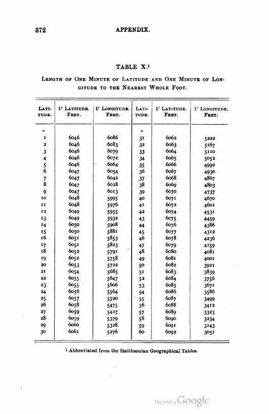
372 APPEND'X.
TABLE X.i
Length of One Minute of Latitude and One Minute of Lon
gitude to the Nearest Whole Foot.
Lati 1' Latitude. 1' Longitude. Lati 1' Latitude. 1' Longitude.
tude. Feet. Feet. tude. Feet. Feet.
- 0
' 6046 6086 31 6062 5222
2 6046 6083 32 6063 5167
3 6046 6079 33 6064 5110
4 6046 6072 34 6065 5052
s 6046 6064 35 6066 4992
6 6047 6054 36 6067 493°
7 6047 6042 37 6068 4867
8 6047 6028 38 6069 4803
9 6047 6013 39 6070 4737
10 6048 5995 40 6071 4670
1 1 6048 5976 41 6072 4601
12 6049 5955 42 6074 4531
i3 6049 5932 43 6075 4459
14 6050 5908 44 6076 4386
'5 6050 5881 45 6077 4312
16 6051 5853 46 6078 4236
«7 6051 5823 47 6079 4159
18 6052 5791 48 6080 4081
19 6052 5758 49 6081 4001
20 6o53 5722 5° 6082 3921
21 6054 5685 51 6083 3839
22 6055 5647 52 6084 3756
23 5606 53 6085 367«
24 6056 5564 54 6086 3586
25 6057 5520 55 6087 3499
26 6058 5475 56 6088 3412
27 6059 5427 57 6089 3323
28 6059 5379 58 6090 3234
29 6060 5328 59 6091 3143
30 6061 5276 60 6092 3051
Abbreviated fr-m the Smiths-nian Geographical Tables.

TABLES. 373
TABLE XI.
Trigonometric Functions and Formulas. Solution of Triangles.
By definition, if R = 1,
ED = sine «.
OD = cosine a.
DA = versed sine a.
HF = coversed sine a.
BA = tangent a.
FC = cotangent «.
OB = secant «.
OC = cosecant «.
If R is other than 1, it follows from
the above definitions and the propor
tionality of similar figures, that
1. ED = R sin «.
2. OD = Rcoaa.
3. DA = R versin «.
4. HF = R coversin a.
5. BA = R tan a.
6. FC = R cot a.
7. OB = R sec a.
8. OC = R cosec a.
from which also in any right triangle of angles « and B, if o be the side
opp-site the angle a, a the side adjacent thereto, and h the hypotenuse,
9. sin a = - = cos B.h ■
13. sec a = - = cosec B.a
10. cos a = - = sin /J.
11. tan a = - = cot B.a
12. cot a = - = tan B.o
14. cosec a = - = sec B.-
15. vers a = - ~ a = covers /?.
h
16. covers « = = vers /J.
Hence,
0{::18
19.
: n sin a = h cos /?0
- - _ o
sin a cos fi
: h cos « = h sin /?.
a _ a
cos a sin B
: a tan a = a cot /8.
0 0 — 0
tan oe cot p
20.
a = o cot a = o tan ;8.
- — - — a
cot a tan B
h = a sec a = a cosec B.( h = a sec a = a cose'
21. ^ _ A ft
1 sec a cosec p
( h = o cosec a
cosec a
= - sec |8
A
sec )3

374 APPENDIX.
23. o = VA2 - a2 = V(A + a)(h - a).
24. a = VA2 - o2 = V(A + o)(A - o).
25. A = Vo2 + a2.
26. Area = 22.
2
Oblique triangles may be solved by some one of the following formulas :
G1ven.
27. A, B, a,
28. A, a, b,
29. C, a, b,
30.
31.
32.
33.
34. a, b, c,
| Sought.
C, b, c,
B, C, e,
i (A + B),
1 (-4 - B),
A,B,
35.
36. A, B, C, a,
Area,
A,
Area,
Area,
Formulas.
C = 180°-04 + B), b = -A- Sin B,
s1n j4
sin 01 + B).sin .4
sinfi =?m-4&j C = 180° - (>4 + B),
a
c =- -sin C.sin -4
JO* +B)=90°-IC.
tan J (.4 - B) = 2j^*tan Hi+B).
a + b
A =i(A +B)+i(A -B);
B = i(A+B)-i(A -B).
cos I (A + B)c = (a + 6)
= (a - 6)
cos 4(^4 _ 5)
sin $ Q4 + B)
sini - B)
Area = J ai sin C.
If « = J (a 4 6 + c),
sin } Al(s-b)(s-e)
\ be
cos J .<4— a)
tanM= J(S~6)(57C).
\ s(s — a)
. . _2 Vj(«-a)(«-6)(»-e)
be
. 2 (s - 6)(s - c)vers A = —* '-± '- .
be
Area = Vs(s — o)(« — 6)(* — c).
a2 sin B sin CArea :
2 sin .4
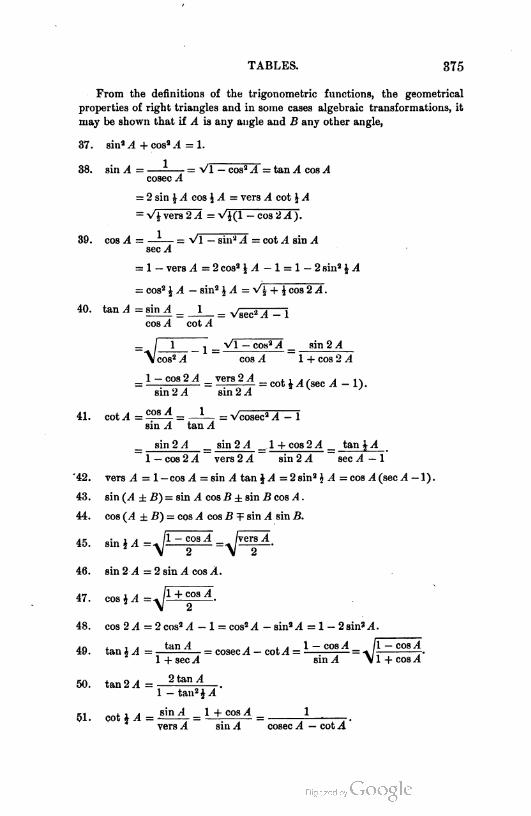
TABLES. 375
From the definitions of the trigonometric functions, the geometrical
properties of right triangles and in some cases algebraic transformations, it
may be shown that if A is any angle and B any other angle,
37. sin1 A + cos2.4 = 1.
38. sin A = - = VI — cos2 A = tan A cos A
cosec A
= 2 sin £ A cos J A = vers A cot J A
— V| vers 2 A = VJ(1 — cos 2 A).
cos A = —-— = VI — sin-2 A = cot A sin A
sec A
= 1 - vers 4 = 2cos2£,4 -1 = 1 - 2 sin2 i 4
= cos2 1 4 - sin2 J 4 = y/\ + J cos 24.
40. tan .4 = sin^ = _J_ = VSec24 -1
cos 4 cot A
_ 1 _ VI - cos2 4 _ sin 2 X
-\Zcos2 .1 cos .1 1 + c-s 2 .1
1 — cos 2 4 vers 2 yI
sin 2 4 sin 2 A
— cot ^ 4 (sec A — 1) .
41. cot4 =£2iii= _L_ = Vcosec24 - 1
sin A tan A
_ sin 2 A _ sin 2 4 _. 1 + cos 2 A _ tan £4
1 — cos 2 4 vers 24 sin 2 4 sec A — 1
-42. vers A = 1— cos A = sin A tan \A =2 sin2 \ A =cos A (sec 4—1).
43. sin (A ±B) = sin 4 cos B ± sin B cos A .
44. cos (A ±B) = cos 4 cos B T sin 4 sin B.
45. sinM=^f^=^/vers 4
>
46. sin 2 4 =2 sin 4 cos 4.
47. c-alA=yJ±±^!LA.
48. cos 2 4 =2 cos2 A - 1 = cos2 A - sin2 4 = 1 -2sin24.
49. tan* 4 = ta" - = cosec4 - cot4 = 1 ~ co8^ = J±.
1 + sec A smA \ 1 +
cos A
50. tan 2 A
■ cos A
2 tan A
1 - tan2 i 4
51. cotM= siiwt = l±£2*A =
vers 4 sin 4 cosec A — cot 4
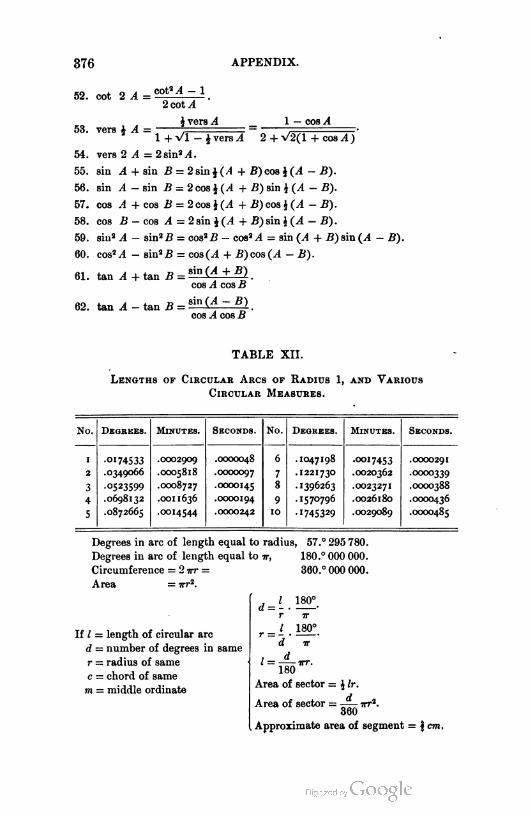
376 APPENDIX.
52. cot 2^=cotS-4-1
2 cot .4
j vers A _ 1 — cos A53. vers J .4 = , —
1 + VI - i vers A 2 + V2(l + cos .4)
54. vers 2 A = 2 sin2 ^4.
55. sin 4 + sin 2} = 2 sin i (.4 + B) cos $(A - B).
56. sin A - sin B = 2 cos i (.4 + -B) sin i (^1 - £).
57. cos A + cos iJ = 2 cos i (4 + if) cos %(A - B).
58. cos B - cos .4 = 2 sin J (/I + -B) sin J (4 - B).
59. sin2 ^ - sin2B = cos2B - cos2 .4 = sin {A + B)siu(A - B).
60. cos2 .4 - sin2£ = cos(A + B)cos(^ - B).
61. tan^+tanB = 3ip^+g).
cos A cos iJ
62. tan A -tan B = 8inC^-g),
cos ^4 cos £
TABLE XII.
Lengths of Circular Arcs of Radius 1, and Various
Circular Measures.
No. Degrees. Minutes. Seconds. No. Degrees. Minutes. Seconds.
' 00174533 .0002909 .0000048 6 .1047198 .0017453 .0000291
2 .0349066 .0005818 .0000097 7 .1221730 .0020362 .0000339
3 00523599 .0008727 .0000145 8 .1396263 .0023271 .0000388
4 .0698132 .0011636 .0000194 9 .1570796 .0026180 .0000436
5 .0872665 .0014544 .0000242 10 -1745329 .0029089 .0000485
Degrees in arc of length equal to radius, 57 .c
Degrees in arc of length equal to 7r, 180.°
Circumference = 2 irr = 360. c
Area = irr2.
295 780.
000 000.
000 000.
If / = length of circular arc
d — number of degrees in same
r = radius of same
c = chord of same
m = middle ordinate
dJ-r
d
180°.
i'
180°
f u( = irr.
180
Area of sector = J Ir.
Area of sector = —— irr2.
360
Approximate area of segment = f cm,

TABLES. 377
TABLE XIII.
Linear Transformations.
1. Gunter's Chains to Feet.
Chains. 0.0 0.01 .02 .03 .04 .05 .06 .07 .08 .09
o.o .66 1.32 1.98 2.64 3-3° 3-96 4.62 5.28 5-94
.1 6.60 7.26 7.92 8.58 9.24 9.90 10.56 11.22 11.88 12.54
.2 13.20 13-86 14.52 15.18 15.84 16.50 17.16 17.82 18.48 19.14
■3 19.80 20.46 21.12 21.78 22.44 23.10 23.76 24.42 25.08 25-74
■4 26.40 27.06 27.72 28.38 29.04 29.70 3Q-36 31.02 31.68 32-34
05 33-°° 33-66 34-32 34-98 35-64 36-3° 36.96 37.62 38.28 38-94
.6 39.60 40.26 40.92 41.58 42.24 42.90 43-56 44.22 44.88 45-54
07 46.20 46.86 47.52 48.18 48.84 49.50 50. 16 50.82 51.48 52-14
.8 52.80 53-46 54-12 54-78 55-44 56.10 56.76 57-42 58.08 58.74
09 594o 60.06 60.72 61.38 62.04 62.70 63-36 64.02 64.68 65-34
0.0 1.0 2.0 3.0 4.0 5-o 6.0 7.0 8.0 9.0
o.o 66 132 .198 264 33° 396 462 528 594
'O.O 660 726 792 858 924 990 1056 1122 1 188 1254
20.0 1320 1386 1452 1518 1584 1650 1716 1782 1848 1914
30.0 1980 2046 2112 2178 2244 2310 2376 2442 2508 2574
40.0 2640 2706 2772 2838 2904 2970 3036 3102 3168 3234
5O.O 33°° 3366 3432 3498 3564 3630 3696 3762 3828 3894
60.O 3960 4026 4092 4158 4224 4290 4356 4422 4488 4554
70.0 4620 4686 4752 4818 4884 4950 5016 5082 5H8 5214
80.O 5280 5346 5412 5478 5544 5610 5676 5742 5808 5874

378 APPENDIX.
O lN n >n SCO u. m N CO Tf m nO CO
g--------------m r^l i^l N On
m m 00 ■*Q CO m
On O ~00 On On
CO »n N CJt
n O no n Q nO r- O nO r-Qs — M Tf n5 N ON ~ N Tf
00 . QNCOTfinnONON0*-«0 | gn©nOnOnOnOnOnOnONN
J n i^i n on h CO in N On
q
q-d
On O « tfinO Mm O0 t Q « N 0000 Tf m 00 "t 'sn w s-- O N **5
— ei n 4 ^'O -- -> d---------------- On
CO N C\ m r- lo r--
3
- ~ r- On nO N ^ O
OO'O^OnOnOnOnO Nm n m Cn m r- in N
8■ ■8 nO N On nO
00 m i- 00 m m 00 m mOn■-" n ^ nO co oii- rom r- Tf m no t^.-- o *■l
r- in N -n i-i n m N on
ro m N -- O *- ro Tf nono N 00 Tf — N ^ Qn wm M tf — OO Tf -■ N Tf00 On m r- Tf «o CO On m
O m ro ^j- m md N CO dTfTfTfTfTfTfTfTfmi- 'o m n -n n m '->
0-rOTtmnON05gm
- m w in N On m in N c>
nO on O N r- m no 00 0ON m « 00 Tf 0 nO M OnOn nO CO On no ro ON nO Mno 00 O m n inn0 00 O
O r- Tf iri nO N 00 ONMMNNNNnNrOi- m n Qn h r- m N
Q
e
s
DO mN-- ini-*-- m --m N On O N ^ io n On O8" nN mnO 's 00 On"OOOOOOOO^qr- in N on rn m n 0n
M CO Tf nOen on m «M M OOm N on O
o o o-i in N
m no N --0 O O O-n — r- m
5
N M O ^ ro O nO pOOnOtj- no -- -n■-i m Tf no -- -no m n n mno N» On O------------------ On
w 4 no -d d nn 4 no -d
m O GO On n rn Tf nO 'snO N 00 Tf i- N r- On mno r- On nO m On nO N OntfnO N On m Cn| tf nO 's
o m n fo inno s-- a------------------NTfOOOONTfnO
m n -- m m --ro m no -- o —o *0* cni r- m _nO nO nO nO nO no no
m m CO Tfrn m no --
nO N -- -n oNO NO nO nO 'S
d « Tf no -d
On O W CO mnOn nO W CO TfTf *4 00 Tf N £m m no -- o
00 On ~nO N OnTf. M 'Srn m no
& nOM Tf no 00 0 N Tf *
r- O t*- **SN Tf in 's
O _ ro O nO r-N Tf m n
. O — N rO Tf nO N OO On OTfTfTfTfTfTfTfTfTfiO
- N TfnOOO 0 N Tf nO CO
N Tf nO 's ON Orn On in h N Tfr- -n no n -nn-n ro in n-- 0
0 — n
* a- ?
CO Tf nOTf Tf TfnO CO O
N r- mO NO NCO On nOn n m
N CO ONTf Tf TfN Tf nO
N -- m h -- m m -- m «-ih N ^NO 'n On m nN Tf nOO *- N rOTfinN-O On OMNNNMNNMNCO
N TfnOOOd M TfnOOO
nO CO On — « Tfii-J'sOnno M co in n Nr-ONmN 00 TfM.00 Tf *- 'S TfnNt>nONOnh«4
O m nN COTfinNOO On
M TfnOOO O « Tf nO
Is r- O nO r- 0 nOm ro m no -- o
cni ro Tf m N --o o o o o q qc4 Tfnd-d 6 nn Tf sd -d
ro oro mON Oo
« r- m no co -n'-' mnO M CO Tf O nO COOnnO r- ON nO CO On nO lN— n Tf no -- -n — r-j- 'nl r-Tfmnd-d on
NTf^co8«TfnO
wo
N CO Tf m nO 's CO On 0
d d
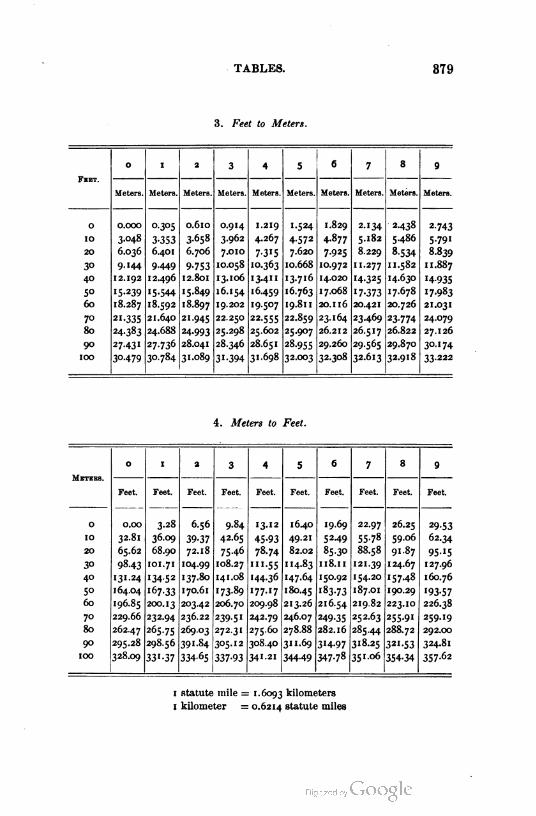
TABLES. 379
3. Feet to Meters.
Feet.
0 1 2 3 4 5 a 7 8 9
Meters. Meters. Meters. Meters. Meters. Meters. Meters. Meters. Meters. Meters.
O O.OOO O.305 0.6IO O.914 I.219 1.524 I.829 2.134 2.438 2-743
IO 3.048 3-353 3.658 3.962 4.267 4-572 4.877 5.182 5.486 5-791
20 6.036 6.401 6.706 7.OIO 7-315 7.620 7.925 8.229 8-534 8.839
3° 9.144 9-449 9-753 IO.058 IO.363 10.668 IO.972 II.277 11.582 1 1.887
40 12.192 12.496 12.801 13.106 13.41 1 13.716 14.020 '4-325 14.630 14-935
50 '5-239 15-544 15.849 16.154 16.459 16.763 17.068 17-373 17.678 '7-983
60 18.287 18.592 18.897 19.202 •9-507 19.811 20.II6 20.421 20.726 21.031
70 21-335 21.640 21.945 22.250 22.555 22.859 23.164 23-469 23-774 24.079
80 24-383 24.688 24.993 25.298 25.602 25-907 26.212 26.517 26.822 27.126
90 27-43I 27-736 28.041 28.346 28.651 28.955 29.260 29565 29.870 30-174
100 30-479 30-784 31.089 31-394 31.698 32.003 32.308 32.613 32.918 33-222
4. Meters to Feet.
Metees.
O I 2 3 4 5 6 7 8 9
Feet. Feet. Feet. Feet. Feet. Feet. Feet. Feet. Feet. FeeI.
0 O.OO 3-28 6.56 9.84 13.12 16-40 19.69 22.97 26.25 29-53
10 32.81 36.09 39-37 42.65 45-93 49.21 52-49 55-78 59.06 62.34
20 65.62 68.90 72.18 75-46 78.74 82.02 85.30 88.58 91.87 95-15
30 98.43 IOI.71 104.99 108.27 '"-55 114.83 Il8.II 121.39 124.67 127.96
40 131.24 '34-52 137.80 141.08 144.36 147.64 150.92 154.20 •57-48 160.76
50 164.04 16733 170.61 173-89 177.17 180.45 183.73 187.OI 190.29 '93-57
60 196.85 200.13 203.42 206.70 209.98 213.26 216.54 219.82 223.10 226.38
70 229.66 232.94 236.22 239-5I 242.79 246.07 249-35 252.63 255.91 259.19
80 262.47 265-75 269.03 272.31 275.60 278.88 282.16 285.44 288.72 292.00
90 295.28 298.56 391-84 305.12 308.40 311.69 3H-97 318.25 321.53 324.81
100 328.09 33'-37 334-65 337-93 341-21 344-49 347-78 351.06 354-34 357-62
1 statute mile = 1.6093 kilometers
1 kilometer = 0.6214 statute miles
J»!aj°h -Eo-0o9-9-o-.9-
Eo-^o9-91o19o9-
o-ox8*>-9--1913 -E•88-9- Eo--3-9-t-•-8-9-
8oo-*8-9--WE98-9-
-9-1g--9-
98o---9-o•oLo--l-l-tE9-
o-o-9E9- e-•89-9- t--l--99-go-B99-Eo-*9----o•99-9-
--"8----9--fr---^-9--E-1-9-
oE-E--9-tE81,"9-
9>---fr-9-
89-8o8E-9«
o981ofr-9-•--8^-9-
---8-5^-9-o--E-
tEU-
8Egoo-EoEeo
oo.a -g-'-t-.
-9"'o-.
9--1--.
1--1E--.
-fr',. •'9W-
.-1--.
-8'1W-
t--'-W-gE'nz-
---91-E-.
-E91-E.•"9-EE.
11-91-E--
9--91.-.
8-91g-. 02-91oE.^*91-E.
-E-9IoE.---919--. ££-91-1.---9E-I-.
99-91to.
19-9191-.
-3-91go.
-oo---.
-91-o.
.o91to.88-919-.
01o-3o9-
eoo,*- 91-----EoEE-
--
-ot-oo8-
.-1Eo*8-
----1---8-
tg----"8-gEE-9--8-
90**1go.
gEt-..EEHEo.•*-..
Botq1-1-*Et---.
9-*--8-.
---t----.
-»--*--g-.
oogg-. -9>--8-^- *8*--^-^-
--*-9-.
•t-$11.-Ig-o-8. oool111-
-o'99-.
9--'g9-.
Eo-'-9.E-*-1-. -1-1*9-/- o-'--.
t■-'E.8--'19-^-EE'-9-.-b--',-. nofrEo
'-
--
81-EE-E
o>.a-_"II-E--9*8-
9---I-fr*--
-E-------oo-o-8-ooo----g-
-*oI3-)«!a
8--•**%-
-9--1---8-
,---o*--8--^---Efr8^
->--EE)j-99-o--Es-
88-I,-8--8-E---8-
-•--EtE8--E--9--8-too--Eg-
•-->Bg-n----E8--o-----8-E--8&-8-
oE-E-E---fr---918-
----•-------1-o8-
810EEg-
o---t--8-EEE-8°8-
------1-8-
I9---E--8-
9-----o8-
g--E9-8-
-1-oWo
E----
910tol-*
ma-joh--o-9--g-
•-1----
1--1-8g-
-fr--oog-oo-.-8-
---1-88-.-o-o--S^--o-188-
---1-88-
K--E8--
9--1go-
,,x-E--
Eoxx*-8-goo-9o--o*n-o- -so----8- -fr------g--fr-n89-8-
9-o--93-
oEo--E8- t--Xl-9-g- 9-1109-8&oE--19-8-frg-n-9-8^Eo-fr98- on--g-
to--.---ont-8--o--oE8-
--o---g-
oo-----8- goo-L-
---o--o
f>X~-frso
E
majoh
,*8oE-
--g-E-
o-g-E-*Eg-E-
89-8tE-
-o--1- E--'"-fE--91--go--•--
-o--o- -E-fro- -fr---o*--fr--oo--E-11-EE--1-
K--8--- -E-fro-EE--o-
-9--90--
-9---o-
-g----- -o-18--8-
00-1-g-
10------g8--1-- 1101.8& t--O-.8°g-o----8&
-Eo-fr--8-•--9---
ofro-.----oo-Eo -oo--
IIOt---I
o-
-1I8^-
EEo-t---ooo--
ooo----
9-9E---
-c-Zli--
8*-t--
-o---9-o9^--
oEo9t---
9---E--
-llo--
-9--t--
E-E"-E---t--
-gogE- -og-E---o9E--*-L-E---8-i8---
n-gtE- K-8oE-
8--8-E-."8-E-<,--E-
o»-8---
-98-E-
---89---
----•E-
,882--
898*E-
9---/--o-oooE
-1--E--*
9--oE-
o-----■---E-g-------EE-EE-A3[3-•sEf•
33~a-Eoh
o----9--E--9--9-589--
-9--g9-------9-
-8--99--to-9-9-
----*-9--
-o--9-98--99-
---9-9-- ---9-9-----919--E-9-9-
'*929--8E9E--
19-99---9-9----
--98o--E--
-999--- -o9o---t--9E---
8E9*---EE9,-- 9-9---
-oo-Eo
9---oo-
8o*o-E-
oE
-A3•3-ma"B•a-joho---98--
99-E-g---9-----
,-E-----t------
8-E9---
lotfr---
---t---
---
----
t----g---ot-8-
g-t-o--oEtI8--t-Efr-8--
8-t-8----tEs--Et-E-
.*-E-
8 -̂t-8--E-to8-- -at%L--
g--t9---g-t-E-9E*-E-n*-E-
tot-9--•---E-
11--.---o--tl-
-t-E--E-EE-
----Eo
t-oo---I-oo-E-
oo.a*°ug--19o-
.-19o-
9--11---o-o-o-t-E--o--A3J3-jsEa to-o9--
---B9o- .-b5-^--b-b-o-
'b-o-■---o-
9--o-o-o--to-Ho*--
gEoto--9-----
-8-o.---Eooo--Eo---
-9---o-
-o--o-.E----
go--o--o--1o--o-1o- E--o- -fr--88
-*"E~88~--EE-g--E----
9--E-----oo-Eo
-0-oo-
----
--,
o1
B](l-joHEEoooE-
•o---01-IO00--19------1
.-O----1
-A3!3-181(1
-o----1
o-oooEELto-0--01
-t-ooE-
.--0--1
g------1o----
9-*o---
oEo00--1t--o----1
---o---
11-1----o1---
--
---
---
---
91*1---o"1g--
t--8--8Bo8---E----
S-I8o--q-1.-
-91-o-
--o8-----o8^--
t-EE-o- 100---
1--oo-
ooo-bo
o°
SE-,•>oo-,-Eo,o
-•v 89to0 -1 -I91tl 8-
E --8=
9oE E- Ett9E o-
9*ttE
o*-o --
to9-8--9
-emBAiXsunajjoiaAansibo•Soiobqpnooasojs•SojoaS•ubjs•ssb9nqAimo[su•avjr•q^iy-dM-^Qpa•nd
-raog-3\n.xapnoBasfltozAq^jd•ana•*Es•Su•pBt-oqb--•"j■•anfo•nJ.,vni/utSn•psajB•pBjssq}"ajSuBjbd•^jsajodo-•daq•j.EpEmso""UBt•bsq}3a•^[d•}[ntu"paare•qoasqoSmpva•jaqjojojs90[baa~xSuaiSuBiBa•-)j9AsnouBAyeoj•un--1josSu•pcaiBtp^jsjoj
-KO•iVAa'•gsoeaoKaaajj•QanvsaoKvxs•(jivxNOz•aojj
nxaaavx
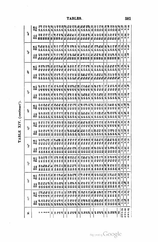
TABLES. 381
%
US
- -SVS-EVg. <8
Til! 1
s-ssg■8 R553- •a
1
s
fss aaaaa a A a »d
d
°8 ■8 J8-8. mo» g,Ssg=S,
****
s
*
aa-?8•2
*
8. E-
s 00 CO CO CO1,.
* **** Jf**£-d H
CO
1d J ,iEi**8,S, s
a
•8 2 ITS' , ■8 SI'S, 3-* S, -8,5 S5? E?
d
Rd
« aaaaa a as, as, a i iiii i an a
a
*
■5 PS?
***£-
s^ss*
*sses
s
s
.S'S.RK. s
s
a
s
K. 3,dw ***** * 2
<S
1tiS R $•5- SI'S,s 8.S8?
1
a
i
s
a
3**S■s.
a
s- a
%
EjETETEr 9 g-sraa 8. a aaasi, g,g;g;g; d
ft
d
«*MCO +« CI H - S-?8 S s
*
aiScffg:■5,
*
$
9
*
so 8.8,8, §n O" CT> 8> 8, *^*^ * *
-
8 srasa
iiii
•ggs-s
1SI
3
-8
3,■8
R
8.
-§.3^8 S g !Tg,S ST
d
a
°t2 8-8 s 8! "8, 8s*S<S
8,&8s8s
•g.g*S
§" S" 8* o>
ass,5?.
tr
&
a.
d
d*5 333358, 3333 5, 3,3.5.8, i & o> o> S> 8>
d
M iiiii
8.
I
s
s-
=3-
s-
El 5 1
s-
8d
•8
d
•a
•as-s-s-s- s-s-s-s- s- ETS-ETS-
%%%%
d
8JESSE'S
I
EE 2XZ•setse;
?8,<£-o?<S $ a.
6"8,
an &S.S.3. 3. 3.3,3,3. 3, 3333 3 3333 3,d
u mu
x
mi
a K
X
c8*as
1m
X
-8
g,S3-5 E 8d
s- S
t?
9
E
8
* **** -a-a-a-a
iiii
i
i
6 d
8s
s
■ass*
sisi
S E a.•8.
8,8,8,8, i iiii id d
asm
a mil
R
if
s 8,
E?
?8>?2' g-ss?
iiii
? s^^g.
iiii
R
j
8 ? Ef
d
a
ErffSTET s- ? iiii
s-a-as
d d
8
1
■8.388.
SSSS
* *<S grg.
ESSES EX
R
S
g.*^5
SSSS
s
s
-8,23,5 a
s
Rd
ESd
s S ESSSS
S.SS'S ff■s
a
g. s
e
s-afss-
I
E- if
d
sr
°?
5s s a a a a
sa*g*
8888 a aasa
is is
a
s
s
EfETEfET
-SEfgE-
d
83
i
■8R
d r* an i i s
°s
5S 8 8 8 8 8 a
8 EVg.<S
8888
*
8 »n s
a
5S5S
8?
S S 5 88
E-2-2 8*
wit
IIII
J
•2
d s J
"6
S
? S-S-aS;
SiSSES
g-s-ja ?
S 1
5;
s
R
d
a
S 8d H
±> R•S.**ES
•asaETS-
8
9
ET
?
s 5 3,-8,8
S-??8 r
2*5 Ere
8 8 8 8
s 8dX
6???? j
?
???? 2> g-
sX ? sg-s-;?
iisi
3
8
*S*J3 E;REtg. s
s
Rd
•8.
d
a
<6iiii * ass sis *Ol
S ;T8<s|a|a;S;'a'a- « "f-nO 00 - a j-gis 8 3. s, as-E's, O W H
lii
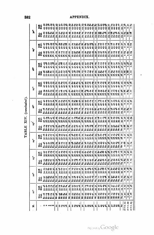
APPENDIX.
ye S1r's,?; 5-
I
5 8, ITS, MSB.
5RS8-
R
3
g.RM
5555
<£-
3
-
iiii
r g,
d
S,
d5„55
RRRR
0
a ass
R
S
Wis
1
a-
j
????
jjjj
R
R
g£"5.S»
RRRR 1
S
«i SRI!
KM3 XRM S
3
8,
R
? s-s S g 5 ?!T
5555 1
o
d Ji
i
iiii * i iiii 5555
6* 8,S°.RS, 8 PS S
I
R
R
8.MK
RRRR
SS-RS,
RRRR R
gK-So1
RRRR 1
£•
o<£-d ?
« nut \ flii mt?
if
an
21
% g
i iiii i iiii i6
8
- d
£\S RS, 3-g.Rg is r?? SM2 SMSIS s,
i
g s
KQ RRRRRR RRRR R R RRRR iiii
6 - H
am1as
?
att
"8. RRR* 3 R
dr g,
i iiii i
i
iiii i iiii i
« Kill
3 .ffgs?
iiii
ass,;?
iiii
8 ^S-8 S 8d
«•s
g.g.g.g. i i iiii Rd
g. RM8.
gffg?
1
a g
i
^Rg.3- 3 Rss,
as
s,
i
kiii i iiii iiii i-
-
d
2ss g-XSM
S3 =MM
K
111! MM mt1
<S,Rg?
R
£6
UiSH1 i
K.R'SjB
iiii
s-gsg
3 g PSg,
1
3d5d
iiii
Mg>s>
i
<s
*
8. Mg.S s S'SS'8 s
Ml
g.
&
s1?
ssss <s <ScS<S<S MM <s S&&&d
tig g 8 fffrS, R s g,M g. r MM s•8.8 ?g
s 9, S.
Cw oooofc E
I
is
8
oooo o oooE
MM
Pi
■s,
o'S'S.'S,
MM
g, iiii
s,s-!rg
g|°6 d
?suss g,KM rs s.
MMi i 5 £ MMi d d
wan
o
i
s
i
SMR R•8.8?g2
ooSo
•s
o J
s,
?
* iiii i
i
iiii i•S.-R-S.-S,
Ml!. SI
io
« JfSSI i
g?*R
MM iiiiJ iiM 1iiii
•s-
<?
81
dS.d
g.S S-S g,
r
*?gS>|g>|.8.?8S.
RRRR R RRRR
<8M8
RRRR
S;
R
$ gdg
*
g.
srrr r RRRR
Rg-53-
Rd
?c" sasM S.SM•8.
J?
g,
i
RR-S1? V SSS8.
1Sll
R S.d
J? mm MMd
Mlilll t
1
K.g.M'# « SR S, MM R
S
R-
d
f
RRRR R RRS j *
s
S SSS j s
ssss Ills fill sill;
i?^<s| s.jas<.'s.Ji
E-
III! 1
-. - W *nO00
s 2 2"Sg 3 ?gg IS™ - M HII II IIo o «

TABLES XV, XVI.
COMMON LOGARITHMS OF NUMBERS.
LOGARITHMS OF TRIGONOMETRIC FUNCTIONS.
EDITED BY C. W. CROCKETT.
383
NOTE.
The well-known tables of Gauss, Hoiiel, Becker, and
Albrecht have been taken as the standards, and the figures
compared with the more extensive tables, the doubtful cases
being recomputed.
384

EXPLANATION OF THE TABLES
INTRODUCTORY.
1. When we have a number with six or more decimal places, and we
wish to use only five :
(a) If the sixth and following figures of the decimal are less than
5 in the sixth place, they are dropped; thus, 0.464374999 is called
0.46437.
(6) If the sixth and following figures of the decimal are greater than
5 in the sixth place, the fifth place is increased by unity and the sixth
and following places are dropped ; thus, 0.46437 5001 is called 0.46438.
(e) If the sixth figure of the decimal is 5, and if it is followed only by
zeros, make the fifth figure the nearest even figure ; thus, 0.46437 500 is
called 0.46438, while 0.46438 500 is also called 0.46438. The number
is thus increased when the fifth figure is odd, and decreased when it is
even, the two operations tending to neutralize each other in a series of
computations, and hence to diminish the resultant error.
2. Hence any number obtained according to Art. 1 may be in error
by half a unit in the fifth decimal place.
3. When the last figure of a number in these tables is 5, the number
printed is too large, the 5 having been obtained according to Art. 1 (b) ;
if the 5 is without the minus sign, the number printed is too small,
the figures following the 5 having been dropped according to Art. 1 (a).
4. The marginal tables contain the products of the numbers at the
top of the columns by 1, 2, 3, ---g tenths, and may be used in multiply
ing and dividing in interpolation.
(a) To multiply 38 by .746 :
38 x .7 = = 26.6
38 X .4 = 15.2 ; .-. 38 X .04 = 1.52 4
38 X .6 = 22.8 ; .-. 38 X .006 = .228 6
.-. 38 X .746 = 28.348 7
3-8
7.6
1 1.4
15.2
19.0
22.8
26.6
3°434-2
In multiplying by the second figure (hundredths), the decimal point
in the table is moved one place to the left ; in multiplying by the third
(thousandths), tw- to the left ; and so on.
r'm'd surv. — 25 (385)

38t]
(b) To divide 28 by 38
Dividend, 28
Next less, 26.6
Remainder,
Next iess,
Remainder,
N earest,
.0. Quotient,
corresponding to .7
corresponding to .03
1 4
ill4
2 6
2 6.6 corresponding to .007
0737
38
3.8
7-6
11.4
15.2
19.0
22.8
26.6
3°4
34-2
to the nearest third decimal place. The decimal point is moved one
place to the right in each remainder, since the next figure in the quotient
will be one place farther to the right.
To divide 23 by 38 :
Dividend, 23
22.8
2
0.0
corresponding to .6
corresponding to .00
Nearest, 1 9.0 corresponding to .005
.-. Quotient, .605
The computer should use the marginal tables mentally.
LOGARITHMS.
5. The logarithm of a number is the exponent of the power to which
a given number called the base must be raised to produce the first
number. If A = e", a is called the logarithm of the number A to the
base e, written log, A = a.
6. If A = ea, and B = eh, or (omitting subscripts) log A = a, and
log B = b, we have
A xB=e"+> ; .-. log(^ x B) = a + b ; : log(AxB) =log A + log B.
A-^B = e"-1; :. \og(A + B) = a — b ; . = log A — log B.
A" =e"a; :. \og(An) =na ;
■■ log(^")= n \ogA.
y~A = e"a ; .-. \ogVA = 10. logV-A =-\ogA.
n- a ;n
EXPLANATION OF THE TABLES. 387
7. When the base is not specified, it is generally understood that
logarithms to the base 1o, or common logarithms, are meant. In this
system, since
o.oo1I I
IO"3 log O.OOI 3 ;IOOO IO3
1U ,
O.OII
=I
IO"2, log O.OI = - 2 ;IOO "1o^ =
O.II
=I
IO"1, log O.I - - 1 ;
I.
JO
=
IO
IO°, log I - o;
IO. —IO1, log 10 = + Ij
IOO. = 1o2, log IOO = + 21
IOOO. = log IOOO + 3-
8. The logarithm of a number between 1oo and 1ooo will be a num
ber between 2 and 3, or 2 + m where m will be a decimal called the
mantissa, the integral portion of the logarithm being the characteristic.
The mantissa is always considered positive; thus log 0.002 will be a
number between — 2 and — 3, that is, either — 3 + m or — 2 — m ',
the first form being used. We write log 0.002 = 3.30103, the negative
sign being placed over the characteristic to show that the characteristic
alone is negative.
9. Since
log (A x 1o") = log A + log 10" = log A + n log 10 = log A + n,
and log (A -- 10") = log A — log 10" = log A — n log 10 = \ogA — n,
we have, if log 37.3 = 1.57171,
log373- =2.57171, and log3.73 =0.57171;
log373° = 3-57I7T, and logo.373 =1.57171;
log373°° = 4-5717I> and logo.0373 = 2.571 71-
Hence the position of the decimal point affects the characteristic alone,
the mantissa being always the same for the same sequence of figures.
For this reason the common system of logarithms is used in practice.
10. The characteristic is found as follows : When the number is
greater than 1, the characteristic is positive, and is one less than the num
ber of digits to the left of the decimal point ; ivheu the number is less
than 1, the characteristic is negative, and is one more than the number ,
of zeros between the decimalpoint and the first significantfigure.
11. To avoid the use of negative characteristics we add 10 to the
characteristic and write —10 after the mantissa, i.e. adding and subtract
ing the same quantity, 10. Thus log 0.2= 1.30103 would be written
388 EXPLANATION OF THE TABLES.
9.30103 — 10. The — 10 is often omitted for brevity when there is no
danger of confusion, but its existence must not be forgotten. Such
logarithms are called augmented logarithms.
In this case the characteristic of the logarithm of a pure decimal is 9
diminished by the number of ciphers to the left of the first significant
figure. Thus the characteristic of log 0.004 >s 9 — 2> or 7> and tnat of
log 0.94 is 9 — o, or 9.
12. The arithmetical complement of the logarithm (written colog)
of a number is the logarithm of its reciprocal, and is found by subtract
ing each figure of the logarithm from 9, commencing at the left, except
the last significant figure on the right, which is subtracted from 10.
For log — = — log x = 10 — log x — 10 ;
thus, if log*= 2.46403, colog x= 7-53597 — 10 ;
if log.* = 8.43000 — 10, colog x = 1.57000.
TABLE XV.
13. Page 397 contains the logarithms of numbers from 1 to 100, to
five decimal places.
Pages 398-415 contain the mantissas of the logarithms of numbers
from 1000 to 10009, t0 five decimal places.
Pages 416, 41 7, contain the mantissas of the logarithms of numbers
from 10000 to 1 1009, to seven decimal places.
NOTE. —The mantissas of the logarithms of numbers, except those of the integral
powers of 10, are incommensurable, the mantissas in the tables being found as
shown in Art. I.
To find the Logarithm of a Number.
14. The characteristic is found by the rules in Arts. 10 and 11, and
the mantissa from the tables, as shown in Arts. 15, 16, 17, 18.
15. When the number has four figures. — Find on pages 398-415
the first three figures in the column marked TV, and the fourth at the top
of one of the other columns. The last three figures of the mantissa are
found in this column on the horizontal line through the first three
figures of the given number in column N. The first two figures of the
mantissa are those under L in the same line with the number, or else
those nearest above it, unless the last three figures of the mantissa as
given in the tables are preceded by a *, when the first two figures are
found under L in the first line below the number. Thus (page 398),
log 1 136 = 3.05538 ; log 1 137 = 3.05576 ; log 1 13S = 3.05614 ;
log 1370 = 3.13672; log 1371 = 3.13704 ; log 1372 = 3.13735 ;
log 1380 = 3.13988 ; log 1381 = 3.14019 ; log 1382 = 3.14051.
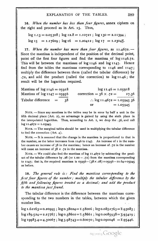
EXPLANATION OF THE TABLES. 389
16. When the number has less than four figures, annex ciphers on
the right and proceed as in Art. 15. Thus,
log 1. 13 =0.05308; log 12.8= 1.10721 ; log 130= 2.11394;
log 15 =1.17609; log 16 =1.20412; log 17 =1.23045".
17. When the number has more than four figures, as 11.4672. —
Since the mantissa is independent of the position of the decimal point,
point off the first four figures and find the mantissa of log 1146.72.
This will be between the mantissas of log 1 146 and log 1 147. Hence
find from the tables the mantissas corresponding to 1146 and 1147;
multiply the difference between them (called the tabular difference) by
.72, and add the product (called the correction) to log 11.46; the
result will be the logarithm required.
Mantissa of log 1146 = 05918 log 11.46 = 1.05918
Mantissa of log 1 147 = 05956 correction = 38 x .72 = 27.36
Tabular difference = 38 .-. log 1 1.4672 = 1.05945 36
or = 1.05945
Note. — Since any mantissa in the tables may be in error by half a unit in the
fifth decimal place (Art. 2), no advantage is gained by using the sixth place in
the interpolated logarithm. Thus, according to Art. I, we drop the .36, and call
log 11.4672 = 1.05945.
Note. — The marginal tables should be used in multiplying the tabular difference
to find the correction (Art. 4).
Note. — It is assumed that the change in the mantissa is proportional to that in
the number, as the latter increases from 1 146 to 1 147. An increase of 1 in the num
ber causes an increase of 38 in the mantissa; hence an increase of .72 in the number
will cause an increase of 38 x .72 in the mantissa.
Note. — We could also find the mantissa of log 11.4672 by subtracting the prod
uct of the tabular difference by .28 (or 1.00 — .72) from the mantissa corresponding
to 1 147 ; that is, the required mantissa is 05956 — (38 x .28) =05956— 10.64 = 05945
as before.
18. The general rule is: Find the mantissa corresponding to the
first four figures of the number; multiply the tabular difference by the
fifth and following figures treated as a decimal; and add the product
to the mantissa just found.
The tabular difference is the difference between the mantissas corre
sponding to the two numbers in the tables, between which the given
number lies.
log 1.62163 = 0.20995 ; log 0.38024= 1.58006 ; ^0.0852763 = 2.93083 ;
^189.524 = 2.27767 ; log 0.38602=1.58661 ; logo.0085938^3.93419 ;
log 19983.4 = 4.30067 ; ^3.98743 = 0.60070 ; logo.090046 =2.95446.
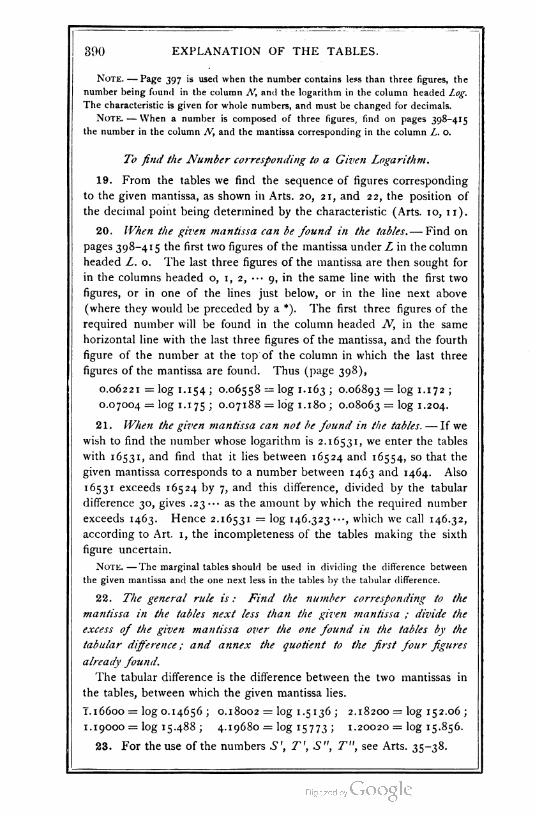
390 EXPLANATION OF THE TABLES.
Note. — Page 397 is used when the number contains less than three figures, the
number being found in the column N, and the logarithm in the column headed Log.
The characteristic is given for whole numbers, and must be changed for decimals.
Note. — When a number is composed of three figures, find on pages 398-415
the number in the column N, and the mantissa corresponding in the column L. o.
To find the Number corresponding to a Given Logarithm,
19. From the tables we find the sequence of figures corresponding
to the given mantissa, as shown in Arts. 20, 21, and 22, the position of
the decimal point being determined by the characteristic (Arts. 10, 11).
20. When the given mantissa can be found in the tables.— Find on
pages 398-415 the first two f1gures of the mantissa under L in the column
headed L. o. The last three figures of the mantissa are then sought for
in the columns headed o, 1, 2, -•• 9, in the same line with the first two
figures, or in one of the lines just below, or in the line next above
(where they would be preceded by a *). The first three figures of the
required number will be found in the column headed N, in the same
horizontal line with the last three figures of the mantissa, and the fourth
figure of the number at the top of the column in which the last three
figures of the mantissa are found. Thus (page 398),
0.06221 = log 1. 154 ; 0.06558 = log 1. 163 ; 0.06893 = log 1. 172 ;
0.07004 = log 1.1 75 ; 0.07188 = log 1. 180 ; 0.08063 = log 1-204.
21. When the given mantissa can not be found in the tables. — If we
wish to find the number whose logarithm is 2.16531, we enter the tables
with 1 653 1, and find that it lies between 16524 and 16554, so that the
given mantissa corresponds to a number between 1463 and 1464. Also
1 65 3 1 exceeds 16524 by 7, and this difference, divided by the tabular
difference 30, gives .23"- as the amount by which the required number
exceeds 1463. Hence 2.16531 = log 146.323 which we call 146.32,
according to Art. 1, the incompleteness of the tables making the sixth
figure uncertain.
Note. — The marginal tables should be used in dividing the difference between
the given mantissa and the one next less in the tables by the tabular difference.
22. The general rule is : Find the number corresponding to the
mantissa in the tables next less than the given mantissa ; divide the
excess of the given mantissa over the one found in the tables by the
tabular difference ; and annex the quotient to the first four figures
already found.
The tabular difference is the difference between the two mantissas in
the tables, between which the given mantissa lies.
T. 16600 = log 0.14656 ; 0.18002 = log 1.5136 ; 2.18200 = log 152.06 ;
1.19000 = ^15.488; 4.19680 = log 15773 ; 1.20020 = log 15.856.
23. For the use of the numbers S', T', S", T", see Arts. 35-38.

EXPLANATION OF THE TABLES. 391
TABLE XVI.
24. This table (pages 420-464) contains the logarithms, to five deci
mal places, of the trigonometric sines, cosines, tangents, and cotangents
of angles from o° to 90°, for each minute. The logarithms in the
columns headed L. Sin, L. Tan, and L. Cos, are augmented, and should
be diminished by 10 (Art. n), while those in the columns headed
L. Cot are correctly given.
25. Since secr = —-—, and cosec* = ^— , the logarithms of thecos x sin x
secant and cosecant of an angle are the arithmetical complements of
those of the cosine and sine respectively (Art. 12).
Tofind the Logarithmic Functions of an Angle Less than go°.
26. When the angle is less than 45°, the degrees are found at the top
of the page, and the minutes on the left. The numbers in the same
horizontal line with the minutes of the angle are the logarithmic functions
indicated by the notation at the top of the columns. Thus (page 428),
log sin 8° 4' = 9.14714 — 10, log tan 8° 4' = 9.15 145 — 10,
log cot 8° 4' = 0.84855, log cos 8° 4' = 9.99568 — 10.
27. When the angle is greater than 45°, the degrees are found at the
b-ttom of the page, and the minutes on the right. The numbers in the
same horizontal line with the minutes of the angle are the logarithmic
functions indicated by the notation at the bottom of the columns. Thus
(page 428),
log sin 81° 251 = 9.99511 — 10, log tan 81° 25' = 0.82120,
log cot 8i° 25' = 9.17880 — 10, log cos 81° 25' = 9.17391 — 10.
28. When the angle is given t- decimals of a minute.— In finding
log sin 30° 8'.48, for example, we see that it will lie between the
logarithmic sines of 300 8' and 30°9', that is, between 9.70072 and
9.70093, their difference 2T being the change in the logarithmic sine
caused by a change of 1' in the angle. Hence, to find the correction
to log sin 30° 8' that would give log sin 30° 8'.48 we multiply 21 by .48
(Art. 4). The product 10.08 added to log sin 30° 8', since log sin 300 9'
is greater than log sin 30° 8', gives log sin 30° 8'.48 = 9.70082 (Art. 1).
Similarly, log tan 300 8'-48 = 9.76391, log cot 30° 8'.48 = 0.23609, log
cos 300 8'.48 = 9.93691, the correction being subtracted in the last
two cases, since the cotangent and the cosine decrease as the angle
increases.
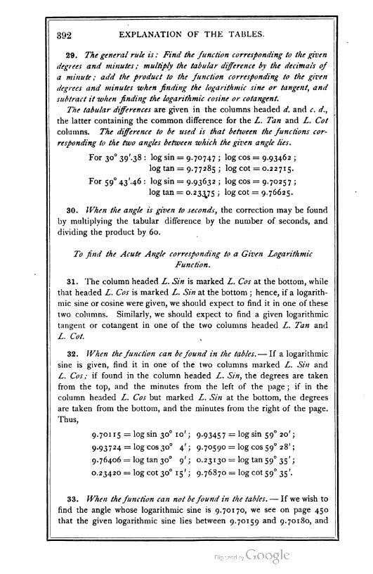
392 EXPLANATION OF THE TABLES.
29. The general rule is : Find the function corresponding to the given
degrees and minutes ; multiply the tabular difference by the decimals of
a minute ; add the product t- the function corresponding to the given
degrees and minutes when finding the logarithmic sine or tangent, and
subtract it when finding the logarithmic cosine or cotangent.
The tabular differences are given in the columns headed d. and c. d.,
the latter containing the common difference for the L. Tan and L. Cot
columns. The difference to be used is that between the functions cor
responding to the two angles between which the given angle lies.
For 300 39'.38 : log sin = 9.70747 ; log cos = 9.93462 ;
log tan = 9.77285 ; log cot = 0.22715.
For 59°43'.46 : log sin = 9.93632 ; log cos = 9.70257 ;
log tan = 0.233J5 ; log cot = 9.76625.
30. When the angle is given to seconds, the correction may be found
by multiplying the tabular difference by the number of seconds, and
dividing the product by 60.
To find the Acute Angle corresponding to a Given Logarithmic
Function.
31. The column headed L. Sin is marked L. Cos at the bottom, while
that headed L. Cos is marked L. Sin at the bottom ; hence, if a logarith
mic sine or cosine were given, we should expect to find it in one of these
two columns. Similarly, we should expect to find a given logarithmic
tangent or cotangent in one of the two columns headed L. Tan and
L. Cot.
32. When the function can befound in the tables.— If a logarithmic
sine is given, find it in one of the two columns marked L. Sin and
L. Cos ; if f-und in the column headed L. Sin, the degrees are taken
from the top, and the minutes from the left of the page ; if in the
column headed L. Cos but marked L. Sin at the bottom, the degrees
are taken from the bottom, and the minutes from the right of the page.
Thus,
9.701 15 = log sin 30° 10'; 9.93457 = log sin 590 20';
9.93724 = log cos 30° 4'; 9.70590= log cos 590 28';
9.76406 = log tan 300 9'; 0.23130 = log tan 590 35';
0.23420 = log cot 300 15'; 9.76870 = log cot 590 35'.
33. When thefunction can not be found in the tables. — If we wish to
find the angle whose logarithmic sine is 9.70170, we see on page 450
that the given logarithmic sine lies between 9.70159 and 9.70180, and
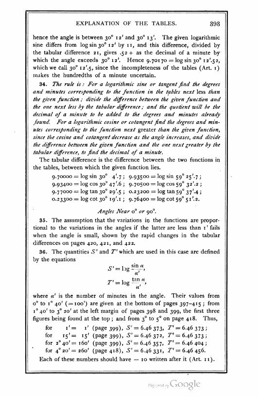
EXPLANATION OF THE TABLES. 393
hence the angle is between 300 12' and 30° 13'. The given logarithmic
sine differs from log sin 300 12' by 11, and this difference, divided by
the tabular difference 21, gives .52+ as the decimal of a minute by
which the angle exceeds 300 12'. Hence 9.701 70 = log sin 300 12'.52,
which we Call 30° i2'.5, since the incompleteness of the tables (Art. 1)
makes the hundredths of a minute uncertain.
34. The rule is : For a logarithmic sine or tangent find the degrees
and minutes corresponding t- the function in the tables next less than
the given function ; divide the difference between the given function and
the one next less by the tabular difference ; and the quotient will be the
decimal of a minute to be added to the degrees and minutes already
found. For a logarithmic cosine or cotangent find the degrees and min
utes corresponding to the function next greater than the given function,
since the cosine and cotangent decrease as the angle increases, and divide
the difference between the given function and the one next greater by the
tabular difference, to find the decimal of a minute.
The tabular difference is the difference between the two functions in
the tables, between which the given function lies.
9.70000 = log sin 30° V.7; 9.93500 = log sin 590 25'.7;
9.93400 = log cos 30° 47'.6 ; 9.70500 = log cos 59° 32'.2 ;
9.77000= log tan 300 29'.5 ; 0.23200 = log tan 59° 37'-4;
0.23300 = log cot 30° ig'.i ; 9.76400 = log cot 590 51/.2.
Angles Near 0° or 900.
35. The assumption that the variations in the functions are propor
tional to the variations in the angles if the latter are less than 1 ' fails
when the angle is small, shown by the rapid changes in the tabular
differences on pages 420, 421, and 422.
36. The quantities .S ' and T' which are used in this case are defined
by the equations
0, , sin a
a
rj,, , tan n7" = log — -,
a
where «' is the number of minutes in the angle. Their values from
o° to i° 40' ( = 100') are given at the bottom of pages 397-415 ; from
1° 40' to 30 20' at the left margin of pages 398 and 399, the first three
figures being found at the top ; and from 30 to 50 on page 418. Thus,
for 1' = 1' (page 399), S' = 6.46 373, T = 6.46 373 ;
for 15'= 15' (page 399), S' = 6.46 372, T — 6.46 373;
for 2° 40' =160' (page 399), S' = 6.46 357, T' = 6.46 404 ;
for 40 20' =260' (page 418), 5' = 6.46 331, T' = 6.46 456.
Each of these numbers should have — 10 written after it (Art. 11).
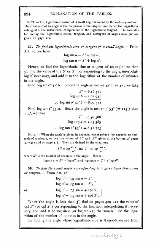
394: EXPLANATION OF THE TABLES.
Note. — The logarithmic cosine of a small angle is found by the ordinary method.
The cotangent of an angle is the reciprocal of the tangent, and hence the logarithmic
cotangent is the arithmetical complement of the logarithmic tangent. The formulas
for finding the logarithmic cosine, tangent, and cotangent of angles near 90- are
given on page 419.
37. To find the logarithmic sine or tangent of a small angle. — From
Art. 36, we have
log sin re = S' + log re',
log tan re = T' + log re'.
Hence, to find the logarithmic sine or tangent of an angle less than
5°, find the value of the -S"' or T' corresponding to the angle, interpolat
ing if necessary, and add it to the logarithm of the number of minutes
in the angle.
Find log sin 0° 42 '.6. Since the angle is nearer 43' than 42', we take
S'= 6.46 371
log 42.6 = 1.62 941
.-. log sin 0° 42 '.6 = 8.09 3 1 2
Find log tan 1°53'.2. Since the angle is nearer 1°53' (= 113') than
114', we take
T' = 6.46 388
log 1 13.2 = 2.05 385
.-. log tan 1°53'.2 = 8.51 773
Note. — When the angle is given in seconds, either reduce the seconds to deci
mals of a minute, or use the values of S" and T" given at the bottom of pages
397-417 and on page 418. They are defined by the equations "
P n , sin a , ~,, , tan aS " = log , and T" = log ,a" S a"
where a" is the number of seconds in the angle. Hence
log sin a = S" + log a", and log tan a = T" + log a".
38. To find the small angle corresponding to a given logarithmic sine
or tangent. — From Art. 36,
log re' = log sin re — S\
log re1 = log tan re — T\ ,
or log a' = log sin a + cpl S ',
log re' = log tan a + cpl T'. ,
When the angle is less than 3°, find on pages 420-422 the value of
cpl S' (or cpl 7") corresponding to the function, interpolating if neces
sary, and add it to log sin re (or log tan re) ; the sum will be the loga
rithm of the number of minutes in the angle.
In finding the angle whose logarithmic sine is 8.09006, we see from
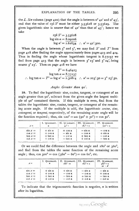
EXPLANATION OF THE TABLES. 395
the L. Sin column (page 420) that the angle is between o° 42' and o° 43',
and that the value of cpl.S' must be either 3.53628 or 3.53629. The
given logarithmic sine is nearer that of 42' than that of 43'; hence we
take
cpl S' = 3.53628
log sin a = 8.09006
log «'= 1.62634 .-. «' = 42'.300.
When the angle is between 3° and 5-, we may find S' and T' from
page 418 after finding the angle approximately from pages 423 and 424.
Thus in finding the angle whose logarithmic tangent is 8.77237 we
find from page 423 that the angle is between 3° 23' and 3- 24', being
nearer 3° 231. Then on page 418 we have
T'= 6.46423
log tan a = 8.77237
.o. log tan « — T' = log «' = 2.30814 .\ «' = 203'.30 = 3° 23'.30.
Angles Greater than 90^.
39. To find the logarithmic sine, cosine, tangent, or cotangent of an
angle greater than 90-, subtract from the given angle the largest multi
ple of 90° contained therein. If this multiple is even, find from the
tables the logarithmic sine, cosine, tangent, or cotangent of the remain
ing acute angle. If the multiple is odd, the logarithmic cosine, sine,
cotangent, or tangent, respectively, of the remaining acute angle will be
the function required ; thus, sin 120° = s1n (90° + 30°) = cos 30°.
I. Quadeant. II. Qt'adranT. III. Quadeant. IV. Quadeant.
x — a 90° +- 1800 + a 2700 + a
sin x = + sin a + cos a — sin a — cos a
COS X — + cos a — sin a — cos a + sin a
tan x — + tan a — cot a + tan a — cot a
cot x = + cot a — tan a + cot a — tan a
Or we could find the difference between the angle and 180° or 3600,
and find from the tables the same function of the remaining acute
angle ; thus, cos 300° = cos (360- — 6o°)= cos 60°, etc.
I. Quadeant.a
II. Quadeant. III. Quadeant.
4- a
IV. Quadeant.
36-0 — a
or - a*
X " 18o°-a
sin x — 4- sin a + sin a — sin a — sin a
COS X — + cos a — cos a — cos a + cos a
tan x — + tan a — tan a + tan a — Ian a
Cot X — + cot a — cot a + cot a — cot a
To indicate that the trigonometric function is negative, n is written
after its logarithm.
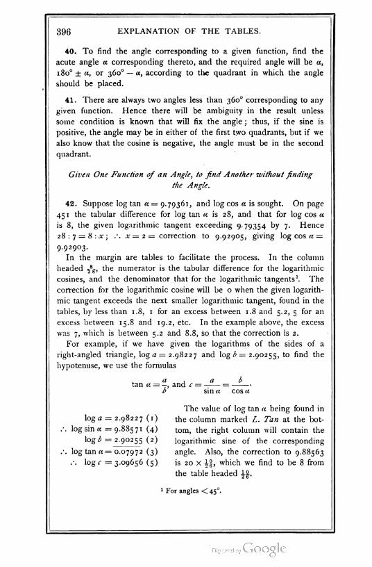
396 EXPLANATION OF THE TABLES.
40. To find the angle corresponding to a given function, find the
acute angle a corresponding thereto, and the required angle will be a,
1 80° ± a, or 360° — «, according to the quadrant in which the angle
should be placed.
41. There are always two angles less than 360° corresponding to any
given function. Hence there will be ambiguity in the result unless
some condition is known that will fix the angle ; thus, if the sine is
positive, the angle may be in either of the first two quadrants, but if we
also know that the cosine is negative, the angle must be in the second
quadrant.
Given One Function of an Angle, to find Another without finding
the Angle.
42. Suppose log tan « = 9.79361, and log cos a is sought. On page
451 the tabular difference for log tan a is 28, and that for log cos a
is 8, the given logarithmic tangent exceeding 9.79354 by 7. Hence
28: 7 = 8:.x ; .-. x = 2 = correction to 9.92905, giving log cos a =
9.92903.
In the margin are tables to facilitate the process. In the column
headed -£g, the numerator is the tabular difference for the logarithmic
cosines, and the denominator that for the logarithmic tangents1. The
correction for the logarithmic cosine will be o when the given logarith
mic tangent exceeds the next smaller logarithmic tangent, found in the
tables, by less than 1.8, 1 for an excess between 1.8 and 5.2, 5 for an
excess between 15.8 and 19.2, etc. In the example above, the excess
was 7, which is between 5.2 and 8.8, so that the correction is 2.
For example, if we have given the logarithms of the sides of a
right-angled triangle, ^0 = 2.98227 and log b = 2.90255, to find the
hypotenuse, we use the formulas
a , a btan a = —, and c --
b' sin « cos a
The value of log tan a being found in
log a = 2.98227 (1) the column marked L. Tan at the bot-
log sin a =9.88571 (4) torn, the right column will contain the
log b = 2.90255 (2) logarithmic sine of the corresponding
log tan a = 0.07972 (3) angle. Also, the correction to 9.88563
.-. log c = 3.09656 (5) is 20 x \%, which we find to be 8 from
the table headed \\.
1 For angles <45°.

TABLE XV.
COMMON
LOGARITHMS OF NUMBERS
FROM I TO IIOOO.
N. Log. N. Log. N. Log. N. Log. N. Log.
0 — 20 1.30 103 40 1 .60 206 60 1.77 8'5 80 1.90309
' 0.00000 21 1.32 222 41 1.61 278 61 1.78 533 81 1 .90 849
2 0.30 103 22 1.34242 42 1.62 325 62 1.79 239 82 1.91 381
3 047 712 23 i-36 173 43 1.63 347 63 1.79 934 83 1.91 908
4 0.60 206 24 1.38 021 44 1.64345 64 1.80 618 84 1.92 428
5 0.69 897 25 i-39 794 45 1.65 321 65 1.81 291 85 1.92942
6 0.77815 26 1.4 1 497 46 1.66 276 66 1.81 954 86 1.93450
7 0.84 510 27 143 136 47 1.67 210 67 1.82 607 87 1.93 952
8 0.90 309 28 1.44 716 48 1.68 124 68 1.83 251 88 1.94 448
9 0.95 424 29 1 .46 240 49 1.69 020 69 1.83 885 89 1.94 939
10 1.00 000 30 1.47 712 50 1.69 897 70 1.84 510 90 1.95 424
ii 1.04 139 31 1.49 136 5i 1.70757 7' 1.85 126 91 1.95 904
12 1.07 918 32 i-5° 5 i5 52 1. 71 600 72 1.85 733 92 1.96379
13 1.n 394 33 1.51 851 53, 1.72428 73 1.86 332 93 1.96848
'4 1. 14 613 34 i-53 H8 54 i-73 239 74 1.86923 94 1.97 313
'5 1. 17 609 35 1.54407 55 1.74036 75 1.87 506 95 1.97 772
16 1.20 412 36 1.55630 56 1-74819 76 1.88 081 96 1.98 227
'7 1.23043 37 1.56 820 57 1.75 587 77 1.88649 97 1.98 677
18 i-25 527 38 1.57978 58 1.76 343 78 1.89 209 98 1.99 123
'9 1.27875 39 1.59 106 59 1.77085 79 1.89 763 99 1.99564
20 1.30 103 40 1.60 206 60 1.77 815 80 1.90309 100 2.00000
S'. V. S". T".
0 646 373 373 o° 0' = 0" 4-68 557 557
1 373 373 0 1 = 60 557 557
0 2 = 120 557 557
(397)
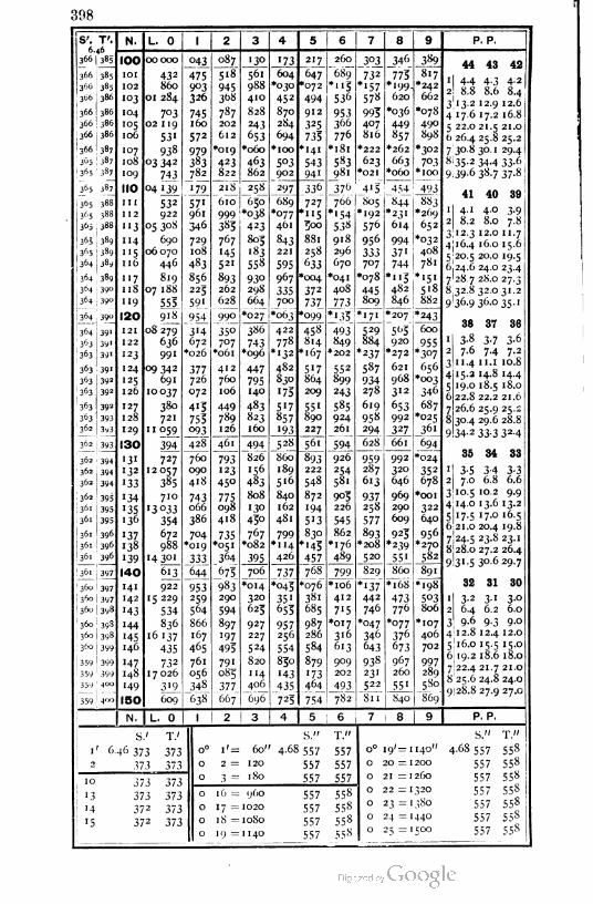
398
IS'. T'6.46
366
3- "
366
365 ! 387
1 365 '387
365 387
365 388
365 , 388
365 388
365 389
365 389
364 389
364 , 389
364 j 390364 | 39-
364 39°
364 39•
363 39'
363 391
363 391
39a
39a
363
I363
363
363
3-- -
362 1 394
3*3
36a
36a
362
36'
136l
361
361
361 396
36' 397
36- 397
36- I 397
36- I 398
36- ; 398
360
360
359
359
359 ' 4°°
359 1 4"°
N. L. 0
IOO
01
02
03
04
°506
07
08
09
IIO
II
12
'3
14
'516
"718
19
120
21
22
23
24
25
26
27
28
29
130
3'32
33
34
3536
3738
39
140
4"
42
43
44
4546
47
48
49
1 50
432
860
01 284
7°302 1 19
531
938
°3 342
743
04 '39
532
922
05308
690
06 070
446
819
07 1 88
555
918
08 279
636
991
°9 342
691
10037
380
721
11 059
043
475903
326
745160
572
979383
782.
'79
57"961
346
729
10S
483
856
225
59'
?54
3'4672
*026
377726
072
415
755
P93
087
-5I8
945
368
787
202
612
'019
423
82 2
394
727
12057
385
710
'3°33
354
672
988
'4 3°'
613
922
15 229
534
836
16 137
435
732
17 026
3'9
009
428
760
090
418
743066
386
704
'019
333
644
953
259
564
866
167
465
761
05-
348
638
218
610
999
3^5
767
•45
521
893
262
628
990
"350
707
"061
412
760
106
449
789
126
461
793
123
450
775098
418
735*05 1
364
675
983
290
594
897
197
495
791
083
377
667
561
98S
410
828
243
f'53
*o6o
4<>3
802
'73
604•030
452
870
284
694
oIOO
5°391 '2
_25l
650
-038
423
805
"83
558
93°298
664 _
'027 |*063
297
689
*°77461
843
22 1
595
967
335
336
727
115
roo
88l
258
633
*oo4
372
737.
*°99
386
743•096
447
795
140
483
823
160
494
826
4§3
808
130
450
767
*082
395
706
*o14
320
()25
927
227
524
820
114
41 id
696
422
778
"132
482
830
'75
5"7857
193
528
860
189
516
840
162
481
799•114
426
.737
'045
35 "655
957256
554
850
'43
435
725
217
647
'072
494
912
325
735
141
543
94'
260
689
*"5536
953300
776
•l8l
583
981
3°1
732
*'57578
995
4"7
816
*222
623
*02I
376_ _4' 5
766 I 805•154 '192
458
814
'167
517
804
209
55 1
890
227
S61_
893
222
548
872
"94
5"3
830
'45
457
768
'076
381
685
987
286
584
879
173
4"4
754
538
918
296
670
*041
408
_773
1L33
493849
-202
552
899
243
585
924
26l
594
926
2$4
58l
905
226
545
862
*176
48,,
576
956
333707
*078
445809
799
*1o6
412
7'5
*o17
316
613
909
202
493
782 81
171
7' 4°8
744 781
1 "3 |*'5"
482 518
846 j 882*207 *243
529
884
*237
587
934
278
619
958
294
628
959287
613
937258
577
893
*2o8
520
829
*'37442
746
*047
346
643
938
231
522
8 9
346 389
773" 817
*'99- *242
620 662
*036 *078
449 490
»5 7 898
*262 *3°2
663 7°3*o6o *IOO
454
844
493
883"•269
652
*032
*23'
614
994
5^5 600
920 955
*2J2 *3°7
621 656
968 *003
312 346
653 687
*025992
327 361
66l 694
992 *024
320 352
646 678
969 *OOI
290 322
609 640
925 956
*270*239
55' 582
860 89'
*168 *198
473 5°3776 806
*077 *107
376 406
673 702
967 997260 289
55' 5 So
840 "869"
8 9
P. P.
44 43 42
1 1 4-4 4-3 4-2
21 8.8 8.6 8.4
3|13.2 12.9 12.6
4 17.6 17.2 16.8
5 22.0 21.5 21.0
b 26.4 25.8 25.2
7 3°-8 30. 1 29.4
8 35-2 34-4 33-6
9.39-6 38.7 37-8
41 40 39
1 4.1 4.0 3.9
2 8.2 8.0 7.8
3 12.3 12.0 1 1.7
4 16.4 16.0 1 5.6
5;2o.5 20.0 19.5
6,24.6 24.0 23.4
728.728.027.3
8.32.832.031.2
9 36.9 36-035.1
38 37 36
1 3-8 3-7 3-6
2 7-6 7-4 7-2
3 11.4 11. 1 10.8
4:15.2 14.8 14.4
5] 19.0 18.5 18.0
6 22.8 22.2 21.6
7 26.6 25.9 25.2
8 30.4 29.6 28.8
9 34-2 33.3 32.4
35 34 33
'! 3-5 3-4 3-32 7.0 6.8 6.6
310.5 10.2 9.9
4I14.o 13.6 13.2
5 17.5 17.0 16.5
6.21.0 20.4 19.8
7)24.5 23.8 23.1
8 28.0 27.2 26.4
9I31.5 30.629.7
32 31 30
1 3-2 3 ' 3-°
2 6.4 6.2 6.0
3 9-6 9-3 9-0
4 12.8 12.4 12.0
5' 16.0 15.5 15.0
6 19.2 18.6 18.0
7[22.4 21.7 21.0
8 25.6 24.8 24.0
9| 28.8 27.9 27.0
N. L. 0 I P. P.
S.' T.'
'' 6.46 373 373
2 373 373
10 373 373
'3 373 373
'4 372 373
51* >/.)
S."
60" 4-68 557
120 557
180 557
T."
557
557
557
: 960
: I020
: IOSO
557
557
557
558
558
558
S." T."
0° 19' = I I40" 4.68 557 558
0 20 = I200 557 558
0 21 = I260 557 558
0 22 = 1320 557 558
0 23 = ' .180 557 558
0 24 = 1440 557 558
1 ) 2 = I5OO 557 558
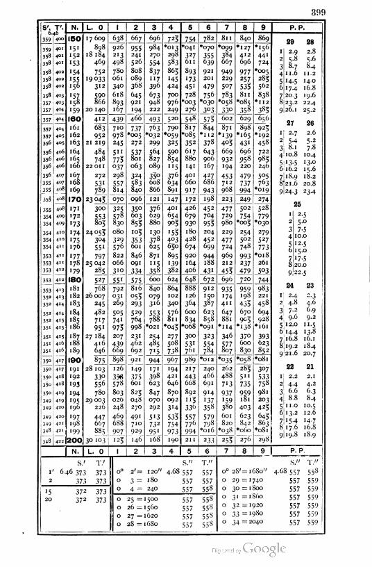
399
S'. T'. N. L. 0 1 2 3 4 5 6 7 8 9
359 j 4<»150 17 609 638 667 696
J3l 754 782 811 840 869
359 ! 4°1 IS1 898 926 955" "984 *o13 *041 *070 *099 •127 •156
358 4-1 152 18 184 213 241 270 298 327 355 384 412 441
358 4-1 '53 469 498 526 554 583 611 639 667 696 724
358 4-2 '54 752 780 808 837 865 893 921 949 977 *005
358 4-2 155 19033 06 1 089 117 H5 '73 201 229 257 283
358 4-2 •56 312 34° 368 396 424 45' 479 507 535 562
358 4-3 157 590 618 645 673 700 728 756 783 811 838
357 4-3 158 866 893 921 948 976 *003 *030 *o58 *o85 *U2
357 4-4 159 20 140 167 194 222 249 276 303 33° 358 383
357 4-4 ISO 412 439 466 493 520 548 573 602 629 656
357 4-4 161 683 710 737 763 790 817 844 871 898 925
357 4-5 162 952 978 *005 *032 *059 *085 *II2 *'39 *'65 *192
356 4-5 '63 21 219 245 272 299 325 352 378 403 43' 458
356 4-6 164 484 511 537 564 590 617 643 669 696 722
356 4-6 .65 748 773 801 827 854 880 906 932 558 985
356 4-6 166 22 01 1 037 063 089 "5 141 167 '94 220 24b
356 4-7 167 272 298 324 33° 376 401 427 453 479 505
355 407 168 531 557 583 608 634 660 686 712 737 763
355 4-8 169 789 814 840 866 891 917 943 968 994 *o19
355 4-8 170 23045 070 096 121 "47 172 198 223 249 274
355 4-8 171 300 325 35° 37° 401 426 452 477 502 528
354 4-9 172 553 578 603 629 654 679 704 729 754 779
354 4-9 '73 805 830 853 880 905 93o 955 980 *oo5 *030
354 41- 174 24053 080 '°5 1 30 '55 180 204 229 254 279
354 410'75 3°4 329 353 378 403 428 452 477 502 527
354 41* 176 551 576 601 625 650 674 699 724 748 773
353 411 177 797 822 846 871 895 920 944 969 993 *o18
353 411 178 25 042 066 091 "5 '39 164 188 212 237 261
353 412 •79 285 310J34
358 382 406 43' 453 479 5°3
353 412 180 527" 55' 575 600 624 648 672 696 720 744
353 4•3 181 768 792 816 840 864 888 912 935 959 983
35= 413 182 26007 03 ' 053 079 102 126 150 '74 198 221
352 414 183 245 269 293 316 340 364 387 4" 433 458
352 414 184 482 505 529 553 576 600 623 647 670 694
352 415 185 717 741 764 788 811 834 858 881 905 928
351 415 186 95' 973 998 *02I *04S *o68 *091 *114 *'38 *161
351 415 187 27 184 207 231 254 277 300 323 346 370 393351 416 188 416 439 462 485 508 53' 554 577 600 623
351 416 189 646 669 692 715 738 761 784 807 830 852
35- 4'7 190 875 898 921 944 967 989 *OI2 !°35. *o58 *o81
35- 417 191 28 103 126 149 171 194 217 24O 262 285 307
35- 418 192 33o 356 375 398 421 443 466 488 5" 533
35o 418 '93 556 578 601 623 646 668 69I 7'3 735 758
35o 419 194 780 803 825 847 870 892 914 937 959 981
349 419 195 29003 026 04S 070 092 "3 '37 '59 181 203
349 42- 196 226 248 270 292 3'4 33t> 358 380 4°3 425
349 42- 197 447 469 491 5'3 535 557 579 601 623 645:
349 421 198 667 688 710 732 754 776 798 820 842 863
348 421 199 885 907 929 95' 973 994 *o16 *oj8 *o6o
348 422 200 30 103 '23 146 168 190 2II 233 255 276 298|
N. L. 0 1 2 3 4 5 6 7 8 9 1
P. P.
2.9
5-8
8.7
11.6
14.5 140
7.4 16.8
2.8
5.6
8.4
11. 2
20.3 19.6
.2 22.4
9I26.1 25.2
823.:
26
2.6
5-2
7.8
27
1 2.7
2 5-4
3 8.1
4 10.8 10.4
5 '3-5 '3°6 16.2 15.6
718.9 18.2
8j21.6 20.89124-3 23.4
25
2-5
5.0
7-51 0.0
12-5
15-0
'7-520.0
22. K
24 23
2.3
4.6
6.9
9.2
1i 2.4
2 4.8
3| 7-2
4' 9-6
5 12.0 u.5
614.4 13.8
716.8 16.1
8j19.2 18.49 21.6 20.7
22 21
2.1
4.2
6-3
8.4
1 2.2
2 4.4
3 6.6
4 8.8
5 1 1.0 10.5
6 13.2 12.6
7 '5-4 '4-78 17.6 16.8
9|19.8 18.9
'' 6.46 373
2 373
T.'
373
373
'5 372 373
20 372 373
P. P
2'= 120
3 = 180
4 = 240
S."
4.68 557
.557
557
T."
557
557
558
o 25 = 1500
o 26 =1560
o 27 = 1620
o 28 = 1 6S0
557
557
557
557
558
558
558
558
S." T."
0° 28' = 1680" 4-6S 557 558
0 29 = 1740 557 559
0 30 = 1800 557 559
0 3 1 = 1860 557 559
0 32 = 1920 557 559
0 33 = 1 980 557 559
0 34 = 2040 557 559
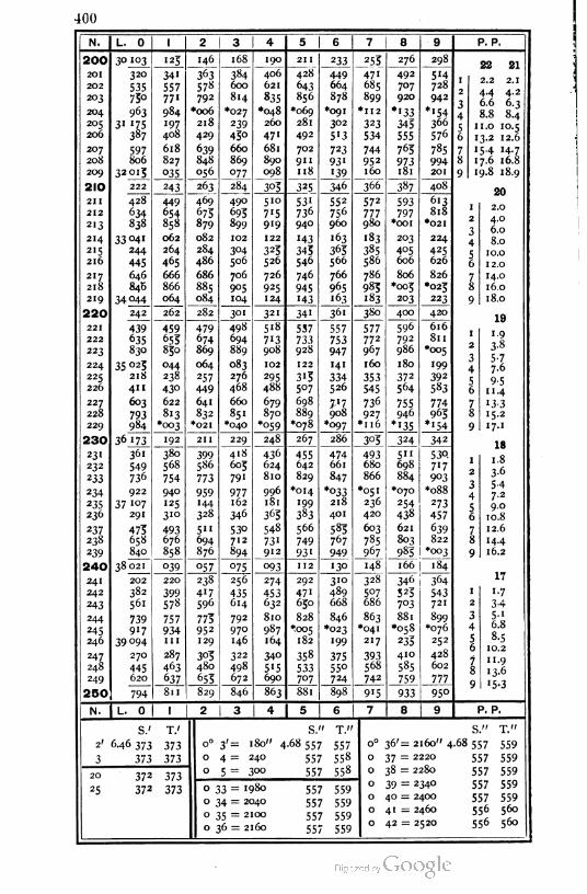
400
N. L. 0 1 2 3 4 5 6 7 8 9
200 30103 123 146 168 190 21 1 233 _?S3 276 298
20 1 320 34 1 363 384 406 "428" 449 471 492 5'4
202 535 557 57« 600 621 643 664 685 707 728
203 750 77" 792 814 835 856 878 899 920 942
204 963 984 *oo6 *027 *o48 •069 *091 *II2 •133 *I54
205 31 175 197 218 239 260 281 302 323 343 366
206 387 408 429 43° 471 492 5'3 534 555 576
207 597 618 639 660 681 702 723 744 763 785
208 806 827 848 869 890 911 93' 952 973 994
209 32013 °35 056 °77 098 118 "39 160 181 201
210 222 243 263 284 303 325 346 366 387 408
211 428 449 469 490 510 53' 552 572 593 613
212 634 654 675 693 7'5 736 756 777 797 818
213 838 858 879 899 919 940 960 980 *OOI *02I
214 33°41 062 082 102 122 "43 163 '83 203 224
215 244 264 284 3°4 323 343 363 385 405 425
216 445 465 486 506 526 546 566 586 606 626
217 646 666 686 706 726 746 766 786 806 826
218 846 866 885 905 925 945 965 983 *003 *023
219 34°44 064 084 104 124 "43 163 "83 203 223
220 242 262 282 301 321 341 361 380 400 420
221 439 459 479 498 5"8 537 557 577 596 616
222 635 655 674 694 7'3 733 753 772 792 8ll
223 830 850 869 889 908 928 947 967 986 *005
224 35 025 044 064 083 102 122 141 160 180 199
225 218 238 257 276 295 3'3 334 353 372 392
226 411 43° 449 468 488 507 526 545 564 583
227 603 622 641 660 679 698 7-l7 736 755 774
228 793 813 832 851 870 889
*o78
908 927 946 965
229 984 *O03 *02I *040 *o59 *097 *u6 *'35 *"54
230 36 173 192 2II 229 248 267 286 303 324 342
23 1 361 380 399 418 436 455 474 493 5" 53Q
232 549 568 586 603 624 642 661 680 698 7"7
233 736 754 773 791 810 829 847 866 884 903
234 922 940 959 977 996 *o14 *033 *051 •070 *o88
235 37 107 125 144 162 181 199 218 236 254 273
236 291 310 328 346 363 383 401 420 438 457
237 475 493 5" 53o 548 566 583 603 621 639
238 658 676 694 712 731 749 767 785 803 822
239 840 858 876 894 912 931 949 967 983 *oo3
240 38 021 039 057 °75 093 112 130 148 166 184
241 202 220 238 256 274 292 310 328 346 364
242 382 399 417 435 453 471 489 5°7 523 543
243 561 578 596 614 632 630 668 686 7°3 721
244 739 757 773 792 810 828 846 863 881 899
*076245 917 934 952 970 987 ^005 *023 *041 •058
246 39094 HI 129 146 164 182 199 217 233 252
247 270 287 303 322 340 358 375 393 410 428
248 445 463 480 498 515 533 550 568 585 602
249 620 637 655 672 690 707 724 742 759 777
250 794 811 829 846 863 881 898 915 933 95°
N. L. 0 1 1 2 3 4 5 6 7 8 9
P. P.
22 21
l 2.2 2.1
2 4.4 4.2
3 6.6 6.3
4 8.8 8.4
5 1 1.0 10.5
6 13.2 12.6
7 15-4 14-7
8 17.6 16.8
9 19.8 18.9
20
2.0
4.0
6.0
8.0
10.0
12.0
14.0
16.0
18.0
19
1-9
3-8
5-77.6
9-51 1.4
"3-3'5-2
17.1
18
1.8
3-6
5-4
7-2
9.0
10.8
12.6
14.4
16.2
17
1.7
3-45-J
6.S
8-5
10.2
1 1.9
13.6
'5-3
P. P.
S." T."
o° 36'= 2160" 4.68 557 559
0 37 = 2220 557 559
0 38 = 2280 557 559
0 39 = 2340 557 559
0 40 = 2400 557 559
0 41 = 2460 556 560
0 42 = 2520 556 560
S.' T.'
2' 6.46 373 373
3 373 373
20
25
372 373
372 373
S." T."
0° 3'= 180" 4-68 557 557
o 4= 240 557 558
o 5 = 300 557 558
o 33 = '98o
o 34 = 2040
o 35 = 2100
o 36 = 2160
557 559
557 559
557 559
557 559
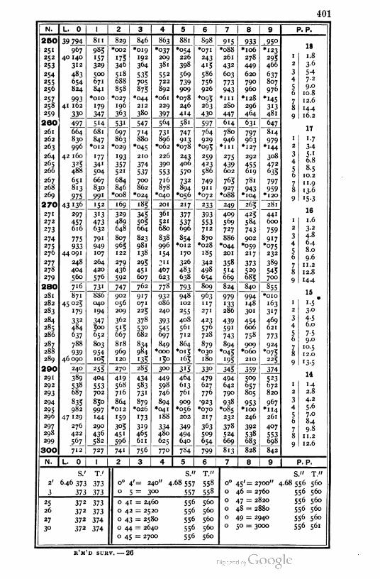
401
N. L. 0 1 2 3 4 5 6 7 8 9
250 39 794 811 829 846 863 881 S98 915 933 .95°
251
252
253
967
40 140
312
983
'57329
*002 *019
192
364
*°37209
*°54226
*071
243
413
*o88
261
432
*1o6
278
449
•123
173 293
466346 381 398
254
255
256
483
654
824
500
671
841
518 533
7°5875
552
722
892
569
739909
586
756
926
603
773
943
620
790
960
637
807
976
688
858
257
258
99341 162
*OIO *027
196
*044
212
*o61 •078
246
414
*°93263
430
•1ll *I28 *H5313
481
179
347
229
397
2S0
447
296
259 33° 363 380 464
260 497 5H 531 547 564 "581 597 614 631 647
261
262
263
664
830
996
681
847
697
863
*029
7'4 731
896
*062
747
9'3*078
764
929
780
946
*1 1 1
797
963
*127
814
880 979*144*OI2 *°45 *°95
264
265
266
42 160 177
341
193
357521
210
374
537
226
39°
553
243
406
259
423
586
275
439
602
292 308
472
633
325
488 5°4 57°
455619
267
268
269
651
813
975
667
830
991
684
846
*oo8
700
862
716
878•040
732
894
*056
749911
763
927
*o88
781
943
*1o4
797
959*024 •072 *I20
270 43 '36 152 169 I85 201 217 233 249 263 28l
271
272
273
297
457616
3'3
473
329
489
648
345
5°5
361
521
680
377
537696
393
553712
409
569
727
423
584
743
44I
600
632 664 759
274
275
276
775
93344 091
791 807 823
981
138
838
996
•54
854 870 886 902 917
949
107
963
122
*0I2
I70
*028 *°44
201*°59217
*°75232185
277
278
279
248
404
264
420
576
279 295
45'
326
483
638
342
498
654
358
5"4
373529
685
389
543
700560
436
592 607
467
623 669
280 716 731 747 762 778 793 809 824 840 855
281
282
283
871
45 025
179
886
O40
194
902
056
209
917
071
225
932
086
240
948
102
963
117
271
979133
286
994148
301
*OIO
255
'63
317
284
285
286
332
484
637
347500
652
362 378
53°682
393
545
697
408
561
712
423
576
728
439
591
743
454 469
621
773
5'3 606
667 758
287
288
289
788 803 818
969
120
834
984
'35
849
*ooo
864
*015
165
879
*03°
180
894
*o43
193
909
*o6o
210
924•073
225
93946090
954
105 150
290 240 253 270 285 300 313 33° 343 359 374
291
292
293
389
538
687
404 419
568
716
434
583
731
449
598
746
464 479
627
776
494
642
790
5°9657
805
523
672
820
553702
613
761
294
295
296
833
982
830 864 879 894
*041
188
909
*056
202
-923
*070
217
938
*o85
232
953 967
*H4
261
997144
*OI2
159
*026 *IOO
47 I29 173 246
297
298
299
276
422
567
290
436
582
303 319
465
611
334480
625
349
494640
363
5°9654
378
524
669
392
538
683
407
45' 553698596
300 712 727 741 756 770 784 799 813 828 842
N. L. 0 1 2 3 4 5 6 7 8 9
P. p.
18
1,8
3-6
5-47.2
9.0
10.8
12.6
14.4
16.2
17
"-7
3-4
5'6.8
8.5
I0.2
1 1.9
13-6
'5-3
16
1.6
3-2
4.8
6.4
8.0
9.6
1 1.2
12.8
'4-4
15
1.5
3°
4-56.0
7-59.0
10.5
12.0
•3-5
14
1.4
2.8
4.2
5.6
7.0
8.4
9.8
1 1.2
12.6
P. P,
S.' T.'
6-46373 373
373 373
25
26
27
30
372 373
372 373
372 374
372 374
S." T."
o° 4'= 240" 4-68 557 558
o 5 = 300 557 558
o 41 = 2460
o 42 = 2520
o 43 = 2580
o 44 = 2640
o 45 = 2700
556 560
556 560
556 560
556 560
556 560
S." T."
o° 45'= 2700" 4.68 556 560
o 46 = 2760 556 560
o 47 = 2820 556 560
o 48 = 2880 556 560
o 49 = 2940 556 560
o 50 = 3000 556 561
r'm'u sukv. — S

402
N. L. 0 1 2 3 4 5 6 7 8 9
300 47 7"2 727 741 756 770 784 799 8'3 828 842
301 857 871 885 900 914 929 943 958 972 986
302 48001 015 029 044 058 073 087 101 116 130
3°3 144 '59 173 187 202 216 230 244 259 273
3°4 287 302 316 33° 344 359 373 387 401 416
3°5 430 444 458 473 487 5°' 5'5 53° 544 558
306 572 586 601 615 629 643 657 671 686 700
3°7 714 728 742 756 770 785 799 8'3 827 841
308 855 869 883 897 9II 926 940 954 968 982
3°9 996 *OIO *024 *o38 *052 *o66 *o8o *°94 *1o8 *I22
310 49 136 15° 164 178 192 206 220 234 248 262
3" 276 290 304 3'8 332 346 360 374 388 402
312 415 429 443 457 47' 485 499 5'3 527 54'313 554 568 582 596 610 624 638 65' 665 679
314 693 707 721 734 748 762 776 790 803 817
315 83' 843 859 872 886 900 9H 927 941 955316 969 982 996 *OIO *024 *°37 *051 *065 *°79 *092
3'7 50 106 120 '33 '47 161 '74 188 202 215 229
3'8 243 256 270 284 297 3" 325 338 352 365
3'9 379 393 406 420 433 447 461 474 488 50I
320 515 529 542 556 569 583 596 610 623 637
321 651 664 678 691 705 718 732 745 759 772
322 786 799 813 826 840 853 866 880 893 907
323 920 934 947 961 974 987 *OOI *014 *028 *041
324 5'°55 068 081 095 108 121 '35 148 162 '75325 188 202 2I5 228 242 255 268 282 295 308
326 322 335 348 362 375 388 402 4'5 428 44'
327 455 468 481 495 508 521 534 548 561 574328 587 601 614 627 640 654 667 680 693 706
329 720 733 746 759 772 786 799 812 825 838
330 851 865 878 891 904 917 93° 943 957 970
983 996 *009 *022 *°35"•048
*o61 *°75 *o88 *IOI
332 52 "4 127 140 '53 166 179 192 205 218 23 '
333 244 257 270 284 297 310 323 336 349 362
334 375 388 401 414 427 440 453 466 479 492
335 504 5'7 53° 543 556 569 582 595 608 621
336 634 647 660 673 686 699 711 724 737 75°
337 763 776 789 802 815 827 840 853 866 879
338 892 905 917 93° 943 956 969 982 994 *oo7
339 53020 °33 046 058 071 084 097 110 122 '35
340 148 161 •73 186 199 212 224 237 250 263
341 275 288 301 3H 326 339 352 364 377 39o
342 4°3 415 428 441 453 466 479 491 5°4 5'7
343 529 542 555 567 580 593 605 618 63" 643
344 656 668 681 694 706 719 732 744 757 769
345 782 794 807 820 832 845 857 870 882 895
346 908 920 933 945 958 970 983 995 *oo8 *020
347 54 033 045 058 070 083 095 108 120 '33 '45
348 158 170 183 "95 208 220 233 245 258 270
349 283 295 3°7 320 332 343 357 37° 382 394
350 407 419 432 444 456 469 481 494 506 5'8
N. L. 0 1 2 3 4 5 6 7 8 9
P. P.
IS
I 1.5
2 3°
3 4-5
4 6.0
5 7-56 9.0
7 10.5
8 12.0
9 '3-5
14
1 1.4
2 2.8
3 4.2
4 5.6
5 7.0
6 8.4
7 9.8
8 11. 2
9 12.6
13
1 1-3
2 2.6
3 39
4 5-2
5 6-5
6 7.8
7 9'8 10.4
9 1 1.7
12
1 1.2
2 2.4
3 3-6
4 4.8
5 6.0
6 7-2
7 8-4
8 9.6
9 10.8
P. P.
S.' T.'
3' 6.46 373 373 0° 5' = 3°o
4 373 373 0 6 = 360
3° 372 374 0 5° = 3000
35 372 374 0 5' = 3060
0 52 = 3120
0 53 = 3180
0 54 = 3240
S." T."
557 558
556 56'
556 561
556 561
556 561
556 561
S." T."
o° 54'= 3240" 4.68 556 561
o 55 = 33°o 556 56'
o 56 = 3360 556 561
o 57 = 3420 555 561
o 58 = 3480 555 562
o 59 = 354° 555 562
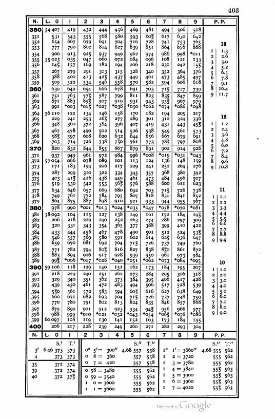
403
N. L. 0 1 2 3 4 5 6 7 8 9 P. P.
350 54 407 419 432 444 456 469 481 494 506 5'8
351 53' 543 555 568 580 593 605 617 6^0 6^2
352 654 667 679 691 704 716 728 74' 753 76513
353 777 790 802 814 827 839 851 864 8^6 888
354 900 913 923 937 949 962 974 986 998 *OII1-3
355 55°23 °35 047 060 072 084 096 108 121 '332 2.6
-2 1 o356 143 157 169 182 194 206 218 230 242 -55
j
4
3-y5.2
357 267 279 291 303 315 328 340 352 364 3765 6.5
358 388 400 413 423 437 449 461 473 485 497 6 7.8
359 509 522 534 546 558 570 582 594 606 6187 9-'
360 630 642 654 666 678 691 7'3 8703 727 739 10.4
11.7361 751 763 773 787 799 811 823 833 847 859 9
362 871 883 893 907 919 93' 943 953 967 979363 991 *oo3 *o1s *027 •038 *050 *o62 *074 *o86 *098
364 56 110 122 134 146 158 170 182 '94 205 21712365 229 241 253 263 277 289 30 1 312 324 336
366 348 360 372 384 396 407 419 43' 443 453 1 1.2
367 467 478 490 502 5'4 526 538 549 56' 573691
2 2.4
368 583 597 608 620 632 644 656 667 679 3 3-6
369 7°3 7H 726 738 75o 76. 773 783 797 808 4 4.8
56
A n
370 820 832 844 855 867 879 891 902 9'4 926O.O
7-2961 984 996 *oo8 *o19 *031 *043
/ ■
371 937 949 9727 8.4
372 57 054 066 078 089 101 "3 124 '36 148 '59 8 9.6
373 171 '83 194 206 217 229 241 252 264 276 10.8
374 287 299 310 322 334 345 357 368 380 392
9
375 403 413 426 438 449 461 473 484 496 5°7376 5'9 530 542 553 563 576 588 600 611 623
377 634 646 657 669 680 692 703 7'3 726 738 11
378 749 761 772 784 795 807 818 830 841 852 1 1.1
379 864 875 887 898 910 921 933 944 955 967 2 2.2
380 978 990 *OOI *o13 *024 *035 *047 *o58 •070 *o81 3 3-3
381 58092 104 "5 127 138 '49 161 172 184 '934 4.4
382 206 218 229 240 252 263 274 286 297 309 5 5-5z £.
383 320 331 343 354 365 377 388 399 410 4220 O.O
384 433 444 456 467 478 490 501 512 524 5337 7-7
8.8385 546 557 569 580 591 602 614 623 636 647
8
Q QQ386 659 670 681 692 704 7'3 726 737 749 760
y y*y
387 771 782 794 805 816 827 838 830 861 872
388 883 894 906 917 928 939 950 961 973 984
389 993 *oo6 *o17 *028 *040 *051 *o62 *073 *o84 *°95 10
390 59 106
218
118 129 140 151 162 173 184 '95 2071 1.0
391 229 240 251 262 273 284 295 306 318 2 2.0392 329 340 351 362 373 384 395 406 4'7 428
3 3-o
393 439 45° 461 472 483 494 506 5'7 528 539 4 4.0
394 53o 561 572 583 594 603 616 627 638 649 5 5.0
395 660 671 682 693 704 7'5 726 737 748 759 6 6.0
396 770 780 791 802 813 824 835 846 857 868 7 7.0
397 879 890 901 912 923 934 943 956 966 9778 8.0
398 988 999 *OIO *02I *032 *043 *©54 *o63 •076 *o86 9 9.0
399 60 097 108 119 130 14' I52 163 '73 184 '95
400 206 217 228 239 249 260 271 282 293 304
N. L. 0 2 3 4 5 6 1 8 9 P. P.
S.' T.' S." T." " T."
3' 6-46373 373 0° 5'= 300" 4-68557 558 .0 1' =3660" 4.68555 562
S
4 373 373 0 6 = 360 557 558 I 2 = 3720 555 562
35 372 3740 7 = 420 557 558 ' 3 = 3780 555 562
39 372 374 0 58 = 3480 555 562 1 4 = 3840 553 563
40 372 373 0 59 = 3540 555 562 1 5 = 3900 555 563
1 0 = 3600 555 562 1 6 = 3960 553 563
1 1 = 3660 555 562 1 7 = 4020 555 563

404
N. L. 0 1 2 3 4 5 6 7 8 9 P. P.
400 60 206 217 228 239 249 260 271 282 293 304
401 3'4 325 336 347 358 369 379 390 401 412
402 423 433 444 455 466 477 487 498 5°9 520
403 53' 54' 552 563 574 584 595 606 617 627
404 638 649 660 670 681 692 7°3 7'3 724 733405 746 756 767 778 7S8 799 810 821 831 842
11406 853 863 874 8S5 895 906 917 927 938 949
407 959 970 981 991 *002 *o13 *023 *°34 *°43 *°551 1.1
408 61 066 077 087 098 IO9 "9 130 140 '5' 1622 2.2
409 172 '83 '94 204 213 225 236 247 257 2f8 3 3-3
4IO 278 289 300 310 321 33' 342 352 363 3744 4-4c
411 384 393 405 416 426 437 448 458 469 479 6 6.6
412 490 500 5" 521 532 542 553 563 574 5847 7-7
413 595 606 616 627 637 648 658 669 679 690 8 §i
414 700 711 721 73' 742 752 763 773 784 794 9 9-9
415 805 815 826 836 847 857 868 878 888 899
416 909 920 93° 94' 95' 962 972 982 993 *003
417 62014 024 °34 045 °55 066 076 086 097 107
418 118 128 '38 149 '59 170 180 190 201 211
419 221 232 242 252 263 273 284 294 3°4 3'3
420 323 335 346 356 366 377 387 397 408 4181 n
421 428 439 449 459 469 480 490 500 5" 521tu
422 531 542 552 562 572 583 593 603 6'3 6241 1 .0
423 634 644 653 665 675 685 696 706 716 7262 2.0
424 737 . 747 757 767 778 788 798 808 818 8293
4
3-°
425 839 849 859 870 880 890 900 910 921 93'A.O
961c s.o
426 941 95' 972 982 992 *O02 *OI2 *022 *°33j6
J6.0
427 63043 053 065 °73 08 s 094 IO4 114 124 '34 7 7.0
428 144 '53 '63 '73 '83 '95 205 215 225 236 8 8.0
429 246 256 266 276 286 296 306 3'7 327 337 9 9.0
430 347 357 367 377 387 397 4°7 417 428 438
43' 448 458 468 478 488 498 5°8 518 528 538
432 548 558 568 579 589 599 609 619 629 639
433 649 659 669 679 689 699 709 719 729 739
434 749 759 769 779 789 799 809 819 829 839
435 849 859 869 879 889 899 909 919 929 939
436 949 959 969 979 988 998 *oo8 *018 *028 *o38
437 64048 058 068 078 088
187
098 108 118 128 '379
438 '47 '57 167 '77 '97 207 217 227 237 1 0.9
439 246 256 266 276 286 296 306 3'6 326 335 2 1.8
440 345" 355 365 373 383 393 404 414 424 434 3 2-7
? f>
44' 444 454 464 473 483 493 5°3 5'3 523 5324c
3-°4. 5
442 542 552 562 572 582 591 601 6II 62: 6316
to
443 640 650 660 670 680 689 699 709 719 7297 6-3
444 738 748 758 768 777 787 797 807 816 826 8 7.2
8.1445 836 846 856 865 875 885 895 904 914 9249
446 933 943 953 963 972 982 992 *002 *o11 *02I
447 65 031 040 050 060 070 079 089 099 108 Il8
448 128 '37 '47 '57 167 176 186 I96 205 21-3
449 225 234 244 254 263 273 283 292 302 3I2
450 321 33' 341 35° 360 369 379 389 398 408
IM. L. 0 1 2 3 4 5 6 7 8 9 P. P.
S.' TV S." T." S." T."
4' 6 46 373 373 o° 6'= 360" 468557 558 1° 9'= 4140" 4-68 553 563
5 373 373 0 7 = 420 557 558 1 10 = 4200 554 563
40 372 37?0 8 = 480 557 558 1 1 1 = 4260 554 564
42 372 373 1 6 = 3960 553 563 1 12 = 4320 554 564
43 37' 373 1 7 = 4020 553 563 1 13 = 4380 554 564
44 371 373 1 8 = 4080 553 5631 14 = 4440 554 564
45 37' 375 1 9 = 4'4° 553 5631 15 = 4500 554 564

405
N. L. 0 1 2 3 4 5 6 7 8 9 P. P.
450 65 321 331 341 350 360 369 379 389 398 408
45 1 418 427 437 447 456 466 475 485 495 504
45 2 5H 523 533 543 552 562 57i 581 591 600
453 610 619 629 639 648 658 667 677 686 696
454 706 7i5 725 734 744 753 763 772 782 792
455 801 811 820 830 839 849 858 868 877 88710456 896 906 916 925 935 944 954 963 973 982
457 992 *OO' *O' 1 *020 ♦030 ♦039*°49 *o58 *o68 *°77
1 1.0
458 66087 096 106 "5 124 134 '43 '53- 162 172 2 2.0
459 181 191 200 210 219 229 238 247 257 266 3 3-°4.0
460 276 285 295 304 3'4 323 332 342 351 361 4c CO
461 37°~ 380 389 398 408 417 427 436 445 455j
6 6.0
462 464 474 483 492 502 5'1 521 53° 539 549 7 7.0463 558 567 577 .586 596 605 614 624 633 642 8 8.0
464 652 661 671 680 689 699 708 717 727 736 9 9.0
465 745 753 764 773 783 792 801 811 820 829
466 839 848 857 867 876 885 894 904 913 922
467 932 941 950 960 969 978 987 997 *oo6 ♦015
468 67 025 034 °43 052 062 071 080 089 099 108
469 117 127 136 '45 i54 164 173 182 191 201
470 210 219 228 237 247 256 265 274 284 293
947i 302 3" 321 33° 339 348 357 367 376 385
472 394 4°3 413 422 431 440 449 459 468 4771 0.9
473 486 495 504 514 523 532 541 55° 560 569 2 1.8
474 578 587 596 605 614 624 633 642 651 660 3 2.7
475 669 679 688 697 706 7«5 724 733 742 752 4 3-°
476 761 770 779 788 797 806 815 825 834 843 5 4-5
6
477 852 861 870 879 888 897 906 916 925 9347 6-3
478 943 952 961 970 979 988 997 *oo6 ♦015 *024 8 7-2
479 68 034 043 052 061 070 079 088 097 106 "5 9 8.1
480 124 133 142 '51 160 169 178 187 196 205
481 215 224 233 242 251 260 269 278 287 296
482 3°5 3'4 323 332 341 33° 359 368 377 386
483 395 404 413 422 431 440 449 458 467 476
484 485 494 502 5" 520 529 538 547 556 565
485 574 583 592 601 610 619 628 637 646 653
486 664 673 681 690 699 708 717 726 735 744 0
487
488
753 762 77i 780 789 797 806 8-5 824 8335
842 851 860 869 878 886 895 904 913 922 1 0.8
489 93 1 940 949 958 966 975 984 993 *002 *Oii 2 1.6
490 69 020 028 °37 046 °55 064 °73 082 090 099 3 2.4
A 2 2491 108 117 126 «35 144 152 161 170 179 188
276
*r
492 197 205 214 223 232 241 249 258 2675 4.0
6 4.8
493 283 294 302 31i 320 329 338 346 355 3647 5-6
494 373 38i 39° 399 408 417 425 434 443 452 8 6.4
495 461 469 478 487 496 504 513 522 531 539 9 7-2
496 548 557 566 574 583 592 601 609 618 627
497 636 644 653 662 671 679 688 697 705 7H
498 723 732 740 749 758 767 775 784 793 801
499 810 819_82I
836 845 854 862 871 880 888
500 897 906 914 923 932 940 949 958 966 975
N. L. 0 1 2 3 4 5 6 7 8 9 P. P.
S.' T.' S." T." I' y 11
4' 646 373 373 0° 7'= 420" 4.68 557 558 i° i8'=468o" 4.68 554 565
S
5 373 373 0 8 = 480 557 558 1 19 =4740 554 565
45 37' 3750 9 = 540 557 558 1 20 =4800 554 565
48 37« 375 1 15 =4500 554 564 1 21 =4860 553 566
49 37« 376 1 16 =4560 554 565 1 22 =4920 553 566
40 371 3761 17 =4620 554 565 1 23 =4980 553 566
01 18 =4680 554 565 1 24 = 5040 553 566
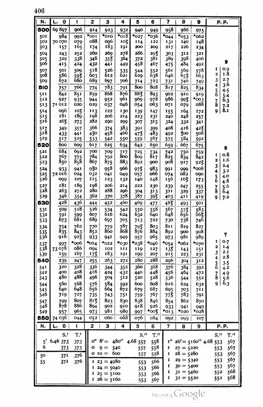
406
N. L. 0 1 2 3 4 5 6 7 8 9 P. P.
50O 69897 906 914 923 932 940 949 958 966 975
5° 1 984 992 *OOI *OIO *o18 •027 *o36 *044 *°53 *o62
502 70070 079 088 096 '°5 114 122 '3' 140 148
5°3 157 165 '74 "«3 191 200 209 217 226 234
S°4 243 252 260 269 278 286 293 3°3 312 321
5°5 329 338 346 355 364 372 38' 389 398 4069506 4'5 424 432 441 449 458 467 475 484 492
507 501 5°9 518 526 535 544 552 561 569 5781 0.9
508 586 595 603 612 621 629 638 646 655 6632 1.8
509 672 680 689 697 706 7'4 723 73' 740 749 3 2-7
t fi
5IO 757 766 774 783 791 800 808 817 _8_?5_ 8344c
3°
5II 842 851 859 868 876 883 893 902 910 919j6 5-4
5" 927 935 944 952 961 969 978 986 995 *oo37 6-3
513 71 012 020 029 °37 046 054 063 071 079 088 8 7.2
5'4 096 103 "3 122 '3° '39 •47 155 164 172 9 8.1
5'5 181 189 198 206 214 223 23" 240 248 257
516 263 273 282 290 299 3°7 315 324 332 341
S'Z 349 357 366 374 383 39' 399 408 416 423
518 433 441 430 458 466 475 483 492 300 508
5'9 5'7 525 533 542 55° 559 567 575 584 592
520 600 609 617 625 634 642 650 659 . 667 675g
521 684 692 700 709 717 725 734 742 750 759 n Q522 767 775 784 792 800 809 817 825 834 842
1 O.O
523 850 858 867 875 883 892 900 908 9'7 9232 1.6
524 933 941 930 958 966 975 983 991 999 *oo83
4
2-4
525 72016 024 032 041 049 °57 066 074 082 090 e0
526 099 107 "5 •23 •32 140 148 156 163 '73j6
4.0
4.8
527 181 189 198 206 214 222 230 239 247 2557 5-6
528 263 272 280 288 296 3°4 313 321 329 337 8 6.4
529 346 354 362 37° 378 387 395 403 411 419 9 7-2
530 428 436 444 452 460 469 477 483 493 501
531 5°9 518 526 534 542 55° 558 567 575 583
532 591 599 607 616 624 632 640 648 656 665
533 673 681 689 697 7°5 7"3 722 73° 738 746
534 754 762 770 779 787 795 803 811 819 827
535 835 843 852 860 868 876 884 892 900 908 M536 916 923 933 941 949 957 965 973 981 989
7
537 997 *oo6 *o14 *022 *030 *o38 •046 *o54 *o62 *0701 0.7
538 73078 086 094 I02 111 119 127 '35 '43 '5'2 1.4
539 159 167 175 183 191 199 207 215 223 23' 3 2.1
2 8540 239 247 255 263 272 280 288 296 3°4 312
4
5 3.554 1 320 328 336 344 352 360 368 376 384 392 6 4.2
542 400 408 416 424 432 440 448 456 464 4727 4-9
543 480 488 496 5°4 512 520 528 536 544 552 8 5-6
544 560 568 576 584 592 600 608 616 624 632 9 6-3
545 640 648 656 664 672 679 687 695 7°3 711
546 719 727 735 743 75' 759 767 775 783 79'
547 799 807 813 823 830 838 846 854 862 870
548 878 886 894 902 910 918 926 933 94' 949
549 957 965 973 981 989 997 *003 *°'3 *020 *028
550 74 036 044 052 060 068 076 084 092 Oy9 107
N. L. 0 1 2 3 4 5 6 7 8 9 P. P.
S.' T.' S. ' T." S." T."
5' 6-46 373 373 0° 8'= 480" 4-68557 558 1° 26'= 5160" 4.68 553 567
6 373 373 0 9 = 540 557 558 1 27 = 5220 553 567
5° 371 3760 10 = 600 557 558 1 28 = 5280 553 567
55 371 376 1 23 = 4980 553 5661 29 = 534° 553 567
1 24 = 5040 553 5661 30 = 5400 553 567
1 25 = 5100 553 5661 31 = 5460 552 568
1 26 = 5160 553 5671 32 = 5520 552 568

407
N. L. 0 1 2 3 4 5 6 7 8 9 P. P.
550 74036 044 052 060 068 076 084 092 099 107
551 "5 123 131 139 "47 '53 162 170 178 186
552 194 202 210 218 225 233 241 249 257 265
553 273 280 288 296 3°4 312 320 327 335 343
554 35 1 359 367 374 382 39° 398 406 414 421
555 429 437 443 453 461 468 476 484 492 500
556 5°7 5'5 523 53" 539 547 554 562 570 578
557 586 593 601 609 617 624 632 640 648 656
558 663 671 679 687 695 702 710 718 726 733
559 741 749 757 764 772 780 788 796 803 811
560 819 827 834 842 850 858 865 873 881 889 8
561 896 904 912 920 927 933 943 95° 958 966 1 0.8562 974 981 989 997 *005 *OI2 *020 •028
*°35 *043 2 1.6
563 75 °5' 059 066 074 082 089 O97 1°3 "3 1203 2.4
564 128 136 •43 '5' '59 166 "74 182 189 197 4 3-2
565 205 213 220 228 236 243 251 259 266 274 5 4.0
566 282 289 297 3°3 312 320 328 335 343 35' 6 4.8
567 358 366 374 381 389 397 404 412 420 427 7 5.6
568 433 442 45° 458 465 473 481 488 496 504 8 6.4
569 5" 5'9 526 534 542 549 557 563 572 580 9 7-2
570 587 595 603 610 618 626 633 641 648 656
571 664 671 679 686 694 702 709 717 724 732
572 740 747 753 762 770 778 785 793 800 808
573 815 823 83' 838 846 853 861 868 876 884
574 891 899 906 914 921 929 937 944 952 959
575 967 974 982 989 997 *oo5 *OI2 *020 *027 *033
576 76 042 050 057 065 072 080 087 093 103 11o
577 118 I25 '33 140 148 '55 163 I70 178 •85
578 193 200 208 215 223 230 238 245 253 260
579 268 275 283 290 298 305 313 320 328 335
580 343 35° 358 365 373 380 388 395 403 410
7581 418 425 433 440 448 453 462 470 477 483
582 492 500 5°7 513 522 530 537 543 552 5591 o-7
583 567 574 582 589 597 604 612 619 626 634 2 1.4
584 641 649 656 664 671 678 686 693 70 1 708 3 2.1
A 2.8585 716 723 73° 738 745 753 760 768 773 782
4£ 1 c
586 790 797 805 812 819 827 834 842 849 856 56
3-54.2
587 864 871 879 886 893 901 908 916 923 93° 7 4.9588 938 945 953 960 967 973 982 989 997 *oo4 8 5.6
589 77 012 019 026 034 041 048 056 063 070 0789 6-3
590 085 093 100 107 U3 122 129 137 144 I51
591 '59 166 173 181 188 '95 203 210 217 223
592 232 240 247 254 262 269 276 283 291 298
593 305 3"3 320 327 333 342 349 357 364 371
594 379 386 393 401 408 415 422 43° 437 444
595 452 459 466 474 481 488 495 5<33 510 5"7596 523 532 539 546 554 561 568 576 583 590
597 597 605 612 619 627 634 641 648 656 663
598 670 677 685 692 699 706 7H 721 728 735
599 743 75° 757 764 772 779 786 793 801 808
600 815 822 830 837 844 | 851 859 86b 873 880
N. | L. 0 1 2 3* I
5 6 1 7 8 9 P. P.
S.' T.' S." T." S." T."
6' 6.46 373 373 0° 9'= 540" 4.68 557 558 1° 35'= 5700" 4.68552 569
55 371 376 0 10 = 600 557 558 1 36 = 5760 552 569
56 37" 376 1 31 = 5460 552 568 ' 37 = 5820 552 569
57 37" 377 1 32 = 5520 552 5681 38 - 5880 S52 569
58 371 377 ' 33 = 558o 552 568 ' 39 = 594° 551 569
59 37° 377 1 34 = 5640 552 5681 40 = 6000 55' 570
60 37° 377 1 35 = 570° 552 569

N. L. 0 1 1 2 3 4 5 6 7 8 9 P. P.
600 77815 822 830 837 844 851 859 866 873 880
6o1 887 895 902 909 916 924 93" 938 945 952
602 960 967 974 981 988 996 *°°3 *o1o *o17 •023
603 78032 039 046 °53 061 068 °73 082 089 097
604 104 1 1 1 118 125 '32 140 '47 '54 161 168
605 176 183 190 197 204 21 1 219 226 233 240
606 247 254 262 269 276 283 290 297 303 312 8
607 3'9 326 333 34° 347 353 362 369 376 383 1 0.8
608 390 398 403 412 419 426 433 440 447 4532 1.6
609 462 469 476 483 490 497 504 512 5'9 526 3 2.4
610 533" 540 547 554 561 569 576 583 590 5974 3-2r 4.0
611 604 611 618 625 633 640 647 654 661 66856 4.8
612 675 682 689 696 704 711 718 723 732 739 7 5.6613 746 753 760 767 774 781 789 796 803 810 8
J6.4
614 817 824 831 838 845 852 859 866 873 880 9 7.2
615 888
958
893 902 909 916 923 93° 937 944 95'616 965 972 979 986 993 *ooo *CK>7 *o14 *02I
617 79029 036 °43 030 °57 064 071 078 083 O92
618 099 106 113 120 127 134 141 148 '55 102
619 169 176 '83 190 197 204 211 218 225 232
620 239 246 253 260 267 274 28l 288 295 3027
621 309 316 323 33° 337 344 35' 358 365 3721 0.7
622 379 386 393 400 407 414 421 428 433 4422 1.4
2,1623 449 456 463 470 477 484 491 498 5°3 5"
624 518 525 532 539 546 553 560 567 574 5810
4 2.8| 625 588 595 602 609 616 623 630 637 644 650
V,626 657 664 671 678 685 692 699 706 7'3 720
D j j4.26
627 727 734 741 748 754 761 768 775 782 789 7 4.9628 796 803 810 817 824 83 ' 837 844 851 858 8 5.6
629 865 872 879 886 893 900 906 9'3 920 927 9 6-3
630 934 941 948 953 962 969 982 989 996
63" 80 003 010 017 024 030 037 044 051 058 063
632 072 079 085 092 099 106 "3 120 127 '34633 140 '47 '54 161 168 175 182 1 83 '95 202
634 209 216 223 229 236 243 250 257 264 271
635 277 284 291 298 3°3 312 3'8 325 332 339636 346 353 359 366 373 380 387 393 400 407 6
637 414 421 428 434 441 448 455 462 468 475 1 0.6
638 482 489 496 502 509 516 523 530 536 543 2 1.2
639 55° 557 564 570 _s;z_ 584 59" 598 604 611 3 1.8
640 618 625 632 638 645 652 659 665 672 679 4 2.4
641 686 693 699 706 713 720 726 733 740 7475 3-°
t &642 754 760 767 774 78. 787 794 8o1 808 814 3-°
643 821 828 835 841 848 853 862 868 875 882 7 4.2
4.8644 889 895 902 909 916 922 929 936 943 949
8 f*u
5.4645 956 963 969 976 983 990 996 *003 *o1o *017
9
646 81 023 030 037 °43 050 °57 064 070 077 084
647 090 097 104 1 1 1 117 124 '3' '37 144 '5'648 158 164 171 178 184 191 198 204 2II 218
649 224 231 238 243 251 258 263 271 _2_78 283
650 291 298 3°3 3" 318 323 33' 338 343 35'
N. L. 0 | 1 2 3 4 5 6 7 P. P.
S.' T.' S." T." S. ' T."
6 6 46 373 373 o° 10'= 600" 4.68 557 558 1° 44' = 624o" 4.68 551 571
7 373 373 0 11 = 660 557 558 1 45 =6300 55" 57'
60 37° 377 1 40 =6000 55' 570 1 46 =6360 55 1 571
63 37° 377 1 41 =6060 55" 57°1 47 =6420 55° 572
64 370 378 1 42 =6120 55 1 57°I 48 =6480 55° 572
65 370 378 1 43 =6180 551 57o 1 49 =6540 55° 572
1 44 =6240 531 571

409
N. L. 0 1 2 3 4 5 6 7 8 9 P . P.
650 81 291 298 3o5 3" 318 325 331 338 343 35 1
651 358 365 371 378 385 39' 398 405 411 418
652 425 431 438 443 45 1 458 463 47 ' 478 483
653 49 1 498 5°3 5" 518 523 531 538 544 551
654 558 564 571 578 584 591 598 604 611 617
655 624 631 637 644 651 657 664 671 677 684
656 690 697 704 710 717 723 730 737 743 730
657 757 763 770 776 783 790 796 803 809 816
658 823 829 836 842 849 856 862 869 875 882
659 889 895 902 908 913 921 928 935 941 948
66O 954 961 968 974 981 987 994 *ooo *007 *014 7
661 82 020 027 °33 040 046 °53 060 066 °73 079 1 0.7
662 086 092 099 105 112 119 125 132 138 '43 2 1.4
663 •5' •58 164 171 178 184 191 197 204 2103 2.1
664 217 223 230 236 243 249 256 263 269 276 4 2.8
665 282 289 295 302 308 313 321 328 334 341 5 3-5
666 347 354 360 367 373 380 387 393 400 406 6 4.2
667 413 419 426 432 439 445 452 458 463 471 7 4-9- r «
668 478 484 491 497 5°4 510 5'7 523 53° 5360 5-6
669 543 549 556 562 569 575 582 588 593 601 9 6.3
670 607 614 620 627 633 640 646 653 659 666
671 672 679 685 692 698 703 711 718 724 73°
672 737 743 73° 756 763 769 776 782 789 795
673 802 808 814 821 827 834 840 847 853 860
674 866 872 879 885 892 898 9o3 911 918 924
675 93° 937 943 950 956 963 969 975 982 988
676 995 *OOI *oo8 *o14 *020 *027 *°33 *040 *046 *052
677 83 °59 065 072 078 083 091 097 104 110 117
678 123 129 136 142 149 '53 161 168 174 181
679 187 193 200 206 213 219 225 232 238 243
680 251 257 264 270 276 283 289 296 302 308g
63 1 315 321 327 334 34° 347 353 359 36b 3721 O.D
682 378 383 391 398 404 410 4'7 423 429 4362 1.2
6^3 442 448 453 461 467 474 480 487 493 4991 1.8
C34 506 512 5.8 523 531 537 544 55° 556 563j
4 2.46S5 569 575 5S2 580 594 601 607 613 620 626
e 3.0686 632 639 645 651 658 664 670 677 683 689
j6 3-6
687 696 702 708 713 721 727 734 740 746 753 7 4.2
688 759 765 771 778 784 790 797 803 809 816 8 4.8
689 822 828 833 841 847 853 860 866 872 879 9 5-4
690 885 891 897 904 910 916 923 929 935 942
691 948 954 960 967 973 979 985 992 998 *oo4
692 840II 017 023 029 036 042 048 053 061 067
693 °73 0S0 0S6 092 098 I03 1n 117 123 130
694 '36 142 148 '53 161 167 173 180 186 192
695 198 205 211 217 223 230 236 242 248 253
696 261 267 273 280 286 292 298 303 3" 317
697 323 330 336 342 348 354 361 367 373 379
698 386 392 398 404 410 417 423 429 435 442
699 448 454 460 466 473 479 483 49 1 497 504
700 510 5l6 522 528 535 541 547 553 559 566
N. L. 0 2 3 4 6 7 8 9 P. P.
S. T.' S." T." S 11 fIi
6' 6-46 373 373 o° 10' = 600" 4.68557 558 1° 51'= 6660" 4.68 530 573
7 373 373 0 11 = 660 557 558 1 52 = 6720 53° 573
65 37° 378 0 12 = 720 557 55s 1 53 = 6780 53° 573
69 37° 378 1 48 = 6480 55° 5/21 54 = 6840 53° 573
70 37° 379 1 49 = 6540 55° 5721 55 = 6900 549 574
1 50 = 6600 55° 5721 56 = 6960 549 574
1 5 1 = 6660 53° 5731 57 = 7020 549 574
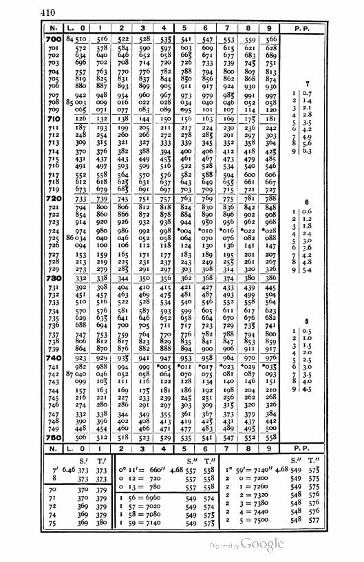
410
N. L. 0 2 3 4 5 6 7 8 9 P. P.
700 84510 5'6 522 528 535 _547_ 553 _559 566
701
702
7°3
704
705
706
707
708
709
572
634
696
578
640
702
584
046
708
770
83 '
893
590
652
714
776
837
899
960
022
083
597658
720
782
844
905
603
665
726
788
850
911
609
671
733
6'5 621
683
745
807
868
93°
628
689
75'
8'3
874
936
757819
880
763
825
.887
794
856
917
677
739
800
862
924 7
942
85 00}
065
948
009
071
954016
077
967
028
089
973034
095
979040
101
985
046
107
99'052
114
997058
120
1 0.7
1.4
2.1
7IO 126 132 '38 '44 _J5°_ _i56 _L63169 '75 181
2
3
4 2.8
5 3-54.2
4.9
711
712
7'3
7'4
7'5716
187
248
3°9
37°431
491
193
254
3'5
376
437
497
558
618
199
260
321
382
443
5°3
205
266
327
388
211 217
278
339
400
461
522
582
643
7°3
224
285
345
406
467
528
588
649
709
230
291
352
412
473
534
594655
7-5
236
297
358
418
479
540
600
661
721
242
3°3364
6
272
333
394
455
5'6
576
78 5-6
425 9 6-3
449
509
485
717
718
719
552
612
564
625
685
57°63'
691
637
697
546
606
667
727673 679
720 733 739 745 75' 757 763 769 775 78. 7886
721 794
854
914
800
860
920
980
040
100
806
866
926
986
046
106
812
872
932
992
052
112
171
231
291
818
878
938
998
058
118
824
884
944
*oo4
064
124
830
890
93°
836
896
956
*o16
076
'36
842
902
962
848
908
968
0.6
1.2
1.8
2.4
722
723
724
725
726
97486034
*0IO *022
082
141
20I
26'
320
•028
088
'47
207
2
3
4070
130
189
5 3-°3-6
4.2
4.8
5-4
094
153
213
273
6
727
728'59219
165
225
285
'77 183
243
3°3
'95255
314
78237
297
249 267
326729 279 308 9
730 332 338 344 35° 356 362 368 374 380 386
73'732
733
734
735736
392 398
457516
404 410 415
475
534
421
481
540
427
487
546
605
664
723
782
841
900
433
493
552
611
670
729
788
439
499
558
617
676
735
794
853
911
445504
564
623
682
741
800
859
917
451
510
463
522
469
528
570
629
688
576
635
694
581
641
587
646
705
593
652
711
770
829
888
599
658
7175
700
737738
739
747
806
864
753812
870
759817
876
764
823
882
776
835
894
1 °-51.0
847
906
2
3
4
1.5
740 923 929 935 941 947 953 958 964 970 9762.0
5 2-5
741
742
743
744
745
746
982
87 040
099
988
046
105
994052
1n
169
227
286
999058
116
*oo5
064
122
181
239
297
355413
47'
*OII *o17 *023
081
140
198
256
315
373431
489
*029 *035
093
'5'
210
6 30
070
128
186
243
3°3
361
419
°75134
192
251
3°9
367
425
483
087
I
9
3- 54.0
157
216
163
221
280
175
146
204
262
4- 5
274
332
390
448
233
291 320
268
326
747
748
749
338
396
454
344402
460
349408
466 477
379
437
495
384
442
500
750 506 512 5'8 523 529 535 541 547 552 ~558
N. L. 0 2 3 5 6 7 8 9 P. P.
S.' T.' S." T." S." T."
7' 6.46 373 373
373
0° 11'= 660" 4.68 557 558
012= 720 557 558
1° 59'= 7140" 4.68 549 575
2 0 = 7200 549 5758 373
70 37° 3790 1 3 — 780 55/ 558 2 1 = 7260 549 575
548 576
548 576
548 576
548 577
7"
72
74
75
370
369
369
369
379
379
379
380
1 56 = 6960
1 57 = 7020
1 58 = 7080
1 59 = 7140
549 574
549 574
549 575
549 575
2
2
2
2
2 = 7320
3 = 738o
4 = 744°
5 = 75°°

411
N. L. 0 1 2 3 4 5 6 7 8 9 P. P.
750 87506 512 518 523 529 535 54i 547 _552_ 558
75' 564 570 576 581 587 593 599 604 610 616
752 622 628 633 639 645 651 656 662 668 674
753 679 685 691 697 7°3 708 7'4 720 726 73'
754 737 743 749 754 760 766 772 777 783 789
755 795 800 806 812 818 823 829 833 841 846
756 852 858 864 869 875 881 887 892 898 904
757 910 915 921 927 933 938 944 95° 955 961
758 967 973 978 984 990 996 *OO' ♦007 ♦013 *oi8
759 88024 030 036 041 047 053 058 064 070 076
760 081 087 093 098 104 1 10 116 121 127 '33g
761 T38" 144 150 ^56 161 167 «73 178 184 1901 0.6
762 195 201 207 213 218 224 230 235 241 2472 1*2
763 252 258 264 270 275 281 287 292 298 3043
4
1.8764 309 3'5 321 326 332 338 343 349 353 360 2.4765 366 372 377 383 389 393 400 406 412 4'7
5 3.0766 423 429 434 440 446 451 457 463 468 474 6 3-6
767 480 485 491 497 502 508 5'3 5'9 523 53° 7 4.2
768 536 542 547 553 559 564 570 576 581 587 8 4.8
769 593 598 604 610 615 621 627 632 638 643 9 54
770 649 653 660 666 672 677 683 689 694 700
77i 705 ,ju 717 722 728 734 739 ~743 75° 756
772 762 767 773 779 784 790 795 80 i 807 812
773 818 824 829 83? 840 846 852 857 863 868
774 874 880 885 891 897 902 908 913 919 925
775 93° 936 941 947 953 958 964 969 975 981
776 986 992 997 *003 ♦009 ♦014 *020 ♦025 *031 *°37
777 89042 048 o53 059 064 070 076 081 087 092
778 098 104 109 "3 120 126 131 '37 «43 148
779 '54 '59 i65 '7° 176 182 187 193 198 204
780 209 215 221 226 232 237 243 248 254 2605
781 265 271 276
"282■
287' 293 298 304 3'o 3'51 0.5
782 321 326 332 337 343 348 354 360 365 37'2
783 376 382 387 393 398 404 409 413 421 426' c
784 432 437 443 448 454 459 465 47° 476 481j
4
*o
785 487 492 498 504 509 513 520 526 531 537
2.0
786 542 548 553 559 564 57° 575 581 586 5925 2.5
6 3-°
787 597 603 609 614 620 625 631 636 642 647 7 3-5
788 653 658 664 669 675 680 686 691 697 702 8 4.0
789 708 7«3 719 724 73° 735 741 746 752 757 9 4-5
790 763 768 774 779
783■
790 796 801 807 812
79' 818 823 829 834 840 845 851 ~85T 862" 867
792 873 878 883 889 894 90090S 911 916 922
793 927 933 938 944 949 953 960 966 971 977
794 982 988 993 998 ♦004 *0O9 ♦015 *020 *026 *°31
795 90037 042 048 053 059 064 069 °75 080 086
796 091 097 102 108 113 119 124 129 '33 140
797 146 151 «57 162 168 '73 i79 184 189 '93
798 200 206 21 1 217 222 227 233 238 244 249
799 255 260 266 271 276 282 287 293 298 304
800 3°9 314 320 325 331 336 342 347 352 358
N. L. 0 1 2 3 4 5 6 7 8 9 P. P.
S.' T.' S." T." S."1■ 11
7' 646 373 373 o° 12' = 720" 4.68 557 558 2° 8' = 7680" 4.68 547 578
8 373 373 0 13 = 780 557 558 2 9 = 7740 547 578
75 369 380 0 '4 = 840 557 558 2 10 = 7800 547 578
80 369 380 2 5 = 7500 548 5772 11 = 7860 547 579
2 6 = 7560 548 5772 12 = 7920 547 579
2 7 = 7620 548 5772 «3 = 7980 547 579
2 8 = 7680 547 578 2 «4 = 8040 546 579
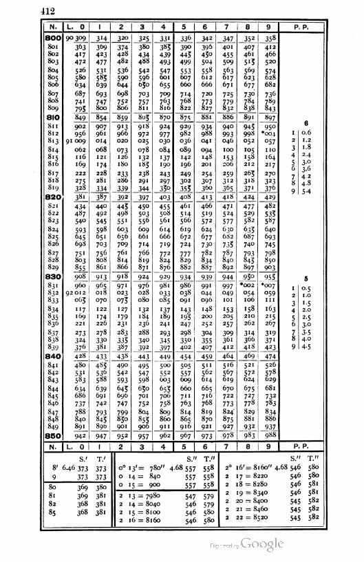
412
N. L. 0 1 2 3 4 5 6 7 8 9 P. P.
800 90309 3'4 ' 320 325 33' 336 342 347 352 358
801 363 3&9 374 380 385 39° 396 401 407 412
802 4'7 423 428 434 439 443 450 455 461 466
803 472 477 482 4S8 493 499 504 5°9 5'3 520
804 526 531 536 542 547 553 558 563 569 574805 580 583 590 596 601 607 612 6.7 623 628
S06 634 639 644 650 655 660 666 671 677 682
807 687 693 698 7°3 709 7'4 720 725 730 736
80S 741 747 752 757 763 768 773 779 784 789
809 795 800 806 811 816 822 827 832 838 843
810 849 854 859 805 870 875 881 886 89' 897
Su 902 907 9'3 918 924 929 934 940 945 9506
812 956 961 966 972 977 982 988 993 998 *O04 1 0.6
8l3 91 009 014 020 025 030 036 041 046 052 057 2 1.2
814 062 068 °73 078 084 089 094 100 105 110 3 1.8
2.48.5 116 121 126 132 '37 142 148 '53 158 164 4
816 169 '74 180 185 190 196 201 206 212 217 5 3-°1 ft
817 222 228 233 238 243 249 254 259 265 2707
3-°4.2
818 275 281 286 291 297 302 307 312 3'8 3231
819 328 334 339 344 33° 353 360 365 37' 3768 4.8
820 381 387 392 397 403 40S 4'3 41S 424 4299 5-4
821 434 440 445 450 455 461 466 47" 477 482
822 487 492 498 5°3 508 5'4 5'9 524 529 533823 540 545 55' 556 561 566 572 577 582 587
824 593 598 603 609 614 619 624 630 633 640
825 645 651 656 661 666 672 677 682 687 693
826 698 703 709 7'4 719 724 73° 733 740 745
827 751 756 761 766 772 777 782 787 793 798
828 803 808 814 819 824 829 834 840 843 850
829 855 861 866 871 876 882 887 892 897 903
830 908 9'3 918 924 929 934 939 944 95° 953 5
83 ' 960 965 97' 976 981 986 99' 997 *002 •0071 0.5
832 92012 018 023 028 o33 038 044 049 054 059j
833 065 070 °73 080 085 091 096 101 I06 1 1 12 1.0
3 1.5
834 "7 122 127 132 '37 '43 148 '53 158 163 4 2.0
835 169 '74 179 184 189 •9? 200 205 2IO 2155 2-5
836 221 226 23' 236 241 247 252 257 262 267 6 30
837 273 278 283 288 293 298 304 3°9 3'4 3'9 7 3-5
83S 324 33° 333 34° 345 35° 355 361 366 37'8 4.0
839 376 381 3«7 392 397 402 407 412 418 423 9 4-5
840 428 433 438 443 449 454 459 464 469 474
841 480 485 490 495 500 5°5 5" 5'6 521 526
842 53' 536 542 547 552 557 562 567 572 578
843 583 588 593 598 603 609 614 619 624 629
844 634 639 645 650 653 660 665 670 675 681
845 686 691 696 701 706 7" 716 722 727 732
846 737 742 747 752 758 763 768 773 778 783
847 788 793 799 804 809 814 819 824 829 834
848 840 845 850 855 860 865 870 875 88l 886
849 891 896 901 906 911 916 921 927 932 937
850 942 947 952 957 962 967 973 978 983 988
N. L. 0 1 2 3 4 5 6 7 8 9 P. P.
S.' T.'
8' 6.46 373 373
9 373 373
80 369 380
81 369 381
82 368 381
85 368 38'
S." T."
o° 13'= 780" 4-68557 558
014= 840 557 558
0 '5 = 900 557 558
213 = 7980
2 14 = 8040
215= 8100
2 16 = 8160
547 579
546 579
546 580
546 580
S." T."
16'= 8160" 4.68 546 580
17 = 8220 546 580
18 = 8280
19 = 8340
20 — 8400
21 = 8460
22 = 8520
546 581
546 581
545 582
545 582
545 582
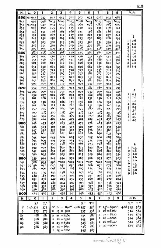
413
N. | L. 0 1 2 3 4 5 6 7 8 9 P. P.
850 92942 947 952 957 962 967 _973_ 978 983 988
851 993 998 *003 *<x>8 *013 *o18 *024 ♦029*°34 *039
852 93 044 049 054 059 064 069 073 080 083 090
853 °93 100 105 110 "5 120 125 13' 136 141
854 146 151 156 161 166 171 176 181 186 192
855 197 202 207 212 217 222 227 232 237 242 a856 247 252 258 263 268 273 278 283 288 293
0
857 298 303 308 313 3'8 323 328 334 339 3441 O.O
858 349 354 359 364 369 374 379 384 389 394** 1.2
859 399 404 409 414 420 423 43° 433 440 4433 1.8
860 43° 453 460 465 470 475 480 485 490 4954
5
0 A
3-°86 1 500 5°5 510 5'5 520 526 53' 536 541 546 6 3-6
862 551 556 561 566 571 576 581 586 591 596 7 4.2
863 601 606 611 616 621 626 631 636 641 646 8 4.8
864 651 656 661 666 671 676 682 687 692 697 9 5-4
865 702 707 712 717 722 727 732 737 742 747
866 752 757 762 767 772 777 782 787 792 797
867 802 807 812 817 822 827 832 837 842 847
868 852 857 862 867 872 877 882 887 892 897
869 902 9°7 912 917 922 927 932 937 942 947
870 95^ 957 962 967 972 977 982 987 992 9975
871 94 002 007 012 017 022 027 032 °37 042 047
872 052 057 062 067 072 077 082 086 091 096 1 0.5
873 101 106 1n 116 121 126 131 136 141 146 2 1.0
874 151 156 161 166 171 176 181 186 191 196 3 1.5
875 201 206 211 216 221 226 231 236 240 245 4 2.0
876 250 255 260 265 270 275 280 285 290 295 5 2-5
877 300 303 310 313 320 323 33° 333 34° 343
6 3.0
878 349 354 359 364 369 374 379 384 389 3947 3.5
879 399 404 409 414 419 424 429 433 438 443
8 4.0
88O 448 453 458 463 468 473 478 483 488 493
9 4.5
88 1 498 503 5°7 512 5'7 5.22 527 532 537 542
882 547 552 557 562 567 571 576 581 586 59'
883 596 601 606 611 616 621 626 630 635 640
884 645 650 655 660 663 670 673 680 683 689
885 694 699 704 709 7'4 719 724 729 734 738
886 743 748 753 758 763 768 773 778 783 787 4
887 792 797 802 807 812 817 822 827 8^2 836 1 0.4
888 841 846 851 856 861 866 87. 876 880 885 2 0.8
889 890 895 900 903 910 913 919 924 929 934 3 1.2
890 939 944 949 954 959 963 968 973 978 983 4 1.6
891 988 993 998 *002 *007 *0I2 *o17 *022 *027 *032 5§
2.0
892 95 036 041 046 051 056 o6l 066 O7I 075 0802.4
893 085 096 093 IOO 1°3 IO9 114 119 124 129 /8
2.8
894 148 'S3 158 "63 1683.2
134 139 143
2l6
173 '77 9 3-6
895 182 187 192 I97 202 207 211 221 226
896 231 236 240 245 250 255 260 263 27O 274
897 279 284 289 294 299 3°3 308 3'3 3'8 323
898 328 332 337 342 347 352 357 361 366 37'
899 376 381 386 39° 395 400 403 4IO 4'3 419
900 424 429 434 439 444 448 453 458 463 468
N. L. 0 1 2 3 4 5 6 7 1 8 1 9 | P. P.
S.' T.' S." T."
8' 6-46 373 373 0° '4' = 840" 4-68 557 558
9 373 373 0 '5 = 900 557 558
85 368 38' 2 21 = 8460 545 582
86 368 382 2 22 = 8520 545 582
89 368 382 2 23 = 8580 543 583
90 368 383 2 24 = 8640 543 583
2 25 = 8700 543 583
25'= 8700"
26 =8760
27 =8820
28 =8880
29 =8940
30 =9000
S." T."
4.68543 583
544 584
544 584
544 584
544 583
544 585
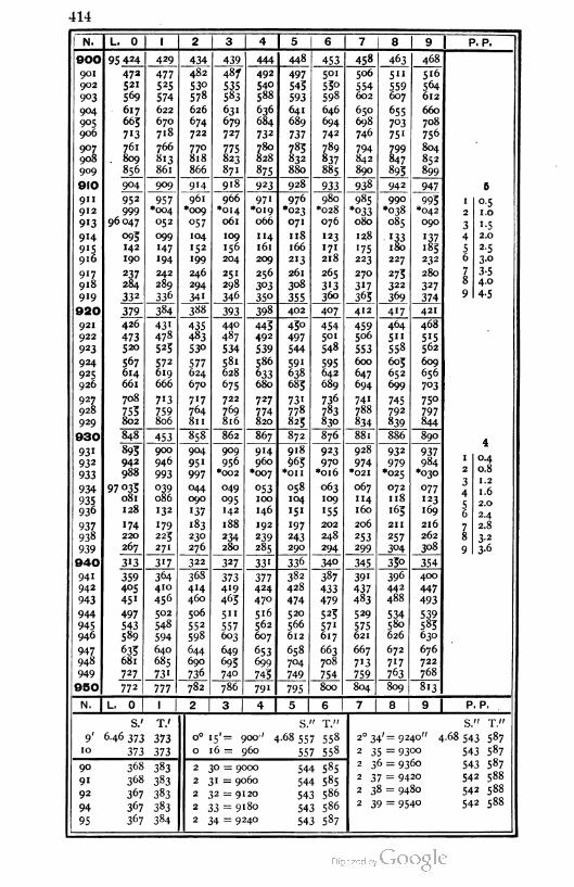
414
N. L. 0 | 1 2 3 4 6 7 8 I 9 | P. P.
900 95 424 429 434 439 444 448 453 458 463 468
901 472 477 482 487 492 497 501 506 5" 516
902 S21 525 53° 535 540 543 53° 554 559 564
9°3 569 574 578 583 588 593 598 602 607 612
904 617 622 626 631 636 641 646 650 655 660
9°5 665 670 674 679 684 689 694 698 7°3 708
906 7'3 718 722 727 732 737 742 746 75' 756
907 761 766 770 775 780 783 789 794 799 804
908 809 813 818 823 828 832 837 842 847 852
909 856 861 866 87. 875 880 885 890 893 899
910 904 909 914 918 923 928 933 938 942 947 S
911 952 957 961 966 971 976 980 985 990 993 , °-5912
96047
999 *oo4 *oc>9 •014 *019 *023 •028*°33 *o38 *042 2 1.0
913 052 °57 06 1 066 071 076 080 085 0903 1.5
914 °93 099 104 109 114 118 123 128 . 133 1 37 4 2.0
915 142 •47 '5* 156 161 166 171 '75 180 183 5 2-5
916 190 194 199 204 209 213 218 223 227 232 6 3-o
917 237 242 246 251 256 261 265 270 273 280 7 3-5Q
4.0918 284 289 294 298 3°3 308 313 317 322 327
O
919 332 336 341 346 35° 355 360 363 369 3749 4-5
920 379 384 388 393 398 402 407 412 417 421
921 426 431 435 440 443 43° 454 459 464 468
922 473 478 483 487 492 497 5°' 506 5" 5'5923 520 523 53° 534 539 544 548 553 558 562
924 567 572 577 581 586 591 595 600 603 609
925 614 619 624 628 633 638 642 647 652 656
926 661 666 670 675 680 683 689 694 699 7°3
927 708 7'3 717 722 727 73' 736 741 745 750
928 753 759 764 769 774 778 783 788 792 797
929 802 806 811 816 820 823 830 834 839 844
930 848 453 858 862 867 872 876 881 886 8904
931 893 900 904 909 9H 918 923 928 932 937
932 942 946 95 1 956 960 963 970 974 979 9841 0.4
n Q
933 988 993 997 *002 *oo7 *OII *o16 *02I *025 *0302 O.O
-} 1.2
934 97 033
081
039 044 049 t>53 058 063 067 072 077S
4 1.6
935 086 090 095 100 104 109 114 118 123 c 2.0936 128 132 137 H2 146 '51 155 160 '63 169
j6 2.4
937 174 179 183 188 192 197 202 206 211 2167 2.8
938 220 223 230 234 239 243 248 253 257 262 8 3-2
939 267 27I 276 280 285 290 294 299 304 3089 3-6
940 313 317 322 327 331 336 34° 345 33° 354
941 359 364 368 373 377 382 387 391 396 400
942 4°5 410 414 419 424 428 433 437 442 447
943 45' 456 460 465 470 474 479 483 488 493
944 497 502 506 5" 516 520 523 529 534 539
945 543 548 552 557 562 566 571 575 580 583
946 589 594 598 603 607 612 617 621 626 630
947 633 640 644 649 653 658 663 667 672 676
948 681 685 690 693 699 704 708 7'3 717 722
949 727 731 736 740 743 749 754 759 763 768
950 772 777 782 786 791 795 800 804 809 813
N. | L. 0 ' 1 2 3 I 4 I 5 6 1 7 8 9 P. P.
S.' T.' S. / T n S." T."
9' 6-46 373 373 o° 15'= 900'' 4.68 557 558 2° 34'= 9240" 4.68 543 587
10 373 373 0 16= 960 557 558 2 35 = 9300 543 587
90 368 383 2 30 = 9000 544 5852 3 6 = 9360 543 587
9' 368 383 2 31 = 906a 544 5852 37 = 9420 54 2 558
92 367 383 2 32 = 9120 543 5862 3o = 94 54 2 588
94 367 383 2 33 = 9180 543 5862 39 = 9540 542 5os
95 367 384 2 34 = 9240 543 587
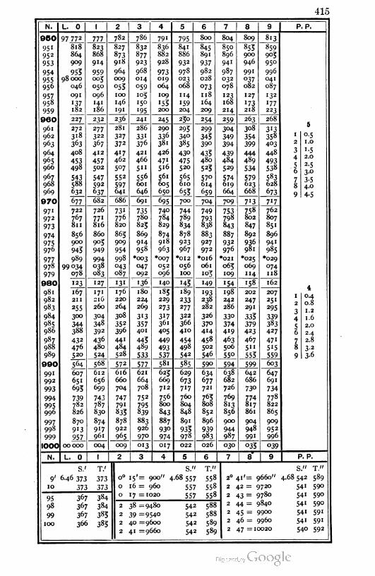
415
N. L. 0 1 2 3 I 4 5 6 7 8 9 P. P.
950 97 772 777 782 786 791 795 800 804 809 813
95i 818 823 827 832 836 841 845 850 853 859
952 864 868 873 877 882 886 891 896 900 903
953 909 914 918 923 928 932 937 941 946 950
954 953 959 964 968 973 978 982 987 991 996
955 98 000 005 009 014 019 023 028 032 °37 041
956 046 050 °55 059 064 068 073 078 082 087
957 091 096 100 «°3 109 114 118 123 127 '32
958 137 141 146 150 153 «59 164 168 173 177
959 182 186 191 «95 200 204 209 214 218 223
960 227 232 236 241 245 250 254 259 263 268
961 272 277 281 286 290 293 299 3i54 308 3135
962 3i8 322 327 331 336 340 343 349 354 358 1 0.5
963 363 367 372 376 381 385 39° 394 399 403 2 1.0
964 408 412 417 421 426 430 433 439 444 448 3 '■5
965 453 457 462 466 47i 475 480 484 489 4934 2.0
966 498 502 5°7 5" 516 520 523 529 534 538 56
2-5
3.0967 543 547 552 556 56i 565 57° 574 579 583
7
j,v
3.5968 588 592 597 601 605 610 614 619 623 628 8 4.0969 632 637 641 646 650 653 659 664 668 673
9 4-5
970 677 682 686 691 695 700 704 709 7'3 717
97 1 722 726 731 735 740 744 749 753 758 762
972 767 771 776 780 784 789 793 798 802 807
973 811 816 820 825 829 834 838 843 847 851
974 856 860 863 869 874 878 883 887 892 896
975 900 905 909 914 918 923 927 932 936 941
976 943 949 954 958 963 967 972 976 981 985
977 989 994 998 *oo3 *oo7 *012 *oi6 *02' *025 *029
978 99 °34 038 °43 047 052 056 061 063 069 074
979 078 083 087 092 096 'OO 103 109 114 118
980 «23 127 131 136 140 '43 149 '54 158 162
98 i 167 171 176 180 183 189 193 198 202 207t
982 211 216 220 224 229 233 238 242 247 2511 O A
983 255 260 264 269 273 277 282 286 291 2950.8
02 1.2
984 300 3°4 308 3'3 317 322 326 33° 333 3390
4 1.6985 344 348 352 357 361 366 37° 374 379 383
5 2.0986 388 392 396 401 405 410 414 419 423 427 6 24
987 43 2 436 441 443 449 454 458 463 467 47' 7 2.8
988 476 480 484 489 493 498 502 506 5" 5«5 8 3-2
989 520 524 528 533 537 542 546 55° 553 559 9 3-6
990 564 568 572 577 58i 585 590 594 599 603
991 607 612 616 621 623 629 634 638 642 647
992 651 656 660 664 669 673 677 682 686 691
993 693 699 704 708 712 717 721 726 73° 734
994 739 743 747 752 756 760 763 769 774 778
995996
782 787 791 795 800 804 808 813 817 822
826 830 833 839 843 848 852 856 861 865
997 870 874 878 883 887 89' 896 900 904 909
998 913 917 922 926 93° 933 939 944 948 952
999 957 961 965 970 974 978 983 987 991 996
1000 00000 004 009 013 017 022 026 030 °33 °39
N. L. 0 1 2 3 4 5 6 7 8 9 P. P.
S.' T.' S." T." S." T."
9' 646 373 373 0° 15'= 900" 4.68 557 558 2° 41'= 9660" 4.68542 589
10 373 373 0 16 = 960 557 558 2 42 = 972O 541 590
95 367 384 0 17 = 1020 557 558 2 43 = 9780 541 59°
98 367 384 2 38 =9480 542 588 2 44 = 9840 54« 59°
2 45 = 99OO 541 59199 367 383 2 39 =954° 54 2 58?f
100 366 383 2 40 =9600 542 589 2 46 = 9960 541 591
2 41 =9660 542 589 2 47 =10020 540 592
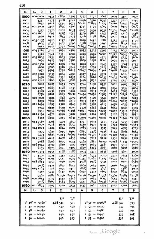
410
N. L. 0 1 2 3 4 5 6 7 8 9
IOOO 0000000 0434 0869 '303 '737 2171 2603 3039 3473 39°7_
IOOl 4341 47759II1
5208
9544
3875
5642 6076•041 1
474'
6510
*o844
5'74
6943•1277
7377*1710
7810 8244
*2576
6903
1002
1003
8677 99774308
*2H3001 3009 3442 5607 6039 6472
1004
1005
1006
7337002 1661
5980
7770
2093
641 1
8202 8633
2957
72/3
9067 9499
3821
8138
9932
4253
8569
•0364
4683
9001
*0796
5116
9432
*I228
2523
6843
3389
7706
5548
9863
1007
1008
1009
003 0293
4605
8912
0726
5036
9342
"575467
9772
158S 2019 2451 2882
7190
*M93
33'37620
*1924
37448051
4174
84815898 6328
*o633
6759
*1063*0203 *2354 *2784
IOIO 004 3214 3644 4074 4504 4933 5363 5793 6223 6652 7082
IOII
IOI2
IOI3
75 12
005 1805
6094
7941
2234
6523
837'
2663
6952
8800
3092
9229
3521
7809
9659 *oo88 *0517
4808
9094
*0947
5237
9523
*1376
5666
7380395°
8238
4379
8666 995 1
IOH
IOI5
IOl6
0060380
4660
8937
0808
5088
9363
1236
5516
9792
1664 2092 2521
6799
*1074
2949
7227•1501
33777653
*1928
3803
8082
*2355
4233
8510
*2782
5944*0219
6372
*o&47
IOI7
IOI8
IOI9
007 3210 3637
7904
2168
4064
833'
2594
4490 4917
9184
53449610
5771
*0037
4298
6198•0463
4724
6624
*0889
5150
7051•1316
5576
7478 8757
3020008 1 742 3446 3872
I020 6002 6427 6853 7279 __77°4 8130 8556 8981 9407 9832
I02I
I022
IO23
009 0257
4509
8756
0683 1 108 1533
5784•0030
'9596208•0454
2384
6633
*0878
2809
7058•1303
3234
7483
*1727
3659
7907
4084
8332
*2575
49349181
53599605 *2I5I
IO24
IO25
IO26
010 3000 3424
7662
3848
8086
2320
4272
8510
4696 5120 55449780
5967
*0204
6391 6813
*1050
5282
7239
on 1474
8933
316693573590
*0627
1897 2743 4013 4436 4859
IO27
I028
IO29
5704 6127
*0354
4576
6550•0776
4998
6973
*1 198
5420
7396 7818•2043
8241
*2465
6685
8664
*2887
7107
9086
*33'°7529
9509
*3732
795'
993'012 4154
*l62I
5842 6264
1030 8372 8794 9215 9637 *oo59 *0480 *0901 *1323 *1744 *2165
1031
1032
1°33
013 2587
6797
3008
7218
1424
3429
7639
1844
3850
8059
2264
4271
8480
2683
4692
8901
3103
5"39321
5534
9742
3945
5955 6376
*o583
4785
*Ol62
014 1003 3525 4365
1034
1°3S1036
5205 5625
9823
4017
6045
*0243
4436
6465
*0662
4853
588j1082
5274
7303
*1501
7723
*1920
6112
8144
*2340
8564 8984
*3178
7369
9403
015 3598
*
5693 6531
*2759
6950
I037
1038
7788
016 1974
8206
2392
6573
8625
2810
6991
9044
3229
7409
9462 9881
4065
8243
*0300 *0718
4901
9080
*"375319
9498
*1555
573799161039 6l55
3647
7827
4483
8663
1040 °17 0333 075 1 1 168 1586 2003 2421 2838 3256 3673 4090
1041
1042
1043
. 45°78677
018 2843
4924
9094
3259
5342 57599927
4092
6176 6593
*0761
7010
*"775341
7427
*'594
5757
7844 8260
*2427
658995"3676
*o344
4508 4923
*20IO
6173
1044
1045
1046
7003
019 1 163
5317
7421
1578
5732
7837
1994
6147
8253
2410
6562
8669
2823
6977
9084
3240
7392
9500
3656
7807
9916
4071
8222
*0332
4486
8637
•0747
4902
9052
1047
1048
1049
9467
0203613
7753
9882
4027
8169
*0296
4442
8583
*071 1 *II26 *I540 *1953 *2369 *2784
6927
*1o66
*3198
4856
8997
5270
94"
5684
9824
6099
*0238
6513
*0652
7341
*1479
1050 021 1893 2307 2720 3134 3547 3961 4374 4787 5201 5614
N. L. 0 1 2 3 4 5 6 7 8 9
S." T." S." T."
2° 46' = 9960" 4.68 541 591 2° 51' = 10260" 4.68 540 593
2 47 = 10020 540 592 2 52 = 10320 539 594
2 48 = I0080 540 592 2 53 = 10380 539 594
2 49 = IOH0 540 592 2 54 = 10440 539 593
2 50 = IO2O0 54° 593 2 55 = IO5O0 539 595
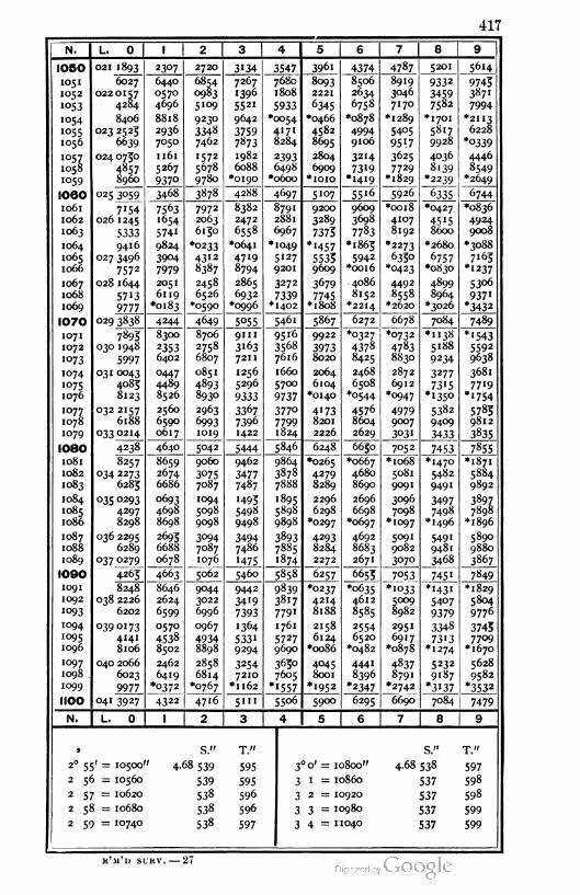
417
N. L. 0 I 2 3 4 5 6 7 8 9
1050 021 1893 2307 2720 3'34 3547 3961 4374 4787 5201 5614
1051
1052
1°53
6027
0220157
4284
6440
0570
4696
6854
0983
51o9
7267
1396
5521
7680
1808
5933
8093
2221
8506
2634
6758
8919
3046
7170
9332
3459
7582
9743
387'
7994
1054
1055
1056
8406
023 2525
6639
8818
2936
7050
9230
3348
7462
9642
3759
7«73
•0054
4171
*0466
4582
8695
6345
*0878 *1289
5405
9517
*1701 *2"3
8284
49949106
5817
9928
6228
*°339
1057
1058
1059
024 0750 1 161 1572
5678
9780
1982
6088
*0190
2393
6498
*o6oo
2804
6909
32H7319
*1419
3625
7729
*1829
4036 4446
4857
8960
5267
937° *IOIO
8139
*2239
8549
*2649
1060 025 3059 3468 3878 4288 4697 5107 5516 5926 6335 6744
1061
1062
1063
7154
026 1 245
7563
1654
7972
2063
6130
8382
2472
6558
8791
2881
6967
9200
3289
7373
9609
3698
7783
*oo18
4107
8192
*0427
8600
*0836
5333 5741
4924
9008
1064
1065
1066
9416
027 3496
7572
9824
3904
7979
*0233
4312
*0641
47'9
8794
*1049
5127
9201
*'457
55339609
*1863 *2273 *2680 •3088
7163
*1237
5942
*oo16
633°
*0423
6757
8387 *0830
1067
1068
1069
028 1644
5713
9777
2051
6119
*0183
2458
6526
*0590
2865
6932
*0996
3272 3679
7745*18o8
4086
8152
4492
8558
4899
8964
53o6
937'*3432
7339*1402 *22H *2620 *3026
1070 029 3838 4244 4649 5055 5461 5867 6272 6678 7084 7489
1071
1072
1073
7893
030 1948
8300 8706
2758
6807
9111
3163
721 1
95 16
3568
7616
9922 *0327
4378
8425
*0732 •1138
5188
9234
*'543
5592
96385997
2353
640239738020
4783
883O
1074
1075
1076
031 0043
4083
8123
0447
4489
8526
0851
4893
8930
1256
5296
9333
1660
5700
9737
2064
6104
*0140
2468
6508
2872
6912
3277
7315
*135o
3681
7719
*'754*o544 *0947
1077
1078
1079
032 2157
6188
2560
6590
0617
2963 3367
7396
1422
377o
77991824
4173
8201
2226
4576
8604
2629
49799007
5382 5783
98126993
1019
9409
033 0214 3031 3433 3835
1080 4238 4640 5042 5444 5846 6248 6630 7052 7453 7855
1081
1082
1083
8257
034 2273
6283
8659
2674
6686
9060 9462
34777487
9864
3878
7888
*0265 *0667
4680
8690
*1o68
5081
9091
*1470
5482
949'
•1871
5884
9892
3075
7087
4279
8289
1084
1085
1086
035 0293 0693
4698
8698
1094
5098
9098
•493
5498
9498
1895
5898
9898
2296
6298
*0297
2696
6698
*0697
3096
7098
*1o97
3497
7498•1496
3897
7898
*1896
4297
8298
1087
1088
1089
036 2295
6289
2693
6688
0678
3094
7087
1076
3494
7486
3893
7885
1874
4293
8284
2272
4692
8683
2671
5091
9082
3070
549'9481
3468
5890
9880
3867037 °279 1475
1090 4265 4663 5062 5460 5858 6257 6653 _7°53_ 745' 7849
1091
1092
8248
038 2226
6202
8646
2624
6599
9044
3022
6996
9442
3419
7393
9839
3817
779'
*0237
4214
8188
•0635
4612
*1o33
5009
8982
*'43'
5407
9379
*1829
5804
9776'°93 8585
1094
1095
1096
0390173
4141
8106
0570
4538
8502
0967 1364
5331
9294
1 761 2158
6124
*oo86
2554
6520
*0482
295 1
6917•0878
3348 3743
7709
*1670
4934
8898
5727
969073'3
*1274
1097
1098
1099
040 2066
6023
9977
2462
6419
*°372
2858
6814•0767
3254
7210
3630
7605
4045
8001
*1952
4441 4837
8791
*2742
5232
9187
*3'37
5628
9582
*3532*Il62 *'557
8396
*2347
1100 041 3927 4322 47'6 5"' 55o6 5900 6295 6690 7084 7479
N. L. 0 1 2 3 4 5 6 7 8 9
j S." T." S." T."
2° 55' = I05OO ' 4-68 539 595 3o' = 10800" 4.68 5383 597
2 56 = IO560 539 595 3 1 = 10860 537 598
2 57 = 10620 538 596 3 2 = 10920 537 598
2 58 = I0680 538 596 3 3 = 10980 537 599
2 59 = IO74O 538 597 3 4 - 1 1040 537 599
k'm'u sukv. — 27
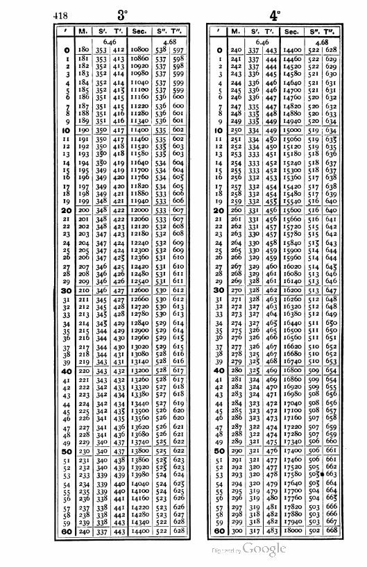
418 3°
i M. S'. T'. Sec. S". T".
6.46 4.68
o 180 353 412 10800 538 597
I 181 353 413 10860 537 598
2 182 352 413 10920 537 598
3 183 352 414 10980 537 599
4 184 352 414 1 1040 537 599
S185 352 415 1 1 100 537 599
6 186 35' 4'5 11160 536 600
7 187 35' 4'5 1 1220 536 600
8 188 35' 416 1 1 280 536 601
9 189 351 416 1 1 340 536 601
IO 190 35° 417 1 1400 535 602
11 191 35° 417 1 1460 535 602
12 192 35° 418 1 1520 533 603
13 193 35° 418 u58o 533 603
"4 194 35° 419 1 1 640 534 604
'5 '95 349 419 1 1 700 534 604
16 196 349 420 1 1 760 534 605
ll 197 349 420 1 1 820 534 605
18 198 349 421 1 1880 533 606
19 '99 348 421 1 1 940 533 606
20 200 348 422 12000 533 607
21 201 348 422 12060 533 607
22 202 348 423 12120 532 608
23 203 347 423 12180 532 608
24 204 347 424 12240 532 609
25 205 347 424 12300 532 609
26 206 347 423 12360 53' 610
27 2O7 346 425 12420 53' 610
28 208 346 426 12480 53' 611
29 209 346 426 12540 53' 611
30 210 346 427 12600 53o 612
31 211 345 427 12660 53o 612
32 212 345 428 12720 53o 6'3
33 213 345 428 12780 530 613
34 214 343 429 12840 529 614
35 215 344 429 12900 529 614
36 216 344 430 12960 529 613
37 217 344 43° 13020 529 6'5
38 218 344 43' 13080 528 616
39 219 343 431 1 3 140 528 616
40 220 343 432 13200 528 617
41 221 343 432 13260 528 617
42 222 342 433 13320 527 618
43 223 342 434 13380 527 618
44 224 342 434 13440 527 619
45 225 342 435 13500 526 620
46 226 341 435 13560 526 620
4748
227 341 436 13620 526 621
228 341 436 13680 526 621
49 229 34° 437 13740 525 622
50 230 340 437 13800 525 622
5' 231 34° 438 13860 525 623
52 232 34° 439 13920 525 623
53 233 339 439 13980 524 624
54 234 339 440 14040 524 625
55 235 339 440 14100 524 625
56 236 338 441 14160 523 626
57 237 338 441 14220 523 626
58 238 338 442 14280 523 627
59 239_ 338 443 H340 522 628
60 240 337 443 14400 522 628
4°
M. S'. T'. Sec. S". T".
6.46 4.68
0 240 337 443 14400 522 628
I 241 337 444 14460 522 629
2 242 337 444 14520 522 629
3 243 336 445 14580 521 630
4 244 336 446 14640 521 63'
5 245 336 446 14700 521 63"
6 246 336 447 14760 520 632
7 247 335 447 14820 520 632
8 248 335 448 14880 520 633
9 249 333 449 14940 520 634
IO 250 334 449 15000 5'9 634
11 251 334 43° 15060 5'9 635
12 252 334 45° 15120 5'9 635
'3 253 333 45' 15180 518 636
'4 254 333 452 15240 518 637
'5 255 333 452 15300 5'8 637
16 256 332 453 15360 5'7 638
'7 257 332 454 15420 5'7 638
18 258 332 454 15480 5'7 639
19 259 332 453 15540 516 640
20 260 33' 456 15600 5'6 640
21 261 33' 456 15660 5'6 641
22 262 33' 457 15720 5'5 642
23 263 330 457 15780 5'5 642
24 264 33° 458 15840 5'3 643
25 265 33° 459 15900 5'4 644
26 266 329 459 15960 5'4 644
27 267 329 460 16020 5'4 645
28 268 329 461 16080 5'3 646
29 269 328 461 16140 5'3 646
30 270 328 462 16200 5'3 647
3' 271 328 463 16260 512 648
32 272 327 463 16320 512 648
33 273 327 464 163S0 512 649
34 274 327 463 16440 5" 650
35 275 326 465 16500 5" 650
36 276 326 466 16560 5" 651
37 277 326 467 16620 5'o 652
38 278 325 467 16680 510 652
39 279 325 468 16740 5'o 653
40 280 325 469 16800 509 654
4' 281 324 469 16860 509 654
42 282 324 470 16920 509 655
43 283 324 47' 16980 508 656
44 284 323 472 17040 508 656
45 285 323 472 17100 508 657
46 286 323 473 17160 507 658
47 287 322 474 17220 507 659
48 288 322 474 17280 507 659
49 289 321 475 17340 506 660
50 290 321 476 17400 506 661
5' 291 321 477 17460 506 661
52 292 320 477 17520 505 662
53 293 320 478 17580 5°5 » .663
54 294 320 479 17640 S03 664
55 295 3'9 479 17700 5°4 664
56 296 3'9 480 17760 5°4 663
57 297 3'9 481 17820 503 666
58 298 3'8 482 17880 503 666
59 299 3'8 482 17940 503 667
60 300 3'7 483 18000 502 668

419
TABLE XVI.
THE LOGARITHMS
OF THE
TRIGONOMETRIC FUNCTIONS
FOR EACH MINUTE.
Formulas for the Use of the Auxiliaries S and T.
1. When a is in the first five degrees of the quadrant :
log a1log sin a = log a' +
log tan a = log a' + 77
log cot o = cpl log tan a.
log sin a = log a" + S."
log tan a = log a" + 77'
log cot a = cpl log tan a.
log a"
: log sin a + cpl S.'
- log tan a + cpl 77
= cpl log cot a + cpl 7V
: log sin o + cpl S."
- log tan o + cpl 7-."
: cpl log cot tt + cpl T."
2. When a is in the last five degrees of the quadrant :
log cos a = log(go° — a)' + S.1
log cot a = log(90° — a)' + 77
log tan a = cpl log cot o.
log cos a = log(90° — a)" + S."
log cot a = log(90° - a)" + 77'
log tan o = cpl log cot o.
log(90° — a)' = log cos a + cpl S.'
= log cot a + cpl T. 1
= cpl log tan a + cpl 77
log(90° — a)"= log cos a + cpl S."
= log cot a + cpl 77'
= cpl log tan a + cpl 77'
a = 90° -(900 - 0).
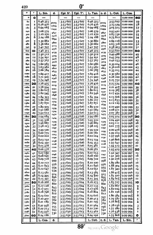
420 0°
'' / L. Sin. d. Cpl. S'. Cpl. T'. L. Tan. c.d. L. Cot. L. Cos.
- 0 — — — — — 0.00000 60
60 1
2
3
4
6.46 373
6.76 476
6.94 085
7.06 579
7.16 270
7.24 188
7.30 882
7.36 682
74 i 797
30103
17609
3-53 627
3-53 627
1 3-53 627
3-53627
3-53 627
3-53627
3-53 627
353627
3-53 627
3-53627
3-53 627
353627
646373
6.7647630103
17609
12494
9691
7918
6694
5800
3-53 627
3-23 524
3-°5 915
2.93421
2.83 730
2.75812
2.69 118
2.63318
2 58 203
0.00000
0.00 000
0.00 000
0.00 000
0.00 000
0.00 000
0.00 000
0.00 000
0.00 000
59
58
57
56
55
54
'SO
: 6.94085
7.06 579
7.16 270
7.24 188
7.30 882
i3-
240
300
360
420
480
540
56
"494
9691
7918
6694
5800
5"5
4576
4139
3779
3470
3218
I
9
3-53 627
3-53627
3-53 627
353627
353627
3-53 627
! 7.36 6825352
5«7-41 7975"5
4576
4139
3779
3476
3219
2996
2803
2633
2482
2348
2228
2119
2020
1931
1848
600 10 746 373 3-53 627 3-53 627 746 373 2-53 627 0.00 000 50
660
720
780
11 7.50512
7-54 29'
7-57 767
3-53627
3-53627
3-53627
3-53 627
3-53627
3-53 627
7.50512
7-54 291
7-57 767
2.49 488
2.45 709
242 233
0.00 000
o.coooo
0.00000
49
4812
«3 47
840
900
960
1020
1080
1 140
'4 7.60 985
7.63 982
7.66 784
7.69417
7.71 900
7.74 248
*997
2802
2633
353 628
353 628
353 628
353627
353627
3-53627
3-53627
3-53 627
3-53 627
7.60 986
7.63 982
7.66 785
7.69418
7.71 900
7-74 248
2.39014
2.36018
2-33 215
2.30 582
2.28 100
2.25 752
0.00000
0.00000
0.00000
9.99 999
9.99 999
9.99 999
46
45
44
'516
«718
2483
2348
2227
2ng
2021
1930
1848
3-53 628
353 628
3-53 628
4342
4''9
i20- 20 7.76 475 3-53 628 353627 7-76476 2.23 524 9.99 999 40
1260
1320
1380
21
22
23
7-78 594
7.80615
7.82 545
3 53 628
3-53 628
353 628
3-53 627
3-53627
3-53 627
7-78 595
7.80615
7.82 546
2.21 405 9.99 999
9.99 999
9.99 999
3938
37
2-19385
2.17454
1440 24 7 84 3931773
1704
1639
3-53 628
3-53 628
3-53 628
3-53 627
3-53627
3-53 627
7-84 394
7.86 167
7.87871
'773
1704
1639
2.15 606 9.99 999
9.99 999
9.99 999
36
35
34
1500
1560
25
26
7.86 166 2-13833
2.12 1297.87 870
1620
1680
1740
27
28
29
7.89 5091579
1524
1472
1424
3-53 628
353 628
3 53 628
353 626
3 53 626
3-53 626
7.89 510
7.91 089
7.92613
1579
1524
'473
1424
2.10490
2.08 91 1
2.07 387
9 99 999
9.99 999
9.99 998
3332
3«
7.91 088
7.92 612
1800 30 7.94 084 3-53 628 3-53 626 7.94 086 2-05 9'4 9-99 998 30
i860
1920
1980
3132
33
7-95 5o8
7.96 887
7.98 223
1379
1336
1297
1259
1223
3-53 628
3-53 628
3-53 628
3-53 626
3 53 626
3-53 626
7.95510
7.96 889
7.98 225
1379
1336
1297
1259
1223
1190
2.04 490
2.03 1 1 1
2.01 775
9.99 998
9.99 998
9.99 998
29
28
27
2040
2100
2160
34 7.99 520
8.00 779
8.02 002
3-53 628
353 628
3-53 628
3.53 626
3.53 626
3-53 626
7.99522
8.00 781
8.02 004
2.00478
1.99 219
1.97 996
9.99 998
9.99 998
9.99 998
26
25
243536
2220
2280
2340
3738
39
8.03 1921158
1128
3-53 628
353 628
353628
3-53 626
3.53626
3-53 626
8 03 194
8 04 353
8.05 481
"59
1128
1 100
1.96 806
1.95647
1.94 5 '9
9.99 997
9.99 997
9.99 997
23
22
21
8.04 350
8.05 478
2400 40 8.065781072
1046
1022
3-53 628 353625 8.06 5811072
1047
1022
'-93 4'9 9.99 997 20
2460
2520
2580
41
42
43
8.07 650 3-53 628
3.53628
353629
3-53 625
3-53625
353625
8.07 653 1.92 347
1.91 300
1.90 278
9-99 997
9.99 997
9.99 997
i9
188.08 696 8.08 700
8.09 718999
976
954
934
8.09 722qq8 '7
2640
2700
2760
2820
2880
2940
44
45
46
8.10 717 3-53 629
3-53 629
3-53629
3-53 625
3-53 625
3-53 625
3-53 625
3-53 625
3-53 624
8.10 720yy°
976
955
934
1.89 280
1.88 304
1-87 349
9.99 996
9.99 996
9.99 996
9.99 996
9.99 996
9.99 996
16
'5
H
8.1 1 693 8.1 1 696
8.12 647 8.12 651
47
48
8.13 581
8.14495
8.15 391
9143-53 629
3-53 629
3-53 629
8.13585
8.14 500915
895
878
1.86415
1.85 500
1.84605
'312
1149896
877
860
8-15 395
3000 50 8.16 268 3-53 629 3-53 624 8.16273860
1-83 727 9-99 995 IO
3060
3120
3180
3240
3300
3360
51
52
53
54
5556
8.17 128
8.17971
8.18798
843
827
812
3-53 629
3-53 629
353629
3-53 624
3-53 624
3-53 624
3-53 624
3-53 624
3-53 624
8.17 133
8.17976843
828
812
1.82867
1.82 024
1.81 196
1.80384
9-99 995
9-99 995
9-99 993
98
8.18 804 7
6
5
4
8.19 610797782
769
3-53 629
3-53 629
3-53 629
8.19 616797782
9-99 995
9.99 994
9.99 994
8.20 407 8.20 413 '-79 587
1.788058.21 189 8.21 195769
756
742
73°
3420
3480
354&
5758
59
8.21 958755
743
73°
3-53 629
3-53629
3-53 630
3-53 623
3-53 623
3-53 623
8.21 964 1.78036
1.77 280
1.76538
9.99 994
9.99 994
9-99 994
32
1
8.22 713 8.22 720
8.23 456 8.23 462
3600 60 8.24 186 3-53 630 3-53 623 8.24 192 1.75 808 9-99 993 O
L. Cos. d. L. Cot. c. d. L. Tan. L. Sin. /
89°

1 421
w 9 L. Sin. d. Cpl. S'. Cpl. T'. L. Tan. c. d. L. Cot. L. Cos.
36-- O 8.24 186717
706
695
684
3-53 630 3-53 623 8.24 192718
706
696
684
1.75 808 9-99 993 60
366-
373-
378-
384-
39--
396-
I 8.24903 3-53 630
3-53 630
3-53 630
3-53 630
3-53 630
3-53 630
3-53 630
3-53 630
3-53 630
3-53 623
3-53 623
3-53 623
3.53 622
3.53 622
353 622
3.53 622
3.53 622
3.53 622
8.24 910 1.75090
1.74 384
1.73688
1.73004
9-99 993
9-99 993
9-99 993
9.99992
5958
57
56
55
54
5352
5'
50
49
48
47
46
45
44
2
3
8.25 609 8.25 616
8.26 304 8.26 312
4 8.26 988673
663
8.26 996673
66356
8.27 661 8.27 669 1.72331
1. 71 668
9-99 992
9.99 9928.28 324 8.28 332
4-2-
4-8-78
8.28 977653
644
634
624
616
608
599
590
8.28 986654
643
634
625
617
607
599
59"
584
575
568
561
553
546
540
1.71 014
1.70 371
1.69 737
9.99 992
9.99 992
9.99 991
8.29 621
8-3° 255
8.29 629
414-9 8.30 263
42-- IO 8.30 879 3-53 630 3-53 621 8.30 888 1.69 112 9.99 991
426- 11 8.31 495 3-53 630
3-53 631
3-53 631
353631
3-53 63I
353631
353631
353931
353631
3-53621
3-53 621
3-53621
8-3' 5°5
8.32 112
1.68495
1.67 888
1.67 289
1.66698
1.66 114
1-65 539
1.64 971
1.64410
1.63857
9.99 991
9.99 990
9.99 990
9.99 990
9.99 990
9.99 989
9.99 989
9.99 989
9.99 989
432- 12
13
14
'516
8.32 103
438- 8.32 702 8.32 711
444- 8-33 292583
575
568
560
553
547
539
3-53 621
3-53 620
3.53 620
8.33 302
8.33 886
8-34 461
8-35 029
8-35 59°
8.36 143
45--
456-
8.33 875
8-34 45°
8.35018462-'7 3.53 620
3.53 620
3-53 620
4342
4'
40
468-
474-
18 8-35 578
8.36 131
48--
19
20 8.36 678 3-53 631 3.53 620 8.36 689 1-63311 9.99 988
486-
492-
498-
5-4-
51--
516-
522-
528-
21 8.37 217533526
520
-3-53 631
3-53 632
353632
3-53 619
3-53619
3-53619
3-53619
3-53619
3-53 6I8
8.37 229
8-37 762 533527
520
1.62 771
1.62 238
1.61 711
1.61 191
1.60 677
1.60 168
1.59 666
1.59 170
1.58679
9.99 988
9.99 988
9.99 987
3938
37
36
35
34
22 8-37 75°
23 8.38 276 8.38 289
24 8.38 7965'4508
502
496
491
3-53 632
353632
3-53 632
3-53632
3-53 632
353632
8.38 8095'4
5°9
502
9-99 987
9.99 987
9.99 986
9.99 986
9.99 986
9-99 985
25
26
8.39 310
8.39818
8-39 323
8.39 832
27
28
8.40 320
8.40816
3-53 618
3-53 618
3.53 618
8.40 334496
491
486
480
3332
3'
30
8.40 830
534° 29 8.41 307485
480
8.41 321
9-99 98554-- 30 8.41 792 3-53632 3-53 6I7 8.41 807 1-58 193
546-
552-
558-
564-
31 8.42 272474
470
464
459
455
450
3-53 632
3-53633
3-53 633
3-53 633
3 53 633
3-53 633
3-53 633
3-53 633
3-53 633
3-53 634
3-53617
3-53 6I7
3-53617
8.42 287
8.42 762
8-43 232
475
470
1.57 7'3
1-57238
1.56 768
1.56304
1.55 844
1-55 389
1-54 939
1-54 493
•-54052
9.99 985
9.99 984
9.99 984
9.99 9849-99 98o3
9-99 983
29
28
27
26
25
24
32
33
34
3536
8.42 746
57°°
576-
582-
588-
594-
8.43 216
8.43 680
8-44 139
8-44 594
8.45 °44
8-45 489
8-45 93°
3-53 6I7
3-53 616
3-53 616
3-53 616
3-53 616
3-53615
3-53 6I5
8-43 696
8.44 156
464
460
455
45°
446
441
8.44 61 1
3738
39
40
41
42
43
44
45
46
445
441
8.45 061
8.45 507
9-99 983
9.99 982
9.99 982
23
22
218.45 948
6--- 8.46 366436
433
427
424
8.46 385437
432
428
424
420
416
412
408
404
401
1-53615 9-99 982 20
6-6-
612-
618-
624-
63--
636-
642-
648-
6540
8.46 799 3-53 634
3-53 634
3-53 634
3-53 634
3-53 634
3-53 634
3-53 634
3-53 633
3-53 635
3.53 615
3-53 615
3-536H
3-53 614
3-53 614
3-53614
3-53 6I3
3-53 6I3
3-53 6I3
8.46 817 1-53183
'-52 755
1.52 331
1.51 911
9.99 981
9.99 981
9.99 981
9.99 980
9.99 980
9.99 979
'9188.47 226 8.47 245
8.47 650 8.47 669 '7
8.48 069
8.48 485
419
416
411
8.48 089
8.48 505
8.48917
1.5' 495
1. 5 1 083
16
'5
H8.48 896
47
48
49
50
8-49 3°4408
404
400
8-49 325
8-49 729
8.50 130
1.50 675
1.50 271
1.49 870
9-99 979
9.99 9799.99978
'312
11
10
8.49 708
8.50 108
66-- 8.50 504396
393
390
386
3-53.635 3-53 6I3
3-53 612
3-53 612
3-53 6I2
8.50527397
393
390
386
383
380
376
373
37°367
363
1.49 473 9.99978
666-
672-
678a
684a
690-
696-
7-2-
7-80
714-
51
52
53
54
5556
5758
59
60
8.50 897 3-53 635
3-53 635
3-53 635
3 53 635
3-53 635
3-53636
8.50 920 1 .49 080
1 .48 690
1.48 304
1.47 921
9.99977
9.99 977
9.99977
9.99 976
9.99 976
9-99 975
9-99 975
9-99 974
9-99 974
9
88.51 287 8.51 310
8.51 696
8.52079
8.52459
8.52835
8.53 208
8.53 578
8-53 945
8.54308
8.51 673
8.52 055382
379376
373
369
367
363
3-53 61 1
3.53 611
3.53 611
7
6
5
4
8.52 434
8.52810
1.47 54'
1.47 165
8-53 183
8-53 552
3-53 636
353636
353636
3-53 611
3-53610
3-53 61o
1.46 792
1.46 422
1.46 055
32
18.53 919
72-- 8.54 282 3-53 636 3-53 61o 1.45 692 9-99 974 0
L. Cos. d. L. Cot. c. d. L. Tan. L. Sin. 1
88°
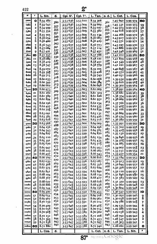
422
n l
7200 0
7260 '
7320 2
7380 3
7440 47500 57560 6
76207
7680 8
774° 9
7800 10
7860 11
7920 12
7980 «3
804° «48100 i5
8160 16
8220 17
8280 18
8340 19
8400 20
8460 21
8520 22
8580 *3
864° 24
8700 25
8760 26
8820 27
8830 28
8940 29
9000 30
9060 3«
9120 32
9180 33
9240 349300 359360 36
942031
9480 38
9540 39
9600 40
9660 41
9720 42
9780 43
9840 44
9900 45
9960 46
1002047
10080 48
10140 49
10200 SO
10260 5«10320 52
10380 53
1044054
1050055
10560 56
1062057
10680 58
1074059
10800 60
L. Sin. Cpl. S', Cpl.T'. [ L.Tan. |c.d. L. Cot. L. Cos.
1.45 692 9-99 974 OO
M5 33' 9-99 973 591.44 973 9-99 973 58
1.44 618 9.99972 57
1 .44 266 9.99 972 56
«43 917 9.99971 551.43 57' 9.99971 54
'43 227 9-99 970 531.42886 9.99 970 52
1.42 548 9.99 969 5'
1.42 212 9.99 969 OO
1.4' 879 9.99 968 49
1.4 1 549 9.99 968 48
1.41 221 9.99 967 47
1.40895 9-99 967 46
1.40572 9.99 967 45
1.40251 9.99 966 44
1.39 932 9-99 966 43
1.39616 9.99 965 42
1.39302 9.99 964 4«
1.38 991 9.99 964 40
1.38 681 9-99 963 39'■38 374 9-99 963 38
1.38069 9.99 962 37
1.37 766 9.99 962 36
'■37 463 9.99 961 351.37 166 9.99 961 34
1.36 869 9.99 960 331.36 574 9.99 960 32
1.36 282 9-99 959 3-
1-35 99' 9-99 959 30
1.35 702 9-99 958 29
1.35 4'3 9.99 958 28
'■35 130 9-99 957 27
1.34846 9.99 956 26
1.34 563 9-99 956 25
1-34285 9-99 955 24
1.34007 9-99 953 23
1.33 73' 9-99 954 22
1.33 457 9-99 954 21
i-33 '84 9-99 953 20
1.32913 9.99 952 '91.32644 9-99 95 2 18
1.32 376 9-99 95' '7
1.32 no 9.99 951 16
1.31 846 9-99 95° '51.3' 583 9.99 949 '4
1.31 322 9.99 949 '31. 31 062 9.99 948 12
1.30804 9.99 948 1 1
1 30 547 9-99 947 IO
1.30 292 9.99 946 91.30 038 9.99 946 8
1.29 786 9-99 945 7
1.29 535 9.99 944 6
1.29 286 9.99 944 51.29038 9 99 943 4
1.28 792 9.99 942 31.28 547 9.99 942 2
1.28 303 9.99 941 1
1.28060 9.99 940 O
L. Tan. L. Sin. t
8.54 282
8.54 642
8.54 999
8-55 354
8.55 705
8.56 054
8.56 400
8-56 743
8.57084
8-57 421
8-57 757
8.58 089
8.58419
8.58 747
8.59072
8-59 395
8-59 715
8.60033
8.60 349
8.60 662
8.60 973
8.61 282
8.61 589
8.61 894
8.62 196
8.62 497
8.62 795
8.63 091
8.63 385
8.63 678
8.63 968
8.64 256
8.64 543
8.64 827
8.65 110
8.65 391
8.65 670
8.65 947
8.66 223
8.66 497
8.66 769
8.67 039
8.67 308
8.67 575
8.67 841
8.68 104
8.68 367
8.68 627
8.68 886
8.69 144
8.69 400
8.69 654
8.69 907
8.70 159
8.70 409
8.70 658
8.70 905
8.71 151
8.71 395
8.71 638
8.71 880
L. Cos.
300
357
355
35'
349
346
343
34'
337
336
33*
330
328
325 I323
320
318 I
316
3«3
3"
309
307
305
302
301
29S
296
294
293
290
288
287
284
283
281
279
277
276
274
272
270
269
267
266
263
263
260
259
258
256
254
253
252
250
249
247
246
244
243
242
~dT
3-53 636
3-53 636
3-53 637
3-53 637
3-53 637
3-53 637
3-53 637
3-53 637
3-53 637
353 638
3-53 638
3-53_6'o
353609
3-53609
3-53609
3-53609
3.53 608
3.53 608
3-53 608
3-53 607
3J3_6o7_
3-53 6o7
3-53 638
3-53 638
3-53 638
3 53 638
3-53 639
3-53 639
3-53 639
3-53 639
3-53 639
3-53 606
3-53 606
3.53606
353605
3 53 605
3-53 603
3-53 604
3-53 604
3 53 604
3-53 639 3-53 603
3-53 640
3-53 640
3-53 640
3-53 640
3-53 640
3-53 640
3-53 641
353641
353641
3-53 603
3-53 603
3-53 602
3-53 602
3.53 602
3-53 6oi
353601
3-53 6oi
3-53600
3 53 64' 353600
3-53 641
3-53 642
3-53642
3-53642
3-53 642
3-53 642
3-53 642
3-53 643
3 53 643
3-53 599
3-53 599
3-53 599
3-53 598
3-53 598
3-53 598
3-53 597
3-53 597
3-53 596
3-53 643 3-53 596
3-53 643
3-53 643
3-53 644
3-53 644
3-53 644
3-53 644
3-53 644
3-53 643
3-53 645
3-53 596
3-53 595
3-53 593
3-53 594
3-53 594
3-53 594
3-53 593
3-53 593
3-53 592
3-53 645 3-53 592
3-53 645
3-53 646
3-53 646
3-53 646
3-53 646
3-53 646
3-53 647
3-53 647
3-53 647
3-53 592
3-53 591
3-53 591
3-53 590
3-53 59o
3-53 589
3-53 589
3-53 589
3-53 588
3-53 647 3-53 588
8-54 308
8.54 669
8-55 027
8-55 382
8-55 734
8.56 083
8.56 429
8.56 773
8-57 114
8-57 452
8.57 788
8.58 121
8.58451
8.58 779
8-59 105
8.59 428
8-59 749
8.60068
8.60 3S4
8.60698
8.61 009
8.61 319
8.61 626
8.61 931
8.62 234
8.62 535
8.62 834
8.63 131
8.63 426
8.63 718
8.64 009
8.64 298
8.64 585
8.64 870
8.65 154
8.65 435
8.65 713
8.65 993
8.66 269
8-66 543
8.66816
8.67 087
8.67 356
8.67 624
8.67 890
8.68 154
8.68417
8.68 678
8.68 938
8.69 196
8-69453
8.69 708
8.69 962
8.70 214
8.70 463
8.70714
8.70 962
8.71 208
8.71 453
8.71 697
8.71 940
L. Cot. c. d
36'
358
355
35*
349
346
344
.541
33«336
333
3.;o
328
326
323
321
319
316
3«4
3"
310
307
3°5
303
3°i
299
297
295
292
291
289
287
285
284
281
280
278
276
274
273
271
269
268
266
264
263
261
260
258
257
255
254
252
251
249
248
246
245
244
243
87°
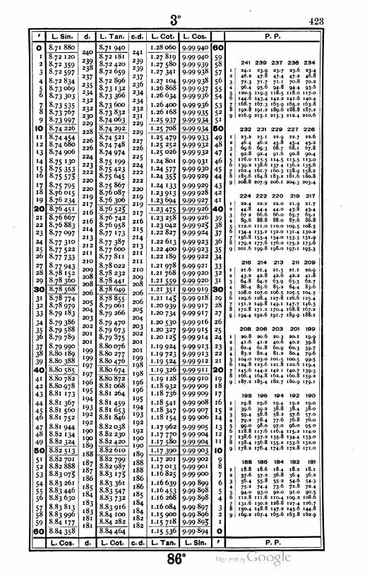
3° 423
L. Sin. L. Tan. c.d L. Cot. L. Cos. P. P.
O
2
3
4
56
78
9
|IO
ii
12
«3
'4
'5i6
'7.18
19
20
21
22
23
24
*526
27
28
29
¡ 30
31
32
33
34
3536
3Z38
39
40
41
42
43
44
45
46
4748
49
SO
51
52
53
54
56
57
58
59
160
8.71 880
8.72 120
8-72 359
8.72597
8.72 834
8.73069
8-73 3°3
8-73 535
8-73 767
8-73 997
8.74 226
8.74 454
8.74 680
8.74 906
8.75 130
8-75 353
8-75 575
8-75 795
8.76015
8.76 234
8.76 451
8.76 667
8.76 883
8.77097
8.77310
8.77 522
8-77 733
8-77 943
8.78152
8.78 360
8.78 568
8.78 774
8.78979
8.79 183
8.79 386
8.79 588
8.79 789
8.79 990
8.80 189
8.80 388
8.80 585
8.80 782
8.80978
8.81 173
8.81 367
8.81 560
8.81 752
8.81 944
8.82 134
8.82 324
8.82513
8.82 701
8.82 888
8.83075
8.83 261
8.83 446
8.83 630
8.83813
8.83 996
884 177
8.84 358
L. Cos.
240
239
238
237
235
234
232
232
230
229
228
226
226
224
223
222
220
220
219
217
216
216
214
213
212
211
210
209
208
208
206
205
204
203
202
201
201
199
«99
'97
197
196
«95
«94
'93192
192
190
190
189
188
187
187
186
185
184
i83
i83
181
181
~d7
8.71 940
8.72 181
8.72 420
8.72 659
8.72 896
8-73 132
8.73 366
8.73 600
8-73 832
8.74063
8.74 292
8.74 521
8.74 748
8-74 974
8-75 «99
8-75 423
8.75 645
8.75 867
8.76087
8.76 306
876 525
8.76 742
8.76958
8-77 «73
8-77 387
8.77 600
8.77 811
8.78 022
8.78 232
8.78441
8.78 649
8.78855
8.79 061
8.79 266
8.79 470
8.79 673
8-79 875
8.80076
8.80277
8.80476
8.80 674
8.80 872
8.81 068
8.81 264
8.81 459
8.8i 653
8.81 846
8.82 038
8.82 230
8.82 420
8.82610
8.82 799
8.82 987
8.83175
8.83 361
8.83 547
8.83 732
8.83 916
8.84 100
8.84 282
8.84 464
L. Cot. I C. d
241
239
239
237
236
234
234
232
23«
229
229
227
226
225
224
222
222
220
219
219
217
216
215
214
2«3
211
211
210
209
208
206
206
205
204
203
202
201
201
«99198
198
196
196
«95
'94
«93
192
192
190
190
189
188
188
186
186
«85
184
184
182
182
28 060
27 819
27 580
27341
.27 104
.26 868
.26 634
.26 400
.26 168
25 937
9^99940
9.99940
9-99 9399-99 938
9-99 938
9-99 9379-99 936
9-99 936
9-99 935
9.99 934
25 708 9-99 934
25 479
25 252
25 026
24 801
.24 577
24 353
24 133
23913
23 694
9-99 9339.99 932
9-99 932
9-99 93«9.99 930
9.99 929
9.99 929
9.99 928
9-99 927
23 475 9.99 926
.23 258
23 042
,22 827
.22613
.22 400
.22 189
.21 978
21 768
.2i 559
9.99 926
9.99 923
9.99 924
9-99 923
9.99 923
9.99 922
9.99 921
9.99 920
9-99 920
21 35« 9.99919
21 143
.20 939
20734
20 530
20 327
20 123
19924
«9 723
19 524
9.99918
9.99917
9.99917
9.99916
9-99 9'59.99914
9-99 9'3
9-99 9«39-99 912
'9 326 9.99 91 1
19 128
18 932
18736
18 541
18 347
18 154
17 962
17770
'7580
'7 390
999910
9.99 909
9.99 909
9.99 908
9.99 907
9 99 906
9.99 905
9.99 904
9.99 904
9.99 903
17 201
17013
16825
16 639
16 453
16 268
16 084
15 900
15 718
i5 536
L. Tan.
9.99 902
9.99 901
9.99 900
9.99 899
9.99 898
9.99 898
9.99 897
9.99 896
9-99 893
9-99 894
L. Sin.
60
5958
57
56
55
54
5352
5«
BO
49
48
47
46
45
44
43
42
4'
40
39
38
37
36
35
34
3332
3«
30
29
28
27
26
25
24
23
22
21
20
«918
«7
16
«514
«312
1 1
10
241 239 237
24.148.272.396.4120.5144.6168.7192.8216.9
23.9 23.747.8 47.471.7 71. '95.6 94.8119. 5 118.5143.4 1422167.3 165.9191. 2 189.6215. ' 213.3
232 231 229
23.2 23.146.4 46.269.6 69.392.8 92.4116.0 115. 5139.2 138.6162.4 161. 7185.6 184.8208.8 207.9
224 222
230
23.647.270.8
94.4118.0141.6165.2188.8212.4
227
22.7
45.41,8.1
22. Q45.868.791.6 9O.8
114. 5 113. 5137.4 '36-2160.3 r58-9183.2 181.6206.1 204.3
22.444.867 289.6112.0134.4156.8179.2201.6
22.2
44.466.688.8
'ii.-133.2155-4177.6199.8
220
22.044.066.088.0
21.9
43-8fc5-787.6
110.0 109.5132.0 131.4154.0 1533176.0 175.2198.0 197.1
234
23-446.870.293.6117.0140.4163.8187.2210.6
226
22.6
45-267.890.4113.0135-6158.2180.8203.4
21.7
43.465.186.8
108.5130.2151.9173-6195-3
216
21.643-264.886.4108.0129.6151.2172.8194.4
208
20.841.662.483.2
214 213 211 209
2«.442.864.285.6107.0128.4149.8171.2192.6
206
20.641.261.882.4
104.0 103.0124.8 123.6145.6 144.2166.4 164.8187.2 185.4
21.342.063.985.2
106.5127.8149.1170.4191. 7
42.2
63.384.4
20.941.862.783.6
105.5 '04.5126.6 125.4147.7 146.3168.8 167.2189.9 '88.1
203 201 199
20.340.6
60. y81.2
101.5121. 8142 '162.4182.7
40.260. 180.4
100.5
19.939.8
59.779.6
99.5120.6 119.4140.7 139.3160.8 159.2180.9 '79.1
198 196 194 192 190
19.839.6
59.4
19.639-258.83
4 79.2 78.4 775 99.0 98.0 976 118.8 117.6 116
138.6 137.2 135158.4 156.8 155178.2 176.4 174.6 172.8 171.0
4 19.2 19.08 38.4 38-02 57.6 57.06 76.8 76.0- 96.0 95.04 115. 2 114.08 134.4 i33--2 153.6 152.0
188 186
18.8 18.637-6 37-256.4 55-875-2 74.494.0 93.0112.8 111.6131.6 130.2150.4 148.8169.2 167.4
184
18.436.855-273.692.0
110.4128.8147.2165.6
182 181
18.2 18.136.4 36.254.6 54.372.8 72.491.0 90.5
109.2 108.6127.4 126.7145.6 144.8163.8 162.9
P. P.
86°

424 4°
o
I
2
3
4
56
78
9
10
ii
12
I '3
«4
'5i6
il
i8
'9
20
21
22
23
24
25
26
27
28
29
30
31
32
33
34
35
36
37
38
39
40
41
42
43
44
45
46
47
48
49
50
5i
52
53
54
55
56
5758
59
I 60|
L. Sin.
8.84358
8.84539
8.84 718
8.84 897
8.85075
8.85 252
8.85 429
8.85 605
8.85 780
8-85 953
8.8b 128
8.86 301
8.86474
8.86 645
8.86816
8.86 987
8.87 156
8.87 325
8.87 494
8.87 661
8.87 829
8.87993
8.88 161
8.88 326
S.88 490
8.88 654
8.88817
8.88 980
8.89 142
8 89 304
8.89 464
8.S9 625-
8.89 784
8.89 943
8.90 102
8.90 260
8.90 4 1 7
8.90574
8.90 730
8.90 885
8.91 040
8.91 193
8.91 349
8.91 502
8.91 655
8.91 807
8.91 959
8.92 no
8.92 261
8 92 411
8.92 561
8.92 710
8.92 859
8.93 007
8-93 154
8.93 301
8.93 448
8-93 594
8.93 740
8-93 883
8-94 03°
L. Cos.
L. Tan. I c.d.
8.84 464
8.84 646
8.84 826
8.85006
8.85 183
8.85 363
8.85 540
8.85717
8.S5 893
8.86 069
8.86 243
8.86417
8.86 591
8.86 763
8.86935
8.87 10b
8.87 277
8.87 447
8.87616
8-87 783
8-87 953
8.88 120
8.88 287
8.88453
8.88618
8.88 783
8.88 948
8.89 1 1 1
8.89 274
8.89 437
8.89 598
8.89 760
8.89 920
8.90 080
8.90 240
8.90 399
8.90 557
8.90713
8.90 872
8.91 029
8.91 1 05
8.91 340
8.91 495
8.91 650
8.91 803
8.91 957
8.92 110
8.92 262
8.92 414
8.92 565
8.92 716
8.92 866
8.93 016
8.93 163
8.93 3'3
8.93 462
8.93 609
8.93 756
8-93 903
8-94 049
8.94 195
L. Cot. c.d
L. C-t. L. Cos.
1.'5 536 9.99894 ao
1.«5 354 999893 591. 15 174 9.99892 58
1. 14994 9.99891 57
1.14815 9.99891 56
1. 14 637 9.99890 551. 14460 9.99 889 54
1. 14 283 9.99 888 Si1. 14 107 9.99 887 5-1.'3 93' 9.99 886 5'
1.«3 757 9-99 885 SO
1.'3 583 9.99 884 491.13409 9.99 883 48
1.'3 237 9.99 882 47
1. 13 063 9.99 881 46
1. 12 894 9.99 880 451. 12 723 9.99 879 44
112 553 9.99 879 43
1. 12 384 9.99 878 42
1. 12 215 9.99 877 41
1. 12047 9.99 876 40
1.1 1 880 9.99 873 391. 11 713 9.99 874 38
1.1 1 547 9-99 873 37
1. 11 382 9.99 872 36
1. 11 217 9.99 871 351. 11 052 9.99 870 34
1. 10 889 9.99 869 331. 10 726 9.99 868 32
1. 10 563 9.99 867 3'
1. 10 402 9.99 866 30
1. 10 240 9-99 863 29
1. 10 080 9.99 864 28
1.09 920 9.99 863 27
1 .09 760 9.99 862 26
1.09 601 9.99 861 25
1.09 443 9.99 860 24
1.09285 9.99 859 23
1.09 128 9.99 858 22
1.08 971 9-99 857 21
1.08 815 9.99 856 20
1.08660 9-99 853 19
1.08 503 9-99 854 18
1.08 350 9-99 853 «7
1.08 197 9.99 852 16
1.08043 9.99851 '51.07 890 9 99 850 14
1.07 738 9.99 84S '31.07586 9.99 847 12
1-07 435 9.99 846 11
1.07 284 9.99 845 10
1.07 134 9.99 844 91.06 984 9-99 843 8
1.06 835 9.99 842 7
1.06 687 9.99 841 6
1.06538 9.99 840 51.06 391 9-99 839 4
1 .06 244 9.99 838 31 .06 097 9.99 837 2
1 -°5 95 1 9.99 836 1
1.05 803 9-99 834 O
L. Tan. L. Sin. r
P. P.
182 181 'SO 179 178
18.2 18. 1 18.0 17.9 '7.8
36.4 36.a 36.0 35.8 35.654.6 54.3 54° 53-7 53-472.8 72.4 72.0 71.6 71.291.0 90.5 90.0 89.5 89.0109.2 108.6 108.0 107.4 106.8127.4 126.7 126.0 125.3 124.6
'45-6 '44.8 144.0 '43-2 142.4163.8 162.9 162.0 161.1 id-. 2
1 r 7 176
ni
52.8
7°-4
175 174
17.7
35453-17u-888.5 88.0106.2 105.6123.9 '23 2141.6 140.8159.3 '58.4
'7-535.0"05
87.5105.0122.5140.0157.5
'7-4,4.3
'.y.-87.0104.4 103121.8 121. '139.2 138.4'56.6 155.7
173
'7-334.6
69.2Si
.8
172 171 170
17.2
34-45..61 S.8
17.1
5'-308.4S50
17 -
34.051 .0t.8.0
169
16.933-850.767.684.5
168
1Ó.8
33-65O-467.284.0
103.2 102.6 102.0 101.4 100.8120.4 X19.7 iiQ-O 118.3 117.6137.6 136.8 136.0 135.2 134.4
154-8 153 9 153° '52-X 151-2
167 166 165 164 163
16.7 16.6 16.5 16.4 16.3
33.4 33-2 33-0 32.8 32.650.1 49.8 49.5 49.2 48.9
66.8 66.4 66.0 65.6 65.283.5 83.0 82.5 82.0 81.5
100. 2 99.6 99.0 98.4 97.8116.9 116.2 115.5 114. 8 114. 1133.6 132.8 132.0 131 2 130.4150.3 149.4 148.5 147.6 146.7
162
'6.232.448.664.881.0
97.2
161
16.132 2
'SO
16.032.0
48.3 48064.4 64.080.5 80.096.6 96.0
113.4 112. 7 112.- in. 3 110.6129.6 128.8 128.0 127.2 126.4145.8 144.9 144.0 143. 1 142.2
159
15-931.8
47-763.6
79.595.4
isa
15.Í31.6
47.463.279.094.8
157
15-73'.447- 162.878594 2109.9125.6141.3
156
15.631.24D.362.478.093.6109 2124.8140.4
155 154 153
15-531.046.562.0
77-593.0
'5-430.846.261.677.092.4
108.5 107.8124.0 123.2139.5 138.6
«5-330.6
45-961.276.591.8
107.1122.4
'37-7
152 151 150 149 148
14.829.6
44.459.274.088 8
15.2 15. i 15.0 14.930.4 30.2 30.0 29.845-6 45-3 45-- 44.760.8 60.4 60 - 59.676.0 75.5 75.0 74.591.2 90.6 90.0 89.4
106.4 i-5-7 105.0 104.3 103.6121.6 120.8 120.0 119.2 118.4136.8 135.9 '35-0 134.1 133-2
P. P.
85°

425
0
i
2
3
4
56
78
9
1 10
ii
12
«3
'4
'516
17
18
19
20
21
22
23
24
25
26
27
28
29
30
31
32
33
34
3536
3738
39
40
4'
42
43
44
45
46
47
48
49
SO
5'52
53
54
5556
5758
59
60
L. Sin.
8.94 030
8.94 174
8.94317
8.94 461
8.94 603
8.94 746
8.94 887
8.95 029
8.95 170
8-95 31o
8-95 45°
8.95 589
8.95 728
8.95 867
8.96 005
8.96 143
8.96 280
8.96417
8.96 553
8.96 689
8.96 82;
8.96 960
8.97 095
8.97 229
8-97 363
8.97 496
8.97 629
8.97 762
8.97 894
8.98 026
8-98 157
8.98 288
8.98419
8.98 549
8.98 679
8.98 937
8.99 066
8.99 194
8-99 322
8-99 45°
8.99 577
8-99 7°4
8.99 830
8.99 956
9.00 082
9.00 207
9.00 332
9.00456
9 00 581
9.00 704
9.00 828
9.00951
9.01 074
9.01 196
9.01 318
9.01 440
9.01 561
9.01 682
9.01 803
9°' 923
L. Cos.
d. I L. Tan.
8-94 '95
8.94 340
8.94 485
8.94 630
8-94 773
8.94917
8.95 060
8.95 202
8-95 344
8.95 486
8-95 027
8-95 767
8.95 908
8.96 047
8.96 187
8.96 325
8.96 464
8.96 602
8.96 739
8.96 877
8-97 01 3
8.97 130
8-97 285
8.97 421
8-97 556
8.97 691
8-97 823
8.97 959
8.98 092
8.98 225
8.98 358
8.98 490
8.98 622
8.98 753
8.98 884
8.99 013
8.99 145
8-99 275
8.99 403
8-99 534
8.99 662
8.99 791
8.99919
9.00 046
9.00 174
9.00 301
9.00427
9.00 553
9.00 679
9.00 803
9-00 93°
9.01 053
9.01 179
9.01 303
9.01 427
9.01 550
9.01 673
9.01 796
9.01 918
9.02 040
9.02 102
L. Cot. L. Cos. |
1.05 803 9-99 834 60
1.05 660 9-99 833 59i°5 5'3 9.99 832 58
1.05 370 9.99 831 57
1.05 227 9.99 830 5°1.05 083 9.99 829 551 .04 940 9.99 828 54
1.04798 9.99 827 531.04656 9.99 825 52
1.04 514 9.99 824 5'
1 °4 373 9.99823 50
1.04233 9.99 822 491.04092 9.99 821 48
1.03 953 9.99 820 47
1.03 813 9.99819 46
1.03 675 9.99817 451.03 536 9.99 816 44
1 .03 398 9.99815 43
1.03 261 9.99814 42
1.03 123 9.99813 4'
1.02 987 9.99 812 40
1.02 850 9.99 810 39
1.02 713 9.99809 38
1.02579 9.99 808 37
1.02444 9.99 807 36
1.02 309 9.99 806 351.02 175 9.99 804 34
1.02 041 9.99 803 331.01 908 9.99 802 32
1.01 775 9.99 801 3'
1.01 642 9.99 800 30
1.01 510 9-99 798 29
1.01 378 9.99 797 28
1.01 247 9.99 796 27
1.01 116 9-99 795 26
1.00 985 9-99 793 25
1.00 853 9.99 792 24
1.00 725 9.99 791 23
1.00 595 9.99 790 22
1 .00 466 9.99 788 21
1.00 338 9.99 787 20
1.00 209 9.99 786 '91 .00 081 9-99 783 18
°-99 954 9-99 783 '7
0.99 826 9.99 782 16
0.99 699 9.99 781 '5o-99 573 9.99 780 '4
0.99 447 9.99 778 '30.99 321 9-99 777 12
0.99 '95 9.99 776 11
0.99 070 9-99 775 10
0.98 945 9-99 773 90.98 821 9.99 772 8
0.98 697 9.99771 7
0.98 573 9.99 769 6
0.98 450 9.99 768 50.98 327 9.99 767 4
0.98 204 9-99 765 30.98 082 9.99 764 2
0.97 960 9-99 763 1
0.97 838 9.99 761 O
L. Tan. L. Sin. l
P. P.
146
14 629.243-8
5«.473 °
B8.2 87.6X02.9 102.2117.6 116. 8132.3 131.4
147
»4.7•9.444.i58.8
73-5
r4.328.642.957-27.1-585.8
100. 1114 4128 7
139
13.927.84i-755-669.5834
97-3in. 2125. 1
'3S
'3-527.040.5
54.-ii7.581.0
94.5108.0121. 5
142
14.228442 656.871.0852
99.4113.6127.8
138
'3-827.641.455-2
6y 082.896.6110.4124.2
'4.529.0
4? 558.072 587.0101.5116.-130.5
14. 128.242-356.4
7°.584698.7
X3.4
26.840.253-S67.080.493-8107.2120.6
'4-428843.257-672.0864100.8115.2129.6
14.028.042.056.070.084.098.0
112. 8 112.-126.9 126.0
137
'3-727.441.154.868.582.2
95 9
'3S
13.627.240.8
54.468.081.695-2
109.6 108.8123.3 122.4
134 133 132
r3-326.6
39.953-266.579.893.1106.4119.7
13.220.439.652.866.079.292.4105.6n8.8
131 130 '2S 128
' z3.' X3.0 12.9 12.82 26.2 26.0 2^.8 25.6
3 39.3 39.0 38.7 38.4
4 524 52.0 5i« 51.2
5 655 64.5 64.06 78.6 78.0 77.4 76.8
I91.7 91.0 90.3 89.6
8 104.8 104.0 103 2 102.4
9 117.9 n7.0 "6.' 115.2
127 126 '2S 124
' 12.7 X2.G 12.5 12.42 25-4 25.2 25.0 24.8
3 38.1 37.8 37 5 37 2
4 50.8 50.4 s- 0 496
5 63 5 63 0 62 5 62 06 76.2 75.6
P° 74.47 88.9 88.2 87.5 S., 88 101.6 100.8 'CO 0 99.2
9 114.3 113.4 1125 in. 6
123 122 121 120
' X2.3 12.2 12.1 12.02 24.6
2H 24.2 24.0
3 36.9 :,(,.,, 36.3 36.0
4 49.2 48. s 48 4 48.0
5 61.5 61 .0 61> s 6-.a6 73.8 73-2 72.6 72.0
7 86.1 85.4 84 7 84.08 98.4 97-6 96.8 96.0
9 110.7 109.8 108.9 108.0
P. P.
84°
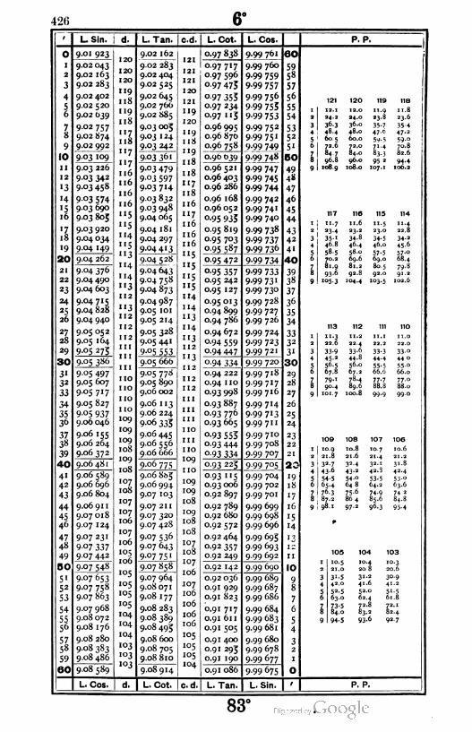
426 6°
0
'
2
3
4
56
78
9
lio
ii
12
«3
«4
«516
il
18
19
20!
21
22
*3
24
25
26
27
28
29
I 30
3«33
33
34
3536
37
38
39
|40|
4«42
43
44
4546
47
48
49
I 50,
5'52
53
54
5556
57.58
59
601
L. Sin,
9-oi 923
9.02 043
9.02 163
9.02 283
9.02 402
9.02 520
9.02 039
9.02 757
9.02 874
9.02 992
9.03 109
9.03 22b
9 °3 342
9.03 458
9 °3 5749.03 690
9.03 805
9.03 920
9.04 034
9-04 '49
9.04 262
9.06 48 1
9.06 589
9.06 696
9.06 804
9.06 91 1
9.07 018
9.07 124
9.07 231
9 °7 3379.07 442
9-°7 54S
9-07 653
9.07 758
9.07 863
9.07 968
9.08 072
9.08 176
9.08 280
9.08 383
9.08 486
9.08 589
L. Cos.
9.04 376
9.04 490
9.04 603
9.04715
9.04 828
9.04 940
9.05 052
9.05 164
9-°5 2 7;
9-°5 3^6
9.05 497
9.05 607
9.05 717
9.05 827
9 05 937
9.06 046
9.06 155
9.06 264
9.06 372
20
20
20
19
18
«9
18
'Z18
«7
»7
16
i6
16
16
«5
'5
14
'5
«3
«4
«4
'3
12
i3
12
12
12
11
11
1 1
10
10
10
10
09
09
09
08
09
08
07
08
07
07
06
07
06
°506
°5
°5
°5
°5
04
04
04
°3
°303
"37
L. Tan. | c.d.
9.02 162
9.02 283
9.02 404
9.02 525
9.02 645
9.02 766
9.02 S85
9.03 005
9.03 1 24
9 °3 242
903 36'
9-03 479
9 03 597
9-°3 7'4
9.03 832
9.03 948
9.04 065
9.04 181
9.04 297
9-°4 4' 3
9.04 528
9.04 643
9.04 758
9.04 873
9.04 987
9.05 101
9.05 214
9.05 328
9.05 441
9-°5 553
9.05 666
9.05 778
9.05 890
9.06 002
9.06 113
9.06 224
9 °6 333
9.06 445
9.06 556
9.06 666
9-°6 775
9.06 8&5
9.06 994
9.07 103
9.07 211
9.07 320
9.07 428
9-07 536
9.07 643
9.07 75 1
9.07 858
9.07 964
9.08071
9.08 177
9.08 283
9.08 389
9.08 493
9.08 600
9.08 705
9.08 810
9.08 914
L. Cot. I c. d.
L. Cot. L. Cos-j
0.97 838 9.99 761 60
0.97717 9.99 760 590.97 596 9-99 759 58
°-97 475 9-99 757 57
o-97 353 9.99 756 56
o-97 234 9-99 753 550.97 115 9-99 753 54
0.96 995 9.99 752 530.96 870 9-99 75' 52
0.96 758 9-99 749 51
0.96 639 9-99 748 SO
0.96 521 9-99 747 490.96 403 9-99 745 48
0.96 286 9-99 744 47
0.96 168 9.99 742 46
0.96 052 9.99 741 45
°-95 933 9.99 740 44
0.95 819 9-99 738 430.95 703 9-99 737 42
0.95 587 9-99 736 4'
0.95 472 9-99 734 40
°-95 357 9-99 733 390.95 242 9-99 73' 38
0.95 127 9-99 73° 37
0.95013 9.99 728 36
0.94 899 9.99 727 350.94 786 9.99 726 34
0.94 672 9.99 724 330.94 559 9-99 723 32
0.94 447 9.99721 31
°-94 334 9.99 720 30
0.94 222 9.99 718 29
0.94 1 10 9.99717 28
0.93 998 9.99716 27
0.93 887 9.99 714 26
0.93 776 9-99 7'3 25
0.93 665 9.99 711 24
°-93 553 9.99 710 23
0.93 444 9.99 708 22
o-93 334 9.99 707 21
0.93 225 9.99 705 20
0.93 115 9.99 704 «90.93 006 9.99 702 18
0.92 897 9.99 701 '7
0.92 789 9.99 699 16
0.92 680 9.99 698 '50.92572 9.99 696 '4
0.92 464 9.99 693 1 ?
0.92 357 9-99 693
0.92 249 9.99 692 11
0.92 142 9.99 690 IO
0.92 036 9.99 689 90.91 929 9.99 687 8
0.91 823 9.99 686 7
0.91 717 9.99 684 6
0.91 611 9.99 683 50.91 505 9.99 681 4
0.91 400 9.99 680 30.91 293 9.99 678 2
0.91 190 9.99 677 1
0.91 086 9-99 675 O
L. Tan. L. Sin.
P. P.
121 120 119 11a
' 12. 1 12.0 11. 1 1.82 24.1 -4-- 23.S -3-ri
3 36.3 36.0 35 44 48.4 4S.0 47-- 47-2
5 60.5 1 . ... - y.'-it) 72.6 7 71 l 70.8
796.8
84.0 83 ■ 52...8 95 2 944
9 108.9 108.0 107. 1 106.2
117 110 119 114
ii. 7 11.6 11.5 11.423.4 2 3 . .1 23.0 -0.-.8
35' 34.8 ;4.5 34.246.8 40-4 4r ■ ' 45-658.5 SS.u 57-5 57-3
69.6 69.0 68.481.9 8i.2 8.. 5 79.893.6 92.S 92.. . 91.2i°5 3 'O4.4 '°3-5 102.6
113 112 111 110
''.3 '1.2 11. 1 1 1 . 022.6 224 22.2 22.0
33-9 33.6 33-3 33°45-2 44. s 44.4 44.056.5 56.0 55. s 55°67.8 67.2 66.-> 66.079.1 78.4 77-7 77°90.4 89.6 S3. 5 88.0
101.7 100.8 99.9 99.0
10S 108 107 100
1 10 9 10.8 10.7 10.62 21 8 21.6 21.4 21.2
3 32 7 32.4 32.1 31.8
4 43 0 43.2 42.3 4*.45 54 s 54.0 53-5 53--6 65 4 648 64.2 63.6
7 76 3 75.6 74.9 74 2
8*Z
2 864 85.6 84.8
9 98 1 97.2 96.3 95.4
105 104 103
' 10.5 10.4 10.32 21.0 20 8 20.6
3 3'-5 31.2 30.9
4 42.0 4'.6 41.2
5 52-5 52.0 51-56 63.0 62.4 61.8
7 73-5 72.8 72.i8 84.0 83.2 82.4
9 94.5 93.6 92.7
P. P.
83°
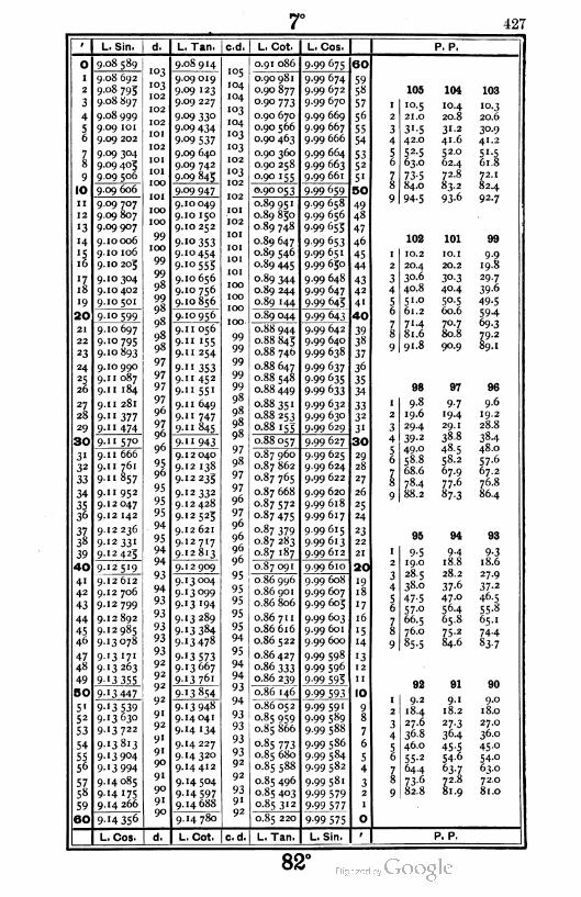
427
o
1
2
3
4
56
78
9
| IO
11
12
'3
14
\l
*l18
19
20
21
22
23
24
25
26
27
28
29
I 30
31
32
33
34
3536
3738
39
I 40
41
42
43
44
45
46
4748
49
I 50
5'52
53
54
5556
5758
59
, 60
L, Sin,
9-o8 589
9.08 692
9.08 793
9.08 897
9.08 999
9.09 IOI
9.09 202
9.09 304
9.09 405
9 09 5°6
9.09 606
9.09 707
9.09 807
9.09 907
0006
o 106
o 203
0304
o 402
05°'
0599
o 697
0795
0893
0 990
1 087
1 184
1 281
1 377
1 474
9- 1 57°
9- 1 666
9- 1 761
9- '857
9- 1 952
9- 2047
9- 2 142
9- 2236
9- 2 331
9- 2423
9-12519
9- 2 612
9- 2 706
9- 2799
9- 2 892
9- 2985
9- 3078
9- 3 17'
9- 3263
9- 3 355
3 447
3 5393630
3722
3813
3904
3 994
4085
4 175
4 266
9-"4 35°
d.
103
103
102
102
102
101
102
101
IOI
100
IOI
100
100
99
100
99
99
98
99
98
98
97
97
97
97
96
9796
96
95
96
95
95
95
94
95
94
94
93
94
93
93
93
93
93
92
92
92
92
9'
92
91
9'90
91
90
9"90
L. Tan. | c.d
9.08 914
9.09 019
9.09 123
9.09 227
9.09 330
9-°9 4349-09 537
9.09 640
9.09 742
9-°9 843
909 947
o 049
o 150
o 252
0353
0454
0555
o 656
0756
0856
0956
I 056
1 155
I 254
" 3531 452
1 55'
1 649
1 747
1845
943
2 040
2 138
2 235
2 332
2 428
2523
2 621
2 7'7
2813
2 909
3004
3°99
3 '94
3289
3 384
3 478
3 5733667
3761
3854
3 948
4041
4 134
4227
4320
4412
4504
4 5974688
4780
105
104
104
103
104
103
103
I02
103
102
102
IOI
102
IOI
IOI
IOI
IOI
100
100
100
100
99
99
99
99
99
97
98
97
97
96
97
96
96
96
96
95
95
95
95
95
94
95
94
94
93
94
93
93
93
9392
92
93
9'92
L. Cot. I L. Cos.
0.91 086
0.90981
0.90 877
0.90 773
0.90 670
0.90 566
0.90 463
0.90 360
0.90 258
0-90 155
0.9° 053
0.89 951
0.89 830
0.89 748
0.89 647
0.89 546
0.89 445
0.89 344
0.89 244
0.89 144
0.89 044
0.88 944
0.88 843
0.88 746
0.88 647
0.88 548
0.88 449
0.88 351
0.88 253
o-88 153
0.88 057
0.87 960
0.87 862
0.87 765
0.87 668
0.87 572
o-87 475
0-87 379
0.87 283
0.87 187
0.87 091
0.86 996
0.86 901
0.86 806
0.86 711
0.86616
0.86 522
0.86427
o-86 333
0.86 239
0.86 146
0.86 052
0.85 959
0.85 866
0-85 773
0.85 680
0.85 588
0.85 496
0.85 403
0-85 3' 2
0.85 220
9-99 675
9-99 674
9-99 672
9.99 670
9.99 669
9.99 667
9.99 666
9.99 664
9.99 663
9.99 661
9-99 659
9.99 658
9.99 656
9-99 655
9-99 653
9.99 651
9-99 650
9.99 648
9.99 647
9-99 643
9-99 643
9.99 642
9.99 640
9.99 638
9-99 637
9-99 635
9-99 633
9.99 632
9.99 630
9-99 629
9-99 627
9-99 625
9.99 624
9.99 622
9.99 620
9.99 618
9.99617
9.99615
9.99613
9.99 612
9.99 610
9.99 608
9-99 607
9.99 603
9-99 603
9.99 601
9.99 600
9-99 598
9-99 596
9-99 595
9-99 593
9.99 591
9-99 589
9.99 588
9.99 586
9-99 584
9-99 582
9.99581
9-99 579
9-99 577
9-99 575
OO
59
58
57
56
55
54
5352
51
BO
49
48
47
46
45
44
43
42
41
40
3938
37
36
35
34
3332
31
30
29
28
27
26
25
24
23
22
21
20|
19
18
17
16
'514
'312
11
10
9
8
7
6
5
4
32
0
P. P.
105 104 103
I IO-5 10.4 10.3
2 21.0 20.8 20.6
3 31-5 31-2 3°-9
4 42.0 41.6 41.2
5 52-5 52.0 51-5
6 63.0 62.4 61.8
7 73-5 72.8I21
8 84.0 83.2 82.4
9 94-5 93-6 92-7
102 101 99
1 10.2 IO.I 9-92 20.4 20.2 19.8
3 30.6 30.3 29.7
4 40.8 40.4 39-6
5 51.0 50.5 49-5
6 61.2 60.6 59-4
7 71-4 70.7 69-3
8 81.6 80.8 79.2
9 91.8 90.9 89.1
98 97 96
1 9.8 9-7 9.6
2 19.6 19-4 19.2
3 29.4 29.1 28.8
4 39-2 38.8 38-4
5 49.0 48.5 48.0
6 58.8 58.2 57.6
7 68.6 67.9 67.2
8 78.4 77.6 76.8
9 88.2 87-3 86.4
95 94 93
1 9-5 9-4 9-3
2 19.0 18.8 18.6
3 28.5 28.2 27.9
4 38.0 37-6 37-2
5 47-5 47.0 46-5
6 57.0 56-4 55.8
7 66.5 65.8 65.1
8 76.0 75-* 74-4
9 85.5 84.6 83-7
92 91 90
I 9.2 9.1 9.0
2 18.4 18.2 18.0
3 27.6 27-3 27.0
4 36.8 36-4 36.0
5 46.0 45-5 45.0
6 55-2 54.6 54 -o
7 64.4 63-7 63.0
8 73-6 72.8 72.0
9 82.8 81.9 81.0
L. Cos. L. Cot. cd L. Tan. I L. Sin. P. P.
82°
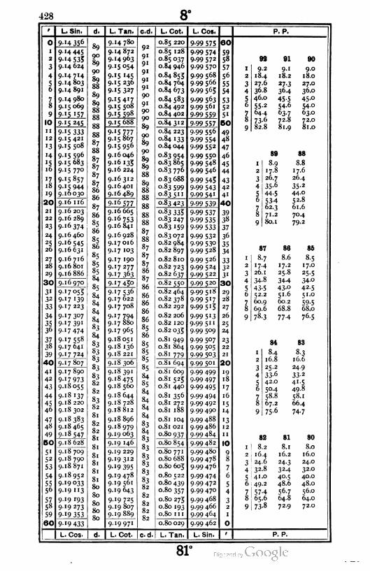
428 8°
L. Sin. L. Tan. c.d L. Cot. I L. Cos. P. P.
1
2
3
4
5I6
7
8
9
HO
II
12
'3
14
'51 6
ll
18
'9
20|
21
22
23
24
25
26
27
28
29
|30|
31
32
33
34
3536
3738
39
|40|
41
42
43
44
45
46
47
48
49
B0|
51
52
53
54
5556
5758
59
601
'4 356 I
'4 445
4 5354624
[4714
4803
4891
4 980
5069
5 '57
5 245
5 3335 421
5508
5 596
5 683
5 77°
5 857
5 944
6030
16 116
[6 203
[6289
16 374
[6 460
[6545
16631
16 716
[6801
16886
6 970
'7o5T
'7 '3917223
17 3°7
17 39'
'7 474
17 558
[7641
'7 724
7807
[7890
17 973
.8055
'8'37
18 220
[8302
'8383
18465
'8 547
18628
18709
18790
18 871
18952
19033
19 "3
'9 r93
19 273
'9 353
19 433
90
89
9°
89
88
89
89
88
SS
8S
88
87
88
87
87
87
87
8b
86
87
86
85
86
85
86
85
85
85
84
85
84
83
84
83
83
83
83
83
82
82
83
82
81
82
82
81
81
81
81
81
81
80
80
80
80
So
4 780
4872
4 963
5 054
5 '45
5 236
5 327
5417
5508
5 598
5 688
5 7775867
5 956
6046
6'33
6 224
6312
6 401
6489
6 577
6665
6 753
6841
6928
7 016
7 '03
7 190
7 277
7363
7 43°
7 536
7 622
7708
7 794
7 880
7965
8051
8136
8 221
8306
8 391
8 475
8560
8644
8728
8812
8896
8979
9 063
9 H6
9 229
9312
9 395
9478
9 561
9643
9 725
9807
9 97'
92
9"
9"
9"
9'
9"
90
91
90
90
89
90
89
9°
89
89
88
89
S8
87
88
87
87
87
86
87
86
86
86
86
86
85
86
85
85
85
85
84
85
84
84
83
84
83
83
83
8.3
83
83
82
82
82
82
82
0.85 220
0.85 128
0.85 037
0.84 946
0.84 855
0.84 764
0.84 673
0.84 583
0.84 492
0.84 402
9-99 575
9-99 5749.99 572
9.99 570
9.99 568
9 99 566
9-99 563
9-99 563
9.99 561
9-99 559
0-843
0.84 223
0.84 133
0.84 044
0.83 954
0.83 865
0.83 776
0.83 688
0.83 599
0 83 5"
9-99 557
9-99 556
9-99 554
9.99552
9.99 550
9-99 548
9.99 546
9-99 543
9-99 543
9-99 54'
0 83 423
0.83 335
0.83 247
0.83 159
0.83 072
0.82 984
0.82 897
0.82 810
0.82 723
0.82 637
9-99 539
9-99 537
9-99 535
9-99 533
9-99 532
9-99 53°9.99 528
9.99 526
9.99 524
9-99 522
0-82 550
0.82 464
0.82 378
0.82 292
0.82 206
0.82 120
0.82 035
0.81 949
0.81 864
0.81 779
9.99 520
9.99518
9-99 5'7
9-99 5'5
9-99 5'39.99 511
9-99 5°9
9.99 507
9-99 5°5
9-99 5°3
0.81 694 9-99 5°'
0.81 609
0.81 525
0.8 1 440
0.81 356
0.81 272
0.81 188
0.81 104
0.81 021
0.80 937
9.99 499
9-99 497
9.99 495
9.99 494
9.99 492
9.99 490
9.99 488
9.99 486
9.99 484
0.80 854 9.99482
0.80 771
0.80 688
0.80 603
0.80 522
0.80 439
0.80 357
0.80 273
0.80 193
0.80 1 1 1
9.99 480
9.99 478
9.99 476
9.99 474
9.99472
9.99 470
9.99 468
9.99 466
9.99 464
0.80 029 9.99 462
60
59
58
57
56
55
54
5352
5'
5O
4948
47
46
45
44
43
42
4'
40
39
38
37
36
35
34
3332
3'
30
29
28
27
26
25
24
23
22
21
20
'9IS
'7
16
'5
'4
'312
II
10
9
S
7
6
5
4
32
1
O
92 91 80
I 9.2 9-" 9.0
2 18.4 18.2 18.0
3 27.6 27-3 27.0
4 36.8 36.4 36.0
5 46.0 45-5 45-°6 55-2 54.6 54-0
7 64.4 63-7 63.0
8 73-6 72.8 72.0
9 82.8 81.9 81.0
B9 88
I 8-9 8.8
2 17.8 17.6
3 26.7 26.4
4 35-6 35-2
5 44-5 44.0
6 53-4 52.8
7 62.3 61.6
8 71.2 70.4
9 80.1 79.2
87 86 88
1 8.7 8.6 8-5
2 17.4 17.2 17.0
3 26.1 25.8 25-5
4 34-8 34-4 34-0
5 43-5 43-° 42.5
6 52.2 51.6 51.0
7 60.9 60.2 59-5
8 69.6 68.8 68.0
9 78.3 77-4 76.5
84 83
1 8.4 8-3
2 16.8 16.6
3 25.2 24.9
4 33-6 33-2
5 42.0 4'-5
6 5°-4 49.8
7 58.8 58..
8 67.2 66.4
9 75-6 74-7
82 Bl 80
1 8.2 8.1 8.0
2 16.4 16.2 16.0
3 24.6 24-3 24.0
4 32.8 32-4 32.0
5 41.0 40.5 40.0
6 49.2 48.6 48.0
7 57-4 56.7 56.0
8 65.6 64.8 64.0
9 73-8 72.9 72.0
L. Cos. L. Cot. c.d. L. Tan. L. Sin. P. P.
81°
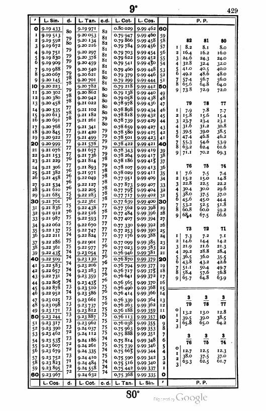
9o
429
O
1
2
3
4
56
7
8
9
HO
11
12
"3
14
"51ó
17
18
19
20
21
22
23
24
25
26
27
28
29
30
31
32
33
34
3536
37
3«
39
40
41
42
43
44
45
46
47
48
49
5O
51
52
53
54
5556
5758
59
I 60|
L. Sin,
9-19 433
9'95"39.19592
9.19 672
9.19 751
9.19 830
9.19909
9.19 988
9.20 067
9-20 '45
9.20 223
9.20 302
9.20 380
9.20458
9-2o 535
9.20 613
9.20 691
9.20 768
9.20 845
9.20922
9-20 999
9.21 076
9-21 153
9.21 229
9.21 306
9.21 382
9.21 458
9-21 534
9.21 610
9.21 685
9.21 761
9.21 836
9.21 912
9.21 987
9.22 062
9.22 137
9.22 211
9.22 286
9.22 361
9-22 435
9.22 509
9-22 583
9.22 657
9.22 731
9.22 803
9.22878
9.22 952
9.23 O25
9.23 098
9.23I7I
9-23 244
9.23 3I7
9-23 390
9.23 462
9-23 535
9.23 607
9.23 679
9-23 752
9.23 823
9-23 895
9.23 967
80
l980
79
79
79
79
79
78
78
79
78
78
77
78
78
77
77
77
77
77
7776
77
76
76
76
76
7576
75
76
75
75
75
74
75
75
74
74
74
74
74
74
73
74
73
73
73
73
73
7372
73
72
72
73
7'72
72
L. Tan. c.d
9-19 971
9.20 053
9.20 134
9.20 216
9.20 297
9.20 378
9.20459
9.20 540
9.20 621
9.20 701
9.20 782
9.20 862
9.20 942
9.21 022
9.21 102
9.21 182
9.21 261
9-21 34'
9.21 420
9-21 499
9-21 578
9.21 657
9.21 736
9.21 814
9.21 893
9.21 971
9.22 049
9.22 127
9.22 205
9.22 283
9.22 361
9.22 438
9.22 516
9.22 593
9.22 670
9.22 747
9.22 824
9.22 901
9.22977
923 054
9.23 130
9.23 206
9.23 283
9-23 359
9-23 435
9.23510
9.23 586
9.23 661
9-23 737
9.23 812
9.23 887
9.23 962
9-24037
9.24 112
9.24 186
9.24 261
9-24 335
9.24 410
9.24 484
9.24 558
9.24 632
82
81
82
81
81
81
81
81
80
81
80
80
80
80
80
79
80
79
79
79
79
79
78
79
78
78
78
78
78
78
77
78
77
77
77
77
77
76
7776
76
7776
76
7576
75
76
75
75
75
75
75
74
75
74
75
74
74
74
L. Cot.
0.80 029
O.79 947
0.79 866
0.79 784
o- 79 7°3
0.79 622
o-79 541
0.79 460
0-79 379
o- 79 299
0.79 218
0.79 138
0.79 058
0.78978
0.78 898
0.78818
0-78 739
0.78 659
0.78 580
0.78 501
0.78 422
0.78 343
0.78 264
0.78 186
0.78 107
0.78029
0.77951
0.77 873
0.77 793
0-77 7'7
0.77 639
0.77 562
0.77 484
0.77 407
0-77 33°
o-77 253
0.77 176
0.77 099
0.77023
0.76 946
0.76 870
0.76 794
0.76 717
0.76 641
0.76 565
0.76 490
0.76 414
o-7-6 339
0.76 263
0.76 188
0.76 "3
0.76038
0.75 963
0.75 888
0.75 814
o-75 739
0.75 663
0.75 590
0.75 516
0-75 442
0.75 368
. Cos.
9-99 462
9.99 460
9.99 458
9.99 456
9-99 4549.99 452
9.99 450
9.99 448
9.99 446
9.99 444
9.99442
9.99 440
9-99 438
9-99 436
9-99 434
9-99 432
9.99 429
9.99 427
9-99 425
9-99 423
9-99 421
9.99419
9.99417
9.99413
9-99 413
9.99 411
9.99 409
9.99 407
9.99 404
9.99 402
9.99 400
9.99 398
9.99 396
9-99 394
9.99 392
9.99 390
9.99 388
9-99 385
9-99 383
9-99 381
9 99 379
9-99 377
9-99 3759-99 372
9-99 37°9.99 368
9.99 366
9-99 364
9.99 362
9-99 359
9-99 357
9-99 355
9-99 3539-99 35 1
9-99 348
9-99 346
9-99 344
9-99 342
9-99 340
9-99 337
9-99 335
60
5958
57
56
55
54
5352
51
80
49
48
47
46
45
44
43
42
4"
40
39
38
37
36
35
34
3332
3'
30
29
28
27
26
25
«4
23
22
21
20
'918
'7
16
'5
'4
"312
11
10
9
8
7
6
5
4
32
1
O
P. P.
82 81 80
I 8.2 8.1 8.0
2 16.4 16.2 16.0
3 24.6 24-3 24.0
4 32.8 32-4 32.0
5 41.0 40.5 40.0
6 49.2 48.6 48.0
7 57-4 56.7 56.0
8 65.6 64.8 64.0
9 738 72.9 72.0
79 78 77
1 7-9 7.8 7-72 15.8 15.6 '5 4
3 23-7 23-4 23- 1
4 31-6 31.2 30.8
5 39-5 39-0 38.5
6 47-4 46.8 46.2
7 55-3 54.6 53-98 63.2 62.4 61.6
9 71. 1 70.2 69-3
76 75 74
1 7.6 7-5 7-4
2 15.2 15.0 14.8
3 22.8 22.5 22.2
4 30-4 30.0 29.6
5 38.0 37-5 37-°6 45.6 45 -o 44-4
7 53-2 52-5 51.8
8 60.8 60.0 59.2
9 68,4 67-5 66.6
73 72 71
1 7-3 7-2 7-1
2 14.6 '4-4 14.2
3 21.9 21.6 21.3
4 29.2 28.8 28.4
5 36.5 36.0 35-56 43-8 43-2 42.6
7 51. 1 50.4 49-7
8 58.4 57.6 56.8
9 65.7 64.8 63-9
8 3 3
79 78 77
013-2 13.0 12.8
39-5 39-o 38.5
365.8 65.0 64.2
3 3 3
76 75 74
012.7 12.5 12.3
38.0 37-5 37-o
363-3 62.5 61.7
L. Cos. L. Cot. c. d. L. Tan. L. Sin P. P.
80°
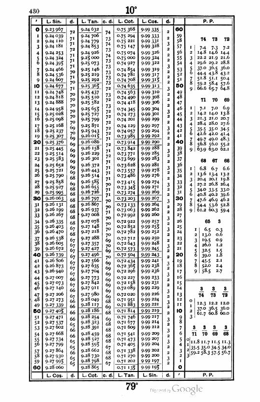
430
9 L. Sin.
o 9.23 967
1 9.24 039
2 9.24 1 10
3 9.24 181
4 9.24 253
S 9.24 324
0 9-24 393
7 9.24 466
8 9-24 536
9 9.24 607
10 9.24 677
11 9.24 748
12 9.24818
'3 9.24 888
'4 9.24 958
15 9.25 028
16 9.25 098
'7.9.25 168
18 9 25 237
19 9 25 3°7
20 9-25 37°
21 9-25 445
22 9 25 514
23 9 25 583
24 9.25 652
25 9.25 721
26 9.25 790
2Z9.25 858
28 9.25 927
*9 9-25 995
30 9.26 063
3' 9.26 131
32 9.26 199
33 9.26 267
34 9-26 335
35 9.26 403
36 9.26470
37 9.26 538
38 9.26 605
39 9.26 672
40 9.26 739
41 9.26 806
42 9.26 873
43 9.26 940
44 9.27 007
45 9.27073
46 9.27 140
4Z9.27 206
48 9.27 273
49 9-27 339
50 9.27 405
5' 9.27471
5* 9-27 537
53 9.27 602
54 9.27 668
55 9-27 734
56 9.27 799
57 9.27 864
58 9.27 930
59 9-27 995
60 9.28 060
L. COS.
d. I L. Tan, c. d
9-24 632
9.24 706
9.24 779
9-24 853
9.24 926
9.23000
9-25 o73
9.25 146
9.25 219
9.25 292
9-25 365
9-25 437
9-25 5'°
9.25 582
9 25 653
9.25 727
9.25 799
9.25 871
9-25 943
9.26013
9.26 086
9.26 158
9.26 229
9.26 301
9.26 372
9.26443
9.26514
9.26 585
9.26 655
9.26 726
9-26 797
9.26 867
9.26 937
9.27 008
9.27 078
9.27 148
9.27 218
9.27 288
9-27 357
9-27 427
9-27 496
9.27 566
9 27 635
9.27 704
9-27 773
9.27 842
9-27911
9.27 980
9.28049
9.28 117
9.28 186
9.28 254
9.28323
9.28 391
9.28 459
9.28 527
9.28 595
9.28 662
9.28 730
9.28 798
9.28 865"
L, Cot. |c. d
L. Cot. L. Cos. d.
0.75 368 9-99 335 260
0.75 294 9-99 333 259
0.75 221 9-99 33' -258
°-75 147 9.99 328 j
257
0.75 074 9.99 3262
56
0.75 000 9-99 3242 55
0.74927 9.99 322-2
54
0.74 854 9-99 3'9j
2 53
0.74 781 9-99 3' 7 252
0.74 708 9-99 3 "3 2 5"
0.74 635 9-99 3'.! 5O
o-74 563 9.993102 49
0.74 490 9.99 3082
48
0.74 418 9.99 306 47
o-74 345 9-99 3042
46
o-74 273 9.99 301 02 45
0.74 201 9.99 2992
44
0.74 129 9.99 2971 43
0.74057 9.99 294 j2
42
°-73 985 9.99 2922 41
0.73914 9.99 2902
40
0.73 842 9.99 288-2 39
0.73771 9.99 285 j2
38
0.73 699 9.99 283 37
0.73628 9.99 281 36
0-73 557 9.99 278 32 35
0.73 486 9.99 2762
34
0-73 4I5 9.99 274-3 33
o-73 343 9.99 271 J 32
0.73 274 9.99 2692
3"
o-73 203 9.99 2672
30-3
0.73 '33 9.99 264J
229
0.73 063 9.99 262 28
0.72 992 9.99 2602
271
0.72 922 9.99 257J
226
0.72 852 9-99 2531
25
0.72 782 9.99 252 J
224
0.72 712 9.99 2502
23
0.72 643 9.99 248-3 22
0-72 573 9.99 245 J2
21
0.72 504 9-99 2432
20
0.72 434 9.99 2411 -
19
0.72 363 9.99 238 18
0.72 296 9-99 2362
'7-3
0.72 227 9-99 233J
16
0.72 158 9-99 2312
'50.72 089 9.99 229
214
0.72 020 9.99 2263
213
0.71 951 9-99 224-3 12
0.71 883 9.99 221 j2
11
0.71 814 9.99 2192
10
0.71 746 9.99217-3 9
0.71 677 9.99 2142
8
0.71 609 9.99 212-3 7
0.71 541 9.99 209j
26
0.71 473 9.99 207-2 5
0.71 405 9.99 204 j
24
0.71 338 9.99 2022 3
0.71 270 9.99 200-2
2
0.71 202 9 99 197 J2
1
0-71 133 9.99 193 O
L. Tan. L. Sin. d. 1
P. P.
74 73 72
I 7-4 7-3 7-2
2 14.8 14.6 14.4
3 22.2 21.9 21.6
4 29.6 29.2 28.8
5 37° 36-5 36.0
6 44.4 43-8 43-2
7 51.8 5'-1 5°4
8 59-2 58-4 57.6
9 66.6 65-7 64.8
71 70 69
1 7-1 7.0 6.9
2 14.2 14.0 13-8
3 21.3 21.0 20.7
4 28.4 28.0 27.6
5 35-5 35° 34-5
6 42.6 42.0 41.4
7 49-7 49.0 48.3
8 56.8 56.0 55-2
9 63-9 63.0 62.1
88 67 66
1 6.8 6.7 6.6
2 13-6 "3-4 13.2
3 20.4 20.1 19.8
4 27.2 26.8 26.4
5 34-o 33-5 33-°6 40.8 40.2 39-6
7 47.6 46.9 46.2
8 54-4 53-6 52-8
9 61.2 60.3 59-4
86 3
1 6-5 0.3
2 13.0 0.6
3 "9-S 09
4 26.0 1.2
5 32.5 1.5
6 39-0 1.8
7 45-5 2.1
8 52.0 2.4
9 58.5 2-7
3 3 3
74 73 72
12.3 12.2 12.0
36.0
60.037°61.7
36.5
60.8
3 3 3
70 69 68
3
71
1 1.8 11. 7 11. 5 11.3
35.5 35.034-5 34-0
59.2 58.3 57.5 56.7
P. P.
79°
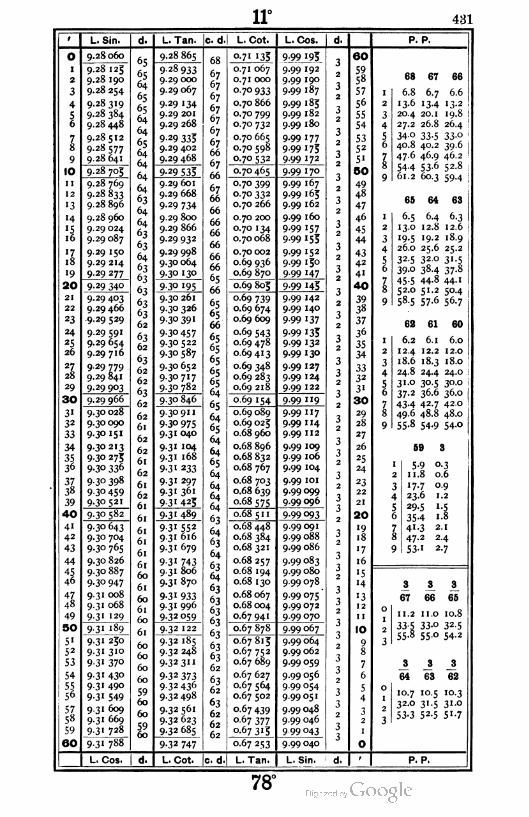
11° 431
' I L, Sin,
9.28060O
1
2
3
4
56
78
9
10
11
12
'3
14
'516
'718
19
1 20
21
22
23
24
25
26
I 2728
29
30
3'32
33
34
3536
3738
39
40
I 4"42
43
44
4546
4Z48
49
50
5"52
53
54
5556
5758
59
60
9.28 125
9.28 190
9.28 254
9.28 319
9.28 384
9.28448
9.28 512
9.28 577
9.28 641
9.28 705
9.28 769
9-28 833
9.28 896
9.28 960
9.29 024
9.29 087
9.29 150
9.29 214
9.29 277
9.29 340
9.29 403
9.29 466
9.29 529
9.29 591
9.29 654
9.29 716
9 29 779
9.29 841
9-29 903
9.29 966
9.30 028
9.30090
9-3° 15"
9.30213
9-3° 275
9-3° 336
9-30 398
9-30 459
9.30521
9.30 582
9-30 643
9.30 704
9.30 765
9.30 826
9.30 887
9-3° 947
9.31 008
9.31 068
9.31 129
9.31 189
9.31 250
9-31 3l°
9-31 37°
9- 3 1 43°
9.31 490
9-3' 549
9.31 609
9.31 669
9-3' 728
9-3' 788
L. Cos.
d. I L. Tan. c. d
9.28 865
9-28 933
9.29 000
9.29 067
9.29 134
9.29 201
9.29 268
9 29 335
9.29 402
9.29 468
9-29 535
9.29 601
9.29 668
9.29 734
9.29 800
9.29 866
9.29 932
9.29 998
9.30 064
9-3° '3°
9-3° '95
9.30 261
9.30 326
9-3° 391
9-30 457
9.30 522
9-3° 587
9.30 652
9-30 7I7
9-3° 782
9.30 846
67
67
67
67
67
67
67
66
67
66
67
66
66
66
66
66
66
66
65
66
65
65
66
65
65
65
65
65
64
65
64
65
64
64
65
64
64
64
64
63
64
63
64
63
64
63
63
63
63
63
63
63
62
63
62
63
62
62
629-32 747
L. Cot. |c. d
9.30 91 1
9-30 975
9.31 040
9.31 104
9.31 168
9-31 233
9-31 297
9-31 361
9-3' 425
9-3' 489
931 552
9.31 616
9.31 679
9 31 743
9.31 806
9.31 870
9-31 933
9.31 996
9-32 059
9.32 122
9-32 185
9.32 248
9.32 31 1
9-32 373
932 436
9.32498
9.32561
9.32 623
9-32 685
L. Cot.
0-7' '35
0.71 067
0.71 000
°-7°933
0.70 866
0.70 799
0.70 732
0.70 665
0.70 598
°-7°532
o-7° 465
0.70 399
070 332
0.70 266
0.70 200
0.70 134
0.70 068
0.70 002
0.69 936
0.69 870
0.69 805
0.69 739
0.69 674
0.69 609
0.69 543
0.69 478
0.69413
0.69 348
0.69 283
0.69 218
o 69 154
0.69 089
0.69 025
0.68 960
0.68 896
0.68 832
0.68 767
0.68 703
0.68 639
°-68 575
0-68511
0.68 448
0.68 384
0.68 321
0.68 257
0.68 194
0.68 130
0.68 067
0.68 004
0.67 941
0.67 878
0.67 815
0.67 752
0.67 689
0.67 627
0.67 564
0.67 502
0.67 439
0.67 377
0-67 3Jj
0 67 253
L. Tan.
L, Cos.
9^9
9-99
9-99
9-99
9-99
9.99
9-99
9-99
9-99
9-99
9-99
9-99
9-99
9-99
9-99
9-99
9-99
9-99
9-99
9-99
9-99
9-99
9-99
9-99
9-99
9-99
9-99
9-99
9-99
9-99
9-99
9-99
9-99
9-99
9-99
9-99
9-99
9.99 101
9.99099
9.99 096
70
45
19
9-99 093
9.99091
9.99 088
9.99 086
9.99 083
9.99 080
9.99078
9-99 075
9.99072
9.99 070
9-99 067
9.99 064
9.99 062
9.99 059
9.99 056
9 99 054
9.99051
9.99 048
9.99 046
9 99 043
d.
3
2
3
2
32
3
2
32
3
2
3
2
32
3
2
32
3
2
3
2
32
3
32
3
2
32
3
32
3
2
3
3
2
32
3
32
3
32
3
3
2
3
3
2
3
3
2
3
39.99 040
L. Sin. d.
60
5958
57
56
55
54
5352
5"
00
49
48
47
46
45
44
4342
4"
40
39
38
37
36
35
34
3332
3"
30
29
28
27
26
25
24
23
22
21
20
"918
'7
16
15
14
'312
11
10
9S
7
6
5
4
P. P.
68 67 66
6.8 6.7 6.6
13.6 13.4 13.2
20.4 20.1 19.8
27.2 26.8 26.4
34-0 33.5 33.0
40.8 40.2 39.6
47.6 46.9 46.2
54-4 53-6 52.8
61.2 60.3 59.4
65 64 63
6.5 6.4 6.3
13.0 12.8 12.6
19.5 19.2 18.9
26.0 25.6 25.2
32.5 32.0 31.5
39.0 38.4 37.8
45-5 44-8 44-'
52.0 51.2 50.4
58.5 57.6 56.7
62 61 60
6.2 6.1 6.0
12.4 12.2 12.0
18.6 18.3 18.0
24.8 24.4 24.0
31.0 30.5 30.0
37.2 36.6 36.0
43.4 42.7 420
49.6 48.8 48.0
55.8 54.9 54.0
59 3
I 5-9 0.3
2 1 1.8 0.6
3 17.7 0.9
4 23.6 1.2
5 29.5 1.5
6 35-4 1.8
7 41-3 2.1
8 47.2 2.4
9 53' 2-7
1 JL !
67 66 65
11. 2 1 1.0 10.8
33-5 33-o 32-5
55.8 55.0 54.2
64
J
63
10.7 10.5
32-0 3' -5
53-3 52-5
P. P.
J
62
10.3
31.0
5'-7
78'

432
2
3
4
56
78
9
10
11
12
'3
'4
'516
'718
'9
|20
21
22
23
24
2£
20
27
28
29
| 30
31
32
33
34
3536
3738
39
I 40
41
42
43
44
4546
47
48
49
50
5"52
53
54
5556
5758
59
I60
L. Sin.
9.31 788
9-3' 847
9-31 9°7
9.31 966
9.32 025
9.32 084
9-32 H3
9.32 202
9.32 261
9-323'9
9-32 378
9-32 437
9-32 495
9 32 553
9.32 612
9.32 670
9.32 728
9.32 786
9.32 844
9-32 902
9-3296°
9.33018
9-33 075
9-33 '33
9-33 190
9-33 248
9-33 305
9-33 362
9-33 420
9-33 477
9-33 534
9-33 591
9-33 647
9-33 704
9-33 761
9.33 818
9-33 874
9-33 931
9-33 987
9-34 043
9.34 100
9-34 156
9.34 212
9.34 268
9-34 324
9-34 380
9-34 436
9-34 491
9-34 547
9-34 602
9-34 658
9-34 7" 39-34 769
9.34 824
9-34 879
9-34 934
9-34 989
9-35 °44
9-35 °99
9-35 '54
9-35 209
L. Cos,
L. Tan. c. d
9-32 747
9.32810
9.32 872
9-32 933
9-32 995
9-33 057
9-33 1 '9
9-33 180
9-33 242
9-33 303
9-33 3°3
9-33 426
9-33 487
9-33 548
9-33 609
9-33 670
9-33 731
9-33 792
9-33 853
9-33 9'3
9-33 974
9-34 034
9 34 095
9-34 155
9-34 2I5
9.34 276
9-34 336
9-34 396
9-34 45°
9-34 5 '6
9-34 576
9-34 635
9-34 693
9-34 755
9.34814
9-34 874
9-34 933
9-34 992
9-35 °51
9-35 111
9-35 !7g9.35 229
9-35 288
9-35 347
9-35 405
9-35 464
9-35 523
9-35 581
9-35 640
9-35 698
9-35 757
9-35 815
9-35 873
9-35 931
9-35 989
9.36047
9.36 105
9-36 163
9.36 221
9.36 279
9-3° 336
L. Cot. Ic. d
12"
L. Cot.
0-67 253
0.67 190
0.67 128
0.67 067
0.67 003
0.66 943
0.66 881
0.66 820
0.66 758
0.66 697
0.66 635
0.66 574
0.66 513
0.66 452
0.66 391
0.66 330
0.66 269
0.66 208
0.66 147
0.66 087
0.66 026
0.65 966
0.65 905
0.65 843
0.65 783
0.65 724
0.65 664
0.65 604
0.65 544
0.65 484
0.65 424
0.65 365
0.65 305
0.65 245
0.65 186
0.65 126
0.65 067
0.65 008
0.64 949
0.64 889
0.64 830
0.64 771
0.64 712
0.64 653
0.64 595
0.64 536
0.64 477
0.64 4 1 9
0.64 360
0.64 302
0.64 243
0.64 185
0.64 127
0.64 069
0.64 01 1
0-63 953
0.63 895
c-63 837
0.63 779
0-63 721
0.63 664
L. Tan.
L. Cos.
9-99 040
9.99038
9-99 035
9.99032
9.99 030
9.99027
9.99 024
9.99 022
9-99 019
9.99 016
9.99013
9.99 o1 1
9.99 008
9.99 005
9.99 002
9.99 000
9.98 997
9.98 994
9.98 991
9.98 989
9.98 986
9.98 983
9.98 980
9.98 978
9.98 973
9.98 972
9.98 969
9.98 967
9.98 964
9.98 961
9-98 958
9-98 955
9-98 953
9.98 930
9.98 947
9.98 944
9.98 941
9.98 938
9.98 936
9-98 933
9.98 930
9.98927
9.98 924
9.98 921
9.98919
9.98 916
9.98913
9.98 910
9.98 907
9.98 904
9.98 901
9.98 898
9.98 893
9.98 890
9.98 887
9.98 884
9.98 881
9.98 878
9-98 875
9.98 872
L. Sin.
eo
59
58
57
56
55
54
5352
51
BO
49
48
47
46
45
44
4342
41
40
39
38
37
36
35
34
3332
31
30
29
28
27
26
25
24
23
22
21
20
19
18
'7
16
15
14
'312
11
10
9
8
7
6
5
4
32
P. P.
63 62 61
6.3 6.2 6.1
12.6 12.4 12.2
18.9 18.6 18.3
25.2 24.8 24.4
31-5 31-0 30 5
37.8 37.2 36.6
44.1 43.4 42.7
50.4 49.6 48.8
56.7 55-8 54-9
60 59
I 6.0 5-92 12.0 1 1.8
3 18.0 17-7
4 24.0 23.6
5 30.0 29.5
6 36.0 35-4
7 42.0 41-3
8 48.0 47.2
9 54-0 53-1
58 67
1 5^ 5-72 1 1.6 11.4
3 17.4 17.1
4 23.2 22.8
5 29.0 28.5
6 34-8 34-2
7 40.6 39-9
8 46.4 45-6
9 52.2 5'-3
66 65 3
1 5-6 5-5 o-3
2 11. 2 II.O 0.6
3 16.8 16.5 0.9
4 22.4 22.0 1.2
5 28.0 27-5 '-56 33-6 33-0 1.8
7 39-2 38.5 2.1
8 44.8 44.0 2.4
9 5°-4 49-5 2-7
JL A i_
62 61 60
10.3 10.2 10.0
31.0 30.5 30.0
51.7 50.8 50.0
3
U 58 57
9.8 9.7 9.5
29.5 29.0 28.5
49.2 48.3 47.5
P. P.
77°

13° 433
L. Sin. L. Tan. Ic. d.l L. Cot. L. Cos. P. P.
9
10
11
12
"3
'4
'516
ll
18
'9
20
21
22
23
24
25
26
2Z28
29
| 30
3"32
33
34
3536
3Z38
39
1 40
41
42
43
44
45
46
*l48
49
I50
51
52
53
54
5556
sl58
59
l60
9.35 209
9-35 263
9-35 318
9-35 373
9-35 427
9-35 481
9-35 536
9-35 590
9-35 644
9-35 698
9-35 752
9.35 806
9.35 860
9-35 9H
9.35 968
9.36 022
9.36 075
9.36 129
9.36 182
9-36 236
9.36 289
9-36 342
9-36 395
9-36 449
9.36 502
9-36 555
9.36 608
9.36 660
9-36 713
9^36766
9-36 819
9.36871
9.36 924
9.36 976
9.37 028
9.37081
9-37 133
9-37 185
9-37 237
9-37 289
9-37 34'
9-37 393
9-37 445
9-37 497
9-37 549
9.37 600
9.37 652
9-37 703
9-37 7539-37 806
9-37 858
9-37 9°99-37 960
9.38 on
9.38 062
9-38 113
9.38 164
938215
9.38 266
9-38317
9.38 368
9-36 336
9-36 394
9.36 452
9.36 509
9.36 566
9.36 624
9.36 681
9-36 738
9-36 795
9-36 852
9-36 9°9
9.36 966
9-37 023
9.37 080
9-37 '379-37 193
9-37 23°
9-37 3°6
9-37 363
9-37 419
937 476
9-37 532
9-37 588
9-37 644
9.37 700
9-37 756
9.37812
9.37 868
9-37 924
9-37 980
938035
9.38091
9-38 147
9.38 202
9-38 257
9-38 3'3
9-38368
9-38 423
9-38 479
9-38 534
9.38 589
9.38 644
9.38 699
9-38 754
9.38 808
9.38 863
9.38918
9.38 972
9 39 027
9-39 °82
9-39 136
9.39 190
9-39 243
9.39 299
9-39 3539-39 407
9.39 461
9-39 5I5
9-39 569
9-39 623
9-39 677
0.63 664 9.98 872
0.63 606
0.63 548
0.63491
0.63 434
0.63 376
0.63 319
0.63 262
0.63 205
0.63 148
9.98 869
9.98 867
9.98 864
9.98 861
9.98 858
9.98 855
9.98 852
9.98 849
9.98 846
0.63 091 9.98 843
0.63 034
0.62 977
0.62 920
0.62 863
0.62 807
0.62 750
0.62 694
0.62 637
0.62 581
9.98 840
9.98 837
9.98 834
9.98831
9.98 828
9.98 825
9.98 822
9.98 819
9.98 816
0.62 524 9.98813
0.62 468
0.62 412
0.62 356
0.62 300
0.62 244
0.62 188
0.62 132
0.62 076
0.62 020
9.98 810
9.98 807
9.98 804
9.98 801
9.98 798
9.98 795
9.98 792
9.98 789
9.98 786
0.61 965 9.98 783
0.61 909
0.61 853
0.61 798
0.61 743
0.61 687
0.61 632
0.61 577
0.61 521
0.61 466
9.98 780
9.98 777
9.98 774
9.98771
9.98 768
9.98 763
9.98 762
9-98 759
9 98 756
0.61 411
0.61 356
0.61 301
0.61 246
0.61 192
0.61 137
0.61 082
0.61 028
0.60 973
0.60918
0.60 864
9-98.753
9.98 750
9.9S 746
9-98 743
9.98 740
9 98 737
9 98 734
9-98 731
9.98 728
9 98 725
0.60 810
°-6o 755
0.60 701
0.60 647
0.60 593
0.60 539
0.60 485
0.60431
0.60 377
0.60 323
9.98 722
9.98719
9.98715
9.98 712
9.98 709
9.98 706
9.98 703
9.98 700
9.98 697
9 98 694
9.98 690
00
59
58
57
56
55
54
5352
5'
BO
49
48
47
46
45
44
4342
41
40
3938
37
36
35
34
3332
3'
30
29
28
27
26
25
24
23
22
21
20
19
18
'7
16
15
"4
13
12
11
10
9
8
7
6
5
4
32
58 57 56
5-8
1 1.6
7-4
5.7 5.6
1 1.4 11. 2
17.1 16.8
23.2 22.8 22.4
29.0 28.5 28.0
34.8 34.2 33.6
4°-6 39-9 39-2
46.4 45.6 44.8
52.2 51.3 50-4
55 54 53
5-511.0
16.5
22.0
27-5
33°38.5
44.0
49-5
5-4 5-310.8 10.6
16.2 15.9
21.6 21.2
27.0 26.5
32-4 3'-8
37-8 37-1
43.2 42.4
48.6 47.7
59 51
I 5-2 5-'2 10.4 10.2
3 15.6 '5-3
4 20.8 20.4
5 26.0 25-5
6 3'-2 30.6
7 36-4 35-7
8 41.6 40.8
9 46.8 45-9
4 3
1 0.4 0-3
2 0.8 0.6
3 1.2 0.9
4 1.6 1.2
5 2.0 1.5
6 2.4 1.8
7 2.8 2.1
8 3-2 2-4
9 3-6 2-7
4
55
4
54
3
68 571
6.9 6.8 9.7 9.5
20.6 20.2 29.0 28.5
34 4 33-8 48.3 47-5
48.147.2 — —
56
3
55 54
9.3 9.2 9.0
28.0 27.5 27.0
46.7 45.8 45.0
L. Cos. L. Cot. c. d L. Tan. L. Sin. P. P.
r'm'd surv. — 28
76°
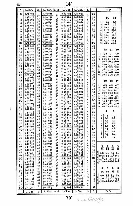
434 14°
1 L. Sin.
0 9.38 368
I 9.38418
2 9.38 469
3 9-38 5"9
4 9.38 570
S 9.38 620
6 9.38 67O
7 9-38 72I
8 9-38 77'
9 9.38 821
10 9.3887I
11 9.3892I
12 9-38 971
'3 9.39 02I
14 9.39 07I
'5 9 39 '21
16 9.39 170
'7 9.39 220
18 9.39 270
19 9-39 3'9
20 9-39 369
21 9.39418
22 9-39 467
23 9-39 5X7
24 9.39 566
25 9.39615
26 9.39 664
27 9-39 7'328 9.39 762
29 9-39 81 1
30 9.39 860
31 9.39 909
32 9-39 958
33 9.40 006
34 9.40053
35 9.40 103
36 9.40 152
37 9.40 200
38 9.40 249
39 9.40 297
40 9.40 346
41 9-4° 394
42 9.40 442
43 9.40 490
44 9.40 538
45 9.40 586
46 9.40 634
47 9.40 682
48 9.40 730
49 9.40 778
50 9.40 825
5" 9.40 873
52 9.40 921
53 9.40 968
54 9.41 016
55 9.41 063
56 9.41 1n
57 9.41 158
58 9.41 205
59 9.41 252
60 9.41 300
L. Cos.
L. Tan. c. d. L. Cot. L, Cos. P. P.
48
9-39 677
9-39 73 1
9-39 783
9-39 838
9.39 892
9-39 945
9-39 999
9.40052
9.40 106
9-4° '59
9.40 212
9.40 266
9.40319
9.40 372
9.40 423
9.40 478
9-40 531
9 4° 584
9.40 636
9.40 689
9-4° 742
94° 7939 4° 847
9.40 900
94° 952
9.41 003
9.41 057
9.41 109
9.41 161
9.41 214
9.41 266
9.41 318
9.41 370
9.41 422
9.41 474
9.41 526
9.41 578
9.41 629
9.41 681
9-41 733
9-41 784
9.41 836
9.41 887
9 4" 939
9.41 990
9.42 041
9.42 093
9.42 144
9.42 195
9.42 246
9-42 297
9.42 348
9-42 399
9.42 450
9.42 501
9.42 552
9.42 603
9 42 653
9.42 704
9-42 755
9.42 805
0.60 323 9.98 690
0.60 269
0.60 215
0.60 162
0.60 108
0.60053
0.60001
0.59 948
0.59 894
0.59 841
9.98 687
9.98 684
9.98 681
9.98 678
9.9S 673
9.98 671
9.98 66S
9.98 665
9.98 662
0.59 788 9 98 659
°-59 7340.59 681
0.59 628
°-59 5750.59 522
0.59 469
0.59 416
0.59 364
0.59 3"
0.59 258
9.98 656
9.98 652
9.98 649
9.98 646
9.98 643
9.98 640
9.98 636
9-98 633
9-98 630
9.98 627
0.59 205
o-59 '53
0.59 100
0.59 048
0.58995
0.58 943
0.58 891
0.58 839
0.58 786
9.98 623
9.98 620
9.98 617
9.98 614
9.98 610
9.98 607
9.98 604
9.98 601
9-98 597
£Jl7349 98 594
0.58 682
0.58 630
0.58578
0.58 526
0.58474
0.58 422
0.58371
0.58319
0.58 267
9.98 591
9.98 588
9.98 584
9.98 581
9.98578
9.98 574
9 98 57'
9.98 568
9-98 565
0.58 216 9-98561
0.58 164
0.58 113
0.58061
0.58 010
o.57 959
0.57 907
0.57856
0.57805
0.57754
0-57 7°3
9-98 558
998 553
9-98551
9.98 548
9-98 543
9.98 541
9.98 538
9 98 533
9-98 531
9-98 528
0.57652
0.57 601
o-57 53°
0.57499
0.57 448
0-57 397
0-57 347
0.57 296
o-57 245
9 98 525
9.98521
9.98 518
9-98 5'3
9-98 5"
9.98 508
9.98 505
9.98 501
9.98 498
o-57 195 9.98 494
60
59
58
57
56
55
54
5352
51
5O
49
48
47
46
45
44
43
42
41
40
39
38
37
36
35
34
3332
3'
30
29
28
27
26
25
24
23
22
21
20
'918
17
16
15
•4
13
12
1 1
10
9S
7
6
5
4
32
1
0
54 58
I 5-4 5-32 10.8 10.6
3 16.2 15.9
4 21.6 21.2
5 27.0 26.5
6 32-4 31-8
7 37-8 37-1
8 43-2 42.4
9 48.6 47-7
52 51 50
5-2 5.1 5.0
10.4
15.6
10.0
15.0
10.2
•5-3 .
20.8 20.4 20.0
26.0 25.5 25.0
31.2 30.6 30.0
36-4 35-7 35-o
41.6 40.8 40.0
46.8 45.9 45.0
49 48 47
4-8 4-7
9.6 9.4
14.4 14.1
19.2 18.8
24.0 23.5
29.4 28.8 28.2
34-3 33-6 32-9
39.2 38.4 37.6
44.1 43.2 42.3
4-9
9.8
'4-719.6
24-5
4 3
I 0.4 0.3
2 0.8 0.6
3 1.2 0.9
4 1.6 1.2
5 2.0 1.5
6 2.4 1.8
7 2.8 2.1
8 3-2 2.4
9 3-6 2-7
4
54 53 52
4
51
6.8 6.6 6.5 6.4
20.2 19.9 19.5 19. 1
33-8 33-1 32-5 31-9
47.2 46.4 45.544-6
3
54 53
3.
51
9.0 8.8 8.7 8.5
27.0 26.5 26.0 25.5
45.0 44.2 43.3 42.5
d. L. Cot. c. d. L. Tan L. Sin. d. P. P.
75°
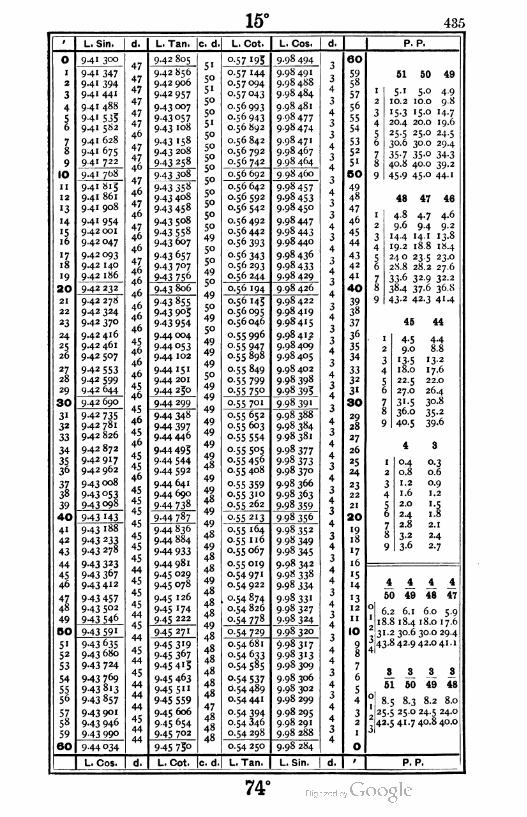
15° 435
L. Sin. L. Tan. c. d. L. Cot. L. Cos. P. P.
O
i
2
3
4
56
78
9
10
ii
12
'3
'415
16
il
i8
«9
20
21
22
23
24
25
26
2Z28
29
30
3132
33
34
3536
3738
39
|40
41
42
43
44
45
46
+248
49
|50
51
52
53
54
5556
57
5«
59
160
9.41 300
941 347
94' 3949.41 441
9.41 488
94i 533
9.41 582
9.41 628
9.41 675
9.41 722
9.41 768
9.41 815
9.41 861
9.41 908
9.41 954
9.42 001
9.42 047
9.42 093
9.42 140
9.42 186
9.42 232
9.42 278
9.42 324
9.42 370
9.42 416
9.42 461
9.42 507
942 553
9.42 599
9.42 644
9.42 690
942 735
9.42 781
9.42 826
9.42 872
942917
9.42 962
9.43 008
943 °53943 098
943 '43
943 188
943 233
943 278
943 323
943 367
9.43412
9 43 457943 5°2
943 546
943 59'
943 635
9.43 680
943 724
943 769
9 43 813
943 857
943 901
943 946
9 43 99°
944 034
L. Cos.
9.42 805
9.42 856
9.42 906
942 957
943 °°7
943057
943 i°8
943 '58
9.43 208
9 43 258
9-43 308
943 358
943 4o8
9 43 458
943 5o8
943 558
943 6°7
943 657
943 7°7
943756
943 806
9 43 855
943 903
943 954
9.44004
944 053
9.44 102
9.44 151
9.44 201
944 250
944 299
944 348
944 3979.44446
944 493
9 44 544944 592
9.44 641
9.44690
944 738
944 787
9 44 836
9.44 884
944 933
944 981
945 029
945 078
945 126
945 '74
9.45 222
945 271
9 45 3'9945 307
945 4'3
945 403
945 5"
9 45 559
9.45 606
9 45 654
945 7°2
9 45 75°
L. Cot. !c. d.
°-57 '93
o-57 '44
0.57094
0.57043
0.56993
0.56943
0.56 892
0.56 842
0.56 792
0.56 742
9-98 494
9.98 491
9.98 488
9.98 484
9.98 481
9.98477
9.98 474
9.98471
9.98 467
9-98 464
0.56 692 9.98 460
0.56 642
0.56 592
0.56 542
0.56492
0.56 442
o-56 393
°-56 343
0.56 293
0.56 244
9.98457
9-98 453
9.98 450
9.98447
9-98 443
9.98440
9.98 436
9-98 433
9.98 429
0-56 '94 9.98 426
0.56 145
0.56 095
0.56 046
0.55 996
°-55 9470.55 898
0.55 849
0.5 5 799
0-55 75°
9.98422
9.98419
9.98415
9.98 412
9.98 409
9.98 405
9.98 402
9.98 398
9-98 393
055701 9 98 39'
0.55 652
0.55 603
o-55 554
o-55 5°5
0.55 456
0.55 408
°-55 3590.55 310
0.55 262
9.98 388
9.98 384
9 98 381
9-98 377
9-98 373
9.98 370
9.98 366
9-98 363
9-98 359
o-55 213
0.55 164
0.55 116
0.55 067
0.55019
0.54 971
0.54 922
0.54 874
0.54 826
0-54 778
9 98 356
0-54 729
998352
9 98 349
9-98 345
9.98 342
9-98 338
9-98 334
9-98 33'
9.98327
9-98 324
9.98 320
0.54 681
o-54 633
0.54 585
0-54 537
0.54489
0.54441
°-54 394
0.54 346
0.54 298
0-54 25°
L. Tan.
998317
998313
9.98 309
9.98 306
9.98 302
9.98 299
9.98 295
9.98 291
9.98 288
9.98 284
L. Sin.
60
5958
57
56
55
54
5352
5i
BO
49
48
47
46
45
44
43
42
41
40
3938
37
36
35
34
3332
3i
30
29
28
27
26
25
24
23
22
21
20
«918
«7
16
'514
'312
11
10
98
7
6
5
4
32
j
O
61 50 49
5'10.2
'5-3
4-9
9.8
14.7
19.6
5.0
10.0
15.0
20.4 20.0
25-5 25.0 24.5
30.6 30.0 29.4
35-7 35-o 34-3
40.8 40.0 39.2
45-9 45-° 44-'
48 47 46
4-8
9.6
4.6
9.2
4-7
9414.4 14.1 13.8
19.2 18.8 18.4
24 o 23.5 23.0
2S.8 28.2 27.6
33-6 32-9 32-2
38.4 37.6 36.8
43.2 42.3 41.4
45 44
4.4
8.84-59.0
'3-5 '3-2
18.0 17.6
22.5 22.0
27.0 26.4
31.5 30.8
36.0 35.2
40.5 39.6
°40.8
1.2
1.6
2.0
24
2.8
3-2
3-6
o-3
0.6
0.9
1.2
1.8
2.1
24
2.7
i A A i
50 49 48 47
0 6.2 6.1 6.0 5.9
; 18.8 18.4 18.0 17.6
31.230.6 30.0 29.4J 43.8 42.9 42.041.1
A 3_ A 1
51 50 49 48
0 8.5 8.3 8.2 8.0
25.5 25.0 24.5 24.0
42.5 41.7 40.8 40.0
P. P.
74°
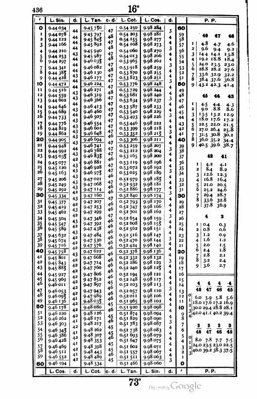
436 16°
L. Sin. I d. L. Tan. c. d. L. Cot. L. Cot. P. P.
O
i
2
3
4
5i.
78
9
10
ii
12
«3
'4
'516
\l
19
I 20
21
22
*3
*4
25
26
2l28
29
1 30
3«
3*
33
34
3$36
3Z38
39
1 40
41
42
43
44
45
46
47
48
49
I 50
51
52
53
54
5556
575S
59
160
944034
944078
9.44 122
9.44 166
9.44 210
944 253
9.44 297
944 341
9.44 Ji>5
944428
944 472
9.44516
944 5599.44 602
9.44 646
9.44 689
944 733
9.44 776
9.44819
9.44 862
944 9°5
9.44 948
944 992
9 45 °35
945 °77
945 120
945 i63
9 45 206
945 249
945 292
945 334
945 3779.45419
945 462
945 5°4
945 547
945 589
945 632
945 674
945 7 16
945 758
9.45 801
945 843
945 8»5
945 927
945 969
9.46 01 1
9.46053
9.46 095
9.46136
9.46 178
9.46 220
9.46 262
9 46 3°3
946 345
9.46 386
9.46 428
9.46 469
9.46 511
946 552
9.46 594
945 75°
9 45 797945 843
945 892
945 940
945 987
946 035
9.46082
9.46 130
946 177
9.46 224
9.46271
946319
946 366
9.46413
9.46 460
946 507
9.46 554
946 601
946 648
946 694
946 741
9.46 788
9.46833
9.46 881
946 928
946 975
947021
9.47 068
947 "4
9.47 160
9 47 207
947 253
947 299
9 47 346
947 392
947 438
9 47 484
947 53°
947 576
9.47 622
9.47 668
947 7'4
947 7&°
9.47 806
9 47 852
947 897
947 943
9 47 989
948 035
948 080
9.48 126
9.48 171
948 217
948 262
9.48 307
948 353
9.48 398
948 443
948 489
948 534
47
48
47
4s
47
-|S
47
48
47
47
47
48
47
47
47
47
47
47
47
46
47
47
47
46
47
47
46
47
46
46
47
46
46
47
46
46
46
46
46
46
46
46
46
46
46
45
46
46
46
45
46
46
45
45
46
45
45
46
45
0.54 250 9.98 284
0.54 203
°-54'550.54 108
0.54060
0.54013
Q-53 965
053918
0.53 S70
0-53 823
0-53 776
o-53 729
0.53 681
0.53 634
o-53 587
0.53 540
0.53 493
0.53 446
o-53 399
0-53 352
0-53 306
9.98 281
9.98 277
9-98 273
9.98 270
9.98 266
9.98 262
9.98 259
9.98 255
998251
9.98 248
9.9S 244
9.98 240
9-98 237
9 98 233
9.98 229
9.98 226
9.98 222
9.98 218
998215
9.98 21 1
o-53 259
0.53 212
°-53 165
Q-53 '19
0.53072
0.53025
0.52979
0.52 932
0.52 886
0.52 840
9.98 207
9.98 204
9.98 200
9.98 196
9.98 192
9.98 189
9.98 183
9.98 1 Si
998 177
9.98174
o-52 793
0.52 747
0.52 701
0.52 654
0.52 608
0.52 562
0.52 516
0.52470
Q-52424
9.98 170
9.98 166
9.98 162
9.98 159
9.98 153
9.98 151
9.98 147
9.98 144
9.98 140
o-52 378 9-98 136
0.52 332
0.52 286
0.52 240
0.52 194
0.52 148
0.52 103
0.52057
0.52 01 1
051 965
9.98 132
9.98 129
9.98125
9.98 121
9.98 ii 7
9.98 113
9.98 no
9.98 106
9.98 102
0.51 920
0.51 874
0.51 829
0.51 783
0-51 738
0.51 693
0.51 647
0.51 602
051 557
0-5' 5"
9.98098
0.51 466
9.98 094
9.98 090
9.98 087
9.98 083
9.98079
9.98075
9.98 071
9.98 067
9.98 063
9.98 060
80
5'»58
57
5ii
55
54
5352
5'
50
4ii
48
47
46
45
44
43
4*41
40
39
38
37
36
35
34
3332
31
30
29
28
27
26
25
24
23
22
21
20
19
18
17
16
15
14
13
12
11
10
9
48 47 46
' 4.8 4-7 4-6
2 9.6 9-4 -■ -
3 144 14 .1 1 3.8
4 19.2 iS.S 184
5 24.0 235 23.0
6 28.8 28.2 27.6
7 33-6 32.9 32.2
8 384 37-6 36.8
9 43-2 423 414
48 44 43
1 4-5 44 4-32 9.0 8.8 8.6
3 i3-5 13 2 12.9
4 18.0 17.6 17.2
5 22.5 22.0 21.5
6 27.0 26.4 25.8
7 31-5 30.8 3°i
8 36.0 35-2 344
9 40.5 39-6 38.7
48 41
' 4-2 4-1
2 8.4 8.2
3 12.6 123
4 16.8 16.4
5 21.0 20.5
6 25.2 24.6
7 29.4 28.7
8 33-6 32.8
9 37-8 36-9
4 8
1 04 °-32 0.8 0.6
3 1.2 0.9
4 1.6 1.2
5 2.0 '■5
6 24 1.8
7 2.8 2.1
8 3-2 2.4
9 3-6 2-7
A 4 ± A
48 47 46 45
6.0 5.9 5.8 5.6
18.0 17.6 17.2 16.9
30.0 29.4 28.8 28.1
42.0 41. 1 40.2 394
48 47 46 45
8.0 7.8 7.7 7.5
24.0 23.5 23.0 22.5
40.0 39.2 38.3 37.5
L. Cos. I d. L. Cot. c. d L. Tan. L. Sin. P. P.
73°
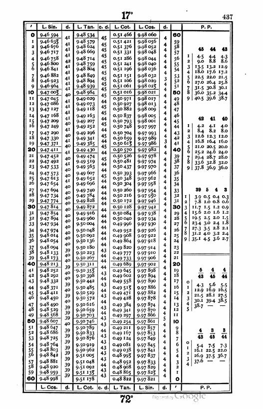
17° 437
2
3
4
56
78
9
10
ii
12
«3
«4
»516
«718
i9
I 20
21
22
23
24
25
26
27
28
29
[30
3i
32
33
34
3536
3738
39
I 40
4i
42
43
44
45
46
47
48
49
I 50
5i
52
53
54
5556
5758
59
160
L. Sin.
946 594
946 633
9.46 676
9.46717
9.46 758
9.46 800
9.46 841
9.46 882
9.46 923
946 964
947 °°5
947 °45
9.47 086
947 127
9.47 168
947 209
947 249
947 290
947 330
947 371
947 4"
947 45 2
947 492
947 533
947 573
947 613
947 654
947 694
947 734
947 774
947 814
947 854
947 894
947 934
947 974
9.48 014
9.48 054
9.48094
948 133
948 173
948213
9.48 252
9.48 292
948 332
9.48371
9.48 41 1
9.48 450
9.48 490
9.48 529
9.48 568
9.48 607
9.48 647
9.48 686
9.48 725
9.48 764
9.48 803
9.48 842
9.48 881
9.48 920
948 959
948 998
L. Cos.
948 534
948 579
9.48 624
9.48 669
9.48 714
948 759
948 804
9.48 849
9.48 894
948 939
948 984
949 029
949 °739.49 118
949 «63
949 2°7
949 252
949 296
949 341
949 385
9 49 430
949 474
949 5 '9
949 563
949 607
9 49 652
949 696
949 740
949 784
9.49 828
949 872
949 916
949 96o
9.50 004
9.50 048
9.50092
9.50 136
9.50 180
9.50 223
9-5° 2&7
9-5° 3"
9-5° 3539.50 398
9.50442
9.50 485
9.50 529
9.50572
9.50616
9.50 659
9-5° 7°3
9-5° 746
9.50 789
9-5° 833
9.50 876
9.50919
9.50 962
9.51005
9.51048
9.51092
9-5i '35-
9-5' 178
L. Cot. |c. d
45
45
45
45
45
45
45
45
45
45
45
44
45
45
44
45
44
45
44
45
44
45
44
44
45
44
44
44
44
44
44
44
44
44
44
44
44
43
44
44
44
43
44
43
44
43
44
43
44
43
43
44
43
43
43
43
43
44
43
43
L. Cot. L. Cos. d.
0.51 466 9.98 060A 60
0.51 421 9.98 056*T
590.51 376 9.98 052 4
58
o-5i 331 9.98 048 457
0.51 286 9.98 0444
56
0.51 241 9.98 040 455
0.51 196 9.98 036 454
0.51 151 9.98 0324
530.51 106 9.98 029 3 52
0.51 061 9.98 025 4 5i
0.51 016 9.980214
50
0.50 971 9.98017
A
490.50 927 9.98013 4 48
0.50 882 9.98 009 447
0.50 837 9.98 0054
46A
°-5° 793 9.98 001 445
0.50 748 9.97 9974
44
0.50 704 9-97 993
A
43
0.50 659 9.97 989 4 42
0.50613 9.97 986 3 4iA
0.50 570 9.97 982*r
40
0.50 526 9.97 978
A
390.50481 9-97 974
4 38
o-5°437 9.97 970 437
0.50 393 9.97 9664
36
0.50 348 9.97 962 435
0.50 304 9.97 958 434
0.50 260 9-97 9544
330.50 216 9.97 930 4 32
0.50 172 9.97 946 431A
0.50 128 9.97 9424
30
0.50 084 9-97 9384
29
0.50 040 9-97 9344 28
0.49 996 9-97 930 4 27
0.49 952 9.97 9264
26
0.49 908 9.97922 4 25
0.49 864 9.97918 4 24
0.49 820 9.979144
23
049 777 9.97910 4 22
049 733 9.97 906 4 21
0.49 689 9.97 9024
20A
0.49 645 9.97 898«f
19
0.49 602 9.97 894 4 18
049 558 9.97 890 4 17
0.49513 9.97 8864
16
0.49471 9.97 882 4 i5
0.49 428 9.97 878 4 14
0.49 384 9.97 8744
'3
0.49 341 9.97 870 4 12
0.49 297 9.97 866 4 11r
0.49 254 9.97 8613
10A
0.49 211 9-97 857*r
90.49 167 9-97 853 4 8
0.49 124 9.97 849 47
0.49 081 9-97 8454
6
0.49 038 9.97 841 45
0.48 993 9-97 8374
4
0.48 952 9-97 8334
30.48 908 9.97 829 4 2
0.48 865 9.97 825 4 1
0.48 822 9.97 821
A
0
L. Tan. L. Sin. d.1
P. P.
46
4-5
44 43
9.04-38.6
4.48.8
13.5 13.2 12.9
18.0 17.6 17.2
22.5 22.0 21.5
27.0 26.4 25.8
31.5 30.8 30.1
36.0 35.2 34.4
4Q-5 39-6 38.7
42 41 40
4.2 4.1 4.0
8.4 8.2 8.0
12.6 12.3 12.0
16.8 16.4 16.0
2'.O 20.5 20.0
25.2 24.6 24.O
29.4 28.7 28.O
33.6 32.8 32.O
37-8 36.9 36-0
39 5 4 3
3.9 0.5 0.4 0.3
7.8 1.0 0.8 0.6
11. 7 1.5 1.2 0.9
15.6 2.0 1.6 1.2
19.5 2.5 2.0 1.5
23.4 3.0 2.4 1.8
27-3 3-5 2-8 2 1
31.2 4.0 3.2 2.4
35.1 4.5 3-6 2.7
5 4 4
43 45 44
4-3 5-6 5-512.9 16.9 16.5
21.5 28.1
30.1 394 38.5
38-7
4 3 3
43 45 44
54 7-5 7-3
16.1 22.5 22.0
26.9 37-5 36.7
37-6 —
P. P,
72°
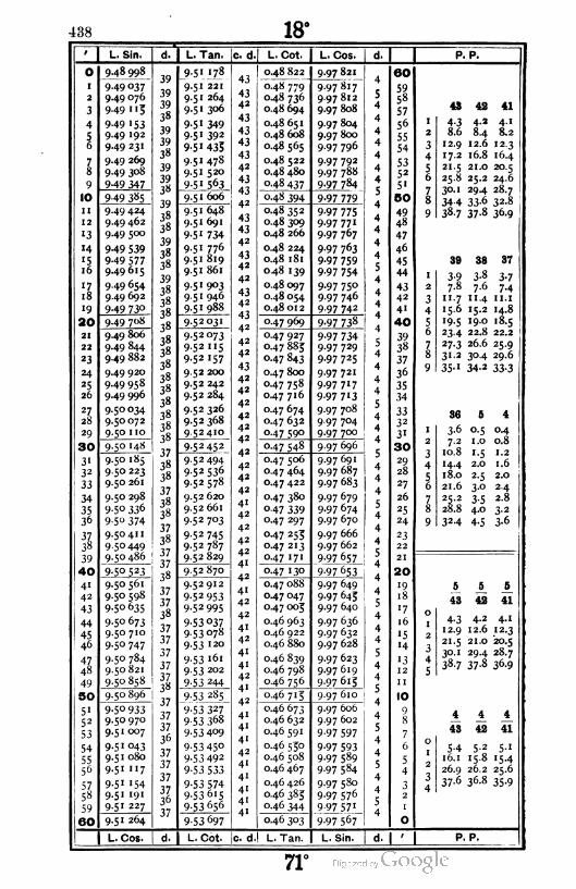
438 18°
9 L. Sin.
0 9.48 998
1 9-49 037
2 9.49 076
3 9.49 113
4 9-49 153
5 9.49 192
6 9-49 231
7 9-49 269
8 9.49 308
9 9-49 347
10 9-49 385
11 9.49 424
12 9-49 462
13 9.49 500
14 9-49 539
'5 9-49 577
16 9.49615
17 9.49 654
18 9.49 692
19 9-49 73°
20 9.49 7O8
21 9.49 806
22 9.49 844
23 9.49 882
24 9.49 920
25 9.49 958
26 9.49 996
27 9.50034
28 9.50072
29 9.50 no
30 9.50 148
31 9.50 185
32 9.50 223
33 9.50 261
34 9.50 298
35 9-5° 336
36 9-5° 374
37 9.50 41 1
38 9.50449
39 9.50 486
40 9.50523
41 9.50561
42 9.50 598
43 9.50 635
44 9.50 673
45 9.50 710
46 9-5° 747
47 9.50 784
48 9.50 821
49 9.50 858
50 9.50 896
51 9-5° 933
52 9.50 970
539.51007
54 9-5 1 °43
559.51 080
56 9.51 117
57 9-5' '54
58 9.51 191
59 9.51 227
60 9.51 264
L. Cos.
L. Tan.
9 5' '78
9.51 221
9.51 264
9.51 306
9-5' 3499-5 1 392
9-5 1 435
9.51 478
9.51 520
9:515^1
9.51 606
9.51 648
9.51 691
9-5 1 734
9.51 776
9.51 819
9.51 861
9-5 1 903
9.51 946
9.51 988
9-5 2 °3'
9.52073
9.52 115
9-52 157
9.52 200
9.52 242
9.52 284
9.52 326
9.52 368
9 52 410
9-52452
9.52494
9-52 536
9.52578
9.52 620
9.52 661
9.52 703
9-52 745
9.52 787
9.52 829
952870
9.52 912
9-52 953
9-52 995
9-53 037
953078
9-53 120
9-53 "61
9.53 202
9-53 244
9-53 285
9-53 327
9-53 368
9-53 409
9-53 45°9-53 492
9-53 533
9-53 5749-53 6l5
9.53656
c. d.1 L. Cot.
0.48 822
0.48 779
0.48 736
0.48 694
0.48 651
0.48 608
0.48 565
0.48 522
0.48 480
0-48 437
9-53 697
0-48 394
0.48 352
0.48 3°9
0.48 266
0.48 224
0.48 181
0.48 139
0.48097
0.48 054
0.48012
0.47 969
0.47 927
0.47 88Jo.47 843
0.47 800
0.47 758
0.47 716
0.47 674
0.47 632
0-47 590
0-47 548
0.47 506
0.47 464
0.47 422
0.47 380
0-47 339
0.47 297
0.47 253
0.47 213
0.47 171
o.47 '30
0.47 088
0.47 047
0.47 003
0.46 963
0.46 922
0.46 880
0.46 839
0.46 798
0-46 756
0 46 7' 5
0.46 673
0.46 632
0.46591
0.46 550
0.46 508
0.46 467
0.46 426
0.46 383
0.46 344
0.46 303
L. Cos.
9.97 821
9-97 817
9.97812
9.97 808
9.97 804
9.97 800
9.97 796
9.97 792
9.97 788
9-97 784
9-97 779
9-97 7759.97 771
9-97 767
9-97 763
9-97 759
9-97 754
9-97 750
9.97 746
9.97 742
9-97 738
9-97 7349.97 729
9.97 725
9.97721
9.97 717
9-97 7'3
9.97 708
9.97 704
9-97 7°°
9.97 696
9.97691
9-97 687
9.97 683
9-97 679
9.97 674
9.97 670
9.97 666
9.97 662
9-97 657
9-97 653
9.97 649
9.97 645
9.97 640
9.97 636
9.97 632
9.97 628
9.97 623
9.97619
9.97613
9.97 610
9.97 606
9.97 602
9-97 597
9-97 593
9.97 589
9.97 584
9.97 580
9.97 576
9.97 571
9.97 567
SO
59
58
57
56
55
54
5352
5'
BO
49
48
47
46
45
44
4342
4'
40
3938
37
36
35
34
3332
3'
30
29
28
27
26
25
24
23
22
21
20
19
18
•7
16
"5
'4
•3
12
10
')
8
7
6
5
4
3
P. P.
43 42 41
4-38.6
12.9
17.2
4.2 4.1
8.4 8.2
12.6 12.3
16.8 16.4
21.5 21.0 20.5
25.8 25.2 24.6
30.1 29.4 28.7
34-4 33-6 32.8
38.7 37.8 36.9
38 38 37
I 3-9 3-8 3-7
2 7.8 7.6 7.4
3 11.7 11.4 11. 1
4 15.6 15.2 14.8
5 '9-5 19.0 18.5
6 234 22.8 22.2
7 27-3 26.6 25.9
8 31.2 30.4 29.6
9 35-" 34-2 33-3
36 S 4
1 3-6 o-5 °-4
2 7-2 1.0 0,8
3 10.8 1.5 1.2
4 14.4 2.0 1.6
5 18.0 2-5 2.0
6 21.6 3-o 2.4
7 25.2 3-5 2.8
8 28.8 4.0 3-2
9 32-4 4-5 3-6
J5
43 42
6^
41
4.2 4.1
12.6 12.3
21.0 -20.5
30.1 29.4 28.7
38.7 37.8 36.9
4-312.9
21.5
4 4 4
48 42 41
5-4 5.2 5.1
16.1 15.8 15.4
26.9 26.2 25.6
37-6 36.8 35-9
L. Cot. c. d,! L. Tan L. Sin. P. P.
71°
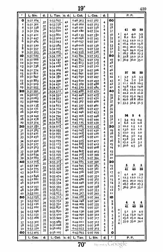
19° 439
O
I
2
3
4
56
78
9
10
II
12
•3
14
'51ó
'7.18
19
|20
21
22
23
24
25
26
27
28
29
I30
3"32
33
34
3536
3738
39
40
41
42
43
44
4546
4748
49
50
51
52
53
54
5556
5758
59
60
L. Sin. d.
9-5 1 264
9.51 301
9.5I 338
951 374
9.51 411
9-51 447
9.51 484
9.51 520
9-51 557
9-5' 593
9.51 629
9.51 666
9.51 702
9-5 1 738
9-51 774
9.51 811
9-5 1 847
9.51 883
9-51 919
9-5' 955
9-51 991
9.52027
9.52 063
9.52099
9-52 '35
9-52 I71
9.52 207
9.52 242
9.52 278
9-52 3'4
9-52 33o
9-52 385
9.52 421
9-52 456
9.52492
9.52 527
9-52 563
9.52 598
9-52634
9.52 669
9-52 705
9.52 740
9-52 775
9.52 811
9.52 846
9.52881
9.52916
9.52951
9.52 986
9-53 02'
9-53056
9.53092
9.53 126
9-53 161
9-53 196
9-53 23I
9.53 266
9-53 3°1
9-53 336
9-53 370
9-53 405
L. Cos.
L. Tan. c. d.
9-53 697
9-53 738
9-53 7799.53 820
9.53861
9.53 902
9-53 943
9-53 984
9-54025
9-54 065
9-54 '06
9-54 147
9-54 187
9.54 228
9.54 269
9-54 309
9-54 35o
9-54 390
9-54 43 1
9-54 47'
9-54 512
9-54 552
9-54 5939-54 633
9-54 673
9-54 7'4
9-54 754
9-54 794
9-54 835
9-54 873
9-54 9'5
9-54 955
9-54 995
9-55 035
9-55 °75
9-55 "5
9-55 '55
9-55 195
9-55 235
9-55 275
9-55 3'5
9-55 355
9-55 393
9-55 434
9-55 474
9-55 5 '4
9-55 554
9-55 593
9-55 633
9-55 673
9-55 7;2
9-55 752
9-55 791
9-55 831
9.55 870
9-55 910
9-55 949
9-55 989
9.56 028
9.56 067
9.56 107
4"
41
41
4'
41
41
41
4"40
4'
4'
40
41
41
40
41
40
41
40
4"
40
4"
40
40
4'40
40
41
40
40
40
40
40
40
40
40
40
40
40
40
40
40
39
40
40
40
39
40
40
39
40
39
40
39
40
39
40
39
3940
L. Cot. L. Cos. d.
0.46 303 9-97 567 60
0.46 262 9-97 5634
59
0.46 221 9-97 558 5 58
0.46 180 9-97 5544
57
0.46 139 9-97 55°4
56
0.46 098 9-97 545c
55A0.46057 9-97 54'
454
c0.46 016 9-97 536
553A
o-45 975 9-97 532 4- 52
0-45 933 9.97 528 4 51
0-45 894 9-97 523
c
50A
0-45 853 9-97 5 '9*r
49
0.45 813 9-97 5 '34 48c
0.45 772 9.97510 J47
0-45 731 9.97 5064
46r
0.45 691 9.97 501 5 45
0.45 650 9-97 4974
44e
0.45 610 9.97 4925
43
o-45 569 9.97 488 4 42
0.45 529 9.97 484 4c 4'
0.45 488 9-97 479J>
40
0.45 448 9-97 473
A
39
0.45 407 9.97 470t
38
0.45 367 9.97 466 437
co-45 327 9.97 461
3 36A
0.45 286 9-97 4574
35
0.45 246 9-97 453
A
34
0.45 206 9.97 4485
33A0-45 l65 9-97 444
4 32c
0.45 125 9-97 4393
3'A
0.45 085 9-97 4334
30c0.45 045 9-97 430
329
0.45 005 9-97 426 4 28e
0.44 965 9.97421 5 27
0.44 925 9.974174
26
0.44 885 9.97412e
25
0.44 845 9.97 408 4 24e
0.44 805 9-97 4033
23A0.44 765 9-97 399
4c
22
0.44 725 9-97 394 A21
0.44 685 9-97 390e 20
0.44 645 9-97 3853
19
0.44 605 9-97 3814
18
0.44 566 9-97 376 5'7
0.44 526 9-97 3724
16
0.44 486 9-97 367 5 15
0.44 446 9-97 3634
c H
0.44407 9-97 358ic
13
0.44 367 9-97 3535 12A
0-44 327 9-97 349T-C
11
0.44 288 9-97 344JA 10
0.44 248 9-97 340*T
90.44 209 9-97 335
e8
0.44 169 9-97 331A
7£0.44 130 9.97 326
56
0.44 090 9.97 322A
5c0.44 05 1 9-97 3'7
Je 4
0.44 01 1 9.97 3123
30.43 972 9.97 308 4
2c0-43 933 9-97 303 J 1
A
0-43 893 9.97 299t
O
L. Tan. L. Sin. d. 1
P. P.
41 40 39
I 4.1 4.0 3-9
2 8.2 8.0 7.8
3 12.3 12.0 11.7
4 16.4 16.0 15.6
5 20.5 20.0 19-5
6 24.6 24.0 23-4
7 28.7 28.0 27-3
8 32-8 32.0 31.2
9 36.9 36.0 35-1
37 36 35
1 3-7 3-6 3-52 7-4 7.2 7.0
3 11. 1 10.8 10.5
4 14.8 14.4 14.0
5 18.5 18.0 '7-56 22.2 21.6 21.0
7 25-9 25.2 24.5
8 29.6 288 28.0
9 33-3 32-4 31-5
34 5 4
1 3-4 0.5 0.4
z 6.8 1.0 0.8
3 10.2 1.5 1.2
4 13-6 2.0 1.6
5 17.0 2-5 2.0
6 20.4 30 2.4
7 23.8 3-5 2.8
8 27.2 4.0 3-2
9 30.6 4-5 3-6
6 5 5
41 40 39
4.1 4.0 3-9
12.3 12.0 U.7
20.5 20.0 "9-528.7 28.0 27-3
36.9 36.0 35'
4 4 4
41 40 39
5-1 5.0 4-9
15.4 15.0 14.6
25.6 25.0 24.4
35-9 35-° 34-1
P, P.
70°

440 20°
L. Sin. L. Tan. c. d. L. Cot. L. Cos. P. P.
9
10
II
13
•3
'4
!i
17
18
"9
I 20
21
22
23
24
25
26
27,
28
29
| 30
3'32
33
34
3536
3738
39
I 40
4142
43
44
45
46
47,
48
49
50
5'52
53
54
5556
5758
59
60
9-53 4°S
9-53 44°
9-53 475
9-53 5°9
9-53 544
9-53 578
9-53 6"3
9-53 647
9.53 682
9 53 7'6
9-53 75'
9-53 785
9-53 819
9-53 854
9-53 888
9.53 922
9-53 957
9-53 991
9.54025
9-54 059
9-54 093
9-54 '27
9-54 161
9-54 195
9-54 229
9.54 263
9-54 297
9-54 331
9-54 365
9-54 399
9-54 433
9.54 466
9-54 5°°
9-54 534
9-54 567
9.54 601
9-54 635
9.54 668
9.54 702
9-54 735
9-54 769
9.54 802
9.54 836
9.54 869
9-54 903
9-54 936
9.54 969
9 55 °°3
9.55 036
9.55069
9-55 102
9-55 '3&9.55 169
9.55 202
9-55 233
9.55 268
9-55 3o1
9-55 334
9-55 367
9-55 400
9-55 433
9-56 '°7
9.56 146
9.56 185
9.56 224
9.56 264
9-56 3t>3
9.56 342
9-56381
9.56 420
956 459
9-56 498
9-56 537
9.56 576
9.56615
9.56 654
9.56 693
9-56 732
9.56771
9.56 810
9-56 849
9-56 887
9.56 926
9.56 963
9.57 004
9.57 042
9.57081
9.57 120
9-57 158
9.57 197
9-57 235
9-57 274
9-57 312
9-57 35 1
9-57 389
9-57 428
9.57466
9-57 5°4
9-57 5439-57 581
9-57 6'9
9-57 658
9.57 696
9-57 7349-57 772
9.57810
9.57 849
9.57887
9-57 923
9-57 963
9.58 001
9-58 039
9.58077
9.58 113
9-58I53
9.58 191
9.58 229
9.58 267
9.58 304
9.58342
9.58 380
9.58418
0-43 893
0.43 854
0.43 813
0-43 776
0-43 736
0.43 697
0.43 658
0.43 619
0.43 580
0-43541
9-97 299
9.97 294
9.97 289
9-97 283
9.97 280
9.97 276
9-97 271
9.97 266
9.97 262
9-97 257
0.43 5°2
0-43 463
0.43 424
o-43 383
°-43 346
°-43 3°7
0.43 268
0.43 229
0.43 190
°-43 '5'
9-97 252
9.97 248
9-97 243
9-97 238
9-97 234
9-97 229
9-97 224
9.97 220
9.97215
9.97 210
0-43 "3 9.97 206
0.43 074
0-43 °35
0.42 996
0.42 958
o 42 919
0.42 880
0.42 842
0.42 803
0.42 763
o 42 726
9.97 201
9.97 196
9.97 192
9.97 187
9.97 182
9.97 178
9-97 173
9.97 168
9-97 l63
9-97 [59
0.42 688
0.42 649
0.42 611
0.42 572
0.42 534
0.42 496
0.42 457
0.42 419
0.42 381
9-97 154
9.97 149
9-97 '43
9.97 140
9-97 '359.97 130
9.97 126
9.97 121
9.97 116
0.42 342 9-97 "'
0.42 304
0.42 266
0.42 228
0.42 190
0.42 151
0.42 113
0.42 075
0.42 037
0.41 999
9.97 107
9.97 102
9.97097
9.97092
9.97 087
9.97 083
9.97078
9-97 °739.97 068
0.41 961 9.97 063
0.41 923
0.41 885
0.41 847
0.41 809
0.41 771
0-41 733
0.41 696
0.41 658
0.41 620
9-97 °59
9-97 °549.97 049
9.97 044
9-97 °399-97 033
9.97 030
9.97 023
9.97 O20
0.41 582 9.97015
60
5958
57
56
55
54
5352
51
BO
49
48
47
46
45
44
4342
41
40
3938
37
36
35
34
3332
31
30
29
28
27
26
25
24
23
22
21
20
19
18
•7
16
'5•4
"312
II
10
9
40 39 38
4-o 3-9 3-8
8.0 7.8 7.6
12.0 11. 7 11-4
16.0 15.6 15.2
20.0 19.5 19.0
24.0 23.4 22.8
28.0 27.3 26.6
32.0 31.2 30.4
36.0 35.1 34.2
37 35 34
3-57.0
10.5 10.2
3-7
7-411. 1
14.8 14.6 13.6
18.5 17.5 17.0
22.2 21.0 20.4
25-9 24.5 23.8
29.6 28.0 27.2
33-3 31-5 3o-6
3-36.6
9-913.2
16.5
19.8
23"
26.4
29.7
0.5
1.0
1.5
2.0
2-5
3°
3-54.0
4-5
0-4
0.8
1.2
1.6
2.0
2-4
2.8
3-2
3-6
5 A A
40 39 38
4.0
12.03-9
1-7
20.0 19.5
28.0 27.3 26.6
360 35.1 34.2
3-8
11.4
19.0
AAA
37 39 38
4.914.6
4.8
14.23-7
1 1.1
18.5 24.4 23.8
25 9 34-1 33-2
33-3 — —
L. Cos. L. Cot. c. d. L. Tan L. Sin, P. P.
69°
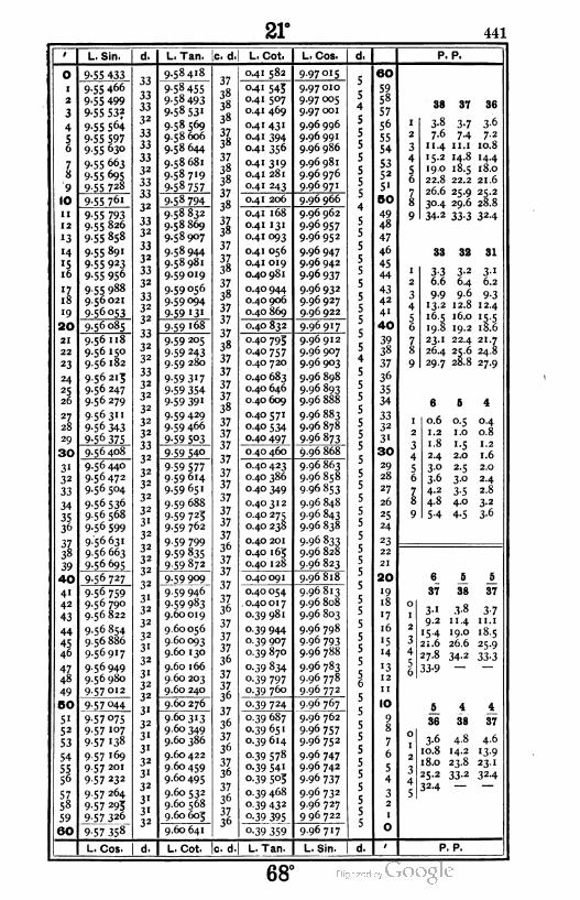
21° 441
L. Sin. d. I L. Tan. c. d. L. Cot L. Cos. P. P.
O
i
2
3
4
56
7k
'9
10
ii
12
13
'4
'516
il
18
19
1 20
21
22
23
24
25
26
2l28
29
1 30
3132
33
34
3536
3Z38
39
40
41
42
43
44
4546
47
48
49
I 50
51
52
53
54
5556
5758
59
|60
9-55 433
9.55 466
9-55 499
9-55 53?
9-55 564
9-55 5979-55 630
9-55 663
9-55 695
9.55728
9-55 761
9-55 7939.55 826
9-55 858
9.55 891
9-55 923
9-55 956
9 55 988
9.56021
9-56 °53
9.56 085
9.56 118
9-56 150
9.56 182
9.56213
9.56 247
9.56279
9-563"
9-56 343
9-56 375
9-56 408
9.56 440
9.56472
9.56 504
9-56 536
9.56 568
9-56 599
9.56 631
9.56 663
9-56 695
9-56727
9 56 759
9.56 790
9.56 822
9.56 854
9.56 886
9.56917
9.56949
9.56 980
9-57012
9-57 044
9-57 075
9.57 107
9-57 138
9-57 i69
9.57 201
9-57 232
9 57 264
9-57 293
9JJ7J26
957 358
L. Cos.
9-58 4i8
9-58 455
9-58 493
9-58 53'
9.58 569
9.58 606
9.58 644
9.58681
9.58 719
9-58 757
9-58 794
9.58 832
9.58 869
9.58 907
9.58 944
9.58 981
9.59019
9.59056
9-59 094
9-59 13'
9-59 168
9.59 205
9-59 243
9.59 280
9-59 3'7
9-59 354
9-59 391
9-59 429
9.59 466
9-59 5°3
9-59 540
9-59 5779.59614
9.59 65 J
9.59 688
9-59 725
9.59 762
9-59 799
9-59 835
9-59 872
9-59 909
9-59 946
9-59 983
9.60019
9.60056
9.60 093
9.60 130
9.60 166
9.60 203
9.60 240
9.60 276
9.60 313
9.60 349
9.60 386
9.60 422
9.60459
9.60 495
9.60 532
9.60 568
9.60 603
9.60 641
37
38
38
38
3738
37
38
38
37
38
3738
37
3138
37
38
37
37
37
38
37
37
37
37
38
37
37
37
37
37
37
37
37
37
37
36
37
37
37
3736
37
37
37
36
37
3736
37
36
37
36
3736
37
36
3736
L. Cot. c. d
0.41 582 9.97015
041 543
0.41 507
0.41 469
0.41 431
0.41 394
0.41 356
0.41 319
0.41 281
0.41 243
9.97 010
9.97 005
9.97 001
9.96 996
9.96 991
9.96 986
9.96 981
9.96976
9-96 97 1
0.41 206 9.96 966
0.4 1 168
0.41 131
0.41 093
0.41 056
0.41 019
0.40 981
0.40 944
0.40 906
0.40 869
9.96 962
9-96 957
9.96 952
9.96 947
9.96 942
9-96 937
9.96 932
9.96927
9.96922
0.40 832 996917
0.40 793
0.40 757
0.40 720
0.40 683
0.40 646
0.40 609
0.40 571
0.40 534
040 497
9.96 912
9.96 907
9.96 903
9.96 898
9.96 893
9.96 888
9.96 883
9.96 878
9-96 873
0.40 460 9.96 868
0.40 423
0.40 386
0.40 349
0.40312
0.40 275
0.40 238
0.40 201
0.40 1 63
0.40 128
9.96 863
9.96 858
9.96 853
9.96 848
9.96 843
9-96 838
9-96 833
9.96 828
9.96 823
0.40091 9.96818
0.40 054
0.40 017
0.39 981
Q-39 944
0.39 907
0.39 870
o.39 834
o.39 797
0.39 760
9.96 813
9.96 808
9.96 803
9.96 798
9-96 793
9.96 788
9.96 783
9.96 778
9 96 772
0-39 724
0.39 687
0.39 651
0.39 614
o-39 578
o.39 54i
o-39 5°3
0.39 468
Q-39 432
0-39 395
0-39 359
L. Tan.
9-96 767
9.96 762
9.96 757
9.96 752
9.96 747
9.96 742
9-96 737
9.96 732
9.96 727
9 96 722
996717
L. Sin.
60
59
58
57
56
55
54
5352
51
50
4948
47
46
45
44
4342
41
40
3938
37
36
35
34
3332
31
30
29
28
27
26
25
24
23
22
21
20
19
18
'7
16
'514
13
12
11
10
9
8
7
6
5
4
32
38 37 36
3-8
7.6
1 1.4
3-7
74
3-6
7-2
10.8
15.2 14.8 14.4
19.0 18.5 18.0
22.8 22.2 21.6
26.6 25.9 25.2
30.4 29.6 28.8
34.2 33.3 32.4
33 32 31
3-36.6
9-913.2 12
16.5
19.8
23
3-2
6.4
9.6
3-1
6.2
9-312.4
16.0 15.5
19.2 18.6
22.4 21.7
26.4 25.6 24.8
29.7 28.8 27.9
6 5 4
0.6 0.5 0.4
1.2 1.0 0.8
1.8 1.5 1.2
2.4 2.0 1.6
3.0 2.5 2.0
3.6 3.0 2.4
4.2 3.5 2.8
4.8 4.0 3.2
54 4-5 3-6
6
37
3-1
9.2
154
21.6
27.8
33-9
5 ±
38 37
3-8
11.4
19.0
26.6
34-2
6^
36
3-6
10.8
18.0
25.2
324
4
38
4-8
14.2
23.8
33-2
3-711. 1
18.5
25-9
33-3
37
4.6
13-9
23- 1
324
P. P.
68°

442 22°
L. Sin. L. Tan. |c. d.l L. Cot L. Cos. P. P.
O
I
2
3
4
56
78
9
10
1l
12
'3
'4
'516
ll
18
"9
20
21
22
23
24
25
26
27
28
29
I 30
3'32
33
34
3536
3738
39
|40
41
42
43
44
45
46
47
48
49
I50
5'52
53
54
5556
5758
59
60
9-57 358
9-57 389
9.57 420
9-57 451
9.57482
9-57 5'4
9-57 543
9-57 576
9-57 6°7
9-57 638
9-57 669
9.57 700
9-57 731
9.57 762
9-57 7939.57 824
9-57 853
9.57 885
9.57916
9-57 947
9-57 978
9.58 008
9.58 039
9.58 070
9.58 101
9-58 131
9.58 162
9.58 192
9.58 223
9-58253
9.58 284
9-58 3'4
9-58 343
9-58 375
9.58 406
9.58436
9.58467
9.58 497
9.58 527
9.58 557
9.58 588
9.58618
9.58 648
9.58678
9.58 709
9-58 739
9.58 769
9.58 799
9.58829
9-58859
9.58919
9.58 949
9.58979
9.59 009
9-59 °399.59 069
9.59098
9.59 128
9-59 158
9.59 188
9.60 641
9.60 677
9.60 714
9.60 750
9.60 786
9.60 823
9.60 859
9.60 895
9.60931
9.60 967
9.61 004
9.61 040
9.61 076
9.61 112
9.61 148
9.61 184
9.61 220
9.61 256
9.61 292
9.61 328
9-61 364
9.61 400
9.61 436
9.61 472
9.61 508
9.61 544
9.61 579
9.61 615
9.61 651
9.61 687
9.61 722
9.61 758
9.61 794
9.61 830
9.61 865
9.61 901
9.61 936
9.61 972
9.62 008
9.62 043
9.62 079
9.62 1 14
9.62 150
9.62 185
9.62 221
9.62 256
9.62 292
9.62 327
9.62 362
9.62 398
9-62 433
9.62 468
9.62 504
9.62 539
9.62 574
9.62 609
9.62 645
9.62 680
9.62715
9.62 750
9.62 785
°-39 359 9.96 717
°-39 323
0.39 286
0.39 250
0.39 214
0.39 177
0.39 141
0.39 105
0.39 069
°-39 033
9.96 71 1
9.96 706
9.96 701
9.96 696
9.96 691
9.96 686
9.96 681
9.96 676
9.96 670
0-38 996 9.96 665
0.38 960
0.38 924
0.38 888
0.38 852
0.38 816
0.38 780
0.38 744
0.38 708
0.38 672
9.96 660
9.96 655
9.96 630
9.96 643
9.96 640
9.96 634
9.96 629
9.96 624
9.96 619
0-38 636
0.38 600
0.38 564
0.38 528
0.38 492
0.38 456
0.38 421
0.38 383
0-38 349
038313
9.96 614
9.96 608
9.96 603
9.96 598
9-96 593
9.96 588
9.96 582
9.96577
9.96572
9-96 567
0.38278 9-96 562
0.38 242
0.38 206
0.38 170
0-38 133
0.38 099
0.38 064
0.38 028
0.37 992
0.37 957
9.96556
9.96551
9.96 546
9.96 541
9-96 535
9.96 530
9.96 523
9.96 520
9-96 5 '4
0.37921
0.37 886
0.37 850
o.37 813
o.37 779
o-37 744
0.37 708
o-37 673
0.37 638
0.37 602
9.96 504
9.96 498
9.96 493
9.96 488
9.96483
9.96477
9.96472
9.96 467
9.96 461
°-37 567 9-96 456
o-37 532
0.37 496
0.37 461
0.37 426
0-37 391
o-37 355
0.37 320
0.37 285
o-37 25°
0.37 213
9.96 451
9-96 445
9.96 440
9-96 433
9.96429
9.96424
9.96419
9.96413
9.96 408
9-96 509
9.96 403
eo
59
5«
57
56
55
54
5352
5'
BO
49
48
47
46
45
44
43
42
41
40
3938
37
36
35
34
3332
3"
30
29
28
27
26
25
24
23
22
21
20
19
18
'7
16
'5•4
"312
II
10
9
8
7
6
5
4
32
37 36 35
I 1-7 3-6 3-52 7-4 7.2 7.0
3 11. 1 10.8 10.5
4 14.8 14.4 14.0
5 18.5 18.0 I7.5
6 22.2 21.6 21.0
7 25.9 25.2 24-5
8 29.6 28.8 28.0
9 33-3 32-4 3'-5
32 31 30
1 3-2 3-" 3°2 6.4 6.2 6.0
3 9.6 9-3 9.0
4 12.8 12.4 12.0
5 16.0 15-5 15.0
6 19.2 18.6 18.0
7 22.4 21.7 21.0
8 25.6 24.8 24.0
9 28.8 27.9 27.0
29 6 5
1 2.9 0.6 o-5
2 5-8 1.2 1.0
3 8.7 1.8 1.5
4 11.6 2.4 2.0
5 '4-5 3° 2.5
6 17.4 3-6 3-o
7 20.3 4.2 3-58 23.2 4.8 4.0
9 26.1 5-4 4-5
6 6
36 36
3-o 2.9
9.0 8.8
15.0 14.6
21.0 20.4
27.0 26.2
33° 32.1
5 5 5
37 36 35
3-7 3-6 3-51 1.1 10.8 10.5
18.5 18.0 17-5
25.9 25.2 24.5
33-3 32-4 3'-5
L. Cos. d. L. Cot. C. d L. Tan. L. Sin. d. P. P.
67°

23° 443
L. Sin. L. Tan. |c. d. L. Cot. L. Cos. d. I P. P.
O
1
2
3
4
56
78
9
10
II
12
•3
'4
I516
'718
19
20
21
22
23
24
25
26
27
28
29
30
31
32
33
34
3536
3738
39
40
4'
42
43
44
45
46
4748
49
50
5'52
53
54
5556
5758
59
60
9-59 188
9.59 218
9-59 247
9.59 277
9-59 3°7
9-59 336
9.59 366
9-59 396
9-59 425
9-59 455"
9-59 484
9-59 5M
9-59 543
9-59 573
9.59 602
9.59 632
9.59 661
9.59 690
9.59 720
9-59 749
9-59 778
9.59 808
9-59 837
9.59 866
9-59 895
9.59 924
9-59 954
9-59 983
9.60012
9.60 041
9.60 070
9.60 099
9.60 128
9.60 157
9.60 186
9.60 213
9.60 244
9.60 273
9.60 302
9-6o 33'
9-6o 359
9.60 388
9.60417
9.60 446
9.60 474
9,60 503
9.60 532
9.60 561
9.60 589
9.60 618
9.60 646
9.60 675
9.60 704
9.60 732
9.60 761
9.60 789
9.60818
9.60 846
9.60 873
9.60 903
9-6o 93 1
I L. Cos.
9.62 785
9.62 820
9.62 855
9.62 890
9.62 926
9.62 961
9.62 996
9.63 031
9.63 066
9-63 101
9-63 135
9.63 170
9.63 205
9.63 240
9-63 275
9.63 310
9-63 345
9-63 379
9.63414
9-63 449
9-63 484
9-63 5 l9
9-63 553
9.63 588
9.63 623
9.63 657
9.63 692
9.63 726
9.63 761
9-63 796
9-°3 830
9.63 863
9.63 899
9-63 934
9.63 968
9.64 003
9.64 037
9.64 072
9.64 106
9.64 140
9.64 175
9.64 209
9.64 243
9.64 278
9.64312
9.64 346
9.64 381
9.64413
9.64 449
9-64 483
9-64 5'7
9.64552
9.64 586
9.64 620
9.64 654
9.64 688
9.64 722
9.64 756
9.64 790
9.64 824
9.64858
d. I L. Cot."
35
35
35
36
35
35
35
35
35
34
35
35
35
35
35
35
34
35
35
35
35
34
35
35
34
35
34
35
35
34
35
34
35
34
35
34
35
34
34
35
34
34
35
34
34
35
34
34
34
34
35
34
34
34
34
34
34
34
34
34
0.37 213 9.96403
0.37 180
°-37 H30.37 11o
0.37 074
°-37 °390.37 004
0.36 969
0.36 934
0.36 899
9-96 397
9.96 392
9.96 387
9.96 381
9.96 376
9.96 370
9.96 363
9.96 360
9-96 354
0-36 865
0.36 830
0.36 795
0.36 760
0.36 723
0.36 690
0.36 655
0.36 621
0.36 586
o-36 551
9-9Q 349
9-96 343
9-96 338
9-96 333
9.96 327
9.96 322
9.96316
9.96 31 1
9.96 305
9.96 300
0-36 5 16 9-96 294
0.36 481
0.36 447
0.36412
o-36 377
0.36 343
0.36 308
0.36 274
0.36 239
0.36 204
9.96 289
9.96 284
9.96 278
9.96 273
9.96 267
9.96 262
9.96 256
9.96 251
9-96 245
0.36 170 9.96 240
o-36 135
0.36 101
0.36 066
0.36 032
0-35 997
0.35 963
0.35 928
0.35 894
0.35 860
9.96 234
9.96 229
9.96 223
9.96 218
9.96 212
9.96 207
9.96 201
9.96 196
9.96 190
0-35 825 9-96 183
o-35 791
°-35 7570.35 722
0.35 688
°-35 654
0.35619
°-35 5S5
o.35 55 1
o.35 517
0-35 483
9.96 179
9.96 174
9.96 168
9.96 162
9.96 157
9.96 151
9.96 146
9.96 140
9-96 135
9.96 129
0.35 448
0.35 4H
0.35 380
0.35 346
0.35 312
0.35 278
0.35 244
0.35 210
0-35 '7&
0.35 142
c. d.| L. Tan.
9.96 123
9.96 1 1 8
9.96 112
9.96 107
9.96 101
9.96 095
9.96 090
9.96084
9.96 079
9-96 073
L. Sin.
60
5958
57
56
55
54
5352
51
60
49
48
47
46
45
44
43
42
41
40
3938
37
36
35
34
3332
31
30
29
28
27
26
25
24
23
22
21
20
19
18
'7
16
1514
'312
1 1
10
98
7
6
5
4
3
d. I
86
3-6
7.2
10.8
14.4
35 34
3-57.0
10.5
14.0
18.0 17.5
21.6 21.0 20.4
25.2 24.5 23.8
28.8 28.0 27.2
32.4 31.5 30.6
10.2
136
17.0
30 29
3-0
6.0
2-9
■;.8
98
2.8
5-6
-49.0 8.7
12.0 11.6 11. 2
15.0 14.5 14.0
18.0 17.4 16.8
21.0 20.3 19.6
24.0 23.2 22.4
27.0 26.1 25.2
6
0.6
1.2
1.8
2-4
3-o
3-6
4.2
4.8
5-4
5
°-51.0
1.5
2.0
2-5
3-o
3-54.0
4-5
6 JL JL
36 35 34
2.9
8.8
3-o
9.0
15.0 14.6
21.0 20.4
27.0 26.2 25.5
33.0 32.1 31.2
2.8
8-5
14.2
19.8
5^
35
3-510.5
'7-524.5
3'-5
6^
34
3-4
10.2
17.0
23.8
30.6
P. P.
66°

444 24°
L. Sin. d. L. Tan. c. d L. Cot. L. Cos. d. P. P.
O
1
2
3
4
56
78
9
10
11
12
'3
14
I51 6
ll
18
'9
| 20
21
22
23
24
25
26
27
28
29
30
3"32
33
34
3536
3738
39
40
4"42
43
44
45
46
47
48
49
50
5'52
53
54
5556
5758
59
I60
9.60 931
9.60960
9.60 988
9.61 016
9.61 043
9.61 073
9.61 101
9.61 129
9.61 158
9.61 186
9.61 214
9.61 242
9.61 270
9.61 298
9.61 326
9-61 354
9.61 382
9.61 41 1
9.61 438
9.61 466
9.61 494
9.61 522
9.61 550
9.61 578
9.61 606
9.61 634
9.61 662
9.61 689
9.61 717
9-61 74?
9-6' 773
9.61 800
9.61 828
9.61 856
9.61 883
9.61 91 1
9.61 939
9.61 966
9.61 994
9.62 021
9.62 049
9.62 076
9.62 104
9.62 131
9.62 159
9.62 186
9.62 214
9.62 241
9.62 268
9.62 296
9.62 323
9.62 350
9.62 377
9.62 403
9.62 432
9.62 459
9.62 486
9.62513
9.62 541
9.62 568
9.62 595
9.64 858
9.64 892
9.64 926
9.64 960
9.64 994
9.65 028
9.65 062
9.65 096
9.65 130
9-65 l64
965 197
9.65 231
9.65 265
9.65 299
9-65 333
9.65 366
9.65 400
9-65 434
9.65 467
9-65 5°'
9-65 535
9.65 568
9.65 602
9.65 636
9.65 669
9.65 703
9.65 736
9.65 770
9.65 803
9-65 837
9.66 204
9.66238
9.66 271
9.66 304
9-66337
9.66371
9.66 404
9.66437
9.66 470
9.66503
9-66 537
9.66 570
9.66 603
9.66 636
9.66 669
9.66 702
9.66 735
9.66 768
9.66 801
9.66 834
9.66 867
0-35 '42 9.96073
9.65 870
9-65 904 , , ,
9-65 937 I TA9.65971
9.66 004
9.66 038
9.66 071
9.66 104
9.66 138
9.66 171
0.35 108
°-35 °740.35 040
0.35 006
°-34 972
o.34 938
0.34 904
0.34 870
o.34 836
9.96 067
9.96 062
9.96 056
9.96050
9.96043
9.96 039
9.96 034
9.96 028
9.96 022
0-34 803 9.96017
0.34 769
°-34 733
0.34 701
0.34 667
°-34 634
0.34600
0-34 566
o-34 533
0-34 499
9.96 01 1
9.96 005
9.96000
9-95 994
9.95 988
9.95 982
9-95 9779.95971
9-95 965
0-34 465
o.34 432
o.34 398
o.34 364
°-34 331
0.34 297
0.34 264
0.34 230
0.34 197
0-34 163
9-95 96o
9-95 9549.95 948
9.95 942
9-95 937
9-95 93'9-95 925
9.95 920
9.95914
9-95 9o8
0.34 130 9-95 902
0.34 096
0.34 063
0.34 029
0.33 996
0.33 962
o-33 929
0.33 896
0.33 862
0.33829
9-95 897
9.95 891
9.95 883
9.95 879
9-95 873
9.95 868
9.95 862
9.95 856
9-95 85°
0-33 796 9-95 844
0.33 762
o-33 729
0.33 696
0.33 663
0.33629
°-33 596
°-33 563
o-33 53o
0.33 497
9-95 839
9-95 833
9.95 827
9.95 821
9.95 815
9.95 810
9.95 804
9-95 798
9-95 792
o.33 463 9-95 786
°-33 43°o-33 397
0.33 364
°-33 331
0.33 298
0.33 265
o-33 232
o-33 199
0.33 166
9-95 780
9-95 7739.95 769
9-95 763
9-95 7579-95 751
9-95 745
9-95 739
9-95 733
o-33 133 9-95 728
00
59
S»
57
56
55
54
5352
5'
BO
49
48
47
46
45
44
43
42
4'
40
3938
37
36
35
34
3332
31
30
29
28
27
26
25
24
23
22
21
20
19
18
'7
16
15
'4
'312
II
10
9
8
7
6
5
4
32
34 33
3-46.8
3-36.6
10.2 9.9
13.6 13.2
17.0 16.5
20.4 19.8
23.8 23.1
27.2 26.4
30.6 29.7
29 28
2.8
5.6
2T
2.7
8.1
10.8
2.9
5.8
8.7 8.4
11.6 11. 2
14.5 14.0 13.5
17.4 16.8 16.2
20.3 19.6 18.9
23.2 22.4 21.6
26.1 25.2 24.3
6
0.6
1.2
1.8
2.4
3°3-6
4.2
4.8
5-4
0.5
1.0
1.5
2.0
2-5
30
3-54.0
4-5
JL JL JL
34 33 34
2.8 2.8 3.4
8.5 8.2 10.2
14.2 13.8 17.0
19.8 19.2 23.8
25.5 24.8 30.6
31.2 30.2 —
L. Cos. d. L. Cot. c. d L. Tan. L. Sin. P. P.
65°
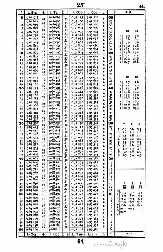
25° 445
0
I
2
3
4
56
78
9
10
11
12
'3
14
'516
"718
'9
I 20
21
22
23
24
*526
27
28
29
I30
3'32
33
34
3536
3738
39
1 40
4'42
43
44
45
46
47
48
49
|S0
5'52
53
54
5556
sl58
59
160
L. Sin.
9-62 5Qg
9.62 622
9.62 649
9.62 676
9.62 703
9.62 730
9.62 757
9.62 784
9.62 811
9.62 838
9.62 863
9.62 892
9.62 918
9.62 945
9.62 972
9.62 999
9.63 026
9.63 052
9.63 079
9.63 106
9-63 133
9-63 159
9.63 186
963213
9 63 239
9.63 266
9.63 292
9 63 3'9
9-63 345
9-63 372
9-63 398
9-63 423
963 45'
9.63 478
9.63 504
.9 63 531
9-63 557
9 63 583
9.63 610
9-63 636
9.63 662
9.63 689
9-63 713
9-63 74'
9.63 767
9-63 794
9.63 820
9.63 846
9.63 872
9-63 898
9.63 924
9.63 950
9.63 976
9.64 002
9.64 028
9.64 054
9.64 080
9.64 106
9.64 132
9.64 158
9.64 184
L. Tan.
9.66 867
9.66 900
9-66 933
9.66 966
9.66 999
9.67 032
9.67 065
9.67 098
9.67 131
9-67 163
9.67 196
9.67 229
9.67 262
9.67 293
9 67 327
9.67 360
9-67 393
9.67 426
9.67458
9-67 491
9-67 524
9.67 556
9.67 589
9.67 622
9.67 654
9.67 687
9.67 719
9.67 752
9.67 785
9.67817
9.67 830
9.67 882
9.67913
9.67 947
9.67 980
9.68012
9.68 044
9.68077
9.68 109
9.68 142
9.68 174
9.68 206
9.68 239
9.68 271
9.68 303
9.68 336
9.68 368
9.68 400
9.68 432
9.68 463
9.68 497
9.68 529
9.68 561
9.68 593
9.68 626
9.68 658
9.68 690
9.68 722
9.68 754
9^8 786_
9768 818"
c. d.
33
33
33
33
33
33
33
3332
33
33
33
33
32
33
33
33
32
33
33
32
33
33
32
3332
33
3332
33
32
3332
33
32
32
33
32
3332
32
3332
32
3332
32
32
3332
32
32
32
33
32
32
32
32
32
32
TTcotT
o-33 '33
0.33 100
0.33 067
o-33 °34
0.33001
0.32 968
0-32935
0.32 902
0.32 869
0-32837
0.32 804
0.32 77'
0-32 738
0.32 705
0.32 673
0.32 640
0.32 607
0.32 574
0.32 542
0-32 5°9
0.32 476
0.32 444
0-32411
o-32 378
0.32 346
0.32313
0.32 281
0.32 248
0.32 215
0.32 183
0.32 15°
0.32 118
0.32085
032053
0.32 020
0.31 988
0.31 956
0.31 923
0.31 891
0-3' 858
0.31 826
0.31 794
0.31 761
0.31 729
0.31 697
0.31 664
0.31 632
0.31 600
0.31 568
0-3' 535
0-3' 5°3
031 47'
o-3' 439
0.31 407
o-3' 374
0.31 342
0.31 310
0.31 278
0.31 246
0.31 214
0.31 182
L. Cos.
9-95 728
9.95 722
9.95 716
9.95 710
9.95 704
9.95 698
9.95 692
9.95 686
9.95 680
9-95 674
9-95 668
9-95 663
9-95 657
9-95 65'
9-95 643
9-95 639
9-95 633
9-95 627
9.95 621
9-95 6'3
9-95 6°9
9.95 603
9-95 597
9-95 59'
9-95 583
9-95 579
9-95 573
9.95 567
9-95 561
9-95 553
9-95 549
9-95 543
9-95 537
9-95 53'
9-95 523
9-95 5'9
9-95 5'3
9.95 507
9.95 500
9-95 494
9-95 488
9.95 482
9.95 476
9.95 470
9-95 464
9.95 458
9-95 452
9.95 446
9-95 440
9-95 434
9-95 427
9.95421
9-95 4'59.95 409
9-95 403
9-95 397
9-95 39'
9-95 384
9-95 378
9-95 372
9-95 366
eo
5958
57
56
55
54
5352
51
50
4948
47
46
45
44
4342
41
40
39
38
37
36
35
34
3332
3'
30
29
28
27
26
25
24
23
22
21
20
'918
•7
16
'5
'4
'312
11
10
98
7
6
5
4
32
1
O
P. P,
83 32
I 3-3 3-2
2 6.6 6.4
3 9-9 9.6
4 13.2 12.8
5 16.5 16.0
6 19.8 19.2
7 23- 1 22.4
8 26.4 25.6
9 29.7 28.8
27 86
1 2-7 2.6
2 5-4 5-2
3 8.1 7-8
4 10.8 10.4
5 '3-5 13.0
6 16.2 15.6
7 18.9 18.2
8 21.6 20.8
9 24-3 23-4
7 6 S
1 0.7 0.6 0.5
2 '-4 1.2 1.0
3 2.1 1.8 1.5
4 2.8 2-4 2.0
5 3-5 3-0 2-5
6 4.2 3-6 30
7 4-9 4.2 3-5
8 5-6 4-8 4.0
9 6-3 5-4 4.5
_L J. Jt
32 32 33
- 2.3 2.7 3.3
6.9 8.0 9.9
11.4 13.3 16.5
16.0 1S.7 23.1
20.6 24.0 29.7
251 29.3 —
29.7 — —
L. Cos. L. Cot. c. d. L. Tan L. Sin. d. P. P.
64°

44G 26°
L. Sin.
o 9.64 184
I 9.64 210
2 9.64 236
3 9.64 262
4 9.64 288
S 9-64 3I3
6 9-64 339
7 9.64 365
9.64 391
9 9.64417
IO 9.64 442
11 9.64 4bS
12 9.64 494
•3 9.64 519
'4 9.64 545
•5 9-64 57'
16 9.64 596
ll 9.64 622
18 9.64 647
'9 9.64 673
20 9.64 69S
21 9.64 724
22 9.64 749
23 9.64 775
24 9.64 800
25 9.64 826
26 9.64 85 1
2l9.64 877
28 9.64 902
29 9.64 927
30 9-64 953
3" 9.64 978
32 9.65 003
33 9.65 029
34 9.65 054
35 9.65 079
36 9.65 104
3Z9.65 130
38 9-65 153
39 9.65 180
40 9.65 205
41 9.65 230
42 9-65 255
43 9.65 281
44 9.65 306
45 9-65 33'
46 9-65 356
47 9.65 381
48 9.65 406
49 9-65 431
50 9.65 456
51 9.65 481
52 9.65 506
53 9-65 531
54 9.65 556
559.65 580
56 9.65 605
579.65 630
5« 9.65 655
59 9.65 680
60 9-65 7°3
L. Cos.
26
L. Tan. !c. d
9.6S S18
9.68 850
9.68 882
9.68 914
9.68 946
9.68 978
9.69 010
9.69 042
9.69 074
9.69 106
9-69 '38
9.69 170
9.69 202
9.69 234
9.69 266
9.69 298
9.69 329
9.69 361
9-69 393
9-69 4^5
9-69 457
9.69 488
9.69 520
9.69 552
9.69 584
9.69 615
9.69 647
9.69 679
9.69 710
9.69 742
9.69 774
9.69 805
9.69 837
9.69 868
9.69 900
9.69 932
9.69 963
9.69 995
9.70 026
9.70 058
9.70 089
9.70 121
9.70 152
9.70 184
9.70215
9.70 247
9.70 278
9.70 309
9.70 341
9.70372
9-7° 404
9.7° 433
9.70 466
9.70498
9.70529
9.70 560
9.70592
9.70 623
9.70 654
9-7° 685
9.70717
L. Cot. L. Cos. d.
"
0.31 182 9.95 366_6
60
0.31 150 9.95 360 59
0.31 1 1 S 9-95 354 558
0.31 086 9-95 34«7
57
0.31 054 9-95 341/
656
0.31 022 9-95 335 6 55
0.30 990 9-95 3296
54
0.30 958 9-95 3236
53
0.30 926 9-95 3'7 752
0.30 894 9.95 310 75"6
0.30 862 9 95 3°4 650
0.30 830 9.95 2986 49
0.30 798 9.95 2920
48A0.30 766 9.95 286
O
,47
°-3° 734 9.95 279 7
646
0.30 702 9-95 2735
45
0.30671 9.95 267 44
0.30 639 9.95 2617
43
0.30 607 9-95 2546
42
°-3°575 9.95 248 4"
°-3° 543 9.95 242 40
0.30 512 9.95 2367
390.30 480 9.95 229 38
0.30 448 9.95 223 37
0.30416 9.95217 36
0.30 385 9.95 2117 35
°-3° 353 9.95 204 J34
0.30321 9.95 1986
336
0.30 290 9.95 192H
32
0.30 258 9.95 185 73"
0.30 226 9-95 1796
30
0.30 193 9-95 "73 29
0.30 163 9.95 167 28
0.30 132 9.95 160 7
627
0.30 100 9-95 '546
26
0.30 068 9.95 1487
25
0.30 037 9.95 141 7
624
0.30 005 9-95 "336
23
0.29 974 9.95 1297
22
0.29 942 9.95 122 76
21
0.29 9II 9.95 1166
20
0.29 879 9.95 no7
"90.29 848 9.95 103 18
0.29 816 9.95 097 "7
0.29 783 9.95 0907
g16
0.29 753 9.95 0846 "5
0.29 722 9.95 078 "4
0.29 691 9.95 0717
5 "30.29 659 9.95 063
612
0.29 628 9.95 0597
11
0.29 596 9.95052/
106
0.29 565 9.95 046 17 90.29 534 9-95 °39
/6
8
0.29 502 9-95 °336
7
0.29471 9.95 0277
6
0.29 440 9.95 020 15
0.29 408 9.950147
4
0.29 377 9.95 007/
30.29 346 9.95 001
(,2
0.29315 9-94 993 71
0.29 283 9.94 988/
O
L. Tan. L. Sin. d. 1
P. P
32 31
I 3-2 3-"2 6.4 6.2
3 9.6 9-3
4 12.8 12-4
5 16.0 '5-50 19.2 18.6
7 22.4 21.7
8 25.6 24.8
9 28.8 27.9
26
2.6
5-2
7.8
10.4
130
15.6
18.2
25 24
2.4
4.8
7-2
9.6
12.0
14.4
16.8
20.8 20.0 19.2
23.4 22.5 21.6
2-5
5.0
7-510.0
12.5
'5-°
7-5
1 6
I 0.7 0.6
2 1.4 1.2
3 2.1 1.8
4 2.8 2.4
5 3-5 3°6 4.2 3-6
7 4-9 4.2
8 5.6 4.8
9 6-3 5-4
82
2.3
6.9
1 1.4
16.0
20.6
25-'
29.7
31
2.2
6.6
11. 1
"5-519.9
24.4
28.8
32
2.7
8.0
"3-318.7
24.0
29-3
P. P.
63°
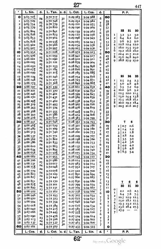
27° 447
L. Sin. L. Tan. c. d. L. Cot. L. Cos. d, P. P.
9
10
11
12
'3
'4
'516
'718
'9
I 20
21
22
23
24
«526
27
28
29
| 30
31
32
33
34
3536
3738
39
|40
41
42
43
44
45
46
47
48
49
ISO
51
52
53
54
5556
5758
59
160
9-65 7°5
9.65 729
9-65 754
9.65 779
9.65 804
9.65 828
9-65 853
9.65 878
9.65 902
9-65 927
9-65 952
9-65 976
9.66001
9.66 025
9.66 050
9.66 075
9.66 099
9.66 124
9.66 148
9.66 173
9.66 197
9.66 221
9.66 246
9.66 270
9.66 295
9.66 319
9-66 343
9.66 368
9.66 392
9.66416
9.66441
9.66 465
9.66 489
9.66513
9.66 537
9.66 562
9.66 586
9.66 610
9.66 634
9.66 658
9.66 682
9.66 706
9.66 731
9.66 755
9.66 779
9.66 803
9.66 827
9.66 851
9.66 87;
9.66 899
9.66 922
9.66 946
9.66 970
9.66 994
9.67 018
9.67 042
9.67 066
9.67 090
9.67 113
9.67 137
9.67 161
9-7° 7'7
9.70 748
9.70 779
9.70 810
9.70 841
9.70 873
9.70 904
9-7° 9359.70 966
9.70 997
9-7
9-7
9-7
028
059
090
121
'53184
215
246
277
308
339
37°401
43"
462
493
524
555586
617
648
679
709
740
77"802
833
863
894
925
9-7' 955
9.71 986
9.72017
9.72 048
9.72 078
9.72 109
9.72 140
9.72 170
9.72 201
9-72231
9.72 262
9.72293
9-72 323
9-72 354
9-72 384
9-72 415
9.72 445
9.72 476
9.72 506
9-72 537
9.72567
0.29 283
0.29 252
0.29 221
0.29 190
0.29 159
0.29 127
0.29 096
0.29 065
0.29 034
0.29 003
9.94 988
9.94 982
9-94 9759.94 969
9.94 962
9.94 956
9.94 949
9-94 9439-94 936
9.94 930
0.28 972 9-94 923
0.28 941
0.28 910
0.28 879
0.28 847
0.28 S16
0.28 785
0.28 754
0.28 723
0.28 692
9.94917
9-94 9"
9.94 904
9.94 898
9.94 891
9.94885
9.94 878
9.94871
9-94 865
0.28 661
0.28 630
0.28 599
0.28 569
0.28 538
0.28 507
0.28 476
0.28 443
0.28 414
0-28 383
9-94 858
9.94 852
9.94 845
9-94 839
9.94 832
9.94 826
9.94819
9.94813
9.94 806
9-94 799
0.28 352
0.28 321
0.28 291
0.28 260
0.28 229
0.28 198
0.28 167
0.28 137
0.28 106
0.28075
0.28 045
0.28 014
0.27 983
0.27952
0.27 922
0.27 891
0.27 860
0.27 830
0.27 799
0.27 769
9-94 793
9.94 786
9.94 780
9-94 773
9.94 767
9.94 760
9-94 753
9-94 747
9.94 740
9-94 734
9-94 727
9.94 720
9.94714
9.94 707
9.94 700
9.94 694
9-94 687
9.94 680
9.94 674
9-94 667
0.27 738 9.94 660
0.27 707
0.27 677
0.27 646
0.27 616
0.27585
0.27 553
0.27 524
0.27 494
0-27 463
9.94654
9.94 647
9.94 640
9-94 634
9.94 627
9.94 620
9.94614
9.94 607
9.94 600
0-27 433 9-94 593
60
59
58
57
56
55
54
5352
5'
60
49
48
47
46
45
44
4342
41
40
393S
37
36
35
34
3332
3'
30
29
28
27
26
25
24
23
22
21
20
'918
'7
16
'5
"4
'312
II
10
98
7
6
5
4
32
1
0
32 31 30
I 3-2 3-' 3-°2 6.4 6.2 6.0
3 9.6 9-3 9.0
4 12.8 12.4 12.0
5 16.0 '5-5 15.0
6 19.2 18.6 18.0
7 22.4 21.7 21.0
8 25.6 24.8 24.0
9 28.8 27.9 27.0
25 24 23
1 2-5 24 2-3
2 5.0 4-8 4.6
3 7-5 7-2 6.9
4 1 0.0 9.6 9.2
5 12.5 12.0 11.5
6 15.0 14.4 13-8
7 "7-5 16.8 16.1
8 20.0 19.2 18.4
9 22.5 21.6 20.7
7 6
1 0.7 0.6
2 1 -4 1.2
3 2.1 1.8
4 2.8 2.4
5 3-5 30
6 4.2 3-6
7 4-9 4.2
8 5.6 4.8
9 6-3 54
7 6 6
30 31 80
2.1 2.6 2-5
6.4 7.8 7-510.7 12.9 12-5
15.0 18.1 '7-5
'9-3 23.2 22.5
23.6 28.4 27-5
27.9 — —
L. Cos. d. L. Cot. c. d L. Tan. L. Sin. P. P.
62°

448 28°
L. Sin. d. I L. Tan. c. d L. Cot. L. Cos. d. P. P.
O
2
3
4
56
78
9
10
ii
12
«3
i4
'516
il
18
«9
1 20
21
22
23
24
25
20
2l2lS
I 30
31
32
33
34
35
3°
373S
39
I 40
4'
42
43
44
45
46
47
48
49
I BO
5'52
53
54
5556
57,58
59
60
9.67 161
9.67 185
9.67 208
9.67 232
9.67 256
9.67 280
9-67 303
9 67 327
9.67 350
»67 374
9-67 398
9.67 421
9.67 445
9.67 468
9.67 492
9 67 5'5
9-67 539
9.67 562
9.67 586
9.67 609
9-67 633
9.67 656
9.67 680
9.67 703
9.67 726
9.67 750
9-67 773
9.67 796
9.67 820
9.67 843
9.67 866
9.67 890
9-67 9'3
9.67 936
9.67 959
9.67 982
9.68 006
9.68 029
9.68 052
9-68075
9.68 098
9.68 121
9.68 144
9.68 167
9.68 190
9.68 213
9.68 237
9.68 260
9.68 283
9.68 305
9.68 328
9.68351
9.68 374
9.68 397
9.68 420
9.68 443
9.68 466
9.68 489
9.68 512
9-68 534
968557
L. C-s.
72 598
72 628
9.72659
72689
72 720
72 750
72780
72 81 1
72841
9 72 872
9.72 902
9.72 932
9.72 963
9-72 993
73 023
9-73 °54
73084
73 "4
9 73 '44
9
9 73205
73 235
9.73 265
73 295
73 326
73 356
73 386
73416
73 446
72 567
73 '75
73 476
73 5°7
9-73 5379-73 567
9-73 597
73627
9-73 657
9.73 687
73 717
9-73 747
73 777
73807
73 837
73867
73 897
73 927
73 957
73 987
74017
74 047
74 077
74 107
74 '3774 166
74 196
74 226
74 256
74 286
74 316
74 345
9-74 375
d. L. Cot. Ic. d
0-27 433
0.27 402
0.27 372
0.27341
0.27 31 1
0.27 280
0.27 250
0.27 220
0.27 189
0.27 159
9-94 593_
9-94 587
9 94 580
9-94 573
9-94 567
9.94 560
9 94 553
9.94 546
9.94 540
9-94 533
0.27 128 9-94 520
0.27 098
0.27 068
0.27037
0.27 007
0.26977
0.26 946
0.26916
0.26 886
0.26 856
9.94519
9-94 5 '39.94 506
9-94 4999.94 492
9.94 485
9-94 4799.94 472
9-94 465
0.26 825
0.26 795
0.26 763
0.26 733
0.26 703
0.26 674
0.26 644
0.26 614
0.26 584
Q-26 554
9-94 458
9.94 451
9-94 445
9-94 438
9-94 43'
9.94 424
9.94417
9.94410
9.94 404
9-94 397
0.26 524 9-94 390
0.26493
0.26 463
0.26433
0.26403
0.26 373
0.26 343
0.26313
0.26 283
0.26 253
0.26 223
0.26 193
0.26 163
0.26 133
0.26 103
0.26073
0.26043
0.26013
0.25 983
0.25 953
9-94 383
9-94 376
9-94 369
9.94 362
9-94 355
9-94 349
9.94 342
9-94 3359-94 328
9 94 321
9-94 3'4
9-94 3°79.94 300
9-94 293
9.94 286
9.94 279
9-94 273
9.94 266
9-94 259
0 25 923
0.25 893
0.25 863
0.25 834
0.25 804
0.25 774
0.25 744
0.25 714
0.25 684
0 25 653
0.25 625
L. Tan.
9-94 252
9.94 243
9.94 238
9-94 231
9.94 224
9.94217
9.94 210
9 94 203
9.94 196
9-94 189
9.94 182
L. Sin.
OO
5958
57
56
55
54
5352
5«
BO
49
48
47
46
45
44
43
42
4i
40
3938
37
36
35
34
3332
3«
30
29
28
27
26
25
24
23
22
21
ao
«918
'7
16
'5
H
'312
11
10
9
8
7
6
5
4
32
0
•1 ao 29
' 3« 3* 2.9
2 6.2 6.0 5.8
3 9-3 9.0 8-7
4 124 1 2.0 11.6
5 '5-5 15.0 '4-56 18.6 1S.0 17.4
7 21.7 21.0 20.3
8 24.8 24.0 23.2
9 27.9 27.0 26.1
24 23 22
2-3
4-6
6.9
9-2
"05
i3-8
16.1
19.2 18.4
21.6 20.7
24
4.8
7-2
9.6
12.0
«4416.8
2.2
44
6.6
8.8
11.0
'3-2
15.4
17.6
19.8
t 6
' 0.7 0.6
2 M 1.2
3 2.1 1.8
4 2.8 24
5 3-5 3.0
6 4.2 3-6
7 4-9 4-2
8 5.6 4.8
9 6-3 54
7 e 6
31 31 30
2.2 2.6 2-5
6.6 7.8 7-5
11. 1 12.9 12-5
'5-5 18.1 '7-5
19.9 23.2 22.5
24.4 28.4 27.5
28.8 — —
d. P. P.
61°

29° 449
0
I
2
3
4
56
78
9
10
II
12
'3
'4
'51 6
"718
19
| 20
21
22
23
24
25
26
27
28
29
I30
3'32
33
34
3536
3738
39
40
41
42
43
44
4546
4748
49
00
5'52
53
54
5556
5758
59
60
L. Sin,
9.68557
9.68 580
9.68 603
9.68 625
9.68 648
9.68 671
9.68 694
9.68 716
9.68 739
9.68 762
9.68 784
9.68 807
9.68 829
9.68 852
9.68 873
9.68 897
9.68 920
9.68 942
9.68 963
9.68 987
9.69 010
9.69 032
9.69 053
9.69 077
9.69 100
9.69 122
9.69 144
9.69 167
9.69 189
9.69 212
9.69 234
9.69 256
9.69 279
9.69 301
9-69 323
9-69 345
9.69 368
9.69 390
9.69 412
9-69 434
9-69 456
9.69 479
9.69 501
9.69 523
9-69 545
9.69 567
9.69 589
9.69 61 1
9-69 633
9-69 655
9-69 677
9.69 699
9.69 721
9-69 743
9.69 765
9.69 787
9.69 809
9.69 831
9.69 853
9.69 875
9.69 897
L. Tan. c. d
9-74 375
9.74 403
9-74 4359-74 463
9-74 4949.74 524
9-74 554
9-74 583
9.74 613
9-74 643
9-74 673
9.74 702
9-74 732
9.74 762
9-74 791
9.74 821
9.74 851
9.74 880
9.74910
9-74 939
9.74 969
9.74 998
9.75 028
9.75058
9.75087
9.75 117
9.75 146
9.75 176
9-75 205
9-75235
9-75 264
9.75 294
9-75 323
9-75 353
9-75 382
9-75 4"
9-75 441
9-75 47°9.75 500
9-75 529
9-75 558
9-75 588
9-75 6l7
9.75 647
9.75 676
9.75 705
9-75 735
9.75 764
9-75 7939-75 822
9-75 852
9.75 88'
9.75910
9-75 939
9-75 969
9-75 998
9.76 027
9.76056
9.76086
9.76 113
9.76 144
L. Cot.
0.25 625
o-25 595
0.25 565
°-25 535
0.25 506
0.25 476
0.25 446
0.25417
0.25 387
0-25 357
0-25 327
0.25 298
0.25 268
0.25 238
0.25 209
0.25 179
0.25 149
0.25 120
0.25 090
0.25 061
0.25 031
0.25 002
0.24 972
0.24 942
0.24913
0.24 883
0.24 854
0.24 824
0.24 793
0-24 765
0-24 736
0.24 706
0.24 677
0.24 647
0.24 618
0.24 589
0.24 559
0.24 530
0.24 500
0.24 471
0.24 442
0.24 412
0.24 383
0-24 353
0.24 324
0.24 293
0.24 265
0.24 236
0.24 207
0.24 178
0.24 148
0.24 119
0.24 090
0.24 061
0.24 031
0.24 002
0-23 973
0.23 944
0.23914
0.23 885
0.23 856
L. Cos.
9.94 182
9-94 175
9.94 168
9.94 161
9.94 154
9-94 147
9.94 140
9-94 133
9.94 126
9.94 119
9.94 112
9.94 105
9.94 098
9.94 090
9.94 083
9-94 076
9.94 069
9.94062
9-94 055
9.94 048
9-94 041
9-94 034
9.94027
9.94 020
9.94012
9.94 005
9-93 998
9-93 99'9.93 984
9-93 977
9-93 97°
9-93 963
9-93 955
9-9J 948
9-93 941
9-93 934
9-93 927
9.93 920
9.93912
9-93 9°5
9-93 898
9.93 891
9.93 884
9.93 876
9.93 869
9.93 862
9-93 853
9-93 847
9-93 840
9-93 833
9-93 826
9.93819
9.93 81 1
9.93 804
9-93 7979-93 789
9.93 782
9-93 7759-93 768
9 93 760
9-93 753
7
7
7
7
7
7
7
7
7
7
7
78
7
7
7
7
7
7
7
7
7
7
8
7
7
7
7
7
7
7
8
7
7
7
7
7
8
7
7
7
78
7
7
7
8
7
7
7
7
8
7
7
8
7
7
78
7
60
5958
57
56
55
54
5352
5'
50
49
48
47
46
45
44
43
42
41
40
39
38
37
36
35
34
3332
3'
3O
29
28
27
26
25
24
23
22
21
20
19
18
'7
16
'514
'312
11
10
9
8
7
6
5
4
32
1
O
P. P.
30 29 23
3-0
6.0
9.0
12.0
2.9
5-8
8-7
1.6
15.0 14.5
18.0 17.4 13.8
21.0 20.3 16.1
24.0 23.2 18.4
27.0 26.1 20.7
2-3
4.6
6.9
9.2
1 1.5
22
2.2
4-4
6.6
8.8
11.0
'3-2
15.4
17.6
19.8
8
0.8
1.6
2.4
3-2
4.0
4.8
5.6
6-4
7-2
7
0.7
1.4
2.1
2.8
3-54.2
4-9
5.6
6-3
8^
30
1-9
5-6
9-4
"3-'16.9
20.6
24.4
28.1
7_
30
2.1
6.4
10.7
15.0
19.3
23.6
27.9
89
5-4
9-"12.7
16.3
19.9
23.6
27.2
2.1
6.2
10.4
14.5
18.6
22.8
26.9
I L, Cos. L. Cot. c. d L. Tan. L. Sin. I d. P. P.
r'm'd surv. — 2960°
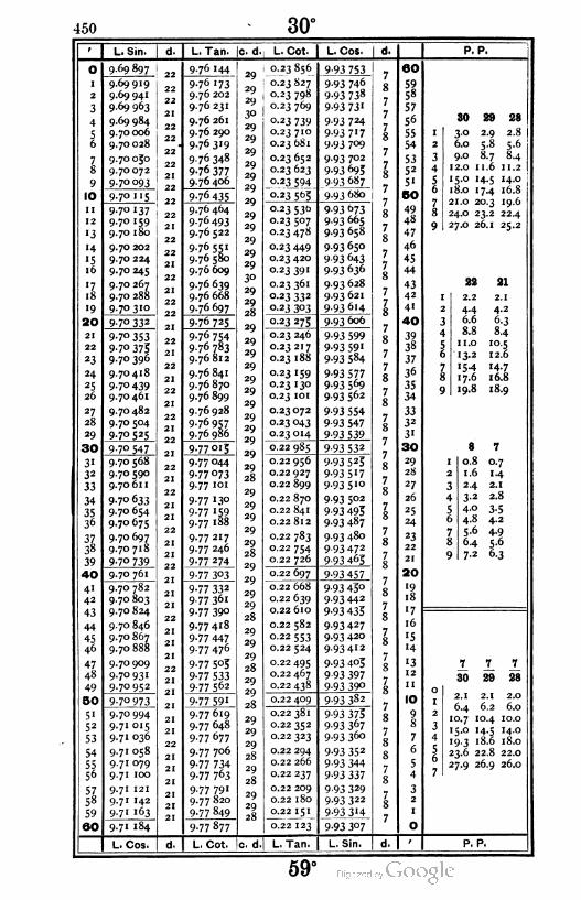
450 30°
L. Sin. d. L. Tan. ¡c. d., L. Cot. L. Cos. i d. P. P.
O
i
2
3
4
56
78
9
10
ii
12
«3
«4
'516
'718
«9
20
21
22
«3
24
«526
27
28
29
1 30
3«32
33
34
3536
3738
39
I 40
41
42
43
44
45
46
4748
49
50
51
52
53
54
5556
5758
59
160
9.69 897
9.69919
9.69 941
9.69 963
9.69 984
9.70006
9.70028
9.70030
9.70 072
9-7° 093
9-7° "5
9-7° '379.70 159
9.70 180
9.70 202
9.70 224
9.70 245
9.70 267
9.70 288
9-7° 3'°
9-7° 332
9-7° 353
9-7° 3759.70 396
9.70418
9.70439
9.70 461
9.70 482
9.70 504
9-7° 525
9-7° 547
9.70 568
9.70 590
9.70 61 1
9-7° 633
9.70 654
9.70 675
9.70 697
9.70 718
9-7° 739
9.70 761
9.70 782
9.70803
9.70 824
9.70 846
9.70 867
9.70 888
9.70 909
9.70 931
9.70 952
9-7° 973
9.70 994
9.71 015
9.71 036
9.71 058
9.71 079
9.71 100
9.71 121
9.71 142
9.71 163
9-7« 184
9.76 144
9-76 '73
9.76 202
9.76 231
9.76 261
9.76 290
9.76319
9.76348
9.76377
9.76 406
9-76 435
9.76 464
976493
9.76 522
9-7655'
9.76 580
9.76 609
9.76 639
9.76 668
9-76697
976 725
9.76 754
9.76 783
9.76 812
9.76 841
9.76 870
9.76 899
9.76928
9.76 957
9.76 986
9-77 oi5
9.77 044
9-77 073
9.77 101
9.77 130
9-77 '599.77 i88
9.77 217
9.77 246
9-77 274
9-77 303
9-77 332
9.77 361
9-77 390
9.77418
9-77 447
9.77476
9-77 505
9-77 5339-77 562
9-77 59'
9.77 619
9.77 648
9.77677
9.77 706
9-77 734
9-77 763
9.77 791
9.77 820
9-77 849
9.77 877
0.23856
0.23 827
0.23 798
0.23 769
0.23 739
0.23 710
0.23 681
0.23 652
0.23 623
Q-23 594
0-23 5b3
9 93 753
9 93 746
9-93 738
9-93 73'
9-93 724
9-93 7' 7
9-93 7°9
9.93 702
9-93 693
9.93 687
023530
0.23 507
0.23478
0.23 449
0.23 420
0 23 391
0.23 361
0.23 332
0.23 303
9-93 »739.93 665
9.93 658
9.93 650
9-93 643
9-93 636
9.93 628
9.93 621
993614
0-23 275 9-93 606
0.23 246
0.23 217
0.23 188
0.23 159
0.23 130
0.23 101
0.23072
0.23 043
023 014
9-93 599
9-93 59'
9-93 584
9-93 5779-93 569
9.93 562
9-93 554
9-93 547
9-93 539
0.22 985 9-93 532
0.22 956
0.22 927
0.22 899
0.22 870
0.22 841
0.22 812
0.22 783
0.22754
0.22 726
9-93 525
9-93 5'79-93 5 10
9.93 502
9-93 493
9-93 487
9.93 480
9-93 472
9-93 465
0.22 697 9-93 457
0.22 668
0.22 639
0.22 610
0.22 582
Q-22553
0.22 524
0.22495
0.22 467
0.22 438
9-93 45°9-93 442
9-93 433
9-93 427
9.93 420
9.93412
9-93 403
9-93 3979-93 390
0.22 409 9-93 382
0.22 381
0.22 352
0.22 323
0.22 294
0.22 266
0.22 237
0.22 209
0.22 180
0.22 151
0.22 123
9-93 3759-93 367
9-93 360
9-93 352
9-93 344
9-93 337
9-93 329
9-93 322
9-93 3'4
9.93 680
9-93 3°7
60
59
5«
57
56
55
54
5352
5'
BO
49
48
47
46
45
44
4342
41
40
3938
37
36
35
34
3332
3'
30
29
28
27
26
25
24
23
22
21
20
'918
'7
16
'5
«4
'312
11
10
9
8
7
6
5
4
32
1
O
30 29 28
3.0 2.9 2.8
6.0 5.8 5.6
9.0 8.7 8.4
12.0 11.6 1 1.2
15.0 14.5 14.0
18.0 17.4 16.8
21.0 20.3 19.6
24.0 23.2 22.4
27.0 26.1 25.2
22 81
' 2.2 2.1
2 4.4 4.2
3 6.6 6-3
4 8.8 8.4
5 1 1.0 10.5
6 13.2 12.6
7 '54 iH
8 17.6 16.8
9 19.8 18.9
B 7
1 0.8 0.7
2 1.6 14
3 2.4 2.1
4 3-2 2.8
5 4.0 3-56 4-8 4.2
7 5-6 4-9
8 6.4 5.6
9 7-2 6-3
7 7 7
30 29 28
2.1 2.1 2.0
6.4 6.2 6.0
10.7 104 10.0
15.0 '4-5 14.0
'9-3 18.6 18.0
23.6 22.8 22.0
27.9 26.9 26.0
L. Cos. L. Cot. c. d. L. Tan L. Sin. P. P.
59°

451
L. Sin. L.Tan. 1c. d.| L. Cot. L. Cos. P. P.
0
1
2
3
4
56
78
9
10
11
12
13
'4
"516
'7,18
"9
|20
21
22
23
24
25
26
27
28
29
| 30
3'32
33
34
3536
3738
39
40
4"
42
43
44
45
46
47
48
49
I 50
51
52
53
54
5556
5758
59
60
9-7
9-7
9-7
9-7
1i
203
226
247
268
289
310
33'352
373
393
414
435456
477
498
5J9
539560
581
602
622
643
664
683
705
726
747
767
829
830
870
891
911
932
952
973
994
9.72 014
9-72 034
9-72 °53
9.72075
9.72 096
9.72 116
9-72 '37
9-72 157
9.72 177
9.72 198
9.72 218
9.72238
9.72259
9.72 279
9.72 299
9.72 320
9.72 340
9.72 360
9.72381
9-72401
9-72421
L. Cos. I d.
9-77 877
9.77 906
9-77 9339-77963
9.77992
9.78 020
9.78 049
9.78 077
9.78 106
9-78 133
9-78 l63
9.78 192
9.78 220
9.78 249
9.78277
9.78 306
9-78 334
9-78 363
9-78 391
9.78419
9-78 448
9.78 476
9.78 503
9-78 533
9.78 562
9.78 590
9.78618
9.78 647
9.78 675
9.78 704
9-78 732
9.78 760
9.78 789
9-78817
9.78 845
9.78 874
9.78 902
9.78 930
9.78959
9-78987
9.79015
9-79 043
9.79 072
9.79 100
9.79 128
9.79 156
9.79 183
9.79213
9-79 241
9-79 269
9-79 297
9.79326
9-79 354
9-79 382
9.79410
9-79 438
9.79 466
9-79 4939-79 523
9-79 55'
9-79 579
L. Cot.
0.22 123 9-93 3°7
0.22 094
0.22065
0.22 037
0.22 008
0.21 9S0
0.21 951
0.21 923
0.21 894
0.21 865
9.93 299
9.93 291
9.93 284
9.93 276
9.93 269
9-93 261
9-93 253
9.93 246
9-93 238
o-21 837 9-93 230
0.21 808
0.21 780
0.21 751
0.21 723
0.21 694
0.21 666
0.21 637
0.21 609
0.2I 58I
9-93 223
9-93 2I5
9.93 207
9.93 200
9.93 192
9-93 184
9-93 177
9.93 169
9-93 '61
o-21 552 q-93 '54
0.21 524
0.21 495
0.21 467
0.21 438
0.21 410
0.21 382
o-21 353
0.21 323
0.21 296
9-93 H6
9-93 '38
9-93 '3'
9-93 " 23
9-93 1 "5
9.93 108
9.93 100
9.93 092
9.93084
0.21 268 9-93 077
0.21 240
0.21 211
0.21 183
0.21 153
0.21 126
0.21 098
0.21 070
0.21 041
0.21 013
9.93 069
9.93 061
9-93 °53
9.93 046
9-93 038
9-93O30
9.93 022
9.93014
9.93 007
0.20 983 9.92 999
0.20 957
0.20 928
0.20 900
0.20 872
0.20 844
0.20 815
0.20 787
0.20 759
0.20 73'
9.92991
9.92 983
9.92976
9.92 968
9.92 960
9.92 952
9.92 944
9.92 936
9.92 929
0.20 703 9.92 921
0.20 674
0.20 646
0.20 618
0.20 590
0.20 562
0.20534
0.20 505
0.20 477
0.20 449
0.20 421
c. d.l L. Tan.
9.92913
9.92 905
9.92 897
9.92 889
9.92 881
9.92 874
9.92 866
9.92 858
9 92 850
9.92 842
L. Sin.
60
59
58
57
5°
55
54
5352
5'
50
49
48
47
46
45
44
43
42
4'
40
39
38
37
36
35
34
3332
31
30
29
28
27
26
25
24
23
22
21
20
'918
'7
16
'5
'4
'312
11
10
9
8
7
6
5
4
32
1
0
29 28
I 2.9 2.8
2 5-8 5-6
3 8-7 8-4
4 1 1.6 1 1.2
5 "4-5 14.0
6 17.4 16.8
7 20.3 19.6
8 23.2 22.4
9 26.1 25.2
2I 20
1 2.1 2.0
2 4-2 4.0
3 6-3 6.0
4 8.4 8.0
5 10.5 10.0
6 12.6 12.0
7 14-7 14.0
8 16.8 16.0
9 18.9 18.0
8 7
1 0.8 0.7
2 1.6 M
3 2.4 2.1
4 3-2 2.8
5 4.0 3-56 4.8 4.2
7 5.6 4.9
8 6.4 5.6
9 7.2 6-3
8 8 8
30 29 28
1.9 1.8 1.8
5.6 5-4 5-2
9-4 9-1 8.8
'3' 12.7 12.2
16.9 16.3 15.8
20.6 19.9 19.2
24.4 23.6 22.8
28.1 27.2 26.2
P. P.
58°

452 32°
' L. Sin.
0 9.72421
' 9.72441
2 9.72461
3 9.72 482
4 9.72 502
5 9.72 522
6 9.72 542
7 9.72 562
s 9.72582
9 9.72 602
IO 9.72 622
ii 9-72 643
12 9.72 663
«3 9.72 683
'4 9.72 703
'5 972 723
16 9 72 743
«7 9.72 763
18 972 783
i9 972 803
20 9.72 823
21 972 «43
22 9.72 863
23 9.72883
*4 9.72 902
25 9.72 922
26 9.72 942
27 9.72 962
28 9.72982
29 9.73002
30 9.73022
3« 973 °4'
32 9.73061
33 9.73081
34 973 101
35 973 12i
36 973 '4°
37 973 160
38 9 73 i80
39 973 200
40 9 73 219
4' 973 239
42 973 259
43 973 278
44 973 298
45 973 318
46 973 337
*z 973 357
48 9 73 377
49 973 396
50 973 416
51 973 435
52 9 73 453
53 973474
54 973 494
55 973 5'3
56 973 533
57 973 552
58 973 572
59 973 591
60 973 611
L. Cos.
L. Tan. |c. d.l L. Cot. L. Cos. d. I P. P.
979 579
979 607
979 635
979 663
9.79691
979 7'9
979 747
9 79 776
979 804
979 832
9.79 8G0
9.79 888
9.79916
979 944
979 972
9.80000
9.80028
9.80056
9.80 084
9.80 112
9.80 140
9.80 168
9.80 195
9.80 223
9.80 251
9.80 279
9.80 307
9-So 335
9.80 363
9.80 391
9.80419
9.80447
9.80474
9.80 502
9.80 530
9.80 558
9.80 586
9.80 614
9.80 642
9.80 669
9.80 697
9.80 725
980753
9.80781
9.80 808
9.80 836
9.80 864
9.80 892
9.80 919
9.80 947
980975
9.81 003
9.81 030
9.81 058
9.81 0S6
9.81 113
9.81 141
9.81 169
9.81 196
9.81 224
9.81 252
L. Cot.
2S
28
28
2S
28
2S
29
28
28
28
28
28
28
28
28
2S
28
28
2.S
28
28
27
28
28
28
28
28
28
28
28
28
2l28
28
28
28
28
28
2l28
28
28
28
27
28
28
28
2l28
28
28
2l28
28
2l28
28
2l28
28
c~d~
0.20 421 9.92 842
0.20 393
0.20 365
°-2o 337
0.20 309
0.20 281
0.20 253
0.20 224
0.20 196
0.20 168
9.92 834
9.92 82b
9.92 818
9.92 810
9.92 803
9.92 793
9.92 787
9.92 779
9-92 77'
0.20 140
0.20 1 1 2
0.20084
0.20 056
0.20028
0.20000
9972
9 944
9916
9888
9860
9.92 763
9-92 753
9-92 747
9-92 739
9-92 73'
9.92 723
9.92715
9.92 707
9.92 699
9.92 691
9-92 683
9832
9805
9 777
9 7499 721
9693
9665
9637
9 609
9.92675
9.92 667
9.92 659
992651
9.92 643
9.92 635
9.92 627
9.92 619
9.92 611
9581
9 5539526
9498
9470
9442
9414
9386
9 358
9 331
9 3°3
9.92 6o3_
9.92 595
9.92 587
9.92 579
9-92 57'
9.92 563
9-92 555
9.92 546
9-92 538
9-92 53o
9.92 522
9275
9 247
9219
9 192
9 164
9 136
9 108
9081
9 053
9.92514
9.92 506
9.92 498
9.92 490
9.92 482
9-92 473
9.92 465
9-92 457
9.92 449
9025 9.92 441
8997
8970
8942
8914
8887
8859
8831
8804
8 776
8 748
L. Tan.
9-92 433
9.92425
9.92 416
9.92 408
9.92 400
9.92 392
9.92 384
9.92 376
9-92 367
9-92 359
L. Sin.
60
5958
57
56
55
54
5352
5«
BO
4948
47
46
45
44
4342
4'
40
39
38
37
36
35
34
3332
3«
30
29
28
27
26
25
24
23
22
21
20
'9
18
«7
16
'514
'312
11
10
98
7
6
5
4
3
29 28 27
' 2.9 2.8 2-7
2 5-8
U
54
3 8.7 8.1
4 1 1.6 1 1.2 10.8
5 '4-5 14.0 '3-56 '74 16.8 16.2
7 20.3 19.6 18.9
<s 23.2 22.4 21.6
9 26.1 25.2 24-3
21 20 19
1 2.1 2.0 i-9
2 4.2 4.0 3-8
3 6-3 6.0 57
4 84 8.0 7.6
5 10.5 10.0 9-5
6 12.6 12.0 1 1.4
7 '47 14.0 '3-38 16.8 16.0 15.2
9 18.9 18.0 17.1
9 8 7
1 0.9 0.8 0.7
2 1.8 1.6 M
3 27 24 2.1
4 3-6 3-2 2.8
5 4-5 4.0 3-5
6 54 4.8 4-2
7 6-3 5.6 4-9
8 7-2 6.4 5.6
9 8.1 7-2 6-3
8 8 7
29 88 28
1.8 1.8 2.0
54 5.2 6.0
9' 8.8 10.0
12.7 12.2 14.0
16.3 15.8 18.0
19.9 19.2 22.0
23.6 22.8 26.0
27.2 26.2
P. P.
57°
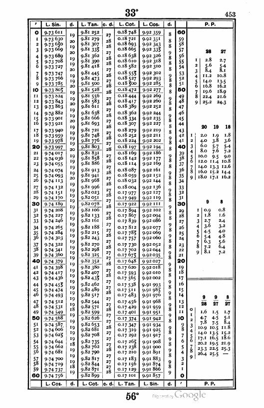
33° 453
O
I
2
3
4
56
78
9
IO
I!
12
'3
'4
'516
"718
•9
20
21
22
23
24
2S26
27
28
29
30
31
32
33
34
3536
37
38
39
40
4'
42
43
44
45
46
4748
49
50
5'52
53
54
5556
5758
59
160
L. Sin.
9-73611
9-73 63°
9-73 63°
9.73 669
9.73 689
9.73 708
9-73 727
9-73 7479.73 766
9-73 785
9-73 805
9-73 >>24
9-73 843
9-73 863
9.73 882
9-73 9°1
9.73921
9-73 94°
9-73 959
9-73 978
9-73 997
9.74017
9.74 036
9.74 055
9.74 074
9-74 °93
9-74 "3
9-74 132
9-74 15'
9.74 170
9-74 189
9.74 208
9.74 227
9.74 246
9.74 265
9.74 284
9-74 3°3
9-74 322
9-74 34'9.74 360
9-74 379
9-74 398
9-744I7
9-74 436
9-74 455
9-74 474
9-74 493
9.74512
9-74 531
9-74 549
9-74 568
9-74 587.
9.74 606
9.74 625
9.74 644
9.74 662
9.74 681
9.74 700
9.74 719
9-74 737
9-74 756
L. Cos.
L. Tan. |c. d
9-8' 252
9.81 279
9.81 307
9-81 333
9.81 362
9.8 1 390
9.81 418
9.81 445
9-81 473
9.81 500
9.81 528
9.81 556
9.81 583
9.81 611
9.81 638
9.81 666
9.81 693
9.81 721
9.81 748
9.81 776
9.81 803
9.81 831
9.81 858
9.81 886
9.S1 913
9.81 941
9.81 968
9.81 996
9.82 023
9.82 051
9.82078
9.82 106
9-82 133
9.82 161
9.82 188
9.82 215
9.82 243
9.82 270
9.82 298
9-82 325
9-82 352
9.82 380
9.82 407
9-82 435
9.82 462
9.82 489
9.82517
9.82 544
9.82 571
9.82 599
9.82 626
9.82 653
9.82 681
9.82 708
9-82 735
9.82 762
9.82 790
9.82817
9.82 844
9.82 871
9.82 899
L. Cot. le. d
L, Cot.
0.18 748
o.
o.
o.
8 721
8693
8665
8638
8610
8582
8 553
8527
500
8472
8444
8417
8389
8362
8 334
8307
8279
8 252
8224
. 197
8 169
8 142
8 114
8087
8059
8032
8004
7 977
7 949
7922
7894
7867
7 839
7812
7 783
7 757
7 73°7 702
7 673
7648
7 620
7 5937 565
7 538
75"7 483
7 456
7 429
7401
7 374
7 3477 319
7 292
7263
7238
7 210
7183
7 156
7 I29
0.17 101
L. Tan.
L. Cos.
9-92 359
9.92351
9-92 343
9-92 333
9.92326
9.92318
9.92310
9.92 302
9.92 293
9.92 285
9.92 277
9.92 269
9.92 260
9.92 252
9.92 244
9.92 235
9.92 227
9.92 219
9.92 211
9.92 202
9.92 194
9.92 186
9.92 177
9.92 169
9.92 161
9.92 152
9.92 144
9.92 136
9.92 127
9.92 II9
9.92 1 1 1
9.92 102
9.92 094
9.92 086
9.92077
9.92 069
9.92 060
9.92 052
9.92044
9-92035
9 92 027
9.92 018
9.92 010
9.92 002
9-91 993
9.91 983
9.91 976
9.91 968
9.91 959
9-91 951
9.91 942
9-91 934
9.91 925
9.91 917
9.91 908
9.91 900
9.91 891
9.91 883
9.91 874
9.91 866
9-9' 857
L. Sin.
60
59
58
57
56
55
54
5352
5'
00
49
48
47
46
45
44
4342
41
40
39
3«
37
36
35
34
3332
3"
30
29
28
27
26
25
24
23
22
21
20
"918
'7
16
'5
"4
'312
1 1
10
98
7
6
5
4
32
1
O
P. P.
28 27
I 2.8 2-7
2 5-6 5-4
3 8.4 8.1
4 11. 2 10.8
5 14.0 '3-5
6 16.8 16.2
7 19.6 18.9
8 22.4 21.6
9 25.2 24-3
20 19 18
2.0
4.0
6.0
8.0
10.0
12.0
1.9
3-8
5-77.6
9-511.4
14.0 13.3 12.6
16.0 15.2 14.4
18.0 17. 1 16.2
1.8
3-6
5-47.2
9.0
10.8
9 8
I 0.9
1.8
0.8
2 1.6
3 2.7 2-4
4 3-6 3-2
5 4-5 4.0
6 5-4 4.8
7 6-3 5-6
8 7-2 6-4
9 8.1 7-2
9 9 8
28 27 27
1.6 1.5 1.7
4-7 4-5 5-1
7.8 7-5 8.4
10.9 10.5 11. 8
14.0 '3-5 15.2
17.1 1.6.5 18.6
20.2 •9-5 21.9
23-3 22.5 25-3
26.4 25-5
P. P.
56°

454 34°
o
I
2
3
4
5o
78
9
IO
11
12
'3
"4
'516
'7,18
19
20
21
22
23
24
25
26
27
28
29
30
31
32
33
34
3536
3738
39
40
41
42
43
44
45
46
47
48
49
50
51
52
53
54
5556
5758
59
160
L. Sin,
9-74 756
9-74 775
9-74 794
9.74 812
9-74 831
9.74 850
9.74 868
9.74 887
9.74 906
9-74 924
9-74 943
9.74 961
9.74 980
9-74 999
9.75017
9.75 036
9-75 °54
9-75 °739.75091
9-75 "0
9.75 128
9-75 '479.75 165
9.75 184
9.75 202
9.75 221
9-75 239
9-75 258
9-75 276
9-75 294
9-75 3'3
9-75 331
9-75 35°9-75 368
9-75 386
9-75 405
9-75 423
9-75 441
9-75 459
9-75 478
9-75 496
9-75 5H
9-75 5339-75 551
9.75 569
9-75 587
9.75 605
9.75 624
9.75 642
9-75 660
9-75 678
9.75 696
9-75 7H
9-75 733
9-75 751
9.75 769
9.75 787
9-75 803
9-75 823
9-75 841
9-75 859
L. Cos.
L. Tan. c. d
9.82 899
9.82 926
9-82 953
9.82 980
9.83 008
9-83 033
9.83 062
9.83 089
9.83 117
9-83 '44
9-83 '7'
9.83 198
9.83 225
9.83 252
9.83 280
9-83 307
9-83 334
9 83 361
9.83 388
9-83 4'5
9.83 442
9.83 470
9-83 497
9-83 524
9-83 55I
9-83 578
9.83 605
9.83 632
9.83 659
9.83 686
9-83 7'3
9.83 740
9.83 768
9-83 793
9.83 822
9.83 849
9.83 876
9-83 9°3
9-83 93°
9-83 957
9-83 984
9.84 on
9.84 038
9.84 063
9.84 092
9.84 119
9.84 146
9-84 173
9.84 200
9.84 227
9.84254
9.84 280
9.84 307
9-84 334
9.84 361
9.84 388
9.84415
9.84 442
9.84 469
9-84 496
9-84 523
L. Cot. |c. d
L. Cot.
0.17 101
0.17074
0.17047
o. 1 7 020
0.16 992
0.16 965
0.16938
0.16 91 1
0.16883
0.16856
0.16 829
0.16 802
0.16773
0.16 748
0.16 720
0.16 693
0.16 666
0.16 639
0.16 612
0-16583
0.16 558
0.16 530
0.16 503
0.16 476
o. 1 6 449
0.16 422
0.16393
0.16368
0.16 341
0.16 314
0.16 287
0.16 260
0.16 232
0.16 205
0.16 178
0.16 151
0.16 124
0.16 097
0.16070
0.16043
0.16 016
0.15989
0.15 962
o-15 935
0.15 908
0.15 881
0.15 854
0.15 827
0.15 800
0.I5 773
0-15 746
0.15 720
0.15 693
o. 1 5 666
0.15 639
o. 1 5 6 1 2
o-1 5 583
0.15 558
015 531
0-I5 504
°-15 477
L. Tan.
L. Cos.
9-')
9-9
9.9
9-9
9-9
9-9
9-9
9-9
9-9
9-9
9.9
9-9
9-9
9-9
9-9
9-9
9-9
9-9
9-9
9-9
9-9
9-9
9-9
9-9
9-9
9-9
9-9
9-9
9-9
9-9
9.9
9.9
9-9
9-9
9-9
9-9
9-9
9-9
9-9
9-9
9-9
9.9
9-9
9-9
9-9
9-9
9-9
9-9
9-9
9-9
9-9
9.9
857
849
840
832
S23
8.3
806
798
789
781
772
763
753746
738
729
720
712
703
693
686
677
669
660
651
643
634
625
617
608
599
59"582
573
563
556
547
538
53°521
512
504
495
486
477469
460
45'442
433
4£3
416
407
398
389
38l
372
363
354
345
336
L. Sin.
eo
5958
57
56
55
54
5352
51
BO
4948
47
46
45
44
4342
41
40
3938
37
36
35
34
3332
31
30
29
28
27
26
25
24
23
22
21
20
19
18
17
16
'514
l3
12
11
10
9
S
7
6
5
4
32
1
O
P. P.
28 27 26
2.8 2.7 2.6
5.6 5.4 5.2
8.4 8.1 7.8
11.2 I0.8 IO.4
HO 13.5 I3.0
l6.8 I6.2 I5.6
I9.6 I8.9 l8.2
22.4 21.6 20.8
25.2 24.3 23.4
19 18
I 1-9 1.8
2 3-8 3-6
3 5-7 5-4
4 7.6 7-2
5 9-5 9.0
6 11.4 10.8
7 13-3 12.6
8 15.2 14-4
9 17.1 16.2
9 8
1 0.9
1.8
0.8
2 1.6
3 2.7 2.4
4 3-6 3-2
5 4-5 4.0
6 5-4 4.8
7 6-3 5-6
8 7-2 6.4
9 8.1 7.2
9 8 8
28 28 27
1.6 1.8 1-7
4-7 5-2 5-1
7.8 8.8 8.4
10.9 12.2 11.8
14.0 15-8 15.2
17.1 19.2 18.6
20.2 22.8 21.9
23-3 26.2 25-3
26.4
P. P.
~55°
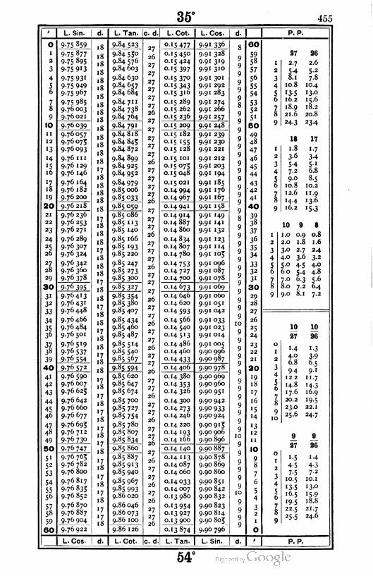
35° 455
L. Sin. L. Tan. c. d. L. Cot. L. Cos. P. P.
9
10
11
12
•3
'4
'516
'718
19
20
21
22
23
24
*S26
27
28
29
30
3'32
33
34
3536
3738
39
40
4"
42
43
44
4546
47
48
49
50 I
5•
52
53
54
5556
5Z58
59
60 I
9-75 859
9-75 877
9-75 895
9-75 9I3
9-75 931
9-75 949
9.75 967
9-75 985
9.76 003
9.76 021
9-76 °39
9.76057
9.76 075
9.76 093
9.76 1n
9.76 129
9.76 146
9.76 164
9.76 182
9.76 200
9.76 218
9.76 236
9-76 253
9.76 271
9.76 289
9.76 307
9.76 324
9-76 342
9.76 360
9-76 378
9-76 395
9-76 4I3
9-76 43 '
9.76 448
9.76 466
9.76 484
9.76 501
9.76519
9-76 537
9-76 554
9-76 572
9.76 590
9.76 607
9.76 623
9.76 642
9.76 660
9.76 677
9.76695
9.76 712
9.76730
9-76 747
9.76 76;
9.76 782
9.76 800
9.76817
9-76 835
9.76852
9.76 870
9.76887
9-7° 9°4
9.76 922
L. Cos.
9.84 523
9.84 550
9.84576
9.84 603
9.84 630
9.84 657
9.84 684
9.84 71 1
9.84 738
9-84 764
9-84 79'
9.84818
9.84 845
9.84 872
9.84 899
9.84 925
9.84 952
9.84979
9.85 006
9-85 033
9-85 °59
9.85 086
9-85 "3
9.85 140
9.85 166
9-85 193
9.85 220
9.85 247
9-85 273
9-85 3°°
9-85 327
9-85 354
9.85 380
9.85 407
9-85 434
9.85 460
9.85 487
9.85 514
9.85 540
9.85 567
9-85 594
9.85 620
9.85 647
9.85 674
9.85 700
9.85 727
9-85 754
9.85 780
9.85 807
9.85 834
9.85 860
9.85 887
9-85 913
9.85 940
9.85 967
9-85 993
9.86 020
9.86 046
9.86 073
9.86 100
9.86 l26
'5 477 9-91 336
15450
15424
15 397
•5 37°
'5 343
'5 316
15289
15 262
'5 236
9-9
9-9
9-9
9-9
9-9
9-9
9-9
9-9
9-9
15 209 9-9
15 182
15 155
15 128
15 101
'5°7515 048
15 021
14994
14967
9-9
9-9
9-9
9-9
9-9
9-9
9-9
9-9
9-9
14 941 9-9
14 914
14887
14860
14834
14807
14 780
'4 75314727
14 700
'4673 9-9
14 646
14 620
H593
14 566
14540
145'3
14486
14 460
H433
328
319
310
301
292
2«3
274
266
257
248
239
230
221
212
203
194
185
176
167
158
'49141
132
123
114
103
096
087
078
069
060
051
042
033
023
014
005
9.90 996
9-9° 987
14 406 9.90 978
14380
'4 353
14326
'4 3°°14273
14 246
14 220
14 '93
14 166
9.90 969
9.90 960
9.90 951
9.90 942
9-9° 9339.90 924
9.90913
9.90 906
9.90 896
14 140 9.90 887
'4 "3
14087
14 060
14033
14 007
13980
'3 95413 927
13900
13874
L. Cot. c. d. L. Tan
9.90 878
9.90 869
9.90 860
9.90851
9.90 842
9.90 832
9.90 823
9.90 814
9.90 805
9-9° 796
L. Sin.
60
59
58
57
56
5S
54
5352
51
50
49
48
47
46
45
44
4342
4'
40
39
38
37
36
35
34
3332
3'
30
29
28
27
26
25
24
23
22
21
20
19
18
17
16
'5
'4
•3
12
11
10
9
8
7
6
5
4
32
27
I 2-7
2 5-4
3 8.1
4 10.8
5 13-5
6 16.2
7 18.9
8 21.6
9 24-3
18
1 1.8
2 3-6
3 5-4
4 7.2
5 9.0
6 10.8
7 12.6
8 14-4
9 16.2
10
26
2.6
5-2
7.8
10.4
13.0
15.6
18.2
20.8
23-4
17
1.7
3-4
5'6.8
8-5
10.2
1 1.9
136
•5-3
1.0
2.0
3.0
4.0
5.0
6.0
7.0
8.0
9.0
9
0.9
1.8
2.7
3-6
4-5
5-4
6-3
7-2
8.1
8
0.8
1.6
2-4
3-2
4.0
4.8
5-6
6.4
7-2
o
I
2
3
4
56
78
910
10 10
27 26
1-4 1.3
4.0 3-9
6.8 6.5
9-4 9-"12.2 11.7
14.8 '4-317.6 16.9
20.2 '9-523.0 22.1
25.6 24-7
9 9
27 26
1-5 1-4
4-5 4-3
7-5 7-2
10.5 10. 1
'3-5 13.0
16.5 '5-9
19-5 18.8
22.5 21.7
25-5 24.6
P. P.
54°
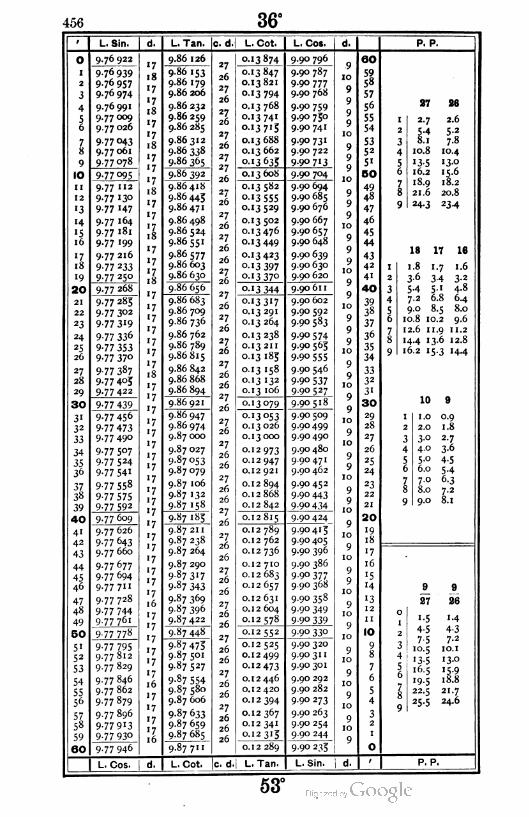
456 36°
o
I
1
3
4
56
78
9
IO
11
12
'3
'4
'516
'718
19
|20
21
22
23
24
25
26
27
28
29
30
3"32
33
34
3536
3738
39
40
41
42
43
44
45
46
4748
49
50
51
52
53
54
5556
5758
59
60
L, Sin.
9.76 922
9-76 939
9.76957
9.76974
9.76991
9.77009
9.77 026
9 77 °439.77 061
9-77 078
9-77 °95
9.77 112
9.77 130
9 77 147
9.77 164
9.77 181
9.77 199
9.77216
9-77 233
9-77 25°
9.77 268
9.77 283
9.77 302
9-77 3'9
9-77 336
9-77 353
9-77 37°
9-77 387
9-77 4°59-77 422
9-77 439
9.77456
9-77 4739.77 490
9.77 507
9-77 524
9-77 541
9-77 558
9-77 5759-77 592
9.77609
9.77 626
9-77 643
9.77 660
9-77 677
9.77 694
9.77 711
9-77 728
9-77 744
9.77 761
9-77 778
9-77 7959.77 812
9.77 829
9.77 846
9.77 862
9.77879
9-77 896
9-77 913
9-77 93°
9-77 946
L. Cos. I d.
L. Tan.
9.86 126
c. d.| L. Cot.
0.13874
9.86 153
9.86 179
9.86 206
9.86 232
9.86 259
9.86 285
9.86312
9.86 338
9-86 365
9.86392
9.86418
9-86 443
9.86 471
9.86 498
9.86 524
9.86551
9.86577
9.86 603
9.86 630
9.86 656
9.86 683
9.86 709
9.86 736
9.86 762
9.86 789
9.86815
9.86 842
9.86 868
9.86 894
9.86 921
9.86 947
9.86 974
9.87 000
9.87 027
9.87 053
9.87 079
9.87 106
9.87 132
9.87 158
9-87 '83
9.87 21 1
9.87 238
9.87 264
9.87 290
9-87 3I7
9-87 343
9.87 369
9.87 396
9.87422
9-87 448
9-87 473
9.87 501
9.87527
9-87 554
9.87 580
9.87 606
9-87 633
9.87 659
9.87 685
9-87 7"
L. Cot.
3847
3821
3 794
3 768
3 741
37'5
3688
3 662
3 635
3608
3 582
3 5553 529
3502
3 476
3 449
3 423
3 397
3 37°
3 344
3 3173291
3 264
3238
32II
3183
3'58
3 132
3 '06
3°79
3 053
3026
3 000
2 973
2 947
2 921
2 894
2868
2815
2 789
2 762
2736
2 710
2683
2657
2631
2 604
2 578
2552
2525
2499
2 473
2 446
2 420
2 394
2367
2 34£
2315
0.12 289
c. d. L. Tan,
L. Cos.
9.90 796
9.90 787
9.90 777
9.90 768
9.90 759
9.90 730
9.90 741
9.90 731
9.90 722
9-9° 7' 3
9.90 704
9.90 694
9.90 685
9.90 676
9.90 667
9.90 657
9.90 648
9.90 639
9.90 630
9.90 620
9.90 611
9.90 602
9.90 592
9.90 583
9-90 574
9.90 563
9-9o 555
9.90 546
9-9° 5379-90 527
9.90 518
9.90 509
9.90499
9.90 490
9.90 480
9.90471
9.90 462
9.90 452
9-9° 443
9-90 434
9.90 424
9.90413
9.90 405
9.90 396
9.90 386
9-90 377
9.90 368
9.90 358
9-90 349
9 90 339
9.90 330
9.90 320
9.90 311
9.90 301
9.90 292
9.90 282
9.90 273
9.90 263
9.90 254
9 90 244
9.90 233
L. Sin.
60
59
58
57
56
55
54
5352
5'
00
49
48
47
46
45
44
4342
4"
40
39
38
37
36
35
34
3332
3'
30
29
28
27
26
25
24
23
22
21
20
•9
18
17
16
15
'4
P. P.
27 28
I 2-7 2.6
2 5-4 5-2
3 8.1 7.8
4 10.8 10.4
5 '3-5 13-0
6 16.2 15.6
7 18.9 18.2
8 21.6 20.8
9 24-3 23-4
18 17 16
1.8 1.7 1.6
3-6 3-4 3-2
5.4 5.1 4.8
7.2 6.8 6.4
9.0 8.5 8.0
10.8 10.2 9.6
12.6 11.9 11.2
14.4 13.6 12.8
16.2 15.3 14.4
10 8
I 1.0 0.9
2 2.0 1.8
3 3-° 2.7
4 4.0 3-6
5 5.0 4-5
6 6.0 5-4
7 7.0 6-3
8 8.0 7-2
9 9.0 8.1
9 9
27 26
1.5 M
4-5 4-3
7-5 7-2
10.5 IO.I
'3-5 13.0
16.5 '5-9
"9-5 18.8
22.5 21.7
25-5 24.6
P. P.
53°

37° 457
1 L. Sin. d. L.Tan. c. d. L. Cot. L. Cos. d. P. P.
o 9.77 94617
«7
'7
9.87 71127
26
26
0.12 289 9.90 23310 60
' 9-77 963 9.87 738
9.87 764
9.87 790
9.87817
9.87 843
9.87 869
0.12 262
0. 1 2 236
0.12 210
0.12 183
0.12 157
0.12 131
0.12 105
0.12 078
0.12 052
9.90 225
9.90 216
9.90 206
9.90 197
9.90 187
9.90 178
9.90 168
9.90 159
9.90 149
910
59
58
57
56
55
54
2 9.77 980
3
4
56
9-77 997
9.7801316 27
26
26
26
9
1027 26
9.78 030
9.78047
9.78063
9.78080
9.78097
17
'7
16
9
10
1 2.7 2.6
2
3
4
54 5-2
8.1 7.878
«717
16
9.87 895
9.87 922
9.87 948
27
26
26
26
910
10
5352
51
50
10.8 10.4
95 13-5 i3-°
16.2 15.6IO 9-78 "3
179.87 974 0. 1 2 026 9.90 139
9
10
6
18.9 18.2
21.6 20.8
24-3 23.4
ii 9.78 130
9.78 147
9.78 163
9.78 180
9.78 197
9.78213
9.78 230
9.78 246
9.78 263
'716
9.88000
9.88027
9.88053
9.88079
9.88 105
9-88 131
9.88 158
9.88 184
9.88 210
27
26
0.12 000
0.1 1 973
0.1 1 947
0.11 921
0.1 1 895
0.1 1 869
0.1 1 842
0.11 816
0.1 1 790
9.90 130
9.90 120
9.90 1 1 1
9.90 'O'
9.90091
9.90 082
9.90072
9.90 063
9.90 053
49
48
78
129
10
10
47
46
45
44
9'3
H
«516
17 26
26
26«716 9
1017
«7
16
27
26
26
26
26
910
10
43
42
41
40
17 16
18'7
'7
16
1 1.7 1.6
19
20
2
3
4
56
34 3-2
5.1 4.89.78 280 9.88 236 0.1 1 764 9.90 0439
10
10
6.8 6.4
8.5 8.021
22
23
24
25
26
9.78 29617
16
9.88 262
9.88 289
988315
9.88 341
9.88 367
9-88 393
9.88 420
9.88 446
9.88472
27
26
o.i 1 738
0.11 711
0.1 1 685
9.90034
9.90 024
9.90014
9.90 005
9.89 995
9.89 985
9.89 976
9.89 966
9.89 956
39
38
37
36
35
34
978313
9.78 32910.2 9.6
1 1.9 1 1.2
13.6 12.8
15-3 '44
9.78 346
9.78 362
9-78 379
17
16
26
26
26
0.1 1 6599
10
10
7
0.1 1 633
0.1 1 607
0.1 1 580
0.1 1 554
0.1 1 528
8
17
16
9
27 9-78 395
9.78412
9.78 428
17
16
27
26
26
26
26
26
9
10
10
3332
3«
30
28
29
30 9.7844517
169.88 498 0.1 1 502 9.89 947
9
10
10
10 9
31 9.78 461
9.78478
9.78 494
17
16
9.88 524
9.88 550
9.88 577
9.88 603
9.88 629
9.88 653
9.88 681
9.88 707
9-88 733
0.1 1 476
0.1 1 430
0.1 1 423
9-89 937
9.89927
9.89 918
9.89 908
9.89 898
9.89 888
9.89 879
9.89 869
9.89 859
29
28
27
26
25
24
1 1.0 0.9
2.0 1.8
3.0 2.7
4.0 3.6
5.0 4.5
6.0 5.4
7.0 6.3
8.0 7.2
9.0 8.1
32
33
34
353*3
27
26
26■26
26
26
26
26
92
3
49.78510
9.78527
9-78 543
9.78 560
9.78576
9.78592
1601 1 397
0.11 371
0.1 1 345
0.1 1 319
0.1 1 293
0.1 1 267
'O
17
16
10
10 56
3738
39
40
41
42
43
44
45
46
17
16
16
17
16
9
10
10
10
23
22
21
20
78
9.78 609 9.88 75927
26
26
26
26
26
26
26
26
26
26
27
26
26
26
26
26
26
26
26
0.1 1 241 9.89 8499
10
10
10
9
9.78 625
9.78 642
9.78658
9.78674
9.78 691
9.78 707
9.78 723
«716
9.88 786
9.88812
9.88 838
9.88 864
9.88 890
9.88916
9.88 942
9.88 968
9.88 994
0.1 1 214
0.11 188
0.11 162
0.1 1 136
0.1 1 no
0. 1 1 084
o.i 1 058
0.1 1 032
0.1 1 006
9.89 840
9.89 830
9.89 820
9.89 810
9.89 801
9.89 791
19
18
16'7
1617
16
910 '5 10 10
169.89781
9.89771
9.89 761
10
10
10
H27 26
47
48 9-78 739
9.78 756
1613
1 2
1 1
0
1
2
3
4
1.4 i-3
4-o 3-9
6.8 6.5
9.4 9.1
12.2 1 1.7
14.8 14.3
17.6 16.9
20.2 19.5
23.0 22.1
25.6 24.7
49
9.78 772
'716
9.89 020 0.10980 9.89 7529
10
10
10
10
10
IO50 1651
52
53
54
5556
5758
59
60
9.78 788
9.78 803
9.78 821
'7
9.89 046
9.89 073
9.89 099
9.89 125
9.89 151
9.89 177
9.89 203
9.89 229
9 89 255
0.10954 9.89 742
9.89732
9.89 722
9.89 712
9.89 702
9.89 693
9.89 683
9.89673
9.89 663
9
816
0.10 927
0.10 9015
978837
9.78853
9.78869
9.78 886
9.78 902
9.78918
16
16
16
0.10875
7 6
6 78
'7
16
16
16
0.10 849
0.10 823
0.10 797
0.10 771
0.10745
9
10
10
10
10
5
4 910
32
9 78 934 9.89 281 0.10 719 9.89 653 O
| L. Cos. | d. L. Cot. c. d. L. Tan. L. Sin. d.' P. P.
52°

458 38°
i L. Sin. d. L. Tan.
0 9-78 93416
9.S9 281
I 9.78 950'716
9.89 307
2 9.78 967 9-89 333
3 9.7898316
9-89 359
4 9.7899916
9.89 385
5 9.7901516
9.89 41 1
6 9.7903116
9-89 437
7 9.79 04716
9.89 463
8 9.79 06316
9.89 489
9 9.79 07916
9.89515
10 9.7909516
9.89 541
II 9.79 m
'716
9.89 567
12 9.79 128 9-89 593
'3 9.79 144if.
9.89 619
'4 9.79 1601 O
169.89 645
'5 9.79 17616
9.89671
16 9.79 192if.
9.89 697
'7 9.79 208to
169-89 723
18 9.79 22416
9.89 749
19 9.79 24016
9-89 775
20 9.79 25616
9.89 801
21 9.79 272if.
9.89 827
22 9.79 28810
9.89 853
23 9-79 3°416
9.89 879
24 9-79 319 '5
169.89 903
2S 9-79 335 if.9.89 931
26 9-79 35'1 O
if,9.89 957
2l9-79 367
ID
tf.9.89 983
28 9-79 383IO
l69.90 009
29 9-79 399l6
9-9° 035
30 9-79415l6
9.90 061
31 9-79 431l6
9.90 086
32 9-79 447 if.9.90 1 1 2
33 9-79 463IO
9.90 138
34 9.79 478 '5
169.90 164
35 9-79 494 if.9.90 190
36 9.795101 O
tf.9.90 216
37 9.79 52610
if.9.90 242
38 9.79 542101f.
9.90 268
39 9-79 558ID
9-9° 294
40 9-79 57315
169.90 320
41 9-79 5891f,
9.90 346
42 9.79 6051O
169.90371
43 9.79 621 9-9° 397
44 9.79 636 '5
169.90423
45 9.79 652if.
9.90 449
46 9.79 6681 -
169.90475
47 9.79 684
'516
9.90 501
48 9.79 699 9.90527
49 9-79 7"516
9-9° 553
50 9-79 731 9.90 578
5• 9.79 746'5tf.
9.90 604
52 9.79 7621 0
if.9.90 630
53 9.79 7781O
9.90 656
54 9-79 793I5
1f.9.90 682
55 9.79 8091 O
9.90 708if,
56 9.79 82510
9-9° 734
57 9.79 840•5
169.90 759
58 9.79 85616
9.90 785
59 9.79 872 9.90 81 1
60 9.79 887I c "9"9o-E837"
L. Cos. d. L. Cot.
0.10 719
0.10 693
0.10 667
0.10 641
0.10 615
0.10 589
0.10 563
0.10537
0.10 51 1
0.10483
0.10 459
°-1°433
0.10 407
0.10 381
0.10355
0.10 329
0.10303
0.10 277
0.10 251
0.10 223
0.10 199
0.10 173
0.10 147
O.IO 121
0.10095
0.10069
0.10043
0.10017
0.09 991
0.09 965
0-09 939
0.09 914
0.09 888
0.09 862
0.09 836
0.09 810
0.09 784
0.09 758
0.09 732
0.09 706
0.09 680
0.09 654
0.09 629
0.09 603
0.09 577
0.09551
0.09 525
0.09 499
0.09 473
0.09 447
0.09 422
0.09 396
0.09 370
0.09 344
0.09 318
0.09 292
0.09 266
0.09 241
0.09 213
0.09 189
0.09 163
c. d.1 L. Tan.
L. Cos.
9-89 653
9.89 643
9-89 633
9.89 624
9.89 614
9.89 604
9.89 594
9.89 584
9.89 574
9.89564
9-89 554
9.89 544
9-89 534
9.89 524
9.89514
9.89 504
9.89 493
9.89 483
9.89 473
9-89 463
9-89 455
9.89 443
9-89 435
9.89 423
9.89415
9.89 403
9-89 395
9.89 385
9-89 375
9.89 364
9-89 354
9-89 344
9-89 334
9.89 324
9.89 314
9.89 304
9.89 294
9.89 284
9.89 274
9.89 264
9.89 254
9.89 244
9 89 233
9.89 223
9.89213
9.89 203
9.89 193
9.89 183
9-89 173
9.89 162
9.89 152
9.89 142
9.89 132
9.89 122
9.89 112
9.89 101
9.89 091
9.89 081
9.89 071
9.89 060
9-89 05°
L. Sin. I d.
d.
60
59
58
57
56
55
54
5352
5'
BO
49
48
47
46
45
44
43
42
4'
40
39
3«
37
36
35
34
3332
31
30
29
28
27
26
25
24
23
22
21
20
'918
17
16
'514
13
1 2
11
10
98
7
6
5
4
32
P. P.
28 as
I 2.6 2-5
2 5-2 5-°
3 7.8 7-5
4 10.4 10.0
5 13.0 12.5
6 15-6 15.0
7 18.2 '7-58 20.8 20.0
9 23-4 22.5
17
1-7
3-4
5-1
6.8
8-5
10.2
1 1.9
16
1.6
3-2
IS
4.8
6.4
8.0
9.6
1 1.2 10.5
13.6 12.8 12.0
15.3 14.4 13.5
1.5
3.0
4-56.0
7-59.0
11 10 9
I 1.1 1.0 0.9
2 2.2 2.0 1.8
3 3-3 3-o 2.7
4 4.4 4.0 3-6
5 5-5 5-o 4-5
6 6.6 6.0 5-4
7 7-7 7.0 6-3
8 8.8 8.0 7.2
9 9-9 9.0 8.1
10 10 9
26 25 26
1-3 1.2 1.4
3-9 3-8 4-3
6.5 6.2 7-2
9-' 8.8 10.1
11.7 1 1.2 13.0
14-3 13-8 15.9
16.9 16.2 18.8
19-5 18.8 21.7
22.1 21.2 24.6
24.7 23.8 —
P. P.
51°
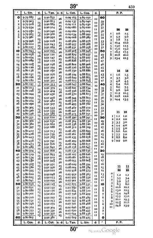
39° 459
o
'
2
3
4
56
78
9
10
ii
12
13
14
«516
'718
19
20
21
22
23
24
25
26
27
28
29
30
3'32
33
34
3536
3738
39
40
41
42
43
44
45
46
47
48
49
50
51
52
53
54
5556
5758
59
60
L. Sin.
9-79 887
9-79 9°39.79918
9-79 934
9.79 950
9.79 965
9.79 981
9.79 996
9.80012
9.80027
9.80043
9.80 058
9.80074
9.80 089
9.80 105
9.80 120
9.80 136
9.80 151
9.80 166
9.80 182
9.80 197
9.80213
9.80 228
9.80 244
9.80 259
9.80 274
9.80 290
9.80 305
9.80 320
9.80 336
9.80 366
9.80 382
9.80 397
9.80412
9.80 428
9.80443
9.80458
9.80 473
9.80 489
9.80 504
9.80 519
9.80 534
9.80 550
9.80 563
9.80 580
9.80 595
9.80 610
9.80 625
9.80 641
9.80 656
9.80 671
9.80 686
9.80 701
9.80 716
9.80 731
9.80 746
9.80 762
9.80 777
9.80 792
9.80 807
L. Cos.
L. Tan.
990 837
9.90 863
9.90 889
9.90914
9.90 940
9.90 966
9.90 992
9.91 018
9.91 043
9.91 069
9-91 095
9.91 121
9.91 147
9.91 172
9.91 198
9.91 224
9.91 250
9.91 276
9.91 301
9-91 327
9-9' 353
9-91 379
9.91 404
9.91 430
9.91 456
9.91 482
9.91 507
9-91 533
9.91 559
9-9' 585
9.91 610
9.91 636
9.91 662
9.91 688
9-91 713
9-91 739
9.91 765
9.91 791
9.91 816
9.91 842
9.91 868
9.91 893
9.91 919
9-91 943
9.91 971
9.91 996
9.92 022
9.92 048
9.92 073
9.92 099
9.92 125
9.92 150
9.92 176
9.92 202
9.92 227
9.92 253
9.92 279
9.92 304
9.92 330
9.92 356
9-92 381
L. Cot.
c. d,
26
26
25
26
26
26
26
25
26
26
26
26
25
26
26
26
26
25
26
26
26
25
26
26
26
25
26
26
26
25
26
26
26
25
26
26
26
25
26
26
25
26
26
26
25
26
26
25
26
26
25
26
26
25
26
26
25
26
26
25
cTd
L. Cot.
0.09 163
0.09 137
0.09 1 1 1
0.09 086
0.09 060
0.09 034
0.09 008
0.08 982
0.08 957
0.08 931
0.08 903
0.08 879
0.08 853
0.08 828
0.08 802
0.08 776
0.08 750
0.08 724
0.08 699
0.08 673
0.08 647
0.08 621
0.08 596
0.08 570
0.08 544
0.08518
0.08 493
0.08 467
0.08 441
0.08 415
0.08 390
0.08 364
0.08 338
0.08 312
0.08 287
0.08 261
0.08 235
0.08 209
0.08 184
0.08 158
0.08 132
0.08 107
0.08 081
0.08 055
0.08 029
0.08 004
0.07 978
0.07 952
0.07 927
0.07 901
007875
0.07 850
0.07 824
0.07 798
0.07 773
0.07 747
0.07 721
0.07 696
0.07 670
0.07 644
0.07 619
L. Tan.
L. Cos.
9.89 050
9.89 040
9.89 030
9.89 020
9.89 009
9.88 999
9.88 989
9.88978
9.88 968
9.88 958
9.88 948
9.88937
9.88 927
9.88917
9.88906
9.88 896
9.88 886
9.88 875
9.88 865
9.88853
9.88 844
9-88834
9.88 824
9.88813
9.88 803
9.88 793
9.88 782
9.88 772
9.88 761
9.88 751
9.88 741
9.88 730
9.88 720
9.88 709
9.88 699
9.88 688
9.88 678
9.88 668
9.88 657
9.88 647
9.88 636
9.88 626
9.88615
9.88 605
9.88 594
9.88 584
9-88 573
9.88 563
9.88 552
9.88 542
9.88531
9.88521
9.88510
9.88 499
9.88 489
9.88478
9.88 468
9.88457
9.88 447
9.88436
9.88 425
L. Sin. d.
60
5958
57
56
55
54
5352
51
50
49
48
47
46
45
44
4342
4i
40
3938
37
36
35
34
3332
3«
30
29
28
27
26
25
24
23
22
21
20
«918
'7
16
15
i4
13
12
11
10
98
7
6
5
4
32
1
O
P. P.
2.6
5-2
7.8
10.4
13.0
15.6
18.2
20.8
234
16
1.6
3-2
4.8
64
8.0
9.6
ii.2
12.8
«44
H 10
1.1 1.0
2.2 2.0
3-3 3-o
44 4-o
5-5 5-°6.6 6.0
7.7 7.0
8.8 8.0
9.9 9.0
o
1
2
3
4
56
78
910
11
11
26
1.2
3-5
8-3
10.6
13.0
«54
17.7
20.1
22.3
24.8
P. P.
50°
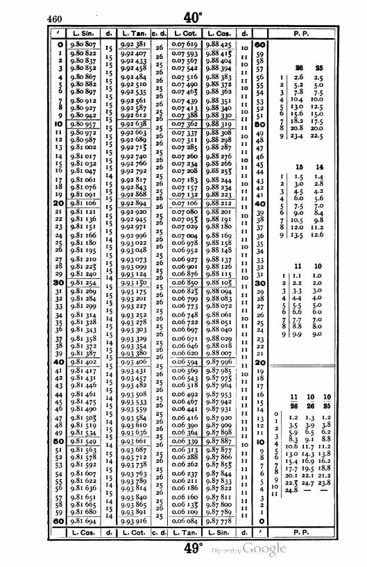
460 40°
o
I
2
3
4
I
78
9
10
11
12
"3
'4
'516
'718
'9
|20|
21
22
23
24
25
26
27,
28
29
|80|
3"
32
33
34
3536
3?,38
39
|40|
4"42
43
44
45
46
47
48
49
IBOI
51
52
53
54
5556
57
58
59
1601
L. Sin,
9.80 807
9.80 822
9.80837
9.80 852
9.80 867
9.80 882
9.80 897
9.80 912
9.80927
9.80 942
9-80 957
9.80972
9.80 987
9.8
9.8
9-8
9-8
9.8
9.8
9.8
9-8
9.8
9.8
9-8
9.8
9.8
9.8
9-8
9.8
9.8
9.8
9.8
9.8
9.8
9.8
9.8
9.8
9.8
9.8
9.8
9.8
9.8
9.8
9.8
9-8
9.8
9.8
9.8
9.8
9.8
9.8
9.8
9.8
9.8
9.8
9.8
9.8
9.8
9.8
9.8
017
032
047
061
076
091
106
121
'36
'51
166
180
'95
210
225
240
254
269
284
299
3 '4
328
343
358
372
387
402
417
43'446
461
475
490
5°3519
534
549
563
578
592
607
622
636
651
665
680
694
L. Cos.
L. Tan. Ic. d
9-92 381
9.92 407
9-92 433
9.92 458
9.92 484
9.92 510
9-92 535
9.92 561
9.92 587
9.92 612
9.92 638
9.92 663
9.92 689
9.92715
9.92 740
9.92 766
9.92 792
9.92817
9.92 843
9.92 868
9.92 894
9.92 920
9.92 945
9.92971
9.92 996
9.93 022
9.93 048
9-93 073
9-93 °999-93 I24
9-93 '3o
9-93 '759.93 20 1
9.93 227
9.93 252
9.93 278
9-93 3°3
9-93 329
9-93 3549-93 380
9.93 406
9-93 43 1
9-934579.93 482
9-93 5°8
9-93 533
9-93 559
9-93 584
9.93 610
9-93 636
9.93 661
9.93 687
9-93 712
9-93 738
9-93 763
9-93 789
9.93814
9-93 840
9.93 865
9-93 89'
9.93916
d. I L. Cot. |c. d
26
26
25
26
26
*5
26
26
25
26
25
26
26
25
26
26
25
26
25
26
26
25
26
25
26
26
25
26
25
26
25
26
26
25
26
25
26
25
26
26
25
26
25
26
25
26
25
26
26
25
26
25
26
25
26
25
26
25
26
25
L. Cot. L. Cos. d.
0.07 619 9.8842510
60
0.07 593 9.88413
j'
590.07 567 9.88 404 58
0.07 542 9.88 394 57
0.07 516 9.88 383 56
0.07 490 9.88 3721n 55
0.07 465 9.88 362 54
0.07 439 9.88 351 530.07413 9.88 340
1n52
0.07 388 9-88 330 5"
0.07 362 9-88319 50
0-07 337 9.88 308 490.07 31 1 9.88 298 48
0.07 285 9.88 287 47
0.07 260 9.88276 46
0.07 234 9.88 266 450.07 208 9-88 253 44
0.07 183 9.88 244 430.07 157 9-88 234 42
0.07 132 9.88 223 4'
0.07 106 9.88212 40
0.07 080 9.88 201 390.07 055 9.88 191 38
0.07 029 9.88 180 37
0.07 004 9.88 169 36
0.06 978 9.88 158 350.06 952 9.88 148 34
0.06 927 9.88 137 330.06 901 9.88 126 32
0.06 876 9-88115IO 3'
0.06 850 9.88 103 30
0.06 823 9.88 094 29
0.06 799 9.88 083 28
0.06 773 9.88072 27
0.06 748 9.88 061 26
0.06 722 9.88 051 25
0.06 697 9.88 040 24
0.06 671 9.88 029 23
0.06 646 9.88018 22
0.06 620 9.88 007 21
0.06 594 9.87 996 20
0.06 5699-87 985 IO '9
0.06 543 9-87 975 „ 18
0.06 5 1 8 9.87 964 17
0.06 492 9-87 953 16
0.06 467 9.87 942 15
0.06 441 9-87 93I '4
0.06 416 9.87 920 '30.06 39O 9.87 909 12
0.06 364 9.87 898 II
0.06 339 9.87 887IO 10
0.06313 9.87877 90.06 288 9.87 866 8
0.06 262 9.87 8537
0.06 237 9.87 844 6
0.06 211 9-87 833 50.06 186 9.87822 4
0.06 160 9.87 811 30.06 133 9.87 800 2
0.06 109 9.87 789 1
0.06 084 9.87 77S O
L. Tan. L. Sin. d.
P. P.
M
I 2.6 2-5
2 5-2 5°
3 7.8 7-5
4 10.4 10.0
5 13.0 12.5
6 15.6 15.0
7 18.2 '7-58 20.8 20.0
9 23-4 22.5
15 14
1 1.5 M
2 3° 2.8
3 4-5 4.2
4 6.0 5-6
5 7-5 7,-°6 9.0 u
7 10.5 98
8 12.0 11. 2
9 '3-5 12.6
11 10
1 1.1 1.0
2 2.2 2.0
3 3-3 3-o
4 4.4 4.0
5 5-5 5-o
6 6.6 6.0
7 7-7 7.0
8 8.8 8.0
9 9-9 9.0
11 10 10
26 26 25
1.2
3-5
8-3
10.6
1.3
3-9
6.5
9'11.7
•3° '4-3
15.4 16.9 16.2
17.7 19.5 18.8
20.1 22.1 21.2
22.3 24.7 23.8
24.8 — —
P. P.
49°
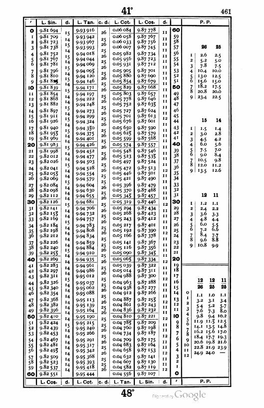
41° 461
L. Sin. d. I L. Tan. c. d. L. Cot. L. Cos. P. P.
2
3
4
56
78
9
10
11
12
'3
14
'516
17
18
'9
|20
21
22
23
24
25
26
2Z28
29
| 30
3'32
33
34
3536
3Z38
39
|40
4"
42
43
44
4546
47
48
49
I5O
5"52
53
54
5556
5758
59
60
9.81 694
9.81 709
9-81 723
9.81 738
9.81 752
9.81 767
9.81 781
9.81 796
9.81 810
9.81 825
9.81 839
9.81 854
9.81 868
9.81 882
9.81 897
9.81 911
9.81 926
9.81 940
9-81 953
9.81 969
9.81 9»j
9.81 998
9.82 012
9.82 026
9.82 041
9.82 053
9.82 069
9 82 084
9.82 098
9.82 112
9.82 126
9.82 141
9.82 155
9.82 169
9.82 184
9.82 198
9.82 212
9.82 226
9.82 240
9-82 25;
9.82 269
9.82 283
9.82 297
9-82311
9.82 326
9.82 340
9-82 354
9.82 368
9.82 382
9.82 396
9.82 410
9.82 424
9.82439
9-82 453
9.82 467
9.82 481
9.82 495
9.82 509
9.82 523
9-82537
9-82551
L. Cos.
9.93916
9-93 942
9-93 967
9-93 993
9.94 018
9.94 044
9.94 069
9-94 095
9.94 120
9-94 146
9-94 171
9.94 197
9.94 222
9.94 248
9-94 273
9.94 299
9-94 324
9-94 33°
9-94 3759.94 401
9.94 426
9.94 452
9-94 477
9-94 5°3
9.94528
9-94 554
9-94 579
9.94 604
9.94 630
9-94 655
9.94 681
9.94 706
9-94 732
9-94 757
9-94 783
9.94 808
9-94 834
9-94 859
9.94 884
9.94910
9-94 935
9.94961
9-94 986
9.95 012
9-95 °379.95 062
9.95 088
9-95 "3
9-95 "399-95 l64
9-95 I9g
9-95 215
9.95 240
9.95 266
9.95 291
9-95 317
9-95 342
9.95 368
9-95 3939-95 418
9-95 444
L. Cot.
0.06 084 9-87 778
0.06 058
0.06 033
0.06 007
0.05 982
0.05 956
0.05931
0.05 905
0.05 880
0-05 854
9.87 767
9.87 756
9-87 745
9-87 734
9-87 723
9.87 712
9.87 701
9.87 690
9 87 679
0.05 829 9.87 668
0.05 803
0.05 778
0.05 752
0.05 727
0.05 701
0.05 676
0.05 650
0.05 625
0-05 599
9.87 657
9.87 646
9-87 633
9.87 624
9.87613
9.87 601
9.87 590
9 87 579
9.87 568
°-°5 574 9-87 557
0.05 548
0.05 523
0.05 497
0.05 472
0.05 446
0.05 421
0.05 396
0.05 370
0-05 345
9.87 546
9-87 533
9-87 524
9-87 5'3
9.87 501
9.87 490
9.87 479
9.87 468
9-87 457
o°5 3'9 9-87 446
0.05 294
0.05 268
0.05 243
0.05 217
0.05 192
0.05 166
0.05 141
0.05 116
0.05 090
9 87 434
9-87 423
9.87412
9.87 401
9.87 390
9-87 378
9.87 367
9.87 356
9-87 343
0.05 065 9-87 334
0.05 039
0.05 014
0.04 988
0.04 963
0.04 938
0.04 912
0.04 887
0.04 861
0.04 836
9.87 322
9.87 3U
9.87 300
9.87 288
9.87 277
9.87 266
9-87 253
9 87 243
9.87 232
0.04 810 9.87 221
0.04 783
0.04 760
0.04 734
0.04 709
0.04 683
0.04 658
0.04 632
0.04 607
0.04 582
0-04 556
c. d.l L. Tan.
9.87 209
9.87 198
9.87 187
9.87 175
9.87 164
987 153
9.87 141
9.87 130
9-87 "9
9.87 107
L. Sin.
60
59
58
57
5°
55
54
5352
51
BO
49
48
47
46
45
44
4342
4'
40
3938
37
36
35
34
3332
31
30
29
28
27
26
25
24
23
22
21
20
'918
'7
16
'5
'4
"312
11
10
9
8
7
6
5
4
3
I 2.6 2-5
2 5-2 5-°
3 7.8 7-5
4 10.4 10.0
5 •3° 12.5
6 15.6 '5-°
7 18.2 '7-58 20.8 20.0
9 23-4 22.5
16 14
1 1-5 1.4
2 3° 2.8
3 4-5 4.2
4 6.0 5.6
5 7-5 7.0
6 9.0 8-4
7 10.5 9.8
8 12.0 11. 2
9 '3-5 12.6
19 11
1 1.2 1.l
2 2.4 2.2
3 3-6 3-3
4 4-8 4-4
5 6.0 s-56 7-2 6.6
7 8-4 7-18 9.6 8.8
9 10.8 9-9
12 12 11
26 25 26
1.1 I.O I.I
3-2 3-1 3-4
5-4 S-2 5-77.6 7-3 8.0
9.8 9.4 10.2
11.9 1 1.3 12.5
14. 1 13.5 14.8
16.2 15.6 17.0
18.4 17-7 '9-3
20.6 19.8 21.6
22.8 21.9 23.9
24.9 24.0 —
P. P.
48'

462 42°
L. Sin. d. I L. Tan. c. d L. Cot. L. Cos. P. P.
O
1
2
3
4
5o
78
9
10
II
12
"3
"4
'516
"718
19
20
21
22
23
24
-526
27
28
29
I 30
3'32
33
34
3536
3738
39
40
41
42
43
44
4546
47
48
49
50
5'52
53
54
5556
5758
59
60
9-82 55I
9.82 565
9.82 579
9-82 593
9.82 607
9.82 621
9.82 635
9.82 649
9.82 663
9-82 677
9.82 691
9.82 705
9.82719
9-82 733
9.82 747
9.82 761
9.82 773
9.82 788
9.82 802
9.82816
9.82 830
9.82 844
9.82 858
9.82 872
9.82 885
9.82 899
9.82913
9.82 927
9.82 941
9-82 955
9.82 968
9.82 982
9.82 996
9.83 010
9.83 023
9-83 °37
9.83 051
9.83 063
9.83 078
9.83092
9.83 106
9.83 120
9-83 133
9-83 147
9.83 161
9-83 174
9.83 188
9.83 202
9-83215
9 83 229
9.83 242
9.83 256
9.83 270
9.83 283
9.83 297
9 83 3'°
9-83 324
9-83 338
9-83 35 1
9 83 365
9-83 378
9-95 444
9.95 469
9-95 495
9.95 520
9-95 545
9-95 57'9.95 596
9.95 622
9.95 647
9-95 672
9-95 698
9-95 723
9-95 748
9-95 774
9-95 799
9-95 823
9.95 850
9-95 875
9.95 901
9-95 926
9-95 952
9-95 9779.96002
9.96028
9.96053
9.96 078
9.96 104
9.96 129
9.96 153
9.96 180
9.96 205
9.96 231
9.96 256
9.96 281
9.96 307
9-96 332
9-96 357
9-96 383
9.96 408
996 433
9-96 459
9.96484
9.96 510
9-96 535
9.96 560
9.96 586
9.96 61 1
9.96 636
9.96 662
9.96 687
9.96 712
9.96 738
9.96 763
9.96 788
9.96 814
9.96 839
9.96 864
9.96 890
9.96915
9.96 940
9.96 966
0.04 556 9.87 107
0.04531
0.04 505
0.04 480
0.04453
0.04 429
0.04 404
0.04 378
0-04 353
0.04 328
0.04 302
0.04 277
0.04 252
0.04 226
0.04 201
0.04 175
0.04 1 50
0.04 123
0.04 099
0.04 074
9.87 096
9.87 083
9-8707j
9.87 062
9.87 050
9.87 039
9.87028
9.87 016
9.87 003
9-86 993
9.86 982
9.86 970
9.86 959
9.86 947
9.86 936
9.86 924
9.86913
9.86 902
9.86 890
0.04 048 9.86 879
0.04 023
0.03 998
0.03 972
0.03 947
0.03 922
0.03 896
0.03 871
0.03 845
0.03 820
0 03 795
9.86 867
9.86 855
9.86 844
9.86 832
9.86 821
9.86 809
9.86 798
9.86 786
9-86 775
9-86 763
0.03 769
0.03 744
0.03719
0.03 693
0.03 668
0.03 643
0.03617
0.03 592
0-03 567
9.86 752
9.86 740
9.86 728
9.86 717
9.86 705
9.86 694
9.86 682
9.86 670
9.86 659
0 03 54' 9.86 647
0.03516
0.03 490
0.03 465
0.03 440
0.03414
0.03 389
0.03 364
0.03 338
003313
0.03 288
9.86635
9.86 624
9.86612
9.86 600
9.S6 589
9.86 577
9.86 565
986554
9.86 542
0.03 262
0.03 237
0.03 212
0.03 186
0.03 161
0.03 136
0.03 1 10
0.03 085
0.03 060
9.86530
0.03 034
9.86518
9.86 507
9.86 495
9.86483
9.86 472
9.86 460
9.86 448
9.86 436
9.86 423
9.86413
60
5958
57
56
55
54
5352
5"
BO
494S
47
46
45
44
43
42
4"
40
3938
37
36
35
34
3332
3'
30
29
28
27
26
25
24
23
22
21
20
19
18
'7
16
1514
13
12
11
10
9
8
7
6
5
4
32
0
26
2.6
5-2
7.8
10.4
1 30
15.6
18.2
20.8
23-4
14 IS
I M •-3
2 2.8 2.6
3 4.2 3-9
4 5.6 5-2
5 7.0
6 8.4 7.8
7 9.8 9-'8 11. 2 10.4
9 12.6 1 1.7
12 11
1 1.2 l.1
2 2.4 2.2
3 3-6 3-3
4 4-8 4-4
5 6.0 5-56 7.2 6.6
7 8.4 7-7
8 9.6 8.8
9 10.8 9-9
is
1.1
3.2
5-4
7.6
9.8
1 1.9
14.1
16.2
°o18.4" ' 20.6
°22.8
11 11
26 25
1.2 1. 1
3-5 3-4
5-9 5-78.3 8.0
10.6 10.2
13.0 12.5
15.4 14.8
17.7 17.0
20.1 19.3
22.3 21.6
24.8 23.9
24.9
L. Cos. L. Cot. c. d.| L. Tan. L. Sin. d. P. P.
47°

43° 463
O
1
2
3
4
56
78
9
10
11
12
'3
J4
'516
ll
18
19
¡20
21
22
23
24
25
26
27
28
29
|30
3'32
33
34
3536
3738
39
40
41
42
43
44
45
46
47
48
49
|50
5'52
53
54
5556
5758
59
|60
L. Sin,
9-83 378
9-83 392
9.83 405
9.83 419
9-83 432
9.83 446
9-83 459
9-83 473
9.83 486
9 83 3oo
9-83513
9-83 527
9.83 540
9-83 554
9-83 567
9.83 581
9-83 594
9.83 608
9.83 621
9 83 634
9.83 648
9.83 661
9.83 674
9.83 688
9.83 701
9-83 713
9.83 728
9-83 741
9-83 753
9-83 768
9-83 78'
9 83 793
9.83 808
9.83 821
9-83 834
9.83 848
9.83 861
9.83 874
9 83 887
9.83 901
9.83914
9.83 927
9.83 940
9-83 954
9.83 967
9.83 980
9-83 993
9.84 006
9.84 020
984033
9.84 046
9.84 059
9.84 072
9.84 085
9.84 098
9.84 1 1 2
9.84 125
9.84 138
9.84 151
9.84 164
p4 177
L. Cos.
L, Tan. c. d
9.96 966
9.96 991
9.97 016
9-97 °42
9.97 067
9-97 °92
9-97 118
9-97 143
9.97 168
9-97 '93
9.97 219
9.97 244
9-97 269
9.97 295
9.97 320
9-97 3459-97 37 1
9-97 396
9.97 421
9^7 447
9.97 472
9-97 497
9-97 523
9.97 548
9-97 5739-97 598
9.97 624
9-97 649
9.97 674
9-97 7°°
9-97 725
9.97 750
9.97 776
9.97 801
9.97 826
9-97 85I
9.97 877
9.97 902
9.97 927
9-97 953
9-97 978
9.98 003
9.98 029
9.98 054
9.98 079
9.98 104
9.98 130
9.98 155
9.98 180
9.98 206
9-98 231
9.98 256
9.98 281
9.98 307
9-98 332
9-98 357
9-98 383
9.98 408
9-98 433
9-98 458
9-98 484
L. Cot. le. d
L. Cot.
0-03 034
0.03 009
0.02 984
0.02 958
0.02 933
0.02 908
0.02 882
0.02 857
0.02 832
0.02 807
0.02 781
0.02 756
0.02 731
0.02 705
0.02 680
0.02 655
0.02 629
0.02 604
0.02 579
0 02 553
0.02 528
0.02 503
0.02 477
0.02 452
0.02 427
0.02 402
0.02 376
0.02 351
0.02 326
0.02 300
0.02 275
0.02 250
0.02 224
0.02 199
0.02 174
0.02 149
0.02 123
0.02 098
0.02 073
0.02 047
0.01 997
0.01 971
0.0 1 946
0.01 921
0.01 896
0.01 870
0.0 1 843
0.0 1 820
0.01 794
0.0 1 769
0.0 1 744
0.01 719
0.0 1 693
0.0 1 668
0.0 1 643
0.01 617
0.01 592
0.01 567
0.01 542
0.01 516
L. Tan.
L, Cos.
9-86413
9.86 401
9.86 389
9.86377
9.86 366
9.86 354
9-86 342
9.86 330
9.86318
9.86 306
9.86 295
9.86 283
9.86 271
9.86 259
9.86 247
9.86 235
9.86 223
9.86 211
9.86 200
9.86 188
9.86 176
9.86 164
9.86 152
9.86 140
9.86 128
9.86 116
9.86 104
9.86092
9.86 080
9.86 068
9.86056
9.86 044
9.86 032
9.86 020
9.86 008
9.85 996
9.85 984
9.85 972
9.85 960
9.85 948
9.85 936
9.85 924
9.85912
9.85 900
9.85 888
9.85 876
9.85 864
9.85 851
9.85 839
9-85 827
9-85815
9.85 803
9-85 791
9.85 779
9.85 766
9-85 754
9.85 742
9.85 730
9.85 718
9.85 706
"P569T
L. Sin.
60
59
58
57
56
55
54
5352
5'
90
49
48
47
46
45
44
4342
41
40
3938
37
36
35
34
3332
31
30
29
28
27
26
25
24
23
22
21
20
19
18
17
16
•5
14
'312
11
10
98
7
6
5
4
32
P. P.
26 25
I 2.6 2-5
2 5-2 5.0
3 7.8 7-5
4 10.4 10.0
5 13.0 12.5
6 15-6 15.0
7 18.2 '7-58 20.8 20.0
9 23-4 22.5
14 13
1 1.4 í-3
2 2.8 2.6
3 4.2 3-9
4 5-6 5-2
5 7.0
6 8-4 7-8
7 9.8 9-1
8 11. 2 10.4
9 12.6 11.7
12 11
1 1.2 1.1
2 2.4 2.2
3 3-6 3-3
4 4.8 4-4
5 6.0 5-56 7.2 6.6
7 8.4 7-78 9.6 8.8
9 10.8 9-9
13 13 12
26 25 25
1.0 1.0 1.0
3-o 2.9 3-1
5.0 4.8 5-2
7.0 6.7 7-39.0 8.7 9-4
II.O 10.6 11.5
13.0 I2-5 13-5
15.0 14.4 15.6
17.0 16.3 17.7
19.0 18.3 19.8
21.0 20.2 21.9
23.0 22.1 24.0
25.0 24.0
P. P.
46°
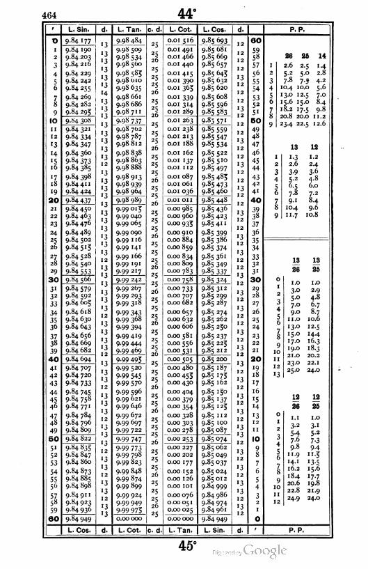
464 44°
9 L. Sin. d. L. Tan.
o 9.84 177I "I _9:9.8i8i.
I 9.84 190* J
9.98 509
2 9.84203l3
9-98 534
3 9.84 21613
9.98 500
4 9.84 229'3
9.98 585
5 9.84 24213
9.98 010
6 9-84 255 '3 9.98 635
7 9.84 269•4
9.98 661
S 9.S4 2S2 '3 9.98 686
9 9.84 29513
9.98 71 11 -i
IO 9.S4 30S* j
9-98 737
11 9-84321'3
9.98 Jb2
12 9-84 334•3
9.98 787
'3 9-84 347 9.98812
'4 9.84 36013
9-98 838
"5 9-84 37313
9.98863
16 9.84 385 9.98 888
'7 9.84 39813
9.98913
18 9.84 41 1I3
9-98 939
'9 9.84 42413
1 19.98 964
20 9-84 437oj
1 19.98 989
21 9.84450'3
9.99015
22 9.84463'3
9.99 040
23 9.84 476 9.99 065
24 9.84489'3
9.99 090T 1
*5 9.84 502 '3 9.99 116
26 9.84515 '3 9.99 141
27 9.84 52813
129.99 166
28 9.84 540'3
9.99 191
29 9-84 5531 -2
9.99217
30 9.84 566Lj
1 39.99 242
31 9.84579* j
9.99 267
32 9.84 59213
9.99 293
33 9.84 60513
9.99318T 1
34 9.8461813
9-99 343
35 9.84 63012
9.99 368
36 9.84 643I3
9-99 394
37 9.84 65613
9.99419
38 9.84 669•3
9.99 444
39 9.84 682 '31 2
9.99 469
40 9.84 6941 1 9-99 495
41 9.84 7071 j
9.99 520
42 9.84 720 '39-99 545
43 9-84 733 '3 9.99 570
44 9-84 745•3
9-99 596
45 9.84 758'3
9.99 621
46 9.84771 9.99 646
47 9.84 784'3
129.99 672
48 9.84 796 9.99 697
49 9.84 809 '31 1
9.99 722
50 9.84 8221 j
1 t9-99 747
51 9.84 835* j
9-99 773
52 9.84 847"3
9.99 798
53 9.84 860 9.99 823
54 9.84873'3
9.99 848
55 9.8488513
9.99 874
56 9.84 898 9.99 899
57 9.84 91 1•3
9.99 924
58 9.84 923•3 9.99 949
59 9.84 9361 1 9-99 975
60 9.84 949 0.00000
L. Cos. d. L. Cot.
c. d.| L. Cot.
0.01 516
0.0 1 491
0.0 1 466
0.0 1 440
0.01 415
0.0 1 390
0.0 1 365
0.0 1 339
0.01 314
0.0 1 289
*3
25
26
25
25
25
26
25
25
26
25
25
25
26
25
25
25
26
25
25
26
25
25
25
26
25
25
25
26
25
25
26
25
25
25
26
25
25
25
26
25
25
25
26
25
25
26
25
25
25
26
25
25
25
26
25
25
25
2b
25
0.01 263
0.01 238
0.01 213
0.0 1 188
0.01 162
0.01 137
0.01 112
0.0 1 087
0.0 1 061
0.01 0^6
0.0 1 on
0.00 985
0.00960
0.00 933
0.00 910
0.00 884
0.00 859
0.00 834
0.00 809
0.00 783
0.00 758
0.00 733
0.00 707
0.00 682
0.00 657
0.00 632
0.00 606
0.00 581
0.00 556
0.00 531
0.00 5°5
0.00 480
0.00 453
0.00 430
0.00 404
0.00 379
0.00 354
0.00 328
0.00 303
0.00 278
0.00 253
0.00 227
0.00 202
0.00 177
0.00 152
0.00 1 26
0.00 101
0.00 076
0.00 05 1
0.00 025
0.00000
L. Cos. d.
9.85 693
9.85 681
9.85 669
9.85 657
9.85 643
9.85 632
9.85 620
9.85 608
9.85 596
9-85 583
9-85 57'
9-85 559
9-85 547
9-85 534
9.85 522
9.85 510
9.85 497
9.85 483
9-85 473
9.85 460
9-85 448
9.85 436
9-85 423
9.85 4"
9-85 399
9.85 386
9-85 374
9.85 361
9-85 349
9-85 337
9-85 324
9.85 312
9.85 299
9.85 287
9-85 274
9.85 262
9.85 230
9-85 237
9.85 223
9.85 212
9.85 200
9.85 187
9.85 173
9.85 162
9.85 130
9-85 137
9-85 123
9.85 112
9.85 100
9.85 087
9-85 074
9.85 062
9.85 049
9-85 037
9.85 024
9.85 012
9.84 999
9.84 986
9.84 974
9.84 961
9-84 949
L. Sin.
60
59
58
57
56
55
54
5352
5"
BO
4948
47
46
45
44
4342
4"
40
3938
37
36
35
34
3332
31
30
29
28
27
26
25
24
23
22
21
20
'918
'7
16
•5
14
13
12
11
10
9
8
7
6
5
4
32
1
0
26 28 14
I 2.6 2-5 1.4
2 5-2 5-o 2.8
3 7.8 7-3 4.2
4 10.4 10.0 5.6
5 13.0 12.5 7.0
6 15.6 15.0 8.4
7 18.2 '7-5 9.8
8 20.8 20.0 11. 2
9 23-4 22.5 12.6
P. P.
IS 12
I 1-3 1.2
2 2.6 24
3 3-9 3-6
4 5-2 4.8
5 6.5 6.0
6 7.8I'2
7 9-1 8.4
8 10.4 9.6
9 1 1.7 10.8
o
I
2
3
4
56
78
910
11
12
"3
o
1
2
3
4
56
78
910
11
12
13 13
26 25
1.0 1.0
3-° 2.9
5-° 4.8
7.0 6.7
9.0 8.7
1 1.0 10.6
13.0 12.5
15.0 14.4
17.0 16.3
19.0 18.3
21.0 20.2
23.0 22.1
25.0 24.O
12 12
26 26
1.1 1.0
3-2 3-1
5-4 5-2
7.6 7-39.8 9-4
1 1.9 "-314.1 '3-516.2 15.6
18.4 17.7
20.6 19.8
22.8 21.9
24.9 24.0
P. P.
45°

TABLES XVII., XVIII.
NATURAL TRIGONOMETRIC FUNCTIONS.
'u SLRV. — 30
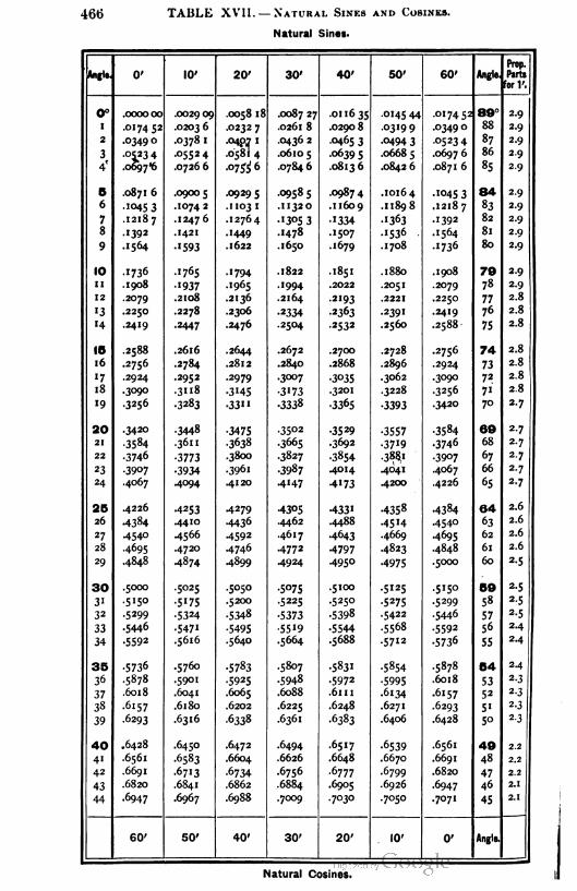
466 TAULE XVII. — Natural S1nes and Cos1nes.
Natural Sines.
Anglo, 0' 10' 20' 30' 40' 50' 60' Angle,
Prop.
Parts
for 1'.
0° .0000 00 .002909 .0058 18 .0087 27 .011635 .0145 44 -017452 80° 2.9
1 .017452 .02036 .0232 7 .0261 8 .0290 8 .0319 9 .03490 88 2.9
2 -0349 0 .0378 1 -040,7 " .0436 2 -0465 3 .0494 3 -0523 4 87 2.9
3 -0523 4 -05524 .0581 4 .0610 5 -06395 .06685 .0697 6 86 2.9
4' .o697,6 .0726 6 -°7$4 6 .07846 .08136 .0842 6 .0871 6 85 2.9
B .0871 6 .0900 5 -09295 -09585 -09874 .10164 -1045 3 84 2.9
6 -10453 .10742 .1103 1 .11320 .11609 .11898 .12187 83 2-9
7 .12187 .12476 .12764 -•3053 -1334 .1363 -1392 82 2-9
8 - 1392 .1421 .1449 .1478 .1507 -1536 .1564 81 2.9
9 .1564 -1593 .1622 .1650 .1679 .1708 -1736 80 2.9
10 -1736 .1765 .1794 .1822 .1851 .1880 .1908 70 2.9
11 .1908 •937 .1965 .1994 .2022 .2051 .2079 78 2.9
12 -2079 .2108 .2136 .2164 -2193 .2221 .2250 77 2.8
'3 .2250 .2278 -2306 -2334 -2363 -2391 .2419 76 2.8
14 .2419 -2447 .2476 .2504 -2532 .2560 .2588 75 2.8
I5 .2588 .2616 .2644 .2672 .2700 .2728 .2756 74 2.8
16 .2756 -2784 .2812 .2840 .2868 .2896 .2924 73 2.8
"7 -2924 -2952 -2979 .3007 -3035 .3062 .3090 72 2.8
18 .3090 .3»8 -3 '45 -3173 .3201 .3228 .3256 7" 2.8
'9 -3256 -3283 -33" -3338 -3365 -3393 -3420 70 2-7
20 .3420 -3448 -3475 .3502 -3529 -3557 -3584 60 2-7
21 -3584 .3611 -3638 .3665 .3692 -37'9 •3746 68 2-7
22 -3746 -3773 .3800 .3827 -3854 .3881 -3907 67 2-7
23 -3907 -3934 .3961 -3987 -4014 .4041 .4067 66 2-7
24 .4067 .4094 .4120 .4147 -4173 -4200 .4226 65 2-7
25 .4226 -4253 -4279 -4305 -433' -4358 -4384 64 2.6
26 -4384 .4410 -4436 .4462 .4488 -45H -4540 63 2.6
27 .4540 .4566 -4592 .4617 -4643 .4669 .4695 62 2.6
28 .4695 .4720 .4746 .4772 -4797 .4823 .4848 61 2.6
29 .4848 -4874 -4899 .4924 .4950 •4975 .5000 60 2-5
30 .5000 -5025 -5050 -5075 .5100 .5125 -5150 50 2-5
3" .5150 -5175 .5200 -5225 -5250 -5275 .5299 58 2.5
32 -5299 -5324 -5348 -5373 -5398 -5422 .5446 572-5
33 -5446 -547" -5495 -55'9 -5544 .5568 -5592 56 2.4
34 •5592 .5616 .5640 .5664 .5688 .5712 -5736 552-4
35 -5736 .5760 -5783 -5807 -5831 -5854 .5878 54 2-4
36 .5878 .5901 -5925 -5948 -5972 -5995 .6018 532.3
37 .6018 .6041 .6065 .6088 .6111 .6134 .6157 52 2-3
38 .6157 .6180 .6202 .6225 .6248 .6271 .6293 51 2.3
39 .6293 .6316 -6338 .6361 •6383 .6406 .6428 5°2-3
40 .6428 .6450 .6472 .6494 -6517 -6539 .6561 40 2.2
41 .6561 .6583 .6604 .6626 .6648 .6670 .6691 48 2.2
42 .6691 -6713 -6734 .6756 -6777 .6799 .6820 47 2.2
43 .6820 .6841 .6862 .6884 .6905 .6926 .6947 46 2.1
44 .6947 .6967 .6988 .7009 .7030 -7050 .7071 452.1
60' 50' 40' 30' 20' 10' 0' Angle.
Natural Cosines.

Natural S1nes and Cos1nes (continued). 467
Natural Sines.
Angle. 0' 10' 20' 30' 40' 50' 60' Angle.
Prop.
Parts
for Y.
45c.7071 .7092 .7112 -7 '33 -7'53 -7'73 •7'93
4402.0
46-7 '93 .7214 -7234 -7254 -7274 -7294 •73'4 43 2.0
47 -73'4 -7333 -7353 -7373 -7392 -74'2 -743'42 2.0
48 -743' -745' .7470 .7490 .7509 .7528 •7547 4' 1.9
49 -7547 .7566 -7585 .7604 .7623 .7642 .7660 40 1.9
SO .7660 .7679 .7698 .7716 •7735 •7753 -777' 30 1.9
s' -777' .7790 .7808 .7826 -7844 .7862 .7880 38 1.8
52 .7880 .7898 .7916 -7934 -795' .7969 .7986 37 1.8
53 .7986 .8004 .8021 .8039 .8056 .8073 .8090 36'-7
54 .8090 .8107 .8124 .8141 .8158 .8175 .8192 35 '•7
ss .8192 .8208 .8225 .8241 .8258 .8274 .8290 34 1.6
56 .8290 -8307 -8323 -8339 -8355 -837' .8387 33 1.6
57 •8387 .8403 .8418 -8434 .8450 .8465 .8480 32 1.6
58 .8480 .8496 .8511 .8526 -8542 •8557 -8572 3' '•5
59 -8572 -8587 .8601 .8616 -863I .8646 .8660 30 '•5
60 .8660 .8675 .8689 .8704 .8718 •8732 .8746 20 1-4
61 .8746 .8760 .8774 .8788 .8802 .8816 .8829 28 1-4
62 .8829 .8843 -8857 .8870 .8884 .8897 .8910 27 1.4
63 .8910 .8923 .8936 .8949 .8962 •8975 .8988 26 '-3
64 .8988 .9001 .9013 .9026 .9038 .9051 .9063 25 1.3
65 .9063 -9075 .9088 .9100 .9112 .9124 •9'35 24 1.2
66 -9'35 -9'47 .9159 .9171 .9182 -9'94 -9205 23 1.2
67 .9205 .9216 .9228 -9239 .9250 .9261 •9272 22 1.1
68 -9272 .9283 -9293 -9304 -93'5 -9325 •9336 21 1.1
69 -9336 -9346 -9356 -9367 -9377 .9387 •9397 20 1.0
70 -9397 .9407 -94'7 .9426 .9436 .9446 -9455 IO 1.0
7' -9455 .9465 -9474 -9483 -9492 .9502 -95" 18 0.9
72 -95" .9520 -9528 -9537 -9546 -9555 -9563 '7 0.9
73 -9563 -9572 -958o .9588 .9596 -9605 .9613 16 0.8
74 -9613 .9621 .9628 .9636 .9644 -9652 -9659 '5 0.8
78 .9659 .9667 .9674 .9681 .9689 .9696 -97°3 14 0.7
76 -97°3 .9710 .9717 -9724 -973° •9737 -9744 '3 0.7
77 -9744 -975° -9757 -9763 .9769 -9775 .9781 12 0.6
78 -9781 .9787 -9793 -9799 .9805 .9811 .9816 11 0.6
79 .9816 .9822 .9827 -9833 .9838 -9843 .9848 10 0.5
80 .9848 -9853 .9858 .9863 .9868 .9872 -9877 O 0.5
81 .9877 .9881 .9886 .9890 -9894 -9899 •9903 8 0.4
82 -9903 .9907 -99" -99'4 .9918 .9922 -9925 7 0.4
83 .9925 .9929 -9932 -9936 -9939 .9942 -9945 6 0.3
84 -9945 .9948 -995' -9954 -9957 -9959 .9962 o-3
88 .9962 .9964 .9967 .9969 .9971 -9974 .9976 4 0.2
86 .9976 -9978 .9980 .9981 -9983 -9985 .9986 3 0.2
87 .9986 .9988 -9989 .9990 -9992 -9993 -9994 2 0.1
88 -9994 -9995 .9996 -9997 -9997 .9998 .9998 1 O.I
89 .9998 -9999 -9999 1.0000 1.0000 1.0000 1.0000 0 0.0
60' 50' 40' 30' 20' 10' 0' Angle.
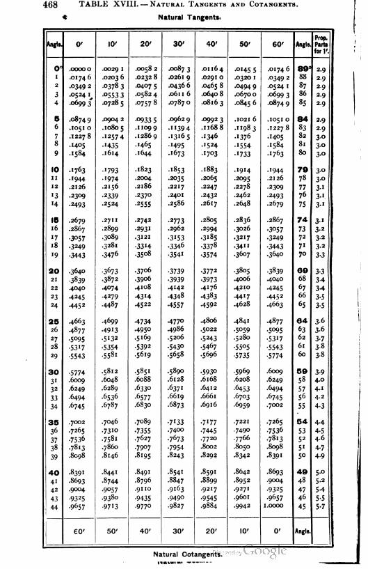
468 TABLE XVIII. — Natural Tangents and Cotangents.
* Natural Tangents.
Anglo. 0' 10' 20' 30' 40' 50' 60' Angle.
Prop.
Parts
for 1'.
o° .00000 .0029 1 .0058 2 .0087 3 .01164 -°'45 5 .0174 6 89° 2-9
1 .0174 6 .0203 6 .0232 8 .0261 9 .0291 0 .0320 1 -°349 2 88 2.9
2 -0349 2 -0378 3 .0407 s .0436 6 .0465 8 .0494 9 .0524 1 87 2.9
3 .0524 1, -0553 3 .0582 4 .061 1 6 .0640 8 .0670 0 .0699 3 86 2.9
4 .06993 .0728 5 .0757 8 .0787 0 .08163 .0845 6 .08749 85 2.9
5 .0874 9 .0904 2 -09335 .0962 9 .09923 .1021 6 .1051 0 84 2.9
6 .1051 0 .1080 s .1109 9 -"394 .11688 .11983 .1227 8 83 2.9
7 .1227 8 -1257 4 .12869 .13165 -•346 -1376 .1405 823°
8 .1405 -1435 .1465 .1495 .1524 .1554 .1584 813°
9 .1584 .1614 .1644 .1673 -17°3 .1733 -1763 803°
10 -1763 -1793 .1823 .I853 .1883 .1914 .1944 79 3°
11 .1944 .1974 .2004 -2035 .2065 -2095 .2126 78 3-°
12 .2126 .2156 .2186 .2217 -2247 .2278 .2309 77 3"•3 .2309 -2339 .2370 .2401 .2432 .2462 -2493 76 3-1
"4 -2493 -2524 -2555 .2586 .2617 .2648 .2679 75 3-1
15 .2679 .2711 -2742 -2773 .2805 .2836 .2867 74 3•
16 .2867 .2899 -2931 .2962 -2994 .3026 -3°57 73 3-2
'7 -3057 .3089 .3121 -3'53 -3185 -3217 -3249 72 3-2
18 -3249 .3281 -33H -3346 -3378 -34" -3443 71 3-2
19 -3443 -3476 .3508 -3541 -3574 .3607 .3640 70 3-3
20 .3640 -3673 .3706 -3739 -3772 .3805 -3839 69 3-3
21 -3839 -3872 .3906 -3939 -3973 .4006 .4040 68 3-4
22 .4040 .4074 .4108 -4142 .4176 .4210 -4245 67 3-4
23 .4245 -4279 -43 '4 -4348 -4383 .4417 -4452 66 3-5
24 -4452 -4487 .4522 •4557 -4592 .4628 .4663 65 3-5
25 .4663 .4699 -4734 -477° .4806 .4841 -4877 64 3-6
26 -4877 .4913 .4950 .4986 .5022 -5°59 -5°95 63 3-6
27 -5095 -5 '32 .5169 .5206 -5243 .5280 -53'7 62 3-7
28 -5317 -5354 -5392 -543° .5467 -55°5 -5543 61 38
29 -5543 .5581 .5619 .5658 .5696 -5735 -5774 60 3-8
30 -5774 -5812 -5851 .5890 -593° -5969 .6009 59 3-9
3' .6009 .6048 .6088 .6128 .6168 .6208 .6249 58 4.0
32 .6249 .6289 -6330 -637' .6412 -6453 .6494 57 4-1
33 .6494 .6536 -6577 .6619 .6661 .6703 .6745 5& 4.2
34 .6745 .6787 .6830 .6873 .6916 -6959 .7002 55 4-3
35 .7002 .7046 .7089 -7'33 .7177 .7221 .7265 54 4.4
36 .7265 -73"° -7355 -74°° -7445 -749° -753° 53 4-5
37 -7536 -7581 .7627 -7673 .7720 .7766 -7813 52 4.6
38 -7813 .7860 .7907 -7954 .8002 .8050 .8098 5' 4-7
39 .8098 .8146 .8195 .8243 .8292 .8342 .8391 5° 4-9
40 -8391 .8441 .8491 .8541 .8591 .8642 -8693 49 5-°
41 .8693 .8744 .8796 .8847 .8899 -8952 .9004 48 5-2
42 .9004 .9057 .91 10 .9163 .9217 .9271 -9325 47 5-4
43 -9325 .9380 -9435 -949° -9545 .9601 .9657 46 5-5
44 -9657 -9713 .9770 -9827 .9884 -9942 1.0000 45 5-7
eo' 50' 40' 30' 20' 10' 0' Angle.
Natural Cotangents.
natu1 «*• — —
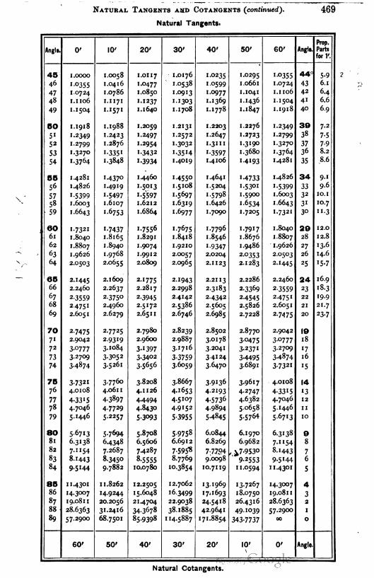
Natural Tangents and Cotangents (continued). 469
Natural Tangents.
Angle. 0' 10' 20' 30' 40' 50' 60' Angle.
Prop.
Parts
for 1'.
45 1.0000 1.0058 1.0117 1.0176 1.0235 1.0295 1.°355440
5-9
46 1-°355 1 .0416 1-0477 1.0538 1-0599 1.066 1 1.0724 43 6.1
47 1.0724 1.0786 1.0850 1.0913 1.0977 1.1041 1.1106 42 6.4
48 1.1 106 1.1 171 11237 1-1303 1. 1369 1. 1436 1-1504 41 6.6
49 1. 1504 1.1571 1. 1640 1. 1708 1-I778 1.1847 1.1918 40 6.9
50 1.1918 1. 1988 1.2059 1.2131 1.2203 1.2276 1-2349 30 7.2
51 '-2349 1.2423 1.2497 1.2572 1.2647 1.2723 1.2799 38 7-5
52 1.2799 1.2876 1.2954 1-3032 1.3m 1.3190 1.3270 37 7-9
53 1.3270 1-3351 1-3432 1-35H 1-3597 1.3680 I.3764 36 8.2
54 1-3764 1.3848 1-3934 1.4019 1.4106 1-4193 1.428 1 35 8.6
55 1.4281 1-437° 1.4460 1-455o 1.4641 1-4733 1.4826 34 9-1
56 1.4826 1.4919 1-5013 1.5 108 1.5204 1.5301 1-5399 33 9.6
57 1-5399 1-5497 1-5597 1-5697 1.5798 1.5900 1.6003 32 IO.I
58 1.6003 1.6107 1.6212 1-6319 1.6426 1-6534 1.6643 31 10.7
59 1.6643 1-6753 1.6864 1.6977 1.7090 1.7205 1-7321 30 "-3
60 1-7321 1-7437 1.7556 1-7675 1.7796 1-79I7 1 .8040 29 12.0
61 1 .8040 1.8165 1.8291 1.8418 1.8546 1.8676 1.8807 28 12.8
62 1.8807 1.8940 1.9074 1 .9210 1-9347 1.9486 1.9626 27 13-6
63 1.9626 1.9768 1.9912 2.0057 2.0204 2-0353 2.0503 26 14.6
64 2.0503 2.0655 2.0809 2.0965 2.1 123 2.1283 2.1445 25 15-7
65 2.1445 2.1609 2.1775 2-1943 2.2113 2.2286 2.2460 24 16.9
66 2.2460 2.2637 2.2817 2.2998 2.3183 2-3369 2-3559 23 ' 8.3
67 2-3559 2-375° 2-3945 2.4142 2-4342 2-4545 2.4751 22 19.9
68 2.4751 2.4960 2.5172 2.5386 2.5605 2.5826 2.605 1 21 21.7
69 2.6051 2.6279 2.65 1 1 2.6746 2.6985 2.7228 2-74 75 20 23-7
70 2-7475 2.7725 2.7980 2.8239 2.8502 2.8770 2.9042 19
71 2.9042 29319 2.9600 2.9887 3.0178 3-0475 3-0777 18
72 3-0777 3.1084 3-1397 3-1716 3.2041 3-237I 3.2709 17
73 3-2709 3-3052 3-3402 3-3759 3-4124 3-4495 3-4874 16
74 3-4874 3.5261 35656 3-6°59 3-647° 3-6891 3-7321 15
75 3-7321 3.7760 3.8208 3-8667 3-9I36 3-96I7 4.0108 14
76 4.0108 4.061 1 4.1 126 4-1653 4-2193 4-2747 4-33I5 13
77 4-3315 43897 4.4494 4.5107 4-5736 4.6382 4.7046 12
78 4.7046 47729 4.8430 4.9152 4.9894 5.0658 5- 1446 11
79 5.1446 5.2257 5-3093 5-3955 5-4845 5-5764 5-67I3 10
80 5-67I3 5-7694 5.8708 5-9758 6.0844 6.1970 6.3138 9
81 6.3138 6.4348 6.5606 6.6912 6.8269 6.9682 7-II54 8
82 7.1154 7.2687 7.4287 7-595« 7-77P4, ^7-9530 8.1443 7
83 8.1443 8.3450 8-5555 8.7769 9.0098 9-2553 9-5144 6
84 9-5144 9.7882 10.0780 10.3854 10.7119 11.0594 1 1.43°1 5
85 1 1.4301 11.8262 12.2505 12.7062 13.1969 13.7267 14.3007 4
86 14.3007 14.9244 1 5.6048 16.3499 17.1693 18.0750 19.0811 3
87 19.081 1 20.2056 21.4704 22.9038 24.5418 26.4316 28.6363 2
88 28.6363 31.2416 343678 38.1885 42.9641 49.1039 57.2900 1
89 57.2900 68.7501 85.9398 114.5887 171.8854 343-7737 -0 0
60' 50' 40' 30' 20' 10' 0' Angle.
\
Natural Cotangents.


PLATE I


PLATE I I


I 1


PLATE III.
3Q00 w--Meters


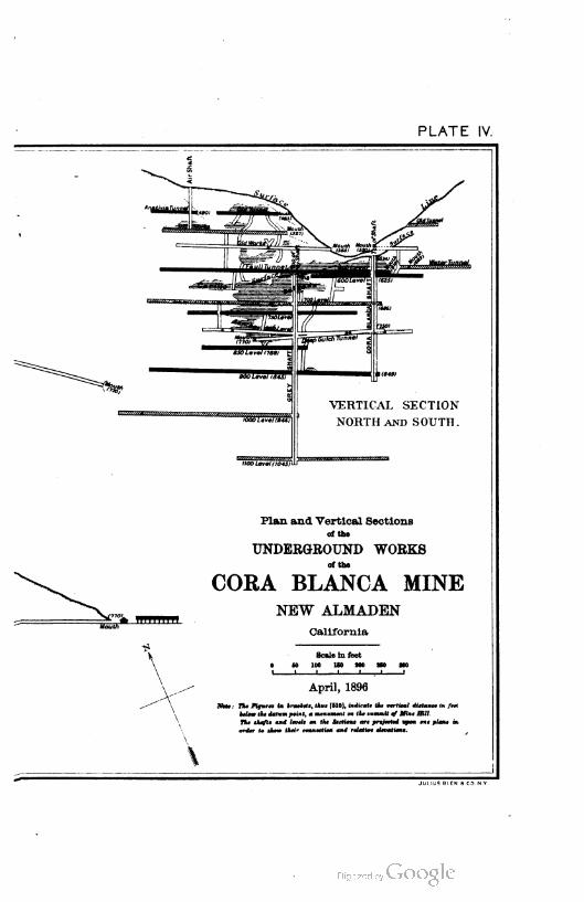
PLATE IV.
VERTICAL SECTION
NORTH and SOUTH .
Plan and Vertical Sections
of Ihe
UNDERGROUND WORKS
of Ihe
CORA BLANCA MINE
NEW ALMADEN
California
Scale 1n feeI
0 SO 1-- 160 oO 2o 3-01 1 1 1 1 —1 !
April, 1896
Not* j THt F1tjurta 1n brackets, thut {510}, 1nd1caU the vert"cal dtstance 1n ft*Mow the datum po1nt, a monnmtnt on tk* summ1t of o1nt H1ll.The shafto and Itvtlt on tkt Stct1tns art prejtettd upon one plant 1norder to show tht1r connect1on and rttat1vt t1trat"on*.

I
1
i
l1
I
"


PLATE VI
i i!


INDEX.
Abney level and clinometer, 72, 73.
Abscissas, denned, 156.
Diagram of positive and negative,
162.
Accuracy of stadia measurements, 127,
139, 140.
of barometric leveling, 76.
Additions, Planning of, 235.
Survey and map of, 236.
Hots of, 354.
Adit, defined, 308.
Mine entered by, 316.
Adjustments, of level, 50, 63.
Collimation adjustment, 64.
of objective slide, 65.
of bubble, 67.
Peg method, 68.
Lateral adjustment of bubble, 69.
Y adjustment, 70.
of dumpy level, 70.
of any level on metal base, 71.
of Locke and Abney levels, 73.
of compass, 79.
of transit, 108.
of solar transit, 122.
of Saegmuller solar attachment, 125.
of triangles, 259.
of plane table, 274.
of sextant, 297.
Agonic line, 87.
Alidade, of transit, 96, 102, 126.
of Colby protractor, 266.
of plane table, 268.
Alignment of chain, 27.
Allin's stadia rod, 131.
Alluvion, Apportionment of, 348.
Altitude, Measuring difference of. See
"Leveling."
Relation to barometer readings, 75.
Altitude of heavenly bodies, 117, 125,
364.
Aneroid barometer, Leveling with,
74-76.
Angles, Measurement of, 77-126, 254,
257. See also " Direction."
Precision in laying off of, 230.
measured by repetition, 255, 256.
measured by continuous reading,
255, 257.
Angular convergences,
of meridians, 224.
and distances between meridians.
Table of, 371.
Annual variation of declination, 86.
Appendix, 322-469.
Problems and examples, 322-340.
Judicial functions of surveyr-s,
341-350.
Ownership of surveys, 351-356.
Geographical positions of base lines
and meridians in public surveys,
357-360.
Tables, 361-469.
Approximate local mean times of cul
mination and elongation of Po
laris, 365.
Approximations in earthwork compu
tations, 277.
Arcs, of tachymeters, 99.
located by chain, 242.
and chords, 243.
Areas, in land survey computations,
152-156.
by double longitudes, 152.
To find the area of a field, 154.
Irregular areas by offsets, 155.
of closed surveys, 155, 160.
by coordinates, 159, 170.
472 INDEX.
Areas, elongated, by offsets, 161.
example solved by latitude differ
ences and double longitudes,
168.
of parcels of ground, 204.
of fields, 204, 205.
Topographical surveys for small,
247.
Topographical surveys for large,
248.
to be triangulated, 253.
of similar figures, 277.
Grading, 279.
Average end, 279.
of cut and fill, 286.
Atmosphere, Pressure of, 74.
Attraction, local, 93.
Average end areas, 279.
Axis, of revolution, Adjustment of, 110.
Polar, 117, 119, 121.
Polar, Adjustment of, 123.
Axes of earth, Lengths of, 9.
Azimuth, at elongation, defined, 91.
of a line, defined, 102.
Determination of, 105, 260.
Needle checks on, 107.
Zero, 162.
in application of coordinates, 214.
in transit and stadia method of
topography, 249.
Plane table turned in, 269.
Back bearing, 83, 84.
Backsights, 51, 57.
Baker's " Engineer's Surveying In
struments," 46, 136.
Balancing surveys, 141, 144-148, 166,
214.
Fundamental hypotheses, 144.
Method explained, 145.
The practice, 147.
When a transit is used, 148.
Example in, 166.
Barometer, Leveling with, 74-76.
described, 74.
Theory of, 74.
Barometric tables, 75, 362, 363.
Practical suggestions, 76.
Accuracy of method, 76.
Base lines, in U. S. public land sur
veys, 220, 223, 357-360.
measured in triangulation, 253, 254.
in mapping, 261.
Bay, Dredging of, 275.
Bayous, Meandering of, 228.
Beacons, 294.
Bearings, of lines, 83.
Errors in, 145.
Magnetic, 212.
Bed of stream, Ownership of, 348.
Bench marks, in leveling, 54, 55.
in mines, 313.
Binocular hand level, 73.
Black Hills meridian, 360.
Boise- meridian, 359.
Boston leveling rod, 47, 49.
Boundaries, of land. 341, 343, 345, 351.
of water, 216, 217, 316, 347, 349.
Bremicker logarithmic tables, 165.
Brough's "Treatise ou Mine Survey
ing," 313.
Bubble, Level, 35-38.
Adjustment of, 64, 67.
of compass, 79.
in transit, 108.
for leveling plane table, 274.
" Bulletin of University of Wisconsin,"
139.
Bull's-eye lamp for transit, 106.
Buoys and buoy flags, 291, 292,
294.
Burt's solar compass, 116.
Canals, Survey of, 238.
Carpenter's level, 71.
Carpenter's rule, 181.
Cautions, in chaining, 21.
in use of aneroid barometer, 76.
in use of compass, 85.
in use of solar transit, 120.
Center of gravity of prism bases, 275.
Chaining, Method of, 18-21.
Hints on, 21.
on slopes, 21, 27.
Errors in, 22.
Chains, Gunter's and engineer's, 13,
14.
Temperature of, 24.
Sag and pull of, 25, 26.
Alignment of, 27.
Gunter's, reduced to feet and
meters, 377, 378.
Chain surveying, 204-208.
Preliminary examination, 205.
Survey, 206.
Notes, 208.

INDEX. 473
Channels, Sounding in, 292.
Check mark in triangulation notes, 256.
Chickasaw meridian, 359.
Choctaw meridian, 358.
Cimarron meridian, 360.
Circle, shape of latitude parallels, 10.
Circular arcs and measures, Tables of,
376.
Circumference, Zero, 178.
of plani1neter wheel, 178.
City lot, Description of, 233.
City surveying, 230-237.
Precision required, 230.
Extent of survey, 231.
Instruments, 231.
Description of city lot, 233.
Finding city lot, 233.
Marking corners, 234.
Discrepancies, 234.
Planning additions, 235.
Making survey and map for an ad
dition, 236.
Claims, mining, 306, 307.
Clarke's spheroid, of 1866, 9.
of 1880, 9.
Clinometer, with Abney level, 72.
Hanging, 313,
Closed fields, Survey of, 141, 155, 159,
160, 205.
Closing line, 146, 263.
Closure, Error of, 141, 143, 144, 145,
171.
Coal mines, Survey of, 305.
Mapping of, 320.
Coefficient, correction, 361.
Coefficient of expansion of steel, 24.
Cplatitude reading, 121.
Colby's protractor, 265.
Colby's slide rule, 136, 253.
Collimation adjustment of level, 64.
Collimation line, denned, 45.
Adjustment of, 64, 113.
Revolution of, 109-112.
in solar transit, 122.
Common logarithms of numbers, Table
of, 397-418.
Compass, 77-85, 94, 104, 116, 205,
213.
Description, 77.
Solar, 77, 116.
Requirements for adjustments, 79.
Plate bubbles, 79.
Sights, 80.
Compass, Needle and pivot, 80.
Bearing, 83.
To determine bearing of a line, 83.
To lay out a line of given bearing,
83.
To run a traverse, 83.
Notes, 84.
Angles by, 85.
Cautions, 85.
Special forms of, 94.
Traversing with, 104.
Solar, 116.
used with chain, 205.
in land surveys, 213.
Compensating errors, 23, 62.
Compound curves, 243.
Connecting surface and underground
work, 316-320.
Mine entered by tunnel, 316.
Mine entered by two shafts, 316.
Mine entered by one shaft, 317.
Constant factors with slide rule, 192.
Construing descriptions of surveys,215.
Continuous reading method of meas
uring angles, 255, 257.
Contour lines, 245, 246, 247, 248, 268.
Contour map, of conical hill, 246.
of small areas, 248.
of valley, 281, 282.
of water, 288.
Convergence, of meridians, 224.
Table of angular, 371.
Cobley's "Judicial Functions of Sur
veyors," 341.
Coordinates, 156-162, 170, 203, 214,
249, 328.
Definitions, 156.
Elementary problems, 157.
To find the area, 159.
To make the coordinates all posi
tive, 160.
Elongated areas by offsets, 161.
Zero azimuth, 162.
Areas determined by, 170.
computed in land surveys, 203c
Application to farm surveys, 214.
Polar, 249.
Model example in, 328.
Corners, Location and marking of, 209,
214, 215, 218, 228, 234, 343, 346.
Correction coefficient for temperature
and hygrometric conditions, Ta
ble of, 361.
474 INDEX.
Correction lines, 223.
Corrections, along slopes, Table of,
301.
for refraction, Table of, 366, 367.
Cosines, Use of, in land survey com
putations, 165.
Table of natural, 466, 467.
Cotangents, Table of natural, 468, 469.
Crockett, C. W., Article on Slide Rule,
179-198.
Cross-cut in mines, 309.
Cross profiles, 280.
Cross-section paper, Use of, 280, 281.
Cross sections of streams, 288.
Cube root, Extraction by slide rule,
192.
Culmination of Polaris, 90, 120, 365.
Cumulative or constant errors in chain
ing, 22, 23.
Current meter, used to determine ve
locity of flow, 288.
Described, 298.
Rating of, 300.
Currents, Direction of, 304.
Curvature of earth, 11, 40.
Consideration of, in leveling, 52,
60, «2, 68.
Curves, 238-243.
Use of, 288.
Principles, '238.
Laying out a curve, 240.
Location by chain alone, 242.
Compound curves, 243.
Cut, Areas of, 279, 280, 286.
Datum or base surface, 51, 55.
Declination, magnetic, defined, 86.
of sun, 117.
Change in magnetic, 211, 212.
Refraction corrections for, 366, 367.
See also " Magnetic declination."
Declination arc, 121, 123.
Declination vernier, 89, 122, 212, 213.
Deeds, Interpretation of, 215, 235.
Defective sides, 150, 151.
Departure, old term for longitude dif
ference, 162.
Depth of cut or fill, 279.
Description of surveys, Construing of,
215.
Diagram for stadia measurements, 134,
135.
Diamond drills, 289.
Differential leveling, 61.
Dip, of needle, 79.
term in mining, defined, 309.
Direction, and measurement of angles,
77-126.
Instruments named, 77.
Compass, 77-79.
Adjustments, 79-82.
Use of compass, 83-85.
Magnetic declination, 86-94.
The transit, 96-99.
Use of transit, 100-108.
Adjustment of transit, 108-116.
Solar transit, 1 16-122.
Adjustment of solar transit,122, 123.
Saegmuller solar attachment, 123-
125.
Meridian and time by transit and
sun, 125, 126.
Direction meter, 288, 304.
Direction of current, how determined,
304.
Discharge of streams determined, 288,
304.
Discrepancies, in legal requirements
for U.S. land surveys, 222.
in surveys, 234, 236.
Distances, Measurement of, 77.
Diurnal variations of declination, 87.
Division, of land, 163-105.
Occurrence of problem, 163.
Solution of problem, 163.
by slide rule, 183.
Dorr's " Surveyor's Guide," 228.
Double centering, with transit, 102.
in mine surveys, 317.
Double longitudes, 152, 153, 166,
168.
Double sextant, 298.
Dredging of river, lake, etc., 275.
Drift, defined, 308.
Mine entered by, 316.
Dumpy level, 43, 47, 61.
Adjustment of, 70.
Earthwork computations, 275-286.
Ordinary methods, 275-281.
Estimating volumes from a map,
281-280.
Earthwork, Payment for, 275.
Eccentricity, 115.
Elevation, Differences of, 51, 134, 380-
382.

INDEX. 475
Elevation, Determination of, in stadia
surveys, 250, 252.
Barometric table of, 362, 363.
Ellicott's boundary line, 357.
Ellipse, shapo of longitude meridians,
10.
Elongated areas, 161.
Elongation of Polaris, 90, 106, 365.
Embankments, Horizontal area of, 283.
Keservoir in, 285, 286.
Engine, Horse power of, 192.
Engineer's scale, 265.
Engineer's transit, 123, 255, 256.
" Engineering News," 131.
Equation of a straight line, 303.
Equator, 9, 116, 117, 119.
Errors, 1n measuring level and hori
zontal lines, 22-30.
in chain and tape measurements,
22-30.
Cumulative, 23.
Compensating, 23, 62.
in use of level, 60.
of graduation, 115.
in latitude and altitude, 126.
of closure, 141, 143, 144, 145, 146,
171.
in bearing, 145.
in latitude and longitude, 146, 148.
of geographical position, 263.
in earthwork computations, 277.
Examples in land surveys, 165-172.
See also "Problems."
Logarithms, 165.
Example stated, 166.
Balancing, 166.
Latitude differences and double
longitudes, 168.
Areas by coordinates, 170.
Supplying an omission, 171.
Excavations, of pit or cellar, 275.
under water, 281.
Horizontal area of, 283.
Reservoir in, 285, 286.
Expansion of steel, Coefficient of, 24.
Extent of city surveys, 231.
Exteriors, Township, 225.
External secant, 239.
Extinct corners, 343-346.
Eyepiece of telescope, 46.
Focusing of, 63.
of transit. 115.
of sextant, 296.
Farm surveys, 205, 206, 208-219.
Classes, 208.
Original surveys, 209. [209.
Making original survey and map,
Description, 210.
Resurveys, 211.
Reasons for resurveys, 211.
Procedure, 211.
Change of declination, 212.
Transit or compass, 213.
Report, 214.
Application of coordinates, 214.
Principles for guidance in resur
veys, 215.
Location surveys, 219.
Feet changed to meters, 379.
Field methods, for small area, 248.
for large area, 248.
Field notes. See "Notes."
Field rules, 218.
Filament of stream, Vertical, 304.
Fill, Area of, 279, 280, 286.
Flag signals, 255.
Floats, to determine direction of sur
face currents, 288.
Rod, 303, 304.
Flow of stream, Velocity of, 288.
Foresights, 51, 57.
Formulas, for sag and pull, 25, 26.
for measuring on slopes, 28.
for correction for curvature, 63.
for barometer readings, 75.
for adjustment of compass, 81.
for azimuth at elongation, 92.
for meridian and time by transit
and sun, 125, 120.
for azimuth of sun, 126.
for stadia measurements, 128-130.
for inclined stadia readings, 133.
for difference of elevation by stadia,
134.
for reductions in stadia work, 140.
for latitude and longitude differ
ences, 142.
for distributing errors in balancing,
146-148.
for supplying omissions, 150-152.
for double longitudes, 153.
for finding areas of closed surveys,
155.
for irregular areas by offsets, 15R.
for coordinate computations, 160,
161.

476INDEX.
Formulas, for dividing land, 164, 165.
for use of plani1neter, 175, 177-179.
for sllde rule computations, 183-19(3.
for horse power of engine, 1!)2.
for change of declination, 212, 213.
for angular convergence of me
ridians, 225.
for curves, 239, 240, 242.
for prisms, 276, 279, 280.
for pris1noids, 277, 278.
for estimating volumes from a map,
283, 284.
for surface grading, 279, 283.
for locating soundings, 293.
showing theory of sextant, 296.
for correction coefficient for tem
perature and hygrometric con
ditions, 361.
for latitude of place, 364.
for azimuth of Polaris, 92, 364.
for refraction correction to declina
tion of sun, 366.
for magnetic declinations, 368-370.
Trigonometric, 373.
for circular measures, 376.
Forward bearing, 83, 84.
Francis's " Lowell Hydraulics," 304.
Fuller's slide rule, 197.
Functions of surveyors, 341.
Gage for soundings, 290.
Gage point, 192.
Galilean telescope, 45.
Gas-pipe rods, 289.
Gauss logarithmic tables, 165.
Geodetic survey, defined, 11, 12.
Adjustment of triangles in, 260.
Geographical positions of base lines
and meridians in public sur
veys, 357-360.
German dial, 313.
Gila and Salt Hiver meridian, 360.
Grade element to be noted, 254.
Grade line, defined, 282.
Gradienter of tachy meter, 99.
Grading, of streets, 280.
Surface, 279, 283.
Grading operations, 275, 279, 280, 283.
Great Bear, Constellation of, 90.
Guide meridians, 224.
Gunter's chains, described, 14.
expressed in feet and meters, 377,
378.
Gurley's monocular and binocular
hand levels, 73.
Hachures, 245.
Hand levels, 27, 72, 73.
Hanging clinometer, 313.
Harbor, Survey of, 294.
Hatching, 245.
Hill-shading, 245.
Historical note of U. S. Public Land
Surveys, 221.
Hodgman and Bellows's " Manual of
Land Surveying," 214, 228.
Horizontal angles, defined, 10.
measured by transit, 108.
Horizontal axis of plane table, ad
justed, 274.
Horizontal distances and differences
of elevation, Table of, 380-382.
Horizontal line, defined, 10.
Horizontal plane, defined, 10.
Generation of, 40.
Horse power of engine, Formula for,
192.
Humboldt meridian, 360.
Huntsville meridian, 358.
Hydraulic engineering, 287.
Hydrographic surveying, 287-304.
Definition, 287
Objects, 287.
Work of surveyor, 287.
Statement of methods, 288.
Soundings, 289-294.
The sextant, 294-298.
Measuring velocity discharge, 298-
304.
Direction of current, 304.
Illumination, of transit wires, 106.
of plumb lines, 107, 313, 314.
Inaccessible points, 202, 203.
Incline in mine, defined, 309.
Inclined line, defined, 10.
Inclined stadia readings, 132.
Index glass of sextant, 295.
Indian meridian, 360.
Instruments for surveying:
Chains, 13.
Tapes, 15, 17.
Measuring rods, 17.
Pins, 18.
Range poles, 18.
Vernier, 31.

INDEX. 477
Instruments for surveying :
Level bubble, 35.
Level, 40.
Telescope, 43.
Leveling rods, 47.
Locke hand level, 72, 73.
Abney level and clinometer, 72, 73.
Gurley's monocular and binocular
hand levels, 73.
Barometer, 74, 76.
Compass, 77.
Special forms of compass, 94.
Transit, 95.
Tachymeter, 99, 311.
Solar transit, 116.
Saegmuller solar attachment, 123.
Stadia, 127, 131.
Slide rule, 136, 179.
Planimeter, 172.
Mannheim rule, 181, 198.
Thacher rule, 196.
Fuller's slide rule, 197.
Transit for city surveying, 231.
Protractors, 2(53.
Colby's protractor, 265.
Ockerson's protractor, 266.
Plane table, 268.
Lead, 289.
Sextant, 294.
Current meter, 298.
Rod floats, 303.
German dial, 313.
Hanging clinometer, 313.
Lamps, 314.
Intersections, Method of, 272.
Introduction, 9-12.
Preliminary conceptions, 9.
Surveying defined, 11.
Irregular areas, 155, 161.
Islands, in streams, Ownership of, 348.
in Great Lakes, 349.
Isogonic line, 87.
Jacob staff, 94.
Johnson, J. B., References to, 25, 263.
Johnson, W. P., Leveling head in
vented by, 209.
Judicial functions of surveyors, 341-
350.
Imperfect training, 341.
Duties, regarding location of mon
uments, 342, 344.
Relocation of extinct corners, 343.
Judicial functions of surveyors :
Corners not to be established, 343.
Must regard occupation and claims,
344.
Must ascertain facts, 346.
Surplus and deficiency in appor
tionment, 346.
Difficulties with meander lines, 346.
Extension of water fronts, 348.
Bed ownership on water fronts, 348.
Riparian rights on lakes, 349.
Key to topographical symbols on maps,
267.
Lakes, Riparian rights in, 217, 349.
Meandering of, 228.
Dredging of, 275.
Land, Map of, 11.
Division of, 163.
Title to, 343.
Land survey computations, 141-198.
Considerations and definitions, 141.
Error of closure, 113.
Balancing the survey, 144-148.
Supplying omissions, 149-152.
Areas, 152-156.
Coordinates, 156-162.
Dividing land, 163-165.
Model examples, 165-172.
The planimeter, 172-179.
The slide rule, 179-198.
Land surveys, 201-237.
Obstacles and problems, 201-203.
Two common problems, 204.
Surveying with chain alone, 204-
208.
Farm surveys, 208-219.
United States public land surveys,
219-229.
City surveying, 230-237.
Lateral adjustment, 69.
Latitude, Parallels of, 10.
Observation for, 121.
of a line and point, defined, 142.
differences, 142, 147-152, 155, 162,
168, 204.
Errors in, 140, 148.
and longitude plotting, 209, 210,
261,301,306.
Table of lengths of, 372.
Formula for, 364.
Laying out curves, 240.

478 INDEX.
Lead used for soundings, 288, 286.
Least squares, formula from Treatise
on, 30.
Reference to demonstration of rule
for balancing survey by, 147.
Method of, mentioned, 303.
Legal requirements for public land
surveys, 222.
Length, Standard of, 231.
Lesser Bear, Constellation of, 90.
Lettering on maps, 210, 2(i7.
Level and horizontal lines, Measure
ment of, 13-30.
Level line, defined, 10.
Line to be measured, 13.
Instruments used, 13-18.
Methods, 18-22.
Classes of errors, 22.
Causes of errors, 23.
Temperature, 24.
Sag and pull, 25, 26.
Alignment, 27.
Slope, 27.
Precision to be obtained, 29.
Level bubble, 35-38.
Level, tenn in mining, defined, 308.
Level tube for chaining, 27.
Level under telescope, 114.
Level, Use and adjustment of, 50-71.
Adjustment and setting up, 50.
Differential leveling, 51.
Profile leveling, 53.
Making the profile, 58.
Leveling over an area, 60.
Errors, 60.
Curvature and refraction, 62.
Reciprocal leveling, 63.
Focusing, 63.
Adjustments named, 64.
Coilimation adjustment, 64.
Adjustment of objective slide, 65.
Bubble adjustment, 67.
Peg method, 68.
Lateral adjustment, 69.
Y adjustment, 70.
Adjustment of dumpy level, 70.
Adjustment of any level on a metal
base, 71.
Hand, 72, 73.
Level vial, 36, 37.
Leveling or measuring differences of
altitude, 40-76, 308.
General principle, 40.
Leveling or measuring differences of
altitude, Instruments for, 40-50.
Use of level, 50-63.
Adjustments of level, 63-71.
Minor instruments, 72, 73.
Leveling with barometers, 74-76.
in underground surveys, 308.
Leveling rods, 47-50.
Limb of transit, 96.
Line of coilimation, defined, 45.
in transit, 108.
Revolution of, 109.
Linear transformations, Table of, 377.
Linen tapes, 17.
Local attraction of magnetic needle,
93.
Local mean times of culmination and
elongation of Polaris, 365.
Locating arcs by chain, 242.
Location surveys, 208, 219.
Locke hand level, 72, 73.
Lode claim, 306.
Lodes, Coloring of, on maps, 320.
Logarithms, Computations by, in land
surveys, 165.
Scale of, defined, 180.
Use of scale, 181.
Infinite extent of scale, 184.
Scale of logarithmic sines and tan
gents, 193, 194.
Table of numbers, 397-418.
Table of trigonometric functions,
419-464.
Longitude, Meridians of, 10.
of a line and point, defined, 142.
Differences of, 142, 147-150, 151,
153, 162, 204.
Errors in, 148.
Double, 152, 153, 155, 168.
Table of lengths of. 372.
Lot, Description of, 233.
Louisiana meridian, 359.
Lunar variation of declination, 86.
Magnetic bearings, 212.
Magnetic declination, 86-94, 368-370.
defined, 86.
Variations of, 86.
Determination of declination, 87.
Determination of true meridian, 89.
Azimuth at elongation, 91.
Local attraction, 93.
Special forms of compasses, 94.
INDEX. 479
Magnetic declination, Table of, 368-
870.
Magnetic meridian, 78, 86, 103, 107, 211.
Magnetic needle, 77, 78, 364.
Mannheim rule, 181, 198.
" Manual of Surveying Instructions,"
221, 228, 365.
Map lettering, 210, 267.
Mapping, 261-268, 320, 321.
Triangles, 261.
Outline of method for topography,
261.
Stadia line, 262.
Side shots, 263.
Colby's protractor, 265.
Ockerson's protractor, 266.
Finishing the map, 267.
Requirements for maps, 267.
Scale, 268.
for metal and coal mines, 320.
Scale in mines, 321.
Problems, 321.
Maps, denned, 11.
of farm surveys, 209.
of city surveys, 237.
Topographical, 244.
Requirements for, 267, 354-356.
Contour for grading, 281, 282.
of harbor surveys, 294.
of mines, 320.
for public records, 353.
Maximum velocity of streams, 298.
Mean surface of earth, 9.
Meander corners, 228.
Meander lines, 346, 347, 349.
Meandering a stream, 227.
Measuring differences of altitude. See
" Leveling."
Measuring velocity discharge, 298-304.
Position of maximum velocity, 298.
Current meters, 298.
Use of meter, 300.
Rating the meter, 300.
Rod floats, 303.
Discharge, 304.
Mercurial barometer, Leveling with,
74, 76.
Meridians, of longitude, 10.
Magnetic and true, 86, 89, 225.
Determination of, 105.
Principal, in U. S. land surveys, 219,
223, 357-360.
Angular convergence of, 224, 371.
Meridians, Guide, 224.
of reference, 261.
Table of distance between, 371.
Meridian and time, by transit and sun,
125, 126.
Metal base, Adjustment of level on, 71.
Metal mines, 306, 320.
Metallic tapes, 17.
"Metes and bounds," Description by,
216, 235.
Methods for earthwork computations,
275-281.
Occurrence of problem, 275.
Prisms, 275.
Prismoids, 276.
Prismoidal formula, 277.
Approximations, 277.
Area grading, 279.
Street grading, 280.
Excavation under water, 281.
Methods of measuring level and hori
zontal lines, 18-22.
Preliminary statement, 18.
Chaining, 18.
Hints, 21.
Chaining on slopes, 21.
Meters changed to feet, 379.
Michigan meridian, 358.
Michigan, Survey of lands in, 341.
Micrometer screw, 36.
Mine surveying, 305-321.
Surface surveys, 305-308.
Underground surveys, 308-316.
Connecting surface and under
ground work, 316-320.
Mapping the survey, 320, 321.
Mining claim, Form of, 306.
Minus sights, 51, 56, 57, 60.
Model examples. See " Problems."
Modulus of elasticity of chains, 25.
Monocular hand level, 73.
Montana meridian, 360.
Monuments for surveys, 200, 211, 216,
218, 234, 237, 253, 307, 341, 344,
345, 351, 355.
Mount Diablo meridian, 359.
Multiplication by slide rule, 182.
Myers's, John H., problems in coordi
nates, 328.
Natural scale of maps, 268.
Natural sines and cosines, Table nf,
466, 467.

480 INDEX.
Natural tangents and cotangents,Table
of, 4(58, 469.
"Nautical Almanac," 120, 126.
Needle and pivot of compass, 80.
Needle checks on azimuths, 107.
New Almaden mine, 310.
New Mexico meridian, 359.
New York leveling rod, 47, 48.
North Star, Observation on, 90.
Notes, in profile leveling, 55.
in traversing, 84.
in stadia measurements, 140.
for land surveys, 169, 208, 228, 229.
for topography, 250, 252.
in triangulation, 256.
for mine surveys, 307, 320.
for underground work, 315.
Private, 351, 354.
Objective of telescope, 43, 45, 46.
Objective slide, Adjustment of, 65.
Oblate spheroid of revolution, 9.
Obstacles in land surveys, 201.
Ockerson's protractor, 266.
Offsets, 155, 156, 161.
Omissions, supplied in land survey
computations, 149-152, 171.
Necessity for, 149.
General discussion, 149.
Cases I.-VI., 160.
Algebraic solution, 151.
Ordinates, 156, 160, 161.
Ore, Mining of, 308.
Orientation, of transit, 104, 261, 273.
of plane table, 273.
Origin of coordinates, 156.
Original land surveys, 208, 209-211.
Ormsbee, J. J., on three-tripod system,
315.
Oughtred, inventor of sliding scales,
180.
Ownership of surveys, 351-356.
Paraltelopiped, Truncated, 276.
Parallels, of latitude, 10.
Standard, 223.
Park drive curves, 238.
Partridge's improvement of slide rule,
180.
Patenting mining claims, 307.
Peg, a turning point, 57.
Peg method of adjusting telescopes, 68,
71, 274.
Philadelphia leveling rod, 47, 48, 49.
Pins used in chaining, 18.
Pitch, defined, 309.
Pivot of compass, 80.
Placer claim, 306.
Plane survey, defined, 12.
Plane table, 268-274, 294.
Description, 268.
Use, 270.
Three-point and two- point prob
lems, 272.
Adjustments, 274.
used in harbor surveys, 294.
Planimeter, 172-179, 270, 284.
Description, 172.
Use, 173.
Theory, 174.
Zero circumference, 178.
Circumference of wheel, 178.
Length of arm, 179.
used in measuring areas, 270, 284.
Plate bubbles, of compass, 79.
of transit, 108.
Plotting, of maps, 209.
by latitudes and longitudes, 209,
210, 261, 301, 306.
of corners, 210.
of points on maps, 292.
Plumb line, a vertical line, 10.
Use of, 22, 90.
Plumbing, 253.
Plummet lamps, 314.
Plummets for mine surveys, 318, 319.
Plus sights, 51, 60.
Polar axis of solar transit, 123.
Polar coordinates, 249.
Polar distance of Polaris, 364.
Polar planimeter, 172, 173.
Polaris, Observations on, 90.
Elongation and culmination of, 90,
106, 107, 120, 223, 365.
Declination of, 92.
Polar distance of, 92, 364.
Porro, inventor of stadia rod, 127.
Positive coordinates, 160.
Precise level, 43, 47, 61.
Precision necessary, in measurement,
29.
in city surveying, 230.
Price, W. G„ Observations by, 301, 339.
Principal meridians, 219, 223, 357-360.
Prisms, 60, 275-277.
Prismatic compass, 94.
INDEX. 481
Prismoids, 276.
Prismoidal formula, 276, 277, 279, 283,
284.
Private notes of survey, 351, 354.
Problems and examples, 157-159, 105-
172, 186, 201-204, 321, 322-340.
in coordinates, 157-159, 328.
in land surveys, 165-172, 201-204.
with slide rule, 186.
in mine surveying, 321.
on Chapter I., 322.
on Chapters III. and IV., 324.
on Chapters V. and VI., 326.
on Chapter VIII., 335.
on Chapter IX., 336.
on Chapter X., 338.
on Chapter XL, 339.
on Chapter XII., 340.
Profile leveling, 53-60.
Profile paper, 58, 59.
Profiles, Cross, 280.
Proportion by slide rule, 183.
Protractor, Land survey drawing made
by, 141.
Vernier, 263.
Colby's, 265.
Ockerson's, 266.
Three-arm, 292, 293.
Plotting with, 3(16.
Public surveys, in Michigan, 341.
Base lines governing, 357-360.
See also "U. S. public land sur
veys."
Pull, Formula for, 25.
Elimination of, 26.
element noted, 254.
Pull scale, 231.
Pyramid, 276, 277.
Quarter sections, 220.
Rack and pinion movement of tele
scope, 44.
Radiation, Method of, 270.
Railroads, Surveys of, 238, 268.
Curves on, 238.
Random lines, 203, 225, 227.
Random surveys, 214, 215.
Range lines, 220, 225, 226, 227, 291.
Range poles, 18.
Raymond's (R. W.) "Glossary of Min
ing and Metallurgic Terms," 308.
Reading glasses, 98.
r'm'd sukv. — 31
Reciprocal leveling, 63.
Reed's " Topographical Drawing and
Sketching," 267.
Reels, 15-17.
Reference lines, 223.
Reflector in telescope, 106.
Refraction, Effect of, 63, 139.
Corrections for, 121, 125, 126.
Table of corrections for, 364, 366,
367.
Repetition measurement of angles,
255, 256.
Report of survey, 214.
Report of U. S. Coast and Geodetic
Survey, 75, 86, 87, 368.
Reservoir, Building of, 275.
Capacity of, 281.
in embankment and excavation,
285, 286.
Resurveys, 208, 211-218.
Riparian rights, 217, 347, 349.
Ritchie and Haskell's direction meter,
304.
River, Dredging of, 275.
River, Survey of, 294.
Roads, Survey of, 238.
Rod floats, Velocities of, 303.
Rod level, 61.
Rods, Wooden and metallic, 13, 17.
Gas-pipe, 289.
for stadia measurements, 131, 136-
138.
Rolling planimeter, 172, 173.
Runner, in slide rule, 180, 185, 191.
Saegmuller solar attachment, 123.
Sag, Formula for, 25.
Elimination of, 26.
Saint Helena meridian, 359.
Saint Stephen's meridian, 358.
Salt Lake meridian, 359.
Salt River meridian, 360.
San Bernardino meridian, 360.
Scale, of slide rule, 179.
Logarithmic, 180-195.
of logarithmic sines and tangents,
193, 194.
of topographical maps, 268.
of mine maps, 321.
Schott's formulas for declination, 87.
Scow, Displacement of, 281.
Sea level, 246.
Secant, External, 239.

482 INDEX.
Sections, 220.
Secular variations of declination, 86.
Sequence of figures, in operations with
slide rule, 185.
Seven Ranges, 221.
Severn tunnel, 320.
Sextant, 77, 294-298.
use mentioned, 77.
Description of, 294.
Use of, 295.
Theory of, 296.
Adjustments of, 297.
Other forms of, 298.
Shafts, defined, 308.
Mine entered by, 317, 318.
Shifting center of transit, 99.
Side shots, 249, 263.
Sights of compass, 80.
Similar figures, Areas of, 277.
Similar triangles, 128.
Simple triangulation, 253-261.
when used, 253.
Measuring base line, 253.
Measuring angles, 254.
Notes, 256.
Adjusting triangles, 259.
Computing triangles, 260.
Use of triangles, 260.
Sines and cosines, 165, 193.
Table of logarithmic, 419-464.
Table of natural, 466, 467.
Sketch of tract to be surveyed, 205.
for topography, 251.
Slide direct, 186.
inverted, 189.
reversed, 193.
Slide rule, 134, 136, 140, 179-198, 253,
281, 380.
used in stadia readings, 134, 136,
140, 380.
for differences of elevation, 136.
described, 179.
Historical note of, 180.
Construction of scales, 180.
Use of scales, 181.
Mannheim rule, 181.
Use of rule, 182.
Extent of logarithmic scale, 184.
Sequence of figures, 185.
Shifting the slide, 185.
Use of runner, 185.
Squares and square roots, 185.
Statement of problems, 186.
Slide rule, Slide direct, 186.
Slide inverted, 189.
Use of runner in complicated ex
pressions, 191.
Gage points, 192.
Extraction of cube roots, 192.
Slide reversed, 193.
Scale of logarithmic sines, 193.
Scale of logarithmic tangents, 194.
The Thacher rule, 196.
Settings for Thacher rule, 197.
Fuller's slide rule, 197.
Mannheim rule, 198.
used in volumetric computations,
281.
Slopes, Chaining on, 27.
• Formula for measuring on, 28.
in mines, 309.
Smith's observations for stadia meas
urements, 139.
Smithsonian geographical tables, 372.
Solar attachment of transit, 122.
Solar compass, 77, 116.
Solar transit, 1 16-125. See " Transit."
Soundings, 288-294.
in hydrographic surveying, 288,
Making soundings, 289.
Locating soundings, 290.
. Occurrence of methods, 293.
Survey of harbor, river, etc., 294.
Sounding lead, 288.
Spacing of stadia wires, 129.
Spanish vara, 221.
Spider lines, 44.
Spirit level, 35.
Squares and square roots by slide rule,
185.
Stadia line, Plotting of, 261, 262, 263.
Stadia measurements, 127-140.
defined, 127.
Method explained, 128.
Spacing of the wires, 129.
To approximate the value of /, 130.
The value of c, 130.
The value of \ and (/ + c), 130.
The rod, 131.
Inclined readings, 132.
Table of, 133.
Difference of elevation, 134.
Diagram, 134.
Slide rule, 136.
Graduating a stadia, 136.
INDEX. 483
Stadia measurements, Smith's obser
vations, 139.
Notes, 140.
Stadia method of topography, 249.
Stadia reduction table, 380-382.
Stadia surveys in coal mines, 305.
Stadia traverse, 261.
Stadia wires of tachymeter, 99.
Standard length, 231.
Standard parallels, 223.
Stanley's " Surveying and Leveling
Instruments," 71.
Station marks in mines, 309, 310.
Statutes for surveyors, Need of, 356.
Steel, Coefficient of expansion of, 24.
Steel tapes, 15, 24, 313.
Stope, defined, 309.
Streams, Meandering of, 227.
Cross sections of, 288.
Street grading, 280.
Striding level, 71, 109.
Strike, defined, 309.
Structures, Volume of, 285.
Sttibben, J., Paper by, 237.
Subcurrents, Direction of, 288, 304.
Subdivision in land surveys, 219.
of townships, 226.
Sun, Declination of, 117, 125, 126.
Surface currents, Direction of, 288,o 304.
Surface form, Representation of, 244.
Surface grading, 281, 283.
Surface monuments of mines, 307.
Surface of earth, 9, 11.
Surface surveys, 305-308.
Coal mines, 305.
Metal mines, 306.
Form of mining claim, 306.
Surveying the claim, 307.
Surface monuments, 307.
Surveying, defined, 11, 351.
Surveyors, Difference of opinion
among, 351.
Laxity and dishonesty of, 352.
Imperfect maps of, 353 , 354.
Duties regarding maps, 355, 356.
Surveys, Public, in Michigan, 341. See
"U. S. public land surveys."
Suspended planimeter, 172, 173.
Tables, 361-469 :
I. Correction to 100 units measured
along slopes given, 361.
II. Correction coefficient for
temperature and hygro-
metric conditions, 361.
III. Barometric elevations, 362.
IV. Polar distance of Polaris,
364.
V. Daily variation of magnetic
needle, 364.
VI. Approximate local mean
times of elongation and
culmination of Polaris,
365.
VII. Refraction corrections, 366.
VIII. Magnetic declination formu
las, 368.
IX. Angular convergences and
distances between merid
ians, 371.
X. Length of one minute of latir
tude and longitude, 372.
XI. Trigonometric functions and
formulas, 373.
XII. Lengths of circular arcs, 376.
XIII. Linear transformations, 377.
XIV. Horizontal distances and dif
ferences of elevation, 380.
XV. Common logarithms of num
bers, 397-418.
XVI. Logarithms of trigonomet
ric functions, 419-464.
XVII. Natural sines and cosines,
466, 467.
XVIII. Natural tangents and co
tangents, 468, 469.
Tacheometer, 127.
Tachymeter, described, 99.
term for complete transit equipped
for stadia work, 127.
used in mine surveys, 311, 312.
Tallahassee meridian, 358.
Tangents, Logarithmic scale of, 194.
Intersection of, 239.
Table of natural, 468, 469.
Tapes, used in measuring, 13.
Steel, 15.
Ribbon, 15.
Linen, 17.
Errors in, 22, 23.
Expansion of, 24.
used in land surveys, 204.
used in city surveys, 231.
used in measuring base line, 254.
used in mine surveys, 313, 317.
484 INDEX.
Target lamp, 314.
Targets of leveling rods, 47-49.
Telescope, of level, 43.
Spider lines of, 44.
Field of view of, 45.
Eyepiece of, 46.
Spherical aberration of, 46.
Axis of revolution of, 114.
Magnifying power of, 230.
pointing in triangulation, 256.
Temperature correction of tapes and
chains, 24.
Temperature element noted, 254.
Temperature correction, Table of, 361.
Texas, Public lands of, 221.
Thacher rule, 182, 196, 197.
Theodolite, 123.
Theory of planimeter, 174-178.
Three-arm protractor, 292, 293.
Three-point problem, 272, 273, 292.
Three-tripod system, 315.
Time, by transit and sun, 125, 126.
Topographical surveying, 11, 127,244-
274, 305.
defined, 11.
Use of stadia in, 127.
Topography, 244-253.
Simple triangulation, 253-261.
Mapping, 261-268.
The plane table, 268-274.
in mine surveying, 305.
Topography, 244-253, 288.
Methods of representing surface
form, 244.
Field methods for small area, 247.
Contour map, 218.
Field methods for large area, 248.
Transit and stadia method, 249.
of bed of water, 288.
Township, a subdivision of public land,
220.
Subdivisions of, 226.
Theoretical, 226.
Township exteriors, 225.
"Transactions American Society Civil
Engineers," 237. .
Transformations, Linear, 377-379.
Gunter's chains to feet, 377.
Gunter's chains to meters, 378.
Feet to meters, 379.
Transit, 77,95-126, 148, 205, 213, 231,
249, 255, 256, 261, 311, 312,
317-319.
Transit, Description, 77, 95.
Tachymeter, 99.
Carrying transit, 100.
Setting up, 104,
To produce a straight line with,
101.
Measuring angles with, 102.
Azimuth, 102.
Traversing, 103.
used instead of compass, 104.
Determining meridian, 105.
Needle checks on azimuths, 107.
Requirements for adjusted, 108.
Plate bubbles, 108.
Line of collimation, 109.
Level under telescope, 114.
Vertical circle, 115.
Eyepiece, 115.
Eccentricity, 115.
Solar transit explained, 116.
Fundamental conception for solar,
116.
Description of solar, 118.
Method of use of solar, 119.
Limitations of solar, 120.
Latitude, 121.
Refraction, 121.
Adjustments of solar, named, 122.
Lines of collimation of solar, 122.
Declination vernier of solar, 122.
Polar axis of solar, 123.
Engineer's, 123, 255, 256.
Saegmuller's solar attachment, de
scribed, 123.
Adjustments of Saegmuller's, 125.
used in land surveys, 148, 213.
used with chain, 205.
City surveyor's, 231.
Orientation of, 261.
used in mine surveys, 311, 312, 317-
319.
Transit and stadia method of topogra
phy, 249. .
Traverse, Running of, 83.
Traverse tables, 165.
Traversing, with compass, 83.
with transit, 103.
with plane table, 270.
in underground surveys, 308.
Triangles, Similar, 128.
Division of fields into, 205.
Adjustment of, 269. ,
Computing, 260.

INDEX. 485
Triangles, used in mapping, 261.
Solution of, 373-376.
Triangulation, Simple, 253.
Stations, 254, 260, 272, 294.
System in topography, 272.
System in coal mine surveys, 305.
Trigonometer, 306.
Trigonometric functions, Signs of, 162.
Formulas of, 373-376.
Tables of, 419-469.
Tropic of Cancer, Extension of, 117.
Tropic of Capricorn, Extension of, 117.
Tunnel, defined, 308.
Mine entered by, 316.
Turning points in leveling, 53.
Two-point problem, 272, 273.
Underground surveys, 308-316.
General statement, 308.
Definitions, 308.
Location and form of station marks,
309.
Instruments used, 310.
Devices for making stations visible,
313.
Notes* 315.
United States Coast and Geodetic Sur
vey, References to, 75, 86, 231,
268, 270, 361, 302, 365, 368.
United States deputy surveyors, 219.
United States Geological Survey, Ref
erences to, 268, 270.
United States public land surveys,
219-229.
Character of work, 219.
Scheme of subdivision, 219.
Historical note, 221.
Legal requirements, inconsistent,
222.
Principal reference lines, 223.
Standard parallels, 223.
Guide meridians, 224.
Angular convergence of two merid
ians, 224.
Township exteriors, 225.
Subdivisions of townships, 226.
Meandering a stream, 227.
Corners, 228.
Notes, 228.
United States surveyor general, 221.
Vara, Spanish measure, 221.
Variations of declination, secular, an
nual, lunar, and diurnal, 86.
Vega logarithmic tables, 165.
Veins in mines, 306.
Velocity of flow of stream, 288.
Vernier and level bubble, 31-39.
Vernier, defined, 31.
Direct, 31, 32."
Retrograde, 33.
Double, 34.
Declination, 122.
Vernier protractor, 263.
Vertical angle, line, and plane, defined,
10.
Vertical circle of transit, 115.
Volumes estimated from a map,281-286.
A reservoir, 281.
Application to surface grading, 283.
Application to structures, 285.
Volume of earth, measured, 275.
in street grading, 280.
in mines, 308.
See also " Earthwork computa
tions."
Wagon roads, Survey of, 238.
Washington meridian, 359.
Water boundaries, Statutes regarding,
216, 217.
Water, Excavation under, 281.
Wedges in earthwork, 276, 277.
Weighting courses, 148.
Weir measurements, 288.
Willamette meridian, 360.
Winslow's stadia reduction table, 380.
Winze, defined, 309.
Wires, Illumination of, 106, 311.
Witness points, 209, 228.
Wright's "Adjustment of Observa
tions," 147.
Y adjustment, 64, 70.
Y level, 43, 47, 61.
Zenith-pole arc, 92.
Zenith-star arc, 92.
Zero azimuth, 162.
Zero circumference, 178.
Zeta Urs» Majoris, 90.
1
Typography by J. S. Cushing & Co., Norwood, Mass.


UNIVERSITY OF MICHIGAN
iiiniiiiiiiiii tin iii miliiiiniiiiiii
3 9015 06359 7523
t


![4.1.1] plane waves](https://static.fdokumen.com/doc/165x107/6322513728c445989105b845/411-plane-waves.jpg)