User manual for MERUS™ MA120xxx reference boards
27
User Manual Please read the Important Notice and Warnings at the end of this document V 1.0 www.infineon.com/merus page 1 of 27 2019-04-28 UM_1902_PL88_1902_171735 User manual for MERUS™ MA120xxx reference boards P100002130 REF_AUDIO_MA12040 P100002140 REF_AUDIO_MA12040P P100002170 REF_AUDIO_MA12070 P100002180 REF_AUDIO_MA12070P About this document Scope and purpose This is a reference and demonstration board for MA12040, MA12040P, MA12070 and MA12070P proprietary multi-level amplifiers. This application note describes the functionality and set-up of the reference design (Sections 2 and 3). It also includes a schematic, PCB layout, bill of materials (BOM) and a discussion of circuit design considerations (Section 4). Measurement results (Section 5) show high performance in audio and efficiency parameters, as well as good thermal characteristics. Testing included a frequency sweep, output power sweep and electromagnetic interference tests. Finally, Appendix A provides sample code that demonstrates basic I 2 C communication using Arduino UNO. Intended audience Audio amplifier design engineers, audio system engineers and audio software engineers.
-
Upload
khangminh22 -
Category
Documents
-
view
1 -
download
0
Transcript of User manual for MERUS™ MA120xxx reference boards
User Manual Please read the Important Notice and Warnings at the end of this document V 1.0
www.infineon.com/merus page 1 of 27 2019-04-28
UM_1902_PL88_1902_171735
User manual for MERUS™ MA120xxx reference
boards P100002130 REF_AUDIO_MA12040
P100002140 REF_AUDIO_MA12040P
P100002170 REF_AUDIO_MA12070
P100002180 REF_AUDIO_MA12070P
About this document
Scope and purpose
This is a reference and demonstration board for MA12040, MA12040P, MA12070 and MA12070P proprietary multi-level amplifiers.
This application note describes the functionality and set-up of the reference design (Sections 2 and 3). It also includes a schematic, PCB layout, bill of materials (BOM) and a discussion of circuit design considerations
(Section 4). Measurement results (Section 5) show high performance in audio and efficiency parameters, as well as good thermal characteristics. Testing included a frequency sweep, output power sweep and electromagnetic
interference tests. Finally, Appendix A provides sample code that demonstrates basic I2C communication using Arduino UNO.
Intended audience
Audio amplifier design engineers, audio system engineers and audio software engineers.

User Manual 2 of 27 V 1.0
2019-04-28
User manual for MERUS™ MA120xxx reference boards Table of contents
Table of contents
About this document ....................................................................................................................... 1
Table of contents ............................................................................................................................ 2
1 Board overview ...................................................................................................................... 3 1.1 General board specifications .................................................................................................................. 4 1.2 RFB device type ....................................................................................................................................... 4 1.3 Set-up guide ............................................................................................................................................ 4
1.4 Board configuration ................................................................................................................................ 6
1.5 Device configuration through I2C ............................................................................................................ 7
2 Schematic, layout and design considerations ............................................................................ 8
2.1 Bill of materials ...................................................................................................................................... 11 2.2 Design considerations ........................................................................................................................... 12
3 Measurement results ............................................................................................................. 13 3.1 Frequency sweep................................................................................................................................... 13
3.2 Output power sweep ............................................................................................................................. 15 3.3 Output spectrum ................................................................................................................................... 16 3.4 Power consumption and efficiency ...................................................................................................... 17
3.5 EMI radiated measurements ................................................................................................................. 19 3.5.1 EMI measurement setup .................................................................................................................. 19 3.5.2 EMI measurement results ................................................................................................................ 19
4 Appendix A – sample code ...................................................................................................... 24
Revision history............................................................................................................................. 26
User Manual 3 of 27 V 1.0
2019-04-28
User manual for MERUS™ MA120xxx reference boards Board overview
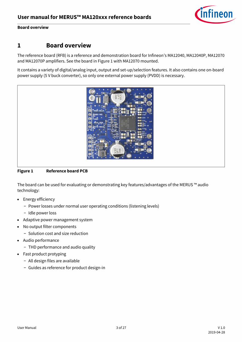
1 Board overview
The reference board (RFB) is a reference and demonstration board for Infineon’s MA12040, MA12040P, MA12070
and MA12070P amplifiers. See the board in Figure 1 with MA12070 mounted.
It contains a variety of digital/analog input, output and set-up/selection features. It also contains one on-board
power supply (5 V buck converter), so only one external power supply (PVDD) is necessary.
Figure 1 Reference board PCB
The board can be used for evaluating or demonstrating key features/advantages of the MERUS ™ audio
technology:
• Energy efficiency
− Power losses under normal user operating conditions (listening levels)
− Idle power loss
• Adaptive power management system
• No output filter components
− Solution cost and size reduction
• Audio performance
− THD performance and audio quality
• Fast product protyping
− All design files are available
− Guides as reference for product design-in

User Manual 4 of 27 V 1.0
2019-04-28
User manual for MERUS™ MA120xxx reference boards Board overview
1.1 General board specifications
• Number of audio channels 2 x BTL or 1 x PBTL
• Audio input format:
o MA12040 and MA12070 Analog o MA12040P and MA12070P Digital (I2S)
• Supply voltage range MA12040(P) 5 to 18 V
• Supply voltage range MA12070(P) 5 to 26 V
• Maximum output current per channel MA12040(P) 6 A
• Maximum output current per channel MA12070(P) 8 A
• Output power capability at 18 V PVDD:
o Peak 2 x 40 W sine 1 kHz (RMS) into 4 Ω (10 percent THD + N) o Peak 2 x 20 W sine 1 kHz (RMS) into 8 Ω (10 percent THD + N)
o Continuous 2 x 9.0 W sine 1 kHz (RMS) into 4 Ω (less than 0.08 percent THD + N)
• Output power capability at 26 V PVDD:
o Peak 2 x 80 W sine 1 kHz (RMS) into 4 Ω (10 percent THD + N) o Peak 2 x 40 W sine 1 kHz (RMS) into 8 Ω (10 percent THD + N)
o Continuous 2 x 9.0 W sine 1 kHz (RMS) into 4 Ω (less than 0.02 percent THD + N)
• Amplifier gain (MA12040 and MA12070 only) 20 dB or 26 dB (register configurable)
• Output integrated noise:
o MA12040 and MA12070 Less than 100 µVrms (AW) o MA12040P and MA12070P Less than 150 µVrms (AW)
• Dynamic range:
o MA12040 and MA12070 More than 100 dB o MA12040P and MA12070P More than 96 dB
• Idle current consumption at 18 V PVDD:
o MA12040 and MA12070 Less than 16 mA
o MA12040P and MA12070P Less than 19 mA
Note: Idle consumption is the sum of output stage current and 5 V supply current. As all the supplies are tied to
PVDD, the efficiency of the buck converter 5 V should be taken into account when measuring idle current consumption directly from PVDD. Please refer to the MA120xx/P device datasheet for exact current figures.
1.2 RFB device type
The type of device (MA12040, MA12040P, MA12070 and MA12070P) on the RFB is printed on the top of the device, and is also stated on the serial number label placed on the bottom side of the PCB.
1.3 Set-up guide
The RFB works out of the box with speakers, input source and power connected. No external configuration or set-up is needed for quick start-up.
Figure 2 shows the top view of the board assembly. The board has following key features, which are indicated by
corresponding numbers marked with red.

User Manual 5 of 27 V 1.0
2019-04-28
User manual for MERUS™ MA120xxx reference boards Board overview
1. PVDD power connector: connect PVDD 5 V to 18 V for MA12040(P) or connect PVDD 5 V to 26 V for MA12070(P)
2. BTL output connection channel 0 3. BTL output connection channel 1
4. PAUDIO: signal input connector: o For MA12070 devices:
▪ Pin 5: AN0A – analog input A channel 0 ▪ Pin 4: AN0B – analog input B channel 0
▪ Pin 3: GND
▪ Pin 2: AN1A – analog input A channel 1 ▪ Pin 1: AN1B – analog input B channel 1
o For MA12070P devices:
▪ Pin 5: SCK – I2S bit clock
▪ Pin 4: WS – I2S word clock ▪ Pin 3: GND ▪ Pin 2: SD0 – I2S audio data
▪ Pin 1: CLK – I2S master clock
5. PCTRL external communication: ▪ Pin 5: SCL – I2C clock
▪ Pin 4: SDA – I2C data ▪ Pin 3: GND ▪ Pin 2: /ENABLE – enable or disable the amplifier
▪ Pin 1: /MUTE – mute or unmute the amplifier 6. MA12040, MA12040P, MA12070 or MA12070P Eximo multi-level amplifier IC
7. Buck regulator: TPS62175 – for generating 5 V supply

User Manual 6 of 27 V 1.0
2019-04-28
User manual for MERUS™ MA120xxx reference boards Board overview
Figure 2 Schematic top view of component and connector assembly
1.4 Board configuration
The board is shipped with a default configuration for automatic start-up, two channels of BTL output, and
default internal register settings. It is however possible to operate the board in different modes. The following
configurations are possible:
• BTL or PBTL output configuration: o BTL: RPBTL unmounted; RBTL mounted o PBTL: RPBTL mounted; RBTL unmounted
• External control of the /ENABLE pin: RENABLE unmounted
• External control of the /MUTE pin: RMUTE unmounted
The board can carry MA12040(P) or MA12070(P) devices. Depending on which device is placed, the following configurations apply for:
• MA12040 and MA12070:
o CAPIN0A, CAPIN0B, CAPIN1A and CAPIN1B are mounted
o RCLK_ANA mounted; RCLK_DIG unmounted o RCLK unmounted
• MA12040P and MA12070P: o CAPIN0A, CAPIN0B, CAPIN1A and CAPIN1B replaced by jumpers o RCLK_ANA unmounted; RCLK_DIG mounted
o RCLK mounted

User Manual 7 of 27 V 1.0
2019-04-28
User manual for MERUS™ MA120xxx reference boards Board overview
1.5 Device configuration through I2C
Multi-level technology offers the possibility to optimize for audio performance, efficiency or EMI. Depending on
the application, typically one parameter is more important than the others. The amplifiers offer the flexibility to make this design trade-off by the use of different optimal modes (Power Mode Profiles or PMP), selected through internal register settings. The RFB uses the MA120XXX in the default PMP0, which optimizes the amplifier operation for highest power efficiency in the low to mid output power region. For a complete
overview of device configurations, please refer to the datasheets.
I2C is used to read and write the internal registers. SCL and SDA can be accessed through Pin 5 and Pin 4 on the
PCTRL header (see previous section). Figure 3 shows how to set up I2C communication using an Arduino UNO.
Sample code for I2C set-up can be found in Apendix A – sample code.
Figure 3 Arduino I2C communication to the RFB
Pull-up

User Manual 8 of 27 V 1.0
2019-04-28
User manual for MERUS™ MA120xxx reference boards Schematic, layout and design considerations
2 Schematic, layout and design considerations
Figure 4 Reference board schematic
User Manual 9 of 27 V 1.0
2019-04-28
User manual for MERUS™ MA120xxx reference boards Schematic, layout and design considerations
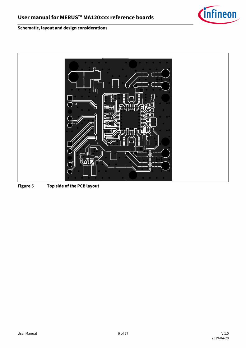
Figure 5 Top side of the PCB layout

User Manual 10 of 27 V 1.0
2019-04-28
User manual for MERUS™ MA120xxx reference boards Schematic, layout and design considerations
Figure 6 Bottom side of the PCB layout
The RFB is cost optimized. The cost of one module including PCB, components and assembly is estimated to be
$2.15 at a volume of 1000 pieces. The price of the MA120xx(P) amplifier depends on the volume and part. For
p rform n optimiz tion s th ppli tion not “EMC output filt r r omm n tion” or ont t Infin on.
User Manual 11 of 27 V 1.0
2019-04-28
User manual for MERUS™ MA120xxx reference boards Schematic, layout and design considerations
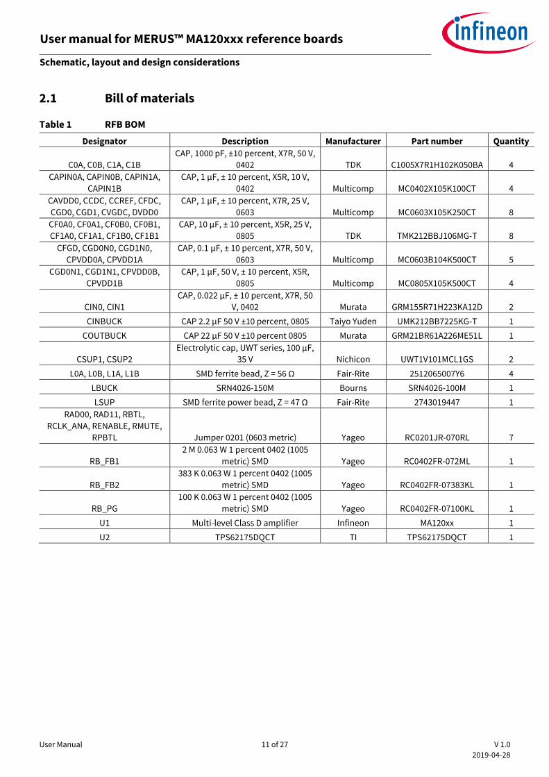
2.1 Bill of materials
Table 1 RFB BOM
Designator Description Manufacturer Part number Quantity
C0A, C0B, C1A, C1B
CAP, 1000 pF, ±10 percent, X7R, 50 V,
0402 TDK C1005X7R1H102K050BA 4
CAPIN0A, CAPIN0B, CAPIN1A,
CAPIN1B
CAP, 1 µF, ± 10 percent, X5R, 10 V,
0402 Multicomp MC0402X105K100CT 4
CAVDD0, CCDC, CCREF, CFDC,
CGD0, CGD1, CVGDC, DVDD0
CAP, 1 µF, ± 10 percent, X7R, 25 V,
0603 Multicomp MC0603X105K250CT 8
CF0A0, CF0A1, CF0B0, CF0B1,
CF1A0, CF1A1, CF1B0, CF1B1
CAP, 10 µF, ± 10 percent, X5R, 25 V,
0805 TDK TMK212BBJ106MG-T 8
CFGD, CGD0N0, CGD1N0,
CPVDD0A, CPVDD1A
CAP, 0.1 µF, ± 10 percent, X7R, 50 V,
0603 Multicomp MC0603B104K500CT 5
CGD0N1, CGD1N1, CPVDD0B,
CPVDD1B
CAP, 1 µF, 50 V, ± 10 percent, X5R,
0805 Multicomp MC0805X105K500CT 4
CIN0, CIN1
CAP, 0.022 µF, ± 10 percent, X7R, 50
V, 0402 Murata GRM155R71H223KA12D 2
CINBUCK CAP 2.2 µF 50 V ±10 percent, 0805 Taiyo Yuden UMK212BB7225KG-T 1
COUTBUCK CAP 22 µF 50 V ±10 percent 0805 Murata GRM21BR61A226ME51L 1
CSUP1, CSUP2
Electrolytic cap, UWT series, 100 µF,
35 V Nichicon UWT1V101MCL1GS 2
L0A, L0B, L1A, L1B SMD ferrite bead, Z = 56 Ω Fair-Rite 2512065007Y6 4
LBUCK SRN4026-150M Bourns SRN4026-100M 1
LSUP SMD ferrite power bead, Z = 47 Ω Fair-Rite 2743019447 1
RAD00, RAD11, RBTL,
RCLK_ANA, RENABLE, RMUTE,
RPBTL Jumper 0201 (0603 metric) Yageo RC0201JR-070RL 7
RB_FB1
2 M 0.063 W 1 percent 0402 (1005
metric) SMD Yageo RC0402FR-072ML 1
RB_FB2
383 K 0.063 W 1 percent 0402 (1005
metric) SMD Yageo RC0402FR-07383KL 1
RB_PG
100 K 0.063 W 1 percent 0402 (1005
metric) SMD Yageo RC0402FR-07100KL 1
U1 Multi-level Class D amplifier Infineon MA120xx 1
U2 TPS62175DQCT TI TPS62175DQCT 1

User Manual 12 of 27 V 1.0
2019-04-28
User manual for MERUS™ MA120xxx reference boards Schematic, layout and design considerations
2.2 Design considerations
The RFB is elegant because of its small form factor, while still being able to operate at up to 80 W output power
per channel. This is possible due to the multi-level technology of the MA12070 and MA12070P devices.
• Thermal considerations:
o Power-efficient operation allows heatsink-free operation because the bottom layer of the PCB
design (connected to the heatsink pad of the IC) is sufficient for cool operating conditions. This
holds when considering playback of real audio signals. o Figure 5 and Figure 6 show the top and bottom PCB design respectively. It can be seen that all the
component placement and main routing is done on the top layer.
o It is important to have as little routing as possible on the bottom layer since it needs to be optimized for thermal heat flow.
o Routing done on the bottom layer is chosen in such a way that it still allows for good thermal heat flow. In this way, the complete bottom plate can function as a heatsink for the amplifier IC.
o Vias placed between bottom and top ground planes add to the copper mass that functions as a
heatsink.
• Filterless operation:
o Multi-level technology also significantly reduces out-of-band noise, which allows LC filter-free operation. Only a small, SMD-sized EMI filter is needed.
o Figure 1 shows the footprint and PCB size it takes. The board size is significantly reduced due to a small-sized EMI filter compared to a bulky LC filter.
o Th us of n LC filt r is lso not n to optimiz th ffi i n y of th mplifi r. Th sp r’s
inductive behavior is sufficient for efficient operation of the amplifier. This is again enabled by reduced out-of-band noise of the amplifier.
• Buck regulator:
o A buck regulator (TPS62175) has been included in the design to derive a 5 V rail from the PVDD input
rail. 5 V is needed as the core supply voltage for the MA120xx(P). TPS62175 has been chosen to balance the need for cost, efficiency and size. The current design of the buck regulator generates 5
V from 26 V PVDD with approximately 85 percent efficiency. Efficiency could have been increased by increasing the inductance, which would have increased the footprint; Infineon opted for a smaller footprint instead.

User Manual 13 of 27 V 1.0
2019-04-28
User manual for MERUS™ MA120xxx reference boards Measurement results
3 Measurement results
This section shows the measurement results from tests performed on a reference board, which demonstrate
high audio and efficiency performance and good thermal characteristics. Measurements include:
• Frequency sweep
• Output power sweep
• Output spectrum
• Power consumption and efficiency
• EMI
All measurement results were obtained using the following settings:
• Device: MA12070
• Two-channel BTL configuration
• Load: 4 Ω + 22 μH series inductance
• PVDD: 18 V
• Gain setting: 20 dB
• PMP: default PMP0
• Measurements carried out with APx 515 + AUX-0025 input filter
• APx uses AES17 brick-wall filter (20 kHz)
3.1 Frequency sweep
Frequency sweeps were carried out with both channels at 1 W output power. To improve the gain drop at 20 Hz, use larger input capacitors.
Figure 7 Gain vs. frequency
0
5
10
15
20
25
30
35
40
10 100 1000 10000
Gai
n [
dB
]
Frequency [Hz]
Channel 1
Channel 2
User Manual 14 of 27 V 1.0
2019-04-28
User manual for MERUS™ MA120xxx reference boards Measurement results
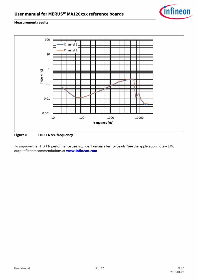
Figure 8 THD + N vs. frequency
To improve the THD + N performance use high-performance ferrite beads. See the application note – EMC output filter recommendations at www.infineon.com.
0.001
0.01
0.1
1
10
100
10 100 1000 10000
THD
+N [
%]
Frequency [Hz]
Channel 1
Channel 2
User Manual 15 of 27 V 1.0
2019-04-28
User manual for MERUS™ MA120xxx reference boards Measurement results
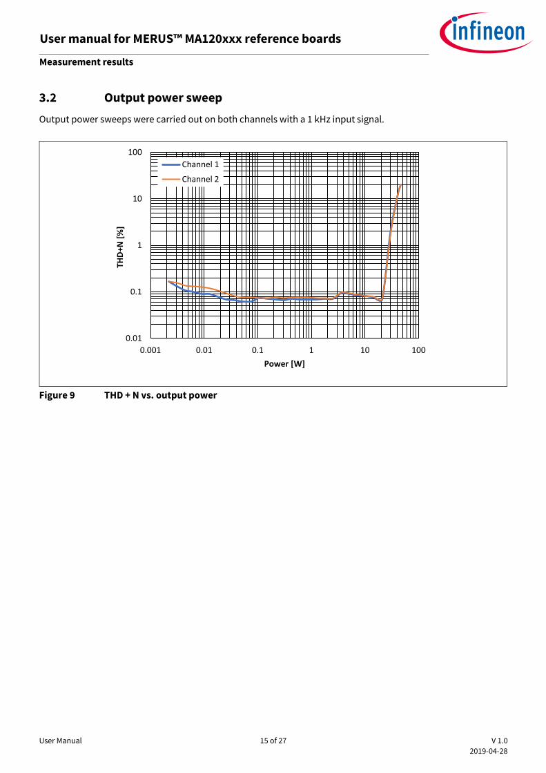
3.2 Output power sweep
Output power sweeps were carried out on both channels with a 1 kHz input signal.
Figure 9 THD + N vs. output power
0.01
0.1
1
10
100
0.001 0.01 0.1 1 10 100
THD
+N [
%]
Power [W]
Channel 1
Channel 2

User Manual 16 of 27 V 1.0
2019-04-28
User manual for MERUS™ MA120xxx reference boards Measurement results
3.3 Output spectrum
The Figure 10 shows the output spectrum that has been obtained by applying 1 mVrms (1 kHz) input signal to both channels. This gives an output signal of -40 dBV. The noise floor for these settings is shown in the Figure
10. The integrated, A-weighted noise floor number for both channels is 70 µVrms (AW).
Figure 10 Output FFT spectrum
Figure 11 Scope capture showing 10 mVrms output signal on both channels
-160
-140
-120
-100
-80
-60
-40
-20
0
20
40
20 200 2000 20000
Leve
l (d
BV
)
Frequency (Hz)
Ch0
Ch1
-0.02
-0.016
-0.012
-0.008
-0.004
0
0.004
0.008
0.012
0.016
0.02
0 0.0005 0.001 0.0015 0.002
Leve
l (V
)
Time (s)
Ch0
Ch1

User Manual 17 of 27 V 1.0
2019-04-28
User manual for MERUS™ MA120xxx reference boards Measurement results
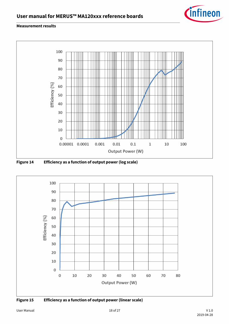
3.4 Power consumption and efficiency
Power consumption and efficiency measurements were obtained by using a test signal of 1 kHz and a load of 4 Ω with 22 μH series inductance. Power consumption was calculated using the RMS method.
Figure 12 Input power as a function of output power
Figure 13 Power loss as a function of output power
0.1
1
10
100
0.00001 0.0001 0.001 0.01 0.1 1 10 100
Inp
ut
Po
wer
(W
)
Output Power (W)
User Manual 18 of 27 V 1.0
2019-04-28
User manual for MERUS™ MA120xxx reference boards Measurement results
Figure 14 Efficiency as a function of output power (log scale)
Figure 15 Efficiency as a function of output power (linear scale)

User Manual 19 of 27 V 1.0
2019-04-28
User manual for MERUS™ MA120xxx reference boards Measurement results
3.5 EMI radiated measurements
3.5.1 EMI measurement setup
AUDIO SOURCE
LINEAR POWER SUPPLY
TURN TABLE
EMC chamber
R&S Spectrum Analyzer
Test PC
SpeakersDEVICE UNDER
TEST
Figure 16 EMI measurement set-up for radiated emission test
Figure 16 shows the set-up for testing.
Measurement results were obtained under the following conditions:
• Linear power supply: 18 V PVDD
• Pink noise test signal output power at 20 dB gain = 1 W average output power per channel
• Speaker cable length: 10 cm
• Amplifier load: 4 Ω speaker (Visaton FR 10 WP)
• EMI filter: Murata ferrite BLE32PN300SN1L + 1 nF capacitor
• Pi filter on PVDD – Würth ferrite 74279221100 + 2 x 22 nF capacitor
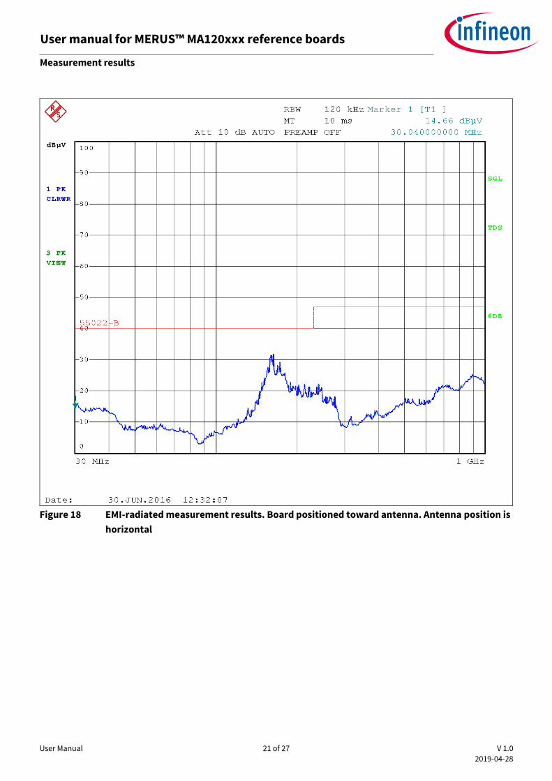
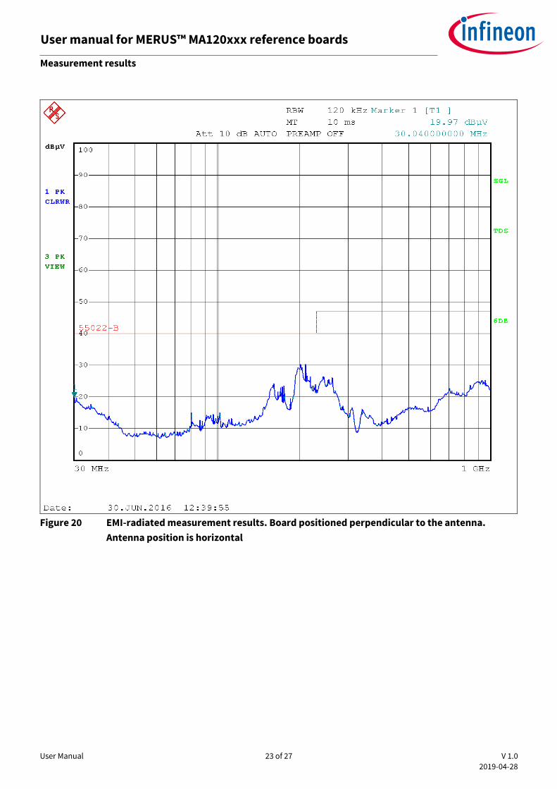
3.5.2 EMI measurement results
EMI-radiated results were collected for the reference board using four scenarios:
• Board was positioned toward the antenna and the antenna was vertical (Figure 17)
• Board was positioned toward the antenna and the antenna was horizontal (Figure 18)
• Board was positioned perpendicular to the antenna and the antenna was vertical (Figure 19)
• Board was positioned perpendicular to the antenna and the antenna was horizontal (Figure 20)

User Manual 20 of 27 V 1.0
2019-04-28
User manual for MERUS™ MA120xxx reference boards Measurement results
Figure 17 EMI-radiated measurement results. Board positioned toward antenna. Antenna position is
vertical
User Manual 21 of 27 V 1.0
2019-04-28
User manual for MERUS™ MA120xxx reference boards Measurement results
Figure 18 EMI-radiated measurement results. Board positioned toward antenna. Antenna position is
horizontal

User Manual 22 of 27 V 1.0
2019-04-28
User manual for MERUS™ MA120xxx reference boards Measurement results
Figure 19 EMI-radiated measurement results. Board positioned perpendicular to the antenna.
Antenna position is vertical
User Manual 23 of 27 V 1.0
2019-04-28
User manual for MERUS™ MA120xxx reference boards Measurement results
Figure 20 EMI-radiated measurement results. Board positioned perpendicular to the antenna.
Antenna position is horizontal
User Manual 24 of 27 V 1.0
2019-04-28
User manual for MERUS™ MA120xxx reference boards Appendix A – sample code
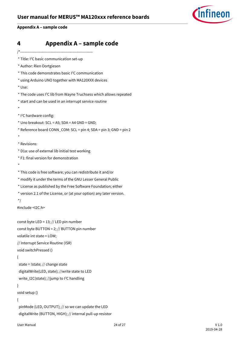
4 Appendix A – sample code /*----------------------------------------------------------
* Title: I2C basic communication set-up
* Author: Rien Oortgiesen
* This code demonstrates basic I2C communication
* using Arduino UNO together with MA120XXX devices
* Use:
* The code uses I2C lib from Wayne Truchsess which allows repeated
* start and can be used in an interrupt service routine
*
* I2C hardware config:
* Uno breakout: SCL = A5; SDA = A4 GND = GND;
* Reference board CONN_COM: SCL = pin 4; SDA = pin 3; GND = pin 2
*
* Revisions:
* D1a: use of external lib initial test working
* F1: final version for demonstration
*
* This code is free software; you can redistribute it and/or
* modify it under the terms of the GNU Lesser General Public
* License as published by the Free Software Foundation; either
* version 2.1 of the License, or (at your option) any later version.
*/
#include <I2C.h>
const byte LED = 13; // LED pin number
const byte BUTTON = 2; // BUTTON pin number
volatile int state = LOW;
// Interrupt Service Routine (ISR)
void switchPressed ()
{
state = !state; // change state
digitalWrite(LED, state); //write state to LED
write_I2C(state); //jump to I2C handling
}
void setup ()
{
pinMode (LED, OUTPUT); // so we can update the LED
digitalWrite (BUTTON, HIGH); // internal pull-up resistor
User Manual 25 of 27 V 1.0
2019-04-28
User manual for MERUS™ MA120xxx reference boards Appendix A – sample code
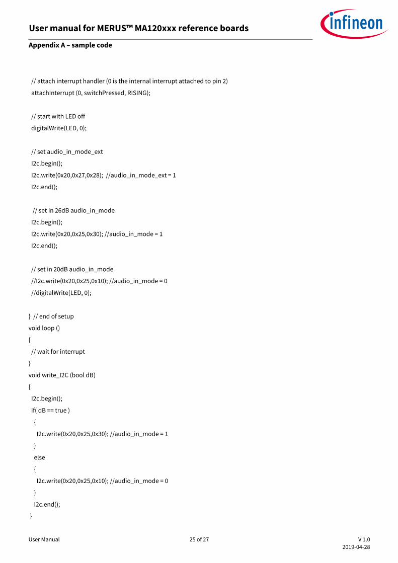
// attach interrupt handler (0 is the internal interrupt attached to pin 2)
attachInterrupt (0, switchPressed, RISING);
// start with LED off
digitalWrite(LED, 0);
// set audio_in_mode_ext
I2c.begin();
I2c.write(0x20,0x27,0x28); //audio_in_mode_ext = 1
I2c.end();
// set in 26dB audio_in_mode
I2c.begin();
I2c.write(0x20,0x25,0x30); //audio_in_mode = 1
I2c.end();
// set in 20dB audio_in_mode
//I2c.write(0x20,0x25,0x10); //audio_in_mode = 0
//digitalWrite(LED, 0);
} // end of setup
void loop ()
{
// wait for interrupt
}
void write_I2C (bool dB)
{
I2c.begin();
if( dB == true )
{
I2c.write(0x20,0x25,0x30); //audio_in_mode = 1
}
else
{
I2c.write(0x20,0x25,0x10); //audio_in_mode = 0
}
I2c.end();
}
User Manual 26 of 27 V 1.0
2019-04-28
User manual for MERUS™ MA120xxx reference boards Revision history
Revision history
Document
version
Date of release Description of changes
V 1.0 2019-04-28 Initial release

Trademarks All referenced product or service names and trademarks are the property of their respective owners.
Edition 2019-04-28
UM_1902_PL88_1902_171735
Published by
Infineon Technologies AG
81726 Munich, Germany
© 2022 Infineon Technologies AG.
All Rights Reserved.
Do you have a question about this
document?
Email: [email protected]
Document reference
IMPORTANT NOTICE The information contained in this application note is given as a hint for the implementation of the product only and shall in no event be regarded as a description or warranty of a certain functionality, condition or quality of the product. Before implementation of the product, the recipient of this application note must verify any function and other technical information given herein in the real application. Infineon Technologies hereby disclaims any and all warranties and liabilities of any kind (including without limitation warranties of non-infringement of intellectual property rights of any third party) with respect to any and all information given in this application note. The data contained in this document is exclusively intended for technically trained staff. It is the responsi ility of ustom r’s t hni l p rtm nts to evaluate the suitability of the product for the intended application and the completeness of the product information given in this document with respect to such application.
For further information on the product, technology, delivery terms and conditions and prices please contact your nearest Infineon Technologies office (www.infineon.com).
WARNINGS Due to technical requirements products may contain dangerous substances. For information on the types in question please contact your nearest Infineon Technologies office. Except as otherwise explicitly approved by Infineon Technologies in a written document signed by authorized representatives of Infineon Technologi s, Infin on T hnologi s’ pro u ts m y not be used in any applications where a failure of the product or any consequences of the use thereof can reasonably be expected to result in personal injury.