PREPARATORY SURVEY ON THE PROJECT FOR ...
249
PREPARATORY SURVEY ON THE PROJECT FOR EXPANSION OF WATER SUPPLY SYSTEM IN SVAY RIENG FINAL REPORT FEBRUARY 2022 JAPAN INTERNATIONAL COOPERATION AGENCY (JICA) CTI ENGINEERING INTERNATIONAL CO., LTD. WATER AND SEWER BUREAU, CITY OF KITAKYUSHU TEC INTERNATIONAL CO., LTD. MINISTRY OF INDUSTRY, SCIENCE, TECHNOLOGY & INNOVATION (MISTI) KINGDOM OF CAMBODIA GE JR 22-030
-
Upload
khangminh22 -
Category
Documents
-
view
0 -
download
0
Transcript of PREPARATORY SURVEY ON THE PROJECT FOR ...
PREPARATORY SURVEY ON THE PROJECT FOR
EXPANSION OF WATER SUPPLY SYSTEM IN SVAY RIENG
FINAL REPORT
FEBRUARY 2022
JAPAN INTERNATIONAL COOPERATION AGENCY (JICA)
CTI ENGINEERING INTERNATIONAL CO., LTD. WATER AND SEWER BUREAU, CITY OF KITAKYUSHU
TEC INTERNATIONAL CO., LTD.
MINISTRY OF INDUSTRY, SCIENCE, TECHNOLOGY & INNOVATION (MISTI) KINGDOM OF CAMBODIA
GE
JR
22-030


PREPARATORY SURVEY ON THE PROJECT FOR
EXPANSION OF WATER SUPPLY SYSTEM IN SVAY RIENG
FINAL REPORT
FEBRUARY 2022
JAPAN INTERNATIONAL COOPERATION AGENCY (JICA)
CTI ENGINEERING INTERNATIONAL CO., LTD. WATER AND SEWER BUREAU, CITY OF KITAKYUSHU
TEC INTERNATIONAL CO., LTD.
MINISTRY OF INDUSTRY, SCIENCE, TECHNOLOGY & INNOVATION (MISTI) KINGDOM OF CAMBODIA

EXCHANGE RATE (based on the average exchange rate June, 2021)
USD 1 = JPY 109.97
PREFACE
Japan International Cooperation Agency (JICA) decided to conduct the preparatory survey and entrust the survey to Consortium consist of CTI Engineering International Co., Ltd., Water and Sewer Bureau, City of Kitakyushu and TEC International Co., Ltd. The survey team held a series of discussions with the officials concerned of the Royal Government of Cambodia and conducted field investigations. As a result of further studies in Japan, the present report was finalized. I hope that this report will contribute to the promotion of the project and to the enhancement of friendly relations between our two countries. Finally, I wish to express my sincere appreciation to the officials concerned of the Royal Government of Cambodia for their close cooperation extended to the survey team. February,2022
EIJI IWASAKI Director General, Global Environment Department Japan International Cooperation Agency

S-1
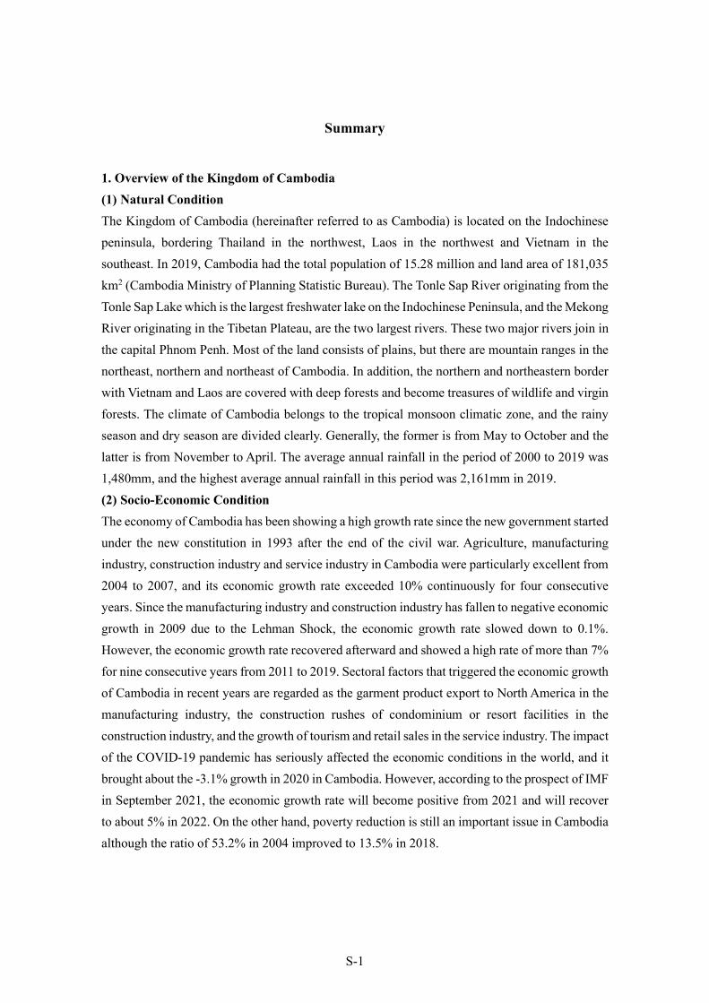
Summary
1. Overview of the Kingdom of Cambodia (1) Natural Condition The Kingdom of Cambodia (hereinafter referred to as Cambodia) is located on the Indochinese peninsula, bordering Thailand in the northwest, Laos in the northwest and Vietnam in the southeast. In 2019, Cambodia had the total population of 15.28 million and land area of 181,035 km2 (Cambodia Ministry of Planning Statistic Bureau). The Tonle Sap River originating from the Tonle Sap Lake which is the largest freshwater lake on the Indochinese Peninsula, and the Mekong River originating in the Tibetan Plateau, are the two largest rivers. These two major rivers join in the capital Phnom Penh. Most of the land consists of plains, but there are mountain ranges in the northeast, northern and northeast of Cambodia. In addition, the northern and northeastern border with Vietnam and Laos are covered with deep forests and become treasures of wildlife and virgin forests. The climate of Cambodia belongs to the tropical monsoon climatic zone, and the rainy season and dry season are divided clearly. Generally, the former is from May to October and the latter is from November to April. The average annual rainfall in the period of 2000 to 2019 was 1,480mm, and the highest average annual rainfall in this period was 2,161mm in 2019. (2) Socio-Economic Condition The economy of Cambodia has been showing a high growth rate since the new government started under the new constitution in 1993 after the end of the civil war. Agriculture, manufacturing industry, construction industry and service industry in Cambodia were particularly excellent from 2004 to 2007, and its economic growth rate exceeded 10% continuously for four consecutive years. Since the manufacturing industry and construction industry has fallen to negative economic growth in 2009 due to the Lehman Shock, the economic growth rate slowed down to 0.1%. However, the economic growth rate recovered afterward and showed a high rate of more than 7% for nine consecutive years from 2011 to 2019. Sectoral factors that triggered the economic growth of Cambodia in recent years are regarded as the garment product export to North America in the manufacturing industry, the construction rushes of condominium or resort facilities in the construction industry, and the growth of tourism and retail sales in the service industry. The impact of the COVID-19 pandemic has seriously affected the economic conditions in the world, and it brought about the -3.1% growth in 2020 in Cambodia. However, according to the prospect of IMF in September 2021, the economic growth rate will become positive from 2021 and will recover to about 5% in 2022. On the other hand, poverty reduction is still an important issue in Cambodia although the ratio of 53.2% in 2004 improved to 13.5% in 2018.

S-2
2. Background of the Project
After the improvement of drinking water supply system in Phnom Penh by the Royal Government of Cambodia (RGC), the government had kept improving the system in provincial cities by expanding the accomplishment of water supply system in Phnom Penh. JICA has been supporting the government through Technical Cooperation, Grant Aid and ODA Loan.
“The Master Plan of Greater Phnom Penh Water Supply in the Kingdom of Cambodia” was formulated under the support of JICA in 1993 after the civil war. Based on the master plan, the drinking water treatment plant (WTP) and distribution water pipe networks were constructed through Japanese Grant Aid. The strengthening of management, operation and maintenance for the water supply system has progressed through the technical cooperation with Water and Sewer Bureau, City of Kitakyushu and so on.
Synergistic effects with other donor’s support made the Phnom Penh Water Supply Authority (PPWSA) as one of the best water supply corporations in Asia (90% of water supply coverage ratio, 8% of water loss rate and 24-hour water supply in 2006). Meanwhile, the water supply coverage ratio in the provincial cities of Cambodia was at 35% in 2005.
The target for water supply ratio in urban areas of provincial cities, i.e., 100% by 2025, has been propagated in the Ministry of Industry and Handicrafts (MIH, then ministry in charge)1, and the RGC proceeded with the expansion of water supply facilities in provincial cities.
It will then become possible to operate water supply systems fairly. However, the water supply coverage ratio of provincial cities is presently low because of the low production capacity. For example, in Svay Rieng City which has approximately 100,000 people in the administrative area2 of Waterworks (WWs), could only supply water to approximately 24,000 people (in 2019), and the water supply coverage ratio was approximately 23.6% in Svay Rieng City.
Under the circumstances, to achieve the target of 100% water supply coverage ratio by 2025, the expansion of the water supply systems is an urgent issue requiring a definite and workable solution. In August 2016, the RGC made an official request for Japanese Grant Aid for “The Project for Expansion of Water Supply Systems in Pursat and Svay Rieng City in the Kingdom of Cambodia”, to improve the water supply services in Pursat City and Svay Rieng City. (The official request letter was submitted in June 2017).
1 MIH was renamed as Ministry of Industry, Science, Technology and Innovation (MISTI) in 2020. 2 The definition of administrative area in this case is based on the area reviewed in October 2015 for the provincial Waterworks (WWs) that will be allowed to supply water under the administrative responsibility of the former Secretary of State H.E. Ek Sonn Chan of MISTI.
S-3
According to the discussion results with the Cambodian officials during the first field survey from June to September in 2017, both sides agreed as follows:
Preparation for grant aid on the expansion of water supply system in Pursat City based on the request will start; and
Although the field survey on Svay Rieng City had started as the premise for using surface water from Vay Kor Lake, it became clear through the field survey and analysis in Japan that the surface water development from the lake is almost impossible because of the unsteadiness of Vay Kor Dam, the insufficient embankment height of the access road to the dam against flood, and the low discharge capacity of its downstream.
Therefore, the possibility of groundwater as the water source for this project should be checked by conducting additional groundwater surveys with some extension of the total schedule.
Based on the above background, the Pursat City portion of the project has to be separately carried out
and completed, while the Svay Rieng City portion with the target year of 2027 has to be studied alone.
This project (hereinafter referred to as “this project”) aims to improve the access rate to safe water,
provide stable water supply services and improve the quality of life of residents by expanding and
improving the water supply systems in Svay Rieng City.
3.Results of Preparatory Survey and Scope of the Project (1) Results of the Preparatory Survey The Japan International Cooperation Agency (JICA) dispatched the Preparatory Survey Team (Survey Team) to Cambodia five times to carry out activities including the joint survey of Pursat and Svay Rieng based on the above-mentioned background.
【Survey for Pursat and Svay Rieng】 The first field work: From May 21, 2017 to July 23, 2017 (Including inception meeting) The second field work: From August, 9 2017 to October 15, 2017
(Including the meeting of Minutes of Discussions (MD) as for the first and second field survey result)
【Survey for Svay Rieng after determination of water source】
The third field work: From November 5, 2019 to December 22, 2019 The fourth field work: From January12, 2020 to March 8, 2020

S-4
Online meeting April 12, 2021 (Meeting for resume of the project) The fifth field work: From November 28, 2021 to December18, 2021
(Including draft outline design (DOD) meeting)
The team conducted the measuring survey, geological survey, water quality survey and the present conditions of the existing water supply facilities, as well as environmental and social condition in Svay Rieng City. A detailed survey on the soundness of the Vay Kor Dam was conducted by the Japan Water Agency in 2018, and it was concluded that there was no need for urgent reconstruction of the Vay Kor Dam with the appropriate maintenance by the Cambodian side. Therefore, both parties agreed to switch the water source from groundwater to surface water in 2019, and continued the survey. Therefore, this preparatory survey for Svay Rieng consists of the appropriate outline design as a grant aid project by formulating the project implementation plan and carrying out project cost estimation after confirming the requested contents from the Cambodian side and evaluating the validity of the project scale. As a result, by the target year 2027 in Svay Rieng, the stable water supply of 13,360 m3 (maximum per day) combined with the capacity of the existing facility is expected for 86.7% of the urban area3 population, 18.5% of the rural area population by constructing new WTP with the capacity of 6,800 m3/day on this project. (2) Scope of the Project 1) Construction of Water Supply Facilities
The water supply facilities to be constructed are as follows:
Intake and Raw Water Transmission Facilities Classification of Facilities
Structure Major Items Middle Items Minor Items
Water Supply 7,480m3/day
Intake Pump station
Pump House Reinforced concrete, Rectangle, Basement structure Ground floor: B11.6m × L16.0m × H3.3m(Under beam) Bacement floor: B7.5m × L10.5m × H6.9m(Under beam) :Electrical room, Generator room, Pump room, Office,
Toilet, Suction pit, Intake pump (5.2m3/m, 19m, 2 pumps)
Conveyance Facility
Conveyance Pipe
Conveyance Pipe
DIP, Diameter 350mm L=2.9km
Source: Survey Team
3 The definition of urban area is based on "Reclassification of Urban Areas in Cambodia, 2011" published by the Ministry of Planning (MOP). (1) The population density is over 200 people / km2, (2) The population of farmers is less than 50%, and (3) The total population of the commune is over 2000 people.

S-5
Water Treatment Plant
Items
New Svay Rieng WTP Design Water Treatment Capacity: 7,480m3/day, Design Maximum Daily Demand: 6,800m3/day
Contents Qty
Receiving Well Reinforced Concrete Structure
1 Basin Internal Dimension: Width 1.50m×Length 3.90m×Depth 4.60m Volume (V): 26.9m3, Retention Time (T): 5.2min (Criteria: T ≧1.5min)
Mixing Well
Reinforced Concrete Structure
1 Basin The method to utilize the energy of water flow itself Internal Dimension: Width 1.50m×Length 1.50m×Depth 4.19m Volume (V): 9.43 m3, Retention Time (T): 1.82min (Criteria: 1<T<5min)
Flocculation Basin
Reinforced Concrete Structure
2 Basins
Slow Mixing Method: Up-and-Down Roundabout Type (zigzag flow) Number of Stage: five (5) Stages Internal Dimension per Basin: Width 7.00m × Length 3.65m × Average Effective Water Depth 3.78m (Height 4.50m) G Value: 10 – 75 (1/s) GT Value: 23,000 – 210,000
Sedimentation Basin
Reinforced Concrete Structure
2 Basins
Horizontal Flow Sedimentation Type Supernatant Water Collecting System: Collecting Trough + Submerged Orifice Internal Dimension per Basin: Width 7.00m × Length 20.00m × Average Water Depth 4.4m Surface Loading: Q/A=18.6mm/min (Criteria:15-30mm/min) Mean Velocity (V): 0.08m/min (Criteria: 0.40m/min or below)
Rapid Sand Filter (Reference) *
Reinforced Concrete Structure
4 Basins
Type: Self-Balancing Type Internal Dimension per Basin: Width 2.50m×Length 6.00m Filter Sand Thickness: 1.0m Underdrain System: Perforated Block Filtration Rate (V): 124.7m/day (Criteria: 120-150m/day) Backwash Method: Air Wash + Water Wash
Service Reservoir
Reinforced Concrete Structure using Flat Slab Structure
2 Basins Effective Volume per Basin (V): 2,188m3 (1,094m3 × 2Basins) Effective Water Depth (H): 3.8m (Criteria:3-6m) Retention Time (T): 8hours (Set from daily-water demand fluctuation) Internal Dimension per Basin: Width 12.00m × Length 24.00m × Height 4.50m
Drainage Basin
Reinforced Concrete Structure
2 Basins Volume (V): 198.0m3 (99.0m3 × 2Basins) (Volume per Basin: More than one-time wastewater volume) Internal Dimension per Basin: Width4.00m × Length 11.00m × Effective Water Depth 2.25m (Height 5.60m)
Drying Bed
Reinforced Concrete Structure
4 Beds Effective Area (A):550.4m2 (Area per bed: Width 8.6m×Length 16m=137.6m2) (Average Turbidity: After calculating the amount of generated sludge from the coagulant injection rate, the area from the planned sludge load is calculated.)
Chemical Feeding Facilities
(In Chemical Building)
Coagulant: PAC Injection Method: Gravity Flow from Constant Water Level Tank. 1 Unit Acid and Alkali Agents: Lime (for supplementing the alkali content consumed by the coagulant)
S-6
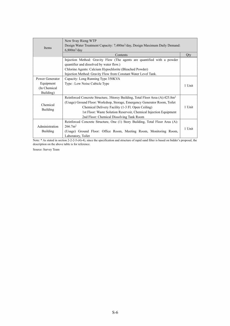
Items
New Svay Rieng WTP Design Water Treatment Capacity: 7,480m3/day, Design Maximum Daily Demand: 6,800m3/day
Contents Qty Injection Method: Gravity Flow (The agents are quantified with a powder quantifier and dissolved by water flow.) Chlorine Agents: Calcium Hypochlorite (Bleached Powder) Injection Method: Gravity Flow from Constant Water Level Tank.
Power Generator Equipment
(In Chemical Building)
Capacity: Long Running Type 350KVA
1 Unit Type : Low Noise Cubicle Type
Chemical Building
Reinforced Concrete Structure, 3Storey Building, Total Floor Area (A):425.8m2
1 Unit (Usage) Ground Floor: Workshop, Storage, Emergency Generator Room, Toilet
Chemical Delivery Facility (1-3 Fl. Open Ceiling) 1st Floor: Waste Solution Reservoir, Chemical Injection Equipment 2nd Floor: Chemical Dissolving Tank Room
Administration Building
Reinforced Concrete Structure, One (1) Story Building, Total Floor Area (A): 266.7m2 1 Unit (Usage) Ground Floor: Office Room, Meeting Room, Monitoring Room, Laboratory, Toilet
Note: * As stated in section 2-2-2-5-(4)-4), since the specification and structure of rapid sand filter is based on bidder’s proposal, the description on the above table is for reference.
Source: Survey Team
S-7
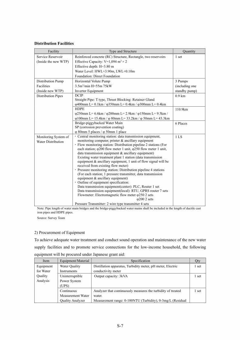
Distribution Facilities
Note: Pipe length of water main bridges and the bridge-piggybacked water mains shall be included in the length of ductile cast iron pipes and HDPE pipes.
Source: Survey Team
2) Procurement of Equipment
To achieve adequate water treatment and conduct sound operation and maintenance of the new water
supply facilities and to promote service connections for the low-income household, the following
equipment will be procured under Japanese grant aid: Item Equipment/Material Specification Qty
Equipment for Water Quality Analysis
Water Quality Instruments
Distillation apparatus, Turbidity meter, pH meter, Electric conductivity meter
1 set
Uninterruptible Power System (UPS)
Output capacity: 3kVA 1 set
Continuous Measurement Water Quality Analyzer
Analyzer that continuously measures the turbidity of treated water. Measurement range: 0-100NTU (Turbidity), 0-3mg/L (Residual
1 set
Facility Type and Structure Quantity Service Reservoir (Inside the new WTP)
Reinforced concrete (RC) Structure, Rectangle, two reservoirs Effective Capacity: V=1,094 m3 × 2 Effective depth: H=3.80 m Water Level: HWL+3.90m, LWL+0.10m Foundation: Direct Foundation
1 set
Distribution Pump Facilities (Inside new WTP)
Horizontal Volute Pump 3.5m3/min H=55m 75kW Inverter Equipment
3 Pumps (including one standby pump)
Distribution Pipes DCIP Straight Pipe: T type, Thrust Blocking: Retainer Gland φ400mm L= 0.1km / φ350mm L= 0.4km / φ300mm L= 0.4km
0.9 km
HDPE φ250mm L= 6.6km / φ200mm L= 2.9km / φ150mm L= 9.5km / φ100mm L= 15.4km / φ 80mm L= 33.2km / φ 50mm L= 43.3km
110.9km
Bridge-piggybacked Water Main SP (corrosion prevention coating) φ 80mm 5 places / φ 50mm 1 place
6 Places
Monitoring System of Water Distribution
Central monitoring station: data transmission equipment, monitoring computer, printer & ancillary equipment Flow monitoring station: Distribution pipeline 2 stations (For
each station; φ200 flow meter 1 unit, φ250 flow meter 1 unit, data transmission equipment & ancillary equipment) Existing water treatment plant 1 station (data transmission equipment & ancillary equipment, 1 unit of flow signal will be received from existing flow meter) Pressure monitoring station: Distribution pipeline 4 stations
(For each station; 1 pressure transmitter, data transmission equipment & ancillary equipment) Outline of equipment specification:
Data transmission equipment(center): PLC, Router 1 set Data transmission equipment(local): RTU, GPRS router 7 sets Flowmeter: Electromagnetic flow meter φ250 2 sets
φ200 2 sets Pressure Transmitter: 2 wire type transmitter 4 sets
1 LS

S-8
Item Equipment/Material Specification Qty chlorine)
Reagents pH standard solution, BTB reagent, DPD reagent, etc. 1 set Glassware Beaker, Measuring flask, Pipette, burette, etc. 1 set Laboratory Table Central laboratory table (including reagent shelf, socket outlet,
piping and wiring), Side laboratory table and sink 1 set
Other Storage shelf, Refrigerator and desk/chair 1 set Tools for Electrical Machinery Equipment
Clamp Power Meter Voltage range: AC600V Current range: AC600mA-AC 1,000mA (or above)
1 set
Insulation Resistance Meter
For analog indication Value 250V Range : 0 – 50MΩ 500V Range : 0 – 100MΩ 1000V Range : 0 – 2000MΩ
For digital indication Value 250V Range : 0 – 500MΩ 500V Range : 0 – 2000MΩ 1000V Range : 0 – 4000MΩ
1 set
Ground Resistance meter
0 – 1000Ω 1 set
Vibration Checker Acceleration: 0.02 – 200m/s2、Velocity:0.3 – 1,000mm/s Displacement: 0.02 – 100mm
1 set
Mechanical Torque Wrench
Measurement Range: 50 – 300Nm 1 set
Portable Ultrasonic Flow meter
Measurement Range of Pipe Diameter: 13 – 600mm 1 set
Sieve Shaking Machine
Effective Diameter: 0.8mm – 1.0mm 1 set
Maintenance for Distribution Pipes
Electrofusion Machine and Accessories for PE Pipes
φ63 – 280mm 1 set
Accounting System Equipment
SUMS System
Three (3) Computers (for billing, accounting and casher, one PC for one software), one (1) UPS, one (1) Printer, SUMS Software (two (2) Full Licenses, one (1) Light License) Software of full license includes “Billing “and “Accounting”. Software of light license includes “Casher”. Since each software of “Billing”, “Accounting”, “Casher” is operated by separated PCs, three (3) PC will be required.
1 set
Service Connection Installations
Water Supply Equipment
Per 1 set Snap taps with saddle from distribution pipes
(DN350mm~OD63mm) HDPE water supply pipe (diameter 25mm) 30m Water meter (diameter 15mm, Tangential flow impeller
type, Single-jet, Class C, Rotatable display (Max.270 degree))
Stopcock (diameter 15mm) Attachment (joint, coupling, etc.)
375 sets
Source: Survey Team
3) Technical Assistance (Soft Component)
Training on the following 3 items will be provided under the technical assistance (soft component) of
this project.

S-9
Operation and maintenance of water treatment facilities Operation and maintenance of water transmission and distribution facilities Production management (Water supply facility management)
4. Implementation Plan and Cost Estimation (1) Implementation Plan The project will be implemented under Japanese’s Grant Aid based on the Grant Agreement (G/A) between the RGC and JICA after the Exchange of Notes (E/N) has been concluded between the RGC and GOJ. The project will begin with the detail design study immediately after the signing of contract for consultancy services. The consultancy services will require 12 months including E/N, engineering design services, preparation of tender documents and tender administration. The total construction period will be 23 months including the construction of facilities and procurement of equipment. (2) Approximate Project Cost Total expenses of the Cambodian side will be approximately 668,229 USD. The expense items will be ground leveling for intake facility and drinking WTP, UXO survey, environmental monitoring survey, information and communication, electric power lead-in to new intake plant and new drinking WTP, bank arrangement, house connection works using procured equipment for poverty households and so on.
5. Project Evaluation (1) Validity of the Project Beneficiary of the Project
The water supply capacity to residents in Svay Rieng City will be improved under the project. The water supply ratio in the administrative area has been 23.6% in 2019 and will increase by 52.6% in the target year of 2027. The water supply ratio in the urban areas, which MISTI targets, will be 86.7%. The number of beneficiaries increase (population newly served) will be approximately 32,419 persons (22,543 persons in the urban areas while it will be 9,876 persons in rural areas).
Urgency of the Project
Although Svay Rieng City operates an existing water service system, its water supply ratio remains at 23.6% as of 2019. Accordingly, the expansion of water supply facilities is urgently needed to further improve the water supply ratio.
Consistency with the National Strategic Development Plan
The National Strategic Development Plan (NSDP) 2019-2023 has set the target of achieving 100% water supply ratio in urban areas by 2025. Ninety percent (90%) of the urban population
S-10
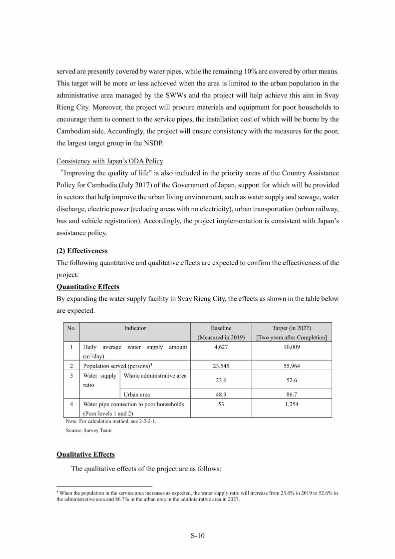
served are presently covered by water pipes, while the remaining 10% are covered by other means. This target will be more or less achieved when the area is limited to the urban population in the administrative area managed by the SWWs and the project will help achieve this aim in Svay Rieng City. Moreover, the project will procure materials and equipment for poor households to encourage them to connect to the service pipes, the installation cost of which will be borne by the Cambodian side. Accordingly, the project will ensure consistency with the measures for the poor, the largest target group in the NSDP.
Consistency with Japan’s ODA Policy
“Improving the quality of life” is also included in the priority areas of the Country Assistance Policy for Cambodia (July 2017) of the Government of Japan, support for which will be provided in sectors that help improve the urban living environment, such as water supply and sewage, water discharge, electric power (reducing areas with no electricity), urban transportation (urban railway, bus and vehicle registration). Accordingly, the project implementation is consistent with Japan’s assistance policy.
(2) Effectiveness The following quantitative and qualitative effects are expected to confirm the effectiveness of the project: Quantitative Effects By expanding the water supply facility in Svay Rieng City, the effects as shown in the table below are expected.
No. Indicator Baseline (Measured in 2019)
Target (in 2027) [Two years after Completion]
1 Daily average water supply amount (m3/day)
4,627 10,009
2 Population served (persons)4 23,545 55,964 3 Water supply
ratio Whole administrative area
23.6 52.6
Urban area 48.9 86.7 4 Water pipe connection to poor households
(Poor levels 1 and 2) 53 1,254
Note: For calculation method, see 2-2-2-1.
Source: Survey Team
Qualitative Effects
The qualitative effects of the project are as follows:
4 When the population in the service area increases as expected, the water supply ratio will increase from 23.6% in 2019 to 52.6% in the administrative area and 86.7% in the urban area in the administrative area in 2027.

S-11
Improving the living environment of residents (improving the public health environment of residents who used to use rainwater, etc., and improving convenience)
As above, the validity of the project is high, and its effectiveness is expected.

i
PREPARATORY SURVEY ON THE PROJECT FOR EXPANSION OF WATER SUPPLY SYSTEM
IN SVAY RIENG FINAL REPORT
Table of Contents Summary
Table of Contents
Location Map/Project Site
Perspective of Intake and Water Treatment Facilities / Photos
List of Figures & Tables
Abbreviations
Chapter 1. Background of the Project ....................................................................... 1-1 1-1 Background of the Project ............................................................................................... 1-1 1-2 Natural Conditions ........................................................................................................... 1-2
1-2-1 Measurement Survey ................................................................................................ 1-2 1-2-2 Soil Investigation ...................................................................................................... 1-3 1-2-3 Water Quality Monitoring ......................................................................................... 1-3 1-2-4 Flood flow in Vay Kor River .................................................................................... 1-4 1-2-5 Vay Kor Lake’s potential for water source ............................................................... 1-4
1-3 Environmental and Social Considerations ....................................................................... 1-4 1-3-1 Project Components and JICA Environmental Categories ....................................... 1-4
1-3-1-1 Overview of the Project Components that have an Environmental and Social Impact ................................................................................................................................... 1-4
1-3-1-2 Basic Environmental and Social Circumstances ..................................................... 1-5
1-3-1-3 Environmental and Social Consideration Systems and Organizations in Cambodia . 1-
24
1-3-1-4 Comparison of Alternatives ....................................................................................1-37
1-3-1-5 Results of Scoping and the Environmental and Social Survey TOR ......................1-40
1-3-1-6 Results of Environmental and Social Study (Including Projection) .......................1-43
1-3-1-7 Impact Assessment .................................................................................................1-49
1-3-1-8 Mitigation Measures and their Implementation Cost .............................................1-51
1-3-1-9 Monitoring Plan ......................................................................................................1-53
1-3-1-10 Stakeholder Meetings ...........................................................................................1-54
1-3-2 Land Acquisition and Resettlement ........................................................................ 1-56 1-3-2-1 Need for Land Acquisition and Resettlement .........................................................1-56
ii
1-3-2-2 Legal Framework on Land Acquisition and Resettlement......................................1-56
1-3-2-3 Need for Land Acquisition and Resettlement .........................................................1-58
1-3-2-4 Compensation and Support .....................................................................................1-58
1-3-3 Others ..................................................................................................................... 1-58 1-3-3-1 Monitoring Form (Draft) ........................................................................................1-58
1-3-3-2 Environmental Checklist ........................................................................................1-60
Chapter 2. Contents of the Project .......................................................................................... 2-1 2-1 Basic Concept of the Project ............................................................................................ 2-1 2-2 Outline Design of the Requested Japanese Assistance .................................................... 2-3
2-2-1 Design Policy ............................................................................................................ 2-3 2-2-1-1 Basic Policy ....................................................................................................... 2-3 2-2-1-2 Natural and Environmental Conditions ............................................................. 2-4 2-2-1-3 Social Conditions .............................................................................................. 2-6 2-2-1-4 Construction / Procurement Circumstances ...................................................... 2-7 2-2-1-5 Utilizing Local Operators .................................................................................. 2-7 2-2-1-6 Operation and Management Capacity of the Implementation Agency.............. 2-7 2-2-1-7 Grade of Facility, Machinery, etc. ..................................................................... 2-7 2-2-1-8 Construction / Procurement Methods and Construction Period ........................ 2-8
2-2-2 Basic Plan ................................................................................................................. 2-8 2-2-2-1 Water Demand Projection .................................................................................. 2-8 2-2-2-2 New Surface Water Source .............................................................................. 2-25 2-2-2-3 Intake Facility Plan .......................................................................................... 2-39 2-2-2-4 Conveyance Pipe ............................................................................................. 2-45 2-2-2-5 Plan for WTP ................................................................................................... 2-47 2-2-2-6 Distribution Facilities ...................................................................................... 2-67 2-2-2-7 Procurement Plan of Equipment and Materials ............................................... 2-79
2-2-3 Outline Design Drawings ....................................................................................... 2-84 2-2-4 Implementation Plan ............................................................................................... 2-86
2-2-4-1 Implementation Policy .................................................................................... 2-86 2-2-4-2 Implementation Conditions ............................................................................. 2-87 2-2-4-3 Scope of Works................................................................................................ 2-88 2-2-4-4 Consultant’s Supervision ................................................................................. 2-88 2-2-4-5 Quality Control Plan ........................................................................................ 2-90 2-2-4-6 Procurement Plan ............................................................................................ 2-91 2-2-4-7 Operation Guidance Plan ................................................................................ 2-92

iii
2-2-4-8 Soft Component (Technical Assistance) Plan .................................................. 2-92 2-2-4-9 Implementation Schedule ................................................................................ 2-97
2-3 Security Plan .................................................................................................................. 2-98 2-4 Obligations of Recipient Country .................................................................................. 2-99
2-4-1 Specific Obligations of the Government of Cambodia, which will not be Funded with the Grant ........................................................................................................................... 2-99
2-4-1-1 Specific Obligations before the Tender ........................................................... 2-99 2-4-1-2 Obligations during Project Implementation .................................................... 2-99 2-4-1-3 Obligations After the Completion of New Facility in the Project ................. 2-101
2-4-2 Treated Water Quality of Existing Plant and Facility ........................................... 2-102 2-4-3 Land Acquisition and Ground Leveling for WTP and Intake Facility .................. 2-102 2-4-4 Approval for Taking Water from Vay Kor Lake ................................................... 2-103 2-4-5 Drawing Electricity Line to the Site of WTP and Intake Facility ......................... 2-105 2-4-6 Occupancy Approval of Conveyance, Transmission and Distribution Pipe Routes ... 2-105
2-4-6-1 Occupancy Approval for National Highway and Bridge-Attached Pipe and Railway ...................................................................................................................... 2-105 2-4-6-2 Occupancy Approval for General Roads ....................................................... 2-105
2-4-7 Service Pipe Connection and Water Meter Installation for Each Household ....... 2-105 2-4-8 Environmental and Social Considerations ............................................................ 2-106
2-4-8-1 Approval of the EPC ..................................................................................... 2-106 2-4-8-2 Implementation of Environmental Management and Monitoring Plans ....... 2-107
2-4-9 Securing Temporary Site ...................................................................................... 2-108 2-4-10 Others ................................................................................................................. 2-108
2-5 Project Operation and Maintenance Plan ..................................................................... 2-109 2-5-1 Project Operation Plan .......................................................................................... 2-109 2-5-2 On-site Maintenance ............................................................................................. 2-113
2-6 Project Cost Estimation................................................................................................ 2-115 2-6-1 Initial Cost Estimation .......................................................................................... 2-115 2-6-2 Operation and Maintenance Cost .......................................................................... 2-115
2-6-2-1 Analysis of Financial Conditions .................................................................. 2-115 2-6-2-2 Water Consumption ....................................................................................... 2-118 2-6-2-3 Water Charge Revenue and NRW Rate in Present Conditions ...................... 2-118 2-6-2-4 Forecast of Water Distribution in the Future ................................................. 2-119 2-6-2-5 Operation and Maintenance Cost in Future ................................................... 2-120 2-6-2-6 Forecast of Revenues and Expenditures for SWWs ...................................... 2-121
iv
Chapter 3. Project Evaluation ................................................................................................. 3-1 3-1 Preconditions for Project Implementation ....................................................................... 3-1 3-2 Necessary Inputs (Obligations) by Recipient Country to Achieve the Whole Project Plan
.................................................................................................................................... 3-2 3-3 External Conditions ......................................................................................................... 3-3 3-4 Project Evaluation ............................................................................................................ 3-3
3-4-1 Validity ...................................................................................................................... 3-3 3-4-2 Effectiveness ............................................................................................................. 3-4
[APPENDECES] 1. Member List of the Survey Team .......................................................................................... A-1 2. Survey Schedule .................................................................................................................... A-5 3. List of Parties Concerned in the Recipient Country ............................................................ A-13 4. Minutes of Discussions ........................................................................................................ A-16 5. Soft Component Plan ........................................................................................................... A-90 6. Relevant Data (List of Collected Data) .............................................................................. A-109 7. Other materials / information ..............................................................................................A-111
7-1 Technical Note ............................................................................................................ A-111 7-2 Outline Design Drawings ............................................................................................ A-142 7-3 Intake Pump Total Head Calculation .......................................................................... A-205 7-4 Water Hammer Analysis between Intake Pump Station and WTP ............................. A-206 7-5 Hydraulic Calculation for Conveyance Pipe ............................................................... A-207 7-6 Selection of Pipe Material ........................................................................................... A-208 7-7 Location and Depth of Laying for Conveyance Pipe and Distribution Mains ............ A-209 7-8 Capacity of the Service Reservoir ............................................................................... A-211 7-9 Hydraulic Network Analysis ....................................................................................... A-212 7-10 Assumptions on the Number of Poor Households .................................................... A-231 7-11 Basic Information of the Water Sector ..................................................................... A-233 7-12 Project Monitoring report (PMR) ............................................................................. A-235

v
Location Map
vi
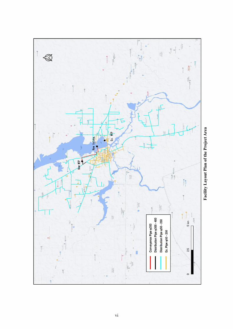
Faci
lity
Lay
out P
lan
of th
e Pr
ojec
t Are
a
vii
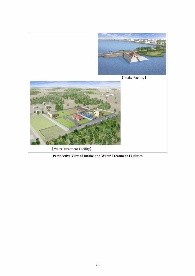
Perspective View of Intake and Water Treatment Facilities
【Intake Facility】
【Water Treatment Facility】

viii
■Photos
Planned Site for New Facilities
Photo-1 : Proposed intake site (North side of Vay Kor Lake across National Highway No.1)
Photo-2 : Road condition near the proposed intake site. Conveyance pipes will be laid on the shoulder of the road.
Photo-3 : Near the proposed intake site. Repair of road shoulders by the Cambodian side.
Photo-4 : Repair of riverbed scouring on the downstream side of Vay Kor Dam by the Cambodian side.
Photo-5 : Proposed WTP site. Originally a wooded area, tree trimming has been completed.
Photo-6 : Road shoulder where distribution pipes will be laid.
Proposed Intake Site

ix
Situation of Water Utilization
Photo-7 : A motor pump is installed in the riser pipe of the original hand pump.
Photo-8 : A motor pump is installed in a hand pump well constructed by UNICEF.
Photo-9 : Drinking water is used through a sand filter when the well water is turbid.
Photo-10 : Especially in the rainy season, rainwater is stored in jars and used for drinking.


x
List of Figures Figure 1-3-1 Project Area ................................................................................................................. 1-5
Figure 1-3-2 Protected Areas in Cambodia ....................................................................................... 1-6
Figure 1-3-3 Protected Area of Vay Kor Lake (Part with Blue Color).............................................. 1-7
Figure 1-3-4 Vay Kor Lake and Protected Area ................................................................................ 1-9
Figure 1-3-5 Rice Cropping Pattern in Svay Rieng .........................................................................1-19
Figure 1-3-6 Land Use Area by Category ........................................................................................1-22
Figure 1-3-7 Process of EPC Approval ............................................................................................1-27
Figure 1-3-8 Process of EIA/IEIA Approval....................................................................................1-28
Figure 2-2-1Administrative Area under the Management of SWWs ................................................ 2-9
Figure 2-2-2 Target Water Supply Area in the Project .....................................................................2-12
Figure 2-2-3 Design Water Supply Area and Administrative Area in Svay Rieng...........................2-15
Figure 2-2-4 Daily Maximum Demand and WTP Capacity ............................................................2-21
Figure 2-2-5 Vay Kor River and the Basin.......................................................................................2-25
Figure 2-2-6 Average Precipitation Over the Last 20 Years .............................................................2-26
Figure 2-2-7 Average Temperature Over the Last 10 Years .............................................................2-27
Figure 2-2-8 Daily Average Water Level on the Downstream Side of the Bridge Downstream of the
Vay Kor Dam ...................................................................................................................................2-28
Figure 2-2-9 HAV Graph of Vay Kor Lake ......................................................................................2-29
Figure 2-2-10 Vay Kor Lake Bank Plan ...........................................................................................2-30
Figure 2-2-11 Standard Cross Section of Parks and Revetments around Vay Kor Lake .................2-31
Figure 2-2-12 Construction Status of the Park and Revetment of Vay Kor Lake (February 2020) .2-31
Figure 2-2-13 Location of Intake Facility and Three Wells in Svay Rieng .....................................2-33
Figure 2-2-14 Well Structure and its Geological Column for WTP in Svay Rieng (Well No. 2) ....2-33
Figure 2-2-15 Operating Pattern of Production Wells for WTP in Svay Rieng ...............................2-34
Figure 2-2-16 Location Map of New Intake Facility and WTP .......................................................2-35
Figure 2-2-17 Cross Section of the Northwestern Shore of Vay Kor Lake (East-West Direction)(1/2)
.........................................................................................................................................................2-35
Figure 2-2-18 Cross Section (East-West Direction) and Photo of the Northwestern Shore of Vay Kor
Lake(2/2) ....................................................................................................................................2-36
Figure 2-2-19 Topographic Map around the Intake Facilities ..........................................................2-37
Figure 2-2-20 Cross-Sectional View of Vay Kor Lake Intake Candidate Site No. 2 .......................2-38
Figure 2-2-21 Status of Candidate Site for Intake Facilities (December 2019) ...............................2-38
Figure 2-2-22 Status of Candidate Construction Sites for Water Intake Facilities (Aerial Photograph)
.........................................................................................................................................................2-39
Figure 2-2-23 Existing Pump Facility in Phnom Penh Metropolitan Area ......................................2-44
xi
Figure 2-2-24 3D Perspective of Intake Facility (Draft) ..................................................................2-44
Figure 2-2-25 Route of Conveyance Pipe ........................................................................................2-46
Figure 2-2-26 Schematic of Existing WTP Syatem .........................................................................2-48
Figure 2-2-27 Layout Map of the Facilities at the Existing WTP ....................................................2-48
Figure 2-2-28 Existing WTP (gravity rapid sand filter) ...................................................................2-48
Figure 2-2-29 Existing WTP (membrane filter) ...............................................................................2-49
Figure 2-2-30 Location map of the planned site of the new WTP ...................................................2-51
Figure 2-2-31 Water Treatment Process Flow..................................................................................2-52
Figure 2-2-32 New WTP Layout .....................................................................................................2-60
Figure 2-2-33 Hydraulic Profile of the New WTP ...........................................................................2-61
Figure 2-2-34 Drainage and Sludge Treatment Process ...................................................................2-62
Figure 2-2-35 Drainage Pipe Route .................................................................................................2-63
Figure 2-2-36 Outline of Existing Water Distribution System.........................................................2-67
Figure 2-2-37 Design Service Area ..................................................................................................2-68
Figure 2-2-38 Relation between Location and Demand in Existing and .........................................2-69
Figure 2-2-39 Two Proposals of Reorganization of Water Distribution System ..............................2-70
Figure 2-2-40 Route of Distribution Pipes .......................................................................................2-72
Figure 2-2-41 Locations Map of Crossing Rivers and Other Structures ..........................................2-74
Figure 2-2-42 Photographs of Bridges and Culverts .......................................................................2-74
Figure 2-2-43 Distribution Block (DMA) for Water Distribution Monitoring and Installation Location
of Flow Meter / Pressure Gauge ......................................................................................................2-76
Figure 2-2-44 Location of Hydrants to be Installed .........................................................................2-77
Figure 2-2-45 Plan for Distribution Mains ......................................................................................2-78
Figure 2-2-46 Draft Schedule of Soft Component ...........................................................................2-96
Figure 2-2-47 Project Implementation Schedule .............................................................................2-97
Figure 2-4-1 Proposed Site of New WTP ......................................................................................2-102
Figure 2-4-2 Proposed Site of New Intake Facility .......................................................................2-102
Figure 2-4-3 An Approval Letter for Water Intake (for 12,000m3/day, as of September 2017) ....2-103
Figure 2-4-4 Request Letter for Water Intake ................................................................................2-104
Figure 2-4-5 Approval Letter for Water Intake ..............................................................................2-104
Figure 2-4-6 Standard Connection Drawing at Each Household ...................................................2-106
Figure 2-4-7 EPC Agreement Letter ..............................................................................................2-107
Figure 2-4-8 Location Map of the Candidate Temporary Yard and Waste Disposal Sites .............2-108
Figure 2-5-1 Current Organizational Chart of SWWs ................................................................... 2-112
Figure 2-5-2 Future Organizational Chart of SWWs ..................................................................... 2-112
Figure 2-6-1 Net Profit and Total Cost per 1 m3 Production in SWWs ......................................... 2-116
xii
List of Tables Table 1-3-1 Endangered Species in Cambodia ................................................................................. 1-8
Table 1-3-2 Results of Bird Survey..................................................................................................1-10
Table 1-3-3 Results of Fish Survey ..................................................................................................1-12
Table 1-3-4 Results of Air Quality Measurement (mg/m3) .............................................................1-14
Table 1-3-5 Water Quality of Private Well .......................................................................................1-14
Table 1-3-6 Results of Water Quality Survey (1) Groundwater (Raw Water of WTP) ....................1-16
Table 1-3-7 Results of Water Quality Survey (2) Groundwater (Treated Water of WTP) ...............1-17
Table 1-3-8 Results of Water Quality Survey (3) Surface water (Near Planned Intake Site) ..........1-18
Table 1-3-9 Results of Noise and Vibration Survey .........................................................................1-20
Table 1-3-10 Occupation (%) ...........................................................................................................1-21
Table 1-3-11 Area by Land Use .......................................................................................................1-22
Table 1-3-12 Poverty Households in Project Area ...........................................................................1-23
Table 1-3-13 Literacy Rate (2008 to 2018)(%) ...............................................................................1-23
Table 1-3-14 State of Health and Hygiene in Project Area ..............................................................1-24
Table 1-3-15 Laws and Environmental Regulations in Cambodia ..................................................1-25
Table 1-3-16 Environmental Standards ............................................................................................1-26
Table 1-3-17 Maximum Permissible Level of Noise dB(A) ............................................................1-26
Table 1-3-18 Gap Analysis between Cambodian Regulations and JICA Guidelines .......................1-29
Table 1-3-19 Comparison of Alternatives (Without Project) ...........................................................1-38
Table 1-3-20 Comparison of Alternative Water Sources..................................................................1-39
Table 1-3-21 Results of Scoping ......................................................................................................1-40
Table 1-3-22 TOR ............................................................................................................................1-42
Table 1-3-23 Results of Environmental and Social Study ...............................................................1-44
Table 1-3-24 Impact Assessment .....................................................................................................1-49
Table 1-3-25 Impacts and Mitigation Measures (Before Construction)...........................................1-51
Table 1-3-26 Impacts and Mitigation Measures (Construction) ......................................................1-52
Table 1-3-27 Impacts and Mitigation Measures (Operation) ...........................................................1-53
Table 1-3-28 Monitoring Plan (Tentative) .......................................................................................1-53
Table 1-3-29 Summary of Stakeholder Meetings ............................................................................1-55
Table 1-3-30 Monitoring Form (Construction) ................................................................................1-59
Table 1-3-31 Monitoring Form (Operation) .....................................................................................1-60
Table 1-3-32 Environmental Checklist ............................................................................................1-61
Table 2-1-1 Main Components of the Project to be Cooperated ....................................................... 2-1
Table 2-2-1 District and Communes in the Administrative Area ...................................................... 2-9
xiii
Table 2-2-2 Present Condition of Water Supply in Svay Rieng (2019) ...........................................2-10
Table 2-2-3 Existing Water Supply Facilities in Svay Rieng ...........................................................2-10
Table 2-2-4 Population of Cambodia and Svay Rieng Province (Census Data) .............................. 2-11
Table 2-2-5 Population of SWWs Management Area (Data from Provincial Hall) ......................... 2-11
Table 2-2-6 Projected Population in 2027 in the Target Water Supply Area ....................................2-12
Table 2-2-7 Comparison of Water Supply Ratio by Effectiveness of the Project ............................2-14
Table 2-2-8 Average Water Consumption per Person per Day for Domestic Use............................2-16
Table 2-2-9 Daily Water Consumption Classified by Application ...................................................2-18
Table 2-2-10 NRW Ratio in SWWs .................................................................................................2-19
Table 2-2-11 Past Records of Load Factor .......................................................................................2-19
Table 2-2-12 Actual and Forecast Table of Water Demand in Svay Rieng ......................................2-20
Table 2-2-13 Comparative Study on Design Water Supply Area .....................................................2-23
Table 2-2-14 Proposed Design Specifications of the Project (1) .....................................................2-24
Table 2-2-15 Proposed Design Specifications of the Project (2) .....................................................2-24
Table 2-2-16 Monthly and Annual Rainfall in Svay Rieng ..............................................................2-26
Table 2-2-17 Designed Elevation of Intake Facilities ......................................................................2-39
Table 2-2-18 Comparison of Horizontal Intake Pipe and Open Channel with Gate Type ...............2-40
Table 2-2-19 Type and Characteristics of Intake Pump ...................................................................2-41
Table 2-2-20 Comparison of the Number of Intake Pumps .............................................................2-41
Table 2-2-21 Design Specifications of Intake Pump ........................................................................2-42
Table 2-2-22 Outline of Intake Pump Facilities ...............................................................................2-44
Table 2-2-23 Specifications of Conveyance Pipe ............................................................................2-47
Table 2-2-24 Summary of Facilities at the Existing WTP (Rapid Filtration) ..................................2-49
Table 2-2-25 Summary of Facilities at the Existing WTP (Membrane Filtration) ...........................2-50
Table 2-2-26 Comparison of Mixing Methods ................................................................................2-52
Table 2-2-27 Comparison of Flocculation Methods ........................................................................2-54
Table 2-2-28 Comparison of Sedimentation Basin Type .................................................................2-55
Table 2-2-29 Comparison of Control Methods of Filtration Flow ...................................................2-56
Table 2-2-30 Design Preconditions of the Filtration Basin ..............................................................2-57
Table 2-2-31 Specifications of the Filtration Basin .........................................................................2-58
Table 2-2-32 Monitoring and Control Items ....................................................................................2-64
Table 2-2-33 Specifications of the New WTP .................................................................................2-65
Table 2-2-34 Comparison of Water Distribution Type .....................................................................2-71
Table 2-2-35 Specifications of Distribution Pump...........................................................................2-73
Table 2-2-36 Pipe Installation Methods for Each Crossing .............................................................2-75
Table 2-2-37 Design Criteria for Distribution Mains .......................................................................2-76
xiv
Table 2-2-38 Specifications of Distribution Facilities .....................................................................2-79
Table 2-2-39 Initial Request from Cambodian Side and Field Survey Results ................................2-79
Table 2-2-40 Water Quality Analysis Devices in the Existing WTP ................................................2-80
Table 2-2-41 Summary of Equipment to be Provided .....................................................................2-82
Table 2-2-42 List of Outline Design Drawings ................................................................................2-84
Table 2-2-43 Major Work Items and Methods for Quality Control .................................................2-90
Table 2-2-44 Roles and Responsibilities of Soft Component ..........................................................2-92
Table 2-2-45 Challenges and Current Situations of SWWs .............................................................2-93
Table 2-2-46 Activities of the Soft Component (Input Plan) ...........................................................2-95
Table 2-3-1 Plan for Safety Measures ..............................................................................................2-98
Table 2-4-1 Obligations of the Recipient Country (Before the Tender) ...........................................2-99
Table 2-4-2 Obligations of the Recipient Country (During Project Implementation)......................2-99
Table 2-4-3 Obligations of Recipient Country (After Project Completion) ...................................2-101
Table 2-5-1 Organizational Structure of the Project Operation by 2027........................................2-109
Table 2-5-2 Work Shift for the Operation of the New WTP .......................................................... 2-110
Table 2-5-3 Personnel Plan ............................................................................................................ 2-112
Table 2-5-4 Operation and Maintenance Items .............................................................................. 2-113
Table 2-6-1 Project Cost borne by Cambodian Side ...................................................................... 2-115
Table 2-6-2 Outline of Profit and Los Statement of SWWs .......................................................... 2-115
Table 2-6-3 Outline of Balance Sheet of SWWs ........................................................................... 2-116
Table 2-6-4 Ratio of Equity to Total Assets of SWWs .................................................................. 2-117
Table 2-6-5 Current Ratio of SWWs.............................................................................................. 2-117
Table 2-6-6 Composition of Revenue Water by User Category ..................................................... 2-118
Table 2-6-7 Water Charge Revenue ............................................................................................... 2-118
Table 2-6-8 Water Distribution and Non- Revenue Water Rate ..................................................... 2-118
Table 2-6-9 Breakdown of the Daily Maximum Water Supply Amount in the Target Year........... 2-119
Table 2-6-10 Breakdown of Total Water Distribution and Total Revenue Water (Forecast) .........2-120
Table 2-6-11 Estimation of Unit Cost for O&M ............................................................................2-120
Table 2-6-12 Number of Staff Members in Present System ..........................................................2-121
Table 2-6-13 Personnel Plan ..........................................................................................................2-121
Table 2-6-14 Estimated Increased Labor Cost (USD※1) .............................................................2-121
Table 2-6-15 Forecast of Revenues and Expenditures (Existing Charge Rate) .............................2-122
Table 2-6-16 Forecast of Revenues and Expenditures (Charge Rates to Make Single-Year Profitability)
.......................................................................................................................................................2-123
Table 2-6-17 Forecast of Revenues and Expenditures (Charge Rate to Make Cumulative Profitability,
without Inflation) ...........................................................................................................................2-124

xv
Table 2-6-18 Forecast of Revenues and Expenditures (Charge Rate to Make Cumulative Profitability,
with Inflation) ................................................................................................................................2-124
Table 3-4-1 Quantitative Effetss ....................................................................................................... 3-4

xvi
ABBREVIATIONS
ADB Asian Development Bank ADCP Acoustic Doppler Current Profiler AFD Agence Française de Développement A/P Authorization to Pay APGR Annual Population Growth Rate ARAP Abbreviated Resettlement Action Plan B/A Banking Arrangement BM Benchmark CDC Council for the Development of Cambodia CMAC Cambodia Mine Action Center CMDGs Cambodia Millennium Development Goals CRC Complaint Resolution Committee DD Detailed Design DIH Department of Industry and Handicraft DIP (DCIP) Ductile Cast Iron Pipe DISTI Department of Industry, Science, Technology and Innovation DOA Department of Agriculture DOWRAM Department of Water Resources and Meteorology DOE Department of Environment DPWS Department of Potable Water Supply DPWT Department of Public Works and Transport EAC Electricity Authority of Cambodia EC Expropriation Committee EDC Electric du Cambodia EMP Environmental Management Plan EMOP Environmental Monitoring Plan E/N Exchange of Notes EIA Environmental Impact Assessment EL Elevation EPC Environmental Protection Contract FS (F/S) Feasibility Study G/A Grant Agreement GOJ Government of Japan GPRS General Packet Radio Service GRET Groupe de Recherche et d’Échanges Technologiques HDPE High Density Polyethylene HH Household HW Headworks HWL High Water Level IBA Important Bird Area IEC International Electrotechnical Commission IEE Initial Environmental Examination IEIA Initial Environmental Impact Assessment IMO Independent Monitoring Organization IRC Inter-ministerial Resettlement ISO International Organization for Standardization IUCN International Union for Conservation of Nature and Natural Resources IWRM Integrated Water Resources Management JEC Japanese Electrotechnical Committee

xvii
JICA Japan International Cooperation Agency JIS Japanese Industrial Standard KBA Key Biodiversity Area KHR Cambodia Riel LCC Life-cycle Cost Lpcd (LPCD) litre per capita day, unit water consumption per day per capita LWL Low Water Level MCM Million Cubic Meter M/D Minute of Discussion MEK-WATSAN Mekong Region Water Supply and Sanitation Initiative MEF Ministry of Economic and Finance MIH Ministry of Industry and Handicraft MIME Ministry of Industry, Mines and Energy MISTI Ministry of Industry, Science, Technology and Innovation MOA Ministry of Agriculture MOE Ministry of Environment MOP Ministry of Planning MOWRAM Ministry of Water Resources and Meteorology MP (M/P) Master Plan MPWT Ministry of Public Works and Transport
MRD Ministry of Rural Development MWL Mean Water Level NCDD National Committee for Sub-National Democratic Development NPRS National Poverty Reduction Strategy NRW Non-Revenue Water NSDP National Strategic Development Plan NTU Nephelometric Turbidity Units OJT On the Job Training OP Operating Policy PAC Poly-Aluminium Chloride PAP Project Affected Person / People PE Polyethylene PIU Project Implement Unit PMO Project Management Office PMR Project Monitoring Report PPWSA Phnom Penh Water Supply Authority
PVC Polyvinyl Chloride Pipe RAP Resettlement Action Plan RD Resettlement Department RGC Royal Government of Cambodia ROW Right of Way SCADA Supervisory Control and Data Acquisition SDGs Sustainable Development Goals SEC Expropriation Sub Committee SEDP Socioeconomic Development Plan SEZ Special Economic Zone SOP Standard Operating Procedure SPM Suspended Particulate Matter SUMS Synergistic Utility Management System SUR Svay Rieng S/V Supervision

xviii
SWWs Svay Rieng Water Works TOR Terms of Reference TPW Targeted Provincial Waterworks TSP Total Suspended Particulate UN United Nations UNESCO United Nations Educational, Scientific, and Cultural Organization UN-OCHA United Nations Office for the Coordination of Humanitarian Affairs USGS United States Geological Survey UPS Uninterruptible Power System UXO Unexploded Ordnance WB World Bank WTP Water Treatment Plant WWs Waterworks

xix
MEASUREMENT UNITS
Length /Thickness : km, m, cm, mm, μm Weight : mg, g, kg, t Time : second: s, sec・minute: min・hour: h, hr・day:
d・year: y, yr Pressure : Pa, kPa, MPa, mmAq, atm,bar Volume : cm3, m3, L (L: liter), MCM Flow Rate (volume) : m3/h, m3/min, m3/d, L/min, mL/min Flow Rate (mass) : kg/h, t/h Density : kg/m3, g/cm3, mg/L Velocity : cm/s, m/s, km/h Viscosity : Pa・s, mPa・s Area : mm2, cm2, m2, km2, ha Frequency : Hz Power : W, kW Voltage : V, kV Electric Current : A, mA, kA Temperature : degree C , degC, ℃ Torque : N・m Rotation Speed : min-1 Force : N Efficiency : %

1-1
Chapter 1. Background of the Project
1-1 Background of the Project The National Strategic Development Plan (NSDP, 2019-2023) of the Royal Government of Cambodia (RGC) has set the target of 100% water supply ratio in urban areas by 2025 (90% water supply ratio by piped water), while the Government of Japan (GOJ) keeps on developing water supply facilities in provincial cities of Cambodia.
In 2007, the GOJ, through the Japan International Cooperation Agency (JICA), the implementation agency of Japanese ODA, in cooperation and collaboration with other donors and the City of Kitakyushu, Japan, etc., started technical cooperation in Cambodia, targeting public water supply entities in eight (8) provincial cities where water treatment plants (WTPs) were constructed, namely; Battambang, Kampot, Kampong Cham, Kampong Thom, Pursat, Svay Rieng, Sihanoukville and Siem Reap. In addition, JICA promoted support for the strengthening of operation and maintenance technology and management capabilities. As a result, the operation of water supply facilities was able to reach a certain level, but due to the small water supply capacity, the water supply ratio in these provincial cities is still low.
In Svay Rieng, the population in the administrative area1 is about 100,000 people as of 2019, but only about 24,000 people are supplied with piped water while the others rely on the groundwater and rainwater, which have an iron and muddy odor. Therefore, the water supply ratio in the administrative area is only about 23.6% (the water supply ratio in urban areas is 48.9%), so that the expansion of water supply facilities is an urgent issue for Svay Rieng to achieve the NSDP target of 100% water supply ratio by 2025.
Under the above circumstances, the RGC requested the GOJ, in August 2016, to provide financial and technical cooperation for the “Preparatory Survey on the Project for Expansion of Water Supply Systems in Pursat and Svay Rieng” as a Grant Aid project under Japanese ODA, aiming at the improvement of water supply services in Pursat and Svay Rieng.
Based on the request from the Cambodian side, it was decided to conduct this project, and the JICA Survey Team (Survey Team) conducted the preparatory survey, formulated a project plan and conducted the outline design for the purpose of estimating the approximate project cost after examining the validity of the project scale.
However, based on the above request, and as a result of the field survey conducted from May to September 2017, it was found that there was an issue in applying surface water (Vay Kor Lake: reservoir of Vay Kor Dam) due to concerns on the stability of the Dam, which was originally expected in the request, as the water source for Svay Rieng City. Therefore, it became necessary to change the water source from surface water to groundwater and to conduct additional field surveys, deciding to separate the survey for Svay Rieng from that of the Pursat project. The survey for the project in Pursat has been
1 The definition of administrative area in this case is based on the area reviewed in October 2015 for the provincial Waterworks (WWs) that will be allowed to supply water under the administrative responsibility of the former Secretary of State H.E. Ek Sonn Chan of MISTI.
1-2
completed, and the E/N was signed in December 2019. This report is thus prepared only for the Survey of the Project in Svay Rieng which has been officially named as the “Preparatory Survey on the Project for the Expansion of Water Supply System in Svay Rieng”.
In this connection, it should be noted that a detailed survey on the soundness of the Vay Kor Dam was conducted by the Japan Water Agency in 2018, which concluded that there was no need for the urgent reconstruction of the Vay Kor Dam because the Dam could be maintained by simple technologies, such as the addition of concrete and protection of streambed which are applicable in Cambodia. Based on this, the field survey was resumed in November 2019 to update the first field survey results of 2017 under the mutual understanding that the Cambodian side will appropriately maintain the Dam by themselves.
The second field survey was conducted in February 2020, and it was decided that the project scope needs agreement with the Ministry of Industry and Handicraft (MIH ; a then ministry in 2017), the executing agency of the RGC. However, due to the relation with other grant aid project budgets, it was agreed to suspend the project during the field survey, and the agreement on the project scope was once again also postponed, although 2027 was still agreed as the target year of 2027 together with the policy of supplying water to 90% of the urban area.
After that, it was found that a WTP, which has the capacity of 9,000 m3 and with the intake capacity of 11,000m3/day and 31km transmission/distribution piping network, will be built for the suburbs of Svay Rieng with a loan from the Asian Development Bank (ADB). In December 2020, the facts were confirmed from Ministry of Industry, Science, Technology & Innovation (MISTI ; renamed from MIH in around April 2020) that the water supply area by the ADB expansion facility does not overlap with the water supply area expected to be implemented by JICA. Both parties agreed on the basic scope of each project and the undertakings of the Cambodian side.
1-2 Natural Conditions The Survey Team conducted measurement soil and water quality surveys in the project site to obtain basic data. Each survey is outlined as follows and the section “1-3 Environmental and Social Considerations” details the state of natural and project site conditions.
1-2-1 Measurement Survey Topographic survey Measurement surveys were conducted in the intake facility site and WTP site. The process of measuring the planned intake facility site included consideration to allow the riverbed shape around the riverside to be recognized, including a cross-sectional survey of the shore of Vay Kor Lake. In addition, a plane survey was also conducted to help determine the shape of the revetment to be installed to the front and rear of the intake facility and the planned scope for the coffer dam installed during the revetment work for intake facility.

1-3
Route survey A route survey was conducted on each major route to be installed, with fewer rough geographical features and most of them relatively flat. Accordingly, there was water distribution to secure sufficient supply pressure and other elements as planned.
1-2-2 Soil Investigation Planned site for the intake facility The soils in the intake facility site are as follows: soil from the surface to layers 6.3 m thick on average, comprising loose clay with an average N value of 5, under which lies a secondary layer of average thickness 3.1 m and comprising loose to medium-silty sand with an average N value of 13. The third layer is an average of 3.3 m thick comprising hard clay with the average N value of 9 and the fourth, 4.2 m thick on average, comprises medium to dense silty sand with an average N value of 18. Although each layer can be excavated by backhoe, the bedding of the intake facility constitutes loose clay with an average N value of 5, hence a proper foundation structure is required.
Planned site for the WTP Soils in the WTP site are as follows: soil from the surface to the average layer thick of 7.3 m is composed of hard sandy clay with the average N value of 15 whereunder the second layer is an average of 6.4 m is hard to very hard clay with sand with the average N value of 18. The third layer is an average of 3.1 m is medium silty sand with the average N value of 23 while the fourth layer with its average thick 17.1 m is hard to very hard salty sand with the average N value of 14. Similar to the planned intake facility site conditions, any layer in the planned WTP site can be excavated by backhoe.
1-2-3 Water Quality Monitoring Supply water monitoring (wells for domestic use) Many households within the project area own wells and tap into groundwater for their domestic use. Although no residents consider the well water quality particularly bad, many would prefer to shift to a piped water supply service with convenience, cost and hygiene in mind. Work to monitor the water quality of wells used in the project site conducted in August 2017 revealed that the turbidity and manganese content of some wells exceeded the drinking water standards.
Supply water monitoring (water source: groundwater) The quality monitoring of raw and treated water of the Water Works service from July 2017 to May 2018 did not detect any E. Coli and only detected toxic metals on rare occasions. A low-level arsenic concentration was confirmed in the raw water, within the range of 0.012 to 0.028 mg/l, but acceptable levels were achieved when a treatment process was applied. Iron and manganese concentrations were both high in raw water, while those of treated water did not meet the water quality standards until the membrane filtration facility with a capacity of 2,000 m3/day was put into service in April 2020. The groundwater is thought to be in a reductive environment and when it comes into contact with air after pumping, the iron it contains starts precipitating. Accordingly, the water treatment process must include sufficient oxidation when the water sourced is groundwater.
1-4
The background to the introduction of the 2,000 m3/day membrane filtration plant will be described later in subsection “2-2-2-5, Plan of WTP”.
Supply water monitoring (water source: surface water of Vay Kor Lake) Between July 2019 and May 2020, the Survey Team monitored the water quality of Vay Kor Lake, earmarked as the water source for the project. Monitoring surveys revealed that clean water was obtainable from Vay Kor Lake by general treatment, although the water was not directly usable for domestic purposes, given ongoing high levels of turbidity and aluminum and iron concentrations. Since a certain level of ammonia concentrations is consistently detected, a sufficient level of free chlorine must be maintained during the water treatment process when the concentration is high.
Supply water monitoring (agrochemicals) The Survey Team took samples on 20 July 2017, which was considered to be the time the level of agrochemicals peaked. The analysis checked for all 18 pesticides in the Drinking Water Quality Standards of Cambodia (2004) as well as 328 pesticides frequently detected at the Japanese quarantine station and no pesticides were detected.
1-2-4 Flood flow in Vay Kor River The water level and flood discharge volume of the Vay Kor River will be described later in section 2-2-2-2- (1) -3).
1-2-5 Vay Kor Lake’s potential for water source The water storage capacity of Vay Kor Lake, the water usage status from Vay Kor Lake, and the possibility of water intake from Vay Kor Lake in terms of water volume will be described later in section 2-2-2-2- (1) -4) to 2-2-2-2- (1) -6). In conclusion, the water storage capacity of Vay Kor Lake at the time of the most drought condition is about 10MCM, and it is possible to secure a total required intake volume of 3.8MCM for existing WTP and new WTP.
1-3 Environmental and Social Considerations 1-3-1 Project Components and JICA Environmental Categories
1-3-1-1 Overview of the Project Components that have an Environmental and Social Impact This is a project for expanding the existing water supply system in response to the request of the RGC. The proposed project is classified as Category B, based on the JICA Guidelines for Environmental and Social Consideration (April 2010; hereinafter JICA Environmental Guidelines), because the potential adverse impacts on the environment and society are less adverse than those of Category A projects. In consultations with MIH and Ministry of the Environment (MOE), the Survey Team confirmed that an Initial Environmental Impact Assessment (IEIA) is required for this project in the accordance with the Cambodian regulations. As such, the Survey Team assisted in preparing the IEIA.
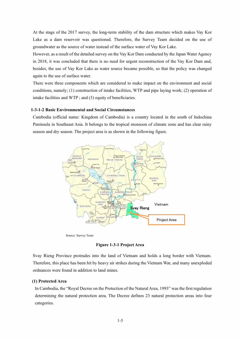
1-5
At the stage of the 2017 survey, the long-term stability of the dam structure which makes Vay Kor Lake as a dam reservoir was questioned. Therefore, the Survey Team decided on the use of groundwater as the source of water instead of the surface water of Vay Kor Lake. However, as a result of the detailed survey on the Vay Kor Dam conducted by the Japan Water Agency in 2018, it was concluded that there is no need for urgent reconstruction of the Vay Kor Dam and, besides, the use of Vay Kor Lake as water source became possible, so that the policy was changed again to the use of surface water. There were three components which are considered to make impact on the environment and social conditions, namely; (1) construction of intake facilities, WTP and pipe laying work; (2) operation of intake facilities and WTP ; and (3) equity of beneficiaries.
1-3-1-2 Basic Environmental and Social Circumstances Cambodia (official name: Kingdom of Cambodia) is a country located in the south of Indochina Peninsula in Southeast Asia. It belongs to the tropical monsoon of climate zone and has clear rainy season and dry season. The project area is as shown in the following figure.
Source: Survey Team
Figure 1-3-1 Project Area
Svay Rieng Province protrudes into the land of Vietnam and holds a long border with Vietnam. Therefore, this place has been hit by heavy air strikes during the Vietnam War, and many unexploded ordnances were found in addition to land mines.
(1) Protected Area In Cambodia, the “Royal Decree on the Protection of the Natural Area, 1993” was the first regulation determining the natural protection area. The Decree defines 23 natural protection areas into four categories.
Svay Rieng
Project Area
Vietnam

1-6
Source:Sub-Decree on Establishment of Biodiversity Conservation Corridor in Natural Protected Area
Figure 1-3-2 Protected Areas in Cambodia
In 2008, the “Law on Natural Protected Areas” was enacted, and it defines eight (8) categories for protection purposes and four (4) management zones. Furthermore, in 2017, the “Sub-Decree on Establishment of Biodiversity Conservation Corridor in Natural Protected Area” was enacted to determine the biodiversity conservation corridor, which resulted in about 40% of the country declared as natural protected area. The following map shows the protected areas. There is no protected area designated by the sub-decree in the vicinity of Svay Rieng. There are 40 areas of Key Biodiversity Areas (KBAs) considered as important places for the protection of biodiversity, and 36 places out of the KBAs are Important Bird Areas (IBAs) in Cambodia. The closest protected area in the neighboring country, Vietnam, is the Lang Sen Wetland Reserve, which is registered under the Ramsar Convention, but it is about 30 km away and no environmental impact is considered. On the other hand, information on the protected area, the lower lake area between National Highway No.1 and Vay Kor Dam, was gathered through the interview with the Department of Environment of Svay Rieng The protected area of about 62 ha is indicated in blue color in the following Figure.
Project Area
National Park Scenery Area Wildlife Area Ramsar Area Multi Purpose Area Natural Heritage Area Biodiversity Conservation Corridor

1-7
Source: DOA, Copy of provincial ordinance
Figure 1-3-3 Protected Area of Vay Kor Lake (Part with Blue Color)
This protected area has been determined by the provincial ordinance that prohibits the capture of any fish in the area for the purpose of preserving the fishery resources of Vay Kor Lake, and allows only traditional fishing outside of the area. Therefore, only the activity related fishing is banned. The Survey Team had several discussions with responsible organizations managing natural resources, such as the Department of Agriculture, Forest and Fishery and the Department of Environment. They mentioned that construction in the area is not prohibited when the mitigation measures are considered well. In fact, the revetment park project is currently under construction at the surrounding bank of the protected area. On the other hand, the location of the water intake for this Svay Rieng Project is planned at the upper stream side of National Highway No. 1 and is outside of the protected area.
(2) Cultural Heritage, etc. There are three (3) important heritages registered as World Heritage by UNESCO, such as Angkor, but their locations are more than 200km far from the project site. In addition, there are no areas which are unique archaeological, historical, and cultural values around the project site under Cambodian laws and regulations.
National Highway No.1
Vay Kor Dam

1-8
(3) State of Natural Environment Cambodia has very rich natural environment and there are ecologically important places such as Tonle Sap Lake, Mekong River and its tributaries. As described above, the Cambodian government had declared more than 40 % of land as protected area, so that they endeavor to conserve the natural environment. In this rich environment, there are many kinds of threatened species. The next table shows the species of critically endangered and endangered species in Cambodia.
Table 1-3-1 Endangered Species in Cambodia Status Class Number Species
Critically Endangered CR
Fauna
Mammalia 8 Sumatran Rhinoceros, etc. Birds 8 Indian Black Vulture, etc. Fishes 18 Mekong Giant Catfish, etc. Amphibian 1 Damleis Reptiles 5 Common Batagur, etc.
Flora Vascular plant 3 Agar Wood, etc.
Endangered EN
Fauna
Mammalia 16 Indian Hog Deer, etc. Birds 10 Yellow-breasted Bunting, etc. Reptiles 5 Elongated Tortoise, etc. Amphibian 3 Musical leaf-litter toad, etc. Fishes 20 Jullien's Golden Carp, etc. Corals, sea cucumber 7 Golden Sandfish, etc.
Flora Vascular plant 22 White Meranti, etc. Source: IUCN Red List
As a result of interviews with the Department of Environment and the Department of Agriculture, Forestry and Fisheries, it was found that the Giant Barb (scientific name: Catlocarpio siamensis) inhabits the Vay Kor Lake. The Giant Barb is the largest fish in the subfamily Cyprininae, and because it is delicious, its population has decreased due to capture; therefore, this species is categorized into “Critically Endangered” species in the IUCN red list. There is no commercial fishing on Lake Vay Kor, but the Department of Agriculture, Forestry and Fisheries is working to educate anglers on the conservation of the fish. Figure 1-3-4 shows the entire Vay Kor Lake. Vay Kor Lake is divided into the northern pond and the southern pond by National Highway No.1, and the protected area mentioned above is the southern pond. Since the water intake is planned to be installed in the northern pond which is in the opposite side of the road/protected area and in the shallow area beside the road, the direct impact such as decrease in habitat is little. However, mitigation measures to protect fish from invading or being inhaled by the water intake should be considered.
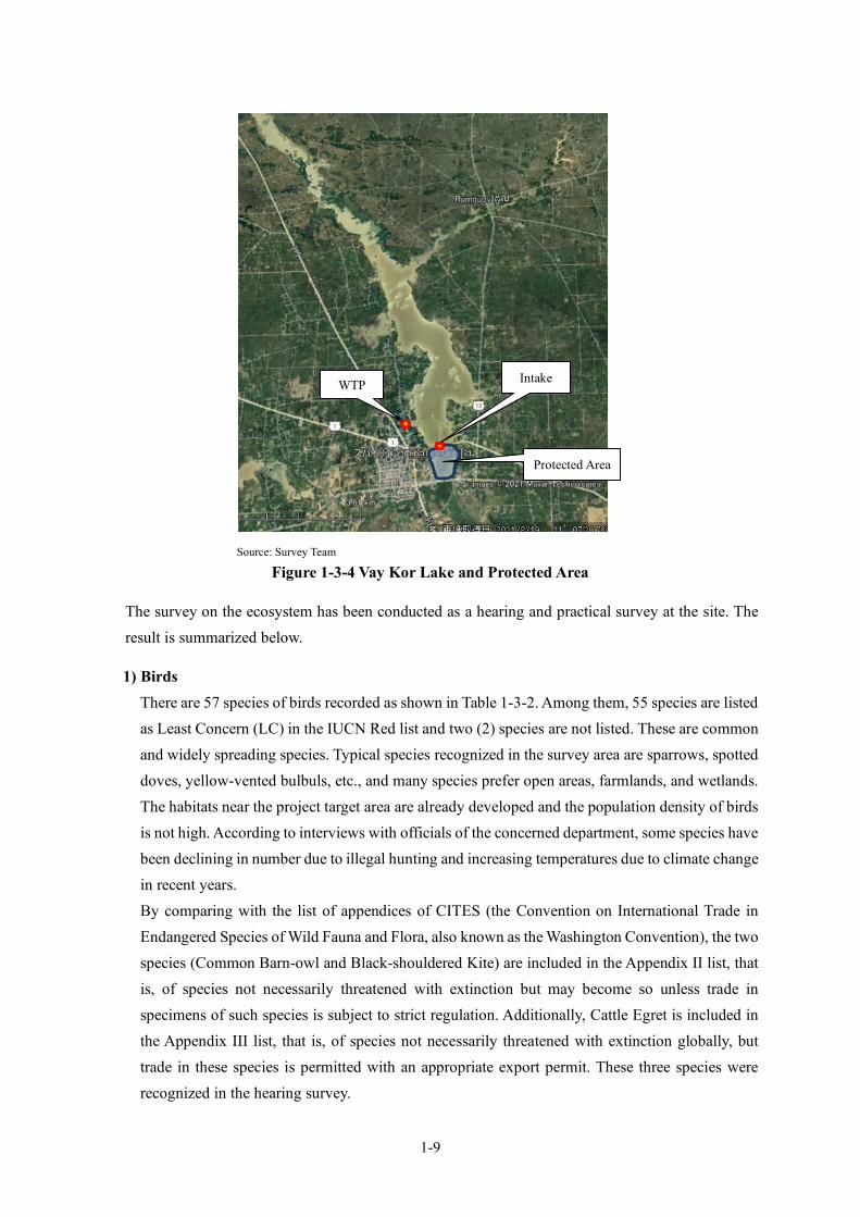
1-9
Source: Survey Team
Figure 1-3-4 Vay Kor Lake and Protected Area
The survey on the ecosystem has been conducted as a hearing and practical survey at the site. The result is summarized below.
1) Birds There are 57 species of birds recorded as shown in Table 1-3-2. Among them, 55 species are listed as Least Concern (LC) in the IUCN Red list and two (2) species are not listed. These are common and widely spreading species. Typical species recognized in the survey area are sparrows, spotted doves, yellow-vented bulbuls, etc., and many species prefer open areas, farmlands, and wetlands. The habitats near the project target area are already developed and the population density of birds is not high. According to interviews with officials of the concerned department, some species have been declining in number due to illegal hunting and increasing temperatures due to climate change in recent years. By comparing with the list of appendices of CITES (the Convention on International Trade in Endangered Species of Wild Fauna and Flora, also known as the Washington Convention), the two species (Common Barn-owl and Black-shouldered Kite) are included in the Appendix II list, that is, of species not necessarily threatened with extinction but may become so unless trade in specimens of such species is subject to strict regulation. Additionally, Cattle Egret is included in the Appendix III list, that is, of species not necessarily threatened with extinction globally, but trade in these species is permitted with an appropriate export permit. These three species were recognized in the hearing survey.
Protected Area
Intake WTP
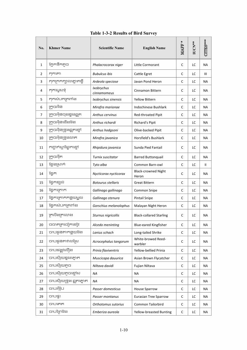
1-10
Table 1-3-2 Results of Bird Survey
No. Khmer Name Scientific Name English Name
MAF
F *
IUC
N**
CITE
S***
1 ែក�កទឹកតូច Phalacrocorax niger Little Cormorant C LC NA
2 កុកេ� Bubulcus ibis Cattle Egret C LC III
3 កុក្រកកក�លេ�� តខ� ី Ardeola speciose Javan Pond Heron C LC NA
4 កុកេម�សទុំ Ixobrychus cinnamomeus
Cinnamon Bittern C LC NA
5 កុកសំបក្រត�ងំ Ixobrychus sinensis Yellow Bittern C LC NA
6 ្រក�ចអិន Mirafra marionae Indochinese Bushlark C LC NA
7 ្រក�ចអុិនចុងខ�ងឆ� �ត Anthus cervinus Red-throated Pipit C LC NA
8 ្រក�ចអុិនេជើងែវង Anthus richardi Richard's Pipit C LC NA
9 ្រក�ចអុិន្រទ�ងឆ� �តេ�� Anthus hodgsoni Olive-backed Pipit C LC NA
10 ្រក�ចអុិន្រទ�ង�ត Mirafra javanica Horsfield's Bushlark C LC NA
11 ក�� ក់�� វ �ណ� កេ�� Rhipidura javanica Sunda Pied Fantail C LC NA
12 ្រក�ចអុឺត Turnix suscitator Barred Buttonquail C LC NA
13 ែខ�ង្រ�ក់ Tyto alba Common Barn-owl C LC II
14 ែខ�ក Nycticorax nycticorax Black-crowned Night Heron
C LC NA
15 ែខ�កខ្យល់ Botourus stellaris Great Bittern C LC NA
16 ែខ�កេ្រ�ក Gallinago gallinago Common Snipe C LC NA
17 ែខ�កេ្រ�កកន� �យម� �ល Gallinago stenura Pintail Snipe C LC NA
18 ែខ�កសំបក្រត�ងំ Gorschius melanolophus Malayan Night Heron C LC NA
19 ្រគលីង្រគេ�ង Sturnus nigricollis Black-collared Starling C LC NA
20 ច�ត្រតេចៀកេខៀវ Alcedo meninting Blue-eared Kingfisher C LC NA
21 �បដូន�កន� �យែវង Lanius schach Long-tailed Shrike C LC NA
22 �បដូន��លែ្រស Acrocephalus tangorum White-browed Reed-warbler
C LC NA
23 �បដង� �វេលឿង Prinia flaviventris Yellow-bellied Prinia C LC NA
24 �បសីុរុយខ�ងេ�� ត Muscicapa dauurica Asian Brown Flycatcher C LC NA
25 �បសីុរុយតូច Niltava davidi Fujian Niltava C LC NA
26 �បសីុរុយតូចេ�� ស NA NA C LC NA
27 �បសីុរុយ្រទ�ង ឆ� �តេ�� ត NA NA C LC NA
28 �បអុឺរ�ុប Passer domesticus House Sparrow C LC NA
29 �បផ�ះ Passer montanus Eurasian Tree Sparrow C LC NA
30 �បេតត Orthotomus sutorius Common Tailorbird C LC NA
31 �បៃ្រពែវង Emberiza aureola Yellow-breasted Bunting C LC NA
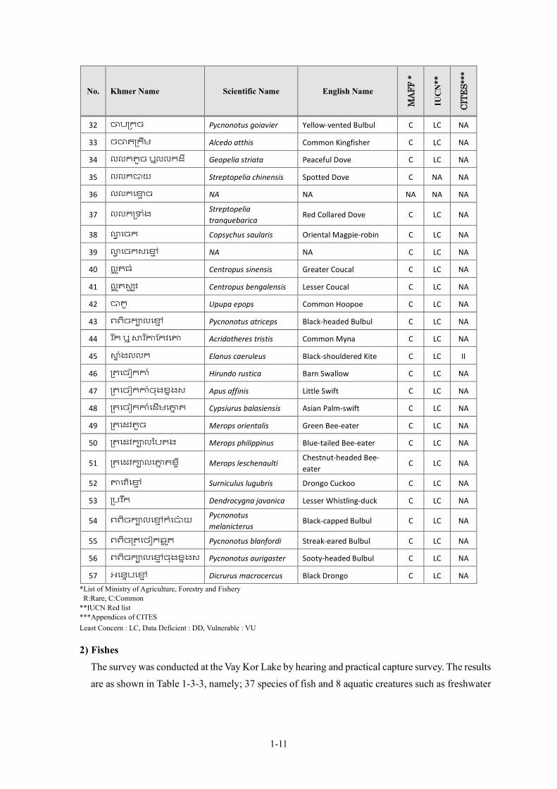
1-11
No. Khmer Name Scientific Name English Name
MAF
F *
IUC
N**
CITE
S***
32 �ប្រកច Pycnonotus goiavier Yellow-vented Bulbul C LC NA
33 ច�ត្រកឹម Alcedo atthis Common Kingfisher C LC NA
34 លលកតូច ឬលលកដី Geopelia striata Peaceful Dove C LC NA
35 លលក�យ Streptopelia chinensis Spotted Dove C NA NA
36 លលកេ�� ច NA NA NA NA NA
37 លលក្រ�ងំ Streptopelia tranquebarica
Red Collared Dove C LC NA
38 �� េចក Copsychus saularis Oriental Magpie-robin C LC NA
39 �� េចកសេ�� NA NA C LC NA
40 ល� �តធំ Centropus sinensis Greater Coucal C LC NA
41 ល� �តស្ប� វ Centropus bengalensis Lesser Coucal C LC NA
42 �គូ Upupa epops Common Hoopoe C LC NA
43 ពពិចក�លេ�� Pycnonotus atriceps Black-headed Bulbul C LC NA
44 រ �ក ឬ �រ ��ែកវេ� Acridotheres tristis Common Myna C LC NA
45 �� ំងលលក Elanus caeruleus Black-shouldered Kite C LC II
46 ្រតេចៀក�ំ Hirundo rustica Barn Swallow C LC NA
47 ្រតេចៀក�ំចុងខ�ងស Apus affinis Little Swift C LC NA
48 ្រតេចៀក�ំេដើមេ�� ត Cypsiurus balasiensis Asian Palm-swift C LC NA
49 ្រតេដវតូច Merops orientalis Green Bee-eater C LC NA
50 ្រតេដវក�លៃបតង Merops philippinus Blue-tailed Bee-eater C LC NA
51 ្រតេដវក�លេ�� តខ� ី Merops leschenaulti Chestnut-headed Bee-eater
C LC NA
52 �េ�� េ�� Surniculus lugubris Drongo Cuckoo C LC NA
53 ្របវ �ក Dendrocygna javanica Lesser Whistling-duck C LC NA
54 ពពិចក�លេ�� កំេ�៉យ Pycnonotus melanicterus
Black-capped Bulbul C LC NA
55 ពពិច្រតេចៀកឆ� �ត Pycnonotus blanfordi Streak-eared Bulbul C LC NA
56 ពពិចក�លេ�� ចុងខ�ងស Pycnonotus aurigaster Sooty-headed Bulbul C LC NA
57 អេន�បេ�� Dicrurus macrocercus Black Drongo C LC NA *List of Ministry of Agriculture, Forestry and Fishery R:Rare, C:Common **IUCN Red list ***Appendices of CITES Least Concern : LC, Data Deficient : DD, Vulnerable : VU
2) Fishes The survey was conducted at the Vay Kor Lake by hearing and practical capture survey. The results are as shown in Table 1-3-3, namely; 37 species of fish and 8 aquatic creatures such as freshwater
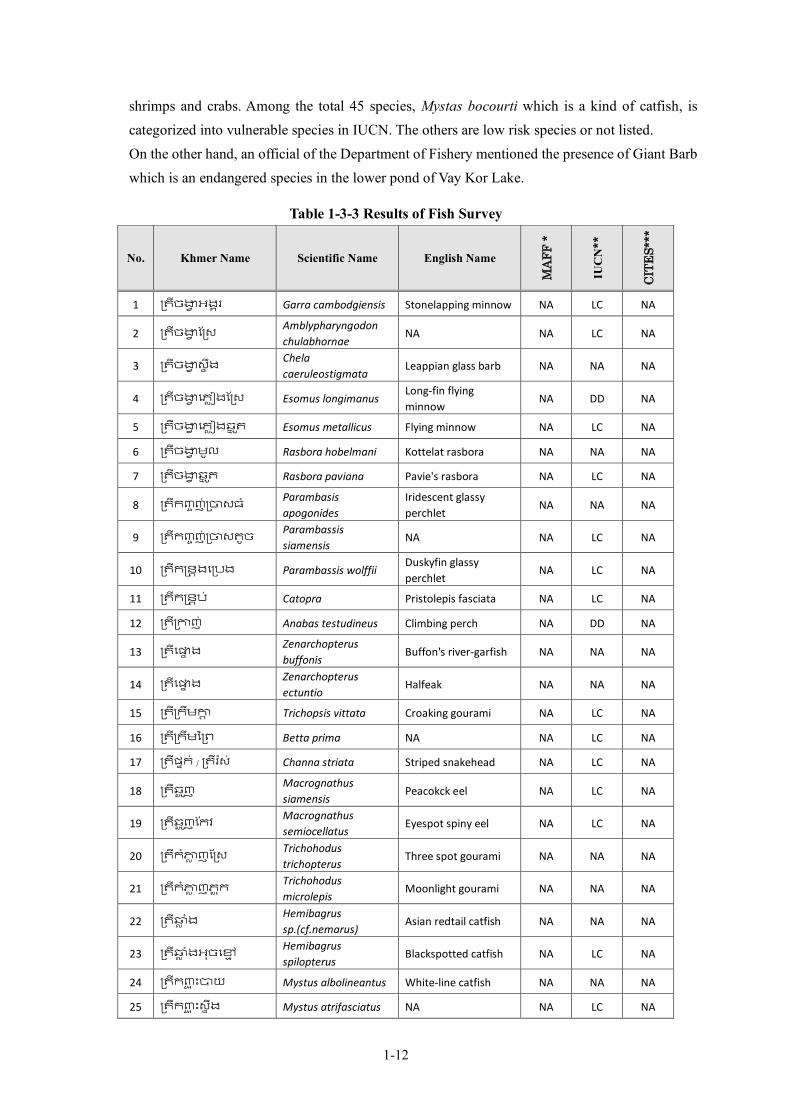
1-12
shrimps and crabs. Among the total 45 species, Mystas bocourti which is a kind of catfish, is categorized into vulnerable species in IUCN. The others are low risk species or not listed. On the other hand, an official of the Department of Fishery mentioned the presence of Giant Barb which is an endangered species in the lower pond of Vay Kor Lake.
Table 1-3-3 Results of Fish Survey
No. Khmer Name Scientific Name English Name
MAF
F *
IUC
N**
CITE
S***
1 ្រតីច�� អង�រ Garra cambodgiensis Stonelapping minnow NA LC NA
2 ្រតីច�� ែ្រស Amblypharyngodon chulabhornae
NA NA LC NA
3 ្រតីច�� ស� ឹង Chela caeruleostigmata
Leappian glass barb NA NA NA
4 ្រតីច�� េភ��ងែ្រស Esomus longimanus Long-fin flying minnow
NA DD NA
5 ្រតីច�� េភ��ងឆ� �ត Esomus metallicus Flying minnow NA LC NA
6 ្រតីច�� មូល Rasbora hobelmani Kottelat rasbora NA NA NA
7 ្រតីច�� ឆ� �ត Rasbora paviana Pavie's rasbora NA LC NA
8 ្រតីក�� ញ់្រ�សធ ំParambasis apogonides
Iridescent glassy perchlet
NA NA NA
9 ្រតីក�� ញ់្រ�សតូច Parambassis siamensis
NA NA LC NA
10 ្រតីក�ន�ងេ្របង Parambassis wolffii Duskyfin glassy perchlet
NA LC NA
11 ្រតីក�ន�ប ់ Catopra Pristolepis fasciata NA LC NA
12 ្រតី្រ�ញ់ Anabas testudineus Climbing perch NA DD NA
13 ្រតីេ�� ង Zenarchopterus buffonis
Buffon's river-garfish NA NA NA
14 ្រតីេ�� ង Zenarchopterus ectuntio
Halfeak NA NA NA
15 ្រតី្រកឹម�� Trichopsis vittata Croaking gourami NA LC NA
16 ្រតី្រកមឹៃ្រព Betta prima NA NA LC NA
17 ្រតីផ�ក់ / ្រតីរ�ស់ Channa striata Striped snakehead NA LC NA
18 ្រតីឆ� �ញ Macrognathus siamensis
Peacokck eel NA LC NA
19 ្រតីឆ� �ញែកវ Macrognathus semiocellatus
Eyespot spiny eel NA LC NA
20 ្រតីកំ�� ញែ្រស Trichohodus trichopterus
Three spot gourami NA NA NA
21 ្រតីកំ�� ញភ� �ក Trichohodus microlepis
Moonlight gourami NA NA NA
22 ្រតី�� ំង Hemibagrus sp.(cf.nemarus)
Asian redtail catfish NA NA NA
23 ្រតី�� ំងអុចេ�� Hemibagrus spilopterus
Blackspotted catfish NA LC NA
24 ្រតីក�� � ះ�យ Mystus albolineantus White-line catfish NA NA NA
25 ្រតីក�� � ះស� ឹង Mystus atrifasciatus NA NA LC NA
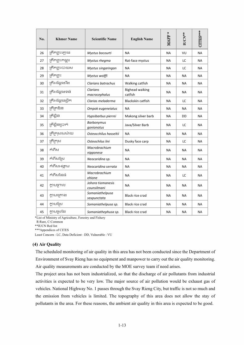
1-13
No. Khmer Name Scientific Name English Name
MAF
F *
IUC
N**
CITE
S***
26 ្រតីក�� � ះេ�� ង Mystus bocourti NA NA VU NA
27 ្រតីក�� � ះកណ� � រ Mystus rhegma Rat-face mystus NA LC NA
28 ្រតីក�� � ះ�យស Mystus singaringan NA NA LC NA
29 ្រតីក�� � ះ Mystus wolffi NA NA NA NA
30 ្រតីអែណ� ងរ �ង Clarians batrachus Walking catfish NA NA NA
31 ្រតីអែណ� ងទន់ Clarians macrocephalus
Bighead waiking catfish
NA NA NA
32 ្រតីអែណ� ងស� ឹក Clarias meladerma Blackskin catfish NA LC NA
33 ្រតី្រតឱន Ompok eugeneiatus NA NA NA NA
34 ្រតីឆ� ិន Hypsibarbus pierrei Makong silver barb NA DD NA
35 ្រតីឆ� ិន្រ�ក ់Barbonymus gonionotus
Java/Silver Barb NA LC NA
36 ្រតី្រក �សេម�៉យ Osteocchilus hasseltii NA NA NA NA
37 ្រតី្រក �ស Osteochilus lini Dusky face carp NA LC NA
38 កំពឹស Macrobrachium nipponese
NA NA NA NA
39 កំពឹសែ្រស Neocaridina sp. NA NA NA NA
40 កំពឹសអ�� ម Neocaridina serrata NA NA NA NA
41 កំពឹសៃដធ ំMacrobrachium ohione
NA NA LC NA
42 �� ម្រ�ល Johora tiomanesis counsilmani
NA NA NA NA
43 �� មេ្រ�ង Somaniathelpusa sexpunctata
Black rice crad NA NA NA
44 �� មែ្រស Somaniathelpusa sp. Black rice crad NA NA NA
45 �� ម្រសែង Somaniathephusa sp. Black rice crad NA NA NA *List of Ministry of Agriculture, Forestry and Fishery R:Rare, C:Common **IUCN Red list ***Appendices of CITES Least Concern : LC, Data Deficient : DD, Vulnerable : VU
(4) Air Quality The scheduled monitoring of air quality in this area has not been conducted since the Department of Environment of Svay Rieng has no equipment and manpower to carry out the air quality monitoring. Air quality measurements are conducted by the MOE survey team if need arises. The project area has not been industrialized, so that the discharge of air pollutants from industrial activities is expected to be very low. The major source of air pollution would be exhaust gas of vehicles. National Highway No. 1 passes through the Svay Rieng City, but traffic is not so much and the emission from vehicles is limited. The topography of this area does not allow the stay of pollutants in the area. For these reasons, the ambient air quality in this area is expected to be good.

1-14
The Survey Team conducted an air quality survey on the 3rd of April 2020 to obtain the baseline data and the results are summarized in following table.
Table 1-3-4 Results of Air Quality Measurement (mg/m3)
Parameters Planned Site of WTP
Planned Site of Intake
Cambodian Standards Environmental Standards in Japan
(24 hours average)
Carbon oxide CO 0.44 0.58 20 (8 hours average) 10 Nitrogen dioxide NO2 0.013 0.024 0.1 (24 hours average) 0.04〜0.06 or less Sulfur dioxide SO2 0.009 0.001 0.3 (24 hours average) 0.04 Total suspended particulate matter TSP 0.08 0.17 0.33 (24 hours average) 0.1(SPM:10µm >)
Ozone O3 0.023 0.027 0.2(24 hours average) - Lead Pb ND ND 0.005 (24 hours average) - PM10 PM10 0.03 0.03 0.05 (24 hours average) - PM2.5 PM2.5 0.02 0.013 0.025 (24 hours average) -
Source: Survey Team
The results of parameters meet the Cambodian standards requirements. These are also less than the Japanese environmental standards. Japanese standard of suspended particulate matter is for particles of less than 10µm in diameter, so that it is not referable directly. The TSP include bigger sizes of particles and it might give larger values, so that the TSP is in an acceptable level.
(5) Water Use and Water Quality The main sources of surface water in the area are the Vay Kor River and the Vay Kor Lake, and there are other small rivers that dry up during the dry season. The area is relatively rich in groundwater; therefore, the existing water supply depends on the groundwater source, and many households in the project area have their own wells for their daily lives. Almost all households in the area own shallow wells because the cost of digging well is affordably low. According to the result of interview survey, there is no particular complaint regarding water quality, but there are many requests for switching water from well water to piped supply water, from the viewpoint of convenience, economy and hygiene. The following table shows the results of water quality test of the well conducted in the target area. in August 2017 Turbidity exceeds drinking water standards in 4 of the 10 well samples.
Table 1-3-5 Water Quality of Private Well
Source: Survey Team
Sample GW-1 GW-2 GW-3 GW-4 GW-5 GW-6 GW-7 GW-8 GW-9 GW-10
dateUnit 8//4 8/5 8/5 8/5 8/5 8/5 8/5 8/5 8/5 8/5
Turbidity NTU 16 4 2 30 2 2 4 6 4 22 <5.0 <2 -
Nitrite (NO2) mg/L 0 0 0 0 0 0 0.099 0 0.063 0 <3.0 -
Nitrate (NO3-) mg/L 0.034 0.15 0.076 0.078 0.032 0.049 1.53 0.037 1.54 0.103 <50 -
Iron (Fe) mg/L 0.04 0.06 0.01 0.13 0.15 0.17 0.06 0.02 0.02 0.1 <0.3 <0.3 -
Manganese (Mn) mg/L 0.2 0.15 0.02 0.19 0.05 0.1 0.15 0.24 0.26 0.29 <0.1 <0.05 -
Total Coliform MPN/100ml 0 0 0 0 0 0 0 0 0 0 0 - -
E-Coli MPN/100ml 0 0 0 0 0 0 0 0 0 0 0 0 0
Parameter NDWQS
Japanesedrinkingwater
standards
WHOguidelines
NO2+NO3<44
1-15
In the early stage of the survey, groundwater was assumed to be the source water; therefore, the Survey Team conducted the water quality monitoring of raw water and treated water of the existing supply system from July 2017 to May 2018. E. Coli was not detected, and toxic metals were rarely detected. Low level concentration of Arsenic was detected in the raw water in the range of 0.012 to 0.028 mg / l, but it was removed to the acceptable level by the treatment process. Iron and manganese concentration is high both in raw and treated water. It is, therefore, thought that the groundwater is in a reductive environment, and when it contacts with the air after pumping, iron starts making precipitation, becomes turbid with coloration. Therefore, sufficient oxidation treatment is required in the water treatment process. The groundwater monitoring results are as shown in Table 1-3-6 and Table 1-3-7. As mentioned above, the Survey Team had decided on the use of groundwater for the raw water, thus the survey on the water quality of surface water was not conducted until the change of policy of water source from groundwater to surface water. The monitoring of surface water quality was then conducted from July 2019 to May 2020 with a break in the middle. The surface water monitoring results have been shown in Table 1-3-8. The characteristics of surface water are described as follows.
No hazardous parameters have been detected. The concentration of iron and manganese is high. COD, an indicator of organic pollution, is high, and annual average is 4.2 mg /l. E.Coli and ammonia which are parameters indicating domestic pollution have been detected. High concentration of total nitrogen (1.67mg/l in annual average) and total phosphorus
(0.14mg/l in annual average) indicate the progress of eutrophication. Ammonia is detected throughout the year ; its annual average is 0.22mg/l. The turbidity near the intake is 102 on annual average and tends to be low in winter. The lowest
observed turbidity is 32. It is high in the first half of the rainy season from May to August.
The water quality is not suitable for direct use of water as domestic water due to its high turbidity and high concentration of aluminum and iron, but it will be in acceptable quality after the conventional water treatment process. Ammonia is always detected, so that breakpoint treatment may be required at high concentrations. The data in gray shaded cells in the table are not reliable. Since the doubtful results were observed in the reported analysis data of the MOE of Cambodia, the Survey Team checked the situation at the laboratory and found some erroneous analysis procedures. Therefore, the metal analysis data of MOE is shown as reference only. The Survey Team brought the sample and requested its analysis by a certified laboratory in Japan from December 2019.
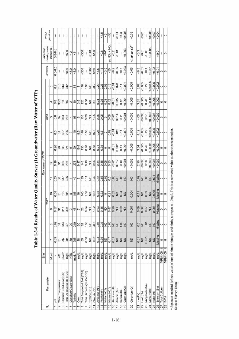
Tabl
e 1-
3-6
Res
ults
of W
ater
Qua
lity
Surv
ey (1
) Gro
undw
ater
(Raw
Wat
er o
f WT
P)
*
Japa
nese
stan
dard
def
ines
val
ue o
f sum
of n
itrat
e ni
troge
n an
d ni
trite
nitr
ogen
as 1
0mg/
l. Th
is is
a c
onve
rted
valu
e as
nitr
ate
conc
entra
tion.
So
urce
: Sur
vey
Team
Site
Mon
th7
89
1011
121
23
45
1pH
-6.
398.
096.
576.
586.
276.
196.
266.
56.
66.
86.
76.
5-8.
55.
8-8.
6-
2W
ater
Tem
pera
ture
oC31
3131
3130
3128
3132
30.2
31.5
--
-3
Elec
trica
l Con
duct
ivity
(EC
)µs
/cm
297
314
317
318
317
309
338
307
304
314
314
--
-4
Tota
l Dis
solve
Sol
ids
(TD
S)m
g/L
284
301
303
305
305
296
324
295
298
307
312
<800
<500
-5
Dis
solve
d O
xyge
n(D
O)
NTU
3020
28
44
02
42
4<5
.0<
2-
6Tu
rbid
itym
g/L
Pt20
521
045
105
4027
590
140
9510
65<5
.0<5
-7
Col
orm
g/L
3830
716
29.
1719
.58.
55
3.5
3-
--
8To
tal S
uspe
nded
Sol
id(T
SS)
mg/
L55
6223
140
135
145
135
140
130
120
170
<300
<300
-9
Tota
l Har
dnes
s(as
CaC
O3)
mg/
L0.
580.
580.
541.
560.
110.
190.
980.
580.
390.
580.
98-
--
10C
yani
de(C
N-)
mg/
LND
NDND
NDND
NDND
NDND
NDND
<0.0
2<0
.01
-11
Chl
orid
e (C
l- )m
g/L
18.2
28.6
18.2
10.2
8.32
0.06
8.58
15.6
12.5
9.2
20.2
<250
<200
-12
Amm
onia
(NH 3
)m
g/L
0.03
0.05
0.03
0.35
0.47
0.34
0.21
0.24
0.25
0.24
0.29
<1.5
--
13Fl
uorid
e (F
)m
g/L
0.36
0.36
0.36
0.32
0.56
0.35
0.35
0.5
0.05
0.25
0.25
<1.
5<0
.8 <
1.5
14Ni
trite
(NO
2)m
g/L
NDND
ND0
0.02
0.08
00
00.
030.
09 <
3.0
<3
15Ni
trate
(NO
3- )m
g/L
0.47
0.63
0.47
0.21
0.5
0.35
00.
020.
080.
420.
18 <
50 <
5016
Alum
inum
(Al)
mg/
L0.
01ND
0.26
0.02
0.03
<0.0
1<0
.01
<0.0
1<0
.01
<0.0
1<0
.01
<0.
2<0
.2-
17Ar
seni
c (A
s)m
g/L
NDND
NDND
ND0.
012
0.01
20.
012
0.01
40.
015
0.02
8 <
0.05
<0.0
1<0
.01
18Ba
rium
(Ba)
mg/
LND
1.09
0.09
0.04
0.03
0.10
0.11
0.11
0.11
0.12
0.11
<0.
7-
<1.
319
Cad
miu
m (C
d)m
g/L
NDND
NDND
ND<0
.001
<0.0
01<0
.001
<0.0
01<0
.001
<0.0
01 <
0.00
3 <
0.00
3 <
0.00
3
20C
hrom
ium
(Cr)
mg/
LND
ND0.
001
0.00
4ND
<0.0
05<0
.005
<0.0
05<0
.005
<0.0
05<0
.005
<0.0
5<0
.05
as C
r6+<0
.05
21Iro
n (F
e)m
g/L
0.01
0.3
0.09
0.11
0.09
2.90
3.64
4.12
4.00
3.85
3.67
<0.
3 <
0.3
-22
Lead
(Pb)
mg/
LND
ND0.
008
NDND
<0.0
05<0
.005
<0.0
05<0
.005
<0.0
05<0
.005
<0.
01 <
0.01
<0.
0123
Man
gane
se (M
n)m
g/L
0.00
10.
010.
070.
090.
060.
280.
260.
270.
270.
280.
27 <
0.1
<0.0
5-
24M
ercu
ry (H
g)m
g/L
NDND
NDND
ND<0
.000
5<0
.000
5<0
.000
5<0
.000
5<0
.000
5<0
.000
5 <
0.00
1 <
0.00
05 <
0.00
625
Nick
el (N
i)m
g/L
NDND
0.00
30.
0005
0.00
1<0
.005
<0.0
05<0
.005
<0.0
05<0
.005
<0.0
05 <
0.02
- <
0.07
26Se
leni
um (S
e)m
g/L
Mis
sing
Mis
sing
Mis
sing
Mis
sing
Mis
sing
<0.0
02<0
.002
<0.0
02<0
.002
<0.0
02<0
.002
<0.
01 <
0.01
<0.
0427
Tota
l Col
iform
MPN
/100
ml
00
00
00
00
00
00
--
28E-
Col
iM
PN/1
00m
l0
00
00
00
00
00
00
0
Japa
nese
drin
king
wat
erst
anda
rds
WHO
guid
elin
es
<44
*as
NO
2 + N
O3
NDW
QS
NoPa
rram
eter
2017
Raw
wate
r of W
TP20
18
1-16
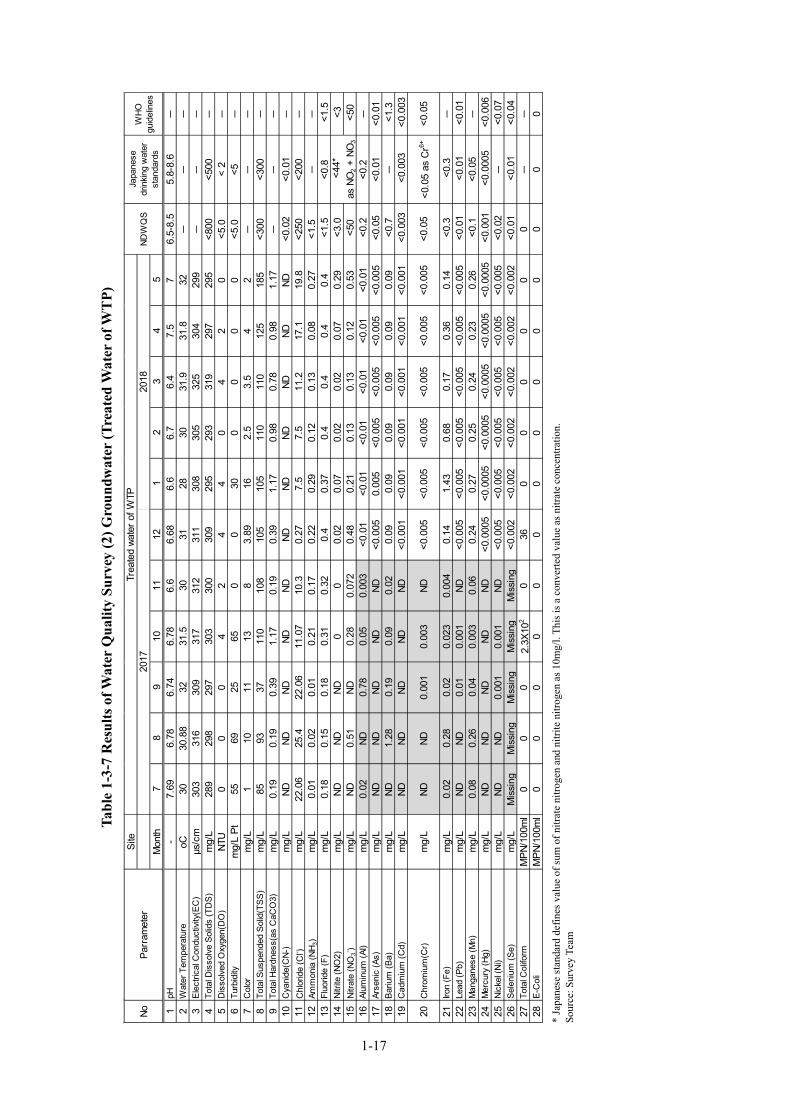
Tabl
e 1-
3-7
Res
ults
of W
ater
Qua
lity
Surv
ey (2
) Gro
undw
ater
(Tre
ated
Wat
er o
f WT
P)
*
Japa
nese
stan
dard
def
ines
val
ue o
f sum
of n
itrat
e ni
troge
n an
d ni
trite
nitr
ogen
as 1
0mg/
l. Th
is is
a c
onve
rted
valu
e as
nitr
ate
conc
entra
tion.
So
urce
: Sur
vey
Team
Site
Mon
th7
89
1011
121
23
45
1pH
-7.
696.
786.
746.
786.
66.
686.
66.
76.
47.
57
6.5-
8.5
5.8-
8.6
-2
Wat
er T
empe
ratu
reoC
3030
.88
3231
.530
3128
3031
.931
.832
--
-3
Elec
trica
l Con
duct
ivity
(EC
)µs
/cm
303
316
309
317
312
311
308
305
325
304
299
--
-4
Tota
l Dis
solve
Sol
ids
(TD
S)m
g/L
289
298
297
303
300
309
295
293
319
297
295
<800
<500
-5
Dis
solve
d O
xyge
n(D
O)
NTU
00
04
24
40
42
0<5
.0<
2-
6Tu
rbid
itym
g/L
Pt55
6925
650
030
00
00
<5.0
<5-
7C
olor
mg/
L1
1011
138
3.89
162.
53.
54
2-
--
8To
tal S
uspe
nded
Sol
id(T
SS)
mg/
L85
9337
110
108
105
105
110
110
125
185
<300
<300
-9
Tota
l Har
dnes
s(as
CaC
O3)
mg/
L0.
190.
190.
391.
170.
190.
391.
170.
980.
780.
981.
17-
--
10C
yani
de(C
N-)
mg/
LND
NDND
NDND
NDND
NDND
NDND
<0.0
2<0
.01
-11
Chl
orid
e (C
l- )m
g/L
22.0
625
.422
.06
11.0
710
.30.
277.
57.
511
.217
.119
.8<2
50<2
00-
12Am
mon
ia (N
H 3)
mg/
L0.
010.
020.
010.
210.
170.
220.
290.
120.
130.
080.
27<1
.5-
-13
Fluo
ride
(F)
mg/
L0.
180.
150.
180.
310.
320.
40.
370.
40.
40.
40.
4 <
1.5
<0.8
<1.
514
Nitri
te (N
O2)
mg/
LND
NDND
00
0.02
0.07
0.02
0.02
0.07
0.29
<3.
0 <
315
Nitra
te (N
O3- )
mg/
LND
0.51
ND0.
280.
072
0.48
0.21
0.13
0.13
0.12
0.53
<50
<50
16Al
umin
um (A
l)m
g/L
0.02
ND0.
780.
050.
003
<0.0
1<0
.01
<0.0
1<0
.01
<0.0
1<0
.01
<0.
2<0
.2-
17Ar
seni
c (A
s)m
g/L
NDND
NDND
ND<0
.005
0.00
5<0
.005
<0.0
05<0
.005
<0.0
05 <
0.05
<0.0
1<0
.01
18Ba
rium
(Ba)
mg/
LND
1.28
0.19
0.09
0.02
0.09
0.09
0.09
0.09
0.09
0.09
<0.
7-
<1.
319
Cad
miu
m (C
d)m
g/L
NDND
NDND
ND<0
.001
<0.0
01<0
.001
<0.0
01<0
.001
<0.0
01 <
0.00
3 <
0.00
3 <
0.00
3
20C
hrom
ium
(Cr)
mg/
LND
ND0.
001
0.00
3ND
<0.0
05<0
.005
<0.0
05<0
.005
<0.0
05<0
.005
<0.0
5<0
.05
as C
r6+<0
.05
21Iro
n (F
e)m
g/L
0.02
0.28
0.02
0.02
30.
004
0.14
1.43
0.68
0.17
0.36
0.14
<0.
3 <
0.3
-22
Lead
(Pb)
mg/
LND
ND0.
010.
001
ND<0
.005
<0.0
05<0
.005
<0.0
05<0
.005
<0.0
05 <
0.01
<0.
01 <
0.01
23M
anga
nese
(Mn)
mg/
L0.
080.
260.
040.
003
0.06
0.24
0.27
0.25
0.24
0.23
0.26
<0.
1<0
.05
-24
Mer
cury
(Hg)
mg/
LND
NDND
NDND
<0.0
005
<0.0
005
<0.0
005
<0.0
005
<0.0
005
<0.0
005
<0.
001
<0.
0005
<0.
006
25Ni
ckel
(Ni)
mg/
LND
ND0.
001
0.00
1ND
<0.0
05<0
.005
<0.0
05<0
.005
<0.0
05<0
.005
<0.
02-
<0.
0726
Sele
nium
(Se)
mg/
LM
issi
ngM
issi
ngM
issi
ngM
issi
ngM
issi
ng<0
.002
<0.0
02<0
.002
<0.0
02<0
.002
<0.0
02 <
0.01
<0.
01 <
0.04
27To
tal C
olifo
rmM
PN/1
00m
l0
00
2.3X
102
036
00
00
00
--
28E-
Col
iM
PN/1
00m
l0
00
00
00
00
00
00
0
<44
*as
NO
2 + N
O3
NDW
QS
Japa
nese
drin
king
wat
erst
anda
rds
WHO
guid
elin
es20
1720
18No
Parr
amet
erTr
eate
d wa
ter o
f WTP
1-17

Tabl
e 1-
3-8
Res
ults
of W
ater
Qua
lity
Surv
ey (3
) Sur
face
wat
er (N
ear
Plan
ned
Inta
ke S
ite)
*
Japa
nese
stan
dard
def
ines
val
ue o
f sum
of n
itrat
e ni
troge
n an
d ni
trite
nitr
ogen
as 1
0mg/
l. Th
is is
a c
onve
rted
valu
e as
nitr
ate
conc
entra
tion.
So
urce
: Sur
vey
Team
Site
2019
Mon
th7
89
1011
121
23
45
1pH
-7.
736.
816.
496.
566.
436.
736.
586.
86.
866.
956.
766.
5-8.
55.
8-8.
6-
2W
ater
Tem
pera
ture
oC28
.230
3230
.528
26.4
25.6
2729
.531
.531
.3-
--
3El
ectri
cal C
ondu
ctivi
ty(E
C)
µs/c
m44
.433
.638
42.3
19.2
28.7
30.4
33.5
42.7
43.3
67.4
--
-4
Tota
l Dis
solve
Sol
ids
(TD
S)m
g/L
4232
3641
1913
1315
1919
30<8
00<5
00-
5D
isso
lved
Oxy
gen(
DO
)m
g/L
5.06
5.06
6.76
6.33
5.9
5.07
5.09
5.05
5.06
5.38
5.24
--
-6
Turb
idity
NTU
350
230
5056
4832
3638
4680
155
<5.0
< 2
-7
Col
orm
g/L
Pt10
031
043
0>>
500
230
340
320
320
210
270
200
<5.0
<5-
8To
tal S
uspe
nded
Sol
id(T
SS)
mg/
L40
8337
2228
2620
3033
5512
3-
--
9To
tal H
ardn
ess(
as C
aCO
3)m
g/L
2228
695
9011
87
915
7<3
00<3
00-
10C
OD
mg/
L8.
238.
235.
092.
353.
331.
761.
763.
184.
513.
84.
2-
--
11C
yani
de(C
N-)
mg/
LND
NDND
NDND
ND0.
005
0.00
60.
007
0.00
7ND
<0.0
2<0
.01
-12
Chl
orid
e (C
l- )m
g/L
12.4
10.9
812
.42.
561.
527.
53.
74.
54.
511
.412
<250
<200
-13
Amm
onia
(NH 3
)m
g/L
0.00
40.
005
0.00
40.
070.
260.
350.
450.
320.
320.
380.
31<1
.5-
-14
Fluo
ride
(F)
mg/
L0.
270.
220.
270.
130.
19ND
NDND
NDND
ND <
1.5
<0.8
<1.
515
Nitri
te (N
O2)
mg/
LND
NDND
00
0.08
NDND
0.04
0.08
0.02
<3.
0 <
316
Nitra
te (N
O3- )
mg/
L0.
180.
110.
078
0.09
0.04
32.
13.
54.
61.
93.
6 <
50 <
5017
Alum
inum
(Al)
mg/
L欠測
欠測
欠測
欠測
欠測
0.50
0.42
0.67
0.93
0.84
1.41
<0.
2<0
.2-
18Ar
seni
c (A
s)m
g/L
NDND
NDND
ND<0
.005
<0.0
05<0
.005
<0.0
05<0
.005
<0.0
05 <
0.05
<0.0
1<0
.01
19Ba
rium
(Ba)
mg/
LND
欠測
0.02
0.17
0.00
30.
020.
020.
020.
020.
020.
04 <
0.7
- <
1.3
20C
adm
ium
(Cd)
mg/
L0.
0009
NDND
NDND
<0.0
01<0
.001
<0.0
01<0
.001
<0.0
01<0
.001
<0.
003
<0.
003
<0.
003
21C
hrom
ium
(Cr)
mg/
L0.
02ND
0.00
40.
004
ND<0
.005
<0.0
05<0
.005
<0.0
05<0
.005
<0.0
05<0
.05
<0.0
5 as
Cr6+
<0.0
5
22Iro
n (F
e)m
g/L
0.58
0.22
0.13
0.01
30.
031.
201.
050.
970.
991.
542.
61 <
0.3
<0.
3-
23Le
ad (P
b)m
g/L
0.00
5 N
D0.
008
0.00
1ND
<0.0
05<0
.005
<0.0
05<0
.005
<0.0
05<0
.005
<0.
01 <
0.01
<0.
0124
Man
gane
se (M
n)m
g/L
0.03
0.00
90.
007
0.00
50.
004
0.01
0.01
0.01
0.02
0.02
0.04
<0.
1<0
.05
-25
Mer
cury
(Hg)
mg/
LND
NDND
NDND
<0.0
005
<0.0
005
<0.0
005
<0.0
005
<0.0
005
<0.0
005
<0.
001
<0.
0005
<0.
006
26Ni
ckel
(Ni)
mg/
L0.
009
ND0.
003
0.00
1ND
<0.0
05<0
.005
<0.0
05<0
.005
<0.0
05<0
.005
<0.
02-
<0.
0727
Sele
nium
(Se)
mg/
LM
issi
ngM
issi
ngM
issi
ngM
issi
ngM
issi
ng<0
.002
<0.0
02<0
.002
<0.0
02<0
.002
<0.0
02 <
0.01
<0.
01 <
0.04
28To
tal C
olifo
rmM
PN/1
00m
l2.
0X10
21.
0X10
42.
0X10
22.
3X10
22.
1X10
27.
2X10
11.
1x10
49.
3x10
22.
3x10
292
920
--
29E-
Col
iM
PN/1
00m
l72
270
7261
7236
1.5x
103
2.1x
102
92<
3036
00
030
T-N
mg/
L4
5.9
1.1
3.5
00.
720.
270.
560.
680.
471.
36-
--
31T-
Pm
g/L
0.78
0.03
0.06
0.14
0.08
0.15
0.03
0.05
0.06
0.1
0.09
--
-
<44
*as
NO
2 + N
O3
2020
Plan
ned
Inta
ke S
iteNo
Parr
amet
erND
WQ
SJa
pane
se d
rinkin
gw
ater
sta
ndar
dsW
HOgu
idel
ines
2017
1-18
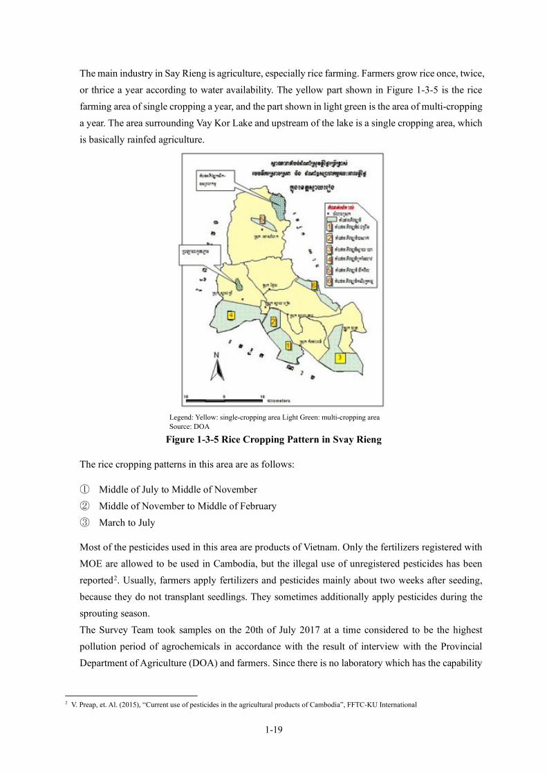
1-19
The main industry in Say Rieng is agriculture, especially rice farming. Farmers grow rice once, twice, or thrice a year according to water availability. The yellow part shown in Figure 1-3-5 is the rice farming area of single cropping a year, and the part shown in light green is the area of multi-cropping a year. The area surrounding Vay Kor Lake and upstream of the lake is a single cropping area, which is basically rainfed agriculture.
Legend: Yellow: single-cropping area Light Green: multi-cropping area Source: DOA
Figure 1-3-5 Rice Cropping Pattern in Svay Rieng
The rice cropping patterns in this area are as follows:
① Middle of July to Middle of November ② Middle of November to Middle of February ③ March to July
Most of the pesticides used in this area are products of Vietnam. Only the fertilizers registered with MOE are allowed to be used in Cambodia, but the illegal use of unregistered pesticides has been reported2. Usually, farmers apply fertilizers and pesticides mainly about two weeks after seeding, because they do not transplant seedlings. They sometimes additionally apply pesticides during the sprouting season. The Survey Team took samples on the 20th of July 2017 at a time considered to be the highest pollution period of agrochemicals in accordance with the result of interview with the Provincial Department of Agriculture (DOA) and farmers. Since there is no laboratory which has the capability
2 V. Preap, et. Al. (2015), “Current use of pesticides in the agricultural products of Cambodia”, FFTC-KU International

1-20
to analyze trace levels of pesticides in Cambodia, the Survey Team brought samples to Japan to be analyzed by a certified and experienced laboratory. All the 18 pesticides of Drinking Water Quality Standards of Cambodia (2004) 3 and the 328 pesticides which are frequently detected at the Japanese quarantine station were analyzed, and no pesticide was detected. Therefore, it is considered that pesticides from rice production do not significantly pollute the water source. MISTI has already obtained an official permission from Ministry of Water Resources and Meteorology (MOWRAM) to take water from Vay Kor Lake: for the project in September 2017 and for the ADB expansion facility in July 2021. At the draft outline design (DOD) meeting of Minutes of Discussions (MD) held in December 2021, it was confirmed that MOWRAM would maintain and manage the Vay Kor Dam, while MISTI would work with MOWRAM to keep the water level needed to take water. There is no commercial fishing activity on Vay Kor Lake, but there are anglers for domestic consumption or hobby. At the time of the field survey, the Survey Team interviewed the residents on catching fishes with cast nets. The answer was that they intended to eat the fish at home, but they sell the excess at the market in case of catching excessively. They know that there are precious species of fish and are requested to release them when they catch them with the guidance of the Department of Fishery. When the Survey Team talked about the possibility of construction work in the vicinity, there was no particular request.
(6) Noise and Vibration The project area is not industrialized, and the traffic is not much except on the national highway, so that the source of noise and vibration is limited. On the other hand, the registered number of vehicles is rapidly increasing, which was reported as 14% increasing rate in 2015. Therefore, a certain level of road noise is expected alongside the main road. There was no available monitoring data, so that the Survey Team conducted surveys on noise and vibration on the 3rd and 4th of April 2020 at the WTP site and on the 4th to 5th of April at the intake site as the baseline survey. The results of the surveys which were done continuously for 24 hours are as summarized in the following table. The table shows the equivalent continuous sound (vibration) levels, and maximum levels are indicated in parentheses.
Table 1-3-9 Results of Noise and Vibration Survey WTP Intake Referable Standards
Noise(6:00〜18:00) 54.6 (118.4) 49.7 (101.5) II III Cambodian noise standards II:Residential area III:Commercial area
60 70 Noise(18:00〜22:00) 46.5 (54.9) 46.1 (54.9) 50 65 Noise(22:00〜6:00) 42.7 (49.9) 42.3 (38.3) 45 50 Vibration(6:00〜18:00) 27.3 (32.6) 12.9 (42.5) 65 Cambodian standards4 Vibration(18:00〜6:00) 25.9 (42.5) 12.5 (40.7) 60
3 The Drinking Water Quality Standards of Cambodia (2004) was updated in 2015. The new standards do not include pesticides because parameters which cannot be monitored in Cambodia were omitted. The Survey Team refer to the old standards because there is no referable document. 4 Prakas on the Using of Sample Term of Reference for Infrastructure and Tourism Development Project dated on 11 April, 2018.

1-21
Source: Survey Team
The Cambodian noise level standards have categories, namely; I: Quiet area ; II: Residential area ; III: Commercial and service areas and mix ; and IV: Small industrial factories intermingling in residential areas. The Department of Environment (DOE) of Svay Rieng consulted the Survey Team if the project area falls under Category II. The results of the survey shows that it meets the standards of Category II There are no environmental standards of vibration in Cambodia, but the required level of vibration is shown in the Prakas Using of Sample Term of Reference for Infrastructure and Tourism Development Project (2018). Both noise and vibration are recorded as low level, and the environment in these terms is good.
(7) Economic Indicators The main industry in Svay Rieng is agriculture, and the area of paddy field is the largest. The second largest farming product is cassava, but the planting area is less than 3% of the area of rice. In addition, a small amount of beans and vegetables are planted. The administrative units of Cambodia are in the order of province, district, commune, and village. The district-wise occupation in the project area is shown in following table. Svay Rieng District contains the project area and the relating urbanized area, and the ratio of employed workers is higher than the other districts, but still the ratio of farmers is more than half. Most of the beneficiaries of the Project will be farmers.
Table 1-3-10 Occupation (%) District Agriculture Craft work Service Unknown
Svay Rieng Province 90.9 0.05 4.2 4.8 Svay Rieng 53.9 0.28 22.7 23.2 Svay Chrum 94.4 0.04 1.8 3.8
Source: National Committee for Sub-National Democratic Development (NCDD), Commune Database Online, Survey Team
(8) Land Use The following figure shows land use in Svay Rieng Province and the table shows the area of the purpose of use.
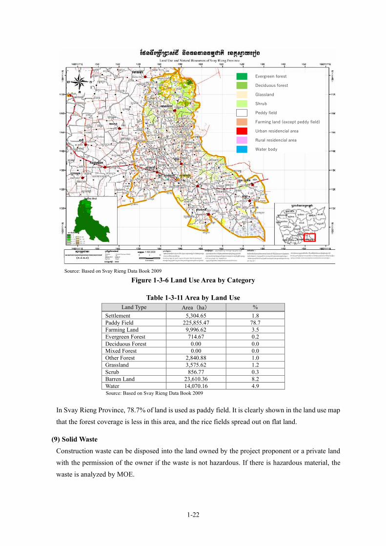
1-22
Source: Based on Svay Rieng Data Book 2009
Figure 1-3-6 Land Use Area by Category
Table 1-3-11 Area by Land Use Land Type Area(ha) %
Settlement 5,304.65 1.8 Paddy Field 225,855.47 78.7 Farming Land 9,996.62 3.5 Evergreen Forest 714.67 0.2 Deciduous Forest 0.00 0.0 Mixed Forest 0.00 0.0 Other Forest 2,840.88 1.0 Grassland 3,575.62 1.2 Scrub 856.77 0.3 Barren Land 23,610.36 8.2 Water 14,070.16 4.9 Source: Based on Svay Rieng Data Book 2009
In Svay Rieng Province, 78.7% of land is used as paddy field. It is clearly shown in the land use map that the forest coverage is less in this area, and the rice fields spread out on flat land.
(9) Solid Waste Construction waste can be disposed into the land owned by the project proponent or a private land with the permission of the owner if the waste is not hazardous. If there is hazardous material, the waste is analyzed by MOE.
Evergreen forest
Deciduous forest
Glassland
Shrub
Peddy field
Farming land (except peddy field)
Urban residencial area
Rural residencial area
Water body

1-23
Currently, sludge of water treatment generated by the Svay Rieng WTP is discharged into the wetland in the land of WTP. The sludge is a mixture of turbid materials of raw water and coagulant; thus, the existence of hazardous materials is not expected. MISTI indicated that the landowners accepted to receive such materials for land filling as countermeasure against flooding ; therefore, the dumping of sludge will not be a problem.
(10) Poverty The Ministry of Planning of the Royal Government of Cambodia had carried out a household survey nationwide to identify poor households in accordance with a poverty reduction program, with the help of the German Federal Ministry for Economic Cooperation and Development (BMZ), the Australian Department of Foreign Affairs and Trade, and the Deutsche Gesellschaft für Internationale Zusammenarbeit (GIZ) GmbH. The program was to define households as Poor Level 1 (very poor) and Poor Level 2 (poor), and it provides Equity Cards to such households to enable them receive appropriate support and benefits. The latest survey in Svay Rieng Province was conducted in 2020. The following table shows the situation of the project area.
Table 1-3-12 Poverty Households in Project Area District Commune Poverty Level 1 Poverty Level 2 Total
Number % Number % Number
Krong Svay Rieng
Svay Rieng 74 2.3% 123 3.9% 3168 Prey Chlak 32 3.7% 32 3.7% 863
Koy Traback 45 5.9% 39 5.1% 763 Pou Ta Hao 26 4.7% 57 10.2% 559
Chek 69 2.4% 108 3.8% 2880 Svay Toea 59 3.1% 96 5.1% 1874 Sangkhoar 44 1.8% 120 4.9% 2458
Svay Chrum Basak 153 6.2% 303 12.2% 2482 Source: Ministry of Planning, Identification of Poor Households Programme database
(11) Minority The ethnic composition in Cambodia is 97.6% Khmer, 1.2% Cham, 0.1 % Chinese, 0.1 % Vietnamese and 0.9% of others (CIA World Fact Book, 2013 estimation). According to the hearing survey with DOE and the City Hall, there is no minority group in the project area.
(12) Education and Literacy Rate The following table shows the literacy rate in Svay Rieng Province.
Table 1-3-13 Literacy Rate (2008 to 2018)(%) District Literacy Rate (2008) Literacy Rate (2013)
Total 80.1 83.3 Male 88.7 89.9 Female 72.3 77.1
Source: Cambodia Intercensal Population Survey 2013
The literacy rate in Svay Rieng Province is over 80% and is increasing year by year. The school enrollment rate is also higher than that of the whole Cambodia.

1-24
According to the results of a social survey in the project area, 86% of the owners were enrolled in schools, and 20% were educated in high schools or higher.
(13) State of Health and Hygiene The data related health and hygiene obtained by the social survey are summarized in the following table. The samples consist of two groups, i.e., the group of households receiving water supply from provincial WWs (Connected HHs) and the group of households living outside of the supply area (Non-connected HHs).
Table 1-3-14 State of Health and Hygiene in Project Area Total Connected HHs Non- Connected HHs Ratio of owning Toilet (%) 96 97 94 Morbidity by Waterborne Disease (last three years)(%)
4 2 6
Source: Result of Social Survey, Survey Team
The ownership of toilet is relatively high in Cambodia. The morbidity by waterborne diseases in the last three years is significantly lower in connected households (HHs) than in non-connected HHs. According to the database of National Committee for Sub-National Democratic Development (NCDD), infant mortality (death of under 5-year-old per 1,000 birth) is 23.6 in Svay Rieng Province and 12.0 in Svay Rieng District. The health and hygiene conditions in urban areas seem better than in rural areas.
1-3-1-3 Environmental and Social Consideration Systems and Organizations in Cambodia
(1) Environmental and Social Consideration Systems and Organizations The Cambodian agency in charge of environmental issues is the Ministry of Environment (MOE). Under the Minister of MOE, five departments work on their own subject of responsibility. Each province has a DOE, which is responsible for the environmental issues in the province.
The legal framework in Cambodia is as summarized in the following table.
Minister
General Department of Environmental Protection General Environmental Knowledge and Information General Department of Finance and Administration General Administration of Nature Conservation and Protection General Department of Local Community General Department of Local Community
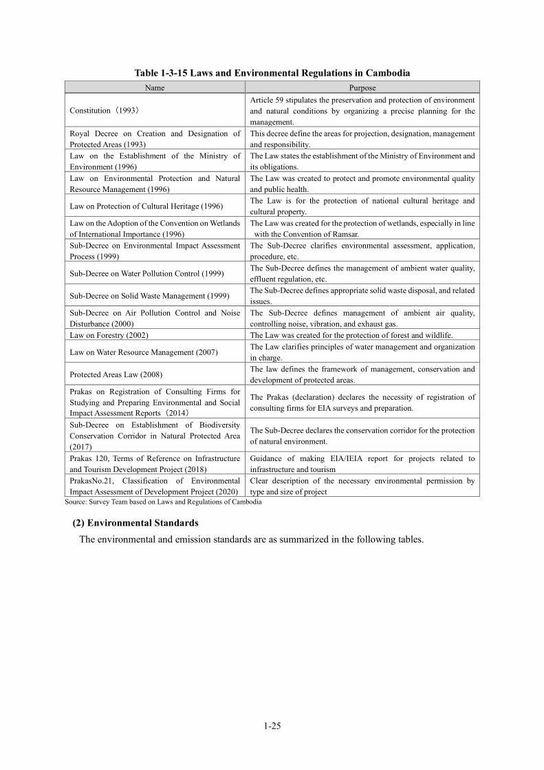
1-25
Table 1-3-15 Laws and Environmental Regulations in Cambodia Name Purpose
Constitution(1993) Article 59 stipulates the preservation and protection of environment and natural conditions by organizing a precise planning for the management.
Royal Decree on Creation and Designation of Protected Areas (1993)
This decree define the areas for projection, designation, management and responsibility.
Law on the Establishment of the Ministry of Environment (1996)
The Law states the establishment of the Ministry of Environment and its obligations.
Law on Environmental Protection and Natural Resource Management (1996)
The Law was created to protect and promote environmental quality and public health.
Law on Protection of Cultural Heritage (1996) The Law is for the protection of national cultural heritage and cultural property.
Law on the Adoption of the Convention on Wetlands of International Importance (1996)
The Law was created for the protection of wetlands, especially in line with the Convention of Ramsar.
Sub-Decree on Environmental Impact Assessment Process (1999)
The Sub-Decree clarifies environmental assessment, application, procedure, etc.
Sub-Decree on Water Pollution Control (1999) The Sub-Decree defines the management of ambient water quality, effluent regulation, etc.
Sub-Decree on Solid Waste Management (1999) The Sub-Decree defines appropriate solid waste disposal, and related issues.
Sub-Decree on Air Pollution Control and Noise Disturbance (2000)
The Sub-Decree defines management of ambient air quality, controlling noise, vibration, and exhaust gas.
Law on Forestry (2002) The Law was created for the protection of forest and wildlife.
Law on Water Resource Management (2007) The Law clarifies principles of water management and organization in charge.
Protected Areas Law (2008) The law defines the framework of management, conservation and development of protected areas.
Prakas on Registration of Consulting Firms for Studying and Preparing Environmental and Social Impact Assessment Reports(2014)
The Prakas (declaration) declares the necessity of registration of consulting firms for EIA surveys and preparation.
Sub-Decree on Establishment of Biodiversity Conservation Corridor in Natural Protected Area (2017)
The Sub-Decree declares the conservation corridor for the protection of natural environment.
Prakas 120, Terms of Reference on Infrastructure and Tourism Development Project (2018)
Guidance of making EIA/IEIA report for projects related to infrastructure and tourism
PrakasNo.21, Classification of Environmental Impact Assessment of Development Project (2020)
Clear description of the necessary environmental permission by type and size of project
Source: Survey Team based on Laws and Regulations of Cambodia
(2) Environmental Standards The environmental and emission standards are as summarized in the following tables.

1-26
Table 1-3-16 Environmental Standards Target Parameters Remarks Source
Air Ambient air quality CO, NO2, SO2, O3, Pb, TSP Sub-decree on Control of Air Pollution and Noise Disturbance
Ambient air (hazardous) 30 hazardous materials Emission (Immobile source)
66 parameters
Emission (Mobile source) CO, HC Emission for vehicle type Content of fuel and coal S, Pb
Noise Noise of vehicle Noise level Maximum level of type of vehicles
Public and residential area noise
Noise level Permissible level at 4 types of areas
Noise level at factory Noise level Maximum period at levels Water Discharge standards 52 parameters Sub-decree on
Water Pollution Control, 1999
Ambient water 5 to 7 parameters for waterbodies
Conservation of biodiversity at public water areas
Ambient water 25 parameters Protection of public health at public water areas
Source: Survey Team based on Sub-Decrees of Cambodia
The maximum permissible level of noise by area is as shown below. There are no standards and regulatory limits for vibration in Cambodia. This standard is applied to control noise level of any source of activity that emits noise into the public and residential areas. The project area falls under Category 3.
Table 1-3-17 Maximum Permissible Level of Noise dB(A) Category
Area Period of Time
From 6am to 18pm
From 18pm to 22pm
From 22pm to 6am
1 Quiet Areas -hospitals, Libraries, School, Kindergarten 45 40 35
2 Residential Areas -Hotels, Administration offices, Houses 60 50 45
3 Commercial and service areas and mix 70 65 50 4 Small industrial factories intermingling in
residential areas 75 70 50
Source: Sub-decree on Control of Air Pollution and Noise Disturbance
These noise standards are applicable to the management of all noise sources in public and residential areas. The target area of this project is categorized under Category 2. The Provincial DOE of Svay Rieng does not monitor the above standards and regulatory limits since they do not have instruments for measuring, facilities and capacity. Discharge standards have many parameters but there are limited number of laboratories which can measure them, and DOE is also not able to measure them. Therefore, these parameters are practically not managed. The existing WTPs in Cambodia usually discharge treatment sludge into the river directly on the basis of agreement with DOE. The Annex on the “Sub-Decree on Water Pollution Control (1999)” defines 67 types of pollution sources which need the permission of MOE before discharging or transporting their wastewater. Category I source needs permission when its discharge amount exceeds 10m3/day. Category II source always needs permission. “Pure drinking water manufacturing” is included in Category I, but the wastewater generated by the Project will be much less than this level and does not require permission.

1-27
(3) Environmental Impact Assessment Procedure The Sub-Decree on Environmental Impact Assessment Process (1999) has a list of projects that require EIA or IEIA as an annex. However, there is no clear description of EIA or IEIA, therefore, it has to be decided by MOE. In addition, the project proponent of a project that does not require EIA / IEIA is required to have an environmental protection contract (EPC) with the MOE. However, the conditions are unclear. To solve such an unclear condition, the Ministerial Ordinance, “Prakas No.21, Classification of Environmental Impact Assessment of Development Project”, was issued under the name of the Minister of Environment on February 3, 2020 and came into effect on the same day. According to this Ministerial Ordinance, all WTPs and water distribution system projects are subject to EPC. In case of IEIA/EIA, changes of plan described in the report need to be consulted with the MOE, but in case of EPC, minor changes are not of concern. There is no specific document which describes the procedure for obtaining the EPC. The following descriptions of particular differences from EIA were prepared by a local environmental consultant.
• Project proponent can submit an application form before creating a report. • The examination takes 28 business days. • MOE organizes a technical team with 12 members for examination of EIA /IEIA, but only 3-4
members for EPC. • EPC does not require actual measurement of water quality, air quality, noise, etc.
The EPC procedure is as shown in the following figure
Source: Survey Team based on interviews with environmental consultant of Cambodia
Figure 1-3-7 Process of EPC Approval
Submission of Application
Organizing inspection team in MOE
Field survey of inspection team and environmental consultant
Submission of Environmental Management Plan
Inspection
Approval of EPC
Success Failure
Revision of the report based on the comment
of Inspection team
Environmental Management Plan can be submitted at once

1-28
The flow of the EIA/IEIA approval procedure is as shown in the following figure for reference.
Source: Sub-Decree on Environmental Impact Assessment Process (1999) together with the hearing survey
Figure 1-3-8 Process of EIA/IEIA Approval
The Parkas (declaration) on the Registration of Consulting Firms for Studying and Preparing Environmental and Social Impact Assessment Reports was enacted in May 2014, and EIA/IEIA survey and report preparation should be conducted by a registered consulting firm. On the other hand, there is no document on the designation of the responsible entity for the preparation of the EPC document. However, environmental consultants are implementing it because of the necessity of preparing the environmental management plan.
(4) Comparison between Cambodian Regulations and JICA Guidelines There are no big gaps between the Cambodian environmental regulation system and the JICA Guidelines. The following table shows the gaps between the Cambodian system and JICA guidelines, and the defined policy of the Project.
Within 30 working days
Submission of initial business plan
Determination of EIA or IEIA
Submission of Survey TOR of IEIA/EIA to Department of EIA under the General Office of Environmental Protection of MOE to finalize the survey contents
Survey, Preparation of report and submission
Revision and re-submission Review
Approval
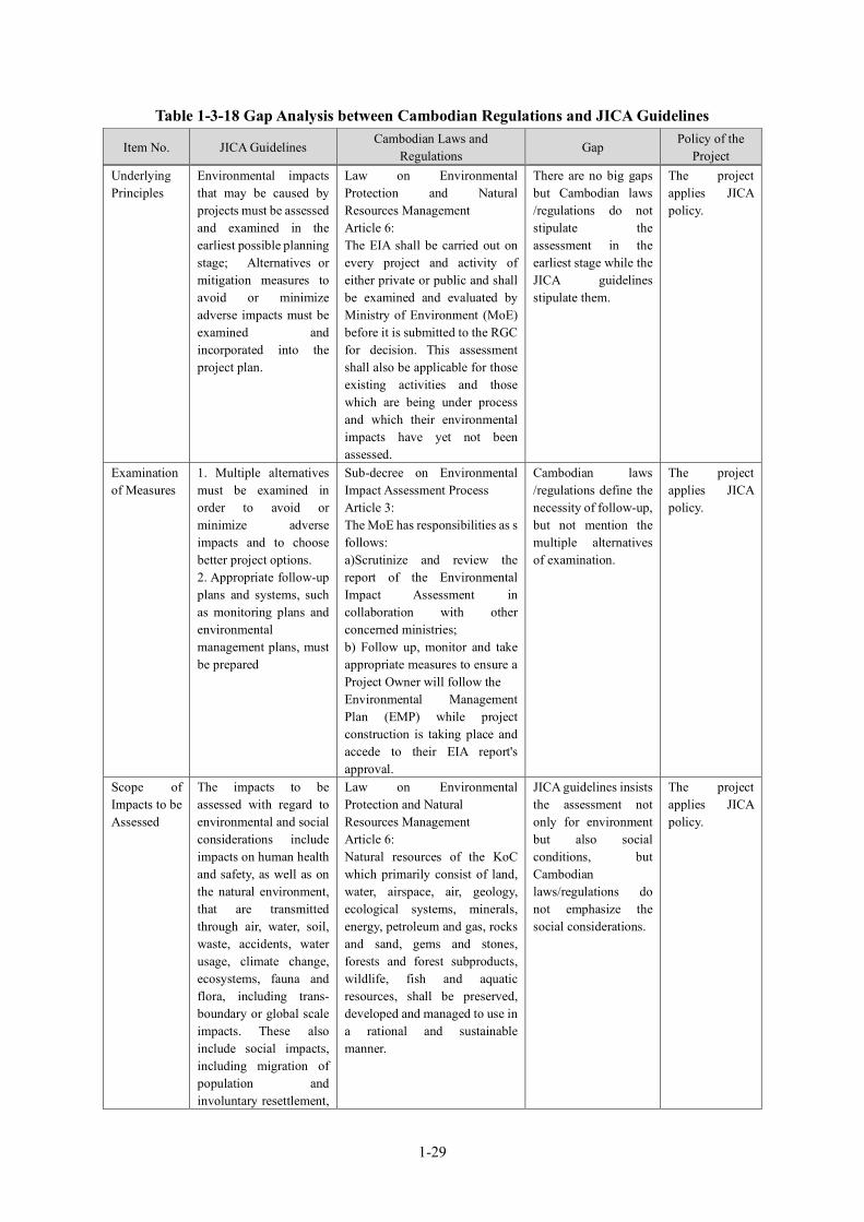
1-29
Table 1-3-18 Gap Analysis between Cambodian Regulations and JICA Guidelines
Item No. JICA Guidelines Cambodian Laws and
Regulations Gap
Policy of the Project
Underlying Principles
Environmental impacts that may be caused by projects must be assessed and examined in the earliest possible planning stage; Alternatives or mitigation measures to avoid or minimize adverse impacts must be examined and incorporated into the project plan.
Law on Environmental Protection and Natural Resources Management Article 6: The EIA shall be carried out on every project and activity of either private or public and shall be examined and evaluated by Ministry of Environment (MoE) before it is submitted to the RGC for decision. This assessment shall also be applicable for those existing activities and those which are being under process and which their environmental impacts have yet not been assessed.
There are no big gaps but Cambodian laws /regulations do not stipulate the assessment in the earliest stage while the JICA guidelines stipulate them.
The project applies JICA policy.
Examination of Measures
1. Multiple alternatives must be examined in order to avoid or minimize adverse impacts and to choose better project options. 2. Appropriate follow-up plans and systems, such as monitoring plans and environmental management plans, must be prepared
Sub-decree on Environmental Impact Assessment Process Article 3: The MoE has responsibilities as s follows: a)Scrutinize and review the report of the Environmental Impact Assessment in collaboration with other concerned ministries; b) Follow up, monitor and take appropriate measures to ensure a Project Owner will follow the Environmental Management Plan (EMP) while project construction is taking place and accede to their EIA report's approval.
Cambodian laws /regulations define the necessity of follow-up, but not mention the multiple alternatives of examination.
The project applies JICA policy.
Scope of Impacts to be Assessed
The impacts to be assessed with regard to environmental and social considerations include impacts on human health and safety, as well as on the natural environment, that are transmitted through air, water, soil, waste, accidents, water usage, climate change, ecosystems, fauna and flora, including trans-boundary or global scale impacts. These also include social impacts, including migration of population and involuntary resettlement,
Law on Environmental Protection and Natural Resources Management Article 6: Natural resources of the KoC which primarily consist of land, water, airspace, air, geology, ecological systems, minerals, energy, petroleum and gas, rocks and sand, gems and stones, forests and forest subproducts, wildlife, fish and aquatic resources, shall be preserved, developed and managed to use in a rational and sustainable manner.
JICA guidelines insists the assessment not only for environment but also social conditions, but Cambodian laws/regulations do not emphasize the social considerations.
The project applies JICA policy.

1-30
Item No. JICA Guidelines Cambodian Laws and
Regulations Gap
Policy of the Project
local economy such as employment and livelihood, utilization of land and local resources, social institutions such as social capital and local decision-making institutions, existing social infrastructures and services, vulnerable social groups such as poor and indigenous people, equality of benefits and losses and equality in the development process, gender, children’s rights, cultural heritage, local conflicts of interest, infectious diseases such as HIV/AIDS, and working conditions including occupational safety.
Social Acceptability
1. Projects must be adequately coordinated so that they are accepted in a manner that is socially appropriate to the country and locality in which they are planned. For projects with a potentially large environmental impact, sufficient consultations with local stakeholders, such as local residents, must be conducted via disclosure of information at an early stage, at which time alternatives for project plans may be examined. The outcome of such consultations must be incorporated into the contents of project plans. 2. Appropriate consideration must be given to vulnerable social groups, such as women, children, the elderly, the poor, and ethnic minorities, all members of which are susceptible to
Law on environmental impact assessment, Article 37; The main objective of public participation is to ensure that project-affected people and relevant stakeholders: - are well informed about the project, - have the opportunity to be involved in the discussion and decision-making process related to the project, and - have the opportunity to participate in the project monitoring. Project Proponents that are required to conduct an EIA shall include public involvement and consultation from local administrations, civil society, community representatives, the project-affected people and other relevant stakeholders in the EIA process during project planning in order to: - identify areas of significance of environment, economy, society and culture - collect opinions of stakeholders and integrate such opinions into the decision-making process
Cambodian laws/regulations state the importance of public participation and the difference from JICA guidelines seem very less. However, JICA guidelines explains more detail about the vulnerable people and minority.
The project applies JICA policy.
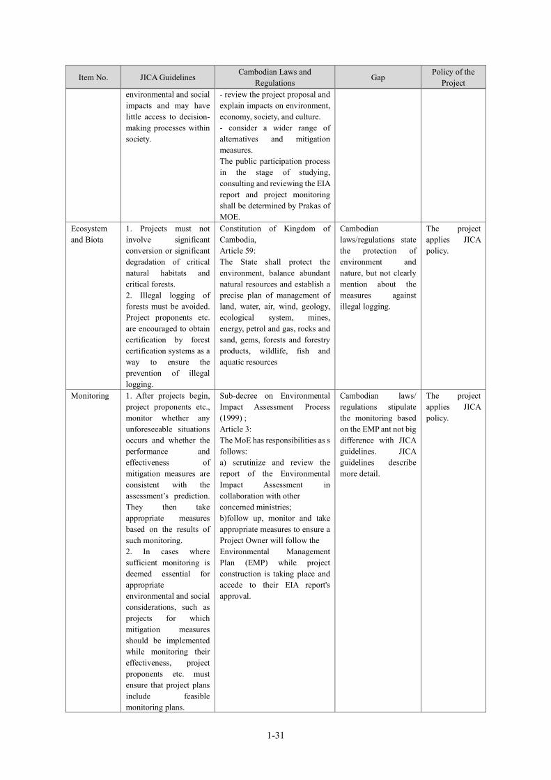
1-31
Item No. JICA Guidelines Cambodian Laws and
Regulations Gap
Policy of the Project
environmental and social impacts and may have little access to decision-making processes within society.
- review the project proposal and explain impacts on environment, economy, society, and culture. - consider a wider range of alternatives and mitigation measures. The public participation process in the stage of studying, consulting and reviewing the EIA report and project monitoring shall be determined by Prakas of MOE.
Ecosystem and Biota
1. Projects must not involve significant conversion or significant degradation of critical natural habitats and critical forests. 2. Illegal logging of forests must be avoided. Project proponents etc. are encouraged to obtain certification by forest certification systems as a way to ensure the prevention of illegal logging.
Constitution of Kingdom of Cambodia, Article 59: The State shall protect the environment, balance abundant natural resources and establish a precise plan of management of land, water, air, wind, geology, ecological system, mines, energy, petrol and gas, rocks and sand, gems, forests and forestry products, wildlife, fish and aquatic resources
Cambodian laws/regulations state the protection of environment and nature, but not clearly mention about the measures against illegal logging.
The project applies JICA policy.
Monitoring 1. After projects begin, project proponents etc., monitor whether any unforeseeable situations occurs and whether the performance and effectiveness of mitigation measures are consistent with the assessment’s prediction. They then take appropriate measures based on the results of such monitoring. 2. In cases where sufficient monitoring is deemed essential for appropriate environmental and social considerations, such as projects for which mitigation measures should be implemented while monitoring their effectiveness, project proponents etc. must ensure that project plans include feasible monitoring plans.
Sub-decree on Environmental Impact Assessment Process (1999) ; Article 3: The MoE has responsibilities as s follows: a) scrutinize and review the report of the Environmental Impact Assessment in collaboration with other concerned ministries; b)follow up, monitor and take appropriate measures to ensure a Project Owner will follow the Environmental Management Plan (EMP) while project construction is taking place and accede to their EIA report's approval.
Cambodian laws/ regulations stipulate the monitoring based on the EMP ant not big difference with JICA guidelines. JICA guidelines describe more detail.
The project applies JICA policy.

1-32
Item No. JICA Guidelines Cambodian Laws and
Regulations Gap
Policy of the Project
3. Project proponents etc. should make efforts to make the results of the monitoring process available to local project stakeholders. 4. When third parties point out, in concrete terms, that environmental and social considerations are not being fully undertaken, forums for discussion and examination of countermeasures are established based on sufficient information disclosure, including stakeholders’ participation in relevant projects. Project proponents, etc., should make efforts to reach an agreement on procedures to be adopted with a view to resolving problems.
Land acquisition and involuntary resettlement 1. Involuntary resettlement
and loss of means of livelihood are to be avoided when feasible by exploring all viable alternatives. (JICA GL)
Constitution (1993) Article 44: Legal private ownership shall be protected by the law. The right to confiscate possessions from any person shall be exercised only in the public interest as provided for under law and shall require fair and just compensation in advance. Land Law (2001) Article 4: The right of ownership, recognized by Article 44 of the 1993 Constitution, applies to all immovable properties within the Kingdom of Cambodia in accordance with the conditions set forth by this law. Article 5: No person may be deprived of his ownership, unless it is in the public interest. An ownership deprivation shall be carried out in accordance with the forms and procedures provided by law and regulations and after the payment of fair and just compensation in
Cambodian laws /regulations do not stipulate avoidance of resettlement and loss of means of livelihood while the JICA guidelines stipulate them.
Involuntary resettlement and loss of means of livelihood are to be avoided when feasible by exploring all viable alternatives
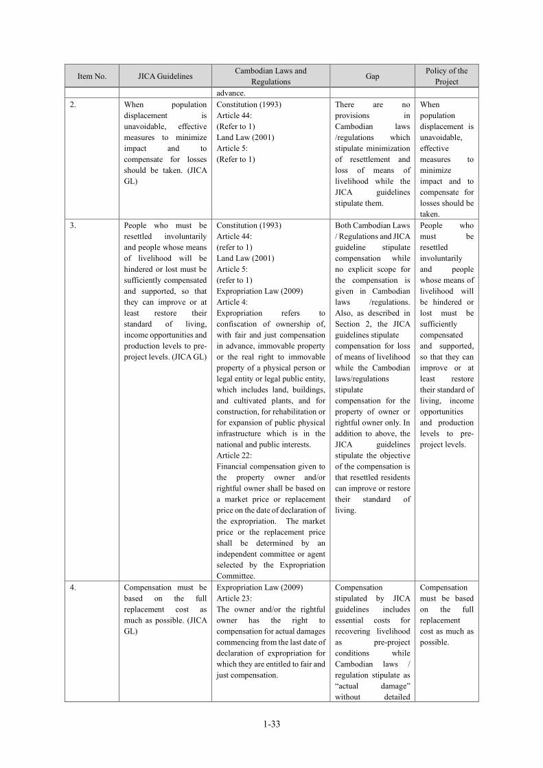
1-33
Item No. JICA Guidelines Cambodian Laws and
Regulations Gap
Policy of the Project
advance. 2. When population
displacement is unavoidable, effective measures to minimize impact and to compensate for losses should be taken. (JICA GL)
Constitution (1993) Article 44: (Refer to 1) Land Law (2001) Article 5: (Refer to 1)
There are no provisions in Cambodian laws /regulations which stipulate minimization of resettlement and loss of means of livelihood while the JICA guidelines stipulate them.
When population displacement is unavoidable, effective measures to minimize impact and to compensate for losses should be taken.
3. People who must be resettled involuntarily and people whose means of livelihood will be hindered or lost must be sufficiently compensated and supported, so that they can improve or at least restore their standard of living, income opportunities and production levels to pre-project levels. (JICA GL)
Constitution (1993) Article 44: (refer to 1) Land Law (2001) Article 5: (refer to 1) Expropriation Law (2009) Article 4: Expropriation refers to confiscation of ownership of, with fair and just compensation in advance, immovable property or the real right to immovable property of a physical person or legal entity or legal public entity, which includes land, buildings, and cultivated plants, and for construction, for rehabilitation or for expansion of public physical infrastructure which is in the national and public interests. Article 22: Financial compensation given to the property owner and/or rightful owner shall be based on a market price or replacement price on the date of declaration of the expropriation. The market price or the replacement price shall be determined by an independent committee or agent selected by the Expropriation Committee.
Both Cambodian Laws / Regulations and JICA guideline stipulate compensation while no explicit scope for the compensation is given in Cambodian laws /regulations. Also, as described in Section 2, the JICA guidelines stipulate compensation for loss of means of livelihood while the Cambodian laws/regulations stipulate compensation for the property of owner or rightful owner only. In addition to above, the JICA guidelines stipulate the objective of the compensation is that resettled residents can improve or restore their standard of living.
People who must be resettled involuntarily and people whose means of livelihood will be hindered or lost must be sufficiently compensated and supported, so that they can improve or at least restore their standard of living, income opportunities and production levels to pre-project levels.
4. Compensation must be based on the full replacement cost as much as possible. (JICA GL)
Expropriation Law (2009) Article 23: The owner and/or the rightful owner has the right to compensation for actual damages commencing from the last date of declaration of expropriation for which they are entitled to fair and just compensation.
Compensation stipulated by JICA guidelines includes essential costs for recovering livelihood as pre-project conditions while Cambodian laws / regulation stipulate as “actual damage” without detailed
Compensation must be based on the full replacement cost as much as possible.
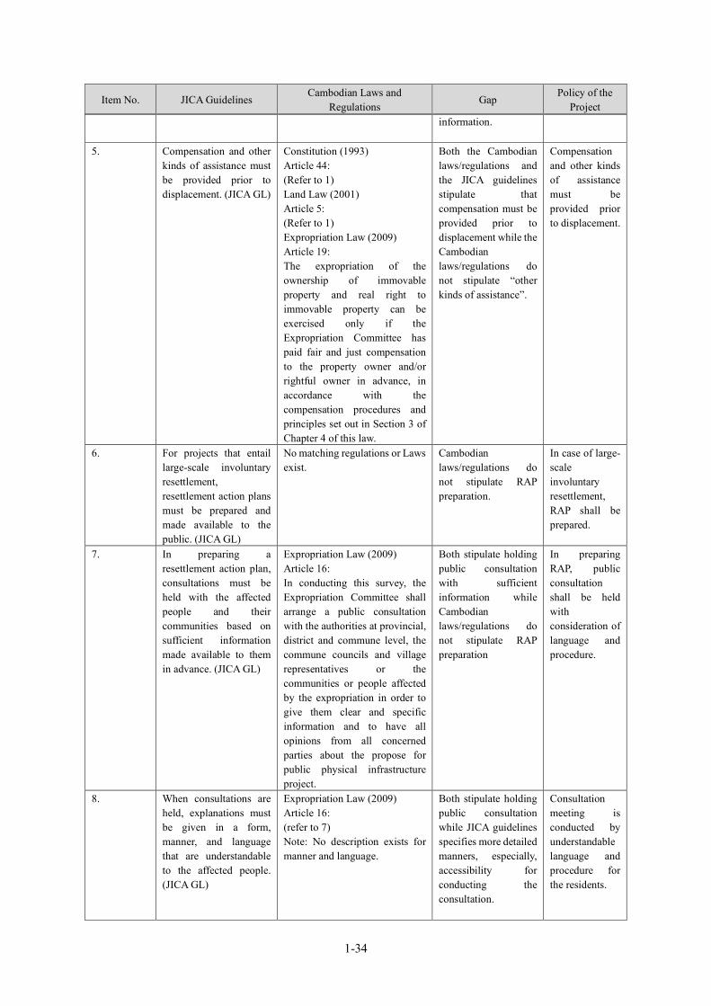
1-34
Item No. JICA Guidelines Cambodian Laws and
Regulations Gap
Policy of the Project
information.
5. Compensation and other kinds of assistance must be provided prior to displacement. (JICA GL)
Constitution (1993) Article 44: (Refer to 1) Land Law (2001) Article 5: (Refer to 1) Expropriation Law (2009) Article 19: The expropriation of the ownership of immovable property and real right to immovable property can be exercised only if the Expropriation Committee has paid fair and just compensation to the property owner and/or rightful owner in advance, in accordance with the compensation procedures and principles set out in Section 3 of Chapter 4 of this law.
Both the Cambodian laws/regulations and the JICA guidelines stipulate that compensation must be provided prior to displacement while the Cambodian laws/regulations do not stipulate “other kinds of assistance”.
Compensation and other kinds of assistance must be provided prior to displacement.
6. For projects that entail large-scale involuntary resettlement, resettlement action plans must be prepared and made available to the public. (JICA GL)
No matching regulations or Laws exist.
Cambodian laws/regulations do not stipulate RAP preparation.
In case of large-scale involuntary resettlement, RAP shall be prepared.
7. In preparing a resettlement action plan, consultations must be held with the affected people and their communities based on sufficient information made available to them in advance. (JICA GL)
Expropriation Law (2009) Article 16: In conducting this survey, the Expropriation Committee shall arrange a public consultation with the authorities at provincial, district and commune level, the commune councils and village representatives or the communities or people affected by the expropriation in order to give them clear and specific information and to have all opinions from all concerned parties about the propose for public physical infrastructure project.
Both stipulate holding public consultation with sufficient information while Cambodian laws/regulations do not stipulate RAP preparation
In preparing RAP, public consultation shall be held with consideration of language and procedure.
8. When consultations are held, explanations must be given in a form, manner, and language that are understandable to the affected people. (JICA GL)
Expropriation Law (2009) Article 16: (refer to 7) Note: No description exists for manner and language.
Both stipulate holding public consultation while JICA guidelines specifies more detailed manners, especially, accessibility for conducting the consultation.
Consultation meeting is conducted by understandable language and procedure for the residents.
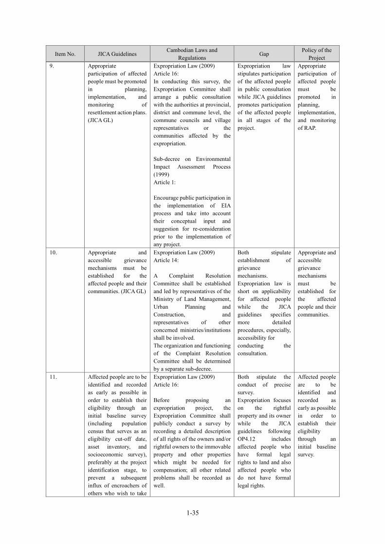
1-35
Item No. JICA Guidelines Cambodian Laws and
Regulations Gap
Policy of the Project
9. Appropriate participation of affected people must be promoted in planning, implementation, and monitoring of resettlement action plans. (JICA GL)
Expropriation Law (2009) Article 16: In conducting this survey, the Expropriation Committee shall arrange a public consultation with the authorities at provincial, district and commune level, the commune councils and village representatives or the communities affected by the expropriation.
Sub-decree on Environmental Impact Assessment Process (1999) Article 1: Encourage public participation in the implementation of EIA process and take into account their conceptual input and suggestion for re-consideration prior to the implementation of any project.
Expropriation law stipulates participation of the affected people in public consultation while JICA guidelines promotes participation of the affected people in all stages of the project.
Appropriate participation of affected people must be promoted in planning, implementation, and monitoring of RAP.
10. Appropriate and accessible grievance mechanisms must be established for the affected people and their communities. (JICA GL)
Expropriation Law (2009) Article 14: A Complaint Resolution Committee shall be established and led by representatives of the Ministry of Land Management, Urban Planning and Construction, and representatives of other concerned ministries/institutions shall be involved. The organization and functioning of the Complaint Resolution Committee shall be determined by a separate sub-decree.
Both stipulate establishment of grievance mechanisms. Expropriation law is short on applicability for affected people while the JICA guidelines specifies more detailed procedures, especially, accessibility for conducting the consultation.
Appropriate and accessible grievance mechanisms must be established for the affected people and their communities.
11. Affected people are to be identified and recorded as early as possible in order to establish their eligibility through an initial baseline survey (including population census that serves as an eligibility cut-off date, asset inventory, and socioeconomic survey), preferably at the project identification stage, to prevent a subsequent influx of encroachers of others who wish to take
Expropriation Law (2009) Article 16: Before proposing an expropriation project, the Expropriation Committee shall publicly conduct a survey by recording a detailed description of all rights of the owners and/or rightful owners to the immovable property and other properties which might be needed for compensation; all other related problems shall be recorded as well.
Both stipulate the conduct of precise survey. Expropriation focuses on the rightful property and its owner while the JICA guidelines following OP4.12 includes affected people who have formal legal rights to land and also affected people who do not have formal legal rights.
Affected people are to be identified and recorded as early as possible in order to establish their eligibility through an initial baseline survey.

1-36
Item No. JICA Guidelines Cambodian Laws and
Regulations Gap
Policy of the Project
advantage of such benefits. (WB OP4.12 Para.6)
12. Eligibility of benefits includes, the Project Affected Person: PAPs who have formal legal rights to land (including customary and traditional land rights recognized under law), the PAPs who do not have formal legal rights to land at the time of census but have a claim to such land or assets and the PAPs who have no recognizable legal right to the land they are occupying. (WB OP4.12 Para.15)
Expropriation Law (2009) Article 4 Owner of immovable property and/or rightful owner refers to a physical person, private legal person, or public legal entity including a proprietor, possessor and all persons who have rights to land and are affected by the expropriation project.
Article 18: The following are null and void and cannot be made legal in any form whatsoever: - any entering into possession of public properties of the State and public legal entities and any transformation of possession of private properties of the State into ownership rights that were not made pursuant to the legal formalities and procedures that had been stipulated prior to that time, irrespective of the date of the creation of possession or transformation; - any transformation of a land concession, into a right of ownership, regardless of whether the transformation existed before this law came into effect, except concessions that are in response to social purposes; - any land concession which fails to comply with the provisions of Chapter 5; - any entering into possession of properties in the private property of the State, through any means, that occurs after this law comes into effect.
Expropriation law stipulates “owner of immovable property and rightful owner” as eligible person for compensation while the JICA guidelines includes PAPs who do not have formal legal rights to land as eligible person
Eligibility shall be given not only for PAP having legal rights but also PAP not having legal rights.
13. Preference should be given to land-based resettlement strategies for displaced people whose livelihoods are land-based. (WB OP4.12 Para.11)
No matching regulation or Law exists.
Cambodian laws /regulations do not stipulate any provision of preference to land-based resettlement strategies.
Preference should be given to land-based resettlement strategies for displaced people whose livelihoods are land-based.
14. Provide support for the transition period
No matching regulation or Law exists.
Cambodian laws /regulations do not
PAP will receive support during

1-37
Item No. JICA Guidelines Cambodian Laws and
Regulations Gap
Policy of the Project
(between displacement and livelihood restoration). (WB OP4.12 Para.6)
stipulate provision of support for the transition period.
transition period.
15. Particular attention must be paid to the needs of the vulnerable groups among those displaced, especially those below the poverty line, landless, elderly, women and children, ethnic minorities, etc. (WB OP4.12 Para.8)
No matching regulations or Law exist.
Cambodian laws /regulations do not stipulate assistance, care or attention toward vulnerable groups.
Particular attention shall be given to minority and indigenous people.
16. For projects that entail land acquisition or involuntary resettlement of fewer than 200 people, abbreviated resettlement plan is to be prepared. (WB OP4.12 Para.25)
No matching regulation or Law exists.
Cambodian Laws /Regulations do not stipulate preparation of RAP nor ARAP.
ARAP shall be prepared for small scale land acquisitions and involuntary resettlements.
Source: Survey Team by Cambodian Laws and Regulations
1-3-1-4 Comparison of Alternatives This project aims at expanding the existing water supply system in Svay Rieng, and it is important to maximize the benefit with consideration on harmonization with existing systems, future population growth and urbanization. Moreover, it is considered to maximize the positive impact and minimize negative impact to the environmental and social conditions. The regular water supply will improve the hygiene and basic living standards. The result of comparison of alternatives is described as follows.
(1) Alternative of Without Project The results of comparison between without project and with project conditions are shown in the following table.

1-38
Table 1-3-19 Comparison of Alternatives (Without Project) Item Alternative 1 Score
Alternative 2 Score Summary With project Without project
Supplied households 9,954HHs in 2027 3 I will not be much better than current supply condition as 4,709HHs 1
Water Quality
Water supply by surface water as raw water will start, and the problem of iron and manganese caused by groundwater will be solved.
3 Sometimes necessity of overload operation occurs, and there are complaints due to high concentration of iron and manganese.
2
Target of government
Government of Cambodia sets the goal of 100% water supply in urban areas and the project will achieve 86.7% supply in urban areas within the controlled area by 2027.
3 The expected supply ratio will be 44.3% by 2027 and the target will not be achieved. 1
Hygiene The water supply ratio will increase and the use of clean water will be promoted.
3 The use of supplied water will not progress, and the sanitary situation will not change significantly from the current situation.
2
Environmental &
Social
Ecosystem The impact on fish of water intake from Lake Vay Koh needs to be minimized.
2 There is no additional negative impact. 3
Natural Environment
The impact of noise and vibration need to be minimized. 2 There is no additional negative impact. 3
Land acquisition and resettlement
There is no land acquisition and resettlement. 3 There is no land acquisition and
resettlement. 3
Socioeconomic Infrastructure development will increase employment and improve the level of social services.
3 There are no big changes. 2
Evaluation 22 17
Source: Survey Team
The above comparisons reject the alternative of Without Project. The coverage of water supply in Svay Rieng is about 23% in 2019. On the other hand, MISTI has set the target of 100% supply in urban area by 2025. To achieve the target, implementation of this project is essential. “Ensure availability and sustainable management of water and sanitation for all” is one of the SDGs goals. To achieve the goal, basic infrastructure should be constructed for safe, accessible and affordable water supply.
(2) Alternatives of Water Source In Svay Rieng, many families have their own wells. According to the results of the social survey conducted in 2017, 79% of households in non-connected areas use well water as drinking water. This is followed by rainwater use at 17% and water supply by water trucks at 7%. On the other hand, 37% of well users answered that there is no particular problem, but 45% answered that the quality of well water is getting worse and worse. Twenty-one percent (21%) of the respondents said that the groundwater level is falling.

1-39
Respondents are highly motivated to connect to water, with 78% saying they want to connect to water. According to the survey results of households in connected areas, 100% answered that they are satisfied with the current water supply service level. The results of comparison of alternatives for water sources are as shown below. The Survey Team examined the water sources and put the score in 3 degrees (3 is the best), as shown in the following table.
Table 1-3-20 Comparison of Alternative Water Sources Item Alternative1 Score
Alternative2 Score
Summary Surface water from Vay Kor Lake Groundwater
Water Source Amount is enough; Water quality is acceptable.
3 Considering the existing groundwater survey results, there is enough capacity . Groundwater has a high concentration of iron and manganese, and the existing facilities may not be able to remove it sufficiently, so the Cambodian side hopes to shift to a surface water source.
2
Environmental &
Social
Impact of construction to surroundings
Measures must be taken to mitigate the impact on Vay Kor Lake where critically endangered species live.
2 Since the construction of certain number of production wells is required, it is necessary to find a good location that can secure sufficient production volume without any negative impact.
2
Natural environment
Part of Lake Vay Kor has been designated as a protected area by Svay Rieng Province, so that sufficient mitigation measures need to be taken, including the conservation of endangered species.
2 The target area is urban area or agricultural land, and there is no major problem in terms of impact on the ecosystem. It is necessary to consider the impact of pumping water on the surrounding water environment.
2
Land acquisition and resettlement
Resettlement is not required.
3 Acquiring private land that does not cause relocation of residents is necessary for the construction of wells.
2
Evaluation 10 8 Source: Survey Team
The existing WTP uses groundwater as a water source, but the shift to a surface water source is desired for WWs due to the water quality problem. In the field survey conducted in 2017, there was concern about the structural fragility of the Vay Kor Dam, so that it was once decided to utilize the groundwater source. However, the Japan Water Agency conducted a detailed soundness survey in 2018 and judged that there will be no problem if appropriate repairs and maintenance were carried out. Therefore, the doubt about the dam was removed.
(3) Distribution Area The distribution area of the project has been evaluated based on the request of MISTI as well as in consideration of the effectiveness of the project. The results are shown in Subsection “2-2-2-1-(12), Study on Design Water Supply Area”. The MISTI requested that the coverage area shall include the less populated area, which was evaluated as low profitability. The irrational extension would lead to an increase in the water rate, so the negative social impact will also increase. For this reason, the supply area was carefully examined, considering the water supply coverage in urban areas, the high-priority villages set by the WWs, and

1-40
the benefit/cost of construction. Considering the effectiveness and efficiency, the decision was made after comparing three cases (See Section 2-2-2, Basic Plan).
(4) Study on Intake Method The open channel water intake method with an intake gate, which has a low risk of invasion of fish and small animals and considered to be advantageous in terms of maintenance and security, was adopted (See Subsection "2-2-2-3-(2), Water Intake Method").
1-3-1-5 Results of Scoping and the Environmental and Social Survey TOR The following tables show the scoping results and the draft TOR.
Table 1-3-21 Results of Scoping
Category Impacts
Selection
Reasons for Assessment Design/ Construct
ion Operation
Pollution
1 Air Pollution ✔
Construction: Although the operation of construction machinery and vehicles is temporary, it is expected to worsen air quality. Operation: The operation of WTP has no impact on ambient air.
2 Water Pollution ✔ ✔
Construction: Turbid water from the work site might cause pollution. Operation: The construction of structures in the lake may affect the flow of lake water, which may affect the water quality.
3 Solid Waste ✔ ✔
Construction: Asphalt and concrete waste will be generated at road pipe laying, and construction waste of earth materials will be generated by the construction of WTP and Intake. Domestic waste will also increase due to workers. Operation: Dried sludge should be disposed appropriately.
4 Soil Pollution Construction/Operation: No work is expected to cause soil pollution.
5 Noise and Vibration ✔ ✔
Construction: Noise and vibration are expected from the operation of construction equipment and vehicles. Operation: Noise and vibration will be generated by pumping station.
6 Ground Subsidence Construction/Operation: No work or other factors are expected to cause ground subsidence.
7 Offensive Odor Construction/Operation: No work or other factors are expected to cause offensive odor.
8 Sediment ✔ Construction: Construction work of intake in the river may stir up bottom sediment. Operation: No possibility of impact on sediment.
Natural Environment
9 Protected Area ✔ ✔ Construction/Operation: The downstream side of the intake point of Vay Kor Lake is subject to fishery resource conservation.
10 Ecosystem ✔
Construction: Impact on ecosystem by construction work is not significant because the project area is located in the urbanized area and farm land; however, ecological survey will be conducted to check the existence of important species and habitat. Operation: Impact on ecosystem is not significant.
11 Hydrology ✔ ✔ Construction: Construction work of intake in the

1-41
Category Impacts
Selection
Reasons for Assessment Design/ Construct
ion Operation
reservoir might affect the water flow. Operation: It is necessary to consider the impact of the intake structure on the water flow of the lake .
12 Topography and
geology Construction/Operation: Construction work does not change the topography and geology significantly.
Social Environment
13 Resettlement Construction/Operation: There is no resident in the project area, and no necessity of resettlement.
14 Poverty ✔
Construction: The extent of the impact is unknown and future confirmation studies are needed. Operation: Water supply to poverty group will be enhanced by the MISTI policy.
15 Ethnic minorities and indigenous peoples Construction/Operation: There is no ethnic minority and
indigenous people to be taken-cared of in the project area.
16 Employment, livelihood and local economy
Construction: Construction employment will be a plus for the local economy. Operation: The expansion of water supply will have a positive effect on the local economy.
17 Land and local resource usage
Construction: Temporary land lease around the construction site will be required, but since the candidate site is unused land, there will be no significant impact. Operation: The project involves the expansion of the water supply system, and the impact on land and local resource usage is not expected.
18 Water Usage
Construction: The water source is lake water, which is also used for irrigation, but it is not the amount of water intake that affects the current irrigation use. An additional water intake permit based on the facility expansion plan by ADB will be obtained from MOWRAM, which has jurisdiction over water use. Operation: The amount of water intake is small compared to the use of irrigation, and the impact on existing facilities is small. The impact on water flow of river is discussed under “hydrology”.
19 Existing social infrastructure and services
✔
Construction: Disturbance to traffic will occur due to construction vehicles, temporary blockage during pipe laying, etc. Operation: No particular negative impact is expected. The improvement of water supply may enhance the improvement of existing social infrastructure and social services.
20
Social capital, local decision-making bodies and other social organizations
Construction/Operation: The Project is not expected to impact social capital or social organizations.
21 Misdistribution of benefits and damages
Construction/Operation: No element of the Project will impact distribution of benefits and damages in the local area.
22 Local conflicts of interest Construction/Operation: The Project will not create any
local conflicts of interest.
23 Cultural heritage Construction/Operation: There is no cultural heritage in and around the project site.
24 Landscape ✔ ✔
Construction: The intake will be constructed at the side of road that crosses the lake, and it is necessary to consider the impact on the entire landscape of the lake. Operation: It is necessary to consider the design of the intake structure so as not to disturb the entire landscape of the lake.

1-42
Category Impacts
Selection
Reasons for Assessment Design/ Construct
ion Operation
25 Gender Construction/Operation: The Project is not expected to have any particular negative impact on gender relations.
26 Children’s right Construction/Operation: The Project is not expected to have any particular negative impact on children’s rights.
27 HIV/AIDS and other infectious diseases ✔
Construction: Although the scale of construction is not so large, the possibility of increased infectious disease due to influx of construction workers shall be reviewed. Operation: No possibility of impact.
28 Working conditions (incl. occupational safety)
✔ Construction: Working environment for construction workers must be considered. Operation: No possibility of impact
Other 29 Accidents ✔ ✔
Construction: Measures should be considered for preventing accident of construction vehicles and work-related injury. Operation: In case of the use of chlorine gas for disinfection, the possibility of gas leak is expected.
30 Transnational impacts and climate change
Construction: The transnational impact or negative impact on climate change on this project is extremely limited. Operation: The design policy is to save energy by adopting a gravity flow type and using a high-efficiency pump, and the impact is limited.
Source: Survey Team
Table 1-3-22 TOR Impacts Study Items Objectives
1 Air Pollution
(1) Applicable standards (2) Current air quality (3) Impacts during
construction (4) Impact of operation
(1) Literature research, precedents, hearings (2) Literature research, interviews, measurement of
ambient air (3) To estimate emissions for construction vehicles/
machinery, generators, etc. (4) Study of previous case
2 Water pollution (1) Turbid water (2) Discharge by operation
(5) To check construction methods and work which could cause turbid water, estimate scale, study water quality
(6) Prediction of possibility of pollution of discharge water by operation
3 Solid Waste (1) Construction waste (2) General waste (3) Treatment sludge
(1) To estimate type/volume of construction waste. Study of procedure of construction waste disposal.
(2) To estimate type/volume of domestic waste and procedure to discard
(3) To check the procedure of method of disposing the sludge, study precedents
5 Noise and Vibration
(1) Applicable standards (2) Current noise and
vibration (3) Impacts during
construction (4) Impacts during service
(1) Literature research, precedents, hearings (2) Literature research, interviews, measurement at
the site. (3) To study the impact of construction vehicles/
machinery, generators, etc. (4) To study the impact of pumping station
8 Sediment (1) Effect of construction (1) Survey of literature and precedent 9 Protected area (1) Scope of protection (1) Hearing survey with stakeholders and experts
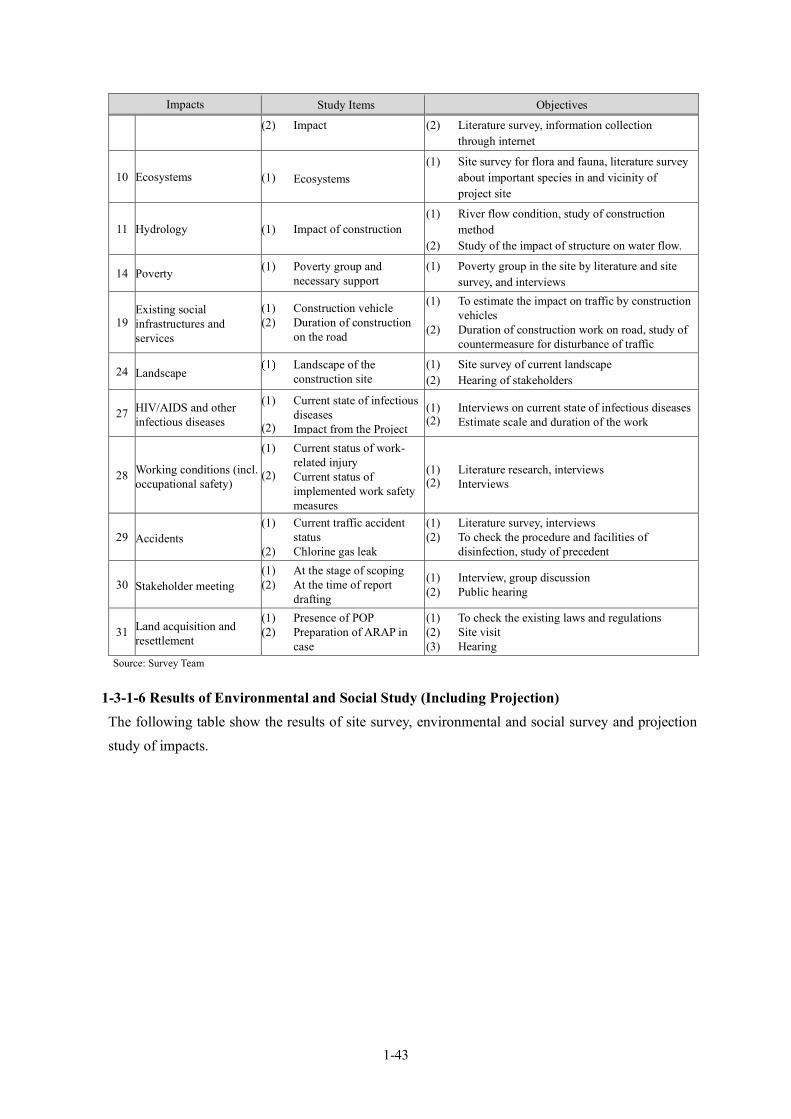
1-43
Impacts Study Items Objectives
(2) Impact (2) Literature survey, information collection through internet
10 Ecosystems (1) Ecosystems (1) Site survey for flora and fauna, literature survey
about important species in and vicinity of project site
11 Hydrology (1) Impact of construction (1) River flow condition, study of construction
method (2) Study of the impact of structure on water flow.
14 Poverty (1) Poverty group and necessary support
(1) Poverty group in the site by literature and site survey, and interviews
19 Existing social infrastructures and services
(1) Construction vehicle (2) Duration of construction
on the road
(1) To estimate the impact on traffic by construction vehicles
(2) Duration of construction work on road, study of countermeasure for disturbance of traffic
24 Landscape Landscape of the construction site
(1) Site survey of current landscape (2) Hearing of stakeholders
27 HIV/AIDS and other infectious diseases
(1) Current state of infectious diseases
(2) Impact from the Project
(1) Interviews on current state of infectious diseases (2) Estimate scale and duration of the work
28 Working conditions (incl. occupational safety)
(1) Current status of work-related injury
(2) Current status of implemented work safety measures
(1) Literature research, interviews (2) Interviews
29 Accidents (1) Current traffic accident
status (2) Chlorine gas leak
(1) Literature survey, interviews (2) To check the procedure and facilities of
disinfection, study of precedent
30 Stakeholder meeting (1) At the stage of scoping (2) At the time of report
drafting
(1) Interview, group discussion (2) Public hearing
31 Land acquisition and resettlement
(1) Presence of POP (2) Preparation of ARAP in
case
(1) To check the existing laws and regulations (2) Site visit (3) Hearing
Source: Survey Team
1-3-1-6 Results of Environmental and Social Study (Including Projection) The following table show the results of site survey, environmental and social survey and projection study of impacts.
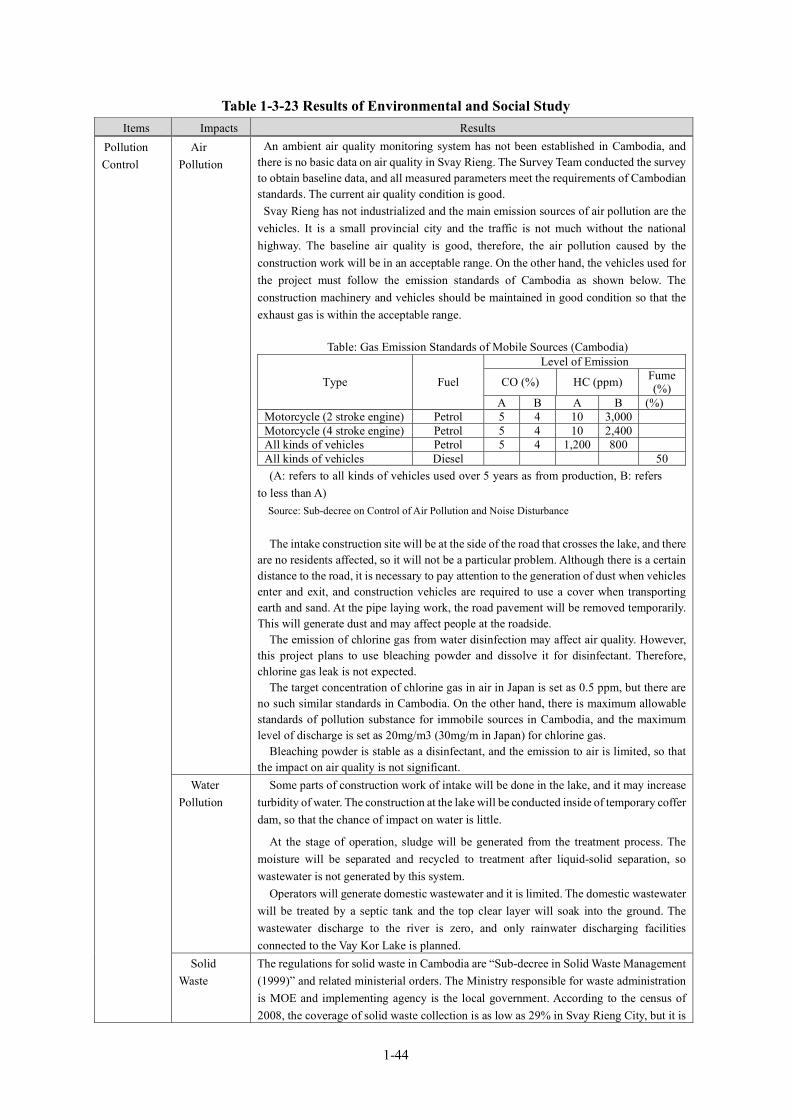
1-44
Table 1-3-23 Results of Environmental and Social Study Items Impacts Results
Pollution Control
Air Pollution
An ambient air quality monitoring system has not been established in Cambodia, and there is no basic data on air quality in Svay Rieng. The Survey Team conducted the survey to obtain baseline data, and all measured parameters meet the requirements of Cambodian standards. The current air quality condition is good.
Svay Rieng has not industrialized and the main emission sources of air pollution are the vehicles. It is a small provincial city and the traffic is not much without the national highway. The baseline air quality is good, therefore, the air pollution caused by the construction work will be in an acceptable range. On the other hand, the vehicles used for the project must follow the emission standards of Cambodia as shown below. The construction machinery and vehicles should be maintained in good condition so that the exhaust gas is within the acceptable range.
Table: Gas Emission Standards of Mobile Sources (Cambodia)
Type Fuel
Level of Emission
CO (%) HC (ppm) Fume (%)
A B A B (%) Motorcycle (2 stroke engine) Petrol 5 4 10 3,000 Motorcycle (4 stroke engine) Petrol 5 4 10 2,400 All kinds of vehicles Petrol 5 4 1,200 800 All kinds of vehicles Diesel 50 (A: refers to all kinds of vehicles used over 5 years as from production, B: refers
to less than A) Source: Sub-decree on Control of Air Pollution and Noise Disturbance The intake construction site will be at the side of the road that crosses the lake, and there
are no residents affected, so it will not be a particular problem. Although there is a certain distance to the road, it is necessary to pay attention to the generation of dust when vehicles enter and exit, and construction vehicles are required to use a cover when transporting earth and sand. At the pipe laying work, the road pavement will be removed temporarily. This will generate dust and may affect people at the roadside.
The emission of chlorine gas from water disinfection may affect air quality. However, this project plans to use bleaching powder and dissolve it for disinfectant. Therefore, chlorine gas leak is not expected.
The target concentration of chlorine gas in air in Japan is set as 0.5 ppm, but there are no such similar standards in Cambodia. On the other hand, there is maximum allowable standards of pollution substance for immobile sources in Cambodia, and the maximum level of discharge is set as 20mg/m3 (30mg/m in Japan) for chlorine gas.
Bleaching powder is stable as a disinfectant, and the emission to air is limited, so that the impact on air quality is not significant.
Water Pollution
Some parts of construction work of intake will be done in the lake, and it may increase turbidity of water. The construction at the lake will be conducted inside of temporary coffer dam, so that the chance of impact on water is little.
At the stage of operation, sludge will be generated from the treatment process. The moisture will be separated and recycled to treatment after liquid-solid separation, so wastewater is not generated by this system.
Operators will generate domestic wastewater and it is limited. The domestic wastewater will be treated by a septic tank and the top clear layer will soak into the ground. The wastewater discharge to the river is zero, and only rainwater discharging facilities connected to the Vay Kor Lake is planned.
Solid Waste
The regulations for solid waste in Cambodia are “Sub-decree in Solid Waste Management (1999)” and related ministerial orders. The Ministry responsible for waste administration is MOE and implementing agency is the local government. According to the census of 2008, the coverage of solid waste collection is as low as 29% in Svay Rieng City, but it is
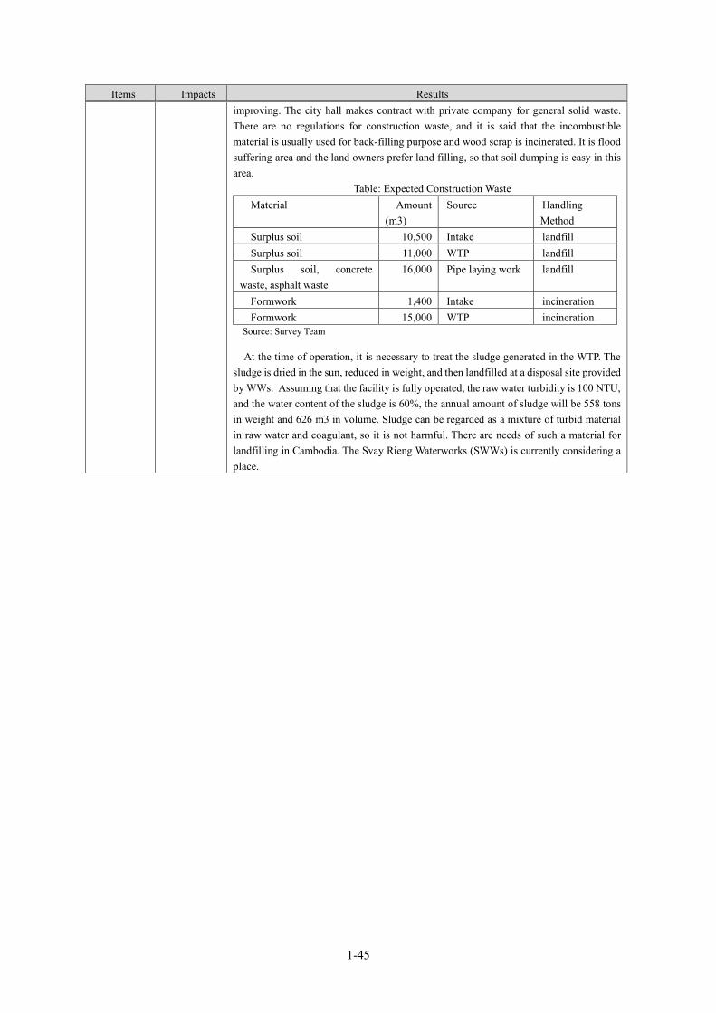
1-45
Items Impacts Results improving. The city hall makes contract with private company for general solid waste. There are no regulations for construction waste, and it is said that the incombustible material is usually used for back-filling purpose and wood scrap is incinerated. It is flood suffering area and the land owners prefer land filling, so that soil dumping is easy in this area.
Table: Expected Construction Waste Material Amount
(m3) Source Handling
Method Surplus soil 10,500 Intake landfill Surplus soil 11,000 WTP landfill Surplus soil, concrete
waste, asphalt waste 16,000 Pipe laying work landfill
Formwork 1,400 Intake incineration Formwork 15,000 WTP incineration
Source: Survey Team
At the time of operation, it is necessary to treat the sludge generated in the WTP. The sludge is dried in the sun, reduced in weight, and then landfilled at a disposal site provided by WWs. Assuming that the facility is fully operated, the raw water turbidity is 100 NTU, and the water content of the sludge is 60%, the annual amount of sludge will be 558 tons in weight and 626 m3 in volume. Sludge can be regarded as a mixture of turbid material in raw water and coagulant, so it is not harmful. There are needs of such a material for landfilling in Cambodia. The Svay Rieng Waterworks (SWWs) is currently considering a place.
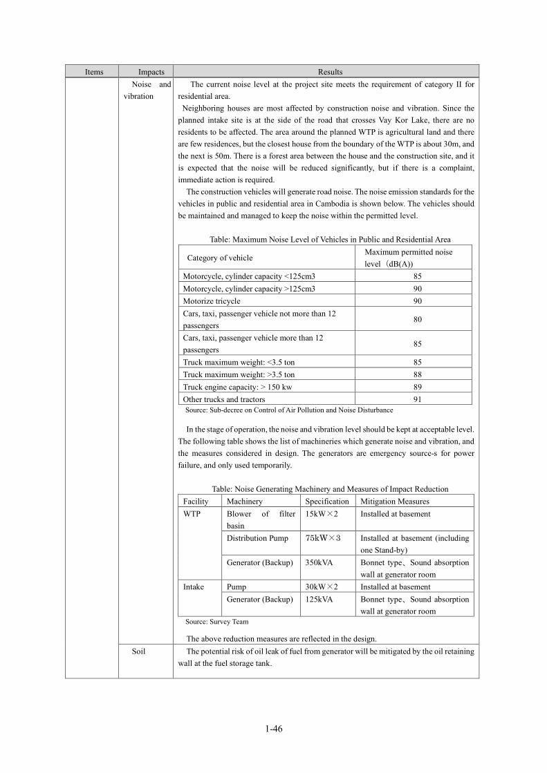
1-46
Items Impacts Results Noise and
vibration The current noise level at the project site meets the requirement of category II for
residential area. Neighboring houses are most affected by construction noise and vibration. Since the
planned intake site is at the side of the road that crosses Vay Kor Lake, there are no residents to be affected. The area around the planned WTP is agricultural land and there are few residences, but the closest house from the boundary of the WTP is about 30m, and the next is 50m. There is a forest area between the house and the construction site, and it is expected that the noise will be reduced significantly, but if there is a complaint, immediate action is required.
The construction vehicles will generate road noise. The noise emission standards for the vehicles in public and residential area in Cambodia is shown below. The vehicles should be maintained and managed to keep the noise within the permitted level.
Table: Maximum Noise Level of Vehicles in Public and Residential Area
Category of vehicle Maximum permitted noise level(dB(A))
Motorcycle, cylinder capacity <125cm3 85 Motorcycle, cylinder capacity >125cm3 90 Motorize tricycle 90 Cars, taxi, passenger vehicle not more than 12 passengers
80
Cars, taxi, passenger vehicle more than 12 passengers
85
Truck maximum weight: <3.5 ton 85 Truck maximum weight: >3.5 ton 88 Truck engine capacity: > 150 kw 89 Other trucks and tractors 91 Source: Sub-decree on Control of Air Pollution and Noise Disturbance
In the stage of operation, the noise and vibration level should be kept at acceptable level. The following table shows the list of machineries which generate noise and vibration, and the measures considered in design. The generators are emergency source-s for power failure, and only used temporarily.
Table: Noise Generating Machinery and Measures of Impact Reduction
Facility Machinery Specification Mitigation Measures WTP Blower of filter
basin 15kW×2 Installed at basement
Distribution Pump 75kW×3 Installed at basement (including one Stand-by)
Generator (Backup) 350kVA Bonnet type、Sound absorption wall at generator room
Intake Pump 30kW×2 Installed at basement Generator (Backup) 125kVA Bonnet type、Sound absorption
wall at generator room Source: Survey Team
The above reduction measures are reflected in the design. Soil The potential risk of oil leak of fuel from generator will be mitigated by the oil retaining
wall at the fuel storage tank.
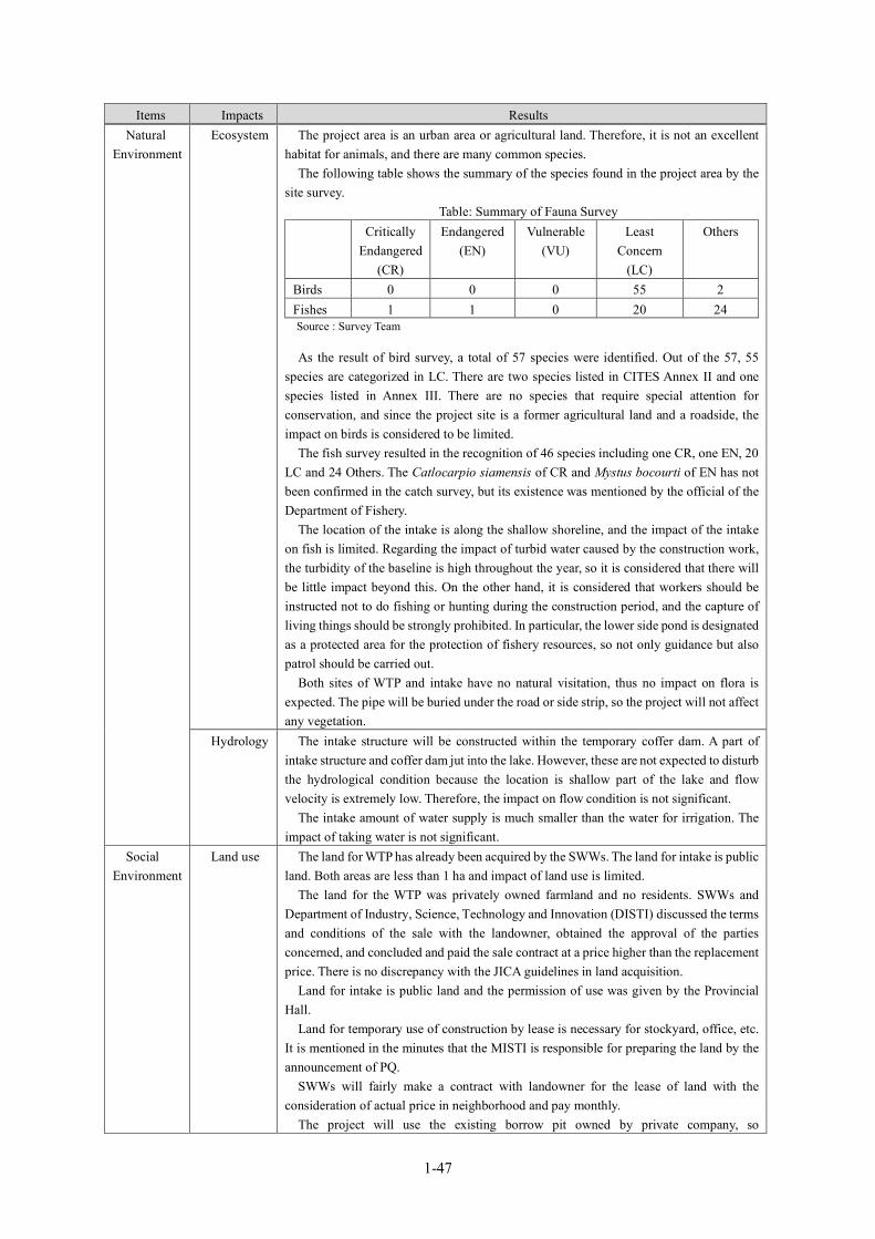
1-47
Items Impacts Results Natural
Environment Ecosystem The project area is an urban area or agricultural land. Therefore, it is not an excellent
habitat for animals, and there are many common species. The following table shows the summary of the species found in the project area by the
site survey. Table: Summary of Fauna Survey
Critically Endangered
(CR)
Endangered (EN)
Vulnerable (VU)
Least Concern
(LC)
Others
Birds 0 0 0 55 2 Fishes 1 1 0 20 24 Source : Survey Team
As the result of bird survey, a total of 57 species were identified. Out of the 57, 55 species are categorized in LC. There are two species listed in CITES Annex II and one species listed in Annex III. There are no species that require special attention for conservation, and since the project site is a former agricultural land and a roadside, the impact on birds is considered to be limited.
The fish survey resulted in the recognition of 46 species including one CR, one EN, 20 LC and 24 Others. The Catlocarpio siamensis of CR and Mystus bocourti of EN has not been confirmed in the catch survey, but its existence was mentioned by the official of the Department of Fishery.
The location of the intake is along the shallow shoreline, and the impact of the intake on fish is limited. Regarding the impact of turbid water caused by the construction work, the turbidity of the baseline is high throughout the year, so it is considered that there will be little impact beyond this. On the other hand, it is considered that workers should be instructed not to do fishing or hunting during the construction period, and the capture of living things should be strongly prohibited. In particular, the lower side pond is designated as a protected area for the protection of fishery resources, so not only guidance but also patrol should be carried out.
Both sites of WTP and intake have no natural visitation, thus no impact on flora is expected. The pipe will be buried under the road or side strip, so the project will not affect any vegetation.
Hydrology The intake structure will be constructed within the temporary coffer dam. A part of intake structure and coffer dam jut into the lake. However, these are not expected to disturb the hydrological condition because the location is shallow part of the lake and flow velocity is extremely low. Therefore, the impact on flow condition is not significant.
The intake amount of water supply is much smaller than the water for irrigation. The impact of taking water is not significant.
Social Environment
Land use The land for WTP has already been acquired by the SWWs. The land for intake is public land. Both areas are less than 1 ha and impact of land use is limited.
The land for the WTP was privately owned farmland and no residents. SWWs and Department of Industry, Science, Technology and Innovation (DISTI) discussed the terms and conditions of the sale with the landowner, obtained the approval of the parties concerned, and concluded and paid the sale contract at a price higher than the replacement price. There is no discrepancy with the JICA guidelines in land acquisition.
Land for intake is public land and the permission of use was given by the Provincial Hall.
Land for temporary use of construction by lease is necessary for stockyard, office, etc. It is mentioned in the minutes that the MISTI is responsible for preparing the land by the announcement of PQ.
SWWs will fairly make a contract with landowner for the lease of land with the consideration of actual price in neighborhood and pay monthly.
The project will use the existing borrow pit owned by private company, so
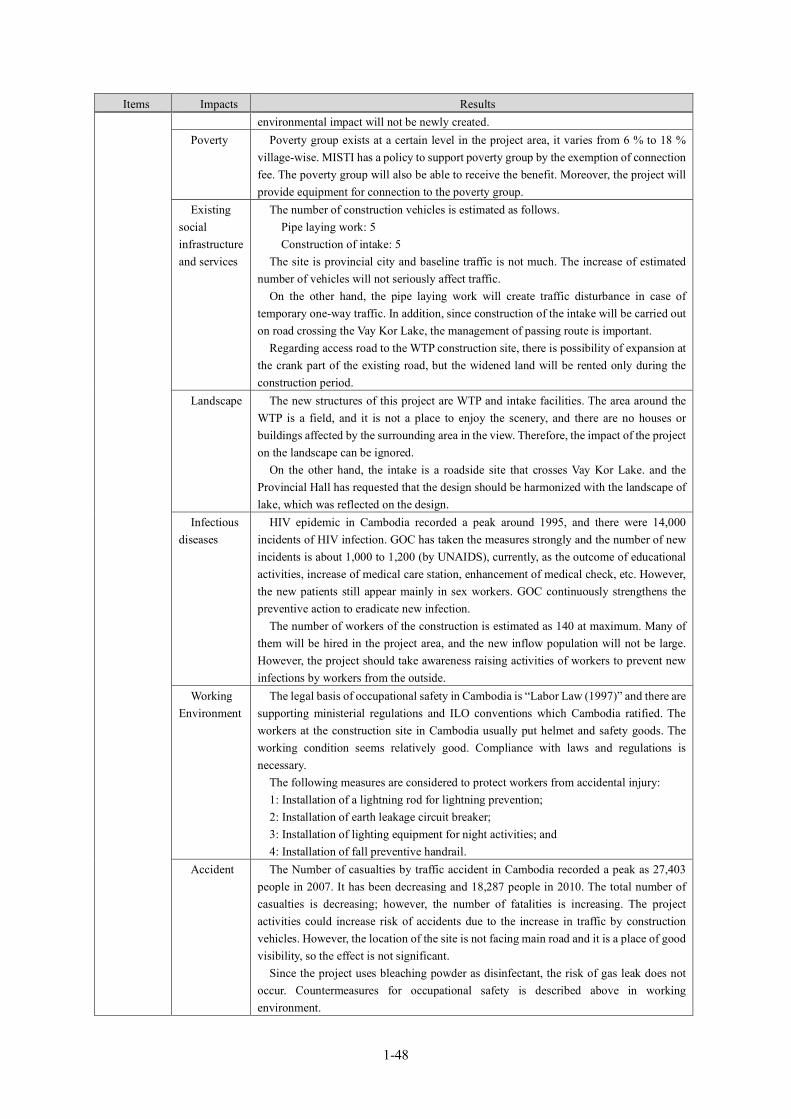
1-48
Items Impacts Results environmental impact will not be newly created.
Poverty Poverty group exists at a certain level in the project area, it varies from 6 % to 18 % village-wise. MISTI has a policy to support poverty group by the exemption of connection fee. The poverty group will also be able to receive the benefit. Moreover, the project will provide equipment for connection to the poverty group.
Existing social infrastructure and services
The number of construction vehicles is estimated as follows. Pipe laying work: 5 Construction of intake: 5 The site is provincial city and baseline traffic is not much. The increase of estimated
number of vehicles will not seriously affect traffic. On the other hand, the pipe laying work will create traffic disturbance in case of
temporary one-way traffic. In addition, since construction of the intake will be carried out on road crossing the Vay Kor Lake, the management of passing route is important.
Regarding access road to the WTP construction site, there is possibility of expansion at the crank part of the existing road, but the widened land will be rented only during the construction period.
Landscape The new structures of this project are WTP and intake facilities. The area around the WTP is a field, and it is not a place to enjoy the scenery, and there are no houses or buildings affected by the surrounding area in the view. Therefore, the impact of the project on the landscape can be ignored.
On the other hand, the intake is a roadside site that crosses Vay Kor Lake. and the Provincial Hall has requested that the design should be harmonized with the landscape of lake, which was reflected on the design.
Infectious diseases
HIV epidemic in Cambodia recorded a peak around 1995, and there were 14,000 incidents of HIV infection. GOC has taken the measures strongly and the number of new incidents is about 1,000 to 1,200 (by UNAIDS), currently, as the outcome of educational activities, increase of medical care station, enhancement of medical check, etc. However, the new patients still appear mainly in sex workers. GOC continuously strengthens the preventive action to eradicate new infection.
The number of workers of the construction is estimated as 140 at maximum. Many of them will be hired in the project area, and the new inflow population will not be large. However, the project should take awareness raising activities of workers to prevent new infections by workers from the outside.
Working Environment
The legal basis of occupational safety in Cambodia is “Labor Law (1997)” and there are supporting ministerial regulations and ILO conventions which Cambodia ratified. The workers at the construction site in Cambodia usually put helmet and safety goods. The working condition seems relatively good. Compliance with laws and regulations is necessary.
The following measures are considered to protect workers from accidental injury: 1: Installation of a lightning rod for lightning prevention; 2: Installation of earth leakage circuit breaker; 3: Installation of lighting equipment for night activities; and 4: Installation of fall preventive handrail.
Accident The Number of casualties by traffic accident in Cambodia recorded a peak as 27,403 people in 2007. It has been decreasing and 18,287 people in 2010. The total number of casualties is decreasing; however, the number of fatalities is increasing. The project activities could increase risk of accidents due to the increase in traffic by construction vehicles. However, the location of the site is not facing main road and it is a place of good visibility, so the effect is not significant.
Since the project uses bleaching powder as disinfectant, the risk of gas leak does not occur. Countermeasures for occupational safety is described above in working environment.

1-49
Source: Survey Team
1-3-1-7 Impact Assessment The results of impact assessment are as shown in the following table on the basis of site visit, environmental and social survey, and discussions with stakeholders.
Table 1-3-24 Impact Assessment
Impact
Impact Assessment at Scoping
Impact Assessment Based on Study Results
Reasons for Assessment
Design/
Construction
Operation
Design/
Construction
Operation
Air Pollution
✔ B- D
Construction: By removing the road pavement and from the pipe laying work, dust is expected. Air pollution is also expected from the exhaust gas emitted by the construction vehicles and machineries.
Operation: No work which causes air pollution is expected.
Water Pollution
✔ ✔ B- D
Construction: Basement construction of intake may generate turbid water.
Operation: The wastewater generated at the treatment process will be recycled, and there will be no discharge to outside of the system. In addition, since wastewater such as domestic wastewater by staff is guided to the septic tank and let go to underground, it does not flow into the water area. Thus, the post survey evaluation is D.
Solid Waste
✔ ✔ B- B-
Construction: Construction work generates solid waste, such as removed road pavement and form, scrap. Construction workers will also generate domestic waste.
Operation: Treatment sludge will be dried and become solid waste; therefore, it shall be treated appropriately.
Noise and Vibration
✔ ✔ B- B-
Construction: Construction vehicles and machinery generate noise and vibration, but it is temporary and there is no resident in the circle of influence. The site and its surroundings are rice fields, and there are no animals to be affected. Therefore, the post survey evaluation is D.
Operation: Pumping station and WTP generate noise and vibration during operation, but there is no person living in the circle of influence at present. However, countermeasures should be considered to keep the appropriate level of noise and vibration. The facilities which generate noise and vibration will be installed at basement and treated by use of absorbing materials.
Sediment ✔ B- D
Construction: Construction work of intake could increase the turbidity due to disturbing sediment.
Operation: No impact on sediment.
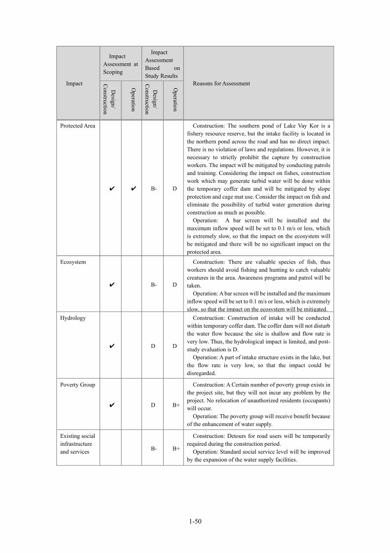
1-50
Impact
Impact Assessment at Scoping
Impact Assessment Based on Study Results
Reasons for Assessment
Design/
Construction
Operation
Design/
Construction
Operation
Protected Area
✔ ✔ B- D
Construction: The southern pond of Lake Vay Kor is a fishery resource reserve, but the intake facility is located in the northern pond across the road and has no direct impact. There is no violation of laws and regulations. However, it is necessary to strictly prohibit the capture by construction workers. The impact will be mitigated by conducting patrols and training. Considering the impact on fishes, construction work which may generate turbid water will be done within the temporary coffer dam and will be mitigated by slope protection and cage mat use. Consider the impact on fish and eliminate the possibility of turbid water generation during construction as much as possible.
Operation: A bar screen will be installed and the maximum inflow speed will be set to 0.1 m/s or less, which is extremely slow, so that the impact on the ecosystem will be mitigated and there will be no significant impact on the protected area.
Ecosystem
✔ B- D
Construction: There are valuable species of fish, thus workers should avoid fishing and hunting to catch valuable creatures in the area. Awareness programs and patrol will be taken.
Operation: A bar screen will be installed and the maximum inflow speed will be set to 0.1 m/s or less, which is extremely slow, so that the impact on the ecosystem will be mitigated.
Hydrology
✔ D D
Construction: Construction of intake will be conducted within temporary coffer dam. The coffer dam will not disturb the water flow because the site is shallow and flow rate is very low. Thus, the hydrological impact is limited, and post-study evaluation is D.
Operation: A part of intake structure exists in the lake, but the flow rate is very low, so that the impact could be disregarded.
Poverty Group
✔ D B+
Construction: A Certain number of poverty group exists in the project site, but they will not incur any problem by the project. No relocation of unauthorized residents (occupants) will occur.
Operation: The poverty group will receive benefit because of the enhancement of water supply.
Existing social infrastructure and services B- B+
Construction: Detours for road users will be temporarily required during the construction period.
Operation: Standard social service level will be improved by the expansion of the water supply facilities.
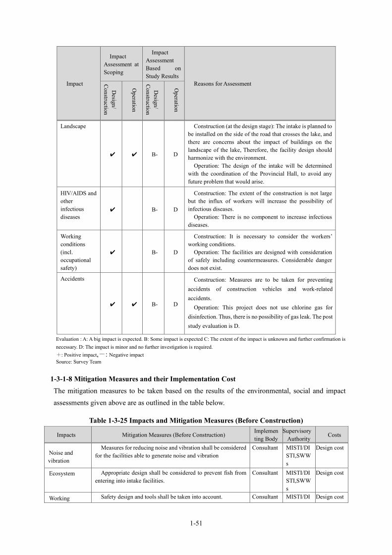
1-51
Impact
Impact Assessment at Scoping
Impact Assessment Based on Study Results
Reasons for Assessment
Design/
Construction
Operation
Design/
Construction
Operation
Landscape
✔ ✔ B- D
Construction (at the design stage): The intake is planned to be installed on the side of the road that crosses the lake, and there are concerns about the impact of buildings on the landscape of the lake, Therefore, the facility design should harmonize with the environment.
Operation: The design of the intake will be determined with the coordination of the Provincial Hall, to avoid any future problem that would arise.
HIV/AIDS and other infectious diseases
✔ B- D
Construction: The extent of the construction is not large but the influx of workers will increase the possibility of infectious diseases.
Operation: There is no component to increase infectious diseases.
Working conditions (incl. occupational safety)
✔ B- D
Construction: It is necessary to consider the workers’ working conditions.
Operation: The facilities are designed with consideration of safely including countermeasures. Considerable danger does not exist.
Accidents
✔ ✔ B- D
Construction: Measures are to be taken for preventing accidents of construction vehicles and work-related accidents.
Operation: This project does not use chlorine gas for disinfection. Thus, there is no possibility of gas leak. The post study evaluation is D.
Evaluation : A: A big impact is expected. B: Some impact is expected C: The extent of the impact is unknown and further confirmation is necessary. D: The impact is minor and no further investigation is required. +: Positive impact,-: Negative impact Source: Survey Team
1-3-1-8 Mitigation Measures and their Implementation Cost The mitigation measures to be taken based on the results of the environmental, social and impact assessments given above are as outlined in the table below.
Table 1-3-25 Impacts and Mitigation Measures (Before Construction)
Impacts Mitigation Measures (Before Construction) Implementing Body
Supervisory Authority
Costs
Noise and vibration
Measures for reducing noise and vibration shall be considered for the facilities able to generate noise and vibration
Consultant MISTI/DISTI,SWWs
Design cost
Ecosystem Appropriate design shall be considered to prevent fish from entering into intake facilities.
Consultant MISTI/DISTI,SWWs
Design cost
Working Safety design and tools shall be taken into account. Consultant MISTI/DI Design cost
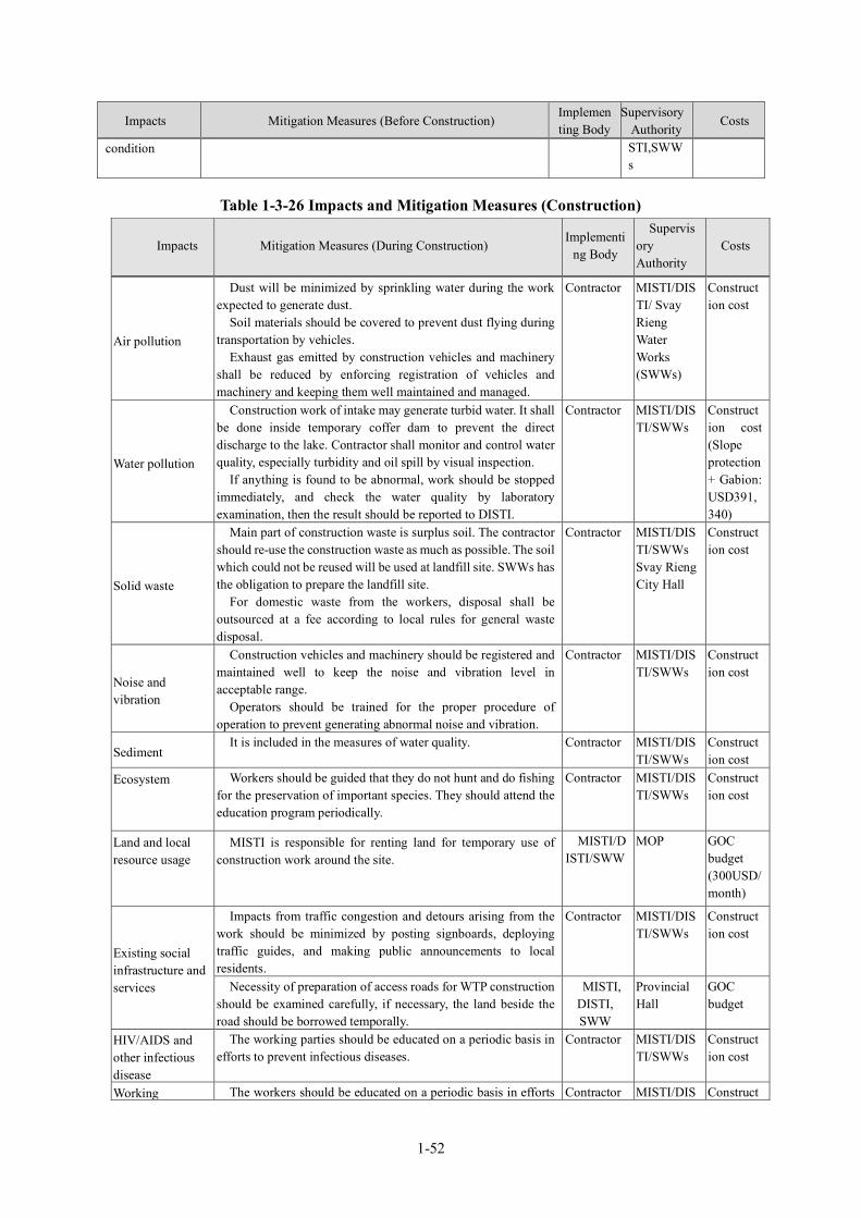
1-52
Impacts Mitigation Measures (Before Construction) Implementing Body
Supervisory Authority
Costs
condition STI,SWWs
Table 1-3-26 Impacts and Mitigation Measures (Construction)
Impacts Mitigation Measures (During Construction) Implementi
ng Body
Supervisory Authority
Costs
Air pollution
Dust will be minimized by sprinkling water during the work expected to generate dust.
Soil materials should be covered to prevent dust flying during transportation by vehicles.
Exhaust gas emitted by construction vehicles and machinery shall be reduced by enforcing registration of vehicles and machinery and keeping them well maintained and managed.
Contractor MISTI/DISTI/ Svay Rieng Water Works (SWWs)
Construction cost
Water pollution
Construction work of intake may generate turbid water. It shall be done inside temporary coffer dam to prevent the direct discharge to the lake. Contractor shall monitor and control water quality, especially turbidity and oil spill by visual inspection.
If anything is found to be abnormal, work should be stopped immediately, and check the water quality by laboratory examination, then the result should be reported to DISTI.
Contractor MISTI/DISTI/SWWs
Construction cost (Slope protection + Gabion: USD391,340)
Solid waste
Main part of construction waste is surplus soil. The contractor should re-use the construction waste as much as possible. The soil which could not be reused will be used at landfill site. SWWs has the obligation to prepare the landfill site.
For domestic waste from the workers, disposal shall be outsourced at a fee according to local rules for general waste disposal.
Contractor MISTI/DISTI/SWWs Svay Rieng City Hall
Construction cost
Noise and vibration
Construction vehicles and machinery should be registered and maintained well to keep the noise and vibration level in acceptable range.
Operators should be trained for the proper procedure of operation to prevent generating abnormal noise and vibration.
Contractor MISTI/DISTI/SWWs
Construction cost
Sediment It is included in the measures of water quality. Contractor MISTI/DIS
TI/SWWs Construction cost
Ecosystem Workers should be guided that they do not hunt and do fishing for the preservation of important species. They should attend the education program periodically.
Contractor MISTI/DISTI/SWWs
Construction cost
Land and local resource usage
MISTI is responsible for renting land for temporary use of construction work around the site.
MISTI/DISTI/SWW
MOP GOC budget (300USD/month)
Existing social infrastructure and services
Impacts from traffic congestion and detours arising from the work should be minimized by posting signboards, deploying traffic guides, and making public announcements to local residents.
Contractor MISTI/DISTI/SWWs
Construction cost
Necessity of preparation of access roads for WTP construction should be examined carefully, if necessary, the land beside the road should be borrowed temporally.
MISTI, DISTI, SWW
Provincial Hall
GOC budget
HIV/AIDS and other infectious disease
The working parties should be educated on a periodic basis in efforts to prevent infectious diseases.
Contractor MISTI/DISTI/SWWs
Construction cost
Working The workers should be educated on a periodic basis in efforts Contractor MISTI/DIS Construct
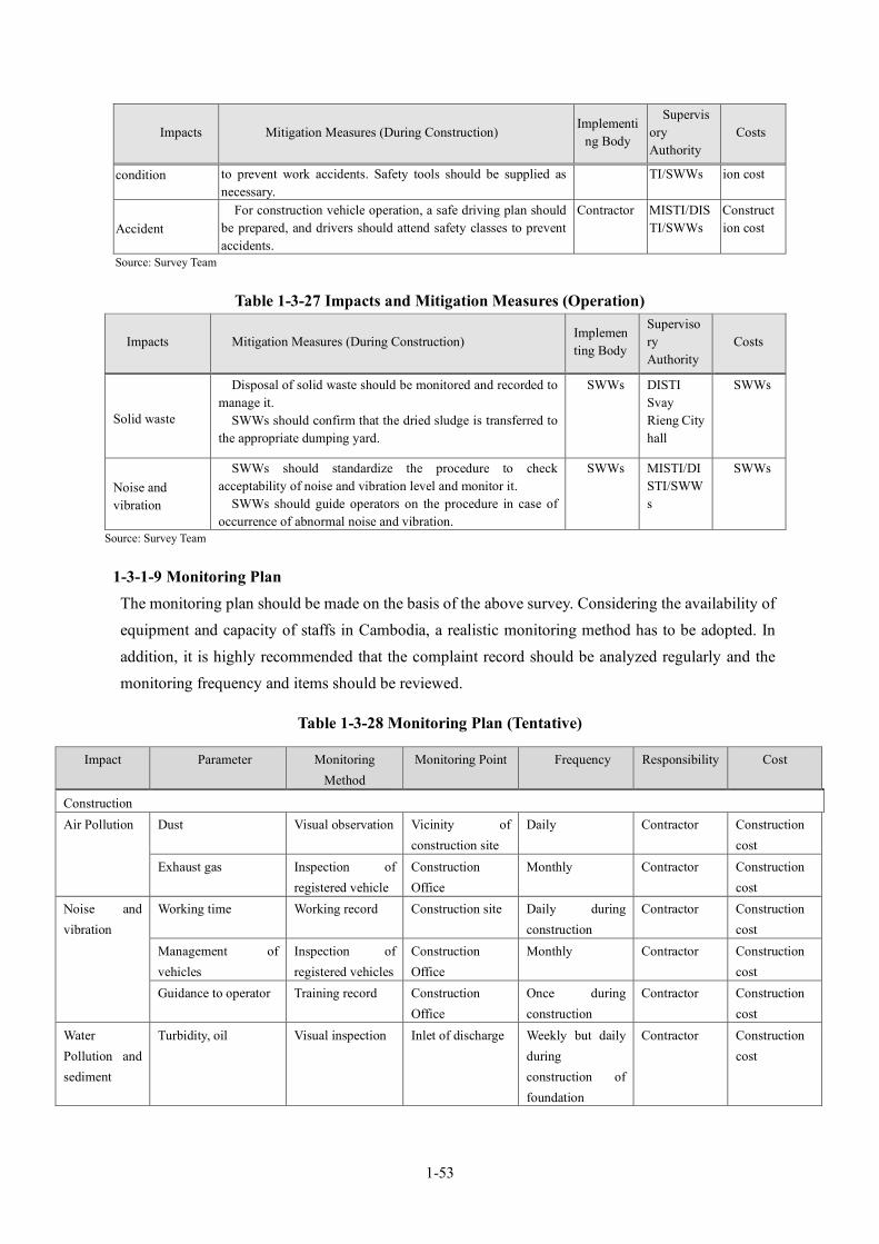
1-53
Impacts Mitigation Measures (During Construction) Implementi
ng Body
Supervisory Authority
Costs
condition to prevent work accidents. Safety tools should be supplied as necessary.
TI/SWWs ion cost
Accident For construction vehicle operation, a safe driving plan should
be prepared, and drivers should attend safety classes to prevent accidents.
Contractor MISTI/DISTI/SWWs
Construction cost
Source: Survey Team
Table 1-3-27 Impacts and Mitigation Measures (Operation)
Impacts Mitigation Measures (During Construction) Implementing Body
Supervisory Authority
Costs
Solid waste
Disposal of solid waste should be monitored and recorded to manage it.
SWWs should confirm that the dried sludge is transferred to the appropriate dumping yard.
SWWs DISTI Svay Rieng City hall
SWWs
Noise and vibration
SWWs should standardize the procedure to check acceptability of noise and vibration level and monitor it.
SWWs should guide operators on the procedure in case of occurrence of abnormal noise and vibration.
SWWs MISTI/DISTI/SWWs
SWWs
Source: Survey Team
1-3-1-9 Monitoring Plan The monitoring plan should be made on the basis of the above survey. Considering the availability of equipment and capacity of staffs in Cambodia, a realistic monitoring method has to be adopted. In addition, it is highly recommended that the complaint record should be analyzed regularly and the monitoring frequency and items should be reviewed.
Table 1-3-28 Monitoring Plan (Tentative)
Impact Parameter Monitoring Method
Monitoring Point Frequency Responsibility Cost
Construction Air Pollution Dust Visual observation Vicinity of
construction site Daily Contractor Construction
cost Exhaust gas Inspection of
registered vehicle Construction Office
Monthly Contractor Construction cost
Noise and vibration
Working time Working record Construction site Daily during construction
Contractor Construction cost
Management of vehicles
Inspection of registered vehicles
Construction Office
Monthly Contractor Construction cost
Guidance to operator Training record Construction Office
Once during construction
Contractor Construction cost
Water Pollution and sediment
Turbidity, oil Visual inspection Inlet of discharge Weekly but daily during construction of foundation
Contractor Construction cost
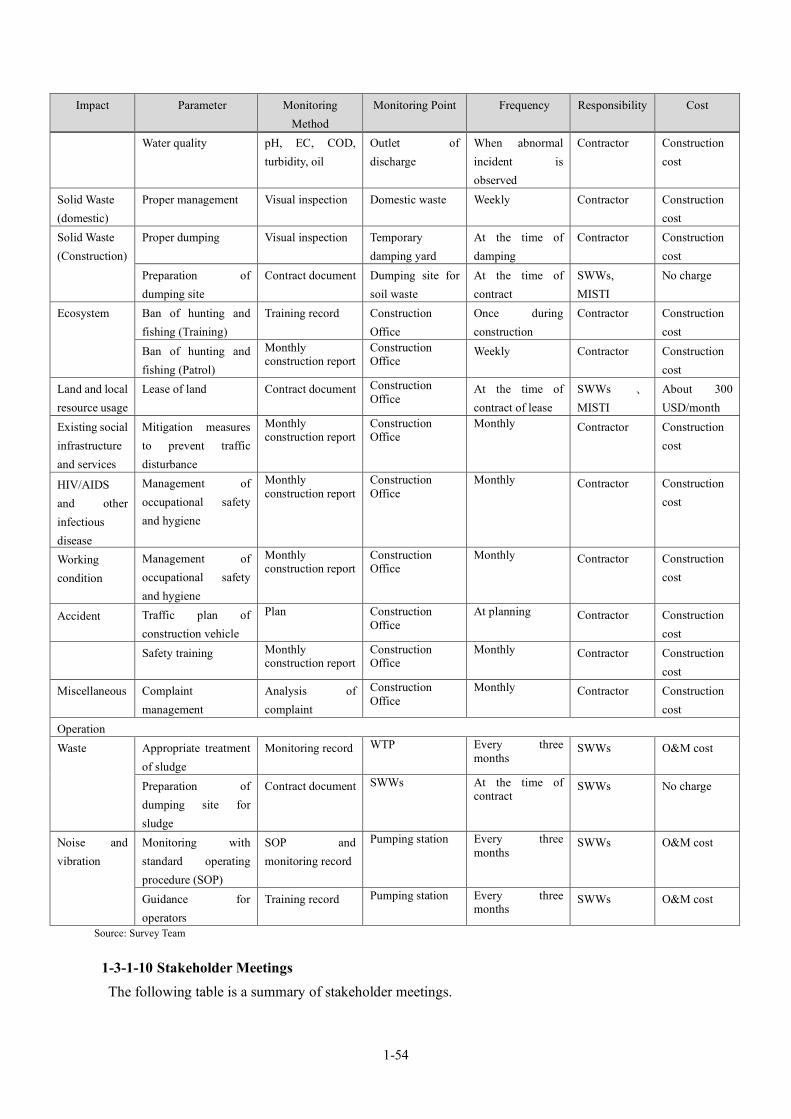
1-54
Source: Survey Team
1-3-1-10 Stakeholder Meetings The following table is a summary of stakeholder meetings.
Impact Parameter Monitoring Method
Monitoring Point Frequency Responsibility Cost
Water quality pH, EC, COD, turbidity, oil
Outlet of discharge
When abnormal incident is observed
Contractor Construction cost
Solid Waste (domestic)
Proper management Visual inspection Domestic waste Weekly Contractor Construction cost
Solid Waste (Construction)
Proper dumping Visual inspection Temporary damping yard
At the time of damping
Contractor Construction cost
Preparation of dumping site
Contract document Dumping site for soil waste
At the time of contract
SWWs, MISTI
No charge
Ecosystem Ban of hunting and fishing (Training)
Training record Construction Office
Once during construction
Contractor Construction cost
Ban of hunting and fishing (Patrol)
Monthly construction report
Construction Office Weekly Contractor Construction
cost Land and local resource usage
Lease of land Contract document Construction Office At the time of
contract of lease SWWs 、
MISTI About 300 USD/month
Existing social infrastructure and services
Mitigation measures to prevent traffic disturbance
Monthly construction report
Construction Office
Monthly Contractor Construction cost
HIV/AIDS and other infectious disease
Management of occupational safety and hygiene
Monthly construction report
Construction Office
Monthly Contractor Construction cost
Working condition
Management of occupational safety and hygiene
Monthly construction report
Construction Office
Monthly Contractor Construction cost
Accident Traffic plan of construction vehicle
Plan Construction Office
At planning Contractor Construction cost
Safety training Monthly construction report
Construction Office
Monthly Contractor Construction cost
Miscellaneous Complaint management
Analysis of complaint
Construction Office
Monthly Contractor Construction cost
Operation Waste Appropriate treatment
of sludge Monitoring record WTP Every three
months SWWs O&M cost
Preparation of dumping site for sludge
Contract document SWWs At the time of contract
SWWs No charge
Noise and vibration
Monitoring with standard operating procedure (SOP)
SOP and monitoring record
Pumping station Every three months
SWWs O&M cost
Guidance for operators
Training record Pumping station Every three months
SWWs O&M cost
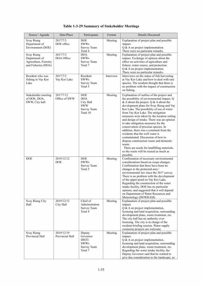
1-55
Table 1-3-29 Summary of Stakeholder Meetings
Source / Agenda Date/Place Participants Format Details Discussed
Svay Rieng Department of Environment (DOE)
2017/7/3 DOE office
DOE SWWs Survey Team Total 4
Meeting Explanation of project plan and possible impact. Q & A on project implementation. There were no particular remarks.
Svay Rieng Department of Agriculture, Forestry and Fisheries (DOA)
2017/7/3 DOA Office
DOA SWWs Survey Team Total 7
Meeting Explanation of project plan and possible impact. Exchange of opinion about the effect on activities of agriculture and fishery, water source, and protection. Q & A on project implementation. There were no particular remarks.
Resident who was fishing in Vay Kor Lake
2017/7/3 Vay Kor Lake
Resident SWWs Survey Team Total 5
Interview Interviews on the status of fish harvesting at Vay Kor Lake and how to deal with rare species. The resident thought that there is no problem with the impact of construction on fishing.
Stakeholder meeting of DOE, DOA, SWW, City hall
2017/7/12 Office of SWW
DOE DOA City Hall SWW Survey Team Total 10
Meeting Explanation of outline of the project and the possibility of environmental impact. Q & A about the project. Q & A about the development plans for Svay Rieng and Vay Kor Lake. The possibility of use of water from Vay Kor Lake. The mitigation measures were taken by the location setting and design of intake. There was an opinion to take mitigation measures for the conservation of precious species. In addition, there was a comment from the residents that the well water is contaminated. Discussion of how to dispose construction waste and domestic waste.
There are needs for landfilling materials, so the waste will be reused as much as possible.
DOE 2019/12/12 DOE
DOE SWWs Survey Team Total 5
Meeting Confirmation of necessary environmental considerations based on scope changes. Confirmation that there have been no changes to the protected area / environmental law since the 2017 survey. There is no problem with the development of the upper pond on Vay Kor Lake. Regarding the construction of the water intake facility, DOE has no particular opinion, and suggested that it will depend on Department of Water Resources and Meteorology (DOWRAM).
Svay Rieng City Hall
2019/12/12 City Hall
Chief of Administration Survey Team Total 4
Meeting Explanation of project plan and possible impact. Q & A on project implementation, licensing and land acquisition, surrounding development plans, waste treatment, etc. The city hall has no authority over licensing. The city is in charge of the resident briefing session. Water supply extension projects are welcome.
Svay Rieng Provincial Hall
2019/12/19 Provincial Hall
Deputy Governor DISTI SWWs Survey Team Total 7
Meeting Explanation of project plan and possible impact. Q & A on project implementation, licensing and land acquisition, surrounding development plans, waste treatment, etc. Regarding the water intake facility, the Deputy Governor said that he wanted to give due consideration to the landscape, so

1-56
Source: Survey Team
1-3-2 Land Acquisition and Resettlement 1-3-2-1 Need for Land Acquisition and Resettlement
The project need land for the WTP and the water intake site. The existing WTP site is not large enough for expansion, but about 1ha is required for the new WTP site and about 1 ha for the water intake installation. SWWs has acquired farmland owned by private people. There are no authorized/ unauthorized residents on this land and no relocation will be required. No peasants are employed, and no one has lost his livelihood due to the loss of land. The landowner harvested all the products from the land during the contracting process and no damage occurred. On the other hand, the intake will be installed on public land and will be used with the permission of the Provincial Hall. It is a land beside a road that crosses the lake, and there are no residents or users.
1-3-2-2 Legal Framework on Land Acquisition and Resettlement The legal basis of the land ownership, acquisition and resettlement are the Constitution (1993), Land Law (2001), and Expropriation Law (2009). The main contents of these laws are explained as follows.
Source / Agenda Date/Place Participants Format Details Discussed
he requested for the design plan of the structure. The Survey Team showed the design concept and it was agreed upon. The provincial hall will convene a meeting of relevant agencies. He said he had been waiting for the spread of water supply for a long time
Public hearing 2020/2/28 Chek commune center
Chek Commune Chief, Vilage Chief, residents, police, SWWs Survey Team Total 38 (female 13)
Public hearing
Explanation of project plan and possible impact. Expectations for project and strong demand for early start of water supply. There is also a request to expand the water supply range. The Survey Team explained that there is a limit to expanding the water supply range due to budget restrictions. Residents expressed concern about the burden of connection charges, but the SWW explained assistance to the poor. There was no dissenting opinion on the implementation of the project, and social consensus was confirmed.
Public hearing 2020/2/28 Prey Chlak
Prey Chlak Commune Chief, Village Chief, residents, SWWs Survey Team Total: 21 (female 7)
Public hearing
Explanation of project plan and possible impact. Expectations for project and strong demand for early start of water supply. Expectation to improve water quality by switching from well water to water supply. Requests for shortening the construction period and proper management of construction vehicles. The project will appropriately manage construction vehicles by monitoring. Request for advance publication of construction plan. There was no dissenting opinion on the implementation of the project, and social consensus was confirmed.
1-57
(1) Constitution (1993) Article 44 states that all persons shall have the right to land ownership, as well as expropriation shall be possible only if public utility demands in the cases stipulated by the law and if prior appropriate and fair compensation is granted. Article 58 states that State property notably consists of land, underground, mountains, sea, sea-bed, undersea-bed, coastline, airspace, islands, rivers, canals, streams, lakes, forests, natural resources, economic and cultural centers, national defense bases, and other building facilities belonging to the State.
(2) Land Law 2001 Article 4 refers to Article 44 of the Constitution and ensures ownership. Article 5 states that no person may be deprived of his ownership, unless it is in the public interest, as well as an ownership deprivation shall be carried out in accordance with the forms and procedures provided by law and regulations and only after the payment of just and equitable compensation. Article 12 states that the State is the owner of properties in the territory of the Kingdom of Cambodia enumerated in Article 58 of the Constitution and of all properties that are escheat, or that are voluntarily given to the State by their owners, that have not been the subject of due and proper private appropriation or that are not presently being privately occupied. Article 15 defines the property that falls within the public property of the State and public legal entities. Article 35 states that only the competent authorities may, on behalf of the State and public legal entities, force occupants without title or insufficient titles to vacate the immovable property.
(3) Expropriation Law, 2009 Article 1 explains aims of this law. Article 3 describes applicability of the law, and states that the law does not govern any issues on expropriation in any agreement or memorandum on supporting investment between the Royal Government of Cambodia and partner countries. Article 5 defines public physical infrastructure which will be target of expropriation. Articles 12, 13 and 14 explain the mechanism of expropriation, i.e., establishment of Expropriation Committee (EC), Expropriation Sub Committee (ESC), and Complaint Resolution Committee (CRC). Article 13 states that the establishment and functioning of the sub-committee shall be determined by the sub-decree, however, the sub-decree has not been issued yet. Article 19 states that the expropriation can be exercised only if the Expropriation Committee has paid fair and just compensation to the property’s owner and/or rightful owner in advance. Article 22 defines that financial compensation shall be based on the market price or replacement price on the date of declaration of the expropriation. The market price or the replacement price shall be determined by an independent committee or agent selected by the Expropriation Committee.
1-58
1-3-2-3 Need for Land Acquisition and Resettlement SWWs procured the land for new WTP in December 2017. The landowner agreed to sell the 10,513m2 land and already fully paid to the seller. The land was farmland and there were no authorized/ unauthorized residents and buildings, thus, resettlement was not required. In selecting a candidate site for a WTP, the SWWs held discussions with multiple landowners on prices and sales conditions, and concluded a sales contract with the approval of a committee formed by related organizations. The purchase cost has already been paid, and discussions with the owner about the sale was conducted smoothy. According to the copy of the sales contract, there are signatures of the wife of the owner and the commune chief as witnesses in concluding the contract. Since the land price is 120% compared with the land in the neighborhood of similar conditions, it is considered that the sales contract was at an appropriate price and equivalent to the replacement cost. Therefore, the land acquisition procedure was properly implemented. The landowner has harvested all the crops on the farmland during the contract process and no damage has occurred. Also, no tenant farmer made a living on this farmland. The pipes will be laid under the road and land acquisition is not required. The intake facility will be provided on the side of the national highway that crosses the Vay Kor Lake. It is a public land and permission to occupy this land will be obtained from the provincial government before notice of the bidding document. Although verbal agreement has been obtained from the provincial government, MISTI is responsible for obtaining formal permission by the prequalification evaluation of the bidding procedure. On the other hand, service pipes will be laid basically in the road area, and if there are buildings in the ROW of the road area, the pipes will be laid in the roadside zone so that they will not affect the existing buildings and residential houses.
1-3-2-4 Compensation and Support The persons who are the target of land acquisition were only two in this case, and the process followed usual land sales, therefore, the EC and CRC were not specially established. The grievance response follows the process of (1) Commune chief is the first window of complaint, (2) Commune chief will hold a meeting to solve a problem with SWW and DISTI, (3) When (2) does not work, the upper authority such as MISTI and City Hall will be involved. In this case, the price was already paid and there were no grievances. As a result, all the processes meet the requirements of the JICA guidelines, and completed.
1-3-3 Others 1-3-3-1 Monitoring Form (Draft) On the basis of the above discussion, the monitoring form was drafted and the following tables show both the time of construction and operation. The reference value of water quality is different from the national standards, because it is known from the monitoring result of water quality from July 2017 that the current water quality does not meet the standards in some parameters. The reference values of such parameters are determined by the observed range of monitoring result.

1-59
Table 1-3-30 Monitoring Form (Construction) Construction Site (Daily Monitoring)
Construction Site (Weekly Monitoring)
Construction Site (Monthly Monitoring)
Others
Source: Survey Team
Monitoring Items Procedures Results Measures
to be Taken Reference Standard Frequency
Dust Visual inspection
Acceptable or not Daily
Noise
Sensory inspection
Acceptable or not Daily
Operation time check
Stated operation time in EMP
Daily
Water Quality (turbidity, oil) Visual inspection
Acceptable or not Daily (during foundation work)
Water Quality
pH Laboratory test
6 - 8 Determined by the monitoring result
In case of abnormal observation of turbidity or oil
EC 80 COD 10 Turbidity 500
Monitoring Items Procedures Results Measures
to be Taken Reference Standard Frequency
Waste (Domestic) Patrol Acceptable or not Weekly
Monitoring Items Procedures Results Measures
to be Taken Reference Standard Frequency
Condition of construction machinery and vehicles
Maintenance record check
Acceptable or not (Exhaust gas, noise, vibration, and usual safety check)
Traffic management Patrol
Stated procedure in EMP
Monthly
Accident Patrol Acceptable or not Monthly
Training and educational meetings with workers
Report check
Stated procedure in EMP (frequency, contents, target, etc.)
Claim and comment Report check Acceptable or not Monthly
Monitoring Items Procedures Results Measures
to be Taken Reference Standards Frequency
Land for waste dumping Land for temporary use
Lease condition
Appropriate or not (Size, location, permission (if necessary))
Contract of lease
Plan of safety transportation Plan check Acceptable or not At planning

1-60
Table 1-3-31 Monitoring Form (Operation)
*Noise and vibration of pump shall be checked in an operation record every day. Source: Survey Team
1-3-3-2 Environmental Checklist The environmental checklist has been prepared based on the above discussion and shown as follows.
Monitoring Items Procedures Results Measures
to be Taken Reference Standards Frequency
Waste (treatment sludge) Patrol Appropriate or not Monthly Land for waste dumping Procedure
check Appropriate or not
(Size, location, permission (if necessary))
At contract agreement
Noise and vibration* Patrol and maintenance
Normal condition or not Daily
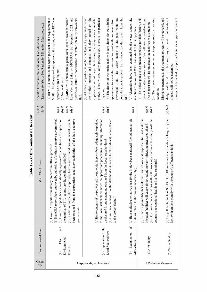
Tabl
e 1-
3-32
Env
iron
men
tal C
heck
list
Category
Envi
ronm
enta
l Ite
m
Mai
n C
heck
Item
s Y
es: Y
N
o: N
Sp
ecifi
c En
viro
nmen
tal a
nd S
ocia
l Con
side
ratio
ns
(Rea
sons
for Y
es o
r No,
Rat
iona
le, M
itiga
tion
Mea
sure
s, et
c.)
1 Approvals, explanations
(1)
EIA
an
d En
viro
nmen
tal
Perm
its
(a) H
ave
EIA
repo
rts b
een
alre
ady
prep
ared
in o
ffic
ial p
roce
ss?
(b) H
ave E
IA re
ports
bee
n ap
prov
ed b
y au
thor
ities
of t
he h
ost c
ount
ry's
gove
rnm
ent?
(c
) Hav
e EI
A re
ports
bee
n un
cond
ition
ally
app
rove
d? If
con
ditio
ns a
re im
pose
d on
th
e ap
prov
al o
f EIA
repo
rts, a
re th
e co
nditi
ons s
atis
fied?
(d
) In
addi
tion
to th
e ab
ove
appr
oval
s, ha
ve o
ther
requ
ired
envi
ronm
enta
l per
mits
be
en o
btai
ned
from
the
app
ropr
iate
reg
ulat
ory
auth
oriti
es o
f th
e ho
st c
ount
ry's
gove
rnm
ent?
(a) Y
(b
) Y
(c) N
(d
) Y
(a) (
b) M
ISTI
sub
mitt
ed th
e re
port
purs
uant
to th
e re
quire
men
t to
MO
E.
MO
E in
spec
ted
and
appr
oved
the r
epor
t, an
d th
e EPC
was
ag
reed
on
Mar
ch 3
0, 2
021.
(c
) No
cond
ition
s.
(d) M
ISTI
will
obt
ain
offic
ial p
erm
issi
on le
tter o
f wat
er ex
tract
ion
from
Vay
Kor
Lak
e by
MO
WR
AM
by
Dec
embe
r 20
21,
and
perm
issi
on l
ette
r of
con
stru
ctio
n of
wat
er i
ntak
e by
Pro
vinc
ial
Hal
l.
(2)
Expl
anat
ion
to th
e Lo
cal S
take
hold
ers
(a) H
ave
cont
ents
of t
he p
roje
ct an
d th
e pot
entia
l im
pact
s bee
n ad
equa
tely
exp
lain
ed
to th
e Lo
cal s
take
hold
ers
base
d on
app
ropr
iate
pro
cedu
res,
incl
udin
g in
form
atio
n di
sclo
sure
? Is
und
erst
andi
ng o
btai
ned
from
the
Loca
l sta
keho
lder
s?
(b) H
ave
the
com
men
t fro
m th
e st
akeh
olde
rs (s
uch
as lo
cal r
esid
ents
) bee
n re
flect
ed
to th
e pr
ojec
t des
ign?
(a) Y
(b
) Y
(a) A
ll re
late
d de
partm
ents
of t
he d
evel
opm
ent p
roje
ct u
nder
stoo
d th
e pr
ojec
t pu
rpos
e an
d co
nten
ts,
and
they
ag
reed
on
th
e im
plem
enta
tion.
At t
he p
ublic
hea
ring,
the
villa
gers
wel
com
ed th
e pr
ojec
t. Th
ey w
ishe
d ea
rly p
roje
ct s
tart.
The
re i
s no
par
ticul
ar
obje
ctio
n.
(b) T
he d
esig
n of
the
inta
ke fa
cilit
y is
con
side
red
for t
he s
uita
ble
appe
aran
ce t
o m
eet
the
lake
env
ironm
ent
with
com
men
ts f
rom
Pr
ovin
cial
H
all.
The
wat
er
inta
ke
is
desi
gned
w
ith
the
cons
ider
atio
n to
pre
vent
fis
h in
vasi
on b
y th
e re
ques
t fr
om t
he
DO
E.
(3)
Exam
inat
ion
of
Alte
rnat
ives
(a
) Hav
e mul
tiple
alte
rnat
ive p
lans
for t
he P
roje
ct b
een
anal
yzed
? (In
clud
ing
anal
ysis
of
item
s rel
ated
to th
e en
viro
nmen
t/soc
iety
.) (a
) Y
(a)
Alte
rnat
ives
hav
e be
en e
xam
ined
for
the
wat
er s
ourc
e, s
ite
sele
ctio
n of
inta
ke a
nd W
TP, a
nd e
xten
t of t
he su
pply
are
a.
2 Pollution Measures
(1) A
ir Q
ualit
y
(a)
Is th
ere
a po
ssib
ility
that
chl
orin
e fro
m c
hlor
ine
stor
age
faci
litie
s an
d ch
lorin
e in
ject
ion
faci
litie
s will
cau
se a
ir po
llutio
n? A
re a
ny m
itiga
ting
mea
sure
s tak
en?
(b)
Do
chlo
rine
conc
entra
tions
with
in th
e w
orki
ng e
nviro
nmen
ts c
ompl
y w
ith th
e co
untry
’s o
ccup
atio
nal h
ealth
and
safe
ty st
anda
rds?
(a) N
(b
) Y
(a) T
he P
roje
ct p
lans
to u
se b
reac
hing
pow
er fo
r dis
infe
ctio
n. T
his
reag
ent i
s sta
ble,
and
occu
rren
ce o
f air
pollu
tion
is co
nsid
ered
less
. Th
e ex
haus
t fan
will
be
situ
ated
at t
he fa
cilit
ies o
f dis
infe
ctio
n.
(b)
The
abov
e m
easu
res
serv
e to
kee
p ap
prop
riate
wor
king
co
nditi
on.
(2) W
ater
Qua
lity
(a) D
o po
lluta
nts,
such
as
SS, B
OD
, CO
D c
onta
ined
in e
fflu
ents
dis
char
ged
by th
e fa
cilit
y op
erat
ions
com
ply
with
the
coun
try’s
eff
luen
t sta
ndar
ds?
(a) N
/A
Dis
char
ge g
ener
ated
at t
he tr
eatm
ent p
roce
ss w
ill b
e re
cycl
ed, a
nd
slud
ge w
ill b
e dr
ied.
The
refo
re,
any
efflu
ent
from
tre
atm
ent
proc
ess w
ill n
ot b
e ge
nera
ted.
Se
wag
e w
ill b
e tre
ated
by
sept
ic ta
nks a
nd cl
ear u
pper
por
tion
will
1-61

Category
Envi
ronm
enta
l Ite
m
Mai
n C
heck
Item
s Y
es: Y
N
o: N
Sp
ecifi
c En
viro
nmen
tal a
nd S
ocia
l Con
side
ratio
ns
(Rea
sons
for Y
es o
r No,
Rat
iona
le, M
itiga
tion
Mea
sure
s, et
c.)
be i
nfilt
rate
d in
to g
roun
d. T
here
fore
, di
scha
rge
wat
er i
s no
t ge
nera
ted.
(3) W
aste
s (a
) Are
was
tes,
such
as
slud
ge g
ener
ated
by
the
faci
lity
oper
atio
ns p
rope
rly tr
eate
d an
d di
spos
ed in
acc
orda
nce
with
the
coun
try’s
regu
latio
ns?
(a) Y
(a) S
ludg
e will
be t
reat
ed an
d dr
ied
at d
ry-b
ed, t
hen
dry
slud
ge w
ill
be d
ispo
sed
at a
n ap
prop
riate
site
with
the
per
mis
sion
of
the
land
owne
r. M
ISTI
is re
spon
sibl
e fo
r the
arr
ange
men
t.
(4)
Noi
se
and
vibr
atio
n (a
) Do
nois
e an
d vi
brat
ions
gen
erat
ed fr
om th
e fa
cilit
ies,
such
as
pum
ping
sta
tions
co
mpl
y w
ith th
e co
untry
’s st
anda
rds?
(a
)Y
(a) T
he p
ump
will
be
inst
alle
d at
bas
emen
t mad
e by
the
RC
with
no
ise
redu
cing
wal
ls. T
he n
oise
will
be
cont
rolle
d w
ithin
the
limit
of R
GC
req
uire
men
t. Th
eref
ore,
noi
se a
nd v
ibra
tion
will
be
cont
rolle
d to
the
perm
issi
ble
limit
by th
e ab
ove
mea
sure
s.
(5) S
ubsi
denc
e (a
) In
the
case
of e
xtra
ctio
n of
a la
rge
volu
me
of g
roun
dwat
er, i
s th
ere
a po
ssib
ility
th
at th
e ex
tract
ion
of g
roun
dwat
er w
ill c
ause
subs
iden
ce?
(a)N
(a
) The
Pro
ject
doe
s not
use
gro
undw
ater
.
3 Natural Environment
(1) P
rote
cted
are
as
(a) I
s th
e pr
ojec
t site
or d
isch
arge
are
a lo
cate
d in
pro
tect
ed a
reas
des
igna
ted
by th
e co
untry
’s la
ws o
r int
erna
tiona
l tre
atie
s and
con
vent
ions
? I
s the
re a
pos
sibi
lity
that
th
e pr
ojec
t will
aff
ect t
he p
rote
cted
are
as?
(a) Y
(a)
The
Vay
Kor
Lak
e is
div
ided
in
two
parts
by
the
natio
nal
high
way
No.
1. T
he in
take
will
be
cons
truct
ed at
the
uppe
r sid
e but
th
e lo
wer
side
is d
esig
nate
d as
pro
tect
ed a
rea
for t
he p
rote
ctio
n of
fis
hery
re
sour
ces.
Mea
sure
s w
ill
be
take
n to
pr
even
t th
e oc
curr
ence
of
turb
id w
ater
dur
ing
cons
truct
ion.
In
addi
tion,
ed
ucat
ion
and
train
ing
will
be
prov
ided
to th
e w
orke
rs so
that
they
w
ill n
ot d
o th
e fis
hing
act
iviti
es.
In th
e de
sign
of t
he w
ater
inta
ke, a
bar
scre
en w
ill b
e ins
talle
d, a
nd
the
max
imum
inf
low
spe
ed i
s se
t to
0.1
m/s
or
less
, whi
ch i
s ex
trem
ely
slow
, to
pre
vent
fis
h fr
om e
nter
ing.
With
the
abo
ve
mea
sure
s, th
e im
pact
of p
roje
ct im
plem
enta
tion
can
be a
void
ed.
(2) E
cosy
stem
s
(a)
Doe
s th
e pr
ojec
t si
te e
ncom
pass
prim
eval
for
ests
, tro
pica
l ra
in f
ores
ts,
ecol
ogic
ally
val
uabl
e ha
bita
ts (e
.g.,
cora
l ree
fs, m
angr
oves
, or t
idal
flat
s)?
(b)
Doe
s th
e pr
ojec
t si
te o
r di
scha
rge
area
enc
ompa
ss t
he p
rote
cted
hab
itats
of
enda
nger
ed s
peci
es d
esig
nate
d by
the
coun
try’s
law
s or
inte
rnat
iona
l tre
atie
s an
d co
nven
tions
? (c
) If
sig
nific
ant
ecol
ogic
al i
mpa
cts
are
antic
ipat
ed,
are
adeq
uate
pro
tect
ion
mea
sure
s tak
en to
redu
ce th
e im
pact
s on
the
ecos
yste
m?
(d)
Is t
here
a p
ossi
bilit
y th
at t
he a
mou
nt o
f w
ater
use
d (e
.g.,
surf
ace
wat
er,
grou
ndw
ater
) by
proj
ect w
ill a
dver
sely
affe
ct a
quat
ic e
nviro
nmen
ts, s
uch
as ri
vers
?
(a) N
(b
) N
(c) N
(d
) N
(a)
The
site
doe
s no
t co
ntai
n an
y vi
rgin
for
ests
, tro
pica
l ol
d -
grow
th fo
rest
s, or
impo
rtant
eco
logi
cal h
abita
ts.
(b) N
o ha
bita
ts fo
r any
rare
spec
ies a
re p
rese
nt in
the
site
. (c
) No
maj
or c
once
rns.
(d) N
o m
ajor
con
cern
s
1-62

Category
Envi
ronm
enta
l Ite
m
Mai
n C
heck
Item
s Y
es: Y
N
o: N
Sp
ecifi
c En
viro
nmen
tal a
nd S
ocia
l Con
side
ratio
ns
(Rea
sons
for Y
es o
r No,
Rat
iona
le, M
itiga
tion
Mea
sure
s, et
c.)
Are
ade
quat
e m
easu
res
take
n to
redu
ce th
e im
pact
s on
aqu
atic
env
ironm
ents
, suc
h as
aqu
atic
org
anis
ms?
(3) H
ydro
logy
(a
) Is
the
re a
pos
sibi
lity
that
the
am
ount
of
wat
er u
sed
(e.g
., su
rfac
e w
ater
, gr
ound
wat
er)
by t
he p
roje
ct w
ill a
dver
sely
aff
ect s
urfa
ce w
ater
and
gro
undw
ater
flo
ws?
(a
) N
(a) I
mpa
ct o
n gr
ound
wat
er is
not
exp
ecte
d. T
he a
mou
nt o
f wat
er
take
n fr
om th
e la
ke is
sm
all c
ompa
red
to th
e ca
paci
ty, a
nd th
e ef
fect
on
surf
ace
wat
er is
lim
ited.
4.Social Environment
(1) R
eset
tlem
ent
(a)
Is i
nvol
unta
ry r
eset
tlem
ent
caus
ed b
y pr
ojec
t im
plem
enta
tion?
If
invo
lunt
ary
rese
ttlem
ent
is c
ause
d, a
re e
fforts
mad
e to
min
imiz
e th
e im
pact
s ca
used
by
the
rese
ttlem
ent?
(b
) Is
ade
quat
e ex
plan
atio
n on
com
pens
atio
n an
d re
settl
emen
t ass
ista
nce
give
n to
af
fect
ed p
eopl
e pr
ior t
o re
settl
emen
t?
(c)
Is t
he r
eset
tlem
ent
plan
, inc
ludi
ng c
ompe
nsat
ion
with
ful
l re
plac
emen
t co
sts,
rest
orat
ion
of li
velih
oods
and
livi
ng s
tand
ards
dev
elop
ed b
ased
on
soci
oeco
nom
ic
stud
ies o
n re
settl
emen
t?
(d) A
re th
e co
mpe
nsat
ions
goi
ng to
be
paid
prio
r to
the
rese
ttlem
ent?
(e
) Are
the
com
pens
atio
n po
licie
s pre
pare
d in
doc
umen
t?
(f) D
oes t
he re
settl
emen
t pla
n pa
y pa
rticu
lar a
ttent
ion
to v
ulne
rabl
e gro
ups o
r peo
ple,
in
clud
ing
wom
en,
child
ren,
the
eld
erly
, pe
ople
bel
ow t
he p
over
ty l
ine,
eth
nic
min
oriti
es, a
nd in
dige
nous
peo
ples
? (g
) Are
agr
eem
ents
with
the
affe
cted
peo
ple
obta
ined
prio
r to
rese
ttlem
ent?
(h
) Is t
he o
rgan
izat
iona
l fra
mew
ork
esta
blis
hed
to p
rope
rly im
plem
ent r
eset
tlem
ent?
A
re th
e ca
paci
ty a
nd b
udge
t sec
ured
to im
plem
ent t
he p
lan?
(i)
Are
any
pla
ns d
evel
oped
to m
onito
r the
impa
cts o
f res
ettle
men
t?
(j) Is
the
grie
vanc
e re
dres
s mec
hani
sm e
stab
lishe
d?
(a)N
(b
) N/A
(c
) N/A
(d
) N/A
(e
) N/A
(f
) N/A
(g
) N/A
(h
) N/A
(i)
N/A
(j)
N/A
(a)
SWW
pur
chas
ed a
bout
1ha
of
land
for
the
WTP
fro
m t
he
land
owne
r. Th
e la
nd w
as a
gric
ultu
ral
land
and
the
re w
ere
no
auth
oriz
ed/u
naut
horiz
ed r
esid
ents
, and
the
re i
s no
rel
ocat
ion
of
resi
dent
s. (b
) Lan
d sa
les w
ere
cond
ucte
d in
the
pres
ence
of t
he v
illag
e ch
ief
and
suff
icie
nt e
xpla
natio
ns w
ere
give
n.
(c)
The
sale
pric
e of
lan
d is
abo
ut 1
.2 t
imes
the
pric
e of
the
su
rroun
ding
land
and
is c
onsi
dere
d to
be
the
repl
acem
ent p
rice.
(d
) SW
W a
lread
y pa
id th
e fu
ll am
ount
. (e
) Con
duct
ed a
s a g
ener
al la
nd sa
le.
(F)
The
land
owne
r is
a f
arm
er,
and
his
fam
ily (
wife
onl
y)
parti
cipa
ted
in th
e con
tract
pro
cess
and
agre
ed to
the s
ales
cont
ract
. (g
) No
relo
catio
n oc
curr
ed.
(h) D
ISTI
and
the
villa
ge c
hief
wer
e in
volv
ed, a
nd la
nd sa
les w
ere
carr
ied
out a
ppro
pria
tely
. (i)
The
ful
l co
ntra
ct a
mou
nt h
as a
lread
y be
en p
aid
and
no
mon
itorin
g is
per
form
ed.
(j) I
f th
ere
is a
com
plai
nt, i
t will
be
com
mun
icat
ed to
DIS
TI o
r M
ISTI
via
the
villa
ge c
hief
, but
no
com
plai
nt h
as o
ccur
red
in th
is sa
le.
(2)
Livi
ng
and
Live
lihoo
d
(a) I
s the
re a
pos
sibi
lity
that
the
proj
ect w
ill a
dver
sely
aff
ect t
he li
ving
con
ditio
ns o
f in
habi
tant
s? A
re a
dequ
ate
mea
sure
s con
side
red
to re
duce
the
impa
cts,
if ne
cess
ary?
(b
) Is
the
re a
pos
sibi
lity
that
the
am
ount
of
wat
er u
sed
(e.g
., su
rfac
e w
ater
, gr
ound
wat
er) b
y th
e pr
ojec
t will
adv
erse
ly a
ffec
t the
exi
stin
g w
ater
use
s an
d w
ater
ar
ea u
ses?
(a) N
(b
) N
(a) T
he p
roje
ct h
as p
ositi
ve im
pact
to im
prov
e ba
sic
hum
an n
eeds
. Th
ere
is n
o pa
rticu
lar n
egat
ive
impa
ct.
(b) T
he S
vay
Rien
g R
iver
has
eno
ugh
disc
harg
e ca
paci
ty a
nd th
e in
take
of w
ater
supp
ly d
oes n
ot a
ffec
t sig
nific
antly
.
(3) H
erita
ge
(a)
Is t
here
a p
ossi
bilit
y th
at t
he p
roje
ct w
ill d
amag
e th
e lo
cal
arch
eolo
gica
l, hi
stor
ical
, cul
tura
l, an
d re
ligio
us h
erita
ge?
Are
ade
quat
e m
easu
res
cons
ider
ed t
o (a
) N
(a)
No
anth
ropo
logi
cal,
hist
oric
al, c
ultu
ral,
relig
ious
ly im
porta
nt
herit
ages
or h
isto
rical
rem
ains
hav
e be
en id
entif
ied
in th
e pr
ojec
t
1-63

Category
Envi
ronm
enta
l Ite
m
Mai
n C
heck
Item
s Y
es: Y
N
o: N
Sp
ecifi
c En
viro
nmen
tal a
nd S
ocia
l Con
side
ratio
ns
(Rea
sons
for Y
es o
r No,
Rat
iona
le, M
itiga
tion
Mea
sure
s, et
c.)
prot
ect t
hese
site
s in
acco
rdan
ce w
ith th
e co
untry
’s la
ws?
si
te.
(4) L
ands
cape
(a
) Is
ther
e a
poss
ibili
ty th
at th
e pr
ojec
t will
adv
erse
ly a
ffec
t the
loca
l lan
dsca
pe?
Are
nec
essa
ry m
easu
res t
aken
? (a
) N
(a)
The
inta
ke w
ill b
e co
nstru
cted
at t
he r
oads
ide,
and
it w
ill b
e de
sign
ed to
har
mon
ize
with
the
envi
ronm
ent t
o m
eet t
he re
ques
t of
the
stak
ehol
ders
.
(5)
Ethn
ic M
inor
ities
an
d In
dige
nous
Pe
ople
s
(a) A
re c
onsi
dera
tions
giv
en to
redu
ce im
pact
s on
the
cultu
re a
nd li
fest
yle
of e
thni
c m
inor
ities
and
indi
geno
us p
eopl
es?
(b)
Are
all
of th
e rig
hts
of e
thni
c m
inor
ities
and
indi
geno
us p
eopl
es in
rel
atio
n to
la
nd a
nd re
sour
ces r
espe
cted
?
(a) N
/A
(b) N
/A
(a)(
b) T
here
are
no
ethn
ic m
inor
ities
or i
ndig
enou
s peo
ples
livi
ng
near
the
proj
ect s
ite.
(6)
Wor
king
C
ondi
tions
(a) I
s th
e pr
ojec
t pro
pone
nt n
ot v
iola
ting
any
law
s an
d or
dina
nces
ass
ocia
ted
with
th
e w
orki
ng c
ondi
tions
of t
he c
ount
ry w
hich
the
proj
ect p
ropo
nent
sho
uld
obse
rve
in th
e pr
ojec
t?
(b) A
re ta
ngib
le sa
fety
cons
ider
atio
ns in
pla
ce fo
r ind
ivid
uals
invo
lved
in th
e pro
ject
, su
ch a
s the
inst
alla
tion
of sa
fety
equ
ipm
ent w
hich
pre
vent
s ind
ustri
al a
ccid
ents
, and
m
anag
emen
t of h
azar
dous
mat
eria
ls?
(c) A
re in
tang
ible
mea
sure
s bei
ng p
lann
ed an
d im
plem
ente
d fo
r ind
ivid
uals
invo
lved
in
the
proj
ect,
such
as
the
esta
blis
hmen
t of a
saf
ety
and
heal
th p
rogr
am, a
nd s
afet
y tra
inin
g (in
clud
ing
traffi
c sa
fety
and
pub
lic h
ealth
) for
wor
kers
etc
.?
(d)
Are
app
ropr
iate
mea
sure
s ta
ken
to e
nsur
e th
at s
ecur
ity g
uard
s in
volv
ed in
the
proj
ect n
ot to
vio
late
safe
ty o
f oth
er in
divi
dual
s inv
olve
d, o
r loc
al re
side
nts?
(a) Y
(b
) Y
(c) Y
(d
) Y
(a) A
dher
ence
to la
ws c
once
rnin
g w
orki
ng co
nditi
ons w
ill b
e mad
e ex
plic
it in
con
tract
s with
con
tract
ors a
nd m
anag
ed.
(b)
Cou
nter
mea
sure
s su
ch a
s in
stal
latio
n of
saf
ety
hand
rail
are
take
n.
(c)
It w
ill b
e ac
hiev
ed t
o se
t as
an
oblig
atio
n of
con
tract
or i
n co
ntra
ct d
ocum
ent.
(d) S
ecur
ity g
uard
s w
ill b
e in
clud
ed in
targ
et m
embe
rs o
f wor
ker
train
ing.
5 Others
(1)
Impa
cts
durin
g C
onst
ruct
ion
(a) A
re a
dequ
ate
mea
sure
s co
nsid
ered
to re
duce
impa
cts
durin
g co
nstru
ctio
n (e
.g.,
nois
e, v
ibra
tions
, tur
bid
wat
er, d
ust,
exha
ust g
ases
, and
was
tes)
? (b
) If c
onst
ruct
ion
activ
ities
adv
erse
ly a
ffec
t the
nat
ural
env
ironm
ent (
ecos
yste
m),
are
adeq
uate
mea
sure
s con
side
red
to re
duce
impa
cts?
(c
) If
con
stru
ctio
n ac
tiviti
es a
dver
sely
aff
ect t
he s
ocia
l env
ironm
ent,
are
adeq
uate
m
easu
res c
onsi
dere
d to
redu
ce im
pact
s?
(d)
If t
he c
onst
ruct
ion
activ
ities
mig
ht c
ause
tra
ffic
con
gest
ion,
are
ade
quat
e m
easu
res c
onsi
dere
d to
redu
ce su
ch im
pact
s?
(a) Y
(b
)N
(c) Y
(d
)Y
(a) M
itiga
tion
mea
sure
s will
be
take
n un
der E
PM fo
r man
agin
g al
l no
ise,
vib
ratio
n, t
urbi
d w
ater
, du
st,
gas
emis
sion
s, an
d w
aste
di
scha
rged
from
the
wor
k si
te.
(b
)Par
ticul
ar n
egat
ive
impa
ct is
not
exp
ecte
d.
(c) T
empo
rary
traf
fic d
istu
rban
ce w
ill o
ccur
. The
neg
ativ
e ef
fect
w
ill b
e m
inim
ized
by
the
mea
sure
s su
ch a
s se
tting
of
deto
urs,
assi
gnm
ent o
f tra
ffic
gui
de, i
nsta
llatio
n of
sig
nboa
rd, a
ppro
pria
te
info
rmat
ion
shar
ing.
(d
) Si
nce
the
wat
er in
take
fac
ility
will
be
cons
truct
ed a
long
the
natio
nal h
ighw
ay c
ross
ing
the
lake
, the
tem
pora
ry re
duct
ion
of th
e nu
mbe
r of
lan
es w
ill b
e re
quire
d, a
nd i
t m
ay c
ause
tra
ffic
1-64
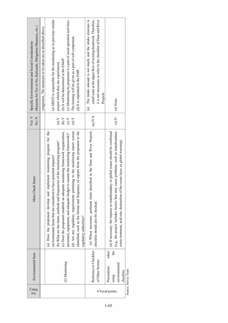
Category
Envi
ronm
enta
l Ite
m
Mai
n C
heck
Item
s Y
es: Y
N
o: N
Sp
ecifi
c En
viro
nmen
tal a
nd S
ocia
l Con
side
ratio
ns
(Rea
sons
for Y
es o
r No,
Rat
iona
le, M
itiga
tion
Mea
sure
s, et
c.)
cong
estio
n. T
he m
easu
res t
o be
take
n ar
e as
des
crib
ed a
bove
.
(2) M
onito
ring
(a)
Doe
s th
e pr
opon
ent
deve
lop
and
impl
emen
t m
onito
ring
prog
ram
for
the
en
viro
nmen
tal i
tem
s tha
t are
con
side
red
to h
ave
pote
ntia
l im
pact
s?
(b) W
hat a
re th
e ite
ms,
met
hods
and
freq
uenc
ies o
f the
mon
itorin
g pr
ogra
m?
(c) D
oes
the
prop
onen
t est
ablis
h an
ade
quat
e m
onito
ring
fram
ewor
k (o
rgan
izat
ion,
pe
rson
nel,
equi
pmen
t, an
d ad
equa
te b
udge
t to
sust
ain
the
mon
itorin
g fr
amew
ork)
? (d
) A
re a
ny r
egul
ator
y re
quire
men
ts p
erta
inin
g to
the
mon
itorin
g re
port
syst
em
iden
tifie
d, s
uch
as th
e fo
rmat
and
fre
quen
cy o
f re
ports
fro
m th
e pr
opon
ent t
o th
e re
gula
tory
aut
horit
ies?
(a) Y
(b
) Y
(c) Y
(d
) Y
(a) M
ISTI
is re
spon
sibl
e fo
r the
mon
itorin
g as
in p
revi
ous s
imila
r pr
ojec
t whi
ch th
ey a
re e
xper
ienc
ed.
(b) I
t will
be
dete
rmin
ed in
the
EMoP
.
(c) M
onito
ring
by p
ropo
nent
is a
par
t of u
sual
ope
ratio
n ac
tiviti
es.
The
train
ing
will
be
give
n as
a p
art o
f sof
t com
pone
nt.
(d) I
t is s
tipul
ated
in th
e EM
P.
6 Focal points
Ref
eren
ce to
Che
cklis
t of
Oth
er S
ecto
rs
(a)
Whe
re n
eces
sary
, pe
rtine
nt i
tem
s de
scrib
ed i
n th
e D
am a
nd R
iver
Pro
ject
s ch
eckl
ist s
houl
d al
so b
e ch
ecke
d.
(a) N
/A
(a)
The
inta
ke a
mou
nt is
not
muc
h, a
nd th
e in
take
stru
ctur
e is
sm
all s
cale
at th
e upp
er fl
ow o
f exi
stin
g he
adw
ork.
The
refo
re,
it is
not
nec
essa
ry to
refe
r to
the
chec
klis
t of D
am a
nd R
iver
Pr
ojec
ts
Prec
autio
ns
whe
n us
ing
the
envi
ronm
enta
l ch
eckl
ist
(a) I
f nec
essa
ry, t
he im
pact
s to
tran
sbou
ndar
y or
glo
bal i
ssue
s sho
uld
be c
onfir
med
(e
.g.,
the
proj
ect i
nclu
des
fact
ors
that
may
cau
se p
robl
ems,
such
as
trans
boun
dary
w
aste
trea
tmen
t, ac
id ra
in, d
estru
ctio
n of
the
ozon
e la
yer,
or g
loba
l war
min
g).
(a) N
(a
) Non
e
Sour
ce: S
urve
y Te
am
1-65
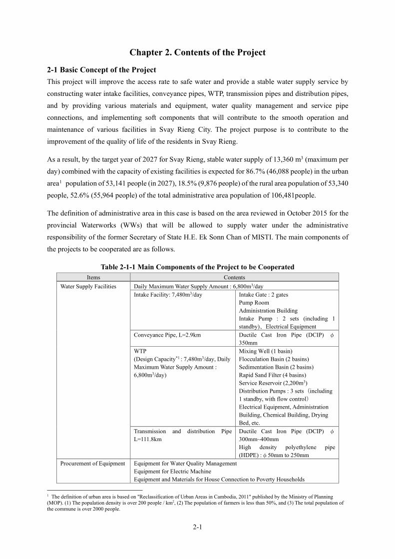
2-1
Chapter 2. Contents of the Project
2-1 Basic Concept of the Project This project will improve the access rate to safe water and provide a stable water supply service by constructing water intake facilities, conveyance pipes, WTP, transmission pipes and distribution pipes, and by providing various materials and equipment, water quality management and service pipe connections, and implementing soft components that will contribute to the smooth operation and maintenance of various facilities in Svay Rieng City. The project purpose is to contribute to the improvement of the quality of life of the residents in Svay Rieng.
As a result, by the target year of 2027 for Svay Rieng, stable water supply of 13,360 m3 (maximum per day) combined with the capacity of existing facilities is expected for 86.7% (46,088 people) in the urban area1 population of 53,141 people (in 2027), 18.5% (9,876 people) of the rural area population of 53,340 people, 52.6% (55,964 people) of the total administrative area population of 106,481people.
The definition of administrative area in this case is based on the area reviewed in October 2015 for the provincial Waterworks (WWs) that will be allowed to supply water under the administrative responsibility of the former Secretary of State H.E. Ek Sonn Chan of MISTI. The main components of the projects to be cooperated are as follows.
Table 2-1-1 Main Components of the Project to be Cooperated Items Contents
Water Supply Facilities Daily Maximum Water Supply Amount : 6,800m3/day Intake Facility: 7,480m3/day Intake Gate : 2 gates
Pump Room Administration Building Intake Pump : 2 sets (including 1 standby)、Electrical Equipment
Conveyance Pipe, L=2.9km Ductile Cast Iron Pipe (DCIP) φ
350mm WTP
(Design Capacity*1 : 7,480m3/day, Daily Maximum Water Supply Amount : 6,800m3/day)
Mixing Well (1 basin) Flocculation Basin (2 basins) Sedimentation Basin (2 basins) Rapid Sand Filter (4 basins) Service Reservoir (2,200m3) Distribution Pumps : 3 sets(including 1 standby, with flow control) Electrical Equipment, Administration Building, Chemical Building, Drying Bed, etc.
Transmission and distribution Pipe L=111.8km
Ductile Cast Iron Pipe (DCIP) φ
300mm~400mm High density polyethylene pipe (HDPE) :φ50mm to 250mm
Procurement of Equipment Equipment for Water Quality Management Equipment for Electric Machine Equipment and Materials for House Connection to Poverty Households
1 The definition of urban area is based on "Reclassification of Urban Areas in Cambodia, 2011" published by the Ministry of Planning (MOP). (1) The population density is over 200 people / km2, (2) The population of farmers is less than 50%, and (3) The total population of the commune is over 2000 people.

2-2
Items Contents Soft Component Operation and Maintenance of Water Treatment Facilities
Maintenance of Distribution Facilities Production Management
Note : *1) The proposed amount of treated water is determined based on the design daily maximum water supply amount, and the amount of miscellaneous wastewater, and other lost water in the WTP is taken into consideration. In this project, the design daily maximum water supply amount is expected to have a margin of 10%, and the design daily maximum water supply amount of 6,800 m3 / day x 1.1 = 7,480 m3 / day is set as the design water treatment amount. Source : Survey Team
2-3
2-2 Outline Design of the Requested Japanese Assistance 2-2-1 Design Policy
2-2-1-1 Basic Policy The purpose of this project is to expand and improve the waterworks facility in Svay Rieng City, thereby contributing to efforts of the RGC which is aiming to increase the number of people in urban areas who have access to safe drinking water. The Survey Team had conducted an outline design based on the request of the government, consultation with government officials and field survey.
1) The target year for this project has been set as 2027 based on the meeting of M/D with the Cambodian side held in April 2021. This target year was set based on the relation between the budget scale of the grant aid project and the facility scale derived from the water demand projection. This year will be two years after 2025, when MISTI has set a disseminated target of 100% water supply ratio in urban areas.
2) The scale of expansion capacity will be a daily maximum water supply amount of 6,800 m3/day, taking into consideration the water demand in 2027 and the water supply capacity of existing facilities.
3) Outline design shall be based on following design criteria:
・The design criteria which Phnom Penh Water Supply Authority (PPWSA) adopts and are widely applied in Cambodia; ・The design criteria which have been applied in other ongoing grant aid projects; and ・”The Design Criteria for Water Supply Facilities 2012” (Japan Waterworks Association).
4) The equipment shall be procured for the equipment that is considered to be the minimum necessary for the operation and maintenance of the facilities constructed in this project, taking into consideration the contents of Cambodia's request and the current status of existing equipment that are currently possessed in Cambodia.
5) In the outline design, high quality materials and equipment shall be applied to the extent locally available in Cambodia, and applicable construction methods that are often conducted in Cambodia shall be adopted as much as possible.
6) The design height and location of the intake facility shall be decided in consideration of the future raising of the dike embankment height around Vay Kor Lake and the widening of National Highway No. 1.
7) The water intake facility shall be designed with consideration for the landscape, taking into consideration, the people coming and going during the annual water festival on the shores of Vay Kor Lake.
2-4
8) Corrosion-resistance material shall be selected as materials of WTP and distribution facilities from the point of life-cycle cost (LCC). Also, the design shall be prepared by emphasizing economic efficiency and not requiring high-skilled technique.
9) In order to assist in improving the water supply ratio of the poverty group, materials and equipment of water supply to the poor households shall be procured.
10) Local construction firms shall be effectively utilized under a Japanese general contractor considering their ability, scale of the business and past performances.
11) Seismic design shall not be applied in this project because the earthquake risk in Cambodia is low and there are no past records of earthquake.
12) Soft component shall be delivered for SWWs to be able to operate and maintain new facilities appropriately and supply safe water which meets the water quality standard.
2-2-1-2 Natural and Environmental Conditions
(1) Precipitation The situation of precipitation in Cambodia is as shown in section “2-2-2-2, New Surface Water Source”. Table 2-2-16 and Figure 2-2-6 show monthly precipitations in Svay Rieng from 2000 to 2019. Since the rainy and dry seasons in the region are clearly divided, as shown in the figure, the project should take such high precipitation periods, in particular, into consideration in the construction of works, such as concrete placement and other works affected by weather condition.
(2) Water Level of Vay Kor Lake With respect to the intake level, the height of the intake facility should be set such as to allow the inflow of water, even during the lowest water level, considering the previous lowest water level of EL +1.6m (in July 2020) and the highest water level of EL +4.35m (October 2011) while configuring the embankment elevation and pump room by adding a freeboard to the water level on the 10-year return period to ensure that they will not be submerged. There is also a plan to elevate the Vay Kor Dam and the lake shore embankment of the Vay Kor Lake to boost the reservoir capacity of the lake, based on which the peak water level of the lake is expected to rise. Since the plan will not raise the level sufficiently to submerge National Highway No. 1 according to the Department of Water Resources and Meteorology (DOWRAM), the embankment elevation in the intake pump station is planned to correspond to EL+5.8 m, which is the elevation of the road shoulder of National Highway No. 1.
(3) Topographical / Geological Features Geographical features in Cambodia can be divided into three regions: northeast, middle and southwest. Svay Rieng is located in the middle region which is equivalent to the Tonle Sap-Mekong lowlands, established by basalt between the Neogene and Quaternary periods in the Cenozoic era, the top of which is covered by alluvial deposits of the Quaternary period.
2-5
Since the bedding of intake facility comprises loose clay with an average N-value of 5, it shall be supported by a pile foundation. The bedding of the WTP comprises hard sandy clay with an average N-value of 15, constituting relatively good soil condition but pile foundations may be applied depending on the design condition of the facilities. The soil quality in both facilities accepts using backhoes for drilling.
(4) Earthquakes Earthquakes in Cambodia are recorded in the research results of the National Institute for Land and Infrastructure Management in Japan and the hazard maps created by the UN-OCHA and the United States Geological Survey (USGS). In these documents, Cambodia is categorized as a region with minimal earthquakes and no past earthquake data recorded. Accordingly, the project shall not apply seismic design.
(5) Water Quality The water quality was surveyed as follows. Since the survey did not detect any heavy metals, pesticides or other hazardous substances, and there is no change of water sources, particular water treatment or other arrangements were initiated. Meanwhile, facilities shall be designed taking into consideration the features of raw water quality (turbidity, iron detection, etc.).
(Overview) The quality test of the raw water did not detect any hazardous substances which would be difficult to remove. Turbidity was highest in July and August, peaking at 350 NTU and with a low point of between 30 and 50 NTU, showing little year-round fluctuation and not declining from a certain concentration level. The turbidity is derived from iron, with a high concentration but removable by general purifying treatment. In Vay Kor Lake, although no commercial fishing is allowed, locals do fish for home cooking and enjoyment. At present, there is no confirmed instance related to health damage.
(Jar test and chlorine requirement) The optimal PAC injection rate ranges between 11 and 18 mg/l, while the chlorine requirement peaks at around 1.5 mg/l.
(Tap water quality) In 2017, turbidity and residual chlorine in tap water were inspected. Bacteriological examination was performed when no residual chlorine was detected. Thirty nine (39) out of 100 surveyed points showed a residual chlorine level below 0.2 mg/l, with coliform bacteria detected at four points, but no fecal coliforms at any of the points. Compared with 5NTU, which is the drinking water quality standard for Cambodia, two out of 100 surveyed points exceeded acceptable turbidity levels, 6NTU and 8NTU, respectively.

2-6
2-2-1-3 Social Conditions
(1) Industry Svay Rieng City is the capital of Svay Rieng Province and its industry centers on agriculture. Most of the planted area is used for paddy rice, followed by cassava, although the latter occupies less than 3%. Beans and vegetables are also produced, even in small amounts. Since over 90% of those living there are farmers, they will comprise the majority of beneficiaries of the waterworks facility to be expanded under this project.
(2) Traffic Conditions There are plans to construct a highway which will extend from the border with Vietnam in Svay Rieng Province to Phnom Penh City to boost the transport capacity of the Southern Economic Corridor in Cambodia and a feasibility study was conducted. The currently planned route does not overlap with the target area of this project, and it is planned to cross about 3 km north of the city area.
Meanwhile, more information concerns a plan to widen areas along National Highway No. 1, where an intake facility will be constructed in the project. Accordingly, the location of the intake facility should be planned, taking the scope of road widening into consideration.
(3) Electricity Supply Electricity in Cambodia is supplied by the Electricite de Cambodge (EDC) company. As part of the Project for Expansion of Distribution Lines in Southern Economic Corridor in Cambodia, transmission lines have been constructed in Svay Rieng to import electricity from Vietnam. Since a substation to supply electricity to the project facility should follow the standards and specifications of the EDC, the latter is responsible for supplying the construction materials needed, while the cost is borne by the contractor. The monthly frequency of power outages is expected to be a few times due to lightning in the rainy season and short circuit accidents.
(4) Land Acquisition and Relocation of Residents Premises for the WTP and intake facility are needed in the project site in Svay Rieng. The former premises were acquired from the original landowner in December 2017, while the planned site for the latter premises is on the road traversing the lake. This is land for public use, permission for use of which shall be obtained from the Provincial Government.
In the interview with the vice provincial governor held on December 19, 2019, the consent was obtained for the use of the land, but the Cambodian side granted a formal use permit from the provincial government before the announcement of the qualification examination and before bidding for construction. The project will not entail any need to relocate residents.
(5) Health and Sanitary Condition The toilet possession rate is high, even in households of unconnected districts, which are home to many suburban residents. The prevalence of waterborne diseases among households with water

2-7
connections has been lower than that of unconnected households over the past three years. According to the database provided by the NCDD (as of 2019), the infant mortality rates (per 1,000 births up to five years old) in the Svay Rieng Province as a whole and in the Svay Rieng District were 23.6 and 12.0, respectively, suggesting a lower infant mortality rate in urban areas.
(6) Waste Except for the hazardous materials, construction residues and other construction waste can be disposed on private land. When the contents are likely to include hazardous material, such materials can be similarly disposed after the MOE inspects its quality and confirms no hazard. The project will not generate any hazardous waste. Broken asphalt and concrete and other construction waste are disposed by landfill. Given the prevalence of lowland within the area, landfill disposal is preferable, and many candidate sites can be provided by the province.
2-2-1-4 Construction / Procurement Circumstances As a general rule, the materials and equipment used will be locally procured.
Within Cambodia, many intake facilities, WTPs and distribution facilities have been constructed and several operators in Phnom Penh have relevant work experience. Accordingly, locally sourcing workers and construction machinery appears feasible.
The major construction materials are cement, quarries, reinforcing bars and pipe materials, all of which can also be procured in Cambodia.
However, ductile cast iron pipes are not produced in Cambodia and are instead procured in Japan or from a third country. Likewise, pumps and distribution flow systems, etc. are not produced in Cambodia, but procured in Japan.
2-2-1-5 Utilizing Local Operators In Cambodia, many projects related to WTPs, intake facilities, conduit/supply and distribution pipes and reservoir constructions have been implemented. Several construction firms have relevant work experience in this area and some also own general purpose construction machinery. Accordingly, the project utilizes local construction company procedures, quality and safety governed by a Japanese construction company.
2-2-1-6 Operation and Management Capacity of the Implementation Agency To operate and manage the water supply system to be newly constructed and expanded, there is a need to refine the organization of the SWWs. A proper operation and management system, sufficient staff and a process to establish the system are all taken into consideration and soft component is provided.
2-2-1-7 Grade of Facility, Machinery, etc. Under circumstances whereby equipment and materials are procurable, and construction skill and capacity are arranged, other relevant criteria include the water volume and quality, power supply conditions, land area and staffing capacity for facility management and the construction of a rapid-

2-8
filtration type WTP, as the most common issues in Cambodia. Moreover, to minimize both operational and management costs, as well as the initial facility investment, the scope of mechanical and electrical equipment within the WTP is also reduced as far as possible.
Chemical handling uses locally available chemicals whenever possible. Energy efficiency is also taken into consideration and facilities are designed, located and constructed to ensure water treatment can proceed utilizing gravity.
2-2-1-8 Construction / Procurement Methods and Construction Period Construction works in the project can be roughly classified into three (3) types: intake facilities, WTP and conveyance/distribution pipe-laying work. There is a possibility to execute them either simultaneously or throughout the year.
Since conveyance/distribution pipe-laying work involves long distances (with a total length of 115 km), construction by multiple teams is planned and personnel allocation is also considered to handle their construction supervision. As a general rule, distribution pipes are laid on road shoulders, unexposed to any significant external pressures, while earth coverings should follow the design policy of PPWSA. Road crossings, water channels, drainage and other siphon parts should be protected by concrete and an air valve installed as required.
2-2-2 Basic Plan 2-2-2-1 Water Demand Projection
(1) Target Year In MISTI, the target water supply ratio of 100% by 2025 in urban areas of provincial cities is set and widely known, and the RGC is proceeding with the expansion of water supply facilities in provincial cities. On the other hand, this project is expected to be completed in 2025. As a result of the M/D held in April 2021, it was agreed that the target year would be 2027 based on the relation between the budget scale of the grant aid project and the facility scale derived from the water demand projection. This target year will be two years after the completion of the facilities of this project.
(2) Administrative Area of Svay Rieng Waterworks (SWWs) The administrative area under the management of SWWs is shown in the figure below. A review of administrative area has been conducted under the direction of RGC in 2015, and the area consists of 2 districts and 12 communes. The administrative area is the licensed area where the WWs is permitted by MISTI to supply water. In addition, urban areas are based on the “Reclassification of Urban Areas in Cambodia, 2011, by the National Institute of Statistics, Ministry of Planning”. The yellow-colored area “Krong Svay Rieng District”, shown in Figure 2-2-1 corresponds to the urban area.

2-9
Source: Survey Team
Figure 2-2-1Administrative Area under the Management of SWWs
Table 2-2-1 District and Communes in the Administrative Area
District Commune Number of Villages
Urban area/ Rural area
Krong Svay Rieng
Svay Rieng 7
Urban area
Prey Chhlak 5 Koy Trabaek 2 Pou Ta Hao 4 Chek 10 Svay Toea 7 Sangkhoar 8
Svay Chrum*
Basak 5
Rural area Kampong Chamlang 7 Ta Suos 8 Pouthi Reach 11 Svay Chrum 7
* Of the 16 communes in the Svay Chrum district, only 5 communes are in the administrative area Source: Survey Team
(3) Present Condition of Water Supply and Summary of Existing Water Supply Facilities As of 2019, the population in the administrative area of the SWWs has been estimated to be less than 100,000 people, and the currently served population for water supply is about 23,000 people which is only 23 % of the population. In addition, NRW ratio is as low as about 9 %, and it is not expected that the water supply flow will increase by implementing measures for NRW reduction. In order to approach the goal, set by RGC, “water supply ratio in urban areas of provincial cities to be 100%”, it is necessary to increase the capacity of existing water supply facilities and expand the water supply area to increase the served population.
However, it is practically difficult to supply all areas requested by the Cambodian side because a huge budget is required. The design water supply area has been decided comprehensively as the appropriate scope of the grant aid project based on the balance among the efficiency of the project, population density and future extensibility.
Basak
Kampong Chamlang
Ta Suos
Svay Chrum
Pouthi Reach
Chek Sangkhoar
Svay Toea Koy Trabaek
Svay Rieng
Prey Chhlak
Pou Ta Hao
Krong Svay Rieng District
Svay Chrum District
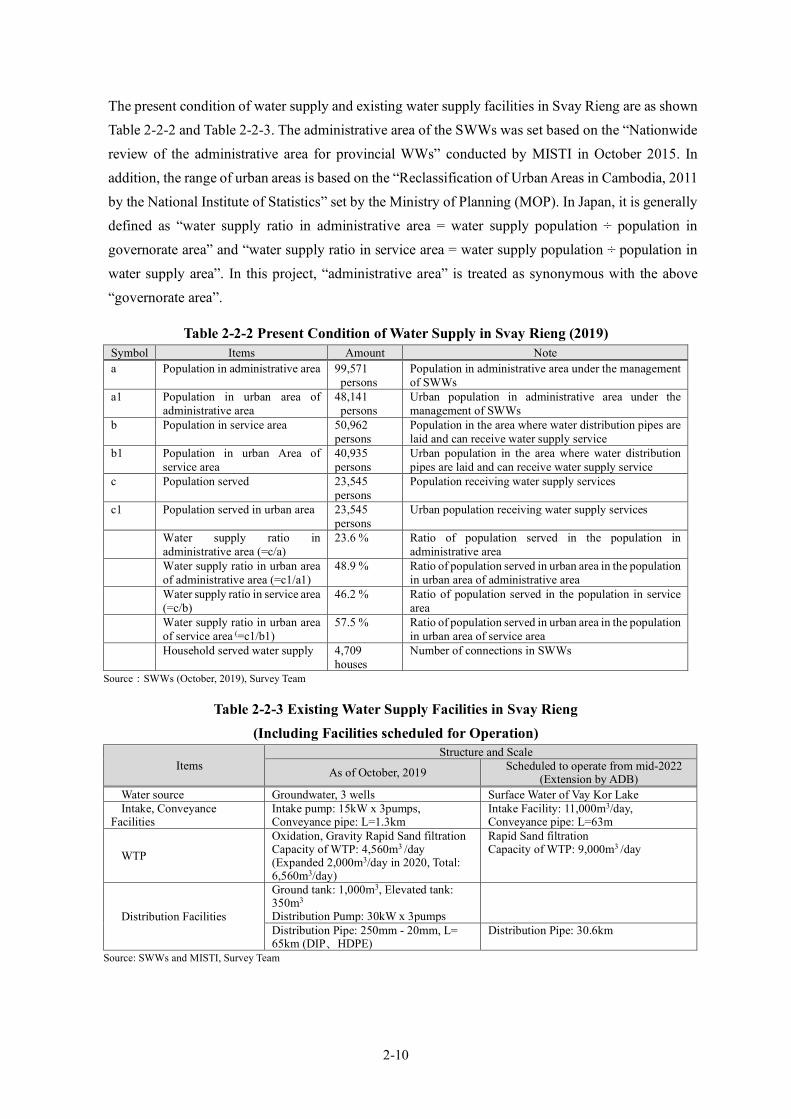
2-10
The present condition of water supply and existing water supply facilities in Svay Rieng are as shown Table 2-2-2 and Table 2-2-3. The administrative area of the SWWs was set based on the “Nationwide review of the administrative area for provincial WWs” conducted by MISTI in October 2015. In addition, the range of urban areas is based on the “Reclassification of Urban Areas in Cambodia, 2011 by the National Institute of Statistics” set by the Ministry of Planning (MOP). In Japan, it is generally defined as “water supply ratio in administrative area = water supply population ÷ population in governorate area” and “water supply ratio in service area = water supply population ÷ population in water supply area”. In this project, “administrative area” is treated as synonymous with the above “governorate area”.
Table 2-2-2 Present Condition of Water Supply in Svay Rieng (2019) Symbol Items Amount Note a Population in administrative area 99,571
persons Population in administrative area under the management of SWWs
a1 Population in urban area of administrative area
48,141 persons
Urban population in administrative area under the management of SWWs
b Population in service area 50,962 persons
Population in the area where water distribution pipes are laid and can receive water supply service
b1 Population in urban Area of service area
40,935 persons
Urban population in the area where water distribution pipes are laid and can receive water supply service
c Population served 23,545 persons
Population receiving water supply services
c1 Population served in urban area 23,545 persons
Urban population receiving water supply services
Water supply ratio in administrative area (=c/a)
23.6 % Ratio of population served in the population in administrative area
Water supply ratio in urban area of administrative area (=c1/a1)
48.9 % Ratio of population served in urban area in the population in urban area of administrative area
Water supply ratio in service area
(=c/b) 46.2 % Ratio of population served in the population in service
area Water supply ratio in urban area
of service area (=c1/b1) 57.5 % Ratio of population served in urban area in the population
in urban area of service area Household served water supply 4,709
houses Number of connections in SWWs
Source:SWWs (October, 2019), Survey Team
Table 2-2-3 Existing Water Supply Facilities in Svay Rieng (Including Facilities scheduled for Operation)
Items Structure and Scale
As of October, 2019 Scheduled to operate from mid-2022 (Extension by ADB)
Water source Groundwater, 3 wells Surface Water of Vay Kor Lake Intake, Conveyance
Facilities Intake pump: 15kW x 3pumps, Conveyance pipe: L=1.3km
Intake Facility: 11,000m3/day, Conveyance pipe: L=63m
WTP
Oxidation, Gravity Rapid Sand filtration Capacity of WTP: 4,560m3 /day (Expanded 2,000m3/day in 2020, Total: 6,560m3/day)
Rapid Sand filtration Capacity of WTP: 9,000m3 /day
Distribution Facilities
Ground tank: 1,000m3, Elevated tank: 350m3 Distribution Pump: 30kW x 3pumps
Distribution Pipe: 250mm - 20mm, L= 65km (DIP、HDPE)
Distribution Pipe: 30.6km
Source: SWWs and MISTI, Survey Team
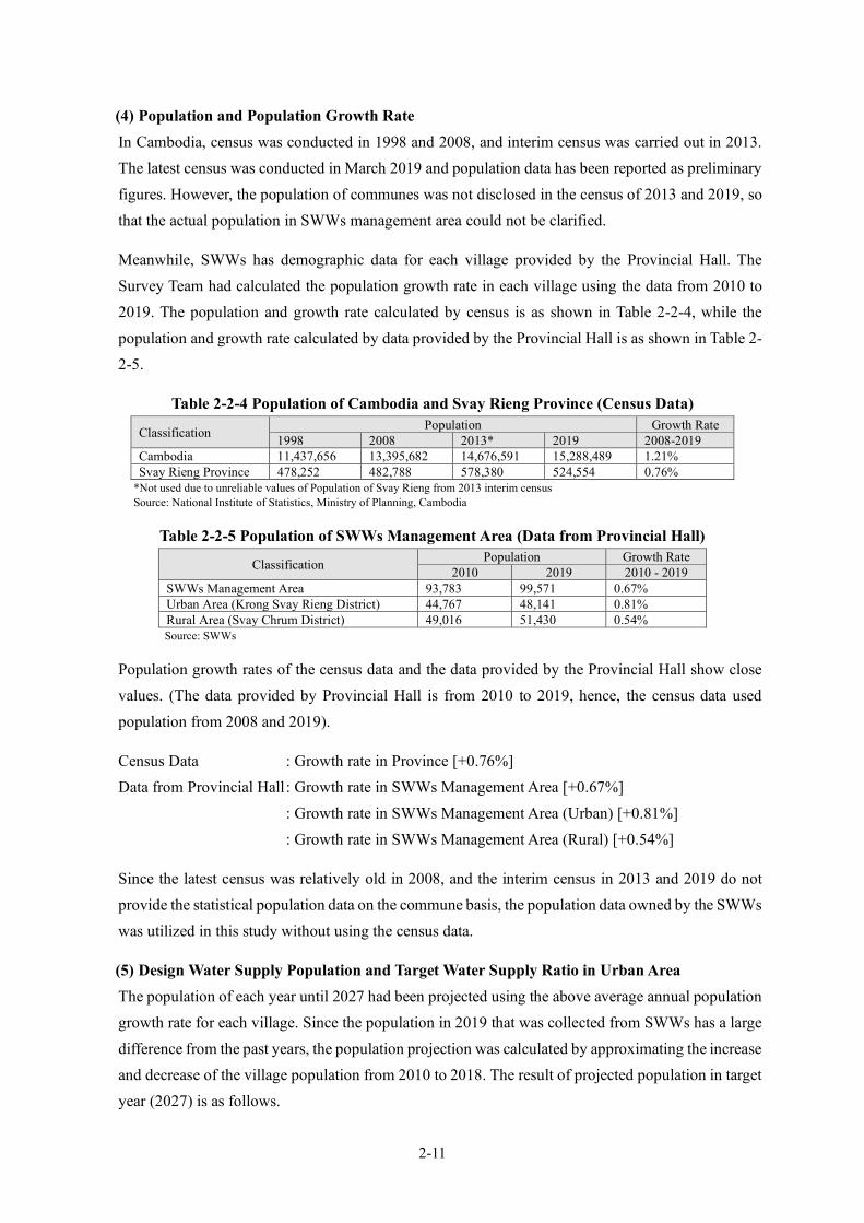
2-11
(4) Population and Population Growth Rate In Cambodia, census was conducted in 1998 and 2008, and interim census was carried out in 2013. The latest census was conducted in March 2019 and population data has been reported as preliminary figures. However, the population of communes was not disclosed in the census of 2013 and 2019, so that the actual population in SWWs management area could not be clarified.
Meanwhile, SWWs has demographic data for each village provided by the Provincial Hall. The Survey Team had calculated the population growth rate in each village using the data from 2010 to 2019. The population and growth rate calculated by census is as shown in Table 2-2-4, while the population and growth rate calculated by data provided by the Provincial Hall is as shown in Table 2-2-5.
Table 2-2-4 Population of Cambodia and Svay Rieng Province (Census Data)
Classification Population Growth Rate 1998 2008 2013* 2019 2008-2019
Cambodia 11,437,656 13,395,682 14,676,591 15,288,489 1.21% Svay Rieng Province 478,252 482,788 578,380 524,554 0.76%
*Not used due to unreliable values of Population of Svay Rieng from 2013 interim census Source: National Institute of Statistics, Ministry of Planning, Cambodia
Table 2-2-5 Population of SWWs Management Area (Data from Provincial Hall)
Classification Population Growth Rate 2010 2019 2010 - 2019
SWWs Management Area 93,783 99,571 0.67% Urban Area (Krong Svay Rieng District) 44,767 48,141 0.81% Rural Area (Svay Chrum District) 49,016 51,430 0.54% Source: SWWs
Population growth rates of the census data and the data provided by the Provincial Hall show close values. (The data provided by Provincial Hall is from 2010 to 2019, hence, the census data used population from 2008 and 2019).
Census Data : Growth rate in Province [+0.76%] Data from Provincial Hall : Growth rate in SWWs Management Area [+0.67%] : Growth rate in SWWs Management Area (Urban) [+0.81%] : Growth rate in SWWs Management Area (Rural) [+0.54%]
Since the latest census was relatively old in 2008, and the interim census in 2013 and 2019 do not provide the statistical population data on the commune basis, the population data owned by the SWWs was utilized in this study without using the census data.
(5) Design Water Supply Population and Target Water Supply Ratio in Urban Area The population of each year until 2027 had been projected using the above average annual population growth rate for each village. Since the population in 2019 that was collected from SWWs has a large difference from the past years, the population projection was calculated by approximating the increase and decrease of the village population from 2010 to 2018. The result of projected population in target year (2027) is as follows.
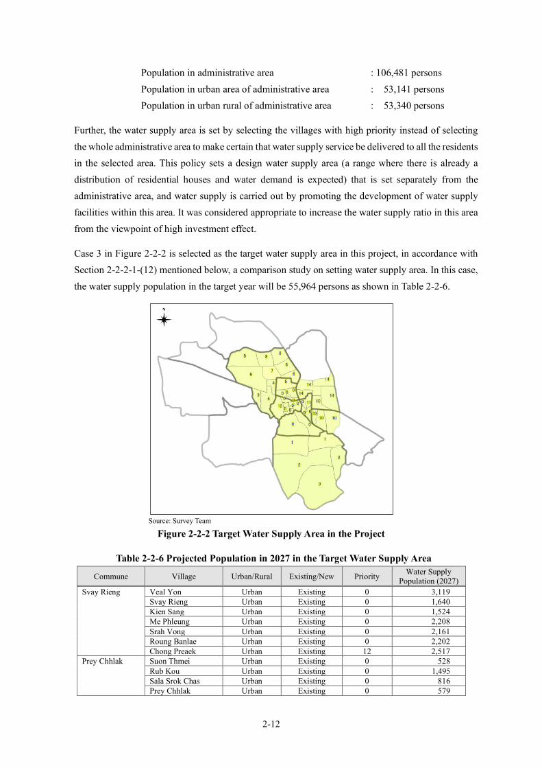
2-12
Population in administrative area : 106,481 persons Population in urban area of administrative area : 53,141 persons Population in urban rural of administrative area : 53,340 persons
Further, the water supply area is set by selecting the villages with high priority instead of selecting the whole administrative area to make certain that water supply service be delivered to all the residents in the selected area. This policy sets a design water supply area (a range where there is already a distribution of residential houses and water demand is expected) that is set separately from the administrative area, and water supply is carried out by promoting the development of water supply facilities within this area. It was considered appropriate to increase the water supply ratio in this area from the viewpoint of high investment effect.
Case 3 in Figure 2-2-2 is selected as the target water supply area in this project, in accordance with Section 2-2-2-1-(12) mentioned below, a comparison study on setting water supply area. In this case, the water supply population in the target year will be 55,964 persons as shown in Table 2-2-6.
Source: Survey Team
Figure 2-2-2 Target Water Supply Area in the Project
Table 2-2-6 Projected Population in 2027 in the Target Water Supply Area
Commune Village Urban/Rural Existing/New Priority Water Supply Population (2027)
Svay Rieng Veal Yon Urban Existing 0 3,119 Svay Rieng Urban Existing 0 1,640 Kien Sang Urban Existing 0 1,524 Me Phleung Urban Existing 0 2,208 Srah Vong Urban Existing 0 2,161 Roung Banlae Urban Existing 0 2,202 Chong Preaek Urban Existing 12 2,517
Prey Chhlak Suon Thmei Urban Existing 0 528 Rub Kou Urban Existing 0 1,495 Sala Srok Chas Urban Existing 0 816 Prey Chhlak Urban Existing 0 579

2-13
Commune Village Urban/Rural Existing/New Priority Water Supply Population (2027)
Andoung Ta Sei Urban Existing 5 955 Koy Trabaek Koy Trabaek Urban Existing 0 2,217
Tarang Bal Urban Existing 0 1,568 Pou Ta Hao Kbal Spean Urban Existing 0 395
Thnal Kaeng Urban Existing 11 836 La Urban Existing 0 1,942 Pou Ta Hao Urban Existing 0 265
Chek Chek Urban New 8 1,791 Chambak Urban New 9 1,866 Svay Urban New 9 1,249 Thmol Urban Existing 4 1,181 Svat Urban Existing 4 184 Totea Urban New 7 1,838 Kandal Urban New 6 466 Meloung Urban New 6 798 Khleang Urban New 8 694 Kok Pae Urban New 8 674
Svay Toea Ta Chour Urban Existing 10 397 Ta Nar Urban Existing 10 1,649 Khousang Urban New 10 931
Sangkhoar Bak Ronoas Urban Existing 14 1,209 Thlok Urban New 14 813 Chambak Peam Urban New 14 693 Thmei Urban Existing 10 1,942 Srama Chrum Urban New 14 746
Basak Svay Ta Phlo Rural New 1 1,922 Sala Rien Rural New 2 2,509 Payab Rural New 3 2,224 Basak Rural New 1 1,898 Pou Ta Ros Rural New 2 1,299
Total 55,964 Source: Survey Team
(6) Changes in Water Supply Ratio and Water Supply Area by Implementation of the Project The population in the administrative area in 2027 is projected as 106,481 persons, and water supply ratio in the administrative area is calculated as 52.6% even after the implementation of this project.
The reason why the water supply ratio remains at around 50% even after the project implementation is that when a specific area within the whole administrative area is set as a design water supply area, it is limited to the area where efficient water distribution is possible, because there is a continuous distribution of currently existing residential houses, and reliable water demand is expected. However, since the population in the administrative urban area is projected as 53,141 persons and the population served in the urban area is projected as 46,088 persons, the water supply ratio in the urban administrative area is estimated as 86.7%. This value approaches the above-mentioned target of 100% water supply ratio in urban areas by 2025, which is the disseminated target in MISTI.

2-14
Table 2-2-7 Comparison of Water Supply Ratio by Effectiveness of the Project
Symbol Items Present (2019)
At the stage of ADB facility expansion
(Scheduled in 2022)
After the Project (2027)
Benefit from the Project (Increment
from 2019)
- Water Supply Capacity
6,560 m3/day =4,560 m3/day
+ 2,000 m3/day*1
15,560 m3/day =6,560 m3/day
+ 9,000 m3/day *2
22,360 m3/day =15,560 m3/day + 6,800 m3/day
6,800 m3/day
a Population in Administrative Area
99,571 persons 102,660 persons 106,481 persons -
a1 (Urban Area) 48,141 persons 50,643 persons 53,141 persons - a2 (Rural Area) 51,430 persons 52,017 persons 53,340 persons -
b Population in Service Area
50,962 persons 62,380 persons =53,530+8,850
persons *3
65,368 persons =55,964+9,404
persons -
b1 (Urban Area) 40,935 persons 43,771 persons 46,088 persons -
b2 (Rural Area) 10,027 persons 18,609 persons =9,759+8,850
persons
19,280 persons =9,876+9,404
persons -
c Population Served 23,545 persons 32,395 persons =23,545+8,850
persons
65,368 persons =55,964+9,404
persons + 32,419 persons
c1 (Urban Area) 23,545 persons 23,545 persons 46,088 persons + 22,543 persons
c2 (Rural Area) 0 persons 8,850 persons 19,280 persons
9,876+9,404 persons
+ 9,876 persons
Household Served Water Supply
JICA 4,709 houses 4,709 houses 12,087=55,964/4.63
persons + 7,378houses
ADB 1,911=8,850/4.63
houses 2,031=9,404/4.63
houses
Total 4,709 houses 6,620 houses 14,118 houses
e=(c/a) x100
Water Supply Ratio in Administrative Area
JICA 23.6 %
=23,545/99,571 22.9%
=23,545/102,660 52.6%
=55,964/106,481 + 29.0 %
ADB 8.6%
=8,850/102,660 8.8%
=9,404/106,481
Total 23.6 % 31.5 % 61.4%
f=(b/c) x100
Water Supply Ratio in Service Area
JICA 46.2 %
=23,545/50,962 44.0 %
=23,545/53,530 100.0 %
=55,964/55,964 + 53.8 %
ADB 100.0 %
=8,850/8,850 100.0 %
=9,404/9,404
Total 51.9%
= (23,545+8,850 /53,530+8,850)
100.0 % = (55,964+9,404
/55,964+9,404)
g=(a1/c1) x100
Water Supply Ratio in Urban Area of Administrative Area
48.9 % =23,545/48,141
46.5 % =23,545/50,643
86.7 % =46,088/53,141
+ 37.8 %
Note: *1 It is an expansion facility of an existing WTP by the Cambodian side, and has been in operation since April 2020. *2The Cambodian side (ADB) is expanding the existing water purification plant, and the operation is scheduled to start in the middle of 2022. *3Blue text indicates information in the design water supply area of ADB project. These values are under the condition that the household connection of each household in the priority water supply area will be completed within 2022. Source: Survey Team

2-15
Source: Survey Team
Figure 2-2-3 Design Water Supply Area and Administrative Area in Svay Rieng
On the other hand, the WTP with a capacity of 9000m3/day, that was been expanded by ADB and scheduled to start operation from the middle of 2022 aims to supply water to the four (4) communes (Svay Chrum, Ta Sous, Por Reach and Kampong Chamlorng) located to the western side of the administrative area as shown in Figure 2-2-3 above.
For the time being, the priority water supply areas are the three (3) villages in the Svay Chrum commune (Thma Sa, Trabaek, Svay Kngao) and the three (3) villages in the Ta Sous commune (Pnov, Angkeas Dei, Ta Pa). The distribution pipe of 30.6km will be laid to supply water to these priority areas.
The water supply population in the target year (2027) of the water supply area that has been preferentially expanded by the ADB is expected to be 9,404 persons. If these water supply populations are added to the water supply population from the implementation of this project, the water supply ratio of 52.6% in the above-mentioned administrative area will increase to 61.4%.

2-16
In addition, it was confirmed in the meeting of M/D in April 2021 that the water supply area from the WTP which was be constructed by JICA and the water supply area from the WTP to be constructed by ADB do not overlap.
(7) Unit (Amount of Water Supply per Person per Day) The average amount of water used by one person per day calculated from the water supply population and the average amount of water used in a single day at home is as shown in Table 2-2-8.
Table 2-2-8 Average Water Consumption per Person per Day for Domestic Use Item Unit 2010 2011 2012 2013 2014 2015 2016 2017 2018 2019*1
Average domestic water consumption per day m3/day 749 912 1,015 1,268 1,544 1,880 2,319 2,632 3,016 3,430
Population Served Persons 7,240 7,630 8,960 10,690 12,745 14,685 17,765 20,020 21,975 23,545 Average domestic water consumption per person per day
L/day/person 103.4 119.5 113.3 118.6 121.1 128.0 130.5 131.5 136.1 145.7
Average domestic water consumption per person per day for last 10 years
L/day/person 124.8
Average domestic water consumption per person per day for last 5 years
L/day/person 115.2 134.4
*1: Data as of October 2019 Source: SWWs
According to the water supply records of SWWs, the unit average for the last 10 years is 124.8 L/day/person, which is increasing year by year.
Factors for increase of Unit include the following: 1) Increase of urban water supply population, 2) Increase of household income, 3) Changes in lifestyle, and so on. However, this increase of unit is only for existing water supply area, since there is a difference of household income and lifestyle between the existing water supply area and the target water supply urban area. Therefore, the Unit shall be set, respectively.
As the result of discussions with the SWWs, the Unit for existing water supply areas is 135 L/day/person, which is the average for the last 5 years (2015 – 2019), and the Unit for new water supply areas is 115 L/day/person, which is the average for the past 5 years (2010 – 2014). Although the average of water consumption is increasing year by year, the average value is adopted for the following reasons:
• According to the 2017 social condition survey conducted by the Survey Team, many households that are connected to the existing water supply belong to the wealthier class. In the target year of this project, 2027, water supply will be served to all households in the area. Therefore, it includes not only the rich but also the poor households. Considering the differences of lifestyle between these classes, it is not reasonable to assume a trend of increase evenly until 2027.
• In the new water supply area, the size of house and lifestyle is significantly different from the existing water supply area. Besides, the water demand in the new supply area is totally different from the water demand in the existing supply area. Therefore, the water demand of the new

2-17
supply area should adopt the water demand value during the period when the population served was few.
• As described in Section 2-2-2-1-(9), the value of Non-Revenue-Water ratio is set higher (smaller effective rate) than the actual NRW ratio, so that the design is on safer side for the required amount of water. Therefore, the design water supply amount calculated based on the existing water supply area with unit of 135L/day/person is expected to have a certain surplus amount against actual water demand.
(8) Average Water Consumption per Day for Industrial and Commercial Use Daily water consumption classified by application is as shown in Table 2-2-9.
As the result of interviews with the SWWs and the Svay Rieng Provincial Hall, the following situations for industrial and commercial water use in administrative area were found:
• There was a plan to construct a new market by reclaiming the eastern part of Lake Vay Kor. However, according to interviews with the SWWs and the Provincial Hall, the market construction plan has been canceled due to no progress of land expropriation.
• There is a clothing factory in the industrial estate about 4 km west from the city center. However, factories will not use public water services because they have their own groundwater sources.
• There are no detailed development plans about the expansion of industrial estates.
In Svay Rieng, the ratio of domestic water consumption to the total water consumption tends to increase due to the rapid increase in the water supply population. The main customers for non-domestic connection are restaurants, guest houses, schools, ice factories, and so on. In addition, there is no concrete plan to construct large-scale schools such as universities, factories, etc., with high water demand. Since the amount of water consumption by application is set based on 78.2%, which is the average ratio of domestic consumption for the past 5 years, the amount of domestic water consumption is set as 80% of the total amount, and non-domestic water consumption is set as 20% of total amount.

2-18
Table 2-2-9 Daily Water Consumption Classified by Application Item Unit 2010 2011 2012 2013 2014 2015 2016 2017 2018 2019 Average
Domestic m3/day 749 912 1,015 1,268 1,544 1,880 2,319 2,632 3,016 3,430 1,877 Commercial m3/ day 188 194 308 349 388 330 326 359 276 276 299 Public m3/ day 221 226 259 273 319 326 376 389 449 509 335 Total m3/ day 1,158 1,332 1,582 1,890 2,251 2,536 3,021 3,380 3,741 4,215 2,511 Non-Domestic Subtotal
m3/ day 409 420 567 622 707 656 702 748 725 785 634
Ratio of Domestic % 64.7 68.5 64.2 67.1 68.6 74.1 76.8 77.9 80.6 81.4 73.8
Ratio of Non-Domestic % 35.3 31.5 35.8 32.9 31.4 25.9 23.2 22.1 19.4 18.6 27.6
Average ratio of domestic consumption
% 78.2
Yearly Increase of Non-Domestic Consumption
m3/ day 11 147 55 85 -51 46 46 -23 60 41.7m3/day/year
Source: SWWs
(9) Leakage Ratio and Effective Water Ratio According to the actual data of SWWs, NRW ratio is decreasing year by year from 24.3% in 2010 to 8.9% in 2019 as shown in Table 2-2-10.
This achievement is due to the improvement of the capacity of operation and maintenance of SWWs through the support of the JICA project, “The Project on Capacity Building for Urban Water Supply System (Phase 2 and 3)”.
Non-revenue water consists of unbilled authorized consumption, apparent loss (illegal connections, inaccuracies of meter, data handling errors, etc.) and real loss (leakages of distribution pipes, service connections, meters and tanks). However, the amount of leakage, which accounts for most of the real loss, has not been calculated by the SWWs. In addition, illegal connections are not found in the recent SWWs operations.
Based on the above, the amount ratio of leakage water within NRW amount is 75% with reference to the records of WWs2 having 10% NRW ratio. On the other hand, the Cambodian government has set the NRW ratio as 15% for determining the design capacity of new WTP due to the following reasons:
• NRW ratio is likely to increase in the future due to the aging of existing pipes. • The exact portion of leakages in NRW is unknown and uncertain.
Based on the above, assuming that the amount of leakage is 75% of the NRW amount, the leakage ratio for 2027, the target year shall be set at 11.3% (15% x 75%), and the effective water rate shall be set at 88.7%.
2 Few countries calculate the amount of water leakage in the amount of non-revenue water. It was judged comprehensively from the estimation results of the non-revenue water rate and water leakage rate of Japanese entities conducted by the Japan Water Research Center in 2014 and the interview surveys with MISTI.
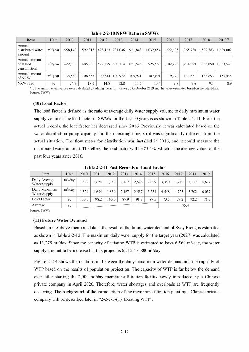
2-19
Table 2-2-10 NRW Ratio in SWWs Items Unit 2010 2011 2012 2013 2014 2015 2016 2017 2018 2019*1
Annual distributed water amount
m3/year 558,140 592,817 678,423 791,086 921,848 1,032,654 1,222,695 1,365,730 1,502,783 1,689,002
Annual amount of Billed consumption
m3/year 422,580 485,931 577,779 690,114 821,546 925,563 1,102,723 1,234,099 1,365,890 1,538,547
Annual amount of NRW m3/year 135,560 106,886 100,644 100,972 105,921 107,091 119,972 131,631 136,893 150,455
NRW ratio % 24.3 18.0 14.8 12.8 11.5 10.4 9.8 9.6 9.1 8.9 *1: The annual actual values were calculated by adding the actual values up to October 2019 and the value estimated based on the latest data. Source: SWWs
(10) Load Factor The load factor is defined as the ratio of average daily water supply volume to daily maximum water supply volume. The load factor in SWWs for the last 10 years is as shown in Table 2-2-11. From the actual records, the load factor has decreased since 2016. Previously, it was calculated based on the water distribution pump capacity and the operating time, so it was significantly different from the actual situation. The flow meter for distribution was installed in 2016, and it could measure the distributed water amount. Therefore, the load factor will be 75.4%, which is the average value for the past four years since 2016.
Table 2-2-11 Past Records of Load Factor Item Unit 2010 2011 2012 2013 2014 2015 2016 2017 2018 2019
Daily Average Water Supply
m3/day 1,529 1,624 1,859 2,167 2,526 2,829 3,350 3,742 4,117 4,627
Daily Maximum Water Supply
m3/day 1,529 1,654 1,859 2,467 2,557 3,234 4,558 4,725 5,702 6,037
Load Factor % 100.0 98.2 100.0 87.9 98.8 87.5 73.5 79.2 72.2 76.7 Average % 75.4
Source: SWWs
(11) Future Water Demand Based on the above-mentioned data, the result of the future water demand of Svay Rieng is estimated as shown in Table 2-2-12. The maximum daily water supply for the target year (2027) was calculated as 13,275 m3/day. Since the capacity of existing WTP is estimated to have 6,560 m3/day, the water
supply amount to be increased in this project is 6,715 ≅ 6,800m3/day.
Figure 2-2-4 shows the relationship between the daily maximum water demand and the capacity of WTP based on the results of population projection. The capacity of WTP is far below the demand even after starting the 2,000 m3/day membrane filtration facility newly introduced by a Chinese private company in April 2020. Therefore, water shortages and overloads at WTP are frequently occurring. The background of the introduction of the membrane filtration plant by a Chinese private company will be described later in “2-2-2-5-(1), Existing WTP”.

2-20
Actu
al ←
→ P
roje
ctio
n
Uni
t20
1220
1320
1420
1520
1620
1720
1820
1920
2020
2120
2220
2320
2420
2520
2620
27
Popu
latio
n in
Adm
inis
trativ
e Ar
eaTo
tal
person
95,1
6895
,357
96,7
6397
,545
97,5
4599
,301
99,3
0199
,571
101,
130
101,
892
102,
660
103,
423
104,
192
104,
954
105,
714
106,
481
Urb
anpe
rson
45,4
9546
,132
46,6
9847
,296
47,2
9648
,419
48,4
1948
,141
49,6
4650
,143
50,6
4351
,143
51,6
4852
,145
52,6
4053
,141
Rura
lpe
rson
49,6
7349
,225
50,0
6550
,249
50,2
4950
,882
50,8
8251
,430
51,4
8451
,749
52,0
1752
,280
52,5
4452
,809
53,0
7453
,340
Popu
latio
n in
Wat
er S
uppl
y Ar
eaTo
tal
pers
on48
,542
49,1
4449
,651
50,2
0150
,201
51,4
1451
,414
50,9
6252
,559
53,0
4353
,530
54,0
1854
,509
54,9
9355
,477
55,9
64U
rban
pers
on39
,024
39,6
2540
,109
40,6
4940
,649
41,7
1041
,710
40,9
3542
,849
43,3
0943
,771
44,2
3644
,704
45,1
6545
,625
46,0
88Ru
ral
pers
on9,
518
9,51
99,
542
9,55
29,
552
9,70
49,
704
10,0
279,
710
9,73
49,
759
9,78
29,
805
9,82
89,
852
9,87
6Po
pula
tion
in W
ater
Sup
ply
Area
Tota
lpe
rson
48,5
4249
,144
49,6
5150
,201
50,2
0151
,414
51,4
1450
,962
52,5
5953
,043
53,5
3054
,018
54,5
0954
,993
55,4
7755
,964
Exis
ting
Area
pers
on27
,530
28,1
0028
,477
28,9
5528
,955
29,8
5729
,857
28,9
6630
,808
31,1
9431
,583
31,9
7332
,366
32,7
5333
,140
33,5
29N
ew A
rea
pers
on21
,012
21,0
4421
,174
21,2
4621
,246
21,5
5721
,557
21,9
9621
,751
21,8
4921
,947
22,0
4522
,143
22,2
4022
,337
22,4
35W
ater
Sup
ply
Popu
latio
nTo
tal
pers
on8,
960
10,6
9012
,745
14,6
8517
,765
20,0
2022
,160
23,5
4525
,830
27,8
0229
,764
31,7
3640
,882
43,9
9449
,929
55,9
64U
rban
pers
on8,
960
10,6
9012
,745
14,6
8517
,765
20,0
2022
,160
23,5
4525
,830
27,8
0229
,764
31,7
3633
,528
36,1
3241
,063
46,0
88Ru
ral
pers
on0
7,35
47,
862
8,86
79,
876
Wat
er S
uppl
y Po
pula
tion
Tota
lpe
rson
8,96
010
,690
12,7
4514
,685
17,7
6520
,020
22,1
6023
,545
25,8
3027
,802
29,7
6431
,736
40,8
8243
,994
49,9
2955
,964
Exis
ting
Area
pers
on8,
960
10,6
9012
,745
14,6
8517
,765
20,0
2022
,160
23,5
4525
,830
27,8
0229
,764
31,7
3631
,736
31,7
3631
,736
33,5
29N
ew A
rea
pers
on0
9,14
612
,258
18,1
9322
,435
Tota
l%
9.4
11.2
13.2
15.1
18.2
20.2
22.3
23.6
25.5
27.3
29.0
30.7
39.2
41.9
47.2
52.6
Urb
an%
19.7
23.2
27.3
31.0
37.6
41.3
45.8
48.9
52.0
55.4
58.8
62.1
64.9
69.3
78.0
86.7
Rura
l%
0.0
0.0
0.0
0.0
0.0
0.0
0.0
0.0
0.0
0.0
0.0
0.0
14.0
14.9
16.7
18.5
Tota
l%
18.5
21.8
25.7
29.3
35.4
38.9
43.1
46.2
49.1
52.4
55.6
58.8
75.0
80.0
90.0
100.
0U
rban
%23
.027
.031
.836
.143
.748
.053
.157
.560
.364
.268
.071
.775
.080
.090
.010
0.0
Rura
l%
0.0
0.0
0.0
0.0
0.0
0.0
0.0
0.0
0.0
0.0
0.0
0.0
75.0
80.0
90.0
100.
0W
ater
Sup
ply
Hou
seho
ldTo
tal
hous
e1,
792
2,13
82,
549
2,93
73,
553
4,00
44,
432
4,70
95,
579
6,00
56,
429
6,85
48,
830
9,50
210
,784
12,0
87Ex
istin
g Ar
eaho
use
1,79
22,
138
2,54
92,
937
3,55
34,
004
4,43
24,
709
5,57
96,
005
6,42
96,
854
6,85
46,
854
6,85
47,
242
New
Are
aho
use
00
00
00
00
00
00
1,97
52,
648
3,92
94,
846
L/da
y/pe
rson
113.
311
8.6
121.
112
8.0
130.
513
1.5
136.
114
5.7
135.
013
5.0
135.
013
5.0
135.
013
5.0
135.
013
5.0
m3/
day
1,01
51,
268
1,54
41,
880
2,31
92,
632
3,01
63,
430
3,48
73,
753
4,01
84,
284
4,28
44,
284
4,28
44,
526
L/da
y/pe
rson
115.
011
5.0
115.
011
5.0
115.
011
5.0
115.
011
5.0
m3/
day
00
00
1,05
21,
410
2,09
22,
580
m3/
day
1,01
51,
268
1,54
41,
880
2,31
92,
632
3,01
63,
430
3,48
73,
753
4,01
84,
284
5,33
65,
694
6,37
67,
106
m3/
day
567
622
707
655
702
748
725
785
872
938
1,00
51,
071
1,33
41,
424
1,59
41,
777
m3/
day
1,58
21,
890
2,25
12,
535
3,02
13,
380
3,74
14,
215
4,35
94,
691
5,02
35,
355
6,67
07,
118
7,97
08,
883
m3/
day
207
207
206
220
247
270
281
309
553
595
637
679
845
902
1,01
01,
126
m3/
day
1,85
92,
167
2,52
62,
829
3,35
03,
742
4,11
74,
627
4,91
25,
286
5,66
06,
034
7,51
58,
020
8,98
010
,009
L/da
y/pe
rson
207
203
198
193
189
187
186
197
190
190
190
190
184
182
180
179
m3/
day
1,85
92,
467
2,55
73,
234
4,55
84,
725
5,70
26,
037
6,51
47,
010
7,50
68,
002
9,96
710
,637
11,9
1013
,275
L/da
y/pe
rson
207
231
201
220
257
236
257
256
252
252
252
252
244
242
239
237.
2%
85.2
87.2
89.1
89.6
90.2
90.4
90.9
91.1
89.2
89.2
89.2
89.2
89.2
89.2
89.2
89.2
%88
.990
.491
.892
.292
.692
.893
.293
.388
.888
.888
.888
.888
.888
.888
.888
.8%
11.1
9.6
8.2
7.8
7.4
7.2
6.8
6.7
11.3
11.3
11.3
11.3
11.3
11.3
11.3
11.3
%10
0.0
87.9
98.8
87.5
73.5
79.2
72.2
76.7
75.4
75.4
75.4
75.4
75.4
75.4
75.4
75.4
m3/
day
4,56
04,
560
4,56
04,
560
4,56
04,
560
4,56
04,
560
6,56
06,
560
6,56
06,
560
6,56
06,
560
6,56
06,
560
m3/
day
- 2,7
01- 2
,093
- 2,0
03- 1
,326
- 216
51,
142
1,47
7- 4
645
094
61,
442
3,40
74,
077
5,35
06,
715
Effe
ctiv
e W
ater
Rat
ioLe
akag
e W
ater
Rat
ioLo
ad F
acto
rCo
nstru
ctio
n Pe
riod
Exis
ting
WTP
Cap
acity
Capa
city
requ
ired
by th
is P
roje
ct
Inef
fect
ive
Wat
er A
mou
ntD
aily
Ave
rage
Wat
er S
uppl
y Am
ount
Aver
age
Wat
er C
onsu
mpt
ion
per p
erso
n pe
r day
D
aily
Max
imum
Wat
er S
uppl
y Am
ount
Max
imum
Wat
er C
onsu
mpt
ion
per p
erso
n pe
r day
Reve
nue
Wat
er R
atio
Aver
age
Wat
er C
onsu
mpt
ion
per p
erso
n pe
r day
for D
omes
tic (N
ew)
Aver
age
Wat
er C
onsu
mpt
ion
per d
ay fo
r Dom
estic
(New
)Av
erag
e W
ater
Con
sum
ptio
n pe
r day
for D
omes
tic (T
otal
)Av
erag
e W
ater
Con
sum
ptio
n pe
r day
for N
on-D
omes
ticEf
fect
ive
Wat
er A
mou
nt
Aver
age
Wat
er C
onsu
mpt
ion
per p
erso
n pe
r day
for D
omes
tic (E
xist
ing)
Aver
age
Wat
er C
onsu
mpt
ion
per d
ay fo
r Dom
estic
(Exi
stin
g)
Wat
er S
uppl
y Ra
tio in
Wat
er S
uppl
y Ar
ea
Item
Wat
er S
uppl
y Ra
tio in
Adm
inis
trativ
e Ar
eaEx
istin
g A
rea
New
Are
a
Tabl
e 2-
2-12
Act
ual a
nd F
orec
ast T
able
of W
ater
Dem
and
in S
vay
Rie
ng
Sour
ce: S
urve
y Te
am
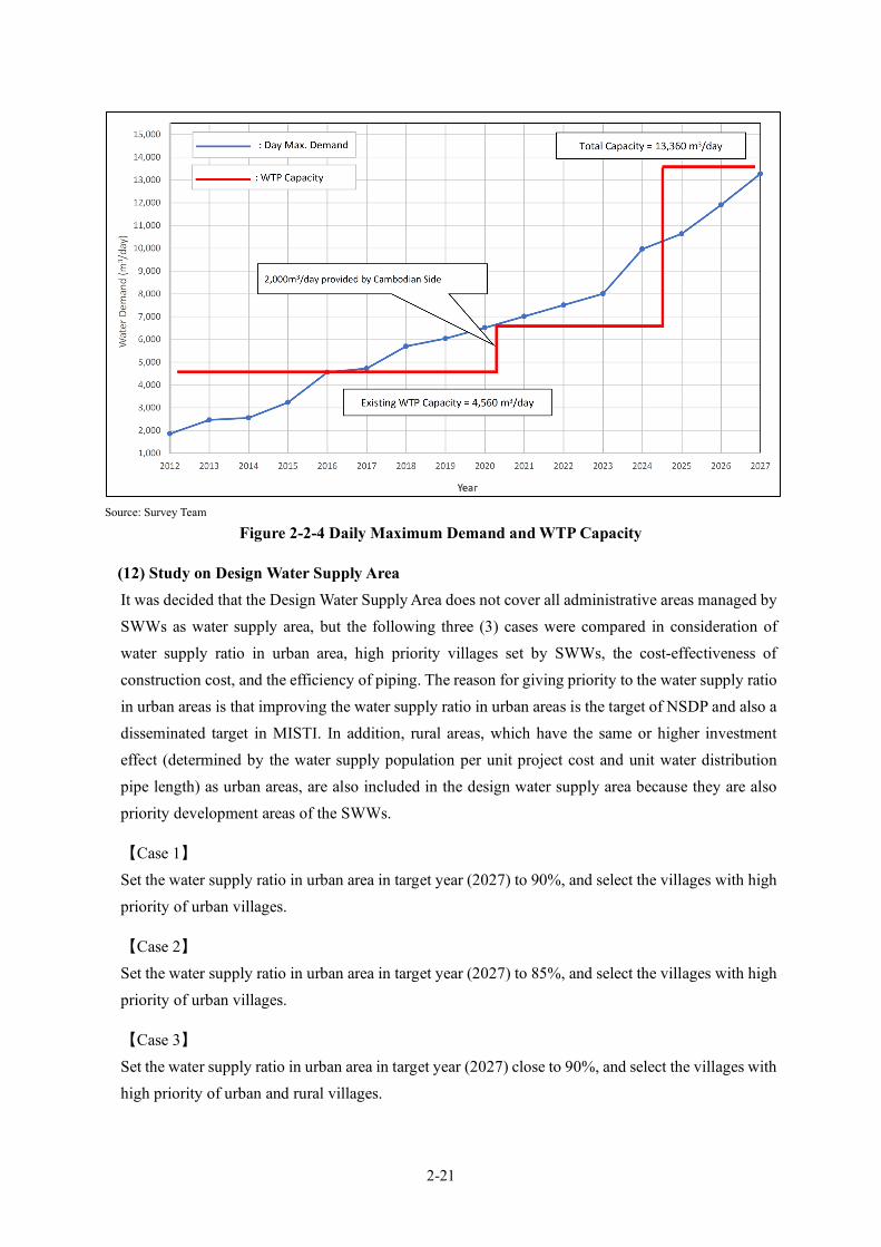
2-21
Source: Survey Team
Figure 2-2-4 Daily Maximum Demand and WTP Capacity
(12) Study on Design Water Supply Area It was decided that the Design Water Supply Area does not cover all administrative areas managed by SWWs as water supply area, but the following three (3) cases were compared in consideration of water supply ratio in urban area, high priority villages set by SWWs, the cost-effectiveness of construction cost, and the efficiency of piping. The reason for giving priority to the water supply ratio in urban areas is that improving the water supply ratio in urban areas is the target of NSDP and also a disseminated target in MISTI. In addition, rural areas, which have the same or higher investment effect (determined by the water supply population per unit project cost and unit water distribution pipe length) as urban areas, are also included in the design water supply area because they are also priority development areas of the SWWs.
【Case 1】 Set the water supply ratio in urban area in target year (2027) to 90%, and select the villages with high priority of urban villages.
【Case 2】 Set the water supply ratio in urban area in target year (2027) to 85%, and select the villages with high priority of urban villages.
【Case 3】 Set the water supply ratio in urban area in target year (2027) close to 90%, and select the villages with high priority of urban and rural villages.

2-22
The results of the comparative study are as shown in Table 2-2-13. Case 3 shall be adopted after comprehensively considering the beneficiary population, water supply ratio in urban area, piping efficiency and cost effectiveness.
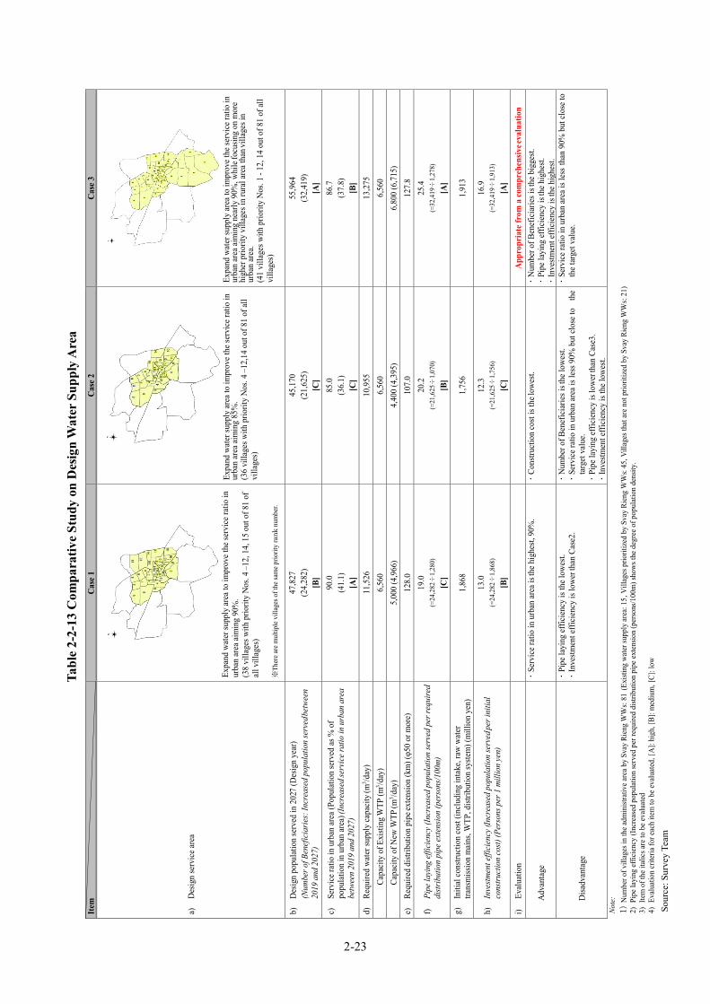
2-23
Item
C
ase 1
C
ase 2
C
ase 3
a)
Des
ign
serv
ice a
rea
Ex
pand
wat
er su
pply
area
to im
prov
e the
serv
ice r
atio
in
urba
n ar
ea ai
min
g 90
%.
(38
villa
ges w
ith p
riorit
y N
os. 4
–12,
14,
15
out o
f 81
of
all v
illag
es)
※Th
ere a
re m
ultip
le v
illag
es o
f the
sam
e prio
rity
rank
num
ber.
Ex
pand
wat
er su
pply
area
to im
prov
e the
serv
ice r
atio
in
urba
n ar
ea ai
min
g 85
%.
(36
villa
ges w
ith p
riorit
y N
os. 4
–12,
14 o
ut o
f 81
of al
l vi
llage
s)
Ex
pand
wat
er su
pply
area
to im
prov
e the
serv
ice r
atio
in
urba
n ar
ea ai
min
g ne
arly
90%
, whi
le fo
cusin
g on
mor
e hi
gher
prio
rity
villa
ges i
n ru
ral a
rea t
han v
illag
es in
ur
ban
area
. (4
1 vi
llage
s with
prio
rity
Nos
. 1 -
12, 1
4 ou
t of 8
1 of
all
villa
ges)
b)
Des
ign
popu
latio
n se
rved
in 2
027
(Des
ign
year
) (N
umbe
r of B
enef
icia
ries:
Incr
ease
d po
pula
tion
serv
ed be
twee
n 20
19 a
nd 2
027)
47,8
27
(24,
282)
[B
]
45,1
70
(21,
625)
[C
]
55,9
64
(32,
419)
[A
]
c)
Serv
ice r
atio
in u
rban
area
(Pop
ulat
ion
serv
ed as
% o
f po
pula
tion
in u
rban
area
) (In
crea
sed s
ervi
ce ra
tio in
urb
an a
rea
betw
een
2019
and
202
7)
90.0
(4
1.1)
[A
]
85.0
(3
6.1)
[C
]
86.7
(3
7.8)
[B
] d)
Re
quire
d w
ater
supp
ly ca
paci
ty (m
3 /day
) 11
,526
10
,955
13
,275
Capa
city
of E
xisti
ng W
TP (m
3 /day
) 6,
560
6,56
0 6,
560
Ca
paci
ty o
f New
WTP
(m3 /d
ay)
5,00
0 (4
,966
) 4,
400
(4,3
95)
6,80
0 (6
,715
) e)
Re
quire
d di
strib
utio
n pi
pe ex
tens
ion
(km
) (φ5
0 or
mor
e)
128.
0 10
7.0
127.
8
f) Pi
pe la
ying
effic
ienc
y (In
crea
sed
popu
latio
n se
rved
per
requ
ired
distr
ibut
ion
pipe
exte
nsio
n (p
erso
ns/1
00m
)
19.0
(=
24,2
82÷
1,28
0)
[C]
20.2
(=
21,6
25÷
1,07
0)
[B]
25.4
(=
32,4
19÷
1,27
8)
[A]
g)
Initi
al co
nstru
ctio
n co
st (in
clud
ing
inta
ke, r
aw w
ater
tra
nsm
issio
n m
ains
, WTP
, dist
ribut
ion
syste
m) (
mill
ion
yen)
1,86
8 1,
756
1,91
3
h)
Inve
stmen
t effi
cien
cy (I
ncre
ased
pop
ulat
ion
serv
ed pe
r ini
tial
cons
truct
ion
cost)
(Per
sons
per
1 m
illio
n ye
n)
13.0
(=
24,2
82÷
1,86
8)
[B]
12.3
(=
21,6
25÷
1,75
6)
[C]
16.9
(=
32,4
19÷
1,91
3)
[A]
i) Ev
alua
tion
App
ropr
iate
from
a co
mpr
ehen
sive e
valu
atio
n
A
dvan
tage
S
ervi
ce ra
tio in
urb
an ar
ea is
the h
ighe
st, 9
0%.
C
onstr
uctio
n co
st is
the l
owes
t.
Num
ber o
f Ben
efic
iarie
s is t
he b
igge
st.
Pip
e lay
ing
effic
ienc
y is
the h
ighe
st.
Inv
estm
ent e
ffici
ency
is th
e hig
hest.
D
isadv
anta
ge
Pip
e lay
ing
effic
ienc
y is
the l
owes
t. I
nves
tmen
t effi
cien
cy is
low
er th
an C
ase2
. N
umbe
r of B
enef
icia
ries i
s the
low
est.
Ser
vice
ratio
in u
rban
area
is le
ss 9
0% b
ut cl
ose t
o th
e ta
rget
val
ue.
Pip
e lay
ing
effic
ienc
y is
low
er th
an C
ase3
. I
nves
tmen
t effi
cien
cy is
the l
owes
t.
Ser
vice
ratio
in u
rban
area
is le
ss th
an 9
0% b
ut cl
ose t
o th
e tar
get v
alue
.
Note
: 1)
Num
ber o
f vill
ages
in th
e adm
inist
rativ
e are
a by
Svay
Rie
ng W
Ws:
81 (E
xisti
ng w
ater
supp
ly ar
ea: 1
5, V
illag
es p
riorit
ized
by
Svay
Rie
ng W
Ws:
45, V
illag
es th
at ar
e not
prio
ritiz
ed b
y Sv
ay R
ieng
WW
s: 21
) 2)
Pip
e lay
ing
effic
ienc
y (In
crea
sed
popu
latio
n se
rved
per
requ
ired
distr
ibut
ion
pipe
exte
nsio
n (p
erso
ns/1
00m
) sho
ws th
e deg
ree o
f pop
ulat
ion
dens
ity.
3) I
tem
of t
he it
alic
s are
to b
e eva
luat
ed
4) E
valu
atio
n cr
iteria
for e
ach
item
to b
e eva
luat
ed, [
A]:
high
, [B]
: med
ium
, [C]
: low
Tabl
e 2-
2-13
Com
para
tive
Stud
y on
Des
ign
Wat
er S
uppl
y A
rea
Sour
ce: S
urve
y Te
am

2-24
The basic design specifications of this project based on the above result for Svay Rieng are as listed in Table 2-2-14 and Table 2-2-15, respectively.
Table 2-2-14 Proposed Design Specifications of the Project (1) Item Unit Actual/Design Value
Present (2019)
Increase by the Project After Completion of the Project (2027)
Population in administrative area
person 99,571 - 106,481
Population in urban area of administrative area
person 48,141 - 53,141
Population in water supply area
person 50,962 - 55,964 (65,368)*
Water supply population person 23,545 32,419 55,964 (65,368)
No. of HHs connections house 4,709 7,378 12,087 (14,118)
Water supply ratio in administrative area
% 23.6 29.0
52.6 (61.4)
Water supply ratio in urban area of administrative area
% 48.9 37.8 86.7
Water supply ratio in water supply area
% 46.2 53.8 100.0
Water supply capacity m3/day 6,560 6,800 13,360 (22,360)
Length of distribution pipe km 65 111.8 176.8 (207.4)
Note: Values in parentheses indicate the case where the numerical value in the design water supply area to be expanded preferentially by the ADB WTP is included. Source: Survey Team
Table 2-2-15 Proposed Design Specifications of the Project (2) Item Unit Design Value
Design Water Supply Population (2027) person 55,964 Unit Consumption for Domestic Water L/day/person Existing Area: 135
New Area: 115 Domestic Water Demand m3/day 7,106 Non-domestic Ratio among whole Water Demand % 20.0 Non-domestic Water Demand m3/day 1,777 Total Water Demand (Domestic + Non-domestic)
m3/day 8,883
Leakage Ratio % 11.3 Design Daily Average Water Supply Amount m3/day 10,009 Load Factor % 75.4 Design Daily Maximum Water Supply Amount m3/day 13,275 Peak (Time) Factor - 1.3 (3 Design Hourly Maximum Water Supply Amount m3/hour 720
Source: Survey Team
3 The time coefficient of 1.30 above has been adopted based on the discussions with MISTI with reference to the actual value of 1.30 in the other similar cities in Cambodia.

2-25
2-2-2-2 New Surface Water Source
(1) Development of New Water Source
1) Vay Kor Lake and River The Vay Kor River passes through Svay Rieng in the southeastern part of the Mekong Delta in Cambodia from North to South. The basin area on the upstream side of Svay Rieng is about 1500 km2, and the river length is about 60 km. At the southern end of Svay Rieng is the Vay Kor Dam. This is an artificial reservoir built by damming the Vay Kor River for a length of about 20 km, a depth of 3 to 7 m, and a total water storage capacity of about 30 MCM (30 million m3).
Source: Survey Team
Figure 2-2-5 Vay Kor River and the Basin
2) Weather and Rainfall Conditions Table 2-2-16 shows the rainfall in Svay Rieng over the past 20 years. The average annual rainfall is about 1,480 mm, and the monthly rainfall during the dry season (November to April) is about 310 mm. The total rainfall for the six (6) months of the dry season from 2015 to 2016 has a minimum of 81.8 mm, and it is estimated that this year was a drought year once every 20 years.
Vay Kor River Basin
Vay Kor River
N

2-26
Table 2-2-16 Monthly and Annual Rainfall in Svay Rieng
Source:Institute of Technology of Cambodia
Source:Institute of Technology of Cambodia
Figure 2-2-6 Average Precipitation Over the Last 20 Years
The following figure shows the monthly average temperature for the past 10 years from 2009 to 2019. Cambodia has a tropical monsoon climate and a hot climate throughout the year. In particular, the dry season from February to April corresponds to the hottest period of the year.
Year January February March April May June July August September October November December Total Nov. to Apr2000 0.0 0.0 18.0 125.0 164.0 222.0 99.0 111.0 86.0 191.0 111.0 20.0 1,147.02001 24.0 0.0 136.0 106.0 142.0 222.0 150.0 153.0 244.0 370.0 38.0 42.0 1,627.0 397.02002 0.0 0.0 0.0 119.0 50.0 198.0 151.0 130.0 240.0 244.0 302.0 158.0 1,592.0 199.02003 0.0 0.0 2.0 22.0 300.0 187.0 364.0 99.0 267.0 297.0 70.0 0.0 1,608.0 484.02004 2.0 0.0 8.0 93.0 204.0 114.0 144.0 203.0 329.0 244.0 216.0 0.0 1,557.0 173.02005 0.0 0.0 0.0 11.0 32.0 232.0 111.0 97.0 251.0 478.0 324.0 168.0 1,704.0 227.02006 7.0 10.0 55.0 161.0 206.0 264.0 199.0 185.0 250.0 424.0 22.0 9.0 1,792.0 725.02007 32.0 0.0 50.0 92.0 189.0 74.0 242.0 249.0 260.0 388.0 122.0 5.0 1,703.0 205.02008 45.0 43.0 135.0 215.0 266.0 228.0 145.0 129.0 243.0 416.0 184.0 121.0 2,170.0 565.02009 0.0 26.3 118.0 147.8 288.3 60.2 159.4 185.5 285.7 178.0 9.0 17.4 1,475.6 597.12010 20.7 0.0 11.5 98.4 126.6 239.0 299.0 284.9 209.1 449.7 241.3 0.0 1,980.2 157.02011 3.9 1.2 92.3 94.6 245.5 170.1 103.0 248.2 251.2 378.6 252.3 0.0 1,840.9 433.32012 29.9 0.8 18.4 82.0 220.0 144.9 73.4 164.3 499.1 399.5 98.3 0.0 1,730.6 383.42013 1.9 6.8 16.0 65.5 125.5 96.8 111.3 107.7 97.5 100.7 62.1 5.4 797.0 188.42014 1.7 2.4 15.9 90.7 93.1 98.9 114.7 96.5 105.3 141.4 43.5 26.6 830.7 178.22015 3.5 0.7 6.0 68.2 108.2 91.5 88.5 128.5 144.3 82.2 38.9 14.8 775.2 148.52016 1.6 0.5 0.1 25.8 67.5 105.3 90.8 73.7 117.0 147.3 51.1 67.3 748.3 81.82017 26.0 14.3 17.7 63.5 131.8 97.1 132.0 164.2 158.3 148.4 71.7 29.6 1,054.6 240.12018 29.8 1.6 9.3 39.8 71.5 109.0 172.2 162.6 197.4 313.9 110.8 100.6 1,318.5 181.82019 27.3 0.2 23.2 59.1 141.6 343.9 331.7 429.8 452.1 230.9 121.0 2,160.8 321.2
Average 12.8 5.4 36.6 89.0 158.6 164.9 164.0 170.1 234.3 281.1 124.4 41.3 1,480.6 309.8Minimume 0.0 0.0 0.0 11.0 32.0 60.2 73.4 73.7 86.0 82.2 9.0 0.0Maximume 45.0 43.0 136.0 215.0 300.0 343.9 364.0 429.8 499.1 478.0 324.0 168.0
0.0
100.0
200.0
300.0
400.0
500.0
600.0
Rain
fall
(mm
)
Month
Monthly Rainfall (2000 - 2019)
Average rainfall Minimume rainfall Maximume rainfall

2-27
Source:Institute of Technology of Cambodia
Figure 2-2-7 Average Temperature Over the Last 10 Years
3) Water Level Status of Vay Kor River and Vay Kor Lake MOWRAM does not observe the water level in Lake Vay Kor. However, the water level of the Vay Kor River has been observed at the Berry Bridge downstream of the Vay Kor Dam even before the Vay Kor Dam was completed in 2007. Even now, water level observations using water level markers continue at the downstream side of the bridge. The highest water level on the downstream side of the bridge is EL.+3.84m (October 13-14, 2011). Considering the differences among the maximum water levels at the upper part of the bridge and the overflow depth of the dam, it is estimated that the maximum water level may have exceeded EL. + 4.00m. Assuming that the water level difference between the upstream and downstream of the bridge during the 2011 flood is 20 cm, and calculating the Manning roughness coefficient as 0.04, the passing flow rate of the bridge is estimated as 243 m3/sec and the flow velocity is estimated to be 1.26 m/sec. Under the above conditions, the water levels on the downstream and upstream sides of the bridge are calculated as EL.+3.84m and EL.+4.04m, respectively, and the overflow depth of the dam is calculated as 1.02m (the overflow of a thin weir). From the elevation of the top of the dam (EL.+3.33), the maximum water level of the lake can be estimated as about EL.+4.35m. The water level difference of about 20 cm before and after the bridge is the water level difference that can be seen in other road bridges that cross the floodplain.
0.0
5.0
10.0
15.0
20.0
25.0
30.0
35.0
40.0
Jan Feb Mar Apr May Jun Jul Aug Sep Oct Nov Dec
最高気温 平均気温 最低気温maximum average minimum

2-28
Source:MOWRAM
Figure 2-2-8 Daily Average Water Level on the Downstream Side of the Bridge Downstream of the Vay Kor Dam
4) Water Storage Capacity of Vay Kor Lake The Survey Team conducted a cross-sectional survey of Vay Kor Lake in 2017. This is a record of the lake surface water level and water depth by setting the cross section at 1km intervals in the longitudinal direction of Vay Kor Lake. The “Water Height- Water Area - Water Volume (H-A-V curve)” obtained from the result is as follows. Since the survey was conducted from the top of the sediment deposited on the bottom of the lake, the V value is considered to correspond to the effective water storage capacity. Since the top elevation of the overflow part of the Vay Kor Dam is EL.+ 3.30m, the water storage capacity of the water level EL. + 3.33m can be estimated to be about 30MCM (30 million m3) from the H-A-V curve. According to the DOWRAM in Svay Rieng Province, the lowest water level of the lake in 2015, which is said to be the most severe drought year in recent years, was 2.15 m. The minimum water storage capacity at that time can be estimated to be about 15.5 MCM (15.5 million m3) from the H-V curve.

2-29
Source: Survey Team
Figure 2-2-9 HAV Graph of Vay Kor Lake
5) Water Use Condition in Vay Kor Lake Irrigation water is taken from Vay Kor Lake. The existing irrigation area is 5,500 ha, but due to insufficient irrigation system, only one-third of the entire irrigation area is supplied with water during the dry season (DOWRAM information). The irrigation period is three (3) months from January to March, and the basic unit of water volume is 10,000 to 12,000 m3 / ha (DOWRAM information). If irrigation water is supplied to two-thirds of 5,500 ha in the future, the amount of irrigation water will be 36 to 44 MCM (36 million to 44 million m3), which exceeds the estimated effective storage capacity (30 MCM) of Vay Kor Lake. For this reason, it is important for the Cambodian side to manage the water use appropriately for the water resources of Vay Kor Lake.
6) Possibility of Water Intake from Vay Kor Lake in terms of Water Volume Regarding the amount of new water intake from Vay Kor Lake, MOWRAM approved the intake of 7,500 to 12,000 m3/day in September 2017. This amount of water corresponds to a maximum of about 2.3 MCM during the 6 months of the dry season. Furthermore, after the start of operation (scheduled for mid-2022) of the WTP currently under construction by ADB, the amount of water intake is expected to be about 21,000 m3 / day, which is equivalent to 3.8 MCM. On the other hand, the amount of residual water in the lake during the dry season in 2015 was about 15.5 MCM and, the water volume with a minimum water level of 1.6 m observed by the survey team in July 2020 is about 10 MCM. From the above, as long as the current amount of irrigation water is maintained, the amount of water intake for domestic water of 3.8 MCM can be secured.
Wat
er S
tora
ge V
olum
e (M
CM)
Elevation (m)
Storage (MCM)
Area (km2)

2-30
7) Future Plan around Vay Kor Dam a) Outline of the Plan According to DOWRAM, two (2) reservoirs (dam lake, total capacity 3-5MCM) upstream of Prefectural Road 319 and one (1) reservoir downstream of Vay Kor Dam are planned. Furthermore, in the future, the amount of irrigation water will be increased by raising the circumference of the lake (about 30km) from the current location of the Vay Kor Dam to Prefectural Route 319, with a lake shore embankment. In addition, there is a dam with the same shape as the current Vay Kor Dam near Prefectural Road 319, and it is planned to construct a lake shore embankment in the upstream area from Prefectural Road 319. However, planning for this upstream embankment has not yet progressed. Currently, the Provincial Hall is in the process of acquiring land to build a lake bank. In this way, the goal is to irrigate 16,000 ha of agricultural land in the future by constructing a lake shore embankment and raising the existing dam (weir) (see Figure 2-2-10). On the other hand, according to the Provincial Hall, which has a maintenance budget, priority is given to parks and revetment maintenance on the downstream side of National Highway No. 1. The timing of the raising work for the entire Vay Kor Lake is undecided. The Vay Kor Lake Development Project will first build the surrounding lake levee, and then raise the Vay Kor Dam. For the time being, it is unlikely that the water level at the Vay Kor Dam will rise above the current HWL. In addition, even if the lake levee is raised, it is considered that it will not exceed the road height of National Highway No. 1. These shall be taken into consideration when designing the intake facility.
Source:Google Earth, arranged by Survey Team
Figure 2-2-10 Vay Kor Lake Bank Plan
Legend :Future Plan (30km) :Immediate Plan (3km) :Constructed (1km) :New WTP
319 号線
National Highway No.1

2-31
b) Downstream Side (South Side) of National Highway No. 1 On the right bank downstream from National Highway No. 1, the construction of a lakeside park and revetment is already underway, utilizing the budget of the Provincial Hall which took over the business from DOWRAM. The standard cross section of this work is as shown in Figure 2-2-11, and the construction status is as shown in Figure 2-2-12. The construction is basically focused on the effective use of the lake shore (parking). There is no plan to raise the embankment, and the height of the top of the revetment remains at a level commensurate with the current road height. In the vicinity of the new water intake facility along National Highway No. 1, there is a plan to widen the road width by about 2 m to the South along with this lake shore development.
c) Upstream Side (North Side) of National Highway No. 1 As mentioned above, the timing of the lake shore embankment is undecided.
Source:Provincial Hall
Figure 2-2-11 Standard Cross Section of Parks and Revetments around Vay Kor Lake
Source:Survey Team
Figure 2-2-12 Construction Status of the Park and Revetment of Vay Kor Lake (February 2020)
New Intake Site
Vay Kor Lake (South)
Vay kor Lake (North)
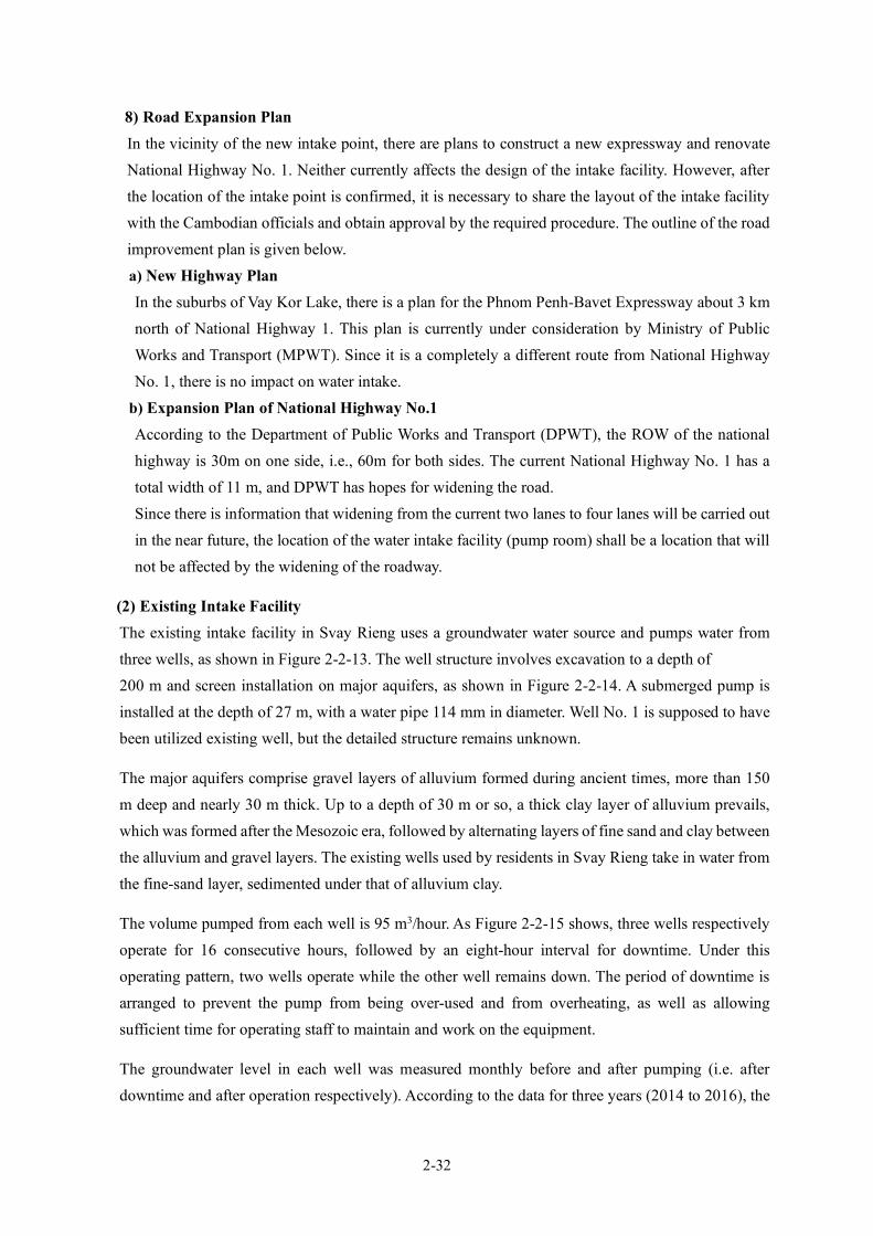
2-32
8) Road Expansion Plan In the vicinity of the new intake point, there are plans to construct a new expressway and renovate National Highway No. 1. Neither currently affects the design of the intake facility. However, after the location of the intake point is confirmed, it is necessary to share the layout of the intake facility with the Cambodian officials and obtain approval by the required procedure. The outline of the road improvement plan is given below. a) New Highway Plan In the suburbs of Vay Kor Lake, there is a plan for the Phnom Penh-Bavet Expressway about 3 km north of National Highway 1. This plan is currently under consideration by Ministry of Public Works and Transport (MPWT). Since it is a completely a different route from National Highway No. 1, there is no impact on water intake.
b) Expansion Plan of National Highway No.1 According to the Department of Public Works and Transport (DPWT), the ROW of the national highway is 30m on one side, i.e., 60m for both sides. The current National Highway No. 1 has a total width of 11 m, and DPWT has hopes for widening the road. Since there is information that widening from the current two lanes to four lanes will be carried out in the near future, the location of the water intake facility (pump room) shall be a location that will not be affected by the widening of the roadway.
(2) Existing Intake Facility The existing intake facility in Svay Rieng uses a groundwater water source and pumps water from three wells, as shown in Figure 2-2-13. The well structure involves excavation to a depth of 200 m and screen installation on major aquifers, as shown in Figure 2-2-14. A submerged pump is installed at the depth of 27 m, with a water pipe 114 mm in diameter. Well No. 1 is supposed to have been utilized existing well, but the detailed structure remains unknown.
The major aquifers comprise gravel layers of alluvium formed during ancient times, more than 150 m deep and nearly 30 m thick. Up to a depth of 30 m or so, a thick clay layer of alluvium prevails, which was formed after the Mesozoic era, followed by alternating layers of fine sand and clay between the alluvium and gravel layers. The existing wells used by residents in Svay Rieng take in water from the fine-sand layer, sedimented under that of alluvium clay.
The volume pumped from each well is 95 m3/hour. As Figure 2-2-15 shows, three wells respectively operate for 16 consecutive hours, followed by an eight-hour interval for downtime. Under this operating pattern, two wells operate while the other well remains down. The period of downtime is arranged to prevent the pump from being over-used and from overheating, as well as allowing sufficient time for operating staff to maintain and work on the equipment.
The groundwater level in each well was measured monthly before and after pumping (i.e. after downtime and after operation respectively). According to the data for three years (2014 to 2016), the
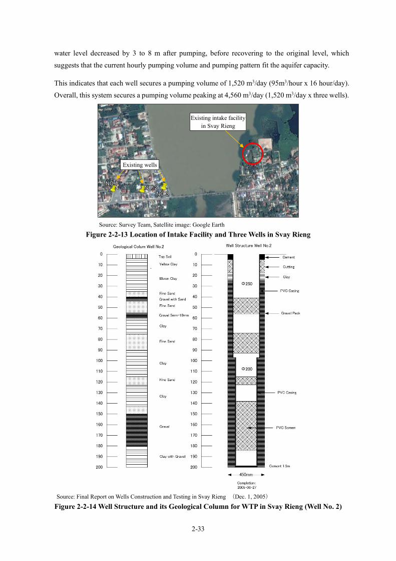
2-33
water level decreased by 3 to 8 m after pumping, before recovering to the original level, which suggests that the current hourly pumping volume and pumping pattern fit the aquifer capacity.
This indicates that each well secures a pumping volume of 1,520 m3/day (95m3/hour x 16 hour/day). Overall, this system secures a pumping volume peaking at 4,560 m3/day (1,520 m3/day x three wells).
Source: Survey Team, Satellite image: Google Earth
Figure 2-2-13 Location of Intake Facility and Three Wells in Svay Rieng
Source: Final Report on Wells Construction and Testing in Svay Rieng (Dec. 1, 2005)
Figure 2-2-14 Well Structure and its Geological Column for WTP in Svay Rieng (Well No. 2)
Existing intake facility in Svay Rieng
Existing wells

2-34
Source: prepared by Survey Team based on the survey result
Figure 2-2-15 Operating Pattern of Production Wells for WTP in Svay Rieng
(3) New Intake Facility
1) Selection of Water Intake Point SWWs presented four (4) water intake candidate points. The Survey Team selected the appropriate site from the four candidate sites based on the following conditions. • There is no legal restriction, and the site can be constructed. • There is sufficient water depth to allow water intake from below LWL (EL + 2.15m) of Vay Kor
Dam. The location map of the four (4) candidate water intake points is shown hereafter. For environmental protection, the water source of Vay Kor Lake is restricted for development in the lake on the South side of National Highway No. 1 (see Figure 1-3-3, for details, see "1-3 Environmental and Social Consideration"). As a result, Candidate Site No. 3 posted by the Cambodian side is excluded. In addition, according to the results of cross-sectional survey, the Northwestern shore of Vay Kor Lake is shallow (see Figure 2-2-17 and Figure 2-2-18), and the points with sufficient water depth are limited. Therefore, Candidate Point No. 1 and Candidate Point No. 4 are excluded. On the other hand, as will be described later, it was confirmed that Candidate Site No. 2 is relatively easy to construct and has the required water depth. Based on the above, Candidate Site No. 2 (North side of National Highway No. 1) is considered to be the most suitable candidate site. There is a distance of about 3.3km between this Candidate Site No. 2 and the candidate site for the new WTP.
1 2 3 4 5 6 7 8 9 10 11 12 13 14 15 16 17 18 19 20 21 22 23 24 1 2 3 4 5 6 7 8 9 10 11 12 13 14 15 16 17 18 19 20 21 22 23 24
No.1 停 止 停 止
No.2 停 止 停 止
No.3 停 止 停 止
Time
Well No
downtime
downtime
downtime
downtime
downtime
downtime
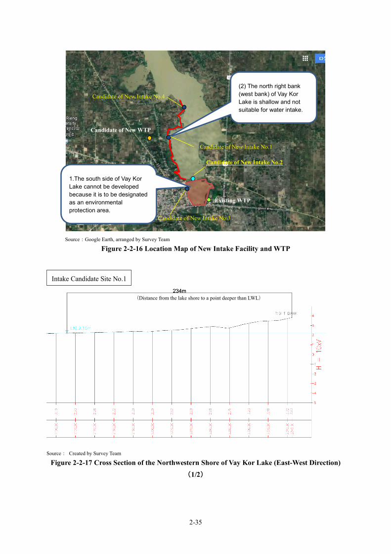
2-35
Source:Google Earth, arranged by Survey Team
Figure 2-2-16 Location Map of New Intake Facility and WTP
Source: Created by Survey Team
Figure 2-2-17 Cross Section of the Northwestern Shore of Vay Kor Lake (East-West Direction)(1/2)
Candidate of New WTP
Existing WTP
Candidate of New Intake No.2
1.The south side of Vay Kor Lake cannot be developed because it is to be designated as an environmental protection area.
(2) The north right bank (west bank) of Vay Kor Lake is shallow and not suitable for water intake.
Candidate of New Intake No.1
Candidate of New Intake No.3
Candidate of New Intake No.4
Intake Candidate Site No.1
(Distance from the lake shore to a point deeper than LWL)
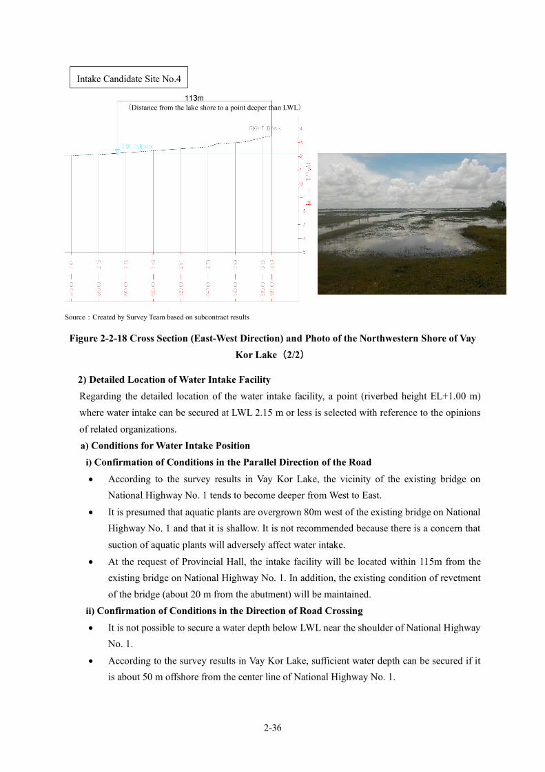
2-36
Source:Created by Survey Team based on subcontract results
Figure 2-2-18 Cross Section (East-West Direction) and Photo of the Northwestern Shore of Vay Kor Lake(2/2)
2) Detailed Location of Water Intake Facility Regarding the detailed location of the water intake facility, a point (riverbed height EL+1.00 m) where water intake can be secured at LWL 2.15 m or less is selected with reference to the opinions of related organizations. a) Conditions for Water Intake Position
i) Confirmation of Conditions in the Parallel Direction of the Road
• According to the survey results in Vay Kor Lake, the vicinity of the existing bridge on National Highway No. 1 tends to become deeper from West to East.
• It is presumed that aquatic plants are overgrown 80m west of the existing bridge on National Highway No. 1 and that it is shallow. It is not recommended because there is a concern that suction of aquatic plants will adversely affect water intake.
• At the request of Provincial Hall, the intake facility will be located within 115m from the existing bridge on National Highway No. 1. In addition, the existing condition of revetment of the bridge (about 20 m from the abutment) will be maintained.
ii) Confirmation of Conditions in the Direction of Road Crossing
• It is not possible to secure a water depth below LWL near the shoulder of National Highway No. 1.
• According to the survey results in Vay Kor Lake, sufficient water depth can be secured if it is about 50 m offshore from the center line of National Highway No. 1.
Intake Candidate Site No.4
(Distance from the lake shore to a point deeper than LWL)

2-37
b) Intake Location Considering the above setting conditions for the water intake position, the water intake point has been set as follows:
Source:Survey Team
Figure 2-2-19 Topographic Map around the Intake Facilities
Distance that can secure water depth
(More than 50m from the road center)

2-38
Source:Survey Team
Figure 2-2-20 Cross-Sectional View of Vay Kor Lake Intake Candidate Site No. 2
The status of No. 2 candidate site for new water intake is as shown below. Since the site faces National Highway No. 1, large-scale construction involving excavation of the shoulder must be avoided. A width of about 3.0 m is secured on the shoulder of the existing road, but it is difficult to construct an electric room and a generator room of the water intake facility in this width. Therefore, it is necessary to reclaim the lake.
Source:Survey Team
Figure 2-2-21 Status of Candidate Site for Intake Facilities (December 2019)
X1 - 8
X1 - 7
Existing Level
Offset
Existing Level
Offset
WL=3.278m
WL=3.278m
1.2m 3.0m
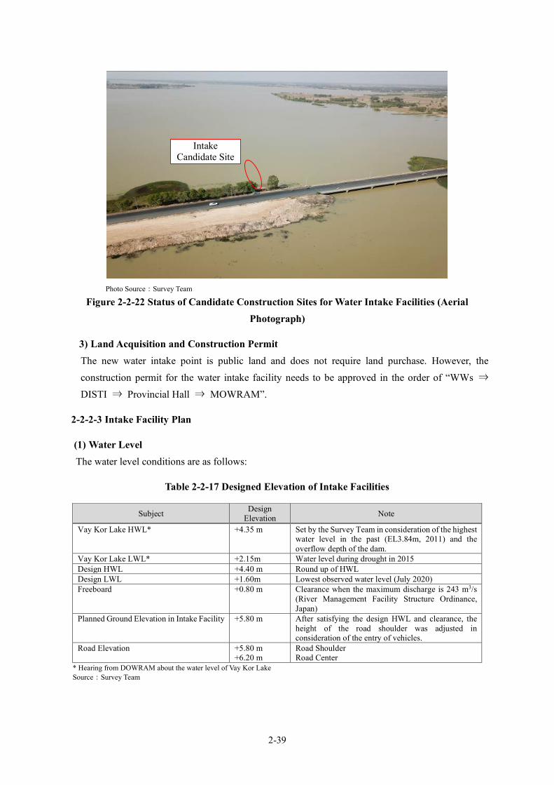
2-39
Photo Source:Survey Team
Figure 2-2-22 Status of Candidate Construction Sites for Water Intake Facilities (Aerial Photograph)
3) Land Acquisition and Construction Permit The new water intake point is public land and does not require land purchase. However, the construction permit for the water intake facility needs to be approved in the order of “WWs ⇒ DISTI ⇒ Provincial Hall ⇒ MOWRAM”.
2-2-2-3 Intake Facility Plan
(1) Water Level The water level conditions are as follows:
Table 2-2-17 Designed Elevation of Intake Facilities
* Hearing from DOWRAM about the water level of Vay Kor Lake Source:Survey Team
Subject Design Elevation Note
Vay Kor Lake HWL* +4.35 m Set by the Survey Team in consideration of the highest water level in the past (EL3.84m, 2011) and the overflow depth of the dam.
Vay Kor Lake LWL* +2.15m Water level during drought in 2015 Design HWL +4.40 m Round up of HWL Design LWL +1.60m Lowest observed water level (July 2020) Freeboard +0.80 m Clearance when the maximum discharge is 243 m3/s
(River Management Facility Structure Ordinance, Japan)
Planned Ground Elevation in Intake Facility +5.80 m After satisfying the design HWL and clearance, the height of the road shoulder was adjusted in consideration of the entry of vehicles.
Road Elevation +5.80 m +6.20 m
Road Shoulder Road Center
Intake Candidate Site

2-40
In July 2020, a water level lower than the LWL (observed lowest water level in 2015) set by DOWRAM was observed. Therefore, when designing the intake facility, the water level in July 2020 shall be adopted as the design LWL.
(2) Water Intake Method Considering the topographical restrictions of the planned water intake location and the shallow lake bottom far away, two (2) water intake methods can be selected: “Horizontal Intake Pipe” and “Open Channel with Gate”.
The features of the two water intake methods are as follows:
Table 2-2-18 Comparison of Horizontal Intake Pipe and Open Channel with Gate Type
Source: Survey Team
Horizontal Intake Pipe (Adopted in the Existing) Open Channel with Gate
Schematic
Overview
It is the method of transporting lake water to the pump suction pit by water intake pipe. The pump station can be constructed along the road of Route No.1, but the distance from the pumping station to the point where the water level is deep is as long as about 30m. The screen is installed in the pump suction pit to prevent fishes, waterweeds, and animals from entering.
The suction pit of the pump station is constructed as deep as possible in the lake. For that reason, the pump station is constructed about 40m off the lake from the side of the road. The bar screens are installed at the end of open channel and the intake gates are installed in the suction pit to prevent the invasion of fishes, waterweeds, and animals. The open channel is 4m wide and 9m long.
Feature
It can be expected that there will be little sedimentation inside of the intake pipe. The screen cannot be attached at the inlet of pipe because maintenance from the water surface of the lake is difficult. Therefore, there is a risk to invasion of waterweeds, fishes, and small animals. Since the amount of embankment is smaller than that of the open channel, the construction cost will be slightly lower.
Waterweeds that gathered to the open channel can be removed easily. The screen panel that attached at the end of open channel can be pulled up to the ground. Therefore, the trash can be easily removed. By dividing the suction pit into two, it is possible to clean each tank.
Judgement
It is possible to avoid the risk of clogging of the intake pipe. In addition, by constructing the pump station in the lake, it will be easier to construct the intake pump station, and it will be advantageous in terms of maintenance and safety because there is an area for vehicles to enter. Furthermore, it is easy to remove waterweeds. Based on the above, the “Open Channel with Gate” is selected as type of intake water.
Gate
スクリーン
Pump
Intake Pipe
Intake Nozzle Suction Bell mouse
Screen
Vay Kor L
ake
Pump Suction Bellmouth
Open Channel
Screen Vay K
or Lake

2-41
(3) Plan of Pump Station
1) Pump Type From the viewpoint of the planned “Total Head” and “Discharge Capacity”, the preferred pump type is as follows.
Table 2-2-19 Type and Characteristics of Intake Pump Type of Intake Pump Characteristics of Intake Pump
・Horizontal, double suction volute Easy maintenance, better suction performance and better efficiency ・Horizontal, end suction centrifugal Inferior to double suction pump on efficiency and maintenance
・Vertical, mixed flow Due to a lot of parts for lubrication system of submersible bearings, great care is required for maintenance and inspection.
・Submersible The service life is shorter than other types, and replacement work of mechanical seals is required about once every two years.
Source: Survey Team
As a result of the above comparison, “Horizontal, Double Suction Volute Type” has been selected for its excellence in terms of efficiency and maintenance and it is requested by the WWs.
2) Number of Pumps The pump suction diameter is reduced by increasing the number of pumps. Therefore, the screen clear spacing becomes narrower and the frequency of cleaning work increases. In addition, the pump efficiency tends to decrease. Since the planned transmission water volume is small, the number of pumps in operation is preferably one or two. The table below shows a comparison.
Table 2-2-20 Comparison of the Number of Intake Pumps Items One Duty Pump Two Duty Pumps Pump Capacity (m3/min) 5.2 2.6 Suction Diameter (mm) 200 150 Rated power of motor (kW) 30 15 Maximum efficiency of pump (%) 81 78 Impeller outlet width (mm) 20 15 Required installation space (%) 100% (2sets:5.67m2) 110% (3sets:6.27m2) Result From the viewpoints of higher efficiency, less clogging, and easy speed
control, the number of duty pump is set to one. One spare pump is added, so that a total of two shall be installed.
Source: Survey Team
3) Calculation of Pump Total Head The calculation of pump total head is as shown in Appendix 7-3. The pump total head is 19m based on the calculation result.
4) Operation Method of Intake Pump The rotation speed of the pump is controlled so that the required flow rate instructed from the intake pump station, or the WTP, is equal to the actual flow rate. The instructed flow and actual flow are displayed on the control panel installed in the intake pump station.

2-42
The start/stop command of the pump is given at the intake pump station, but it can be operated from the WTP by switching the “Local / Remote” changeover switch of the intake pump station to “Remote”.
5) Design Specification of Intake Pump The design specification of the intake pump is as shown in the following table.
Table 2-2-21 Design Specifications of Intake Pump Item Design Specifications
Type of Pump Horizontal, double suction volute pump Quantity 2 sets (including one standby) Flow Rate 7,480m3/day (5.2m3/min) Total Head 19m Rated Power of Motor 30kW Suction Diameter 200mm Synthetic Speed 1,500min-1 Speed Control Inverter
Source: Survey Team
6) Water Hammer Analysis The results of water hammer analysis are as shown on Appendix 7-4. According to the results of the analysis, dangerous negative pressure appears in a wide range of water pipes. Therefore, as a measure to control the negative pressure, the most reliable flywheel device shall be installed between the pump and the motor. The capacity of the flywheel shall be 50 kg/m2 based on the analysis results.
(4) Electric Equipment Planning
1) Substation A new substation facility shall be installed in the intake pumping station. Electric power shall be distributed from the EDC's 22kV transmission line about 600m away.
2) Emergency Diesel Generator Facility Since short-circuit accidents occur several times a month, an emergency diesel generator facility with the full load capacity required by the intake pumping station shall be installed. The approval of the WWs has been obtained, that is, the fuel tank capacity should be of 10 hours or more operation. In order to omit the installation of a separate fuel service tank, a power generator unit with a fuel tank capacity of 10 hours or more operation shall be selected.
3) Instrumentation The following instrumentations shall be installed so that the pump can be operated safely, and the operating status of the pump can be monitored at the WTP: a) Water level meter of Vay Kor Lake :1set in each suction pit b) Electromagnetic flowmeter for measuring water intake :1 set in pump room
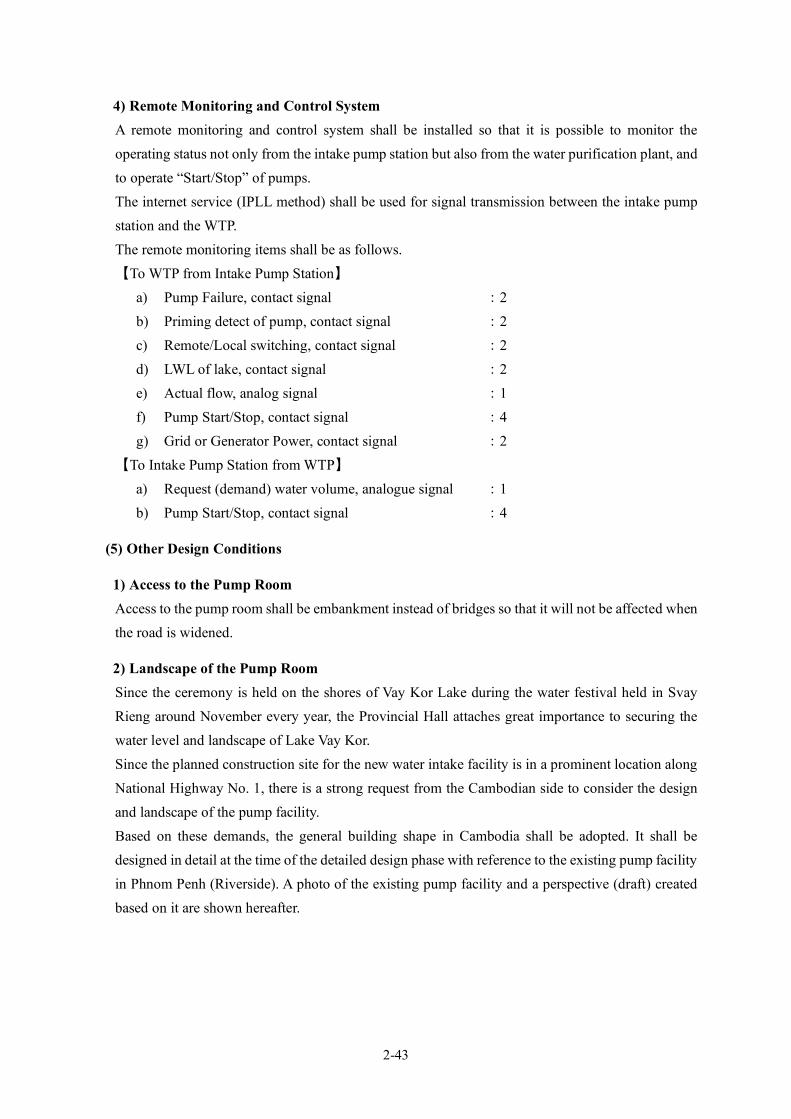
2-43
4) Remote Monitoring and Control System A remote monitoring and control system shall be installed so that it is possible to monitor the operating status not only from the intake pump station but also from the water purification plant, and to operate “Start/Stop” of pumps. The internet service (IPLL method) shall be used for signal transmission between the intake pump station and the WTP. The remote monitoring items shall be as follows. 【To WTP from Intake Pump Station】
a) Pump Failure, contact signal :2 b) Priming detect of pump, contact signal :2 c) Remote/Local switching, contact signal :2 d) LWL of lake, contact signal :2 e) Actual flow, analog signal :1 f) Pump Start/Stop, contact signal :4 g) Grid or Generator Power, contact signal :2
【To Intake Pump Station from WTP】 a) Request (demand) water volume, analogue signal :1 b) Pump Start/Stop, contact signal :4
(5) Other Design Conditions
1) Access to the Pump Room Access to the pump room shall be embankment instead of bridges so that it will not be affected when the road is widened.
2) Landscape of the Pump Room Since the ceremony is held on the shores of Vay Kor Lake during the water festival held in Svay Rieng around November every year, the Provincial Hall attaches great importance to securing the water level and landscape of Lake Vay Kor. Since the planned construction site for the new water intake facility is in a prominent location along National Highway No. 1, there is a strong request from the Cambodian side to consider the design and landscape of the pump facility. Based on these demands, the general building shape in Cambodia shall be adopted. It shall be designed in detail at the time of the detailed design phase with reference to the existing pump facility in Phnom Penh (Riverside). A photo of the existing pump facility and a perspective (draft) created based on it are shown hereafter.

2-44
Source: Survey Team
Figure 2-2-23 Existing Pump Facility in Phnom Penh Metropolitan Area
Source: Survey Team
Figure 2-2-24 3D Perspective of Intake Facility (Draft)
(6) Outline of Intake Pump Facility
Table 2-2-22 shows the facilities required for the intake pump station.
Table 2-2-22 Outline of Intake Pump Facilities Classification of Facilities Structure
Major Items Middle Items Minor Items Water Supply 7,480m3/day
Intake Pump Station
Pump House Reinforced concrete, Rectangular, Basement structure Ground floor: B11.6m × L16.0m × H3.3m(Under beam) Basement floor: B7.5m × L10.5m × H6.9m(Under beam) Electrical room, Generator room, Pump room, Office, Toilet,
Suction pit
Source: Survey Team
View from Southwest
View from Northeast

2-45
2-2-2-4 Conveyance Pipe
(1) Existing Conveyance Pipe The existing conveyance pipe connects between three existing wells and the existing WTP. The material of conveyance pipe is Ductile Iron pipe and the diameter is 250mm. The total length of the conveyance pipe is about 1,400m. Each of the three wells has been operated at 95m3/hour for 16 hours a day, and there has been no leakage or insufficient capacity in the water pipes.
(2) Basic Conditions for Designing of Proposed Conveyance Pipe
1) Design Flow of Conveyance Pipe Based on the design flow of raw water intake that has been set out considering ten percent of safety factor to the design daily maximum water supply, the design flow of conveyance pipe shall be 7,480 m3/ day4.
2) Type of Conveyance Pipe The type of conveyance pipe shall be the pumping type, considering the difference in elevation5 between its beginning point (i.e., the raw water intake facility) and its terminal point (i.e., the WTP), the topography requiring the river crossing, and the geography that is a nearly flat terrain. The conveyance pipes shall be laid under public roads to convey raw water.
3) Route of Conveyance Pipe The route of the conveyance pipe shall be selected along public roads and the route shall be the shortest distance between the water intake facility and the WTP, considering economic efficiency, ease of construction, and ease of maintenance and management.
(3) Pipe Material With regard to the pipe material6 , it is selected by considering the applicable pipe diameter, the economic benefits, ease of construction work 7 , and precedence of water pipe materials used in Cambodia. The materials for the conveyance pipe shall be ductile cast iron pipe (T-type) for general buried sections, and steel pipe (with corrosion prevention) or stainless-steel pipe for the river crossing sections. ISO standards shall be adopted.
4 The design flow of conveyance pipe = 6,800 m3 / day ×1.1 = 7,480 m3 / day 5 The difference in water level between the planned intake pump well (HWL + 4.40 m, LWL + 1.60 m) and the planned receiving well (WL+ 7.90 m) is from 3.50 to 6.30 m, the geography along the route of conveyance pipe almost flat. 6 The selection of pipe material is shown in Appendix 7-6 (Selection of pipe material). 7 Corrosion is a concern for buried steel pipes, and on-site welding work may cause poor finishing as compared with ductile cast iron pipe.
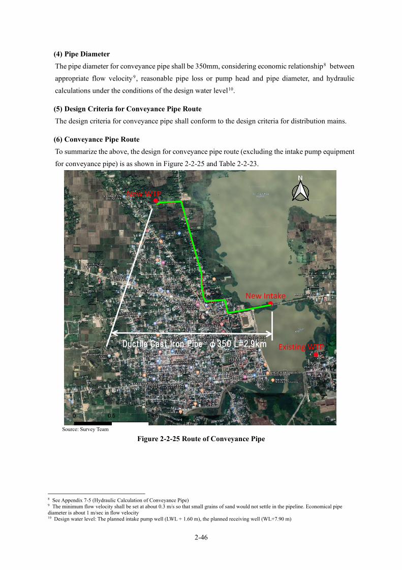
2-46
(4) Pipe Diameter The pipe diameter for conveyance pipe shall be 350mm, considering economic relationship8 between appropriate flow velocity9 , reasonable pipe loss or pump head and pipe diameter, and hydraulic calculations under the conditions of the design water level10.
(5) Design Criteria for Conveyance Pipe Route The design criteria for conveyance pipe shall conform to the design criteria for distribution mains.
(6) Conveyance Pipe Route To summarize the above, the design for conveyance pipe route (excluding the intake pump equipment for conveyance pipe) is as shown in Figure 2-2-25 and Table 2-2-23.
Source: Survey Team
Figure 2-2-25 Route of Conveyance Pipe
8 See Appendix 7-5 (Hydraulic Calculation of Conveyance Pipe) 9 The minimum flow velocity shall be set at about 0.3 m/s so that small grains of sand would not settle in the pipeline. Economical pipe diameter is about 1 m/sec in flow velocity 10 Design water level: The planned intake pump well (LWL + 1.60 m), the planned receiving well (WL+7.90 m)
New WTP
Existing WTP
New Intake
Ductile Cast Iron Pipe φ350 L=2.9km
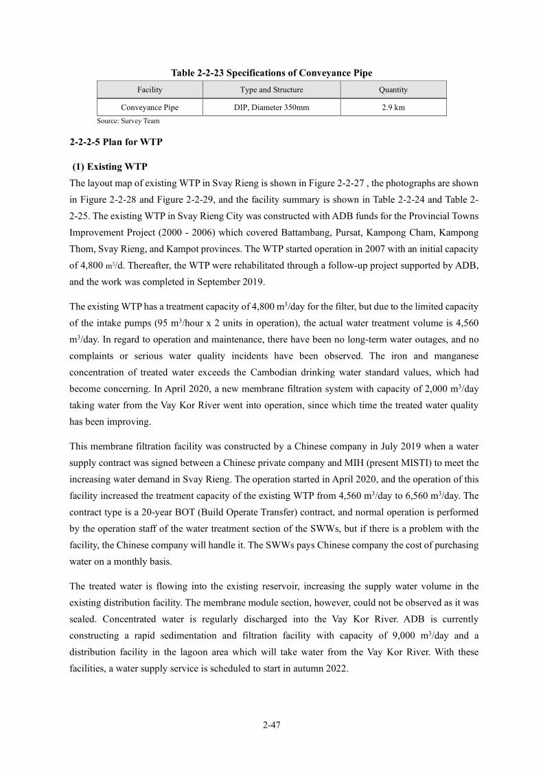
2-47
Table 2-2-23 Specifications of Conveyance Pipe Facility Type and Structure Quantity
Conveyance Pipe DIP, Diameter 350mm 2.9 km Source: Survey Team
2-2-2-5 Plan for WTP
(1) Existing WTP The layout map of existing WTP in Svay Rieng is shown in Figure 2-2-27 , the photographs are shown in Figure 2-2-28 and Figure 2-2-29, and the facility summary is shown in Table 2-2-24 and Table 2-2-25. The existing WTP in Svay Rieng City was constructed with ADB funds for the Provincial Towns Improvement Project (2000 - 2006) which covered Battambang, Pursat, Kampong Cham, Kampong Thom, Svay Rieng, and Kampot provinces. The WTP started operation in 2007 with an initial capacity of 4,800 m3/d. Thereafter, the WTP were rehabilitated through a follow-up project supported by ADB, and the work was completed in September 2019.
The existing WTP has a treatment capacity of 4,800 m3/day for the filter, but due to the limited capacity of the intake pumps (95 m3/hour x 2 units in operation), the actual water treatment volume is 4,560 m3/day. In regard to operation and maintenance, there have been no long-term water outages, and no complaints or serious water quality incidents have been observed. The iron and manganese concentration of treated water exceeds the Cambodian drinking water standard values, which had become concerning. In April 2020, a new membrane filtration system with capacity of 2,000 m3/day taking water from the Vay Kor River went into operation, since which time the treated water quality has been improving.
This membrane filtration facility was constructed by a Chinese company in July 2019 when a water supply contract was signed between a Chinese private company and MIH (present MISTI) to meet the increasing water demand in Svay Rieng. The operation started in April 2020, and the operation of this facility increased the treatment capacity of the existing WTP from 4,560 m3/day to 6,560 m3/day. The contract type is a 20-year BOT (Build Operate Transfer) contract, and normal operation is performed by the operation staff of the water treatment section of the SWWs, but if there is a problem with the facility, the Chinese company will handle it. The SWWs pays Chinese company the cost of purchasing water on a monthly basis.
The treated water is flowing into the existing reservoir, increasing the supply water volume in the existing distribution facility. The membrane module section, however, could not be observed as it was sealed. Concentrated water is regularly discharged into the Vay Kor River. ADB is currently constructing a rapid sedimentation and filtration facility with capacity of 9,000 m3/day and a distribution facility in the lagoon area which will take water from the Vay Kor River. With these facilities, a water supply service is scheduled to start in autumn 2022.

2-48
Source: Survey Team
Figure 2-2-26 Schematic of Existing WTP Syatem
Source: Survey Team
Figure 2-2-27 Layout Map of the Facilities at the Existing WTP
Note: Left: Clean Service Reservoir(③)/Right: Filter Tank(②), Chlorination Building(⑥) (Facility corresponding to each ID is presented in Figure 2-2-26) Source: Survey Team
Figure 2-2-28 Existing WTP (gravity rapid sand filter)
ADB WTP (rapid filtration)
Membrane filtration
⑦

2-49
Note: Left: Intake Facility/Center & Right: Membrane Filter Source: Survey Team
Figure 2-2-29 Existing WTP (membrane filter)
Table 2-2-24 Summary of Facilities at the Existing WTP (Rapid Filtration) No. Item Facility Outline Contents 1 Filter Tank Gravity Type Steel Filter Tank × 2
units Installed on a concrete foundation above ground. (with roof) Filtration Capacity: 100m3/h × 2 units = 200m3/h Wash method: Backwash Wash pump: 9.0m3/min × 2 units (Installed in the water distribution pump room)
No significant deterioration or water leakage was observed in the tank.
The backwash is manually operated every 5 to 6 hours.
2 Clean Service Reservoir
Reinforced Concrete Construction 2 Basins Total 1,275m3 (Effective Depth Approx.5m, Nominal 1,000m3)
No significant deterioration or water leakage was observed in the structure.
The water level gauge that was used at the beginning of operation in 2007 has been damaged, but a float-type water level gauge has been installed to control the water level.
3 Distribution Pump Room
Reinforced Concrete Construction 1 story & 1 basement story Distribution Pump 75.7m3/h × 3 units
The flow meter was installed from the beginning of operation, but is now damaged.
The water distribution pump room is an integrated structure with the clear water reservoir.
The backwash pump and the pressurized water pump for chlorination are also installed in the water distribution pump room.
4 Generator Building
Reinforced Concrete Construction 1 story Generator 2 units
The generation facilities are operated and maintained in good condition.
5 Water Quality Laboratory
Reinforced Concrete Construction 1 story
Water quality testing equipment was provided and updated by ADB in 2018. Those is properly managed and covers the water testing items of the WTP.
6 Chlorination Building
Reinforced Concrete Construction Pressurized Water Pump for Chlorination 2 units (Installed in the water distribution pump room)
No significant deterioration or water leakage was observed in the structure.
At the time of construction (2007), chlorine gas was used, but the equipment was damaged in 2015 and is no longer in use.
Calcium hypochlorite (bleaching powder) was dissolved in a PE tank installed in the chlorination building with its own funds since 2015, and chlorination has been performed. The chlorination facilities were upgraded by ADB in September 2019.
7 Lagoon Area:Approx.1600 m2 Depth:Approx.1 m
Sedimentation basin, filtration basin, and distribution reservoir with processing capacity of 9,000 m3 / day are under construction by ADB.
8 O&M conditions Number of maintenance staff: 5 people are engaged in O&M. No serious maintenance problems such as prolonged water shutdown or water quality
accidents were observed. However, the iron ion concentration sometimes exceeded the standard value.

2-50
Source: Survey Team
Table 2-2-25 Summary of Facilities at the Existing WTP (Membrane Filtration) No. Items Facility Outline Contents 1 Intake Facility Pontoon (float type): 1 barge
Intake capacity: >2,000m3/day
Two intake pumps
Since the upper part of the pump has no roof, a blue tarp is used.
The pump specifications are unknown. Maintenance is carried out by the maintenance staff moving to the pontoon by boat.
2 Conveyance Pipe Polyethylene pipe (diameter: 250 mm)
Above-ground piping
3 Membrane Filtration Facility
Loaded in the container box. First story: - Control panel - Membrane filtration tank - Backwash pump (for membrane cleaning) - Blower (for membrane cleaning) - Compressor (for air valve operation) - Chemical tank (calcium hypochlorite injected when sterilizing treated water and cleaning membrane)
Second story: - Main membrane filtration system (unconfirmed)
The membrane module part could not be observed as it was sealed.
4 Drain Pit Primary tank for concentrated (wash) water from the membrane filtration facility.
The discharging cycle could not be confirmed but the discharging time was around 30 minutes.
5 Power Power is installed from the WWs. Electric rate is also incurred by the WWs. 6 Purchasing Water
from the Chinese Company
An electromagnetic flow meter is used to measure the volume of treated water, after which water is flowing into the existing reservoir.
Contract period: A monthly-paid contract for 20 years.
7 Operation and Maintenance Status
(Monitoring / Operation and Maintenance System, Response to Abnormal Situations) The intake facility is usually monitored in Phnom Penh via a mobile phone connection.
When an abnormality is detected, the WWs are called and requested to handle the situation. When a serious abnormality occurs, the person in charge visits Svay Rieng to respond.
Those staff left the WWs earlier and were hired by the abovementioned Chinese private company to respond to any anomalies. In August 2021, the filtration volume decreased by 10% (60,000m3 to 54,000m3/month), which was addressed via the abovementioned approach. This event was considered attributable to the intake facility having to handle high-turbidity raw water since August at the beginning of the rainy season.
(Water Quality) Water quality analysis is carried out by the operation and maintenance section and the
water quality test section of the WTP Division of SWWs. Currently, the outlet turbidity of the membrane filtration unit is 0.008NTU which shows
a good level. Source: Survey Team
(2) Proposed Site for the New WTP The planned site for the new WTP was chosen from a list provided by the Cambodian side in which checked the ease of site acquisition and positional relationship between the new intake site and the water distribution area. The site (rectangular; about 1.0ha) is shown in Figure 2-2-30. The site is

2-51
currently a forest of small trees, and the area around the site is flat but adjacent to waterways and swamps. The land for the construction of the new WTP was purchased by the Cambodian side (SWWs) after the on-site survey in 2017. The land is unused; therefore, no resettlement is required.
Source: Study Team
Figure 2-2-30 Location map of the planned site of the new WTP
(3) Treatment Process The treatment process is designed to achieve high treatment and energy efficiency, and ease of operation and maintenance as well, so that the integrated operation components of the treatment process, such as sedimentation, filtration and disinfection, will be efficient and effective.
The key factors to consider for designing the treatment process shall be the quality of the raw water, the target quality of the treated water, the quantity of water to be treated, and the level of technology required for proper operation and maintenance. The conventional treatment process (coagulation – sedimentation – rapid sand filtration), similar to that used at the Phum Prek plant in Phnom Penh and other plants in Cambodia, is deemed the most appropriate. The chemical feeding system uses PAC for coagulant, lime for pH and alkalinity adjustment and chlorine powder for disinfection.
PAC is widely used in other WTPs in Cambodia. Lime is rarely used nowadays, but its purpose is to replenish the alkalinity consumed during high coagulant injection in response to high turbidity. Chlorine powder (Calcium hypochlorite) is a less hazardous chemical used by the SWWs as an alternative to disinfection with chlorine gas. As for the process, two-stage chlorine injection is planned to cope with high concentrations of iron/manganese, ammonia and organic matter in raw water. Figure 2-2-31 shows the flow chart of the treatment process.
Google Earth
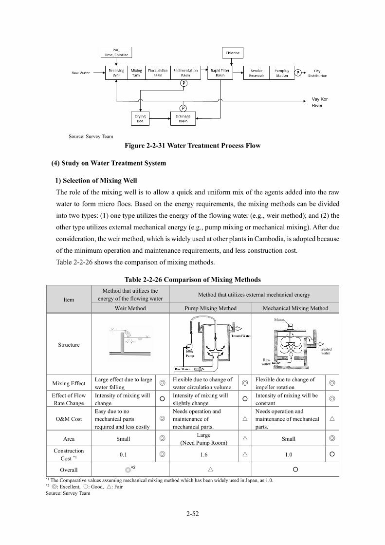
2-52
Source: Survey Team
Figure 2-2-31 Water Treatment Process Flow
(4) Study on Water Treatment System
1) Selection of Mixing Well The role of the mixing well is to allow a quick and uniform mix of the agents added into the raw water to form micro flocs. Based on the energy requirements, the mixing methods can be divided into two types: (1) one type utilizes the energy of the flowing water (e.g., weir method); and (2) the other type utilizes external mechanical energy (e.g., pump mixing or mechanical mixing). After due consideration, the weir method, which is widely used at other plants in Cambodia, is adopted because of the minimum operation and maintenance requirements, and less construction cost. Table 2-2-26 shows the comparison of mixing methods.
Table 2-2-26 Comparison of Mixing Methods
Item Method that utilizes the
energy of the flowing water Method that utilizes external mechanical energy
Weir Method Pump Mixing Method Mechanical Mixing Method
Structure
Mixing Effect Large effect due to large water falling
◎ Flexible due to change of water circulation volume
◎ Flexible due to change of impeller rotation
◎
Effect of Flow Rate Change
Intensity of mixing will change
○ Intensity of mixing will slightly change
○ Intensity of mixing will be constant
◎
O&M Cost Easy due to no mechanical parts required and less costly
◎ Needs operation and maintenance of mechanical parts.
△ Needs operation and maintenance of mechanical parts.
△
Area Small ◎ Large (Need Pump Room)
△ Small ◎
Construction Cost *1
0.1 ◎ 1.6 △ 1.0 ○
Overall ◎*2 △ ○
*1 The Comparative values assuming mechanical mixing method which has been widely used in Japan, as 1.0. *2 ◎: Excellent, ○: Good, △: Fair Source: Survey Team
Treated water
Raw water
Motor
Vay Kor River
2-53
2) Selection of Flocculation Basin The role of a flocculation basin is to gently stir the micro flocs generated in the mixing well, allowing them to grow large for efficient settling and separation in the latter sedimentation process. The flocculation methods are mainly divided into two methods: methods that utilize the energy of the flowing water (zigzag flow method, up-and-down roundabout method), and methods that utilize external mechanical energy (e.g., horizontal shaft turbine method, vertical shaft turbine method). After due consideration, a combination of up-and-down roundabout method using zigzag flow, which is used in other plants in Cambodia, is adopted, because of the absence of mechanical drive resulting in minimum operation and maintenance requirement, and less construction cost. Table 2-2-27 shows the comparison of flocculation methods.
3) Selection of Sedimentation Basin The role of a sedimentation basin is to settle and separate large flocs formed in the flocculation basin by gravity sedimentation. Sedimentation basins are mainly divided into horizontal flow type, horizontal flow with inclined plate type, upward flow with tube settler type, and suspended solid contact type. Suspended solid contact type is, however, excluded from consideration since it requires high-level operational technique and has not been constructed in Cambodian WTPs since the 2000s. Table 2-2-28 shows the comparison of type of sedimentation basins. Horizontal flow with inclined plate type and upward flow with tube settler type is superior to horizontal flow type in terms of turbidity fluctuation of the raw water. Since construction land is not restricted for this project, placing priority on the construction cost, horizontal flow type (intermediate flow uniform wall type), which is also applied in other plants in Cambodia, is preferred.
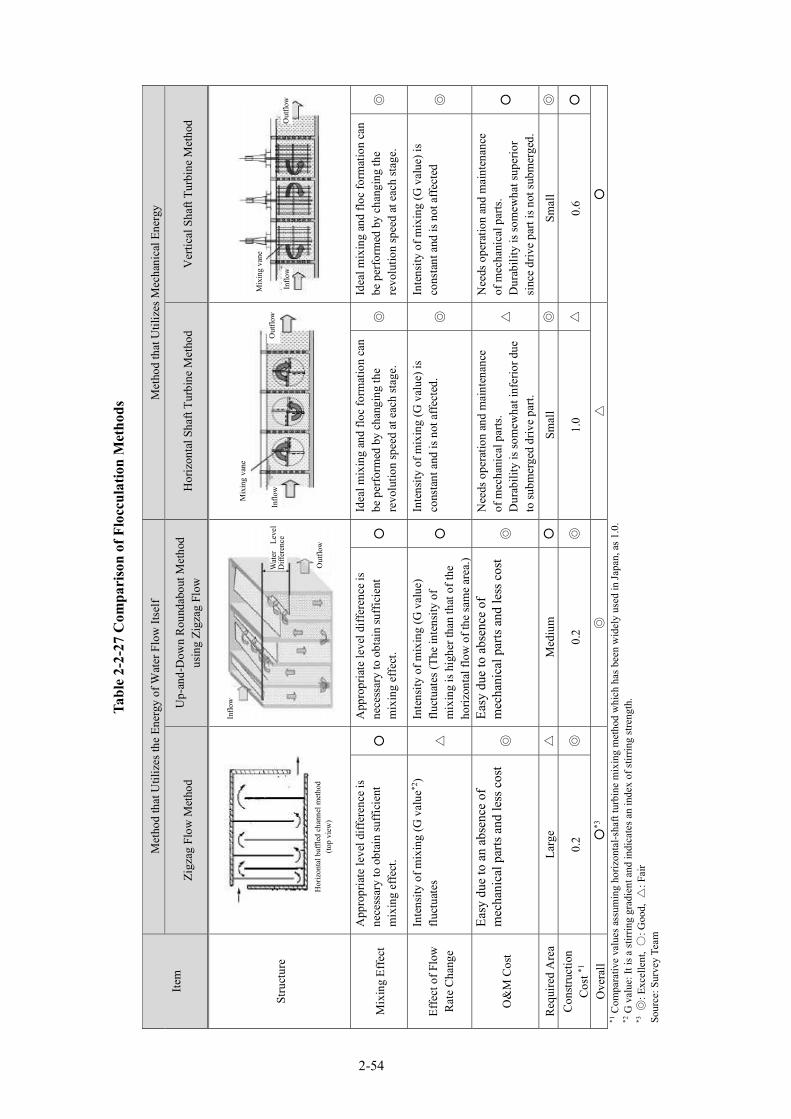
Tabl
e 2-
2-27
Com
pari
son
of F
locc
ulat
ion
Met
hods
Item
Met
hod
that
Util
izes
the
Ener
gy o
f Wat
er F
low
Itse
lf M
etho
d th
at U
tiliz
es M
echa
nica
l Ene
rgy
Zigz
ag F
low
Met
hod
Up-
and-
Dow
n R
ound
abou
t Met
hod
usin
g Zi
gzag
Flo
w
Hor
izon
tal S
haft
Turb
ine
Met
hod
Ver
tical
Sha
ft Tu
rbin
e M
etho
d
Stru
ctur
e
Mix
ing
Effe
ct
App
ropr
iate
leve
l diff
eren
ce is
ne
cess
ary
to o
btai
n su
ffic
ient
m
ixin
g ef
fect
. ○
A
ppro
pria
te le
vel d
iffer
ence
is
nece
ssar
y to
obt
ain
suff
icie
nt
mix
ing
effe
ct.
○
Idea
l mix
ing
and
floc
form
atio
n ca
n be
per
form
ed b
y ch
angi
ng th
e re
volu
tion
spee
d at
eac
h st
age.
◎
Id
eal m
ixin
g an
d flo
c fo
rmat
ion
can
be p
erfo
rmed
by
chan
ging
the
revo
lutio
n sp
eed
at e
ach
stag
e.
◎
Effe
ct o
f Flo
w
Rat
e C
hang
e
Inte
nsity
of m
ixin
g (G
val
ue*2
) flu
ctua
tes
△
Inte
nsity
of m
ixin
g (G
val
ue)
fluct
uate
s (Th
e in
tens
ity o
f m
ixin
g is
hig
her t
han
that
of t
he
horiz
onta
l flo
w o
f the
sam
e ar
ea.)
○
Inte
nsity
of m
ixin
g (G
val
ue) i
s co
nsta
nt a
nd is
not
aff
ecte
d.
◎
Inte
nsity
of m
ixin
g (G
val
ue) i
s co
nsta
nt a
nd is
not
aff
ecte
d ◎
O&
M C
ost
Easy
due
to a
n ab
senc
e of
m
echa
nica
l par
ts an
d le
ss c
ost
◎
Easy
due
to a
bsen
ce o
f m
echa
nica
l par
ts an
d le
ss c
ost
◎
Nee
ds o
pera
tion
and
mai
nten
ance
of
mec
hani
cal p
arts
. D
urab
ility
is so
mew
hat i
nfer
ior d
ue
to su
bmer
ged
driv
e pa
rt.
△
Nee
ds o
pera
tion
and
mai
nten
ance
of
mec
hani
cal p
arts
. D
urab
ility
is so
mew
hat s
uper
ior
sinc
e dr
ive
part
is n
ot su
bmer
ged.
○
Req
uire
d A
rea
Larg
e △
M
ediu
m
○
Smal
l ◎
Sm
all
◎
Con
stru
ctio
n C
ost *1
0.
2 ◎
0.
2 ◎
1.
0 △
0.
6 ○
Ove
rall
○*3
◎
△
○
*1
Com
para
tive
valu
es a
ssum
ing
horiz
onta
l-sha
ft tu
rbin
e m
ixin
g m
etho
d w
hich
has
bee
n w
idel
y us
ed in
Japa
n, a
s 1.0
. *2
G v
alue
: It i
s a st
irrin
g gr
adie
nt a
nd in
dica
tes a
n in
dex
of st
irrin
g st
reng
th.
*3 ◎
: Exc
elle
nt, ○
: Goo
d, △
: Fai
r So
urce
: Sur
vey
Team
Hor
izon
tal b
affle
d ch
anne
l met
hod
(top
view
)
Inflo
w
Wat
er
Leve
l D
iffer
ence
Out
flow
Mix
ing
vane
Inflo
w
Out
flow
M
ixin
g va
ne
Out
flow
In
flow
2-54
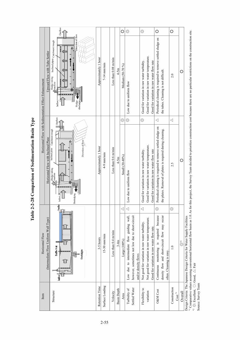
Tabl
e 2-
2-28
Com
pari
son
of S
edim
enta
tion
Bas
in T
ype
Item
H
oriz
onta
l Flo
w
(Inte
rmed
iate
Flo
w U
nifo
rm W
all T
ype)
H
oriz
onta
l Flo
w w
ith S
edim
enta
tion
Effe
ct E
nhan
cem
ent
Hor
izon
tal F
low
with
Incl
ined
Pla
te
Upw
ard
Flow
with
Tub
e Se
ttler
Stru
ctur
e
R
eten
tion
Tim
e 3-
5 ho
urs
App
roxi
mat
ely
1 ho
ur
App
roxi
mat
ely
1 ho
ur
Surfa
ce L
oadi
ng
15-3
0 m
m/m
in
4-9
mm
/min
7-
14 m
m/m
in
Vel
ocity
Le
ss th
an 0
.4 m
/min
Le
ss th
an 0
.6 m
/min
Le
ss th
an 0
.08
m/m
in
Bas
in D
epth
3-
4m
4-5m
4-
5m
Are
a La
rge
(100
%)
△
Smal
l (30
-40%
) ◎
M
ediu
m (5
0-70
%)
○
Turb
idity
of
Settl
ed W
ater
Lo
w
due
to
inte
rmed
iate
flo
w
guid
ing
wal
l, ho
wev
er, s
omet
imes
not
low
due
to s
hort-
circ
uit
and/
or d
ensi
ty fl
ows
△
Low
due
to u
nifo
rm fl
ow
◎
Low
due
to u
nifo
rm fl
ow
◎
Flex
ibili
ty to
va
riatio
n N
ot g
ood
for v
aria
tion
in ra
w w
ater
turb
idity
. N
ot g
ood
for v
aria
tion
in ra
w w
ater
tem
pera
ture
. G
ood
for v
aria
tion
in ra
w w
ater
flow
rate
.
△
Goo
d fo
r var
iatio
n in
raw
wat
er tu
rbid
ity.
Goo
d fo
r var
iatio
n in
raw
wat
er te
mpe
ratu
re.
Goo
d fo
r var
iatio
n in
raw
wat
er fl
ow ra
te
◎
Goo
d fo
r var
iatio
n in
raw
wat
er tu
rbid
ity.
Goo
d fo
r var
iatio
n in
raw
wat
er te
mpe
ratu
re.
Goo
d fo
r var
iatio
n in
raw
wat
er fl
ow ra
te
◎
O&
M C
ost
Con
tinuo
us
mon
itorin
g is
re
quire
d be
caus
e de
nsity
flo
w a
nd s
hort-
circ
uit
flow
may
occ
ur
ofte
n. C
lean
ing
is e
asy.
◎
Perio
dica
l cle
anin
g is
requ
ired
to re
mov
e se
ttled
slud
ge o
n th
e pl
ates
. Rem
oval
of p
late
s is r
equi
red
durin
g cl
eani
ng.
△
Perio
dica
l cle
anin
g is
requ
ired
to re
mov
e se
ttled
slud
ge o
n th
e tu
bes.
Cle
anin
g is
not d
iffic
ult.
○
Con
stru
ctio
n C
ost *1
1.
0 ◎
2.
5 △
2.
0 ○
Ove
rall
◎*2
○
○
D
esig
n C
riter
ia: T
he Ja
pane
se D
esig
n C
riter
ia fo
r Wat
er S
uppl
y Fa
cilit
ies
*1 C
ompa
rativ
e va
lues
ass
umin
g co
nven
tiona
l hor
izon
tal f
low
bas
in a
s 1.0
. As f
or th
is p
roje
ct, t
he S
urve
y Te
am d
ecid
ed to
prio
ritiz
e co
nstru
ctio
n co
st b
ecau
se th
ere
are
no p
artic
ular
rest
rictio
ns o
n th
e co
nstru
ctio
n si
te.
*2 ◎
: Exc
elle
nt, ○
: Goo
d, △
: Fai
r So
urce
: Sur
vey
Team
2-55
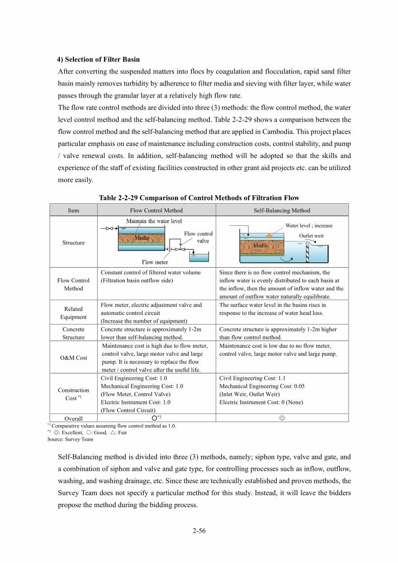
2-56
4) Selection of Filter Basin After converting the suspended matters into flocs by coagulation and flocculation, rapid sand filter basin mainly removes turbidity by adherence to filter media and sieving with filter layer, while water passes through the granular layer at a relatively high flow rate. The flow rate control methods are divided into three (3) methods: the flow control method, the water level control method and the self-balancing method. Table 2-2-29 shows a comparison between the flow control method and the self-balancing method that are applied in Cambodia. This project places particular emphasis on ease of maintenance including construction costs, control stability, and pump / valve renewal costs. In addition, self-balancing method will be adopted so that the skills and experience of the staff of existing facilities constructed in other grant aid projects etc. can be utilized more easily.
Table 2-2-29 Comparison of Control Methods of Filtration Flow
Item Flow Control Method Self-Balancing Method
Structure
Flow Control Method
Constant control of filtered water volume (Filtration basin outflow side)
Since there is no flow control mechanism, the inflow water is evenly distributed to each basin at the inflow, then the amount of inflow water and the amount of outflow water naturally equilibrate.
Related Equipment
Flow meter, electric adjustment valve and automatic control circuit (Increase the number of equipment)
The surface water level in the basins rises in response to the increase of water head loss.
Concrete Structure
Concrete structure is approximately 1-2m lower than self-balancing method.
Concrete structure is approximately 1-2m higher than flow control method.
O&M Cost
Maintenance cost is high due to flow meter, control valve, large motor valve and large pump. It is necessary to replace the flow meter / control valve after the useful life.
Maintenance cost is low due to no flow meter, control valve, large motor valve and large pump.
Construction Cost *1
Civil Engineering Cost: 1.0 Mechanical Engineering Cost: 1.0 (Flow Meter, Control Valve) Electric Instrument Cost: 1.0 (Flow Control Circuit)
Civil Engineering Cost: 1.1 Mechanical Engineering Cost: 0.05 (Inlet Weir, Outlet Weir) Electric Instrument Cost: 0 (None)
Overall ○*2 ◎ *1 Comparative values assuming flow control method as 1.0. *2 ◎: Excellent, ○: Good, △: Fair Source: Survey Team
Self-Balancing method is divided into three (3) methods, namely; siphon type, valve and gate, and a combination of siphon and valve and gate type, for controlling processes such as inflow, outflow, washing, and washing drainage, etc. Since these are technically established and proven methods, the Survey Team does not specify a particular method for this study. Instead, it will leave the bidders propose the method during the bidding process.
Media
Outlet weir
Water level ; increase
2-57
In addition, there are three (3) types of feeding system into the filtration basin, namely; from other basin(s), using a backwash pump, and from a supply tank. The Survey Team decided to avoid feeding using backwash pump, which incurs large operation and maintenance costs, and not to specify a particular method, but left the bidders propose between the remaining two methods. Furthermore, the backwash tank type is divided into an internal and an external type. The Survey Team did not also specify a particular method for this study. Instead, it left the bidders propose during the bidding process. The filtration basins shown in Appendix 7-2, “Outline Design Drawings”, in this report are reference drawings only. The process control of these basins is a combination type, i.e., both siphon and valve and gate type; whereas the feeding system is a backwash type that has an internal tank within the filtration area. However, bidders may propose a different shape and type of filtration basins as long as they satisfy the “Prerequisite of filtration basin” and the “Basic specification of filtration basins” shown in Table 2-2-30 and Table 2-2-31. Table 2-2-30 shows the design preconditions of the filtration basin.
Table 2-2-30 Design Preconditions of the Filtration Basin No. Contents 1. Raw Water: Surface Water of the Vay Kor River
2. Design Water Treatment Output: 7,480 m3/day
3. Outline of intake facility, the construction site for the intake facility, route for laying the water conveying
pipe, the construction site for the WTP: Refer to the outline design drawings (Drawing number G1, SI-1 to SI-6, SR-1 to SR-4)
4. Shape and dimensions of the construction site of the WTP: Refer to the design drawing (Drawing number ST-1)
5. Construction plan of WTP facilities other than filtration basin: Refer to the schematic design drawing (Drawing numbers ST-1 to ST-16)
6. Hydraulic Profile of the WTP located upstream of the filtration basin: Refer to the schematic design drawing (Drawing number ST-2)
7. Transmission/distribution system from the WTP: Water supply to customers by the water distribution pump direct delivery system
Source: Survey Team
Table 2-2-31 shows the basic specifications of the filtration basin based on the following concept. i. Since it is not a bidding for the performance guarantee method, the contents of the basic
specification are to be relatively conservative, with top priority for minimizing risks of O&M.
ii. Since the bid evaluation is basically based on the bid price (construction cost of the facility), the method, whose O&M cost (i.e., the backwash pump method on filtration basins) is expected to be relatively large and shall be excluded from the options in advance.
iii. The contents of the basic specifications shall be in accordance with the contents of “Waterworks Facility Design Guidelines 2012 (Japan Waterworks Association)” as much
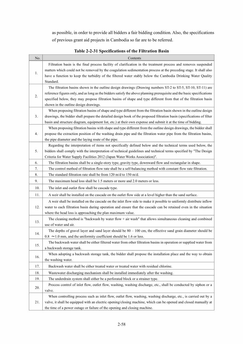
2-58
as possible, in order to provide all bidders a fair bidding condition. Also, the specifications of previous grant aid projects in Cambodia so far are to be referred.
Table 2-2-31 Specifications of the Filtration Basin No. Contents
1.
Filtration basin is the final process facility of clarification in the treatment process and removes suspended matters which could not be removed by the coagulation sedimentation process at the preceding stage. It shall also have a function to keep the turbidity of the filtered water stably below the Cambodia Drinking Water Quality Standard.
2.
The filtration basins shown in the outline design drawings (Drawing numbers ST-2 to ST-5, ST-10, ST-11) are reference figures only, and as long as the bidders satisfy the above planning prerequisite and the basic specifications specified below, they may propose filtration basins of shape and type different from that of the filtration basin shown in the outline design drawings.
3. When proposing filtration basins of shape and type different from the filtration basin shown in the outline design
drawings, the bidder shall prepare the detailed design book of the proposed filtration basin (specifications of filter basin and structure diagram, equipment list, etc.) at their own expense and submit it at the time of bidding.
4. When proposing filtration basins with shape and type different from the outline design drawings, the bidder shall
propose the extraction position of the washing drain pipe and the filtration water pipe from the filtration basins, the pipe diameter and the laying route of the pipe.
5. Regarding the interpretation of items not specifically defined below and the technical terms used below, the
bidders shall comply with the interpretation of technical guidelines and technical terms specified by "The Design Criteria for Water Supply Facilities 2012 (Japan Water Works Association)".
6. The filtration basins shall be a single-story type, gravity type, downward flow and rectangular in shape. 7. The control method of filtration flow rate shall be a self-balancing method with constant flow rate filtration. 8. The standard filtration rate shall be from 120 m/d to 150 m/d.
9. The maximum head loss shall be 1.5 meters or more and 2.0 meters or less.
10. The inlet and outlet flow shall be cascade type.
11. A weir shall be installed on the cascade on the outlet flow side at a level higher than the sand surface.
12. A weir shall be installed on the cascade on the inlet flow side to make it possible to uniformly distribute inflow
water to each filtration basin during operation and ensure that the cascade can be retained even in the situation where the head loss is approaching the plan maximum value.
13. The cleaning method is "backwash by water flow + air wash" that allows simultaneous cleaning and combined
use of water and air.
14. The depths of gravel layer and sand layer should be 80 – 100 cm, the effective sand grain diameter should be
0.8 ~1.0 mm, and the uniformity coefficient should be 1.6 or less.
15. The backwash water shall be either filtered water from other filtration basins in operation or supplied water from
a backwash storage tank.
16. When adopting a backwash storage tank, the bidder shall propose the installation place and the way to obtain
the washing water.
17. Backwash water shall be either treated water or treated water with residual chlorine.
18. Wastewater discharging mechanism shall be installed immediately after the washing. 19. The underdrain system shall either be a perforated block or a strainer type.
20. Process control of inlet flow, outlet flow, washing, washing discharge, etc., shall be conducted by siphon or a
valve.
21. When controlling process such as inlet flow, outlet flow, washing, washing discharge, etc., is carried out by a
valve, it shall be equipped with an electric opening/closing machine, which can be opened and closed manually at the time of a power outage or failure of the opening and closing machine.
2-59
No. Contents
22.
When a controlling process such as inflow, outflow, washing, washing drainage, etc., is conducted by siphon, 2 pieces of air valves for creating vacuum, 2 pieces of air valves for breaking vacuum and 2 pieces of 3-way solenoid valves shall be provided as spare parts for each siphon, and the expenses shall be included in the bid price in advance.
23. The washing operation shall be able to perform both manual washing on the local operation panel and automatic
washing through sequence control. Source: Survey Team
(5) New WTP Layout The new WTP shall be designed for a capacity of 7,480 m3/day based on the site area and the land shape, and then the facility layout shall be proposed taking account of the following matters. The layout and the flow diagram of the proposed new water treatment facilities shall be as shown in Figure 2-2-32 and Figure 2-2-33, respectively.
(Consideration Item)
・ Facility layout considering the inflow direction of raw water, difference of water level between treatment processes (energy efficient), water supply direction, the location of the substation, accessibility, etc.
・ Minimum land development area, and earthworks reduction ・ Future facility extensibility

2-60
Source: Survey Team
Figure 2-2-32 New WTP Layout
Administration Building
Filter Basin Sedimentation Basin
Drainage Basin Chemical Building Drying Bed
Pumping Station
Flow Direction:
Service Reservoir

2-61
Source: Survey Team
Figure 2-2-33 Hydraulic Profile of the New WTP
(6) Chemical Feeding Facilities The chemical feeding facilities shall be installed at the 2nd floor of the chemical building, and the feeding method shall be the gravity flow method without using a pump. The chemicals are planned to be carried in from the ground floor to the 2nd floor using electric chain blocks.
1) Polyaluminum Chloride (PAC) Feeding Facility Polyaluminum chloride (PAC) shall be used as a coagulant in consideration of its ease of procurement and storage management, ease of handling, and past use in Cambodia. Dissolution is to be done by manually feeding PAC into the solution tank, adding water, and using an agitator. The feeding volume is to be adjusted by using a constant water level tank.
2) Lime Feeding Facility Lime is to be used as lime agent in consideration of its ease of procurement and storage management, ease of handling, and past use in Cambodia. Lime is to be weighed and supplied by a lime injector of the powder metering and supply type and mixed with water in a lime solution tank.
3) Calcium Hypochlorite Feeding Facility Calcium hypochlorite is to be used as a chlorine agent in consideration of its ease of procurement and storage management, ease of handling, and past use in Cambodia. Dissolution is to be done by manually feeding calcium hypochlorite into the solution tank, adding water, and using an agitator. The feeding volume is to be adjusted by using a constant water level tank.
(7) Design for Other Water Treatment Facilities
1) Drainage Facilities From the viewpoint of compliance with the effluent standards of Cambodia, the following three items shall be considered in the design.
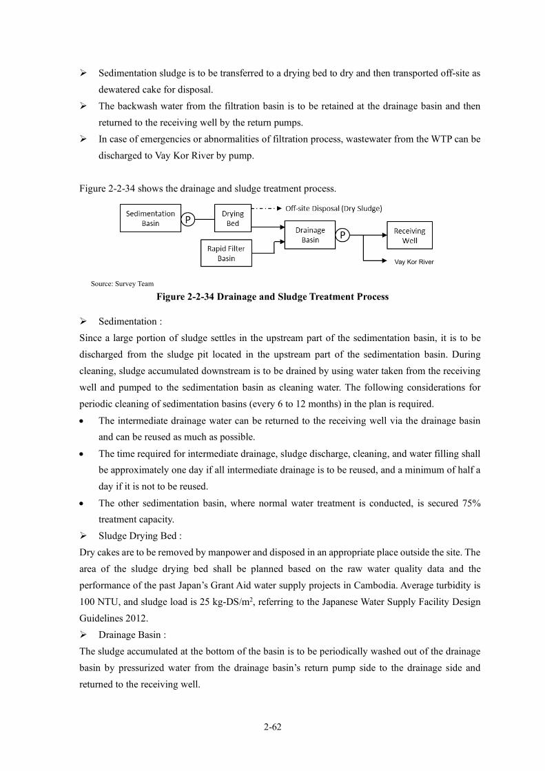
2-62
Sedimentation sludge is to be transferred to a drying bed to dry and then transported off-site as dewatered cake for disposal.
The backwash water from the filtration basin is to be retained at the drainage basin and then returned to the receiving well by the return pumps.
In case of emergencies or abnormalities of filtration process, wastewater from the WTP can be discharged to Vay Kor River by pump.
Figure 2-2-34 shows the drainage and sludge treatment process.
Source: Survey Team
Figure 2-2-34 Drainage and Sludge Treatment Process
Sedimentation : Since a large portion of sludge settles in the upstream part of the sedimentation basin, it is to be discharged from the sludge pit located in the upstream part of the sedimentation basin. During cleaning, sludge accumulated downstream is to be drained by using water taken from the receiving well and pumped to the sedimentation basin as cleaning water. The following considerations for periodic cleaning of sedimentation basins (every 6 to 12 months) in the plan is required.
• The intermediate drainage water can be returned to the receiving well via the drainage basin and can be reused as much as possible.
• The time required for intermediate drainage, sludge discharge, cleaning, and water filling shall be approximately one day if all intermediate drainage is to be reused, and a minimum of half a day if it is not to be reused.
• The other sedimentation basin, where normal water treatment is conducted, is secured 75% treatment capacity.
Sludge Drying Bed : Dry cakes are to be removed by manpower and disposed in an appropriate place outside the site. The area of the sludge drying bed shall be planned based on the raw water quality data and the performance of the past Japan’s Grant Aid water supply projects in Cambodia. Average turbidity is 100 NTU, and sludge load is 25 kg-DS/m2, referring to the Japanese Water Supply Facility Design Guidelines 2012. Drainage Basin : The sludge accumulated at the bottom of the basin is to be periodically washed out of the drainage basin by pressurized water from the drainage basin’s return pump side to the drainage side and returned to the receiving well.
Vay Kor River
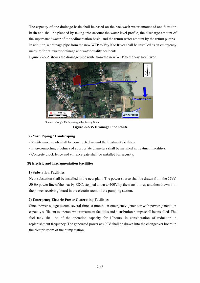
2-63
The capacity of one drainage basin shall be based on the backwash water amount of one filtration basin and shall be planned by taking into account the water level profile, the discharge amount of the supernatant water of the sedimentation basin, and the return water amount by the return pumps. In addition, a drainage pipe from the new WTP to Vay Kor River shall be installed as an emergency measure for rainwater drainage and water quality accidents. Figure 2-2-35 shows the drainage pipe route from the new WTP to the Vay Kor River.
Source:Google Earth, arranged by Survey Team
Figure 2-2-35 Drainage Pipe Route
2) Yard Piping / Landscaping • Maintenance roads shall be constructed around the treatment facilities. • Inter-connecting pipelines of appropriate diameters shall be installed in treatment facilities. • Concrete block fence and entrance gate shall be installed for security.
(8) Electric and Instrumentation Facilities
1) Substation Facilities New substation shall be installed in the new plant. The power source shall be drawn from the 22kV, 50 Hz power line of the nearby EDC, stepped down to 400V by the transformer, and then drawn into the power receiving board in the electric room of the pumping station.
2) Emergency Electric Power Generating Facilities Since power outage occurs several times a month, an emergency generator with power generation capacity sufficient to operate water treatment facilities and distribution pumps shall be installed. The fuel tank shall be of the operation capacity for 10hours, in consideration of reduction in replenishment frequency. The generated power at 400V shall be drawn into the changeover board in the electric room of the pump station.
Vay Kor River
Downstream
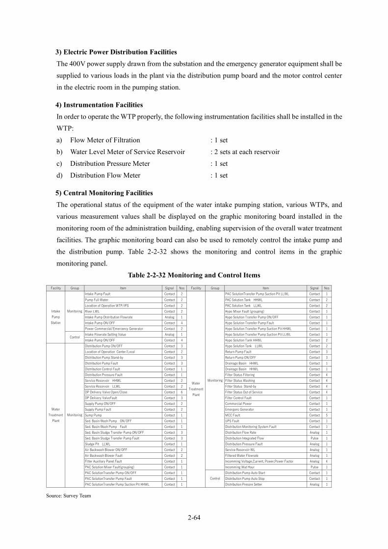
2-64
3) Electric Power Distribution Facilities The 400V power supply drawn from the substation and the emergency generator equipment shall be supplied to various loads in the plant via the distribution pump board and the motor control center in the electric room in the pumping station.
4) Instrumentation Facilities In order to operate the WTP properly, the following instrumentation facilities shall be installed in the WTP: a) Flow Meter of Filtration : 1 set b) Water Level Meter of Service Reservoir : 2 sets at each reservoir c) Distribution Pressure Meter : 1 set d) Distribution Flow Meter : 1 set
5) Central Monitoring Facilities The operational status of the equipment of the water intake pumping station, various WTPs, and various measurement values shall be displayed on the graphic monitoring board installed in the monitoring room of the administration building, enabling supervision of the overall water treatment facilities. The graphic monitoring board can also be used to remotely control the intake pump and the distribution pump. Table 2-2-32 shows the monitoring and control items in the graphic monitoring panel.
Table 2-2-32 Monitoring and Control Items
Source: Survey Team
Facility Group Item Signal Nos Facility Group Item Signal NosIntake Pump Fault Contact 2 PAC SolutionTransfer Pump Suction Pit LLWL Contact 1Pump Full Water Contact 2 PAC Solution Tank HHWL Contact 2Location of Operation WTP/IPS Contact 2 PAC Solution Tank LLWL Contact 2River LWL Contact 2 Hypo Mixer Fault (grouping) Contact 1Intake Pump Distribution Flowrate Analog 1 Hypo Solution Transfer Pump ON/OFF Contact 1Intake Pump ON/OFF Contact 4 Hypo Solution Transfer Pump Fault Contact 1Power Commercial/Emercency Generator Contact 2 Hypo Solution Transfer Pump Suction Pit HHWL Contact 1Intake Flowrate Setting Value Analog 1 Hypo Solution Transfer Pump Suction Pit LLWL Contact 1Intake Pump ON/OFF Contact 4 Hypo Solution Tank HHWL Contact 2Distribution Pump ON/OFF Contact 3 Hypo Solution Tank LLWL Contact 2Location of Operation Center/Local Contact 2 Return Pump Fault Contact 3Distribution Pump Stand-by Contact 3 Return Pump ON/OFF Contact 3Distribution Pump Fault Contact 3 Drainage Basin HHWL Contact 1Distribution Control Fault Contact 1 Drainage Basin HHWL Contact 1Distribution Pressure Fault Contact 1 Filter Status Filtering Contact 4Service Resorvoir HHWL Contact 2 Filter Status Washing Contact 4Service Resorvoir LLWL Contact 2 Filter Status Stand-by Contact 4DP Delivery Valve Open/Close Contact 6 Filter Status Out of Service Contact 4DP Delivery ValveFault Contact 3 Filter Control Fault Contact 1Supply Pump ON/OFF Contact 2 Commercial Power Contact 1Supply Pump Fault Contact 2 Emergenc Generator Contact 1Sump Pump Contact 1 MCC Fault Contact 5Sed. Basin Wash Pump ON/OFF Contact 1 UPS Fault Contact 1Sed. Basin Wash Pump Fault Contact 1 Distribution Monitoring System Fault Contact 1Sed. Basin Sludge Transfer Pump ON/OFF Contact 3 Distribution Flow Rate Analog 1Sed. Basin Sludge Transfer Pump Fault Contact 3 Distribution Integrated Flow Pulse 1Sludge Pit LLWL Contact 1 Distribution Pressure Fault Analog 1Air Backwash Blower ON/OFF Contact 2 Service Resorvoir WL Analog 1Air Backwash Blower Fault Contact 2 Filtered Water Flowrate Analog 1Filter Auxiliary Panel Fault Contact 1 Incomming Voltage,Current, Power,Power Factor Analog 4PAC Solution Mixer Fault(grouping) Contact 1 Incomming Wat Hour Pulse 1PAC SolutionTransfer Pump ON/OFF Contact 1 Distribution Pump Auto Start Contact 1PAC SolutionTransfer Pump Fault Contact 1 Distribution Pump Auto Stop Contact 1PAC SolutionTransfer Pump Suction Pit HHWL Contact 1 Distribution Pressre Setter Analog 1
IntakePumpStation
Monitoring
WaterTreatment
Plant
Monitoring
Control
WaterTreatment
PlantMonitoring
Control

2-65
6) Remote Monitoring and Control System of Intake Pump Facilities A remote monitoring and control system using telecommunication lines of telecommunication companies shall be installed in the WTP monitoring room to monitor the remote operation of the intake pumping station, operation status and pump distribution flow rate, etc. at the WTP monitoring room.
7) Distribution Monitoring System The flow rate data of the water intake pump station, filtration flow rate, distribution flow rate and distribution pressure in the WTP, distribution water flow (four locations) and distribution pressure (four locations) at the local stations, and information on the flow of the existing WTP shall be imported into the personal computer of the monitoring system in the monitoring room of the administration building, enabling unified management of intake, treatment and distribution. As for the data collection at off-site roadside stations and the old WTP, the mobile network shall be used as in the existing system.
8) Summary of the WTP Plan Table 2-2-33 shows the components of the necessary facilities and instruments discussed in the new WTP plan.
Table 2-2-33 Specifications of the New WTP
Items New Svay Rieng WTP
Design Water Treatment Capacity: 7,480m3/day, Design Maximum Daily Demand: 6,800m3/day
Contents Qty
Receiving Well
Reinforced Concrete Structure
1 basin Internal Dimensions: Width 1.50m × Length 3.90m × Depth 4.60m
Volume (V): 26.9 m3, Retention Time (T): 5.2min (Criteria: T ≧1.5min)
Mixing Well
Reinforced Concrete Structure
1 basin The method to utilize the energy of water flow itself
Internal Dimensions: Width 1.50m × Length 1.50m × Depth 4.19m
Volume (V): 9.43 m3, Retention Time (T): 1.82min (Criteria: 1<T<5min)
Flocculation Basin
Reinforced Concrete Structure
2 basins
Slow Mixing Method: Up-and-Down Roundabout Type (zigzag flow)
Number of Stages: five (5) stages
Internal Dimensions per Basin:
G Value: 10 – 75 (1/s) GT Value: 23,000 – 210,000 Width 7.00 m × Length 3.65 m× Average Effective Water Depth3.78m (Height 4.50m)
Sedimentation Basin
Reinforced Concrete Structure
2 basins
Horizontal Flow Sedimentation Type
Supernatant Water Collecting System: Collecting Trough + Submerged Orifice
Internal Dimensions per Basin:
Width 7.00m × Length 20.00m × Average Water Depth 4.4m
Surface Loading: Q/A=18.6mm/min (Criteria:15-30mm/min)
Mean Velocity (V): 0.08m/min (Criteria: 0.40m/min or below)

2-66
Items New Svay Rieng WTP
Design Water Treatment Capacity: 7,480m3/day, Design Maximum Daily Demand: 6,800m3/day
Contents Qty
Rapid Sand Filter (Reference) *
Reinforced Concrete Structure
4 basins
Type: Self-Balancing Type
Internal Dimensions per Basin: Width 2.50m × Length 6.00m
Filter Sand Thickness: 1.0m
Underdrain System: Perforated Block
Filtration Rate (V): 124.7m/day (Criteria: 120-150m/day)
Backwash Method: Air Wash + Water Wash
Service Reservoir
Reinforced Concrete Structure using Flat Slab Structure
2 basins
Effective Volume per Basin (V): 2,188m3 (1,094m3 × 2Basins)
Effective Water Depth (H): 3.8m (Criteria:3-6m)
Retention Time (T): 8hours (Set from daily-water demand fluctuation)
Internal Dimension per Basin: Width 12.00m × Length 24.00m × Height 4.50m
Drainage Basin
Reinforced Concrete Structure
2 basins Volume (V): 198.0m3(99.0m3 × 2Basins) (Volume per Basin: More than one-time wastewater volume) Internal Dimension per Basin:
Width4.00m × Length 11.00m × Effective Water Depth 2.25m (Height 5.60m)
Drying Bed
Reinforced Concrete Structure
4 beds Effective Area (A): 550.4m2 (Area per bed: Width 8.6m × Length 16m=137.6m2) (Average Turbidity: After calculating the amount of generated sludge from the coagulant injection rate, the area from the planned sludge load is calculated.)
Chemical Feeding Facilities
(In Chemical Building)
Coagulant: PAC Injection Method: Gravity Flow from Constant Water Level Tank.
1 unit
Acid and Alkali Agents: Lime (for supplementing the alkali content consumed by the coagulant) Injection Method: Gravity Flow (The agents are quantified with a powder quantifier and dissolved by water flow.)
Chlorine Agents: Calcium Hypochlorite (Bleached Powder) Injection Method: Gravity Flow from Constant Water Level Tank.
Power Generator Equipment
(In Chemical Building)
Capacity: Long Running Type 350KVA
1 unit Type : Low Noise Cubicle Type
Chemical Building
Reinforced Concrete Structure, 3-Storey Building, Total Floor Area (A): 425.8m2
1 unit
(Usage) Ground Floor: Workshop, Storage, Emergency Generator Room, Toilet
Chemical Delivery Facility (1-3 Fl. Open Ceiling)
1st Floor: Waste Solution Reservoir, Chemical Injection Equipment
2nd Floor: Chemical Dissolving Tank Room
Administration Building
Reinforced Concrete Structure, 1 Story Building, Total Floor Area (A): 266.7m2
1 unit (Usage) Ground Floor: Office Room, Meeting Room, Monitoring Room, Laboratory, Toilet
Note: * As stated in Section 2-2-2-5-(4)-4), since the specification and structure of rapid sand filter is based on bidder’s proposal, the description on the above table is for reference. Source: Survey Team
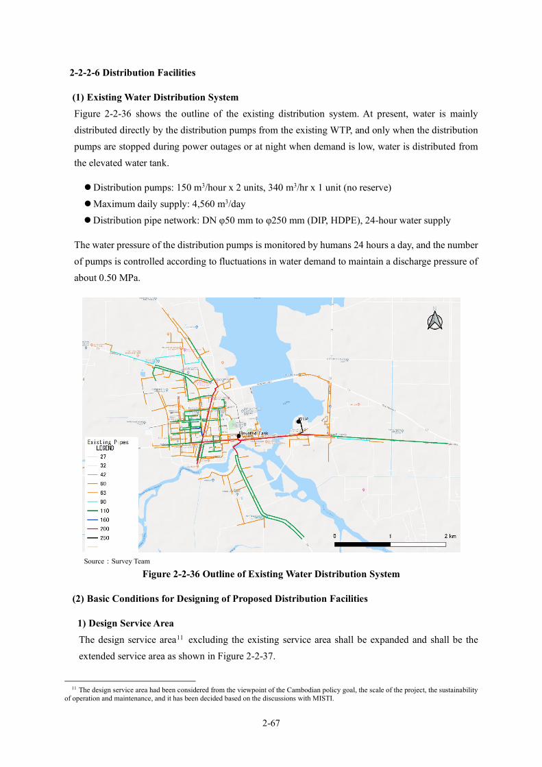
2-67
2-2-2-6 Distribution Facilities
(1) Existing Water Distribution System Figure 2-2-36 shows the outline of the existing distribution system. At present, water is mainly distributed directly by the distribution pumps from the existing WTP, and only when the distribution pumps are stopped during power outages or at night when demand is low, water is distributed from the elevated water tank.
Distribution pumps: 150 m3/hour x 2 units, 340 m3/hr x 1 unit (no reserve) Maximum daily supply: 4,560 m3/day Distribution pipe network: DN φ50 mm to φ250 mm (DIP, HDPE), 24-hour water supply
The water pressure of the distribution pumps is monitored by humans 24 hours a day, and the number of pumps is controlled according to fluctuations in water demand to maintain a discharge pressure of about 0.50 MPa.
Source:Survey Team
Figure 2-2-36 Outline of Existing Water Distribution System
(2) Basic Conditions for Designing of Proposed Distribution Facilities
1) Design Service Area The design service area11 excluding the existing service area shall be expanded and shall be the extended service area as shown in Figure 2-2-37.
11 The design service area had been considered from the viewpoint of the Cambodian policy goal, the scale of the project, the sustainability
of operation and maintenance, and it has been decided based on the discussions with MISTI.

2-68
Source: Survey Team
Figure 2-2-37 Design Service Area
2) Design Distribution Flow The design distribution flow shall be 368.3m3/hr which is the design maximum hourly distribution flow in the design service area calculated from the design maximum daily supply of 6,800 m3/day divided by 24hr and multiplied by the time coefficient of 1.312.
(3) Water Distribution System
1) Reorganization of Water Distribution Systems Figure 2-2-38 shows the relation between the location and water demand in the existing and extended service areas. The existing service area shown in yellow is located in the center of the figure, and the extended service area shown in light blue surrounds the existing water supply area. The existing facility capacity is 6,560 m3/day against the planned water demand of 8,360 m3/day in the existing area, and the new facility capacity is 6,800m3/day against the planned water supply of 5,000 m3/day in the extended area, so that the facility capacity and the demand of target area do not match. Therefore, it is necessary to reorganize the distribution system in the existing area and the extended area.
12 Since the facility of Svay Rieng City is similar in scale and condition to that of Pursat City, which is being implemented as a similar project, the time coefficient will be set to 1.30 adopted to the facility of Pursat.
既存配水管
既存給水区域
計画給水区域 :Design Service Area
:Existing Service Area
:Ex. Distribution Pipes

2-69
Source: Survey Team
Figure 2-2-38 Relation between Location and Demand in Existing and Extended Service Areas
Figure 2-2-39 shows two proposals for the reorganization of the distribution systems in the existing and extended areas. “PLAN 1” is to completely separate the existing system from the new system, and “PLAN 2” is to reorganize each system according to capacity and location. “PLAN 1” requires the reinforcement of existing pipes with insufficient capacities and the construction of new pipes on the same line as the existing pipes, which will result in double piping that is unnecessary, and the boundary between the existing and new areas is complicated and difficult to understand. Therefore, “PLAN 2” shall be adopted.
P
Existing WTP
Capacity:4,560+2,000=6,560m3/D
Elevated Tank
P
New WTP
Capacity:6,800m3/D
Existing Area
Demand:8,360m3/D
Extended Area
Demand:5,000m3/D
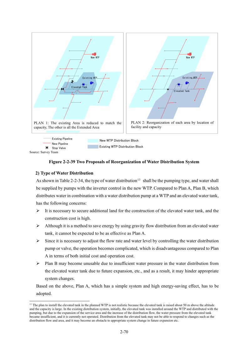
2-70
Source: Survey Team
Figure 2-2-39 Two Proposals of Reorganization of Water Distribution System
2) Type of Water Distribution As shown in Table 2-2-34, the type of water distribution13 shall be the pumping type, and water shall be supplied by pumps with the inverter control in the new WTP. Compared to Plan A, Plan B, which distributes water in combination with a water distribution pump at a WTP and an elevated water tank, has the following concerns: It is necessary to secure additional land for the construction of the elevated water tank, and the
construction cost is high. Although it is a method to save energy by using gravity flow distribution from an elevated water
tank, it cannot be expected to be as effective as Plan A. Since it is necessary to adjust the flow rate and water level by controlling the water distribution
pump or valve, the operation becomes complicated, which is disadvantageous compared to Plan A in terms of both initial cost and operation cost.
Plan B may become unusable due to insufficient water pressure in the water distribution from the elevated water tank due to future expansion, etc., and as a result, it may hinder appropriate system changes.
Based on the above, Plan A, which has a simple system and high energy-saving effect, has to be adopted.
13 The plan to install the elevated tank in the planned WTP is not realistic because the elevated tank is raised about 50 m above the altitude and the capacity is large. In the existing distribution system, initially, the elevated tank was installed around the WTP and distributed with the pumping, but due to the expansion of the service area and the increase of the distribution flow, the water pressure from the elevated tank became insufficient, and it is currently not operated. Distribution from the elevated tank may not be able to respond to changes such as the distribution flow and area, and it may become an obstacle to appropriate system change in future expansion etc.
P
Existing WTP
Elevated Tank
P
New WTP
New WTP Distribution Block
Existing WTP Distribution Block
P
Existing WTP
Elevated Tank
P
New WTP
Existing Pipeline
New Pipeline
Stop Valve
PLAN 1: The existing Area is reduced to match the capacity, The other is all the Extended Area
PLAN 2: Reorganization of each area by location of facility and capacity

2-71
Table 2-2-34 Comparison of Water Distribution Type
Case Plan A: Pumping (inverter control) type from the WTP
Plan B: Combined type (pumping from the WTP and gravity flow from elevated tank)
Description
- Directly conveys water from the new pump to the planned distribution block.
- Directly conveys water from the existing pump to the existing distribution block.
- Facilities (Service Reservoir, Distribution Pump, Distribution Trunk Mains, Operation Control System).
- Directly conveys water from the new pump to around the WTP in the planned distribution block, and gravity flow from the elevated tank to the distance area of the planned distribution block.
- Directly conveys water from the existing pump to the existing distribution block.
- Facilities (Service Reservoir, Distribution Pump, Elevated Tank, Distribution Trunk Mains, Operation Control System)
Conceptual Illustration
Ease of operation and maintenance
- It is easier than Plan B. - Water level control of the elevated tank is necessary. - Pump operation to cover water distribution for
demand is necessary, and water transmission to the elevated tank becomes complicated.
- There are two facilities, which makes maintenance slightly difficult.
Necessity of site acquisition
- It is unnecessary to acquire a new site. - It is necessary to acquire the site for the elevated tank.
Construction cost - It is slightly cheaper than Plan B. - It is slightly more expensive than Plan A.
Electricity consumption
- The electricity usage of the distribution pump according to demand can be expected to be minimized by inverter control.
- Water distribution by the elevated tank can suppress the pump energy at the maximum time period, but it is over Plan A at the time of water distribution to the elevated tank during the small water distribution period such as late night.
- Overall, Plan B cannot expect energy saving beyond Plan A.
Comprehensive evaluation
- Compared to Plan B, there are few facilities and equipment, it is a simple system, and energy saving effect is high.
- Compared to Plan A, there are many facilities and equipment, controlling the system is complicated, and energy saving effect is lesser.
〇*1 △ *1 ◎: Excellent, ○: Good, △: Fair Source: Survey Team
(4) Route of Distribution Pipes The route of distribution pipes shall be decided by selecting the route with high density of houses and then confirming the road width, obstacles, etc., by field survey. The proposed distribution pipe route is as shown in Figure 2-2-40.
P
Existing WTP
Elevated Tank
P
New WTP
New WTP Distribution Block
Existing WTP Distribution Block
Existing Pipeline
Planned PipelineStop Valve
P
P
Existing Pipeline
Planned PipelineStop Valve
Existing WTP
Elevated Tank
New WTP
New WTP Distribution Block
Existing WTP Distribution Block
Elevated Tank
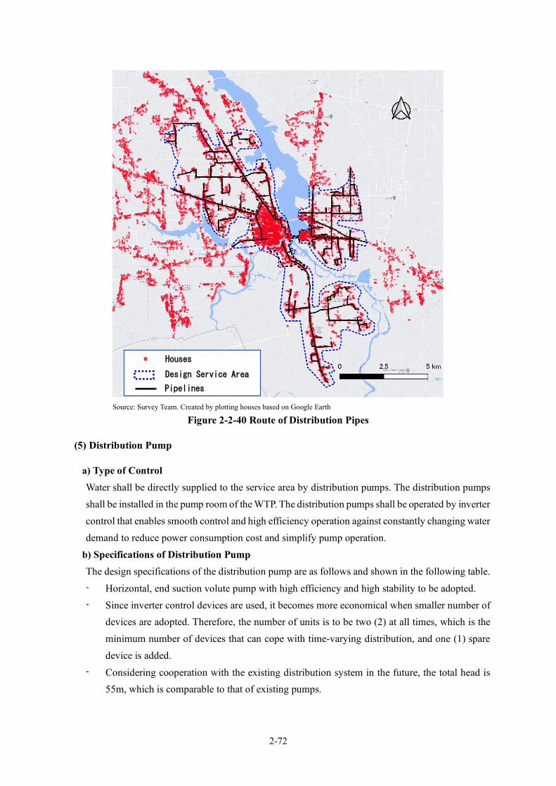
2-72
Source: Survey Team. Created by plotting houses based on Google Earth
Figure 2-2-40 Route of Distribution Pipes
(5) Distribution Pump
a) Type of Control Water shall be directly supplied to the service area by distribution pumps. The distribution pumps shall be installed in the pump room of the WTP. The distribution pumps shall be operated by inverter control that enables smooth control and high efficiency operation against constantly changing water demand to reduce power consumption cost and simplify pump operation.
b) Specifications of Distribution Pump The design specifications of the distribution pump are as follows and shown in the following table. - Horizontal, end suction volute pump with high efficiency and high stability to be adopted. - Since inverter control devices are used, it becomes more economical when smaller number of
devices are adopted. Therefore, the number of units is to be two (2) at all times, which is the minimum number of devices that can cope with time-varying distribution, and one (1) spare device is added.
- Considering cooperation with the existing distribution system in the future, the total head is 55m, which is comparable to that of existing pumps.
Houses
Design Service Area
Pipelines

2-73
Table 2-2-35 Specifications of Distribution Pump Items Specifications
Type Horizontal, end suction volute pump Quantity 3 sets (including one set of standby) Capacity of pump 5,040m3/day (3.5m3/min) Total head 55m Output of motor 75kW Diameter 200mm x 100mm Speed SS1500min-1 Accessory equipment Flywheel GD2=200kgm2
Source:Survey Team
(6) Capacity of Service Reservoir In order to achieve stable water supply during normal times and emergency, the capacity of the service reservoir shall be 8 hours14 volume equivalent of the maximum daily supply of the service area; 2,200 m3 (6,800 m3 × 8/24).
(7) Pipe Diameter for Distribution Mains The pipe diameter in which the minimum dynamic water pressure shall not become lower than the minimum standard pressure15 , and shall be determined, based on hydraulic network analyses for normal operation and at the time of fire. Appendix 7-9 presents the results of the hydraulic network analyses.
(8) Pipe Material for Distribution Mains The materials and standards for the distribution mains, buried sections in general, shall be as follows. In case the diameter 300 mm or more, the pipe shall be DIP and the ISO standard (push-on joint excellent in workability even in narrow excavation width) shall be adopted. In case the diameter is 250 mm or less, it shall be HDPE pipe of PN 10 class. In the case of river crossing sections, the materials for the distribution mains shall be SP with corrosion prevention.
(9) Crossing River and Other Water Channel Figure 2-2-41 shows the main points on the distribution pipeline that require special piping such as river crossings and culverts (box culverts, hume pipes). There are 6 steel / concrete bridges, 3 culverts (boxes), and 65 culverts (hume pipes). The construction method for each location is shown as follows.
14 With regard to the service reservoir capacity, it shall be decided by coordination with MISTI with reference to 4 hours of the design maximum daily supply which is actual value of existing distribution facilities and other cities. See Appendix 7-8. 15 Minimum pressure: 0.05MPa. The distribution pipe network is designed to ensure the adequate residual water pressure throughout the terminal area, highlands, etc. The target area is flat with the elevation difference of approximately 5m across the whole area and there is no highland. Under such conditions, it is efficient and economical to secure a minimum water pressure at the end of the pipeline by gradually increasing the loss water pressure according to the length of the pipeline.

2-74
Source: Survey Team, created by means of plotting river crossings etc. on Google Earth image
Figure 2-2-41 Locations Map of Crossing Rivers and Other Structures
Steel and Concrete Bridge-Photo A Concrete Bridge-Photo B Steel and Concrete Bridge-Photo C
Culvert-Photo D Culvert-Photo E Culvert-Photo F
Source: Survey Team
Figure 2-2-42 Photographs of Bridges and Culverts
Bridge
Distribution Pipelines
Hume Pipe
Box Culvert
Photo A
Photo B
Photo C
Photo D
Photo E
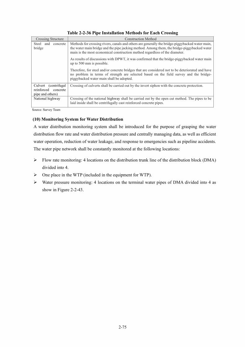
2-75
Table 2-2-36 Pipe Installation Methods for Each Crossing Crossing Structure Construction Method
Steel and concrete bridge
Methods for crossing rivers, canals and others are generally the bridge-piggybacked water main, the water main bridge and the pipe jacking method. Among them, the bridge-piggybacked water main is the most economical construction method regardless of the diameter.
As results of discussions with DPWT, it was confirmed that the bridge-piggybacked water main up to 500 mm is possible.
Therefore, for steel and/or concrete bridges that are considered not to be deteriorated and have no problem in terms of strength are selected based on the field survey and the bridge-piggybacked water main shall be adopted.
Culvert (centrifugal reinforced concrete pipe and others)
Crossing of culverts shall be carried out by the invert siphon with the concrete protection.
National highway Crossing of the national highway shall be carried out by the open cut method. The pipes to be laid inside shall be centrifugally cast reinforced concrete pipes.
Source: Survey Team
(10) Monitoring System for Water Distribution A water distribution monitoring system shall be introduced for the purpose of grasping the water distribution flow rate and water distribution pressure and centrally managing data, as well as efficient water operation, reduction of water leakage, and response to emergencies such as pipeline accidents. The water pipe network shall be constantly monitored at the following locations:
Flow rate monitoring: 4 locations on the distribution trunk line of the distribution block (DMA) divided into 4.
One place in the WTP (included in the equipment for WTP). Water pressure monitoring: 4 locations on the terminal water pipes of DMA divided into 4 as
show in Figure 2-2-43.
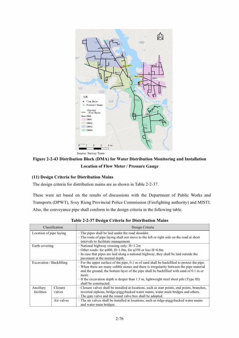
2-76
Source: Survey Team
Figure 2-2-43 Distribution Block (DMA) for Water Distribution Monitoring and Installation Location of Flow Meter / Pressure Gauge
(11) Design Criteria for Distribution Mains The design criteria for distribution mains are as shown in Table 2-2-37.
These were set based on the results of discussions with the Department of Public Works and Transports (DPWT), Svey Rieng Provincial Police Commission (Firefighting authority) and MISTI. Also, the conveyance pipe shall conform to the design criteria in the following table.
Table 2-2-37 Design Criteria for Distribution Mains Classification Design Criteria
Location of pipe laying The pipes shall be laid under the road shoulder. The route of pipe laying shall not move to the left or right side on the road at short
intervals to facilitate management. Earth covering National highway crossing only: H=1.2m
Other roads: for φ400, H=1.0m, for φ350 or less H=0.8m In case that pipes are laid along a national highway, they shall be laid outside the
pavement at the normal depth. Excavation / Backfilling For the upper surface of the pipe, 0.1 m of sand shall be backfilled to protect the pipe.
When there are many cobble stones and there is irregularity between the pipe material and the ground, the bottom layer of the pipe shall be backfilled with sand of 0.1 m or more. If the excavation depth is deeper than 1.5 m, lightweight steel sheet pile (Type III)
shall be constructed. Ancillary
facilities Closure valves
Closure valves shall be installed at locations, such as start points, end points, branches, inverted siphons, bridge-piggybacked water mains, water main bridges and others. The gate valve and the round valve box shall be adopted.
Air valves The air valves shall be installed at locations, such as ridge-piggybacked water mains and water main bridges.

2-77
Classification Design Criteria For φ200 or more, the air valves shall be installed at locations, such as topographical
convex parts, inverted siphons and others. Drainage facilities
The drainage facilities shall be installed at pipe concave sections and/or near rivers and irrigation canal etc.
Protection of special fittings
The anti-escapement fixture shall be adopted. (This is a countermeasure to suppress the damage of pipe due to the imbalanced forces generated by the bent parts, the branch parts, the gate valves and others. The protection by concrete blocks as another method requires curing period of concrete. Therefore, it shall not be adopted considering the workability based on road conditions.)
Hydrants The hydrant (ground type) shall be installed at eight places where the distribution mains are laid out among the 4 places requested. (See Figure 2-2-44).
Source: Survey Team
Source: Survey Team, Satellite image: Google Earth
Figure 2-2-44 Location of Hydrants to be Installed
(12) Plan for Distribution Facilities Based on the above, the plan for distribution facilities is summarized as shown in Figure 2-2-45 and Table 2-2-38.
Fire Hydrant Requested
Design Service Area
Distribution Pipelines
Administrative Area

2-78
Source: Survey Team
Figure 2-2-45 Plan for Distribution Mains

2-79
Table 2-2-38 Specifications of Distribution Facilities
Note: Pipe length of water main bridges and the bridge-piggybacked water mains shall be included in the length of ductile cast iron pipes and HDPE pipes. Source: Survey Team
2-2-2-7 Procurement Plan of Equipment and Materials Based on the initial request from the Cambodian side and the discussion results at the inception stage or the on-site explanation stage about the outline of survey results, the minimum required equipment and materials for this project are selected as shown in Table 2-2-39.
Table 2-2-39 Initial Request from Cambodian Side and Field Survey Results
Classification of Equipment to be Procured Contents of Initial Request Equipment to be Procured based on
Field Survey Results Procurement of Equipment
Equipment for Water quality management
Atomic absorption photometer, distillation equipment, microscope, reagents, glassware, turbidimeter, pH meter, UPS, etc.
Distilled water maker, portable turbidity meter, turbidity meter, pH meter (glass electrode type), electrical conductivity meter, UPS, continuous water quality analyzer for conductivity and residual chlorine, reagents, glassware, center laboratory table, side laboratory table, chemical cabinet, refrigerator, desk and chair.
Equipment for electric Power tester, detector, vibrometer, Clamp power meter, insulation
Facility Type and Structure Quantity Service Reservoir (Inside new WTP)
Reinforced concrete (RC) Structure, Rectangle, two reservoirs Effective capacity: V=1,094 m3×2 Effective depth: H=3.80 m Water level: HWL+3.90m, LWL+0.10m Foundation: Direct foundation
1 set
Distribution Pump Facilities (Inside new WTP)
Horizontal volute pump 3.5m3/min H=55m 75kW Inverter equipment
3 Pumps (Including one standby pump)
Distribution Mains DCIP Straight pipe: T type, Thrust blocking: Retainer gland φ400mm L= 0.1km / φ350mm L= 0.4km / φ300mm L= 0.4km
0.9 km
HDPE φ250mm L= 6.6km / φ200mm L= 2.9km / φ150mm L= 9.5km / φ100mm L= 15.4km / φ 80mm L= 33.2km / φ 50mm L= 43.3km
110.9km
Bridge-piggybacked Water main SP (corrosion prevention coating) φ 80mm 5 places / φ 50mm 1 place
6 Places
Monitoring System of Water Distribution
Central monitoring station: data transmission equipment, monitoring computer, printer & ancillary equipment Flow monitoring station: Distribution pipeline 2 stations (For each
station; φ200 flow meter 1 unit, φ250 flow meter 1 unit, data transmission equipment & ancillary equipment) Existing water treatment plant 1 station (data transmission equipment & ancillary equipment, 1 unit of flow signal will be received from existing flow meter) Pressure monitoring station: Distribution pipeline 4 stations (For
each station; 1 pressure transmitter, data transmission equipment & ancillary equipment) Outline of equipment specification:
Data transmission equipment (center): PLC, Router, 1 set Data transmission equipment (local): RTU, GPRS router, 7 sets Flowmeter: Electromagnetic flow meter φ250 2 sets
φ200 2 sets Pressure transmitter: 2 wire type transmitter, 4 sets
1 LS
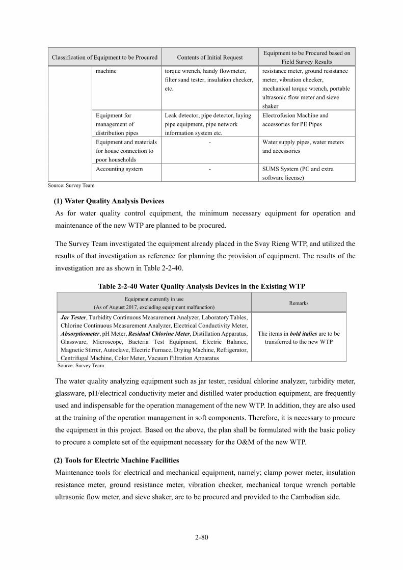
2-80
Classification of Equipment to be Procured Contents of Initial Request Equipment to be Procured based on
Field Survey Results machine torque wrench, handy flowmeter,
filter sand tester, insulation checker, etc.
resistance meter, ground resistance meter, vibration checker, mechanical torque wrench, portable ultrasonic flow meter and sieve shaker
Equipment for management of distribution pipes
Leak detector, pipe detector, laying pipe equipment, pipe network information system etc.
Electrofusion Machine and accessories for PE Pipes
Equipment and materials for house connection to poor households
- Water supply pipes, water meters and accessories
Accounting system - SUMS System (PC and extra software license)
Source: Survey Team
(1) Water Quality Analysis Devices As for water quality control equipment, the minimum necessary equipment for operation and maintenance of the new WTP are planned to be procured.
The Survey Team investigated the equipment already placed in the Svay Rieng WTP, and utilized the results of that investigation as reference for planning the provision of equipment. The results of the investigation are as shown in Table 2-2-40.
Table 2-2-40 Water Quality Analysis Devices in the Existing WTP Equipment currently in use
(As of August 2017, excluding equipment malfunction) Remarks
Jar Tester, Turbidity Continuous Measurement Analyzer, Laboratory Tables, Chlorine Continuous Measurement Analyzer, Electrical Conductivity Meter, Absorptiometer, pH Meter, Residual Chlorine Meter, Distillation Apparatus, Glassware, Microscope, Bacteria Test Equipment, Electric Balance, Magnetic Stirrer, Autoclave, Electric Furnace, Drying Machine, Refrigerator, Centrifugal Machine, Color Meter, Vacuum Filtration Apparatus
The items in bold italics are to be transferred to the new WTP
Source: Survey Team
The water quality analyzing equipment such as jar tester, residual chlorine analyzer, turbidity meter, glassware, pH/electrical conductivity meter and distilled water production equipment, are frequently used and indispensable for the operation management of the new WTP. In addition, they are also used at the training of the operation management in soft components. Therefore, it is necessary to procure the equipment in this project. Based on the above, the plan shall be formulated with the basic policy to procure a complete set of the equipment necessary for the O&M of the new WTP.
(2) Tools for Electric Machine Facilities Maintenance tools for electrical and mechanical equipment, namely; clamp power meter, insulation resistance meter, ground resistance meter, vibration checker, mechanical torque wrench portable ultrasonic flow meter, and sieve shaker, are to be procured and provided to the Cambodian side.

2-81
(3) Equipment for Management of Distribution Pipe Leak detector, pipe detector and laying pipe equipment have been procured through other past technical cooperation of Japan and it was confirmed that the above-mentioned equipment are used and stored in good condition in the SWWs. Therefore, they shall be excluded from the procurement list of this project.
Meanwhile, as for the pipe laying equipment, butt fusion machine for PE pipes shall be procured. The pipe network information system shall be included as a water-distribution management system for construction work.
(4) Service Connection Installations Service connection installations are granted to the poor households (Poor Level 1): 375 in the planned water supply area. Connecting poor households to piped water supply is the obligation of the RGC. For all beneficiaries except poor households, the beneficiaries will pay labor cost and the cost of connection materials.
The connection fee including pipe material cost is about 290,000KHR. Out of this connection fee, labor cost is 4,000KHR/m. Therefore, the cost of connection for a 5m length service pipe is about 20,000 KHR (5USD). So far, the poor households have been exempted from paying or paid in installments up to 12 times.
The number of poor households in the area is estimated by the following formula based on the poverty group data from “Identification of Poor Household Programme” conducted in 2010 to 2011 by the Ministry of Planning.
Poor Household Number (F) = Σ{Poverty Ratio of Village (C)×Household Number of Village (E)}
The number of Poor Level 1 households in the design water supply area in 2027 has been estimated to be 410 households.
The number of poor households eligible for grant aid (house connection materials) is 375, which was calculated by subtracting 35 households connected at the time of survey in December 2019 from 410 in the design water supply area in 2027. The estimation results of the number of poor households are shown in Appendix 7-10.
(5) SUMS System Synergistic Utilities Management System (SUMS) is an integrated business data processing system which has features of issuing invoice by use of reading data of water meter, accounting and automated payment. Although the SWWs have already installed a PC with software for billing, accounting and casher through the Project on Capacity Building for Urban Water Supply System (Phase 3), additional software license and a client PC shall be procured because the number of water-supplied households will increase.

2-82
(6) Equipment Procurement Countries Water quality analysis equipment and vibration checker, etc. are special devices and the quality of these equipment is particularly important. As a matter of fact, in Cambodia, high-quality third-country water quality instruments such as those made in the United States are also distributed through local distributors. This equipment shall be continuously procured by the WWs even after the project is implemented.
Therefore, the procurement source of the equipment shall not be limited to procurement in Japan and Cambodia, considering the procurement record of equipment in the other grant aid project currently being implemented and the compatibility with the existing equipment made in a third country and distributed in Cambodia.
In conclusion, if the specifications can be satisfied, it is considered that third country procured products can be applied.
(7) Procurement Timing of Equipment Water quality analysis equipment, mechanical equipment and accounting system equipment shall be procured at the time prior to the implementation of the soft component because training on how to handle and maintain this procured equipment is planned during the activity of soft component.
The service connection materials shall be provided before the completion of the project because it is necessary to have the Cambodian side conduct service connection work before the completion of the project in order to increase the water supply ratio in the target water supply area.
Table 2-2-41 shows the summary of equipment to be provided in this project based on the considerations described above.
Table 2-2-41 Summary of Equipment to be Provided
Item Equipment/Material Specification Qty
Equipment for Water Quality Analysis
Water Quality Instruments
Distillation apparatus, Turbidity Meter, pH Meter, Electric Conductivity Meter
1 set
Uninterrupted Power System (UPS)
Output Capacity: 3kVA 1 set
Continuous Measurement Water Quality Analyzer
Analyzer that continuously measures the turbidity of treated water. Measurement Range: 0-100NTU (Turbidity), 0-3mg/L (Residual Chlorine)
1 set
Reagents pH Standard Solution, BTB reagent, DPD reagent, etc. 1 set Glassware Beaker, Measuring Flask, Pipette, burette, etc. 1 set Laboratory Table Central Laboratory Table (including reagent shelf, socket outlet, piping
and wiring), Side Laboratory Table and Sink 1 set
Other Storage Shelf, Refrigerator and Desk/Chair 1 set Tools for Electrical Machinery Equipment
Clamp Power Meter Voltage Range: AC600V Current Range: AC600mA-AC 1,000mA (or above)
1 set
Insulation resistance meter
For analog indication Value 250V Range : 0 – 50MΩ 500V Range : 0 – 100MΩ 1000V Range : 0 – 2000MΩ
For digital indication Value 250V Range : 0 – 500MΩ
1 set

2-83
Item Equipment/Material Specification Qty
500V Range : 0 – 2000MΩ 1000V Range : 0 – 4000MΩ
Ground resistance meter
0 – 1000Ω 1 set
Vibration Checker Acceleration: 0.02 – 200m/s2 ; Velocity:0.3 – 1,000mm/s Displacement: 0.02 – 100mm
1 set
Mechanical Torque Wrench
Measurement Range: 50 – 300Nm 1 set
Portable Ultrasonic Flow meter
Measurement Range of Pipe Diameter: 13 – 600mm 1 set
Sieve Shaking Machine
Effective Diameter: 0.8mm – 1.0mm 1 set
Maintenance for Distribution Pipes
Electrofusion Machine and Accessories for PE Pipes
φ63 – 280mm 1 set
Accounting System Equipment
SUMS System
Three (3) Computers (for billing, accounting and casher, one (1) PC for one software), one (1) UPS, one (1) Printer, SUMS Software [two (2) Full Licenses, one (1) Light License] Software of full license includes “Billing “and “Accounting”. Software of light license includes “Casher”. Since each software of “Billing”, “Accounting”, and “Casher” is operated by separate PCs, three (3) PC will be required.
1 set
Service connection installations
Water Supply Equipment
Per 1 set Snap taps with saddle from distribution pipes
(DN350mm~OD63mm) HDPE service pipe (diameter 25mm) 30m Water meter (diameter 15mm, Tangential flow impeller type,
Single-jet, Class C, Rotatable display (Max.270 degree)) Stopcock (diameter 15mm) Attachment (joint, coupling, etc.)
375 sets
Source: Survey Team

2-84
2-2-3 Outline Design Drawings Selected drawings of outline design are attached in Appendix 7-2. The drawing list of the outline design as shown in Table 2-2-42.
Table 2-2-42 List of Outline Design Drawings No. FACILITY CLASIFICATION Description DRAWING No 1. General (G) General Layout of Svay Rieng G1 2. Intake Facility (I) Intake Facilities (1) PI-1
Intake Facilities (2) PI-2
Intake Facilities (3) PI-3
Intake Facilities (4) PI-4
Intake Facilities (5) PI-5
Pump House Plan PI-6
Pump House Section PI-7
3. Raw Water Transmission Facility (R)
Conveyance Pipeline Plan SR-1
4. Treatment Facility (T) Water Treatment Plant General Plan ST-1
Hydraulic Profile of Svay Rieng Water Treatment Plant ST-2
Water Treatment Facilities Structure (1) ST-3
Water Treatment Facilities Structure (2) ST-4
Water Treatment Facilities Structure (3) ST-5
Water Treatment Facilities Structure (4) ST-6
Water Treatment Facilities Structure (5) ST-7
Water Treatment Facilities Structure (6) ST-8
Water Treatment Facilities Structure (7) ST-9
Water Treatment Facilities Structure (8) ST-10
Water Treatment Facilities Structure (9) ST-11
Service Reservoir and Pumping Station Structure (1) ST-12
Service Reservoir and Pumping Station Structure (2) ST-13
Service Reservoir and Pumping Station Structure (3) ST-14
Drainage Basin Structure ST-15
Drying Bed Structure ST-16
Water Treatment Plant Process Flow Diagram (1) ST-17
Water Treatment Plant Process Flow Diagram (2) ST-18
Chemical Feeding Facility Plan (1) ST-19
Chemical Feeding Facility Plan (2) ST-20
Instrument & Control Flow Diagram ST-21
Intake PS Monitoring System & Distribution Monitoring System
ST-22
5. Distribution Facility (D) Location Map for Distribution Pipeline SD-1
Distribution Pipe Plan (1) SD-2
Distribution Pipe Plan (2) SD-3
Distribution Pipe Plan (3) SD-4
Distribution Pipe Plan (4) SD-5
Distribution Pipe Plan (5) SD-6
Distribution Pipe Plan (6) SD-7
Distribution Pipe Plan (7) SD-8
Distribution Pipe Plan (8) SD-9
Distribution Pipe Plan (9) SD-10
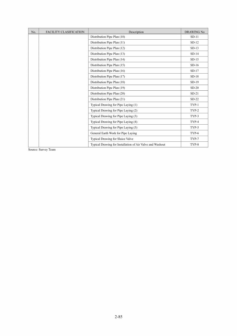
2-85
No. FACILITY CLASIFICATION Description DRAWING No Distribution Pipe Plan (10) SD-11
Distribution Pipe Plan (11) SD-12
Distribution Pipe Plan (12) SD-13
Distribution Pipe Plan (13) SD-14
Distribution Pipe Plan (14) SD-15
Distribution Pipe Plan (15) SD-16
Distribution Pipe Plan (16) SD-17
Distribution Pipe Plan (17) SD-18
Distribution Pipe Plan (18) SD-19
Distribution Pipe Plan (19) SD-20
Distribution Pipe Plan (20) SD-21
Distribution Pipe Plan (21) SD-22
Typical Drawing for Pipe Laying (1) TYP-1
Typical Drawing for Pipe Laying (2) TYP-2
Typical Drawing for Pipe Laying (3) TYP-3
Typical Drawing for Pipe Laying (4) TYP-4
Typical Drawing for Pipe Laying (5) TYP-5
General Earth Work for Pipe Laying TYP-6
Typical Drawing for Sluice Valve TYP-7
Typical Drawing for Installation of Air Valve and Washout TYP-8 Source: Survey Team

2-86
2-2-4 Implementation Plan 2-2-4-1 Implementation Policy
(1) Basic Policy of Project Implementation
・ Should the project be implemented under the Japan’s Grant Aid Scheme, Japan’s Grant Aid is provided through the following procedures:
・ The client of the project is MISTI. Agreements for Contract Documents and Certificate of Completion shall be issued by the Signer of MISTI.
・ The organization for management, operation and maintenance of this project is DISTI and the WWs under the DISTI, which consistently makes technical decisions, and perform various practices such as process control and quality control from the design stage to the operation and maintenance stage.
・ The RGC shall enter into contract with the Consultant for consulting services with regard to designing, tendering, cost estimation and supervision of the procurement and construction works for the project. The Consultant shall be a Japanese consulting firm, which shall be selected by JICA and recommended to the RGC for the project in order to maintain technical consistency.
・ The RGC shall enter into contract with the contractor which shall be selected through competitive tendering, and the contract shall be verified by JICA to fulfil accountability to Japanese taxpayers. The contractor shall be a Japanese firm which is capable of procuring the products and of construction in a proper manner under Japan’s Grant Aid.
・ To establish a smooth and safe construction method and schedule, the following conditions shall be considered: (i) Natural Environment: meteorology, topography and geology; (ii) Social Environment: traffic control, underground facilities and other negative impacts against residents.
(2) Construction and Procurement Policy In Phnom Penh, there are over 15 local construction firms. Some of these firms have experience in Japan’s Grant Aid project as subcontractors of Japanese general contractors. Common technique is required for civil works to implement the construction of water intake facilities and the WTP including building and pipe installation. Although, this project will be carried out in Svay Rieng, it is possible to dispatch workers from the above-mentioned construction companies in Phnom Penh. Therefore, caretakers, machine operators, form workers, concrete workers, and other workers can be dealt with by hiring local people in principle, and there is no need to dispatch special workers from outside Cambodia.
The civil engineering work carried out in this project mainly consists of the construction of water intake facilities, the construction of WTP facilities, and the construction of new water transmission and distribution pipelines and does not require special construction techniques. The office in the water intake facility, the administration building (office) in the WTP facility, and the chemical injection

2-87
building will be constructed. In addition, the water quality analysis equipment used at the WTP and the water supply equipment for the poor households are equipment procurement and do not require special construction technology.
However, since the construction in this project will be carried out in multiple areas, in order to carry out construction management in consideration of safety, environment and quality, Japanese engineers who shall be in charge of management of each construction area including the site office manager shall be dispatched. Japanese engineers for construction management also serve as procurement management for water quality analysis equipment. In addition, construction materials, equipment and labor shall be procured locally.
2-2-4-2 Implementation Conditions The following conditions shall apply to the implementation of the project at construction sites:
・ Great effort will be devoted to coordination and information sharing because there are a number of parties involved. The Cambodian side, the construction contractor, the consultant and the related donor organizations shall meet regularly to review the progress of the project. Other means of communications shall also be used.
・ The consultant shall share information with the involved parties continuously and deploy one project manager and one resident engineer on site to ensure smooth implementation of the project.
・ The construction contractor shall also deploy one representative and one site manager on site.
・ The consultant and the construction contractor shall have offices set up at appropriate locations.
・ Consultations with the Cambodian side shall be required since coordination with the national and state governments is indispensable for approvals of water rights, construction permission for intake facilities, seeking permissions for occupancy of roads, etc.
・ It is planned to install temporary water coffers so that the construction of intake facilities could be executed throughout the year, even in July and October when the water level is higher.
・ The total length of pipes for conveyance pipe, clear water transmission and distribution will be approximately 115 km. Although the main sites are residential areas with unpaved roads, busy paved roads with heavy traffic are also included. Accordingly, the pipe installation shall require special considerations for safety, and disruption of traffic and daily activities in the area shall be minimized.
・ The Cambodian side shall assure the safety of the construction work sites from landmines and unexploded ordinance (UXO) by submitting an official report to the JICA Cambodia Office by the commencement of the construction work.
2-88
・ The construction shall be done in the day time. In case night-time construction cannot be avoided, consultation with the Cambodian side is required.
・ Materials and equipment shall be procured locally. If that is not possible, procurement from Japan or third countries shall be considered sequentially.
・ Materials for service connections to be provided by the Japanese side shall be products manufactured in neighboring countries and sold in Cambodia. These are likely already used by the WWs for existing pipes.
2-2-4-3 Scope of Works The Japanese side shall be responsible for the construction of facilities. The Cambodian side shall be responsible for the storage of procured equipment (especially materials for service connections) and installation of service connections between distribution pipes and households.
Details of the obligations of the Cambodian side are described in Section “2-4, Obligations of Recipient Country”.
2-2-4-4 Consultant’s Supervision The consultant shall provide professional services to the RGC with regard to detailed design, cost estimation, tendering and supervision of the procurement and construction works for the project in accordance with a contract with the RGC.
(1) Detailed Design
The consultant shall conduct the detailed design study for the project, including the following:
• Kick-off meeting with the executing agency and site investigation • Detailed design study on civil and architectural structures and preparation of detail design
drawings
• Detailed design study on mechanical and electrical works and preparation of detail design drawings
• Cost estimation
(2) Tendering Management The consultant shall assist the RGC in conducting the procurement tendering in fair and proper manner, as follows:
• Preparation of tender documents • Notice for Prequalification • Evaluation of Prequalification Documents • Tender Notice • Execution of tendering and Evaluation of tendering • Facilitation of contract between the Client and the contractor
2-89
(3) Construction Supervision The consultant shall provide appropriate supervision and guidance to the contractor, on behalf of the RGC, as follows:
• Check and approve shop drawings • Inspect major equipment and materials at the factories before shipping • Supervise construction activities • Inspect completed structures • Test facility operations and evaluate performance • Inspect the procured equipment • Report on construction progress to the Japanese and Cambodian sides • Safety guidance on the construction work and supervision of the construction quality • Advise on work to be carried out by the Cambodia side • Technical assistance (capacity building) on operation and maintenance of the facilities • Assist the Cambodian side on the necessary procedures and responsibilities in the execution of
the Japan’s Grant Aid project
In order to supervise the activities throughout the construction period, it is necessary to deploy one resident engineer from the start of construction to the commissioning of facilities. In addition, various specialists (as listed below) are required for on-site supervision of the construction of the different facilities as described in detail hereafter.
i) Civil Engineer (conveyance/transmission and distribution facilities) Check shop drawings, supervise construction activities as well as test procedures, provide instruction and advice concerning conveyance/transmission and distribution facilities.
ii) Civil Engineer (Intake facilities / WTP facilities) Check shop drawings, supervise construction activities as well as test procedures, provide instruction and advice concerning intake facilities and WTP facilities.
iii) Architect (office, administration building, chemical room) Check shop drawings, supervise installation of electrical equipment as well as test procedures, provide instruction and advice concerning architectural facilities.
iv) Mechanical Specialist / Electrical Specialist Check shop drawings, supervise installation of mechanical equipment as well as test procedures, provide instruction and advice concerning mechanical and electrical equipment/facilities.
v) Specialist for Procurement of Equipment Check approval procedures, supervise the procurement of equipment and provide instruction and advice.
vi) Defect Inspection Engineer Defect Inspection Engineer shall be dispatched to engage in defect inspection implemented a year after project completion.
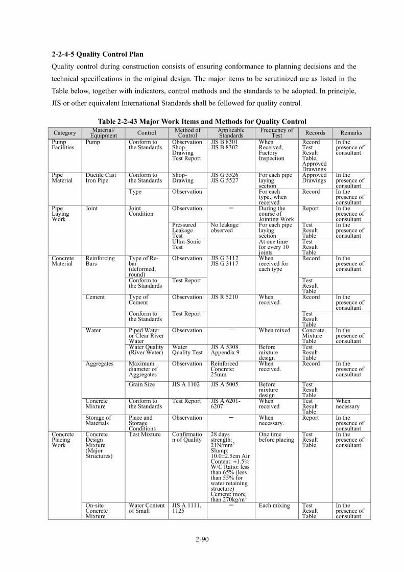
2-90
2-2-4-5 Quality Control Plan Quality control during construction consists of ensuring conformance to planning decisions and the technical specifications in the original design. The major items to be scrutinized are as listed in the Table below, together with indicators, control methods and the standards to be adopted. In principle, JIS or other equivalent International Standards shall be followed for quality control.
Table 2-2-43 Major Work Items and Methods for Quality Control Category Material/
Equipment Control Method of Control
Applicable Standards
Frequency of Test Records Remarks
Pump Facilities
Pump Conform to the Standards
Observation Shop-Drawing Test Report
JIS B 8301 JIS B 8302
When Received, Factory Inspection
Record Test Result Table, Approved Drawings
In the presence of consultant
Pipe Material
Ductile Cast Iron Pipe
Conform to the Standards
Shop-Drawing
JIS G 5526 JIS G 5527
For each pipe laying section
Approved Drawings
In the presence of consultant
Type Observation For each type、when received
Record In the presence of consultant
Pipe Laying Work
Joint Joint Condition
Observation - During the course of Jointing Work
Report In the presence of consultant
Pressured Leakage Test
No leakage observed
For each pipe laying section
Test Result Table
In the presence of consultant
Ultra-Sonic Test
At one time for every 10 joints
Test Result Table
Concrete Material
Reinforcing Bars
Type of Re-bar (deformed, round)
Observation JIS G 3112 JIS G 3117
When received for each type
Record In the presence of consultant
Conform to the Standards
Test Report Test Result Table
Cement Type of Cement
Observation JIS R 5210 When received.
Record In the presence of consultant
Conform to the Standards
Test Report Test Result Table
Water Piped Water or Clear River Water
Observation - When mixed Concrete Mixture Table
In the presence of consultant
Water Quality (River Water)
Water Quality Test
JIS A 5308 Appendix 9
Before mixture design
Test Result Table
Aggregates Maximum diameter of Aggregates
Observation Reinforced Concrete: 25mm
When received.
Record In the presence of consultant
Grain Size JIS A 1102 JIS A 5005 Before mixture design
Test Result Table
Concrete Mixture
Conform to the Standards
Test Report JIS A 6201-6207
When received
Test Result Table
When necessary
Storage of Materials
Place and Storage Conditions
Observation - When necessary.
Report In the presence of consultant
Concrete Placing Work
Concrete Design Mixture (Major Structures)
Test Mixture Confirmation of Quality
28 days strength: 21N/mm2 Slump: 10.0±2.5cm Air Content: ±1.5% W/C Ratio: less than 65% (less than 55% for water retaining structure) Cement: more than 270kg/m3
One time before placing
Test Result Table
In the presence of consultant
On-site Concrete Mixture
Water Content of Small
JIS A 1111, 1125
- Each mixing Test Result Table
In the presence of consultant
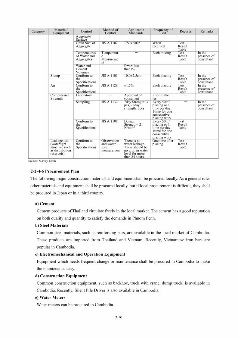
2-91
Category Material/ Equipment Control Method of
Control Applicable Standards
Frequency of Test Records Remarks
Aggregate Surface Grain Size of Aggregate
JIS A 1102 JIS A 5005 When received
Test Result Table
Temperatures of Water and Aggregates
Temperature Measurement
- Each mixing Test Result Table
In the presence of consultant
Water and Cement Volumes
Error: less than1%
Slump Conform to the Specifications
JIS A 1101 10.0±2.5cm Each placing Test Result Table
In the presence of consultant
Air Conform to the Specifications
JIS A 1128 ±1.5% Each placing Test Result Table
In the presence of consultant
Compressive Strength
Laboratory - Approval of consultant
Prior to the test
-
Sampling JIS A 1132 7day Strength: 3 pcs, 28day strength: 3pcs
Every 50m3 placing or 1 time per day, 1time for one consecutive placing work
- In the presence of consultant
Conform to the Specifications
JIS A 1108 Design Strength= 21 N/mm2
Every 50m3 placing or 1 time per day, 1time for one consecutive placing work
Test Result Table
Leakage test (watertight structure such as distribution reservoir)
Conform to the Specifications
Observation and water level measurement
There is no water leakage. There should be no drop in water level for more than 24 hours.
One time after placing
Test Result Table
Source: Survey Team
2-2-4-6 Procurement Plan The following major construction materials and equipment shall be procured locally. As a general rule, other materials and equipment shall be procured locally, but if local procurement is difficult, they shall be procured in Japan or in a third country.
a) Cement Cement products of Thailand circulate freely in the local market. The cement has a good reputation on both quality and quantity to satisfy the demands in Phnom Penh.
b) Steel Materials Common steel materials, such as reinforcing bars, are available in the local market of Cambodia. These products are imported from Thailand and Vietnam. Recently, Vietnamese iron bars are popular in Cambodia.
c) Electromechanical and Operation Equipment Equipment which needs frequent change or maintenance shall be procured in Cambodia to make the maintenance easy.
d) Construction Equipment Common construction equipment, such as backhoe, truck with crane, dump truck, is available in Cambodia. Recently, Silent Pile Driver is also available in Cambodia.
e) Water Meters Water meters can be procured in Cambodia.

2-92
f) Others Construction materials and equipment for the project shall be procured in Cambodia, Japan or other countries, according to the following considerations. Quality of materials and equipment shall conform to the requirements.
- For local materials and equipment, quality and capacity of supply shall be at the acceptable level - Sufficient supply in the Cambodian market - Easy operation and maintenance taking into account availability of spare parts - Appropriate price
- Availability of after-sales service
Pipe materials, not available in Cambodia and being the larger part of the project cost, shall be procured from other countries where the price is lower. It is desirable that there is an experience of procurement record in Japan’s Grant Aid project.
The transportation route for materials and equipment procured in Japan shall be sea transportation from Yokohama Port to Sihanoukville Port, and land transportation from Sihanoukville Port to Svay Rieng City.
2-2-4-7 Operation Guidance Plan The manuals and instructions introduced in this project for the operation and maintenance of each facility by the contractor after the facilities are transferred shall fall within the scope of the initial operation instructions. The operation guidance covers several fields that are difficult to include in the initial operation instructions, such as actual operation in response to changes in water quality and demand, maintenance of facilities to ensure optimal operation, and efficient management to guarantee the sustainable water supply business. The operation guidance shall be implemented by highly skilled experts and engineers with considerable experience in WWs as a soft component of this project.
Table 2-2-44 Roles and Responsibilities of Soft Component Instruction Items Initial Operation Operation Guidance
Instructions by Contractor via Soft Component
Provisions of manuals O -
Instructions on the operation and maintenance of each facility O -
Actual operation of facilities - O
Actual maintenance of facilities - O
Efficient management for sustainable business - O Source: Survey Team
2-2-4-8 Soft Component (Technical Assistance) Plan The SWWs are provincial waterworks agencies that are the targets of a project on capacity building for urban water supply system in Cambodia (Phase 2 and 3) by JICA. Technical transfer associated with the operation and maintenance of the WTPs, water quality tests, and the operation and maintenance of

2-93
distribution facilities have been implemented for five years from 2007 to 2012, and technical transfer related to the improvement of management has been carried out from 2012.
Although local staff can operate and maintain the existing WTP by following the prescribed procedures, they may not necessarily have the advanced technical knowledge required for their work. Since the water treatment facilities constructed in this project have different water treatment methods from the existing WTP, the SWWs have not reached the technical ability to formulate appropriate operation and maintenance methods for the new facilities. Challenges in the operation and maintenance of the new facilities, and current situations are as shown in Table 2-2-45.
Table 2-2-45 Challenges and Current Situations of SWWs Challenges Current Situations
Operation and maintenance of new facilities
Treatment process for the new WTP adopts a rapid filtration system, which is different from the existing one operation and maintenance, may be more complicated. Therefore, it is necessary to understand the basic knowledge with OJT using the facility. As for water quality test, the staff have no knowledge and experience of jar test. Procedures for water quality test using the newly installed equipment shall be developed with the assistance of experts. The planning of operation and maintenance procedures is difficult for the staff of the SWWs to carry out alone because it requires specialized knowledge of water treatment and waterworks technology based on extensive experience.
Facility maintenance based on water distribution monitoring and water distribution flow analysis
Since the new water distribution monitoring system shall be installed by this project, it is necessary to learn the basics of the system, including its operation and maintenance. By operating the water distribution monitoring system, they should acquire skills in interpreting information and analyzing flow data and use them to maintain the water distribution facilities.
Ensuring quality of service connection installations
The staff is accustomed to service connection installations. However, no special efforts have been made to ensure quality. To prevent leakage from service connections which are expected to increase rapidly with the implementation of this project, review of work procedure and improvement of construction management skills for service connection installations with assistance from experts are necessary.
Promotion of applications for service connections
Although SWWs carries out educational activities for residents, in order to achieve the target number of service connections in this project, assistance for preparation of more effective materials and plans for educational activities is necessary.
Improvement of production management
Since SWWs have no experience to manage plural WTPs, principles of efficient management of two WTPs must be studied, formulated and understood. Since the existing WTP has no sludge treatment process, formulation of a sludge treatment plan and work procedure and OJT are necessary.
Revision and creation of SOP
Although there are SOP which were formulated on the premise of use of the existing facilities and equipment, to make the staff understand the operation and maintenance of the new facilities and equipment, it is important that procedures, principles, key points and precautions are simply compiled in SOP. They should be referred at any time as necessary for the staff as well. Therefore, creation and revision of SOP are necessary.
Source: Survey Team
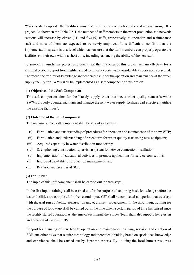
2-94
WWs needs to operate the facilities immediately after the completion of construction through this project. As shown in the Table 2-5-1, the number of staff members in the water production and network sections will increase by eleven (11) and five (5) staffs, respectively, as operation and maintenance staff and most of them are expected to be newly employed. It is difficult to confirm that the implementation system is at a level which can ensure that the staff members can properly operate the facilities on their own within a short time, including enhancing the ability of the new staff.
To smoothly launch this project and verify that the outcomes of this project remain effective for a minimal period, support from highly skilled technical experts with considerable experience is essential. Therefore, the transfer of knowledge and technical skills for the operation and maintenance of the water supply facility for SWWs shall be implemented as a soft component of this project.
(1) Objective of the Soft Component This soft component aims for the “steady supply water that meets water quality standards while SWWs properly operate, maintain and manage the new water supply facilities and effectively utilize the existing facilities”.
(2) Outcome of the Soft Component The outcome of the soft component shall be set out as follows:
(i) Formulation and understanding of procedures for operation and maintenance of the new WTP; (ii) Formulation and understanding of procedures for water quality tests using new equipment;
(iii) Acquired capability in water distribution monitoring; (iv) Strengthening construction supervision system for service connection installation; (v) Implementation of educational activities to promote applications for service connections;
(vi) Improved capability of production management; and (vii) Revision and creation of SOP.
(3) Input Plan The input of this soft component shall be carried out in three steps.
In the first input, training shall be carried out for the purpose of acquiring basic knowledge before the water facilities are completed. In the second input, OJT shall be conducted at a period that overlaps with the trial run by facility construction and equipment procurement. In the third input, training for the purpose of follow-up shall be carried out at the time when a certain period of time has passed since the facility started operation. At the time of each input, the Survey Team shall also support the revision and creation of various SOPs.
Support for planning of new facility operation and maintenance, training, revision and creation of SOP, and other tasks that require technology and theoretical thinking based on specialized knowledge and experience, shall be carried out by Japanese experts. By utilizing the local human resources

2-95
developed in the capacity building project as part of the support, the Survey Team shall carry out technology transfer unique to local engineers.
The human resources involved shall include Japanese experts, local engineers, local staff. Their roles are as generally outlined below.
1) Japanese Expert Summary of each training course, analysis of work content and work volume necessary for the management of new facilities, training course management, formulation of procedures for operation and maintenance, basic training, OJT, assistance for revision and creation of SOP, preparation of training materials, and evaluation of achievements.
2) Local Engineer Training based on experience in Cambodia, and training outside SWWs, preparation of training materials in Khmer.
3) Local Staff Preparation of materials and training materials in Khmer, providing coordination with counterparts, interpreter for Japanese expert, and translation of documents. Table 2-2-46 shows the activities in each field; Figure 2-2-46 shows the draft schedule of the soft component.
Table 2-2-46 Activities of the Soft Component (Input Plan) Field Outcomes Activities Trainees Inputs
Operation and maintenance of water treatment facilities
(1) Formulation and understanding of procedures for operation and maintenance of the new WTP
1. Formulation of procedures for operation and maintenance 2. Basic training of operation and maintenance 3. OJT of operation and maintenance - Water treatment - Operation records - Chemical injection - Back washing of filtration basin - Operation of pumps, etc. - Maintenance - Handling of facilities - Accident and malfunction handling
23 people from Water production Section
Japanese Expert - One person×2.03 P/M First Input - Basic training of operation and maintenance - Basic training of water quality test - SOP revision guidance Second Input - Training of operation and maintenance - Training of water quality test - SOP revision guidance Third Input - Review - Follow-up training - SOP revision guidance Local Engineer - One person×0.17 P/M Local Staff - One person×1.79 P/M
(2) Formulation and understanding of procedures for water quality tests using new equipment
1.Formulation of procedures for water quality test 2. Basic training of water quality test 3. OJT of water quality test - Water quality test - Analysis and records
(7) Revision and creation of SOP
1. Assistance for revision and creation of SOP - Operation and maintenance of water treatment facilities - Water quality test
Maintenance of water distribution facilities
(3) Acquired capability in water distribution monitoring
1. Formulation of procedure for water distribution monitoring 2. Basic training of water distribution monitoring 3. OJT of water distribution monitoring - Distribution flow monitoring and records - Minimum night flow analysis - Operation of monitoring system - Distribution flow analysis
10people from Network Section
Japanese Expert - One person×2.03 PM First Input - Basic training of water distribution flow monitoring - Basic training of service connection installation - SOP revision guidance Second input
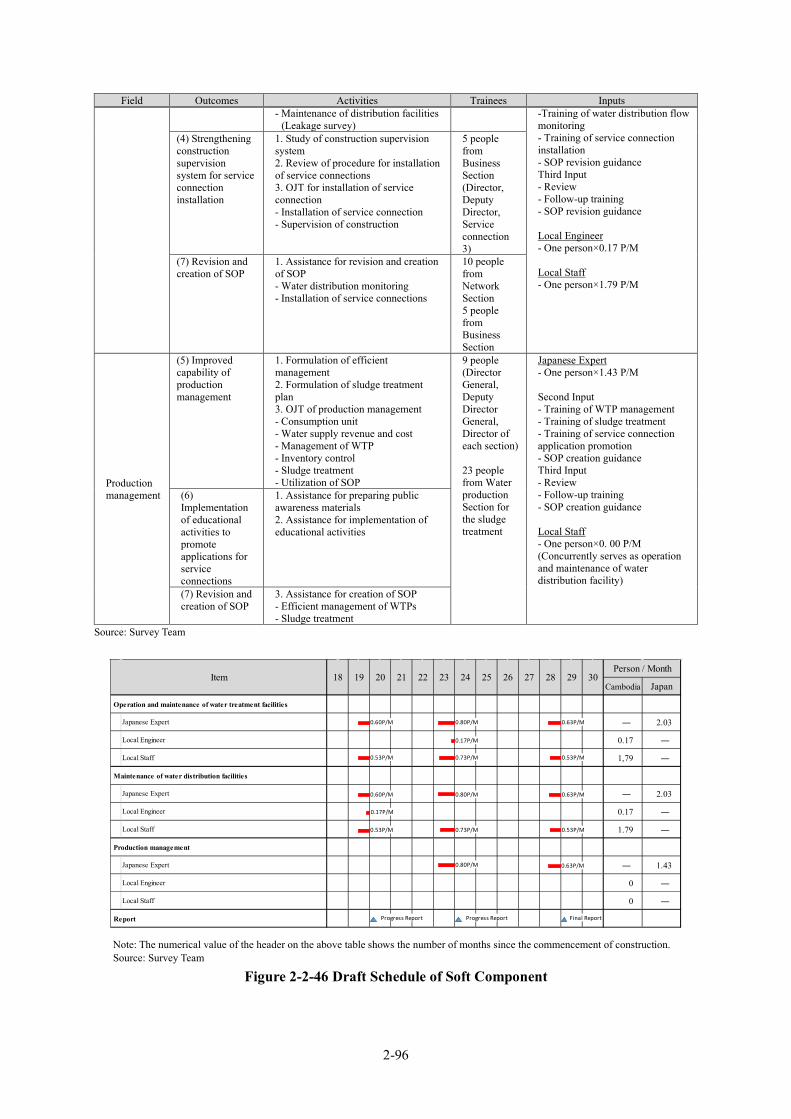
2-96
Field Outcomes Activities Trainees Inputs - Maintenance of distribution facilities
(Leakage survey) -Training of water distribution flow monitoring - Training of service connection installation - SOP revision guidance Third Input - Review - Follow-up training - SOP revision guidance Local Engineer - One person×0.17 P/M Local Staff - One person×1.79 P/M
(4) Strengthening construction supervision system for service connection installation
1. Study of construction supervision system 2. Review of procedure for installation of service connections 3. OJT for installation of service connection - Installation of service connection - Supervision of construction
5 people from Business Section (Director, Deputy Director, Service connection 3)
(7) Revision and creation of SOP
1. Assistance for revision and creation of SOP - Water distribution monitoring - Installation of service connections
10 people from Network Section 5 people from Business Section
Production management
(5) Improved capability of production management
1. Formulation of efficient management 2. Formulation of sludge treatment plan 3. OJT of production management - Consumption unit - Water supply revenue and cost - Management of WTP - Inventory control - Sludge treatment - Utilization of SOP
9 people (Director General, Deputy Director General, Director of each section) 23 people from Water production Section for the sludge treatment
Japanese Expert - One person×1.43 P/M Second Input - Training of WTP management - Training of sludge treatment - Training of service connection application promotion - SOP creation guidance Third Input - Review - Follow-up training - SOP creation guidance Local Staff - One person×0. 00 P/M (Concurrently serves as operation and maintenance of water distribution facility)
(6) Implementation of educational activities to promote applications for service connections
1. Assistance for preparing public awareness materials 2. Assistance for implementation of educational activities
(7) Revision and creation of SOP
3. Assistance for creation of SOP - Efficient management of WTPs - Sludge treatment
Source: Survey Team
Note: The numerical value of the header on the above table shows the number of months since the commencement of construction. Source: Survey Team
Figure 2-2-46 Draft Schedule of Soft Component
Cambodia Japan
Operation and maintenance of water treatment facilities
Japanese Expert ― 2.03
Local Engineer 0.17 ―
Local Staff 1,79 ―
Maintenance of water distribution facilities
Japanese Expert ― 2.03
Local Engineer 0.17 ―
Local Staff 1.79 ―
Production management
Japanese Expert ― 1.43
Local Engineer 0 ―
Local Staff 0 ―
Report
22Item 18 19 20 21 29 30Person / Month
23 24 25 26 27 28
0.60P/M
0.53P/M
0.80P/M
0.73P/M
0.63P/M
0.53P/M
0.17P/M
0.60P/M
0.53P/M
0.80P/M
0.73P/M
0.63P/M
0.53P/M
0.17P/M
0.80P/M 0.63P/M
Progress Report Progress Report Final Report
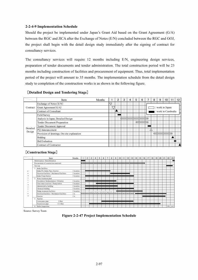
2-97
2-2-4-9 Implementation Schedule Should the project be implemented under Japan’s Grant Aid based on the Grant Agreement (G/A) between the RGC and JICA after the Exchange of Notes (E/N) concluded between the RGC and GOJ, the project shall begin with the detail design study immediately after the signing of contract for consultancy services.
The consultancy services will require 12 months including E/N, engineering design services, preparation of tender documents and tender administration. The total construction period will be 23 months including construction of facilities and procurement of equipment. Thus, total implementation period of the project will amount to 35 months. The implementation schedule from the detail design study to completion of the construction works is as shown in the following figure.
[Detailed Design and Tendering Stage]
[Construction Stage]
Source: Survey Team
Figure 2-2-47 Project Implementation Schedule
Item MonthsExchange of Notes(E/N)
Grant Agreement(G/A)Contract of ConsultantField SurveyAnalysis in Japan, Detailed DesignTender Document PreparationTender Document ApprovalPQ AnnouncementProvision of drawings, On-site explanationBiddingBid EvaluationContract of Contractor
Contract
DetailedDesign
1 9 10 11 122 3 4 5 6 7 8
Item MonthsMobolization / DemobilizationProcurement of construction materialsTest run1. Intake facilities
Intake Pit, Intake Pipe, Exterior 1 locationElectrical facilities / Mechanical facilities 1 locationIntake Pump Station 1 location
2. Water treatment plantFloculation /Sedimentation / Filtration 1 locationClear water reservoir / Pump station 1 locationAdministrative building 1 locationChemical building 1 locationSludge treatment facilities 1 locationElectrical facilities / Mechanical facilities 1 lsExterior 1 ls
3. PipelineConveyance pipe 2.9kmTrasmission pipe/ 111.8km
4. Defect inspection
1 2 21 22 23
Construction
15 16 17 18 19 209 10 11 12 13 143 4 5 6 7 8
Equipment design / manufacturing period
After 1 year
: work in Japan : work in Cambodia
2-98
2-3 Security Plan Table 2-3-1 shows the safety management items, inspection frequency and how the implementation during the construction work should be managed. In planning the safety measures, it is also important to monitor whether contractors secure a good labor environment and focusing on safety, not only of persons involved in the work but also third parties and visitors.
Also important are ongoing efforts to thoroughly manage safety by conducting joint safety patrols with the client and contractors as well as regularly holding safety management meetings. Details of a plan for safety measures and inspection frequency are as follows.
Table 2-3-1 Plan for Safety Measures Item Details Inspection
Frequency Witnessing Frequency
Remarks
1. General - Safety competition As appropriate As required Daily
management - Safety patrolling, etc. 2. Safety Management
- Hazardous material management As appropriate As required Daily management
- Traffic safety measures - High-place works, etc. 3. Worker’s Clothes - Wearing helmet, etc. As appropriate As required Daily
management 4. Security Means - Security guide, etc. As appropriate As required Daily
management 5. Clean and Tidy - Organizing material storage, etc. As appropriate As required Daily
management 6. Hygiene Management
- First-aid kit, etc. As appropriate As required Daily management
7. COVID-19 Prevention
- COVID-19 prevention As appropriate As required Daily management
- COVID-19 vaccination 8. Anti-crime Measures
- Security staff, etc. As appropriate As required Daily management
Source: Survey Team
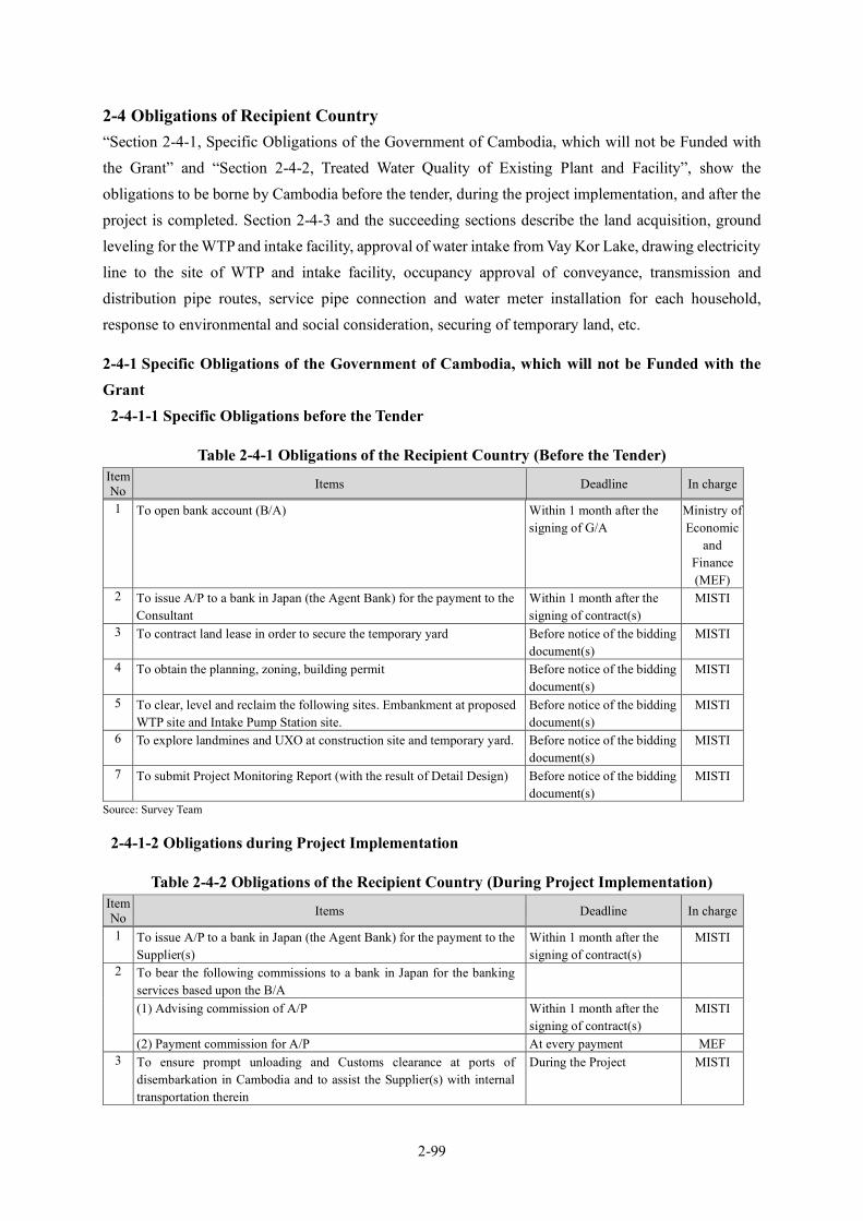
2-99
2-4 Obligations of Recipient Country “Section 2-4-1, Specific Obligations of the Government of Cambodia, which will not be Funded with the Grant” and “Section 2-4-2, Treated Water Quality of Existing Plant and Facility”, show the obligations to be borne by Cambodia before the tender, during the project implementation, and after the project is completed. Section 2-4-3 and the succeeding sections describe the land acquisition, ground leveling for the WTP and intake facility, approval of water intake from Vay Kor Lake, drawing electricity line to the site of WTP and intake facility, occupancy approval of conveyance, transmission and distribution pipe routes, service pipe connection and water meter installation for each household, response to environmental and social consideration, securing of temporary land, etc.
2-4-1 Specific Obligations of the Government of Cambodia, which will not be Funded with the Grant
2-4-1-1 Specific Obligations before the Tender
Table 2-4-1 Obligations of the Recipient Country (Before the Tender) ItemNo Items Deadline In charge
1 To open bank account (B/A) Within 1 month after the signing of G/A
Ministry of Economic
and Finance (MEF)
2 To issue A/P to a bank in Japan (the Agent Bank) for the payment to the Consultant
Within 1 month after the signing of contract(s)
MISTI
3 To contract land lease in order to secure the temporary yard Before notice of the bidding document(s)
MISTI
4 To obtain the planning, zoning, building permit Before notice of the bidding document(s)
MISTI
5 To clear, level and reclaim the following sites. Embankment at proposed WTP site and Intake Pump Station site.
Before notice of the bidding document(s)
MISTI
6 To explore landmines and UXO at construction site and temporary yard. Before notice of the bidding document(s)
MISTI
7 To submit Project Monitoring Report (with the result of Detail Design) Before notice of the bidding document(s)
MISTI
Source: Survey Team
2-4-1-2 Obligations during Project Implementation
Table 2-4-2 Obligations of the Recipient Country (During Project Implementation) Item No Items Deadline In charge
1 To issue A/P to a bank in Japan (the Agent Bank) for the payment to the Supplier(s)
Within 1 month after the signing of contract(s)
MISTI
2 To bear the following commissions to a bank in Japan for the banking services based upon the B/A
(1) Advising commission of A/P Within 1 month after the signing of contract(s)
MISTI
(2) Payment commission for A/P At every payment MEF 3 To ensure prompt unloading and Customs clearance at ports of
disembarkation in Cambodia and to assist the Supplier(s) with internal transportation therein
During the Project MISTI
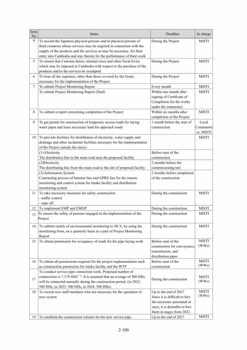
2-100
Item No Items Deadline In charge
4 To accord the Japanese physical persons and/or physical persons of third countries whose services may be required in connection with the supply of the products and the services as may be necessary, for their entry into Cambodia and stay therein for the performance of their work
During the Project MISTI
5 To ensure that Customs duties, internal taxes and other fiscal levies which may be imposed in Cambodia with respect to the purchase of the products and/or the services be exempted
During the Project MISTI
6 To bear all the expenses, other than those covered by the Grant, necessary for the implementation of the Project
During the Project MISTI
7 To submit Project Monitoring Report Every month MISTI To submit Project Monitoring Report (final) Within one month after
signing of Certificate of Completion for the works under the contract(s)
MISTI
8 To submit a report concerning completion of the Project Within six months after completion of the Project
MISTI
9 To get permit for construction of temporary access roads for laying water pipes and lease necessary land for approach roads
1 month before the start of construction
Local Communities, MISTI
10 To provide facilities for distribution of electricity, water supply and drainage and other incidental facilities necessary for the implementation of the Project outside the site(s)
MISTI
(1) Electricity The distribution line to the main road near the proposed facility
Before start of the construction
(2)Electricity The distributing line from the main road to the site of proposed facility
2 months before the commissioning test
(3) Information System Contracting process of Internet line and GPRS line for the remote monitoring and control system for intake facility and distribution monitoring system
2 months before completion of the construction
11 To take necessary measures for safety construction - traffic control - rope off
During the construction MISTI
12 To implement EMP and EMOP During the construction MISTI
13
To ensure the safety of persons engaged in the implementation of the Project
During the construction MISTI
14 To submit results of environmental monitoring to JICA, by using the monitoring form, on a quarterly basis as a part of Project Monitoring Report
During the construction MISTI
15 To obtain permission for occupancy of roads for the pipe laying work Before start of the construction for conveyance, transmission, and distribution pipes
MISTI (WWs)
16 To obtain all permissions required for the project implementation such as construction permission for intake facility and the WTP
Before start of the construction
MISTI (WWs)
17
To conduct service pipe connection work, Proposed number of connections is 7,378 HHs* 1). It is assumed that an average of 500 HHs will be connected annually during the construction period. (in 2022: 500 HHs, in 2023: 500 HHs, in 2024: 500 HHs)
During the construction MISTI (WWs)
18 To recruit new staff members who are necessary for the operation of new system
Up to the end of 2027 Since it is difficult to hire the necessary personnel at once, it is desirable to hire them in stages from 2022.
MISTI (WWs)
19 To establish the construction scheme for the new service pipe Up to the end of 2027 MISTI
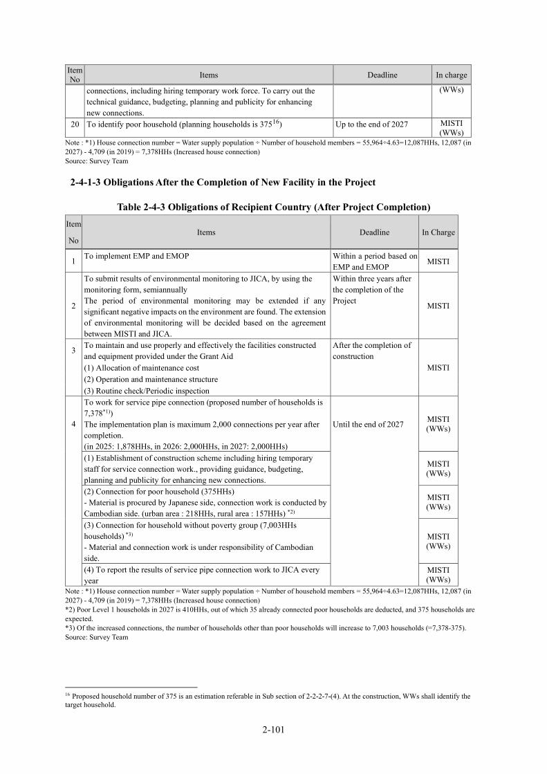
2-101
Item No Items Deadline In charge
connections, including hiring temporary work force. To carry out the technical guidance, budgeting, planning and publicity for enhancing new connections.
(WWs)
20 To identify poor household (planning households is 37516) Up to the end of 2027 MISTI (WWs)
Note : *1) House connection number = Water supply population ÷ Number of household members = 55,964÷4.63=12,087HHs, 12,087 (in 2027) - 4,709 (in 2019) = 7,378HHs (Increased house connection) Source: Survey Team
2-4-1-3 Obligations After the Completion of New Facility in the Project
Table 2-4-3 Obligations of Recipient Country (After Project Completion) Item
No Items Deadline In Charge
1 To implement EMP and EMOP Within a period based on EMP and EMOP
MISTI
2
To submit results of environmental monitoring to JICA, by using the monitoring form, semiannually The period of environmental monitoring may be extended if any significant negative impacts on the environment are found. The extension of environmental monitoring will be decided based on the agreement between MISTI and JICA.
Within three years after the completion of the Project MISTI
3 To maintain and use properly and effectively the facilities constructed and equipment provided under the Grant Aid
After the completion of construction
MISTI (1) Allocation of maintenance cost (2) Operation and maintenance structure (3) Routine check/Periodic inspection
4
To work for service pipe connection (proposed number of households is 7,378*1)) The implementation plan is maximum 2,000 connections per year after completion. (in 2025: 1,878HHs, in 2026: 2,000HHs, in 2027: 2,000HHs)
Until the end of 2027 MISTI (WWs)
(1) Establishment of construction scheme including hiring temporary staff for service connection work., providing guidance, budgeting, planning and publicity for enhancing new connections.
MISTI (WWs)
(2) Connection for poor household (375HHs) - Material is procured by Japanese side, connection work is conducted by Cambodian side. (urban area : 218HHs, rural area : 157HHs) *2)
MISTI (WWs)
(3) Connection for household without poverty group (7,003HHs households) *3) - Material and connection work is under responsibility of Cambodian side.
MISTI (WWs)
(4) To report the results of service pipe connection work to JICA every year
MISTI (WWs)
Note : *1) House connection number = Water supply population ÷ Number of household members = 55,964÷4.63=12,087HHs, 12,087 (in 2027) - 4,709 (in 2019) = 7,378HHs (Increased house connection) *2) Poor Level 1 households in 2027 is 410HHs, out of which 35 already connected poor households are deducted, and 375 households are expected. *3) Of the increased connections, the number of households other than poor households will increase to 7,003 households (=7,378-375). Source: Survey Team
16 Proposed household number of 375 is an estimation referable in Sub section of 2-2-2-7-(4). At the construction, WWs shall identify the target household.
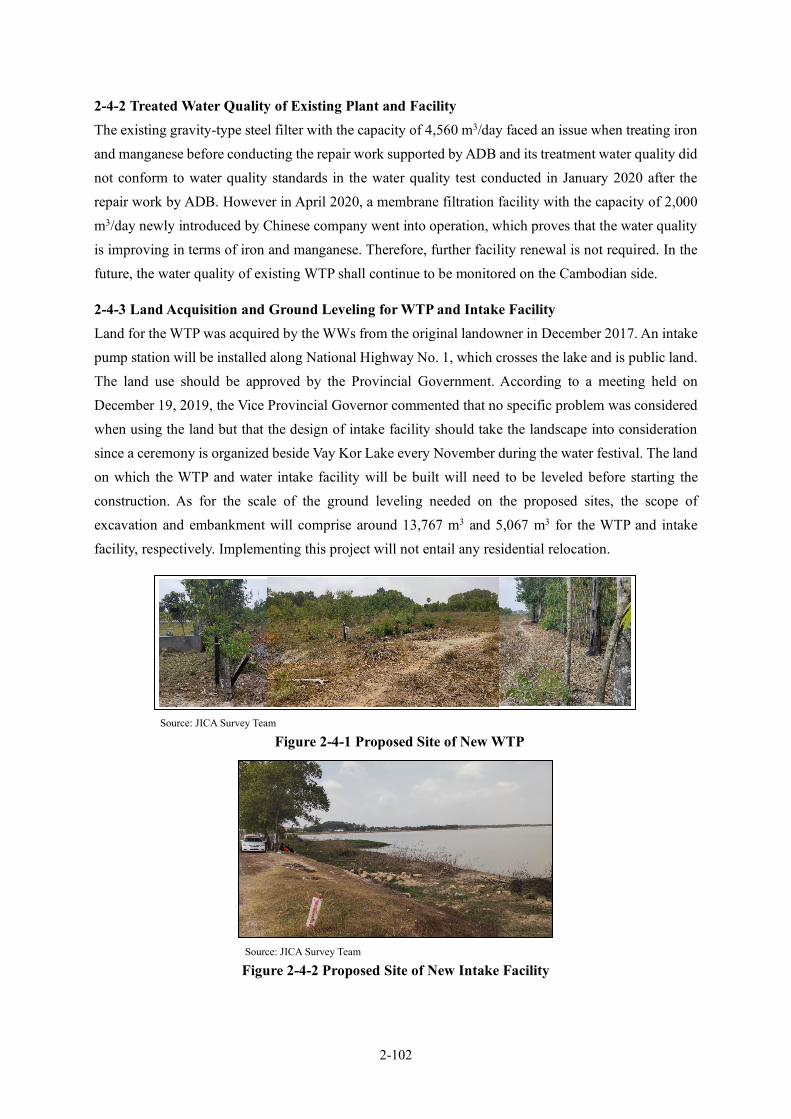
2-102
2-4-2 Treated Water Quality of Existing Plant and Facility The existing gravity-type steel filter with the capacity of 4,560 m3/day faced an issue when treating iron and manganese before conducting the repair work supported by ADB and its treatment water quality did not conform to water quality standards in the water quality test conducted in January 2020 after the repair work by ADB. However in April 2020, a membrane filtration facility with the capacity of 2,000 m3/day newly introduced by Chinese company went into operation, which proves that the water quality is improving in terms of iron and manganese. Therefore, further facility renewal is not required. In the future, the water quality of existing WTP shall continue to be monitored on the Cambodian side.
2-4-3 Land Acquisition and Ground Leveling for WTP and Intake Facility Land for the WTP was acquired by the WWs from the original landowner in December 2017. An intake pump station will be installed along National Highway No. 1, which crosses the lake and is public land. The land use should be approved by the Provincial Government. According to a meeting held on December 19, 2019, the Vice Provincial Governor commented that no specific problem was considered when using the land but that the design of intake facility should take the landscape into consideration since a ceremony is organized beside Vay Kor Lake every November during the water festival. The land on which the WTP and water intake facility will be built will need to be leveled before starting the construction. As for the scale of the ground leveling needed on the proposed sites, the scope of excavation and embankment will comprise around 13,767 m3 and 5,067 m3 for the WTP and intake facility, respectively. Implementing this project will not entail any residential relocation.
Source: JICA Survey Team
Figure 2-4-1 Proposed Site of New WTP
Source: JICA Survey Team
Figure 2-4-2 Proposed Site of New Intake Facility

2-103
To acquire land at the intake point, the SWWs should file an application to the Provincial Government via DISTI, a MISTI district office, so that approval can be obtained. The Provincial Government will then notify DOWRAM of the construction location, method and other relevant information.
2-4-4 Approval for Taking Water from Vay Kor Lake In Cambodia, MOWRAM, as the responsible agency, strives to implement the Integrated Water Resource Management (IWRM), including management of the surface and ground water volume and quality as well as flood/sediment disaster countermeasures based on the Law on Water Resources Management of the Kingdom of Cambodia that was enforced in 2007.
The expected total volume of surface water taken from Vay Kor Lake is around 20,680 m3/day (= 2,000 x 1.1 + 6,800 x 1.1+11,000) for facilities, including those already in place, a rapid-filtration WTP with capacity of 9,000m3/day, which will start operation under ADB’s assistance and a rapid-filtration WTP with the capacity of 6,800 m3/day, which will be developed by this project. On the other hand, MISTI obtained MOWRAM’s approval to take 12,000m3/day of water from Vay Kor Lake in September 2017. MISTI also obtained additional approval in July 2021, separately, to take in 11,000 m3/day of water for the intake facility to be expanded by ADB.
Source: Survey Team
Figure 2-4-3 An Approval Letter for Water Intake (for 12,000m3/day, as of September 2017)
In Khmer In English
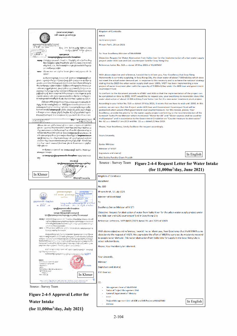
2-104
Figure 2-4-4 Request Letter for Water Intake (for 11,000m3/day, June 2021)
Source : Survey Team
In Khmer
In English
In English
In Khmer
Figure 2-4-5 Approval Letter for Water Intake (for 11,000m3/day, July 2021)
Source : Survey Team
2-105
2-4-5 Drawing Electricity Line to the Site of WTP and Intake Facility In this project, new transformer systems within the premises of the intake facility and WTP will be installed. The cost of work to draw power from EDC’s 22 kV transmission line into each new transformer shall be borne by Cambodia.
Since the intake facility faces National Highway No. 1, electric power will be drawn from EDC’s 22 kV transmission line located to the east of the Highway into the transformer system in the premises via a ground line of about 600 m, which, in turn, draws power from the 22 kV distribution line along Prefectural Route 319 into the transformer system of the WTP via an overhead line of about 600 m long.
2-4-6 Occupancy Approval of Conveyance, Transmission and Distribution Pipe Routes 2-4-6-1 Occupancy Approval for National Highway and Bridge-Attached Pipe and Railway To obtain occupancy approval through the National Highway and bridge attached pipe and railways, the road occupancy approval application should be submitted to MISIT via its district office, DISIT. Subsequently, MISTI informs construction locations, methods and other relevant information to MPWT and applies for its approval. After approving the application, MPWT notifies its approval to MISTI and its local office, DPWT.
2-4-6-2 Occupancy Approval for General Roads SWWs applies for the general road occupancy with the Provincial Governor via DISTI. After approving the application, the Provincial Governor notifies its approval to DPWT and informs construction locations, method and other relevant information.
2-4-7 Service Pipe Connection and Water Meter Installation for Each Household The water supply system, including the water meter, service pipe and other accessories at each household from the distribution pipe, is installed by the WWs in response to residents’ requests. For general homes, the service pipe diameter is 25 mm while water meter diameter is 15 mm and the standard cost of this equipment and installation (connection fee) is 290,000 KHR. The connection fee is borne by residents (beneficiary fees) but a payment exemption or 12 monthly payment installments is also accepted for poor households.
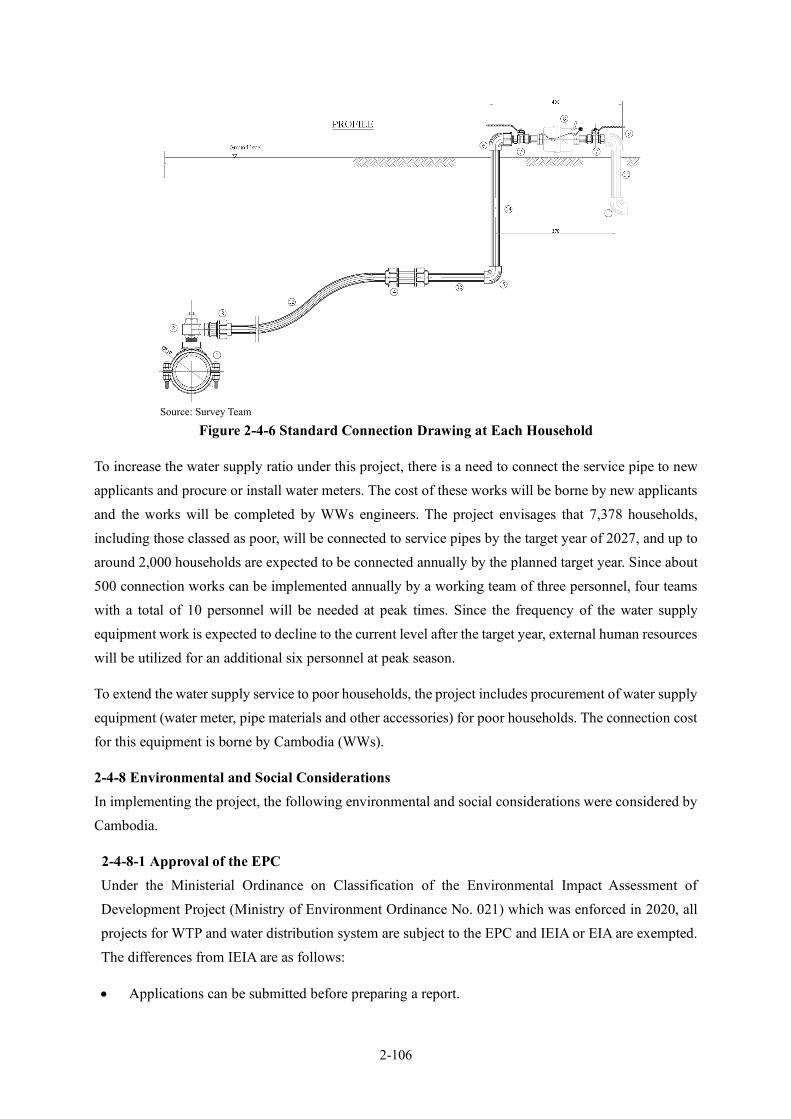
2-106
Source: Survey Team
Figure 2-4-6 Standard Connection Drawing at Each Household
To increase the water supply ratio under this project, there is a need to connect the service pipe to new applicants and procure or install water meters. The cost of these works will be borne by new applicants and the works will be completed by WWs engineers. The project envisages that 7,378 households, including those classed as poor, will be connected to service pipes by the target year of 2027, and up to around 2,000 households are expected to be connected annually by the planned target year. Since about 500 connection works can be implemented annually by a working team of three personnel, four teams with a total of 10 personnel will be needed at peak times. Since the frequency of the water supply equipment work is expected to decline to the current level after the target year, external human resources will be utilized for an additional six personnel at peak season.
To extend the water supply service to poor households, the project includes procurement of water supply equipment (water meter, pipe materials and other accessories) for poor households. The connection cost for this equipment is borne by Cambodia (WWs).
2-4-8 Environmental and Social Considerations In implementing the project, the following environmental and social considerations were considered by Cambodia.
2-4-8-1 Approval of the EPC Under the Ministerial Ordinance on Classification of the Environmental Impact Assessment of Development Project (Ministry of Environment Ordinance No. 021) which was enforced in 2020, all projects for WTP and water distribution system are subject to the EPC and IEIA or EIA are exempted. The differences from IEIA are as follows:
• Applications can be submitted before preparing a report.
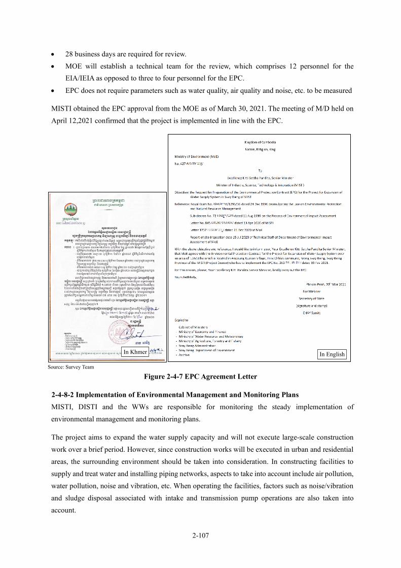
2-107
• 28 business days are required for review. • MOE will establish a technical team for the review, which comprises 12 personnel for the
EIA/IEIA as opposed to three to four personnel for the EPC.
• EPC does not require parameters such as water quality, air quality and noise, etc. to be measured
MISTI obtained the EPC approval from the MOE as of March 30, 2021. The meeting of M/D held on April 12,2021 confirmed that the project is implemented in line with the EPC.
Source: Survey Team
Figure 2-4-7 EPC Agreement Letter
2-4-8-2 Implementation of Environmental Management and Monitoring Plans MISTI, DISTI and the WWs are responsible for monitoring the steady implementation of environmental management and monitoring plans.
The project aims to expand the water supply capacity and will not execute large-scale construction work over a brief period. However, since construction works will be executed in urban and residential areas, the surrounding environment should be taken into consideration. In constructing facilities to supply and treat water and installing piping networks, aspects to take into account include air pollution, water pollution, noise and vibration, etc. When operating the facilities, factors such as noise/vibration and sludge disposal associated with intake and transmission pump operations are also taken into account.
In Khmer In English
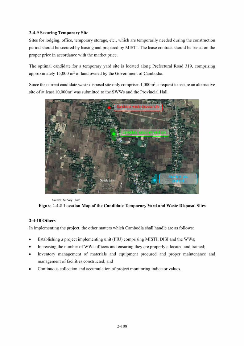
2-108
2-4-9 Securing Temporary Site Sites for lodging, office, temporary storage, etc., which are temporarily needed during the construction period should be secured by leasing and prepared by MISTI. The lease contract should be based on the proper price in accordance with the market price.
The optimal candidate for a temporary yard site is located along Prefectural Road 319, comprising approximately 15,000 m2 of land owned by the Government of Cambodia.
Since the current candidate waste disposal site only comprises 1,000m2, a request to secure an alternative site of at least 10,000m2 was submitted to the SWWs and the Provincial Hall.
Source: Survey Team
Figure 2-4-8 Location Map of the Candidate Temporary Yard and Waste Disposal Sites
2-4-10 Others In implementing the project, the other matters which Cambodia shall handle are as follows:
• Establishing a project implementing unit (PIU) comprising MISTI, DISI and the WWs; • Increasing the number of WWs officers and ensuring they are properly allocated and trained; • Inventory management of materials and equipment procured and proper maintenance and
management of facilities constructed; and
• Continuous collection and accumulation of project monitoring indicator values.
Candidate temporary yard site
New WTP site
(planned)
Candidate waste disposal site

2-109
2-5 Project Operation and Maintenance Plan 2-5-1 Project Operation Plan In consideration of the volume of work required for the management, operation and maintenance of the expanded water supply facilities in this Project, the organization structure for actual operation of the facilities by 2027 has been studied and the results are as summarized in Table 2-5-1 .
Table 2-5-1 Organizational Structure of the Project Operation by 2027
Section Responsibilities Current Number
of Staff (2021)
Number of Staff in Target Year
(2027)
Increase of Staff
Director General Comprehensive management 1 1 0
Deputy Director General
Supervision of administration section 1 1 0
Deputy Director General
Supervision of accounting and finance section
1 1 0
Deputy Director General
Supervision of business section/ water production section/ network section
1 1 0
Administration Section General affairs, personnel, planning 2 3 1
Accounting and Finance Section
Accounting, financing, tariff collection 4 5 1
Business Section Customer management, water meter readings, service connection installation
8 12 4
Water Production Section
Operation and maintenance of WTP, water quality tests
12 23 11
Network Section Leakage surveys and repairs, Expansion and updates to network, network management
5(4)* 10 5
Total 35(34)* 57 22 * Number outside of parenthesis indicate the fixed capacity number, and number inside indicate the current situation of vacancies. Source: Survey Team
(1) Water Production Section The new WTP shall treat the extracted surface water by the rapid sand filtration method, and the treatment capacity is about 6,800 m3/day compared to the existing capacity of 6,560 m3/day. Since the new WTP shall be constructed at a location approximately 5 km away from the existing WTP, a new team shall be organized for its operation and maintenance.
The composition of the Team is as shown in the following items 1) to 4). A Deputy Director shall be assigned to assist the Team Leader of the new WTP, and necessary personnel shall be allocated to the selected current staff and newly hired staff. The total staff members of the Water Production Section shall be increased by eleven (11), but the number of operation and maintenance staff of the existing WTP will not be increased.
1) Deputy Director: 1 officer One (1) deputy director shall be assigned to supervise the operation and maintenance of the new WTP.

2-110
2) Operators: 8 officers Two (2) officers in the new WTP shall be assigned to the operation staff. For a 24-hour operation, the operation work shall be conducted in two shifts. Four teams of two (2) operators each will be needed as shown in the Table 2-5-2 . An increase of eight (8) staff members will be required. No operator will be in the intake station because the intake pump can be operated and monitored remotely at the new WTP.
Table 2-5-2 Work Shift for the Operation of the New WTP
Source: Survey Team
3) Maintenance Officer:1 officer One (1) staff will be assigned for the maintenance of facilities, free from chemical and other daily duties. If manpower is required, such as dealing with equipment failures or cleaning the sedimentation basin, one (1) of the deputy directors and (1) one of the operators shall support the maintenance staff.
4) Water Quality Testing Officer: 1 officer A laboratory shall be prepared at the new WTP. The new WTP needs to treat surface water, which has greater turbidity fluctuations than groundwater treated with the existing WTP. Therefore, daily water quality management is important. One (1) staff shall be assigned for the water quality testing.
(2) Network Section The pipe network shall be extended to approximately 112km. The supply area shall also be expanded. Based on the experiences in other cities, it is estimated that the number of maintenance staff needed for a 100-km pipe network is 4.7 staff. Therefore, the number of staff members in the network section shall be increased from five (5) staffs to ten (10) staffs. After the increase, the number of staff members will be three (3) staffs for leakage survey and repairing, three (3) staffs for network expansion and updates, and two (2) staffs for network management.
A B1 B2 A B1 B2 A B1 B2 A B1 B2 A B1 B2 A B1 B2 A B1 B2
Staff 1 O O O O O O
Staff 2 O O O O O O
Staff 3 O O O O O
Staff 4 O O O O O
Staff 5 O O O O O
Staff 6 O O O O O
Staff 7 O O O O O
Staff 8 O O O O O
Shift A 08:30-17:00Shift B1 16:30-01:00Shift B2 00:30-09:00
Team1
Team2
Team3
Team4
SunMon Tue Wed Thu Fri Sat

2-111
(3) Business Section As of 2019, two (2) staffs check about 4,700 water meters every month. It is estimated that approximately 12,000 water meters need to be installed by the target year. Therefore, the number of meter readers shall be increased from two (2) staffs to five (5) staffs.
Regarding the installation of service connections, it is necessary to carry out plenty of connections systematically until the target year. However, after the completion of the installation period, the service will be back to normal. Therefore, additional staffs during the busiest period shall be supplied through outsourcing and not the increase in the number of staff members at SWWs. Specifically, one (1) staff member and two (2) outsourced staffs shall be grouped into one group, and a three-group system shall be established.
Currently, customer management is handled by a Director. However, in the target year, the number of water supply connections will more than double, so that two (2) staffs shall be assigned for customer management. The Director shall manage the Sales Section, which is the original business assignment.
Therefore, the number of employees in the Business Section as a whole shall be increased by four (4) staffs, and as a result, the number of employees will be increased to twelve (12) staff members.
(4) Accounting and Finance Section The amount of work for the Accounting and Finance Section which is related to water tariff collection and financial and fiscal works is expected to increase. Although the SUMS system has been implemented in the capacity building project, there is still a shortage of manpower. Therefore, the number of staff members in the section shall be increased by one (1) staff, from the current four (4) staff members to five (5) staff members.
(5) Administration Section There will be no new work for the administration section as a result of the implementation of this project. However, since the administration section is the department in charge of the management work of each section, the work will increase as the number of staff members increases due to the construction of the new water facilities. The current number of staff members shall be increased by one (1) staff from two (2) staff to three (3) staff members.
Figure 2-5-1 and Figure 2-5-2 show the current and future organizations of SWWs, respectively.
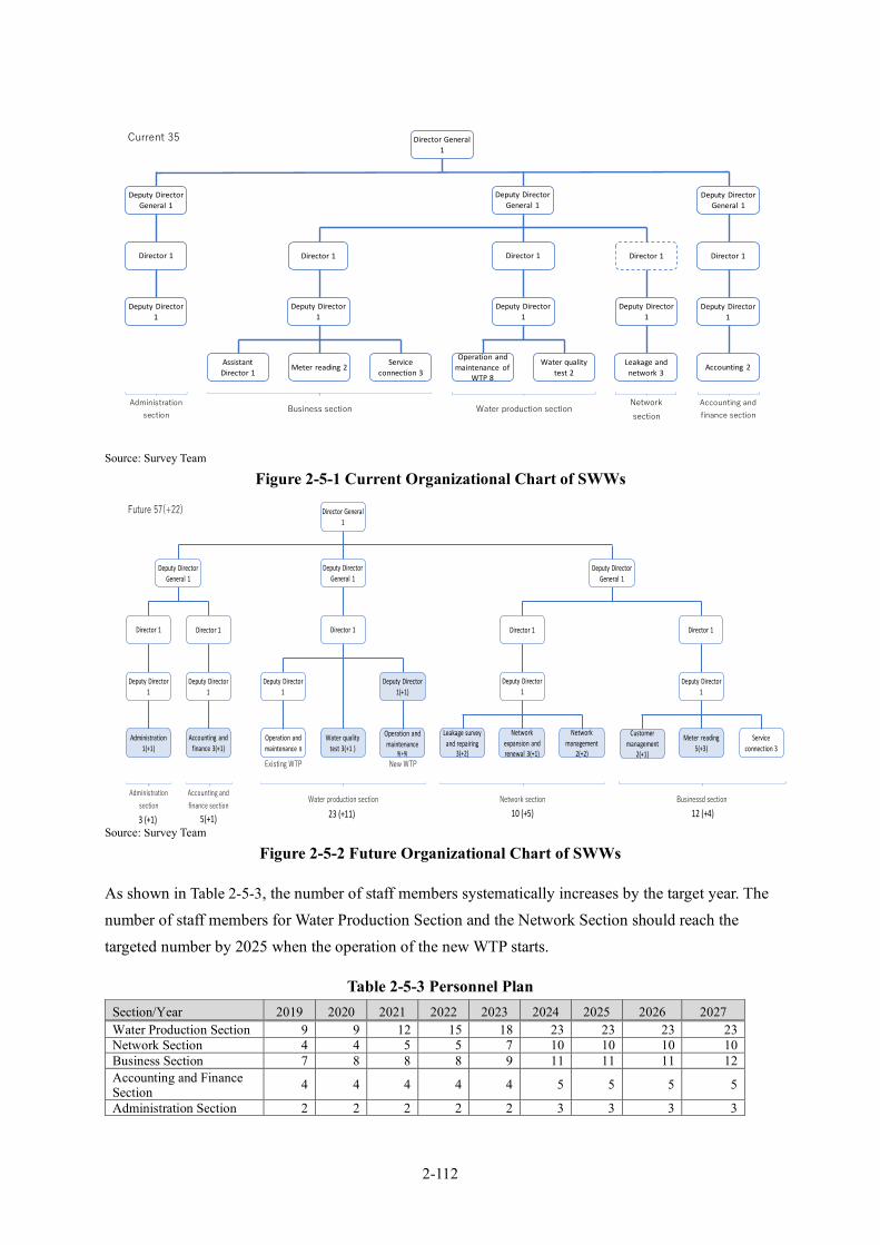
2-112
Source: Survey Team
Figure 2-5-1 Current Organizational Chart of SWWs
Source: Survey Team
Figure 2-5-2 Future Organizational Chart of SWWs
As shown in Table 2-5-3, the number of staff members systematically increases by the target year. The number of staff members for Water Production Section and the Network Section should reach the targeted number by 2025 when the operation of the new WTP starts.
Table 2-5-3 Personnel Plan Section/Year 2019 2020 2021 2022 2023 2024 2025 2026 2027 Water Production Section 9 9 12 15 18 23 23 23 23 Network Section 4 4 5 5 7 10 10 10 10 Business Section 7 8 8 8 9 11 11 11 12 Accounting and Finance Section 4 4 4 4 4 5 5 5 5
Administration Section 2 2 2 2 2 3 3 3 3
Current 35
Accounting andfinance section
Networksection
Water production sectionBusiness sectionAdministration
section
Deputy Director General 1
Deputy Director General 1
Deputy Director General 1
Deputy Director 1
Director 1
AssistantDirector 1
Serviceconnection 3
Meter reading 2
Director 1
Operation and maintenance of
WTP 8
Water quality test 2
Deputy Director 1
Director 1
Leakage andnetwork 3
Deputy Director 1
Director 1
Accounting 2
Deputy Director 1
Director 1
Deputy Director 1
Director General 1
Future 57(+22)
Accounting andfinance section
Businessd section
Existing WTP New WTP
Administrationsection
Water production section Network section
Director General 1
Deputy Director General 1
Deputy Director General 1
Deputy Director 1
Director 1
Operation and maintenance 8
Operation and maintenance
9(+9)
Director 1
Leakage survey and repairing
3(+2)
Water quality test 3(+1 )
Deputy Director 1(+1)
Deputy Director 1
Administration1(+1)
Network expansion and renewal 3(+1)
Deputy Director 1
Director 1
Networkmanagement
2(+2)
Deputy Director General 1
Accounting and finance 3(+1)
Deputy Director1
Director 1
Serviceconnection 3
Meter reading 5(+3)
Director 1
Deputy Director 1
Customer management
2(+1)
3 (+1) 5(+1) 23 (+11) 12 (+4)10 (+5)

2-113
Section/Year 2019 2020 2021 2022 2023 2024 2025 2026 2027 Director and Deputy Director 4 4 4 4 4 4 4 4 4
Total 30 31 35 38 44 56 56 56 57 Outsourcing of Service Connections 3 6 6 6 6
Number of Water Supply Households 4,709 5,579 6,005 6,429 6,854 8,830 9,502 10,784 12,087
Construction work
Source: Survey Team
2-5-2 On-site Maintenance The proposed operation and maintenance items for the new facilities is as shown in Table 2-5-4.
Table 2-5-4 Operation and Maintenance Items Facility Section Work Section Work Contents Frequency Remarks
Intake Facility Maintenance
Routine maintenance check Daily Regular check of pump and motor
Twice / Month
Regular check of electrical equipment
Twice / Month
Drainage of sludge in pit Monthly
Screen cleaning Weekly
Treatment Facility
Water Treatment
Intake pump operation Daily Operate remotely from the WTP
Condition of coagulation and flocculation
Daily
Coagulant dissolving and dosing rate
Daily Based on Jar test and floc
Lime dissolving and dosing rate Daily Based on pH
Chlorine dissolving and dosing rate
Daily Residual chlorine(pre, and post)
Filtration Operation Daily
Filter sand washing Daily
Sludge pump operation Daily
Sludge drying bed checking Daily Water content
Drainage of sludge in sedimentation basin
As needed
Sedimentation basin cleaning Once / 4 month
Sludge basin cleaning Once / 2month
Observation of sludge conveyance
Once / 2month
Filter layer Measurement Yearly
Quality of filter sand Yearly Effective size, uniformity coefficient
Water level monitoring Daily Receiving well, sedimentation basin, filtration basin, service reservoir, etc.
Recording daily operation Daily
Water Quality Analysis
Essential analytical items Daily Turbidity, residual chlorine, pH, water temperature, etc.
Important analytical items Once / 3 month Aluminum, ammonium nitrogen, etc.
Jar test Daily
Water quality instrument cleaning
Weekly
Residual Chlorine in tap water Twice / Month Several places

2-114
Facility Section Work Section Work Contents Frequency Remarks Daily record of water quality Daily
Monthly record of water quality Monthly
Electrical and Mechanical Facilities
Routine maintenance check Daily Checking of instrument abnormality
Minor fault repairing Daily
Regular check of pump and motor
Twice / Month
Regular check of electric valve Twice / Year
Regular check of chemical equipment
Twice / Month
Washing chemical pipe As needed
Regular check of level gage Twice / Year Filter basin, service reservoir
Insulation resistance and earthing resistance test Yearly Electrical facilities
Others Cleaning work Daily
Security duties Daily
Distribution Facility
Distribution Facility Operation
Pump operation Daily
Recording pump operation Daily
Operation daily schedule Daily
Recording monthly operation Monthly
Distribution flow and pressure Monitoring
System
Recording water flow data Daily
Water flow and pressure analysis Daily
Implementation of leakage survey
As needed
Leakage repair As needed
Distribution Facility Maintenance
Water quality check of distribution network
Twice / Month
Pipe Cleaning As needed
Pipe inspection As needed
Attendance and checking for other construction
As needed
Production Management Maintenance Duties
Making annual report Yearly
Chemical stock management Daily Coagulant, lime, chlorine
Sludge treatment plan As needed
Source: Survey Team
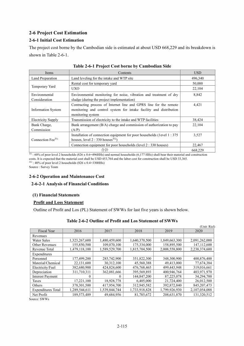
2-115
2-6 Project Cost Estimation 2-6-1 Initial Cost Estimation The project cost borne by the Cambodian side is estimated at about USD 668,229 and its breakdown is shown in Table 2-6-1.
Table 2-6-1 Project Cost borne by Cambodian Side Items Contents USD
Land Preparation Land leveling for the intake and WTP site 496,340
Temporary Yard Rental cost for temporary yard 50,000 UXO 22,104
Environmental Consideration
Environmental monitoring for noise, vibration and treatment of dry sludge (during the project implementation)
8,842
Information System Contracting process of Internet line and GPRS line for the remote monitoring and control system for intake facility and distribution monitoring system
4,421
Electricity Supply Transmission of electricity to the intake and WTP facilities 38,424 Bank Charge, Commission
Bank arrangement (B/A) charge and commission of authorization to pay (A/P)
22,104
Connection Fee※1 Installation of connection equipment for poor households (1evel 1 : 375 houses, level 2 : 330 houses※2)
3,527
Connection equipment for poor households (level 2 : 330 houses) 22,467 合計 668,229
※1 : 60% of poor level 2 households (826 x 0.6=496HHs) and normal households (6,177 HHs) shall bear their material and construction costs. It is expected that the material cost shall be USD 453,764 and the labor cost for construction shall be USD 33,365. ※2 : 40% of poor level 2 households (826 x 0.4=330HHs) Source : Survey Team
2-6-2 Operation and Maintenance Cost 2-6-2-1 Analysis of Financial Conditions
(1) Financial Statements Profit and Loss Statement Outline of Profit and Los (PL) Statement of SWWs for last five years is shown below.
Table 2-6-2 Outline of Profit and Los Statement of SWWs (Unit: Riel)
Fiscal Year 2016 2017 2018 2019 2020 Revenues Water Sales 1,323,267,600 1,480,459,600 1,640,370,500 1,849,663,300 2,091,262,000 Other Revenues 155,850,500 109,070,100 175,334,000 158,895,500 147,112,600 Revenue Total 1,479,118,100 1,589,529,700 1,815,704,500 2,008,558,800 2,238,374,600 Expenditures Personnel 177,499,200 285,742,900 351,822,300 348,300,900 400,876,400 Material/Chemical 22,131,600 30,312,100 45,560,388 49,413,000 77,674,384 Electricity/Fuel 382,680,900 424,824,600 476,768,465 499,443,948 319,016,661 Depreciation 311,710,311 362,081,666 395,569,893 400,946,764 403,971,970 Interest Payment 0 0 144,847,200 87,225,078 34,294,700 Taxes 17,221,100 18,928,778 6,405,000 21,724,400 26,012,500 Others 378,301,500 417,954,700 312,945,582 392,872,840 845,207,473 Expenditures Total 1,289,544,611 1,539,844,744 1,733,918,828 1,799,926,930 2,107,054,088 Net Profit 189,573,489 49,684,956 81,785,672 208,631,870 131,320,512
Source: SWWs
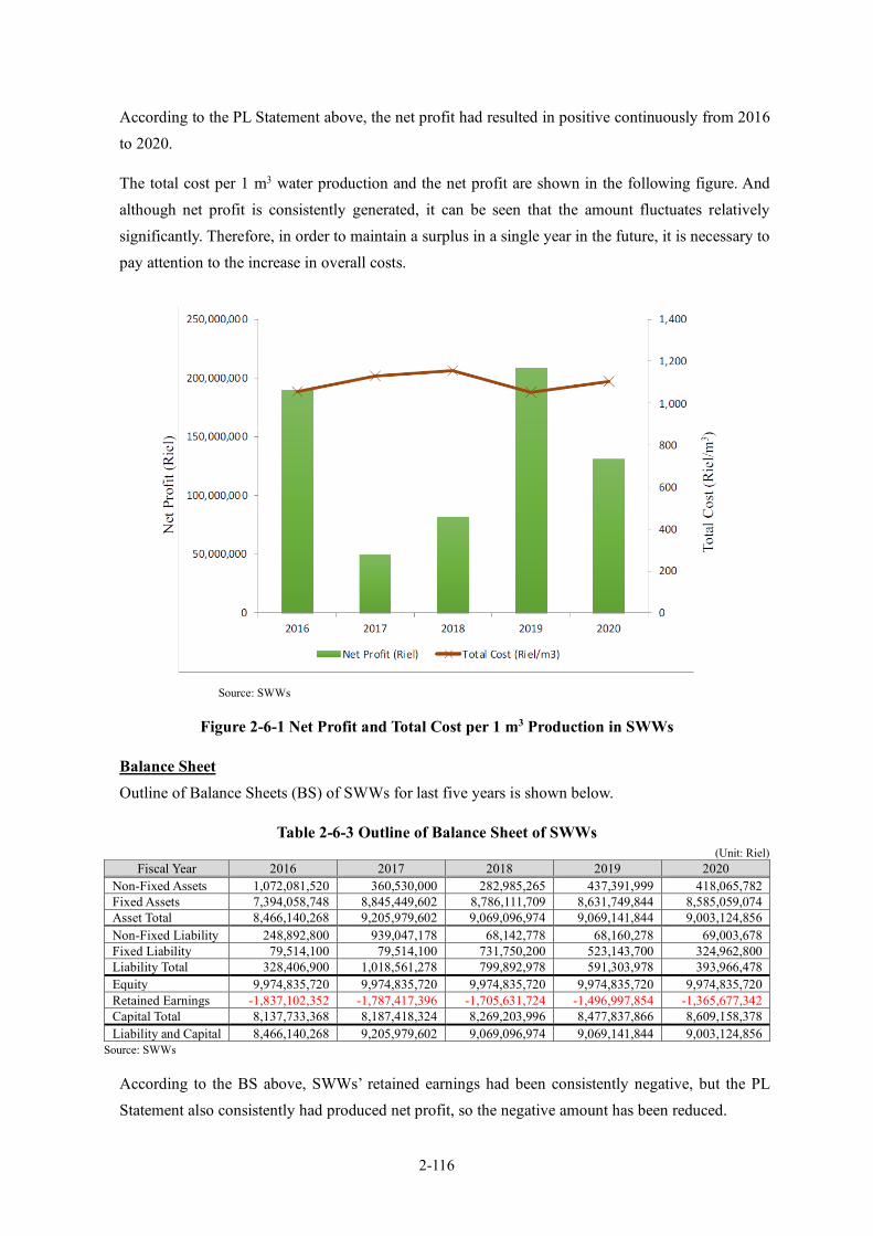
2-116
According to the PL Statement above, the net profit had resulted in positive continuously from 2016 to 2020.
The total cost per 1 m3 water production and the net profit are shown in the following figure. And although net profit is consistently generated, it can be seen that the amount fluctuates relatively significantly. Therefore, in order to maintain a surplus in a single year in the future, it is necessary to pay attention to the increase in overall costs.
Source: SWWs
Figure 2-6-1 Net Profit and Total Cost per 1 m3 Production in SWWs
Balance Sheet Outline of Balance Sheets (BS) of SWWs for last five years is shown below.
Table 2-6-3 Outline of Balance Sheet of SWWs (Unit: Riel)
Fiscal Year 2016 2017 2018 2019 2020 Non-Fixed Assets 1,072,081,520 360,530,000 282,985,265 437,391,999 418,065,782 Fixed Assets 7,394,058,748 8,845,449,602 8,786,111,709 8,631,749,844 8,585,059,074 Asset Total 8,466,140,268 9,205,979,602 9,069,096,974 9,069,141,844 9,003,124,856 Non-Fixed Liability 248,892,800 939,047,178 68,142,778 68,160,278 69,003,678 Fixed Liability 79,514,100 79,514,100 731,750,200 523,143,700 324,962,800 Liability Total 328,406,900 1,018,561,278 799,892,978 591,303,978 393,966,478 Equity 9,974,835,720 9,974,835,720 9,974,835,720 9,974,835,720 9,974,835,720 Retained Earnings -1,837,102,352 -1,787,417,396 -1,705,631,724 -1,496,997,854 -1,365,677,342 Capital Total 8,137,733,368 8,187,418,324 8,269,203,996 8,477,837,866 8,609,158,378 Liability and Capital 8,466,140,268 9,205,979,602 9,069,096,974 9,069,141,844 9,003,124,856
Source: SWWs
According to the BS above, SWWs’ retained earnings had been consistently negative, but the PL Statement also consistently had produced net profit, so the negative amount has been reduced.

2-117
The management status of SWWs will be examined based on commonly used management indicators hereinafter.
1) Ratio of Equity to Total Assets Ratio of equity to total assets is the indicator of a long-term stability for water supply business, which is calculated by the following formula:
Ratio of Equity to Total Assets =Capital Total
Liability and Capital
The larger the ratio, the more expected is long-term stability of the business. The ratio of SWWs for last five years is shown below:
Table 2-6-4 Ratio of Equity to Total Assets of SWWs Fiscal Year 2016 2017 2018 2019 2020
Ratio of Equity to Total Assets 96.1% 88.9% 91.2% 93.5% 95.6% Source: SWWs
SWWs has been continuously showing a high ratio, comparing with the national average of Japanese water supply entities in 2015, 69.5%. It does not necessarily show the long-term stability of SWWs, but it is due to the low amount of liability. The water supply business in Japan has been successful in rapid expansion of prevalence rate with aggressive capital investment, introducing long-term and low interest financing by issuing bonds, in the developing period. The most of business entities in that era showed 20% to 30% of the ratio. Presently, Cambodia has no financing system such as bond issuing as in Japan, thus public water supply business cannot access long-term and low interest financing which is necessary for capital investment. If it is assumed that the business will be managed in the future with independent accounting in the setup of a government corporation, unavailability of long-term and low interest financing could be an obstacle to the independent stability or expansion of the business.
2) Current Ratio Current ratio is the indicator of capability to pay back current liabilities or the short-term stability for water supply business, which is calculated by the following formula:
Current Ratio =Current Asset
Current Liability
Current ratio is required to be 100% or more. If it is lower than 100%, it means that the business entity has bad debts. The current ratio of SWWs for last five years is shown below:
Table 2-6-5 Current Ratio of SWWs Fiscal Year 2016 2017 2018 2019 2020
Current Ratio 430.7% 38.4% 415.3% 641.7% 605.9% Source: SWWs

2-118
SWWs has been continuously showing high current ratio, more than 400% except 2017. This also does not necessarily indicate short-term stability of business, and is due to the fact that long-term, low-interest financing is not possible, resulting in low amount of liability and low annual interest payments.
2-6-2-2 Water Consumption Revenue water for last five years in SWWs is shown below:
Table 2-6-6 Composition of Revenue Water by User Category (Unit: m3)
2016 2017 2018 2019 2020
Domestic 846,460 956,171 1,094,849 1,231,363 1,407,805 Commercial 119,168 131,287 100,948 110,503 100,727 Institution 137,095 142,049 163,957 192,347 225,439 3 m3 or less 0 4,592 6,136 6,927 6,438 Total 1,102,723 1,234,099 1,365,890 1,541,140 1,740,409
Note: “3 m3 or less” is explained in 2-6-2-3. Source: SWWs
Revenue water in SWWs increased by 1.58 times in seven years, whose annual average growth rate is nearly 9.56%.
2-6-2-3 Water Charge Revenue and NRW Rate in Present Conditions The water charge in SWWs is 1,200 Riel per m3, which is the same for all user categories. In addition, a special charge of 1,100 Riel per m3 was set from 2017 when the monthly usage is 3 m3 or less for the purpose of measures for the poor. However, if it exceeds 3 m3, the general charge of 1,200 Riel per m3 will be applied for all the usage.
Table 2-6-7 Water Charge Revenue (Unit: Riel)
2016 2017 2018 2019 2020 Domestic 1,015,752,000 - 1,319,994,000 1,482,411,300 1,696,464,900 Commercial 143,001,600 - 121,015,800 133,060,800 120,888,900 Institution 164,514,000 - 196,751,500 230,816,400 270,526,800 3 m3 or less 0 - 2,609,200 3,374,800 3,381,400 Total 1,323,267,600 1,480,459,600 1,640,370,500 1,849,663,300 2,091,262,000
Note: Detailed data for 2017 were not provided. Source: SWWs
The NRW rate was maintained 11 - 10% as shown below. It reached the 9% level in 2020.
Table 2-6-8 Water Distribution and Non- Revenue Water Rate (Unit: m3)
2016 2017 2019 2019 2020
Water Distribution 1,102,723 1,234,099 1,365,890 1,542,166 1,740,409 Non-Revenue
Water 119,972 136,223 136,893 174,660 164,825
NRW Rate 10.88% 11.04% 10.02% 11.33% 9.47% Note1: "Non-revenue water" is the supplied water amount that is not the revenue water. Note2: In 2020, it will include water supply from the "2,000 m3/day membrane filtration facility newly introduced by a Chinese company". Source: SWWs
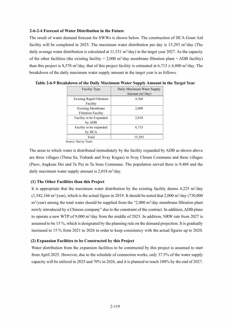
2-119
2-6-2-4 Forecast of Water Distribution in the Future The result of water demand forecast for SWWs is shown below. The construction of JICA Grant Aid facility will be completed in 2025. The maximum water distribution per day is 15,293 m3/day (The daily average water distribution is calculated at 11,531 m3/day) in the target year 2027. As the capacity of the other facilities (the existing facility + 2,000 m3/day membrane filtration plant + ADB facility)
than this project is 8,578 m3/day, that of this project facility is estimated at 6,715 ≅ 6,800 m3/day. The breakdown of the daily maximum water supply amount in the target year is as follows.
Table 2-6-9 Breakdown of the Daily Maximum Water Supply Amount in the Target Year Facility Type Daily Maximum Water Supply
Amount (m3/day) Existing Rapid Filtration
Facility 4,560
Existing Membrane Filtration Facility
2,000
Facility to be Expanded by ADB
2,018
Facility to be expanded by JICA
6,715
Total 15,293 Source: Survey Team
The areas to which water is distributed immediately by the facility expanded by ADB as shown above are three villages (Thma Sa, Trabaek and Svay Kngao) in Svay Chrum Commune and three villages (Pnov, Angkeas Dei and Ta Pa) in Ta Sous Commune. The population served there is 9,404 and the daily maximum water supply amount is 2,018 m3/day.
(1) The Other Facilities than this Project It is appropriate that the maximum water distribution by the existing facility deems 4,225 m3/day (1,542,166 m3/year), which is the actual figure in 2019. It should be noted that 2,000 m3/day (730,000 m3/year) among the total water should be supplied from the “2,000 m3/day membrane filtration plant newly introduced by a Chinese company” due to the constraint of the contract. In addition, ADB plans to operate a new WTP of 9,000 m3/day from the middle of 2023. In addition, NRW rate from 2027 is assumed to be 15 %, which is designated by the planning rule on the demand projection. It is gradually increased to 15 % from 2021 to 2026 in order to keep consistency with the actual figures up to 2020.
(2) Expansion Facilities to be Constructed by this Project Water distribution from the expansion facilities to be constructed by this project is assumed to start from April 2025. However, due to the schedule of connection works, only 37.5% of the water supply capacity will be utilized in 2025 and 70% in 2026, and it is planned to reach 100% by the end of 2027.
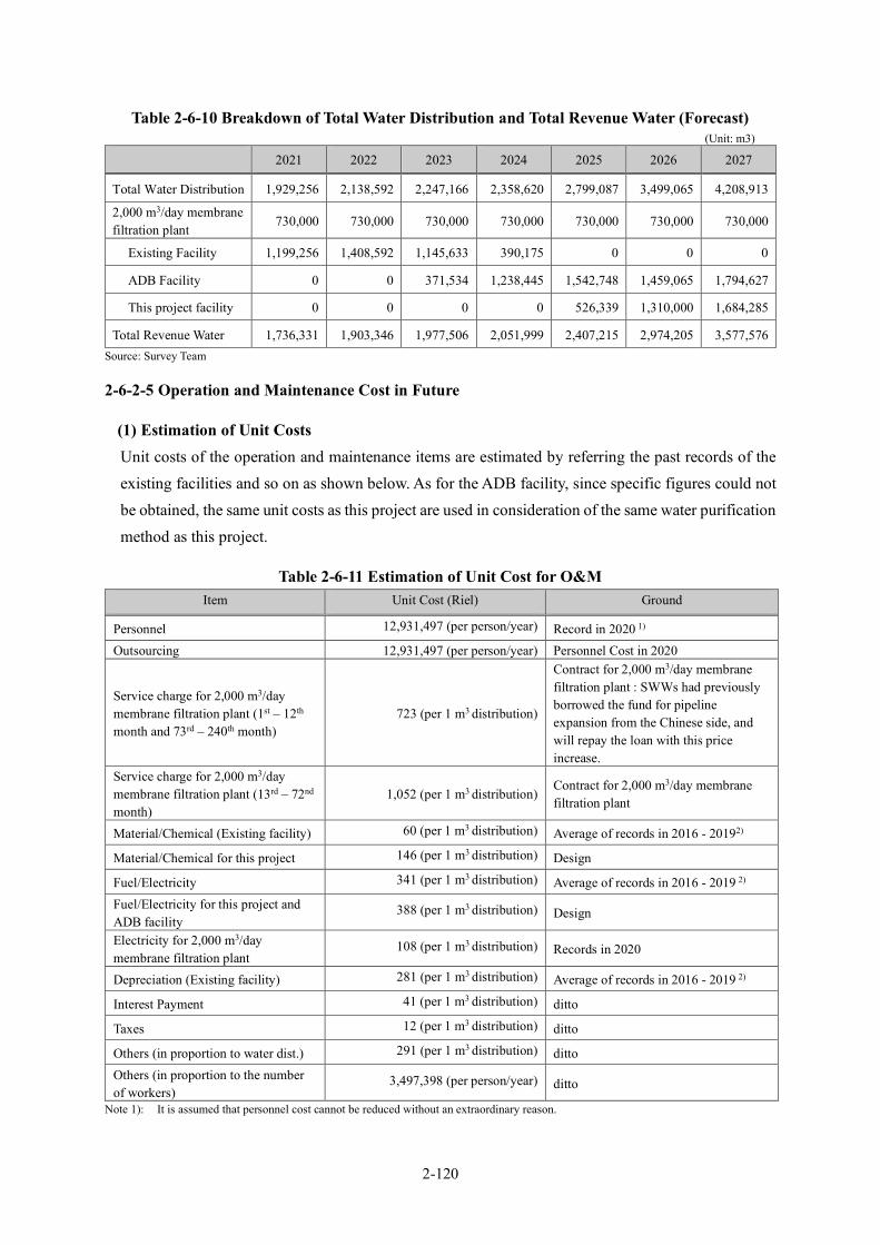
2-120
Table 2-6-10 Breakdown of Total Water Distribution and Total Revenue Water (Forecast) (Unit: m3)
2021 2022 2023 2024 2025 2026 2027
Total Water Distribution 1,929,256 2,138,592 2,247,166 2,358,620 2,799,087 3,499,065 4,208,913
2,000 m3/day membrane filtration plant
730,000 730,000 730,000 730,000 730,000 730,000 730,000
Existing Facility 1,199,256 1,408,592 1,145,633 390,175 0 0 0
ADB Facility 0 0 371,534 1,238,445 1,542,748 1,459,065 1,794,627
This project facility 0 0 0 0 526,339 1,310,000 1,684,285
Total Revenue Water 1,736,331 1,903,346 1,977,506 2,051,999 2,407,215 2,974,205 3,577,576 Source: Survey Team
2-6-2-5 Operation and Maintenance Cost in Future
(1) Estimation of Unit Costs Unit costs of the operation and maintenance items are estimated by referring the past records of the existing facilities and so on as shown below. As for the ADB facility, since specific figures could not be obtained, the same unit costs as this project are used in consideration of the same water purification method as this project.
Table 2-6-11 Estimation of Unit Cost for O&M Item Unit Cost (Riel) Ground
Personnel 12,931,497 (per person/year) Record in 2020 1) Outsourcing 12,931,497 (per person/year) Personnel Cost in 2020
Service charge for 2,000 m3/day membrane filtration plant (1st – 12th month and 73rd – 240th month)
723 (per 1 m3 distribution)
Contract for 2,000 m3/day membrane filtration plant : SWWs had previously borrowed the fund for pipeline expansion from the Chinese side, and will repay the loan with this price increase.
Service charge for 2,000 m3/day membrane filtration plant (13rd – 72nd month)
1,052 (per 1 m3 distribution) Contract for 2,000 m3/day membrane filtration plant
Material/Chemical (Existing facility) 60 (per 1 m3 distribution) Average of records in 2016 - 20192)
Material/Chemical for this project 146 (per 1 m3 distribution) Design
Fuel/Electricity 341 (per 1 m3 distribution) Average of records in 2016 - 2019 2) Fuel/Electricity for this project and ADB facility
388 (per 1 m3 distribution) Design
Electricity for 2,000 m3/day membrane filtration plant
108 (per 1 m3 distribution) Records in 2020
Depreciation (Existing facility) 281 (per 1 m3 distribution) Average of records in 2016 - 2019 2)
Interest Payment 41 (per 1 m3 distribution) ditto
Taxes 12 (per 1 m3 distribution) ditto
Others (in proportion to water dist.) 291 (per 1 m3 distribution) ditto Others (in proportion to the number of workers)
3,497,398 (per person/year) ditto
Note 1): It is assumed that personnel cost cannot be reduced without an extraordinary reason.

2-121
Note 2): The expenditure ratio for each item was changed in 2020 due to 2,000 m3/day membrane filtration plant, so the average of records in 2016 to 2019 is used.
Source: Survey Team
(2) Personnel Plan Number of staff members of the present system is as follows:
Table 2-6-12 Number of Staff Members in Present System 2016 2017 2018 2019 2020 2021
Director 1 1 1 1 1 1 Deputy Director 3 3 3 3 3 3 Administration and Planning Section 1 2 3 2 2 2 Accounting and Finance Section 3 4 4 4 4 4 Business Section 6 7 7 7 8 8 Production Section 5 8 8 9 9 9+(3) Network Section 4 6 6 4 4 4+(1) Total 23 31 32 30 31 31+(4)
Note: ( ) indicates the number of personnel for the facility of ADB. Source: SWWs
Total number of staff members in the present system is 35 (4 of them are staff hired for ADB facilities). Total number of staff members will be increased gradually to 57 in 2027. Assuming this, the personnel plan until 2027 will be as follows:
Table 2-6-13 Personnel Plan 2022 2023 2024 2025 2026 2027
Director 1 1 1 1 1 1 Deputy Director 3 3 3 3 3 3 Administration and Planning Section 2 2 3 3 3 3 Accounting and Finance Section 4 4 5 5 5 5 Business Section 8 9 11 11 11 12 Production Section 12+(3) 15+(3) 20+(3) 20+(3) 20+(3) 20+(3) Network Section 4+(1) 6+(1) 9+(1) 9+(1) 9+(1) 9+(1) Total 34+(4) 40+(4) 52+(4) 52+(4) 52+(4) 53+(4) Outsourcing - 3 6 6 6 6
Note 1: A part of connection services will be outsourced from 2023 to 2027. Note 2: ( ) indicates the number of personnel for the facility of ADB. Source: Survey Team
The estimated increase in labor cost is shown in Table 2-6-14.
Table 2-6-14 Estimated Increased Labor Cost (USD※1) Organization Items 2021 2022 2023 2024 2025 2026 2027
WWs Increased employees※2
3 6 12 0 0 1 Increased cost 9,387 18,774 37,548 0 0 3,129 External resource Employment 3 6 6 6 6 Cost 9,387 18,774 18,774 18,774 18,774 Increased cost 9,387 9,387 0 0 0 Total of Increased cost 9,387 28,161 46,935 0 0 3,129
※1: Estimated as the average person labor cost (USD3,129/person/year) based on the records of 2020. ※2: The number of increased employees compared with the previous year Source: Survey Team
2-6-2-6 Forecast of Revenues and Expenditures for SWWs Based on the estimated revenue water and unit costs of O&M mentioned above, a forecast of revenues and expenditures for the SWWs is examined with the conditions shown below:

2-122
Conditions for Forecast of Revenues and Expenditures
i. The same general water charge is set per 1 m3 for all user categories as the present one. Special water charge is 1,100 Riel per m3, which is fixed on the forecast;
ii. Facilities/equipment constructed/installed on this project and ADB are not depreciated; iii. Interest payment and redemption of the loan for ADB facility construction are not born by SWWs iv. NRW rate is set at 15%; and v. Price escalation is not included basically. (Other than one consideration at the request of the
Cambodian side.)
Analysis on Forecast of Revenues and Expenditures (Existing Water Charge Rate)
According to the table below, the current rate of 1,200 Riel per m3 will continue to make the financial result be in the red from 2021, and it will be able to return to the black in 2027. Therefore, the cumulative deficit will be 68 million yen even within this forecast period. The reason is that the introduction of the 2,000 m3/day membrane filtration plant will increase the cost per m3 of water distribution, compared to the existing facility. Rather, it can be said that the cost of the existing facility was low because they used groundwater with good water quality. The water supply ratio of the existing facility with low costs, ADB facility and this project facility, which are much lower costs, will gradually increase, but on the other hand, costs that are not proportional to the amount of water supply, such as labor costs, will also increase. As a result, the deficit amount will decrease when the water supply ratio of the ADB facility and this project facility rises to a certain extent.
Table 2-6-15 Forecast of Revenues and Expenditures (Existing Charge Rate) Unit: Million Yen
2021 2022 2023 2024 2025 2026 2027 Water Charge (Riel/m3) 1,200 1,200 1,200 1,200 1,200 1,200 1,200 Revenues
Water Sales 55.4 60.8 63.1 65.5 76.8 94.9 114.2 Other Revenue 4.3 4.8 5.1 5.3 6.3 7.9 9.5 Revenues Total 59.8 65.6 68.2 70.8 83.1 102.8 123.7
Expenditures
Personnel 12.0 13.1 16.2 21.3 21.3 21.3 21.7 Material/Chemical 1.9 2.2 3.3 5.4 8.1 10.8 13.5 Electricity/Fuel 12.9 14.8 16.2 18.4 23.5 30.7 38.0 Depreciation 9.0 10.5 8.6 2.9 0.0 0.0 0.0 Interest Payment 2.1 2.3 2.4 2.6 3.0 3.8 4.6 Taxes 0.6 0.6 0.7 0.7 0.8 1.0 1.2 Others (in proportion to water dist.)
9.1 10.1 10.6 11.1 13.2 16.4 19.8
Others (in proportion to the number of workers)
3.6 3.9 4.8 6.3 6.3 6.3 6.4
Service charge for 2,000 m3/day membrane filtration plant
18.8 20.4 20.4 20.4 20.4 15.6 14.0
Expenditures Total 69.9 77.9 83.1 89.1 96.6 106.0 119.3 Net Profit -10.1 -12.3 -14.9 -18.3 -13.4 -3.2 4.4 Net Profit (Cumulative) -10.1 -22.5 -37.4 -55.7 -69.2 -72.4 -68.0
Note : 1 Riel = 0.02661 Yen Source: Survey Team
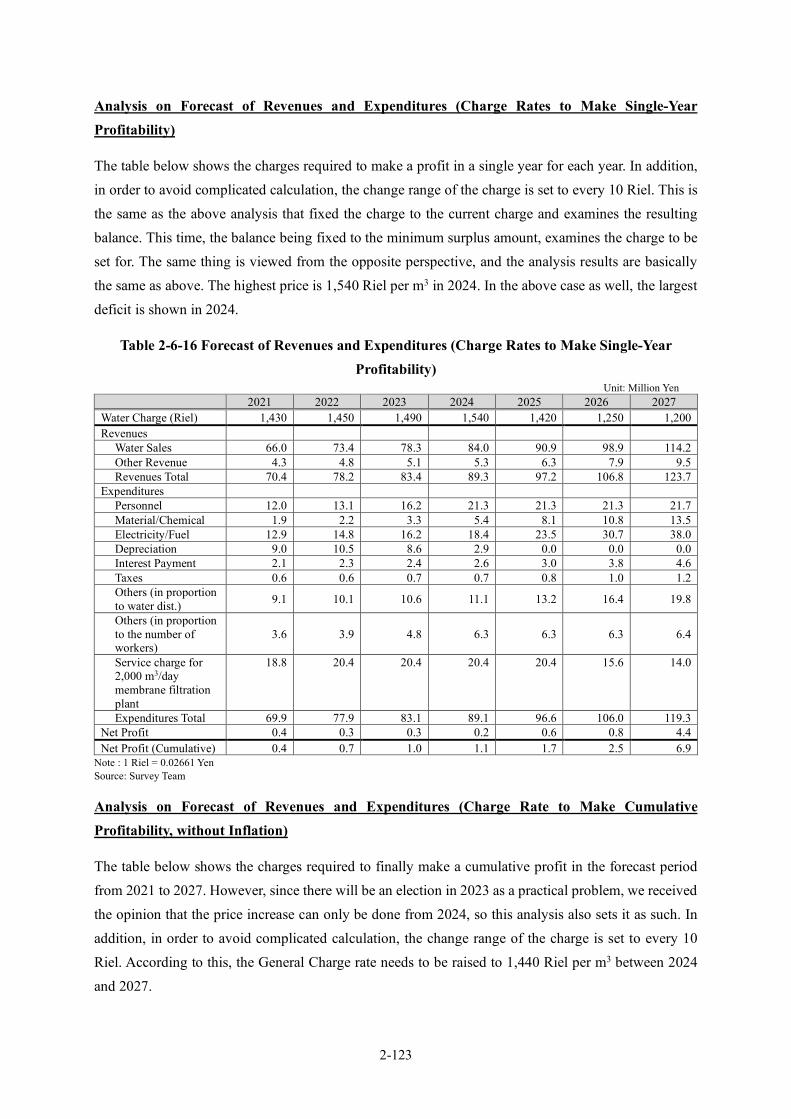
2-123
Analysis on Forecast of Revenues and Expenditures (Charge Rates to Make Single-Year Profitability)
The table below shows the charges required to make a profit in a single year for each year. In addition, in order to avoid complicated calculation, the change range of the charge is set to every 10 Riel. This is the same as the above analysis that fixed the charge to the current charge and examines the resulting balance. This time, the balance being fixed to the minimum surplus amount, examines the charge to be set for. The same thing is viewed from the opposite perspective, and the analysis results are basically the same as above. The highest price is 1,540 Riel per m3 in 2024. In the above case as well, the largest deficit is shown in 2024.
Table 2-6-16 Forecast of Revenues and Expenditures (Charge Rates to Make Single-Year Profitability)
Unit: Million Yen 2021 2022 2023 2024 2025 2026 2027
Water Charge (Riel) 1,430 1,450 1,490 1,540 1,420 1,250 1,200 Revenues
Water Sales 66.0 73.4 78.3 84.0 90.9 98.9 114.2 Other Revenue 4.3 4.8 5.1 5.3 6.3 7.9 9.5 Revenues Total 70.4 78.2 83.4 89.3 97.2 106.8 123.7
Expenditures Personnel 12.0 13.1 16.2 21.3 21.3 21.3 21.7 Material/Chemical 1.9 2.2 3.3 5.4 8.1 10.8 13.5 Electricity/Fuel 12.9 14.8 16.2 18.4 23.5 30.7 38.0 Depreciation 9.0 10.5 8.6 2.9 0.0 0.0 0.0 Interest Payment 2.1 2.3 2.4 2.6 3.0 3.8 4.6 Taxes 0.6 0.6 0.7 0.7 0.8 1.0 1.2 Others (in proportion to water dist.) 9.1 10.1 10.6 11.1 13.2 16.4 19.8
Others (in proportion to the number of workers)
3.6 3.9 4.8 6.3 6.3 6.3 6.4
Service charge for 2,000 m3/day membrane filtration plant
18.8 20.4 20.4 20.4 20.4 15.6 14.0
Expenditures Total 69.9 77.9 83.1 89.1 96.6 106.0 119.3 Net Profit 0.4 0.3 0.3 0.2 0.6 0.8 4.4 Net Profit (Cumulative) 0.4 0.7 1.0 1.1 1.7 2.5 6.9
Note : 1 Riel = 0.02661 Yen Source: Survey Team
Analysis on Forecast of Revenues and Expenditures (Charge Rate to Make Cumulative Profitability, without Inflation)
The table below shows the charges required to finally make a cumulative profit in the forecast period from 2021 to 2027. However, since there will be an election in 2023 as a practical problem, we received the opinion that the price increase can only be done from 2024, so this analysis also sets it as such. In addition, in order to avoid complicated calculation, the change range of the charge is set to every 10 Riel. According to this, the General Charge rate needs to be raised to 1,440 Riel per m3 between 2024 and 2027.
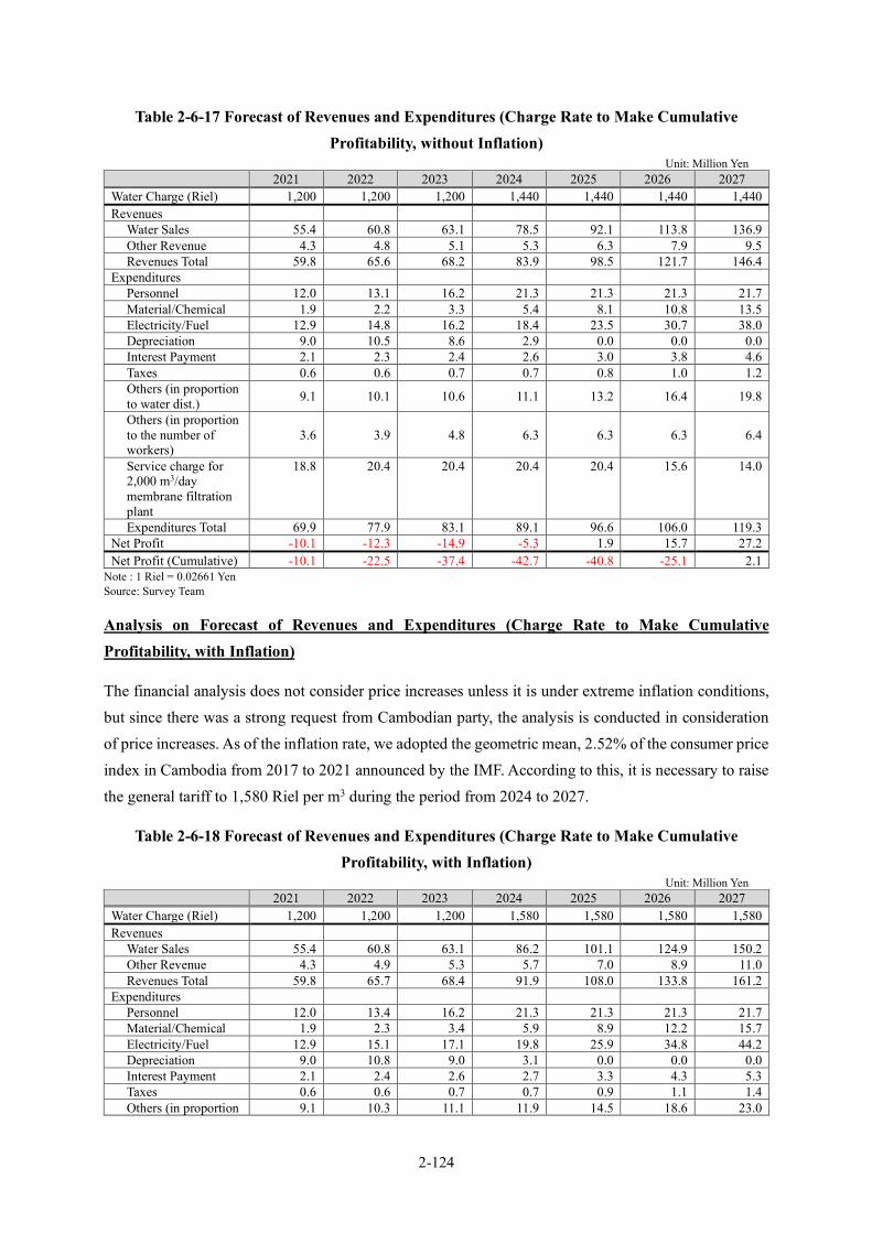
2-124
Table 2-6-17 Forecast of Revenues and Expenditures (Charge Rate to Make Cumulative Profitability, without Inflation)
Unit: Million Yen 2021 2022 2023 2024 2025 2026 2027
Water Charge (Riel) 1,200 1,200 1,200 1,440 1,440 1,440 1,440 Revenues
Water Sales 55.4 60.8 63.1 78.5 92.1 113.8 136.9 Other Revenue 4.3 4.8 5.1 5.3 6.3 7.9 9.5 Revenues Total 59.8 65.6 68.2 83.9 98.5 121.7 146.4
Expenditures Personnel 12.0 13.1 16.2 21.3 21.3 21.3 21.7 Material/Chemical 1.9 2.2 3.3 5.4 8.1 10.8 13.5 Electricity/Fuel 12.9 14.8 16.2 18.4 23.5 30.7 38.0 Depreciation 9.0 10.5 8.6 2.9 0.0 0.0 0.0 Interest Payment 2.1 2.3 2.4 2.6 3.0 3.8 4.6 Taxes 0.6 0.6 0.7 0.7 0.8 1.0 1.2 Others (in proportion to water dist.) 9.1 10.1 10.6 11.1 13.2 16.4 19.8
Others (in proportion to the number of workers)
3.6 3.9 4.8 6.3 6.3 6.3 6.4
Service charge for 2,000 m3/day membrane filtration plant
18.8 20.4 20.4 20.4 20.4 15.6 14.0
Expenditures Total 69.9 77.9 83.1 89.1 96.6 106.0 119.3 Net Profit -10.1 -12.3 -14.9 -5.3 1.9 15.7 27.2 Net Profit (Cumulative) -10.1 -22.5 -37.4 -42.7 -40.8 -25.1 2.1
Note : 1 Riel = 0.02661 Yen Source: Survey Team
Analysis on Forecast of Revenues and Expenditures (Charge Rate to Make Cumulative Profitability, with Inflation)
The financial analysis does not consider price increases unless it is under extreme inflation conditions, but since there was a strong request from Cambodian party, the analysis is conducted in consideration of price increases. As of the inflation rate, we adopted the geometric mean, 2.52% of the consumer price index in Cambodia from 2017 to 2021 announced by the IMF. According to this, it is necessary to raise the general tariff to 1,580 Riel per m3 during the period from 2024 to 2027.
Table 2-6-18 Forecast of Revenues and Expenditures (Charge Rate to Make Cumulative Profitability, with Inflation)
Unit: Million Yen 2021 2022 2023 2024 2025 2026 2027
Water Charge (Riel) 1,200 1,200 1,200 1,580 1,580 1,580 1,580 Revenues
Water Sales 55.4 60.8 63.1 86.2 101.1 124.9 150.2 Other Revenue 4.3 4.9 5.3 5.7 7.0 8.9 11.0 Revenues Total 59.8 65.7 68.4 91.9 108.0 133.8 161.2
Expenditures
Personnel 12.0 13.4 16.2 21.3 21.3 21.3 21.7 Material/Chemical 1.9 2.3 3.4 5.9 8.9 12.2 15.7 Electricity/Fuel 12.9 15.1 17.1 19.8 25.9 34.8 44.2 Depreciation 9.0 10.8 9.0 3.1 0.0 0.0 0.0 Interest Payment 2.1 2.4 2.6 2.7 3.3 4.3 5.3 Taxes 0.6 0.6 0.7 0.7 0.9 1.1 1.4 Others (in proportion 9.1 10.3 11.1 11.9 14.5 18.6 23.0

2-125
2021 2022 2023 2024 2025 2026 2027 to water dist.) Others (in proportion to the number of workers)
3.6 4.0 5.0 6.8 7.0 7.1 7.4
Service charge for 2,000 m3/day membrane filtration plant
18.8 20.9 21.5 22.0 22.6 17.7 16.3
Expenditures Total 69.9 79.9 86.5 94.4 104.5 117.2 135.0 Net Profit -10.1 -14.2 -18.1 -2.5 3.6 16.6 26.2 Net Profit (Cumulative) -10.1 -24.3 -42.4 -44.9 -41.3 -24.8 1.5
Note : 1 Riel = 0.02661 Yen Source: Survey Team
Evaluation on Forecast of Revenues and Expenditures
The 2,000m3/day membrane filtration facility was introduced in 2020. As its unit price of water supply per 1 m3 is higher than that of existing facilities. As a result, the single-year balance will be negative for SWWs as a whole if the current rate of 1,200 Riel per m3 remains unchanged. However, if the water supply ratio of ADB facilities and this project facility, which have relatively low water supply unit costs, rises to a certain extent, the deficit amount will decrease in a single year and will return to the black in 2027. However, since a cumulative deficit of nearly 70 million yen will occur in this analysis period alone, it will be necessary to raise the water charge to prevent this. As for the amount of price increase, it was calculated that it is necessary to raise it to at least 1,580 Riel per m3, considering that the price increase will be from 2024 for political reasons, and the forecasted inflation rate during that period.
Regarding the amount of 1,580 Riel per m3, the charge of the Pursat Waterworks, which is also a local water supply Grant Aid project that was conducted the survey almost at the same time in this project, is 1,600 Riel per m3, and a special charge of 1,100 Riel per m3 up to 3 m3 per month for low-income households will be maintained. So, it is considered that there is a good affordability to pay for residents.
In addition, according to the results of the social survey conducted in the preparatory survey, the average amount of water consumed per household is about 18.2 m3 per month, and if the price is raised at 1,580 Riel per m3, the total water charge will be 28,756 Riel per month. This amount of water charge is about 2% of the average income of 1,512,000 Riel per month for unconnected households, which is considered to be a feasible tariff level that can be borne by the residents.
Furthermore, at the meeting of M/D held in December 2021, MISTI showed an understanding of the need to revise the water tariff from the current 1,200 Riel per m3 to about 1,580 Riel per m3. If the water tariff revision cannot be implemented as planned, MISTI has agreed to take necessary budgetary measures. If the water tariff cannot be revised, the cumulative deficit of 68 million yen in 2027, which is the target year of this project, is equivalent to 0.7% of MISTI's 2021 budget of US $ 93 million (10.1 billion yen). Therefore, even if the tariff revision cannot be implemented, it is possible to be born the operation and maintenance costs of the facilities constructed on this project by MISTI.

3-1
Chapter 3. Project Evaluation
3-1 Preconditions for Project Implementation As detailed in “Section 2-4 Obligations of Recipient Country”, the main preconditions for project implementation and the costs borne by Cambodia are as follows:
Securing Additional Water Rights The total capacity of the existing WTP, the facility to be expanded by ADB and the facility expanded under this Project is expected to be around 20,680 m3/day, and will involve taking surface water from Vay Kor Lake. Regarding the surface water intake permit from Vay Kor Lake, MISTI has already obtained an approval from MOWRAM in September 2017 for 12,000 m3/day and an additional 11,000 m3/day in July 2021.
Securing the Durability of the Vay Kor Dam To ensure that surface water can be taken safely from Vay Kor Lake, the soundness of the Vay Kor Dam, which maintains the water level of the Vay Kor Lake by blocking the inflow from the Vay Kor River at the area downstream of the lake, should be maintained in future. At the meeting of M/D in December 2021, it was confirmed that MOWRAM shall be responsible for maintaining and managing the Vay Kor Dam and MISTI shall work with MOWRAM to keep the water level needed to take water.
Environmental and Social Considerations The Ministerial Ordinance on the Classification of the Environmental Impact Assessment of Development Projects (No. 021) which was enforced on February 3, 2020, prescribes, that all projects for WTPs and water distribution systems are subject to the EPC. MISTI thus obtained the EPC approval from the MOE on March 30, 2021. It was confirmed at the meeting of M/D in April 12, 2021 that the project will be implemented in line with the EPC.
Occupancy Approval for Proposed WTP and Intake Facility Construction Sites The site for the WTP is on a private land and the WWs acquired approval from the landowner in December 2017. The intake facility site is on a public land, and it was confirmed at the meeting of M/D in December 2021 that the SWWs will obtain the approval of using the land from the Provincial Governor via DISTI by August 2022 before notice of the bidding document.
Acquisition and Ground Leveling of Sites for the WTP and Intake Facility At the meeting of M/D in April 2021, acquisition and ground leveling of sites for the WTP and intake facility were discussed. Since embankments are needed in the WTP and intake facility sites (around 13,767 m3 and 5,067 m3 for the WTP and intake facility sites1, respectively), the Survey Team explained the work schedule to the Cambodian side, confirmed to secure the necessary budget and prepare the
1 The amount of embankment soil at the WTP (after compaction) = 13,767 m3, the amount of embankment soil at the intake facility (after compaction) = 5,067 m3, loosening rate: 1.2, compaction rate: 0.95, and the amount of purchased soil is calculated as follows. The amount of soil purchased for the WTP = 13,767 m3 ÷ 0.95 x 1.2 ≒ 17,390 m3, and the amount of soil purchased for the intake facility = 5,067 m3 ÷ 0.95 x 1.2 ≒ 6,400 m3.

3-2
embankment for the construction site by August 2022 before notice of the bidding document at the meeting of M/D in December 2021.
Occupancy Approval for Conveyance, Transmission and Distribution Pipe Routes All conveyance, transmission and distribution pipes are supposed to be buried underground along public roads (except for portions installed by a bridge-attached pipe). Accordingly, issues concerning private land acquisition and others are not expected; however, occupancy approval should be obtained from the MPWT for national highways and from the Provincial Governor for other roads. It was confirmed at the meeting of M/D in December 2021 that these occupancy approvals would be obtained before start of the construction.
Drawing Electricity Line into the New Intake Facility and WTP Site The provision of transformers to be installed in proposed construction sites for new intake facility and WTP are included in a Grant Aid project. The Cambodian side is responsible for drawing electricity into the transformers. It was confirmed at the meeting of M/D in December 2021 that the distribution line of electricity to the main road near the proposed facility will be provided before start of the construction and that from the main road to the site of proposed facility will be provided by 2 months before the commissioning test.
Tax Exemption Measures The Cambodian government provides indirect support for tax exemption measures to contractors.
3-2 Necessary Inputs (Obligations) by Recipient Country to Achieve the Whole Project Plan Promotion of Service Pipe Connection to Each Household The work involved in connecting the service pipe to each household from the distribution pipe to be installed in this project will be handled by Cambodia. Under this project, new service pipe connections for approximately 7,378 households, including 375 classed as poor, will be needed for achievement of project purpose. Since failure to connect to each household means the development effect of this project will not be realized, the specific schedule and organizational structure expected for service pipe connections was explained and it was agreed at the meeting of M/D in December 2021 that the necessary measures would be taken by the Cambodian side. Support for an activity involving residents promoting these connections is planned via soft component activities.
Hiring New Personnel Both new and existing plants have to be operated, maintained and managed while the number of connections is being increased. Accordingly, the SWWs needs to increase the number of personnel from the current thirty-five (35) (as of 2021) to fifty-seven (57) by gradually adding twenty-two (22) personnel until 2027. The details of this increase are planned as follows: eleven (11) personnel for the Water Treatment Division; five (5) personnel for the Water Distribution Division; four (4) personnel for

3-3
the Service Division, and one (1) each for the General Affairs Division and the Accounting/Finance Division.
Financial Soundness In order for the SWWs to aim to be a "growing water supply entity" that can ensure financial soundness and
expand and improve water services, the operation and maintenance of the facilities constructed in this project
shall be carried out properly. Therefore, it is necessary to raise the water tariff to cover the operation and
maintenance cost. At the meeting held in December 2021, it was explained that it is necessary to raise the
current water tariff of 1,200 Riel per m3 to about 1,580 Riel per m3 in case the tariff is revised from 2024.
The Cambodian side understood the need for water tariff increases and agreed to take necessary measures
toward 2024.
3-3 External Conditions To achieve and sustain the project effects, the following external conditions should be considered:
Large-scale unseasonable weather or natural disasters will not occur; Social and economic situations will not seriously deteriorate; Population in the target area does not move unexpectedly; and The current capacity of the existing WTP will be maintained.
3-4 Project Evaluation 3-4-1 Validity Beneficiaries of the Project The water supply capacity to residents in Svay Rieng City will be improved under the project. The water supply ratio in the administrative area was 23.6% in 2019 and will increase by 52.6% in the target year 2027. The water supply ratio in the urban areas, which MISTI targets, will be 86.7%. The increased number of beneficiaries (population newly served) will be approximately 32,419 (22,543 personnel in urban areas while it is 9,876 personnel in rural areas).
Urgency of the Project Although Svay Rieng City operates an existing water service system, its water supply ratio remained at 23.6% as of 2019. Accordingly, the expansion of the water supply facilities is urgently needed to further improve the water supply ratio.
Consistency with the Upper-Level Plan (NSDP) of the Project The National Strategic Development Plan (NSDP 2019-2023) has set the target of achieving 100% water supply ratio in urban areas by 2025. Ninety Percent (90%) of the urban population served are presently covered by water pipes, while the remaining 10% are covered by other means. The target will be more or less achieved when the area is limited to the urban population in the administrative area managed by the SWWs, and the project will help achieve this aim in Svay Rieng City. Moreover, the project will procure and provide materials and equipment to poor households to encourage them connect to service pipes, the installation cost of which will be borne by the Cambodian side.
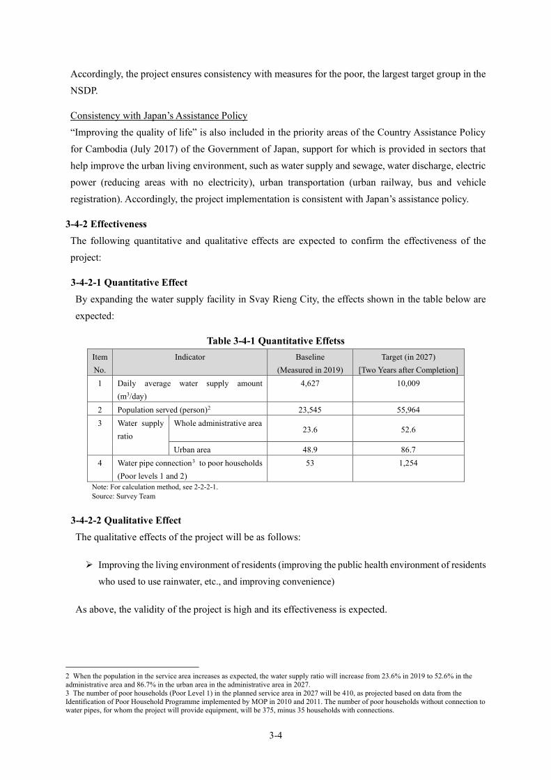
3-4
Accordingly, the project ensures consistency with measures for the poor, the largest target group in the NSDP.
Consistency with Japan’s Assistance Policy “Improving the quality of life” is also included in the priority areas of the Country Assistance Policy for Cambodia (July 2017) of the Government of Japan, support for which is provided in sectors that help improve the urban living environment, such as water supply and sewage, water discharge, electric power (reducing areas with no electricity), urban transportation (urban railway, bus and vehicle registration). Accordingly, the project implementation is consistent with Japan’s assistance policy.
3-4-2 Effectiveness The following quantitative and qualitative effects are expected to confirm the effectiveness of the project:
3-4-2-1 Quantitative Effect By expanding the water supply facility in Svay Rieng City, the effects shown in the table below are expected:
Table 3-4-1 Quantitative Effetss Item No.
Indicator Baseline (Measured in 2019)
Target (in 2027) [Two Years after Completion]
1 Daily average water supply amount (m3/day)
4,627 10,009
2 Population served (person)2 23,545 55,964 3 Water supply
ratio Whole administrative area
23.6 52.6
Urban area 48.9 86.7 4 Water pipe connection3 to poor households
(Poor levels 1 and 2) 53 1,254
Note: For calculation method, see 2-2-2-1. Source: Survey Team
3-4-2-2 Qualitative Effect The qualitative effects of the project will be as follows:
Improving the living environment of residents (improving the public health environment of residents
who used to use rainwater, etc., and improving convenience)
As above, the validity of the project is high and its effectiveness is expected.
2 When the population in the service area increases as expected, the water supply ratio will increase from 23.6% in 2019 to 52.6% in the administrative area and 86.7% in the urban area in the administrative area in 2027. 3 The number of poor households (Poor Level 1) in the planned service area in 2027 will be 410, as projected based on data from the Identification of Poor Household Programme implemented by MOP in 2010 and 2011. The number of poor households without connection to water pipes, for whom the project will provide equipment, will be 375, minus 35 households with connections.

[APPENDECES]
1. Member List of the Survey Team .................................................................................................. A-1 2. Survey Schedule............................................................................................................................. A-5 3. List of Parties Concerned in the Recipient Country .................................................................... A-13 4. Minutes of Discussions ................................................................................................................ A-16 5. Soft Component Plan ................................................................................................................... A-90 6. Relevant Data (List of Collected Data) ..................................................................................... A-109 7. Other materials / information ...................................................................................................... A-111
7-1 Technical Note ......................................................................................................................A-111 7-2 Outline Design Drawings .................................................................................................... A-142 7-3 Intake Pump Total Head Calculation .................................................................................. A-205 7-4 Water Hammer Analysis between Intake Pump Station and WTP .................................... A-206 7-5 Hydraulic Calculation for Conveyance Pipe ....................................................................... A-207 7-6 Selection of Pipe Material ................................................................................................... A-208 7-7 Location and Depth of Laying for Conveyance Pipe and Distribution Mains ................... A-209 7-8 Capacity of the Service Reservoir ....................................................................................... A-211 7-9 Hydraulic Network Analysis ............................................................................................... A-212 7-10 Assumptions on the Number of Poor Households ............................................................ A-231 7-11 Basic Information of the Water Sector .............................................................................. A-233 7-12 Project Monitoring report (PMR) ...................................................................................... A-235


A-1
1. Member List of the Survey Team
(1) Survey for Pursat and Svay Rieng : The 1st field work (From May 21th, 2017 to July 23th, 2017)
Name Job Title Occupation Survey Period Mr. Sadanobu SAWARA Leader Senior Advisor, JICA
HDQs May 21th to May 28th
Mr. Shingo FUJIWARA Project Planning Deputy Director, Water Resources Groupe, Global Environment Department, JICA HDQs
May 21th to May 28th
Mr. Hideki KONNO Chief Consultant/Water Supply Planning Specialist 1
CTI Engineering International Co., Ltd.
June 11th to July 3rd
Mr. Masashi YAYAMA Deputy Chief Consultant/Water Supply Planning Specialist 2
Water and Sewer Bureau, City of Kitakyushu
June 11th to July 2nd
Mr. Takashi FURUKAWA Water Resources/River and Flood Control Specialist
CTI Engineering International Co., Ltd.
June 11th to July 2nd
Mr. Norifumi YAMAMOTO
Hydrogeologist CTI Engineering International Co., Ltd.
May 23th to May 28th June 11th to July 10th
Mr. Naohide MATSUMOTO
Water Treatment Plant Designer 1
TEC International Co., Ltd..
June 11th to June 30th
Mr. Junichi KAWAKAMI Water Treatment Plant Designer 2
TEC International Co., Ltd..
June 11th to June 30th
Mr. Oki SHINDO Intake Facility Plan/River Structure Specialist
CTI Engineering International Co., Ltd.
May 21th to May 28th June 11th to July 9th
Mr. Kiyoshi MIFUNE Conveyance and Distribution Designer 1
TEC International Co., Ltd..
June 16th to July 2nd
Mr. Takuro KOHARA Conveyance and Distribution Designer 2
TEC International Co., Ltd..
June 6th to June 30th
Mr. Shuji SATO Equipment Planning Specialist 2 (Machine Equipment)
CTI Engineering International Co., Ltd.
June 18th to July 2nd
Mr. Naoki MATSUO Construction and Procurement Planning 1/Cost Estimation Specialist
CTI Engineering International Co., Ltd.
June 25th to July 9th
Ms. Asa KINUGAWA Construction and Procurement Planning 2/ Coordinator
CTI Engineering International Co., Ltd.
June 11th to July 10th
Ms. Yasuko KAMEGAI Environmental & Social Considerations /UXO Confirmation
CTI Engineering International Co., Ltd.
June 26th to July 23th
Mr. Makoto YAJIMA Financial Specialist CTI Engineering International Co., Ltd.
June 11th to July 7th

A-2
(2) Survey for Pursat and Svay Rieng : The 2nd field work (From August 9th, 2017 to October 15th, 2017)
Name Job Title Occupation Survey Period Ms. Eriko TAMURA Leader Director, Water Resources
Team1, Water Resources Group, Global Environment Department, JICA HDQs
August 20th to August 27th
Mr. Norihiro OBITSU Project Planning In-house Technical Consultant for Water Supply, JICA Contractor, Water Resources Group, Global Environment Department, JICA HDQs
August 20th to August 25th
Mr. Hideki KONNO Chief Consultant/Water Supply Planning Specialist 1
CTI Engineering International Co., Ltd.
August 9th to September 2nd
Mr. Takashi FURUKAWA Water Resources/River and Flood Control Specialist
CTI Engineering International Co., Ltd.
August 10th to September 3rd
Mr. Norifumi YAMAMOTO
Hydrogeologist CTI Engineering International Co., Ltd.
August 20th to August 27th
Mr. Naohide MATSUMOTO
Water Treatment Plant Designer 1
TEC International Co., Ltd..
August 10th to September 1st
Mr. Junichi KAWAKAMI Water Treatment Plant Designer 2
TEC International Co., Ltd..
August 13th to September 1st
Mr. Daigo TAKEDA O&M Organization Specialist (Soft component)
Water and Sewer Bureau, City of Kitakyushu
August 13th to August 26th
Mr. Oki SHINDO Intake Facility Plan/River Structure Specialist
CTI Engineering International Co., Ltd.
August 17th to September 1st
Mr. Kiyoshi MIFUNE Conveyance and Distribution Designer 1
TEC International Co., Ltd..
August 10th to September 2nd
Mr. Takuro KOHARA Conveyance and Distribution Designer 2
TEC International Co., Ltd..
August 10th to September 2nd
Mr. Kouichi NAOI Equipment Planning Specialist 1 (Electrical Equipment)
TEC International Co., Ltd..
August 20th to September 3rd
Mr. Shuji SATO Equipment Planning Specialist 2 (Machine Equipment)
CTI Engineering International Co., Ltd.
August 20th to September 3rd
Mr. Naoki MATSUO Construction and Procurement Planning 1/Cost Estimation Specialist
CTI Engineering International Co., Ltd.
August 3th to September 4th
Ms. Asa KINUGAWA Construction and Procurement Planning 2/ Coordinator
CTI Engineering International Co., Ltd.
August 10th to August 25th
Ms. Yasuko KAMEGAI Environmental & Social Considerations /UXO Confirmation
CTI Engineering International Co., Ltd.
September 20th to October 15th

A-3
(3) Survey for Svay Rieng after determination of water source : The 3rd field work (From November 5th, 2019 to December 22th, 2019)
Name Job Title Occupation Survey Period Mr. Hideki KONNO Chief Consultant/Water
Supply Planning Specialist 1
CTI Engineering International Co., Ltd.
November 5th to November 9th November 18th to November 23th December 3rd to December 8th December 11th to December 18th
Mr. Hiroshi HIROWATARI
Deputy Chief Consultant/Water Supply Planning Specialist 2
Water and Sewer Bureau, City of Kitakyushu
December 4th to December 8th December 13th to December 15th December 17th to December 18th
Mr. Satoru HADA Water Supply Planning Specialist 3
CTI Engineering International Co., Ltd.
November 14th to December 22th
Mr. Naohide MATSUMOTO
Water Treatment Plant Designer 1
TEC International Co., Ltd..
November 25th to December 14th
Mr. Yoshiki OSHIMA O&M Organization Specialist (Soft component)
Water and Sewer Bureau, City of Kitakyushu
December 4th to December 22th
Mr. Kiyoshi MIFUNE Conveyance and Distribution Designer 1
TEC International Co., Ltd..
November 13th to December 14th
Mr. Takuro KOHARA Conveyance and Distribution Designer 2
TEC International Co., Ltd..
November 17th to December 14th
Mr. Kouichi NAOI Equipment Planning Specialist 1 (Electrical Equipment)
TEC International Co., Ltd..
November 27th to December 14th
Mr. Shuji SATO Equipment Planning Specialist 2 (Machine Equipment)
CTI Engineering International Co., Ltd.
December 1st to December 14th
Mr. Hikaru TAKATSU Construction and Procurement Planning 1/Cost Estimation Specialist
CTI Engineering International Co., Ltd.
November 25th to December 9th
Ms. Yasuko KAMEGAI Environmental & Social Considerations /UXO Confirmation
CTI Engineering International Co., Ltd.
December 8th to December 21th
(4) Survey for Svay Rieng after determination of water source : The 4th field work (From January 12th, 2020 to March 8th, 2020)
Name Job Title Occupation Survey Period Mr. Makoto IWASE Leader Director, Water Resources
Team1, Water Resources Group Global Environment Department, JICA HDQs
February 9th to February 15th
Mr. Satoshi HAMANO Project Planning Deputy Director, Water February 9th to February
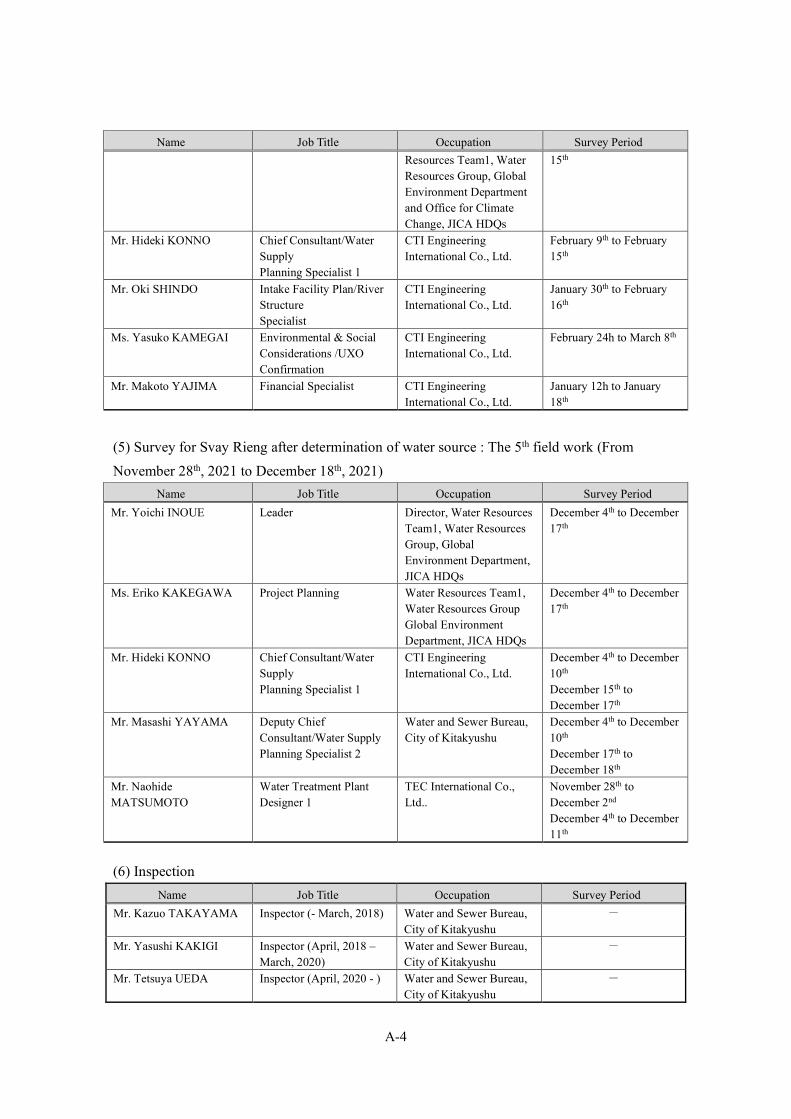
A-4
Name Job Title Occupation Survey Period Resources Team1, Water Resources Group, Global Environment Department and Office for Climate Change, JICA HDQs
15th
Mr. Hideki KONNO Chief Consultant/Water Supply Planning Specialist 1
CTI Engineering International Co., Ltd.
February 9th to February 15th
Mr. Oki SHINDO Intake Facility Plan/River Structure Specialist
CTI Engineering International Co., Ltd.
January 30th to February 16th
Ms. Yasuko KAMEGAI Environmental & Social Considerations /UXO Confirmation
CTI Engineering International Co., Ltd.
February 24h to March 8th
Mr. Makoto YAJIMA Financial Specialist CTI Engineering International Co., Ltd.
January 12h to January 18th
(5) Survey for Svay Rieng after determination of water source : The 5th field work (From November 28th, 2021 to December 18th, 2021)
Name Job Title Occupation Survey Period Mr. Yoichi INOUE Leader Director, Water Resources
Team1, Water Resources Group, Global Environment Department, JICA HDQs
December 4th to December 17th
Ms. Eriko KAKEGAWA Project Planning Water Resources Team1, Water Resources Group Global Environment Department, JICA HDQs
December 4th to December 17th
Mr. Hideki KONNO Chief Consultant/Water Supply Planning Specialist 1
CTI Engineering International Co., Ltd.
December 4th to December 10th December 15th to December 17th
Mr. Masashi YAYAMA Deputy Chief Consultant/Water Supply Planning Specialist 2
Water and Sewer Bureau, City of Kitakyushu
December 4th to December 10th December 17th to December 18th
Mr. Naohide MATSUMOTO
Water Treatment Plant Designer 1
TEC International Co., Ltd..
November 28th to December 2nd December 4th to December 11th
(6) Inspection Name Job Title Occupation Survey Period
Mr. Kazuo TAKAYAMA Inspector (- March, 2018) Water and Sewer Bureau, City of Kitakyushu
-
Mr. Yasushi KAKIGI Inspector (April, 2018 – March, 2020)
Water and Sewer Bureau, City of Kitakyushu
-
Mr. Tetsuya UEDA Inspector (April, 2020 - ) Water and Sewer Bureau, City of Kitakyushu
-

A-5
2. Survey Schedule
The survey schedule is attached as follows.
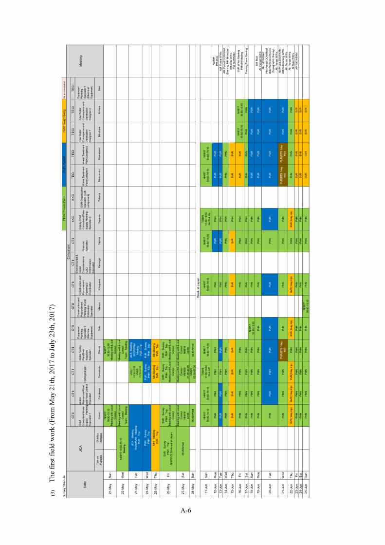
(3)
The
first
field
wor
k (F
rom
May
21t
h, 2
017
to Ju
ly 2
3th,
201
7)
No
acco
mod
atio
n
CTI
IC
TII
CTI
IC
TII
CTI
IC
TII
CTI
IC
TII
CTI
IKK
CKK
CTE
CI
TEC
ITE
CI
TEC
ITE
CI
Chi
efC
onsu
ltant
/Wat
erSu
pply
Plan
ning
Spec
ialis
t 1
Wat
erR
esou
rces
/Rive
ran
d Fl
ood
Con
trol
Spec
ialis
t
Hydr
ogeo
logi
st
Inta
ke F
acilit
yPl
an/R
iver
Stru
ctur
eSp
ecia
list
Equi
pmen
tPl
anni
ngSp
ecia
list 2
(Mac
hine
Equi
pmen
t)
Con
stru
ctio
n an
dPr
ocur
emen
tPl
anni
ng 1
/Cos
tEs
timat
ion
Spec
ialis
t
Con
stru
ctio
n an
dPr
ocur
emen
tPl
anni
ng 2
/C
oord
inat
or
Envir
onm
enta
l &So
cial
Con
side
ratio
ns/U
XOC
onfir
mat
ion
Spec
ialis
t
Fina
ncia
lSp
ecia
list
Dep
uty
Chi
efC
onsu
ltant
/Wat
erSu
pply
Plan
ning
Spec
ialis
t 2
O&M
Org
aniz
atio
nSp
ecia
list (
Soft-
com
pone
nt)
Wat
er T
reat
men
tPl
ant D
esig
ner1
Wat
er T
reat
men
tPl
ant D
esig
ner2
Raw
Wat
erC
onve
yanc
e an
dD
istri
butio
nD
esig
ner 1
Raw
Wat
erC
onve
yanc
e an
dD
istri
butio
nD
esig
ner 2
Equi
pmen
tPl
anni
ngSp
ecia
list 1
(Ele
ctric
alEq
uipm
ent)
Tam
ura
/Fuj
iwar
aO
obits
u/S
awar
aKo
nno
Furu
kaw
aYa
mam
oto
Shin
doSa
toM
atsu
oKi
nuga
wa
Kam
egai
Yajim
aYa
yam
aTa
keda
Mat
sum
oto
Kaw
akam
iM
izuf
une
Koha
raNa
oi
21-M
aySu
nNH
817
10:5
0-15
:10
Mee
ting
with
Loc
alC
onsu
l
NH81
710
:50-
15:1
0M
eetin
g w
ith L
ocal
Con
sul
22-M
ayM
onM
eetin
g w
ith L
ocal
Con
sul
Team
M
eetin
g
Mee
ting
with
Loc
alC
onsu
lTe
am
Mee
ting
23-M
ayTu
eV
N32
110
:30-
13:5
5V
N92
015
:55-
16:5
0
JICA
Mee
ting
WO
WR
AMM
eetin
gPU
R
Trip
24-M
ayW
edPU
R
Surv
eyPN
H Tr
ipPU
R
Surv
eyPN
H Tr
ip
25-M
ayTh
uM
IH M
eetin
gSV
R
Trip
MIH
Mee
ting
SVR
Trip
26-M
ayFr
iSV
R
Surv
eyPN
H Tr
ipM
eetin
g w
ith L
ocal
Con
sul
SVR
Surv
eyPN
H Tr
ipM
eetin
g w
ith L
ocal
Con
sul
SVR
Surv
eyPN
H Tr
ipM
eetin
g w
ith L
ocal
Con
sul
27-M
aySa
tM
eetin
g w
ith L
ocal
Con
sul
NH81
822
:50-
Mee
ting
with
Loc
alC
onsu
lVN
3850
21:0
5-22
:00
Mee
ting
with
Loc
alC
onsu
lNH
818
22:5
0-
28-M
aySu
n06
:45A
rriva
lVN
320
00:3
0-07
:20
06:4
5Arri
val
11-J
unSu
nNH
817
10:5
0-15
:10
NH81
710
:50-
15:1
0
TG64
911
:35-
19:5
5Pi
ck U
P
NH81
710
:50-
15:1
0NH
817
10:5
0-15
:10
NH81
710
:50-
15:1
0
TG64
911
:35-
19:5
5No
Pic
k Up
NH81
710
:50-
15:1
0NH
817
10:5
0-15
:10
12-J
unM
onPN
HPN
HPN
HPN
HPN
HPU
RPN
HPU
RPU
RAM
:MIH
PM:J
ICA
13-J
unTu
ePU
RPU
RPN
HPU
RPN
HPU
RPN
HPU
RPU
RAM
: Pur
sat W
Ws
14-J
unW
edPN
HPN
HPN
HPH
NPH
NPH
NPN
HPH
NPH
NAM
: Pur
sat D
OW
RAM
Even
ing:
MIH
Hiro
wat
ari
15-J
unTh
uSV
RSV
RSV
RSV
RSV
RSV
RPN
HSV
RSV
RAM
:Sva
y W
Ws
PM: D
oWR
AM
16-J
unFr
iPH
NPH
NPH
NPH
NPH
NPN
HPN
HSV
RSV
RNH
817
10:5
0-15
:10
NH81
710
:50-
15:1
0SV
R W
Ws
Mee
ting
PM:M
IH M
eetin
g
17-J
unSa
tPH
NPH
NPH
NPH
NPH
NPH
NPN
HPH
NPH
NPH
NPH
NEv
enin
g:Te
am M
eetin
g
18-J
unSu
nPH
NPH
NPH
NPH
NNH
817
10:5
0-15
:10
PHN
PHN
PHN
PUR
PUR
PUR
PUR
19-J
unM
onPH
NPH
NPH
NPH
NPH
NPH
NPH
NPH
NPU
RPU
RPU
RPU
RAM
: MoA
All:
Purs
at W
WS
20-J
unTu
ePH
NPU
RPU
RPU
RPU
RPU
RPH
NPU
RPU
RPU
RPU
RPU
R
AM: M
OW
RAM
PM: P
ursa
t DO
WR
AMAM
orPM
:Sub
cont
ruct
or(T
opog
raph
ic S
urve
y)Al
l: Pu
rsat
WW
s
21-J
unW
edPH
NPH
NPH
NPU
R(B
TB 1
day
trip)
PHN
PHN
PHN
PHN
PUR
(BTB
1da
ytri
p)PU
R(B
TB 1
day
trip)
PUR
PUR
AM:P
rusa
t DO
WR
AMAM
:Bat
tam
bang
WW
sAl
l: Pu
rsat
WW
s
22-J
unTh
uSV
R(1
day
trip)
SVR
(1da
y tri
p)SV
R(1
day
trip)
PHN
SVR
(1da
y tri
p)SV
R(1
day
trip)
PHN
SVR
(1da
y tri
p)PH
NPH
NPH
NPH
NAl
l: Pu
rsat
WW
sAl
l:Sva
y W
Ws
23-J
unFr
iPH
NPH
NPH
NPH
NPH
NPH
NPH
NPH
NSV
RSV
RSV
RSV
RAM
: MO
WR
AM24
-Jun
Sat
PHN
PHN
PHN
PHN
PHN
PHN
PHN
PHN
SVR
SVR
SVR
SVR
25-J
unSu
nPH
NPH
NPH
NPH
NPH
NNH
817
10:5
0-15
:10
PHN
PHN
PHN
SVR
SVR
SVR
SVR
Wor
k in
Jap
an
Dat
eJI
CA
Con
sulta
ntPH
N:P
hnom
Pen
hPU
R:P
ursa
tSV
R:S
vay
Rie
ngSu
rvey
She
dule
NH81
7 10
:50-
15:1
0M
eetin
g JICA
Mee
ting
WO
WR
AM
Mee
ting
PUR
Trip
PUR
Surv
eyPN
H Tr
ip
Mee
ting
MIH
Mee
ting
SVR
Trip
SVR
Surv
eyPN
H Tr
ipNH
818
22;5
0-Ar
rival
at J
apan
06:4
5Arri
val
A-6

No
acco
mod
atio
n
CTI
IC
TII
CTI
IC
TII
CTI
IC
TII
CTI
IC
TII
CTI
IKK
CKK
CTE
CI
TEC
ITE
CI
TEC
ITE
CI
Chi
efC
onsu
ltant
/Wat
erSu
pply
Plan
ning
Spec
ialis
t 1
Wat
erR
esou
rces
/Rive
ran
d Fl
ood
Con
trol
Spec
ialis
t
Hydr
ogeo
logi
st
Inta
ke F
acilit
yPl
an/R
iver
Stru
ctur
eSp
ecia
list
Equi
pmen
tPl
anni
ngSp
ecia
list 2
(Mac
hine
Equi
pmen
t)
Con
stru
ctio
n an
dPr
ocur
emen
tPl
anni
ng 1
/Cos
tEs
timat
ion
Spec
ialis
t
Con
stru
ctio
n an
dPr
ocur
emen
tPl
anni
ng 2
/C
oord
inat
or
Envir
onm
enta
l &So
cial
Con
side
ratio
ns/U
XOC
onfir
mat
ion
Spec
ialis
t
Fina
ncia
lSp
ecia
list
Dep
uty
Chi
efC
onsu
ltant
/Wat
erSu
pply
Plan
ning
Spec
ialis
t 2
O&M
Org
aniz
atio
nSp
ecia
list (
Soft-
com
pone
nt)
Wat
er T
reat
men
tPl
ant D
esig
ner1
Wat
er T
reat
men
tPl
ant D
esig
ner2
Raw
Wat
erC
onve
yanc
e an
dD
istri
butio
nD
esig
ner 1
Raw
Wat
erC
onve
yanc
e an
dD
istri
butio
nD
esig
ner 2
Equi
pmen
tPl
anni
ngSp
ecia
list 1
(Ele
ctric
alEq
uipm
ent)
Tam
ura
/Fuj
iwar
aO
obits
u/S
awar
aKo
nno
Furu
kaw
aYa
mam
oto
Shin
doSa
toM
atsu
oKi
nuga
wa
Kam
egai
Yajim
aYa
yam
aTa
keda
Mat
sum
oto
Kaw
akam
iM
izuf
une
Koha
raNa
oi
26-J
unM
onPH
NPH
NPH
NPH
NPH
NPH
NPH
NNH
817
10:5
0-15
:10
PHN
PHN
SVR
SVR
SVR
SVR
AM: M
OW
RAM
/MO
APM
:Con
truct
orAl
l:Sva
y W
Ws
27-J
unTu
ePU
RPU
RPH
NPU
RPU
RPU
RPU
RPH
NPH
NPU
RSV
RSV
RSV
RSV
RAl
l:Sva
y W
Ws
PM:PursatWWs,DPW、
DLM
UPC
28-J
unW
edBT
BPH
NPH
NPH
NPH
NPH
NPH
NPH
NPH
NPH
NSV
R-K
PC-P
HNSV
R-K
PC-P
HNPH
NPH
NAM
:Pur
sat D
OW
RAM
All:P
ursa
t WW
sAl
l:KM
C W
TP
29-J
unTh
uPH
NSV
R(1
day
trip)
PHN
PHN
PHN
SVR
(1da
y tri
p)SV
R(1
day
trip)
PHN
PHN
PHN
NH81
822
:50
NH81
822
:50
PHN
NH81
822
:50
AM:J
ICA
All:P
hum
Pre
k W
TPAl
l:Sva
y W
Ws
AM:S
vay
Dow
ram
30-J
unFr
iPH
NPH
NPH
NPH
NPH
NPH
NPH
NPH
NPH
NPH
N06
:45A
rriva
l06
:45A
rriva
lPH
N06
:45A
rriva
lPM
:MIH
1-Ju
lSa
tPH
NPH
NPH
NPH
NSt
ruct
ure
Des
ign
NH81
822
:50-
PHN
PHN
PHN
PHN
PHN
NH81
822
:50
AM:C
ontru
ctor
2-Ju
lSu
nNH
818
22:5
0-D
epar
t 14:
15 -
Hano
iPH
NPH
N06
:45A
rriva
lPH
NPH
NPH
NPH
NPH
N06
:45A
rriva
l
3-Ju
lM
on06
:45A
rriva
lSV
R(1
day
trip)
SVR
(1da
y tri
p)SV
R(1
day
trip)
PHN
SVR
(1da
y tri
p)PH
NPH
NAM
:Sva
y D
oAPM
:Sva
y D
oEAl
l:Sva
y W
Ws
4-Ju
lTu
ePH
NPH
NPH
NPH
NPH
NPH
NPH
NAl
l:Sva
y W
Ws
5-Ju
lW
edPH
NPU
RPU
RPU
RPU
RPH
NPH
NAM
:MoP
6-Ju
lTh
uPH
NPH
NPU
RPU
RPH
NNH
818
22:5
0-PH
NAl
l:Pur
sat W
Ws
AM:P
ursa
t DoA
PM:P
ursa
t DoE
7-Ju
lFr
iPH
NPH
NPH
NPH
NPH
N06
:45A
rriva
lPH
NAM
:JIC
AAl
l:Pur
sat W
Ws
8-Ju
lSa
tPH
NNH
818
22:5
0-NH
818
22:5
0-PH
NPH
NPH
N
9-Ju
lSu
nTG
585
21:1
5-08
:00
06:4
5Arri
val
06:4
5Arri
val
NH81
822
:50-
PHN
PHN
10-J
ulM
onAr
rival
at J
apan
06:4
5Arri
val
PHN
PHN
11-J
ulTu
ePH
NPH
N
12-J
ulW
edSV
R(1
day
trip)
SVR
(1da
y tri
p)AM
:Sva
y D
oEAM
:Sva
y Pr
ovin
cial
Hal
lPM
:Sva
y C
loth
Fac
tory
13-J
ulTh
uPU
R(1
day
Trip
)PU
R(1
day
Trip
)AM
:Pur
sat P
rovin
cial
Hal
l
14-J
ulFr
iPH
NPH
NAM
:MoE
PM:M
IH15
-Jul
Sat
PHN
PHN
16-J
ulSu
nPH
NPH
N
17-J
ulM
onPH
NTG
585
21:1
5-08
:00
AM:M
IH(T
echn
ical
Not
e)
18-J
ulTu
ePU
R(1
day
Trip
)Ar
rival
at J
apan
AM:C
MAC
PM:P
ursa
t WW
s
19-J
ulW
edPH
NAM
:Pur
sat W
Ws
PM:M
oE20
-Jul
Thu
SVR
(1da
y tri
p)Al
l:Sva
y W
Ws
21-J
ulFr
iPH
NAM
:PPW
SAPM
:MIH
22-J
ulSa
tNH
818
22:5
0-
23-J
ulSu
n06
:45A
rriva
l
Dat
eJI
CA
Con
sulta
ntPH
N:P
hnom
Pen
hPU
R:P
ursa
tSV
R:S
vay
Rie
ngSu
rvey
She
dule
Mee
ting
A-7
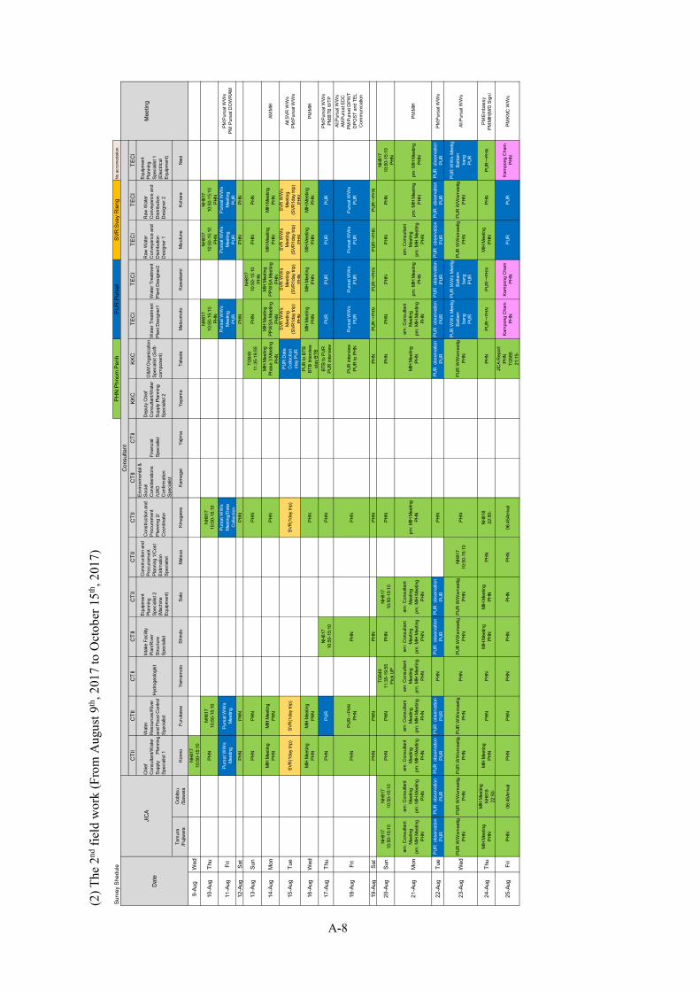
(2) T
he 2
nd fi
eld
wor
k (F
rom
Aug
ust 9
th, 2
017
to O
ctob
er 1
5th, 2
017)
No
acco
mod
atio
n
CTI
IC
TII
CTI
IC
TII
CTI
IC
TII
CTI
IC
TII
CTI
IKK
CKK
CTE
CI
TEC
ITE
CI
TEC
ITE
CI
Chi
efC
onsu
ltant
/Wat
erSu
pply
Plan
ning
Spec
ialis
t 1
Wat
erR
esou
rces
/Rive
ran
d Fl
ood
Con
trol
Spec
ialis
t
Hydr
ogeo
logi
st
Inta
ke F
acilit
yPl
an/R
iver
Stru
ctur
eSp
ecia
list
Equi
pmen
tPl
anni
ngSp
ecia
list 2
(Mac
hine
Equi
pmen
t)
Con
stru
ctio
n an
dPr
ocur
emen
tPl
anni
ng 1
/Cos
tEs
timat
ion
Spec
ialis
t
Con
stru
ctio
n an
dPr
ocur
emen
tPl
anni
ng 2
/C
oord
inat
or
Envir
onm
enta
l &So
cial
Con
side
ratio
ns/U
XOC
onfir
mat
ion
Spec
ialis
t
Fina
ncia
lSp
ecia
list
Dep
uty
Chi
efC
onsu
ltant
/Wat
erSu
pply
Plan
ning
Spec
ialis
t 2
O&M
Org
aniz
atio
nSp
ecia
list (
Soft-
com
pone
nt)
Wat
er T
reat
men
tPl
ant D
esig
ner1
Wat
er T
reat
men
tPl
ant D
esig
ner2
Raw
Wat
erC
onve
yanc
e an
dD
istri
butio
nD
esig
ner 1
Raw
Wat
erC
onve
yanc
e an
dD
istri
butio
nD
esig
ner 2
Equi
pmen
tPl
anni
ngSp
ecia
list 1
(Ele
ctric
alEq
uipm
ent)
Tam
ura
/Fuj
iwar
aO
obits
u/S
awar
aKo
nno
Furu
kaw
aYa
mam
oto
Shin
doSa
toM
atsu
oKi
nuga
wa
Kam
egai
Yajim
aYa
yam
aTa
keda
Mat
sum
oto
Kaw
akam
iM
izuf
une
Koha
raNa
oi
9-Au
gW
edNH
817
10:5
0-15
:10
10-A
ugTh
uPH
NNH
817
10:5
0-15
:10
NH81
710
:50-
15:1
0
NH81
710
:50-
15:1
0PH
N
NH81
710
:50-
15:1
0PH
N
NH81
710
:50-
15:1
0PH
N
11-A
ugFr
iPu
rsat
WW
sM
eetin
gPu
rsat
WW
sM
eetin
g
Purs
at W
Ws
Mee
ting/
Dat
aC
olle
ctio
n
Purs
at W
Ws
Mee
ting
PUR
Purs
at W
Ws
Mee
ting
PUR
Purs
at W
Ws
Mee
ting
PUR
PM:P
ursa
t WW
sPM
: Pur
sat D
OW
RAM
12-A
ugSa
tPH
NPH
NPH
NPH
NPH
NPH
N
13-A
ugSu
nPH
NPH
NPH
NTG
649
11:3
5-19
:55
PHN
NH81
710
:50-
15:1
0PH
NPH
NPH
N
14-A
ugM
onM
IH M
eetin
gPH
NM
IH M
eetin
gPH
NPH
NM
IH M
eetin
gPh
ase
3 M
eetin
gPH
N
MIH
Mee
ting
PPW
SA M
eetin
gPH
N
MIH
Mee
ting
PPW
SA M
eetin
gPH
N
MIH
Mee
ting
PHN
MIH
Mee
ting
PHN
AM:M
IH
15-A
ugTu
eSV
R(1
day
trip)
SVR
(1da
y tri
p)SV
R(1
day
trip)
PUR
Dat
aC
olle
ctio
nst
ay P
UR
SVR
WW
sM
eetin
g(S
VR1d
ay tr
ip)
PHN
SVR
WW
sM
eetin
g(S
VR1d
ay tr
ip)
PHN
SVR
WW
sM
eetin
g(S
VR1d
ay tr
ip)
PHN
SVR
WW
sM
eetin
g(S
VR1d
ay tr
ip)
PHN
All:S
VR W
Ws
PM:P
ursa
t WW
s
16-A
ugW
edM
IH M
eetin
gPH
NM
IH M
eetin
gPH
NPH
NPU
R to
BTB
BTB
Inte
rvie
wst
ay B
TB
MIH
Mee
ting
PHN
MIH
Mee
ting
PHN
MIH
Mee
ting
PHN
MIH
Mee
ting
PHN
PM:M
IH
17-A
ugTh
uPH
NPU
RNH
817
10:5
0-15
:10
PHN
BTB
to P
URPU
R in
terv
iew
PUR
PUR
PUR
PUR
PM:P
ursa
t WW
sPM
:BTB
WTP
18-A
ugFr
iPH
NPU
R→
PHN
PHN
PHN
PHN
PUR
inte
rvie
wPU
R to
PHN
Purs
at W
Ws
PUR
Purs
at W
Ws
PUR
Purs
at W
Ws
PUR
Purs
at W
Ws
PUR
All:P
ursa
t WW
sAM
:Pur
sat E
DC
PM:P
ursa
t DPW
TD
POST
and
TEL
Com
mun
icat
ion
19-A
ugSa
tPH
NPH
NPH
NPH
NPH
NPU
R→
PHN
PUR→
PHN
PUR→
PHN
PUR→
PHN
20-A
ugSu
nNH
817
10:5
0-15
:10
NH81
710
:50-
15:1
0PH
NPH
NTG
649
11:3
5-19
:55
Pick
UP
PHN
NH81
710
:50-
15:1
0PH
NPH
NPH
NPH
NPH
NPH
NNH
817
10:5
0-15
:10
PHN
21-A
ugM
onam
: Con
sulta
ntM
eetin
gpm
: MIH
Mee
ting
PHN
am: C
onsu
ltant
Mee
ting
pm: M
IH M
eetin
gPH
N
am: C
onsu
ltant
Mee
ting
pm: M
IH M
eetin
gPH
N
am: C
onsu
ltant
Mee
ting
pm: M
IH M
eetin
gPH
N
am: C
onsu
ltant
Mee
ting
pm: M
IH M
eetin
gPH
N
am: C
onsu
ltant
Mee
ting
pm: M
IH M
eetin
gPH
N
am: C
onsu
ltant
Mee
ting
pm: M
IH M
eetin
gPH
N
pm: M
IH M
eetin
gPH
NM
IH M
eetin
gPH
N
am: C
onsu
ltant
Mee
ting
pm: M
IH M
eetin
gPH
N
pm: M
IH M
eetin
gPH
N
am: C
onsu
ltant
Mee
ting
pm: M
IH M
eetin
gPH
N
pm: M
IH M
eetin
gPH
Npm
: MIH
Mee
ting
PHN
PM:M
IH
22-A
ugTu
ePU
R o
bser
vatio
nPU
RPU
R o
bser
vatio
nPU
RPU
R o
bser
vatio
nPU
RPU
R o
bser
vatio
nPU
RPH
NPU
R o
bser
vatio
nPU
RPU
R o
bser
vatio
nPU
RPH
NPU
R o
bser
vatio
nPU
RPU
R o
bser
vatio
nPU
RPU
R o
bser
vatio
nPU
RPU
R o
bser
vatio
nPU
RPU
R o
bser
vatio
nPU
RPU
R o
bser
vatio
nPU
RPM
:Pur
sat W
Ws
23-A
ugW
edPU
R W
Wsm
eetig
PHN
PUR
WW
smee
tigPH
NPU
R W
Wsm
eetig
PHN
PUR
WW
smee
tigPH
NPH
NPU
R W
Wsm
eetig
PHN
PUR
WW
smee
tigPH
NNH
817
10:5
0-15
:10
PHN
PUR
WW
smee
tigPH
N
PUR
WW
s M
eetig
Batta
mba
ngPU
R
PUR
WW
s M
eetig
Batta
mba
ngPU
R
PUR
WW
smee
tigPH
NPU
R W
Wsm
eetig
PHN
PUR
WW
s M
eetig
Batta
mba
ngPU
R
All:P
ursa
t WW
s
24-A
ugTh
uM
IH M
eetin
gPH
N
MIH
Mee
ting
NH81
822
:50-
MIH
Mee
ting
PHN
PHN
PHN
MIH
Mee
ting
PHN
MIH
Mee
ting
PHN
PHN
NH81
822
:50-
PHN
PUR→
PHN
PUR→
PHN
MIH
Mee
ting
PHN
PHN
PUR→
PHN
PM:E
mba
ssy
PM:M
IH(M
/D S
ign)
25-A
ugFr
iPH
N06
:45A
rriva
lPH
NPH
NPH
NPH
NPH
NPH
N06
:45A
rriva
l
JICA
Rep
ort
PHN
TG58
521
:15-
Kam
pong
Cha
mPH
NKa
mpo
ng C
ham
PHN
PUR
PUR
Kam
pong
Cha
mPH
NPM
:KM
C W
Ws
Dat
eJI
CA
Con
sulta
ntPH
N:P
hnom
Pen
hPU
R:P
ursa
tSV
R:S
vay
Rie
ngSu
rvey
She
dule
Mee
ting
A-8

No
acco
mod
atio
n
CTI
IC
TII
CTI
IC
TII
CTI
IC
TII
CTI
IC
TII
CTI
IKK
CKK
CTE
CI
TEC
ITE
CI
TEC
ITE
CI
Chi
efC
onsu
ltant
/Wat
erSu
pply
Plan
ning
Spec
ialis
t 1
Wat
erR
esou
rces
/Rive
ran
d Fl
ood
Con
trol
Spec
ialis
t
Hydr
ogeo
logi
st
Inta
ke F
acilit
yPl
an/R
iver
Stru
ctur
eSp
ecia
list
Equi
pmen
tPl
anni
ngSp
ecia
list 2
(Mac
hine
Equi
pmen
t)
Con
stru
ctio
n an
dPr
ocur
emen
tPl
anni
ng 1
/Cos
tEs
timat
ion
Spec
ialis
t
Con
stru
ctio
n an
dPr
ocur
emen
tPl
anni
ng 2
/C
oord
inat
or
Envir
onm
enta
l &So
cial
Con
side
ratio
ns/U
XOC
onfir
mat
ion
Spec
ialis
t
Fina
ncia
lSp
ecia
list
Dep
uty
Chi
efC
onsu
ltant
/Wat
erSu
pply
Plan
ning
Spec
ialis
t 2
O&M
Org
aniz
atio
nSp
ecia
list (
Soft-
com
pone
nt)
Wat
er T
reat
men
tPl
ant D
esig
ner1
Wat
er T
reat
men
tPl
ant D
esig
ner2
Raw
Wat
erC
onve
yanc
e an
dD
istri
butio
nD
esig
ner 1
Raw
Wat
erC
onve
yanc
e an
dD
istri
butio
nD
esig
ner 2
Equi
pmen
tPl
anni
ngSp
ecia
list 1
(Ele
ctric
alEq
uipm
ent)
Tam
ura
/Fuj
iwar
aO
obits
u/S
awar
aKo
nno
Furu
kaw
aYa
mam
oto
Shin
doSa
toM
atsu
oKi
nuga
wa
Kam
egai
Yajim
aYa
yam
aTa
keda
Mat
sum
oto
Kaw
akam
iM
izuf
une
Koha
raNa
oi
26-A
ugSa
tNH
818
22:5
0-PH
NPH
NTG
585
21:1
5-08
:00
PHN
PHN
PHN
8:00
Arriv
alPH
NPH
NPU
RPU
RPH
N
27-A
ugSu
n06
:45A
rriva
lPH
NPH
NAr
rival
at J
apan
PHN
PHN
PUR
Surv
eyPU
RPU
RPU
RPU
RPH
N
28-A
ugM
onFi
eld
Surv
eyD
ata
Anal
ysis
Stru
ctur
e D
esig
nM
eetin
gD
ata
Arra
nge
PUR
Surv
eyPU
RPU
RPU
RPU
RPU
RAl
l:Pur
sat W
Ws
PM:P
ursa
t Pol
ice,
DPW
TPM
:MoA
、M
oWR
AM
29-A
ugTu
ePU
R
Surv
eyPU
R
Surv
eyPU
R
Surv
eyPU
R
Surv
eyPU
R
Surv
eyPU
RPU
RPU
RPU
RPU
RAl
l:Pur
sat W
Ws
30-A
ugW
edPU
R→PH
NPU
R→PH
NPU
R→PH
NPU
R→
PHN
PUR→
PHN
PHN
PHN
PHN
PHN
PHN
AM:P
ursa
t WW
sMIH
Mee
ting
16:0
0
31-A
ugTh
uPH
NPH
NSt
ruct
ure
Des
ign
NH81
822
:50-
PHN
PHN
NH81
822
:50-
NH81
822
:50-
PHN
PHN
PHN
PM:M
IH(Te
chni
cal N
ote)
1-Se
pFr
iNH
818
22:5
0-PH
N06
:45A
rriva
lPH
NPH
N06
:45A
rriva
l06
:45A
rriva
lNH
818
22:5
0-NH
818
22:5
0-Ka
mpo
ng C
ham
PHN
AM:M
IH M
eetin
g
2-Se
pSa
t06
:45A
rriva
lPH
NNH
818
22:5
0-PH
N06
:45A
rriva
l06
:45A
rriva
lR
epor
ting
NH81
822
:50-
3-Se
pSu
nPH
N→BG
K06
:45A
rriva
lD
ata
Col
lect
ion
NH81
822
:50-
06:4
5Arri
val
4-Se
pM
on06
:45A
rriva
l5-
Sep
Tue
19-S
epTu
e20
-Sep
Wed
NH81
710
:50-
15:1
021
-Sep
Thu
PHN
22-S
epFr
iPH
N23
-Sep
Sat
PHN
24-S
epSu
nPH
N25
-Sep
Mon
PHN
26-S
epTu
ePH
N27
-Sep
Wed
PHN
28-S
epTh
uPH
N29
-Sep
Fri
PHN
30-S
epSa
tPH
N1-
Oct
Sun
PHN
2-O
ctM
onPH
N3-
Oct
Tue
PHN
4-O
ctW
edPH
N5-
Oct
Thu
PHN
6-O
ctFr
iPH
N7-
Oct
Sat
PHN
8-O
ctSu
nPH
N9-
Oct
Mon
PHN
10-O
ctTu
ePH
N11
-Oct
Wed
SVR
(1da
y tri
p)12
-Oct
Thu
PHN
13-O
ctFr
iPH
N
14-O
ctSa
tNH
818
22:5
0-15
-Oct
Sun
06:4
5Arri
val
Dat
eJI
CA
Con
sulta
ntPH
N:P
hnom
Pen
hPU
R:P
ursa
tSV
R:S
vay
Rie
ngSu
rvey
She
dule
Mee
ting
A-9

A-10
(3) The 3rd field work (From November 5th, 2019 to December 22th, 2019)
CTII CTII CTII CTII CTII KKC KKC TECI TECI TECI TECI
ChiefConsultant/Water SupplyPlanningSpecialist 1
EquipmentPlanningSpecialist 1(MachineEquipment)
ConstructionandProcurementPlanning1/CostEstimationSpecialist
Environmental& SocialConsiderations/UXOConfirmationSpecialist
Water SupplyPlanningSpecialist 3
Deputy ChiefConsultant/Water SupplyPlanningSpecialist 2
O&MOrganizationSpecialist(Soft-component)
WaterTreatmentPlantDesigner1
Raw WaterConveyanceand DistributionDesigner 1
Raw WaterConveyanceand DistributionDesigner 2
EquipmentPlanningSpecialist 1(ElectricalEquipment)
Konno Sato Takatsu Kamegai Hada Hirowatari Ooshima Matsumoto Mizufune Kohara Naoi
5-Nov Tue PHN
6-Nov Wed PHN JICA Office
7-Nov Thu PHN MIH
8-Nov Fri SVR SWWs
9-Nov Sat PHN
10-Nov Sun
11-Nov Mon
12-Nov Tue
13-Nov Wed PHN
14-Nov Thu PHN SVR
15-Nov Fri PHN SVR
16-Nov Sat PHN SVR
17-Nov Sun PHN SVR PHN
18-Nov Mon PHN PHN PHN SVR
19-Nov Tue PHN PHN PHN SVR
20-Nov Wed PHN PHN PHN SVR MIH (Inception Meeting)
21-Nov Thu SVR SVR SVR SVR
22-Nov Fri PHN SVR SVR SVR
23-Nov Sat PHN PHN SVR SVR
24-Nov Sun PHN SVR SVR
25-Nov Mon PHN PHN PHN SVR SVR
26-Nov Tue PHN PHN PHN SVR SVR
27-Nov Wed SVR SVR PHN SVR SVR PHN SWWs
28-Nov Thu PHN PHN SVR SVR SVR SVR
29-Nov Fri PHN PHN SVR SVR SVR SVR
30-Nov Sat PHN PHN SVR PHN PHN SVR
1-Dec Sun PHN PHN PHN PHN PHN PHN PHN
2-Dec Mon KMP PHN PHN KMP PHN PHN KMP KPWW
3-Dec Tue PHN KMP PHN PHN KMP SVR SVR KMP DPWT
4-Dec Wed SVR PHN SVR SVR PHN PHN PHN SVR SVR PHN
5-Dec Thu SVR SVR SVR SVR PHN PHN SVR SVR SVR SVR EDC, Police
6-Dec Fri SVR SVR SVR SVR SVR SVR SVR SVR SVR SVR DPWT
7-Dec Sat PHN PHN PHN PHN PHN PHN PHN SVR SVR PHN
8-Dec Sun PHN PHN PHN PHN PHN PHN PHN PHN SVR SVR PHN
9-Dec Mon PHN ARRIVAL PHN PHN SVR PHN SVR SVR PHN MIH、City Hall
10-Dec Tue PHN PHN PHN PHN PHN SVR SVR PHN
11-Dec Wed SVR PHN SVR PHN SVR PHN SVR SVR SVR EDC
12-Dec Thu SVR PHN SVR PHN PHN SVR PHN PHN PHN City Hall
13-Dec Fri SVR PHN PHN PHN PHN PHN PHN PHN PHN PHN DOWRAM
14-Dec Sat PHN ARRIVAL PHN PHN PHN PHN ARRIVAL ARRIVAL ARRIVAL ARRIVAL
15-Dec Sun PHN PHN PHN PHN PHN
16-Dec Mon PHN PHN PHN PHN PPWSA
17-Dec Tue PHN PHN PHN PHN PHN MIH
18-Dec Wed PHN PHN PHN PHN PHN MIH (Technical Note), JICA
19-Dec Thu SVR SVR HOSPITAL PHN Provincial Hall
20-Dec Fri PHN PHN PHN
21-Dec Sat ARRIVAL PHN PHN
22-Dec Sun ARRIVAL ARRIVAL
Survey Shedule PHN:Phnom Penh SVR:Svay Rieng KMP:Kampot
Date
Consultant
Meeting
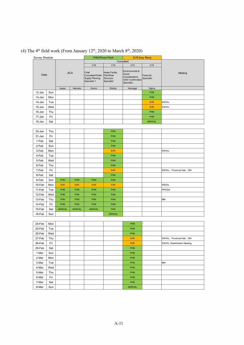
A-11
(4) The 4th field work (From January 12th, 2020 to March 8th, 2020)
CTII CTII CTII CTII
ChiefConsultant/WaterSupply PlanningSpecialist 1
Intake FacilityPlan/RiverStructureSpecialist
Environmental &SocialConsiderations/UXO ConfirmationSpecialist
FinancialSpecialist
Iwase Hamano Konno Shindo Kamegai Yajima
12-Jan Sun PHN
13-Jan Mon PHN
14-Jan Tue SVR SWWs
15-Jan Wed SVR SWWs
16-Jan Thu PHN
17-Jan Fri PHN
18-Jan Sat ARRIVAL
30-Jan Thu PHN
31-Jan Fri PHN
1-Feb Sat PHN
2-Feb Sun PHN
3-Feb Mon SVR SWWs
4-Feb Tue PHN
5-Feb Wed PHN
6-Feb Thu PHN
7-Feb Fri SVR SWWs、Provincial Hall、DIH
8-Feb Sat PHN
9-Feb Sun PHN PHN PHN PHN
10-Feb Mon SVR SVR SVR SVR SWWs
11-Feb Tue PHN PHN PHN PHN PPWSA
12-Feb Wed PHN PHN PHN PHN
13-Feb Thu PHN PHN PHN PHN MIH
14-Feb Fri PHN PHN PHN PHN
15-Feb Sat ARRIVAL ARRIVAL ARRIVAL PHN
16-Feb Sun ARRIVAL
24-Feb Mon PHN
25-Feb Tue PHN
26-Feb Wed PHN
27-Feb Thu SVR SWWs、Provincial Hall、DIH
28-Feb Fri SVR SWWs, Stakeholders Meeting
29-Feb Sat PHN
1-Mar Sun PHN
2-Mar Mon PHN
3-Mar Tue PHN MIH
4-Mar Wed PHN
5-Mar Thu PHN
6-Mar Fri PHN
7-Mar Sat PHN
8-Mar Sun ARRIVAL
Survey Shedule PHN:Phnom Penh SVR:Svay Rieng
MeetingDate JICA
Consultant
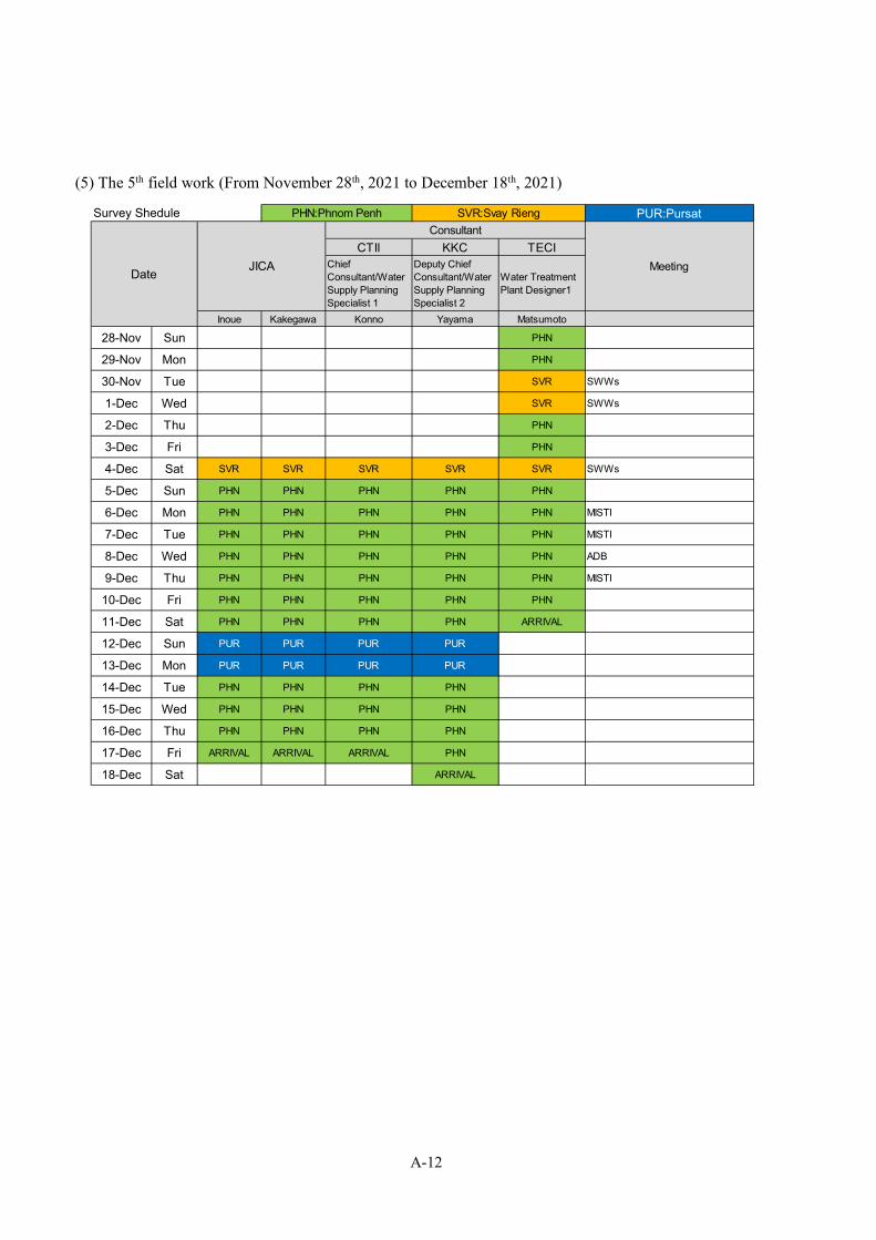
A-12
(5) The 5th field work (From November 28th, 2021 to December 18th, 2021)
PUR:Pursat
CTII KKC TECIChiefConsultant/WaterSupply PlanningSpecialist 1
Deputy ChiefConsultant/WaterSupply PlanningSpecialist 2
Water TreatmentPlant Designer1
Inoue Kakegawa Konno Yayama Matsumoto
28-Nov Sun PHN
29-Nov Mon PHN
30-Nov Tue SVR SWWs
1-Dec Wed SVR SWWs
2-Dec Thu PHN
3-Dec Fri PHN
4-Dec Sat SVR SVR SVR SVR SVR SWWs
5-Dec Sun PHN PHN PHN PHN PHN
6-Dec Mon PHN PHN PHN PHN PHN MISTI
7-Dec Tue PHN PHN PHN PHN PHN MISTI
8-Dec Wed PHN PHN PHN PHN PHN ADB
9-Dec Thu PHN PHN PHN PHN PHN MISTI
10-Dec Fri PHN PHN PHN PHN PHN
11-Dec Sat PHN PHN PHN PHN ARRIVAL
12-Dec Sun PUR PUR PUR PUR
13-Dec Mon PUR PUR PUR PUR
14-Dec Tue PHN PHN PHN PHN
15-Dec Wed PHN PHN PHN PHN
16-Dec Thu PHN PHN PHN PHN
17-Dec Fri ARRIVAL ARRIVAL ARRIVAL PHN
18-Dec Sat ARRIVAL
Survey Shedule PHN:Phnom Penh SVR:Svay Rieng
MeetingDate JICA
Consultant
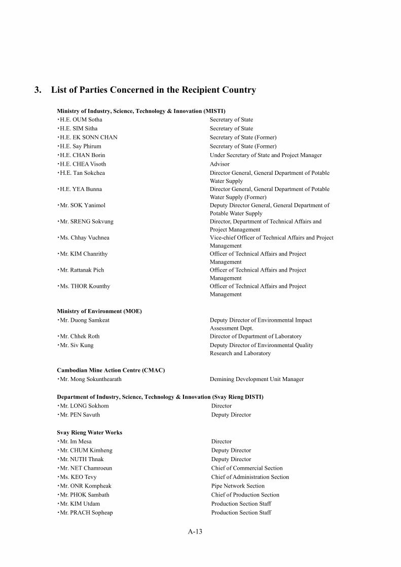
A-13
3. List of Parties Concerned in the Recipient Country
Ministry of Industry, Science, Technology & Innovation (MISTI) ・H.E. OUM Sotha Secretary of State ・H.E. SIM Sitha Secretary of State ・H.E. EK SONN CHAN Secretary of State (Former) ・H.E. Say Phirum Secretary of State (Former) ・H.E. CHAN Borin Under Secretary of State and Project Manager ・H.E. CHEA Visoth Advisor ・H.E. Tan Sokchea Director General, General Department of Potable
Water Supply ・H.E. YEA Bunna Director General, General Department of Potable
Water Supply (Former) ・Mr. SOK Yanimol Deputy Director General, General Department of
Potable Water Supply ・Mr. SRENG Sokvung Director, Department of Technical Affairs and
Project Management ・Ms. Chhay Vuchnea Vice-chief Officer of Technical Affairs and Project
Management ・Mr. KIM Chanrithy Officer of Technical Affairs and Project
Management ・Mr. Rattanak Pich Officer of Technical Affairs and Project
Management ・Ms. THOR Kounthy Officer of Technical Affairs and Project
Management Ministry of Environment (MOE) ・Mr. Duong Samkeat Deputy Director of Environmental Impact
Assessment Dept. ・Mr. Chhek Roth Director of Department of Laboratory ・Mr. Siv Kung Deputy Director of Environmental Quality
Research and Laboratory Cambodian Mine Action Centre (CMAC) ・Mr. Mong Sokunthearath Demining Development Unit Manager Department of Industry, Science, Technology & Innovation (Svay Rieng DISTI) ・Mr. LONG Sokhom Director ・Mr. PEN Savuth Deputy Director Svay Rieng Water Works ・Mr. Im Mesa Director ・Mr. CHUM Kimheng Deputy Director ・Mr. NUTH Thnak Deputy Director ・Mr. NET Chamroeun Chief of Commercial Section ・Ms. KEO Tevy Chief of Administration Section ・Mr. ONR Kompheak Pipe Network Section ・Mr. PHOK Sambath Chief of Production Section ・Mr. KIM Utdam Production Section Staff ・Mr. PRACH Sopheap Production Section Staff

A-14
・Ms. CHHUOT Somala Staff of Laboratory ・Ms. LUN Titsoda Staff of Laboratory Department of Water Resources and Meteorology of Svay Rieng (Svay Rieng DOWRAM) ・Mr. Kim Savuth Director Department of Environment of Svay Rieng Province (Svay Rieng DOE) ・Mr. Kaet Saroeun Director ・Mr. Chan Chhun Office Chief ・Mr. Path Veasna Staff Department of Public Work and Transportation of Svay Rieng Province (Svay Rieng DPWT) ・Mr. YUN Raksmey Deputy Director ・Mr. Men Phann Chief of Technical office ・Mr. Koy Vahoun Chief of Sewerage office Svay Rieng Provincial Hall ・H.E. Mr. HEM Piseth Deputy Provincial Governor Svay Rieng City Hall ・Mr. Pheum Tha Chief of Administration ・Mr. Sor Sadany Deputy Director of City Hall Svay Rieng Deapartment of Post and Telecommunication (DoPTC) ・Mr. Chea Hoeun Director ・Mr. Saom Piseth Office Director ・Mr. Chomraeun Socheat Staff of CFOCN Company ・Mr. Moeung Sophea Chief administrative ・Mr. Tan Saran Staff ・Mr. Lin Kheavuth Staff Electricite du Cambodia (EDC) ・Mr. SORN Siphat Chief of Distribution Section ・Mr. KOENG Thuok Vice Chief of Distribution Section ・Mr. OUM Phanov Technical Engineer Police Office (Svay Rieng) ・Mr. Brak Chout Deputy Director in charge of Firefighting ・Mr. Sous Sarin Office Chief in charge of Firefighting Metfone (Phnom Penh) ・Ms. POV Pheanou Sales Section ・Ms. Manit Sales Section Kampot Water Works ・Mr. Ty Kean Director ・Mr. RIN Parinha Chief of New WTP Battambang Water Works

A-15
・Mr. Touch Chhuonsaorith Director ・Mr. Heom Siphann Vice Chief of Production Section ・Mr. Khorn Narith Chief of Administration Section Asian Development Bank (ADB) ・Mr. Carlos Dela Cruz Team Leader ・Mr. SAN Chanty Deputy Team Leader ・Mrs. Ouk Moniroth Accountant