prepaid smart water meter university of khartoum
68
PREPAID SMART WATER METER UNIVERSITY OF KHARTOUM By MOHAMED HUSSEIN KHALIL AHMED INDEX NO. 124074 Supervisor Prof. Mustafa Omer Nawari A REPORT SUBMITTED TO University of Khartoum In partial fulfillment of the requirements for the degree of B.Sc. (HONS) Electrical and Electronic Engineering (Control Engineering) Faculty of Engineering Department of Electrical and Electronic Engineering Oct 2017
-
Upload
khangminh22 -
Category
Documents
-
view
0 -
download
0
Transcript of prepaid smart water meter university of khartoum

PREPAID SMART WATER METER
UNIVERSITY OF KHARTOUM
By
MOHAMED HUSSEIN KHALIL AHMED
INDEX NO. 124074
Supervisor
Prof. Mustafa Omer Nawari
A REPORT SUBMITTED TO
University of Khartoum
In partial fulfillment of the requirements for the degree of B.Sc. (HONS) Electrical and
Electronic Engineering (Control Engineering)
Faculty of Engineering
Department of Electrical and Electronic Engineering
Oct 2017

ii
DECLARATION OF ORGINALITY
I declare this report entitled “PREPAID SMART WATER METER” is my own work except as
cited in references. The report has been not accepted for any degree and it is not being submitted
currently in candidature for any degree or other reward.
Signature: ____________________
Name: _______________________
Date: __________________

iii
Acknowledgment
Huge efforts were made towards achieving this project. I would like to thank first the caring
Prof. Mustafa Omer Nawari for his limitless guidance and care.
Also, Special thanks and gratitude to my friends and colleagues’ who were nothing but a
backbone for me. Specially my friend and partner Mohamed Osman Abdallah Saeed who
showed what a true team work spirit really meant.

iv
Abstract
Water Efficiency is considered as a major aspect for every country in the world, many studies such
as integrated water management were developed to enhance the way water resources are managed.
Consequently, smart water systems were developed to reach equity for water usage, economic
benefits for both the consumer and the utility, improve system management and achieve maximum
water efficiency.
In this project, a smart two-way communication water meter that operates in prepaid payment
method was simulated using PROTEUS software on PC. The water meter communicates with the
water utility company and transfer data containing the daily water usage of the user through GSM
technology.
The smart water meter also contains a LCD monitor that displays the remaining balance of cubic
meter of water with the aid of a PIC18F4550 Microcontroller. Therefore, the user acknowledges
the consumption of water, which is a major difference between the conventional mechanical water
meter and the intelligent water meter.
If fully Implemented, the smart water meter calculates the difference between the remaining
balance of cubic meter of water and the input water, when the balance finishes, the valve closes
the main pipe of water. The meter also sends data of consumption via SMS at known specific time
intervals through the day to the utility and the utility also can monitor and the control the meter
remotely.

v
لمستخلصا
العالم و الكثير من االبحاث و الدراسات مثل ادارة المياة المتكاملة اجريت في المياة من اهم المحاور لكل دول استخدام تعد كفاءة
حول تحقيق بناء على ذلك, تم تطوير عداد المياه الذكي الذي تتمحور اهدافه لزيادة و تحسين الطرق التي تدار بها موارد المياه.
و الفوائد و المصلحة االقتصادية لكل من موفر المياة و المستخدم , و تطوير ادارة النظام و اخيرا ة باالستخدام العادل للمياةالعدال
تحقيق اكبر كفاءة للمياة ممكنة.
ياه يعمل باتجاهين لالتصال و يدار التحصيل المادي عداد مل "PROTEUS"برنامج بواسطة محاكاة الفي هذا المشروع, تمت
" و ذلك بارسال رسائل GSMوم عداد المياة بالتواصل مع الجهة الموفرة عن طريق تكنولوجيا ال "عن طريق الدفع المقدم. يق
"SMS.تحوي معلومات عن االستهالك اليومي للمستخدم للمياه "
ي من المتر " لعرض الرصيد المتبقLCDشاشة عرض " "و PIC18F4550شريحة تحكم " كما يحتوي العداد ايضا على
يساعد المستخدم على معرفة ما تبقى من الرصيد و استهالك المياة. و تعد هذه الخاصية من اميز الفروقات ما المكعب للمياه مما
بين عداد المياة التقليدي و عداد المياة الذكي.
من االمتار المكعبة و المياة المنسابة داخل العداد. عند للعدادفي حالة تطبيق العداد, يقوم العداد بحساب الفرق بين الرصيد الفعلي
نفاذ الرصيد يقوم باغالق صمام المياة الرئيسي. كما يقوم العداد بارسال بيانات االستهالك اليومي خالل فترات معلومة الى الجهة
الموفرة. كما بامكان الجهة الموفرة التحكم عن بعد في العداد.
vi
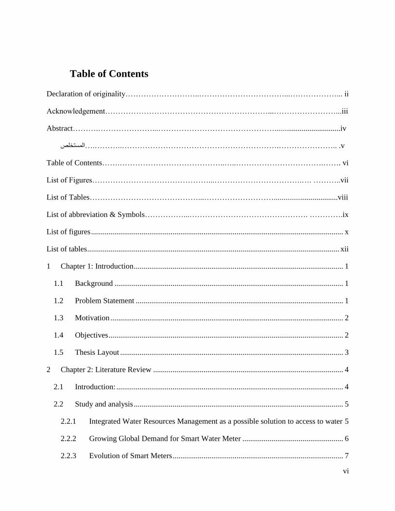
Table of Contents
Declaration of originality………………………..……………………………...………………... ii
Acknowledgement………………………………………………………...……………………...iii
Abstract……….…………………...………………………………………..................................iv
v. ..………………….……………………………………………………..……….…المستخلص
Table of Contents…….…………………………………..…..…………………………….……. vi
List of Figures………………………………………...…………………………….…. ………..vii
List of Tables……………………………………...……………………….................................viii
List of abbreviation & Symbols……………...………………………………………. ………….ix
List of figures .................................................................................................................................. x
List of tables .................................................................................................................................. xii
1 Chapter 1: Introduction ............................................................................................................ 1
1.1 Background ...................................................................................................................... 1
1.2 Problem Statement ........................................................................................................... 1
1.3 Motivation ........................................................................................................................ 2
1.4 Objectives ......................................................................................................................... 2
1.5 Thesis Layout ................................................................................................................... 3
2 Chapter 2: Literature Review .................................................................................................. 4
2.1 Introduction: ..................................................................................................................... 4
2.2 Study and analysis ............................................................................................................ 5
2.2.1 Integrated Water Resources Management as a possible solution to access to water 5
2.2.2 Growing Global Demand for Smart Water Meter .................................................... 6
2.2.3 Evolution of Smart Meters ........................................................................................ 7

vii
2.3 Brief History ..................................................................................................................... 8
2.3.1 AMR ......................................................................................................................... 8
2.3.2 AMI ........................................................................................................................... 9
2.3.3 AMI vs. AMR ........................................................................................................... 9
2.4 Types of Metering Devices ............................................................................................ 11
2.4.1 Displacement water meters ..................................................................................... 12
2.4.2 Velocity water meters ............................................................................................. 13
2.4.3 Compound meters ................................................................................................... 14
2.4.4 Static Meter ............................................................................................................. 15
2.5 Implementing Static Meters ........................................................................................... 17
2.6 Payment Methods ........................................................................................................... 18
2.6.1 Postpaid Meters ....................................................................................................... 18
2.6.2 Prepaid Meters ........................................................................................................ 18
2.7 Payment Solutions .......................................................................................................... 19
2.7.1 RF ID Credit Cards ................................................................................................. 19
2.7.2 Barcode ................................................................................................................... 19
2.7.3 Coins ....................................................................................................................... 19
2.7.4 Pin/ Tokens ............................................................................................................. 20
2.8 Benefits of Smart Water Metering ................................................................................. 20
2.9 Problems of water metering ........................................................................................... 21
3 Chapter 3: Design and Methodology ..................................................................................... 23
3.1 Introduction .................................................................................................................... 23
3.2 Design Approach ............................................................................................................ 23
3.3 System Design ................................................................................................................ 23

viii
3.3.1 Power Supply .......................................................................................................... 23
3.3.2 Microcontroller ....................................................................................................... 24
3.3.3 Liquid Crystal Display (LCD) display .................................................................... 24
3.3.4 GSM (Global System for Mobile Communication) Modem .................................. 24
3.3.5 Real Time Clock (RTC) .......................................................................................... 25
3.4 The Water Meter Components ....................................................................................... 25
3.4.1 Batteries .................................................................................................................. 25
3.4.2 PIC18f4550 ............................................................................................................. 26
3.4.3 16x2 LCD................................................................................................................ 29
3.4.4 4x3 Keypad ............................................................................................................. 30
3.4.5 Water Flow Sensor .................................................................................................. 30
3.4.6 GSM ........................................................................................................................ 31
3.4.7 Real Time Clock (RTC – PCF8583) ....................................................................... 34
3.5 Software Development ................................................................................................... 35
3.6 Complete System Design ............................................................................................... 35
4 Chapter 4: Results and Discussion ........................................................................................ 36
4.1 Introduction .................................................................................................................... 36
4.2 Block Simulation ............................................................................................................ 36
4.2.1 LCD Simulation ...................................................................................................... 36
4.2.2 RTC Simulation ...................................................................................................... 37
4.2.3 Keypad Simulation.................................................................................................. 38
4.3 System Simulation.......................................................................................................... 38
5 Chapter 5: Conclusion ........................................................................................................... 43
5.1 Conclusion ...................................................................................................................... 43

ix
5.2 Limitation ....................................................................................................................... 43
5.3 Future work .................................................................................................................... 44
References ..................................................................................................................................... 45

x
List of figures
Figure 2-1 The World Market for Advanced Water Meters Revenue Opportunity by Major
Region ............................................................................................................................................. 7
Figure 2-2 Smart Grid Market: Market restraints and drivers in Europe 2011-2020 ................... 10
Figure 2-3 Market for Water Meters ............................................................................................. 11
Figure 2-4 Water meter in Belo Horizonte. .................................................................................. 12
Figure 2-5 velocity meter .............................................................................................................. 13
Figure 2-6 Turbine Meter .............................................................................................................. 14
Figure 2-7 Compound meter ......................................................................................................... 14
Figure 2-8 Electromagnetic flow meter ........................................................................................ 16
Figure 2-9 Ultrasonic meter .......................................................................................................... 16
Figure 2-10 Water meter ultrasonic time-of-flight solution features the MAX35101 time-to-
digital converter with analog front-end (AFE). ............................................................................ 17
Figure 2-11 Prepaid Metering System .......................................................................................... 19
Figure 3-1 batteries ....................................................................................................................... 26
Figure 3-2 PIC18F4550 Pin Diagram ........................................................................................... 28
Figure 3-3 PIC18F4550 ................................................................................................................ 28
Figure 3-4 LCD ............................................................................................................................. 29
Figure 3-5 Keypad ........................................................................................................................ 30
Figure 3-6 Water Flow Sensor ...................................................................................................... 31
Figure 3-7 GSM & PIC18F4550 Block Diagram ......................................................................... 32
Figure 3-8 GSM modem ............................................................................................................... 33
Figure 3-9 RTC ............................................................................................................................. 34
Figure 3-10 Complete System Design .......................................................................................... 35

xi
Figure 4-1 LCD Simulation .......................................................................................................... 36
Figure 4-2 RTC Simulation .......................................................................................................... 37
Figure 4-3 Keypad Simulation ...................................................................................................... 38
Figure 4-4 System Simulation with the valve highlighted............................................................ 39
Figure 4-5 System Simulation with the valve open ...................................................................... 40
Figure 4-6 System Simulation Subtracting ................................................................................... 41
Figure 4-7 System Simulation with balance zero and a closed valve ........................................... 42

xii
List of tables
Table 2-1 Processes of an intelligent metering system. .................................................................. 5
Table 2 LCD Pin Description ....................................................................................................... 29

xiii
LIST OF ABBREVITIONS & SYMBOLS
AMR Automated Meter Reading
MDG Millennium Development Goals
SDG Sustainable Development Goals
ACEEE The American Council for an Energy-Efficient Economy
AMI Advanced Metering Infrastructure
PLC Power Line Communications
SCADA Supervisory Control and Data Acquisition
MCU Microcontroller Unit
RAM Random Access Memory
LCD liquid crystal display
GSM Global System for Mobile Communication
RTC real-time clock
ADC Analogue-to-Digital Converters
PIT Programmable Interval Timer
PWM Pulse Width Modulation
SPI Peripheral Interface
GPRS Global Packet Radio Service

xiv
GWP Global water partnership
IWRM Integrated Water Resource Management
CDMA Code Division Multiple Access
GIS Geographic Information System
PD Positive Displacement
AFE Analog Front-End
RF Radio Frequency
RAM Random Access Memory

1
1 Chapter 1: Introduction
1.1 Background
Conserving water is becoming increasingly important in the world as it faces a widening gap
between ever reducing water supplies due to climate change, inefficiencies in agriculture, poor
water governance, industrialization, urbanization and increased demand from population growth.
It results in many environmental, political, economic, and social forces. The post-2015 eight
Millennium Development Goals (MDGs) and the newly adopted 17 Sustainable Development
Goals (SDGs) aim at integrating social inclusion, economic development and environmental
sustainability. The SDG 6.1 aims to achieve the realization of the human right to water through
universal and equitable access to available, safe and affordable drinking water for all, by the year
2030 [1]. This is particularly critical for Africa which still accounts for 40 percent of the population
without access to safe drinking water.
Water conservation means using less water as well as using alternate sources of water. Today’s
integrated programs embrace the use of water efficient appliances and technologies. Through the
use of control systems, a far better water utilization is achieved. Automatic leak detection and
monitoring systems permit to identify and then fix leaks, and even cut off the flow. Incentives and
tighter regulation are yet another component.
Smart Water meter is a device that measures water consumption at specific time intervals and
the volume of water consumed at that time and communicate this data with the utility company.
In this paper, a better, fair and more convenient solution for water conservation and usage was
attempted through using a smart two ways communication water meter.
1.2 Problem Statement
They say: “if you can’t measure, you can’t manage”. Although Sudan has one of the biggest
water resources in the world, we still tackle the water service economically inefficiently by paying
depending on your demographic location in the country, for example if you live in a first-degree
neighborhood you pay a more fixed charge and if you live in a second-degree neighborhood you
pay a less fixed charge and so on. Therefore, it doesn’t depend on the consumption/conservation
of the water.

2
Also, the waste and loss of water is a major concern, thereby a way to reach maximum water
efficiency is a must by determining the present and future leakage through embracing the feature
of feedback and communication. Another important part for the utility is to be ready for future
warnings such as high demands and loads for different areas and this can be achieved by analyzing
big data through using forecasting and prediction techniques.
1.3 Motivation
A smart water meter provides an interface between the utility and the customer. Successfully
implemented, this meter will benefit the customer as well as the water utility in the following ways:
• The device will show the remaining balance so that the consumer knows how much he
has consumed and when he needs to refill the account.
• The utility companies will have a better idea of water demand. This will help them to
plan ahead.
• The utility companies would be able to collect the expenses from customers in advance,
so they will no longer have to deal with late payments.
• Since the meter will send daily consumption data to the utility company; it will help
reduce water bypass and determine water leakage.
1.4 Objectives
The smart water must be able to do the following:
1. Measure water consumption accurately.
2. Display real time account balance.
3. Communicate with the utility company to:
• Perform a daily verification of water consumption.
• Give signals from the utility company to the client such as closing the valve and
sending consumption data.
4. Cut water off when there is zero credit on the account.

3
1.5 Thesis Layout
Chapter 2: This chapter gives an introduction to smart water meter generally, the development
of it through history, the evolution of smart water meters and its benefits and problems as
presented in different papers.
Chapter 3: This chapter shows the design methodology by giving a detailed description of the
meter components and introducing the entire system scheme.
Chapter 4: This chapter carries out the results from the Simulation in Chapter 3.
Chapter 5: This chapter discuss the results obtained in the previous chapters. Along with
conclusion, limitation and future work.

4
2 Chapter 2: Literature Review
2.1 Introduction:
Water meters are used to measure the volume of water used by residential or
commercial buildings that are supplied with water by a public water supply utility. It is
also, very useful in finding water leaks. It operates by continuously measuring the
incoming water volume subtracts it from the available gallons or cubic meters and then
displays the remaining volume.
The difference between a conventional water meter and a smart (intelligent) water meter is that
in smart water meter there is an on-going monitoring an evaluation of the use of water by the
utility company. We can bound the system with four key processes:
• The measurement.
• Data transfer.
• Processing and analysis.
• Feedback of water use data.
as described in Table 2-1.

5
Table 2-1 Processes of an intelligent metering system.
Measurement Data transfer Processing and
Analysis
Feedback
Water meter
used to
capture information
about water
consumption.
Residential
intelligent metering
typically uses
displacement meters
which
generate a pulse
signal after a set
volume passes
through the meter.
Means by which data
is
transferred from
meters to utilities,
customers and back.
Data is
transferred from the
water meter
via broadband, cable
or wireless
(e.g., radio, GSM,
CDMA *). May
be fully remote or
require near
range collection.
Means by which a
utility/third
party stores (e.g., data
servers)
and manipulates (e.g.,
end-use
analysis software
package) water
use data. Implications
for third
party access.
Method by which data
is provided to
customers for
interpretation, e.g.,
postal
bill, email, web
interface, smart phone
application. Behavior
change may/may
not ensue.
2.2 Study and analysis
The American Council for an Energy-Efficient Economy (ACEEE) reviewed more than 36
different residential smart metering and feedback programs internationally. This is the most
extensive study of its kind. Their conclusion was: “To realize potential feedback-induced
savings, advanced meters [smart meters] must be used in conjunction with in-home (or on-line)
displays and well-designed programs that successfully inform, engage, empower and motivate
people. [2]
2.2.1 Integrated Water Resources Management as a possible solution to access to water
The Global Water Partnership (GWP) defines water governance as the range of political, social,
economic and administrative systems that are in place to develop and manage water resources,
and the delivery of water services at different levels of society. Thus, Integrated Water Resource
Management (IWRM) is aimed: at promoting more equitable access to water resources and the
benefits that are derived from water in order to tackle poverty; to ensure that scarce water is used

6
efficiently and for the benefit of the greatest number of people; and to achieve more sustainable
utilization of water, including for a better environment. [3]
Treating water as an economic good entail allocating water to its highest value and moving
towards full cost pricing to encourage rational use and recover the cost. Economic tools ought to
determine how limited water resources are to be distributed efficiently and equitably. In addition,
managing water as an economic good is essential to achieving financial sustainability of water
service provision by pricing water at levels that guarantee full cost recovery [4].
Most countries within southern African regions have adopted IWRM plans to try to improve the
management of water resources by adopting the concept of promoting efficiency, equity and
sustainability of water resources. However, the adoption of IWRM has not been totally beneficial
to the management of water in urban areas as many residents still do not have access to drinking
water.
2.2.2 Growing Global Demand for Smart Water Meter
The global demand for smart water meter is growing. As the demand for water rises, water
utilities around the globe will be facing pressure to manage water resources as efficiently as
possible, and this smart water meter is a key element in smart water management, providing
information that helps utilities to control cost and achieve efficient use of resources. Moreover,
there are projects demonstrating the growing demand for smart water meter in Europe and North
America.
Smart meters and associated smart grid technology currently represent a $3 billion annual
industry, projected to rise to $15 billion annually by 2015. According to some forecasts, there
will be close to one billion smart meters in the world by 2020, with 65 million in the US alone.
The figure 2-1 below gives a glance of revenues of smart water meter around the world since
2010. [5]

7
Figure 2-1 The World Market for Advanced Water Meters Revenue Opportunity by Major Region
2.2.3 Evolution of Smart Meters
In the 1990s, automated meter reading (AMR), the technology of automatically collecting data
from energy metering devices and transferring that data to a central database for billing,
troubleshooting and analyzing, took to the scene. This technology saved utility providers the
expense of periodic trips to each physical location to read a meter. Additionally, billing became
based on real-time consumption rather than on estimates based on past consumption. This timely
information coupled with analysis helped both utility providers and customers better control the
use and production of electric energy, gas usage or water consumption.
The first-generation of smart meters, which appeared in 2005, transmitted information back to
the utility company monthly. The second-generation of smart meters could transmit daily and
some even hourly. The third-generation of smart meters now allows two-way communication,
on-demand. As a result, utility providers can now extract detailed information on power usage of
individual homes.

8
2.3 Brief History
The smart water metering market emerged in the 2000s as water utilities responded to global
trends of using detailed and near real time data and analytics to deliver more predictive and
proactive services. The backbone of this effort is advanced metering infrastructure (AMI)
technology. AMI can provide a remote and constant two-way data link between utilities, meters
and consumers. Communications are delivered through various technologies including power
line communications (PLC), telephony, broadband, fiber optic cable, wireless radio frequency
and cellular transmissions.
a communications infrastructure of concentrators, repeaters and gateways, data is passed
between meter and utility and funneled into analytical software that can immediately set off pre-
determined alerts. This is as well as produce accurate billings and consumption patterns at
neighborhood and area levels, inform other utility software such as GIS (Geographic Information
Systems) and SCADA (Supervisory Control and Data Acquisition) and departments including
customer services, pumping stations and reservoirs. Apart from monitoring the current status of
water consumption, data can contribute towards hydraulic modelling to help predict outcomes
and changes in water distribution.
Hydraulic modelling and network monitoring can be used by utilities to make evidence-based
network investments and upgrades. Utilities can also send information back to the meter to
perform remote upgrades and fixes, reset alert parameters, shut off water supply during change
of tenancy or reduce water flow for unpaid accounts.
2.3.1 AMR
Automatic meter reading, or AMR, is the technology of automatically collecting consumption,
diagnostic, and status data from water meter or energy metering devices (gas, electric) and
transferring that data to a central database for billing, troubleshooting, and analyzing. This
technology mainly saves utility providers the expense of periodic trips to each physical location
to read a meter. Another advantage is that billing can be based on near real-time consumption
rather than on estimates based on past or predicted consumption. This timely information
coupled with analysis can help both utility providers and customers better control the use and
production of electric energy, gas usage, or water consumption.

9
AMR technologies include handheld, mobile and network technologies based on telephony
platforms (wired and wireless), radio frequency (RF), or powerline transmission
2.3.2 AMI
Advanced Metering Infrastructure (AMI) refers to systems that measure, collect, and analyze
energy usage, and communicate with metering devices such as electricity meters, gas meters,
heat meters, and water meters, either on request or on a schedule. These systems include
hardware, software, communications, consumer energy displays and controllers, customer
associated systems, meter data management software, and supplier business systems. AMI
extends automatic meter reading (AMR) technology by providing two-way meter
communications, allowing commands to be sent toward the home for multiple purposes,
including time-based pricing information, demand-response actions, or remote service
disconnects
2.3.3 AMI vs. AMR
Water utilities often debate whether to fully convert to AMI or run an AMR water grid instead.
The truest of smart water grid definitions requires AMI technology and its enabling two-way
communications. Many water utilities, however, do not see a clear advantage to AMI and feel the
uni-directional communications from meter to utility offered by AMR is fit for purpose.
Receiving one-way information for accurate billing, leakage and NRW detection and GIS and
SCADA is viewed as solving the bulk of water utility needs. Many water utilities feel the
financial cost to roll out and operate an AMI grid will not justify the benefits of two-way
communications. It is felt that remote upgrades rather than replacements will be infrequent,
centralized alarms will be sufficient and utilities will rarely restrict water flows into homes, even
if this is legally permitted. [6]

10
Figure 2-2 Smart Grid Market: Market restraints and drivers in Europe 2011-2020
This issue needs to be addressed on a case by case basis, but water utilities, widely known to be
risk-averse, will find the most "future-proofed" investment in AMI deployments. An example of
which is the UK's most advanced project currently being deployed by Thames Water in London.
AMI offers the most advanced capabilities and as this technology evolves and utilities grow
more sophisticated in their data analysis and operations, AMR deployments may prove limiting;
water utilities stand to gain the most through AMI.
Smart water metering differs from smart energy metering in that smart water meters are rarely in
convenient reach of mains power supply. As a result, smart water meters are dependent on a
reliable and long-lasting battery to power data transmission. Ensuring a 15-year battery life,
which matches the lifespan of most meters, is essential for investments. Because of the proximity
to water and possible submersion of meters, batteries are sealed water-tight and are not meant to
be replaced.
Operating an AMR deployment with scheduled data transmissions does not impinge on this 15-
year battery life. Deploying an AMI system, however, where meters must be constantly ready to
receive incoming transmissions can drain battery life significantly, down to eight years or less.

11
This has a large impact on the business case for investment. The market is seeing solutions to
this challenge where meters will power up to potentially receive transmissions on scheduled
intervals rather than a constant state of readiness. This ensures maximized battery life and offers
the benefits of a two-way AMR-like communications system. The figure 2-3 below demonstrate
the growth of all three types of water meter: Basic Meter, One-Way Meter and Two-way Meter.
Figure 2-3 Market for Water Meters
2.4 Types of Metering Devices
There are two common approaches to flow measurement, displacement and velocity, each
making use of a variety of technologies. Common displacement designs include oscillating
piston and notating disc meters. Velocity-based designs include single- and multi-jet meters and
turbine meters.
There are also (Static) non-mechanical designs, for example electromagnetic and ultrasonic
meters, and meters designed for special uses. Additionally, there are electromechanical meters,
like prepaid water meters and automatic meter reading meters. The latter integrates an electronic

12
measurement component and a LCD with a mechanical water meter. Mechanical water meters
normally use a reed switch, hall or photoelectric coding register as the signal output. After
processing by the microcontroller unit (MCU) in the electronic module, the data are transmitted
to the LCD or output to an information management system.
Water meters are generally owned, read and maintained by a public water provider such as a city,
rural water association or private water company. In some cases, an owner of a mobile home
park, apartment complex or commercial building may be billed by a utility based on the reading
of one meter, with the costs shared among the tenants based on some sort of key (size of flat,
number of inhabitants or by separately tracking the water consumption of each unit in what is
called sub-metering).
2.4.1 Displacement water meters
This type of water meter is most often used in residential and small commercial applications and
homes. Displacement meters are commonly referred to as Positive Displacement, or "PD" meters.
It relies on the water to physically displace the moving measuring element in direct proportion to
the amount of water that passes through the meter. The disk moves a magnet that drives the
register. PD meters are generally very accurate at the low-to-moderate flow rates typical of
residential and small commercial users and not practical in applications require high flow rates
because displacement meters require that all water flows through the meter to "push" the measuring
element. PD meters normally have a built-in strainer to protect the measuring element from parts
that could stop or break the measuring element. [7]
Figure 2-4 Water meter in Belo Horizonte.

13
2.4.2 Velocity water meters
A velocity-type meter measures the velocity of flow through a meter of a known internal capacity.
The speed of the flow can then be converted into volume of flow to determine the usage. There
are several types of meters that measure water flow velocity, including jet meters (single-jet and
multi-jet), turbine meters, propeller meters and mag meters. Most velocity-based meters have an
adjustment vane for calibrating the meter to the required accuracy.
Figure 2-5 velocity meter
2.4.2.1 Multi-jet meters
Multi-jet meters are very accurate in small sizes and are commonly used in ⅝" to 2" sizes for
residential and small commercial users. Multi-jet meters use multiple ports surrounding an
internal chamber to create multiple jets of water against an impeller, whose rotation speed
depends on the velocity of water flow. Multi-jets are very accurate at low flow rates, but there
are no large size meters since they do not have the straight-through flow path needed for the high
flow rates used in large pipe diameters. Multi-jet meters generally have an internal strainer
element that can protect the jet ports from getting clogged [7]
2.4.2.2 Turbine meters
Turbine meters are less accurate than displacement and jet meters at low flow rates, but the
measuring element does not occupy or severely restrict the entire path of flow. The flow
direction is generally straight through the meter, allowing for higher flow rates and less pressure
loss than displacement-type meters. They are the meter of choice for large commercial users, fire

14
protection and as master meters for the water distribution system. Turbine meter bodies are
commonly made of bronze, cast iron or ductile iron. [7]
Figure 2-6 Turbine Meter
2.4.3 Compound meters
A compound meter is used where high flow rates are necessary, but where at times there are also
smaller rates of flow that need to be accurately measured. Compound meters have two measuring
elements and a check valve to regulate flow between them. At high flow rates, water is normally
diverted primarily or completely to the high flow element. The high flow element is typically a
turbine meter. When flow rates drop to where the high flow element cannot measure accurately,
a check valve closes to divert water to a smaller element that can measure the lower flow rates
accurately. The low flow element is typically a multi-jet or PD meter. By adding the values
registered by the high and low elements, the utility has a record of the total consumption of water
flowing through the meter. [7]
Figure 2-7 Compound meter

15
2.4.4 Static Meter
A static meter, which is any metrology device with no moving parts, has significant advantages
over traditional mechanical meters. Static meters have already been used for years in the
commercial and industrial markets. Static meters are classified as electromagnetic and
ultrasonic time-of-flight.
Static meters have significantly better accuracy, especially at low flow rates. Furthermore, due to
their lack of moving parts, they are more reliable and their performance does not degrade over
time. With less leakage, there is less waste and loss. Consequently, the service provider is not
billing the cost of lost revenue back to the consumer.
In this meter, a piezo transducer is pulsed. The resultant acoustic wave travels through the media
(water in our discussion) and is picked up at a second piezo transducer downstream. After this
path is completed, the piezo transducer signals are reversed; the downstream piezo is pulsed and
the upstream piezo picks up the signal. The difference in the time of flight for the two pulses
enables the measurement of the flow, since the acoustic wave's speed is proportional to flow
2.4.4.1 Electromagnetic meters
Magnetic flow meters are technically a velocity-type water meter, except that they use
electromagnetic properties to determine the water flow velocity, rather than the mechanical
means used by jet and turbine meters. In an electromagnetic meter, a magnetic field is applied to
the pipe and a voltage is generated perpendicular to the flux lines. This voltage is proportional to
the flow rate. While this type of meter provides excellent accuracy, it tends to have fairly high-
power consumption. [7]

16
Figure 2-8 Electromagnetic flow meter
2.4.4.2 Ultrasonic meters
The dominant type of static meter technology today is ultrasonic time-of-flight. Ultrasonic water
meters use one or more ultrasonic transducer to send ultrasonic sound waves through the fluid to
determine the velocity of the water. Since the cross-sectional area of the meter body is a fixed
and known value, when the velocity of water is detected, the volume of water passing through
the meter can be calculated with very high accuracy. Because water density changes with
temperature, most ultrasonic water meters also measure the water temperature as a component of
the volume calculation. The Figure 2-10 below shows of a Water meter ultrasonic time-of-flight
solution features the MAX35101 time-to-digital converter with analog front-end (AFE).
Figure 2-9 Ultrasonic meter

17
Figure 2-10 Water meter ultrasonic time-of-flight solution features the MAX35101 time-to-digital converter with analog front-end
(AFE).
2.5 Implementing Static Meters
Until now the technology for static meters was not practical for residential water use.
However, recent evolutionary changes in service delivery are creating opportunities.
The greatest challenge for residential use of static meters is straightforward: power. It takes power
to operate an electronic device. Because most water meters are not wired for power, static meters
traditionally were not a practical option. With the onset of AMR (advanced meter reading) and
AMI (advance meter infrastructure), this is changing. AMI and AMR enable remote meter reading
and/or control, typically with wireless communications technologies.
When a service provider decides that they need the capabilities of AMI/AMR, they now need to
power the meter, either through a line voltage or from a battery. Since power has to be provided
to the meter anyway, this opens the door to static metering. The power required for static metering
adds to the power requirements to be sure, but it does not create a new challenge. Concurrent
improvements in battery technology are helping drive the change in meter technology. Because

18
power densities are improving, the life of the meters is also increasing. It is not uncommon to see
static meters with a battery life of 15 or more years.
Other factors are driving the residential adoption of static meters, notably improved leak detection
and the ability to act on that information. A meter that can detect a leak and then react, such as
through an automatic valve shutoff, adds significant safety to the home. While not necessarily an
immediate safety hazard, water leak detection could spare the homeowner unnecessarily high-
water bills and prevent water damage.
2.6 Payment Methods
There are two General Approaches for payment or refilling the account of the water meter. These
approaches or methods are Prepaid or Postpaid. Thus, Electronic meters can be either postpaid
meters or prepaid meters. A brief discussion about both meters is discussed as follows. But the
Prepaid Meter is discussed intensively regarding the project’s scope.
2.6.1 Postpaid Meters
In the case of postpaid meters, consumers receive bills based on regular meter readings—
monthly, or even more often. This will have a positive impact on the accuracy of the bills.
2.6.2 Prepaid Meters
In the case of prepaid meters, consumers pay prior to actual consumption. Traditionally,
prepaid meters have been targeted at low-income segments. The overall uptake of prepaid meters
is low, principally because the service is seen as inconvenient.
In general, prepaid consumers had to approach payment points to “re-charge” their meters.
The payment points are usually managed by the utility company or a third party and tend to be
scarce. Payment methods for prepaid smart meters are expected to be more diverse than for regular
prepaid meters. Smart prepaid meters are likely to leverage the proliferation of other technologies,
such as the Internet and smart phones. New solutions will enable consumers to “re-charge” their
meters through a wider range of electronic or online payments (instead of “recharging” through
the scarce payment points). Contactless payment is seen as a user-friendly payment method for

19
consumers. A number of form factors can be used to enable contactless payments, but smart cards
and mobile phones are at the forefront of industry advancements. However, as the utilities’ smart
grids visions become a reality, we expect to see a greater number of prepaid smart meters. The
Figure 2-11 below shows the block foe a Prepaid Smart Water Meter.
Figure 2-11 Prepaid Metering System
2.7 Payment Solutions
There are several ways used globally to pay for the water consumption, the following are
the most common of them:
2.7.1 RF ID Credit Cards
Contactless credit cards are cards that use radio-frequency identification (RFID) for
making secure payments. It allows cardholders to wave their cards in front of contactless Meter
payment terminals to complete transactions. Unlike a barcode, the tag need not be within the line
of sight of the reader, so it may be embedded in the tracked object
2.7.2 Barcode
With the deployment of Pay point payment solutions, barcodes could be used. The
customer would pay with a bank card or cash, with the generated barcode allowing the user to
reload energy levels.
2.7.3 Coins
This is the simplest and the most widely established way to pay via a prepaid meter. The
main disadvantage of this system is the vulnerability of the meter itself. Indeed, there is a risk of

20
theft of the cash, while fraud is not rare. The other negative impact is on the energy supplier or
subcontractor companies that need to collect the cash on a regular basis.
2.7.4 Pin/ Tokens
This is one of the most important payment solutions used in the metering ecosystem. This payment
concept offers simplicity and flexibility. There are different form factors to store the token or PIN.
For example, the consumer could buy a ticket, including a token number, from dedicated shops
and supermarkets. Alternatively, some solutions allow customers to reload a plastic key or a
magnetic strip card via a dedicated vendor machine.
2.8 Benefits of Smart Water Metering
Advanced metering systems can provide benefits for utilities, retail providers and customers.
Benefits will be recognized by the utilities with increased efficiencies, outage detection, tamper
notification and reduced labor cost as a result of automating reads, connections and disconnects.
Retail providers will be able to offer new innovative products in addition to customizing packages
for their customers. In addition, with the meter data being readily available, more flexible billing
cycles would be available to their customers instead of following the standard utility read cycles.
With timely usage information available to the customer, benefits will be seen through
opportunities to manage their energy consumption. Because of these benefits, many utilities are
moving towards implementing some types of AMI solutions.
The benefits of smart metering for the utility: [8]
• Accurate meter reading, no more estimates
• Improved billing
• Accurate profile classes and measurement classes, true costs applied
• Improved security and tamper detection for equipment
• Energy management through profile data graphs
• Less financial burden correcting mistakes
• Less accrued expenditure
• Transparency of “cost to read” metering
• Improved procurement power though more accurate data - “de-risking” price
• In cases of shortages, utility will be able to manage/allocate supply.
21
• The benefits of smart metering for the customer.
• Improved billing and tracking of usage.
• in conjunction with volumetric pricing it provides an incentive for water conservation.
2.9 Problems of water metering
• Studies indicate that the implementation of PPWMs entrenches social inequality and
poverty in society; as the rich use more water as there are able to pay for it. The two biggest
barriers to prepaid metering in the North America market have been the high cost of meter
as customers have to pay between US$225 - US$400 per installation. In addition, it is
viewed as economic discrimination in terms of racial, social or cultural profiling. The poor
have to consider their consumptions, hindering their water requirements and productive
water use for improving their livelihood strategies. Productive use of water includes uses
such as brewing, animal watering, construction and small-scale. An aspect of good
neighborliness is lost in cases where PPWMs are introduced this is because water is likely
to be treated as an individualized market commodity thereby largely excluding the poor
from accessing it . Since the development in the United Kingdom, the use of these meters
have spread through countries like Brazil, Egypt, Uganda, Curacao, Nigeria, Tanzania,
Swaziland, Sudan, Malawi, Namibia and South Africa. Where the common evidence
found, that the prepaid system of water supply being enforced on the poor is dangerous
environmentally, socially, politically and questionable morally. The UKs 1998 Water Act
declared prepayment meters to represents a threat to public health and water cutoffs to be
an unacceptable method of recovering outstanding debt [9]
• Sudden changes in pressure can damage meters to the extent that many meters in cities in
developing countries are not functional. Also, some types of meters become less accurate
as they age, and under-registering consumption leads to lower revenues if defective
meters are not regularly replaced. Many types of meters also register air flows, which can
lead to over-registration of consumption, especially in systems with intermittent supply,
when water supply is re-established and the incoming water pushes air through the
meters. In addition, the real working life of prepaid meters is only about five to seven
years, compared to the estimated 15 to 20 years for conventional meters.
22
From a cost perspective for the utility company, the operational cost, maintenance and
installation cost and the price of the meter can be expensive.
• Utility can possibly control amount allocated to users. [10]
• Risk of loss of privacy - details of use reveal information about user activities.
• Greater potential for monitoring by other/unauthorized third parties.
• Potentially reduced reliability (more complicated meters, more potential for interference
by third parties).
• Increased security risks from network or remote access [11]

23
3 Chapter 3: Design and Methodology
3.1 Introduction
This chapter shows the design methodology by giving a detailed description of the meter
components and introducing the entire system scheme.
3.2 Design Approach
The smart water metering system consists of Water Flow Sensor, Batteries, microcontroller, Liquid
Crystal Display (LCD), Keypad, GSM Module and Real Time Clock.
• Water Flow Sensor generally produces electrical pulses proportional to the amount of water
consumed by the consumer, and these pulses go to the microcontroller.
• The microcontroller continuously subtracts the consumed water from the available credit
and display the result on the LCD.
• When the result of the subtraction is zero, the microcontroller sends a signal to close the
valve.
• Batteries are used to supply the system with the appropriate voltage levels to the different
electronic components of the meter.
• RTC is used to supply the system with the real time and date.
• The GSM Module is used to communicate with the utility company providing it with the
updates of the consumption rate.
3.3 System Design
3.3.1 Power Supply
Any invention of latest technology cannot be activated without source of power so in this fast-
moving world we deliberately need a proper power source which will be apt for particular
requirement. The power supply section is the most important one for circuit operation. It
provides requirement power supply for every one blocks and it produce constant 5 volts DC
voltage.

24
3.3.2 Microcontroller
A microcontroller is a compact integrated circuit designed to govern a specific operation in an
embedded system. A typical microcontroller includes a processor, memory and input/output (I/O)
peripherals on a single chip.
A microcontroller's processor will vary by application. Options range from the simple 4-bit, 8-bit
or 16-bit processors to more complex 32-bit or 64-bit processors. Generally, microcontrollers are
designed to be readily usable without additional computing components because they are designed
with sufficient onboard memory as well as offering pins for general I/O operations, so they can
directly interface with sensors and other components.
Microcontroller processors can be based on complex instruction set computing (CISC) or reduced
instruction set computing (RISC). CISC generally has around 80 instructions while RISC has about
30, as well as more addressing modes, 12-24 compared to RISC's 3-5. While CISC can be easier
to implement and has more efficient memory use, it can have performance degradation due to the
higher number of clock cycles needed to execute instructions. RISC, which places more emphasis
on software, often provides better performance than CISC processors, which place more emphasis
on hardware, due to its simplified instruction set and, therefore, increased design simplicity, but
because of the emphasis it places on software, software can be more complex. Which ISC is used
varies depending on application.[13]
3.3.3 Liquid Crystal Display (LCD) display
The LCD (liquid crystal display) is based upon the liquid crystal technology. By applying
Voltage to the LCD, it becomes opaque, but before that it was a transparent material. The above
property is main operating principle of LCD. The LCD display is used for displaying account
balance and power usage; It also acts as an interface between user and power meter.[13]
3.3.4 GSM (Global System for Mobile Communication) Modem
A GSM Modem is a specialized type of modem which accepts a SIM card, and operates over a
subscription to a mobile operator, just like a mobile phone. From the mobile operator perspective,

25
a GSM modem looks just like a mobile phone. When a GSM modem is connected to a computer,
this allows the computer to use the GSM modem to communicate over the mobile network. While
these GSM modems are most frequently used to provide mobile internet connectivity, many of
them can also be used for sending and receiving SMS and MMS messages. A GSM modem can
be a dedicated modem device with a serial, USB or Bluetooth connection, or it can be a mobile
phone that provides GSM modem capabilities. Communication with the GSM is done using a
series of machine instructions used to activate features on an intelligent modem known as AT
commands set. The AT command set is the standard set of instructions for configuring and
controlling modems. The commands are short sequences of ASCII characters. All command
strings (i.e., sequences of characters) must be prefaced by the letters AT, an abbreviation for
attention, thereby accounting for the name of the set.[14]
3.3.5 Real Time Clock (RTC)
A real-time clock (RTC) is a computer clock that keeps track of the current time. RTCs are present
in almost any electronic device which needs to keep accurate time.
Although keeping time can be done without an RTC, using one has benefits:
• Low power consumption (important when running from alternate power).
• Frees the main system for time-critical tasks.
• Sometimes more accurate than other methods[15]
3.4 The Water Meter Components
3.4.1 Batteries
An electric battery is a device consisting of one or more electrochemical cells with external
connections provided to power electrical devices.
Broadly there is two types of batteries:
• Primary (single-use or "disposable") batteries are used once and discarded
• Secondary batteries, also known as secondary cells, or rechargeable batteries.

26
3.4.1.1 Advantages of Primary Battery
• High energy density since no design compromises necessary to accommodate recharging.
• Best alternative for low cost, low drain applications such as watches or hearing aids.
• The obvious choice for single use applications such as guided missiles and military
ordnance.
• Low initial cost
• Convenient.
• Wide availability of standard products
In this project 5V single-use battery was used.[16]
Figure 3-1 batteries
3.4.2 PIC18f4550
A PIC microcontroller is a small computer in a single integrated circuit containing a processor
core, memory and programmable I/O peripherals. Program memory in the form of NOR flash is
also often included on chip, as well as a typical small amount of RAM.
PIC Microcontrollers are designed for embedded applications in contrast to the microprocessors
used in personal computers or other general purposes applications.
3.4.2.1 Features:
• General Purpose I/O (GPIO): Microcontrollers usually contain from several to dozens
of general purpose input/output pins (GPIO). GPIO pins are software configurable to
either an input or an output state. When GPIO pins are configured to an input state, they

27
are often used to read sensors or external signals. Configured to the output state, GPIO
pins can drive external devices such as LEDs or motors.
• Analogue-to-Digital Converters (ADC): Many embedded systems need to read sensors
that produce analog signals. This is the purpose of the analog-to-digital converter (ADC).
Since processors are built to interpret and process digital data, i.e. 1s and 0s, they are not
able to do anything with the analog signals that may be sent to it by a device. So the
analog to digital converter is used to convert the incoming data into a form that the
processor can recognize. A less common feature on some microcontrollers is a digital-to-
analog converter (DAC) that allows the processor to output analog signals or voltage
levels.
• Timers: In pic microcontrollers programming timers are very useful. In addition to the
converters, many embedded microprocessors include a variety of timers as well. One of
the most common types of timers is the Programmable Interval Timer (PIT). A PIT may
either count down from some value to zero, or up to the capacity of the count register,
overflowing to zero. Once it reaches zero, it sends an interrupt to the processor indicating
that it has finished counting. This is useful for devices such as thermostats, which
periodically test the temperature around them to see if they need to turn the air
conditioner on, the heater on, etc. Timers are a very important part of Microcontrollers
that would be focused on in later labs.
• Pulse-Width Modulation (PWM): A dedicated Pulse Width Modulation (PWM) block
makes it possible for the CPU to control power converters, resistive loads, motors, etc.,
without using lots of CPU resources in tight timer loops. The PWM generation hardware
remains busy in generating a clock signal of your desired frequency and duty cycle whilst
the processor can execute regular programs.
• Universal Synchronous Asynchronous Receiver/Transmitter (USART): This block
makes it possible to receive and transmit data over a serial line with very little load on the
CPU. Dedicated on-chip hardware also often includes capabilities to communicate with
other devices (chips) in digital formats such as I²C and Serial Peripheral Interface
(SPI).[17]
• MULTIPLE IDLE MODES: It has the advantage of working even when its CPU
disabled but peripherals being active. The power can be reduced up to 4% in these states.

28
• NANO WATT GENERATION: PIC18F4550 is an 8-bit microcontroller. PIC18F4550
has been applied with NANO WATT technology, therefore, it requires very low strength
for its operation.[18]
Figure 3-2 PIC18F4550 Pin Diagram
Figure 3-3 PIC18F4550
29
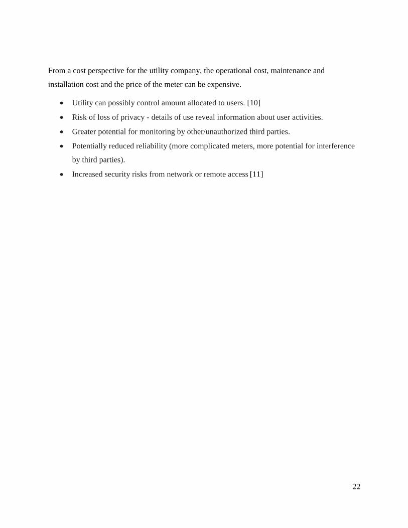
3.4.3 16x2 LCD
A 16x2 LCD display is very basic module and is very commonly used in various devices and
circuits. The reasons being: LCDs are economical, easily programmable, have no limitation of
displaying special & even custom characters (unlike in seven segments), animations and so on.
A 16x2 LCD means it can display 16 characters per line and there are 2 such lines. This LCD
has two registers, namely, Command and Data. The command register stores the command
instructions given to the LCD, and the data register stores the data to be displayed on the LCD.
The data is the ASCII value of the character to be displayed on the LCD.
Figure 3-4 LCD
Table 2 LCD Pin Description

30
3.4.4 4x3 Keypad
The Keypad is used as an interface between the user and the meter, it’s used as one of the
payment solution mentioned in chapter two to recharge the account by entering a PIN code
which is generated from the utility water company or the vending machine from the sale point.
While entering the PIN code using the keypad, the LCD displays the numbers typed on the
keypad. The keypad used in this project is 4x3 Keypad.
Figure 3-5 Keypad
3.4.5 Water Flow Sensor
Water flow sensor consists of a plastic valve body, a water rotor, and a hall-effect sensor. When
water flows through the rotor, rotor rolls. Its speed changes with different rate of flow. The hall-
effect sensor outputs the corresponding pulse signal. This one is suitable to detect flow in water
dispenser or coffee machine. We have a comprehensive line of water flow sensors in different
diameters. Check them out to find the one that meets your need most.

31
3.4.5.1 Features
• Compact, Easy to Install.
• High Sealing Performance.
• High Quality Hall Effect Sensor.[19]
Figure 3-6 Water Flow Sensor
3.4.6 GSM
GSM/GPRS module is used to establish communication between a computer and a GSM-GPRS
system. Global System for Mobile communication (GSM) is an architecture used for mobile
communication in most of the countries. Global Packet Radio Service (GPRS) is an extension of
GSM that enables higher data transmission rate. GSM/GPRS module consists of a GSM/GPRS
modem assembled together with power supply circuit and communication interfaces (like RS-
232, USB, etc) for computer. GSM/GPRS MODEM is a class of wireless MODEM devices that
are designed for communication of a computer with the GSM and GPRS network. It requires
aSIM (Subscriber Identity Module) card just like mobile phones to activate communication with

32
the network. Also, they have IMEI (International Mobile Equipment Identity) number similar to
mobile phones for their identification.
A GSM/GPRS MODEM can perform the following operations:
1. Receive, send or delete SMS messages in a SIM.
2. Read, add, search phonebook entries of the SIM.
3. Make, Receive, or reject a voice call.
The MODEM needs AT commands, for interacting with processor or controller, which are
communicated through serial communication. These commands are sent by the
controller/processor. The MODEM sends back a result after it receives a command. Different AT
commands supported by the MODEM can be sent by the processor/controller/computer to interact
with the GSM and GPRS cellular network.
Figure 3-7 GSM & PIC18F4550 Block Diagram

33
3.4.6.1 AT Commands
AT command set is the fundamental interface with the modem. An AT command is simply a string
of characters preceded by the AT prefix that is sent to the modem. The commands typically instruct
the modem to perform some action or set some characteristic within the modem. The modem has
two states: command state and on-line state. In command state, the modem will accept and respond
to AT commands. In the on-line state, the modem will transmit data, but ignore AT commands.
AT commands has the following format:
• The command is prefixed with AT (Attention).
• The command is terminated by a carriage return <CR> (except the A/ command and
escape sequence).
• The commands can be entered in upper case or lower case.
• The AT prefix can be in upper case or lower case, but both the A and the T must be the
same case.
• Multiple commands can be strung together on a single line and spaces may be included
between commands but are not necessary.[20]
Figure 3-8 GSM modem

34
3.4.7 Real Time Clock (RTC – PCF8583)
The PCF8583 is a clock and calendar chip, based on a 2048 bit static CMOS1 RAM organized as
256 words by 8 bits. Addresses and data are transferred serially via the two-line bidirectional
I²C-bus. The built-in word address register is incremented automatically after each written or
read data byte. Address pin A0 is used for programming the hardware address, allowing the
connection of two devices to the bus without additional hardware.
3.4.7.1 Features of PCF8583
• I²C-bus interface operating supply voltage: 2.5 V to 6 V
• Clock operating supply voltage 1.0 V to 6.0 V at 0 ℃ to +70 ℃
• 240 × 8-bit low-voltage RAM
• Data retention voltage: 1.0 V to 6.0 V
• Operating current (at fSCL = 0 Hz): max 50 μA
• Clock function with four year calendar
• Universal timer with alarm and overflow indication
• 24 hour or 12 hour format
• 32.768 kHz or 50 Hz time base
• Serial input and output bus (I²C-bus)
• Automatic word address incrementing
• Programmable alarm, timer, and interrupt function.[21]
Figure 3-9 RTC

35
3.5 Software Development
The system software is implemented by C language and the developed code is edited, compiled
and debugged by mikroC PRO 6.6.3 software.
• For the developed code refer to appendix A.
3.6 Complete System Design
Putting all the mentioned components together gives the complete Energy Meter design shown in
Figure 3-9
Figure 3-10 Complete System Design

36
4 Chapter 4: Results and Discussion
4.1 Introduction
This chapter is about Simulation and Discussion. Simulation was done with the use of software
simulating program “Proteus 7.1 Professional”, along with C language Compiler “mikroC PRO
6.6.3” for the code written to the MCU.
Several separate code blocks were written for different blocks of the meter in order to simulate
and test them separately before integration and system simulation and testing.
Some of the hardware components of the meter could not be simulated due to their unavailability
on simulation programs, such as the Water flow sensor.
4.2 Block Simulation
4.2.1 LCD Simulation
A code was written to the MCU to continually output “Smart Water Meter” on the LCD. The
LCD was connected to PORT D of the MCU.
Figure 4-1 LCD Simulation

37
4.2.2 RTC Simulation
The RTC was connected to the MCU at PORT D to pin6 (SCL) and pin7 (SDA), with pull-up
resisters connected to pin5 (SDA) and pin6(SCL) of the RTC as shown in the Figure below.
The operation of the RTC requires to have those pull up resistors, along with a crystal oscillator
of 32.786kHz for the internal clocking circuit.
It is recommended to connect a battery to pin7 (3 volts VBAT) of the RTC because in case of
power disconnection, the date and time obtained by the RTC will be lost and reset to the default
values on repowering in the absence of the battery.
An LCD was connected to the same PORT to display the Time & Date, and a code was written
into the MCU to carry this operation.
Figure 4-2 RTC Simulation

38
4.2.3 Keypad Simulation
The Keypad was connected to the Microcontroller at PORTA (from pin0 – pin6). And it
worked perfectly as excepted by entering random numbers as shown in the figure below.
Figure 4-3 Keypad Simulation
4.3 System Simulation
Here the system was simulated using signal generator instead of the Water Flow Sensor with the
exception of Input Batteries and the GSM modem. The complete code was written into the
microcontroller and the output from the signal generator was connected to pin0 of PORT C.
The input of the signal is subtracted from the previous remaining balance to obtain the new
remaining balance which was successfully displayed on the LCD.
• The entire circuit could not be simulated on software due to unavailability of some of the
hardware components of the meter such as the Water flow sensor and the GSM module.

39
• The Water Flow Sensor was replaced with a signal generator to simulate the output from
the IC to the MCU at pin0 of PORT C.
• Moreover, the system simulation excluded the GSM part because it can only be tested by
physically connecting the Modem to the circuit, and the Batteries was also removed from
system simulation for its insignificance to software simulation.
• A LED was connected to pin7 of PORT D to indicate the statue of the Water Main Valve
.
The Simulation starts with initial 150 gallons as shown in the figure below. And as there is a
remaining balance, the Main valve –which is indicated by the yellow led- is open.
Figure 4-4 System Simulation with the valve highlighted

40
The process continues with the signal coming from the signal generator decrease the reaming
balance. And the valve still opened as in the figures 4-5 below.
Figure 4-5 System Simulation with the valve open

41
As Shown Below, The remaining Balance is decreasing.
Figure 4-6 System Simulation Subtracting

42
When the result of the subtraction is zero, the supply of the water is stopped as shown in the
figure below
Figure 4-7 System Simulation with balance zero and a closed valve
At 12 am the GSM should send the daily water consumption, the C code for this process is:
if(seconds==0 && minutes==0 && hours==0){
SendDailyConsmp();
delay_ms(60000);
}

43
5 Chapter 5: Conclusion
5.1 Conclusion
This paper presented a prepaid smart water meter using two-way communication. It was an effort
towards upgrading existing water meters; thus, improving the revenue collection for the
scheduled supply.
The main achievement was that a water measurement system was successfully simulated. An
LCD display was interfaced as well as a GSM modem with the proposed system and also a user-
friendly interface program was successfully implemented. This user interface notifies the user of
his current account balance after measuring the input accurately and assists him in recharging his
account. A signal Generator was used as an input because it’s similarity with the Flow
Measurement Sensor in the Smart Water Meter. The Sensor generates pulses an input to the
Microcontroller with certain frequency. These analogue signals converted to digital signals with
an internal ADC (analog to digital converter) in the Microcontroller. The GSM module was also
successfully tested using the Hyper-Terminal program available on a PC.
The proposed prepaid meter was successfully implemented on a software model which was
simulated with the help of Proteus 7.1 Professional and MikroC 6.6.3. For hardware
implementation, the PIC18F4550 is categorized as a commercial microcontroller because of its
low cost. Thus, this water meter is cost effective.
5.2 Limitation
However, the project still suffers from some limitation:
• The disability of the Proteus 7.1 Professional software to produce a power graph of the
circuit in the simulation. And some components could not be found in the library of the
Proteus 7.1 Professional such as the Meter flow sensor. So we used Pulse Generator
because it mimics the use of Meter Flow Sensor.
• If the project is implemented, the power supply could be a problem because the batteries
suggested for this project is finite and it has an estimated life time. And it’s also
irreplaceable due to the sensitivity of the water meter internal components with

44
electricity. So, when the battery dies, the whole meter has to be replaced with a new
unopened one.
• The Security introduced in this project which is the PIN code as a payment solution is
vulnerable and not secure enough.
5.3 Future work
• Furthermore, some enhancements and improvements could be done, such as:
• This project was simulated on Proteus 7.1 Professional, with more time and researches a
hardware model can be implemented.
• The finite irreplaceable power supply could be improved because of the advancement of
technology. For example, a renewable source of energy such as Solar energy can be used,
if the sufficient knowledge found.
• Because of the advancement of technology in fields such as IOT (Internet of Things) and
AI (Artificial Intelligence), smartphones and Internet can be used to access the Smart
Water Meter Remotely to monitor the consumption and control the valve. Furthermore,
recharging the account balance. Also from the AI perspective, charging the user could be
more specific, for example, a maximum limit could be set according to the user
consumption and hence charging less or more for the user consumption.
• The Security introduced in this project which is the PIN code as a payment solution is
vulnerable and not secure enough. A more secure approach could be implanted.
• The Tariff cost doesn’t depend on the season of the year or the time of the day. In
developed countries which use the smart water meter, the tariff cost varies regarding the
time of consumption.

45
References
[1] UNICEF, "Sustainable Develoment Goals Summit," 2015.
[2] K. A. D. a. J. A. “. L. Karen Ehrhardt-Martinez, "Advanced Metering Initiatives and
Residential Feedback Programs: A Meta-Review for Household Electricity-Saving
Opportunities," 2010.
[3] GWP, "Water Management," in GWP, 2015.
[4] "Veiga da Cunha," 2009.
[5] J. Palacios, "The Evolution & Benefits of Smart Meters," 2012. [Online]. Available:
http://www.vitria.com/blog/The-Evolution-Benefits-of-Smart-Meters/.
[6] U. D. o. Energy, "U.S. Department of Energy," [Online].
[7] J. V. ZYL, "Introduction to integrated water meter management," 2011, p. 128.
[8] E. C. a. J. a. R. C. Franciso arrigui, "Water meter management," 2006.
[9] E. I. G Hauber-Davidson, "smart water metering," 2006.
[10] Mary, "Yes, Smart Meters do enable utilities to remotely control your appliances,"
Maryland, 2012.
[11] A. BLEICHER, "Privacy on Smart Grid".
[12] WHO, 2015.

46
[13]“Techtarget.”[Online].Available:
http://internetofthingsagenda.techtarget.com/definition/microcontroller. [Accessed: 07-Oct-
2017].
[14]“nowsms.” [Online]. Available: https://www.nowsms.com/faq/what-is-a-gsm-modem.
[Accessed: 07-Oct-2017].
[15]“Maximintegrated.”[Online].Available:
https://www.maximintegrated.com/en/products/digital/real-time-clocks.html. [Accessed: 07-Oct-
2017].
[16]“Mpoweruk.” [Online]. Available: http://www.mpoweruk.com/primary.htm.
[17]“Futureelectronics.”[Online].Available:
http://www.futureelectronics.com/en/Microcontrollers/microcontrollers.aspx. [Accessed: 15-Jul-
2017].
[18]“microcontrollerslab.”[Online].Available: http://microcontrollerslab.com/introduction-
pic18f4550-microcontroller/.
[19]“Aliexpress.” [Online]. Available: https://www.aliexpress.com/.
[20]“engineersgasrage.” [Online]. Available: https://www.engineersgarage.com/tutorials/at-
commands.
[21] “NXP.” [Online]. Available: https://www.nxp.com/products/interfaces/ic-bus/ic-real-
time-clocks-rtc/clock-and-calendar-with-240-x-8-bit-ram:PCF8583T.
.

47
Appendix A
The Complete Code
// Keypad module connections
char keypadPort at PORTB;
// End Keypad module connections
// LCD module connections
sbit LCD_RS at RD0_bit;
sbit LCD_EN at RD1_bit;
sbit LCD_D4 at RD2_bit;
sbit LCD_D5 at RD3_bit;
sbit LCD_D6 at RD4_bit;
sbit LCD_D7 at RD5_bit;
sbit LCD_RS_Direction at TRISD0_bit;
sbit LCD_EN_Direction at TRISD1_bit;
sbit LCD_D4_Direction at TRISD2_bit;
sbit LCD_D5_Direction at TRISD3_bit;
sbit LCD_D6_Direction at TRISD4_bit;
sbit LCD_D7_Direction at TRISD5_bit;
// End LCD module connections
// RTC module connections

48
sbit Soft_I2C_Scl at RD6_bit;
sbit Soft_I2C_Sda at RD7_bit;
sbit Soft_I2C_Scl_Direction at TRISD6_bit;
sbit Soft_I2C_Sda_Direction at TRISD7_bit;
// End Software I2C connections
// Global variables
unsigned short kp = 0; // For Keypad
char txt[6];
char seconds, minutes, hours, day, month, year; // For RTC
char number[] = "+249927767818"; //For GSM
int daily_cons = 0;
int sensor;
int Balance;
// --------------GSM Module Initialization
void GSM_init()
{
UART1_Init(9600);
delay_ms(1000);
}

49
//----------------- Send The daily water consumptiona
void SendDailyConsmp()
{
UART1_Write_Text("AT");
Delay_ms(1000);
UART_Write(0x0D);
Delay_ms(1000);
UART1_Write_Text("AT0");
Delay_ms(1000);
UART_Write(0x0D);
Delay_ms(1000);
UART1_Write_Text("AT+CMGF=1");
Delay_ms(1000);
UART_Write(0x0D);
Delay_ms(1000);
UART1_Write_Text("AT+CMGS=");
Delay_ms(200);
UART1_Write(0x22); // "
Delay_ms(200);
UART1_Write_Text(number);
Delay_ms(200);
UART1_Write(0x22); // "
Delay_ms(1000);

50
UART_Write(0x0D);
Delay_ms(1000);
UART1_Write_Text(daily_cons);
Delay_ms(2000);
UART_Write(26);
Delay_ms(1000);
UART_Write(0x0D);
Delay_ms(1000);
}
//--------------------- Reads time and date information from RTC (PCF8583)
void Read_Time() {
Soft_I2C_Start(); // Issue start signal
Soft_I2C_Write(0xA0); // Address PCF8583, see PCF8583 datasheet
Soft_I2C_Write(2); // Start from address 2
Soft_I2C_Start(); // Issue repeated start signal
Soft_I2C_Write(0xA1); // Address PCF8583 for reading R/W=1
seconds = Soft_I2C_Read(1); // Read seconds byte
minutes = Soft_I2C_Read(1); // Read minutes byte

51
hours = Soft_I2C_Read(1); // Read hours byte
day = Soft_I2C_Read(1); // Read year/day byte
month = Soft_I2C_Read(0); // Read weekday/month byte
Soft_I2C_Stop(); // Issue stop signal
}
//-------------------- Formats date and time
void Transform_Time() {
seconds = ((seconds & 0xF0) >> 4)*10 + (seconds & 0x0F); // Transform seconds
minutes = ((minutes & 0xF0) >> 4)*10 + (minutes & 0x0F); // Transform months
hours = ((hours & 0xF0) >> 4)*10 + (hours & 0x0F); // Transform hours
year = (day & 0xC0) >> 6; // Transform year
day = ((day & 0x30) >> 4)*10 + (day & 0x0F); // Transform day
month = ((month & 0x10) >> 4)*10 + (month & 0x0F); // Transform month
}
void Display_Bal(){
Lcd_Cmd(_LCD_CLEAR); // Clear display
Lcd_Cmd(_LCD_CURSOR_OFF); // Cursor off
Lcd_Out(1,3,Balance);
Lcd_Out(2,9,"Galloons");
}

52
void main() {
Keypad_Init(); // Initialize Keypad
Lcd_Init(); //Initialize LCd
Delay_ms(500);
GSM_init(); //Initialize GSM
Soft_I2C_Init(); // Initialize RTC
OSCCON = 0X70;
ADCON1 = 0x0F;
TrisD.f7 = 0; //The Main Valve
TrisC.f0 = 0; //The Water flow Sensor
while (1) { // Endless loop
Read_Time(); // Read time from RTC(PCF8583)
Transform_Time(); // Format date and time
//entering data from keypad
kp = 0; // Reset key code variable

53
// Wait for key to be pressed and released
do
// kp = Keypad_Key_Press(); // Store key code in kp variable
kp = Keypad_Key_Click(); // Store key code in kp variable
while (!kp);
// Prepare value for output, transform key to it's ASCII value
switch (kp) {
case 1: kp = 49; break; // 1
case 2: kp = 50; break; // 2
case 3: kp = 51; break; // 3
case 4: kp = 52; break; // 4
case 5: kp = 53; break; // 5
case 6: kp = 54; break; // 6
case 7: kp = 55; break; // 7
case 8: kp = 56; break; // 8
case 9: kp = 57; break; // 9
case 10: kp = 42; break; // *
case 11: kp = 48; break; // 0
case 12: kp = 35; break; // #
}
Lcd_Chr(1, 10, kp); // Print key ASCII value on LCD
}

54
//Calculate Daily consumption
daily_cons = daily_cons+sensor;
//Calculate the Remaining Balance
Balance = Balance-sensor;
if(Balance==0)
{
PORTD.f7 = 0;
}
else
{
PORTD.f7 = 1;
}
//Display the Remaining Balance
Display_Bal();
//send the daily consmpution at 12am
if(seconds==0 && minutes==0 && hours==0){
SendDailyConsmp();
delay_ms(60000); }
}