Literature Review - University of Khartoum Repository
74
SOFTWARE DEFINED RADIO By MARWA MAMOUN ABDELGADIR ABDELRAHMAN INDEX NO. 074083 Supervisor Dr. Tahani Abdalla Attia A REPORT SUBMITTED TO University of Khartoum In partial fulfillment of the requirements for the degree of B.Sc. (HONS) Electrical and Electronics Engineering (COMMUNICATION ENGINEERING) Faculty of Engineering Department of Electrical and Electronics Engineering September 2012
-
Upload
khangminh22 -
Category
Documents
-
view
0 -
download
0
Transcript of Literature Review - University of Khartoum Repository

SOFTWARE DEFINED RADIO
By
MARWA MAMOUN ABDELGADIR ABDELRAHMAN
INDEX NO. 074083
Supervisor
Dr. Tahani Abdalla Attia
A REPORT SUBMITTED TO
University of Khartoum
In partial fulfillment of the requirements for the degree of
B.Sc. (HONS) Electrical and Electronics Engineering
(COMMUNICATION ENGINEERING)
Faculty of Engineering
Department of Electrical and Electronics Engineering
September 2012

II
DECLARATION OF ORIGINALITY
I declare that this report entitled “Software Defined Radio for Cubesat” is my own work except
as cited in the references. The report has not been accepted for any degree and is not being
submitted concurrently in candidature for any degree or other award.
Signature: _________________________
Name: ____________________________
Date: _____________________________

III
ACKNOWLEDGEMENTS
From the very beginning to the end, I thank Allah who provided me with health and strength and
through whom a number of relatives, friends and many others helped me throughout this project.
I would like to express my sincere appreciation and gratitude to my supervisor Dr.Tahani Abdallah
for her support, help and guidance throughout this project.
I would like to thank also Dr. Nadir Omer, whose vision and constructive criticism over the last year
have been my privilege.
Special gratitude to my project partner Nibras Sirag, for her support, hard work, team spirit and
patience.
I am as ever, indebted to my family, especially my mother for supporting me throughout my life.

IV
ABSTRACT
Software defined radio (SDR) has emerged from obscurity to be heralded in recent years as offering
a potential solution to our historical and continued inability to achieve common global
communication standards. Software defined radio offers a highly flexible system that can work with
different communication standards. Moreover, it allows new features to be added to the system
without requiring the underlying architecture to be changed.
This project aims to develop a simple software defined radio transceiver for University of Khartoum
educational ground station that provides users with basic capabilities of changing the filtering
parameters, tuning frequency and modulation/demodulation scheme. The system is based on
software in which most of the transceiver functions are implemented with as minimum hardware as
possible.
The system was developed and implemented successfully using a PC and an RF front end. The
software program was written using C++ to cope with real time processing requirement. The
software operation for baseband processing was tested. Transmission and reception of baseband
signals were performed successfully.
Although the results obtained from testing the system are satisfactory, a software improvement is
still required in order to increase the signal quality. System integration was not completed due to
time constraints.

V
.
RF .
C++ .
.
VI
TABLE OF CONTENTS
TITLE.................................................................................................................................................. I
DECLARATION OF ORIGINALITY …....................................................................................... II
ACKNOWLEDGMENT.................................................................................................................. III
ABSTRACT...................................................................................................................................... IV
…..…………………………………………………………………………….……………..V
TABLE OF CONTENTS................................................................................................................. VI
LIST OF FIGURES......................................................................................................................... IX
LIST OF TABLES........................................................................................................................... XI
LIST OF ABBREVIATIONS .........................................................................................................XII
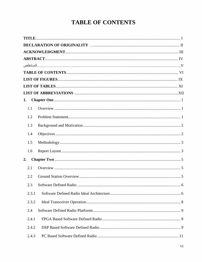
1. Chapter One ................................................................................................................................ 1
1.1 Overview ............................................................................................................................... 1
1.2 Problem Statement ................................................................................................................. 1
Background and Motivation .................................................................................................. 2 1.3
Objectives .............................................................................................................................. 2 1.4
Methodology .......................................................................................................................... 3 1.5
Report Layout ........................................................................................................................ 3 1.6
2. Chapter Two ............................................................................................................................... 5
Overview ............................................................................................................................... 5 2.1
Ground Station Overview ...................................................................................................... 5 2.2
Software Defined Radio ........................................................................................................ 6 2.3
2.3.1 Software Defined Radio Ideal Architecture ....................................................................... 6
2.3.2 Ideal Transceiver Operation ............................................................................................... 8
Software Defined Radio Platforms ........................................................................................ 9 2.4
2.4.1 FPGA Based Software Defined Radio ............................................................................... 9
2.4.2 DSP Based Software Defined Radio .................................................................................. 9
2.4.3 PC Based Software Defined Radio .................................................................................. 11
VII
Software Defined Radio Projects Review ........................................................................... 13 2.5
3. Chapter Three .......................................................................................................................... 15
Introduction ......................................................................................................................... 15 3.1
Design Considerations ......................................................................................................... 15 3.2
Development Methodology ................................................................................................. 16 3.3
Project Scope ....................................................................................................................... 16 3.4
System Requirements .......................................................................................................... 17 3.5
System Design ..................................................................................................................... 18 3.6
3.6.1 PC Sound Card ................................................................................................................. 18
3.6.2 Hardware Design ............................................................................................................. 19
3.6.2.1 Receiver RF Front End ................................................................................................. 19
3.6.2.2 Transmitter RF Front End ............................................................................................ 22
3.6.3 Software Design ............................................................................................................... 23
3.6.3.1 Sound Card Access ....................................................................................................... 23
3.6.3.2 The Object-Oriented Programming (OOP) .................................................................. 24
3.6.3.3 C++ Programming Language ....................................................................................... 25
System Implementation ....................................................................................................... 25 3.7
3.7.1 Hardware .......................................................................................................................... 25
3.7.2 Software ........................................................................................................................... 25
3.7.2.1 Audio Class .................................................................................................................. 27
3.7.2.2 Modulation Class .......................................................................................................... 28
3.7.2.3 Demodulation Class ..................................................................................................... 29
3.7.2.4 Filter Class .................................................................................................................... 29
3.7.2.5 GUI Implementation .................................................................................................... 30
4. Chapter Four ............................................................................................................................ 33
Introduction ......................................................................................................................... 33 4.1

VIII
Software Modules Testing ................................................................................................... 33 4.2
4.2.1 Audio Class Testing ......................................................................................................... 33
4.2.2 Filter Class Testing .......................................................................................................... 36
4.2.3 Modulation Class ............................................................................................................. 37
4.2.3.1 AM ............................................................................................................................... 37
4.2.3.2 DSB .............................................................................................................................. 37
4.2.3.3 ASK .............................................................................................................................. 38
4.2.3.4 FM ................................................................................................................................ 39
4.2.3.5 BFSK ............................................................................................................................ 40
4.2.3.6 BPSK ............................................................................................................................ 40
4.2.4 Demodulation Class ......................................................................................................... 41
4.2.4.1 AM ............................................................................................................................... 41
4.2.4.2 DSB .............................................................................................................................. 41
4.2.4.3 ASK .............................................................................................................................. 42
4.2.4.4 FM ................................................................................................................................ 43
4.2.4.5 BFSK ............................................................................................................................ 44
4.2.4.6 BPSK ............................................................................................................................ 44
Hardware Testing ................................................................................................................ 45 4.3
5. Chapter Five ............................................................................................................................. 46
Project Preview .................................................................................................................... 46 5.1
Future Work ......................................................................................................................... 46 5.2
REFERENCES .......................................................................................................................... 48
APPENDIX A…………………….…..…...………………………………………………….A-1
APPENDIX B……………………...…………………………………………………….........B-1
APPENDIX C………………………………………………………………………………....C-1

IX
LIST OF FIGURES
Figure Page
Figure 2.1 Ideal transceiver architecture .............................................................................................. 8
Figure 2.2 FPGA based software defined radio ................................................................................. 10
Figure 2.3 Xilinix SpartanIIE FPGA kit ............................................................................................ 10
Figure 2.4 DSP based software defined radio .................................................................................... 11
Figure 2.5 Altera-Cyclone II DSP kit ................................................................................................. 11
Figure 2.6 PC Based Software Defined Radio ................................................................................... 12
Figure 3.1 Spiral model ...................................................................................................................... 16
Figure 3.2 Typical transceiver system ................................................................................................ 17
Figure 3.3 Receiver Subsystem .......................................................................................................... 18
Figure 3.4 Transmitter Subsystem ..................................................................................................... 18
Figure 3.5 Receiver RF front end block diagram ............................................................................... 19
Figure 3.6 Pre-selector filter ............................................................................................................... 20
Figure 3.7 Mixer ................................................................................................................................. 20
Figure 3.8 Phase transformer.............................................................................................................. 21
Figure 3.9 Transmitter RF front end block diagram .......................................................................... 22
Figure 3.10 Typical computer architecture ........................................................................................ 24
Figure 3.11 Receiver RF front end circuit schematic ......................................................................... 26
Figure 3.12 Transmitter RF front end circuit schematic .................................................................... 26
Figure 3.13 A photo of the system RF front end ................................................................................ 27
Figure 3.14 Audio stream flow .......................................................................................................... 28
Figure 3.15 GUI window ................................................................................................................... 30
Figure 3.16 Modulation mode operations .......................................................................................... 31
Figure 3.17 Demodulation mode operations ...................................................................................... 32
Figure 4.1 Sound card output at input of constant amplitude ........................................................... 35
Figure 4.2 Sound card output at input of constant frequency ............................................................ 35
Figure 4.3 Lowpass filter at 10KHz cutoff frequency Bode plot ....................................................... 36
Figure 4.4 AM modulated signal ........................................................................................................ 37
Figure 4.5 DSB modulated signal ...................................................................................................... 38
Figure 4.6 ASK modulated signal ...................................................................................................... 39

X
Figure 4.7 FM modulated signal ........................................................................................................ 39
Figure 4.8 BFSK modulated signal .................................................................................................... 40
Figure 4.9 BPSK modulated signal .................................................................................................... 41
Figure 4.10 AM demodulation ........................................................................................................... 42
Figure 4.11 DSB demodulation .......................................................................................................... 42
Figure 4.12 ASK demodulation ......................................................................................................... 43
Figure 4.13 FM demodulation ............................................................................................................ 43
Figure 4.14 BFSK demodulation ....................................................................................................... 44
Figure 4.15 BPSK demodulation ....................................................................................................... 44
Figure 4.16 Received signal using RF front end ................................................................................ 45

XI
LIST OF TABLES
Table Page
Table 4.1 Sound card output at 0.3Vp-p input ................................................................................... 34
Table 4.2 Sound card output at input of 12KHz ................................................................................ 34
Table 4.3 Lowpass filter of 10KHz cutoff frequency behavior ......................................................... 36

XII
LIST OF ABBREVIATIONS
A/D Analog To Digital Converter
AM Amplitude Modulation
API Application Programing Interface
ASK Amplitude Shift Keying
BFSK Binary Frequency Shift Keying
BPF Bandpass Filter
BPSK Binary Phase Shift Keying
BRF Bandreject Filter
BTS Base Transceiver Station
CR Cognitive Radio
D/A Digital To Analog Converter
DLL Dynamic Link Library
DSB Double Side Band
DSP Digital Signal Processer
FIR Finite Impulse Response
FM Frequency Modulation
FPGA Field Programmable Gate Array
GPL General Public License
GPP General Purpose Processor
GUI Graphical User Interface
HDL Hardware Description Language
HPF High Pass Filter
LPF Lowpass Filter
OOP Object Oriented Programming
OS Operating System
PC Personal Computer
RF Radio Frequency
SDR Software Defined Radio
SNR Signal To Noise Ratio

1
1. Chapter One
INTRODUCTION
1.1 Overview
Traditionally, radio communication systems required specialized hardware to implement
their functionality. In order to keep production costs low, these systems contained only
the hardware necessary to perform the tasks that they were designed for. Therefore these
hardware defined systems were often difficult to modify and upgrade.
Software based systems emerged offering a potential solution of higher flexibility and
comparatively lower cost. Software defined radio is defined as "Radio in which some or
the entire physical layer functions are software defined" [1]. Software defined radio
allows engineers to implement any number of different signal processing elements
without altering the underlying system hardware. This is done by simply upgrading
system software.
1.2 Problem Statement
2. The conventional hardware defined radios have little flexibility and mostly doesn't
support multiple wireless communication protocols because of the limitation of hardware.
Also, development of radio that involves new services is very difficult because it requires
hardware changes, which means more power consumption, long development time and
high production cost.
3. Performing the baseband signal processing in the software domain allows for much
greater re-configurability than traditional radios provide. In addition, the cost of a
software defined radio platforms are often lower than those of a more traditional
platforms because the software is reusable and often available at relatively low cost.
Introduction Chapter One
2
Background and Motivation 1.3
4. The costs incurred in evolving a communication system to a new standard, by means of
hardware replacement, is enormous. Therefore software defined radio must be employed.
Software defined radio decreases the cost dramatically because any system upgrade
requires only software update.
Moreover, software defined radio increases system flexibility. With software defined
radio, system becomes adaptable to the continuously changing requirements of
scrambling or encryption codes, modulation format, channel bandwidth, data rate, and
voice codec type. Therefore the system becomes able to operate with different equipment
standards.
Software defined radio evolved from pure academically concept to be implemented in the
defense sector in both U.S. and Europe [2]. The United States Military developed a
software defined radio system in the early 1990s that required four of the most powerful
digital signal processors (DSP) available and some FPGAs to glue them together. This
system, known as SpeakEasy, filled the back of a truck. By the time the engineers
finished writing the software for SpeakEasy, three years had passed and the hardware in
the system was already obsolete [3].
Then software defined radio broke out and revolutionized the communication world.
Nowadays most mobile handsets and base transceiver station (BTS) systems include
software defined radio system. Different manufacturing companies are developing
software defined radio systems for reception of RF signals such as FlexRadio and
SoftRock.
Software defined radio is future of radio, maximum flexibility a lot of possibility from
the same hardware, what was very hard to achieve with hardware realization now is very
easy by software.
Objectives 1.4
The main objective of this project is to develop a software defined radio of high
flexibility and minimum cost for University of Khartoum KNSAT educational ground

Introduction Chapter One
3
station. This is done with the aim of making the system available for usage and/or
modification by students, graduates and researchers.
Methodology 1.5
In order to implement a software defined radio consists of software that used for different
type of modulation and RF front end receiver, a small set of requirements is considered
and goes through each development phase for those set of requirements, design,
implementing and testing is done at each phase, based on that, functionality for additional
requirements is added in ever-increasing until the application is ready for integration,
installation and maintenance phase.
The system is divided into modules, so that each module is independent from the others,
to be reused for other implementation where ever it needed. For the hardware part, the
components with low cost are selected. On the other hand, free and open source software
is implemented.
Report Layout 1.6
This report is organized as follows:
Chapter 2 (Literature Review): This chapter presents an overview to software
defined radio and its projects. It begins by describing the software defined radio
architecture and the various platforms that are used to implement it and their
capabilities.
Chapter 3 (Design and Implementation): This chapter details the project
requirements and scope. Also, it presents the design methodology, components
description, in addition to the methods, and tools used to implement the system.
Chapter 4 (Testing and Results): Presents a description of how the system was
tested followed by the results of tests and their discussion.
Chapter 5 (Conclusion): The project is reviewed in this chapter, discussing the
achieved objectives and not achieved ones; in addition to the further
developments that can be made to the resulting system.

Introduction Chapter One
4
Appendix A: represents the GNU License of PortAudio
Appendix B: describes the audio I/O code.
Appendix C: Presents the software modules used.

1
2. Chapter Two
LITERATURE REVIEW
Overview 2.1
This chapter aims to examine the possible architectures for a software defined radio. This
is done with the aim of providing guidance to certain design decisions that will be made
later throughout the project. This chapter begins a brief overview of ground stations
which is provided to show the importance of software defined radio. Following that, the
various tools and techniques that can be used for software-defined radio are introduced
and discussed. The chapter ends by presenting some of the software defined radio
existing implemented projects.
Ground Station Overview 2.2
A ground station is a terrestrial terminal station designed for
telecommunication with spacecraft, or reception of radio waves from an astronomical
radio source. Ground stations are located either on the surface of the Earth, or within the
atmosphere [4]. Earth stations communicate with spacecraft by transmitting and receiving
radio waves using transceivers. Both the transmitter and receiver of the transceiver must
be customized to the signaling format used such as encryption, modulation/demodulation
and frequency used by the spacecraft or the astronomical radio source. This places high
burden in the choice of ground station equipment. When ground station is to be used to
receive signals from different radio sources, the equipment purchased must match the
wide range of signaling format used by each source and to be able to differentiate
between sources too. Therefore more equipment is purchased to cope with all inquiries
which increase the cost dramatically.

Literature Review Chapter Two
6
A potential solution is to use software defined radio transceivers to increase flexibility
and to decrease cost.
Software Defined Radio 2.3
A software defined radio is defined as a form of transceiver in which ideally all aspects of
its operation are determined using versatile, general-purpose hardware whose
configuration is under software control. This is often thought of in terms of base-band
digital signal processers (DSPs). The following section describes how software defined
radio can be implemented in a transceiver system.
2.3.1 Software Defined Radio Ideal Architecture
A software defined radio consists of, for the most part, the same basic functional blocks
as any digital communication system [5]. Software defined radio lays new demands on
many of these blocks in order to provide multiple bands, multiple service operation and
re-configurability needed for supporting various air interface standards. To achieve the
required flexibility, the boundary of digital processing should be moved as close as
possible to the antenna, and application specific integrated circuits, which are used for
baseband signal processing, should be replaced with programmable implementations [6].
An ideal software defined radio would have a very minimal analog front end as illustrated
by Figure 2.1 Ideal transceiver architecture, note that the A/D converter is assumed to
have a built-in anti-alias filter and that the D/A is assumed to have a built-in
reconstruction filter [7]. The system consists of the following:
Digital signal processor: the modulation scheme, channelization,
protocols, and equalization for transmit and receive are all determined in
software within the digital processing subsystem. This is shown containing
a DSP in Figure 2.1 Ideal transceiver architecture.
Circulator: is used to isolate the transmit and receive path signals to
allow using a single antenna for both transmitter and receiver.
Amplifier: two amplifiers are used. One of which is responsible for
including enough power in the signal for transmission after the D/A

Literature Review Chapter Two
7
conversion. The other one magnifies the incoming signal from the antenna
before passing it to A/D. The amplifier must have linear characteristics to
prevent signal distortion.
Anti-Aliasing and Reconstruction Filter: anti-aliasing filter is included
before the A/D converter to prevent generation of image signals. Because
once an aliased image is created in the sampling process, no amount of
further processing can distinguish between a true signal and an aliased
signal.
The filter must be a lowpass filter tuned to a frequency that is less or equal
half the sampling frequency of the A/D converter. The filter must have
also linear characteristics in order to protect signal properties.
For the same reason, the output of a D/A converter requires a lowpass
analog filter, called a reconstruction filter, as the output signal must be
band limited, to prevent aliasing (here meaning Fourier coefficients being
reconstructed as low frequency waves, not as higher frequency aliases).
Ideally, both filters should be brick wall filters, constant phase delay in the
passband with constant flat frequency response, and zero response from
the Nyquist frequency.
Antenna: it is used to radiate and receive signals.
A/D converter: it is used to convert the incoming analog signal into
digital in order to perform digital signal processing techniques to it. The
converter must have a sampling rate that is twice maximum incoming
signal frequency according to sampling theorem. A/D converters of high
sampling rate for high frequency signals are quiet expensive and are not
usually available in the local markets. A potential solution is to down
convert the incoming signal frequency into a suitable frequency range
using a mixer stage before the converter.
D/A converter: it is used to convert digital signal into analog in order to
transmit it by the antenna. This component is chosen depending on the
required frequency band of the output signals. Its sampling rate must also
follow the sampling theorem.

Literature Review Chapter Two
8
2.3.2 Ideal Transceiver Operation
The signal is received by the antenna through the circulator which is then amplified. This
is because received signals power is very low due to attenuation encountered in the
propagation path. The signal is passed to an anti-aliasing filter then to A/D converter. The
signal is then passed to the final stage which is digital signal processing.
When the signal is to be transmitted, the data generated by the processor are passed to
D/A converter. The signal is then amplified and radiated by the antenna through the
circulator to space. The reason behind amplification here is to include enough power in
the signal that helps it to propagate to the required destination and to be detected by the
receiver.
Transmit/Receive
Antenna
Power
Amplifier Circulator RF-output DAC
RF-input ADC
DSP
Digital
Processing
D/A
A/D
Figure 2.1 Ideal transceiver architecture

Literature Review Chapter Two
9
Software Defined Radio Platforms 2.4
There exist a large number of available platforms for software defined radio, each with its
own features and capabilities. The choice between them depends on the particular
application area, the cost and power consumption. In the following section, the potential
digital hardware platforms are viewed.
2.4.1 FPGA Based Software Defined Radio
A field-programmable gate array (FPGA) is an integrated circuit that contains an array of
programmable logic components called "logic blocks" which can be configured by a
customer or a designer after manufacturing hence the name "field-programmable".
The FPGA kits contain many features. The most important for the transceiver
architecture are A/D converter, D/A converter, power amplifier, RF input pins, and a
processor. Therefore the kit along with an antenna and a circulator can be used as a
transceiver as shown in Figure 2.2.
FPGA processor is programmed using a hardware description language (HDL) such as
VHDL and Verilog. The DSP program is written in one of these languages on PC
compiler and then loaded into the FPGA using a USB port.
Different kits of different processing capabilities and sampling frequencies are available
which can be used depending on application and cost. Usually, the FPGA processor is
capable of performing high speed calculations but its operation is limited by the small
memory contained in the FPGA kit. Therefore optimization between memory and certain
operations (for example making a filter program) is needed. Moreover FPGA size is large
compared to other platforms discussed below.
FPGA is used with applications that require high processing requirements at high
frequencies such as military communication systems.
2.4.2 DSP Based Software Defined Radio
A digital signal processor (DSP) is a microprocessor that has an architecture specialized
for fast operational needs of digital signal processing. They are best suited to the less

Literature Review Chapter Two
10
computationally intensive forms of signal processing, rather than very high-speed front-
end applications.
The DSP kit - like the FPGA kit- contains many features that can be utilized for the
transceiver, such as A/D and D/A converters, anti-aliasing and reconstruction filters, RF
inputs pins and the processor. Figure 2.4 DSP based software defined radio describes a
possible architecture for the transceiver.
Figure 2.3 Xilinx SpartanIIE FPGA kit
The DSP based software-defined radio contains features that ease the DSP operations
more than the FPGA based architecture, but still not as much as the PC based one.
FPGA Kit
Diplexer
Transmit/Receive
Antenna
Figure 2.2 FPGA based software defined radio

Literature Review Chapter Two
11
Moreover, DSP based architecture is built to perform DSP operations; any other
operation type is not applicable, therefore decreasing the system flexibility.
Different aspects must be considered for purchasing the DSP kit for software-defined
radio; most important are the memory, sampling rate and clock speed.
Figure 2.5 Altera-Cyclone II DSP kit
2.4.3 PC Based Software Defined Radio
The PC based software defined radio depends on the PC processor. Each PC utilizes a
general purpose processor (GPP) to perform its functions. GPP is not restricted to a
Diplexer
DSP Kit
Transmit/Receive
Antenna
Figure 2.4 DSP based software defined radio

Literature Review Chapter Two
12
specific language or software. GPP has high processing capabilities therefore it can be
used in different application by simply programming it by any high level language such
as C and Java.
Today PCs can contain more than one processor and very large memory. Consequently,
implementing DSP operations on PC is simple, efficient and cost effective. Therefore
there is no need to buy an FPGA or DSP kit. Anyone with sufficient knowledge can
create his own transceiver using his PC. Figure 2.6 PC Based Software Defined Radio
illustrates the PC based software defined radio. The signal is input to the processor using
any one of the external ports. A/D and D/A converters are required in the system
preceding the ports as shown in the figure (the figure assumes that all input signals are of
frequency below half the sampling rate). To eliminate the need for an external A/D and
D/A converters, the PC sound card can be utilized. This is by passing the incoming signal
through the microphone jack and then taking the output signal after processing from the
speakers jack. This method limits the signal frequency band that can be received
depending on the sound card sampling rate.
A/D
D/A
Transmit/Receive
Antenna
Diplexer
Figure 2.6 PC Based Software Defined Radio

Literature Review Chapter Two
13
Software Defined Radio Projects Review 2.5
Software defined radio was first termed 'software radio' which was first introduced in
1984 by a team at the Garland Texas Division of E-Systems Inc. (now Raytheon). A new
digital signal processing laboratory was developed in which sellable software radio
products were produced and popularized within various government agencies. This 1984
software radio was a digital baseband receiver that provided programmable interference
cancellation and demodulation for broadband signals, typically with thousands
of adaptive filter taps, using multiple array processors accessing shared memory [8].
Perhaps the first software defined radio transceiver was designed and implemented by
Peter Hoeher and Helmuth Lang at the German Aerospace Research Establishment
(DLR, formerly DFVLR) in Oberpfaffenhofen, Germany, in 1988 [9]. Both transmitter
and receiver of an adaptive digital satellite modem were implemented according to the
principles of software defined radio, and a flexible hardware periphery was proposed.
Latter, in 1991, term "Software Defined Radio" was introduced by Joseph Mitola, who
published the first paper on the topic in 1992, though the concept was first proposed in
1991[2].
In the defense sector, software-defined radios have been known since the late 1970s in
both the U.S. and Europe [3]. The first military application that used software-defined
radio was SpeakEasy program that was initiated by the U.S. military. The program aimed
to use programmable processing to emulate multiple existing radios and to be able easily
incorporate new coding and modulation standards in future so that military
communications can keep pace with advances in coding and modulation techniques [4].
Another program by the U.S. military is the Joint Tactical radio system (JTRS) which
produces a family of interoperable, modular, software-defined radios that operate as
nodes in a network that provides secure wireless communication and networking services
for mobile and fixed forces, consisting of U.S. Allies, joint and coalition partners, and in
time, disaster response personnel [10].
Software defined radio was then spread from military to a wide variety of applications
making the platform itself a commodity that is available in everyone hand. Software
defined radio is used extensively in mobile communication systems, both in the handset

Literature Review Chapter Two
14
and the base transceiver station. Nowadays there is no mobile that does not use software
defined radio.
Moreover, there are several companies that develop the hardware and/or the software
products to be used for different applications such as FlexRadio systems. Open source
hardware and software are also available for software-defined radio. GNU Radio is a free
and open source software development toolkit that provides signal processing blocks to
implement software radios upon which several open source hardware can be used [11].
Universal software radio peripheral (USRP) is an open source hardware which is
designed and sold by Ettus Research, LLC and its parent company, National Instruments.
The USRP is commonly used with the GNU Radio software suite to create complex
software-defined radio systems. HPSDR (high performance software defined radio) is
open source hardware and software project intended for use by Radio Amateurs ("hams")
and Short Wave Listeners (SWLs) [12].
Another SDR hardware that has recently become available in small numbers and which
has been bought by amateur radio enthusiasts around the world is the Fun Cube Dongle
or „FCD‟ [13]. FCD can be used with any of the software defined radio programs
available such as Rocky developed by Alex VE3NRA and WINRAD developed by
Alberto IPHD [14].

1
3. Chapter Three
DESIGN AND IMPLEMENTATION
Introduction 3.1
The project is designed based on a straightforward methodology using PC components, to
help use and development of the project. The aim of this chapter is to describe the tools
and designs that were employed to implement the project and achieve its objectives. The
chapter begins by listing some considerations that were taken into account while
designing the system. Then the development methodology, project scope and system
requirements are discussed. The chapter continues by discussing system design in details
for both hardware and software and ends by discussing system implementation.
Design Considerations 3.2
Low cost: the system is to be designed and implemented using available
components, while at the same time perform its functions with high efficiency.
Re-configurability: The system should be easily reconfigurable and flexible so
that it can be used to support any number modulation, demodulation, or other
signal processing schemes.
Extensibility: The system must be designed such that new capabilities can be
added to it without major changes to the underlying architecture.
Modularity: The components of the resulting system should be well defined and
independent which leads to better maintainability. The components could then be
implemented and tested in isolation before being integrated to form the system.
Open Source: such that the source code is available for modification or
customization. Also the hardware is designed using simple components of low
cost such that hardware becomes available in anyone‟s hands.

Design and Implementation Chapter Three
16
Compatibility: The project target is to design a software-defined radio
transceiver that is compatible and operable on any PC.
Convenience: the system is to be designed such that it is convenient to use by all
users of all levels.
Simplicity: the system is designed based on a simple approach to help system
development.
Development Methodology 3.3
The system was developed under spiral model approach, according to which the
development starts with a small set of requirements and goes through each development
phase for those set of requirements. Based on that, functionality for additional
requirements is added in ever-increasing "spirals" until the application is ready for the
Installation and Maintenance phase. With the spiral model no need for full understanding
of the requirements and their implementation from the beginning.
Figure 3.1 Spiral model
Project Scope 3.4
The scope of the project is to develop a software defined radio that can be used for
reception and transmission of radio signals. This is by implementing the RF front end
part and the digital modulation and demodulation part of the transceiver system shown in
Figure 3.2 Typical transceiver system. The system is designed to be an educational
transceiver targeting different users such as students, graduates and researchers.
Analysis Evaluation
Planning Development

Design and Implementation Chapter Three
17
Figure 3.2 Typical transceiver system
System Requirements 3.5
In order to fulfill the project objectives and design considerations, certain system
requirements arise. Figure 3.3 Receiver Subsystemand Figure 3.4 Transmitter Subsystem
illustrate the general structure of receiver and transmitter subsystems. The soundcard will
be used to perform the conversion operation from analog to digital and from digital to
analog, and all processing is carried out by PC. Consequently, the system must contain
and perform the following:
i. A RF front end must be included in order to perform all analog operations and to
generate an in-phase and quadrature projection of the received signal and passing
them to the microphone jack.
ii. Getting the signals directly from the sound card.
iii. Modulation or demodulation on the input signals.
iv. Delivering the modulated or demodulated signal to the sound card at which the signal
can be taken from speakers jack.
v. Giving the user the ability to change the settings of the software and specify the mode
of operation (modulation, demodulation, others …) and the type of each.

Design and Implementation Chapter Three
18
Figure 3.3 Receiver Subsystem
Figure 3.4 Transmitter Subsystem
System Design 3.6
The system design is divided into hardware and software design. Both designs require the
knowledge of PC sound card accessing. Therefore sound card is first discussed then
hardware and software designs are presented.
3.6.1 PC Sound Card
Nowadays every PC nowadays comes with a sound card; they vary immensely in sound
quality, features and input/output options. Most standard PC soundcards allow the
incoming signal to be sampled at rates up to 44.1 kHz per channel. High end professional
soundcards allow higher sampling rates, typically 96 kHz and above. Most common
soundcards operate using 16 bit A/D converters. High end soundcards use 24 bit A/D
converters allowing a greater range of output values. This is because sound card is
intended to process only audio signals. Sound cards also contain a built in anti-aliasing
and reconstruction filter for their A/D and D/A converters respectively.
The sound card inputs audio signals from the microphone jack and outputs it to the
speakers through its A/D and D/A converters.
Input From Antenna
Analog Radio Front
End
A/D converter
(Sound Card)
Digital Signal
Processing on GPP
Digital Signal
Processing on GPP
D/A Converter
(Sound Card)
RF Front End
Output to Antenna

Design and Implementation Chapter Three
19
3.6.2 Hardware Design
The hardware design consists of designing a RF front end for receiver and transmitter
subsystems. These are discussed in the following.
3.6.2.1 Receiver RF Front End
In this section all the analog operations are performed to get the signal ready for the next
section in which the signal is transformed into digital. The RF front end constitutes of the
following components:
i. Antenna
For reception of radio frequency an antenna is used.
ii. Pre-Selector Filter
A simple bandpass filter is used to select the frequency band required for reception of
radio signals. A tank circuit is used with a variable inductor along with a variable
capacitor to change the frequency range. The circuit designed is shown in Figure 3.6.
The center frequency of the circuit is determined by the following equation:
Antenna
Pre-selector
Filter
VFO
Phase
Transformer
I
Q
L
R
Figure 3.5 Receiver RF front end block diagram

Design and Implementation Chapter Three
20
(Eqn. 3.1)
Figure 3.6 Pre-selector filter
iii. Mixer
An external analog mixer is required to down convert the signal frequency into low
frequencies depending on the sound card sampling rate.
Simple double diode mixer is used as shown in Figure 3.7 Mixer. The mixer has two
inputs. One of which is taken from the RF input signal, the other is taken from a
variable frequency oscillator.
Figure 3.7 Mixer
The mixer produces two frequency components. One of which with frequency equals
the sum of the two input signals frequencies and the other is the difference. Only the
lower frequency signal will be passed through the anti-aliasing filter. This is what is
referred to as frequency down conversion. It is described by the following equations:
(Eqn. 3.2)
(Eqn. 3.3)
(Eqn. 3.4)
And after filtering:

Design and Implementation Chapter Three
21
(Eqn. 3.5)
iv. Variable Frequency Oscillator
The variable frequency oscillator used is the laboratory signal generator. The signal
generator can generate a signal from dc up to a frequency of 1GHz. It can also
generate a signal of different forms. That is square, triangular and sinusoidal wave.
The signal form used here is the sinusoidal.
v. Phase Transformer
To make the 90° phase shift, the circuit shown in
Figure 3.8 was used. The circuit must be tuned to a specific frequency in order to
give the required phase shift. Therefore a potentiometer is used. By varying the
potentiometer the phase shift is varied until phase shift required is obtained at a
particular frequency. The capacitor and potentiometer values depend on the following
equation.
(Eqn. 3.6)
where f is the VFO frequency.
Figure 3.8 Phase transformer
Q I

Design and Implementation Chapter Three
22
3.6.2.2 Transmitter RF Front End
The transmitter RF front end contains most of the components used for the receiver part.
The signal is taken from the speaker jack that consists of the left and right components.
The transmitter RF front end (shown in Figure 3.9 Transmitter RF front end block
diagram) consists of the following:
i. Mixer
Here the mixer is used to up convert the signal from baseband to higher frequencies
suitable for transmission as described by (Eqn. 3.2)
(Eqn. 3.3)
ii. Variable Frequency Oscillator
The variable frequency oscillator is also needed here to generate the carrier. The
device used here is the laboratory function generator.
iii. Antenna:
The same reception antenna is used for the transmitter.
Antenna
VCO
L
R
Figure 3.9 Transmitter RF front end block diagram
Design and Implementation Chapter Three
23
3.6.3 Software Design
When talking about the software part of the system, there are three important issues to be
determined; how the software program will interact with the sound card for audio I/O, the
programming language and approach. Both are discussed in the following two sections.
3.6.3.1 Sound Card Access
To develop a real time audio application it is necessary to obtain the audio data directly
from the sound card using the operating system (OS). Since there are different types of
operating systems and much hardware each with their own driver, there are a wide
variety of possibilities to access the audio data. These access points are commonly called
application programming interface (API).The software access to the sound card is guided
by varies application programming interfaces (API), which differs within and from
platform to platform.
For a cross platform application, one that works on different platforms or OS, it is
necessary to be able to use all these different API‟s. In this case an additional API which
is a fully software orientated API is used to create one access point to interface a number
of different system API‟s such as: CLAM, OpenAL,pureData, STK and PortAudio. Most
of these APIs are licensed under the General Public License (GPL) (see Appendix A) so
they are free to use within these regulations.
The API used for software design is Port Audio Library because it causes the smallest
overhead for this application and is easy to use.
PortAudio is a free, audio I/O library, it is meant to have cross platform abilities
(including Windows, Macintosh (8, 9, X), Unix (OSS), SGI, and BeOS) and a very easy
to use API for recording and/or playing. It is a simple API and does not bring any
functions like mixing, filtering or analyzing.
PortAudio Library was chosen among other API's that are used for audio data because it
causes the smallest overhead for this application and is easy to use.

Design and Implementation Chapter Three
24
Figure 3.10 Typical computer architecture
3.6.3.2 The Object-Oriented Programming (OOP)
The fundamental idea behind object-oriented languages is to combine into a single unit
both data and the functions that operate on that data. Such a unit is called an object. OOP
is not primarily concerned with the details of program operation. Instead, it deals with the
overall organization of the
Next are the major elements of object-oriented that are important to this project:
Objects: When you approach a programming problem in an object-oriented
language, you no longer ask how the problem will be divided into functions, but
how it will be divided into objects. The match between programming objects and
real-world objects is the happy result of combining data and functions: The
resulting objects offer a revolution in program design. No such close match
between programming constructs and the items being modeled exists in a
procedural language.

Design and Implementation Chapter Three
25
Classes: In OOP we say that objects are members of classes. A class is thus a
description of a number of similar objects. An object is often called an “instance”
of a class.
Reusability: Once a class has been written, created, and debugged, it can be
distributed to other programmers for use in their own programs.
3.6.3.3 C++ Programming Language
C++ is derived from the C language. The most important elements added to C to create
C++ are classes and objects, therefore it has been chosen as the programming language.
For this project it is preferred over the C language. C++ is also chosen over java although
it is also OOP language, because of the need for fast processing since real time signal is
applied, and the virtual machine that is used by Java or C# and its.NET environment
could be speed waster.
System Implementation 3.7
After designing the system hardware and software to fulfill the project objectives, the
system was implemented.
3.7.1 Hardware
The receiver RF front end components described in section Receiver RF Front End3.6.2.1
were connected together. The complete circuit schematic is shown in Figure 3.11. Also,
the Transmitter RF front end components described in section 3.6.2.2 were also
connected. The complete circuit schematic is shown in Figure 3.12. Since the two
circuits have components in common, the two circuits were combined into one circuit
that can operate as a transmitter or receiver, depending on the user requirements. The
created circuit is shown in Figure 3.13.
3.7.2 Software
The system software could was divided into five modules, each module represent a C++
class that consist of its own data and functions, the functions operate on these data to

Design and Implementation Chapter Three
26
perform a specific task. These classes are Audio class, Modulation class, Demodulation
class, Filter class and GUI class. See Appendix C for description about the classes found
in the header files.
Figure 3.11 Receiver RF front end circuit schematic
Figure 3.12 Transmitter RF front end circuit schematic

Design and Implementation Chapter Three
27
Figure 3.13 A photo of the system RF front end
3.7.2.1 Audio Class
This class is responsible for Audio I/O operations using PortAudio library functions as
illustrated by Figure 3.14 Audio stream flow Using PortAudio is quiet easy; the software
comes as pure code, therefore it was compiled as a dynamic link library (DLL). After
this, the header was included and the DLL was linked to the project. The two channels
(stereo) function of the soundcard was used. The first recorded block is the right channel
the next one the left and so on. In order to run PortAudio, the following steps were taken:
i. PortAudio was initialized
ii. The stream was managed.
iii. The manipulation of the audio data was performed depending on the mode
that the user selects.
iv. The stream was then terminated terminate.

Design and Implementation Chapter Three
28
The main part of initialization is to set the basic parameters for the audio, like input
channels, output channels, data type, sample rate, frames per buffer then the callback
function performs the audio manipulation. However, PortAudio delivers the audio data
always in blocks of sizes which must be chosen as minimum as possible.
The actual signal processing is done in the manipulation part. The task that has to be
performed by callback function is to call the sub-routines that will do the desired
processing by the user.
Figure 3.14 Audio stream flow
3.7.2.2 Modulation Class
An instance of this class (object) is created when the user choose to start a modulation
process. Then the carrier frequency, modulation type and the sampling rate values are
collected from the GUI and sent to the constructor to be initialized. According to the
modulation type that is chosen by the user, one of the following modulation techniques is
applied: AM, DSB, ASK, FM,BFSK or BPSK. For each type there is a function that
implements operations that needed by specific modulation type. Since C++ is a high level
language, the represention of the operations which are just mathmetical equatuions are
streightforward.
One important issue that was taken into account, is phase incrementation control, such
that it does not exceed the float number range. Since π) is same as ,
whenever the angle becomes more than 2π, 2π is subtracted from the angle. This ensures
that the phase incrementation is always within float range.
Another thing that should be considered, is that the values of the samples are represented
by float values in the range from -1 to 1, hence whenever the output of the modulation is
expected to be more than 1 or less than -1, it should be normalized to 1.

Design and Implementation Chapter Three
29
3.7.2.3 Demodulation Class
An instance of this class (object) is created when the user choose to start a demodulation
process. Then the filter bandwidth, modulation type and the sampling rate values are
collected from the GUI, this is used to initialize the data of the created object. According
to the modulation type that is chosen by the user, one of the following demodulation
techniques is applied: AM, ASK, FM, BFSK or BPSK. For each type there is a function
that implements operations that needed by specific demodulation type. Since C++ is a
high level language, the represention of the operations which are just mathmetical
equatuions are striegt forward.
Using I/Q represenation of the modulated signal, any signal can be demodulated, for an
AM , ASK , and BPSK it is just . For FM and BFSK quadricorrelator method is
used.
For digital demodulation, multi levels decision is used to determine the received digital
data if it is 0 or 1.
3.7.2.4 Filter Class
An instance of this class (object) is created when the user choose to start a filtering
process. Then the filter bandwidth, filter type and the sampling rate values are collected
from the GUI, which is used to initialize the data of the created object. According to the
filter type LPF, HPF, BPF or BRF will be performed for the samples. The filter chosen to
be implemented is FIR with Blackman window. Blackman filters are excruciatingly slow,
because they must use convolution but they have high selectivity.
When using filter in a real-time environment there is one problem occurring. The
resulting signal is going to contain a periodic clipping noise. This is because of the nature
of the filters and their tendency to settlement. To avoid this problem, the values of the
delay lines after every filtering are saved, so they can be used as the filter initialization of
the next block. With this, a smooth crossover from one to the next block is guaranteed
and the settlement takes only place during the first initialization of the filter, which is
negligible.

Design and Implementation Chapter Three
30
3.7.2.5 GUI Implementation
Through the GUI the user is able to select different modulation, demodulation and filter
types in addition to setting other parameters. Moreover, the GUI allows user to save and
play back signals to or from file, and display these signals as in oscilloscopes. User
Interface window made is shown in Figure 3.15.
The Two Important modes for the program are modulation and demodulation. When the
user checks the button Mod Enable on the window enters the requested values and then
presses the Start button, the program will run on the modulation mode. This process is
described by the flow chart shown Figure 3.16. On the other hand, when user checks
Demod Enable, the program will run on the demodulation mode as described by the flow
chart will in Figure 3.17.
Figure 3.15 GUI window

Design and Implementation Chapter Three
31
Figure 3.16 Modulation mode operations

Design and Implementation Chapter Three
32
Figure 3.17 Demodulation mode operations

1
4. Chapter Four
TESTING AND RESULTS
Introduction 4.1
As a consequence of using the spiral model for the system development, the design
procedure is carried out for each module separately. Then the modules were
implemented, tested, debugged and improved by adding more features. Any PC running
windows 98 SE or better has Microsoft Visual C++ 2008 Express with PortAudio V 19
audio library installed in it can be used. Since the software has not been integrated yet, a
special test code for each module was written. The hardware was also tested separately
for performing its function.
Software Modules Testing 4.2
The testing was performed by passing a sine wave signal from the function generator to
the microphone jack. The signal parameters were changed depending on the test
performed.
4.2.1 Audio Class Testing
The main purpose of this test is to examine the sound card behavior with signals. This
was done by varying the signal frequency at constant amplitude then varying the
amplitude at constant frequency. The results obtained are shown in Table 4.1 Table 4.2.
It was realized that, and during varying the frequency at constant input voltage, the signal
starts to exhibit distortion at frequency of 15 KHz. This is due to the built in anti-aliasing
filter in the sound card. On the other hand, when the input voltage was varied at constant
frequency, it was realized that signal exhibits clipping at voltages greater than 0.3Vp-p
such that the output voltage stays constant at 2.5Vp-p. This is because the sound card has

Testing and Results Chapter Four
34
the limitation that maximum input voltage that can be applied to it is 0.3Vp-p and
maximum output voltage is 3Vp-p. It worth noting here that the results were taken at
speakers volume of 100%, that‟s why the output results are amplified by almost ten times
the input voltage.
Table 4.1 Sound card output at 0.3Vp-p input
Frequency (kHz) Output voltage (Vp-p)
1 1.3
5 2.2
10 3
15 2.8
20 2.4
25 1
30 0
Table 4.2 Sound card output at input of 12 KHz
Input voltage (Vp-p) Output voltage (Vp-p)
0 0.02
0.1 2.2
0.15 2.5
0.2 2.58
0.3 3
0.4 2.5
0.5 2.5
2.5 2.5

Testing and Results Chapter Four
35
Figure 4.1 Sound card output at input of constant amplitude
Figure 4.2 Sound card output at input of constant frequency
0
0.5
1
1.5
2
2.5
3
3.5
1 5 10 15 20 25 30
Output (Vp-p)
Frequency (KHz)
0
0.5
1
1.5
2
2.5
3
3.5
0 0.1 0.15 0.2 0.3 0.4 0.5 2.5 3 4
Output (Vp-p)
Input (Vp-p)

Testing and Results Chapter Four
36
4.2.2 Filter Class Testing
This test is used to examine the low pass filter designed. Table describes a filter of 10
KHz cutoff frequency behavior at different input signal frequencies.
Table 4.3 Lowpass filter of 10 KHz cutoff frequency behavior
Frequency (kHz) Amplitude (Vp-p)
0.5 3
1 3
2 3
4 3
5 3
6 3
10 3
10.5 2
10.8 0.5
11 0.1
11.5 0
15 0
20 0
Figure 4.3 Lowpass filter at 10 KHz cutoff frequency Bode plot
0%
10%
20%
30%
40%
50%
60%
70%
80%
90%
100%
0.5 1 2 4 5 6 10 10.5 10.8 11 11.5 15 20
Amplitude (Vp-p)
Frequency (KHz)

Testing and Results Chapter Four
37
4.2.3 Modulation Class
Here all modulation types implemented are tested. Note that the speakers output volume
was 100% and the function generator signal frequency was 1.9 KHz.
4.2.3.1 AM
Here the program modulates the incoming signal through the microphone jack and
outputs the result through the speakers jack. The message signal voltage used was 0.3Vp-
p. Then signal from the speakers jack was measured using an oscilloscope. The signal is
shown in Figure 4.4.
Figure 4.4 AM modulated signal
As shown in Figure 4.4, the AM modulation is perfect. And the message and AM signal
are in phase.
4.2.3.2 DSB
For DSB modulation, the program modulates the incoming signal through the
microphone jack and outputs the result through the speakers jack. The program also asks
for the modulation index required. This option is limited by the maximum output voltage
that the sound card can deliver, for example if the speakers volume is 100% and the
maximum modulated signal amplitude is greater than 0.3 the output signal will suffer

Testing and Results Chapter Four
38
from clipping. Therefore it is important to carefully calculate the modulation index and to
put under consideration the speakers volume. By performing a DSB modulation on the
message signal, the output was displayed on the oscilloscope and it is shown in Figure
4.5.
Figure 4.5 DSB modulated signal
Figure 4.5 illustrates DSB modulation with a modulation index of 40%. The results were
taken at speakers volume of 100% and carrier amplitude=0.5Vp-p.
4.2.3.3 ASK
For ASK modulation, the ASK option must be chosen. The program modulates the
incoming signal through the microphone jack, which was 0.2Vp-p, and outputs the result
through the speakers jack. The signal from the Speakers jack was is displayed on an
oscilloscope. The signal is shown in Figure 4.6.
As shown in Figure 4.6, we realize that the ASK signal in not smooth. This is because the
sound card D/A converter cannot represent a smooth square signal, because the sound
card has a limited bandwidth, while a perfect square wave would require infinite (or at
least very large) bandwidth.

Testing and Results Chapter Four
39
Figure 4.6 ASK modulated signal
4.2.3.4 FM
Here the incoming signal is FM modulated. The results is then taken from the speakers
jack and displayed on the oscilloscope. The results are shown in Figure 4.7.
Figure 4.7 FM modulated signal
Testing and Results Chapter Four
40
From Figure 4.7, the FM modulated signal is perfect; having the frequency of the carrier
varies in accordance with the message signal amplitude. The results were taken with
input signal voltage of 0.2Vp-p.
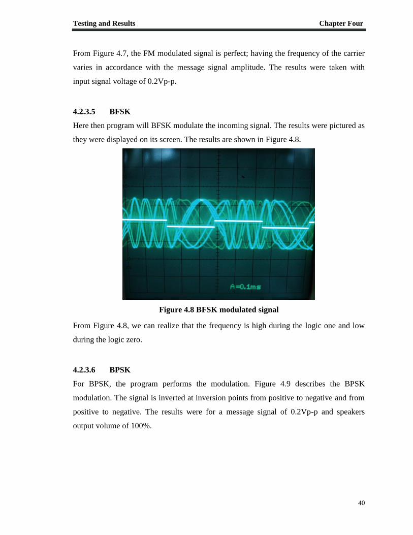
4.2.3.5 BFSK
Here then program will BFSK modulate the incoming signal. The results were pictured as
they were displayed on its screen. The results are shown in Figure 4.8.
Figure 4.8 BFSK modulated signal
From Figure 4.8, we can realize that the frequency is high during the logic one and low
during the logic zero.
4.2.3.6 BPSK
For BPSK, the program performs the modulation. Figure 4.9 describes the BPSK
modulation. The signal is inverted at inversion points from positive to negative and from
positive to negative. The results were for a message signal of 0.2Vp-p and speakers
output volume of 100%.

Testing and Results Chapter Four
41
Figure 4.9 BPSK modulated signal
4.2.4 Demodulation Class
The testing was performed by passing the earlier generated modulated signals to the
microphone jack of another PC with the program installed in it. The demodulated signal
was measured from the new PC speakers jack. The signal parameters were changed
depending on the test performed.
4.2.4.1 AM
For AM demodulation option, any AM signal that is passed to the microphone jack is
demodulated and the message signal is extracted from it. Figure 4.10 shows the AM
demodulation performed on the AM modulated signal that was previously generated in
section 4.2.3.1.
4.2.4.2 DSB
As in section 4.2.4.1, the DSB demodulation will take the generated DSB modulated
signal and demodulate it. Figure 4.11 shows the results of the demodulation operation
that is performed on the DSB modulated signal generated previously.

Testing and Results Chapter Four
42
4.2.4.3 ASK
Here the demodulation is also performed on the ASK signal that was generated
previously to have the output results are shown in Figure 4.6. We can realize that the
generated signal is not smooth. This is for the same reason mentioned in section 4.2.3.3.
Figure 4.10 AM demodulation
Figure 4.11 DSB demodulation

Testing and Results Chapter Four
43
4.2.4.4 FM
FM demodulation was performed on the generated FM signal that was generated in
section 4.2.3.4; the generated output is shown in Figure 4.13.
Figure 4.12 ASK demodulation
Figure 4.13 FM demodulation

Testing and Results Chapter Four
44
4.2.4.5 BFSK
Here too the BFSK demodulation was tested on the BFSK signal generated previously in
section 4.2.3.5. The generated output is shown in Figure 4.14.
Figure 4.14 BFSK demodulation
4.2.4.6 BPSK
As done previously, the BPSK demodulation is performed on the signal generated in
section 4.2.3.6 is used to test the demodulator. The results are shown in Figure 4.15.
Figure 4.15 BPSK demodulation

Testing and Results Chapter Four
45
Hardware Testing 4.3
The RF front end circuit (shown in Figure 3.13) operation was tested for reception. HF
dipole antenna and the function generator. A free licensed program that performs
spectrum analyzing was used. The function generator frequency was changed until a
radio signal was received at 0.95475MHz. The variable resistors, capacitor and inductor
were varied for maximum signal reception. The results obtained from the program are
shown in Figure 4.16.
Figure 4.16 Received signal using RF front end

1
5. Chapter Five
CONCLUSION
Project Preview 5.1
The project has met its deign considerations and requirements and has successfully
implemented many of the software defined radio features. These features include the
ability to change the filtering parameter, tuning frequency and modulation/demodulation
scheme.
On the other hand, further research and developments for the software implementation of
the radio functionality and the RF frond end is still required. For the current
implementation, further work is needed software modules integration and testing the
overall system behavior.
Future Work 5.2
For future work many features can be added to the system. These features include:
Matched filter must be implemented in order to increase the SNR.
Reading and writing the signal to and from the file feature should be added.
The software defined radio needs to be migrated to other platforms. At present the
software is only available for Windows platform.
Making it multi terminal, so it could read the signal from USB or serial port other
than sound card.
Control the RF front end using the software. This is also a major area where work
is to be done, i.e. adding software modules that responsible for controlling the
hardware and designing the hardware in order to make that possible.
Including more blocks of the digital transmitter and receiver, that shown in Figure
2.1, like encryption and decryption, to be implemented on software,

Conclusion Chapter Five
47
A web based software defined radio.
Some other modern techniques that to be applied to software defined radio, such
as Artificial Neural Networks which will provide a number of fascinating features
such as automatic modulation recognition.
Looking even beyond software defined radio, software defined radio technology
is an enabler for Cognitive Radio (CR). Whereas software defined radio
represents the implementation of a radio in software, cognitive radio represents a
model-based representation for a radio, one which allows a radio to further
configure itself to meet application needs and demands which utilizes the artificial
intelligence algorithms.
It is important to note here almost all of these feature are to be performed in software,
therefore higher flexibility and lower cost are always achievable.

1
6. REFERENCES
[1] “What is Software Defined Radio” The Wireless Innovation Forum and IEEE
p1900.1 Group [online]. Available:
http://www.wirelessinnovation.org/introduction_to_sdr, accessed in Jan 14, 2012.
[2] “Software Defined Radio” Wikipedia [online].
Available: http://en.wikipedia.org/wiki/Software-defined_radio, accessed in Dec
21, 2011.
[3] RJ Lackey and DW Upmal, "Speakeasy: The Military Software Radio," IEEE
Communications Magazine, May 1995
[4] "Earth station" , Federal Standard 1037C, General Services Administration, 1996
[5] P. G. Cook,W. Bonser, “Architectural Overview of the SPEAKeasy System”,
IEEE Communications Magazine, April 1999
[6] Z. Salcic, C. F. Mecklenbrauker, “Software Radio - Architectural Requirements,
Research and Development Challenges”, The 8th International Conference on
Communication Systems, Volume 2, November 2002
[7] Peter B. Kenington, RF Baseband Techniques for Software Defined Radio.
London: Artech House, 2005.
[8] P. Johnson, "New Research Lab Leads to Unique Radio Receiver," by space
systems technology group, garland division May 1985, Vol. 5, No. 4, pp 6-7.
Available: http://chordite.com/team.pdf
[9] P. Hoeher and H. Lang, "Coded-8PSK modem for fixed and mobile satellite
services based on DSP," in Proc. First Int. Workshop on Digital Signal Processing
Techniques Applied to Space Communications, ESA/ ESTEC, Noordwijk,
Netherlands, Nov. 1988; ESA WPP-006, Jan. 1990, pp. 117-123.
[10] “JTRS” [online] Available: http://jpeojtrs.mil/Pages/about.aspx. Accessed in Apr
9, 2012
[11] “GNU Radio” [online]. Available:
http://gnuradio.org/redmine/projects/gnuradio/wiki. Accessed in Apr 9,2012
[12] “HPSDR” [online]. Available: http://openhpsdr.org/. Accessed in Apr 11, 2012.

49
[13] “Fun Cube Dongle” [online]. Available:
http://www.funcubedongle.com/?page_id=2.Accessed in Mar 29,2012
[14] “SoftRock” [online]. Available: http://softrocksdr.wikispaces.com/Software.
Accessed in Mar 30, 2012.

A-1
A. APPENDIX A: GNU License
PortAudio is free to use software where even the source code is free and users are
allowed to change the code. To ensure that it is used in the way the primary developer
wanted it, it is published under the “The GNU General Public License (GNU GPL or
simply GPL) is a widely used free software license, originally written by Richard
Stallman for the GNU project. It is the license used by the Linux kernel. The GPL is the
most popular and well-known example of the type of strong copy left license that requires
derived works to be available under the same copy left. Under this philosophy, the GPL
is said to grant the recipients of a computer program the rights of the free software
definition and uses copy left to ensure the freedoms are preserved, even when the work is
changed or added to. This is in distinction to permissive free software licensees, of which
the BSD licenses are the standard examples.
The GNU Lesser General Public License (LGPL) is a modified, more permissive, version
of the GPL, intended for some software libraries. There is also a GNU Free
Documentation License, which was originally intended for use with documentation for
GNU software, but has also been adopted for other uses, such as the Wikipedia project.”
[http://en.wikipedia.org/wiki/GNU_General_Public_License]

B-1
B. APPENDIX B: Audio.cpp

B-2

B-3

B-4

B-5

B-6

B-7

C-1
C. APPENDIX C: Software Modules
C.1 Audio.h

C-2

C-3
C.2 Modulation.h

C-4
C.3 Demodulation.h

C-5
C.4 Filter.h