Published literature summary
105
Selected scientific literature concerning LASAK products Published literature summary A-A A A A
-
Upload
khangminh22 -
Category
Documents
-
view
1 -
download
0
Transcript of Published literature summary

Selected scientific literature concerning LASAK products
Published literature summary
A-A
AA
A

Foreword
LASAK Ltd. is a research-oriented medical technology company, established in 1991 in Prague, Czech Republic. The mission of the company is the de-velopment, production and sale of medical devices. Currently LASAK is one of the leading Czech companies in the field of dental implantology and bone tissue regeneration.Since 1992, the research and development of bioactive materials for bone-tissue replacement has been carried out systematically at LASAK in cooperation with universities, research institutes and major clinics. Results of the research have then been used in the development of new products, which successfully entered the market. These products are now widely used in clinical practice, especially in the fields of dental implantology, maxillofacial surgery, ortho-pedics, neurosurgery, as well as in other fields. An important product line consists of resorbable and nonresorbable ceramic materials based on calcium phosphates (PORESORB®-TCP) and on hydroxyapatite (OssaBase®-HA). Significant progress has been achieved by the development of surface-treated bioactive titanium, which exhibits unique properties enabling faster implant healing. This new biomaterial has been successfully used in the production of dental (IMPLADENT®) and spinal (IMPLASPIN) titanium implants.The development results and clinical evaluations are widely documented in a number of research and clinical studies published in professional journals, conference proceedings and monographs.This publication presents a collection of selected studies published in the field of dental implantology, bone tissue regeneration and spinal surgery in co-nnection with LASAK products.
3
List of selected publications
Dental implants
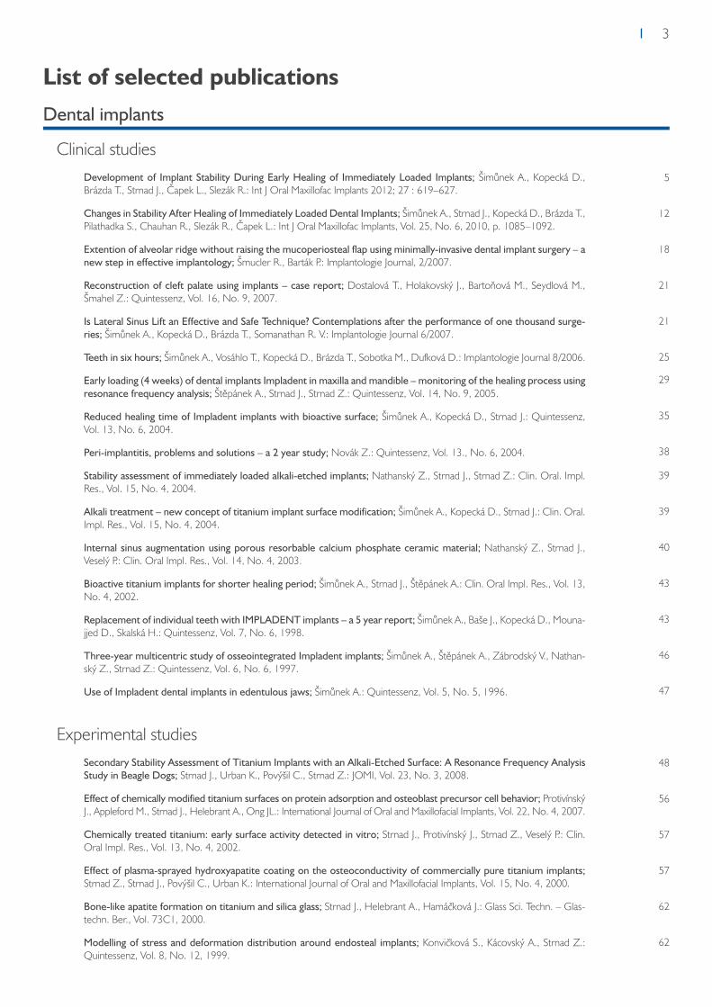
Clinical studiesDevelopment of Implant Stability During Early Healing of Immediately Loaded Implants; Šimůnek A., Kopecká D., Brázda T., Strnad J., Čapek L., Slezák R.: Int J Oral Maxillofac Implants 2012; 27 : 619–627.
Changes in Stability After Healing of Immediately Loaded Dental Implants; Šimůnek A., Strnad J., Kopecká D., Brázda T., Pilathadka S., Chauhan R., Slezák R., Čapek L.: Int J Oral Maxillofac Implants, Vol. 25, No. 6, 2010, p. 1085–1092.
Extention of alveolar ridge without raising the mucoperiosteal flap using minimally-invasive dental implant surgery – a new step in effective implantology; Šmucler R., Barták P.: Implantologie Journal, 2/2007.
Reconstruction of cleft palate using implants – case report; Dostalová T., Holakovský J., Bartoňová M., Seydlová M., Šmahel Z.: Quintessenz, Vol. 16, No. 9, 2007.
Is Lateral Sinus Lift an Effective and Safe Technique? Contemplations after the performance of one thousand surge-ries; Šimůnek A., Kopecká D., Brázda T., Somanathan R. V.: Implantologie Journal 6/2007.
Teeth in six hours; Šimůnek A., Vosáhlo T., Kopecká D., Brázda T., Sobotka M., Dufková D.: Implantologie Journal 8/2006.
Early loading (4 weeks) of dental implants Impladent in maxilla and mandible – monitoring of the healing process using resonance frequency analysis; Štěpánek A., Strnad J., Strnad Z.: Quintessenz, Vol. 14, No. 9, 2005.
Reduced healing time of Impladent implants with bioactive surface; Šimůnek A., Kopecká D., Strnad J.: Quintessenz, Vol. 13, No. 6, 2004.
Peri-implantitis, problems and solutions – a 2 year study; Novák Z.: Quintessenz, Vol. 13., No. 6, 2004.
Stability assessment of immediately loaded alkali-etched implants; Nathanský Z., Strnad J., Strnad Z.: Clin. Oral. Impl. Res., Vol. 15, No. 4, 2004.
Alkali treatment – new concept of titanium implant surface modification; Šimůnek A., Kopecká D., Strnad J.: Clin. Oral. Impl. Res., Vol. 15, No. 4, 2004.
Internal sinus augmentation using porous resorbable calcium phosphate ceramic material; Nathanský Z., Strnad J., Veselý P.: Clin. Oral Impl. Res., Vol. 14, No. 4, 2003.
Bioactive titanium implants for shorter healing period; Šimůnek A., Strnad J., Štěpánek A.: Clin. Oral Impl. Res., Vol. 13, No. 4, 2002.
Replacement of individual teeth with IMPLADENT implants – a 5 year report; Šimůnek A., Baše J., Kopecká D., Mouna-jjed D., Skalská H.: Quintessenz, Vol. 7, No. 6, 1998.
Three-year multicentric study of osseointegrated Impladent implants; Šimůnek A., Štěpánek A., Zábrodský V., Nathan-ský Z., Strnad Z.: Quintessenz, Vol. 6, No. 6, 1997.
Use of Impladent dental implants in edentulous jaws; Šimůnek A.: Quintessenz, Vol. 5, No. 5, 1996.
Experimental studiesSecondary Stability Assessment of Titanium Implants with an Alkali-Etched Surface: A Resonance Frequency Analysis Study in Beagle Dogs; Strnad J., Urban K., Povýšil C., Strnad Z.: JOMI, Vol. 23, No. 3, 2008.
Effect of chemically modified titanium surfaces on protein adsorption and osteoblast precursor cell behavior; Protivínský J., Appleford M., Strnad J., Helebrant A., Ong JL.: International Journal of Oral and Maxillofacial Implants, Vol. 22, No. 4, 2007.
Chemically treated titanium: early surface activity detected in vitro; Strnad J., Protivínský J., Strnad Z., Veselý P.: Clin. Oral Impl. Res., Vol. 13, No. 4, 2002.
Effect of plasma-sprayed hydroxyapatite coating on the osteoconductivity of commercially pure titanium implants; Strnad Z., Strnad J., Povýšil C., Urban K.: International Journal of Oral and Maxillofacial Implants, Vol. 15, No. 4, 2000.
Bone-like apatite formation on titanium and silica glass; Strnad J., Helebrant A., Hamáčková J.: Glass Sci. Techn. – Glas-techn. Ber., Vol. 73C1, 2000.
Modelling of stress and deformation distribution around endosteal implants; Konvičková S., Kácovský A., Strnad Z.: Quintessenz, Vol. 8, No. 12, 1999.
5
12
18
21
21
25
29
35
38
39
39
40
43
43
46
47
48
56
57
57
62
62

4
Bone regeneration materials
Clinical StudiesGuided bone regeneration in the pre-implantation phase; Poleník P.: Implantologie Journal 5/2007.
Porous ß-TCP and platelet rich plasma (PRP) in treatment of periodontal defects; Poleník, P.: J. Int. Acad. Periodontol., Vol. 6, No. 2, 2004.
ß-TCP as a scaffold for tissue engineered bone; Polenik, P.: J. Clin. Periodontol., Vol. 30, suppl. 4, 2003.
Experimental studiesIn vivo behaviour of the syntethetic porous hydroxyapatite prepared by low temperature processing and comparison with deproteinized bovine bone; Strnadová M., Strnad Z., Šponer P., Jirošova J., Strnad J.: Key Engineering Materials Vols. 493–494, 2012, p. 236–241.
In vivo behaviour of low-temperature calcium-deficient hydroxyapatite: comparison with deproteinised bovine bone; Šponer P., Strnadová M., Urban K.: International Orthopaedics, 2010.
Physical and chemical characterization of bone regeneration materials based on TCP; Strnadová M., Skrčená A., Nathanský Z.: Clin. Oral impl. Res., Vol. 16, No. 4, 2005.
Role of the glass phase in bioactive glass-ceramics; Strnad Z.: Biomaterials, Vol. 13, No. 5, 1992, p. 317–321.
Spinal surgeryDevelopment and Clinical Evaluation of Bioactive Implant for Interbody Fusion in the Treatment of Degenerative Lumbar Spine Disease; Filip M., Linzer P., Strnad J.: Low Back Pain Pathogenesis and Treatment, 2012, p. 201–220.
Bioactive titan cage Implaspin in treatment of degeneratie disease of the cervcal spine – the results from 2007 till 2008; Filip M., Linzer P., Šámal F., Jurek P., Strnad Z., Strnad J.: Chirurgia Narządów Ruchu i Ortopedia Polska, 75 (1), 2010, p. 69–73.
Two years of experiences with the biotitanium replacement (Implaspin) used in treatment of degenerative lumbar spine diseases; Mrůzek M., Filip M., Veselský P., Paleček T., Strnad Z.: Chirurgia narzadów ruchu i Ortopedia Polska 75 (2), 2010, p. 131–135.
The Implaspin biotitanium intervertebral disk replacement used in treatment of cervical spine degenerative diseases – the first experiences; Filip M., Veselský P., Mrůzek M., Paleček T., Strnad Z., Strnad J.: NEURO3 2005 01:A01.
Surgical technique verification by the help of new bioactive titanium cage in treatment of degenerative disease of the lumbar spine – Experimental study; Filip M., Lizner P., Veselský P., Paleček T., Mrázek M., Strnad Z.: Acta Chir. Orthop. et Traum. Cechosl., Vol. 68, 2001.
OrthopaedicsHealing of cavitary bone defects; Kučera T., Urban K., Ragkou S.: Eur J Orthop Surg Traumatol, 2011.
The use of interconnected ß-tricalcium phosphate as bone substitute after curettage of benign bone tumours; Šponer P., Urban K., Kučera T., Kohout A., Brtková J., Knížek J.: Eur J Orthop Surg Traumatol, 2010.
63
64
65
66
69
75
75
76
85
89
93
96
97
101

5Dental implants
Development of Implant Stability During Early Healing of
Immediately Loaded Implants
A. Šimůnek1, D. Kopecká,1 T. Brázda,1 J. Strnad2, L. Čapek3, R. Slezák,1
Int J Oral Maxillofac Implants 2012; 27:619-627
1 Department of Dentistry, Charles University in Prague, Faculty of Medicine in Hradec Kralove, Czech Republic.2 Lasak Ltd, Prague, Czech Republic.3 Department of Mechanical Engineering, Technical University of Liberec, Czech Republic.
Purpose: To monitor the development of stability of immediately loaded implants during early healing. Materials and Methods: A total of 90 interforaminally placed implants with an alkali-treated surface were considered. The stability of each implant was examined at placement and 1, 2, 3, 4, 5, 6, 8, and 10 weeks after the surgery using resonance frequency analysis (RFA) and damping capacity meas-urement. The development of implant stability focusing on the decrease in stability (as measured by implant stability quotient [ISQ]) and the interplay of primary (ISQ0) and secondary implant stability was evaluated. The implants were divided into three groups based on primary stability: group L (ISQ0 < 68), group M (ISQ0 68 to 72), and group H (ISQ0 > 72). Stability curves for each group were cre-ated and analyzed statistically. Implant stability measurement results gained with RFA and damping capacity were compared employing the Wilcoxon paired test, correlation coefficients, and regression analysis. The threshold for statistical significance was set at P < .05. Results: The most pronounced decrease in ISQ values occurred 1 week after implant placement (mean decrease of 2.2 ISQ). During the 10-week experiment, mean ISQ rose by 5.5 in group L and by 1.3 in group M and dropped by 1.8 in group H (P < .001). The coefficient of determination R2 = 0.06 showed a weak dependence of RFA on the damping capacity (P < .001). Conclusions: Implants with low primary stability showed a significant increase in stability during healing. In contrast, implants with high primary stability lost some stability over time.
Implant stability is considered one of the most important parameters in implant dentistry. It affects the healing and successful osseointegration of implants. Its importance is further increased when employing modern treatment protocols, ie, accelerated treatments such as immediate loading.Implant stability (total stability) is usually divided into two stages: primary stability (implant stability reached during implant placement) and secondary stability (implant stability after healing). Primary implant stability has been proven to be a mechanical phenomenon, whereas secondary stability is a result of biologic events (osseointegration).1 The proportion of biologic and mechanical components varies during the healing period. At the time of implant placement, implant stability is based solely on the mechanical com-ponent. During the healing period, mechanical stability decreases, whereas biologic stability increases.2 Finally, for an osseointegrated implant, stability relies entirely on the biologic component. This implies that an implant that has been loaded after a healing period resists masticatory forces by means of biologic stability, whereas an immediately loaded implant is immobile immediately after insertion only as a result of mechanical stability.According to conventional opinions, overall implant stability increases dur-ing the healing process.2,3 However, this appears to be a rather simplified view of the complex healing process.4 More precisely, implant stability in-creases during healing only in implants with low primary stability, whereas in implants with high primary stability, a decrease in stability is observed. Therefore, the primary stability affects the development of stability during the healing process.4 However, this pattern of implant stability develop-ment was demonstrated with a delayed-loading protocol.2,3 For immedi-ately loaded implants, the stability curve may follow a different course as a result of the functional loading of implants during the healing period.5 There is a need for larger studies to confirm this finding.6,7
Several methods have been proposed to determine implant stability non-invasively in clinical practice, but only two of them—measurement of the damping capacity and resonance frequency analysis (RFA)—have been con-sidered sufficiently valid.8,9 The only commercially available device utilizing damping capacity measurement is the Periotest device (Siemens). The de-termination of implant stability with this device is determined by tapping on a rod abutment and recording its contact time, which is considered to be a function of implant mobility. The result is displayed using numeric values ranging from -8 to +50, referred to as Periotest values (PTVs). The lower the value, the greater the stability.
The most reliable noninvasive method to measure implant stability is RFA. This method was introduced by Meredith et al in 1996.10 The RFA prin-ciple is predominantly used in devices of the Osstell series, with the wire-less Osstell being its most recent modification. A magnet on an aluminum metal rod (SmartPeg) is screwed into the implant. After it receives a signal from the device, vibrations in two perpendicular directions are produced. Because the resonance frequency is directional, the highest and the lowest values are presented simultaneously. If the numeric difference between the values is greater than three units, both values are displayed.2 Higher reso-nance frequencies correspond to higher implant stability. The resonance frequencies are transformed into implant stability quotients (ISQs), which range from 0 to 100.Numerous studies have investigated the development of implant stabil-ity during the healing period. Some have recorded implant stability only at placement and compared it with the stability obtained after healing is complete.11 However, this does not provide an accurate record of how implant stability is established. Longitudinal monitoring of implant stability has provided data indicating that implant stability is not established in a linear fashion. In the case of a slow increase in biologic stability and a rapid decrease in mechanical stability, a transient decrease in overall stability dur-ing healing occurs. This phenomenon has been termed a „dip“ (or „drop“ or „gap“) in stability.12,13 In principle, it is caused by the loss of mechanical stability when not sufficiently compensated by the growing biologic stability.The existence and pattern of the stability dip are probably influenced by a variety of factors, such as the quality of bone, final insertion torque, and implant design, especially its surface. In some studies, no dip was reported, while other studies have reported differences in its timing, du-ration, and depth.2,5,6-8,12-18 Understanding this issue is crucial for acceler-ated loading protocols.The aims of the present prospective clinical study were, in light of previous research,4 (1) to monitor the development of implant stability in imme-diately loaded implants during the initial healing period, (2) to investigate how primary stability affects stability post-healing, (3) to compare measure-ments of implant stability obtained with RFA and damping capacity, and (4) to determine mutual relationships between selected insertion parameters (type of bone, final insertion torque, and primary stability). The experiment was conducted using implants with an alkali-treated surface, a surface that shows signs of bioactivity.

6 Dental implants
Materials and methodsEighteen Caucasian subjects (7 women and 11 men; mean age 57.2 ± 9.7 years) requesting an implant-supported fixed full-arch denture in the mandible were enrolled in the study. No dropouts were observed. Be-tween October 2009 and June 2010, 90 implants were consecutively placed according to the „Teeth in 6 Hours“ concept. This concept is based on the insertion of five implants in the interforaminal area of the mandible, which are then immediately loaded by a provisional cantilevered prosthesis fabricated from an existing mandibular removable complete denture and attached to the abutments by means of titanium impression copings.4 All procedures were performed at the Department of Dental Implantology, University Hospital in Hradec Kralove, Czech Republic. The local ethics committee officially approved the design of this study. All patients were informed about the nature of the study and their participation, and writ-ten consent according to the Helsinki Declaration of 1994 was granted by every participant.The inclusion criteria were based upon the patient‘s current stable medical condition and the ability to withstand the stress of a dental implant surgery. Patients with metabolic bone disease, unstable systemic conditions such as uncontrolled diabetes or untreated hypothyroidism, and those who smoked more than five cigarettes a day were not included.
Surgical ProcedureAll surgical procedures were performed under local anesthesia in an out-patient setting by the same surgeon (AS). Amoxicillin clavulanate (1 g orally twice per day) was prescribed for 6 days; an initial dose (2 g) was admin-istered 1 hour before surgery. All implants were placed in healed extrac-tion sockets at least 6 months after extraction. After a mucoperiosteal flap was raised, both mental nerves were identified and the alveolar crest was contoured as required. Then five self-tapping, screw-form implants with a sandblasted and acid- and alkali-treated surface (Bio, Impladent Straight STI-BIO-C, Lasak Ltd) were inserted at regular intervals into the interfo-raminal region according to the manufacturer‘s protocol. All implants were 3.7 mm in diameter and 16 mm in length. The final drill diameter was 3.0 mm; a tap was not used. The final torque of the implants was measured using a torque wrench (torque control device, Lasak Ltd). The bone type was classified using Lekholm and Zarb standards based on the subjective evaluation of the surgeon.A 4-mm-high abutment for screw-retained prostheses was attached to every implant and was tightened to 35 Ncm using a torque wrench. The wounds were then sutured. Tiaprofenic acid (300 mg) was recommended three times a day for pain relief. An abutment-level impression was taken immediately using a polyaddition type of silicone impression material in a modified preformed plastic impression tray. A fixed screw-retained provi-sional prosthesis that extended to the second premolars was fabricated. The prosthesis was delivered and functionally loaded within 6 hours. Oral hygiene instructions were given and the patients were scheduled for regu-lar follow-up visits.Implant success criteria consisted of (1) no clinically detectable implant mo-bility, (2) no pain or any subjective sensation, (3) no recurrent peri-implant infection, and (4) no progressive peri-implant bone loss.
Measurement of Implant Stability and Marginal Bone LossThe stability of each implant was measured at baseline and 1, 2, 3, 4, 5, 6, 8, and 10 weeks after the surgery using the Osstell and Periotest devices. All measurements were performed by an experienced surgeon (TB).At each follow-up visit, the Osstell device was used initially. The provisional prosthesis and abutments were removed and the SmartPeg was screwed to each implant and tightened to approximately 5 Ncm. The transducer probe was aimed at the small magnet on top of the SmartPeg at a distance of 2 to 3 mm and held stable during the pulsing time until the instrument beeped and displayed the ISQ value. If two ISQ values were displayed si-multaneously, their mean value was recorded. Measurements were taken twice in the buccolingual direction as well as in the mesiodistal direction. The mean of all measurements was rounded to the nearest whole num-
ber and was regarded as representative of the ISQ. The abutments were then screwed backon the implants and tightened to 35 Ncm; thereafter, measurements using the Periotest device were performed. The stylus was positioned perpendicular to the abutment in a buccolingual direction as apically as possible. Measurements were repeated until the same value was obtained twice in succession. This value was recorded. Then the pro-visional prosthesis was reinserted.Values acquired at baseline (ISQ0 for RFA and PTV0 for damping capacity) corresponded to primary stability. Values obtained at the follow-up vis-its were marked by the relevant week of the measurement (ie, ISQ1 to ISQ10 and PTV1 to PTV10). A digital panoramic radiograph was obtained according to the user´s manual and by the same technician after the last measurement, ie, 10 weeks postplacement. Progressive peri-implant bone loss was defined as a mean of the mesial and distal bone loss exceeding 1 mm at 10 weeks after the surgery; it was measured independently by two surgeons (AS, DK). On the radiograph, bone resorption was measured from the implant-abutment interface to the first visible bone-to-implant contact. The implant-abutment interface was used as a reference point because the implants were normally placed with the implant-abutment connection at the level of the alveolar crest. The distance between the peaks of the threads (1.0 mm) served as a known standard to compensate for any radiographic distortion.
Statistical AnalysisStatistical analysis was carried out using Statistica software. The Wilcoxon paired test, correlation coefficients, and regression analysis were em-ployed. The statistical significance of all tests was defined as P < .05. A dip in stability was defined as a significant drop in implant stability in one or several consecutive weeks, followed by a significant increase.Statistical analysis of the entire cohort of implants was accomplished and the development of stability (as compared with ISQ0) was evaluated. For this purpose, the implants were divided into three groups: those with low primary stability (ISQ0 < 68, group L); those with moderate primary sta-bility (ISQ0 68 to 72, group M); and those with high primary stability (ISQ0 > 72, group H). Stability curves were created for each group and evalu-ated statistically.
ResultsOne implant (1.1 %) was removed after 8 weeks because of mobility. Ten weeks postplacement, all remaining implants were classified as successful. With regard to bone type, 33.3% of implants were placed in type 1 bone, 45.6% were placed in type 2 bone, and 21.1% were placed in type 3 bone. The mean (± standard deviation [SD]) final insertion torque was 61.3 ± 11.5 Ncm (6 implants with 31 to 40 Ncm, 12 implants with 41 to 50 Ncm, 26 implants with 51 to 60 Ncm, 33 implants with 61 to 70 Ncm, and 13 implants with 71 to 80 Ncm). The mean (± SD) primary stability, as measured with RFA, was 72.5 ± 5.5 ISQ (2 implants with 51 to 60 ISQ, 6 implants with 61 to 65 ISQ, 25 implants with 66 to 70 ISQ, 31 implants with 71 to 75 ISQ, 19 implants with 76 to 80 ISQ, and 7 implants with 81 to 85 ISQ). The mean primary stability (± SD) as measured via damping capacity was -4.6 ± 1.3 PTV (1 implant with 0 to -1 PTV, 14 implants with -2 to -3 PTV, 51 implants with -4 to -5 PTV, and 24 implants with -6 to -7 PTV). A correlation between the final insertion torque and bone type was confirmed (r = -0.63, P < .001). A correlation between bone type and ISQ0 was not confirmed (r = -0.07, P > .05), and there was no correla-tion between final insertion torque and ISQ0 (r = 0.02, P > .05). On the other hand, correlations between bone type and PTV0 (r = 0.43, P < .001) and between final insertion torque and PTV0 (r = -0.40, P < .001) were confirmed.Stability curves created from the ISQs and PTVs are presented in Fig 1, and stability values are presented in Table 1. While a dip in stability was not detected by damping capacity, it was obvious and statistically significant as measured with RFA. The most pronounced dip in ISQs occurred 1 week after implant placement, with a mean decrease of 2.2 (range, -7 to +4, P < .001). The ISQs rose significantly every week until the fourth week (P < .001, P < .05, P < .001, and P < .001, respectively). The closest value to ISQ0 was reached at 5 weeks postplacement, and the ISQs then

7Dental implantsDental implants
in group H (P < .001). Differences between the three groups were highly significant (P < .001).The progression of ISQs and PTVs in the only failed implant is shown in Fig. 4. The implant was inserted in type 3 bone with an insertion torque of 60 Ncm. During the first 6 weeks after placement, this implant did not show any signs of failure and all performed measurements were free of pain. However, 8 weeks after placement it was not possible to remove the abutment without causing pain, and the implant was removed from its bone bed, with the site anesthetized locally.
DiscussionThe present study was designed to accomplish, as much as possible, stand-ardized experimental conditions. The implants were inserted in the inter-foraminal area of the mandible, where compact bone prevails. All implants featured the same length, diameter, and surface properties.In the present study, high values for insertion torque were achieved as a result of the bone quality in the anterior mandible, the implant design, and the omission of tapping. A high final insertion torque may be useful for im-mediate implant loading17 and can contribute to safe manipulation with the implant during the healing period. Insertion torque can be measured easily and is considered to be an indirect indicator of primary implant stability.19
However, the present study observed a correlation of insertion torque with PTV only; a correlation between final insertion torque and ISQ could not be confirmed.Any dip in implant stability has fundamental clinical importance for im-mediately loaded implants. If the stability decreases below a critical level during the healing process, a functionally loaded implant cannot withstand masticatory forces, becomes mobile, and fails. There is a considerable lack of agreement regarding the parameters of the dip in postinsertion stability. Studies that have demonstrated this dip in stability have usually observed it between the second and eighth weeks following implant place-ment.5,13-15,20–24 The maximum stability drop was detected during the third or fourth week postplacement13-15,20,21 and ranged from 2 to 12 ISQs be-low the baseline ISQ.5,13
However, some studies did not observe this decrease in stability.6,25 These differences in results may be related to variations in the design of implants employed, especially variations in surface properties.24,26,27 A time depend-ence of implant stability, without the initial decline, has been observed in
association with rapid increases in bone-implant contact. This feature is typical for fluoride-treated or alkali-treated, ie, potentially bioactive, sur-faces.25,28 Accelerated formation of bone-to-implant contact contributes to a faster increase in biologic stability. This biologic process compensates for any decrease of mechanical stability and ensures consistency in stability over time, without the drop during the healing period.25 Geckili et al meas-ured the stability of titanium grit-blasted dental implants with and without fluoride treatment longitudinally in a comparative study.12 Implants were inserted interforaminally in the mandible and were followed for 24 weeks. Implants without fluoride treatment showed a statistically significant drop in ISQ (mean, 4.9 units) in the first 2 weeks after implant placement. This change was statistically insignificant in the second group of implants, sug-gesting that fluoride modification of the implant surfaces may enhance the osseointegration process.12 Similar trends were observed with fluoride-treated implants in other studies.2
The results are ambivalent for the widely used SLA (sandblasted, large-grit, acid-etched; Straumann) and SLActive surfaces, despite the unquestionably positive effect of both surfaces on osseointegration.29 Sim and Lang detected a continuous increase in ISQs without signs of a dip in implants with an SLA surface during a 12-week period after implant placement.2 Valderrama et al came to similar conclusions.18 On the other hand, Schätzle et al detected a dip in stability in palatal implants with SLA and SLActive surfaces.29 However, features of the stability curve were different for both surfaces, suggesting a tendency for the SLActive surface to contribute to a decreased healing time. Han et al also detected a period of reduced stability, but without any differ-ence between SLA and SLActive surfaces.16 ISQs decreased by 3 to 4 units during healing and reached the lowest values in the third week. Following this, the ISQs increased steadily up to the 12th week. Lai et al detected a dip in stability between weeks 2 and 6 for implants with the SLA surface.13 Depression of the curve was significant and reached 12 ISQs.The results of some studies were very difficult to interpret, and several authors therefore consider RFA to be a controversial method.30 Abra-hamsson et al detected neither a dip in stability nor a significant difference in development of ISQs between implants with the SLA surface and implants with a turned surface during a 12-week experiment in Labrador dogs, al-though the degree of bone-to-implant contact was significantly higher at the SLA surface.8
The present study confirmed a dip in stability between the first and fourth week postplacement. The ISQs did not change significantly after the fifth week. On average, the maximum dip was only 2.2 ISQ. Com-
Fig. 1: Mean PTVs during the study period
Table 1: Mean ISQs and PTVs (± SDs) During the Study Period
Time (wk)
Value 0 1 2 3 4 5 6 8 10
ISQ 72.5 ± 5.5 70.3 ± 6.2 70.7 ± 5.8 71.7 ± 5.4 72.3 ± 4.9 72.4 ± 4.4 72.6 ± 4.1 72.7 ± 3.6 72.9 ± 3.1
PTV -4.6 ± 1.3 -5.0 ± 1.1 -5.1 ± 1.3 -5.1 ± 1.5 -5.0 ± 1.3 -5.5 ± 1.6 -5.4 ± 1.2 -5.7 ± 1.1 -5.6 ± 1.1
rose continuously but insignificantly until the end of the experiment. While ISQ10 was not significantly different from ISQ0, PTV10 was significantly lower than PTV0 (mean difference, 0.96 PTV, P < .001).The coefficient of determination describing the dependence of ISQ on PTV values was R2 = 0.06 (P < .001). Thus, the strength of this relation-ship was rather low, but it remained statistically significant (Fig. 2).A multiple regression model was used in which ISQ10 was a dependent variable and ISQ0, density, and torque were independent variables (R2 = 0.637). According to this analysis, only ISQ10 was dependent on ISQ0 (P < .001), while ISQ0 was not related to density or torque (P > .05).Fifteen implants were included in group L, 29 implants in group M, and 46 implants in group H. Stability curves for each of these groups are shown in Fig. 3, and the respective stability values are shown in Table 2. The stabil-ity dip was most significant at 1 week postplacement in all groups, when it reached 3.5 ISQ in group L, 1.8 ISQ in group M, and 2.0 ISQ in group H (P < .001). The stability dip was greater in group L than in groups M and H (P < .01). During the 10-week experiment, implant stability rose by 5.5 ISQ in group L and by 1.3 ISQ in group M and dropped by 1.8 ISQ

8 Dental implants
parison with the aforementioned studies indicates that depression of the curve was relatively shallow and subsided rapidly. This could be ex-plained by the alkali-treated surface Bio, which is potentially bioactive.25 The three-dimensional macro-, micro-, and nanostructured Bio sur-face may significantly enhance the surface reactivity with the surround-ing ions, amino acids, and proteins, which modulate the initial cellular events at the cell-implant interface.25 In addition, the wettable, hydro-philic Bio surface enhances the establishment of good contact between the blood clot and the implant. It rapidly induces adsorption of calcium and phosphate ions on contact with the ions of the blood plasma.25 This mechanism can accelerate the formation of a stable bone-implant interface.25 Hence, it can be hypothesized that the dip in stability was minimized by the effect of the highly textured and hydrophilic Bio sur-face, which accelerated the acquisition of biologic stability. 25,31
The parameters of the dip can be influenced by factors other than surface properties and implant macrodesign as well, eg, timing of func-tional loading or bone type.20 Zhou et al compared immediately loaded with delayed loaded SLA implants and discovered that the ISQs for im-mediately loaded implants were significantly higher. The maximum sta-bility dip was reached at 2 weeks postsurgery, while in delayed loaded implants this dip was observed 2 weeks later.5 Implants in types 1 and 2 bone showed higher implant stability than implants inserted into type 3 bone.5 In the present study, the anatomical conditions were uniform, distinguishing this study from most other studies.13,15,21-24 Implants were inserted only in the anterior mandible and loaded immediately. Func-tional loading could have promoted bone formation and maturation around the implants, making the surrounding bone stronger.20 All these factors may have influenced the unusual timing of the stability dip.Several authors have studied the effect of primary implant stability on the development of overall stability during healing. It was demonstrated that stability changes are mainly dependent on primary implant stabil-ity.2 In a 12-week clinical study, Nedir et al found that ITI implants with ISQ0 < 60 exhibited a stability increase, whereas implants with ISQ0 between 60 and 69 exhibited decreased stability after 8 weeks.7 The implants returned to their initial stability values at the end of the 12-week period. Implants with ISQ0 > 69 exhibited decreased stabil-ity during the first 4 weeks, after which they maintained stability. In a similar longitudinal study, West and Oates employed the same type of implants and divided them into two groups (ISQ0 < 56 and ISQ0 >
56).32 During the first 16 weeks, implants in the first group maintained a lower ISQ than the implants in the second group. Thereafter, the dif-ferences were statistically insignificant; both groups maintained a value of 61 ISQ. Similarly, Friberg et al stated that the stability of implants placed in softer bone would „catch up“ over time with implants placed in denser bone.19 A study conducted by Simunek et al showed a sig-nificant increase in stability for implants with low primary stability (ISQ0 < 68), while high-primary-stability (ISQ0 > 72) implants lost some stability over time.4 Balshi et al came to the same conclusions.20 Limiting values of ISQ 68 and 72 were chosen with consideration of the results of a previous investigation of the same research group. This research revealed that, within an ISQ range of 68 to 72, stability alterations dur-ing the healing period are minimal.The present study confirmed most previously published results. When ISQ0 and ISQ10 values were compared, group L, with the lowest pri-mary stability, presented a significant increase in ISQs (average increase of 5.5 ISQ, P < .001). On the other hand, group H implants, with high primary stability, demonstrated a significant drop in stability (on aver-age, 1.8 ISQ, P < .001). Group M implants, with moderate primary stability, presented a mild but a significant increase in stability (on aver-age, 1.3 ISQ, P < .001), in contrast to an earlier study conducted by the same research group.4 This minor discrepancy may be a result of
Table 2: Mean ISQs (± SDs) in Each Group During the Study Period
Fig. 2: Regression of ISQs on PTVs. The correlation was weak (R2 = 0.06) but significant (P < .001).
Fig. 3: Development of implant stability (in ISQ) in relation to primary stability. Group H: ISQ0 > 72; group M: ISQ0 68 to 72; group L: ISQ0 < 68.
Fig. 4: Development of stability in a failed implant, which was removed 8 weeks postplacement.
Time (wk)
Group 0 1 2 3 4 5 6 8 10
Group H 76.6 ± 3.1 74.7 ± 3.5 74.8 ± 3.1 75.6 ±3.0 75.7 ± 2.6 75.5 ±2.3 75.4 ±2.3 75.2 ±2.6 74.8 ± 2.7
Group M 70.2 ± 1.5 68.4 ±2.7 68.9 ±2.9 69.6 ±2.5 70.3 ± 3.0 70.4 ±3.2 70.6 ± 3.3 70.8 ±2.5 71.5 ±1.3
Group L 64.1 ±3.8 60.7 ± 4.3 61.7 ±4.5 63.7 ± 4.2 65.6 ±4.3 66.7 ± 3.5 68.0 ±3.5 68.9 ± 2.9 69.7 ± 2.8
9Dental implantsDental implants
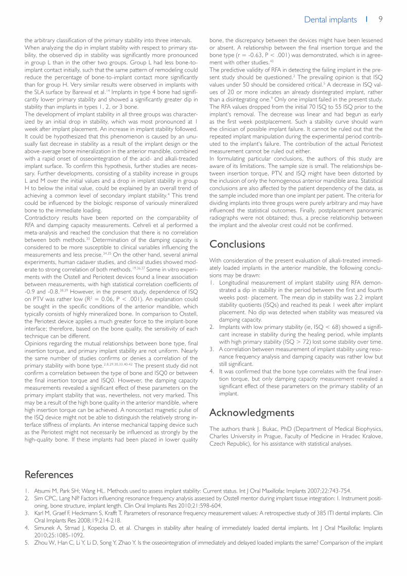
the arbitrary classification of the primary stability into three intervals.When analyzing the dip in implant stability with respect to primary sta-bility, the observed dip in stability was significantly more pronounced in group L than in the other two groups. Group L had less bone-to-implant contact initially, such that the same pattern of remodeling could reduce the percentage of bone-to-implant contact more significantly than for group H. Very similar results were observed in implants with the SLA surface by Barewal et al.14 Implants in type 4 bone had signifi-cantly lower primary stability and showed a significantly greater dip in stability than implants in types 1, 2, or 3 bone.The development of implant stability in all three groups was character-ized by an initial drop in stability, which was most pronounced at 1 week after implant placement. An increase in implant stability followed. It could be hypothesized that this phenomenon is caused by an unu-sually fast decrease in stability as a result of the implant design or the above-average bone mineralization in the anterior mandible, combined with a rapid onset of osseointegration of the acid- and alkali-treaded implant surface. To confirm this hypothesis, further studies are neces-sary. Further developments, consisting of a stability increase in groups L and M over the initial values and a drop in implant stability in group H to below the initial value, could be explained by an overall trend of achieving a common level of secondary implant stability.4 This trend could be influenced by the biologic response of variously mineralized bone to the immediate loading.Contradictory results have been reported on the comparability of RFA and damping capacity measurements. Cehreli et al performed a meta-analysis and reached the conclusion that there is no correlation between both methods.33 Determination of the damping capacity is considered to be more susceptible to clinical variables influencing the measurements and less precise.34,35 On the other hand, several animal experiments, human cadaver studies, and clinical studies showed mod-erate to strong correlation of both methods.19,36,37 Some in vitro experi-ments with the Osstell and Periotest devices found a linear association between measurements, with high statistical correlation coefficients of -0.9 and -0.8.38,39 However, in the present study, dependence of ISQ on PTV was rather low (R2 = 0.06, P < .001). An explanation could be sought in the specific conditions of the anterior mandible, which typically consists of highly mineralized bone. In comparison to Osstell, the Periotest device applies a much greater force to the implant-bone interface; therefore, based on the bone quality, the sensitivity of each technique can be different.Opinions regarding the mutual relationships between bone type, final insertion torque, and primary implant stability are not uniform. Nearly the same number of studies confirms or denies a correlation of the primary stability with bone type.2,8,29,30,33,40-42 The present study did not confirm a correlation between the type of bone and ISQ0 or between the final insertion torque and ISQ0. However, the damping capacity measurements revealed a significant effect of these parameters on the primary implant stability that was, nevertheless, not very marked. This may be a result of the high bone quality in the anterior mandible, where high insertion torque can be achieved. A noncontact magnetic pulse of the ISQ device might not be able to distinguish the relatively strong in-terface stiffness of implants. An intense mechanical tapping device such as the Periotest might not necessarily be influenced as strongly by the high-quality bone. If these implants had been placed in lower quality
bone, the discrepancy between the devices might have been lessened or absent. A relationship between the final insertion torque and the bone type (r = -0.63, P < .001) was demonstrated, which is in agree-ment with other studies.43
The predictive validity of RFA in detecting the failing implant in the pre-sent study should be questioned.2 The prevailing opinion is that ISQ values under 50 should be considered critical.5 A decrease in ISQ val-ues of 20 or more indicates an already disintegrated implant, rather than a disintegrating one.9 Only one implant failed in the present study. The RFA values dropped from the initial 70 ISQ to 55 ISQ prior to the implant‘s removal. The decrease was linear and had begun as early as the first week postplacement. Such a stability curve should warn the clinician of possible implant failure. It cannot be ruled out that the repeated implant manipulation during the experimental period contrib-uted to the implant‘s failure. The contribution of the actual Periotest measurement cannot be ruled out either.In formulating particular conclusions, the authors of this study are aware of its limitations. The sample size is small. The relationships be-tween insertion torque, PTV, and ISQ might have been distorted by the inclusion of only the homogenous anterior mandible area. Statistical conclusions are also affected by the patient dependency of the data, as the sample included more than one implant per patient. The criteria for dividing implants into three groups were purely arbitrary and may have influenced the statistical outcomes. Finally, postplacement panoramic radiographs were not obtained; thus, a precise relationship between the implant and the alveolar crest could not be confirmed.
ConclusionsWith consideration of the present evaluation of alkali-treated immedi-ately loaded implants in the anterior mandible, the following conclu-sions may be drawn:1. Longitudinal measurement of implant stability using RFA demon-
strated a dip in stability in the period between the first and fourth weeks post- placement. The mean dip in stability was 2.2 implant stability quotients (ISQs) and reached its peak 1 week after implant placement. No dip was detected when stability was measured via damping capacity.
2. Implants with low primary stability (ie, ISQ < 68) showed a signifi-cant increase in stability during the healing period, while implants with high primary stability (ISQ > 72) lost some stability over time.
3. A correlation between measurement of implant stability using reso-nance frequency analysis and damping capacity was rather low but still significant.
4. It was confirmed that the bone type correlates with the final inser-tion torque, but only damping capacity measurement revealed a significant effect of these parameters on the primary stability of an implant.
AcknowledgmentsThe authors thank J. Bukac, PhD (Department of Medical Biophysics, Charles University in Prague, Faculty of Medicine in Hradec Kralove, Czech Republic), for his assistance with statistical analyses.
References1. Atsumi M, Park SH; Wang HL. Methods used to assess implant stability: Current status. Int J Oral Maxillofac Implants 2007;22:743-754.2. Sim CPC, Lang NP. Factors influencing resonance frequency analysis assessed by Osstell mentor during implant tissue integration: I. Instrument positi-
oning, bone structure, implant length. Clin Oral Implants Res 2010;21:598-604.3. Karl M, Graef F, Heckmann S, Krafft T. Parameters of resonance frequency measurement values: A retrospective study of 385 ITI dental implants. Clin
Oral Implants Res 2008;19:214-218.4. Simunek A, Strnad J, Kopecka D, et al. Changes in stability after healing of immediately loaded dental implants. Int J Oral Maxillofac Implants
2010;25:1085-1092.5. Zhou W, Han C, Li Y, Li D, Song Y, Zhao Y. Is the osseointegration of immediately and delayed loaded implants the same? Comparison of the implant

10 Dental implants
stability during a 3-month healing period in a prospective study. Clin Oral Implants Res 2009;20:1360-1366.6. Bischof M, Nedir R, Szmukler-Moncler S, Bernard JP, Samson J. Implant stability measurement of delayed and immediately loaded Implants
during healing. A clinical resonance-frequency analysis study with sandblasted-and-etched ITI implants. Clin Oral Implants Res 2004;15:529-539.
7. Nedir R, Bischof M, Szmukler-Moncler S, Bernard JP, Samson J. Predicting osseointegration by mean of implant primary stability. A resonance-frequen-cy analysis study with delayed and immediately loaded ITI SLA implants. Clin Oral Implants Res 2004;15:520-528.
8. Abrahamsson I, Linder E, Lang NP. Implant stability in relation to osseointegration: An experimental study in the Labrador dog. Clin Oral Implants Res 2009;20:313-318.
9. Huwiler MA, Pjetursson BE, Bosshardt DD, Salvi GE, Lang NP. Resonance frequency analysis in relation to jawbone characteristics and during early healing of implant installation. Clin Oral Implants Res 2007;13:275-280.
10. Meredith N, Alleyne D, Cawley P. Quantitative determination of the stability of the implant-tissue interface using resonance frequency analysis. Clin Oral Implants Res 1996;7:261-267.
11. Melo AC, de Freitas MC, Bernardes SR, de Mattias Sartori IA, Bassi AP, Thome G. A prospective follow-up study of 44 mandibular immediately loaded implants using resonance frequency analysis: Preliminary 1-year results. Implant Dent 2009;18:530-538.
12. Geckili 0, Bilhan H, Bilgin T. A 24-week prospective study comparing the stability of titanium dioxide grit-blasted dental implants with and without fluoride treatment. Int J Oral Maxillofac Implants 2009;24:684-688.
13. Lai HC, Zhang ZY, Wang F, Zhuang LF, Liu X. Resonance frequency analysis of stability on ITI implants with osteotome sinus floor elevation technique without grafting: A 5-month prospective study. Clin Oral Implants Res 2008;19:469-475.
14. Barewal RM, Oates TW, Meredith N, Cochran DL. Resonance frequency measurement of implant stability in vivo on implants with a sandblasted and acid-etched surface. Int J Oral Maxillofac Implants 2003;18:641-651.
15. Glauser R, Ruhstaller P, Windisch S, et al. Immediate occlusal loading of Brånemark system TiUnite implants placed predominantly in soft bone: 4-year results of a prospective clinical study. Clin Implant Dent Relat Res 2005;7(suppl 1):52-59.
16. Han J, Lulic M, Lang NP. Factors influencing resonance frequency analysis assessed by Osstell Mentor during implant tissue integration: II. Implant surface modifications and implant diameter. Clin Oral Implants Res 2010;21:605-611.
17. Trisi P, Perfetti G, Baldoni E, Berardi D, Colagiovanni M, Scogna G. Implant micromotion is related to peak insertion torque and bone density. Clin Oral Implants Res 2009;20:467-471.
18. Valderrama P, Jones AA, Wilson TG Jr, et al. Bone changes around early loaded chemically modified sandblasted and acid-etched surfaced implants with and without a machined collar: A radiographic and resonance frequency analysis in the canine mandible. Int J Oral Maxillofac Implants 2010;25:548-557.
19. Friberg B, Sennerby L, Meredith N, Lekholm U. A comparison between placement torque and resonance frequency measurements of maxillary implants. A 20-month clinical study. Int J Oral Maxillofac Surg 1999;28:297-303.
20. Balshi SF, Allen FD, Wolfinger GJ, Balshi TJ. A resonance frequency analysis assessment of maxillary and mandibular immediately loaded implants. Int J Oral Maxillofac Implants 2005;20:584-594.
21. Ersanli S, Karabuda C, Beck F, Leblebicioglu B. Resonance frequency analysis of one-stage dental implant stability during the osseointe- gration period. J Periodontol 2005;76:1066-1071.
22. Glauser R, Sennerby L, Meredith N, et al. Resonance frequency analysis of implants subjected to immediate or early functional occlusal loading. Su-ccessful vs. failing implants. Clin Oral Implants Res 2004;15:428-434.
23. Glauser R, Zembic A, Ruhstaller P, Windisch S. Five-year results of implants with an oxidized surface placed predominantly in soft quality bone and subjected to immediate occlusal loading. J Pros- thet Dent 2007;97:59-68.
24. Oates TW, Valderrama P, Bischof M, et al. Enhanced implant stability with a chemically modified SLA surface: A randomized pilot study. Int J Oral Maxillofac Implants 2007;22:755-760.
25. Strnad J, Urban K, Povysil C, Strnad Z. Secondary stability assessment of titanium implants with an alkali-etched surface: A resonance frequency analysis study in beagle dogs. Int J Oral Maxillofac Implants 2008;23:502-512.
26. Sennerby L, Meredith N. Implant stability measurements using resonance frequency analysis: Biological and biomechanical aspects and clinical implica-tions. Periodontology 2000 2008;47:51-66.
27. Himmlová L, Dostálová T, Kácovský A, Konvičková S. Influence of implant length and diameter on stress distribution: A finite element analysis. J Pro-sthet Dent 2004;91:20-25.
28. Ellingsen JE, Johansson CB, Wennerberg A, Holmén A. Improved retention and bone-to-implant contact with fluoride-modified titanium implants. Int J Oral Maxillofac Implants 2004;19:659-666.
29. Schätzle M, Männchen R, Baibach U, Hämmerle CHF, Toutenburg H, Jung RE. Stability change of chemically modified sandblasted/ acid-etched titani-um palatal implants. A randomized-controlled clinical trial. Clin Oral Implants Res 2009;20:489-495.
30. Bardyn T, Gédet P, Hallermann W, Büchler P. Quantifying the influence of bone density and thickness on resonance frequency analysis: An in vitro study of biomechanical test materials. Int J Oral Maxillofac Implants 2009;24:1006-1014.
31. Protivinsky J, Appleford M, Strnad J, Helebrant A, Ong JL. Effect of chemically modified titanium surfaces on protein adsorption and osteoblast precur-sor cell behavior. Int J Oral Maxillofac Implants 2007;22:542-550.
32. West JD, Oates TW. Identification of stability changes for immediately placed dental implants. Int J Oral Maxillofac Implants 2007;22: 623-630.33. Cehreli MC, Karasoy D, Akca K, Eckert SE. Meta-analysis of methods used to assess implant stability. Int J Oral Maxillofac Implants 2009; 24:1015-
1032.34. Park JC, Kim HD, Kim SM, Kim MJ, Lee JH. A comparison of implant stability quotients measured using magnetic resonance frequency analysis from
two directions: A prospective clinical study during the initial healing period. Clin Oral Implants Res 2010;21:591-597.35. Zix J, Hug S, Kessler-Liechti G, Mericske-Stern G. Measurement of dental implant stability by resonance frequency analysis and damping capacity
assessment: Comparison of both techniques in a clinical trial. Int J Oral Maxillofac Implants 2008;23:525-530.36. Oh JS, Kim SG, Lim SC, Ong JL. A comparative study of two noninvasive techniques to evaluate implant stability: Periotest and Osstell Mentor. Oral
Surg Oral Med Oral Pathol Oral Radiol Endod 2009;107:513-518.37. Seong WJ, Holte JE, Holtan JR, Olin PS, Hodges JS, Ko CC. Initial stability measurement of dental implants placed in different anatomical regions of
fresh human cadaver jawbone. J Prosthet Dent 2008; 99:425-434.38. Lachmann S, Jäger B, Axmann D, Gomez-Roman G, Groten M, Weber B. Resonance frequency analysis and damping capacity assessment. Part 1: An
in vitro study on measurement reliability and a method of comparison in the determination of primary dental implant stability. Clin Oral Implants Res 2006;17:75-79.

11Dental implantsDental implants
39. Lachmann S, Laval JY, Jäger B, et al. Resonance frequency analysis and damping capacity assessment. Part II: Peri-implant bone loss follow-up. An in vitro study with Periotest and Osstell instruments. Clin Oral Implants Res 2006;17:80-84.
40. Degidi M, Daprile G, Piatelli A. Determination of primary stability: A comparison of the surgeon‘s perception and objective measurements. Int J Oral Maxillofac Implants 2010;25:558-561.
41. Kahraman S, Bal BT, Asar NV, Turkyilmaz l, TözümTF. Clinical study on the insertion torque and wireless resonance frequency analysis in the assess-ment of torque capacity and stability of self-tapping dental implants. J Oral Rehabil 2009;36:755-761.
42. Ohta K, Takechi M, Minami M, et al. Influence of factors related to implant stability detected by wireless resonance frequency analysis device. J Oral Rehabil 2010;37:131-137.
43. Tabassum A, Meijer GJ, Wolke JGC, Jansen JA. Influence of the surgical technique and surface roughness on the primary stability of an implant in artificial bone with a density equivalent to maxillary bone: A laboratory study. Clin Oral Implants Res 2009;20:327-332.

12 Dental implants
Changes in Stability After Healing of Immediately Loaded
Dental Implants
A. Šimůnek1, J. Strnad2, D. Kopecká1, T. Brázda1, S. Pilathadka1, R. Chauhan3, R. Slezák1, L. Čapek4
Int J Oral Maxillofac Implants, Vol. 25, No. 6, 2010, p. 1085–1092
1 Department of Dentistry, Charles University in Prague, Faculty of Medicine in Hradec Kralove, Czech Republic.2 Lasak Ltd, Prague, Czech Republic.3 Faculty of Medicine at Hradec Kralove, Charles University in Prague, Czech Republic.4 Department of Mechanical Engineering, Technical University of Liberec, Czech Republic.
Purpose: To investigate the parameters that affect primary stability of dental implants, to determine how primary stability influences posthealing stability, and to ascertain the effect of primary stability and insertion parameters on marginal bone loss. Materials and Methods: A total of 940 immediately loaded implants were considered. Using resonance frequency analysis, primary stability (primary implant stability quotient [pISQ]) and stability after 4 months (tISQ) were recorded. When the differences between pISQ and tISQ exceeded 5 units, marginal bone loss was measured. The implants were placed into three groups based on their primary stability: high (pISQ > 72), moderate, and low (pISQ < 68). Changes in stability after 4 months of loading were evaluated. The relationships between pISQ, insertion parameters, ΔISQ (ie, tISQ – pISQ), and marginal bone loss were analyzed. The Student t test, one-way analysis of variance, and Spearman nonparametric correlation coefficient were employed for statistical evaluation. Results: Of the 940 implants, tISQ was recorded in 526 implants and marginal bone loss was meas-ured in 76 implants. There was no statistical relationship between pISQ and insertion torque. Primary stability was influenced by implant diam-eter but not by implant length. There was a significant relationship between implant insertion torque and bone type. The low primary stability group showed a significant increase in stability during healing. However, high primary stability implants demonstrated a significant reduction in their stability. The linear regression analysis demonstrated that at a pISQ of 69.2, tISQ value would equal pISQ value. Correlations between marginal bone loss and final insertion torque and between marginal bone loss and ΔISQ values were observed. Conclusions: Stability of im-mediately loaded implants with high pISQ decreased significantly during the initial 4 months of healing. However, stability of implants with low primary stability increased significantly. ΔISQ and insertion torque showed correlation with marginal bone loss. Int J Oral Maxillofac Implants 2010;25:1085-1092.
Dental implant stability is a measure of the anchorage quality of an im-plant in the alveolar bone and is considered to be the consequential parameter in implant dentistry. Implant stability has been confirmed to affect the process of osseointegration, the pattern of implant load-ing, and, finally, the success of an implant.1 Stability of an implant can be classified into that measured immediately after implantation (ie, primary stability) and that seen posthealing (ie, secondary stability). Primary implant stability has been proven to be a mechanical phe-nomenon.2 On the other hand, secondary stability occurs through a cascade of biologic events, such as bone regeneration and remod-eling at the bone-implant interface.2 It is influenced by many factors, including implant surface topography, bone quality, and patient behav-ior.3 Earlier investigation showed that during the healing process, me-chanical anchorage of the implant in the bone weakens; conversely, biologic stability of the implant increases.4
Several methods have been proposed to determine implant stability in clin-ical practice. Among these, resonance frequency analysis (RFA) has been found to be the most accurate.5 Meredith et al introduced RFA into implant dentistry in the 1990s. Since then, it has become a widely accepted and used technique.6 The only commercially available device based on RFA is Osstell (Integration Diagnostics). It has lately been modified and upgraded in the Osstell Mentor device. The function of this instrument is to measure resonance frequency, which is automatically transformed into an implant stability quotient (ISQ) ranging from 0 to 100.5
The absolute RFA values are not completely dependent on the quality of osseointegration. There are three important factors that can directly influence RFA: the stiffness of the implant-bone interface, the stiffness of the bone itself, and the stiffness of the implant components.6–8 Con-sequently, the clinically measurable characteristic of implant stability can be compared in the follow-up of each individual implant, but caution should be exerted in comparing these values among different implants, either in the same patient or interindividually.9
Previous longitudinal studies have indicated that implant stability changes during the process of osseointegration. Typically, implant stability is antici-
pated to decrease during the early weeks of healing; this is followed by an increase in stability.5,7,10 This is related to the biologic reaction of the bone to surgical trauma. During the initial bone remodeling phase, bone and necrotic material are resorbed by osteoclastic activity, which is reflected by a reduction in the ISQ value. This process is followed by new bone apposition initiated by osteoblastic activity, ie, adaptive bone remodeling around the implant.3,11 There is a lack of agreement among investigators regarding the exact timing of the greatest decrease in postinsertion stabil-ity of an implant; the recorded data range between the third and eighth weeks following implant placement.3,4,12–16 Some studies did not observe any decline in stability during the healing phase.17,18 The reason for these differences in results may have to do with variations in the designs of the implants employed, especially variations in surface properties.8,19 Time dependence of implant stability without the initial decline was observed in association with fast increases in bone-implant contact, which is typi-cal for fluoride-treated or alkali-treated (and thus potentially bioactive) surfaces.18,20 An accelerated formation of bone-to-implant contact con-tributes to a faster increase in secondary stability. This biologic process eliminates the decrease in primary stability and ensures consistency of stability over time (without the drop during the healing period).18 There is a limited amount of documentation about the relationship between primary and secondary stability. Sennerby and Meredith8 confirmed that implants of many types would, over time, approach a similar level of secondary stability. He also denoted that consistent attainment of an ISQ value of 65 to 75 seems to correspond to Brånemark implants and an ISQ value of 55 to 65 was seen for Straumann implants.8
Hence, it was the intent of this retrospective clinical study to further elucidate some aspects related to the stability of immediately loaded implants under relatively uniform clinical conditions in the interforam-inal region of the mandible. The objectives of the present study were (1) to investigate how primary stability influences posthealing stability, (2) to determine the parameters that can affect primary stability of dental implants, and (3) to ascertain the effect of primary stability and insertion parameters on marginal bone loss.

13Dental implantsDental implants
Materials and methods
Surgical Procedure and Measurement of Implant StabilityIn this study, consecutively placed implants in the interforaminal region of the mandible, which were designed for the immediate loading concept „Teeth in 6 Hours,“ were considered. This concept is based on the inser-tion of five implants in the region between the first premolars, which are then immediately loaded by a provisional cantilevered prosthesis fabricated from an existing mandibular removable complete denture and attached to the abutments by means of titanium impression copings. All surgical procedures were performed between October 2004 and January 2008 at The Center for Dental Implantology, University Hospital, Hradec Kralove, Czech Republic. The local ethical committee officially approved the design of this study. All the patients were informed about the nature of the study, and their participation and written consent were obtained according to the Helsinki Declaration of 1994.All included patients needed a fixed full-arch prosthesis supported by dental implants for their edentulous mandible. Patients were included based upon a current stable medical condition and the ability to withstand the stress of dental implant surgery. Patients with metabolic bone disease, unstable sys-temic conditions (eg, uncontrolled diabetes or untreated hypothyroidism), and smokers of more than five cigarettes a day were excluded. All surgical procedures were performed under local anesthesia in a sterile hospital setting. Amoxicillin clavulanate (1 g orally twice per day) was prescribed for 6 days; an initial dose (2 g) was administered 1 hour before surgery. All im-plants were inserted into healed extraction sockets. After a mucoperiosteal flap was raised, both mental nerves were isolated and the alveolar crest was contoured as required. Then five self-drilling, screw-form implants with sandblasted, acid-treated, and alkali-treated surfaces (STI-BIO-C, La-sak) were inserted at regular intervals into the interforaminal region ac-cording to the manufacturer‘s protocol. The final insertion torque of the implants was measured using a torque wrench. The type of bone was classified using Lekholm and Zarb criteria on the basis of the subjective evaluation of the surgeon.21
Primary stability (pISQ) of each implant was measured using an Osstell de-vice. Two experienced surgeons conducted measurements independently. The transducer was secured at the implant level perpendicular to the long axis of the alveolar bone. Measurements were repeated until the same value was measured twice in succession, and this value was recorded. Fol-lowing this, the abutments were attached and the wound was sutured. Tiaprofenic acid (300 mg) was recommended three times a day for pain relief. An abutment-level impression was immediately made with additional silicone material (Aquasil Rigid and Aquasil Ultra LV, Dentsply Caulk) with a modified preformed plastic impression tray. A cantilevered fixed screw-retained provisional prosthesis was fabricated that extended to the second premolars. The prosthesis was delivered and fully functionally loaded. Oral hygiene instructions were given and the patients were scheduled for regu-lar recall appointments.The impression for the definitive prosthesis was made after 4 months of healing. For those patients for whom an impression was made in Sep-tember 2006 or later, the measurement with the Osstell device was repeated for each implant. The measured values were recorded and denoted as tISQ. After confirming passive fit of the construction and cor-recting the occlusion, a definitive cantilevered prosthesis that extended to both first molars was fabricated and delivered within 2 weeks after taking the impression. A digital panoramic radiograph (Planmeca ProMax) was obtained immediately after fixation of the definitive prosthesis ac-cording to the manufacturer‘s recommendation and was done by the same technician.
Measurement of Marginal Bone LossMarginal bone loss was determined at all implants at which the absolute value of the difference between pISQ and tISQ exceeded 5 units. The measurement of bone loss was conducted independently by the two sur-geons on the patient‘s digital panoramic radiographs. On the radiograph, bone levels were measured from the implantabutment interface to the
first visible bone-implant contact. The implantabutment interface was used as a reference point, because the implants were normally placed with the implant-abutment connection at the level of the alveolar crest (Fig. 1). The distance between the thread peaks (1.0 mm) served as a known standard to calculate the exact bone loss on the mesial and distal sides of the im-plants. These measurements were rounded to the nearest 0.1 mm. With these data, the mean marginal bone resorption was determined for each implant. However, if the radiograph did not clearly reproduce the exact bone level, the implant was excluded from the cohort.
Statistical AnalysisThe difference between posthealing stability (after 4 months of loading) and primary stability (tISQ – pISQ) was denoted as ΔISQ. The linear re-gression line, calculated from the plot of ΔISQ versus pISQ, was used to determine a pISQ value at which ΔISQ attains a value of zero. With respect to this value and to the unpublished results of a previous investiga-tion, the implants were further divided into three study groups: those with low primary stability (pISQ < 68), those with moderate primary stability (pISQ 68 to72), and those with high primary stability (pISQ > 72). Statisti-cal analysis was employed to verify the main working hypothesis that the
Fig. 1: Method used to measure marginal bone level. First visible bone-implant contact (Bl) was measured relative to the reference point at the implant-abutment interface (IA). The distance between the thread peaks is 1.0 mm and served as a
known standard.
Fig. 2: Final torque (Ncm).

14 Dental implants
immediately loaded implants with higher primary stability would lose some of their stability during healing, whereas the implants with lower primary stability would gain stability during healing.In addition, the dependence of marginal bone loss on pISQ, on final torque, and on ΔISQ was evaluated. Additional working hypotheses were that pISQ, similar to the final torque, is positively correlated with marginal bone loss, while ΔISQ is negatively correlated with marginal bone loss.Statistical analysis was carried out using Statistica software (Statsoft lnc). The Student t test, one-way analysis of variance, and Spearman nonparametric correlation coefficient were employed to test the hypotheses. The statisti-cal significance of all tests was defined as P < .05.
ResultsA total of 940 dental implants placed in 188 patients (84 men and 104 women; mean age 54.3 ± 9.4 years) was initially considered for this inves-tigation. However, Osstell measurements showed an invalid Bode diagram for 22 implants, and these implants were therefore excluded from the cohort. Thus, the remaining 918 implants were considered for statistical analysis. The majority (97.2 %) of implants were 3.7 mm in diameter, whereas only 2.8 % of implants were 5.0 mm in diameter. A large major-ity of implants (82.2 %) were 16 mm long; 9.3 % were 14 mm long, 3.8 % were 12 mm long, 3.8 % were 18 mm long, and 0.9 % were 10 mm long. With regard to bone type, 37.5 % of implants were placed in type 1 bone, 40.4 % were placed in type 2 bone, 21.8 % were placed in type
Fig. 3: Primary stability (in ISQ) of the implants.
Fig. 4: Implant stability over time according to the level of primary stability (see text). The decrease in ISQ for implants with high primary stability and the increase
in ISQ for implants with low primary stability were highly significant (P < .001).
Fig. 6: Marginal bone loss versus change in stability (ΔISQ) (R = –0.27; P < .05).
Fig. 5: Marginal bone loss versus final insertion torque (R = 0.27; P < .05).
Fig. 7: Change in stability (ΔISQ) versus primary stability (pISQ) (R = –0.47; P < .01). The reggresion curve indicates that ΔISQ attains zero value at a pISQ of
69.2.

15Dental implantsDental implants
3 bone, and 0.3 % were placed in type 4 bone. Of the total number of implants placed, six implants (with pISQ 61 to 79) failed to osseointegrate (two implants in one patient and one implant each in four other patients). The osseointegration rate was therefore 99.3 %.The distribution of the final torque of implants is shown in Fig. 2. The mean final insertion torque for the implants was 60.2 ± 12.0 Ncm (65.7 ± 7.2 Ncm for type 1 bone, 61.9 ± 10.3 Ncm for type 2 bone, 52.3 ± 14.6 Ncm for type 3 bone, and 30.0 ± 0.0 Ncm for type 4 bone). Statistical comparison of implant insertion torque versus bone type at the site of im-plantation showed a highly significant relationship (P < .001; between type 3 and type 4 bone, P < .05). No significant correlation between the final torque and implant diameter was found (61.4 ± 11.4 Ncm for 3.7-mmdi-ameter implants, 60.8 ±11.9 Ncm for 5.0-mm-diameter implants).Figure 3 shows the distribution of pISQ among the surveyed implants. The recorded mean pISQ value was 72.2 ± 5.0. The mean pISQ values for each bone type were of 72.4 ± 4.9 for type 1 bone, 71.8 ± 4.9 for type 2 bone, 72.7 ± 5.1 for type 3 bone, and 71.3 ± 2.5 for type 4 bone. There was no significant difference among groups, except for a marginally signifi-cant difference between type 2 and type 3 bone (P = .03). Furthermore, statistical analysis disproved the dependence of pISQ on implant length: mean values for pISQ were 70.8 ± 6.1, 73.4 ± 5.3, 72.0 ± 4.4, 72.2 ± 5.0, and 71.9 ± 4.6 for implants with lengths of 10, 12, 14, 16, and 18 mm, respectively. However, the primary stability of 5.0-mm-diameter im-plants was significantly higher than that of 3.7-mm-diameter implants (pISQ 75.1 ± 5.2 versus 72.1 ± 4.9, respectively; P < .01). No significant cor-relation was found between pISQ and final torque (pISQ of 69.0 ± 5.9, 72.3 ± 3.7, 72.1 ± 5.1, 71.9 ± 4.9, and 72.5 ± 5.0 for a final torque of < 15, 16 to 35, 36 to 45, 46 to 60, and > 60 Ncm, respectively).In this current study, the tISQ value was measured for 526 implants. Among these, 100 belonged to the low primary stability group, 189 to the moderate primary stability group, and 237 to the high primary stability group. An increase in stability was seen during the healing period in the low primary stability group (from 64.2 ± 2.8 ISQ to 66.8 ± 5.6; P < .001) (Fig. 4). The moderate primary stability group did not exhibit any significant change in stability (from 70.3 ± 1.4 to 70.0 ± 5.4) (Fig. 4). However, the high primary stability group showed a decrease in stability during the heal-ing phase (from 75.9 ± 2.6 to 72.0 ± 5.0; P < .001) (Fig. 4).Marginal bone loss was measured for 76 implants and had a mean of 0.9 ± 0.7 mm (range, –1.0 to 2.6 mm). The values measured on the mesial side of the implant (0.9 ± 0.7 mm; range –0.9 to 2.9 mm) and on the distal side (0.9 ± 0.7 mm; range –1.1 to 2.9 mm) did not differ significantly.A statistically significant relationship between primary stability and bone loss was not confirmed (Spearman nonparametric correlation coefficient, R = 0.07). However, a positive correlation was found between final torque and bone loss (R = 0.27; P < .05) (Fig. 5). In addition, negative correlations were also found between ΔISQ and bone loss (R = –0.27; P< .05) (Fig. 6) and between pISQ and ΔISQ (R = –0.47; P < .01) (Fig. 7). Linear regression analysis indicated that ΔISQ attains a value of zero at a pISQ of 69.2 (Fig. 7).
DiscussionA 99.3% success rate of the implants confirmed that immediate loading of splinted implants in the interforaminal region is a viable treatment al-ternative. Primary stability of the failed implants did not differ significantly from that of implants that osseointegrated successfully. Measurement of RFA at the time of implant placement is therefore incapable of predict-ing implants with a prognosis of nonosseointegration, as described else-where.22
The topic of primary stability is currently the subject of intense scien-tific interest. Several authors have investigated the relationship between pISQ and other parameters, particularly the final insertion torque. Al-though a positive correlation between pISQ and insertion torque may initially seem probable, many authors have not found a significant re-lationship.23–27 The results of the present study are in agreement with the aforementioned studies and do not support the sporadic findings of contradictory results.28–31 However, it cannot be excluded that the dis-crepancies in the results were affected by the design of the implant or by local bone quality. As was also confirmed by the present study, primary
stability is influenced mainly by implant diameter30,32–36 and not by implant length.7,30,36 This study demonstrated a highly significant relationship be-tween final torque and bone type. However, no statistical relationship was found between final torque and implant diameter.Several authors have studied the effect of primary stability on the de-velopment of stability during healing. The recent investigation by Karl et al assumed a general increase in stability during healing as a common phenomenon. This appears to be the somewhat confused view of the authors.34 A few groups of authors have indicated that changes in stabil-ity during healing were mainly dependent on the initial stability level of an implant. In their 12-week clinical study, Nedir et al22 found that ITI implants with a pISQ < 60 exhibited an increase in stability, whereas im-plants with a pISQ of 60 to 69 exhibited decreased stability after 8 weeks. At the end of the 12th week, the implants had returned to their initial sta-bility values. Implants with pISQ values > 69 exhibited decreased stability during the first 4 weeks, after which they maintained consistent stability.22 In a similar longitudinal study, West and Oates37 employed the same type of implants and divided them into two groups (pISQ < 56 and pISQ > 56). During the first 16 weeks, implants from the first group continuously maintained a lower ISQ versus implants from the second group. Thereaf-ter, differences were statistically insignificant. The stability of both groups remained at a value of 61 ISQ.37 Similarly, in 1999, Friberg et al stated that the stability of implants placed in softer bone would „catch up“ over time to implants placed in denser bone.29 Balshi et al3 and Olsson et al38 came to the conclusion that implants with high primary stability lose part of their stability during healing, whereas implants with low primary stabil-ity have a tendency to increase their stability. The results of the present study support this theory. A significant increase in stability was recorded for the implants with low primary stability (pISQ < 68), whereas the implants with high primary stability (pISQ > 72) lost some of their stabil-ity over time. This confirms the main working hypothesis of the current investigation.It could be further hypothesized that, in clinical practice, it may be op-timal to achieve a primary stability that corresponds to the final stability value of the osseointegrated implant (ie, pISQ = tISQ; ΔISQ = 0). In this study, this pISQ value was determined by linear regression analysis to equal 69.2. This hypothetical value is probably not generally valid but is more likely specific to a particular implant system, surgical protocol, or bone type.8
An intraoral standardized radiograph is frequently used for exact meas-urements of the amount of marginal bone loss. However, unfavorable anatomical conditions frequently prevent the use of this radiographic technique in the interforaminal region of the mandible, especially in pa-tients with an atrophied edentulous arch.33 Consequently, panoramic radiography has been used in similar studies by other authors as an al-ternative.33,39–41 In the present study, a noteworthy finding of bone gain was frequently encountered at 4 months after implant placement. Similar findings have been reported elsewhere.42 An explanation may be found in the neck of the implant, which has a miniature thread and a chemically modified surface with signs of bioactivity. Functional stimulation of the bone by immediate loading may also play a role.43,44
Marginal bone loss was measured immediately after fixation of the de-finitive prosthesis, approximately 5 months after insertion of the implant. Bone loss could be caused by several factors, for example, surgical trau-ma, inadequate fit of the provisional restoration, or overloading of the implants. A detailed analysis, however, exceeds the scope of this study. The detected value of 0.9 ± 0.7 mm is acceptable.45 No relationship was found in this study between primary stability and marginal bone loss; thus, the first of the three additional working hypotheses was not con-firmed.However, correlations were confirmed between final torque and bone loss and between ΔISQ and bone loss.Thus, the remaining two addi-tional working hypotheses were supported. Taking the essence of these results and considering the fact that the final insertion torque did not correlate to primary stability, it is possible to infer further that the use of extremely high insertion torque should be avoided. On the other hand, it is necessary to emphasize that the regression analysis indicated a weak dependence between the variables. Therefore it can be concluded that these relationships are affected by additional factors that were not ex-

16 Dental implants
amined in the analyses. The aforementioned analyses are pilot tests and require confirmation by other studies. The validity of the conclusions, therefore, is limited by the use of panoramic radiographs and by the selection of implants with a pronounced change in ISQ values during the healing period.
ConclusionsWithin the limitations of the present study, it was seen that:1. Primary stability was influenced by implant diameter and not by implant
length. There was no significant relationship between primary stability and final insertion torque.
2. Implants with low primary stability showed a significant increase in sta-bility, while implants with high primary stability showed a significantly decreased stability over time. On the basis of linear regression analysis, the change in implant stability quotient attains a value of zero at a pri-mary implant stability quotient of 69.2.
3. A statistically insignificant relationship was found between primary stability and marginal bone loss. A positive correlation was confirmed between the final insertion torque and marginal bone loss. A nega-tive correlation was confirmed between primary stability and change in stability during healing and between change in stability during healing and marginal bone loss.
References1. Meredith N. Assessment of implant stability as a prognostic determinant. Int J Prosthodont 1998;11:491–501.2. Atsumi M, Park SH, Wang HL. Methods used to assess implant stability: Current status. Int J Oral Maxillofac Implants 2007;22: 743–754.3. Balshi SF, Allen FD, Wolfinger GJ, Balshi TJ. A resonance frequency analysis assessment of maxillary and mandibular immediately loaded implants. Int J
Oral Maxillofac Implants 2005;20:584-594.4. Barewal RM, Oates TW, Meredith N, Cochran DL. Resonance frequency measurement of implant stability in vivo on implants with a sandblasted and
acid-etched surface. Int J Oral Maxillofac Implants 2003;18:641–651.5. Huwiler MA, Pjetursson BE, Bosshardt DD, Salvi GE, Lang NP. Resonance frequency analysis in relation to jawbone characteristics and during early
healing of implant installation. Clin Oral Implants Res 2007;18:275–280.6. Meredith N, Alleyne D, Cawley P. Quantitative determination of the stability of the implant-tissue interface using resonance frequency analysis. Clin
Oral Implants Res 1996;7:261–267.7. Bischof M, Nedir R, Szmukler-Moncler S, Bernard JP, Samson J. Implant stability measurement of delayed and immediately loaded implants during
healing. A clinical resonance-frequency analysis study with sandblasted-and-etched ITI implants. Clin Oral Implants Res 2004;15:529–539.8. Sennerby L, Meredith N. Implant stability measurements using resonance frequency analysis: Biological and biomechanical aspects and clinical implica-
tions. Periodontology 2000 2008; 47:51–66.9. Lachmann S, Jäger B, Axmann D, Gomez-Roman G,Groten M, Weber B. Resonance frequency analysis and damping capacity assessment. Part 1: An
in vitro study on measurement reliability and a method of comparison in the determination of primary dental implant stability. Clin Oral Implants Res 2006;17: 75–79.
10. Schliephake H, Hüls A, Müller M. Early loading of surface modified titanium implants in the posterior mandible: Preliminary results. Appl Osseointegra-tion Res 2006;5:56–58.
11. Monov G, Fuerst G,Tepper G, Watzak G, Zechner W, Watzek G. The effect of platelet-rich plasma upon implant stability measured by resonance frequency analysis in the lower anterior mandibles. Clin Oral Implants Res 2005;16:461–465.
12. Ersanli S, Karabuda C, Beck F, Leblebicioglu B. Resonance frequency analysis of one-stage dental implant stability during the osseointegration period. J Periodontol 2005;76:1066–1071.
13. Glauser R, Sennerby L, Meredith N, et al. Resonance frequency analysis of implants subjected to immediate or early functional occlusal loading. Suc-cessful vs failing implants. Clin Oral Implants Res 2004;15:428–434.
14. Glauser R, Ruhstaller P, Windisch S, et al. Immediate occlusal loading of Brånemark system TiUnite implants placed predominantly in soft bone: 4-year results of a prospective clinical study. Clin Implant Dent Relat Res 2005;7(suppl 1):52–59.
15. Lai HC, Zhang ZY, Wang F, Zhuang LF, Liu X. Resonance fre-quency analysis of stability on ITI implants with osteotome sinus floor elevation technique without grafting: A 5-month prospective study. Clin Oral Implants Res 2008;19:469–475.
16. Verdonck HWD, Meijer GJ, Laurin T, et al. Implant stability during osseointegration in irradiated and non-irradiated minipig alveolar bone: An experi-mental study. Clin Oral Implants Res 2008;19:201–206.
17. Calandriello R,Tomatis M. Immediate function of single implant using Brånemark system: Prospective one-year report of final restorations. Appl Os-seointegration Res 2004;4:32–40.
18. Strnad J, Urban K, Povysil C, Strnad Z. Secondary stability assessment of titanium implants with an alkali-etched surface: A resonance frequency analysis study in beagle dogs. Int J Oral Maxillofac Implants 2008;23:502–512.
19. Oates TW, Valderrama P, Bischof M, et al. Enhanced implant stability with a chemically modified SLA surface: A randomized pilot study. Int J Oral Maxillofac Implants 2007;22:755-760.
20. Ellingsen JE, Johansson CB, Wennerberg A, Holmen A. Improved retention and bone-to-implant contact with fluoride-modified titanium implants. Int J Oral Maxillofac Implants 2004;19:659–666.
21. Lekholm U, Zarb G. Patient selection and preparation. In: Brånemark P-l, Zarb G, Albrektsson T (eds). Tissue-Integrated Prostheses: Osseointegration in Clinical Dentistry. Chicago: Quintessence, 1985:199–209.
22. Nedir R, Bischof M, Szmukler-Moncler S, Bernard JP, Samson J. Predicting osseointegration by mean of implant primary stability. A resonance-frequen-cy analysis study with delayed and immediately loaded ITI SLA implants. Clin Oral Implants Res 2004;15:520–528.
23. Akca K, Akkocaoglu M, Commert A, Tekdemir I. Human ex vivo bone tissue strains around immediately loaded implants supporting maxillary over-dentures. Clin Oral Implants Res 2005; 16:715–722.
24. da Cunha HA, Francischone CE, Filho HN, de Oliveira RCG. A comparison between cutting torque and resonance frequency in the assessment of primary stability and final torque capacity of standard and TiUnite single-tooth implants under immediate loading. Int J Oral Maxillofac Implants 2004;19:578–585.
25. Ito Y, Sato D, Yoneda S, Ito D, Kondo H, Kasugai S. Relevance of resonance frequency analysis to evaluate dental implants stability: Simulation and histomorphometrical animal experiments. Clin Oral Implants Res 2008;19:9–14.
26. Nkenke E, Michael H, Konstanze W, Martin R, Friedrich W, Klaus E. Implant stability and histomorphometry: A correlation study in human cadavers using stepped cylinder implants. Clin Oral Implants Res 14;2003:601–609.

17Dental implantsDental implants
27. Rabel A, Kohler SG, Schmidt-Westhausen AM. Clinical study on the primary stability of two dental implant systems with resonance frequency analysis. Clin Oral Investig 2007;11:257–265.
28. Friberg B, Sennerby L, Gröndahl K, Bergstrom C, Back T, Lekholm U. On measurements during implant placement: A 3-year clinical prospective study. Clin Implant Dent Relat Res 1999;1:75–83.
29. Friberg B, Sennerby L, Meredith N, Lekholm U. A comparison between placement torque and resonance frequency measurements of maxillary implants. A 20-month clinical study. Int J Oral Maxillofac Surg 1999;28:297–303.
30. Horwitz J, Zuabi O, Peled M. Resonance frequency analysis in immediate loading of dental implants [in Hebrew]. Refuat- Hapeh-Vehashinayim 2003;20:80–88.
31. Turkyilmaz l, Tozum TF, Tumer C, Ozbek EN. Assessment of correlation between computerized tomography values of the bone, and maximum torque and resonance frequency values at dental implant placement. J Oral Rehabil 2006;33:881–888.
32. Himmlová L, Dostálová T, Kácovský A, Konvicková S. Influence of implant length and diameter on stress distribution: A finite element analysis. J Pros-thet Dent 2004;91:20–25.
33. Kessler-Liechti G, Zix J, Mericske-Stern R. Stability measurements of 1-stage implants in the edentulous mandible by means of resonance frequency analysis. Int J Oral Maxillofac Implants 2008;23:353–358.
34. Karl M, Graef F, Heckmann S, KrafftT. Parameters of resonance frequency measurement values: A retrospective study of 385 ITI dental implants. Clin Oral Implants Res 2008;19:214–218.
35. Zix J, Kessler-Liechti G, Mericske-Stern R. Stability measurements of 1-stage implants in the maxilla by means of resonance frequency analysis: A pilot study. Int J Oral Maxillofac Implants 2005;20:747–752.
36. Zix J, Hug S, Kessler-Liechti G, Mericske-Stern G. Measurement of dental implant stability by resonance frequency analysis and damping capacity as-sessment: Comparison of both techniques in a clinical trial. Int J Oral Maxillofac Implants 2008;23:525–530.
37. West JD, Oates TW. Identification of stability changes for immediately placed dental implants. Int J Oral Maxillofac Implants 2007;22:623–630.38. Olsson M, Urde G, Anderson JB, Sennerby L. Early loading of maxillary fixed cross-arch dental prostheses supported by six or eight oxidized titanium
implants: Results after 1 year of loading, case series. Clin Implant Dent Relat Res 2003;5(suppl 1):81–85.39. Kahnberg KE, Vannas-Löfqvist L. Sinus lift procedure using a 2-stage surgical technique: I. Clinical and radiographic report up to 5 years. Int J Oral
Maxillofac Implants 2008;23:876–884.40. Marchetti C, Pieri F, Corinaldesi G, Degidi M. A long-term retrospective study of two different implant surfaces placed after reconstruction of the se-
verely resorbed maxilla using Le Fort I osteotomy and interpositional bone grafting. Int J Oral Maxillofac Implants 2008;23:911–918.41. Nickenig HJ, Wichmann M, Schlegel KA, Nkenke E, Eitner S. Radiographic evaluation of marginal bone levels adjacent to parallel-screw cylinder ma-
chined-neck implants and rough- surfaced microthreaded implants using digitized panoramic radiographs. Clin Oral Implants Res 2009;20:550–554.42. Botticelli D, Renzi A, Lindhe J, Berglundh T. Implants in fresh extraction sockets: A prospective 5-year follow-up clinical study. Clin Oral Implants Res
2008;19:1226–1232.43. Hansson S. The dental implant meets bone – A clash of two paradigms. Appl Osseointegration Res 2006;5:5–17.44. Protivinsky J, Appleford M, Strnad J, Helebrant A, Ong JL. Effect of chemically modified titanium surfaces on protein adsorption and osteoblast precur-
sor cell behavior. Int J Oral Maxillofac Implants 2007;22:542–550.45. Albrektsson T, Zarb G, Worthtington P. The long-term efficacy of currently used dental implants: A review and proposed criteria of success. Int J Oral
Maxillofac Implants 1986;1:11–25.

18 Dental implants
IntroductionIt is not surprising that minimally-invasive flapless implant surgery has become a hit in the past years. With this method a dental implant is inserted without raising the mucoperiosteal flap. With regard to aesthetics, the benefits of flaplessimplant surgery are: reduced post-operative pain, less surgical and overall treatment time, faster healing and lower costs.1
This method has its origin some 5,500 years ago2 and it has been re-appea-ring regularly ever since, being particularly progressive at the end of the 19th and start of the 20th centuries before being overshadowed by the two-pha-se implant insertion, which was considered at the time to be safer.3 At the present time, since the 1990s, the method of minimally-invasive flapless pro-cedure has been dramatically expanding - as it has been shown that its results are comparable, providing that the correct protocol is followed, with the two-phase method. In such cases where bone augmentation is not required - either to ensure implant stability or to achieve a good aesthetic result - the method of flapless implant surgery has multiple advantages for the patient as well as the surgeon. Its many benefits are:a/ morphological – as the anatomy of the alveolar ridge is not disturbed,b/ nutritive – as the periosteum is left intact and the blood supply to the site maintained, healing is faster and the likelihood of crestal bone resorption and soft tissue inflammation minimized,c/ a reduced risk in medically-disadvantaged patients, i.e.patients with diabetes and reduced immunity (thanks to the reduced trauma and smaller wound size),d/ a reduced need for the use of analgetics – the reduced risk of inflammation and damage to the nerves brings about less pain,e/ psychological – the single-phase operation and the reduced overall tre-atment time makes it more acceptable to patients,f/ financial – a less complex protocol reduces the operation time and makes the treatment cheaper, thus accessible to a wider range of patients.
There are, nonetheless, disadvantages as well as advantages associated with this method:a/ Despite being a seemingly simple operation – it nevertheless requires a highly-experienced dental surgeon as the implant has to be inserted into the bone without direct visual checking of its position in the bone. The flapless procedure thus demands a surgeon who has considerable previous experi-ence with flap surgery.4,5
b/ In the case of an unsatisfactory anatomy of the alveolar ridge (with regard to aesthetics or stability), conventional methods of alveolar ridge augmenta-tion need to be employed.6,7
With the minimally-invasive procedure, implants are inserted without raising the periosteal flap, by employing one of the following procedures:a/ immediate implantation – placed somewhere intermediately between a flapless and an augmentation procedure – the implant is inserted immedia-tely after tooth extraction,b/ punch incision – a cylindrical punch hole is made using trephine, the bone is then examined and the implant inserted,c/ transmucosal – implants are inserted directly through the mucoperioste-um.
When inserting the implant surgeons choose from the following procedu-res to guide them when inserting the implant.a/ clinical examination – implants are inserted without any further instru-mentation other than using tactile orientation; this method can only be used in cases of abundant tissue, especially soon after tooth extraction when orientation is easier thanks to the structure of the alveolar socket,b/ drilling templates – derived from laboratory modelling of the future den-ture and the reconstruction of the real bone shape using invasive instru-ments (caliper, endodontic instruments) for mapping the bone width, and tomography (CT scan); or possibly by reconstruction of the probable bone shape on a cast model - this is the most commonly-used method,c/ navigation using a CAD/CAM method which includes CT-based im-plant planning and fabrication of a CT-scan-designed surgical template or possibly an individual implant abutment – this is, without doubt, the safest method but requires more preparation time and the cost is higher (CT-scan, fabrication of surgical template)8,9. Also not all dentists have access to a CT-scan.
Our indications for minimally-invasive implantology and results in its useThe use of the minimally-invasive implant procedure is limited in particular by the alveolar width. To comply with the widely-accepted recommenda-tion, an implant should be surrounded by a minimum of 1 mm of bone. The method is used and is most suitable for alveolar ridges, which are of a generous height and width.4,10,11
Our dental surgery has offered minimally-invasive dental surgery since 1995 and with our increasing experience we have set up two indication groups based on alveolar width and implant diameter:a/ safe indications – the diameter of the alveolar ridge is in all directions and along its whole length larger by 4 mm than the diameter of the used implant. Our criterion is based upon the widely accepted requirement of 1 mm of intact bone surrounding the implant plus 2 mm as a cover for possible surgical inaccuracies (i.e., a 5 mm STI-BIO-C implant, LASAK Ltd., Czech Republic, would be inserted into an alveolar ridge of 9 mm width or more). A criterion of 4 mm is an arbitrary one and much depends on the surgeon‘s skill. For a trainee surgeon just beginning (practical dentists)
Extention of alveolar ridge without raising the
mucoperiosteal flap using minimally-invasive dental
implant surgery – a new step in effective implantology
R. Šmucler,1,2 P. Barták2
Implantologie Journal, 2/2007
1 Dental Clinic of the General Faculty Hospital and the 1st Faculty of Medicine of Charles University, Prague, Czech Republic2 ASKLEPION, Prague, Czech Republic
Figs. 1-4: Use of Horizontal Control System
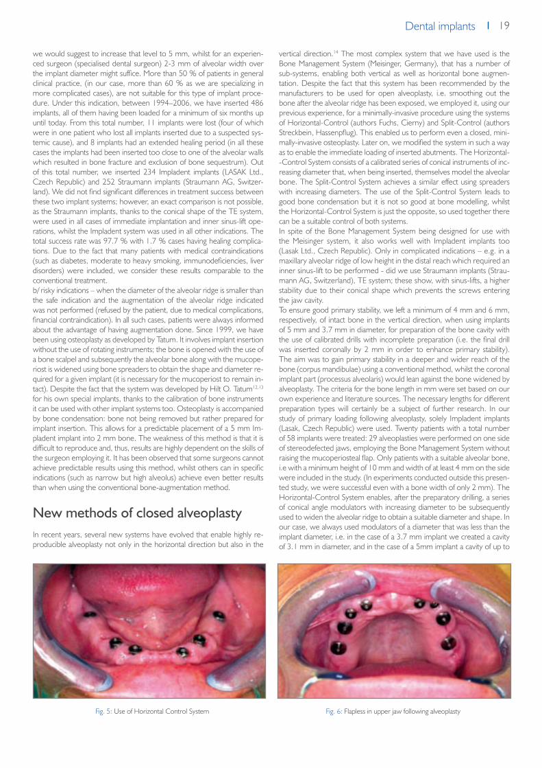
19Dental implantsDental implants
we would suggest to increase that level to 5 mm, whilst for an experien-ced surgeon (specialised dental surgeon) 2-3 mm of alveolar width over the implant diameter might suffice. More than 50 % of patients in general clinical practice, (in our case, more than 60 % as we are specializing in more complicated cases), are not suitable for this type of implant proce-dure. Under this indication, between 1994–2006, we have inserted 486 implants, all of them having been loaded for a minimum of six months up until today. From this total number, 11 implants were lost (four of which were in one patient who lost all implants inserted due to a suspected sys-temic cause), and 8 implants had an extended healing period (in all these cases the implants had been inserted too close to one of the alveolar walls which resulted in bone fracture and exclusion of bone sequestrum). Out of this total number, we inserted 234 Impladent implants (LASAK Ltd., Czech Republic) and 252 Straumann implants (Straumann AG, Switzer-land). We did not find significant differences in treatment success between these two implant systems; however, an exact comparison is not possible, as the Straumann implants, thanks to the conical shape of the TE system, were used in all cases of immediate implantation and inner sinus-lift ope-rations, whilst the Impladent system was used in all other indications. The total success rate was 97.7 % with 1.7 % cases having healing complica-tions. Due to the fact that many patients with medical contraindications (such as diabetes, moderate to heavy smoking, immunodeficiencies, liver disorders) were included, we consider these results comparable to the conventional treatment.b/ risky indications – when the diameter of the alveolar ridge is smaller than the safe indication and the augmentation of the alveolar ridge indicated was not performed (refused by the patient, due to medical complications, financial contraindication). In all such cases, patients were always informed about the advantage of having augmentation done. Since 1999, we have been using osteoplasty as developed by Tatum. It involves implant insertion without the use of rotating instruments; the bone is opened with the use of a bone scalpel and subsequently the alveolar bone along with the mucope-riost is widened using bone spreaders to obtain the shape and diameter re-quired for a given implant (it is necessary for the mucoperiost to remain in-tact). Despite the fact that the system was developed by Hilt O. Tatum12,13 for his own special implants, thanks to the calibration of bone instruments it can be used with other implant systems too. Osteoplasty is accompanied by bone condensation: bone not being removed but rather prepared for implant insertion. This allows for a predictable placement of a 5 mm Im-pladent implant into 2 mm bone. The weakness of this method is that it is difficult to reproduce and, thus, results are highly dependent on the skills of the surgeon employing it. It has been observed that some surgeons cannot achieve predictable results using this method, whilst others can in specific indications (such as narrow but high alveolus) achieve even better results than when using the conventional bone-augmentation method.
New methods of closed alveoplastyIn recent years, several new systems have evolved that enable highly re-producible alveoplasty not only in the horizontal direction but also in the
vertical direction.14 The most complex system that we have used is the Bone Management System (Meisinger, Germany), that has a number of sub-systems, enabling both vertical as well as horizontal bone augmen-tation. Despite the fact that this system has been recommended by the manufacturers to be used for open alveoplasty, i.e. smoothing out the bone after the alveolar ridge has been exposed, we employed it, using our previous experience, for a minimally-invasive procedure using the systems of Horizontal-Control (authors Fuchs, Cierny) and Split-Control (authors Streckbein, Hassenpflug). This enabled us to perform even a closed, mini-mally-invasive osteoplasty. Later on, we modified the system in such a way as to enable the immediate loading of inserted abutments. The Horizontal--Control System consists of a calibrated series of conical instruments of inc-reasing diameter that, when being inserted, themselves model the alveolar bone. The Split-Control System achieves a similar effect using spreaders with increasing diameters. The use of the Split-Control System leads to good bone condensation but it is not so good at bone modelling, whilst the Horizontal-Control System is just the opposite, so used together there can be a suitable control of both systems.In spite of the Bone Management System being designed for use with the Meisinger system, it also works well with Impladent implants too (Lasak Ltd., Czech Republic). Only in complicated indications – e.g. in a maxillary alveolar ridge of low height in the distal reach which required an inner sinus-lift to be performed - did we use Straumann implants (Strau-mann AG, Switzerland), TE system; these show, with sinus-lifts, a higher stability due to their conical shape which prevents the screws entering the jaw cavity.To ensure good primary stability, we left a minimum of 4 mm and 6 mm, respectively, of intact bone in the vertical direction, when using implants of 5 mm and 3.7 mm in diameter, for preparation of the bone cavity with the use of calibrated drills with incomplete preparation (i.e. the final drill was inserted coronally by 2 mm in order to enhance primary stability). The aim was to gain primary stability in a deeper and wider reach of the bone (corpus mandibulae) using a conventional method, whilst the coronal implant part (processus alveolaris) would lean against the bone widened by alveoplasty. The criteria for the bone length in mm were set based on our own experience and literature sources. The necessary lengths for different preparation types will certainly be a subject of further research. In our study of primary loading following alveoplasty, solely Impladent implants (Lasak, Czech Republic) were used. Twenty patients with a total number of 58 implants were treated: 29 alveoplasties were performed on one side of stereodefected jaws, employing the Bone Management System without raising the mucoperiosteal flap. Only patients with a suitable alveolar bone, i.e with a minimum height of 10 mm and width of at least 4 mm on the side were included in the study. (In experiments conducted outside this presen-ted study, we were successful even with a bone width of only 2 mm). The Horizontal-Control System enables, after the preparatory drilling, a series of conical angle modulators with increasing diameter to be subsequently used to widen the alveolar ridge to obtain a suitable diameter and shape. In our case, we always used modulators of a diameter that was less than the implant diameter, i.e. in the case of a 3.7 mm implant we created a cavity of 3.1 mm in diameter, and in the case of a 5mm implant a cavity of up to
Fig. 5: Use of Horizontal Control System Fig. 6: Flapless in upper jaw following alveoplasty

20 Dental implants
4 mm in diameter. The final alveolar shape was created by bone spreading when the self-tapping screw was being inserted.Implants were inserted in the above-described procedure and immediately loaded. If all implants on one side of the jaw could be loaded, we prefered to use a fixed bridge made from resin and placed on temporary abutments from the manufacturer. If only one implant at the side was available, we used a temporary, screw-retained prosthesis fixed on a ball attachment from the manufacturer. The requirement of a torque of at least 35 Ncm was achieved for all implants in the study.On the opposite side, which was used as a control, implants were inserted either by a two-phase bone augmentation procedure, where necessary, or by using a minimally-invasive procedure without immediate loading. The objective and subjective results were then evaluated. As for the objective results, all 30 implants on the research and control side were successufully loaded. On the research side an average loss in bone height of 0.3 mm ± 0.8 mm was measured whilst on the control side, where either aug-mentation or a minimally invasive-procedure without immediate loading was performed, a bone gain of 1.1 mm ± 1.8 mm was measured. Thus, augmentation proved to bring a bone gain in many cases; the results, ho-wever, are highly variable.
The disadvantage of the pilot study was that it was not homogeneous. Nevertheless, it could be said that a minimally-invasive procedure imple-mented along with alveoplasty and subsequent immediate loading does not cause a higher risk of implant loss. Its big advantage is its much shorter treatment time. As far as evaluation of the treatment by patients goes: all patients preferred to have minimally-invasive treatment without alveo-plasty but such a treatment could only have been offered to four patients (with sufficient alveolar bone width) out of twenty involved in the study. Minimally-invasive treatment with alveoplasty (although some patients ini-tially feared the widening of the implant cavity) was the preferred choice over a two-phase implant insertion procedure with bone augmentation. As reported in the literature, the latter was found to be more painful - causing swelling - and had a longer healing time.To conclude, the Bone Management System of Meisinger and Impladent implants (Lasak, Czech Republic) can be successfully used in flapless alve-oplasty - even for cases that would have been contraindicated in the past. In addition, in cases of sufficient bone availability (height of 10 mm and width of 4 mm) and satisfactory primary stability, the immediate loading of implants can be recommended.
Literature1. Whitehouse JA. Adopting a new philosophy: minimal invasion. Dent Today. 2006 Jun;25(6):102, 104-5.2. Irish JD. A 5,500 year old artificial human tooth from Egypt: a historical note. Int J Oral Maxillofac Implants. 2004 Sep-Oct;19(5):645-7.3. Ring ME. A thousand years of dental implants: a definitive history--part 1. Compend Contin Educ Dent. 1995 Oct;16(10):1060, 1062, 1064 passim.4. Becker W, Goldstein M, Becker BE, Sennerby L. Minimally invasive flapless implant surgery: a prospective multicenter study. Clin Implant Dent Relat
Res. 2005;7 Suppl 1:S21-7.5. Becker W, Wikesjo UM, Sennerby L, Qahash M, Hujoel P, Goldstein M, Turkyilmaz I. Histologic evaluation of implants following flapless and flapped
surgery: a study in canines. J Periodontol. 2006 Oct;77(10):1717-22.6. Buser, D., Belser, U., Wismeijer, D. ITI Treatment Guide, Vol I: Implant Therapy in the Esthetic Zone for Single-Tooth Replacements Quintessence,
2006.7. Oh TJ, Shotwell JL, Billy EJ, Wang HL. Effect of flapless implant surgery on soft tissue profile: a randomized controlled clinical trial.J Periodontol. 2006
May;77(5):874-82.8. Balshi SF, Wolfinger GJ, Balshi TJ Surgical planning and prosthesis construction using computer technology and medical imaging for immediate loading
of implants in the pterygomaxillary region.Int J Periodontics Restorative Dent. 2006 Jun;26(3):239-47.9. Engelke W, Capobianco M. Flapless sinus floor augmentation using endoscopy combined with CT scan-designed surgical templates: method and
report of 6 consecutive cases.10. al-Ansari BH, Morris RR. Placement of dental implants without flap surgery: a clinical report. Int J Oral Maxillofac Implants. 1998 Nov-Dec;13(6):861-5.11. Chen ST, Wilson TG Jr, Hammerle CH. Immediate or early placement of implants following tooth extraction: review of biologic basis, clinical proce-
dures, and outcomes.12. Tatum H Jr, Lebowitz M, Borgner R. Restoration of the atrophic, edentulous mandible. J Oral Implantol. 1994;20(2):124-34.13. Tatum H Jr. Endosteal implants. CDA J. 1988 Feb;16(2):71-6.14. Gaggl A, Schultes G, Rainer H, Karcher H. The transgingival approach for placement of distraction implants.J Oral Maxillofac Surg. 2002 Jul;60(7):793-
6.Int J Oral Maxillofac Implants. 2005 Nov-Dec;20(6):891-7.
Figs. 7 and 8: X-ray one month before and after alveoplasty

21Dental implantsDental implants
Is lateral sinus lift an effective and safe technique?
Contemplations after the performance of one thousand
surgeries
A. Šimůnek1, D. Kopecká1, T. Brázda1, R. V. Somanathan1
Implantologie Journal 6/2007
1 Centre of dental implantology at the Clinic of Stomatology, Teaching Hospital and Faculty of Medicine, Charles University, Hradec Králové, Czech Republic
Objective: Early prosthodontic therapy (usually at around 18 years of age) often leads to early loss of teeth and in extreme cases to complete loss of dentition at between 40 and 50 years of age. Patients: This report describes the treatment of two middle ages cleft patients. Edentulous maxilla with cleft defect was treated with screw-retained prosthesis supported by 6 implants (STI-BIO-C, IMPLADENT, LASAK, Ltd., Czech Republic). Results: Treatment of the whole dental arch on the basis of implants is currently fre-
quently used as it provides a possibility of thorough functional and aesthetic therapy to a patient. The biomechanics of the reconstruc-tion enables individual adjustment of the shape of the dental arch. Conclusions: The problem in cleft patients involves altered relati-ons in the dental arch caused by the defect alone or also by affecting of the growth of the maxillary segment by surgery. A potentially removable framework is therefore the main method of choice be-cause the position of the implants must be prosthetically modified.
IntroductionThe authors assess the importance of lateral sinus lift in current implantolo-gy. They prefer a variant of the surgical protocol that minimizes the surgical and financial burdens for the patient. In addition they provide comments on contraindications and describe the most frequently occurring complica-tions. After comparing it with alternative procedures, they concluded that Lateral Sinus Lift, despite having some disadvantages, is the most effective method for implantation into dorsal parts of the maxilla.
Dental implantology at the beginning of the Third Millennium can replace tooth defects almost always if they occur in an adult individual who is willing
to cooperate and to provide a financial contribution thereto. Contraindica-tions for implants are increasingly being reduced. Thanks to the augmen-tation procedure, we know of virtually no situations that the implant could not be implanted due to insufficient quantity of the alveolar bone.2,10
Lateral Sinus Lift is one of the most widely used augmentation procedures. It enables to make an implant in the dorsal parts of the maxilla, where the bone often has poor quality and is reduced by the extended maxillary sinus. When considering that the minimum safe length of the implant is 10 mm, the bone at the site of the first premolar is very low in one-fourth (25%) of patients. The bone is insufficient in more than half of patients at the level of the second premolar, and in 80 to 90% of patients at the level of molars.3
Reconstruction of cleft palate using implants – Case Report
T. Dostalová1, J. Holakovský2, M. Bartoňová2, M. Seydlová1, Z. Šmahel3
Quintessenz, Volume 16, 2007, No. 9
1 Charles University, 2nd Medical School, Department of paediatric Stomatology, Czech Republic2 Charles University, 1st Medical Faculty, Department of Stomatology, Czech Republic3 Charles University, Faculty of Science, Department of Anthropology and Human Genetics, Czech Republic
Fig. 1: Window in the front wall of the maxilla. The mucosa of the maxillary sinus remains undamaged
Fig. 2: Preparation of the mucosa of the maxillary sinus using the special raspatorium
Fig. 3: Space for the augmentation material

22 Dental implants
Lateral Sinus Lift is usually carried out under general or local anesthesia, or under analgesia. After lifting the mucoperiostium from the front wall of the maxilla, we should first use a ball drill to create a window in the thin bone demarcating the maxillary sinus (Fig. 1). Antral mucosa must remain undamaged. Then we should lift the mucosa away from the bone using a special raspatorium to the extent of the alveolar recession and dislocate the same cranially (Fig. 2). A space will be created at the base of the maxillary sinus (Fig. 3) that will be filled with an appropriate augmentation material.2
When an inadvertent perforation of the antral mucosa occurs during the preparation, such defect is most often covered by a resorbable barrier membrane, or sometimes collagen tape, a plate from autologous or lyo-philized bone, or it can be closed by fibrin glue or by a fine suture.2,9 The scientific literature typically says that when the residual alveolar bone is at least 3 to 5 mm high, dental implants should be introduced during the Sinus Lift, as this would ensure their sufficient primary stability (single-step surge-ry) (Fig. 4)2. When the bone is lower, the implant should not be inserted before partial consolidation of the augmentation material (two-step surge-ry) (Fig. 5, 6)2. The time of healing depends on the augmentation material used. If non-autologous, implants in the single-step Sinus Lift should not be exposed to a functional load until 9 months. When using the two-step variant, the implants should be applied after 6 to 9 months and exposed to a functional load after another 9 to 6 months. Use of autologous bone can reduce the length of treatment to one third.2
The objective of the work is to present our own experience with sinus lift surgery, describe its risks, most frequent complications and to evaluate the effectiveness of the procedure. This contemplation is based on the evaluation of results from one thousand lateral sinus lift surgeries that were performed from October 1995 until April 2007 at the authors‘ facility. A total of 2056 Impladent implants (Lasak, Ltd., Czech Republic)5 and 232 Replace Select Tapered implants (Nobel Biocare, Sweden) were inserted into the augmented boned.
Surgical ProtocolLateral Sinus Lift can be performed in many variants, characterized for example by type of anesthesia, method of bone preparation, selection of augmentation material, number of surgery phases, surface of implants or length of healing period.2 These factors have an influence on the rate of treatment, surgical load for patients, length of convalescence period, frequency of complications, and price of procedure. We consider the fo-llowing surgical protocol to be optimal in terms of usual clinical practice. The protocol is adjusted to minimize the invasiveness of the procedure, risk of complications and financial burden for the patients. The said surgical protocol is characterized by the following parameters:
regimen: outpatient
anesthesia: local
bone preparation: bone cutter, diamond ball cutter
augmentation material: non-autologous
type of surgery: single step
dental implants: hydroxyapatite coated
bone window coverage: without barrier membrane
healing period: 6 to 9 months
Simplifying the procedure is the priority. Therefore, local anesthesia is fully sufficient when the surgery procedure is performed quickly. The use of a high-performance bone cutter with a diameter of 3 mm (40000 revo-lutions per minute), which should be replaced at the end with a gentle, albeit less effective diamond ball of the identical diameter, reduces the time needed for the creation of the bone window to 1 to 3 minutes (Fig. 7, 8). The surgery as a whole including the implantation takes 30 to 40 minutes and is very well tolerated by patients. An unquestionable advantage is if the surgery is performed by a maxillofacial surgeon, as the procedure falls under the discipline of facial surgery rather than dental medicine.Use of non-autologous augmentation material only substantially reduces the operative burden for the patient, although sometimes at the expense of longer in-growth period. Deproteinized bovine bone or beta-tricalcium phosphate are preferred materials.6 Addition of a small quantity of auto-logous bone (such as from tuber maxillae) has no positive influence on the augmentation effect.4,6 According to the authors, limited indications of one-step Sinus Lift for alveoli higher than 3 to 5 mm is not justified, as it is contradictory to the commonly published opinions of experts.2 Publicati-ons that prove this statement are currently under preparation.One-step variant of the Sinus Lift is more beneficial in all aspects (Fig. 9). The standard healing period is 9 months and can be reduced to 6 months depending on the height of the alveolus. According to the experience of the authors, the rate of non-osseointegration for hydroxyapatite-coated implants is significantly lower compared to the implants with textured tita-nium surfaces.1,8 Use of a barrier membrane to cover the bone window is unnecessary. It is beneficial to apply medicines against the postoperative
Fig. 4: One-step Sinus Lift Fig. 5: Expanded maxillary sinus makes the common implantation impossible
Fig. 6: Two-step Sinus Lift in a patient from Fig. 5. A condition before the implantation
Fig. 7: A larger part of the preparation can be performed by a high-performance bone cutter

23Dental implantsDental implants
swelling, such as dexamethasone in the dose of 8 mg intravenously before the procedure and 0.75 mg twice daily orally for the subsequent 3 days.
ContraindicationsDisorders and conditions that contraindicate the Sinus Lift have not been fully defined yet.2 We would like to add the following remarks on the ge-nerally known and recognized rules:1. Purulent exudate in the maxillary sinus is the most frequently occurri-
ng contraindication of Sinus Lift. Empyema, whether asymptomatic or not, is an absolute, though temporary, contraindication.
2. S/P Caldwell-Luc operation usually makes the Sinus Lift highly difficult or impossible. Scar tissue cannot be treated as physiological mucosal lining.
3. If the patient reports a history of acute sinusitis and the cause thereof has not been eliminated, the augmentation may increase the prone-ness to further attacks of inflammation. The patient must be informed to this respect.
4. Chronic sinusitis does not complicate the Sinus Lift. On the contrary. hyperplastic antral mucosa is increased mechanical resistance, which facilitates the preparation.
5. Mild osteoporosis is not considered to be contraindication, while mo-derate forms of this disease require prolongation of the healing period up to 12 months. We never performed surgery in case of severe os-teoporosis.
6. Concurrent treatment with anti-aggregation drugs causes no life-thre-atening bleeding. Nevertheless it is recommended to discontinue such treatment subject to an agreement with the treating physician. Dose reduction is required in case of concurrent treatment with anticoagu-lants (the borderline level is INR 1.8). If not realistic, the patient should be transferred to low-molecular heparin.
7. Inhalation or superficial application of corticoids has no influence on the effects of surgery, as the absorbed dose of the medication is low.
8. Age itself is not a contraindication.
9. Controlled diabetes mellitus is not considered to be a contraindication, independently of the type of treatment.
10. We don‘t agree with the frequently occurring statement that heavy smokers have a thin mucous lining of the maxillary sinus, that is highly prone to perforation during the surgery.2
ComplicationsThe following list contains notes on the most significant complication of Sinus Lift. Serious complications are very rare, while the occurrence of the other complications corresponds to the character of the procedure and is acceptable for both the patient and the surgeon.1. By far the most frequently occurring complication is perforation of mu-
cosa of the maxillary sinus during the surgery. If not closed spontane-ously, we should use oxycellulose mesh (Surgicel, Johnson & Johnson) for coverage. This original procedure is fast, cheap and reliable, and was repeatedly published by the authors (Figures 10, 11)7,9. In emer-gency, the mesh can be used to reconstruct the entire ceiling of the augmented space.
2. Acute sinusitis is the most serious complication. It is most frequently caused by infection of the augmentation material during the surgery. It has dramatic manifestations and requires revision surgery of the ma-xillary sinus under general anesthesia with removal of all extraneous objects. It is a quite rarely occurring episode, that had the occurrence of 0.1% in the presented group of patients.
3. Mild purulent exudate from a dehiscent mucosal wound accompanied by swelling, pain and subfebrile conditions, is not a big threat. It can be usually managed by irrigations and antibiotic therapy.
4. From time to time, we observe second intention healing, which re-presents no big risk for the effectiveness of the procedure. If the bone window is situated too close to the mucosal incision, or if the augmen-tation material is too much compressed, the augmentation material can be liberated from the wound. In this case, it is recommended to use antibiotic treatment and try to apply a secondary suture.
5. Postoperative hematoma is observed mostly in older females (Fig. 12). It has annoying effects in esthetic terms but usually re-absorbs within two weeks.
6. Primary failure (non-osseointegration) of the implant remains a very rare event in hydroxyapatite-coated fixtures (1.4% in our group vs. 0.6% in implants into non-augmented bone). Long-term success is not significantly different from that of usual implantations.
Evaluation of the MethodSinus Lift is not an ideal technique in terms of advanced implantology that is characterized by efforts for easier and more rapid treatment. Relatively high invasiveness compared to plain dental implants, need for great erudi-tion of the surgeon, impossibility to correct vertical atrophy of the alveolar crest in the oral direction, financial burden, and especially prolonged hea-ling period, are obvious handicaps.
Fig. 8: Completion of the preparation using the diamond ball that is gentler to the antral mucosa
Fig. 9: One-step Sinus Lift. Deproteinized bovine bone with Impla-dent implants (Lasak, Czech Republic)
Fig. 10: Mucosal perforation
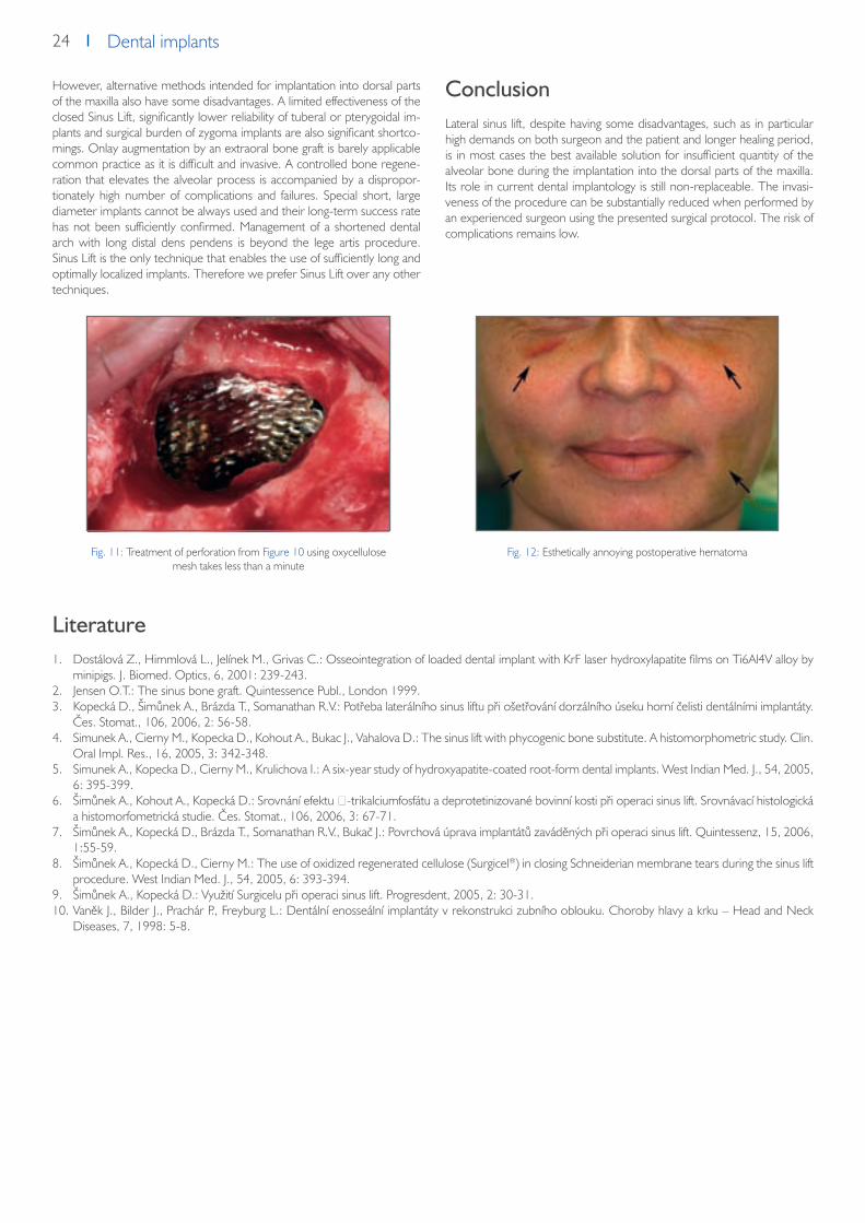
24 Dental implants
However, alternative methods intended for implantation into dorsal parts of the maxilla also have some disadvantages. A limited effectiveness of the closed Sinus Lift, significantly lower reliability of tuberal or pterygoidal im-plants and surgical burden of zygoma implants are also significant shortco-mings. Onlay augmentation by an extraoral bone graft is barely applicable common practice as it is difficult and invasive. A controlled bone regene-ration that elevates the alveolar process is accompanied by a dispropor-tionately high number of complications and failures. Special short, large diameter implants cannot be always used and their long-term success rate has not been sufficiently confirmed. Management of a shortened dental arch with long distal dens pendens is beyond the lege artis procedure. Sinus Lift is the only technique that enables the use of sufficiently long and optimally localized implants. Therefore we prefer Sinus Lift over any other techniques.
ConclusionLateral sinus lift, despite having some disadvantages, such as in particular high demands on both surgeon and the patient and longer healing period, is in most cases the best available solution for insufficient quantity of the alveolar bone during the implantation into the dorsal parts of the maxilla. Its role in current dental implantology is still non-replaceable. The invasi-veness of the procedure can be substantially reduced when performed by an experienced surgeon using the presented surgical protocol. The risk of complications remains low.
Literature1. Dostálová Z., Himmlová L., Jelínek M., Grivas C.: Osseointegration of loaded dental implant with KrF laser hydroxylapatite films on Ti6Al4V alloy by
minipigs. J. Biomed. Optics, 6, 2001: 239-243.2. Jensen O.T.: The sinus bone graft. Quintessence Publ., London 1999.3. Kopecká D., Šimůnek A., Brázda T., Somanathan R.V.: Potřeba laterálního sinus liftu při ošetřování dorzálního úseku horní čelisti dentálními implantáty.
Čes. Stomat., 106, 2006, 2: 56-58.4. Simunek A., Cierny M., Kopecka D., Kohout A., Bukac J., Vahalova D.: The sinus lift with phycogenic bone substitute. A histomorphometric study. Clin.
Oral Impl. Res., 16, 2005, 3: 342-348.5. Simunek A., Kopecka D., Cierny M., Krulichova I.: A six-year study of hydroxyapatite-coated root-form dental implants. West Indian Med. J., 54, 2005,
6: 395-399.6. Šimůnek A., Kohout A., Kopecká D.: Srovnání efektu β-trikalciumfosfátu a deprotetinizované bovinní kosti při operaci sinus lift. Srovnávací histologická
a histomorfometrická studie. Čes. Stomat., 106, 2006, 3: 67-71.7. Šimůnek A., Kopecká D., Brázda T., Somanathan R.V., Bukač J.: Povrchová úprava implantátů zaváděných při operaci sinus lift. Quintessenz, 15, 2006,
1:55-59.8. Šimůnek A., Kopecká D., Cierny M.: The use of oxidized regenerated cellulose (Surgicel®) in closing Schneiderian membrane tears during the sinus lift
procedure. West Indian Med. J., 54, 2005, 6: 393-394.9. Šimůnek A., Kopecká D.: Využití Surgicelu při operaci sinus lift. Progresdent, 2005, 2: 30-31.10. Vaněk J., Bilder J., Prachár P., Freyburg L.: Dentální enosseální implantáty v rekonstrukci zubního oblouku. Choroby hlavy a krku – Head and Neck
Diseases, 7, 1998: 5-8.
Fig. 11: Treatment of perforation from Figure 10 using oxycellulose mesh takes less than a minute
Fig. 12: Esthetically annoying postoperative hematoma

25Dental implantsDental implants
Teeth in six hours
A. Šimůnek1, T. Vosáhlo2, D. Kopecká1, T. Brázda1, M. Sobotka1, D. Dufková1
Implantologie Journal 8/2006
1 Centre of dental implantology at the Clinic of Stomatology, Teaching Hospital and Faculty of Medicine, Charles University, Hradec Králové, Czech Republic2 Private Dental Clinic, Hradec Králové, Czech Republic
The authors describe their own modification to a fixed mandibular prosthesis using Impladent implants. A temporary fixed bridge is made from the lower total prosthesis and fixed into the mouth using impression abutment coping. Patients are able to eat immediately. After six week the provisional bridge is replaced by the classical Brånemark bridge. Over a 30 month period, 92 patients were treated in this way - not a single implant was lost, giving a success rate of 100 % for this supraconstruction.
IntroductionThe restoration of a mandibular occlusion using a conventional prosthesis is rarely successful. When the alveolar ridge is highly atrophied it becomes extremely difficult to fit a denture. In such cases implant surgery can offer an effective solution16. Two options are available: a hybrid prosthesis or a fixed bridge. In the first case, the prosthesis is connected to two or four im-plants via attachments; ball, bar-clip and magnet attachments are the most commonly used10. The limited long-term success of these implants, the frequent technical problems with attachments, and the frequent occurren-ce of other complications, has led us to abandon this type of treatment11. A fixed bridge offers the patient higher comfort, has a better performance for chewing and, in comparison with a hybrid prosthesis, is far more reliable. Its disadvantages are the higher cost, the extensive surgery and more de-manding hygienic care required. Thus the need to develop a new proce-dure for the replacement of a mandibular occlusion that would be spared some or all of the above constraints and satisfy the following requirements:1. acceptable price2. suitable for a highly-atrophied alveolar ridge3. short treatment time4. easy hygiene care5. minimally-invasive treatment6. long-term success
Most of the above is offered by the bridge first presented by P.-I. Bråne-mark in 1965 and commonly known as the Brånemark bridge10. Traditi-onally, this bridge was fixed to implants that were already healed in, thus not complying with the above requirement for a short treatment time. However, there are published cases where immediate loading had been performed - but unfortunately then the cost of the treatment went up.7
In March 2004, the Implantology Department of the Dental Clinic in Hra-dec Králové (T. Vosáhlo) conceived the idea and developed a procedure that satisfied all the above stated criteria.17 The preparation of the provisio-nal bridge followed that of the earlier published methodology but this time included the use of the IMPLADENT implant system, allowing a reduction in the number of necessary components used. This approach proved to be decisive in satisfying the requirement of acceptable cost.2, 3, 4, 5, 6, 7, 8 This concept has been commercially presented as ‚Teeth in six hours‘.The aim of this paper is to provide a description of the treatment protocol and an evaluation some two and half years after its first use.
Basic characteristics of the concept‚Teeth in six hours‘ The concept ‚Teeth in six hours‘ works with the Impladent implant system (Lasak Ltd.). It is based on inserting five Impladent STI-Bio-C implants (im-plants having a bioactive surface – Bio surface) with high primary stability in the interforaminal area.12, 13, 14, 15 Immediately the abutments for the screw--retained prosthesis are then attached. Using standard titanium impression
coping that ensures not only a high mechanical strength but also the nece-ssary passive accuracy, the provisional bridge is made from an existing total screw-retained prosthesis. Both the surgical and prosthetic phase need take no more than six hours. The provisional bridge allows for food to be taken immediately.9 In patients with a partial denture, the remaining teeth are extracted directly prior to implant surgery and the supraconstruction made by completion of the partial prosthesis.After implant osseointegration, the provisional bridge is replaced by a clas-sical Brånemark bridge.10 However its appearance is a unique and specific one, unlike any found among conventional prosthetics. It consists of a me-tal framework with long cantilevers leading to the first molar region. The metal framework is covered by pink resin and holds twelve prefabricated resin teeth.
Step-by-step procedure
1. Application of antibiotics, local anaesthesia.2. If necessary, extraction of existing mandibular teeth, careful excochlea-
tion of walls and bottom of the extraction site.3. Raising of mucoperiost of the alveolar ridge to the extent of 35 – 45.4. Detection of both foramina mentalia.5. Smoothening of alveolar ridge.6. Localisation of suitable sites for implant placement; maintaining a regu-
lar interforaminal distance so that the gap between the end implant and foramen mentale is at least 3 mm.
7. Preparation of five bone beds for fixing Impladent STI- Bio-C implants 3.7 mm in diameter and usually 16 mm in length (the implant length depends on the bone but the minimum length should be 10 mm).
8. Implant insertion ensuring high primary stability (torque ≥ 45 Ncm, ISQ ≥ 60) (Fig. 1).
9. Attachment of abutments for screw-retained supraconstruction (usua-lly 4 mm long, depending on the width of soft tissue), torque 35 Ncm.
10. Suture using resorbable material (Fig. 2).11. Fixing of impression copings equipped with blocks of self-curing acrylic
resin (PMMA).12. Impression copings equipped with blocks of self-curing acrylic resin
(PMMA) are connected together using the same resin to form a rigid block (Fig. 3).
13. An impression is taken using A-silicon impression material and titanium impression copings; the recommended method is an open-tray im-pression technique but instead of an impression tray a modified lower dental prosthesis is used (Fig. 4).
14. A plaster working model with implant replicas is made.15. The working model prosthesis is extended using self-curing acrylic
resin; impression copings become part of the prosthesis (Fig. 5).16. Transformation of the prosthesis into a fixed bridge by reducing it to
35 – 45 and by reducing the saddle.17. Final preparation of the bridge (Fig. 6).18. Fixing of the provisional bridge to the implants using screws (15 Ncm)
(Fig. 7).

26 Dental implants
Fig. 1: Five Impladent STI-Bio-C implantsinserted in the interforaminal area
Fig. 3: Impression coping fixed with fastening screw and kept in blocks by self-polymerising resin
Fig. 5: Working model with impression copingand prepared prosthesis
Fig. 7: Temporary bridge fixed after six hourssince the start of operation
Fig. 2: The final surgical phase, abutments areready for taking the impression
Fig. 4: Impression taken. A modified lower dental prosthesis is used instead of impression tray; impression copings become part of the
impression
Fig. 6: Temporary bridge made of prosthesis andimpression coping ensuring passive fit
Fig. 8: Brånemark bridge

27Dental implantsDental implants
19. Checking the articulation.20. Instructing the patient (use of antibiotics for another week, mouth rin-
sing with 0.12 % chlorhexidin), oral hygiene (the use of dental brush and intra-dental brush).
21. After six weeks the Brånemark bridge is made10 (Fig. 8).
Should a usable lower total prosthesis be unavailable, the bridge is fabrica-ted de novo using basal resin. Although fixation of the impression coping remains the same, the relationships between the lower and upper jaw need to be reconstructed. Overall treatment time is thus increased from six to eight hours.
ResultsThe concept ‚Teeth in six hours‘ was used by the authors in 92 patients between March 2004 and August 2006, 57 of which were male and 35 female. The average age of the patients was 62 years (range from 27 to 79 years of age). Contra-indications that might have an impact on the tre-atment success rate included diabetes mellitus in 13 patients (in four cases compensated by diet, in six cases by per oral application of antidiabetics, and in three cases by the application of insulin), and one patient suffering from kidney polycystitis that in a few weeks after treatment resulted in kidney failure. In a twenty-seven-year-old patient teeth loss was caused by ectodermal dysplasia.Altogether 460 Impladent implants (Lasak Ltd., Prague) with bioactive surface Bio were inserted,12, 13, 14, 15 of which 410 implants were STI-Bio modified implants and 50 were of a newer type STI-Bio-C. The implant di-mensions are given in Table 1. The height of the gingival part of abutments for screw-retained supraconstruction is given in Table 2.
diameter/length [mm]
8 10 12 14 16 18
3.7 0 7 18 54 367 8
5.0 0 0 0 2 4 0
Table 1: Implant dimensions
Height[mm]
1 2 3 4 5 6
N 0 0 1 445 12 2
Table 2: Height of the gingival part
All surgeries were performed in out-patient care, in a dental chair, under local anaesthesia using Ubistesin F, and a prophylactic course of doxycic-lin (Deoxymykoin tbl. 1x100 mg p.o.), or, in case of allergy of doxyciclin, clindamycin (Dalacin C cps. 3x300 mg p.o.). The application of antibiotics started one day before surgery and finished seven days after. The implants were surveyed over a period of 0 to 30 months, on average over 12.5 months: all implants and superaconstructions were functional, i.e. survival rate was 100 %.
DiscussionThe cost for the patient has been reduced by limiting the use of prosthetic components and by making a provisional bridge from the patient‘s exis-ting total prosthesis and by manufacturing a Brånemark bridge with resin teeth as the final bridge10. The given data set, that includes all the implant treatments of the type performed at the authors‘ workplace, shows an extremely high success rate. It is expected that such a high success rate has been favoured by the rather high number of implant treatments included in this study compared to other documented procedures.7, 8 A statistical evaluation of the data set was performed only at the mid-term period. Considering that we have more than ten years experience and excellent results with conventional Brånemark bridges, we expect that the use of the same bridge type and the concept ‚Teeth in six hours‘ will have similarly good results in the long term. This hypothesis, of course, will have to be confirmed by a long-term study.A typical characteristic of the implants used was their Bio surface. It is a chemically-treated titanium surface that speeds up and enhances the pro-cess of osseointegration compared to other surface types.12, 13, 14, 15 The latest type of implant, STI-Bio-C, differs from its predecessor STI-Bio in having a cervical micro-thread, new thread design and a more-pronoun-ced narrowing apex.The concept of the Brånemark bridge that is characterised by its concent-ration of implants in the interforaminal area avoids the problem of the lack of alveolar bone which in the interforaminal area is almost always abundant and of high quality1. The Brånemark bridge is particularly destined for older patients, often having lowered motor skills and thus having difficulties to maintain good oral hygiene. The design of the Brånemark bridge makes oral hygiene easier.
The treatment period is reduced to a minimum. The method of immediate loading is normally used in the case of the remaining teeth, immediate reconstruction after teeth extraction and immediate implant loading being performed10. From the patient‘s psychological point of view, it is also very important that the surgery brings results within a few hours rather than se-veral months. In this way post-operative difficulties are easier to overcome too. The surgery is performed in an easily accessible area and is completed within 90 minutes of anaesthesia and with minimum trauma for the soft tissues. Neither sedation nor hospitalisation are necessary.
Conclusions‘Teeth in six hours‘ represents the immediate replacement of the man-dibular arch, using the Brånemark bridge with all its advantages. Clinical experience has shown that its success rate is very high. In our opinion its cost-effectiveness is the highest amongst the whole of implantology. The treatment is extremely fast and simple and the costs relatively low. Teeth replacement that can be completed within one day has a positive psycho-logical impact on the patient, making the method highly attractive and, in addition, also raising the image of dental surgery.
Literature1. Brosky M.E., Korioth T.W.P., Hodges J.: The anterior cantilever in the implant-supported screw-retained mandibular prosthesis.J. Prosthet. Dent., 89, 2003, 244–249.2. Castellon P., Block M.S., Smith M.B., Finger I.M.: Immediate loading of the edentulous mandible: Delivery of the final restoration or a provisional
restoration – which method to use? J. Oral Maxillofac. Surg., Suppl., 62, 2004, 30–40.3. Hatano N., Yamaguchi M., Suwa T., Watanabe K.: A modified method of immediate loading using Branemark implants in edentulous mandibles.
Odontology, 91, 2003, 37–42.4. Hatano N.: The Maxis New. A novel one-day technique for fixed individualized implant-supported prosthesis in the edentulous mandible using Brane-
mark system implants. Appl. Osseointegration Res., 2, 2001, 40–43. 5. ChanJin P., DongSuk K., YangJin Y., Lepra C.: Fabrication of a screw-retained, implant-supported, provisional prosthesis: a clinical report. J. Prosthet. Dent., 91, 2004, 409–412.
6. Chow J., Hui E., Li D., Liu J.: Immediate loading of Branemark system fixtures in the mandibule with a fixed provisional prosthesis. Appl. Osseointe-gration Res., 2, 2001, 30–33.

28 Dental implants
7. Lekholm U.: Patient selection for Branemark Novum Treatment. Appl. Osseointegration Res., 2, 2001, 36–39.8. Maló P., Rangert B., Nobre M.: „All-on-four“ immediate-function concept with Branemark system implants for completely edentulous mandibles: a
retrospective clinical study. Clin. Implant Dent. Relat. Res., Suppl., 5, 2003, 2–9.9. Seydlová M., Havlová Z., Dostálová T., Nathanský Z., Šimůnek P.: Přímé zatížení implantátu (souborný referát). Prakt. Zub. Lék., 52, 2004, 54–63.10. Šimůnek A. a kol.: Dentální implantologie. Nucleus HK, Hradec Králové 2001.11. Šimůnek A., Kopecká D., Krulichová I., Škrabková Z., Mounajjed R.: Pětileté sledování dentálních implantátů Impladent. Quintessenz, 10, 2001, 10:
20–25.12. Šimůnek A., Strnad J., Kopecká D.: Stability time dependence of loaded and unloaded dental implants. Clin. Oral Impl. Res., 16, 2005, XLI.13. Šimůnek A., Strnad J., Novák J., Strnad Z., Kopecká D., Mounajjed R.: STI-Bio: titanium implant with bioactive surface design. Clin. Oral Impl. Res.,
12, 2001, 416.14. Šimůnek A., Strnad J., Somanathan R.V., Kopecká S., Brázda T.: Stability-time dependence of unloaded dental implants. Clin. Oral Impl. Res., 17, 2006,
LXX.15. Šimůnek A., Strnad J., Štěpánek A.: Bioactive titanium implants for shorter healing period. Clin. Oral Impl. Res., 13, 2002, XXXIV.16. Vaněk J., Bilder J., Prachár P., Freyburg L.: Dentální enosseální implantáty v rekonstrukci zubního oblouku. Choroby hlavy a krku – head and neck
diseases, 7, 1998, 5–8.17. Vosáhlo T., Šimůnek A., Kopecká D.: Rekonstrukce zubů dolní čelisti během šesti hodin. LKS, 15, 2005, 15–17.

29Dental implantsDental implants
Early loading (4 weeks) of dental implants Impladent in
maxilla and mandible - monitoring of the healing process
using resonance frequency analysis
A. Štěpánek1, J. Strnad2, Z. Strnad2
Quintessenz, Vol.14, No. 9, 2005
1 Centre for Dental Surgery and Implantology, Třebíč, Czech Republic2 Lasak Ltd., Papírenská 25, Prague 6, Czech Republic
The aim of the study was to assess the impact of a reduced (4-week long) healing period following the application of an implant - Impladent STI BIO with a bioactive surface - in the maxilla and mandible with a statistical evaluation of the success rate. The statistical analysis included an evaluation of primary stability of implants and of the factors that influence primary stability, as well as concurrent monitoring of the time-dependent development of implant stability during the healing and fully-functional periods using resonance frequency analysis.
Introduction There are certain conditions that enable the early, or even immediate, loa-ding of implants as an alternative to the more ‘classical’ two-phase implan-tation process 1, 2, 3, 4, 5. The classical implantation process involves a healing period of no-direct-loading, lasting six months for implants inserted into the maxilla and three months for mandible implants, using a titanium screw implant with a machined surface6. This ensures the needed immobility of the implant at the beginning of the healing period: necessary for the deve-lopment of secondary stability of the implant, which results in the long-life of the fully-loaded implant7. A shorter healing period, or its complete eli-mination, brings with it new demands on both the primary and secondary stability of the implant. Primary implant stability is mainly dependent on the mechanical characteristics of the bone (its local quality and quantity), the type of implant used (its geometry, diameter, length and surface) and the method of insertion. Secondary stability represents an enhancement of stability as a result of new bone formation and its ‘remodelling’ at the contact surface of bone/implant and within the implant’s surroundings. The use of a shorter healing period has to be compensated by an early and sufficiently fast increase in secondary stability that can withstand the expec-ted demands of implant loading. Exceeding the limits of implant immobility might result in unwanted fibrous encapsulation of the implant and its sub-sequent failure 8, 9, 10, 11. In order to achieve faster healing, the macro-morphology of the titanium sur-faces of implants may be modified by sand-blasting, or the micro-roughness modified using acid-etching or anodic oxidation in mineral acids. Currently, a new generation of implant surfaces is appearing (e.g. STI-Bio, Osseospe-ed), initiated through the development of some chemical modification of the surface in order to obtain a specific surface reactivity - called bioactivity. This bioactivity of the surface stimulates the formation of calcium phosphates on the implant’s surface immediately after implantation, i.e. at a time when the synthesis of bone minerals by osteogenic cells is not yet possible. Bioactive surfaces are characterized by their perfect hydrophilic character (wetting pr-operties), high surface area and high levels of hydration 13, 29.Implants STI-BIO with their bioactive surface initiate oseointegration fas-ter and thus hasten the needed development of an implant’s secondary stability 12, 13, 14. The shorter healing period of Impladent implants achieved through their bioactive surface (STI BIO) – six weeks for a mandibular implant and twelve weeks for the maxillar implant – has already been do-cumented by a clinical study.15 The present study evaluates the possibility of a further reduction of the healing period to four weeks in both the maxilla and mandible, using Impladent BIO-surface implants. Resonance frequency analysis (RFA) was used to assess primary implant stability and the factors that influence it, and also to check the development of implant stability during the periods of healing and full-use.
The aim of this paper is to provide a description of the treatment protocol and an evaluation some two and half years after its first use.
Material and methodsBetween October and December 2004, altogether 90 implants of Im-pladent STI BIO (LASAK, Praha, Czech Republic) were implanted. This involved 34 patients, 22 men and 12 women, aged between 26-71 years (the average age was 51.5 years). None of the patients were diagnosed with any medical contraindication for implantation. Out of the total number of 90, 53 (58.9%) implants were implanted in the maxilla and 37 (41.1%) in the mandible. Indications are summarised in Table 1. A two-stage pro-cedure was used in all cases. One week after implantation healing cylin-ders were introduced, and four weeks (at the latest) after implantation the implants were loaded using provisional restoration fixed to temporary abutments (Fig. 1). Thirteen weeks after implantation, at the latest, the pro-visional restoration was replaced by the final supraconstruction (Table 2). Bone quality, classified as D1, D2, D3 or D4 according to Lekholm-Zarb16, was assessed during the bone bed preparation using resistance as a sub-jective measure 17. The primary stability of implants was evaluated in two ways: by measuring the insertion torque and with the use of resonance frequency analysis (RFA) by Osstell (Integration Diagnostics AB, Göteborg, Sweden). Insertion torque was measured using a ratchet torque-control adapter (Lasak) at the final position of the implant in the bone bed (ITf). With resonance frequency analysis, the range of the dynamic resonance frequency of the whole complex - transducer/implant/bone - (3,500 Hz – 8,500 Hz) is divided into 100 ‘intervals’ and expressed as ISQ (Implant Stability Quotient) from 0 to 100. Implant stability values, ISQ(t), were always measured by RFA at weeks one, four and thirteen after implantation (time t being measured in weeks). Change in implant stability after t weeks of healing, dISQ(t), was expressed as the difference between the stability in a given week of healing [ISQ(t)] and primary implant stability (ISQp).The success rate was assessed following Albrektsson18. Implants con-sidered as successful were every loaded implant that: was clinically not moving; did not cause any chronical discomfort (pain or other); showed no observation of repeated infections or radioluscent bone in the implant surroundings; and did not show progressive marginal bone loss. For the evaluation of success, life-table analysis was used. Data obtained on implant stability underwent statistical analysis (mean value and standard error). Di-fferences of experimental data were tested using a twin-tailed Student’s t-test (Type 2), being statistically significant if p<0.05.

30 Dental implants
Fig. 1: Making temporary prosthesis (c,d) from acrylate on temporary abutments Impladent (a,b) and final prosthesis with a screw-retained metal-ceramic bridge (e,f). The implant in localization 33 showing a remarkable reduction in stability during the first week after implantation (d(ISQ(1) =-11) was not loaded by a temporary prosthesis
(c,d) and was later explanted. When healed, reimplantation in the same localization was done and the implant was loaded with final prosthesis (e,f).
Loss of one tooth
Shortened dental arch
Large gap Toothless jaws
Maxilla 10 4 4 5
Mandible 4 6 2 4
Total 14 10 6 9
diameter/length[mm]
8 mm 10 mm 12 mm 14 mm
5.0 mm 2 9 17 2
3.7 mm - 6 25 29
Individual crown Fixed bridge Hybrid prosth
Maxilla 10 11 -
Mandible 4 11 3
Total 14 22 3
Bone quality Maxilla Mandible
D1 9 13
D2 41 36
D3 3 4
D4 0 0
Table 1: Indication
a
c
e
b
d
f
Table 3: Dimensions of implants used
Table 2: Supraconstruction
Table 4: Implant frequency per bone quality

31Dental implantsDental implants
Results
Primary stability
Mean primary stability (ISQp) of all introduced implants was 60.2±7.7 (n=90). Altogether six parameters that could influence primary stability were considered: implant localization (maxilla and mandible), bone qua-lity, diameter and length of implant, and the means of implant insertion. The primary stability of mandible implants was statistically somewhat higher 63.6±7.8 (n=37) in comparison to maxilla implants 57.8±6.6 (n=53), (p=0.0003). In the mandible, primary stability (ISQp) was higher for all teeth positions compared to those in the maxilla. For the position 3 (canine) and 4, 5 (premolars), however, the difference was not statistically significant (Fig. 2).
Fig. 2: Primary implant stability ISQp according to the localization in maxilla and mandible. ( *) p<0.05.
The data obtained on stability were further analyzed to assess the implant’s impact on the bone. With decreasing bone quality (D1“D2“D3), the dec-rease in primary stability of implants was statistically significant (Fig. 3). In turn, bone quality had an impact on the insertion torque, which at its final position may indicate the primary stability of the implant19. Mean values of final insertion torques of the implant groups, divided according to bone qua-lity, became lower with lowering bone quality (Fig. 4) in a similar way to that of ISQp (Fig. 3). Analysing the data for individual implants (n=90) showed that the final insertion torque (ITf) and primary stability (ISQp) were directly related: [ITf] = 0.5 Ncm, [ISQp] = -6.3; though the correlation coefficient was low (R2=0.1892).
Fig. 3: Mean values of primary implant stability according to bone quality (categories D1, D2 and D3 after Legholm-Zarb.( *) p<0.05.
Fig. 4: Mean values of implant insertion torque according to bone quality (categories D1, D2 and D3 after Legholm-Zarb. ( *) p<0.05.
The diameter of the implant was found to be an important parameter ha-ving an influence on primary stability of the implant. Implants with a dia-meter of 5.0 mm showed a higher primary stability of 62.4±7.8 (n=30) compared to implants with a diameter of 3.7 mm with 59.0±7.4 (n=60), the difference being statistically significant (p=0.0485). There was no signi-ficant correlation of primary stability of the implant and implant length. The measured differences of implant stability for various implant lengths were not statistically significant. Another studied factor that has an influence on primary implant stability was the selected surgery procedure. Groups of implants with high (ISQp>60), medium (ISQp=50-60) and low (ISQ < 50) primary stability were asse-ssed. Within the group ISQp>60, a statistically-significant higher mean pri-mary stability (ISQp) was found in implants where the bone bed had been prepared using a threadformer rather than the drill alone. Within the group with lower primary stability (ISQp=50-60 and ISQ<50), higher ISQp was observed in self-tapping implants but this was not statistically significant (Fig. 5).
Loaded implant stability 13 weeks after implantation
The mean value of stability of loaded implants 13 weeks after implantation (ISQ13) was 59.1±5.2 (n=88). For the mandible the value of ISQ13 reached 62.8±5.3 (n=36) and for the maxilla ISQ13 56.4±3.7 (n=52). Bone quali-ty did not influence implant stability measured 13 weeks after implantation. Mean values of implant stability ISQ13 did not show any statistically significant differences between implant groups of varying bone quality (Fig. 6). In con-trast, the impact of implant diameter was statistically significant. Implants of 5.0 mm in diameter showed higher stability ISQ13 61.6±6.3 (n=30) than implants of 3.7 mm in diameter (ISQ13 = 57.4±4.2; n=58).
Fig. 5: Mean values ISQp of implants inserted into bone bed prepared by threadfor-mer or drill, for implants of ISQp >60, 50-60 and <50. ( *) p<0.05.

32 Dental implants
Fig. 6: Mean values of implant stability 13 weeks after implantation ISQ13, for implant group categories D1, D2 and D3 after Legholm-Zarb .
Development of implant stability during the peri-ods of healing and functional loading
Primary stability of implants had an essential impact on the development of secondary stability during the healing and loading periods. Figure 7 shows the development of implant stability for high (ISQp>60), medium (ISQp=50-60) and low (ISQp<50) primary stabili-ty, the mean values being ISQp 66.3±3.8 (n=45), 56.7±2.0 (n=34) and 45.8±3.9 (n=11), respecti-vely; differences of mean ISQp values are statisti-cally significant (p<0.05). In the group ISQp> 60, implant stability initially declined but after the first week remained stable. The group of implants with medium ISQp did not show any statistically signi-ficant changes either during the healing period or within the thirteen weeks of functional loading. The group of implants with low primary stability showed an increasing enhancement of stability since the first week of the healing period and through the period of functional loading studied.
Fig. 7: Time dependence of stability ISQ(t) for implant categories (ISQp >60, 50-60 a <50) during the healing period (0-4 weeks) and functional loading (4-13 weeks).
Implant failure
Within the study group, two implants were lost during the healing period. The first case was a 63-year-old man, with an implant 3.7 mm in diameter and 12 mm in length, inserted in tooth location 33, of bone quality D1; during the healing period, the implant stability ISQp value of 55 had mar-kedly decreased 44 by week 4, [dISQ (0-4) = -11]. The second case was a 63-year-old woman, with an implant of equal dimensions (3.7/12mm), implanted in location 25, and bone quality D3; the implant stability ISQp of 55 showed no significant change during the healing period, dISQ(0-4) = 1. All other implants complied with the success criteria even after nine weeks of functional loading. The healing phase success rate (with a four-week--long healing period) reached 97.8% (97.3% and 98.1% in mandible and maxilla, respectively). The success rate of the nine-week functional loading was 100% (Table 5).
Discussion A healing period reduced to four weeks offers less time for osseointegration of an implant prior to its loading, which increases the risk of micromove-ments of the implant in the bone bed that can result in fibrous membrane formation when loaded 8, 9. In this case, a higher frequency of implant loss can be expected. The effect, therefore, of a reduced healing period was
evaluated against a control group of implants STI BIO where a longer he-aling period (twelve weeks for maxilla and six weeks for mandible) was used and the results evaluated after twelve months of functional loading 15 (Table 6).The statistical evaluation of success rate of the experimental and control implant sets did not show any significant difference during the healing phase or the nine-week loading phase tested. We can say, therefore, that the re-duced healing period does not increase the risk of implant loss compared to the original twelve-week healing period for the maxilla and six-week period for the mandible.Resonance frequency analysis allows for an objective assessment of the im-plant stability with sufficient exactness and reproducibility of results (±0.5 ISQ units). The method, however, does cover an aggregate of implant sta-bility, based on the dynamic resonance frequency of the whole complex: transducer/implant/bone, including the stiffness of their connections. The higher the frequency, the higher is the stiffness of the measured complex. When interpreting data, it has to be borne in mind that the value of ISQ combines a number of factors.
Amongst the six parameters assessed, the highest impact on implant stability was found to be the location in maxilla or mandible, bone quality, the method of implant inser-tion and implant diameter. The higher primary stability found for the mandible ensures implant immobility and a higher success rate when compared with the maxilla20. The main difference can be attributed to bone density and to some extent also tooth location 21. The use of a threadformer to prepare the bone bed is characterized by its greater exactness and is less traumatic, enabling a higher implant stability to be achieved and is in accor-dance with the Impladent protocol. Some authors reco-mmend the use of implants of larger diameter to deal
Timeperiod
Number ofimplants
Number ofimplant loss
Lost fromevidence
Successrate (%)
Cummula-tive success
rate (%)
Healing period(0-4 weeks)
90 2 0 97,8 97,8
Functional loading(4-13 weeks)
88 0 0 100 97,8
Time period Success rate per interval % (n- number of implants)
Statistical significance of diffe-rence between sets compared
Experimental set – present study
Control set 15
Healing phase 97.8 (n=90) 99,1(n=582) p=0.3998 NS
Mandible 97.3(n=37) 98,8(n=1013) p=0.2678 NS
Maxilla 98.1(n=53) 98,4(n=431) p=0.8877 NS
Functional loading 100 (n=88) 99,5(n=771) p=0.5012 NS
Table 6: Success rate of STI BIO implants for experimental and control set
NS –statistically unsignificant difference
Table 5: Life-table analysis

33Dental implantsDental implants
NS –statistically unsignificant difference
with compromised clinical situations, with the expectation of enhancing the implant’s primary stability 22, 23. Our results, that show a significantly higher primary stability for implants of 5 mm in diameter compared to those of 3.7 mm, confirm the above clinical assumption. The development of implant stability with time during the first week after implantation is characterised either by a decrease or increase in stability, depending on the primary implant stability (Fig. 7). During the first of week after implantation, the stability decreases in cases where the primary stability was high (ISQ>60), being characterized by high insertion torque and high frequencies of dense bone. In this case, oseointegration can be seen as compensation for low mechanical fixation caused by relaxation processes and biological changes accompanying the early healing stage. The resulting stability (measured by RFA) after the first, fourth and thirteenth week fo-llowing implantation was not decreasing further as the decrease in primary stability was fully compenzated by increasing secondary stability due to the fast interaction between the implant’s bioactive surface and the bone 24. This situation males it suitable for early implant loading and is typical for bone of high density (Fig. 9). The rate at which a stable boundary between the implant and the bone bed is formed, besides the primary stability, is given by the osseconductive characteristics of the implant surface. When bio-inert surfaces (such as titanium with a machined surface) are used, se-condary stability starts to grow later and thus, also, compenzation of any marked decrease in primary stability occurs later. As an example can be given the loss of primary stability measured by a reverse torque method on machined surfaces of titanium implants when used in rats, where a decrea-sing reverse torque (reducing from 24 Ncm to 19 Ncm) was measured still four weeks following implantation 25 and clinical measurements using RFA which indicated decreasing implant stability for twenty weeks with machi-ned titanium surfaces and for eight weeks with the oxidized surface TiUni-te26. A sand-blasted and acid-treated implant surface (SLA) tested on sheep using the reverse-torque method showed a decrease in stability from 100 Ncm to 88 Ncm after two weeks of implantation 27 and statistical tests on RFA data revealed decreasing stability up until the sixth week for implants of primary stability higher than 60 ISQ27. Implants of low primary stability, ISQp<50, showed increasing stability from the first week of the healing period (Fig. 7). These implants have a lower insertion torque (Fig. 8) and higher frequency of soft, spongy bone.
Fig. 8: Relationship of the implant insertion torque and the change in implant stability in the first week after implantation dISQ(1) for implant groups ISQp (1) >70, (2)
66-69, (3) 61-65, (4) 56-60, (5) 51-55 and (6)<50.
A less traumatic preparation of the bone bed (in spongy bone with abun-dant blood supply), along with the bioactive properties of the STI BIO im-plant surface, are the main stimulators of a remarkable increase in seconda-ry stability during the healing period of unloaded implants. In this case, the increased rate in implant stability is considered to be a critical parameter which decides when the implant can be loaded. This is especially true for bones of a lower quality. In bones of D3 quality, already after four weeks implants reached 98.7% of their final stability as measured thirteen weeks following implantation (Fig. 9).
Fig. 9: Implant stability ISQ(t) after the first, fourth and thirteenth week of implantati-
on for implants of bone qualities of D1 and D3.
The value of primary stability of the implant, assessed by resonance fre-quency analysis does not unambiguously predetermine implantation su-ccess. The study presented did not find a difference in primary stability between implants that were lost during the healing phase and those that were successful and clinically stable when fully loaded thirteen weeks after implantation. However, a marked decrease in stability often indicates unsu-ccessful implantation and calls for a specific treatment procedure (Fig.10).
Fig. 10: Development of stability for a lost implant and for five clinically stable im-plants inserted in mandible (Fig. 1). Twenty percent of stability decline in week one
after the implantation indicates unsuccessful implantation.
ConclusionsThe statistical evaluation of data shows that, for Impladent STI BIO im-plants, a healing period reduced to four weeks for both maxilla and man-dible does not reduce the rate of the implants’ healing success, nor does it increase the frequency of lost implants during the nine week period of full loading. The reduced healing period thus does not pose any enhanced risk on implantation and maintains the prediction of a similar success rate. Primary implant stability is influenced by the implant localization, bone quality, selected insertion method, and implant diameter. Higher values of primary stability were found for mandibular implants ISQp 63.6±7.8 rather than maxillar implants ISQp 57.8±6.6. Bone quality mainly influ-ences the primary stability of implants. ISQp within the higher D1 bone quality (65.3±8.8) was reduced by 10% within the group with D2 bone quality (59.1±6.2), and by 20% within the D3 bone quality group (52.4±8.8). Preparation of the bone bed in dense bone with the use of a threadformer, in accordance with the protocol for the Impladent system, enabled a higher primary stability to be achieved. The implant diameter was found to have a significant impact on the implant’s primary stability: implants with a diameter of 5.0 mm showed a higher primary stability 62.4±7.8 compared to implants with 3.7 mm in diameter, for which the primary stability was 59.0±7.4. The differences in stability for various implant lengths were not statistically significant.

34 Dental implants
The level of primary stability of the implant, assessed by resonance fre-quency analysis, does not determine unambiguously implantation success. It does, however, have an impact on stability development during the healing period and full loading.
AcknowledgementThe study was funded by the grant MPO ČR FT-TA/087
Literature1. Cochran D., Buser D. et al.: The use of reduced healing times on ITI® implants with a sandblasted and acid-etched (SLA) surface: Early results from
clinical trials on ITI® SLA implants. Clinical Oral Implants Research 2002, Vol.13, (144-153))2. Roccuzzo M.: Early loading of sandblasted and acid-etched (SLA) implants: a prospective split-mouth comparative study. One-year results. Clinical Oral
Implants Research 2001, Vol.12, (572-578))3. Glauber R. at al: Resonance frequency analysis of implants subjected to immediate or early functional occlusal loading. Clinical Oral Implants Research
2004, Vol.15, (428-434)4. Antoun H. et al.: Immediate loading and Branemark Novum concept: a retrospective multicentric study. Clinical Oral Implants Research 2004, Vol.15,
(xxxii)5. Rocci A. et al.: Immediate Function of Single and Partial Reconstruction in Maxilla Using Mk IV fixtures. Applied Osseointegration Research 2001, Vol.2
(22-26)6. Branemark P.I. et al.: Osseointegrated implants in the treatment of the edentulous jaw. Skand.J. Plastic Reconstr. Surg. 1971; 11:supl 16,(1-132 )7. Adell, R. et al.: A 15-year study of osseointegrated implants in the treatment of the edentulous jaw. Int. J. Oral Surgery 1981; 10, (387-416.)8. Sobale K, Hansen E.: Tissue ingrowth into titanium and hydroxyapatite coated implants during stable and unstable mechanical conditions. J.Orthop.
Res. 1992, 10, 285-2999. Sobale K, Rasmussen H.: Hydroxyapatite coating modifies implant membrane formation. Controlled micromotion studied in dogs. Acta Orthop.
Scand. 1992, 63(2), 128-140. 10. Pilliar R. M.: Quantitative evaluation of the effect of movement at a porous coated implant-bone interface. In: Davis. ed. The bone-material interface,
380-387. Toronto: University of Toronto Press (1991)11. Piliar R.M., Lee J.M., Maniatopoulos C.: Observations on the effect of movement on bone ingrowth into porous-surfaced implants Clinical Orthopae-
dics and Related Research 1986, 208, (108-113)12. Strnad J. Kinetika tvorby hydroxyapatitu na anorganických materiálech, Disertační práce, VŠCHT, Praha .200413. Šimůnek A. et al: Alkali treatment –new concept of titanium implant surface modification Clinical Oral Implants Research 2004, Vol.15, ()14. Šimůnek A. et al: Bioactive titanium implants for shorter healing period. Clinical Oral Implants Research 2002, Vol.13, ()15. Šimůnek A. et al: Zkrácení vhojovacího období implantátů Impladent s bioaktivním povrchem. Quintessenz, 2004, 13(34-38)16. Lekholm U., Zarb G.A: Patient selection and preparation. In: Branemark P-I,et al:Tisue integrated prosthesis :osseointegration in clinical dentistry .
Quintessence, Chicago, 1985(211-232)17. MischC.E.: Division of available bone in implant dentistry. Int.Oral Implantol1990,7 (17-21)18. Albrektsson T. et al: Osseointegrated oral implants. J.Periodontol 1988, 59 (287-296)19. Frieberg B. et al.: A comparison between cutting torque and resonance frequency measurement of maxillary implants. A 20-month clinical study.
Int.J.Oral Maxillofac.Surg. 1999, 28 (297-303)20. Cochran D.: A comparison of endosseous dental implant surface J. Periodontol 1999, 70,1523-153921. Watzek G.: Implants in Qualitatively Compromised Bone. Quinressence Publishing Co,Ltd London,2004.22. Langer B. et al.: The wide fixture : solution for special bone situations and rescue for the compromised implant Int.J. of Oral and Maxillofacial Implants.
1993, 8 (400-408)..23. Polizzi G. et al.: Branemark system wide platform for single molar replacement clinical evaluation of prospective and retrospective material. Clinical
Implant Dentistry and Related Research 2000, 2 (61-69)) 24. Strnad J., Strnad Z., Urban K.: The effect of bioactive surface on implant stability during healing. Clinical Oral Implants Research (to be published)25. Branemark R. et al: Biomechanical characterization of osseointegration during healing : an experimental in vivo study in the rat. Biomaterials 1997, 18
(969-978) 26. Glauser R. et al.: Stability measurements of immediately loaded machined and oxidized implants in the posterior maxila. Applied Osseointegration
Research 2001, Vol.2 (27-2927. Wilke H., J. et al. The influence of various titanium surfaces on the interface shear strength between implants and bone In: Heimke G.: Advance in
biomaterial Vol. 9, 1990, 390-314, Elsevier Science Publisher, Amsterdam) 28. Neider R. et al.: Predicting osseointegration by means of implant stability. Clinical Oral Implants Research 2004, Vol.15, No.3, (520-528))29. Ellingsen, J.E. Increasing Biocompatibility by chemical modification of titanium implant surfaces. Ellingsen, Lyngstadaas (eds.) The Bio-Implant Interface:
Improving Biomaterials and tissue reactions. CRC Press, Boca Raton. 2003; 323-340

35Dental implantsDental implants
Reduced healing time of Impladent Implants
with bioactive surface
A. Šimůnek1, D. Kopecká1, J. Strnad2
Quintessenz, No. 3, Volume 13, 2004
1 Centre of Dental Implantology at the Clinic of Stomatology, teaching Hospital and Faculty of Medicine, Charles University, Hradec Králové, Czech Republic2 Lasak Ltd., Papírenská 25, Prague, Czech Republic
Dental implantology is a popular and generally recognised part of stomatology. There is no doubt about the long-term functioning and aesthetic benefits of implants. The increasing requirements of medical doctors and their patients are leading to faster and simpler treatment using implants. The greatest efforts are being directed towards attempts to shorten or completely eliminate the healing time of the implant.
IntroductionThe length of the healing period, during which the implant is not subjected to loading, has been determined for a number of decades by the Bråne-mark treatment protocol14,18. In the upper jaw, the implant is left nonfunc-tional for six months and, in the lower jaw, usually for three months1,28. This unpleasantly long period of time is no longer acceptable in contemporary implantology and is being shortened. If the time reserved for healing the im-plant is reduced by at least one half, this is termed early loading. If this time is shortened to less than 48 hours, this corresponds to immediate loading.The difference between early and immediate loading is not only quantitative, but also qualitative. For early loading, the special surface of the implant acce-lerates the formation of oseointegration, i.e. secondary stability, so that the
implant heals sooner2,9. The implantologist is usually able to verify the healing (tapping, torque wrench, Periotest, resonance frequency analysis, etc.) and only then functionally load the implant25. Immediate loading requires not only the same surface quality, but also high primary stability of the implant2,4. It ensures sufficient resistance to loading until primary stability is replaced by secondary stability8,30. Thus, the incompletely healed implant is brought into function. Immediate loading is a promising method; however, not all its disa-dvantages have been evaluated at the present time. Both therapeutic approaches are connected with a special implant surface accelerating the occurrence of osteointegration. Various modifications of highly structured surfaces have been developed by practically all leading inter-national manufacturers. The significance of these changes is of key importance in the field and greatly affects the nature of dental implantology. The sur-
Fig. 1: The porous structure of the Bio surface (SEM magnification 10000x)
Fig. 3: Induction of bone-like apatite (K) formation. The image shows apatite crys-tals on the Bio surface following three-day exposure in simulated body fluid
(SEM magnification 4000x)
Fig. 4: Proof of the ability of a Bio surface to differentiate cells towards the osteob-lastic phenotype. Elevated alkaline phosphatase activity (arrows) in the vicinity of
the Bio surface (Ti). (Cells of chicken bone marrow following three-day exposure,magnification 200x)
Fig. 2: Demonstration of the bioactivity of the bio surface by an experiment on an animal. Osteointegration (arrows) occurred even at the bottom of a 2 mm deep groove in a cylindrical titanium implant (Ti) with a Bio surface in 4 weeks
(magnification 50x)
K
Ti

36 Dental implants
face of the implant is modified macroscopically, i.e. on a scale of hundreds of micrometres and, for some surfaces, also microscopically. Macro-roughness is most frequently created by sand-blasting with an abrasive medium (e.g. the TiOblast surface of the Astra Tech company) or plasma spraying of titanium powder (TPS from the Straumann company)5,29. This increases the surface of the implant and bone trabecules can grow into it in later phases of the healing. Micro-roughness is created, for example, by anodic oxidation-creating a po-rous titanium oxide layer on the surface of the implant (TiUnite from the No-bel Biocare company)10,13. In other cases, it is machined, the smooth titanium being etched with mineral acids (e.g. Osseotite from the 3i company)6,26,27. In some cases titanium is etched in a similar manner prior to sand-blasted acid etching (SLA from the Straumann company)11,12.Impladent implants (Lasak s.r.o.) have also been given a new surface, called Bio because of its bioactive properties. This was developed in 1999 and a year later was used for titanium screw implants STI-Bio with a diameter of 3.7 mm and later 5.0 mm.The production of the Bio surface occurs in three phases. The titanium is first sand-blasted to obtain macroroughness; then it is etched with a mineral acid to obtain micro-roughness (Fig. 1). The third phase is most important; here, the implant is exposed to an alkaline medium. A submicroscopic gradient porous surface is formed, giving the implant bioactive properties (Fig. 2).Chemical treatment of the Impladent implant increases its surface many times,22 and simultaneously increases its hydration by an order of magnitu-de. Thus, the originally hydrophobic acid-etched surface becomes a highly hydrophilic surface that is capable of immediate ionic interaction with the blood7. Rapid ion adsorption leads to accelerated formation of apatitic lay-ers, which are a key factor for inducing new bone formation (Fig. 3).The characteristics of the bio surface have been determined in a series of laboratory tests in vivo and in vitro22,23 (Fig. 4). The results, together with clinical evaluation, have been repeatedly published in the international pro-fessional literature22,23.The Bio surface has similar favourable qualities to those of a hydroxyapatite coating. Especially in less mineralised bones, it increases the quality of os-teointegration and tolerates minor incongruencies between the bone bed and the surface of the implant. However, it does not have the disadvantages of hydroxyapatite coating, where the hydroxyapatite surface is considered controversial. The Bio surface is stable in the long term and is highly mecha-nically resistant, is not endangered by slow disintegration in biological media and can even be used for self-cutting design of the implant, which is a pre-condition for higher primary stability. The completed experiments indicate that the bioactive properties of the Bio surface accelerate osteointegration and permit shortening of the healing time. However, clinical verification of this hypothesis has not been published yet.It is the purpose of the study to evaluate the success of STI-Bio implants, for which the usual healing period was shortened to one half, and to determine how this change in the treatment protocol was manifested in the success rate of the treatment.
Material and methodsAll STI-Bio implants between March 2002 and December 2003 at the Cli-nic of Stomatology, Hradec Králové were introduced into natural, i.e. not augmented bone, where the healing period was reduced to one half com-pared to the Brånemark protocol, were included in a retrospective study.
None of the patients in the study suffered from a disease that would be an absolute „contra-indication“ for implantation18, underwent radiation or cytostatic therapy, or were treated with corticoids or anticoagulants. Eight patients had compensated diabetes mellitus, of which four were treated only by modified diet, three by peroral antidiabetics and one by insulin.The implantation was carried out by the two-phase technique, a maximum of twelve weeks in the maxilla and six weeks in the mandible expired between the first and second surgical phases of the implantation. With the exception of the healing time, the operation protocol specified by the manufacturer was followed. In the second surgical phase, all the clinically stable implants were tested by a 35 N.cm torque wrench acting in the clockwise direction. If they resisted the torque, they were evaluated as successfully osteointegrated.Production of a superstructure was commenced two weeks after the se-cond surgical phase. After this the patients were instructed by a dental hy-gienist and included in the follow-up care program. They were invited for controls after three months and then after a further nine months (Fig. 5). Following one-year loading, those implants which were clinically stable, did not cause chronic subjective discomfort, were not the cause of repeated peri-implant infections, did not exhibit progressive loss of marginal bone and tissue, and whose surroundings were not radiolucent, were considered to be successful.An x-ray was taken immediately after affixing the abutment and then one year later, using a Planmeca ProMax digital orthopantomograph or Gendex Visualix radiovisiographic instrument with XCP-DS grooves ensuring parallel projection, i.e. pathway of the central beam perpendicular to the plane of the implant and the recorder. Resorption of the marginal bone was read off an enlarged radiovisiogram or orthopantomonogram with a precision of 0.5 mm, on the mesial and distal sides of the implant.The statistical treatment included implants that completed the healing pe-riod by January 2004. Life-table analysis, the log-rank test and two-choice t-test were employed to evaluate the success of the implantation and re-sorption of the marginal bone.
ResultsDuring the monitored period a total of 1092 implants with Bio surface, meeting the above criteria, were used with 420 patients; 202 men and 218 women between the ages 15 and- 76 years (average 45.2 years). Of these, 1013 implants, 431 in the maxilla and 582 in the mandible completed the healing period (Tab. 1).
Table 1: Dimensions of the implants employed
Osteointegration did not occur for twelve implants, of which seven were in the maxilla and five in the mandible. Thus 98.8 % success was achieved in the healing phase (98.4 % in the maxilla and 99.1% in the mandible, p>0.05). A superstructure was fitted on all the healed implants. 176 implants bore a single crown, 663 implants bore a fixed bridge and 162 implants bore a hybrid replacement.
diameter/length[mm]
8 10 12 14 16 18
3.7 0 29 86 181 235 258
5.0 0 20 77 47 80 0
Fig. 5: Clinical use of STI-Bio implants (the Brånemark bridge)

37Dental implantsDental implants
During the first year of functional loading, one implant was explanted be-cause of loss of stability. At the end of the first year, 770 implants were exa-mined; the patients with remaining implants did not accept the follow-up care. 767 implants met the criterion of success. The interval success rate for the first year of loading equalled 99.5%. The cumulative success rate for the entire monitored period was 98.3%. These data, treated in the form of life-table analysis, are summarised in Table 2. Resorption of the marginal bone (±SD) at the end of the healing period equalled 1.1 ± 0.4 mm and, after the first year of loading, increased by 0.7 ± 0.4 mm.
DiscussionThe minimal invasiveness of the operation, the almost hundred-percent probability of osteointegration, a high success rate of the implants in the long term, and almost perfect aesthetic effect of the superstructures are all attributes which have received maximum attention from implantologists. Reducing the interval between introduction of the implant and bringing it into use, or between removing a tooth and introducing an implant into use is a requirement that cannot be met without revision of the Brånemark pro-tocol3. The development of a new generation of titanium implant surfaces15 is a key precondition for this step to be revealed by evaluation of the success rate for the healing phase, supported by the short-term statistical success rate of the functional phase. It is not probable that early loading of implants would have negative manifestations only in the long-term.The probability of the formation of osteointegration of 97.6- 98.8% was found from formerly published values of sand-blasted and hydroxyapatite-coated Im-pladent implants with unreduced healing periods16,17,19,21,24. The success of the
implantation after one year was from 96.8 to 98.3%19,21,24. The results of the described study (98.8 and 98.3%) correspond with these results.The loss of marginal bone for sand-blasted and hydroxyapatite-coated Im-pladent implants measured at the end of the healing period and after the first year of functional loading have already been published and equalled 1.80 and 0.15 mm, resp.20 The values found here (1.10 mm and 0.70 mm) do not indicate faster resorption for implants with Bio surfaces.
ConclusionsIt follows from the above statistical findings that STI-Bio Impladent implants can be loaded following twelve months of healing in the upper jaw and after six weeks in the lower jaw without risk of the implant not healing, accele-ration of resorption of the marginal bone, or an increase in the frequency of failure of the implants during the first year of functional loading. In this sense, we recommend changing the treatment protocol laid down by the manufacturer of the implant system. It is probable that even in shortening the healing time to one half, the po-tential of the Bio surface is not exhausted. It is not clear though how far the healing time can be shortened. It follows from clinical experience that a six--week interval for implants in the mandible is usually acceptable for patients, while twice this time for the maxilla is not satisfactory. Further studies will be carried out to evaluate the potential for shortening the healing time to six weeks in both jaws and to establish criteria for immediate loading. This study was supported by grant of IGA MH CR 7711-3/03.
Literature1. Adell R.5 Lekholm U., Rockler B., Branemark P.I.: A15-year study of osseointegrated implants in the treatment of the edentulous jaw. Int. J, Oral
Surg,,10, 1981,387, 416.2. Cannizzaro G., Leoně M.; Restoration of partially edentulous patients using dental implants with microtextured surface: a prospective comparison of
delayed and immediate full occlusal loading. Int. J. Oral Maxillofac. Implants, 18,2003,512-522.3. Cevallos M.D.L., Čelko M., Šimůnek A.; Je Branemarkův protokol poslední slovo v dentální implantologii? Češ, Stomat., 101, 2001, 130-133.4. Glauser, R., Portmann M., Ruhstaller P, Gottlow J., Scharer P: Initial implant stability using different implant designs and surgical techniques. A compara-
tive clinical study using insertion torque and resonance frequency analysis. Applied Osseointegration Res,, 2, 2001, 6-8.5. Gotfredsen K., Berglundh T., Lindhe J.: Anchorage of titanium implants with different surface characteristics; an experimen tal study in rabbits. Clin,
Implant Dent, Relat. Res., 2, 2000: 120-128.6. Klokkevold P.R., Johnson P, Dadgostari S., Caputo A., Davies J.E., Nishimura R.D.; Early endosseous integration enhanced by duál acid etching of
titanium; a torque removal study in the rabbit. Clin. Oral Impl. Res., 12, 2001, 350-357.7. Lim Y.J., OshidaY., Andres C.J., Barco M.T. Surface characterizations of variously treated titanium materials. / Oral Maxillofac. Impl., 16,2001,333-342.8. Meyer U., Wiesmann H.P, Fillies T., Joos U.: Early tissue reaction at the interface of immediately loaded dental implants. Int. J. Oral Maxillofac. Implants,
18,2003,489-499.9. Raghoebar G.M., Schoen P, Meijer H.J.A., Stellingsma K., Vissink A.: Early loading of endosseous implants in the augmented m axilla; a 1-year pro-
spective study. Clin. Oral Impl. Res., 14, 2003, 697-702.10. Rocci A., Martignoni M., Sennerby L., Gottlow J.; Immediate loading of a Branemark system implant with the TiUnite surface. Histological evaluation
after 9 months. Applied Osseointegration Res., 3, 2002, 25-28.11. Roccuzzo M., Bunino M., Prioglio F., Bianchi S.D.; Early loading of sandblasted and acid-etched (SLA) implants; a prospecti ve split-mouth comparative
study. Clin. Oral Impl. Res., 12, 2001, 572-578.12. Roccuzzo M., Wilson T.G.; A prospective study evaluating a prot ocol for 6 weeks‘ loading of SLA implants in the posterior maxilla. One-year results.
Clin, Oral Impl. Res., 13, 2002, 502-507.13. Salata L., Rasmusson L., Novaes A., Papalexiou V., Sennerby L.; The influence of anodic oxidation on implant integration and stability in bone defects.
An RFA study in the dog mandible. Applied Osseointegration Res., 3, 2002, 32-34.14. Wolfinger G.J., Balshi T.J., Rangert, B.; Immediate functional loading of Bránemark systém implants in edentulous mandibles ; clinical report of the
results of developmental and simplified protocols. Int. J. Oral Maxillofac. Implants, 18, 2003, 250-257.15. Spiekermann H. Implantology. In; Rateitschak KH, Wolf HF, eds. Color atlas of dental medicine. Georg Thieme Verlag, New York 1995.16. Strnad Z., Šimůnek A., Novák J.; Okamžité zatížení - některé aspekty léčebného protokolu systému Impladent. Zpravodaj Lasak, 9, 2003, 8-9.17. Šimůnek A.; Náhrada zkrácených zubních oblouk ů implantáty Impladent. Quintessenz, 4, 1995, 22-26.18. Šimůnek A.; Use of Impladent Dental Implants in Edentulous Jaws . Quintessenz, 5, 1996,45-51.19. Šimůnek A. a kol.: Dentální implantologie. Nucleus, Hradec Králové 2001.20. Šimůnek A., Baše J., Kopecká D., Mounajjed R., Skalská H.; Replacement of individual teeth with IMPLADENT implants Quintessenz, 7, 1998, 46-50.
Time interval Number of implants Number of failures Lost from records Interval success rate (%) Cumulative success rate (%)
healing period 1013 12 0 98.8 98.8
first year of loading 1001 4 230 99.5 98.3
Table 2: Life-table analysis

38 Dental implants
21. Šimůnek A., Kopecká D., Baše J., Závodský P, Krulichová I., Škrabková Z.: Ztráta marginální kosti u povlakovaných a nepovlakovaných dentálních implantátů Imladent. Quintessenz, 10, 2001, 2, 16-18.
22. Šimůnek A., Kopecká D., Krulichová I., Škrabková Z., Mounajjed R.; Pětileté sledování dentálních implantátů Impladent. Quintessenz, 10, 2001, 20-25.
23. Šimůnek A., Strnad J., Novák J., Strnad Z., Kopecká D., Mounajjed R.: STI-Bio: Titanium implant with bioactive surface design. Clin . Oral Impl. Res., 12,2001,416.
24. Šimůnek A., Strnad J., Štěpánek A.; Bioactive titanium implants for shorterhealing period. Clin, Oral Impl, Res,, 13, 2002, XXXIV.25. Šimůnek A., Štěpánek A., Zábrodský V., Nathanský Z., Strnad Z.: Three-year multicentric study of ossointegrated Impladent implants. Quintessenz, 6,
1997,3,35-40.26. Šimůnek A., Vok ůrková J., Kopecká D., Čelko M., Krulichová I., Škrabková Z.; Evaluation of stability of titanium and hydroxyapatite-coated dental
implants: a pilot study. Clin. Oral Impl. Res., 13, 2002, 75-79.27. Testori T, Del Fabbro M., Feldman S., Vincenzi G., Sullivan D., Rossi R., Anitua E., Bianchi F, Francetti L., Weinstein R.L .; A multicenter prospective
evaluation of 2-months loaded Osseotite® implants placed in the posterior jaws: 3-year follow-up results. Clin. Oral Impl. Res., 13, 2002, 154-161.28. Testori T, Del Fabbro M., Szmukler-Moncler S., Francetti L., Weinstein R.L.: Immediate occlusal loading of Osseotite implan ts in the completely eden-
tulous mandible. Int. J. Oral Maxillofac. Implants, 18, 2003, 544-551.29. Van ěk J., Bilder J., Pracha ř P, Freyburg L.; Dentální enosseální implantáty v rekonstrukci zubního oblouku. Choroby hlavy a krku - Head and Neck
Diseases, 7, 1998, 5-8.30. Wennerberg A., Albrektsson T., Johansson C., Andersson B.; Experimental study of turned and grit-blasted screw-shaped impla nts with special em-
phasis on effects of blasting materiál and surface topography. Biomaterials, 17, 1996, 15-22.
Peri-implantitis, problems and solutions – a 2 year study
Z. Novák1
Quintessenz, Vol.13, No.6, 2004
1 Privat Dental Clinic, Prague, Czech Republic
Peri-implantitis is defined as a progressive loss of bone near an implant accompanied by inflammation of the soft tissue. As is apparent from to long-term monitoring, peri-implantitis is considered to be the main reason for implant failure and, if not promptly treated, it will result in implant loss. Several possibilities of halting peri-implantitis or even to restore and return the anatomy of supportive tissues to a normal state are discussed. The need for prevention is stressed and the results of short-term observations on the stability of the bone level around two-phase implants are presented .
Peri-implantitis is an eminent complication in implant therapy. It greatly affects its success; in the case of bone loss the ratio between the extra- and intra-alveolar parts of the implant changes, thus reducing the occlusal force which the implant is able to transfer on the bone in the frame of physio-logical load. The therapy becomes more complicated and modification of the treatment procedure used for periodontal therapy of natural teeth is required. Two types of marginal peri-implantitis are known: peri-implant mucositis, i.e. an inflammatory process that is limited to the peri-implant soft tissue (occurring at the implant neck) without resorption of the alveolar bone, and real peri-implantitis, i.e. inflammation of soft tissues and bone loss detectable by x-ray. Also known from literature is apical peri-implantitis, which is not directly connected to the implant neck and is therefore not discussed in this paper.Evaluation of two stage implant system Impladent
STI-BIO with respect to marginal bone resorption
The criteria for implant success have been set up with reference to the Brå-nemark Implant System. The major criterion is the annual measurement of peri-implant bone loss; during the first year of implant placement, the bone loss should be no more than 1.5 mm and, in subsequent years, no more than 0.1 mm. With some other implant systems, higher rates of bone loss have been observed.The two-year study presented here was aimed at evaluating osseo-integra-tion using the STI-BIO Implant System. The study monitored 42 patients with a total of 77 implants, 31 of which were monitored for a year or lon-ger. Bone loss was measured using radiography.Results: Four months after the implant insertion – prior to Phase II – 91% of the implants showed either no signs of bone resorption or less than 0.5 mm, 5.2 % showed bone resorption of 0.5-1.5 mm and 3.9 % more than 1.5 mm. After 12 or more months, the implant having been under functio-nal loading following the seating of the prosthetic posts; 9.7 % of implants
showed no bone loss, 67.7 % bone loss less than 0.5 mm (87 % of im-plants fitted into the category of bone loss between 0.0-0.5 mm), 19.4 % of implants showed bone loss between 0.5–1.5 mm, and 3.2 % more than 1.5 mm. No implant was lost during the period monitored. Substantial bone loss (2.0-3.5mm) was observed in patients with mucosal dehiscence above the implant during the healing phase.Conclusions: Results of the short-term STI-BIO implant study are fully comparable with more renowned systems; larger bone loss at the implant neck was explained in all cases. Peri-implantitis may occur with all implant system presently in use.The most important factors causing peri-implantitis are: bacterial infection (colonisation of the implant surface and micro-gaps between the implant components), biomechanical overloading, chronic traumatisation of soft tissues, and acute trauma of hard tissues (preparatory thermal or mechanical). The prevention of peri-implantitis includes careful surgical procedure, exact prosthetic treatment, and especially oral hygiene (individual as well as professional). Based on clinical experience, prevention of peri-implantitis is being highly stressed as the most reliable measure en-suring the long-term success of implant function.
Table 1: Success evaluation of STI-BIO implants (RVG Trophy)
Bone loss After 4 months After 12 months
n % n %
without bone resorption 38 49.4 3 9.7
< 0.5 mm 32 41.6 21 67.7
0.5 – 1.5 mm 4 5.2 6 19.4
> 1.5 mm 3 3.9 1 3.2
Total 31 77

39Dental implantsDental implants
Bone loss After 4 months After 12 months
n % n %
without bone resorption 38 49.4 3 9.7
< 0.5 mm 32 41.6 21 67.7
0.5 – 1.5 mm 4 5.2 6 19.4
> 1.5 mm 3 3.9 1 3.2
Total 31 77
Stability assessment of immediately loaded alkali-etched
implants
Z. Nathanský1, J. Strnad2, Z. Strnad2
Clin. Oral. Impl. Res. Vol.15, No.4, 2004
1 Charles University, 1st Medical Faculty, Department of Stomatology, Prague, Czech Republic2 Lasak Ltd., Papírenská 25, Prague, Czech Republic
Alkali treatment - new concept of titanium implant
surface modification
A. Šimůnek1, D. Kopecká1, J. Strnad2
Clin. Oral. Impl. Res. Vol.15, No.4, 2004
1 Centre of Dental Implantology at the Clinic of Stomatology, teaching Hospital and Faculty of Medicine, Charles University, Hradec Králové, Czech Republic2 Lasak Ltd., Papírenská 25, Prague, Czech Republic
This study presents properties of recently developed alkali-treated titanium implant surface and evaluates the effect of early-loading protocol on the success rate of the alkali-treated implants.Four titanium implant surfaces – alkali-treated, machined, sandblasted, and acid-etched - were tested. They were analyzed using electron microsco-py and x-ray photoelectron spectroscopy. The wettability was determined using dynamic contact angle measurement and the real surface area was measured using krypton adsorption isotherm. The level of surface hydrati-on was evaluated by infrared spectroscopy. In the 34-month clinical study the success rate of 1013 alkali-treated implants (Impladent STI-Bio, Lasak Ltd. Prague, Czech Republic) was evaluated. The healing time of these im-plants was 50% shorter than the conventional period. The alkali treatment
of the titanium created a porous, hydrated, and reactive titanium oxide sur-face. The contact angle of the alkali-etched surface significantly decreased (Q=29.9°) compared to that of the acid-etched (Q=119.7°) and sandblas-ted (Q=79.9°) surfaces. The level of surface hydration was increased 14 times compared to the acid-etched surface. The relative surface area of the machined, acid-etched, and alkali-etched titanium was 1.4, 7.2, and 137.9 respectively. In the clinical study no difference between the success rates of early loading and delayed loading protocol was found.The alkali-treated surface proved to possess more favourable properties compared with other tested surfaces. The 50% reduction of the standard healing period had no significant effect on the implant success rate.
To determine changes in stability of immediately loaded implants with an alkali-etched surface.18 STI-BIO Impladent dental implants were surgically placed in the mandi-ble of patients ranging in age from 52 to 74 years. All implants were loaded immediately with ball attachments. Of the 18 inserted implants none failed over a subsequent 2 years period. The PeriotestTM (Medizintechnik Gul-den) was used for implant stability measurement. Periotest values (PTVs) were taken at weeks by 0, 2, 4, 8, 12 and 26 by a single observer. Each measurement was repeated three times and average value was used. Eva-luation of bone quality according to Lekholm and Zarb´s classification was made during surgery for each site.Across bone qualities 1, 2 and 3; 8, 8 and 2 implants were inserted re-spectively. Initial PTVs were in the range of -3 to +1with a mean value of -1.54 (SD=1.37, n=18). Final PTVs at 26 weeks were in the range from -6 to -1 with mean value -3 (SD=1.35, n=18). Student t-test analysis showed a statistically significant decrease of implant stability after 2 weeks (p=0.01), as well as significant subsequent increase over the following six weeks (p=0.001). The maximum of the PTV values were detected 2 weeks after insertion (Fig.1). It is assumed that the maximum represents a transition in the degree of stability from the time of primary bone contact to the development of early secondary bone contact during healing. After this time, secondary stability increased and stabilized at about 8 weeks. The
results indicated that alkali-etched implants exhibit a greater rate of stability increase than machined implants (Ti-Machined) and an rate implant stability incease comparable to acid etched and grit blasted implants.Based on the limited number of patient included, the implants with alkali--etched surface offer predictable and reliable results for immediate loading procedure in the edentulous mandible.
Fig. 1: Periotest values ± SE measured for each time point
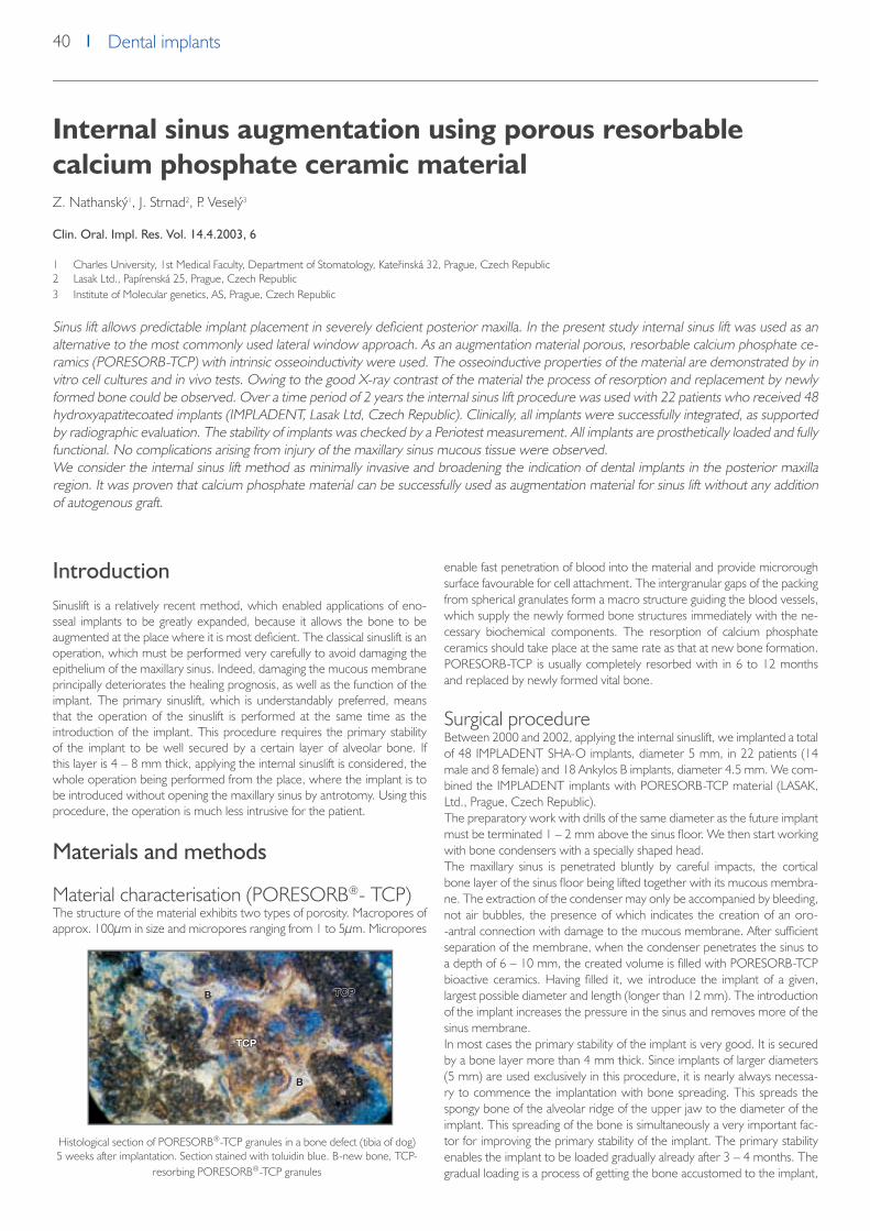
40 Dental implants
Internal sinus augmentation using porous resorbable
calcium phosphate ceramic material
Z. Nathanský1, J. Strnad2, P. Veselý3
Clin. Oral. Impl. Res. Vol. 14.4.2003, 6
1 Charles University, 1st Medical Faculty, Department of Stomatology, Kateřinská 32, Prague, Czech Republic2 Lasak Ltd., Papírenská 25, Prague, Czech Republic3 Institute of Molecular genetics, AS, Prague, Czech Republic
Sinus lift allows predictable implant placement in severely deficient posterior maxilla. In the present study internal sinus lift was used as an alternative to the most commonly used lateral window approach. As an augmentation material porous, resorbable calcium phosphate ce-ramics (PORESORB-TCP) with intrinsic osseoinductivity were used. The osseoinductive properties of the material are demonstrated by in vitro cell cultures and in vivo tests. Owing to the good X-ray contrast of the material the process of resorption and replacement by newly formed bone could be observed. Over a time period of 2 years the internal sinus lift procedure was used with 22 patients who received 48 hydroxyapatitecoated implants (IMPLADENT, Lasak Ltd, Czech Republic). Clinically, all implants were successfully integrated, as supported by radiographic evaluation. The stability of implants was checked by a Periotest measurement. All implants are prosthetically loaded and fully functional. No complications arising from injury of the maxillary sinus mucous tissue were observed.We consider the internal sinus lift method as minimally invasive and broadening the indication of dental implants in the posterior maxilla region. It was proven that calcium phosphate material can be successfully used as augmentation material for sinus lift without any addition of autogenous graft.
IntroductionSinuslift is a relatively recent method, which enabled applications of eno-sseal implants to be greatly expanded, because it allows the bone to be augmented at the place where it is most deficient. The classical sinuslift is an operation, which must be performed very carefully to avoid damaging the epithelium of the maxillary sinus. Indeed, damaging the mucous membrane principally deteriorates the healing prognosis, as well as the function of the implant. The primary sinuslift, which is understandably preferred, means that the operation of the sinuslift is performed at the same time as the introduction of the implant. This procedure requires the primary stability of the implant to be well secured by a certain layer of alveolar bone. If this layer is 4 – 8 mm thick, applying the internal sinuslift is considered, the whole operation being performed from the place, where the implant is to be introduced without opening the maxillary sinus by antrotomy. Using this procedure, the operation is much less intrusive for the patient.
Materials and methods
Material characterisation (PORESORB®- TCP)The structure of the material exhibits two types of porosity. Macropores of approx. 100μm in size and micropores ranging from 1 to 5μm. Micropores
enable fast penetration of blood into the material and provide microrough surface favourable for cell attachment. The intergranular gaps of the packing from spherical granulates form a macro structure guiding the blood vessels, which supply the newly formed bone structures immediately with the ne-cessary biochemical components. The resorption of calcium phosphate ceramics should take place at the same rate as that at new bone formation. PORESORB-TCP is usually completely resorbed with in 6 to 12 months and replaced by newly formed vital bone.
Surgical procedureBetween 2000 and 2002, applying the internal sinuslift, we implanted a total of 48 IMPLADENT SHA-O implants, diameter 5 mm, in 22 patients (14 male and 8 female) and 18 Ankylos B implants, diameter 4.5 mm. We com-bined the IMPLADENT implants with PORESORB-TCP material (LASAK, Ltd., Prague, Czech Republic).The preparatory work with drills of the same diameter as the future implant must be terminated 1 – 2 mm above the sinus floor. We then start working with bone condensers with a specially shaped head.The maxillary sinus is penetrated bluntly by careful impacts, the cortical bone layer of the sinus floor being lifted together with its mucous membra-ne. The extraction of the condenser may only be accompanied by bleeding, not air bubbles, the presence of which indicates the creation of an oro--antral connection with damage to the mucous membrane. After sufficient separation of the membrane, when the condenser penetrates the sinus to a depth of 6 – 10 mm, the created volume is filled with PORESORB-TCP bioactive ceramics. Having filled it, we introduce the implant of a given, largest possible diameter and length (longer than 12 mm). The introduction of the implant increases the pressure in the sinus and removes more of the sinus membrane.In most cases the primary stability of the implant is very good. It is secured by a bone layer more than 4 mm thick. Since implants of larger diameters (5 mm) are used exclusively in this procedure, it is nearly always necessa-ry to commence the implantation with bone spreading. This spreads the spongy bone of the alveolar ridge of the upper jaw to the diameter of the implant. This spreading of the bone is simultaneously a very important fac-tor for improving the primary stability of the implant. The primary stability enables the implant to be loaded gradually already after 3 – 4 months. The gradual loading is a process of getting the bone accustomed to the implant,
Histological section of PORESORB®-TCP granules in a bone defect (tibia of dog) 5 weeks after implantation. Section stained with toluidin blue. B-new bone, TCP-
resorbing PORESORB®-TCP granules
TCP
TCPB
B

41Dental implantsDental implants
in which during the first 14 days the provisional bridge does not reach the occlusion, and the patient is cautioned to eat soft food only. After another two weeks, the bridge has reached the occlusion, and the patient should still try to protect the implant by avoiding biting hard. After six weeks the patient may normally chew food, but avoid hard foodstuffs (nuts, etc.).
Clinical resultsAll implants are prosthetically loaded and the patients have no subjective or objective complaints. In the course of implant healing, an inflammato-ry complication in the region of the alveolar ridge of the upper jaw was observed in two patients. One patient complained of neuralgia of the 2nd branch of the trigeminus, most probably caused by irritation due to too robust an implant.Complications associated with injury to the membrane of the maxillary sinus were not observed in our group of patients. The Periotest values ranged from -3 to 0. Postoperation X-rays show the filled area in the im-plant neighbourhood thanks to X-ray contrast. The contrast decreases after 2 years due to the resorption of the material and its replacement by the newly formed bone tissue.
DiscussionOur present experience indicates that the internal sinuslift is a considerate method, which can also be performed by a dentoalveolar surgeon. Thanks to a certain layer of alveolar bone, the stability of the implant is very good, which enables beginning loading after only 4 months. The loading is, of course, gradual by provisional bridges and requires certain restrictions on foodstuffs which are eaten. If the alveolar ridge is narrow, it must be widened at the beginning of the operation by expanders using the bone spreading method. The resorbable PORESORB-TCP augmentation mate-rial proved to be suitable for this application. We consider the greater X-ray contrast of PORESORB-TCP to be an advantage. Thanks to it the gradual replacement of this material by newly formed bone tissue can be monito-red by X-ray. This is not possible, for example, with bovine hydroxyapatite.The periotest values do not vary greatly during the healing of the implant and, in our opinion, are determined by the height of the alveolar ridge, the quality of the bone and length of the implant.
Evaluation of osteogenic activity of the PORESORB®-TCP in vitro.Chicken embryo bone marrow from long bones derived cells were cul-tivated in vitro with pieces of TCP size of 0.3 mm. After initial cultivation
SEM photograph showing the microstructure of PORESORB®- TCP
Bone condensors IMPLADENT® Application of the PORESORB®-TCP augmentation material
a) The preparation of the implant bed without damaging the mucous membra-ne of the maxillary sinus.
c) The space created by lifting the base of the maxillary sinus together with the membrane is filled with the augmentati-on material.
Granules of PORESORB®- TCP (particle size 0.3-0.6 mm)
b) Introduction of condensers into the bed
d) IMPLADENT® implants in situ

42 Dental implants
for 4 days in standard culture medium (M) the ALP activity was measu-red and found to be at the same level in all selected combinations of tre-atment (Fig. 1). Standard medium was then changed for Target media (D or V) and 3 days later ALP activity was found high in combinations of two factors - (TCP and osteogenic medium): TCP-D or TCP-V, while in single treatments: TCP-M and all controls without TCP be it M, D or V no parti-cular raise of ALP activity was observed. This trend continued until day 16, and then declined as cultures grew old and started dying. On day 27 the remaining cultures were stained of intracellular activity of the ALP, which confirmed the previous findings of extracellular ALP activity. In Fig. 2 (picture width 300 mm) ALP positive cells around a piece of TCP in medium V are shown. Similarly positive cells were observed in bright field around TCP in medium D in Fig. 3a in bright field and in 3b in phase contrast. Explanations:TCP – synthetic, ß-tricalcium phosphate (PORESORB–TCP)
Culture media: M- Standard medium (MEM + 5% calf serum + 5% fetal bovine serum)Target media: V-Osteogenic medium : standard medium + 50 mm vitamin C/ml + 10 mM betaglycerophosphate; D-Osteogenic medium D: Medi-um V + 1 nMDexamethasone.ALP-alkaline phosphatase activity (assessed by BIO-LA-TEST Alkaline phos-phatase 330: the measure in mkat/l of the catalytic concentration of the enzyme is the amount of released 4-nitrophenole)Staining- cells were stained for intracellular ALP activity at the end of expe-riment using SIGMA Fast Red TR/ NAPHTOL AS/MX Tablet Set (F-4523)
ConclusionsIt was shown that the internal sinus lift method is minimally invasive and broadens the indication of dental implants in the posterior maxilla region. It was proven that beta tri-calcium phosphate (PORESORB-TCP) material can be successfully used as an augmentation material for sinus lift without any addition of autogenous graft. Thanks to the resorbability and good X-ray contrast of the material the process of new bone formation can be well monitored.Results of the in vitro experiments confirmed osseoinductive properties of TCP providing that there are three cooperating components of the assay system. The first component was the committed cells in this case derived from chicken bone marrow. The second component was the osteogenic medium in either of the two forms used here, and the last indispensable ingredient was the TCP material. Functionality of such a system depends largely on the conditions of the cells to be committed to osteogenesis as in some earlier experiments these cells could start production of the ALP spontaneously. From this point of view the composed system described here apparently manifests higher potential for directing to osteogenesis even cells that are only weakly committed to osteogenic lineage.
AcknowledgementsThe study was supported by the Department of Industry of the Czech Republic under the project number: FB-CV/64 FF-P/056
Literature1. Meindl D.: Methodik und Ergebnisse der einzeitigen Sinusbodenelevation und Augmentation, Prawissimo Journal 3, 10-11, 20002. Jensen O.T.: The Sinus Bone Graft, Quintessence Publishing Co, 19993. Sethi A.: Die Oberkiefer-Alveolarkammspreizung, Prawissimo Journal 4, 24-27, 20014. Nathanský Z.: Vnitřní sinus lift - nové možnosti dentální implantologie. Česko-slovenská stomatologie (v tisku)5. Poleník P.: The use of platelet rich plasma in regeneration of parodontal and bone tisuue. Quintessence Paradontologie, II. 2002
Postoperative x-ray
Fig. 2: (medium V) - ALP positive cells around TCP particles
Fig. 3a: (medium D) – bright field Fig. 3b: (medium D) – phase
Situation 2 years after prosthetic rehabilitation
Fig. 1: Development of extracellular ALP activity of chicken bone marrow derived cells after treatment with TCP and osteogenic media
Postoperative x-ray Situation 2 years afterprosthetic rehabilitation

43Dental implantsDental implants
Bioactive titanium implants for shorter healing period
A. Šimůnek1, J. Strnad2, A. Štěpánek3
Clin. Oral impl. Res. Vol.13,No. 4, 2002
1 Centre of Dental Implantology at the Clinic of Stomatology, teaching Hospital and Faculty of Medicine, Charles University, Hradec Králové, Czech Republic2 Lasak Ltd., Papírenská 25, Prague, Czech Republic3 Centre of Dental Surgery and Implantology, Třebíč, Czech Republic
A new type of surface treatment for titanium implants has been developed. It combines grit-blasting and acid- and alkali-etching procedures to create three levels of roughness on the macro, micro and sub-micro scale. It has been previously shown that this Bio surface exhibits bioactive and osseo-conductive properties.The effect of the Bio surface on cell differentiation was studied using in vitro cultivated cells isolated from chicken embryos. The first results indicated that the chemically treated titanium surface had the ability to influence differenti-ation of the surrounding cells towards osteoblastic phenotypic expression.
The possibility of reducing the healing period by using implants with a Bio surface has been the subject of a clinical study. Over a period of 27 mon-ths, 485 implants were studied. The healing time was reduced to periods between 90 % and to 30 % of the standard healing period. The success rate of the osseointegration was 99.4%, and the overall success rate of the implants was 98.6%. The statistical data processing reveals that it is possible to reduce the healing period to one half of the conventional time. A pro-spective clinical study will investigate the possibility of shortening the healing period even further.
Replacement of individual teeth with IMPLADENT
implants - a 5 year study
A. Šimůnek1, J. Baše1, D. Kopecká1, R. Mounajjed1, H. Skalská2
Quintessenz, Volume 7, 1998, No.6
1 Centre of Dental Implantology at the Clinic of Stomatology, teaching Hospital and Faculty of Medicine, Charles University, Hradec Králové, Czech Republic2 Department of Informatics, Faculty of Control and Information Technologies, Teacher´s College, Hradec Králové, Czech Republic
Dental implantology is one of the fastest developing stomatological disciplines in the Czech Republic. Thanks to the constantly evolving practice of domestic implantology, dental implants are becoming generally accepted as a part of modern stomatology. In the early 1990‘s there were several implantation systems developed in the Czech Republic, exemplifying further remarkable evolution17. Thanks to the wide offer of accessories, domestic implantation systems match the quality of foreign competitors, whilst still being available for reasonable prices. These implants however lack long-term clinical success rate evaluation, published in professional periodicals.
IntroductionWe have so far devoted a series of articles to the IMPLADENT implant sys-tem, offered since 1992 by the Prague-based company Lasak s.r.o. (Ltd.)14. This has focussed on the shortened dental arch 15, and edentulous jaws16, presenting a three-year multicentric statistical analysis of a collection of 1264 implants 12. We now aim to consider the potential of this system for the single tooth replacement.We replace frontal teeth with dental implants far more frequently in the maxilla than in the mandible. This area is typical for high aesthetic demands concerning the quality of supraconstructions, generally limited bone availa-bility, due to alveolar atrophy and extra-axial load on the implant. In lateral areas, we use implants in both jaws, in the area of molar teeth, mandible is predominant because the volume of alveolar bone available in maxilla is often considerably limited due to the maxillary antrum. The aesthetic aspect is much less important. The greatest problem is the risk of overloading the implant. Sometimes, it is recommended to use two implants under one crown, however, this is often impossible due to the gap length.
Material and methodologyThe analysis incorporates all IMPLADENT implants, applied from July 1993 to February 1998, concerning the indication „loss of one tooth“, which
were assigned for a solo crown. The data on implantations were acquired retrospectively from medical documentation. We followed the common-ly specified contra-indications12. Before applying each implant, orthopan-tomogram was carried out for each patient, sometimes completed with intraoral x-ray images. In order to find out the thickness of alveolus, we made use of dental CT analysis or mapping the gingiva, using a hypodermic needle with a rubber disc. Most patients were instructed on dental hygiene. Recall examinations were carried out according to the previously published scheme.The IMPLADENT system offers seven types of fixtures. Four of them are made of titanium alloy, Ti6A14V (ISO 5832-3), with a hydroxyapatite co-ating, either cylindrical (VHA) or screw-shaped (SHA). They may contain antirotary elements which ensure that abutments do not rotate in the im-plant (SHA-O, VHA-O). The remaining three implants are made of pure titanium (ISO 5832-2) with grit-beasted surface. The first one is screw-type (STI), complemented with a modification comprising an antirotary element (STI-O). The diameter of all the above said implants is 3.6 mm and the length ranges from 8 to 14 mm. In addition, there is a titanium self-tapping screw with an antirotary element (STI- S), diameter 2.9 mm and length 10 to 15 mm. The implants SHA, VHA and STI were available from the very beginning of the monitored period. The SHA-O modification was intro-duced in October 1995 and we subsequently ceased to use all previous types for the replacement of one tooth. The STI-O and STI-S modifications were made available from October and December 1997, respectively and

44 Dental implants
the VHA-O modification in February 1998. We used abutments with a diameter 3.6 or 4.8 mm, either direct or angled at 15 or 25 degrees. The supraconstructions were produced using the appropriate impression and laboratory tools6.Implants were left free of load and isolated from the mouth cavity for a pe-riod of at least three months (mandible) and six months (maxilla). Upon the conclusion of the healing period, the second surgery phase followed, with a two-week application of healing cylindres. We then fitted a new abutment, produced a solo crown and fixed it with cement.We modified the success criteria according to Olsson et al9.An implant was classified as a failure in the case of occurrence of at least one of the following: elimination from alveolus, poor stability, signs of chronic infection, pain or any other undesired subjective feelings, or considerable mechanical damage. Non-osseo-integration during the healing period was classified as primary failure, later malfunction as secondary failure. Implants of patients who did not accept the follow-up care were excluded from our statistical analysis. We evaluated the success rate using the „input-output“ method and the life-table was determined according to the Kaplan-Meier‘ method13. The second evaluation method is based on the time interval elapsed from the application of each particular implant. It gives less optimis-tic results, however, it is a truer expression of reality13.
ResultsWe inserted 1212 IMPLADENT implants between June 1993 and February 1998. We used IMPLADENT implants with 148 (12.2 %) patients (75 male and 73 female patients). One hundred and twenty-four patients had one tooth replaced, nine patients had two teeth replaced and in two cases, we replaced three teeth. Our group therefore comprised 135 patients. For further basic information, see Table 1, Diagram 1 details the age structure of the group. Almost all of the implantations we carried out were delayed at least one year following the extraction of the tooth. In three cases, we carried out immediate or delayed immediate implantation, always in the frontal area of the maxilla, which in all cases turned out to be a success. In one case we replaced a tooth # 27 with two SHA 10 mm implants, bearing a single
crown. We decided upon this option in order to avoid excessive load on the short implants in a poor-quality bone density D4.For the type and length of implants used, see Diagrams 2 and 3. Ninety--eight (66.2 %) implants were made in the maxilla and fifty (33.8 %) in the mandible; for the exact location. For frequency, see Diagram 4. Twenty-three patients are still in the healing phase, which was completed amongst concerning the remaining 125 implants. We encountered primary failure in three cases, in locations 24, 33 and 36. The extractions were carried out not later than during the second surgery phase. The remai-ning 97.6% of implants were successful. Secondary failure was reported in one implant, location 11, which was extracted nineteen months after the application of the crown. The subsequent our-patient programme was not accepted by 29 patients (19.6%), with 19 tooth replacements in the maxilla and 10 replacements in the mandible. Other implants were monitored for an average period of 25.4 months from the implantation (ranging from 3 to 53 months) and 19.3 months after the application of the crown (from 1 to 50 months). Based on the „input-output“ analysis, a total of 95.0% of implantations were successful. The result was identical for both jaws. For the life-table, see Diagram 5. Towards the end of the first and second year, the success rate reached 96.8%, dropping down to 96.8% during the third year. It subsequently remained unchanged.
DiscussionComparison of statistical results between various publications often reveals a considerable discrepancies. We therefore consider the most reliable a comparison with the previously published three-year multicentric study of 1264 IMPLADENT implants, used for all implantological indications 13. The success of the healing phase (97.7 %) was very close to our result – 97.6 %. According to the „input-output“ analysis, 97.7 % of all implants were clas-sified as successful after a period of thirty-six months. In our statistics, the success rate reached 95.0 % after a period of fifty-six months. A more accu-rate result can be determined on the basis of a comparison of the life-table analyses, which take into account the actual monitoring period of individual implants. Within a three-year study13 the success rates after periods of one, two and three years, were 97.2 %, 94.8 % and 92.6 % respectively. Our
Diagram 1: Age structure of patients
Diagram 3: Length of implants applied
Diagram 2: Types of implants applied
Diagram 4: Implantation frequency

45Dental implantsDental implants
result was 96.8 % during the first and second year, and 94.8 % after the third and fourth years. We compared literature resulsts by Malevez et al,8 in order to analyse the topic of a one-tooth replacement. Their evaluation focussed on 84 Brånemark‘ implants, reporting 2.4 % failure within a 5-year period, always during the first year after the implantation itself. Becker et.al.1 evaluated 24 Brånemark‘ implants with the same indication. After a period of one year, they achieved a success rate of 95.7%. Klemke et.al.7 indicate a 90.0% success rate of one-tooth replacements after 10 years, based on an analysis of 236 implants.
ConclusionThe study focuses on the topic of single tooth replacements using IMPLA-DENT dental implants. It references previous publications dealing with this implantation system. The authors draw our attention to specific problems
of this particular procedure and present solutions based on the IMPLA-DENT system. Within the statistical section, the study presents 148 im-plants inserted over a period of 56 months. Implants were monitored du-ring an average period of 25.4 months. Osseointegration was successful for 97.6 % of all implants, based on the final „input-output“ evaluation, 95.0 % of all implants were successful. There was no considerable statistical difference between implants applied in the maxilla and the mandible. Accor-ding to the Kaplan-Meier‘s analysis, the success rate reached 96.8% after the first and second year, dropping down to 94.8 % during the third year, without any further changes. The results are comparable to similar reports of foreign authors involved in the application of prestigious implantation sys-tems. The authors conclude that replacement of single teeth using dental implants is one of the most complex and difficult tasks in stomatology. The IMPLADENT system exhibited adequate reliability over a medium time ho-rizon, and convenient for the patient under consideration.
Literature
1. Becker W., Becker B.E. : Replacement of maxillary and mandibular molars with single endosseous implant restorations. J.Prosthet.Dent. 74, 1995, 51-55
2. Ben-Yehouda A. : Reconstruction of anterior papillae by interdental connective tissue grafts. J.Prosthet.Dent. 77, 1997, 111 -1133. Brugnolo E., Mazzocco C., Cordioli G., Majzoub Z. : Clinical and radiographic findings following placement of single-tooth implants in young patients.
Int.J.Periodont.Rest.Dent. 16, 1996, 421-4334. Coelho A.B., Miranda J.E.S., Pegoraro L.F. : Single-tooth impl ants : A procedure to make a precise, flexible gingival contour on the master cast. J.Pro-
sthet.Dent. 78, 1997, 109-1105. Friedmann J.V. : Five techniques for single tooth replacement on endosseous root-form implants. J.Prosthet.Dent. 69, 1993, 582-587.6. Impladent manual, Protetika, Lasak s.r.o., Prague 19967. Klemke J., Walther W., Worle M., Heners M. : Einzelzahnersatz auf Implantaten – implantologisches und protetisches Risiko. Dtsch. Zahnarztl. Z. 50,
1995, 751-7538. Malevez C., Hermans M., Daelemans P. : Marginal bone levels at Branemark system implants used for single tooth restoration. The influence of implant
design and anatomical region. Clin.Oral Impl.Res. 7, 1996, 162-1699. Olsson M., Friberg B., Nilson H., Kultje C. : Mk II- A modified self-tapping Branemark implant – 3 year results of a control led prospective pilot study.
Int.J.Oral Maxillofac.Impl. 10, 1995, 15-2110. Ramford S.P., Ash M. : Occlusion 4.Ed. W.B.Saunders Co. Philadelphia – London – Toronto 199611. Schirra, C., Wittkowski, S., Hürzeler, M.B.: Aesthetic treatment using a single implant – New technique for optima treatment of soft tissue via impre-
ssion in the first surgery phase and temporary solution, Quintessenz, 7, 1998, No. 1, page 31-3812. Spiekermann H: Implantologie In: Farbatlanten der Zahnmedizin. Band 10. Georg Thieme Verlag, Stuttgart, New York 199413. Šimůnek, A., Stěpánek, A., Zábrodský, V., Nathanský, Z., Strnad, Z.: Three-year multicentric study of ossointegrated Impladent implants, Quinte-
ssenz,6, 1997 No. 3, page 35-4014. Šimůnek, A.: Twelve months with Impladent dental implants, LKS, 6, 1994, No. 12: 22-2415. Šimůnek, A.: Replacement of short dental arch, using Impadent implants. Quintessenz, 4, 1995, No. 6, page 22-2616. Šimůnek, A.: Use of dental Impladent implants in edentulous jaws, Quintessenz, 5, 1996, No. 5, page 45-5117. Vaněk J., Zábrodský, V., Jandl, P.: Current situation of Czechoslovak dental implantology, LKS, 3, 1992, No. 7-8, page 6-7

46 Dental implants
Three-year multicentric study of osseointegrated
Impladent implants
A. Šimůnek1, A. Štěpánek2, V. Zábrodský,3 Z. Nathanský,4 Z. Strnad5
Quintessenz, Vol.6, No.6, 1997
1 Cee of Dental Implantology at the Clinic of Stomatology, teaching Hospital and Faculty of Medicine, Charles University, Hradec Králové, Czech Republic2 Centre of Dental Surgery and Implantology, Třebíč, Czech Republic3 Privat Dental Clinic, Prague, Czech Republic4 Privat Dental Clinic, Prague, Czech Republic5 Lasak Ltd., Papírenská 25, Prague, Czech Republic
Impladent was among the first systems introduced on the market in 1992 in CR and since that time has been subject to several analyses presented in professional periodicals. Our objective is to consolidate these studies and present a longitudinal clinical study of a representa-tive collection of Impladent implants, inserted over a three-year period.
Impladent is a system of two-stage implants, of either of a cylindrical or screw type. The implants are available with a sand-blasted or hydoxyapatite coated surface. All these modifications are available with a diameter of 3.6 mm and lengths of 8, 10, 12 and 14 mm. In addition, there is a titanium self--tapping screw with a diameter of 2.9 mm and lengths of 12, 14, 16 and 18 mm. There is a wide range of abutments supplied: direct, with a 15 or 25 grade angulations, with antirotary elements, ball attachments, for tempora-ry supraconstructions, etc. We recorded basic information on the patients (age, sex, diseases) and the implants applied (type, length), the indication and localisation, dates of first and second implantation phase, type of supra-construction and follow-up data. For our statistical analysis, we applied the two-selection t-test and the relative frequency balance test. We then de-termined the success curve (life table) applying the Kaplan-Meier’ method.Over a period of three years, 529 patients received a total of 1264 im-plants. In total, 698 implants were applied in the maxilla and 566 implants were applied in the mandible. At the conclusion of the monitoring, the healing phase of 983 implants (77.8%) was successfully completed. Osseo- integration was unsuccessful in 23 cases (primary failure), the success rate of the healing phase therefore being 97.7%. Fifteen of the osseointegrated implants were left dormant because the patient failed to appear for further treatment. Supraconstructions were applied to the remaining implants. The
longest period from the application of an implant until the final check-up was 1110 days (437 days on average) and the longest period from the sur-gery phase to the final check-up took 915 days (264 days on average). We carried out final evaluation with respect to 950 implants, because 13 pati-ents, comprising a total of 33 implants, failed to accept the follow-up care. Consequently, a total of 96.6% of implants were successful. We classified additional 32 implants (3.4%) as a failure, of which 23 were primary failures and 9 were secondary failures.The success rate was also expressed on the basis of a “life table” analysis. The results are comparable with results exhibited by prestigious foreign implants. The statistical analyses of coated implants did not reveal any sig-nificant difference between the maxilla and mandible. Nor was there any significant difference in the number of primary and secondary failures. Du-ring the first twelve months from implantation, the risk of failure was not higher than during the subsequent period. Authors attribute these positive properties to the quality of hydroxyapatite implant coating. No event of delamination or dissolution of the coating has been reported. The authors believe that coated implants are particularly appropriate for use in areas of poorer bone quality. This hypothesis shall be examined in further research.

47Dental implantsDental implants
Use of Impladent dental implants in edentulous jaws
A. Šimůnek1
Quintessenz Vol.5, No.5, 1996
1 Centre of Dental Implantology at the Clinic of Stomatology, teaching Hospital and Faculty of Medicine, Charles University, Hradec Králové, Czech Republic
Purpose of this 2 year study was to evaluate the efficacy of the Impladent system in the treatment of edentulous jaw with overdentures supported by ball attachments, screw-retained bars and magnetic attachments.
During the period from September 1993 to April 1996, we applied the Impladent implantation system to 54 patients with an indication „edentu-lous jaw“ (28 male and 26 female patients), aged from 35 to 74 years. The average age was 55.6 years. We replaced the upper dental arch of 17 patients and the lower dental arch of 30 patients, seven patients had both arches replaced. We had at our disposal ball attachments with Ceka ny-lon matrix and a metal adaptor, Dyna system of magnetic fixation (magnets identified as 500g) and the Preci-Horix bar with plastic sliders. After the delivery of a prosthetic replacement, all patients were included in an out--patient programme, including examinations carried out after one, three, six and nine months and then annually. Each year an additional x-ray examina-tion was carried out.We applied a total of 180 screw or cyllindrical implants with hydroxyapatite coatings Impladent, 85 in the maxilla and 95 in the mandible, on average 3.3 implants per patient. We monitored implants for a period of 1 – 32 months after their insertion (19.0 months on average) and1– 27 months af-ter the completion of the healing phase (13.6 months on average). Osseo--integration failure only occurred in two implants, the success rate therefore being 98.8%. The healing phase was successful for 98.7% of cases in the maxilla, and 98.8% of cases in the mandible (considering only implants with
the healing phase complated). After this period, no other implants were extracted.All patients with ball attachments, clips and temporary bridges reported satisfaction with the outcome. Concerning the group with magnetic atta-chments, 12 of them reported being satisfied (48.0%), 4 of them were quite satisfied (16.0%) and 9 of them were not satisfied (36.0%) at all. The reason for their discontent was an inadequate retention of the repla-cement in eight cases (magnetic implants were replaced with other type of attachments). One patient was not satisfied with the aesthetic properties. The remaining 4 replacement were not evaluated, having lost contact with those out-patients.Discussion: We are particularly satisfied with the successful osseo-integra-tion rate. The success rate of 98.9% places Impladent among the world‘s top-quality products in comparison with the results of other studies. Wit-hout any doubt, one of the greatest factors in this success is the hydroxya-patite coating. Together with other authors, we found the vague and poorly demonstrated claims questioning the quality of hydroxypapatite implant co-atings to be poorly justified. Time will prove whether these objections are valid or whether these claims are simply due to commercial considerations.

48 Dental implants
Secondary Stability Assessment of Titanium Implants
with an Alkali-Etched Surface: A Resonance Frequency
Analysis Study in Beagle Dogs
J. Strnad,3 K. Urban,1 C. Povysil2, Z. Strnad3
JOMI, Vol. 23, No. 3, 2008
1 Orthopedic Clinic, Teaching Hospital, Charles University, Hradec Králové, Czech Republic.2 Institute of Pathology, 1st Medical Faculty of Charles University and Institute for Postgraduate Studies, Prague, Czech Republic.3 Laboratory for Glass and Ceramics, Lasak, Prague, Czech Republic.
Purpose: This study was carried out to quantify the effect of an alkali-modified surface on implant stability during healing using an animal model. Materials and Methods: A total of 24 screw-shaped, self-tapping, commercially pure titanium dental implants, divided into a test group (implants with an alkali-modified surface or „biosurface“) and a control group (implants with a turned, machined surface) were in-serted without pretapping in the tibiae of 3 beagle dogs. The resonance frequency analysis method was used to measure the implant stabi-lity quotient (ISQ) 0, 1, 3, 9, and 12 weeks after implantation. The animals were sacrificed after 2, 5, and 12 weeks, and the bone-implant contact (BIC%) was evaluated histomorphometrically. Results: The difference in the osseointegration rates (ΔISQ/Δhealing time) between the implants with alkali-modified surface (biosurface) and those with a turned, machined surface was evaluated as a mean of 0.843 ISQ/week within the first 9 weeks of healing. The mean increase in the secondary implant stability was found to be proportional to the mean increase in the BIC at healing period earlier than 5 weeks. Discussion: The characteristics that differed between the implant surfaces, ie, specific surface area, contact angle, and hydroxylation/hydration, may represent factors that influence the rate of osseointegration and the secondary implant stability. Conclusion: The alkali-treated surface enhances the secondary stability in the early stages of healing compared to the turned, machined surface, as a consequence of faster BIC formation.
In modern dental implantology, advanced treatment protocols (eg, early or immediate loading) are fre quently used to reduce treatment time. Shor-tening the healing period entails new demands on both the pri mary and secondary stability of the implant. Primary implant stability is mainly depen-dent on the mechani cal characteristics of the original bone (its local quality and quantity), the type of implant used (its geometry, diameter, length, and surface), and the surgical tech niques employed. Secondary stability repre-sents enhancement of the stability as a result of peri-implant bone formation through gradual bone remodeling and osteoconduction, with the possibi-lity of new bone formation at the implant-bone interface.1 Contempo rary knowledge indicates that the degree of micromo tion at the bone-implant interface (primary stability) during initial healing is of utmost importance in achieving good secondary stability.2-4 However, sev eral experimental and clinical studies have shown that secondary stability is also strongly influenced by the implant surface characteristics.5,6
To enhance secondary stability and accelerate the formation of stable and functional bone-implant interfaces, a number of implant surfaces have been developed. Surface roughness is the most frequently studied property affecting secondary stability. A sum mary of a number of studies7,8 provi-ding analysis of bone-implant contact and removal torque values using ani-mal models, indicates that roughened tita nium surfaces generally exhibit greater contact with the bone and/or higher removal torque values than smoother implant surfaces, such as turned, machined or polished titanium surfaces. Some authors sug gested that surfaces with mean roughness of 1.0 to 1.5μm exhibit stronger bone response than smoother or rougher implant surfaces.9–12 These sug gestions do not take into consideration che-mical composition changes and physical chemical property variations intro-duced to the compared surfaces by the roughening procedures. It has been shown that the optimal roughness value varies according to the chemical composition and physical chemical properties of the tested surfaces and that, in some cases, the bone response can be more strongly affected by these parameters than by the roughness alone.13–15
Currently, surface modification of titanium by acid etching of turned or sandblasted titanium surfaces to create a micro-rough texture is being in-troduced to support and accelerate the healing and bone forma tion proce-sses around the implant.16–21 Some experi mental studies have indicated that acid-etched sur faces with minimal roughness (Ra = 0.62 μm)16 or greater
roughness (Ra = 2.15 μm)17 exhibit a stronger bone response compa-red to sandblasted, moderately rough surfaces (Ra = 1.26 μm)16 or to mechanically turned, machined low-roughness surfaces (Ra = 0.86 μm).17 Some acid-etched implants with a micro-rough texture can accelerate the osseointegration processes despite their minimal roughness compared to the moderately roughened sand-blasted surfaces.The surface chemistry of titanium implants is also thought to affect the secon-dary stability indepen dently of the surface topography although it is diffi cult to separate the effects of these 2 factors. There is extensive experimental evidence in the literature showing that biomaterials with different chemical compositions trigger different biologic responses.22–26 A specific biologic re-sponse is elicited at the interface with bioactive materials with high surface reactivi ties,14 resulting in the formation of a bond between the tissue and the material surface.22 Bioactive materi als with special chemical compositi-ons, including bioactive glasses, bioactive glass ceramics, hydrated silica, and titanium gel oxides or hydroxyapatite have the ability to very rapidly form a stable interface with bone tissue following the formation of calcium phos phate deposition on their surfaces as a consequence of chemical interaction with body fluids.22 For instance, 50% bone-implant contact is achieved within 7 days for bioactive glasses.22 The mechanical strength of this interface usua-lly exceeds the strength of the bone tissue to which the bioactive material is bonded.27,28 However, because their poor mechanical properties prevent their use as solid implants under high load-bearing conditions, bioactive mate-rials (especially hydroxyapatite) are generally used as a coating applied on the surface of titanium implants to achieve faster and more reliable bonding with bone tissue. In spite of the success achieved in accelerating the bone healing process and in exhibiting greater tol erance to low primary stability in the ear-ly phases of healing,21–31 hydroxyapatite plasma-sprayed coatings have often been the subject of controversy regarding their stability32,33 and low long-term success rate.34,35 On the other hand, some medium-term and long-term clinical studies demonstrate the high success rate of hydroxyapatite-coated implants.36–38 The literature tends to indicate the imperfect adhesion of the hydroxyapatite surface layers and their chemical and mechanical instability ra-ther than their inability to substantially improve osseointegration, especially in the initial stages of healing.

49Dental implantsDental implants
Various attempts have been made to modify the titanium surface to make it bioactive without the use of a thick coating of another bioactive materi-al. The most successful methods of titanium bioactivation have been, for example, alkali or fluoride treatment.39–41 Recently, an alkali-modified sur-face for titanium dental and spinal implants was clinically introduced under the brand name Bio-surface as a potentially bioactive sur face.42–47 The pre-sent study was carried out to quantify the effect of this surface modification on the implant stability during healing, using resonance frequency analysis and histologic examination on an animal model. This study also describes the characteristic sur face properties of this surface and compares them with the turned, machined titanium surface.
Materials and methods
Implant MaterialsA total of 24 screw-shaped, self-tapping, (c.p.) titanium dental implants divi-ded into a control group (12 implants with a turned, machined surface) and a test group (12 implants [Lasak, Prague, Czech Republic]) with sandblas-ted, acid-, and alkali-treated surface [Biosurface; Lasak]) were inserted wit-hout pretapping into the tibiae of 3 beagle dogs. Identically shaped implants with a diameter of 3.7 mm and a length of 10 mm were used for the test and control groups.
Surface CharacterizationThe overall surface morphology of the employed implants was characteri-zed using a scanning electron microscope (SEM, Hitachi, Tokyo, Japan) with an accel erating voltage of 15 to 30 kV (Fig. 1). Surface rough ness measu-rement was carried out using a scanning surface topography instrument, a Talysurf CLI 1000 with a confocal CLA gauge (Taylor Hobson, Leicester, United Kingdom), which provides highly accurate non-contact 3-dimensi-onal measurements. The fol lowing were measured for 3 implants in each group: 3 thread tops, 3 thread valleys, and 3 thread flanks. Four 3-dimensi-onal parameters (amplitude, spacing, and hybrid) were calculated (Table 1). The original unfiltered measurements and measurements made with a filter size of 50 X 50 μm were evaluated.Dynamic contact angle measurement was per formed by the Wilhelmy plate method using a Tensiometer K15 instrument (Kruss, Hamburg, Germany).The wetting angle values in water were determined from the dependence of the wetting force on the immersion depth. The mean values of the we-tting angle were calculated from 4 repeated measure ments (Table 2). The specific surface area was deter mined by the BET krypton gas adsorption method. The surface area is expressed in relation to unit geo metric surface area of the implant as the mean value of 4 repeated measurements (Table 2). The determi nation was performed using an ASAP 2010 M instru ment (Micromeritics, Norcross, GA). Diffuse reflectance infrared Fourier trans-form (DRIFT) spec troscopy was used to determine the degree of sur face hydration. The measurement was performed on a Nicolet 740 instrument
Fig. 1: SEM images of (a to c) the turned, machined surface and (d to f) the biosurface (original magnification a and d X30; b and e X200, c X1500; f X4000).
a
1 mm
200µm 200µm
2µm 2µm
1 mm
b
c
d
e
f
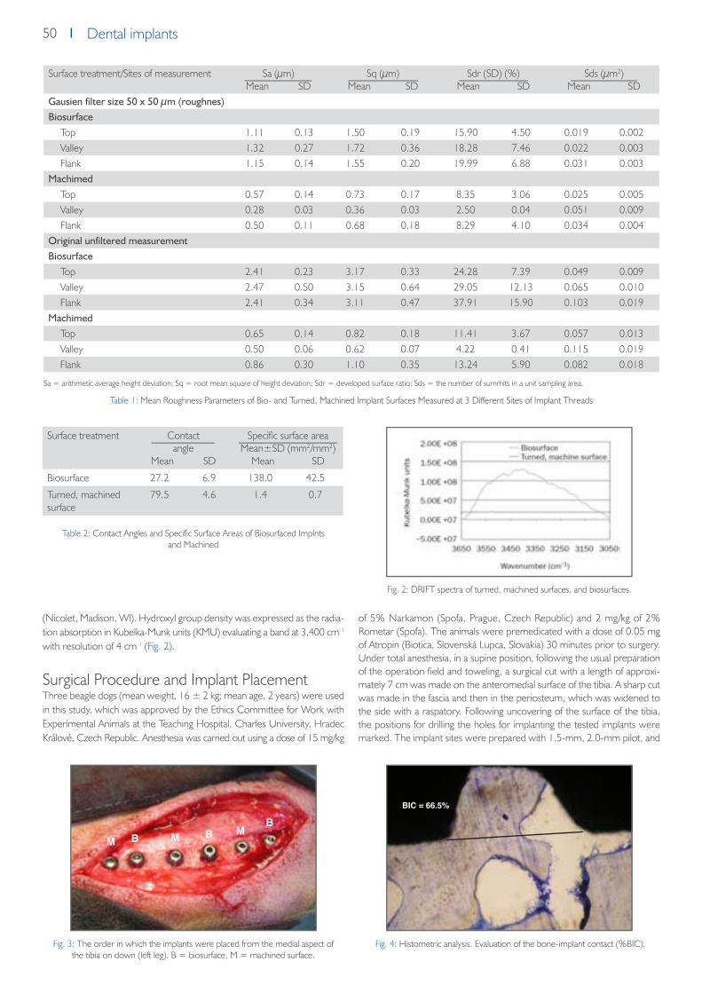
50 Dental implants
(Nicolet, Madison, Wl). Hydroxyl group density was expressed as the radia-tion absorption in Kubelka-Munk units (KMU) evalu ating a band at 3,400 cm-1 with resolution of 4 cm-1 (Fig. 2).
Surgical Procedure and Implant PlacementThree beagle dogs (mean weight, 16 ± 2 kg; mean age, 2 years) were used in this study, which was approved by the Ethics Committee for Work with Experimental Animals at the Teaching Hospital, Charles University, Hradec Králové, Czech Republic. Anesthesia was carried out using a dose of 15 mg/kg
of 5% Narkamon (Spofa, Prague, Czech Republic) and 2 mg/kg of 2% Rometar (Spofa). The animals were premedicated with a dose of 0.05 mg of Atropin (Biotica, Slovenská Lupca, Slovakia) 30 minutes prior to surgery. Under total anesthesia, in a supine position, following the usual preparation of the operation field and toweling, a surgical cut with a length of approxi-mately 7 cm was made on the anteromedial surface of the tibia. A sharp cut was made in the fascia and then in the periosteum, which was widened to the side with a raspatory. Following uncovering of the sur face of the tibia, the positions for drilling the holes for implanting the tested implants were marked. The implant sites were prepared with 1.5-mm, 2.0-mm pilot, and
Fig. 2: DRIFT spectra of turned, machined surfaces, and biosurfaces.
Table 2: Contact Angles and Specific Surface Areas of Biosurfaced Implnts and Machined
Table 1: Mean Roughness Parameters of Bio- and Turned, Machined Implant Surfaces Measured at 3 Different Sites of Implant Threads
Sa = arithmetic average height deviation; Sq = root mean square of height deviation; Sdr = developed surface ratio; Sds = the number of summits in a unit sampling area.
Fig. 4: Histometric analysis. Evaluation of the bone-implant contact (%BIC).Fig. 3: The order in which the implants were placed from the medial aspect of the tibia on down (left leg). B = biosurface, M = machined surface.
Surface treatment Contactangle
Mean SD
Specific surface areaMean±SD (mm2/mm2)
Mean SD
Biosurface 27.2 6.9 138.0 42.5
Turned, machined surface
79.5 4.6 1.4 0.7
Surface treatment/Sites of measurement Sa (μm)Mean SD
Sq (μm)Mean SD
Sdr (SD) (%)Mean SD
Sds (μm2)Mean SD
Gausien filter size 50 x 50 µm (roughnes)Biosurface
Top 1.11 0.13 1.50 0.19 15.90 4.50 0.019 0.002Valley 1.32 0.27 1.72 0.36 18.28 7.46 0.022 0.003Flank 1.15 0.14 1.55 0.20 19.99 6.88 0.031 0.003
MachimedTop 0.57 0.14 0.73 0.17 8.35 3.06 0.025 0.005Valley 0.28 0.03 0.36 0.03 2.50 0.04 0.051 0.009Flank 0.50 0.11 0.68 0.18 8.29 4.10 0.034 0.004
Original unfiltered measurementBiosurface
Top 2.41 0.23 3.17 0.33 24.28 7.39 0.049 0.009Valley 2.47 0.50 3.15 0.64 29.05 12.13 0.065 0.010Flank 2.41 0.34 3.11 0.47 37.91 15.90 0.103 0.019
MachimedTop 0.65 0.14 0.82 0.18 11.41 3.67 0.057 0.013Valley 0.50 0.06 0.62 0.07 4.22 0.41 0.115 0.019Flank 0.86 0.30 1.10 0.35 13.24 5.90 0.082 0.018
M M M
BIC = 66.5%
B BB

51Dental implantsDental implants
3.0-mm drills at 800 rpm with simultaneous cooling with a physiologic so-lution. A countersink drill was then used. The implants were screwed in with an insertion torque of approximately 40 Ncm. The biosur faced and machined implants were alternately inserted in the tibia side by side (eg, biosurfaced, machined, biosurfaced, and so on), as depicted in Fig. 3. The order of the implants was the opposite in the other leg of the same animal (eg, machined, biosur faced, machined, and so on). The first animal received 12 implants (6 from each group). Each of the other 2 animals received 6 implants (3 from each group). In the first animal, implantation was followed by measur ing the stability of the implants using resonance fre quency analy-sis. A probe was screwed into the cervi cal part of the implant, and the soft tissues were pulled to one side with a hook so that they did not affect the probe. The measurement was carried out twice for each implant. This was followed by rinsing of the operation incision. The implants were closed with cover screws, and, following control of hemostasis, the operation incisions were closed in layers and were finally covered with a sterile bandage. Im-plant stabil ity measurement was repeated for each implant in the 1st, 3rd, 9th, and 12th weeks using the same pro cedure. Following completion of the experiment, the dogs were sacrificed after 2, 5, and 12 weeks by an overdose of thiopental (ICN, Roztoky u Prahy, Czech Republic), and the tibiae were removed and fixed in 10% formaldehyde prior to histologic evaluation.
Implant Stability MeasurementThe resonance frequency analysis (RFA) method was used to measure im-plant stability. The measurement was performed using an Osstell instrument (Integra tion Diagnostics, Göteborg, Sweden) with a commer cially available transducer (type F37 L5). The perpen dicular orientation of the transducer along the long axis of the bone was always maintained. The trans ducer, which is fixed to the implant in the bone, con tains a wave source and an analyzer. The wave source vibrates with gradually increasing frequency. The analyzer records the frequency of the source, causing the resonance in the transducer-implant-bone sys tem, including the bone-implant interface. The recorded frequency value in Hz is converted to an implant stability quotient (ISQ) value, which varies in a range from 0 to 100, with 100 indicating maximum stability. The method allows measurement with a precision of ± 1 ISQ.
Histologic Preparation and AnalysisThe tibiae were dissected and blocks of 7 mm thick ness containing 1 im-plant each were prepared. Non-decalcified (ground) sections were pro-cessed accord ing to the method of Donath and Breuner.48 Thin sections with a thickness of 30 to 50 μm were stained with toluidine blue and examined using an optical microscope (Olympus BX-60, Tokyo, Japan) equipped with an image system (Quick PHOTO Industrial 2.0; Olympus, Prague, Czech Republic). Bone-implant interfaces at the threaded part were histometrically analyzed by evaluating the percentage of bone-im-plant contact (BIC). The length of the bone tissue in direct contact with the implant (BC) and the total interface length (IL) were measured (Fig. 4). The per centage of BIC is given by the ratio of the direct con tact length to
the total interface length multiplied by 100. The presented mean values were calculated from the 3 sections as an average for each implant for both types of implant surface.
Statistical AnalysisImplant stability quotient (ISQ) and BIC% data are reported as mean values with standard deviations (SD).Nonparametric Friedman‘s analysis of variance (ANOVA) was performed to analyze variations of ISQ and BIC% during the 12-week follow-up period. The analysis was followed by nonparametric Wilcoxon tests to determine differences within groups between par ticular time intervals. To investigate the statistical signifi cance of the implant group differences, the data were subjected to the nonparametric Mann-Whitney tests. A difference was con-sidered significant when P < .05.To determine the difference in the osseointegration rate between the test and control groups, the time-dependence of the differences (test ISQ – con trol ISQ and test BIC% – control BIC%) were evaluated by the method of linear regressions and the parameters of the straight lines (slopes and inter cepts) were determined. These parameters were cal culated together with the P values, reliability limits, and correlation coefficients. The values of the physico-chemical properties of surfaces are pre sented as mean values and standard deviations (SD).
Results
Primary Implant Stability and Variation of Implant Stability During HealingThe mean ISQs for the machined and biosurfaced groups (± SD) at base-line (primary stability) and at 1, 3, 9, and 12 weeks are presented in Fig. 5.The RFA measurements indicate similar mean pri mary stabilities for both groups of monitored implants (74.0 ± 2.45 for biosurfaced and 74.5 ± 2.99 for machined); no significant difference was observed between the 2 groups (P = .871; Mann-Whitney test). Friedman ANOVA revealed no statisti cally significant differences in biosurface-group ISQ at any of the mea-sured time points (P = 0.482). In contrast, significant differences (P < .001) were revealed during the 12-week follow-up for the machined group. The-re was a statistically significant decrease in ISQ between baseline and 3 (P = .028) and 9 (P = .028) weeks (Wilcoxon matched pairs test). A statistically significant difference between the test and control groups was observed after 3 (P = .0035) and 9 (P = .0035) weeks (Mann-Whitney test; Fig. 5).The time dependence of the differences (biosurface ISQ – machined ISQ) in the first 9 weeks of follow-up was evaluated by the method of linear regressions, and the parameters of the straight line (slope and intercept) were determined as follows: biosurface ISQ – machined ISQ = 0.843 X time (weeks) + 1.0111 (Fig. 6). The correlation coefficient (r = 0.6561) indicated a moderately strong relationship between variables; the slope of the regression line was positive and statistically significant (P < .001).
Fig. 5: Mean implant stability (ISQ ± SD) of biosurfaced implants (B) and machined implants (M) at placement (baseline) and after 1, 3, 9, and 12
weeks. * indicates significant difference (P < .05).
Fig. 6: Time dependence of implant stability difference (biosurface ISQ – machined ISQ). Regression straight line: biosurface ISQ – machined ISQ = 0.843 X time (weeks) + 1.0111. Boundaries of reliability are shown
(dashed lines). Correlation coefficient r = 0.756.

52 Dental implants
Histologic Examination (Histologic Observations)Histologic examination of the bone-implant inter face was performed for both types of tested implant surfaces 2, 5, and 12 weeks after implantation. Three implants from each group were evaluated for each time interval. The cervical part of the implants was mostly surrounded by cortical bone, while the thread part was surrounded by trabecular bone. Close BIC was frequently observed at the cervical part of the implants with the biosurface. In contrast, the speci mens with turned, machined surfaces showed patchy BIC, and intermediate soft tissue was indicated in some cases (Fig. 7). The time development of the bone-implant contact (BIC%) at the thread part of
the implant was evaluated histometrically (Figs. 8 and 9). The results of the histometric analysis are pre sented in Fig. 10.Friedman ANOVA revealed statistically significant differences in BIC% for the test group (P = .029) as well as the control group (P = .032) at all measured time points. BIC of the biosurfaced group increased sharply during the first 2 weeks in contrast to the machined group, which exhibited a gradual increase starting at a later timepoint (Fig. 11 ). Using the Mann-Whitney test, statistically significant differences between the test and control groups were observed after 2 weeks (P = .046) , 5 weeks (P = .049), and 12 weeks (P = .049).The time dependence of the differences in BIC between the groups in the first 5 weeks was evalu ated by the method of linear regressions, and the parameters of the straight line (slope and intercept) were determined as fo-llows: test BIC – control BIC = 7.94 * time (weeks) + 10.92. The positive slope of the regression line was found to have a correlation coef ficient of r = 0.7561 and to be statistically significant (P = .013).
Relationship Between Implant Stability and BICEvaluation of the correlation between the contribu tion of the biosurface to the implant stability (test ISQ – control ISQ) and the BIC (test BIC% – con-trol BIC%) could not be performed by the standard method of correlation coefficients because of the experimental arrangement. Nevertheless, it was shown that test BIC% – control BIC% was propor tional to time (P = .013) as was test ISQ – control ISQ (P < .001). This supports the hypothesis that during the first 5 weeks of the healing period, these 2 quan tities are proportional to each other.
DiscussionThis study presents the results of measurement of changes in the stability and BIC during healing of implants with biosurfaces and turned, machined surfaces.
Fig. 7: Photomicrographs of the bone-implant interface at the cervical part of the implants with (a) a machined surface and (b) a biosurface 2 weeks after implantation (toluidine blue; original magnification X500). Histologic examination indicated the
formation of intermediate soft tissue in the case of implants with machined surfaces.
Fig. 8: Photomicrographs of the BIC at the threaded part of implants with (a) a machined surface and (b) a biosurface 5 weeks after implantation (toluidine blue;
original magnification X200). The BIC of the machined implant surface was a consi-derably lower value than the biosurface.
Fig. 10: Mean BIC values ± SD for biosurfaced and machined implants at 2, 5, and 12 weeks postimplantation. * indicates significant difference (P < .05).
Fig. 9: Photomicrographs of the bone-implant interface at the threaded part of im-plants with (a) a machined surface and (b) a biosurface 12 weeks after implantation (toluidine blue; original magnification X200). High BIC was seen in the threads of
both the machined and biosurfaced groups.
Fig. 11: Scheme of the variation in the total, primary, and secondary implant stability during healing, illustrating the relationship ISQT = ISQP + ISQS.
a b
a ab b

53Dental implantsDental implants
RFA measurements showed that implants with machined surfaces exhibited a significant stability decrease after implantation. This decrease leveled off after as long as 12 weeks of healing. The biosurfaced implants did not show any significant stability change and maintained their stability during the monitored period. It was observed that even RFA indicated no change in implant stability with time (Fig. 5); simultaneously, bone integration and increased bone-im-plant contact were observed (Fig. 10). Similar results have been reported by several authors, showing that distinct BIC%s may have simi lar values of implant stability or that implants with similar BIC%s may have different ISQs. These results could be taken as an indication of lack of correlation between BIC and implant stability.49–52 However, it must be borne in mind that the measured RFA data represent the total implant stability (ISQT), which is com-posed of the contributions of the primary (ISQP) and secondary (ISQS) implant stability (ISQT = ISQP + ISQS). Furthermore, when monitoring changes du-ring healing, it must also be recalled that the contribu tions of these 2 factors (secondary and primary sta bility) change with the healing time. The secondary stability increases with increasing healing time as a result of new bone forma-tion. The initial primary stability decreases with time as a result of mechani-cal bone relaxation and biologic changes associated with the original bone. Consequently, the individual data on the total stability of the implant do not provide any information on the relationship to osseointegration or the degree of BIC in the absence of information on how the secondary or primary sta-bility contribute to the total stability value. The con tribution of primary stability (ISQP) must be known in order to determine that of secondary stability (ISQS = ISQT – ISQP; Fig. 11).Nevertheless, in a comparative study, considering the same pattern of pri-mary stability for the 2 types of implants compared at placement and during heal ing, the difference in their total implant stabilities (test ISQT – control ISQT)t measured by RFA at time point t yields the difference in the seconda-ry stabili ties according to the following formula:
(test ISQs–control ISQs)t = (test ISQT–control ISQT)t– (test ISQP–control ISQP)t, where (test ISQP–control ISQP)t = 0.
In the animal model used, the primary implant sta bility (at the moment of placement) did not exhibit a statistically significant difference between the test and control groups; (test ISQP – control ISQP)t = 0 = 0. Furthermo-re, standardization of the insertion proce dure and the identical shapes of the implants used for both groups of implants make it possible to assume that the variations in the primary stability with time for the test and con-trol groups are coinci dent (test ISQP – control ISQP)t = 0. Under these cir cumstances, the stability difference (test ISQT – con trol ISQT) observed experimentally from RFA measurements representing the net contribution of the biosurface to the implant stability may be consid ered equal to the difference in the secondary stabilities (test ISQS – control ISQS) of implants with biosur face (test) and the turned, machined surface (control). The slope of the dependence of (test ISQT – control ISQT) versus healing time t then corresponds to the difference in the secondary stability rates between the implants with the biosurface and the turned, machined surface
(test ISQT– control ISQT) = (Δtest ISQS) –
(Δcontrol ISQS) Δt Δt Δt
where Δtest ISQs and Δcontrol ISQs correspond to the changes in ISQ values and Δt represents the corresponding interval of the healing time of implants in bone.
If the osseointegration rate is defined as propor tional to the secondary sta-bility rate (ΔISQ/Δt), the difference in the osseointegration rate between the biosurfaces and turned, machined surfaces could be estimated as a mean value at 0.843 ISQ/week within the first 9 weeks of healing.Referring to the evaluation of the correlation between the contributions of the biosurface to ISQ and BIC, it may also be concluded that the variations in the secondary stabilities of the biosurfaced implants were proportional to the changes in the BIC within the first 5 weeks of follow-up. These findings demonstrated that the biosurface enhances sec ondary stability compared with the turned, machined surface as a consequence of more rapid forma-tion of BIC in the early stages of healing.It can be speculated that the differences in the rates of osseointegration in the initial stages of healing for the biosurfaces and the machined surfaces could be related to different surface reactivity due to the different surface material properties, eg, specific surface area, surface wettability, surface contact angle, and surface hydroxylation/hydration. In general, surface re-activity, which is a common characteristic of bioactive materials,14 increases with increasing specific surface area. Therefore, the 3-dimensional macro-, micro- and nano-structured biosurface which exhibits a surface area almost 100 times larger than the turned, machined surface, may significantly en-hance the surface reactivity with the surrounding ions, amino acids, and proteins, which modulate the initial cellular events at the cell-material in-terface.53
In addition, the easily wettable hydrophilic biosurface enables establishment of good contact between the body (specifically, blood) and the rough and porous structure of the implant, and thus contributes to cellular and biomo-lecular migration and adhesion.54,55 This biosurface, which is rich in hydroxyl groups, in contrast to the machined surface, rapidly induces adsorption of calcium and phosphate ions on contact with the ions of the blood plasma.42 The calcium phosphate-rich layer promotes adsorption and concentrati-on of proteins56,57 and constitutes a suitable substrate for the first apatite structures of the bone matrix, which are synthesized by the osteogenic cells at the beginning of the formation of the new bone tissue. This mechanism can accelerate the formation of a stable bone-implant interface formed by fusion of the biologic cement-line matrix with the reactive calcium phospha-te layer on the surface.
ConclusionsThe test surface (biosurface) enhances the secondary stability at an early stage of healing compared with the turned, machined surface, as a conse-quence of more rapid bone-implant contact formation. In con trast to the hydrophobic turned, machined surface, the biosurface, which is rich in hyd-roxyl groups, exhibits hydrophilic character, a low wetting angle, and high specific surface area.
AcknowledgmentsThe study was supported by the Grant Agency of the Ministry of Industry and Trade of the Czech Republic (project no. FT-TA/087). Two authors (Jakub Strnad, Zdenek Strnad) are working in the research department of the Lasak, which is one of the grant fund ing recipients.
References1. Davies JE. Mechanisms of endosseous integration. Int J Prosthodont 1998;11:391 -401.2. Søballe K, Hansen ES, B-Rasmussen H, Jørgensen PH, Bünger C. Tissue ingrowth into titanium and hydroxyapatite-coated implants during stable and
unstable mechanical conditions.J Orthop Res 1992;10:285-299.3. Pilliar RM. Quantitative evaluation of the effect of movement at a porous coated implant-bone interface. In: Davis EJ (ed). The Bone-Biomaterial Inter-
face.Toronto: University of Toronto Press, 1995:380–387.4. Brunski JE. Biomechanical factors affecting the bone-dental implant interface. Clin Materials 1992;3:153–201.5. Raghavendra S, Wood MC, Taylor TD. Early wound healing around endosseous implants: Review of the literature. Int J Oral Maxillofac Implants
2005;20:425-431.6. Hench LL. Surface reaction kinetics and adsorption of biologi cal moieties: A mechanistic approach to tissue attachment. In: Davies JE (ed). The Bone-
-Biomaterial Interface.Toronto: Uni versity of Toronto Press, 1995:33–48.

54 Dental implants
7. Cochran DL, Buser D. Bone response to sandblasted and acid- attacked titanium: Experimental and clinical studies In: Davies JE. Bone Engineering.Toronto: Em Squared, 2000:391–398.
8. Wennerberg A, Albrektsson T, Johansson C, Andersson B. Experimental study of turned and grit-blasted screw-shaped implants with special emphasis on effects of blasting material and surface topography. Biomaterials 1996;17:15–22.
9. Wennerberg A, Albrektsson T, Lausmaa J. Torque and histomorphometric evaluation of c.p. titanium screws blasted with 25- and 75-micron-sized particles of AI203. J Biomed Mater Res 1996;30:251–260.
10. Wennerberg A, Albrektsson T, Anderson B, Krol JJ. A histomorphometric and removal torque study of screw-shaped tita nium implants with three different surface topografie. Clin Oral Implants Res 1995;6:24–30.
11. Wennerberg A, Hallgren C, Johansson C, Danelli S. A histomorphometric evaluation of screw-shaped implants each pre pared with two surface rou-ghnesses. Clin Oral Implants Res 1998;9:11–19.
12. Wennerberg A, Albrektsson T. Suggested guidelines for the topographic evaluation of implant surfaces. Int J Oral Maxillo fac Implants 2000;15:331–344.13. Sul YT, Johansson C, Wennerberg A, Cho LR, Chang BS, Albrek tsson T. Optimum surface properties of oxidized implants for reinforcement of osseo-
integration: Surface chemistry, oxide thickness, porosity, roughness, and crystal structure. Int J Oral Maxillofac Implants 2005;20:349–359.14. Ducheyne P, Qiu Q. Bioactive ceramics: The effect of surface reactivity on bone formation and bone cell function. Biomate rials 1999;20:2287–3303.15. Sul YT, Johansson C, Albrektsson T. Which surface properties enhance bone response to implants? Comparison of oxidized magnesium, TiUnite, and
Osseotite implant surfaces. Int J Prosthodont 2006;19:319–329.16. Cordioli G, Majzoub Z, Piattelli A, Scarano A. Removal torque and histomorphometric investigation of 4 different titanium surfaces: An experimental
study in the rabbit tibia. Int J Oral Maxillofac Implants 2000;15:668–674.17. Marinho VC, Celletti R, Bracchetti G, Petrone G, Minkin C, Piat telli A. Sandblasted and acid-etched dental implants: A histo logic study in rats. Int J Oral
Maxillofac Implants 2003;18:75–81.18. Lazzara RJ. Bone response to dual acid-etched and machined titanium implant surfaces. In: Davies JE. Bone Engineering. Toronto: Em squared,
2000:381–388.19. Klokkevold PR, Johnson P, Dadgostari S, Caputo A, Davies JE, Nishimura RD. Early endosseous integration enhanced by dual acid etching of titanium:
A torque removal study in the rabbit. Clin Oral Implants Res 2001;12:350–357.20. Abrahamsson I, Berglundh T, Binder E, Lang NP, Jan Lineje J. Early bone formation adjacent to rough and turned endosseous implant surfaces. An
experimental study in the dog. Clin Oral Implants Res 2004;15:381–392.21. Buser D, Schenk RK, Steinemann S, Fiorellini JP, Fox CH, Stich H. Influence of surface characteristics on bone integration of titanium implants. A histo-
morphometric study in miniature pigs. J Biomed Mater Res 1991;25:889–902.22. Hench LL, Wilson J (eds.). An Introduction to Bioceramics. Singapore: World Scientific, 1999:1 –23,41–62.23. Anderson OH, Larisin KH. Models for physical properties and bioactivity of phosphate opal glasses. Glastech Ber 1988;61: 141–145.24. Strnad Z. Role of the glass phase in bioactive glass-ceramics. Biomaterials 1992;13:317–321.25. Koga N, Strnad J, Strnad Z, Šesták J. Thermodynamics of nonbridging oxygen in silica bio-compatible glass-ceramics: Mimetic material for the bone
tissue substitution. J Therm Anal Calorim 2003;71:927–937.26. Sul YT. The significance of the surface properties of oxidized titanium to the bone response: Special emphasis on potential biochemical bonding of
oxidized titanium implant. Biomaterials 2003;24:3893–3907.27. Kokubo T, Ito S, Shigematsu M, Sakka S, Yamamuro T. Fatigue and life-time of bioactive glass-ceramics A-W containing apatite and wollastonite. J Mater
Sci 1987;22;4067–4070.28. Hench LL. Bioceramics: From concept to clinic. J Am Ceram Soc 1991;74:1487–1570.29. Sun L, Berndt CC, Gross KA, Kucuk A. Material fundamentals and clinical performance of plasma-sprayed hydroxyapatite coatings: A review. J Biomed
Mater Res 2001;58:570–592.30. Clemens JAM, Klein CPAT, Vriesde RC, Rozing PM, deGroot K. Healing of large (2 mm) gaps around calcium phosphatecoated bone implants: A study
in goats with a follow-up of 6 months. J Biomed Mater Res 1998;40:341–349.31. Strnad Z, Strnad J, Povysil C, Urban K. Effect of plasma- sprayed hydroxyapatite coating on osteoconductivity of comercially pure titanium implants. Int
J Oral Maxillofac Implants 2000;15:483–490.32. Liao H, Fartash B, Li J. Stability of hydroxyapatite coatings on titanium oral implants (IMZ). 2 retrieved cases. Clin Oral Implants Res 1997;8:68–72.33. Rohrer MD, Sobczak RR, Prasad HS, Morris HF. Postmortem his tologic evaluation of mandibular titanium and maxillary hydroxyapatite-coated implants
from 1 patient. Int J Oral Max illofac Implants 1999;14:579–586.34. Block MS, Gardiner D, Kent JN, Misiek DJ, Finger IM, Guerra L. Hydroxyapatite-coated cylindrical implants in the posterior mandible: 10-year observa-
tions. Int J Oral Maxillofac Implants 1996;11:626–633.35. Wheeler SL. Eight-year clinical retrospective study of titanium plasma-sprayed and hydroxyapatite-coated cylinder implants. Int J Oral Maxillofac Im-
plants 1996;11:340–350.36. Geurs NCJeffcoat RL, McGlumphy EA, Reddy MS, Jeffcoat MK. Influence of implant geometry and surface characteristics on progressive osseointegra-
tion. Int J Oral Maxillofac Implants 2002;17:811–815.37. McGlumphy EA, Peterson LJ, Larsen PE, Jeffcoat MK. Prospec tive study of 429 hydroxyapatite-coated cylindric Omniloc implants placed in 121 pati-
ents. Int J Oral Maxillofac Implants 2003;18:82–92.38. Schwartz-Arad D, Mardinger 0, Levin L, Kozlovsky A, Hirshberg A. Marginal bone loss pattern around hydroxyapatite-coated versus commercially pure
titanium implants after up to 12 years of follow-up. Int J Oral Maxillofac Implants 2005;20:238–244.39. Kim HM, Miyaji F, Kokubo T, Nishiguchi S, Nakamura T. Graded surface structure of bioactive titanium metal prepared by chemical treatment. J Biomed
Mater Res 1999;45:100–107.40. Ellingsen JE, Johansson CB, Wennerberg A, Holmén A. Improved retention and bone to implant contact with fluo ride modified titanium implants. Int
J Oral Maxillofac Implants 2004;19:659–666.41. Ellingsen JE. On the properties of surface-modified yitanium. In: Davies JE (ed). Bone Engineering. Toronto: Em Squared, 2000:183–189.42. Strnad J, Protivínsky J, Mazur D, et al. Interaction of acid and alkali treated titanium with dynamic simulated body environ ment. J Therm Anal Calorim
2004;76:17–31.43. Jonášová L, Müller FA, Helebrand A, Strnad J, Greil P. Bio- mimetic apatite formation on chemically treated titanium. Biomaterials 2004;25:1187–1194.44. Strnad J, Helebrant A, Mráz R. Effect of titanium processing on the bioactivity of sodium titanate gel layer. In: Stallforth H, Revell P (eds). Materials for
Medical Engineering. Euromat 99 (vol 2). Weinheim: Wiley-VCH, 2000:133–139.45. Strnad J, Helebrant A. Kinetics of bone-like apatite formation in simulate body fluid. In: Helebrant A, Maryska M, Kasa S (eds). Proceedings of the 5th
ESG Conference, Glass Science and Technology for the 21 st Century. Prague: Czech Glass Society, 1999:9–16.

55Dental implantsDental implants
46. Jonášová L, Hlaváč J. Effect of chemical treatment of titanium on apatite formation. In: Stallforth H, Revell P (eds). Materials for Medical Engineering. Euromat 99 (vol 2). Weinheim: Wiley- VCH, 2000:126–132.
47. Strnad J, Helebrant A, Hamáčková J. Bone-like apatite forma tion in titanium and silica glass. Glastechn Ber 2000;73(C1): 262–269.48. Donath K, Breuner GA. Method for the study of undecalcified bones and teeth with attached soft tissues.The Sage-Schliff (sawing and grinding) tech-
nique. J Oral Pathol 1982;11:318–321.49. Rasmusson L, Kahnberg KE, Tan A. Effects of implant design and surface on bone regeneration and implant stability. Clin Implant Dent and Relat Res
2001;3:2–8.50. Rasmusson L, Meredith N, Cho H, Sennerby L.The influence of simultaneous vs delayed placement on stability of titanium implants in onlay bone
grafts. Int J Oral Maxillofac Surg 1999; 28:224–231.51. Friberg B, Sennerby L, Meredith N, Lekholm U. Comparison between cutting torque and resonance frequency measure ment of maxillary implants.
Int J Oral Maxillofac Surg 1999; 28:297–303.52. Rompen E, DaSilva D, Hockers T, et al. Influence of implant design on primary fit and stability. Applied Osseointegration Res 2001;2:9–11.53. Keselowsky BG, Collard DM, Garcia AJ. Surface chemistry mod ulates focal adhesion composition and signalling through changes in integrin binding.
Biomaterials 2004;25:5947–5954.54. Lampin M,Warocquier–Cclerout R, Legris C, et al. Correlation between substratum roughness and wettability, cell adhesion and cell migration. J
Biomed Mater Res 1997;36:99–108.55. Webb K, Hlady V,Tresco PA. Relative importance of surface wettability and charged functional groups on NIH 3T3 fibrob last attachment, spreading,
and cytoskeletal organization. J Biomed Mater Res 1998;41:422–442.56. El-Ghannam A, Ducheyne P, Shapiro IM. Formation of surface reaction products on bioactive glass and their effects on the expression of the osteob-
lastic phenotype and the deposition of mineralized extracellular matrix. Biomaterials 1997;18:295–303.

56 Dental implants
Effect of chemically modified titanium surfaces on protein
adsorption and osteoblast precursor cell behavior
J. Protivínský1,2, M. Appleford2, J. Strnad1, A. Helebrant3, JL. Ong2
International Journal of Oral and Maxillofacial Implants Vol. 22, No. 4, 2007
1 LASAK Ltd, Papírenská 25, Prague 6, Czech Republic2 Department of Biomedical Engineering, University of Texas at San Antonio, San Antonio, Texas, USA3 Institute of Chemical Technology, Technická 5, Prague 6, Czech Republic
Purpose: To investigate the effects of different chemically treated titanium on protein adsorption and the osteoblastic differentiation of human embryonic palatal mesenchyme cells (HEPM). Materials and Methods: In this study, a total of 3 different surfaces were evaluated. The first had a machined surface used as controls for the study (Ti-M). The second sample type (Ti-AE) was acid etched. The third type of altered titanium (Ti-AAE) samples was prepared by exposing the Ti-AE samples to NaOH solution. The surface characteristics of chemi-cally modified Ti were investigated by means of scanning electron microscopy (SEM), Fourier transform infrared spectroscopy (FTIR), and profilometry. To evaluate the production of biomarkers, commercial kits were utilized. Results: This study shows that surface composition and morphology affected the kinetics of protein adsorption. Ti-AE surfaces manifested a higher affinity for fibronectin adsorption when compared to Ti-M and Ti-AAE surfaces. It was observed that Ti-AE and Ti-AAE surfaces promoted a significantly higher cell attachment when compared to Ti-M surfaces. Statistically significant differences were also observed in the expression ofALPactivity, osteocalcin, and osteopontin on all three titanium surfaces. Discussion: Alkaline phosphatase (ALP) activity and osteocalcin production up to day 12 su-ggested that differentiation of the cells into osteoblasts had occurred and were expressing a bone-forming phenotype. Conclusions: It was thus concluded from this study that surface morphology and composition play a critical role in enhancing HEPMcell proliferation and its differentiation into osteoblast cells.
Fig. 1: FN adsorption kinetics of 0,5 mg/mL FN over 3-hour period. Values represent means stan-
dard deviation (n = 5)
Fig. 2: Osteoblast precusor cell attachment on Ti-M, Ti-AE and Ti-AAE. Values represent means standard
deviation (n = 5)
Fig. 3: Osteoblast precusor cell proliferation after 1, 6, 12, 18 and 24 days of culture on Ti-M, Ti-AE and Ti-AAE. Values represent means ± standard
deviation; each bar represents 5 disks * denotes a statistically significant difference
(P < .05)
Fig. 4: SEM images of osteoblast precursor cells plated on (a) Ti-M, (b) Ti-AE and (c) Ti-AAE surfaces after 6 hours of cell culture
a b c

57Dental implantsDental implants
Chemically treated titanium: early surface activity
detected in vitro
J. Strnad1, J. Protivínský2, Z. Strnad1, P. Veselý3
Clin. Oral impl. Res., Vol. 13, No. 4, 2002
1 Lasak Ltd., Papírenská 25, Prague, Czech Republic2 Department of Glass and Ceramics, Institute of Chemical Technology, Technická 5, Prague, Czech Republic3 Institute of Molecular Genetics, AS, Prague, Czech Republic
This study examined the early interaction of the acid and alkali-etched titanium surfaces with the simulated body fluid (SBF) and cultured cells. Machined commercially pure (CP) titanium was used as a reference mate-rial. After exposure to SBF samples were analyzed by X-ray photoelectron spectroscopy, X-ray diffraction and electron microanalysis. The results pro-ved presence of adsorbed calcium and phosphate ions on the chemically treated (CT)surface after 2.5 minutes exposure to SBF. The adsorbate later transformed into crystalline apatite. The surface changes were in accord with those in the solution, showing an immediate decrease of calcium and phosphate concentrations. The rapid formation of the calcium phosphate on the surface could cause the bioactive properties of the (CT) surface.
The significance of this finding was tested in an interaction with living cells in vitro. Machined CP titanium did not stimulate long lasting cells, ALP ne-gative, did not discriminate between CT Ti or CP Ti or steel within first 2 days. Where as over a period of 2 weeks it was proven that haptotaxis was a property of only the CT Ti. Chicken embryonic cells with an osteoblastic potential during 3 weeks in contact with the CT Ti surface attached them-selves to it and showed increased alkaline phosphatase (ALP) activity. This therefore indicated its conceivable osteoinductive potential. This relation-ship between surface chemistry and bioactivity was revealed by an in vitro bioassay with living cells.
Effect of plasma sprayed hydroxyapatite coating
on osteoconductivity of commercially pure titanium
implants
Z. Strnad1, J. Strnad2, C. Povýšil3, K. Urban4
Int. J. Oral. Maxillofac Implants, Vol.15, No. 4, 2000
1 Lasak Ltd., Papírenská 25, Prague, Czech Republic2 Department of Glass and Ceramics, Institute of Chemical Technology, Technická 5, Prague, Czech Republic3 2nd Institute of Pathology, 1st Medical Faculty of Charles University and Institute for Postgraduate Studies, U Nemocnice 4, Prague, Czech Republic4 Orthopedic Clinic, Faculty Hospital, Hradec Králové, Czech Republic
This study examines the formation of a calcium phosphate layer on surfaces of plasma sprayed hydroxyapatite (PSHA) and sand-blasted co-mmercially pure (CP) titanium in simulated body fluid (SBF) with ion concentrations similar to those of human blood plasma. The surface of PSHA induced the formation of calcium phosphate surface layers, while the precipitation of calcium phosphate on sand-blasted CP titanium has not been detected. Histologic evaluation of in vivo tests has demonstrated that implants with a PSHA coating enabled the growth of the bone tissue into gaps with a depth of up to 1 mm without significant formation of intermediate fibrous tissue. In comparison to sand-blasted CP titanium, implants with PSHA coating exhibited greater tolerance to unfavorable conditions during healing, such as gaps at the interface or primary instability of the implant. In the case of good primary stability of the implant gap-filling with fibrous tissue was observed for sand--blasted CP titanium implants over the greater part of the surface of gaps with a depth of 0.3 mm. A direct contact of CP titanium implants with bone was achieved only when press-fit implantation model was used.
IntroductionIt is known that, in addition to their ability to form a direct bond with living bone tissue1,2,3, bioactive materials (bioglass, A-W glassceramic, Hydroxya-patite) also exhibit osteoconductive properties in contrast to bioinert mate-rials such as CP titanium or the titanium alloy, Ti6Al4V4. Osteoconductive properties are understood to consist of the ability of the material to act as a lattice for the osteoblast in the interconnection of defects (gaps) during the gradual formation of new bone. It can be expected that this specific
property of bioactive materials is a consequence of their ability to form a thin calcium phosphate layer on the surface of the implant during a period of minutes to days, depending on the type of material, as a consequence of reactions with body fluids.5,6 The chemical and crystallographic properties of this calcium phosphate phase are almost identical with bone apatite7. It can be assumed that bioactive implants with osteoconductive ability will thus exhibit greater tolerance to unfavorable conditions during implant hea-ling, such as micro-movements8 or gaps between the implant and the bone matrix9. It was recently demonstrated in the work of Clemens et al.10, 11

58 Dental implants
that there is a maximum gap size witch still permits bone apposition on the surface of an implant with plasma sprayed hydroxyapatite (PSHA) coating during healing, without the gap filling with soft tissue. The authors demon-strated on an animal model that this limit lies between 1-2 mm. Gaps of 1 mm between an implant with PSHA coating and the bone were filled with new bone without being filled by soft tissue. This is in contrast to a CP titanium implant, where the bone was separated by fibrous tissue under the same conditions.12 The same results were achieved both 6 weeks and 6 months following the implantation. It can be assumed that a maximal size of the gap for which gap-filling with soft tissue will not occur will also exist for titanium implants, with a value of less than 1 mm.10,11,12
Thus, models with gaps of 0 to 1 mm were selected for the present study to investigate the growth of bone tissue. Samples of uncoated CP titanium implants and implants with PSHA coating were implanted into the tibiae of dogs in model arrangements with different primary stability and primary contact of bones to the surface of the implant, for histologic evaluation. The interactions of implants with PSHA coating and CP titanium implants with simulated body fluid (SBF) were studied by tests in vitro. These tests involved analysis of the surface of the implants and examination of changes in the concentrations of ions in SBF solutions dependent upon the exposure period.
Methods and materials
Sample preparationSamples in simulated body fluid (in vitro test) were prepared using co-mmercially pure (CP) titanium (Austenal Dental material AB, Malmö, Sweden) grade 3, in the form of discs with a diameter of 10 mm and thickness of 1 mm. Non-coated samples were roughened by sand-blas-ting with alumina powder (grain size 100μm). The samples were washed in ethanol in an ultrasonic cleaner and dried at 120oC. Coated samples were prepared by plasmatic deposition of hydroxyapatite on the surface of the abovementioned sand-blasted CP titanium discs. Thickness of the coating was 50μm. Surface roughness parameters of both sand-blasted and plasma sprayed hydroxyapatite (PSHA) coated samples were evalua-ted (Tab.2): Ra – arithmetic mean of the profile departures from the mean line, S – mean spacing of the adjacent local peaks, Rku– profile sharpness. The profilometer TALYSURF 6 (Taylor Hobson, Leicester, U.K.) was used. Test implantation was undertaken using implants with the above described sand-blasted and PSHA coated surfaces. Both kinds of implants had the shape of cylinders (or cylinders with a 0.3 mm deep groove, Fig. 2), with a diameter of 3.7 mm and height of 10 mm. Before plasma spraying the diameter of implants was machined to 3.6 mm so that an identical final diameter (3.6 mm±0.02 mm) of both PSHA coated and sand-blasted implants was ensured.
Exposure of samples in simulated body fluid (SBF) and analytical methodsThe samples were exposed in SBF (Fig. 1) with a composition similar to that of the inorganic part of blood plasma (Table 2). The pH value was ad-justed to 7.40 at 36.5oC. The samples were immersed in 100 ml of SBF-solution, where the ratio of the surface of the sample (S) to the volume of the solution (V) had a value of S/V = 0.02cm-1. Concentration changes in sample extracts were determined spectrophotometrically (UV-1201, Shimadzu Europe, Ltd.), by atomic absorption spectroscopy (VARIAN--Spectr AA300) and using a pH meter (WTW-526). Following exposure in SBF, the surface of the samples was studied using a scanning electron fitted with an energy dispersion analyzer -SEM-EDS (Jeol XA-733-super-
probe, Jeol, U.S.A., Inc.) and thin film X-ray diffraction (TF-XRD) using a Seifert XRD 3000P diffractometer.
Implantation of the tested materials and histolo-gical evaluationThe Ethical Board of the Orthopedic Cllinic of the Faculty Hospital in Hra-dec Králové, Czech republic, approved all experimental procedures used in the study. Prior to the operation, the tested materials were sterilized with saturated water vapor at a temperature of 125oC and pressure of 140kPa for a period of 15 minutes. Implantation was carried out on 2 dogs of diffe-rent sex of an unknown breed with a weight of 12kg (± 2 kg). They were premedicated with Dolsin (Biotika a.s., Slovakia), 10 mg/kg of weight, half an hour prior to the operation. Anesthesia was carried out continuously by an i.v. infusion of a 2% solution of Thiopental (Spofa a.s.), Following disinfection of the operation area and drying, an insection was made above the upper edge of the tibia. Following passage through the soft tissue and moving the periosteum to one side, holes were drilled in the corticalis using a bit with a diameter of 3.7 or 4.7 mm.Three implantation models were used. Implants with a diameter of 3.7 mm were introduced into the holes with the same diameter, i.e. were placed inside the bone with good primary stability - press-fit (model A, Fig. 2a). The second implantation model differed from the previous one in that the implants had a groove around their circumference with a depth of 0.3 mm.
Once again, the press-fit principle was used. These implants exhibited good stability and simultaneously, the gap between the bone and the implant was exactly defined by the groove (model B, Fig. 2b). In the third implantation model implants with a diameter of 3.7 mm were inserted in a bone opening with a diameter of 4.7 mm (non press-fit).In this group, the bone did not lie immediately on the surface of the implant. Thus, the implant had low primary stability and a low area of primary con-tact of the bone with the surface of the implant (model C, Fig. 2c).In each implantation model 2 pairs of implants were used. Each pair con-sisted of 1 PSHA implant and 1 sand-blasted CP titanium implant. The first animal received two pairs of implants in the left tibia -models A, B and two
Ra (um) S (um) Rku
sand-blasted 0.9 12.9 3.2
PSHA coated 8.3 47.0 3.0
Table 1: Roughness parameters of sand-blasted and plasma sprayed hydroxyapatite (PSHA) coated surfaces.
Fig. 1: Schematic depiction of the experimental arrangement for sample exposure in a simulated body fluid solution (SBF)
Model A Model B Model C
Fig. 2: Schematic depiction of the manner of introduction of test implants into bones: Model - A: press-fit; diameter of the bone matrix and implant is identical - 3.7 mm.
Model - B: press-fit; diameter of the bone matrix and implant is identical - 3.7 mm; a 0.3 mm deep grove was present on the surface of the implant.
Model - C: non-press-fit implant in the bone matrix; implant diameter - 3.7 mm. diameter of the bone matrix - 4.7 mm.

59Dental implantsDental implants
pairs of implants in the right tibia -models A, C. The other animal received one pair -model C in the left and one pair -model B in the right tibia. The total of 12 implants were used in the study.In the post-operative period, antibiotics were not administered. Three months after the operation, the animals were put down an overdose of Thiopental. The tibiae were removed, immersed in 10% formaldehyde and blocks containing 1 implant each were prepared. The blocks were then dehydrated using graded methanols (70-100%) and embedded in methylmethacrylate. Samples were processed undecalcified. From each implant two longitudinal sections with thicknesses of 5-50μm were made on a saw (Struers Accutom-2, Struers, Copenhagen, Denmark). Sections were affixed onto a glass slides and if necessary hand-ground to a thickness of 5-10um. Sections were stained with toluidine blue. Photomicrographs for histologic analyses were taken using an OLYMPUS BX-60 microscope fitted with JAI 2040 CCD camera (JAI Corp., Yokohama, Japan). The digi-tized image analysis was performed using LUCIA 4.1software (Laboratory imaging, LIM, Ltd., Czech republic).The length of the bone tissue in direct contact with implant (BC) and the total interface length (IL) were measured. The percentage of bone-implant contact is given by the ratio of the direct contact length to the total interface length (BC/IL). The presented mean values were calculated from the four results (4 sections) available for all types of the particular implantation model.
ResultsImmersion of the PSHA coated implants in the simulated body fluid was accompanied by removal of calcium and phosphate ions from solution (Fig. 3a, b) and deposition of spherulitic crystals of calcium phosphate on the surface, as depicted in the electron microscope image (Fig. 4 a, b). During the first few days, there was a clear decrease of the Ca2+ and PO4
3- concen-tration in the solution and the process stabilized after 10-12 days. Following more than10 days of exposure, the surface of the sample was covered with a continuous layer of calcium phosphate agglomerates (Fig. 5). Analysis of the surface layer with an electron microprobe demonstrated that the molar Ca/P ratio of 1.50 was close to that of hydroxyapatite (1,67) (Fig. 6). The crystalline nature of the precipitated layer was also confirmed by thin film X-ray diffraction analysis (Fig. 7). The X-ray diffraction pattern of the calci-um phosphate layer (Fig. 7b) indicates its diffusion character, similar to that of bone apatite (Fig. 7c), in contrast to the x-ray diffraction pattern of the original PSHA coated sample (Fig. 7a), which indicates larger crystals of the apatite phase and higher crystallinity.Sand-blasted CP titanium samples did not exhibit a decrease in the concentra-tion of calcium or phosphate ions in the leaching solution following exposure in SBF, even after 50 days, as indicated in the time dependence in Fig. 3. The changes in the concentrations of Ca2+ and PO4
3- ions in the solution lay wi-thin the range of the changes in concentration observed in a parallel control sample. In addition, analysis of the surface of samples using an electron micro-probe did not indicate the presence of calcium or phosphorus. Microscopic examination of implants introduced by the press-fit method (model A) sho-wed a high percentage of bone tissue apposition to the surface of the implant three months following the implantation, both for sand-blasted CP titanium implants (BC/IL=54%) and for implants with PSHA coating (BC/IL=79%)
(Figs. 8 a, b). The effect of the different osteoconductive ability of the tested materials was marked for implants with a defined gap between the implant and the bone with relatively good primary stability of the implant (model B). Three months after the implantation of the sand-blasted CP titanium implant, the gap (0.3 mm) was filled with new bone tissue; however, over its entire surface it was separated from the titanium surface by fibrous tissue with a thickness of about 50 mm (BC/IL=2%), in contrast to the gap with the PSHA coated surface, where the newly formed bone was immediately adjacent to the surface of the implant without significant gap-filling by fibrous tissue (BC/IL=88%) (Figs. 8 c, d). Histological evaluation of the non-press-fit implants in the bone matrix with a gap of 0 - 1 mm with an average value of 0.5 mm (model C) once again demonstrated the effect of PSHA coating. The surface of the sand-blasted CP titanium implants was almost entirely coated with a layer of fibrous tissue with negligible area in direct contact with bone (BC/IL=5%). The implant coated with hydroxyapatite was in direct contact with the newly formed bone tissue over 72% of the total surface of the implant (BC/IL=72%) (Figs. 8 e, f).
DiscussionA plasma sprayed hydroxyapatite coating exposed to a solution of simulated body fluid (SBF) induced the formation of a calcium phosphate surface layer, which was chemically and crystallographically similar to bone apatite. This was in contrast to sand-blasted CP titanium, where a calcium phosphate layer was not formed. The results indicate that the formation of calcium phosphate layers on the surface of PSHA coated implants may contribute to their os-teoconductive properties. Unfavorable conditions for the healing of implants such as gaps between the bone and implant and primary instability of the im-plant at the time of placement were overcome better by implants with PSHA coating than sand-blasted CP titanium implants. The surface of implants with PSHA coating permitted the growth of bone tissue into gaps with a depth of 1 mm without significant gap filling by fibrous tissue. The formation of direct contact between the surface of the implant and the bone was affected less by primary instability of the implant than in the case of sand-blasted CP titanium surface. The sand-blasted CP titanium surface enables only a small degree of
Fig. 3: Time dependence of changes in the concentration of calcium and phosphate ions in a simulated body fluid solution (SBF)for exposure of samples of pure titanium (Δ) and plasma sprayed hydroxyapatite (■). Values depicted as (○) correspond to the SBF blank.
Table 2: Compositions of the simulated body fluid (SBF) used and the inorganic part of blood plasma
blood plasma [mmol/l]
SBF [mmol/l]
Na+ 137-147.0 142.0
K+ 3.8-5.1 5.0
Ca2+ 2.25-2.75 2.5
Mg2+ 0.75-1.25 1.5
Cl- 98-106 147.8
HCO3- 24-35 4.2
HPO42- 0.65-1.62 1.0
SO42- 0.5 0.5

60 Dental implants
gap healing without the formation of intermedial fibrous tissue. Gap filling by soft tissue over a major part of the area of the gap was still observed for gaps with a depth of 0.3 mm, with relatively good primary stability of the implant. Only the press-fit implantation model (model A) permitted osseo-integration of implants with sand-blasted CP titanium surface.It is reasonable to assume that the observed difference in osteoconductivity of the tested surfaces is not associated with any difference in roughness, since the average roughness (Ra) of the sand-blasted surface was close to the interval of about 1-1.4 um, which is usually considered the most sui-table for good metal-bone fixation13. Unfortunately, the small number of implants used in the study was unsuitable for statistical analysis, but clinically relevant conclusions may nevertheless be drawn from the results. It should be pointed out that these conclusions were based on unloaded implants histologically examined using light microscopy.
Fig. 4: Electron microscope images (a) of the surface of a sample with plasma sprayed hydroxyapatite coating and (b) the surface of a sample with plasma sprayed hydroxyapatite coating covered with bone-like apatite spherulitic crystals after 7 days of soaking in SBF. Bar =100 um
Fig. 5: Electron microscope image of a sample with plasma sprayed hydroxyapatite coating after 14 days of soaking in SBF showing a
continuous layer of calcium phosphate agglomerates. Bar = 100 um
Fig. 6: SEM-EDS analysis of layers formed on the surface of a sample with plasma sprayed hydroxyapatite coating after 7 days of soaking in SBF
Fig. 7: Thin-film-X-ray diffraction patterns (a) of plasma sprayed hydroxya-patite. (b) plasma sprayed hydroxyapatite exposed to SBF for 14 days. (c)
bone apatite
(a) a sand-blasted CP titanium implant (b) a CP titanium implant with plasma sprayed hydroxyapatite coating - implanted by the press-fit procedure - model A
(magnification 320x; toluidine blue stain)
(c) a sand-blasted CP titanium implant

61Dental implantsDental implants
ConclusionThis study demonstrated that plasma sprayed hydroxyapatite (PSHA) co-ated implants exhibit greater tolerance than sand-blasted CP titanium im-plants to unfavorable conditions during healing such as gaps at the interface or the primary instability of the implant. PSHA coated implants showed high percentage of bone contact if gaps were smaller than 1mm even when non press-fit insertion was used. In the case of sand-blasted CP titanium implants gap-filling with fibrous tissue was observed over the greater part of the surface of gaps with a depth of 0,3mm. Direct contact of sand-blasted CP titanium implants with bone was achieved only when press-fit implanta-tion was used. It can be concluded that more precise surgical placement is needed for CP-titanium implants than for PSHA coated ones.
AcknowledgementThe study was supported by the Grant Agency of the Czech Republic under project No: 106/97/0985 and by the Internal Grant Agency of Ministry of Health under the No.: NK4745-3
Literature1. Hench LL, Splinter RJ, Allen WC, Greenlee TK.: Bonding mechanisms at the interface of ceramic prosthetic materials, J. Biomed. Mater. Res. Symp.,
1971;2:179-149.2. Jarcho M, Kay JF, Gumaer RH, Drobeck HP.: Tissue cellular and subcellural events at bone-ceramic hydroxyapatite interface, J. Bioeng., 1977; 2:79-92.3. Kokubo T, Shigematsu M, Naghashima Y.: Apatite wollastonite-containing glass-ceramic for prosthetic application, Bull. Inst. Chem. Res., Kyoto Univ.,
1982; 60: 260-268.4. Claes L,Wilke HJ, Kiefer H, Maschenmoser A.: Bone defect bridging with different implant materials. In: Yamamuro T, Hench LL,Wilson J, (eds). Hand-
book of Bioactive Ceramics. Vol.2, Florida, CRC Press, 1990:77-86.5. Neo M, Kotani S, Nakamura T.: A comparative study of ultrastructure of the interfaces between four kinds of surface-active ceramic and bone, J.Bio-
med.Mater.Res. 1992; 26:1363-1370.6. Li P, Kangasniemi I, de Groot K, Kokubo T.: Bonelike hydroxyapatite induction by a gel-derived titania on a titanium substrate, J Am. Ceram. Soc., 1994,
77: 1307-13127. Soballe K, Hansen ES, B-Rasmussen H, Pedersen CM, Bünger C.: Hydroxyapatite coating enhances fixation of porous coated implants. Acta Orthop.
Scand. 1990; 61:299-306.8. Carlsson L, Rostland T, Albrektsson B, Albrektsson T.: Implant fixation improved by close fit. Cylindrical implant-bone interface studied in rabbits. Acta
Orthop. Scand. 1988;59:272-275.9. Clemens JAM, Klein CPAT, Vriesde RC, Rozing PM, de Groot K.: Healing of large (2 mm) gaps around calcium phosphatecoated bone implants: A
study in goats with a follow-up of 6 months, J.Biomed. Mater.Res., 1998;40:341-34910. Clemens JAM, Klein CPAT, Sakkers RJB, Dhert WJA., de Groot K, Rozing PM. Healing of gaps around calcium phosphatecoated implants in trabecular
bone of the goat, J.Biomed.Mater.Res. 1997; 36:55-64.11. Clemens JAM, Klein CPAT, Dhert WJA, Rozing PM, de Groot K.: Bone Apposition on Apatite Coatings Inhibited by Large Gaps, Bioceramics , Vol 7,
Andersson ÖH, Yli-Urpo A, Proceedings of the International Symposium on Ceramics in Medicine, Turku, Finland, July 1994.12. Wennerberg A, Albrektsson T, Lausmaa J.: Torgue and histomorphometric evaluation of c.p. titanium screws blasted with 25- and 75-um-sized par-
ticles of Al2O3, J. Biomed. Mater. Res., 1996;30:251-260
Fig. 8: Photomicrographs of the boundary between the bone tissue and... (a), (b), (c), (d), (e), (f)
(d) a CP titanium implant with plasma sprayed hydroxyapatite coating- implanted by the press-fit procedure with a 0.3 mm deep groove - model B
(magnification 100x; toluidine blue)
(e) a sand-blasted CP titanium implant (magnificati-on 320x; toluidine blue stain)
(f) a CP titanium implant with plasma sprayed hyd-roxyapatite coating (magnification 200x; toluidine blue stain) - non-press-fit implanted in the bone
matrix - model C

62
Bone-like apatite formation on titanium and silica glass
J. Strnad1, A. Helebrant2, J. Hamáčková2
Glass Sci. Techn. - Glastechn.Ber. , Vol. 73C1, 2000
1 LASAK, Ltd, Papírenská 25, Prague 6, Czech Republic2 Department of Glass and Ceramics, ICT Prague, Technicka 5, Prague 6, Czech Republic
If a material induces apatite formation in SBF (simulated body fluid) it is likely to exhibit bioactive behavior and form a stable interface with bone tissue. Apatite formation kinetics can help to estimate bioactivity of material and also to describe the formation mechanism. In present study, apatite formation on the surface of titanium and silica glass was investigated using microscope image analysis and by weighing the precipitated apatite. The titanium surface was chemically treated in sodium hydroxide before the interaction with SBF.A microscope image analysis of the sample surface was used to describe apatite formation kinetics during the initial stages of precipitation, when iso-lated apatite spherullites were formed. These are parameters evaluated by the image analysis: mean and maximum diameter of apatite spherullites, their number per unit area and the percentage of apatite covered surface. The time dependence of maximum diameter was the most reproducible one and it could be used to determine the apatite growth rate and to esti-mate the induction times for different supersaturations of the SBF solution. It was found that not immediate but continuous nuclei formation occurs. It was shown that it is possible to characterize the initial stages of apatite precipitation by the induction times evaluated using extrapolation of the li-near time dependence of spherullite maximum diameter. This method was used to characterize apatite formation on chemically treated titanium and silica glass.
The induction times could be used to determine the apparent interfacial energy (SCL) for nucleation according to modified Gibbs-Thomson equation:
ln(1/ t )= ln(A) – 16πsCL3 v2 . 1
3k 3T3 (ln S )2
where t is induction time, v -molecular volume, k –Boltzman constant, T –absolute temperature and S –supersaturation ratio.The obtained apparent interfacial energy value for apatite precipitation on chemically treated titanium was 3.7 mJ/m2. This value could serve as a mea-sure of a substrate‘s ability to induce apatite formation and thus it could help to estimate the bioactivity of a material on the basis of in vitro tests.Because during the interaction of titanium with SBF no significant release of any component occurs, the apatite growth rate can be evaluated by wei-ghing the precipitate. It is possible to describe the growth rate using equati-on R=k(S- 1)n, in which S is the supersaturation and n is the effective order of reaction indicating the rate controlling mechanism. The calculated value of n�2.8 indicates that the rate controlling process of apatite formation on the surface of chemically treated titanium is polynucleation.The apatite precipitation on the surface of silica glass occurred only in SBF solution with increased supersaturation ratio.
Modelling of stress and deformation distribution around
endosteal implants
S. Konvičková1, A. Kácovský1, Z. Strnad2
Quintesenz, Vol. 8, No. 12, 1999
1 Faculty of Mechanical Engineering, Department of Mechanics, CVUT, Prague, Czech Republic2 Lasak Ltd., Papírenská 25, Prague, Czech Republic
The study uses a finite elements analysis to determine of the stress and deformation distribution in bone a around dental implant. Two types of im-plant shape were considered in the calculation – screw and cylinder, 12mm in length and 3,6mm in diameter. For each implant type three models of bone-implant interface were considered –1. osseointegrated bioactive im-plant; 2. direct contact of a bioinert material with bone without bonding; 3. nonosseointegrated bioinert implant without a direct contact to bone (fibrous tissue encapsulation). For modelling we used a jaw segment co-
rresponding to the position of a second molar. The implant was loaded by systematic forces. By calculation, equivalent stress and deformation values in the bone around the cervical section of the implant were determined. The model of osseointegrated bioactive implant (1) exhibited significantly lower maxima compared to that in the other two model types. Regarding the shape of the implant, a screw-like design proved to be more suitable than a cylindrical one.
Dental implants

63
Guided bone regeneration in the pre-implantation phase
P. Poleník1
Implantologie Journal 5/2007
1 Clinic of Dental Medicine, Medical Faculty, Charles University, Czech Republic
Bone regeneration is a complex procedure that plays an important role in many fields of medicine, including dentistry. It is mainly connected to some kind of defect of the bone, of variable origin, and is a component of the complex regeneration of periodontal tissues. Intraoral bone regeneration is important in planning in-bone implant insertion. For successful bone regeneration procedures need to follow various basic requirements. There are several factors that might, under certain conditions and in certain situations, have a negative impact on bone regeneration. For example, tissue regeneration within an area of periodontal disease is likely to be affected by bacterial infection. To promote bone regeneration in the area not in direct contact with the periodontal disease, the bone regenerati-on site can be isolated. On the other hand, this limits the source of cells that can contribute to the bone regeneration process only to those cells located in adjacent bone marrow, whereas in a periodontal site multipotential me-senchymal cells of periodontal ligaments are also available.The regeneration procedure requires a suitable matrix to provide the ske-leton for future bone tissue and a suitable environment for cells involved in the regeneration process. The structure resembling a labyrinth needs to be of the size of adhering cells and enable their interaction. The same material should prevent unwanted cells from entering the site. The optimal pore size should be between 200 – 400 μm, as this size reflects the average size of osteon in humans (which is ca. 230 μm). The surface topography of the material can also affect the proliferation activity of osteoblasts. Such a mechanism is especially important in resorbable materials in which the characteristics of the material undergoes continuous change. Another vital characteristic of the matrix is its ability to induce vascularization of the regeneration site. The material should be resorbable to be able to subsequently give space to the newly growing bone. The material compo-nents themselves may also participate in creating the structure of the newly growing bone. An important role in the bone regeneration process is also played by hu-moral factors - these perform an irreplaceable role in governing all ongoing reactions and are especially responsible for their coordination in time. The cascade process of bone regeneration is mainly run by transforming and growth factors. The transforming factors, in fact, are responsible for a re-capitulation of the cell transformation events that occur during embryonic development, the growth factors being engaged in further cell production and differentiation. In connection with bone regeneration are the functions of the transforming growth factor–ß (TGF-ß), bone morphogenetic pro-
teins (BMP), fibroblast growth factor (FGF), platelet-derived growth factor (PDGF), epidermal growth factor (EGF), insulin-like growth factor (IGF) and vascular endothelial growth factor (VEGF).Transforming growth factors play an irreplaceable role in the proliferation and differentiation of osteoprogenitor cells and osteoblasts. The bone mor-phogenetic proteins induce the transformation of mesenchymal cells into cells forming bone tissue. Platelets are a suitable source of growth factors – after degranulation they release a number of the growth factors named above. The procedure is not technically complicated and, given certain preconditions, can be performed in any dental surgery. The presented study aimed at verifying the function of a matrix consisting of porous ß- tricalciumphosphate and platelet-derived growth factors in the reconstruction of alveolar ridge defects prior to implant placement into the bone.
Material and methodsTwelve patients (32-48 years) were treated for horizontal defects of the alveolar ridge caused either as a result of trauma or periodontal disease. In all patients implants were subsequently inserted into the bone. At the time of implant insertion, some bone material was obtained in order for an histological survey to be undertaken to evaluate the efficacy of the regene-rative system used. Bone defects were treated using porous ß-tricalciumphosphate (PORE-SORB–TCP, Lasak Ltd., Czech Republic). The structure of PORESORB–TCP is similar to the structure of spongiform bone with a macroporosity of ca. 100 μm and a microporosity of ca. 5 μm. Macroporosity is important for the settlement of regenerative cells, whilst microporosity is important for the adherence of protein mediators and for regenerating vascularization. Prior to surgery, from each patient 20 ml of anticoagulated venous blood was taken; this was centrifuged in two steps to obtain platelet-rich plasma (PRP) that was further treated by adding calcium chloride and thrombin. In this way, platelet alpha-granules are degraded and growth factors released that are then ready to be used for the reparation and regeneration of inte-gral tissue. The gel that is produced is a suitable carrier for the powdered PORESORB–TCP and when both are mixed together a material that is easily applied is obtained for use in bone defects.
Fig. 1: X-ray taken in the area of tooth # 21 ninemonths after the guided bone regeneration tre-
atment
Fig. 2: Histological picture of a newly-formed bonecollected from the regenerated area at the time of implant insertion. In trichrome staining, the deve-
loped lamellar bone is seen green. Visible are small remains of Poresorb - TCP granules.
Fig. 3: X-ray showing the healed implant
Bone regeneration materials

Bone regeneration materials64
A fully-mobilised mucoperiosteal flap was raised at the site of the defective alveolar ridge under local anaesthesia. The surface of the defected bone was then perforated to allow better contact between the augmentation site and bone marrow. The gel-like material with added PORESORB–TCP gra-nules was used to repair the bone defect, i.e. to reconstruct the bone sha-pe reaching a slightly larger volume. A collagen membrane was employed over the augmentation site to exclude unwanted cells from the defect area. Subsequently the mucoperiosteal flap was sutured back. The operated site was protected against mechanical damage and during the healing period an intensive antibacterial regime was ensured. Nine months later, an X-ray was taken and implants placed into the bone. Samples of the newly-formed alveolar bone were obtained for histological evaluation using a 2 mm drill. The bone samples were stained using hematoxylin-eosin and Goldner tri-chrome.
ResultsThe healing of soft tissue following augmentation was without complications and the augmented site fully integrated. Radiographic evaluation nine moths later showed that the structure of the newly-formed bone was identical to standard bone and also the torque applied to the bone tissue during prepa-ration for implant placement was equivalent (Fig. 1).The histological assessment of bone specimen material showed, to a com-plete extent, the formation of lamellar bone with remains of PORESORB–TCP granules (Fig. 2). Also vascularization of the bone tissue was normal. Figure 3 shows radiograph of the operated site with a healed-in implant.
SummaryThe presented results show that porous ß-tricalciumphosphate together with platelet-derived growth factors is able to ensure the regeneration of good-quality bone tissue. The use of platelet-rich plasma (PRP), and thus platelet-derived growth factors, has been described in many papers with varying results. Some papers present a positive impact of PDGF on tissue regeneration, others no effect at all. The most likely explanation for such variable findings is a differing procedure for the separation of PDGFs and also the characteristics of the materials used as a carrier for the cellular and humoral components. The most important characteristic is the ability of the material to adsorb proteins. In an ideal situation the adsorbed proteins should be subsequently gradually released; in this way the dynamics of the growth factors and their participation in individual reactions is regulated. Despite the fact that for therapeutic treatment the platelet-derived growth factors are supplied in quantities highly in excess of the physiological need, it is important to ensure that they are present for a sufficient time at a given site, as otherwise their effect might be negligible. PORESORB–TCP, the material that we have used in this study, is capable of ensuring proper PDGF functioning and thus contributes to new bone formation. In addition, PO-RESORB–TCP is a material that is resorbable and nine months following its application was almost undetectable in the histological evaluation. In com-bination with the membrane technique, unwanted cells did not interfere with the healing process. As the placed implants have been functional for several years now, the mechanical bone quality can also be considered to be satisfactory.
Porous ß-TCP and platelet rich plasma (PRP)
in treatment of periodontal defects
P. Poleník1
J. Int. Acad. Periodontol., Vol. 6, 2004, No. 2
1 Clinic of Dental Medicine, Medical Faculty, Charles University, Czech Republic
The aim of the present investigation was to evaluate the clinical and histo-logical results obtained in the therapy of periodontal defects by composite graft formed by calcium sulphate, ß-TCP (Poresorb) and platelet rich plasma (PRP). In10 patients with advanced periodontitis, ten 3-wall periodontal defects were treated. Autologous PRP was prepared immediately before periodontal surgery. Probing dept (PD), clinical attachment level (CAL), bleeding on probing (BOP) and X-ray examinations were recorded before surgery and 6 and 24 months after treatment. After 6 months the histo-logical examination of regenerated bone was performed. After 6 months, reduction of pocket depth from 8.1 to 3.8 mm was observed. Nearly the same value was measured after 24 months.
The attachment gain after 6 months reached the average value of 4.2 mm without some substantial differences after 24 months. Radiologically eva-luated bone fill was 4.6 mm after 6 months and 4.4 mm after 24 months. Bleeding in probing (BOP) was 54% at baseline and 36% and 34% after 6 months and 24 months respectively. Histological examination after 6 mon-ths showed complete resorption of calcium sulphate particles, advanced resorption of ß-TCP and formation of regular alveolar bone. The clinical re-sults also demonstrate that calcium sulphate and ß-TCP in combination with PRP acts as a very good osteoconductive material for osteoinductive me-chanisms and they are suitable materials for this type of GTR procedures.

Bone regeneration materialsBone regeneration materials 65
ß-TCP as a scaffold for tissue engineered bone
P. Poleník1
J. Clin. Periodontol., Vol. 30, 2003, suppl. 4, s. 51
1 Clinic of Dental Medicine, Medical Faculty, Charles University, Czech Republic
The use of platelet rich plasma (PRP) can enhance tissuere generation. Ma-cro and micro-porous beta-tricalcium phosphate (PORESORB-TCP, Lasak, Czech Rep.) was used as a scaffold for periodontal bone defects treated by PRP. The surface of this material was formed in order to enable the best attachment of proteins. 27 patients with adult periodontitis and alveolar bone defects were treated by combination of PORESORB and PRP. Plaque index, pocket depth, attachment level and extent of bone fill were recorded before treatment and after six and twelve months. Six specimens from the area of regeneration were taken and histologically prepared by HE and Goldner trichrome. After 6 months reduction of pocket depth from 7,6 to 3,2mm was observed. Nearly the same value was recorded after 12 mon-
ths. The attachment gain after 6 months reached the average value of 3,2 mm without any substantial difference after 12 months. Radiologically eva-luated bone fill revealed the average value of 4,1 mm after 6 months and 4,0 mm after 12 months. The level of hygienic conditions was did not vary during the experimental period with values of PlI 0,72 before treatment and 0,65 and 0,62 after 6 and 12 months respectively. Histological exami-nations revealed very good integration of material inside the periodontal and defect, and also osteogenic activity in the central part of its volume. This study indicated that PORESORB acts as a very good scaffold for tissue engineered bone.

Bone regeneration materials66
In vivo behaviour of the synthetic porous hydroxyapatite
prepared by low temperature processing and comparison
with deproteinized bovine bone
M. Strnadová1, Z. Strnad1, P. Šponer2, J. Jirošova1, J. Strnad1
Key Engineering Materials, Vols. 493-494, 2012
1 Lasak Ltd. Papírenská 25, Prague 6, Czech Republic2 Faculty of Medicine and University Hospital in Hradec Kralove, Charles University in Prague, Czech Republic
Abstract The aim of this study was to evaluate the osteoconductive properties of synthetic porous hydroxyapatite prepared by low-temperature micro-wave processing OssaBase®–HA (SPHA) in comparison with biological apatite, non-sintered deproteinized bovine bone Bio-Oss® (DBB). The materials were implanted into the bone sockets of the tibia of Beagle dogs for 3 and 6 months. The bone response to granules of the materials of si-milar sizes was compared. Histological analysis of the specimens with his-tomorphometry was performed at different times after in vivo implanta-tion. Based on the histological analysis, the level of bone formation in the spaces between the implanted granules and through the interconnected pores of both implanted materials within a cortical region was significantly higher (bone area ingrowth 72–85%) than within a cancellous bone site (bone area ingrowth 16–28%) at three and six months after implantati-on. According to our study, the bioactive and osteoconductive properties (bone implant contact and bone area ingrown) of the synthetic porous hydroxyapatite are very high and comparable with the biological apatite, non-sintered deproteinized bovine bone. The favourable influence of the high specific surface area and carbonate content of the synthetic, porous hydroxyapatite on bone formation was confirmed.
IntroductionThe bone-graft substitutes include a spectrum of products that have various effects on bone healing. Calcium phosphate biomaterials are frequently used for bone defect reconstructions, because of their bone-like chemi-cal composition. They are bioactive and highly osteoconductive. These properties are dependent on the chemical composition of the material, the technique of fabrication, the level of crystallinity, the morphological and structural parameters that have a direct or indirect effect on the cells’ mig-ration, and the adhesion, proliferation and differentiation with subsequent new bone formation. Hydroxyapatite (HA) seems to be one of the most important calcium phosphate materials for bone regeneration. In contrast to stoichiometric HA Ca10(PO4)6(OH)2 with a Ca/P molar ratio of 1.67, bio-logical hydroxyapatites, which contain minor substituents in their structure (CO3
2- ,Cl-, Mg++, K+, Na+), are usually calcium-deficient with a Ca/P mo-lar ratio lower than 1.67 and CO3
2- substitutes primarily for PO4 3- groups
(B-type substitution)1. The synthetic porous carbonated HA prepared by low-temperature synthesis (resembles the structure and chemical compo-sition of the biological bone HA and can successfully substitute for non--sintered bovine apatite prepared by the deproteinisation of bovine bone with benefit of absolute elimination of the risk caused by residual antigenic proteins of xenogenic bone2.
Materials and MethodsThe synthetic nanostructured hydroxyapatite powder was prepared by the reaction of calcium hydroxide aqueous solution and phosphoric acid using microwave technology. The powders were structured during drying without using any porogenic additives. The porous granules (SPHA) Ossa-Base®–HA (LASAK Ltd., Czech Republic) of the tested materials measuring 0.6–1.0 mm in diameter were implanted into tibia defects of 3.7 mm dia-meter and 8 mm depth. The deproteinized bovine bone (DBB) commer-cially available as Bio-Oss® (Geistlich Pharma AG, Wolhusen, Switzerland) was used as control material. X-ray diffraction analysis (XRD 3000P, Seifert, Germany), chemical analysis, differential thermal analysis, SEM- scanning electron microscopy (Vega II--LSU, Tescan, CR) and gas adsorption (ASAP 2010 M Micromeritics, USA), mercury porosimetry (Autopore III Micromeritics, USA), optical microsco-py (Olympus BX60) were used for the characterisation of the physical--chemical materials properties. Carbonate substitution in the structure of samples was distinguished by infrared spectroscopy. An in vitro cytotoxicity test and the preclinical evaluation of this material were performed. In vivo tests were carried out in the tibiae of beagle dogs. In the cancellous bone sites, the bone implant contact (BIC%) was deter-mined using histomorphometry after three and six months postoperatively In the cortical bone region, the bone ingrowth in the spaces between gra-nules (BAI%-bone area ingrowth) was evaluated using the quantification of the material/new bone/soft tissue amount after three and six months postoperatively.
Statistical analysisThe values were presented as mean ± standard deviation (SD). The Mann--Whitney U test was used to determine differences between the implanted materials. A P value of less than 0.05 was considered significant.
Results and DiscussionCarbonate substitution in the structure of samples was distinguished by infrared spectroscopy. A-type carbonate substitution was detected by the presence of a band observed at 1545 [cm-1] and B-type at wave num-ber 1415 [cm-1]. Infrared spectra were recorded on a Nicolet 7600 FTIR spectrophotometer (Thermo Nicolet Instruments Co., Madison, USA).A high structural and morphological resemblance of the synthetic hydroxy-apatite (SPHA) to nanocrystalline non-sintered deproteinized bovine bone (DBB) was found (Table 1).

Bone regeneration materialsBone regeneration materials 67
The X-ray diffraction patterns of the synthetic hydroxyapatite (SPHA) and deproteinized bovine bone (DBB) showed apatitic patterns (PDF database card 9-342) with low crystallinity. The X-ray diffraction pattern of deprotei-nized bovine bone (DBB) has been almost identical to that of synthetic HA (SPHA). The diffusion character of the X-ray diffraction lines indicates the small size of crystals. The differences of the crystallinity between low-tem-perature and high-temperature hydroxyapatites were determined (Fig. 1).The porous structure of the samples was studied by SEM - scanning electron microscopy. The size of the macro pores of the synthetic HA (PSHA) and deproteinized bovine bone (DBB) was evaluated. The macro pore size was more than 100 μm for both tested materials (Fig. 2 ). The micro pores and high specific surface of the tested materials allows fast penetration of body fluids and the adhesion of proteins.
Bone healing in the cortical bone sites—histo-morphometryIn the cortical bone sites, the amount of new bone formation, remaining material volume (OssaBase (SPHA), BioOss (DBB), and amount of soft tissue (marrow spaces) were determined using histomorphometry after three and six months postoperatively (Fig. 4). No evidence of giant cell foreign body reaction was found in any biopsy. The bone formation in the spaces between the implanted granules within the cortical region (BAI % -Bone Area Ingrowth) at 6 months had reached 80,49 %, and 85,90 % in OssaBase®–HA and Bio-Oss® , respectively. However, there was no signifi-cant difference in BAI %. (Fig. 3) The new bone tissue was viable, organised into Haversian systems and completely mineralized at 6 months.
(SPHA) (OssaBase®HA.) ( DBB)Bio-Oss®
Size of granules [mm] 0.6- 1 0.6- 1
Size of macropores [μm] >100 > 100
Mean size of micropores [nm] 5 12,4
Specific surface area [m2/g] 78.3 ±0.34 74.4± 0.27
Porosity [%] 83 54.8
Crystal size [nm] 30 30
Ca/P molar ratio 1.65 1.57
Rel CO3´´ „A“ (I1545/I1041) * 1.10-6 1.9.10-6
Rel CO3´´ „B“ (I1420/I1041) * 0.023 0.051* Values expressing a relative carbonate content using phosphate band at 1041cm-1as standard
Table1: Physical-chemical characteristics of the implanted materials
Fig. 1: The X-ray diffraction patterns of the a) SPHA b) DBB and c) high temperatu-re HA (heating temperature, 1180°C).
Fig. 2: SEM photograph of a) the DBB b) of the porous synthetic SPHA.
Fig. 3: The bone formation in the spaces between (SPHA) OssaBased–HA and (DBB) BioOss granules (BAI % -Bone Area Ingrowth) at 3 and 6
months after surgery within the cortical bone site. The significant (*) and nonsignificant (NS) differences are marked.
Fig. 4: Tissue volumes (%) of residual material, newly-formed bone and remnant spaces at 3 and 6 months (3M, 6M) after surgery within the cortical bone site. Each triple bar represents one implant material and one time point. Values are mean ±
SD of six biopsies (n=6).

Bone regeneration materials68
Bone healing in the cancellous bone sites—histomorphometryThe bone implant contact of the tested and control materials SPHA and DBB ) was >70% after three months and increased to >80% after six months independently of the granules’ size (Fig. 5). These histomorphome-trical findings indicate that the in vivo osteoconductivity of SPHA was similar to the DBB at both three and six months. The values were presented as mean ± SD. The Mann-Whitney U test was used to determine differences between the implanted materials. A P value of less than 0.05 was conside-red significant.The thickness of the new bone layer formed by osteoconduction on the surface of granules was relatively unified and ranged from 100 to 300 [μm]. The bone bridging up to 2000 [μm] in size was observed but the spaces between granules were not completely filled by bone tissue (Fig. 6). The bone formation in the spaces between the implanted granules within the cancellous region (bone area ingrowth as BAI%) had reached 22 ± 6% without significant differences between different implanted materials and time points.
SummaryThe new porous synthetic bone regeneration low-temperature materi-al based on hydroxyapatite with micro and maco porous interconnected structure indicates high osteoconductive properties comparable with non--sintered deproteinized bovine bone (DBB). This material is very perspecti-ve material suitable for the bone regeneration due to its high structural and morphological resemblance to biological apatite.This synthetic material seems to be a successful bone replacement material in bone surgery with benefit of absolute elimination of the risk caused by residual antigenic proteins of xenogenic bone.
AcknowledgementThis work was supported by the Department of Industry and Trade of the Czech Republic under the Project No. FR-TI3/587.
References1. B. Wopenka and J.D. Pasteris, A mineralogical perspective on the apatite in bone, Mater. Sci. Eng. C Biomim. Mater. Sens. Syst. 25 (2005)p. 131–1432. J.F. Honig, H.A. Merten and D.E.Heinemann, Risk of transmission of agents associated with Creutzfeldt-Jakob disease and bovine spongiform ence-
phalopathy, Plast. Reconstr. Surg. 103 (1999)p. 1324–1325
Fig. 5: Bone implant contact (%BIC) of tested and control materials at 3 and 6 mon-ths after surgery within the cancellous bone site. The significant (*) and nonsignifi-
cant (NS) differences are marked.
Fig. 6: High magnification image of OssaBase (SPHA) implant showing that new bone (NB) has formed around the implanted granules. Notice the bone bridge
that connects the granules. Arrows indicate the osteoblast and osteoid layer at the periphery of the newly-formed bone. Note the central osteoid area in the case
of the thinner and longer bone bridge. BM-bone marrow. Toluidine blue staining. Original magnification: 200x.

Bone regeneration materialsBone regeneration materials 69
In vivo behaviour of low-temperature calcium-deficient
hydroxyapatite: comparison with deproteinised bovine
bone
P. Šponer,1 M. Strnadová,2 K. Urban1
International Orthopaedics, 2010
1 Department of Orthopaedic Surgery, Faculty of Medicine and University Hospital in Hradec Králové, Charles University in Prague, Hradec Králové, Czech Republic2 Department of Glass and Ceramics, Faculty of Chemical Technology, Institute of Chemical Technology in Prague, Prague, Czech Republic
Abstract This study aims to evaluate in detail the biological osteoconductive pr-operties of the low-temperature synthetic porous calcium-deficient hyd-roxyapatite and to compare it with the biological apatite. Bone reactions to granules of similar sizes of the low-temperature hydroxyapatite and co-mmercially available non-sintered deproteinized bovine bone were com-pared. Two different temperatures were used to fabricate two batches of newly developed porous hydroxyapatite with different carbonate groups content and specific surface area. The histological analysis of specimens with histomorphometry was performed at different time after in vivo im-plantation. Based on histological analysis, the level of bone formation in the spaces between the implanted granules and through the interconne-cted pores of all implanted materials within a cortical region (bone area ingrowth 72–85 %) was several-fold higher than within a cancellous bone site (bone area ingrowth 16–28 %) at three and six months after implan-tation. Within the cancellous bone site, bone coverage of the implanted material at six months was significantly higher in hydroxyapatite material fabricated using low-temperature synthesis and subsequent processing at 150°C than in hydroxyapatite scaffold developed using low-temperature synthesis with subsequent processing at 700°C or deproteinized bovi-ne bone. According to our study, the bioactive properties of the low--temperature calcium-deficient hydroxyapatite are comparable with the biological apatite. The favourable influence of a high specific surface area of a low-temperature calcium-deficient hydroxyapatite on in vivo bone formation was emphasized.
IntroductionThere is a need for treatment of bone defects throughout the whole spectrum of orthopaedic surgery—to replace bone substance which has been lost due to congenital disorders, traumatic and inflammatory events, for reconstructive surgical procedures in hip arthroplasty revision surge-ry and surgery for bone tumours and tumour-like lesions. Bone remode-lling allows the skeleton to achieve the optimal architecture dependent on applied load. Bone tissue regeneration and repair processes can be effective in small defects (under 60 cm3) but larger defects usually need filling1. Auto-logous bone grafting is the current gold standard in this situation because au-tografts have osteogenic, osteoconductive, and osteoinductive properties. However, there is a limited quantity of autologous bone grafts as harvesting requires a further operation with prolongation of operative times, and there is a potential for donor site morbidity. An allograft bonegraft has to be both safe in use and to possess acceptable mechanical and biological properties. In an effort to overcome the limitations of autografts and allografts, a variety of synthetic bone-graft substitutes have been developed2.The bone-graft substitutes include a spectrum of products that have various effects on bone healing. Growth factors, principally bone morphogenetic proteins (BMPs), present within the osteoinductive materials induce the process of differentiation of undifferentiated mesenchymal cells into the chondro-osteogenic pathway3. Enhanced bone healing induced by BMPs has been shown in preclinical and clinical studies4. Growth-factor therapy
with two BMPs available for clinical applications—recombinant human BMP-2 and recombinant human BMP-7 (osteogenic protein 1)—has been appro-ved for specific indications5. However, the effects of BMPs in clinical studies have revealed safety and efficacy complying with autologous bone grafts without the intensive response that was seen in animal studies6.Calcium phosphate biomaterials are frequently used for bone defect re-constructions, because of their bone-like chemical composition. They are bioactive and highly osteoconductive. These properties are dependent on the chemical composition of the material, the technique of fabrication, the level of crystallinity, the morphological and structural parameters that have a direct or indirect effect on the cells’ migration, and the adhesion, proli-feration and differentiation with subsequent new bone formation. Hydro-xyapatite (HA) seems to be one of the most important calcium phosphate materials for bone substitution. In contrast to stoichiometric calcium HA Ca10(PO4)6(OH)2 with a Ca/P molar ratio of 1.67, biological hydroxyapatites contain minor substituents in their structure (CO3
2-,Cl-1, Mg++, K+, Na+), are usually calcium-deficient with a Ca/P molar ratio lower than 1.67 and CO3
2- substitutes primarily for PO4 3- groups (B-type substitution)7. The
synthetic porous B-type carbonated HA prepared by low-temperature syn-thesis (precipitation) resembles the structure and chemical composition of the biological bone HA and can successfully substitute non-sintered bovine apatite prepared by deproteinisation of bovine bone with absolute elimina-tion of risk caused by residual antigenic proteins of xenogeneic bone8.To date there have been no reports which compare the in vivo bioactivity of the synthetic porous carbonated HA with non-sintered bovine apatite after implantation into defects of long bones. In this study, we investigated two different types of scaffolds; bone reaction to granules of similar sizes of the new low-temperature calcium-deficient HA and commercially available deproteinised bovine bone (DBB) were compared. Two different tempera-tures were used to create two batches of newly developed porous HA with different carbonate groups content and specific surface area. The aim of this study was to evaluate the biological osteoconductive properties of the low--temperature synthetic porous calcium-deficient HA and to compare it with biological apatite–non-sintered deproteinised bovine bone.
Materials and methods
Implant materialsThe porous HA used in this study was prepared using low-temperature synthesis and subsequent processing at 150°C (HAp1) or 700°C (HAp2) with hydrogen peroxide as a pore-creating additive (Fig. 1). Both synthe-tic low-temperature HA bioceramics had different material properties and were produced by Lasak Praha (Prague, Czech Republic) (Table 1). The thi-rd implanted biomaterial was DBB Bio-Oss® (Geistlich Pharma AG, Wolhu-sen, Switzerland). The porous granules of the tested materials measuring 0.6–1.0 mm in diameter were implanted into tibial defects of 3.7 mm diameter and 8 mm depth.

Bone regeneration materials70
Material characteristicsThe phases present were identified by X-ray diffraction analysis (XRD 3000P, Seifert, Germany). The X-ray diffraction patterns of the synthetic samples (HAp1, HAp2) and DBB showed apatitic patterns (PDF database card 9-342) with low crystallinity. The diffuse characteristic of X-ray diffrac-tion peaks increases with increasing carbonate content. The X-ray diffrac-tion pattern of DBB has been almost identical to that of HAp1 (Fig. 2).
Carbonate substitution in the structure of samples was distinguished by infra-red spectroscopy. A-type carbonate substitution was detected by the presen-ce of a band observed at 1,545 cm-1 and B-type at wave number 1,415 cm-1. Infrared spectra were recorded on a Nicolet 7600 FTIR spectrophotometer (Thermo Nicolet Instruments Co., Madison, USA). The specific surface area of the implanted materials was measured using BET method (ASAP 2010 M, Micromeritics, USA). The porosity was determined by mercury intrusi-on porosimetry (Autopore III Micromeritics, USA), standard light microscopy
Characteristics HAp 1 HAp 2 DBB
Size of granules (mm) 0.6–1 0.6–1 0.6–1
Size of macropores (μm) >100 >100 > 100
Mean size of micropores (nm) 5 20 12.4
Specific surface area (m2/g) 78.3 (±0.34) 25.4 (±0.11) 74.4 (±0.27)
Porosity (%) 83 74 54.8
Crystal size (nm) 30 40 30
Ca/P molar ratio 1.65 1.66 1.57
Rel CO3“ „A“ (I1545/I1041) a 1.10-6 2.10-6 1.9.10-6
Rel CO3“ „B“ (I1420/I1041) a 0.023 0.006 0.051
Fig. 1: Scanning electron micrograph of the tested material HAp1 showing its macro- (a) and nanostructure (b)
Fig. 2: The X-ray diffraction patterns of DBB, HAp1 and HAp2
Table 1: Physical and chemical characteristics of the implanted materials
a Values expressing a relative carbonate content using phosphate band at 1,041 cm−1 as standard

Bone regeneration materialsBone regeneration materials 71
(Olympus BX60, Japan) with image analysis and scanning electron microsco-py (Vega II- LSU, Tescan, Czech Republic). The phosphorous content was analysed colorimetrically. The complexation titration method was used for the calcium determination. High structural and morphological resemblance of the synthetic biomaterials (HAp1, HAp2) to nanocrystalline non-sintered biological hydroxyapatite (DBB) was found (Table 1).
Implantation procedureTwenty-seven implantations were performed on two-year-old Beagle dogs weighing between 12 and 16 kg. The tested materials were implanted into the tibia of the hind legs of the dogs. Each material composition (HAp1, HAp2, DBB) was applied in three implantations for a period of three months and in six implantations for a period of six months. The study was performed in agreement and with the approval of the competent ethical committee.The animals were anaesthetised with Narkamon 5% (15 mg/kg) and Ro-metar 2% (2 mg/kg) and maintained with a mixture of oxygen, nitrous oxide and halothane after administration of Atropin by way of premedica-tion. The left and right hind limb were clipped, scrubbed and draped for aseptic surgery. An incision was made adjacent to the right tibial diaphysis and the soft tissue was dissected to reveal the underlying bone. Defects, 3.7 mm in diameter and 8 mm in depth, were created within the bone using drill bits and a battery drill. The defect sites were subsequently irrigated with sterile saline solution and the granules of the tested materials were implanted into the defects. After implantation, the incisions were closed using interrupted suturing. The process was repeated on the opposite hind leg with granules of a different composition. Analgesics (Novalgin 16 mg/kg/day) were administered for three days by intramuscular injections; no antibiotics were given.
Histological evaluation and histomorphometryThe dogs were put to sleep at three and six months after surgery by an in-travenous overdose of barbiturates and both tibiae were dissected. Radio-graphs of the tibiae were obtained perpendicular to the direction in which the implants were placed. The trimmed tibiae containing the implants were placed in 10% w/v of paraformaldehyde solution for fixation. Tibial bone defects filled with the tested materials were separated as tissue blocks. The samples were dehydrated using increasing concentrations of alcohol and embedded in an acrylate resin. The EXACT technology was used for pre-paration of the longitudinal undecalcified thin cut sections9. A total of three sections were cut perpendicular to the longitudinal axis of the tibia per im-plant area.The sections with a thickness of 30–50 μm were stained at 60°C for one hour with 0.9% w/v toluidine blue solution for histology and histomorpho-metry. The amount of newly-formed bone was assessed using an Olympus BX 60 optical microscope and quantified using the image analysis software Image-Pro Plus 5.1. In the cortical bone region, the bone ingrowth in the spaces between granules (BAI%- bone area ingrowth) for all implant compositions and time points was evaluated using the quantification of the
material/new bone/soft tissue amount. In the cancellous bone region, the osteoconductive properties of materials were assessed using the coverage of the material surface (bone implant contact as BIC%).
Statistical analysisThe values were presented as mean ± standard deviation (SD). The Mann--Whitney U test was used to determine differences between the implanted materials. A P value of less than 0.05 was considered significant.
ResultsAll animals survived without complications, the wounds were primarily hea-led and the range of movement in adjacent joints was full. At the retrieval of the tibiae three months postoperatively, normal healing of the soft tissues had occurred and postoperative examination revealed only mild swelling of the soft tissues over the site of the operation. The fascia and periosteum were firmly fixed to the surface of the bone and no signs of hyperaemia were found. In most cases the defect site was mildly prominent over the surface of bone. Several entry apertures were covered with bone tissue. At the retrieval of the tibiae six months postoperatively, normal healing of the soft tissues was observed without swelling over the anteromedial aspect of the tibia. The defect sites were indistinguishable from the surrounding unoperated bone due to new bone overgrowth.Contact radiographs made prior to the histological processing three and six months postoperatively demonstrated no radiolucent zones between the implanted ceramic and the surrounding bone, no thickening of the cortex, and no signs of periosteal reaction. The bone trabeculae growing in close proximity to the surface of the implanted material were seen in cancellous bone sites. No differences at the implanted material-recipient bone inter-face were observed for any implant composition (HAp1, HAp2, DBB) after the two different time points within both the cortical and cancellous bone sites.
Bone healing in the cortical bone sites—histo-morphometryIn the cortical bone sites, the amount of new bone formation, remaining material volume (HAp1, HAp2, DBB), and amount of soft tissue (marrow spaces) were determined using histomorphometry after three and six mon-ths postoperatively. Histological evaluation indicated that bone bridging had occurred between the new bone and the surface of the implanted granules with no evidence of fibrous encapsulation for all implant compositions and time points (Fig. 3). No evidence of giant cell foreign body reaction was found in any biopsy.The newly-formed bone tissue in the cortical sites of the HAp1 implants had reached 36.07% (±8.04) of the total cortical defect after three months in vivo; in HAp2 and DBB the newly-formed bone was 39.99% (±8.70) and 40.08% (±7.35) of the total cortical defect, respectively (Fig. 4a). The bone formation in the spaces between implanted granules of HAp1 within
Fig. 3: Light micrograph (a) of 3-month biopsies, the tibial defect filled with granules of synthetic hydroxyapatite (HAp1). Dashed line indicates the border of the created bone defect, thicker line indicates the border between the cortical and cancellous site of bone. Overview showing the pre-existing bone area (OB), residual hydroxyapatite particles and newly-formed bone (NB). High magnification image (b) of HAp1 implant at 3 months in vivo showing direct contact of newly-formed bone to the surface of
granule and deposition of bone tissue from the edge of ceramic pore towards the centre. Arrows indicate newly-formed bone (NB), dashed lines indicate osteoid depositi-ons (O). BM = bone marrow. Toluidin blue staining. Original magnification (a) × 20; (b) × 200

Bone regeneration materials72
the cortical region (BAI % -Bone Area Ingrowth) had reached 73.2% (± 11.6); in HAp2 and DBB the newly-formed bone filled 79.2% (±15.8) and 79.9% (±7.3), respectively. At three months in vivo, the newly-for-med bone between the implanted particles connected them into a mass of mostly mineralised tissue.The amount of remaining material (HAp1, HAp2, and DBB) within the cortical sites of implantation decreased in the period between three and six months after the operation (a relative decrease of 3.2%, 5.4%, and 12.5%, respectively). At the same time the amount of new bone formation increased (a relative increase of 6.2%, 0.5%, and 13.6%, respectively). The bone formation in the spaces between the implanted granules within the cortical region (BAI % -Bone Area Ingrowth) had reached 80.49%, 72.46%, and 85.90% in HAp1, HAp2, and DBB, respectively. However, there was no significant difference in BAI %. The new bone tissue was viable, organised into Haversian systems and completely mineralised at six months.
Bone healing in the cancellous bone sites—histomorphometryIn the cancellous bone sites, the bone implant contact (BIC%) was deter-mined using histomorphometry after three and six months postoperatively. The bone implant contact of the tested materials (HAp1, HAp2 a DBK) was >70% after three months and increased to >80% after six months independently of the granules’ size (Fig. 4b). These histomorphometrical findings indicate that the in vivo osteoconductivity of HAp1 material was greater than that for HAp2 and DBB at both three and six months.The thickness of the new bone layer formed by osteoconduction on the surface of granules was relatively unified and ranged from 100 to 300 μm. The interconnections which had a size above 100 μm were partially or completely filled with vital bone. The bone bridging up to 2000 μm in size was observed but the spaces between granules were not completely filled
by bone tissue (Fig. 5). The bone formation in the spaces between the im-planted granules within the cancellous region (bone area ingrowth as BAI%) had reached 22 ±6% without significant differences between different im-planted materials and time points.
DiscussionIt remains a great challenge to design the ideal bone graft substitute that emulates nature’s bone structure and function. Consequently, the first ge-neration of biomaterials consisted of bioinert materials which reduced the immune response and foreign body reaction to a minimum. Between 1980 and 2000 the field of development began to shift to bioactive and resor-bable biomaterials. Bioactive components could interact with the biological environment to enhance the tissue/surface bonding. Resorbable materials undergo a progressive degradation while new tissue regenerates and heals. The third generation of biomaterials are able to stimulate specific cellular response at the molecular level, and the bioactivity and biodegradability concepts are combined. A temporary three-dimensional porous structure that stimulates the cells’ invasion, adhesion, proliferation, differentiation and extracellular matrix production is required for clinical applications10.DBB, which was used in our study as a control, is calcium-deficient carbo-nate apatite, chemically and physically identical to human bone with high osteoconductive properties. The granules provide an ideal scaffold for new bone formation11. DBB is a xenogeneic material from which all organic components have been removed. The testing of materials of bovine origin was recommended despite a complete absence of proteins to guarantee that they are free of infectious prion particles12. Xenograft bone substitu-tes have been successfully applied in stomatology and traumatology13, 14. Histological evaluations have shown that DBB is a highly osteoconductive material with no adverse effects, such as an inflammatory cell infiltrate or fo-reign body response even at long-term follow-up15. The presence of DBB particles perfectly integrated into the bone architecture but without com-plete resorption could be explained by the influence of a microenvironment at the bone–xenograft interface on the recipient osteoclastic activity16. The chemical composition, solubility, and surface morphology were reported as significantly important factors regulating osteoclast activity. Integrins play a critical role as mediators of osteoclastic adhesion to the surface of the im-planted material with subsequent acid secretion into the resorption lacuna. The erosion of the material surface via a mineral release causes a high con-centration of Ca+2 ions in this area that could inhibit osteoclastic activity 15.HA (Ca10(PO4)6(OH)2), ß-tricalcium phosphate (TCP) (Ca3(PO4)2), their derivatives and their combinations are the most commonly used cera-mic materials in bone surgery. The requirements for an ideal synthetic bone substitute appear deceptively simple. It should be a porous matrix with interconnecting porosity that promotes rapid bone ingrowth. The microstructure of an implant should allow a formation of environment opti-mal for cellular settlement, growth and function. At the same time, the ideal matrix should possess a sufficient strength to prevent its crushing under physiological loads during integration and healing. The pore size and in-terconnection pathway play a crucial role in ceramic biomaterials17–20. A minimal pore size of ~100 μm appropriate for bone growth into ceramic has been described. The porosity must be interconnected to allow the pro-tein adhesion, ingrowth of cells and formation of effective blood supply that is necessary for new bone formation and subsequent bone remodelling. The ideal material should form a secure bond with the surrounding tissues by encouraging new cells to grow and penetrate. The implantation of HA ceramics with porosities range from 35% to 75%, and pore sizes between 50 μm and 400 μm have been reported in the literature17–20. There are few reports about quantitative analysis of bone formation with respect to diffe-rent particle sizes of implanted bioceramics. Kuroda reported that the per-centages of bone in contact with the HA surfaces did not differ significantly after implantation of granules with three different sizes into osseous tissue21. In recent years, considerable attention has been paid to the development of fabrication methods to prepare porous ceramic scaffolds suitable for bone tissue regeneration.From the presented histological analysis, it is evident that the level of bone formation in the spaces between implanted granules and through the in-terconnected pores of implanted materials (HAp1, HAp2, DBB) within a cortical region (BAI% 72–85%) was several-fold higher than within a cance-
Fig. 4: Tissue volumes of remaining material, newly-formed bone and marrow spaces (a) at 3 and 6 months after surgery within the cortical bone site. Each
double bar represents one implant material and one time point. Values are mean ± SD of three or six biopsies. Bone coverage of different implanted materials (b) at 3 and 6 months after surgery within the cancellous bone site. The significant (*)
and nonsignificant (NS) differences are marked

Bone regeneration materialsBone regeneration materials 73
llous bone site (BAI% 16–28%) at three and six months after implantation. Relatively great differences in the bone area ingrowth within cortical and cancellous regions may be influenced by simultaneously running new bone formation and spontaneous healing of the bone defect that is greater in the cortical site than in the cancellous site22. Within the cancellous bone site, the bone coverage of the implanted material at six months was significantly higher in HAp1 than in HAp2 and DBB. The level of bioactivity may be re-lative to the time interval (t0.5bb in days) that is necessary for bone coverage more than 50% of implant surface and is represented by the index of bio-activity Ib = 100/t0.5bb
23. The time interval t0.5bb was estimated and the index of bioactivity was calculated using a logarithmic regression analysis of the bone implant contact correlated to the period after implantation (Table 2).With regard to the calculated index of bioactivity, the level of osteocon-ductive properties is greater in HAp1 than in HAp2. This may be caused by different structural parameters and chemical composition of both materials particularly the content of carbonate substituents, specific surface area and porosity (Table 1). These parameters were described as important factors in osteogenesis and osteoconduction24. Compared to non-sintered bovi-ne apatite with nanometric-size crystals, the osteoconductive properties of synthetic porous HA prepared at low temperature are comparable in HAp2 and higher in HAp1. The findings presented are preliminary as the number of implantations was small. Larger experimental groups and a longer follow-
up are necessary to verify these results. This is planned in subsequent trials.Although bone grafts are used in all facets of orthopaedic surgery, nearly 50% of all bone graft material, including allograft, demineralised bone mat-rix and synthetic bone graft substitutes, are applied in spinal surgery. Revisi-on arthroplasty and trauma cases each make up approximately 20%25. HA ceramics have been successful in filling bone voids resulting from the reduc-tion of tibial plateau fractures and in surgery for bone tumours; biphasic HA/TCP material has been beneficial for the reconstruction in hip arthroplasty revision surgery2, 26, 27.In recent years, human mesenchymal stem cells have aroused great inte-rest as a potential source of cell-based therapeutic strategies. Mesenchymal stem cells are pluripotent cells capable of differentiating into several lineages such as osteoblasts, chondrocytes and adipocytes. The association of me-senchymal stem cells differentiated with respect to osteoblasts and ceramics is an important treatment strategy developed by tissue engineering for large bone defects. To induce in vivo bone formation, mesenchymal stem cells were associated with an appropriate matrix. The effect of the particle size and shape on bone formation has been published28. Although ceramic is chemically very close to the natural mineral structure of bone, high-tem-perature porous HA with a low specific surface area is very far from bone structure at the cellular level29. Low-temperature calcium-deficient HA, bi-phasic HA/TCP and ß-TCP could be suitable materials for the application of mesenchymal stem cells28, 30, 31.According to our study, the bioactive properties of the low-temperature synthetic porous HA are comparable with the non-sintered DBB that is su-ccessfully used in traumatology and stomatology. The favourable influence of a high specific surface area of a low-temperature calcium-deficient HA on in vivo bone formation was confirmed. This new bioactive HA matrix, pro-duced at low temperature, appears to be a successful bone replacement material in orthopaedic surgery.
Conflict of interest statement None of the authors have a conflict of inte-rest in relation to the content of this manuscript.
References1. Hirn M, de Silva U, Sidharthan S, Grimer RJ, Abudu A, Tillman RM, Carter SR (2009) Bone defects following curettage do not necessarily need aug-
mentation. A retrospective study of 146 patients. Acta Orthop 80:4–82. Sponer P, Urban K, Urbanova E, Karpas K, Mathew PG (2009) Behavior of nonresorbable bioactive glass-ceramic implanted into long bone defects:
comparison with cancellous allografts. Arch Orthop Trauma Surg 129:1353–13603. Pecina M, Vukicevic S (2007) Biological aspects of bone, cartilage and tendon regeneration. Int Orthop 31:719–7204. McKay WF, Peckham SM, Badura JM (2007) A comprehensive clinical review of recombinant human bone morphogenetic protein-2 (INFUSE® Bone
Graft). Int Orthop 31:729–7345. White AP, Vaccaro AR, Hall JA, Whang PG, Friel BC, McKee MD (2007) Clinical applications of BMP-7/OP-1 in fractures, nonunions and spinal vision.
Int Orthop 31:735–7416. Bishop GB, Einhorn TA (2007) Current and future clinical applications of bone morphogenetic proteins in orthopaedic trauma surgery. Int Orthop
31:721–7277. Wopenka B, Pasteris JD (2005) A mineralogical perspective on the apatite in bone. Mater Sci Eng C Biomim Mater Sens Syst 25:131–143
Fig. 5: High magnification image of HAp1 implant showing that new bone (NB) has formed around the implanted granules. (a) Notice the bone bridge that connects the granules. Arrows indicate the osteoid layer at the periphery of the newly-formed bone. (b) Note the central osteoid area in case of thinner and longer bone bridge. BM
bone marrow. Toluidin blue staining. Original magnification: (a)×500, (b) × 200
a Values expressing parameters of the synthetic sintered hydroxyapatite produced at high temperature according to [19]
Implanted material t0.5bb (days) Ib = 100/t0.5bb (days -1)
HAp1 12 8,3
HAp2 17 5,9
DBK 18 5,6
HAa 32 3,1
Table 2: The index of bioactivity of the implanted materials
HAp 1
HAp 1
a b
HAp 1
Δ NBNB
NB
BM BM

Bone regeneration materials74
8. Honig JF, Merten HA, Heinemann DE (1999) Risk of transmission of agents associated with Creutzfeldt-Jakob disease and bovine spongiform ence-phalopathy. Plast Reconstr Surg 103:1324–1325
9. Donath K, Breuner GA (1982) A method for the study of undecalcified bones and teeth with attached soft tissues—the sage- schliff (sawing and grinding) technique. J Oral Pathol 11:318–326
10. Hench LL, Polak JM (2002) Third-generation biomedical materi- als. Science 295:1014–101711. Wetzel AC, Stich H, Caffesse RG (1995) Bone apposition onto oral implants in the sinus area filled with different grafting materials. A histological study
in beagle dogs. Clin Oral Implants Res 6:155–16312. Hartl A, Bitzan P, Wanivenhaus A, Kotz R (2004) Faster integration of human allograft bone than of the bovine substitute Lubboc. Non-randomized
evaluation of 20 cases with benign tumors or tumor-like conditions. Acta Orthop Scand 75:217–22013. Briem D, Linhart W, Lehmann W, Meenen NM, Rueger JM (2002) Long-term results after application of a porous hydroxy- apatite ceramic (Endobon)
in proximal tibia fractures. Unfallchir- urg 105:128–13314. Meyer S, Floerkemeier T, Windhagen H (2008) Histological osseointegration of Tutobone®: First results in human. Arch Orthop Trauma Surg 128:539–
54415. Traini T, Valentini P, Iezzi G, Piattelli A (2007) A histologic and histomorphometric evaluation of anorganic bovine bone retrieved 9 years after a sinus
augmentation procedure. J Periodontol 78:955–96116. Ramaswamy Y, Haynes DR, Berger G et al (2005) Bioceramics composition modulate resorption of human osteoclasts. J Mater Sci Mater Med
16:1199–120517. Flautre B, Descamps M, Delecourt C, Blary MC, Hardouin P (2001) Porous HA ceramic for bone replacement: role of the pores and interconnecti-
ons—experimental study in the rabbit. J Mater Sci Mater Med 12:679–68218. Itala AI, Ylanen HO, Ekholm C, Karlsson KH, Aro HT (2001) Pore diameter of more than 100 mm is not requisite for bone ingrowth in rabbits. J
Biomed Mater Res 58:679–68319. Pilliar RM, Filiaggi MJ, Wells JD, Grynpas MD, Kandel RA (2001) Porous calcium polyphosphate scaffolds for bone substi- tute applications—in vitro
characterization. Biomaterials 22:963–97220. Tamai N, Myoui A, Tomita T, Nakase T, Tanaka J, Ochi T et al (2002) Novel hydroxyapatite ceramics with an interconnective porous structure exhibit
superior osteoconduction in vivo. J Biomed Mater Res 59:110–11721. Kuroda T (1995) Bone formation and mechanical properties of the cancellous bone defect site filled with hydroxyapatite granules. Nippon Seikeigeka
Gakkai Zasshi 69:1037–104922. Lu JX, Gallur A, Flautre B, Anselme K, Deschamps M, Thierry B, Hardouin P (1998) Comparative study of tissue reactions to calcium phosphate
ceramics among cancellous, cortical, and medullar bone sites in rabbits. J Biomed Mater Res 42:357–36723. Hench LL (2000) Bioactive glasses and ceramics. In: Yamamuro T, Hench LL, Wilson J (eds) Handbook of bioactive ceramics. Boca Raton, CRC Press24. Afonso A, Santos JD, Vasconcelos M, Branco R, Cavalheiro J (1996) Granules of osteopatite and glass-reinforced hydroxyapa- tite implanted in rabbit
tibiae. J Mater Sci Mater Med 7:507–51025. Bostrom MPG, Seigerman DA (2005) The clinical use of allografts, demineralized bone matrice, synthetic bone graft substitutes and osteoinductive
growth factors: A survey study. HSS J 1:9–1826. Ogose A, Hotta T, Kawashima H, Kondo N, Gu W, Kamura T, Endo N (2005) Comparison of hydroxyapatite and beta tricalcium phosphate as bone
substitutes after excision of bone tumors. J Biomed Mater Res B Appl Biomater 72B:94–10127. Schwarz C, Bornei CR (2005) Biphasic phospho-calcium ceramics used as bone substitutes are efficient in the management of severe acetabular bone
loss in revision total hip arthroplasties. Eur J Orthop Surg Traumatol 15:191–19628. Mankani MH, Kuznetsov SA, Fowler B, Kingman A, Gehron Robey P (2001) In vivo bone formation by human bone marrow stromal cells: effect of
carrier particle size and shape. Biotechnol Bioeng 72:96–10729. Cordonnier T, Layrolle P, Gaillard J, Langonne A, Sensebe L, Rosset P, Sohier J (2010) 3D environment on human mesenchy- mal stem cells differen-
tiation for bone tissue engineering. J Mater Sci Mater Med 21:981–98730. Kasten P, Beyen I, Niemeyer P, Luginbühl R, Bohner M, Richter W (2008) Porosity and pore size of β-tricalcium phosphate scaffold can influence
protein production and osteogenic differ- entiation of human mesenchymal stem cells: An in vitro and in vivo study. Acta Biomater 4:1904–191531. Kasten P, Vogel J, Luginbühl R, Niemeyer P, Tonak M, Lorenz H, Helbig L, Weiss S, Fellenberg J, Leo A, Simank HG, Richter W (2005) Ectopic bone
formation associated with mesenchymal stem cells in a resorbable calcium deficient hydroxyapatite carrier. Biomaterials 26:5879–5889

Bone regeneration materialsBone regeneration materials 75
Physical and chemical characterization of bone
regeneration materials based on TCP
Strnadová M.1 , Skrčená A.1 , Nathanský Z.2
Clin. Oral impl. Res., Vol. 16, No. 4, 2005
1 Institute of Chemical Technology, Technická 5, Prague 6, Czech Republic2 Charles University, 1st Medical Faculty, Department of Stomatology, Kateřinská 32, Prague, Czech Republic
The purpose of this study was to determine basic physical and chemical properties including phase purity of bone regeneration materials based on ß-tricalcium phosphate.Three commercially available materials were in-vestigated: BioResorb (B) (Oraltronics, Germany), Cerasorb (C) (Curasan, Germany) and Poresorb-TCP (P) (Lasak, Czech Republic). X-ray diffraction was used to determine the phase composition. The chemical composition was analyzed by Xray fluorescence analysis. The microstructure was ob-served by scanning electron microscope. Specific surface area and porosity was determined by krypton adsorption (BET) and mercury porosimetry. Changes of pH values during exposure in a static physiological solution at 37±0.5°C were evaluated.X-rays diffraction detected ß-tricalcium phosphate as a single crystalline phase in samples C and P. Two phases – a and ß-tricalcium phosphate were
detected in the sample B. Based on the chemical composition analysis the theoretical phase purity was calculated to 99.4% and 99.0% in the C and P sample. Specific surface area of samples B, P and C was 0.78, 0.18 and 0.17 [m2.g-1 ] respectively. Total porosity was 60% (B), 35% (P) and 30% (C). The change in pH value during the interaction with solution was 1.4 and 1.2 in case of P and C samples respectively and significantly higher pH increase (2.9) was detected in sample B.Single crystalline phase was detected in two of three samples evaluated. The presence of more reactive a–TCP phase in the third sample could cause the higher pH increase after the exposure in solution.
Role of the glass phase in bioactive glass-ceramics
Z. Strnad1
Biomaterials 1992, Vol. 13, No.5, p. 317 - 321
1 Lasak Ltd., Papírenská 25, Prague, Czech Republic
Glass-ceramics, or composites with a glass-ceramic matrix prepared by controlled crystallization, almost invariably contain a residual glass phase. A suitable composition for the residual glass phase of bioactive glass-ceramics can be found approximately and controlled on the basis of calculation of a structural parameter Y, which in the simplified concept of the glass structure
corresponds to the mean number of bridging oxygens per polyhedron in the glass lattice. The structural parameter Y can be use d as a tool for tailo-ring bioactive glass-ceramics, and composites with a glass-ceramic matrix, which a exhibit combination of the additional required properties.

Spinal surgery76
Development and Clinical Evaluation of Bioactive Implant
for Interbody Fusion in the Treatment of Degenerative
Lumbar Spine Disease
M. Filip1, P. Linzer1, J. Strnad2
Low Back Pain Pathogenesis and Treatment, 2012
1 Neurosurgical Dept. KNTB Zlín, Czech Republic2 LASAK Ltd., Prague, Czech Republic
IntroductionDue to new information about the pathophysiology and biomechanics of degenerative lumbar spine disease, the surgical treatment of this disease has undergone a significant increase over the past forty years. Novel diagnos-tic approaches and the development of new materials provided the impe-tus to produce new types of instrumentation, and these instruments have led to the modernization of interbody fusion including PLIF, TLIF and ALIF methods. These interventions are currently performed in either an open mini-invasive or endoscopic manner. The open interventions are indicated in cases where the spinal canal stenosis is caused by severe degenerative lesions affecting the motion of intervertebral discs, joints, ligaments, or ver-tebral arch. Despite the development of other surgical techniques (e.g., functional disc substitutes, dynamic stabilization), the posterior interbody fusion represents a powerful approach in the surgical treatment of degene-rative stenosis of the spinal canal.The PLIF method was first applied in the 1940s by Briggs and Milligan who inserted crushed bone grafts into the intervertebral space, and the bone grafts insertion technique was further developed by Cloward (Cloward, 1953). Due to complications associated with autografts (i.e., pain at the sampling site, procedure prolongation, etc.), the PLIF surgical technique was improved in the 1980s, and new implants constructed of various ma-terials were developed (Bienik and Swiecki, 1991; Brantigan et al, 1994; Khoo et al, 2002; Šrámek et al, 2010). Likewise, novel diagnostic tools have been developed including MRI, 3D CT, SPECT-CT (Crock, 1976, Modic et al, 1988; Blumenthal et al, 1988), and new materials (e.g., ceramic, titani-um, PEEK) have yielded new types of implants leading to the modernizati-on of the interbody fusion via PLIF techniques (Alexander et al, 2002; Be-ssho et al, 1997; Brayan et al, 2002; Ciappetta et al, 1997; Kokubo, 1990; Yamamuro, 1995; Hashimoto et al, 2002; Thalgott et al, 2002; Sandhu, 2003). Currently, the majority of implants for PLIF consist of two separate components, including the solid cage shape and osseoconductive material (i.e., TCP, BMP) that ensures osteoblastic activity and the interbody fusi-on formation. To date, no material with both suitable mechanic properties and high grade bioactivity is currently available. For instance, solid materials (e.g., medical steel, titanium, PEEK) lack bioactivity that is able to support the osseoconduction (Carlson et al, 1988; Williams and McNamara, 1987; Zdeblick and Philips, 2003). Likewise, bioactive or resorbable materials (e.g., glass-ceramic, hydroxyapatite, polysacharides) do not meet the me-chanical requirements for fusion implants of intervertebral discs (Hench el al, 1971; Filip et al, 1996; Sobale et al, 1990; McAfee, 1986).Currently, the majority of implants consist of cages that form various shapes. The perimeter is constructed from a solid material that ensures the structu-ral strength. The centre of the cage is hollow and is filled by bone grafts or osseoconductive material (e.g. bi- or tri-calcium phosphate) to promote bone fusion in this part of the implant. The optimal implant for an inter-body fusion should imitate the properties of the bone tissue by combining sufficient mechanical strength as well as bioactive surface. Therefore, the mechanical strength and the shape of the implant should ensure the pri-mary stability of the segment of the lumbar spine following the operation. Furthermore, the bioactive surface should allow stimulation of osteoblast proliferation at the interface of the implant and bone, and should promote
activation of their migration along the implant surface. The bioactive surface should also act as a conductor for osteoblast migration to the fixed vertebral bodies to form the fusion. This quality would prevent the requirement for additional filling of the implant by osseoconductive material. The aim of our work was to create an implant with optimal strength and bioactivity in an attempt to replace the use of autografts and two-compartment implants for PLIF.
Research
Advantages and disadvantages of PLIF surgical technique using autograftsWhen the conservative treatment fails, patients from categories LS syn-drome and FBS syndrome (Failed Back Surgery syndrome) are often refe-rred to surgical management via posterior interbody fusion (Benzel et al, 2003; Cloward, 1953; Crock, 1976; Daniaux, 1986; Dove, 1990; Gurr et al, 1999; Cho et al, 2002). The indication for this surgery is based on neurological finding. In general, the patient predominantly either suffers from back pain associated with progression of root lesion in a lower ex-tremity or with neurogenic claudications in the lower limbs, and shows no reaction to the full conservative therapy algorhytm (Anderson, 2000; Brinnckman et al, 1989; Brodke et al, 1997; Cloward, 1953, Hrabálek et al, 2009; Paleček et al, 1994; Fischgrund et al, 1997). Furthermore, the disease is supported by graphic images of compression of the neural structures caused by degenerative lesions (Knudson, 1944; Crock, 1978; Modick et al, 1983; Sonntag and Theodore, 2000). The desired clinical effect can be achieved by the decompression of neural structures toge-ther with spondylodesis of the affected spine segment using PLIF (Steffee, 1988; Hashimoto el al, 2002; Dick, 1987; Wang et al, 2005). When sur-gical treatment is necessary, no acceptable scientific long-term evidence of efficacy exists for any type of surgical treatment of the degenerative lumbar spine disease (Brodke et al, 1997; Benzel, 2003; Sonntag and Theodore, 2000; Paleček et al, 1994).We performed PLIF using autografts that were developed in the 1980s. An autograft (mostly iliac crest bone grafts) stripped of connective tissue was inserted under compression into the intervertebral space. The best stability was achieved by transpedicular fixation of the operated segment necessary for osteointegration of the grafts via their remodeling and PLIF formation (Bauer and Muschler, 2000). The advantage of a recently collected auto-log bone graft has been the presence of live bone cells with mineralized extracellular matrix. The biological activity, structure and proteins of bone morphogenesis are important prerequisites of the fusion. In addition, clinical experiences from the first half of the 20th century have proved better sur-gical outcomes with autolog grafts in comparison to simple decompression (Cloward, 1953; Dawson et al, 1981; Dick, 1987; Carlson et al, 1988). Autolog grafts in this form have been the gold standard for PLIF in the majo-rity of spondylosurgical clinics through the end of the 20th century. Despite improving surgical outcomes with a growing number of operated patients, new complications still exist regarding this otherwise successful surgical technique (Kurz et al, 1989).

77Spinal surgerySpinal surgery
The most common complications associated with this surgery include pro-blems with bone graft sampling in that limitations are present in bone size and structure that may be safely collected from a live patient in cases of extensive intervention. Furthermore, patients can suffer from unpleasant reactions including debilitating postoperative pain, infection, seroma, cos-metic defects, nerve injury, hip fractures, vessel injury and blood loss. These adverse reactions can occur in 10 to 39% of cases (Arrington et al, 1996; Banwart el al, 1994; Banwart et al, 1995). Therefore, these reactions and other problems have led to search for artificial materials for PLIF. The op-timal material for PLIF substituting bone grafts should ideally have the fo-llowing characteristics. First, the material should show solid structural supp-ort (load resistance immediately after implantation). Second, the material should display osseoconductivity and bioactivity or the ability to bind with a bone, fusion support without any other additional material (e.g., bone, BCP etc.). Third, the material should provide the possibility for a radiographical assessment of the bone fusion process. Finally, the material should show biomechanic properties (elasticity modulus similar to bone).
Development of a new implant for PLIFAs described above we considered using an implant made from a synthetic material for PLIF in the early 1990s to eliminate the disadvantages of auto-grafts (Madawi et al, 1996). The most available implants were constructed of medical steel (Bagby, 1988). However, these implants did not meet our notion of sufficient strength accompanied by bioactivity. Spondylosurgeons in Charkov (Professor Gruntovskij) have successfully used corundum im-plants in combination with hydroxyapatite for PLIF in the surgical treatment of degenerative lumbar spine disease in the 1980s. According to results of this clinic, the success of this implant resulted from its prism shape with projections firmly anchored in the intervertebral space that helped the im-plant to fixate the segment with or without transpedicular fixation following operation. Due to its bioinertion, hydroxyapatite was added, and this soft material was placed around the corundum (Rowlings, 1993; Gogolewski et al, 1993). Therefore, this implant stimulated formation of osteoblasts, and served as a conductor for their migration between adjacent surfaces of adjoining vertebral bodies. In the early 1990s, another type of prosthesis produced from bioactive glass-ceramic was developed by Electric Nippon Glass, and was used by Japanese orthopedists for PLIF (Yamamuro, 1995, Kokubo, 1990). While transpedicular fixation was added to PLIF due to its fragility, the bioactivity of the implant surface allowed fusion due to migration of bone cells along its surface without addition of any supporting material (e.g., bone, hydroxyapatite) (Sobale, 1990; Yamamuro, 1995). Based on these experiences, we began searching for a material for PLIF implant that would combine the advantages of both the shape and the strength of co-rundum and the bioactivity of glass-ceramic used in the early1990s. Thereby, the combination of these two properties would allow strong anchoring of this material in the intervertebral space, the restoration of ana-tomy in the operated segment, the stabilization of unstable segment, and the formation of interbody fusion associated with osseoconductive properties without addition of another material and without the risk of migration.
Experimental development of glass-ceramic im-plant (BAS-O)Unlike bioinert or biotolerant materials, bioactive glass-ceramic material BAS-O, forms a strong chemical bond with live bone tissue (Fatley et al, 1979; Urban, 1992). Material BAS-O is prepared by progressive steps, such as sintering, controlled crystallization and others. The controlled crys-tallization allows control of processes that determine the bioactive ability of the final material including material transformation, the control of chemical structure, and the structure of the glass phase (Strnad, 1992). The ability of this material to form a strong bond with bone tissue results from the forma-tion of an apatite layer on the material surface resulting in the connection of the bioactive material with body fluid. Crystallographic chemical characteri-stic of apatite released on the material surface is similar to the organic part of the bone tissue. Thereby, the stability of the operated segment without micromovements and the tight contact of the material without microgaps are necessary for perfect chemical bond BAS-O / live tissue. Otherwise, a risk of connective tissue penetration exists that can prevent the chemical bond on the bone / implant interface (Kokubo, 1990; Urban, 1992).The most important finding for the planned use of the lumbar implant nece-ssitated that the biochemical and mechanical properties of the glass-ceramic BAS-O mimic the cortical bone tissue. According to the Young model, the shape of their implant exceeded twice the strength of the vertical load, and was close to its flexural strength. Therefore, we based our implant shape on our previous experiences and according to the models that we observed during our study visits. Together with size and shape development, we also created application instrumentation used for the intervertebral space as well as the operation procedure. At this time, the fragility of the ceramic in the contact with steel represented our only disadvantage in that this fragility could cause problems with insertion using metal application instrumen-tation. The application instrumentation was coated by Teflon in order to prevent damage to the implant. A rectangular prism-shaped implant (25 mm long, 8 mm high and 10 mm wide) was progressively developed after repeated experiments with cadavers from 1991 to 1993 (Filip et al, 1995). “Winglets” have been placed on the opposite sides of the prism (Figure 1).The winglets cut into the adjacent vertebral bodies after its rotation by 90 degrees, and the implant was firmly attached within the space without a risk of migration into the spinal canal. Due to its bioactivity, the implant should stimulate migration of bone cells along its surface to form interbody fusion. The application technique for the glass-ceramic implant was the same as with other implants for PLIF. During experimental application in cadavers, the implants were well-anchored in the vertebral bodies without compre-ssion of dural sac in the spinal canal, and this placement was confirmed by imaging techniques (X-ray and CT).
We also planned to apply such PLIF methods alone in both low-grade insta-bilities and to add transpedicular fixation in high-grade instabilities.
Fig. 1: Outline of the implant and its position in the interbody space (1992).

78 Spinal surgery
The implant was inserted using a specially developed instrumentation into the interbody space (Figure 2).
Implant made of material BAS-0 in clinical practiceImplant BAS-O was registered by the Ministry of Health of the Czech Re-public with registration number 89/492/98-IIB in 1992. After registration of the implant and based on experimental results, we introduced the implant into clinical practice in 1994. Based on the advantages from the experi-mental studies (e.g., stability in the operated space, restoration of anatomy, elimination of the risk of bone grafts sampling, etc.), we expected that these results would be confirmed. From 1994 to 1999, we used this technique in 65 patients observing the indication criteria and the surgical procedure described in the previous chapters. We assessed clinic and graphic postope-rative findings in 25 patients out of this population during follow-ups con-ducted three, six, and twelve months after the intervention. The average age of the patients was 52 years. In 22 patients, the operation represented the first on the spinal segment affected by degenerative instability of various types. We applied the implant BAS-O according to the experimental study.
Additionally, PLIF was performed using a pair of implants by the stand alone technique in ten patients (Figure 3), and PLIF was conducted using one or two implants with additional transpedicular fixation by various companies in fifteen patients (Synthes, Stryker etc.).We assessed our results three, six and twelve months after the operation using the ODI score (Oswestry Disability Index; see Table 1). The Oswest-ry Disability Index (ODI) has become one of the principal condition-specific outcome measures used in the management of spinal disorders. We also used imaging techniques that were available at the time (i.e., X-ray, CT, rarely MRI), and we assessed the change of the implant position in the operated space (i.e., damage, dislocation) using the postoperative imaging techniques (X-ray; see Table 2).
Table 1: Clinical assessment according to ODI score.
Table 2: Assessment of position change using X-ray.
Our results indicated that we achieved a mean improvement of I grade in the aforementioned population according to ODI assessment during twelve months [60% (severe invalidity) and 42% (moderate invalidity) with mild progression in long-term; 38% at month three and 42% at month twelve]. Using X-ray, we diagnosed implant damage without fragment(s) migration towards the spinal canal or in the prevertebral direction in five patients (20%) after twelve months. Initially, we utilized the sole interbody fixation (stand alone technique) mainly in patients with low grade instability. We found that the clinical condition stabilized in these patients, and the post-operative imaging investigation showed good fixation of the operated seg-ment without prosthetic damage and with adequate postoperative changes around the nerve structures (Figure 4).In case of 1st or 2nd grade translation as previously defined by Meyerding, we added posterior transpedicular fixation of the whole segment to the implant application. The assessments of the population showed advantages and disadvantages associated with the glass-ceramic implant. For example, the operation time was shortened, and firm anchoring in the interbody space was confirmed due to the shape and elimination of risk associated with bone graft sampling. However, the limiting factor for the universal use, in particular for application stand alone technique, was the mechanical resi-stance to bending at the ultimate load as well as the probable discongruen-ce of the implant and the bone bed, especially related to shorter implants (under 10 mm). This finding was reflected by implant damage on X-ray in the clinical practice (see Table 2). Due to the relatively good results previ-ously observed (Filip et al, 1996), we extended the stand alone technique to higher grades of translation. However, the lower mechanical resistance of the glass-ceramic to bending was observed, and damage of the implant was detected several months after the operation. This problem affected five patients following operation using this technique during twelve months. Despite implant damage, no migration towards the spinal canal or across vertebral bodies occurred resulting from the construction with retention winglets and the chemical bond (Figure 5).
Fig. 2: Glass-ceramic implant plus application fork (1992).
Fig. 3: Fixation of L4/5 instability using a pair of glass-ceramic implants by stand alone technique (1995).
ODI score of our population [%]
Mean [n] 25
Primary instability
[n] 8
Degenerative listhesis grade
I–II [n] 11
Isthmic listhesis up to grade II [n] 6
Before operation 60 55 67 58
3 months after operation
39 36 44 38
6 months after operation
40 39 42 38
12 months after operation
42 40 46 41
BAS-O implant position on X-ray
Assessment Month 3
Assessment Month 6
Assessment Month 12
No damage, no migration 25 23 20
Damage, no migration 2 3 5 (20%)
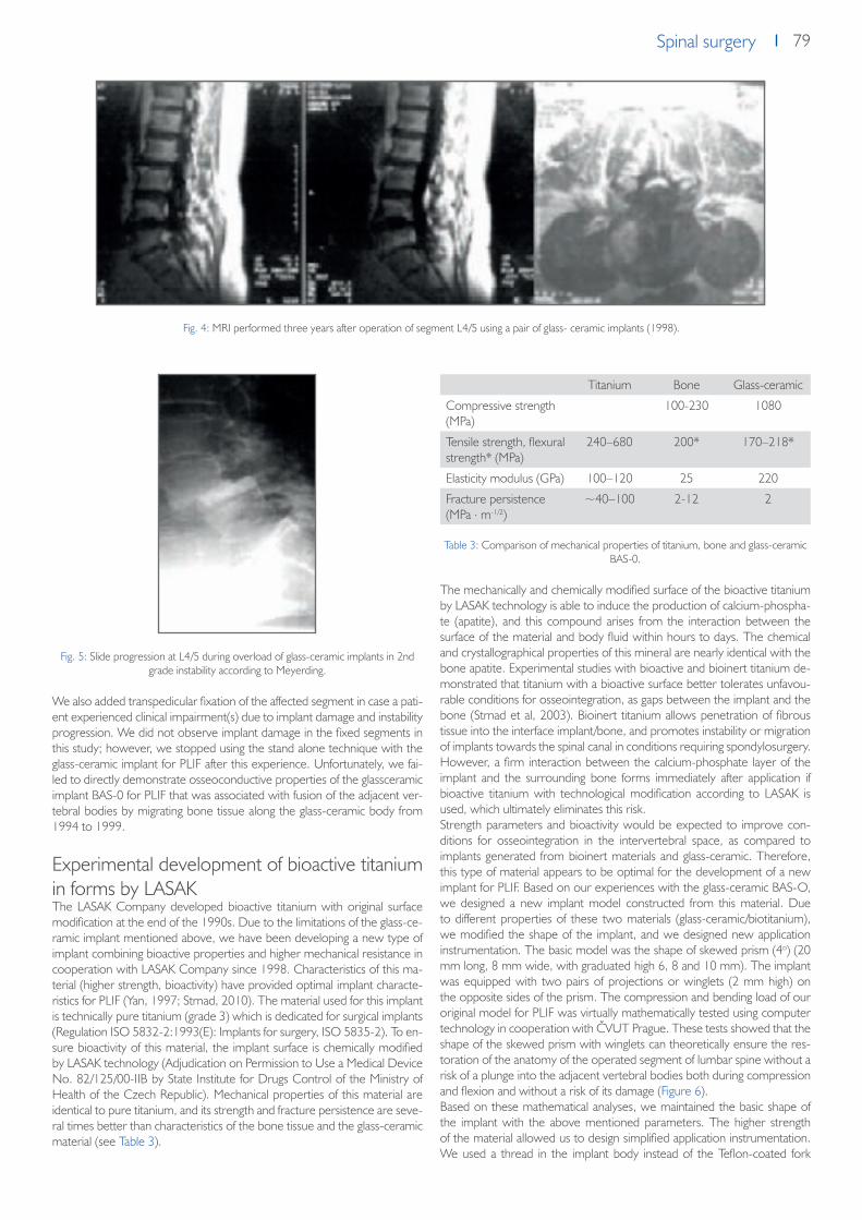
79Spinal surgerySpinal surgery
Fig. 5: Slide progression at L4/5 during overload of glass-ceramic implants in 2nd grade instability according to Meyerding.
We also added transpedicular fixation of the affected segment in case a pati-ent experienced clinical impairment(s) due to implant damage and instability progression. We did not observe implant damage in the fixed segments in this study; however, we stopped using the stand alone technique with the glass-ceramic implant for PLIF after this experience. Unfortunately, we fai-led to directly demonstrate osseoconductive properties of the glassceramic implant BAS-0 for PLIF that was associated with fusion of the adjacent ver-tebral bodies by migrating bone tissue along the glass-ceramic body from 1994 to 1999.
Experimental development of bioactive titanium in forms by LASAKThe LASAK Company developed bioactive titanium with original surface modification at the end of the 1990s. Due to the limitations of the glass-ce-ramic implant mentioned above, we have been developing a new type of implant combining bioactive properties and higher mechanical resistance in cooperation with LASAK Company since 1998. Characteristics of this ma-terial (higher strength, bioactivity) have provided optimal implant characte-ristics for PLIF (Yan, 1997; Strnad, 2010). The material used for this implant is technically pure titanium (grade 3) which is dedicated for surgical implants (Regulation ISO 5832-2:1993(E): Implants for surgery, ISO 5835-2). To en-sure bioactivity of this material, the implant surface is chemically modified by LASAK technology (Adjudication on Permission to Use a Medical Device No. 82/125/00-IIB by State Institute for Drugs Control of the Ministry of Health of the Czech Republic). Mechanical properties of this material are identical to pure titanium, and its strength and fracture persistence are seve-ral times better than characteristics of the bone tissue and the glass-ceramic material (see Table 3).
Table 3: Comparison of mechanical properties of titanium, bone and glass-ceramic BAS-0.
The mechanically and chemically modified surface of the bioactive titanium by LASAK technology is able to induce the production of calcium-phospha-te (apatite), and this compound arises from the interaction between the surface of the material and body fluid within hours to days. The chemical and crystallographical properties of this mineral are nearly identical with the bone apatite. Experimental studies with bioactive and bioinert titanium de-monstrated that titanium with a bioactive surface better tolerates unfavou-rable conditions for osseointegration, as gaps between the implant and the bone (Strnad et al, 2003). Bioinert titanium allows penetration of fibrous tissue into the interface implant/bone, and promotes instability or migration of implants towards the spinal canal in conditions requiring spondylosurgery. However, a firm interaction between the calcium-phosphate layer of the implant and the surrounding bone forms immediately after application if bioactive titanium with technological modification according to LASAK is used, which ultimately eliminates this risk.Strength parameters and bioactivity would be expected to improve con-ditions for osseointegration in the intervertebral space, as compared to implants generated from bioinert materials and glass-ceramic. Therefore, this type of material appears to be optimal for the development of a new implant for PLIF. Based on our experiences with the glass-ceramic BAS-O, we designed a new implant model constructed from this material. Due to different properties of these two materials (glass-ceramic/biotitanium), we modified the shape of the implant, and we designed new application instrumentation. The basic model was the shape of skewed prism (4o) (20 mm long, 8 mm wide, with graduated high 6, 8 and 10 mm). The implant was equipped with two pairs of projections or winglets (2 mm high) on the opposite sides of the prism. The compression and bending load of our original model for PLIF was virtually mathematically tested using computer technology in cooperation with ČVUT Prague. These tests showed that the shape of the skewed prism with winglets can theoretically ensure the res-toration of the anatomy of the operated segment of lumbar spine without a risk of a plunge into the adjacent vertebral bodies both during compression and flexion and without a risk of its damage (Figure 6).Based on these mathematical analyses, we maintained the basic shape of the implant with the above mentioned parameters. The higher strength of the material allowed us to design simplified application instrumentation. We used a thread in the implant body instead of the Teflon-coated fork
Fig. 4: MRI performed three years after operation of segment L4/5 using a pair of glass- ceramic implants (1998).
Titanium Bone Glass-ceramic
Compressive strength (MPa)
100-230 1080
Tensile strength, flexural strength* (MPa)
240–680 200* 170–218*
Elasticity modulus (GPa) 100–120 25 220
Fracture persistence (MPa . m-1/2)
~40–100 2-12 2

80 Spinal surgery
used in the implant BAS-O. Due to its strength, no opposite space dilatation was necessary before the application as a result of the bioactive titanium implant, and no risk of damage of the implant shape by metal loaders was detected. Therefore, the handling of the implant during an intervention is easy and safe. The shape of the implant ensured good restoration of the anatomy of the operated area (restoration of the interbody space and its stability) with minimal risk of implant plunge into the adjacent vertebral bo-dies, as demonstrated by imaging investigations. Other benefits of the new implant included higher strength and shape variability.We removed the whole motion segment with implants from cadavers after experimental operations, and we assessed their localization and the degree of their damage by X-ray and CT scans (Filip et al, 2001). Both investigati-ons showed proper localization of the implants in the intervertebral spaces without any contact with the spinal canal or perforation of the winglets into the adjacent vertebral bodies (Figure 7).Additionally, their shape and surface were not damaged by the new type of instrumentation. Therefore, we assumed that these findings would transfer from experimental studies into clinical practice. However, we were not able to verify the osseoconductive properties of the implant surface in the cada-vers. A perfect contact was observed between the surrounding bone tissue resulting from the simple application in cadavers, which was a good pre-condition for supporting osseointegration in the interbody space via osteob-
lasts´ migration along its surface. Thus, we verified the osseoconductive properties of the BIO surface of the implant in an animal model (Strnad, 2008). The implant surface in the direct contact with newly produced bone tissue yielded the following values [BIC (%) = 48,5 ± 2,9, 66,0 ± 7,4 and 90,6± 7,0, respectively, two, five and twelve weeks after implantation].
Fig. 8: Histological section of the interface of newly formed bone tissue on the BIO surface of the titanium implant twelve weeks after implantation. This figure illustrates
the osseoconductive properties of the surface (optical microscope, toluidine blue staining, original magnification - 200x).
Implaspin in clinical practiceEncouraged by these experimental results, we began to use this type of implant in clinical practice in indications for PLIF instead of the glass-ceramic implant since 2002 (Figure 9).The operation technique PLIF was identical to the operation technique used in cadavers (Filip et al, 2010). For example, we decompressed the nervous structures through posterior median line approach, and we then radically removed the degenerated intervertebral disc under the control of the ope-ration microscope. Afterwards, we removed the surfaces of the adjacent vertebral bodies, and we then inserted the bioactive titanium implant using
Fig. 6: Illustration of the mathematical testing of the implant model.
Fig. 9: Implant from bioactive titanium – Implaspin (2002).
Fig. 10: Insertion of Implaspin into the interbody space.
Fig. 7: Implaspin in the intersomatic space of a cadaver by CT (2001).

81Spinal surgerySpinal surgery
the innovated instrumentation (Figure 10). Finally, we added transpedicular fixation of the whole segment (Synthes, Signus, Easy spine, etc.) (Figure 11).
Fig. 11: Transpedicular application of screws (SIGNUS)
To date, we have not observed any complications associated with the im-plant application into the interbody space. According to the postoperative scans, the implant was always placed in the correct position with winglet penetration into the spongious tissue of the adjacent vertebral bodies. We have selected the size empirically according to the extent of osteochond-rosis of the affected disc and the degenerative lesions of the surrounding tissues on scans (X-ray, CT, MRI) during the intervention. In the majority of cases, we used implants (8 or 10 mm high) with angle 4% to maintain lordosis in the lumbar area (Figure 12).
According to the experimental studies, tight contact with the surrounding bone tissue was necessary to activate the bioactivity of the surface. This contact was ensured by the shape of the implant and the winglets that pe-netrated into the spongious bone tissue of the adjacent vertebral bodies, and was the precondition for migration of the osteoblasts along the implant body resulting in the formation of a junction of the adjacent vertebral bodies
by bone tissue without the need to sample bone grafts or to add supporting synthetic materials inside or around the implants.In 2002 to 2007, operations were performed on 57 patients using the bio-active implant Implaspin in the Neurosurgery Clinic of the Faculty Hospital in Ostrava and in the Neurosurgery Department of Tomáš Baťa´s Regional Hospital in Zlín. We assessed a population of 25 patients with follow-up examinations conducted two or more years following surgery, according to the clinical condition. The follow-ups were also based on the generally used score system ODI and imaging methods (X-ray, CT, MRI) that occurred three, six, twelve and 24 months after surgery. During the follow-ups, we examined the patients for signs of implant damage, instability of the opera-ted segment, and signs of supposed osteoblastic activity of the bioactive sur-face of the implant on the scans. Results of the ODI questionnaire showed that with Implaspin, our success rate improved by 1 degree (59%–40%), or we stabilized the clinical condition of the majority of the patients long--term (2 and more years), which corresponds to results of other clinics using other implant types (Bessho et al, 1997; Brantigan et al 1993; Brayan et al, 2002; Bienik and Swiecki, 1991; Ciappetta et al, 1997; see Table 4).
The assessment of the implant position on scans (X-ray, CT, MRI) at post-operative visits demonstrated no signs of implant damage or implant migra-tion out of the intersomatic space. These investigations have not yet shown any signs of instability of the operated segment (i.e., formation of new os-teophytes, progression of hypertrophy of the articular facets, and migration of the implant at the site of application). We observed one severe complica-tion in the population which was caused by an inaccurate application of the transpedicular screws. The wound healed in this patient, and the neurolo-gical findings stabilized after removal of the screws. The stabilization of the condition may be supported by the implant shape and the winglets which prevented instability even after the removal of the transpedicular screws. This finding was confirmed by the imaging investigations. Based on the cli-nical condition and the absence of instability signs on imaging investigations, we concluded that the formation of bone fusion was due to osteopblasts´ migration along the bioactive of Implaspin surface.
Assessment of bioactivity of the implant using SPECT-CTDuring our investigations, we attempted to demonstrate the migration of bone cells along the surfaces of the glass-ceramic or biotitanium implants using imaging investigations. Unfortunately, standard CT or MRI were not able to provide this precise information. The CT scans were limited by screw artefacts, and the MRI scans were generally unable to detect changes in bone. In an attempt to resolve these problems, we utilized SPECT-CT, a method that provides up-to-date computed tomography (CT) and gamma camera (SPECT), to detect the activity of the osteoblasts on the body of the titanium implant applied into the interbody space. The computed tomo-graphy (CT) can precisely display the anatomic structure of the investigated tissue, and the gamma camera investigation (SPECT) can yield a functional view of the metabolic process in the patient´s body, but without its precise localization or other anatomical details. Thereby, the combination of these investigations provided more complete information on the precise place of the metabolic process as well as its dynamics. In our study, the metabolic process included the activity of the osteoblasts on the surface of the bio-active implant, as applied by the PLIF method.
ODI score in our population [%]
Mean [n] 25
FBSS [n] 9
IS [n] 6
DI [n] 10
Before surgery 59 65 55 57
3 months after surgery 42 46 40 40
6 months after surgery 40 45 37 38
12 months after surgery 41 45 39 39
24 months after surgery 40 47 35 38
Fig. 12: Fixation L4/5 (Implaspin plus transpedicular screws Signus).
Table 4: Mean Oswestry score values before surgery and at regular visits (FBSS – failed back surgery syndrome; IS – isthmic spondylolisthesis; DI – degenerative
instability).

82 Spinal surgery
In 2009, we performed this type of investigation in four patients after sur-gery for the primary instability of the lower lumbar spine segment using the PLIF operation technique with Implaspin. The study was conducted before the surgery as well as two and six months after the intervention, and we as-sessed the anatomical changes and metabolic activity at the location where the implants were applied by using the combined scans. The investigation provided preoperative signs of instability localized to the affected space in the area of the disc in all four patients. We detected a hyperintense signal at the operated segment two to three months after the surgery, which was a sign of osteoblast activity on the surface of the implant. We also observed a decrease of this activity (hypointense signal) six months after the surgery as well as a change on the surface of the implant using the combined CT scans.According to our method, hypointensity signified the completion of the os-teoblastic activity. The changes on the CT scans were completed by con-ducting a measurement using Haunsfield´s units (metal – about 2000 HU; bone tissue 100–300 HU), which provided evidence that the implant was overgrown by bone tissue. This kind of image detects the primary succe-ssful binding of the implant via activation of the osteoblasts by its specially adapted bioactive surface (figure 13 and 14). Using this combined imaging technique in all four patients, we demonstrated the migration of bone cells along Implaspin wall and the formation of fusion without the addition of another material, such as autografts or TCP, six months after the surgery. Therefore, the successful fusion was indirectly confirmed using the SPECT--CT improving the postoperative clinical findings.
ConclusionThe development of both the material and the shapes of implants continues to progress. Currently, the primary focus of this development is to produce an implant that forms a firm fusion as soon as possible and to ensure the for-
mation of new bone due to its material composition. The current implants for PLIF combine two separate components, including a solid cage shape and osseoconductive material (i.e., TCP, BMP) that ensures the activity of osteoblasts and the formation of the interbody fusion. To date, none of the materials for PLIF available on the market optimally meet both characteri-stics (see Table 5).During this investigation, our goal was to develop an implant that would combine both of these components in one unit, ultimately maintaining the strength and bioactive properties present in two-component implants. At the end of the 1990s, we were close to the development of such material due to the implant BAS-0. However, the resistance of the glass-ceramic at the ultimate load provided a limitation that negatively influenced the shape and the application process, as described in chapters above. However, due to these experiences, we and other technicians successfully designed an implant that meets our original conception. This implant is currently used in clinical practice, and experimental studies have confirmed its supposed properties. The combination of the implant’s strength and shape with bio-activity enables the smooth application and restoration of anatomy, thereby providing a perfect fixation of the operated segment and stimulating growth of osteoblasts and their migration along its surface. Our original implant Implaspin combines the osteoconductive and osteoplastic properties of the glass-ceramic with the strength of titanium, which was the aim of our research. Thanks to these properties, this implant represents a quality al-ternative to implants constructed from other materials dedicated to PLIF (see Table 5).
AcknowledgementThis study was supported by the Ministry of Industry and Trade of the Czech Republic under the project number: FR-TI3/587
Optimal parameters of the implant Metal (Titanium, steel)
PEEK or +PEEK carbon fibres
Glass-ceramic Resorbable implants - polylactides
Bioactive titanium (LASAK Ltd.)
1. Firm structural support (load resistance imme-diately after implantation)
+ + +/- +/- +
2. Osseoconductivity, bioactivity – ability to bind with a bone, support of fusion without addition of other material (bone, TCP, etc.)
- - + - +
3. Possibility of radiographic assessment of the bone fusion progression
+ + + + +
4. Biomechanical properties (elasticity modulus similar to bone)
- + - +/- -
Fig. 13: Implants applied into the spaces L3/4 and L4/5 on SPECT CT. The figure shows the surface of the implant with the bone tissue (grey-black colour) and the
titanium screw in the body of the L3 (white colour).
Fig. 14: Implants on a SPECT-CT scan. The bone growth at the border of bone tissue (grey) and Implaspin (white) is visible in the space L4/5.
Table 5: Parameters of the implant according to the type of material.

83Spinal surgerySpinal surgery
References1. Anderson, V. C.: A rationale for treatment algorithm of failed back surgery syndrome. Curr Rev Pain 2000; 4: 395-4062. Alexander, J., Branch, C., Subach, B., et al.: Applications of a resorbable interbody spacer in posterior lumbar interbody fusion. J Neurosurg (Spine).
2002;97:468-4723. Arrington, E., Smith, W., Chanbers, H., et al.: Complications of iliac crest bone graft harvesting. Clin Orthop Rel Res. 1996;329:300-3094. Bagby, G.: Arthrodesis by the distraction-compression method using a stainless steel implant. Orthopedics. 1988;11:931-9445. Banwart, J., Asher, M., Hassanein, R.: Iliac crest bone harvest donor site morbidity; a statistical evaluation. Spine. 1994;20:1055-10606. Banwart, J., Asher, M., Hassanein, R.: Iliac crest bone graft harvest donor site morbidity. Spine. 1995; 20:1055-1060.Sandhu H, Hs G, Parvatanemi
H. Bone grafting for spinal fusions. Orthop Clin North Am. 1999;30:685-6987. Bauer, T., Muschler, G.: Bone graft materials: an overview of the basic science. Clin Orthop. 2000;371:10-278. Benzel, E.: Best indications for DDD: Fusion or Non Fusion. In International symposium- Non Fusion techniques in Spinal Surgery. Bordeaux France
2003, Book of Abstracts: 140-19. Bessho, K., Iizuka, T., Murakami, K.: A bioabsorbable polt-L-lactide miniplate and screw system for osteosynthesis in oral and maxillofacial surgery. J
Oral Maxillofac Surg. 1997;55:941-94510. Bienik J, Swiecki Z.Porous and porous-compact ceramics in orthopedics.Clin Orthop 1991;27:88-9411. Blumenthal, S.L., Baker, J., Dosset, A., Selby, D.K.: The role of anterior lumbar vision for internal disc disruption. Spine 1988; 13: 566-912. Brantigan, J., McAfee, P., Cunningham, B., et al.: Interbody fusion using a carbon fiber implant versus allograft bone: a investigational study in the Spanish
goat. Spine. 1994;19:1436-144413. Brantigan, J., Steffee, A.: A carbon fiber implant to aid interbody lumbar fusion. Spine. 1993;18:2106-211714. Brinckmann, P, Bigemann, M., Hilweg, D.: Prediction of the Compressive Strength of Human Lumbar Vertebrae. Clin. Biomech., 1989, č. 4, s. S1-S27.15. Brodke, D., Dick, J.C., Kunz, D.N., McCabe, R., Zdeblick, T.A.: Posterior Lumbar Interbody Fusion: A Biomechanical comparsion,Including a New
Threaded Cage. Spine 1997; 22(1): 26-3116. Bryan, B., Gerald, E., Regis, W.H., Brian, R.S., Mark, R.M.: Allograft Implants for Posterior Lumbar Interbody Vision: Results Comparing Cylindrical
Dosela and Impacted Wedges. Neurosurgery 2002; 51(5): 119117. Carlson, L., Rostland, T., Albrektsson, B.: Implant fixation improved by close fit. Acta Orthop. Scand., 59: 272-275, 1988.18. Cloward R.: Gas-sterilized cadaver bone grafts for spinal fusion operations. Spine. 1980;5:419. Ciappetta, P., Boriani, S., Fava, G.P.: A Carbon Fiber Reinforced Polymer cage for Vertebral Body Replacement: Technical Note. Neurosurgery, 41:
1203-1206, 1997 [20] Clemens, J.A.M., Klein, C.P.A.T., Sakkers, R.J.B.: Healing of gaps around calcium phosphate-coated implants in trabecular bone of the goat. J. Biomed. Mater. Res., 36:55-64, 1997
21. Cloward, R.: The Treatment of Ruptured Lumbar Intervertebral Disc by Vertebral Body Fusion. 1. Neurosurg., 10, 1953, s. 154-168. Cockin, J.: Autologous bone grafting complications at the donor site. J Bone Joint Surg Br. 1971;53:153
22. Crock, H. V.: Isolated Lumbat Disc Resotption as a Cause of Nerve Root Canal Stenosis. Clin. Orthop., 1 15, 1976, s. 109-l 15.23. Daniaux, H.: Transpedikuläre Reposition und Spongiosplatik bei Wirbelkörperbrüchen der unteren Brust-und Lendenwirbelsäule. Unfalldionogie, 89,
1986, 197-21324. Dick, W.: The Fixateno Interne as a Versatile Implant for Spine Surgery. Spine, 12, 1987, 882-90025. Dove, J.: Instrumentation postérieure di rachis: Le systéme de Hartshill. Rachis, 2, 1990, s. 487-492.26. Fatley T. J., Lynch, K. L., Bensen, M. D.: Tissue Response to Implants of Calcium Phosphate Ceramic in Rabbit Spine. Clin. Orthop., 1979, 1983, s. 246.27. Filip, M., Veselský, P., STRNAD, Z.,LANÍK, P.: Replacement of an Intervertebral Disc,using a ceramic prosthesis in the treatment of degenerative dise-
ases of the spine. Acta Chirurgicae Orthopedicae et Traumatologiae Czechoslovakia 62, 1995,p. 226 – 231.28. Filip, M., Veselský, P.: Treatment of instability of the lumbar spine by Glass-ceramic Prostheses of the intervertebral disc. Acta Chirurgiae Orthopaedicae
et Traumatologiae Czechoslovakia.. Acta Chir Orthop Traum Čech 1996; 63: 83-729. Filip, M., Linzer, P.,Veselský, P., Paleček, T.: Surgical technique verification by the Help of New bioactive titan cage in treatment of degenerative disease
of the lumbr spine- experimental study. Acta Chir Orthop Traum Čech 2001; 68: 369-37330. Filip M.,Linzer P.,Šámal F.,Kremr J.,Mrůzek M.,Paleček T., Strnad J. : Bioactive cage implaspin in operation treatment of LBP. Bolest No.1, 25- 30, r.201031. Fischgrund, J., Mackay, M., Herkowitz, H., et al.: Degenerative lumbar spondylolisthesis with spinal stenosis: a prospective, randomized study compa-
ring decompressive laminectomy and arthrodesis with and without spinal instrumentation. Spine. 1997;22:2807-281232. Gogolewski, S., Jovanovich, M., Dillon, J., et al.: Tissue response and in vivo degradation of selected polyhydroxyacids: polylactides (PLA), poly(3-
hydroxybutyrate) (PHB), and poly(3-hydroxybutyrate-co-3-hydroxyvalerate) (PHB/VA). J Biomed Mater Res. 1993;27:1135-114833. Gurr, K. R., McAfee, P. C., Shih, C.-M.: Biochemical Analysis of Posterior Instrumentation Systems after Decompressive Laminectomy. An Unstable
Calf- spine Model. J. Bone Jt Surg., 70-A, June 1988, 680-691.Hamer, A., Stockley, I., Elson, R.: Changes in allograft bone irradiated at different tem-peratures. J Bone Joint Surg Br. 1999;81:342-344
34. Hashimoto, T., Shigenobu, K., Kanayama, M., Harada, M., Oha, F., Ohkoshi, Y., et al.: Clinical Results of Single-Level Posterior Lumbar Interbody vision Using the Brantigan I/F Carbon Cage Filled With a Mixture of local Morselized Bone and Bioactive Ceramic Granules. Spine 2002; 27(3): 258-262
35. Hench, L.L., Splinter, R.J., Allen, W.C.,Greenlee, T.K.: Bonding mechanisms at the interface of ceramic prosthetic materials. J. Biomed. Mater. Res. Symp., 2: 179-149, 1971
36. Hrabálek, L., Rešková, I., Bučil, J., Vaverka, M., Houdek, M.: Použití titanových a PEEKových implantátů při ALIF stand-alone u degenerativního one-mocnění lumbosakrální páteře – prospektivní studie. Česká a slovenská neurologie a neurochirurgie, 72/105 (1), 2009, 38-44
37. Chaloupka, R., Krbec, M., Ciencala, J., Tichý, V.: Comparison of Surgical Load in Case of 360-degree Fusion in Lumbar Vertebra Spondylolistheses Treated via Rear Instrumentation and the PLIF or ALIF Technique. Acta spondylologica 2003; 2: 69-72
38. Cho, D., Liau, W., Lee, W., et al.: Preliminary experience using a polyetheretherketone (PEEK) cage in the treatment of cervical disk disease. Neuro-surgery. 2002;51:1343-1350
39. Khoo, LT., Palmer, S., Laich, DT., Fessler, RG.: Minimally invasive percutaneous posterior lumbar interbody fusion. Neurosurgery 2002; 51 (5 Suppl): 166-1
40. Knudson, R.: The Instability Associated with Disc Degeneration in the Lumbar Spine. Acta Radiol., 25, 1944, s. 594-609.41. Kokubo, T.: Bonding Mechanism of Bioactive Glass-ceramics A-W to Living Bone. In: CRC. Handbook od Bioactive Ceramics, Volume I. Bioactive
Glasses and Glass- Ceramics, Yamamuro, T., Hench, L. L., Wilson, J. (eds). Boca Raton, CRC Press, 1990, 41 - 49.42. Kokubo, T., Shigematsu, M., Naghashima, Y.: Apatite wollastonite-containing glass-ceramic for prosthetic application. Bull. Inst. Chem. Res., Kyoto
Univ., 60: 260-268, 1982

84 Spinal surgery
43. Kurz, L., Garfin, S., Booth, R.: Harvesting autogenous iliac bone: a review of complications and techniques. Spine. 1989;14:1324-133144. Madawi. A.A., Powell, M., Crockard, H.A.: Biocompatible osteoconductive polymer versus iliac graft:. Spine. 21:2123-2130, 199645. McAfee, P. C.: Biochemical Approach to Instrumentation of Thoracolumbar Spine: A Review Article, Adv. Orthop. Surg., 8, 1985, 313 - 327.46. McAfee, P.C., Bohlmann, H.H., Ducker, T., Elsmont, F.J.: Failure of Stabilization of the Spine with Methylmethal - crylate. A Retrospective Analysis of
Twenty-four Cases. J. Bone Jt Surg., 68: 1145-1151, 198647. Modic, M. T., Wienstein, M. A., Pavlicek, W. et al.: Nuclear Magnetic Resonance Imaging of the Spine. Radiology, 148, 1983, s. 757-762.48. Modic, M.T., Masaryk, T.J., Ross, J.S., Carter, J.R.: Imaging degenerative disc diseasse. Radiology 1988; 168(1): 177-18649. Paleček, T., Wolný E., Veselský, P., Filip M., Drábek, P.: Náš současný přístup k chirurgické léčbě degenerativního onemocnění bederní meziobratlové
ploténky. čes. a Slov. Nettrol. Neurochic, 57/90, 1994, č. 5, s. 198-201.50. Rowlings, CH.E.III.: Modern Bone Substitutes with emphasis on calcium Phosphate ceramics and osteoinductors. Neurosurgery, 4: 933-936,199351. Russell, G., Hu, R., Raso, J.: Bone banking in Canada: a review. Can J Surg. 1989;32:231- 23652. Sandhu, HS.: Bone Morphogenetic Proteins and Spinal Surgery. Spine 2003; 28: 64-7353. Sobale, K., Hansen, E.S., Rasmussen, H.: Hydroxyapatite coating enhance fixation of porous coated implants. Acta Orthop. Scand., 61: 299-306,
199054. Sonntag, V. K.H., Theodore, N.: Spinal Surgery: The Past Century and the Next. Neurosurgery, 46: 767-778, 200055. Steffee, A.D., Sitkowski, D.J.: Posterior lumbar interbody fusion and plates. Clin Orthop Relat Res 1988 ; 227:99-10256. Strnad Z., Role of the glass phase in bioactive glass-ceramics. Biomaterials Vol.13, No. 5 1992, p.317-32157. Strnad J., Urban K., Povysil C., Strnad Z.: Secondary Stability Assessment of Titanium Implants with Alkali-Etched Surface: A Resonance Frequency
Analysis Study in Beagle Dogs; The International Journal of Oral & Maxillofacial Implants, Volume 23, Number 3, 200858. Strnad J.: Způsob úpravy povrchu titanových implantátů“ Pat.č.291685 (2003)59. Strnad J., Helebrant A.: Kinetics of bone-like apatite formation in simulated body fluid In: Proc. 5th ESG Conference (eds. Helebrant A., Kasa S., Ma-
ryška M.), pp. B2 9-16, Czech Glass Soc., Praha 199960. Thalgott, J., Giuffre, J., Klezl, Z., et al.: Anterior lumbar interbody fusion with titanium mesh cages, coralline hydroxyapatite, and demineralized bone
matrix as part of a circumferential fusion. Spine J. 2002;2:63-6961. Tullberg, T.: Failure of a carbon fiber implant: a case report. Spine. 1998;23:1804-180662. Urban, K., Strnad, J.: Clinical Application of the Bioactive Glass-Ceramics BAS-O in Orthopaedics, Lékařské zprávy LF UK, Hradec Králové 37, 1992.
Vaccaro, A.R., Madigan, L.: Spinal applications of bioabsorbable implants. J Neurosurg. 97[Suppl 4]:407- 412, 200263. Wang, J.C., Mummaneni, P.V., Haid, R.W.: Current treatment strategies for the painful lumbar motion segment: Posterolateral fusion versus interbody
fusion. Spine 2005;30:S33-S4364. Williams, A., McNamara, R.: Potential of polyetheretherketone and carbon fiber- reinforced PEEK in medical applications. J Mater Sci Lett. 1987;6:188-19065. Yamamuro, T.: AW Glass-Ceramic in Spinal Repair. Bioceramics, Vol.8,p.123, Ed.: J. Wilson, L. Henche, D. Greenspan, Ponte Verda, Florida, USA,
November 199566. Yan, W.Q., Nakamura, T., Kobayashi, M., Kim, H.M., Miyaji, F., Kokubo, T.: Bonding of chemically treated titanium implant to bone. J. Biomed Mater.
Res., 37: 265-275, 199767. Zdeblick, T.A., Philips, F.M.: Interbody Cage Device. Spine 2003; 28 (15 Suppl ): S2-S7

85Spinal surgerySpinal surgery
Bioactive titan cage Implaspin in treatment
of degenerative disease of the cervcal spine - the results
from 2007 till 2008
M. Filip1, P. Linzer1, F. Samal1, P. Jurek1, Z. Strnad2, J. Strnad2
Chirurgia Narządów Ruchu i Ortopedia Polska, 75 (1), 2010
1 Neurosurgery Department, Regional Hospital of Tomas Baťa in Zlín, Czech Republic2 LASAK s.r.o (Ltd.)- Glass and Ceramics Laboratory, Praha 6, Czech Republic
SummaryThe authors present results of surgical treatment of cervical spine degene-rative disease via Implaspin biotitanium replacement. Surgery was indicated for a group of 24 patients with symptoms of cervical spondylogenic myelo-pathy or the irritation decay root syndrome non-reacting to conservative treatment. Pre-surgery X-ray and MRI examinations showed spinal canal stenosis caused by the inter vertebral disk osteochondrosis combined with prolapse or dorsal osteophytes. Clinical problems of the group of patients were evalu ated through the JOA classification before surgery and during the 2nd ,the 6th and month 12th after surgery. The surgery rate of success was evaluated in percentages during post-surgery examinations that took place in the 12th month. Based on the JOA classification, that rate of success falls into the good surgery results zone. The post-surgery X-ray examinations showed two sank replacements by 1/ 3 of its height into the surrounding vertebral bodies. In these cases we performed the control MRI. No signs of the new spinal com pression were found and the spinal canal was free in the operated site. Based on our short-term experiences, the lmplaspin bioactive replacement seems to be a suitable alternative to the other types of replacements designed for intervertebral fusion in the lower cervical spi-ne area.
IntroductionBetween 1955 and 1958, Robinson, Smith and Cloward1, 2 published gra-dually their first experience with a de compression of the spinal canal in the cervical part from the anterior approach. Due to this knowledge the surgical therapy of the degenerative disease of the cervical spine achieved a great development in the recent 40 years. The various methods, modifications of decompression and fixation of the cervical spine from the anterior appro-ach gradually appear. From the simple decompression with or without the interbody fusion using the bone graft or various cages with or without the splint to the functional replacement of the intervertebral disk.3-16 Between 2007 and 2008, we operated 61 patients with a degenerative disease of the cervical spine at the neurosurgery depart ment of the KNTB Zlín. In 24 patients we performed a de compression with the fusion from the anterior approach by means of the biotitanium cage lmplaspin. The clinical con dition of the patients was evaluated using the JOA classifi cation before and 2, 6 and 12 months after the surgery. The position of the implants in the ope-rated field was eva luated in the same time period using the X-ray images. The presence of the fusion was evaluated using the CT between the 6. and 12. month after the surgery. According to the JOA classification we achie-ved the efficacy of 50% which lies in the range of the good surgical results. According to the post-operative X-ray images no impairment or dislocation of the cage occurred. The CT examination in four patients performed be-tween the 6. and 12. month after the surgery found a development of the osseous fusion.
Material and methodsIn 2005, based on good practice with the bioactive titanium cages of the lum-bar spine, we developed a cage for the cervical spine from the same material, as well. Similarly as in the case of the lumbar spine cage the osteoconductive properties of the material remained the same and the rigidity was significantly improved. The cage has a shape of the skewed prism narrowed by 1 grade towards the spinal canal of 13-15 mm in length and a graduated height of 8-5 mm and 13 mm in width. It is produced from the technically pure titanium with chemically modified surface that ensures its bioactive properties. The bioactive surface enables to create a rigid binding with the osseous tissue and has oseoconductive properties.17, 18 The material is grey-black with a density of 4500 kg.m-3 and it is rigid in traction to a maximum of 450 MPa. The replace ment is intended for a replacement of the intervertebral disk to pre-vent the instability of the affected locomotive segment of the cervical spine.On the opposite parts of the prism which are attached to the vertebral bodies the replacement has sharp wings of 0.5 mm in height and the angle of 30 grades. They ensure the primary stability for an undisturbed healing of the implant into the surrounding vital bone tissue. The shape and size were supported by the biomechanical studies.The patients with persisting or progressive irritation extinction radicular syn-drome and/ or spondylogenic cer vical myelopathy after unsuccessful con-servative therapy were indicated for the anterior decompression of the spinal canal with interbody fusion in the area of the lower part of the cervical spine5.The clinical finding was evaluated by means of the JOA (Japan Orthopaedic Association) classification. Ac cording to the JOA classification the motor func-tion is rated from 0 to 4 points on the upper limb, 0 to 4 points on the lower limb, 0 to 2 points for sensitive disorders and 0 to 3 points in the urinary bladder function. The less rate the more severe is the affection of a patient.
The successfulness of the surgical therapy according to the JOA classification was in our set of 24 patients evalu ated in percents by comparison of the points in the group before the surgery and during the preoperative check--ups on the 2., 6. and 12. month after the surgery and by using the formula:
successfulness (%) = (A - B) I (C - B) . 100
A - Postoperative JOA score in the groupB - Preoperative mean JOA score in the groupC - JOA score in a healthy human17
Evaluation of the successfulness of the surgery is displayed in the Table I.
Percent of the successfulness according to the JOA formula
Evaluation
100-75% excellent result
75-50% good result
50-25% weak result
25-0% bad result
Table I: Evaluation of the successfulness of the surgery according to the JOA classi-fication
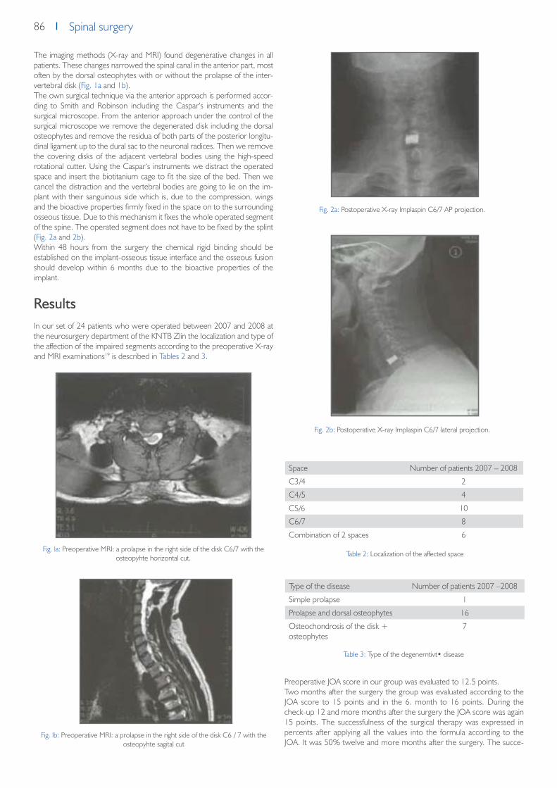
86 Spinal surgery
The imaging methods (X-ray and MRI) found degenerative changes in all patients. These changes narrowed the spinal canal in the anterior part, most often by the dorsal osteophytes with or without the prolapse of the inter-vertebral disk (Fig. 1a and 1b).The own surgical technique via the anterior approach is performed accor-ding to Smith and Robinson including the Caspar‘s instruments and the surgical microscope. From the anterior approach under the control of the surgical microscope we remove the degenerated disk including the dorsal osteophytes and remove the residua of both parts of the posterior longitu-dinal ligament up to the dural sac to the neuronal radices. Then we remove the covering disks of the adjacent vertebral bodies using the high-speed rotational cutter. Using the Caspar‘s instruments we distract the operated space and insert the biotitanium cage to fit the size of the bed. Then we cancel the distraction and the vertebral bodies are going to lie on the im-plant with their sanguinous side which is, due to the compression, wings and the bioactive properties firmly fixed in the space on to the surrounding osseous tissue. Due to this mechanism it fixes the whole operated segment of the spine. The operated segment does not have to be fixed by the splint (Fig. 2a and 2b).Within 48 hours from the surgery the chemical rigid binding should be established on the implant-osseous tissue interface and the osseous fusion should develop within 6 months due to the bioactive properties of the implant.
ResultsIn our set of 24 patients who were operated between 2007 and 2008 at the neurosurgery department of the KNTB Zlin the localization and type of the affection of the impaired segments according to the preoperative X-ray and MRI examinations19 is described in Tables 2 and 3.
Preoperative JOA score in our group was evaluated to 12.5 points.Two months after the surgery the group was evaluated according to the JOA score to 15 points and in the 6. month to 16 points. During the check-up 12 and more months after the surgery the JOA score was again 15 points. The successfulness of the surgical therapy was expressed in percents after applying all the values into the formula according to the JOA. It was 50% twelve and more months after the surgery. The succe-
Fig. la: Preoperative MRI: a prolapse in the right side of the disk C6/7 with the osteopyhte horizontal cut.
Fig. lb: Preoperative MRI: a prolapse in the right side of the disk C6 / 7 with the osteopyhte sagital cut
Fig. 2a: Postoperative X-ray lmplaspin C6/7 AP projection.
Fig. 2b: Postoperative X-ray Implaspin C6/7 lateral projection.
Space Number of patients 2007 – 2008
C3/4 2
C4/5 4
CS/6 10
C6/7 8
Combination of 2 spaces 6
Type of the disease Number of patients 2007 –2008
Simple prolapse 1
Prolapse and dorsal osteophytes 16
Osteochondrosis of the disk + osteophytes
7
Table 2: Localization of the affected space
Table 3: Type of the degenerntivt• disease

87Spinal surgerySpinal surgery
ssfulness in percents ranges within the good results at all check-ups – see Table 1.During the clinical check-up we performed the X-ray control of the opera-ted part as well with the focus on the position of the implant – see Table 4 (Fig. 3a and 3b).In our group, we found two sank replacements by 1/3 of its height into the surrounding vertebral bodies. In these cases we performed the control MRI. No signs of the new spinal compression were found and the spinal canal was free in the operated site.
Between the 6. and 12. month after the surgery we tried to find out the direct signs of the osseous fusion using the ultrathin cuts by means of the CT (Fig. 4a and 4b) in four patients. The fusion was developed due to the osse-oconductive properties of the replacement (a growth of the osteoblasts on the walls of the implant as it is seen in the CT cuts).
DiscussionThe interbody fusion via the anterior approach remains the verified standard therapeutic procedure in the subaxial part of the cervical spine in mono and bisegmental severe degenerative stenoses caused by the posterior osteo-phytes and/ or by the osteophytes in combination with the prolapse of the intervertebral disk.6-9
Using of the various materials for the purpose of the interbody fusions was initiated worldwide approximately in the second half of 80‘s. We compared the properties of the lmplaspin cage with the similar implants manufactured by Medtronic, Biomed, Synthes, Aesculap, and Johnson which we use con-currently with this implant or we used them at the previous departments in the same indications.4, 8-12, 16
The surgical procedure and the own surgical technique was similar in all the implants. We compared the shape, function of the wings at the opposite sides and the bioactivity of its surface with other implants. Implaspin has a shape of a skewed prism in various sizes. It provides better prerequisites for maintaining the lordosis of the cervical spine in the postoperative period compared to some types of the cages. They have a shape of a prism or oval but without skewing.The wings of the Implaspin cage pointing at the sur rounding vertebral bodies. Together with the compression they increase a stability and ensure a direct contact of the implant with the osseous tissue. The wings help to mechanically fix the operated part in the first hours until the chemical binding bone-implant develops. Some implants available on the market such as Ti-bone of Biomed do not have these wings and the mechanical stability of the operated part is provided only by the compression of the surrounding vertebra.Due to the bioactivity of the surface of the Implaspin implant a chemical bin-
The position of the biotitanium replacement on the X--ray images - a group of 24 patients
Control 12. month
No changes, preserved lordosis, without propagation into the spinal canal, without any new osteophytes
22 patients
Sinking into the bodies of the surrounding vertebra, wit-hout propagation into the spinal canal, without any new osteophytes
2 patients
Fig. 3a: X-ray after 6 months lmplaspin C6/7 AP projection. Fig. 3b: X-ray after 6 months lmplaspin C6/7 lateral projection.
Table 4: Position of the Implaspin replacement on the X-ray images after 12 months
Fig. 4a: CT after 6 months lmplaspin C6/7 horizontal cut.
Fig. 4b: CT after 6 months Implaspin C6/7 sagital cut.

88 Spinal surgery
ding between the bone and implant at the contact side with the adjacent vertebral bodies occurs. The chemical binding increases a stability of the operated part and is a prerequisite for a development of the osseous fusion within 6 months after the surgery. We managed to verify this prerequisite in four patients who were randomly selected for examination using the ultrathin CT cuts. The osseoconductive properties of the bioactive surface facilitate growing of the osteoblasts on the walls of the replacement and, within several months, they enable development of the osseous interobdy fusion of the operated part. The replacements of other companies have a central cavity which is filled either by bone grafts of hydroxyapatite.16, 20, 21 The surrounding bearing material (Titanium, Peek) does not have the bioactive properties11. The chemical binding and a subsequent interbody fusion occurs only at this place.The bioactive material is not homogenous which may cause retarda-tion of growing of the osteoblasts duringthe fusion. There is also a higher risk of sinking of the implant into the surrounding vertebral bodies due to a hollow center of the implant9. This risk is minimized in case of the lmplaspin replacement as confirmed by the postoperative X-ray. A sinking of the cervi-cal implant into the surrounding vertebral bodies with out any clinical finding occurred only in two patients. We assume that the sinking occurred due to impairment of the spongious tissue during milling of the bed for the implant.
During the application of the lmplaspin replacement there is no need to fill the implant with the bone grafts or hydroxyapatite as in other replacements. It is not necessary to take the bone graft from the patient. Therefore the time of the own surgical procedure is reduced and the patient is not traumatized by the collection of the bone graft from the hlp bone. Therefore, we consi-der the shape, wings and the bioactive surface as an advantage compared to other replacements.
ConclusionBased on the clinical results and imaging examinations it appears that we use the lmplaspin cage separately for the fusion in serious preoparative clinical fin-dings (pre operative JOA score of 12.5 point) caused by the compression of the nervous structures most often due to prolapse of the disk with the dorsal osteophytes based on the imaging methods (X-ray, MRI). The postoperative results OOA, X-ray, CT) show the lmplaspin is a good alternative to other cages intended for the anterior interbody fusion of the cervical spine. It succe-ssfully competes with the foreign products as for its quality and price.
Literature1. Robinson R.A.,Smith G.W.: Anterolateral cervical disc removal and interbody fusion for cervical disc syndrome. Bull. John Hopkins Hasp., 1955; 96: 223-224.2. Cloward R.B.: The anterior approach for removal of ruptured cervical disks. J. Neurosurg., 1958; 15: 602-617.3. Simmons E.H., Bhalla S.K.: Anterior cervical discectomy and fusion. A clinical and biomechanical study with eight-year follow up. J. Bone Joint Surg. Br., 1969;
51: 225-237.4. Matge G.: Cervical cage fusion with 5 different implants: 250 cases. Acta Neurochir., 2002; 144: 539-550.5. Gregorius F.K., Estrin T., Crandall P.H.: Cervical spondylotic radiculopathy and myelopathy. Arch. Neural., 1976; 33: 618-625.6. Dunsker S.B.: Anterior cervical discectomy with and without fusion. Clin. Neurosurg., 1977; 24: 516-520.7. Capen D.A., Garland D.E., Waters R.L.: Surgical stabilization of the cervical spine. A Comparative analysis of anterior and posterior spine fusions. Clin. Orthop.,
1985; 196: 229-237.8. KostuikJ.P., Connolly P.J., Esses S.I., Suh P.: Anterior cervical plate fixation with the titanium hollow screw plate system. Spine, 1984; 18: 1273-1278.9. Matge G.: Anterior interbody fusion with the BAK-cage in cervical spondylosis. Acta Neurochir. (Wien), 1998; 140: 18.10. Filip M., Veselsky P., Paleeek T., Wolny E.: The glass-ceramic replacement of the intervertebral disk in the degenerative diseases of the cerivical spine - the first
experience. Ees. Slav. Neural. Neurochir. 2000; 1: 31-36.11. Cho D., Liau W., Lee W., et al.: Preliminary experience using a polyetheretherketone (PEEK) cage in the treatment of cervical disk disease. Neurosurgery,
2002; 51: 1343-1350.12. Hacker R.J., Cauthen J.C., Gilbert T.J., Griffith S.L.: A prospective randomized multicenter clinical evaluation of an anterior cervical fusion cage. Spine, 2000;
25: 2646-2655.13. Goffin J., Van Calenbergh F., van Loon J., et al.: Intermediate follow-up after treatment of degenerative disc disease with the Bryan Cervical Disc Prosthesis:
single-level and bi-level . Spine, 2003;28: 2673-2678.14. Hrabalek L., Vaverka M., Koupka B., Houdek M.: Komplikace operací z předního přístupu pro degenerativní onemocnění krční páteře. Ees. Slav. Neural.
Neurochir., 2007; 70/103(2): 23-28.15. Sekhon L.H.S.: Cervical arthroplasty in the management of spondylotic myelopathy. J. Spinal Disord. Tech., 2003; 16: 307-313.16. McConnell J., Freeman B., Dabnath U., et al.: A prospective randomized comparison of coralline hydroxyapatite with autograft in cervical interbody fusion.
Spine 2003; 28: 317-323.17. Strnad J., Helebrant A., Mraz R.: Effect of titanium processing on the bioactivity of sodium titanate gel layer. Proceedings Euromat 99, Materials for Medical
engineering, Wiley-VCH, 1999; 2, Dl: 967.18. Yamamuro T.: AW Glass-Ceramic in Spinal Repair, ed. J. Wil son, L. Henche, D. Greenspan, Ponte Verda, Florida, USA, November, Bioceramics, 1995; 8: 123.19. Mehalic T.F., Pezzuti R.T., Applebaum B.I.: Magnetic reso nance imaging and cervical spondylotic myelopathy. Neuro surgery 1990; 26: 217-227.20. Madawi A.A., Powell M., Crockard H.A.: Biocompatible osteoconductive polymer versus iliac graft .Spine,1996; 21:2123-2130.21. Vaccaro A.R., Madigan L.: Spinal applications of bioabsorbable implants. J. Neurosurg., 2002; 97(supl. 4]: 407-412.

89Spinal surgerySpinal surgery
Two years of experiences with the biotitanium
replacement (Implaspin) used in treatment
of degenerative lumbar spine diseases
M. Mrůzek1, M. Filip1, P. Veselský1, T. Paleček1, Z. Strnad2
Chirurgia narzadów ruchu i Ortopedia Polska 75 (2), 2010, p. 131–135
1 Neurosurgical Clinic of the University Hospital in Ostrava-Poruba, Czech Republic2 LASAK Ltd, Papírenmská 25, Prague 6, Czech Republic
SummaryA group of 25 patients operated on at the neurosurgical clinic of the Uni-versity Hospital in Ostrava from May 2001 to December 2003 due to their lumbar spine monosegmental stenosis with prograding neurological sym-ptomathology and serious patient limitation in accordance with the Oswes-try score / pain scale (59% / poor) were continuously evaluated after surge-ry every 3, 6, 12, and 24 months by means of the Oswestry protocol and the pain scale supplemented by projection methods (X-ray image – ante-roposterioric and side projection, functional X-ray images, and CT scans).Spinal canal stenosis was diagnosed by means of X-ray, perimyelo –CT, and MRI. Sixteen patients from that group were operated on due to their primary degenerative problems (instability associated with osteochondrosis and osteoarthrosis, and isthmic spondylolisthesis grade I, II ). Nine patients from that group ware operated on due to their secondary degenerative problems caused by previous surgeries (FBSS – Failed Back Surgery). Upon decompression of nerve structures, the whole group was subject to poste-rior lumbar interbody fusion (PLIF) by means of the new Implaspin bioactive replacement (LASAK, Ltd) and transpedicular fixation (Stryker, Miami-Moss, Click). During the monitoring period, it was possible to decrease Oswes-try scores of the operated patients to 42 - 40 % without any significant impact on the pain scale (good-poor) by the last check in the 24th month (no change of the instrumentarium position, based on visual examinations). Only one complication associated with fixation was identified in our group. It was a case of surgical wound infection observed on the 6th day after the surgery and caused by an improperly transpedicularly applied screw. We re-moved the transpedicular fixation and used only intersomatic fusion based on Implaspin replacements. The patient did not report growing problems and the replacement positions did not change (X-ray).
IntroductionDuring the past twenty years, surgical treatment of the lumbar spine dege-nerative disease significantly progressed thanks to the new findings in the area of the lumbar spine degenerative disease pathophysiology. Those fin-dings were confirmed by modern imaging methods like 3D CT or myelo – MRI. New possibilities of diagnostics and development of new materials tri-ggered development of new types of instrumentaria for surgical treatment of stenosis caused by the lumbar spine degenerative disease. Interbody fusion gets modernized via the PLIF, TLIF, and ALIF1, 2, 3, 4, 5, 6, 7 techniques. Those operations may currently be conducted in the open, mini-invasive or endoscopic manner. Open surgeries with PLIF are indicated in those cases when spinal canal stenosis is caused by degenerative changes affecting the whole motor segment (intervertebral disk, joints, ligaments, disk arch). From the end of the 90th, surgical techniques like intervertebral disk func-tional replacements or dynamic stabilizations have been used again. Those surgeries are generally indicated in connection with degenerative diseases affecting mainly the intervertebral disk1 with minor affection of the motor segment rear elements. Despite the rebirth of those techniques, rear de-compression of nerve structures supplemented by PLIF with transpedicular fixation conducted during surgical treatment of serious degenerative steno-
sis of the spinal canal still remains a viable option.4, 8, 9, 10, 11 Numerous repla-cements for PLIF made of various types of material are currently available.8,
10, 11, 12 During the period of 1993-1999, a replacement for PLIF made of bioactive glass ceramics made by LASAK13 had been used at the Neuro-surgical Clinic of the University Hospital in Ostrava. Its disadvantage rested in lower mechanical strenght of the material, therefore, its limited handling in the surgical field. After that we used and still use replacements made by Stryker, Johnson Johnson, Stratec Medical etc. Since the year 2001, upon completion of experimental works, we started using the Implaspin replace-ment made of bioactive titanium by LASAK for PLIF.14
Material and methodologyThe Implaspin replacement is a rectangular prism with a length of 20 mm. The implant front part height is from 8 to 10 mm. The angle towards the spinal canal is 4 degrees and its width is 8 mm. The shape that could already serve as an intervertebral disk replacement features two pairs of wings (height of 2 mm, sharp edges) located on the opposite sides of the tapered prism. The strength of the wings depends on the used titanium type. Upon turning in the interbody area, the wings pene-trate spongiosis of adjacent vertebra bodies and secure implant mechanical stability in the operated section before creation of the bone fusion itself. Material mechanical strength allows anchoring of the application instrumen-tarium in the replacement. As a result of that, handling in the surgical field during its application is made easier and better organized. Thanks to the application of bioactive material by means of etching to the whole titani-um replacement surface, there is no risk of damaging the bioactive layer during application in the interbody area like in the case of those replace-ments whose bioactive surface is applied by means of plasma or enameling. Thanks to those properties, within 48 hours the bone-implant chemical bond is created over its whole surface that is in contact with adjacent ver-tebra bodies. The chemical bond increases the strength of the mechanical fixation created by means of the wings. The mechanical fixation and the chemical bond stabilize the operated section and allow, therefore, creation of bond fusion within 12 weeks from surgery thanks to material osteocon-ductivity. Bioactive surface osteoconductive properties expedite the growth of osteoblasts on the replacement walls and production of bone intersoma-tic fusion of the operated section.
MethodologyThe intersomatic fusion via PLIF was indicated upon completion of con-servative therapy, based on the patient’s problems evaluated through neurological examination, the Oswestry questionnaire, and the pain scale (poor, fair, good, and excellent). Five patients reported mainly LS spine pain, 8 patients suffered irritation and destructive root lesion, and 12 patients were diagnosed with intermittent claudications (see Table 2). The pre-sur-gery limitation value of the group patients obtained via the Oswestry ques-tionnaire was 59 %. That means serious problems up to paralysis and pain perception at the fair level, based on the pain scale. That means intense all-day pains.

90 Spinal surgery
Imaging methods supplemented the pre-surgery diagnostics. Plain and func-tional X-ray images were produced and perimyelo CT / static MRI comple-ted. The imaging examinations evaluated both the type and the dynamics of the lumbar spine examined section affection19. The patients diagnosed with FBSS were examined by a psychologist.15, 16 In order to obtain objective data on root lesion, electrophysiological examinations were completed, as necessary. In the case of 2 patients, indication for PLIF was completed via diagnostics through external fixator due to nondescript clinical finding during serious post-surgery changes identified via imaging methods.17, 18 Imaging examinations indicated the following patients for PLIF: 10 patients with de-generative instability, 6 patients with isthmic spondylolisthesis, and 9 patients with FBSS (see Table 1).
Surgical techniqueThe surgery itself was conducted under total anesthesia. The patient was in his/her prone position, under control of the C shoulder. Skeletization of paravertebral muscles and clarification of the scope of decompression were followed by laminectomy conducted above the affected segment and re-lease of nerve structures from hypertrophied facets, arcs or scarves caused by the previous surgeries completed by means of a surgical microscope.6, 7,
and 10 When protection of the released nerve structures was established rear discectomy was completed. Cover surfaces of the adjacent vertebras were covered with blood by means of sharp curettes. This way a bed for inter-body application of replacements was created from both sides. Measuring of that bed was followed by application of the Implaspin replacement of the right size by means of application instrumentarium. Transpedicular fixation of the operated section was applied as well. The transpedicular fixation was completed by means of the Miammi-Moss instrumentarium (8x), Click X (4x), and Stryker XIA (13x) (see Table 4).After surgery, the patients were treated at the ICU for 24 hours and then at a standard ward when their overall condition stabilized. Verticalization of the patients in corsets was initiated on the 3rd – 5th day after surgery when their post-surgery pains subsided. During the first 2 days, those pains were suppressed by opiates and then by a combination of peroral and injection analgetic (most frequently Korylan + Novalgin). During that Verticalization, check-up X-ray images of the operated lumbar spine section of all the pati-ents were produced. The patients were released from the hospital on the 10th day after their surgery (on average) and they were advised to observe the vertebrogenic regime, to use their lumbar corset during Verticalization, and to complete checks conducted by their general practitioners and regi-onal neurologist.
ResultsThe clinical condition of the group of 25 patients operated on was conti-nuously evaluated via the limitation level specified in % by means of the Oswestry score (0-20 % – mild limitation, 20-40 % – medium-heavy limi-tation, 40-60 % – heavy limitation, 60-80 % – disability, 80 % and more – inability to conduct a normal way of life) and the pain scale expressed in points (excellent 0-2, good 3-5, poor 5-7, bad 7-10). The average age was 51.6 years (the age range was 36-65 years). Out of that, there were 13 women and 12 men. There were two surgeries of the L3/L4 section, 14 surgeries of the L4/L5 section, and 9 surgeries of the L5/Sl section (see Ta-ble 3). During post-surgery checks conducted 3, 6, 12, and 24 months after surgery, the patients were checked through the Oswestry questionnaire, the pain scale, and imaging methods. The Oswestry score / pain scale were evaluated in the 3rd month (42 % / good), in the 6th month (40% / good), in the 12th month (41% / good), and in the 24th month (40% / poor). During the whole monitored period of 24 months, based on the Oswestry score, it was possible to decrease the affection percentage of the whole group to 40 %, i.e. medium-heavy affection.18, 20 Based on the pain scale, it was not possible to significantly affect the level of pain on a long-term basis. During the last check conducted in the 24th month, the level of pain was evaluated as fair, therefore, as in the pre-surgery period. Imaging me-thods applied at identical intervals were used for evaluation of changes of positions of surgical instrumentarium (plain X-ray images), signs of instability (functional X-ray images produced 6 months after surgery), and direct signs
of bond fusion were proved through osteoblastic activity on implant walls (CT produced 6 months after surgery). CT examinations applied mostly to those patients whose clinical condition did not improve after their surgery. There were 6 of those patients in the group.Anteroposterioric and side X-ray images did not show any changes of the fixation instrumentarium position in 24 patients during all of their X-ray checks. Their replacements were firmly anchored in vertebral bodies and there was no progression into the vertebral bodies. The screws were applied transpedicularly and there was no fixation instrumentarium failure. In the group of isthmic listheses (6 patients, grade II according to Meydering) there were 4 cases of complete listhesis repositioning. In this group, there was l case of identified incorrect screw position in the vertebra pedicle. During the 6th month after surgery, functional images of all the types of degenerative diseases showed no signs of instability (movement in the ope-rated segment, thinner mass around replacements in the vertebra body, creation of osteophytes etc.). That was also confirmed by supplemental CT examinations. They did not show post-surgery spinal canal stenosis caused by dislocated replacement or osteophytes. It was not possible to prove creation of interbody bone fusion through osteoblastic activity on the walls of Implaspin replacements.
DiscussionIn connection with surgical indications we have to constantly remember that there is no acceptable scientific evidence of effectiveness of any type of surgical treatment of lumbar spine degenerative disease treatment on a long-term basis. That was also confirmed by the results of our work during evaluations of the Oswestry questionnaire and the pain scale. From a long--term perspective, there was a percentage improvement by approximately one grade (59 % – 40 %) and the level of pain was not significantly affected. Thanks to the rapid development of surgical methods, development of new materials and replacements during the past ten years, the spondylo-sur-geon has possibilities, which, if utilized properly, may benefit the patient at least in the form of temporary stabilization of his/her problems, however, the patient’s condition may worsen both due to incorrect indication before surgery and technically incorrect surgery. The use of materials with bioactive properties expediting PLIF started in the world approximately in the second half of the 1980s.1, 2, 24, 26 In the previous period, PLIF was conducted by means of separate bone grafts or replace-ments filled with bone grafts. During surgery, bone grafts are obtained for example from the patient’s ala ossis ilium or cadaverous tissue. The patient faces either an additional surgical load with all its risks or the risk of transfer of potential infections from the cadaver. Until the year 1993, the Neuro-surgical Clinic of the University Hospital in Ostrava would complete PLIF via separate bone grafts and in the year 1993 it started surgical treatment of lumbar spine degenerative disease based on application of replacements of bioactive glass ceramics.8, 9, 10 Thanks to their shape and bioactivity, they successfully replaced bone grafts during PLIF. In the years 1993 – 1998, we accumulated plenty of experiences and also discovered the disadvantages and limitations of glass ceramic replacements deriving mainly from the me-chanical properties of glass ceramics. The limiting factor of application of glass ceramic replacements in the case of significant degenerative changes of the lumbar spine rests in the implant strength that depends on its size. Another limiting factor is glass ceramic’s fragility, which does not allow any contact with metal tools during surgery. It is also not possible to attach the instrumentarium to the glass ceramic replacement – the replacement must be inserted into the instrumentarium. That means the surgeon must com-plete a large-scale decompression whose scope sometimes exceeds the scope of degenerative changes. If a replacement is not big enough, there is a risk of its damage when subjected to flexural load. There were recor-ded cases of post-surgical complications like fracture and dislocation of the replacement fragment in the interbody area. The desire to eliminate the undesirable mechanical properties of glass ceramic replacements triggered development of new material – bioactive titanium developed by the LA-SAK company.14, 27 That material combines the benefits of glass ceramics bioactivity with mechanical properties of titanium. Thanks to the bioactive layer application to the replacement surface through etching, the risks of the replacement bioactivity damage associated with the replacement appli-cation were decreased. This material allowed producing of smaller sizes of

91Spinal surgerySpinal surgery
Implaspin replacements and changed the way of attaching the application instrumentarium.The work results showed that the new Implaspin replacement eliminated the glass ceramic replacement disadvantages associated with application and the material strength. During surgeries, it was not necessary to conduct any excessive decompression thanks to the size of the application instrumenta-rium and the way of its attachment in the replacement. Post-surgery check examinations of all the 25 patients of the group did not identify and implant damage or position changes. One case of incorrect transpedicular screw application did not relate to the implant application. The surgery technique and the mechanical and bioactive properties of the Implaspin replacement were compared with similar implants we have been using over the past 7 years (produced by Stryker, SpineTech, Comesa, and Miami-Moss). Both the type of surgery and the surgical technique itself were similar to the foreign implants. The scope of removal of bone and ligament structures of rear elements conducted during application of the Implaspin replacement was comparable with the other types of implants. In terms of all strength-related parameters and creation of intersomatic fusion, the mechanical and bioactive properties of our implant match the properties of similar products made by foreign companies. Based on functional images, our group contained no signs of instability. No CT scans showed direct signs of any osteoblastic activity.We see the benefits of the Implaspin replacement, compared to other types of implants, in the shape of the replacement with its wings and its osteointegration through a chemical bond. The wings allow firm fixing of a replacement in the operated intersomatic area. This mechanical stability represents a tight contact of bone marrow with the implant surface and it is the first precondition of creation of the future bone fusion. Osteo-integration via chemical bond increases the strength after application and enables osteoblastic activity of bone cells at the replacement walls. That should allow creation of bone fusion in the operated area within 20 weeks. This statement cannot be backed by any direct signs of osseointegration due to a low-quality CT image. X-ray images showed a fusion through indirect signs in the form of unchanged positions of fixation equipment and during all the X-ray checks no signs of instability were detected in all the 25 patients. Thanks to those properties, Implaspin does not have to be filled with bone grafts or hydroxyapatite like the other replacements. Bioactive titanium of the LASAK company guarantees good X-ray contract during surgery and after surgery at an X-ray amplifier or X-ray images and quality legibility of findings in CT /MRI images of post-surgery conditions.
During evaluation of the clinical condition (Oswestry/pain scale) of our group, it was possible to stop progression of problems and to achieve a small improvement, compared to the pre-surgery finding (position of the operated section did not change during production of images). Following the cited authors, we find it a successful result, comparable to those work-sites that complete PLIF with other types of replacements.One of the 25 operated on patients faced complications during the surgery itself. The patient was a woman with polyvalent allergy. She was operated on due to her isthmic spondylolisthesis. A laminectomy with L4/L5 PLIF and transpedicular fixation of the L4/L5 segment were completed. The patient was covered with ATB (cefotaxim 3x1 g i.v.). On the 6th day after her surgery, there was retention with festering secretion in the wound. Con-servative treatment of her wound was not successful, therefore, a surgery revision was indicated and the transpedicular fixation instrumentarium was removed. After the revision, the patient’s condition was stabilized and her surgery wound was calm. Her verticalization started 10 days after the sur-gery (fixation was removed). The patient completed her verticalization in a corset and she was released to home care 20 days after her surgery. During her regular checks she mentioned improvements (the good group) and the objective finding was improved. Her completed CT showed a free spinal canal and her X-ray image showed no signs of instability (no replacement dislocation). This complication cannot be associated with application of a replacement into the intervertebral area. A few factors contributed to the complication – changed immunity due to the allergy, post-surgery infection, and possibly dislocation of the screw applied to the L5 body.
ConclusionThe Implaspin lumbar replacement perfectly integrates the osseocon-ductive properties of glass ceramics and the strength of titanium.During our evaluations of the group we registered a decreased level of the patients’ problems, based on the Oswestry questionnaire, and no deteri-oration on the pain scale during the 24-month post-surgery period. Our imaging methods revealed no signs of damage, replacement progression or instability of the operated section. It is clear from the results that the Im-plaspin replacement of the LASAK company represents a perfect alternative to other lumbar spine replacements in the case of intersomatic fusion indi-cations. Thanks to its quality and reasonable price, it successfully competes with foreign products.
Literature1. Benzel E.: Best indications for DDD: Fusion or Non Fusion. International symposium- Non Fusion techniques in Spinal Surgery, Bordeaux France
2003, Book of Abstracts, p. 140-1412. Blumenthal S.L., Baker J., Dosset A., Selby D.K.: The role of anterior lumbar vision for internal disc disruption. Spine 1988,13, p. 566-5693. Loguidice V.A.,Johnson R.G., Futer R.D., et al.: Anterior lumbar interbody vision. Spine 1988, 13, p. 366-3694. Khoo L., Palmer S., Laich D., Fessler L.G.: Minimally invasive percutaneous posterior lumbar interbody fusion. Neurosurgery, 51, 2002, 5 Suppl, p.
165-1725. Lee C.K., Vessa P., Lee J.K.: Chronic disabling low back pain syndrome cause by internal disc derangements. Spine 1995, 20(3), p. 356-361 6. Dario A., et al.: Treatment of failed back surgery syndrome. Neuromodulation 2001, 4, 3, p. 106-1117. Brodke D., Dick J.C., Kunz D.N., McCabe R., Zdeblick T.A.: Posterior Lumbar Interbody Fusion: A Biomechanical Comparison, Including a New
Threaded Cage. Spine 1997,22,1, p. 26-318. Kramer F.J.K.: PLIF with carbon fiber cages and posterior plates in recurrent disc disease. Presented at the Pain management 1998,FBSS, Rotterdam,
Holland.9. Grob D., Scheier H.J., Dvorak J., Siegrist H., Rubeli M., Miller R.: Circumferential fusion of the lumbar and lumbosacral spine. Archives of Orthopaedic
Trauma Surgery, 1991, 111, 1, p. 20-25 10. Hashimoto T., Shigenobu K, Kanayama M., Harada M., Oha F., Ohkoshi Y., Tada H., Yamamoto K.,Yamane S.: Clinical Results of Single- Level Posterior
Lumbar Interbody vision Using the Brantigan I/F Carbon Cage Filled With a Mixture of local Morselized Bone and Bioactive Ceramic Granules. Spine 2002, 27, 3, p. 258-262
11. Bryan B., Gerald E.,Regis W.H., Brian R.S., Mark R. M.: Allograft Implants for Posterior Lumbar Interbody Vision: Results Comparing Cylindrical Dosela and Impacted Wedges. Neurosurgery 2002, 51, 5, p. 1191
12. Sandhu H.S.: Bone Morphogenetic Proteins and Spinal Surgery. Spine 2003, 28, p. 64-7313. Filip M.,Veselský P.: První klinické zkušenosti v léčbě instability bederní páteře sklokeramickou náhradou meziobratlové ploténky /The First Clinical Ex-
periences with Treatment of Lumbar Spinal Instability through Glass Ceramic Replacement of the Intervertebral Disk/. Acta Chirurgicae Orthopedicae et Traumatologiae, Czechoslovakia, 63, p. 83-87, 1996
14. Filip M.,Linzer P.,Veselský P.,Paleček T.: Ověření operační techniky pomocí nové biotitanové cage u degenerativního onemocnění bederní páteře-ex-perimentální práce /Verification of Surgery Technique through New Biotitanium Cage Used in Case of Lumbar Spine Degenerative Disease – Experi-mental Work/. Acta Chirurgicae Orthopedicae et Traumatologiae, Czechoslovakia, 68, p. 369-373, year 2001

92 Spinal surgery
15. Paleček T.: Failed back surgery syndrome – re-surgery indications. Collection of Abstracts, Neurosurgery postgraduate course, Hradec Králové 2003, p. 41-42
16. Chrobok J., Prokop L., Kučera R.: Diferencovaný přístup k DDD /Differentiated Approach to DDD/. Collection of Abstracts, Neurosurgery postgra-duate course, Hradec Králové 2003, p. 38-39
17. Modic M.T., Masaryk T.J., Ross J.S., et al.: Imaging degenerative disc disease. Radiology 1988, 168, p.177-186 18. Anderson V.C.: A rationale for treatment algorithm of failed back surgery syndrome. Current review of Pain 2000, 4, p. 395-40619. Paleček T., Mrůzek M.: Failed back surgery syndrome. Neurologie pro praxi /Practical Neurosurgery/ 2003, 6, p. 315-31720. Chaloupka R., Krbec M., Ciencala J., Tichý V.: Srovnání operační zátěže u 360 st. fůze u spondylolistéz bederního obratle ošetřených zadní instrumen-
tací a technikou PLIF nebo ALIF /Comparison of Surgical Load in Case of 360-degree Fusion in Lumbar Vertebra Spondylolistheses Treated via Rear Instrumentation and the PLIF or ALIF Technique/. Acta spondylologica 2003, 2, p. 69-72
21. Dvorak J., Siegrist H., Rubeli M., Miller R.: Circumferential fusion of the lumbar and lumbosacral spine. Archives of Orthopaedic Trauma Surgery, 1991, 111, 1, p. 20-25 Rotterdam, Holland
22. Uzi E., Dabby D., Tolessa E., Finkelstein J.A.: Early Retropulsion of Titanium-Threaded Cages after Posterior Lumbar Interbody Vision: A Report of Two Cases. Spine 2001, 26, 9, p. 1073-1075
23. Rapoff A.J., Ghanayem A.J., Zdeblick T.A.: Biomechanical Comparison of Posterior Lumbal Interbody Fusion Cages . Spine 1997, 22, 20, p. 2375-2379
24. Zdeblick T. A., Philips F.M.: Interbody Cage Device. Spine 2003,28, supplement, S2-S725. Kim H.M., Miayaji F., Kokubo T., Nakamura T.: Bonding strength of bonelike apatite layer to Ti metal substrate. J. Biomed. Mater. Res.: Appl. Biomater.,
38: 121-127, 1997.26. Clemens J.A.M., Klein C.P.A.T., Vriesde R.C., Rozing P.M., de Groot K.: Healing of large (2 mm) gaps around calcium phosphate-coated bone implants:
A study in goats with a follow-up of 6 months. J. Biomed. Mater. Res., 40: 341-349, 1998.27. Filip M., Veselský P., Strnad J., Laník P.: Náhrada meziobratlové ploténky pomocí keramické protézy při léčbě degenerativních onemocnění páteře /
Intervertebral Disk Replacement via Ceramic Implant During Treatment of Spine Degenerative Diseases/. Acta Chir. orthop. Traum. čech., 62: 226 – 231, 1995.
28. McAfee P. C., Bohlmann H. H., Ducker T., Elsmont F. J.: Failure of Stabilization of the Spine with Methylmethal-crylate. A Retrospective Analysis of Twenty-four Cases. J. Bone Jt Surg., 68: 1145-1151, 1986.
Degenerative instabilities 10
Degenerative and isthmic spondylolistheses 6
FBSS 9
LS spine pains 5
Irritation and destr. root lesions 8
Intermittent claudication 12
L3/L4 2x
L4/L5 14x
L5/Sl 9x
Miammi Moss 8x
Click X 4x
XIA Stryker 13x
Oswestry score before surgery 59 %
Oswestry score 3 months after surgery 42 %
Oswestry score 6 months after surgery 40 %
Oswestry score 12 months after surgery 41 %
Pain scale:
0---------5--------10
Legend: 0 – smallest pain 10 – maximum pain
The patient will mark his/her level of pain on the scale.
Table l: Indications based on paraclinical examinations Table 4: Applied instrumentaria
Table 5: Oswestry score
Table 2: Indications based on clinical discomforts
Table 3: Heights of the operated segments

93Spinal surgerySpinal surgery
The Implaspin biotitanium intervertebral disk
replacement used in treatment of cervical spine
degenerative diseases – the first experiences
M. Filip1, P. Veselský1, M. Mrůzek1, T. Paleček1, Z. Strnad2, J. Strnad2
NEURO3 2005 01:A01
1 Neurosurgical clinic FNsP Ostrava-Poruba, Czech Republic2 LASAK Ltd, Papírenská 25, Prague 6, Czech Republic
SummaryThe authors present their short-term results of surgical treatment of cervical spine degenerative disease via Implaspin biotitanium replacement. Surgery was indicated for a group of 12 patients with symptoms of cervical spondy-logenic myelopathy or the irritation decay root syndrome non-reacting to conservative treatment. Pre-surgery X-ray and MRI examinations showed spinal canal stenosis caused by the intervertebral disk osteochondrosis com-bined with prolapse or dorsal osteophytes. Clinical problems of the group of patients were evaluated through the JOA classification before surgery (11.6 points) and during the 2nd and the 6th month after surgery (15.5 and 15.0 points). The surgery rate of success was evaluated in percentages during post-surgery examinations that took place in the 2nd and the 6th month (72.2 % and 62.0 %). Based on the JOA classification, that rate of success falls into the good surgery results zone. The post-surgery X-ray examinations showed no replacement damage or dislocation. Based on our short-term experiences, the Implaspin bioactive titanium replacement se-ems to be a suitable alternative to the other types of replacements designed for intervertebral fusion in the lower cervical spine area.
IntroductionIn the year 1934, Mixter and Bar completed the first laminectomy for the lumbar intervertebral disk prolapse.1 This method of spinal canal decom-pression subsequently became a standard procedure used during spinal ca-nal obturation due to various reasons.2 In the years 1955-1958 Robinson, Smith, and Cloward gradually published their first experiences with spinal canal decompression completed in the cervical section from the front.3, 4 Thanks to those findings, the degenerative cervical spine disease treatment significantly advanced during the past 40 years. Various methods of decom-pression modification and fixation of the cervical spine from the front be-come available. They include plain decompression without or with interbody fusion by me-ans of bone grafts or various replacements with or without splints, including the intervertebral disk functional replacement5-15. We have been dealing with these issues at our clinic for already 30 years. In June 2003, we started completing interbody fusions through the biotitanium cervical replacement Implaspin made by LASAK, Ltd., Czech Republic16. During one year, we provided this implant to 12 patients. We evaluated our results via JOA clas-sification-based examinations and X-ray images.
Material and methodologyIn the year 2003, based on our positive experiences with the lumbar spi-ne bioactive titanium replacement that gradually replaced the glass ceramic replacement we also developed a replacement for the cervical spine of the same material. The material osseoconductive properties applied in the lumbar spine replacement were preserved and the strength significantly in-creased. Thanks to that we were also able to use smaller sizes than in the case of the glass ceramic replacement. The implant’s basic shape is a tape-
red prism narrowed by 1 degree towards the spinal canal with a length of 13-15 mm and a graded height of 8-5 mm, and a width of 13 mm. On the opposite sides of the prism attached to vertebra bodies upon application, the implant features sharp wings with a height of 0.5 mm. They secure pri-mary stability necessary for undisturbed implant healing in the surrounding vital bone tissue. The implant is made of commercially pure titanium with chemically treated surface securing its bioactive properties (BIO surface). The implant bioactive surface allows creating of firm bonds with bone tissue and features osseoconductive properties.The material is black-gray and its density is 4,500 kg/m3. Its tensile strength is at least 450 MPa. The implant is designed for intervertebral replacements preventing instability of the affected cervical spine motor segment. The anterior decompression of spinal canal with interbody fusion in the lower section of the cervical spine was completed in patients with permanent or prograding irritation decay root syndrome or spondylogenic cervical myelo-pathy after unsuccessful conservative therapy caused by dorsal osteophytes, osteochondrosis or cervical spine intervertebral disk prolapse. Clinical findings were evaluated through the JOA (Japanese Orthopaedic Association) classification. JOA uses 0-4 points for evaluation of the upper limb motor function and the lower limb motor function, 0-2 points for sen-sitive failures, and 0-3 points for bladder functions. The smaller the number of points, the bigger the problems faced by the patient.The surgical treatment rate of success evaluated via the JOA classification was expressed as a percentage based on the comparison of points available before surgery and after during post-surgery examinations in line with the following formula:
Success rate (%) = (A - B) / (C - B) * 100
A – post-surgery JOA score of the group, B – pre-surgery average JOA score of the group, and C – JOA score of a healthy individual17
The surgery success rate evaluations are available in Table 1.Imaging methods (X-ray and MRI) applied to all the patients showed degenerative changes that narrowed the spinal canal anterior part, most often via dorsal osteophytes with or without intervertebral disk prolap-se17 – Fig. 1.
Surgery techniqueThe surgery technique based on the anterior access was applied in accor-dance with Smith and Robinson and it was supplemented by Caspar’s in-strumentation and surgery microscope.3 Under the surgery microscope a degenerated disk and dorsal osteophytes were removed from the anterior section, including remainders of both parts of the rear longitudinal ligament up to the dura matter to nerve roots. After that, cover disks of adjacent vertebra bodies were removed by a high-speed milling machine. The operated area was dilated by Caspar’s instrumentarium and a biotitanium replacement of the right size was inserted. After that, the dilation ended and the blood-covered surfaces of vertebra bodies were attached to the implant. Thanks to compression, the wings, and the bioactive properties,

94 Spinal surgery
the implant firmly attaches to its surrounding bone tissue. As a result of that, the whole operated spine segment gets fixed. After their surgeries, the patients were verticalized via Schantz collar on the second day after surgery in the same way as during surgeries utilizing different types of replacements (LASAK Ltd. glass-ceramic replacement, Ti-bone, bone grafts etc.). The im-plant healing period lasts 6-8 weeks. That causes a permanent fixation of the operated section without any risk of newly created osteophytes with further narrowing of the spinal canal.
ResultsThe group comprised 12 patients – 4 women and 8 men with an average age of 48 years36 – 57. Tables 2 and 3 show the numbers of patients with medical problems in their intervertebral areas and types of diseases, as indi-cated by pre-surgery X-ray and MRI examinations. The pre-surgery JOA score of our group was 11.6 points. During an exa-mination conducted in the 2nd month the group received its JOA score of 15.5 points and 15.0 points in the 6th month. The success rate of surgery treatment based on the Implaspin replacement expressed as a percentage in accordance with the JOA classification was 72.2 % in the 2nd month and 62.4 % in the 6th month after the surgery. The success rate expressed as a percentage falls in the good result zone (both examinations) – see Table 1.Our clinical examinations also included X-ray examinations of operated areas with a focus on implant positions – see Table 4. Examinations of no patient revealed implant dislocation or damage – Fig. 2 and 3.
DiscussionDuring recent treatments of cervical spine degenerative diseases renai-ssance of functional replacements of the intervertebral disk takes place. It generally applies that those replacements are applied in those cases whe-re degenerative changes are associated mainly with affected intervertebral disks without any changes of their surrounding bone skeleton. Despite the first optimistic references, we still have to wait for long-term results14, 15. In-terbody fusion based on anterior access remains a verified standard method of treatment applied to the distal section of cervical spine in connection with mono- and bisegmental serious degenerative stenoses caused by osteo-phytes or osteophytes in combination with intervertebral disk prolapse.5, 8,
9, 13 Approximately in the second half of the 1980s the world started to use the interbody fusion materials.16, 18, 19, 20, 21 Our clinic began using bioactive glass ceramic replacements in treatment of lumbar spine degenerative di-seases in the year 199319 and in the year 1995 also in treatment of cervi-cal spine degenerative diseases.11 Growing experiences with glass ceramic replacements contributed to development of precise indications for their applications.11 The disadvantages and limitations deriving from mechanical
Biotitanium replacement position in X-ray images
Examination com-pleted in the 2nd
month
Examination completed in the
6th month
No changes, wellpreserved lordosis without propagation into the spinal canal
12 patients 12 patients
Area Number of patients
Plain prolapse 2 2
Prolapse and dorsal osteophytes 8
Disk osteochondrosis + osteophytes
2
Area Number of patients
C4/5 3
C5/6 7
C6/7 2
Combination of 2 areas 2
Success rate percentage based on the JOA formula
Evaluation
100 – 75 % Excellent result
75 – 50 % Good result
50 – 25 % Poor result
25 – 0 % Bad result
Table 1: Evaluation of surgery success rate according to the JOA classification
Table 2: Type of degenerative disease, as revealed by X-ray and MRI examinations
Table 3: Type of degenerative disease, as revealed by X-ray and MRI examinations
Table 4: Implaspin replacement positions in X-ray images obtained during the 2nd and the 6th month after the surgery
Fig. 1: Disk prolapse in the C5/6 area, pre-surgery examination, side projection
Fig. 2: Implaspin in the C5/6 area – X-ray side projection completed 6 months after surgery
Fig. 3: Implaspin in the C5/6 area – X-ray image, anteroposterioric projectioncompleted 6 months after surgery
95Spinal surgerySpinal surgery
properties of glass ceramics became clear as well. The limiting factor con-cerning the use of glass ceramic replacements in the cervical spine area, like in the case of the lumbar spine, remains the implant strength linked to its size. Another limiting factor deriving from mechanical properties of glass ceramics became clear as well. The limiting factor concerning the use of glass ceramic replacements in the cervical spine area, like in the case of the lumbar spine, remains the implant strength linked to its size. Another limi-ting factor is the fragility of glass ceramics that requires elimination of contact with metal tools during surgeries. The application instrumentarium may not be attached to the glass ceramic replacement. When the replacement size was respected due to the significantly narrowed intervertebral area it was necessary to remove not only the degenerated disk and its cover vertebra, but also its adjacent cancellous tissue. That situation represents a risk of replacement propagation into the adjacent vertebra bodies and creation of lateral stenosis. When the replacement size was insufficient it was damaged in the intervertebral area without fragment dislocation into the spinal canal. For the time being, similar complications were not observed among the group of patients operated by means of the Implaspin replacement pro-duced from bioactive titanium.9, 16 It seems that the properties of bioactive titanium of the LASAK, Ltd. minimize complications associated with the size and mechanical strength.Mechanical properties of the Implaspin replacement were compared to pr-operties of the Ti-bone replacement made by the Biomed company. The Ti-bone replacement has been used in our clinical practice together with the Implaspin replacement since the year 2002. The surgery techniques and approaches of both implants are similar. The Ti-bone advantage rests in the fact that during surgery its size is determined through a model before its application into the interbody area. The Implaspin replacement does not allow that. Unlike the Ti-bone replacement, our replacement should feature benefits in the form of its shape, the wings on the opposite sides, and its surface treatment.Implaspin is produced in the form of tapered prisms of various sizes. It provides better conditions for preservation of cervical spine lordosis in the post-surgery period, compared to the Ti-bone replacement shape. It looks like a prism but it is not tapered.The Implaspin replacement wings aiming towards adjacent vertebra bodies and the compression increase stability and secure direct contact of the im-plant with bone tissue. As a result of that, the wings help fix the mechanically operated section during the first hours before the bone-implant chemical
bond is produced. The Ti-bone replacement does not have those wings and mechanical stability of the operated section only depends on compre-ssion of neighboring vertebras. Thanks to the bioactive material application to the whole surface of the titanium replacement, a bone-implant chemical bond covering the whole surface that is in contact with adjacent vertebral bodies is produced within 24 hours. That chemical bond increases fusion strength. Osseoconductive properties of the bioactive surface facilitate the growth of osteoblasts on the replacement walls and they allow creation of bone intersomatic fusi-on of the operated section within a few weeks. The Ti-bone replacement contains a cavity filled with bioactive material. The surrounding supporting titanium features no bioactive properties. The chemical bond and the sub-sequent interbody fusion occur only at that location. The bioactive material is not homogeneous and that could slow down intergrowing of osteoblasts during the creation of fusion. That subsequently increases the risk of the operated area’s instability.The Implaspin replacement does not have to be filled with bone grafts or hydroxyapatite in order to create fusion like in the case of the other replace-ments.10, 12, 13 The patient does not have to provide any graft. That shortens the time of the surgery itself and the patient is spared of another risk associ-ated with obtaining a bone graft (pain, cosmetic effect).These expected benefits of the Implaspin replacement, compared to the Ti-bone replacement, must be confirmed by long-term clinical results that are not available so far.
ConclusionBased on the first short-term results, the Implaspin cervical replacement perfectly combines the osseoconductive properties of glass ceramics with titanium strength.During a six-month monitoring the group of 12 operated patients demon-strated no complications associated with replacement damage, its disloca-tion into the canal or the prevetebral area. X-ray images showed positive surgery results and the JOA score was good as well. We have to wait for a final evaluation of results for at least 2 years. Now, it seems that the Im-plaspin replacement made by the LASAK, Ltd. applied in connection with indications of interbody fusion in the cervical spine area could be a perfect alternative to the other replacements.
Literature1. Mixter WJ., Barr JS.: Rupture of intervertebral disc with involvement of the spinal canal. N Engl J Med, 1934, 211, p. 210-215.2. Love JG., Walsh MN.: Intraspinal protrusion of intervertebral discs. Arch Surg, 1940, 40, p. 454-4843. Robinson RA., Smith GW.: Anterolateral cervical disc removal and interbody fusion for cervical discs syndrome. Bull John Hopkins Hosp, 1955, 96, p.
223-224.4. Cloward RB.: The anterior approach for removal of ruptured cervical disks. J Neurosurg, 1958, 15, p. 602-617.5. Smmons EH., Bhalla SK.: Anterior cervical discectomy and fusion. A clinical and biomechanical study with eight-year follow-up. J Bone Joint Surg, 1969,
51, p. 225-237.6. Gregorius FK., Estrin T., Crandall PH.: Cervical spondylotic radiculopathy and myelopathy. Arch Neurol, 1976, 33, p. 618–625.7. Dunsker SB.: Anterior cervical discectomy with and without fusion. Clin Neurosurg, 1977, 24, p. 516–520. 8. Capen DA., Garland DE., Waters RL.: Surgical stabilization of the cervical spine. A Comparative analysis of anterior and posterior spine fusions. Clin
Orthop, 1985, 196, p. 229–237. 9. Kostuik JP., Connolly PJ., Esses SI., Suh P.: Anterior cervical plate fixation with the titanium hollow screw plate system. Spine, 1984, 18, p. 1273–1278. 10. Matge G.: Anterior interbody fusion with the BAK-cage in cervical spondylosis. Acta Neurochir, 1998, 140, p. 18. 11. Filip M., Veselský P., Paleček T., Wolný E.: Intervertebral disk glass ceramic replacement used in treatment of cervical spine degenerative diseases – the
first experiences. Czech Slov Neurol Neurochir, 2000, 1, p. 31–36. 12. CHo D., Liau W., Lee W., et al.: Preliminary experience using a polyetheretherketone (PEEK) cage in the treatment of cervical disk disease. Neuro-
surgery, 2002, 51, p. 1343–1350. 13. Hacker RJ., Cauthen JC., Gilbert TJ., Griffith SL.: A prospective randomized multicenter clinical evaluation of an anterior cervical fusion cage. Spine,
2000, 25, p. 2646–2655.14. Goffin J., Van Calenbergh F., Van Loon J., et al: Intermediate follow-up after treatment of degenerative disc disease with the Bryan Cervical Disc Pro-
sthesis: single-level and bi-level. Spine, 2003, 28, p. 2673–2678. 15. Sekhon LHS.: Cervical arthroplasty in the management of spondylotic myelopathy. J Spinal Disord Tech, 2003, 16, p. 307–313. 16. Strnad J., Helebrant A., Mráz R.: Effect of titanium processing on the bioactivity of sodium titanate gel layer, in Proceedings Euromat 99. Materials for
Medical engineering, 1999, 2, p. 967. 17. Mehalic TF., Pezzuti RT., Applebaum BI.: Magnetic resonance imaging and cervical spondylotic myelopathy. Neurosurgery, 1990, 26, p. 217–227. 18. Yamamuro T.: AW Glass-Ceramic in Spinal Repair. Bioceramics, 1995, 8, p. 123.

96
19. Filip M., Veselský P.: The first clinical experiences with treatment of lumbar spine instability by means of the intervertebral disk glass ceramic replace-ment. Act Chir Orthop Traumat Czech, 1996, 63, s. 83-87.
20. Madawi AA., Powell M., Crockard HA.: Biocompatible osteoconductive polymer versus iliac graft: Spine, 1996, 21, p. 2123–2130. 21. Vaccaro, AR., Madigan, L. Spinal applications of bioabsorbable implants. J Neurosurg, 2002, 97 (Suppl 4), p. 407–412. 22. Ciccone WJ., Motz C., Bentley C., Tasto JP.: Bioabsorbable implants in orthopaedics:. J Am Acad Orthop Surg, 2001, 9, p. 280–288.
Surgical technique verification with the use of new
bioactive titan cage in the treatment of degenerative
disease of the lumbar spine – experimental study
M. Filip1, P. Linzer1, P. Veselský1, T. Paleček1, M. Mrázek1, Z. Strand2
Acta Chirurgiae Ortopedicae et Traumatologiae Cechosl., Vol. 68, 2001, p. 369-373
1 Neurosurgical Clinic University Hospital, Ostrava, Czech Republic2 Lasak Ltd., Papírenská 25, Prague, Czech Republic
The authors performed experimental PLIF operations on cadavers to verify the appropriate shape and size of a cage to be made from bioactive tita-nium material. The suitable approach for application in the intervertebral region of the lumbar spine and appearance on X-ray and CT scans was also investigated.In experiment on cadavers five implantations of interbody cages were per-formed, two of them in interbody space L3/L4 and three of them in L4/L5. Subtotal discectomy and end plates preparation was undertaken before cage insertion. The cage is made from bioactive titan material and fastened using an application instrument developed specifically for this purpose.To verify the operational approach we used midline incision and opened the spinal canal through laminectomy, partial hemilaminectomy or partial medical facetectomy. This phase was followed by discectomy and end pla-tes preparation. Stability of inserted cages in intervertebral space is ensured by rotation and anchorage of the cage wings in the end plates. Operated motion sagment was removed and evaluated by X–rays and CT scans.The operational approach through partial hemilaminectomy and partial me-dial facetectomy was fully sufficient for cage application with respect to the operated segment. All implantations were successful and position of cages satisfactory. Due to the use of a less robust gripping instrument, the appro-ach was more efficient compared to a glass-ceramics cage and comparable with commercially produced cages with which we have experience (Spine Tech, Stryker, cage Comesa). Due to cage being radio opaque, proper po-sition of cages is easy to control on X-ray and CT scans and allows good per-operative monitoring by X-ray magnifier.
Use of bioactive materials in spinal surgery began with of glass ceramics. Based on our experience we determined suitable indications. To eliminate some of the disadvantages of glass ceramics (mainly mechanical properties), a cage made from bioactive material was developed. This type of cage does not require bone harvesting to fill the cage. This fact results in for better comfort for the patient in postoperative the post-operative and eliminates complications from bone graft harvesting. The bioactive surface of the cage with osseoconductive and aseontergrative features creates prerequisites for solid fusion without bone grafts. Titanium material guarantees mechanical strength and makes it possible to produce a wide range of shapes and sizes. The strength of the material enables more secure gripping of the cage with the application instrument. The cage is easily visible in X-ray and in MRI scans artefacts are considerably reduced. The operational approach and technique are similar to those employed for other commercially produced cages and the extent of destabilization is limited to a minimum.Experimentally we repeatedly verified the operational approach, and the suitable shape and applicability of a bioactive titanium cage into interverte-bral space. For clinical use bioactive titanium could be a possible method for replacement of bone grafts. For spinal surgeons it represents a chemically and mechanically stable material capable of interaction with environment in which it is implanted. Even in difficult conditions the level of osseo-integra-tion is high.
Spinal surgery

97
Healing of cavitary bone defects
T. Kucera1, K. Urban1, S. Ragkou1
Eur J Orthop Surg Traumatol, 2011
1 Department of Orthopaedic Surgery, Medical Faculty, University Hospital, Charles University in Prague, Hradec Kralove, Czech Republic
Background: It has been a retrospective review of healing of bone defects, due to benign tumours or tumour-like lesions. We evaluated the therapeutical outcome in patients after use of either autologous bone grafts, or ß-tricalcium phosphate (ß-TCP), or mixture of both components. We tried to find indications for ß-TCP application. Methods: The initial volume of defects, as well as, their volume in the follow-up period resorption of the filling materials and trabeculation of the defects were measured using radiographs. By means of statistical analysis, we sought a dependence of bone healing on the initial volume of the defect, type of bone involved, patient’s age, gender and weight-bearing. Results: During the period of 6 years from 2003 to 2009, 87 patients with bone defects (average volume 15 cm3) were included. Significant factor for bone healing remains the volume of the defect, and in case of large defects, there was a restricted progress of trabeculation into the central part. Conclusions: Autologous bone grafts remain the gold standard in the healing of bone defects. ß-TCP may be indicated in cases where there is insufficient amount of autologous bone grafts or in cases of bone defects up to 4 cm3 particularly in epiphysis or metaphysis.
IntroductionCavitary bone defects and their management are common in orthopaedic surgery and may present after curettage of benign tumours (most often enchondromas) or as tumour-like lesions including solitary bone cysts, non--ossifying fibromas or aneurysmal bone cysts. These defects should be en-countered during revision arthroplasty procedures, as well as in cases of compressive metaphyseal fractures. Autologous bone grafts, allografts, or bone graft substitutes can be used for filling up of these defects. Autolo-gous bone grafts remain the gold standard. However, there is an increasing popularity of bone graft substitutes, especially of resorbable materials like ß-tricalcium phosphate (ß-TCP). Cavitary defects differ in size, localization, availability of mesenchymal stem cells and growth factors from surrounding tissues. Patients with such defects differ in gender, age, health status and long-term used medication. The same factors have impact on the quality of bone defects healing. We reviewed the healing of bone defects and tried to find indications for ß-TCP application.
Materials and methodsAs already mentioned, materials used and further more compared in this study included autologous bone grafts, ß-TCP and the mixture of autologous bone grafts with ß-TCP. We included patients treated in our clinic in the time interval of 6 years, from 2003 to 2009, and main inclusion criteria to the study were bone defects in the upper or lower extremity, due to benign tumour or tumour-like lesion, and follow-up of the patients for at least 12 months after operation. Excluded from the study were patients with malignant tumours, immunosuppressed, users of corticosteroids and cytostatics, smokers.Pre-operatively in consideration were taken age, gender of patients, diagno-sis, location of defects, dominant type of bone in the region of the defects (cancellous, corticocancellous, cortical bone) and volume of defects. The volume of the defect was calculated in cm3 as the rectangular parallelepiped of the anteroposterior, transverse and cephalocaudal dimensions of a lesion measured on two perpendicular radiographs. The largest dimension in each plane was evaluated according to Anker et al. 1. Peri-operatively after thorou-gh curettage of the defect, we used either autologous bone grafts harvested from iliac crest or ß-TCP granules (Poresorb-TCP®, Lasak Ltd, Prague, Czech Republic: size of granules 1.3±0.7 mm, size of macropores 100 μm, size of micropores 3±2 μm, porosity 35±5%, speciffic density 3,050±50 kg/m2, sintering temperature 1180°C) or the mixture of autologous bone grafts and ß-TCP (ratio of components approximately 1:2). In 10 cases, we performed additional osteosynthesis using metal plate (in 4 of the cases due to present pathologic fracture in lesion, and in the rest 6 due to bending overloading of affected bone and eventual high risk of fracture). While removing the os-
teosynthetic material, we got the opportunity to harvest a sample of tissue from the original defect. Post-operatively we considered type of filling ma-terial used, graft-related complications, possible occurrence of ß-TCP in soft tissues. Patients were followed-up clinically and radiographically at 6 weeks, 3 months, 6 months and 1 year time. Radiographs were taken in standard projections and in same conditions. Two independent reviewers assessed each radiograph, by means of level of resorption of the filling material and trabeculation of the defect, by absolute numbers in cm3 and by relative values in percents (including demission of radiolucency around the filling material, growth of trabeculae and their joining with filling material used). The data of the two reviewers were then checked and averaged for each observation therefore resulting in a single value. Weight-bearing of lower extremity or loa-ding of upper extremity was allowed at 6 weeks or 3 months time, depending on the size and location of the defect and patients complaints.Using a statistical analysis, we assessed a dependence of the healing of bone defects on their size, on patients’ age and gender, by means of regressive analysis, as well as the marginal volume for successful healing (we accepted an average value of 80% trabeculation as a rate of successful healing, by the end of the first year). We evaluated trabecalution of defects during follow--up in each group (autologous grafts, ß-TCP and mixture), healing of defects depending on weight-bearing of the lower extremity and the type of the surrounding bone (cancellous, corticocancellous, cortical).
ResultsIn the time period from 2003 to 2009 selected patients included 49 men and 38 women of average age of 26 years (range 3–77 years, median 17 years). Primary diagnosis included bone cysts (44), enchondromas (24), non-ossifying fibromas (9), fibrous dysplasia (6), intraosseous ganglions (2), intraosseous lipoma (1) and chondroblastoma (1). Lesions were located
Fig. 1: Course of trabeculation of filled defects depending on time
Orthopaedics

98 Orthopaedics
in the femur (14), tibia (18), fibula (3), talus (3), calcaneus (9), humerus (12), radius (2), metacarpals (8) and phalanges (18). Affected types of bone were cancellous (45), corticocancellous (26) and cortical (16). The average volume of the defects was 15 cm3 (range, 0.4–144 cm3, median 9 cm3). Twentyeight defects were filled with autologous bone grafts, 44 with ß-TCP and 15 with a mixture of both components. The average follow-up period was 4 years (1–6 years).We did not observe any significant complications after harvesting autolo-gous bone grafts from iliac crest. There was a mild resorption of autologous bone grafts in the first 6 weeks followed by a rapid phase of trabeculation until the end of the first year after operation that continued with a slow pha-se process. Where ß-TCP was used, we noticed a slow resorption during the years and two phases of trabeculation—faster until first year after operati-on and slower thereafter. However, the trabeculation in case of ß-TCP was less intensive than in autologous bone grafts. Similar situation was in cases where mixture of ß-TCP with autologous bone grafts was used. In compa-rison with use of pure ß-TCP, we noticed a faster resorption and trabecula-tion in the first 6 months after operation (Fig. 1). In 11 patients, ß-TCP was identified within the soft tissues but was completely resorbed between 6 weeks and 3 months after operation. Within the end of the first year after operation, when the rapid phase of trabeculation was complete, we were able to evaluate trabeculation in relation to the original size of the defect.Correlation coeffcient (c.c.) was assessed. We found out a strong depen-dence between the size of the defect in absolute values and trabeculation in case of autologous bone grafts (c.c. 0.98), in case of mixture of autologous bone grafts with ß-TCP (c.c. 0.95) and strong dependence in case of pure ß-TCP (c.c. 0.82). However, when we assessed dependence between tra-beculation and size of defect in relative merits, there was no dependence (c.c. 0.48 for autologous bone grafts, c.c. 0.6 for pure ß-TCP, c.c. 0.14 for mixture of the both components) (Fig. 2). The process of resorption
and trabeculation proceeded from the periphery to the central part of the defect. In large defects, there was a considerable resorption of the material and trabeculation in the periphery (absolute value of trabeculation volume), but the defect had reduced about 10% (relative merit). This was due to restricted progress of trabeculation into the central part of the defects. Si-multaneously there was no dependence of trabeculation, in the end of the first year, on gender and age of patients (c.c. 0.1 for gender, c.c. 0.12 for age). Average trabeculation in the first year when autologous bone grafts were used exceeded 70 % (Fig. 1). Therefore, we accepted an average value of 80% trabeculation as a rate of a successful healing, by the end of the first year. Defects with volume up to 4 cm3 had the same successful rate of healing both for autologous bone grafts and ß-TCP. Only 40% of defects greater than 4 cm3 just Wlled up with autologous bone grafts were completely healed (Fig. 3). ß-TCP was successfully used in defects with vol- ume up to 4 cm3 (Fig. 4). Trabeculation depended on type of surrounding bone. We observed slower resorption and trabeculation in cortical bones, especially when the defects were filled up with ß-TCP (Fig. 5). We noted two fractures in cortical bone in bone defects filled up with ß-TCP (1 year after operation in the first patient, 2 years after filling up of the defect and 1 year after osteosynthetic material removal in the second patient). Follow-up of the dependence of trabeculation on weight-bearing in case of lower ex-tremity defects with additional osteosynthesis (10 patients) (Fig. 6), showed a rapid acceleration of trabeculation after full weight-bearing between 3 and 6 months after operation and the second mild acceleration of trabeculation, after the first year, when osteosynthetic material was removed (Fig. 7). Du-ring the removal of the osteosynthetic material, there was an opportunity to harvest a sample of tissue from the original defect for histologic assessment (Fig. 8).
Fig. 2: Bone defect filled with autologous bone graft and ß-TCP. Marked resorption and trabeculation from the periphery into the central part. Continual line indicates
the border of filling immediately after surgery. Dashed line indicates the border after 1 year
Fig. 4: Enchondroma of the basal phalanx of the thumb in 16 years old girl (a) after curettage filled with ß-TCP (Poresorb-TCP®, Lasak Ltd, Prague, Czech Republic) (b) 4 years after complete resorption including material in soft tissues and trabeculation
(c)
Fig. 5: Unicameral bone cyst in 12 years old girl filled with ß-TCP, after curettage. (a) Slower resorption and trabeculation in diaphysis, while marked trabeculation
in metaphysis 1 year after operation. (b) Note distalward shift of the defect during growing activity of the humerus
Fig. 3: Successful healing of the defects depending on their size

99OrthopaedicsOrthopaedics
DiscussionHealing of bone defects after curettage of present benign tumours or tumour-like lesions may be a suitable for understanding of healing pro-cess of the other bone voids, i.e., cases of loosening arthroplasties. The advantage of these lesions is their easy follow-up and calculation of their approximate volume and structural changes on two plane perpendicular radiographs according to Anker et al.1 Bone defect volume plays a significant role in the healing process. Resorption of bio-material and trabeculation processes start from periphery towards the central part of the defect and they are strongly dependent on oxygen diffusion. Due to central hypoxia, there could be formed fibrous tissue especially in large defects regardless of type of bio-material used2–6. In the present time, there is an effort to re--inforce the angiogenesis during the bone defect healing by means of tissue engineering—special matrices and gene therapy 7–10. However, there are differences among studies in vitro, animal models and in humans, and it is diffcult to develop an experimental model with realistic clinical settings11. We may notice rapid resorption of ß-TCP in experimental models with small cavitary defects and persistence of the same material in human beings in cases of large defects, for years12, 13. Use of autologous bone grafts appears with better results; nevertheless, volume, oxygen availability and nutrients supply of the defect are essential for bone healing.Defects up to 4 cm3 appear with similar results, either autologous bone grafts were used, or ß-TCP. Autologous bone grafts have been considered as a gold standard for filling of bone defects, even though they have dra-wbacks in terms of availability and morbidity at the harvesting site, and there is age- and gender-related decrease in the prevalence of osteoblastic pro-genitors in human bone marrow14. Possible donor site morbidity has often been referred15, 16. However, we did not have any significant complications after harvesting of autologous bone grafts similarly to Ghassemi et al.17 ß-TCP is a preferable bone graft substitute18, 19.It is osteoconductive and its osteointegration rate depends on the crystalline
size and stoichiometry, though it does not provide a high level of structural support 20. Galois and Mainard21 reported variable intervals of optimal pore size for bone ingrowth mentioned in the literature. They demonstrated that an optimum pore size of 80–250 μm may by the most suitable. Our type of ß-TCP (Poresorb-TCP®, Lasak Ltd, Prague, Czech Republic) had smaller sizes of pores—in the lower limit of the recommended interval (100 μm), and this could be one possible reason of lingering resorption. Observation showed, on one hand, that the pore size is enlarged after implantation and during degradation by means of dissolution and phagocytic processes22, and on the other hand, marked new lamellar bone formation adjacent to bio--material in histologic samples. ß-TCP is well tolerated, though there has been reported eventual risk of macrophage reaction to damaged ceramic during implantation23. ß-TCP added to autologous bone grafts replaces mi-ssing grafts. This composite material appears with osteoconductive, osteo-inductive and osteogenic properties, despite the fact that the concentration of osteoinductive factors and osteoprogenitor cells is different20, 23–26 and has positive impact on bone healing especially in the first 6 months after the operation. In case of the ratio of autologous bone grafts to ß-TCP in our stu-dy (1:2), the long-lasting results were similar like in pure ß-TCP. However, the results may differ in case of another value of rate. Considering, on one hand, that resorption and trabeculation of ß-TCP were significantly slower than in case autologous bone grafts were used, and on the other hand, its quite pure mechanical properties, we may conclude that ß-TCP is prefe-rably used in the location without bone bending overloading. Even though there is slower bone defect healing in regions where prevales cortical bone, ß-TCP is widely used in defects of metaphysis and epiphysis. In cases of large defects, additional osteosynthesis might be performed, to prevent po-ssible pathological fracture. However, additional osteosynthesis may slow down the trabeculation in comparison with healing of defects without it (in case of ß-TCP average trabeculation in 1 year after operation—50% in cases without osteosynthesis, 35% in cases with additional osteosynthesis). Positive impact of weight-bearing and real loading on bone remodelling was obvious even after removing of osteosynthetic material.
ConclusionHealing of bone defects was quickest when autologous bone grafts were used, thus it proved to be the best material for filling. Quality of healing de-pends on their size and thus corresponding nutrients supply from periphery to the central part of the defect. Reinforcing angiogenesis during healing could appear essential especially in case of large defects. It will be further task of our research.ß-TCP (Poresorb-TCP®, Lasak Ltd, Prague, Czech Republic) is a reliable bone graft substitute and we suppose that it could be indicated to fill up defects in patients with insufficient amount of autologous bone grafts, or in cases where bone defects measure up to 4 cm3 particularly in epiphysis or metaphysis.
Conflict of interest None.
Fig. 6: Trabeculation of the defects with the additional osteosynthesis depending on weight-bearing and on time
Fig. 7: Pathologic fracture in non-ossifying fibroma, in 13 years old boy. Defect filled with ß-TCP and additional osteosynthesis. Radiography before full weight-bearing (a), 6 months after operation with full weight-bearing marked progress in resorption and trabeculation (b), 14 months after primary operation and 2 months after removing of the
plate further progress in trabeculation (c)

100 Orthopaedics
References1. Anker CJ, Holdridge SP, Baird B, Cohen H, Damron TA (2005) Ultraporous ß-tricalcium phosphate is well incorporated in small cavitary defects. Clin
Orthop Relat Res 434:251–2572. Muschler GF, Nakamoto C, Griffth L (2004) Engineering principles of clinical cell-based tissue engineering. J Bone Joint Surg 86- A:1541–15583. Nakahara H, Goldberg VM, Caplan AI (1992) Culture-expanded periosteal-derived cells exhibit osteochondrogenic potential in porous calcium phos-
phate ceramics in vivo. Clin Ortho Relat Res 276:291–2984. Cancedda R, Giannoni P, Mastrogiacomo M (2007) A tissue engineering approach to bone repair in large animal models and in clinical practice. Bio-
materials 28:4240–42505. Sponer P, Urban K, Urbanova E, Karpas K, Mathew PG (2010) Behavior of bioactive glass-ceramic implanted into long bone defects: a scintigraphic
study. J Pediatr Orthop B 19:102–1076. Sponer P, Urban K, Urbanova E, Karpas K, Mathew PG (2009) Behaviour of nonresorbable bioactive glass-ceramic implanted into long bone defects:
comparison with cancellous allografts. Arch Orthop Trauma Surg 129:1353–13607. Guo X, Zheng Q, Kulbatski I, Yuan Q, Yang S, Shao Z, Wang H, Xiao B, Pan Z, Tang S (2006) Bone regeneration with active angiogenesis by basic
fibroblast growth factor gene transfected mesenchymal stem cells seeded on porous beta-TCP ceramic scaffolds. Biomed Mater 1:93–998. El-Ghannam A (2005) Bone reconstruction: from bioceramics to tissue engineering. Expert Rev Med Devices 2:87–1019. Zisch AH, Schenk U, Schense JC, Sakiyama-Elbert SE, Hubbell JA (2001) Covalently conjugated VEGF-fibrin matrices for endothelialization. J Control
Release 72:101–11310. Parikh SN (2004) Gene therapy: principles and clinical applications in ortopedics. Ortopedics 27:294–30511. Buma P, Schreurs W, Verdonschot N (2004) Skeletal tissue engineering: from in vitro studies to large animal models. Biomaterials 25:1487–149512. Nicholas RW, Lange TA (1994) Granular tricalcium phosphate grafting of cavitary lesions in human bone. Clin Orthop Relat Res 306:197–20313. Urban K, Strnad Z, Povýšil C, Šponer P (1996) Trikalciumfosfát jako substituce kostní tkáně (testování biologických vlastností v experimentu na zvílatech.
Acta Chir orthop Traumatol bech 63:16–2014. Muschler GF, Nitto H, Boehm CA, Easley KA (2001) Age- and gender-related changes in the cellularity of human bone marrow and the prevalence of
osteoblastic progenitors. J Orthop Res 19:117–12515. Banwart JC, Asher MA, Hassanein RS (1995) Iliac crest bone graft harvest donor site morbidity: a statistical evaluation. Spine 20:1055–106016. Goulet JA, Senunas LE, DeSilva GL, Greenfield ML (1997) Autogenous iliac crest bone graft: complications and functional assessment. Clin Orthop
Relat Res 339:76–8117. Ghassemi A, Ghassemi M, Riediger D, Hilgers RD, Gerressen M (2009) Comparison of donor-site engraftment after harvesting vascularized and
nonvascularized iliac bone grafts. J Oral Maxillofac Surg 67:1589–159418. Johnson KD, Frierson KE, Keller TS et al (1996) Porous ceramics as bone graft substitutes in long bone defects: a biomechanical, histological and ra-
diographic analysis. J Orthop Res 14:351–36919. Šponer P, Urban K, Kučera T, Kohout A, Brtková J, Knížek J (2010) The use of interconnected ß-tricalcium phosphate as bone substitute after curettage
of benign bone tumours. Eur J Orthop Surg Traumatol, doi: 10.1007/s00590-010-0701-x20. DeLong WG, Einhorn TA, Koval K, McKee M, Smith W, Sanders R, Watson T (2007) Bone grafts and bone graft substitutes in orthopaedic trauma
surgery. J Bone Joint Surg 89-A:649–65921. Galois L, Mainard D (2004) Bone ingrowth into two porous ceramics with different pore sizes: an experimental study. Acta Orthop Belg 70:598–60322. Lu JX, Flautre B, Anselme K, Hardouin P, Gallur A, Descamps Metal (1999) Role of interconnections in porous bioceramics on bone recolonization in
vitro and in vivo. J Mater Sci Mater Med 10:111–12023. Arts CJJ, Gardeniers JWM, Welten MLM, Verdonschot N, Schreurs BW, Buma P (2005) No negative effects of bone impaction grafting with bone and
ceramic mixtures. Clin Orthop Relat Res 438:239–24724. El-Adl G, Mostafa MF, Enan A, Ashraf M (2009) Biphasic ceramic bone substitute mixed with autogenous bone marrow in the treatment of cavitary
benign bone lesions. Acta Orthop Belg 75:110–11825. Siegel HJ, Baird RC 3rd, Hall J, Lopez-Ben R, Lander PH (2008) The outcome of composite bone graft substitute used to treat cavitary bone defects.
Orthopedics 318:75426. Lindfors NC, Koski I, Heikkilä JT, Mattila K, Aho AJ (2010) A prospective randomized 14-year follow-up study of bioactive glass and autogenous bone
as bone graft substitutes in benign bone tumors. J Biomed Mater Res B Appl Biomater 94:157–164
Fig. 8: Histologic assessment of tissue harvested from the original region of the de-fect filled by ß-TCP during the removing of the plate 1 year after primary operation.
Marked new lamellar bone formation

101OrthopaedicsOrthopaedics
The use of interconnected ß-tricalcium phosphate as bone
substitute after curettage of benign bone tumours
P. Šponer1, K. Urban1, T. Kučera1, A. Kohout2, J. Brtková3, J. Knížek4
Eur J Orthop Surg Traumatol, 2010
1 Department of Orthopaedic Surgery, Faculty of Medicine and University Hospital in Hradec Kralove, Charles University in Prague, Hradec Kralove, Czech Republic2 Department of Pathology, Faculty of Medicine and University Hospital in Hradec Kralove, Charles University in Prague, 500 05 Hradec Kralove, Czech Republic3 Department of Diagnostic Radiology, University Hospital in Hradec Kralove, 500 05 Hradec Kralove, Czech Republic4 Department of Medical Biophysics, Faculty of Medicine in Hradec Kralove, Charles University in Prague, 500 05 Hradec Kralove, Czech Republic
Objective: The purpose of this study was to analyse the clinical and radiological outcome in patients after implantation of ß-tricalcium phosphate as a bone graft substitute to fill the defects after curettage of benign bone tumours and tumour-like lesions. Method: A total of 21 male and 26 female patients underwent the process of curettage of the tumour and filling of the bone defect with interconnected ß-tricalcium phosphate in granule form. In 39 patients, ß-tricalcium phosphate was exclusively used; in contrast, in 8 patients, it was com-bined with a cancellous autografts. The mass of implanted ß-tricalcium phosphate ranged from 1.5 to 66 g (mean = 12.5 g). The clinical examination and radiographs were performed 24–96 months (50 months on average) after curettage of the tumour and implantation of the bioactive ceramics. Results: No patient complained of local pain, and all patients were satisfied with their limb function. Periodic radiogra-phic assessments revealed that the material was incorporated in the surrounding bone without significant difference between implantation of ß-tricalcium phosphate only and implantation of ß-tricalcium phosphate mixed with autografts. Gradual resorption has started on the periphery and progressed centrally in both groups. Signs of the implanted ß-tricalcium phosphate still remained radiographically in all 8 cases after implantation of synthetic material mixed with bone grafts and 27 of 39 cases after implantation of synthetic material only. The resorption was dependent on the mass of implanted ß-tricalcium phosphate. In small defects with the mass of implanted material ≤3.5 g, we observed complete resorption of the material. The larger lesions with the mass of implanted material ≥5.5 g have healed more slowly, and ß-tricalcium phosphate granules have been gradually resorbed but still remained radiographically distinct. Conclusion: According to our study, interconnected ß-tricalcium phosphate is a safe and successful bone graft substitute for the treatment of benign bone tumours and tumour-like lesions because of its biocompatibility and bioresorbability.
IntroductionA variety of synthetic bone graft substitutes have been developed to fill bone defects in an effort to overcome the limitations of autografts and allo-grafts. An ideal synthetic bone substitute should be a porous matrix with interconnecting porosity that promotes rapid bone ingrowth, and at the same time, it should possess a sufficient strength to prevent its crushing under physiological loads during integration and healing. Hydroxyapatite (Ca10(PO4)6(OH)2), ß-tricalcium phosphate (Ca3(PO4)2), their derivatives and combinations are the most commonly used ceramic materials in bone surgery. While hydroxyapatite materials provide an osteoconductive matrix for bone ingrowth and ongrowth, slow in-vivo resorption profiles can po-tentially limit their clinical applications1–6. Although ß-tricalcium phosphate has been studied extensively in animal models and its biocompatibility, os-teoconductivity and cell-mediated resorbability have been reported, there have been only limited data regarding long-term outcome of its clinical use in surgery for bone tumours7–17. The information regarding biological re-sponses such as bone bonding and resorption of ceramics is very important in clinical applications.The purpose of this study was to analyse the clinical and radiological out-come in patients after implantation of ß-tricalcium phosphate as a bone graft substitute to fill the defects caused by curettage for benign bone tumours and tumour-like lesions.
Materials and methodsThere were 47 consecutive patients who fulfilled the following inclusion criteria: (1) histologically confirmed benign bone tumour or tumour-like lesion, (2) treatment by curettage of the lesion and implantation of beta--tricalcium phosphate, (3) follow-up after at least 24 months to confirm a static radiographic outcome without recurrence of benign bone lesion. A total of 21 were men and 26 were women. Their age at the time of surgery was 5–65 years with an average age of 19 years. The benign bone tumours
and tumour-like lesions were located in the humerus (11 patients), femur (10), tibia (10), phalanx (7), metacarpal bone (3), calcaneus (3) and fibula (3). Histological examinations revealed that 18 were unicameral bone cysts, 11 were enchondromas, 8 nonossifying fibromas, 5 fibrous dysplasias, 4 aneurysmal bone cysts and 1 bone cyst in neurofibromatosis.All patients underwent the process of curettage of the tumour and filling of the bone defect with ß-tricalcium phosphate (Poresorb®, Lasak Ltd., Prague, Czech Republic) in granule form with particle size of 0,6–2 mm. The porosity of the interconnected ß-tricalcium phosphate scaffold was 35 ± 5%, the average macropore size was 100 μm in diameter, the size of micropores was 1–5 μm and the sintering temperature was 1180°C. The mass of implanted ß-tricalcium phosphate ranged from 1.5 to 66 g (mean = 12.5 g). In 39 patients, ß-tricalcium phosphate was exclusively used; in contrast, in 8 patients, it was combined with a cancellous autografts harves-ted from iliac crest. Internal fixation was employed in 8 patients because a pathological fracture occurred in 4 cases and an impending fracture was in 4 patients. Splints or bandages were used postoperatively for patients judged to be at risk of pathologic fracture. Full weight bearing was allowed after 8–12 weeks. The patients were scheduled for follow-up evaluations which included clinical and radiographic examinations at 4- to 6-week, 10- to 14-week, 6- and 12-month intervals. Thereafter, they were seen yearly. All patients were followed up 24–96 months (50 months on average) after curettage of the tumour and implantation of the bioactive ceramics.The clinical findings were evaluated according to the criteria of Enneking et al.18. The radiographs were taken in standard projections and assessed independently by three investigators (two orthopaedic surgeons and one independent radiologist). The data were then checked for interobserver agreement. In the case of disagreement, the patient‘s radiograph was re--evaluated by all three observers together. To determine changes in the radiolucent zone surrounding the bioactive ceramics and to evaluate the re-sorption of ß-tricalcium phosphate, a radiographic analysis was performed. We also investigated whether a difference of incorporation after implanta-tion of ß-tricalcium phosphate only and ß-tricalcium phosphate mixed with cancellous autografts exists.
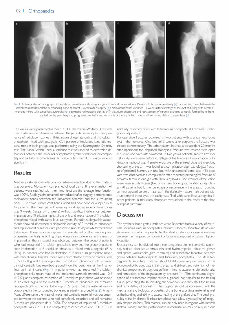
102 Orthopaedics
The values were presented as mean ± SD. The Mann–Whitney U test was used to determine differences between the periods necessary for disappea-rance of radiolucent zones in ß-tricalcium phosphate only and ß-tricalcium phosphate mixed with autografts. Comparison of implanted synthetic ma-terial mass in both groups was performed using the Kolmogorov–Smirnov test. The Aspin–Welch unequal variance test was applied to determine dif-ferences between the amounts of implanted synthetic material for comple-tely and partially resorbed cases. A P value of less than 0.05 was considered significant.
ResultsNeither postoperative infection nor adverse reaction due to the material was observed. No patient complained of local pain at final examination. All patients were satisfied with their limb function; the average limb function was 100%. Radiographs obtained immediately after surgery demonstrated radiolucent zones between the implanted ceramics and the surrounding bone. Over time, radiolucent zones faded and new bone developed in all 47 patients. The mean period necessary for disappearance of these zones was 9 weeks (range 5–13 weeks) without significant difference between implantation of ß-tricalcium phosphate only and implantation of ß-tricalcium phosphate mixed with cancellous autografts. Periodic radiographic assess-ments showed decreased radiographic density of ß-tricalcium phosphate and replacement of ß-tricalcium phosphate granules by newly formed bone trabeculae. These processes appear to have started on the periphery and progressed centrally in both groups. A significant difference in the mass of implanted synthetic material was observed between the group of patients who had implanted ß-tricalcium phosphate only and the group of patients after implantation of ß-tricalcium phosphate mixed with autografts (P < 0.05). In patients who had implantation of ß-tricalcium phosphate mixed with cancellous autografts, mean mass of implanted synthetic material was 30.5±17.8 g and the incorporated ß-tricalcium phosphate still remained distinct centrally but resorbed gradually on the periphery at the final fo-llow-up in all 8 cases (Fig. 1). In patients who had implanted ß-tricalcium phosphate only, mean mass of the implanted synthetic material was 10.6 ± 9.0 g and complete resorption of ß-tricalcium phosphate was observed in 12 cases. Signs of the implanted ß-tricalcium phosphate still remained radiographically at the final follow-up in 27 cases, but the material was in-corporated in the surrounding bone and gradually resorbed (Fig. 2). A signi-ficant difference in the mass of implanted synthetic material was documen-ted between the patients who had completely resorbed and still remained ß-tricalcium phosphate (P < 0.05). The amount of implanted ß-tricalcium phosphate was 2.2 ± 1.3 in completely resorbed cases and 14.0 ± 8.5 in
gradually resorbed cases with ß-tricalcium phosphate still remained radio-graphically distinct.Postoperative fractures occurred in two patients with a unicameral bone cyst in the humerus. One boy fell 3 weeks after surgery; the fracture was treated conservatively. The other patient has had a car accident 20 months after operation; the displaced diaphyseal fracture was treated with open reduction and plate osteosynthesis. In two young patients, growth arrest or deformity were seen before curettage of the lesion and implantation of ß--tricalcium phosphate. Premature closure of the physeal plate with resulting shortening of the arm was found as a complication after pathological fractu-re of proximal humerus in one boy with unicameral bone cyst. Mild coxa vara was observed as a complication after repeated pathological fracture of proximal femur in one girl with fibrous dysplasia. Recurrences of the lesion were seen in only 4 cases (two unicameral bone cysts, two fibrous dysplasi-as). All patients had further curettage of recurrence in the area surrounding an incorporated ceramic material. In the skeletally mature male patient with a unicameral bone cyst, the cavity was filled with cancellous autografts; in other patients, ß-tricalcium phosphate was added to the cavity at the time of repeat curettage.
DiscussionThe synthetic bone graft substitutes were fabricated from a variety of mate-rials, including calcium phosphates, calcium sulphates, bioactive glasses and glass-ceramics which appear to be the ideal substances for use as matrices because the inorganic component of bone is composed of calcium hydro-xyapatite.Bioceramics can be divided into three categories: bioinert ceramics (alumi-na), surface-bioactive ceramics (sintered hydroxyapatite, bioactive glasses and apatite-wollastonite glass-ceramics) and resorbable bioactive ceramics (low-crystalline hydroxyapatite and tricalcium phosphate). The ideal bio-degradable substitute materials should fulfill some requirements such as biocompatibility, adequate initial strength and stiffness and retention of me-chanical properties throughout sufficient time to assure its biofunctionality and nontoxicity of the degradation by-products19–21. The continuous degra-dation of a resorbable implant causes a gradual load transfer to the healing tissue, preventing stress-shielding phenomenon, and stimulates the healing and remodelling of bones6, 22. The surgeon should be concerned with the mechanical and biological properties of the bone substitute material as well as the handling and ability to assess healing of the grafted site. The small gra-nules of the implanted ß-tricalcium phosphate allow tight packing of irregu-larly shaped defects. This material can be only used in regions with intrinsic skeletal stability and the postoperative immobilization may be required due
Fig. 1: Anteroposterior radiograph of the right proximal femur showing a large unicameral bone cyst in a 15-year-old boy preoperatively (a); radiolucent zones between the implanted material and the surrounding bone apparent 6 weeks after surgery (b); radiolucent zones vanished 11 weeks after curettage of the cyst and filling with ceramic granules mixed with cancellous autografts (c); decreased radiographic density of ß-tricalcium phosphate and replacement of ceramic granules by newly formed bone have
started on the periphery and progressed centrally, and remnants of the implanted material still remained distinct 3 years later (d)
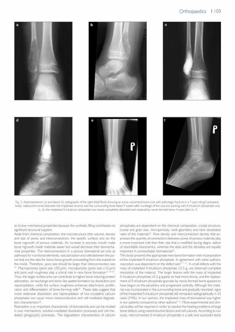
103OrthopaedicsOrthopaedics
Fig. 2: Anteroposterior (a) and lateral (b) radiographs of the right distal fibula showing an active unicameral bone cyst with pathologic fracture in a 7-year-old girl preopera-tively; radiolucent zones between the implanted ceramic and the surrounding bone faded 9 weeks after curettage of the cyst and packing with ß-tricalcium phosphate only
(c, d); the implanted ß-tricalcium phosphate was nearly completely absorbed and replaced by newly formed bone 4 years later (e, f)
to its low mechanical properties because the synthetic filling contributes no significant structural support.Aside from chemical composition, the microstructure (the volume, density and size of pores and interconnections, the specific surface) acts on the bone ingrowth of porous materials. An increase in porosity would make bone ingrowth inside materials easier but would decrease their biomecha-nical properties. The interconnections in a porous biomaterial act only as pathways for nutritional elements, vascularization and cells between the po-res that are the sites for bone tissue growth proceeding from the outside to the inside. Therefore, pore size should be larger than interconnection size 23. Macroporosity (pore size ≥50 μm), microporosity (pore size ≤10 μm) and pore wall roughness play a critical role in new bone formation16, 24–29. Thus, the larger surface area can contribute to higher bone inducing protein adsorption, ion exchange and bone-like apatite formation by dissolution and reprecipitation, while the surface roughness enhances attachment, prolife-ration and differentiation of bone-forming cells28. These data suggest that more extensive dissolution and reprecipitation of low-crystalline calcium phosphates can cause more osteoconductive and cell-mediated degrada-tion characteristics30.Resorption is an important characteristic of biomaterials and can be divided in two mechanisms: solution-mediated dissolution processes and cell-me-diated (phagocytic) processes. The degradation characteristics of calcium
phosphates are dependent on the chemical composition, crystal structure, crystal and grain size, microporosity, neck geometry and neck dissolution rates of the materials30. Pore density and interconnection density that ex-presses the quantity of connections between pores of porous materials play a more important role than their size that is modified during degra- dation of resorbable bioceramics, whereas the sizes and the densities are equally important in unresorbable biomaterials23.This study presents the appropriate new bone formation with incorporation of the implanted ß-tricalcium phosphate. In agreement with other authors, resorption was dependent on the defect size9, 11, 31. In small defects with the mass of implanted ß-tricalcium phosphate ≤3.5 g, we observed complete resorption of the material. The larger lesions with the mass of implanted ß-tricalcium phosphate ≥5.5 g appear to heal more slowly, and the replace-ment of ß-tricalcium phosphate granules by newly formed bone appears to have begun on the periphery and progressed centrally. Although the mate-rial was incorporated in the surrounding bone and gradually resorbed, signs of the implanted ß-tricalcium phosphate still remained radiographically in 35 cases (74%). In our opinion, the implanted mass of biomaterial was higher in our patients compared to other authors9, 10. More experimental and clini-cal studies will be required in order to resolve the healing problems of large bone defects using osteoinductive factors and cell cultures. According to our study, interconnected ß-tricalcium phosphate is a safe and successful bone

104 Orthopaedics
References1. Uchida A, Araki N, Shinto Y, Yoshikawa H, Kurisaki E, Ono K (1990) The use of calcium hydroxyapatite ceramic in bone tumour surgery. J Bone Joint
Surg 72-B:298–3022. Hibi A, Ishikawa T, Asano M, Ohsawa S, Tsuge K, Iyoda K (1994) A study of failed implantation of hydroxyapatite for benign bone tumor. Orthoped
Surg (Sekiekgeka) 45:1423–14283. Itokazu M, Matsunaga T, Ishii M, Kusakabe H, Wyni Y (1996) Use of arthroscopy and interporous hydroxyapatite as a bone graft substitute in tibial
plateau fractures. Arch Orthop Trauma Surg 115:45–484. Matsumine A, Myoui A, Kusazaki K, Araki N, Seto M, Yos- hikawa H, Uchida A (2004) Calcium hydroxyapatite ceramic implants in bone tumour sur-
gery: a long-term follow-up study. J Bone Joint Surg 86-B:719–7255. Ito M, Abumi K, Moridaira H, Shono Y, Kotani Y, Minami A, Kaneda K (2005) Iliac crest reconstruction with a bioactive ceramic spacer. Eur Spine J
14:99–1026. Sponer P, Urban K, Urbanova E, Karpas K, Mathew PG (2010) Behavior of bioactive glass-ceramic implanted into long bone defects: a scintigraphic
study. J Pediatr Orthop B 19:102–1077. Merten HA, Wiltfang J, Grohmann U, Hoenig JF (2001) Intraindividual comparative animal study of α-and ß-tricalcium phosphate degradation in con-
junction with simultaneous insertion of dental implants. J Craniofacial Surg 12:59–678. Wiltfang J, Merten HA, Schlegel KA, Schultze-Mosgau S, Kloss FR, Rupprecht S, Kessler P (2002) Degradation characteristics of a and ß-tricalcium-
-phosphate (TCP) in minipigs. J Biomed Mater Res (Appl Biomater) 63:115–1219. Galois L, Mainard D, Delagoutte JP (2002) Beta-tricalcium phosphate ceramic as a bone substitute in orthopaedic surgery. Inter Orthop 26:109–11510. Ogose A, Hotta T, Kawashima H, Kondo N, Gu W, Kamura T, Endo N (2005) Comparison of hydroxyapatite and beta tricalcium phosphate as bone
substitutes after excision of bone tumors. J Biomed Mater Res Part B: Appl Biomater 72B:94–10111. Hirata M, Murata H, Takeshita H, Sakabe T, Tsuji Y, Kubo T (2006) Use of purified beta-tricalcium phosphate for filling defects after curettage of benign
bone tumours. Inter Orthop 30:510–51312. Brunner TJ, Grass RN, Bohner M, Stark WJ (2007) Effect of particle size, crystal phase and crystallinity on the reactivity of tricalcium phosphate cements
for bone reconstruction. J Mater Chem 17:4072–407813. Walsh WR, Vizesi F, Michael D, Auld J, Langdown A, Oliver R, Yu Y, Irie H, Bruce W (2008) ß-TCP bone graft substitutes in a bilateral rabbit tibial defect
model. Biomaterials 29:266–27114. Gál P, Ondruš Š, Škvařil J, Straka M, Jochymek J, Plánka L (2009) Synthetic biocompatible degradable material for juvenilie bone cyst treatment. Acta
Chir Orthop Traumatol Cech 76:495–50015. Stubbs D, Deakin M, Chapman-Sheath P, Bruce W, Debes J, Gillies RM et al (2004) In vivo evaluation of resorbable bone graft substitutes in a rabbit
tibial defect model. Biomaterials 25:5037–504416. von Doernberg MC, von Rechenberg B, Bohner M, Grunenfelder S, van Lenthe GH, Muller R et al (2006) In vivo behavior of calcium phosphate
scaffolds with four different pore sizes. Bio- materials 27:5186–519817. Urban K, Strnad Z, Povysil C, Sponer P (1996) Tricalcium phosphate as a bone tissue substitute (testing of biological properties in animal experiments).
Acta Chir Orthop Traumatol Cech. 63:16–2018. Enneking WF, Dunham W, Gebhardt MC, Malawar M, Pritchard DJ (1993) A system for the functional evaluation of reconstructive procedures after
surgical treatment of tumors of the musculoskeletal system. Clin Orthop Rel Res 286:241–24619. Botez P, Sirbu P, Simion L, Munteanu F, Antonia I (2009) Application of a biphasic macroporous synthetic bone substitutes CERAFORM®: clinical and
histological results. Eur J Orthop Surg Traumatol 19:387–39520. Mano JF, Sousa RA, Boesel LF, Neves NM, Reis RL (2004) Bioinert, biodegradable and injectable polymeric matrix composites for hard tissue replace-
ment: state of the art and recent developments. Compos Sci Technol 64:789–81721. Naito K, Obayashi O, Mogami A, Itoi A, Kaneko K (2008) Fracture of the calcium phosphate bone cement which used to enchondroma of the hand:
a case report. Eur J Orthop Surg Traumatol 18:405–40822. Dorozhkin SV (2009) Calcium orthophosphate-based biocomposites and hybrid biomaterials. J Mater Sci 44:2343–238723. Lu JX, Flautre B, Anselme K, Hardouin P, Gallur A, Descamps M et al (1999) Role of interconnections in porous bioceramics on bone recolonization
in vitro and in vivo. J Mater Sci Mater Med 10:111–12024. Bohner M, Baumgart F (2004) Effects of geometrical factors on the resorption of calcium phosphate bone substitutes. Biomaterials 25:3569–358225. Daculsi G, Passuti N (1990) Effect of macroporosity for osseous substitution of calcium phosphate ceramics. Biomaterials 11:86–8726. Eggli PS, Muller W, Schenk RK (1988) Porous hydroxyapatite and tricalcium phosphate cylinders with two different macropore size ranges implanted
in the cancellous bone of rabbits. Clin Orthop 232:127–13827. Galois L, Mainard D (2004) Bone ingrowth into two porous ceramics with different pore sizes: an experimental study. Acta Orthop Belg 70:598–60328. Karageorgiou V, Kaplan D (2005) Porosity of 3D biomaterial scaffolds and osteogenesis. Biomaterials 26:5474–549129. Yuan H, Kurashina K, de Bruijn JD, Li Y, de Groot K, Zhang X (1999) A preliminary study on osteoinduction of two kinds of calcium phosphate cera-
mics. Biomaterials 20:1799–180630. Oonishi H, Hench LL, Wilson J, Sugihara F, Tsuji E, Kushitani S, Iwaki H (1999) Comparative bone growth behavior in granules of bioceramic materials
of various sizes. J Biomed Mater Res 44:31–4331. Nicholas RW, Lange TA (1994) Granular tricalcium phosphate grafting of cavitary lesions in human bone. Clin Orthop Rel Res 306:197–203
graft substitute for the treatment of benign bone tumours and tumour-like lesions because of its biocompatibility and bioresorbability.
Acknowledgment The authors declare that they have no conflict of interest. No financial supp-ort was provided for this report.
Conflict of interest No funds were received in support of this study. No benefits in any form have been or will be received from a commercial party related directly or indirectly to the subject of this manuscript.

Orthopaedics
A-A
AA
A
LASAK Ltd. • Českobrodská 1047/46 • 190 01 Prague 9 – Hloubětín • Czech Republictel.: +420 224 315 663 • fax: +420 224 319 716 • e-mail: [email protected] • www.lasak.com