Pre-Feasibility Report For Onshore Oil and Gas Exploration ...
31
Pre-Feasibility Report For Onshore Oil and Gas Exploration and Appraisal in Block CB- ONHP-2017/6 in Gandhinagar, Ahmedabad and Mahesana Districts of Gujarat VEDANTA LTD. (CAIRN OIL & GAS) March, 2019
-
Upload
khangminh22 -
Category
Documents
-
view
0 -
download
0
Transcript of Pre-Feasibility Report For Onshore Oil and Gas Exploration ...
Pre-Feasibility Report
For
Onshore Oil and Gas Exploration and Appraisal in Block CB-ONHP-2017/6 in Gandhinagar, Ahmedabad and Mahesana
Districts of Gujarat
VEDANTA LTD. (CAIRN OIL & GAS)
March, 2019

2
Table of Contents
1. Executive Summary ...................................................................................................................... 4
1.1 Project Details ............................................................................................................................... 4
1.4 Pollution control measures........................................................................................................... 5
1.4.1 Pollution Control measures during Seismic Operations ............................................................... 5
1.4.2 Pollution Control measures during Drilling Operations ............................................................... 5
1.5 Project schedule and cost estimate .............................................................................................. 6
1.6 Employment Generation .............................................................................................................. 6
1.7 Rehabilitations and Resettlements ............................................................................................... 6
2. Introduction of the project ........................................................................................................... 7
3 Project Description ....................................................................................................................... 9
3.1 Type of project .............................................................................................................................. 9
3.2 Location with co-ordinates ........................................................................................................... 9
3.5 Project description with process details ..................................................................................... 10
3.6 Raw materials required and source ............................................................................................ 24
3.8 Water and power requirement .................................................................................................. 25
3.9 Quantity of waste to be generated and its disposal ................................................................... 26
3.10 Schematic of Feasibility Drawing ................................................................................................ 27
4. Site Analysis ................................................................................................................................ 28
4.1 Connectivity ................................................................................................................................ 28
4.3 Topography (along with map) .................................................................................................... 28
4.4 Existing land use pattern and relative location of protected areas ............................................ 28
4.5 Existing infrastructure/ industries .............................................................................................. 29
4.6 Soil classification ......................................................................................................................... 29
4.7 Climate data from secondary sources ........................................................................................ 29
4.7.1 Wind ........................................................................................................................................... 30
4.7.2 Storms and cyclones ................................................................................................................... 30
4.7.3 Rainfall ........................................................................................................................................ 30
4.7.4 Temperature and humidity......................................................................................................... 30
5 Planning Brief .............................................................................................................................. 30
5.1 Planning concept ........................................................................................................................ 30
5.2 Population projection ................................................................................................................. 30
5.3 Land use planning (break up along with green belt, etc) ........................................................... 30
5.4 Assessment of Infrastructure demand ....................................................................................... 31
3
7. Rehabilitation and resettlement (R&R) Plan........................................................................31
6. Proposed Infrastructure ............................................................................................................. 31
8. Project schedule and cost estimate ............................................................................................ 31
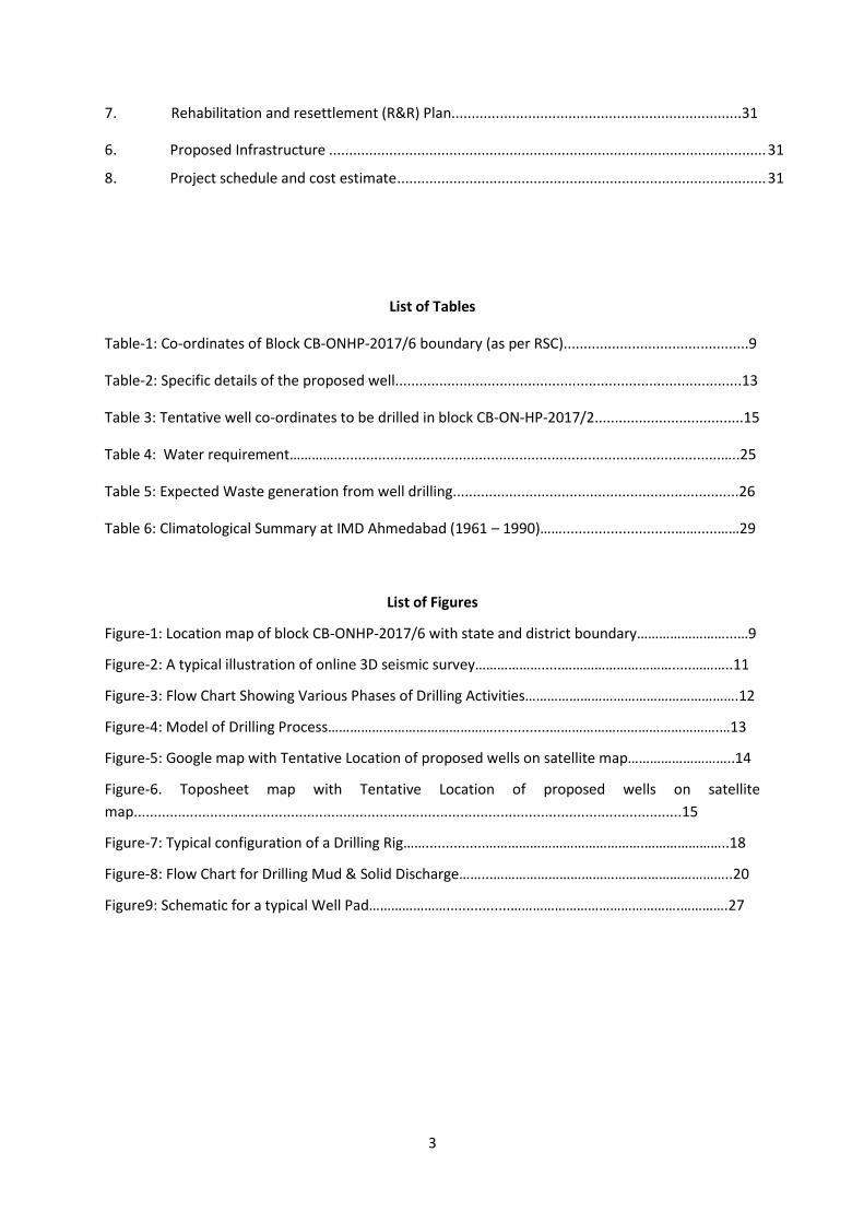
List of Tables
Table-1: Co-ordinates of Block CB-ONHP-2017/6 boundary (as per RSC)..............................................9
Table-2: Specific details of the proposed well......................................................................................13
Table 3: Tentative well co-ordinates to be drilled in block CB-ON-HP-2017/2.....................................15
Table 4: Water requirement…………................................................................................................…..25
Table 5: Expected Waste generation from well drilling.......................................................................26
Table 6: Climatological Summary at IMD Ahmedabad (1961 – 1990)……............................…….....……29
List of Figures
Figure-1: Location map of block CB-ONHP-2017/6 with state and district boundary……………………...…9
Figure-2: A typical illustration of online 3D seismic survey……………….....………………………….....………..11
Figure-3: Flow Chart Showing Various Phases of Drilling Activities………………………………………………….12
Figure-4: Model of Drilling Process………………………………………..............……………………………………….…13
Figure-5: Google map with Tentative Location of proposed wells on satellite map………………………..14
Figure-6. Toposheet map with Tentative Location of proposed wells on satellite
map........................................................................................................................................15
Figure-7: Typical configuration of a Drilling Rig……...............…………………………………….…………………..18
Figure-8: Flow Chart for Drilling Mud & Solid Discharge……...………………………………………………………..20
Figure9: Schematic for a typical Well Pad…………………................……………………………………….………….27
4
1. Executive Summary
Vedanta (erstwhile Cairn India Limited merged with Vedanta Limited w.e.f. April 11, 2017, pursuant
to NCLT order dated March 23, 2017) is a globally diversified natural resources company with
interest in Zinc, Iron Ore, Aluminium, Copper, Power and Oil & Gas. Vedanta Ltd. (Cairn Oil & Gas) is
the operator of the Onshore CB-ONHP-2017/6 block. The block covers an area of 19 Sq.Km in
Gandhinagar, Ahmedabad and Mahesana districts of Gujarat. Vedanta Ltd. has been granted with an
exploration and production license by Government of India under the Revenue Sharing Contract
(RSC) on 1st October 2018.
1.1 Project Details
1.1.1 Proposed facilities
Vedanta Limited (Cairn Oil & Gas) proposes to carryout seismic survey, exploratory including
appraisal well drilling and setting up of Early Production Units (EPUs)/Quick Production Units
(QPUs) and Early production in the block CB-ONHP-2017/6.
1.1.2 Justification of the project
The demand for petroleum has recorded a considerable increase over the last few years. There is a
considerable increase in consumption of petroleum products due to the development activities in
the country in the last few years. During the year 2016-17, the consumption of petroleum products
in India was 194.60 MMT with a growth of 5.37% as compared to consumption of 184.67 MMT
during 2015-16. The consumption of petroleum products during April-November, 2017 was at
134.60 MMT i.e. an increase of 3.40% over 130.17 MMT in April-November, 2016. The crude oil
production for the year 2016-17 is at 36.01 Million Metric Tonnes (MMT) as against production of
36.94 MMT in 2015-16, showing a decrease of about 2.53%. Whereas Natural Gas production
during the year 2016-17 is at 31.90 Billion Cubic Meters (BCM) which is 1.09% lower than
production of 32.25 BCM in 2015-16. Import of crude oil during 2016-17 was 213.93 MMT valued
at 470159 crore as against import of 202.85 MMT valued at 416579 crore in 2015-16 which
marked an increase of 5.46% in quantity terms and 12.86% in value terms as compared to the
import of crude oil during 2015-16.
Import of Crude Oil during April-November, 2017 was 144.72 MMT valued at 3,42,673 crore which
marked an increase of 9.31% in quantity terms and 15.32% in value terms as against the imports of
143.81 MMT valued at 2,97,161 crore for the same period of last year. Therefore, India is largely
dependent on import of petroleum goods to meet its requirements. Facing an environment of
increasing consumption, static reserves, increasing imports and increasing costs of crude as well as
decreasing value of the Indian Rupee vis-à-vis the US Dollar, it follows that any accretion of
hydrocarbon reserves in the country, is welcome.
Vedanta’s proposed exploratory drilling, development and production project could possibly result
in the discovery of hydrocarbon and in that case, would help in reducing India’s dependence on
imports.
1.2 Site Analysis
1.2.1 Climate
The study area experiences a humid and warm sub-tropical climate throughout the year except for a
cold winter in December till February. Hourly micro-meteorological data collected during the pre-
monsoon reveals that the pre-dominant wind direction is from SouthEast with an average speed of
0.80 m/s.
5
1.3 Water and power requirements
1.3.1 Water Requirement
A. Water Requirement during Seismic Survey
The water requirement is 20-30 m3/day for domestic needs of the temporary campsite and will be
sourced locally through approved authorities.
B. Water requirement during Exploratory and Appraisal well drilling
The most significant requirement of water for drilling activities is for mud preparation. The water
requirement for WBM preparation will be 600-1000 m3/well. The water requirement for SBM
preparation will be 150-300 m3/well. The other requirement approx. 25-50 m3/well/day would be
for drilling activities like engine cooling, floor / equipment / string washing, fire-fighting storage /
make-up. For domestic consumption, approx. 20 - 30 m3/day water will be required during drilling
period. The water requirement will be sourced locally through approved authorities.
1.3.2 Power requirement
A. Power requirement during seismic Survey
Each camp site shall have access to 2x 350KVA (1 standby). The required power supply will be
provided either from diesel generators or state grid.
B. Power requirement during Exploratory and Development well drilling
The power requirement of drill rig will be met by three (03) DG sets (including one as standby)
(3*1000 KVA), 2*350 KVA for drilling camp site and 2* 100 KVA for the radio room respectively.
1.4 Pollution control measures
1.4.1 Pollution Control measures during Seismic Operations
A. Air Emissions and Control Measure
Emissions to air include transient airborne dust raised by construction activities (e.g. preparation of
seismic cut lines and moving vehicles and equipment) and emissions from vehicles and machinery.
These emissions are transient and insignificant nature.
B. Noise Emissions and Control Measure
Noise emissions that could be released during the seismic operations will include those generated by
blasting of charges in shot holes, field machinery (Bulldozer and support vehicles) and generators
and work yard at the camp site. Adequate noise control measures will be taken to minimize the
noise level.
C. Wastes treatment and disposal
The non-hazardous wastes like domestic wastes and effluents, plastics, and paper and disposal
options include, compaction and removal from site and burying (especially for biodegradable
material), or a combination of these activities.
1.4.2 Pollution Control measures during Drilling Operations
A. Air Emissions and Control Measure
The emissions to the atmosphere from the drilling operations shall be from the diesel engines, and
power generator and temporary from flaring activity (during testing).
6
B. Noise Emissions and Control Measure
The source of noise generation during this phase of operations would be the operation of rig and
diesel generator sets. Besides, certain pumps are expected to be in operation during this phase, for
mud circulation. The noise generation work however is transient and limited to the drilling period
only. Appropriate control measures will be taken to minimize exposure of noise to drilling personnel.
C. Waste treatment and disposal
250-750tons/well for drill cuttings associated with WBM and 500-1500 tons/well for drill cuttings
associated with SBM and 250-500 tons/well WBM spent/residual drilling mud will be generated at
site during drilling operations. This will be stored in well-designed HDPE line pit.
Used /waste Oil – During the drilling approx. 1-2 tons of used oil, sludge containing oil and other
drilling wastes will be 250-500tons/well will be generated per well. This oil will be sent to
authorized recyclers.
Domestic waste of 25-30 kg/day per well will be generated at site, which will be segregated at
source (Organic/ Inorganic) and disposed accordingly.
All kinds of waste will be disposed in accordance with the requirement of CPCB/SPCB.
D. Waste water Treatment
The drilling waste water will be treated suitably.
1.5 Project schedule and cost estimate
Vedanta Ltd (Cairn Oil and gas) has planned to carryout proposed project activities in the CB-ONHP-
2017/6 Block in next 10-12 years.
The estimated cost of the project is given below:
1) Physical Surveys Cost estimated to be approximately INR 2 Crore.
2) Average Cost per well for exploratory & appraisal well drilling is estimated to be INR 7 Crore.
3) Average cost of a QPF (Quick Processing Facility) is estimated to be INR 44.13 Crore.
1.6 Employment Generation
The seismic surveys are expected to take about 6 to 8 months and will require a crew of
approximately 400 to 500 persons. Most of the workforce will be from local nearby areas. During
the site preparation for drilling, approximately 30-35 workmen will be employed per drill site.
During the drilling phase, about 50 workmen per shift will be working on site. This will include
technical experts, who will be responsible for various drilling related activities and some technical
manpower engaged are either from Vedanta Limited or contractor’s crew as applicable. It is
anticipated that, at any given time, there will be about 80-100 personnel working on site including
technical staff, drilling crew, security staff etc.
1.7 Rehabilitations and Resettlements
For exploration, appraisal and production activities, the project does not envisage any R & R of the
project, since the land requirement would be very less and on temporary short term lease and
away from the settlements. If the identified lands are of private landowners then land lease mode
will be applied and in case of govt. land, land allotment from Govt. to be applied. Initially
7
temporary short term lease will be taken for 3 - 5 years for exploration purpose and in case of
commercially viable discovery of hydrocarbon resources; the land lease would be converted into
long term lease up to life of the project.
For sites selected having settlements if any, Resettlement & rehabilitation (R&R) plan will be
developed and implemented as per the applicable State/ Central Govt. policy. Compensation to
affected landowners for any loss of land, Cairn will ensure the livelihood of local community, if any
affected by the proposed land take, are identified and compensated through adequate
compensation and other livelihood restoration activities directly or indirectly through CSR
activities.
2. Introduction of the project
2.1 Identification of the project
Vedanta Ltd (Cairn Oil & Gas) has been awarded the CB-ONHP-2017/6 hydrocarbon block under the
OALP (Open Acreage Licensing Policy) by MoP&NG, Govt. of India. RSC (Revenue Sharing Contract)
has been signed between Vedanta Ltd and MoP&NG on 1st October, 2018 for the exploration and
exploitation of hydrocarbons. Vedanta Ltd (Cairn Oil & Gas) proposes to carry out exploration
(including seismic surveys, exploratory and appraisal well drilling), and early production of oil and
gas in the block.
In case of a discovery (ies), the exploratory and appraisal well(s) will be tested for extended duration
by flowing hydrocarbons to ascertain the reservoir parameters and assess the quality and
commercial viability. Moreover, in case of commercially viable discovery (s) of hydrocarbons in the
block and having established the size of the hydrocarbon field (s), field will be immediately brought
into early production of crude oil and associated gas using some of the successful
exploratory/appraisal wells by setting up of temporary and mobile Early Production Units
(EPUs)/QPU (Quick Production Unit) for the processing of produced well fluids.
2.2 Brief description of nature of the project
The proposed project is green field in nature. The project is an oil and gas exploration and early
production project.
2.3 Need for the project and its importance to country and region
India is largely dependent on import of petroleum goods to meet its requirements. Facing an
environment of increasing consumption, static reserves, increasing imports and increasing costs of
crude as well as decreasing value of the Indian Rupee vis-à-vis the US Dollar, it follows that any
accretion of hydrocarbon reserves in the country, is welcome.
Vedanta’s proposed exploratory drilling project could possibly result in the discovery of hydrocarbon
and subsequent development and production would help in reducing India’s dependence on
imports. Consequently, the need for the project is evident. The proposed project would also
contribute to the state Governments in terms of royalty through the mining lease. Additionally the
proposed project would generate direct and indirect employment in the region.
2.4 Demand-supply Gap
As on 1.4.2017, In-place hydrocarbon volume of 10454 million tonnes of oil and oil equivalent gas
could be established through exploration by ONGC, OIL and Private/JV companies. So, about 75% of
8
resources are under “yet to find” category. Out of 10454 MMT of oil and oil equivalent gas of In-
place volumes, the ultimate reserves which can be produced are about 4017 MMT of oil and oil
equivalent gas since inception. The balance recoverable reserves are of the order of 1787 MMT of oil
and oil equivalent gas.
2.4.1Production and Consumption
The crude oil production for the year 2016-17 is at 36.01 Million Metric Tonnes (MMT) as against
production of 36.94 MMT in 2015-16, showing a decrease of about 2.53%. Whereas Natural Gas
production during the year 2016-17 is at 31.90 Billion Cubic Meters (BCM) which is 1.09% lower than
production of 32.25 BCM in 2015-16. The demand for petroleum has recorded a considerable
increase over the last few years due to the development activities in the country in the last few
years.
During the year 2016-17, the consumption of petroleum products in India was 194.60 MMT with a
growth of 5.37% as compared to consumption of 184.67 MMT during 2015-16. The consumption of
petroleum products during April-November, 2017 was at 134.60 MMT i.e. an increase of 3.40% over
130.17 MMT in April-November, 2016
Therefore, India is largely dependent on import of petroleum goods to meet its requirements.
Vedanta’s proposed exploratory drilling project could possibly result in the discovery of hydrocarbon
and in that case, would help in reducing India’s dependence on imports.
2.4.2Imports
Import of crude oil during 2016-17 was 213.93 MMT valued at 470159 crore as against import of
202.85 MMT valued at 416579 crore in 2015-16 which marked an increase of 5.46% in quantity
terms and 12.86% in value terms as compared to the import of crude oil during 2015-16. Import of
Crude Oil during April-November, 2017 was 144.72 MMT valued at 3,42,673 crore which marked an
increase of 9.31% in quantity terms and 15.32% in value terms as against the imports of 143.81 MMT
valued at 2,97,161 crore for the same period of last year.
2.5 Import versus indigenous production and export
India imports more than 80% of the petroleum products of its daily requirement.
2.6 Domestic Markets
The produced Oil & Gas, in case of commercially viable discoveries of hydrocarbon, will be utilized
for domestic purpose to supply the increasing demand in domestic market.
2.7 Employment generation
The seismic surveys and drilling operations are expected to take about 6 to 8months to complete
and will require a crew of approximately 400 to 500 persons. And most of the workforce will be from
local area. During the site preparation for drilling, approximately 30-35 workmen will be employed
per drill site. During the drilling phase, about 50 workmen per shift will be working on site. This will
include technical experts, who will be responsible for various drilling related activities and some
technical manpower engaged are either from Vedanta Limited or contractor’s crew as applicable. It
is anticipated that, at any given time, there will be about 80-100 personnel working on site including

9
technical staff, drilling crew, security staff etc. In case of commercial discovery of oil and gas
additional manpower will be employed for building of production facilities and laying of pipelines.
3 Project Description
3.1 Type of project
The proposed project is a green field project. There is no interlinked and inter-dependent project.
3.2 Location with co-ordinates
The block CB-ONHP-2017/6 is located in Gandhinagar, Ahmedabad and Mahesana districts of
Gujarat. It encloses an area of 19 Sq. Km. and is bounded by the points having following coordinates
Table-1. A map of the contract area is shown in Figure 1.
Figure-1: Location map of block CB-ONHP-2017/6 with state and district boundary
Table-1: Co-ordinates of Block CB-ONHP-2017/6 boundary (as per RSC)
Points Longitude Latitude
1 72° 22' 23° 7'
2 72° 22' 23° 6'

10
3 72° 23' 23° 6'
4 72° 23' 23° 2'
5 72° 22' 23° 2'
6 72° 22' 23° 5'
7 72° 21' 23° 5'
8 72° 21' 23° 7'
The block area covers total of 19 Sq. Km falls under Gandhinagar, Ahmedabad and Mahesana
districts of Gujarat.
3.3 Details of alternate site considered and the basis of selecting the proposed site
The block is allocated by the Government of India under the Revenue Sharing Contract (RSC).
Vedanta Ltd. - Cairn Oil & Gas is the Operator for this block. Drilling locations are proposed based on
geo-scientific information and alternate sites cannot be considered for the proposed project facilities
due to the following reasons:
The location is within the existing RSC boundary of the field/block. The locations of wells are
selected considering the drilling configuration (reach to reservoirs).
3.4 Size/ magnitude of operation
The proposed onshore oil and gas Exploration, Appraisal and Early production project is expected to
carry out
1. Seismic data acquisition
2. Drilling of 20 exploratory (including appraisal wells) and testing
3. Setting up of Early Production Units (EPUs)/Quick Production Units (QPUs) for produced well
fluid processing and early production of up to 8000 BOPD crude oil and up to 1.2 MMSCFD of
associated natural gas
4. The exploratory and appraisal wells will be drilled to explore the reservoirs up to depth of
approx. 3500 m.
3.5 Project description with process details
3.5.1 2D & 3D Seismic survey:
Seismic surveys are a primary tool utilized during the exploration of hydrocarbons over land and
water. A seismic survey is conducted by creating an energy wave commonly referred to as a ‘seismic
wave’ on the surface of the ground/ over water along a predetermined line, using an energy source.
This wave travels into and through the earth strata, where it is reflected and refracted by various
subsurface formations, and returns to the surface where receivers called geophones are used to
detect the waves and convey them to a recorder for analysis. Seismic waves can be induced by the
following methods: small explosive charges, primarily dynamite, set off in shallow holes known as
‘shot holes’; or by large ‘Vibroseis’ trucks equipped with heavy plates that vibrate on the ground or
air guns for water based surveys. By analyzing the time it takes for the seismic waves to reflect off
subsurface formations and return to the surface formations can be mapped and potential oil or
gasdeposits identified. 3D surveys are acquired by laying out energy source points (vibroseis or
dynamite charges) and receiver points (geophones) in a grid over the area to be surveyed. The
receiver points - to record the reflected vibrations from the source points - are laid down in parallel
lines (receiver lines), and the source points are laid out in parallel lines that are approximately
11
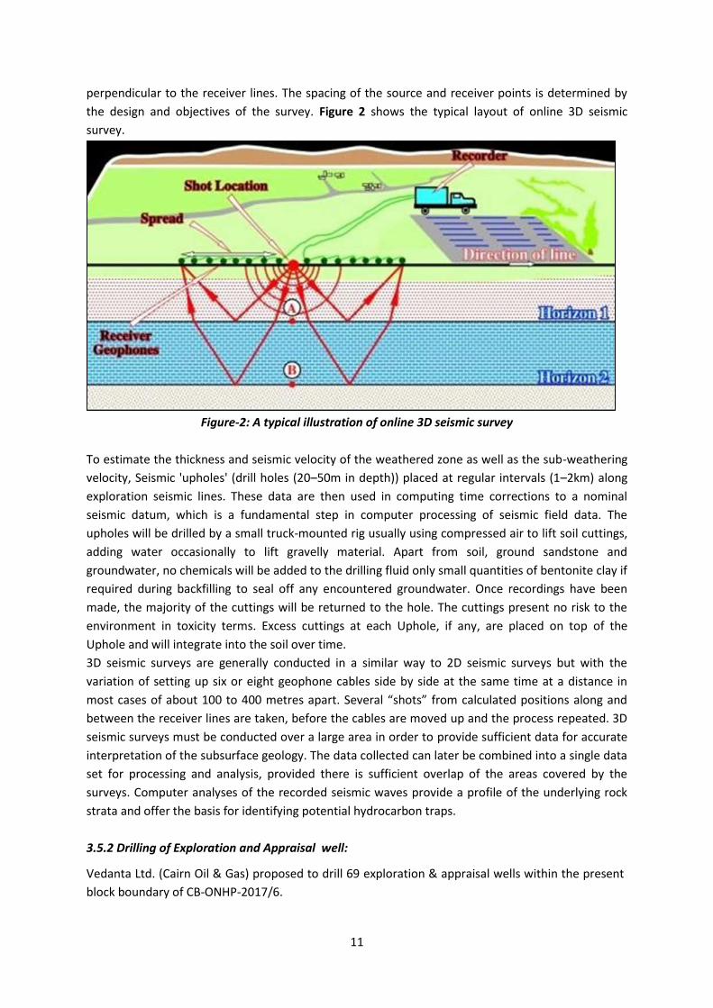
perpendicular to the receiver lines. The spacing of the source and receiver points is determined by
the design and objectives of the survey. Figure 2 shows the typical layout of online 3D seismic
survey.
Figure-2: A typical illustration of online 3D seismic survey
To estimate the thickness and seismic velocity of the weathered zone as well as the sub-weathering
velocity, Seismic 'upholes' (drill holes (20–50m in depth)) placed at regular intervals (1–2km) along
exploration seismic lines. These data are then used in computing time corrections to a nominal
seismic datum, which is a fundamental step in computer processing of seismic field data. The
upholes will be drilled by a small truck-mounted rig usually using compressed air to lift soil cuttings,
adding water occasionally to lift gravelly material. Apart from soil, ground sandstone and
groundwater, no chemicals will be added to the drilling fluid only small quantities of bentonite clay if
required during backfilling to seal off any encountered groundwater. Once recordings have been
made, the majority of the cuttings will be returned to the hole. The cuttings present no risk to the
environment in toxicity terms. Excess cuttings at each Uphole, if any, are placed on top of the
Uphole and will integrate into the soil over time.
3D seismic surveys are generally conducted in a similar way to 2D seismic surveys but with the
variation of setting up six or eight geophone cables side by side at the same time at a distance in
most cases of about 100 to 400 metres apart. Several “shots” from calculated positions along and
between the receiver lines are taken, before the cables are moved up and the process repeated. 3D
seismic surveys must be conducted over a large area in order to provide sufficient data for accurate
interpretation of the subsurface geology. The data collected can later be combined into a single data
set for processing and analysis, provided there is sufficient overlap of the areas covered by the
surveys. Computer analyses of the recorded seismic waves provide a profile of the underlying rock
strata and offer the basis for identifying potential hydrocarbon traps.
3.5.2 Drilling of Exploration and Appraisal well:
Vedanta Ltd. (Cairn Oil & Gas) proposed to drill 69 exploration & appraisal wells within the present
block boundary of CB-ONHP-2017/6.
12
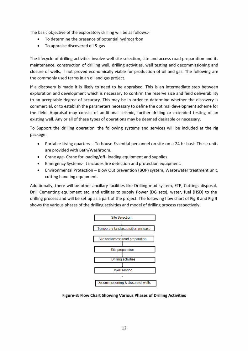
The basic objective of the exploratory drilling will be as follows:-
To determine the presence of potential hydrocarbon
To appraise discovered oil & gas
The lifecycle of drilling activities involve well site selection, site and access road preparation and its
maintenance, construction of drilling well, drilling activities, well testing and decommissioning and
closure of wells, if not proved economically viable for production of oil and gas. The following are
the commonly used terms in an oil and gas project.
If a discovery is made it is likely to need to be appraised. This is an intermediate step between
exploration and development which is necessary to confirm the reserve size and field deliverability
to an acceptable degree of accuracy. This may be in order to determine whether the discovery is
commercial, or to establish the parameters necessary to define the optimal development scheme for
the field. Appraisal may consist of additional seismic, further drilling or extended testing of an
existing well. Any or all of these types of operations may be deemed desirable or necessary.
To Support the drilling operation, the following systems and services will be included at the rig
package:
Portable Living quarters – To house Essential personnel on site on a 24 hr basis.These units
are provided with Bath/Washroom.
Crane age- Crane for loading/off- loading equipment and supplies.
Emergency Systems- It includes fire detection and protection equipment.
Environmental Protection – Blow Out prevention (BOP) system, Wastewater treatment unit,
cutting handling equipment.
Additionally, there will be other ancillary facilities like Drilling mud system, ETP, Cuttings disposal,
Drill Cementing equipment etc. and utilities to supply Power (DG sets), water, fuel (HSD) to the
drilling process and will be set up as a part of the project. The following flow chart of Fig 3 and Fig 4
shows the various phases of the drilling activities and model of drilling process respectively:
Figure-3: Flow Chart Showing Various Phases of Drilling Activities
13
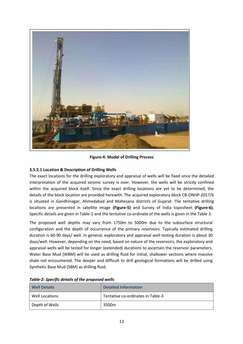
Figure-4: Model of Drilling Process
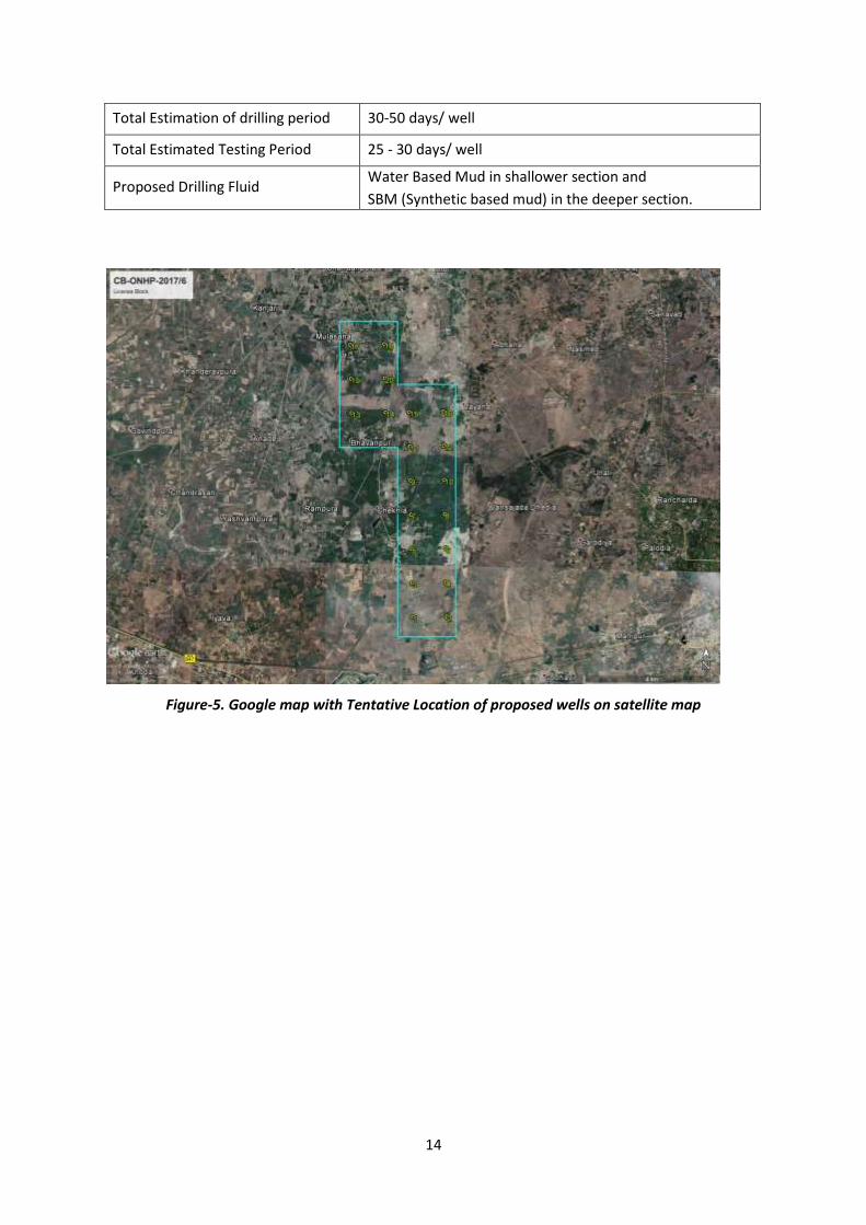
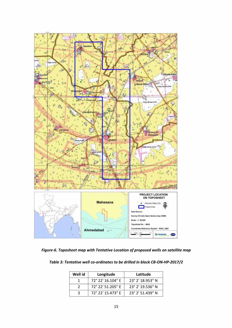
3.5.2.1 Location & Description of Drilling Wells
The exact locations for the drilling exploratory and appraisal of wells will be fixed once the detailed
interpretation of the acquired seismic survey is over. However, the wells will be strictly confined
within the acquired block itself. Since the exact drilling locations are yet to be determined, the
details of the block location are provided herewith. The acquired exploratory block CB-ONHP-2017/6
is situated in Gandhinagar, Ahmedabad and Mahesana districts of Gujarat. The tentative drilling
locations are presented in satellite image (Figure-5) and Survey of India toposheet (Figure-6).
Specific details are given in Table-2 and the tentative co-ordinate of the wells is given in the Table 3.
The proposed well depths may vary from 1750m to 5000m due to the subsurface structural
configuration and the depth of occurrence of the primary reservoirs. Typically estimated drilling
duration is 60-90 days/ well. In general, exploratory and appraisal well testing duration is about 30
days/well. However, depending on the need, based on nature of the reservoirs, the exploratory and
appraisal wells will be tested for longer (extended) durations to ascertain the reservoir parameters.
Water Base Mud (WBM) will be used as drilling fluid for initial, shallower sections where massive
shale not encountered. The deeper and difficult to drill geological formations will be drilled using
Synthetic Base Mud (SBM) as drilling fluid.
Table-2: Specific details of the proposed wells
Well Details Detailed Information
Well Locations Tentative co-ordinates in Table-3
Depth of Wells 3500m
14
Total Estimation of drilling period 30-50 days/ well
Total Estimated Testing Period 25 - 30 days/ well
Proposed Drilling Fluid Water Based Mud in shallower section and
SBM (Synthetic based mud) in the deeper section.
Figure-5. Google map with Tentative Location of proposed wells on satellite map
15
Figure-6. Toposheet map with Tentative Location of proposed wells on satellite map
Table 3: Tentative well co-ordinates to be drilled in block CB-ON-HP-2017/2
Well id Longitude Latitude
1 72° 22' 16.104" E 23° 2' 18.953" N
2 72° 22' 51.205" E 23° 2' 19.536" N
3 72° 22' 15.473" E 23° 2' 51.439" N
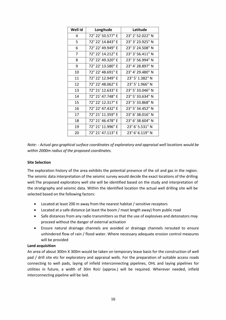
16
Well id Longitude Latitude
4 72° 22' 50.577" E 23° 2' 52.022" N
5 72° 22' 14.843" E 23° 3' 23.925" N
6 72° 22' 49.949" E 23° 3' 24.508" N
7 72° 22' 14.212" E 23° 3' 56.411" N
8 72° 22' 49.320" E 23° 3' 56.994" N
9 72° 22' 13.580" E 23° 4' 28.897" N
10 72° 22' 48.691" E 23° 4' 29.480" N
11 72° 22' 12.949" E 23° 5' 1.382" N
12 72° 22' 48.062" E 23° 5' 1.966" N
13 72° 21' 12.633" E 23° 5' 33.046" N
14 72° 21' 47.748" E 23° 5' 33.634" N
15 72° 22' 12.317" E 23° 5' 33.868" N
16 72° 22' 47.432" E 23° 5' 34.452" N
17 72° 21' 11.359" E 23° 6' 38.016" N
18 72° 21' 46.478" E 23° 6' 38.604" N
19 72° 21' 11.996" E 23° 6' 5.531" N
20 72° 21' 47.113" E 23° 6' 6.119" N
Note: - Actual geo-graphical surface coordinates of exploratory and appraisal well locations would be
within 2000m radius of the proposed coordinates.
Site Selection
The exploration history of the area exhibits the potential presence of the oil and gas in the region.
The seismic data interpretation of the seismic survey would decide the exact locations of the drilling
well.The proposed exploratory well site will be identified based on the study and interpretation of
the stratigraphy and seismic data. Within the identified location the actual well drilling site will be
selected based on the following factors:
Located at least 200 m away from the nearest habitat / sensitive receptors
Located at a safe distance (at least the boom / mast length away) from public road
Safe distances from any radio transmitters so that the use of explosives and detonators may
proceed without the danger of external activation
Ensure natural drainage channels are avoided or drainage channels rerouted to ensure
unhindered flow of rain / flood water. Where necessary adequate erosion control measures
will be provided
Land acquisition
An area of about 300m X 300m would be taken on temporary lease basis for the construction of well
pad / drill site etc for exploratory and appraisal wells. For the preparation of suitable access roads
connecting to well pads, laying of infield interconnecting pipelines, OHL and laying pipelines for
utilities in future, a width of 30m RoU (approx.) will be required. Wherever needed, infield
interconnecting pipeline will be laid.
17
Site Preparation
Site preparation will involve all activities required to facilitate the operation of the drilling rig and
associated equipment’s and machineries. At the initial stage, the drilling site will be elevated to
about 2.0 m from the existing ground level with minimal clearance of existing ground vegetation.
The loose top soil will be removed by using mechanical means like bulldozer and saved at a nearby
place for later use during site restoration. Leveling and compaction will be done with the help of
graders and mechanical rollers.
The land filling materials and rubbles will be required for the purpose of site preparation in sufficient
amount. All such materials will be procured by Vedanta through contractors and it will be ensured
that they source the materials from government approved borrows and quarries. A backhoe will be
used for all excavation and cutting activities (for construction of pits) on site. Subsequently, the
proposed well site & campsite will be duly fenced using chain link and barbed wires.
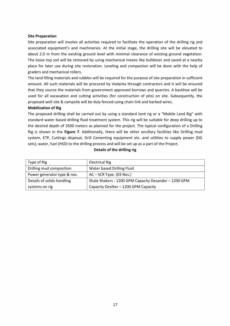
Mobilization of Rig
The proposed drilling shall be carried out by using a standard land rig or a “Mobile Land Rig” with
standard water based drilling fluid treatment system. This rig will be suitable for deep drilling up to
the desired depth of 3500 meters as planned for the project. The typical configuration of a Drilling
Rig is shown in the Figure 7. Additionally, there will be other ancillary facilities like Drilling mud
system, ETP, Cuttings disposal, Drill Cementing equipment etc. and utilities to supply power (DG
sets), water, fuel (HSD) to the drilling process and will be set up as a part of the Project.
Details of the drilling rig
Type of Rig Electrical Rig
Drilling mud composition Water based Drilling Fluid
Power generator type & nos. AC – SCR Type. (03 Nos.)
Details of solids handling
systems on rig
Shale Shakers - 1200 GPM Capacity Desander – 1200 GPM
Capacity Desilter – 1200 GPM Capacity
18
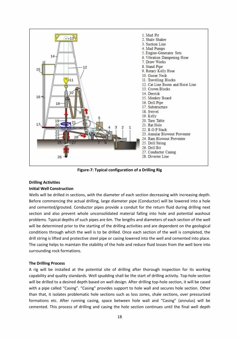
Figure-7: Typical configuration of a Drilling Rig
Drilling Activities
Initial Well Construction
Wells will be drilled in sections, with the diameter of each section decreasing with increasing depth.
Before commencing the actual drilling, large diameter pipe (Conductor) will be lowered into a hole
and cemented/grouted. Conductor pipes provide a conduit for the return fluid during drilling next
section and also prevent whole unconsolidated material falling into hole and potential washout
problems. Typical depths of such pipes are 6m. The lengths and diameters of each section of the well
will be determined prior to the starting of the drilling activities and are dependent on the geological
conditions through which the well is to be drilled. Once each section of the well is completed, the
drill string is lifted and protective steel pipe or casing lowered into the well and cemented into place.
The casing helps to maintain the stability of the hole and reduce fluid losses from the well bore into
surrounding rock formations.
The Drilling Process
A rig will be installed at the potential site of drilling after thorough inspection for its working
capability and quality standards. Well spudding shall be the start of drilling activity. Top-hole section
will be drilled to a desired depth based on well design. After drilling top-hole section, it will be cased
with a pipe called “Casing”. “Casing” provides support to hole wall and secures hole section. Other
than that, it isolates problematic hole sections such as loss zones, shale sections, over pressurized
formations etc. After running casing, space between hole wall and “Casing” (annulus) will be
cemented. This process of drilling and casing the hole section continues until the final well depth
19
(target) is achieved. Drilling process is associated with various hazards such as well active situation
(kicks), blowouts, H2S situation etc
Mud System and Cuttings
During drilling operations, the drilling fluid (or mud) is pumped through the drill string down to the
drilling bit and returns at the drill pipe–casing annulus up to surface back into the circulation system
after separation of drill cuttings /solids through solids control equipment. The primary function of
drilling fluid is to ensure that the rock cuttings generated by the drill bit are continuously removed
from the wellbore. The mud must be designed such that it can carry the cuttings to surface while
circulating, suspend the cuttings while not circulating and drop the cuttings out of suspension at the
surface. The drilled solids are removed at the surface by mechanical devices such as shale shakers,
de-sanders and de-silters. The hydrostatic pressure exerted by the mud column prevents influx of
formation fluids into the wellbore. The instability caused by the pressure differential between the
borehole and the pore pressure can be overcome by increasing the mud weight. Hydration of the
clays can be overcome by using non aqueous based muds, or partially addressed by treating the mud
with chemicals which will reduce the ability of the water in the mud to hydrate the clays in the
formation. Water based mud will be used for initial, shallower sections where massive shales are not
encountered. The deeper and difficult to drill formations will be drilled using synthetic base mud
(SBM). Synthetic base mud unlike oil based mud (OBM) is biodegradable but can be re-used. At the
end of drilling a well almost the entire amount of the SBM is collected for re-use in next drilling
operation. SBM systems promote good hole cleaning and cuttings suspension properties. They also
suppress gas hydrate formation and exhibit improved conditions for well bore stability compared to
most WBM. WBM typically consists of water, bentonite, polymers and barite. Other chemical
additives viz. glycols and salts may be used in conjunction to mitigate potential problems related to
hydrate formation. The mud to be used will be continuously tested for its density, viscosity, yield
point, water loss, pH value etc. The mud will be prepared onsite (drill location) using centrifugal
pumps, hoppers and treatment tanks.
During drilling activity, cuttings will be generated due to crushing action of the drill bit. These
cuttings will be removed by pumping drilling fluid into the well via triplex mud pumps. The mud used
during such operation will flush out formation cuttings from the well hole. Cuttings will be then
separated from drilling mud using solids-control equipment. This will comprise a stepped system of
processes consisting of linear motion vibrating screens called shale shakers, hydro-cyclones
(including de-sanders and de-silters), and centrifuges to mechanically separate cuttings from the
mud.
Figure 8 shows the schematic layout of drilling mud & solids discharge involved as a part of the
drilling system for exploratory wells.
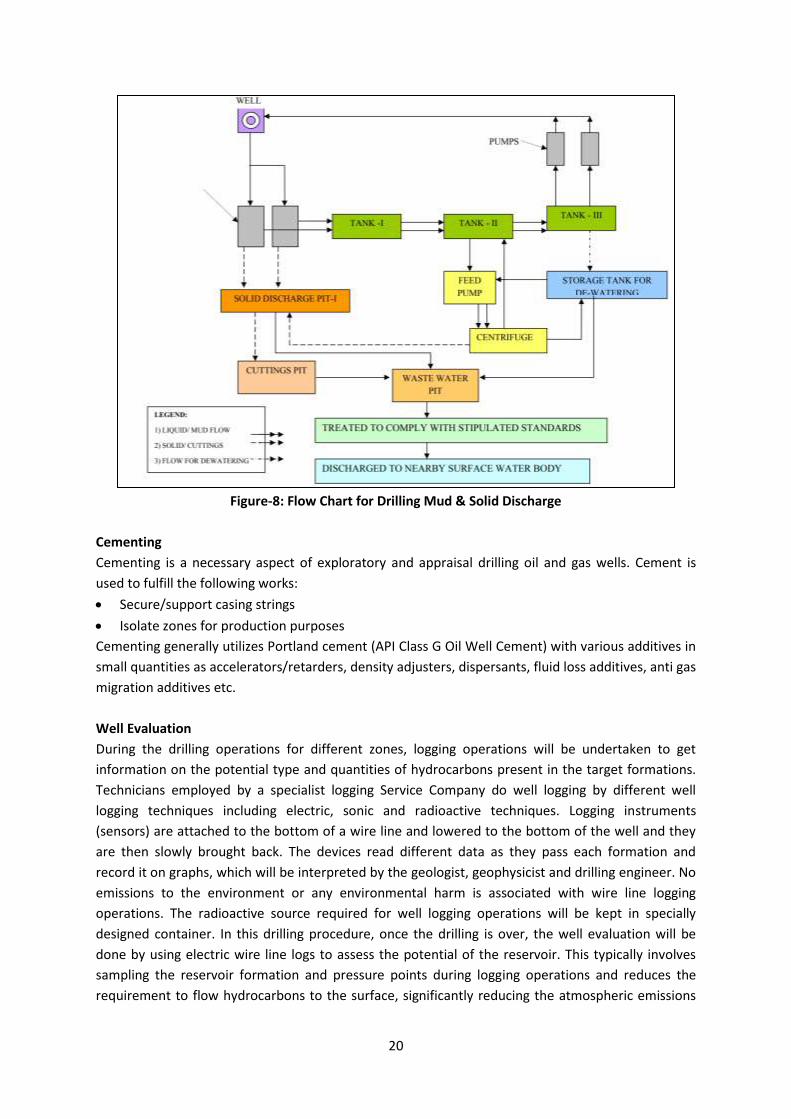
20
Figure-8: Flow Chart for Drilling Mud & Solid Discharge
Cementing
Cementing is a necessary aspect of exploratory and appraisal drilling oil and gas wells. Cement is
used to fulfill the following works:
Secure/support casing strings
Isolate zones for production purposes
Cementing generally utilizes Portland cement (API Class G Oil Well Cement) with various additives in
small quantities as accelerators/retarders, density adjusters, dispersants, fluid loss additives, anti gas
migration additives etc.
Well Evaluation
During the drilling operations for different zones, logging operations will be undertaken to get
information on the potential type and quantities of hydrocarbons present in the target formations.
Technicians employed by a specialist logging Service Company do well logging by different well
logging techniques including electric, sonic and radioactive techniques. Logging instruments
(sensors) are attached to the bottom of a wire line and lowered to the bottom of the well and they
are then slowly brought back. The devices read different data as they pass each formation and
record it on graphs, which will be interpreted by the geologist, geophysicist and drilling engineer. No
emissions to the environment or any environmental harm is associated with wire line logging
operations. The radioactive source required for well logging operations will be kept in specially
designed container. In this drilling procedure, once the drilling is over, the well evaluation will be
done by using electric wire line logs to assess the potential of the reservoir. This typically involves
sampling the reservoir formation and pressure points during logging operations and reduces the
requirement to flow hydrocarbons to the surface, significantly reducing the atmospheric emissions
21
associated with the testing operation. Normally, in the event that hydrocarbons are encountered in
sufficient quantities, as determined by electric wire line logs, a temporary drill stem test string may
be run and the well fluids flowed to surface and processed using a surface well testing package,
involving the oil being stored and trucked off the site and associated gas being flared to atmosphere.
Hydraulic Fracturing – for Tight Rock Reservoirs of Hydrocarbons Hydraulic fracturing is used in tight rock reservoirs with low permeability, such as shale (i.e., the
conductivity or ability of hydrocarbons to flow in the formation is low because of the small pore size
in the rock). The goal of hydraulic fracturing in tight reservoir (shale) formations is to enable a well to
produce the resource or to increase the rate at which a well is able to produce the resource.
Hydraulic fracturing may be conducted in wells with low permeability formation and low pressure.
Wells requiring hydraulic fracturing and numbers of stages of hydraulic fracturing per well will
depend on seismic data acquired & interpreted and data acquired during the drilling phase of the
project.
Hydraulic fracturing is a common technique used to stimulate the production of oil and natural gas
by creating fractures or cracks that extend from the well hole into the rock formations. This is
accomplished by injecting fluid, which is usually a mixture of water and high viscosity fluid additives,
under extremely high pressure. The pressure of the water will then exceed the strength of the rock,
causing fractures to enlarge. After the fractures take place, a “propping agent” known as proppant
(which is usually sand) is injected into the fractures to keep them from closing. This allows the
hydrocarbon to move more efficiently from the rock to the well. A single well may require up to
15,000 m3 of water which may vary depending on the fracking requirements. For the hydraulic
fracturing in a well, proppant mass of 150,000 – 200,000 lbs per stage and fluid volume of 2500 bbls
– 4000 bbls per stage will be required.
Fracturing effluent generated will be discharged in the HDPE lined pits at the drilling well sites.
Additional land will be procured wherever required. For effective recycling and reuse of the fracfluid,
effluent treatment plant (ETP) will be installed, thus raw water required for fracturing will be
minimized.
Well Testing & Flaring
During the exploration and appraisal drilling, where a hydrocarbon formation is found, initial well
tests (generally about one month of duration) will be carried out to establish flow rates, formation
pressure and other parameters. However, depending on the need, based on nature of the
reservoirs, the exploratory and appraisal wells will be tested for longer/extended durations to
ascertain the reservoir parameters. During the well testing, crude oil, natural gas and produced
water could be generated and will be treated/ disposed appropriately. Hydrocarbons will be flared.
Efficient test flare burner will be used to minimize incomplete combustion. As an alternative option,
if feasible, crude oil/ slop oil will be transferred to nearby refinery (terminals/depots) for processing
or will be sent to a GPCB authorized recyclers.
Completion of Drilling
On completion of activities, the well will be either plugged and suspended (if the well evaluations
indicate commercial quantities of hydrocarbons) or will be killed and permanently abandoned. In the
event of a decision to suspend the well, it will be filled with a brine solution containing very small
quantities of inhibitors to protect the well. The well will be sealed with cement plugs and some of
22
the wellhead equipment (Blind Flange) will be left on the surface (Cellar). If the well is abandoned it
will be sealed with a series of cement plugs, all the wellhead equipment will be removed, by leaving
the surface clear of any debris and the site will be restored. The Crude oil produces during the well
testing at appraisal stage will be collected and sent to nearly and approved waste oil recyclers.
Decommissioning & closure of wells
After the completion of the drilling activity, partial de-mobilization of the drilling rig and associated
infrastructure will be initiated. As discussed earlier, well testing may be carried out immediately
after the drilling is completed. The complete de-mobilization of the facilities at site will happen once
well-testing completed successfully. This will involve the dismantling of the rig, all associated
equipment and the residential camp, and transporting it out of the project area. It is expected that
demobilization will take approximately 20-25 days and will involve the trucking away of materials,
equipment and other materials from the site to bring it back to its original condition. It is estimated
that about 50 truckloads will be transported out of site during this period. If no indication of any
commercially viable amount of oil or gas is encountered either before or after testing, the well will
be declared dry and accordingly will be plugged of and abandoned, and the site will be restored in
line with regulations and good industry practice.
Appraisal
When, exploratory drilling is successful, more wells (termed as Appraisal wells) will be drilled to
determine the size and the extent of the field. Wells drilled to quantify the hydrocarbon reserves
found are called as ‘appraisal’ wells. The appraisal activity will be carried out with an aim to
evaluate the size and nature of the reservoir, to determine the number of confirming or appraisal
wells required, and whether any further seismic survey is necessary. The technical procedures and
activities in appraisal drilling will be the same as those employed for exploration wells. A number of
wells may be drilled from a single well pad/ drill site. Deviated or directional drilling at an angle
from a site adjacent to the original discovery well may be used to appraise other parts of the
reservoir, in order to reduce the land requirement.
Setting up of Early Production Units (EPUs)/ Quick Production Facility (QPF) and Early Production
Vedanta Ltd (Cairn Oil & Gas), as an interim plan, in case of commercially viable discovery (s) of
hydrocarbons in the block and having established the size of the hydrocarbon field (s), proposes to
immediately bring the field (s) into production using one or more of the appraisal wells for the
production of crude oil by setting up of Early Production Units (EPUs) or QPUs (Quick Production
Units). Early production of the Crude oil will enable the Country to reduce dependence on import of
crude oil.
Here, it may be noted that after the commercially viable discovery (s) of the hydrocarbon field(s),
following the typical life cycle of Oil & Gas Exploration & Production sector, full-fledged field
development plan including development well drilling, establishing crude oil & natural gas
processing facilities, laying of intra-field & cross country pipelines and other associated physical and
social infrastructures will be taken up and prior development EC and other approval will be obtained
as applicable. The lead time for entire process is about 3 – 4 years for the production of crude oil and
natural gas.
23
Once the full-fledged field development comes up, the Early Production Unit(s)/ Quick Production
Unit(s) will suitably be integrated with the full-fledged facilities and/ or phased out.
Early Production Units (EPUs) or QPUs (Quick Production Unit) will be installed for the processing of
produced well fluid. A EPU/ QPU will be a packaged/ modular mobile unit and will mainly consists of
a three phase separator & production heater or heater-treater, oil storage tanks, oil tanker loading
system, produced water (PW) separation and disposal system, power generation (GEG or DG), utility
systems such as fuel gas, flare & Inst. Air packages, firefighting equipment, etc. Each EPU/ QPU
capacity will be ~2,000 BFPD (Barrels of Fluid per Day).
The EPUs/ QPUs will be installed near the already established exploration and appraisal well location
within the well pad in the commercially viable discovered oil field. The separated crude oil will be
stabilized further, stored in storage tanks and subsequently send through road tankers to the
nearing available facilities like terminals/ depots. The produced gas will be used for internal heating,
power generation purpose as far as possible & surplus gas will be safely disposed off using flare
system.
The produced water will be treated to achieve MoEF/ CPCB/ SPCB specification (discharge standards)
and will be disposed off. The treated effluent (produced water) will be disposed off using either a
nearby down hole disposal well (by reinjection in abandoned well) or other available & suitable
onshore disposal medium or solar/ mechanical evaporators depending on the feasibility.
The power requirement will be met through state electricity grid and/ or installation of Diesel/ Gas
Engine Generator(s) using produced gas.
The water requirement for the oil and gas processing will be sourced locally through approved
authorities or through extraction of ground water. In case of extraction of ground water, permission
(NOC) will be obtained from CGWA/ CGWB (Central Ground Water Authority/ Board) of from State
Govt. Installation of raw water treatment plant will be done depending on the need for process
water and domestic water consumption.
The typical broad requirements envisaged for the well fluid processing and production of crude oil
and associated natural gas through QPF are the following:
Wells with selected artificial lift; & flow lines;
Combination of Heater (using produced gas) & 3 phase separator or single heater-treater
Stabilized Crude oil storage, pumping & tanker loading facilities;
PW separation and disposal system;
Fuel gas system, Instrument air/ gas system;
Flare system, Firefighting equipment, Raw water treatment plant;
Diesel/ Gas Engine Generator (s);
Domestic sewage treatment facility (STP or septic tank & soak pit system);
3.6 Raw materials required and source
Broad requirements of raw materials:
24
Seismic Acquisition
The seismic survey will be conducted using dynamite charges. The explosive sources (dynamites) and
drilling fluid chemicals for shot hole drilling will be procured by the company before commencement
of the operations. During surveying the main tasks include initial installation of a small number of
survey control points, then setting-out source points and receiver stations for use. This would be
done by the conventional survey method of using RTK GPS backpack surveying units and
biodegradable markers. Cutting activities though minimal for the receiver and source lines shall be
done manually or mechanically where appropriate. In open areas where there is clear line of sight no
cutting shall be done. Recording involves laying of geophones on the receiver stations and
generating energy (vibrations) on the perpendicular source lines to generate seismic energy, which
are reflected and recorded on magnetic tapes via the recording instrument.
Drilling
During drilling activities, materials like HSD, Steel (in the form of casings & tubulars) and chemicals
like barite, oil well cement and bentonite will be required. Other production equipments like tubular
(Casing and tubings), wellhead assembly, packer etc, and chemicals for mud and cementing required
for the drilling operations and shall be procured by the company from within the country and from
abroad before the commencement of operations.
Water based mud will be used for initial, shallower sections where massive shales are not
encountered. The deeper and difficult to drill formations will be drilled using synthetic base mud
(SBM). Synthetic base mud unlike oil based mud (OBM) is biodegradable but can be re-used. WBM
typically consists of water, bentonite, polymers and barite. Other chemical additives viz. glycols and
salts may be used in conjunction to mitigate potential problems related to hydrate formation.
Requirement WBM (approx.) 800-1000 m3/well
Requirement SBM (approx.) 600-800 m3/well
3.7 Resource optimization/ recycling and reuse envisaged in the project
Maximum care will be taken for resource optimization, wherever possible with an aim of
Resource Conservation
Elimination of Waste Streams
Minimizing Waste
Reuse / Recycle of Wastes
The drill cuttings from the drilling operations associated with water based mud will be used for
filling low lying areas as a sub grade construction material in construction of well pads etc.
Synthetic base mud will be re-used in further drilling activities.
3.8 Water and power requirement
3.8.1 Water Requirement
Seismic Operations:
The water required during seismic operation will be mostly for domestic use which is about 20-30
m3/day.
25
Drilling Operations:
Drilling Operations: The water requirement in drilling rig is mainly meant for preparation of drilling
mud apart from washings and domestic use. While former constitutes majority of water
requirement, latter or the water requirement for domestic and wash use is minor. Water for both
process and domestic uses would be procured through surface water sources. The water
requirement per well is shown in below in Table 4.
Table 4: Water requirement
Description Quantity
Water for domestic use 20-30 m3/well/day
Drilling water consumption for mud preparation 600-1000 m3/well
(WBM) and 150-300
m3/well (SBM)
Water requirement for miscellaneous use (Engine cooling,
floor/equipment/string wasteline, firefighting, storage/makeup) during
drilling phase (KL)
25-50 m3/well/day
The water requirement for all the project activities will be sourced locally through approved/
authorized sources of surface water and/ or ground water (e.g. PHD bore wells, privately owned
bore wells, Irrigation Dept./ Water Resources Dept. of State Govt.). In case, required water could not
be sourced from locally available approved sources, ground water will be extracted after obtaining
permission from CGWA/ State Govt.
3.8.2 Power Requirement
During Seismic Operations
The power requirement during seismic is 350 KVA will be provided through diesel generator (DG)
sets or state electricity grid.
During Drilling Operations
The power requirement in the drilling site and the campsites will be provided through diesel
generator (DG) sets. The rated capacity of the DG sets required for onshore drilling site is provided in
following table.
Details of DG sets of Onshore Drilling Activity
Location DG Capacity
Camp site 2 X 350 kVA (one working and one standby)
Drilling site 3 x 1000 kVA ( two working and one standby)
Radio Room 2X100 kVA
3.9 Quantity of waste to be generated and its disposal
During Seismic Operation:
Insignificant amount of waste water will be generated from domestic use and the same shall be
disposed through septic tanks/soak pits. The Air emissions and noise emissions will be also very
insignificant and will be temporary in nature. Domestic effluent of about 15-25 m3/day is
anticipated. Also, non-hazardous solid wastes like food waste, paper, etc. are expected.
26
During Drilling Operations:
Waste water generation
The drilling operation would generate wastewater in the form of wash water due to washing of
equipment, string and cuttings etc. The only other source of wastewater generated from drilling
operation is sewage from sanitation facilities, around 15-25 m3/day/well, which shall be disposed
through septic tanks/soak pits. It is expected that wastewater in the form of Drill cutting washing +
Rig washing+ cooling etc shall be generated at an average rate of around 30-40 m3/day/well during
the drilling operations from a single well. Waste water will be discharged in HDPE lined evaporation
pit for disposal, size of the pit is generally 50mx20mx1.5m. The wash water would contain variable
quantities of mineral salts, solids, suspended and dissolved hydrocarbons, and other organic and
inorganic components in very minor quantities.
Waste Management
The drill cuttings and spent drilling mud will be generated at site per well during drilling operations.
This will be stored in well-designed HDPE line pit. It will be tested for its hazardous constituents (Oil
and Grease), If found to be hazardous, It will be handed over to authorized TSDF. In case of
Nonhazardous, it will be disposed insitu in HDPE lined pit.
Used /waste Oil – During the drilling approx. 1-2 tons/well of spent oil will be generated per well.
This oil will be sent to authorized recyclers.
Domestic waste of 25-30 kg/day per well will be generated at site, which will be segregated at
source (Organic / Inorganic) and disposed accordingly.
Disposal of wastes will be as per prior approval of CPCB /SPCB.
The expected waste generation from well drilling will be as per Table 5.
S.N Nature of waste Quantity during Drilling Activities
A Hazardous Waste
1 Drill cuttings associated with WBM
Drill cuttings associated with SBM
250-750 tons/well m3 per well
500-1500 tons/well
2 Spent /Residual drilling mud 250-500 tons/well
3 Used Lubricating oil,
Sludge containing oil and other drilling work
1-2 tons/well
250-500 tons/well
B Non Hazardous Waste
4 Food waste 25-30 Kg per well
5 Non-combustible waste containing metallic
residues, glass
1000-1200 Kg/well
6 Packaging wastes including drums, wooden pallets,
plastic containers, plastic foils.
1000 kg/well
7 Left over chemicals and materials, scrap metal,
sludges, scales, batteries, spent acids, spent
lubricants, filters etc.
250-300 kg/well
8 Cement, grit, blasting and painting wastes. 500 kg per well
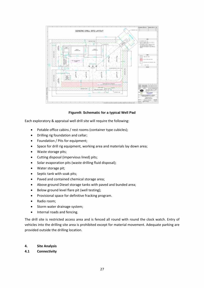
3.10 Schematic of Feasibility Drawing
The typical layout of a well pad/drill site for exploratory and appraisal well is as below:
27
Figure9: Schematic for a typical Well Pad
Each exploratory & appraisal well drill site will require the following:
Potable office cabins / rest rooms (container type cubicles);
Drilling rig foundation and cellar;
Foundation / Pits for equipment;
Space for drill rig equipment, working area and materials lay down area;
Waste storage pits;
Cutting disposal (impervious lined) pits;
Solar evaporation pits (waste drilling fluid disposal);
Water storage pit;
Septic tank with soak pits;
Paved and contained chemical storage area;
Above ground Diesel storage tanks with paved and bunded area;
Below ground level flare pit (well testing);
Provisional space for definitive fracking program.
Radio room;
Storm water drainage system;
Internal roads and fencing.
The drill site is restricted access area and is fenced all round with round the clock watch. Entry of
vehicles into the drilling site area is prohibited except for material movement. Adequate parking are
provided outside the drilling location.
4. Site Analysis
4.1 Connectivity
28
The project location is situated in Gandhinagar, Ahmedabad and Mahesana districts of Gujarat. The nearest major town for this project is Mehsana. The project location is well connected by road, rail and by Air. SH-135 passes through the block, National Highway 947 is about 3.48Km. Sanand Railway Station is about 1.09Km South from the block and Amod Railway Station (11.5km, South east from the block). Sardar Vallabhbhai Patel International Airport, Ahmedabad is about 25.5 Kms, South from the block boundary. 4.2 Land form, land use and land ownership
Chekhla village, Mulasana village falls within the block. Ahmedabad city is approx. 15 Km from the block.Thol Town (1.85Km), Sanand Town (4.3 km), Ahmedabad (14.2 Km) are within close proximity of the block. Thol Bird Sanctuary is located at 3.3Km, North from the block boundary and the Eco sensitive boundary is located at 1.79Km,North form the block boundary. 4.3 Topography (along with map)
The block area is almost flat topography with elevation varying approximately 42m to 46m across
area. The terrain of the districts is flat level plain with an altitude ranging from 52 m to 85 m above
MSL. The slope gradient of this district is from SE to NW. The eastern part of the district is relatively
higher and attains the maximum altitude of 85 m above MSL and the elevation gradually decreases
towards south and west. Figure 4 below shows the Topographic map of the study area. Topography
sheet is given in Fig. 4 of this document.
4.4 Existing land use pattern and relative location of protected areas
The entire block area is divided into following land use types
Agriculture land
Land with scrubs
Land without scrubs
Habitation
Water bodies
Among this agriculture land is major land use type in the block.
Thol Bird Sanctuary is located at 3.3Km, North from the block boundary and the Eco sensitive
boundary is located at 1.79Km,North form the block boundary.
4.5 Existing infrastructure/ industries
The block area is located in Gandhinagar, Ahmedabad and Mahesana districts and well equipped
with existing infrastructure like roads, rail lines, water supply, power supply, sewerage facility,
telecommunication facilities, hospitals, schools etc.
4.6 Soil classification
The soils in the Ahmedabad district can broadly be classified as Black Soils, Goradu Soils, Kyari and
Rocky soils. The soil in Gandhinagar district are generally sandy loam type with grey to brown colour.
As per the studies carried out during UNDP project, they are generally deep and have moderate to
good permeability and drainability. In the western part of the district the soils are alkali type and
saline. They are typically deep, grey, calcareous sandy loam of very low permeability.
4.7 Climate data from secondary sources

29
The climatological summary details of parameters like temperature, relative humidity, rainfall, cloud
cover, wind speed and wind direction monitored at IMD Ahmedabad is given below:
Table 6: Climatological Summary at IMD Ahmedabad (1961 – 1990)
Month
Daily mean Temp. (0C)
Relative Humidity
(%) Rainfall (mm)
Cloud cover
(in Okta)
Mea
n W
ind
Sp
eed
(k
m/h
)
Pre
do
min
ant
Win
d
Dir
ecti
on
Calm (%) M
ax
Min
8:3
0
17
:30
Mo
nth
ly T
ota
l
No
. of
Rai
ny
day
s
8:3
0
17
:30
8:3
0
17
:30
January 28.3 11.9 59 32 1.8 0.2 1.3 1.3 5.7 NE 25 5
February 30.9 14.0 53 25 1.1 0.1 1.2 1.3 6.0 NW 28 4
March 35.8 18.9 49 20 1.0 0.1 1.4 1.6 6.4 NW 21 4
April 39.8 23.5 54 20 2.7 0.2 1.4 1.8 7.2 NW 9 4
May 41.7 26.2 65 23 15.1 0.7 1.8 1.2 9.5 W 3 2
June 38.5 27.1 74 45 98.7 4.2 4.8 3.9 10.8 SW 6 4
July 33.4 25.6 85 67 262.3 11.2 6.5 6.2 8.9 SW 9 8
August 31.9 24.7 87 71 239.6 10.8 6.6 6.3 7.4 SW 9 10
September 33.7 24.2 82 58 108.9 5.3 4.3 4.0 6.1 W 13 15
October 36.0 21.0 64 37 16.2 0.4 1.5 1.5 4.2 NW 36 27
November 33.1 16.6 55 35 11.5 0.6 1.4 1.5 4.4 E 29 27
December 29.6 13.2 60 35 3.8 0.2 1.5 1.6 5.4 E 23 17
Annual or
Mean 34.4 20.6 66 39 762.7 34.0 2.8 2.7 6.8 SW, NW 18 11
Source:India Meteorological Department (IMD)
4.7.1 Wind
The monthly mean wind speed varied from 4.2 to 10.8km/hr occurring in October and June months
respectively. The calm winds at 8:30 hrs varied from 3%(May) to 36%(October) while at 17:30 hrs
varied from 2% (May) to 27%(October-November). The table reveals that Morning hour’s had higher
calm winds as compared to evening hours. The monthly mean wind speed during winter season has
been recorded close to 6m/s.
The Predominant wind direction was recorded from NW during February-April, October and from
SW during June-August i.e., monsoon period. The predominant wind during winter season was
recorded from E and NE direction.
4.7.2 Storms and cyclones
The block area doesn’t fall under high risk zone with respect to cyclone and storms as per Gujarat
Cyclone Hazard Risk Zonation.
4.7.3 Rainfall
30
The 100 years data revealed that rainfall occurred maximum in July (309.8 mm) followed by August
(213.8 mm). The total rainfall received in the year is about 784.3 mm with total number of rainy days
of about 23 days.
4.7.4 Temperature and humidity
The monthly mean maximum temperature for a period of 100 years varied from 28.7°C in January to
41.4°C in May while monthly mean minimum varied from 13.1°C in January to 27.2°C in June
indicating January as the coldest while May as hottest month. The monthly mean maximum during
winter season was recorded between 28-31°C while minimum between 13-15°C.
5 Planning Brief
5.1 Planning concept
The project is a green field oil and gas exploration & appraisal and early production in CB-ONHP-
2017/6.
The present area of Block of area 19 km2 in Gandhinagar, Ahmedabad and Mahesana districts of
Gujarat.
Well sites and roads will be built or upgraded for transportation of rig and its equipment for seismic
acquisition and drilling. The drilling will be carried out following the international safety standards.
Upon successful exploration the well will be completed and suspended for further activities and the
wells devoid of hydrocarbon will be plugged and abandoned. The land will be restored back to its
original form.
5.2 Population projection
Direct and indirect employment will be created due to project. Temporary influx of people will be
there as the managerial and supervisory staff will generally be outsider.
5.3 Land use planning (break up along with green belt, etc)
The well within the block will not be taken completely for drilling of the wells. An area of about
300m X 300m would be taken on temporary short-term lease basis for the construction of well pad,
drill site etc.
5.4 Assessment of Infrastructure demand
No major infrastructure (physical and social) is envisaged. Access road will be taken up by Vedanta
(Cairn Oil & Gas) for the drilling well site for the movement of heavy equipment.
5.5 Amenities and facilities
The amenities/ facilities
Potable drinking water
Firefighting/ alarm system and ambulance is available in case of emergency
Drinking water, canteen and electricity facilities is provided
Separate sanitation facilities will be provided for men and women.
6. Proposed Infrastructure
31
No major physical and social infrastructure is envisaged. Only drill site / well pad and temporary
camp site (Porta cabin)for the drilling of exploratory (including) appraisal wells are envisaged, which
will be dismantled after drilling of the wells.
7. Rehabilitation and resettlement (R&R) Plan
For exploration, appraisal and production activities, the project does not envisage any R & R of the
project, since the land requirement would be very less and on short term lease and away from the
settlements. If the identified lands are of private landowners then land lease mode will be applied
and in case of govt. land, land allotment from Govt. to be applied. Initially lease will be taken for 3 - 5
years for exploration purpose and in case of commercially viable discovery of hydrocarbon
resources; the land lease would be converted into long term lease up to life of the project.
For sites selected having settlements if any, Resettlement & rehabilitation (R&R) plan will be
developed and implemented as per the applicable State/ Central Govt. policy. Compensation to
affected landowners for any loss of land, Cairn will ensure the livelihood of local community, if any
affected by the proposed land take, are identified and compensated through adequate
compensation and other livelihood restoration activities directly or indirectly through CSR activities.
8. Project schedule and cost estimate
Vedanta Ltd (Cairn Oil and gas) has planned to carry out the proposed project activities in CB-ONHP-
2017/6 Block in next 10-12 years.
The estimated cost of the project is given below:
1) Physical Surveys Cost estimated to be approximately INR 2 Crore.
2) Average Cost per well for exploratory & appraisal well drilling is estimated to be INR 7 Crore.
3) Average cost of each EPU (Early Production Unit)/QPF (Quick Production Facility) is
estimated to be INR 44.13 Crore.
9. Analysis of Proposals (Final Recommendations)
The implementation of this project will not have any adverse effect on the environment as
appropriate pollution control measures will be taken from the initial stage itself.
Proposed drilling activities will result in growth of the surrounding areas by increasing direct and
indirect employment opportunities in the region.