FEASIBILITY OF FAST FREQUENCY RESPONSE ...
26
FEASIBILITY OF FAST FREQUENCY RESPONSE OBLIGATIONS OF NEW GENERATORS Australian Energy Market Commission (AEMC) 8 June 2017
-
Upload
khangminh22 -
Category
Documents
-
view
4 -
download
0
Transcript of FEASIBILITY OF FAST FREQUENCY RESPONSE ...

FEASIBILITY OF FAST FREQUENCY RESPONSE OBLIGATIONS OF NEW GENERATORS
Australian Energy Market Commission (AEMC)
8 June 2017

AECOM Feasibility of Fast Frequency Response Obligations of New Generators
Feasibility of Fast Frequency Response Obligations of NewGenerators
Client: Australian Energy Market Commission (AEMC)ABN: 49 236 270 144
Prepared byAECOM Australia Pty LtdLevel 21, 420 George Street, Sydney NSW 2000, PO Box Q410, QVB Post Office NSW 1230, AustraliaT +61 2 8934 0000 F +61 2 8934 0001 www.aecom.comABN 20 093 846 925
08-Jun-2017
AECOM in Australia and New Zealand is certified to ISO9001, ISO14001 AS/NZS4801 and OHSAS18001.
© AECOM Australia Pty Ltd (AECOM). All rights reserved.
AECOM has prepared this document for the sole use of the Client and for a specific purpose, each as expressly stated in the document. No otherparty should rely on this document without the prior written consent of AECOM. AECOM undertakes no duty, nor accepts any responsibility, to anythird party who may rely upon or use this document. This document has been prepared based on the Client’s description of its requirements andAECOM’s experience, having regard to assumptions that AECOM can reasonably be expected to make in accordance with sound professionalprinciples. AECOM may also have relied upon information provided by the Client and other third parties to prepare this document, some of whichmay not have been verified. Subject to the above conditions, this document may be transmitted, reproduced or disseminated only in its entirety.

AECOM Feasibility of Fast Frequency Response Obligations of New Generators
Quality Information
Document Feasibility of Fast Frequency Response Obligations of New Generators
Date 08-June-2017
Prepared by Carl Christiansen, Nadia Hillmann
Reviewed by Winodh Jayewardene
Revision History
Revision A
RevisionDate 08-June-2017
Details Final
Authorisedby
Craig BearsleyAssociate Director / Team Leader - Renewables

1
Table of ContentsAcronyms 2Executive Summary 31.0 Introduction 5
1.1 Project Scope 51.2 Background and Context 51.3 Definitions 5
2.0 Frequency Stability 72.1 Synchronous Inertia and Rate of Change of Frequency 72.2 Frequency Control (Contingency) 72.3 Defining Fast Frequency Response 7
3.0 International Trends 83.1 Overview 83.2 Hydro-Quebec (Canada) 83.3 ERCOT (Texas, USA) 93.4 EirGrid/SONI (Ireland/Northern Ireland) 113.5 National Grid (United Kingdom) 133.6 Germany 14
4.0 Technology FFR Capability 154.1 Response times 154.2 Wind 154.3 Other FFR technologies 18
5.0 Over Frequency 216.0 References 22
2
AcronymsTerm Definition
AC Alternating Current
AEMC Australian Energy Market Commission
AEMO Australian Energy Market Operator
DC Direct Current
EFR Enhanced Frequency Response
EirGrid Transmission network company in Ireland
ERCOT Electric Reliability Council of Texas
ENTSO-E European Network of Transmission Operators
FCAS Frequency Control Ancillary Market
FFR Fast Frequency Response
HVDC High Voltage Direct Current
NEM National Electricity Market
NREL National Renewable Energy Laboratory (USA)
PCR Primary Control Reserve
PFR Primary Frequency Response
PJM Regional transmission network operator in the United States
PMU Phase Measurement Unit
POR Primary Operating Reserve
PV Photovoltaic
RE Renewable Energy
RFR Rapid Frequency Response
RoCoF Rate of Change of Frequency
SFR Secondary Frequency Response
SIR Synchronous Inertia Response
SONI Transmission network company in Northern Ireland
SOR Secondary Operating Reserve
SPS Special Protection Schemes
TFR Tertiary Frequency Response
TSO Transmission System Operator
WPP Wind Power Plant
WTG Wind Turbine Generator
3
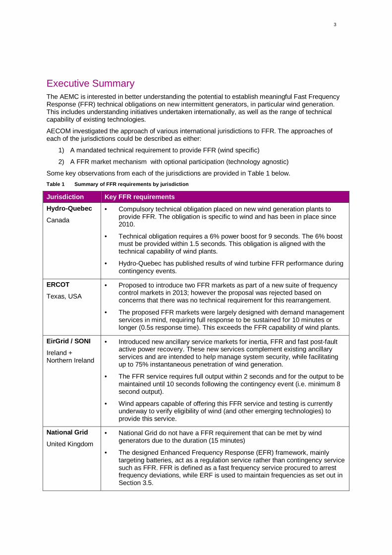
Executive SummaryThe AEMC is interested in better understanding the potential to establish meaningful Fast FrequencyResponse (FFR) technical obligations on new intermittent generators, in particular wind generation.This includes understanding initiatives undertaken internationally, as well as the range of technicalcapability of existing technologies.
AECOM investigated the approach of various international jurisdictions to FFR. The approaches ofeach of the jurisdictions could be described as either:
1) A mandated technical requirement to provide FFR (wind specific)
2) A FFR market mechanism with optional participation (technology agnostic)
Some key observations from each of the jurisdictions are provided in Table 1 below.Table 1 Summary of FFR requirements by jurisdiction
Jurisdiction Key FFR requirementsHydro-Quebec
Canada
· Compulsory technical obligation placed on new wind generation plants toprovide FFR. The obligation is specific to wind and has been in place since2010.
· Technical obligation requires a 6% power boost for 9 seconds. The 6% boostmust be provided within 1.5 seconds. This obligation is aligned with thetechnical capability of wind plants.
· Hydro-Quebec has published results of wind turbine FFR performance duringcontingency events.
ERCOT
Texas, USA
· Proposed to introduce two FFR markets as part of a new suite of frequencycontrol markets in 2013; however the proposal was rejected based onconcerns that there was no technical requirement for this rearrangement.
· The proposed FFR markets were largely designed with demand managementservices in mind, requiring full response to be sustained for 10 minutes orlonger (0.5s response time). This exceeds the FFR capability of wind plants.
EirGrid / SONI
Ireland +Northern Ireland
· Introduced new ancillary service markets for inertia, FFR and fast post-faultactive power recovery. These new services complement existing ancillaryservices and are intended to help manage system security, while facilitatingup to 75% instantaneous penetration of wind generation.
· The FFR service requires full output within 2 seconds and for the output to bemaintained until 10 seconds following the contingency event (i.e. minimum 8second output).
· Wind appears capable of offering this FFR service and testing is currentlyunderway to verify eligibility of wind (and other emerging technologies) toprovide this service.
National Grid
United Kingdom
· National Grid do not have a FFR requirement that can be met by windgenerators due to the duration (15 minutes)
· The designed Enhanced Frequency Response (EFR) framework, mainlytargeting batteries, act as a regulation service rather than contingency servicesuch as FFR. FFR is defined as a fast frequency service procured to arrestfrequency deviations, while ERF is used to maintain frequencies as set out inSection 3.5.
4
The key observation here is that Hydro-Quebec mandated that wind turbines provide a well-definedFFR service, while other jurisdictions developed FFR market mechanisms that could be considered“opt-in”. However, it is clear that the design of the FFR market mechanisms can dictate whattechnologies are eligible. For example, the ERCOT FFR market requires a minimum of 10 minutesoutput, which precludes wind from offering this service.
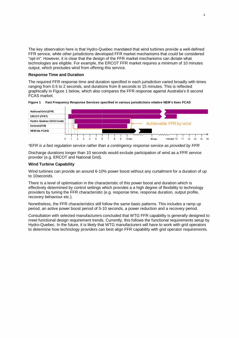
Response Time and Duration
The required FFR response time and duration specified in each jurisdiction varied broadly with timesranging from 0.5 to 2 seconds, and durations from 8 seconds to 15 minutes. This is reflectedgraphically in Figure 1 below, which also compares the FFR response against Australia’s 6 secondFCAS market.Figure 1 Fast Frequency Response Services specified in various jurisdictions relative NEM’s 6sec FCAS
*EFR is a fast regulation service rather than a contingency response service as provided by FFR
Discharge durations longer than 10 seconds would exclude participation of wind as a FFR serviceprovider (e.g. ERCOT and National Grid).
Wind Turbine Capability
Wind turbines can provide an around 6-10% power boost without any curtailment for a duration of upto 10seconds.
There is a level of optimisation in the characteristic of this power boost and duration which iseffectively determined by control settings which provides a a high degree of flexibility to technologyproviders by tuning the FFR characteristic (e.g. response time, response duration, output profile,recovery behaviour etc.).
Nonetheless, the FFR characteristics still follow the same basic patterns. This includes a ramp upperiod, an active power boost period of 5-10 seconds, a power reduction and a recovery period.
Consultation with selected manufacturers concluded that WTG FFR capability is generally designed tomeet functional design requirement trends. Currently, this follows the functional requirements setup byHydro-Quebec. In the future, it is likely that WTG manufacturers will have to work with grid operatorsto determine how technology providers can best align FFR capability with grid operator requirements.

5
1.0 Introduction
1.1 Project ScopeAECOM has been commissioned by the AEMC to investigate the feasibility of establishing technicalobligations of new intermittent generators to provide FFR.
The focus is on wind turbine technologies; however relevant learnings relating to other technologies(e.g. solar PV) are also reported.
The study includes:
· A review of international markets, to determine how they have specified FFR requirements
· Consultation with suppliers to understand the capability of their equipment. The informalconsultation will seek to understand the existing capability within the technology class, the trendsand the key characteristics which define FFR behaviour of intermittent generation technologies.
The findings of this report are intended to inform the AEMC’s system security work and assist theformation of initial policy positions. The learnings will then be further tested through consultation withindustry as part of the AEMC’s subsequent work programs.
1.2 Background and ContextHistorically, synchronous generators (such as coal and gas fired generators) provided dispatchablegeneration, inertia, and ancillary services such as frequency regulation and reserve capacity. Marketand policy forces are leading to changes in the generation mix however, and much of this technicalcapability is being lost. With increasing penetration of intermittent generation (e.g. solar and wind) anddecreasing sources of system inertia from synchronous generation, there is an emerging need to re-consider how grid security and stability can be maintained.
Various studies [1] [2] [3] [4] have concluded that for reliable operation of electricity systems, a sourceof inertia is essential to reduce the rate of change of frequency (RoCoF) following a contingency event(e.g. loss of a line, generator or other network element) and to provide fault current.
Fast Frequency Response (FFR) can be provided either by introducing generation (or reducing load).At present this can technically occur within approximately 250-500ms1 of a contingency event. Variousdefinitions of the terminology used throughout this report related to rapid frequency response, asdefined in this study, is presented below.
1.3 DefinitionsTable 2 Terminology Definitions
Term Definition
Synchronous In the context of this report, refers to AC generation or load technologies(rotating machinery) electrically coupled to the grid with controls in place toregulate and match the nominal frequency on the electrical network (50Hz).
Non-synchronous Non-synchronous is used to refer to generation or load technologies (solar,batteries, wind) connected to the electrical network by means of powerelectronics such as inverters, where inverters are used to convert DC to AC ina regulated fashion to match the nominal electric network frequency (50Hz).
Frequency ControlAncillary Services(FCAS)
This includes various services procured from NEM market participants toregulate and stabilise frequency deviations on the network. Generators orlarge consumers may receive a signal to increase or decrease power output orconsumption.· Regulation FCAS: correction of supply/demand balance in response to
1 Some definitions allow for slower response times (e.g. up to 2 seconds for full output)
6
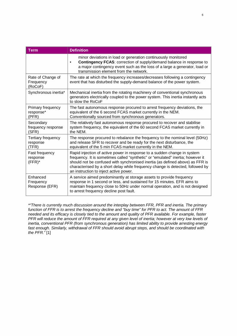
Term Definition
minor deviations in load or generation continuously monitored· Contingency FCAS: correction of supply/demand balance in response to
a major contingency event such as the loss of a large a generator, load ortransmission element from the network.
Rate of Change ofFrequency(RoCoF)
The rate at which the frequency increases/decreases following a contingencyevent that has disturbed the supply-demand balance of the power system.
Synchronous inertia* Mechanical inertia from the rotating machinery of conventional synchronousgenerators electrically coupled to the power system. This inertia instantly actsto slow the RoCoF
Primary frequencyresponse*(PFR)
The fast autonomous response procured to arrest frequency deviations, theequivalent of the 6 second FCAS market currently in the NEM.Conventionally sourced from synchronous generators.
Secondaryfrequency response(SFR)
The relatively fast autonomous response procured to recover and stabilisesystem frequency, the equivalent of the 60 second FCAS market currently inthe NEM.
Tertiary frequencyresponse(TFR)
The response procured to rebalance the frequency to the nominal level (50Hz)and release SFR to recover and be ready for the next disturbance, theequivalent of the 5 min FCAS market currently in the NEM.
Fast frequencyresponse(FFR)*
Rapid injection of active power in response to a sudden change in systemfrequency. It is sometimes called “synthetic” or “emulated” inertia; however itshould not be confused with synchronised inertia (as defined above) as FFR ischaracterised by a short delay while frequency change is detected, followed byan instruction to inject active power.
EnhancedFrequencyResponse (EFR)
A service aimed predominantly at storage assets to provide frequencyresponse in 1 second or less, and sustained for 15 minutes. EFR aims tomaintain frequency close to 50Hz under normal operation, and is not designedto arrest frequency decline post fault.
*“There is currently much discussion around the interplay between FFR, PFR and inertia. The primaryfunction of FFR is to arrest the frequency decline and “buy time” for PFR to act. The amount of FFRneeded and its efficacy is closely tied to the amount and quality of PFR available. For example, fasterPFR will reduce the amount of FFR required at any given level of inertia; however at very low levels ofinertia, conventional PFR (from synchronous generation) has limited ability to provide arresting energyfast enough. Similarly, withdrawal of FFR should avoid abrupt steps, and should be coordinated withthe PFR.” [1]

7
2.0 Frequency StabilityFrequency stability is a core requirement of power system stability. Frequency varies depending onthe balance of supply and demand: if demand exceeds supply then frequency drops and vice versa.Over frequency is typically easier to address as generation technologies have the capability to quicklyreduce output and rebalance supply and demand. Under frequency is more difficult to address forintermittent renewable generators as additional generation needs to be injected into the grid to arrestdecline and is subject to availability of the primary resource.
Frequency stability can become an issue when there is sudden change in the supply-demand mixsuch as loss of an interconnector, a large load, or a large generator. A robust power system must beable to withstand such “contingency events”.
2.1 Synchronous Inertia and Rate of Change of FrequencySystem frequency begins to change following a disturbance. The initial rate-of-change-of-frequency(RoCoF) immediately after the disturbance is related to synchronous system inertia and the size of thesystem disturbance.
Conventional synchronous generating plant coupled to the power system have rotating machinerywhich inherently possesses mechanical inertia. This inertia acts to slow the RoCoF which in turndetermines the response time available to arrest the system frequency before reaching the maximumdeviation limit.
Technologies such as wind and solar PV are typically connected non-synchronously with powerelectronic interfaces such as inverters. Increasing uptake of wind and solar inadvertently leads tohigher RoCoF as synchronous generation in the networks decreases (with associated inertia loss).
2.2 Frequency Control (Contingency)While inertia is valuable in slowing RoCoF, with no further action the balance between load andgeneration will continue to deviate from the stable frequency level. Thus, inertia alone is insufficient toarrest frequency deviations following a system disturbance.
Typically most frequency control services procured fall within three categories:
· Primary Frequency Response (PFR): denotes the fast autonomous response procured to arrestfrequency deviations,
· Secondary Frequency Response (SFR): denotes the relatively fast autonomous responseprocured to stabilise/recover system frequency,
· Tertiary Frequency Response (TFR): is the response procured to rebalance the frequency to thenominal level (50Hz) and release SFR to recover and be ready for the next disturbance.
While frequency deviations can be either higher or lower than the frequency standard, the focus of thisreport remains on lower (under frequency events) as this is more challenging to address.
2.3 Defining Fast Frequency ResponseHistorically, 6 second FCAS response procured in the NEM was adequate to manage crediblecontingencies. However, with increasing uptake of wind and solar (and the associated loss of systeminertia), there is an emerging need for faster response. [5]
The period immediately following a contingency event up to the frequency minimum (nadir) is referredto as the arresting period. The amount of inertia in the system at the time of the disturbancedetermines how much time is available for PFR services to respond.
Higher RoCoF in low inertia systems leads to rapid frequency decline and in turn creates an emergingneed for faster performance within the PFR capability. Hence, a new distinct service known as fastfrequency response (FFR) has emerged to bridge the gap between inertia and PFR. The primaryfunction of FFR is to arrest the frequency decline and “buy time” for PFR to commence [1].

8
3.0 International Trends
3.1 OverviewA report published in October 2016 on “International Review of Frequency Control Adaption” [3], wasprepared in a collaborative process between DGA Consulting and AEMO. This comprehensive reviewexamined international experiences in frequency control across all timeframes and types, with aspecific focus on Fast Frequency Response Services. AECOM used this report as the main referencesource to assess multiple jurisdictions, in addition to deeper research on areas identified with FFRframeworks.
The study found that a number of jurisdictions considered modifying FCAS frameworks to procure newFFR services, in anticipation that providers of frequency control services will be required to operatewith high RoCoF exposure and large quantities of variable generation in the future. Some jurisdictions(such as Great Britain) have mandatory requirements for all generators (including wind farms) to havethe capability to provide a range of frequency control services (even if these are never called upon inpractice) [3]. No jurisdiction currently has an FFR technical enablement framework in place, howeverHydro-Quebec has had FFR grid connection requirements in place for several years. The jurisdictionsdiscussed in the following sections were of particular interest to this review and investigated in furtherdetail.
Figure 2 provides a brief overview of the FFR parameters in the aforementioned jurisdictions, withmore detailed discussions in the sections following.
Figure 2 Fast Frequency Response Services specified in various jurisdictions relative NEM’s 6sec FCAS
*EFR is a fast regulation service rather than a contingency response service as provided by FFR
3.2 Hydro-Quebec (Canada)Hydro-Québec is the electricity utility managing Quebec’s electricity system, including generation,transmission and distribution. In 2016, 95% of the grid’s power generation was from hydro-electricsources, with wind contributing 4%, and thermal generators producing 1% [6]. Hydro-Quebec also hasa 4GW HVDC link to the Easter Interconnection [3].
In 2005, Hydro-Quebec sought tenders for 2,000MW of new wind generation (up to 25%instantaneous penetration during low demand periods), which was being tendered from third parties.Grid studies revealed that this level of penetration may require FFR capability to mitigate the severityof frequency deviations during major disturbances [3]. In 2010, Hydro-Quebec was the first gridoperator to connect wind plants with FFR capability.
The requirements only apply to wind farms larger than 10MW, which must be equipped with afrequency control system. The system must be in continuous service, but only act during majorfrequency deviations (i.e. major disturbances rather than steady-state frequency regulation).
The required level of response is specified to be greater than 6% of the name plate capacity, andsustained for 9 seconds. The full response (6% boost) should be provided in less than 1.5 seconds. [7]
The table below summarises Hydro-Quebec’s preferred FFR performance characteristics includingresponse time, duration and ramp down characteristics (following FFR discharge event) as describedin the 2013 Grid Code.
9
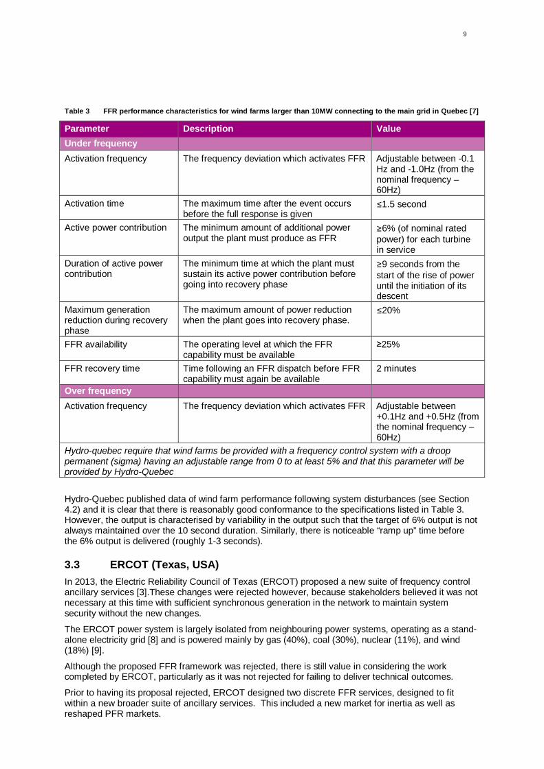
Table 3 FFR performance characteristics for wind farms larger than 10MW connecting to the main grid in Quebec [7]
Parameter Description ValueUnder frequencyActivation frequency The frequency deviation which activates FFR Adjustable between -0.1
Hz and -1.0Hz (from thenominal frequency –60Hz)
Activation time The maximum time after the event occursbefore the full response is given
≤1.5 second
Active power contribution The minimum amount of additional poweroutput the plant must produce as FFR
≥6% (of nominal ratedpower) for each turbinein service
Duration of active powercontribution
The minimum time at which the plant mustsustain its active power contribution beforegoing into recovery phase
≥9 seconds from thestart of the rise of poweruntil the initiation of itsdescent
Maximum generationreduction during recoveryphase
The maximum amount of power reductionwhen the plant goes into recovery phase.
≤20%
FFR availability The operating level at which the FFRcapability must be available
≥25%
FFR recovery time Time following an FFR dispatch before FFRcapability must again be available
2 minutes
Over frequencyActivation frequency The frequency deviation which activates FFR Adjustable between
+0.1Hz and +0.5Hz (fromthe nominal frequency –60Hz)
Hydro-quebec require that wind farms be provided with a frequency control system with a drooppermanent (sigma) having an adjustable range from 0 to at least 5% and that this parameter will beprovided by Hydro-Quebec
Hydro-Quebec published data of wind farm performance following system disturbances (see Section4.2) and it is clear that there is reasonably good conformance to the specifications listed in Table 3.However, the output is characterised by variability in the output such that the target of 6% output is notalways maintained over the 10 second duration. Similarly, there is noticeable “ramp up” time beforethe 6% output is delivered (roughly 1-3 seconds).
3.3 ERCOT (Texas, USA)In 2013, the Electric Reliability Council of Texas (ERCOT) proposed a new suite of frequency controlancillary services [3].These changes were rejected however, because stakeholders believed it was notnecessary at this time with sufficient synchronous generation in the network to maintain systemsecurity without the new changes.
The ERCOT power system is largely isolated from neighbouring power systems, operating as a stand-alone electricity grid [8] and is powered mainly by gas (40%), coal (30%), nuclear (11%), and wind(18%) [9].
Although the proposed FFR framework was rejected, there is still value in considering the workcompleted by ERCOT, particularly as it was not rejected for failing to deliver technical outcomes.
Prior to having its proposal rejected, ERCOT designed two discrete FFR services, designed to fitwithin a new broader suite of ancillary services. This included a new market for inertia as well asreshaped PFR markets.

10
Table 4 ERCOT's proposed suite of ancillary services [3]
Acronym Service Response time
SIR Synchronous Inertial Response Instantaneous response from synchronous machines
FFR1 Fast Frequency Response #1 Full response in 0.5 seconds, sustain for 10 minutes.Full capability restored within 15 minutes
FFR2 Fast Frequency Response #2 Full response in 0.5 seconds, sustain as long as neededFull capability restored within 180 minutes.
PFR Primary Frequency Response Commence response in 1.5 seconds, full response in 16seconds, sustain for 1 hour
Reg Regulation Reserve Commence response in 4-6 seconds, full response in 5minutes, sustain for 10 minutes
CRS Contingency Spinning Reserve Commence response in 5 minutes, full response in 10minutes, sustain for 1 hour
The FFR specifications are interesting in that they rule out many technologies from contributing to thisservice. In particular:
· Most technologies cannot ramp up to “full response” within 0.5 seconds (unless the “fullresponse” is defined to be sufficiently small to eliminate ramping delays)
· Wind cannot sustain its response for the 10 minute period
Rather, it appears that the FFR specifications are suitable for demand response (which is common inTexas with 1400MW of load reserves compliant with FFR requirements [2]). In addition, it appearsutility-scale batteries would also be compliant with the FFR1 requirements.
In addition, the large overlap of timeframes between different ancillary services is unusual. In general,it is more efficient to have non-overlapping response, particularly for overlap of the ‘full response”periods. [10]
More detailed FFR specifications are listed in the table below.Table 5 ERCOT’s FFR requirements (detailed) [2]; [3]
Metric Requirement
Response Full response in 0.5 seconds
Output Must be maintained between 95% and 110% of the awarded obligation
Equipment Resources need to be equipped with high resolution recorders, for example,PMU
Deployment Self-deployment through controller or relay
Duration FFR1: At least 10 minutesFFR2: Indefinite – services provided until recalled by ERCOT (longer than 10minutes)
Quality control Deployment records to be provided to ERCOT
Restoration time FFR1: 15 minutesFFR2: 180 minutes

11
3.4 EirGrid/SONI (Ireland/Northern Ireland)3.4.1 New FCAS Framework
EirGrid/SONI is a collaborative body formed between Ireland (EirGrid) and Northern Ireland’s (SONI)Transmission System Operators (TSOs). The combined (Ireland + Northern Ireland) system ispowered mostly by gas (44%), wind (18%), coal (17%), peat (7%) and imports from Wales (10%) viatwo underwater HVDC interconnectors (500MW each [11]). It is expected that all new generation builtin the future will be renewable. [12]
In 2009/10, EirGrid/SONI carried out various studies to examine technical challenges related to highrenewable penetration and subsequent issues associated with high RoCoF following contingencyevents. In 2011, EirGrid/SONI launched a comprehensive work plan (DS32) to address thesechallenges.
A key work stream was set up to reshape frequency stability services, to ensure that the electricitysystem could operate securely with up to 75% instantaneous wind penetration [4]. EirGrid/SONIdeveloped a new ancillary service framework following extensive modelling and research in the DS3program. The new service was developed to complement existing reserve services for frequencycontrol. Table 6 provides an overview of existing and new proposed FCAS, with a focus on the fasterfrequency services.
Table 6 EirGrid/SONI's new and existing suite of faster ancillary services [4] (excl. voltage services)
Acr. Service Response time Notes
Existing
POR Primary OperatingReserve
5 – 15 seconds A form of PFR, where additional power output isdelivered to arrest the frequency nadir. Full outputis required for the 10 second duration.
SOR Secondary OperatingReserve
15 seconds,sustained for 75seconds
Additional MW output designed to follow-on fromthe POR service, commencing at 15 seconds markand continuing until the 90 second mark. Full outputis required for the 75 second duration.
TOR1 Tertiary OperatingReserve 1
90 seconds,sustained for 5minutes
Additional MW output designed to follow-on fromthe SOR service, commencing at 90 seconds markand continuing until the 5 minute mark. Full outputis required for the duration of the service.
New
SIR Synchronous InertialResponse
Instantaneous for15-45 seconds
A market service rewarding the provision of inertiafrom synchronous generators, condensers anddemand loads. The active energy output from SIRproviders must be between 15 and 45 seconds induration.
FFR Fast FrequencyResponse
2 seconds,sustained for 8seconds
Additional power output or demand reductionfollowing a contingency event. This service bridgesthe gap between SIR and POR (with some overlapwith POR).FFR providers who maintain or increase theiroutputs are eligible for POR services.
FPFAPR Fast Post-Fault ActivePower Recovery
250ms followingrecovery of gridvoltage
This service rewards units that can recover theiroutput quickly following a voltage disturbance (e.g.transmission fault). This can mitigate the impact ofvoltage disturbances on system frequency.Generators are eligible if they can restore their
2 Delivering a Secure, Sustainable Electricity System program = DS3

12
Acr. Service Response time Notes
output to 90% of its pre-fault value within 250ms ofthe voltage recovering to 90% of its pre-fault value.The generator must also remain connected to thesystem for at least 15 mins following the fault.
At 2 seconds, the FFR service is notably slower than observed in other jurisdictions and significantlyslower than the technical ability of many technologies. In addition, no incentive is provided totechnologies to provide its output prior to the 2 second response time. The Single Electricity market(SEM) Committee explained in its 2013 decision paper that this was because it deemed no technicalrequirement for response times faster than 2 seconds. In addition, the slower response times would bemore inclusive of more technologies to offer the FFR service. [4]
A key concern in the specification of the FFR requirements was the potential impact of recoveryfollowing the provision of FFR. This is particularly relevant to wind technologies which require arecovery period following FFR dispatch. The approach has been to stipulate that the additional energyoutput in the response period (2-10 seconds) must be greater than any energy losses during the 10-20second recovery period. This is demonstrated in Figure 3 where the blue hatched area (energy outputduring response period) should be larger than the green hatched area.Figure 3 Example of reduced output during the recovery period
The FPFAPR service provides incentives to generators who can provide post-fault active powerrecovery as it is recognised that if a large number of generators do not recover their MW outputsufficiently quickly following a transmission fault, this could lead to a large change in the systemfrequency. Generators that can recover their MW output quickly following a voltage disturbance(including transmission faults) can mitigate the impact of such disturbances on the system frequency.[4]
In the context of the NEM, active power recovery times are documented in Generator PerformanceStandards and there is no particular market for this presently.
3.4.2 Progress of works – DS3 program
The DS3 program is well advanced at this stage. In order to facilitate provision of ancillary servicesfrom emerging technologies, EirGrid/SONI is running a “Qualification Trial Process”, which seeks to

13
test the ability of emerging technologies to provide ancillary services. Technologies that demonstratereliable delivery of the services and measurability of that service over 5 contingency events will gainaccess to the Central Procurement Process (i.e. eligibility for trading ancillary services).
This process will also help inform the development of new codes and standards for the emergingtechnologies, functional design metrics, and testing and commissioning procedures.
Qualification trials are currently underway, and are considering technologies such as wind, energystorage, demand-side technologies and flywheels. Results are expected later this year. [3]
3.4.3 EirGrid Grid Code Requirements
The latest EirGrid Grid code (2015) sets out technical obligations for wind turbines and includesrequirements for active power management in response to changes in system frequency [13].
The technical requirements are very detailed, describing multiple operating modes and requiredbehaviours during contingency events of varying severity. However, the grid code requirements arealigned to the POR market, rather than the new FFR market. This is representative of how the DS3program has not yet qualified wind for the FFR market, and the grid code may be updated followingthe results of the Qualification Trial Process for wind under the DS3 program.
3.5 National Grid (United Kingdom)National Grid, the Transmission System Operator (TSO) in the United Kingdom, established aFrequency Response Technical Subgroup in 2010 to investigate issues such as the ability of windturbines to contribute to frequency stability in response to increasing high RoCoF events [3]. Thissubgroup attended meetings with wind turbine manufacturers in order to understand their ability todevelop FFR capability [14]. All manufacturers confirmed that FFR could be delivered (within 5seconds), however delivery depended on the wind resource available at the time of the disturbance.
The Rapid Frequency Response (RFR) service (FFR equivalent service) was to be introduced as arequirement for non-synchronous generators, where mandatory full response would be required within5 seconds. The Frequency Response Workgroup concluded however, that it could not recommendprioritising development of RFR due to unresolved technical issues associated with wind operation(such as recovery period and inability to provide FFR and Primary Response (PR) simultaneously). [3]
National Grid found that an alternative approach to set faster PR may be preferable, where thiscapability would require wind turbines to provide full response in 5 sec, and sustain for 25 sec. This isbased on active power generated from pitch control rather than inertia, to avoid recovery periodissues; however it also requires pre-curtailment which has high opportunity costs. This concept is stillunder investigation and further development.
Even though the study was specifically related to understanding implications of emulated inertialresponse from wind turbines, it had a strong focus on development of an adequate measurement andcontrol system as the control strategy applied for FFR was found to be of critical importance.
As a result, National Grid established their “Enhanced Frequency Control Capability (EFCC)/SMARTFrequency Control project” which runs till March 2018. The project aims to develop technical solutionsin combination with commercial frameworks to ensure that new generation technologies will be able tocompete effectively with existing response providers. The Enhanced Frequency Response (EFR)service was established as part of this project, and is to be added to existing services (Table 7). Thisnew service is aimed predominantly at storage assets to provide frequency response in 1 second orless, and sustained for 15 minutes. [3] [15]

14
Table 7 Frequency control services procured by National Grid
Acronym Service Response time
PR Primary Response Full response in 10 seconds, sustain for 20 seconds.
SR Secondary Response Full response in 30 seconds, sustain for 30 minutes.
EFR Enhanced Frequency Response Full response in 1 sec or less, sustained for 15 minutes
Factors to note about this service:
· EFR aims to maintain frequency close to 50Hz under normal operation, and is not designed toarrest frequency decline post fault. [3] This makes it different to FFR services proposed byEirGrid/SONI and ERCOT, which target post fault reactions after a big drop or spike in thefrequency.
· EFR systems must be capable of detecting a change in system frequency within 500ms, and ableto provide the contracted change in active power within 1 second. [16] [3] [17]
· The assets must be able to deliver at 100% EFR capacity for a minimum of 15 minutes. [3] [17].This requirement effectively precludes FFR from wind as it could only maintain maximumadditional active power output for ~10sec.
· The majority of tenders received by National Grid involved batteries, which can sustain aresponse for a longer duration. National Grid have indicated that assets with short duration, fastresponse characteristics “are more suited to post-fault frequency control”, and that thedevelopment of such a service (termed “Rapid Frequency Response”, discussed earlier) will beprogressed separately to EFR. [3] [17]
· EFR service is symmetrical, which means that assets are to provide EFR in both over and under-frequency scenarios and sustain the increased or decreased power out for 15 minutes. Thisprecludes solar PV, unless it is being operated under curtailed conditions.
3.6 GermanyGermany is a leading jurisdiction in terms of the amount of renewables integrated into their network,where renewable generation peaked at or just exceeded 90% instantaneous penetration on previousoccasions [18].
There are multiple reasons why Germany has been able to successfully integrate large penetrations ofrenewables including factors such as the existing strength of its power grids; flexible operation of coaland nuclear plants; better system control software and day-ahead weather forecasting; modesttechnical improvements to local-level distribution systems; and exports of power to neighbouringcountries. [19] There is no evidence of initiatives currently underway in regards to FFR in Germany.
Germany relies on its control reserves to maintain the system frequency within a narrow range aroundits target frequency of 50 Hz (regulation), and to eliminate regional deviations in the balance from theirreference value (contingencies). [20] The most rapid control reserve service procured by GermanTSOs is the Primary Control Reserve (PCR) with the following technical aspects:
· Procured by all TSOs connected within the ENTSO-E area· Automatic and complete activation of primary control reserve within 30 seconds· Period per incident to be covered: 0 < t < 15 min [20]
Activation is automatic, decentralised and frequency-controlled, and the energy provided is notmeasured and settled. In case of a power plant outage, all suppliers activate PCR autonomously. [21]
As a member of ENTSO-E (European Network of Transmission Operators), Germany can rely on ahighly interconnected network with an established integrated electricity market with 43 TSO’s from 36countries across Europe [22]. This allows trading across borders and high synchronous generationfrom neighbouring countries help to regulate and support frequency deviations in Germany. As such,Germany is not likely to encounter high RoCoF challenges until considerably higher renewablepenetration is achieved in ENTSO-E networks. [3]
15
4.0 Technology FFR Capability
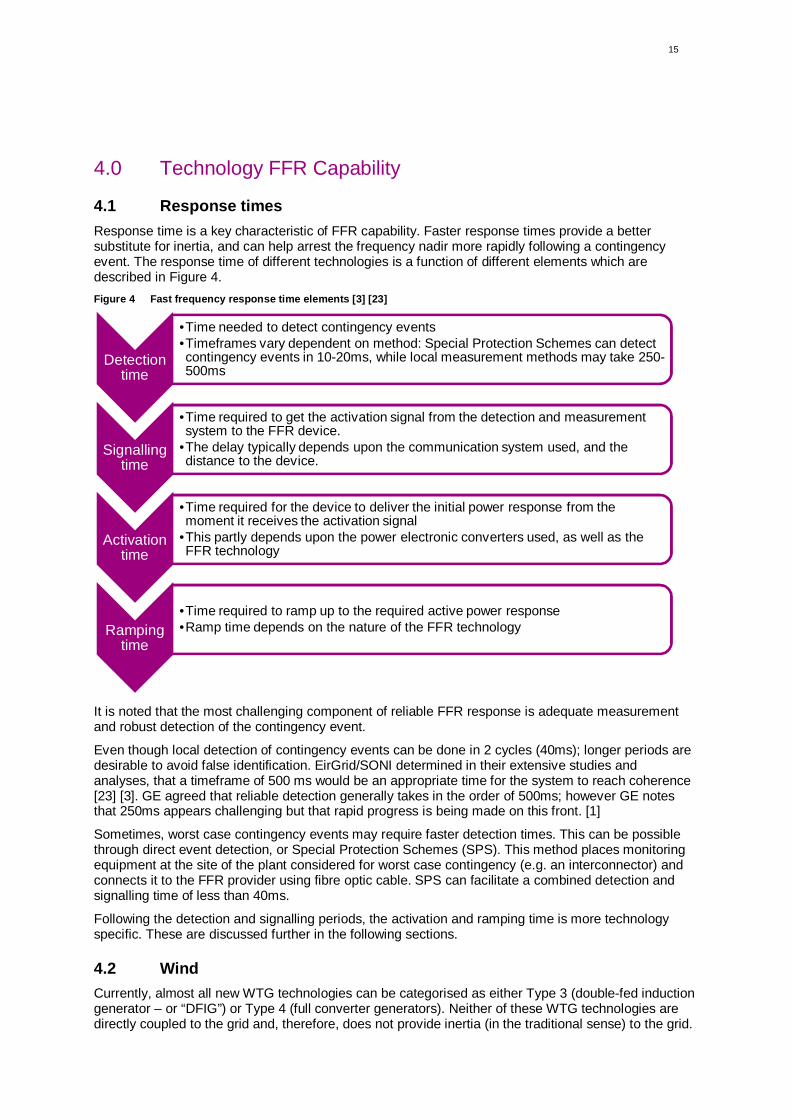
4.1 Response timesResponse time is a key characteristic of FFR capability. Faster response times provide a bettersubstitute for inertia, and can help arrest the frequency nadir more rapidly following a contingencyevent. The response time of different technologies is a function of different elements which aredescribed in Figure 4.Figure 4 Fast frequency response time elements [3] [23]
It is noted that the most challenging component of reliable FFR response is adequate measurementand robust detection of the contingency event.
Even though local detection of contingency events can be done in 2 cycles (40ms); longer periods aredesirable to avoid false identification. EirGrid/SONI determined in their extensive studies andanalyses, that a timeframe of 500 ms would be an appropriate time for the system to reach coherence[23] [3]. GE agreed that reliable detection generally takes in the order of 500ms; however GE notesthat 250ms appears challenging but that rapid progress is being made on this front. [1]
Sometimes, worst case contingency events may require faster detection times. This can be possiblethrough direct event detection, or Special Protection Schemes (SPS). This method places monitoringequipment at the site of the plant considered for worst case contingency (e.g. an interconnector) andconnects it to the FFR provider using fibre optic cable. SPS can facilitate a combined detection andsignalling time of less than 40ms.
Following the detection and signalling periods, the activation and ramping time is more technologyspecific. These are discussed further in the following sections.
4.2 WindCurrently, almost all new WTG technologies can be categorised as either Type 3 (double-fed inductiongenerator – or “DFIG”) or Type 4 (full converter generators). Neither of these WTG technologies aredirectly coupled to the grid and, therefore, does not provide inertia (in the traditional sense) to the grid.
Detectiontime
•Time needed to detect contingency events•Timeframes vary dependent on method: Special Protection Schemes can detectcontingency events in 10-20ms, while local measurement methods may take 250-500ms
Signallingtime
•Time required to get the activation signal from the detection and measurementsystem to the FFR device.
•The delay typically depends upon the communication system used, and thedistance to the device.
Activationtime
•Time required for the device to deliver the initial power response from themoment it receives the activation signal
•This partly depends upon the power electronic converters used, as well as theFFR technology
Rampingtime
•Time required to ramp up to the required active power response•Ramp time depends on the nature of the FFR technology
16
Instead, power electronics control active power delivery, and are able to command controlled changesin the active power. [1]
By leveraging the kinetic energy contained within the wind turbine’s blades, the power output can beboosted briefly. However the boost cannot be sustained. As the kinetic energy is drained from theturbine blades, the resulting slow rotation leads to a drop in energy output. To return the turbine to itspre-fault operating conditions, energy needs to be recovered from the grid. This functionality issometimes terms “Inertia-based FFR”.
An alternative method of providing FFR functionality from wind is to pre-curtail the WTG output, suchthat “head room” is available. However this method comes at a substantial energy cost.
4.2.1 FFR from wind
The mechanism operates on the basis that the WTG temporarily extracts kinetic energy stored in theturbine rotor and drive train to deliver additional electrical power, however this causes the rotor to slowdown. [1] This motion therefore dictates how long power injection can be sustained: higher FFRrequires more rapid power injection which can be sustained for shorter periods, while lower FFRrequires slower injection which can be sustained for slightly longer periods.
The aeromechanics of wind turbines set the practical upper limit of FFR extracted from wind turbinesat ~10% of the power production level at the time of the disturbance. The amount of available inertialresponse starts to decline rapidly below ~50% rated power, dropping down to zero below ~20% ratedpower. [1]
Electrical power must temporarily drop below mechanical power in order to recover the inertial energyextracted from the slowing rotation of the turbine. The time required to recover the additional energyinjection, and to reaccelerate rotational speed to pre-fault levels, depends on the amount and rate ofFFR requested and available wind speed at the time of recovery.
A key observation for operating conditions at or below rated wind speed is that FFR can help to arrestfrequency deviations and buy time for primary frequency response to act. Ideally withdrawal of FFRshould begin at the nadir, carefully coordinated with the rate of rise of the primary frequency responseduring the post-nadir recovery period. [1]
When wind speeds exceed rated speeds, WTGs “spill” excess energy by pitching the blades (inaddition to other mechanisms) to keep constant power generation. Under these conditions, availablepower in the wind is greater than the WTG rated power and it is possible to capture additional energyusing pitch control rather than just extracting stored inertial energy by slowing the rotor. At or aboverated wind speeds, a recovery period may not be required. [1] While WTGs would be able to exceedthe steady-state power output rating under these conditions, additional power is still subject to physicallimitations of the equipment, which is currently known to be ~10% of the power level.
4.2.2 FFR from wind demonstration trials
Field tests were carried out in 2008, on a GE WTG for inertial frequency controls under various windspeeds. [1] The results were averaged and plotted as shown in Figure 5. [1]
The results demonstrate the increased power output and recovery period at wind speeds below rated(<14/ms), while no recovery period is observed for the rated wind speed test. Similarly it can be seenthat little additional power was available at the low (5m/s) wind speed and corresponding low powerlevel. The frequency response increased power output in the order of 5% to 10% of the turbine rating,for a duration of several seconds. [1] [3]

17
Figure 5 Field demonstrations of wind FFR capability [1]
4.2.3 Hydro-Quebec power system experiences with FFR
Hydro-Quebec has set a requirement for wind generators to provide an FFR service. This service ischaracterised by a 1.5 second response time (including detection), and a 6% (of rate capacity) boostfor a 9 second duration (further details are provided in Section 3.2). In 2016, Hydro-Québec publishedsome detailed analyses on practical power system experiences with FFR responses from windgeneration under various under-frequency contingency events. [3] [24] For illustration purposes,AECOM has provided two example response events.
Figure 6 shows two examples of recorded behaviour of Type IV wind turbines during two differentunder frequency events. The top panel illustrates the active power response measured at an individualWTG in red, and the whole Wind Power Plant (WPP) in blue. The bottom panels illustrate thecorresponding wind and rotor speeds during the event.
The left panel (a) show the response of a wind farm comprising Enercon E70 2.3MW turbines,operating with settings equivalent to the ‘proportional function’ defined by Hydro-Québec, while theright panel (b) shows the response of a wind farm comprising Enercon E82 2.3MW turbines operatingwith settings equivalent to ‘step function’ defined by Hydro-Québec.
Figure 6 Hydro-Québec measured emulated inertial response in two different events by Type IV wind turbines [3] [24]
In the first instance (a) the individual turbine was operating at ~74% of its rated power, while the wholefarm operated at ~50% of rated power. It can be seen that at the time of the disturbance, the individualturbine increased its output by 10% of the rated power, while the whole WPP increased power outputby ~7% on average. [3]
(a) (b)
%of
nom
inal
rate
dpo
wer
(m/s
)
18
The response sustain period of the individual turbine seem to start dropping just before 10 secondsfollowed by steep power reduction (active power reduces by 54% during this period), while on aholistic wind farm basis the power reduction and recovery is less extreme [3]. Power reduction prior to10 sec may have been in response to a signal from the operator, or due to the fact that the turbineresponded with higher power output (10% instead of 6%) which may have led to more rapid recovery.
At the individual wind turbine, the significant reduction is exacerbated by the corresponding reductionin wind speed from 13 to 10.5m/s. The recovery period lasted for ~14 seconds. [3]
In the second instance (b) the WTG operated at a lower 40% of rated power immediately prior to theevent, while the whole WPP operated at 25% of the rated capacity. The WTG and the whole WPPincreased active power by ~6% in response to the disturbance, for a duration of ~10 seconds asdesigned. These wind turbines have longer blades than the previous example, which leads to a higherinertia constant. [3]
In this case, the whole wind farm sees an active power reduction of only 9% for a slightly longerduration of ~20 seconds [3]. It is notable however, that even though the individual WTG recoverspower output sufficiently to pre-fault levels within ~25sec, the wind farm power output does not recovercompletely to the pre-fault levels for the duration of this chart. It is not clear if this may be attributed tolower wind speeds at other locations in the wind farm after the event.
4.2.4 FFR specifications based on wind FFR characteristics
It is notable that the Hydro-Quebec grid standards require that the WTGs increase power output by atleast 6% of the nominal power to be sustained for 10sec. The observed response in the results shownabove demonstrates that the turbines have the capability to meet these requirements.
In addition to these requirements, GE has made a set of recommendations for use in specifying FFRrequirements for WTGs [1]:
· Specification of minimum turbine power below which inertial response is not required
· Specification of preferred interactions/priority with other wind plant controls (e.g. should FFR orcurtailment have priority? Should reactive support or frequency support have priority?)
· Specification should not attempt to replicate synchronous machine requirements or capabilities
· Not specified to be identical for all operating conditions
· Not specified to be exactly reproducible with individual turbine tests
· Not specified to be energy neutral (for all events)
· Not specified to be overly prescriptive or requiring of impossible power recovery constraints
· Not specified to require delivery of energy beyond that necessary to improve the frequency nadir
In addition, it is important to note that since WTG FFR characteristics are effectively determined bycontrol settings, there is a high degree of flexibility available to technology providers to providedifferent FFR characteristics (e.g. response time, response duration, output profile, recovery behaviouretc.)
4.3 Other FFR technologies4.3.1 Solar PV FFR
Solar PV has no inherent kinetic energy stored (such as wind). Therefore, if solar PV was to deliverFFR, the inverter would need to be operating at an AC power transfer level lower than the DC poweravailable from the PV panel at the time, and/or power output would need to be curtailed to a levelbelow the available power.
No examples of technical obligations relating to solar PV for FFR were evident based on the literaturereview.
A trial of solar PV to provide FFR was conducted however for a 20MW solar PV plant and this wasdocumented in a NREL report.

19
The results indicate that a response time of around 50-100ms is possible and the characteristic of theresponse depends on the co-ordination between the solar PV MPPT and inverter AC controls. Theresponse based on the trails carried out are replicated in Figure 7.
Figure 7 FFR response for a 20MW PV plant in Puerto Rico
The response of the PV inverter is similar to a battery storage inverter; however there are somedifferences in the initial response due to differences in the stiffness of the DC bus of a solar PVinverter versus a battery storage inverter [1].
4.3.2 Demand Side ResponseDemand side response or load resources can provide high quality FFR. In under-frequency events,rather than asking generators to rapidly increase power, a faster response may be elicited by asking aload to drop power instead.
Modern commercial and industrial loads often have electronically controlled motors and processeswhich give rise to a class of load resources that can provide sophisticated FFR from demand sideresponse. In ERCOT for example, loads provide half of the interconnected power system’s FrequencyResponsive Reserves that support the system in a sudden loss of generation event. ERCOT’s FFRtriggers at 59.7 Hz or 59.8 Hz and provides full response in 500 ms. [1] In New Zealand, the TSOprocures a type of Fast Instantaneous Reserve (FIR) specifically from interruptible loads, where load isto be reduced within 1 second and sustained for 60 sec. [3]
It is important that all resources are allowed to participate in potential FFR markets due to the diversitypossible market participants. In PJM3 for example, the minimum size requirement for resourceparticipation was 1MW which acted as barrier to smaller demand response aggregators. [3] [25]Demand side participation increased dramatically after market rules were changed in 2011, whereminimum size requirement for resources was lowered from 1MW to 100kW. [25] There is also apractical limit to how much industrial load may be available to participate in fast voluntary loadshedding. Rapid communication to a larger number of highly distribute load nodes appears to begaining practicality. [1]
One of the considerations in using load as an FFR resource is that load may also be providing inertia,which is helping to mitigate RoCoF. Therefore, it may be necessary to assess the characteristics of
3 PJM Interconnection LLC (PJM) is a regional transmission organization (RTO) in the United States. It is part of the EasternInterconnection grid operating an electric transmission system serving all or parts of Delaware, Illinois, Indiana, Kentucky,Maryland, Michigan, New Jersey, North Carolina, Ohio, Pennsylvania, Tennessee, Virginia, West Virginia, and the District ofColumbia.

20
potential load-based resources and accept those that can provide the greatest net benefit to thesystem. [1]
4.3.3 Battery Storage
Batteries convert chemical energy into electrical energy, and have the potential to provide useful FFRwith extremely fast response times. The technology is generally well established, however significantimprovement and further development of the technology is facilitated with increasing uptake globally tosupplement intermittent generation.
Battery storage systems comprise a power conversion system (usually inverter and controls) and abattery. Batteries are not limited by chemical response times, but by inverter and control responsetimes. At a plant level, the response time consists of sensing, communication and dispatch toindividual inverters [1]. In consultations with battery manufacturers, response time is conservativelyestimated to be 120-400 ms. (see an example of a battery response to an FFR signal in Figure 8)
Due to these extremely fast response times, FFR is better implemented directly to the inverters,however the drawback is that the inverter would need to be maintained in a hot standby mode in orderto react fast, which induces parasitic losses in the order of 2% of rated power. [1]
The total response time of FFR from batteries is determined by RoCoF detection and communication,which highlights once again the requirement for an adequate monitoring and control system toeffectively eliminate significant delays in signalling FFR providers.
Figure 8 Large-scale storage response times (provided in consultation with a battery manufacturer)
21
5.0 Over FrequencyThis report is largely focused on the ability of technologies such as wind and solar generators todeliver adequate response services in the event of under-frequency, where additional power needs tobe injected into the network to arrest and stabilise frequency decline. This is of course subject toavailability of the energy resource (wind or solar) which cannot be controlled.
Over frequency events would require curtailing output in order to manage the frequency rise. Inprincipal, this can be achieved by either solar PV or wind generation, however the ramp rates wouldbe relatively different.
Ramping down of wind generation has inherent limitations which are defined typically by:
- Converter controls (relatively fast)
- Blade pitching (relatively slow)
- Mechanical loading placed on turbine components.
Based on discussions with turbine supplier, it is understood that ramp rates would be limited toaround 20% per second for a modern Type IV wind turbine.
Solar PV inverters do not have any moving parts and the ramp rate would be limited typically by thespeed of the maximum power point tracker (MPPT) which would have delays in the order of seconds.
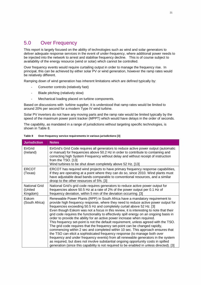
The capability, as mandated in a range of jurisdictions without targeting specific technologies, isshown in Table 8.
Table 8 Over-frequency service requirements in various jurisdictions [3]
Jurisdiction Notes
EirGrid(Ireland)
EirGrid’s Grid Code requires all generators to reduce active power output (automaticor manual) for frequencies above 50.2 Hz in order to contribute to containing andcorrecting high System Frequency without delay and without receipt of instructionfrom the TSO. [13]Wind turbines to be shut down completely above 52 Hz. [13]
ERCOT(Texas)
ERCOT has required wind projects to have primary frequency response capabilities,if they are operating at a point where they can do so, since 2010. Wind plants musthave adjustable dead bands comparable to conventional resources, and a similardroop to the other resources of 5%. [3]
National Grid(UnitedKingdom)
National Grid’s grid code requires generators to reduce active power output forfrequencies above 50.5 Hz at a rate of 2% of the power output per 0.1 Hz offrequency deviation, within 5 min of the deviation occurring. [3]
Eskom(South Africa)
Renewable Power Plants (RPP) in South Africa have a mandatory requirement toprovide high frequency response, where they need to reduce active power output forfrequencies exceeding 50.5 Hz and completely curtail above 52 Hz. [3]Even though Eskom was not a focus in this review, it is interesting to note that theirgrid code requires the functionality to effectively spill energy on an ongoing basis inorder to provide the ability for an active power increase when required.This frequency set-point is not the default requirement, unless agreed with the TSO.The grid code requires that the frequency set-point can be changed rapidly,commencing within 2 sec and completed within 10 sec. This approach ensures thatthe TSO can elicit a sophisticated frequency response (to manage both overfrequency and under frequency events) from all renewable generators in the systemas required, but does not involve substantial ongoing opportunity costs in spilledgeneration (since this capability is not required to be enabled in unless directed). [3]
22
6.0 References
[1] GE, “Technology Capabilities for Fast Frequency Response,” 2017.
[2] ERCOT, “ERCOT Concept Paper: Future Ancillary Services in ERCOT,” 2013.
[3] DGA Consulting, “International Review of Frequency Control Adaptation,” 2016.
[4] Commission for Energy Regulation (CER), “Single Electricity Market - DS3 System ServicesTechnical Definitions - Decision Paper - SEM-13-098,” 2013.
[5] I. M. A. B. Ori Agranat, “Fast Frequency Markets and High Penetrations of Renewable Energy inthe Australian National Electricity Market,” 2015.
[6] Hydro-Quebec, “Power generation, purchases and exports,” 2017. [Online]. Available:http://www.hydroquebec.com/sustainable-development/energy-environment/power-generation-purchases-exports.html. [Accessed 16 May 2017].
[7] Hydro-Quebec, “Exigences techniques de raccordement de centrales au réseau de transportd'Hydro-Québec,” 2013.
[8] EIA, “Texas: State Profile and Energy Estimates,” 2017. [Online]. Available:https://www.eia.gov/state/analysis.php?sid=TX. [Accessed 18 May 2017].
[9] EIA, “Electric Power Monthly with Data for Feburary 2017,” 2017.
[10] EY, “2014 ancillary service standards and requirements study,” 2014.
[11] Ofgem, “Electricity Interconnectors,” 2017. [Online]. Available:https://www.ofgem.gov.uk/electricity/transmission-networks/electricity-interconnectors. [Accessed6 June 2017].
[12] EIR Grid Group, “All-Island Generation Capacity Statement 2016-2025,” 2016.
[13] EirGrid, “EirGrid Grid Code Version 6.0,” July 2015.
[14] National Grid, “Frequency Response Technical Sub-Group Report: Grid Code and BSSG,” 2011.
[15] National Grid, “Frequency Response Services,” [Online]. Available:http://www2.nationalgrid.com/uk/services/balancing-services/frequency-response/. [Accessed May2017].
[16] National Grid, “TESTING GUIDANCE FOR PROVIDERS OF ENHANCED FREQUENCYRESPONSE BALANCING SERVICE,” March 2017.
[17] National Grid, “ENHANCED FREQUENCY RESPONSE - Invitation to tender for pre-qualifiedparties v2.2,” July 2016.
[18] RenewEconomy, “Did Germany just surpass 100% renewable electricity?,” [Online]. Available:http://reneweconomy.com.au/did-germany-just-surpass-100-renewable-electricity-88700/.[Accessed 31 May 2017].
[19] Renewable Energy Futures to 2050, “How is Germany Integrating and Balancing RenewableEnergy Today?,” January 2015. [Online]. Available: http://www.martinot.info/renewables2050/how-is-germany-integrating-and-balancing-renewable-energy-today. [Accessed 31 May 2017].
[20] REGELLEISTUNG.NET - Internetplattform zur Vergabe von Regelleistung, “General informationon control reserve - technical aspects,” [Online]. Available:https://www.regelleistung.net/ext/static/technical. [Accessed 7 June 2017].
23
[21] 50Hertz, “Balancing,” [Online]. Available: http://www.50hertz.com/en/Markets/Balancing.[Accessed 7 June 2017].
[22] European Network of Transmission System Opertors for Electricity, “Who is ENTSO-E,” [Online].Available: https://www.entsoe.eu/about-entso-e/Pages/default.aspx. [Accessed 31 May 2017].
[23] DNV GL, “RoCoF Alternative Solutions Technology Assessment,” 2015.
[24] C.-E. L. Mohamed Asmine, “Field Measurements for the assessment of inertial response for windpower plants based on Hydro-Quebec TransEnergie requirements,” IET Journals, 2015.
[25] Synapse Energy Economics Inc., “Synapse Comments on FAST Proposals in ERCOT,” 2014.
[26] Hyrdo-Quebec, “Transmission Provider Technical Requirements for the Connection of PowerPlants to the Hydro-Quebec Tranmission System,” 2009.
[27] EIR Grid Group, “All-Island Generation Capacity Statement 2016-2025,” 2016.
[28] EIRGRID, “North South Interconnector Answering Your Questions,” 2016.
[29] EirGrid Group, “Celtic Interconnector,” EIRGRID PLC 2015, [Online]. Available:http://www.eirgridgroup.com/the-grid/projects/celtic-interconnector/the-project/. [Accessed 052017].
[30] National Grid, “Smart Frequency Control Project,” [Online]. Available:http://www.nationalgridconnecting.com/The_balance_of_power/. [Accessed May 2017].
[31] European Commission, “System Operation Guideline,” 2016.