Fast Switching Optical Modulator Based on Dual Frequency Nematic Cell
12
FAST SWITCHING OPTICAL MODULATOR BASED ON DUAL FREQUENCY NEMATIC CELL Ye Yin, Mingxia Gu, Andrii B. Golovin, Sergij V. Shiyanovskii, and Oleg D. Lavrentovich Liquid Crystal Institute, Kent State University, Kent, Ohio, 44242-0001, USA We demonstrate a fast optical modulator capable of switching large amount of optical retardation (a few microns) in less than 1 ms. The result is achieved by employing a dual frequency nematic in cells with high pre-tilt alignment and by providing a special addressing scheme that features amplitude and fre- quency modulated voltage. We explore the effect of surface alignment and dielectric heating on the switching time. We also report the measurements of dielectric permittivities and crossover frequency of dual frequency nematic. Keywords: dielectric heating; dual frequency nematic; optical retarder; response time 1. INTRODUCTION Electrically-controlled liquid crystal (LC) cells are used in many modern optical applications that require switching of large optical retardation with short response time [1,2]. The two crucial parameters, the maximum optical retardation DL max and the switching speeds ð 1=s on ; 1=s off Þ of the nematic LC cells depend differently on the cell thickness d setting the stage for necessary trade-offs [3]: DL max ¼ðn e n o Þd; ð1Þ s on ¼ c 1 d 2 ½e 0 De j jðU rms U c Þ = ; s off ¼ c 1 d 2 =ðp 2 K Þ: ð2Þ Here n o , n e are the ordinary and extraordinary refractive indices, respect- ively, K is the effective elastic constant, c 1 is the characteristic rotational viscosity, De ¼ e jj e ? is the dielectric anisotropy, e jj and e ? are the dielec- tric permittivity components measured along and perpendicular to the We thank Phil Bos, Ivan Smalyukh, and Yuriy Nastishin for helpful discussions. Corresponding author. Tel.: (330) 672-4844, Fax: (330) 672-2796, E-mail: [email protected]. edu 133 Mol. Cryst. Liq. Cryst., Vol. 421, pp. 133–144, 2004 Copyright # Taylor & Francis Inc. ISSN: 1542-1406 print=1563-5287 online DOI: 10.1080=15421400490501699
Transcript of Fast Switching Optical Modulator Based on Dual Frequency Nematic Cell

FAST SWITCHING OPTICAL MODULATOR BASED
ON DUAL FREQUENCY NEMATIC CELL
Ye Yin, Mingxia Gu, Andrii B. Golovin, Sergij V. Shiyanovskii,
and Oleg D. Lavrentovich�
Liquid Crystal Institute, Kent State University, Kent,
Ohio, 44242-0001, USA
We demonstrate a fast optical modulator capable of switching large amount of
optical retardation (a few microns) in less than 1ms. The result is achieved by
employing a dual frequency nematic in cells with high pre-tilt alignment and
by providing a special addressing scheme that features amplitude and fre-
quency modulated voltage. We explore the effect of surface alignment and
dielectric heating on the switching time. We also report the measurements of
dielectric permittivities and crossover frequency of dual frequency nematic.
Keywords: dielectric heating; dual frequency nematic; optical retarder; response time
1. INTRODUCTION
Electrically-controlled liquid crystal (LC) cells are used in many modernoptical applications that require switching of large optical retardation withshort response time [1,2]. The two crucial parameters, the maximumoptical retardation DLmax and the switching speeds ð�1=son; �1=soff Þ ofthe nematic LC cells depend differently on the cell thickness d settingthe stage for necessary trade-offs [3]:
DLmax ¼ ðne � noÞd; ð1Þ
son ¼ c1d2 ½e0 Dej jðUrms � UcÞ�= ; soff ¼ c1d
2=ðp2KÞ: ð2Þ
Here no, ne are the ordinary and extraordinary refractive indices, respect-ively, K is the effective elastic constant, c1 is the characteristic rotationalviscosity, De ¼ ejj � e? is the dielectric anisotropy, ejj and e? are the dielec-tric permittivity components measured along and perpendicular to the
We thank Phil Bos, Ivan Smalyukh, and Yuriy Nastishin for helpful discussions.�Corresponding author. Tel.: (330) 672-4844, Fax: (330) 672-2796, E-mail: [email protected].
edu
133
Mol. Cryst. Liq. Cryst., Vol. 421, pp. 133–144, 2004
Copyright # Taylor & Francis Inc.
ISSN: 1542-1406 print=1563-5287 online
DOI: 10.1080=15421400490501699

director, respectively; e0 is the permittivity of free space, Uc is the thres-hold voltage of Frederiks transition in a cell with planar or homeotropicalignment, and Urms > Uc is the actual applied voltage. The relevant figureof merit that depends on the switch-off time and characterizes the trade-offfor the optical modulators,
FoM ¼ DL2max=p
2soff ; ð3Þ
can be re-expressed exclusively in terms of the material parameters [4]:
FoMm ¼ Kðne � noÞ2=c1: ð4Þ
The latest expression inspired many researchers to seek for theimprovement of optical retarders by synthesizing new materials with ahigher optical birefringence, lower viscosity and larger Frank constants.Recently, our group has demonstrated that FoM can be improved by twoorders of magnitude by exploring a different method of switching ratherthan synthesizing new materials [5]. The idea is to use dual frequencynematic (DFN) MLC2048 (EM Industries) in cells with high pre-tilt anglealignment and a special addressing scheme that features amplitude and fre-quency modulated voltage [5].
In this paper, we describe the technique briefly outlined in Reference [5],in a greater detail. In particular, we explore the effect of surface alignmentand dielectric heating on the switching time of DFN cells. We also charac-terize the material properties of DFN such as dielectric permittivities,crossover frequency and rotational viscosity at different temperatures.We analyze the issue of dielectric heating, which is of special interest toDFN-based devices as the best mode of their operation might be achievedat elevated temperatures.
2. MATERIAL PROPERTIES OF DFN
Field-induced director reorientation depends on dielectric anisotropyDe f ;Tð Þ, which in DFNs changes its sign at a crossover frequency fc. Thequantities ejj, e?, and fc depend on the cell temperature T. We measuredthese dependencies for MLC2048 in planar and homeotropic cells withthickness about 15 mm. The pre-tilt angle in these and all other cells wasmeasured by the magnetic null technique [6]. The cell was mounted in ahot stage permitting temperature stabilization within 0.1�C. The compleximpedance amplitude of the cell was measured by the Impedance=Gain-Phase Analyzer (model Schlumberger 1260) in the frequency rangefrom 1Hz to 10MHz at voltage 0.5 V, in order to determine the dielectricpermittivities of DFN.
134 Y. Yin et al.

Figure 1 shows ejj and e? as the functions of the applied voltage fre-quency at 20�C. The value of e? does not change much in the frequencyrange (0.1–100) kHz while ejj shows a dispersion region at relatively lowfrequencies (1–100) kHz. The intersection of two curves represents thecrossover frequency, fc ¼ 12 kHz � 2 kHz at T ¼ 20�C. We independentlydetermined fc to be 12.9 kHz� 0.2 kHz at 20�C by Senarmont method[7,8] (at fc the cell becomes insensitive to the field and shows no opticalresponse). The temperature dependence of e? is shown in Figure 2.
We notice that fc increases with temperature, for example, from 12 to31 kHz when T changes from 20 to 32�C. At high temperature, De is alwayspositive in broad frequency range of applied voltage as shown in Figure 3.The temperature behavior of fc can be fitted by a straight line in theinverse-logarithmic coordinates, Figure 4, which implies that it is con-trolled by an activation process:
fc � expð�Ef=kBTÞ; ð5Þ
FIGURE 1 Frequency (logarithmic scale) dependent dielectric permittivities ejjand e? at 20�C.
Modulator Based on Dual Frequency Nematic Cell 135

where kB is the Boltzman constant and Ef is the activation energy repre-senting the energy barrier associated with flip-overs of the long molecularaxis. The linear fit in Figure 4 yields Ef ¼ 0.61 eV.
The rotational viscosity c1 measured by the technique described inReference [9] demonstrates the temperature dependence of the similaractivation type [10], Figure 5:
c1 � S � exp Ec=kBT� �
ð6Þ
Here S is the order parameter, Ec is the activation energy equal 0.27 eV(see Fig. 5). Both Ef and Ec describe the processes associated with rotationof long molecular axes; however, Ef and Ec are different, most probablybecause Ef describes flip-overs of a single molecule while Ec is associatedwith a small angle rotation of many molecules.
3. FAST MODULATION OF OPTICAL RETARDATION
The original idea [5] of this work was to employ the DFN in a geometry inwhich the electric field yields a substantial reorienting torque in both the
FIGURE 2 Dielectric permittivity e? vs. temperature (10�C to 105�C) at f ¼ 10 kHz.
136 Y. Yin et al.

processes of director reorientation toward the planar state and the home-otropic state. A suitable geometry would be the one with a high pre-tiltangle, say ab ¼ 45�. There is no threshold of reorientation and the dielectrictorque is also assisted by the surface anchoring torque when the directorreturns to the initial titled orientation.
We carried out the experiments at an elevated temperature 32�C, wherefc ¼ 31 kHz. This allowed us to decrease the rotational viscosity and alsoto use a relatively high frequency of 7 kHz to drive the cell in the ‘‘low-frequency’’ regime. The high-frequency driving voltage was applied at50 kHz. The voltage dependence of phase retardation was measured in astandard fashion, with the DFN cell of thickness d ¼ 14.5 mm placedbetween two crossed polarizers, Figure 6.
The projection of director n onto the cell substrates makes an angle 45�
with the axes of polarizer and the analyzer, so the intensity of transmittedlight follows the rule: I ¼ I0sin
2pDL=k, where I0 is the intensity of incidentlight (we neglect small corrections caused by reflection at interfaces, scat-tering at director fluctuations, etc.) and k is wavelength of the light [3].Figure 6 shows I (top trace) vs. applied voltage Urms at frequencies 7
FIGURE 3 Dielectric anisotropy De as a function of the cell temperature T.
Modulator Based on Dual Frequency Nematic Cell 137

and 50 kHz (bottom trace). The variation of I between the two neighboringminima (e.g., A and B in Fig. 6) corresponds to the retardation shiftDLAB ¼ 633 nm. A larger shift DLCD ¼ 2:5 mm is achieved between thestates C and D.
As follows from the theory, see Reference [5], the switching time can bedramatically shortened by applying large-amplitude voltage signals to thecell at both frequencies, as the value of FoM increases at high voltages:
FoM � K ne � noð Þ2
1:2c11þ U2
rms
U2c
� �ð7Þ
We optimized the driving scheme for DFN cell by including special shortpulses (SSPs) of high-amplitude (at both driving frequencies) to initiatefast director reorientation, followed by a relatively low voltage to keepthe retardation at the desired level. The oscilloscope pictures of fastswitching at relatively small (DLOA � 0:3 mm) and large (DLCD ¼ 2:5 mm)optical retardations are demonstrated in Figures 7 and 8, respectively.In Figure 7, the first SSP (duration 100 ms, Urms ¼ 50V ) triggers fast
FIGURE 4 Crossover frequency fc (logarithmic scale) vs. the inverse temperature
1=T.
138 Y. Yin et al.

reorientation towards the homeotropic state. A square-wave holding volt-age Urms ¼ 2V at 7 kHz follows to hold the cell in the state A (the statesare labeled as in Fig. 1). The A state is switched back into the initial O stateby a second SSP (duration 120 ms, Urms ¼ 25V at 50 kHz); the holdingvoltage is zero for the state O.
Figure 8 shows C $ D transition, switched with SSPs of 100 V ampli-tude. The switching times are �0.5ms. We use a short duration SSP pulseto minimize dielectric heating of the cell. Some features of fast switchingare worth mentioning. First, there is a small time delay (30–50 ms) betweenthe initial front of an SSP and the corresponding front of the photodiodesignal, Figures 7, 8 [5]. Second, the transient maxima and minima seen inFigure 8 are relatively small (meaning that the modulation of light intensityis not complete). There are few possible reasons of this effect: (a) in-planenon-homogeneity of pre-tilt angle, anchoring energy, surface viscosity, etc.;(b) the structural transition can be accompanied by an in-plane flow, whichin turn may cause director dynamics.
FIGURE 5 Rotational viscosity c1 (logarithmic scale) vs. the inverse temperature
1=T.
Modulator Based on Dual Frequency Nematic Cell 139

FIGURE 6 Optical setup: 1-He-Ne laser (633 nm), 2-polarizer prism, 3-DFN cell,
4-analyzer prism, 5-photodiode and the optical retardation (top) vs. applied voltage
(bottom).
FIGURE 7 Fast phase shift by DL ¼ 0:3 mm driven by holding voltage 7 kHz and
two SSPs.
140 Y. Yin et al.

To conclude this section, we demonstrate experimentally that the cho-sen cell design with the high pre-tilt angle is preferable than the regularcells with either planar or homeotropic alignment. As seen from Equation(2) and (7), the response time is dependent on the elastic constant K,and one can expect that the homeotropic cell might have a faster responsethan a cell with either planar or high pre-tilt alignment, as the correspond-ing splay constant is generally smaller than that of bend. Table 1 demon-strates that the homeotropic cell is indeed capable of the fastestresponse, but there is a drawback as it is hard to achieve a uniform directorreorientation. Even in the cells with rubbed homeotropic alignment layers,the director experiences in-plane distortions upon reorientation from thehomeotropic to planar (or tilted) state. As the result, the cells with a highpre-tilt angle such as described in this work are the best overall choice.
4. DIELECTRIC HEATING
Dielectric heating is an important factor that might influence the perform-ance of DFN cells. It affects all dielectric parameters because the Debye-type relaxation [11] is sensitive to temperature. To detect the temperature
FIGURE 8 Fast switching by DL ¼ 2.5 mm during s � 0:5ms.
TABLE 1 Comparison of Response Times for Different Surface Alignments
Planar High Pre-tilt Homeotropic
soff=d2ð109 s=m2Þ 2.48 2.43 1.42
Modulator Based on Dual Frequency Nematic Cell 141
changes in the cell, we used E-type thermocouple CHCO-0005 (OmegaInc.) with 0.05�C accuracy and head size 32 mm. We assembled 45 mm thickplanar cell with etched electrodes on substrates. The head of the thermo-couple was incorporated in the cell outside the electrode area, but as closeas possible to it (within 1mm).
To describe the dielectric heating effect in the nematic cell we measurethe stationary temperature change DT with respect to the room tempera-ture with applied voltage of various amplitudes and frequencies. Usually,DT reaches a stationary level within 100 s and is determined by the station-ary heat flux out of the cell, as described by
DT ¼ P=G: ð8Þ
Here G is the effective heat conductivity of the cell (including the glasssubstrates, the nematic layer and the possible thermal shields) and P is thepower absorbed by the cell:
P ¼ 2pAU2rms f e
00?ð f Þ=d ð9Þ
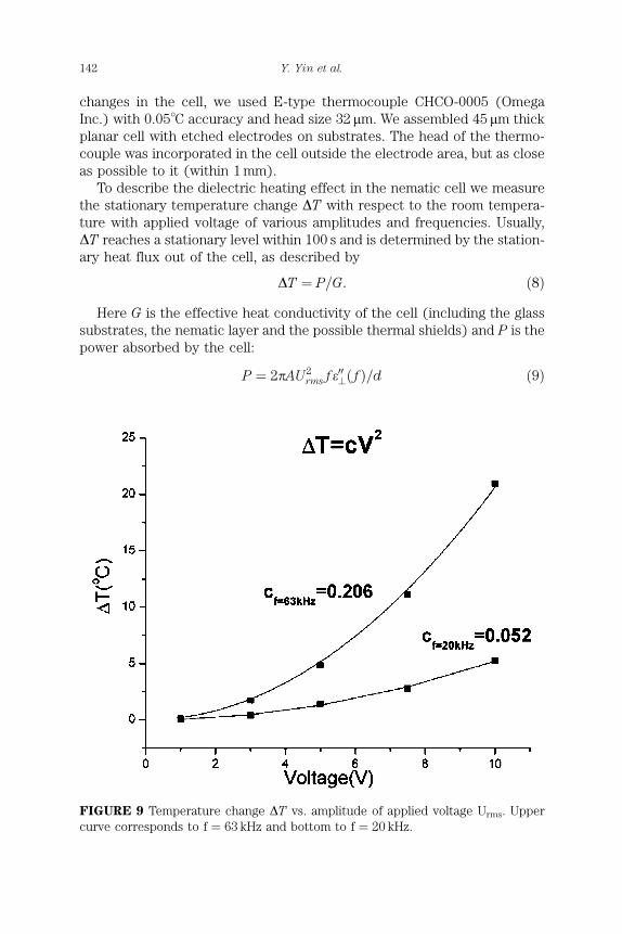
FIGURE 9 Temperature change DT vs. amplitude of applied voltage Urms. Upper
curve corresponds to f ¼ 63 kHz and bottom to f ¼ 20 kHz.
142 Y. Yin et al.

where A is the electrode area, and e00?ð f Þ is the imaginary part of the dielec-tric permittivity component measured perpendicularly to the director.
The experimental data in Figure 9 confirm that DT / U2rms, as expected
from Eqs. (8) and (9). The frequency dependence of DT under the con-dition of constant voltage amplitude is determined by e00?ð f Þ: DT / f e00?ð f Þ,Figure 10. Dispersion of dielectric permittivities of LC is usually describedby a Debye-type relaxation process with a relaxation time s [12]:
e00?ð f Þ ¼eL? � eH?� �
f s
1þ f 2s2ð10Þ
where eH? and eL? are the asymptotic values of e? above and below the charac-teristic frequency fD ¼ s�1 (Figure 1 shows that fD > 1MHz for e?), respect-ively. However, Eq. (10) provides only a qualitative description of the curvesin Figure 9. Thus, either temperature dependence of s should be taken intoaccount in self-consistent way, or the approximation based on a singleDebye-type relaxation process does not work in DFN MLC2048. Furtherinvestigations are required to clarify this issue.
We also verified that the DFN cells can be driven by high-amplitudeSSPs with a high repetition rate without substantial heating-induced
FIGURE 10 Temperature change DT vs. frequency of applied voltage f.
Modulator Based on Dual Frequency Nematic Cell 143

changes of the switched optical retardation. For example, a DFN cell of thesquare aperture (2 2 cm2), thickness of the glass substrates 1.1mm, andd � 14.5 mm, operating without any temperature-stabilizing device, wascapable of switching DL � 1.9 mm with a repetition rate 25Hz while drivenby SSPs of amplitude Urms � 90 V and pulse duration 1ms.
6. CONCLUSION
We demonstrated the scheme of fast optical modulator based on DFNs. Wemeasured the temperature dependent dielectric permittivities, crossoverfrequency and rotational viscosity of dual frequency nematic MLC2048.We measured the response times of cells with different surface alignmentsand found the homeotropic cells to be the fastest; however, the opticalquality of the realigned state is often poor. We analyzed the dielectric heat-ing phenomenon, and demonstrated that this effect can be controlled tomaintain the operating temperature of the cell constant.
REFERENCES
[1] McManamon, P. F., Dorschner, T. A., & Barnes, L. J. (1993). Optical Engin., 32, 2657;
McManamon, P. F., Dorschner, T. A., Corkum, D. L., Friedman, L., Hobbs, D. S., Holz,
M., Liberman, S., Nguyen, H. Q., Resler, D. P., Sharp, R. C., & Watson, E. A. (1996). Proc.
IEEE, 84, 268.
[2] Dayton, D., Browne, S., Gonglewski, J., & Restaino, S. (2001). Appl. Opt., 40, 2345.
[3] Blinov, L. M. & Chigrinov, V. G. (1994). Electrooptic effects in liquid crystal materials,
Springer-Verlag: New York, 133–234.
[4] Wu, S. T., Neubert, M.E., Keast, S. S., Abdallah, D. G., Lee, S. N., Walsh, M. E., &
Dorschner, T. A. (2000). Appl. Phys. Lett., 77, 957.
[5] Golovin, A. B., Shiyanovskii, S. V., & Lavrentovich, O. D. (2003). SID digest, 2, 1472;
Golovin, A. B., Shiyanovskii, S. V., & Lavrentovich, O. D. Appl. Phys. Lett., to be pub-
lished.
[6] Scheffer, T. J. & Nehring, J. (1977). Appl. Phys., 48, 1783.
[7] Born, M. & Wolf, E. (1999). Principle of optics. 7th ed. Cambridge: Cambridge, UK.
[8] Nastishin, Y. A., Polak, R. D., Shiyanovskii, S. V., Bodnar, V. H., & Lavrentovich, O. D.
(1999). J. Appl. Phys., 86, 8.
[9] Chigrinov, V. G. & Grebinkin, M. F. (1975). Krystallografiya, 20, 1240.
[10] de Jeu, W. H. (1980). Physical properties of liquid crystalline materials, Gordon and
Breach: New York.
[11] Debye, P. (1929). Polar molecules. Dover: New York.
[12] Schadt, M. (1981). Mol. Cryst. Liq. Cryst., 319, 336.
144 Y. Yin et al.