
Powerware 9390 and 9395 Sync Control Installation and ...
36
Powerware 9390 and 9395 Sync Control Installation and Operation Manual ®
-
Upload
khangminh22 -
Category
Documents
-
view
2 -
download
0
Transcript of Powerware 9390 and 9395 Sync Control Installation and ...

Powerware 9390 and 9395
Sync Control
Installation and Operation Manual
®
IMPORTANT SAFETY INSTRUCTIONSSAVE THESE INSTRUCTIONS
This manual contains important instructions that you should follow during installation and maintenance of the UPS and batteries. Please
read all instructions before operating the equipment and save this manual for future reference.
CONSIGNES DE SÉCURITÉ IMPORTANTESCONSERVER CES INSTRUCTIONS
Ce manuel comporte des instructions importantes que vous êtes invité à suivre lors de toute procédure d’installation et de maintenance
des batteries et de l’onduleur. Veuillez consulter entièrement ces instructions avant de faire fonctionner l’équipement et conserver ce
manuel afin de pouvoir vous y reporter ultérieurement.
Eaton, Powerware, and X−Slot are registered trademarks of Eaton Corporation or its subsidiaries and affiliates. NEC is a registered
trademarks of National Fire Protection Association, Inc. All other trademarks are property of their respective companies.
�Copyright 2005–2009 Eaton Corporation, Raleigh, NC, USA. All rights reserved. No part of this document may be reproduced in any
way without the express written approval of Eaton Corporation.

EATON Powerware® 9390 and 9395 Sync Control Installation and Operation Manual � 164201571 Rev E www.powerware.com i
Table of Contents
1 Introduction 1−1. . . . . . . . . . . . . . . . . . . . . . . . . . . . . . . . . . . . . . . . . . . . . . . . . . . . . . . . . . . . . . . . . . . . . . . . . . .
1.1 Conventions Used in This Manual 1−2. . . . . . . . . . . . . . . . . . . . . . . . . . . . . . . . . . . . . . . . . . . . . . . . . . . . . . . . . . . . . . . . . . . . . . . . . .
1.2 Safety Warnings 1−3. . . . . . . . . . . . . . . . . . . . . . . . . . . . . . . . . . . . . . . . . . . . . . . . . . . . . . . . . . . . . . . . . . . . . . . . . . . . . . . . . . . . . .
1.3 For More Information 1−4. . . . . . . . . . . . . . . . . . . . . . . . . . . . . . . . . . . . . . . . . . . . . . . . . . . . . . . . . . . . . . . . . . . . . . . . . . . . . . . . . . .
1.4 Getting Help 1−4. . . . . . . . . . . . . . . . . . . . . . . . . . . . . . . . . . . . . . . . . . . . . . . . . . . . . . . . . . . . . . . . . . . . . . . . . . . . . . . . . . . . . . . . .
2 Installation Plan and Unpacking 2−1. . . . . . . . . . . . . . . . . . . . . . . . . . . . . . . . . . . . . . . . . . . . . . . . . . . . . . . . . . .
2.1 Creating an Installation Plan 2−1. . . . . . . . . . . . . . . . . . . . . . . . . . . . . . . . . . . . . . . . . . . . . . . . . . . . . . . . . . . . . . . . . . . . . . . . . . . . . .
2.2 Preparing the Site 2−1. . . . . . . . . . . . . . . . . . . . . . . . . . . . . . . . . . . . . . . . . . . . . . . . . . . . . . . . . . . . . . . . . . . . . . . . . . . . . . . . . . . . .
2.2.1 Environmental and Installation Considerations 2−1. . . . . . . . . . . . . . . . . . . . . . . . . . . . . . . . . . . . . . . . . . . . . . . . . . . . . . . . . . . . .
2.2.2 Powerware Sync Control Wiring Preparation 2−4. . . . . . . . . . . . . . . . . . . . . . . . . . . . . . . . . . . . . . . . . . . . . . . . . . . . . . . . . . . . . .
2.3 Inspecting and Unpacking the Powerware Sync Control 2−4. . . . . . . . . . . . . . . . . . . . . . . . . . . . . . . . . . . . . . . . . . . . . . . . . . . . . . . . . . .
3 Powerware Sync Control Installation 3−1. . . . . . . . . . . . . . . . . . . . . . . . . . . . . . . . . . . . . . . . . . . . . . . . . . . . . . .
3.1 Installation and Wiring with a Powerware 9390 UPS 3−1. . . . . . . . . . . . . . . . . . . . . . . . . . . . . . . . . . . . . . . . . . . . . . . . . . . . . . . . . . . . .
3.2 Installation and Wiring with a Powerware 9395 UPS 3−7. . . . . . . . . . . . . . . . . . . . . . . . . . . . . . . . . . . . . . . . . . . . . . . . . . . . . . . . . . . . .
4 Powerware Sync Control Operating Instructions 4−1. . . . . . . . . . . . . . . . . . . . . . . . . . . . . . . . . . . . . . . . . . . . . .
4.1 Startup for UPS Systems Equipped with a Powerware Sync Control 4−1. . . . . . . . . . . . . . . . . . . . . . . . . . . . . . . . . . . . . . . . . . . . . . . . . .
4.2 Understanding Powerware Sync Control Operation 4−1. . . . . . . . . . . . . . . . . . . . . . . . . . . . . . . . . . . . . . . . . . . . . . . . . . . . . . . . . . . . . .
4.3 Operation 4−3. . . . . . . . . . . . . . . . . . . . . . . . . . . . . . . . . . . . . . . . . . . . . . . . . . . . . . . . . . . . . . . . . . . . . . . . . . . . . . . . . . . . . . . . . . .
4.4 Customer Monitoring 4−5. . . . . . . . . . . . . . . . . . . . . . . . . . . . . . . . . . . . . . . . . . . . . . . . . . . . . . . . . . . . . . . . . . . . . . . . . . . . . . . . . . .
4.5 Maintenance Operations 4−5. . . . . . . . . . . . . . . . . . . . . . . . . . . . . . . . . . . . . . . . . . . . . . . . . . . . . . . . . . . . . . . . . . . . . . . . . . . . . . . .
5 Warranty 5−1. . . . . . . . . . . . . . . . . . . . . . . . . . . . . . . . . . . . . . . . . . . . . . . . . . . . . . . . . . . . . . . . . . . . . . . . . . . . .

TABLE OF CONTENTS
EATON Powerware® 9390 and 9395 Sync Control Installation and Operation Manual � 164201571 Rev E www.powerware.comii
List of Figures
Figure 1-1. Powerware Sync Control 1−1. . . . . . . . . . . . . . . . . . . . . . . . . . . . . . . . . . . . . . . . . . . . . . . . . . . . . . . . . . . . . . . . . . . . . .
Figure 1-2. Powerware Sync Control with Door Open 1−2. . . . . . . . . . . . . . . . . . . . . . . . . . . . . . . . . . . . . . . . . . . . . . . . . . . . . . . . . . .
Figure 2-1. Powerware Sync Control Dimensions – Front View 2−2. . . . . . . . . . . . . . . . . . . . . . . . . . . . . . . . . . . . . . . . . . . . . . . . . . . .
Figure 2-2. Powerware Sync Control Dimensions – Side Views 2−3. . . . . . . . . . . . . . . . . . . . . . . . . . . . . . . . . . . . . . . . . . . . . . . . . . . .
Figure 3-1. Powerware Sync Control Typical Control Wiring Termination Locations 3−3. . . . . . . . . . . . . . . . . . . . . . . . . . . . . . . . . . . . . .
Figure 3-2. Powerware Sync Control TB1 Terminal Block Detail 3−4. . . . . . . . . . . . . . . . . . . . . . . . . . . . . . . . . . . . . . . . . . . . . . . . . . . .
Figure 3-3. Powerware 9390 UPS (40–80 kVA) Interface Locations for Powerware Sync Control 3−5. . . . . . . . . . . . . . . . . . . . . . . . . . . . .
Figure 3-4. Powerware 9390 UPS (100–160 kVA) Interface Locations for Powerware Sync Control 3−6. . . . . . . . . . . . . . . . . . . . . . . . . . .
Figure 3-5. TB6 Terminal Block Detail 3−6. . . . . . . . . . . . . . . . . . . . . . . . . . . . . . . . . . . . . . . . . . . . . . . . . . . . . . . . . . . . . . . . . . . . . .
Figure 3-6. Powerware 9395 UPS (225–275 kVA) Interface Locations for Powerware Sync Control 3−9. . . . . . . . . . . . . . . . . . . . . . . . . . .
Figure 3-7. Powerware 9395 UPS and Plus 1 UPS (450–550 kVA) Interface Locations for Powerware Sync Control 3−10. . . . . . . . . . . . . . . .
Figure 3-8. Powerware 9395 UPS and Plus 1 UPS (650–825 kVA) Interface Locations for Powerware Sync Control 3−11. . . . . . . . . . . . . . . .
Figure 3-9. Powerware 9395 UPS (1000–1100 kVA) Interface Locations for Powerware Sync Control 3−12. . . . . . . . . . . . . . . . . . . . . . . . . .
Figure 3-10. Relay Interface Card 3−13. . . . . . . . . . . . . . . . . . . . . . . . . . . . . . . . . . . . . . . . . . . . . . . . . . . . . . . . . . . . . . . . . . . . . . . . .
Figure 3-11. Relay Interface Card Terminals 3−13. . . . . . . . . . . . . . . . . . . . . . . . . . . . . . . . . . . . . . . . . . . . . . . . . . . . . . . . . . . . . . . . .
Figure 4-1. Typical Powerware Sync Control Block Diagram with a Powerware 9390 or Powerware 9395 UPS System 4−2. . . . . . . . . . . . .
Figure 4-2. Synchronization Reference Control 4−3. . . . . . . . . . . . . . . . . . . . . . . . . . . . . . . . . . . . . . . . . . . . . . . . . . . . . . . . . . . . . . .
Figure 4-3. Powerware Sync Control Controls and Indicators 4−4. . . . . . . . . . . . . . . . . . . . . . . . . . . . . . . . . . . . . . . . . . . . . . . . . . . . . .
EATON Powerware® 9390 and 9395 Sync Control Installation and Operation Manual � 164201571 Rev E www.powerware.com 1−1
Chapter 1 Introduction
Eaton’s Powerware® Sync Control maintains the critical load outputs of either two
separate single Powerware 9390 UPS systems or two separate single Powerware
9395 UPS systems in synchronization. Use of the Powerware Sync Control provides
the uninterrupted transfer of the load from one load bus to another by means of
downstream, dual−source, solid−state, transfer switches. Without the load sync
option, the two system output (critical load) buses could become out of phase with
each other. This condition occurs if suitable bypass sources are not available or if the
bypass sources feeding each system are not in sync with each other. Examples of
this condition are two systems supplied by separate diesel generator sets, or the
bypass sources for the two systems are lost.
The Powerware Sync Control can provide customer remote monitoring of sync
control operation and alarms. See section 4.4 for detailed information.
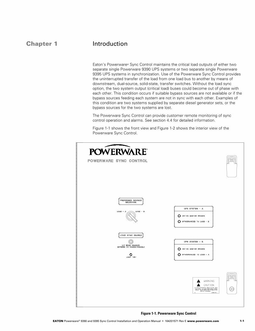
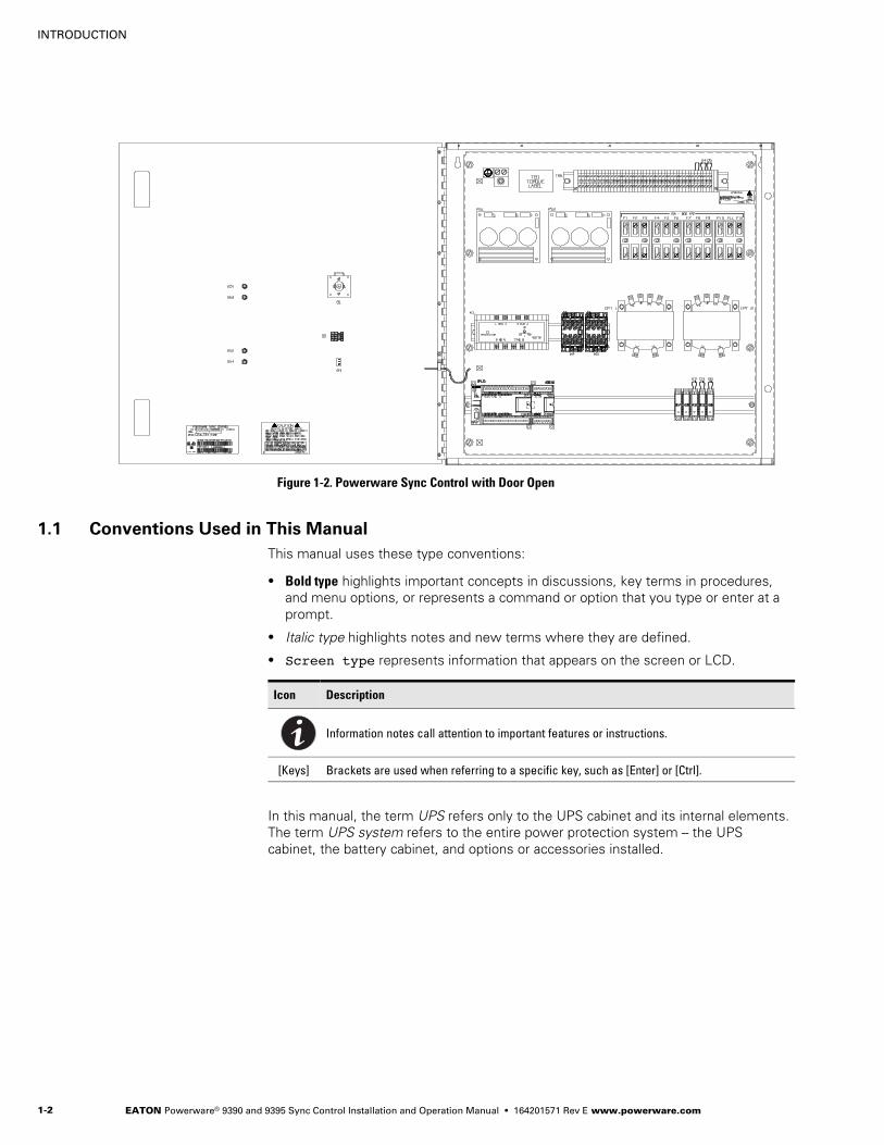
Figure 1-1 shows the front view and Figure 1-2 shows the interior view of the
Powerware Sync Control.
Figure 1-1. Powerware Sync Control
Figure 1Table 1
INTRODUCTION
EATON Powerware® 9390 and 9395 Sync Control Installation and Operation Manual � 164201571 Rev E www.powerware.com1−2
Figure 1-2. Powerware Sync Control with Door Open
1.1 Conventions Used in This Manual
This manual uses these type conventions:
� Bold type highlights important concepts in discussions, key terms in procedures,
and menu options, or represents a command or option that you type or enter at a
prompt.
� Italic type highlights notes and new terms where they are defined.
� Screen type represents information that appears on the screen or LCD.
Icon Description
Information notes call attention to important features or instructions.
[Keys] Brackets are used when referring to a specific key, such as [Enter] or [Ctrl].
In this manual, the term UPS refers only to the UPS cabinet and its internal elements.
The term UPS system refers to the entire power protection system – the UPS
cabinet, the battery cabinet, and options or accessories installed.
INTRODUCTION
EATON Powerware® 9390 and 9395 Sync Control Installation and Operation Manual � 164201571 Rev E www.powerware.com 1−3
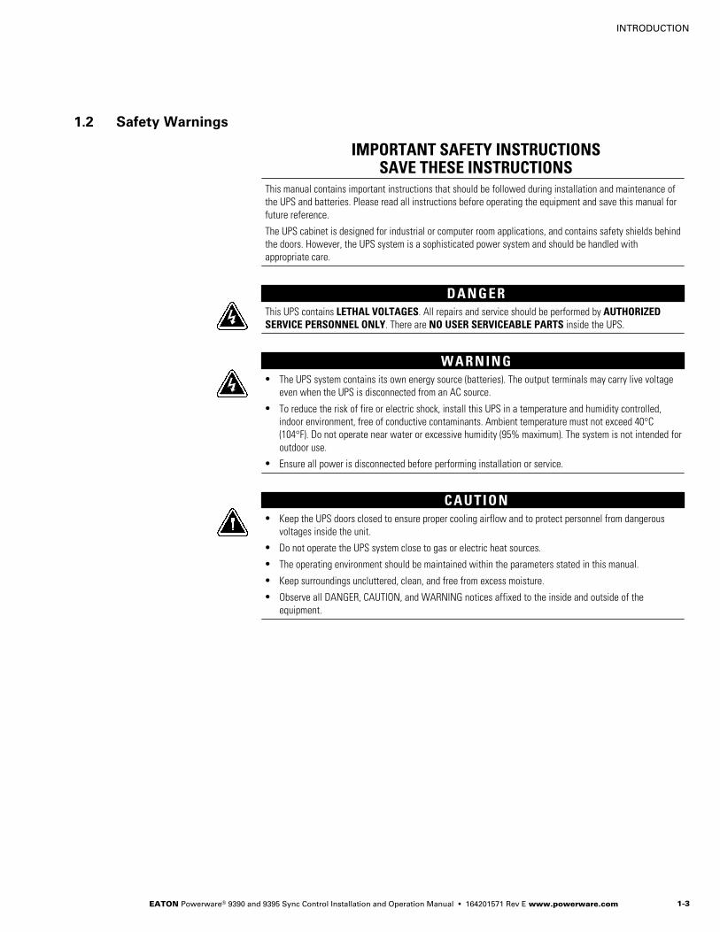
1.2 Safety Warnings
IMPORTANT SAFETY INSTRUCTIONSSAVE THESE INSTRUCTIONS
This manual contains important instructions that should be followed during installation and maintenance of
the UPS and batteries. Please read all instructions before operating the equipment and save this manual for
future reference.
The UPS cabinet is designed for industrial or computer room applications, and contains safety shields behind
the doors. However, the UPS system is a sophisticated power system and should be handled with
appropriate care.
D A N G E RThis UPS contains LETHAL VOLTAGES. All repairs and service should be performed by AUTHORIZEDSERVICE PERSONNEL ONLY. There are NO USER SERVICEABLE PARTS inside the UPS.
W A R N I N G� The UPS system contains its own energy source (batteries). The output terminals may carry live voltage
even when the UPS is disconnected from an AC source.
� To reduce the risk of fire or electric shock, install this UPS in a temperature and humidity controlled,
indoor environment, free of conductive contaminants. Ambient temperature must not exceed 40°C
(104°F). Do not operate near water or excessive humidity (95% maximum). The system is not intended for
outdoor use.
� Ensure all power is disconnected before performing installation or service.
C A U T I O N� Keep the UPS doors closed to ensure proper cooling airflow and to protect personnel from dangerous
voltages inside the unit.
� Do not operate the UPS system close to gas or electric heat sources.
� The operating environment should be maintained within the parameters stated in this manual.
� Keep surroundings uncluttered, clean, and free from excess moisture.
� Observe all DANGER, CAUTION, and WARNING notices affixed to the inside and outside of the
equipment.

INTRODUCTION
EATON Powerware® 9390 and 9395 Sync Control Installation and Operation Manual � 164201571 Rev E www.powerware.com1−4
1.3 For More Information
Refer to the followong manuals for additional information:
� Powerware 9390 UPS (40–80 kVA) Installation and Operation Manual
� Powerware 9390 UPS (100–160 kVA) Installation and Operation Manual
� Powerware 9395 UPS (225–275 kVA) Installation and Operation Manual
� Powerware 9395 Plus 1 UPS (225–275 kVA) Installation and Operation Manual
� Powerware 9395 UPS (300 kVA) Installation and Operation Manual
� Powerware 9395 550/275 UPS (225–550 kVA) Installation and Operation Manual
� Powerware 9395 UPS and Plus 1 UPS (450–550 kVA) Installation and Operation
Manual
� Powerware 9395 UPS and Plus 1 UPS (650–825 kVA) Installation and Operation
Manual
� Powerware 9395 UPS (1000–1100 kVA) Installation and Operation Manual
These manuals describe:
� UPS cabinet, optional components, and accessory installation instructions,
including site preparation, planning for installation, and wiring and safety
information. Detailed illustrations of cabinets and optional accessories with
dimensional and connection point drawings are provided.
� UPS operation, including UPS cabinet controls, functions of the UPS, standard
features and optional accessories, procedures for starting and stopping the UPS,
and information about maintenance and responding to system events.
� Communication capabilities of the UPS system.
Visit www.powerware.com or contact Eaton service representative for information on
how to obtain copies of these manuals.
1.4 Getting Help
If help is needed with any of the following:
� Scheduling initial startup
� Regional locations and telephone numbers
� A question about any of the information in this manual
� A question this manual does not answer
Please call the Eaton Help Desk for Eaton Corporation products at:
United States: 1−800−843−9433 or 1−919−870−3028
Canada: 1−800−461−9166 ext 260
All other countries: Call your local service representative
EATON Powerware® 9390 and 9395 Sync Control Installation and Operation Manual � 164201571 Rev E www.powerware.com 2−1
Chapter 2 Installation Plan and Unpacking
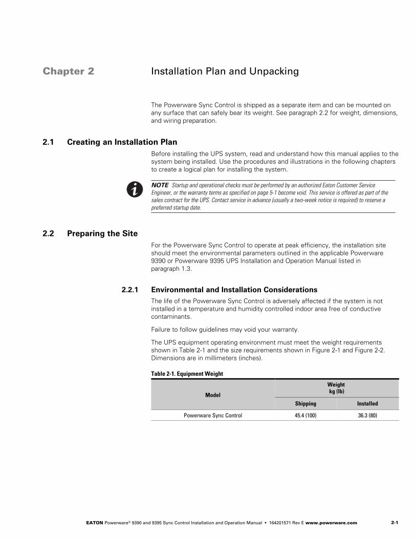
The Powerware Sync Control is shipped as a separate item and can be mounted on
any surface that can safely bear its weight. See paragraph 2.2 for weight, dimensions,
and wiring preparation.
2.1 Creating an Installation Plan
Before installing the UPS system, read and understand how this manual applies to the
system being installed. Use the procedures and illustrations in the following chapters
to create a logical plan for installing the system.
NOTE Startup and operational checks must be performed by an authorized Eaton Customer Service
Engineer, or the warranty terms as specified on page 5−1 become void. This service is offered as part of the
sales contract for the UPS. Contact service in advance (usually a two−week notice is required) to reserve a
preferred startup date.
2.2 Preparing the Site
For the Powerware Sync Control to operate at peak efficiency, the installation site
should meet the environmental parameters outlined in the applicable Powerware
9390 or Powerware 9395 UPS Installation and Operation Manual listed in
paragraph 1.3.
2.2.1 Environmental and Installation Considerations
The life of the Powerware Sync Control is adversely affected if the system is not
installed in a temperature and humidity controlled indoor area free of conductive
contaminants.
Failure to follow guidelines may void your warranty.
The UPS equipment operating environment must meet the weight requirements
shown in Table 2-1 and the size requirements shown in Figure 2-1 and Figure 2-2.
Dimensions are in millimeters (inches).
Table 2-1. Equipment Weight
Model
Weight kg (lb)
Shipping Installed
Powerware Sync Control 45.4 (100) 36.3 (80)
Figure 2Table 2
INSTALLATION PLAN AND UNPACKING
EATON Powerware® 9390 and 9395 Sync Control Installation and Operation Manual � 164201571 Rev E www.powerware.com2−2
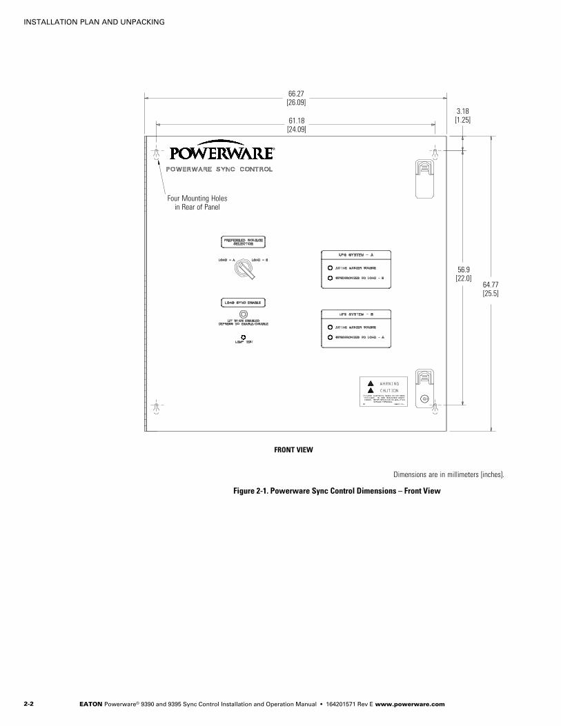
FRONT VIEW
66.27[26.09]
Dimensions are in millimeters [inches].
61.18[24.09]
Four Mounting Holesin Rear of Panel
3.18[1.25]
56.9[22.0]
64.77[25.5]
Figure 2-1. Powerware Sync Control Dimensions – Front View
INSTALLATION PLAN AND UNPACKING
EATON Powerware® 9390 and 9395 Sync Control Installation and Operation Manual � 164201571 Rev E www.powerware.com 2−3
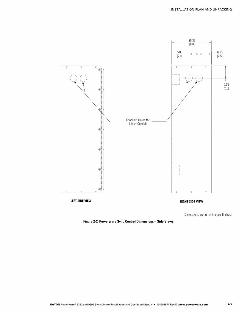
LEFT SIDE VIEW RIGHT SIDE VIEW
Knockout Holes for1−Inch Conduit
Dimensions are in millimeters [inches].
20.32[8.0]
5.08[2.0]
6.35[2.5]
6.35[2.5]
Figure 2-2. Powerware Sync Control Dimensions – Side Views
INSTALLATION PLAN AND UNPACKING
EATON Powerware® 9390 and 9395 Sync Control Installation and Operation Manual � 164201571 Rev E www.powerware.com2−4
2.2.2 Powerware Sync Control Wiring Preparation
Read and understand the following notes while planning and performing the
installation:
� Refer to national and local electrical codes for acceptable external wiring practices.
� Material and labor for external wiring requirements are to be provided by
designated personnel.
� For external wiring, use 90°C copper wire with a minimum insulation rating of
600V. If wire is run in an ambient temperature greater than 30°C, higher
temperature wire and/or larger size wire may be necessary. See the applicable
wiring information in Table 3-1 on page 3−2 and Table 3-2 on page 3−3 for the
Powerware 9390 UPS, and the applicable wiring information in Table 3-3 on
page 3−8 and Table 3-2 on page 3−3 for the Powerware 9395 UPS.
� Use 14 AWG wiring with a minimum insulation rating of 600V for interconnections
between the Powerware Sync Control, the UPS, and the customer remote
monitoring system.
� Use Class 1 wiring methods (as defined by the NEC®) for interface wiring up to
30V. The wire should be rated at 24V, 1A minimum.
� Use Class 2 wiring methods (as defined by the NEC) for interface wiring from
30 to 600V. The wire should be rated at 600V, 1A minimum and 12 AWG
maximum.
� Sync Control dry contacts are rated at 5–30 Vdc/250 Vac at 2A per contact
(maximum load).
� When installing external wiring between the Powerware Sync Control and the
UPS, conduit must be installed between the Sync Control and the UPS cabinet.
� The Powerware Sync Control can be installed up to a maximum of 152.4m (500 ft)
from the Powerware 9390 or Powerware 9395 UPS system.
C A U T I O NWhen connecting the bypass and load voltage from another model UPS to a Powerware 9390 or Powerware
9395 UPS using the Powerware Sync Control accessory, use Phase A, Phase B, and Neutral connections from
the other UPS. DO NOT connect the other model UPS Phase C bypass and load voltage to the Sync Control
connection point when connecting to a Powerware 9390 or Powerware 9395 UPS.
2.3 Inspecting and Unpacking the Powerware Sync Control
The unit arrives covered with protective packaging material.
1. Carefully inspect the outer packaging for evidence of damage during transit.
C A U T I O NDo not install a damaged cabinet. Report any damage to the carrier and contact Eaton service representative
immediately.
2. Remove the protective cardboard covering from the Powerware Sync Control by
cutting where indicated using a knife blade no longer than 25 mm (1").
3. Remove the plastic bag and foam packing material, and discard or recycle them
in a responsible manner.

EATON Powerware® 9390 and 9395 Sync Control Installation and Operation Manual � 164201571 Rev E www.powerware.com 3−1
Chapter 3 Powerware Sync Control Installation
W A R N I N G� Only qualified service personnel (such as a licensed electrician) shall perform the electrical installation. Risk
of electrical shock.
� Shut down all sources of power to the Powerware 9390 or Powerware 9395 UPS system before connecting
the control wiring to the Powerware Sync Control enclosure and UPS. Hazardous voltages exist inside the
UPS and in the Powerware Sync Control enclosure. Check all terminal conductors with a known serviceable
voltmeter before connecting the wiring.
Once the Powerware Sync Control has been moved to its installed location,
unpacked, and inspected, it is ready for installation and wiring.
Use the applicable procedure from the following list to install the Powerware Sync
Control to the UPS:
� With a Powerware 9390 UPS, proceed to paragraph 3.1.
� With a Powerware 9395 UPS, proceed to paragraph 3.2.
3.1 Installation and Wiring with a Powerware 9390 UPS
NOTE When installing wiring connections, conduit must be installed between the Powerware Sync Control and
the UPS cabinet. Conduit also must be installed between the Powerware Sync Control and the customer’s remote
monitoring system.
To install and wire:
1. Install the Powerware Sync Control panel to the selected mounting location.
See Figure 2-1 on page 2−2 for mounting hole dimensions and Figure 2-2 on
page 2−3 for conduit entrance locations.
2. Unfasten the front door latches and swing the door open.
3. Complete all control wiring interconnections using Table 3-1 for wiring
requirements.
Figure 3-1 on page 3−3 shows the Powerware Sync Control TB1 terminal block
and ground terminal locations. Figure 3-2 on page 3−4 shows the TB1 terminal
block wiring detail.
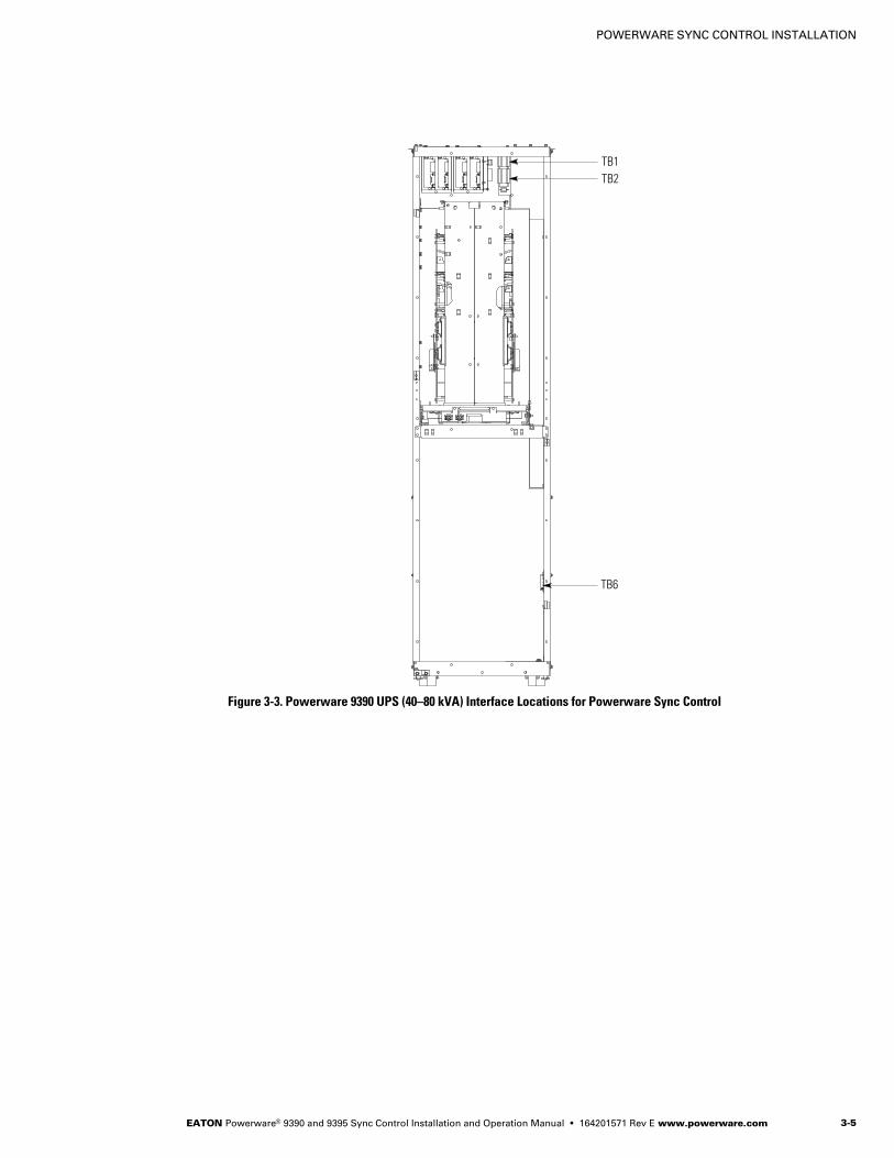
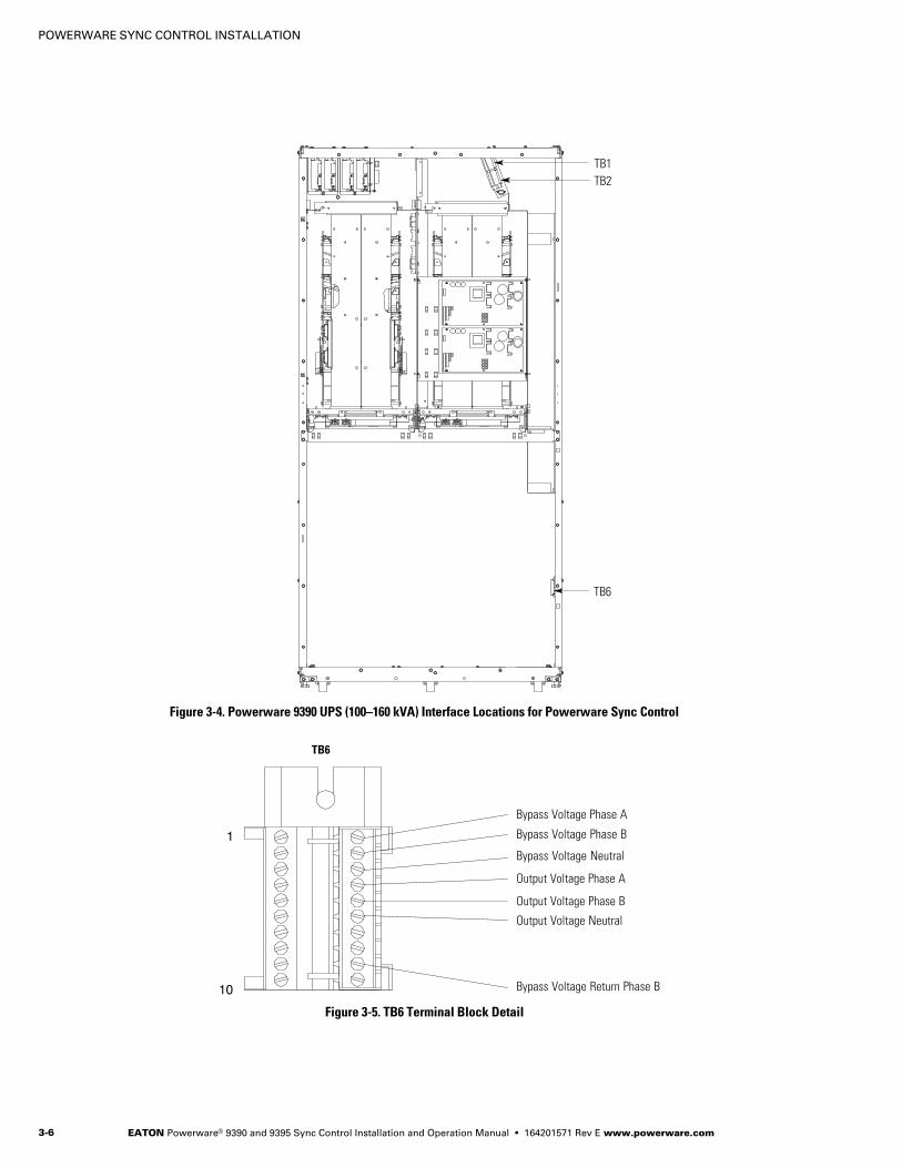
Figure 3-3 on page 3−5 and Figure 3-4 on page 3−6 show the typical locations of
the UPS TB1, TB2, and TB6 interconnect terminal blocks. Figure 3-5 on
page 3−6 shows the TB6 detail.
Refer to the applicable Powerware 9390 UPS Installation and Operation Manual
listed in paragraph 1.3 on page 1−4 for UPS cabinet terminal locations and
assignments, termination requirements, conduit landing locations, and terminal
access instructions.
4. Verify the jumper is installed between Sync Control terminal TB1−40 and TB1−41
(see Figure 3-2 on page 3−4).
Figure 3Table 3
POWERWARE SYNC CONTROL INSTALLATION
EATON Powerware® 9390 and 9395 Sync Control Installation and Operation Manual � 164201571 Rev E www.powerware.com3−2
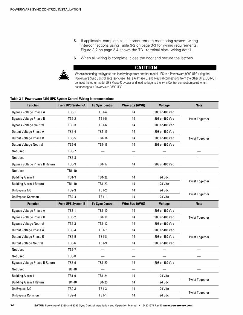
5. If applicable, complete all customer remote monitoring system wiring
interconnections using Table 3-2 on page 3−3 for wiring requirements.
Figure 3-2 on page 3−4 shows the TB1 terminal block wiring detail.
6. When all wiring is complete, close the door and secure the latches.
C A U T I O NWhen connecting the bypass and load voltage from another model UPS to a Powerware 9390 UPS using the
Powerware Sync Control accessory, use Phase A, Phase B, and Neutral connections from the other UPS. DO NOT
connect the other model UPS Phase C bypass and load voltage to the Sync Control connection point when
connecting to a Powerware 9390 UPS.
Table 3-1. Powerware 9390 UPS System Control Wiring Interconnections
Function From UPS System−A To Sync Control Wire Size (AWG) Voltage Note
Bypass Voltage Phase A TB6−1 TB1−4 14 208 or 480 Vac
Twist TogetherBypass Voltage Phase B TB6−2 TB1−5 14 208 or 480 Vac
Bypass Voltage Neutral TB6−3 TB1−6 14 208 or 480 Vac
Output Voltage Phase A TB6−4 TB1−13 14 208 or 480 Vac
Twist TogetherOutput Voltage Phase B TB6−5 TB1−14 14 208 or 480 Vac
Output Voltage Neutral TB6−6 TB1−15 14 208 or 480 Vac
Not Used TB6−7 � � � �
Not Used TB6−8 � � � �
Bypass Voltage Phase B Return TB6−9 TB1−17 14 208 or 480 Vac
Not Used TB6−10 � � � �
Building Alarm 1 TB1−9 TB1−22 14 24 VdcTwist Together
Building Alarm 1 Return TB1−10 TB1−23 14 24 Vdc
On Bypass NO TB2−3 TB1−2 14 24 VdcTwist Together
On Bypass Common TB2−4 TB1−1 14 24 Vdc
Function From UPS System−B To Sync Control Wire Size (AWG) Voltage Note
Bypass Voltage Phase A TB6−1 TB1−10 14 208 or 480 Vac
Twist TogetherBypass Voltage Phase B TB6−2 TB1−11 14 208 or 480 Vac
Bypass Voltage Neutral TB6−3 TB1−12 14 208 or 480 Vac
Output Voltage Phase A TB6−4 TB1−7 14 208 or 480 Vac
Twist TogetherOutput Voltage Phase B TB6−5 TB1−8 14 208 or 480 Vac
Output Voltage Neutral TB6−6 TB1−9 14 208 or 480 Vac
Not Used TB6−7 � � � �
Not Used TB6−8 � � � �
Bypass Voltage Phase B Return TB6−9 TB1−20 14 208 or 480 Vac
Not Used TB6−10 � � � �
Building Alarm 1 TB1−9 TB1−24 14 24 VdcTwist Together
Building Alarm 1 Return TB1−10 TB1−25 14 24 Vdc
On Bypass NO TB2−3 TB1−3 14 24 VdcTwist Together
On Bypass Common TB2−4 TB1−1 14 24 Vdc
POWERWARE SYNC CONTROL INSTALLATION
EATON Powerware® 9390 and 9395 Sync Control Installation and Operation Manual � 164201571 Rev E www.powerware.com 3−3
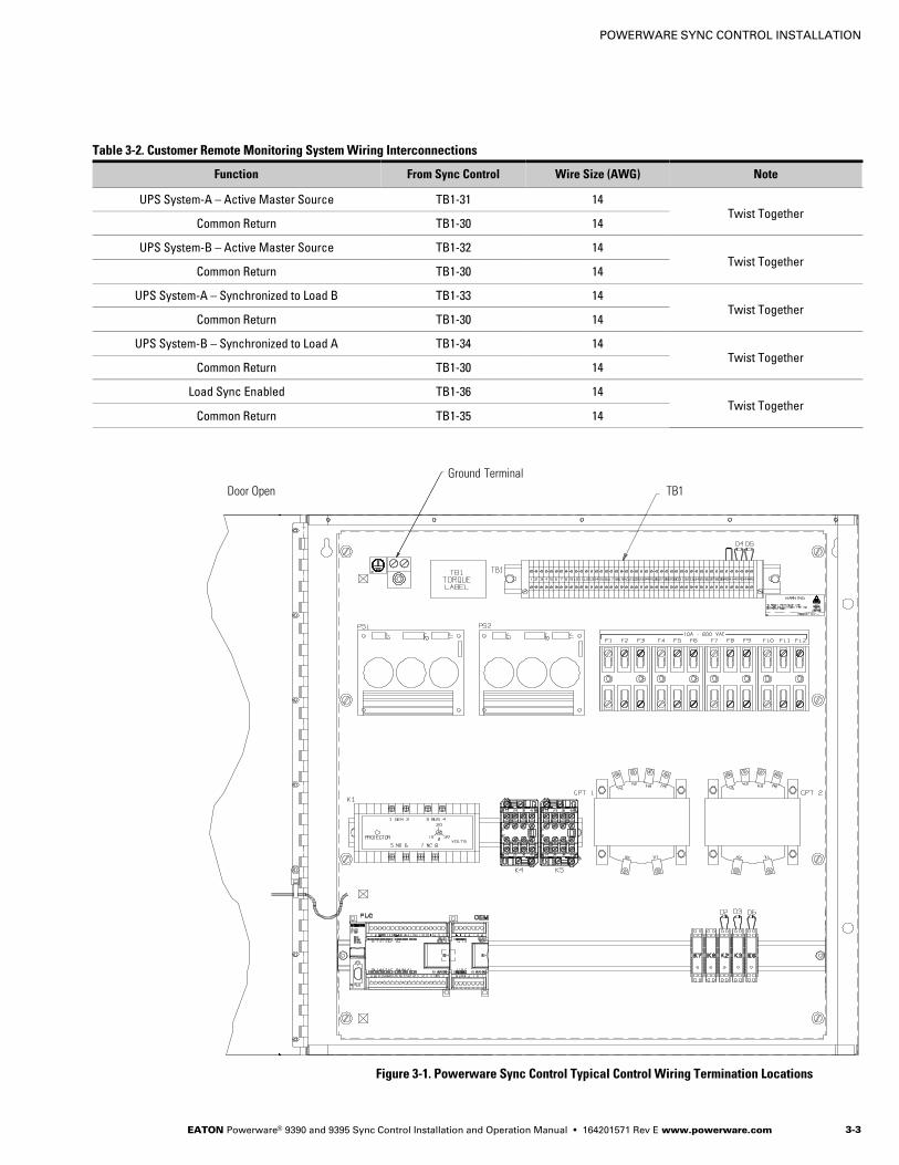
Table 3-2. Customer Remote Monitoring System Wiring Interconnections
Function From Sync Control Wire Size (AWG) Note
UPS System−A – Active Master Source TB1−31 14Twist Together
Common Return TB1−30 14
UPS System−B – Active Master Source TB1−32 14Twist Together
Common Return TB1−30 14
UPS System−A – Synchronized to Load B TB1−33 14Twist Together
Common Return TB1−30 14
UPS System−B – Synchronized to Load A TB1−34 14Twist Together
Common Return TB1−30 14
Load Sync Enabled TB1−36 14Twist Together
Common Return TB1−35 14
TB1Door Open
Ground Terminal
Figure 3-1. Powerware Sync Control Typical Control Wiring Termination Locations

POWERWARE SYNC CONTROL INSTALLATION
EATON Powerware® 9390 and 9395 Sync Control Installation and Operation Manual � 164201571 Rev E www.powerware.com3−4
UPS System−A – Bypass Voltage Phase A
UPS System−A – Bypass Voltage Phase B Return
UPS System−A – Bypass Voltage Phase B
UPS System−A – Bypass Voltage Neutral
UPS System−B – Bypass Voltage Phase A
UPS System−B – Bypass Voltage Phase B
UPS System−B – Bypass Voltage Neutral
UPS System−B – Bypass Voltage Phase B Return
UPS System−A – Output Voltage Phase A
UPS System−A – Output Voltage Phase B
UPS System−A – Output Voltage Neutral
UPS System−B – Output Voltage Phase A
UPS System−B – Output Voltage Phase B
UPS System−B – Output Voltage Neutral
On Bypass Common
UPS System−A – On Bypass NO
UPS System−B – On Bypass NO
UPS System−A – Building Alarm 1 (see Note)
UPS System−A – Building Alarm 1 Return
UPS System−B – Building Alarm 1 (see Note)
UPS System−B – Building Alarm 1 Return
Jumper
Common Return
UPS System−A – Active Master Source
UPS System−B – Active Master Source
UPS System−A – Synchronized to Load B
UPS System−B – Synchronized to Load A
Load Sync Enabled
Common Return
NOTE 9395 UPS ONLY – If Building Alarm 1 is being used for another purpose, any unused building alarmon the 9395 UPS TB3 terminal board can be used for the Sync Control. Refer to the applicable Powerware9395 UPS Installation and Operation Manual listed in paragraph 1.3 on page 1−4 for the 9395 UPS TB3terminal assignments.
Figure 3-2. Powerware Sync Control TB1 Terminal Block Detail
POWERWARE SYNC CONTROL INSTALLATION
EATON Powerware® 9390 and 9395 Sync Control Installation and Operation Manual � 164201571 Rev E www.powerware.com 3−5
TB1
TB2
TB6
Figure 3-3. Powerware 9390 UPS (40–80 kVA) Interface Locations for Powerware Sync Control
POWERWARE SYNC CONTROL INSTALLATION
EATON Powerware® 9390 and 9395 Sync Control Installation and Operation Manual � 164201571 Rev E www.powerware.com3−6
TB6
TB1
TB2
Figure 3-4. Powerware 9390 UPS (100–160 kVA) Interface Locations for Powerware Sync Control
1
10
Bypass Voltage Neutral
Bypass Voltage Phase A
Bypass Voltage Phase B
Output Voltage Phase A
Output Voltage Phase B
Output Voltage Neutral
Bypass Voltage Return Phase B
TB6
Figure 3-5. TB6 Terminal Block Detail

POWERWARE SYNC CONTROL INSTALLATION
EATON Powerware® 9390 and 9395 Sync Control Installation and Operation Manual � 164201571 Rev E www.powerware.com 3−7
3.2 Installation and Wiring with a Powerware 9395 UPS
NOTE When installing wiring connections, conduit must be installed between the Powerware Sync Control and
the UPS cabinet. Conduit also must be installed between the Powerware Sync Control and the customer’s remote
monitoring system.
To install and wire:
1. Install the Powerware Sync Control panel to the selected mounting location.
See Figure 2-1 on page 2−2 for mounting hole dimensions and Figure 2-2 on
page 2−3 for conduit entrance locations.
2. Unfasten the front door latches and swing the door open.
3. Complete all control wiring interconnections using Table 3-3 for wiring
requirements.
Figure 3-1 on page 3−3 shows the Powerware Sync Control TB1 terminal block
and ground terminal locations. Figure 3-2 on page 3−4 shows the TB1 terminal
block wiring detail.
Figure 3-6 through Figure 3-9 starting on page 3−9 show the typical locations of
the UPS TB3, TB6, and X−Slot® Relay Interface Card interconnect terminal blocks.
Figure 3-5 on page 3−6 shows the TB6 detail.
Refer to the applicable Powerware 9395 UPS Installation and Operation Manual
listed in paragraph 1.3 on page 1−4 for UPS cabinet terminal locations and
assignments, termination requirements, conduit landing locations, and terminal
access instructions.
NOTE Complete the wiring to the X−Slot Relay Interface Card terminals before installing the cards in the
Communication Bay in each of the UPS cabinets.
4. Route wires through the strain relief bushing and connect to the terminals on the
X−Slot Relay Interface Card in each of the UPS cabinets (see Figure 3-10 on
page 3−13 and Figure 3-11 on page 3−13).
5. Install the X−Slot Relay Interface Card into an open X−Slot communication bay on
the front of the UPS (see Figure 3-6 on page 3−9, Figure 3-7 on page 3−10,
Figure 3-8 on page 3−11, or Figure 3-9 on page 3−12). Refer to the applicable
Powerware 9395 UPS Installation and Operation Manual listed in paragraph 1.3
on page 1−4 for UPS cabinet access instructions.
6. Verify the jumper is installed between Sync Control terminal TB1−40 and TB1−41
(see Figure 3-2 on page 3−4).
7. If applicable, complete all customer remote monitoring system wiring
interconnections using Table 3-2 on page 3−3 for wiring requirements.
Figure 3-2 on page 3−4 shows the TB1 terminal block wiring detail.
8. When all wiring is complete, close the door and secure the latch.
C A U T I O NWhen connecting the bypass and load voltage from another model UPS to a Powerware 9395 UPS using the
Powerware Sync Control accessory, use Phase A, Phase B, and Neutral connections from the other UPS. DO NOT
connect the other model UPS Phase C bypass and load voltage to the Sync Control connection point when
connecting to a Powerware 9395 UPS.
POWERWARE SYNC CONTROL INSTALLATION
EATON Powerware® 9390 and 9395 Sync Control Installation and Operation Manual � 164201571 Rev E www.powerware.com3−8
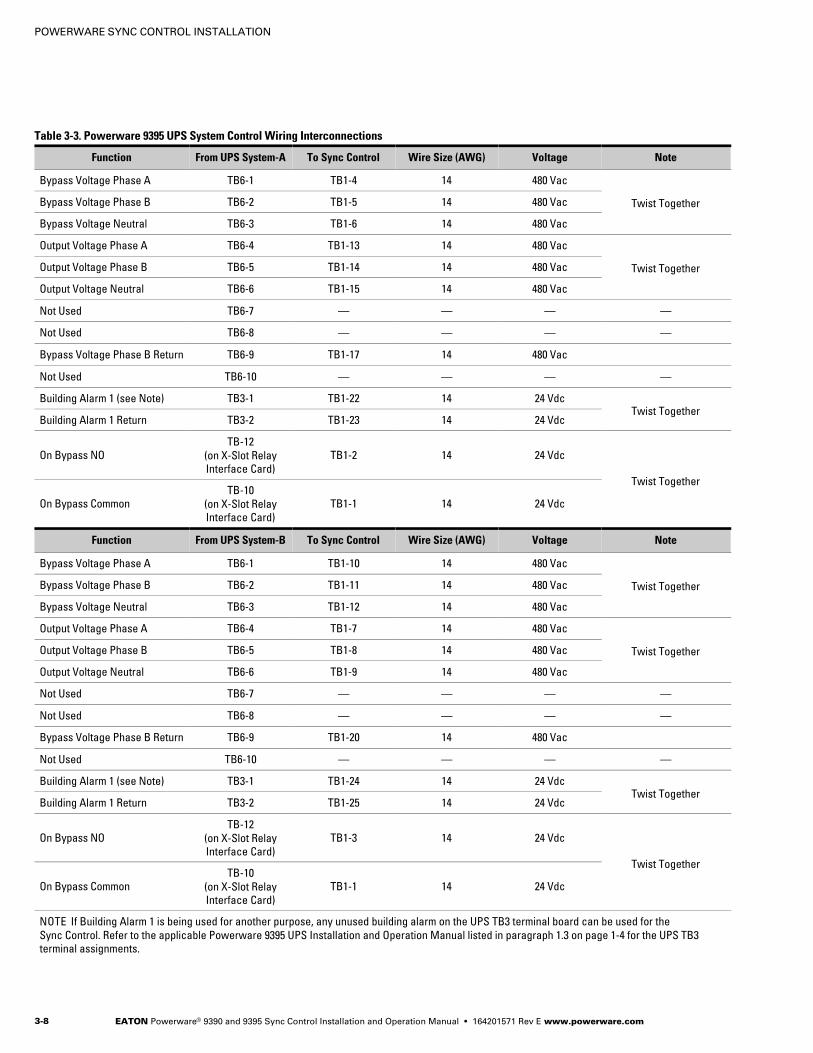
Table 3-3. Powerware 9395 UPS System Control Wiring Interconnections
Function From UPS System−A To Sync Control Wire Size (AWG) Voltage Note
Bypass Voltage Phase A TB6−1 TB1−4 14 480 Vac
Twist TogetherBypass Voltage Phase B TB6−2 TB1−5 14 480 Vac
Bypass Voltage Neutral TB6−3 TB1−6 14 480 Vac
Output Voltage Phase A TB6−4 TB1−13 14 480 Vac
Twist TogetherOutput Voltage Phase B TB6−5 TB1−14 14 480 Vac
Output Voltage Neutral TB6−6 TB1−15 14 480 Vac
Not Used TB6−7 � � � �
Not Used TB6−8 � � � �
Bypass Voltage Phase B Return TB6−9 TB1−17 14 480 Vac
Not Used TB6−10 � � � �
Building Alarm 1 (see Note) TB3−1 TB1−22 14 24 VdcTwist Together
Building Alarm 1 Return TB3−2 TB1−23 14 24 Vdc
On Bypass NO
TB−12
(on X−Slot Relay
Interface Card)
TB1−2 14 24 Vdc
Twist Together
On Bypass Common
TB−10
(on X−Slot Relay
Interface Card)
TB1−1 14 24 Vdc
Function From UPS System−B To Sync Control Wire Size (AWG) Voltage Note
Bypass Voltage Phase A TB6−1 TB1−10 14 480 Vac
Twist TogetherBypass Voltage Phase B TB6−2 TB1−11 14 480 Vac
Bypass Voltage Neutral TB6−3 TB1−12 14 480 Vac
Output Voltage Phase A TB6−4 TB1−7 14 480 Vac
Twist TogetherOutput Voltage Phase B TB6−5 TB1−8 14 480 Vac
Output Voltage Neutral TB6−6 TB1−9 14 480 Vac
Not Used TB6−7 � � � �
Not Used TB6−8 � � � �
Bypass Voltage Phase B Return TB6−9 TB1−20 14 480 Vac
Not Used TB6−10 � � � �
Building Alarm 1 (see Note) TB3−1 TB1−24 14 24 VdcTwist Together
Building Alarm 1 Return TB3−2 TB1−25 14 24 Vdc
On Bypass NO
TB−12
(on X−Slot Relay
Interface Card)
TB1−3 14 24 Vdc
Twist Together
On Bypass Common
TB−10
(on X−Slot Relay
Interface Card)
TB1−1 14 24 Vdc
NOTE If Building Alarm 1 is being used for another purpose, any unused building alarm on the UPS TB3 terminal board can be used for the
Sync Control. Refer to the applicable Powerware 9395 UPS Installation and Operation Manual listed in paragraph 1.3 on page 1−4 for the UPS TB3
terminal assignments.
POWERWARE SYNC CONTROL INSTALLATION
EATON Powerware® 9390 and 9395 Sync Control Installation and Operation Manual � 164201571 Rev E www.powerware.com 3−9
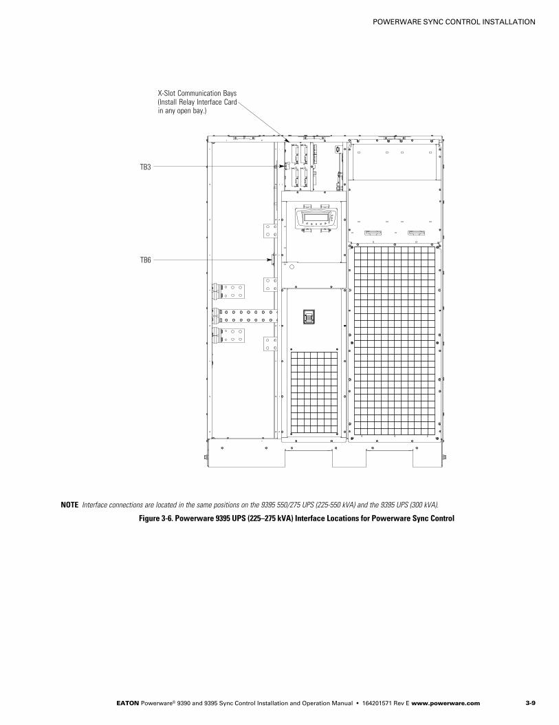
TB3
TB6
NOTE Interface connections are located in the same positions on the 9395 550/275 UPS (225−550 kVA) and the 9395 UPS (300 kVA).
X−Slot Communication Bays(Install Relay Interface Cardin any open bay.)
Figure 3-6. Powerware 9395 UPS (225–275 kVA) Interface Locations for Powerware Sync Control
POWERWARE SYNC CONTROL INSTALLATION
EATON Powerware® 9390 and 9395 Sync Control Installation and Operation Manual � 164201571 Rev E www.powerware.com3−10
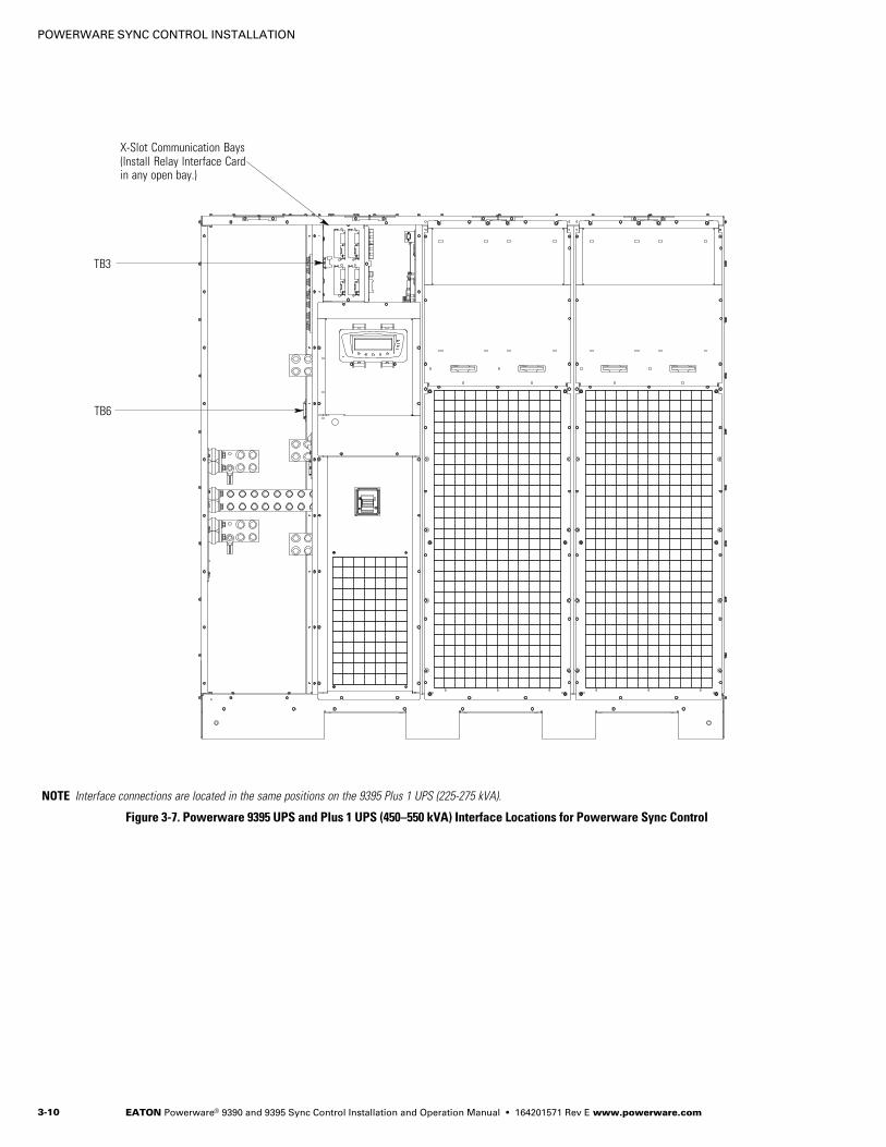
TB3
TB6
NOTE Interface connections are located in the same positions on the 9395 Plus 1 UPS (225−275 kVA).
X−Slot Communication Bays(Install Relay Interface Cardin any open bay.)
Figure 3-7. Powerware 9395 UPS and Plus 1 UPS (450–550 kVA) Interface Locations for Powerware Sync Control

POWERWARE SYNC CONTROL INSTALLATION
EATON Powerware® 9390 and 9395 Sync Control Installation and Operation Manual � 164201571 Rev E www.powerware.com 3−11
TB3
TB6
X−Slot Communication Bays(Install Relay Interface Cardin any open bay.)
ISBM SECTION
Figure 3-8. Powerware 9395 UPS and Plus 1 UPS (650–825 kVA) Interface Locations for Powerware Sync Control
POWERWARE SYNC CONTROL INSTALLATION
EATON Powerware® 9390 and 9395 Sync Control Installation and Operation Manual � 164201571 Rev E www.powerware.com3−12
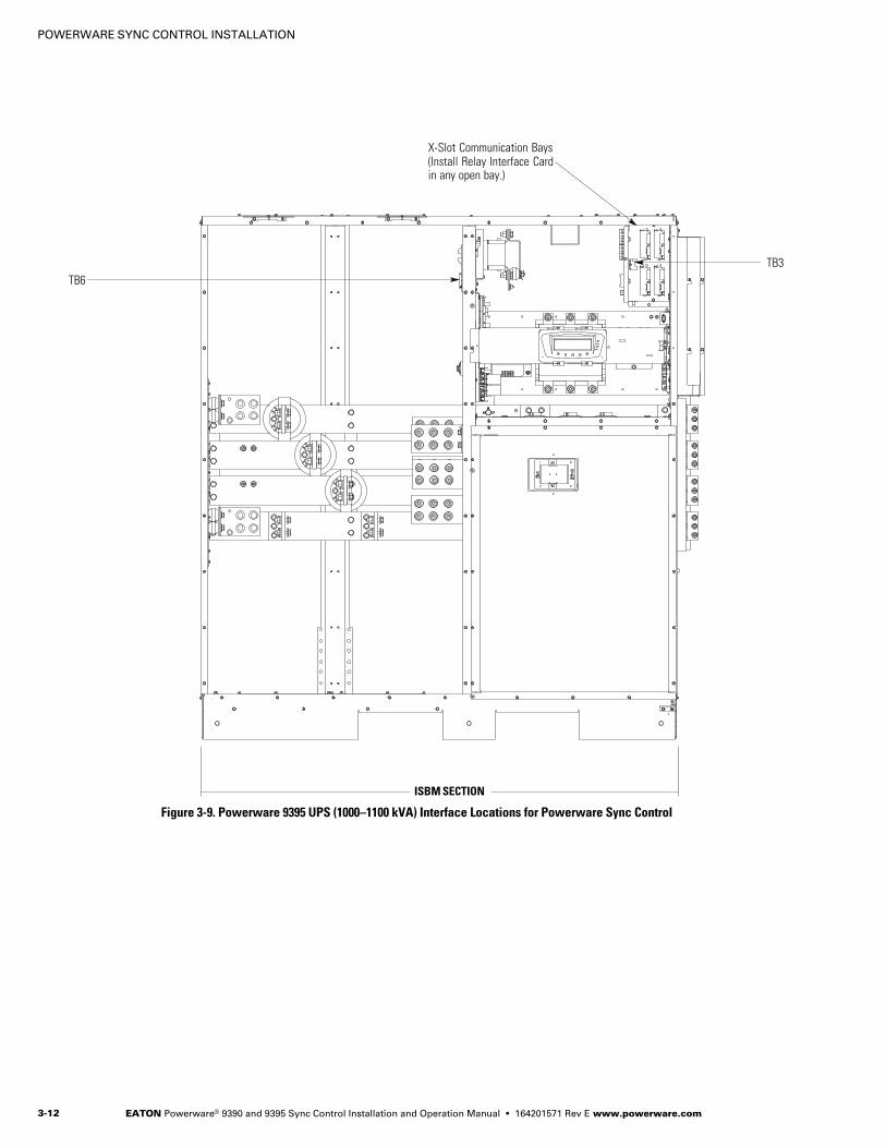
TB3
TB6
X−Slot Communication Bays(Install Relay Interface Cardin any open bay.)
ISBM SECTION
Figure 3-9. Powerware 9395 UPS (1000–1100 kVA) Interface Locations for Powerware Sync Control
POWERWARE SYNC CONTROL INSTALLATION
EATON Powerware® 9390 and 9395 Sync Control Installation and Operation Manual � 164201571 Rev E www.powerware.com 3−13
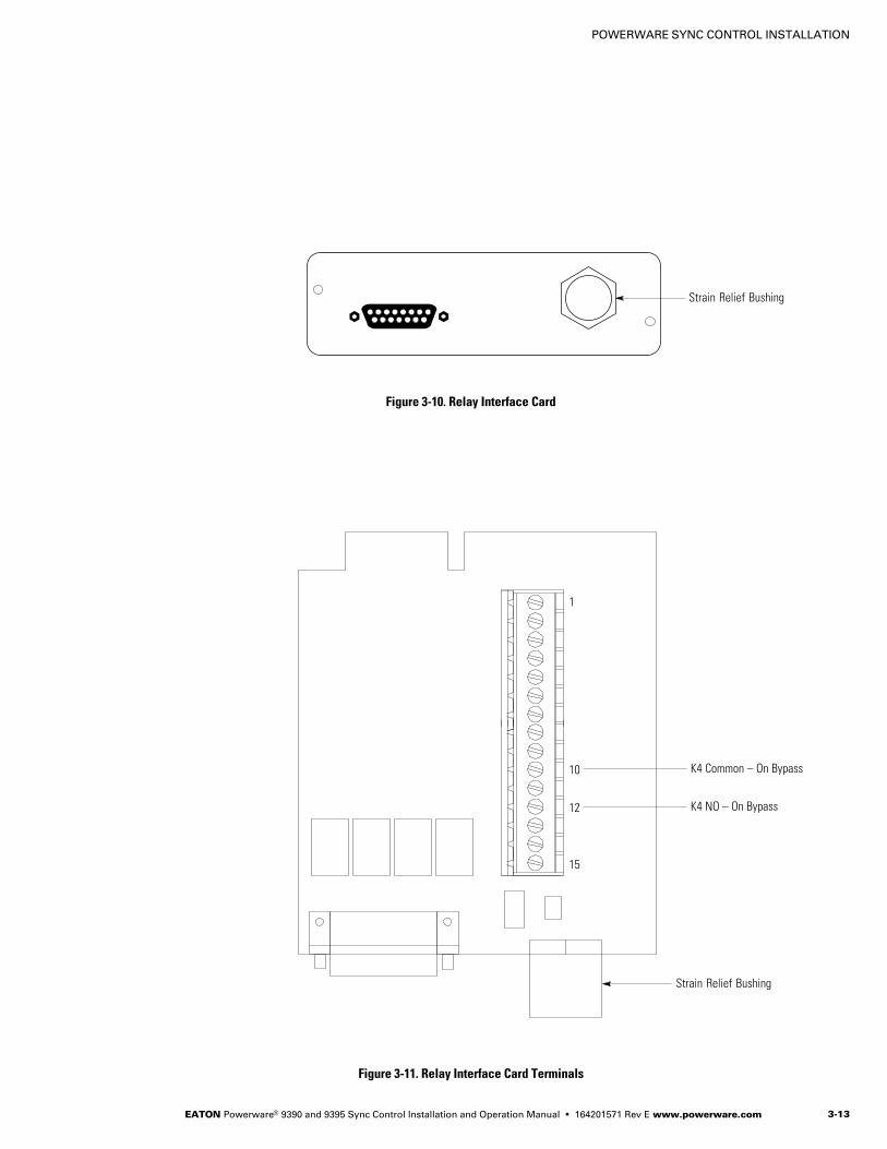
Strain Relief Bushing
Figure 3-10. Relay Interface Card
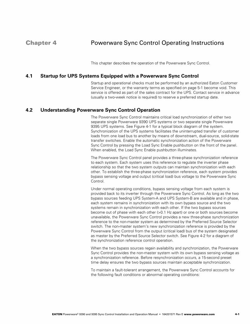
1
15
K4 NO – On Bypass12
10 K4 Common – On Bypass
Strain Relief Bushing
Figure 3-11. Relay Interface Card Terminals

POWERWARE SYNC CONTROL INSTALLATION
EATON Powerware® 9390 and 9395 Sync Control Installation and Operation Manual � 164201571 Rev E www.powerware.com3−14
This page intentionally left blank.
EATON Powerware® 9390 and 9395 Sync Control Installation and Operation Manual � 164201571 Rev E www.powerware.com 4−1
Chapter 4 Powerware Sync Control Operating Instructions
This chapter describes the operation of the Powerware Sync Control.
4.1 Startup for UPS Systems Equipped with a Powerware Sync Control
Startup and operational checks must be performed by an authorized Eaton Customer
Service Engineer, or the warranty terms as specified on page 5−1 become void. This
service is offered as part of the sales contract for the UPS. Contact service in advance
(usually a two−week notice is required) to reserve a preferred startup date.
4.2 Understanding Powerware Sync Control Operation
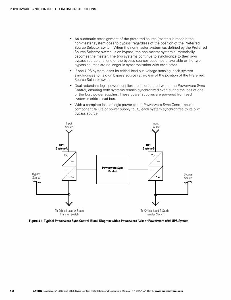
The Powerware Sync Control maintains critical load synchronization of either two
separate single Powerware 9390 UPS systems or two separate single Powerware
9395 UPS systems. See Figure 4-1 for a typical block diagram of the system.
Synchronization of the UPS systems facilitates the uninterrupted transfer of customer
loads from one load bus to another by means of downstream, dual−source, solid−state
transfer switches. Enable the automatic synchronization action of the Powerware
Sync Control by pressing the Load Sync Enable pushbutton on the front of the panel.
When enabled, the Load Sync Enable pushbutton illuminates.
The Powerware Sync Control panel provides a three−phase synchronization reference
to each system. Each system uses this reference to regulate the inverter phase
relationship so that the two system outputs can maintain synchronization with each
other. To establish the three−phase synchronization reference, each system provides
bypass sensing voltage and output (critical load) bus voltage to the Powerware Sync
Control.
Under normal operating conditions, bypass sensing voltage from each system is
provided back to its inverter through the Powerware Sync Control. As long as the two
bypass sources feeding UPS System−A and UPS System−B are available and in phase,
each system remains in synchronization with its own bypass source and the two
systems remain in synchronization with each other. If the two bypass sources
become out of phase with each other (>0.1 Hz apart) or one or both sources become
unavailable, the Powerware Sync Control provides a new three−phase synchronization
reference to the non−master system as determined by the Preferred Source Selector
switch. The non−master system’s new synchronization reference is provided by the
Powerware Sync Control from the output (critical load) bus of the system designated
as master by the Preferred Source Selector switch. See Figure 4-2 for a diagram of
the synchronization reference control operation.
When the two bypass sources regain availability and synchronization, the Powerware
Sync Control provides the non−master system with its own bypass sensing voltage as
a synchronization reference. Before resynchronization occurs, a 15−second preset
time delay ensures the two bypass sources maintain acceptable synchronization.
To maintain a fault−tolerant arrangement, the Powerware Sync Control accounts for
the following fault conditions or abnormal operating conditions:
Figure 4Table 4
POWERWARE SYNC CONTROL OPERATING INSTRUCTIONS
EATON Powerware® 9390 and 9395 Sync Control Installation and Operation Manual � 164201571 Rev E www.powerware.com4−2
� An automatic reassignment of the preferred source (master) is made if the
non−master system goes to bypass, regardless of the position of the Preferred
Source Selector switch. When the non−master system (as defined by the Preferred
Source Selector switch) is on bypass, the non−master system automatically
becomes the master. The two systems continue to synchronize to their own
bypass source until one of the bypass sources becomes unavailable or the two
bypass sources are no longer in synchronization with each other.
� If one UPS system loses its critical load bus voltage sensing, each system
synchronizes to its own bypass source regardless of the position of the Preferred
Source Selector switch.
� Dual redundant logic power supplies are incorporated within the Powerware Sync
Control, ensuring both systems remain synchronized even during the loss of one
of the logic power supplies. These power supplies are powered from each
system’s critical load bus.
� With a complete loss of logic power to the Powerware Sync Control (due to
component failure or power supply fault), each system synchronizes to its own
bypass source.
Powerware SyncControl
InputSource
UPSSystem−A
To Critical Load−A StaticTransfer Switch
InputSource
UPSSystem−B
BypassSource
To Critical Load−B StaticTransfer Switch
BypassSource
Figure 4-1. Typical Powerware Sync Control Block Diagram with a Powerware 9390 or Powerware 9395 UPS System
POWERWARE SYNC CONTROL OPERATING INSTRUCTIONS
EATON Powerware® 9390 and 9395 Sync Control Installation and Operation Manual � 164201571 Rev E www.powerware.com 4−3
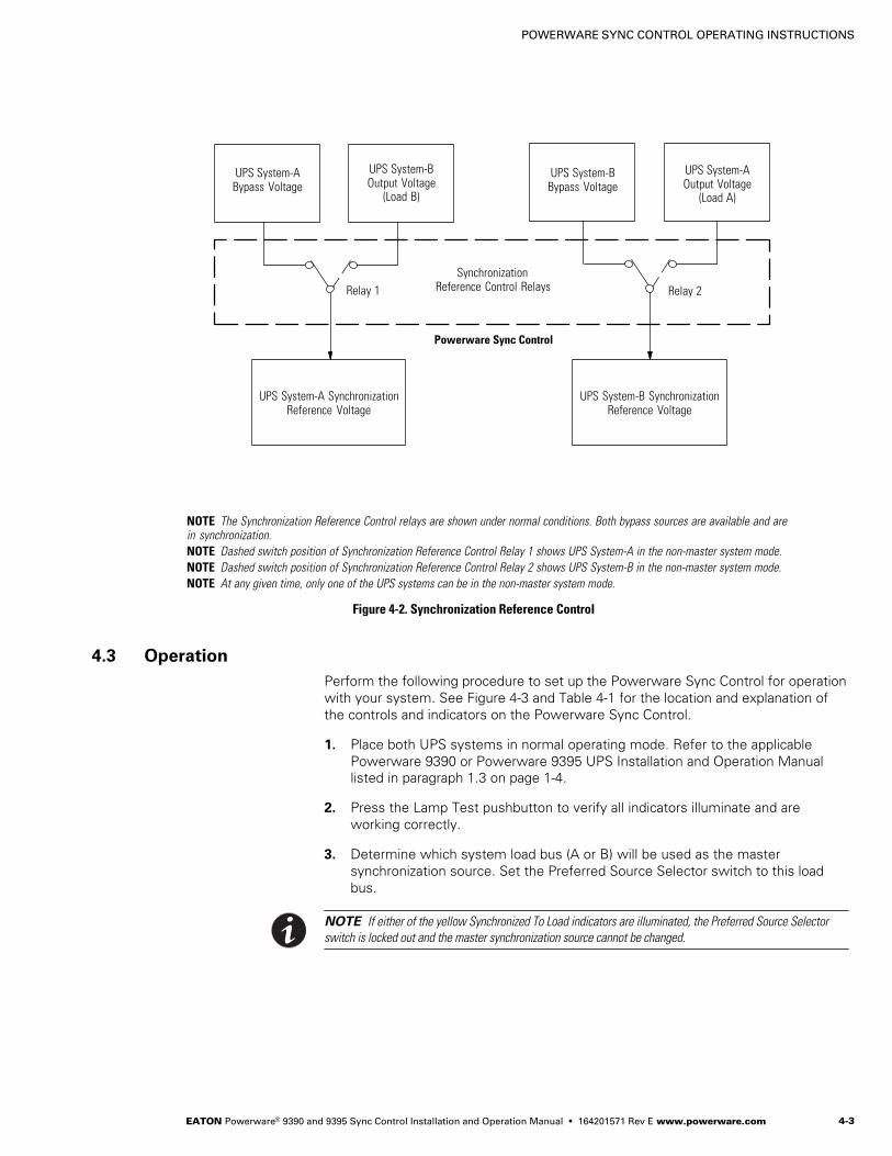
UPS System−ABypass Voltage
UPS System−BOutput Voltage
(Load B)
UPS System−BBypass Voltage
UPS System−AOutput Voltage
(Load A)
UPS System−A SynchronizationReference Voltage
UPS System−B SynchronizationReference Voltage
Powerware Sync Control
SynchronizationReference Control RelaysRelay 1 Relay 2
NOTE The Synchronization Reference Control relays are shown under normal conditions. Both bypass sources are available and arein synchronization.
NOTE Dashed switch position of Synchronization Reference Control Relay 1 shows UPS System−A in the non−master system mode.
NOTE Dashed switch position of Synchronization Reference Control Relay 2 shows UPS System−B in the non−master system mode.
NOTE At any given time, only one of the UPS systems can be in the non−master system mode.
Figure 4-2. Synchronization Reference Control
4.3 Operation
Perform the following procedure to set up the Powerware Sync Control for operation
with your system. See Figure 4-3 and Table 4-1 for the location and explanation of
the controls and indicators on the Powerware Sync Control.
1. Place both UPS systems in normal operating mode. Refer to the applicable
Powerware 9390 or Powerware 9395 UPS Installation and Operation Manual
listed in paragraph 1.3 on page 1−4.
2. Press the Lamp Test pushbutton to verify all indicators illuminate and are
working correctly.
3. Determine which system load bus (A or B) will be used as the master
synchronization source. Set the Preferred Source Selector switch to this load
bus.
NOTE If either of the yellow Synchronized To Load indicators are illuminated, the Preferred Source Selector
switch is locked out and the master synchronization source cannot be changed.
POWERWARE SYNC CONTROL OPERATING INSTRUCTIONS
EATON Powerware® 9390 and 9395 Sync Control Installation and Operation Manual � 164201571 Rev E www.powerware.com4−4
1
2
3
4
5
6
7
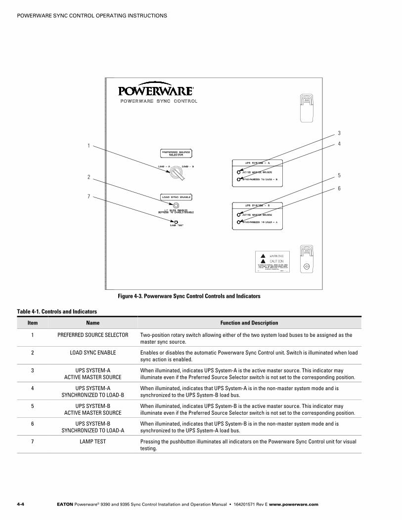
Figure 4-3. Powerware Sync Control Controls and Indicators
Table 4-1. Controls and Indicators
Item Name Function and Description
1 PREFERRED SOURCE SELECTOR Two-position rotary switch allowing either of the two system load buses to be assigned as the
master sync source.
2 LOAD SYNC ENABLE Enables or disables the automatic Powerware Sync Control unit. Switch is illuminated when load
sync action is enabled.
3 UPS SYSTEM−A
ACTIVE MASTER SOURCE
When illuminated, indicates UPS System−A is the active master source. This indicator may
illuminate even if the Preferred Source Selector switch is not set to the corresponding position.
4 UPS SYSTEM−A
SYNCHRONIZED TO LOAD−B
When illuminated, indicates that UPS System−A is in the non−master system mode and is
synchronized to the UPS System−B load bus.
5 UPS SYSTEM−B
ACTIVE MASTER SOURCE
When illuminated, indicates UPS System−B is the active master source. This indicator may
illuminate even if the Preferred Source Selector switch is not set to the corresponding position.
6 UPS SYSTEM−B
SYNCHRONIZED TO LOAD−A
When illuminated, indicates that UPS System−B is in the non−master system mode and is
synchronized to the UPS System−A load bus.
7 LAMP TEST Pressing the pushbutton illuminates all indicators on the Powerware Sync Control unit for visual
testing.
POWERWARE SYNC CONTROL OPERATING INSTRUCTIONS
EATON Powerware® 9390 and 9395 Sync Control Installation and Operation Manual � 164201571 Rev E www.powerware.com 4−5
4. Press the Load Sync Enable pushbutton to enable the automatic synchronization
control. The pushbutton illuminates when the synchronization control is enabled.
NOTE If both systems are operating normally, the Active Master Source green indicator illuminates for the
selected master synchronization source.
NOTE If one system is in bypass, the Active Master Source green indicator illuminates for the system in
bypass, regardless of the position of the Preferred Source Selector switch.
NOTE If one or both of the systems lose their bypass sources or if the bypass sources are no longer in
synchronization, the yellow Synchronized To Load indicator illuminates for the non−master system.
5. To disable the automatic synchronization control, press the Load Sync Enable
pushbutton and verify that the indicators, including the Load Sync Enable
pushbutton, are off.
4.4 Customer Monitoring
The operating status of the Powerware Sync Control is available for the customer’s
remote monitoring system using dry relay contacts connected to the TB1 terminal
strip. Status of the following Powerware Sync Control conditions are provided:
� UPS System−A Active Master Source
� UPS System−B Active Master Source
� UPS System−A Synchronized to Load B
� UPS System−B Synchronized to Load A
� Load Sync Enabled
4.5 Maintenance Operations
Maintenance should be scheduled on a periodic basis, recommended not to exceed
one year. More frequent intervals are recommended if the equipment Is subjected to
highly repetitive operations.
D A N G E RThis UPS contains LETHAL VOLTAGES. All repairs and service should be performed by AUTHORIZEDSERVICE PERSONNEL ONLY. There are NO USER SERVICEABLE PARTS inside the UPS.
Periodic inspections of the Powerware Sync Control should be made to determine if
components, wiring, and connections exhibit evidence of overheating or damage.
C A U T I O NRefer to the maintenance chapter in the applicable Powerware 9390 or Powerware 9395 UPS Installation and
Operation Manual listed in paragraph 1.3 on page 1−4 before beginning maintenance or repairs on the UPS.

POWERWARE SYNC CONTROL OPERATING INSTRUCTIONS
EATON Powerware® 9390 and 9395 Sync Control Installation and Operation Manual � 164201571 Rev E www.powerware.com4−6
This page intentionally left blank.
EATON Powerware® 9390 and 9395 Sync Control Installation and Operation Manual � 164201571 Rev E www.powerware.com 5−1
Chapter 5 Warranty
LIMITED FACTORY WARRANTY FOR THREE-PHASE POWERWARE® UPS PRODUCTS
WARRANTOR: The warrantor for the limited warranties set forth herein is Eaton Corporation, a Delaware Corporation (�Eaton").
LIMITED WARRANTY: This limited warranty (this �Warranty") applies only to the original end−user (the �End−User") of the Powerware Three−Phase UPS
Products (the �Product") and cannot be transferred. This Warranty applies even in the event that the Product is initially sold by Eaton for resale to an
End−User.
LIMITED WARRANTY PERIOD: The period covered by this Warranty for Product installed [and currently located] in the fifty (50) United States and the
District of Columbia is twelve (12) months from the date of Product start−up or eighteen (18) months from the date of Product shipment, whichever occurs
first, for parts coverage and 90 days from the date of Product start−up for labor coverage. The period covered by this Warranty for Product installed [and
currently located] outside of the fifty (50) United States and the District of Columbia is twelve (12) months from the date of Product start−up or eighteen (18)
months from the date of Product shipment, whichever occurs first, for parts coverage.
WHAT THIS LIMITED WARRANTY COVERS: The warrantor warrants that the Powerware three−phase UPS electronics, Eaton−built accessories, and
Powerware−built battery cabinets (individually and collectively, the "Warranted Items") are free from defects in material and workmanship. If, in the
opinion of Eaton, a Warranted Item is defective and the defect is within the terms of this Warranty, Eaton’s sole obligation will be to repair or replace such
defective item (including by providing service, parts, and labor, as applicable), at the option of Eaton. The Warranted Item will be repaired or replaced
onsite at the End−User’s location or such other location as determined by Eaton. Any parts that are replaced may be new or reconditioned. All parts
replaced by Eaton shall become the property of Eaton.
WHAT THIS LIMITED WARRANTY DOES NOT COVER: This Warranty does not cover any defects or damages caused by: (a) failure to properly store
the Product before installation, including the "trickle charge" of batteries no later than the date indicated on the packaging; (b) shipping and delivery of
the Product if shipping is FOB Factory; (c) neglect, accident, fire, flood, lightning, vandalism, acts of God, Customer’s neglect, abuse, misuse,
misapplication, incorrect installation; (d) repair or alteration not authorized in writing by Eaton personnel or performed by an authorized Eaton Customer
Service Engineer or Agent; or (e) improper testing, operation, maintenance, adjustment, or any modification of any kind not authorized in writing by Eaton
personnel or performed by an authorized Eaton Customer Service Engineer or Agent.
This Warranty is not valid: (a) unless an authorized Eaton Customer Service Engineer (in the USA) or Agent (outside of the USA) performs startup and
commissioning of the Product; (b) if the Product is moved to a new location by someone other than an authorized Eaton Customer Service Engineer (in the
USA) or Agent (outside of the USA); or (c) if the Product’s serial numbers have been removed or are illegible. Any Warranted Items repaired or replaced
pursuant to this Warranty will be warranted for the remaining portion of the original Warranty subject to all the terms thereof. Labor warranty is not
provided for Product located outside of the fifty (50) United States or the District of Columbia. Any equipment, parts, or materials included in the
Product and not manufactured by Eaton are warranted solely by the manufacturer of such equipment, parts, or materials and are not included as
part of this Warranty. Batteries are not warranted by Eaton.
THIS WARRANTY IS THE END−USER’S SOLE REMEDY AND IS EXPRESSLY IN LIEU OF, AND THERE ARE NO OTHER EXPRESSED OR IMPLIED
GUARANTEES OR WARRANTIES (INCLUDING ANY IMPLIED WARRANTY OF MERCHANTABILITY OR FITNESS FOR ANY PURPOSE, WHICH ARE
EXPRESSLY DISCLAIMED).
LIMITATION OF LIABILITY: In no event shall Eaton be liable for any indirect, incidental, special, or consequential damages of any kind or type
whatsoever, or based on any claim or cause of action, however denominated. Eaton shall not be responsible for failure to provide service or parts due to
causes beyond Eaton’s reasonable control. In no case will Eaton’s liability under this Warranty exceed the replacement value of the Warranted Items.
END−USER’S OBLIGATIONS: In order to receive the benefits of this Warranty, the End−User must use the Product in a normal way, follow the Product’s
installation, operation and maintenance manual, and protect against further damage to the Product if there is a covered defect.
OTHER LIMITATIONS: Eaton’s obligations under this Warranty are expressly conditioned upon receipt by Eaton of all payments due to it (including
interest charges, if any). During such time as Eaton has not received payment of any amount due to it for the Product, in accordance with the contract
terms under which the Product is sold, Eaton shall have no obligation under this Warranty. Also during such time, the period of this Warranty shall
continue to run and the expiration of this Warranty shall not be extended upon payment of any overdue or unpaid amounts.
COSTS NOT RELATED TO WARRANTY: The End−User shall be invoiced for, and shall pay for, all services not expressly provided for by the terms of this
Warranty, including without limitation site calls involving an inspection that determines no corrective maintenance is required. Any costs for replacement
equipment, installation, materials, freight charges, travel expenses, or labor of Eaton representatives outside the terms of this Warranty will be borne by
the End−User.
OBTAINING WARRANTY SERVICE: In the USA, call the Eaton Customer Reliability Center 7x24 at 800−843−9433. Outside of the USA, call your local Eaton
sales or service representative, or call the Eaton Customer Reliability Center in the USA at 919−870−3028. For comments or questions about this Limited
Factory Warranty, write to the Customer Quality Representative, 3301 Spring Forest Road, Raleigh, North Carolina 27616 USA.

WARRANTY
EATON Powerware® 9390 and 9395 Sync Control Installation and Operation Manual � 164201571 Rev E www.powerware.com5−2
This page intentionally left blank.


*164201571E*164201571 E