PowerConnect J-EX4200 Hardware Guide
238
Dell PowerConnect J-Series J-EX4200 Ethernet Switch Hardware Guide Published: 2011-05-20 Revision 3
-
Upload
khangminh22 -
Category
Documents
-
view
0 -
download
0
Transcript of PowerConnect J-EX4200 Hardware Guide

Dell PowerConnect J-Series J-EX4200Ethernet Switch
Hardware Guide
Published: 2011-05-20
Revision 3

Dell501 Dell WayRound Rock , Texas 78682United Stateswww.dell.com
This product includes the Envoy SNMP Engine, developed by Epilogue Technology, an Integrated Systems Company. Copyright © 1986-1997,Epilogue Technology Corporation. All rights reserved. This program and its documentation were developed at private expense, and no partof them is in the public domain.
This product includes memory allocation software developed by Mark Moraes, copyright © 1988, 1989, 1993, University of Toronto.
This product includes FreeBSD software developed by the University of California, Berkeley, and its contributors. All of the documentationand software included in the 4.4BSD and 4.4BSD-Lite Releases is copyrighted by the Regents of the University of California. Copyright ©1979, 1980, 1983, 1986, 1988, 1989, 1991, 1992, 1993, 1994. The Regents of the University of California. All rights reserved.
GateD software copyright © 1995, the Regents of the University. All rights reserved. Gate Daemon was originated and developed throughrelease 3.0 by Cornell University and its collaborators. GateD is based on Kirton’s EGP, UC Berkeley’s routing daemon (routed), and DCN’sHELLO routing protocol. Development of GateD has been supported in part by the National Science Foundation. Portions of the GateDsoftware copyright © 1988, Regents of the University of California. All rights reserved. Portions of the GateD software copyright © 1991, D.L. S. Associates.
This product includes software developed by Maker Communications, Inc., copyright © 1996, 1997, Maker Communications, Inc.
Information in this document is subject to change without notice. All rights reserved. Reproduction of these materials in any mannerwhatsoever without the written permission of Dell, Inc. is strictly forbidden. Trademarks used in this text: Dell™, the DELL™ logo, andPowerConnect™ are trademarks of Dell Inc.
Juniper Networks®, Junos®, NetScreen®, ScreenOS®, and Steel-Belted Radius® are registered trademarks of Juniper Networks, Inc. in the
United States and other countries. The Juniper Networks Logo, the Junos logo, and JunosE™ are trademarks of Juniper Networks, Inc.
All other trademarks, service marks, registered trademarks, or registered service marks are the property of their respective owners.
Juniper Networks assumes no responsibility for any inaccuracies in this document. Juniper Networks reserves the right to change, modify,transfer, or otherwise revise this publication without notice.
Products made or sold by Juniper Networks or components thereof might be covered by one or more of the following patents that areowned by or licensed to Juniper Networks: U.S. Patent Nos. 5,473,599, 5,905,725, 5,909,440, 6,192,051, 6,333,650, 6,359,479, 6,406,312,6,429,706, 6,459,579, 6,493,347, 6,538,518, 6,538,899, 6,552,918, 6,567,902, 6,578,186, and 6,590,785.
Dell PowerConnect J-Series J-EX4200 Ethernet Switch Hardware Guide© Copyright Dell, Inc. , 2010, 2011. All rights reserved.
Writing: Appumon Joseph, Aviva Garrett, Greg Houde, Hemraj Rao S, Hareesh Kumar K N, Keldyn West, Shikha Kalra, Steve LevineEditing: Cindy Martin, Rajan V K, Taffy EvertsIllustration: Faith Bradford Brown
Revision History30 April 2011—Revision 315 October 2010—Revision 24 June 2010—Revision 1
The information in this document is current as of the date listed in the revision history.
SOFTWARE LICENSE
The terms and conditions for using this software are described in the software license contained in the acknowledgment to your purchaseorder or, to the extent applicable, to any reseller agreement or end-user purchase agreement executed between you and Juniper Networks.By using this software, you indicate that you understand and agree to be bound by those terms and conditions.
ii

Generally speaking, the software license restricts the manner in which you are permitted to use the software and may contain prohibitionsagainst certain uses. The software license may state conditions under which the license is automatically terminated. You should consultthe license for further details.
For complete product documentation, please see the Juniper Networks Web site at www.juniper.net/techpubs.
ENDUSER LICENSE AGREEMENT
READ THIS ENDUSER LICENSE AGREEMENT (“AGREEMENT”) BEFORE DOWNLOADING, INSTALLING, ORUSING THE SOFTWARE.BY DOWNLOADING, INSTALLING, OR USING THE SOFTWARE OR OTHERWISE EXPRESSING YOUR AGREEMENT TO THE TERMSCONTAINED HEREIN, YOU (AS CUSTOMER OR IF YOU ARE NOT THE CUSTOMER, AS A REPRESENTATIVE/AGENT AUTHORIZED TOBIND THE CUSTOMER) CONSENT TO BE BOUND BY THIS AGREEMENT. IF YOU DO NOT OR CANNOT AGREE TO THE TERMS CONTAINEDHEREIN, THEN (A) DO NOT DOWNLOAD, INSTALL, OR USE THE SOFTWARE, AND (B) YOU MAY CONTACT JUNIPER NETWORKSREGARDING LICENSE TERMS.
1. The Parties. The parties to this Agreement are (i) Juniper Networks, Inc. (if the Customer’s principal office is located in the Americas) orJuniper Networks (Cayman) Limited (if the Customer’s principal office is located outside the Americas) (such applicable entity being referredto herein as “Juniper”), and (ii) the person or organization that originally purchased from Juniper or an authorized Juniper reseller the applicablelicense(s) for use of the Software (“Customer”) (collectively, the “Parties”).
2. The Software. In this Agreement, “Software” means the program modules and features of the Juniper or Juniper-supplied software, forwhich Customer has paid the applicable license or support fees to Juniper or an authorized Juniper reseller, or which was embedded byJuniper in equipment which Customer purchased from Juniper or an authorized Juniper reseller. “Software” also includes updates, upgradesand new releases of such software. “Embedded Software” means Software which Juniper has embedded in or loaded onto the Juniperequipment and any updates, upgrades, additions or replacements which are subsequently embedded in or loaded onto the equipment.
3. LicenseGrant.Subject to payment of the applicable fees and the limitations and restrictions set forth herein, Juniper grants to Customera non-exclusive and non-transferable license, without right to sublicense, to use the Software, in executable form only, subject to thefollowing use restrictions:
a. Customer shall use Embedded Software solely as embedded in, and for execution on, Juniper equipment originally purchased byCustomer from Juniper or an authorized Juniper reseller.
b. Customer shall use the Software on a single hardware chassis having a single processing unit, or as many chassis or processing unitsfor which Customer has paid the applicable license fees; provided, however, with respect to the Steel-Belted Radius or Odyssey AccessClient software only, Customer shall use such Software on a single computer containing a single physical random access memory spaceand containing any number of processors. Use of the Steel-Belted Radius or IMS AAA software on multiple computers or virtual machines(e.g., Solaris zones) requires multiple licenses, regardless of whether such computers or virtualizations are physically contained on a singlechassis.
c. Product purchase documents, paper or electronic user documentation, and/or the particular licenses purchased by Customer mayspecify limits to Customer’s use of the Software. Such limits may restrict use to a maximum number of seats, registered endpoints, concurrentusers, sessions, calls, connections, subscribers, clusters, nodes, realms, devices, links, ports or transactions, or require the purchase ofseparate licenses to use particular features, functionalities, services, applications, operations, or capabilities, or provide throughput,performance, configuration, bandwidth, interface, processing, temporal, or geographical limits. In addition, such limits may restrict the useof the Software to managing certain kinds of networks or require the Software to be used only in conjunction with other specific Software.Customer’s use of the Software shall be subject to all such limitations and purchase of all applicable licenses.
d. For any trial copy of the Software, Customer’s right to use the Software expires 30 days after download, installation or use of theSoftware. Customer may operate the Software after the 30-day trial period only if Customer pays for a license to do so. Customer may notextend or create an additional trial period by re-installing the Software after the 30-day trial period.
e. The Global Enterprise Edition of the Steel-Belted Radius software may be used by Customer only to manage access to Customer’senterprise network. Specifically, service provider customers are expressly prohibited from using the Global Enterprise Edition of theSteel-Belted Radius software to support any commercial network access services.
The foregoing license is not transferable or assignable by Customer. No license is granted herein to any user who did not originally purchasethe applicable license(s) for the Software from Juniper or an authorized Juniper reseller.
4. Use Prohibitions. Notwithstanding the foregoing, the license provided herein does not permit the Customer to, and Customer agreesnot to and shall not: (a) modify, unbundle, reverse engineer, or create derivative works based on the Software; (b) make unauthorized
iii

copies of the Software (except as necessary for backup purposes); (c) rent, sell, transfer, or grant any rights in and to any copy of theSoftware, in any form, to any third party; (d) remove any proprietary notices, labels, or marks on or in any copy of the Software or any productin which the Software is embedded; (e) distribute any copy of the Software to any third party, including as may be embedded in Juniperequipment sold in the secondhand market; (f) use any ‘locked’ or key-restricted feature, function, service, application, operation, or capabilitywithout first purchasing the applicable license(s) and obtaining a valid key from Juniper, even if such feature, function, service, application,operation, or capability is enabled without a key; (g) distribute any key for the Software provided by Juniper to any third party; (h) use theSoftware in any manner that extends or is broader than the uses purchased by Customer from Juniper or an authorized Juniper reseller; (i)use Embedded Software on non-Juniper equipment; (j) use Embedded Software (or make it available for use) on Juniper equipment thatthe Customer did not originally purchase from Juniper or an authorized Juniper reseller; (k) disclose the results of testing or benchmarkingof the Software to any third party without the prior written consent of Juniper; or (l) use the Software in any manner other than as expresslyprovided herein.
5. Audit. Customer shall maintain accurate records as necessary to verify compliance with this Agreement. Upon request by Juniper,Customer shall furnish such records to Juniper and certify its compliance with this Agreement.
6. Confidentiality. The Parties agree that aspects of the Software and associated documentation are the confidential property of Juniper.As such, Customer shall exercise all reasonable commercial efforts to maintain the Software and associated documentation in confidence,which at a minimum includes restricting access to the Software to Customer employees and contractors having a need to use the Softwarefor Customer’s internal business purposes.
7. Ownership. Juniper and Juniper’s licensors, respectively, retain ownership of all right, title, and interest (including copyright) in and tothe Software, associated documentation, and all copies of the Software. Nothing in this Agreement constitutes a transfer or conveyanceof any right, title, or interest in the Software or associated documentation, or a sale of the Software, associated documentation, or copiesof the Software.
8. Warranty, Limitation of Liability, Disclaimer ofWarranty. The warranty applicable to the Software shall be as set forth in the warrantystatement that accompanies the Software (the “Warranty Statement”). Nothing in this Agreement shall give rise to any obligation to supportthe Software. Support services may be purchased separately. Any such support shall be governed by a separate, written support servicesagreement. TO THE MAXIMUM EXTENT PERMITTED BY LAW, JUNIPER SHALL NOT BE LIABLE FOR ANY LOST PROFITS, LOSS OF DATA,OR COSTS OR PROCUREMENT OF SUBSTITUTE GOODS OR SERVICES, OR FOR ANY SPECIAL, INDIRECT, OR CONSEQUENTIAL DAMAGESARISING OUT OF THIS AGREEMENT, THE SOFTWARE, OR ANY JUNIPER OR JUNIPER-SUPPLIED SOFTWARE. IN NO EVENT SHALL JUNIPERBE LIABLE FOR DAMAGES ARISING FROM UNAUTHORIZED OR IMPROPER USE OF ANY JUNIPER OR JUNIPER-SUPPLIED SOFTWARE.EXCEPT AS EXPRESSLY PROVIDED IN THE WARRANTY STATEMENT TO THE EXTENT PERMITTED BY LAW, JUNIPER DISCLAIMS ANYAND ALL WARRANTIES IN AND TO THE SOFTWARE (WHETHER EXPRESS, IMPLIED, STATUTORY, OR OTHERWISE), INCLUDING ANYIMPLIED WARRANTY OF MERCHANTABILITY, FITNESS FOR A PARTICULAR PURPOSE, OR NONINFRINGEMENT. IN NO EVENT DOESJUNIPER WARRANT THAT THE SOFTWARE, OR ANY EQUIPMENT OR NETWORK RUNNING THE SOFTWARE, WILL OPERATE WITHOUTERROR OR INTERRUPTION, OR WILL BE FREE OF VULNERABILITY TO INTRUSION OR ATTACK. In no event shall Juniper’s or its suppliers’or licensors’ liability to Customer, whether in contract, tort (including negligence), breach of warranty, or otherwise, exceed the price paidby Customer for the Software that gave rise to the claim, or if the Software is embedded in another Juniper product, the price paid byCustomer for such other product. Customer acknowledges and agrees that Juniper has set its prices and entered into this Agreement inreliance upon the disclaimers of warranty and the limitations of liability set forth herein, that the same reflect an allocation of risk betweenthe Parties (including the risk that a contract remedy may fail of its essential purpose and cause consequential loss), and that the sameform an essential basis of the bargain between the Parties.
9. Termination. Any breach of this Agreement or failure by Customer to pay any applicable fees due shall result in automatic terminationof the license granted herein. Upon such termination, Customer shall destroy or return to Juniper all copies of the Software and relateddocumentation in Customer’s possession or control.
10. Taxes. All license fees payable under this agreement are exclusive of tax. Customer shall be responsible for paying Taxes arising fromthe purchase of the license, or importation or use of the Software. If applicable, valid exemption documentation for each taxing jurisdictionshall be provided to Juniper prior to invoicing, and Customer shall promptly notify Juniper if their exemption is revoked or modified. Allpayments made by Customer shall be net of any applicable withholding tax. Customer will provide reasonable assistance to Juniper inconnection with such withholding taxes by promptly: providing Juniper with valid tax receipts and other required documentation showingCustomer’s payment of any withholding taxes; completing appropriate applications that would reduce the amount of withholding tax tobe paid; and notifying and assisting Juniper in any audit or tax proceeding related to transactions hereunder. Customer shall comply withall applicable tax laws and regulations, and Customer will promptly pay or reimburse Juniper for all costs and damages related to anyliability incurred by Juniper as a result of Customer’s non-compliance or delay with its responsibilities herein. Customer’s obligations underthis Section shall survive termination or expiration of this Agreement.
11. Export. Customer agrees to comply with all applicable export laws and restrictions and regulations of any United States and anyapplicable foreign agency or authority, and not to export or re-export the Software or any direct product thereof in violation of any such
iv

restrictions, laws or regulations, or without all necessary approvals. Customer shall be liable for any such violations. The version of theSoftware supplied to Customer may contain encryption or other capabilities restricting Customer’s ability to export the Software withoutan export license.
12. Commercial Computer Software. The Software is “commercial computer software” and is provided with restricted rights. Use,duplication, or disclosure by the United States government is subject to restrictions set forth in this Agreement and as provided in DFARS227.7201 through 227.7202-4, FAR 12.212, FAR 27.405(b)(2), FAR 52.227-19, or FAR 52.227-14(ALT III) as applicable.
13. Interface Information. To the extent required by applicable law, and at Customer's written request, Juniper shall provide Customerwith the interface information needed to achieve interoperability between the Software and another independently created program, onpayment of applicable fee, if any. Customer shall observe strict obligations of confidentiality with respect to such information and shall usesuch information in compliance with any applicable terms and conditions upon which Juniper makes such information available.
14. Third Party Software.Any licensor of Juniper whose software is embedded in the Software and any supplier of Juniper whose productsor technology are embedded in (or services are accessed by) the Software shall be a third party beneficiary with respect to this Agreement,and such licensor or vendor shall have the right to enforce this Agreement in its own name as if it were Juniper. In addition, certain third partysoftware may be provided with the Software and is subject to the accompanying license(s), if any, of its respective owner(s). To the extentportions of the Software are distributed under and subject to open source licenses obligating Juniper to make the source code for suchportions publicly available (such as the GNU General Public License (“GPL”) or the GNU Library General Public License (“LGPL”)), Juniperwill make such source code portions (including Juniper modifications, as appropriate) available upon request for a period of up to threeyears from the date of distribution. Such request can be made in writing to Juniper Networks, Inc., 1194 N. Mathilda Ave., Sunnyvale, CA
94089, ATTN: General Counsel. You may obtain a copy of the GPL at http://www.gnu.org/licenses/gpl.html, and a copy of the LGPL
at http://www.gnu.org/licenses/lgpl.html .
15. Miscellaneous. This Agreement shall be governed by the laws of the State of California without reference to its conflicts of lawsprinciples. The provisions of the U.N. Convention for the International Sale of Goods shall not apply to this Agreement. For any disputesarising under this Agreement, the Parties hereby consent to the personal and exclusive jurisdiction of, and venue in, the state and federalcourts within Santa Clara County, California. This Agreement constitutes the entire and sole agreement between Juniper and the Customerwith respect to the Software, and supersedes all prior and contemporaneous agreements relating to the Software, whether oral or written(including any inconsistent terms contained in a purchase order), except that the terms of a separate written agreement executed by anauthorized Juniper representative and Customer shall govern to the extent such terms are inconsistent or conflict with terms containedherein. No modification to this Agreement nor any waiver of any rights hereunder shall be effective unless expressly assented to in writingby the party to be charged. If any portion of this Agreement is held invalid, the Parties agree that such invalidity shall not affect the validityof the remainder of this Agreement. This Agreement and associated documentation has been written in the English language, and theParties agree that the English version will govern. (For Canada: Les parties aux présentés confirment leur volonté que cette convention demême que tous les documents y compris tout avis qui s'y rattaché, soient redigés en langue anglaise. (Translation: The parties confirm thatthis Agreement and all related documentation is and will be in the English language)).
v

vi

Table of Contents
About This Guide . . . . . . . . . . . . . . . . . . . . . . . . . . . . . . . . . . . . . . . . . . . . . . . . . xiii
How to Use This Guide . . . . . . . . . . . . . . . . . . . . . . . . . . . . . . . . . . . . . . . . . . . . . . . xiii
Downloading Software . . . . . . . . . . . . . . . . . . . . . . . . . . . . . . . . . . . . . . . . . . . . . . xiv
Documentation Conventions . . . . . . . . . . . . . . . . . . . . . . . . . . . . . . . . . . . . . . . . . xiv
Repair and Warranty . . . . . . . . . . . . . . . . . . . . . . . . . . . . . . . . . . . . . . . . . . . . . . . . . xv
Requesting Technical Support . . . . . . . . . . . . . . . . . . . . . . . . . . . . . . . . . . . . . . . . xvi
Part 1 Switch and Components Overview and Specifications
Chapter 1 Dell PowerConnect J-Series J-EX4200 Switches Overview . . . . . . . . . . . . . . 3
J-EX4200 Switches Hardware Overview . . . . . . . . . . . . . . . . . . . . . . . . . . . . . . . . . 3
J-EX4200 Switch Types . . . . . . . . . . . . . . . . . . . . . . . . . . . . . . . . . . . . . . . . . . . 3
J-EX4200 Switches . . . . . . . . . . . . . . . . . . . . . . . . . . . . . . . . . . . . . . . . . . . . . . 4
Uplink Modules . . . . . . . . . . . . . . . . . . . . . . . . . . . . . . . . . . . . . . . . . . . . . . . . . . 4
Power over Ethernet (PoE) Ports . . . . . . . . . . . . . . . . . . . . . . . . . . . . . . . . . . . . 5
J-EX4200 Switch Models . . . . . . . . . . . . . . . . . . . . . . . . . . . . . . . . . . . . . . . . . . . . . 5
Chassis Physical Specifications for J-EX4200 Switches . . . . . . . . . . . . . . . . . . . . . 5
Front Panel of a J-EX4200 Switch . . . . . . . . . . . . . . . . . . . . . . . . . . . . . . . . . . . . . . 6
Rear Panel of a J-EX4200 Switch . . . . . . . . . . . . . . . . . . . . . . . . . . . . . . . . . . . . . . . 7
J-EX4200 Switch Hardware and CLI Terminology Mapping . . . . . . . . . . . . . . . . . . 8
Chapter 2 Component Descriptions . . . . . . . . . . . . . . . . . . . . . . . . . . . . . . . . . . . . . . . . . . . 11
LCD Panel in J-EX4200 Switches . . . . . . . . . . . . . . . . . . . . . . . . . . . . . . . . . . . . . . . 11
LCD Panel Modes . . . . . . . . . . . . . . . . . . . . . . . . . . . . . . . . . . . . . . . . . . . . . . . . 12
LCD Panel Menus . . . . . . . . . . . . . . . . . . . . . . . . . . . . . . . . . . . . . . . . . . . . . . . . 13
Field-Replaceable Units in J-EX4200 Switches . . . . . . . . . . . . . . . . . . . . . . . . . . . 16
Chassis Status LEDs in J-EX4200 Switches . . . . . . . . . . . . . . . . . . . . . . . . . . . . . . 16
Network Port LEDs in J-EX4200 Switches . . . . . . . . . . . . . . . . . . . . . . . . . . . . . . . 18
Management Port LEDs in J-EX4200 Switches . . . . . . . . . . . . . . . . . . . . . . . . . . . . 21
Power Supply in J-EX4200 Switches . . . . . . . . . . . . . . . . . . . . . . . . . . . . . . . . . . . . 21
PoE Power Budget and AC Power Supplies . . . . . . . . . . . . . . . . . . . . . . . . . . . 23
AC Power Supply LEDs in J-EX4200 Switches . . . . . . . . . . . . . . . . . . . . . . . . . . . . 24
Cooling System and Airflow in a J-EX4200 Switch . . . . . . . . . . . . . . . . . . . . . . . . 24
Uplink Modules in J-EX4200 Switches . . . . . . . . . . . . . . . . . . . . . . . . . . . . . . . . . . 25
SFP Uplink Module . . . . . . . . . . . . . . . . . . . . . . . . . . . . . . . . . . . . . . . . . . . . . . 26
SFP+ Uplink Module . . . . . . . . . . . . . . . . . . . . . . . . . . . . . . . . . . . . . . . . . . . . . 26
Chapter 3 Component Specifications . . . . . . . . . . . . . . . . . . . . . . . . . . . . . . . . . . . . . . . . . 29
USB Port Specifications for a J-EX Series Switch . . . . . . . . . . . . . . . . . . . . . . . . . . 29
Network Port Connector Pinout Information for a J-EX4200 Switch . . . . . . . . . . 30
Console Port Connector Pinout Information for a J-EX Series Switch . . . . . . . . . . 30
vii

Management Port Connector Pinout Information for a J-EX4200 Switch . . . . . . . 31
Optical Interface Support in J-EX4200 Switches . . . . . . . . . . . . . . . . . . . . . . . . . . 32
Uplink Modules Connector Pinout Information for J-EX4200 Switches . . . . . . . . 41
Virtual Chassis Ports Connector Pinout Information for J-EX4200 Switches . . . . 49
Part 2 Planning for Switch Installation
Chapter 4 Site Preparation . . . . . . . . . . . . . . . . . . . . . . . . . . . . . . . . . . . . . . . . . . . . . . . . . . . 57
Site Preparation Checklist for J-EX4200 Switches . . . . . . . . . . . . . . . . . . . . . . . . . 57
General Site Guidelines for J-EX Series Switches . . . . . . . . . . . . . . . . . . . . . . . . . . 59
Site Electrical Wiring Guidelines for J-EX Series Switches . . . . . . . . . . . . . . . . . . . 59
Environmental Requirements and Specifications for J-EX Series Switches . . . . . 60
Chapter 5 Mounting and Clearance Requirements . . . . . . . . . . . . . . . . . . . . . . . . . . . . . . 63
Rack Requirements for J-EX4200 Switches . . . . . . . . . . . . . . . . . . . . . . . . . . . . . . 63
Cabinet Requirements for J-EX4200 Switches . . . . . . . . . . . . . . . . . . . . . . . . . . . 64
Requirements for Mounting a J-EX4200 Switch on a Desktop or Wall . . . . . . . . . 66
Clearance Requirements for Airflow and Hardware Maintenance for J-EX4200
Switches . . . . . . . . . . . . . . . . . . . . . . . . . . . . . . . . . . . . . . . . . . . . . . . . . . . . . . 66
Chapter 6 Cable Specifications . . . . . . . . . . . . . . . . . . . . . . . . . . . . . . . . . . . . . . . . . . . . . . 69
Network Cable Specifications for J-EX4200 Switches . . . . . . . . . . . . . . . . . . . . . 69
Chapter 7 Planning Power Requirements . . . . . . . . . . . . . . . . . . . . . . . . . . . . . . . . . . . . . . 71
Power Specifications for J-EX4200 Switches . . . . . . . . . . . . . . . . . . . . . . . . . . . . . 71
AC Power Cord Specifications for J-EX4200 Switches . . . . . . . . . . . . . . . . . . . . . . 71
Chapter 8 Planning the Virtual Chassis . . . . . . . . . . . . . . . . . . . . . . . . . . . . . . . . . . . . . . . . 75
Understanding Virtual Chassis Hardware Configuration on a J-EX4200
Switch . . . . . . . . . . . . . . . . . . . . . . . . . . . . . . . . . . . . . . . . . . . . . . . . . . . . . . . . 75
Planning the J-EX4200 and J-EX4500 Virtual Chassis . . . . . . . . . . . . . . . . . . . . . 76
Virtual Chassis Cabling Configuration Examples for J-EX4200 Switches . . . . . . . 77
Adding a New Switch to an Existing Virtual Chassis Configuration (CLI
Procedure) . . . . . . . . . . . . . . . . . . . . . . . . . . . . . . . . . . . . . . . . . . . . . . . . . . . . . 79
Adding a New Switch to an Existing Virtual Chassis Configuration Within
the Same Wiring Closet . . . . . . . . . . . . . . . . . . . . . . . . . . . . . . . . . . . . . . . 79
Adding a New Switch from a Different Wiring Closet to an Existing Virtual
Chassis Configuration . . . . . . . . . . . . . . . . . . . . . . . . . . . . . . . . . . . . . . . . . 81
Adding a New Switch to an Existing Preprovisioned Virtual Chassis
Configuration Using Autoprovisioning . . . . . . . . . . . . . . . . . . . . . . . . . . . 82
Part 3 Installing and Connecting the Switch and Switch Components
Chapter 9 Installing the Switch . . . . . . . . . . . . . . . . . . . . . . . . . . . . . . . . . . . . . . . . . . . . . . . 87
Installing and Connecting a J-EX4200 Switch . . . . . . . . . . . . . . . . . . . . . . . . . . . . 87
Unpacking a J-EX4200 Switch . . . . . . . . . . . . . . . . . . . . . . . . . . . . . . . . . . . . . . . . 88
Mounting a J-EX4200 Switch . . . . . . . . . . . . . . . . . . . . . . . . . . . . . . . . . . . . . . . . . 90
Mounting a J-EX4200 Switch on a Desk or Other Level Surface . . . . . . . . . . . . . . 91
Mounting a J-EX4200 Switch on Two Posts in a Rack or Cabinet . . . . . . . . . . . . . 92
Mounting a J-EX4200 Switch on Four Posts in a Rack or Cabinet . . . . . . . . . . . . 96
Mounting a J-EX4200 Switch in a Recessed Position in a Rack or Cabinet . . . . . 100
viii
Dell PowerConnect J-Series J-EX4200 Ethernet Switch Hardware Guide

Mounting a J-EX4200 Switch on a Wall . . . . . . . . . . . . . . . . . . . . . . . . . . . . . . . . 100
Chapter 10 Installing Switch Components . . . . . . . . . . . . . . . . . . . . . . . . . . . . . . . . . . . . . 105
Installing and Removing J-EX4200 Switch Hardware Components . . . . . . . . . . 105
Installing a Power Supply in a J-EX4200 Switch . . . . . . . . . . . . . . . . . . . . . . . . . 106
Installing a Fan Tray in a J-EX4200 Switch . . . . . . . . . . . . . . . . . . . . . . . . . . . . . . 107
Installing an Uplink Module in a J-EX4200 Switch . . . . . . . . . . . . . . . . . . . . . . . . 108
Installing a Transceiver in a J-EX Series Switch . . . . . . . . . . . . . . . . . . . . . . . . . . . 110
Connecting a Virtual Chassis Cable to a J-EX4200 Switch . . . . . . . . . . . . . . . . . . 112
Chapter 11 Connecting the Switch . . . . . . . . . . . . . . . . . . . . . . . . . . . . . . . . . . . . . . . . . . . . 115
Connecting Earth Ground to a J-EX Series Switch . . . . . . . . . . . . . . . . . . . . . . . . . 115
Connecting Earth Ground to a J-EX4200 Switch . . . . . . . . . . . . . . . . . . . . . . 116
Connecting AC Power to a J-EX4200 Switch . . . . . . . . . . . . . . . . . . . . . . . . . . . . . 117
Connecting a J-EX Series Switch to a Network for Out-of-Band Management . . 120
Connecting a J-EX Series Switch to a Management Console . . . . . . . . . . . . . . . . 121
Connecting a J-EX Series Switch to a Modem . . . . . . . . . . . . . . . . . . . . . . . . . . . . 122
Setting the Serial Console Speed for the Switch . . . . . . . . . . . . . . . . . . . . . . 122
Configuring the Modem . . . . . . . . . . . . . . . . . . . . . . . . . . . . . . . . . . . . . . . . . . 123
Connecting the Modem to the Console Port . . . . . . . . . . . . . . . . . . . . . . . . . 124
Connecting a Fiber-Optic Cable to a J-EX Series Switch . . . . . . . . . . . . . . . . . . . 125
Chapter 12 Performing Initial Configuration . . . . . . . . . . . . . . . . . . . . . . . . . . . . . . . . . . . . 127
J-EX4200 Default Configuration . . . . . . . . . . . . . . . . . . . . . . . . . . . . . . . . . . . . . . 127
Connecting and Configuring a J-EX Series Switch (CLI Procedure) . . . . . . . . . . . . 131
Connecting and Configuring a J-EX Series Switch (J-Web Procedure) . . . . . . . . 133
Setting the Mode on an SFP+ Uplink Module (CLI Procedure) . . . . . . . . . . . . . . . 135
Part 4 Removing Switch Components
Chapter 13 Removing Switch Components . . . . . . . . . . . . . . . . . . . . . . . . . . . . . . . . . . . . 139
Installing and Removing J-EX4200 Switch Hardware Components . . . . . . . . . . 139
Removing a Power Supply from a J-EX4200 Switch . . . . . . . . . . . . . . . . . . . . . . 140
Removing a Fan Tray from a J-EX4200 Switch . . . . . . . . . . . . . . . . . . . . . . . . . . . 141
Removing an Uplink Module from a J-EX4200 Switch . . . . . . . . . . . . . . . . . . . . . 142
Removing a Transceiver from a J-EX Series Switch . . . . . . . . . . . . . . . . . . . . . . . 144
Disconnecting a Fiber-Optic Cable from a J-EX Series Switch . . . . . . . . . . . . . . . 146
Disconnecting a Virtual Chassis Cable from a J-EX4200 Switch . . . . . . . . . . . . . 147
Replacing a Member Switch of a Virtual Chassis Configuration (CLI
Procedure) . . . . . . . . . . . . . . . . . . . . . . . . . . . . . . . . . . . . . . . . . . . . . . . . . . . . 148
Remove, Repair, and Reinstall the Same Switch . . . . . . . . . . . . . . . . . . . . . . 149
Remove a Member Switch, Replace with a Different Switch, and Reapply
the Old Configuration . . . . . . . . . . . . . . . . . . . . . . . . . . . . . . . . . . . . . . . . 149
Remove a Member Switch and Make Its Member ID Available for
Reassignment to a Different Switch . . . . . . . . . . . . . . . . . . . . . . . . . . . . 150
Removing a Cage Nut from a Rack . . . . . . . . . . . . . . . . . . . . . . . . . . . . . . . . . . . . 150
Part 5 Switch and Component Maintenance
Chapter 14 Routine Maintenance . . . . . . . . . . . . . . . . . . . . . . . . . . . . . . . . . . . . . . . . . . . . . 153
Maintaining Fiber-Optic Cables in J-EX Series Switches . . . . . . . . . . . . . . . . . . . . 153
ix
Table of Contents

Part 6 Troubleshooting Switch Components
Chapter 15 Troubleshooting Switch Components . . . . . . . . . . . . . . . . . . . . . . . . . . . . . . . 157
Troubleshooting Network Interfaces on J-EX4200 Switches . . . . . . . . . . . . . . . . 157
The interface on the port in which an SFP or SFP+ transceiver is installed
in an SFP+ uplink module is down . . . . . . . . . . . . . . . . . . . . . . . . . . . . . . 157
Troubleshooting Uplink Module Installation or Replacement on J-EX4200
Switches . . . . . . . . . . . . . . . . . . . . . . . . . . . . . . . . . . . . . . . . . . . . . . . . . . . . . 158
Virtual Chassis port (VCP) connection does not work . . . . . . . . . . . . . . . . . 158
Part 7 Returning Hardware
Chapter 16 Getting Help . . . . . . . . . . . . . . . . . . . . . . . . . . . . . . . . . . . . . . . . . . . . . . . . . . . . . 161
Obtaining Assistance . . . . . . . . . . . . . . . . . . . . . . . . . . . . . . . . . . . . . . . . . . . . . . . 161
Online Services . . . . . . . . . . . . . . . . . . . . . . . . . . . . . . . . . . . . . . . . . . . . . . . . 162
Automated Order-Status Service . . . . . . . . . . . . . . . . . . . . . . . . . . . . . . . . . . 163
Support Service . . . . . . . . . . . . . . . . . . . . . . . . . . . . . . . . . . . . . . . . . . . . . . . . 163
Dell Enterprise Training and Certification . . . . . . . . . . . . . . . . . . . . . . . . . . . . . . . 163
Problems With Your Order . . . . . . . . . . . . . . . . . . . . . . . . . . . . . . . . . . . . . . . . . . . 163
Product Information . . . . . . . . . . . . . . . . . . . . . . . . . . . . . . . . . . . . . . . . . . . . . . . . 163
Returning Items for Warranty Repair or Credit . . . . . . . . . . . . . . . . . . . . . . . . . . . . 163
Before You Call . . . . . . . . . . . . . . . . . . . . . . . . . . . . . . . . . . . . . . . . . . . . . . . . . . . . 164
Diagnostics Checklist . . . . . . . . . . . . . . . . . . . . . . . . . . . . . . . . . . . . . . . . . . . 164
Contacting Dell . . . . . . . . . . . . . . . . . . . . . . . . . . . . . . . . . . . . . . . . . . . . . . . . . . . . 165
Locating a J-EX Series Switch Component Serial Number and Agency Labels . . 165
Locating the Serial Number on a J-EX4200 Switch or Component . . . . . . . 165
Locating the Chassis Serial Number and Agency Labels . . . . . . . . . . . . . . . . 166
Locating the Serial Number ID Labels on FRUs in a J-EX4200 Switch . . . . . 166
Packing a J-EX4200 Switch or Component for Shipping . . . . . . . . . . . . . . . . . . . 166
Packing a J-EX4200 Switch for Shipping . . . . . . . . . . . . . . . . . . . . . . . . . . . . 167
Packing J-EX4200 Switch Components for Shipping . . . . . . . . . . . . . . . . . . 168
Dell Support . . . . . . . . . . . . . . . . . . . . . . . . . . . . . . . . . . . . . . . . . . . . . . . . . . . . . . 168
Part 8 Safety Information
Chapter 17 General Safety Information . . . . . . . . . . . . . . . . . . . . . . . . . . . . . . . . . . . . . . . . 171
General Safety Guidelines and Warnings for J-EX Series Switches . . . . . . . . . . . . 171
Definitions of Safety Warning Levels for J-EX Series Switches . . . . . . . . . . . . . . . 172
Fire Safety Requirements for J-EX Series Switches . . . . . . . . . . . . . . . . . . . . . . . . 174
Qualified Personnel Warning for J-EX Series Switches . . . . . . . . . . . . . . . . . . . . . 175
Warning Statement for Norway and Sweden for J-EX Series Switches . . . . . . . . 176
Chapter 18 Radiation and Laser Warnings . . . . . . . . . . . . . . . . . . . . . . . . . . . . . . . . . . . . . . 177
Laser and LED Safety Guidelines and Warnings for J-EX Series Switches . . . . . . 177
General Laser Safety Guidelines . . . . . . . . . . . . . . . . . . . . . . . . . . . . . . . . . . . 177
Class 1 Laser Product Warning . . . . . . . . . . . . . . . . . . . . . . . . . . . . . . . . . . . . . 177
Class 1 LED Product Warning . . . . . . . . . . . . . . . . . . . . . . . . . . . . . . . . . . . . . . 178
Laser Beam Warning . . . . . . . . . . . . . . . . . . . . . . . . . . . . . . . . . . . . . . . . . . . . 178
Radiation from Open Port Apertures Warning for J-EX Series Switches . . . . . . . 180
x
Dell PowerConnect J-Series J-EX4200 Ethernet Switch Hardware Guide

Chapter 19 Installation and Maintenance Safety Information . . . . . . . . . . . . . . . . . . . . 183
Installation Instructions Warning for J-EX Series Switches . . . . . . . . . . . . . . . . . . 183
Chassis Lifting Guidelines for J-EX4200 Switches . . . . . . . . . . . . . . . . . . . . . . . . 184
Ramp Warning for J-EX Series Switches . . . . . . . . . . . . . . . . . . . . . . . . . . . . . . . . 184
Rack-Mounting and Cabinet-Mounting Warnings for J-EX Series Switches . . . . 185
Wall-Mounting Warning for J-EX4200 Switches . . . . . . . . . . . . . . . . . . . . . . . . . 189
Grounded Equipment Warning for J-EX Series Switches . . . . . . . . . . . . . . . . . . . 190
Maintenance and Operational Safety Guidelines and Warnings for J-EX Series
Switches . . . . . . . . . . . . . . . . . . . . . . . . . . . . . . . . . . . . . . . . . . . . . . . . . . . . . 190
Jewelry Removal Warning . . . . . . . . . . . . . . . . . . . . . . . . . . . . . . . . . . . . . . . . 191
Lightning Activity Warning . . . . . . . . . . . . . . . . . . . . . . . . . . . . . . . . . . . . . . . . 192
Operating Temperature Warning . . . . . . . . . . . . . . . . . . . . . . . . . . . . . . . . . . 193
Product Disposal Warning . . . . . . . . . . . . . . . . . . . . . . . . . . . . . . . . . . . . . . . . 195
Chapter 20 Power and Electrical Safety Information . . . . . . . . . . . . . . . . . . . . . . . . . . . . 197
General Electrical Safety Guidelines and Warnings for J-EX Series Switches . . . 197
Prevention of Electrostatic Discharge Damage on J-EX Series Switches . . . . . . . 198
AC Power Electrical Safety Guidelines for J-EX Series Switches . . . . . . . . . . . . . 200
AC Power Disconnection Warning for J-EX Series Switches . . . . . . . . . . . . . . . . . 201
Multiple Power Supplies Disconnection Warning for J-EX Series Switches . . . . 202
Power Sources for Redundant Power Supplies Warning for J-EX4200
Switches . . . . . . . . . . . . . . . . . . . . . . . . . . . . . . . . . . . . . . . . . . . . . . . . . . . . . 202
TN Power Warning for J-EX Series Switches . . . . . . . . . . . . . . . . . . . . . . . . . . . . . 202
Action to Take After an Electrical Accident . . . . . . . . . . . . . . . . . . . . . . . . . . . . . . 203
Part 9 Compliance Information
Chapter 21 Compliance Information . . . . . . . . . . . . . . . . . . . . . . . . . . . . . . . . . . . . . . . . . . 207
Agency Approvals for J-EX Series Switches . . . . . . . . . . . . . . . . . . . . . . . . . . . . . 207
Compliance Statements for EMC Requirements for J-EX Series Switches . . . . . 208
Canada . . . . . . . . . . . . . . . . . . . . . . . . . . . . . . . . . . . . . . . . . . . . . . . . . . . . . . 208
European Community . . . . . . . . . . . . . . . . . . . . . . . . . . . . . . . . . . . . . . . . . . 209
Japan . . . . . . . . . . . . . . . . . . . . . . . . . . . . . . . . . . . . . . . . . . . . . . . . . . . . . . . . 209
United States . . . . . . . . . . . . . . . . . . . . . . . . . . . . . . . . . . . . . . . . . . . . . . . . . 209
FCC Part 15 Statement . . . . . . . . . . . . . . . . . . . . . . . . . . . . . . . . . . . . . . . . . . 209
Non-Regulatory Environmental Standards . . . . . . . . . . . . . . . . . . . . . . . . . . 210
Compliance Statements for Acoustic Noise for J-EX Series Switches . . . . . . . . . 210
Declarations of Conformity for J-EX4200 Switches . . . . . . . . . . . . . . . . . . . . . . . . 211
Part 10 Index
Index . . . . . . . . . . . . . . . . . . . . . . . . . . . . . . . . . . . . . . . . . . . . . . . . . . . . . . . . . . . . 215
xi
Table of Contents

xii
Dell PowerConnect J-Series J-EX4200 Ethernet Switch Hardware Guide

About This Guide
• How to Use This Guide on page xiii
• Downloading Software on page xiv
• Documentation Conventions on page xiv
• Repair and Warranty on page xv
• Requesting Technical Support on page xvi
How to Use This Guide
This guide, the Dell PowerConnect J-Series J-EX4200 Ethernet Switch Hardware Guide,
covers Dell PowerConnect J-Series J-EX4200 Virtual Chassis switches.
To download the Dell PowerConnect J-EX Series documentation listed in Table 1 on
page xiii, see the following Dell support website:
http://www.support.dell.com/manuals
Table 1: List of J-EX Series Guides
DescriptionTitle
Component descriptions, site preparation, installation,replacement, and safety and compliance information forJ-EX4200 switches
Dell PowerConnect J-Series J-EX4200 Ethernet SwitchHardware Guide
Component descriptions, site preparation, installation,replacement, and safety and compliance information forJ-EX4500 switches
Dell PowerConnect J-Series J-EX4500 Ethernet SwitchHardware Guide
Component descriptions, site preparation, installation,replacement, and safety and compliance information forJ-EX8208 switches
Dell PowerConnect J-Series J-EX8208 Ethernet SwitchHardware Guide
Component descriptions, site preparation, installation,replacement, and safety and compliance information forJ-EX8216 switches
DellPowerConnect J-Series J-EX8216EthernetSwitchHardwareGuide
Software feature descriptions, configuration examples, andtasks for Juniper Networks Junos Operating System (Junos OS)for J-EX Series switches
DellPowerConnect J-SeriesEthernetSwitchCompleteSoftwareGuide for Junos OS
xiii

To download additional Junos OS documentation for J-EX Series and all other
PowerConnect J-Series products, see the following Juniper Networks support website:
http://www.juniper.net/techpubs/ .
If the information in the latest release notes differs from the information in the
documentation, follow the release notes.
Downloading Software
You can download Junos OS for J-EX Series switches from the Download Software area
at https://www.juniper.net/support/csc/swdist-domestic/. To download the software,
you must have a Juniper Networks user account. For information about obtaining an
account, see http://www.support.dell.com.
Documentation Conventions
Table 2: Notice Icons
DescriptionMeaningIcon
Indicates important features or instructions.Informational note
Indicates a situation that might result in loss of data or hardware damage.Caution
Alerts you to the risk of personal injury or death.Warning
Alerts you to the risk of personal injury from a laser.Laser warning
Table 3: Text and Syntax Conventions
ExamplesDescriptionConvention
To enter configuration mode, type theconfigure command:
user@host> configure
Represents text that you type.Bold text like this
user@host> show chassis alarms
No alarms currently active
Represents output that appears on theterminal screen.
Fixed-width text like this
• A policy term is a named structure thatdefines match conditions and actions.
• Junos OS System Basics ConfigurationGuide
• RFC 1997, BGP Communities Attribute
• Introduces important new terms.
• Identifies book names.
• Identifies RFC and Internet draft titles.
Italic text like this
Configure the machine’s domain name:
[edit]root@# set system domain-namedomain-name
Represents variables (options for whichyou substitute a value) in commands orconfiguration statements.
Italic text like this
xiv
Dell PowerConnect J-Series J-EX4200 Ethernet Switch Hardware Guide

Table 3: Text and Syntax Conventions (continued)
ExamplesDescriptionConvention
• To configure a stub area, include thestub statement at the [edit protocolsospf area area-id] hierarchy level.
• The console port is labeledCONSOLE.
Represents names of configurationstatements, commands, files, anddirectories; IP addresses; configurationhierarchy levels; or labels on routingplatform components.
Plain text like this
stub <default-metricmetric>;Enclose optional keywords or variables.< > (angle brackets)
broadcast | multicast
(string1 | string2 | string3)
Indicates a choice between the mutuallyexclusive keywords or variables on eitherside of the symbol. The set of choices isoften enclosed in parentheses for clarity.
| (pipe symbol)
rsvp { # Required for dynamicMPLS onlyIndicates a comment specified on thesame line as the configuration statementto which it applies.
# (pound sign)
community namemembers [community-ids ]
Enclose a variable for which you cansubstitute one or more values.
[ ] (square brackets)
[edit]routing-options {static {route default {nexthop address;retain;
}}
}
Identify a level in the configurationhierarchy.
Indention and braces ( { } )
Identifies a leaf statement at aconfiguration hierarchy level.
; (semicolon)
J-Web GUI Conventions
• In the Logical Interfaces box, selectAllInterfaces.
• To cancel the configuration, clickCancel.
Represents J-Web graphical userinterface (GUI) items you click or select.
Bold text like this
In the configuration editor hierarchy,select Protocols>Ospf.
Separates levels in a hierarchy of J-Webselections.
> (bold right angle bracket)
Repair andWarranty
CAUTION: Many repairs may only be done by a certified service technician.You should only perform troubleshooting and simple repairs as authorizedin your product documentation, or as directed by the online or telephoneservice and support team. Damage due to servicing that is not authorized byDell is not covered by your warranty. Read and follow the safety instructionsthat camewith the product.
xv
About This Guide

For more information, see “Getting Help” on page 161.
Requesting Technical Support
For technical support, seehttp://www.support.dell.com. For more information, see “Getting
Help” on page 161.
xvi
Dell PowerConnect J-Series J-EX4200 Ethernet Switch Hardware Guide

PART 1
Switch and Components Overview andSpecifications
• Dell PowerConnect J-Series J-EX4200 Switches Overview on page 3
• Component Descriptions on page 11
• Component Specifications on page 29
1

2
Dell PowerConnect J-Series J-EX4200 Ethernet Switch Hardware Guide

CHAPTER 1
Dell PowerConnect J-Series J-EX4200Switches Overview
• J-EX4200 Switches Hardware Overview on page 3
• J-EX4200 Switch Models on page 5
• Chassis Physical Specifications for J-EX4200 Switches on page 5
• Front Panel of a J-EX4200 Switch on page 6
• Rear Panel of a J-EX4200 Switch on page 7
• J-EX4200 Switch Hardware and CLI Terminology Mapping on page 8
J-EX4200 Switches Hardware Overview
J-EX Series Switches provide scalable connectivity for the enterprise market, including
branch offices, campus locations, and data centers. The switches run under Juniper
Networks Junos operating system (Junos OS), which provides Layer 2 and Layer 3
switching, routing, and security services. The same Junos OS code base that runs on J-EX
Series switches also runs on Dell PowerConnect J-SRX Series Services Gateways.
You can interconnect multiple J-EX4200 chassis to form a Virtual Chassis that operates
as a single network entity. You can deploy these switches wherever you need a high
density of Gigabit Ethernet ports (24 to 480 ports), redundancy, or the ability to span a
single switch across several wiring closets. Typically, the switches are used in large branch
offices, campus wiring closets, and top-of-rack locations in a data center.
• J-EX4200 Switch Types on page 3
• J-EX4200 Switches on page 4
• Uplink Modules on page 4
• Power over Ethernet (PoE) Ports on page 5
J-EX4200 Switch Types
You can interconnect J-EX4200 switches to form a Virtual Chassis that operates as a
single network entity. You can deploy these switches wherever you need a high density
of Gigabit Ethernet ports (24 to 480 ports), redundancy, or the ability to span a single
switch across several wiring closets. Typically, J-EX4200 switches are used in large
branch offices, campus wiring closets, and top-of-rack locations in a data center.
3

J-EX4200 Ethernet Switches have these features:
• Run under Junos OS for J-EX Series switches
• Have options of 24-port and 48-port models
• Have options of full (all ports) or partial (8 ports) Power over Ethernet (PoE) capability
• Have optional uplink modules that provide connection to distribution switches
J-EX4200 Switches
J-EX4200 switches provide connectivity for medium- and high-density environments
and scalability for growing networks. These switches can be deployed wherever you need
a high density of Gigabit Ethernet ports (24 to 480 ports) or redundancy. Typically,
J-EX4200 switches are used in large branch offices, campus wiring closets, and data
centers where they can be positioned as the top device in a rack to provide connectivity
for all the devices in the rack.
You can connect individual J-EX4200 switches together to form one unit and manage
the unit as a single chassis, called a Virtual Chassis. You can add more member switches
to the Virtual Chassis as needed, up to a total of 10 members.
J-EX4200 switches are available in models with 24 or 48 ports and with no ports or 8
ports equipped for PoE. All models provide ports that have 10/100/1000Base-T Gigabit
Ethernet connectors and optional 1-gigabit small form-factor pluggable (SFP) transceivers
or 10-gigabit small form-factor pluggable (SFP+) transceivers.
Additionally, a 24-port model provides 100Base-FX/1000Base-X SFP ports. This model
is typically used as a small distribution switch.
All J-EX4200 switches have dedicated 64-Gbps Virtual Chassis ports that allow you to
connect the switches to each other. You can also use optional uplink module ports to
connect members of a Virtual Chassis across multiple wiring closets.
To provide carrier-class reliability, J-EX4200 switches include:
• Dual redundant power supplies that are field-replaceable and hot-swappable. An
optional additional connection to an external power source is also available.
• A field-replaceable fan tray with three fans. The switch remains operational if a single
fan fails.
• Redundant Routing Engines in a Virtual Chassis configuration. This redundancy enables
GRES (graceful Routing Engine switchover) and nonstop active routing.
• Junos OS with its modular design that enables failed system processes to gracefully
restart.
Uplink Modules
Optional uplink modules are available for all J-EX4200 switches. Uplink modules provide
four 1-gigabit small form-factor pluggable (SFP) transceivers or two 10-gigabit small
form-factor pluggable (SFP+) transceivers. You can use SFP or SFP+ ports to connect
4
Dell PowerConnect J-Series J-EX4200 Ethernet Switch Hardware Guide

an access switch to a distribution switch or to interconnect member switches of a Virtual
Chassis across multiple wiring closets.
Power over Ethernet (PoE) Ports
PoE ports provide electrical current to devices through the network cables so that separate
power cords for devices such as IP phones, wireless access points, and security cameras
are unnecessary. J-EX4200 switches have partial (8 ports) PoE capability.
Partial PoE models are used in environments where, for example, only a few ports for
wireless access points or security cameras are required.
RelatedDocumentation
J-EX4200 Switch Models on page 5•
• Field-Replaceable Units in J-EX4200 Switches on page 16
• Site Preparation Checklist for J-EX4200 Switches on page 57
J-EX4200 SwitchModels
The J-EX4200 switch is available with 24 or 48 ports and with partial Power over Ethernet
(PoE) capability. Table 4 on page 5 lists the J-EX4200 switch models.
Table 4: J-EX4200 SwitchModels
Power Supply(Minimum)Number of PoE-enabled PortsPortsModel
320 WFirst 8 ports24 Gigabit EthernetJ-EX4200-24T
320 WFirst 8 ports48 Gigabit EthernetJ-EX4200-48T
320 WNot applicable24 small form-factor pluggable(SFP) transceivers
J-EX4200-24F
RelatedDocumentation
Front Panel of a J-EX4200 Switch on page 6•
• Rear Panel of a J-EX4200 Switch on page 7
• J-EX4200 Switches Hardware Overview on page 3
Chassis Physical Specifications for J-EX4200 Switches
The J-EX4200 switch chassis is a rigid sheet-metal structure that houses the hardware
components. Table 5 on page 5 summarizes the physical specifications of the J-EX4200
switch chassis.
Table 5: Physical Specifications of the J-EX4200 Switch Chassis
ValueDescription
1.75 in. (4.45 cm)Chassis height
5
Chapter 1: Dell PowerConnect J-Series J-EX4200 Switches Overview

Table 5: Physical Specifications of the J-EX4200 Switch Chassis (continued)
ValueDescription
• 17.25 in. (43.82 cm)
• 19 in. (48.2 cm) with mounting brackets attached
Chassis width
• Without power supply installed—17 in. (43.18 cm)
• With power supply installed:
• 320 W AC power supply installed—17 in. (43.18 cm)
• 600 W or 930 W AC power supply installed—19.25 in. (48.9 cm)
Chassis depth
• J-EX4200 switch with 1 power supply: 16–18 lb (7.2–8.2 kg)
• 320 W AC power supply: 2.5 lb (1.1 kg)
• 600 W and 930 W AC power supplies: 3.1 lb (1.4 kg)
Weight
RelatedDocumentation
Rack Requirements for J-EX4200 Switches on page 63•
• Cabinet Requirements for J-EX4200 Switches on page 64
• Mounting a J-EX4200 Switch on page 90
• Installing and Connecting a J-EX4200 Switch on page 87
• Installing and Removing J-EX4200 Switch Hardware Components on page 105
Front Panel of a J-EX4200 Switch
The front panel of a J-EX4200 switch consists of the following components:
• Network ports—depending on the switch model, either of:
• 10/100/1000Base-T Gigabit Ethernet ports, some or all of which are enabled for
Power over Ethernet (PoE)
• 100Base-FX/1000Base-X SFP ports for use with fiber-optic connections
• Uplink module ports—SFP or SFP+ ports (The uplink module is an optional feature.)
• LCD panel and the LCD navigation buttons
• Chassis status LEDs
• Network port LEDs
Figure 1 on page 7 shows the front panel of a J-EX4200 switch with 48 Gigabit Ethernet
ports. Figure 2 on page 7 shows the front panel of a J-EX4200 switch with 24 Gigabit
Ethernet ports. Figure 3 on page 7 shows the front panel of a J-EX4200-24F switch with
24 SFP ports for use with fiber-optic connectors.
6
Dell PowerConnect J-Series J-EX4200 Ethernet Switch Hardware Guide
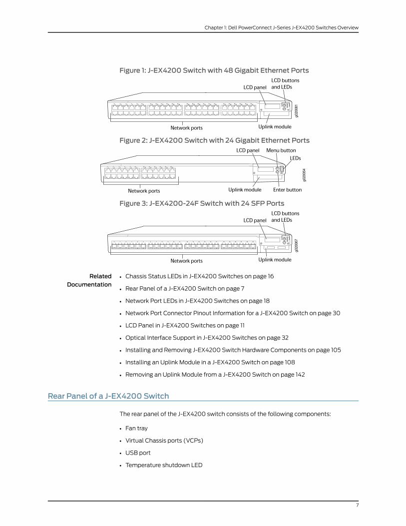
Figure 1: J-EX4200 Switch with 48 Gigabit Ethernet Ports
Figure 2: J-EX4200 Switch with 24 Gigabit Ethernet Ports
Figure 3: J-EX4200-24F Switch with 24 SFP Ports
RelatedDocumentation
Chassis Status LEDs in J-EX4200 Switches on page 16•
• Rear Panel of a J-EX4200 Switch on page 7
• Network Port LEDs in J-EX4200 Switches on page 18
• Network Port Connector Pinout Information for a J-EX4200 Switch on page 30
• LCD Panel in J-EX4200 Switches on page 11
• Optical Interface Support in J-EX4200 Switches on page 32
• Installing and Removing J-EX4200 Switch Hardware Components on page 105
• Installing an Uplink Module in a J-EX4200 Switch on page 108
• Removing an Uplink Module from a J-EX4200 Switch on page 142
Rear Panel of a J-EX4200 Switch
The rear panel of the J-EX4200 switch consists of the following components:
• Fan tray
• Virtual Chassis ports (VCPs)
• USB port
• Temperature shutdown LED
7
Chapter 1: Dell PowerConnect J-Series J-EX4200 Switches Overview

• Management Ethernet port
• Console port
• ESD point
• Power supply or power supplies
Figure 4 on page 8 shows the rear panel of a J-EX4200 switch. All J-EX4200 switches
have the same rear panel. The 320 W AC power supply is flush with the chassis. The
600 W AC power supply and 930 W AC power supply extend out of the chassis by 2.25 in.
Power cord retainer clips extend out of the power supply by 3 in.
Figure 4: J-EX4200 Switch Rear Panel
g020
084
Virtualchassisports
USBport
ManagementEthernetport
Fantray
Consoleport
PowerSupply 1
PowerSupply 0
Protective earthingterminal (on side panel)
ESDpoint
Temperatureshutdown LED
RelatedDocumentation
Field-Replaceable Units in J-EX4200 Switches on page 16•
• Front Panel of a J-EX4200 Switch on page 6
• USB Port Specifications for a J-EX Series Switch on page 29
• Cooling System and Airflow in a J-EX4200 Switch on page 24
• Power Supply in J-EX4200 Switches on page 21
• Prevention of Electrostatic Discharge Damage on J-EX Series Switches on page 198
• Connecting Earth Ground to a J-EX Series Switch on page 115
• Installing and Removing J-EX4200 Switch Hardware Components on page 105
• Understanding Virtual Chassis Hardware Configuration on a J-EX4200 Switch on
page 75
J-EX4200 Switch Hardware and CLI TerminologyMapping
This topic describes the hardware terms used in J-EX4200 switch documentation and
the corresponding terms used in the Junos OS command line interface (CLI). See Table
6 on page 9.
8
Dell PowerConnect J-Series J-EX4200 Ethernet Switch Hardware Guide

Table 6: CLI Equivalents of Terms Used in Documentation for the J-EX4200 Switch
Additional InformationItem inDocumentationValue (CLI)Description (CLI)
Hardware Item(CLI)
“Chassis Physical Specifications forJ-EX4200 Switches” on page 5
Switch chassis–One of the following:
• DellJ-EX4200-24T
• DellJ-EX4200-48T
• DellJ-EX4200-24F
• EX4200-24T
• EX4200-48T
• EX4200-48T
Chassis
See the information about interfacesand interface naming conventions onJ-EX Series Ethernet switches in themultivolume Dell PowerConnectJ-Series Ethernet Switch CompleteSoftware Guide for Junos OS athttp://www.support.dell.com/manuals.
The switch does nothave actual FPCs. Inthis case, the FPCrefers to the switchitself.
Value of n isalways 0.
On a standaloneJ-EX4200switches—Abbreviatedname of the FlexiblePIC Concentrator(FPC)
One of the following:
• EX4200-48T
• EX4200-48T
• EX4200-24F
FPC (n)
See the information about VirtualChassis and Virtual Chassiscomponents in the multivolume DellPowerConnect J-Series EthernetSwitchComplete Software Guide for Junos OSat http://www.support.dell.com/manuals.
In this case, the FPCnumber refers to themember ID assignedto the switch.
n is a value in therange of 0-9.
On a J-EX4200VirtualChassis—Member IDof the switch withinthe Virtual Chassis
See the information about interfacesand interface naming conventions onJ-EX Series Ethernet switches in themultivolume Dell PowerConnectJ-Series Ethernet Switch CompleteSoftware Guide for Junos OS athttp://www.support.dell.com/manuals.
The switch does nothave actual PICdevices; see entriesfor PIC 0 throughPIC 1 for theequivalent item onthe switch.
n is a value in therange of 0-1.
Abbreviated nameof the PhysicalInterface Card (PIC).
PIC (n)
“Front Panel of a J-EX4200 Switch” onpage 6
Built-in networkports on the frontpanel of the switch
PIC 0One of the following:
• 24x 10/100/1000Base-T
• 24x 100Base-FX/1000Base-X
• 48x 10/100/1000Base-T
9
Chapter 1: Dell PowerConnect J-Series J-EX4200 Switches Overview

Table6: CLIEquivalentsofTermsUsed inDocumentation for the J-EX4200Switch (continued)
Additional InformationItem inDocumentationValue (CLI)Description (CLI)
Hardware Item(CLI)
“Uplink Modules in J-EX4200 Switches”on page 25
Uplink moduleinstalled on the frontpanel of the switch
PIC 1One of the following:
• 2x 10GE SFP+
• 4x GE SFP
“Optical Interface Support in J-EX4200Switches” on page 32
Optical transceiversn is a valueequivalent to thenumber of theport in which thetransceiver isinstalled.
Abbreviated nameof the transceiver
Xcvr (n)
“Power Supply in J-EX4200 Switches”on page 21
AC power supplyn is a value in therange of 0-1. Thevaluecorresponds tothe power supplyslot number.
One of the following:
• PS 320W AC
• PS 600W AC
• PS 930W AC
Power supply (n)
“Cooling System and Airflow in aJ-EX4200 Switch” on page 24
Fan tray–Fan trayFan tray
10
Dell PowerConnect J-Series J-EX4200 Ethernet Switch Hardware Guide

CHAPTER 2
Component Descriptions
• LCD Panel in J-EX4200 Switches on page 11
• Field-Replaceable Units in J-EX4200 Switches on page 16
• Chassis Status LEDs in J-EX4200 Switches on page 16
• Network Port LEDs in J-EX4200 Switches on page 18
• Management Port LEDs in J-EX4200 Switches on page 21
• Power Supply in J-EX4200 Switches on page 21
• AC Power Supply LEDs in J-EX4200 Switches on page 24
• Cooling System and Airflow in a J-EX4200 Switch on page 24
• Uplink Modules in J-EX4200 Switches on page 25
LCD Panel in J-EX4200 Switches
The LCD panel on the front panel of J-EX4200 switches shows two lines of text, each a
maximum of 16 characters in length. The LCD panel displays a variety of information
about the switch and also provides a menu to perform basic operations such as initial
setup and reboot.
There are two navigation buttons—Menu and Enter—to the right of the LCD panel.
See Figure 5 on page 11.
Figure 5: LCD Panel in J-EX4200 Switches
You can configure the second line of the LCD panel to display a custom message. If the
LCD panel is configured to display a custom message, the Menu button and the Enter
button are disabled. See the instructions for configuring the LCD panel on J-EX Series
switches in the Dell PowerConnect J-Series Ethernet Switch Complete Software Guide for
Junos OS: Volume 1 at http://www.support.dell.com/manuals.
11

The LCD panel has a backlight. If the LCD panel is idle for 60 seconds, the backlight turns
off. You can turn on the backlight by pressing theMenuorEnterbutton once. After turning
on the backlight, you can toggle between the LCD panel menus by pressing the Menu
button and navigate through the menu options by pressing the Enter button.
NOTE: Thechassis viewer in the J-Web interfacealsodisplays theLCDpanel.From the J-Web interface, you can view real-time status information in theLCDpanel.See the informationabout thedashboard for J-EXSeries switchesin the Dell PowerConnect J-Series Ethernet Switch Complete Software Guidefor Junos OS: Volume 1 at http://www.support.dell.com/manuals.
This topic describes:
• LCD Panel Modes on page 12
• LCD Panel Menus on page 13
LCD Panel Modes
The LCD panel operates in four modes: boot, idle, status, and maintenance.
The LCD panel operates in boot mode during switch reboot. The boot mode displays the
key milestones in the switch boot process. The boot mode does not have any menu
options. After the boot process is complete, the LCD panel automatically reverts to the
Idle menu.
In a J-EX4200 switch that is not a member of a Virtual Chassis, the first line of the LCD
panel displays the slot number, the role of the switch, and hostname. For a standalone
J-EX4200 switch, the slot number is always 00 and the role is always RE (for master).
In a J-EX4200 switch that is a member of a Virtual Chassis, the first line of the LCD panel
displays:
• The slot number (the member ID for the Virtual Chassis member)
• Role of the switch in a Virtual Chassis (RE for master,BK for backup, and LC for linecard
member)
• Hostname
In the idle mode, the second line displays the mode of the network ports’ Status LED and
the number of chassis alarms. The number of alarms is updated every second.
In the status mode, the second line displays:
• Virtual Chassis port (VCP) status (for a J-EX4200 switch that is a member of a Virtual
Chassis)
• Status of the power supply
• Status of the fan and temperature
• Version of Junos OS for J-EX Series switches loaded on the switch
12
Dell PowerConnect J-Series J-EX4200 Ethernet Switch Hardware Guide

In the maintenance mode, the second line displays one of the following options that you
can use to configure and troubleshoot the switch:
• System halt
• System reboot
• Load rescue
• Request VC port (for a switch that is a member of a Virtual Chassis)
• Factory default
• System EZSetup
LCD Panel Menus
The LCD panel has three menus: Idle, Status, and Maintenance. Toggle between the LCD
panel menus by pressing theMenubutton. Navigate through the menu options by pressing
the Enter button.
Table 7 on page 13 describes the LCD panel menu options.
Table 7: LCD Panel Menu Options in J-EX4200 Switches
DescriptionMenu
In the Idle menu:
• Press Enter to cycle through the Status LED modes:
• ADM (administrative status)
• DPX (duplex)
• Power over Ethernet (PoE)
• SPD (speed)
See “Network Port LEDs in J-EX4200 Switches” on page 18 for information on the Status LED modes.
• Press Menu to exit the Idle menu and go to the Status menu.
IDLE
13
Chapter 2: Component Descriptions

Table 7: LCD Panel Menu Options in J-EX4200 Switches (continued)
DescriptionMenu
The Status menu has the following options:
• Show VCP status—Choose one of the following:
• Press the Enter button to display the Virtual Chassis port (VCP) status: Up, Down, Disabled. This menuoption is available only for a J-EX4200 switch that is a member of a Virtual Chassis configuration.
• Press the Menu button to go to the next option in the Status menu.
• Show PSU status—Choose one of the following:
• Press the Enter button to display the status of the power supply: OK, Failed, Absent.
• Press the Menu button to go to the next option in the Status menu.
• Show Environment status—Choose one of the following:
• Press the Enter button to display the status of the fan and temperature:
• Fan status: OK, Failed, Absent
• Temp status: OK, High, Shutdown
• Press the Menu button to go to the next option in the Status menu.
• Show Junos OS version—Choose one of the following:
• Press the Enter button to version of Junos OS for J-EX Series switches loaded on the switch.
• Press the Menu button to go to the next option in the Status menu.
• EXIT STAT MENU?—Choose one of the following:
• Press the Enter button to exit the Status menu. Then press the Menu button to go to the Maintenancemenu.
• Press the Menu button to return to the Show VCP status option.
If you do not want users to use Status menu options, disable the entire menu or individual menu options. Seethe instructions for configuring the LCD panel on J-EX Series switches in theDell PowerConnect J-Series EthernetSwitch Complete Software Guide for Junos OS: Volume 1 at http://www.support.dell.com/manuals.
STATUS
14
Dell PowerConnect J-Series J-EX4200 Ethernet Switch Hardware Guide

Table 7: LCD Panel Menu Options in J-EX4200 Switches (continued)
DescriptionMenu
The Maintenance menu has the following options to configure and troubleshoot the switch:
• SYSTEM HALT?—Choose one of the following:
• Press the Enter button to halt the switch. Press the Enter button again to confirm the halt.
• Press the Menu button to go to the next option in the Maintenance menu.
• SYSTEM REBOOT?—Choose one of the following:
• Press the Enter button to reboot the switch. Press the Enter button again to confirm the reboot.
• Press the Menu button to go to the next option in the Maintenance menu.
• LOAD RESCUE?—Choose one of the following:
• Press the Enter button to roll back the switch to the rescue configuration. Press the Enter button againto confirm the rollback.
• Press the Menu button to go to the next option in the Maintenance menu.
• REQUEST VC PORT?—Choose one of the following:
• Press the Enter button to configure an uplink module port or a J-EX4200-24F network port to be a VirtualChassis port (VCP) or to delete a VCP from the switch configuration (when you delete the VCP, the portis reset to an uplink module port or a J-EX4200-24F network port).
• Press the Menu button to go to the next option in the Maintenance menu.
• FACTORY DEFAULT?—Choose one of the following:
• Press the Enter button to restore the switch to the factory default configuration. Press the Enter buttonagain to confirm the restoration.
• Press the Menu button to go to the next option in the Maintenance menu.
• ENTER EZSETUP?—Choose one of the following:
• Press the Enter button to launch EZSetup. Press the Enter button again to confirm the launch.
NOTE: You can use the ENTER EZSETUP option only if the switch is in the factory default configuration.
For information about EZSetup, see “Connecting and Configuring a J-EX Series Switch (J-Web Procedure)”on page 133.
• Press the Menu button to go to the next option in the Maintenance menu.
• EXIT MAINT MENU?—Choose one of the following:
• Press the Enter button to exit the Maintenance menu. Then press theMenu button to go to the Idle menu.
• Press the Menu button to go to the System Halt option.
If you do not want users to use Maintenance menu options, disable the entire menu or individual menu options.See the instructions for configuring the LCD panel on J-EX Series switches in the Dell PowerConnect J-SeriesEthernetSwitchCompleteSoftwareGuide for JunosOS:Volume 1athttp://www.support.dell.com/manuals.
MAINT(MaintenanceMenu)
RelatedDocumentation
Front Panel of a J-EX4200 Switch on page 6•
• Field-Replaceable Units in J-EX4200 Switches on page 16
• Connecting and Configuring a J-EX Series Switch (CLI Procedure) on page 131
• Connecting and Configuring a J-EX Series Switch (J-Web Procedure) on page 133
15
Chapter 2: Component Descriptions

Field-Replaceable Units in J-EX4200 Switches
Field-replaceable units (FRUs) are components that you can replace at your site. The
field-replaceable units (FRUs) in J-EX4200 switches are:
• Power supply
• Fan tray
• Uplink module
• SFP transceiver
• SFP+ transceiver
NOTE: Uplinkmodules are not part of the standard package andmust beordered separately.
The power supply, fan tray, uplink module, and transceivers are hot-removable and
hot-insertable: You can remove and replace them without powering off the switch or
disrupting switch functions.
NOTE: If youhaveaservicecontract, registeranyaddition, change,orupgradeof hardware components at http://www.dell.com. Failure to do so can result
in significant delays if you need replacement parts. This note applies if youchange the type of power supply or add a new type of uplinkmodule. It doesnotapply if you replacethesecomponentswith thesametypeofcomponent.
RelatedDocumentation
Uplink Modules in J-EX4200 Switches on page 25•
• Installing a Power Supply in a J-EX4200 Switch on page 106
• Removing a Power Supply from a J-EX4200 Switch on page 140
• Installing a Fan Tray in a J-EX4200 Switch on page 107
• Removing a Fan Tray from a J-EX4200 Switch on page 141
• Installing an Uplink Module in a J-EX4200 Switch on page 108
• Removing an Uplink Module from a J-EX4200 Switch on page 142
• Installing a Transceiver in a J-EX Series Switch on page 110
• Removing a Transceiver from a J-EX Series Switch on page 144
Chassis Status LEDs in J-EX4200 Switches
The front panel of a J-EX4200 switch has three LEDs on the far right side of the panel,
next to the LCD panel (see Figure 6 on page 17).
16
Dell PowerConnect J-Series J-EX4200 Ethernet Switch Hardware Guide

Figure 6: Chassis Status LEDs in a J-EX4200 Switch
Table 8 on page 17 describes the chassis status LEDs in a J-EX4200 switch, their colors
and states, and the status they indicate. You can view the colors of the three LEDs
remotely through the CLI by issuing the operational mode command show chassis lcd.
Table 8: Chassis Status LEDs in a J-EX4200 Switch
State and DescriptionColorLED Label
There is no alarm.UnlitALM (Alarm)
There is a major alarm.
NOTE: When you connect power to the switch, the Alarm (ALM) LED lights red to indicate thatthe network link is disconnected. This behavior is normal. Plugging an active Ethernet cable intothe management (MGMT) port on the switch completes the network link and turns off the ALMLED. (See “Connecting a J-EX Series Switch to a Network for Out-of-Band Management” onpage 120.)
Connecting the switch to a dedicated management console instead of a network does not affectthe ALM LED. The LED remains red until the switch is connected to a network.
Red
There is a minor alarm.
NOTE: The Alarm (ALM) LED lights amber if you commit a configuration to make it active on theswitch and do not also create a rescue configuration to back it up. To save the most recentlycommitted configuration as the rescue configuration, enter the operational mode commandrequestsystemconfiguration rescuesave. For more information, see theDell PowerConnect J-SeriesEthernet Switch Complete Software Guide for Junos OS athttp://www.support.dell.com/manuals.
Amber
• On steadily—Junos OS for J-EX Series switches has been loaded on the switch.
• Blinking—The switch is booting.
GreenSYS(System)
• On steadily—The switch is the master in the Virtual Chassis configuration.
• Blinking—The switch is the backup in the Virtual Chassis configuration.
• Off—The switch is a linecard member in the Virtual Chassis configuration.
GreenMST(Master)
A major alarm (red) indicates a critical error condition that requires immediate action.
A minor alarm (amber) indicates a noncritical condition that requires monitoring or
maintenance. A minor alarm that is left unchecked might cause interruption in service or
performance degradation.
NOTE: Theamberglowof theAlarmLEDthat indicatesaminoralarmcloselyresembles the red glow that indicates amajor alarm.
17
Chapter 2: Component Descriptions

All three LEDs can be lit simultaneously.
RelatedDocumentation
Front Panel of a J-EX4200 Switch on page 6•
• For information about active alarms, alarm types, and alarm severity levels, see the
Dell PowerConnect J-Series Ethernet Switch Complete Software Guide for Junos OS at
http://www.support.dell.com/manuals.
Network Port LEDs in J-EX4200 Switches
Each network port on a J-EX4200 switch has two LEDs. The four figures in this topic show
the location of those LEDs:
• Figure 7 on page 18 shows the location of the LEDs on the network ports on the front
panel.
• Figure 8 on page 19 shows the location of the LEDs on the uplink module ports on the
SFP uplink module.
• Figure 9 on page 19 shows the location of the LEDs on the uplink module ports on the
SFP+ uplink module.
Figure 7: LEDs on the Network Ports on the Front Panel
18
Dell PowerConnect J-Series J-EX4200 Ethernet Switch Hardware Guide

Figure 8: LEDs on the Uplink Module Ports on the SFP Uplink Module
Figure 9: LEDs on the Uplink Module Ports on the SFP+ Uplink Module
The LEDs labeled Link/Activity LED in Figure 7 on page 18, Figure 8 on page 19, and Figure
9 on page 19 indicate link activity. The LEDs labeled Status LED indicate the status of
one of the four port parameters. The port parameters are administrative status, duplex
mode, Power over Ethernet (PoE) status, and speed.
Table 9 on page 19 describes the Link/Activity LED.
Table 9: Link/Activity LED on Network Ports in J-EX4200 Switches
State and DescriptionColorLED
• Blinking—The port and the link are active, and there is link activity.
• On steadily—The port and the link are active, but there is no link activity.
• Off—The port is not active.
GreenLink/Activity
Table 10 on page 20 describes the Status LED. From the Idle menu of the LCD, use the
Enterbutton on the LCD panel to toggle between the ADM, DPX, POE, and SPD indicators.
19
Chapter 2: Component Descriptions

Table 10: Status LED on Network Ports in J-EX4200 Switches
State and DescriptionLCDIndicatorLED
Indicates the administrative status (enabled or disabled). The status indicators are:
• Green—Administrative status enabled.
• Unlit—Administrative status disabled.
LED: ADMStatus
Indicates the duplex mode.
The uplink module ports are always set to full-duplex; therefore, the LED is always green.
The status indicators for network ports on the front panel are:
• Green—Port is set to full-duplex mode.
• Unlit—Port is set to half-duplex mode.
LED: DPX
Indicates the PoE status.
PoE is not enabled on uplink module ports; therefore, the LED for those ports is always unlit.
The status indicators for network ports on the front panel are:
• Green—PoE is enabled on the port.
• Amber—PoE is enabled on the port, but no power is drawn from the port because of one of thefollowing:
• No device that draws power from the port is connected to the port.
• A device that draws power from the port is connected to the port, but the device is not drawingany power from the port.
• Unlit—PoE is not enabled on the port.
LED: POE
Indicates the speed.
The speed indicators for network ports on the front panel are:
• One blink per second—10 Mbps
• Two blinks per second—100 Mbps
• Three blinks per second—1000 Mbps
The speed indicators for network ports on the SFP uplink module are:
• Green—1000 Mbps
• Unlit—10/100 Mbps
The speed indicators for network ports on the SFP+ uplink module are:
• Green—The speed of the transceiver installed in the port is the same as the speed at which theuplink module port is configured to operate.
• Unlit—The speed of the transceiver installed in the port is not the same as the speed at whichthe uplink module port is configured to operate.
LED: SPD
RelatedDocumentation
Front Panel of a J-EX4200 Switch on page 6•
• Uplink Modules in J-EX4200 Switches on page 25
• LCD Panel in J-EX4200 Switches on page 11
20
Dell PowerConnect J-Series J-EX4200 Ethernet Switch Hardware Guide

Management Port LEDs in J-EX4200 Switches
The management port on J-EX4200 switches has two LEDs that indicate link/activity
and port status (see Figure 10 on page 21). The management port is set to full-duplex
and the speed is set to 100 Mbps.
Figure 10: LEDs on theManagement Port on a J-EX4200 Switch
Table 11 on page 21 describes the Link/Activity LED.
Table 11: Link/Activity LED on theManagement Port on J-EX4200 Switches
State and DescriptionColorLED
• Blinking—The port and the link are active, and there is link activity.
• On steadily—The port and the link are active, but there is no link activity.
• Off—The port is not active.
GreenLink/Activity
Table 12 on page 21 describes the Status LED (administrative status).
Table 12: Status LED on theManagement Port on J-EX4200 Switches
State and DescriptionColorLED
• On steadily—Administrative status is enabled.
• Off—Administrative status is disabled.
GreenStatus
RelatedDocumentation
See Rear Panel of a J-EX4200 Switch on page 7 for port location.•
• Connecting a J-EX Series Switch to a Network for Out-of-Band Management on page 120
Power Supply in J-EX4200 Switches
The power supply in J-EX4200 switches (see Figure 11 on page 22 and Figure 12 on page 22)
is a hot-removable and hot-insertable field-replaceable unit (FRU) that you can install
on the rear panel without powering off the switch or disrupting the switching function.
J-EX4200 switches have an internal redundant power supply, making the power supply
in J-EX4200 switches fully redundant.
21
Chapter 2: Component Descriptions

J-EX4200 switches use power that provides two DC output voltages: 12 V for system and
logic power and 48–51 V (or higher, to compensate for voltage drops along the path from
the power supplies to the RJ-45 connector) for PoE ports.
The AC power supply in J-EX4200 switches is available in 320 W, 600 W, and 930 W
models. The exterior of the 600 W model is identical to that of the 930 W model. The
320 W power supply is flush with the chassis. The 600 W power supply and 930 W power
supply extend out of the chassis by 2.25 in. The power cord retainer clips extend out of
the power supply by 3 in. The number of ports on which PoE is enabled determines the
minimum power requirements.
Figure 11: 320WACPower Supply in J-EX4200 Switches
Figure 12: 600Wand 930WACPower Supplies in J-EX4200 Switches
To avoid electrical injury, follow instructions in “Installing a Power Supply in a J-EX4200
Switch” on page 106 and “Removing a Power Supply from a J-EX4200 Switch” on page 140
carefully.
22
Dell PowerConnect J-Series J-EX4200 Ethernet Switch Hardware Guide

NOTE: After powering on a J-EX4200 switch, wait for at least 60 secondsbefore powering it off. After powering off a J-EX4200switch,wait for at least60 seconds before powering it back on.
After a switch has been powered on, it can take up to 60 seconds for statusindicators—suchasLEDsonthepowersupply,showchassiscommandoutput,
andmessages on the LCD—to indicate that the power supply is functioningnormally. Ignore error indicators that appear during the first 60 seconds.
PoE Power Budget and AC Power Supplies
The PoE power budget for a PoE switch model is determined by the capacity of its power
supply. For a J-EX4200 switch, the capacity of the power supply provided with the switch
is sufficient to supply each PoE-capable port with up to 15.4 W in compliance with the
IEEE 802.3af PoE standard.
Table 13 on page 23 lists the J-EX4200 power supply ratings and associated PoE power
budgets.
Starting with Junos OS Release 11.1, a J-EX Series Ethernet switch supports enhanced
PoE, a Juniper Networks extension to the IEEE 302.3af PoE standard. Enhanced PoE
permits up to 18.6 W per PoE port. Because the power supply provided with a switch is
designed to supply a maximum of 15.4 W per PoE port, if you connect a powered device
that draws more than 15.4 W, the PoE power budget might not be sufficient to supply a
full 15.4 W to the remaining PoE ports.
NOTE: To enable enhanced PoE support, switches upgraded to Junos OSRelease 11.1 from a previous release require a separate upgrade of the PoEcontroller software.
Table 13: MinimumPower Requirements for a J-EX4200 Switch
MinimumPower RequirementNumber of PoE-enabled PortsModel Number
320 W8J-EX4200-24T
320 W8J-EX4200-48T
320 W–J-EX4200-24F
RelatedDocumentation
AC Power Cord Specifications for J-EX4200 Switches on page 71•
• AC Power Supply LEDs in J-EX4200 Switches on page 24
• Rear Panel of a J-EX4200 Switch on page 7
• Field-Replaceable Units in J-EX4200 Switches on page 16
• Power Specifications for J-EX4200 Switches on page 71
23
Chapter 2: Component Descriptions

• Prevention of Electrostatic Discharge Damage on J-EX Series Switches on page 198
• Connecting AC Power to a J-EX4200 Switch on page 117
• Connecting Earth Ground to a J-EX Series Switch on page 115
AC Power Supply LEDs in J-EX4200 Switches
The AC power supply in a J-EX4200 switch is on the rear panel. Table 14 on page 24
describes the LEDs on the AC power supplies in J-EX4200 switches.
Table 14: AC Power Supply LEDs in J-EX4200 Switches
State and DescriptionLED
• Off—Disconnected from power or power is not coming into the power supply.
• On—Power is coming into the power supply.
AC OK
• Off—Power supply is not sending out power correctly.
• On—Power supply is sending out power correctly.
DC OK
NOTE: If the ACOK and DCOK LEDs are both unlit, either the AC power cord
is not installed properly or the power supply fuse has failed. If the ACOK LED
is lit and the DCOK LED is unlit, the AC power supply is not installed properly
or the power supply has an internal failure.
RelatedDocumentation
Power Supply in J-EX4200 Switches on page 21•
• Connecting AC Power to a J-EX4200 Switch on page 117
Cooling System and Airflow in a J-EX4200 Switch
The cooling system in a J-EX4200 switch consists of a field-replaceable unit (FRU) fan
tray with three fans (see Figure 13 on page 24). The fan tray is located at the rear of the
chassis and provides side-to-rear chassis cooling (see Figure 14 on page 25).
Figure 13: Fan Tray Used in a J-EX4200 Switch
24
Dell PowerConnect J-Series J-EX4200 Ethernet Switch Hardware Guide

Figure 14: Airflow Through the J-EX4200 Switch Chassis
The fan tray used in a J-EX4200 switch comes with load-sharing redundancy that can
tolerate a single fan failure at room temperature (below 45° C/113° F) to still provide
sufficient cooling.
Temperature sensors in the chassis monitor the temperature within the chassis. The
system raises an alarm if the fan fails or if the temperature inside the chassis rises above
permitted levels. If the temperature inside the chassis rises above the threshold, the
system shuts down automatically and the temperature shutdown LED on the rear panel
is lit. You can see the status of fans and the temperature from the Show Environment
Status option in the Status menu in the LCD panel.
RelatedDocumentation
Field-Replaceable Units in J-EX4200 Switches on page 16•
• Rear Panel of a J-EX4200 Switch on page 7
• Prevention of Electrostatic Discharge Damage on J-EX Series Switches on page 198
• Installing a Fan Tray in a J-EX4200 Switch on page 107
• Removing a Fan Tray from a J-EX4200 Switch on page 141
Uplink Modules in J-EX4200 Switches
J-EX4200 switches support the following types of uplink modules:
• SFP uplink module—Provides four ports for 1-gigabit small form-factor pluggable (SFP)
transceivers.
• SFP+ uplink module—Provides two ports for 10-gigabit small form-factor pluggable
(SFP+) transceivers when configured to operate in 10-gigabit mode or four ports for
25
Chapter 2: Component Descriptions

1-gigabit small form-factor pluggable (SFP) transceivers when configured to operate
in 1-gigabit mode.
NOTE: When a new uplink module is installed in the switch or an existinguplink module is replaced with another uplink module, the switch detectsthe newly installed uplinkmodule. The switch creates the required interfacesif the uplink module has transceivers in its ports and when new transceiversare installed in those ports.
You can use the optional uplink module ports to connect an access switch to a distribution
switch. You can also use these ports to connect members of a Virtual Chassis across
multiple wiring closets.
When connecting uplink module ports, you can install an SFP uplink module at one end
of the connection and install an SFP+ uplink module configured to operate in the 1-gigabit
mode at the other end.
This topic describes:
• SFP Uplink Module on page 26
• SFP+ Uplink Module on page 26
SFPUplink Module
Figure 15 on page 26 shows the SFP uplink module, which provides four ports for 1-gigabit
SFP transceivers.
Figure 15: SFP Uplink Module
SFP uplink modules are shipped with dust covers preinstalled in the ports.
SFP+Uplink Module
SFP+ uplink modules can be used for either SFP+ or SFP transceivers. You configure the
operating mode on the module to match the type of transceiver you want to use—for
26
Dell PowerConnect J-Series J-EX4200 Ethernet Switch Hardware Guide

SFP+ transceivers, you configure the 10-gigabit operating mode, and for SFP transceivers,
you configure the 1-gigabit operating mode. See “Setting the Mode on an SFP+ Uplink
Module (CLI Procedure)” on page 135.
By default, the SFP+ uplink module operates in the 10-gigabit mode and supports only
SFP+ transceivers. If you have not changed the module from the default setting and you
want to use SFP+ transceivers, you do not need to configure the operating mode.
If the operating mode and the configured mode for an SFP+ uplink module are different,
it is shown in the output of show chassis pic fpc-slot slot number pic-slot 1.
Figure 16 on page 27 shows the SFP+ uplink module.
Figure 16: SFP+ Uplink Module
Transceivers are supported in the uplink module’s ports as follows:
• SFP+ transceivers are supported in ports 0 and 2.
• SFP transceivers are supported in all four ports.
The ports that support SFP+ transceivers are labeled 10 G on the uplink module’s
faceplate (see Figure 16 on page 27).
NOTE: When an SFP+ uplink module is operating in 10-gigabit mode:
• Only the 10-gigabit ports (ports 0 and 2) are enabled.
• You can use only SFP+ transceivers in those ports.
When an SFP+ uplink module is operating in 1-gigabit mode:
• All four ports are enabled.
• You can use only SFP transceivers in all four ports.
The SFP+ uplink module has an LED on the faceplate (labeled Operatingmode LED in
Figure 16 on page 27) that indicates the operating mode. If the uplink module is operating
27
Chapter 2: Component Descriptions

in the 10-gigabit mode, the LED is lit. If the uplink module is operating in the 1-gigabit
mode, the LED is unlit.
SFP+ uplink modules are shipped with dust covers preinstalled in the ports.
RelatedDocumentation
• Network Port LEDs in J-EX4200 Switches on page 18
• Uplink Modules Connector Pinout Information for J-EX4200 Switches on page 41
• Optical Interface Support in J-EX4200 Switches on page 32
• For information about configuring aggregated Ethernet high-speed uplinks between
Virtual Chassis access and distribution switches, see the Dell PowerConnect J-Series
Ethernet Switch Complete Software Guide for Junos OS: Volume 1 at
http://www.support.dell.com/manuals.
• Installing an Uplink Module in a J-EX4200 Switch on page 108
• Troubleshooting Uplink Module Installation or Replacement on J-EX4200 Switches
on page 158
28
Dell PowerConnect J-Series J-EX4200 Ethernet Switch Hardware Guide

CHAPTER 3
Component Specifications
• USB Port Specifications for a J-EX Series Switch on page 29
• Network Port Connector Pinout Information for a J-EX4200 Switch on page 30
• Console Port Connector Pinout Information for a J-EX Series Switch on page 30
• Management Port Connector Pinout Information for a J-EX4200 Switch on page 31
• Optical Interface Support in J-EX4200 Switches on page 32
• Uplink Modules Connector Pinout Information for J-EX4200 Switches on page 41
• Virtual Chassis Ports Connector Pinout Information for J-EX4200 Switches on page 49
USB Port Specifications for a J-EX Series Switch
The following Dell USB flash drives have been tested and are officially supported for the
USB port on all J-EX Series switches:
• 1-GB USB flash drive (WFXDH)
• 2-GB USB flash drive (T8GCH)
• 4-GB USB flash drive (7XMF7)
CAUTION: Any USBmemory product not listed as supported for J-EX Seriesswitches has not been tested. The use of any unsupported USBmemoryproduct couldexposeyour switch tounpredictablebehavior. Dell canprovideonly limited support for issues related to unsupportedhardware.We stronglyrecommend that you use only supported USB flash drives.
All USB flash drives used on the switches must have the following features:
• USB 2.0 or later
• Formatted with a FAT or MS-DOS file system
RelatedDocumentation
See Front Panel of a J-EX4500 Switch for port location.•
• For information about booting the switch from a software package stored on a USB
flash drive, see the Dell PowerConnect J-Series Ethernet Switch Complete Software
Guide for Junos OS at http://www.support.dell.com/manuals.
29

Network Port Connector Pinout Information for a J-EX4200 Switch
A network port on a J-EX4200 switch uses an RJ-45 connector to connect to a device.
The port uses an autosensing RJ-45 connector to support a 10/100/1000Base-T
connection. Two LEDs on the port indicate link/activity on the port and the port status.
See “Network Port LEDs in J-EX4200 Switches” on page 18.
Table 15 on page 30 provides the pinout information for the RJ-45 connector. An RJ-45
cable, with a connector attached, is supplied with the switch.
Table 15: Network Port Connector Pinout Information for a J-EX4200 Switch
DescriptionSignalPin
Transmit/receive data pair 1
Negative Vport (in PoE models)
TRP1+1
Transmit/receive data pair 1
Negative Vport (in PoE models)
TRP1-2
Transmit/receive data pair 2
Positive Vport (in PoE models)
TRP2+3
Transmit/receive data pair 3TRP3+4
Transmit/receive data pair 3TRP3-5
Transmit/receive data pair 2
Positive Vport (in PoE models)
TRP2-6
Transmit/receive data pair 4TRP4+7
Transmit/receive data pair 4TRP4-8
RelatedDocumentation
Front Panel of a J-EX4200 Switch on page 6•
Console Port Connector Pinout Information for a J-EX Series Switch
The console port on a J-EX Series switch is an RS-232 serial interface that uses an RJ-45
connector to connect to a console management device. The default baud rate for the
console port is 9600 baud.
Table 16 on page 31 provides the pinout information for the RJ-45 console connector.
An RJ-45 cable and an RJ-45 to DB-9 serial port adapter are supplied with the switch.
30
Dell PowerConnect J-Series J-EX4200 Ethernet Switch Hardware Guide

NOTE: If your laptopor PCdoes not have aDB-9male connector pin and youwant to connect your laptop or PC directly to a J-EX Series switch, use acombination of the RJ-45 to DB-9 female adapter supplied with the switchand a USB to DB-9male adapter. Youmust provide the USB to DB-9maleadapter.
Table 16: J-EX Series Switches Console Port Connector Pinout Information
DescriptionSignalPin
Request to sendRTS Output1
Data terminal readyDTR Output2
Transmit dataTxD Output3
Signal groundSignal Ground4
Signal groundSignal Ground5
Receive dataRxD Input6
Data carrier detectCD Input7
Clear to sendCTS Input8
RelatedDocumentation
See Rear Panel of a J-EX4200 Switch on page 7 for port location.•
• Connecting a J-EX Series Switch to a Management Console on page 121
Management Port Connector Pinout Information for a J-EX4200 Switch
The management port on a J-EX4200 switch uses an RJ-45 connector to connect to a
management device for out-of-band management.
The port uses an autosensing RJ-45 connector to support a 10/100/1000Base-T
connection. Two LEDs on the port indicate link/activity on the port and the administrative
status of the port. See “Management Port LEDs in J-EX4200 Switches” on page 21.
Table 17 on page 31 provides the pinout information of the RJ-45 connector. An RJ-45
cable, with a connector attached, is supplied with the switch.
Table 17: Management Port Connector Pinout Information for J-EX4200 Switches
DescriptionSignalPin
Transmit/receive data pair 1TRP1+1
Transmit/receive data pair 1TRP1-2
31
Chapter 3: Component Specifications

Table 17: Management Port Connector Pinout Information for J-EX4200 Switches (continued)
DescriptionSignalPin
Transmit/receive data pair 2TRP2+3
Transmit/receive data pair 3TRP3+4
Transmit/receive data pair 3TRP3-5
Transmit/receive data pair 2TRP2-6
Transmit/receive data pair 4TRP4+7
Transmit/receive data pair 4TRP4-8
RelatedDocumentation
See Rear Panel of a J-EX4200 Switch on page 7 for port location.•
• Connecting a J-EX Series Switch to a Network for Out-of-Band Management on page 120
Optical Interface Support in J-EX4200 Switches
Optional uplink modules for J-EX4200 switches support SFP or SFP+ transceivers. This
topic describes the optical interfaces supported for those transceivers. It also lists the
copper interface supported for the SFP transceivers.
NOTE: Foryour J-EX4200switch,useonly theoptical transceiversandopticalconnectors described in this manual. For more information, contact Dell.
The Gigabit Ethernet SFP or SFP+ transceivers installed in J-EX4200 switches support
digital optical monitoring (DOM): you can view the diagnostic details for these transceivers
by issuing the operational mode CLI command show interfaces diagnostics optics . The
command does not give any output for copper transceivers, Fast Ethernet transceivers,
or transceivers not purchased from Dell.
The following tables describe the optical interface support over single-mode fiber-optic
(SMF) and multimode fiber-optic (MMF) cables for SFP and SFP+ transceivers and over
the copper interface for SFP transceivers:
• Table 18 on page 33—Optical interface support and copper interface support for Gigabit
Ethernet SFP transceivers.
• Table 19 on page 38—Optical interface support for Fast Ethernet SFP transceivers.
• Table 20 on page 39—Optical interface support for Gigabit Ethernet SFP+ transceivers.
32
Dell PowerConnect J-Series J-EX4200 Ethernet Switch Hardware Guide

Table 18: Optical Interface Support and Copper Interface Support for Gigabit Ethernet SFPTransceivers in J-EX4200 Switches
SpecificationsEthernet Standard
EX-SFP-1GE-TModel Number1000Base-T
10/100/1000 MbpsRate
RJ-45Connector Type
CopperFiber Count
–Transmitter Wavelength
–Minimum Launch Power
–Maximum Launch Power
–Minimum Receiver Sensitivity
–Maximum Input Power
CopperFiber Type
–Core/Cladding Size
–Modal Bandwidth
100 m (328 ft)Distance
Not availableDOM Support
Junos OS for J-EX Series switchesSoftware required
33
Chapter 3: Component Specifications

Table 18: Optical Interface Support and Copper Interface Support for Gigabit Ethernet SFPTransceivers in J-EX4200 Switches (continued)
SpecificationsEthernet Standard
EX-SFP-1GE-SXModel Number1000Base-SX
1000 MbpsRate
LCConnector Type
DualFiber Count
850 nmTransmitter Wavelength
–9.5 dBmMinimum Launch Power
–3 dBmMaximum Launch Power
–21 dBmMinimum Receiver Sensitivity
0 dBmMaximum Input Power
MMFFiber Type
50/125 µm50/125 µm62.5/125 µm62.5/125 µmCore/Cladding Size
OM2–OM1FDDIFiber Grade
500 MHz/km400 MHz/km200 MHz/km160 MHz/kmModal Bandwidth
550 m(1804 ft)
500 m(1640 ft)
275 m(902 ft)
220 m(722 ft)
Distance
AvailableDOM Support
Junos OS for J-EX Series switchesSoftware required
34
Dell PowerConnect J-Series J-EX4200 Ethernet Switch Hardware Guide

Table 18: Optical Interface Support and Copper Interface Support for Gigabit Ethernet SFPTransceivers in J-EX4200 Switches (continued)
SpecificationsEthernet Standard
EX-SFP-1GE-LXModel Number1000Base-LX
1000 MbpsRate
LCConnector Type
DualFiber Count
1310 nmTransmitter Wavelength
–9.5 dBmMinimum Launch Power
–3 dBmMaximum Launch Power
–25 dBmMinimum Receiver Sensitivity
–3 dBmMaximum Input Power
SMFFiber Type
9/125 µmCore/Cladding Size
–Modal Bandwidth
10 km (6.2 miles)Distance
AvailableDOM Support
Junos OS for J-EX Series switchesSoftware required
35
Chapter 3: Component Specifications

Table 18: Optical Interface Support and Copper Interface Support for Gigabit Ethernet SFPTransceivers in J-EX4200 Switches (continued)
SpecificationsEthernet Standard
EX-SFP-1GE-LX40KModel Number1000Base-LX
1000 MbpsRate
LCConnector Type
SingleFiber Count
1310 nmTransmitter Wavelength
–14 dBmMinimum Launch Power
–8 dBmMaximum Launch Power
–45 dBmMinimum Receiver Sensitivity
–3 dBmMaximum Input Power
SMFFiber Type
9/125 µmCore/Cladding Size
–Modal Bandwidth
40 km (24.8 miles)Distance
AvailableDOM Support
Junos OS for J-EX Series switchesSoftware required
36
Dell PowerConnect J-Series J-EX4200 Ethernet Switch Hardware Guide

Table 18: Optical Interface Support and Copper Interface Support for Gigabit Ethernet SFPTransceivers in J-EX4200 Switches (continued)
SpecificationsEthernet Standard
EX-SFP-1GE-LHModel Number1000Base-LH (or1000Base-ZX)
1000 MbpsRate
LCConnector Type
DualFiber Count
1550 nmTransmitter Wavelength
–2 dBmMinimum Launch Power
5 dBmMaximum Launch Power
–25 dBmMinimum Receiver Sensitivity
–3 dBmMaximum Input Power
SMFFiber Type
9/125 µmCore/Cladding Size
–Modal Bandwidth
70 km (43.5 miles)Distance
AvailableDOM Support
Junos OS for J-EX Series switchesSoftware required
37
Chapter 3: Component Specifications
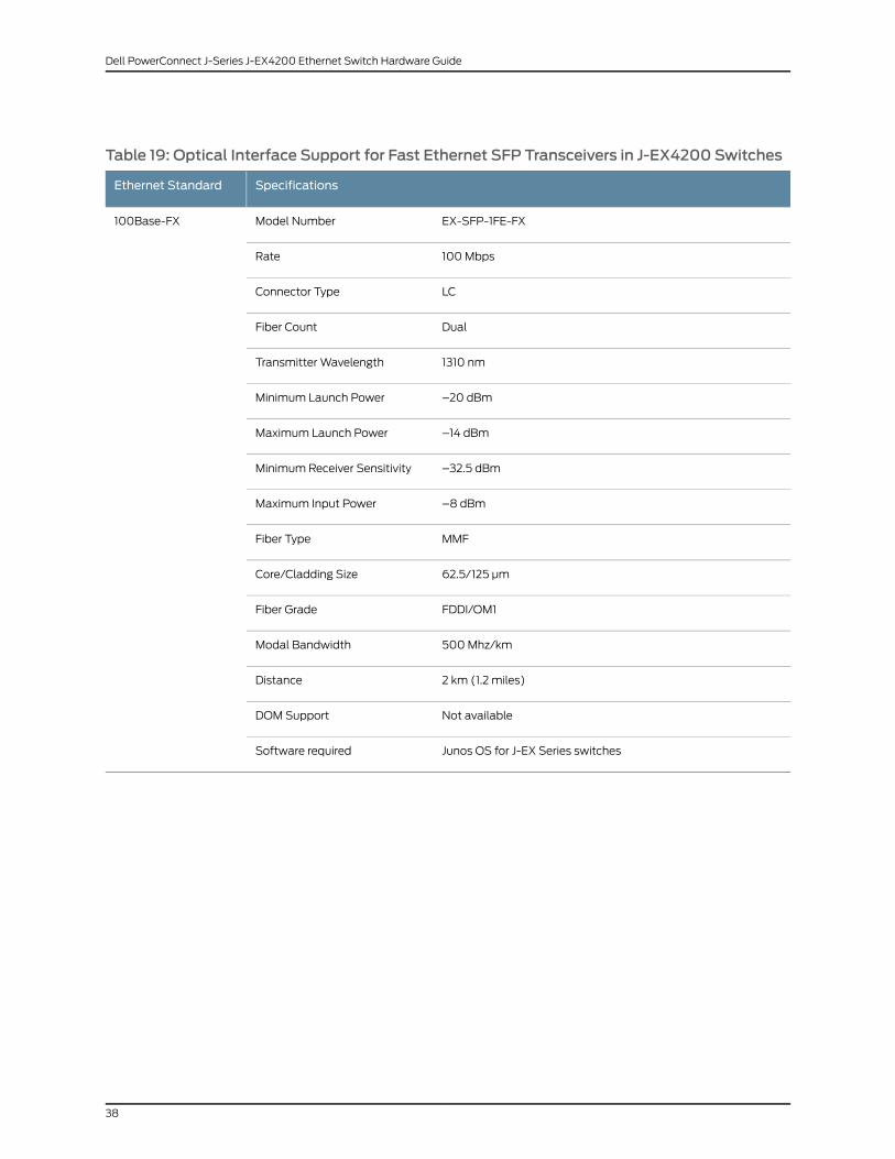
Table 19: Optical Interface Support for Fast Ethernet SFP Transceivers in J-EX4200 Switches
SpecificationsEthernet Standard
EX-SFP-1FE-FXModel Number100Base-FX
100 MbpsRate
LCConnector Type
DualFiber Count
1310 nmTransmitter Wavelength
–20 dBmMinimum Launch Power
–14 dBmMaximum Launch Power
–32.5 dBmMinimum Receiver Sensitivity
–8 dBmMaximum Input Power
MMFFiber Type
62.5/125 µmCore/Cladding Size
FDDI/OM1Fiber Grade
500 Mhz/kmModal Bandwidth
2 km (1.2 miles)Distance
Not availableDOM Support
Junos OS for J-EX Series switchesSoftware required
38
Dell PowerConnect J-Series J-EX4200 Ethernet Switch Hardware Guide

Table 20: Optical Interface Support for Gigabit Ethernet SFP+ Transceivers in J-EX4200Switches
SpecificationsEthernet Standard
EX-SFP-10GE-SRModel Number10GBase-SR
10 GbpsRate
LCConnector Type
DualFiber Count
850 nmTransmitter Wavelength
–7.3 dBmMinimum Launch Power
–1 dBmMaximum Launch Power
–9.9 dBmMinimum Receiver Sensitivity
–1 dBmMaximum Input Power
MMFFiber Type
50/125 µm50/125µm
50/125 µm62.5/125µm
62.5/125µm
Core/Cladding Size
OM3OM2–OM1FDDIFiber Grade
1500MHz/km
500MHz/km
400MHz/km
200MHz/km
160MHz/km
Modal Bandwidth
300 m(984 ft)
82 m(269 ft)
66 m(216 ft)
33 m(108 ft)
26 m(85 ft)
Distance
AvailableDOM Support
Junos OS for J-EX Series switchesSoftware required
39
Chapter 3: Component Specifications
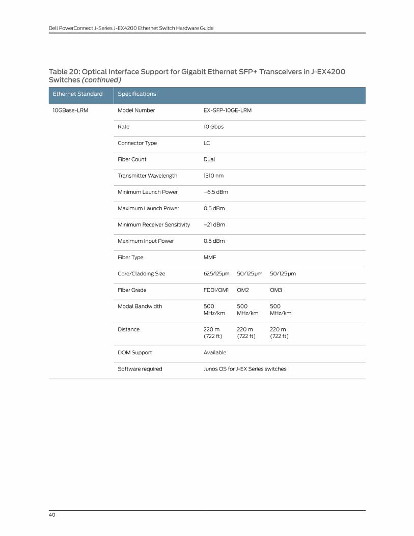
Table 20: Optical Interface Support for Gigabit Ethernet SFP+ Transceivers in J-EX4200Switches (continued)
SpecificationsEthernet Standard
EX-SFP-10GE-LRMModel Number10GBase-LRM
10 GbpsRate
LCConnector Type
DualFiber Count
1310 nmTransmitter Wavelength
–6.5 dBmMinimum Launch Power
0.5 dBmMaximum Launch Power
–21 dBmMinimum Receiver Sensitivity
0.5 dBmMaximum Input Power
MMFFiber Type
50/125 µm50/125µm62.5/125µmCore/Cladding Size
OM3OM2FDDI/OM1Fiber Grade
500MHz/km
500MHz/km
500MHz/km
Modal Bandwidth
220 m(722 ft)
220 m(722 ft)
220 m(722 ft)
Distance
AvailableDOM Support
Junos OS for J-EX Series switchesSoftware required
40
Dell PowerConnect J-Series J-EX4200 Ethernet Switch Hardware Guide

Table 20: Optical Interface Support for Gigabit Ethernet SFP+ Transceivers in J-EX4200Switches (continued)
SpecificationsEthernet Standard
EX-SFP-10GE-LRModel Number10GBase-LR
10 GbpsRate
LCConnector Type
DualFiber Count
1310 nmTransmitter Wavelength
–8.2 dBmMinimum Launch Power
0.5 dBmMaximum Launch Power
–18 dBmMinimum Receiver Sensitivity
0.5 dBmMaximum Input Power
SMFFiber Type
9/125 µmCore/Cladding Size
–Modal Bandwidth
10 km (6.2 miles)Distance
AvailableDOM Support
Junos OS for J-EX Series switchesSoftware required
RelatedDocumentation
Uplink Modules in J-EX4200 Switches on page 25•
• For show interfaces diagnostics optics command syntax, see the Dell PowerConnect
J-Series Ethernet Switch Complete Software Guide for Junos OS at
http://www.support.dell.com/manuals.
• Installing a Transceiver in a J-EX Series Switch on page 110
• Removing a Transceiver from a J-EX Series Switch on page 144
Uplink Modules Connector Pinout Information for J-EX4200 Switches
J-EX4200 switches have a field-replaceable unit (FRU) uplink module on the front panel.
Table 21 on page 42 provides the uplink modules connector pinout information.
41
Chapter 3: Component Specifications

NOTE: You can use these ports to connect an access switch to a distributionswitch. You can also use optional uplink module ports to connect membersof a Virtual Chassis acrossmultiple wiring closets.
Table 21: Uplink Modules Connector Pinout Information for J-EX4200 Switches
Pin NamePin Number
GNDA1
GNDA2
GNDA3
GNDA4
GNDA5
GNDA6
GNDA7
GNDA8
GNDA9
GNDA10
GNDA11
GNDA12
GNDA13
GNDA14
Uplink_I2C_SCKA15
GNDA16
Uplink_PDA17
GNDA18
POWER (12V)A19
GNDA20
GNDB1
42
Dell PowerConnect J-Series J-EX4200 Ethernet Switch Hardware Guide

Table 21: Uplink Modules Connector Pinout Information for J-EX4200 Switches (continued)
Pin NamePin Number
XAUI0_RX0NB2
GNDB3
XAUI0_RX2NB4
Uplink_P25_LED2B5
XAUI1_RX0NB6
Uplink_P27_LED2B7
XAUI1_RX2NB8
GNDB9
SRX28NB10
Uplink_XAUI_XMDIOB11
SRX26NB12
GNDB13
SGMIIRXNB14
Uplink_I2C_RstB15
Uplink_IntrB16
Uplink_Pwr_EnB17
Uplink_P26_LED0B18
POWER (12V)B19
POWER (12V)B20
GNDC1
XAUI0_RX0PC2
GNDC3
XAUI0_RX2PC4
GNDC5
43
Chapter 3: Component Specifications

Table 21: Uplink Modules Connector Pinout Information for J-EX4200 Switches (continued)
Pin NamePin Number
XAUI1_RX0PC6
GNDC7
XAUI1_RX2PC8
GNDC9
SRX28PC10
GNDC11
SRX26PC12
GNDC13
SGMIIRXPC14
CPU_UPLINK_MDCC15
Uplink_I2C_SDAC16
CPU_UPLINK_MDIOC17
Uplink_P26_LED1C18
UPLNK_PWR_OKC19
POWER (12V)C20
GNDD1
GNDD2
XAUI0_TX1ND3
GNDD4
XAUI0_TX3ND5
GNDD6
XAUI1_TX1ND7
GNDD8
XAUI1_TX3ND9
44
Dell PowerConnect J-Series J-EX4200 Ethernet Switch Hardware Guide

Table 21: Uplink Modules Connector Pinout Information for J-EX4200 Switches (continued)
Pin NamePin Number
GNDD10
STX27ND11
GNDD12
STX25ND13
GNDD14
Uplink_RstD15
GNDD16
Uplink_Status_LED0D17
GNDD18
POWER (12V)D19
GNDD20
GNDE1
XAUI0_TX0NE2
XAUI0_TX1PE3
XAUI0_TX2NE4
XAUI0_TX3PE5
XAUI1_TX0NE6
XAUI1_TX1PE7
XAUI1_TX2NE8
XAUI1_TX3PE9
STX28NE10
STX27PE11
STX26NE12
STX25PE13
45
Chapter 3: Component Specifications

Table 21: Uplink Modules Connector Pinout Information for J-EX4200 Switches (continued)
Pin NamePin Number
SGMIITXNE14
Uplink_Hotswap_LEDE15
Uplink_Spare_IntrE16
Uplink_Status_LED1E17
Uplink_P27_LED0E18
POWER (12V)E19
POWER (12V)E20
GNDF1
XAUI0_TX0PF2
GNDF3
XAUI0_TX2PF4
GNDF5
XAUI1_TX0PF6
GNDF7
XAUI_TX2PF8
GNDF9
STX28PF10
GNDF11
STX26PF12
GNDF13
SGMIITXPF14
GNDF15
Uplink_Expander_IntrF16
GNDF17
46
Dell PowerConnect J-Series J-EX4200 Ethernet Switch Hardware Guide

Table 21: Uplink Modules Connector Pinout Information for J-EX4200 Switches (continued)
Pin NamePin Number
Uplink_P27_LED1F18
GNDF19
POWER (12V)F20
GNDG1
GNDG2
XAUI0_RX1NG3
GNDG4
XAUI0_RX3NG5
GNDG6
XAUI1_RX1NG7
GNDG8
XAUI1_RX3NG9
GNDG10
SRX27NG11
GNDG12
SRX25NG13
GNDG14
GNDG15
GNDG16
Uplink_P25_LED0G17
GNDG18
POWER (12V)G19
GNDG20
Uplink_PD_LoopbackH1
47
Chapter 3: Component Specifications

Table 21: Uplink Modules Connector Pinout Information for J-EX4200 Switches (continued)
Pin NamePin Number
GNDH2
XAUI0_RX1PH3
GNDH4
XAUI0_RX3PH5
Uplink_P26_ LED2H6
XAUI1_RX1PH7
Uplink_P28_ LED2H8
XAUI1_RX3PH9
GNDH10
SRX27PH11
Uplink_XAUI_MDCH12
SRX25PH13
GNDH14
Serial_RXH15
GNDH16
Uplink_P25_LED1H17
Uplink_P28_LED0H18
POWER (12V)H19
POWER (12V)H20
GNDI1
GNDI2
GNDI3
GNDI4
GNDI5
48
Dell PowerConnect J-Series J-EX4200 Ethernet Switch Hardware Guide

Table 21: Uplink Modules Connector Pinout Information for J-EX4200 Switches (continued)
Pin NamePin Number
GNDI6
GNDI7
GNDI8
GNDI9
GNDI10
GNDI11
GNDI12
GNDI13
GNDI14
GNDI15
Serial_TXI16
GNDI17
Uplink_P28_LED1I18
GNDI19
POWER (12V)I20
RelatedDocumentation
Uplink Modules in J-EX4200 Switches on page 25•
• Front Panel of a J-EX4200 Switch on page 6
• Installing an Uplink Module in a J-EX4200 Switch on page 108
• Removing an Uplink Module from a J-EX4200 Switch on page 142
Virtual Chassis Ports Connector Pinout Information for J-EX4200 Switches
J-EX4200 switches use a 68-pin connector cable to interconnect switches to form a
Virtual Chassis. The cable is provided with the switch. Table 22 on page 50 provides
connector pinout information for the Virtual Chassis ports (VCPs).
49
Chapter 3: Component Specifications

Table 22: Virtual Chassis Ports (VCPs) Connector Pinout Information
Pin NamePin Number
GNDA1
P1TXP0A2
P1TXN0A3
GNDA4
P1TXP1A5
P1TXN1A6
GNDA7
P1TXP2A8
P1TXN2A9
GNDA10
P1TXP3A11
P1TXN3A12
GNDA13
NCA14
NCA15
GNDA16
NCA17
NCA18
NCA19
NCA20
NCA21
GNDA22
P2TXP0A23
P2TXN0A24
50
Dell PowerConnect J-Series J-EX4200 Ethernet Switch Hardware Guide

Table 22: Virtual Chassis Ports (VCPs) Connector Pinout Information (continued)
Pin NamePin Number
GNDA25
P2TXP1A26
P2TXN1A27
GNDA28
P2TXP2A29
P2TXN2A30
GNDA31
P2TXP3A32
P2TXN3A33
GNDA34
GNDB1
P1RXP0B2
P1RXN0B3
GNDB4
P1RXP1B5
P1RXN1B6
GNDB7
P1RXP2B8
P1RXN2B9
GNDB10
P1RXP3B11
P1RXN3B12
GNDB13
NCB14
51
Chapter 3: Component Specifications

Table 22: Virtual Chassis Ports (VCPs) Connector Pinout Information (continued)
Pin NamePin Number
NCB15
NCB16
NCB17
NCB18
NCB19
NCB20
NCB21
GNDB22
P2RXP0B23
P2RXN0B24
GNDB25
P2RXP1B26
P2RXN1B27
GNDB28
P2RXP2B29
P2RXN2B30
GNDB31
P2RXP3B32
P2RXN3B33
GNDB34
RelatedDocumentation
• Virtual Chassis Cabling Configuration Examples for J-EX4200 Switches on page 77
• Planning the Virtual Chassis on page 76
• For information about Virtual Chassis components, see theDell PowerConnect J-Series
Ethernet Switch Complete Software Guide for Junos OS at
http://www.support.dell.com/manuals.
52
Dell PowerConnect J-Series J-EX4200 Ethernet Switch Hardware Guide

• Understanding Virtual Chassis Hardware Configuration on a J-EX4200 Switch on
page 75
• Connecting a Virtual Chassis Cable to a J-EX4200 Switch on page 112
53
Chapter 3: Component Specifications

54
Dell PowerConnect J-Series J-EX4200 Ethernet Switch Hardware Guide

PART 2
Planning for Switch Installation
• Site Preparation on page 57
• Mounting and Clearance Requirements on page 63
• Cable Specifications on page 69
• Planning Power Requirements on page 71
• Planning the Virtual Chassis on page 75
55

56
Dell PowerConnect J-Series J-EX4200 Ethernet Switch Hardware Guide

CHAPTER 4
Site Preparation
• Site Preparation Checklist for J-EX4200 Switches on page 57
• General Site Guidelines for J-EX Series Switches on page 59
• Site Electrical Wiring Guidelines for J-EX Series Switches on page 59
• Environmental Requirements and Specifications for J-EX Series Switches on page 60
Site Preparation Checklist for J-EX4200 Switches
The checklist in Table 23 on page 57 summarizes the tasks you need to perform when
preparing a site for J-EX4200 switch installation.
Table 23: Site Preparation Checklist
DatePerformed ByFor More InformationItem or Task
Environment
“Environmental Requirements andSpecifications for J-EX SeriesSwitches” on page 60
Verify that environmental factors such astemperature and humidity do not exceed switchtolerances.
Power
Measure distance between external powersources and switch installation site.
Locate sites for connection of systemgrounding.
“Power Specifications for J-EX4200Switches” on page 71
Calculate the power consumption andrequirements.
Hardware Configuration
“J-EX4200 Switches HardwareOverview” on page 3
Choose the number and types of switches youwant to install.
Rack or Cabinet
57

Table 23: Site Preparation Checklist (continued)
DatePerformed ByFor More InformationItem or Task
“Rack Requirements for J-EX4200Switches” on page 63
“Cabinet Requirements for J-EX4200Switches” on page 64
Verify that your rack or cabinet meets theminimum requirements for the installation ofthe switch.
“Clearance Requirements for Airflowand Hardware Maintenance forJ-EX4200 Switches” on page 66
Plan rack or cabinet location, including requiredspace clearances.
Secure the rack or cabinet to the floor andbuilding structure.
Wall
“Requirements for Mounting aJ-EX4200 Switch on a Desktop orWall” on page 66
Verify that the wall meets the minimumrequirements for the installation of the switch.
“Clearance Requirements for Airflowand Hardware Maintenance forJ-EX4200 Switches” on page 66
Verify that there is appropriate clearance in yourselected location.
Cables
Acquire cables and connectors:
• Determine the number of cables neededbased on your planned configuration.
• Review the maximum distance allowed foreach cable. Choose the length of cable basedon the distance between the hardwarecomponents being connected.
Plan the cable routing and management.
RelatedDocumentation
General Safety Guidelines and Warnings for J-EX Series Switches on page 171•
• General Site Guidelines for J-EX Series Switches on page 59
• Installing and Connecting a J-EX4200 Switch on page 87
• Mounting a J-EX4200 Switch on page 90
58
Dell PowerConnect J-Series J-EX4200 Ethernet Switch Hardware Guide

General Site Guidelines for J-EX Series Switches
Efficient switch operation requires proper site planning and maintenance and proper
layout of the equipment, rack or cabinet (if used), and wiring closet.
To plan and create an acceptable operating environment for your J-EX Series switch and
prevent environmentally caused equipment failures:
• Keep the area around the chassis free from dust and conductive material, such as
metal flakes.
• Follow prescribed airflow guidelines to ensure that the cooling system functions properly
and that exhaust from other equipment does not blow into the intake vents of the
switch.
• Follow the prescribed ESD prevention procedures to avoid damaging the equipment.
Static discharge can cause components to fail completely or intermittently over time.
• Install the switch in a secure area, so that only authorized personnel can access the
switch.
RelatedDocumentation
Prevention of Electrostatic Discharge Damage on J-EX Series Switches on page 198•
• Clearance Requirements for Airflow and Hardware Maintenance for J-EX4200 Switches
on page 66
• Environmental Requirements and Specifications for J-EX Series Switches on page 60
Site ElectricalWiring Guidelines for J-EX Series Switches
Table 24 on page 59 describes the factors you must consider while planning the electrical
wiring at your site.
WARNING: It is particularly important to provide a properly grounded andshielded environment and to use electrical surge-suppression devices.
Table 24: Site ElectricalWiring Guidelines
GuidelinesSiteWiring Factor
If your site experiences any of the following problems, consultexperts in electrical surge suppression and shielding:
• Improperly installed wires cause radio frequency interference(RFI).
• Damage from lightning strikes occurs when wires exceedrecommended distances or pass between buildings.
• Electromagnetic pulses (EMPs) caused by lightningdamages unshielded conductors and electronic devices.
Signaling limitations
59
Chapter 4: Site Preparation

Table 24: Site ElectricalWiring Guidelines (continued)
GuidelinesSiteWiring Factor
To reduce or eliminate radio frequency interference (RFI) fromyour site wiring, do the following:
• Use twisted-pair cable with a good distribution of groundingconductors.
• If you must exceed the recommended distances, use ahigh-quality twisted-pair cable with one ground conductorfor each data signal when applicable.
Radio frequency interference
If your site is susceptible to problems with electromagneticcompatibility (EMC), particularly from lightning or radiotransmitters, seek expert advice.
Some of the problems caused by strong sources ofelectromagnetic interference (EMI) are:
• Destruction of the signal drivers and receivers in the switch
• Electrical hazards as a result of power surges conductedover the lines into the equipment
Electromagnetic compatibility
RelatedDocumentation
General Safety Guidelines and Warnings for J-EX Series Switches on page 171•
• General Electrical Safety Guidelines and Warnings for J-EX Series Switches on page 197
• Prevention of Electrostatic Discharge Damage on J-EX Series Switches on page 198
• Power Supply in J-EX4200 Switches on page 21
Environmental Requirements and Specifications for J-EX Series Switches
The switch must be installed in a rack or cabinet housed in a dry, clean, well-ventilated,
and temperature-controlled environment.
Ensure that these environmental guidelines are followed:
• The site must be as dust-free as possible, because dust can clog air intake vents and
filters, reducing the efficiency of the switch cooling system.
• Maintain ambient airflow for normal switch operation. If the airflow is blocked or
restricted, or if the intake air is too warm, the switch might overheat, leading to the
switch temperature monitor shutting down the switch to protect the hardware
components.
Table 25 on page 60 provides the required environmental conditions for normal switch
operation.
Table 25: J-EX Series Switch Environmental Tolerances
ToleranceDescription
No performance degradation to 10,000 feet (3048 meters)Altitude
60
Dell PowerConnect J-Series J-EX4200 Ethernet Switch Hardware Guide

Table 25: J-EX Series Switch Environmental Tolerances (continued)
ToleranceDescription
Normal operation ensured in relative humidity range of 10% through85%, noncondensing
Relative humidity
Normal operation ensured in temperature range of 32° F through113° F (0° C through 45° C)
Temperature
Complies with Zone 4 earthquake requirements as per GR-63, Issue3.
Seismic
NOTE: Install J-EXSeries switchesonly in restrictedareas, suchasdedicatedequipment roomsandequipmentclosets, inaccordancewithArticles 110–16,110–17, and 110–18 of the National Electrical Code, ANSI/NFPA 70.
RelatedDocumentation
• Clearance Requirements for Airflow and Hardware Maintenance for J-EX4200 Switches
on page 66
61
Chapter 4: Site Preparation

62
Dell PowerConnect J-Series J-EX4200 Ethernet Switch Hardware Guide

CHAPTER 5
Mounting and Clearance Requirements
• Rack Requirements for J-EX4200 Switches on page 63
• Cabinet Requirements for J-EX4200 Switches on page 64
• Requirements for Mounting a J-EX4200 Switch on a Desktop or Wall on page 66
• Clearance Requirements for Airflow and Hardware Maintenance for J-EX4200
Switches on page 66
Rack Requirements for J-EX4200 Switches
You can mount the switch on two-post racks or four-post racks.
Rack requirements consist of:
• Rack type
• Mounting bracket hole spacing
• Rack size and strength
• Rack connection to the building structure
Table 26 on page 63 provides the rack requirements and specifications for the switch.
Table 26: Rack Requirements and Specifications for the Switch
GuidelinesRack Requirement
Use a two-post rack or a four-post rack. You can mount the switch on any two-post or four-post rackthat provides bracket holes or hole patterns spaced at 1 U (1.75 in./4.45 cm) increments and thatmeets the size and strength requirements to support the weight.
A U is the standard rack unit defined inCabinets, Racks, Panels, andAssociatedEquipment (documentnumber EIA-310–D) published by the Electronics Industry Association (http://www.eia.org).
The rack must meet the strength requirements to support the weight of the chassis.
Rack type
The holes in the mounting brackets are spaced at 1 U (1.75 in. or 4.45 cm), so that the switch can bemounted in any rack that provides holes spaced at that distance.
Mounting bracket holespacing
63

Table 26: Rack Requirements and Specifications for the Switch (continued)
GuidelinesRack Requirement
• Ensure that the rack complies with one of these standards:
• A 19-in. rack as defined inCabinets, Racks, Panels, andAssociatedEquipment (document numberEIA-310–D) published by the Electronics Industry Association (http://www.eia.org).
• Ensure that the rack rails are spaced widely enough to accommodate the switch chassis' externaldimensions . The outer edges of the front-mounting brackets extend the width of the chassis to19 in. (48.2 cm).
• The rack must be strong enough to support the weight of the switch. A fully configured J-EX4200switch weighs up to 22 lb (10 kg). If you mount multiple units in one rack, that rack must supportthe total weight of the units.
• Ensure that the spacing of rails and adjacent racks allows for the proper clearance around theswitch and rack as specified in “Clearance Requirements for Airflow and Hardware Maintenancefor J-EX4200 Switches” on page 66.
Rack size and strength
• Secure the rack to the building structure.
• If earthquakes are a possibility in your geographical area, secure the rack to the floor.
• Secure the rack to the ceiling brackets as well as wall or floor brackets for maximum stability.
Rack connection tobuilding structure
One pair of mounting brackets for mounting the switch on two posts of a rack is supplied
with each switch. For mounting the switch on four posts of a rack or cabinet, you can
order a four-post rack-mount kit separately.
RelatedDocumentation
Chassis Physical Specifications for J-EX4200 Switches on page 5•
• Rack-Mounting and Cabinet-Mounting Warnings for J-EX Series Switches on page 185
• Clearance Requirements for Airflow and Hardware Maintenance for J-EX4200 Switches
on page 66
• Mounting a J-EX4200 Switch on Two Posts in a Rack or Cabinet on page 92
• Mounting a J-EX4200 Switch on Four Posts in a Rack or Cabinet on page 96
• Mounting a J-EX4200 Switch in a Recessed Position in a Rack or Cabinet on page 100
Cabinet Requirements for J-EX4200 Switches
You can mount the switch in a cabinet that contains a 19-in. rack.
Cabinet requirements consist of:
• Cabinet size
• Clearance requirements
• Cabinet airflow requirements
Table 27 on page 65 provides the cabinet requirements and specifications for the switch.
64
Dell PowerConnect J-Series J-EX4200 Ethernet Switch Hardware Guide

Table 27: Cabinet Requirements and Specifications for the Switch
GuidelinesCabinet Requirement
• You can mount the switch in a cabinet that contains a 19-in.rack as defined in Cabinets, Racks, Panels, and AssociatedEquipment (document number EIA-310–D) published bythe Electronics Industry Association (http://www.eia.org).
NOTE: The rack must meet the strength requirements tosupport the weight of the switch. A fully configured J-EX4200switch weighs up to 22 lb (10 kg). If you mount multiple unitsin one rack, that rack must support the total weight of theunits.
• The minimum cabinet size must be able to accommodatethe maximum external dimensions of the switch.
Cabinet size
• The outer edges of the mounting brackets extend the widthof the chassis to 19 in. (48.3 cm).
• The minimum total clearance inside the cabinet is 30 in.(76.2 cm) between the inside of the front door and the insideof the rear door.
Cabinet clearance
When you mount the switch in a cabinet, ensure thatventilation through the cabinet is sufficient to preventoverheating.
• Ensure adequate cool air supply to dissipate the thermaloutput of the switch or switches.
• Ensure that the cabinet allows the chassis hot exhaust airto exit the cabinet without recirculating into the switch. Anopen cabinet (without a top or doors) that employs hot airexhaust extraction from the top allows the best airflowthrough the chassis. If the cabinet contains a top or doors,perforations in these elements assist with removing the hotair exhaust.
• Install the switch in the cabinet in a way that maximizes theopen space on the side of the chassis that has the hot airexhaust. This maximizes the clearance for critical airflow.
• Route and dress all cables to minimize the blockage ofairflow to and from the chassis.
• Ensure that the spacing of rails and adjacent cabinets allowsfor the proper clearance around the switch and cabinet asspecified in “Clearance Requirements for Airflow andHardware Maintenance for J-EX4200 Switches” on page 66.
• A cabinet larger than the minimum required provides betterairflow and reduces the chance of overheating.
Cabinet airflow requirements
RelatedDocumentation
Clearance Requirements for Airflow and Hardware Maintenance for J-EX4200 Switches
on page 66
•
• Rack Requirements for J-EX4200 Switches on page 63
• Mounting a J-EX4200 Switch on Two Posts in a Rack or Cabinet on page 92
65
Chapter 5: Mounting and Clearance Requirements

Requirements for Mounting a J-EX4200 Switch on a Desktop orWall
You can install the switch on a desktop or wall. When choosing a location, allow at least
6 in. (15.2 cm) of clearance between the front and back of the chassis and adjacent
equipment or walls.
Ensure that the wall onto which the switch is installed is stable and securely supported.
If you are mounting the switch in sheetrock (wall board with a gypsum plaster core) or
in wall board not backed by wall studs, use hollow wall anchors capable of supporting
the combined weight of two fully loaded chassis—up to 44 lb (20 kg). Insert the screws
into wall studs wherever possible to provide added support for the chassis.
Use the wall-mount kit from Dell to mount the switch on a wall. The wall-mount kit is
not part of the standard package and needs to be ordered separately.
RelatedDocumentation
Clearance Requirements for Airflow and Hardware Maintenance for J-EX4200 Switches
on page 66
•
• Wall-Mounting Warning for J-EX4200 Switches on page 189
• Mounting a J-EX4200 Switch on a Desk or Other Level Surface on page 91
• Mounting a J-EX4200 Switch on a Wall on page 100
ClearanceRequirementsforAirflowandHardwareMaintenancefor J-EX4200Switches
When planning the site for installing a J-EX4200 switch, you must allow sufficient
clearance around the installed switch (see Figure 17 on page 66).
Figure 17:ClearanceRequirements forAirflowandHardwareMaintenancefor J-EX4200 Switches
• Allow at least 6 in. (15.2 cm) of clearance on the side between devices that have fans
or blowers installed. Allow 2.8 in. (7 cm) between the side of the chassis and any
non-heat-producing surface such as a wall. For the cooling system to function properly,
66
Dell PowerConnect J-Series J-EX4200 Ethernet Switch Hardware Guide

the airflow around the chassis must be unrestricted. Figure 18 on page 67 shows the
airflow through the J-EX4200 switch chassis.
• If you are mounting a J-EX4200 switch on a rack or cabinet with other equipment, or
if you are placing it on the desktop or floor near other equipment, ensure that the
exhaust from other equipment does not blow into the intake vents of the chassis.
• Leave at least 24 in. (61 cm) both in front of and behind the J-EX4200 switch. For
service personnel to remove and install hardware components, you must leave adequate
space at the front and back of the switch. NEBS GR-63 recommends that you allow
at least 30 in. (76.2 cm) in front of the rack or cabinet and 24 in. (61 cm) behind the
rack or cabinet.
Figure 18: Airflow Through the J-EX4200 Switch Chassis
RelatedDocumentation
• Rack Requirements for J-EX4200 Switches on page 63
• Cabinet Requirements for J-EX4200 Switches on page 64
• General Site Guidelines for J-EX Series Switches on page 59
• Rack-Mounting and Cabinet-Mounting Warnings for J-EX Series Switches on page 185
• Cooling System and Airflow in a J-EX4200 Switch on page 24
67
Chapter 5: Mounting and Clearance Requirements

68
Dell PowerConnect J-Series J-EX4200 Ethernet Switch Hardware Guide

CHAPTER 6
Cable Specifications
• Network Cable Specifications for J-EX4200 Switches on page 69
Network Cable Specifications for J-EX4200 Switches
J-EX4200 switches have interfaces that use various types of network cables.
For instructions on connecting a J-EX4200 switch to a network for out-of-band
management using an Ethernet cable with an RJ-45 connector, see “Connecting a J-EX
Series Switch to a Network for Out-of-Band Management” on page 120.
For instructions on connecting a J-EX4200 switch to a management console using an
Ethernet cable with an RJ-45 connector, see “Connecting a J-EX Series Switch to a
Management Console” on page 121.
RelatedDocumentation
• Management Port Connector Pinout Information for a J-EX4200 Switch on page 31
• Console Port Connector Pinout Information for a J-EX Series Switch on page 30
• Rear Panel of a J-EX4200 Switch on page 7
69

70
Dell PowerConnect J-Series J-EX4200 Ethernet Switch Hardware Guide

CHAPTER 7
Planning Power Requirements
• Power Specifications for J-EX4200 Switches on page 71
• AC Power Cord Specifications for J-EX4200 Switches on page 71
Power Specifications for J-EX4200 Switches
Table 28 on page 71 provides the AC power supply electrical specifications for J-EX4200
switches.
Table 28: AC Power Supply Electrical Specifications for J-EX4200 Switches
SpecificationItem
100 through 240 VACAC input voltage
50 through 60 HzAC input line frequency
4 A (for switches with 8 ports equipped for Power over Ethernet (PoE) or theswitch with 24 100Base-FX/1000Base-SX SFP ports)
AC system current rating
RelatedDocumentation
AC Power Cord Specifications for J-EX4200 Switches on page 71•
• Power Supply in J-EX4200 Switches on page 21
• General Safety Guidelines and Warnings for J-EX Series Switches on page 171
• General Electrical Safety Guidelines and Warnings for J-EX Series Switches on page 197
AC Power Cord Specifications for J-EX4200 Switches
NOTE: A jumper cable for each power supply was shipped with your switch.If your site uses a power distribution unit (PDU) to distribute power to therack that houses the switch, you do not have to purchase AC power cords.
If your site does not use a PDU, you need an AC power cord for your geographical location
for each power supply on the switch. Detachable AC power cords are separately orderable
as a field-replaceable unit (FRU) item. The coupler is type C13 as described by
71

International Electrotechnical Commission (IEC) standard 60320. The plug at the male
end of the power cord fits into the power source outlet that is standard for your
geographical location.
CAUTION: The AC power cord for the switches is intended for use with thatswitch only and not for any other use.
NOTE: In North America, AC power cordsmust not exceed 4.5meters(approximately 14.75 feet) in length, to complywith National Electrical Code(NEC) Sections 400-8 (NFPA 75, 5-2.2) and 210-52 and Canadian ElectricalCode (CEC) Section 4-010(3). The cords separately orderable as FRUs arein compliance.
Table 29 on page 72 lists AC power cord specifications provided for each country or
region.
Table 29: AC Power Cord Specifications
Plug StandardElectrical SpecificationCountry/Region
RA/3, IRAM 2073250 VAC, 10 A, 50 HzArgentina
AS/NZ 3112250 VAC, 10 A, 50 HzAustralia
BR/3, NBR 14136250 VAC, 10 A, 60 HzBrazil
GB2099 and GB1002250 VAC, 10 A, 50 HzChina
CEE (7) VII250 VAC, 10 A, 50 HzEurope (except Italy, Switzerland,and United Kingdom)
IND/3, IS 1293250 VAC, 10 A, 50 Hz or 60 HzIndia
IL/3G, SI 32/1971250 VAC, 10 A, 50 HzIsrael
CEI 23-16250 VAC, 10 A, 50 HzItaly
JIS C8303125 VAC, 12 A, 50 Hz or 60 HzJapan
NEMA 5-15125 VAC, 13 A, 60 HzNorth America
ZA/3, SABS 164/1:1992250 VAC, 10 A, 50 HzSouth Africa
SEV 1011 SEV 6534/2250 VAC, 10 A, 50 HzSwitzerland
CNS 10917 (NEMA 5-15-P)125 VAC, 10 A, 60 HzTaiwan
BS 1363/A250 VAC, 10 A, 50 HzUnited Kingdom
72
Dell PowerConnect J-Series J-EX4200 Ethernet Switch Hardware Guide

Figure 19 on page 73 illustrates the plug on the power cord for many of the countries and
regions listed in Table 29 on page 72.
Figure 19: AC Plug Types
RelatedDocumentation
• Power Supply in J-EX4200 Switches on page 21
• General Safety Guidelines and Warnings for J-EX Series Switches on page 171
• General Electrical Safety Guidelines and Warnings for J-EX Series Switches on page 197
• Prevention of Electrostatic Discharge Damage on J-EX Series Switches on page 198
73
Chapter 7: Planning Power Requirements

74
Dell PowerConnect J-Series J-EX4200 Ethernet Switch Hardware Guide

CHAPTER 8
Planning the Virtual Chassis
• Understanding Virtual Chassis Hardware Configuration on a J-EX4200
Switch on page 75
• Planning the J-EX4200 and J-EX4500 Virtual Chassis on page 76
• Virtual Chassis Cabling Configuration Examples for J-EX4200 Switches on page 77
• Adding a New Switch to an Existing Virtual Chassis Configuration (CLI
Procedure) on page 79
Understanding Virtual Chassis Hardware Configuration on a J-EX4200 Switch
Virtual Chassis is a feature in Dell PowerConnect J-EX4200 Ethernet Switches that allows
you to interconnect two or more switches, enabling them to operate as a unified single
high bandwidth switch. You can interconnect a maximum of 10 J-EX4200 switches
through the dedicated 64-Gbps Virtual Chassis ports (VCPs) or the uplink module ports
configured as VCPs to form a Virtual Chassis. All J-EX4200 switch models support Virtual
Chassis, and you can interconnect different models, offering a range of port configurations,
within the same Virtual Chassis.
The Virtual Chassis configuration includes designation of a master switch and a backup
switch, with all other switches in the configuration designated as "line card" role switches.
Virtual Chassis operation is managed through the master switch. Each switch in the
Virtual Chassis is assigned a unique identifier that is displayed on the switch LCD.
RelatedDocumentation
For information about Virtual Chassis components, see theDell PowerConnect J-Series
Ethernet Switch Complete Software Guide for Junos OS at
http://www.support.dell.com/manuals.
•
• Planning the Virtual Chassis on page 76
• Virtual Chassis Ports Connector Pinout Information for J-EX4200 Switches on page 49
• Virtual Chassis Cabling Configuration Examples for J-EX4200 Switches on page 77
75

Planning the J-EX4200 and J-EX4500 Virtual Chassis
Before installing J-EX4200 switches and J-EX4500 switches in a Virtual Chassis
configuration, you must consider the following factors:
• Number and Location of Switches in the Virtual Chassis. You can interconnect two
to ten switches to form a Virtual Chassis composed exclusively of J-EX4200 switches.
Only two J-EX4500 switches can be interconnected into a Virtual Chassis composed
exclusively of J-EX4500 switches.
J-EX4200 switches and J-EX4500 switches can be connected together into the same
Virtual Chassis to form a mixed J-EX4200 and J-EX4500 Virtual Chassis. A mixed
Virtual Chassis supports up to two J-EX4500 switches and up to eight J-EX4200
switches.
You can mount the switches in a single rack or install them on multiple racks. For
information on the size and strength of racks for a J-EX4200 switch, see “Rack
Requirements for J-EX4200 Switches” on page 63. See “Chassis Physical Specifications
for J-EX4200 Switches” on page 5 for the dimensions and weights of the switch
models. For information on the size and strength of racks for J-EX4500 switches and
chassis weights and dimensions, see theDell PowerConnect J-Series J-EX4500Ethernet
Switch Hardware Guide at http://www.support.dell.com/manuals.
• CablingRequirementsforVirtualChassis.You can interconnect the J-EX4200 switches
in a Virtual Chassis configuration through Virtual Chassis ports (VCPs) using the
0.5-meter-long Virtual Chassis cable. The Virtual Chassis cable is supplied with a
J-EX4200 switch but must be ordered separately for a J-EX4500 switch..
Depending on the Virtual Chassis configurations you have, you might need cables of
different lengths. If you need cables longer than 0.5 meter, you can purchase them
separately. The longest Virtual Chassis cable is 5 meters.
To interconnect J-EX4200 switches that are installed farther apart, you must configure
the uplink module ports as Virtual Chassis ports and use them to interconnect the
switches.
To interconnect J-EX4500 switches that are installed farther apart, you must configure
either the uplink module ports or the SFP+ network ports as Virtual Chassis ports and
use them to interconnect the switches.
NOTE: If you order Virtual Chassis cables separately, youmust reuse thecable connector retainers provided with the original cable or order VirtualChassis cable connector retainers separately.
• Rear Clearance. You must have access to the rear of the switch if you plan to
interconnect switches to form a Virtual Chassis.
• Power Supply. You must plan the installation site to meet the power requirements of
the J-EX Series switches in a Virtual Chassis. The input power requirements vary
depending on the number of Power over Ethernet (PoE) ports in a switch. See “Power
76
Dell PowerConnect J-Series J-EX4200 Ethernet Switch Hardware Guide

Supply in J-EX4200 Switches” on page 21 for the power requirements for the PoE ports
in J-EX4200 switches.
RelatedDocumentation
For information about Virtual Chassis components, see theDell PowerConnect J-Series
Ethernet Switch Complete Software Guide for Junos OS at
http://www.support.dell.com/manuals.
•
• Virtual Chassis Ports Connector Pinout Information for J-EX4200 Switches on page 49
• Understanding Virtual Chassis Hardware Configuration on a J-EX4200 Switch on
page 75
• Virtual Chassis Cabling Configuration Examples for J-EX4200 Switches on page 77
• Clearance Requirements for Airflow and Hardware Maintenance for J-EX4200 Switches
on page 66
Virtual Chassis Cabling Configuration Examples for J-EX4200 Switches
You can install J-EX4200 switches in a single rack or multiple racks, or in different wiring
closets, and interconnect them to form a Virtual Chassis. Two dedicated Virtual Chassis
ports (VCPs) on the rear panel of the J-EX4200 switch are used exclusively to interconnect
J-EX4200 switches as a Virtual Chassis.
The physical location of the switches in a Virtual Chassis is restricted only by the maximum
length supported for cables to connect the VCPs. The maximum cable length for
interconnecting the dedicated VCPs is 5 meters. To interconnect switches that are located
beyond the reach of the dedicated VCP cables, you can install the SFP uplink module or
the SFP+ uplink module and set the uplink module ports as VCP interfaces. See the
instructions for setting an uplink module as a Virtual Chassis port in theDell PowerConnect
J-Series Ethernet Switch Complete Software Guide for Junos OS at
http://www.support.dell.com/manuals.
NOTE: The interfaces for the twodedicatedVCPs are operational by default.However, if youareusing theuplinkmoduleportsasVCPs, youmustexplicitlyset the uplink module ports to function as VCPs.
The following illustrations describe various Virtual Chassis cabling configuration examples.
NOTE: For increased availability and redundancy, we recommend that youalways configure your Virtual Chassis in a ring topology.
Figure 20 on page 78 and Figure 21 on page 78 show five switches stacked vertically in a
rack and interconnected in a ring topology using four short Virtual Chassis cables and
one long Virtual Chassis cable.
77
Chapter 8: Planning the Virtual Chassis

Figure 20: J-EX4200SwitchesMounted on aSingle Rack andConnectedin a Ring Topology Using Short and Long Cables: Option 1
Figure 21: J-EX4200 SwitchesMounted on a Single Rack and Connectedin a Ring Topology Using Short and Long Cables: Option 2
Figure 22 on page 78 shows five switches stacked vertically in a rack and interconnected
in a ring topology using short-length and medium-length Virtual Chassis cables.
Figure 22: J-EX4200SwitchesMounted on a Single Rack and Connectedin a Ring Topology Using Short andMediumCables
78
Dell PowerConnect J-Series J-EX4200 Ethernet Switch Hardware Guide

Figure 23 on page 79 and Figure 24 on page 79 show five switches mounted on the top
rows of adjacent racks and interconnected in a ring topology using medium-length and
long-length Virtual Chassis cables.
Figure23: J-EX4200SwitchesMountedonAdjacentRacksandConnectedin a Ring Topology UsingMedium and Long Cables: Option 1
Figure24: J-EX4200SwitchesMountedonAdjacentRacksandConnectedin a Ring Topology UsingMedium and Long Cables: Option 2
RelatedDocumentation
Understanding Virtual Chassis Hardware Configuration on a J-EX4200 Switch on
page 75
•
• For information about Virtual Chassis components and an example of Virtual Chassis
configuration across multiple wiring closets, see theDellPowerConnect J-SeriesEthernet
SwitchCompleteSoftwareGuide for JunosOSathttp://www.support.dell.com/manuals.
• Planning the Virtual Chassis on page 76
• Virtual Chassis Ports Connector Pinout Information for J-EX4200 Switches on page 49
Adding a New Switch to an Existing Virtual Chassis Configuration (CLI Procedure)
You can add one or more J-EX4200 switches to an existing Virtual Chassis configuration
that is nonprovisioned or preprovisioned.
To add a J-EX4200 switch to an existing J-EX4200 Virtual Chassis, use the procedure
below that matches what you need to accomplish. For information on adding a switch
to other types of Virtual Chassis configurations, see the Dell PowerConnect J-Series
Ethernet Switch Complete Software Guide for Junos OS at
http://www.support.dell.com/manuals.
• Adding a New Switch to an Existing Virtual Chassis Configuration Within the Same
Wiring Closet on page 79
• Adding a New Switch from a Different Wiring Closet to an Existing Virtual Chassis
Configuration on page 81
• Adding a New Switch to an Existing Preprovisioned Virtual Chassis Configuration Using
Autoprovisioning on page 82
AddingaNewSwitch toanExistingVirtualChassisConfigurationWithin theSameWiringCloset
Follow these instructions to add a J-EX4200 switch to a J-EX4200 Virtual Chassis.
Before you begin, be sure you have:
79
Chapter 8: Planning the Virtual Chassis

• Mounted the new switch in a rack.
• Confirmed that the new switch is powered off.
• If you are expanding a preprovisioned configuration, made a note of the serial number
(on the back of the switch). You will need to edit the Virtual Chassis configuration to
include the serial number of the new member switch.
• If you are expanding a preprovisioned configuration, edited the existing Virtual Chassis
configuration to include the serial number of the new member switch. You can specify
the role of the new member switch when you add its serial number in the Virtual Chassis
configuration file. The parameters specified in the master Virtual Chassis configuration
file are applied after the new member switch has been interconnected to an existing
member switch.
NOTE: After you have created a preprovisioned Virtual Chassisconfiguration, you can use the autoprovisioning feature to addmemberswitches to that configuration.
To add a new member switch to an existing Virtual Chassis configuration within the same
wiring closet:
1. If the new member switch has been previously configured, revert that switch’s
configuration to the factory defaults. For information about reverting to the factory
default configuration, see the Dell PowerConnect J-Series Ethernet Switch Complete
Software Guide for Junos OS at http://www.support.dell.com/manuals.
2. Interconnect the unpowered new switch to at least one member of the existing Virtual
Chassis configuration using the dedicated Virtual Chassis ports (VCPs).
3. Power on the new switch.
4. Confirm that the new member switch is now included within the Virtual Chassis
configuration by checking the front-panel display for the member ID. It should display
a member ID that is higher than 0 (1 through 9), because there is already at least one
member of the Virtual Chassis configuration.
NOTE: If you are using a preprovisioned configuration, themember ID isautomaticallyassigned to themember’s serial number in theconfigurationfile.
80
Dell PowerConnect J-Series J-EX4200 Ethernet Switch Hardware Guide

AddingaNewSwitch fromaDifferentWiringCloset toanExistingVirtualChassisConfiguration
Follow these instructions to add a J-EX4200 switch to a J-EX4200 Virtual Chassis.
To add a new switch from a different wiring closet to an existing Virtual Chassis
configuration, you must use a long cable to connect the new member switch across
wiring closets. You can use a port on an SFP or SFP+ uplink module, or an SFP network
port on a J-EX4200-24F switch, and a fiber-optic cable for this purpose.
Before you begin, be sure you have:
• Installed the uplink modules needed for the Virtual Chassis configuration.
• Mounted the new switch in a rack.
• If the new member switch has been previously configured, reverted its configuration
to the factory defaults. For information about reverting to the factory default
configuration, see the Dell PowerConnect J-Series Ethernet Switch Complete Software
Guide for Junos OS at http://www.support.dell.com/manuals.
• Powered on the new member switch as a standalone switch and configured its uplink
module ports as VCPs. Otherwise, it cannot be recognized as a member switch by the
master.
• If you are expanding a preprovisioned configuration, made a note of the serial number
(on the back of the switch). You will need to edit the Virtual Chassis configuration to
include the serial number of the new member switch.
• If you are expanding a preprovisioned configuration, edited the existing Virtual Chassis
configuration to include the serial number of the new member switch. You can specify
the role of the new member switch when you add its serial number in the Virtual Chassis
configuration file. The parameters specified in the master Virtual Chassis configuration
file are applied after the new member switch has been interconnected with its uplink
VCP to an existing member switch.
• Confirmed that the new, currently standalone switch is powered off.
• Prepared an existing member switch for interconnecting with the new switch through
an uplink module port by configuring an uplink module port as a VCP on the existing
member switch.
NOTE: After you have created a preprovisioned Virtual Chassisconfiguration, you can use the autoprovisioning feature to addmemberswitches to that configuration.
To add a new member switch that is going to be interconnected with the existing Virtual
Chassis configuration across wiring closets:
1. Power on the new switch.
2. Connect a laptop or terminal to the console port of the switch, or use EZSetup on the
standalone switch to specify temporary identification parameters. (When you
81
Chapter 8: Planning the Virtual Chassis

interconnect the new member switch with the existing Virtual Chassis configuration,
the master will overwrite and disable any specified parameters that conflict with the
Virtual Chassis parameters or assigned member configuration.)
3. Use the CLI or the J-Web interface to set the uplink module ports as VCPs.
NOTE: If youareusinganonprovisionedconfiguration, youmightconfigurethe newmember switch with amastership priority value that is less thanthat of the existingmember switches. Doing so ensures that the newmember switch will function in a linecard role when it is included withinthe Virtual Chassis configuration.
4. Power off the new switch.
5. Interconnect the new member switch to at least one member of the existing Virtual
Chassis configuration using the uplink module ports on each of the switches that have
been configured as VCPs.
6. Power on the new member switch.
7. Confirm that the new member switch is now included within the Virtual Chassis
configuration by checking the front-panel display for the member ID. It should display
a member ID that is higher than 0 (1 through 9), because there is already at least one
member of the Virtual Chassis configuration.
NOTE: If you are using a preprovisioned configuration, themember ID isautomaticallyassignedto themember's serial number in theconfigurationfile.
Adding a New Switch to an Existing Preprovisioned Virtual Chassis Configuration UsingAutoprovisioning
Follow these instructions to add a J-EX4200 switch to a J-EX4200 Virtual Chassis.
Before you begin, be sure you have:
• Installed the uplink modules needed for the Virtual Chassis configuration.
• Mounted the new switch in a rack.
• Ensured that the preprovisioned Virtual Chassis configuration has an active master.
For information about configuring a Virtual Chassis with a preprovisioned configuration
file, see the Dell PowerConnect J-Series Ethernet Switch Complete Software Guide for
Junos OS at http://www.support.dell.com/manuals.
• On the master, configured the Link Level Discovery Protocol (LLDP) on the uplink
module ports that will be used as VCPs. LLDP is configured by default but might have
been disabled. To configure LLDP, see see the Dell PowerConnect J-Series Ethernet
SwitchCompleteSoftwareGuide for JunosOSathttp://www.support.dell.com/manuals.
82
Dell PowerConnect J-Series J-EX4200 Ethernet Switch Hardware Guide

• Ensured that the new member switch has the factory-default configuration. If the new
member switch has been previously configured, revert its configuration to the factory
defaults. For information about reverting to the factory default configuration, see the
Dell PowerConnect J-Series Ethernet Switch Complete Software Guide for Junos OS at
http://www.support.dell.com/manuals.
• Made a note of the serial number (on the back of the switch). You will need to edit the
Virtual Chassis configuration to include the serial number of the new member switch.
• Edited the existing Virtual Chassis preprovisioned configuration to include the serial
number of the new member switch. You can specify the role of the new member switch
when you add its serial number to the Virtual Chassis configuration file. The parameters
specified in the master Virtual Chassis configuration file are applied to the new member
switch after it has been interconnected through its uplink VCP to an existing member
switch.
• Prepared an existing member switch to interconnect with the new switch through an
uplink module port by configuring an uplink module port as a VCP on the existing
member switch.
• Ensured that the operational modes of the uplink modules on the existing member
switch and the new member switch match.
• Confirmed that the new member switch is powered off.
• Interconnected the existing switch with the new switch using the appropriate cable.
If these conditions are not met, autoprovisioning will not work and you will need to
manually configure uplink module ports on the switch to be added to the configuration
to be VCPs. For information about setting an uplink module as a Virtual Chassis port, see
the Dell PowerConnect J-Series Ethernet Switch Complete Software Guide for Junos OS
at http://www.support.dell.com/manuals.
To add a switch to an existing preprovisioned Virtual Chassis configuration using the
autoprovisioning feature:
1. Power on the new member switch.
2. Confirm that the new member switch is now included in the Virtual Chassis
configuration by checking the front-panel display for the member ID. It should display
a member ID in the range from 0 through 9 because there was already at least one
member of the Virtual Chassis configuration. The member ID is automatically assigned
to the new member switch's serial number in the configuration file.
RelatedDocumentation
• Replacing a Member Switch of a Virtual Chassis Configuration (CLI Procedure) on
page 148
• For more information about Virtual Chassis configuration, see the Dell PowerConnect
J-Series Ethernet Switch Complete Software Guide for Junos OS at
http://www.support.dell.com/manuals.
83
Chapter 8: Planning the Virtual Chassis

84
Dell PowerConnect J-Series J-EX4200 Ethernet Switch Hardware Guide

PART 3
Installing and Connecting the Switch andSwitch Components
• Installing the Switch on page 87
• Installing Switch Components on page 105
• Connecting the Switch on page 115
• Performing Initial Configuration on page 127
85

86
Dell PowerConnect J-Series J-EX4200 Ethernet Switch Hardware Guide

CHAPTER 9
Installing the Switch
• Installing and Connecting a J-EX4200 Switch on page 87
• Unpacking a J-EX4200 Switch on page 88
• Mounting a J-EX4200 Switch on page 90
• Mounting a J-EX4200 Switch on a Desk or Other Level Surface on page 91
• Mounting a J-EX4200 Switch on Two Posts in a Rack or Cabinet on page 92
• Mounting a J-EX4200 Switch on Four Posts in a Rack or Cabinet on page 96
• Mounting a J-EX4200 Switch in a Recessed Position in a Rack or Cabinet on page 100
• Mounting a J-EX4200 Switch on a Wall on page 100
Installing and Connecting a J-EX4200 Switch
The J-EX4200 switch chassis is a rigid sheet-metal structure that houses the hardware
components.
To install and connect a J-EX4200 switch:
1. Follow instructions in “Unpacking a J-EX4200 Switch” on page 88.
2. Mount the switch by following instructions appropriate for your site:
• “Mounting a J-EX4200 Switch on Two Posts in a Rack or Cabinet” on page 92 (using
the mounting brackets provided)
• “Mounting a J-EX4200 Switch on Four Posts in a Rack or Cabinet” on page 96 (using
the separately orderable four-post rack-mount kit)
• “Mounting a J-EX4200 Switch in a Recessed Position in a Rack or Cabinet” on
page 100 (using the 2-in.-recess front brackets from the separately orderable
four-post rack-mount kit)
• “Mounting a J-EX4200 Switch on a Desk or Other Level Surface” on page 91 (using
the rubber feet provided)
• “Mounting a J-EX4200 Switch on a Wall” on page 100 (using the separately orderable
wall-mount kit)
3. Follow instructions in “Connecting Earth Ground to a J-EX Series Switch” on page 115.
87

4. Follow instructions for connecting power as appropriate for your site:
• Connecting AC Power to a J-EX4200 Switch on page 117
5. Perform initial configuration of the switch by following instructions in “Connecting
and Configuring a J-EX Series Switch (CLI Procedure)” on page 131 or “Connecting and
Configuring a J-EX Series Switch (J-Web Procedure)” on page 133.
6. Set the switch’s management options by following the appropriate instructions:
• Connecting a J-EX Series Switch to a Network for Out-of-Band Management on
page 120
• Connecting a J-EX Series Switch to a Management Console on page 121
RelatedDocumentation
Rack Requirements for J-EX4200 Switches on page 63•
• Cabinet Requirements for J-EX4200 Switches on page 64
• Clearance Requirements for Airflow and Hardware Maintenance for J-EX4200 Switches
on page 66
Unpacking a J-EX4200 Switch
The J-EX4200 switch chassis is a rigid sheet-metal structure that houses the hardware
components. J-EX4200 switches are shipped in a cardboard carton, secured with foam
packing material. The carton also contains an accessory box and quick start instructions.
CAUTION: J-EX4200 switches aremaximally protected inside the shippingcarton. Do not unpack the switches until you are ready to begin installation.
To unpack a J-EX4200 switch (see Figure 25 on page 89):
1. Move the shipping carton to a staging area as close to the installation site as possible,
but where you have enough room to remove the system components.
2. Position the carton so that the arrows are pointing up.
3. Open the top flaps on the shipping carton.
4. Remove the accessory box and verify the contents against the parts inventory on the
label attached to the carton.
5. Pull out the packing material holding the switch in place.
6. Verify the chassis components received against the packing list included with the
switch. An inventory of parts provided with a J-EX4200 switch is provided in Table 30
on page 89.
If you have a problem with your order, such as missing parts, wrong parts, or incorrect
billing, contact Dell for customer assistance. Have your invoice or packing slip handy
88
Dell PowerConnect J-Series J-EX4200 Ethernet Switch Hardware Guide

when you call. For the telephone number to call for your region, see “Contacting Dell”
on page 165.
7. Save the shipping carton and packing materials in case you need to move or ship the
switch later.
Figure 25: Unpacking a J-EX4200 Switch
Table 30: Inventory of Components Providedwith a J-EX4200 Switch
QuantityComponent
1Switch
1Fan tray (preinstalled)
1Power supply (preinstalled if your system order includes a 320 W AC power supply; not preinstalled if yoursystem order includes a 600 W AC power supply or a 930 W AC power supply)
1Power supply jumper cord
1Power cord retainer
2Mounting brackets
8Screws to connect the mounting brackets to the switch
4Rubber feet
89
Chapter 9: Installing the Switch

Table 30: Inventory of Components Providedwith a J-EX4200 Switch (continued)
QuantityComponent
4Cage nuts for a round-hole rack (clip nuts), #10-32, 0.375-in. (9.525-mm), for mounting the switch in a rackor cabinet
4Cage nuts for a square-hole rack, #10-32, 0.375-in. (9.525-mm), for mounting the switch in a rack or cabinet
4Phillips pan-head screws, #10-32 x 5/8-in (15.8-mm), for mounting the switch in a rack or cabinet
4Phillips pan-head screws, #12-24 x 1/2-in. (12.7-mm), for mounting the switch in a rack or cabinet
4Washers, #10, for mounting the switch in a rack or cabinet
1RJ-45 cable and RJ-45 to DB-9 serial port adapter
1Virtual Chassis cable
2Virtual Chassis cable connector retainers
24Dust covers for ports (for a J-EX4200-24F switch)
1Quick Start installation instructions
1Dell PowerConnect Safety, Environmental, and Regulatory Information
1End User License Agreement
1DellPowerConnect Warranty and Support Information
1Registration and Software Updates for Your Dell PowerConnect J-Series Product
1Open Source Code Notice
RelatedDocumentation
Mounting a J-EX4200 Switch on page 90•
• Installing and Connecting a J-EX4200 Switch on page 87
• Connecting and Configuring a J-EX Series Switch (CLI Procedure) on page 131
• Connecting and Configuring a J-EX Series Switch (J-Web Procedure) on page 133
Mounting a J-EX4200 Switch
You can mount a J-EX4200 switch:
• On two posts in a 19-in. rack or cabinet by using the mounting brackets provided with
the switch.
• On four posts in a 19-in. rack or cabinet by using the separately orderable four-post
rack-mount kit.
90
Dell PowerConnect J-Series J-EX4200 Ethernet Switch Hardware Guide

• In a position recessed 2 in. from the front of a 19-in. rack or cabinet by using the
2-in.-recess front brackets in the separately orderable four-post rack-mount kit. You
can mount the switch in this recessed position on two-post or four-post racks and
cabinets.
• On a desk or other level surface by using rubber feet. The switch is shipped with four
rubber feet to be used to stabilize the chassis on a desk or other level surface.
• On a wall by using the separately orderable wall-mount kit.
The holes in the mounting brackets are placed at 1 U (1.75 in. or 4.45 cm.) apart so that
the switch can be mounted in any rack or cabinet that provides holes spaced at that
distance.
RelatedDocumentation
Mounting a J-EX4200 Switch on Two Posts in a Rack or Cabinet on page 92•
• Mounting a J-EX4200 Switch on Four Posts in a Rack or Cabinet on page 96
• Mounting a J-EX4200 Switch in a Recessed Position in a Rack or Cabinet on page 100
• Mounting a J-EX4200 Switch on a Desk or Other Level Surface on page 91
• Mounting a J-EX4200 Switch on a Wall on page 100
• Connecting Earth Ground to a J-EX Series Switch on page 115
Mounting a J-EX4200 Switch on a Desk or Other Level Surface
You can mount a J-EX4200 switch on a desk or other level surface by using the 4 rubber
feet that are shipped with the switch. The rubber feet stabilize the chassis.
Before mounting a J-EX4200 switch on a desk or other level surface:
• Verify that the site meets the requirements described in “Site Preparation Checklist
for J-EX4200 Switches” on page 57.
• Place the desk in its permanent location, allowing adequate clearance for airflow and
maintenance, and secure it to the building structure.
• Read “General Safety Guidelines and Warnings for J-EX Series Switches” on page 171,
with particular attention to “Chassis Lifting Guidelines for J-EX4200 Switches” on
page 184.
• Remove the switch from the shipping carton (see “Unpacking a J-EX4200 Switch” on
page 88).
Ensure that you have the following parts and tools available:
• 4 rubber feet to stabilize the chassis on the a desk or other level surface (provided in
the accessory box shipped with the switch)
• Dust covers for ports (for J-EX4200-24F switches only; optional)
To mount the switch on a desk or other level surface:
91
Chapter 9: Installing the Switch

1. Turn the chassis upside down on the desk or the level surface where you intend to
mount the switch.
2. Attach the rubber feet to the bottom of the chassis, as shown in Figure 26 on page 92.
3. Turn the chassis right side up on the desk or the level surface.
4. If it is a J-EX4200-24F switch, we recommend you insert dust covers in unused SFP
ports.
Figure 26: Attaching Rubber Feet to a J-EX4200 Switch Chassis
RelatedDocumentation
Connecting AC Power to a J-EX4200 Switch on page 117•
• Connecting and Configuring a J-EX Series Switch (CLI Procedure) on page 131
• Connecting and Configuring a J-EX Series Switch (J-Web Procedure) on page 133
• Clearance Requirements for Airflow and Hardware Maintenance for J-EX4200 Switches
on page 66
Mounting a J-EX4200 Switch on Two Posts in a Rack or Cabinet
You can mount a J-EX4200 switch on two posts of a 19-in. rack or cabinet by using the
mounting brackets provided with the switch. (The remainder of this topic uses “rack” to
mean “rack or cabinet.”)
You can mount the switch on four posts of a four-post rack by using the mounting brackets
provided with the separately orderable four-post rack-mount kit. See “Mounting a
J-EX4200 Switch on Four Posts in a Rack or Cabinet” on page 96.
NOTE: If you need tomount the switch in a recessed position on either atwo-post rack or a four-post rack, you can use the 2-in.-recess front bracketsprovided in the separately orderable four-post rack-mount kit.
92
Dell PowerConnect J-Series J-EX4200 Ethernet Switch Hardware Guide

Before mounting a J-EX4200 switch on two posts in a rack:
• Verify that the site meets the requirements described in “Site Preparation Checklist
for J-EX4200 Switches” on page 57.
• Place the rack in its permanent location, allowing adequate clearance for airflow and
maintenance, and secure it to the building structure.
• Read “General Safety Guidelines and Warnings for J-EX Series Switches” on page 171,
with particular attention to “Chassis Lifting Guidelines for J-EX4200 Switches” on
page 184.
• Remove the switch from the shipping carton (see “Unpacking a J-EX4200 Switch” on
page 88).
Ensure that you have the following parts and tools available:
• Phillips (+) screwdriver, number 2
• Flat-blade (-) screwdriver if you are installing the switch in a rack with square,
nonthreaded holes
• 2 mounting brackets and 8 mounting screws (provided in the accessory box shipped
with the switch)
• 4 screws—and 4 cage nuts and washers if your rack requires them—of the appropriate
size to secure the chassis to the rack (provided)
• 2-in.-recess front brackets if you will mount the switch in a recessed position (brackets
are from the separately orderable four-post rack-mount kit).
• Dust covers for ports (for J-EX4200-24F switches only; optional)
NOTE: Onepersonmust be available to lift the switchwhile another securesthe switch to the rack.
CAUTION: If you aremountingmultiple switches on a rack, mount a switchin the bottom of the rack first and proceed tomount the rest of the switchesfrom bottom to top.
To mount the switch on two posts in a rack:
1. If your rack has unthreaded round or square holes:
a. Determine the location on the rack where you want to mount the switch, and install
2 cage nuts in the appropriate holes in each rack post.
Use Figure 27 on page 94 or Figure 28 on page 94 to help you with cage-nut
installation.
93
Chapter 9: Installing the Switch

Figure 27: Installing a Round-Hole Cage Nut (Clip Nut)
g040
637
Figure 28: Installing a Square-Hole Cage Nut
g040
639
b. To ensure that the switch chassis is level after installation, verify that the cage nuts
on one side of the rack are aligned with the cage nuts on the other side.
2. Place the switch on a flat, stable surface.
3. Align the mounting brackets along the front, rear, or center of the side panels of the
switch chassis depending on how you want to mount the switch. For example, if you
want to center-mount the switch, align the brackets along the centers of the side
panel. See Figure 29 on page 94.
Figure 29: Attaching theMounting Bracket Along the Front of the Switch
NOTE: Tomount the switch in a recessed position, use the 2-in.-recessfrontmountbrackets fromtheseparatelyorderable four-post rack-mountkit.
4. Align the bottom holes in the mounting brackets with holes on the side panels of the
switch chassis.
5. Insert mounting screws into the aligned holes. Tighten the screws.
6. Ensure that the other holes in the mounting brackets are aligned with the holes in the
side panels. Insert a screw in each hole and tighten the screws.
94
Dell PowerConnect J-Series J-EX4200 Ethernet Switch Hardware Guide

7. Have one person grasp both sides of the switch, lift the switch, and position it in the
rack. See Figure 30 on page 95.
• If you installed cage nuts, align the bottom hole in each bracket with the bottom
cage nut in each post.
• If your rack has threaded holes, align the mounting bracket holes with the threaded
holes in the rack rail, and align the bottom hole in each bracket with a hole in each
post, making sure the chassis is level.
Figure 30: Mounting the Switch on Two Posts in a Rack
g020
094
Mounting rack
Mounting bracket
8. Have a second person secure the switch to the rack with the appropriate hardware:
• If you installed cage nuts, install the appropriate screws with washers through the
rack holes and into the cage nuts in each post.
• If your rack has threaded holes, install screws into the aligned rack holes in each
post.
9. Tighten the screws.
10. Ensure that the switch chassis is level by verifying that all screws on one side of the
rack are aligned with the screws on the other side.
11. If the switch is a J-EX4200-24F model, we recommend that you insert dust covers in
any unused SFP ports.
RelatedDocumentation
Connecting Earth Ground to a J-EX Series Switch on page 115•
• Connecting AC Power to a J-EX4200 Switch on page 117
• Connecting and Configuring a J-EX Series Switch (CLI Procedure) on page 131
• Connecting and Configuring a J-EX Series Switch (J-Web Procedure) on page 133
• Mounting a J-EX4200 Switch in a Recessed Position in a Rack or Cabinet on page 100
• Rack-Mounting and Cabinet-Mounting Warnings for J-EX Series Switches on page 185
95
Chapter 9: Installing the Switch

Mounting a J-EX4200 Switch on Four Posts in a Rack or Cabinet
You can mount a J-EX4200 switch on four posts of a 19-in. rack or cabinet by using the
separately orderable four-post rack-mount kit. (The remainder of this topic uses “rack”
to mean “rack or cabinet.”)
You can mount the switch on two posts in either a two-post rack or a four-post rack by
using the mounting brackets provided with the switch. See “Mounting a J-EX4200 Switch
on Two Posts in a Rack or Cabinet” on page 92.
NOTE: If you need tomount the switch in a recessed position on either atwo-post rack or a four-post rack, you can use the 2-in.-recess front bracketsprovided in the separately orderable four-post rack-mount kit.
NOTE: If you aremounting a J-EX4200 switch on four posts, ensure that therack is 27.5 in. through 30.5 in. deep if you will mount the switch flush withthe rack front and that the rack is 29.5 in. through 32.5 in. deep if you willmount the switch 2 in. recessed from the rack front, thus ensuring that theprotective earthing terminal is accessible through the opening in the rearbracket.
Before mounting the switch on four posts in a rack:
• Verify that the site meets the requirements described in “Site Preparation Checklist
for J-EX4200 Switches” on page 57.
• Place the rack in its permanent location, allowing adequate clearance for airflow and
maintenance, and secure it to the building structure.
• Read “General Safety Guidelines and Warnings for J-EX Series Switches” on page 171,
with particular attention to “Chassis Lifting Guidelines for J-EX4200 Switches” on
page 184.
• Remove the switch from the shipping carton (see “Unpacking a J-EX4200 Switch” on
page 88).
Ensure that you have the following parts and tools available:
• Phillips (+) screwdriver, number 2
• Flat-blade screwdriver if you are installing the switch in a rack with square, nonthreaded
holes
• 6 flat-head 4-40 mounting screws (provided with the four-post rack-mount kit)
• 12 flat-head 4x6-mm Phillips mounting screws (provided with the four-post rack-mount
kit)
• One pair each of flush or 2-in.-recess front brackets
96
Dell PowerConnect J-Series J-EX4200 Ethernet Switch Hardware Guide

• One pair of side-rail brackets
• One pair of rear brackets
• 8 screws—and 8 cage nuts and washers if your rack requires them—to secure the
chassis and the rear brackets to the rack (provided)
• Dust covers for ports (for J-EX4200-24F switches only; optional)
CAUTION: If you aremountingmultiple units on a rack, mount the heaviestunit at the bottom of the rack andmount the other units from the bottom ofthe rack to the top in decreasing order of the weight of the units.
To mount the switch on four posts in a rack:
1. If your rack has unthreaded round or square holes:
a. Determine the location on the rack where you want to mount the switch, and install
2 cage nuts in the appropriate holes in each rack post, front and rear.
Use Figure 31 on page 97 or Figure 32 on page 97 to help you with cage-nut
installation.
Figure 31: Installing a Round-Hole Cage Nut (Clip Nut)
g040
637
Figure 32: Installing a Square-Hole Cage Nut
g040
639
b. To ensure that the switch chassis is level after installation, verify that the cage nuts
on the front of the rack are aligned with the cage nuts in the back.
2. Attach the front brackets (either the flush or the 2-in.-recess brackets) to the side-rail
brackets using six 4-40 flat-head Phillips mounting screws. See Figure 33 on page 98.
97
Chapter 9: Installing the Switch

Figure 33: Attaching the Front Bracket to the Side-Rail Bracket
3. Place the switch on a flat, stable surface.
4. Align the side-rail brackets along the side panels of the switch chassis. Align the two
holes in the rear of the side-rail brackets with the two holes on the rear of the side
panel.
5. Insert 4x6-mm Phillips flat-head mounting screws into the two aligned holes and
tighten the screws. Ensure that the remaining four holes in the side-rail brackets are
aligned with the four holes in the side panel. See Figure 34 on page 98.
Figure 34: Attaching the Side-Rail Bracket to the Switch Chassis
6. Insert the 4x6-mm Phillips flat-head mounting screws into the remaining four holes
in the side-rail brackets and tighten the screws.
7. Have one person grasp both sides of the switch, lift the switch, and position it as
follows in the rack. See Figure 35 on page 99.
• If you installed cage nuts, position the switch so that the bottom hole in each
mounting bracket is aligned with the bottom cage nut in each post.
• If your rack has threaded holes, position the switch so that the side-rail bracket
holes are aligned with the holes in each front post. Align the bottom hole in each
mounting bracket with a hole in each rack post, making sure the chassis is level.
98
Dell PowerConnect J-Series J-EX4200 Ethernet Switch Hardware Guide

Figure 35: Mounting the Switch to the Front Posts in a Rack
g004
477Side-rail
bracket
Switch
Frontbracket
8. Have a second person secure the front of the switch to the rack with the appropriate
hardware for your rack:
• If you installed cage nuts, install the appropriate screws with washers through the
rack holes and into the cage nuts in each front post.
• If your rack has threaded holes, install screws into the aligned rack holes in each
front post.
9. Slide the rear brackets into the side-rail brackets. See Figure 36 on page 99.
Figure 36: Sliding the Rear Brackets to the Rear of a Four-Post Rack
g004
478Side-rail
bracket
Switch
Rear brackets
10. Attach the rear brackets to the rear post by using the appropriate hardware for your
rack.
• If you installed cage nuts, install the appropriate screws with washers through the
rack holes and into the cage nuts in each rear post.
• If your rack has threaded holes, install screws into the aligned rack holes in each
rear post.
99
Chapter 9: Installing the Switch

11. Tighten the screws.
12. Ensure that the switch chassis is level by verifying that all the screws on the front of
the rack are aligned with the screws at the back of the rack.
13. If the switch is a J-EX4200-24F model, we recommend that you insert dust covers in
any unused SFP ports.
RelatedDocumentation
Connecting Earth Ground to a J-EX Series Switch on page 115•
• Connecting AC Power to a J-EX4200 Switch on page 117
• Connecting and Configuring a J-EX Series Switch (CLI Procedure) on page 131
• Connecting and Configuring a J-EX Series Switch (J-Web Procedure) on page 133
• Mounting a J-EX4200 Switch in a Recessed Position in a Rack or Cabinet on page 100
• Rack-Mounting and Cabinet-Mounting Warnings for J-EX Series Switches on page 185
Mounting a J-EX4200 Switch in a Recessed Position in a Rack or Cabinet
You can mount a J-EX4200 switch in a rack or cabinet such that the switch is recessed
inside the rack from the rack front by 2 inches. You can use the 2-in.-recess front brackets
provided in the separately orderable four-post rack-mount kit to mount the switch in a
recessed position.
Reasons that you might want to mount the switch in a recessed position include:
• You are mounting the switch in a cabinet and the cabinet doors will not close completely
unless the switch is recessed.
• The switch you are mounting has an uplink module with transceivers installed in it—the
transceivers in the uplink module ports protrude from the front of the switch.
To mount the switch in a recessed position on four posts, follow the instructions in
“Mounting a J-EX4200 Switch on Four Posts in a Rack or Cabinet” on page 96. To mount
the switch in a recessed position on two posts, follow the instructions in “Mounting a
J-EX4200 Switch on Two Posts in a Rack or Cabinet” on page 92.
RelatedDocumentation
Connecting Earth Ground to a J-EX Series Switch on page 115•
• Rack-Mounting and Cabinet-Mounting Warnings for J-EX Series Switches on page 185
Mounting a J-EX4200 Switch on aWall
You can mount a J-EX4200 switch on a wall by using the separately orderable wall-mount
kit.
Before mounting a J-EX4200 switch on a wall:
• Verify that the site meets the requirements described in “Site Preparation Checklist
for J-EX4200 Switches” on page 57.
100
Dell PowerConnect J-Series J-EX4200 Ethernet Switch Hardware Guide

• Read “General Safety Guidelines and Warnings for J-EX Series Switches” on page 171,
with particular attention to “Chassis Lifting Guidelines for J-EX4200 Switches” on
page 184.
• Remove the switch from the shipping carton (see “Unpacking a J-EX4200 Switch” on
page 88).
Ensure that you have the following parts and tools available:
• Phillips (+) screwdriver, number 2
• 2 wall-mount brackets (provided with the wall-mount kit)
• 12 wall-mount bracket screws (provided with the wall-mount kit)
• 4 mounting screws (8-32 x 1.25 in. or M4 x 30 mm) (not included)
• Dust covers for ports (for J-EX4200-24F switches only; optional)
• Hollow wall anchors capable of supporting the combined weight of two fully loaded
switches, up to 44 lb (20 kg) (not included)—if you are mounting the switch in sheetrock
(wall board with a gypsum plaster core) or in wall board not backed by wall studs
WARNING: Whenmounted in a vertical position, a J-EX4200 switchmustbe oriented with the front panel of the chassis pointing down in order toensure proper airflow andmeet safety requirements in the event of a fire.
NOTE: For easier lifting, install any additional power supplies only after youmount the switch on the wall.
To mount the switch on a wall:
101
Chapter 9: Installing the Switch

1. Attach the wall-mount brackets to the sides of the chassis using four of the wall-mount
bracket screws on each side, as shown in Figure 37 on page 102.
Figure 37: AttachingWall-Mount Brackets to a J-EX4200Switch Chassis
g020
200
Front panel
Rear panel
2. If you are mounting two switches together, line the second switch on top of the first
and attach it to the mounting brackets using two wall-mount bracket screws on each
side (see Figure 38 on page 103).
3. Insert the mounting screws in the wall. Insert the top pair of mounting screws
474.35 mm apart, and insert the second pair of mounting screws 151.81 mm directly
below the first set.
If the mounting screws are inserted in wall board with no stud behind it, you must use
dry wall anchors rated to support 75 lb (34 kg). Insert the screws into wall studs
wherever possible to provide added support for the chassis.
Screw the screws only part way in, leaving about 1/4 in. (6 mm) distance between
the head of the screw and the wall.
4. Grasp each side of the switch or switches, lift the switch or switches, and hang the
brackets from the mounting screws as shown in Figure 38 on page 103.
102
Dell PowerConnect J-Series J-EX4200 Ethernet Switch Hardware Guide

Figure 38: Mounting a J-EX4200 Switch on aWall
Hang attached bracketson wall-mounted screws.
g020
201
Frontpanel
Rear panel
5. Tighten the mounting screws.
6. If it is a J-EX4200-24F switch, we recommend you insert dust covers in unused SFP
ports.
RelatedDocumentation
• Connecting AC Power to a J-EX4200 Switch on page 117
• Connecting and Configuring a J-EX Series Switch (CLI Procedure) on page 131
• Connecting and Configuring a J-EX Series Switch (J-Web Procedure) on page 133
• Wall-Mounting Warning for J-EX4200 Switches on page 189
103
Chapter 9: Installing the Switch

104
Dell PowerConnect J-Series J-EX4200 Ethernet Switch Hardware Guide

CHAPTER 10
Installing Switch Components
• Installing and Removing J-EX4200 Switch Hardware Components on page 105
• Installing a Power Supply in a J-EX4200 Switch on page 106
• Installing a Fan Tray in a J-EX4200 Switch on page 107
• Installing an Uplink Module in a J-EX4200 Switch on page 108
• Installing a Transceiver in a J-EX Series Switch on page 110
• Connecting a Virtual Chassis Cable to a J-EX4200 Switch on page 112
Installing and Removing J-EX4200 Switch Hardware Components
The J-EX4200 switch chassis is a rigid sheet-metal structure that houses the hardware
components. The field-replaceable units (FRUs) in J-EX4200 switches are:
• Power supply
• Fan tray
• Uplink module
• SFP transceiver
• SFP+ transceiver
The power supply, fan tray, uplink module, and transceivers are hot-removable and
hot-insertable: You can remove and replace them without powering off the switch or
disrupting switch functions.
To install a power supply in a J-EX4200 switch, follow instructions in “Installing a Power
Supply in a J-EX4200 Switch” on page 106. To remove a power supply, follow instructions
in “Removing a Power Supply from a J-EX4200 Switch” on page 140.
To install a fan tray in a J-EX4200 switch, follow instructions in “Installing a Fan Tray in
a J-EX4200 Switch” on page 107. To remove a fan tray, follow instructions in “Removing
a Fan Tray from a J-EX4200 Switch” on page 141.
To install an uplink module in a J-EX4200 switch, follow instructions in “Installing an
Uplink Module in a J-EX4200 Switch” on page 108. To remove an uplink module, follow
instructions in “Removing an Uplink Module from a J-EX4200 Switch” on page 142.
105

To install an SFP or SFP+ transceiver in a J-EX4200 switch, follow instructions in “Installing
a Transceiver in a J-EX Series Switch” on page 110. To remove a transceiver, follow
instructions in “Removing a Transceiver from a J-EX Series Switch” on page 144.
RelatedDocumentation
Cooling System and Airflow in a J-EX4200 Switch on page 24•
• Power Supply in J-EX4200 Switches on page 21
• Uplink Modules in J-EX4200 Switches on page 25
• Optical Interface Support in J-EX4200 Switches on page 32
Installing a Power Supply in a J-EX4200 Switch
The power supply in J-EX4200 switches is a hot-removable and hot-insertable
field-replaceable unit (FRU): You can remove and replace it without powering off the
switch or disrupting switch functions.
Ensure that you have the following parts and tools available:
• A Phillips (+) screwdriver, number 2
To install a power supply in a J-EX4200 switch (see Figure 39 on page 107):
1. Taking care not to touch power supply components, pins, leads, or solder connections,
remove the power supply from its bag.
2. Loosen the locking lever screw on the left front of the power supply by using the
screwdriver.
3. Push down on the locking lever until it is in its lowest position.
4. Using both hands, place the power supply in the power supply slot on the rear panel
of the switch and slide it in until it is fully seated.
NOTE: The handle on the 320WAC power supply is at the bottom of thepower supply faceplate, while the handle on the 600W and the 930WAC power supplies is at the top of the faceplate.
5. Push the locking lever up to its highest position (this action might pull the power supply
in).
6. Tighten the locking lever screw by using the screwdriver.
106
Dell PowerConnect J-Series J-EX4200 Ethernet Switch Hardware Guide

Figure 39: Installing a Power Supply in a J-EX4200 Switch
NOTE: Each power supply must be connected to a dedicated power sourceoutlet.
RelatedDocumentation
Removing a Power Supply from a J-EX4200 Switch on page 140•
• Installing and Removing J-EX4200 Switch Hardware Components on page 105
• Power Supply in J-EX4200 Switches on page 21
• Field-Replaceable Units in J-EX4200 Switches on page 16
• AC Power Cord Specifications for J-EX4200 Switches on page 71
• Rear Panel of a J-EX4200 Switch on page 7
Installing a Fan Tray in a J-EX4200 Switch
J-EX4200 switches have a single fan tray on the rear panel. The fan tray is a hot-removable
and hot-insertable field-replaceable unit (FRU): You can remove and replace it without
powering off the switch or disrupting switch functions.
Ensure that you have the following parts and tools available:
• A Phillips (+) screwdriver, number 2
To install a fan tray in a J-EX4200 switch chassis (see Figure 40 on page 108):
CAUTION: When installing the fan tray in the switch, ensure the fans facedownwards.
1. Remove the fan tray from its bag. Using both hands, align the tray with the fan tray
guides on the fan tray slot on the rear panel of the chassis and slide it in until it is fully
seated.
107
Chapter 10: Installing Switch Components

2. Tighten the screw or screws on the fan tray by using the screwdriver.
Figure 40: Installing a Fan Tray in a J-EX4200 Switch
RelatedDocumentation
Removing a Fan Tray from a J-EX4200 Switch on page 141•
• Installing and Removing J-EX4200 Switch Hardware Components on page 105
• Cooling System and Airflow in a J-EX4200 Switch on page 24
• Field-Replaceable Units in J-EX4200 Switches on page 16
• Rear Panel of a J-EX4200 Switch on page 7
Installing an Uplink Module in a J-EX4200 Switch
If your J-EX4200 switch includes an optional uplink module, you install it in the switch's
front panel. The different types of uplink modules are described in “Uplink Modules in
J-EX4200 Switches” on page 25.
The uplink module in J-EX4200 switches is a hot-removable and hot-insertable unit
(FRU): You can remove and replace it without powering off the switch or disrupting switch
functions.
NOTE: If you have set an uplinkmodule port as a Virtual Chassis port (VCP),removing the uplink module breaks the setting. Youmust reset the port as aVCP after you replace themodule. See the instructions for setting an uplinkmodule port as a VCP in the Dell PowerConnect J-Series Ethernet SwitchComplete Software Guide for Junos OS athttp://www.support.dell.com/manuals.
Before you begin installing an uplink module in a J-EX4200 switch:
• Ensure that you have taken the necessary precautions to prevent ESD damage (see
“Prevention of Electrostatic Discharge Damage on J-EX Series Switches” on page 198).
Ensure that you have the following parts and tools available:
108
Dell PowerConnect J-Series J-EX4200 Ethernet Switch Hardware Guide

• Electrostatic discharge (ESD) grounding strap (If a grounding strap is not available,
follow the alternative grounding method described in Step 1 of the following procedure.)
• Cross-head screwdriver (provided in the uplink module kit)
To install an uplink module in a J-EX4200 switch (see Figure 41 on page 110):
1. Attach the electrostatic discharge (ESD) grounding strap to your bare wrist, and
connect the strap to the ESD point on the chassis.
If a grounding strap is not available, hold the uplink module in its antistatic bag in one
hand and touch the exposed, bare metal of the switch with the other hand to ground
yourself and the component.
2. Loosen the screws that secure the flip-up door covering the empty uplink module slot
on the front panel of the switch by using the cross-head screwdriver, flip the door
upward, and remove the blanking panel covering the empty uplink module slot.
NOTE: If you are removing an uplinkmodule and installing another uplinkmodule, wait for at least 10 seconds after removing the uplink modulebefore installing the newor the sameuplinkmodule. If you do notwait forat least 10 seconds, the interfaces on the uplink modulemight not comeup.
3. Taking care not to touch module components, pins, leads, or solder connections,
remove the uplink module from its bag.
CAUTION: Before you slide the uplink module into the slot on the switchchassis, ensure theuplinkmodule isalignedcorrectly.Misalignmentmightcause the pins to bend, making the uplink module unusable.
4. Using both hands, place the module in the empty slot and slide it in gently until it is
fully seated.
5. Flip the door down and tighten the screws by using the cross-head screwdriver.
NOTE: If the switchdoesnotdetect theuplinkmodule, see “TroubleshootingUplink Module Installation or Replacement on J-EX4200 Switches” onpage 158.
109
Chapter 10: Installing Switch Components

Figure 41: Installing an Uplink Module in a J-EX4200 Switch
RelatedDocumentation
Troubleshooting Uplink Module Installation or Replacement on J-EX4200 Switches
on page 158
•
• Removing an Uplink Module from a J-EX4200 Switch on page 142
• Installing a Transceiver in a J-EX Series Switch on page 110
• Installing and Removing J-EX4200 Switch Hardware Components on page 105
• For information about configuring Gigabith Ethernet interfaces on the switch, see the
Dell PowerConnect J-Series Ethernet Switch Complete Software Guide for Junos OS at
http://www.support.dell.com/manuals.
• Front Panel of a J-EX4200 Switch on page 6
Installing a Transceiver in a J-EX Series Switch
The transceivers for J-EX Series switches are hot-removable and hot-insertable
field-replaceable units (FRUs): You can remove and replace them without powering off
the switch or disrupting switch functions.
NOTE: Foryour J-EX4200switch,useonly theoptical transceiversandopticalconnectors described in this manual. For more information, contact Dell.
Before you begin installing a transceiver in a J-EX Series switch, ensure that you have
taken the necessary precautions for safe handling of lasers (see “Laser and LED Safety
Guidelines and Warnings for J-EX Series Switches” on page 177).
Ensure that you have a rubber safety cap available to cover the transceiver.
Figure 42 on page 111 shows how to install an SFP transceiver. The procedure is the same
for all transceiver types.
110
Dell PowerConnect J-Series J-EX4200 Ethernet Switch Hardware Guide

To install a transceiver in a J-EX Series switch:
CAUTION: Toavoidelectrostaticdischarge (ESD)damage to the transceiver,do not touch the connector pins at the end of the transceiver.
1. Remove the transceiver from its bag.
2. Check to see whether the transceiver is covered by a rubber safety cap. If it is not,
cover the transceiver with a rubber safety cap.
WARNING: Do not leave a fiber-optic transceiver uncovered exceptwheninserting or removing a cable. The rubber safety cap keeps the port cleanand prevents accidental exposure to laser light.
3. If the port in which you want to install the transceiver is covered with a dust cover,
remove the dust cover and save it in case you need to cover the port later. If you are
hot-swapping a transceiver, wait for at least 10 seconds after removing the transceiver
from the port before installing a transceiver.
4. Using both hands, carefully place the transceiver in the empty port. The connectors
must face the switch chassis.
CAUTION: Before you slide the transceiver into the port, ensure thetransceiver is aligned correctly. Misalignmentmight cause the pins tobend, making the transceiver unusable.
5. Slide the transceiver in gently until it is fully seated.
6. Remove the rubber safety cap when you are ready to connect the cable to the
transceiver.
WARNING: Do not look directly into a fiber-optic transceiver or into theends of fiber-optic cables. Fiber-optic transceivers and fiber-optic cablesconnected to transceivers emit laser light that can damage your eyes.
Figure 42: Installing a Transceiver in a J-EX Series Switch
111
Chapter 10: Installing Switch Components

RelatedDocumentation
Removing a Transceiver from a J-EX Series Switch on page 144•
• Connecting a Fiber-Optic Cable to a J-EX Series Switch on page 125
• Optical Interface Support in J-EX4200 Switches on page 32
Connecting a Virtual Chassis Cable to a J-EX4200 Switch
J-EX4200 switches have two Virtual Chassis ports on the rear panel. You can use the
Virtual Chassis ports to interconnect up to 10 J-EX4200 switches, enabling them to
operate as a unified single high bandwidth switch. To see illustrations of a few Virtual
Chassis cabling configuration examples, see “Virtual Chassis Cabling Configuration
Examples for J-EX4200 Switches” on page 77.
Ensure that you have the following parts and tools available:
• A cross-head screwdriver (provided in the uplink module kit)
NOTE: If you order Virtual Chassis cables separately, youmust reuse thecable connector retainers provided with the original cable or order VirtualChassis cable connector retainers also separately.
To connect a Virtual Chassis cable to a J-EX4200 switch (see Figure 43 on page 113):
1. Taking care not to touch module components, pins, leads, or solder connections,
remove the Virtual Chassis cable from its bag.
2. Using both hands, place the Virtual Chassis cable connector in the empty Virtual
Chassis port and slide it in gently until it is fully seated.
3. Slide the cable connector retainer over the Virtual Chassis cable connector.
4. Tighten the screws on the retainer by using the cross-head screwdriver.
112
Dell PowerConnect J-Series J-EX4200 Ethernet Switch Hardware Guide

Figure 43: Connecting a Virtual Chassis Cable to a J-EX4200 Switch
g020
122
Slide cable connector retainer overVirtual Chassis cable connector.
RelatedDocumentation
• Disconnecting a Virtual Chassis Cable from a J-EX4200 Switch on page 147
• Understanding Virtual Chassis Hardware Configuration on a J-EX4200 Switch on
page 75
• For information about Virtual Chassis components, see theDell PowerConnect J-Series
Ethernet Switch Complete Software Guide for Junos OS at
http://www.support.dell.com/manuals.
• Planning the Virtual Chassis on page 76
• Virtual Chassis Ports Connector Pinout Information for J-EX4200 Switches on page 49
113
Chapter 10: Installing Switch Components

114
Dell PowerConnect J-Series J-EX4200 Ethernet Switch Hardware Guide

CHAPTER 11
Connecting the Switch
• Connecting Earth Ground to a J-EX Series Switch on page 115
• Connecting AC Power to a J-EX4200 Switch on page 117
• Connecting a J-EX Series Switch to a Network for Out-of-Band Management on page 120
• Connecting a J-EX Series Switch to a Management Console on page 121
• Connecting a J-EX Series Switch to a Modem on page 122
• Connecting a Fiber-Optic Cable to a J-EX Series Switch on page 125
Connecting Earth Ground to a J-EX Series Switch
To meet safety and electromagnetic interference (EMI) requirements and to ensure
proper operation, you must connect the switches to earth ground before you connect
them to power.
For installations that require a separate grounding conductor to the chassis, use the
protective earthing terminal on the J-EX Series switch chassis to connect to the earth
ground (see Figure 44 on page 115).
Figure 44: Connecting a Grounding Cable to a J-EX Series Switch
Before you connect earth ground to the protective earthing terminal of a J-EX Series
switch, ensure that a licensed electrician has attached an appropriate grounding lug to
the grounding cable.
115

CAUTION: Using a grounding cable with an incorrectly attached lug candamage the switch.
Follow the procedure that applies to your switch:
• Connecting Earth Ground to a J-EX4200 Switch on page 116
Connecting Earth Ground to a J-EX4200 Switch
The protective earthing terminal is located on the left side of the chassis in a J-EX4200
switch.
An AC-powered J-EX Series switch chassis gets additional grounding when you plug the
power supply in the switch into a grounded AC power outlet by using an AC power cord
appropriate for your geographical location. See “AC Power Cord Specifications for
J-EX4200 Switches” on page 71.
Ensure that you have the following parts and tools available:
• Grounding cable for your J-EX4200 switch—The grounding cable must be minimum
14 AWG (2 mm²), minimum 90°C wire, or as permitted by the local code.
• Grounding lug for your grounding cable—The grounding lug required is a
Panduit LCD6-14BH-L or equivalent.
• Washers and 10-32x.25-in. screws to secure the grounding lug to the protective earthing
terminal.
• Phillips (+) screwdriver, number 2.
To connect earth ground to a J-EX4200 switch:
1. Connect one end of the grounding cable to a proper earth ground, such as the rack in
which the switch is mounted.
2. Place the grounding lug attached to the grounding cable over the protective earthing
terminal. See Figure 44 on page 115.
If you mounted a J-EX4200 switch on four posts of a rack using the four-post
rack-mount kit, the protective earthing terminal on the switch is accessible through
the slot on the left rear bracket. See Figure 45 on page 117.
NOTE: The protective earthing terminal on a J-EX4200 switchmountedon four posts is available only if the rack is 27.5 in. deep through 30.5 in.deep for a switchmounted flush with the rack front and 29.5 in. deepthrough 32.5 in. deep for a switchmounted 2 in. recessed from the rackfront.
116
Dell PowerConnect J-Series J-EX4200 Ethernet Switch Hardware Guide

Figure 45: Connecting the Grounding Lug to a J-EX4200 Switch on aFour-Post Rack
g004
479
Protectiveearthing terminal
Side-railbracket
Rearbracket
Groundinglug
NOTE:The brackets must be attached to the chassis before the grounding lug is attached.(The brackets are shown pulled away from the chassis so that the protective earthing terminalcan be seen.)
3. Secure the grounding lug to the protective earthing terminal with screws.
4. Dress the grounding cable and ensure that it does not touch or block access to other
switch components and that it does not drape where people could trip over it.
RelatedDocumentation
Connecting AC Power to a J-EX4200 Switch on page 117•
• General Safety Guidelines and Warnings for J-EX Series Switches on page 171
• Grounded Equipment Warning for J-EX Series Switches on page 190
Connecting AC Power to a J-EX4200 Switch
The power supply in a J-EX4200 switch is a hot-removable and hot-insertable
field-replaceable unit (FRU) located on the rear panel: You can remove and replace it
without powering off the switch or disrupting switch functions.
Before you begin connecting AC power to a J-EX4200 switch:
• Ensure that you have connected the switch chassis to earth ground.
CAUTION: Before you connect power to the switch, a licensed electricianmustattachacable lug to thegroundingandpower cables that yousupply.A cable with an incorrectly attached lug can damage the switch (forexample, by causing a short circuit).
117
Chapter 11: Connecting the Switch

Tomeet safety and electromagnetic interference (EMI) requirements andto ensure proper operation, youmust connect J-EX4200 switches to earthground before you connect them to power. For installations that require aseparate grounding conductor to the chassis, use the protective earthingterminal on the switch chassis to connect to the earth ground. Forinstructions on connecting earth ground, see “Connecting Earth Ground toa J-EX Series Switch” on page 115. A J-EX4200 switch gets additionalgrounding when you plug the power supply in the switch into a groundedAC power outlet by using the AC power cord appropriate for yourgeographical location (see “AC Power Cord Specifications for J-EX4200Switches” on page 71).
• Install the power supply in the chassis. For instructions on installing a power supply in
a J-EX4200 switch, see “Installing a Power Supply in a J-EX4200 Switch” on page 106.
NOTE: Each power supply must be connected to a dedicated power sourceoutlet.
Ensure that you have the following parts and tools available:
• An AC jumper cord or a separately orderable AC power cord appropriate for your
geographical location (See “AC Power Cord Specifications for J-EX4200 Switches”
on page 71.)
To connect AC power to a J-EX4200 switch:
1. Ensure that the power supplies are fully inserted in the chassis and the screws on their
faceplates are tightened.
2. Squeeze the two sides of the power cord retainer clip and insert the L-shaped ends
of the wire clip into the holes in the bracket on each side of the AC power cord inlet
on the AC power supply faceplate (see Figure 46 on page 119).
3. Locate the jumper cord or cords shipped with the switch, or the separately orderable
power cord or cords with plugs appropriate for your geographical location. (For power
cord information, see “AC Power Cord Specifications for J-EX4200 Switches” on
page 71.)
WARNING: Ensure that the jumper cord or power cord does not blockaccess to switch components or drape where people can trip on it.
4. Insert the coupler end of the jumper cord or power cord into the AC power cord inlet
on the AC power supply faceplate.
5. Push the cord into the slot in the adjustment nut of the cord retainer. Turn the nut
until it is tight against the base of the coupler and the slot in the nut is turned 90°
from the top of the switch (see Figure 47 on page 119).
118
Dell PowerConnect J-Series J-EX4200 Ethernet Switch Hardware Guide

6. If the AC power source outlet has a power switch, set it to the OFF (0) position.
7. Insert the jumper cord or power cord plug into an AC power source outlet.
8. If the AC power source outlet has a power switch, set it to the ON (|) position.
9. Verify that the AC OK LED on the power supply is lit and is on steadily.
NOTE: When you connect power to the switch, the Alarm (ALM) LED lightsred to indicate that the network link is disconnected. This behavior is normal.Plugging an active Ethernet cable into themanagement (MGMT)port on theswitch completes the network link and turns off the ALM LED. (See“ConnectingaJ-EXSeriesSwitchtoaNetwork forOut-of-BandManagement”on page 120.)
Connecting the switch to a dedicatedmanagement console instead of anetwork does not affect the ALM LED. The LED remains red until the switchis connected to a network.
Figure 46: Connecting the AC Jumper Cord or Power Cord Retainer Clipto an AC Power Supply in a J-EX4200 Switch
Figure 47: Connecting an AC Jumper Cord or Power Cord to an AC PowerSupply in a J-EX4200 Switch
RelatedDocumentation
Connecting and Configuring a J-EX Series Switch (CLI Procedure) on page 131•
• Connecting and Configuring a J-EX Series Switch (J-Web Procedure) on page 133
• Power Supply in J-EX4200 Switches on page 21
• AC Power Supply LEDs in J-EX4200 Switches on page 24
119
Chapter 11: Connecting the Switch

Connecting a J-EX Series Switch to a Network for Out-of-BandManagement
You can monitor and manage a J-EX Series switch using a dedicated management
channel. J-EX Series switches have a management port with an RJ-45 connector for
out-of-band management. Use the management port to connect the J-EX Series switch
to the management device.
Ensure that you have an Ethernet cable with an RJ-45 connector available. One such
cable is provided with the switch. Figure 48 on page 120 shows the RJ-45 connector of
the Ethernet cable supplied with the switch.
Figure 48: Ethernet Cable Connector
To connect a J-EX Series switch to a network for out-of-band management (see Figure
49 on page 120):
1. Connect one end of the Ethernet cable to the management port (labeled MGMT) on
the J-EX Series switch.
For the location of the MGMT port, see “Rear Panel of a J-EX4200 Switch” on page 7.
2. Connect the other end of the Ethernet cable to the management device.
Figure 49: Connecting a J-EXSeriesSwitch to aNetwork forOut-of-BandManagement
RelatedDocumentation
Connecting a J-EX Series Switch to a Management Console on page 121•
• Management Port Connector Pinout Information for a J-EX4200 Switch on page 31
120
Dell PowerConnect J-Series J-EX4200 Ethernet Switch Hardware Guide

Connecting a J-EX Series Switch to aManagement Console
You can configure and manage a J-EX Series switch using a dedicated console. Every
J-EX Series switch has a console port with an RJ-45 connector. Use the console port to
connect the J-EX Series switch to the management console or to a console server. The
console port accepts a cable with an RJ-45 connector.
Ensure that you have an Ethernet cable with an RJ-45 connector available. An RJ-45
cable and an RJ-45 to DB-9 serial port adapter are supplied with the switch.
Figure 50 on page 121 shows the RJ-45 connector of the Ethernet cable supplied with the
switch.
Figure 50: Ethernet Cable Connector
NOTE: If your laptopor PCdoes not have aDB-9male connector pin and youwant to connect your laptop or PC directly to a J-EX Series switch, use acombination of the RJ-45 to DB-9 female adapter supplied with the switchand a USB to DB-9male adapter. Youmust provide the USB to DB-9maleadapter.
To connect a J-EX Series switch to a management console (see Figure 51 on page 121 and
Figure 52 on page 122):
1. Connect one end of the Ethernet cable into the console port (labeled CON or
CONSOLE) on the J-EX Series switch.
For the location of the CON/CONSOLE port, see “Rear Panel of a J-EX4200 Switch”
on page 7.
2. Connect the other end of the Ethernet cable into the console server (see Figure 51 on
page 121) or management console (see Figure 52 on page 122).
To configure the switch from the management console, see“Connecting and Configuring
a J-EX Series Switch (CLI Procedure)” on page 131 or “Connecting and Configuring a J-EX
Series Switch (J-Web Procedure)” on page 133.
Figure 51: Connecting a J-EX Series Switch to aManagement ConsoleThrough a Console Server
121
Chapter 11: Connecting the Switch

Figure 52: Connecting a J-EX Series Switch Directly to aManagementConsole
RelatedDocumentation
Connecting a J-EX Series Switch to a Network for Out-of-Band Management on page 120•
• Console Port Connector Pinout Information for a J-EX Series Switch on page 30
Connecting a J-EX Series Switch to aModem
You can connect a J-EX Series switch to a modem through the console port on the switch.
Before you connect the switch to a modem:
• Perform the initial setup and configuration of the switch. See “Connecting and
Configuring a J-EX Series Switch (CLI Procedure)” on page 131 or “Connecting and
Configuring a J-EX Series Switch (J-Web Procedure)” on page 133.
Ensure that you have the following parts available before you begin to connect the switch
to the modem:
• A modem (not provided)
• A desktop or notebook computer (not provided)
• An RJ-45 to DB-9 adapter and an Ethernet cable (provided)
• A phone cable (not provided)
• If your computer does not have a DB-9 male connector pin, a USB to DB-9 male adapter
(not provided)
• An adapter to connect the RS-232 DB-25 connector on the modem to the RJ-45 to
DB-9 adapter on the switch (not provided)
This topic describes:
1. Setting the Serial Console Speed for the Switch on page 122
2. Configuring the Modem on page 123
3. Connecting the Modem to the Console Port on page 124
Setting the Serial Console Speed for the Switch
Before you can connect the switch to a modem, the switch’s serial console speed must
be set to 115200 baud.
NOTE: The default serial console speed is 9600 baud.
122
Dell PowerConnect J-Series J-EX4200 Ethernet Switch Hardware Guide

To change the serial console speed:
1. Power on the switch. The loader script starts.
2. You are prompted with:
Hit [Enter] to boot immediately, or space bar for command prompt.
Press the Spacebar to pause the switch in the loader state (after Junos OS has loaded
on the switch but before the software starts).
The loader> prompt appears.
3. Set the baud rate:
loader> set baudrate=115200
Press Enter.
4. Press Enter when you see the following message:
Switch baud rate to 115200 bps and press Enter.
The loader> prompt reappears.
5. Save the new serial console speed:
loader> save
Press Enter. The serial console speed is now set to 115200 baud.
6. Boot the software:
loader> boot
The boot process proceeds as normal and ends with a login prompt.
Configuring theModem
Before you connect the modem, you must configure the modem with required port
settings.
NOTE: ThefollowingprocedureusesHayes-compatible-modemcommandsto configure themodem. If your modem is not Hayes-compatible, see thedocumentation for your modem for the equivalent modem commands.
To configure the modem:
1. Connect the modem to the desktop or notebook computer.
2. Power on the modem.
3. From the computer, start your asynchronous terminal emulation application (such
as Microsoft Windows HyperTerminal) and select the COM port to which the modem
is connected (for example, COM1).
4. Configure the port settings shown in Table 31 on page 124.
123
Chapter 11: Connecting the Switch

Table 31: Port Settings
ValuePort Settings
115200Bits per second
8Data bits
NoneParity
1Stop bits
NoneFlow control
5. In the HyperTerminal window, type at. Press Enter.
The modem sends an OK response to verify that it can communicate successfully
with the COM port on your desktop or notebook computer.
6. To configure the modem to answer a call on the first ring, type ats0=1 at the prompt.
Press Enter.
7. To configure the modem to accept modem-control DTR signals, type at&d1 at the
prompt. Press Enter.
8. To disable flow control on the modem, type at&k0 at the prompt. Press Enter.
9. To set the fixed serial port speed on the modem, type at&b1 at the prompt. Press
Enter.
NOTE: Youmust set the serial port to the fixed speed so that themodemwill not adjust the serial port speed to the negotiated line speed.
10. To save the new modem settings, type at&w0 at the prompt. Press Enter.
The modem sends an OK message. The modem is now ready to be connected to the
switch.
Connecting theModem to the Console Port
The console port on every J-EX Series switch accepts a cable with an RJ-45 connector.
Figure 53 on page 124 shows the RJ-45 connector of the Ethernet cable supplied with the
switch.
Figure 53: Ethernet Cable Connector
124
Dell PowerConnect J-Series J-EX4200 Ethernet Switch Hardware Guide

NOTE: If your laptopor PCdoes not have aDB-9male connector pin and youwant to connect your laptop or PC directly to the switch, use a combinationof the RJ-45 to DB-9 female adapter supplied with the switch and a USB toDB-9male adapter. Youmust provide the USB to DB-9male adapter.
NOTE: MostmodemshaveanRS-232DB-25connector.Youmustseparatelypurchase an adapter to connect your modem to the RJ-45 to DB-9 adapterand Ethernet cable supplied with the switch.
To connect a modem to the console port:
1. Turn off power to the switch.
2. Turn off power to the modem.
3. Connect one end of the cable to the console port (labeled CON or CONSOLE) on the
switch.
For the location of the console port, see “Rear Panel of a J-EX4200 Switch” on page 7.
4. Connect the other end of the cable to the RJ-45 to DB-9 serial port adapter supplied
with your switch.
5. Connect the serial port adapter to the DB-9 female to DB-25 male adapter or other
adapter appropriate for your modem.
6. Plug the modem adapter into the DB-25 connector on the modem.
7. Connect one end of the phone cable to the modem and the other end to your telephone
network.
8. Turn on the power to your modem.
9. Power on the switch.
RelatedDocumentation
Connecting a J-EX Series Switch to a Management Console on page 121•
• Console Port Connector Pinout Information for a J-EX Series Switch on page 30
Connecting a Fiber-Optic Cable to a J-EX Series Switch
J-EX Series switches have field-replaceable unit (FRU) optical transceivers to which you
can connect fiber-optic cables.
Before you begin connecting a fiber-optic cable to an optical transceiver installed in a
J-EX Series switch, ensure that you have taken the necessary precautions for safe handling
of lasers (see “Laser and LED Safety Guidelines and Warnings for J-EX Series Switches”
on page 177).
125
Chapter 11: Connecting the Switch

To connect a fiber-optic cable to an optical transceiver installed in a J-EX Series switch:
WARNING: Do not look directly into a fiber-optic transceiver or into the endsof fiber-opticcables.Fiber-optic transceiversandfiber-opticcablesconnectedto transceivers emit laser light that can damage your eyes.
1. If the fiber-optic cable connector is covered by a rubber safety cap, remove the cap.
Save the cap.
2. Remove the rubber safety cap from the optical transceiver. Save the cap.
3. Insert the cable connector into the optical transceiver (see Figure 54 on page 126).
Figure 54: Connecting a Fiber-Optic Cable to an Optical TransceiverInstalled in a J-EX Series Switch
g027
016
Fiber-optic cable
Transceiver
4. Secure the cables so that they are not supporting their own weight. Place excess cable
out of the way in a neatly coiled loop. Placing fasteners on a loop helps cables maintain
their shape.
CAUTION: Do not bend fiber-optic cables beyond their minimum bendradius.Anarcsmaller thana few inches indiametercandamagethecablesand cause problems that are difficult to diagnose.
Do not let fiber-optic cables hang free from the connector. Do not allowfastened loops of cables to dangle, which stresses the cables at thefastening point.
RelatedDocumentation
• Disconnecting a Fiber-Optic Cable from a J-EX Series Switch on page 146
• Installing a Transceiver in a J-EX Series Switch on page 110
• Maintaining Fiber-Optic Cables in J-EX Series Switches on page 153
• Optical Interface Support in J-EX4200 Switches on page 32
126
Dell PowerConnect J-Series J-EX4200 Ethernet Switch Hardware Guide

CHAPTER 12
Performing Initial Configuration
• J-EX4200 Default Configuration on page 127
• Connecting and Configuring a J-EX Series Switch (CLI Procedure) on page 131
• Connecting and Configuring a J-EX Series Switch (J-Web Procedure) on page 133
• Setting the Mode on an SFP+ Uplink Module (CLI Procedure) on page 135
J-EX4200 Default Configuration
Each J-EX Series switch is programmed with a factory default configuration that contains
the values set for each configuration parameter when a switch is shipped. The default
configuration file sets values for system parameters such as syslogandcommit; configures
Power over Ethernet (PoE), storm control, and Ethernet switching on all interfaces; and
enables the LLDP and RSTP protocols.
When you commit changes to the configuration, a new configuration file is created that
becomes the active configuration. You can always revert to the factory default
configuration. For instructions, see the Dell PowerConnect J-Series Ethernet Switch
Complete Software Guide for Junos OS at http://www.support.dell.com/manuals.
The following factory default configuration file is for a J-EX4200 switch with 24 ports
(for models that have more ports, this default configuration file has more interfaces):
NOTE: In thisexample,ge-0/0/0 throughge-0/0/23are thenetwork interface
ports. Optional uplink modules provide four 1-gigabit SFP transceivers(ge-0/1/0 throughge-0/1/3).Althoughyoucan install onlyoneuplinkmodule,
the interfaces for both are shown below.
system {syslog {user * {any emergency;
}file messages {any notice;authorization info;
}file interactive-commands {
127

interactive-commands any;}
}commit {factory-settings {reset-chassis-lcd-menu;reset-virtual-chassis-configuration;
}}
}interfaces {ge-0/0/0 {unit 0 {family ethernet-switching;
}}ge-0/0/1 {unit 0 {family ethernet-switching;
}}ge-0/0/2 {unit 0 {family ethernet-switching;
}}ge-0/0/3 {unit 0 {family ethernet-switching;
}}ge-0/0/4 {unit 0 {family ethernet-switching;
}}ge-0/0/5 {unit 0 {family ethernet-switching;
}}ge-0/0/6 {unit 0 {family ethernet-switching;
}}ge-0/0/7 {unit 0 {family ethernet-switching;
}}ge-0/0/8 {unit 0 {family ethernet-switching;
}}
128
Dell PowerConnect J-Series J-EX4200 Ethernet Switch Hardware Guide

ge-0/0/9 {unit 0 {family ethernet-switching;
}}ge-0/0/10 {unit 0 {family ethernet-switching;
}}ge-0/0/11 {unit 0 {family ethernet-switching;
}}ge-0/0/12 {unit 0 {family ethernet-switching;
}}ge-0/0/13 {unit 0 {family ethernet-switching;
}}ge-0/0/14 {unit 0 {family ethernet-switching;
}}ge-0/0/15 {unit 0 {family ethernet-switching;
}}ge-0/0/16 {unit 0 {family ethernet-switching;
}}ge-0/0/17 {unit 0 {family ethernet-switching;
}}ge-0/0/18 {unit 0 {family ethernet-switching;
}}ge-0/0/19 {unit 0 {family ethernet-switching;
}}ge-0/0/20 {
129
Chapter 12: Performing Initial Configuration

unit 0 {family ethernet-switching;
}}ge-0/0/21 {unit 0 {family ethernet-switching;
}}ge-0/0/22 {unit 0 {family ethernet-switching;
}}ge-0/0/23 {unit 0 {family ethernet-switching;
}}xe-0/1/0 {unit 0 {family ethernet-switching;
}}ge-0/1/0 {unit 0 {family ethernet-switching;
}}ge-0/1/1 {unit 0 {family ethernet-switching;
}}ge-0/1/2 {unit 0 {family ethernet-switching;
}}ge-0/1/3 {unit 0 {family ethernet-switching;
}}
}protocols {igmp-snooping{vlan all;
}lldp {interface all;
}lldp-med {interface all;
}rstp;
130
Dell PowerConnect J-Series J-EX4200 Ethernet Switch Hardware Guide

}ethernet-switching-options {storm-control {interface all;
}}poe {interface all;
}
RelatedDocumentation
Connecting and Configuring a J-EX Series Switch (CLI Procedure) on page 131•
• Connecting and Configuring a J-EX Series Switch (J-Web Procedure) on page 133
• For information about J-EX Series switch configuration files and interfaces and
instructions for reverting to the factory default configuration, see theDell PowerConnect
J-Series Ethernet Switch Complete Software Guide for Junos OS at
http://www.support.dell.com/manuals.
Connecting and Configuring a J-EX Series Switch (CLI Procedure)
There are two ways to connect and configure a J-EX Series switch: one method is through
the console using the CLI and the other is using the J-Web interface. This topic describes
the CLI procedure.
NOTE: To run the ezsetup script, the switchmust have the factory default
configuration as the active configuration. If you have configured anything ontheswitchandwant to runezsetup, revert to the factorydefault configuration.
For instructions, see theDellPowerConnect J-SeriesEthernetSwitchCompleteSoftware Guide for Junos OS at http://www.support.dell.com/manuals.
Before you begin connecting and configuring a J-EX Series switch through the console
using the CLI:
• Set the following parameter values in the console server or PC:
• Baud Rate—9600
• Flow Control—None
• Data—8
• Parity—None
131
Chapter 12: Performing Initial Configuration

• Stop Bits—1
• DCD State—Disregard
To connect and configure the switch from the console:
1. Connect the console port on the rear panel of the switch to a laptop or PC using the
RJ-45 to DB-9 serial port adapter. The RJ-45 cable and RJ-45 to DB-9 serial port
adapter are supplied with the switch.
2. At the Junos OS shell prompt root%, type ezsetup.
3. Enter the hostname. This is optional.
4. Enter the root password you plan to use for this device. You are prompted to re-enter
the root password.
5. Enter yes to enable services like Telnet and SSH. By default, Telnet is not enabled and
SSH is enabled.
NOTE: When Telnet is enabled, you will not be able to log in to a J-EXSeries switch through Telnet using root credentials. Root login is allowed
only for SSH access.
6. Use the Management Options page to select the management scenario:
• Configure in-bandmanagement. In this scenario you have the following two options:
• Use the default VLAN.
• Create a new VLAN—If you select this option, you are prompted to specify the
VLAN name, VLAN ID, management IP address, and default gateway. Select the
ports that must be part of this VLAN.
• Configure out-of-bandmanagement. Specify the IP address and gateway of the
management interface. Use this IP address to connect to the switch.
7. Specify the SNMP Read Community, Location, and Contact to configure SNMP
parameters. These parameters are optional.
8. Specify the system date and time. Select the time zone from the list. These options
are optional.
The configured parameters are displayed. Enter yes to commit the configuration.
The configuration is committed as the active configuration for the switch. You can now
log in with the CLI or the J-Web interface to continue configuring the switch. If you use
the J-Web interface to continue configuring the switch, the Web session is redirected to
the new management IP address. If the connection cannot be made, the J-Web interface
displays instructions for starting a J-Web session.
RelatedDocumentation
Connecting and Configuring a J-EX Series Switch (J-Web Procedure) on page 133•
• Installing and Connecting a J-EX4200 Switch on page 87
132
Dell PowerConnect J-Series J-EX4200 Ethernet Switch Hardware Guide

Connecting and Configuring a J-EX Series Switch (J-Web Procedure)
There are two ways to connect and configure a J-EX Series switch: one method is through
the console using the CLI and the other is using the J-Web interface. This topic describes
the J-Web procedure.
NOTE: Before you begin the configuration, enable a DHCP client on themanagementPC youwill connect to the switch so that the switch canobtainan IP address dynamically.
NOTE: Read the following steps before you begin the configuration. Youmust complete the initial configurationusingEZSetupwithin 10minutes. Theswitch exits EZSetup after 10minutes and reverts to the factory defaultconfiguration, and the PC loses connectivity to the switch. The LCD displaysa count-down timer when the switch is in initial setupmode.
To connect and configure the switch using the J-Web interface:
1. To transition the switch into initial setup mode, use theMenuandEnterbuttons located
to the right of the LCD panel (see Figure 55 on page 133):
Figure 55: LCD Panel in a J-EX4200 Switch
a. Press the Menu button until you see MAINTENANCEMENU. Then press the Enter
button.
b. Press Menu until you see ENTER EZSetup. Then press Enter.
If EZSetup does not appear as an option in the menu, select Factory Default to
return the switch to the factory default configuration. EZSetup is displayed in the
menu only when the switch is set to the factory default configuration.
c. Press Enter to confirm setup and continue with EZSetup.
2. Connect the Ethernet cable from the Ethernet port on the PC to port 0 (ge-0/0/0)
on the front panel of the switch.
The port is configured as the DHCP server with the default IP address, 192.168.1.1. The
switch can assign an IP address to the management PC in the IP address range
192.168.1.2 through 192.168.1.253.
3. From the PC, open a Web browser, type http://192.168.1.1 in the address field, and
press Enter.
133
Chapter 12: Performing Initial Configuration

4. On the J-Web login page, type root as the username, leave the password field blank,
and click Login.
5. On the Introduction page, clickNext.
6. On the Basic Settings page, modify the hostname, the root password, and date and
time settings:
• Enter the hostname. This is optional.
• Enter a password and reenter the password.
• Specify the time zone.
• Synchronize the date and time settings of the switch with the management PC or
set them manually by selecting the appropriate option button. This is optional.
7. ClickNext.
8. Use the Management Options page to select the management scenario:
• In-bandManagement—Use VLAN 'default' for management.
Select this option to configure all data interfaces as members of the default VLAN.
ClickNext. Specify the management IP address and the default gateway for the
default VLAN.
• In-bandManagement—Create newVLAN formanagement.
Select this option to create a management VLAN. ClickNext. Specify the VLAN
name, VLAN ID, member interfaces, management IP address, and default gateway
for the new VLAN.
• Out-of-bandManagement—Configuremanagement port.
Select this option to configure only the management interface. ClickNext. Specify
the IP address and default gateway for the management interface.
9. ClickNext.
10. On the Manage Access page, you may select options to enable Telnet, SSH, and SNMP
services. For SNMP, you can configure the read community, location, and contact.
11. ClickNext. The Summary screen displays the configured settings.
12. Click Finish.
NOTE: After the configuration takes effect, youmight lose connectivitybetween the PC and the switch. To renew the connection, release andrenew the IP address by executing the appropriate commands on themanagement PC or by removing and reinserting the Ethernet cable.
The configuration is committed as the active switch configuration. You can now log in
with the CLI or the J-Web interface to continue configuring the switch.
134
Dell PowerConnect J-Series J-EX4200 Ethernet Switch Hardware Guide

If you use the J-Web interface to continue configuring the switch, the Web session is
redirected to the new management IP address. If the connection cannot be made, the
J-Web interface displays instructions for starting a J-Web session.
RelatedDocumentation
Connecting and Configuring a J-EX Series Switch (CLI Procedure) on page 131•
• Installing and Connecting a J-EX4200 Switch on page 87
Setting theMode on an SFP+ Uplink Module (CLI Procedure)
SFP+ uplink modules are supported on J-EX4200 switches. You can use these uplink
modules either for two SFP+ transceivers or four SFP transceivers. You configure the
operating mode on the module to match the type of transceiver you want to use—for
SFP+ transceivers, you configure the 10-gigabit operating mode, and for SFP transceivers,
you configure the 1-gigabit operating mode.
By default, the SFP+ uplink module operates in the 10-gigabit mode and supports only
SFP+ transceivers. If you have not changed the module from the default setting and you
want to use SFP+ transceivers, you do not need to configure the operating mode.
To set the operating mode of an SFP+ uplink module:
1. Change the operating mode to the appropriate mode for the transceiver type you
want to use by using one of the following commands:
[edit]user@switch# set chassis fpc 0 pic 1 sfpplus pic-mode 1g
[edit]user@switch# set chassis fpc 0 pic 1 sfpplus pic-mode 10g
2. Reboot the switch.
If you commit the configuration but then do not reboot the switch, the new configuration
does not take effect and the operating mode of the uplink module is not changed.
You can see whether the operating mode has been changed to the new mode you
configured by issuing the show chassis pic fpc-slot slot-number pic-slot 1 command.
RelatedDocumentation
• Uplink Modules in J-EX4200 Switches on page 25
• Optical Interface Support in J-EX4200 Switches on page 32
135
Chapter 12: Performing Initial Configuration

136
Dell PowerConnect J-Series J-EX4200 Ethernet Switch Hardware Guide

PART 4
Removing Switch Components
• Removing Switch Components on page 139
137

138
Dell PowerConnect J-Series J-EX4200 Ethernet Switch Hardware Guide

CHAPTER 13
Removing Switch Components
• Installing and Removing J-EX4200 Switch Hardware Components on page 139
• Removing a Power Supply from a J-EX4200 Switch on page 140
• Removing a Fan Tray from a J-EX4200 Switch on page 141
• Removing an Uplink Module from a J-EX4200 Switch on page 142
• Removing a Transceiver from a J-EX Series Switch on page 144
• Disconnecting a Fiber-Optic Cable from a J-EX Series Switch on page 146
• Disconnecting a Virtual Chassis Cable from a J-EX4200 Switch on page 147
• Replacing a Member Switch of a Virtual Chassis Configuration (CLI
Procedure) on page 148
• Removing a Cage Nut from a Rack on page 150
Installing and Removing J-EX4200 Switch Hardware Components
The J-EX4200 switch chassis is a rigid sheet-metal structure that houses the hardware
components. The field-replaceable units (FRUs) in J-EX4200 switches are:
• Power supply
• Fan tray
• Uplink module
• SFP transceiver
• SFP+ transceiver
The power supply, fan tray, uplink module, and transceivers are hot-removable and
hot-insertable: You can remove and replace them without powering off the switch or
disrupting switch functions.
To install a power supply in a J-EX4200 switch, follow instructions in “Installing a Power
Supply in a J-EX4200 Switch” on page 106. To remove a power supply, follow instructions
in “Removing a Power Supply from a J-EX4200 Switch” on page 140.
To install a fan tray in a J-EX4200 switch, follow instructions in “Installing a Fan Tray in
a J-EX4200 Switch” on page 107. To remove a fan tray, follow instructions in “Removing
a Fan Tray from a J-EX4200 Switch” on page 141.
139

To install an uplink module in a J-EX4200 switch, follow instructions in “Installing an
Uplink Module in a J-EX4200 Switch” on page 108. To remove an uplink module, follow
instructions in “Removing an Uplink Module from a J-EX4200 Switch” on page 142.
To install an SFP or SFP+ transceiver in a J-EX4200 switch, follow instructions in “Installing
a Transceiver in a J-EX Series Switch” on page 110. To remove a transceiver, follow
instructions in “Removing a Transceiver from a J-EX Series Switch” on page 144.
RelatedDocumentation
Cooling System and Airflow in a J-EX4200 Switch on page 24•
• Power Supply in J-EX4200 Switches on page 21
• Uplink Modules in J-EX4200 Switches on page 25
• Optical Interface Support in J-EX4200 Switches on page 32
Removing a Power Supply from a J-EX4200 Switch
The power supply in J-EX4200 switches is a hot-removable and hot-insertable
field-replaceable unit (FRU): You can remove and replace it without powering off the
switch or disrupting switch functions.
Ensure that you have the following parts and tools available:
• Phillips (+) screwdriver, number 2
• An antistatic bag or an antistatic mat
CAUTION: Do not leave the power supply slot empty for a long timewhilethe switch is on. The power supply must remain in the chassis for properairflow.
To remove a power supply from a J-EX4200 switch (see Figure 56 on page 141):
1. Place the antistatic bag or the antistatic mat on a flat, stable surface.
2. To disconnect power to the switch, if the AC power source outlet has a power switch,
set it to the OFF (0) position.
If the AC power source outlet does not have a power switch, gently pull out the male
end of the power cord connected to the power source outlet.
3. Gently pull out the female end of the power cord connected to the power supply
faceplate.
4. Loosen the locking lever screw on the left front of the power supply by using the
screwdriver.
5. Push down on the locking lever until it is in its lowest position.
6. Grasp the power supply handle and pull firmly to slide it halfway out of the chassis.
140
Dell PowerConnect J-Series J-EX4200 Ethernet Switch Hardware Guide

7. Place one hand under the power supply to support it and slide it completely out of
the chassis. Take care not to touch power supply components, pins, leads, or solder
connections.
8. Place the power supply in the antistatic bag or on the antistatic mat placed on a flat,
stable surface.
Figure 56: Removing a Power Supply from a J-EX4200 Switch
RelatedDocumentation
Installing a Power Supply in a J-EX4200 Switch on page 106•
• Installing and Removing J-EX4200 Switch Hardware Components on page 105
• Power Supply in J-EX4200 Switches on page 21
• Field-Replaceable Units in J-EX4200 Switches on page 16
• AC Power Cord Specifications for J-EX4200 Switches on page 71
• Rear Panel of a J-EX4200 Switch on page 7
Removing a Fan Tray from a J-EX4200 Switch
J-EX4200 switches have a single fan tray on the rear panel. The fan tray is a hot-removable
and hot-insertable field-replaceable unit (FRU): You can remove and replace it without
powering off the switch or disrupting switch functions.
Ensure that you have the following parts and tools available:
• Phillips (+) screwdriver, number 2
• An antistatic bag or an antistatic mat
To remove a fan tray from a J-EX4200 switch (see Figure 57 on page 142):
1. Place the antistatic bag or the antistatic mat on a flat, stable surface.
2. Loosen the screw or screws securing the fan tray by using the screwdriver.
141
Chapter 13: Removing Switch Components

WARNING: To avoid injury, do not touch the fan with your hands or anytools as you slide the fan tray out of the chassis—the fanmay still berunning.
3. Grasp the handle on the fan tray and pull firmly to slide the fan tray halfway out of
the chassis.
4. When the fan stops spinning, slide the fan tray completely out of the chassis.
5. Place the fan tray in the antistatic bag or on the antistatic mat placed on a flat, stable
surface.
Figure 57: Removing a Fan Tray from a J-EX4200 Switch
NOTE: When a fan tray is removed, Fan/Blower is Absent is logged in thesystem log and the system raises aminor alarm.
RelatedDocumentation
Installing a Fan Tray in a J-EX4200 Switch on page 107•
• Installing and Removing J-EX4200 Switch Hardware Components on page 105
• Cooling System and Airflow in a J-EX4200 Switch on page 24
• Field-Replaceable Units in J-EX4200 Switches on page 16
• Rear Panel of a J-EX4200 Switch on page 7
Removing an Uplink Module from a J-EX4200 Switch
If your J-EX4200 switch includes an optional uplink module, it is installed in the switch's
front panel. The different types of uplink modules are described in “Uplink Modules in
J-EX4200 Switches” on page 25.
The uplink module in J-EX4200 switches is a hot-removable and hot-insertable unit
(FRU): You can remove and replace it without powering off the switch or disrupting switch
functions.
142
Dell PowerConnect J-Series J-EX4200 Ethernet Switch Hardware Guide

NOTE: If you have set an uplinkmodule port as a Virtual Chassis port (VCP),removing the uplink module breaks the setting. Youmust reset the port as aVCPafter you replace themodule. For instructions, see theDellPowerConnectJ-Series Ethernet Switch Complete Software Guide for Junos OS athttp://www.support.dell.com/manuals.
Before you begin removing an uplink module from a J-EX4200 switch:
• Ensure that you have taken the necessary precautions to prevent ESD damage (see
“Prevention of Electrostatic Discharge Damage on J-EX Series Switches” on page 198).
• If there are any transceivers installed in the uplink module, remove them before you
remove the uplink module. For instructions on removing transceivers, see “Removing
a Transceiver from a J-EX Series Switch” on page 144.
Ensure that you have the following parts and tools available:
• Electrostatic discharge (ESD) grounding strap (If a grounding strap is not available,
follow the alternative grounding method described in Step 1 of the following procedure.)
• Cross-head screwdriver (provided in the uplink module kit)
• An antistatic bag or antistatic mat
To remove an uplink module from a J-EX4200 switch:
1. Attach the electrostatic discharge (ESD) grounding strap to your bare wrist, and
connect the strap to the ESD point on the chassis.
If a grounding strap is not available, touch the exposed, bare metal of the switch with
the other hand to ground yourself and the component.
2. Loosen the screws that secure the flip-up door covering the uplink module slot on the
front panel of the switch by using the cross-head screwdriver provided with the uplink
module kit and flip the door upward.
3. Insert the ball end of the screwdriver in the keyhole on the front panel of the uplink
module and slide the screwdriver to the narrow part of the keyhole (see Figure 58 on
page 144).
CAUTION: Ensure the screwdriver does not slip out of the keyhole whenyou pull the uplink module out of the switch chassis.
4. Using both hands, gently pull the screwdriver to slide the uplink module halfway out
of the chassis (see Figure 59 on page 144).
5. Place one hand under the uplink module to support it and slide it completely out of
the chassis.
143
Chapter 13: Removing Switch Components

6. Slide the screwdriver out of the keyhole.
7. Place the uplink module in an antistatic bag or on an antistatic mat placed on a flat,
stable surface.
Figure 58: Sliding the Screwdriver to the Narrow Part of the Keyhole
Figure 59: Removing an Uplink Module from a J-EX4200 Switch
RelatedDocumentation
Installing an Uplink Module in a J-EX4200 Switch on page 108•
• Installing and Removing J-EX4200 Switch Hardware Components on page 105
• Field-Replaceable Units in J-EX4200 Switches on page 16
• Front Panel of a J-EX4200 Switch on page 6
Removing a Transceiver from a J-EX Series Switch
The transceivers for J-EX Series switches are hot-removable and hot-insertable
field-replaceable units (FRUs): You can remove and replace them without powering off
the switch or disrupting switch functions.
144
Dell PowerConnect J-Series J-EX4200 Ethernet Switch Hardware Guide

Before you begin removing a transceiver from a J-EX Series switch, ensure that you have
taken the necessary precautions for safe handling of lasers (see “Laser and LED Safety
Guidelines and Warnings for J-EX Series Switches” on page 177).
Ensure that you have the following parts and tools available:
• An antistatic bag or an antistatic mat
• Needlenose pliers
• Rubber safety caps to cover the transceiver and fiber-optic cable connector
• A dust cover to cover the port
Figure 60 on page 146 shows how to remove an SFP transceiver. The procedure is the
same for all transceiver types.
To remove a transceiver from a J-EX Series switch:
1. Place the antistatic bag or antistatic mat on a flat, stable surface.
2. Label the cable connected to the transceiver so that you can reconnect it correctly.
WARNING: Do not look directly into a fiber-optic transceiver or into theends of fiber-optic cables. Fiber-optic transceivers and fiber-optic cablesconnected to transceivers emit laser light that can damage your eyes.
WARNING: Do not leave a fiber-optic transceiver uncovered exceptwheninserting or removing a cable. The rubber safety cap keeps the port cleanand prevents accidental exposure to laser light.
CAUTION: Do not bend fiber-optic cables beyond their minimum bendradius.Anarcsmaller thana few inches indiametercandamagethecablesand cause problems that are difficult to diagnose.
3. Remove the cable connected to the transceiver (see “Disconnecting a Fiber-Optic
Cable from a J-EX Series Switch” on page 146). Cover the transceiver and the end of
each fiber-optic cable connector with a rubber safety cap immediately after
disconnecting the fiber-optic cables.
4. Using your fingers, pull the ejector lever on the transceiver to unlock the transceiver.
CAUTION: Before removingthetransceiver,makesureyouopentheejectorlever completely until you hear it click. This prevents damage to thetransceiver.
5. Using the needlenose pliers, pull the ejector lever out from the transceiver.
145
Chapter 13: Removing Switch Components

6. Grasp the transceiver ejector lever and gently slide the transceiver approximately
0.5 in. (1.3 cm) straight out of the port.
CAUTION: To avoid electrostatic discharge (ESD) damage to thetransceiver, do not touch the connector pins at the end of the transceiver.
7. Using your fingers, grasp the body of the transceiver and pull it straight out of the port.
8. Place the transceiver in the antistatic bag or on the antistatic mat placed on a flat,
stable surface.
9. Place the dust cover over the empty port.
Figure 60: Removing a Transceiver from a J-EX Series Switch
RelatedDocumentation
Installing a Transceiver in a J-EX Series Switch on page 110•
• Optical Interface Support in J-EX4200 Switches on page 32
Disconnecting a Fiber-Optic Cable from a J-EX Series Switch
J-EX Series switches have field-replaceable unit (FRU) optical transceivers to which you
can connect fiber-optic cables.
Before you begin disconnecting a fiber-optic cable from an optical transceiver installed
in a J-EX Series switch, ensure that you have taken the necessary precautions for safe
handling of lasers (see “Laser and LED Safety Guidelines and Warnings for J-EX Series
Switches” on page 177).
Ensure that you have the following parts and tools available:
• A rubber safety cap to cover the transceiver
• A rubber safety cap to cover the fiber-optic cable connector
146
Dell PowerConnect J-Series J-EX4200 Ethernet Switch Hardware Guide

To disconnect a fiber-optic cable from an optical transceiver installed in the switch:
1. Disable the port in which the transceiver is installed by issuing the command:
[edit interfaces]
user@switch# set interface-name disable
WARNING: Do not look directly into a fiber-optic transceiver or into theends of fiber-optic cables. Fiber-optic transceivers and fiber-optic cablesconnected to transceivers emit laser light that can damage your eyes.
2. Carefully unplug the fiber-optic cable connector from the transceiver.
3. Cover the transceiver with a rubber safety cap.
WARNING: Do not leave a fiber-optic transceiver uncovered exceptwheninserting or removing a cable. The rubber safety cap keeps the port cleanand prevents accidental exposure to laser light.
4. Cover the fiber-optic cable connector with the rubber safety cap.
RelatedDocumentation
Connecting a Fiber-Optic Cable to a J-EX Series Switch on page 125•
• Removing a Transceiver from a J-EX Series Switch on page 144
• Maintaining Fiber-Optic Cables in J-EX Series Switches on page 153
• Optical Interface Support in J-EX4200 Switches on page 32
Disconnecting a Virtual Chassis Cable from a J-EX4200 Switch
If you need to disconnect a J-EX4200 switch from a Virtual Chassis configuration, you
need to disconnect the Virtual Chassis cable from the Virtual Chassis ports (VCPs).
Ensure that you have the following parts and tools available:
• A cross-head screwdriver (provided in the uplink module kit)
To disconnect a Virtual Chassis cable from a J-EX4200 switch (see Figure 61 on page 148):
1. Loosen the screws on the cable connector retainer by using the cross-head screwdriver.
2. Slide the retainer back.
3. Gently pull the release pull tab on the Virtual Chassis cable connector to release the
lock holding the Virtual Chassis cable connector in the Virtual Chassis port.
4. Gently pull the Virtual Chassis cable connector out of the Virtual Chassis port.
147
Chapter 13: Removing Switch Components

Figure 61: Virtual Chassis Cable Connector in a J-EX4200 Switch
g020
121
Virtual Chassis cable connector
Release pull tab
Cable connector retainer
NOTE: If you order Virtual Chassis cables separately, youmust reuse thecable connector retainers provided with the original cable or order VirtualChassis cable connector retainers also separately.
RelatedDocumentation
Connecting a Virtual Chassis Cable to a J-EX4200 Switch on page 112•
• Understanding Virtual Chassis Hardware Configuration on a J-EX4200 Switch on
page 75
• For information about Virtual Chassis components, see theDell PowerConnect J-Series
Ethernet Switch Complete Software Guide for Junos OS at
http://www.support.dell.com/manuals.
• Planning the Virtual Chassis on page 76
• Virtual Chassis Ports Connector Pinout Information for J-EX4200 Switches on page 49
Replacing aMember Switch of a Virtual Chassis Configuration (CLI Procedure)
You can replace a member switch of a J-EX4200 Virtual Chassis, a J-EX4500 Virtual
Chassis, or a mixed J-EX4200 and J-EX4500 Virtual Chassis without disrupting network
service for the other members. You can retain the existing configuration of the member
switch and apply it to a new member switch, or you can free up the member ID and make
it available for assignment to a new member switch.
148
Dell PowerConnect J-Series J-EX4200 Ethernet Switch Hardware Guide

To replace a member switch, use the procedure that matches what you need to
accomplish:
• Remove, Repair, and Reinstall the Same Switch on page 149
• Remove a Member Switch, Replace with a Different Switch, and Reapply the Old
Configuration on page 149
• Remove a Member Switch and Make Its Member ID Available for Reassignment to a
Different Switch on page 150
Remove, Repair, and Reinstall the Same Switch
If you need to repair a member switch, you can remove it from the Virtual Chassis
configuration without disrupting network service for the other members. The master
stores the configuration of the member ID so that it can be reapplied when the member
switch (with the same base MAC address) is reconnected.
1. Power off and disconnect the member switch to be repaired.
2. Repair, as necessary.
3. Reconnect and power on the member switch.
Remove aMember Switch, Replacewith aDifferent Switch, andReapply theOldConfiguration
If you are unable to repair a member switch, you can replace it with a different member
switch and retain the old configuration. The master stores the configuration of the member
that was removed. When you connect a different member switch, the master assigns a
new member ID. But the old configuration is still stored under the previous member ID
of the previous member switch.
NOTE: If you have used a preprovisioned configuration, use the replace
command to change the serial number in the Virtual Chassis configurationfile. Substitute the serial number of the replacementmember switch (on theback of the switch) for the serial number of themember switch that wasremoved.
1. Power off and disconnect the member switch to be replaced.
2. If the replacement member switch has been previously configured, revert that switch’s
configuration to the factory defaults. For instructions, see the Dell PowerConnect
J-Series Ethernet Switch Complete Software Guide for Junos OS at
http://www.support.dell.com/manuals.
3. Connect and power on the replacement member switch.
4. Note the member ID displayed on the front panel.
5. Issue the request virtual-chassis renumber command from the Virtual Chassis master
to change the member switch’s current member ID to the member ID that belonged
to the member switch that was removed from the Virtual Chassis configuration).
149
Chapter 13: Removing Switch Components

Remove aMember Switch andMake Its Member ID Available for Reassignment to a DifferentSwitch
When you remove a member switch from the Virtual Chassis configuration, the master
keeps its member ID on reserve. To make that member switch’s member ID available for
reassignment, issue the requestvirtual-chassis recycle command from the Virtual Chassis
master.
NOTE: When you add or deletemembers in a Virtual Chassis configuration,internal routingchangesmightcause temporary traffic loss fora fewseconds.
RelatedDocumentation
For information about monitoring a Virtual Chassis configuration, see the Dell
PowerConnect J-Series Ethernet Switch Complete Software Guide for Junos OS at
http://www.support.dell.com/manuals.
•
• Adding a New Switch to an Existing Virtual Chassis Configuration (CLI Procedure) on
page 79
Removing a Cage Nut from a Rack
Ensure that you have the following parts and tools available:
• A flat-blade (-) screwdriver for square-hole cage nuts
To remove a round-hole cage nut from a rack, see Figure 62 on page 150.
Figure 62: Removing a Round-Hole Cage Nut (Clip Nut)
g040
638
To remove a square-hole cage nut from a rack, see Figure 63 on page 150.
Figure 63: Removing a Square-Hole Cage Nut
g040
635
150
Dell PowerConnect J-Series J-EX4200 Ethernet Switch Hardware Guide

PART 5
Switch and Component Maintenance
• Routine Maintenance on page 153
151

152
Dell PowerConnect J-Series J-EX4200 Ethernet Switch Hardware Guide

CHAPTER 14
Routine Maintenance
• Maintaining Fiber-Optic Cables in J-EX Series Switches on page 153
Maintaining Fiber-Optic Cables in J-EX Series Switches
Fiber-optic cables connect to optical transceivers that are installed in J-EX Series switches.
To maintain fiber-optic cables:
• When you unplug a fiber-optic cable from a transceiver, place rubber safety caps over
the transceiver and on the end of the cable.
• Anchor fiber-optic cables to avoid stress on the connectors. When attaching a
fiber-optic cable to a transceiver, be sure to secure the fiber-optic cable so that it is
not supporting its own weight as it hangs to the floor. Never let a fiber-optic cable hang
free from the connector.
• Avoid bending fiber-optic cables beyond their minimum bend radius. Bending fiber-optic
cables into arcs smaller than a few inches in diameter can damage the cables and
cause problems that are difficult to diagnose.
• Frequent plugging and unplugging of fiber-optic cables in and out of optical instruments
can damage the instruments, which are expensive to repair. Attach a short fiber
extension to the optical equipment. Any wear and tear due to frequent plugging and
unplugging is then absorbed by the short fiber extension, which is easier and less
expensive to replace than the instruments.
• Keep fiber-optic cable connections clean. Micro-deposits of oil and dust in the canal
of the transceiver or cable connector can cause loss of light, reduction in signal power,
and possibly intermittent problems with the optical connection.
To clean the transceiver canal, use an appropriate fiber-cleaning device such as RIFOCS
Fiber Optic Adaptor Cleaning Wands (part number 946). Follow the directions in the
cleaning kit you use.
After cleaning the transceiver, make sure that the connector tip of the fiber-optic cable
is clean. Use only an approved alcohol-free fiber-optic cable cleaning kit such as the
Opptex Cletop-S®
Fiber Cleaner. Follow the directions in the cleaning kit you use.
RelatedDocumentation
• Connecting a Fiber-Optic Cable to a J-EX Series Switch on page 125
• Laser and LED Safety Guidelines and Warnings for J-EX Series Switches on page 177
153

• Optical Interface Support in J-EX4200 Switches on page 32
154
Dell PowerConnect J-Series J-EX4200 Ethernet Switch Hardware Guide

PART 6
Troubleshooting Switch Components
• Troubleshooting Switch Components on page 157
155

156
Dell PowerConnect J-Series J-EX4200 Ethernet Switch Hardware Guide

CHAPTER 15
Troubleshooting Switch Components
• Troubleshooting Network Interfaces on J-EX4200 Switches on page 157
• Troubleshooting Uplink Module Installation or Replacement on J-EX4200
Switches on page 158
Troubleshooting Network Interfaces on J-EX4200 Switches
This topic provides troubleshooting information for specific problems related to interfaces
on J-EX4200 switches.
• The interface on the port in which an SFP or SFP+ transceiver is installed in an SFP+
uplink module is down on page 157
The interface on the port in which an SFP or SFP+ transceiver is installed in an SFP+ uplinkmodule is down
Problem The interface on the port in which an SFP or SFP+ transceiver is installed in an SFP+
uplink module installed in a J-EX4200 switch is down.
When you check the status with the CLI command show interfaces ge- or with the J-Web
user interface, the disabled port is not listed.
Cause By default, the SFP+ uplink module operates in the 10-gigabit mode and supports only
SFP+ transceivers. The operating mode for the module is incorrectly set.
Solution Either SFP+ or SFP transceivers can be installed in SFP+ uplink modules. You must
configure the operating mode of the SFP+ uplink module to match the type of transceiver
you want to use. For SFP+ transceivers, configure the 10-gigabit operating mode and for
SFP transceivers, configure the 1-gigabit operating mode. See “Setting the Mode on an
SFP+ Uplink Module (CLI Procedure)” on page 135.
RelatedDocumentation
Troubleshooting Uplink Module Installation or Replacement on J-EX4200 Switches
on page 158
•
• For information about J-EX4200 switch interfaces, interface configuration, and interface
monitoring, see the Dell PowerConnect J-Series Ethernet Switch Complete Software
Guide for Junos OS at http://www.support.dell.com/manuals.
• Removing a Transceiver from a J-EX Series Switch on page 144
157

• Uplink Modules in J-EX4200 Switches on page 25
Troubleshooting Uplink Module Installation or Replacement on J-EX4200 Switches
This topic provides troubleshooting information for specific problems related to uplink
module ports on J-EX4200 switches.
1. Virtual Chassis port (VCP) connection does not work on page 158
Virtual Chassis port (VCP) connection does not work
Problem The Virtual Chassis port (VCP) connection configured in a J-EX4200 switch does not
work.
A port of the uplink module is set as a VCP.
Cause The uplink module installed in the switch was replaced.
Solution Set a port in the uplink module as a VCP. For instructions, see the Dell PowerConnect
J-Series Ethernet Switch Complete Software Guide for Junos OS at
http://www.support.dell.com/manuals.
RelatedDocumentation
• For information about J-EX4200 switch interfaces, interface configuration, and interface
monitoring, see the Dell PowerConnect J-Series Ethernet Switch Complete Software
Guide for Junos OS at http://www.support.dell.com/manuals.
• Installing an Uplink Module in a J-EX4200 Switch on page 108
• Removing a Transceiver from a J-EX Series Switch on page 144
• Uplink Modules in J-EX4200 Switches on page 25
• Understanding Virtual Chassis Hardware Configuration on a J-EX4200 Switch on
page 75
158
Dell PowerConnect J-Series J-EX4200 Ethernet Switch Hardware Guide

PART 7
Returning Hardware
• Getting Help on page 161
159

160
Dell PowerConnect J-Series J-EX4200 Ethernet Switch Hardware Guide

CHAPTER 16
Getting Help
This chapter contains information about getting help for questions about the
PowerConnect J–EX Series switches. The topics covered in this section include:
• Obtaining Assistance on page 161
• Dell Enterprise Training and Certification on page 163
• Problems With Your Order on page 163
• Product Information on page 163
• Returning Items for Warranty Repair or Credit on page 163
• Before You Call on page 164
• Contacting Dell on page 165
• Locating a J-EX Series Switch Component Serial Number and Agency Labels on page 165
• Packing a J-EX4200 Switch or Component for Shipping on page 166
• Dell Support on page 168
Obtaining Assistance
If you experience a problem with your switch, you can complete the following steps to
diagnose and troubleshoot the problem:
1. Fill out the diagnostics checklist. See “Diagnostics Checklist” on page 164.
2. Use Dell's extensive suite of online services available at Dell Support
(http://www.support.dell.com) for help with installation and troubleshooting
procedures. See “Online Services” on page 162 for a more extensive list of Dell Support
3. If the preceding steps have not resolved the problem, see “Contacting Dell” on page 165.
NOTE: Call Dell Support from a telephone near or at the computer so thatthe support staff can assist you with any necessary procedures.
NOTE: Dell's Express Service Code systemmay not be available in allcountries.
161

When prompted by Dell's automated telephone system, enter your Express Service Code
to route the call directly to the proper support personnel. For instructions on using the
Dell Support, see “Support Service” on page 163.
NOTE: Someof the followingservicesarenotalwaysavailable inall locationsoutside thecontinentalU.S.Call your localDell representative for informationon availability.
Online Services
You can learn about Dell products and services on the following websites:
• http://www.dell.com
• http://www.dell.com/ap (Asian/Pacific countries only)
• http://www.dell.com/jp (Japan only)
• http://www.euro.dell.com (Europe only)
• http://www.dell.com/la (Latin American and Caribbean countries)
• http://www.dell.ca (Canada only)
You can access Dell Support through the following websites and e-mail addresses:
• Dell Support websites
• http://www.support.dell.com
• http://support.jp.dell.com (Japan only)
• http://support.euro.dell.com (Europe only)
• Dell Support e-mail addresses
• [email protected] (Latin America and Caribbean countries only)
• [email protected] (Asian/Pacific countries only)
• Dell Marketing and Sales e-mail addresses
• [email protected] (Asian/Pacific countries only)
• [email protected] (Canada only)
• Anonymous file transfer protocol (FTP)
• ftp://ftp.dell.com
Log in as user: anonymous, and use your e-mail address as your password.
162
Dell PowerConnect J-Series J-EX4200 Ethernet Switch Hardware Guide

Automated Order-Status Service
To check on the status of any Dell products that you have ordered, you can go to
http://www.support.dell.com, or you can call the automated order-status service. A
recording prompts you for the information needed to locate and report on your order. For
the telephone number to call for your region, see “Contacting Dell” on page 165.
Support Service
Dell's support service is available 24 hours a day, 7 days a week, to answer your questions
about Dell hardware. Our support staff use computer-based diagnostics to provide fast,
accurate answers. To contact Dell's support service, see “Before You Call” on page 164
and then see the contact information for your region.
Dell Enterprise Training and Certification
Dell Enterprise Training and Certification is available; see http://www.dell.com/training
for more information. This service may not be offered in all locations.
ProblemsWith Your Order
If you have a problem with your order, such as missing parts, wrong parts, or incorrect
billing, contact Dell for customer assistance. Have your invoice or packing slip handy
when you call. For the telephone number to call for your region, see “Contacting Dell” on
page 165.
Product Information
If you need information about additional products available from Dell, or if you would
like to place an order, visit the Dell website at http://www.dell.com. For the telephone
number to call for your region or to speak to a sales specialist, see “Contacting Dell” on
page 165.
Returning Items forWarranty Repair or Credit
Prepare all items being returned, whether for repair or credit, as follows:
1. Call Dell to obtain a Return Material Authorization (RMA) Number, and write it clearly
and prominently on the outside of the box. For the telephone number to call for your
region, see “Contacting Dell” on page 165.
2. Include a copy of the invoice and a letter describing the reason for the return.
3. Include a copy of the Diagnostics Checklist (see “Diagnostics Checklist” on page 164),
indicating the tests that you have run and any error messages reported by the Dell
Diagnostics.
4. Include any accessories that belong with the item(s) being returned (such as power
cables and guides) if the return is for credit.
5. Pack the equipment to be returned in the original (or equivalent) packing materials.
See “Packing a J-EX4200 Switch or Component for Shipping” on page 166.
163
Chapter 16: Getting Help

You are responsible for paying shipping expenses. You are also responsible for insuring
any product returned, and you assume the risk of loss during shipment to Dell. Collect
On Delivery (C.O.D.) packages are not accepted.
Returns that are missing any of the preceding requirements will be refused at Dell’s
receiving dock and returned to you.
Before You Call
NOTE: Have your Express Service Code readywhen you call. The code helpsDell’s automated-support telephone systemdirect your callmore efficiently.
Remember to fill out the Diagnostics Checklist (see “Diagnostics Checklist” on page 164).
If possible, turn on your computer before you call Dell for assistance and call from a
telephone at or near the computer. You may be asked to type some commands at the
keyboard, relay detailed information during operations, or try other troubleshooting steps
possible only at the computer itself. Ensure that the computer documentation is available.
WARNING: Before working inside your switch, follow the safety instructionsin the Safety, Environmental, and Regulatory Information that shipped withyour system.
Diagnostics Checklist
Name:
Date:
Address:
Phone number:
Service Tag (bar code on the back or bottom of the device):
Express Service Code:
Return Material Authorization Number (if provided by Dell support technician):
Operating system and version:
Devices:
Expansion cards:
Are you connected to a network? Yes No
Network, version, and network adapter:
Programs and versions:
164
Dell PowerConnect J-Series J-EX4200 Ethernet Switch Hardware Guide

See your operating system documentation to determine the contents of the system’s
start-up files. If the switch is connected to a printer, print each file. Otherwise, record the
contents of each file before calling Dell.
Error message, beep code, or diagnostic code:
Description of problem and troubleshooting procedures you performed:
Contacting Dell
For customers in the United States, call 800-WWW.DELL (800.999.3355).
NOTE: If you do not have an active Internet connection, you can find contactinformationonyourpurchase invoice,packingslip, bill, orDell productcatalog.
Dell provides several online and telephone-based support and service options. Availability
varies by country and product, and some services may not be available in your area. To
contact Dell for sales, technical support, or customer service issues:
1. Visit http://www.support.dell.com.
2. Click your country or region at the bottom of the page. For a full listing of countries
and regions, click All.
3. In the Support menu, click All Support.
4. Choose the method of contacting Dell that is convenient for you.
Locating a J-EX Series Switch Component Serial Number and Agency Labels
Before contacting Dell to request an RMA, you must find the serial number and agency
label on the switch or component.
• Locating the Serial Number on a J-EX4200 Switch or Component on page 165
• Locating the Chassis Serial Number and Agency Labels on page 166
• Locating the Serial Number ID Labels on FRUs in a J-EX4200 Switch on page 166
Locating the Serial Number on a J-EX4200 Switch or Component
To list the switch and switch components and their serial numbers, enter the following
command-line interface (CLI) command:
user@host> show chassis hardware
You see output similar to the following:
user@switch> show chassis hardwareHardware inventory:Item Version Part number Serial number DescriptionChassis BR0209472294 DELL J-EX4200-24FRouting Engine 0 REV 00A 750-034182 BR0209472294 EX4200-24FFPC 0 REV 00A 750-034182 BR0209472294 EX4200-24F CPU BUILTIN BUILTIN FPC CPU
165
Chapter 16: Getting Help

PIC 0 BUILTIN BUILTIN 24x 100 Base-FX/1000 Base-XPower Supply 0 REV 04 740-020957 AT0509398043 PS 320W ACFan Tray Fan Tray
NOTE: Most components also have a serial number ID label attached to thecomponent body.
Locating the Chassis Serial Number and Agency Labels
J-EX4200 switches have serial number ID labels located on the rear panel of the chassis
(see Figure 64 on page 166).
Figure 64: Location of the Serial Number ID Label on a J-EX4200 Switch
Locating the Serial Number ID Labels on FRUs in a J-EX4200 Switch
The power supplies, fan trays, and uplink modules installed in J-EX Series switches are
field-replaceable units (FRUs).
For each of these FRUs, you must remove the FRU from the switch chassis to see the
FRU’s serial number ID label.
• Power Supply—The serial number ID label is on the top of the power supply. See
“Removing a Power Supply from a J-EX4200 Switch” on page 140.
• Fan tray—The serial number ID label is on the back of the fan tray. See “Removing a
Fan Tray from a J-EX4200 Switch” on page 141.
• Uplinkmodule—The serial number ID label is on the circuit board. See “Removing an
Uplink Module from a J-EX4200 Switch” on page 142.
Packing a J-EX4200 Switch or Component for Shipping
If you are returning a J-EX4200 switch or component for repair or replacement, pack the
item as described in this topic.
166
Dell PowerConnect J-Series J-EX4200 Ethernet Switch Hardware Guide

Before you begin packing the switch or component:
• Ensure that you have retrieved the original shipping carton and packing materials.
Contact Dell if you do not have these materials, to learn about approved packing
materials. See “Returning Items for Warranty Repair or Credit” on page 163.
Ensure that you have the following parts and tools available:
• Antistatic bag, one for each switch or component
• Phillips (+) screwdriver, number 2
This topic describes:
• Packing a J-EX4200 Switch for Shipping on page 167
• Packing J-EX4200 Switch Components for Shipping on page 168
Packing a J-EX4200 Switch for Shipping
1. On the console or other management device connected to the switch (to the master
switch in a Virtual Chassis configuration), enter the CLI operational mode and issue
the following command to shut down the switch software:
user@switch> request system halt
Wait until a message appears on the console confirming that the operating system
has halted.
2. Disconnect power from the switch by performing one of the following:
• If the power source outlet has a power switch, set it to the OFF (0) position.
• If the power source outlet does not have a power switch, gently pull out the male
end of the power cord connected to the power source outlet.
3. Remove the cables that connect the switch to all external devices. See “Disconnecting
a Fiber-Optic Cable from a J-EX Series Switch” on page 146.
4. Remove all field-replaceable units (FRUs) from the switch.
5. If the switch is installed on a wall, rack, or cabinet, have one person support the weight
of the switch while another person unscrews and removes the mounting screws.
6. Remove the switch from the wall, rack, cabinet, or desk (see “Chassis Lifting Guidelines
for J-EX4200 Switches” on page 184) and place the switch in an antistatic bag.
7. Place the switch in the shipping carton.
8. Place the packing foam on top of and around the switch.
9. If you are returning accessories or FRUs with the switch, pack them as instructed in
“Packing J-EX4200 Switch Components for Shipping” on page 168.
10. Replace the accessory box on top of the packing foam.
11. Close the top of the cardboard shipping box and seal it with packing tape.
12. Write the RMA number on the exterior of the box to ensure proper tracking.
167
Chapter 16: Getting Help

Packing J-EX4200 Switch Components for Shipping
CAUTION: Do not stack switch components. Return individual componentsin separate boxes if they do not fit together on one level in the shipping box.
To pack and ship switch components:
• Place individual boards in antistatic bags.
• Ensure that the components are adequately protected with packing materials and
packed so that the pieces are prevented from moving around inside the carton.
• Close the top of the cardboard shipping box and seal it with packing tape.
• Write the RMA number on the exterior of the box to ensure proper tracking.
Dell Support
If you need assistance while troubleshooting a switch, please go to the Dell Support
website at http://www.support.dell.com.
168
Dell PowerConnect J-Series J-EX4200 Ethernet Switch Hardware Guide

PART 8
Safety Information
• General Safety Information on page 171
• Radiation and Laser Warnings on page 177
• Installation and Maintenance Safety Information on page 183
• Power and Electrical Safety Information on page 197
169

170
Dell PowerConnect J-Series J-EX4200 Ethernet Switch Hardware Guide

CHAPTER 17
General Safety Information
• General Safety Guidelines and Warnings for J-EX Series Switches on page 171
• Definitions of Safety Warning Levels for J-EX Series Switches on page 172
• Fire Safety Requirements for J-EX Series Switches on page 174
• Qualified Personnel Warning for J-EX Series Switches on page 175
• Warning Statement for Norway and Sweden for J-EX Series Switches on page 176
General Safety Guidelines andWarnings for J-EX Series Switches
The following guidelines help ensure your safety and protect the J-EX Series switch from
damage. The list of guidelines might not address all potentially hazardous situations in
your working environment, so be alert and exercise good judgment at all times.
• Perform only the procedures explicitly described in the hardware documentation for
this product. Make sure that only authorized service personnel perform other system
services.
• Keep the area around the chassis clear and free from dust before, during, and after
installation.
• Keep tools away from areas where people could trip over them while walking.
• Do not wear loose clothing or jewelry, such as rings, bracelets, or chains, which could
become caught in the chassis.
• Wear safety glasses if you are working under any conditions that could be hazardous
to your eyes.
• Do not perform any actions that create a potential hazard to people or make the
equipment unsafe.
• Never attempt to lift an object that is too heavy for one person to handle.
• Never install or manipulate wiring during electrical storms.
• Never install electrical jacks in wet locations unless the jacks are specifically designed
for wet environments.
• Operate the J-EX Series switch only when it is properly grounded.
• Ensure that the separate protective earthing terminal provided on this product is
permanently connected to earth.
171

• Replace fuses only with fuses of the same type and rating.
• Do not open or remove chassis covers or sheet-metal parts unless instructions are
provided in the hardware documentation for this product. Such an action could cause
severe electrical shock.
• Do not push or force any objects through any opening in the chassis frame. Such an
action could result in electrical shock or fire.
• Avoid spilling liquid onto the J-EX Series switch chassis or onto any switch component.
Such an action could cause electrical shock or damage the switch.
• Avoid touching uninsulated electrical wires or terminals that have not been
disconnected from their power source. Such an action could cause electrical shock.
• Always ensure that all modules, power supplies, and cover panels are fully inserted
and that the installation screws are fully tightened.
RelatedDocumentation
AC Power Electrical Safety Guidelines for J-EX Series Switches on page 200•
• General Electrical Safety Guidelines and Warnings for J-EX Series Switches on page 197
• Maintenance and Operational Safety Guidelines and Warnings for J-EX Series Switches
on page 190
• Laser and LED Safety Guidelines and Warnings for J-EX Series Switches on page 177
• Installation Instructions Warning for J-EX Series Switches on page 183
• Grounded Equipment Warning for J-EX Series Switches on page 190
Definitions of SafetyWarning Levels for J-EX Series Switches
The documentation for J-EX Series switches uses the following levels of safety warnings
(there are two “Warning” formats):
NOTE: Youmight find this information helpful in a particular situation, or youmight overlook this important information if it was not highlighted in a Note.
CAUTION: You need to observe the specified guidelines to avoidminor injuryor discomfort to you or severe damage to the J-EX Series switch.
WARNING: This symbol alerts you to the risk of personal injury from a laser.
WARNING: This symbolmeansdanger.Youare inasituation thatcouldcausebodily injury. Before you work on any equipment, be aware of the hazards
172
Dell PowerConnect J-Series J-EX4200 Ethernet Switch Hardware Guide

involved with electrical circuitry and be familiar with standard practices forpreventing accidents.
WARNING: Waarschuwing Dit waarschuwingssymbool betekent gevaar. Uverkeert in een situatie die lichamelijk letsel kan veroorzaken. Voordat u aanenigeapparatuurgaatwerken,dientu zichbewust te zijn vandebij elektrischeschakelingen betrokken risico's en dient u opde hoogte te zijn van standaardmaatregelen om ongelukken te voorkomen.
WARNING: VaroitusTämävaroitusmerkkimerkitseevaaraa.Olet tilanteessa,jokavoi johtaa ruumiinvammaan.Ennenkuin työskenteletminkään laitteistonparissa, ota selvää sähkökytkentöihin liittyvistä vaaroista ja tavanomaisistaonnettomuuksien ehkäisykeinoista.
WARNING: Attention Ce symbole d'avertissement indique un danger. Vousvous trouvez dans une situation pouvant causer des blessures ou desdommagescorporels. Avantde travailler sur unéquipement, soyez conscientdes dangers posés par les circuits électriques et familiarisez-vous avec lesprocédures couramment utilisées pour éviter les accidents.
WARNING: WarnungDiesesWarnsymbol bedeutetGefahr. Sie befinden sichin einer Situation, die zu einer Körperverletzung führen könnte. Bevor Sie mitder Arbeit an irgendeinemGerät beginnen, seienSie sich dermit elektrischenStromkreisen verbundenen Gefahren und der Standardpraktiken zurVermeidung von Unfällen bewußt.
WARNING: AvvertenzaQuesto simbolo di avvertenza indica un pericolo. Lasituazione potrebbe causare infortuni alle persone. Prima di lavorare suqualsiasi apparecchiatura, occorre conoscere i pericoli relativi ai circuitielettrici ed essere al corrente delle pratiche standard per la prevenzione diincidenti.
WARNING: Advarsel Dette varselsymbolet betyr fare. Du befinner deg i ensituasjon som kan føre til personskade. Før du utfører arbeid på utstyr, måduvareoppmerksompådefaremomentenesomelektriskekretser innebærer,samt gjøre deg kjent med vanlig praksis når det gjelder å unngå ulykker.
173
Chapter 17: General Safety Information

WARNING: Aviso Este símbolo de aviso indica perigo. Encontra-se numasituação que lhe poderá causar danos físicos. Antes de começar a trabalharcomqualquer equipamento, familiarize-se comosperigos relacionados comcircuitos eléctricos, e com quaisquer práticas comuns que possam prevenirpossíveis acidentes.
WARNING: ¡Atención! Este símbolo de aviso significa peligro. Existe riesgopara su integridad física. Antes demanipular cualquier equipo, considerarlos riesgos que entraña la corriente eléctrica y familiarizarse con losprocedimientos estándar de prevención de accidentes.
WARNING: Varning! Denna varningssymbol signalerar fara. Du befinner digi en situation som kan leda till personskada. Innan du utför arbete på någonutrustningmåste du varamedveten om farornamed elkretsar och känna tillvanligt förfarande för att förebygga skador.
RelatedDocumentation
Warning Statement for Norway and Sweden for J-EX Series Switches on page 176•
• General Safety Guidelines and Warnings for J-EX Series Switches on page 171
• Installation Instructions Warning for J-EX Series Switches on page 183
• Maintenance and Operational Safety Guidelines and Warnings for J-EX Series Switches
on page 190
• Grounded Equipment Warning for J-EX Series Switches on page 190
• Laser and LED Safety Guidelines and Warnings for J-EX Series Switches on page 177
Fire Safety Requirements for J-EX Series Switches
In the event of a fire emergency involving switches and other network equipment, the
safety of people is the primary concern. You should establish procedures for protecting
people in the event of a fire emergency, provide safety training, and properly provision
fire-control equipment and fire extinguishers.
In addition, you should establish procedures to protect your equipment in the event of a
fire emergency. The switch should be installed in an environment suitable for electronic
equipment. We recommend that fire suppression equipment be available in the event
of a fire in the vicinity of the equipment and that all local fire, safety, and electrical codes
and ordinances be observed when installing and operating your equipment.
Fire Suppression
174
Dell PowerConnect J-Series J-EX4200 Ethernet Switch Hardware Guide

In the event of an electrical hazard or an electrical fire, you should first turn power off to
the equipment at the source. Then use a Type C fire extinguisher, which uses noncorrosive
fire retardants, to extinguish the fire.
Fire Suppression Equipment
Type C fire extinguishers, which use noncorrosive fire retardants such as carbon dioxide
and Halotron™, are most effective for suppressing electrical fires. Type C fire extinguishers
displace oxygen from the point of combustion to eliminate the fire. For extinguishing fire
on or around equipment that draws air from the environment for cooling, you should use
this type of inert oxygen displacement extinguisher instead of an extinguisher that leaves
residues on equipment.
Do not use multipurpose Type ABC chemical fire extinguishers (dry chemical fire
extinguishers). The primary ingredient in these fire extinguishers is monoammonium
phosphate, which is very sticky and difficult to clean. In addition, in the presence of minute
amounts of moisture, monoammonium phosphate can become highly corrosive and
corrodes most metals.
Any equipment in a room in which a chemical fire extinguisher has been discharged is
subject to premature failure and unreliable operation. The equipment is considered to
be irreparably damaged.
NOTE: Tokeepwarrantieseffective,donotuseadrychemical fireextinguisherto control a fire at or near a switch running Junos OS. If a dry chemical fireextinguisher is used, the unit is no longer eligible for coverage under a serviceagreement.
We recommend that you dispose of any irreparably damaged equipment in an
environmentally responsible manner.
RelatedDocumentation
General Safety Guidelines and Warnings for J-EX Series Switches on page 171•
• General Electrical Safety Guidelines and Warnings for J-EX Series Switches on page 197
• In Case of Electrical Accident: Action to Take on a J-EX Series Switch on page 203
Qualified PersonnelWarning for J-EX Series Switches
WARNING: Only trainedandqualified personnel should install or replace theJ-EX Series switch.
Waarschuwing Installatie en reparaties mogen uitsluitend door getraind enbevoegd personeel uitgevoerd worden.
VaroitusAinoastaankoulutettu japätevähenkilökuntasaaasentaatai vaihtaatämän laitteen.
175
Chapter 17: General Safety Information

Attention Tout installation ou remplacement de l'appareil doit être réalisépar du personnel qualifié et compétent.
WarnungGerät nur vongeschultem, qualifiziertemPersonal installierenoderauswechseln lassen.
Avvertenza Solo personale addestrato e qualificato deve essere autorizzatoad installare o sostituire questo apparecchio.
Advarsel Kun kvalifisert personell med riktig opplæring bør montere ellerbytte ut dette utstyret.
Aviso Este equipamento deverá ser instalado ou substituído apenas porpessoal devidamente treinado e qualificado.
¡Atención! Estos equipos deben ser instalados y reemplazadosexclusivamenteporpersonal técnicoadecuadamentepreparadoycapacitado.
Varning! Denna utrustning ska endast installeras och bytas ut av utbildadoch kvalificerad personal.
RelatedDocumentation
General Safety Guidelines and Warnings for J-EX Series Switches on page 171•
• General Electrical Safety Guidelines and Warnings for J-EX Series Switches on page 197
• AC Power Electrical Safety Guidelines for J-EX Series Switches on page 200
Warning Statement for Norway and Sweden for J-EX Series Switches
WARNING: The equipmentmust be connected to an earthedmainssocket-outlet.
Advarsel Apparatet skal kobles til en jordet stikkontakt.
Varning! Apparaten skall anslutas till jordat nätuttag.
RelatedDocumentation
• General Safety Guidelines and Warnings for J-EX Series Switches on page 171
176
Dell PowerConnect J-Series J-EX4200 Ethernet Switch Hardware Guide

CHAPTER 18
Radiation and Laser Warnings
• Laser and LED Safety Guidelines and Warnings for J-EX Series Switches on page 177
• Radiation from Open Port Apertures Warning for J-EX Series Switches on page 180
Laser and LED Safety Guidelines andWarnings for J-EX Series Switches
J-EX Series switches are equipped with laser transmitters, which are considered a Class 1
Laser Product by the U.S. Food and Drug Administration and are evaluated as a Class 1
Laser Product per EN 60825–1 requirements.
Observe the following guidelines and warnings:
• General Laser Safety Guidelines on page 177
• Class 1 Laser Product Warning on page 177
• Class 1 LED Product Warning on page 178
• Laser Beam Warning on page 178
General Laser Safety Guidelines
When working around ports that support optical transceivers, observe the following
safety guidelines to prevent eye injury:
• Do not look into unterminated ports or at fibers that connect to unknown sources.
• Do not examine unterminated optical ports with optical instruments.
• Avoid direct exposure to the beam.
WARNING: Unterminated optical connectors can emit invisible laserradiation. The lens in the human eye focuses all the laser power on theretina, so focusing the eye directly on a laser source—even a low-powerlaser—could permanently damage the eye.
Class 1 Laser ProductWarning
WARNING: Class 1 laser product.
177
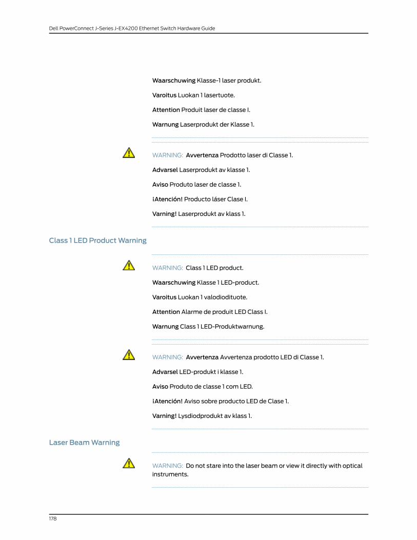
Waarschuwing Klasse-1 laser produkt.
Varoitus Luokan 1 lasertuote.
Attention Produit laser de classe I.
Warnung Laserprodukt der Klasse 1.
WARNING: Avvertenza Prodotto laser di Classe 1.
Advarsel Laserprodukt av klasse 1.
Aviso Produto laser de classe 1.
¡Atención! Producto láser Clase I.
Varning! Laserprodukt av klass 1.
Class 1 LED ProductWarning
WARNING: Class 1 LED product.
Waarschuwing Klasse 1 LED-product.
Varoitus Luokan 1 valodiodituote.
Attention Alarme de produit LED Class I.
Warnung Class 1 LED-Produktwarnung.
WARNING: Avvertenza Avvertenza prodotto LED di Classe 1.
Advarsel LED-produkt i klasse 1.
Aviso Produto de classe 1 com LED.
¡Atención! Aviso sobre producto LED de Clase 1.
Varning! Lysdiodprodukt av klass 1.
Laser BeamWarning
WARNING: Do not stare into the laser beam or view it directly with opticalinstruments.
178
Dell PowerConnect J-Series J-EX4200 Ethernet Switch Hardware Guide

WARNING: WaarschuwingNiet in de straal staren of hem rechtstreeksbekijkenmet optische instrumenten.
WARNING: VaroitusÄläkatsosäteeseenäläkätarkastelesitäsuoraanoptisenlaitteen avulla.
WARNING: AttentionNe pas fixer le faisceau des yeux, ni l'observerdirectement à l'aide d'instruments optiques.
WARNING: WarnungNicht direkt in den Strahl blicken und ihn nicht direktmit optischen Geräten prüfen.
WARNING: AvvertenzaNon fissare il raggio con gli occhi né usare strumentiottici per osservarlo direttamente.
WARNING: Advarsel Stirr eller se ikke direkte p strlenmed optiskeinstrumenter.
WARNING: AvisoNão olhe fixamente para o raio, nem olhe para eledirectamente com instrumentos ópticos.
WARNING: ¡Atención!Nomirar fijamente el haz ni observarlo directamentecon instrumentos ópticos.
WARNING: Varning! Rikta inte blicken in mot strålen och titta inte direkt påden genom optiska instrument.
RelatedDocumentation
General Safety Guidelines and Warnings for J-EX Series Switches on page 171•
• Radiation from Open Port Apertures Warning for J-EX Series Switches on page 180
• Installation Instructions Warning for J-EX Series Switches on page 183
• Grounded Equipment Warning for J-EX Series Switches on page 190
• Optical Interface Support in J-EX4200 Switches on page 32
179
Chapter 18: Radiation and Laser Warnings

Radiation fromOpen Port AperturesWarning for J-EX Series Switches
WARNING: Because invisible radiationmight be emitted from the apertureof the portwhen no fiber cable is connected, avoid exposure to radiation anddo not stare into open apertures.
WARNING: WaarschuwingAangezienonzichtbarestralingvanuitdeopeningvan de poort kan komen als er geen fiberkabel aangesloten is, dientblootstellingaanstralingenhetkijken inopenopeningenvermedenteworden.
WARNING: Varoitus Koska portin aukosta voi emittoitua näkymätöntäsäteilyä, kunkuitukaapelia ei ole kytkettynä, vältä säteilylle altistumistaäläkäkatso avoimiin aukkoihin.
WARNING: Attention Des radiations invisibles à l'il nu pouvant traverserl'ouverture du port lorsqu'aucun câble en fibre optique n'y est connecté, ilest recommandé de ne pas regarder fixement l'intérieur de ces ouvertures.
WARNING: Warnung Aus der Port-Öffnung können unsichtbare Strahlenemittieren, wenn kein Glasfaserkabel angeschlossen ist. Vermeiden Sie es,sich den Strahlungen auszusetzen, und starren Sie nicht in die Öffnungen!
WARNING: AvvertenzaQuando i cavi in fibra non sono inseriti, radiazioniinvisibili possono essere emesse attraverso l'apertura della porta. Evitate diesporvi alle radiazioni e non guardate direttamente nelle aperture.
WARNING: AdvarselUnngå utsettelse for stråling, og stirr ikke inn i åpningersom er åpne, fordi usynlig stråling kan emiteres fra portens åpning når detikke er tilkoblet en fiberkabel.
WARNING: Aviso Dada a possibilidade de emissão de radiação invisívelatravés do orifício da via de acesso, quando esta não tiver nenhum cabo defibra conectado, deverá evitar a exposição à radiação e não deverá olharfixamente para orifícios que se encontrarem a descoberto.
180
Dell PowerConnect J-Series J-EX4200 Ethernet Switch Hardware Guide

WARNING: ¡Atención! Debido a que la apertura del puerto puede emitirradiación invisible cuando no existe un cable de fibra conectado, evite mirardirectamente a las aperturas para no exponerse a la radiación.
WARNING: Varning!Osynlig strålning kan avges från en portöppning utanansluten fiberkabelochdubördärförundvikaattbli utsatt för strålninggenomatt inte stirra in i oskyddade öppningar.
RelatedDocumentation
• General Safety Guidelines and Warnings for J-EX Series Switches on page 171
• Laser and LED Safety Guidelines and Warnings for J-EX Series Switches on page 177
• Installation Instructions Warning for J-EX Series Switches on page 183
• Grounded Equipment Warning for J-EX Series Switches on page 190
181
Chapter 18: Radiation and Laser Warnings

182
Dell PowerConnect J-Series J-EX4200 Ethernet Switch Hardware Guide

CHAPTER 19
Installation and Maintenance SafetyInformation
• Installation Instructions Warning for J-EX Series Switches on page 183
• Chassis Lifting Guidelines for J-EX4200 Switches on page 184
• Ramp Warning for J-EX Series Switches on page 184
• Rack-Mounting and Cabinet-Mounting Warnings for J-EX Series Switches on page 185
• Wall-Mounting Warning for J-EX4200 Switches on page 189
• Grounded Equipment Warning for J-EX Series Switches on page 190
• Maintenance and Operational Safety Guidelines and Warnings for J-EX Series
Switches on page 190
Installation InstructionsWarning for J-EX Series Switches
WARNING: Read the installation instructions before you connect the switchto a power source.
WaarschuwingRaadpleegde installatie-aanwijzingenvoordatuhetsysteemmet de voeding verbindt.
VaroitusLueasennusohjeetennen järjestelmänyhdistämistävirtalähteeseen.
AttentionAvantdebrancher lesystèmesur lasourced'alimentation,consulterles directives d'installation.
Warnung Lesen Sie die Installationsanweisungen, bevor Sie das System andie Stromquelle anschließen.
AvvertenzaConsultare le istruzionidi installazioneprimadicollegare il sistemaall'alimentatore.
Advarsel Les installasjonsinstruksjonene før systemet kobles til strømkilden.
Aviso Leia as instruções de instalação antes de ligar o sistema à sua fontede energia.
183

¡Atención! Ver las instrucciones de instalación antes de conectar el sistemaa la red de alimentación.
Varning! Läs installationsanvisningarna innan du kopplar systemet till dessströmförsörjningsenhet.
RelatedDocumentation
General Safety Guidelines and Warnings for J-EX Series Switches on page 171•
• Laser and LED Safety Guidelines and Warnings for J-EX Series Switches on page 177
• Grounded Equipment Warning for J-EX Series Switches on page 190
• Connecting AC Power to a J-EX4200 Switch on page 117
Chassis Lifting Guidelines for J-EX4200 Switches
The weight of a fully loaded J-EX4200 switch chassis is approximately 22 lb (10 kg).
Observe the following guidelines for lifting and moving a or J-EX4200 switch:
• Before installing a J-EX4200 switch, read the guidelines in “Site Preparation Checklist
for J-EX4200 Switches” on page 57 to verify that the intended site meets the specified
power, environmental, and clearance requirements.
• Before lifting or moving the J-EX4200 switch, disconnect all external cables.
• As when lifting any heavy object, lift most of the weight with your legs rather than your
back. Keep your knees bent and your back relatively straight and avoid twisting your
body as you lift. Balance the load evenly and be sure that your footing is solid.
RelatedDocumentation
General Safety Guidelines and Warnings for J-EX Series Switches on page 171•
• Installation Instructions Warning for J-EX Series Switches on page 183
• Mounting a or J-EX4200 Switch on page 90
RampWarning for J-EX Series Switches
WARNING: When installing the switch, do not use a ramp inclined at morethan 10 degrees.
WaarschuwingGebruik een oprijplaat niet onder een hoek vanmeer dan 10graden.
VaroitusÄläkäytäsellaistakaltevaapintaa, jonkakaltevuusylittää 10astetta.
AttentionNe pas utiliser une rampe dont l'inclinaison est supérieure à 10degrés.
WarnungKeine Rampenmit einer Neigung vonmehr als 10 Grad verwenden.
184
Dell PowerConnect J-Series J-EX4200 Ethernet Switch Hardware Guide

AvvertenzaNon usare una rampa con pendenza superiore a 10 gradi.
Advarsel Bruk aldri en rampe som heller mer enn 10 grader.
AvisoNão utilize uma rampa com uma inclinação superior a 10 graus.
¡Atención!No usar una rampa inclinadamás de 10 grados
Varning! Använd inte rampmed en lutning påmer än 10 grader.
RelatedDocumentation
General Safety Guidelines and Warnings for J-EX Series Switches on page 171•
• Laser and LED Safety Guidelines and Warnings for J-EX Series Switches on page 177
• Installation Instructions Warning for J-EX Series Switches on page 183
• Grounded Equipment Warning for J-EX Series Switches on page 190
Rack-Mounting and Cabinet-MountingWarnings for J-EX Series Switches
Ensure that the rack or cabinet in which the J-EX Series switch is installed is evenly and
securely supported. Uneven mechanical loading could lead to a hazardous condition.
WARNING: To prevent bodily injury whenmounting or servicing the switchin a rack, take the following precautions to ensure that the system remainsstable. The following directives helpmaintain your safety:
• The switchmust be installed in a rack that is secured to the buildingstructure.
• The switch should bemounted at the bottom of the rack if it is the onlyunit in the rack.
• Whenmounting the switch on a partially filled rack, load the rack from thebottom to the topwith the heaviest component at the bottom of the rack.
• If the rack is providedwith stabilizing devices, install the stabilizers beforemounting or servicing the switch in the rack.
WARNING: WaarschuwingOm lichamelijk letsel te voorkomenwanneer udit toestel in een rekmonteert of het daar een servicebeurt geeft, moet uspeciale voorzorgsmaatregelen nemen om ervoor te zorgen dat het toestelstabiel blijft. De onderstaande richtlijnen worden verstrekt om uw veiligheidte verzekeren:
185
Chapter 19: Installation and Maintenance Safety Information

• De switchmoet in een stellage worden geïnstalleerd die aan een bouwselis verankerd.
• Dit toestel dient onderaan in het rek gemonteerd teworden als het toestelhet enige in het rek is.
• Wanneer u dit toestel in een gedeeltelijk gevuld rekmonteert, dient u hetrekvanonderennaarboven te ladenmethet zwaarsteonderdeelonderaanin het rek.
• Als het rek voorzien is van stabiliseringshulpmiddelen, dient u destabilisatoren temonteren voordat u het toestel in het rekmonteert of hetdaar een servicebeurt geeft.
WARNING: Varoitus Kun laite asetetaan telineeseen tai huolletaan senollessa telineessä, on noudatettava erityisiä varotoimia järjestelmänvakavuuden säilyttämiseksi, jotta vältytään loukkaantumiselta. Noudataseuraavia turvallisuusohjeita:
• Switch on asennettava telineeseen, joka on kiinnitetty rakennukseen.
• Jos telineessä ei ole muita laitteita, aseta laite telineen alaosaan.
• Jos laite asetetaan osaksi täytettyyn telineeseen, aloita kuormittaminensen alaosasta kaikkein raskaimmalla esineellä ja siirry sitten sen yläosaan.
• Jos telinettä varten on vakaimet, asenna ne ennen laitteen asettamistatelineeseen tai sen huoltamista siinä.
WARNING: Attention Pour éviter toute blessure corporelle pendant lesopérations demontage ou de réparation de cette unité en casier, il convientdeprendredesprécautionsspécialesafindemaintenir la stabilitédusystème.Lesdirectivesci-dessoussontdestinéesàassurer laprotectiondupersonnel:
• Le rack sur lequel est monté le switch doit être fixé à la structure dubâtiment.
• Si cette unité constitue la seule unitémontéeencasier, elle doit êtreplacéedans le bas.
• Si cette unité est montée dans un casier partiellement rempli, charger lecasier de bas en haut en plaçant l'élément le plus lourd dans le bas.
• Si lecasier estéquipédedispositifs stabilisateurs, installer les stabilisateursavant demonter ou de réparer l'unité en casier.
186
Dell PowerConnect J-Series J-EX4200 Ethernet Switch Hardware Guide

WARNING: Warnung Zur Vermeidung von Körperverletzung beimAnbringenoderWarten dieser Einheit in einemGestell müssen Sie besondereVorkehrungen treffen, um sicherzustellen, daß das System stabil bleibt. Diefolgenden Richtlinien sollen zur Gewährleistung Ihrer Sicherheit dienen:
• Der switchmuß in einemGestell installiert werden, das in derGebäudestruktur verankert ist.
• Wenn diese Einheit die einzige im Gestell ist, sollte sie unten im Gestellangebracht werden.
• Bei Anbringung dieser Einheit in einem zum Teil gefüllten Gestell ist dasGestell von unten nach oben zu laden, wobei das schwerste Bauteil untenim Gestell anzubringen ist.
• Wird das Gestell mit Stabilisierungszubehör geliefert, sind zuerst dieStabilisatoren zu installieren, bevor Sie die Einheit im Gestell anbringenoder sie warten.
WARNING: Avvertenza Per evitare infortuni fisici durante il montaggio o lamanutenzione di questa unità in un supporto, occorre osservare specialiprecauzioni per garantire che il sistema rimanga stabile. Le seguenti direttivevengono fornite per garantire la sicurezza personale:
• Il switch deve essere installato in un telaio, il quale deve essere fissato allastruttura dell'edificio.
• Questa unità deve venire montata sul fondo del supporto, se si trattadell'unica unità damontare nel supporto.
• Quando questa unità vienemontata in un supporto parzialmente pieno,caricare il supporto dal basso all'alto, con il componente più pesantesistemato sul fondo del supporto.
• Se il supporto è dotato di dispositivi stabilizzanti, installare tali dispositiviprimadimontareodiprocedereallamanutenzionedell'unitànel supporto.
WARNING: AdvarselUnngå fysiske skader under montering ellerreparasjonsarbeid på denne enheten når den befinner seg i et kabinett. Værnøyemedat systemet er stabilt. Følgende retningslinjer er gitt for å verne omsikkerheten:
• Switchmå installeres i et stativ som er forankret til bygningsstrukturen.
• Denne enheten børmonteres nederst i kabinettet hvis dette er den enesteenheten i kabinettet.
187
Chapter 19: Installation and Maintenance Safety Information

• Vedmontering av denne enheten i et kabinett som er delvis fylt, skalkabinettet lastes frabunnenogoppmeddentyngstekomponentennedersti kabinettet.
• Hvis kabinettet er utstyrt med stabiliseringsutstyr, skal stabilisatoreneinstalleres før montering eller utføring av reparasjonsarbeid på enheten ikabinettet.
WARNING: Aviso Para se prevenir contra danos corporais aomontar oureparar estaunidadenumaestante, deverá tomarprecauçõesespeciais parase certificar de que o sistema possui um suporte estável. As seguintesdirectrizes ajudá-lo-ão a efectuar o seu trabalho com segurança:
• O switch deverá ser instalado numa prateleira fixa à estrutura do edificio.
• Esta unidade deverá ser montada na parte inferior da estante, caso sejaesta a única unidade a ser montada.
• Aomontar esta unidade numa estante parcialmente ocupada, coloque ositensmais pesados na parte inferior da estante, arrumando-os de baixopara cima.
• Se a estante possuir um dispositivo de estabilização, instale-o antes demontar ou reparar a unidade.
WARNING: ¡Atención!Paraevitar lesionesduranteelmontajedeesteequiposobre un bastidor, o posteriormente durante sumantenimiento, se debeponermucho cuidado en que el sistema quede bien estable. Para garantizarsu seguridad, proceda según las siguientes instrucciones:
• El switch debe instalarse en un bastidor fijado a la estructura del edificio.
• Colocar el equipo en la parte inferior del bastidor, cuando sea la únicaunidad en el mismo.
• Cuandoesteequiposevayaa instalarenunbastidorparcialmenteocupado,comenzar la instalación desde la parte inferior hacia la superior colocandoel equipomás pesado en la parte inferior.
• Si el bastidor dispone de dispositivos estabilizadores, instalar éstos antesdemontaroprocederalmantenimientodel equipo instaladoenelbastidor.
WARNING: Varning!Förattundvikakroppsskadanärdu installerar eller utförunderhållsarbete på denna enhet på en ställningmåste du vidta särskilda
188
Dell PowerConnect J-Series J-EX4200 Ethernet Switch Hardware Guide

försiktighetsåtgärder föratt försäkradigomattsystemetstår stadigt. Följanderiktlinjer ges för att trygga din säkerhet:
• Switchmåste installeras i en ställning som är förankrad i byggnadensstruktur.
• Omdenna enhet är den enda enheten på ställningen skall den installeraslängst ned på ställningen.
• Omdenna enhet installeras på en delvis fylld ställning skall ställningenfyllasnedifrånochupp,meddetyngstaenheterna längstnedpåställningen.
• Omställningenär förseddmedstabiliseringsdonskalldessamonteras fastinnan enheten installeras eller underhålls på ställningen.
RelatedDocumentation
General Safety Guidelines and Warnings for J-EX Series Switches on page 171•
• Installation Instructions Warning for J-EX Series Switches on page 183
• Grounded Equipment Warning for J-EX Series Switches on page 190
• Mounting a J-EX4200 Switch on page 90
Wall-MountingWarning for J-EX4200 Switches
WARNING: Whenmounted in a vertical position, a J-EX4200 chassis mustbeorientedwith the frontpanelof thechassispointingdowntoensureproperairflow andmeet safety requirements in the event of a fire.
WARNING: Avertissement: lorsqu’installé en position verticale, un châssisde commutation J-EX4200 doit être orienté avec le panneau avant dirigévers le bas.
WARNING: Warnhinweis: Bei der Befestigung in vertikaler Positionmuss einJ-EX4200-Switch-Gehäuse so ausgerichtet werden, dass das vordereBedienfeld des Switch-Gehäuses nach unten zeigt.
RelatedDocumentation
Mounting a J-EX4200 Switch on a Wall on page 100•
189
Chapter 19: Installation and Maintenance Safety Information

Grounded EquipmentWarning for J-EX Series Switches
WARNING: Theswitch is intended tobegrounded.Duringnormaluse, ensurethat you have connected earth ground to the switch chassis.
Waarschuwing Deze apparatuur hoort geaard te worden Zorg dat dehost-computer tijdens normaal gebruik met aarde is verbonden.
Varoitus Tämä laitteisto on tarkoitettumaadoitettavaksi. Varmista, ettäisäntälaite on yhdistetty maahan normaalikäytön aikana.
Attention Cet équipement doit être relié à la terre. S'assurer que l'appareilhôte est relié à la terre lors de l'utilisation normale.
Warnung Dieses Gerät muß geerdet werden. Stellen Sie sicher, daß dasHost-Gerät während des normalen Betriebs an Erde gelegt ist.
AvvertenzaQuestaapparecchiaturadeveesserecollegataamassa.Accertarsiche il dispositivo host sia collegato alla massa di terra durante il normaleutilizzo.
AdvarselDette utstyret skal jordes. Forviss deg om vertsterminalen er jordetved normalt bruk.
Aviso Este equipamento deverá estar ligado à terra. Certifique-se que o hostse encontra ligado à terra durante a sua utilização normal.
¡Atención!Esteequipodebeconectarsea tierra.Asegurarsedequeel equipoprincipal esté conectado a tierra durante el uso normal.
Varning! Denna utrustning är avsedd att jordas. Se till att värdenheten ärjordad vid normal användning.
RelatedDocumentation
General Safety Guidelines and Warnings for J-EX Series Switches on page 171•
• Connecting Earth Ground to a J-EX Series Switch on page 115
MaintenanceandOperationalSafetyGuidelinesandWarnings for J-EXSeriesSwitches
While performing the maintenance activities for J-EX Series switches, observe the
following guidelines and warnings:
• Jewelry Removal Warning on page 191
• Lightning Activity Warning on page 192
• Operating Temperature Warning on page 193
• Product Disposal Warning on page 195
190
Dell PowerConnect J-Series J-EX4200 Ethernet Switch Hardware Guide

Jewelry RemovalWarning
WARNING: Before working on equipment that is connected to power lines,remove jewelry, including rings, necklaces, and watches. Metal objects heatupwhen connected to power and ground and can cause serious burns or canbe welded to the terminals.
WARNING: Waarschuwing Alvorens aan apparatuur te werken die metelektrische leidingen is verbonden, sieraden (inclusief ringen, kettingen enhorloges) verwijderen. Metalen voorwerpen worden warmwanneer zemetstroomenaardezijnverbonden,enkunnenernstigebrandwondenveroorzakenof het metalen voorwerp aan de aansluitklemmen lassen.
WARNING: VaroitusEnnenkuin työskentelet voimavirtajohtoihin kytkettyjenlaitteiden parissa, ota pois kaikki korut (sormukset, kaulakorut ja kellotmukaan lukien). Metalliesineet kuumenevat, kun ne ovat yhteydessäsähkövirran jamaan kanssa, ja ne voivat aiheuttaa vakavia palovammoja taihitsatametalliesineet kiinni liitäntänapoihin.
WARNING: AttentionAvantd'accéderàcetéquipementconnectéaux lignesélectriques, ôter tout bijou (anneaux, colliers etmontres compris). Lorsqu'ilssont branchés à l'alimentation et reliés à la terre, les objets métalliqueschauffent, ce qui peut provoquer des blessures graves ou souder l'objetmétallique aux bornes.
WARNING: WarnungVorderArbeitanGeräten,dieandasNetzangeschlossensind, jeglichenSchmuck(einschließlichRinge,KettenundUhren)abnehmen.Metallgegenstände erhitzen sich, wenn sie an das Netz und die Erdeangeschlossen werden, und können schwere Verbrennungen verursachenoder an die Anschlußklemmen angeschweißt werden.
WARNING: Avvertenza Prima di intervenire su apparecchiature collegatealle linee di alimentazione, togliersi qualsiasi monile (inclusi anelli, collane,braccialetti ed orologi). Gli oggetti metallici si riscaldano quando sonocollegati tra punti di alimentazione emassa: possono causare ustioni gravioppure il metallo può saldarsi ai terminali.
191
Chapter 19: Installation and Maintenance Safety Information

WARNING: AdvarselFjernallesmykker(inkludert ringer,halskjederogklokker)førduskalarbeidepåutstyr somerkoblet til kraftledninger.Metallgjenstandersom er koblet til kraftledninger og jord blir svært varme og kan forårsakealvorlige brannskader eller smelte fast til polene.
WARNING: Aviso Antes de trabalhar em equipamento que esteja ligado alinhas de corrente, retire todas as jóias que estiver a usar (incluindo anéis,fiose relógios).Osobjectosmetálicosaquecerãoemcontactocomacorrentee em contacto com a ligação à terra, podendo causar queimaduras gravesou ficarem soldados aos terminais.
WARNING: ¡Atención! Antes de operar sobre equipos conectados a líneasde alimentación, quitarse las joyas (incluidos anillos, collares y relojes). Losobjetosdemetal secalientancuandoseconectana laalimentaciónyatierra,lo que puede ocasionar quemaduras graves o que los objetosmetálicosqueden soldados a los bornes.
WARNING: Varning! Tag av alla smycken (inklusive ringar, halsband ocharmbandsur) innanduarbetarpåutrustningsomärkoppladtill kraftledningar.Metallobjekt hettas upp när de kopplas ihopmed ström och jord och kanförorsaka allvarliga brännskador; metallobjekt kan också sammansvetsasmed kontakterna.
Lightning ActivityWarning
WARNING: Donotworkon thesystemorconnectordisconnectcablesduringperiods of lightning activity.
WARNING: Waarschuwing Tijdens onweer dat gepaard gaat met bliksem,dient u niet aan het systeem te werken of kabels aan te sluiten of teontkoppelen.
WARNING: Varoitus Älä työskentele järjestelmän parissa äläkä yhdistä taiirrota kaapeleita ukkosilmalla.
WARNING: AttentionNe pas travailler sur le système ni brancher oudébrancher les câbles pendant un orage.
192
Dell PowerConnect J-Series J-EX4200 Ethernet Switch Hardware Guide

WARNING: Warnung Arbeiten Sie nicht am System und schließen Sie keineKabel an bzw. trennen Sie keine ab, wenn es gewittert.
WARNING: AvvertenzaNonlavoraresulsistemaocollegareoppurescollegarei cavi durante un temporale con fulmini.
WARNING: AdvarselUtfør aldri arbeid på systemet, eller koble kabler til ellerfra systemet når det tordner eller lyner.
WARNING: AvisoNão trabalhe no sistemaou ligue e desligue cabos duranteperíodos demau tempo (trovoada).
WARNING: ¡Atención!Nooperarel sistemaniconectarodesconectarcablesdurante el transcurso de descargas eléctricas en la atmósfera.
WARNING: Varning! Vid åska skall du aldrig utföra arbete på systemet elleransluta eller koppla loss kablar.
Operating TemperatureWarning
WARNING: To prevent the switch from overheating, do not operate it in anarea that exceeds themaximum recommended ambient temperature of104° F (40° C). To prevent airflow restriction, allow at least 6 in. (15.2 cm)of clearance around the ventilation openings.
WARNING: WaarschuwingOmtevoorkomendatwelkeswitchvandeswitchdan ook oververhit raakt, dient u deze niet te bedienen op een plaats waardemaximale aanbevolen omgevingstemperatuur van 40° Cwordtoverschreden. Om te voorkomen dat de luchtstroomwordt beperkt, dient erminstens 15,2 cm speling rond de ventilatie-openingen te zijn.
WARNING: Varoitus Ettei switch-sarjan reititin ylikuumentuisi, sitä ei saakäyttää tilassa, jonka lämpötila ylittää korkeimman suositellunympäristölämpötilan 40° C. Ettei ilmanvaihto estyisi, tuuletusaukkojenympärille on jätettävä ainakin 15,2 cm tilaa.
193
Chapter 19: Installation and Maintenance Safety Information

WARNING: AttentionPour éviter toute surchauffe des routeurs de la gammeswitch, ne l'utilisez pas dans une zone où la température ambiante estsupérieure à 40°C. Pour permettre un flot d'air constant, dégagez un espaced'aumoins 15,2 cm autour des ouvertures de ventilations.
WARNING: WarnungUmeinenRouterderswitchvorÜberhitzungzuschützen,darf dieser nicht in einer Gegend betrieben werden, in der dieUmgebungstemperatur das empfohleneMaximumvon 40° C überschreitet.Um Lüftungsverschluß zu verhindern, achten Sie darauf, daßmindestens15,2 cm lichter Raum um die Lüftungsöffnungen herum frei bleibt.
WARNING: Avvertenza Per evitare il surriscaldamento dei switch, nonadoperateli in un locale che ecceda la temperatura ambientale massima di40°C.Perevitareche lacircolazionedell'aria sia impedita, lasciateunospaziodi almeno 15.2 cm di fronte alle aperture delle ventole.
WARNING: AdvarselUnngåoveropphetingaveventuelle rutere i switchDisseskal ikke brukes på steder der den anbefalte maksimaleomgivelsestemperaturen overstiger 40° C (104° F). Sørg for at klaringenrundt lufteåpningene er minst 15,2 cm (6 tommer) for å forhindre nedsattluftsirkulasjon.
WARNING: Aviso Para evitar o sobreaquecimento do encaminhador switch,não utilize este equipamento numa área que exceda a temperaturamáximarecomendada de 40° C. Para evitar a restrição à circulação de ar, deixe pelomenos um espaço de 15,2 cm à volta das aberturas de ventilação.
WARNING: ¡Atención! Para impedir que un encaminador de la serie switchse recaliente, no lo haga funcionar en un área en la que se supere latemperatura ambientemáxima recomendada de 40° C. Para impedir larestricciónde laentradadeaire, dejeunespaciomínimode 15,2 cmalrededorde las aperturas para ventilación.
WARNING: Varning! Förhindra att en switch överhettas genom att inteanvända den i ett område där denmaximalt rekommenderadeomgivningstemperaturenpå40°Cöverskrids. Förhindraatt luftcirkulationeninskränksgenomattse till attdet finns fritt utrymmepåminst 15,2cmomkringventilationsöppningarna.
194
Dell PowerConnect J-Series J-EX4200 Ethernet Switch Hardware Guide

Product DisposalWarning
WARNING: Disposalof thisproductmustbehandledaccording toall nationallaws and regulations.
WARNING: Waarschuwing Dit produkt dient volgens alle landelijke wettenen voorschriften te worden afgedankt.
WARNING: Varoitus Tämän tuotteen lopullisesta hävittämisestä tuleehuolehtia kaikkia valtakunnallisia lakeja ja säännöksiä noudattaen.
WARNING: Attention Lamise au rebut définitive de ce produit doit êtreeffectuée conformément à toutes les lois et réglementations en vigueur.
WARNING: Warnung Dieses Produkt muß den geltenden Gesetzen undVorschriften entsprechend entsorgt werden.
WARNING: Avvertenza L'eliminazione finale di questo prodotto deve essereeseguita osservando le normative italiane vigenti in materia
WARNING: AdvarselEndeligdisponeringavdetteproduktetmåskje ihenholdtil nasjonale lover og forskrifter.
WARNING: Aviso A descartagem final deste produto deverá ser efectuadade acordo com os regulamentos e a legislação nacional.
WARNING: ¡Atención! El desecho final de este producto debe realizarsesegún todas las leyes y regulaciones nacionales
WARNING: Varning!Slutlig kassering av denna produkt bör skötas i enlighetmed landets alla lagar och föreskrifter.
195
Chapter 19: Installation and Maintenance Safety Information

RelatedDocumentation
• General Safety Guidelines and Warnings for J-EX Series Switches on page 171
• General Electrical Safety Guidelines and Warnings for J-EX Series Switches on page 197
• AC Power Electrical Safety Guidelines for J-EX Series Switches on page 200
• Laser and LED Safety Guidelines and Warnings for J-EX Series Switches on page 177
• Installation Instructions Warning for J-EX Series Switches on page 183
• Grounded Equipment Warning for J-EX Series Switches on page 190
196
Dell PowerConnect J-Series J-EX4200 Ethernet Switch Hardware Guide

CHAPTER 20
Power and Electrical Safety Information
• General Electrical Safety Guidelines and Warnings for J-EX Series Switches on page 197
• Prevention of Electrostatic Discharge Damage on J-EX Series Switches on page 198
• AC Power Electrical Safety Guidelines for J-EX Series Switches on page 200
• AC Power Disconnection Warning for J-EX Series Switches on page 201
• Multiple Power Supplies Disconnection Warning for J-EX Series Switches on page 202
• Power Sources for Redundant Power Supplies Warning for J-EX4200
Switches on page 202
• TN Power Warning for J-EX Series Switches on page 202
• Action to Take After an Electrical Accident on page 203
General Electrical Safety Guidelines andWarnings for J-EX Series Switches
WARNING: Certain ports on the switch are designed for use as intrabuilding(within-the-building) interfaces only (Type 2 or Type 4 ports as described inGR-1089-CORE, Issue4)and require isolation fromtheexposedoutsideplant
(OSP) cabling. To comply with NEBS requirements and protect againstlightning surges and commercial power disturbances, the intrabuilding portsmust not bemetallically connected to interfaces that connect to the OSP orits wiring. The intrabuilding ports on the switch are suitable for connectionto intrabuilding or unexposed wiring or cabling only. The addition of primaryprotectors is not sufficient protection for connecting these interfacesmetallically to OSPwiring.
CAUTION: Before removing or installing components of a switch, attach anESD strap to an ESD point and place the other end of the strap around yourbare wrist. Failure to use an ESD strap could result in damage to the switch.
If a grounding strap is not available, hold the component in its antistatic bag(see Figure 65 on page 199) in one hand and touch the exposed, baremetalof theswitchwith theotherhand immediatelybefore inserting thecomponentinto the switch.
197

• Install the J-EX Series switch in compliance with the following local, national, and
international electrical codes:
• United States—National Fire Protection Association (NFPA 70), United States
National Electrical Code.
• Other countries—International Electromechanical Commission (IEC) 60364, Part 1
through Part 7.
• Evaluated to the TN power system.
• Canada—Canadian Electrical Code, Part 1, CSA C22.1.
• Locate the emergency power-off switch for the room in which you are working so that
if an electrical accident occurs, you can quickly turn off the power.
• Make sure that grounding surfaces are cleaned and brought to a bright finish before
grounding connections are made.
• Do not work alone if potentially hazardous conditions exist anywhere in your workspace.
• Never assume that power is disconnected from a circuit. Always check the circuit before
starting to work.
• Carefully look for possible hazards in your work area, such as moist floors, ungrounded
power extension cords, and missing safety grounds.
• Operate the J-EX Series switch within marked electrical ratings and product usage
instructions.
• To ensure that the J-EX Series switch and peripheral equipment function safely and
correctly, use the cables and connectors specified for the attached peripheral
equipment, and make certain they are in good condition.
You can remove and replace many switch components without powering off or
disconnecting power to the switch, as detailed elsewhere in the hardware documentation
for this product. Never install equipment if it appears damaged.
RelatedDocumentation
General Safety Guidelines and Warnings for J-EX Series Switches on page 171•
• AC Power Electrical Safety Guidelines for J-EX Series Switches on page 200
Prevention of Electrostatic Discharge Damage on J-EX Series Switches
Switch components that are shipped in antistatic bags are sensitive to damage from
static electricity. Some components can be impaired by voltages as low as 30 V. You
can easily generate potentially damaging static voltages whenever you handle plastic
or foam packing material or if you move components across plastic or carpets. Observe
the following guidelines to minimize the potential for electrostatic discharge (ESD)
damage, which can cause intermittent or complete component failures:
198
Dell PowerConnect J-Series J-EX4200 Ethernet Switch Hardware Guide

• Always use an ESD grounding strap when you are handling components that are subject
to ESD damage, and make sure that it is in direct contact with your skin.
If a grounding strap is not available, hold the component in its antistatic bag (see Figure
65 on page 199) in one hand and touch the exposed, bare metal of the switch with the
other hand immediately before inserting the component into the switch.
WARNING: For safety, periodically check the resistance value of the ESDstrap. Themeasurementmust be in the range of 1 through 10Mohms.
• When handling any component that is subject to ESD damage and that is removed
from the chassis, make sure the equipment end of your ESD strap is attached to the
ESD point on the chassis.
If no grounding strap is available, touch the exposed, bare metal of the switch to ground
yourself before handling the component.
• Avoid contact between the component that is subject to ESD damage and your clothing.
ESD voltages emitted from clothing can damage components.
• When removing or installing a component that is subject to ESD damage, always place
it component-side up on an antistatic surface, in an antistatic card rack, or in an
antistatic bag (see Figure 65 on page 199). If you are returning a component, place it in
an antistatic bag before packing it.
Figure 65: Place a Component into an Antistatic Bag
CAUTION: ANSI/TIA/EIA-568 cables such as category 5e and category 6can get electrostatically charged. In order to dissipate this charge, alwaysground the cables to a suitable and safe earth ground before connectingthem to the system.
RelatedDocumentation
General Safety Guidelines and Warnings for J-EX Series Switches on page 171•
• See Rear Panel of a J-EX4200 Switch on page 7 for the ESD point location.
199
Chapter 20: Power and Electrical Safety Information

AC Power Electrical Safety Guidelines for J-EX Series Switches
CAUTION: For switcheswithACpower supplies, an external surgeprotectivedevice (SPD)must be used at the AC power source.
The following electrical safety guidelines apply to AC-powered switches:
• Note the following warnings printed on the chassis:
“CAUTION: THIS UNIT HAS MORE THAN ONE POWER SUPPLY CORD. DISCONNECT
ALL POWER SUPPLY CORDS BEFORE SERVICING TO AVOID ELECTRIC SHOCK.”
“ATTENTION: CET APPAREIL COMPORTE PLUS D'UN CORDON D'ALIMENTATION.
AFIN DE PRÉVENIR LES CHOCS ÉLECTRIQUES, DÉBRANCHER TOUT CORDON
D'ALIMENTATION AVANT DE FAIRE LE DÉPANNAGE.”
• AC-powered switches are shipped with a three-wire electrical cord with a
grounding-type plug that fits only a grounding-type power outlet. Do not circumvent
this safety feature. Equipment grounding must comply with local and national electrical
codes.
• You must provide an external certified circuit breaker rated minimum 20 A in the building
installation.
• The power cord serves as the main disconnecting device for the switch. The socket
outlet must be near the switch and be easily accessible.
• For J-EX Series switches that have more than one power supply connection, you must
ensure that all power connections are fully disconnected so that power to the switch
is completely removed to avoid electric shock. To disconnect power, unplug all power
cords (one for each power supply).
Power CableWarning (Japanese)
WARNING: The attached power cable is only for this product. Do not use the cable for another product.
RelatedDocumentation
General Safety Guidelines and Warnings for J-EX Series Switches on page 171•
• General Electrical Safety Guidelines and Warnings for J-EX Series Switches on page 197
• Multiple Power Supplies Disconnection Warning for J-EX Series Switches on page 202
• Connecting AC Power to a J-EX4200 Switch on page 117
200
Dell PowerConnect J-Series J-EX4200 Ethernet Switch Hardware Guide

AC Power DisconnectionWarning for J-EX Series Switches
WARNING: Before working on the switch or near power supplies, unplug allthe power cords from an AC switch.
Waarschuwing Voordat u aan een frame of in de nabijheid van voedingenwerkt, dient u bij wisselstroom toestellen de stekker van het netsnoer uit hetstopcontact te halen.
Varoitus Kytke irti vaihtovirtalaitteiden virtajohto, ennen kuin teet mitäänasennuspohjalle tai työskentelet virtalähteiden läheisyydessä.
AttentionAvantde travailler surunchâssisouàproximitéd'unealimentationélectrique, débrancher le cordon d'alimentation des unités en courantalternatif.
Warnung Bevor Sie an einem Chassis oder in der Nähe von Netzgerätenarbeiten, ziehen Sie bei Wechselstromeinheiten das Netzkabel ab bzw.
AvvertenzaPrimadi lavorare suun telaioo intornoadalimentatori, scollegareil cavo di alimentazione sulle unità CA.
Advarsel Før det utføres arbeid på kabinettet eller det arbeides i nærhetenav strømforsyningsenheter, skal strømledningen trekkes ut påvekselstrømsenheter.
AvisoAntesdetrabalharnumchassis,ouantesdetrabalharpertodeunidadesde fornecimento de energia, desligue o cabo de alimentação nas unidadesde corrente alternada.
¡Atención!Antes demanipular el chasis de un equipoo trabajar cerca deunafuentedealimentación, desenchufar el cabledealimentaciónen losequiposde corriente alterna (CA).
Varning! Innanduarbetarmedett chassi eller nära strömförsörjningsenheterskall du för växelströmsenheter dra ur nätsladden.
RelatedDocumentation
General Safety Guidelines and Warnings for J-EX Series Switches on page 171•
• General Electrical Safety Guidelines and Warnings for J-EX Series Switches on page 197
• AC Power Electrical Safety Guidelines for J-EX Series Switches on page 200
201
Chapter 20: Power and Electrical Safety Information

Multiple Power Supplies DisconnectionWarning for J-EX Series Switches
WARNING: For J-EX Series switches that havemore than one power supplyconnection, youmustensure thatallpowerconnectionsare fullydisconnectedso that power to the switch is completely removed.
RelatedDocumentation
General Safety Guidelines and Warnings for J-EX Series Switches on page 171•
• General Electrical Safety Guidelines and Warnings for J-EX Series Switches on page 197
• AC Power Electrical Safety Guidelines for J-EX Series Switches on page 200
Power Sources for Redundant Power SuppliesWarning for J-EX4200 Switches
J-EX4200 switches have a redundant power supply. When you have redundant power
supplies in a switch, you must connect each power supply to a different input power
source. Failure to do so makes the switch susceptible to total power failure if one of the
power supplies fails.
RelatedDocumentation
General Safety Guidelines and Warnings for J-EX Series Switches on page 171•
• General Electrical Safety Guidelines and Warnings for J-EX Series Switches on page 197
• AC Power Electrical Safety Guidelines for J-EX Series Switches on page 200
TN PowerWarning for J-EX Series Switches
WARNING: The switch is designed to work with a TN power system.
WaarschuwingHet apparaat is ontworpen om te functionerenmet TNenergiesystemen.
Varoitus Koje on suunniteltu toimimaan TN-sähkövoimajärjestelmienyhteydessä.
Attention Ce dispositif a été conçu pour fonctionner avec des systèmesd'alimentation TN.
WarnungDasGerät ist fürdieVerwendungmitTN-Stromsystemenausgelegt.
Avvertenza Il dispositivo è stato progettato per l'uso con sistemi dialimentazione TN.
202
Dell PowerConnect J-Series J-EX4200 Ethernet Switch Hardware Guide

AdvarselUtstyret er utfomet til brukmed TN-strømsystemer.
AvisoO dispositivo foi criado para operar com sistemas de corrente TN.
¡Atención! El equipo está diseñado para trabajar con sistemas dealimentación tipo TN.
Varning! Enheten är konstruerad för användning tillsammansmedelkraftssystem av TN-typ.
RelatedDocumentation
General Safety Guidelines and Warnings for J-EX Series Switches on page 171•
• General Electrical Safety Guidelines and Warnings for J-EX Series Switches on page 197
• Grounded Equipment Warning for J-EX Series Switches on page 190
• Multiple Power Supplies Disconnection Warning for J-EX Series Switches on page 202
Action to Take After an Electrical Accident
If an electrical accident results in an injury, take the following actions in this order:
1. Use caution. Be aware of potentially hazardous conditions that could cause further
injury.
2. Disconnect power from the switch.
3. If possible, send another person to get medical aid. Otherwise, assess the condition
of the victim, then call for help.
RelatedDocumentation
• General Safety Guidelines and Warnings for J-EX Series Switches on page 171
• General Electrical Safety Guidelines and Warnings for J-EX Series Switches on page 197
• AC Power Electrical Safety Guidelines for for J-EX Series Switches on page 200
203
Chapter 20: Power and Electrical Safety Information

204
Dell PowerConnect J-Series J-EX4200 Ethernet Switch Hardware Guide

PART 9
Compliance Information
• Compliance Information on page 207
205

206
Dell PowerConnect J-Series J-EX4200 Ethernet Switch Hardware Guide

CHAPTER 21
Compliance Information
• Agency Approvals for J-EX Series Switches on page 207
• Compliance Statements for EMC Requirements for J-EX Series Switches on page 208
• Compliance Statements for Acoustic Noise for J-EX Series Switches on page 210
• Declarations of Conformity for J-EX4200 Switches on page 211
Agency Approvals for J-EX Series Switches
J-EX Series switches comply with the following standards:
• Safety
• CAN/CSA-22.2 No. 60950–1–03/UL 60950–1. Safety of Information Technology
Equipment
• EN 60950–1:2001. Safety of Information Technology Equipment
• EN 60825–1 Safety of Laser Products – Part 1: Equipment Classification,
Requirements and User's Guide
• EMC
• FCC 47CFR Part 15 Class A (USA)
• EN 55022 Class A Emissions (Europe)
• ICES-003 Class A
• VCCI Class A (Japan)
• AS/NZS CISPR 22 Class A (Australia/New Zealand)
• CISPR 22 Class A
• EN 55024
• EN 300386
• EN 61000-3-2 Power Line Harmonics
• EN 61000-3-3 Voltage Fluctuations and Flicker
207

• EN 61000-4-2 ESD
• EN 61000-4-3 Radiated Immunity
• EN 61000-4-4 EFT
• EN 61000-4-5 Surge
• EN 61000-4-6 Low Frequency Common Immunity
• EN 61000-4-11 Voltage Dips and Sags
RelatedDocumentation
Compliance Statements for EMC Requirements for J-EX Series Switches on page 208•
• Compliance Statements for Acoustic Noise for J-EX Series Switches on page 210
Compliance Statements for EMC Requirements for J-EX Series Switches
This topic describes the EMC requirements for J-EX Series switches for:
• Canada on page 208
• European Community on page 209
• Japan on page 209
• United States on page 209
• FCC Part 15 Statement on page 209
• Non-Regulatory Environmental Standards on page 210
Canada
This Class A digital apparatus complies with Canadian ICES-003.
Cet appareil numérique de la classe A est conforme à la norme NMB-003 du Canada.
The Industry Canada label identifies certified equipment. This certification means that
the equipment meets certain telecommunications network protective, operational, and
safety requirements. Industry Canada does not guarantee the equipment will operate to
the users’ satisfaction.
Before installing this equipment, users should ensure that it is permissible to connect the
equipment to the facilities of the local telecommunications company. The equipment
must also be installed using an acceptable method of connection. In some cases, the
inside wiring associated with a single line individual service may be extended by means
of a certified connector assembly. The customer should be aware that compliance with
the above conditions may not prevent degradation of service in some situations.
Repairs to certified equipment should be made by an authorized Canadian maintenance
facility designated by the supplier. Any repairs or alterations made by the user to this
equipment, or equipment malfunctions, may give the telecommunications company
cause to request the user to disconnect the equipment.
208
Dell PowerConnect J-Series J-EX4200 Ethernet Switch Hardware Guide

CAUTION: Users should not attempt tomake electrical ground connectionsby themselves, but should contact the appropriate inspection authority oran electrician, as appropriate.
Users should ensure for their own protection that the electrical ground connections of
the power utility, telephone lines, and internal metallic water pipe system, if present, are
connected together. This precaution may be particularly important in rural areas.
European Community
This is a Class A product. In a domestic environment this product may cause radio
interference in which case the user may be required to take adequate measures.
Japan
The preceding translates as follows:
This is a Class A product. In a domestic environment this product may cause radio
interference in which case the user may be required to take adequate measures.
VCCI-A
United States
The J-EX Series switch has been tested and found to comply with the limits for a Class A
digital device, pursuant to Part 15 of the FCC Rules. These limits are designed to provide
reasonable protection against harmful interference when the equipment is operated in
a commercial environment. This equipment generates, uses, and can radiate radio
frequency energy and, if not installed and used in accordance with the instruction manual,
may cause harmful interference to radio communications. Operation of this equipment
in a residential area is likely to cause harmful interference in which case the user will be
required to correct the interference at his own expense.
FCC Part 15 Statement
This equipment has been tested and found to comply with the limits for a Class A digital
device pursuant to Part 15 of the FCC Rules. These limits are designed to provide
reasonable protection against harmful interference in a residential installation. This
equipment generates, uses, and can radiate radio frequency energy and, if not installed
and used in accordance with the instructions, may cause harmful interference to radio
communications. However, there is no guarantee that interference will not occur in a
particular installation.
209
Chapter 21: Compliance Information

If this equipment does cause harmful interference to radio or television reception, which
can be determined by turning the equipment off and on, the user is encouraged to try
and correct the interference by one or more of the following measures:
• Reorient or relocate the receiving antenna.
• Increase the separation between the equipment and the receiver.
• Connect the equipment into an outlet on a circuit different from that to which the
receiver is connected.
• Consult the dealer or an experienced radio or TV technician for help.
Non-Regulatory Environmental Standards
NEBS compliance—These J-EX Series switch models are Network Equipment Building
System (NEBS) compliant:
• J-EX4200-24F, J-EX4200-24T, and J-EX4200-48T
Those switch models meet the following NEBS compliance standards:
• SR-3580 NEBS Criteria Levels (Level 3 Compliance)
• GR-1089-CORE: EMC and Electrical Safety for Network Telecommunications Equipment
• GR-63-CORE: NEBS, Physical Protection
• The equipment is suitable for installation as part of the Common Bonding Network
(CBN).
• The equipment is suitable for installation in locations where the National Electrical
Code (NEC) applies.
• The battery return connection is to be treated as an Isolated DC return (DC-I), as
defined in GR-1089-CORE.
RelatedDocumentation
Agency Approvals for J-EX Series Switches on page 207•
• Compliance Statements for Acoustic Noise for J-EX Series Switches on page 210
Compliance Statements for Acoustic Noise for J-EX Series Switches
Maschinenlärminformations-Verordnung - 3. GPSGV, der höchste Schalldruckpegel
beträgt 70 dB(A) oder weniger gemäss EN ISO 7779
Translation:
The emitted sound pressure is below 70 dB(A) per EN ISO 7779.
RelatedDocumentation
Agency Approvals for J-EX Series Switches on page 207•
• Compliance Statements for EMC Requirements for J-EX Series Switches on page 208
210
Dell PowerConnect J-Series J-EX4200 Ethernet Switch Hardware Guide

Declarations of Conformity for J-EX4200 Switches
211
Chapter 21: Compliance Information

RelatedDocumentation
• Agency Approvals for J-EX Series Switches on page 207
• Compliance Statements for EMC Requirements for J-EX Series Switches on page 208
• Compliance Statements for Acoustic Noise for J-EX Series Switches on page 210
212
Dell PowerConnect J-Series J-EX4200 Ethernet Switch Hardware Guide

PART 10
Index
• Index on page 215
213

214
Dell PowerConnect J-Series J-EX4200 Ethernet Switch Hardware Guide

Index
Symbols2-post rack installation.........................................................92
4-post rack installation........................................................96
AAC plug types............................................................................73
AC power
connecting........................................................................117
disconnecting................................................................140
disconnection warning...............................................201
power cord specifications............................................71
power supply LEDs........................................................24
safety guidelines and warnings.............................200
accident, action to take after...........................................203
acoustic noise compliance................................................210
agency approvals.................................................................207
airflow
cabinet requirements...................................................64
clearance requirements..............................................66
cooling system................................................................24
maintaining......................................................................60
ALM (alarm) LED.............................................................16, 119
altitude, acceptable range..................................................60
approvals, agency................................................................207
Australia-New Zealand Declaration of
Conformity............................................................................211
autoprovisioning in Virtual Chassis..................................82
Bbefore you call........................................................................164
Ccabinet requirements............................................................64
cables
AC plug types...................................................................73
AC power cord specifications.....................................71
fiber-optic, maintaining.............................................153
for Virtual Chassis configurations.............................77
grounding, connecting.................................................115
jumper cable......................................................................71
network cable specifications....................................69
reducing radio frequency interference
(RFI)...............................................................................60
Virtual Chassis, connecting........................................112
Virtual Chassis, disconnecting.................................147
cage nuts
installing.....................................................................93, 97
removing..........................................................................150
Canadian EMC compliance.............................................208
certification and training, Dell..........................................163
chassis
component serial number labels...........................166
lifting guidelines...........................................................184
physical specifications...................................................5
status LEDs.......................................................................16
checklist for site preparation..............................................57
clearance requirements.......................................................66
CLI terminology mapping.......................................................8
clip nuts See cage nuts
compliance
acoustic noise................................................................210
Canadian EMC.............................................................208
declarations of conformity.........................................211
EMC requirements......................................................208
European EMC.............................................................209
FCC EMC.........................................................................209
general standards........................................................207
Japanese EMC..............................................................209
NEBS.................................................................................210
United States EMC.....................................................209
components
installation......................................................................105
packing for shipping....................................................168
provided with the switch............................................89
serial number label......................................................166
configuration, factory default............................................127
configuring the switch
CLI........................................................................................131
J-Web................................................................................133
conformity declarations.......................................................211
215

connecting
fiber-optic cable............................................................125
management console connection..........................121
modem connection......................................................122
out-of-band management connection...............120
power..................................................................................117
switch to earth ground........................................115, 116
Virtual Chassis cable....................................................112
connector port pinouts.........................................................30
console port
connecting to a modem.............................................124
pinouts...............................................................................30
setting the speed for a modem
connection..................................................................122
contacting Dell.......................................................................165
conventions, documentation.............................................xiv
cooling system.........................................................................24
See also fan tray
See also temperature
cooling, ensuring.....................................................................60
customer support...........................................................xvi, 161
Ddeclarations of conformity..................................................211
default factory configuration.............................................127
Dell automated order-status service............................163
Dell Enterprise Training and Certification....................163
Dell online services...............................................................162
Dell product information....................................................163
Dell Support.............................................................................161
Dell support service, contacting......................................163
Dell, contacting......................................................................165
depth, chassis.............................................................................5
desk installation
instructions........................................................................91
requirements...................................................................66
diagnostic checklist.............................................................164
disconnecting
fiber-optic cable...........................................................146
Virtual Chassis cable...................................................147
disconnecting power...........................................................140
disposal, product, warning about...................................195
documentation conventions..............................................xiv
downloading software..........................................................xiv
Ee-mail addresses, Dell.........................................................162
earth ground, connecting............................................115, 116
earthquakes, tested toleration for shock......................60
electricity wiring guidelines.................................................59
EMC (electromagnetic compatibility)
preventing problems with..........................................60
requirements................................................................208
standards........................................................................207
EMI (electromagnetic interference)
standards........................................................................207
suppressing......................................................................60
environmental specifications............................................60
ESD point, location...................................................................8
ESD wrist strap
alternative grounding method to...........................199
correct use of.................................................................198
verifying resistance, for safety.................................199
EU Declaration of Conformity............................................211
European EMC compliance.............................................209
European Union Declaration of Conformity.................211
Ffactory default configuration.............................................127
fan tray
description........................................................................24
installation......................................................................107
removal.............................................................................141
serial number.................................................................166
Fast Ethernet SFP transceivers.........................................38
FCC EMC compliance.........................................................209
fiber-optic cable
connecting.......................................................................125
disconnecting................................................................146
maintaining.....................................................................153
field-replaceable units (FRUs)...........................................16
fire safety requirements......................................................174
four-post rack installation..................................................96
front panel
description..........................................................................6
LCD panel............................................................................11
FRUs (field-replaceable units)...........................................16
FTP site, Dell...........................................................................162
GGigabit Ethernet SFP transceivers....................................33
Gigabit Ethernet SFP+ transceivers................................39
grounding
equipment warning.....................................................190
grounding strap, correct use of...............................198
See also ESD wrist strap
grounding the switch............................................115, 116
warning (Norway and Sweden only)....................176
216
Dell PowerConnect J-Series J-EX4200 Ethernet Switch Hardware Guide

grounding cable, connecting..............................................115
Hhardware and CLI terminology mapping.........................8
hardware information, Dell support service...............163
hardware overview....................................................................3
height, chassis............................................................................5
humidity (relative), acceptable........................................60
Iinjury, action to take after..................................................203
installation
cage nuts....................................................................93, 97
desk......................................................................................91
fan tray..............................................................................107
four-post rack.................................................................96
options...............................................................................90
overview.............................................................................87
power supply.................................................................106
recessed position.........................................................100
switch components....................................................105
transceiver.......................................................................110
two-post rack..................................................................92
uplink module...............................................................108
uplink module, troubleshooting.............................158
Virtual Chassis examples.............................................77
wall mount.....................................................................100
inventory of switch components......................................89
JJ-EX4200-24F............................................................................5
J-EX4200-24T............................................................................5
J-EX4200-48T...........................................................................5
J-EX4500 switch See Virtual Chassis
Japanese EMC compliance..............................................209
jewelry removal warning.....................................................191
jumper cable..............................................................................71
Llabels, serial number...........................................................166
LAN port LEDs...........................................................................18
lasers
beam warning................................................................178
Class 1 product warning..............................................177
open aperture warning..............................................180
safety guidelines............................................................177
LCD panel
description..........................................................................11
menus..................................................................................13
modes..................................................................................12
LEDs
AC power supplies.........................................................24
ALM..............................................................................16, 119
chassis status...................................................................16
Class 1 product warning.............................................178
front panel.........................................................................16
management port...........................................................21
MST......................................................................................16
network ports...................................................................18
safety warnings..............................................................177
SFP uplink module ports.............................................18
SFP+ uplink module ports...........................................18
SYS.......................................................................................16
temperature shutdown...........................................8, 25
lifting guidelines....................................................................184
lightening activity warning.................................................192
Mmaintenance
fiber-optic cables.........................................................153
routine...............................................................................153
warnings..........................................................................190
management connection
modem connection......................................................122
out-of-band management channel.....................120
with a dedicated console............................................121
management console connection...................................121
management port
LEDs.....................................................................................21
pinouts................................................................................31
minimum power requirements..........................................23
mixed Virtual Chassis, planning.........................................76
mode, SFP+ uplink module, setting...............................135
models, switch...........................................................................5
modem connection
configuring the modem..............................................123
connecting.......................................................................122
connecting to the console port...............................124
setting the serial console speed.............................122
MST (master) LED..................................................................16
NNEBS compliance.................................................................210
217
Index

network cable
connecting for out-of-band management........120
connecting to a management console.................121
specifications..................................................................69
Network Equipment Building System (NEBS)
compliance.........................................................................210
network interfaces, troubleshooting..............................157
network ports
LEDs.....................................................................................18
pinouts...............................................................................30
New Zealand-Australia Declaration of
Conformity............................................................................211
Norway, earthed mains socket warning........................176
Oonline services, Dell..............................................................162
optical interfaces.....................................................................32
order status, checking.........................................................163
out-of-band management connection........................120
Ppacking materials
packing components for shipping.........................168
packing the switch for shipping..............................167
packing the switch for shipping.......................................167
personnel warning.................................................................175
pinouts
console port.....................................................................30
management port...........................................................31
network ports..................................................................30
uplink module...................................................................41
Virtual Chassis ports.....................................................49
PoE power budget..................................................................23
port LEDs
SFP uplink module.........................................................18
SFP+ uplink module......................................................18
ports
console See console port
management See management port
network See network ports
PoE.........................................................................................5
Virtual Chassis See Virtual Chassis
power
AC power cord specifications.....................................71
connecting........................................................................117
disconnecting................................................................140
minimum requirements...............................................23
powering off the switch.............................................140
powering on the switch...............................................117
specifications....................................................................71
Power over Ethernet See PoE
power over Ethernet (PoE) ports........................................5
power supplies
AC LEDs.............................................................................24
description.........................................................................21
installation......................................................................106
multiple (redundant) power sources
warning.......................................................................202
multiple (redundant) power supplies
disconnection warning..........................................202
PoE power budget.........................................................23
removal............................................................................140
serial number label......................................................166
powering off the switch......................................................140
powering on the switch........................................................117
problems with your order...................................................163
product disposal...................................................................195
Rrack installation
lifting guidelines...........................................................184
overview.............................................................................87
requirements...................................................................63
safety guidelines and warnings..............................185
ventilation guidelines...................................................60
radio frequency interference (RFI), reducing...............60
ramp angle requirement....................................................184
rear panel......................................................................................7
recessed installation...........................................................100
redundant (multiple) power supplies
disconnection warning..............................................202
power sources warning.............................................202
relative humidity, acceptable.............................................60
removal
cage nuts.........................................................................150
fan tray...............................................................................141
overview...........................................................................139
power supply.................................................................140
transceiver......................................................................144
uplink module................................................................142
uplink module, troubleshooting.............................158
remove and replace switch; reapply
configuration......................................................................149
remove switch and reassign its ID..................................150
remove, repair, reinstall the same switch....................149
218
Dell PowerConnect J-Series J-EX4200 Ethernet Switch Hardware Guide

repair and warranty
limitations..........................................................................xv
return procedure...........................................................163
Return Materials Authorization See RMA (Return
Materials Authorization) return
returning hardware
packing components for shipping.........................168
packing the switch for shipping..............................167
parts and tools required............................................166
returning the switch..............................................................161
RMA (Return Materials Authorization) return
before you call...............................................................164
diagnostics checklist..................................................164
getting help......................................................................161
packing components for shipping.........................168
packing the switch for shipping..............................167
parts and tools required............................................166
procedure........................................................................163
Ssafety guidelines and warnings
AC power........................................................................200
AC power disconnection............................................201
earthed mains socket (Norway and Sweden
only)...............................................................................176
electrical...........................................................................197
fire safety..........................................................................174
general...............................................................................171
grounded equipment..................................................190
in case of electrical accident..................................203
jewelry removal..............................................................191
lasers and LEDs..............................................................177
levels..................................................................................172
lightening activity.........................................................192
maintenance and operation....................................190
multiple (redundant) power sources..................202
multiple (redundant) power supplies.................202
operating temperature...............................................193
personnel warning........................................................175
product disposal...........................................................195
rack-mounting...............................................................185
ramps................................................................................184
read installation instructions...................................183
TN power system........................................................202
wall installation............................................................189
safety standards...................................................................207
seismic (earthquake), tested level..................................60
serial number
chassis components, label.......................................166
chassis, locating............................................................165
fan tray.............................................................................166
locating.............................................................................165
power supply.................................................................166
uplink module................................................................166
SFP transceivers list
Fast Ethernet...................................................................38
Gigabit Ethernet..............................................................33
SFP uplink module
description........................................................................26
port LEDs...........................................................................18
SFP+ transceivers list
Gigabit Ethernet.............................................................39
SFP+ uplink module
description........................................................................26
port LEDs...........................................................................18
setting the mode..........................................................135
shipping carton
packing components for shipping.........................168
packing the switch for shipping..............................167
show chassis hardware command................................165
signaling limitations...............................................................59
site
environmental specifications...................................60
preparation checklist....................................................57
See also site preparation
site preparation
cabinet requirements...................................................64
clearance requirements..............................................66
desk-mounting requirements...................................66
electrical wiring guidelines.........................................59
environmental specifications...................................60
general guidelines..........................................................59
power specifications......................................................71
rack requirements..........................................................63
wall-mounting requirements....................................66
software, downloading.........................................................xiv
standards compliance........................................................207
status of your order, checking..........................................163
support
customer, getting help.................................................161
technical, requesting....................................................xvi
troubleshooting, requesting.....................................168
support service, Dell, contacting.....................................163
Sweden, earthed mains socket warning......................176
SYS (system) LEDs.................................................................16
219
Index

Ttechnical support....................................................................xvi
temperature
shutdown LED............................................................8, 25
warning.............................................................................193
temperature, acceptable range........................................60
terminology mapping..............................................................8
TN power system.................................................................202
tolerances..................................................................................60
tools and equipment for hardware return...................166
training and certification, Dell..........................................163
transceivers
description........................................................................32
Fast Ethernet SFP transceivers................................38
Gigabit Ethernet SFP transceivers...........................33
Gigabit Ethernet SFP+ transceivers.......................39
installation.......................................................................110
removal............................................................................144
troubleshooting.............................................................157
troubleshooting switch components
network interfaces........................................................157
uplink modules..............................................................158
warranty limitations.......................................................xv
troubleshooting the switch
getting Dell support....................................................168
warranty limitations.......................................................xv
turning the switch off..........................................................140
turning the switch on.............................................................117
two-post rack installation...................................................92
Uuninstalling See removal
United States EMC compliance.....................................209
unpacking the switch............................................................88
uplink module.............................................................................4
installation......................................................................108
overview........................................................................4, 25
See also Virtual Chassis
pinouts................................................................................41
removal.............................................................................142
serial number.................................................................166
SFP......................................................................................26
SFP+...................................................................................26
troubleshooting installation and removal..........158
troubleshooting transceiver interfaces.................157
See also Virtual Chassis
URLs, Dell.................................................................................162
USB flash drives supported................................................29
USB port specifications........................................................29
VVCP connection, troubleshooting...................................158
ventilation guidelines............................................................60
Virtual Chassis
adding a new switch from different wiring
closet...............................................................................81
adding a new switch in same wiring closet..........79
adding a new switch with
autoprovisioning........................................................82
cabling.................................................................................77
connecting a cable........................................................112
description........................................................................75
disconnecting a cable.................................................147
exclusive J-EX4200.......................................................76
exclusive J-EX4500.......................................................76
mixed J-EX4200 and J-EX4500..............................76
overview.............................................................................75
planning.............................................................................76
port connection, troubleshooting..........................158
port pinouts.....................................................................49
replacing a member switch......................................148
understanding.................................................................75
Wwall installation
instructions....................................................................100
requirements...................................................................66
safety guidelines and warnings..............................189
warnings
AC power........................................................................200
AC power disconnection............................................201
disconnecting multiple (redundant) power
supplies.......................................................................202
earthed mains socket (Norway and Sweden
only)...............................................................................176
general...............................................................................171
grounded equipment..................................................190
jewelry removal..............................................................191
laser and LED..................................................................177
levels defined..................................................................172
lightening activity.........................................................192
maintenance and operational................................190
multiple (redundant) power sources..................202
operating temperature...............................................193
personnel.........................................................................175
product disposal...........................................................195
rack-mounting requirements..................................185
ramp angle......................................................................184
read installation instructions...................................183
220
Dell PowerConnect J-Series J-EX4200 Ethernet Switch Hardware Guide

TN power system........................................................202
wall installation requirements................................189
warranty and repair
limitations..........................................................................xv
return procedure...........................................................163
websites, Dell..........................................................................162
weight, chassis...........................................................................5
width, chassis..............................................................................5
wiring guidelines
radio frequency interference (RFI).........................60
signaling limitations......................................................59
suppressing electromagnetic interference
(EMI)..............................................................................60
wrist strap, ESD, correct use of........................................198
See also ESD wrist strap
221
Index

222
Dell PowerConnect J-Series J-EX4200 Ethernet Switch Hardware Guide