Reduced Differentiation Efficiency of Murine Embryonic Stem Cells in Stirred Suspension Bioreactors
Research Article
————————————————Received, May 2013; Accepted, January 2014
* Corresponding Author: Muddasar Habib; Email: [email protected]
Proceedings of the Pakistan Academy of Sciences 51 (1): 31–42 (2014) Pakistan Academy of SciencesCopyright © Pakistan Academy of SciencesISSN: 0377 - 2969 (print), 2306 - 1448 (online)
Power Draw, Solids Suspension and Liquid Mixing in a Non-standard Stirred Tank Reactor fitted with a
Retreat Curve Impeller
Muddasar Habib1*, Unsia Habib1, Mohammad Jaffar2, Abdul Rehman Memon3, Jamil Ahmed1, Nusruth Begum Mohabuth4,
Taimur Ahmad Kaka Khel1, Farooq Khan Khalil1, Faisal Abbasi1 and Muhammad Haris Nisar1
1Department of Chemical Engineering, University of Engineering and Technology, Peshawar, Pakistan
2Department of Environmental Science and Engineering, Beijing University of Chemical Technology, Beijing, 100029, China
3Department of Chemical Engineering, Mehran University of Engneering and Technology, Jamshoro, Pakistan
4FCC Environment, 900 Pavilion Drive, Northampton, UK
Abstract: The pharmaceutical sector often uses non-standard impellers and stirred tank reactor (STR) geometries, compared to those in other chemical processes. Many such reactors are glass-lined to provide corrosion prevention and to avoid product contamination. Typically, these contain retreat curve impellers, which may have been modified to fit into a conical-based vessel, designed for ease of product discharge. These geometries are not covered by the standard correlations in the literature. This research work was carried out using a conical-based vessel with a diameter of 0.29 m. Power numbers have been obtained for a range of impeller clearances and baffling arrangements and correction factors have been proposed to account for the effect of the conical base and partial baffles. Liquid blending operations have been shown to occur rather quickly in the vessel mainly due to the use of impeller with increased diameter. Just-suspended impeller speeds for solids dispersion have been measured and correlated with Zwietering’s equation. The values of Zwietering’s s parameter are proposed for a range of liquid fill levels, impeller clearances and baffle arrangements.
Keywords: Pharmaceuticals, stirred tank reactor, solid-liquid mixing, power number, mixing time
1. INTRODUCTION
Stirred tank reactors (STRs) are widely used throughout the pharmaceutical sector for mixing, heat and mass transfer, chemical reaction and crystallization. The design of these tanks is often based on empirical design equations, scale-up rules and heuristics derived from experiments conducted in so-called standard geometry vessels, similar to those used in petrochemical and fine chemicals processing [1]. In these industries, cleaning and emptying of vessels is not an issue, and so the
standard designs are usually based around small diameter impellers (e.g. pitched blade turbines and commercial hydrofoils) operating in turbulent flow conditions, with four wall baffles, dished bases and fill heights of around one tank diameter. In contrast, many mixing and reaction vessels in the pharmaceuticals sector are glass-lined and have partial or no baffling; they may use non-standard impellers, such as the retreat curve impeller (RCI) [2]. Furthermore, many such vessels feature conical bases, which are intended for ease of product
32 Muddasar Habib et al
discharge, and may be operated at relatively low fill levels; the RCI designs are often modified to match the conical base, e.g. by angling the blades upwards [3].
A large proportion of pharmaceutical STRs are used for solid-liquid processing operations [4]. For example, mixing, reaction and heat transfer are commonly used to nucleate a crystal phase; the distribution of super-saturation and the processes of nucleation, crystal growth, agglomeration and crystal breakage are all partly affected by the hydrodynamic environment. Consequently, mixing can affect the crystal size distribution and morphology, as well as the homogeneity of a solids suspension withdrawn from the vessel. These properties can adversely affect downstream separation processes, such as filtration, isolation and drying. Thus they partly determine the overall yield of the process and the characteristics of the final product. The work described here is a first-step towards understanding these complex issues, by characterizing the liquid and solid-liquid flows in conical-based vessels.
2. EXPERIMENTAL
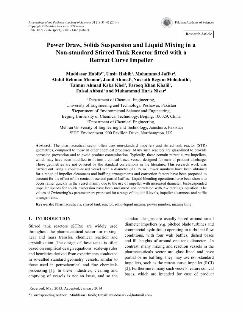
The experimental rig is schematically shown in Fig. 1, where diameter D = 0.18 m, 3-bladed retreat curve impeller in a transparent conical base STR of T = 0.29 m as inside diameter. The maximum vessel volume was 20 L, fill levels corresponding to H/T = 0.50, 0.75 and 1.00 were investigated, as well as various clearances of the impeller above the base of the cone. The conical base STR was surrounded by a square tank filled with water to provide an undistorted view of the vessel contents. Observations were used for flow visualization (Fig. 2) using neutrally buoyant 0.5 mm particles and to find just suspended speeds for solid suspension. Within the tank, between 1 and 4 wall baffles could be installed; these were 0.03 m wide and 0.005 m thick baffles and were equally spaced in the tangential direction. Alternatively, a single 0.03 m wide beavertail baffle with a thickness of 0.01m could be positioned in the STR at 0.44T from the bottom and at 0.1T from the vessel wall. The vessel headspace was open to the atmosphere and the working fluid used in all the experiments was tap
water.
The power input was calculated from the torque on the impeller shaft which was measured by a Torque Track 9000 digital telemetry system (Binsfeld Engineering Inc.); strain gauges and an FM transmitter were mounted on the impeller shaft and the signals were received by a wireless antenna. The strain gauges were below the top bearing on the shaft so no frictional effects were measured. Preliminary checks measured the power numbers of standard geometry impellers such as the Rushton turbine (6DT) and the pitched blade turbine (PBT) in flat-based vessels, which agreed well with the values reported in the literature [5].
The mixing time experiments were performed by measuring the concentration time history of a salt (NaCl) tracer; the effects of different geometric arrangements were studied. A 50 ml salt solution containing about 1 mass % NaCl was introduced at the top surface of the vessel. A single conductivity probe with a tip diameter of about 1 mm [6] was placed near the discharge of the impeller and was connected to the conductivity meter, which sent a voltage to a PC data logger at 12 Hz. 95% mixing time was calculated as the time required for the concentration fluctuations to have decayed within ±5% of the well-mixed value. It was found that consistent average values could be obtained by repeating the mixing time experiments three times for each experimental condition.
Glass ballotini particles with a density of 2500 kg/m3 were used in the solids suspension experiments and the weight fraction was varied from 2 to 30 mass %. Two particle sizes were used, with weight-average diameters of 220 and 540 μm; these had fairly narrow size distributions with standard deviations of 55 and 85 µm, respectively. Zwietering's [7] just-suspension criterion was applied to obtain Njs, i.e. it was considered that complete suspension of solids had occurred when no particle remained on the bottom of the tank for more than 1–2 sec, as observed by visual inspection.
3. RESULTS AND DISCUSSION
3.1 Flow Visualizations
Neither the wall baffles nor the beavertail baffle
Power Draw, Solids Suspension and Liquid Mixing 33
Fig. 1. The geometry of the conical vessel, retreat curve impeller and baffles used in the experimental work.
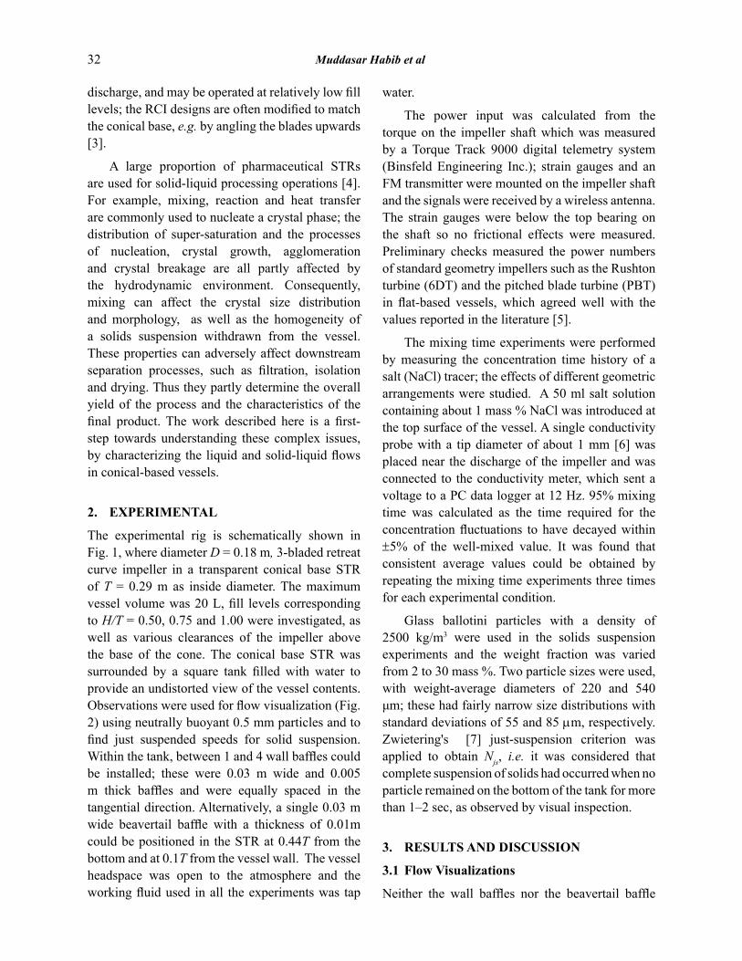
Fig. 2. Flow visualization performed in the conical vessel with a retreat curve impeller and a single wall baffle (located behind the impeller shaft).
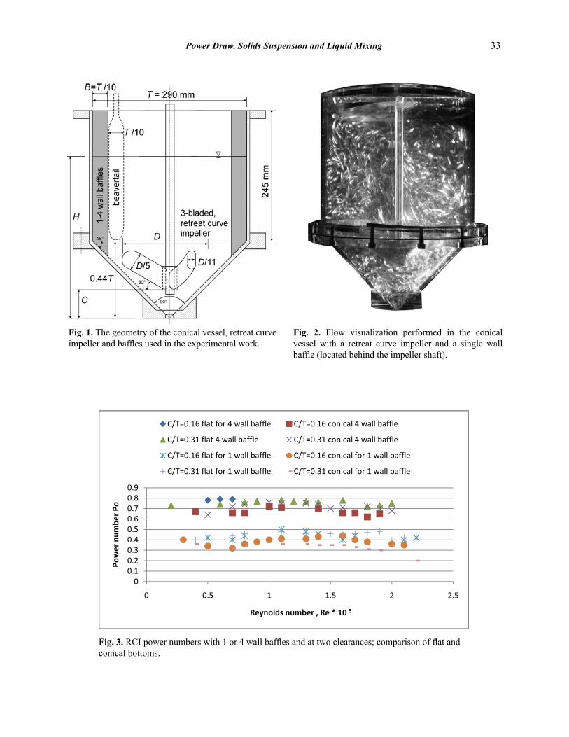
Fig. 3. RCI power numbers with 1 or 4 wall baffles and at two clearances; comparison of flat and conical bottoms.
34 Muddasar Habib et al
extend into the conical section (Fig. 1) and hence the flow in that region is effectively unbaffled. As a consequence the liquid velocity is predominantly tangential. Above the conical section, even with a single baffle the tangential flow is disrupted and converted into axial and radial components. With a single baffle, the flow structure is difficult to determine from instantaneous snapshots, but Li et al.’s [8, 9] CFD simulations suggest that there ought to be a down-flow around the shaft and an up-flow at the walls, with weak flows near the surface, which is in agreement with Fig. 2 depiction. Streak photographs, such as shown in Fig. 2, were obtained for a number of baffle configurations for the RCI. Surprisingly, the case with four wall baffles produced a rather chaotic flow above the conical section, with some segregation from the flow in the cone below.
3.2 Power Input of the RCI
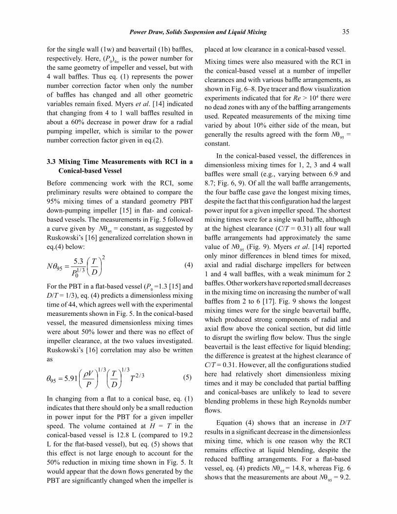
Power inputs were measured for a range of mixer configurations, over Reynolds numbers in the turbulent regime (Re = ρND2/µ > 104). The effects of conical bases, partial baffles (1 or 4 wall baffles or a beavertail baffle) and various impeller clearances on the power number were investigated and are presented in Fig. 3, 4. Campolo et al. [10, 11] reported measured power numbers, P0, for a D/ T = 0.58, three-bladed RCI and for two beavertail baffles. In their laboratory scale apparatus (T = 0.31 m) the power number fell from 0.79 to 0.70 over the range 104 < Re < 105, although their calculation from Nagata’s [12] correlation suggested that it should remain constant. Dickey et al. [13] found only a small decrease in P0 in this Reynolds number range for a 0.1T width finger baffle. Li et al. [8, 9]
calculated power numbers for an RCI with a single cylindrical baffle, but found no effect of Reynolds number in the range Re > 104. Therefore, for systems containing partial baffling it was expected that P0 would be approximately independent of Reynolds number in the range studied (Re > 4×10⁴), which is what is shown in Fig. 3, 4, where there is only a very small effect of the impeller clearance, which is in agreement with Nagata’s [12] power number correlation.
Averaged power numbers are presented in Table 1: at the lowest clearance of C/T = 0.16, the power number is less than 10% greater than for the more standard clearance of C/T = 0.31, for the flat-based vessel. The effect is slightly greater for the conical-based vessel, since the shape of the blades is such that their tips come very close to the tank base at the lowest clearance studied here. Table 1 and Fig. 3 show that conical-based vessels generally draw less power than the flat-based systems, with
(1)
for all baffle types and clearances and also for a 6DT operated in these two vessels (Table 1). Equation (1) represents the power number correction factor when only the vessel base shape has changed and all other geometric variables remain fixed. The predominant effect in Fig. 3, 4 is of changing the number of baffles. Compared to the fully baffled (4 wall) cases, the power numbers are given approximately by:
(2)
and (3)
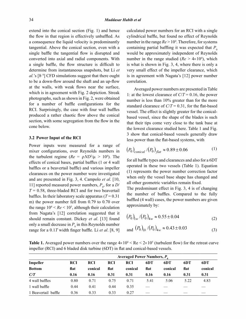
Table 1. Averaged power numbers over the range 4×10⁴ < Re < 2×10⁵ (turbulent flow) for the retreat curve impeller (RCI) and 6 bladed disk turbine (6DT) in flat and conical-based vessels.
Averaged Power Numbers, P0
Impeller RCI RCI RCI RCI 6DT 6DT 6DT 6DTBottom flat conical flat conical flat conical flat conicalC/T 0.16 0.16 0.31 0.31 0.16 0.16 0.31 0.314 wall baffles 0.80 0.71 0.75 0.71 5.41 5.06 5.22 4.831 wall baffle 0.44 0.41 0.44 0.35 — –– –– ––1 Beavertail baffle 0.36 0.33 0.33 0.27 –– –– –– ––
Power Draw, Solids Suspension and Liquid Mixing 35
for the single wall (1w) and beavertail (1b) baffles, respectively. Here, (P0)4w is the power number for the same geometry of impeller and vessel, but with 4 wall baffles. Thus eq. (1) represents the power number correction factor when only the number of baffles has changed and all other geometric variables remain fixed. Myers et al. [14] indicated that changing from 4 to 1 wall baffles resulted in about a 60% decrease in power draw for a radial pumping impeller, which is similar to the power number correction factor given in eq.(2).
3.3 Mixing Time Measurements with RCI in a Conical-based Vessel
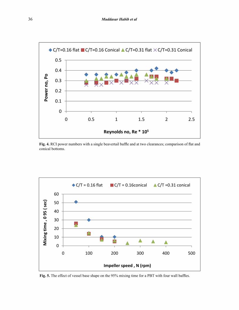
Before commencing work with the RCI, some preliminary results were obtained to compare the 95% mixing times of a standard geometry PBT down-pumping impeller [15] in flat- and conical-based vessels. The measurements in Fig. 5 followed a curve given by Nθ95 = constant, as suggested by Ruskowski’s [16] generalized correlation shown in eq.(4) below:
(4)
For the PBT in a flat-based vessel (P0 =1.3 [15] and D/T = 1/3), eq. (4) predicts a dimensionless mixing time of 44, which agrees well with the experimental measurements shown in Fig. 5. In the conical-based vessel, the measured dimensionless mixing times were about 50% lower and there was no effect of impeller clearance, at the two values investigated. Ruskowski’s [16] correlation may also be written as
(5)
In changing from a flat to a conical base, eq. (1) indicates that there should only be a small reduction in power input for the PBT for a given impeller speed. The volume contained at H = T in the conical-based vessel is 12.8 L (compared to 19.2 L for the flat-based vessel), but eq. (5) shows that this effect is not large enough to account for the 50% reduction in mixing time shown in Fig. 5. It would appear that the down flows generated by the PBT are significantly changed when the impeller is
placed at low clearance in a conical-based vessel.
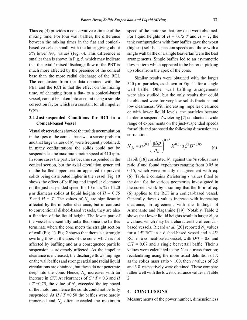
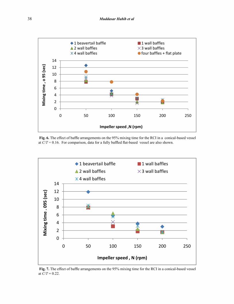
Mixing times were also measured with the RCI in the conical-based vessel at a number of impeller clearances and with various baffle arrangements, as shown in Fig. 6–8. Dye tracer and flow visualization experiments indicated that for Re > 104 there were no dead zones with any of the baffling arrangements used. Repeated measurements of the mixing time varied by about 10% either side of the mean, but generally the results agreed with the form Nθ95 = constant.
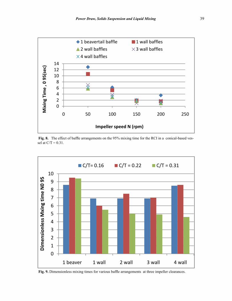
In the conical-based vessel, the differences in dimensionless mixing times for 1, 2, 3 and 4 wall baffles were small (e.g., varying between 6.9 and 8.7; Fig. 6, 9). Of all the wall baffle arrangements, the four baffle case gave the longest mixing times, despite the fact that this configuration had the largest power input for a given impeller speed. The shortest mixing times were for a single wall baffle, although at the highest clearance (C/T = 0.31) all four wall baffle arrangements had approximately the same value of Nθ95 (Fig. 9). Myers et al. [14] reported only minor differences in blend times for mixed, axial and radial discharge impellers for between 1 and 4 wall baffles, with a weak minimum for 2 baffles. Other workers have reported small decreases in the mixing time on increasing the number of wall baffles from 2 to 6 [17]. Fig. 9 shows the longest mixing times were for the single beavertail baffle, which produced strong components of radial and axial flow above the conical section, but did little to disrupt the swirling flow below. Thus the single beavertail is the least effective for liquid blending; the difference is greatest at the highest clearance of C/T = 0.31. However, all the configurations studied here had relatively short dimensionless mixing times and it may be concluded that partial baffling and conical-bases are unlikely to lead to severe blending problems in these high Reynolds number flows.
Equation (4) shows that an increase in D/T results in a significant decrease in the dimensionless mixing time, which is one reason why the RCI remains effective at liquid blending, despite the reduced baffling arrangements. For a flat-based vessel, eq. (4) predicts Nθ95 = 14.8, whereas Fig. 6 shows that the measurements are about Nθ95 = 9.2.
36 Muddasar Habib et al
Fig. 4. RCI power numbers with a single beavertail baffle and at two clearances; comparison of flat and conical bottoms.
Fig. 5. The effect of vessel base shape on the 95% mixing time for a PBT with four wall baffles.
Power Draw, Solids Suspension and Liquid Mixing 37
Thus eq.(4) provides a conservative estimate of the mixing time. For four wall baffles, the difference between the mixing times in the flat and conical-based vessels is small, with the latter giving about 5% lower Nθ95 values (Fig. 6). This difference is smaller than is shown in Fig. 5, which may indicate that the axial / mixed discharge flow of the PBT is much more affected by the presence of the conical base than the more radial discharge of the RCI. The conclusion from the data obtained with the PBT and the RCI is that the effect on the mixing time, of changing from a flat- to a conical-based vessel, cannot be taken into account using a simple correction factor which is a constant for all impeller types.
3.4 Just-suspended Conditions for RCI in a Conical-based Vessel
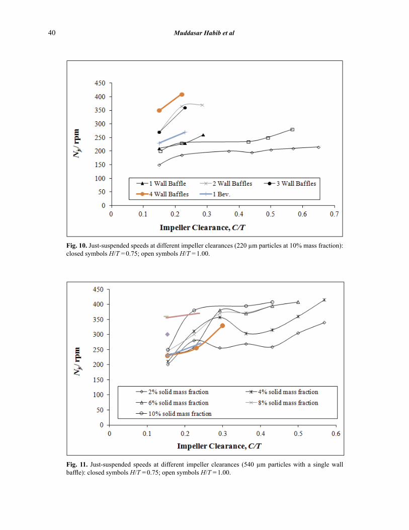
Visual observations showed that solids accumulation in the apex of the conical base was a severe problem and that large values of Njs were frequently obtained; in many configurations the solids could not be suspended at the maximum motor speed of 410 rpm. In some cases the particles became suspended in the conical section, but the axial circulation generated in the baffled upper section appeared to prevent solids being distributed higher in the vessel. Fig. 10 shows the effect of baffling and impeller clearance on the just-suspended speed for 10 mass % of 220 µm diameter solids at liquid heights of H = 0.75 T and H = T. The values of Njs are significantly affected by the impeller clearance, but in contrast to conventional dished-based vessels, they are also a function of the liquid height. The lower part of the vessel is essentially unbaffled since the baffles terminate where the cone meets the straight section of wall (Fig. 1). Fig. 2 shows that there is a strongly swirling flow in the apex of the cone, which is not affected by baffling and as a consequence particle suspension is adversely affected. As the impeller clearance is increased, the discharge flows impinge on the wall baffles and stronger axial and radial liquid circulations are obtained, but these do not penetrate deep into the cone. Hence, Njs increases with an increase in C/T. At clearances of C / T > 0.3 and H / T =0.75, the value of Njs exceeded the top speed of the motor and hence the solids could not be fully suspended. At H / T =0.50 the baffles were hardly immersed and Njs often exceeded the maximum
speed of the motor so that few data were obtained. For liquid heights of H = 0.75 T and H = T, the tank configurations with four baffles gave the worst (highest) solids suspension speeds and those with a single wall baffle or a single beavertail were the best arrangements. Single baffles led to an asymmetric flow pattern which appeared to be better at picking up solids from the apex of the cone.
Similar results were obtained with the larger 540 µm particles, as shown in Fig. 11 for a single wall baffle. Other wall baffling arrangements were also studied, but the only results that could be obtained were for very low solids fractions and low clearances. With increasing impeller clearance or with lower liquid levels, the particles became harder to suspend. Zwietering [7] conducted a wide range of experiments on the just-suspended speeds for solids and proposed the following dimensionless correlation.
(6)
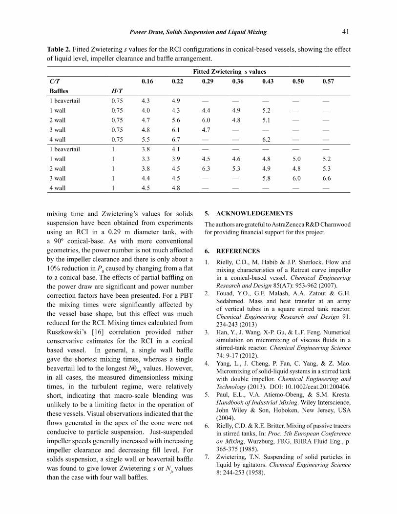
Habib [18] correlated Njs against the % solids mass ratio X and found exponents ranging from 0.05 to 0.15, which were broadly in agreement with eq. (6). Table 2 contains Zwietering s values fitted to the data for the various geometries investigated in the current work by assuming that the form of eq. (6) applies to the RCI in a conical-based vessel. Generally these s values increase with increasing clearance, in agreement with the findings of Armenante and Nagamine [19]. Notably, Table 2 shows that lower liquid heights result in larger Njs or s values, which may be a characteristic of conical-based vessels. Ricard et al. [20] reported Njs values for a 15º RCI in a dished-based vessel and a 45º RCI in a conical-based vessel, with D/T = 0.6 and C/T = 0.07 and a single beavertail baffle. Their s values were calculated using X as a mass fraction; recalculating using the more usual definition of X as the solids mass ratio × 100, then s values of 3.5 and 3.8, respectively were obtained. These compare rather well with the lowest clearance values in Table 2.
4. CONCLUSIONS
Measurements of the power number, dimensionless
38 Muddasar Habib et al
Fig. 6. The effect of baffle arrangements on the 95% mixing time for the RCI in a conical-based vessel at C/T = 0.16. For comparison, data for a fully baffled flat-based vessel are also shown.
Fig. 7. The effect of baffle arrangements on the 95% mixing time for the RCI in a conical-based vessel at C/T = 0.22.
Power Draw, Solids Suspension and Liquid Mixing 39
Fig. 8. The effect of baffle arrangements on the 95% mixing time for the RCI in a conical-based ves-sel at C/T = 0.31.
Fig. 9. Dimensionless mixing times for various baffle arrangements at three impeller clearances.
40 Muddasar Habib et al
Fig. 10. Just-suspended speeds at different impeller clearances (220 µm particles at 10% mass fraction): closed symbols H/T = 0.75; open symbols H/T = 1.00.
Fig. 11. Just-suspended speeds at different impeller clearances (540 µm particles with a single wall baffle): closed symbols H/T = 0.75; open symbols H/T = 1.00.
Power Draw, Solids Suspension and Liquid Mixing 41
mixing time and Zwietering’s values for solids suspension have been obtained from experiments using an RCI in a 0.29 m diameter tank, with a 90º conical-base. As with more conventional geometries, the power number is not much affected by the impeller clearance and there is only about a 10% reduction in P0 caused by changing from a flat to a conical-base. The effects of partial baffling on the power draw are significant and power number correction factors have been presented. For a PBT the mixing times were significantly affected by the vessel base shape, but this effect was much reduced for the RCI. Mixing times calculated from Ruszkowski’s [16] correlation provided rather conservative estimates for the RCI in a conical based vessel. In general, a single wall baffle gave the shortest mixing times, whereas a single beavertail led to the longest Nθ95 values. However, in all cases, the measured dimensionless mixing times, in the turbulent regime, were relatively short, indicating that macro-scale blending was unlikely to be a limiting factor in the operation of these vessels. Visual observations indicated that the flows generated in the apex of the cone were not conducive to particle suspension. Just-suspended impeller speeds generally increased with increasing impeller clearance and decreasing fill level. For solids suspension, a single wall or beavertail baffle was found to give lower Zwietering s or Njs values than the case with four wall baffles.
5. ACKNOWLEDGEMENTS
The authors are grateful to AstraZeneca R&D Charnwood for providing financial support for this project.
6. REFERENCES
1. Rielly, C.D., M. Habib & J.P. Sherlock. Flow and mixing characteristics of a Retreat curve impellor in a conical-based vessel. Chemical Engineering Research and Design 85(A7): 953-962 (2007).
2. Fouad, Y.O., G.F. Malash, A.A. Zatout & G.H. Sedahmed. Mass and heat transfer at an array of vertical tubes in a square stirred tank reactor. Chemical Engineering Research and Design 91: 234-243 (2013)
3. Han, Y., J. Wang, X-P. Gu, & L.F. Feng. Numerical simulation on micromixing of viscous fluids in a stirred-tank reactor. Chemical Engineering Science 74: 9-17 (2012).
4. Yang, L., J. Cheng, P. Fan, C. Yang, & Z. Mao. Micromixing of solid-liquid systems in a stirred tank with double impellor. Chemical Engineering and Technology (2013). DOI: 10.1002/ceat.201200406.
5. Paul, E.L., V.A. Atiemo-Obeng, & S.M. Kresta. Handbook of Industrial Mixing. Wiley Interscience, John Wiley & Son, Hoboken, New Jersey, USA (2004).
6. Rielly, C.D. & R.E. Britter. Mixing of passive tracers in stirred tanks, In: Proc. 5th European Conference on Mixing, Wurzburg, FRG, BHRA Fluid Eng., p. 365-375 (1985).
7. Zwietering, T.N. Suspending of solid particles in liquid by agitators. Chemical Engineering Science 8: 244-253 (1958).
Table 2. Fitted Zwietering s values for the RCI configurations in conical-based vessels, showing the effect of liquid level, impeller clearance and baffle arrangement.
Fitted Zwietering s valuesC/T 0.16 0.22 0.29 0.36 0.43 0.50 0.57Baffles H/T1 beavertail 0.75 4.3 4.9 — — — — —1 wall 0.75 4.0 4.3 4.4 4.9 5.2 — —2 wall 0.75 4.7 5.6 6.0 4.8 5.1 — —3 wall 0.75 4.8 6.1 4.7 — — — —4 wall 0.75 5.5 6.7 — — 6.2 — —1 beavertail 1 3.8 4.1 — — — — —1 wall 1 3.3 3.9 4.5 4.6 4.8 5.0 5.22 wall 1 3.8 4.5 6.3 5.3 4.9 4.8 5.33 wall 1 4.4 4.5 — — 5.8 6.0 6.64 wall 1 4.5 4.8 — — — — —
42 Muddasar Habib et al
8. Li, M., G. White & D. Wilkinson. LDA measurements and CFD modelling of a stirred vessel with a retreat curve impellor. Industrial and Engineering Chemistry Research 43: 6534-6547 (2004).
9. Li, M., G. White, D. Wilkinson 7& K.J. Roberts. Scale up study of retreat curve impellor stirred tank using LDA measurements and CFD simulations. Chemical Engineering Journal 108: 81-90 (2005).
10. Campolo, M. & A. Soldati. Appraisal of fluid dynamic efficiency of retreated-blade and Turbofoil impellor in industrial size CSTR. Industrial and Engineering Chemistry Research 41: 1370-1377 (2002).
11. Campolo, M., A. Paglianti, & A. Soldati. Fluid dynamic efficiency and scale-up of a retreated blade impellor CSTR. Industrial and Engineering Chemistry Research 41: 164-172 (2002).
12. Nagata, S. Mixing: Principles and Applications. Halstead Press, Tokyo, Japan (1975).
13. Dickey, D.S., K.J. Bittorf, C.J. Ramsey & K.E. Johnson. Understand flow patterns in glass-lined reactors. Chemical Engineering Progress 11: 21-25 (2004).
14. Myers, K. J., M. Reeder & J.B. Fasano. Optimize mixing by using the proper baffles. Chemical Engineering Progress 9: 42-47 (2002).
15. Khan, F.R., C.D. Rielly & G.K. Hargrave. A multi
block approach to obtain angle-resolved PIV measurements of the mean flow and turbulent fields in a stirred vessel. Chemical Engineering and Technology 27: 264-269 (2004).
16. Ruszkowski, S. A rational method for measuring blending performance and comparison of different impellor types. In: Proc. 8th Euro Conf on Mixing, Inst. Chem. Engr. Rugby, UK, p. 283-291 (1994).
17. Kumaresan, T., N.K. Nere & J.B. Joshi. Effects of internals on the flow pattern and mixing in stirred tanks. Industrial and Engineering Chemistry Research 44(26): 9951-9961 (2005).
18. Habib, M. Mixing in a Conical based Pharmaceutical Reactors Equipped with Retreat Curve Impellors. MSc thesis, Department of Chemical Engineering, Loughborough University, Leicestershire, UK (2005).
19. Armeneante, P.M. & E.U. Nagamine. Effect of low-bottom impellor clearance on the minimum agitation speed for complete suspension of solids in stirred tanks. Chemical Engineering Science 53(9): 1757-1775 (1998).
20. Ricard, F., C. Brechtelsbauer, X. Xu & C. Lawrence. Monitoring of multiphase pharmaceutical processes using electrical resistance tomography. Chemical Engineering Research and Design 83: (A7): 794-805 (2005).
Copyright © 2022 FDOKUMEN