
Design of a Centrifugal Compressor Impeller for Micro Gas ...
www.elsevier.com/locate/etfs
Experimental Thermal and Fluid Science 30 (2006) 565–577
Effects of tip clearance and impeller geometry on the performanceof semi-open ceramic centrifugal fan impellers
at elevated temperatures
Tahsin Engin a,*, Mesut Gur a, Reinhard Scholz b
a Department of Mechanical Engineering, Sakarya University, Esentepe Campus, 54187 Sakarya, Turkeyb Institute for Energy Process Engineering and Fuel Technology, Clausthal Technical University, Agricolastrabe 4,
38678 Clausthal, Zellerfeld, Germany
Received 25 September 2004; accepted 2 December 2005
Abstract
Centrifugal fans are being widely used in many industrial applications. However, when handling gases with temperatures exceeding800 �C, the use of centrifugal fan impellers are of particular interest since the conventional steel impellers would not be operated at suchelevated temperatures. In the present experimental study, three semi-open centrifugal fan impellers have been designed and fabricatedusing ceramic materials to provide high resistance to temperature. Experiments have been conducted to investigate the performance char-acteristics of these impellers and the deteriorations in their performance due to varying tip clearance. Factors have been determined toestimate the tip clearance losses. Results showed that the simple impeller geometries of ceramic materials were less sensitive to the varyingtip clearance. In addition, the gas temperature has been found to have almost no influence on the performance degradation due to the tipleakage flow.� 2005 Elsevier Inc. All rights reserved.
Keywords: Centrifugal fan impeller; Ceramic impeller; Hot gas handling; Tip clearance effects; Semi-open impeller; Shrouded impeller; Waste heatrecovery
1. Introduction
It is well established that significant alterations in theperformance of rotating machines are unavoidable due tovarying tip clearances. These effects have to be particularlytaken into account for the design considerations of high-temperature machines, such as liquid metal turbo pumps[1], and hot gas fans [2]. As for the closed impellers, theseeffects generally play an insignificant role, while they area major source of degradation in the hydraulic perfor-mance for semi-open impellers. This is mainly due to com-plex flow field existed in the flow passage of the semi-openimpellers. A survey of literature shows that there are three
0894-1777/$ - see front matter � 2005 Elsevier Inc. All rights reserved.
doi:10.1016/j.expthermflusci.2005.12.002
* Corresponding author. Tel./fax: +90 264 346 0160.E-mail address: [email protected] (T. Engin).
major effects associated with the tip clearance, namely, (i)secondary flow due to pressure gradients across the flowpassage, (ii) leakage of the flow past the tip clearance dueto the pressure difference across the blade tip, and (iii)the boundary scraping effect caused by the blades movingrelative to the wall boundary layer and scraping fluid fromit.
Although the effects of varying tip clearance on the per-formance of turbomachineries have attracted much interestby many investigators for long time, there is currently notheory or method, which can be used to predict theseeffects. Wood et al. [3] tested several models of centrifugalpump impellers to determine the tip clearance effects onnon-cavitating and cavitating performance and observedthat the varying degrees of produced dissimilar trends inthe hydraulic performance for different impeller models.
Nomenclature
a relative tip clearance (–)b blade width (mm)bave average blade width (mm)d impeller diameter (mm)ds suction pipe diameter (mm)fa, fb, fc tip clearance influence factors (–)m a factor (–)Ma fan Mach number based on fan peripheral speed
(–)n shaft speed (rpm)Ns specific speed (–)P shaft power (W)Q volumetric flow rate (m3/h)Re Fan Reynolds number based on fan peripheral
speed (–)rE radius of curvature at impeller inlet (mm)T temperature (�C)u peripheral speed (m/s)x tip clearance width (mm)Z number of blades
Dp pressure rise (Pa)Dpth1 theoretical pressure rise for closed impeller (Pa)f �b modified pressure influence factor (–)b blade exit angle (�)a blade inlet angle (�)u flow number (–)q gas density (kg/m3)m kinematic viscosity (m2/s)k power number (–)w pressure number (–)l slip factor (–)gh,ci hydraulic efficiency of closed impeller (%)
Subscripts
1 impeller inlet2 impeller exitx at given tip clearancex = 0 at zero tip clearanceci closed impellerth1 theoretical
566 T. Engin et al. / Experimental Thermal and Fluid Science 30 (2006) 565–577
They reported that the maximum efficiency for all semi-open impellers tested occurred at the minimum value ofthe tip clearance. Engeda and Rautenberg [4] investigatedexperimentally five different centrifugal pump impellers toreveal the performance degradation due to varying tipclearance. They reported that it was difficult to correlatethe tip clearance effects to the machine specific speed, sinceno general trend was observed. Hesselgreaves [5] proposeda correlation to predict the efficiency drop of mixed-flowand axial-flow turbomachines based on the published data.He indicated that an increase in the tip clearance wasshown to have two distinct effects: to reduce the work out-put of the machine owing to the change in load distributionon the blade, and to reduce the efficiency owing to the lossin kinetic energy of the tip leakage flow. Howard and Kitt-mer [6] measured velocity components inside a rotatingradial impeller passage of both closed and semi-openimpellers. They concluded that there was a secondary flowpattern progressed from a single vortex at entry to a vortexnear each of the hub and shroud. Plutecki and Wajda [7]examined the effects of axial clearance on total head, effi-ciency and suction ability of four, differently bladed impel-lers operated in one casing with the axial clearance varyingfrom 0.5 to 2 mm. They found that the total head decreasedproportionally to the tip clearance ratio up to about 11%,while the efficiency decreased with the growth of the tipclearance. Tip clearance effects have also been the subjectfor two-phase flows such as air–water [8], and solid–waterflow through the semi-open impellers [9]. Ishida and Senoo[10] measured the pressure distribution along the shroudfor three types of centrifugal impeller at seven different val-ues of tip clearance and found that the pressure loss due to
the tip clearance was relatively small in the region wherethe relative velocity was nearly constant. They also under-lined that this loss was proportional to the pressure risecaused by the deceleration of the relative velocity. Inanother study, Senoo and Ishida [11] derived equationsfor predicting the tip clearance effects on centrifugal andaxial blower impellers, and compared the predicted effi-ciency drops versus experimental data. Their model showedfair agreement with the experimental data.
Tip clearance effects on compressor stage performancehave been extensively studied by some other investigatorssuch as [12–17]. Engeda et al. [18] presented a tip clearanceloss sensitivity factor depending upon pump specific speed,and observed that the pump with a specific speed of 57 washighly insensitive to the varying tip clearance and could beregarded as an ideal design for semi-open centrifugal pumpimpeller. In a later study, Engeda [19] analyzed five differ-ent centrifugal pump impellers with specific speeds rangingfrom 17 to 80 to model the degradation in the pump effi-ciency due to the tip clearance effects. He developed anempirical correlation based on specific speed and tip clear-ance that predicts the tip clearance effects within a fairlygood margin. There are some other studies on the investi-gation of the tip clearance effects on mixed-flow pumps[20,21], and axial-flow fans [22,23]. All of these studies indi-cated a considerable deterioration in the machine perfor-mance due to the change in the tip clearance. The mainproblem associated with the tip clearance effects in the flowmachines is that these effects generally differ from onemachine to another. This is why there is no generalizedprocedure, method or correlation to predict these effectsfor any flow machine with semi-open impeller. The Pflei-
T. Engin et al. / Experimental Thermal and Fluid Science 30 (2006) 565–577 567
derer’s empirical model [24] has been widely used to esti-mate tip clearance effects, which gives a simple linear effectof the tip clearance, and it offers a good approximation forthe range of small gaps.
The use of open impellers is quite favorable in some pro-cesses due to the fact that they offer low friction losses,which is very important in handling viscous fluids, easyof manufacturing, and being favorable for coating surfaceswith some protective materials such as ceramics.
In the present study, centrifugal fan impellers have beendesigned, fabricated and tested for handling hot processgases with temperatures up to 1050 �C. The impellers havebeen made of ceramic materials to ensure high resistance totemperature. Due to the limitations in the manufacturingof ceramic impellers, the geometry has been selected to betwo-dimensional with different blade exit angles. To makethe manufacturing process easy, the test impellers havebeen designed as open on one side. The performance testsof these impellers have been carried out for varying tipclearances, which are relatively large compared to the usualones to compensate the thermal expansion effects. Tipclearance influence factors have been introduced to predictthe pressure drop due to the tip clearance based on the pre-sented experimental data.
2. Problem description and design considerations
for ceramic impellers
The fans are of particular interest when operated to han-dle hot gases at elevated temperatures, e.g., exceeding800 �C. Some industrial processes require hot gases beingconveyed at elevated temperatures to increase the productquality, to reduce the energy consumption and gas emis-sions. Examples are glass industry, some chemical engi-neering processes, ceramic industry, some metallurgicalengineering processes, etc. The steel fan impellers can besafely operated up to 800 �C. On the other hand, themechanical strength of the steel materials drops drasticallydue to both high temperatures exceeding 600 �C and toincreased centrifugal forces acting on the impeller blades.To overcome this problem, one possible alternative is toconsiderably reduce the rotational speed of the fan, whichleads low performance characteristics due to off-designoperating conditions. The operating temperature essen-tially limits the allowable peripheral speeds for centrifugalsteel fan impellers, which can be as high as 800 �C. Aperipheral speed of 50 m/s can be regarded as the upperlimit at this temperature [25,26]. The 3-D impeller geo-metry can be optimized to meet the high pressure-rise byconsidering these limitations.
For the temperatures exceeding 800 �C, a more specificfan design procedure must be followed. The use of ceramicmaterials for the fan impellers would come to mind at first.Ceramic materials offer some remarkable advantages suchas high resistance to temperature, low friction losses owingto the smooth surfaces, high corrosion and wear resistance,lightness, and low thermal expansion. On the other hand
they have some disadvantages such as difficulty in forming,fragileness, and low resistance to even low-temperaturegradients. Ceramic materials are not continuum and dueto this reason, thermal stresses would not be compensatedby elastic deformations. When the excessive stresses occurin the ceramic blades, micro cracks would become unavoid-able in the material, which may result in costly damages.Further, ceramic materials are very sensitive to the suddenchanges in temperature. Due to their low thermal conduc-tion coefficient, obtaining a uniform temperature distribu-tion through the ceramic blade may take longer time ascompared to the steels ones. The increments in the temper-ature should be low enough to avoid high internal stresses.Unpredictable damages can occur when combined effectsof internal stresses and centrifugal forces due to high rota-tional speeds take place. Therefore, an exclusive attentionmust be given to the ceramic impeller design. Due to theselimitations, the optimized 3-D geometries for the steelimpellers may not be achieved for the ceramic impellers.In the case of such high-temperature gases, the priority isgenerally to convey the gas rather than high performancecharacteristics. Therefore, one of the objectives of thisstudy is to investigate the feasibility of the use of ceramicmaterials for the centrifugal fan impellers with 2-D simplegeometries.
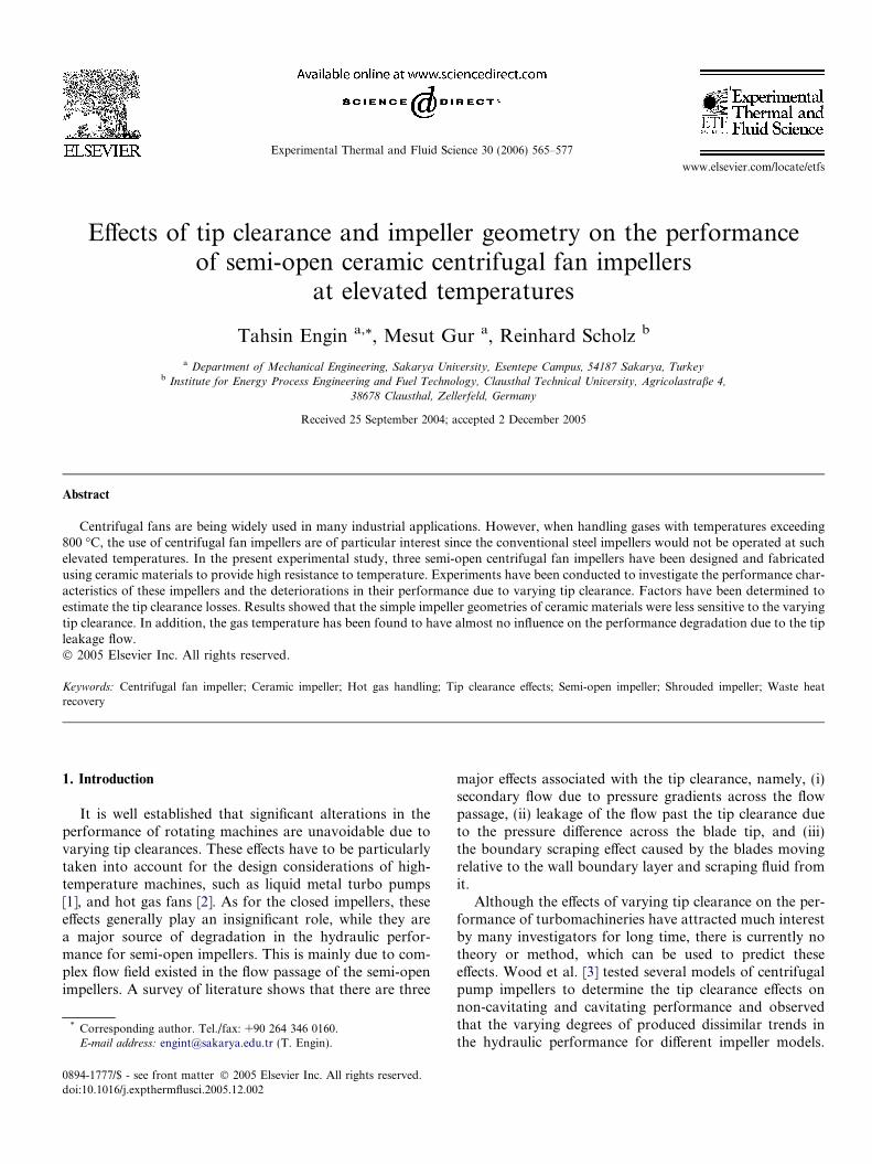
As noted above, the semi-open impellers with simplegeometries can be successfully designed and manufactured.One of the main energy losses in such impellers occurs dueto tip leakage flow across the tip gap between open side ofthe impeller and stationary casing. Furthermore, the tipclearance should be large enough due to thermal expansioneffects in order to provide a safe operation, otherwise theopen side of the impeller may hit to the casing surface,which would result in costly damages. Therefore, the tipclearance effects have to be considered for such impellers.Considering the easy of manufacturing, the impeller typewith blade angles b1 = b2 = 90� can be preferred. This typeof blade forms can lead to a higher resistance against cen-trifugal forces. The closed and open forms of a typical fanimpeller with main dimensions are shown in Fig. 1, inwhich the absolute tip clearance is indicated by x. The typ-ical design is done based on the required pressure rise andflow rate. In order to increase the fan internal efficiency, thefollowing parameters are usually changed without reducingdesign pressure and flow rate: d1/d2, rE, x/ds, and m = 4b1/d1. Usually m = 1.7 refers to the optimal value for most ofthe designs.
For most of the flow machines, the performance of theimpeller deteriorates as the tip clearance x increases. Thesensitivity of the machine performance is relatively muchhigher for small tip clearances, and over a critical value,the performance may become insensitive to the tip clear-ance. The severity of the degradation in the performancedepends generally upon both the tip clearance and thefan flow rate. The relative tip clearance is usually definedas the ratio of the tip clearance to the blade width, e.g.,a = x/b. Generally the tip absolute clearance (x) is selected
Fig. 1. Tip clearance in radial flow impellers: (a) Closed impeller and (b) semi-open impeller.
568 T. Engin et al. / Experimental Thermal and Fluid Science 30 (2006) 565–577
to be less than 5 mm, which refers to a relative tip clearanceof a = 30% or less. However, this ratio must be remarkablyhigher than 30% for hot gas fans due to thermal expansioneffects.
The ratio of b2/b1 is another important design variable,and is usually selected less than unity for conventional fans.For simplicity, these blade widths can be taken to be equalto each other, that is b1 = b2.
3. Experimental study
3.1. Experimental set-up
Experiments were conducted to ascertain performancecharacteristics of the test impellers with blades made ofceramic under varying tip clearances. An experimentalset-up was designed and constructed to carry out the coldand hot gas experiments.
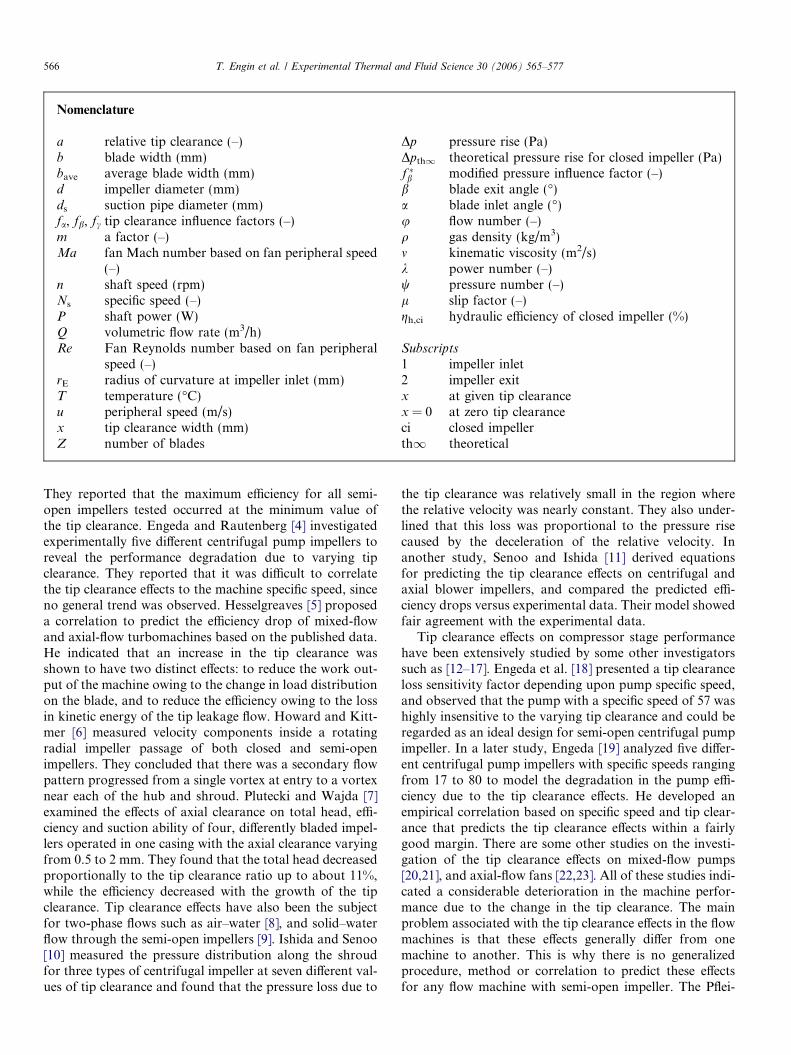
The set-up consisted of two main sections, namely fantest section and combustion chamber section, as shown inFig. 2. The hot gas was provided from the combustionchamber wherein natural gas was used as the fuel. The testsection was based on the DIN 24163 and designed accord-ing to the combustion chamber capacity. The maximumflow rate was 1500 m3/h (at 1 atm and 20 �C) through apipe section with a diameter of 100 mm. The inner surfaceof the pipe was lined by employing refractory material to
Secondary
p1, T5
p2, T6
T7, Q4
Co ch
Test section Chimney
Test fan
V4
V5
Fig. 2. Experimental set-up
protect the pipe from high temperatures. The maximumtemperature that can be achieved was about 1300 �C. Thefan test section enables the operator to easily mount vari-ous test impellers. The inside of the casing was also linedwith the same refractor material. The test section allowsthe operator to measure temperatures (T1–T5), pressures(P1, P2), and flow velocity (flow rates Q1–Q4) at differentlocations as illustrated in Fig. 2. The calibration of eachelectronic transducer has been checked before and aftereach of test run. The gas components such as CO, CO2,O2, SO2, H2, and NO2 were periodically measured toensure an effective combustion. All measurements of pres-sure, temperature, fan speed, flow velocity, and the powertransmitted to the motor shaft were made using electronictransducers, and the electrical signals corresponding tothese physical quantities were collected by a data acquisi-tion and control system commanded by a PC. A data pro-cessing code was utilized for real-time calculations andmonitoring the process. Rotational speed of the fan hasbeen measured using a digital tachometer. Since the speedslightly vary over the tests, the following affinity laws havebeen used to convert the fan pressure rise and volume flowrate into the desired test speed:
Qdesired ¼ Qactual
ndesired
nactual
ð1Þ
Dpdesired ¼ Dpactual
T actual
T desired
ndesired
nactual
� �2
ð2Þ
Booster fan
V1
T1, Q1 air
T2, Q2
T3, Q3 T4
mbustion amber
Mixingchamber
Fresh air
Natural gas
Combustion section
V2
V3
and instrumentation.
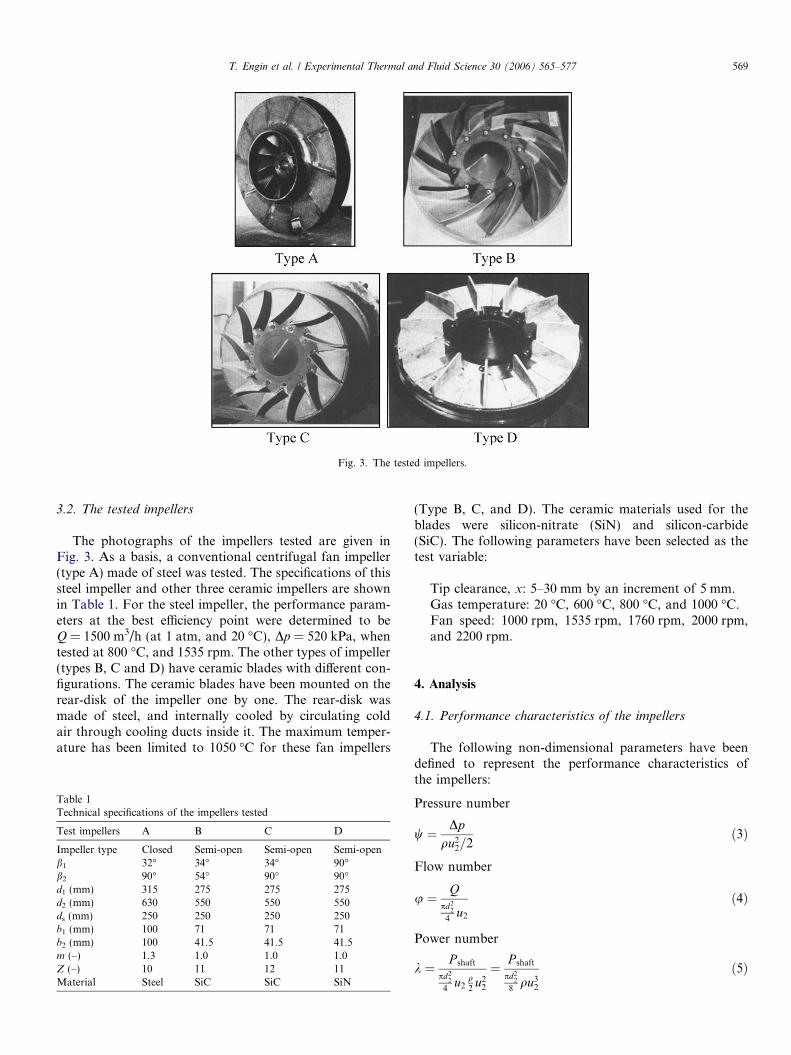
Fig. 3. The tested impellers.
T. Engin et al. / Experimental Thermal and Fluid Science 30 (2006) 565–577 569
3.2. The tested impellers
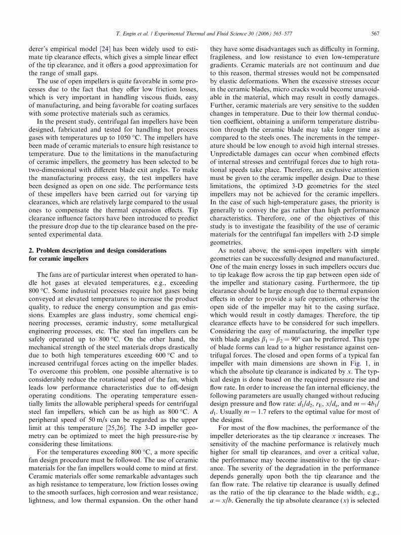
The photographs of the impellers tested are given inFig. 3. As a basis, a conventional centrifugal fan impeller(type A) made of steel was tested. The specifications of thissteel impeller and other three ceramic impellers are shownin Table 1. For the steel impeller, the performance param-eters at the best efficiency point were determined to beQ = 1500 m3/h (at 1 atm, and 20 �C), Dp = 520 kPa, whentested at 800 �C, and 1535 rpm. The other types of impeller(types B, C and D) have ceramic blades with different con-figurations. The ceramic blades have been mounted on therear-disk of the impeller one by one. The rear-disk wasmade of steel, and internally cooled by circulating coldair through cooling ducts inside it. The maximum temper-ature has been limited to 1050 �C for these fan impellers
Table 1Technical specifications of the impellers tested
Test impellers A B C D
Impeller type Closed Semi-open Semi-open Semi-openb1 32� 34� 34� 90�b2 90� 54� 90� 90�d1 (mm) 315 275 275 275d2 (mm) 630 550 550 550ds (mm) 250 250 250 250b1 (mm) 100 71 71 71b2 (mm) 100 41.5 41.5 41.5m (–) 1.3 1.0 1.0 1.0Z (–) 10 11 12 11Material Steel SiC SiC SiN
(Type B, C, and D). The ceramic materials used for theblades were silicon-nitrate (SiN) and silicon-carbide(SiC). The following parameters have been selected as thetest variable:
Tip clearance, x: 5–30 mm by an increment of 5 mm.Gas temperature: 20 �C, 600 �C, 800 �C, and 1000 �C.Fan speed: 1000 rpm, 1535 rpm, 1760 rpm, 2000 rpm,and 2200 rpm.
4. Analysis
4.1. Performance characteristics of the impellers
The following non-dimensional parameters have beendefined to represent the performance characteristics ofthe impellers:
Pressure number
w ¼ Dpqu2
2=2ð3Þ
Flow number
u ¼ Qpd2
2
4u2
ð4Þ
Power number
k ¼ P shaft
pd22
4u2
q2
u22
¼ P shaft
pd22
8qu3
2
ð5Þ
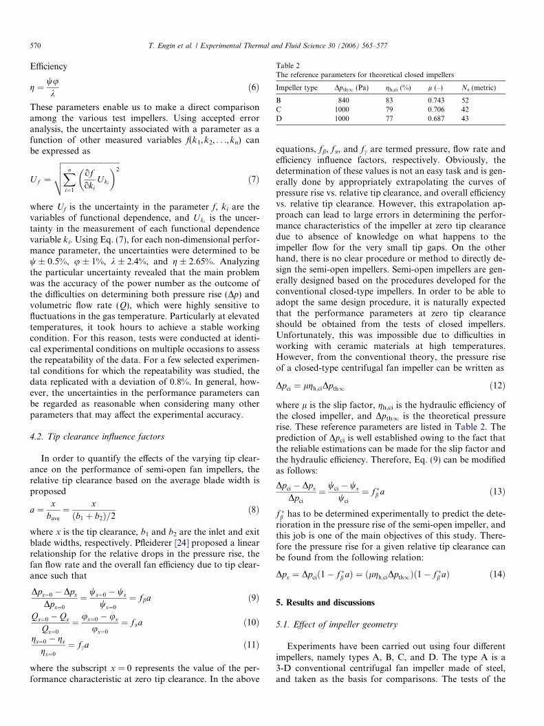
Table 2The reference parameters for theoretical closed impellers
Impeller type Dpth1 (Pa) gh,ci (%) l (–) Ns (metric)
B 840 83 0.743 52C 1000 79 0.706 42D 1000 77 0.687 43
570 T. Engin et al. / Experimental Thermal and Fluid Science 30 (2006) 565–577
Efficiency
g ¼ wuk
ð6Þ
These parameters enable us to make a direct comparisonamong the various test impellers. Using accepted erroranalysis, the uncertainty associated with a parameter as afunction of other measured variables f(k1,k2, . . .,kn) canbe expressed as
Uf ¼
ffiffiffiffiffiffiffiffiffiffiffiffiffiffiffiffiffiffiffiffiffiffiffiffiffiffiffiffiffiffiXn
i¼1
ofoki
Uki
� �2
vuut ð7Þ
where Uf is the uncertainty in the parameter f, ki are thevariables of functional dependence, and Uki is the uncer-tainty in the measurement of each functional dependencevariable ki. Using Eq. (7), for each non-dimensional perfor-mance parameter, the uncertainties were determined to bew ± 0.5%, u ± 1%, k ± 2.4%, and g ± 2.65%. Analyzingthe particular uncertainty revealed that the main problemwas the accuracy of the power number as the outcome ofthe difficulties on determining both pressure rise (Dp) andvolumetric flow rate (Q), which were highly sensitive tofluctuations in the gas temperature. Particularly at elevatedtemperatures, it took hours to achieve a stable workingcondition. For this reason, tests were conducted at identi-cal experimental conditions on multiple occasions to assessthe repeatability of the data. For a few selected experimen-tal conditions for which the repeatability was studied, thedata replicated with a deviation of 0.8%. In general, how-ever, the uncertainties in the performance parameters canbe regarded as reasonable when considering many otherparameters that may affect the experimental accuracy.
4.2. Tip clearance influence factors
In order to quantify the effects of the varying tip clear-ance on the performance of semi-open fan impellers, therelative tip clearance based on the average blade width isproposed
a ¼ xbave
¼ xðb1 þ b2Þ=2
ð8Þ
where x is the tip clearance, b1 and b2 are the inlet and exitblade widths, respectively. Pfleiderer [24] proposed a linearrelationship for the relative drops in the pressure rise, thefan flow rate and the overall fan efficiency due to tip clear-ance such that
Dpx¼0 � Dpx
Dpx¼0
¼ wx¼0 � wx
wx¼0
¼ fba ð9Þ
Qx¼0 � Qx
Qx¼0
¼ ux¼0 � ux
ux¼0
¼ faa ð10Þgx¼0 � gx
gx¼0
¼ fca ð11Þ
where the subscript x = 0 represents the value of the per-formance characteristic at zero tip clearance. In the above
equations, fb, fa, and fc are termed pressure, flow rate andefficiency influence factors, respectively. Obviously, thedetermination of these values is not an easy task and is gen-erally done by appropriately extrapolating the curves ofpressure rise vs. relative tip clearance, and overall efficiencyvs. relative tip clearance. However, this extrapolation ap-proach can lead to large errors in determining the perfor-mance characteristics of the impeller at zero tip clearancedue to absence of knowledge on what happens to theimpeller flow for the very small tip gaps. On the otherhand, there is no clear procedure or method to directly de-sign the semi-open impellers. Semi-open impellers are gen-erally designed based on the procedures developed for theconventional closed-type impellers. In order to be able toadopt the same design procedure, it is naturally expectedthat the performance parameters at zero tip clearanceshould be obtained from the tests of closed impellers.Unfortunately, this was impossible due to difficulties inworking with ceramic materials at high temperatures.However, from the conventional theory, the pressure riseof a closed-type centrifugal fan impeller can be written as
Dpci ¼ lgh;ciDpth1 ð12Þ
where l is the slip factor, gh,ci is the hydraulic efficiency ofthe closed impeller, and Dpth1 is the theoretical pressurerise. These reference parameters are listed in Table 2. Theprediction of Dpci is well established owing to the fact thatthe reliable estimations can be made for the slip factor andthe hydraulic efficiency. Therefore, Eq. (9) can be modifiedas follows:
Dpci � Dpx
Dpci
¼ wci � wx
wci
¼ f �b a ð13Þ
f �b has to be determined experimentally to predict the dete-rioration in the pressure rise of the semi-open impeller, andthis job is one of the main objectives of this study. There-fore the pressure rise for a given relative tip clearance canbe found from the following relation:
Dpx ¼ Dpcið1� f �b aÞ ¼ ðlgh;ciDpth1Þð1� f �b aÞ ð14Þ
5. Results and discussions
5.1. Effect of impeller geometry
Experiments have been carried out using four differentimpellers, namely types A, B, C, and D. The type A is a3-D conventional centrifugal fan impeller made of steel,and taken as the basis for comparisons. The tests of the
0.03 0.05 0.08 0.10
Flow number,
0.00
0.25
0.50
0.75
1.00
1.25P
erfo
rman
ce p
aram
eter
s, (
ψ, η
, λ)
ABCD
Pressure
Efficiency
Power
ϕ
Fig. 4. Comparison of the performances for the tested impellers(T = 20 �C, u2 = 50 m/s, a = 17.8%).
AD
u = 50 m/s2
u = 64 m/s2
u = 64 m/s2
1000 2000 3000 4000 5000 6000
Flow rate, Q (m / h)
1000
1500
2000
2500
Pre
ssur
e ri
se,
p (
Pa)
3
Δ
0.00 0.05 0.10
0.5
1.0
1.5
Δp
ψ
Pre
ssur
e nu
mbe
r, ψ
ϕFlow number,
u = 50 m/s2
Fig. 5. Effect of peripheral speed on impeller pressure number for impellertypes A and D (T = 20 �C, a = 17.8%).
0.02 0.04 0.06 0.08 0.10
Flow number,
0.70
0.80
0.90
1.00
1.10
1.20
1.30
Pre
ssur
e nu
mbe
r,
ϕ
D (u = 64 m/s)
800 oC
1000 oC
A (u = 50 m/s) 2
C (u = 64 m/s)2
2
ψ
Fig. 6. Effect of peripheral speed and gas temperature on impeller pressurenumber for impeller types A, C, and D.
T. Engin et al. / Experimental Thermal and Fluid Science 30 (2006) 565–577 571
semi-open impellers have been conducted for a constantrelative tip clearance of 17.8%. The non-dimensional per-formance characteristics of these impellers have beenshown in Fig. 4. As expected, the highest performance pres-sure rise is obtained from type A. However, the overall effi-ciency of the type C is higher than all other three types.This is mainly due to lower shaft power consumption com-pared to the other types. The drag on the type C would belower than type D that results in an increase in the inputpower. Type C has 12 blades on it with b1 = 34� while typeD has 11 blades with b1 = 90�. Since the type A is a closedimpeller, it exhibits relatively high friction characteristics,and therefore its overall efficiency is lower than type C asshown in Fig. 4. It is also clear that the overall efficiencyranges from 40% to 50% for simple 2-D geometries. It isinteresting to observe that the simplest impeller (type D)gives almost 40% of efficiency. Although this can beregarded as relatively low compared to the conventionalfans, the energy consumption of this impeller could be neg-ligible when considering the energy level of the process(recovered or delivered).
5.2. Effect of fan speed and gas temperature
Figs. 5 and 6 show the effect of fan speed (thereforeimpeller peripheral speed) and the gas temperature, respec-tively. In Fig. 5, the temperature was kept constant atT = 20 �C, and the relative tip clearance was adjusted to17.8%, which corresponds to a tip clearance of 10 mm. Itis clear that, if the peripheral speed of type D is increasedby nearly 25%, that is, from 50 m/s to 64 m/s, a higher
pressure rise (Dp but not w) compared to the closed-typeimpeller (A) can be achieved at the same flow rate. How-ever, this remarkable increase in the pressure rise cannotbe seen when it is represented its corresponding non-dimen-sional pressure number as shown in the same figure. This isbasically due to the fact that the pressure rise is propor-tional to the square of u2, whose square is used for non-dimensionalize the fan pressure rise. It can therefore beconcluded that by bearing a moderate increase in the cen-trifugal loads due to increased speed, it is possible toachieve the same pressure rise (Dp) with the type A.Fig. 6 compares the pressure-rises of three types of impellerA, C, and D at elevated temperatures. As noted earlier,u2 = 50 m/s at T = 800 �C is the upper limit for the steelimpellers, and therefore the type A cannot be employedat higher limits. In such cases, the semi-open impellers
1.0E+5 1.0E+6Reynolds number, Re
0.30
0.60
0.90
1.20
Pre
ssur
e nu
mbe
r,ψ
105 106 2x10⁶
C
D
B
Re = u d2 2
ν
n = 1000, 1760 rpm
T = 20 oC, 600 oC, 800 oC, 1000 oC
(Ma < 0.18 at all conditions)
Fig. 7. Effect of fan Reynolds number on pressure number at variousoperating conditions (impeller types B, C, and D).
(a)
(b)
(c)
0.02 0.04 0.06 0.08
Flow number,
0.20
0.40
0.60
0.80
1.00
1.20
Pre
ssur
e nu
mbe
r,
ϕ
ψ
a=8.9%a=17.8%a=26.7%a=35.5%a=44.4%a=53.3%
a = 2x
b + b1 2
Impeller type: B
0.02 0.04 0.06 0.08
Flow number,
0.03
0.06
0.09
0.12
Pow
er n
umbe
r,
ϕ
λ
a=8.9%a=17.8%a=26.7%a=35.5%a=44.4%a=53.3%
a = 2x
b + b1 2
Impeller type: B
0.02 0.04 0.06 0.08
Flow number,
0.20
0.30
0.40
0.50
Eff
icie
ncy,
ϕ
η
a=8.9%a=17.8%a=26.7%a=35.5%a=44.4%a=53.3%
a = 2x
b + b1 2
Impeller type : B
Fig. 8. Effect of relative tip clearance on the performance characteristicsof impeller B (T = 20 �C, n = 1760 rpm).
572 T. Engin et al. / Experimental Thermal and Fluid Science 30 (2006) 565–577
made of ceramics (types C and D) can successfully fulfillthe task since they can be operated at higher peripheralspeeds. It is clear from Fig. 6 that, both C and D providehigher pressure rises (but not pressure numbers) at even1000 �C as compared to the type A. Since the peripheralvelocity of type A is 50 m/s in this case, its pressure numberis well above that of types C and D.
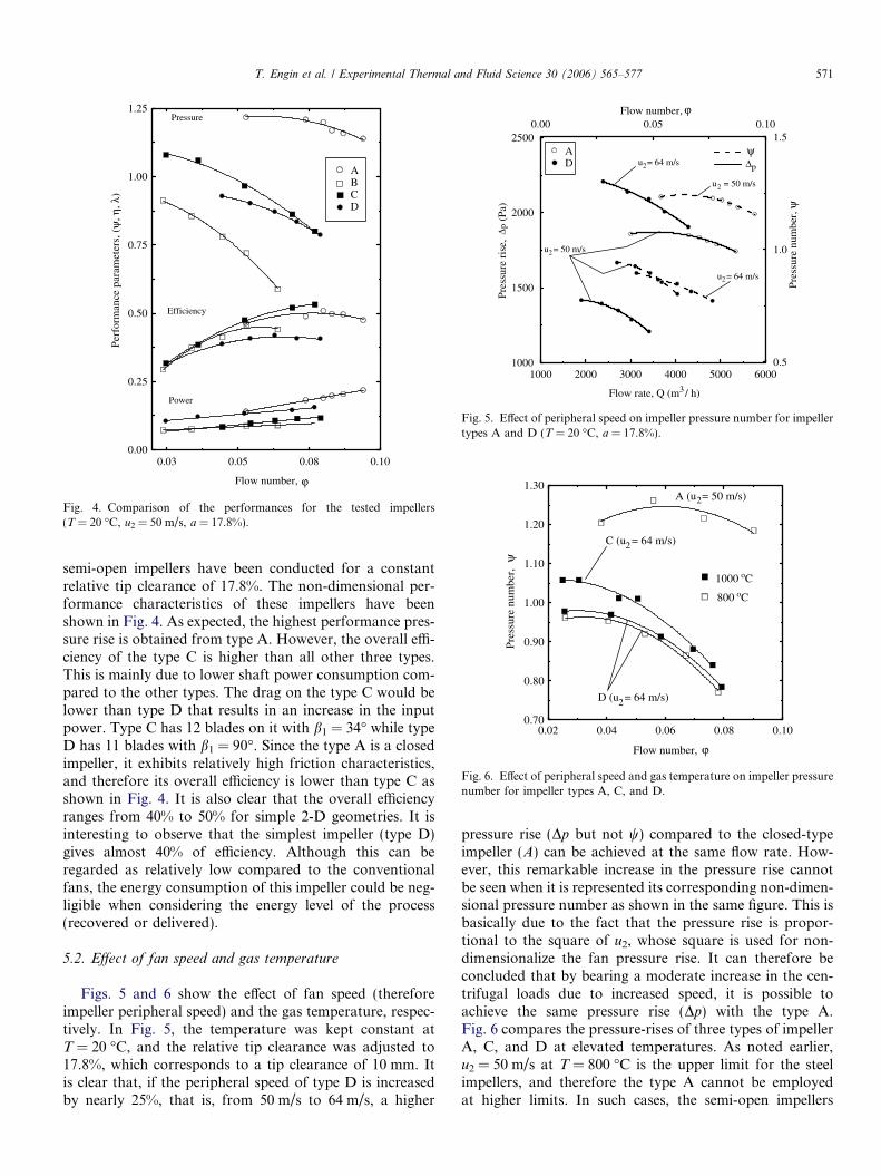
Fig. 7 shows the effect of fan Reynolds (Re) number onthe pressure numbers for ceramic impellers (types B, C, andD) at their best efficiency flow rates. The flow numbers attheir best efficiency points were determined to be, 0.067,0.065, and 0.067, respectively. The Re number was definedbased on the peripheral velocity of the impeller. As shownin Fig. 7, viscous effects can be regarded as important forRe number up to nearly 100,000 beyond which of theseeffects become almost negligible. For the range of100,000 < Re < 2,000,000 the maximum deviation fromthe average pressure number for each ceramic impellers(B, C, and D) are 5.5%, 3.1%, and 6.44%, respectively. Inorder to investigate the compressibility effects for eachimpeller, the Mach (Ma) numbers were defined based onthe peripheral velocity (u2). It was found that the highestMa number was less than 0.18, which meant the compress-ibility effects were also negligible as expected.
5.3. The effect of tip clearance
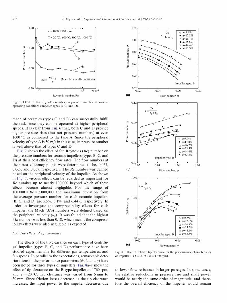
The effects of the tip clearance on each type of centrifu-gal impeller (types B, C, and D) performance have beenstudied experimentally for different gas temperatures, andfan speeds. In parallel to the expectations, remarkable dete-riorations in the performance parameters (w, k, and g) havebeen noted for three types of impellers. Fig. 8a–c show theeffect of tip clearance on the B type impeller at 1760 rpm,and T = 20 �C. Tip clearance was varied from 5 mm to30 mm. Since friction losses decrease as the tip clearanceincreases, the input power to the impeller decreases due
to lower flow resistance in larger passages. In some cases,the relative reductions in pressure rise and shaft powerwould be nearly the same order of magnitude, and there-fore the overall efficiency of the impeller would remain

(a)
(b)
(c)
0.02 0.04 0.06 0.08 0.10
Flow number,
0.60
0.80
1.00
1.20
Pre
ssur
e nu
mbe
r,
ϕ
ψ
a=17.8%a=26.7%a=35.5%a=44.4%a=53.3%
a = 2x
b + b1 2
Impeller type: C
0.02 0.04 0.06 0.08
Flow number,
0.06
0.09
0.12
Pow
er n
umbe
r,
ϕ
λ
a=17.8%a=26.7%a=35.5%a=44.4%a=53.3%
a = 2x
b + b1 2
Impeller type: C
0.02 0.04 0.06 0.08
Flow number,
0.20
0.30
0.40
0.50
0.60
Eff
icie
ncy,
ϕ
η
a=17.8%a=26.7%a=35.5%a=44.4%a=53.3%
a = 2x
b + b1 2
Impeller type: C
Fig. 9. Effect of relative tip clearance on the performance characteristicsof impeller C (T = 20 �C, n = 1760 rpm).
T. Engin et al. / Experimental Thermal and Fluid Science 30 (2006) 565–577 573
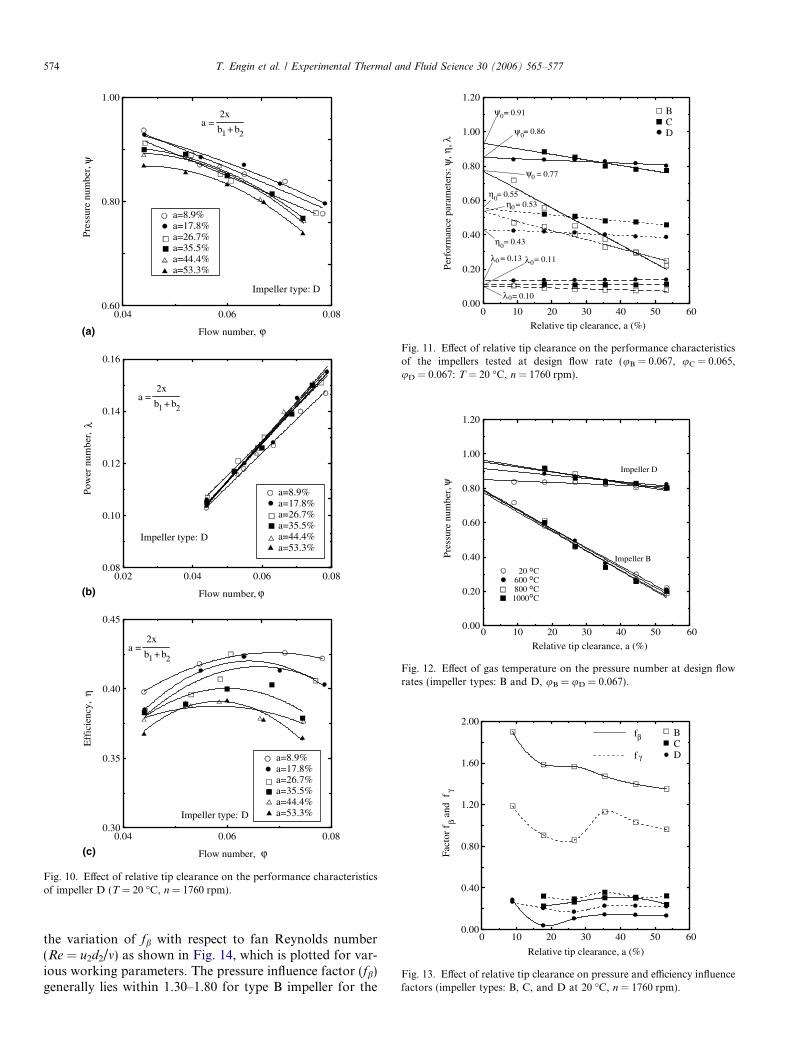
unchanged. This is not the case for type B since the overallimpeller efficiency decreases as the tip clearance increasesas shown in Fig. 8c. It can thus be concluded that the typeB exhibits high sensitivity to the running tip clearance. Sim-ilar performance variations are given for types C and D, inFigs. 9 and 10, respectively. However, the severity of theseeffects varies from one type to another. For example typesC and D present poorer dependency in terms of perfor-mance parameters as compared to type B, as shown inFig. 11. The reduction in the overall efficiency for thesetypes (types C and D) is totally due to their relative reduc-tions in the pressure rise since the input powers for thesetypes show almost no dependency to the varying tip clear-ance. Hence, the types C and D are nearly insensitivedesigns to the varying tip clearance. This is presumablydue to the fact that the flow work is mostly converted tothe pressure rise within the casing in these types of designswhereas this conversion takes place in the impeller passagesfor backward-curved impellers (type B). By enlarging thetip clearance the tip leakage flow from high-pressure sideto the low-pressure side of the blade increases substantiallyin such impellers, which bring considerable pressure losses.
When the gas temperature is elevated, the viscous effectsmay become significant and the combined effects of the tipclearance and high temperature would be of interest for theprocess. Since the types C and D dictate nearly the samecharacteristics under the test conditions, it would be inter-esting to compare type B versus type D. This is because ofthe fact that the type D is the most appropriate design forceramic material when considering its simplicity. Fig. 12gives the variation of pressure number versus flow numberfor different gas temperatures at a shaft speed of 1760 rpm.Tests were conducted for T = 20 �C, 600 �C, 800 �C, and1000 �C. Although a significant change was expected inthe pressure rise of each impeller as a response to theincreased gas temperature, it was observed that the bothimpellers exhibited a weak dependency to the gas tempera-ture for varying relative tip clearances. At only narrowertip clearances, an additional pressure rise due to theincreased gas viscosity was noted for especially the typeD impeller. This type of impeller became almost insensitivewithin the range of relative tip clearance of 17.8–53.3%,whereas the type B was insensitive for whole range of rela-tive tip clearance considered. A similar tendency wasrecorded for 1000 rpm as well.
5.4. Tip clearance influence factors and comparisons with the
literature
In order to determine the tip clearance influence factorsdescribed in Pfleiderer’s method [24], the values of perfor-mance parameters at zero tip clearance (wx=0, kx=0, andgx=0) have been obtained by extrapolation as can be seenfrom Fig. 11. The variation of fb and fc with relative tipclearance for three types of impeller (B, C, and D) areshown in Fig. 13. It is seen from this figure that both influ-ence factors are considerably higher for the type B com-
pared to the other two impellers. With the exception ofsmall tip clearances, it can be concluded that the influencefactors are almost independent of the relative tip clearancefor types C and D. A similar trend was also observed for
(a)
(b)
(c)
0.04 0.06 0.08
Flow number,
0.60
0.80
1.00P
ress
ure
num
ber,
ϕ
ψ
a=8.9%a=17.8%a=26.7%a=35.5%a=44.4%a=53.3%
a = 2x
b + b1 2
Impeller type: D
0.02 0.04 0.06 0.08
Flow number,
0.08
0.10
0.12
0.14
0.16
Pow
er n
umbe
r,
ϕ
λ
a=8.9%a=17.8%a=26.7%a=35.5%a=44.4%a=53.3%
a = 2x
b + b1 2
Impeller type: D
0.04 0.06 0.08
Flow number,
0.30
0.35
0.40
0.45
Eff
icie
ncy,
ϕ
η
a=8.9%a=17.8%a=26.7%a=35.5%a=44.4%a=53.3%
a = 2x
b + b1 2
Impeller type: D
Fig. 10. Effect of relative tip clearance on the performance characteristicsof impeller D (T = 20 �C, n = 1760 rpm).
0 10 20 30 40 50 60
Relative tip clearance, a (%)
0.00
0.20
0.40
0.60
0.80
1.00
1.20
Per
form
ance
par
amet
ers:
ψ, η
, λ
BCD
ψ = 0.910
ψ0= 0.86
ψ0 = 0.77
η0= 0.55η0
η0
= 0.53
= 0.43
λ0
λ0
λ0= 0.13 = 0.11
= 0.10
Fig. 11. Effect of relative tip clearance on the performance characteristicsof the impellers tested at design flow rate (uB = 0.067, uC = 0.065,uD = 0.067: T = 20 �C, n = 1760 rpm).
0 10 20 30 40 50 60
Relative tip clearance, a (%)
0.00
0.20
0.40
0.60
0.80
1.00
1.20
Pre
ssur
e nu
mbe
r,ψ
Impeller B
Impeller D
20 C 600 C 800 C1000 C
oooo
Fig. 12. Effect of gas temperature on the pressure number at design flowrates (impeller types: B and D, uB = uD = 0.067).
0 10 20 30 40 50 60
Relative tip clearance, a (%)
0.00
0.40
0.80
1.20
1.60
2.00
Fac
tor
f a
nd f
βγ
BCD
f
f
β
γ
Fig. 13. Effect of relative tip clearance on pressure and efficiency influencefactors (impeller types: B, C, and D at 20 �C, n = 1760 rpm).
574 T. Engin et al. / Experimental Thermal and Fluid Science 30 (2006) 565–577
the variation of fb with respect to fan Reynolds number(Re = u2d2/m) as shown in Fig. 14, which is plotted for var-ious working parameters. The pressure influence factor (fb)generally lies within 1.30–1.80 for type B impeller for the
100000 1000000Reynolds number, Re
0.40
0.80
1.20
1.60
2.00F
acto
r f
β
0.02105 106 102x 6
Impeller BImpeller D
a = 17.8%a = 26.7%a = 35.6%a = 44.4%a = 53.3%
T = 20 C, 600 C, 800 Co o o
Fig. 14. Effect of fan Reynolds number on pressure influence factor forvarious relative tip clearances and operating conditions (impeller types: Band D).
T. Engin et al. / Experimental Thermal and Fluid Science 30 (2006) 565–577 575
Re number up to approximately 2 · 106. On the otherhand, for the type D, the range of fb was found to be0.1–0.4 for the same limit value of Re number.
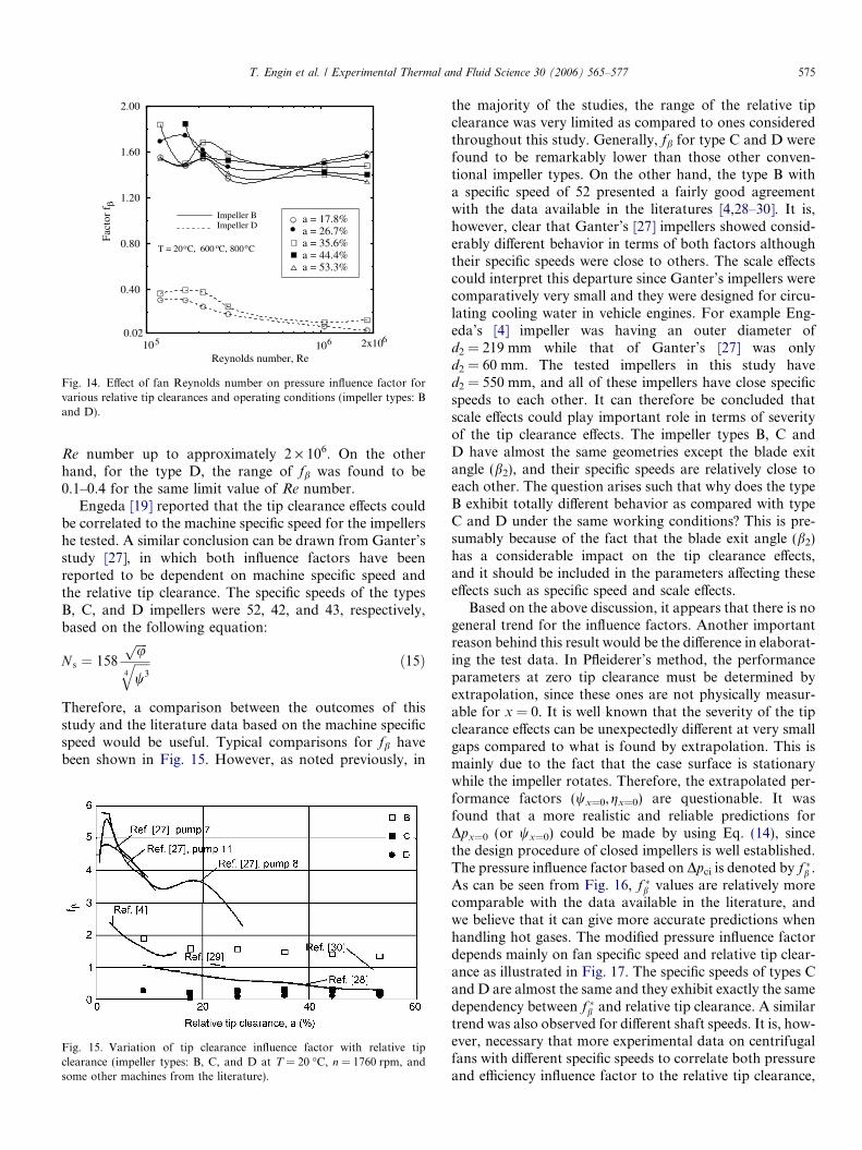
Engeda [19] reported that the tip clearance effects couldbe correlated to the machine specific speed for the impellershe tested. A similar conclusion can be drawn from Ganter’sstudy [27], in which both influence factors have beenreported to be dependent on machine specific speed andthe relative tip clearance. The specific speeds of the typesB, C, and D impellers were 52, 42, and 43, respectively,based on the following equation:
N s ¼ 158
ffiffiffiffiupffiffiffiffiffiw34
q ð15Þ
Therefore, a comparison between the outcomes of thisstudy and the literature data based on the machine specificspeed would be useful. Typical comparisons for fb havebeen shown in Fig. 15. However, as noted previously, in
Fig. 15. Variation of tip clearance influence factor with relative tipclearance (impeller types: B, C, and D at T = 20 �C, n = 1760 rpm, andsome other machines from the literature).
the majority of the studies, the range of the relative tipclearance was very limited as compared to ones consideredthroughout this study. Generally, fb for type C and D werefound to be remarkably lower than those other conven-tional impeller types. On the other hand, the type B witha specific speed of 52 presented a fairly good agreementwith the data available in the literatures [4,28–30]. It is,however, clear that Ganter’s [27] impellers showed consid-erably different behavior in terms of both factors althoughtheir specific speeds were close to others. The scale effectscould interpret this departure since Ganter’s impellers werecomparatively very small and they were designed for circu-lating cooling water in vehicle engines. For example Eng-eda’s [4] impeller was having an outer diameter ofd2 = 219 mm while that of Ganter’s [27] was onlyd2 = 60 mm. The tested impellers in this study haved2 = 550 mm, and all of these impellers have close specificspeeds to each other. It can therefore be concluded thatscale effects could play important role in terms of severityof the tip clearance effects. The impeller types B, C andD have almost the same geometries except the blade exitangle (b2), and their specific speeds are relatively close toeach other. The question arises such that why does the typeB exhibit totally different behavior as compared with typeC and D under the same working conditions? This is pre-sumably because of the fact that the blade exit angle (b2)has a considerable impact on the tip clearance effects,and it should be included in the parameters affecting theseeffects such as specific speed and scale effects.
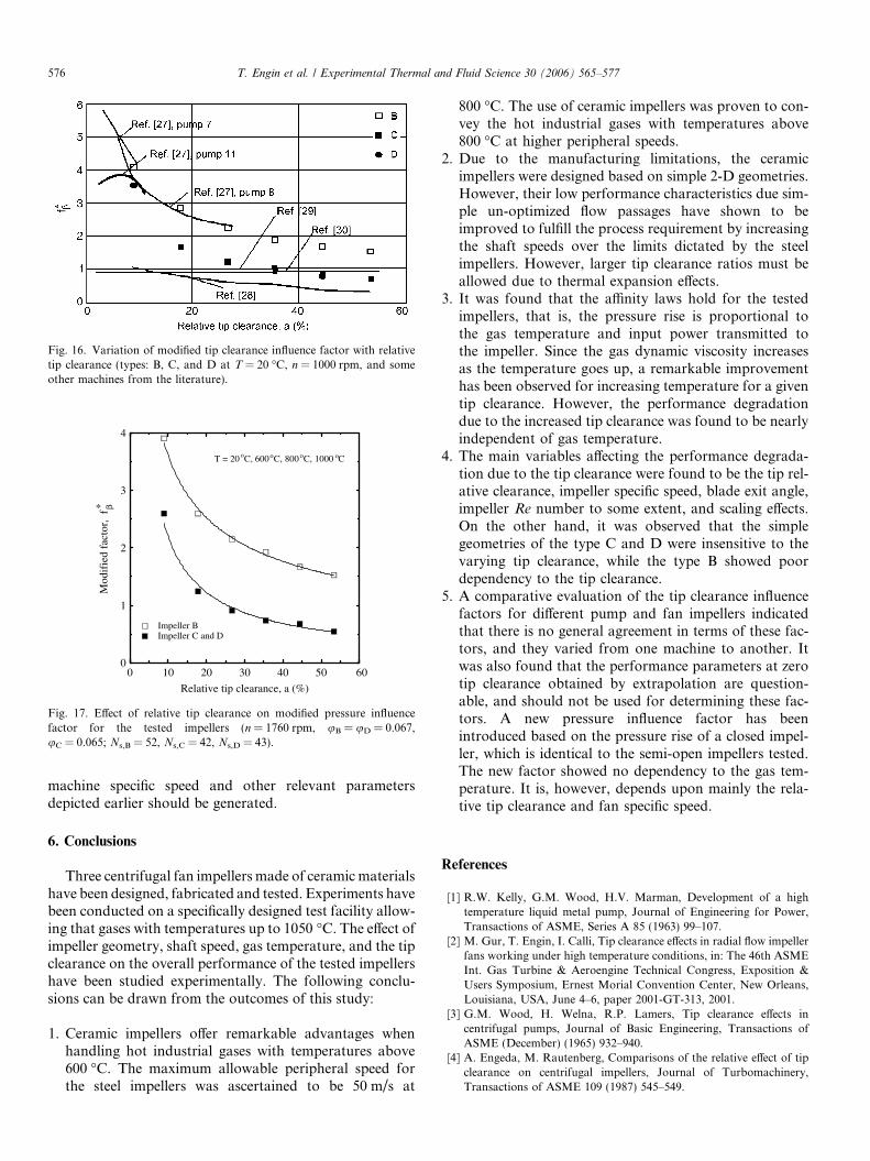
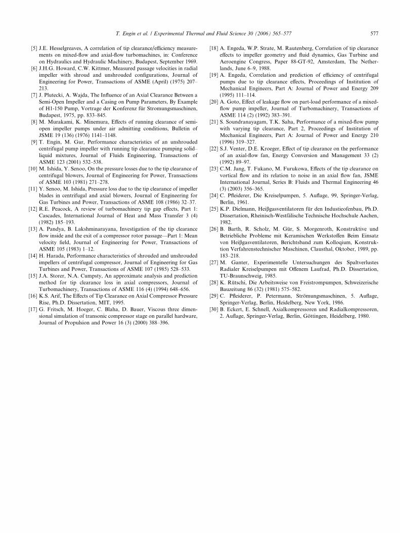
Based on the above discussion, it appears that there is nogeneral trend for the influence factors. Another importantreason behind this result would be the difference in elaborat-ing the test data. In Pfleiderer’s method, the performanceparameters at zero tip clearance must be determined byextrapolation, since these ones are not physically measur-able for x = 0. It is well known that the severity of the tipclearance effects can be unexpectedly different at very smallgaps compared to what is found by extrapolation. This ismainly due to the fact that the case surface is stationarywhile the impeller rotates. Therefore, the extrapolated per-formance factors (wx=0,gx=0) are questionable. It wasfound that a more realistic and reliable predictions forDpx=0 (or wx=0) could be made by using Eq. (14), sincethe design procedure of closed impellers is well established.The pressure influence factor based on Dpci is denoted by f �b .As can be seen from Fig. 16, f �b values are relatively morecomparable with the data available in the literature, andwe believe that it can give more accurate predictions whenhandling hot gases. The modified pressure influence factordepends mainly on fan specific speed and relative tip clear-ance as illustrated in Fig. 17. The specific speeds of types Cand D are almost the same and they exhibit exactly the samedependency between f �b and relative tip clearance. A similartrend was also observed for different shaft speeds. It is, how-ever, necessary that more experimental data on centrifugalfans with different specific speeds to correlate both pressureand efficiency influence factor to the relative tip clearance,
0 10 20 30 40 50 60
Relative tip clearance, a (%)
0
1
2
3
4
Mod
ifie
dfa
ctor
, f
β*
Impeller BImpeller C and D
T = 20 C, 600 C, 800 C, 1000 Co o o o
Fig. 17. Effect of relative tip clearance on modified pressure influencefactor for the tested impellers (n = 1760 rpm, uB = uD = 0.067,uC = 0.065; Ns,B = 52, Ns,C = 42, Ns,D = 43).
Fig. 16. Variation of modified tip clearance influence factor with relativetip clearance (types: B, C, and D at T = 20 �C, n = 1000 rpm, and someother machines from the literature).
576 T. Engin et al. / Experimental Thermal and Fluid Science 30 (2006) 565–577
machine specific speed and other relevant parametersdepicted earlier should be generated.
6. Conclusions
Three centrifugal fan impellers made of ceramic materialshave been designed, fabricated and tested. Experiments havebeen conducted on a specifically designed test facility allow-ing that gases with temperatures up to 1050 �C. The effect ofimpeller geometry, shaft speed, gas temperature, and the tipclearance on the overall performance of the tested impellershave been studied experimentally. The following conclu-sions can be drawn from the outcomes of this study:
1. Ceramic impellers offer remarkable advantages whenhandling hot industrial gases with temperatures above600 �C. The maximum allowable peripheral speed forthe steel impellers was ascertained to be 50 m/s at
800 �C. The use of ceramic impellers was proven to con-vey the hot industrial gases with temperatures above800 �C at higher peripheral speeds.
2. Due to the manufacturing limitations, the ceramicimpellers were designed based on simple 2-D geometries.However, their low performance characteristics due sim-ple un-optimized flow passages have shown to beimproved to fulfill the process requirement by increasingthe shaft speeds over the limits dictated by the steelimpellers. However, larger tip clearance ratios must beallowed due to thermal expansion effects.
3. It was found that the affinity laws hold for the testedimpellers, that is, the pressure rise is proportional tothe gas temperature and input power transmitted tothe impeller. Since the gas dynamic viscosity increasesas the temperature goes up, a remarkable improvementhas been observed for increasing temperature for a giventip clearance. However, the performance degradationdue to the increased tip clearance was found to be nearlyindependent of gas temperature.
4. The main variables affecting the performance degrada-tion due to the tip clearance were found to be the tip rel-ative clearance, impeller specific speed, blade exit angle,impeller Re number to some extent, and scaling effects.On the other hand, it was observed that the simplegeometries of the type C and D were insensitive to thevarying tip clearance, while the type B showed poordependency to the tip clearance.
5. A comparative evaluation of the tip clearance influencefactors for different pump and fan impellers indicatedthat there is no general agreement in terms of these fac-tors, and they varied from one machine to another. Itwas also found that the performance parameters at zerotip clearance obtained by extrapolation are question-able, and should not be used for determining these fac-tors. A new pressure influence factor has beenintroduced based on the pressure rise of a closed impel-ler, which is identical to the semi-open impellers tested.The new factor showed no dependency to the gas tem-perature. It is, however, depends upon mainly the rela-tive tip clearance and fan specific speed.
References
[1] R.W. Kelly, G.M. Wood, H.V. Marman, Development of a hightemperature liquid metal pump, Journal of Engineering for Power,Transactions of ASME, Series A 85 (1963) 99–107.
[2] M. Gur, T. Engin, I. Calli, Tip clearance effects in radial flow impellerfans working under high temperature conditions, in: The 46th ASMEInt. Gas Turbine & Aeroengine Technical Congress, Exposition &Users Symposium, Ernest Morial Convention Center, New Orleans,Louisiana, USA, June 4–6, paper 2001-GT-313, 2001.
[3] G.M. Wood, H. Welna, R.P. Lamers, Tip clearance effects incentrifugal pumps, Journal of Basic Engineering, Transactions ofASME (December) (1965) 932–940.
[4] A. Engeda, M. Rautenberg, Comparisons of the relative effect of tipclearance on centrifugal impellers, Journal of Turbomachinery,Transactions of ASME 109 (1987) 545–549.
T. Engin et al. / Experimental Thermal and Fluid Science 30 (2006) 565–577 577
[5] J.E. Hesselgreaves, A correlation of tip clearance/efficiency measure-ments on mixed-flow and axial-flow turbomachines, in: Conferenceon Hydraulics and Hydraulic Machinery, Budapest, September 1969.
[6] J.H.G. Howard, C.W. Kittmer, Measured passage velocities in radialimpeller with shroud and unshrouded configurations, Journal ofEngineering for Power, Transactions of ASME (April) (1975) 207–213.
[7] J. Plutecki, A. Wajda, The Influence of an Axial Clearance Between aSemi-Open Impeller and a Casing on Pump Parameters, By Exampleof H1-150 Pump, Vortrage der Konferenz fur Stromungsmaschinen,Budapest, 1975, pp. 833–845.
[8] M. Murakami, K. Minemura, Effects of running clearance of semi-open impeller pumps under air admitting conditions, Bulletin ofJSME 19 (136) (1976) 1141–1148.
[9] T. Engin, M. Gur, Performance characteristics of an unshroudedcentrifugal pump impeller with running tip clearance pumping solid–liquid mixtures, Journal of Fluids Engineering, Transactions ofASME 123 (2001) 532–538.
[10] M. Ishida, Y. Senoo, On the pressure losses due to the tip clearance ofcentrifugal blowers, Journal of Engineering for Power, Transactionsof ASME 103 (1981) 271–278.
[11] Y. Senoo, M. Ishida, Pressure loss due to the tip clearance of impellerblades in centrifugal and axial blowers, Journal of Engineering forGas Turbines and Power, Transactions of ASME 108 (1986) 32–37.
[12] R.E. Peacock, A review of turbomachinery tip gap effects, Part 1:Cascades, International Journal of Heat and Mass Transfer 3 (4)(1982) 185–193.
[13] A. Pandya, B. Lakshminarayana, Investigation of the tip clearanceflow inside and the exit of a compressor rotor passage—Part 1: Meanvelocity field, Journal of Engineering for Power, Transactions ofASME 105 (1983) 1–12.
[14] H. Harada, Performance characteristics of shrouded and unshroudedimpellers of centrifugal compressor, Journal of Engineering for GasTurbines and Power, Transactions of ASME 107 (1985) 528–533.
[15] J.A. Storer, N.A. Cumpsty, An approximate analysis and predictionmethod for tip clearance loss in axial compressors, Journal ofTurbomachinery, Transactions of ASME 116 (4) (1994) 648–656.
[16] K.S. Arif, The Effects of Tip Clearance on Axial Compressor PressureRise, Ph.D. Dissertation, MIT, 1995.
[17] G. Fritsch, M. Hoeger, C. Blaha, D. Bauer, Viscous three dimen-sional simulation of transonic compressor stage on parallel hardware,Journal of Propulsion and Power 16 (3) (2000) 388–396.
[18] A. Engeda, W.P. Strate, M. Rautenberg, Correlation of tip clearanceeffects to impeller geometry and fluid dynamics, Gas Turbine andAeroengine Congress, Paper 88-GT-92, Amsterdam, The Nether-lands, June 6–9, 1988.
[19] A. Engeda, Correlation and prediction of efficiency of centrifugalpumps due to tip clearance effects, Proceedings of Institution ofMechanical Engineers, Part A: Journal of Power and Energy 209(1995) 111–114.
[20] A. Goto, Effect of leakage flow on part-load performance of a mixed-flow pump impeller, Journal of Turbomachinery, Transactions ofASME 114 (2) (1992) 383–391.
[21] S. Soundranayagam, T.K. Saha, Performance of a mixed-flow pumpwith varying tip clearance, Part 2, Proceedings of Institution ofMechanical Engineers, Part A: Journal of Power and Energy 210(1996) 319–327.
[22] S.J. Venter, D.E. Kroeger, Effect of tip clearance on the performanceof an axial-flow fan, Energy Conversion and Management 33 (2)(1992) 89–97.
[23] C.M. Jang, T. Fukano, M. Furukowa, Effects of the tip clearance onvortical flow and its relation to noise in an axial flow fan, JSMEInternational Journal, Series B: Fluids and Thermal Engineering 46(3) (2003) 356–365.
[24] C. Pfleiderer, Die Kreiselpumpen, 5. Auflage, 99, Springer-Verlag,Berlin, 1961.
[25] K.P. Dielmann, Heibgasventilatoren fur den Industieofenbau, Ph.D.Dissertation, Rheinisch-Westfalische Technische Hochschule Aachen,1982.
[26] B. Barth, R. Scholz, M. Gur, S. Morgenroth, Konstruktive undBetriebliche Probleme mit Keramischen Werkstoffen Beim Einsatzvon Heibgasventilatoren, Berichtsband zum Kolloqium, Konstruk-tion Verfahrenstechnischer Maschinen, Clausthal, Oktober, 1989, pp.183–218.
[27] M. Ganter, Experimentelle Untersuchungen des SpaltverlustesRadialer Kreiselpumpen mit Offenem Laufrad, Ph.D. Dissertation,TU-Braunschweig, 1985.
[28] K. Rutschi, Die Arbeitsweise von Freistrompumpen, SchweizerischeBauzeitung 86 (32) (1981) 575–582.
[29] C. Pfleiderer, P. Petermann, Stromungsmaschinen, 5. Auflage,Springer-Verlag, Berlin, Heidelberg, New York, 1986.
[30] B. Eckert, E. Schnell, Axialkompressoren und Radialkompressoren,2. Auflage, Springer-Verlag, Berlin, Gottingen, Heidelberg, 1980.
Copyright © 2022 FDOKUMEN