Closing the gap in series scale up of high shear wet granulation process using impeller power and...
9
Closing the gap in series scale up of high shear wet granulation process using impeller power and blade design Gossett A. Campbell a, ⁎, Donald J. Clancy a, ⁎, Jinzhou X. Zhang b , Manish K. Gupta a , Choon K. Oh a a GlaxoSmithKline, Pharmaceutical Development, 709 Swedeland Rd., King of Prussia, PA 19406, USA b University of Iowa, College of Pharmacy, Iowa City, Iowa, USA abstract article info Article history: Received 23 March 2010 Received in revised form 7 September 2010 Accepted 8 September 2010 Available online 17 September 2010 Keywords: Granulation Blade angle Tip speed Froude number Scale up Inflection point This paper investigates the use of impeller work combined with an understanding of the significance of the impeller power inflection point during granulation to monitor, control, and scale up high shear wet granulation processes in the pharmaceutical industry. High shear wet granulations were carried out in a series of PMA Fielder granulators (25, 65, 150, and 300-L) with a geometric similar bowl at conditions of constant water addition time and constant tip speed. The results suggested that the granulation process can be effectively scaled up using a linear relationship between the impeller power inflection point (percent of water added at the point where the impeller load starts rising) and the Froude number in PMA Fielder granulator. To close the gap in the series scale up of wet granulation processes, it is desirable to design a granulator at small scale that performs similarly to a full scale commercial granulator such that no variables have to be significantly changed during scale up. A customized 6-L granulator (Fluid Air, Inc.) was designed with a similar bowl geometry as the 300-L Fielder granulator with a specialized blade of lower angle. It is illustrated in this paper that a 6-L granulator can be directly scaled up to a 300-L granulator using constant tip speed and percentage water addition, with the same impeller work and drug product performance. Granulation scale up using the impeller power as the endpoint measurement, combined with a proper impeller blade design can significantly reduce expenditure and time and accelerate the progression of drug product to market, by eliminating stepwise series scale up, and minimizing drug substance requirements. © 2010 Elsevier B.V. All rights reserved. 1. Introduction Process understanding and control by implementation of Quality by Design (QbD) have become critical in the submission of New Drug Application (NDA) and Marketing Authorization Application (MAA). High shear wet granulation (HSWG) is a unit operation in the manufacturing process that can significantly impact the quality of the final product and therefore, needs to be fully understood. High shear granulation results in an improved flow of the resulting granules for improved weight control during compression of tablets. With an optimized endpoint, HSWG can provide effective control over granule porosity and density as well as maintain content uniformity of the drug substance. Granule and tablet porosity and density are key product attributes due to their impact on dissolution, disintegration, and potentially bioavailability. The mechanism for HSWG and optimization of this process are reported in the literature [1–7]. Wet granulation process involves two main steps, addition of granulating liquid and wet massing. A binder may be added as a liquid or as a powder incorporated in the powder blend. In either case, the binder is distributed on the powder surfaces as the powder is agitated by an impeller blade, causing nucleation, consolidation, and growth into larger granules as the liquid is sprayed on top of the agitating bed [8]. A smaller high-rpm chopper blade is typically installed on the side of the bowl. As liquid is added, the chopper helps break up the very large agglomerates and distribute the granulating liquid. After liquid addition is completed, the material continues to be mixed in a step referred to as wet massing. Decisions of how much liquid to be added, and when to stop the wet massing step are quality critical and must be carefully controlled. Scale up of the HSWG process has been previously examined on the basis of Froude number, power number, pseudo Reynolds number, constant impeller tip speed [9,10], or constant impeller work per unit mass [11]. Other input variables to consider during scale up are the amount of granulating liquid, the rate of addition of granulating liquid, and the quality of the liquid spray distribution [1,12]. Equipment geometry also plays an important role [10]. Granulation endpoint is a critical control step in the scale up process to ensure that granules are manufactured with suitable characteristics of strength and density to maintain the quality and performance of the final drug product. Endpoint determination has been described in terms of granulation Powder Technology 205 (2011) 184–192 ⁎ Corresponding authors. Campbell is to be contacted at Tel.: + 1 610 917 5871; fax: +1 610 917 5935. Clancy Tel.: +1 610 917 7535; fax: +1 610 917 5935. E-mail addresses: [email protected] (G.A. Campbell), [email protected] (D.J. Clancy). 0032-5910/$ – see front matter © 2010 Elsevier B.V. All rights reserved. doi:10.1016/j.powtec.2010.09.009 Contents lists available at ScienceDirect Powder Technology journal homepage: www.elsevier.com/locate/powtec
Transcript of Closing the gap in series scale up of high shear wet granulation process using impeller power and...

Powder Technology 205 (2011) 184–192
Contents lists available at ScienceDirect
Powder Technology
j ourna l homepage: www.e lsev ie r.com/ locate /powtec
Closing the gap in series scale up of high shear wet granulation process usingimpeller power and blade design
Gossett A. Campbell a,⁎, Donald J. Clancy a,⁎, Jinzhou X. Zhang b, Manish K. Gupta a, Choon K. Oh a
a GlaxoSmithKline, Pharmaceutical Development, 709 Swedeland Rd., King of Prussia, PA 19406, USAb University of Iowa, College of Pharmacy, Iowa City, Iowa, USA
⁎ Corresponding authors. Campbell is to be contactefax: +1 610 917 5935. Clancy Tel.: +1 610 917 7535; f
E-mail addresses: [email protected] ([email protected] (D.J. Clancy).
0032-5910/$ – see front matter © 2010 Elsevier B.V. Adoi:10.1016/j.powtec.2010.09.009
a b s t r a c t
a r t i c l e i n f oArticle history:Received 23 March 2010Received in revised form 7 September 2010Accepted 8 September 2010Available online 17 September 2010
Keywords:GranulationBlade angleTip speedFroude numberScale upInflection point
This paper investigates the use of impeller work combined with an understanding of the significance of theimpeller power inflection point during granulation to monitor, control, and scale up high shear wetgranulation processes in the pharmaceutical industry. High shear wet granulations were carried out in a seriesof PMA Fielder granulators (25, 65, 150, and 300-L) with a geometric similar bowl at conditions of constantwater addition time and constant tip speed. The results suggested that the granulation process can beeffectively scaled up using a linear relationship between the impeller power inflection point (percent of wateradded at the point where the impeller load starts rising) and the Froude number in PMA Fielder granulator. Toclose the gap in the series scale up of wet granulation processes, it is desirable to design a granulator at smallscale that performs similarly to a full scale commercial granulator such that no variables have to besignificantly changed during scale up. A customized 6-L granulator (Fluid Air, Inc.) was designed with asimilar bowl geometry as the 300-L Fielder granulator with a specialized blade of lower angle. It is illustratedin this paper that a 6-L granulator can be directly scaled up to a 300-L granulator using constant tip speed andpercentage water addition, with the same impeller work and drug product performance. Granulation scale upusing the impeller power as the endpoint measurement, combined with a proper impeller blade design cansignificantly reduce expenditure and time and accelerate the progression of drug product to market, byeliminating stepwise series scale up, and minimizing drug substance requirements.
d at Tel.: +1 610 917 5871;ax: +1 610 917 5935.Campbell),
ll rights reserved.
© 2010 Elsevier B.V. All rights reserved.
1. Introduction
Process understanding and control by implementation of Qualityby Design (QbD) have become critical in the submission of New DrugApplication (NDA) and Marketing Authorization Application (MAA).High shear wet granulation (HSWG) is a unit operation in themanufacturing process that can significantly impact the quality of thefinal product and therefore, needs to be fully understood. High sheargranulation results in an improved flow of the resulting granules forimproved weight control during compression of tablets. With anoptimized endpoint, HSWG can provide effective control over granuleporosity and density as well as maintain content uniformity of thedrug substance. Granule and tablet porosity and density are keyproduct attributes due to their impact on dissolution, disintegration,and potentially bioavailability.
The mechanism for HSWG and optimization of this process arereported in the literature [1–7]. Wet granulation process involvestwo main steps, addition of granulating liquid and wet massing. A
binder may be added as a liquid or as a powder incorporated in thepowder blend. In either case, the binder is distributed on the powdersurfaces as the powder is agitated by an impeller blade, causingnucleation, consolidation, and growth into larger granules as theliquid is sprayed on top of the agitating bed [8]. A smaller high-rpmchopper blade is typically installed on the side of the bowl. As liquidis added, the chopper helps break up the very large agglomerates anddistribute the granulating liquid. After liquid addition is completed,the material continues to be mixed in a step referred to as wetmassing. Decisions of howmuch liquid to be added, andwhen to stopthe wet massing step are quality critical and must be carefullycontrolled.
Scale up of the HSWG process has been previously examined onthe basis of Froude number, power number, pseudo Reynolds number,constant impeller tip speed [9,10], or constant impeller work per unitmass [11]. Other input variables to consider during scale up are theamount of granulating liquid, the rate of addition of granulating liquid,and the quality of the liquid spray distribution [1,12]. Equipmentgeometry also plays an important role [10]. Granulation endpoint is acritical control step in the scale up process to ensure that granules aremanufactured with suitable characteristics of strength and density tomaintain the quality and performance of the final drug product.Endpoint determination has been described in terms of granulation

Fig. 1. Schematic representation of a high shear granulator impeller blade.
185G.A. Campbell et al. / Powder Technology 205 (2011) 184–192
time [5,13], near infrared reflectance spectroscopy [14], power ortorque [15], imaging [16], vibration [17], and acoustics [18].
In this paper, we have showed that the HSWG process can beeffectively scaled up through a series of Fielder PMA granulators(including PMA 25, 65, 150, and 300 L) having a similar bowl designusing Froude number and impeller work load inflection point at aconstant tip speed. We have also demonstrated that by having asimilar geometric design between granulator bowls (blade length tobowl ratio and blade height to bowl volume ratio) and suitable bladeangles the HSWG process can be scaled up directly from a 6-L Fluid Airgranulator to a 300-L PMA Fielder granulator. The success of scale upwas measured by similar impeller work behavior and drug productperformance. Granulation scale up using impeller blade design cansignificantly reduce expenditure and time, and accelerate theprogression of the drug product to market without compromisingproduct quality by eliminating stepwise series scale up.
2. Theory
The impeller work of a granulator can be used to effectively controlandmonitor the granulation endpoint. The impeller work is calculatedby integrating impeller motor power over the time of operation usingEq. (1):
WT = ∫t
0Pi dt ð1Þ
whereWT is the total impeller work applied over the time of operationand Pi is the impeller power at time t. Work input on a batch basis ismeasured in units of (Watt×seconds) or Joules. The motor powersignal on high shear granulators is measured as the line input to thegranulator motor. The energy used to rotate the impeller when nomaterial is loaded into the granulator bowl is used to overcome forceswithin the power-train of the granulator and does not go into theproduct. This is termed the baseline impeller power. The work that isapplied to the powder mass in the granulator bowl can be expressedas Eq. (2):
WT = ∫t
0Pi−P0ð Þdt ð2Þ
where P0 is the baseline impeller work load at the speed used to turnthe impeller when no material is in the bowl. In our work, P0 ismeasured by running the granulator empty for 6 min, and is theaverage power observed from the fifth to sixth minute. The baselinepower for a granulator can vary from batch to batch and is thusmeasured prior to every batch, and this also gives a chance for thegranulator to warm up, which reduces motor warm up effects on thepower input being observed.
Numeric integration is used to provide the work value throughoutthe batch. The granulation is stopped when the target work value isachieved. Eq. (3) is the actual numeric computation utilized tocalculate the integral work.
Wi = Pi−P0ð Þ:Δt + Wi−1 ð3Þ
Wi−1 is the total work calculated at the (ith−1) time point, and△t is the time difference measured in seconds between “i” and “i−1”time interval. The output from the above equation is integrated overtime of the granulation once the water input has started to the end ofwet massing.
Froude number can be thought of as a measure of the number ofthe gravitational forces (g-forces) of centrifugation at the granulatorblade tip. A schematic diagram of an impeller blade is shown in Fig. 1.
Centrifugal force is necessary for accelerating the powder bed intotoroidal (roping) flow, which is the predominant flow pattern at thelater stages in granulation. The centrifugal force also creates a
compressive force pressing the powder bed toward the inner wallsof the bowl. The centrifugal force is proportional to the square of theangular velocity (ω) and the radius of the impeller blade (R). FroudeNumber (Fr) (Eq. (4)) is a hypothesized scaling criterion forgranulation, and can be thought of as a measure of the centrifugalforces being applied to the power.
Fr =4π2RN2
602gð4Þ
where N is the impeller rotation speed (rpm), R is the impeller radius(m), and g is the gravitational constant (9.81 m s−2). The impeller tipspeed is calculated using Eq. (5).
V =πND60
ð5Þ
where V is the velocity of the blade (m/s), and D is the impeller bladediameter (m).
3. Materials and methods
3.1. Materials
The materials used were of pharmaceutical grade and include themodel drug substance X (GlaxoSmithKline), microcrystalline cellulose(Avicel PH102, Filler, FMC Biopolymer), Povidone K30 (Binder, BASF),sodium starch glycolate (Disintegrant, Roquette) and Opadry (Filmcoat, Colorcon). Purified water was used as the granulating liquid.
3.2. Method
3.2.1. Granulator designA series of Fielder PMA granulators (Aeromatic-Fielder Ltd.) with
bowl capacities of 25-L, 65-L, 150-L, and 300-L were used to performthe granulation process. In these Fielders design the impeller ismounted on a vertical shaft fixed through the bottom of the bowl andthe chopper is on a horizontal shaft fixed through the side of the bowl.
In a second study, a 6-L granulator (Fluid Air Inc.) was speciallydesigned at GlaxoSmithKline's request to geometricallymimic the bowlof the 300-L PMA Fielder granulator. In the Fluid Air granulator,experiments were carried out with two types of blades at a constantwater addition rate. One blade was geometrically identical to the 300-LPMA Fielder granulator, with the exception that the blade angle wassmaller, and the other 6-L Fluid Air granulator blade was the originalblade of Fluid Air designwith a 47° angle and a flared tip. The impeller is

Table 1Dimensions of Fluid Air and PMA Fielder granulators.
Description 6-L Fluid Air customized blade 6-L Fluid Air standard blade 25-L Fielder 65-L Fielder 150-L Fielder 300-L Fielder
Impeller radius (cm) 12.7 12.7 19.1 24.8 38.1 46.4Blade inside height (cm) 1.3 1.4 2.9 4.8 5.4 7.6Blade outside Height (cm) 0.6 2.5 2.9 4.8 3.8 4.5Impeller blade width near hub (cm) 3.2 1.9 5.1 7.6 10.2 13.7Impeller blade width at tip (cm) 1.9 3.5 5.1 7.6 6.4 6.7Blade angle at hub (°) 24 49 34 39 32 34Blade angle at tip (°) 20 47 34 39 37 41Average blade angle (°) 22 48 34 39 34.5 37.5Blade height/bowl height 0.1 0.4 0.2 0.2 0.1 0.1Blade height/straight wall height 0.1 0.6 0.3 0.3 0.2 0.2
186 G.A. Campbell et al. / Powder Technology 205 (2011) 184–192
mounted on a vertical shaft fixed through the bottom of the bowl andthe chopper is mounted on a horizontal shaft entering from the side ofthe bowl. The dimensions of the granulators evaluated in this studywere measured at GSK and are presented in Table 1.
3.2.2. Granulation processThegranulation runswere carried out at constant tip speed (5.5 m/s)
and granulating liquid (purified water) addition time using the sameformulation. The formulation consists of the model drug substance X(GlaxoSmithKline),microcrystalline cellulose (Avicel PH102, Filler, FMCBiopolymer), Povidone K30 (Binder, BASF), and sodium starch glycolate(Disintegrant, Roquette). The powder was screened through a 20meshscreen and charged into the granulator bowl. Then water was sprayedon the top of the agitating powder bed using a nozzle protrudingthrough the lid. The water flow rate and spray pattern over the powderbed were maintained constant relative to the granulation batch size.Water was added over a fixed time of 5 min and then wet massing wasperformed to a fixed time-independent impeller work-based endpoint.A power cell is fitted to the impeller motor to measure the torque andpower per batch size. The power data was collected using the AspenIP.21© software. The processing parameters for the granulations at thevarious scales are presented in Table 2. The wet massed material waspassed through a Co-mill 0.250"R screen (Quadro), and dried in a Fluidbed dryer (Glatt) using an inlet air temperature of 60 °C to a loss ondrying (LOD) of less than 1.5%. Subsequently, the dried granules weremilled using a Co-mill 0.032"R screen (Quadro).
3.2.3. Compression and coatingThe dry milled granules were blended with extra-granular
excipients in a suitable size blender and compressed on a rotarytablet press into tablets using a modified capsule shaped tooling. Filmcoating was performed to approximately 3% weight gain using asuitable coating pan.
4. Results and discussion
4.1. Impeller load behavior during water addition for PMA Fieldergranulators
The amount of water needed for optimum granulation increaseswith the scale for the Fielder PMA granulators where tip speed is held
Table 2Processing parameters for granulation processes at the various scales.
Description 6-L Fluid Air customized blade 6-L Fluid Air stand
Water addition time (min) 5 5Batch size (kg) 0.94 0.94Impeller speed (rpm) 410.0 413.6Chopper speed (rpm) 2500 2500Tip speed (m/s) 5.5 5.5Number of blades 3 3Froude number 23.9 24.3
constant (in this case at 5.5 m/s). This phenomenon has been reportedelsewhere [2,19]. Scale up of the granulation process for the drugproduct described in this paper showed that the optimal wateramounts required for 25-L, 65-L, 150-L and 300-L granulators were23%, 26%, 28%, and 30% of the dry powder batch size, respectively, inorder to achieve desirable dissolution. The water fraction added (wt/wt) is defined as the mass of water added divided by the total mass ofthe dry powder batch size.
A key observation during experimentation at the various scaleswas that it required different amounts of water to invoke an impellerpower increase when the total water addition time was held constant(5 min). To provide a picture of how the impeller power responded tothe water content at various scales, the impeller power wasnormalized by dividing the power at each moment in time by theaverage impeller power observed from 0% to 15% water contentadded. Fig. 2 shows the scaled impeller power (P*) versus waterfraction added at the different equipment scales. A value ofapproximately one indicates that no impeller power response wasobserved.
Initially, the impeller power decreases due to hysteresis effects(time taken for impeller motor to warm up) then rises at a later pointdue to commencement of the granulation process. The amount ofwater added at the point of inflection in the impeller power indicatesthe beginning of densification in the granulation process and is called“Xsat” in this analysis.
Xsat can be found using two mathematical techniques. The firsttechnique is to find the point where the impeller power mean valuefor 10 s is 3-standard deviation higher than the previous 30 s worth ofdata prior to the rapid rise in the impeller power. The second is to findthe amount of water added at a point of minima when the objectivefunction (Eq. 6) is plotted against the water fraction added.
Objective Function =P15s−P0ð ÞMH2O
ð6Þ
P15 s is the 15-s backward data averaging of the impeller power. A15-s backward data averaging is used to smooth the impeller powerdata to prevent extraneous noise from providing a false minimum.The variable MH20 is the amount of water added. The twomethodologies for Xsat determination agree with an R2 of 90% forthe data presented in this paper. The minima approach was chosen
ard blade 25-L Fielder 65-L Fielder 150-L Fielder 300-L Fielder
5 5 5 53.90 10.14 23.40 46.80
275.7 223.7 137.9 113.32500 2500 2500 2500
5.5 5.8 5.5 5.53 3 3 3
16.2 13.9 8.1 6.7
y = 5.770x2-2.048x + 0.247R2 = 0.932
0.05
0.07
0.09
0.11
0.13
0.15
0.17
0.19
0.04 0.08 0.12 0.16 0.2 0.24 0.28
Water Fraction Added (wt/wt)
150L
A
y = 30.19x2-12.68x + 1.630R2 = 0.965
0.2
0.3
0.4
0.5
0.6
0.7
0.8
0.05 0.1 0.15 0.2 0.25 0.3 0.35
(P-P
0)/X
H2O
(P-P
0)/X
H2O
Water Fraction Added (wt/wt)
300L
B
Fig. 3. Plots of objective function versus water fraction added. Panel A; 150 L granulator.Panel B; 300 L granulator.
0.20
0.22
0.24
rved
(w
t/w
t)
150-L
300-L
0.9
1.0
1.1
1.2
1.3
1.4
1.5
1.6
1.7
1.8
1.9
2.0
0.00 0.05 0.10 0.15 0.20 0.25 0.30
Water Fraction Added (wt/wt)
Sca
led
Imp
elle
r L
oad
(P
*)
25-L Scale 65-L Scale
150-L Scale 300-L Scale
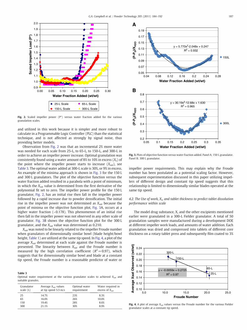
Fig. 2. Scaled impeller power (P*) versus water fraction added for the variousgranulation scales.
187G.A. Campbell et al. / Powder Technology 205 (2011) 184–192
and utilized in this work because it is simpler and more robust tocalculate in a Programmable Logic Controller (PLC) than the statisticaltechnique, and is not affected as strongly by signal noise, thusproviding better models.
Observation from Fig. 2 was that an incremental 2% more waterwas needed for each scale from 25-L, to 65-L, to 150-L, and 300-L inorder to achieve an impeller power increase. Optimal granulation wasconsistently found using a water amount of 8% to 10% in excess (Xs) ofthe point where the impeller power starts to increase (Xsat), seeTable 3. The optimal water added at 300-L scale is 30%, or 9% in excess.An example of the minima approach is shown in Fig. 3 for the 150 Land 300 L granulators. The plot of the objective function versus thewater fraction added resulted in a parabola with a point of minimum,in which the Xsat value is determined from the first derivative of thepolynomial fit set to zero. The impeller power profile for the 150 Lgranulator, Fig. 2, has an initial rise then fall in the impeller powerfollowed by a rapid increase due to powder densification. The initialrise in the impeller power was not determined as Xsat because thepoint of minima on the objective function plot, Fig. 3A, occurs at ahigher water fraction (~0.178). This phenomenon of an initial risethen fall in the impeller power was not observed in any other scale ofgranulator. Fig. 3B shows the objective function plot for the 300 Lgranulator, and the Xsat value was determined as 0.210.
Xsatwas noted to be linearly related to the impeller Froude numberwhen granulators of dimensionally similar bowl (blade height/bowlheight, Table 1) are utilized at the same tip speed. In Fig. 4, a plot of theaverage Xsat determined at each scale against the Froude number ispresented. The linearity between Xsat and the Froude number ismeasured by the high correlation coefficient (R2=0.97), whichsuggests that for dimensionally similar bowl and blade at a constanttip speed, the Froude number is a reasonable predictor of water or
Table 3Optimal water requirement at the various granulator scales to achieved Xsat andsuitable granules.
Granulatorscale (L)
Average Xsat valuesat tip speed 5.5 m/s
Optimal waterrequirement
Water required inexcess of Xsat
25 14.7% 23% 8.3%65 16.0% 26% 10.0%150 19.4% 28% 8.6%300 21.1% 30% 8.9%
impeller power requirements. This may explain why the Froudenumber has been postulated as a potential scaling factor. However,subsequent experimentation discussed in this paper utilizing impel-lers of different design and constant tip speed suggests that thisrelationship is limited to dimensionally similar blades operated at thesame tip speed.
4.2. The Use of work, Xs, and tablet thickness to predict tablet dissolutionperformance within scale
The model drug substance, X, and the other excipients mentionedearlier were granulated in a 300-L Fielder granulator. A total of 50granulation samples were manufactured during a development DOEat different impeller work loads, and amounts of water addition. Eachgranulation was dried and compressed into tablets of different corethickness on a rotary tablet press and subsequently film coated to 3%
y = -0.0059x + 0.2725
R2 = 0.97
0.10
0.12
0.14
0.16
0.18
5.0 10.0 15.0 20.0 25.0
Froude Number
Ave
rag
e X
sat
Ob
se
25-L
65-L
Fig. 4. A plot of average Xsat values versus the Froude number for the various Fieldergranulator scales at a constant tip speed.

Table 4Water addition and work endpoint data set for 300-L Fielder granulator with film-coated tablet dissolution performance at 45 min.
SampleID
Granulationwater (%)
Xsat
(%)Xs
(%)Work(kJ/kg)
Tabletthickness (mm)
Film-coated %dissolution at45 min
1 29.9 20.2 9.7 20.95 6.21 652 29.9 20.2 9.7 20.95 6.34 883 29.9 20.2 9.7 20.95 6.51 914 29.9 20.2 9.7 20.95 6.67 895 29.9 20.2 9.7 20.95 6.86 876 31.8 20.2 11.6 31.24 6.21 57 31.8 20.2 11.6 31.24 6.36 138 31.8 20.2 11.6 31.24 6.51 319 31.8 20.2 11.6 31.24 6.68 6910 31.8 20.2 11.6 31.24 6.85 7711 31.8 21.9 9.9 20.25 6.23 7012 31.8 21.9 9.9 20.25 6.35 8913 31.8 21.9 9.9 20.25 6.53 8914 31.8 21.9 9.9 20.25 6.70 8915 31.8 21.9 9.9 20.25 6.86 8216 27.7 20.5 7.2 13.73 6.21 8817 27.7 20.5 7.2 13.73 6.36 9618 27.7 20.5 7.2 13.73 6.55 9619 27.7 20.5 7.2 13.73 6.71 9420 27.7 20.5 7.2 13.73 6.89 9021 27.7 20.1 7.6 27.43 6.20 6922 27.7 20.1 7.6 27.43 6.36 9423 27.7 20.1 7.6 27.43 6.50 9424 27.7 20.1 7.6 27.43 6.69 9325 27.7 20.1 7.6 27.43 6.87 8026 31.8 22.1 9.7 12.99 6.19 9227 31.8 22.1 9.7 12.99 6.34 9628 31.8 22.1 9.7 12.99 6.50 9629 31.8 22.1 9.7 12.99 6.69 9330 31.8 22.1 9.7 12.99 6.87 8431 29.9 20.7 9.2 24.22 6.20 6032 29.9 20.7 9.2 24.22 6.34 9033 29.9 20.7 9.2 24.22 6.52 8834 29.9 20.7 9.2 24.22 6.68 8935 29.9 20.7 9.2 24.22 6.87 8436 30.1 21.0 9.1 12.89 6.20 8937 30.1 21.0 9.1 12.89 6.37 9438 30.1 21.0 9.1 12.89 6.52 9339 30.1 21.0 9.1 12.89 6.71 8740 30.1 21.0 9.1 12.89 6.89 8641 28.0 20.5 7.5 17.73 6.21 9042 28.0 20.5 7.5 17.73 6.36 9743 28.0 20.5 7.5 17.73 6.53 9744 28.0 20.5 7.5 17.73 6.70 9345 28.0 20.5 7.5 17.73 6.88 8346 30.1 20.9 9.3 18.23 6.20 8047 30.1 20.9 9.3 18.23 6.36 9148 30.1 20.9 9.3 18.23 6.52 9149 30.1 20.9 9.3 18.23 6.68 8950 30.1 20.9 9.3 18.23 6.86 81
188 G.A. Campbell et al. / Powder Technology 205 (2011) 184–192
weight gain using Opadry. Dissolution profiles of the film coatedtablets were used to determine the impact of the amount of wateradded and impeller work. The data set of work endpoints and filmcoated tablet dissolution is tabulated in Table 4 for the 300-Lgranulator.
For this drug product, impeller work, water amount, and tabletthickness are good predictors of dissolution performance. A quadraticmodel of R2=0.92 was derived from the 50 observations. It is possible
Table 5Improvement of work model prediction for dissolution at 300-L scales using Xs instead of a
Film coated tablet dissolutionat 45 min predicted by
Data set R2 R2 adjusted R2
Work, water, and thickness Table 4 92% 90% 85Work, Xs, and thickness Table 4 94% 92% 87
to define a design space of proven acceptable quality such that ifimpeller work, water addition, and tablet thickness are controlledacceptable dissolution performance will be achieved. As a result,impeller work, water amount, and tablet thickness can be utilized aseffective control parameters to ensure the desired dissolution.
The prediction of dissolution can be incrementally improved byconsidering the amount of water added in excess of the point wherethe impeller power starts rising. The difference between the totalwater added and the water added at the work inflection point istermed the amount of water added in excess of the inflection point, Xs.By replacing the absolute amount of water added with Xs animprovement in the quadratic model for predicting dissolutionperformance was observed. That is, R2=0.94 and is summarized inTable 5.
4.3. The use of work, Xs, and tablet thickness to predict tablet dissolutionperformance across scale
Several granulation studies were carried out at the 150-L and 300-L scales during the scale up of a model drug product containing X. The150-L and 300-L granulators used in these studies have similar motorand drive train design and therefore, their impeller work efficiencyshould be similar. It is, therefore, expected to achieve a similar work-dissolution model for both granulators. A total of 28 granulationsamples were collected in experimentation with the 150-L PMAFielder granulator with 26% and 28% water content. The data set withwork endpoints calculated on a work per unit mass basis is presentedin Table 6 for the 150-L granulator.
A trend plot of dissolution versus impeller work is presented inFig. 5 for both the 150-L and 300-L granulators at the samegranulation water amount ranging from 26 to 28% w/w. It can beobserved that for both granulators the maximum tablet dissolutionwas achieved between 20 and 40 kJ/kg of impeller work applied.However, there is a slight offset of the 300-L dissolution profile to theright. This is an expected result because as the size of the granulatorincreases more work is needed to drive the granulation processcorresponding with the observation of an increased Xsat value for the300-L scale. It is worth noting that although good tablet dissolutionperformance could be achieved at 28% water addition at the 300-Lscale, the tablet population dissolution variance was on the high sideof the acceptance limit. Conversely, 30% water addition was found toprovide both good average dissolution performance and reducedpopulation dissolution variance. The optimum tablet dissolution withhighmean value and low population variance using granulations from150-L and 300-L granulators were obtained with total water added of28% and 30%, respectively. This provides further evidence that theimpeller power inflection point may be a good measure for thedetermination of optimum water added between scales.
Table 7 summarized the output from a quadratic linear regressionmodel developed in Design Expert© using the data set of the 150-Land 300-L granulators to predict the combined effect of impeller workper unit mass, water added, and tablet thickness on the amount ofdrug dissolved at 45 min.
Individual models for the 150-L and 300-L data set gave goodcorrelation coefficients of 87% and 92%, respectively, as a function ofwork, water added, and tablet thickness. When the data sets werecombined to predict dissolution performance across scales, a 2% to 3%
bsolute water addition.
Predicted Standard deviationof prediction
Model P value Number of datapoints in model
% 5.9% b0.01% 50% 5.3% b0.01% 50

Table 6Water addition and work endpoint data set for 150-L Fielder granulator with tabletphysical measurements and dissolution performance at 45 min.
Granulation ID samples Wateradded(%)
Xsat
(%)Xs
(%)Work(kJ/kg)
Tabletthickness(mm)
Film-coatedtablet %dissolution at45 min
A 1 26.0 16.9 9.1 2.20 6.83 692 4.92 6.73 743 9.64 6.58 804 17.33 6.50 90
B 1 26.0 17.5 8.5 1.88 6.81 662 3.50 6.71 723 6.28 6.68 804 10.01 6.62 865 15.64 6.51 93
C 1 26.0 18.5 7.5 12.17 6.71 882 19.17 6.71 863 28.19 6.58 974 39.61 6.50 815 55.16 6.55 63
D 1 28.0 18.9 9.1 5.34 6.89 822 9.67 6.81 813 15.38 6.71 934 23.87 6.60 975 36.53 6.57 966 49.29 6.57 85
E 1 28.0 21.2 6.8 6.95 6.76 952 15.16 6.65 983 25.08 6.61 944 37.53 6.60 875 53.75 6.67 806 69.73 6.74 47
F 1 28.0 20.9 7.1 32.27 6.54 82G 1 28.0 19.3 8.7 38.14 6.56 86
40
50
60
70
80
90
100
0 20 40 60 80
Granulation Work (kj/kg)
%D
isso
luti
on
150-LDissolution
300-LDissolution
Fig. 5. Plot of raw data for aqueous film coated tablet dissolution at 45 min againstimpeller work of the 150-L and 300-L PMA Fielder granulator from 26% to 28% wateradded.
189G.A. Campbell et al. / Powder Technology 205 (2011) 184–192
increase in the predicted standard deviation was noticed, which is anindication that there is a difference between equipment and/or scale.It does appear that there is a consistent and significant scaling effect inthe water required for granulation, an understanding of which willhelp improve dissolution predictions and is discussed below.
Improvements to the prediction of dissolution are noted when Xs
(amount of water in excess of Xsat) is substituted for absolute wateramount in the 150-L, 300-L, and the combined model. These resultsare summarized in Table 8. It implies that the understanding of Xsat
and how it shifts between scales and also systematically by scaleappear to be significant. Using Xs in the model improved theindividual model dissolution by 2% to 3% and the combined modelby~4%.
4.4. Closing the gap in high shear wet granulation scale up process usingthe concept of blade design and impeller power inflection point
In the Pharmaceutical industry, high shear wet granulation(HSWG) processes are scaled up in a sequential fashion using a seriesof similar design granulators. In order to close the gap in this seriesscale up of HSWG processes, it is desirable to design a Pilot Plant scalegranulator to replicate the water and impeller work interactions of acommercial scale granulator. This would offer numerous advantagesin R&D for testing products at small scale for potential problems at alarger scale, particularly when drug substance is limited. In addition,scale up would be significantly less expensive and faster withoutcompromising product quality and safety. Indications are that bydesigning a blade of the appropriate angle such that the impellerpower inflection point at the Pilot Plant scale is similar to thecommercial scale, using constant tip speed and percent wateraddition, direct scale up can be achieved.
An important aspect that often got overlooked during scale up isthat the shear rate is changing as the granulation process is scaled up,with corresponding loss of water spray flux and the degree of mixing.
An objective was to create a 6-L granulator (Fluid Air) that maintainedsimilar mixing characteristics and water spray flux as a 300-Lgranulator (PMA Fielder) to test if the same dissolution designspace of work and water added could be generated. To accomplishthis, a specialized blade for the 6-L granulator was constructed with a20° angle of inclination at the tip base on the impeller powerinflection point and tip speed of the 300-L granulator used to get thedesirable impeller power-water profile. The diameter of the 6-Lgranulator impeller blade was determined from a constant ratio of theblade diameter to the bowl inside diameter of the 300-L granulator.On the same token, the width of the 6-L granulator impeller blade wasdetermined from a constant ratio of blade width to blade diameter ofthe 300-L granulator. If the geometry of the blades is similar and tipspeed is held constant the powder bed in the 6-L granulator passesbelow the spray nozzle many more times during water addition, thusachieving better liquid distribution at the small scale relative to thelarge scale. Knowing the blade tip speed (V) used to obtain theimpeller power profile at the 300-L scale and the diameter of the 6-Lgranulator impeller blade (D) the impeller rotation speed of the 6-Lgranulator (N) can be calculated from Eq. (5). It was observed in ourstudies that the Xsat is proportional to the blade angle as follows:
Xsatα1
N⋅ sin θð Þ2 : ð7Þ
A plot of Xsat versus1
N⋅ sin θð Þ2is shown in Fig. 6. The relationship
gave a linear line with a correlation coefficient of R2=0.90, and canalso be used to estimate the appropriate blade angle.
Fig. 6 was utilized to design the customized blade for the 6-Lgranulator and appears to provide a reasonable approximation for thedesign of the blade angle to scale up most products. The effect of theblade angle on the power consumption of the impeller blade wasinvestigated by Murakami et al. [20]. The results from theirinvestigation showed that the Power number (Pn) is proportional tothe sine of the blade angle squared, expressed as:
Pnαsin θð Þ2: ð8Þ

Table 7Summary of impeller work, water added, and thickness model for the prediction of tablet dissolution at 45 min using 150-L and 300-L PMA Fielder granulator.
Film-coated tablet dissolutionat 45 min predicted by
Data set R2 R2 adjusted R2 Predicted Standard deviationof prediction
Model P value Number of datapoints in model
Work, water, and thickness 150-L 87% 83% 77% 4.9% b0.01% 28Work, water, and thickness 300-L 92% 90% 85% 5.9% b0.01% 50Work, water, and thickness 150-L plus 300-L 80% 78% 67% 8% b0.01% 78
Table 8Improvement of model prediction at 150-L and 300-L scales using Xs instead of absolute water addition.
Film-coated tablet dissolutionat 45 min predicted by
Data set R2 R2 adjusted R2 Predicted Standard deviationof prediction
Model P value Number of datapoints in model
Work, Xs, and thickness 150-L 90% 86% 76% 4.4% b0.01% 28Work, Xs, and thickness 300-L 94% 92% 87% 5.3% b0.01% 50Work/mass, Xs, and thickness 150-L+300-L 84% 82% 75% 7.2% b0.01 78
1.10
1.15
1.20
1.25
1.30
Po
wer
(P
*)
190 G.A. Campbell et al. / Powder Technology 205 (2011) 184–192
Since Xsat increases with the larger granulator scale due to theslower rate of power input during water addition, Xsat is proportionalto the reciprocal of the Power number(Pn) and therefore, Murakamiet al. observation is in concordance with the results seen in this paper.
The standard 47° angle blade for the 6-L granulator was also usedin the experimentation for comparison. Both the customized andstandard blades for the 6-L granulator were ran at multiple speedswith a standard water addition amount of 30% w/w of the batch sizeand 5 min water addition time. A plot of impeller power profilesversus percent water added for the 6-L granulator and 300-Lgranulator is shown in Fig. 7. As previously discussed, the hysteresiseffect (impeller motor warm up) causes an initial decrease in theimpeller power. The 6-L granulator uses a smaller drive chain andimpeller motor resulting in a larger hysteresis effect. As a result, inFig. 7 the water fraction added is shown from 10% and beyond toprovide visibility of the impeller power inflection point.
From Fig. 7 it can be observed that the impeller power profiles forthe customized blade differ at various tip speeds. That is, the impellerpower inflection point (Xsat) increases as tip speed decreased.Interestingly, if the customized blade (20° angle) was operated at a3.1 m/s tip speed the impeller power profile did not increase duringthe 5 min of water addition resulting in a significant under granulatedpowder. This suggests that there is a minimum tip speed belowwhichagglomeration and granule growth will not take place under theseexperimental conditions. The data also showed that the impellerpowder profile of the customized blade operated at a 5.5 m/s tip speedclosely matches that of the 300-L granulator impeller operated at thesame tip speed. The inflection points are identical, 22% w/w wateradded. This suggests that if the impeller blade is designed base onimpeller blade power consumption between scales direct granulationscale up can be effectively achieved using the same processingparameters of tip speed and percent water addition.
y = 4.804x + 0.104R2 = 0.90
0.10
0.12
0.14
0.16
0.18
0.20
0.22
0.24
0.000 0.005 0.010 0.015 0.020 0.025
Ave
rag
e X
sat
Ob
serv
ed
1/(N.Sin(θ)2)
Fig. 6. Influence of impeller blade angle on the average Xsat.
Fig. 8 shows the impeller power/water addition profile for thestandard blade used in the 6-L granulator. The trend in impeller powerbehavior is similar to that observed with the customized blade, in thatthe inflection point (Xsat) increases as the impeller tip speeddecreased. When the standard blade (47° tip angle) was operated atthe same tip speed (5.5 m/s) as the customized blade (20° tip angle) alower inflection point was observed with the standard blade. Thissuggests that the standard blade requires less water to start thegranulation process and puts more work/power into the granulationduring the water addition step, which is largely due in-part to itslarger angle of attack. The data also indicates that in order to use thestandard 47° angle blade for scale up the water addition rate andamount would need to be changed, because too much work is placedinto the granulation during the water addition step at the currentprocess conditions resulting in over granulation.
The impeller power inflection point, Froude number, tip speed,and impeller speed for both the customized and standard blades arepresented in Table 9. The impact of the blade angle is most noticeablewhen comparing the customized blade operated at a 3.1 m/s tip speedand the standard blade at a 3.6 m/s tip speed. An impeller powerinflection was not observed for the customized blade while for the
0.90
0.95
1.00
1.05
0.10 0.20 0.30
Sca
le
Water Fraction Added (wt/wt)
P* (5.5 m/sec, 20-deg Blade) P* (7.2 m/sec, 20-deg Blade)
P* (3.1 m/sec, 20-deg Blade) 300-L Scale (5.5 m/sec, 41 -deg Blade)
Fig. 7. Scaled impeller power profiles versus percent water added to the 6-L Fluid Airgranulator with customized blade (20° tip angle) and varying tip speed, and the 300-Lcommercial scale Fielder granulator at a 5.5 m/s tip speed.

0.90
0.95
1.00
1.05
1.10
1.15
1.20
1.25
1.30
0.10 0.20 0.30
Sca
le P
ow
er (
P*)
Water Fraction Added (wt/wt)
P* (3.6 m/sec, 47-deg Blade) P* (5.5 m/sec 47-deg Blade)
300-L Scale (5.5 m/sec, 41-deg Blade)
Fig. 8. Scaled impeller power profiles versus percent water added to the 6-L Fluid Airgranulator with standard blade (47° tip angle) and varying tip speed, and the 300-Lcommercial scale Fielder granulator at a 5.5 m/s tip speed.
0
10
20
30
40
50
60
70
80
90
100
0.0 10.0 20.0
%D
isso
lved
at
45-m
inu
tes
Work, KJ/Kg
6-L Data Dissolutionpredicted by 300-L Work Model
Fig. 9. Comparison of impeller work versus percentage of drug substance dissolved in45 min for the 6-L data and 300-L scale model at a constant tip speed (5.5 m/s) andpercentage total water added of 30% w/w.
y = 0.931x + 1.321R² = 0.944
20.0
22.0
24.0
sat
(%)
191G.A. Campbell et al. / Powder Technology 205 (2011) 184–192
standard blade (Xsat) was 15%. Further confirmation of the scale upprocess was determined from the tablet dissolution and impellerwork model at both 6-L and 300-L scales. Fig. 9 shows the overlay ofimpeller work against tablet dissolution for the 6-L Fluid Airgranulator with customized blade and 300-L Fielder granulatoroperated at a constant tip speed (300-L model developed using datafrom Table 4). The data shows that optimal tablet dissolution at45 min for both scales was achieved at the same impeller work inputof approximately 10 kJ/kg with an acceptable impeller work rangefrom 6 to 15 kJ/kg. Therefore, designing blade angle such that theimpeller power inflection point is similar between scales, and alsoensuring similarity in all the other critical variables (such as tip speed,bowl geometry, liquid added, liquid spray pattern, and similar drivetrain design) direct scale up from a Pilot Plant 6-L Fluid Air granulatorto a 300-L commercial scale granulator can be achieved.
4.5. Prediction of blade angle to facilitate wet granulation scale up
When a linear regression analysis was carried out on all the datagenerated from the studies conducted during the scale up of themodel compound X HSWG process, impeller speed and blade anglegave the best fit model of Xsatwith a 94.4% prediction coefficient. The3-term model is as follows:
Xsat = 0:797−3:25 × 10−4 × N−1:85 × sin θð Þ + 1:53 × sin θð Þ2: ð9Þ
Table 9Operating and measured parameters for the customized and standard impeller bladesused in the 6-L Fluid Air granulator.
Fluid Air 6-Lgranulator impellerblade
Impellerspeed(rpm)
Tipspeed(m/s)
Froudenumber
Impeller powderinflection point(Xsat) (%)
Customized blade 233 3.1 7.7 Not observed410. 5.5 23.9 22540 7.2 41.4 17
Standard blade 272 3.6 10.5 15414 5.5 24.3 13
Fig. 10 shows the plot of predicted Xsat against the actual Xsat acrossthe different granulator scales. No correlation to the Froude numberwas observed once geometrically dissimilar blades and different tipspeeds were utilized in the model. Also, when the data is limited togeometrically similar blades (eliminating the 6-L 47° bladewith flaredtip), the above correlation fits the data with a 99% correlationcoefficient. None of the other possible squared terms or cross productswas significant at the 95% confidence interval.
5. Conclusions
Impeller work and water amount added are effective controlparameters that can be used to ensure product quality at a given scaleof granulation. It appears that the control methodology may beslightly improved by monitoring and reacting to variation in impellerpower during the water addition step, and a change in impeller powerinflection point indicates that the powder is more or less reactive tothe water addition and may need a reduction or increase in work orwater added. Measurement of the amount of water added in excess ofthe power inflection point improves predictive models at every scaleinvestigated. When scaling up a granulation process, more water is
10.0
12.0
14.0
16.0
18.0
10.0 12.0 14.0 16.0 18.0 20.0 22.0 24.0
Pre
dic
ted
X
Actual Xsat Observed (%)
Fig. 10. Predicted Xsat observed versus actual Xsat from impeller speed and blade anglemodel.

192 G.A. Campbell et al. / Powder Tech
needed to evoke an impeller work response due to the reduction inimpeller rotation speed (rpm), and more water or more work may beneeded to reach the same granulation endpoint and drug productperformance. The amount of water in excess of the inflection point forthe granulation at each scale was observed to be a constantpercentage. By designing a blade of controlled geometry at the PilotPlant scale (6-L) using the impeller blade power consumption orimpeller power inflection point, a similar impeller power profileduring water addition was observed at 6-L and 300-L scale with asimilar relationship for product dissolution and impeller work.
References
[1] J.N. Michaels, L. Farber, G.S. Wong, K. Hapgood, S.J. Heidel, J. Farabaugh, J.-H. Chou,G.I. Tardos, Steady states in granulation of pharmaceutical powders withapplication to scale-up, Powder Technology 189 (2009) 295–303.
[2] A. Faure, P. York, R.C. Rowe, Process control and scale-up of pharmaceutical wetgranulation processes: a review, European Journal of Pharmaceutics andBiopharmaceutics 52 (2001) 269–277.
[3] B.J. Ennis, G.I. Tardos, R. Pfeffer, A microlevel-based characterization ofgranulation phenomena, Powder Technology 65 (1991) 257–272.
[4] S.J.R. Simons, R.J. Fairbrother, Direct observations of liquid binder–particleinteractions: the role of wetting behaviour in agglomerate growth, PowderTechnology 110 (2000) 44–58.
[5] A. Hassanpour, C.C. Kwan, B.H. Ng, N. Rahmanian, Y.L. Ding, S.J. Antony, X.D. Jia, M.Ghadiri, Effect of granulation scale-up on the strength of granules, PowderTechnology 189 (2009) 304–312.
[6] K.P. Hapgood, J.D. Litster, R. Smith, Nucleation regime map for liquid boundgranules, AIChE Journal 49 (2003) 350–361.
[7] G.I. Tardos, K.P. Hapgood, O.O. Ipadeola, J.N. Michaels, Stress measurements inhigh shear granulators using calibrated test particles: application to scale-up,Powder Technology 140 (2003) 217–227.
[8] H.G. Kristensen, Agglomeration of powders, Acta Pharmaceutica Suecica 25(1988) 187–204.
[9] M. Landin, P. York, M.J. Cliff, R.C. Rowe, A.J. Wigmore, Scale-up of a pharmaceuticalgranulation in fixed bowl mixer- granulators, International Journal of Pharma-ceutics 133 (1996) 127–131.
[10] A. Faure, I.M. Grimsey, R.C. Rowe, P. York, M.J. Cliff, Applicability of a scale-upmethodology for wet granulation processes in Collette Gral high shear mixer-granulators, European Journal of Pharmaceutical Sciences 8 (1999) 85–93.
[11] P.J. Sirois, G.D. Craig, Scaleup of a high-shear granulation process using anormalized impeller work parameter, Pharmaceutical Development and Tech-nology 5 (2000) 365–374.
[12] J.D. Litster, K.P. Hapgood, J.N. Michaels, A. Sims, M. Roberts, S.K. Kameneni, Scale-up of mixer granulators for effective liquid distribution, Powder Technology 124(2002) 272–280.
[13] P. van der Wel, personal communication, Hosokawa micron B.V., March 2004.[14] P. Frake, D. Greenhalgh, S.M. Grierson, J.M. Hempenstall, D.R. Rudd, Process
control by application of near infra-red spectroscopy, International Journal ofPharmaceutics 151 (1977) 75–80.
[15] M. Landin, P. York, M.J. Cliff, R.C. Rowe, A.J. Wigmore, The effect of batch size onscale-up of a pharmaceutical granulation in a fixed bowl mixer granulator,International Journal of Pharmaceutics 134 (1996) 243–246.
[16] S. Watano, Direct control of wet granulation processes by image processingsystem, Powder Technology 117 (2001) 163–172.
[17] A. Ohike, K. Ashihara, R. Ibuki, Granulation monitoring by fast Fourier transformtechnique, Chemical and Pharmaceutical Bulletin 47 (1999) 1734–1739.
[18] M.Whitaker, G.R. Baker, J. Westrup, P.A. Goulding, D.R. Rudd, R.M. Belchamber, M.P.Collins, Application of acoustic emission to the monitoring and end pointdetermination of a high shear granulation process, International Journal ofPharmaceutics 204 (2000) 79–91.
[19] H.G. Kristensen, Particle agglomeration in high shear mixers, Powder Technology88 (1996) 197–202.
[20] Y. Murakami, T. Hirose, S. Ono, H. Eltoku, T. Nishijima, Power consumption andpumping characteristics in a loop reactor, Industrial and Engineering ChemistryProcess Design and Development 21 (1982) 273–276.
Dr. Gossett Campbell holds a Ph.D. in Chemical andBiological Engineering and a Bachelor's in ChemicalEngineering from Drexel University, Philadelphia, PA,USA. His background is in chemical synthesis, biochem-istry, protein chemistry, drug delivery, and biosensingtechnology. Dr. Campbell also has Bachelor's degrees in
Computer Science and Programming and Chemical Tech-nology. Dr. Campbell works at GlaxoSmithKline, in R&DPharmaceutical Development where he develops and/orsupports solid oral dosage, IV, suspension, and ocularformulations. Prior to GlaxoSmithKline Dr. Campbellworked at Merck & Company, West Point, as a biologicalengineer.Mr. Donald Clancy is a product and process improvement
nology 205 (2011) 184–192
engineer at GlaxoSmithKline, Collegeville, PA, USA. Mr.Clancy has 16 years of experience in varying industries,including oil and gas, electronic materials, and for the past5 years Pharmaceuticals with GlaxoSmithKline, R&D Pro-duct Development. Mr. Clancy has successfully led activ-
ities in process understanding and control, Quality byDesign via Process Analytical Technology that has resultedin the registering and launching of Votrient® tablets in2009. Mr. Clancy received a Bachelor's, and a Maste's inChemical Engineering from Texas Tech University.Mr. Jinzhou Zhang is a fifth year graduate student at theUniversity of Iowa, where he is pursuing a Ph.D. inpharmaceutics and is anticipating graduation in June2011. His thesis research focuses on cellulosic polymersand their uses as pharmaceutical excipients, and biode-gradable delivery systems. Mr. Zhang has a B.S. in
Chemistry from Anhui University and a M.S. in Chemistryfrom the University of Iowa. Mr. Zhang has garneredpharmaceutical experiences in drug product developmentfrom GlaxoSmithKline, Boehringer Ingelheim, and Novar-tis.Dr.ManishGupta is currently serving as theHead for ProcessUnderstanding and Control Group at GlaxoSmithKline,Collegeville, USA. During his career at GlaxoSmithKline, Dr.Gupta has made significant contributions in the ProductDevelopment Group to bring two oncology products tomarket. Dr. Gupta has interacted with regulatory agencies
such as FDA, EMEA,MHRA, and ANVISA and has championedthe Quality by Design approach for one of the approvedproducts. Prior to GlaxoSmithKline, Dr. Gupta completed hisPh.D. fromtheUniversity ofConnecticutwhereheworkedonstabilizing amorphous state.Dr. Choon Oh is a director in Pharmaceutical ProductDevelopment at GlaxoSmithKline, R&D, Collegeville, PA,USA. Dr. Oh holds a Bachelor's in Pharmacy and Master's inBiochemistry from Sung Kyun Kwan University, Korea anda Ph.D. in Biopharmaceutics from the University ofCincinnati, Cincinnati, Ohio, USA. Since joining SmithKline
Beecham (former GlaxoSmithKline) in 1989, Dr. Oh hassuccessfully led activities involved in registering andlaunching Coreg® IR tablets in 1996, Coreg® CR tablet in2006 and recently Votrient® tablets in 2009.