Post Market Surveillance for the Dynesys® Spinal System ...
157
PROTOCOL: Post Market Surveillance for the Dynesys® Spinal System, Assessing Safety and Fusion. CMU2010-10S Version 2.0 December 5, 2011 Sponsor: Zimmer Spine, Inc. 7375 Bush Lake Road Edina, MN 55439
-
Upload
khangminh22 -
Category
Documents
-
view
1 -
download
0
Transcript of Post Market Surveillance for the Dynesys® Spinal System ...

PROTOCOL: Post Market Surveillance for the Dynesys®
Spinal System, Assessing Safety and Fusion.
CMU2010-10S Version 2.0
December 5, 2011
Sponsor: Zimmer Spine, Inc.
7375 Bush Lake Road Edina, MN 55439

Page 2 of 29 CMU 2010-10S V2.0 December 5, 2011
TABLE OF CONTENTS PROTOCOL SUMMARY 4 INTRODUCTION Purpose 7 Objectives 7 Study Design 7 DEVICE Overview of The Dynesys® Spinal System 8 SUBJECT SELECTION Inclusion Criteria 9 Exclusion Criteria 9 STUDY PROCEDURE AND DATA COLLECTION Table 1. Study Schematic 10 Pre-Operative Visit 11 Operative Summary 11 Post-Operative – 6 Month 11 Post-Operative – 12/24 Month 12 Post-Operative - Annual Visits 12 Interim/Unscheduled Visits 12 Adverse Events 13 Adverse Events Advisory Group 14 Explant Analysis 15 Patient Withdrawal 15 Data Collection 16 STATISTICAL ANALYSIS Analysis Population 17 Primary Analysis: Fusion Status 19 Primary Analysis: Safety Endpoints & Evaluation 19 Analysis of Additional Endpoints 20 Baseline & Operative Analysis 21 Missing Data 21 Study Hypothesis and Sample Size Determination using a Literature Control 21 TIMELINE Clinical Trial Agreement 22 Institutional Approvals 23 Project Execution 23 Project Deliverables 23 Monitor Schedule 23 Record Retention 23 Final Reports 23 Termination of Study 23 APPENDIX A: EXPLANT ANALYSIS PROTOCOL APPENDIX B: IMAGING PROTOCOL

Page 3 of 29 CMU 2010-10S V2.0 December 5, 2011
APPENDIX C: INSTRUCTIONS FOR USE APPENDIX D: SURGICAL TECHNIQUE APPENDIX E: INFORMED CONSENT APPENDIX F: CASE REPORT FORMS

Page 4 of 29 CMU 2010-10S V2.0 December 5, 2011
PROTOCOL SUMMARY Title Post Market Surveillance for the Dynesys® Spinal System, Assessing
Safety and Fusion. Device The Dynesys® Spinal System Study Purpose To assess the safety profile and fusion rates following posterior lateral
fusion with the Dynesys ® Spinal System as an adjunct to fusion compared to a literature control.
Study Design This is a prospective, non-randomized study involving up to 168 subjects at up to 12 investigative centers. Each subject will be an appropriate candidate for an instrumented, pedicle screw implantation and will meet the inclusion and exclusion criteria defined in Section III. Patients will receive either (1) Dynesys/Dynesys Top Loading with autograft at the instrumented levels, as an adjunct to fusion, or (2) Zimmer DTO Implant with autograft at the instrumented levels, as an adjunct to fusion and will be compared to a literature control. Data will be collected pre-operatively, operatively and post-operatively at six, twelve and twenty-four months. Patients will be followed annually thereafter until the last patient has completed follow-up. This study will be conducted in compliance with the protocol, GCP and applicable regulatory requirements.
Enrollment Size Up to 168 subjects at up to 12 investigative centers Patient Population Patients who are candidates for a PLF procedure and meet the
inclusion/exclusion criteria are eligible for enrollment. Endpoints Determine the fusion rates at every treated level.
For adverse events at every treated level:
Determine the incidence rates. Determine the severities. Determine the time course.
For subsequent surgical procedures at every treated level: Determine the types of surgical procedures that are required. Determine the incidence rates. Determine the time course.
Based on explanted, retrieved devices: Determine the failure modes. Determine the causes of failure.

Page 5 of 29 CMU 2010-10S V2.0 December 5, 2011
Inclusion Criteria
1. Patients must be skeletally mature between the ages of 20-80 2. Candidate for a posterior lateral fusion between T1-S1 with
autograft 3. Degenerative spondylolisthesis with evidence of neurologic
impairment, or failed previous fusion (pseudarthrosis) 4. Symptoms of leg and/or back pain 5. Non-responsive to conservative/non-surgical treatment for at least
three (3) months 6. Must be willing and able to comply with study requirements;
including complete necessary study paperwork and return for required follow-up visits.
Exclusion Criteria 1. Active systemic or local infection 2. Obesity 3. Use of interbody device 4. Pregnancy 5. Mental illness 6. Incarceration 7. Alcohol or drug abuse 8. Severe osteoporosis or osteopenia 9. Use in the cervical spine 10. Sensitivities/allergy to metals, polymers, polyethylene,
polycarbonate urethane and polyethylene terephthalate 11. Soft tissue deficit not allowing sound closure 12. Any medical or physical condition that would preclude the
potential benefit of spinal implant surgery 13. Congenital abnormalities, tumors or other conditions that would
prevent secure component fixation that has the potential to decrease the useful life of the device
14. Active malignancy or other significant medical comorbidities 15. Any medical or mental condition which would put the patient at
high risk due to the severity of surgery 16. Inadequate pedicles of the thoracic, lumbar and sacral vertebrae 17. Patient unwilling or unable to follow postoperative instructions
Pre-Op Visit ( 4 weeks)
Informed Consent Patient Entrance Checklist Patient History Patient Assessment Oswestry Disability Index (ODI) Clinician Evaluation Dexa Scan: (females, over age 50) Radiographs

Page 6 of 29 CMU 2010-10S V2.0 December 5, 2011
Radiographic Assessment Protocol Deviation (as needed) Patient Discontinuation (as needed)
Operative Summary
Operative/Discharge Evaluation Adverse Event (as needed) Protocol Deviation (as needed) Patient Discontinuation (as needed)
6 Month Post-Op Visit ( 4 weeks)
Surgeon Assessment Oswestry Disability Index (ODI) Clinician Evaluation Patient Assessment Radiographs Radiographic Assessment Protocol Deviation (as needed) Adverse Events (as needed) Patient Discontinuation/Termination (as needed)
12 Month Post-Op Visit ( 8 weeks)
Patient Assessment Oswestry Disability Index (ODI) Clinician Evaluation Radiographs Radiographic Assessment Adverse Event (as needed) Protocol Deviation (as needed) Patient Discontinuation (as needed)
24 Month Post-Op Visit ( 8 weeks)
Patient Assessment Oswestry Disability Index (ODI) Clinician Evaluation Radiographs Radiographic Assessment Adverse Event (as needed) Protocol Deviation (as needed) Patient Discontinuation (as needed)
Annual Post-Op Visit ( 8 weeks)
Patient Assessment Oswestry Disability Index (ODI) Clinician Evaluation Radiographs Radiographic Assessment Adverse Event (as needed) Protocol Deviation (as needed) Patient Discontinuation (as needed)

Page 7 of 29 CMU 2010-10S V2.0 December 5, 2011
Interim / Unscheduled Visit
Adverse Event
Study Principle Investigator
I. INTRODUCTION
A. Purpose To assess the safety profile and fusion rates following posterior lateral fusion with the Dynesys ® Spinal System as an adjunct to fusion compared to a literature control.
B. Objectives Determine the fusion rates at every treated level.
For adverse events at every treated level:
Determine the incidence rates. Determine the severities. Determine the time course.
For subsequent surgical procedures at every treated level: Determine the types of surgical procedures that are required. Determine the incidence rates. Determine the time course.
Based on explanted, retrieved devices: Determine the failure modes. Determine the causes of failure.
C. Study Design
This is a prospective, non-randomized study involving up to 168 subjects at up to 12 investigative centers. Each subject will be an appropriate candidate for an instrumented, pedicle screw implantation and will meet the inclusion and exclusion criteria defined in Section III. Patients will receive either (1) Dynesys/Dynesys Top Loading with autograft at the instrumented levels, as an adjunct to fusion, or (2) Zimmer DTO Implant with autograft at the instrumented levels, as an adjunct to fusion and will be compared to a literature control. Data will be collected pre-operatively, operatively and post-operatively at six, twelve and twenty-four months. Patients will be followed annually thereafter until the last patient has completed follow-up. This study will be conducted in compliance with the protocol, GCP and applicable regulatory requirements.

Page 8 of 29 CMU 2010-10S V2.0 December 5, 2011
Clinical investigators for this study will include individuals who meet all study requirements as indicated in the Clinical Trial Agreement and outlined in this protocol. Selection criteria for participation include:
Good standing in his/her specialty Adequate time, motivation, facilities, and availability of dedicated and qualified staff for
proper conduct of the trial Experienced in performing instrumented posterolateral fusion (PLF) procedures using
pedicle screw fixation systems and/or Dynesys Agrees to comply with all requirements of the clinical protocol Agrees to follow the clinical protocol in accordance with all regulatory agency and
Institutional Review Board (IRB) requests and requirements Agrees to comply with the responsibilities of a clinical investigator Adequate subject population and the potential to meet study requirements to enroll a
minimum of two subjects per month Willingness to establish and/or continue a working relationship with Zimmer Spine, Inc Agrees to periodic center monitoring/auditing by sponsor clinical monitors and to
inspection by regulatory authority representatives Agrees to provide sufficient and accurate financial disclosure Agrees to participate in investigator meetings
II. DEVICE
A. Overview of the Dynesys® Spinal System When used as a pedicle screw fixation system in skeletally mature patients, the Dynesys Spinal System is intended to provide immobilization and stabilization of spinal segments as an adjunct to fusion in the treatment of the following acute and chronic instabilities or deformities of the thoracic, lumbar, and sacral spine; degenerative spondylolisthesis with objective evidence of neurological impairment, and failed previous fusion (pseudarthrosis).
In addition, when used as a pedicle screw fixation system, the Dynesys Spinal System is indicated for use in patients:
Who are receiving fusions with autogenous graft only; Who are having the device fixed or attached to the lumbar or sacral spine; Who are having the device removed after the development of a solid fusion mass.
When the Dynesys Spinal System and the OPTIMA ZS Spinal System are used on contiguous levels, they must be used with the Zimmer DTO Implant, rod-cord combination implant, and the U & I Corporation OPTIMA ZS Transition Screw. The indications for use for each level is as specified for each system.
Dynesys is comprised of a variety of pedicle screw sizes, tensioning cords and longitudinal spacers that are uniquely fitted for each individual case.

Page 9 of 29 CMU 2010-10S V2.0 December 5, 2011
III. SUBJECT SELECTION Patients participating in this study will be recruited from each investigator’s standard patient population.
All patients who meet the inclusion/exclusion criteria will be consecutively enrolled.
A. Inclusion Criteria Patients must meet all of the following criteria to be enrolled into the study:
1. Patients must be skeletally mature between the ages of 20-80 2. Candidate for a posterior lateral fusion between T1-S1 with autograft 3. Degenerative spondylolisthesis with evidence of neurologic impairment, or failed
previous fusion (pseudarthrosis) 4. Symptoms of leg and/or back pain 5. Non-responsive to conservative/non-surgical treatment for at least three (3) months 6. Must be willing and able to comply with study requirements; including complete
necessary study paperwork and return for required follow-up visits.
B. Exclusion Criteria Patients who meet any of the following criteria should not be enrolled into the study:
1. Active systemic or local infection 2. Obesity 3. Use of interbody device 4. Pregnancy 5. Mental illness 6. Incarceration 7. Alcohol or drug abuse 8. Severe osteoporosis or osteopenia 9. Use in the cervical spine 10. Sensitivities/allergy to metals, polymers, polyethylene, polycarbonate urethane and
polyethylene terephthalate 11. Soft tissue deficit not allowing sound closure 12. Any medical or physical condition that would preclude the potential benefit of spinal
implant surgery 13. Congenital abnormalities, tumors or other conditions that would prevent secure
component fixation that has the potential to decrease the useful life of the device 14. Active malignancy or other significant medical comorbidities 15. Any medical or mental condition which would put the patient at high risk due to the
severity of surgery 16. Inadequate pedicles of the thoracic, lumbar and sacral vertebrae 17. Patient unwilling or unable to follow postoperative instructions

Page 10 of 29 CMU 2010-10S V2.0 December 5, 2011
IV. STUDY PROCEDURES AND DATA COLLECTION
Table 1: Study Schematics Pre-Op Surgery 6M 12M 24M Annual Interim / Unscheduled
Visits -4 weeks ±4 weeks ±8 weeks ±8 weeks ±8 weeks
Informed Consent X
Patient Entrance Checklist X
Patient History X
Operative / Discharge Evaluation X
Patient Assessment X X X X X
Oswestry Disability Index (ODI) X X X X X
Clinician Evaluation X X X X X
Dexa Scan (females, 50+) X
Radiographs (AP, NL, Flexion, Extension) X X X X X
Radiographic Assessment X X X X X
Adverse Event as needed X
Explanted Device Form as needed Protocol Deviation as needed
Patient Discontinuation as needed

Page 11 of 29 CMU 2010-10S V2.0 December 5, 2011
A. Pre-Operative Visit (- 4 weeks) Patients who meet the pre-operative criteria will be enrolled in the study by signing a Zimmer Spine, Inc., IRB approved informed consent form prior to participating in any study activities.
The following procedures and assessments will be performed prior to surgery and the results will be recorded on the patient case report forms (CRF):
Informed Consent: must be signed prior to any study specific procedures Patient Entrance Checklist: gender, date of birth, height, weight, inclusion and exclusion
criteria for study involvement Patient History: worker’s compensation injury, primary indication, diagnostic tests,
surgical spine history, conservative treatments and concomitant pathologies Patient Assessment: pain level Oswestry Disability Index (ODI): functional assessment Clinician Evaluation: neurological assessment (sensory and motor testing, reflex testing
and straight leg raising), medication usage, employment status and tobacco use. Dexa Scan: complete if the subject is a female, over age 50 and has not or does not
have the scan results readily available Radiographs: A/P, N/L, flexion, extension Radiographic Assessment: Establish baseline assessment. Protocol Deviation (as needed): deviation and reason Patient Discontinuation (as needed): reason for discontinuation and date
B. Operative Summary
The following procedures and assessments will be performed at surgery. Operative/Discharge Evaluation: dates of admission, surgery and discharge, operative
level, estimated blood loss, duration of surgery, discharge medications, device implant specifics, reason for device choice, autograft harvest and placement and neurological assessment
Adverse Event (as needed): record events, device relationship, date of complication, severity, outcome and treatment details
Protocol Deviation (as needed): deviation and reason Patient Discontinuation (as needed): reason for discontinuation and date
C. Post-Operative – 6 month (+/- 4 weeks)
The following procedures and assessments will be performed following surgery. Patient Assessment: pain level and satisfaction Oswestry Disability Index (ODI): functional assessment Clinician Evaluation: neurological assessment (sensory and motor testing, reflex testing
and straight leg raising), medication usage, employment status, tobacco use and surgical results
Radiographs: A/P, N/L, flexion, extension Radiographic Assessment: overall and unilateral fusion success (translation motion
<3mm, angulation motion <5° and bridging bone) will be assessed by site radiologist and an independent reviewer
Adverse Event (as needed): record events, device relationship, date of complication, severity, outcome and treatment details
Page 12 of 29 CMU 2010-10S V2.0 December 5, 2011
Protocol Deviation (as needed): deviation and reason Patient Discontinuation (as needed): reason for discontinuation and date
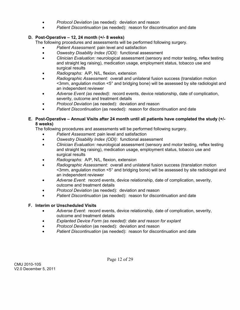
D. Post-Operative – 12, 24 month (+/- 8 weeks)
The following procedures and assessments will be performed following surgery. Patient Assessment: pain level and satisfaction Oswestry Disability Index (ODI): functional assessment Clinician Evaluation: neurological assessment (sensory and motor testing, reflex testing
and straight leg raising), medication usage, employment status, tobacco use and surgical results
Radiographs: A/P, N/L, flexion, extension Radiographic Assessment: overall and unilateral fusion success (translation motion
<3mm, angulation motion <5° and bridging bone) will be assessed by site radiologist and an independent reviewer
Adverse Event (as needed): record events, device relationship, date of complication, severity, outcome and treatment details
Protocol Deviation (as needed): deviation and reason Patient Discontinuation (as needed): reason for discontinuation and date
E. Post-Operative – Annual Visits after 24 month until all patients have completed the study (+/-
8 weeks) The following procedures and assessments will be performed following surgery.
Patient Assessment: pain level and satisfaction Oswestry Disability Index (ODI): functional assessment Clinician Evaluation: neurological assessment (sensory and motor testing, reflex testing
and straight leg raising), medication usage, employment status, tobacco use and surgical results
Radiographs: A/P, N/L, flexion, extension Radiographic Assessment: overall and unilateral fusion success (translation motion
<3mm, angulation motion <5° and bridging bone) will be assessed by site radiologist and an independent reviewer
Adverse Event: record events, device relationship, date of complication, severity, outcome and treatment details
Protocol Deviation (as needed): deviation and reason Patient Discontinuation (as needed): reason for discontinuation and date
F. Interim or Unscheduled Visits
Adverse Event: record events, device relationship, date of complication, severity, outcome and treatment details
Explanted Device Form (as needed): date and reason for explant Protocol Deviation (as needed): deviation and reason Patient Discontinuation (as needed): reason for discontinuation and date

Page 13 of 29 CMU 2010-10S V2.0 December 5, 2011
G. Adverse Events (AE) An adverse event is any unfavorable and unintended sign, symptom, or disease associated with the use of an investigational product, whether or not related to the investigational product, taking into consideration the patient history, surgical history, histological analysis as well as explants evaluation. Events may be complications, observations (including radiographic), change in patient condition or related/unrelated death. A change indicating worsening as reported on an assessment is an adverse event.
A serious adverse event (SAE) is any event that is fatal, life-threatening, disabling, or which results in hospitalization.
A unanticipated adverse device effect (UADE) is defined as any serious adverse effect on health or safety, or any life-threatening problem or death caused by, or associated with, a device if that effect, problem or death was not previously identified in nature, severity or degree of incidence, or any other unanticipated serious problem associated with a device that relates to the rights, safety, or welfare of subjects.
The investigator will complete the Adverse Events case report form to capture:
Date and time of onset of the event Type of complication Severity
o Mild: The AE is noticeable to the subject, but does not interfere with routine activity. The AE typically does not require symptomatic therapy, rest or device removal.
o Moderate: The AE interferes with routine activity but responds well to symptomatic therapy or rest. The AE does not require device removal.
o Severe: The AE significantly limits the subject’s ability to perform routine activities despite symptomatic therapy. The AE requires medical or surgical treatment or results in hospitalization. In addition, the AE may require removal of the study device.
Relationship to the device o Not related: An AE for which sufficient information exists to indicate that there is
no causal connection between the event and the device/procedure. The AE is due to and readily explained by the subject’s underlying disease state or is due to concomitant medication or therapy not related to the use of the device or the procedure.
o Possibly related: There is a reasonable possibility that the AE may have been primarily caused by the device/procedure and follows a known or expected response pattern. Alternative etiology is equally or more likely compared to the potential relationship to the use of the device/procedure.
o Probably related: There is a reasonable probability that the AE may have been primarily caused by the device/procedure and follows a known or expected response pattern.
o Definitely related: The AE has a strong casual relationship to the device/procedure and follows a known response pattern. The event cannot be

Page 14 of 29 CMU 2010-10S V2.0 December 5, 2011
reasonably explained by known characteristics of the subject’s clinical state or other therapies.
Treatment includes a detailed narrative of how this adverse event was treated and the outcome.
The outcome of the event will be defined as resolved, ongoing, study withdrawal, device revision, removal, reoperation, supplemental fixation and death. Additional surgeries will include details in the treatment narrative.
Revision: a procedure that adjusts or in any way modifies or removes part of the original implant configuration, with or without replacement of a component. A revision may also include adjusting the position of the original configuration.
Removal: a procedure where the entire original system configuration is removed with/without replacement.*
Reoperation: any surgical procedure at the involved level(s) that does not involve removal, modification or addition of any components to the system.
Supplemental Fixation: a procedure in which additional instrumentation not under study in the protocol is implanted at the spine level(s) under study.
* Elective removals following fusion are not considered adverse events; however, they will still be reported.
All adverse events observed during the course of this study, regardless of severity or relationship to the investigational device will be recorded on the Adverse Event case report form. All events should be followed until resolved or until a chronic, stable state is achieved.
All serious adverse events and unanticipated adverse device effects or events of unexpected severity must be reported to Zimmer Spine within 24 hours of the time the investigator learns of the event or effect. Zimmer Spine will notify the reviewing IRBs within 10 days of the time of learning of the event.
H. Adverse Events Advisory Group
Independent spine surgeons (neuro or orthopedic) will be selected from a subset of 13 member (10 US and 3 OUS) Zimmer Spine Clinical Affairs Advisory Group (CAAG), who are not study investigators, to determine adverse event severity and device relationship. The CAAG surgeons serve two-year terms and function to provide expert advice to the Clinical Affairs department with respect to protocol development, unmet clinical needs, clinical benefits of devices, quantification and measurement of clinical evaluations, pathology, diagnosis and indication and review of explant cases during clinical trials. The surgeons have a strong core competency in the conduct and logistics of clinical trials. This group allows Zimmer Spine the ability to a quickly and responsibly respond to any questions regarding clinical use of our devices, review of data from clinical trials and response to other research collaborators with respect to study conduct. The members of this panel can be trained on the protocol, most importantly, with respect to the blind adjudication of adverse events determining severity and relatedness. The depth of the panel allows
Page 15 of 29 CMU 2010-10S V2.0 December 5, 2011
Zimmer Spine to easily convene three members for adjudication and receive expert assistance in review of any adverse events that may ultimately be “unanticipated” or “serious.” The adjudication process will occur at least annually during the study. Reviewers will be blinded to the site. Two independent surgeons will review all available appropriate data (including CRFs, AE forms, hospital operative reports, lab reports, films, discharge reports, etc.) and determine:
whether the event is related to the device, device procedure, general surgery; or none of the above
AE severity (mild, moderate, severe) whether the event constitutes a SAE or UADE.
In instances of non-concordance between the two surgeons, a third surgeon will provide the final determination. The surgeons will provide their review, adjudication and reporting independent of the trial.
All reviewing surgeons’ determinations regarding the AEs are final and supersede preliminary judgments made by each clinical investigator. The sponsor has the responsibility for coordinating the adjudication process. All correspondence, reports, minutes and other documentation as applicable will be supplied to the FDA as part of the regular progress reports. The sponsor will notify regulatory authorities (FDA, IRB, etc) and the clinical study investigators of any SAE/UADEs in accordance with regulations.
I. Explant Analysis All hardware segments, complete constructs or components must be returned to Zimmer Spine for analysis by the site using the explant kits provided at the initiation training. Instructions and all necessary materials for returning the hardware will be included in the explant kit. Investigators and external Zimmer representatives will be trained on the importance and process of returning explants for analysis. Every attempt will be made to evaluate the explanted devices using the Analysis of Dynesys Explants Protocol (Appendix A). A secondary analysis to determine the association (if any) between demographics, clinical data, device failure and characteristics will also be completed.
J. Patient Withdrawal A patient is enrolled in the study by signing a Zimmer Spine, Inc., IRB approved informed consent. No personal health information will be collected from the patient prior to obtaining a signed informed consent.
Patients who are determined to be ineligible prior to surgery will be considered screen failures and will not require additional follow-up visits. The reason(s) for ineligibility will be documented on the Patient Discontinuation case report form.

Page 16 of 29 CMU 2010-10S V2.0 December 5, 2011
Patients who complete the Pre-Operative visit, but do not receive treatment with the study device will be considered discontinued. The Patient Discontinuation case report form will indicate proposed surgery not performed.
Patients have a right to withdraw permission (revoke informed consent authorization). Patients who withdraw consent will have no further private health information collected. Once authorization is revoked, patients may no longer participate in the research activities, but standard medical care will not be affected. Revoking authorization only affects information obtained after the request has been received, but not information obtained prior to that time. Patient withdrawal will be documented on the Patient Discontinuation case report form. Remuneration will be provided to all subjects who complete scheduled follow-up office assessments at 24 months and annual follow-up visits thereafter as required. The subjects’ financial compensation package will be outlined in the Informed Consent Form and approved by the Institutional Review Board (IRB) prior to the start of the study.
Every attempt will be made to contact patients who are non-compliant or lost to follow-up. Three contact attempts by certified letters will be documented. Patients who are lost to follow-up will be documented on the Patient Discontinuation case report form. To compensate for a potential 20% attrition rate, additional subjects have been added to the sample size. The number of enrolled and completed subjects will be closely monitored, and if needed patients will be added to assure the study endpoints can be achieved.
K. Data Collection
The purpose of the case report form is to reconstruct the study. Information should always be documented in the source document first, and then transferred to the case report form, either paper or electronic. As an exception, the Oswestry Disability Index (ODI) and Patient Assessment forms are considered source documents. It is recommended that patient questionnaires be completed prior to the patient meeting with any clinical staff to minimize the bias in the study or in accordance with site specific standard operating procedures. Patient confidentiality will be protected at all times and patient identifiers will be used.
Case report forms must be completed in black ink. To correct an entry, strike a single line through the error and mark the correct response. Date and initial the correction. Do not use liquid paper or correction tape.
Case report forms should be submitted via an electronic data capture system within 15 days of evaluation. Radiographs should be sent via Fed Ex to Zimmer Spine, Clinical Affairs, 5251 W 73rd Street, Edina, MN 55439 within two weeks of evaluation.

Page 17 of 29 CMU 2010-10S V2.0 December 5, 2011
V. STATISTICAL ANALYSIS
A. Analysis Population The population for analysis will include all subjects who have completed eligibility screening, signed an informed consent, and have met inclusion and exclusion requirements.
A poolability analysis will be done to ensure that the two Dynesys devices (Dynesys/Dynesys Top Loading with autograft at the instrumented levels and Zimmer DTO Implant with autograft at the instrumented levels) have similar outcomes. The summary statistics resulting from the primary safety and fusion endpoints, for each subgroup, will be explored to assess possible differences in results based on the subgroup. Additionally, poolability will be assessed by comparing the sub group population characteristics for key baseline, demographic and clinical characteristics as well as for primary diagnoses. If there are no differences in this comparison, the subgroups will be pooled for the purpose of analysis. Similarly, a poolability analysis will be done to ensure that there are no differences in outcomes between the different level procedures (1-level, 2-level, 3-level). The summary statistics resulting from the primary safety and fusion endpoints, for each subgroup, will be explored to assess possible differences in results between the subgroups. Additionally, poolability will be assessed by comparing the sub group population characteristics for key baseline, demographic and clinical characteristics as well as for primary diagnoses. If there are no differences in these comparisons, the subgroups will be pooled for the purpose of analysis.
A meta-analysis was done using the same methodology as was used for the primary endpoint, fusion rate. When sufficient data were available for baseline characteristics, point estimates and 95% confidence intervals were generated for use to assess comparability of baseline data in the historical literature to the experimental data. The data were extracted from the same literature that was used to obtain an estimate for the primary endpoint of fusion rate. The first table below represents the detail available for use in comparison of the treatment group to the literature control data for the baseline characteristics and the second table contains the point estimates of interest for the baseline characteristics from the literature. Comparability will be inferred if the rates of males or smoking status in the experimental group are contained in the respective 95% confidence intervals established using the literature control rates. Comparability for age will be inferred if the point estimate for mean age in the experimental group is contained in the range presented for the historical control. Additionally, a frequency distribution of pre-operative diagnoses, from both the experimental group and what is available in the literature control group will be done to ensure comparability between the data from each.

Page 18 of 29 CMU 2010-10S V2.0 December 5, 2011
Demographic Endpoints N Age Gender (% Male)
Smoking Status (%)
BMI
Acharya 2008 22 55 36.4% Chen 2005* 74 61.6 20.3% Cheng 2009 66 48 52.9% 0.221 Christensen 2002 63 46 41.3% 0.65 Christensen 2002 71 45.5 37.0% Dimar 2006 45 52.7 44.4% 0.222 Fernandez-Fairen_1 2007 41 61.42 35.7% Glassman 2008 52 69.9 32.7% 0.173 28.1 +/-6.1 Lee 2009 182 59 33.5% Moller 2000 37 39 43.2% 0.57 Thalgott_1 1997 21 55 0.429 Thalgott_2 1997 21 45 0.523 Wang 1998 94 67.03 17.0%
Point Estimates Demographic Endpoints Age Mean STD MIN MAX Weighted Average 55.9706 NA 40.72783 75.31652 Random Effects Rate SE LCL UCL Gender (Male) 35.78% 3.14% 28.78% 42.77% Smoking Status 39.11% 7.13% 21.64% 56.57%
BMI - not enough information

Page 19 of 29 CMU 2010-10S V2.0 December 5, 2011
To assure that baseline characteristics of the history control data are similar to those found in the experimental data, the demographic characteristics from the study data will be reviewed to confirm that the characteristics of age, gender, smoking status, and preoperative diagnosis in the test data are similar to the data that existed for the historical control data. The rate of males and rate of smokers will be checked against the 95% confidence interval found in the point estimate table. The distribution of preoperative diagnoses will be tested for no difference between the historical control and the test group. The average age will checked to assure that it is in the range from 41 to 75. If any differences are noted, patients with extreme data will be removed until the rates and means of the test population do reside within the bounds determined by the meta-analysis. If needed, more patients will be enrolled in the test group to assure that the sample size is sufficient for inferential testing.
B. Primary Analysis: Fusion Status
Fusion success will be defined as evidence of bridging bone and angulation of <5° and translation of <3mm at treated levels at 24 months. Radiographic assessment will determine for each patient a fusion status, either fused or not fused. The primary endpoint is fusion status at Month 24. Efficacy will be confirmed by the achievement of fusion in the experimental group when compared to the rate established in a literature control. Normand (1999) provided the direction for the meta-analysis1. The details of that analysis included creating population mean and variance estimates using a weight of the inverse of the variance. (See pp. 335-336 for complete description of the algorithm) A point estimate of 80.6% with a standard error of 2.6% was established. The 95% confidence interval for this point estimate is (75.0%, 86.3%).
If Month 24 fusion status cannot be determined, but fusion was determined to have occurred earlier, the Month 24 status will be considered fused. Otherwise, subjects without earlier fusion who are missing Month 24 values will be excluded from primary analysis. For the purpose of a sensitivity analyses, all subjects excluded as described above for a missing Month 24 fusion status will be defined as not fused.
C. Primary Analysis: Safety Endpoints and Evaluation
Subjects will be clinically evaluated for adverse experiences and functional outcomes over the course of 24 months. Detailed and descriptive analyses will be provided for all adverse events, including specific treatment required and outcomes for all secondary surgeries at the index and adjacent levels, any deaths, and all potential device related adverse events. Adverse event incidence rates, severities and time course will be determined. For subsequent surgical procedures, at every treated level, the type of surgical procedure required the incidence rate and time course will be determined and reported.
1 Normand, S. T. (1999). Tutorial in biostatistics meta-analysis: Formulating, evaluating, combining, and reporting. Statist. Med. (18), 321-359.

Page 20 of 29 CMU 2010-10S V2.0 December 5, 2011
All of the safety endpoints will be summarized descriptively at all available assessments. Summaries will be chosen as appropriate for the scale and distribution of the measures being analyzed. For categorical variables, summaries will consist of counts and percentages to describe the distribution of the endpoint. For continuous variables, descriptive summaries will consist of N, Mean, Median, Standard Deviation, Minimum and Maximum. Similarly, exact incidence and rates of AEs and subsequent surgical procedures will be calculated for the experimental group and whenever possible for the control group. Assessing adverse events (AEs) using only the literature control data is not sufficient, because of the heterogeneity of reporting across the manuscripts. Thus, we propose using the observed data from the recent Dynesys IDE clinical study (historical). The AEs collected in this study (historical) is expected to have a similar profile as those in the present study (experimental). A test for non-inferiority will be performed using both incidence and rates, for each AE category, in both the historical control and experimental group. Non-inferiority will be inferred if the lower limit of the 95% confidence interval around the treatment difference between the 2 groups is greater than δ = -10%, using the hypotheses below where pe is the incidence or rate in the experimental group and pd is the incidence or rate in the historical study group.
H0: pe – pd < - 0.10 H1: pe – pd > - 0.10
In addition, for each category of AE in the experimental group, a non-inferiority analysis will be performed assessing how the incidence and rates in the experimental group compare to the AEs as described in each of the contributing articles that were used for the meta-analysis. The incident rate that occurs in the experimental data will be computed with a 95% confidence interval. Any AEs that occurred in any of the literature control studies will be compared to those ranges to ensure that the incidence or rate found in the experimental group does not exceed the incidence or rate in the literature data. Non-inferiority will be inferred if the assessment of AEs under both analyses meets the specified criteria for non-inferiority. Any explanted devices will be retrieved and evaluated for determination of failure modes and causes. Any correlation between the subject’s demographic data and device failure will be determined.
D. Analysis of Additional Endpoints
Fusion status, at all time intervals other than the 24 month, as well as any other collected endpoints will be analyzed to assess the overall safety of the patient population in this investigation. The following post-operative outcomes will be summarized:
Neurologic Assessment Medication Usage Employment Status Pain Assessment Satisfaction Assessment Oswestry Disability Index (ODI)

Page 21 of 29 CMU 2010-10S V2.0 December 5, 2011
These and any additional endpoints will be summarized descriptively at all available assessments, both as originally collected and with a change from baseline calculation including the number of subjects who improved, the number who deteriorated and the number who stayed the same from baseline. Summaries will be chosen as appropriate for the scale and distribution of the measures being analyzed. For categorical variables, summaries will consist of counts and percentages to describe the distribution of the endpoint. For continuous variables, descriptive summaries will consist of N, Mean, Median, Standard Deviation, Minimum, and Maximum. To compare the AEs that are collected in the experimental group to the literature data, in all interim clinical summaries, as well as the final clinical summary, a tabular comparison of incidence observed for all literature reported AEs or secondary surgeries to those prospectively captured will be presented in a format similar to the table below: Adverse Event Article
#1 Article #2
etc 522i Result
Screw Fracture Pseudarthrosis Secondary Surgery Revision Removal and Refusion
E. Baseline and Operative Analysis
Baseline summaries will be chosen to be appropriate for the scale and distribution of the measures being analyzed. Statistical methods will be the same as described above for the non primary endpoint analyses.
F. Missing data
Except for the primary analysis, if a value, at any assessment is not available for analysis, it will be excluded from summaries.
G. Study Hypothesis and Sample Size Determination using a Literature Control Study Hypothesis The hypothesis is Dynesys fusion rate is non-inferior to the historical literature sample data estimated fusion rate of 80.6%. This hypothesis will be assessed by testing that the difference between the experimental rate (pe) and the historical control rate (pc) is not worse than 10%. The non-inferiority test will be inferred if the lower limit of the 95% confidence interval around the treatment difference between 2 groups is greater than δ = -10%.
H0: pe - pc < - 0.10 H1: pe - pc > - 0.10
Sample Size Sample size for the Dynesys Post-Market Surveillance Study was estimated using SAS, Proc Power with a testing level alpha (Type I) error level of 0.05, 80 percent statistical power, a meaningful difference of 10%, and a success rate for lumbar fusion from the literature historical

Page 22 of 29 CMU 2010-10S V2.0 December 5, 2011
control group of 80.6% (0.806). For this set of criteria, the sample size was 134, without adjustment for attrition. With a 20% attrition sample added, this would result in a sample size of 168. Sample size estimates are presented in Table 2.
Table 2: Proposed Sample Sizes
Primary Endpoint
Difference Predicted Success
Type I Error Power N Patients
Radiographic Success (Fusion)
10% 80.6% 0.05 80% 168
VI. TIMELINE
A. Clinical Trial Agreement No portion of this protocol will be implemented until both copies of the Clinical Trial Agreement havebeen completed by both parties. Table 3: Study Timeline
Study Timeline Sponsor Expectation
Expected date of Study Initiation March 2012
Expected date of first IRB Approval(s) January 2012
Expected monthly number of sites obtaining IRB approval 1
Expected subject enrollment initiation March 2012
Expected average number of subjects to be enrolled/month 7
Expected Date of Subject Enrollment Completion March 2014
Expected date of Subject follow-up Completion March 2016
Reports
Interim Postmarket Surveillance Study Report
Every 6 months through 2 years, annually thereafter
Expected date for the Final Postmarket Surveillance Study Report June 2016
Page 23 of 29 CMU 2010-10S V2.0 December 5, 2011
B. Institutional Approvals No portion of this protocol will be implemented until approval is granted by the institutional review board. No personal health information or other data will be transmitted to Zimmer Spine without consent from the patient.
C. Project Execution
This project will begin at the time of contract agreement execution. IRB approval will be obtained within 2 months. Enrollment will start following IRB approval and site initiation. The first patient will be enrolled within 2 months after IRB approval. Enrollment will take place for 24 months. Follow-up of all patients will be complete within 26 months (24 months +/- 2 month visit window) following the last surgery.
D. Project Deliverables
The site must provide Zimmer Spine with a copy of the report submitted to the IRB for annual renewal and the approval status within two weeks of receipt. The report must include the number of patients enrolled and the treated levels.
E. Monitor Schedule This study will be monitored a minimum of one time every 12 months by Zimmer Spine Clinical Affairs personnel per the Zimmer Spine monitoring procedure. The purpose of these visits is to review the patient charts, to verify the data submission process, and to clarify any discrepancies. With increased enrollment or center challenges, monitoring may occur more than once a year.
F. Record Retention The investigator will maintain the records of the study including all correspondence, the study
protocol with any/all amendments, all correspondence with and approval from the IRB, the budget agreement, the research agreement, individual patient records, and signed informed consent forms. Patient files and other source data must be kept for a period of not less than 2 years after the date on which this investigation is terminated or completed.
G. Final Reports A final report produced by the lead principal investigator will be written in a format acceptable for a peer reviewed journal.
H. Termination of Study
The study may be terminated per the terms of the Clinical Trial Agreement at any time.

Page 24 of 29 CMU 2010-10S V2.0 December 5, 2011
Appendix A: EXPLANT ANALYSIS PROTOCOL

Page 25 of 29 CMU 2010-10S V2.0 December 5, 2011
Appendix B: IMAGING PROTOCOL

Page 26 of 29 CMU 2010-10S V2.0 December 5, 2011
Appendix C: INSTRUCTIONS FOR USE
The Instructions for Use as provided in the January 21, 2010, response to FDA will be used and are not repeated here.

Page 27 of 29 CMU 2010-10S V2.0 December 5, 2011
Appendix D: SURGICAL TECHNIQUE
The Surgical Techniques as provided in the January 21, 2010, response to FDA will be used and are not repeated here.

Page 28 of 29 CMU 2010-10S V2.0 December 5, 2011
Appendix E: INFORMED CONSENT

Page 29 of 29 CMU 2010-10S V2.0 December 5, 2011
Appendix F: CASE REPORT FORMS

Zimmer Research Protocol
ANALYSIS OF RETRIEVED DYNESYS EXPLANTS
Page 1 of 9
September 201 1
Abstract: This document describes the various methods for retrieval analysis of explanted DYNESYS 1 DTO spinal implant systems, including PCU spacers, PET cords, titanium alloyed pedicle and set screws, and DTO implants, which are manufactured at Zimmer GmbH, Winterthur, Switzerland.
Personnel: Petra Köttig, Retrieval analysis
Location: Zimmer GmbH, Winterthur, Switzerland
~ u t k r - Petra Köttig Werner Schneider Markus Windler Sr. Engineer I1 Retrievals Research Principal Engineer Polymers Research Materials Research Director
C Jochen Reinmuth Marco Zimmermann Elsa Linke rincipal Engineer Spine Development Regulatory Affairs Manager Sr. Regulatory Affairs Specialist
John Dawson Global Research Director
Keywords: Petrieval, DYNESYS, DTO implant, FTIR analysis, GPC analysis
C O N F I D E N T I A L
AAU Q.01.1072e
This document contains proprietary and confidential information owned by Zimmer, distributed without taking appropriate action to protect its contents according to
Protocol Number: ZRP-Wl-1856-10-Rev 1

Zimmer Research Protocol
ANALYSIS OF RETRIEVED DYNESYS EXPLANTS
Page 1 of 9
September 201 1
Abstract: This document describes the various methods for retrieval analysis of explanted DYNESYS 1 DTO spinal implant systems, including PCU spacers, PET cords, titanium alloyed pedicle and Set screws, and DTO implants, which are inanufactured at Zimmer GmbH, Wintei.thus, Switzerland.
Personnel: Petra Köttig, Retrieijal analysis
Location: Zil?iiller GmbH, Wjnferfhzlr, Sti)itzerland
Author - Petra Kattig Werner Schneider Markits Windler Sr. Engineer I1 Retrievals Research Principal Engineer Polynlers Researcli Materials Research Director
Jochen Reinmiith Marco Zimniemann Principal Engineer Spine Develop~nent Regulatory Affairs Manager
Elsa Linke Sr. Regulatory Affairs Specialist
John Dawson Global Research Director
Kewvords: Retrieval, DYNESYS, DTO implant, FTIR analysis, GPC analysis
C O N F I D E N T I A L This document contains proprietary and confidential information owned by Zimmer, Inc. and should not be
distrlbuted without taking appropriate actlon to protect its contents accordlng to Zimmer procedures.
AAU Q.01.1072e Protocol Number: ZRP-WI-I 856-1 0-Rev I

ZRP_WI_1856_10_Rev 1 Page 2 of 9
1 INTRODUCTION The Dynesys® dynamic stabilization system is a pedicle screw system that has been in clinical use for about 16 years. It consists of titanium alloy pedicle screws, coated and un-coated with hydroxyapatite, set screws, polycarbonate urethane (PCU) spacers and polyethylene terephthalate (PET) cord. The Zimmer DTO Implant, consisting of a titanium alloy rod and PET cord, was introduced in 2007 to allow connection of the Dynesys dynamic system to the Optima rigid pedicle screw system.
The Dynesys components consist of the following materials:
• Pedicle screw made of Titanium alloy (PROTASUL-100) according to ISO 5832-11 • Set screw made of Titanium alloy (PROTASUL-100) according to ISO 5832-11 • Spacers made of Sulene® PCU (Polycarbonate-urethane). • Cord made of Sulene® PET (Polyethylene-terephthalate) • DTO Implant made of of Titanium alloy (PROTASUL-100) according to ISO 5832-11 and
Sulene® PET (Polyethylene-terephthalate) One of the markets in which Dynesys is sold is the United States. The US medical device regulatory body, FDA, has ordered that a post-market surveillance study be conducted on all Dynesys device configurations for the US cleared indication as an adjunct to fusion. As part of this post market surveillance study FDA has mandated an analysis of all Dynesys explants received worldwide to identify possible failure modes, the clinical circumstances in which failure is occurring, and associated patient demographics.
2 OBJECTIVE The goal of this study is to perform retrieval analysis [1-3] on all explants received at Zimmer, including the identification of structural failures in failed components. Structural failures are classified as fractured pedicle screws, set screws or Titanium rods, rupture of PET cords, or fracture and cracking of PCU spacers that lead to malfunction or non-function of the components or the system.
3 HANDLING of RETRIEVALS Revision surgery: A patient outside the US needs to give his/her written consent that he/she agrees that the explants will be used for investigation which might include adverse modification or destructive testing of the explants [8]. If the patient agrees to the investigation of his/her explants the rights of ownership and storage of the retrievals will be handed over to Zimmer GmbH. From US patients no written patient consent for explant analysis is required even if the investigation might include adverse modification or destructive testing.
All removed Dynesys parts must be fully traceable back to the instrumented levels and side of vertebra. All retrieved implants of a received system must be sent back to Zimmer.
Cleaning, disinfection, sterilization: Immediately after removal the explanted Dynesys parts must be carefully cleaned by rinsing under cold (<20ºC) tap water (no brushing). The components should be free of attached soft tissue after cleaning. The components must not be treated with any cleaning agent; an investigation may not be possible if a cleaning agent is used. It is possible to

ZRP_WI_1856_10_Rev 1 Page 3 of 9
autoclave the screws. The PCU spacers, the PET cords and DTO implant must not be autoclaved; if they are autoclaved an investigation is not possible.
Storage and shipment condition: All components should be dried in air with no additional heat. The components should be packaged individually in plastic bags and labeled with patient’s identifier and instrumented levels e. g. patient initials or ID, L5, right.
General information: The following information is needed to do a full retrieval assessment at Zimmer GmbH:
Patient: initials or patient ID, gender, birthday, body mass index or height and weight
Clinical: implantation date, revision date, reason for revision, treated segments, name of surgeon, name and address of hospital/clinic, surgical notes, x-rays
Product information: REF number and LOT number from the spacers and cords. This information is only available from the implantation of the device (patient chart stickers) and not on the device itself. Without this information no conclusions may be drawn about the impact of manufacturing on the explants.
Note: The quality of the retrieval analysis depends on the quality of data we receive from the hospital and from the quality of the explanted Dynesys parts. Wrong handling of the retrieved components or missing information can influence the quality of the analysis; under certain conditions the investigation can not be performed. For retrievals coming from patients outside the US a written consent of the patient has to be at hand to conduct adverse modification or destructive testing of the explants. Without written patient consent only visual inspection can be performed.
4 MATERIALS and METHODS
4.1 Material All retrievals received at Zimmer.
4.2 Methods
4.2.1 General The following methods will be used for the specific investigation of the single parts of the Dynesys system.
Component Used investigation methods
Pedicle screw Visual inspection
Low power light microscope
Scanning Electron Microscopy (SEM) (if necessary and / or of interest)
Set screw Visual inspection
Low power light microscope
SEM (if necessary and / or of interest)

ZRP_WI_1856_10_Rev 1 Page 4 of 9
Spacer Visual inspection
Low power light microscope
SEM (if necessary and / or of interest)
Attenuated Total Reflection Fourier Transform Infrared Spectroscopy (ATR-FTIR)
Gel Permeation Chromatography (GPC)
Cord Visual inspection
Low power light microscope
SEM (if necessary and / or of interest)
ATR-FTIR
GPC
DTO Implant Visual inspection
Low power light microscope
SEM (if necessary and / or of interest)
ATR-FTIR for the cord only
GPC for the cord only
4.2.2 Sample preparation Pedicle and set screws will be disinfected by the following steps:
• soaking at room temperature in a 4% disinfective solution (Deconex 53 plus, Borer Chemie AG, Zuchwil Switzerland) for 30 minutes ± 5 minutes
• rinsing with cold (<20ºC) tap water • soaking in industrial ethyl alcohol (96%) for one hour ± 10 minutes. • rinsing with cold (<20ºC) tap water • autoclaving at 134°C for 18 min
Spacers, cords and DTO implants will be disinfected by the following steps:
• soaking at room temperature in a 4% disinfective solution (Deconex 53 plus, Borer Chemie AG, Zuchwil Switzerland) for 30 minutes ± 5 minutes
• rinsing with cold (<20ºC) tap water These steps will be repeated three times.
4.2.3 Visual inspection Visual Inspection All explanted components will be visually inspected by the naked eye. Areas of interests are: contact areas, fractured surfaces, wear/tear, surface cracks, discoloration, deformation, or other interested phenomena. Photographical documentation of the components will be performed if it helps for clarification or documentation.

ZRP_WI_1856_10_Rev 1 Page 5 of 9
Low Power Light Microscope This method allows documentation of areas of interest on the components up to 40X.
SEM The method of the SEM allows two functions: (1) imaging of areas of interest with high magnification and (2) semi-quantitative analysis of elemental composition of areas of interest. SEM enables a profound analysis of fractures, wear, and cracks.
(1) Imaging of surface: High-powered electron beam that produces an image with secondary electrons (SE) or back-scattered electrons (BSE). Polymer materials must be sputter coated before with a thin layer of carbon or gold. This method will be used if the magnifications of 40X provided by the low power light microscope is not sufficient perform a full analysis of areas of interest.
(2) Elemental analysis: The technique is energy dispersive X-ray analysis (EDX) to identify elemental composition of small areas. Polymer materials must be sputter coated before with a thin layer of carbon or gold.
4.2.4 ATR-FTIR Analyses of PET Cords Fracture, rupture and cracking of polymeric components originates at the molecular level due to the chemical changes that result from the chemical reactions between polymeric components and the environment of the human body. ATR-FTIR Analyses will produce spectra readings that reveal the chemical structures of the polymer. If there are changes in the chemical structures this may be indicative of changes and breakage of molecular bonds. PET cord samples will be placed on an ATR cell, and the spectra will be recorded using an FTIR with a scan range of 400-4000 cm-1 and a scan resolution of 4 cm-1. FTIR spectra will be taken from a minimum of two different locations at the PET cord: (1) on the outer woven cord surface, and (2) on the center fibers of cord.
To evaluate the differences in all the spectra and to assess the absence of residual tissue, the spectra will be normalized to the band of a chemically stable aromatic group (725 cm-1) and compared to the spectra of a non-implanted reference PET cord. Control (reference) specimens will be current-production parts.
To evaluate the possible chemical change of the PET cord due to hydrolytic degradation, the carboxyl index, i.e., the absorbance ratio of the carboxylic acid (1640 cm-1) to the carbonyl group (1713 cm-1), will be calculated. To minimize the interference from the protein bands of residual tissues, only the spectra that have weak or no protein bands at 1520-1540 and 1650 cm-1 will be recorded.
4.2.5 ATR-FTIR Analyses of PCU Spacers Fracture, rupture and cracking of polymeric components originates at the molecular level due to the chemical changes that result from the chemical reactions between polymeric components and the environment of the human body. ATR-FTIR Analyses will produce spectra readings that reveal the chemical structures of the polymer. If there are changes in the chemical structures this may be indicative of changes and breakage of molecular bonds. PCU spacer samples will be placed on an ATR cell, and the spectra will be recorded using a FTIR with a scan range of 400-4000 cm-1 and a scan resolution of 4 cm-1. The ATR-FTIR spectra of PCU spacers will be specifically collected from at least three sample locations: (1) on the spacer surface, (2) 100 µm below the surface and (3) in the bulk of spacer. Because the surface chemistry of polyurethanes may vary in the air environment, spectra of the bulk spacer samples will be recorded immediately after cutting them.
All spectra will be normalized to the chemically stable aromatic group (510 cm-1). Subsequently, the spectra will be compared to a representative non-implanted reference PCU spacer. Control (reference) specimens will be current-production parts.

ZRP_WI_1856_10_Rev 1 Page 6 of 9
The percentage differences in peak height of the retrieval samples to the reference PCU sample will be quantified using the following peaks: (1) NH (~3340 cm-1) and (2) hydrogen-bonded C=O (~1701 cm-1) of urethane hard segment, (3) free C=O (~1740 cm-1) and (4) C-O-C (~1248 cm-1) of carbonate soft segment, and (5) the broad band at 3200-3500 cm-1 (measured at ~3280 cm-1) corresponding to the increase in NH and OH of degraded urethane and carbonate or to absorbed biofluid.
4.2.6 GPC Analyses of PET Cords Gel Permeation Chromatography will produce spectra identifying the molecular weight and distribution of the PET polymer. Molecular changes may be indicative of bond breakages. The PET cord samples (on the outer woven cord surface, and on the center fibers of cord) will be completely dissolved in hexafluoroisopropanol (3 g/L) with 0.05M potassium-trifluoroacetate. The chromatography is done in a PSS-PFG 7 μm column or comparable. Poly(methyl-methacrylate) standards will be used for calibration.
The weight average molecular weight (Mw), number average molecular weight (Mn), and the polydispersity indices (PDI, the ratio of Mw to Mn) will be calculated. The results will be compared to a representative non-implanted reference PET cord. Control (reference) specimens will be current-production parts.
4.2.7 GPC Analyses of PCU Spacers Gel Permeation Chromatography will produce spectra identifying the molecular weight and distribution of the PCU Spacer polymer. Molecular changes may be indicative of bond breakages. The PCU samples (on the spacer surface of 0-100 µm below the surface, and in the bulk of spacer) are dissolved in dimethylacetamide (3 g/L) with 0.1% of LiBr at 80°C. The chromatography is done in a PSS-GRAM 10 μm column or comparable. Polystyrene standards will be used for calibration.
The weight average molecular weight (Mw), number average molecular weight (Mn), and the polydispersity indices (PDI, the ratio of Mw to Mn) will be calculated. The results will be compared to a representative non-implanted reference PCU spacer. Control (reference) specimens will be current-production parts.
4.3 Test method and sample size rationale
Component Used investigation methods Sample selection including rationale
Pedicle screw Visual inspection All
Low power light microscope All
SEM (if necessary and / or of interest) Fracture surfaces
Set screw Visual inspection All
Low power light microscope All
SEM (if necessary and / or of interest) Special phenomena (e.g., cracks)
Spacer Visual inspection All (discoloration, deformation, surface)
Low power light microscope All
SEM (if necessary and / or of interest) Contact areas, worn areas, surface cracks
ATR-FTIR Analysis only performed on samples ≥ 12 months because no significant changes were identified up to 19 months in-vivo [4-6]. One contact area, one non-contact area and if available a worn area of one
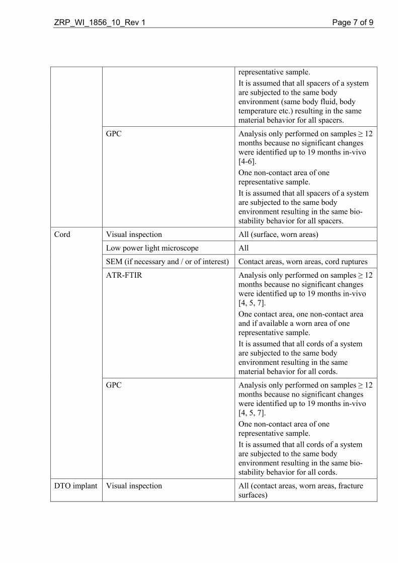
ZRP_WI_1856_10_Rev 1 Page 7 of 9
representative sample. It is assumed that all spacers of a system are subjected to the same body environment (same body fluid, body temperature etc.) resulting in the same material behavior for all spacers.
GPC Analysis only performed on samples ≥ 12 months because no significant changes were identified up to 19 months in-vivo [4-6]. One non-contact area of one representative sample. It is assumed that all spacers of a system are subjected to the same body environment resulting in the same bio-stability behavior for all spacers.
Cord Visual inspection All (surface, worn areas)
Low power light microscope All
SEM (if necessary and / or of interest) Contact areas, worn areas, cord ruptures
ATR-FTIR Analysis only performed on samples ≥ 12 months because no significant changes were identified up to 19 months in-vivo [4, 5, 7]. One contact area, one non-contact area and if available a worn area of one representative sample. It is assumed that all cords of a system are subjected to the same body environment resulting in the same material behavior for all cords.
GPC Analysis only performed on samples ≥ 12 months because no significant changes were identified up to 19 months in-vivo [4, 5, 7]. One non-contact area of one representative sample. It is assumed that all cords of a system are subjected to the same body environment resulting in the same bio-stability behavior for all cords.
DTO implant Visual inspection All (contact areas, worn areas, fracture surfaces)

ZRP_WI_1856_10_Rev 1 Page 8 of 9
Low power light microscope All
SEM (if necessary and / or of interest) Contact areas, worn areas, cord ruptures or rod fractures
ATR-FTIR for the cord only Analysis only performed on samples ≥ 12 months because no significant changes were identified up to 19 months in-vivo [4, 5, 7]. One contact area, one non-contact area and if available a worn area of one representative sample. It is assumed that all cords of a system are subjected to the same body environment resulting in the same material behavior for all cords.
GPC for the cord only Analysis only performed on samples ≥ 12 months because no significant changes were identified up to 19 months in-vivo [4, 5, 7]. One non-contact area of one representative sample. It is assumed that all cords of a system are subjected to the same body environment resulting in the same biostability behavior for all cords.
4.4 Acceptance Criteria Since this protocol applies to a retrieval analysis and not to testing there are no acceptance criteria. Only the current condition of the received retrievals, including the identification of structural failures, will be documented.
5 REPORTING A Zimmer Research Report (ZRR) will be created to document the retrieval analysis of every received case. A copy of the ZRR(s) will be sent to the Zimmer Spine Clinical Affairs Section 522 Clinical Study Manager for analysis and inclusion in the Dynesys Section 522 Post-Market Surveillance Study final report documenting device failure, patient demographics, and clinical circumstance. Any trends or correlations between device failure, patient demographics, and clinical circumstances will be documented in the Section 522 final study report. A summary report of the received cases will be written after 12, 24, and 36 months. This report should summarize all the findings and results from the retrieval analysis, including identification of structural failures. The report should also include a section to propose modification of the test

ZRP_WI_1856_10_Rev 1 Page 9 of 9
protocol for the retrieval analysis if necessary. This may include additional test(s), to omit existing tests, or to perform tests only after a certain time in-vivo.
6 REFERENCES [1] ISO 12891-1 (2011) Retrieval and analysis of surgical implants -- Part 1: Retrieval and handling
[2] ISO 12891-2 (2000) Retrieval and analysis of surgical implants -- Part 2: Analysis of retrieved metallic surgical implants
[3] ISO 12891-3 (2000) Retrieval and analysis of surgical implants -- Part 3: Analysis of retrieved polymeric surgical implants
[4] ZRR_WI_0737_07 Analysis of Dynesys Pedicle Screw, Spacer, and Cord Retrievals from a U.S. IDE Study
[5] Trommsdorff U., Köttig P. Analysis of retrievals of the Dynesys dynamic stabilization system for the spine, EuroSpine 2005, 7th Annual Meeting of the Spine Society of Europe, Vol. 14, Suppl. 1, Sep. 2005, SP 33
[6] Petrini, P., Tanzi M. C., Zurbrügg, D Structural characterisation of retrieved PCU spacers used in a spinal implant system, 7th World Biomaterials Congress, 2004, p 1858
[7] Trommsdorff U., Zurbrügg D., Schneider W. Biostability of Poly(Ethylene-Terephthalate) cords used in a spinal implant system, 7th World Biomaterials Congress, 2004, p 1864
[8] lnformed Consent for the use of retrieved implants
7 APPENDICES
8 REVISION HISTORY In Revision 1 of this protocol the following changes were made: • On the cover page a signatory for Regulatory Affairs had to be updated. • On the cover page a signatory for Research had to be updated. • On page 2 under chapter 3 Handling of Retrievals section Revision surgery it was added
that patient consent is only necessary for patients outside the US. • On page 3 under chapter 3 Handling of Retrievals section Note it was added that patient
consent is only necessary for patients outside the US. • On page 9 under chapter 6 References in reference [1] the version of the ISO was updated
and in reference [8] the word spinal was deleted.
IMAGING PROTOCOL: Post Market Surveillance for the Dynesys® Spinal
System, Assessing Safety and Fusion.
CMU2010-10S September 20, 2010
Sponsor: Zimmer Spine, Inc.
7375 Bush Lake Road Edina, MN 55439

CMU2010-10S September 20, 2010
Page 2 of 5
I. STUDY PURPOSE
To assess the safety profile and fusion rates following posterior lateral fusion with the Dynesys ® Spinal System as an adjunct to fusion compared to literature control.
II. RADIOGRAPHIC IMAGING Subjects will undergo standard evaluations at specified pre- and post-operative time points. The
radiographic imaging schedule is presented in Table 1 below. Plain film imaging will include Neutral Lateral, Neutral AP and Flexion-Extension.
Table 1: Radiograph Schematics
Pre-Op Surgery 6M 12M 24M Annual
-4 weeks ±4 weeks
±8 weeks
±8 weeks
±8 weeks
Radiographs (AP, NL, Flexion,
Extension) X X X X X
Radiographic Assessment X X X X X
A. Quality Assurance
Unless limited by subject or equipment constraints, plain radiographs will be obtained with the subject in a standing position. The subject will be instructed to move in the directed position to the maximum extent possible. The radiology technician and study coordinator will ensure that the views exhibit minimal out-of-plane effects, that all relevant levels are visible and that the films are properly labeled. The films will be used to evaluate device condition and to detect the presence of device-related complications including retrolisthesis, spondylolisthesis, instability, degeneration, radiolocency, bridging bone and fusion status. The radiographs will also be used to quantify certain radiographic parameters including translations, angular range of motion and bridging bone. Quantitative and qualitative radiographic assessments will be collected pre-operatively and at the follow-up intervals through 24 months and annually thereafter until the last patient has completed follow-up.
III. DATA COLLECTION & TRANSMITTAL
The investigational sites will produce the films identified in Table 1 and will send via Fed Ex to Zimmer Spine, Clinical Affairs, 5251 W 73rd Street, Edina, MN 55439 within 15 days of evaluation, as stated in the protocol.
A. Image Collection
Sites will label each film and film jacket and/or CD and disc envelope with the patient ID, visit ID (PreOp, 6M, 12M, 24M, annual), the visit date and the views (AP, NL, Flexion, Extension). The label should be attached to the film in such a way that it does not obscure the anatomy. If possible, the film label should be placed over the patient identifiers to mask this information. It may be necessary to redact the patient identifiers by other means if the film label fails to achieve this purpose. Additionally, be sure to identify the patient’s right and left side. This is mandatory on AP

CMU2010-10S September 20, 2010
Page 3 of 5
views. Images for specific subject visits should be stored on a single film or CD. If possible, a single CD should contain only the images obtained during a single visit. It is recommended that images be stored in DICOM format.
B. Shipment All digital images and plain films shipped to Zimmer Spine must be accompanied with a memo
stating the inventory of all images contained in the shipment. Images will not be returned to the site, therefore ensure all copies are made prior to shipment.
C. Data Management
Upon receipt, Zimmer Spine Data Management will verify the content and labeling of the films, verify the visit dates to ensure that all films are dated chronologically by designation, verify the visit views to ensure that all views are correctly labeled and that there are no missing films, verify film receipt logs to ensure that each set of films is stored and accounted. Access to films and associated study data will be restricted to authorized personnel only. Data Management will send an inventory report, case report forms and radiographs to independent reviewers every six months for review.
IV. REVIEWERS
The first assessment will be completed at the site by a radiologist. The second assessment of radiographic bridging and device condition will be performed by independent radiographic reviewers. The independent reviewers shall be a board-certified, fellowship-trained and practicing radiology with no financial interest in Zimmer Spine. The reviewers shall be fully trained on the schedule of radiographic assessments and the classification system for performing each assessment. The reviewers shall be trained on the radiographic features of the treatment, its design, the clinical indications for its use and the relevant inclusion/exclusion criteria. The independent reviewers will not have access to clinical outcomes data when conducting the assessments.
All independent reviewers’ determinations regarding the bone bridging, fusion status and additional observations are final and supersede preliminary judgments made by each site investigator.
V. DIAGRAM AND DESCRIPTION OF MEASUREMENTS
The following descriptions summarize how the measurements will be performed. Data will be collected on paper case report forms provided to the reviewers. A. Disc Angle
Disc Angle is the angle formed between the endplates of adjacent vertebrae as shown in Figure 1. Disc Angle will be measured on neutral lateral radiographs to assess local segmental lordosis. Disc Angle will also be measured on flexion and extension radiographs to assess angular range of motion. Disc Angle will be reported in units of degrees.

CMU2010-10S September 20, 2010
Page 4 of 5
Figure 1: Disc Angle Diagram
B. Angular Motion Angular range of motion will be calculated from lateral flexion-extension radiographs in accordance with Figure 2. As described above, Disc Angle is the angle between the endplates of adjacent vertebrae. The change in Disc Angle from flexion to extension determines the angular range of motion. Angular Motion will be reported in units of degrees.
Figure 2: Angular Motion Diagram
C. Translational Motion Translational motion will be calculated from flexion-extension radiographs in accordance with Figure 3. Translational motion is defined as displacement of the posterior-inferior corner of the superior vertebra in a direction defined parallel to the superior endplate of the inferior vertebra. Translational Motion will be reported in units of millimeters.
Figure 3: Translational Motion Diagram
D. Bridging Bone
Bony Bridging will be graded as “Absent, Present or Unclear’ in accordance with the definitions provided below. Bridging will be defined as a continuous connection of mineralized tissue from the superior to the inferior vertebral body.
Absent: Absence of continuous bridging bone from endplate to endplate Present: Presence of continuous bridging bone from endplate to endplate

CMU2010-10S September 20, 2010
Page 5 of 5
Unclear: No determination or absence or presence of continuous bone bridging can be made based on the provided radiographs
There is no scientific consensus concerning the minimum threshold of bridging required to classify a level as solidly bridged. Therefore, discretion will be left to the radiologist to determine whether sufficient bridging exists to render an affirmative assessment.
E. Fusion Status
Fusion Status will be graded as ‘Fused or Not Fused’. Fusion Status will be derived from a logical analysis of the following factors: bony bridging, angular motion and translational motion.
Not Fused: No evidence of bridging bone between the involved vertebral endplates and ≥ 5º total angular motion and ≥3 mm translational motion Fused: Evidence of bridging bone between the involved vertebral endplates and <5º total angular motion and <3 mm translational motion
Fusion Status will be reported for each treated level.
F. Other Radiographic Observations Additional incidental observations or noteworthy findings will be documented at the radiologist’s discretion and may include observations of screw/device loosening, lucency, malplacement or broken. Additional observations of spondylolithesis, retrolistesis, degeneration, fracture and arthrodesis will be identified. Clarifying remarks regarding the assessments will also be provided, including the location/type of failure/condition.

Dynesys® Spinal System and the Zimmer® DTO Implant Instructions for Use Important information for the operating surgeon
Zimmer GmbH P.O. Box CH-8404 Winterthur, Switzerland Telephone +41/ (0)52 262 60 70 Fax +41/ (0)52 262 01 39 www.zimmer.com
Manufacturer: Zimmer GmbH Sulzer-Allee 8 CH-8404 Winterthur, Switzerland
Distributed in the USA by: Zimmer Spine, Inc. 7375 Bush Lake Road Minneapolis, MN 55439-2027, USA Telephone (800) 655-2614 (952) 832-5600 Fax (952) 832-5620 Art. No. D011 500 217 - e - Ed. 10/09
1.0 Description
When used as a pedicle screw fixation system, the Dynesys Spinal System is intended to provide immobilization and stabilization of spinal segments as an adjunct to fusion in the treatment of the following acute and chronic instabilities or deformities of the thoracic, lumbar, and sacral spine: degenerative spondylolisthesis with objective evidence of neurologic impairment, and failed previous fusion (pseudoarthrosis). The Dynesys Spinal System is comprised of a variety of pedicle screws sizes, tensioning cords and longitudinal spacers that are uniquely fitted for each individual case. The pedicle screws are manufactured from medical grade titanium alloy conforming to ISO 5832-11. They are provided with or without hydroxyapatite coating conforming to ISO 13779-2. The tensioning cords are manufactured from Sulene-PET (polyethylene-terephthalate). The longitudinal spacers are manufactured from Sulene-PCU (polycarbonate-urethane).
The Zimmer DTO Implant is a cord-rod combination implant that is assembled intraoperatively by the final tightening of the fastening pin. The U & I Corporation Optima ZS Transition Screw is a transition pedicle screw that is part of the Optima ZS Spinal System. The Zimmer DTO Implant is used as an interface device when the Dynesys Spinal System and the Optima ZS Spinal System are implanted at adjacent levels. The tensioning cords are manufactured from Sulene-PET. The rod and pin are manufactured from Ti-6Al-4V conforming to IS0 5832-3. For information on the intended use, device description and materials for the Optima ZS Spinal System and the Optima ZS Transition Screw refer to the U & I Corporation's Instructions for Use for the Optima ZS Spinal System.
Before using the Dynesys Spinal System alone or in combination with the Zimmer DTO Implant the operating surgeon should study carefully the following recommendations, warnings and instructions, as well as the product-specific information.
Any complications or other effects that may occur for reasons such as incorrect indications or surgical technique, unsuitable choice of material or treatment, inappropriate use or handling of the instruments, sepsis, etc., fall within the responsibility of the operating surgeon; the manufacturer, the importers or the suppliers of Zimmer products cannot be held liable for same. Zimmer products should be implanted only by operating surgeons who are familiar with the general problems of spinal surgery and who are able to master the product-specific surgical technique.
Implants are always components of a system. They should only be combined with other components belonging to the same system or as defined in the surgical technique, and may be implanted only using original instruments also belonging to the same system unless otherwise indicated. • Occasional exceptions to the above rules are pointed out in the description of the surgical technique or in the
product description. • Zimmer Companies implants and implant parts should never be combined with parts from other companies,
unless otherwise indicated in the Instructions for Use and/or the Surgical Technique Manual. General use
EN_D011 500 217 Ed. 10/09 Page 1 of 6 © Zimmer GmbH, 2009 SAP Document 90204 Rev. 01

operating room instruments and/or other instruments described in the surgical technique are permitted for use. In addition, when using the Zimmer DTO Implant it is permitted to combine the Dynesys Spinal System with the Optima ZS Spinal System. Each system must be implanted using the appropriate instruments and surgical technique as defined in the respective Surgical Technique Manuals. The instruments for the different systems must not be commingled or used interchangeably.
• Spinal implants must not be machined or altered in any way, unless instructed to do so in the surgical technique. • Implants or implant-parts that are contaminated, not sterile, damaged, scratched or have been improperly
handled or altered without authorization may not be implanted under any circumstances.
2.0 Indications, Contraindications and Potential Adverse Events. • An implant should only be considered if all other therapeutic possibilities have been carefully considered and
found unsuitable or inappropriate. • Any implant is subject to unavoidable wear and aging. In the course of time, an implant initially implanted in a
stable manner can loosen or its functionality can become impaired. Wear, aging, loosening and so on can lead to the need for re-operation.
• The selection of patients depends to a great extent on the age of the patient, his/her general state of health, the condition of the existing bone, previous operations and anticipated further surgery. Normally speaking, prosthetic replacements are only indicated for patients whose skeleton is fully developed.
• For the indications, contra-indications and potential adverse events of the Optima ZS Spinal System refer to the Instructions for Use for that system.
2.1 Indications When used as a pedicle screw fixation system in skeletally mature patients, the Dynesys Spinal System is intended to provide immobilization and stabilization of spinal segments as an adjunct to fusion in the treatment of the following acute and chronic instabilities or deformities of the thoracic, lumbar, and sacral spine: degenerative spondylolisthesis with objective evidence of neurologic impairment, and failed previous fusion (pseudarthrosis).
In addition, when used as a pedicle screw fixation system, the Dynesys Spinal System is indicated for use in patients: • Who are receiving fusions with autogenous graft only; • Who are having the device fixed or attached to the lumbar or sacral spine; • Who are having the device removed after the development of a solid fusion mass. When the Dynesys Spinal System and the Optima ZS Spinal System are used on contiguous levels, they must be used with the Zimmer DTO Implant, rod-cord combination implant, and the U & I Corporation Optima ZS Transition Screw. The intended use for each level is as specified for each system.
2.2 Contraindications Contraindications of the Dynesys Spinal System and the Zimmer DTO Implant are similar to other commercially available posterior spinal fixation systems. Contraindications include but are not limited to the following:
• Use in the cervical spine; • Active systemic or local infection; • Obesity; • Pregnancy; • Mental illness; • Severe osteoporosis or osteopenia; • Sensitivities/allergy to metals, polymers, polyethylene, polycarbonate urethane and polyethylene terephthalate; • Alcohol or drug abuse; • Patient unwilling or unable to follow postoperative instructions; • Soft tissue deficit not allowing sound closure; • Any medical or physical condition that would preclude the potential benefit of spinal implant surgery; • Congenital abnormalities, tumors or other conditions that would prevent secure component fixation that has
the potential to decrease the useful life of the device; • Any medical or mental condition which would exclude the patient at high risk from surgery of this severity; • For pedicle screw cases, inadequate pedicles of the thoracic, lumbar, and sacral vertebrae.
EN_D011 500 217 Ed. 10/09 Page 2 of 6 © Zimmer GmbH, 2009 SAP Document 90204 Rev. 01

2.3 Complications and Possible Adverse Events Prior to surgery, patients should be made aware of the following possible adverse effects in addition to the potential for additional surgery to correct these effects:
• Loosening, disassembly, bending or breakage of components; • Tissue sensitivity to implant material; • Potential for skin breakdown and/or wound complications; • Non-union or delayed union; • Infection; • Nerve damage, including loss of neurologic function, dural tears, paralysis, paresthesia, and cerebral spinal
fluid leakage; • Fracture of vertebrae; • Foreign body reaction (allergic) to components or debris; • Loss of fixation; • Vascular or visceral injury; • Change of normal spinal curvature; • Gastrointestinal, urological and/or reproductive system compromise; • Pain or discomfort; • Bursitis; • Decrease in bone density due to stress shielding; • Loss of bone or fracture of bone above or below the level of surgery; • High removal torques may be encountered with the use of the hydroxyapatite coated screw; • Bone graft donor site pain, fracture, and/or delayed wound healing; • Restriction of activities; • Lack of effective treatment of symptoms for which surgery was intended; • Death.
3.0 Warnings The safety and effectiveness of the Dynesys Spinal System and the Zimmer DTO Implant have not been established for spinal indications beyond those stated in the Indications section.
The safety and effectiveness of this device has not been established for the intended use of spinal stabilization without fusion. This device is only intended to be used when fusion with bone graft is being performed at all instrumented levels. For a complete list of Warnings and Precautions for the Optima ZS Spinal System, including the Optima ZS Transition Screw, refer to the Instructions for Use for that system.
3.1 Precautions Only experienced spinal surgeons with specific training in the use of the Dynesys Spinal System, the Zimmer DTO Implant and the Optima ZS Spinal system should perform the implantation of these systems. This is due to the technically demanding procedure presenting a risk of serious injury to the patient. These systems should only be used with instrumentation specifically designed for each system. Refer to the respective surgical techniques to determine which instruments should be used for each step of the surgical procedure. Unless the Zimmer DTO Implant is being used, components of spinal fixation systems other than Zimmer Companies should not be used with the components of the Dynesys Spinal System. Only the Optima ZS Spinal System, including the Optima ZS Transition Screw, may be used in combination with the Zimmer DTO Implant.
No component of the Dynesys Spinal System and the Zimmer DTO Implant should be reused or re-sterilized. The Dynesys Spinal System and the Zimmer DTO Implant are intended to be used with bone graft, which is required to provide additional spinal support. A successful result is not always achieved in every surgical case. The patients should be made aware that a successful result, as defined by reduced pain, increased function and the establishment of solid fusion, is not always achieved in every surgical case. Proper patient selection will greatly affect the results. Patients who smoke have been shown to have an increased incidence of non-union. These
EN_D011 500 217 Ed. 10/09 Page 3 of 6 © Zimmer GmbH, 2009 SAP Document 90204 Rev. 01

patients should be informed of this increased risk and counselled to discontinue tobacco use prior to and immediately after surgery. Obese, malnourished, and/or alcohol abuse patients are also poor candidates for spinal fusion. Patients with poor muscle tone and bone quality, and/or nerve paralysis are also poor candidates for spinal fusion. The use of autogenous bone graft has been shown to provide superior results compared to the use of allograft bone graft material. In addition to the above specified warnings and precautions, general surgical risks should be explained to the patient prior to surgery.
3.2 Preoperative • Only patients that meet the criteria described in Indications section and that do not have any conditions included
in the Contraindications section of this package insert should be selected for surgery. • Implants of this system must be handled and stored to avoid damage. Implants should be protected from
damage including scratches, nicks and corrosive environments. • The surgeon should be instructed on the proper use of instruments and implants. • The doctor must explain the risks of a spinal implant to the patient, including the possible impact of the factors
mentioned under Section 2.3 on the success of the operation and the possible side effects. The patient should also be informed as to what steps he/she can take in order to reduce the possible effects of these factors.
Note: The Dynesys Spinal System, the Zimmer DTO Implant and the Optima ZS Spinal System Surgical Technique Manuals should be followed carefully. Important information on the proper usage of implants and instrument are included.
3.3 Intraoperative • The surgeon must follow the instructions provided in the surgical technique manual for the Dynesys Spinal
System, the Zimmer DTO Implant and / or the Optima ZS Spinal System. Extreme caution must be used around the spinal cord and nerve root, especially during insertion of screws.
• A correct choice of the implant is extremely important. The appropriate type and size of an implant for the individual patient must be selected, taking anatomical and biomechanical factors into account.
• Aseptic handling is to be observed during the implantation. Implants removed from a patient should never be re-sterilized or reused.
• The Zimmer DTO Implant requires specific assembly; refer to the respective Surgical Technique Manual for the assembly instructions.
• When using the Zimmer DTO Implant, surgeon must be cautious about verifying that no component of the implant has become loose in the packaging, if the Zimmer DTO Implant components have become loose in the packaging please return the implant to Zimmer.
• Verify that the Zimmer DTO Implant is fully assembled prior to implantation. • Remove any protective devices prior to implantation (i.e. protective caps or bags). • The Zimmer DTO is supplied pre-bent and must not be further contoured.
EN_D011 500 217 Ed. 10/09 Page 4 of 6 © Zimmer GmbH, 2009 SAP Document 90204 Rev. 01

3.4 Postoperative • Implant removal should be considered after fusion has occurred. The risk and benefit of a second surgical
procedure must be evaluated carefully. The surgeon is expected to supply postoperative care and management instructions to the patient. The patient should be advised that non-compliance with post-operative instructions could lead to poor results, including implant failure.
• The patient must be adequately instructed regarding the risks and limitations of this implant system. Additional surgeries may be required if fusion does not occur and implant failure occurs.
• Patient must be instructed on the physical limitations that are required to avoid placing excessive stress on the implant causing implant failure or delays in recovery.
• The patient must be informed that the risks of multiple complications do exist. • Components of this system are only intended to support the spine during the period required to achieve solid
spinal fusion. • Regular X-ray checks are recommended in order to detect any changes in the position of the implant and signs
of loosening or breakage of components. • The patient should be urged to inform his doctor immediately of any unusual changes to the operated area. • An implant-bearer’s card should also be made out for the patient
3.5 MRI Compatibility • The patient must be told that implants can affect the results of computer tomography (CT) or magnetic
resonance imaging (MRI) scans. • The DEVICE has not been evaluated for safety and compatibility in the MR environment. • The DEVICE has not been tested for heating or migration in the MR environment.
4.0 Sterilization The Dynesys Spinal System and the Zimmer DTO Implants are Gamma-sterilized. Before the implant is used, the expiration date for sterility, indicated in the bar code or on the package label must be noted and the protective packing and the sterile packing must be checked for damage. Implants are provided ready to use, therefore, cleaning is not required. Implants must not be re-cleaned, re-sterilized or industrially processed for re-use after the surgery. Re-sterilization of synthetic materials/components can cause deterioration of the material. Refer to the Optima ZS Spinal System Instructions for Use for instructions on the cleaning and sterilization of the Optima ZS Spinal System and the Optima ZS Transition Screw. Warning: Do not sterilize the Optima ZS Transition Screw tray with the Zimmer DTO Instrument Tray. The effectiveness of these two trays together has not been established. Refer their respective sterilization instructions. 5.0 Storage and Handling • Implants must be stored in their original packaging, unopened. • Before implants are removed from their packaging, the protective wrapping must be examined for possible
damage as this could jeopardize their sterility. If an expiration date for sterility of the product is indicated, this must be observed. If the packaging is damaged or the sterility expiration date has been reached, the implants must not be used and must be returned to the manufacturer.
• Protective caps or other protective devices must not be removed until immediately before use. • Implants are extremely sensitive to damage. Even small scratches or marks left by impacts on the surfaces will
cause excessive wear or breakage and can give rise to complications. Extremely careful handling is therefore strongly recommended.
• Any additional instructions (e.g. adhesive instruction labels on the packaging) are to be followed. Refer to the Optima ZS Spinal System Instructions for Use for instructions for proper storage and handling of the Optima ZS Spinal System and the Optima ZS Transition Screw.
6.0 Caution
EN_D011 500 217 Ed. 10/09 Page 5 of 6 © Zimmer GmbH, 2009 SAP Document 90204 Rev. 01

EN_D011 500 217 Ed. 10/09 Page 6 of 6 © Zimmer GmbH, 2009 SAP Document 90204 Rev. 01
United States (Federal) law restricts these devices to sale by or on the order of a physician.
7.0 Additional Information
If further information is required, please contact Zimmer Spine, Inc.
8.0 Pictograms
Symbol for «Follow the Instructions for Use»
Symbol for «Not to be re-used»
Symbol for «To be used by…» (Year, Month)
Symbol for «By Prescription Only»
Symbol for «Manufacture Date»
Symbol for «Manufacturer»
not sterile Symbol for «Contents packed without sterilization»
STERILE R Symbol for «Sterile» and «Sterilization by radiation»
9.0 Trademarks
Optima™ ZS is a trademark of U&I Corporation.
All other names, trademarks, service marks and logos referred to within this package insert are the property of Zimmer Inc. and/or their respective subsidiaries.

Dynesys® Top-Loading
System
The Dynamic Stabilization System
Surgical Technique

� Dynesys® Top-Loading Surgical Technique
The Dynamic Stabilization System
Please refer to the Dynesys® Top-Loading Spinal System package insert for the Instructions for Use/indications, device description, contraindications, precautions, warnings and potential risks associated with the Dynesys TL System.
Dynesys Instruments• Implant Trial• Bone Awl• Cannulated Bone Awl• Cannulated Pedicle Probe• Depth Sleeve• Pedicle Sound• Cannulated Bone Taps• T-Handle• Pedicle Screw Driver• Ratcheting Handles• Pedicle Distance Gauge• Spacer Cutter• Spacer Cutter Handle• Guide Pin• Guide Pin Wrench• 0° Glide• 7° Glide• Spacer Holder• Spacer Pusher• 7° Cord Guide• Set Screw Driver• Set Screw Torque Indicating Handle• Cord Tensioner

�Dynesys® Top-Loading Surgical Technique
The Dynesys TL Spinal System is composed of pedicle screws, universal spacers and cords.
Pedicle Screws: The screws anchor the Dynesys TL System into the spine.
Universal Spacers: The spacers are used to hold the segments in a more natural anatomical position and to control the spine in extension.
Cords: The cord controls forwardflexion movements.
Pedicle Screw:PROTASUL®-100 (Titanium alloy)
Universal Spacers: SULENE® PCU (Polycarbonate-urethane)
Pedicle Screws
Twenty screw sizes are available:
5.2 mm 6.0 mm 6.4 mm 7.2 mm 8.0 mm Diameter Diameter Diameter Diameter Diameter
5.2x35mm 6.0x35mm 6.4x35mm 7.2x35mm 8.0x35mm
6.0x40mm 6.4x40mm 7.2x40mm 8.0x40mm
6.0x45mm 6.4x45mm 7.2x45mm 8.0x45mm
6.0x50mm 6.4x50mm 7.2x50mm 8.0x50mm
6.4x55mm 7.2x55mm 8.0x55mm
Note: A screw with a diameter greater than 6.0 mm is recommended for good anchorage in the sacrum.
Note: 8.0 mm screws should be used for revisions only.
Use the largest diameter and longest length screw possible according to the patient's anatomy. Consider the individual patient's case when selecting a screw.
Cord: SULENE® PET (Polyethylene-terephthalate)

� Dynesys® Top-Loading Surgical Technique
Patient Positioning
Prone or Knee-Chest positions are acceptable provided that care is taken to preserve the natural lordosis of the lumbar spine. Avoid any pressure on the abdominal cavity that might result in excessive bleeding.
The use of fluoroscopy for placement of the screws is strongly recommended.
Other valid computer-aided surgical navigation techniques may also be used.
Incision
Two Options:
Midline Approach:Make a lumbar median incision over the spinous processes of the vertebrae.
Make the incision one segment longer (proximal and distal) than the planned operative level(s).
Move the musculature aside from the spinous process.
Paraspinal Approach:The Paraspinal Intermuscular Approach is the preferred minimally invasive technique to be used (without bone decompression indication).
Incision Choices:Use a midline incision over the spinous processes of the vertebrae.
OR
Make two cuts 3.5 cm lateral from the spinous processes of the vertebrae.
Open the dorsal fascia.
Split up the muscles (L1-L3 between Multifidus and Longissimus L4-S1 between Illiocostalis and Longissimus).
Midline Approach
Paraspinal Approach

�Dynesys® Top-Loading Surgical Technique
Preparation Before the Placement of the Pedicle Screws
Place the screws lateral to the facet joints.
Correct screw placement is absolutely necessary for optimal functioning of the system and for long term anchorage of the screws.
Use the Implant Trial to determine the correct position of the screws.
Note: The facet joints must remain intact.
Note: If there is not enough room for the spacer, you can remove bone from the lateral aspect of the articular process, preserving the capsule.
Option 1:
Pedicle Preparation and Screw Placement with K-wires
Pedicle Preparation with K-wires
The Dynesys TL System is designed for use with 1.6 mm K-wires with blunt ends.
Place K-wire into the vertebral body.
Caution: X-ray use is recommended when using K-wires and cannulated instrumentation to ensure proper positioning within the pedicle and vertebral body.
Note: Inspect the Cannulated Bone Awl, Cannulated Pedicle Probe, Cannulated Taps, and Pedicle Screw Driver prior to use to ensure the cannula is not occluded.
Place the Cannulated Bone Awl over the K-wire and open the pedicle with the Cannulated Bone Awl.
Note: The Cannulated Bone Awl is intended for use over a K-wire only.
Remove the Cannulated Bone Awl leaving the K-wire in desired position.
ImplantTrialusage
ProperCannulatedAwlplacement
Properlateralscrewplacement

� Dynesys® Top-Loading Surgical Technique
Place the Cannulated Pedicle Probe over the K-wire and advance to create the channel for the screw.
The marks on the Cannulated Pedicle Probe help determine the appropriate screw lengths (35, 40, 45, 50 or 55 mm).
Note: Do not open the pedicle deeper than length of the intended screw (maximum screw length is 55 mm). Screw length depends on patient morphology.
Note: X-ray use is recommended.
Remove the Cannulated Pedicle Probe leaving the K-wire in desired position.
Pedicle Tapping with K-wires
Note: Dynesys TL screws do not require tapping. Use of a Cannulated Bone Tap is optional.
Select appropriate sized Cannulated Bone Tap.
Place over K-wire, advance to pedicle entrance point and tap to the appropriate depth.
Caution: • Always select the Bone Tap diameter that
corresponds to the pedicle screw size to be implanted.
• Inspect cannulated Bone Taps prior to use to ensure the cannula is not occluded.
• Do not tap beyond the length of the pedicle screw to be implanted.
• X-ray use is recommended when using Bone Taps.
Remove Cannulated Bone Tap leaving K-wire in desired position.
ThemarksontheCannulatedPedicleProbewillhelpdeterminetheappropriatescrewlengths(35,40,45,50or55mm).
OPTIONAL: Depth SleeveIf you have difficulty seeing the marks on the tip of the Cannulated Pedicle Probe, use the Depth Sleeve and the corresponding marks on the proximal end of the shaft.

�Dynesys® Top-Loading Surgical Technique
Placement of the Pedicle Screws with K-wires
Set Up of the Pedicle Screw
Engage the Pedicle Screw Driver with the desired Ratcheting Handle.
Insert the screw onto the Pedicle Screw Driver.
Ensure the Pedicle Screw Driver tangs are fully seated into the corresponding screw slots.
Caution: Avoid contact between glove and screw threads to ensure aseptic conditions.
Advance thumbwheel, turning clockwise to secure the screw to the Pedicle Screw Driver.
Caution: Do not over tighten.
Placement of the Pedicle Screws
Place desired screw and Pedicle Screw Driver over K-wire.
Advance into the pedicle until the screw head or the polished portion of the screw is in contact with the bone.
Caution:• Inspect the Pedicle Screw Driver and Ratcheting
Handle prior to use to ensure the cannula is not occluded.
• Ensure the K-wire is properly positioned in the cannulated portion of the Pedicle Screw Driver when advancing the screw.
Caution: Upon insertion of the screw, do not reverse the screw to back it up.
Position the screws to allow for passage of the cord.
Caution: A torque and/or bending load that is too high can fracture the pedicle.
NoteorientationofthePedicleScrewDriverandthepediclescrewhead.
<10mm

� Dynesys® Top-Loading Surgical Technique
Turn the thumbwheel counterclockwise to release the pedicle screw from the Pedicle Screw Driver.
Remove the Pedicle Screw Driver.
After the first screw has been placed, use the Implant Trial to approximate the final position and orientation of the second screw head, and to ensure adequate room for the spacer.
Place all screws.
Check the screw placement with fluoroscopy, x-ray or other valid computer-aided surgical navigation techniques.
You may either remove K-wires or leave in place to facilitate placement of the Guide Pin and construct assembly instruments.
Proceed to the “Universal Spacer” section.
Option 2:
Pedicle Preparation and Screw Placement without K-wires
Pedicle Preparation without K-wires
Open the pedicle with the Bone Awl.

�Dynesys® Top-Loading Surgical Technique
Use the Cannulated Pedicle Probe to create the channel for the screw.
The marks on the Cannulated Pedicle Probe help determine the appropriate screw lengths (35, 40, 45, 50 or 55 mm).
Note: Do not open the pedicle deeper than length of the intended screw (maximum length is 55 mm). Screw length depends on patient morphology.
Note: We do not recommend using a curved pedicle probe, which may widen the bone channel.
Note: X-ray use is recommended.
Check with the Pedicle Sound whether the pedicle wall is intact.
Pedicle Tapping
Note: Dynesys TL screws do not require tapping. Use of a Cannulated Bone Tap is optional.
Select appropriate sized Cannulated Bone Tap.
Advance to pedicle entrance point and tap to the appropriate depth.
Caution:• Always select the Bone Tap diameter that
corresponds to the pedicle screw size to be implanted.
• Inspect cannulated Bone Taps prior to use to ensure the cannula is not occluded.
• Do not tap beyond the length of the pedicle screw to be implanted.
• X-ray is recommended when using Bone Taps.
Remove the Cannulated Bone Tap.
OPTIONAL: Depth SleeveIf you have difficulty seeing the marks on the tip of the Cannulate Pedicle Probe, use the Depth Sleeve and the corresponding marks on the proximal end of the shaft.

10 Dynesys® Top-Loading Surgical Technique
Placement of the Pedicle Screws without K-wires
Set Up of the Pedicle Screw
Engage the Pedicle Screw Driver with the desired Ratcheting Handle.
Insert the screw onto the Pedicle Screw Driver.
Ensure the Pedicle Screw Driver tangs are fully seated into the corresponding screw slots.
Caution: Avoid contact between glove and screw threads to ensure aseptic conditions.
Advance the thumbwheel, turning clockwise to secure the screw to the Pedicle Screw Driver. Caution: Do not over tighten.
Placement of the Pedicle Screws
Insert the screws. It is important to place the screws lateral to the facets.
Advance the screw until the head or the polished portion of the screw is in contact with the bone.
Caution: Upon insertion of the screw, do not reverse the screw to back it up.
Position the screws to allow for passage of the cord.
Caution: A torque and/or bending load that is too high can fracture the pedicle.
Turn the thumbwheel counterclockwise to release the screw from the Pedicle Screw Driver.
Remove the Pedicle Screw Driver.
NoteorientationofthePedicleScrewDriverandthepediclescrewhead.
<10mm

11Dynesys® Top-Loading Surgical Technique
After the first screw has been placed, use the Implant Trial to approximate the final position and orientation of the second screw head, and to ensure adequate room for the spacer.
Place all screws.
Check the screw placement with fluoroscopy, x-ray or other valid computer-aided surgical
navigation techniques.
Universal SpacerMeasuring Spacer Length
Verify that the Drag Indicator on the Pedicle Distance Gauge is in the start position.
Place the Pedicle Distance Gauge between the screw heads at the bottom of the screw slots and measure the appropriate spacer length.
Note: The Pedicle Distance Gauge allows measurement with or without the cord in place.
DragIndicatorstartposition

1� Dynesys® Top-Loading Surgical Technique
Assess the movement in the facets in distraction and compression.
Measure the distance (spacer length) with a slight distraction force.
Possible guidelines: Distract to create parallel endplates or distract to create neutral facet joint position.
Caution: Do not induce kyphosis or scoliosis.
Note: Fluoroscopy usage is highly recommended while
measuring the spacer length.
Considering patient position, determine the desired spacer length for each side with light distraction or compression.
Record the measured spacer length for all levels. Spacer length measurement must be done on both sides before the cord and spacer are implanted.
Note: Reset the Drag Indicator after each measurement. Failure to reset may lead to incorrect spacer measurement.
Cutting the Universal Spacer to Size
Use the Spacer Cutter to cut the spacer.The spacer can only be cut once and is used only on one vertebral segment side.
Spacer lengths can be cut from 6 mm to 45 mm.
The Cutter Blade must be replaced if the cutting edge has deteriorated (nicks on the cut surface of the spacer). Refer to Appendix A for instructions.
Remove the Lever from the tray. Put the Lever into the Blade Holder. Open the Cover while pressing the Unlock Button.

1�Dynesys® Top-Loading Surgical Technique
To open the channel for the spacer, press the Fast Shift Button and move the Adjustable Screw as far to the right as it will go.
Place the spacer groove into the slot provided on the Adjustable Screw.
Hold down the Fast Shift Button and push the Adjustable Screw to the left for the initial adjustment.
Note: The Blade Holder must be in the backward (open) position to adjust the Spacer.
Turn the Adjustable Screw to set the final desired length.
Alignment of the markers shows the actual size being cut.
Close the Cover while pressing the Unlock Button.
Hold the Spacer Cutter with one hand and pull the Lever forward with the other hand until it stops.
Open the Cover while pressing the Unlock Button.

1� Dynesys® Top-Loading Surgical Technique
Discard the cut off portion of the spacer.Remove the sized spacer. Spacer length may be verified on the scale located on the top of the Spacer Cutter.
Note: Implant the spacer portion with the groove.
You may order an optional Spacer Organizer (P/N 07.01174.001) to organize cut spacers by placing them on a peg that corresponds to the correct level and side.
Cord
The cord is available in two sizes: 100 mm and 200 mm.
Note: Use the 100 mm length for one level. Use the 200 mm length for two levels.
The cord is made up of three segments: the Introduction Zone, the Working Zone and the Functional Zone.
Note: The Introduction Zone is the thin part of the cord and should be positioned on the most cephalad side of the implant construct (100 mm length only).
Note: The Working Zone is wrapped in green thread and is intended to facilitate cord tensioning.
Note: With the Cord Tensioning Instrument, only work in the Working Zone.
Note: The Functional Zone is the part implanted into the
patient.
Do not work with the Cord Tensioning Instrument in the Functional Zone.
The 100 mm cord has one Introduction Zone, one Working Zone and one Functional Zone.The 200 mm cord has two Introduction Zones (one on each end), two Working Zones (next to the Introduction Zones) and one Functional Zone (in the middle of the cord).
Note: Handle the cord carefully to ensure aseptic conditions
100mmCord
200mmCord

1�Dynesys® Top-Loading Surgical Technique
Dynesys Glide Instrumentation:Primary Level
The Dynesys Glide instruments are available in two angulations (0° and 7°) to accommodate various corresponding angles of screw conver-gence.
Dock 7° Dynesys Glide instrument to cephalad screw. Dock 0° or 7° Dynesys Glide instrument to most caudal screw.
Note: When the appropriate angled Dynesys Glide instru-ments have been docked to the pedicle screws the two instruments should be parallel or slightly divergent.

1� Dynesys® Top-Loading Surgical Technique
Optional Guide Pin
The Guide Pin may be used to dock Glide instruments as required. One end of the Guide Pin is terminated with threads to fix the Guide Pin to the screw. The opposite end of the Guide Pin is terminated with a blunt end that provides a floating engagement with the screw.
Note: If using the threaded end of the Guide Pin, do not over tighten.
Use the Guide Pin Wrench to remove the Guide Pin from the screw.
Note: It may be necessary to compensate for tissue pres-sure when removing the Guide Pin.
Reduction of the Cord and Spacer
Attach the appropriately sized spacer to distal end of the Spacer Holder and advance sleeve to lock spacer into place.
Thread a 100 or 200 mm cord through spacer and position with the spacer in the Functional Zone.
Ensure a minimum of 20 mm of Functional Zone extends beyond the spacer on the caudal side.
When using the 100 mm cord the Introduction and Working Zone should be positioned cephalad.
Note: Handle the cord carefully to ensure aseptic conditions.
Introduction and Working Zone
cephalad

1�Dynesys® Top-Loading Surgical Technique
Place the spacer and cord between the Dynesys Glide instruments with the cord posi-tioned into the Dynesys Glide instrument slots.
Using the Spacer Holder, carefully advance the spacer towards the pedicle screws until fully seated.
You may use a mallet to gently tap against the Spacer Holder handle if desired.
Note: While advancing the spacer, a slight distractive force may be applied with the Glide instrument handle.
Caution: A torque and/or bending load that is too high can fracture the pedicle.
Disengage and remove the Spacer Holder. Ensure the cord is placed properly into the Dynesys Glide instrument slots.
Repeat contralateral side as desired.

1� Dynesys® Top-Loading Surgical Technique
Placing and Tightening 1st Set Screw
0° Dynesys Glide Instrument
Reposition the cord as required ensuring 10 mm extends beyond the most caudal screw.
Assemble the Set Screw Driver to the Set Screw Torque Indicating Handle.
The Set Screw Driver has a screw retaining feature and will hold the set screw securely when the set screw is properly placed.
Insert the set screw onto the Set Screw Driver tip and inspect to ensure the screw is fully seated and secure.
Caution: Do not use bone wax to fix screw to Set Screw Driver.
Advance set screw through the 0° Dynesys Glide instrument into the pedicle screw.
Note: Proper alignment is necessary to ensure set screw is properly engaged. Never force the set screw. Thread strip-ping may result.

1�Dynesys® Top-Loading Surgical Technique
Place one hand on the 0° Dynesys Glide instru-ment handle to provide anti-torque.
Tighten set screw to final torque.
Proper torque has been reached when the two arrows on the Torque Indicating Handle intersect.
Caution: Do not over or under tighten set screw.
Remove Set Screw Driver assembly and 0° Dynesys Glide instrument .
Note: It may be necessary to compensate for tissue pres-sure when removing the 0° Dynesys Glide instrument.
7° Dynesys Glide Instrument
Reposition the cord as required ensuring 10 mm extends beyond the most caudal screw.
Place the 7° Cord Guide into the 7° Dynesys Glide instrument and advance until locked in place.
Note: It may be necessary to temporarily remove the cephalad Dynesys Glide instrument to provide adequate clearance for the 7° Cord Guide.

�0 Dynesys® Top-Loading Surgical Technique
Assemble the Set Screw Driver to the Set Screw Torque Indicating Handle.
The Set Screw Driver has a screw retaining feature and will hold the set screw securely when the set screw is properly placed.
Insert the set screw onto the Set Screw Driver tip and inspect to ensure the screw is fully seated and secure.
Caution: Do not use bone wax to fix screw to Set Screw Driver.
Advance set screw through the 7° Cord Guide into the pedicle screw.
Note: Proper alignment is necessary to ensure set screw is properly engaged. Never force the set screw. Thread strip-ping may result.
Place one hand on the 7° Dynesys Glide instrument handle to provide anti-torque. Tighten set screw to final torque. Proper torque has been reached when the two arrows on the Torque Indicating Handle intersect.
Caution: Do not over or under tighten set screw.
Remove Set Screw Driver assembly and caudal 7° Dynesys Glide instrument.
Note: It may be necessary to compensate for tissue pres-sure when removing the 7° Dynesys Glide instrument.
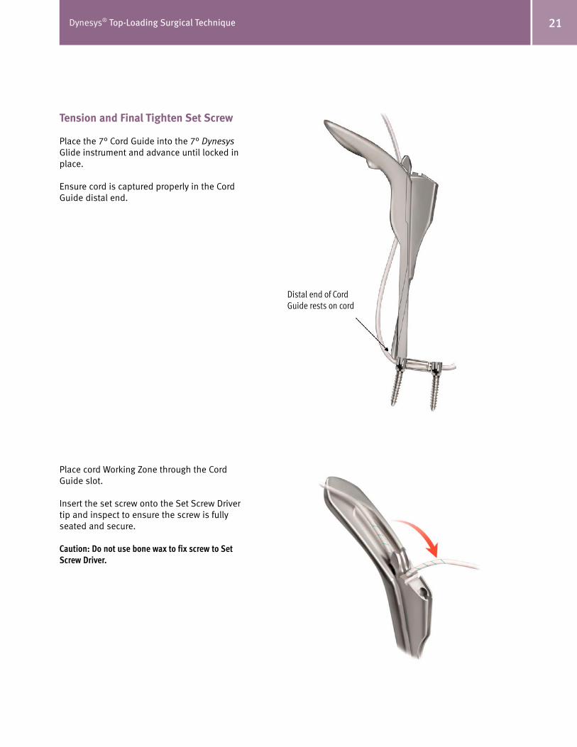
�1Dynesys® Top-Loading Surgical Technique
Tension and Final Tighten Set Screw
Place the 7° Cord Guide into the 7° Dynesys Glide instrument and advance until locked in place.
Ensure cord is captured properly in the Cord Guide distal end.
Place cord Working Zone through the Cord Guide slot.
Insert the set screw onto the Set Screw Driver tip and inspect to ensure the screw is fully seated and secure.
Caution: Do not use bone wax to fix screw to Set Screw Driver.
Distal end of Cord Guide rests on cord

�� Dynesys® Top-Loading Surgical Technique
Feed cord through Cord Tensioner and place onto the 7° Cord Guide docking location. Advance set screw through the 7° Cord Guide into initial position on pedicle screw. Do not tighten screw at this time.
Squeeze tensioner handles to appropriate tension as indicated on the tensioner. While maintaining cord tension, advance and tighten set screw to final torque.
Proper torque has been reached when the two arrows on the Torque Indicating Handle inter-sect.
Note: Proper alignment is necessary to ensure set screw is properly engaged. Never force the set screw. Thread strip-ping may result.
Note: When properly docked the Cord Tensioner will provide anti-torque.
Caution: Do not over or under tighten set screw.Cord Tensioner
provides anti-torque in notch of Cord Guide

��Dynesys® Top-Loading Surgical Technique
Remove Set Screw Driver assembly.
Remove Cord Tensioner.
Remove the assembled 7° Dynesys Glide instrument and Cord Guide.
Repeat Contralateral Side
Adjacent Segment
Refer to the next section of this document to implant and tension additional segment.
When the entire construct is complete and the system is fully tensioned, cut the cords leav-ing 10 mm of cord out of the screw heads and remove cut ends.
Note: Only implant the Functional Zone of the cord.
Caution: Implantation of the Working or Introduction Zones in the patient could lead to cord failure.
Dynesys Glide Instrumentation:Adjacent Level
Optional Guide Pin
The Guide Pin may be used to dock Glide instru-ments as required.
One end of the Guide Pin is terminated with threads to fix the Guide Pin to the screw.
The opposite end of the Guide Pin is terminated with a blunt end that provides a floating engage-ment with the screw.
Note: If using the threaded end of the Guide Pin, do not over tighten.
Use the Guide Pin Wrench to remove the Guide Pin from the screw.
Note: It may be necessary to compensate for tissue pressure when removing the Guide Pin.

�� Dynesys® Top-Loading Surgical Technique
Place and Reduce Spacer
Dock the 7° Dynesys Glide instrument to the cephalad screw.
Use Guide Pin to dock instruments as required.
Thread cord through the appropriately sized spacer and place the spacer against caudal screw head.
Ensure the cord is placed properly into the 7° Dynesys Glide instrument slot.
Place the Spacer Pusher into the 7° Dynesys Glide instrument and advance until positioned in contact with spacer.
Advance the Spacer Pusher until spacer is in final position.
You may use a mallet to gently tap against the Spacer Holder handle if desired.
Note: Handle the cord carefully to ensure aseptic conditions.
Note: A slight distractive force may be applied with the 7° Glide instrument handle if necessary while advancing.
Caution: A torque and/or bending load that is too high can fracture the pedicle.
Remove the Spacer Pusher.
Reducing a Spacer Less than 12 mm in Length
Advance the Spacer Pusher until spacer is fully seated or the Spacer Pusher cannot be advanced further.
Caution: Carefully advance the Spacer Pusher when implanting a spacer less than 12 mm in length to avoid damaginging the pedicle screw.
Remove the Spacer Pusher. Engage the distal end of the Spacer Holder and advance sleeve to lock spacer into place. Using the Spacer Holder, carefully advance the spacer until fully seated. Disengage and remove the Spacer Holder.

��Dynesys® Top-Loading Surgical Technique
Tension and Final Tighten Set Screw
Place the 7° Cord Guide into the 7° Dynesys Glide instrument and advance until locked in place.
Ensure cord is captured properly in the Cord Guide distal end.
Place cord Working Zone through the Cord Guide slot.
Insert the set screw onto the Set Screw Driver tip and inspect to ensure the screw is fully seated and secure.
Caution: Do not use bone wax to fix screw to Set Screw Driver.
Feed the cord through Cord Tensioner and place onto the 7° Cord Guide docking location. Advance the set screw through the 7° Cord Guide into initial position on pedicle screw. Do not tighten screw at this time.
Distal end of Cord Guide rests on cord

�� Dynesys® Top-Loading Surgical Technique
Squeeze the tensioner handles to appropriate tension as indicated on the tensioner. While maintaining cord tension, tighten the set screw to final torque.
Proper torque has been reached when the two arrows on the Torque Indicating Handle inter-sect.
Note: Proper alignment is necessary to ensure set screw is properly engaged. Never force the set screw. Thread strip-ping may result.
Note: When properly docked the Cord tensioner will provide anti-torque.
Caution: Do not over or under tighten set screw.
Remove Set Screw Driver assembly.
Remove Cord Tensioner.
Remove the assembled 7° Dynesys Glide instru-ment and Cord Guide.
Repeat Contralateral Side and Adjacent Segment as Desired.
When the system is fully tensioned, cut the cords leaving 10 mm of Functional Zone out of the screw heads and remove cut ends.
Note: Only implant the Functional Zone of the cord.
Caution: Implantation of the Working or Introduction Zones in the patient could lead to cord failure.
Cord Tensioner provides anti-torque in notch of
Cord Guide

��Dynesys® Top-Loading Surgical Technique
Postoperative Treatment
It is the responsibility of the surgeon to assess the adequate postoperative treatment depend-ing on the patient’s condition.
• Analgesics.• Possible antibiotic prophylaxis against infection.• Possible prophylaxis against thromboembolism.• Early physiotherapy.• Limited activity is recommended for approximately six weeks.• A non-rigid brace should be considered during the period of limited activity.• A gradual resumption of activities can begin after approximately six weeks.
Hardware Removal/Revision Instructions
Note: It may be necessary to use general surgical instrumen-tation to remove the implants.
Set Screw Removal
Engage the 0° Dynesys Glide instrument with the pedicle screw head of the set screw to be removed. Fully seat the Torque Indicating Handle and Set Screw Driver into the set screw. While providing anti-torque with the 0° Dynesys Glide instrument, turn the Set Screw Driver counter-clockwise until the set screw is removed. Repeat for all set screws to be removed.

�� Dynesys® Top-Loading Surgical Technique
Spacer and Cord Removal
Slide the Spacer Holder sleeve into the open position and place onto the spacer to be removed. Carefully slide the Spacer Holder sleeve into the closed position and withdraw the spacer and cord. A slight rocking motion may be necessary to facilitate removal. Repeat for all spacers to be removed. Repeat on the contralateral side as desired.
Pedicle Screw Removal
Assemble the Ratcheting T-Handle and Pedicle Screw Driver and place onto the screw head using the marks located on the Pedicle Screw Driver to ensure proper orientation. Turn the Pedicle Screw Driver retainer nut clockwise and secure the screw to the Pedicle Screw Driver.
Once the screw is fully engaged on the driver, carefully turn the Pedicle Screw Driver counterclockwise until the screw is removed. Repeat for all pedicle screws to be removed.
Carefully examine the operative site and count implants to ensure all hardware has been removed.
APPENDIX AChanging the Cutter Blade
Rotate the Blade Holder clockwise into the forward (cut) position.
Loosen the Screw on the Blade Holder using the Wrench Feature of the Spacer Cutter Lever.
Turn the Blade counterclockwise and pull it down, removing it from the Spacer Cutter. Take the new Replacement Blade and insert it into the Spacer Cutter as far as it will go.
Rotate the Replacement Blade clockwise as far as it will go.
Verify that the hole of the blade is properly aligned with the screw.
Tighten the screw with the Wrench Feature of the Spacer Cutter Lever.
Note: Do not over tighten the Blade Cutter Screw.

Contact your Zimmer Spine representative or visit us at www.zimmerspine.com
www.zimmerspine.com
L139
3Re
v.C
©20
07Z
imm
erS
pine
,Inc
.(
851S
-10
01-
00
)
Zimmer Spine, Inc.
7375 Bush Lake Road
Minneapolis, MN 55439-2027
U.S.A.
Telephone 952.832.5600
or 800.655.2614
Fax 952.832.5620
The Dynesys Spinal System and Zimmer DTO Implant are manufactured by:Zimmer GmbH Sulzer Allee/ P.O. BoxCH-8404 WinterthurSwitzerlandTel: 41 (0)52 262 60 70Fax: 41 (0)52 262 01 39


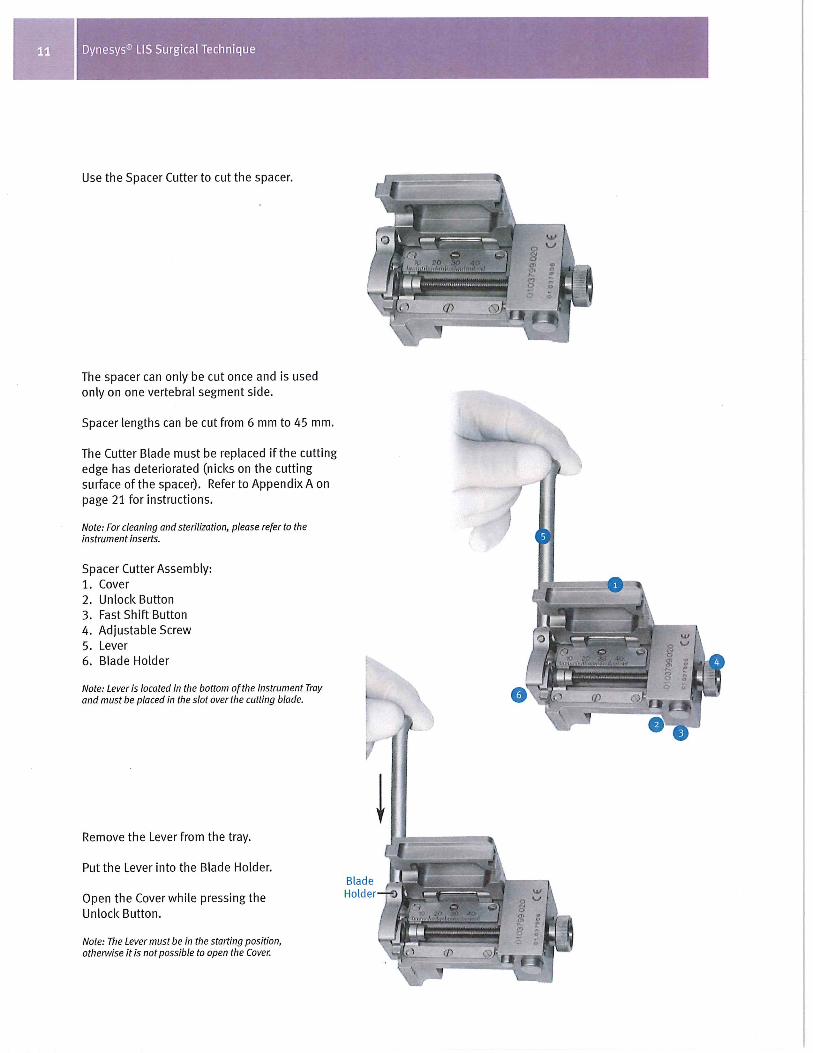


Because different stages of spinal degeneration require a different solution.
Zimmer® DTO™ Implant and OPTIMA™ ZS
Transition Screw with LIS Instruments
Surgical Technique

2 Zimmer® DTO™ Implant and OPTIMA™ ZS Transition Screw with LIS Instruments
Surgical TechniqueZimmer DTO and OPTIMA ZS Transition Screwwith LIS Instruments
Table of Contents
Foreword 3
General Information 3
Zimmer DTO Implant 4
OPTIMA ZS Transition Screw 5
Zimmer DTO Instruments 5
Patient Positioning 6
Approach 6
Dynesys Screw Pedicle Preparation 7
Dynesys Screw Placement 8
OPTIMA ZS Transition Screw Placement 9
OPTIMA ZS Screw Placement 10
DTO Implant Selection 10
DTO Implant Final Preparation before Insertion 11
DTO Implant Assembly 15
Compression/ Distraction 17
Final Set Screw Tightening 18
Dynesys Assembly 21
Final Construct 23
Hardware Removal/Revision Instructions 24
Postoperative Treatment 25
Cleaning Instructions 25
Appendix 1 26
Appendix 2 27
Warnings and Precautions 28

3Zimmer® DTO™ Implant and OPTIMA™ ZS Transition Screw with LIS Instruments
Foreword
• This document describes the surgical technique to implant the Zimmer® DTO™ Implant and the OPTIMA™ ZS Transition Screw in combination with the Dynesys® and OPTIMA ZS Spinal Systems.
• For implant selection and the complete respective surgical techniques of the Dynesys and OPTIMA ZS systems, please refer to:
– Dynesys LIS Less Invasive Surgery, L1301
– OPTIMA ZS Spinal Fixation System, L1264
• When the Dynesys and OPTIMA ZS systems are used on contiguous levels, they must be used with the Zimmer DTO implant, rod-cord combination implant, and the OPTIMA ZS transition screw. The indication for use for each level is as specified for each system.
General information
• The Dynesys LIS instruments should only be used with the Dynesys Spinal System. OPTIMA ZS instruments should only be used with OPTIMA ZS screws. The Zimmer DTO implant and OPTIMA ZS transition screw should be used with DTO instruments, Dynesys LIS and OPTIMA ZS instruments according to the instructions for use described in this brochure.
• For further information regarding indications, warnings, precautions, adverse events and other important medical information, please read the respective instruction leaflets for the systems.

4 Zimmer® DTO™ Implant and OPTIMA™ ZS Transition Screw with LIS Instruments
DTO Implant
The DTO implant and OPTIMA ZS transition screw are designed to allow the Dynesys and OPTIMA ZS systems to be implanted at contiguous levels of the lumbar spine.
The DTO implant is made of a combined 100 mm PET (Polyethylene-Terephthalate) Dynesys cord and a titanium alloy 6 mm rod. The rod is pre-bent.
The DTO implant is delivered partially pre-assembled (cord inserted in the rod and maintained in position by means of a small needle).
The assembly must be finalized intra-operatively by pressing the pre-assembled pin with the DTO Hand Press.
The Dynesys cord must be carefully handled in order to maintain aseptic conditions during the assembly.
The DTO implant is available in four rod lengths: • 40 mm• 50 mm• 60 mm• 80 mm
The DTO implant is delivered sterile.
The Dynesys system is placed cranially from the OPTIMA ZS system.
The DTO implant is intended only for index surgery.
Zimmer DTO Implant
OPTIMA ZS Transition Screw
DTO Implant

5Zimmer® DTO™ Implant and OPTIMA™ ZS Transition Screw with LIS Instruments
OPTIMA ZS Transition Screw
The polyaxial OPTIMA ZS transition screw is specially designed to be used with the DTO implant.
Available sizes: 6.0 mm 7.0 mm Diameter Diameter 6.0 x 35 mm 7.0 x 35 mm
6.0 x 40 mm 7.0 x 40 mm
6.0 x 45 mm 7.0 x 45 mm
6.0 x 50 mm 7.0 x 50 mm
The OPTIMA ZS transition screw is delivered nonsterile.
Caution: The DTO implant can only be used in connection with the OPTIMA ZS transition screw.
Zimmer DTO InstrumentsFour DTO instruments are available:
DTO Hand Press
DTO Anti Torque
DTO Protective Adapter (for the DTO Compressor)
DTO Compressor
The specific instruments for Dynesys LIS and OPTIMA ZS systems are described in their respective surgical techniques.

6 Zimmer® DTO™ Implant and OPTIMA™ ZS Transition Screw with LIS Instruments
Patient Positioning
Prone or Knee-Chest positions are acceptable, provided that care is taken to preserve the natural lordosis in the lumbar spine as well as to avoid any pressure on the abdominal cavity that might result in excessive bleeding.
The use of fluoroscopy or X-ray (AP and lateral view) is strongly recommended for placement of the screws.
Other valid computer-aided surgical navigational techniques may also be used.
Approach
The spine is approached through a standard posterior midline incision or a paraspinal approach. Muscles are retracted until the facet joints are visible.
Caution: Do not damage the posterior ligaments or the facet joint capsules.
Preparation Before the Placement of the Pedicle Screws
Place the screws lateral to the facet joints.
Correct screw placement is absolutely necessary for optimal functioning of the system and for long term anchorage of the screws.
Note: The facet joints must remain intact.
Note: If there is not enough room for the spacer, you can remove bone from the lateral aspect of the articular process, preserving the capsule.
Use the Spacer Template to determine the correct position of the screws.
Open the pedicle with the Awl.
Spacer Template usage
Proper Awl placement

7Zimmer® DTO™ Implant and OPTIMA™ ZS Transition Screw with LIS Instruments
Dynesys ScrewPedicle Preparation
The assembly is started at the most cranial level with the placement of the Dynesys pedicle screws.
Using the Dynesys Awl and the Pedicle Probe, prepare the pedicle for insertion of the screw.
The marks on the Pedicle Probe help determine the appropriate screw lengths (35, 40, 45, 50 or 55 mm).
Note: Do not open the pedicle deeper than length of the intended screw (maximum screw length is 55 mm). Screw length depends on patient morphology.
Note: We do not recommend using a curved Pedicle Probe, which may widen the bone channel.
Note: X-ray use is recommended.
Check the integrity of the pedicle wall with the Pedicle Sound.
Note: Dynesys screws do not require tapping. Use of the Dynesys Bone Tap System is optional.
Caution: X-ray use is recommended when using Bone Taps. Always select the Bone Tap diameter that corresponds to the pedicle screw size to be implanted. Do not tap beyond the length of the pedicle screw to be implanted. Inspect cannulated Bone Taps prior to use to ensure the cannula is not occluded.
Proper Awl placement
The marks on the Pedicle Probe will help determine the appropriate screw lengths (35, 40, 45, 50, or 55 mm).
OPTIONAL: Depth SleeveIf you have difficulty seeing the marks on the tip of the Pedicle Probe, use the Depth Sleeve and the corresponding marks on the proximal end of the shaft.

8 Zimmer® DTO™ Implant and OPTIMA™ ZS Transition Screw with LIS Instruments
OPTIMA ZS ScrewPedicle Preparation
Using the OPTIMA ZS Awl and Probe, prepare the pedicles of the vertebrae below the Dynesys screw for insertion of the OPTIMA ZS transition screw and OPTIMA ZS screw(s).
Screw insertion should follow the angle of the pedicle canal.
Correct lateral placement of all the screws
Dynesys Screw Placement
Place Dynesys screws as described in the following sections of the Dynesys LIS Surgical Technique Manual, L1301:
•PedicleScrews
•SetUpoftheGuidePinandPedicleScrew
•PlacementoftheGuidePinsandPedicle Screws
Proper lateral screw placement
<10 mm

9Zimmer® DTO™ Implant and OPTIMA™ ZS Transition Screw with LIS Instruments
UseofGuidePins
OPTIMA ZS Transition Screw Placement
The OPTIMA ZS transition screw is placed lateral to the facet joint (see Pedicle Screw Preparation).
Select the appropriate size OPTIMA ZS transition screw.
Using the OPTIMA ZS Small Poly Screw Driver, insert the OPTIMA ZS transition screw.
Note: Insert the OPTIMA ZS transition screw as deep as possible.
Insert the OPTIMA ZS transition screw into the desired pedicle.
Note: Ensure that the Driver is fully engaged with the screw prior to inserting. The tip of the screw will not toggle when the driver is fully engaged.
Caution: While implanting the OPTIMA ZS transition screw, do not damage the facet joint capsule.
Note: In order to facilitate the assembly of the screws, the optional Dynesys Guide Pin can be removed.
Straight or Curved Testers are graduated to help determine hole depth
GuidePinsmaybeplacedtoidentifythe appropriate screw trajectory (OPTIMA ZS screws and OPTIMA ZS transition screw only) via a lateral X-Ray view.
Check the integrity of the pedicle wall with the OPTIMA ZS Tester.

10 Zimmer® DTO™ Implant and OPTIMA™ ZS Transition Screw with LIS Instruments
OPTIMA ZS Screw Placement
Place the OPTIMA ZS screws as described in the following sections of the OPTIMA ZS Surgical Technique, L1264:
•PediclePreparation
•PolyaxialScrewInsertion
Note: Select only OPTIMA ZS polyaxial screws for a proper alignment with the OPTIMA ZS transition polyaxial screw.
Note: Check that the standard OPTIMA ZS screw is placed lateral to the facet joint like the cranial Dynesys screws.
Repeat the same procedure for all pedicle screws on the contra-lateral side.
DTO Implant Selection
Once screws have been placed, determine the appropriate rod length of the DTO implant.
The rod should extend approximately 5 mm beyond the most distal edge of the inferior screw polybody.
Dynesys Pedicle screw
OPTIMA ZS Transition
screw
OPTIMA ZS screw
Pin to be pressed
Small needle
Protective bag

11Zimmer® DTO™ Implant and OPTIMA™ ZS Transition Screw with LIS Instruments
DTO Implant – Final Preparation Before Insertion
Caution: Use new gloves when handling the DTO implant and Hand Press.
Carefully remove the DTO implant from its sterile packaging (Refer to Appendix 2).
The DTO implant is delivered partially pre-assembled. A small needle ensures that the cord maintains its position in the rod.
Caution: The DTO implant cord must be handled carefully during assembly to maintain aseptic conditions. It is delivered in a protective bag to maintain aseptic conditions prior to assembly.
In order to complete the assembly of the implant, the pin must be fully pressed using the Hand Press. Final insertion ensures sufficient connection strength between the cord and the rod.
Keep the cord in its protective bag during handling.
Caution: Do not implant the DTO without fully pressing the pin.
Open the Hand Press.
Note: The Blue handle is placed on the top.
Note: Refer to Appendix 1 for more information regarding the Hand Press.

12 Zimmer® DTO™ Implant and OPTIMA™ ZS Transition Screw with LIS Instruments
Place the DTO implant into the Hand Press and position according to the ‘cord’ and ‘rod’ markings on the instrument.
Once the DTO implant is correctly placed in the Hand Press, close the Hand Press.
Note: The Hand Press can only be closed in one direction.
Ensure the Power Screw is at its highest position prior to closing the Hand Press. The Hand Press cannot be closed if the Power Screw is partially advanced.
Caution: Do not use excessive force to close the instrument; otherwise, it may be damaged.

13Zimmer® DTO™ Implant and OPTIMA™ ZS Transition Screw with LIS Instruments
Turn the handle of the Hand Press in a clockwise direction until there is no further rotation.
Ensure the line on the ram is past the line on the Hand Press body.
Start Position End Position
Ram

14 Zimmer® DTO™ Implant and OPTIMA™ ZS Transition Screw with LIS Instruments
Release the Power Screw by turning the handle counterclockwise until the Hand Press opens.
Carefully remove the DTO implant from the Hand Press.
Note: Hold the cord by its protective bag to ensure aseptic handling.
Caution: Visually check that the pin has been fully inserted/pressed into the DTO implant prior to implantation.
Check that the pin surface is flush with the DTO implant.
If the pin is not fully inserted, repeat the preparation with the Hand Press.
Caution: Remove the protective bag before continuing the assembly.

15Zimmer® DTO™ Implant and OPTIMA™ ZS Transition Screw with LIS Instruments
DTO Implant Assembly
The DTO rod is delivered pre-bent.
Caution: Rod is supplied pre-bent and must not be further contoured.
First place the connecting part of the DTO implant into the OPTIMA ZS transition screw.
Caution: The OPTIMA ZS Persuader cannot be used with the OPTIMA ZS transition screw.
In the cranio-caudal direction, placement of the DTO implant is guided by the two flanges on each side of the connecting part.
Caution: Carefully handle the cord during the assembly in order to ensure aseptic conditions.
Caution: The surface containing the pin of the connecting part must be facing upwards from the exposure.
The DTO rod is placed in the OPTIMA ZS screw head using the Rod Holder.
The Rod Pusher may be used to seat the DTO rod while inserting set screws with the Set Screw Inserter.

16 Zimmer® DTO™ Implant and OPTIMA™ ZS Transition Screw with LIS Instruments
Note: Use a set screw from the OPTIMA ZS Set for the OPTIMA ZS transition screw.
Caution: Only use a small set screw for the OPTIMA ZS transition screw.
Insert the set screw of the OPTIMA ZS transition screw using the OPTIMA ZS SetScrewDriverGuide.
Note: The DTO implant must be adequately seated prior to set screw insertion.
The set screw starts easily when properly aligned. If incorrectly aligned, the set screw will exhibit noticeable resistance during the initial threading. If this occurs, back the set screw completely off the screw and check that it is properly seated on the Set Screw Driver Guide.
Advance the set screw as far as possible, but:
• Do not attempt to final tighten the system using the Set Screw DriverGuide.
• Over-tightening of the set screw could damage the OPTIMA ZS transition screw thread.
Repeat the same procedure for the OPTIMA ZS screws.
Small Set Screw
Large Set Screw

17Zimmer® DTO™ Implant and OPTIMA™ ZS Transition Screw with LIS Instruments
Caution: Select the appropriate set screw for the OPTIMA ZS screw. Two set screws are available.
Select and place the DTO implant for the contra-lateral side.
Insert the set screws.
Compression / Distraction
Provisionally tighten the set screw on the side of the segment being translated, while leaving the set screw on the contra-lateral side loose.
Perform compression or distraction against the provisionally tightened assembly.
In case of a compression, a special DTO Compressor with Protective Adapters has been designed to protect the polished surface of the DTO implant.
Caution: Only use the DTO Compressor for compression.
Caution: Excessive compression force can result in damage of anatomical structures or compromise the implant/bone interface.
Caution: Do not use any Compressor on the Dynesys screw.
Caution: Complete any compression/distraction before the implanting of the Dynesys spacer.
• 5.0 mm, 6.0 mm and 7.0 mm polyaxial screws utilize the Small Set Screw
• 7.5 mm and 8.0 mm polyaxial screws utilize the Large Set Screw
Small Set Screw
Large Set Screw

18 Zimmer® DTO™ Implant and OPTIMA™ ZS Transition Screw with LIS Instruments
Final Set Screw Tightening
After achieving the desired amount of correction, perform final tightening of the set screw.
Place the DTO Anti-Torque on the OPTIMA ZS transition screw and use the OPTIMA ZS Axial Torque Wrench to tighten the set screw(s).
Caution: The DTO Anti-Torque is intended for use on the OPTIMA ZS transition screw only.
Tighten the set screw until the line and arrow on the Torque Wrench Handle (106 in-lbs./12 Nm) align.
Initial torqueposition
Final torque position(106 in-lbs.)

19Zimmer® DTO™ Implant and OPTIMA™ ZS Transition Screw with LIS Instruments
Position the OPTIMA ZS Anti-Torque over the polybody of the OPTIMA ZS screws to be tightened.
Insert the Axial Torque Wrench through the cannulated Anti-Torque Device into the set screw.
Tighten the set screw until the line and arrow on the Torque Wrench Handle (106 in-lbs./12 Nm) align.
Repeat the process until the remaining set screws are tightened.
Alternative Technique for OPTIMA ZS Screws:Assemble the 4 mm OPTIMA ZS Hex Driver and the Torque Limiting T-handle.
Insert the 4 mm Hex Driver through the cannulated Anti-Torque into the OPTIMA ZS set screw.
Caution: Only use this optional instrument with the OPTIMA ZS screws and not with the OPTIMA ZS transition screw.

20 Zimmer® DTO™ Implant and OPTIMA™ ZS Transition Screw with LIS Instruments
Tighten the set screw until the Torque Limiting T-handle breaks over/clicks at 106 in-lbs./12 Nm.
Note: The Axial Torque Wrench or 4 mm Hex Driver and Torque Limiting T-Handle used in conjunction with the Anti-Torque are the only instruments acceptable for final set screw tightening.
Caution: Do not place the transverse link against the connecting part of the DTO implant.
Optional: Transverse links may be used to connect rod segments.
For more information, please review the OPTIMA ZS Spinal System surgical technique.
Adjustable transverse links are color-coded according to length.

21Zimmer® DTO™ Implant and OPTIMA™ ZS Transition Screw with LIS Instruments
Top View of Pedicle Distance Gauge
1
2
4
53
1. Start Position
2. Drag Indicator for length of Universal Spacer
3. Distraction Indicator
4. Ball end
5. Forked end
Dynesys Assembly
Re-insert the optional DynesysGuidePins on the Dynesys screws heads to assist in docking instrumentation.
Using the Dynesys Pedicle Distance Gaugewithaforkededge,measurethe spacer length between the Dynesys pedicle screw and the OPTIMA ZS transition screw.
Verify that the Drag Indicator is in the start position.
Assess the movement in the facets in distraction and compression. Measure the distance (spacer length) with a slight distraction force.
Note: The Pedicle Distance Gauge with a forked end must be used, and is included in the DTO instrument tray.
Caution: Do not induce kyphosis or scoliosis.
Record the measured spacer length for the levels.
Cut the Dynesys spacer with the Dynesys Spacer Cutter according to the previously determined measurement.
Thread the appropriately sized spacer onto the DTO cord and place against the OPTIMA ZS transition screw head.
Using a clamp, insert the DTO cord through the Dynesys pedicle screw head.
Note: The end of the introduction zone of the cord can be bent to facilitate the introduction of the cord into the screw head.
Note: Avoid twisting and looping of the cord.

22 Zimmer® DTO™ Implant and OPTIMA™ ZS Transition Screw with LIS Instruments
Complete the Dynesys construct assembly and cord tensioning according to the Dynesys LIS Surgical Technique, L1301:
•ConstructAssembly

23Zimmer® DTO™ Implant and OPTIMA™ ZS Transition Screw with LIS Instruments
Final Construct
After segment by segment work, a two-level assembly is completed.
Decorticate the posterior elements as necessary. Place bone graft to achieve the desired fusion.

24 Zimmer® DTO™ Implant and OPTIMA™ ZS Transition Screw with LIS Instruments
Hardware Removal/Revision Instructions
Set Screw Removal
Position the appropriate Anti-Torque Device over the pedicle screw body of the set screw to be removed. Insert the matching Torque Wrench through the Anti-Torque Device and into the set screw. Turn the Torque Wrench counterclockwise until the set screw is loose but not completely disengaged. Remove the Torque Wrench and Anti-Torque Device. Carefully remove the OPTIMA ZS set screws with the Set Screw Driver GuideandtheDynesys set screws with the Set Screw Starter. Repeat for all set screws.
DTO Implant Removal
Place the OPTIMA ZS Rod Holder onto the rod component of the DTO implant near the connecting portion and remove from the OPTIMA ZS pedicle and transition screws. Once the DTO Implant connecting portion has been removed from the OPTIMA ZS transition screw, carefully remove the DTO cord and Dynesys spacer assembly. It may be necessary to cut the cord adjacent to the spacer with a scalpel blade to facilitate removal. Remove all components of the DTO implant. Repeat on the contralateral side.
OPTIMA ZS Transition and Pedicle Screw Removal
Insert the tip of the OPTIMA ZS Small Poly Screw Driver into the polybody, positioning the tangs of the attached T-Handled Screwdriver Sleeve into the slots on the screw body. Turn the Ratchet handle clockwise while holding the Screwdriver Sleeve. Once the pedicle screw is fully engaged
on the driver, carefully turn the screwdriver counterclockwise until the OPTIMA ZS screw is removed. Repeat for all OPTIMA ZS transition and pedicle screws.
Dynesys Pedicle Screw Removal
Insert the Long Retainer into the Pedicle Screw Driver handle and turn clockwise to engage. Place the Pedicle Screw Driver onto the Dynesys screw head using the marks located on the Pedicle Screw Driver to ensure proper orientation. Turn the Long Retainer clockwise and secure the Dynesys screw to the Pedicle Screw Driver.
Caution: Do not overtighten the Long Retainer.
Once the pedicle screw is fully engaged on the driver, carefully turn the Screw Driver counterclockwise until the Dynesys screw is removed. Repeat for all Dynesys pedicle screws.
Carefully examine the operative site to ensure all hardware has been removed.

25Zimmer® DTO™ Implant and OPTIMA™ ZS Transition Screw with LIS Instruments
Postoperative Treatment
It is the responsibility of the surgeon to assess the adequate postoperative treatment depending on the patient’s condition.
Analgesics
Possible antibiotic prophylaxis against infection
Possible prophylaxis against thromboembolism
Early physiotherapy
Limited activity is recommended for approximately six weeks
A non-rigid brace should be considered during the period of limited activity
A gradual resumption of activities can begin after approximately 6 weeks
Cleaning Instructions
For information on cleaning and sterilization refer to:
• OPTIMA ZS Instruction for Use leaflet, IFU-SD01
• Dynesys and DTO Instructions for Use leaflet, D011500217
Caution: Pedicle screws should not be put back in the tray for resterilization if they have been in contact with bodily fluids. They should be treated as a biohazard and disposed of accordingly.
Please consult the following documents for additional information on the instrumentation:•Dynesys LIS Instruments Instructions for Use 07.00996.001
•Zimmer DTO Instruments Cleaning Leaflet, 07.01352.001
• Instructions for Use for Surgical Instruments, D011500192
Warning: Do not sterilize the OPTIMA ZS transition screw tray with the Zimmer DTO instrument tray. The effectiveness of the sterilization of these two trays together has not been established. Refer to the sterilization instructions for each system in their respective Instructions for Use leaflets.

26 Zimmer® DTO™ Implant and OPTIMA™ ZS Transition Screw with LIS Instruments
Appendix 1
The Hand-Press
Handle (top)
Power Screw Housing
Ball and Spring Plunger
Power Screw
Ram
Implant Housing
Handle (bottom)
Hinge Screw

27Zimmer® DTO™ Implant and OPTIMA™ ZS Transition Screw with LIS Instruments
Appendix 2
Aseptic handling of the DTO Implant
Remove the DTO implant from its innermost pouch but leave the cord in its protective bag to allow aseptic handling of the implant during the assembly.
Caution: The protective bag must be removed before the final assembly of the implant inside the patient.

28 Zimmer® DTO™ Implant and OPTIMA™ ZS Transition Screw with LIS Instruments
OPTIMA™ ZS Spinal System & OPTIMA™ ZS Transition ScrewInstructions for UsePrecaution:The implantation of pedicle screw spinal systems should be performed only by experienced spinal surgeons with specific training in the use of this pedicle screw spinal system because this is a technically demanding procedure presenting a risk of serious injury to the patient.
Warning:The safety and effectiveness of pedicle screw spinal systems have been established only for spinal condi-tions with significant mechanical instability or deformity requiring fusion with instrumentation. These conditions are significant mechanical instability or deformity of the thoracic, lumbar and sacral spine secondary to degenera-tive spondylolisthesis with objective evidence of neurologic impairment, fracture, dislocation, scoliosis, kyphosis, spinal tumor, and failed previous fusion, (pseudoarthrosis). The safety and effectiveness of these devices for any other condition is unknown. The safety and effectiveness of this device for the indication of spinal stabilization without fusion have not been established.
Important Note:The users of the OPTIMA™ ZS Spinal System acknowledge that they have read and agreed to the conditions in this insert, which are considered to be contractual. When using the Zimmer GmbH Zimmer® DTO™ Implant, the users of the OPTIMA™ ZS Spinal System should also study carefully Instruction for Use and Surgical Technique Manual of the Zimmer GmbH Dynesys® Spinal System as well as the product-specific information. In addition, it should be noted that the Dynesys® Spinal System and the Zimmer® DTO™ Implant are only indicated for use in the posterior lumbar spine. For additional details regarding the indica-tions for use, precautions, warnings, contraindications and other product specific information for the Dynesys® Spinal System and the Zimmer® DTO™ Implant refer to the Instruc-tions for Use for these devices.
Basic Structure:The OPTIMA™ ZS Spinal System is an internal fixation device for spinal surgery comprising pedicle screws, connectors, rods, housings and transverse link assemblies. Various forms and sizes of these implants are available, so that adaptations can be made to take into account the pathol-ogy and individual patient.
Material:All components of the OPTIMA™ ZS Spinal System and the OPTIMA™ ZS Transition Screw are made of Ti6Al4V ELI, a titanium-based alloy which complies with ASTM F136.
Indications for Use:The OPTIMA™ ZS Spinal System is a posterior pedicle screw fixation system indicated for the treatment of severe spondylolisthesis, (Grade 3 and 4), of the L5-S1 vertebra in skeletally-mature patients receiving fusion by autogenous bone graft having implants attached to the lumbar and sacral spine with removal of implants after the attainment of a solid fusion.In addition, The OPTIMA™ ZS Spinal System is intended to provide immobilization and stabilization of spinal segments in skeletally-mature patients as an adjunct to fusion in the treatment of the following acute and chronic instabilities or deformities of the thoracic, lumbar and sacral spine:• Degenerative spondylolisthesis with objective evidence of
neurological impairment• Fracture of the vertebral body• Dislocation• Scoliosis• Kyphosis• Spinal tumor• Failed previous fusion (Pseudoarthrosis).When the Zimmer GmbH Dynesys® Spinal System and the OPTIMA™ ZS Spinal System are used on contiguous levels, they must be used with the Zimmer GmbH Zimmer® DTO™ Implant, rod-cord combination implant, and the OPTIMA™ ZS Transition Screw. The indications for use for each level is as specified for each system.
Note: The OPTIMA™ ZS Spinal System’s Surgical Technique Manual should be followed carefully. Important informa-tion on the proper usage of implants and instruments is included. When using the Zimmer® DTO™ Implant, the users of the OPTIMA™ ZS Spinal System should also study care-fully Instruction for Use and Surgical Technique Manual of the Dynesys® Spinal System as well as the product-specific information.
Levels of Fixation:Levels of fixation are for the thoracic, lumbar and sacral spine.
General Conditions of Use:• The implants must be implanted only by surgeons having
undergone the necessary training in spinal surgery. Their use in implantation must be decided upon in accordance with surgical and medical indications, the potential risks and limitations related to this type of surgery, the con-traindications, side effects and precautions. The surgeon should also possess knowledge of the metallurgic and biological characteristics of the implants.
• The OPTIMA™ ZS Spinal System implants and implants parts should never be combined with parts from other companies, unless otherwise indicated in the Instruction for Use and/or Surgical Technique Manual. General use operating room instruments and/or other instruments described in the surgical technique are permitted for use. In addition, when using the Zimmer GmbH Zimmer® DTO™ Implant it is permitted to combine the Zimmer GmbH Dynesys® Spinal System with the OPTIMA™ ZS Spinal System. Each system must be implanted using the appropriate instruments and surgical technique as defined in the respective Surgical Technique Manuals. The instruments for the different systems must not be commingled or used interchangeably. If this should occur, U&i Corporation declines all responsibility.
• Under no circumstances may the implants be re-used after previous implantation or patient contact. Although the device may appear intact on removal, internal modification due to the stress and strains placed on it, or small defects may exist which may lead to fracture of the implant.
Contraindications:• Any active or suspected latent infection in or about the
spine.• Any mental or neuromuscular disorder which would create
an unacceptable risk of fixation failure or complications in post-operative care.
• Bone stock compromised by disease, infection or prior implantation which cannot provide adequate support and or fixation to the implant.
• Obesity, an overweight or obese patient can produce loads on the spinal system which can lead to failure of the fixation of the device or to failure of the device itself.
• Recent infection, fever or leukocytosis• Bony abnormalities preventing safe screw fixation• Open wounds• Metal sensitivity, documented or suspected• Bone absorption, osteopenia and/or osteoporosis• Patients having inadequate tissue coverage over the
operative site• Pregnancy• Excessive local inflammation• Use in the cervical spine• Alcohol or drug abuse• Patient unwilling or unable to follow postoperative
instructions• Sensitivities/allergy to polymers, polyethylene, polycar-
bonate, urethane and polyethylene terephthalate when using the Zimmer GmbH Dynesys® Spinal System and the Zimmer® DTO™ Implant
• Other medical or surgical conditions which would pre-clude the potential benefit of spinal implant surgery such as the presence of tumors, congenital abnormalities, elevation of sedimentation rate unexplained by other diseases, elevation of white blood cell count, (WBC) or marked left shift in the WBC differential count.
Side Effects:• Late bone grafting or no visible fusion mass and pseud-
arthrosis• Neurological complication, paralysis, soft tissue lesions,
pain, wound complication, paresthesia and cerebral spi-nal fluid leakage due to the surgical procedure, breakage deformation and or migration of the implant
• Pedicle failure while preparing and inserting the pedicle screw
• Superficial or deep-set infection and inflammatory phenomena
• Allergic reaction to the implant material• Reduction in bone density due to different distribution of
mechanical stresses• Pain and abnormal sensations due to hardware bulkiness• Neurological and spinal dura matter lesions from surgical
trauma• Bursitis• Presence of micro-particles around the implants• Growth of the fused vertebrae is altered• Partial loss of the degree of correction achieved during
surgery• Modification of spinal curvature and stiffness of the
vertebral column• Loosening, disassembly, bending or breakage of
components• Non-union or delayed union• Fracture of vertebrae• Foreign body reaction (allergic) to components or debris• Loss of fixation• Vascular or visceral injury• Gastrointestinal, urological and/or reproductive system
compromise• Loss of bone or fracture of bone above or below the level
of surgery• Bone graft donor site pain, fracture, and/or delayed
wound healing• Restriction of activities• Lack of effective treatment of symptoms for which surgery
was intended• Death• The above list of side effects is not exhaustive. These
side effects can sometimes necessitate further surgical treatment.

29Zimmer® DTO™ Implant and OPTIMA™ ZS Transition Screw with LIS Instruments
Precautions:• The surgeon should consider the level of implantation,
the weight of the patient, the patient’s activity level or general conditions and any other factor which may have an impact on the performance of the system based on published fatigue test results of the system.
• Patients who smoke have been shown to have an increased incidence of non-unions. Such patients should be advised of this fact and warned of the potential consequences.
• If the patient is involved in an occupation or activity which applies inordinate stress upon the implant (e.g., substan-tial walking, running, lifting or muscle strain), resultant forces can cause failure of the device.
• In some cases, progression of degenerative disease may also be so advanced at the time of implantation that they may substantially decrease the expected useful life to the appliance. In such cases, orthopedic devices may be considered only as a delaying technique or to provide temporary relief.
• Before clinical use, the surgeon should thoroughly understand all aspects of the surgical procedure and limitations of the spinal fixation system. This device is recommended for use only by surgeons familiar with pre-operative and surgical techniques, cautions and potential risks associated with such spinal surgery. Knowledge of surgical techniques, proper reduction, selection and placement of implants, and pre and post-operative patient management are considerations essential to a successful surgical outcome.
• Patients should be instructed in detail about the limita-tions of the implants, including but not limited to the impact of excessive loading through patient weight or activity, and should be taught to govern their activities ac-cordingly. The patient should understand that a metallic implant is not as strong as normal, healthy bone and will bend, loosen or fracture if excessive demands are placed on it. An active, debilitated or demented patient who cannot properly use weight supporting devices may be particularly at risk during postoperative rehabilitation.
• Appropriate selection, placement and fixation of the spinal system components are critical factors which affect implant service life. As in the case of all prosthetic implants, the durability of these components is affected by numerous biologic, biomechanics and other extrinsic factors, which limit service life. Accordingly, strict adher-ence to the indications, contraindications, precautions, and warnings for this product is essential to potentially maximize service life. (Note: While proper implant selec-tion can minimize risks, the size and shape of human bones present limitations on the size, shape and strength of the implants.)
• Care must be taken to protect the components from being marred, nicked or notched as a result of contact with metal or abrasive objects. Alterations will produce defects in surface finish and internal stresses which may become the focal point for eventual breakage of the implant.
Warning:• The safety and effectiveness of this device for the
indication of spinal stabilization without fusion have not been established.
• The benefit of spinal fusion utilizing any pedicle screw fixation system has not been adequately established in patients with stable spine.
• Potential risks associated with the use of this system, which may require additional surgery, include device component fracture, loss of fixation, non-union, fracture of the vertebra, neurological injury and vascular or
visceral injury.• Discard all damaged or mishandled implants.• Never reuse an implant after patient contact even though
it may appear undamaged.• Internal fixation devices cannot withstand activity and
loads equal to those placed on normal healthy bone. Until maturation of the fusion mass is confirmed, do not subject this device to the stress of full weight bearing, or implant failure may result.
• Contouring or bending of a screw or hook may reduce its fatigue strength and cause failure under load. If spinal screws or hooks are bent or otherwise damaged during insertion or adjustment, they may not be implanted and must be replaced. Rods should only be contoured with the proper contouring instruments. Incorrectly contoured rods or rods which have been repeatedly or excessively contoured must not be implanted.
• The Zimmer GmbH Zimmer® DTO™ Implant rods are sup-plied pre-bent and should not be further contoured.
• Mixing Metal: Some degree of corrosion occurs on all implanted metal and alloys. Contact of dissimilar metals, however, may accelerate this corrosion process. The presence of corrosion may accelerate fatigue fracture of implants and the amount of metal compounds released into the body system may also increase. Internal fixation devices such as rods, connectors, screws, hooks, etc., which come into contact with other metal objects must be made from like or compatible metals.
• Removal of an unloosened spinal screw may require the use of special instruments to disrupt the interface at the implant surface. This technique may require practice in the laboratory before being attempted clinically.
• Any decision by a surgeon to remove the internal fixation device should take into consideration such factors as the risk to the patient of the additional surgical procedure as well as the difficulty of removal.
• Implant removal should be followed by adequate postop-erative management to avoid fracture.
Packaging, Labeling and Storage:• Individual OPTIMA™ ZS Spinal System implants are
delivered in packages. These must be intact at the time of receipt. All the legal information required for this type of implant is given in the labeling of each package.
• Implants may also be delivered as a complete set, in specially designed trays or in boxes which can be steril-ized directly.
• Use care in handling and storage of implant components. Cutting, sharply bending or scratching the surface can significantly reduce the strength and fatigue resistance of the implant system. This, in turn, could induce cracks and/or non-visible internal stresses that could lead to fracture of the implants. Implants and instruments in storage should be protected from corrosive environments such as air, moisture, etc. Inspection and trial assembly are recommended prior to surgery to determine if the instruments or implants have been damaged during storage or prior procedures.
Sterilization Procedures:The OPTIMA™ ZS implants are provided clean and non-sterile, and must be sterilized prior to use using one of the following recommended sterilization cycles.• CAUTION: Use of sodium hydroxide (NaOH) is prohibited.
Use of corrosive products and/or instruments including abrasive sponges and metal brushes should be avoided.
• Implant removed from a patient or that contact bodily tissues or fluids should never be reused.
• Sterilization: Recommended method to achieve a degree
of sterility equal to at least 10-6. Sterilize by the autoclav-ing procedure regularly used in the hospital.° Suggested method (1): Steam, Wrapped Gravity Cycle at
132° C (270° F) for 20 minutes.° Suggested method (2): Steam, Prevacuum Cycle at 132°
C (270° F) for 4 minutes.
Warning:The Zimmer GmbH Dynesys® Spinal System Implants and the Zimmer® DTO™ Implants are delivered sterile and cannot be re-sterilized. Do not sterilize the OPTIMA™ ZS Transition Screw tray inside the Zimmer® DTO™ Instrument Tray. The effectiveness of the sterilization of these two trays together has not been established.

30 Zimmer® DTO™ Implant and OPTIMA™ ZS Transition Screw with LIS Instruments
Dynesys® Spinal System and the Zimmer® DTO™ Implant Instructions for Use1.0 DescriptionWhen used as a pedicle screw fixation system, the Dynesys Spinal System is intended to provide immobilization and stabilization of spinal segments as an adjunct to fusion in the treatment of the following acute and chronic instabilities or deformities of the thoracic, lumbar, and sacral spine: degenerative spondylolisthesis with objective evidence of neurologic impairment, and failed previous fusion (pseudoarthrosis). The Dynesys Spinal System is comprised of a variety of pedicle screws sizes, tensioning cords and longitudinal spacers that are uniquely fitted for each individual case. The pedicle screws are manufactured from medical grade titanium alloy conforming to ISO 5832-11. They are provided with or without hydroxyapatite coating conforming to ISO 13779-2. The tensioning cords are manufactured from Sulene-PET (polyethylene-tere-phthalate). The longitudinal spacers are manufactured from Sulene-PCU (polycarbonate-urethane).
The Zimmer DTO Implant is a cord-rod combination implant that is assembled intraoperatively by the final tightening of the fastening pin. The U & I Corporation Optima™ ZS Transition Screw is a transition pedicle screw that is part of the Optima ZS Spinal System. The Zimmer DTO Implant is used as an interface device when the Dynesys Spinal System and the Optima ZS Spinal System are implanted at adjacent levels. The tensioning cords are manufactured from Sulene-PET. The rod and pin are manufactured from Ti-6Al-4V conforming to IS0 5832-3. For information on the intended use, device description and materials for the Optima ZS Spinal System and the Optima ZS Transition Screw refer to the U & I Corporation’s Instructions for Use for the Optima ZS Spinal System.
Before using the Dynesys Spinal System alone or in combination with the Zimmer DTO Implant the operating surgeon should study carefully the following recom-mendations, warnings and instructions, as well as the product-specific information.
Any complications or other effects that may occur for rea-sons such as incorrect indications or surgical technique, unsuitable choice of material or treatment, inappropriate use or handling of the instruments, sepsis, etc., fall within the responsibility of the operating surgeon; the manufacturer, the importers or the suppliers of Zimmer products cannot be held liable for same.
Zimmer products should be implanted only by operating surgeons who are familiar with the general problems of spinal surgery and who are able to master the product-spe-cific surgical technique.
Implants are always components of a system. They should only be combined with other components belonging to the same system or as defined in the surgical technique, and may be implanted only using original instruments also belonging to the same system unless otherwise indicated.• Occasional exceptions to the above rules are pointed out in the description of the surgical technique or in the product description.• Zimmer Companies implants and implant parts should never be combined with parts from other companies, un-less otherwise indicated in the Instructions for Use and/or the Surgical Technique Manual. General use operating room instruments and/or other instruments described in the surgical technique are permitted for use. In addition, when using the Zimmer DTO Implant it is permitted to combine the Dynesys Spinal System with the Optima ZS
Spinal System. Each system must be implanted using the appropriate instruments and surgical technique as defined in the respective Surgical Technique Manuals. The instru-ments for the different systems must not be commingled or used interchangeably.• Spinal implants must not be machined or altered in any way, unless instructed to do so in the surgical technique.• Implants or implant-parts that are contaminated, not sterile, damaged, scratched or have been improperly handled or altered without authorization may not be implanted under any circumstances.
2.0 Indications, Contraindications and Potential Adverse Events.• An implant should only be considered if all other thera-peutic possibilities have been carefully considered and found unsuitable or inappropriate.• Any implant is subject to unavoidable wear and aging. In the course of time, an implant initially implanted in a stable manner can loosen or its functionality can become impaired. Wear, aging, loosening and so on can lead to the need for re-operation.• The selection of patients depends to a great extent on the age of the patient, his/her general state of health, the condition of the existing bone, previous operations and anticipated further surgery. Normally speaking, prosthetic replacements are only indicated for patients whose skel-eton is fully developed.• For the indications, contra-indications and potential adverse events of the Optima ZS Spinal System refer to the Instructions for Use for that system.
2.1 Indications When used as a pedicle screw fixation system in skeletally mature patients, the Dynesys Spinal System is intended to provide immobilization and stabilization of spinal segments as an adjunct to fusion in the treatment of the following acute and chronic instabilities or deformities of the thoracic, lumbar, and sacral spine: degenerative spondylolisthesis with objective evidence of neurologic impairment, and failed previous fusion (pseudoarthrosis). In addition, when used as a pedicle screw fixation system, the Dynesys Spinal System is indicated for use in patients: • Who are receiving fusions with autogenous graft only;• Who are having the device fixed or attached to the lumbar or sacral spine;• Who are having the device removed after the develop-ment of a solid fusion mass.
When the Dynesys Spinal System and the Optima ZS Spinal System are used on contiguous levels, they must be used with the Zimmer DTO Implant, rod-cord combination implant, and the U & I Corporation Optima ZS Transition Screw. The intended use for each level is as specified for each system.
2.2 ContraindicationsContraindications of the Dynesys Spinal System and the Zimmer DTO Implant are similar to other commercially avail-able posterior spinal fixation systems. Contraindications include but are not limited to the following:• Use in the cervical spine;• Active systemic or local infection;• Obesity;• Pregnancy;• Mental illness;• Severe osteoporosis or osteopenia;• Sensitivities/allergy to metals, polymers, polyethylene, polycarbonate urethane and polyethylene terephthalate;• Alcohol or drug abuse;• Patient unwilling or unable to follow postoperative
instructions;• Soft tissue deficit not allowing sound closure;• Any medical or physical condition that would preclude the potential benefit of spinal implant surgery;• Congenital abnormalities, tumors or other conditions that would prevent secure component fixation that has the potential to decrease the useful life of the device;• Any medical or mental condition which would exclude the patient at high risk from surgery of this severity;• For pedicle screw cases, inadequate pedicles of the thoracic, lumbar, and sacral vertebrae.
2.3 Complications and Possible Adverse EventsPrior to surgery, patients should be made aware of the fol-lowing possible adverse effects in addition to the potential for additional surgery to correct these effects:• Loosening, disassembly, bending or breakage of compo-nents;• Tissue sensitivity to implant material;• Potential for skin breakdown and/or wound complica-tions;• Non-union or delayed union;• Infection;• Nerve damage, including loss of neurologic function, dural tears, paralysis, paresthesia, and cerebral spinal fluid leakage;• Fracture of vertebrae;• Foreign body reaction (allergic) to components or debris;• Loss of fixation;• Vascular or visceral injury;• Change of normal spinal curvature;• Gastrointestinal, urological and/or reproductive system compromise;• Pain or discomfort;• Bursitis;• Decrease in bone density due to stress shielding;• Loss of bone or fracture of bone above or below the level of surgery;• High removal torques may be encountered with the use of the hydroxyapatite coated screw;• Bone graft donor site pain, fracture, and/or delayed wound healing;• Restriction of activities;• Lack of effective treatment of symptoms for which surgery was intended;• Death.
3.0 WarningsThe safety and effectiveness of the Dynesys Spinal System and the Zimmer DTO Implant have not been established for spinal indications beyond those stated in the Indications section.
The safety and effectiveness of this device for the indica-tion of spinal stabilization without fusion have not been established.
For a complete list of Warnings and Precautions for the Op-tima ZS Spinal System, including the Optima ZS Transition Screw, refer to the Instructions for Use for that system.
3.1 PrecautionsOnly experienced spinal surgeons with specific training in the use of the Dynesys Spinal System, the Zimmer DTO Implant and the Optima ZS Spinal system should perform the implantation of these systems. This is due to the tech-nically demanding procedure presenting a risk of serious injury to the patient. These systems should only be used with instrumentation specifically designed for each system. Refer to the respective surgical techniques to determine which instruments should be used for each step of the surgical procedure.

31Zimmer® DTO™ Implant and OPTIMA™ ZS Transition Screw with LIS Instruments
Unless the Zimmer DTO Implant is being used, components of spinal fixation systems other than Zimmer Companies should not be used with the components of the Dynesys Spinal System. Only the Optima ZS Spinal System, including the Optima ZS Transition Screw, may be used in combination with the Zimmer DTO Implant.
No component of the Dynesys Spinal System and the Zimmer DTO Implant should be reused or re-sterilized. The Dynesys Spinal System and the Zimmer DTO Implant are intended to be used with bone graft, which is required to provide additional spinal support. A successful result is not always achieved in every surgical case.
The patients should be made aware that a successful result, as defined by reduced pain, increased function and the establishment of solid fusion, is not always achieved in every surgical case. Proper patient selection will greatly affect the results. Patients who smoke have been shown to have an increased incidence of non-union. These patients should be informed of this increased risk and counselled to discontinue tobacco use prior to and immediately after sur-gery. Obese, malnourished, and/or alcohol abuse patients are also poor candidates for spinal fusion. Patients with poor muscle tone and bone quality, and/or nerve paralysis are also poor candidates for spinal fusion. The use of autogenous bone graft has been shown to provide superior results compared to the use of allograft bone graft material.
In addition to the above specified warnings and precau-tions, general surgical risks should be explained to the patient prior to surgery.
3.2 Preoperative• Only patients that meet the criteria described in Indica-tions section and that do not have any conditions included in the Contraindications section of this package insert should be selected for surgery.• Implants of this system must be handled and stored to avoid damage. Implants should be protected from damage including scratches, nicks and corrosive environments.• The surgeon should be instructed on the proper use of instruments and implants.• The doctor must explain the risks of a spinal implant to the patient, including the possible impact of the factors mentioned under Section 2.3 on the success of the opera-tion and the possible side effects. The patient should also be informed as to what steps he/she can take in order to reduce the possible effects of these factors.
Note: The Dynesys Spinal System, the Zimmer DTO Implant and the Optima ZS Spinal System Surgical Technique Manu-als should be followed carefully. Important information on the proper usage of implants and instrument are included.
3.3 Intraoperative• The surgeon must follow the instructions provided in the surgical technique manual for the Dynesys Spinal System, the Zimmer DTO Implant and / or the Optima ZS Spinal System. Extreme caution must be used around the spinal cord and nerve root, especially during insertion of screws.• A correct choice of the implant is extremely important. The appropriate type and size of an implant for the individual patient must be selected, taking anatomical and biomechanical factors into account.• Aseptic handling is to be observed during the implanta-tion. Implants removed from a patient should never be re-sterilized or reused.• The Zimmer DTO Implant requires specific assembly; refer to the respective Surgical Technique Manual for the assembly instructions. • When using the Zimmer DTO Implant, surgeon must be
cautious about verifying that no component of the implant has become loose in the packaging, if the Zimmer DTO Implant components have become loose in the packaging please return the implant to Zimmer.• Verify that the Zimmer DTO Implant is fully assembled prior to implantation.• Remove any protective devices prior to implantation (i.e. protective caps or bags).• The Zimmer DTO is supplied pre-bent and must not be further contoured.
3.4 Postoperative• Implant removal should be considered after fusion has occurred. The risk and benefit of a second surgical procedure must be evaluated carefully. The surgeon is expected to supply postoperative care and management instructions to the patient. The patient should be advised that non-compliance with post-operative instructions could lead to poor results, including implant failure.• The patient must be adequately instructed regarding the risks and limitations of this implant system. Additional surgeries may be required if fusion does not occur and implant failure occurs.• Patient must be instructed on the physical limitations that are required to avoid placing excessive stress on the implant causing implant failure or delays in recovery.• The patient must be informed that the risks of multiple complications do exist.• Components of this system are only intended to support the spine during the period required to achieve solid spinal fusion.• Regular X-ray checks are recommended in order to detect any changes in the position of the implant and signs of loosening or breakage of components.• The patient should be urged to inform his doctor im-mediately of any unusual changes to the operated area.• The patient must be told that implants can affect the results of computer tomography (CT) or magnetic resonance imaging (MRI) scans.• An implant-bearer’s card should also be made out for the patient
4.0 SterilizationThe Dynesys Spinal System and the Zimmer DTO Implants are Gamma-sterilized. Before the implant is used, the expiration date for sterility, indicated in the bar code or on the package label must be noted and the protective pack-ing and the sterile packing must be checked for damage. Implants are provided ready to use, therefore, cleaning is not required. Implants must not be re-cleaned, re-steril-ized or industrially processed for re-use after the surgery. Re-sterilization of synthetic materials/components can cause deterioration of the material.
Refer to the Optima ZS Spinal System Instructions for Use for instructions on the cleaning and sterilization of the Op-tima ZS Spinal System and the Optima ZS Transition Screw.
Warning: Do not sterilize the Optima ZS Transition Screw tray with the Zimmer DTO Instrument Tray. The effective-ness of these two trays together has not been established. Refer their respective sterilization instructions.
5.0 Storage and Handling• Implants must be stored in their original packaging, unopened.• Before implants are removed from their packaging, the protective wrapping must be examined for possible dam-age as this could jeopardize their sterility. If an expiration date for sterility of the product is indicated, this must be observed. If the packaging is damaged or the sterility
expiration date has been reached, the implants must not be used and must be returned to the manufacturer.• Protective caps or other protective devices must not be removed until immediately before use.• Implants are extremely sensitive to damage. Even small scratches or marks left by impacts on the surfaces will cause excessive wear or breakage and can give rise to com-plications. Extremely careful handling is therefore strongly recommended.• Any additional instructions (e.g. adhesive instruction labels on the packaging) are to be followed.
Refer to the Optima ZS Spinal System Instructions for Use for instructions for proper storage and handling of the Op-tima ZS Spinal System and the Optima ZS Transition Screw.

Contact your Zimmer Spine representative or visit us at www.zimmerspine.com
www.zimmerspine.com
L138
5 Re
v.C
(85
1S-1
001-
00)
©20
08 Z
imm
er S
pine
, Inc
.
Distributed by:Zimmer Spine, Inc.7375 Bush Lake RoadMinneapolis, MN 55439 Telephone 952.832.5600or 800.655.2614Fax 952.832.5620
The OPTIMA ZS Spinal System and OPTIMA ZS Transition Screw are: U&i Corporation is:Manufactured by U&i Corporation Represented in the EU by Obelis S.A529-1, Yonghyun-dong, Euijungbu, Kyunggi-do, Korea, 480-050 Av.de Tervuren 34, bte 44, B-1040 Brussels, BelgiumTelephone: +82.31.852.0102 Telephone: +32.2.732.59.54Fax: +82.31.852.0107 Fax: +32.2.732.60.03Email: [email protected] Email: [email protected] orwww.youic.com [email protected]
U&i Corporation is:Represented in the USA by RCRI Inc. Principal Regulatory and Quality AdvisorRegulatory & Clinical Research Institute, Inc. 5353 Wayzata Boulevard, Suite 505 Minneapolis, MN USA 55416-1334 Telephone: (952) 746-8080, ext. 234Fax (651) 466-0145
The Dynesys Spinal System and Zimmer DTO Implant are manufactured by:ZimmerGmbHSulzer Allee/ P.O. BoxCH-8404 WinterthurSwitzerlandTel: 41 (0)52 262 60 70Fax: 41 (0)52 262 01 39
Zimmer is the exclusive, worldwide distributor of OPTIMA™ ZS Spinal System (except in Belgium, Luxembourg, Turkey and South Korea). Zimmer has the exclusive, worldwide distribution rights for the OPTIMA™ ZS Transition Screw.
OPTIMA™ is a trademark of the U&i Corporation, Korea. All other names, trademarks, service marks and logos referenced to within this brochure arethepropertyofZimmerGmbHand/ortheirrespectivesubsidiaries.

CMU2010-10S 28March2012 v4
Page 1 of 5
INFORMED CONSENT
TITLE: CMU2010-10S: Post Market Surveillance for the Dynesys® Spinal System,
Assessing Safety and Fusion. SPONSOR: Zimmer Spine INVESTIGATOR: ____________________, MD STUDY SUMMARY
This is a research study. Your decision to participate in this study is voluntary. You will be in the study for at least two (2) years. You will have at least five (5) study visits. The care you receive in this study is standard medical care for patients who undergo spine
surgery. Your medical insurance will be billed for any treatment you receive as part of the study and
other standard medical care. If you agree to be in this study, your medical records will become part of this study. They will
be reviewed and may be copied by the sponsor (Zimmer Spine) of this study, government agencies or other groups associated with the study.
If you decide to be in this study and later change your mind, you can leave the study at any time.
INTRODUCTION You are being asked to participate in a research study because your physician has determined that you are a candidate for a posterior lateral fusion surgery with pedicle screw instrumentation. Dynesys is a pedicle screw system comprised of a variety of pedicle screw sizes, tensioning cords and longitudinal spacers that are uniquely fitted for each individual case. This product is not experimental or investigational, and is approved for use by the U.S. Food and Drug Administration (FDA). Dynesys has been implanted in more than 40,000 patients worldwide and has been available in the United States since 2005. The purpose of this study is to look at complications related to receiving Dynesys with autograft (a piece of bone taken from your spine) as compared to other types of pedicle screw systems. Additionally, this study looks at the device’s ability to cause the spine to fuse or joint together. There will be approximately 168 patients enrolled in this study at up to 12 sites in the United States. Your total study participation will last approximately 24 months after your surgery. STUDY PROCEDURES If you agree to participate in this study, your study doctor or his /her staff will ask you about your medical

CMU2010-10S 28March2012 v4
Page 2 of 5
history and will examine you before your surgery. You will be asked to complete questionnaires that provide information about your health and medical history, back/leg pain affecting your everyday life and medication usage. You will undergo up to 4 x-rays to document your current status. Your surgery will require an incision(s) to be made on your back. You will undergo a posterior lateral fusion surgery with Dynesys®, that will be described in detail by your surgeon. After surgery, you will be evaluated by your study doctor and/or his/her staff at 6 months, 12 months and 24 months, and annual visits until the study is closed. These visits are scheduled at the same time you would normally visit your physician for this type of surgery. Your postoperative (after your surgery) evaluations will include an examination of your back, an evaluation of your pain and up to 4 x-rays of your spine. You will also be asked to complete questionnaires, which will take about 15 minutes, at each postoperative study visit. These questionnaires ask about your satisfaction regarding your surgery and post surgery recovery, your physical and emotional health and daily activities. This information will allow the surgeons and the sponsor (Zimmer Spine) to evaluate your overall health and the outcome of your treatment. If any of the devices under study are removed, they must be returned to Zimmer Spine for further analysis and product safety monitoring, which may modify or destroy the implant. You will not be able to keep the removed devices. RISKS AND DISCOMFORTS As with all surgical procedures there are risks involved. Below is a list of risks that you should be aware of: General surgical risks include but are not limited to: Bleeding which his hard to stop, blood clots causing additional body damage, stroke, heart attack, allergic reactions to items used during surgery, problems caused by sleep medication, infections or sickness caught during surgery, infections in or around the surgical wound, failure of the surgery to achieve anticipated results, the need for a second surgery due to complications with the original surgery and death. Spinal surgery risks: The inability of the spine surgery to relieve pain and/or increase your ability to do things, loss of large amounts of blood, problems going to the bathroom, problems with food movement through the digestive system, tearing of the protective lining around the spine. Although rare, damage to the spinal cord causing possible paralysis, may also occur, as well as fractures of the spine, damage to areas of the spine close to the area already causing trouble, narrowing of the spinal canal, increase instability of the spine and organ damage. Also rare, but possible, are problems specific to men include pain or swelling of the testes or prostate, inability to perform sexually and inability to ejaculate. Spinal surgery risks with pedicle screw system: The screws being put in the wrong place, the screws breaking in the spine, the screws moving after surgery, the screws becoming loose, the connections coming apart, sensitivity to the screws or other materials placed into the spine, the need for another surgery and failure of the system. BENEFITS OF THE STUDY The potential benefit to you from the procedure is relief of pain and improved function. There are no additional benefits to you for being in this study. Your participation in the study will help to capture information that may potentially benefit others deciding on the appropriate surgical treatment for their back pain.

CMU2010-10S 28March2012 v4
Page 3 of 5
ALTERNATIVE TREATMENTS You may choose not to participate in this study. If you choose not to participate, you may still receive the same treatment with Dynesys, or your physician will discuss other spinal surgeries and conservative treatments (i.e.: physical therapy, epidural injections, and medication treatments) available to you. CONFIDENTIALITY If you agree to participate in this research, identifiable health information about you will be used and shared with others involved in this research. For you to be in this research, we need your permission to collect and share this information. Federal law protects your right to privacy concerning this information. When you sign at the end of this consent form, it means that you have read this section and authorize the use and/or sharing of your protected health information as explained below. Your signature also means you have received a copy of the Privacy Notice from your doctor. Under the federal privacy law, individually identifiable health information is considered to be any information from your medical record, or obtained from this study, that can be associated with you, and relates to your past, present, or future physical or mental health or condition. This is referred to as protected health information. A description of this clinical trial will be available on http://www.ClinicalTrials.gov, as required by U.S. Law. This Web site will not include information that can identify you. At most, the Web site will include a summary of the results. You can search this Web site at any time. Why is it necessary to use/share your protected health information with others? The main reason to use and share your health information is to conduct the research as described in this consent form. Your information may also be shared with people and organizations that make sure the research is being done correctly, and to report unexpected or bad side effects you may have. In addition, we may be required by law to release protected health information about you. This may occur if a judge requires such release in a lawsuit, or if you tell us of your intent to harm yourself or others. What protected health information about you will be used or shared with others as part of this research? We may use and share the results of tests, questionnaires, and interviews. We may also use and share information from your medical and research records. We will only collect information that is needed for the research. Who will be authorized to use and/or share your protected health information? The researchers, their staff and the staff of _________________________ participating in the research will use your protected health information for this research study. In addition, the _________________________Institutional Review Board (IRB), a committee responsible for protecting the rights of research subjects, and other staff who supervise the way the research is done may have access to your protected health information. The researchers and their staff will determine if your protected health information will be used or shared with others outside of _____________________________ for purposes directly related to the conduct of the research, such as the sponsor (Zimmer Spine) and your insurance company.

CMU2010-10S 28March2012 v4
Page 4 of 5
The study sponsor (Zimmer Spine) will receive the details of your surgery, such as date of admission, date of discharge, operative level, length of surgery, blood loss during surgery, complications (if any) and discharge medications and follow-up office visits. Additionally, if the product is explanted, the study sponsor will review documentation relating to the explant of the device. With whom would the protected health information be shared? Your protected health information may be shared with:
Federal agencies that supervise the way the research is conducted, such as: the Department of Health and Human Services’ Office for Human Research Protections and the Food and Drug Administration (FDA), or other governmental offices as required by law.
Your insurance company. The sponsor (Zimmer Spine) and its representatives.
All reasonable efforts will be used to protect the confidentiality of your protected health information. However, not all individuals or groups have to comply with the Federal privacy law. Therefore, once your protected health information is disclosed, the Federal privacy law may not protect it. For how long will your protected health information be used or shared with others? There is no scheduled date at which this information will be destroyed or no longer used. This is because information that is collected for research purposes continues to be used and analyzed for many years and it is not possible to determine when this will be complete. Can you withdraw your authorization to collect/use/share your protected health information? You always have the right to withdraw your permission (revoke authorization) for use, by putting your request in writing to the study doctor. This means that no further private health information will be collected. Once authorization is revoked, you may no longer participate in this research activity, but standard medical care and any other benefits to which you are entitled will not be affected. Revoking your authorization only affects use and sharing of information obtained after your written request has been received, but not information obtained prior to that time. Even after you withdraw your permission, ___________________________ may continue to use and share information needed for the integrity of the study; for example, information about an unexpected or bad side effect you experienced related to the study. Can you have access to your health information? Access may be limited while the study is in progress. VOLUNTARY PARTICIPATION AND WITHDRAWAL Your participation in this study is entirely voluntary and you may refuse to participate or discontinue participation at any time without penalty or loss of benefits to which you would normally be entitled. Your decision about whether or not to participate in the study will not affect the care you receive. By agreeing to participate in this study, you are agreeing to return for follow-up visits until the study is completed. Your participation in the study may be discontinued without your consent if you are unable to comply with the study procedures or if the study is stopped by the sponsor (Zimmer Spine), FDA or ______________________.

CMU2010-10S 28March2012 v4
Page 5 of 5
COSTS/PAYMENTS There will be no additional cost to you to participate in this study. You and your insurance company will be responsible for the fees incurred with this type of fusion surgery and subsequent follow-up visits as they would if you were not enrolled in the study. You will be paid $250 for the 24 month visit and an additional $100 if you are required to complete an annual visit after 24 months. QUESTIONS You will be notified of any significant new findings or developments during the study that may affect your health or safety. You will also be notified of any significant findings which might cause you to change your mind about being in this study. If you have any questions about the research, or in the event of a research-related injury, please contact ___________________________at _________________________. If you have any questions about your rights as a research subject, please contact the ________________ Institutional Review Board Office at ______________________________. IN CASE OF INJURY In the event of illness or physical injury resulting from taking part in this research study, medical treatment will be provided at _____________________. You will be responsible for any costs not paid by your insurance company. No other compensation is offered by Zimmer Spine. CONSENT I have reviewed the information in this document with the study representative. I have had time to read and think about my participation. I have had all of my questions answered. I hereby give my consent to participate in this research study and agree that my personal health information can be collected, used and shared by the researchers and staff for the research study described in this form. I will receive a signed copy of this consent form. ___________________________ ____________________________ ______________ Name of Subject (Print) Signature Date ___________________________ ____________________________ ______________ Name of Person Obtaining Signature Date Consent/Authorization (Print)