Portable Stair Lift System - Worcester Polytechnic Institute
28
Portable Stair Lift System Designing a Modular and Mobile Assistive Lift Apparatus A Major Qualifying Project Report: Submitted to the Faculty of WORCESTER POLYTECHNIC INSTITUTE In partial fulfillment of the requirements for the Degree of Bachelor of Science in Mechanical Engineering and the Degree of Bachelor of Science in Electrical and Computer Engineering by Madison Brown (ME) and Ethan Peters (ECE) The first phase of the project has been completed in the academic year 2019-2020 by Madison Brown (ME), 2020 Ethan Peters (ECE), 2020 Chenxi Li (ME), 2021 Robert Peralta (ME), 2021 Mingzhang Zhu (ME & RBE), 2021 Completed under the advisement and approval of Selcuk Guceri, Advisor, and Stephen Bitar, Co-Advisor This report represents the work of WPI undergraduate students submitted to the faculty as evidence of a degree requirement. WPI routinely publishes these reports on its website without editorial or peer review. For more information about the projects program at WPI, see http://www.wpi.edu/Academics/Projects
-
Upload
khangminh22 -
Category
Documents
-
view
2 -
download
0
Transcript of Portable Stair Lift System - Worcester Polytechnic Institute

Portable Stair Lift System Designing a Modular and Mobile Assistive Lift Apparatus
A Major Qualifying Project Report:
Submitted to the Faculty of WORCESTER POLYTECHNIC INSTITUTE
In partial fulfillment of the requirements for the Degree of Bachelor of Science in Mechanical Engineering and the
Degree of Bachelor of Science in Electrical and Computer Engineering by Madison Brown (ME)
and Ethan Peters (ECE)
The first phase of the project has been completed in the academic year 2019-2020 by
Madison Brown (ME), 2020 Ethan Peters (ECE), 2020
Chenxi Li (ME), 2021 Robert Peralta (ME), 2021
Mingzhang Zhu (ME & RBE), 2021
Completed under the advisement and approval of
Selcuk Guceri, Advisor, and
Stephen Bitar, Co-Advisor
This report represents the work of WPI undergraduate students submitted to the faculty as evidence of a degree requirement. WPI routinely publishes these reports on its website without editorial or peer
review. For more information about the projects program at WPI, see http://www.wpi.edu/Academics/Projects

Abstract This paper outlines the design and prototyping of a portable stair lift system.
The system is able to be quickly assembled and disassembled on any straight set of
stairs to assist in transporting heavy objects between floors of multi-level buildings.
It is composed of three main parts: rails, cart, and lifting system. Objects to be lifted
are secured to the cart which is then pulled up the rails by the modular lifting
system.
1

Acknowledgements
This project would not have been at all possible without the support of each
of the following people and groups. For this, we thank you.
Worcester Polytechnic Institute
Professor Selcuk Guceri
Professor Stephen Bitar
WPI Mechanical Engineering Department
WPI Electrical and Computer Engineering Department
Barbara Furhman
WPI Library Cafe Staff
2

Table of Contents
Abstract 1
Acknowledgements 2
Table of Contents 3
List of Figures and Tables 4
I. Introduction 5 i. Problem Statement 5 ii. Proposed Solution 5
II. Methodology 7 i. Mechanical 7 ii. Electrical 8
III. Design 10 i. Mechanical 10 ii. Electrical 13
a. Lifting Mechanism 13 b. Power Supply 14 c. Controller 15
IV. Implementation 20 i. Mechanical 20 ii. Electrical 20
V. Plans Going Forward 25
VI. Conclusion 26
References 27
3
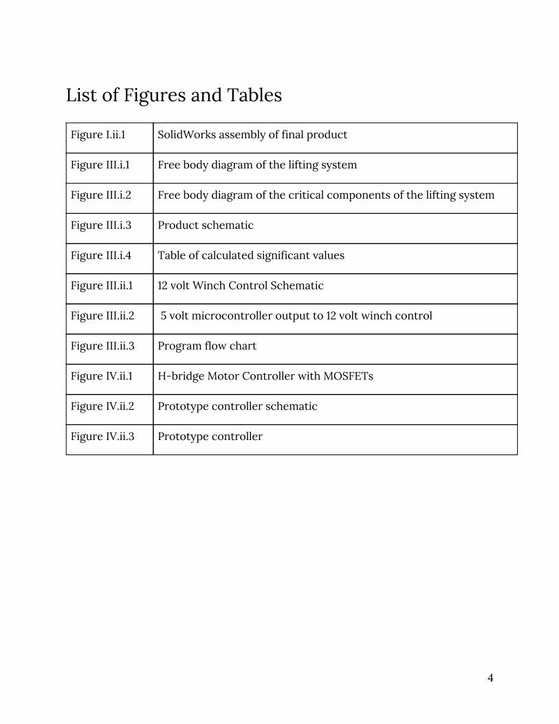
List of Figures and Tables
Figure I.ii.1 SolidWorks assembly of final product
Figure III.i.1 Free body diagram of the lifting system
Figure III.i.2 Free body diagram of the critical components of the lifting system
Figure III.i.3 Product schematic
Figure III.i.4 Table of calculated significant values
Figure III.ii.1 12 volt Winch Control Schematic
Figure III.ii.2 5 volt microcontroller output to 12 volt winch control
Figure III.ii.3 Program flow chart
Figure IV.ii.1 H-bridge Motor Controller with MOSFETs
Figure IV.ii.2 Prototype controller schematic
Figure IV.ii.3 Prototype controller
4

I. Introduction According to the United Nations, between 80 and 85 percent of people in the
United States are living in areas classified as urban. This figure is projected to reach
approximately 90 percent by the year 2050, which is a stark change from the low
65 percent in the year 1950 [1]. With this increasing migration of the population to
urban areas, people are choosing to live in highrise buildings and giving up the
luxury of owning vehicles. This trend of vertical urbanization has caused a boom in
the moving company industry, which saw a 2.4 percent increase between the years
2017 and 2018, with an industry revenue peak of 18 billion dollars [2]. This mass
exodus into multi-residence buildings with many levels of stairs and no elevators is
the root of our problem.
i. Problem Statement
When moving into multi-level buildings, there is a question of how heavy
furniture and appliances will be carried up to a residence on an upper level without
the assistance of an elevator. Moving companies charge high rates due to the time,
liability, and physical stress it takes to move furniture, mattresses, pianos, and
other heavy objects up multiple flights of stairs. However, moving into a residence
on any floor above ground is unrealistic without the help of professionals.
ii. Proposed Solution
Our solution to this problem is the creation of a powered modular assistive
lift that can be used by movers of all types and can be installed easily and quickly on
any straight set of stairs. Our objective is to develop a powered non-permanent lift
that is easy to install and uninstall, with a simple and modular design that is
designed to fit any length of straight stairs using a telescopic final rail. It limits the
problem of movers causing damage to themselves or the items being moved when
5
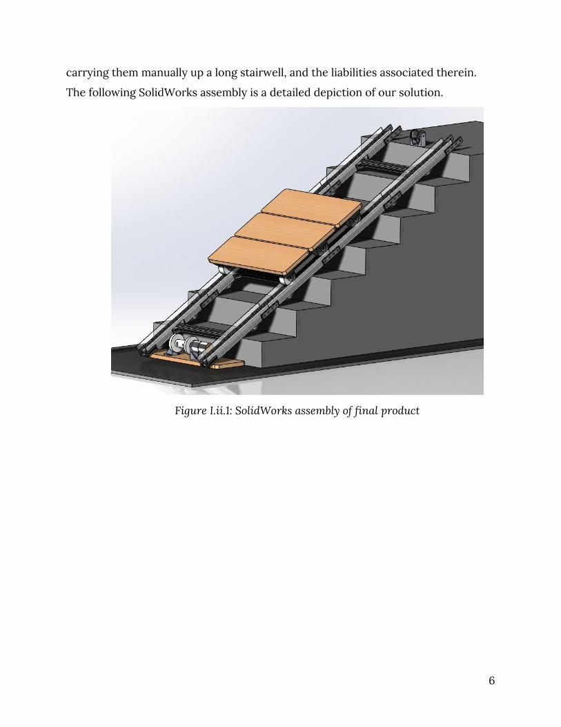
carrying them manually up a long stairwell, and the liabilities associated therein.
The following SolidWorks assembly is a detailed depiction of our solution.
Figure I.ii.1: SolidWorks assembly of final product
6

II. Methodology Below we will discuss both what the requirements are for our product and
the methods we used to decide on how to fulfill those requirements.
i. Mechanical
With our goal of creating a powered non-permanent lift to assist in moving
burdensome objects up flights of stairs, we had many mechanical aspects and
functions to consider. There were several requirements that needed to be met in
order to generate a product that would effectively perform the role of our
proposed solution. First, we considered the construction of our product, namely
the three sections involved: embarkation, straight stairs, and disembarkation.
This year, we mainly focused on the design of the rail section that moves the
object up the stairs, the straight rail section. This construction included the rails
themselves, considering the cross-section of the bars and the connection between
consecutive bars. Then, we considered the cross-bars necessary for stabilization
and for ensuring that the rails can not translate or rotate when they are bearing a
load. Finally, we iterated through designs of the cart that would carry the load. This
included the cart itself as well as the wheels and the connection to the winch.
Our final consideration was the materials that would be used for each of the
components mentioned above. For the rails and crossbars, we considered various
load-bearing metals. For the cart and wheels, we considered many materials, all
strong enough to withstand the weight of the heaviest loads rated for our product.
All of the above features were deliberated keeping in mind the safety,
efficacy, portability, manufacturability, and efficiency of set up and take down time.
These goals were important in the designs of all of the final products.
In the following subsection, the methods we used to determine the electrical
requirements for our product will be discussed.
7

ii. Electrical
The electrical subsystem for the portable stair lift system is a complex set of
components. There is no off-the-shelf solution that would fulfill every function
necessary. The solution needed to be designed from the ground up considering
many requirements. By evaluating the minimum requirements for the system to
function and considering the needs of the user, the following list of product
requirements was developed: safe, robust and reliable, portable, easy to use, low
cost.
First and foremost, the lift needs to be safe. No failure of the electrical
system should result in an unsafe situation, and further, the electrical system
should not allow for any unsafe operation to occur. The system must be protected
against reasonable faults but unexpected faults should bring the lift system to a safe
state (i.e. stopped).
The lift system should reliably lift and lower the cart up and down the rails.
Additionally, customers will be using this product in order to avoid lifting the items
themselves. To be reliable, the electrical system must be robust. A part being
dropped or a small voltage surge should not impact the operation of the product.
The electronics must be designed within reasonable limits to handle conditions
outside the optimal ranges.
The lift system may be set up, used, taken down, moved, and set up again
multiple times per day. The electronics must therefore be easily portable. Nothing
should require extraneous time to connect or set up. It also should be configurable
in different ways to allow for maximum flexibility in operation. For instance, in the
case that there is no outlet near where the lift system is needed, it could be run on
battery power.
A diverse selection of people with varying skill levels will be using this
product. Therefore, both the setup and control system should be intuitive and easy
8

to use. A complicated setup or user interface could result in a dissatisfactory
experience in using the product and turn customers away from future use.
Since much of the purpose of this project is to lower the cost of moving
companies’ services, we have decided to prioritize low cost of the system. By
integrating existing products, the electrical system can minimize cost while still
maintaining high levels of safety and functionality.
9

III. Design In this section, we will illustrate the design choices we made for our product
and the reasoning behind them.
i. Mechanical
As mentioned in section II.i, the mechanical components of our product had
to be taken into careful consideration. Mathematical calculations and estimations
were performed by our team members to complete an analysis thorough enough to
ensure the safety and efficacy of our product. In addition, qualitative and
observational data was considered and weighed in our design process.
When performing analyses on our product, we started with the basics of our
machine. Below, in Figures III.i.1 and III.i.2, free body diagrams of our complete
product and of its critical components are shown.
Figure III.i.1: Free body diagram of the lifting system [3]
10
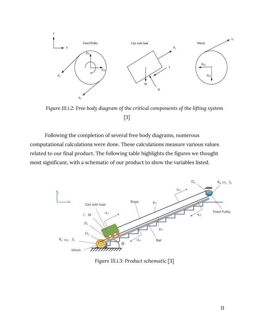
Figure III.i.2: Free body diagram of the critical components of the lifting system
[3]
Following the completion of several free body diagrams, numerous
computational calculations were done. These calculations measure various values
related to our final product. The following table highlights the figures we thought
most significant, with a schematic of our product to show the variables listed.
Figure III.i.3: Product schematic [3]
11

Variable Value Units Meaning
V cart 0.038 m/s Velocity of cart
D 1 44.66 Ns/m Damping coefficient
D 2 0.437 Nm/rad/s Damping coefficient
D 3 0.25 Ns/m Damping coefficient
D A1-D output 0.3 Nm/rad/s Damping coefficient
K output 1203.31 N/m Shaft stiffness
K winch 1195.31 N/m Shaft stiffness
K 1, K 2 1862.03 N/m Shaft stiffness
K a 491.13 N/m Shaft stiffness
K s 8.08 N/m Shaft stiffness
L 1.2 m Length
θ 30 degrees Angle from floor to stair surface Figure III.i.4: Table of calculated significant values [3]
Our next design choice was the material we used in our final product. When
iterating through choices, we considered many metal options. Eventually, we
decided on steel and purchased a sample. Upon receiving the sample, we realized
that the steel was too heavy to support the portability of our product. Because of
this, we decided on aluminum rails and crossbars.
For the cart, we also chose aluminum, because of its versatility, low cost, and
low mass. As a protective layer on the cart and to decrease the chance of damage to
the load, we chose to add a sheet of rubber. This will give the load a cushioned area
to rest while being lifted on the rails. As for the wheels, we have chosen to use hard
rubber wheels. These will be strong enough to hold the weight of the object and the
12

cart, but not so sharp that they would cause damage to the floor during
embarkation or disembarkation.
Finally, for the pulleys and the cord attached to the winch, we have decided
to use steel and steel cable, respectively. These objects need to be completely fail
safe, and are the most imperative to be strong. This is why we chose steel for each
of these, despite the cost and the weight associated.
In the following section, the design choices made for the electrical
components of our product will be discussed. This section will, in detail, illustrate
the electrical construction of the product and the basis on which we made these
decisions.
ii. Electrical
The electrical system for our product can be broken down into three main
pieces: the lifting mechanism, the power supply, and the controller. Each part was
carefully designed to fulfill the electrical product requirements as outlined in the
previous section. The lifting mechanism was chosen first, as the requirements for a
power supply and controller would need to be based on supplying power for and
interfacing with it.
a. Lifting Mechanism
The lifting mechanism, as explained in the mechanical design section above,
consists of a steel cable running through a pulley system at the top of the rails. The
cable is pulled from the bottom, moving the cart up the rails. There are a number of
ways of pulling this cable, the most common being the use of a motor to wrap the
cable around a drum (i.e. a winch).
First, we had to consider whether to use a commercially available winch or to
design our own. By designing our own we would have more control over the winch
and could specify exactly which motor and control electronics to use. However, we
would also need to design the gear system, brake system, and many other
13

intricacies that have already been determined in commercial products. The winch
is a critical part of the product. Failure of the motor would result in a stopped cart
that would be difficult to unload if it were in the middle of the staircase. Failure of
the brake system could result in substantial damages. Considering this, we decided
to use a commercially available winch.
There are two basic types of winches, those that run on AC power and those
that run on DC power. AC winches require a specified voltage and frequency for the
motor inside, therefore different winches would be required for operation in
countries with differing types of power available. AC winches would need to be run
on power from an outlet, requiring an extension cord for locations that were not
near one. DC winches are almost universally run on 12 volts DC power which can be
generated by power supplies (input requirements can have a wide range to account
for different countries' power) or supplied by a battery. To allow increased
flexibility and portability, a DC winch will be used.
DC winches can be based on either a permanent magnet motor or series
wound motor. In a permanent magnet motor the stator is composed of permanent
magnets whereas in a series wound motor the stator is made up of field coils
wound in series with the armature. The permanent magnet motor requires less
current as it does not need to power the field coils, but magnets may lose their
strength over time and these motors are generally used for lighter duty
applications. Given these tradeoffs, a winch with a permanent magnet motor was
chosen for its lower current requirements.
b. Power Supply
The power supply needs to provide power for both the winch and the
controller. The winch, as discussed above, requires 12 volts DC. The controller will
run on lower voltage which can be generated using a DC-DC buck converter. A 12
volt DC winch requires high amounts of current, upwards of 150 amps when loaded
to full capacity.
14

A standalone AC-DC converter that can supply 150 amps at 12 volts would be
very expensive. Additionally, without considering power losses, such a power
supply would require 1800 watts from the AC side. This is equivalent to a 15 amp
circuit common in houses. Running the winch for a long period of time or using a
circuit with other loads already on it could result in tripped circuit breakers.
In general, 12 volt DC winches are designed for use on vehicles where the
power is supplied by the battery. Vehicle batteries are typically sealed lead-acid
batteries, are capable of supplying high currents on demand, and come in varying
capacities. To allow for longer operation, a battery charger could be plugged into
the wall. The battery charger would require much less power from the outlet as it is
able to deliver the power to the battery over a long time while the battery supplies
the high demand of the winch for shorter intervals. This configuration also allows
for lower cost and more portability.
c. Controller
The controller is the part the user will interact with most often. It must be
robust, reliable, and easy to use. A commercially available winch typically comes
with a controller that allows the user to operate the winch. It is wired to the winch
and has two buttons, one for in (up the rails) and one for out (down the rails).
However, there is not any way to automatically stop the winch when it gets to a
certain point or add any other automation. To do this, a custom controller is
required.
The easiest way to implement a custom controller is to mimic the existing
controller. To do this, we must first understand how a winch works and how the
existing controller interfaces with it.
A winch has a motor which must be run in both directions based on user
input. To do this, an H-bridge driver is typically used. Due to the extremely high
current requirements, mechanical relays are used. As seen in Figure III.ii.1 below,
when relays 1 and 4 are activated, the electricity flows through the motor from
15

positive to negative and it rotates in one direction. When relays 2 and 3 are
activated, the electricity flows through the motor from negative to positive and it
rotates in the opposite direction. The controller consists of a single pole double
throw (SPDT) switch; the pole is connected to 12 volts and the two throws are
connected to each of the two pairs of relays described above.
Figure III.ii.1: 12 volt Winch Control Schematic
To mimic this switch, transistors can be used to apply 12 volts to the relays.
Two P-channel metal-oxide-semiconductor field-effect transistors (MOSFETs) will
be connected to the relays similar to how the SPDT switch is connected. When 12
volts are applied to the gate of the MOSFET, the “switch” is off. When 0 volts is
applied, the “switch” is on. To drive the gates to 12 volts using a microcontroller
(which operates at 5 volts), a NPN bipolar junction transistor (BJT) is used as seen
below in Figure III.ii.2. Now we have a system that can be connected to the winch in
place of the existing controller. This is useful as it requires no modification of the
16

winch and allows for sensors to be connected to the microcontroller for more
advanced operation.
Figure III.ii.2: 5 volt microcontroller output to 12 volt winch control
When operating, the winch should only run between the limits of the top and
bottom of the rail. It should not continue to pull the cart once the cart has reached
the top or continue to let out cable when the cart is at the bottom. To know when
the cart is at the top and bottom, limit switches will be attached to the rails. When
the limit switch at the top is activated the controller will only allow the winch to
lower the cart and when the limit switch at the bottom is activated the controller
will only allow the winch to raise the cart.
The limit switches used will be normally closed switches, that is when
unpressed, the circuit is closed and when pressed, the circuit is open. The limit
switches will be connected to 5 volts on one side and an input on the
microcontroller on the other. When the microcontroller senses 0 volts on the input
17

(open circuit from the limit switch being pressed), it will not allow the winch to
move in the respective direction. This configuration is fail-safe as any break in the
wire would look the same as the limit switch being pressed instead of no longer
being able to register it being pressed.
The controller will have a user interface consisting of two buttons, a rotary
encoder with a switch, and a small LCD. The two buttons will act like a normal
winch control, one for up and one for down. By using a SPDT switch, only one
direction will be able to be activated at a time. The LCD will be used to show the
status of the device to the user and the rotary encoder will be used for user input
such as acknowledging fault conditions or changing settings. The custom controller
will be housed in a protective plastic case. A flow diagram of the program control
can be seen in Figure III.ii.3 below.
Figure III.ii.3: Program flow chart
18

The three parts of the electrical system work together to provide a low cost,
safe, and user friendly portable stair lift.
19

IV. Implementation The following section will be an explanation of our prototype and the
realization we completed on this phase of our project.
i. Mechanical
For our initial prototype, we chose to build a small-scale model of our
machine. This model was not made completely to scale because we used the
actual-sized aluminum rails as well as crossbars and fixtures. However, the cart and
the length and width of the model were made scaled down. This way, we could
analyze the ability of the cart to navigate up the rails, without building a full-size
model. In this model, we used inexpensive and accessible materials in order to
fashion our cart. This included birch plywood as the base of the cart, rubber drawer
protectors, small rubber wheels, and piano hinges to hold the wood together and to
increase ease of embarkation and disembarkation. From what was completed, the
model design was successful. The section below discusses the electrical
components of our semi-scaled prototype.
ii. Electrical
An electrical system for the small-scale mode was designed and built. The
model electrical system consists of a motor, a motor control circuit, the
microcontroller, and buttons for user input. The motor control circuitry was
designed to be functionally equivalent to a winch that would be used in the final
product to help more accurately design the microcontroller software.
A small 12 volt DC motor was purchased for the model. The type of hobby
motor used is a “geared motor”, it is a high speed brushed DC motor connected to
an internal planetary gear system to reduce the spindle speed to 50 RPM
(revolutions per minute). To control the motor, an H-bridge driver was built using
20

MOSFETs. Two P-channel MOSFETs make up the high voltage side of the bridge
(the side between the motor and the 12 volt supply) and two N-channel MOSFETs
make up the low voltage side (between the motor and ground). By alternating which
pair of MOSFETs is “on” at a time the motor can be controlled to rotate in either
direction.
The N-channel MOSFETs act similarly to relays; when 0 volts are applied to
the gate they are off and when 12 volts are applied they are on. For the P-channel
MOSFETs, however, this is inverted. To allow the P-channel MOSFETs to be
controlled as relays would be, an inverter using complementary MOSFETs was
added to the gate input. With the inverter, a 0 volt input would result in a 12 volt
output to the MOSFET’s gate, turning it off and a 12 volt input would result in a 0
volt output, turning the MOSFET on. Opposing pairs of MOSFETs are connected
together, resulting in two control lines. Now, the H-bridge driver and motor system
seen below in Figure IV.ii.1 are functionally equivalent to a winch.
Figure IV.ii.1: H-bridge Motor Controller with MOSFETs
21

An Arduino, a popular microcontroller development board, was used for the
prototype. Four pushbuttons are connected to inputs on the Arduino, two to
simulate the SPDT switch and two to act as the limit switches. Two Arduino outputs
drive NPN transistors which in turn drive P-channel MOSFETs connected to the 12
volt supply to turn on and off the two control lines. The microcontroller is
programmed almost the same as it would be on the product with two main
differences: it checks the two user input buttons exclusively (would not be
necessary on the product as the SPDT switch does this by design) and there is no
LCD (the Arduino is connected to a computer and the Serial Monitor function is
used instead). The complete electrical prototype can be seen in the figures below.
22

Figure IV.ii.2: Prototype controller schematic
23

Figure IV.ii.3: Prototype controller
The current prototype worked as a test of the 5 volt to 12 volt driver circuit
and the microcontroller code. It can be used in the future as a test bed for
additional features, such as more sensors or a different user interface.
24

V. Plans Going Forward The team this year was composed of both third-year and fourth-year
students. This year, we designed a basic, straight rail system, a cart, a lifting
mechanism, and a controller. Next year, the remaining students will continue
working on the project, developing it further and adding more features. The main
goal for next year is to design the system so it will work on stairs with a corner or
turn in the middle of them. Additional design goals include simpler assembly and
disassembly, increased load capacity, and reduction of cost to manufacture.
25

VI. Conclusion In recent decades, there has been a mass migration of the U.S. population
from rural to urban areas, especially presenting itself in younger generations. With
so many people moving into cities that, comparably, have a lot less space for
residences, the solution has been to build vertically. People are moving into homes
built in highrises, many of them lacking elevators. This has caused an upsurge in the
moving company industry, which routinely charges high fees for moving heavy
objects up multiple flights of stairs. These high prices are due to the time, effort,
physical strain, and liability associated with the moving process. Our solution is to
create a product that could aid movers in transporting cumbersome items up
flights of stairs efficiently, effectively, and at a low cost.
To accomplish this, we designed a powered portable assistive lift. This
machine will be able to be set up and taken down in less than an hour, will move
objects up to 800 pounds up any straight set of stairs, and will use the power of an
electric winch to do so. This product will be modular, and hence will be able to fit
on any set of stairs without turns or curves. This design is made for movers to bring
to multiple establishments per day to make moving into multi-level buildings many
times easier.
This project will continue into next year, with members of our team
continuing on. We hope to improve upon our product until it is able to perform
many types of stairs, including ones with turns. We also hope to make the design
simpler in set-up and take-down and more affordable. This year, our completed
project is merely the base model of what our team hopes to accomplish in the
future.
26

References
[1] “World Urbanization Prospects - Population Division,” United Nations . [Online].
Available: https://population.un.org/wup/Country-Profiles/ . [Accessed:
15-May-2020].
[2] M. C., “Moving Trends & Relocation Industry Analysis,” Movers Development ,
07-May-2020. [Online]. Available:
https://moversdev.com/moving-trends-analysis/. [Accessed: 15-May-2020].
[3] Z. Huang, L. Zhang, and M. Zhu, “Portable Heavy Load Lifting Mechanism.”
27