Dormitory Design Project - Worcester Polytechnic Institute
234
LDA-1303\LDA-1307 This report represents the work of WPI undergraduate students. It has been submitted to the faculty as evidence of completion of a degree requirement. WPI publishes these reports on its website without editorial or peer review. Any opinions expressed herein reflect the views of the student authors and are not representative of the views of WPI or its personnel. Worcester Polytechnic Institute: Dormitory Design Project Major Qualifying Project Submitted by: Corey Fisher Kelsey Forward Shane Ruddy Date Submitted: April 25, 2013 Approved: Professor Leonard Albano
-
Upload
khangminh22 -
Category
Documents
-
view
5 -
download
0
Transcript of Dormitory Design Project - Worcester Polytechnic Institute
LDA-1303\LDA-1307
This report represents the work of WPI undergraduate students. It has been submitted to the faculty as evidence of completion of a degree requirement. WPI publishes these
reports on its website without editorial or peer review. Any opinions expressed herein reflect the views of the student authors and are not representative of the views of WPI or
its personnel.
Worcester Polytechnic Institute:
Dormitory Design Project
Major Qualifying Project
Submitted by:
Corey Fisher
Kelsey Forward
Shane Ruddy
Date Submitted:
April 25, 2013
Approved:
Professor Leonard Albano

i
ABSTRACT This project compared and provided steel and precast concrete structural systems for the
new dormitory for Worcester Polytechnic Institute., in compliance with ASCE 7, AISC, ACI,
MSBC, and NFPA provisions. The various components of both gravity and lateral loading were
addressed. This project provided cost and performance analyses on both designs and explored the
role LEED requirements played in the design. Included are investigations into footing designs,
scheduling constraints, and the social and political impacts of the project. A sprinkler system was
designed using different materials, and comparisons were made to determine the most cost
effective and safe design. To conclude, a code compliance discussion and review of the different
life safety aspects of the building was completed.
ii
EXECUTIVE SUMMARY Colleges across the nation have been increasing residency capacities on their campuses.
Some of the motivating factors have been safety of students and the desirability of on-campus
housing for undergraduate and graduate students. Another reason for the increase of capacity is
that colleges are expanding to accept more students for both undergraduate and graduate studies.
Worcester Polytechnic Institute has been continuously growing and expanding the campus and
community, which means that new construction is inevitable. Gateway Park, located along
Interstate 290, has become an answer to WPI’s push to expand and help redevelop a deteriorated
area of Worcester. Rising numbers of students in recent years have meant the need for additional
housing as well. The construction of East Hall (finished in 2008) was one solution to this issue.
More recently, the construction of the residence hall at 10 Faraday Street in Gateway Park was
another project that would ease the housing strains of an expanding campus. This new residence
hall was designed for upperclassmen and graduate students, and was placed in a prime location
close to research laboratories.
A residence hall must contain separate spaces for its occupants, including bedrooms,
kitchens, bathrooms, and living spaces. Residence halls also usually include a number of
supporting spaces, such as corridors, entryways, mechanical rooms, storage, common areas, and
laundry facilities. For this project, the new Faraday residence hall was used as the basis for design.
Elements in the Faraday residence hall were used to further investigate the building design criteria.
The layout of the new dormitory includes suite-style apartments with kitchens and separate
bathrooms and common areas used as technology suites. The nature of the layout and room style
imposes complications for plumbing, mechanical, and fire protection layouts. One major
complication is the system integrations since the various rooms require different plumbing needs,
unlike single room dormitories in which a bank of plumbing serves one or two locations in the
building. Plumbing, mechanical, electrical, and the fire protection design must be integrated to
ensure ease of construction, and this imposes limitations on the building and the architectural
layout.
This report focused on the building design and evaluation of the new dormitory, examining
the structural aspects of the current construction, as well as environmental issues, fire protection,
and alternative construction options. The new residence hall has been constructed by Daniel
iii
O’Connell’s Son, Inc. (DOC) using structural steel framing; this report re-creates the steel design
process, while posing the use of precast construction as an alternative construction material.
The design of any building takes much thought, analysis, and research, and the new
dormitory was no exception. The dormitory design developed in this report first required an
understanding of the architectural layouts that had been established by DOC to recognize the
geometry imposed on the columns, girders, and beams. As is true for all construction projects
taking place in the state of Massachusetts, the building must meet the requirements set forth by the
Massachusetts State Building Code (MSBC). All aspects of construction were addressed, such as
means of egress, concrete construction, steel construction, etc., and these standards were essential
to the validity of the structural design and the design of the life safety aspects of the structure.
Construction projects also require the use of national standards. This report relied on the
use of the American Institute of Steel Construction (AISC), the American Concrete Institute (ACI),
the American Society of Civil Engineering Standards (ASCE 7), the Precast/Prestressed
Concrete Institute (PCI), and the National Fire Protection Association (NFPA, particularly:
NFPA 13, NFPA 14, and NFPA 20). The fourteenth edition of the Steel Construction Manual
published by the AISC was used to establish properly sized steel members, while PCI tables were
used to select the appropriate precast concrete members. All design calculations relied on the
standards set forth by these organizations, as well as the limitations set forth by Load and
Resistance Factor Design (LRFD).
Design loads for both gravity and lateral loading were investigated using RISA-2D
software, Excel spreadsheets, and hand calculations. Due to the unique shape of the building and
the parapet around its roof, the loading was complicated to determine. Snow drifting and the
varying pressure effects caused by different wind directions were considered. In areas where the
loading patterns were quite variable (such as snow drift locations), the larger values were used to
standardize member sizes and promote constructability. Constructability refers to reducing the
complexity of construction, and a common strategy is to create typical sections of the frame that
involve less variation.
Steel girder sizes had to be adjusted after the steel lateral bracing analysis was completed.
Using RISA-2D and the second-order analysis process, member sizes for the steel bracing were
selected; however, varying sizes of the bracing members and girders presented connection issues.

iv
The adjustment of girder sizes was the most reasonable solution. Typical designs for footings and
base plates were the final elements of the structural steel design. Equations were used to start the
design, but common sense and an understanding of the dimensions of the columns and footing
supports were necessary to make modifications to the calculated dimensions.
Since the architectural layout that was followed for this project was the same as that
produced by DOC, the steel beam, girder, and column sizes determined in this report could be
compared to the member sizes used in DOC’s structural plan to compare and contrast design
decisions. A 3D Revit Model was developed to better visualize the completed steel design.
To expand on the design possibilities, a precast concrete design was established as well;
this was done using information from the Precast/Prestressed Concrete Institute. The layout of the
concrete members was adjusted and discussed in an effort to select the most efficient design
option. The reduction of the number of concrete members used was incorporated, and the limits
introduced by precast concrete member connections were addressed.
With a structural outline of the building completed, fire protection aspects were addressed.
The first aspect dealt with a code review of the plans. This review was based upon the applicable
fire safety codes for the Commonwealth of Massachusetts, and these references included the
Massachusetts State Building Code (MSBC) and the Massachusetts State Fire Code. These codes
describe the many active fire protection features, such as sprinkler systems, fire alarm systems, and
smoke management systems, that are required installations in particular buildings; they also
address the many passive fire protection features, such as the construction of fire walls and smoke
barriers, and various fire resistance rating requirements. Review of these elements was necessary to
determine whether the building was compliant with the applicable codes and standards. The second
aspect of fire protection that was addressed was a design of the sprinkler system required by the
MSBC. The sprinkler system was designed in accordance with NFPA 13: Standard for the
Installation of Sprinkler Systems. NFPA 13 is referenced by the MSBC as the manner in which to
install a sprinkler system fit for the project. The sprinkler system was designed and laid out based
upon the expected hazards and use of the building. Using these hazards and the appropriate fluid
mechanics equations, specific sprinklers, fittings, and piping were defined for the system.
By addressing such a variety of aspects of the structural design of the dormitory, a much
better understanding was gained on the interconnections amongst the various facets of design. In

v
addition to the structural design options and the fire safety systems, project schedule and cost
estimates were investigated to illustrate the construction management aspects of the residence hall
project. Cost comparisons between precast concrete and steel design were important to display the
variations in these design materials. RS Means publications were used to determine the costs of the
designed elements; they were also used to project an estimation of the total cost of the project. In
order to gain a better understanding of the construction timetable, the schedule created by DOC
was analyzed and compacted to make it more comprehensible to the reader.
While creating a project that can be completed within the established timeframe and budget
is important, following proper safety and environmental regulations is just as essential. This report
looked into these features of the project by detailing the important LEED credits met in the
dormitory construction process. Many people do not fully understand the role LEED plays in
modern day construction; therefore, this report focused on educating readers on the topic and
illustrating its importance. Codes set forth by the MSBC direct projects into safe and acceptable
environments for their residents. The codes that must be followed can be complicated and detailed.
In an effort to simplify and explain the main regulations, a section of the report was dedicated to
code compliance issues. These policies cannot be overlooked, because it is these codes that insure
that the building will be safe for the large number of people that will be passing in and out of its
doors every day.
The topic of people presents yet another issue that accompanies any large project located
within a town or city: impacts, both social and political. New buildings have neighbors and affect
those around them; this means that buildings cannot be constructed without considering the effect
they will have on their surroundings. The beauty of construction is that the addition of one
structure can affect thousands of people in very positive ways. The new residence hall will play a
significant role in the redevelopment of downtown Worcester by bringing a large population of
young people closer to the heart of the city. By interviewing the general manager at the Marriot
Courtyard Hotel across from the dormitory, as well as a councilman of Worcester, it was
determined that the new residence hall will be a large addition to the push to revitalize Worcester.
Not only will the dormitory improve and enhance life on the Worcester Polytechnic Institute
campus, it will also enrich and energize the quiet downtown area of Worcester.

vi
In conclusion, this design gave us a better understanding of the scale and resources
necessary for a project such as this one. This project has outlined all the intricacies of design
projects and shows how all the systems interconnect with one another. Several aspects of the
project, such as lateral loading and snow loading, provided challenges during the design process
and proved to be more difficult once the topics themselves were thoroughly addressed. If one small
aspect of the structural design were to change, many other aspects were adjusted because of this
small change. Additionally, we were able to see that the project affects many other entities besides
WPI. The social implications of the project extend far beyond the WPI community and have a
great impact on the continuing improvements of the City of Worcester.
vii
AUTHORSHIP

viii
CAPSTONE DESIGN STATEMENT In order to address engineering designs and the constraints faced in engineering projects,
this report considers a number of specific constraints that are relevant and timely in the design of
the new residence hall and all real-world projects. The problem this report addressed is how to
effectively design a large, residential building in Gateway Park. Architectural layouts and different
structural layouts were also designed as needed to accommodate both steel and concrete structures.
Both concrete and steel structures were designed for the basis of comparison. Scheduling and cost
needed to be analyzed as well to make sure the project would be able to meet required deadlines
and to gain an understanding of the project management aspects of the construction process. Fire
safety aspects were examined by addressing the needs of a sprinkler system and compliance with
state and local fire codes. In order to evaluate the impacts the construction would have on the
environment, LEED aspects were investigated. The realistic constraints addressed in this report
include: economic, environmental, sustainability, ethical, health and safety, social, and political.
Economic: The financial aspect of construction is a significant factor in the building of the new
residence hall and is addressed continuously throughout the report. The costs for steel construction
and precast concrete construction were investigated to add to the comparison of both structures.
This project analyzed the cost of construction, outlined the cost for structural materials and other
elements used in the building (electrical work, plumbing, furnishing, etc.), and determined labor
costs. Square foot costs for different aspects of construction were calculated. Additionally, the
costs of specific materials for the life safety systems were investigated, such as piping material and
sprinkler heads. The investigation determined whether or not different and lower cost materials
were able to provide the same level of safety compared to what is typical for a building of this
type.
Environmental: Throughout the construction process, environmental aspects created another
constraint. The construction site plan addressed this by outlining strategies to mitigate the negative
impacts on the environment.
Sustainability: Sustainability has become increasingly important in many large construction
projects, and the new residence hall is no exception. Following in the footsteps of the Bartlett
Center, East Hall, and the new athletic facility, the new residence hall will be LEED certified.

ix
Therefore, this report addressed several of the LEED certification requirements and what they
entailed.
Ethical: This project addressed the construction of the new residence hall using the most up-to-
date technology. For scheduling, cost estimating, and modeling, state-of-the-art technology was
used including Revit 2013 and Primavera. The design loads are based on the most recent ASCE 7
standards, and the building is designed to safely withstand all of these loads.
Health and Safety: Ensuring that the building is safe and healthy for its occupants is addressed in
this project. Using the MSBC, the building layout was analyzed to ensure that safety requirements
were met, such as proper hallway and stairwell widths and the number of emergency exits. Other
life safety requirements, such as fire resistance ratings, occupant loads, and height and area
requirements of the MSBC, and their associated criteria for the new residence hall were addressed.
Fireproofing of the steel members and analyzing seismic, wind, and gravity loads based on ASCE 7
design loads was also completed to meet this requirement.
Social: To address the social aspect of this project, the effect of this addition on the WPI
community was investigated. The neighbors directly surrounding the building, including the
Courtyard Marriott Hotel, were interviewed, and an analysis was done to determine the impact the
new dormitory project will have on them. The social constraint focused on how the new dormitory
project will affect everyday life for those living in the area and/or attending WPI.
Political: Large construction projects are not always accepted by the neighboring residents and/or
communities. The new residence hall will have an impact on the redevelopment of downtown
Worcester, and, therefore, required an evaluation of how it would fit into the City. The new
residence hall will bring more students even closer to the downtown area yet it is only a small part
of the redevelopment taking place at Gateway Park. The report investigated how leaders of the City
feel about this project and some of the political steps that are necessary to make construction
possible. This includes permits and land acquisition for Gateway Park, which encompasses the
specific area of the new residence hall.

x
TABLE OF CONTENTS
Abstract ........................................................................................................................................................ i
Executive Summary ................................................................................................................................ ii
Authorship .............................................................................................................................................. vii
Capstone Design Statement ............................................................................................................. viii
Table of Figures .................................................................................................................................... xiv
Table of Tables ..................................................................................................................................... xvi
Table of Equations .............................................................................................................................. xvii
1.0 Introduction ....................................................................................................................................... 1
2.0 Background ........................................................................................................................................ 4
2.1 Layouts ............................................................................................................................................ 4
2.2 Massachusetts State Building Code ....................................................................................... 6
2.3 Zoning .............................................................................................................................................. 8
2.4 Design Standards and Specifications .................................................................................... 9
2.5 Cost Analysis ............................................................................................................................... 10
2.6 Footing and Foundation Design Factors ........................................................................... 11
2.7 Leadership in Energy and Environmental Design (LEED) ......................................... 12
3.0 Methodology .................................................................................................................................... 13
3.1 Architectural Layout and Structural Design Basis ........................................................ 13
3.2 Steel Design versus Precast Concrete Design ................................................................. 14
3.3 Lateral Design ............................................................................................................................ 14
3.4 Footing Design ........................................................................................................................... 15

xi
3.5 LEED Investigation ................................................................................................................... 15
3.6 Construction Schedule ............................................................................................................ 15
3.7 Cost Estimation .......................................................................................................................... 15
3.8 Environmental ........................................................................................................................... 15
3.9 Political and Social Impacts .................................................................................................. 15
3.10 Sprinkler System Design ..................................................................................................... 16
3.11 Code Review ............................................................................................................................. 16
4.0 Structural Design Criteria and Assumptions ....................................................................... 17
4.1 Structural Design Loads ......................................................................................................... 17
4.1.1 Snow Loads .............................................................................................................................. 18
4.1.2 Lateral Loads .......................................................................................................................... 20
4.2 Structural Steel Design ........................................................................................................... 28
4.2.1 Steel Bracing ........................................................................................................................... 31
4.3 Precast Concrete Design......................................................................................................... 36
4.4 Footing Design ........................................................................................................................... 40
4.5 Sprinkler System Design ........................................................................................................ 41
5.0 Design Results ................................................................................................................................ 45
5.1 Structural Steel Design ........................................................................................................... 45
5.1.2 Steel Bracing Member Selection ...................................................................................... 52
5.2 Precast Concrete Design......................................................................................................... 54
5.3 Footing Design ........................................................................................................................... 59
5.4 Steel Versus Precast Concrete .............................................................................................. 60
6.0 Consideration of LEED Certification ....................................................................................... 65

xii
7.0 Scheduling ........................................................................................................................................ 67
8.0 Sprinkler Design and Layout ..................................................................................................... 71
8.1 System Selection ....................................................................................................................... 71
8.2 Sprinkler Selection ................................................................................................................... 71
8.3 Sprinkler Comparison ............................................................................................................. 72
8.4 Sprinkler Layout ....................................................................................................................... 75
9.0 Cost Estimation .............................................................................................................................. 79
10.0 Code Compliance Review ......................................................................................................... 82
10.1 Applicable Codes and Standards ...................................................................................... 82
10.2 Building Overview ................................................................................................................. 82
10.3 Height and Area ...................................................................................................................... 83
10.4 Fire Separation Characteristics ........................................................................................ 84
10.5 Means of Egress....................................................................................................................... 87
10.6 Occupant Load ......................................................................................................................... 87
10.7 Doors and Stairs ..................................................................................................................... 89
11.0 Consideration of Broader Impacts ....................................................................................... 91
11.1 Environmental Impacts ....................................................................................................... 91
11.2 Social Implications ................................................................................................................ 92
11.3 Political Implications ............................................................................................................ 93
12.0 Conclusions ................................................................................................................................... 96
References ............................................................................................................................................... 99
Appendix A.1 Proposal – Structural ............................................................................................. 103
Appendix A.2 Proposal – Fire Protection ................................................................................... 134

xiii
Appendix B.1 Calculations for Composite Decking ................................................................ 162
Appendix B.2 Calculations for Snow Loading ........................................................................... 163
Appendix B.3 Sample Calculation for Steel Design ................................................................. 165
Appendix B.4 Sample Calculation for Steel Beam Under Mechanical Screen Wall ..... 172
Appendix B.5 Sample Calculation for Concrete Design ......................................................... 183
Appendix C.1 Sample Spreadsheets for Wind Loading ......................................................... 186
Appendix C.2 Sample Spreadsheet for Seismic Loading ....................................................... 188
Appendix C.3 Sample Spreadsheet for Beam Steel Design .................................................. 189
Appendix C.4 Sample Spreadsheet for Girder Steel Design ................................................. 191
Appendix C.5 Sample Spreadsheet for Column Steel Design .............................................. 193
Appendix C.6 Sample Spreadsheet for RISA-2D Input - Weights ....................................... 194
Appendix C.7 Sample Spreadsheet For Effective Length Method ...................................... 195
Appendix C.8 Sample Spreadsheet for Footing Design ......................................................... 196
Appendix C.9 Spreadsheet of Beams and Cost for Steel Design ......................................... 197
Appendix C.10 Spreadsheet of Columns and Cost for Steel Design .................................. 202
Appendix C.11 Sprinkler Design Calculation Spreadsheet .................................................. 203
Appendix D.1 Various RISA-2D Load and Frame Analyses................................................... 205
Appendix D.2 LEED Credits Checklist .......................................................................................... 212
Appendix D.3 Complete Primavera Construction Schedule ................................................ 214
Appendix D.4 Schedule Data ........................................................................................................... 216

xiv
TABLE OF FIGURES Figure 1: Map of Innovation Square Growth District in Worcester (taken from “Growth District Communities”) ....... 2 Figure 2: Gateway Park Detailed Map (Taken from Gateway Park at WPI) ................................................................................. 3 Figure 3: Architectural Layout, First Floor ................................................................................................................................................. 5 Figure 4: Architectural Layout, Second Floor............................................................................................................................................. 6 Figure 5: Worcester Zoning Map (taken from City of Worcester (2012b). ..................................................................................... 8 Figure 6: Leeward and Windward Snow Drifts, Adapted FroM ASCE 7 ........................................................................................ 18 Figure 7: Surcharge Loading Due to Snow Drift Including Balance Snow Load, Adapted From ASCE 7 ........................ 19 Figure 8: Visual of Wind Loads Applied to Frame ................................................................................................................................. 21 Figure 9: Visual of Seismic Loads Applied to Frame ............................................................................................................................. 21 Figure 10: Division of Building for Wind Analysis and Depection of Windward, Leeward and SideWalls ..................... 24 Figure 11: Example of Tributary Area During Wind Loading, Taken From Lateral Force Resisting Systems-Braced
Frames..................................................................................................................................................................................................................... 25 Figure 12: Lateral Bracing Frame Locations .......................................................................................................................................... 26 Figure 13: North Elevation View of Mechanical Roof Column .......................................................................................................... 29 Figure 14: East Elevation View of Mechanical Roof Column ............................................................................................................. 30 Figure 15: Three Typical Lateral Braced Frames .................................................................................................................................. 32 Figure 16: Gravity Loading Cases ................................................................................................................................................................. 33 Figure 17: Lateral Loading ............................................................................................................................................................................. 34 Figure 18: Basic Load Cases from RISA-2D .............................................................................................................................................. 34 Figure 19: Load Combinations from RISA-2D ......................................................................................................................................... 35 Figure 20: Axial and Moment Diagrams Created using RISA-2D .................................................................................................... 35 Figure 21: Precast Concrete Connection Illustration ........................................................................................................................... 36 Figure 22: Precast Concrete Girder Layout .............................................................................................................................................. 37 Figure 23: Precast Concrete L-Beam, Taken from PCI Design Handbook .................................................................................... 37 Figure 24: Precast Concrete Inverted Tee-Beam, taken from PCI Design Handbook .............................................................. 38 Figure 25: Depiction of Two Main Tributary Areas .............................................................................................................................. 40 Figure 26: Layout of Design Area ................................................................................................................................................................. 44 Figure 27: Building Steel Layout and Wing Labels ............................................................................................................................... 45 Figure 28: Lancaster Street Wing, Wing 1 Steel Layout Roof ........................................................................................................... 46 Figure 29: Faraday Street Side, Main Building Steel Layout Roof .................................................................................................. 47 Figure 30: Grove Street Wing, Wing 2 Steel Layout Roof ................................................................................................................... 48 Figure 31: Lancaster Street Wing, Wing 1 Steel Layout Floors 2-4 ................................................................................................ 49 Figure 32: Faraday Street Side, Main Building Steel Layout Floors 2-4 ....................................................................................... 50 Figure 33: Grove Street Wing, Wing 2 Steel Layout Floors 2-4 ........................................................................................................ 51 Figure 34: Fixed End Connections For Lateral Braced Frame Created Using RISA-2D .......................................................... 53

xv
Figure 35: Pinned Connections For Lateral Braced Frame Created Using RISA-2D ................................................................ 53 Figure 36: Typical Steel Framing Plan ....................................................................................................................................................... 54 Figure 37: Hollow Core Precast Concrete Slab, Taken From PCI Design Handbook ................................................................ 55 Figure 38: Precast Concrete L-Beam, Taken From PCI Deisgn handbook ................................................................................... 56 Figure 39: Precast concrete Inverted Tee-Beam, Taken From PCI Deisgn handbook ............................................................. 57 Figure 40: Precast Concrete Rectangular Beam .................................................................................................................................... 58 Figure 41: Precast Concrete Column Possibilities .................................................................................................................................. 59 Figure 42: Typical Work Breakdown Structure (WBS) for Steel Construction, Taken From Construction
Management of Steel Construction .............................................................................................................................................................. 63 Figure 43: Primavera Construction Schedule .......................................................................................................................................... 68 Figure 44: Percentage of Total Time Required per Division.............................................................................................................. 69 Figure 45: Adequate Diesel Pump for Black Steel Design ................................................................................................................... 74 Figure 46: Adequate Electric Pump For CPVC Design .......................................................................................................................... 75 Figure 47: Typical Sprinkler Layout for RD Unit, Taken From DOC ............................................................................................... 76 Figure 48: Typical Sprinkler Layout for Four Person Suite, Taken From DOC ........................................................................... 76 Figure 49: Typical Sprinkler LAyout for Four Person Accessible Suite, Taken From Doc ...................................................... 77 Figure 50: Typical Sprinkler Layout for Single Suite, Taken from DOC ........................................................................................ 77 Figure 51: Ground FLoor Cooridor Sprinkler Layout, Taken From DOC ...................................................................................... 77 Figure 52: Floors 2-4 Typical Cooridor Sprinkler Layout, Taken from DOC ............................................................................... 78 Figure 53: Percentage of Construction Costs per Division ................................................................................................................. 81 Figure 54: Measure of Remoteness Exit Staircases ............................................................................................................................... 90

xvi
TABLE OF TABLES Table 1: Permitted Uses by Zoning Districts (Taken from City of Worcester (2012a)) ............................................................. 9 Table 2: Methodology Topics, Activities and Resources ...................................................................................................................... 13 Table 3: IBC Table 1607.1 Live Loading Used ......................................................................................................................................... 17 Table 4: Dead Loading Used ........................................................................................................................................................................... 17 Table 5: Snow Load Factors ........................................................................................................................................................................... 18 Table 6: Wind Direction Scenarios............................................................................................................................................................... 23 Table 7: Wind Loading Coefficients, Taken From ASCE 7 Chapter 6 .............................................................................................. 23 Table 8: Seismic Loading Coefficients, Taken from ASCE 7 ................................................................................................................ 26 Table 9: Seismic Loading Values per Level ............................................................................................................................................... 27 Table 10: Typical Roof Loading Conditions .............................................................................................................................................. 28 Table 11: Typical Floor Loading Conditions ............................................................................................................................................ 28 Table 12: Hollow Core Precast Concrete Slab Design Table, Taken From PCI Deisgn Handbook ...................................... 55 Table 13: Precast Concrete Member Sizes ................................................................................................................................................ 58 Table 14: Steel Footing Design Dimensions.............................................................................................................................................. 60 Table 15: Precast Concrete Footing Design Dimensioins .................................................................................................................... 60 Table 16: Cost Comparison Steel versus Precast Concrete ................................................................................................................. 60 Table 17: LEED Certification Levels, Taken From LEED Green Building Certification ........................................................... 65 Table 18: Total Costs of Precast Concrete and Steel ............................................................................................................................. 79 Table 19: Permissible Height and Area Requirements, Based on the MSBC ................................................................................ 83 Table 20: Fire Resistance Ratings For Various Building Elements, Based on the MSBC ........................................................ 84 Table 21: Fire Resistance Ratings Dependent on Fire Separation Distances, Based on the MSBC ..................................... 85 Table 22: Percentage of Exterior Wall Area Open Dependent on Fire Separation Distances, Based on the MSBC ..... 86 Table 23: Building Element and Opening Protective Fire Restiance Ratings, Based on the MSBC .................................... 86 Table 24: Occupant Load Per Floor based on Expected Use of Areas, , Based on the MSBC ................................................. 88 Table 25: Allowable Occupants Based on Stair and Door Widths, Based on the MSBC .......................................................... 89

xvii
TABLE OF EQUATIONS Equation 1: Flat Roof Snow Load ................................................................................................................................................................. 18 Equation 2: Surcharge Drift Height ............................................................................................................................................................ 19 Equation 3: Drift Area ....................................................................................................................................................................................... 20 Equation 4: Unit Weight of Snow ................................................................................................................................................................. 20 Equation 5: Design Wind Pressure ............................................................................................................................................................... 24 Equation 6: Seismic Base Shear, Taken From ASCE 7 .......................................................................................................................... 27 Equation 7: Seismic Forces per Level, Taken from Buyukozturk ..................................................................................................... 27 Equation 8: Precast Concrete Slab Load on Precast Concrete Girders .......................................................................................... 38 Equation 9: Precast Concrete Slab Load on Precast Concrete Column ......................................................................................... 39 Equation 10: Pressure Loss Per Foot Due to Friction ........................................................................................................................... 42 Equation 11: Pressure Loss Per Foot Due to Gravity ............................................................................................................................ 42 Equation 12: Conversion Factor For Non-Schedule 40 Pipe .............................................................................................................. 42 Equation 13: Hydraulic Flow Equation ...................................................................................................................................................... 42 Equation 14: Hydraulic Pressure Equation .............................................................................................................................................. 42 Equation 15: Number of Sprinklers in Design Area .............................................................................................................................. 43 Equation 16: Number of Sprinklers Along Most Remote Branch Line ........................................................................................... 43 Equation 17: Slab Load on the Precast Concrete Girders Design Values ...................................................................................... 56 Equation 18: Loading on the Precast Concrete Beams Design Values .......................................................................................... 57

1
1.0 INTRODUCTION Worcester Polytechnic Institute has been continuously growing since its beginning in 1865.
The student body has been ever increasing, thus causing the campus to expand. The current need
on campus is new student housing due to the recent jump in class sizes and the expansion of the
graduate programs. WPI currently has nine residence halls accommodating undergraduate students,
five of which are specifically for freshmen residence.
Graduate programs, especially in the life sciences and bioengineering, have been growing
in the past few years; this is especially true for WPI. WPI has acquired Gateway Park, a twelve
acre park in downtown Worcester, with the intention to build-out the park with five buildings.
These buildings, expected to be 500,000 total square feet, will feature laboratory, classroom and
office space.1
Massachusetts has launched the “’Growth Districts Initiative’ as a focused means of
expediting commercial and residential development within the Commonwealth.” 2 Through this
initiative, the City of Worcester has created a plan for the redevelopment of downtown Worcester.
As seen below in the map of the redevelopment (Figure 1), Gateway Park is the first major section
of redevelopment focus.
The area where Gateway Park is located was once a brownfield used for Worcester’s large
industrial economy, making the area a great location for redevelopment. The City knew that this
area needed to be repaired and developed. The location of Gateway Park was critical for the City of
Worcester because of its prime location along Interstate 290; this site is the first view of the City
for visitors from the North.3
1 Gateway Park at WPI
2 Growth districts initiative, 2012
3 The Phoenix Awards

2
FIGURE 1: MAP OF INNOVATION SQUARE GROWTH DISTRICT IN WORCESTER (TAKEN FROM “GROWTH DISTRICT
COMMUNITIES”) 4
The first mixed-use building in Gateway Park was completed in 2007, with the second
completed in 2012. The first building, known as Gateway Park 1, “is fully occupied with graduate
research laboratories, life science companies, state-of-the-art core facilities, and WPI’s Corporate
and Professional Education division.”5 Gateway Park 2 houses three of WPI’s academic programs,
laboratories, office space and classrooms.
The new WPI dormitory, which will house upperclassmen and graduate students, is located
in the Gateway Park area. The specific location for the new residence hall in Gateway Park is 10
Faraday Street, at the intersections of Faraday, Grove, and Lancaster Streets as seen in Figure 2
below.
4 Growth district communities, 2012
5 Gateway Park at WPI

3
FIGURE 2: GATEWAY PARK DETAILED MAP (TAKEN FROM GATEWAY PARK AT WPI)6
The site location is due to the expansion of the WPI campus into Gateway Park. Many WPI
faculty members not only have offices that are located in the two current Gateway Park buildings,
but also lab space in which seniors and graduate students work on research projects. This makes
the location of the new dormitory ideal.
6 Gateway Park Detailed Map

4
2.0 BACKGROUND Construction projects involve many different factors, which are all crucial to the success of
the project. The following paragraphs describe the important aspects that were involved in the
design and construction of the new residence hall. The design needed to meet specific regulations
set forth by the Commonwealth of Massachusetts and the City of Worcester before any
construction could begin. Footings and foundations needed to be designed to support the loads of
the building, while the structural design needed to be able to withstand gravity and lateral loads.
Investigation into the site conditions for the location of the new building were an important step
early on in the project. The resources for cost estimations are described, as well as LEED and its
importance to promoting green design. With a better understanding of these elements, a proper
design was able to be developed.
2.1 LAYOUTS
In order to begin the process of structurally designing a building one must first understand
the architectural layout of the building. The architectural grid and the occupancies of the spaces
must first be defined in order to understand the loading of the structure.
For the Worcester Polytechnic Institute’s upperclassmen and graduate dormitory, Daniel
O’Connell’s Sons (DOC) was hired to design and build the facility. The architect that was
subcontracted by DOC is ADD Inc. Figure 3 and Figure 4 below show the architectural layout of
the building. The second, third and fourth floor layouts are typical, thus only the second floor
layout is shown.

5
FIGURE 3: ARCHITECTURAL LAYOUT, FIRST FLOOR

6
FIGURE 4: ARCHITECTURAL LAYOUT, SECOND FLOOR
Many applications were considered for laying out the architectural grid, such as building
code standards, client needs and functional spaces, esthetics and much more.
2.2 MASSACHUSETTS STATE BUILDING CODE
The designs for the new dorm had to follow specific regulations set forth by the
Commonwealth of Massachusetts. Every state has its own set of building codes which dictate
certain safety requirements and other construction requirements. The Massachusetts State Building
Code (MSBC) has been updated throughout the years and is currently in its eighth edition. The
MSBC adopts the International Building Code in its entirety and then makes certain additions and
deletions for what the lawmakers see fit as best for construction in the State. The MSBC is divided

7
into 35 sections, each giving thorough descriptions of the regulations for that topic.7 For the scope
of this project, only a portion of these sections were used, including, but not limited to:
Chapter 6: Types of Construction
Chapter 7: Fire and Smoke Protection Features
Chapter 8: Interior Finishes
Chapter 9: Fire Protection Systems
Chapter 10: Means of Egress
Chapter 16: Structural Design
Chapter 18: Soils and Foundations
Chapter 19: Concrete
Chapter 22: Steel
Chapter 29: Plumbing Systems (State of Massachusetts, 2010)8
Following the building code was essential to the validity of the structural design and the
design of the life safety aspects of the structure. Local building codes are important because they
give the legal requirements for the design loads for different conditions such as wind and
earthquakes. Not only do they establish structural design criteria, such as the minimum design
loads that must be followed in Massachusetts, but they also give information on other design
factors, such as the exit accessibility for buildings, bracing for frames, and deflection requirements.
The code provisions reference documents which outline the required sprinkler types, pressures and
flows, and design areas for sprinkler systems. The MSBC also outlines aspects such as the width
and number of means of egress and the types of interior finishes which are allowed on the walls,
ceilings and floors of buildings of this nature. This project, as well as DOC’s plans that have
already been created, have all been greatly influenced by the provisions of the MSBC.
7 State of Massachusetts, 2010
8 State of Massachusetts, 2010

8
2.3 ZONING
“Zoning is the process of planning for land use by locality to allocate certain kinds of
structures in certain areas.”9 Zoning also places restrictions on different building aspects, such as
the types of businesses that can be in an area, the height of buildings, the density, etc.10 The City of
Worcester Zoning Ordinance describes the
regulations for construction within the different
zones of Worcester. There are six major use
types for the zoning in Worcester: residential,
manufacturing, business, institutional, parks,
and conservation areas. Use intensity is also
used to subdivide the residential,
manufacturing, and business districts.11 Using
Figure 5, it was determined that the location of
the new dorm building, as well as all of
Gateway Park, is located within the zoning
district classified as BG-6.0. 12 BG 6.0 is a
business district and has a maximum floor area
ratio (FAR) of 6 square feet / 1 square feet.13
This means that a building in this district may
have a floor area that is six times larger than
the land area of its lot. This simply means that
this district encompasses many multi-story
buildings.
9 Murray, 2012
10 Murray, 2012
11 City of Worcester, 2012a
12 City of Worcester, 2012b
13 City of Worcester, 2012a
FIGURE 5: WORCESTER ZONING MAP (TAKEN FROM CITY
OF WORCESTER (2012B).

9
The City of Worcester Zoning Ordinance (COWZ) also contains a table depicting the
different permitted uses by zoning districts. This table states the different types of structures that
can and cannot be built in the different zones. Table 1 shows a small portion of the whole table, but
as you can see by the yellow highlights, dormitories are acceptable in the BG-6.0 district.14
In addition to limiting the FAR and users, the zoning ordinance gives specific requirements
for building in the BG-6.0 district. For example, there is no specific height regulation, but there is a
10 linear foot rear yard setback.15 Just as the MSBC influences building design, so does the City’s
zoning ordinance.
2.4 DESIGN STANDARDS AND SPECIFICATIONS
Building designs are based on different codes and regulations. The residence hall design not
only follows the regulations and requirements set forth by the MSBC and the COWZ, it also relies
heavily on guidance from the American Institute of Steel Construction (AISC), the American
Concrete Institute (ACI), and American Society of Civil Engineering Standards (ASCE 7). The
fourteenth edition of the Steel Construction Manual published by the AISC was used to acquire the
different dimensions and properties for various structural products that are found in steel design.
14 City of Worcester, 2012a
15 City of Worcester, 2012a
TABLE 1: PERMITTED USES BY ZONING DISTRICTS (TAKEN FROM CITY OF WORCESTER (2012A))

10
The Steel Construction Manual provides the specifications that govern the evaluation of limit
states for the design of members and connections. It provides geometric data for standard steel
sections and design aids to facilitate proper sizing of members and connections. It was crucial in
many different aspects of design, such as determining the minimum and maximum spacing of bolts
and checking the various limit states.
ACI 318 provides minimum requirements for the design and construction of concrete
structural members. ACI 318, similar to the Steel Construction Manual, governs the evaluation of
limit states for concrete design. ASCE 7 provides the current minimum design loads that can be
used when designing a building. Live and dead loads are provided, such as the proper snow, wind,
and seismic loading requirements.
In addition to the building and structural codes, life safety codes needed to be referenced,
primarily codes and standards written by the National Fire Protection Association (NFPA). The
primary codes that were referenced are NFPA 13, NFPA 14, and NFPA 20 which are the standards
for the installation of sprinkler systems, the installation of standpipes and hose systems, and the
installation of stationary pumps for fire protection. These standards give requirements for
sprinklers, standpipes and pipes in relation to sizing, materials, and application, amongst others.
2.5 COST ANALYSIS
Estimating the cost of a construction project is a difficult task. Using RS Means is one way
to determine accurate cost estimations. RS Means is a construction estimation database that
provides cost information to the industry. The information is based on U.S. national averages and
is adjusted depending on location. 16 Labor costs, material costs, and equipment costs are all
included. All of the information is determined based on many different factors, including the size
of the project, season of the year, environmental considerations, quality of the work, etc.17
RS Means does have limitations, and in the case that certain cost values specific to the
project could not be found, interviews with DOC were used. By acquiring lump-sum costs for the
16 Reed Construction, 2012
17 Reed Construction, 2012

11
dormitory project (i.e. electrical work or plumbing) by interviewing DOC members, an accurate
total cost could be calculated and all of the needed cost values could be determined. Putting the
cost into dollars/square foot was a good way to make comparisons with the square footage costs of
other buildings on the Gateway Park site, as well as the rest of the WPI campus.
An important distinction to know is tangible versus intangible benefits. A tangible benefit is
one which is relatively straightforward and can be accounted for, such as saving money. An
intangible benefit is one that does not affect the bottom line of the person or organization; these
benefits can be harder to define, such as student satisfaction. For this project, only tangible benefits
were examined.
2.6 FOOTING AND FOUNDATION DESIGN FACTORS
There are many different footing and foundation types that can be chosen for large scale
construction. Foundations and footings are crucial, as it is their job to transmit loads from the
structure to the ground. A footing is often the last structural element of the foundation that loads
pass through. They have the important function of spreading out the superimposed load to produce
bearing stresses that are within the capacity of the underlying soil.18 The different factors that were
considered in order to determine the best footing and foundation types included:
Design load
Soil bearing capacity
Subsurface formations and the nature of the soil
Site conditions
Climatic conditions
Economic considerations
Superstructure type
Special design requirements 19 20 21
18 University of Maryland, 2004
19 Chapter 5: Foundation Design
20 Foundation…, 2012

12
The development of Gateway Park has been a time-consuming process, due partly to the
site conditions of the area. An issue with redeveloping this area was overcoming the stigma of the
long industrial past of Worcester, which had led to contamination in the selected site. 22
Contaminants within the twelve-acre area included lead, arsenic, chromium, thallium, nickel zinc,
petroleum compounds, polynuclear aromatic hydrocarbons, and several volatile organic
compounds. 23 Before construction could begin, the ground needed to be cleared of these
contaminants to make it a safe and usable site. Contaminants in the ground were time consuming
and costly to remove since the ground must be excavated to depths usually far below the
foundation depth. These soils must also be removed from the site and cannot be reused for fill on
the site.
2.7 LEADERSHIP IN ENERGY AND ENVIRONMENTAL DESIGN (LEED)
LEED certifications can be met in a variety of ways that must be considered from the
beginning of the design. The main LEED credits include sustainability on site, water efficiency,
energy and atmosphere, materials and resources, indoor environmental quality, and regional
priority. To obtain a LEED certification, the credentials must be addressed in the site selection, the
design of the building and throughout construction. Specific applications of “green building” such
as alternative roof designs can affect the structural design of the building. This is why it was
critical to define the LEED credits in the beginning of the project.
21 University of Maryland, 2004
22 The Phoenix Awards
23 The Phoenix Awards

13
3.0 METHODOLOGY The work accomplished in this report is structured into sections of focus. These sections
include architectural layouts, structural steel design, structural precast concrete design, a
comparison of precast concrete and steel design, lateral loading and bracing analysis, typical
footing design, LEED discussion, sprinkler system design, building code analysis, scheduling, and
cost estimation, as seen in Table 2 below.
TABLE 2: METHODOLOGY TOPICS, ACTIVITIES AND RESOURCES
3.1 ARCHITECTURAL LAYOUT AND STRUCTURAL DESIGN BASIS
The original layout for the building, provided by Daniel O’Connell’s Sons (DOC), was
used as a basis for structural design. The proper design values for gravity loading were calculated
and obtained using the International Building Code (IBC) and ASCE 7 and can be seen in Chapter
4.1. Special considerations were made throughout the gravity system designs to address areas of
Methodology Topics Activities ResourcesLayout Previous architectural layout DOC
Gravity loads ASCE 7 , DOCTypical bays LRFDA-typical bays LRFDStructural steel 3D model Using Autodesk RevitConstruction scheduling DOC, ResearchCost DOC, RS MeansMaterial availability DOC, ResearchDesign limitations DOC, ResearchSafety ResearchSeismic loads ASCE 7, Using RISA-2DWind loads ASCE 7, Using RISA-2DSteel bracing design ASCE 7, Research, Using RISA-2DSite conditions DOC, ResearchLoading Structural Design, ACI
LEED Discussion Classifications and requirements ResearchScheduling Determination of tasks/milestones/duration DOC, Research, Using Primavera
Material DOC, RS MeansLabor DOC, RS MeansTotal cost/lazy s-curve Research
Environmental Investigation of impacts ResearchSocial Implications Interview Courtyard-Motel Hotel General ManagerPolitical Implications Interview Worcester District Two Councilor
Sprinkler system design DOC, NFPA 13Code analysis MSBC
Lateral Loading
Structural Design (for precast concrete and steel)
Fire Safety Investigation
Cost Estimation
Steel Versus Concrete Design
Footing Design

14
design which posed challenges due to geometry of the building and additional loading due to
permanent structures on the roof. Effects of the mechanical units located on the roof, the effects of
snow drifting, and the effects of the ascetic design on the loading of the building were all
addressed. Calculations were performed by hand in order to determine the deflection and loading
values for the considered areas. With gravity loading determined, initial structural designs were
prepared for both steel and precast concrete systems. A BIM (building information modeling)
model for the structural steel design was created using Revit.
3.2 STEEL DESIGN VERSUS PRECAST CONCRETE DESIGN
Two designs were developed, a precast concrete design and a structural steel design.
During the design process, key findings and assumptions were made and are outlined in Chapter 4.
These findings were used to compare both designs. Some of the key components that were
compared were cost, material availability, time, design limitations and safety factors. Costs of the
two designs were determined using RS Means. Scheduling was another important factor for
comparison, and the relevant information was acquired from specific research. Ductility and
additional safety procedures were also factored into the comparison, such as spray fireproofing
with steel structures.
3.3 LATERAL DESIGN
Lateral loading was taken into account once the gravity framing for each material was
completed. The effects of wind loading and seismic loading and the implications on the steel
design were examined. The major challenge that was faced with seismic loading was caused by the
shape of the residence hall. The building had to be split into two separate wings before seismic
loads could be determined. Similarly, the profile of the building presented a challenge when
investigating the wind loads; wind from all directions had to be considered. In order to perform a
proper wind load analysis, the building had to be split into two wings, just as it was for seismic
loading. With separate wings, the maximum load values caused by wind and seismic could be
determined and accounted for.

15
3.4 FOOTING DESIGN
Typical footings were designed for this project in order to further investigate aspects of the
structural design process. Reinforced concrete footings were designed in accordance with ACI
standards and MSBC requirements.
3.5 LEED INVESTIGATION
An investigation into LEED design criteria was performed to provide an outline of criteria
that the building must meet in order to become LEED certified. Detailed descriptions of the credits
to be met were provided.
3.6 CONSTRUCTION SCHEDULE
Information was obtained from DOC in order to create a construction schedule. This was a
condensed version of DOC’s original schedule. The construction schedule was used to demonstrate
both the importance of time, due to the fast-track schedule, and how the procurement of materials
factors into the comparison of steel versus precast concrete. Primavera software was used to create
a schedule and bar chart in order to create a visual that highlights the fast-track schedule.
3.7 COST ESTIMATION
A final cost estimation was performed which included the cost of the structural design and
labor required to construct. The costs from the structural design incorporated the costs of material,
such as the cost of steel per ton, which were obtained from RS Means. Labor cost was based on the
quantities of anticipated work for the construction processes and the corresponding labor cost rates.
3.8 ENVIRONMENTAL
Environmental factors were also considered in this project. These included various methods
to prevent construction runoff into the neighboring areas. The discussion also included the benefits
of each method.
3.9 POLITICAL AND SOCIAL IMPACTS
Interviews were conducted with the general manager of the Courtyard Marriott Hotel, and
the District Two Councilor for the City of Worcester in order to determine, the positive and
negative, social and political impacts of the new dormitory and Gateway Park on the City. These
16
interviews also helped us to determine if there was any political action taken from WPI in order to
acquire the land.
3.10 SPRINKLER SYSTEM DESIGN
A typical sprinkler system per NFPA 13 requirements was designed for the residence hall
based on occupancy hazards and commodity classifications. NFPA 13, Standard for Installation of
Standpipes and Hose Systems, and NFPA 20, Standard for Installation of Stationary Pumps for
Fire Protection were referenced for those aspects of a sprinkler system that are required by either
NFPA 13 or the MSBC. Through this design, different options were chosen and processes were
compared to determine which materials would provide the designer with the most flexibility with
respect to cost and constructability. The options in this comparison included different piping
materials, sprinkler sizes, and pump sizes.
3.11 CODE REVIEW
The drawings and layouts provided by DOC, labeled as FP-xxx or A-xxx, were evaluated
for their compliance with various sections of the MSBC. Only select architectural drawings were
necessary for this evaluation. The sections evaluated included height and area requirements, use
and occupancy characteristics, and means of egress and fire protection ratings. Through this
evaluation, a series of charts and tables were developed in order to show the adequacy of the
different building features that are regulated by the MSBC.

17
4.0 STRUCTURAL DESIGN CRITERIA AND ASSUMPTIONS The following chapter provides the procedures for the design of specific elements. This
chapter includes the processes to determine structural design loads, a-typical snow loading due to
drift, lateral loading, as well as steel and precast concrete structural design.
4.1 STRUCTURAL DESIGN LOADS
Loading for this project was based on LRFD design. Before any sizing of structural steel or
precast concrete elements began, values or calculation strategies for the various design loads were
established. 2009 International Building Code (IBC) Table 1607.1 was the source used to calculate
the live loads that would impact building design, shown in Table 3.
TABLE 3: IBC TABLE 1607.1 LIVE LOADING USED
Dead loads were more involved than simply using a table. There were several different
point loads caused by the mechanical equipment on the roof that needed to be included. The values
were gathered from the technical drawings created by DOC. These different concentrated loads
affected the moments at various points along the building frame, and, therefore, required a more
detailed analysis at their locations. Along with these, dead loads outlined below are exerted on the
roof framing. Table 4 portrays the loads used to account for the distribution of MEP (mechanical,
electrical, plumbing), ceilings, and insulation throughout the building.
TABLE 4: DEAD LOADING USED
The self-weight of the composite decking on the roof and each floor also had to be estimated and
added to the dead load. For the steel design, a value of 62.4 pounds per square foot (psf) was
calculated to account for the effect of concrete ponding (using 10% of the concrete weight), as
shown in Appendix B.1 Calculations for Composite Decking.
Type of Live Load Distributed Load (psf)Roof Live Load 20Residential Live Load 40Corridor Live Load 100
Type of Dead Load Distributed Load (psf)MEP 5Ceiling 3Insulation 2

18
4.1.1 SNOW LOADS
When analyzing the design snow loads for the new residence hall, the first value that
needed to be determined was the ground snow load pg. Using Figure 7-1 from Chapter 7 of ASCE
7, the value of pg=50 psf was determined for Worcester, Massachusetts. Next, the flat roof snow
loads were determined using information from ASCE 7, seen in Table 5, and in Equation 1.
EQUATION 1: FLAT ROOF SNOW LOAD
𝑝𝑓 = 0.7𝐶𝑒𝐶𝑡𝐼𝑝𝑔
TABLE 5: SNOW LOAD FACTORS
The new residence hall has roofs that are slightly slopped, but because their slope is less than 5°,
they could all be placed in the flat roof snow load (pf) category (ASCE Chapter 7).
Varying roof heights can create larger snow loads due to snow drifting. Snow drifts are
much more complex than simple flat roof snow loads. Drifts accumulate differently depending on
whether the higher-level roof is on the leeward side or the windward side, as shown in Figure 6.
FIGURE 6: LEEWARD AND WINDWARD SNOW DRIFTS, ADAPTED FROM ASCE 7
Factor Definition ASCE 7 Table ValueCe Exposure Factor 7-2 0.9
Ct Thermal Factor 7-3 1.0I Importance Factor 7-4 1.0
pf = 31.5 psf
Wind
Roof A
Roof C
Roof B
Windward
Drift
Leeward
Drift
lu lu
hb
hb
hd hd

19
W
Balanced Snow Load
hc hd
hb
lu
Surcharge Load
Due to Drifting
pd
Leeward drifts often create a triangular shaped drift, while windward drifts usually start out
as a quadrilateral shape due to the fact that the wind creates a vortex as it collides with the vertical
wall directly past the drift. As the height of the drift increases and the wind is redirected over the
top of the wall, the drift begins to turn into a triangular shape, as shown in Figure 7. With the
varying roof heights, the wind direction dictates whether the length of the lower roof or that of the
higher roof will be used as the length of the roof upwind of the drift, lu. Using lu and pg, the drift
height (hd) can be determined using Equation G7-3 from ASCE 7:
EQUATION 2: SURCHARGE DRIFT HEIGHT
𝑆𝑢𝑟𝑐ℎ𝑎𝑟𝑔𝑒 𝐷𝑟𝑖𝑓𝑡 𝐻𝑒𝑖𝑔ℎ𝑡,ℎ𝑑 = 0.43�𝑙𝑢3 �𝑝𝑔 + 104 − 1.5
Using the calculated drift height, the average snow loads were determined for the areas
where drifting was assumed to occur (calculations can be found in Appendix B.2 Calculations for
Snow Loading). Following a conservative approach, the location with the largest drift height was
used to calculate the maximum load due to drifting for application to the entire roof. For this value,
the average load of the maximum value (hd+hb) and the minimum value (balanced snow load,
which equals the flat roof snow load) was used to approximate the expected snow loading pattern:
120.7 𝑝𝑠𝑓 + 31.5 𝑝𝑠𝑓2
= 76.1 𝑝𝑠𝑓 ≈ 80 𝑝𝑠𝑓
One exception to the snow loading was the area inside the steel panels surrounding the
mechanical equipment on the west wing of the building. Here a conservative value of 120 psf
FIGURE 7: SURCHARGE LOADING DUE TO SNOW DRIFT INCLUDING BALANCE SNOW LOAD, ADAPTED FROM ASCE 7
Wind Direction

20
(maximum snow load due to drifting) was used to account for snow build up due to drifting within
the confined space and the complex wind effects that may be created by the surrounding steel panel
heights.
With the intensity of the snow loading determined, the next step was to calculate the area
that the larger snow loads encompass, as shown in Figure 7. The drift width was equal to 4hd. The
one exception is if the drift height, hd, is larger than hc (the height from the top of the balanced
snow load to the top of the adjacent roof), then the drift width, w, equals 4ℎ𝑑2
ℎ𝑐� , and the drift
height simply equals hc (hd=hc) (ASCE Chapter 7). Based on these geometric relationships, a width
of 8 ft. was used along the parapet, and in order to keep a uniform width, 8 ft. was used as the
width around the mechanical equipment as well.
The drift area and the unit weight of the snow were easily found using the equations below.
EQUATION 3: DRIFT AREA
𝐷𝑟𝑖𝑓𝑡 𝐴𝑟𝑒𝑎 =12ℎ𝑑𝑤 = 2(ℎ𝑑)2
EQUATION 4: UNIT WEIGHT OF SNOW
𝑈𝑛𝑖𝑡 𝑊𝑒𝑖𝑔ℎ𝑡 𝑜𝑓 𝑆𝑛𝑜𝑤 (𝛾) = 0.13𝑝𝑔 + 14 ≤ 30 𝑙𝑏 𝑓𝑡3�
4.1.2 LATERAL LOADS
An additional aspect to the design of the residence hall was design of the lateral force
resisting system. The lateral force resisting system is crucial in resisting lateral loads such as wind
loads and earthquake loads. Wind and earthquake loads force the building to act as a cantilever
stemming from the ground. These lateral forces affect a building more as the building increases in
height. Buildings with less height may not be as greatly affected but the lateral stability of the
building still needs to be checked during the design. Without any lateral stability, the building
would give way to an overturning moment and collapse. For this reason, there are frames and cross
bracing provided within the structure to offset these loads. The application of wind and seismic
loading on the frame can be seen below in Figure 8 and Figure 9.

21
FIGURE 8: VISUAL OF WIND LOADS APPLIED TO FRAME
FIGURE 9: VISUAL OF SEISMIC LOADS APPLIED TO FRAME
On the exterior faces of the building, the walls act as slabs and transfer the forces into the
girder and beams. The wind pressures and earthquake loading calculated according to the
Massachusetts State Building Code can be seen in the examples above, Figures 8 and 9. The wind
pressures are applied to the building based on whether or not the wall is a windward or leeward

22
wall. Using these pressures, the size of the girders and beams which will carry the load were
determined according to the wind loading. Additionally, the earthquake loading was addressed,
even though the region is not prone to large earthquakes.
Lateral forces due to wind loading were examined first. ASCE 7 outlines three different
methods that can be used to design buildings and their components to withstand the code-specified
wind loads.
1. “Method 1 – Simplified procedure for low-rise simple diaphragm buildings”24
2. “Method 2 – Analytical procedure for regular shaped buildings and structures”25
3. “Method 3 – Wind tunnel procedure for geometrically complex buildings and structures”26
The new residence hall required the second method to analyze wind loading because it did not
meet the specifications set forth by Method 1. Due to the various wings of the building, the logical
way to examine the wind loads was to look at each wing individually. Many coefficients were
determined using various ASCE tables and figures in order to, ultimately, determine the design
wind pressure, p or the design wind load, F.27 As used when examining snow drifts, the windward
wall refers to the wall located on the upwind side, while the leeward wall refers to the wall on the
downwind side of the building.
For the wind loading analysis, the building was split into two sections, the main building
and the west wing. The main building is made up of the Faraday St. and Grove St. wings, while the
west wing consists of the Lancaster St. wing. For a thorough analysis, the different wind pressures
on the building were determined for eight different scenarios, as shown in Table 6. The number of
frames for each scenario are also displayed.
24 Buyukozturk
25 Buyukozturk
26 Buyukozturk
27 Buyukozturk

23
TABLE 6: WIND DIRECTION SCENARIOS
Before the wind pressure could be calculated, the necessary coefficients had to be
determined using ASCE 7. Table 7 displays the crucial factors used and where in ASCE 7 they can
be found.
TABLE 7: WIND LOADING COEFFICIENTS, TAKEN FROM ASCE 7 CHAPTER 6
Main Building Frames West Wing FramesEast to West 10 East to West 7West to East 10 West to East 7
North to South 9 North to South 3South to North 9 South to North 3
Wind Direction
ASCE 7 , Chapter 6 Section Figures/Tables Values
Classification 6.5.9 Enclosed
V (ft/s) 6.5.4 Figure 6-1 146.67
Iw 6.5.5 Table 6-1 1
B 6.5.6.2/6.5.6.3 B
Kzt 6.5.7 1
GCpi ± 6.5.11.1 Figure 6-5 0.18
Kd 6.5.4 Table 6-4 0.85
Kz 6.5.6 Table 6-3 0.85
G 6.5.8.1 0.85
qz (psf) 6.5.10 39.79qh (psf) 6.5.10 39.79
(+GCpi) (-GCpi)p (psf) Windward 6.5.12 19.89 34.22p (psf) Leeward 6.5.12 -24.07 -9.75p (psf) Side Walls 6.5.12 -30.83 -16.51
Windward Cp 6.5.11.2.1 Figure 6-6 0.8Leeward Cp 6.5.11.2.1 Figure 6-6 -0.5Side Wall Cp 6.5.11.2.1 Figure 6-6 -0.7
Basic Wind Speed
Enclosure Classification
Wall/Roof Pressure Coefficient
Wind Directionality Factor
Internal Pressure Coefficient
Wind Topographic Factor
Wind Exposure Category
Wind Load Importance Factor
Design Wind Pressure
Velocity Pressure
Gust Effect Factor
Velocity Pressure Exposure Coefficient

24
Depending on which section of the building was being analyzed, the windward, leeward,
and side walls varied. Figure 10 depicts the locations of windward, leeward, and sidewalls when
analyzing the main building (Faraday and Grove St. Wings) with wind moving from east to west.
FIGURE 10: DIVISION OF BUILDING FOR WIND ANALYSIS AND DEPECTION OF WINDWARD, LEEWARD AND SIDEWALLS
With the necessary coefficients accounted for, the design wind pressures were calculated
using the following equation found in Section 6.5.12.2.1 of ASCE 7:
EQUATION 5: DESIGN WIND PRESSURE
𝑝 = 𝑞𝐺𝐶𝑝 − 𝑞𝑖(𝐺𝐶𝑝𝑖)(𝑙𝑏 𝑓𝑡2� )
The different values for Cp (roof/wall pressure coefficient) depending on whether it is a windward,
leeward, or side wall account for changes in wind directions that are experienced. GCpi is a positive
and negative value, so when calculating p, both options were analyzed, which resulted in a positive
and negative value of p, in which the maximum absolute value out of the two was used. The
negative values of pressure, often felt on the leeward and side walls of the building, indicate that

25
the walls are experiencing suction as the wind is acting away from the surface, unlike the pushing
force felt when the design wind pressure is a positive value.
The pressure was changed into a load (kips) using the tributary area for each level of the
building. Figure 11 depicts an example of how the tributary area was determined for a location
where the pressure was being applied. For the windward side in the example, the tributary area
would be 20’ x 10’ = 200 ft2.
A crucial step in the design of the lateral bracing and the analysis of the frames, was that
the wind load calculated for the different wind scenarios needed to be divided by the number of
frames for that specific case. The frames used to in the lateral bracing analysis were the same as
those used by DOC, as shown in Figure 12. The red lines represent the different frames. For the
case described above (Figure 10), with wind hitting the main building: Faraday and Grove St.
Wings from east to west, the number of frames is ten. The frames that are parallel to the wind
direction were counted because they are the ones being used to help prevent deflection and
counteract moment and axial forces. The wind loading experienced by each frame was then
determined using the spreadsheet found in Appendix C.1 Sample Spreadsheets for Wind Loading,
and the results were used for a RISA-2D analysis.
2012
10
FIGURE 11: EXAMPLE OF TRIBUTARY AREA DURING WIND LOADING, TAKEN FROM LATERAL FORCE RESISTING SYSTEMS-
BRACED FRAMES

26
FIGURE 12: LATERAL BRACING FRAME LOCATIONS
The lateral forces due to seismic activity were also important to investigate. The method for
determining the loading due to seismic is defined in Chapters 11 and 12 of ASCE 7. These chapters
outline the essential equations and how to determine the coefficients used within those equations.
The different variables and coefficients required to complete this analysis can be seen in Table 8.
Coefficient Value ASCE 7 Coefficient Value ASCE 7Ss 0.240 Fig. 22-1 T0 0.08 Sect. 11.4.5
S1 0.067 Fig. 22-2 Ts 0.42 Sect. 11.45
Fa 1.6 Table 11.4-1 TL 6.00 Fig. 22-15
Fv 2.4 Table 11.4-2 Ie 1.00 Table 11.5-1
SMS 0.384 Sect. 11.4.3
SM1 0.161 Sect. 11.4.3
SDS
0.256 Sect. 11.4.4
Response Modification
Factor, Ra3.25 Table 12.2-1
SD1 0.107 Sect. 11.4.4 Cs 0.08 Sect. 12.8.1.1
Cu 1.7 Table 12.8-1
Ct 0.003 Table 12.8-2x 0.75 Table 12.8-2hn 70Ta 0.06 Sect. 12.8.2.1
Seismic Design Category
B Table 11.6-1
TABLE 8: SEISMIC LOADING COEFFICIENTS, TAKEN FROM ASCE 7

27
With the coefficients known, the following equation was used to determine the seismic base
shear of the building:
EQUATION 6: SEISMIC BASE SHEAR, TAKEN FROM ASCE 7
𝑉 = 𝐶𝑠𝑊, where 𝐶𝑠 = 𝑆𝐷𝑆𝑅𝐼�
Once the base shear was known, determining the forces due to seismic activity required the use of
the following equation:
EQUATION 7: SEISMIC FORCES PER LEVEL, TAKEN FROM BUYUKOZTURK
𝐹𝑥 = 𝑉𝐵𝑊𝑖ℎ𝑖
∑ 𝑊𝑖ℎ𝑖𝑛𝑖=1
• Fx= Force at given height • VB= Base shear • Wi=Story weight • hi=Story height • n=Number of stories
The story heights of the building were known, while the weights were more challenging to
determine. A spreadsheet was developed and used (as seen in Appendix C.2 Sample Spreadsheet
for Seismic Loading) to determine the weight of each floor (Wi), including the weight of the beams
and supported mechanical equipment (if any). Once the loading for each level of the building was
determined, the loads were summed to check if they equaled the base shear and were calculated
correctly, as shown in Table 9.
TABLE 9: SEISMIC LOADING VALUES PER LEVEL
V (lbs) 669,834 670 kips
Fx2 82,684 83 Fx3 137,823 138
Fx4 192,963 193
Fxroof 256,365 256 Total 670 Total Check
lbs

28
With both seismic and wind loading analyzed, the lateral bracing for the steel design of the
dormitory was investigated. Steel bracing members were determined by investigating which
member sizes could handle the calculated lateral loads.
4.2 STRUCTURAL STEEL DESIGN
In order to complete the design of the steel structure, some key assumptions were made.
The snow load on the roof varied as discussed previously due to snow drift. In order to account for
the snow load during design, the larger more conservative snow load value of 80 pounds per square
foot was used uniformly on the roof adjacent to the mechanical area.
The loading used for steel design can be seen below in Table 10: Typical Roof Loading
Conditions and Table 11: Typical Floor Loading Conditions.
TABLE 10: TYPICAL ROOF LOADING CONDITIONS
TABLE 11: TYPICAL FLOOR LOADING CONDITIONS
The beams and girders were designed using full composite action and unshored
construction. Composite action increases the stiffness and the moment capacity of the member,
thus leading to a reduction in member sizes.28 This reduction lends composite action to become a
more favorable selection due to the reduction in cost from decreasing member sizes, even though
typically more studs are required in full composite action. The construction of this building was
assumed to be unshored, meaning it will not require temporary bracing to support the weight of the
28 Caprani, Colin
Loading Value (psf)Dead Load 72.37Snow Load 1 80Live Load 0Roof Live Load 20
Loading Value (psf)Dead Load 72.37Snow Load 1 0Live Load 100

29
beams, girders, decking, and wet concrete during construction. This means that the beams and
girders had to be designed to withstand higher live loads due to construction and the ponding of
concrete before it hardens and acts compositely with the steel.
The first step of the design process was to design the beams of the steel structure. Sample
beam calculations can be seen in Appendix B.3 Sample Calculation for Steel Design, and the
spreadsheet that was developed to streamline the calculations can be found in Appendix C.3
Sample Spreadsheet for Beam Steel Design. The roof beams were designed first, with the loading
cases specified for the roof. All beams were designed in the same fashion, with the varying lengths
and loading conditions. The exception to this was the beams directly under the mechanical
equipment screen wall. As seen in an example provided in Figure 13: North Elevation View of
Mechanical Roof Column and Figure 14: East Elevation View of Mechanical Roof Column below,
the columns that support the screen wall are connected to the supporting beams underneath.
FIGURE 13: NORTH ELEVATION VIEW OF MECHANICAL ROOF COLUMN
Beam under investigation
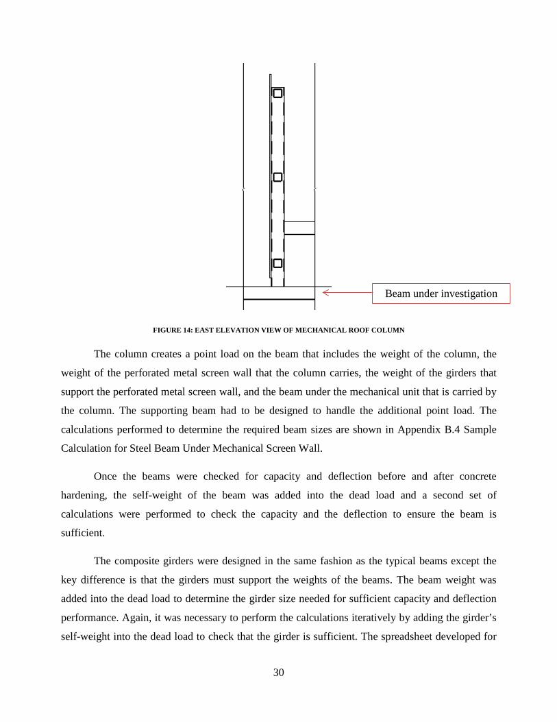
30
FIGURE 14: EAST ELEVATION VIEW OF MECHANICAL ROOF COLUMN
The column creates a point load on the beam that includes the weight of the column, the
weight of the perforated metal screen wall that the column carries, the weight of the girders that
support the perforated metal screen wall, and the beam under the mechanical unit that is carried by
the column. The supporting beam had to be designed to handle the additional point load. The
calculations performed to determine the required beam sizes are shown in Appendix B.4 Sample
Calculation for Steel Beam Under Mechanical Screen Wall.
Once the beams were checked for capacity and deflection before and after concrete
hardening, the self-weight of the beam was added into the dead load and a second set of
calculations were performed to check the capacity and the deflection to ensure the beam is
sufficient.
The composite girders were designed in the same fashion as the typical beams except the
key difference is that the girders must support the weights of the beams. The beam weight was
added into the dead load to determine the girder size needed for sufficient capacity and deflection
performance. Again, it was necessary to perform the calculations iteratively by adding the girder’s
self-weight into the dead load to check that the girder is sufficient. The spreadsheet developed for
Beam under investigation

31
the design of the girders can be found in Appendix C.4 Sample Spreadsheet for Girder Steel
Design.
When designing the beam and girders on the floors below the roof, it was necessary to
change the loading to match the floor in which they were located. As discussed in Chapter 4, the
loadings on the floor levels were residential live loads and corridor live loads from the 2009
International Building Code. Floor levels two through four all had the same loading; therefore, it
was not necessary to design unique girders and beams for each floor; the beams and girders were
designed for one floor and then used for the other floors. The only exception to this was on floor
level three. At this level, the exterior girders include a relieving angle which supports the brick
work for the top two floor levels. An additional calculation was performed for these girders, in
which the total weight of the bricks per linear foot was determined and then added into the dead
weight calculation. Once carried out, it was determined that the girders that were originally
selected for the other floors were sufficient to carry the additional loading of the bricks.
For both the girder and the beam design, certain members were used throughout the
building in order to promote ease of construction or constructability. As an example, certain beam
comparisons indicated that the span of the beam changed causing a smaller beam to be sufficient
for capacity and deflection. However, for constructability, the same beam size was selected for
both cases.
In order to design the columns, it was necessary to complete the design of the beams and
the girders. This is because the columns were designed based on carrying the total combined
weight of the girders, beams, dead loads, floor and roof live loads, and rood snow loads. The
vertical column consists of two W shapes spanning the total height of the building. The bottom
most column segment is 30’ 8” tall. The columns were designed as gravity columns, and the
spreadsheet that was developed can be found in Appendix C.5 Sample Spreadsheet for Column
Steel Design.
4.2.1 STEEL BRACING
With the steel structural framing defined, and all of the lateral and gravity loads
determined, the next step was to establish the proper lateral bracing members. This step required
the use of RISA-2D software to evaluate the different frames and determine the axial forces and

32
moment values on the columns and braces. The frame was drawn using the girder sizes which were
found using the aforementioned methods. The trial lateral bracing member size was an
HSS6X6X5/16. This size was selected because it was reasonable compared to the other member
sizes; it was also the same member size used by DOC in their lateral bracing design. The load
analysis was done for each LRFD combination for each of the three types of frames within the
building, shown below in Figure 15.
FIGURE 15: THREE TYPICAL LATERAL BRACED FRAMES

33
RISA-2D was used to check if this bracing was adequate to handle the calculated loading
and ensure minimal deflections, moments, and axial loads would occur. The loading used in RISA-
2D is illustrated on Frame G of the Grove Street Wing. The gravity loads are shown in Figure 16,
while the lateral loads are shown in Figure 17.
Dead Load
Roof Live Load Snow Load
Floor Live Load
FIGURE 16: GRAVITY LOADING CASES

34
The snow and live loads were easy to input; they simply had to be changed from pounds
per foot to kips per foot. The dead load was more complex and required the use of spreadsheets to
calculate the loading that would occur on each floor. This was calculated using a conservative
approach: the heaviest beams and girders for the frame were used (beam=22 lbs/ft; girder=31
lbs/ft). Using the tributary area, a pound per square foot value could be determined for each floor.
The spreadsheet used can be seen in Appendix C.6 Sample Spreadsheet for RISA-2D Input -
Weights. The wind and earthquake loading used was determined in Chapter 4.1.2 Lateral Loads.
Load combinations were entered into RISA by first using the Basic Load Cases tab to give
each type of loading a numerical representation, as shown in Figure 18. For example, the dead load
is now represented by 1, the live load is now
represented by 2, and so on. Using these numbers, the
LRFD load combinations could be placed into the
Load Combinations tab, as shown in Figure 19.
Earthquake Load Wind Load
FIGURE 17: LATERAL LOADING
FIGURE 18: BASIC LOAD CASES FROM RISA-2D

35
FIGURE 19: LOAD COMBINATIONS FROM RISA-2D
The load analysis was done for each of the three frame types (Figure 15) and provided
values along the columns for both axial (Pnt) and moment (Mnt) forces due to gravity loading, as
well as axial (Plt) and moment (Mlt) forces due to lateral loading. Figure 20 illustrates the analysis
that was used to determine values of Pnt and Mnt for Frame G. Appendix D.1 Various RISA-2D
Load and Frame Analyses displays more analyses done in RISA-2D for the different types of
frames and load combinations.
FIGURE 20: AXIAL AND MOMENT DIAGRAMS CREATED USING RISA-2D
A second-order analysis could then be completed using the values determined in RISA-2D.
Using the AISC Manual and Structural Steel Design by McCormac and Csernak values of B1 and
B2 were calculated. When “the approximate second-order analysis is used, only B1 will be
Axial Moment

36
computed, as B2 is not applicable,”29 and therefore, the moments and axial forces on the columns
due to lateral loads become irrelevant when put into the AISC H1-1a and AISC H1-1b equations.
The columns were checked to ensure that they were satisfactory using these equations. A more
thorough analysis of the application of these equations can be seen in Appendix C.7 Sample
Spreadsheet For Effective Length Method. Web local buckling (WLB) and flange local buckling
(FLB) were also checked to confirm that the braced frame could handle the expected loading
(Appendix C.7 Sample Spreadsheet For Effective Length Method).30
4.3 PRECAST CONCRETE DESIGN
In an effort to explore different building materials that could be used to construct the new
dormitory, the option of using precast concrete was examined. The superimposed gravity loading
for the building was already determined, such as the snow loads, the dead loads, and the various
live loads throughout the building. Figure 21 illustrates how the precast concrete columns would be
connected to the girders and slabs. The girders rest on corbels located on the side of the columns,
while the hollow-core slab rests on top of the girders. This scheme allows everything to fit together
smoothly. In the 3rd dimension, girders also sit on corbels and come directly out of and into the
page (not shown in this figure). The Precast/Prestressed Concrete Institute (PCI) gives information
on the necessary sizes for concrete members, and this was the main source that was used for this
design process.
FIGURE 21: PRECAST CONCRETE CONNECTION ILLUSTRATION
29 McCormac
30 McCormac
Girder
Hollow-Core Slab
Corbel
Column

37
The first step was to determine the type of slab needed on the roof of the building. A
hollow-core slab was chosen over the solid flat-slab because of its lighter weight (while
maintaining its structural integrity) and lower building costs. Hollow-core slabs also provide
excellent fire resistance. With precise and accurate designs, the voids in the hollow-core slabs can
be used for electrical or mechanical runs,31 however, the design and integration of these services
are out of the scope of this MQP. A design based on a superimposed snow load of 80 psf was used
to select the hollow-core slab for the roof. In order to have a slab that could be prepared for the
installation of a floor covering, a hollow-core slab with a 2-inch normal weight topping was
selected.
The next step was selecting the types of girders that would support the slab. For the
spandrel girders along the outside of the building (Girder A in Figure 22), an L-shape was the best
option, as shown in Figure 23 below.
FIGURE 22: PRECAST CONCRETE GIRDER LAYOUT
FIGURE 23: PRECAST CONCRETE L-BEAM, TAKEN FROM PCI DESIGN HANDBOOK
31 Buettner, Donal R., and Roger J. Becker.

38
The loading for these members would still include the 80 psf snow load, but they would also
include the weight of the selected slab. The slab weight is a pounds per foot force, however, it is a
line load perpendicular to the length of the girder. Therefore, in order to determine the line load
that the girder was required to handle from the hollow-core slab, the following calculations were
performed, as seen in Equation 8.
EQUATION 8: PRECAST CONCRETE SLAB LOAD ON PRECAST CONCRETE GIRDERS
𝑆𝑙𝑎𝑏 𝑙𝑜𝑎𝑑 𝑜𝑛 𝑡ℎ𝑒 𝑔𝑖𝑟𝑑𝑒𝑟𝑠
=
⎝
⎜⎜⎛
⎝
⎜⎛𝑆𝑙𝑎𝑏 𝑤𝑒𝑖𝑔ℎ𝑡 (𝑙𝑏𝑓𝑡)
𝑆𝑙𝑎𝑏 𝑤𝑖𝑑𝑡ℎ (𝑓𝑡)�
⎠
⎟⎞
+ 80𝑝𝑠𝑓
⎠
⎟⎟⎞
× (𝑙𝑒𝑛𝑔𝑡ℎ 𝑜𝑓 𝑡ℎ𝑒 𝑠𝑙𝑎𝑏 𝑐𝑎𝑟𝑟𝑖𝑒𝑑 𝑏𝑦 𝑡ℎ𝑒 𝑔𝑖𝑟𝑑𝑒𝑟) = 𝑙𝑖𝑛𝑒 𝑙𝑜𝑎𝑑𝑙𝑏𝑓𝑡
The superimposed service load that is calculated was used in conjunction with the “L-Beam Load
Tables” published by PCI to find the required girder size.
The girders running through the middle of the building, shown as girders B and C in
Figure 22: Precast Concrete Girder Layout, had to be different than the L-shaped ones used for the
spandrels because they will support a slab on both sides. The best shape was, therefore, an inverted
tee beam, shown in Figure 24: Precast Concrete Inverted Tee-Beam.
FIGURE 24: PRECAST CONCRETE INVERTED TEE-BEAM, TAKEN FROM PCI DESIGN HANDBOOK

39
The loading on the girder was found using the same equation as above with one minor addition.
Now that the slab was located on both sides of the girder, the additional load due to the larger
tributary width carried by the girder had to be included.
The hollow-core slab will rest on the girders, sitting atop the 8-inch lip that projects from
one side for the L-beams and on both sides for the inverted tee- beam. Beams also needed to be
selected. Less beams were required for the concrete design than the steel design. The steel beams
were responsible for carrying the weight of the composite decking all around them (found by using
tributary areas). The concrete beams are more useful for help with stability of the building when it
comes to lateral loading. These beams help to tie the columns together in the direction parallel to
the span of the hollow-core slabs. The girders support the slab ends and tie the columns together in
the transverse direction.
With the precast concrete slab, beams, and girders selected for the roof, the following
floors were examined. All of the elevated floors have the same layout and, therefore, only required
the analysis of one floor system to complete the concrete design. Similar steps to the design of the
roof floor slab and framing were followed for these floors, with the type and intensity of loading
being the only difference. A snow load was no longer present, however, various live loads were.
These included the 40 psf loading in the rooms and the 100 psf loading along the corridors.
After the slab, beams, and girders were selected, the precast columns were selected using
the previous loads. Determining the loads on the column were much like determining the loading
on the girder except that instead of multiplying the loads by the length of slab carried by the girder,
the loading on a column depends on the tributary area supported by the column as seen in the
equation below.
EQUATION 9: PRECAST CONCRETE SLAB LOAD ON PRECAST CONCRETE COLUMN
𝑆𝑙𝑎𝑏 𝑙𝑜𝑎𝑑 𝑜𝑛 𝑐𝑜𝑙𝑢𝑚𝑛
=
⎝
⎜⎜⎛
⎝
⎜⎛𝑆𝑙𝑎𝑏 𝑤𝑒𝑖𝑔ℎ𝑡 (𝑙𝑏𝑓𝑡)
𝑆𝑙𝑎𝑏 𝑤𝑖𝑑𝑡ℎ (𝑓𝑡)�
⎠
⎟⎞
+ 80𝑝𝑠𝑓
⎠
⎟⎟⎞
× (𝑡𝑟𝑖𝑏𝑢𝑡𝑎𝑟𝑦 𝑎𝑟𝑒𝑎 𝑠𝑢𝑝𝑝𝑜𝑟𝑡𝑒𝑑 𝑏𝑦 𝑡ℎ𝑒 𝑐𝑜𝑙𝑢𝑚𝑛) = 𝑝𝑜𝑖𝑛𝑡 𝑙𝑜𝑎𝑑 (𝑙𝑏)
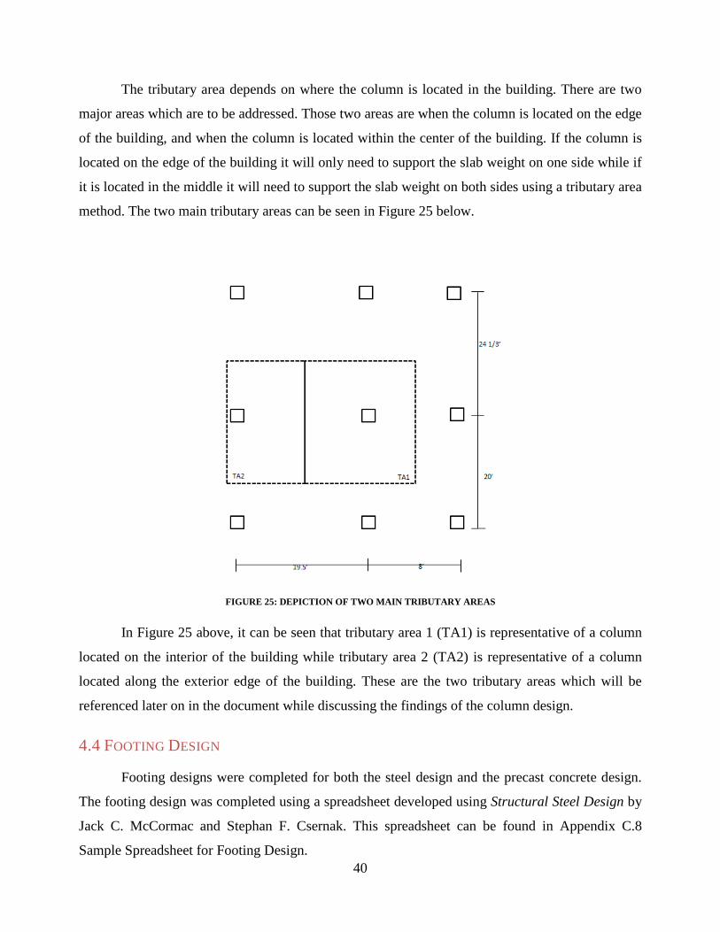
40
The tributary area depends on where the column is located in the building. There are two
major areas which are to be addressed. Those two areas are when the column is located on the edge
of the building, and when the column is located within the center of the building. If the column is
located on the edge of the building it will only need to support the slab weight on one side while if
it is located in the middle it will need to support the slab weight on both sides using a tributary area
method. The two main tributary areas can be seen in Figure 25 below.
FIGURE 25: DEPICTION OF TWO MAIN TRIBUTARY AREAS
In Figure 25 above, it can be seen that tributary area 1 (TA1) is representative of a column
located on the interior of the building while tributary area 2 (TA2) is representative of a column
located along the exterior edge of the building. These are the two tributary areas which will be
referenced later on in the document while discussing the findings of the column design.
4.4 FOOTING DESIGN
Footing designs were completed for both the steel design and the precast concrete design.
The footing design was completed using a spreadsheet developed using Structural Steel Design by
Jack C. McCormac and Stephan F. Csernak. This spreadsheet can be found in Appendix C.8
Sample Spreadsheet for Footing Design.

41
For steel design, it was first necessary to calculate the minimum required area based on the
load applied from the column. This load was determined based on the loads that the column carried
and the tributary area of the column. The minimum area was also determined based on the
compressive strength of the footing. Once the minimum area was determined, the dimensions of
the baseplate and the pedestal could be tried for selected. Then the permissible stress was checked
against the actual stress exerted.
The actual dimensions were determined based on the calculated deflection. Once the
dimensions of the base plate were finalized, the bearing strength of the concrete was checked
against the loading applied to the footing to ensure that it was sufficient. Finally, the footing
dimensions were calculated.
For precast concrete design, it was first necessary to ensure that the face area of the footing
was larger than the face area of the precast concrete column. The load that was applied to the
footing from the column was determined in the same manner as steel design. This meant
calculating the loads that the column carried and the tributary area of the column. Once the
dimensions of the concrete footing were determined the bearing strength was checked against the
loading applied to the footing through the column to ensure that it was sufficient.
4.5 SPRINKLER SYSTEM DESIGN
The basis for sprinkler system design is the hazards present in the building and the intended
use of that building. The uses of the building are separated into different hazards, Light Hazard,
Ordinary Hazard (I and II), and Extra Hazard (I and II) with increasing danger respectively. The
hazards present in the building are divided into different commodity classifications. These
commodities are labeled Class I-IV or Class A/B/C plastics with their relative dangers increasing
respectively. Once it is determined what the general use of the space and what is going to be
present in the space it is possible to determine the flow and pressure required at the most
hydraulically remote sprinkler in the space.
In order to complete a sprinkler design, hydraulic calculations were performed. Hydraulic
calculations use the pressures and flows in the pipes along with the material characteristics of the
pipe. The hydraulic calculations start with the most remote sprinkler and work backwards within
the design area until all sprinklers are included. These calculations incorporate friction loss due to

42
gravity and elevation as well. The governing equations for hydraulic calculations can be seen
below.
EQUATION 10: PRESSURE LOSS PER FOOT DUE TO FRICTION
𝑝 =4.52𝑄1.85
𝐶1.85𝑑4.97 𝑝𝑠𝑖/𝑓𝑡
• Q=flow (gpm)
• C=Friction Loss Coefficient
• D=internal pipe diameter (in)
EQUATION 11: PRESSURE LOSS PER FOOT DUE TO GRAVITY
𝑝 = 0.433 𝑝𝑠𝑖/𝑓𝑡
EQUATION 12: CONVERSION FACTOR FOR NON-SCHEDULE 40 PIPE
(𝑃𝑖𝑝𝑒 𝐼𝑛𝑠𝑖𝑑𝑒 𝐷𝑖𝑎𝑚𝑒𝑡𝑒𝑟
𝑆𝑐ℎ𝑒𝑑𝑢𝑙𝑒 40 𝐼𝑛𝑠𝑖𝑑𝑒 𝐷𝑖𝑎𝑚𝑒𝑡𝑒𝑟)4.87
Equation 10 gives the pressure loss due to friction, Equation 11 gives the pressure loss due
to gravity, and Equation 12 is a normalizing equation that creates an equivalency between pipes of
differing diameters. The pressure losses are then multiplied by the total number of feet of the
applicable pipe size to get a total pressure lost over that many feet. In the pressure loss due to
frication equation, the result is heavily dependent on the C Factor. This factor is a characteristic of
the pipe material and can be found in NFPA 13.
In addition to the pressure loss equations, the flow and pressure present at every sprinkler is
necessary. The flows and pressures at each sprinkler can be found using the two equations below.
EQUATION 13: HYDRAULIC FLOW EQUATION
𝑄 = 𝑘√𝑃
EQUATION 14: HYDRAULIC PRESSURE EQUATION
𝑃 = (𝑄𝐾
)2
• K=K Factor for sprinkler

43
• P=Required Pressure (psi)
• Q=Flow (gpm)
By adding the pressure losses due to friction and gravity and inputting those numbers into
these two equations it is possible to determine the pressure and flow required at each sprinkler.
Additionally, different fittings will affect the flows and pressures differently. Tables of their
equivalent lengths, how much pressure loss there would be in the fitting if it was a straight piece of
pipe, are provided in NFPA 13. These hydraulic calculations were calculated for a specific design
area. This area was established by first determining the number of sprinklers within the design
area. This was determined using the equation below.
EQUATION 15: NUMBER OF SPRINKLERS IN DESIGN AREA
# 𝑜𝑓 𝑠𝑝𝑟𝑖𝑛𝑘𝑙𝑒𝑟𝑠 =𝑆𝑝𝑟𝑖𝑛𝑘𝑙𝑒𝑟 𝑜𝑝𝑒𝑟𝑎𝑡𝑖𝑜𝑛 𝑎𝑟𝑒𝑎
𝑃𝑟𝑜𝑡𝑒𝑐𝑡𝑖𝑜𝑛 𝐴𝑟𝑒𝑎
The sprinkler operation area is equal to the total square footage of the design area which is
found in NFPA 13 and the protection area is based on the type of sprinkler used which can also be
found in NFPA 13. Once the total number of sprinklers was determined, the number of sprinklers
required on the most remote branch line was needed. This number of sprinklers was found using
the equation below.
EQUATION 16: NUMBER OF SPRINKLERS ALONG MOST REMOTE BRANCH LINE
# 𝑜𝑓 𝑠𝑝𝑟𝑖𝑛𝑘𝑙𝑒𝑟𝑠 =1.2�𝐷𝑒𝑠𝑖𝑔𝑛 𝐴𝑟𝑒𝑎𝑆𝑝𝑟𝑖𝑛𝑘𝑙𝑒𝑟 𝑆𝑝𝑎𝑐𝑖𝑛𝑔
The spacing of the sprinklers was referenced from NFPA 13 and was also based on the type
of sprinkler. Once both of these values were determined, it was possible to orient the design area
over the most remote section of the building. This design area can be seen in Figure 26 below.

44
FIGURE 26: LAYOUT OF DESIGN AREA

45
5.0 DESIGN RESULTS In this chapter both the steel and the concrete design alternatives will be presented and
compared. Design results, discussions and key findings will also be addressed throughout the chapter.
5.1 STRUCTURAL STEEL DESIGN
Below are the steel design layouts for the floor framing. In Figure 27 below, the wings of
the building are labeled and will be referred to as such for the report. The two wings, Lancaster
Street and Grove Street are highlighted.
FIGURE 27: BUILDING STEEL LAYOUT AND WING LABELS
In Figure 28, Figure 29, and Figure 30, below, the main building (Faraday Street Side) and
each wing (Grove Street Wing and Lancaster Street Wing) were separated in order to display the
beam and girder framing steel designs. These figures show the steel designs for the roof of the
building. They illustrate the repetitive use of W12X22 beam sizes along the outer spans of the roof
Grove Street W
ing, Wing 2
Faraday Street Side, Main Building

46
and W10X12 beam sizes along the corridor. The frequent use of W14X22 for the girders around
the outside of the roof is also portrayed.
FIGURE 28: LANCASTER STREET WING, WING 1 STEEL LAYOUT ROOF
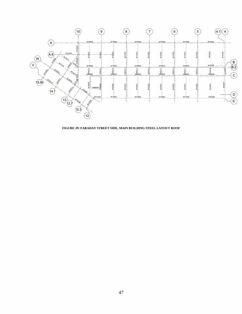
47
FIGURE 29: FARADAY STREET SIDE, MAIN BUILDING STEEL LAYOUT ROOF

48
FIGURE 30: GROVE STREET WING, WING 2 STEEL LAYOUT ROOF

49
The steel designs that are typical for each floor (2-4) are shown below in Figure 31, Figure
32, and Figure 33. They are similar to the steel design for the roof in many ways, including a
repetitive use of W12X22 beam sizes along the outer spans of the floor and W10X12 beam sizes
along the corridor. The repeated use of W14X22 for the girders around the outside of the roof is
also portrayed for floors two through four.
FIGURE 31: LANCASTER STREET WING, WING 1 STEEL LAYOUT FLOORS 2-4

50
FIGURE 32: FARADAY STREET SIDE, MAIN BUILDING STEEL LAYOUT FLOORS 2-4
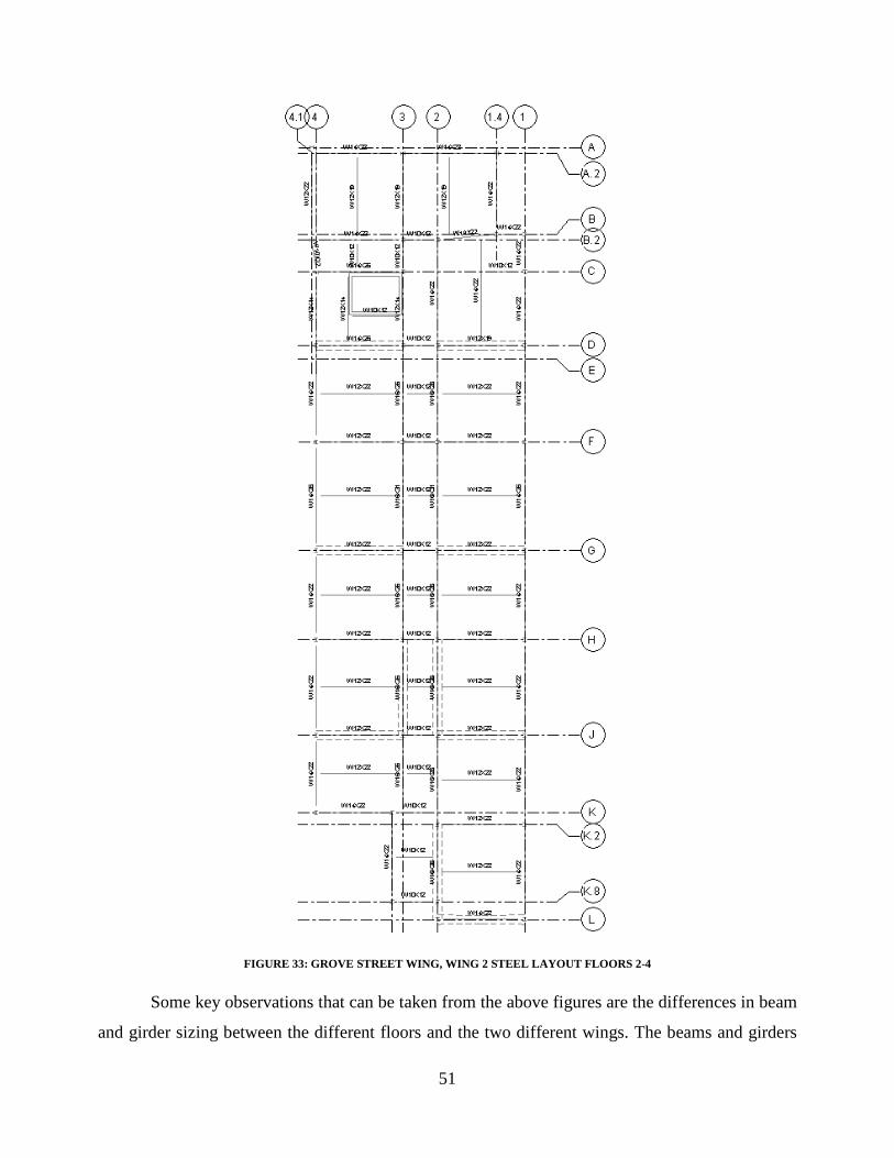
51
FIGURE 33: GROVE STREET WING, WING 2 STEEL LAYOUT FLOORS 2-4
Some key observations that can be taken from the above figures are the differences in beam
and girder sizing between the different floors and the two different wings. The beams and girders

52
designed for the roof were different than those designed for the floors below. This was due to the
different loading cases, such as snow, that were applied. The framing plans for the roofs of the
wings were also very different in beam and girder sizes because of the mechanical units and screen
wall on the Lancaster Street Wing. The structural framing plans for the wings on the floors below
the roof were typical of each other. The beams and girders for the entire design were first selected
for adequacy for the loading and then for constructability. This means that if a W12X14 was
adequate for a girder, but the surrounding girders were required to be W12X22, then the W12X14
was switched to be more uniform which promotes constructability.
5.1.2 STEEL BRACING MEMBER SELECTION
After checking the braced, steel structural frame through RISA-2D, it was determined that
the HSS6X6X5/16 members were adequate and could handle the gravity and lateral loading.
Equation AISC H1-1a and AISC H1-1b for combined axial and flexural forces ensured that the
frames were satisfactory, and the WLB and FLB equations confirmed that local buckling would
not be an issue. Through RISA-2D, it was also determined that the braced frames should be pin
connected to the girders and columns, rather than connected by fixed ends. Pin connections
prevented moments from passing into the bracing, unlike the fixed ends, and took some of the
stress off the HSS members. Figure 34 and Figure 35 display the difference between these two
options by showing a plot of the moment diagrams for each case. They make it very clear that
bracing with pin connections is much more advantageous. The red ovals highlight one area where
the change is very clear.
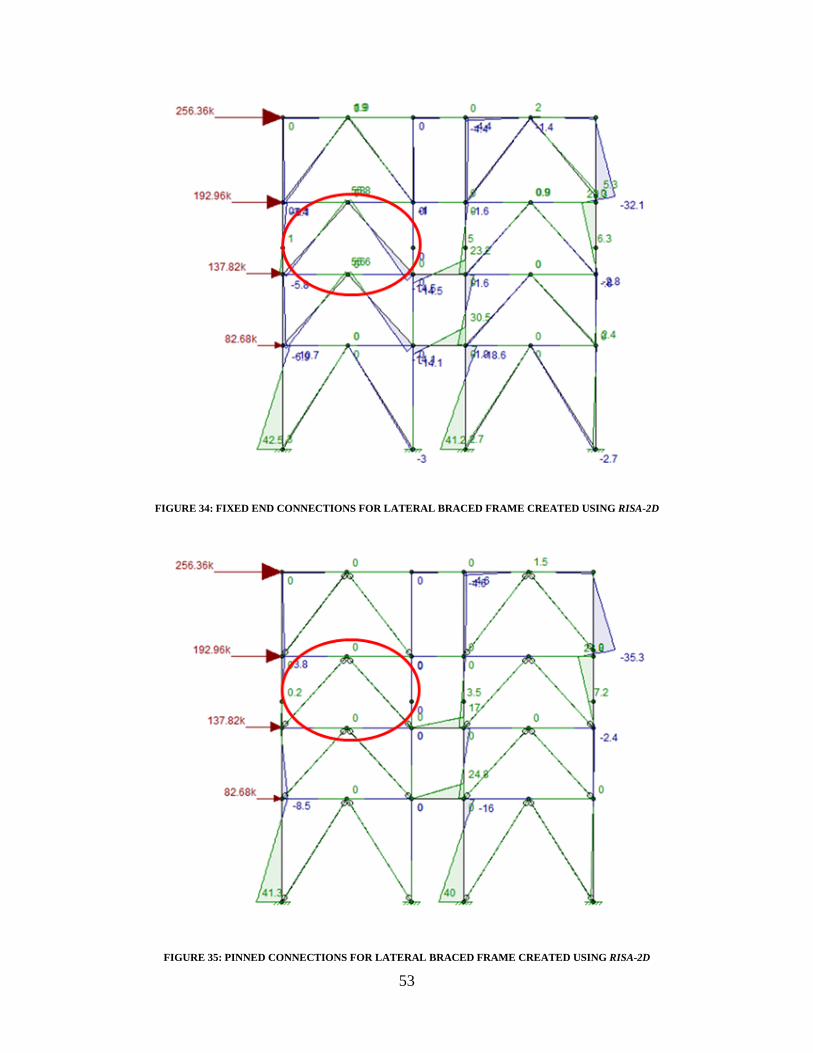
53
FIGURE 34: FIXED END CONNECTIONS FOR LATERAL BRACED FRAME CREATED USING RISA-2D
FIGURE 35: PINNED CONNECTIONS FOR LATERAL BRACED FRAME CREATED USING RISA-2D

54
Another outcome of the lateral bracing design was a change in girder sizes around the
lateral frames. The HSS members had a width of 6 inches, and this presented a geometry issue with
the connection to the girders. The girder width where these connections occurred needed to be
larger than 6 inches. Therefore, the widths of all the girders along the frame were checked and
changed accordingly. For example, W12X22 girders have a flange width of about 4 inches, and
were, therefore, bumped up to W12X26 which have a flange width of about 6.5 inches, as seen in
Figure 36 below. W14X26 members were another girder size that was adjusted: they were changed
to W14X36 members. The structural diagrams and models presented throughout Chapters 5.1
Structural Steel Design and 5.1.2 Steel Bracing Member Selection account for the change in
girders sizes.
FIGURE 36: TYPICAL STEEL FRAMING PLAN
5.2 PRECAST CONCRETE DESIGN
With the necessary steps for selecting the different precast concrete members clearly
established, the actual loads were determined and the member sizes were selected from the PCI

55
Tables. 32 The hollow-core slab was the first member chosen, and an example cross section is
shown in Figure 37.
FIGURE 37: HOLLOW CORE PRECAST CONCRETE SLAB, TAKEN FROM PCI DESIGN HANDBOOK
Table 12 displays the design data given by the Precast/Prestressed Concrete Institute (PCI). The
maximum span of the slab is 19’ 5 ½”, so a value of 20 feet was used for the span length. The
yellow highlights in the table depict how the slab type was selected, and the red circle indicates
which type was chosen, a 4HC6+2: 66-S
TABLE 12: HOLLOW CORE PRECAST CONCRETE SLAB DESIGN TABLE, TAKEN FROM PCI DEISGN HANDBOOK
32 PCI Design Handbook Seventh Edition

56
The PCI Tables gave the weight load of a 6” hollow-core slab with 2” normal weight
topping as 295 pounds per foot of span length. This value was then used in Equation 17 to
determine the loading that would be placed on the girders.
EQUATION 17: SLAB LOAD ON THE PRECAST CONCRETE GIRDERS DESIGN VALUES
𝑆𝑙𝑎𝑏 𝑙𝑜𝑎𝑑 𝑜𝑛 𝑡ℎ𝑒 𝑔𝑖𝑟𝑑𝑒𝑟𝑠 =
⎝
⎜⎜⎛
⎝
⎜⎛295 𝑙𝑏𝑓𝑡
4𝑓𝑡�
⎠
⎟⎞
+ 80𝑝𝑠𝑓
⎠
⎟⎟⎞
× �19.5𝑓𝑡2� � = 1499.06
𝑙𝑏𝑓𝑡
• 4 ft. is the slab width, used to convert the given weight into psf • 80 psf is the roof snow load • (19.5 ft. /2) is half the distance between the girders, used to account for the slab area
tributary to this particular girder. This is the only distance used because the slab is only on one side of the girder due to its location on the building.
Looking under the “L-Beam Load Tables” section of the PCI Tables and using a
superimposed service load of about 1500 lb./ft. and a girder span length of 22 ft., it was determined
that a 20LB20 could be used. This size L-beam has an h1 value of 12 inches and an h2 value of 8
inches (Figure 38). The 22 foot span length covers the lengths of all the girders except for one
section of the building between column lines G and F where the girder span is 24’ 4”. For this
FIGURE 38: PRECAST CONCRETE L-BEAM, TAKEN FROM PCI DEISGN HANDBOOK
area, the span length had to be rounded up to 26 ft. to use the PCI Tables which increase by values
of 2 ft. For this case, the 20LB20 girder was strong enough to handle the load at 22 foot and 26
foot spans, meaning that no change in girder size would be necessary for this larger span.

57
The interior girders used an inverted tee-beam shape. These members were required to
carry the weight of the slab from both sides. This was incorporated by using a tributary width (19.5
ft./2 + 8 ft./2) to encompass the whole area of the hollow-core slab carried by the girder. Using
Equation 18, with the addition of (8 ft./2), a superimposed service load of about 2114 lb./ft. was
calculated. From the “Inverted Tee-Beam Load Tables” section of the PCI Tables, it was
concluded that a 28IT20 would be acceptable for all girders in this section, whether they had 22
foot spans or 26 foot spans. The h1 value was 12 inches, while the h2 value was 8 inches, which are
the same values used for the L-beam and can accommodate a 6 in. slab with 2 in. topping (Figure
39).
FIGURE 39: PRECAST CONCRETE INVERTED TEE-BEAM, TAKEN FROM PCI DEISGN HANDBOOK
In the longitudinal direction, the design only includes beams between the columns,
meaning that the concrete design used half the number of beams as the steel design. The concrete
beams were rectangular shape, and the loading used to select the proper size was found using the
following calculations.
EQUATION 18: LOADING ON THE PRECAST CONCRETE BEAMS DESIGN VALUES
𝐿𝑜𝑎𝑑𝑖𝑛𝑔 𝑜𝑛 𝑡ℎ𝑒 𝑏𝑒𝑎𝑚𝑠 = (73.75 𝑝𝑠𝑓 + 80 𝑝𝑠𝑓) × (1𝑓𝑡) = 153.75 𝑙𝑏𝑓𝑡
• 73.75 psf is the loading from the slab • 80 psf is the roof snow load • 1 ft. is the width of the beam

58
The beams run parallel to the slab and the maximum span the beams cover is 19.5 feet. The beams
were all designed based on this span, so the selected beam size is conservative for beams that cover
smaller spans. Using the “Rectangular Beam Load Tables” section of the PCI Tables, a 12RB16
rectangular beam was chosen. The dimensions are shown in Figure 40.
Table 13: Precast Concrete Member Sizes shows the results for concrete slab, beam, and
girder sizes for all floors, including the roof.
TABLE 13: PRECAST CONCRETE MEMBER SIZES
All precast member sizes were the same for each category, with the one exception being the
variation between the roof and the other floors for the 26 foot inverted tee-beam size.
The precast concrete members had large capacities and, therefore, some of the minimum
sizes in the PCI Tables had capacities that could handle loads much larger than any of the
superimposed design loads for the residence hall. In an effort to explore this dilemma, and create a
more efficient design, the possibility of removing one row of columns was analyzed. Throughout
most of the building, four columns are used to span its width. By removing one row of columns, a
larger beam and slab span are created, as shown in Figure 41 below.
22 Ft. Span 26 Ft. SpanRoof 4HC6+2: 66-S 12RB16 20LB20 28IT20 28IT204th 4HC6+2: 66-S 12RB16 20LB20 28IT20 28IT243rd 4HC6+2: 66-S 12RB16 20LB20 28IT20 28IT242nd 4HC6+2: 66-S 12RB16 20LB20 28IT20 28IT24
Inverted Tee-BeamGirder Type
Floor Slab Type Beam TypeL-Beam
h=16 inches
b=12 inches
FIGURE 40: PRECAST CONCRETE RECTANGULAR BEAM

59
FIGURE 41: PRECAST CONCRETE COLUMN POSSIBILITIES
This option would be feasible, with only minor changes in precast member sizes. The
selected 6 inch hollow-core slab can accommodate the increased span; however, a slab with more
reinforcing strands would be required. The steel strands running through the member increase the
capacity of the concrete members.
In order to compare results, hand calculations were done to determine the required
thickness and steel reinforcement needed for a typical concrete slab. Through this investigation, it
was determined that a 6-inch slab, with a 1-inch cover, would be satisfactory for the anticipated
loads. By analyzing the minimum steel reinforcement area required, it was concluded that #5 bars,
spaced 16 inches apart, would be adequate. Detailed calculations can be seen in Appendix B.5
Sample Calculation for Concrete Design. The 7-inch depth used for the hand calculations was only
1 inch smaller than the hollow-core slab previously selected. This analysis displays the many
specifications that need to be considered when designing a concrete structure, as well as illustrates
the usefulness and effectiveness the PCI design tables have in the concrete structural design
process.
5.3 FOOTING DESIGN
For the footing design to support the steel frame, the required area of the baseplate was
calculated to be less than the area of the steel column. This meant that the actual area of the
baseplate would have to be larger than the calculated area to adhere to design geometry. The
dimensions of the column, baseplate, pedestal and footing can be seen below in Table 14.
A B C D
19.5 ft. 8 ft. 19.5 ft.
A B D
27.5 ft. 19.5 ft.
Before: 4 Columns After: 3 Columns

60
TABLE 14: STEEL FOOTING DESIGN DIMENSIONS
The required pedestal area for the precast concrete was also determined to be less than the
area of the concrete column. The concrete column, pedestal and footing dimensions calculated can
be seen below in Table 15.
TABLE 15: PRECAST CONCRETE FOOTING DESIGN DIMENSIOINS
5.4 STEEL VERSUS PRECAST CONCRETE
A major choice that must be made in any modern day construction is which construction
material to use. For the dormitory, both steel and precast concrete construction was explored.
There were advantages and disadvantages of both, and depending on the type of building being
constructed, one material is sometimes better suited. In the case of the dormitory, one of the first
factors analyzed was the cost of the structural framing for each material. Table 16 displays the cost
of precast concrete versus steel construction. It accounts for the beams, girders, columns, slabs, and
fireproofing.
TABLE 16: COST COMPARISON STEEL VERSUS PRECAST CONCRETE
The table depicts a major cost addition that is experienced when building with steel, which
is fireproofing. Steel members are noncombustible; however, in temperatures often reached in
fires, the strength is greatly reduced. “Steel is an excellent heat conductor, and non-fireproofed
steel members may transmit enough heat from one burning compartment of a building to ignite
Column 10" X 10.1"Baseplate 13" X 12"Pedestal 18" X 17"Footing 6' X 6'
Column 12" X 12"Pedestal 15" X 15"Footing 6' X 6'
Precast Concrete Steel w/out Fireproofing Steel w/ Fireproofing$2,532,980.80 $2,551,225.20 $2,908,897.04

61
materials with which they are in contact in adjoining sections of the building.”33 Fire-protective
covers are necessary to increase the fire resistance ratings for steel members; these include
concrete gypsum, mineral fiber sprays, special paints, and other materials. Spray-on fireproofing is
the most used fire resistant material and usually consists of either mineral fibers or cementious
fireproofing materials. Fireproofing presents an issue because of its high cost, which discourages
its use compared to other construction materials.34 Steel without fireproofing is not an option, but it
is used to show the significance that fireproofing has in increasing the overall price of steel
construction. Precast concrete is also noncombustible and the high temperatures experienced
during fires have little effect on the structural integrity of the concrete.35 Therefore, concrete is
much more advantageous and efficient in terms of fire protection.
One positive aspect of steel construction is that the properties of steel are uniform and do
not change throughout, like in concrete. Another positive of steel is its ductility, meaning its ability
to withstand extensive deformation without failing when put under large tensile stresses. Steel
structures, however, are susceptible to corrosion, and are therefore, required to be painted
periodically.36 Concrete, on the other hand, can be left unpainted without the danger of being
damaged by the elements. Precast concrete has a larger thermal mass than steel, meaning that its
“capacity to store and regulate internal heat”37 is much better. Therefore, energy efficiency of
precast concrete design is superior to steel construction. When it comes to design limitations, the
opportunities with precast concrete design are endless, and more diverse than that of steel.38 In the
case of the new residence hall, the design is fairly straightforward, meaning that both steel and
concrete fit the design plan.
33 McCormac
34 McCormac
35 Building with Precast
36 Assakkaf
37 Principles of Eco-Design
38 Building with Precast
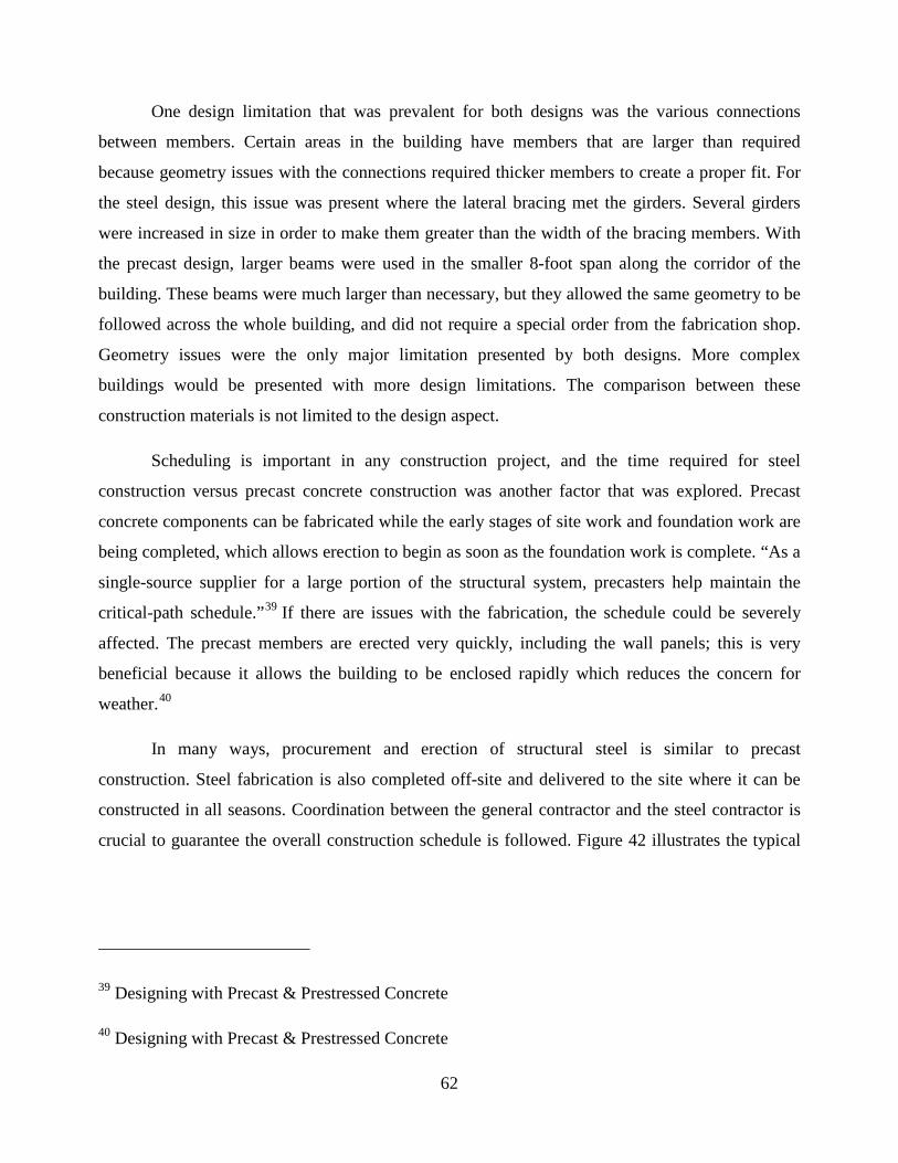
62
One design limitation that was prevalent for both designs was the various connections
between members. Certain areas in the building have members that are larger than required
because geometry issues with the connections required thicker members to create a proper fit. For
the steel design, this issue was present where the lateral bracing met the girders. Several girders
were increased in size in order to make them greater than the width of the bracing members. With
the precast design, larger beams were used in the smaller 8-foot span along the corridor of the
building. These beams were much larger than necessary, but they allowed the same geometry to be
followed across the whole building, and did not require a special order from the fabrication shop.
Geometry issues were the only major limitation presented by both designs. More complex
buildings would be presented with more design limitations. The comparison between these
construction materials is not limited to the design aspect.
Scheduling is important in any construction project, and the time required for steel
construction versus precast concrete construction was another factor that was explored. Precast
concrete components can be fabricated while the early stages of site work and foundation work are
being completed, which allows erection to begin as soon as the foundation work is complete. “As a
single-source supplier for a large portion of the structural system, precasters help maintain the
critical-path schedule.”39 If there are issues with the fabrication, the schedule could be severely
affected. The precast members are erected very quickly, including the wall panels; this is very
beneficial because it allows the building to be enclosed rapidly which reduces the concern for
weather.40
In many ways, procurement and erection of structural steel is similar to precast
construction. Steel fabrication is also completed off-site and delivered to the site where it can be
constructed in all seasons. Coordination between the general contractor and the steel contractor is
crucial to guarantee the overall construction schedule is followed. Figure 42 illustrates the typical
39 Designing with Precast & Prestressed Concrete
40 Designing with Precast & Prestressed Concrete

63
Work Breakdown Structure (WBS) for steel construction.41 Many of the activities are similar to
those required in precast concrete construction.
FIGURE 42: TYPICAL WORK BREAKDOWN STRUCTURE (WBS) FOR STEEL CONSTRUCTION, TAKEN FROM
CONSTRUCTION MANAGEMENT OF STEEL CONSTRUCTION
41 Construction Management of Steel Construction

64
The time required for each type of design varies, and a specific time cannot be put on either
method. The duration for each option is very quick, but in the end, the project with the best
coordination and fewest delays prevails. Precast concrete lead time is often faster than that of steel
members42, however, depending on when the materials are ordered, this may not have an effect.
Because both methods are so similar, they both face related issues that can negatively impact
schedule. These include, but are not limited to:
• Material procurement: It is important to place orders for the required materials as early as possible. Shortages in materials, delays in production or shipment, unusual member sizes, and overbooked fabrication shops are some of the main problems that can lead to schedule interruptions.
• Shop drawing approval: Getting drawings approved can take time, and issues may lead to delays.
• Coordination among subcontractors: Delays caused by one subcontractor can affect the outcome of the entire project. Therefore, effective coordination is required between all parties involved.43
The outcome for every project is different, but it is evident that for both precast concrete and steel
construction, where fabrication of the materials takes place off-site, many issues can arise, which
validates the importance of a detailed and organized schedule. Additional discussion on these two
options can be seen in 9.0 Cost Estimation.
42 Bridges
43 Construction Management of Steel Construction

65
6.0 CONSIDERATION OF LEED CERTIFICATION As part of the design/build contract, WPI has laid out the requirement for the residence hall
to be LEED certified. In order to achieve LEED certification, the building is required to meet
certain criteria and receive a number of different credits and points. To become LEED certified,
40-49 points must be achieved. There are other LEED certification levels that can also be achieved,
as shown in Table 17.
TABLE 17: LEED CERTIFICATION LEVELS, TAKEN FROM LEED GREEN BUILDING CERTIFICATION
The number of points received for each credit is weighted differently and is allocated
“based on strategies that will have greater positive impacts on what matters most – energy
efficiency and CO2 reductions.” 44 These credits promote sustainable design and lessen the
environmental impact. The following seven LEED credits are some of the criteria which the
project achieved:
1. Credit Sustainable Sites 7.1 2. Credit Sustainable Sites 7.2 3. Credit Material and Resources 2 4. Credit Material and Resources 4 5. Credit Material and Resources 5 6. Credit Material and Resources 7 7. Credit Indoor Environmental Quality 3.145
Credits 1 and 2 are achieved by having paving and roofing materials compliant with
requirements set forth by LEED for solar reflectance index. With materials meeting these criteria,
the heating and cooling requirements of the building will be decreased. Credit 3 is aimed at having
44 LEED Green Building Certification
45 USGBC
LEED Certification Levels Points Required
Certified 40-49Silver 50-59Gold 60-79
Platinum 80 and above

66
a waste management plan during construction to limit runoff and the addition of pollutants into the
environment. Credit 4 outlines the use of materials with recycled content which is aimed to reuse
resources. Credit 5 is required to determine the amount of regionally extracted materials. Materials
that come from the region cut down on the amount of fossil fuels burned in shipping those
materials from elsewhere in the world. Credit 6 aims to identify the amount of certified wood that
is to be used in the building. The last credit, 7, required outlining an air quality management plan
for the construction phase of the project.46
These LEED credits are the basis for the sustainable design aspect of the project. The seven
credits listed above only add up to 8 LEED points, meaning that at least 32 more LEED points are
required, as well as a certain number of credits from each individual category, for the dormitory to
become certified. There are certain credits for the different categories that do not add points to the
count, and are simply required. These credits are known as prerequisites and must be met in
conjunction with the other credits (that add up to 40 points) in order for a building to become
LEED certified. Additionally, there are some credits which are given a higher priority/more points
because they are deemed more important towards the sustainability of a structure.47 By analyzing
DOC’s entire LEED checklist, it was determined that the new dormitory will attain at least 43
LEED points.48 A table portraying the credits that will definitely be achieved by the new residence
hall can be seen in Appendix D.2 LEED Credits Checklist.
46 USGBC
47 USGBC
48 Daniel O’Connell’s Sons, Inc.

67
7.0 SCHEDULING “A good plan for a construction project is not a plan which can complete the project in the
shortest time but it is the plan which can safely execute the project in a given time and budget
without compromising the quality and without any litigation.”49 Scheduling is one of the most
important aspects of the planning process for construction projects. The scheduling for the
residence hall was crucial because the goal was for the dormitory to be opened to students in
August 2013 before the start of the school year. The construction process had about one year to be
completed; therefore, falling behind schedule could be extremely costly. With students expecting
to move into the residence hall in August, if the building was not completed, not only would DOC
face cost penalties, students would be left without proper housing.
A condensed version of DOC’s schedule was entered into Primavera. Figure 43 displays a
portion of the timetable for the construction processes. The schedule is split by wing (Lancaster
Wing, Faraday Wing, and Grove Wing), creating three similar segments within the one timetable.
The labels next to the green bars depict the activity of construction and its associated wing. The
complete Primavera schedule can be seen in Appendix D.3 Complete Primavera Construction
Schedule.
.
49 Sharma

68
FIGURE 43: PRIMAVERA CONSTRUCTION SCHEDULE
Due to the scope of this project, many of the divisions (interior finishes, HVAC, plumbing,
electrical, testing) were combined to obtain a total duration. The structural, exterior finishes, and
fire protection aspects were left in a more detailed form to display the different features that must
be considered. By examining the schedule, the interconnectivity amongst the various activities
became apparent. Many activities relied on the completion of other activities before their
construction could begin. It became evident that the dependence of early activities to later activities
meant that actions that were being completed during overlapping time periods had to confirm that
the location of the work or specific building features were already constructed or finished.
In order to understand the time requirements for each division of construction, the total
durations for each division were combined from each wing. The division durations were divided by
the total duration of the project to determine the percentage of time spent on each division, and this
information is displayed in the pie chart shown in Figure 44. Calculations can be seen in Appendix
D.4 Schedule Data.

69
FIGURE 44: PERCENTAGE OF TOTAL TIME REQUIRED PER DIVISION
As illustrated by the pie chart, the MEP aspects of construction consume a majority of the
total time in comparison to the other features. The superstructure division was a very small
percentage of the total time; however, the percentage used for the pie chart only refers to the steel
construction. Footing and foundation work and site work were not included in the superstructure
schedule duration. It is interesting to note the large difference between the time required for steel
framing construction (superstructure) and the time required for the MEP work. One explanation to
this large difference that was discovered was the fact that much of the MEP work required testing
after it had been installed, which increased the amount of time before the division was completed.
Another explanation for the large percentage difference was that many divisions included much
more intricate work than the steel construction. The superstructure is the first aspect of
construction, and often times steel erection does not have to be coordinated with the other divisions
because it must be completed before installation of the enclosure, MEP, and interiors can even
begin. “The structural steel phase has a significant impact on the overall project schedule;
completion of the structural frame is generally considered a significant milestone in overall project
completion. Completion of the frame allows the work of the architectural, mechanical, electrical,

70
and finally the finishing trades, to proceed.”50 Those divisions that follow the steel erection are
often faced with the challenges of coordinating with one another, and many times the start date for
one trade relies on the finish dates of other trades.
Scheduling is a very detailed and important aspect of construction projects. When project
deadlines are on the line, such as the case for the new residence hall, it is crucial that each activity
is completed on time. One late activity can alter the finish date of the entire project. For the new
residence hall, the schedule illustrates how the productivity for each day was vital to successful
completion of the project; one bad day due to weather or delayed arrival of materials could push
back numerous activities and make it very difficult to get back on track.
50 Construction Management of Steel Construction

71
8.0 SPRINKLER DESIGN AND LAYOUT According to the Massachusetts State Building Code, an automatic sprinkler system is
required for the residence hall. This sprinkler must be installed according to the requirements of
NFPA 13: Automatic Sprinkler Systems Handbook. NFPA 13 provides the minimum requirements
for the design and installation of automatic sprinkler systems. The following section discusses the
applicable sections of NFPA 13 as well as present the layout and design of the system which will
be installed in the residence hall.
8.1 SYSTEM SELECTION
There are two types of systems that can be installed; wet pipe systems and dry pipe
systems. Wet pipe systems have water located within the pipes, while dry pipe systems are filled
with pressurized air, and once the system is actuated, water starts to flow through the pipes. There
are both positives and negatives to both systems. For dry pipe systems, there is a longer time
between the sprinkler being actuated and water flowing onto the fire in comparison to wet pipe
systems. Wet pipe systems are prone to freezing in an unheated building which is possible in the
northeast. For the residence hall, a wet pipe system was selected because the building will be
heated and therefore the pipes are not prone to freezing. Additionally, only one sprinkler system is
required due to the size of the building. A sprinkler system protecting a light hazard occupancy,
which is determined to be the case in the next section, is capable of protecting up to 52,000 ft2 of
floor space. This limit is a per floor limit because the scope of the code outlines that the design of a
sprinkler system according to NFPA 13 refers to a single fire at one point in the building. In such
an event, the sprinklers on only one floor of the building would be operational, and each floor is
slightly over 21,000 ft2, creating a system within the limits of a light hazard occupancy.
8.2 SPRINKLER SELECTION
The selection of the types of sprinklers present was based upon the apparent hazards
present in the building, the building occupancy, and the required orifice size for the sprinklers.
First, dormitory-type buildings are considered light hazard occupancies. This type of hazard is
considered the least prone for fires with the least hazardous materials. Typically, the most
hazardous materials found within the building are the mattresses, furniture and personal
possessions. Additionally, there is a mechanical room on the first floor which would create an

72
additional hazard classification. This area is considered Ordinary Hazard Group I which allows for
the same orifice sized sprinklers to be used as for the remainder of the building.
8.3 SPRINKLER COMPARISON
First, a design area was chosen in order to complete the sprinkler comparison. This design
area is required to be in the most hydraulically remote section of the building. In a system such as
this one, there is one cross main with branch lines running off of it. The water main enters the
building on the Lancaster Wing in the mechanical room which makes the most remote portion of
the building the Grove Street wing corner on the third floor. Even though the mechanical room is a
higher hazard category, the hydraulic demand is very little because it is where the water main
enters the building. In the design area, a comparison was made between using either Schedule 40
Black Steel pipe or CPVC Pipe. The comparison was created in order to determine which pipe
material would be more economically feasible when looking at many factors, including the
physical cost of materials, maintenance, and the size of the fire pump needed to complete the
system.
While designing a sprinkler system, there are many different aspects that are regulated by
the code. However, there are also a few aspects which are left up to personal preference. One of
those aspects is the type of pipe to be used in the system. A few of the different types of pipe that
can be used are copper, steel, and chlorinated polyvinyl chloride (CPVC). Each type pipe is
available in different Schedules, 10, 40, 80 etc. The schedule of the pipe refers to the relative
thickness of the pipe wall. Higher schedules are thicker and therefore the internal diameter of the
pipe decreases. Also, thicker schedules are normally used for harsher environments like exterior or
underground applications. Additionally, each type of pipe is usually more prominently used in
different scenarios. Although black steel pipe is one of the most common pipe types, the other
types of pipe have common uses. CPVC generally comes in an orange color, and since it is plastic,
it is lightweight in comparison to the black steel pipe. CPVC is becoming more prominently used
in residential occupancies. Also, the Hazen-Williams C facto for CPVC is larger than that of black
steel. With a larger C factor the pipe is smoother, and therefore creates less friction which reduces
the pressure and flow necessary for the system.
Originally, Schedule 40 Black Steel pipe was chosen for the system. This decision was
based solely on its widespread use in sprinkler systems. Once the material was determined, the

73
hydraulic equations for pressure, flow and friction loss were used to determine the pressure and
flow first at the most remote sprinkler and then throughout the design area. Once a certain number
of sprinklers are included in the system, the pipe size needs to increase which therefore changes the
friction factors. This transition can be seen in the sample calculations found in Appendix C.11.
Using this material, the required flow is 180.1 gpm at 440.8 psi. The complete calculations can be
seen in Appendix C.11 Sprinkler Design Calculation Spreadsheet. Additionally, there is a required
inside and outside hose stream of 100 gpm and 150 gpm, respectively. These create a total required
flow of 430.1 gpm at 440.8 psi. The static pressure (no flow) at the test hydrant is 140 psi, while
the residual pressure (full flow) at the test hydrant is 138 psi. These elements are needed to
determine whether or not a fire pump is required to increase flow or if the city supply is adequate.
Consequently, the flow and pressure supplied by city water mains are not sufficient, and for this
reason, a pump is needed to increase the pressure to the sprinklers. If a pump was not installed, the
water would not discharge from the sprinkler at a sufficient pressure and would not achieve the
performance requirements of the system. Using the static and residual pressures provided by the
city water supply, a water supply curve was created to show the adequacy of the system. The
addition of this water supply curve and a pump curve provided by manufacturers, gave the total
supply flow and pressure of the combined systems. Provided the combined curve is greater than the
necessary flow and pressure, and adequate pump was determined. A pump that would meet the
desired requirements for the scenario can be seen in Figure 45 below.

74
FIGURE 45: ADEQUATE DIESEL PUMP FOR BLACK STEEL DESIGN51
As seen in the pump curve above, at 430 gpm, the pump is capable of supplying an additional 450
psi which creates adequate pressure for the system.
For the purpose of the comparison, CPVC pipe was chosen for the system as well. This was
because CPVC is becoming increasingly common in residential occupancies due to its flexibility,
lightweight properties, and cost. Using this material, the required flow is 169.4 gpm at 274.9 psi.
Including the inside and outside hose stream allowances of 100 gpm and 150 gpm, respectively,
the total required flow is 419.4 gpm at 274.9 psi. The static pressure (no flow) at the test hydrant is
140 psi, while the residual pressure (full flow) at the test hydrant is 138 psi. Even with a lower
required pressure, because the CPVC has less friction loss, a pump is still required to offset the
residual pressure supplied by the city water mains. A pump that would meet the desired
requirements for the scenario can be seen in Figure 46 below.
51 Pentair

75
FIGURE 46: ADEQUATE ELECTRIC PUMP FOR CPVC DESIGN52
The pump above is a smaller pump than what is required for the black steel design. The pump
for the CPVC system is also a pump with an electric driven motor as opposed the diesel driven
motor for the black steel system. According to RS Means, a pump of this size has a lower initial
cost per unit. Also, diesel pumps have more of a maintenance requirement compared to electric
pumps.
8.4 SPRINKLER LAYOUT
The hydraulic calculations are completed simultaneously with the layout verification. The
hydraulic calculations are dependent on the locations of the sprinklers in comparison to fittings and
other construction members. This simultaneous completion makes for a trial and error type design
and changing different aspects of the design and layout in order to achieve the best possible design.
Changing one aspect of the layout will change the hydraulic calculations of the resulting sprinkler
or run of pipe and therefore change the remainder of the elements. While the design was being
completed and the characteristics of the sprinklers were chosen, the sprinkler layouts were also
52 Pentair

76
verified. The sprinkler layouts were completed on a per room basis as the majority of the rooms are
identical with the exception of the ground floor. The layouts of four typical areas can be seen
below. These identical floors and rooms make creating the layouts easier as well as promote the
constructability of the system.
FIGURE 47: TYPICAL SPRINKLER LAYOUT FOR RD UNIT, TAKEN FROM DOC
FIGURE 48: TYPICAL SPRINKLER LAYOUT FOR FOUR PERSON SUITE, TAKEN FROM DOC

77
FIGURE 49: TYPICAL SPRINKLER LAYOUT FOR FOUR PERSON ACCESSIBLE SUITE, TAKEN FROM DOC
FIGURE 50: TYPICAL SPRINKLER LAYOUT FOR SINGLE SUITE, TAKEN FROM DOC
In addition to the areas shown above, the corridors on each floor will have a typical sprinkler
layout. The typical layout for the corridors can be seen in Figure 51 and Figure 52 below.
FIGURE 51: GROUND FLOOR COORIDOR SPRINKLER LAYOUT, TAKEN FROM DOC

78
FIGURE 52: FLOORS 2-4 TYPICAL COORIDOR SPRINKLER LAYOUT, TAKEN FROM DOC
Using the designs for black steel and CPVC pipe as outlined earlier in the results section,
the layouts above were deemed adequate for use in the residence hall with the stated
characteristics. The layouts taken from DOC were verified using the design area created in Section
4.5. As long flow and pressure provided for the design area is adequate, the remaining aspects of
the system are only required to meet the spacing and protection area requirements for the specific
sprinklers. If the characteristics in the building or the general use of the building were altered, the
sprinkler system would have to be checked for adequacy.

79
9.0 COST ESTIMATION An important aspect of the project which needs to be addressed is the cost. When it comes
to the real world, the final cost would be known until after the job is completed; however, a
relatively accurate estimation is determined during the bidding process. This estimation will
include all aspects of the project, from the structure itself to the mechanical equipment and testing
processes to the final interior finishes of the building.
The cost estimation for this project primarily focused on the steel/concrete structure, fire
protection features, spray-on fire proofing (SFRM), HVAC, electrical, and interior/exterior
finishes. The need to estimate the cost of SFRM is a necessary aspect of the total cost for the
structure because all of the steel members must be coated even though they are not combustible.
When steel is heated excessively it loses its capacity to sustain the loads it had safely supported
before the heating event. Costs were determined using unit cost values found in the RS Means
reference book.53 The table below (Table 18) is going to outline the total costs associated with this
building.
TABLE 18: TOTAL COSTS OF PRECAST CONCRETE AND STEEL54
In essence, the cost estimation offers a comparison of the steel and concrete designs. The
cost of the steel beams and columns used in construction were found using tables created in Revit
53 Waier
54 Waier
Item Cost Item CostBeams 913,000$ Beams 763,000$ Columns 699,000$ Columns 579,000$ Slabs 745,000$ Slabs 1,033,000$ SFRM N/A SFRM 358,000$ Fire Protection 176,000$ Fire Protection 176,000$ Total Cost 2,533,000$ Total Cost 2,909,000$
Total CostsPrecast Concrere Steel

80
that list the different sized members, the number of elements for each member size, and their total
lengths. The detailed tables and cost calculations can be seen in Appendix C.9 Spreadsheet of
Beams and Cost for Steel Design and Appendix C.10 Spreadsheet of Columns and Cost for Steel
Design. Aside from the steel and concrete design, the remaining features of the building did not
differ significantly depending on structural system was used. These main features would be
constructed using the same materials, however, the manner in which these features are attached to
the structure will change whether steel or concrete is used. Although different, these features will
not change the total cost of the design drastically and for the purpose of this comparison, the
difference between those costs will be omitted.
As seen in Table 18 above, the steel structure is more costly than the concrete design. The
physical beams and columns themselves are not more expensive when it comes to steel. However,
all of these beams and columns need to be covered with spray-applied fire resistive material
(SFRM) in order to provide the required fire resistance rating. Additionally, the sprinkler system
that was designed would have similar differences when it comes to the supporting features as do
the other interior features. The major components of the system will not change (sprinkler type,
pipe, pump, etc.) but the bracing and members that attach the system to the building structure will
change. In comparison to the sprinkler system as a whole, their difference will not account for a
large portion of the total cost, and therefore the difference in the cost between the systems whether
it was installed in a steel or concrete building is minimal. According to RS Means, a representative
residence hall construction project has roughly 8.6% of the total cost towards HVAC
($942,877.645), 11.7% of the total cost towards electrical ($1,282,752.15), 26.4% of the total cost
towards interior finishes ($2,894,415.10), and 6.1% of the cost towards interior finishes
($668,785.31). These percentages account for an additional $5,788,830.21 above the total
construction costs for both the steel and concrete designs. 55 Figure 53 below displays the
percentages of the construction costs per division.
55 Balboni

81
FIGURE 53: PERCENTAGE OF CONSTRUCTION COSTS PER DIVISION
Overall, the steel design ends up being more expensive than the concrete design. This
difference is primarily due to the addition of the SFRM on the steel members which is not required
for the precast. However, another aspect to look at would be the constructability of each method.
The cost for one to be constructed may be vastly different depending on the ease of construction
and faster construction times.

82
10.0 CODE COMPLIANCE REVIEW One of the first steps necessary when completing a building design is ensuring that the
building is compliant with the applicable codes and standards. The following review will discuss
the different aspects of the building and fire codes as they pertain to life safety.
10.1 APPLICABLE CODES AND STANDARDS
The Commonwealth of Massachusetts sets forth their building and fire regulations through the
Code of Massachusetts Regulations (CMR). The applicable codes and standards related to this
project are
• 780 CMR: Massachusetts State Building Code (8th Edition)
• 527 CMR: Massachusetts Fire Prevention Regulations
The Massachusetts State Building Code is an adoption of the 2009 International Building Code
with state amendments. The State Fire Code, 527 CMR, is a document that has been written and
adopted by the Board of Fire Prevention Regulations (BFPR) throughout the years although they
are currently undergoing the adoption process to NFPA 1: Fire code. However, as that code has yet
to be adopted, 527 CMR is the document which will be applicable to this building design.
These codes lay out the requirements for how a building is to be constructed, what materials
can be used, how those materials will react to fire, amongst many other topics. The specific
requirements are identified by determining the type of occupancy and the different hazards that
would be present in the space. For example, the hazards that are found in a school are much
different than the hazards found in a hospital, and therefore they would need to be addressed in
different ways. These codes are written for the protection of property and contents, and for the
protection of adjacent properties with a secondary aspect of life safety being addressed to a lesser
degree.
10.2 BUILDING OVERVIEW
The building in question is a 4-story residence hall for the housing of graduate level
students at Worcester Polytechnic Institute (WPI). The residence hall has 72, two bedroom
apartment-style suites giving a total of 258 beds. This type of living arrangement classifies the
building as a Group R-2 occupancy according to IBC, 2009, Section 310.1. The study areas on
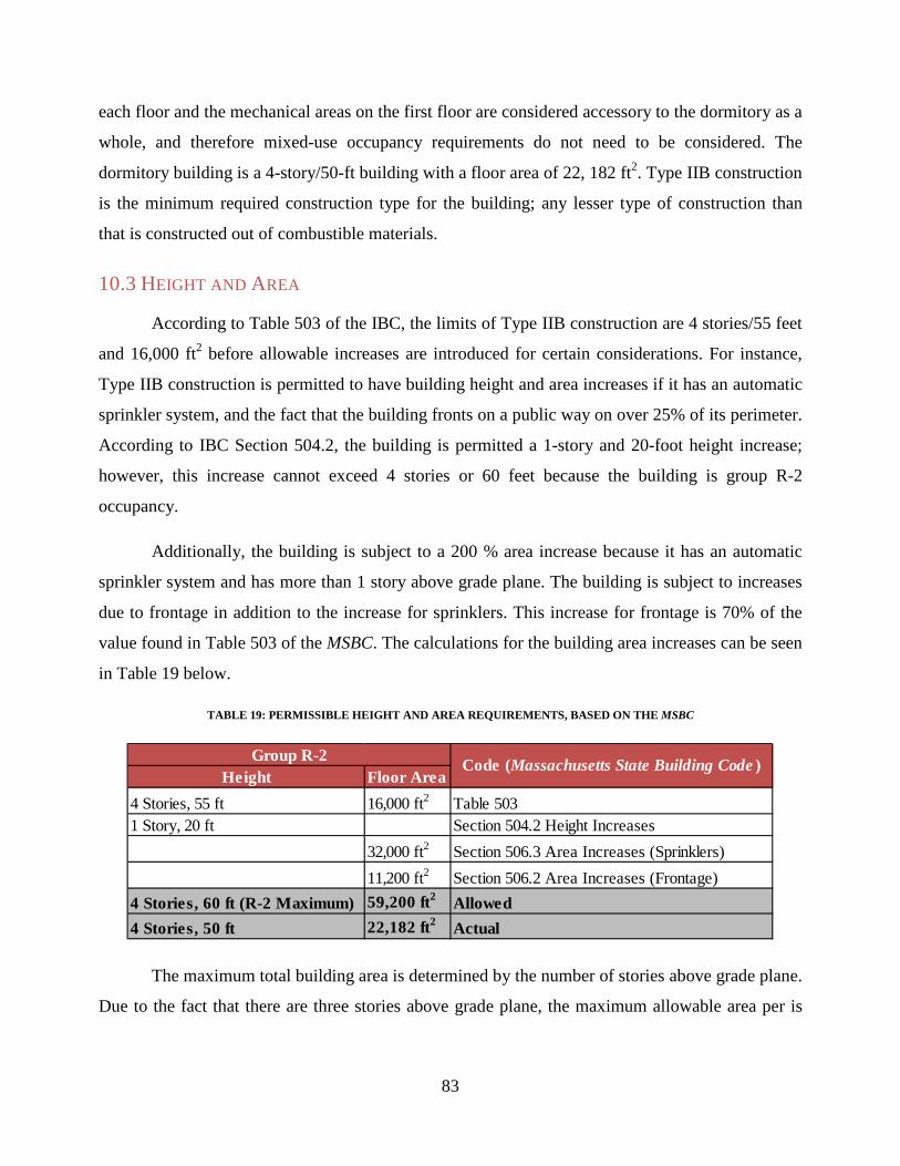
83
each floor and the mechanical areas on the first floor are considered accessory to the dormitory as a
whole, and therefore mixed-use occupancy requirements do not need to be considered. The
dormitory building is a 4-story/50-ft building with a floor area of 22, 182 ft2. Type IIB construction
is the minimum required construction type for the building; any lesser type of construction than
that is constructed out of combustible materials.
10.3 HEIGHT AND AREA
According to Table 503 of the IBC, the limits of Type IIB construction are 4 stories/55 feet
and 16,000 ft2 before allowable increases are introduced for certain considerations. For instance,
Type IIB construction is permitted to have building height and area increases if it has an automatic
sprinkler system, and the fact that the building fronts on a public way on over 25% of its perimeter.
According to IBC Section 504.2, the building is permitted a 1-story and 20-foot height increase;
however, this increase cannot exceed 4 stories or 60 feet because the building is group R-2
occupancy.
Additionally, the building is subject to a 200 % area increase because it has an automatic
sprinkler system and has more than 1 story above grade plane. The building is subject to increases
due to frontage in addition to the increase for sprinklers. This increase for frontage is 70% of the
value found in Table 503 of the MSBC. The calculations for the building area increases can be seen
in Table 19 below.
TABLE 19: PERMISSIBLE HEIGHT AND AREA REQUIREMENTS, BASED ON THE MSBC
The maximum total building area is determined by the number of stories above grade plane.
Due to the fact that there are three stories above grade plane, the maximum allowable area per is
Height Floor Area4 Stories, 55 ft 16,000 ft2 Table 5031 Story, 20 ft Section 504.2 Height Increases
32,000 ft2 Section 506.3 Area Increases (Sprinklers)11,200 ft2 Section 506.2 Area Increases (Frontage)
4 Stories, 60 ft (R-2 Maximum) 59,200 ft2 Allowed4 Stories, 50 ft 22,182 ft2 Actual
Group R-2 Code (Massachusetts State Building Code )

84
multiplied by three to give the total building area. This factor yields a total building area of
177,600 ft2 which is much greater than the actual total building area of 88,728 ft2.
10.4 FIRE SEPARATION CHARACTERISTICS
The physical characteristics of the building are also regulated by 780 CMR. These
characteristics are inclusive of the type of construction and different passive fire protection features
including separation of different portions of the building amongst other characteristics. Primarily,
these are the fire resistance ratings of various elements of the building construction. First, the fire
resistance ratings of the different building elements are laid out in Table 601 of the MSBC. The
requirements for Type IIB Construction can be seen in Table 20 below.
TABLE 20: FIRE RESISTANCE RATINGS FOR VARIOUS BUILDING ELEMENTS, BASED ON THE MSBC
As seen in Table 20 above, all of the different elements of the building are not required to
have a fire resistance rating. This is due to the fact that the construction type is consistent with
unprotected steel construction. Steel is considered a non-combustible material; however,
unprotected steel has no fire resistance rating. This means that the steel is susceptible to the fire
event and will start to be affected by fire at the start of the fire event. In addition to the
requirements for the exterior walls in the above table, the fire resistance rating of these walls needs
to be confirmed in relation to the fire separation distance (FSD). The FSD is determined by
drawing a perpendicular line from the exterior wall to the centerline of the public street or
arbitrarily created line between two buildings on the same lot. In this scenario, the FSD is twenty-
five feet. The required fire resistance rating can be seen in the table below which is an excerpt of
Table 602 of the MSBC.
Building Element Type II BPrimary Structural frame 0Bearing WallsExterior 0Interior 0Non-Bearing WallsExterior 0Interior 0Floor Construction and Secondary Members 0Roof Construction and Secondary Members 0

85
TABLE 21: FIRE RESISTANCE RATINGS DEPENDENT ON FIRE SEPARATION DISTANCES, BASED ON THE MSBC
As seen in all of the different elements of the building are not required to have a fire
resistance rating. This is due to the fact that the construction type is consistent with unprotected
steel construction. Steel is considered a non-combustible material; however, unprotected steel has
no fire resistance rating. This means that the steel is susceptible to the fire event and will start to be
affected by fire at the start of the fire event. In addition to the requirements for the exterior walls in
the above table, the fire resistance rating of these walls needs to be confirmed in relation to the fire
separation distance (FSD). The FSD is determined by drawing a perpendicular line from the
exterior wall to the centerline of the public street or arbitrarily created line between two buildings
on the same lot. In this scenario, the FSD is twenty-five feet. The required fire resistance rating can
be seen in the table below which is an excerpt of Table 602 of the MSBC.
Table 21 above shows that the exterior walls are required to have a zero hour fire resistance
rating based on a FSD equaling twenty-five feet. The required fire resistance of the exterior walls
is the greater of the values determined from Table 601 and Table 602 of the MSBC. However, both
tables require no fire resistance rating for the exterior walls of this building. Additionally, the
openings within the exterior wall are also regulated by 780 CMR as well as by the FSD. The table
below is an excerpt from Table 705.8 of the MSBC which gives percentages of open area in
relation to FSD.
Fire ResistanceGroup R-2
FSD < 5 ft All 1 HourIA 1 HourOthers 1 HourIA,IB 1 HourIIB,VB 0 HourOthers 1 Hour
FSD > 30 ft All 1 Hour
Fire Separation Distance (FSD) Type of Construction
10 ft < FSD < 30 ft
5 ft < FSD < 10 ft

86
TABLE 22: PERCENTAGE OF EXTERIOR WALL AREA OPEN DEPENDENT ON FIRE SEPARATION DISTANCES, BASED ON
THE MSBC
As stated earlier, the FSD around the perimeter of the building is twenty five feet. This
twenty five foot distance yields an unlimited area of openings on the exterior walls. The last
building characteristic to be addressed is the interior wall separation from specific rooms or areas.
As stated earlier, the FSD around the perimeter of the building is twenty-five feet. This
twenty-five foot distance yields an unlimited area of openings on the exterior walls. The last
building characteristic to be addressed is the interior wall separation from specific rooms or areas.
Although all of the building elements outlined in Table 601 and 602 of the MSBC required
no fire resistance rating, there are other special aspects of the building which require a fire
resistance rating no matter what the type of construction dictates. These ratings are found
throughout Chapter 7, titled Fire and Smoke Protection Features in the MSBC. Primarily, according
to Section 420 of 780 CMR, there is a required thirty minute separation between dwelling units
adjacent, above, or below each other. Additional separation requirements as well as separation type
can be seen in Table 23 below.
TABLE 23: BUILDING ELEMENT AND OPENING PROTECTIVE FIRE RESTIANCE RATINGS, BASED ON THE MSBC
Fire Separation Distance (FSD) % of Exterior Wall Area Open0 ft < FSD < 3 ft Not Permitted3 ft < FSD < 5 ft 15%
5 ft < FSD < 10 ft 25%10 ft < FSD < 15 ft 45%15 ft < FSD < 20 ft 75%
20 ft< FSD No Limit
Building Element Separation Type Fire Resistance Rating Opening Protective RatingShaft Enclosures (4 Stories) Fire Barrier 2 Hours 90 MinutesShaft Enclosures (3 Stories) Fire Barrier 1 Hour 91 MinutesStair Enclosures (4 Stories) Fire Barrier 2 Hours 92 MinutesStair Enclosures (3 Stories) Fire Barrier 1 Hour 93 MinutesElevator Machine Room Fire Barrier 2 Hours 94 MinutesEmeregency Electrical Room Fire Barrier 2 Hours 95 MinutesCorridors Serving Dwellings Fire Partition 0.5 Hours 20 MinutesTrash Rooms Over 100 ft2 Fire Barrier 1 Hour 45 Minutes

87
As can be seen above, the majority of interior walls are required to have some type of fire
resistance rating. The requirements listed above are greater than the requirements of Tables 601
and 602 and therefore must be implemented in the building. These separation requirements are
based on the need of property protection, and not life safety requirements.
10.5 MEANS OF EGRESS
Egress is defined as the action of going out of or leaving a space. Therefore the means of
egress would be the physical aspects of a building which allow for the egress of its occupants. The
first aspect which must be addressed when it comes to the means of egress is the occupant load.
The occupant load will determine the number of required exits and then those exit capacities will
have to be sufficient for the occupant load. In addition to the occupant load, the occupancy
category of the building will determine other requirements such as door swing, and common path
of travel limits, amongst others.
10.6 OCCUPANT LOAD
Two occupant loads were calculated for this building. The first being the occupant load of
the first floor while the second refers to the occupant load of the second through fourth floor as
those floors are identical. Each different area within a floor has a specific use, and each of these
uses is provided with a different occupant load factor for its expected use. If the usage of a given
room were to change, the occupant load would have to be revised to meet the corresponding
requirements for the new usage. Each floor is not able to be blanketed with one occupant load
factor due to the large differences in use types. Occupant load factors can be found in Table
1004.1.1 of the MSBC. The table below (Table 24) outlines the different areas within each floor,
the square footage of each area, the differing occupant load factors, and the total number of
occupants allowed in each area as well as the floor as a whole.

88
TABLE 24: OCCUPANT LOAD PER FLOOR BASED ON EXPECTED USE OF AREAS, , BASED ON THE MSBC
As seen above, the first floor has an occupant load of 492 persons while the second, third,
and fourth floors each have an occupant load of 445 persons. This gives a total occupant load for
the building as 1,827 persons. Based on these occupant loads, the prescribed number of exits
required from each floor was determined. The number of required exits is outlined in Section
1021.1 of the MSBC. According to Table 1021.1 of the MSBC, stories with an occupant load
between 1 and 500 people are required to have two exits. Thus, there are two exits on each of the
second through fourth stories, and 4 exits on the first story since the story must accommodate the
egress of all the building occupants. This is acceptable because the required number of exits from
any story must be maintained until the occupants arrive at grade level or a public way. Even if the
number of exits is deemed adequate, the exit stairs and doors need to have adequate width to
sustain the number of occupants who will be using that exit.
Floor Area Floor Area Occupanct Load Factor Occupanct Load
Dormitory 15,279 ft2 50 gross ft2/occupanct 306Mechanical/Storage 2,773 ft2 300 gross ft2/occupanct 10Multipurpose Room 769 ft2 7 net ft2/occupanct 110RD Apartment 610 ft2 200 gross ft2/occupanct 4Trash Room 457 ft2 50 gross ft2/occupanct 10Laundry Room 381 ft2 50 gross ft2/occupanct 8Gaming Area 368 ft2 15 gross ft2/occupanct 25Lobby 1,922 ft2 15 gross ft2/occupanct 13Lounges 85 ft2 15 gross ft2/occupanct 6
492
Dormitory 19,792 ft2 50 gross ft2/occupanct 396Tech Suite 349 ft2 15 gross ft2/occupanct 24Study Room/Lounge 237 ft2 15 gross ft2/occupanct 16Mechanical/Electrical 225 ft2 300 gross ft2/occupanct 1Trash Room 126 ft2 300 gross ft2/occupanct 1Small Lounge 91 ft2 15 gross ft2/occupanct 7
445Building 1,827
Floor Total
Floor TotalTotal Occupanct Load
First
Second-Fourth
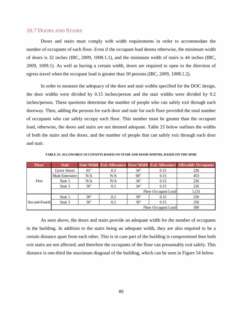
89
10.7 DOORS AND STAIRS
Doors and stairs must comply with width requirements in order to accommodate the
number of occupants of each floor. Even if the occupant load deems otherwise, the minimum width
of doors is 32 inches (IBC, 2009, 1008.1.1), and the minimum width of stairs is 44 inches (IBC,
2009, 1009.1). As well as having a certain width, doors are required to open in the direction of
egress travel when the occupant load is greater than 50 persons (IBC, 2009, 1008.1.2).
In order to measure the adequacy of the door and stair widths specified for the DOC design,
the door widths were divided by 0.15 inches/person and the stair widths were divided by 0.2
inches/person. These quotients determine the number of people who can safely exit through each
doorway. Then, adding the persons for each door and stair for each floor provided the total number
of occupants who can safely occupy each floor. This number must be greater than the occupant
load, otherwise, the doors and stairs are not deemed adequate. Table 25 below outlines the widths
of both the stairs and the doors, and the number of people that can safely exit through each door
and stair.
TABLE 25: ALLOWABLE OCCUPANTS BASED ON STAIR AND DOOR WIDTHS, BASED ON THE MSBC
As seen above, the doors and stairs provide an adequate width for the number of occupants
in the building. In addition to the stairs being an adequate width, they are also required to be a
certain distance apart from each other. This is in case part of the building is compromised then both
exit stairs are not affected, and therefore the occupants of the floor can presumably exit safely. This
distance is one-third the maximum diagonal of the building, which can be seen in Figure 54 below.
Floor Stair Stair Width Exit Allowance Door Width Exit Allowance Allowable OccupantsGrove Street 61" 0.2 34" 0.15 226
Main Enterance N/A N/A 68" 0.15 453Stair 1 N/A N/A 34" 0.15 226Stair 3 50" 0.2 34" 0.15 226
1,131Stair 1 50" 0.2 39" 0.15 250Stair 3 50" 0.2 39" 0.15 250
500
First
Second-Fourth
Floor Occupant Load
Floor Occupant Load

90
FIGURE 54: MEASURE OF REMOTENESS EXIT STAIRCASES
As seen in the figure above, the distance between the exits is adequate. This is because the
distance between the two most remote exits, is 207 ft while the required separation distance is 100
ft. To complete the egress analysis, certain components of the corridors and travel distances were
checked. First, the maximum travel distance from any point in the dormitory to an exit access is
250 feet. Additionally, there is a maximum distance of a dead end corridor of fifty feet. However,
there is no dead end corridor in the residence hall. Last, the maximum common path of egress
travel, the path which one must take before reaching a point where they can choose two distinct
paths to reach an exit access, is 125 feet for residential occupancies.

91
11.0 CONSIDERATION OF BROADER IMPACTS Some of the topics presented in this chapter include environmental impacts, social
implications, and political implications. Interviews and research was performed in order to provide
the following discussions.
11.1 ENVIRONMENTAL IMPACTS
A major environmental concern determined in this project that was focused on was runoff
and erosion from the site. Runoff is increased during construction due to the vegetation removed
from the site and the increased activity and volume of runoff on site. The removal of vegetation
from the site also creates a greater vulnerability to erosion.
In order to decrease or prevent environmental impacts such as erosion, control methods
were researched. Control methods aim to disrupt erosion by providing soil stabilization, runoff
management and sediment control. 56 Some options that have immediate effects are mulches,
erosion control blankets, polymer soils, silt fences and straw bale barriers. The benefits of these
control methods include the immediate mitigation effects and the ease of obtaining, placing and
removing these systems. Another approach to erosion control is to combine multiple methods. For
example, it is popular to find silt fences used in combination with straw bale barriers. Some more
labor intensive control methods include constructing a swale, planting vegetation cover and
making inlets to retention ponds or other area. These methods tend to provide better runoff control
but take more time to create and setup. The removal of these control methods also is more difficult
as the vegetation must be removed or the swales need to be filled in. These control methods can
also be left permanently if planned ahead of time.57
56 Broz, Bob, Don Pfost, and Allen Thompson.
57 Broz, Bob, Don Pfost, and Allen Thompson.

92
11.2 SOCIAL IMPLICATIONS
One of the aspects of any design-build project which needs to be considered is the social
impact of the project and the effect it will have on the surrounding community. Although many of
the buildings in the direct vicinity of the residence hall are owned by WPI, the owners of the other
buildings should be consulted to see their views on the project and how it may affect their business.
One of the businesses that is directly affected by the new residence hall as well as Gateway
Park as a whole is the Courtyard Marriot Hotel. The hotel is sandwiched between the Gateway 1
and 2 buildings and the new residence hall. An interview was conducted with Socrates Ramirez
(January 2013), the Manager of the hotel, to learn his views on the major construction projects
WPI is conducting in general, as well as how he feels the construction may positively or adversely
affect his business.58
Overall, Mr. Ramirez was very positive about the construction. He sees the construction as
a way of bringing more students to campus. The more students that visit the campus and become
students at WPI, the more opportunities the hotel has to house family members, especially for
special events like graduation and parent’s weekend. He also expressed his feelings that any
construction is not only good for his business and the hotel industry as a whole, but good for the
City as a whole. Mr. Ramirez had seen this type of development in the time he spent living in
Providence, RI and believes that the construction and growth that is being seen presently in
Worcester is very similar to that which went on in Providence.
The principal negative aspect he saw was the construction process in general. Since a hotel
is mainly used for sleeping and business functions, loud noises are definitely not ideal. With
construction starting early in the morning, possibly before people wake up for the day, it can
become a hindrance for people staying at the hotel. However, Mr. Ramirez knew that this was
something that was necessary for growth in the City.
Overall, the construction of the new residence hall, as well as the ever expanding Gateway
Park, has a very positive social impact on the immediate area and Worcester as a whole. The
58 Ramirez

93
success and positive experience that this construction project gives the City will lead to more
construction and a better city as a whole.
11.3 POLITICAL IMPLICATIONS
Large construction projects have many obstacles to overcome throughout their construction
process. Political issues, such as changes in zoning and the effects a project could have on a
neighborhood or city are critical aspects of gaining approvals. How a project fits in with the goals
and plans of a city are essential questions to answer. Political figures can be some of the most
influential people when it comes to new construction. Numerous people have been involved in the
development of the new WPI residence hall in Worcester, and one of the forerunners is Councilor
Philip Palmieri. Mr. Palmieri is currently serving his sixth, two-year term as the District Two
Councilor. District 2 covers a large area of Worcester, including Lincoln Street, WPI, downtown
east of Main Street, UMass, the Canal District north of Kelley Square, and several other areas.59
Mr. Palmieri grew up in Worcester and is very knowledgeable on the current expansion and
redevelopment efforts of WPI and the City of Worcester as a whole. With so many years of
experience, Mr. Palmieri has had many interactions with the different colleges of Worcester. He
has witnessed WPI grow with the development of Gateway Park, and has seen the effects it has had
on the City.
In an interview with Mr. Palmieri (January 2013), significant insight into the political and
social impacts that Gateway Park and the new residence hall have and will have on Worcester
became clear.60 Zoning was one of the first issues that was addressed. The zoning for the area of
Gateway Park had to be changed from a light industrial zone, because it is not acceptable to build
dormitories in this type of zone. Mr. Palmieri explained how, before construction could begin, the
zoning for that location was changed so that it could encompass all of the desired Gateway Park
buildings, including, but not limited to, the new residence hall. He clarified that in order to get the
City to change the zoning of an area, you have to follow a regulatory process. A proposal for the
change comes first and is brought in front of the city council and then a subcommittee. Next, the
59 Councilor Palmieri
60 Palmieri

94
planning board looks at the proposal. The most crucial aspect needed when pushing for a zoning
change is a critical mass of neighbors to argue that this change is the right thing for everyone in
that area. Mr. Palmieri clarified that you cannot simply change the zoning for one street or one
block, it needs to be a change for a whole area. This process has many steps, and this was the first
political step that needed to take place for construction of Gateway Park and the new dormitory to
even begin. This makes it clear that changing the zoning of an area is not a simple task and
involves much support and push. Mr. Palmieri expressed the importance of Gateway Park in
helping to transition this area of Worcester from its light industrial zone of the past to a flourishing
business and multi-purpose district.
The whole reason that Gateway Park was able to be developed in the first place was due to
the fact that Worcester Polytechnic Institute partnered with the Worcester Business Development
Corporation (WBDC) to purchase the biotechnology park and change this rundown site into an
attractive area of Worcester. This depicts the intricacies behind the dormitory project, and how this
building did not simply pop up, it took years of planning and many different parties. Mr. Palmieri
referred to the redevelopment of this area as turning “brownfields into cornfields.”
Focusing more on the political and social aspects of the new dormitory, Mr. Palmieri
stressed the benefits this dorm will have on downtown Worcester. Simply stated, a new building
used for housing (especially one the size of the new residence hall) close to downtown, means that
more people will be within walking distance of the stores, restaurants, bars, etc. that are located
downtown. Therefore, downtown Worcester should see an economic improvement. Mr. Palmieri
discussed how it is a goal of Worcester to increase the activity of downtown and draw more
people, especially younger people, to it. The addition of the dormitory is expected to be a strong
contributor to this endeavor. People often see the greater good in adding housing to an area Mr.
Palmieri explained, and he believed that the increased foot traffic in Gateway Park and the
surrounding areas would only better the City of Worcester.
With any large construction project, in our case the new residence hall (and all of Gateway
Park), Mr. Palmieri made it clear that one of the most important features necessary to make it a
success is for it to fit in with the goals of the City it is in and be accepted by those around it. There
are many political efforts to revitalize and redevelop Worcester, of which, the Gateway Park area
of District 2 is the focal point, according to Mr. Palmieri. Therefore, the expansions and additions

95
that WPI makes are often widely accepted because of their beneficial outcomes for Worcester. The
new residence hall has a solid political advantage because of the way it will help with the City’s
plans. Just as Mr. Palmieri described, WPI will continue to be an anchor for the Northern sector of
Worcester and the new dormitory will only benefit District 2 and downtown Worcester.

96
12.0 CONCLUSIONS Worcester Polytechnic Institute (WPI) is growing and expanding its campus and academic
offerings, which has created a need for increased residency for graduate students. The construction
of a residence hall within the Gateway Park area increases the number of graduate students that are
able to pursue graduate studies at WPI. The ability to house graduate students makes WPI a more
desirable campus for potential students. The need for the residence hall can be seen in increased
acceptance rates and a greater desire to be housed on campus. Before any new buildings are
constructed in the Gateway Park region, designs need to be completed to determine their adequacy
with state and local building codes and to ensure their stability in adverse conditions.
Throughout this project many different design aspects and conditions were addressed. The
design of the primary structural elements was completed for both steel and concrete systems using
the requirements of ASCE 7, PCI and AISC as referenced by the MSBC. These design aspects
included gravity loading, such as dead loads, live loads and snow loads, and lateral loading, such as
wind and earthquake loads. Using these loads it was possible to design the building following the
load distribution from the concrete slabs, to the beams and girders, to the columns, and down to the
footings. While completing the steel design, beams, girders, and columns were selected from Steel
Construction Manual. The beams, girders, and columns for the concrete design were taken from
PCI design tables. The design completed by DOC was verified using these techniques, and an
alternate design using precast concrete members was completed for comparison. From the
comparison, it was evident that the steel design was more costly; however, the steel construction
process may be more fluid and have a faster completion time which may offset labor costs to even
out the total costs.
In addition to the structural design, some passive measures of fire protection were evaluated
to determine their compliance with the provisions of the MSBC and 527CMR. These measures
included, but were not limited to, height and area maximums, occupancy loads, and widths of
doors and stairs. These aspects are used to ensure the safety of the occupants in making sure
buildings with lower safety ratings are less expansive and do not become overcrowded in the event
of a fire or other emergency. Many fires with large loss due to fire, like the Station Nightclub Fire
in Rhode Island and the Kiss Nightclub Fire in Brazil, have been due to overcrowding and
buildings not compliant with the applicable codes. Passive fire protection measures are generally
97
accompanied by active fire protection measures, such as sprinkler systems, to provide additional
protection.
The last design aspect which was addressed was the design of the sprinkler system required
by the MSBC. The sprinkler system was designed in accordance with NFPA 13. The system was
designed based upon the intended use and occupancy and the typical commodities that are
expected to be present within the building. The typical commodities and uses, as well as the
orientation of the building, delegate the type and spacing of sprinklers required for the project. For
the sake of comparison two different piping materials, black steel and Chlorinated Polyvinyl
Chloride (CPVC), were used to determine the required pump size and number of sprinklers which
would be required within the building. Black steel pipe was chosen to be used even though it was
more costly because CPVC is generally accepted to be used in small residential houses and not
large-scale construction project such as this.
In addition to the physical design associated with the project, some construction
management aspects, mainly scheduling and cost estimation, were reviewed. The predicted costs
for each design aspect, steel, concrete, and fire protection, were determined using the RS Means
Total Construction Costs. These costs only provide two aspects of the total construction costs. The
remainder of the costs (HVAC, electrical, etc.) were estimated in comparison to the structural costs
using RS Means Square Foot Costs for a representative residential hall. A schedule was created
using Primavera software. It was a condensed version of the timetable created by DOC, and was
used to gain a better understanding of the time required for each division of construction. Using a
pie chart to compare the percentages of time for each division, it was determined that the more
intricate and detailed aspects of construction, such as electrical and plumbing work, took much
more time than the structural steel erection.
Throughout the course of the project, we determined some additional aspects that warrant
further research and study. One of the major items for further research is the thermal properties of
the steel and concrete structures and their impact on the design and performance of the heating and
cooling systems of the building. With many buildings trying to achieve LEED certification, the use
of the materials which allow for flexibility of HVAC use is crucial. Additionally, the actual costs
of HVAC, Electrical, and other building systems warrant more investigation in an integrated
manner instead of approximating those costs as percentages of the structural costs. Last, the

98
hangers and bracing of the sprinkler system can be addressed. There are specific hangers and
bracings designed for seismic loading that can be used and should be addressed in further detail in
future projects.

99
REFERENCES ACI. American Concrete Institute, n.d. Web. 10 Dec. 2013.
<http://www.concrete.org/general/home.asp>. AISC. Steel Construction Manual. 14th ed. N.p.: American Institute of Steel
Construction, 2011. Print. ASCE. ASCE/SEI 7-10 Minimum Design Loads of Building and Other Structures. N.p.:
American Society of Civil Engineers, 2010. Print. Assakkaf, Ibrahim, Dr. "Introduction to Structural Steel Design." Lecture. Part II-
Structural Steel Design and Analysis. University of Maryland, College Park. Dept. of Civil and Environmental Engineering, University of Maryland, 2002. Web. 3 Jan. 2013. <http://www.assakkaf.com/Courses/ENCE355/Lectures/Part2/Chapter1.pdf>.
Balboni, Barbara. RSMeans Square Foot Costs 2011. 32nd ed. Norwell, Ma.: R S Means,
2010. Print "Bridges." Kerkstra Precast. N.p., 2013. Web. 13 Feb. 2013.
<http://kerkstra.com/products/bridges/>. Broz, Bob, Don Pfost, and Allen Thompson. "Controlling Runoff and Erosion at Urban
Construction Sites." G1509. University of Missouri, Biological Engineering Department, Sept. 2003. Web. 10 Mar. 2013.
Buettner, Donal R., and Roger J. Becker. PCI Manual for the Design of Hollow Core
Slabs. Rep. 2nd ed. Chicago: PCI, 1998. PCI.org. PCI. Web. "Building with Precast." Precast Building Innovation. Spancrete, n.d. Web. 1 Feb. 2013.
<http://www.spancrete.com/global_solutions/building_with_precast/>. Buyukozturk, Oral. Calculation of Wind and Earthquake Loads on Structures According
to ASCE 7 & IBC. N.p., Fall 2003. Web. 30 Jan. 2013. <http://ocw.mit.edu/courses/civil-and-environmental-engineering/1-051-structural-engineering-design-fall-2003/recitations/rec1wind_eqloads.pdf>.
Caprani, Colin. Structural Engineering, Bridge Research, Programming, and More.
Word Press, n.d. Web. 15 Jan. 2013. “Chapter 5: Foundation Design." Geotechnical Manual: Foundation Design. N.p., n.d.
Web. 12 Sept. 2012. <http://onlinemanuals.txdot.gov/txdotmanuals/geo/foundation_design.htm>.

100
City of Worcester. (2012a) "City of Worcester Zoning Ordinance." N.p., 22 May 2012. Web. 10 Sept. 2012. <http://www.worcesterma.gov/uploads/e8/34/e834c36f88640db2ce79c76c61fc3972/zoning-ord.pdf>.
City of Worcester. (2012b) "City of Worcester, MA - Zoning Map." N.p., 17 July 2012.
Web. 10 Sept. 2012. <http://www.worcesterma.gov/uploads/95/9b/959b28180c52c716e44312cb40d5e2ca/zoning-map.pdf>.
Commonwealth of Massachusetts. 527 CMR: Board of Fire Prevention Regulations.
2010. Commonwealth of Massachusetts. 780 CMR: Massachusetts State Building Code, 8th.
2010. "Construction Management of Steel Construction." American Institute of Steel
Construction Inc., n.d. Web. 2 Feb. 2013. <http://www.pcmanagement.es/editorial/management_sp/AISC%20Construction%20Management%20of%20Steel%20Construction.pdf>.
"Councilor Palmieri." Welcome to the City of Worcester, MA. N.p., 2013. Web. 10 Jan.
2013. Daniel O'Connell's Sons Inc. New Residence Hall: Worcester Polytechnic Institute. Tech.
ADD Inc., 2012. Print Daniel O’Connell’s Sons, Inc. New Residence Hall. 3 vols. Boston: ADD, 2012. Print. "Designing with Precast & Prestressed Concrete." Precast/Prestressed Concrete Institute,
n.d. Web. 16 Feb. 2013. <http://www.pci.org/files/PCI_DWP_binder_ch3.pdf>. "Foundation... Selecting What Type Of Footing Is Appropriate For Your Project." Energy
Efficient Building Network., n.d. Web. 12 Sept. 2012. <http://www.energyefficientbuild.com/foundation.html>.
Gateway Park at WPI. N.p., n.d. Web. 03 Sept. 2012.
<http://www.gatewayparkworcester.com/>. “Gateway Park Detailed Map.” WPI, n.d. Web. 03 Sept. 2012.
<http://www.gatewayparkworcester.com/maps.html>. "Google Maps." Google Maps. N.p., 2012. Web. 13 Sept. 2012.
<http://maps.google.com/maps?hl=en>.

101
Growth District Communities. N.p., n.d. Web. 04 Sept. 2012. <http://www.mass.gov/hed/economic/eohed/pro/gdi/gdi-guidelines.html>.
Growth Districts Initiative Description. N.p., n.d. Web. 04 Sept. 2012.
<http://www.mass.gov/hed/economic/eohed/pro/gdi/growth-districts.html>. Lake, James D. NFPA 13, Standard for the Installation of Sprinkler Systems. Quincy,
MA: National Fire Protection Association (NFPA), 2009. Print. "Lateral Force Resisting Systems-Braced Frames." Lecture. Delhi.edu. Web. 30 Jan.
2013. <http://faculty.delhi.edu/hultendc/AECT210-Lecture%2038.pdf>. "LEED Green Building Certification." USGBC. US Green Building Council, n.d. Web. 23 Feb. 2013. <http://www.usgbc.org/Docs/Archive/General/Docs3330.pdf>. McCormac, Jack C., and Stephen F. Csernak. Structural Steel Design. 5th ed. Boston:
Prentice Hall, 2012. Print. Murray, Jean. "Zoning." N.p., n.d. Web. 10 Sept. 2012.
<http://biztaxlaw.about.com/od/glossaryz/g/zoning.htm>. Palmieri, Philip. "Interview: Worcester District Two Councilor." Personal interview. 23 Jan. 2013. PCI Design Handbook Seventh Edition. Precast/Prestressed Concrete Institute, 2010.
Web. 3 Dec. 2012. <http://www.pci.org/cms/index.cfm/DHSeventhEdition>. Pentair. "Aurora Pump Home Page." Aurora Pump Home Page. Pentair, 2013. Web. 10
Mar. 2013. The Phoenix Awards. N.p., 2007. Web. 03 Sept. 2012.
<http://www.phoenixawards.org/factsheets/2007_Region_1_Gateway_Park.pdf> "Principles of Eco-Design." Eco-Principles. N.p., n.d. Web. 08 Feb. 2013.
<http://www.theyellowhouse.org.uk/eco-prin/princip.html>. "Products: Benefits of Precast Concrete." Wells Concrete. Wells Concrete Products, Inc.,
n.d. Web. 4 Feb. 2013. <http://wellsconcrete.com/products/benefits-of-precast-concrete/>.
Ramirez, Socrates. "Interview: General Manager of Courtyard Marriot Hotel." Personal
interview. 21 Jan. 2013. Reed Construction. "Understanding RSMeans Data." N.p., 2012. Web. 9 Sept. 2012.
<http://www.reedconstructiondata.com/help/costworks/understanding-rsmeans-data/>.

102
Sharma, Anamika, "An Interactive Visual Approach to Construction Project Scheduling" (2009). Master's Theses (2009 -). Paper 14. <http://epublications.marquette.edu/theses_open/14>.
University of Maryland. "Footings." N.p., 2004. Web. 10 Sept. 2012.
<http://www.assakkaf.com/Courses/ENCE454/Lectures/CHAPTER12a.pdf>.
USGBC. 2009 Leed for New Construction and Major Renovations. Washington D.C: U.S. Green Building Council, 2009. Print.
USGBC. "U.S. Green Building Council | U.S. Green Building Council." U.S. Green
Building Council | U.S. Green Building Council. U.S. Green Building Council, 2013. Web. 20 Feb. 2013.
Waier, Phillip R., PE. RSMeans Building Construction Cost Data 2013. 71st ed. Norwell,
MA: RSMeans, 2012. Print.

103
APPENDIX A.1 PROPOSAL – STRUCTURAL

104

105

106

107

108
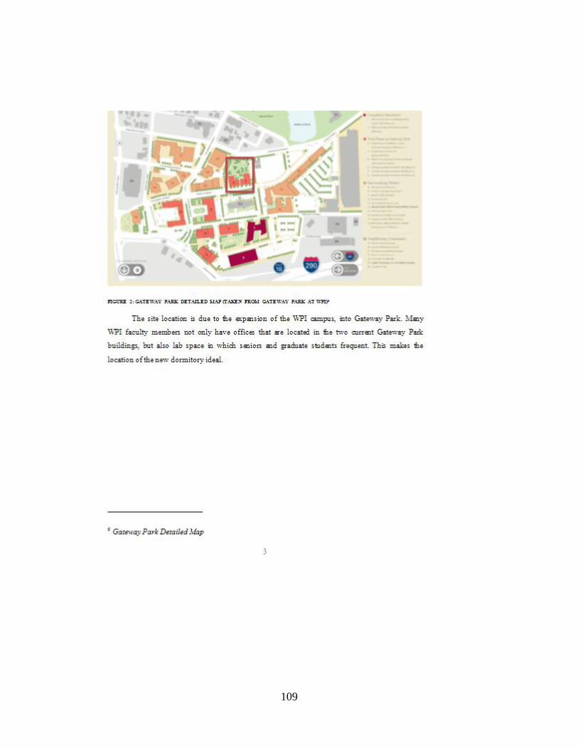
109

110

111

112

113
114

115

116

117

118

119

120
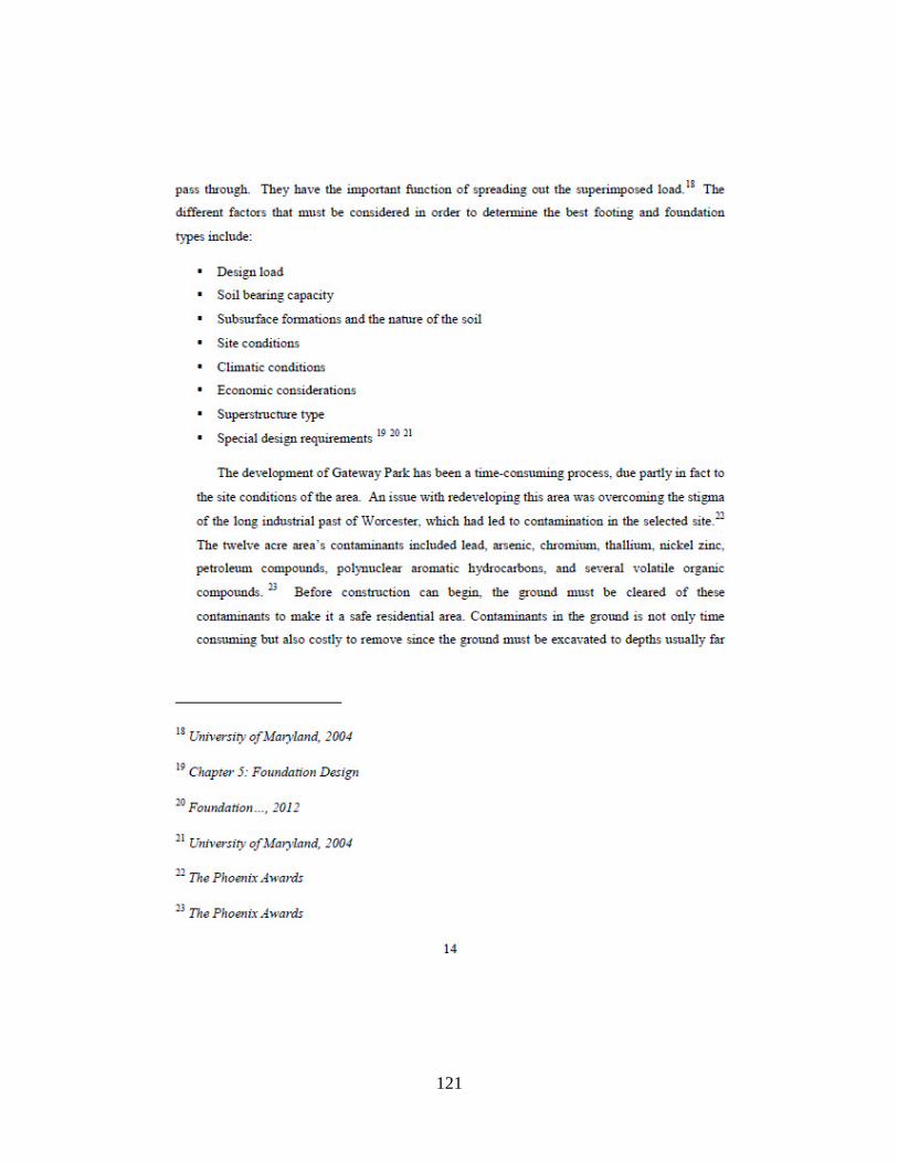
121

122

123

124

125

126

127

128

129

130

131
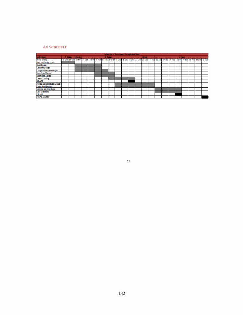
132

133

134
APPENDIX A.2 PROPOSAL – FIRE PROTECTION

135

136

137

138

139

140

141

142

143

144

145

146

147

148

149

150

151

152

153
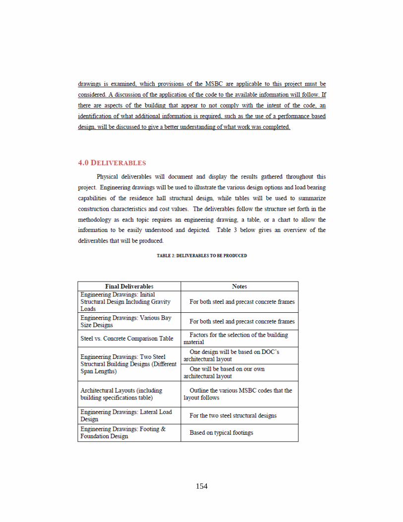
154

155

156

157

158

159

160
161

162
APPENDIX B.1 CALCULATIONS FOR COMPOSITE DECKING

163
APPENDIX B.2 CALCULATIONS FOR SNOW LOADING

164

165
APPENDIX B.3 SAMPLE CALCULATION FOR STEEL DESIGN

166

167

168

169

170

171

172
APPENDIX B.4 SAMPLE CALCULATION FOR STEEL BEAM UNDER
MECHANICAL SCREEN WALL

173

174

175
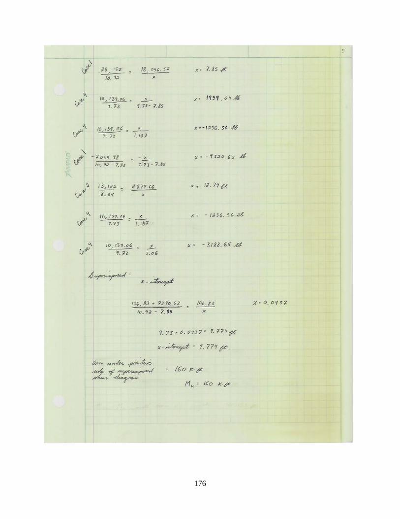
176

177

178
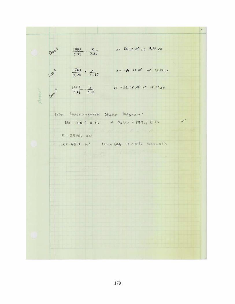
179

180

181

182

183
APPENDIX B.5 SAMPLE CALCULATION FOR CONCRETE DESIGN

184

185

186
APPENDIX C.1 SAMPLE SPREADSHEETS FOR WIND LOADING
Number of Frames 10Windward
Level Height (ft) Width (ft) Area (ft2) Force (lbs) Force (k)Roof 6.67 173 1153 3946.3 3.95
V (ft/s) 146.67 Floor 4 12.00 173 2076 7104.4 7.10Floor 3 10.67 173 1846 6316.1 6.32
Iw 1 Floor 2 13.34 173 2307 7893.7 7.89Floor 1 8.00 173 1384 4735.6 4.74
LeewardKzt 1 Level Height (ft) Width (ft) Area (ft2) Force (lbs) Force (k)
Roof 6.67 154.8 1032 -2484.3 -2.48GCpi ± 0.18 Floor 4 12.00 154.8 1858 -4472.3 -4.47
Floor 3 10.67 154.8 1652 -3976.1 -3.98a (ft) 5 Floor 2 13.34 154.8 2064 -4969.2 -4.97
Floor 1 8.00 154.8 1238 -2981.1 -2.98h (ft) 60
Side Wall 1θ (degrees) 0 Level Height (ft) Width (ft) Area (ft2) Force (lbs) Force (k)Wind Directionality Factor Roof 6.67 191.51 1277 -3936.8 -3.94Kd 0.85 Floor 4 12.00 191.51 2298 -7087.3 -7.09Velocity Pressure Exposure Coefficient Floor 3 10.67 191.51 2043 -6300.9 -6.30Kz 0.85 Floor 2 13.34 191.51 2554 -7874.7 -7.87
Floor 1 8.00 191.51 1532 -4724.2 -4.72G 0.85
Side Wall 2qz (psf) 39.79 Level Height (ft) Width (ft) Area (ft2) Force (lbs) Force (k)
qh (psf) 39.79 Roof 6.67 114.01 760 -2343.7 -2.34
Design Wind Pressure (+GCpi) (-GCpi) Floor 4 12.00 114.01 1368 -4219.3 -4.22p (psf) Windward 19.89 34.22 Floor 3 10.67 114.01 1217 -3751.2 -3.75p (psf) Leeward -24.07 -9.75 Floor 2 13.34 114.01 1520 -4688.1 -4.69p (psf) Side Walls -30.83 -16.51 Floor 1 8.00 114.01 912 -2812.5 -2.81
Windward Cp 0.8 Side Wall 3
Leeward Cp -0.5 Level Height (ft) Width (ft) Area (ft2) Force (lbs) Force (k)
Side Wall Cp -0.7 Roof 6.67 46.67 311 -959.3 -0.96Floor 4 12.00 46.67 560 -1727.0 -1.73Floor 3 10.67 46.67 498 -1535.4 -1.54Floor 2 13.34 46.67 622 -1918.9 -1.92Floor 1 8.00 46.67 373 -1151.2 -1.15
Grove Street Wing (east to west)
Wall/Roof Pressure Coefficient
Velocity Pressure
Top of Elevator/Stairs From ASCE 7Enclosure Classification
EnclosedBasic Wind Speed
Wind Load Importance Factor
Wind Topographic Factor
Internal Pressure Coefficient
Corner Zone Dimension
Mean Roof Height
Angle of Roof Plane
Wind Exposure CategoryB
Gust Effect Factor

187
Number of Frames 7Windward
Level Height (ft) Width (ft) Area (ft2) Force (lbs) Force (k)Roof 6.67 134.0 893 4366.7 4.37
V (ft/s) 146.67 Floor 4 12.00 134.0 1608 7861.2 7.86Floor 3 10.67 134.0 1430 6988.9 6.99
Iw 1 Floor 2 13.34 134.0 1787 8734.5 8.73Floor 1 8.00 134.0 1072 5240.1 5.24
LeewardKzt 1 Level Height (ft) Width (ft) Area (ft2) Force (lbs) Force (k)
Roof 6.67 134.0 893 -3071.9 -3.07GCpi ± 0.18 Floor 4 12.00 134.0 1608 -5530.2 -5.53
Floor 3 10.67 134.0 1430 -4916.6 -4.92a (ft) 5 Floor 2 13.34 134.0 1787 -6144.6 -6.14
Floor 1 8.00 134.0 1072 -3686.3 -3.69h (ft) 60
Side Wall 1θ (degrees) 0 Level Height (ft) Width (ft) Area (ft2) Force (lbs) Force (k)Wind Directionality Factor Roof 6.67 46.67 311 -1370.4 -1.37Kd 0.85 Floor 4 12.00 46.67 560 -2467.1 -2.47Velocity Pressure Exposure Coefficient Floor 3 10.67 46.67 498 -2193.4 -2.19Kz 0.85 Floor 2 13.34 46.67 622 -2741.2 -2.74
Floor 1 8.00 46.67 373 -1644.5 -1.64G 0.85
qz (psf) 39.79
qh (psf) 39.79
Design Wind Pressure (+GCpi) (-GCpi)p (psf) Windward 19.89 34.22p (psf) Leeward -24.07 -9.75p (psf) Side Walls -30.83 -16.51
Windward Cp 0.8
Leeward Cp -0.5Side Wall Cp -0.7
West Wing (east to west)
Wall/Roof Pressure Coefficient
Velocity Pressure
Top of Elevator/Stairs From ASCE 7Enclosure Classification
EnclosedBasic Wind Speed
Wind Load Importance Factor
Wind Topographic Factor
Internal Pressure Coefficient
Corner Zone Dimension
Mean Roof Height
Angle of Roof Plane
Wind Exposure CategoryB
Gust Effect Factor

188
APPENDIX C.2 SAMPLE SPREADSHEET FOR SEISMIC LOADING
Roof Floor 4 Floor 3 Floor 2 Floor 1Snow Load (psf) 16 0 0 0 0Mechanical Equipment (lbs) 43,964 0 0 0Live Load (psf) 5 25 25 25 25Dead Load (psf) 71.07 71.07 71.07 71.07 67.00 Total (ft.)
Story Height (ft) 13.3333 10.67 10.67 16 0 50.6733Total Area (ft2) 22,182 22,182 22,182 22,182 22,182
Total Weight (lbs) 2,086,155 2,130,919 2,130,919 2,130,919 - TOTAL (lbs) 8,478,914
WXh (cumulative) 105,712,377 79,568,529 56,831,620 34,094,710 276,207,236
Cs 0.079
V (lbs) 669,834.17 669.83 kips
Fx2 82,683.57 82.68 Fx3 137,823.18 137.82
Fx4 192,962.79 192.96
Fxroof 256,364.62 256.36 Total 669.83 Total Check
lbs

189
APPENDIX C.3 SAMPLE SPREADSHEET FOR BEAM STEEL DESIGN
Loading Value (psf) YCON 6.25Dead Load 72.37 Assume "a" 2Snow Load 1 80 Y1 0Live Load 0 Y2 5.25Roof Live Load 20
Beam Length (ft) 19.5Beam Spacing (ft) 12
WDL (lb/ft) 868.44 WLL (lb/ft) - WSL (lb/ft) 960
Load Combinations wu (lb/ft)U=1.4D 1215.82
U=1.2D + 1.6L + 0.5(Lr or S or R) 1522.13U=1.2D + 1.6(Lr or S or R) + 0.5(L or 0.5W) 2578.13
U=1.2D + 1.0W + 0.5L + 0.5(Lr or S or R) 1522.13U=1.2D + 1.0E + 0.5L + 0.2S 1234.13
Mu (lb*ft) 122,541.65 5 5.25 5.5Mu (k*ft) 122.54 132 135.5 139
ΣQn (k) Weight (lbs/ft)177 12
bE (in) ≤ 59f'c (ksi) 4.00 bE (in) ≤ 144
a (in) 0.89 Y2 5.81ts 6.25
Confirm a ≤ ts Check5.5 5.81 6.0
WDL (lb/ft) 880.44 139 142.7 145WLL (lb/ft) - WSL (lb/ft) 960
Load Combinations wu (lb/ft)U=1.4D 1232.62
U=1.2D + 1.6L + 0.5(Lr or S or R) 1536.53 E (ksi)U=1.2D + 1.6(Lr or S or R) + 0.5(L or 0.5W) 2592.53 Ix (in4) 53.8 from Table 1-1
U=1.2D + 1.0W + 0.5L + 0.5(Lr or S or R) 1536.53U=1.2D + 1.0E + 0.5L + 0.2S 1248.53
Mu (lb*ft) 123,226.10 Mu (k*ft) 123.23 < φbMn (k*ft) Check
29000
Beam Spreadsheet
Interpolation from Table 3-19
φbMn (k*ft) from Interpolation in AISC Table 3-19
W10X12
W10X12
Trial for Selected Member
Selection Using AISC Table 3-19
142.7

190
WDL (k/in) 0.07 WLL (k/in) - 5.5 5.81 6.0WSL (k/in) 0.08 247 258.0 265
ΔLL (in) 0.42 ≤ 0.65 CheckΔDL (in) 0.80 ≤ 0.98 Check
Wt. wet concrete (psf) 59.07Construction LL (psf) 20
WDL + WLL (lb/ft) 0.08
ΔDL+LL (in) 2.09 ≤ L/300 (in) 0.78 FALSE
Required Ix (in4) 143.89
New Grider (Using Table 3-3) Ix (in4) ∑Qn (k) Weight (lb/ft)W12X22 156 324 22
f'c (ksi) 4.00
a (in) 1.63 Y2 5.44ts 6.25
Confirm a ≤ ts Check5 5.44 5.5
WDL (lb/ft) 890.44 271 281.5 283WLL (lb/ft) - WSL (lb/ft) 960
Load Combinations wu (lb/ft)U=1.4D 1246.62
U=1.2D + 1.6L + 0.5(Lr or S or R) 1548.53 E (ksi)U=1.2D + 1.6(Lr or S or R) + 0.5(L or 0.5W) 2604.53 Ix (in4) 156 from Table 1-1
U=1.2D + 1.0W + 0.5L + 0.5(Lr or S or R) 1548.53U=1.2D + 1.0E + 0.5L + 0.2S 1260.53
Mu (lb*ft) 123,796.47 Mu (k*ft) 123.80 < φbMn (k*ft) Check
WDL (k/in) 0.07 WLL (k/in) - 5.0 5.44 5.5WSL (k/in) 0.08 559 591.2 596
ΔLL (in) 0.18 ≤ 0.65 CheckΔDL (in) 0.35 ≤ 0.98 Check
Wt. wet concrete (psf) 59.07Construction LL (psf) 20
WDL + WLL (lb/ft) 0.08
ΔDL+LL (in) 0.73 ≤ L/300 (in) 0.78 Check
If Defelection does not pass (FALSE)
φbMn (k*ft) from Interpolation in AISC Table 3-19
29000
Deflection for beams after hardening of concrete
L/360 (or 1" max)
ILB (in4) Interpoliated from Table 3-20 in AISC Manual
L/240 (in)
Deflection for beams before concrete hardens
L/240 (in)
Deflection for girders before concrete hardens
281.5
Deflection for girders after hardening of concrete
L/360 (or 1" max)
ILB (in4) Interpolated from Table 3-20 in AISC Manual

191
APPENDIX C.4 SAMPLE SPREADSHEET FOR GIRDER STEEL DESIGN
Loading Value (psf) YCON 6.25Dead Load 72.4 Assume "a" 2Snow Load 1 80 Y1 0Live Load 0 Y2 5.25Roof Live Load 20
Girder Length (ft) 24.33Beam Weight (lbs/ft) 22Beam Spacing (ft) 12
Girder Spacing (ft) 13.75
WDL (lb/ft) 1,020.71 WLL (lb/ft) - WSL (lb/ft) 1100
Load Combinations wu (lb/ft)U=1.4D 1428.99
U=1.2D + 1.6L + 0.5(Lr or S or R) 1774.85U=1.2D + 1.6(Lr or S or R) + 0.5(L or 0.5W) 2984.85
U=1.2D + 1.0W + 0.5L + 0.5(Lr or S or R) 1774.85U=1.2D + 1.0E + 0.5L + 0.2S 1444.85
Mu (lb*ft) 220,919.75 5 5.25 5.5Mu (k*ft) 220.92 213 218 223
ΣQn (k) Weight (lbs/ft)281 19
bE (in) ≤ 73f'c (ksi) 4.00 bE (in) ≤ 165
a (in) 1.13 Y2 5.68ts 6.25
Confirm a ≤ ts Check5.5 5.68 6.0
WDL (lb/ft) 1,039.71 223 227.0 234WLL (lb/ft) - WSL (lb/ft) 1100
Load Combinations wu (lb/ft)U=1.4D 1455.59
U=1.2D + 1.6L + 0.5(Lr or S or R) 1797.65 E (ksi)U=1.2D + 1.6(Lr or S or R) + 0.5(L or 0.5W) 3007.65 Ix (in4) 96.3 from Table 1-1
U=1.2D + 1.0W + 0.5L + 0.5(Lr or S or R) 1797.65U=1.2D + 1.0E + 0.5L + 0.2S 1467.65
Mu (lb*ft) 222,607.26 Mu (k*ft) 222.61 < φbMn (k*ft) Check
WDL (k/in) 0.09 WLL (k/in) - 5.5 5.68 6.0WSL (k/in) 0.091666667 412 423.4 443
ΔLL (in) 0.71 ≤ 0.81 CheckΔDL (in) 1.37 ≤ 1.22 FALSE
Wt. wet concrete (psf) 59.07Construction LL (psf) 20
WDL + WLL (lb/ft) 0.10
ΔDL+LL (in) 3.32 ≤ L/300 (in) 0.973332 FALSE
ILB (in4) Interpolated from Table 3-20 in AISC Manual
L/240 (in)
Deflection for girders before concrete hardens
29000
Girder Spreadsheet
Interpolation from Table 3-19
φbMn (k*ft) from Interpolation in AISC Table 3-19
W10X19
W10X19
Trial for Selected Member
Selection Using AISC Table 3-19
227.0
Deflection for girders after hardening of concrete
L/360 (or 1" max)

192
Required Ix (in4) 328.87
New Grider Ix (in4) ∑Qn (k) Weight (lb/ft)W16X31 375 457 31
f'c (ksi) 4.00
a (in) 1.84 Y2 5.33ts 6.25
Confirm a ≤ ts Check5.0 5.33 5.5
WDL (lb/ft) 1,051.71 443 454.2 460WLL (lb/ft) - WSL (lb/ft) 1100
Load Combinations wu (lb/ft)U=1.4D 1472.39
U=1.2D + 1.6L + 0.5(Lr or S or R) 1812.05 E (ksi)U=1.2D + 1.6(Lr or S or R) + 0.5(L or 0.5W) 3022.05 Ix (in4) 375 from Table 1-1
U=1.2D + 1.0W + 0.5L + 0.5(Lr or S or R) 1812.05U=1.2D + 1.0E + 0.5L + 0.2S 1482.05
Mu (lb*ft) 223,673 Mu (k*ft) 223.67 < φbMn (k*ft) Check
WDL (k/in) 0.09 WLL (k/in) - 5.0 5.33 5.5WSL (k/in) 0.091666667 794 825.0 841
ΔLL (in) 0.36 ≤ 0.81 CheckΔDL (in) 0.71 ≤ 1.22 Check
Wt. wet concrete (psf) 59.07Construction LL (psf) 20
WDL + WLL (lb/ft) 0.10
ΔDL+LL (in) 0.86 ≤ L/300 (in) 0.97 Check
L/240 (in)
Deflection for girders before concrete hardens
If Defelection does not pass (FALSE)
454.2
Deflection for girders after hardening of concrete
L/360 (or 1" max)
φbMn (k*ft) from Interpolation in AISC Table 3-19
29000
ILB (in4) Interpolated from Table 3-20 in AISC Manual

193
APPENDIX C.5 SAMPLE SPREADSHEET FOR COLUMN STEEL DESIGN
Sroof (psf) 80 Concrete Dead Load (psf) 57Droof (psf) 71.06525 Tributary Area (ft2) 167.0625 Tributary Area (ft2) 167.0625 Tributary Area (ft2) 167.0625 Tributary Area (ft2) 167.0625 MEP (psf) 10Lfloor3 (psf) 100Dfloor3 (psf) 71.06525 Beam Wt. (lbs/ft.) 22 Beam Wt. (lbs/ft.) 22 Beam Wt. (lbs/ft.) 22 Beam Wt. (lbs/ft.) 22Lfloor2 (psf) 100 Beam Spacing (ft.) 12.15 Beam Spacing (ft.) 12.15 Beam Spacing (ft.) 12.15 Beam Spacing (ft.) 12.15Dfloor2 (psf) 71.06525Lfloor 1 (psf) 100 Girder Wt. (lbs/ft.) 31 Girder Wt. (lbs/ft.) 31 Girder Wt. (lbs/ft.) 31 Girder Wt. (lbs/ft.) 31Dfloor1 (psf) 71.06525 Girder Spacing (ft.) 13.75 Girder Spacing (ft.) 13.75 Girder Spacing (ft.) 13.75 Girder Spacing (ft.) 13.75Mechanical Point Load (lbs.) 0
Pu (k) Length of Column (ft.) 32 E (psi) 290001.2D+1.6L+0.5S 143859.7 143.8597 Assume K1= 1 Fy (psi) 50
KL= 32
rx (in) 4.37ry (in) 2.56
KL/rx 87.87185KL/ry 150
150 Governs > 4.71√(E/Fy) 113.4318 Check
Fe (ksi) 12.72082Fcr (ksi) 11.15616ΦcFcr (ksi) 10.04055 Ag (in2) 15.8
ΦcPn (k) 158.6406 > Pu 143.8597 Check
Floor 1
Using Table 4-1 in AISC Manual: Select
From Table 1-1
Pu (lbs)
Roof Floor 3 Floor 2
W10X54From Table 1-1

194
APPENDIX C.6 SAMPLE SPREADSHEET FOR RISA-2D INPUT - WEIGHTS
Weight (lbs)Sroof (psf) 80.0 Concrete Dead Load (psf) 57Droof (psf) 71.1 72960.3172 Tributary Area (ft2) 1026.667 Tributary Area (ft2) 1026.667 Tributary Area (ft2) 1026.667 Tributary Area (ft2) 1026.667 MEP (psf) 10Lfloor3 (psf) 100.0Dfloor3 (psf) 71.1 72960.3172 Beam Wt. (lbs/ft.) 22 Beam Wt. (lbs/ft.) 22 Beam Wt. (lbs/ft.) 22 Beam Wt. (lbs/ft.) 22Lfloor2 (psf) 100.0 Beam Spacing (ft.) 12.15 Beam Spacing (ft.) 12.15 Beam Spacing (ft.) 12.15 Beam Spacing (ft.) 12.15Dfloor2 (psf) 71.1 72960.3172Lfloor 1 (psf) 100.0 Girder Wt. (lbs/ft.) 31 Girder Wt. (lbs/ft.) 31 Girder Wt. (lbs/ft.) 31 Girder Wt. (lbs/ft.) 31Dfloor1 (psf) 71.1 72960.3172 Girder Spacing (ft.) 13.75 Girder Spacing (ft.) 13.75 Girder Spacing (ft.) 13.75 Girder Spacing (ft.) 13.75Mechanical Point Load (lbs.) 0.0
Weight (k)291,841 291.84
Floor 1
Weight (lbs)
Roof Floor 3 Floor 2

195
APPENDIX C.7 SAMPLE SPREADSHEET FOR EFFECTIVE LENGTH
METHOD
Pnt (gravity loads) k 89.8 Member 10X54Mnt (gravity loads) ft-k 0.2
Braced Frame, Let K= 1 KL (ft) 30 31 32L (ft) 31 φcPn (k) 180 169.5 159KL (ft) 31
Zx (in3) (Table 1-1) Fy (ksi) B2=0
Pc = φcPn (k) 169.5 66.6 50
Pr = Pnt + B2Plt 89.8
Pr/Pc 0.529794 ≥ 0.2 Lp (ft.) Lr (ft.)9.04 33.6
M1 0.1 E (ksi) 29000M2 0.2 I (in4) 303Cm 0.4 α 1
Pe1 (k) 626.6925 Lb (ft.) Lp (ft.) Lr (ft.)B1 0.466904 31 9.04 33.6
Mr (ft-k) 0.093381φbMp 3330 bf (in) tf (in) h/tw Sx (in3) Zx (in3)
10 0.615 21.2 60 66.6Pr/Pc + 8/9 (Mr/Mc) 0.529818 < 1.0 Section is Satisfactory
bf/2tf ≤8.13 ≤ 9.2 Checkh/tw <21.2 < 91 Check
3.76√(E/Fy)WLB
Table 1-1 in AISC
Interpolation from Table 4-1 in AISC
0.38√(E/Fy)
Zone 2
FLB
Use Equation H1-1aTable 4-1 in AISC
> <

196
APPENDIX C.8 SAMPLE SPREADSHEET FOR FOOTING DESIGN
Pu (k) 162.94375 Column W10X54 φc 0.65From Table 1-1
f'c Pedastal (psi) 3000 bf (in) d (in)f'c Footing (psi) 4000 10 10.1Base Plate Steel A36 Fy (ksi) 36
Assume √A2/A1 = 1 A1 (in2) = 73.73020362 ≥ d*bf= 101 False
A1 Minimum (in2) ≥ (bf)(d)A1 Minimum (in2) ≥ 101
A1 (in2) = 144 A2 (in2) = 289
3130.833333 Pu/A1 = 1131.55 Check
Δ (in) = 0.7975 Baseplate (in) 13 X 12Pedestal (in) 18 X 17
N (in) = 12.7975 ≈ 13B (in) = 11.07692308 ≈ 12 A1 (in2) = 156
A2 (in2) = 306
√(A2/A1) 1.40
482.85 > Pu (k) = 162.94 Check
m (in) = 1.70n (in) = 2n' (in) = 2.51
l (in) = 2.51
t required (in) = 0.64 ≈ 3/4
A2 (in2) = 306 < 4*A1 (in2) = 624 Check
P (k)= 113.724 Af (ft2)= 28.431S (k/ft2)= 4
Af = 6ft X 6ft
Base Plate Design
φc(0.85(f'c))(√(A2/A1)) =Permissable Stress (psi) Actual Stress (psi)
>
* The area of the baseplate needs to be larger than the column, therefore use 12"X12" to accommodate 10"x10" with 2" on each side
Calculate Footing Size
Confirm Pedestal Area is less than four times the area of the baseplate
ΦcPp (k) = φc(0.85(f'c))(A1)(√(A2/A1)) =
Try a Base Plate of 12"X12"Pedestal Area of 17"X17"
Base Plate Dimensions
Then, Check Bearing Strength of Concrete

197
APPENDIX C.9 SPREADSHEET OF BEAMS AND COST FOR STEEL
DESIGN
Assembly Code Assembly Description Family and Type Count Length Cost/LF Cost of One @ Length Total Cost
B10 Superstructure HSS-Hollow Structural Section: HSS6X6X5/16 1 12' - 10 1/8" 35.75$ 459.09$ 459.09$ B10 Superstructure HSS-Hollow Structural Section: HSS6X6X5/16 1 12' - 10 3/4" 35.75$ 461.16$ 461.16$ B10 Superstructure HSS-Hollow Structural Section: HSS6X6X5/16 2 12' - 11 1/8" 35.75$ 462.06$ 924.12$ B10 Superstructure HSS-Hollow Structural Section: HSS6X6X5/16 1 13' - 10 1/4" 35.75$ 495.39$ 495.39$ B10 Superstructure HSS-Hollow Structural Section: HSS6X6X5/16 1 13' - 10 3/8" 35.75$ 495.80$ 495.80$ B10 Superstructure HSS-Hollow Structural Section: HSS6X6X5/16 1 14' - 0 5/8" 35.75$ 502.40$ 502.40$ B10 Superstructure HSS-Hollow Structural Section: HSS6X6X5/16 1 14' - 0 7/8" 35.75$ 503.09$ 503.09$ B10 Superstructure HSS-Hollow Structural Section: HSS6X6X5/16 1 14' - 1 3/4" 35.75$ 505.58$ 505.58$ B10 Superstructure HSS-Hollow Structural Section: HSS6X6X5/16 1 14' - 3" 35.75$ 509.35$ 509.35$ B10 Superstructure HSS-Hollow Structural Section: HSS6X6X5/16 1 14' - 3 1/4" 35.75$ 510.35$ 510.35$ B10 Superstructure HSS-Hollow Structural Section: HSS6X6X5/16 1 14' - 4 1/8" 35.75$ 512.91$ 512.91$ B10 Superstructure HSS-Hollow Structural Section: HSS6X6X5/16 1 14' - 4 1/4" 35.75$ 513.30$ 513.30$ B10 Superstructure HSS-Hollow Structural Section: HSS6X6X5/16 1 14' - 4 1/2" 35.75$ 513.82$ 513.82$ B10 Superstructure HSS-Hollow Structural Section: HSS6X6X5/16 1 14' - 4 5/8" 35.75$ 514.14$ 514.14$ B10 Superstructure HSS-Hollow Structural Section: HSS6X6X5/16 1 14' - 4 3/4" 35.75$ 514.83$ 514.83$ B10 Superstructure HSS-Hollow Structural Section: HSS6X6X5/16 1 14' - 4 7/8" 35.75$ 515.00$ 515.00$ B10 Superstructure HSS-Hollow Structural Section: HSS6X6X5/16 1 14' - 4 7/8" 35.75$ 515.14$ 515.14$ B10 Superstructure HSS-Hollow Structural Section: HSS6X6X5/16 2 14' - 5" 35.75$ 515.26$ 1,030.52$ B10 Superstructure HSS-Hollow Structural Section: HSS6X6X5/16 1 14' - 5" 35.75$ 515.33$ 515.33$ B10 Superstructure HSS-Hollow Structural Section: HSS6X6X5/16 3 14' - 5" 35.75$ 515.48$ 1,546.44$ B10 Superstructure HSS-Hollow Structural Section: HSS6X6X5/16 7 14' - 5 1/8" 35.75$ 515.48$ 3,608.36$ B10 Superstructure HSS-Hollow Structural Section: HSS6X6X5/16 4 14' - 5 1/8" 35.75$ 515.94$ 2,063.76$ B10 Superstructure HSS-Hollow Structural Section: HSS6X6X5/16 1 14' - 5 1/4" 35.75$ 516.14$ 516.14$ B10 Superstructure HSS-Hollow Structural Section: HSS6X6X5/16 2 14' - 5 1/4" 35.75$ 516.24$ 1,032.48$ B10 Superstructure HSS-Hollow Structural Section: HSS6X6X5/16 5 14' - 5 1/4" 35.75$ 516.32$ 2,581.60$ B10 Superstructure HSS-Hollow Structural Section: HSS6X6X5/16 1 14' - 5 3/8" 35.75$ 516.36$ 516.36$ B10 Superstructure HSS-Hollow Structural Section: HSS6X6X5/16 5 14' - 5 3/8" 35.75$ 516.48$ 2,582.40$ B10 Superstructure HSS-Hollow Structural Section: HSS6X6X5/16 1 14' - 5 3/8" 35.75$ 516.55$ 516.55$ B10 Superstructure HSS-Hollow Structural Section: HSS6X6X5/16 1 14' - 5 1/2" 35.75$ 516.73$ 516.73$ B10 Superstructure HSS-Hollow Structural Section: HSS6X6X5/16 3 14' - 5 1/2" 35.75$ 516.87$ 1,550.61$ B10 Superstructure HSS-Hollow Structural Section: HSS6X6X5/16 1 14' - 5 1/2" 35.75$ 516.94$ 516.94$ B10 Superstructure HSS-Hollow Structural Section: HSS6X6X5/16 1 14' - 5 3/4" 35.75$ 517.49$ 517.49$ B10 Superstructure HSS-Hollow Structural Section: HSS6X6X5/16 2 14' - 5 3/4" 35.75$ 517.71$ 1,035.42$ B10 Superstructure HSS-Hollow Structural Section: HSS6X6X5/16 1 14' - 5 7/8" 35.75$ 518.09$ 518.09$ B10 Superstructure HSS-Hollow Structural Section: HSS6X6X5/16 1 14' - 6" 35.75$ 518.32$ 518.32$ B10 Superstructure HSS-Hollow Structural Section: HSS6X6X5/16 1 14' - 6" 35.75$ 518.51$ 518.51$ B10 Superstructure HSS-Hollow Structural Section: HSS6X6X5/16 1 14' - 6 1/4" 35.75$ 519.11$ 519.11$ B10 Superstructure HSS-Hollow Structural Section: HSS6X6X5/16 1 14' - 6 1/2" 35.75$ 519.70$ 519.70$ B10 Superstructure HSS-Hollow Structural Section: HSS6X6X5/16 1 14' - 6 5/8" 35.75$ 520.15$ 520.15$ B10 Superstructure HSS-Hollow Structural Section: HSS6X6X5/16 9 14' - 6 5/8" 35.75$ 520.15$ 4,681.35$ B10 Superstructure HSS-Hollow Structural Section: HSS6X6X5/16 1 14' - 6 5/8" 35.75$ 520.24$ 520.24$ B10 Superstructure HSS-Hollow Structural Section: HSS6X6X5/16 1 14' - 6 5/8" 35.75$ 520.30$ 520.30$ B10 Superstructure HSS-Hollow Structural Section: HSS6X6X5/16 1 14' - 7 1/8" 35.75$ 521.78$ 521.78$ B10 Superstructure HSS-Hollow Structural Section: HSS6X6X5/16 1 14' - 7 1/4" 35.75$ 521.93$ 521.93$ B10 Superstructure HSS-Hollow Structural Section: HSS6X6X5/16 1 14' - 7 1/4" 35.75$ 522.13$ 522.13$ B10 Superstructure HSS-Hollow Structural Section: HSS6X6X5/16 1 14' - 7 3/8" 35.75$ 522.64$ 522.64$ B10 Superstructure HSS-Hollow Structural Section: HSS6X6X5/16 3 14' - 7 1/2" 35.75$ 522.81$ 1,568.43$ B10 Superstructure HSS-Hollow Structural Section: HSS6X6X5/16 2 14' - 7 1/2" 35.75$ 523.00$ 1,046.00$ B10 Superstructure HSS-Hollow Structural Section: HSS6X6X5/16 4 14' - 7 1/2" 35.75$ 523.01$ 2,092.04$ B10 Superstructure HSS-Hollow Structural Section: HSS6X6X5/16 1 14' - 7 5/8" 35.75$ 523.22$ 523.22$ B10 Superstructure HSS-Hollow Structural Section: HSS6X6X5/16 1 14' - 7 3/4" 35.75$ 523.70$ 523.70$ B10 Superstructure HSS-Hollow Structural Section: HSS6X6X5/16 2 14' - 7 7/8" 35.75$ 523.93$ 1,047.86$ B10 Superstructure HSS-Hollow Structural Section: HSS6X6X5/16 1 14' - 8" 35.75$ 524.23$ 524.23$ B10 Superstructure HSS-Hollow Structural Section: HSS6X6X5/16 1 14' - 9 1/4" 35.75$ 527.97$ 527.97$ B10 Superstructure HSS-Hollow Structural Section: HSS6X6X5/16 1 14' - 10 1/2" 35.75$ 531.65$ 531.65$ B10 Superstructure HSS-Hollow Structural Section: HSS6X6X5/16 1 14' - 10 1/2" 35.75$ 531.69$ 531.69$ B10 Superstructure HSS-Hollow Structural Section: HSS6X6X5/16 1 14' - 11" 35.75$ 533.18$ 533.18$ B10 Superstructure HSS-Hollow Structural Section: HSS6X6X5/16 1 14' - 11 1/4" 35.75$ 534.05$ 534.05$ B10 Superstructure HSS-Hollow Structural Section: HSS6X6X5/16 1 14' - 11 1/4" 35.75$ 534.17$ 534.17$ B10 Superstructure HSS-Hollow Structural Section: HSS6X6X5/16 1 14' - 11 1/2" 35.75$ 534.72$ 534.72$ B10 Superstructure HSS-Hollow Structural Section: HSS6X6X5/16 2 15' - 0 1/8" 35.75$ 536.45$ 1,072.90$ B10 Superstructure HSS-Hollow Structural Section: HSS6X6X5/16 1 15' - 0 1/4" 35.75$ 536.89$ 536.89$ B10 Superstructure HSS-Hollow Structural Section: HSS6X6X5/16 1 15' - 0 1/4" 35.75$ 536.92$ 536.92$ B10 Superstructure HSS-Hollow Structural Section: HSS6X6X5/16 1 15' - 0 1/2" 35.75$ 537.68$ 537.68$ B10 Superstructure HSS-Hollow Structural Section: HSS6X6X5/16 1 15' - 0 1/2" 35.75$ 537.69$ 537.69$ B10 Superstructure HSS-Hollow Structural Section: HSS6X6X5/16 1 15' - 1" 35.75$ 539.09$ 539.09$ B10 Superstructure HSS-Hollow Structural Section: HSS6X6X5/16 4 15' - 1" 35.75$ 539.29$ 2,157.16$
Structural Framing Schedule

198
B10 Superstructure HSS-Hollow Structural Section: HSS6X6X5/16 2 15' - 1 5/8" 35.75$ 541.14$ 1,082.28$ B10 Superstructure HSS-Hollow Structural Section: HSS6X6X5/16 1 15' - 9 5/8" 35.75$ 564.76$ 564.76$ B10 Superstructure HSS-Hollow Structural Section: HSS6X6X5/16 1 15' - 9 5/8" 35.75$ 564.93$ 564.93$ B10 Superstructure HSS-Hollow Structural Section: HSS6X6X5/16 1 15' - 9 3/4" 35.75$ 565.34$ 565.34$ B10 Superstructure HSS-Hollow Structural Section: HSS6X6X5/16 1 15' - 9 3/4" 35.75$ 565.43$ 565.43$ B10 Superstructure HSS-Hollow Structural Section: HSS6X6X5/16 2 15' - 11 3/4" 35.75$ 571.35$ 1,142.70$ B10 Superstructure HSS-Hollow Structural Section: HSS6X6X5/16 1 16' - 3 5/8" 35.75$ 582.78$ 582.78$ B10 Superstructure HSS-Hollow Structural Section: HSS6X6X5/16 1 16' - 3 5/8" 35.75$ 582.84$ 582.84$ B10 Superstructure HSS-Hollow Structural Section: HSS6X6X5/16 1 16' - 3 3/4" 35.75$ 583.06$ 583.06$ B10 Superstructure HSS-Hollow Structural Section: HSS6X6X5/16 1 16' - 3 3/4" 35.75$ 583.08$ 583.08$ B10 Superstructure HSS-Hollow Structural Section: HSS6X6X5/16 1 16' - 4 1/2" 35.75$ 585.31$ 585.31$ B10 Superstructure HSS-Hollow Structural Section: HSS6X6X5/16 1 16' - 4 5/8" 35.75$ 585.69$ 585.69$ B10 Superstructure HSS-Hollow Structural Section: HSS6X6X5/16 1 16' - 4 5/8" 35.75$ 585.75$ 585.75$ B10 Superstructure HSS-Hollow Structural Section: HSS6X6X5/16 2 16' - 4 7/8" 35.75$ 586.45$ 1,172.90$ B10 Superstructure HSS-Hollow Structural Section: HSS6X6X5/16 1 16' - 5 1/8" 35.75$ 587.10$ 587.10$ B10 Superstructure HSS-Hollow Structural Section: HSS6X6X5/16 2 16' - 5 1/8" 35.75$ 587.15$ 1,174.30$ B10 Superstructure HSS-Hollow Structural Section: HSS6X6X5/16 1 16' - 5 1/8" 35.75$ 587.19$ 587.19$ B10 Superstructure HSS-Hollow Structural Section: HSS6X6X5/16 1 16' - 5 1/8" 35.75$ 587.25$ 587.25$ B10 Superstructure HSS-Hollow Structural Section: HSS6X6X5/16 1 16' - 5 3/8" 35.75$ 587.91$ 587.91$ B10 Superstructure HSS-Hollow Structural Section: HSS6X6X5/16 2 16' - 5 7/8" 35.75$ 589.38$ 1,178.76$ B10 Superstructure HSS-Hollow Structural Section: HSS6X6X5/16 2 16' - 6" 35.75$ 590.02$ 1,180.04$ B10 Superstructure HSS-Hollow Structural Section: HSS6X6X5/16 13 16' - 6 1/8" 35.75$ 590.07$ 7,670.91$ B10 Superstructure HSS-Hollow Structural Section: HSS6X6X5/16 1 16' - 6 1/2" 35.75$ 591.31$ 591.31$ B10 Superstructure HSS-Hollow Structural Section: HSS6X6X5/16 4 16' - 6 3/4" 35.75$ 592.12$ 2,368.48$ B10 Superstructure HSS-Hollow Structural Section: HSS6X6X5/16 2 16' - 6 7/8" 35.75$ 592.34$ 1,184.68$ B10 Superstructure HSS-Hollow Structural Section: HSS6X6X5/16 1 16' - 7 1/2" 35.75$ 594.51$ 594.51$ B10 Superstructure HSS-Hollow Structural Section: HSS6X6X5/16 1 16' - 10 5/8" 35.75$ 603.47$ 603.47$ B10 Superstructure HSS-Hollow Structural Section: HSS6X6X5/16 2 16' - 10 7/8" 35.75$ 604.55$ 1,209.10$ B10 Superstructure HSS-Hollow Structural Section: HSS6X6X5/16 1 17' - 0" 35.75$ 607.62$ 607.62$ B10 Superstructure HSS-Hollow Structural Section: HSS6X6X5/16 1 17' - 0 1/4" 35.75$ 608.35$ 608.35$ B10 Superstructure HSS-Hollow Structural Section: HSS6X6X5/16 1 17' - 0 7/8" 35.75$ 610.23$ 610.23$ B10 Superstructure HSS-Hollow Structural Section: HSS6X6X5/16 8 17' - 0 7/8" 35.75$ 610.23$ 4,881.84$ B10 Superstructure HSS-Hollow Structural Section: HSS6X6X5/16 2 17' - 8 5/8" 35.75$ 633.38$ 1,266.76$ B10 Superstructure HSS-Hollow Structural Section: HSS6X6X5/16 1 18' - 0 1/4" 35.75$ 644.07$ 644.07$ B10 Superstructure HSS-Hollow Structural Section: HSS6X6X5/16 2 18' - 2" 35.75$ 649.33$ 1,298.66$ B10 Superstructure HSS-Hollow Structural Section: HSS6X6X5/16 1 18' - 2 5/8" 35.75$ 651.42$ 651.42$ B10 Superstructure HSS-Hollow Structural Section: HSS6X6X5/16 1 18' - 2 5/8" 35.75$ 651.46$ 651.46$ B10 Superstructure HSS-Hollow Structural Section: HSS6X6X5/16 1 18' - 2 3/4" 35.75$ 651.75$ 651.75$ B10 Superstructure HSS-Hollow Structural Section: HSS6X6X5/16 1 18' - 2 3/4" 35.75$ 651.83$ 651.83$ B10 Superstructure HSS-Hollow Structural Section: HSS6X6X5/16 1 18' - 2 7/8" 35.75$ 652.12$ 652.12$ B10 Superstructure HSS-Hollow Structural Section: HSS6X6X5/16 1 18' - 2 7/8" 35.75$ 652.22$ 652.22$ B10 Superstructure HSS-Hollow Structural Section: HSS6X6X5/16 1 18' - 3" 35.75$ 652.37$ 652.37$ B10 Superstructure HSS-Hollow Structural Section: HSS6X6X5/16 2 18' - 3 1/8" 35.75$ 652.66$ 1,305.32$ B10 Superstructure HSS-Hollow Structural Section: HSS6X6X5/16 1 18' - 3 1/4" 35.75$ 653.34$ 653.34$ B10 Superstructure HSS-Hollow Structural Section: HSS6X6X5/16 1 18' - 3 3/8" 35.75$ 653.40$ 653.40$ B10 Superstructure HSS-Hollow Structural Section: HSS6X6X5/16 4 18' - 3 3/8" 35.75$ 653.44$ 2,613.76$ B10 Superstructure HSS-Hollow Structural Section: HSS6X6X5/16 1 18' - 3 3/8" 35.75$ 653.45$ 653.45$ B10 Superstructure HSS-Hollow Structural Section: HSS6X6X5/16 2 18' - 3 3/8" 35.75$ 653.55$ 1,307.10$ B10 Superstructure HSS-Hollow Structural Section: HSS6X6X5/16 1 18' - 3 3/8" 35.75$ 653.57$ 653.57$ B10 Superstructure HSS-Hollow Structural Section: HSS6X6X5/16 1 18' - 3 3/8" 35.75$ 653.64$ 653.64$ B10 Superstructure HSS-Hollow Structural Section: HSS6X6X5/16 1 18' - 3 3/8" 35.75$ 653.69$ 653.69$ B10 Superstructure HSS-Hollow Structural Section: HSS6X6X5/16 4 18' - 3 1/2" 35.75$ 653.86$ 2,615.44$ B10 Superstructure HSS-Hollow Structural Section: HSS6X6X5/16 1 18' - 3 1/2" 35.75$ 653.92$ 653.92$ B10 Superstructure HSS-Hollow Structural Section: HSS6X6X5/16 1 18' - 3 1/2" 35.75$ 653.98$ 653.98$ B10 Superstructure HSS-Hollow Structural Section: HSS6X6X5/16 1 18' - 3 1/2" 35.75$ 654.03$ 654.03$ B10 Superstructure HSS-Hollow Structural Section: HSS6X6X5/16 3 18' - 3 5/8" 35.75$ 654.14$ 1,962.42$ B10 Superstructure HSS-Hollow Structural Section: HSS6X6X5/16 1 18' - 3 5/8" 35.75$ 654.17$ 654.17$ B10 Superstructure HSS-Hollow Structural Section: HSS6X6X5/16 1 18' - 3 5/8" 35.75$ 654.28$ 654.28$ B10 Superstructure HSS-Hollow Structural Section: HSS6X6X5/16 1 18' - 3 5/8" 35.75$ 654.29$ 654.29$ B10 Superstructure HSS-Hollow Structural Section: HSS6X6X5/16 1 18' - 3 5/8" 35.75$ 654.33$ 654.33$ B10 Superstructure HSS-Hollow Structural Section: HSS6X6X5/16 1 18' - 3 5/8" 35.75$ 654.41$ 654.41$ B10 Superstructure HSS-Hollow Structural Section: HSS6X6X5/16 1 18' - 3 5/8" 35.75$ 654.44$ 654.44$ B10 Superstructure HSS-Hollow Structural Section: HSS6X6X5/16 3 18' - 3 7/8" 35.75$ 654.44$ 1,963.32$ B10 Superstructure HSS-Hollow Structural Section: HSS6X6X5/16 1 18' - 7 3/8" 35.75$ 665.59$ 665.59$ B10 Superstructure HSS-Hollow Structural Section: HSS6X6X5/16 2 18' - 7 7/8" 35.75$ 666.83$ 1,333.66$ B10 Superstructure HSS-Hollow Structural Section: HSS6X6X5/16 1 18' - 7 7/8" 35.75$ 666.84$ 666.84$ B10 Superstructure HSS-Hollow Structural Section: HSS6X6X5/16 1 18' - 7 7/8" 35.75$ 666.91$ 666.91$ B10 Superstructure HSS-Hollow Structural Section: HSS6X6X5/16 1 18' - 8" 35.75$ 667.35$ 667.35$ B10 Superstructure HSS-Hollow Structural Section: HSS6X6X5/16 1 18' - 8 1/8" 35.75$ 667.62$ 667.62$ B10 Superstructure HSS-Hollow Structural Section: HSS6X6X5/16 2 18' - 8 1/8" 35.75$ 667.62$ 1,335.24$

199
B10 Superstructure HSS-Hollow Structural Section: HSS6X6X5/16 1 18' - 8 1/4" 35.75$ 668.11$ 668.11$ B10 Superstructure HSS-Hollow Structural Section: HSS6X6X5/16 2 18' - 8 3/8" 35.75$ 668.42$ 1,336.84$ B10 Superstructure HSS-Hollow Structural Section: HSS6X6X5/16 1 18' - 8 3/8" 35.75$ 668.45$ 668.45$ B10 Superstructure HSS-Hollow Structural Section: HSS6X6X5/16 1 18' - 8 5/8" 35.75$ 669.11$ 669.11$ B10 Superstructure HSS-Hollow Structural Section: HSS6X6X5/16 1 18' - 8 5/8" 35.75$ 669.35$ 669.35$ B10 Superstructure HSS-Hollow Structural Section: HSS6X6X5/16 1 18' - 8 5/8" 35.75$ 669.38$ 669.38$ B10 Superstructure HSS-Hollow Structural Section: HSS6X6X5/16 1 18' - 8 3/4" 35.75$ 669.41$ 669.41$ B10 Superstructure HSS-Hollow Structural Section: HSS6X6X5/16 1 18' - 8 3/4" 35.75$ 669.42$ 669.42$ B10 Superstructure HSS-Hollow Structural Section: HSS6X6X5/16 1 19' - 3 1/4" 35.75$ 688.85$ 688.85$ B10 Superstructure HSS-Hollow Structural Section: HSS6X6X5/16 1 19' - 3 3/8" 35.75$ 689.47$ 689.47$ B10 Superstructure HSS-Hollow Structural Section: HSS6X6X5/16 1 24' - 8" 35.75$ 882.01$ 882.01$ B10 Superstructure HSS-Hollow Structural Section: HSS8X6X3/8 6 5' - 5 1/2" 35.75$ 195.14$ 1,170.84$ B10 Superstructure HSS-Hollow Structural Section: HSS8X6X3/8 5 7' - 9" 35.75$ 276.90$ 1,384.50$ B10 Superstructure HSS-Hollow Structural Section: HSS8X6X3/8 12 10' - 0" 35.75$ 357.50$ 4,290.00$ B10 Superstructure HSS-Hollow Structural Section: HSS8X6X3/8 6 10' - 0" 35.75$ 357.59$ 2,145.54$ B10 Superstructure HSS-Hollow Structural Section: HSS8X6X3/8 12 10' - 8" 35.75$ 381.33$ 4,576.00$ B10 Superstructure HSS-Hollow Structural Section: HSS8X6X3/8 6 10' - 11" 35.75$ 390.17$ 2,341.02$ B10 Superstructure HSS-Hollow Structural Section: HSS8X6X3/8 7 10' - 11" 35.75$ 390.27$ 2,731.89$ B10 Superstructure HSS-Hollow Structural Section: HSS8X6X3/8 1 11' - 0" 35.75$ 393.25$ 393.25$ B10 Superstructure W-Wide Flange: W10X12 4 4' - 7 1/8" 24.27$ 111.50$ 446.00$ B10 Superstructure W-Wide Flange: W10X12 4 5' - 1 1/2" 24.27$ 124.32$ 497.28$ B10 Superstructure W-Wide Flange: W10X12 3 6' - 5 1/8" 24.27$ 155.99$ 467.97$ B10 Superstructure W-Wide Flange: W10X12 1 6' - 6 5/8" 24.27$ 158.92$ 158.92$ B10 Superstructure W-Wide Flange: W10X12 8 7' - 1" 24.27$ 171.92$ 1,375.36$ B10 Superstructure W-Wide Flange: W10X12 4 7' - 1 7/8" 24.27$ 173.62$ 694.48$ B10 Superstructure W-Wide Flange: W10X12 1 7' - 3 1/4" 24.27$ 176.46$ 176.46$ B10 Superstructure W-Wide Flange: W10X12 53 7' - 9" 24.27$ 187.98$ 9,962.94$ B10 Superstructure W-Wide Flange: W10X12 44 7' - 9" 24.27$ 188.09$ 8,275.96$ B10 Superstructure W-Wide Flange: W10X12 1 7' - 9" 24.27$ 188.14$ 188.14$ B10 Superstructure W-Wide Flange: W10X12 22 8' - 5" 24.27$ 204.28$ 4,494.16$ B10 Superstructure W-Wide Flange: W10X12 21 8' - 5 3/4" 24.27$ 205.88$ 4,323.48$ B10 Superstructure W-Wide Flange: W10X12 1 9' - 4 3/4" 24.27$ 227.95$ 227.95$ B10 Superstructure W-Wide Flange: W10X12 2 9' - 5 5/8" 24.27$ 229.71$ 459.42$ B10 Superstructure W-Wide Flange: W10X12 3 9' - 8 3/4" 24.27$ 236.13$ 708.39$ B10 Superstructure W-Wide Flange: W10X12 1 10' - 0" 24.27$ 242.70$ 242.70$ B10 Superstructure W-Wide Flange: W10X12 12 10' - 0" 24.27$ 242.71$ 2,912.52$ B10 Superstructure W-Wide Flange: W10X12 12 10' - 2 1/2" 24.27$ 247.76$ 2,973.12$ B10 Superstructure W-Wide Flange: W10X12 8 10' - 5 3/4" 24.27$ 254.32$ 2,034.56$ B10 Superstructure W-Wide Flange: W10X12 1 11' - 3 3/4" 24.27$ 274.48$ 274.48$ B10 Superstructure W-Wide Flange: W10X12 3 12' - 2 3/4" 24.27$ 296.80$ 890.40$ B10 Superstructure W-Wide Flange: W10X12 11 12' - 10 1/4" 24.27$ 311.98$ 3,431.78$ B10 Superstructure W-Wide Flange: W10X12 3 13' - 1 1/4" 24.27$ 318.02$ 954.06$ B10 Superstructure W-Wide Flange: W10X12 6 13' - 4 1/8" 24.27$ 323.85$ 1,943.10$ B10 Superstructure W-Wide Flange: W12X14 2 9' - 11 7/8" 27.85$ 278.32$ 556.64$ B10 Superstructure W-Wide Flange: W12X14 1 10' - 0" 27.85$ 278.50$ 278.50$ B10 Superstructure W-Wide Flange: W12X14 1 12' - 2 1/4" 27.85$ 339.42$ 339.42$ B10 Superstructure W-Wide Flange: W12X14 4 13' - 4 1/8" 27.85$ 371.62$ 1,486.48$ B10 Superstructure W-Wide Flange: W12X14 11 16' - 5 1/2" 27.85$ 458.36$ 5,041.96$ B10 Superstructure W-Wide Flange: W12X19 2 19' - 2 1/4" 32.10$ 615.85$ 1,231.70$ B10 Superstructure W-Wide Flange: W12X19 11 19' - 5 1/2" 32.10$ 624.61$ 6,870.71$ B10 Superstructure W-Wide Flange: W12X19 1 20' - 9 1/2" 32.10$ 667.41$ 667.41$ B10 Superstructure W-Wide Flange: W12X22 4 10' - 0" 36.35$ 363.50$ 1,454.00$ B10 Superstructure W-Wide Flange: W12X22 3 13' - 4 1/8" 36.35$ 485.04$ 1,455.12$ B10 Superstructure W-Wide Flange: W12X22 3 17' - 1 5/8" 36.35$ 623.03$ 1,869.09$ B10 Superstructure W-Wide Flange: W12X22 2 18' - 6 5/8" 36.35$ 674.46$ 1,348.92$ B10 Superstructure W-Wide Flange: W12X22 1 18' - 7 1/2" 36.35$ 676.87$ 676.87$ B10 Superstructure W-Wide Flange: W12X22 1 19' - 2" 36.35$ 696.90$ 696.90$ B10 Superstructure W-Wide Flange: W12X22 21 19' - 4 3/4" 36.35$ 704.91$ 14,803.11$ B10 Superstructure W-Wide Flange: W12X22 37 19' - 5 3/8" 36.35$ 707.11$ 26,163.07$ B10 Superstructure W-Wide Flange: W12X22 40 19' - 5 1/2" 36.35$ 707.30$ 28,292.00$ B10 Superstructure W-Wide Flange: W12X22 146 19' - 5 1/2" 36.35$ 707.30$ 103,265.80$ B10 Superstructure W-Wide Flange: W12X22 2 19' - 5 5/8" 36.35$ 707.61$ 1,415.22$ B10 Superstructure W-Wide Flange: W12X22 1 20' - 1 1/8" 36.35$ 730.34$ 730.34$ B10 Superstructure W-Wide Flange: W12X22 3 20' - 9 1/2" 36.35$ 755.78$ 2,267.34$ B10 Superstructure W-Wide Flange: W12X26 4 19' - 5 3/8" 41.85$ 814.10$ 3,256.40$ B10 Superstructure W-Wide Flange: W12X26 1 19' - 5 1/2" 41.85$ 814.32$ 814.32$ B10 Superstructure W-Wide Flange: W12X26 2 19' - 5 1/2" 41.85$ 814.32$ 1,628.64$ B10 Superstructure W-Wide Flange: W14X22 2 5' - 5 1/2" 41.31$ 225.48$ 450.96$ B10 Superstructure W-Wide Flange: W14X22 4 6' - 4" 41.31$ 261.63$ 1,046.52$ B10 Superstructure W-Wide Flange: W14X22 2 6' - 8 1/4" 41.31$ 276.33$ 552.66$

200
B10 Superstructure W-Wide Flange: W14X22 1 6' - 8 3/8" 41.31$ 276.75$ 276.75$ B10 Superstructure W-Wide Flange: W14X22 1 6' - 9" 41.31$ 278.84$ 278.84$ B10 Superstructure W-Wide Flange: W14X22 4 7' - 9" 41.31$ 319.96$ 1,279.84$ B10 Superstructure W-Wide Flange: W14X22 2 8' - 5" 41.31$ 347.70$ 695.40$ B10 Superstructure W-Wide Flange: W14X22 2 8' - 5 3/4" 41.31$ 350.43$ 700.86$ B10 Superstructure W-Wide Flange: W14X22 2 10' - 0" 41.31$ 413.10$ 826.20$ B10 Superstructure W-Wide Flange: W14X22 9 10' - 0" 41.31$ 413.11$ 3,717.99$ B10 Superstructure W-Wide Flange: W14X22 4 10' - 0" 41.31$ 413.15$ 1,652.60$ B10 Superstructure W-Wide Flange: W14X22 1 10' - 5 5/8" 41.31$ 432.63$ 432.63$ B10 Superstructure W-Wide Flange: W14X22 7 10' - 5 3/4" 41.31$ 432.87$ 3,030.09$ B10 Superstructure W-Wide Flange: W14X22 4 10' - 8" 41.31$ 440.64$ 1,762.56$ B10 Superstructure W-Wide Flange: W14X22 4 10' - 11" 41.31$ 450.86$ 1,803.44$ B10 Superstructure W-Wide Flange: W14X22 4 10' - 11" 41.31$ 450.97$ 1,803.88$ B10 Superstructure W-Wide Flange: W14X22 1 11' - 0" 41.31$ 454.41$ 454.41$ B10 Superstructure W-Wide Flange: W14X22 4 12' - 10 3/8" 41.31$ 531.56$ 2,126.24$ B10 Superstructure W-Wide Flange: W14X22 2 13' - 2 1/4" 41.31$ 544.99$ 1,089.98$ B10 Superstructure W-Wide Flange: W14X22 1 13' - 2 3/8" 41.31$ 545.27$ 545.27$ B10 Superstructure W-Wide Flange: W14X22 4 13' - 7 1/4" 41.31$ 561.85$ 2,247.40$ B10 Superstructure W-Wide Flange: W14X22 2 16' - 3 1/2" 41.31$ 672.92$ 1,345.84$ B10 Superstructure W-Wide Flange: W14X22 2 16' - 3 1/2" 41.31$ 673.11$ 1,346.22$ B10 Superstructure W-Wide Flange: W14X22 5 16' - 5 1/2" 41.31$ 679.88$ 3,399.40$ B10 Superstructure W-Wide Flange: W14X22 4 17' - 0" 41.31$ 702.27$ 2,809.08$ B10 Superstructure W-Wide Flange: W14X22 4 17' - 4" 41.31$ 716.15$ 2,864.60$ B10 Superstructure W-Wide Flange: W14X22 2 18' - 0 3/4" 41.31$ 746.01$ 1,492.02$ B10 Superstructure W-Wide Flange: W14X22 2 18' - 1 1/2" 41.31$ 748.74$ 1,497.48$ B10 Superstructure W-Wide Flange: W14X22 9 19' - 5 1/2" 41.31$ 803.82$ 7,234.38$ B10 Superstructure W-Wide Flange: W14X22 8 20' - 0" 41.31$ 826.08$ 6,608.64$ B10 Superstructure W-Wide Flange: W14X22 28 20' - 0" 41.31$ 826.08$ 23,130.24$ B10 Superstructure W-Wide Flange: W14X22 8 20' - 0" 41.31$ 826.23$ 6,609.84$ B10 Superstructure W-Wide Flange: W14X22 8 20' - 0" 41.31$ 826.31$ 6,610.48$ B10 Superstructure W-Wide Flange: W14X22 8 20' - 0" 41.31$ 826.41$ 6,611.28$ B10 Superstructure W-Wide Flange: W14X22 7 20' - 5 1/2" 41.31$ 845.13$ 5,915.91$ B10 Superstructure W-Wide Flange: W14X22 4 20' - 10 1/2" 41.31$ 862.35$ 3,449.40$ B10 Superstructure W-Wide Flange: W14X22 7 21' - 4" 41.31$ 881.24$ 6,168.68$ B10 Superstructure W-Wide Flange: W14X22 27 21' - 4" 41.31$ 881.28$ 23,794.56$ B10 Superstructure W-Wide Flange: W14X22 8 21' - 4" 41.31$ 881.39$ 7,051.12$ B10 Superstructure W-Wide Flange: W14X22 8 21' - 4" 41.31$ 881.40$ 7,051.20$ B10 Superstructure W-Wide Flange: W14X22 1 21' - 5 7/8" 41.31$ 887.78$ 887.78$ B10 Superstructure W-Wide Flange: W14X22 8 21' - 8" 41.31$ 895.05$ 7,160.40$ B10 Superstructure W-Wide Flange: W14X22 1 21' - 9" 41.31$ 898.66$ 898.66$ B10 Superstructure W-Wide Flange: W14X22 4 22' - 4" 41.31$ 922.59$ 3,690.36$ B10 Superstructure W-Wide Flange: W14X22 4 23' - 4" 41.31$ 963.90$ 3,855.60$ B10 Superstructure W-Wide Flange: W14X22 3 23' - 6 1/2" 41.31$ 972.50$ 2,917.50$ B10 Superstructure W-Wide Flange: W14X22 2 24' - 6 3/8" 41.31$ 1,013.33$ 2,026.66$ B10 Superstructure W-Wide Flange: W14X22 1 24' - 7" 41.31$ 1,015.36$ 1,015.36$ B10 Superstructure W-Wide Flange: W14X26 1 13' - 2 3/8" 41.31$ 545.27$ 545.27$ B10 Superstructure W-Wide Flange: W14X26 7 19' - 5 1/2" 41.31$ 803.82$ 5,626.74$ B10 Superstructure W-Wide Flange: W14X26 1 20' - 5 1/2" 41.31$ 845.13$ 845.13$ B10 Superstructure W-Wide Flange: W14X26 1 23' - 6 1/2" 41.31$ 972.50$ 972.50$ B10 Superstructure W-Wide Flange: W14X26 8 24' - 4" 41.31$ 1,005.21$ 8,041.68$ B10 Superstructure W-Wide Flange: W14X26 1 24' - 7" 41.31$ 1,015.36$ 1,015.36$ B10 Superstructure W-Wide Flange: W14X30 4 14' - 4" 47.74$ 684.13$ 2,736.52$ B10 Superstructure W-Wide Flange: W14X30 5 19' - 5 1/2" 47.74$ 928.93$ 4,644.65$ B10 Superstructure W-Wide Flange: W16X26 1 9' - 4 3/4" 41.27$ 387.62$ 387.62$ B10 Superstructure W-Wide Flange: W16X26 1 17' - 1 5/8" 41.27$ 707.36$ 707.36$ B10 Superstructure W-Wide Flange: W16X26 4 17' - 4" 41.27$ 715.46$ 2,861.84$ B10 Superstructure W-Wide Flange: W16X26 1 18' - 7 1/2" 41.27$ 768.48$ 768.48$ B10 Superstructure W-Wide Flange: W16X26 2 19' - 5 1/2" 41.27$ 803.05$ 1,606.09$ B10 Superstructure W-Wide Flange: W16X26 8 20' - 0" 41.27$ 825.28$ 6,602.24$ B10 Superstructure W-Wide Flange: W16X26 28 20' - 0" 41.27$ 825.28$ 23,107.84$

201
B10 Superstructure W-Wide Flange: W16X26 8 20' - 0" 41.27$ 825.43$ 6,603.44$ B10 Superstructure W-Wide Flange: W16X26 6 20' - 0" 41.27$ 825.51$ 4,953.06$ B10 Superstructure W-Wide Flange: W16X26 6 20' - 0" 41.27$ 825.61$ 4,953.66$ B10 Superstructure W-Wide Flange: W16X26 8 21' - 4" 41.27$ 880.39$ 7,043.12$ B10 Superstructure W-Wide Flange: W16X26 23 21' - 4" 41.27$ 880.43$ 20,249.89$ B10 Superstructure W-Wide Flange: W16X26 6 21' - 4" 41.27$ 880.54$ 5,283.24$ B10 Superstructure W-Wide Flange: W16X26 8 21' - 4" 41.27$ 880.55$ 7,044.40$ B10 Superstructure W-Wide Flange: W16X26 8 21' - 8" 41.27$ 894.18$ 7,153.44$ B10 Superstructure W-Wide Flange: W16X26 3 22' - 4" 41.27$ 921.70$ 2,765.10$ B10 Superstructure W-Wide Flange: W16X26 1 22' - 4 1/2" 41.27$ 923.50$ 923.50$ B10 Superstructure W-Wide Flange: W16X26 4 23' - 4" 41.27$ 962.97$ 3,851.88$ B10 Superstructure W-Wide Flange: W16X31 8 19' - 5 3/8" 49.24$ 957.85$ 7,662.80$ B10 Superstructure W-Wide Flange: W16X31 8 19' - 5 1/2" 49.24$ 958.12$ 7,664.96$ B10 Superstructure W-Wide Flange: W16X31 2 20' - 0" 49.24$ 984.93$ 1,969.86$ B10 Superstructure W-Wide Flange: W16X31 2 20' - 0" 49.24$ 985.06$ 1,970.12$ B10 Superstructure W-Wide Flange: W16X31 1 21' - 4" 49.24$ 1,050.59$ 1,050.59$ B10 Superstructure W-Wide Flange: W16X31 2 22' - 11 3/8" 49.24$ 1,129.78$ 2,259.56$ B10 Superstructure W-Wide Flange: W16X31 2 22' - 11 3/8" 49.24$ 1,130.17$ 2,260.34$ B10 Superstructure W-Wide Flange: W16X31 8 24' - 4" 49.24$ 1,198.17$ 9,585.36$ B10 Superstructure W-Wide Flange: W16X36 3 19' - 5 1/2" 62.34$ 1,213.02$ 3,639.06$ B10 Superstructure W-Wide Flange: W16X36 5 21' - 4" 62.34$ 1,329.92$ 6,649.60$ B10 Superstructure W-Wide Flange: W16X36 1 21' - 4" 62.34$ 1,330.09$ 1,330.09$
TOTAL 763,010.79$

202
APPENDIX C.10 SPREADSHEET OF COLUMNS AND COST FOR STEEL
DESIGN
Assembly Code Assembly Description Family and Type Count Length Cost/LF Cost of 1 @ length Total Cost
B10 Superstructure HSS-Hollow Structural Section-Column: HSS6X6X1/2 10 5' - 4" 35.75$ 190.67$ 1,906.70$ B10 Superstructure HSS-Hollow Structural Section-Column: HSS6X6X1/2 4 15' - 4" 35.75$ 548.17$ 2,192.68$ B10 Superstructure HSS-Hollow Structural Section-Column: HSS12X6X1/2 14 15' - 4" 93.06$ 1,426.92$ 19,976.88$ B10 Superstructure W-Wide Flange-Column: W10X54 101 20' - 0" 101.34$ 2,026.80$ 204,706.80$ B10 Superstructure W-Wide Flange-Column: W10X54 108 30' - 8" 101.34$ 3,107.76$ 335,638.08$ B10 Superstructure W-Wide Flange-Column: W10X54 4 35' - 4" 101.34$ 3,580.68$ 14,322.72$
Total Cost 578,743.86$
Structural Column Schedule

203
APPENDIX C.11 SPRINKLER DESIGN CALCULATION SPREADSHEET
Categoty Classification NotesOccupancy Category Residential (R-2) IBC 2009 Section 310.1Hazard Classification Light Hazard NFPA 13 2012 Section A.5.2
Alcoholic beverages in glass or metal containers
Class I NFPA 13 2012 Table A.5.6.3
Furniture-Wood Class III NFPA 13 2012 Table A.5.6.4Liquor-Glass Bottles Class IV NFPA 13 2012 Table A.5.6.5
Liquor-Plasting Bottles Class IV NFPA 13 2012 Table A.5.6.6Mattresses-Standard Box
SpringClass III NFPA 13 2012 Table A.5.6.7
Wood Products-Doors, windows, wood cabinets
and furnitureClass III NFPA 13 2012 Table A.5.6.8
Area of Sprinkler Operation 1,500 ft2 NFPA 13 2012 Exhibit 5.4
Sprinklers in Area 7Area of Sprinkler
Operation/Protection AreaSprinklers Along Branch
Line4 [1.2(Design Area)(1/2)]/Spacing
System Type Wet PipeProtection Area
Limitations 52,000 ft2 NFPA 13 2012 Section 8.2.1
Number of systems 1 NFPA 13 2012 Section 8.2.2Protection Area 225 ft2 NFPA 13 2012 Table 8.6.2.2.1 (a)
Spacing 15 ft NFPA 13 2012 Table 8.6.2.2.1 (a)Upright NFPA 13 2012 Section 8.4.1.1Pendant NFPA 13 2012 Section 8.4.1.2Sidewall NFPA 13 2012 Section 8.4.2
Design Density 0.1 gpm/ft2 NFPA 13 2012 Exhibit 5.5K Factor 5.6
Remote Flow 22.5 (Protection Area)(Design Density)Discharge Pressure 16.1 (Remote Flow/K Factor)2
Temperature Classification Ordinary (135-170) NFPA 13 2012 Table 6.2.5.1
Schedule 40C Factor 120
Occupancy Classufication
Commodity Classification
Pipe Specifications
Sprinkler Classifications
Sprinkler Type
Design Area
System Criteraia

204
Equipment Number
Nominal Pipe Size Pipe Diameter (in) FittingsFriction Loss
(psi/ft)q 22.5 Pipe 13.33333 Pt 16.1Q 22.5 Fittings 0 Pe 0
Total 13.33333 Pf 2.15751q 23.92813252 Pipe 6.666667 Pt 18.25751Q 46.42813252 Fittings 0 Pe 0
Total 6.666667 Pf 4.120316Pt 22.37783 Pressure from right side of branch line
q 22.5 Pipe 6.666667 Pt 16.1Q 22.5 Fittings 0 Pe 0
Total 6.666667 Pf 1.078755Pt 17.17876 Pressure from left side of branch line
k 5.428585379q 25.6800355
Pipe 6.77085 Pt 22.37783Q 72.10816802 Fittings 5 Pe 0
Total 11.77085 Pf 2.039343q 27.67168969 Pipe 10.052 Pt 24.41717Q 99.77985771 Fittings 5 Pe 0
Total 15.052 Pf 4.755921Pt 29.17309 Pressure from left side of HJP2
q 22.5 Pipe 13.33333 Pt 16.1Q 22.5 Fittings 0 Pe 0
Total 13.33333 Pf 2.15751q 23.92813252 Pipe 13.33333 Pt 18.25751Q 46.42813252 Fittings 0 Pe 0
Total 13.33333 Pf 8.240631q 28.82675365 Pipe 26.615 Pt 26.49814Q 75.25488617 Fittings 4 Pe 0
Total 30.615 Pf 5.7403Pt 32.23844 Pressure from right side of HJP2
k 18.4736055
q 104.8911109
Pipe 408.99 Pt 32.23844Q 180.1459971 Fittings 14 Pe 0
Total 422.99 Pf 398.7005Pipe 45 Pt 430.9389
Q 180.1459971 Fittings 17 Pe 7.361Total 62 Pf 2.529093
Pt 440.829
Required Pressure (psi)
Flow (gpm) Equivalent Pipe Length (ft)
N/A1 1.049Sprinkler 1 to
Sprinkler 20.16181328
Sprinkler 3 Adjustment
Hydraulic Junction Point 1 to Sprinkler 4
1.5 1.61
0.618047353Sprinkler 2 to
Hydraulic Junction Point 1
Sprinkler 3 to Hydraulic Junction
Point 11 1.049 N/A 0.16181328
1 1.049 N/A
1 Tee 0.17325364
Sprinkler 4 to Hydraulic Junction
Point 21.5 1.61 1 Tee 0.315966065
Sprinkler 5 to Sprinkler 6
1 1.049 N/A 0.16181328
1 Elbow 0.187499586
Sprinkler 6 to Sprinkler 7
1 1.049 N/A 0.618047353
Hydraulic Junction Point 2
Adjustment
Hydraulic Junction Point to top of
riser1.5 1.61
Sprinkler 7 to Hydraulic Junction
Point 21.5 1.61
1 Tee 1 Elbow 1 Sweep
0.942576599
Top of riser to bottom of riser
3 3.068Swing Check
and Gate 0.040791821

205
APPENDIX D.1 VARIOUS RISA-2D LOAD AND FRAME ANALYSES Frame G
Load Combination 2

206
Load Combination 3

207
Frame S
Load Combination 1

208
Load Combination 2

209
Load Combination 3

210
Frame B
Load Combination 1

211
Load Combination 2
Load Combination 3

212
APPENDIX D.2 LEED CREDITS CHECKLIST
LEED Credits Points Available
Points Attained
Sustainable Sites (SS)Site Selection 1 1Development Density & Community Connectivity 5 5Alternative TransportationPublic Transportation Access 6 6Site Development5.1 Protect or Restore Habitat 1 15.2 Maximize Open Space 1 1Heat Island Effect7.1 Non-Roof 1 17.2 Roof 1 1Water Efficiency (WE)Water Efficient Landscaping1.1 Reduce by 50% 2 2Water Use Reduction3.1-30% Reduction (from baseline water use) 2 2Energy and Atmosphere (EA)Optimize Energy PerformanceExceed ASHRAE 90.1 by 12% New bldg / 8% Exist. Bldg
1 1
Exceed ASHRAE 90.1 by 14% New bldg / 10% Exist. Bldg
1 1
Exceed ASHRAE 90.1 by 16% New bldg / 12% Exist. Bldg
1 1
Exceed ASHRAE 90.1 by 18% New bldg / 14% Exist. Bldg
1 1
Exceed ASHRAE 90.1 by 20% New bldg / 16% Exist. Bldg
1 1
Exceed ASHRAE 90.1 by 22% New bldg / 18% Exist. Bldg 1 1
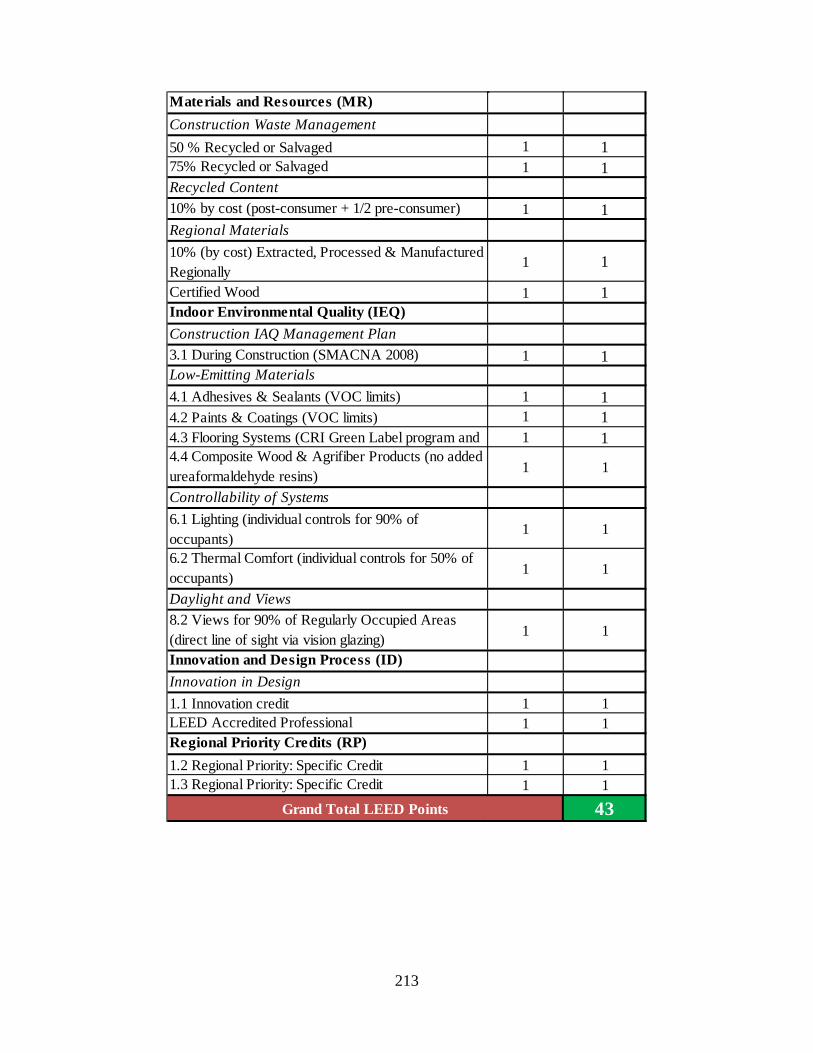
213
Materials and Resources (MR)Construction Waste Management50 % Recycled or Salvaged 1 175% Recycled or Salvaged 1 1Recycled Content10% by cost (post-consumer + 1/2 pre-consumer) 1 1Regional Materials10% (by cost) Extracted, Processed & Manufactured Regionally
1 1
Certified Wood 1 1Indoor Environmental Quality (IEQ)Construction IAQ Management Plan3.1 During Construction (SMACNA 2008) 1 1Low-Emitting Materials4.1 Adhesives & Sealants (VOC limits) 1 14.2 Paints & Coatings (VOC limits) 1 14.3 Flooring Systems (CRI Green Label program and 1 14.4 Composite Wood & Agrifiber Products (no added ureaformaldehyde resins) 1 1
Controllability of Systems6.1 Lighting (individual controls for 90% of occupants)
1 1
6.2 Thermal Comfort (individual controls for 50% of occupants) 1 1
Daylight and Views8.2 Views for 90% of Regularly Occupied Areas (direct line of sight via vision glazing) 1 1
Innovation and Design Process (ID)Innovation in Design1.1 Innovation credit 1 1LEED Accredited Professional 1 1Regional Priority Credits (RP)1.2 Regional Priority: Specific Credit 1 11.3 Regional Priority: Specific Credit 1 1
43Grand Total LEED Points

214
APPENDIX D.3 COMPLETE PRIMAVERA CONSTRUCTION SCHEDULE

215

216
APPENDIX D.4 SCHEDULE DATA
Wing Lancaster Faraday Grove Total PercentageSuperstructure 66 49 45 160 7%Exterior Enclosure 140 129 129 398 18%Interiors 139 121 108 368 17%HVAC 122 115 103 340 15%Plumbing 120 114 99 333 15%Fire Protection 64 58 72 194 9%Electrical 163 130 129 422 19%
2215
Duration