Optical Measurement of Toxic Gases Produced during Firefighting Using Halons
Upload
khangminh22Category
view
0download
0
Firefighting Remote Exploration Device II
A Major Qualifying Project Report
Submitted by:
Justin Cheng | Demi Karavoussianis | Augustus Moseley | Leif Sahyun
WORCESTER POLYTECHNIC INSTITUTE
A report submitted in partial fulfillment
of the requirements for the degree of
BACHELOR OF SCIENCE
Advisors:
Professor Carlo Pinciroli
Professor Sarah Wodin-Schwartz
Professor William Michalson
Professor Ahmet Sabuncu
Professor Rajib Mallick
Submitted on: May 16, 2020
This report represents work of WPI undergraduate students submitted to the faculty as evidence of a degree
requirement. WPI routinely publishes these reports on its web site without editorial or peer review. For more
information about the projects program at WPI, see http://www.wpi.edu/Academics/Projects.

1
Abstract
The need for “smart” recovery for disasters is at the forefront. Firefighters operating in indoor
firegrounds are put at risk by the constantly changing environment. The use of robotics in
firefighting can assist firefighters by informing them about different aspects of the fireground, such
as the structural layout and temperature distribution. Taking inspiration from a design devised by
a previous WPI Major Qualifying Project, our team prototyped a heat, water, and impact-resistant
robot capable of navigating around obstacles in the fireground and returning relevant real-time
data. In this year’s iteration, a new chassis was designed to improve heat resistance, a new pair of
whegs were adapted to meet heat and mobility requirements, a battery management system was
integrated to monitor the state of the battery, and a new user interface was designed to be more
accessible and user-friendly.

2
Acknowledgements
We would like to thank everyone who has provided input, feedback, time and support throughout
this project. First and foremost, we would like to thank our advisors: Professor Pinciroli, Professor
Wodin-Schwartz, Professor Michalson, Professor Sabuncu, and Professor Mallick, for this project
would not have been a success without their guidance, patience, support and feedback.
Thank you to the previous year’s MQP team: Eva Barinelli, Jacob Berman-Jolton, Gavin Macneal,
Karina Naras, and Yil Verdeja, for their willingness to share resources and the work they did last
year. Thank you to Nicolas Tagaris for his assistance in the background research conducted for
this report and his contributions to the Introduction and Related Work sections.
We would also like to thank Russell Lang from the WPI Civil Engineering Department for his
time and generosity in helping to 3D print the wheg prototype. Thank you to Tom Gravel, and
Hydro Cutter Inc. for waterjet cutting the whegs. Thank you to Raymond Ranellone at the Fire
Protection Engineering Lab for coordinating a tour of the facility and the assistance with
scheduling thermal tests. Thank you to the Washburn Shops lab staff for their knowledge and
assistance in constructing the chassis.

3
Table of Contents Abstract 1
Acknowledgements 2
Table of Contents 3
Introduction 8
Dangers of Firefighting 9
Flashover 9
Backdraft 10
Obstructions/Disorientation 11
Structural Collapse 11
Problem Statement 11
Contributions 12
Related Work 12
Smart Buildings 12
Robots for Firefighting 13
Previous MQP 16
Novelty and Conclusion 18
Approach 19
Project Formulation 19
Requirements 19
Design Overview 21
Chassis Design 22
Chassis Shape 22
Chassis Material Layering System 23
Phase Change Material 26
Heat Transfer Simulations 28
Wheel Design 32
Selected Wheel Design 35
Chassis Construction 38
Power Systems 39
Battery Management System 39
BMS Design 40
Battery Charging 41
Charge Design 42
Temperature Differential Power Generation 46
Thermoelectric Generator 46
Stirling Engine 47
Code Design Methodology 48
Node Structure 49
Sensor Selection 50
Radar Processing 53
Sensor Denoising 54
Bandwidth Use 54
Visual Sensor Considerations 56
ROS Considerations 56
Graphical User Interface 57

4
Considerations 57
Implementation 57
Critical Time Estimate Calculation 59
Autonomous Obstacle Avoidance 60
Analysis of Energy Consumption of Electrical Components 61
Experimental Evaluation 63
Unit Testing 63
Whegs 63
Chassis 64
Battery Management System 66
Radar 68
Autonomous Obstacle Avoidance Test 71
Bandwidth Use Test 72
Critical Time Estimation Test 73
Integration Testing 75
Whegs 75
Battery Management System 76
Software Integration 76
System Testing 77
Conclusion 79
Lessons Learned 79
Future Work 80
Completing Construction 80
Conduct Metric Testing 80
Modify Axle and Whegs 81
Phase Change Material Containment Unit 81
Sensor Lens Distortion 82
Automatic Launching on Boot 82
Intelligent Autonomous Exploration 82
Autonomous Mapping 82
Flashover and Burnout Alert 82
Interior Time Algorithm 83
Expansion of BMS to Monitor Individual Cells 83
Implementation of Wireless Charging 83
Adding More Robots 83
References 85
Appendix A: Requirement Decision Matrix 90
Appendix B: COMSOL Verification via MATLAB 93
Appendix C: Bill of Materials (BOM) 97
Battery Management System BOM 97
Robot Chassis BOM 98
Appendix D: Github Repository 99

5
Table of Figures
Figure 1: Firefighting Fatalities Over the Past Decade 8
Figure 2: Stages of fire in an enclosed structure 10
Figure 3: Conditions for the occurrence of a backdraft 10
Figure 4: Dragon robot extinguishing a fire 14
Figure 5: King Saud University indoor firefighting robot 15
Figure 6: Portable Evacuation Guide Robot System 15
Figure 7: FRED from previous MQP 17
Figure 8: Original Chassis Design, Top-Down View, in inches 22
Figure 9: Updated Chassis Design, top-down view, side view 23
Figure 10: Material Layering System 26
Figure 11: Phase Change Latent Heat 27
Figure 12: Boundary Conditions Through One Chassis Wall 29
Figure 13: Data Collection Point 31
Figure 14: Temperature versus Time Graph 32
Figure 15: Rocker-Bogie Model [20] 34
Figure 16: Wheels in a Tread Formation With an Incline Front (Side View) 34
Figure 17: Transformable Wheel, Front and Back 35
Figure 18: Fully Extended Wheg 36
Figure 19: Asymmetric Pin and Slide Layout on Force Transmitter 37
Figure 20: Wheel Activation Mechanics 38
Figure 21: BMS Printed Circuit Board as designed by Stuart Pittaway 40
Figure 22: Block Diagram of Wireless Charging 43
Figure 23: Taidacent 48 V Transmitting 12 V Wireless Charging Module 43
Figure 24: 48 V AC/DC Wall Adapter 45
Figure 25: Wall Adapter Plug 45
Figure 26: KNACRO 15V 2A DC-DC Converter 46
Figure 27: Thermoelectric Generator 47
Figure 28: System Communication 48
Figure 29: Software Nodal Architecture 50
Figure 30: Radar Service Profile Comparison 53
Figure 31: Operator Interface Mockup 57
Figure 32: Operator Interface 58
Figure 33: Minimum Obstacle Distance 60
Figure 34: Robot Turning Diagram 61
Figure 35: Internal Chassis Temperature at 160 ℃ for 15 minutes 65
Figure 36: Internal Chassis Temperature at 215 ℃ for 3 minutes 66
Figure 37: BMS Module Assembled Together on a PCB 67
Figure 38: BMS Connected to Battery Pack 67

6
Figure 39: BMS User Interface with Data from One Connected Module 68
Figure 40: Radar Distance Detection Verification 69
Figure 41: Radar Test Experimental Setup with Insulation 70
Figure 42: Radar Distance Detection Through Insulation 70
Figure 43: Radar Distance Detection with Wind 71
Figure 44: Obstacle Avoidance Test Movement Trace 72
Figure 45: Bandwidth Use by Topic 73
Figure 46: Estimated Time Remaining Over Time 74
Figure 47: Estimated Time Remaining Over Time with Linear Regression 74
Figure 48: A Sample of the ROS Published BatteryState Messages 76
Figure 49: Gazebo Simulation With GUI 77
Figure 50: Robot in Simulated System Test 78
Figure 51: Material Layering System Resistance 94

7
Table of Tables
Table 1: Insulation properties of different materials 25
Table 2: Phase Change Material Options 28
Table 3: Wheel Design Pugh Chart 33
Table 4: Taidacent 48 V Transmitting 12 V Wireless Charging Module Specification 44
Table 5: Sensor Modules 51
Table 6: Advantages versus Disadvantages of Sensors 52
Table 7: Bandwidth of Sensors 55
Table 8: Color Coding Thresholds 59
Table 9: Operating Voltage and Current Consumption of Motors and Raspberry Pi 62
Table 10: Sensor Voltage and Max Current Rating 62
Table 11: Simulated Sensor Parameters 78
Table 12: Material thermal conductivities 94
8
Introduction
As contemporary technology used continues to evolve, and the need for “Smart” recovery for
disasters remains at the forefront. Emergency responders are now using technologies including
drones, satellites, and robotics to assist their teams when responding to disasters. Even while most
modern buildings are equipped with advanced fire and smoke detectors, a more advanced
assistance system is requested [1]. Firefighters are equipped with fire-resistant equipment, and go
through rigorous training to eliminate wasted time and increase their success while fighting a fire.
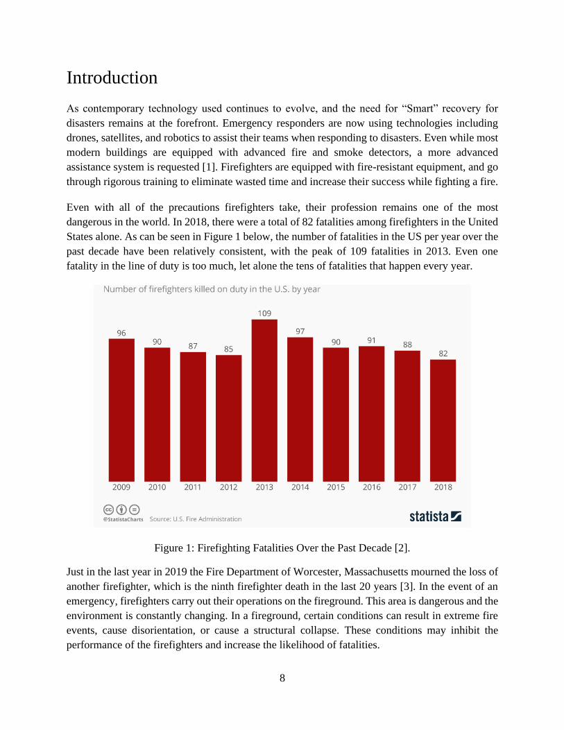
Even with all of the precautions firefighters take, their profession remains one of the most
dangerous in the world. In 2018, there were a total of 82 fatalities among firefighters in the United
States alone. As can be seen in Figure 1 below, the number of fatalities in the US per year over the
past decade have been relatively consistent, with the peak of 109 fatalities in 2013. Even one
fatality in the line of duty is too much, let alone the tens of fatalities that happen every year.
Figure 1: Firefighting Fatalities Over the Past Decade [2].
Just in the last year in 2019 the Fire Department of Worcester, Massachusetts mourned the loss of
another firefighter, which is the ninth firefighter death in the last 20 years [3]. In the event of an
emergency, firefighters carry out their operations on the fireground. This area is dangerous and the
environment is constantly changing. In a fireground, certain conditions can result in extreme fire
events, cause disorientation, or cause a structural collapse. These conditions may inhibit the
performance of the firefighters and increase the likelihood of fatalities.

9
Operational decisions at a fireground are made by the Incident Commander who is typically a
senior member of the crew that makes decisions. The Incident Commander bases his strategies and
resource management primarily on their past experiences and instinct. Decision making on the
fireground is limited by the collection of available data, the real-time data about the building, fire,
and firefighters.
In order to assist and/or improve the Incident Commander's decisions, the use of “smart”
technology could increase available information by accumulating information from a wide range
of databases and sensor networks, both within and beyond the fireground. According to the
National Institute of Standards and Technology (NIST), the addition of “smart” technologies to
firefighting would “enable [considerably] better situational awareness, predictive models and
decision making” [1]. The need for a “smart” system to facilitate and improve the way fire
situations are currently addressed is necessary.
Dangers of Firefighting
There are many dangers involved in firefighting. Fire events such as flashovers and backdrafts are
extremely dangerous to firefighters because they happen nearly instantaneously, resulting in the
building to be consumed in fire, leaving firefighters little to no time to make decisions. Fighting
fires can become disorienting due to the intense heat and smoke, causing the firefighters to become
trapped or lost. Another danger in firefighting is the collapse of a building due to the fire weakening
the building’s structural integrity.
Flashover
A flashover is a rapid transition of fire from the growth stage into the fully developed stage in
which the temperature rises exponentially. It is the physical event in which the temperature of the
room has reached a critical point, approximately 500 ºC, causing objects in the room to dry out
and emit flammable gases [4]. Flashovers are typically contained in one room; everything will
instantaneously burst into flames causing a rapid increase of temperature. Firefighters attempt to
anticipate the occurrence of flashover by looking at the smoke above them, a flashover is about to
occur when the smoke ignites, and they need to evacuate the room immediately.

10
Figure 2: Stages of fire in an enclosed structure [4].
Backdraft
A backdraft is an explosion that occurs when a large quantity of additional oxygen is introduced
to a smoldering flame with a temperature great enough to ignite the added oxygen. Oxygen can
accelerate a fire and when introduced into the system by a crack in the structure’s exterior or by
an open window or door. A backdraft also involves the deflagration, or rapid combustion of
flammable products upon mixing with air. Firefighters are trained to anticipate backdrafts by
watching smoke patterns, since backdrafts occur faster than flashovers, firefighters must be
attentive to their surroundings. If smoke is being sucked into a room, then there is low pressure
in the room and a backdraft may occur. When a backdraft occurs, it is more dangerous than a
flashover. The change in pressure and temperature can affect an entire floor of a building and
even cause the building to collapse [4]. In the figure below, the change in heat released over time
in relation to when a backdraft would occur.
Figure 3: Conditions for the occurrence of a backdraft [4].
11
Obstructions/Disorientation
The largest threat to firefighter safety is getting lost in a fireground. Firefighters do not know the
layout of a building before they enter it, especially how the homeowner has arranged the furniture
or other obstructions. In addition, there may be blueprint reconstruction where the homeowner
changes the layout of the original print. Smoke and particulates are another major factor that can
prevent firefighters from performing their actions, but it can also create confusion and a firefighter
can get lost in the building or space they are performing search and rescue [1]. All of these
scenarios and factors can lead to confusion and disorientation.
Structural Collapse
Structural collapse hazards are accentuated in the event of enclosed fires within structures. The
structural resistance of buildings during fires is an especially major concern as structural design
becomes more efficient; this allows structures to become more modernized over time, which
allows for more lightweight construction of integral structural components. While more modern
and more lightweight construction components may perform equally as well or better than older
truss convention for load distribution, they are less resistant to fire conditions because there is less
material to be consumed by fire, thus resulting in more immediate structural failure. The American
Society for Testing and Materials (ASTM) has conducted fire resistance tests to show that modern
lightweight construction has a significantly faster collapse time.
Problem Statement
Firefighters operating in indoor firegrounds are put at risk by the constantly changing environment.
Because they are often unaware of the structural layout of the building, firefighters can become
disoriented and get lost inside the fireground. In addition, the changing temperature and pressure
inside the fireground can cause a sudden flashover or burnout, which can be fatal for the
firefighters in the fireground. The use of robotics in firefighting can assist firefighters by informing
them about different aspects of the fireground, such as the structural layout and temperature
distribution. Currently, there is a lack of robots that can provide real-time data in the fireground,
as well as function independently of the firefighters after deployment. Taking inspiration from a
design devised by a previous WPI Major Qualifying Project, our goal is to design and build a robot
that can survive in a high temperature fireground for a sufficiently long time with minimal damage
to allow for repeated use, navigate to avoid obstacles in the fireground, and return relevant real-
time data.

12
Contributions
This project improved on the previous iteration of the Firefighting Remote Exploration Device by
designing improvements to the whegs, heat shielding, and power system and by adding new
features to the robot’s software. The new wheg design proposed in this project is heat resistant and
opens and closes more smoothly than the previous wheg design. The heat shielding proposed in
this project allows the robot to survive temperatures of 160℃ for longer than the previous design
and also allows the robot to survive temperatures of 215℃ briefly. The new battery management
system proposed in this project provides information about the battery state during robot operation.
The software system used in this project provides a new unified graphical user interface along with
an estimate of how long the robot can continue operating and allows the robot to autonomously
avoid obstacles. These improvements bring FRED one step closer to becoming a deployable device
that can be sent into a fireground ahead of firefighters to explore and discover dangerous locations.
Related Work
There are efforts working towards creating robots that can be implemented in firefighting in
multiple ways. Currently, there are different prototypes for assisting in firefighting, exploration,
search-and-rescue, and many more. Technological advancements have also led to the integration
of sensors and interfaces that create what are considered “smart” buildings. While these types of
buildings currently do not have strong infrastructures to support firefighting, there is the future
potential to utilize sensors and features to aid in firefighting effort.
Smart Buildings
The integration of smart technology in the field of robotics can enhance the performance of the
robots. Smart technology in buildings and structures today are primarily used as appliances for
resident comfort. The question of whether this technology can evolve into part of a more central
system to benefit the residents living within it, is where the concept of “Smart Building” becomes
a reality. Smart thermostats, such as Nest, come with integrated Wi-Fi, allowing users to schedule,
monitor and remotely control home temperatures [5]. The use of smart thermostats can benefit not
only the building but will relay information to assist firefighters. The ability for both the building
and the robot to learn normal behaviors and automatically modify settings to efficiently provide
residents with maximum comfort is important, but it can also be used as a possible early warning
system where the building can detect an unusual spike in temperature somewhere in the structure.
Using smart locks, users can grant or deny access to visitors but more importantly, smart locks can
also detect where residents are in relation to where they used their ID last [5]. This would allow
firefighters and the robot to be more efficient when performing search and rescue operations
because the building and robot will know if there are any people in the room and how many. With

13
smart security cameras as well as smart motion sensors, the building can help guide the robot to
the last position of where a resident was seen to help assist in search and rescue as well.
Firefighters are at the greatest risk from environmental hazards when there is limited information
about the environment. Robots could assist firefighters in avoiding danger by providing them with
such information. For example, robots could indicate the direction of the nearest exit or the
presence of various hazards such as obstacles or high temperatures [6]. Additionally, robots could
search for civilians still in the building and either alert firefighters of their presence or guide them
to safety [7].
Robots for Firefighting
Due to the challenges faced in implementing a robotic system that cooperates with firefighters,
robots are not commonly used by fire departments today. First, firefighting robots currently in use
are expensive, limiting the number of fire departments that use them, and they are often large and
heavy, which not only makes them difficult to deploy and use but also creates an additional danger
if the robot accidentally hits someone [8]. Second, in order for a robot to be useful, it must be
deployed quickly before the fire has reached flashover and become too hot to enter, which
constrains the deployment speed [4]. Third, because it is difficult to communicate in a fire situation
and firefighters may need to interact with the robot without going through the Incident
Commander, firefighting robots need a robust direct interface for firefighters to use, which most
firefighting robots do not have [6]. Fourth, in a fire situation, firefighters are under extreme stress
and time constraints, so interacting with robots should not cause additional stress or take significant
time [6]. Most importantly, firefighting robots need to avoid interfering with human firefighters
and should have a well-defined role separate from firefighters’ roles [6].
As a result of the challenges mentioned previously, a firefighting robot should be cheap, easy to
carry, easy to use, and the robot should stay out of the way of firefighters. Firefighting robots
should be affordable so that they can be used in as many fire departments as possible, some of
which will have limited budgets. Firefighting robots should also be small and light so that they
require negligible effort to bring the robot to an emergency site and so that the robot can be
deployed there as quickly as possible. Additionally, firefighting robots should not require much
training to use; communication between firefighters and robots should be resilient to
environmental interference and interacting with firefighting robots should take as little time as
possible while not creating additional stress for firefighters who are already working in a stressful
situation. Finally, firefighting robots should stay out of the way of firefighters and not interfere
with standard firefighting protocol.
A research study conducted on the present status of firefighting robots classified firefighting robots
into four categories: monitor nozzle vehicles, underwater searching robots, reconnaissance robots,
and rescue robots [8]. Underwater searching robots are used by a few fire departments, but are not

14
used in fire situations, so they will not be discussed here. Monitor nozzle vehicles maneuver a fire
hose nozzle to a difficult-to-reach location to help extinguish the fire. Reconnaissance robots are
deployed into the fireground and relay useful information to firefighters. Rescue robots attempt to
find survivors in a fireground and either guide or transport them to safety. The study notes that
reconnaissance and rescue robots are not commonly used.
The Dragon firefighting robot designed by researchers at Tohoku University and Japan’s National
Institute of Technology is a flying monitor nozzle vehicle that can access any location [9, 10]. This
robot uses water jets in order to fly the fire hose nozzle to the desired location.
Figure 4: Dragon robot extinguishing a fire [9].
The Dragon robot does not gather any information on the fire but serves to extend the reach of a
fire hose beyond what is normally possible. It succeeds in this task but has a few limitations. It has
a limited range and precision due to the weight of a water-filled hose and the body vibration of
continuum robots. In order to increase the range and maneuverability, additional Dragon units
must be added along the length of the hose but there is still a maximum range imposed by the
length of the hose. Additionally, the Dragon robot is difficult to control when there is wind.
A firefighting robot designed by researchers at King Saud University combines functions
associated with rescue robots and monitor nozzle vehicles [11]. The robot is designed to enter a
fireground with a chemical fire extinguisher built into the robot, then find the source of the fire
and extinguish it. If encountering survivors, the robot is equipped with useful items that survivors
could take, such as gas masks and oxygen breathing bottles. This robot can withstand 700 °C
temperatures, climb stairs, and relay visual information to a command unit.

15
Figure 5: King Saud University indoor firefighting robot [11].
Although this general-purpose firefighting robot has numerous features, the robot as a whole
would not be practical for fire environments we hope to address. If deployed by firefighters to a
fireground, the fire will already be too large to be extinguished by a chemical extinguisher carried
by a robot. Additionally, if a robot is entering a 700 °C fire, there will be no survivors to give gas
masks to.
The Portable Evacuation Guide Robot System designed at the Daegu Gyeongbuk Institute of
Science and Technology is a remote-controlled robot that allows firefighters to seek out and rescue
survivors without entering the building [7]. By using a microphone and a speaker, this robot is able
to relay spoken communication between a controller outside a building and a survivor inside. After
communication is established, the robot uses LED lamps to guide the survivor to safety through
potentially smoky conditions. Additionally, the robot can transmit information from various
sensors to the controller if desired [7].
Figure 6: Portable Evacuation Guide Robot System [7].
16
The Portable Evacuation Guide Robot System is small, weighs only 2 kg, and can be deployed
quickly and easily. It is impact-resistant, water-resistant, and can survive temperatures up to 250
°C. This robot is a promising rescue robot, but it cannot climb stairs or overcome obstacles [7].
The robots described above focus on performing specific functions - either extinguishing a fire or
rescuing victims, with gathering data as an ancillary task if included; however, human firefighters
already perform these tasks and fire departments indicate that the roles of human firefighters and
robots should be distinct from each other [6]. In contrast, we focus on building a reconnaissance
robot that gathers data that firefighters cannot obtain, since lack of information is the cause of
many firefighter casualties.
Previous MQP
Our team is working to continue previous efforts in developing a firefighting remote exploration
device (FRED). Last year’s MQP team began designing and prototyping the remote firefighting
exploration device with the goal “to design and build a robot to provide firefighters with additional
information about a fire environment to help them make more informed decisions when fighting a
fire” [4].
The team met with the Worcester fire department, as well as conducted technical research to
develop a set of physical considerations for building the robot. Specifically, the robot had to be
compact, quick to deploy, and resistant to heat, water, and impact. The Worcester fire department
placed importance on a compact, easy-to-deploy design. In addition, they emphasized that due to
budgeting concerns, FRED should be reasonably priced and reusable. Firefighters go through
training that promotes quick actions and instincts. For this reason, FRED should be non-obtrusive
to current firefighting practices. The robot should only communicate with the incident commander
outside of the fireground. Ideally the robot would deploy fast enough that there would not be much
overlap between time firefighters and FRED are both in the fireground. Other requirements
included low-power consumption, long-range communication, and ability to collect environmental
data. After determining the requirements and use cases, the team designed FRED as seen in Figure
7 below.

17
Figure 7: FRED from previous MQP.
The designing was divided into mechanical, electrical, and software tasks as follows:
1. Mechanical
○ Robot wheel design
○ Chassis shape and design
○ Material layering system
2. Electrical
○ Sensor integration
○ Power distribution
○ Motor controls
3. Software
○ Data processing
○ Wireless communication
○ User Interface
By the end of the project, the previous MQP had designed and unit tested most of these elements.
However, FRED has not been tested in an actual fire ground yet. For all non-electrical related
testing, the electrical components were removed to avoid unnecessary damage. To test the thermal
resistance, the chassis was placed in a furnace set to 135 °C for 18 minutes, while measuring the
internal temperature. Impact resistance was measured by dropping a jug of water measured to
different masses on the center of the impact shield from various heights. Visual observations were
made following each trial. The water resistance was tested by pouring 5 gallons of water directly
on the top of the impact shield. Paper towels were placed inside the robot to indicate whether water
had entered the layered chassis. The last test conducted was to test the accuracy of the sensors. To
test the distance sensor, the readings were compared to a measurement with a ruler. The test was
repeated in trials, each incrementing by 1 inch.

18
The results of these tests are as follows. FRED survived a 135 °C environment for 11 minutes and
36 seconds, before the interior reached 60 °C, the critical point for the electrical components. The
water resistance test did not provide quantitative results, but the team observed moisture in the air
layer of the multi-layer chassis. The interior remained dry. This indicates a small gap in the Teflon
layer. The impact test did not show any visible damage before or after the test was executed. The
accuracy of sensor data was shown to decrease significantly when tested with a protective ZnSe
lens.
Using the results of these tests, the team detailed suggestions for future work. Their
recommendations are detailed below:
● Utilize an interior time algorithm to determine how much time is left before the robot
reaches critical internal temperature
● Implement a phase-change cooling system
● Add another layer of insulating material outside of Teflon layer
● Develop a system to keep whegs deployed when dropped
● Implement autonomous functionalities
● Improve sensor system
● Correct for sensor system
● Design a custom battery with power management system
● Refine user interface
● Implement automatic launch of scripts on robot boot
● Complete requirement metric testing
Novelty and Conclusion
In our attempt to design and prototype a firefighting robot, we have identified the many layers of
analysis required to produce a practical robot that can be used in a fire environment, specifically
in a home. Though the prototyping is still early in the works, the concept of such a robot has the
potential to reduce risk in firefighting and help with decision making by gathering data and
relaying it to the incident commander. The work that has been done in continuing with the previous
team's effort has made improvements on heat resistance and protection as well as improvements
on usability. This work has also paved ways for future iterations in which our blueprint can be
used to complete a prototype of our design, or it can serve as a point of reference for developing
an improved version.
19
Approach
Discussed in this section is the team’s design process, which includes process in which the team
formulates the set of requirements for the design of the robot, the breakdown of design tasks by
major, and material selection.
Project Formulation
The nature of fire protection makes the implementation of firefighting robots difficult. Both in the
previous MQP and in our own research, our team has found exploration robots, which work
independently of the firefighters entering the fireground, to be more practical than robots that
extinguish fires. These exploration robots are designed to operate in a manner that does not
interfere with current firefighting practices, allowing the firefighters to freely perform their tasks.
To address the need for an exploration robot that aids firefighting, the previous team of WPI
students produced FRED, which laid the foundation for our project.
Requirements
We developed a list of requirements to address the different aspects and performances required by
the robot such that it can be implemented in firefighting. Firefighters have limited time when
addressing fires. As such, the robot must be deployable within a short amount of time. The robot
must be able to survive the conditions of the fireground, while providing useful data to the operator,
in this case, the incident commander. Exploration robots such as FRED are not widely used and
are potentially very expensive to acquire. As such, the robot must be designed while considering
the cost of production [4].
Our team compiled a list of requirements using some of the previous project’s requirements and
specifications as well as requirements we have identified to be necessary for the project’s
progression. For this iteration, our requirements focus on overall functionality and performance
specifications, while maintaining critical factors outlined in the previous project, such as being
affordable and quickly deployable. The robot must:
● Be heat proof and maintain an internal temperature of less than 60 °C for 15 minutes
● Have deployable and heat resistant whegs above capable of withstanding temperatures up
to 250 °C
● Be waterproof on all sides and angles
● Maintain an internal temperature of less than 60 °C for 3 minutes while in 215 °C
environment
● Utilize a battery management system
20
● Perform long-range communication while operating in a burning structure through at least
three walls and at least 15 meters out from the structure
● Provide heat and pressure mapping
● Have a comprehensible user interface with defined modules
● Autonomously exit the fire environment before reaching critical internal temperature
● Estimate and relay time until internal temperature reaches 60 °C (using an interior time
algorithm)
● Perform autonomous exploration of the fireground, moving towards hot zones and
avoiding collisions
● Automatically launch program on booting robot
● Compensate for ZnSe lens distortion (especially for IR range-finders)
● Deploy in under 2 minutes
● Move at 0.5 m/s with heat and impact shielding on robot
The time constraints of this project do not allow for a complete implementation of every feature
listed above. We used a decision matrix to select and prioritize requirements that best align with
our project statement, as well as feasibility in terms of the scope of the project. Shown in Appendix
A is the result of the decision matrix.
The criteria for the matrix are durability, ease of use, heat resistance, time to implement, cost and
the team’s prior experience on the requirement. These criteria were determined to identify how the
requirement will contribute to functionality of the robot, how the robot will meet key customer
needs, and the team’s ability to accomplish the requirements. Durability measures how likely a
feature is to break while the robot is deployed, in relation to the other features being evaluated.
Ease of use was selected as a criteria to determine which features are more intuitive and easier for
the operator to use. Heat resistance was selected to determine if the feature would aid or inhibit
the heat resistance goals. Time to implement was defined as an estimate of how long the feature
would take the team to implement. Cost was measured as a cost estimate of all the materials
required to fully implement the feature. Prior experience was defined based on the number of team
members that had experience with similar skills needed to implement the feature. Each
requirement is weighed on a scale of 1 to 5, where for each criteria 1 is least desirable and 5 is
most desirable. The scores for each requirement are determined by multiplying the rank of the
criteria with the weight of each requirement for each criteria, and summing the products.
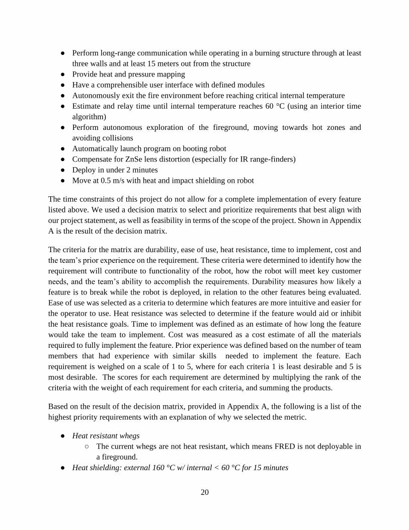
Based on the result of the decision matrix, provided in Appendix A, the following is a list of the
highest priority requirements with an explanation of why we selected the metric.
● Heat resistant whegs
○ The current whegs are not heat resistant, which means FRED is not deployable in
a fireground.
● Heat shielding: external 160 °C w/ internal < 60 °C for 15 minutes

21
○ Testing in the previous project showed that FRED lasted a little over 11 minutes.
Our goal is to increase this to 15 minutes, which was the original requirement.
● Heat shielding: external 215 °C w/ internal < 60 °C for 3 minutes
○ Personal Protective Equipment (PPE) have been tested to withstand 260 °C for 5
minutes with shrinkage of no more than 10% under catastrophic conditions [12].
As a safety net for FRED on a scaled-down level, it should be able to last 3 minutes
under similar extreme conditions to be able to remove itself from the environment.
● Autonomous obstacle avoidance
○ FRED needs to be able to perform basic obstacle avoidance, with the ultimate goal
of autonomous exploration of the fireground. Our iteration focuses on FRED’s
ability to avoid obstacles in the environment by using a front-facing distance sensor.
Though this is not complete autonomous exploration, it opens the opportunity for
implementation of exploration in future iterations. Since FRED is designed to
survive in the fireground for 15 minutes, it should also be able to avoid obstacles
for this amount of time.
● Critical time estimation
○ FRED should provide firefighters with an estimate of how long it can continue
functioning under current conditions.
● Unified graphical user interface
○ The previous iteration of FRED did not have a unified GUI. This iteration will have
a single GUI that displays all robot information that could be of use to firefighters.
● Long range communication
○ Though this requirement has a high score in the matrix, it was deemed as not as
relevant to our project based on our project statement and would be in it of itself an
entirely different project. Addressing this requirement would be too complex, as
the communication system would need to be able to communicate through the
different materials in a structure and account for deflective debris and heat, among
other factors.
Design Overview
The design development was separated into distinct categories, mechanical, electrical, and
software/sensors, each responsible for a set of subtasks. The responsibilities are as follows:
1. Mechanical
a. Wheel design
b. Wheel material selection
c. Chassis shape
d. Chassis material layering system
2. Electrical

22
a. Battery management system
b. Wireless charging
3. Software/Sensors
a. Code structure
b. Data processing
c. Sensor selection
d. Bandwidth use
e. User interface
f. Autonomous obstacle avoidance
Chassis Design
The chassis design involved selecting an overall shape of the robot, as well as designing a material
layering system to maximize performance in a fire round.
Chassis Shape
The original design had two driving wheels in the front of the chassis, and one omnidirectional
wheel attached to the back for stability. The team selected a tapered box with a rectangular cutout
for the omnidirectional wheel. A dimensioned (in inches) top-down view of the outer shell of this
design can be seen in Figure 8 below.
Figure 8: Original Chassis Design, Top-Down View, in inches [4].
23
The side profile of the chassis is rectangular. There is no tapering vertically to maximize the
dimensions of the interior. The tail of the chassis tapers to reduce the risk of debris getting caught
on a back corner, and to improve the overall aerodynamics of the shape. The concave rectangle at
the tail of the chassis connects the omni-directional wheel to the chassis body.
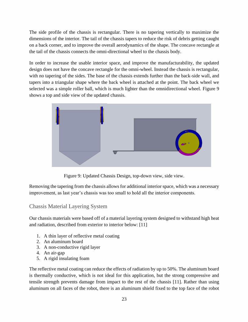
In order to increase the usable interior space, and improve the manufacturability, the updated
design does not have the concave rectangle for the omni-wheel. Instead the chassis is rectangular,
with no tapering of the sides. The base of the chassis extends further than the back-side wall, and
tapers into a triangular shape where the back wheel is attached at the point. The back wheel we
selected was a simple roller ball, which is much lighter than the omnidirectional wheel. Figure 9
shows a top and side view of the updated chassis.
Figure 9: Updated Chassis Design, top-down view, side view.
Removing the tapering from the chassis allows for additional interior space, which was a necessary
improvement, as last year’s chassis was too small to hold all the interior components.
Chassis Material Layering System
Our chassis materials were based off of a material layering system designed to withstand high heat
and radiation, described from exterior to interior below: [11]
1. A thin layer of reflective metal coating
2. An aluminum board
3. A non-conductive rigid layer
4. An air-gap
5. A rigid insulating foam
The reflective metal coating can reduce the effects of radiation by up to 50%. The aluminum board
is thermally conductive, which is not ideal for this application, but the strong compressive and
tensile strength prevents damage from impact to the rest of the chassis [11]. Rather than using
aluminum on all faces of the robot, there is an aluminum shield fixed to the top face of the robot
24
to protect from any vertical impact. Only shielding one face of the chassis reduces the weight of
the robot significantly, allowing for easier transportation to the fireground, and faster movement.
The previous team selected the following design using the material layering system above as a
guideline:
1. Reflective metal adhesive
2. Teflon (PTFE) sheets
3. Airgap
4. Foam PET insulation board
After analyzing both the material layering system design guidelines above, and the design from
the previous year’s project, we selected the following material layering system.
1. Reflect-a-Cool
2. Teflon PTFE
3. Aerogel mat
4. Calcium silicate insulation board
The outer reflective layer uses the commercial product Reflect-a-Cool. This material is an
aluminum and fiberglass mix, with an adhesive attached for ease of application. Reflect-a-Cool
advertises radiant heat resistance for temperatures up to 1093℃, with a decomposition temperature
of 300℃, due to the coating. Both these temperatures are above the maximum operating
temperature of 215℃ selected as a requirement metric for this project. The thermal emissivity is
0.31, meaning the material is able to reflect a majority of the radiation [13].
For the non-conductive rigid layer, we selected polytetrafluoroethylene (PTFE), more commonly
known as Teflon. We selected Teflon due to its high tensile and compressive strength, as well as
low conductivity [14].
The original design utilized an air gap to reduce heat transfer by convection. We investigated
further reducing the convection by replacing the air gap with a vacuum. By lowering the pressure
in the air gap, the number of molecules in the gap would decrease. A decrease in molecules means
there would be less collisions of molecules, and therefore less heat transfer via convection. There
are commercial products available, but because any puncture or impact to the product can create a
small hole in the wall, which would cause the pressure to equalize with the external environment,
they are not durable enough for our application. In addition, the effectiveness of the commercial
product decreases over time [15]. An alternative option is to create a vacuum manually, using an
air pump and a valve. This would prevent anyone from being able to open the interior of the robot
and might affect the humidity reading of the internal sensors. In addition, the valve would create
another hole in the chassis, compromising the effectiveness of the material layering system.
Considering these factors, we decided to employ an aerogel mat instead.

25
Aerogel is a material composed of fiberglass nano silica. It is extremely lightweight and insulating,
having a density of 200 𝑘𝑔
𝑚3 and a thermal conductivity of 0.015 𝑊
𝑚𝐾. Since the thermal
conductivity is lower than that of air, we decided to replace the air gap with an aerogel mat.
The innermost layer needs to be able to withstand high temperatures and have good known thermal
resistance properties. As a preliminary selection, four different types of board insulation were
considered: polyisocyanurate, extruded polystyrene, Expanded polyurethane, and calcium silicate.
Table 1 below shows the properties of interest of the four different insulations.
Table 1: Insulation properties of different materials.
Material Thermal Conductivity [𝑊
𝑚𝐾] R-Value [per inch]
Maximum Effective
Temperature [℃]
Calcium Silicate 0.07 2.63 926.6
Polyisocyanurate 0.03 5.6 147.2
Extruded
Polystyrene 0.035 5 74
Expanded
Polyurethane 0.023 5.5 93
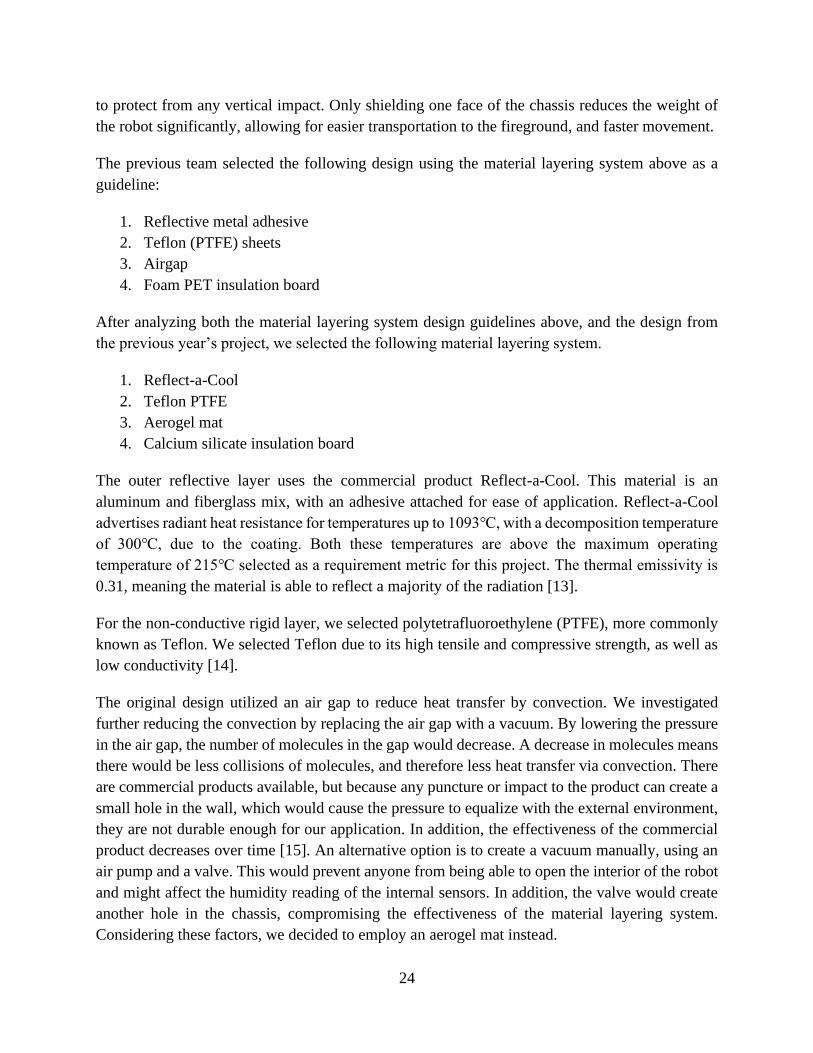
Although calcium silicate has the highest thermal conductivity, it is the only option we considered
with a maximum effective temperature above 210 degrees. Figure 10 shows the layering system
selected for the chassis.
26
Figure 10: Material Layering System.
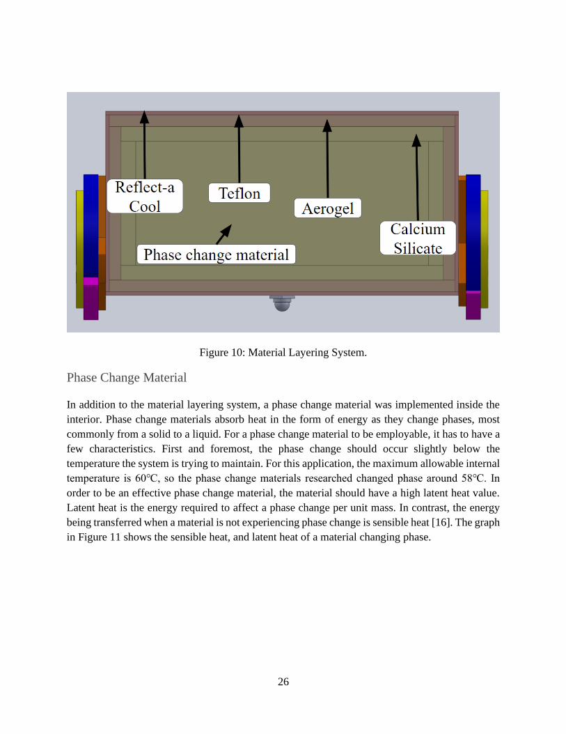
Phase Change Material
In addition to the material layering system, a phase change material was implemented inside the
interior. Phase change materials absorb heat in the form of energy as they change phases, most
commonly from a solid to a liquid. For a phase change material to be employable, it has to have a
few characteristics. First and foremost, the phase change should occur slightly below the
temperature the system is trying to maintain. For this application, the maximum allowable internal
temperature is 60℃, so the phase change materials researched changed phase around 58℃. In
order to be an effective phase change material, the material should have a high latent heat value.
Latent heat is the energy required to affect a phase change per unit mass. In contrast, the energy
being transferred when a material is not experiencing phase change is sensible heat [16]. The graph
in Figure 11 shows the sensible heat, and latent heat of a material changing phase.

27
Figure 11: Phase Change Latent Heat.
The diagonal sections of the line are when the material is experiencing sensible heat, where the
temperature is increasing proportional to the heat supplied. The horizontal portions of the line are
where the material is undergoing latent heat. At this point the temperature of the material remains
constant, because all the energy, in the form of heat, is being used to conduct the phase change
[17]. An ideal phase change material has a high latent heat of fusion. Table 2 shows possible phase
change material options.

28
Table 2: Phase Change Material Options.
Material
Phase
Change
Temperature
[C]
Density
[g/ml]
Heat
Storage
Capacity
[J/g]
Thermal
Conductivity
[W/m*C]
Specific
Heat
[J/g*c]
Corrosive
Or Toxic
PureTemp 58 58 0.89 225 0.25 2.47 Mildly
PureTemp 60 61 0.96 220 0.25 2.04 Mildly
PlusICE Hydrated Salt -
S58 58 1.505 145 0.69 2.55 Corrosive
PlusICE Organic - A58 58 0.91 215 0.22 2.22 Mildly
PlusICE Organic -
A58H 58 0.82 103 0.18 2.85 Mildly
PlusICE Solid-Solid -
X55 55 1.06 115 0.36 1.62
PlusICE Solid-Solid -
X70 70 1.085 160 0.36 1.57
In addition, for this use case, the phase change material should have a low thermal conductivity
and not be toxic or corrosive. The toxicity rating in Table 2 was determined by looking at technical
data safety sheets. A material was deemed “mildly” toxic if the material can cause skin irritation
when handled with bare skin. Hydrated salt was eliminated because of its corrosive properties. The
bottom two options, PlusICE solid-solid, are solid to solid phase change materials. They remain
solid past the phase change temperature, and instead use energy to change their atomic crystalline
structure. The best performing of these options is PureTemp 58, which was selected for use on the
robot. To simulate the selected materials in a fire environment, we used the multiphysics software
COMSOL.
Heat Transfer Simulations
Before constructing the chassis, we modeled and simulated the heat transfer through the system.
Using a simulation allowed us to easily observe how various materials affected the heat resistance
of the system as a whole. Consecutively with the simulations, we calculated the heat transfer
through the system by hand, both to verify the simulation results and provide greater understanding
of the heat transfer problem. The chassis heat resistance was simulated in COMSOL with the
following initial conditions:
● Internal temperature of the robot = 20 ° C.
● Temperature of the phase change material = 20 ° C.
● Temperature of the ambient air = 160 ° C.
● Interior air velocity field = 0.1 m/s in z direction.

29
The robot was modelled by defining a heat flux from natural convection on all sides and the top.
There was no heat flux from the bottom because airflow under the chassis is assumed to be
negligible. In addition, there is radiation applied to the front face of the robot, as if the robot were
driving straight towards the fire. Figure 12 below shows a diagram of the boundary conditions
through one wall.
Figure 12: Boundary Conditions Through One Chassis Wall.
To verify the COMSOL model of the heat transfer caused by convection from high external
temperatures, we developed a MATLAB script that iteratively calculates the heat flow through the
system. The system is modelled using an analogy between thermal transport and electrical current
and resistance, specifically the equation 𝑉 = 𝐼𝑅, where V is voltage, I is current, and R is
resistance. In our model, the voltage is represented as temperature, T, the current is the heat flow
through the system, q, and the resistance is the thermal resistance of each respective layer, R. After
rewriting this equation with the relevant variables, we obtain the equation 𝑄 =𝛥𝑇
𝑅. Analogous to
how the current is constant through a system with resistors, the heat flow Q, in watts, is constant
through each layer of the chassis wall.
Using the labeling in Figure 12, where the external ambient temperature is Tamb and each boundary
layer starting on the outside moving inwards is labeled T0 - T3 , we can form the following equation:

30
𝑄 = 𝑇𝑎𝑚𝑏 −𝑇0
𝑅0 =
𝑇0 −𝑇1
𝑅1 =
𝑇1 −𝑇2
𝑅2 =
𝑇2 −𝑇3
𝑅3 =
𝑇3 −𝑇𝑖𝑛𝑡
𝑅𝑖𝑛𝑡 Equation 1
That equation can be split into 5 separate equalities, which can be used to solve a linear system of
equations for the temperatures T0, T1, T2, T3, and Tint. The equations were put into matrix formation
and were solved iteratively until the error, |𝑇𝑜𝑙𝑑 −𝑇𝑛𝑒𝑤 |
𝑇𝑜𝑙𝑑 , was less than 5% for the temperature of the
interior. After the last iteration, the heat flow through the system, Q, was used to determine how
long the system would take to heat the boundary between layer 3 and the interior. A datapoint was
added to the boundary between the innermost layer and the interior space of the COMSOL model.
We then ran a temperature dependent study to collect the temperature at the datapoint overtime.
The results were consistent with one another, verifying the accuracy of the simplified COMSOL
model. A more detailed synopsis of the COMSOL verification using MATLAB can be found in
Appendix B.
As an additional verification, we created a model of last year’s design, which was tested
experimentally in a furnace at 148 ℃. Last year’s team selected a maximum internal temperature
of 70 ℃. Their robot survived 13 minutes in the furnace before the internal temperature reached
the maximum. We created and ran a COMSOL model of last year’s design with an external
temperature of 148 ℃, like the physical experiment. The model’s interior reached 71 ℃ at 13
minutes, further verifying the COMSOL results.
In addition to the heat from the outside environment, the battery management system and motors
act as an internal heat source, as seen above. We assumed the battery has a 90% efficiency rating.
By taking the maximum voltage and Amp-hour rating of the battery, the heat dissipated, in the
form of power, can be calculated using the following equation.
𝑃 = (5 𝐴ℎ ⋅14.4 𝑉 ⋅60 𝑚𝑖𝑛𝑢𝑡𝑒𝑠)
20 𝑚𝑖𝑛𝑢𝑡𝑒𝑠⋅ 0.1 = 18 𝑊 Equation 2
The battery is rated for 5 amp-hours, and a maximum of 14.4 volts. This is multiplied by 60
minutes per 1 hour to make the time in minutes. The product of these three values is divided by
the duration, which is 20 minutes. This value is multiplied by 0.1 to represent the 90% efficiency
rating. In addition to the battery, there is a battery management system with many resistors
attached. The heat dissipation from the resistors can be calculated by adding up all the resistances
and using the equation for power.
𝑃 =𝑉2
𝑅 Equation 3
In a resistor, all of the power produced is dissipated as heat. The heat dissipation, in watts, was six
orders of magnitude smaller than the battery heat dissipation, and therefore the power produced
by the resistors is negligible.

31
For the motors, the mechanical efficiency is around 75%, and each motor is rated for 16 watts. We
can assume that 25% of the total 16 watts of each motor is dissipated as heat into the interior. This
value multiplied by 2, because there are 2 motors, means that an additional 8 watts of power is
dissipated into the interior [18].
In total, 26 W are released as heat, over the course of 20 minutes. This is equal to 520 watt-minutes
of energy.
The phase change material was also incorporated into the COMSOL model to fill the remaining
space after blocks representing the electrical components were added.
In order to create a temperature vs. time graph, we selected a single datapoint where the internal
temperature sensor of the physical prototype would be; this point is shown in Figure 13.
Figure 13: Data Collection Point.
In order to determine if the material layering system was sufficient in keeping the interior under
60 ̊ C for 20 minutes, a time dependent study was conducted. The duration was from 0 minutes to
20 minutes with a time step of 1 minute. Using the point described above, Figure 14 shows a plot
of temperature and time over the 20 minutes.

32
Figure 14: Temperature versus Time Graph.
At 20 minutes, the interior has reached about 27.7 ℃, which is well below the maximum allowable
temperature of 60℃. The use of this COMSOL data, in conjunction with results from physical
testing will also be used to create an interior time algorithm, which will allow the operator
interfacing unit to predict, in live time, how much time is left before FRED overheats.
Wheel Design
The updated chassis design has two driving wheels and a tail with a roller ball bearing for stability.
Other designs considered included the rocker-bogie, four driving wheels, wheels in a tread
formation, track,whegs, and transformable whegs. A Pugh chart was created to analyze the various
options, based on user functionality. The functional considerations in the Pugh Chart are drive
smoothness, ease of turning, weight, ease of implementation, obstacle avoidance, speed, drop-
ability, and upkeep. Each of these categories was rated on a scale of 1-3 based on importance of
implementation, with 1 being least important, and 3 being of high importance. All of the wheel
options were given a rating from 1-5 for each category, where 1 is least desirable, or unattainable,
and 5 is the most desirable. The score was then multiplied by the category's importance to obtain

33
a weighted measurement. Each category’s score was added, and the wheel with the highest total is
the “best option”. The Pugh chart can be seen in Table 3 below.
Table 3: Wheel Design Pugh Chart.
Ranking Criteria Weights
4
Whegs
2
Whegs
with
tail
Transformable
Whegs with tail Tracks
Tracks
with
Incline
Front 4 Wheels
Wheels in
a Tread
Formation
with
incline
Front
Rocker -
Bogie
3 Smooth Drive
1 -
Wobbly,
5 -
Smooth 2 3 4 5 5 4 4 5
1
Ease of
Turning
1 - Hard,
5 - Easy 1 3 5 4 4 5 4 5
2 Weight
1 -
Heavy, 5
- Light 4 5 4 2 2 3 2 2
3
Obstacle
Avoidance
1 - Can't
Climb, 5
- Climb
Stairs 5 5 5 3 5 1 4 5
1
Ease of
Implementation
1 - Hard,
5 - Easy 4 4 2 4 3 5 4 1
2 Speed
1 - slow,
5 - Fast 3 3 5 2 2 5 5 4
1 Droppable
1 - 0m, 5
- >3m 4 3 2 1 1 5 5 4
1 Maintenance
1 - Hard,
5 - Easy 5 5 4 1 1 5 4 4
TOTAL 49 55 58 42 47 51 55 56
From this table, the transformable whegs with a tail performed the best. This is the design that was
utilized last in the last report, and the final design selected for the current design.
Since the Pugh chart totals were close, the second and third best options were also investigated.
The second option, the rocker-bogie, shown in Figure 15, was not selected because of complex
manufacturing, and exposed electrical components. Since the chassis body is located on the top of
link 1 in Figure 15 the motors and corresponding wiring would be exposed to the conditions of the
fireground, including high temperatures and a possibly wet environment. This could cause
overheating, melting, and electrical malfunction. Advantages of this design include the ability to
34
tilt in any direction by 45 ° while keeping all 6 wheels on a surface. In addition, the axle-less design
allows the robot to be dropped without the impact damaging the wheels or axle [19]. Although
the axle-less design has advantages, it is more complex to manufacture than a simple axle and
wheel.
Figure 15: Rocker-Bogie Model [20].
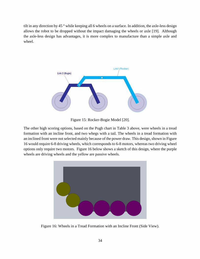
The other high scoring options, based on the Pugh chart in Table 3 above, were wheels in a tread
formation with an incline front, and two whegs with a tail. The wheels in a tread formation with
an inclined front were not selected mainly because of the power draw. This design, shown in Figure
16 would require 6-8 driving wheels, which corresponds to 6-8 motors, whereas two driving wheel
options only require two motors. Figure 16 below shows a sketch of this design, where the purple
wheels are driving wheels and the yellow are passive wheels.
Figure 16: Wheels in a Tread Formation with an Incline Front (Side View).

35
The main appeal of the wheels with an inclined front is the ability to climb, and maintain a smooth
drive, which is ideal for the sensors, especially the camera. Having the wheels in a track formation,
but not with actual tracks mitigates the risk of debris getting caught in the track, or the track coming
out of place, two large concerns for any tracked option. The inclined front would allow the robot
to climb stairs and navigate difficult obstacles. Ultimately, we did not select this design because
of the large power draw and internal space required to hold 6-8 motors.
The two whegs with a tail were not selected because whegs have a much less smooth ride compared
to wheels, which would constantly jolt and disrupt the camera feed. Transformable whegs have
the same advantages of non-transformable whegs, mainly the ability to climb. They mitigate the
concern of a choppy camera feed by transforming into wheels for a smoother drive. The ability for
the whegs to transform passively, without an electrical stimulus, keeps the power consumption
low.
Selected Wheel Design
Each of the whegs has three legs, one trigger leg and two follower legs. These legs are connected
to two side panels, the wheel-base and the force transmitter. The two follower legs are identical,
with slides that each encompass a pin from the force transmitter. The trigger leg has a pin that
attaches to a slide on the force transmitter. The force transmitter contains two pins and one slide,
with the function of connecting the movement of all three legs. The wheelbase’s primary function
is to orient the wheels correctly to the axle and motors. Figure 17 below shows the front and back
of the transformable wheel.
Figure 17: Transformable Wheel, Front and Back.
36
As the figure above shows, the wheelbase fixes the legs to the wheel, while the force transmitter
distributes the force on the trigger wheel to open or collapse the legs.
The orientation of the sliders and pin on the force transmitter is crucial to the function of the wheg.
As an external force rotates the trigger leg into the expanded position, the trigger leg’s pin applies
force on the side of the force transmitter’s slider.
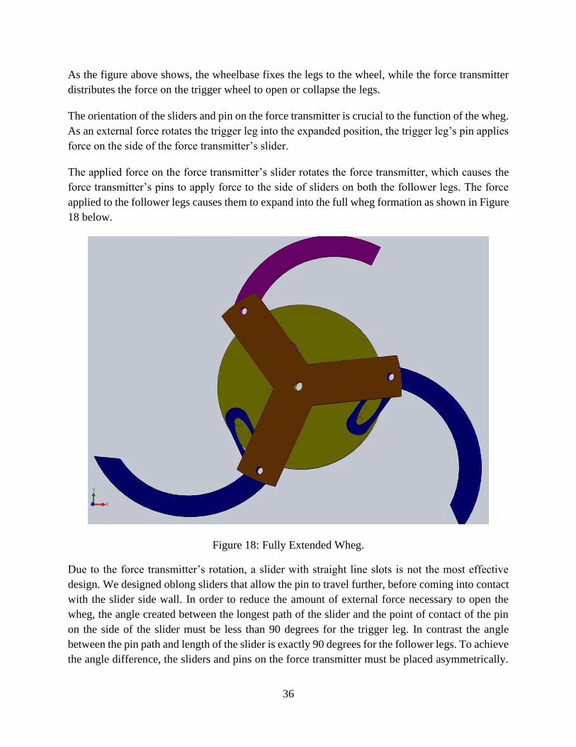
The applied force on the force transmitter’s slider rotates the force transmitter, which causes the
force transmitter’s pins to apply force to the side of sliders on both the follower legs. The force
applied to the follower legs causes them to expand into the full wheg formation as shown in Figure
18 below.
Figure 18: Fully Extended Wheg.
Due to the force transmitter’s rotation, a slider with straight line slots is not the most effective
design. We designed oblong sliders that allow the pin to travel further, before coming into contact
with the slider side wall. In order to reduce the amount of external force necessary to open the
wheg, the angle created between the longest path of the slider and the point of contact of the pin
on the side of the slider must be less than 90 degrees for the trigger leg. In contrast the angle
between the pin path and length of the slider is exactly 90 degrees for the follower legs. To achieve
the angle difference, the sliders and pins on the force transmitter must be placed asymmetrically.

37
Figure 19 shows a model of the force transmitter, where the dotted lines intersect to form 120-
degree angles. The two pins that connect to the follower leg’s slides are exactly 120 degrees from
each other. The slider that attaches to the trigger leg’s pin has been placed asymmetrically, with a
20-degree offset towards one of the pins.
Figure 19: Asymmetric Pin and Slide Layout on Force Transmitter.
In order to activate the wheg formation, the trigger leg relies on friction at points A and B shown
in Figure 20, step 1 below. To increase the friction at these points, a high temperature silicone was
applied to the external face of each leg. In addition, other transformable wheg designs include a
small “foot” at the end of the trigger leg. This would increase the amount of external force applied
to the trigger leg. In step 3 of Figure 20, the wheg is fully extended, and one leg is able to overcome
the obstacle height. The driving force of the wheels allows the entire wheel to overcome the
obstacle once a single leg has made contact with the top [21].

38
Figure 20: Wheel Activation Mechanics [21].
We selected aluminum 6061 to construct the wheels due to the high maximum effective heat. Since
the wheels are in contact with the ground, and any other debris, we selected a metal to ensure if
the wheel touched a piece of debris hotter than the ambient air, the wheg would not deform or
melt. To construct the pieces, we used a commercial waterjet cutting company. We had the outline
of each piece and the sliders cut out. After, we bored threaded holes for the pins and screwed in
threaded shoulder pins.
Chassis Construction
The following steps were developed to construct the chassis. Please note that due to the COVID-
19 pandemic, we were unable to finish chassis construction, as the project was transitioned to
remote work. These steps are not complete, rather an outline of the intended construction process.
1. Cut the materials
a. The Teflon was cut using a bandsaw
b. The aerogel mat was cut using an Exacto Knife and scissors
c. The calcium silicate insulation boards were cut using a tile saw
2. Drill holes for the angle bracket screws (#6-32), sensors lenses, axle bearing, and through
the Teflon tail for the roller ball bearing

39
a. The Teflon was drilled into using a steel drill bit
b. The aerogel mat was scored in an “X” shape with an Exacto Knife
c. The calcium silicate foam board was drilled into using carbide drill bits intended
for masonry and concrete
3. Attach the layers together using the angle bracket screws
4. Press fit the axle bearings into their respective holes in the calcium silicate
5. Attach the sides to the base with the angle brackets, lock nuts, zinc washers (#6) and the
screws (used to attach the layers in step 5)
6. Screw the roller ball bearing onto the tail of the base
The top was not attached because we anticipated having to access the interior components.
Power Systems
In terms of the power system in FRED, we have investigated two aspects of power management:
battery management and charging. The previous design has a sufficient system that would allow
for FRED to operate, however, we have identified beneficial features that would drastically
improve the ability to monitor the power components as well as improve overall convenience of
use in terms of charging. We intend to use the same battery to power the robot, as specified in the
previous report, however, we are making modifications to the protective circuitry for charging the
battery, and integrating the protective features into a battery management system. Presented in this
subsection is the design of the battery management system (BMS) and the wireless charging
feature for FRED.
Battery Management System
The previous design utilizes a battery with an on-board protection circuit module (PCM). This
module single-handedly provides the battery with a layer of protection against overcharge,
overcurrent, and short circuits. Additionally, there is an auto balancing feature that helps prolong
the lifespan of the battery by maintaining balanced charging through each cell. In many cases, this
battery PCM provides sufficient protection during charging and discharging operations [4].
However, as this system operates unmonitored; information and measured sensory data for
charging and battery health is not communicated to the system operator. Moreover, the operating
environment for FRED has fluctuating temperatures that may result in the battery reaching critical
temperatures, which requires a system to monitor the temperature of the battery for effective
decision-making. The previous design included a thermocouple for temperature measurements of
the battery, however, this is an ad-hoc design to temporarily address this missing field of
information from the battery system and is limited in capability, as the thermocouples are placed
to measure the sections of the battery in contact. Our team has identified the incorporation of a
battery management system (BMS) as an opportunity to improve upon the existing design. The

40
battery management system will not only provide a layer of protection for overcharge and
overcurrent, and short circuit, it will also monitor and relay the health and temperature of the
battery.
BMS Design
Upon investigation of available systems for battery management, a Do-It-Yourself design created
by a user named Stuart Pittaway was found to be appropriate for FRED. This design was created
to centralize charging and to ensure cell voltage is isolated from other cells and ground voltage
[22]. The intent for this device, as specified by the creator, was to be used or paired with charging
a battery pack (14) 18650 cell lithium ion battery. Each of these battery cells operate between 3.0
V (discharged) and 4.2 (charged) for a total of 48 V DC in the pack [22]. However, we intend to
use the same battery for FRED as in the previous design, which is the 14.4V 5Ah LiNiMnCo
26650 Battery [4]. This battery pack is made up of four rechargeable 26650 LiNiMnCo cylindrical
battery cells, each with a max charge voltage of 4.2 V, which is the same as the 18650 cells [23].
With this design, since it incorporates an interactive software with user interface, the parameters
for charging can be set by the user.
The creator of the BMS design provides to the public a printed circuit board (PCB) he designed
and for convenience of connecting circuit components. There are two designs, a standard and a
smaller design. For FRED, we will be utilizing the smaller design, as the space in the robot is
limited and to reduce the amount of weight added overall. Shown below in Figure 21 is the PCB.
Figure 21: BMS Printed Circuit Board as designed by Stuart Pittaway [22].
Since the LiNiMnCo battery pack has four cells, one PCB can be used to regulate charging and
monitor the status of battery pairs. For two battery pairs, we will need two PCBs. These circuits
manage the charging of the battery pairs, providing protection and the temperature reading of the

41
pairs. However, they are only part of the BMS system, which requires a microcontroller that
controls the logic of the system to allow for user-defined settings and interaction between the BMS
and the user. To assemble the PCB, the board itself was sourced from an online vendor of PCBs
called JLCPCB. The circuit components were acquired from various online vendors. A full list of
the specific components is provided by the creator of the BMS [22]. For our construction of the
PCB, we found alternative vendors of similar parts that were cheaper. The bill of materials and
their sources can be found in the Appendix.
In this BMS design, the creator uses an ESP 8266-12e microcontroller to serve as the brains of the
system. However, it is our intention to reuse the ESP 32 microcontroller that is already in FRED.
Since these two microcontrollers are both ESP devices, the latter having stronger capabilities as
compared to the former, we are anticipating limited issues with compatibility and, instead,
potential issues with port connectivity, since this controller is already being used for other data
collection. However, this connectivity issue may be avoided since we will no longer be using the
Time of Flight sensor that was used in the previous design.
In terms of interfacing with the BMS, the creator programmed the microcontroller to communicate
through Wi-Fi the measurements and data from the battery to the user through a web browser.
After establishing a connection using the user’s IP address, the user can monitor the status of the
battery as well as modify the settings [22]. However, these features are extraneous for the design
for FRED. Our team intends to integrate this BMS system by having values such as temperature
and battery health communicated from FRED to the operator interface defined in a later section,
rather than have the BMS interfaced by a web browser.
Battery Charging
The focus of the previous design was primarily concerned with the functionality and operability
of the robot in a fire environment. However, this design did not account for charging the battery.
While our focus is to improve upon the previous design such that the robot is operable in a fire
environment, with all of the internal components fitted into the chassis, we have identified a point
of consideration for charging the FRED’s battery. Since the previous design did not consider how
to charge the FRED, whether by cord or wireless charging, there was not a concern for creating a
plug port through FRED’s heat shield, as it was irrelevant. For a practical device, means of
charging needs to be considered. However, we acknowledge that incorporating this feature may
be ambitious given the limited time we have to address the main issue of putting together FRED
such that it can move and operate as intended. As such, we provide an overview of the results from
our investigation.

42
Charge Design
Our team was presented with the option to incorporate battery charging in our iteration of FRED.
If charging was not included in the design, testing and charging the battery in FRED would require
exposing the internal component. To not consider how the robot would be charged is a severe flaw
in the system, however, given the goal and overall objective of the project, the priority of focus is
on designing a functional robot that can move through and survive in fire environments. Our team
is working off of the design of the previous MQP team and as such, we have identified an
opportunity to expand upon their design and potentially incorporate charging.
When considering charging, we looked at two different approaches. The first approach is to create
a port in the body of FRED that would serve as the connection from the battery to an external plug
to the wall adapter. The issue with this approach is that we would have to create a hole in the
protective chassis, which will create a point of weakness for heat. Additionally, we may have to
select materials that would have better thermal resistance compared to typical plug-in mechanisms,
depending on how exposed or deep the plug port is placed. The second and alternative approach
is to utilize wireless charging. There are many advantages to wireless charging. One major
advantage is preservation of thermal protection; a plug or cord would not be needed to connect the
battery from the inside of FRED to an outlet and thus there would not be a need to create a point
of weakness in the chassis. Another advantage is operation convenience in terms of charging.
Rather than having to plug the battery into an outlet, the entire robot can simply be placed on a
charging pad. The disadvantage to wireless charging is the need for additional hardware,
integrating the hardware into FRED, creating the aforementioned charging pad, all of which are
expensive in terms of time and money.
For our design, we are taking the risk of incorporating space for wireless charging. In our
investigation of wireless charging, we have identified that it is possible for our system, and that it
is possible to include the additional hardware into FRED without making major modifications to
the shape of FRED. Since we are already reshaping the chassis, we have considered the dimensions
necessary to incorporate the wireless charging hardware inside of FRED. To incorporate wireless
charging, there are multiple modules needed. Shown below in Figure 22 is a block diagram of the
modules and their interconnectivity.
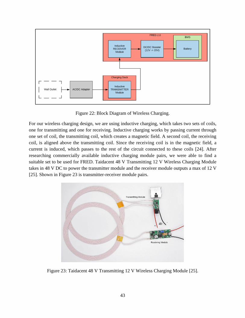
43
Figure 22: Block Diagram of Wireless Charging.
For our wireless charging design, we are using inductive charging, which takes two sets of coils,
one for transmitting and one for receiving. Inductive charging works by passing current through
one set of coil, the transmitting coil, which creates a magnetic field. A second coil, the receiving
coil, is aligned above the transmitting coil. Since the receiving coil is in the magnetic field, a
current is induced, which passes to the rest of the circuit connected to these coils [24]. After
researching commercially available inductive charging module pairs, we were able to find a
suitable set to be used for FRED. Taidacent 48 V Transmitting 12 V Wireless Charging Module
takes in 48 V DC to power the transmitter module and the receiver module outputs a max of 12 V
[25]. Shown in Figure 23 is transmitter-receiver module pairs.
Figure 23: Taidacent 48 V Transmitting 12 V Wireless Charging Module [25].

44
Since the receiver module will need to be placed inside of FRED, we reviewed the size and shape
of the coil and found that we would be able to fit the coils at the bottom of the inner space with the
rest of the internal components. Assuming the two coils are within range, the voltage remains
consistent. However, as the distance between the coils increases, the amount of current decreases
until connection is completely lost. Shown below in Table 4 is an overview of the specifications
for the Taidacent modules.
Table 4: Taidacent 48 V Transmitting 12 V Wireless Charging Module Specification [25].
Transmitter Module Receiver Module
Inner Diameter 150 mm Inner Diameter 150 mm
Outer Diameter 180 mm Outer Diameter 180 mm
Thickness 2 mm Thickness 2 mm
Input 48 V Output 12 V
● 50 mm: 3 A
● 60 mm: 2.5 A
● 70 mm: 2 A
● 100 mm: 0.8 A
In addition to the transmitter and receiver modules, supportive hardware is required for both
modules. The transmitter module requires 48 V which can be provided by connecting a plug and
adapter to a wall outlet. The adapter is necessary to convert the 120 V AC voltage from the wall
outlet to DC and step down the voltage to 48 V. A cheap and suitable adapter and plug was found
on a commercial vendor online called Jameco [26]. Shown in Figure 24 and 25 are the adapter and
wall cord, respectively.

45
Figure 24: 48 V AC/DC Wall Adapter [26].
Figure 25: Wall Adapter Plug [27].
Since the battery for FRED is rated at 14.4 V, the voltage from the inductive receiver module is
insufficient. The 12 V from the receiver module needs to be boosted to a voltage equal to or above
the voltage rating for the battery, which can be done by integrating a DC/DC boost converter. The
KNACRO 15V 2A DC-DC Converter takes in a 9 to 14 V input and outputs a voltage of 15 V and
a current of 2 A [28]. Shown below in Figure 26 is the boost converter.

46
Figure 26: KNACRO 15V 2A DC-DC Converter [28].
Together, these components make up the wireless charging system. Though these added parts
require spending more money, the major limiting factor is time. The addition of these parts requires
constructing a charging pad, which can be simple for the purpose of creating a working prototype.
The assembly of the receiver coil and boost converter inside the robot will contribute to the overall
weight of the robot, though the two components together are relatively light, and they weigh under
one pound. If time does not allow for integrating charging into the system, this design will be
proposed as a recommendation for future implementations.
Temperature Differential Power Generation
Given the hot external environment and cooler internal temperature we discussed implementing a
system that generates power from the temperature differential. The following options were omitted
from the final design due to time constraints and efficiency concerns.
Thermoelectric Generator
A thermoelectric generator works by using the Seebeck effect to generate voltage from a heat
differential. A thermoelectric generator can be created by connecting two semiconductors by a
metal conductor in series. The temperature differential between the heat source and the heat sink
causes the charge carriers in the semiconductors n and p to move, which creates a voltage
differential. Figure 27 is a diagram of the movement of charge carriers in a thermoelectric
generator.

47
Figure 27: Thermoelectric Generator [29].
These thermoelectric generators commercially available are about 40mm2 and could be attached
to the outermost layer of the robot. Rather than having the interior be the heat sink, or cold source,
another phase change material could be used, within the insulation layers, separate from the
interior. This would remove the concern of the thermoelectric generator heating up the interior as
it works. The design requirements did not include any goals about increasing the battery
operational time. In addition, these devices have an efficiency of 5-8%, which was not efficient
enough to warrant creating another hole in the insulation [29].
Stirling Engine
Another option for generating power from the temperature differential, was to implement a Stirling
engine in the wall of the chassis. Stirling engines operate as a closed cycle regenerative heat engine.
There are typically 2 pistons fitted in a closed chamber of gas. As one side of the chamber heats
up, the gas expands, moving the piston, and effecting the pressure on the other side of the chamber.
The change in temperature and pressure keeps the pistons moving, generating mechanical work
which can be converted to voltage [30]. By comparing the maximum efficiency to the efficiency
of a Stirling engine at the initial condition temperatures, the efficiency of a Stirling engine in the
robot can be attained. The maximum efficiency was calculated by solving the efficiency of the
Carnot cycle at the desired temperatures. The efficiency would be 31.1% at the time 0 minutes and
decrease as the interior heats up. Stirling engines are in general heavy and fairly fragile. In addition,
by mixing the hot and cold temperatures, the interior components would heat up very fast, so the
team decided not to use a design with a Stirling engine.
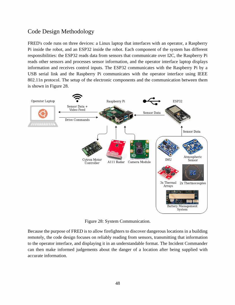
48
Code Design Methodology
FRED's code runs on three devices: a Linux laptop that interfaces with an operator, a Raspberry
Pi inside the robot, and an ESP32 inside the robot. Each component of the system has different
responsibilities: the ESP32 reads data from sensors that communicate over I2C, the Raspberry Pi
reads other sensors and processes sensor information, and the operator interface laptop displays
information and receives control inputs. The ESP32 communicates with the Raspberry Pi by a
USB serial link and the Raspberry Pi communicates with the operator interface using IEEE
802.11n protocol. The setup of the electronic components and the communication between them
is shown in Figure 28.
Figure 28: System Communication.
Because the purpose of FRED is to allow firefighters to discover dangerous locations in a building
remotely, the code design focuses on reliably reading from sensors, transmitting that information
to the operator interface, and displaying it in an understandable format. The Incident Commander
can then make informed judgements about the danger of a location after being supplied with
accurate information.
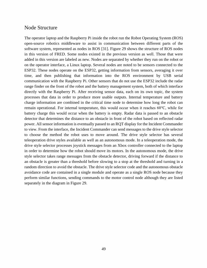
49
Node Structure
The operator laptop and the Raspberry Pi inside the robot run the Robot Operating System (ROS)
open-source robotics middleware to assist in communication between different parts of the
software system, represented as nodes in ROS [31]. Figure 29 shows the structure of ROS nodes
in this version of FRED. Some nodes existed in the previous version as well. Those that were
added in this version are labeled as new. Nodes are separated by whether they run on the robot or
on the operator interface, a Linux laptop. Several nodes are noted to be sensors connected to the
ESP32. These nodes operate on the ESP32, getting information from sensors, averaging it over
time, and then publishing that information into the ROS environment by USB serial
communication with the Raspberry Pi. Other sensors that do not use the ESP32 include the radar
range finder on the front of the robot and the battery management system, both of which interface
directly with the Raspberry Pi. After receiving sensor data, each on its own topic, the system
processes that data in order to produce more usable outputs. Internal temperature and battery
charge information are combined in the critical time node to determine how long the robot can
remain operational. For internal temperature, this would occur when it reaches 60℃, while for
battery charge this would occur when the battery is empty. Radar data is passed to an obstacle
detector that determines the distance to an obstacle in front of the robot based on reflected radar
power. All sensor information is eventually passed to an RQT display for the Incident Commander
to view. From the interface, the Incident Commander can send messages to the drive style selector
to choose the method the robot uses to move around. The drive style selector has several
teleoperation drive styles available as well as an autonomous mode. In a teleoperation mode, the
drive style selector processes joystick messages from an Xbox controller connected to the laptop
in order to determine how the robot should move its motors. In the autonomous mode, the drive
style selector takes range messages from the obstacle detector, driving forward if the distance to
an obstacle is greater than a threshold before slowing to a stop at the threshold and turning in a
random direction to avoid the obstacle. The drive style selector code and the autonomous obstacle
avoidance code are contained in a single module and operate as a single ROS node because they
perform similar functions, sending commands to the motor control node although they are listed
separately in the diagram in Figure 29.
50
Figure 29: Software Nodal Architecture.
Sensor Selection
The previous version of FRED used the sensors listed in Table 5 to detect heat, pressure, humidity,
orientation, and obstacles.

51
Table 5: Sensor Modules.
Sensor Purpose
Raspberry Pi Camera Module Capture video around the robot for the Incident
Commander to view
32x24 RES Melexis MLX90640 IR
array (3)
Capture images of IR radiation for the Incident
Commander to view
Bosch BNO055 absolute
orientation sensor
Detect robot orientation
Bosch BME680 environmental unit Detect temperature inside the robot as well as humidity
and pressure
Thermocouple (3) Detect temperature outside robot heat shield and between
heat shield layers
The sensors above in Table 5 are viable for detecting heat, pressure, humidity, and orientation.
However, the time-of-flight sensors were mounted on the sides of the robot in the previous design
and would not be able to detect obstacles in front of the robot, which would be necessary for the
robot to autonomously avoid obstacles. In addition, the time-of-flight sensors in question operate
at the 940 nm wavelength. Since fire emits radiation around the 1000 nm wavelength, it could
potentially cause interference with the sensors. Because of these issues, alternative obstacle
detection sensors were considered with the advantages and disadvantages of each summarized in
Table 6.

52
Table 6: Advantages versus Disadvantages of Sensors.
Sensor Advantages Disadvantages
Camera + computer vision - Wide field-of-view - Relies on visibility of
obstacles' point-of-
contact with floor in
order to determine
distance
- Difficult to implement
- Can be impaired by
visual conditions
IR time-of-flight - Cheap <$20
- Low power
consumption
- Can be washed out by
IR emissions from the
fire
LIDAR - Gives precise obstacle
locations
- Requires all-around
vision, which would
be blocked by robot's
heat shield
- Expensive >$100
Radar - Smoke does not block
radar unlike other
sensors
- Does not require an
aperture in robot heat
shield
- Wide field-of-view for
pulsed radars or all-
around vision for
scanning radars
- High power
consumption
- Expensive >$100

53
If not for the price and energy consumption of a radar, a radar would be the best option for this
application as it can detect obstacles through smoke, will not be interfered with by light from fire,
and can be used without an aperture in the robot's heat shield. Fortunately, we found the A111
Pulsed Coherent Radar, which at $60 is cheaper than other radars, is designed for low-power
applications, and emits ranging pulses in a single direction instead of in a circle around the sensor
[32].
Radar Processing
The A111 radar produces lists of reflected radiance ordered by distance from the radar. We process
these lists into a distance reading by finding the nearest radiance peak beyond minimum range
above a noise threshold. The radar has five possible service profiles that it can be set to. These
primarily change the power of radio waves output by the radar. The amount of reflected radiance
produced by an obstacle increases with increased power output from the radar, making obstacles
easier to detect, especially at long range; however, the increased power also causes direct feedback
at close ranges, preventing the radar from detecting nearby obstacles. Reflected radiance for each
sensor profile with the radar pointed at a wall 0.75m away is shown in Figure 30.
Figure 30: Radar Service Profile Comparison.
We chose service profile 2 because it has a small direct feedback range while also producing
reflected radiance peaks for obstacles that can be distinguished from noise. With this sensor
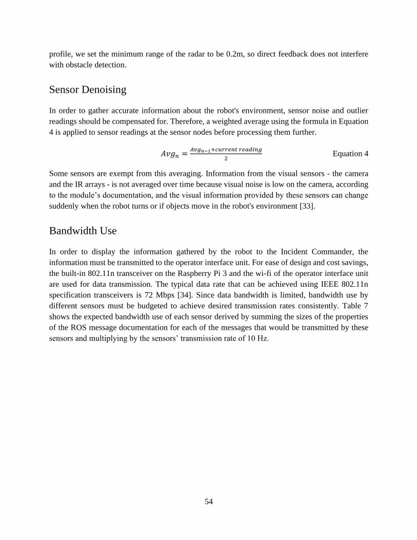
54
profile, we set the minimum range of the radar to be 0.2m, so direct feedback does not interfere
with obstacle detection.
Sensor Denoising
In order to gather accurate information about the robot's environment, sensor noise and outlier
readings should be compensated for. Therefore, a weighted average using the formula in Equation
4 is applied to sensor readings at the sensor nodes before processing them further.
𝐴𝑣𝑔𝑛 =𝐴𝑣𝑔𝑛−1+𝑐𝑢𝑟𝑟𝑒𝑛𝑡 𝑟𝑒𝑎𝑑𝑖𝑛𝑔
2 Equation 4
Some sensors are exempt from this averaging. Information from the visual sensors - the camera
and the IR arrays - is not averaged over time because visual noise is low on the camera, according
to the module’s documentation, and the visual information provided by these sensors can change
suddenly when the robot turns or if objects move in the robot's environment [33].
Bandwidth Use
In order to display the information gathered by the robot to the Incident Commander, the
information must be transmitted to the operator interface unit. For ease of design and cost savings,
the built-in 802.11n transceiver on the Raspberry Pi 3 and the wi-fi of the operator interface unit
are used for data transmission. The typical data rate that can be achieved using IEEE 802.11n
specification transceivers is 72 Mbps [34]. Since data bandwidth is limited, bandwidth use by
different sensors must be budgeted to achieve desired transmission rates consistently. Table 7
shows the expected bandwidth use of each sensor derived by summing the sizes of the properties
of the ROS message documentation for each of the messages that would be transmitted by these
sensors and multiplying by the sensors’ transmission rate of 10 Hz.

55
Table 7: Bandwidth of Sensors.
Sensor Bandwidth
Camera 19.35 Mbps
IR Arrays (3) 575.28 Kbps
Controller 44.16 Kbps
Radar 15.84 Kbps
Internal Temperature Sensor 15.36 Kbps
External Temperature Sensor 15.36 Kbps
BMS 28.32 Kbps
IMU 111.36 Kbps
Pressure Sensor 15.36 Kbps
Humidity Sensor 15.36 Kbps
Total Bandwidth Use 20.19 Mbps

56
Visual Sensor Considerations
Among the sensors used by FRED, the greatest consumers of bandwidth are the visual sensors: the
camera and the IR arrays. Special attention should be given to the design decisions made in order
to achieve the bandwidth use listed in Table 7 for these visual sensors. The Raspberry Pi Camera
Module records video at 720p resolution at 30fps with 10-bit color depth [33]. Without
compression or overhead, the camera yields 276.48 Mbps of data, which exceeds the maximum
bandwidth that can be transmitted over 802.11n. Fortunately, the Raspberry Pi Camera Module
outputs video in H.264 format, which typically compresses videos to 7% of their original size,
which gives 19.35 Mbps here [35]; however, since ROS video streams transmit still images one at
a time over an Image topic, a compressed video like this must be transmitted from FRED to the
operator interface unit separately from the ROS messages sent by other sensors. Instead, the video
is transmitted using UDP output from RaspiVid. The exact bandwidth use of the camera may vary
more than the bandwidth use of other sensors because it is dependent on the H.264 compression
performed on the video. This compression will give better results when there is less movement in
front of the robot’s camera.
In addition to the camera, there are 3 IR arrays that generate 32x24 matrices of one-byte thermal
readings of the environment. Since the visual information from the IR arrays is a lower resolution
than the camera video, it does not require video compression in order to be viable. Instead, the
array readings are transmitted through ROS as byte arrays with a 248-bit overhead. Three IR arrays
making 30 readings per second yields the 575.28 Kbps bandwidth usage in Table 7. The total
bandwidth usage of these IR arrays combined with all other non-camera sensors is 836.4 Kbps.
ROS Considerations
ROS was chosen for this project because of its ease of use, modularity, and library support;
however, ROS does not handle wireless data transmission reliably in a system where connection
between devices is not guaranteed. This is because ROS relies on the connection-oriented
Transmission Control Protocol to transmit data over a network. To constrain the scope of this
project, we assume a reliable connection between FRED and the operator interface unit, but in a
real-world application there may be interference or connection loss that makes another data
transmission protocol preferred such as the User Datagram Protocol used by FRED to stream
camera video.

57
Graphical User Interface
Considerations
For stressful situations such as firefighting, it is important for any user interface to be easy to
understand and have different types of interface for different types of information and controls
[36]. The GUI needs to display visual information in front of the robot, the distance between the
robot and any obstacle in front of it, and scalar readings from the robot’s sensors. The design
shown in Figure 31 uses different elements to display each of those types of information and
displays the robot's remaining time before failure in another location in colored text to indicate its
importance. Additionally, the user interface must allow the user to change the drive control mode
of the robot including changing the drive control to use autonomous obstacle avoidance. This is
handled by the radio buttons in the lower right. In order to maximize the detail provided to the user
in the visual information from the camera and the IR arrays, these elements were made as large as
possible, expecting that an Incident Commander tele-operating the robot would find this
information most useful for navigation.
Figure 31: Operator Interface Mockup.
Implementation
We extended ROS’s RQT GUI to accommodate our user interface design [37]. The resulting
interface is shown in Figure 32. The thermal array feeds from the left and right sides of the robot
are shown flanking the main camera feed in the center. The camera feed can be switched to the
center thermal array using a drop-down menu above it. Rviz is used in the lower-left to display the

58
robot’s orientation and the location of the currently detected obstacle. Since RQT’s built-in topic
monitor for displaying sensor readings displays all readings and is difficult to read, a select set of
sensor readings are displayed with formatted text instead. Since the sensor readings and
operational time to failure are displayed with the same color coding and formatting, they have been
combined in a single area of the display.
Figure 32: Operator Interface.
Many of FRED’s sensor readings receive additional processing before display on the GUI. The
thermal array outputs, initially arrays of numbers, are converted to grayscale images. In the Figure
32 above they are full color images because the system is being run in simulation, where we use
color to simulate temperature. This is discussed in more detail in the Experimental Evaluation
section. The gyroscope gives FRED’s orientation relative to its original position and is applied to
the robot model in the lower left. An obstacle is also displayed in that area of the GUI at the
distance that FRED’s radar detects the nearest obstacle. Important numeric sensor values are
programmed to appear in the bottom center of the GUI. These numbers are formatted with labels
Camera Feed
Thermal Feeds
Robot Orientation +
Obstacle Detection
Sensor Readouts
Drive Style
Selector

59
and units and displayed in a large font color-coded in green, yellow, and red. Color coding
thresholds follow Table 8.
Table 8: Color Coding Thresholds.
Reading Thresholds Rationale
Time Remaining Green: ≥10 minutes
Yellow: <10 minutes
Red: <5 minutes
FRED is designed to last 15 minutes in a
fireground. These thresholds divide that
time evenly into 5-minute intervals.
Obstacle Range Green: ≥0.3 m
Yellow: <0.3 m
Red: <0.2 m
The radar’s minimum range is 0.2 m. If an
obstacle is within 0.3 m, FRED should be
slowing to turn away from it.
Temperature (internal) Green: ≤40℃
Yellow: >40℃
Red: >60℃
The battery is rated to withstand
temperatures up to 60℃. 40℃ is halfway
between that and room temperature.
Temperature (external) Green: ≤60℃
Yellow: >60℃
Red: >200℃
At a temperature of 60℃ or more, FRED
will eventually heat up to its maximum
internal temperature. At 200℃, the area has
become too hot for firefighters to enter.
Critical Time Estimate Calculation
In order to provide the robot operator with an estimate of how long the robot can remain
operational, we generate time estimates for both how long the robot can continue under current
power draw conditions and how long the robot can continue under current temperature conditions,
showing the operator the lower of the two estimates. The time estimate based on power draw is
calculated by taking a weighted average of the change in battery charge as detected by the battery
management system. Because the change in the battery charge in one second is only 1.53 mAh
when 5.5 A are drawn from the battery, less than 0.1% of total battery capacity of 5000 mAh, this
change in charge could be obscured by noise in the BMS sensors. In order to get accurate readings,
two steps have been taken. First, the critical time estimator checks the charge every 2.5 seconds
so that there is a larger change in charge per time period. Second, the critical time estimator uses
a weighted average for the change in charge that gives only 1/10 weight to the most recent reading,
shown in Equation 5.
𝐴𝑣𝑔𝑛 =9∗𝐴𝑣𝑔𝑛−1+𝑐𝑢𝑟𝑟𝑒𝑛𝑡 𝑐ℎ𝑎𝑛𝑔𝑒 𝑖𝑛 𝑐ℎ𝑎𝑟𝑔𝑒
10 Equation 5
This average change in battery charge is compared to the current battery charge to determine the
amount of time before the battery is depleted. The time estimate based on temperature is

60
determined by taking the robot’s weighted average internal and external temperature, as detected
by the robot’s thermocouples, and using those values to index into tables of time estimates
generated through COMSOL simulations of the robot’s insulation done in advance.
Autonomous Obstacle Avoidance
FRED can autonomously avoid obstacles in the fireground, so it does not have to be constantly
controlled by the Incident Commander while it explores the fireground. In order to autonomously
avoid obstacles, FRED drives forward at full speed until it detects an obstacle with its radar. FRED
approaches the obstacle with a PID speed control until it reaches a minimum distance of 0.212m.
At this distance, the field-of-view of the radar allows FRED to see any obstacle that it might hit
by driving forwards, including obstacles that are not directly in front of the robot, as shown in
Figure 33. Since the minimum range of the radar is 0.2m, approaching an obstacle at 0.212m is
feasible without the radar losing track of the obstacle.
Figure 33: Minimum Obstacle Distance.
After approaching an obstacle, FRED turns in a random direction, calculating a turning radius that
will allow it to avoid both the obstacle in front and any obstacles that it remembers seeing to the
sides. FRED turns in a random direction in order to avoid getting stuck in a location that cannot
be escaped by turning in the same direction every time. Similarly, FRED turns a random amount
between 0.2 and 1 radian. For turning radius calculations, FRED is assumed to follow a simple
differential drive turning model, shown in Figure 34.
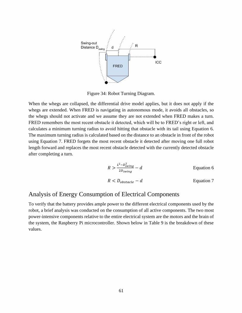
61
Figure 34: Robot Turning Diagram.
When the whegs are collapsed, the differential drive model applies, but it does not apply if the
whegs are extended. When FRED is navigating in autonomous mode, it avoids all obstacles, so
the whegs should not activate and we assume they are not extended when FRED makes a turn.
FRED remembers the most recent obstacle it detected, which will be to FRED’s right or left, and
calculates a minimum turning radius to avoid hitting that obstacle with its tail using Equation 6.
The maximum turning radius is calculated based on the distance to an obstacle in front of the robot
using Equation 7. FRED forgets the most recent obstacle it detected after moving one full robot
length forward and replaces the most recent obstacle detected with the currently detected obstacle
after completing a turn.
𝑅 >𝐿2−𝐷𝑠𝑤𝑖𝑛𝑔
2
2𝐷𝑠𝑤𝑖𝑛𝑔− 𝑑 Equation 6
𝑅 < 𝐷𝑜𝑏𝑠𝑡𝑎𝑐𝑙𝑒 − 𝑑 Equation 7
Analysis of Energy Consumption of Electrical Components
To verify that the battery provides ample power to the different electrical components used by the
robot, a brief analysis was conducted on the consumption of all active components. The two most
power-intensive components relative to the entire electrical system are the motors and the brain of
the system, the Raspberry Pi microcontroller. Shown below in Table 9 is the breakdown of these
values.
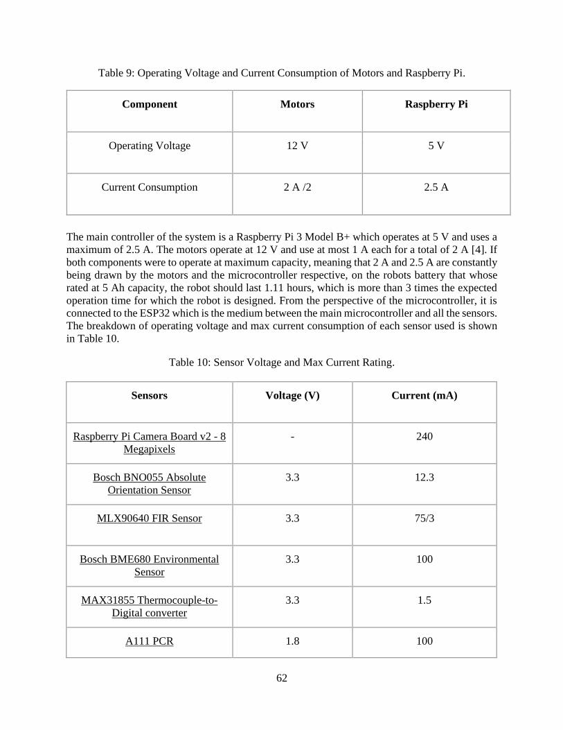
62
Table 9: Operating Voltage and Current Consumption of Motors and Raspberry Pi.
Component Motors Raspberry Pi
Operating Voltage 12 V 5 V
Current Consumption 2 A /2 2.5 A
The main controller of the system is a Raspberry Pi 3 Model B+ which operates at 5 V and uses a
maximum of 2.5 A. The motors operate at 12 V and use at most 1 A each for a total of 2 A [4]. If
both components were to operate at maximum capacity, meaning that 2 A and 2.5 A are constantly
being drawn by the motors and the microcontroller respective, on the robots battery that whose
rated at 5 Ah capacity, the robot should last 1.11 hours, which is more than 3 times the expected
operation time for which the robot is designed. From the perspective of the microcontroller, it is
connected to the ESP32 which is the medium between the main microcontroller and all the sensors.
The breakdown of operating voltage and max current consumption of each sensor used is shown
in Table 10.
Table 10: Sensor Voltage and Max Current Rating.
Sensors Voltage (V) Current (mA)
Raspberry Pi Camera Board v2 - 8
Megapixels
- 240
Bosch BNO055 Absolute
Orientation Sensor
3.3 12.3
MLX90640 FIR Sensor 3.3 75/3
Bosch BME680 Environmental
Sensor
3.3 100
MAX31855 Thermocouple-to-
Digital converter
3.3 1.5
A111 PCR 1.8 100

63
Based on the table above, if all sensors were to be operating at their max ratings, the total amount
of current drawn from the sensors is 0.5288 A, which is below the maximum current draw of 1.2
A for peripheral devices connected. Since the microcontroller uses 0.5 A alone, accounting for the
microcontroller, motor, and sensors would draw a total of 3.0288 A. Under the max conditions,
the robot would last 1.65 hours. This calculation does not, however, account for the current
consumption from the BMS, which would need to be measured separately. These calculations only
assume that the system will be operating under the worst condition, meaning that every component
is drawing as much current as it is rated to do. However, this is not likely to be the case in reality.
For an accurate analysis of consumption, a physical evaluation would need to be conducted in
which the current draw for the components would need to be measured in testing.
Experimental Evaluation
In this section, we discuss the testing of FRED at different stages of development, as well as the
results from the tests.
Unit Testing
To ensure proper functionality of each component of FRED, component-specific unit tests were
planned. Due to the COVID-19 pandemic, WPI facilities were closed for the final few months of
this project, leaving us unable to complete construction and physical testing. As a response, our
team modified the testing to be primarily simulation based. Environmental specifications and setup
for both physical and simulation-based testing were selected in accordance with the project
requirements.
In this section, we discuss the testing of FRED at different stages of development, as well as the
results from the tests.
Whegs
In creating the whegs, the first unit test we completed was a simulation. Using SOLIDWORKS,
we created an assembly of the whegs, with proper mates to allow movement of the legs. By
dragging the trigger leg of the SOLIDWORKS assembly away from the wheel we observed the
follower legs move to form the expanded wheg. This was the expected result. We then dragged
the trigger leg towards the wheel (as if a force was being applied to the outside) and observed the
follower legs collapse inward into a wheel formation, as expected. Figure 35 shows the 3D printed
wheg in the open and closed formation, as we used for testing.
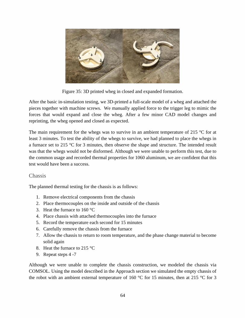
64
Figure 35: 3D printed wheg in closed and expanded formation.
After the basic in-simulation testing, we 3D-printed a full-scale model of a wheg and attached the
pieces together with machine screws. We manually applied force to the trigger leg to mimic the
forces that would expand and close the wheg. After a few minor CAD model changes and
reprinting, the wheg opened and closed as expected.
The main requirement for the whegs was to survive in an ambient temperature of 215 °C for at
least 3 minutes. To test the ability of the whegs to survive, we had planned to place the whegs in
a furnace set to 215 °C for 3 minutes, then observe the shape and structure. The intended result
was that the whegs would not be disformed. Although we were unable to perform this test, due to
the common usage and recorded thermal properties for 1060 aluminum, we are confident that this
test would have been a success.
Chassis
The planned thermal testing for the chassis is as follows:
1. Remove electrical components from the chassis
2. Place thermocouples on the inside and outside of the chassis
3. Heat the furnace to 160 °C
4. Place chassis with attached thermocouples into the furnace
5. Record the temperature each second for 15 minutes
6. Carefully remove the chassis from the furnace
7. Allow the chassis to return to room temperature, and the phase change material to become
solid again
8. Heat the furnace to 215 °C
9. Repeat steps 4 -7
Although we were unable to complete the chassis construction, we modeled the chassis via
COMSOL. Using the model described in the Approach section we simulated the empty chassis of
the robot with an ambient external temperature of 160 °C for 15 minutes, then at 215 °C for 3

65
minutes. Figure 36 below shows the results of the 160 °C test, where the temperature was recorded
every second.
Figure 36: Internal Chassis Temperature at 160 ℃ for 15 minutes.
The data shows the interior remained well under 60 °C for the entire 15-minute duration. The point
used to record the internal temperature was at the center of the interior of the model, to mimic
where the thermocouple would have been placed in a physical test. Using the same data collection
point, we ran the simulation at 215 °C for 3 minutes, with data collection every second, to obtain
the results in Figure 37.

66
Figure 37: Internal Chassis Temperature at 215 ℃ for 3 minutes.
After 3 minutes in the 215 ℃ environment, the interior temperature increased by less than one
degree, according to the COMSOL results. This data suggests that our requirement metric has
been exceeded, and that in further iterations, the metric can be increased for the robot to withstand
higher temperatures.
As a more comprehensive simulation test, we inserted the internal components into the model, and
had them expend heat as waste into the interior. Calculations for the amount of heat by-product
produced can be found in the Approach section of this report. In the 160 ℃ external environment
for 15 minutes, with internal heating, the chassis reached about 24.7 ℃. This further suggests the
requirement metric for heat resistance has been achieved using the composite material layering
system.
Battery Management System
As mentioned in the previous section, this iteration’s design for the BMS uses two modules to
monitor the two cell pairs. The materials used to construct the BMS were provided in the bill of

67
materials in the original repository. The final product of one cell module can be seen below in
Figure 38, which is the same as the PCB diagram shown previously. Shown in Figure 39 is the
two BMS modules hooked up to the battery pack.
Figure 38: BMS Module Assembled Together on a PCB.
Figure 39: BMS Connected to Battery Pack.
A set of instructions on how to program and connect the module to the battery was provided in the
repository. To verify that the module worked, this was used as the initial unit test. The original
design of this BMS was to integrate the module with an ESP8266, which would later be adapted
to work with the ESP32 that is used in the robot, and connects to a Wi-Fi network, allowing the
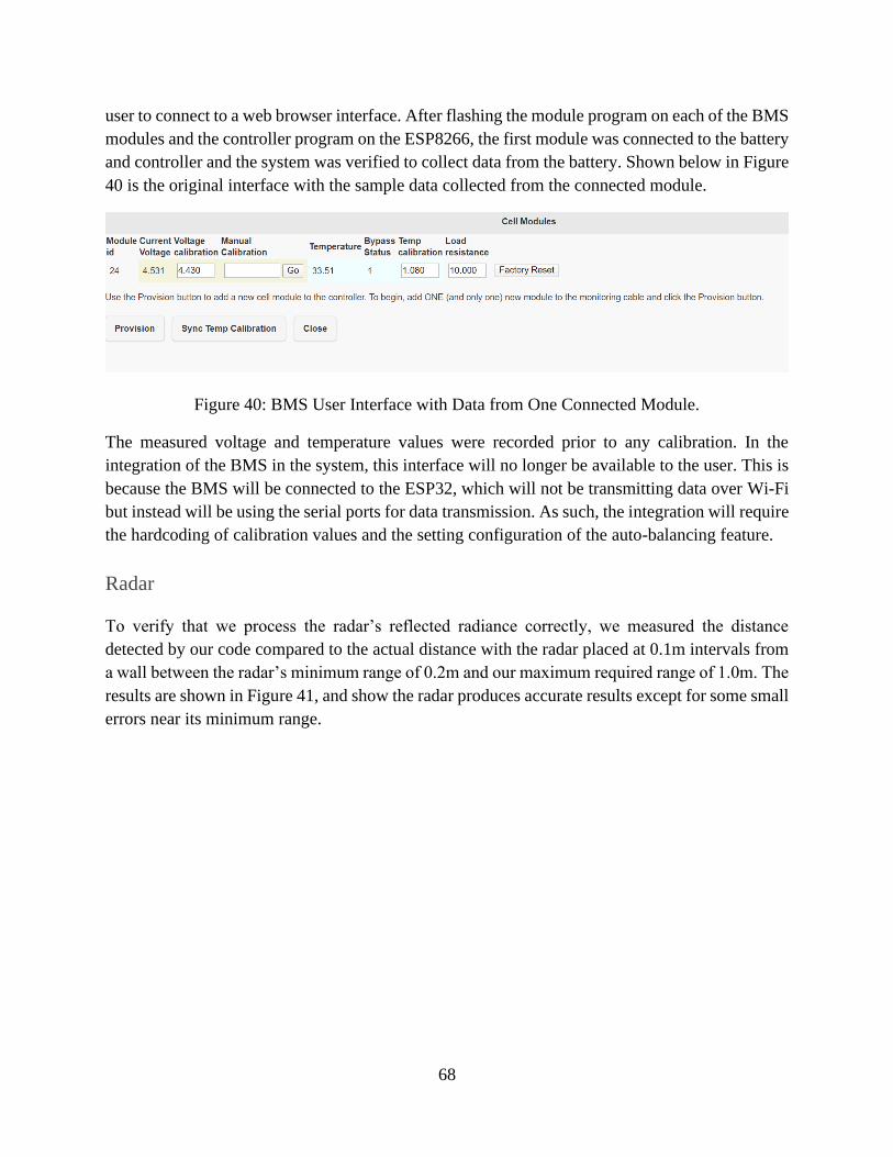
68
user to connect to a web browser interface. After flashing the module program on each of the BMS
modules and the controller program on the ESP8266, the first module was connected to the battery
and controller and the system was verified to collect data from the battery. Shown below in Figure
40 is the original interface with the sample data collected from the connected module.
Figure 40: BMS User Interface with Data from One Connected Module.
The measured voltage and temperature values were recorded prior to any calibration. In the
integration of the BMS in the system, this interface will no longer be available to the user. This is
because the BMS will be connected to the ESP32, which will not be transmitting data over Wi-Fi
but instead will be using the serial ports for data transmission. As such, the integration will require
the hardcoding of calibration values and the setting configuration of the auto-balancing feature.
Radar
To verify that we process the radar’s reflected radiance correctly, we measured the distance
detected by our code compared to the actual distance with the radar placed at 0.1m intervals from
a wall between the radar’s minimum range of 0.2m and our maximum required range of 1.0m. The
results are shown in Figure 41, and show the radar produces accurate results except for some small
errors near its minimum range.
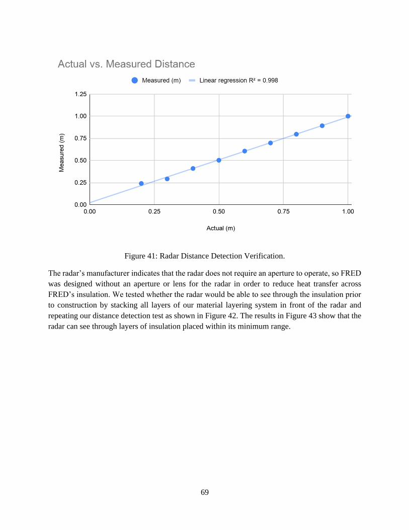
69
Figure 41: Radar Distance Detection Verification.
The radar’s manufacturer indicates that the radar does not require an aperture to operate, so FRED
was designed without an aperture or lens for the radar in order to reduce heat transfer across
FRED’s insulation. We tested whether the radar would be able to see through the insulation prior
to construction by stacking all layers of our material layering system in front of the radar and
repeating our distance detection test as shown in Figure 42. The results in Figure 43 show that the
radar can see through layers of insulation placed within its minimum range.

70
Figure 42: Radar Test Experimental Setup with Insulation.
Figure 43: Radar Distance Detection Through Insulation.
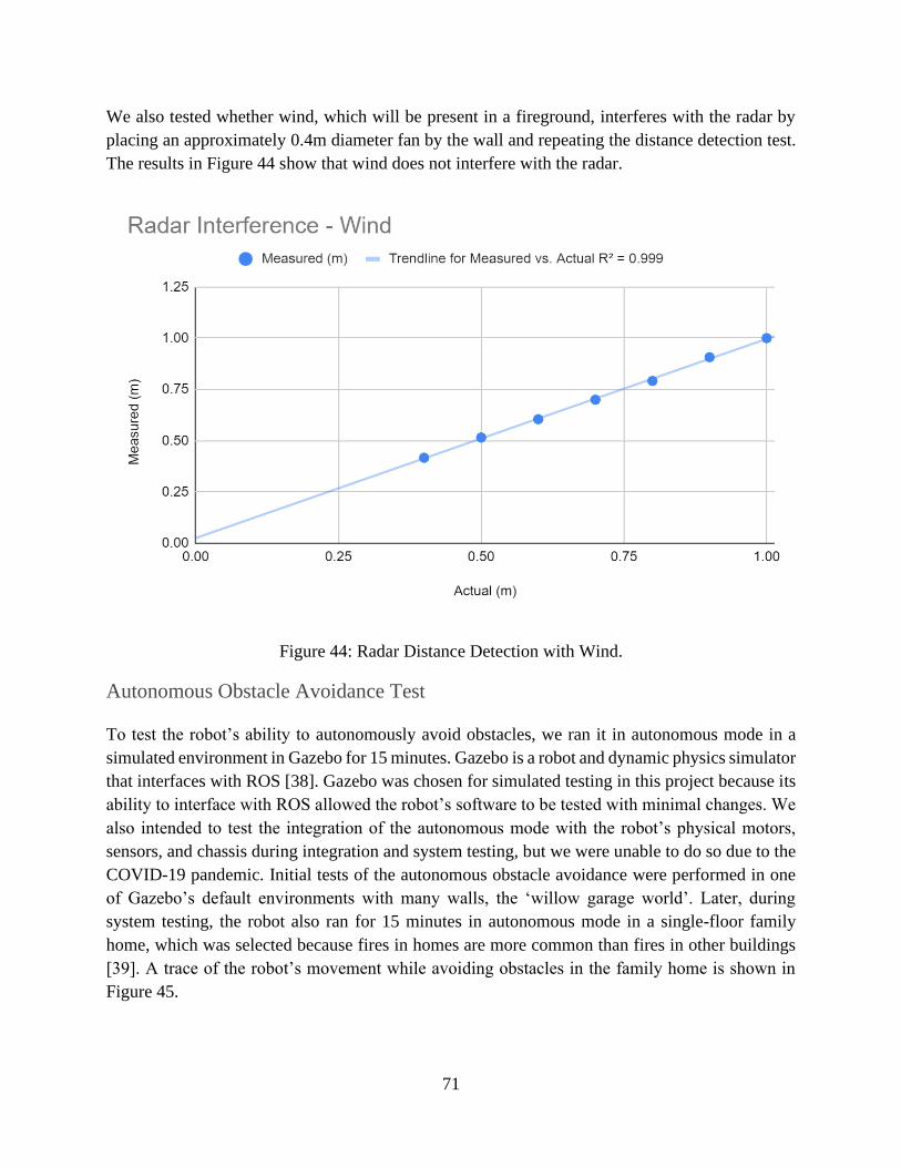
71
We also tested whether wind, which will be present in a fireground, interferes with the radar by
placing an approximately 0.4m diameter fan by the wall and repeating the distance detection test.
The results in Figure 44 show that wind does not interfere with the radar.
Figure 44: Radar Distance Detection with Wind.
Autonomous Obstacle Avoidance Test
To test the robot’s ability to autonomously avoid obstacles, we ran it in autonomous mode in a
simulated environment in Gazebo for 15 minutes. Gazebo is a robot and dynamic physics simulator
that interfaces with ROS [38]. Gazebo was chosen for simulated testing in this project because its
ability to interface with ROS allowed the robot’s software to be tested with minimal changes. We
also intended to test the integration of the autonomous mode with the robot’s physical motors,
sensors, and chassis during integration and system testing, but we were unable to do so due to the
COVID-19 pandemic. Initial tests of the autonomous obstacle avoidance were performed in one
of Gazebo’s default environments with many walls, the ‘willow garage world’. Later, during
system testing, the robot also ran for 15 minutes in autonomous mode in a single-floor family
home, which was selected because fires in homes are more common than fires in other buildings
[39]. A trace of the robot’s movement while avoiding obstacles in the family home is shown in
Figure 45.

72
Figure 45: Obstacle Avoidance Test Movement Trace.
Bandwidth Use Test
We tested the bandwidth use of the system by recording one minute of sensor data from the robot
and playing it back in RQT’s topic monitor, shown in Figure 46, which can display bandwidth
used by topic [37]. The total bandwidth use of non-camera sensors was 20.456 Kbps, which is
substantially less than our original estimate of 836.4 Kbps.

73
Figure 46: Bandwidth Use by Topic.
The bandwidth use of the camera was measured separately because the video feed is not
transmitted through ROS. For the camera bandwidth use, an 18 second sample video of a team
member waving their hand in front of the robot’s camera was taken using the same encoding that
would be used to transmit the video with a resulting file size of 1641 KB. Transmitting that file
over 18 seconds yields an average bandwidth use of 729 Kbps. While much larger than the
bandwidth usage of the non-camera sensors, this value is also dramatically less than our original
estimate of 19.35 Mbps. This test shows that the robot does not use a significant amount of the
total 72 Mbps bandwidth available, as was initially estimated, opening the door for multiple robots
transmitting full sets of sensor information and video feeds on the same network.
Critical Time Estimation Test
We tested the critical time estimation by simulating a 5000 mAh battery depleting from full charge
over the course of 15 minutes with 50 mAh variance gaussian noise on each battery charge reading.
Because the time estimate uses a weighted average over time with long periods between estimate
updates to get accurate readings on change in temperature and battery charge, it requires a minute
to warm up, as shown by the inaccurate estimates at the beginning of Figure 47. Once the critical
time node has gathered a full set of readings to average, it produces estimates that fit the actual
time remaining within ~25% as shown by the linear regression in Figure 48.
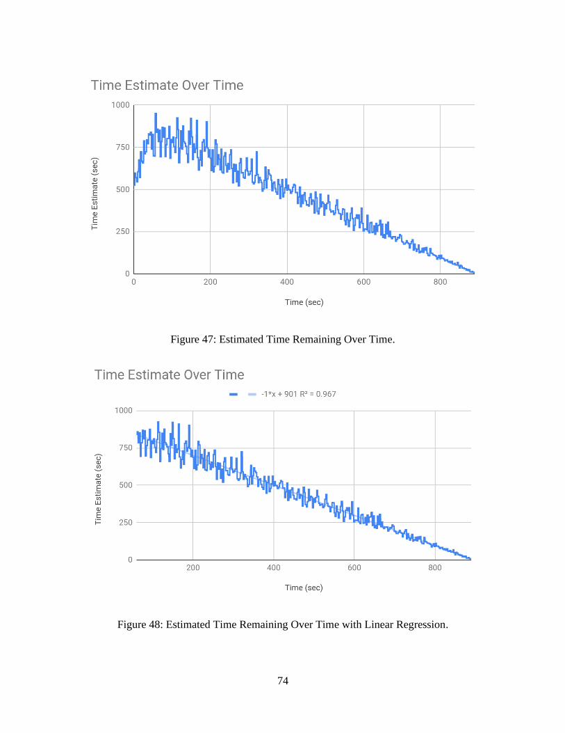
74
Figure 47: Estimated Time Remaining Over Time.
Figure 48: Estimated Time Remaining Over Time with Linear Regression.

75
Integration Testing
This testing is performed to ensure that components are compatible with each other, ie. are able to
work together without compromising on certain performances of either of the components.
Whegs
The first step to integrate the whegs is a pass/fail test of whether they can support the weight of
the robot with the entire chassis attached. This can be achieved by constructing the robot with the
wheels attached and observing how the wheels react under the weight of the chassis. Given the
material selected, we do not anticipate any deformation of the whegs at room temperature.
Additionally, when conducting the chassis tests in the furnace, the whegs should be attached and
observed to ensure they can support the chassis weight at high temperature without deforming
After integrating the whegs into the stationary system, the next test is to conduct moving tests. The
requirement metric is that the robot should be able to move at 0.5 m/s on wet or uneven flooring.
The following procedure details how we would have tested this metric.
1. Measure a straight line of 10 meters long
2. Mark each meter on the ground
3. Place the robot about the first meter, moving straight over the line measured in step one
a. The placement does not have to be exact, just far enough back that the team has
time to start the timer as the robot passes the first meter mark
4. Use the front face of the robot as the measurement point
5. Start the robot at maximum speed
6. Once the robot’s front face has crossed the meter marking start the timer
7. Record the time as the front face of the robot passes each of the meter marks
8. Repeat steps 3-7 at least 3 times for each environment.
This procedure should be executed for various types of environments:
1. Dry, even flooring
2. Dry, uneven flooring
3. Wet, even flooring
4. Wet, uneven flooring
The metric for wet should be one gallon of water spread evenly across the 10 meters, about 0.5
meters in width. Uneven flooring is considered uneven tiles or wood planks, and even driving over
a low-pile rug.

76
Battery Management System
After verifying that the assembled BMS modules worked, the controlled code needs to be modified
in order to work with the ESP32 and send data over I2C to the device. This modification includes
removing all of the WiFi communication code, changing the old libraries to use ESP32-compatible
libraries, hard-coding calibration values, and moving the adapted program to be integrated in the
main ESP32 file. It should be noted that it is theoretically possible to have all of the BMS program
as a separate module, but to save time and reduce complexity, all of the necessary code was moved
to the main ESP32 file, with the supporting local libraries in the same folder.
To ensure that the newly introduced sub-system would work with the rest of the existing system,
the BMS code was adapted to use the same means of communicating the received data, which is
through ROS. A new ROS Topic called BatteryState was introduced to track the state of the
battery, which includes the voltage, current, and capacity of the battery. The temperature value is
tracked separately by the same Temperature topic used with the thermal sensor. Once the code was
adapted, the integration was verified by observing the data published on the BatteryState topic, as
shown in Figure 49 below.
Figure 49: A Sample of the ROS Published BatteryState Messages.
It should be noted that the voltage is in volts, current is in milliamperes, and charge/capacity is in
milliamp-hours. At this point, the voltage value can be verified; when setting initial calibrations
for the cell modules, each cell in the battery pack was recorded and averaged approximately 3.95
V, which happened months prior to integration. Due to the outbreak and lack of proper equipment
at the team’s disposal, a more recent set of measurements was not able to be obtained. It is assumed
that the testing that occurred between the original measurement and the recent measurement done
by the BMS in the integration test resulted in a drop in voltage level in the battery pack, which is
reasonably consistent with the presented results. Since there is not a physical component to
perform the capacity and charge measurements of the battery cells, the values are calculated based
on the voltage level measured.
Software Integration
The GUI was run with sensor outputs produced by the robot model in a Gazebo simulation to
mimic integration between the GUI and sensor outputs from a physical robot. Both the simulation

77
and GUI consume most of the screen, making it difficult to compare them at a single point in time,
but recording sensor readings in a bag file and playing them back allowed us to capture images of
the robot in simulation and of the GUI at the same point in time, as shown in Figure 50. After
integrating the GUI with simulation sensor outputs, the autonomous obstacle avoidance node was
added to the system followed by the critical time estimator node.
Figure 50: Gazebo Simulation With GUI.
System Testing
Initially, the team planned to conduct system testing by running the robot autonomously in a room
for 15 minutes. Due to the COVID-19 pandemic, we were unable to complete construction of the
chassis and carry out this test. Instead, the robot was tested in a simulated environment in Gazebo.
We selected a one-story home floor plan for our simulated environment in Gazebo because fires
in houses are more common than other fires [39]. The robot is shown in this environment in Figure
51.
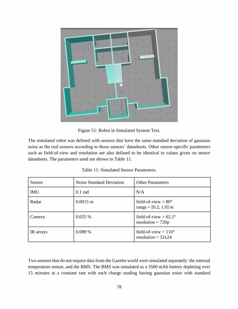
78
Figure 51: Robot in Simulated System Test.
The simulated robot was defined with sensors that have the same standard deviation of gaussian
noise as the real sensors according to those sensors’ datasheets. Other sensor-specific parameters
such as field-of-view and resolution are also defined to be identical to values given on sensor
datasheets. The parameters used are shown in Table 11.
Table 11: Simulated Sensor Parameters.
Sensor Noise Standard Deviation Other Parameters
IMU 0.1 rad N/A
Radar 0.0015 m field-of-view = 80°
range = [0.2, 1.0] m
Camera 0.025 % field-of-view = 62.2°
resolution = 720p
IR arrays 0.089 % field-of-view = 110°
resolution = 32x24
Two sensors that do not require data from the Gazebo world were simulated separately: the internal
temperature sensor, and the BMS. The BMS was simulated as a 3500 mAh battery depleting over
15 minutes at a constant rate with each charge reading having gaussian noise with standard

79
deviation of 50 mAh. The internal temperature of the robot was simulated with an initial
temperature of 20℃ then periodically taking the difference between the sensed external
temperature and the simulated internal temperature, multiplying by the time since the last update
and a constant derived from COMSOL simulations, and adding this value to the simulated internal
temperature. Although the external temperature is dependent on the environment around the robot,
Gazebo does not have built-in temperature simulation capabilities, so we defined the temperature
of the walls as the color of the walls and used the temperature of the wall appearing in the robot’s
front thermal array to determine the temperature outside the robot. The real IR arrays produce
arrays of 8-bit values representing temperatures linearly interpolated between a programmatically
set minimum temperature of 20℃ and the arrays’ maximum temperature of 300℃. Reversing the
interpolation allows us to encode temperatures between 20℃ and 300℃ in 8-bit color values on
the walls in Gazebo.
Conclusion
The profession of firefighting can be called heroic or valiant, but in the end, the reality of what
firefighters have to do in the line of duty is not only frightening, but life threatening. The process
of search and rescue and having to breach into a burning building to save lives is not just part of
their profession but part of their moral code. Any firefighters’ responsibility and priority is to save
the lives of others before their own. FRED is a robot designed to assist firefighters on the
fireground in various ways while keeping out of the way of the firefighters performing their tasks.
The dangers of firefighting are never ending and it is the request that FRED performs tasks and
analysis that would not only benefit the safety of the firefighters who are using FRED, but also
assist in search and rescue by making the process of finding individuals more efficient. The data
that FRED obtains could be sent to the Incident Commander who would be able to make informed
decisions and strategies because of it, rather than make decisions solely on prior experiences and
what can be seen from outside the fireground. The use of “Smart Technologies” and the
advancement of just everyday technology is creating a new market for products that can aid in all
types of disasters. With FRED the long term goal is to create an autonomous robot that can be
deployed prior to the entrance of the firefighters and send data consisting of building integrity,
persons, and temperature among other functions that could save the lives of the firefighters.
Lessons Learned
In designing and simulating this robot, we learned about the intricacies of creating a fire-resistant
robot. Keeping the robot relatively lightweight, impact resistant, and maintaining a cool interior
were some design metrics that tended to disagree, especially when selecting materials. Balancing
both machinability and efficient design is not a trivial task. We came across many designs that
would have fit the use case well, particularly wheels, but the advanced machining skill required

80
made them less desirable for this iteration of the project. In addition, we discovered that it is
difficult to develop an effective autonomy specific to mapping and navigating a fireground, where
the environment is constantly changing. Developing a comprehensive, easy to understand GUI
when there is so much prominent information is not trivial. We learned a lot about the importance
of verification, and different methods for verifying results. Due to the COVID-19 pandemic, we
were unable to run physical tests, so verifying the simulation results became an extra important
step.
Future Work
While many aspects of the project were successful in simulation, there are many additions and
improvements that can be implemented to make the robot more useful for firefighters. Below is a
list of possible improvements that can be implemented in future iterations of the project. Following
the list is a detailed description of the rationale for each suggestion.
● Complete construction of chassis and whegs
● Conduct metric testing of all the components
● Modify whegs and axle to survive a 1-meter drop
● Design a containment unit for the phase change material
● Correct for lens distortion on IR arrays
● Implement automatic launching of scripts on boot
● Implement intelligent autonomous exploration
● Implement autonomous mapping of the environment
● Alert the user of potential flashover or burnout
● Improve interior time algorithm
● Expansion of BMS to monitor individual cells
● Implementation of wireless charging
● Addition of more robots
Completing Construction
Due to the COVID-19 pandemic causing classes and projects to become remote, we were unable
to finish constructing the chassis. Completing this step will allow testing of the current design,
which will give more insight on how the current design works, and what improvements can be
made going forward.
Conduct Metric Testing
Conducting metric testing on the prototype will allow for a better understanding of what aspects
of the project worked well, and which did not. Specifically, testing the heat resistance of the chassis
using the procedure highlighted in the Experimental Evaluation section would be valuable to future
project iterations. For the simulations, we used thermal constants listed in the technical datasheets
of the products. Certain materials and products were advertised in a “too good to be true” fashion,

81
which led to some doubt about the accuracy of these values, and therefore the simulations created
using the advertised values. Because we were unable to physically test the materials, we had to
accept the values as advertised for the simulations. Conducting thermal testing would allow the
next iteration to further verify or disprove the simulated results of the material layering system.
The whegs have only been tested for their ability to open and close in SOLIDWORKS, and with
a 3D printed model. The next step would be to conduct unit and integration tests with the aluminum
waterjet cut whegs. After assembling the whegs together with proper screws and the shoulder pins,
they should be tested by being attached to the motors to make sure they spin with the axle. These
tests should all be done in respect to a pass/fail scale where the whegs can perform the task in
question or can not. While conducting the tests, observations should be made for how to improve
the system. After testing for basic driving capabilities, the robot should be tested for the ability to
move on flat ground, with the whegs in wheel formation. After flat ground, the whegs should be
tested for their ability to open as a reaction to hitting a small step or ledge while moving, and then
close once the surface is flat again.
After completing those unit tests, integration and system testing should be completed. A full 15-
minute test was only completed in simulation, so a physical test is also necessary.
Modify Axle and Whegs
A requirement metric that we had considered including in this iteration was for the robot to be able
to withstand a 1-meter drop. In order to deploy the robot quickly, the robot may not be gently
placed on the ground, so we had intended to develop a product capable of withstanding a short
drop. With the current materials and design, there is concern about whether the axle will be able
to withstand the force from the drop without damage or deformation. A potential solution would
be to design a system where the whegs remain in an open formation for the duration of deployment.
The curved leg of the whegs would absorb some force that impacts the axle otherwise.
Phase Change Material Containment Unit
Incorporating a phase change material significantly improved the heat resistance of the chassis.
The current design involved storing the phase change material in a plastic bag with a high heat
resistance, like those used in kitchen ovens. Often these bags do not have a way to close, as they
are shaped like liners. Designing a containment unit to limit the chance of the phase change
material leaking or spilling would improve the durability and longevity of the robot. A
consideration when designing the containment unit is that it must be able to effectively contain
both solids and liquids.

82
Sensor Lens Distortion
Due to the budgetary constraints of the project, and the research last year’s team conducted, we
decided to continue using the Zinc Selenide (ZnSe) lenses implemented last year. Besides
purchasing different lenses, which will likely be more expensive, the distortion problem can be
improved by modifying the design.
Through experimental testing, the optimal distance between the sensor and the lens, to minimize
distortion can be determined. Once each individual lens has been tested, the placement of the lens
and sensors on the chassis could be modified to maintain that distance. In addition, this data could
be used to create a correction equation to be applied when processing the sensor data.
Automatic Launching on Boot
In order to decrease deployment time, the Linux machine used to run the robot could automatically
start ROS and robot control scripts on boot. This would allow for the user to simply turn on the
machine and have the robot start running. An obstacle to automatic launching on boot is that the
robot needs to pair with the operator interface laptop.
Intelligent Autonomous Exploration
Although the robot is able to move autonomously through a building, there are still improvements
that can be made. Rather than moving in random directions, the robot could instead be designed
to move towards a target, such as heat sources or unexplored areas. Targeted autonomous
exploration will potentially allow the robot to search more of the fireground and provide more
information about areas of interest.
Autonomous Mapping
Another autonomy improvement that can be implemented is mapping of the environment. In
conjunction with intelligent autonomous exploration, the robot will be able to explore more of the
fireground and provide firefighters with a learned floor plan of the environment. This addition to
the system is especially important considering unfamiliar surroundings clouded by smoke can
cause firefighters to become disoriented in the fireground. Autonomous mapping could also inform
firefighters of mobile obstacles such as furniture.
Flashover and Burnout Alert
Currently the graphical user interface gives the user information about the external temperature of
the environment. A future implementation is to create a script that analyzes the external
temperature and pressure patterns and alerts the user when there is a high risk of burnout or
flashover. This would involve defining the characteristics and signs of these events, and tracking
not only current temperature, but the change in temperature over time.

83
Interior Time Algorithm
The current interior time algorithm uses data from the COMSOL simulation and the current
internal and external temperature to determine how much longer the robot can survive in a
fireground before overheating. As described in the rationale for conducting metric testing, the
COMSOL model may be inaccurate due to the given thermal constants for some of the materials
seeming outlandish. Instead of using COMSOL data, future iterations could consider using
experimental data to determine how much longer the robot can survive.
Expansion of BMS to Monitor Individual Cells
The current BMS monitors cell pairs, that is, there are two cell modules that are used to monitor
the status of two battery cells together of the battery pack of four cells. For budgeting and spacing
reasons, the design included only two modules, but a future implementation could expand that to
have each cell be monitored by an individual module. This could be done by redesigning the PCB
for the module, making it more compact, or using a new BMS design that is smaller in size.
Implementation of Wireless Charging
A fair amount of research was conducted on the possibility of integrating a wireless charging
system to charge the battery while in the robot. Currently, there is no strong consideration of how
the robot should be charged as a final product. Charging the prototype requires opening the chassis
to plug a charging cable into the battery. However, this year’s design accommodated for the
possibility of including a set of coils on the bottom of the robot for wireless charging. As a future
implementation, a charging dock would need to be created, the receiver coils would have to be
connected to the rest of the internal system.
Adding More Robots
As an exploration robot with limited obstacle detection capability, a deployment of FRED could
benefit from having multiple robots exploring the fireground cooperatively, which would allow
the robots to explore the fireground more quickly before firefighters enter a dangerous area. There
are four major areas to think about if adding more robots to the system: software architecture,
cooperation among the robots, adjustments to the GUI, and bandwidth constraints.
The current software architecture relies on ROS, but a system with many robots will likely need
to use different software. In the current system, the ROS master resides on the robot, which allows
disconnections to occur between the operator interface laptop and the robot without crashing the
robot; however, only one ROS master can exist in the system, so it must be moved to the operator
interface laptop, which creates the possibility of robots disconnecting and crashing without control
from the ROS master. Additionally, ROS is not optimized for systems with many robots, therefore
we recommend using different software if more robots are to be added. One possibility is to port
Buzz, a robot swarm programming language, to FRED and use it for programming [40].

84
Several robots exploring the fireground at least need a way to avoid running into each other and
ideally should have a way to intelligently explore the fireground so that exploration can be
completed more quickly than with a single robot. FRED robots should be able to avoid each other
as-is by detecting other robots as obstacles; however, if implementing mapping as well as adding
robots to the system, this could lead to erroneous obstacle markings. One way to improve the
exploration speed of multiple robots would be to have each robot be repelled by each other robot
while moving randomly and avoiding obstacles. In this way, the swarm of robots will expand
through the fireground like a fluid.
The GUI is currently designed around a single robot. If multiple robots are used, the robot-specific
video feeds that take up the top half of the GUI become less important. The top-down view of the
robot in the Rviz window in the bottom right of the GUI becomes more important as long as it
shows all robots in the system. A multi-robot GUI setup should include a large central area
displaying all robots in the system and their relative positions along with any global maps created
by the robots of physical obstacles, temperature, or pressure. The user should be able to select
individual robots through this window to see robot-specific data including the video feeds and
sensor data. The drive style selector in the lower right of the GUI will also likely be eliminated as
it would be undesirable to control all robots with a single controller with the drive styles available;
however, the drive style selector could also be changed to a menu that allows the operator to alter
the autonomous behavior of the system to accomplish different goals.
Finally, if many robots are to be involved in a large fireground, bandwidth constraints come into
play. The expected maximum bandwidth use calculated by our team prohibits more than three
robots transmitting video feeds over the same network. Fortunately, the bandwidth use observed
experimentally is less than 1 Mbps, which allows many robots to operate on the network; however,
for large numbers of robots, more than 70, the robots will exceed the available bandwidth.

85
References
1. N. P. Bryner et al., “Research Roadmap for Smart Fire Fighting,” NIST. June 11, 2015.
[Online] Available:
https://nvlpubs.nist.gov/nistpubs/SpecialPublications/NIST.SP.1191.pdf. [Accessed Oct.
10, 2019].
2. N. McCarthy, “82 American Firefighters Died On Duty In 2018,” Statista, Oct. 8, 2019.
[Online]. Available: https://www.statista.com/chart/19578/number-of-firefighters-killed-
on-duty/. [Accessed May 3, 2020].
3. R. Sobey, “Another fallen Worcester firefighter: The city’s brutal history,” Boston
Herald, Nov. 13, 2019. [Online]. Available:
https://www.bostonherald.com/2019/11/13/another-fallen-worcester-firefighter-the-citys-
brutal-history/. [Accessed May 3, 2020].
4. E. Barinelli, J. Berman-Jolton, G. MacNeal, K. Naras, and Y. Verdeja, “Firefighting
Remote Exploration Device,” April 25, 2019. [Online]. Available:
https://digitalcommons.wpi.edu/mqp-all/6840/. [Accessed Oct. 10, 2019].
5. “What is smart home or building (home automation or domotics)?,” IoT Agenda, 2019.
[Online]. Available: https://internetofthingsagenda.techtarget.com/definition/smart-
home-or-building. [Accessed Oct. 10, 2019].
6. A. M. Naghsh et al., “Analysis and Design of Human-Robot Swarm Interaction in
Firefighting,” Proceedings of the 17th IEEE International Symposium on Robot and
Human Interactive Communication. [Online]. Available:
https://ieeexplore.ieee.org/document/4600675. [Accessed October 10, 2019].
7. Y. D. Kim, Y. G. Kim, S. H. Lee, J. H. Kang, and J. An, “Portable Fire Evacuation Guide
Robot System”, IEEE/RSJ International Conference on Intelligent Robots and Systems,
2009. [Online]. Available:
https://www.researchgate.net/publication/224090447_Portable_Fire_Evacuation_Guide_
Robot_System. [Accessed October 10, 2019].
8. I. Amano, “Present Status and Problems of Fire Fighting Robots,” SICE, 2002. [Online]
Available:
https://www.researchgate.net/publication/4012414_Present_status_and_problems_of_fire
_fighting_robots. [Accessed Oct. 10, 2019].
86
9. H. Ando et al., “Aerial Hose Type Robot by Water Jet for Fire Fighting,” IEEE Robotics
and Automation Letters, vol. 3, no. 2, pp. 1128-1135, 2018, 10.1109/lra.2018.2792701,
[Online]. Available:
https://www.researchgate.net/publication/322449333_Aerial_Hose_Type_Robot_by_Wat
er-Jet_for_Fire_Fighting. [Accessed Oct. 10, 2019].
10. T. Yamaguchi et al., “A Mechanical Approach to Suppress the Oscillation of a Long
Continuum Robot Flying With Water Jets,” IEEE Robotics and Automation Letters, vol.
4, no. 4, pp. 4346-4353, 2019. Available: 10.1109/lra.2019.2932582. [Online]. Available:
https://www.researchgate.net/publication/334849911_A_Mechanical_Approach_to_Supp
ress_the_Oscillation_of_a_Long_Continuum_Robot_Flying_With_Water_Jets.
[Accessed Oct. 10, 2019].
11. T. AlHaza, A. Alsadoon, Z. Alhusinan, M. Jarwali, and K. Alsaif, “New Concept for
Indoor Fire Fighting Robot,” Procedia - Social and Behavioral Sciences, vol. 195, pp.
2343-2352, 2015. Available: 10.1016/j.sbspro.2015.06.191. [Online]. Available:
https://www.researchgate.net/publication/282556896_New_Concept_for_Indoor_Fire_Fi
ghting_Robot. [Accessed Oct. 10, 2019].
12. J. Calfee, “Understanding Your PPE Levels and Ratings,” Fire Rescue, Dec. 31, 2013.
[Online]. Available:
https://firerescuemagazine.firefighternation.com/2013/12/31/understanding-your-ppe-
levels-and-ratings/#gref. [Accessed May 15, 2020].
13. Design Engineering Inc., “Reflect-A-Cool Heat Reflective Sheets,” Design Engineering
Inc., 2019. [Online]. Available: https://designengineering.com/reflect-a-cool-heat-
reflective-sheets/. [Accessed Dec. 9, 2019].
14. Laminated Plastics, “TECHNICAL DATA SHEET Teflon (PTFE),” Laminated Plastics.
[Online]. Available: https://laminatedplastics.com/teflon.pdf. [Accessed Oct. 25, 2019].
15. J. H. Kim et al., “Aging performance evaluation of vacuum insulation panel (VIP),”
Elsevier Ltd, June 2, 2017. [Online]. Available:
https://www.sciencedirect.com/science/article/pii/S2214509517301109. [Accessed Dec.
13, 2019].
16. “Latent and Sensible Heat,” North Carolina Climate Office. [Online]. Available:
https://climate.ncsu.edu/edu/Heat. [Accessed Dec. 10, 2019].

87
17. T. Bergman, A. Lavine, F. Incropera and D. Dewitt, “Physical Origins and Rate
Equations,” in Fundamentals of Heat and Mass Transfer Seventh Edition, Danvers, John
Wiley & Sons, 2011, p. 7.
18. U.S. Department of Energy, “Determining Electric Motor Load and Efficiency,” U.S
Department of Energy, 2014. [Online]. Available:
https://www.energy.gov/sites/prod/files/2014/04/f15/10097517.pdf. [Accessed Oct. 15,
2019].
19. “The Mars 2020 Rover Wheels and Legs.” Retrieved December 13, 2019 from
https://mars.nasa.gov/mars2020/mission/rover/wheels/
20. C. Nethmal, “Rocker Bogie Suspension System for a Mobile Robot, ” Medium, May 24,
2019. [Online]. Available: https://medium.com/@chandulanethmal/rocker-bogie-
suspension-system-for-a-mobile-robot-654b1a30992e. [Accessed Sept. 28, 2019].
21. Y. S. Kim, G. P. Jung, H. Kim, K. J. Cho, and C. N. Chu, “Wheel transformer: A
miniaturized terrain adaptive robot with passively transformed wheels,” Proceedings -
IEEE International Conference on Robotics and Automation, 5625-5630.
10.1109/ICRA.2013.6631385. 2013. [Online]. Available:
https://www.researchgate.net/publication/261416066_Wheel_transformer_A_miniaturize
d_terrain_adaptive_robot_with_passively_transformed_wheels. [Accessed Dec. 13,
2019].
22. S. Pittaway, “diyBMS,” July 16, 2019. [Online] Available:
https://github.com/stuartpittaway/diyBMS. [Accessed Dec. 13, 2019].
23. “LiNiMnCo 26650 Rechargeable Cell: 3.6V 5Ah (18Wh, 15A rated) - UN38.3 Passed,”
AA Portable Power Corp, 2019. https://www.batteryspace.com/linimnco-26650-
rechargeable-cell-3-6v-5ah-18wh-15a-rated---un38-3-passed--.aspx. [Accessed Dec. 13,
2019].
24. L. Mearian, “Wireless charging explained: What is it and how does it work?,”
Computerworld, March 28, 2018. [Online]. Available:
https://www.computerworld.com/article/3235176/wireless-charging-explained-what-is-it-
and-how-does-it-work.html. [Accessed Dec. 13, 2019].
25. Taidacent, “Taidacent 48V Transmitting 12V 2A Output Wireless Charging Module
50~100mm DC Long Distance Wireless Power Supply Module (12V2A Long

88
Distancee),” Taidacent.
https://www.amazon.com/dp/B07W12DS31/ref=psdc_10967761_t3_B0777HK38T?th=1
. [Accessed Dec. 13, 2019].
26. “48 Volt DC 2 Amp 96 Watt Regulated Switching Table Top Power Supply 2.5mm
Plug,” Jameco. https://www.jameco.com/z/GM95-480200-F-48-Volt-DC-2-Amp-96-
Watt-Regulated-Switching-Table-Top-Power-Supply-2-5mm-Plug_2271319.html.
[Accessed Dec. 13, 2019].
27. “3-Conductor AC Power Cord 18 AWG NEMA 5-15P to C13 SVT Jacket 6 Feet Black,”
Jameco. [Online]. Available: https://www.jameco.com/z/2500-072-Quail-Electronics-3-
Conductor-AC-Power-Cord-18-AWG-NEMA-5-15P-to-C13-SVT-Jacket-6-Feet-
Black_2271575.html. [Accessed Dec. 13, 2019].
28. “KNACRO 15V 2A DC-DC Converter DC 9V / 12V 9-14V to DC 15V 2A 30W DC
Boost Module Waterproof (DC 15V 2A 30W),” KNACRO. [Online]. Available:
https://www.amazon.com/KNACRO-DC-DC-Converter-module-
Waterproof/dp/B078XBSQGP/ref=asc_df_B078XB6V64/?tag=hyprod-
20&linkCode=df0&hvadid=309764501757&hvpos=1o7&hvnetw=g&hvrand=53186739
57138027099&hvpone=&hvptwo=&hvqmt=&hvdev=c&hvdvcmdl=&hvlocint=&hvlocp
hy=9001843&hvtargid=pla-667953675503&th=1. [Accessed Dec. 13, 2019].
29. Alfred, “How Thermoelectric Generators Work,” Applied Thermoelectric Solutions.
[Online]. Available: https://thermoelectricsolutions.com/how-thermoelectric-generators-
work/. [Accessed Dec. 11, 2019].
30. “How Stirling Engines work,” American Stirling Company, [Online]. Available:
https://www.stirlingengine.com/. [Accessed Dec. 11, 2019].
31. ROS. Open Robotics, 2018. [Online]. Available: http://www.ros.org. [Accessed: May 15,
2020].
32. “SparkFun Pulsed Radar Breakout - A111,” SEN-15577 - SparkFun Electronics, 2019.
[Online]. Available: https://www.sparkfun.com/products/15577. [Accessed: May 15,
2020].
33. “Camera Module,” Raspberry Pi. [Online]. Available:
https://cdn.sparkfun.com/datasheets/Dev/RaspberryPi/RPiCamMod2.pdf. [Accessed Dec.
13, 2019].
89
34. “What is 802.11?,” IEEE, [Online]. Available: https://www.air802.com/files/802-11-
WiFi-Wireless-Standards-and-Facts.pdf. [Accessed Dec. 13, 2019].
35. K. Ullah, “H264 Primer,” March 30, 2010. [Online]. Available:
https://issuu.com/konu/docs/h264_primer. [Accessed Dec.13, 2019].
36. A. Kleiner et al., “Disaster Robotics,” 2016. [Online]. Available:
https://www.researchgate.net/publication/305721922_Disaster_Robotics. [Accessed Dec.
13, 2019].
37. D. Thomas, “RQT,” 2016. [Online]. Available: http://wiki.ros.org/rqt. [Accessed May 14,
2020].
38. Gazebo, Open Source Robotics Foundation, 2014. [Online]. Available:
http://www.gazebosim.org [Accessed May 14, 2020].
39. “Fires by occupancy or Property Type,” NFPA, 2018. [Online]. Available:
https://www.nfpa.org/News-and-Research/Data-research-and-tools/US-Fire-
Problem/Fires-by-occupancy-or-property-type. [Accessed May 2, 2020].
40. C. Pinciroli and G. Beltrame, “Buzz: A Programming Language for Robot Swarms” in
IEEE Software, vol. 33, no. 04, pp. 97-100, 2016. doi: 10.1109/MS.2016.95.

90
Appendix A: Requirement Decision Matrix
Below is the requirement decision matrix. Each requirement has been ranked according to
various criteria on a scale of 1-5. For each criterion, 1 is the least desirable, and 5 is most
desirable.
Rank 3 1 2 2 2 1
Criteria: Durability
Ease of
Use
Heat
Resistance
Time to
implement cost
Prior
experience Total
Weight
1 - no
impact
5 - vital
impact
1 - more
difficult to
use
5 -
drastically
improves
usability
1 - adds
another
component to
make heat
resistant
5 -
significantly
improves heat
resistance
1 -
impossible/a
ll year
5 - 1-3 days
to
implement
1 - out
of
budget
($2500)
5 - free
1 - no one
has relevant
experience
5 - one
person has
relevant,
extensive
experience
Optimize Heat
shielding to maintain
internal temperature
of less than 60c for 15
minutes
4 3 5 2 3 3
38
Whegs that reliably
and automatically
deploy
3 2 1 3 3 2
27
Heat Resistant
Whegs
4 3 5 3 2 3
38
Waterproofing all
sides/angles
5 3 3 2 3 2
36
Physical Mapping w/
no initial assumptions
1 4 2 3 5 4
31

91
Heatproof Shell 215
°C for 3 minutes w/
Internal Temp < 60
°C
4 3 5 2 3 3
38
Battery management
system
4 4 3 3 3 2
36
Extended long-range
communication
1 4 3 2 3 2
25
Range Finding/3D
imaging
1 4 2 1 2 2
19
Heat and Pressure
mapping
1 4 2 2 2 2
21
Refine User Interface 1 5 2 4 5 4
34
Autonomous exit
prior to critical
internal temperature
2 4 3 2 4 4
32
Add an interior time
algorithm that
estimates and
displays the time
before internal
temperature reaches
60 °C
1 4 3 3 5 3
32
Autonomous
exploration of the
fireground, moving
toward hot zones and
avoiding collisions
1 3 2 2 5 5
29
Automatically launch
scripts on robot boot
1 5 2 5 5 4
36
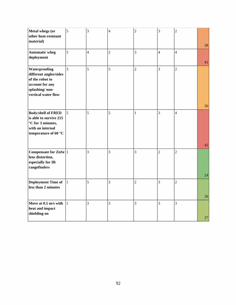
92
Metal whegs (or
other heat-resistant
material)
5 3 4 2 3 2
38
Automatic wheg
deployment
5 4 2 3 4 4
41
Waterproofing
different angles/sides
of the robot to
account for any
splashing/ non-
vertical water flow
3 5 5 2 3 2
36
Body/shell of FRED
is able to survive 215
°C for 3 minutes,
with an internal
temperature of 60 °C
5 5 5 1 3 4
42
Compensate for ZnSe
lens distortion,
especially for IR
rangefinders
1 3 3 3 2 2
24
Deployment Time of
less than 2 minutes
1 5 3 2 3 2
26
Move at 0.5 m/s with
heat and impact
shielding on
1 3 3 3 3 3
27

93
Appendix B: COMSOL Verification via MATLAB
In order to verify the results from the COMSOL simulation were accurate, we used a mixture of
hand calculations, MATLAB, and other COMSOL models. To simplify the problem, the following
assumptions were made:
● No internal heating from components
● No phase change material
● The chassis walls do not have any gaps or holes
● Radiation is negligible
● The exterior remains at a constant temperature
● Material thermal values are constant
● Heat transfer is occurring through a single wall
With these assumptions, the first step of the process was to hand calculate the time for the interior
temperature to reach 60 ℃. The point selected to calculate was the boundary between the foam,
the innermost layer, and the interior air space.
The energy (in watts) transmitted through the system is given by 𝑄𝑠𝑦𝑠𝑡𝑒𝑚 =𝛥𝑇
𝑅, where T is the
temperature, R is the thermal resistance, given by 𝑅 = 𝑑
𝑘 ⋅𝐴, where d is the thickness of the layer,
in meters, k is the thermal conductivity, and A is the cross sectional area.
We can analogize the heat transfer through the system to electrical resistance. The energy
transmitted through the system, Qsystem,, otherwise referred to as heat flux can be equated to heat
electrical current, I. The temperature is voltage in the analogy, and thermal resistance is electrical
resistance. Applying 𝑉 = 𝐼𝑅, Ohm’s law, we can conclude that 𝑇 = 𝑄𝑠𝑦𝑠𝑡𝑒𝑚𝑅𝑡𝑜𝑡𝑎𝑙. Rewritten in
a different format, the heat flux through the system is 𝑄𝑠𝑦𝑠𝑡𝑒𝑚 =𝛥𝑇
𝑅, as described above.
Thermal conductivity is a tabulated value that differs by material, and in different temperatures.
We used the conductivity for each material at 40℃, the average between the high and low
temperature. Table 12 details the thermal conductivities of the materials.

94
Table 12: Material thermal conductivities.
Material Thermal conductivity [𝑾
𝒎𝑲]
Teflon 0.25
Aerogel 0.015
Calcium Silicate 0.027
Air 0.30
Since the materials are all placed one after another, they are in series, and the resistances can be
summed to produce the total resistance. Figure 52 below shows a diagram of the material
layering system’s resistances.
Figure 52: Material Layering System Resistance
The amount of energy needed to change the temperature ΔT of the foam is calculated by:
𝑄𝑓𝑜𝑎𝑚 = 𝜌 ⋅ 𝐴 ⋅ 𝐶𝑝 ⋅ 𝛥𝑇 where ⍴ is the density of the material, and Cp is the specific heat of the
material.
By dividing the energy needed to increase the temperature of the foam from 20℃ to 60℃ , with
the total energy through the system, we obtain the time required to heat the boundary between
the foam and the interior to 60℃. Qsystem is the heat flux at the first moment in time.
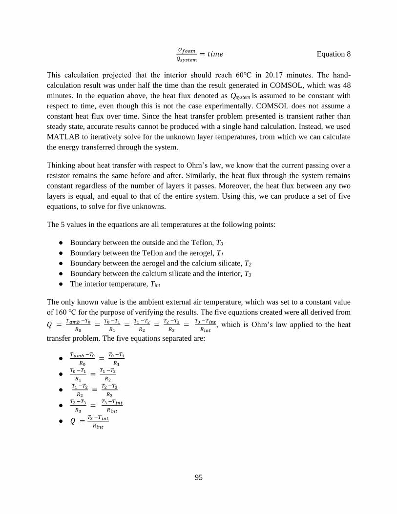
95
𝑄𝑓𝑜𝑎𝑚
𝑄𝑠𝑦𝑠𝑡𝑒𝑚= 𝑡𝑖𝑚𝑒 Equation 8
This calculation projected that the interior should reach 60℃ in 20.17 minutes. The hand-
calculation result was under half the time than the result generated in COMSOL, which was 48
minutes. In the equation above, the heat flux denoted as Qsystem is assumed to be constant with
respect to time, even though this is not the case experimentally. COMSOL does not assume a
constant heat flux over time. Since the heat transfer problem presented is transient rather than
steady state, accurate results cannot be produced with a single hand calculation. Instead, we used
MATLAB to iteratively solve for the unknown layer temperatures, from which we can calculate
the energy transferred through the system.
Thinking about heat transfer with respect to Ohm’s law, we know that the current passing over a
resistor remains the same before and after. Similarly, the heat flux through the system remains
constant regardless of the number of layers it passes. Moreover, the heat flux between any two
layers is equal, and equal to that of the entire system. Using this, we can produce a set of five
equations, to solve for five unknowns.
The 5 values in the equations are all temperatures at the following points:
● Boundary between the outside and the Teflon, T0
● Boundary between the Teflon and the aerogel, T1
● Boundary between the aerogel and the calcium silicate, T2
● Boundary between the calcium silicate and the interior, T3
● The interior temperature, Tint
The only known value is the ambient external air temperature, which was set to a constant value
of 160 ℃ for the purpose of verifying the results. The five equations created were all derived from
𝑄 = 𝑇𝑎𝑚𝑏 −𝑇0
𝑅0 =
𝑇0 −𝑇1
𝑅1 =
𝑇1 −𝑇2
𝑅2 =
𝑇2 −𝑇3
𝑅3 =
𝑇3 −𝑇𝑖𝑛𝑡
𝑅𝑖𝑛𝑡, which is Ohm’s law applied to the heat
transfer problem. The five equations separated are:
● 𝑇𝑎𝑚𝑏 −𝑇0
𝑅0 =
𝑇0 −𝑇1
𝑅1
● 𝑇0 −𝑇1
𝑅1 =
𝑇1 −𝑇2
𝑅2
● 𝑇1 −𝑇2
𝑅2 =
𝑇2 −𝑇3
𝑅3
● 𝑇2 −𝑇3
𝑅3 =
𝑇3 −𝑇𝑖𝑛𝑡
𝑅𝑖𝑛𝑡
● 𝑄 =𝑇3 −𝑇𝑖𝑛𝑡
𝑅𝑖𝑛𝑡
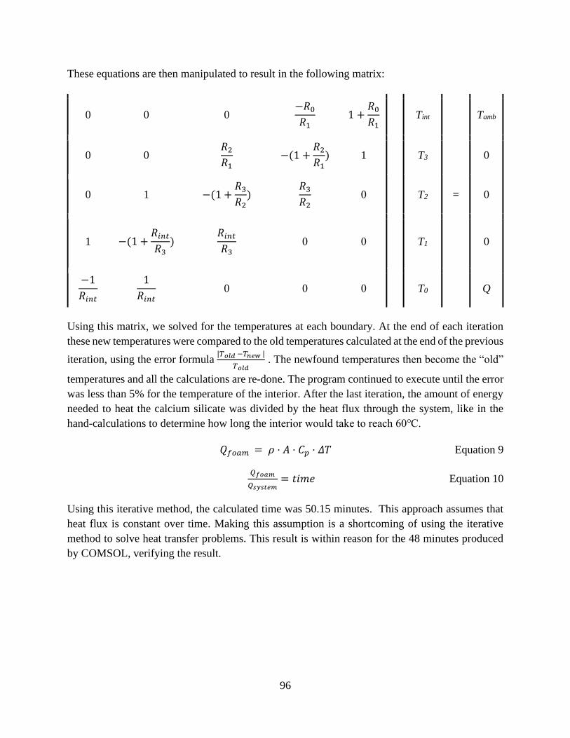
96
These equations are then manipulated to result in the following matrix:
0 0 0 −𝑅0
𝑅1 1 +
𝑅0
𝑅1 Tint Tamb
0 0 𝑅2
𝑅1 −(1 +
𝑅2
𝑅1) 1 T3 0
0 1 −(1 +𝑅3
𝑅2)
𝑅3
𝑅2 0 T2 = 0
1 −(1 +𝑅𝑖𝑛𝑡
𝑅3)
𝑅𝑖𝑛𝑡
𝑅3 0 0 T1 0
−1
𝑅𝑖𝑛𝑡
1
𝑅𝑖𝑛𝑡 0 0 0 T0 Q
Using this matrix, we solved for the temperatures at each boundary. At the end of each iteration
these new temperatures were compared to the old temperatures calculated at the end of the previous
iteration, using the error formula |𝑇𝑜𝑙𝑑 −𝑇𝑛𝑒𝑤 |
𝑇𝑜𝑙𝑑 . The newfound temperatures then become the “old”
temperatures and all the calculations are re-done. The program continued to execute until the error
was less than 5% for the temperature of the interior. After the last iteration, the amount of energy
needed to heat the calcium silicate was divided by the heat flux through the system, like in the
hand-calculations to determine how long the interior would take to reach 60℃.
𝑄𝑓𝑜𝑎𝑚 = 𝜌 ⋅ 𝐴 ⋅ 𝐶𝑝 ⋅ 𝛥𝑇 Equation 9
𝑄𝑓𝑜𝑎𝑚
𝑄𝑠𝑦𝑠𝑡𝑒𝑚= 𝑡𝑖𝑚𝑒 Equation 10
Using this iterative method, the calculated time was 50.15 minutes. This approach assumes that
heat flux is constant over time. Making this assumption is a shortcoming of using the iterative
method to solve heat transfer problems. This result is within reason for the 48 minutes produced
by COMSOL, verifying the result.
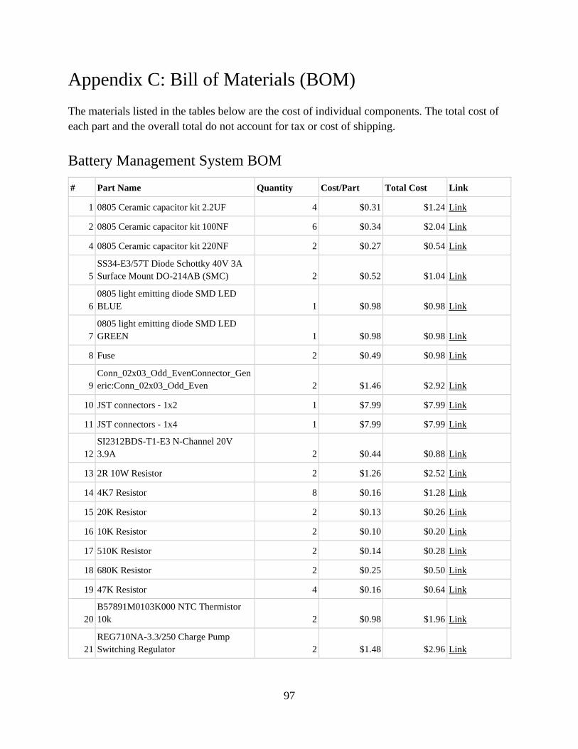
97
Appendix C: Bill of Materials (BOM)
The materials listed in the tables below are the cost of individual components. The total cost of
each part and the overall total do not account for tax or cost of shipping.
Battery Management System BOM
# Part Name Quantity Cost/Part Total Cost Link
1 0805 Ceramic capacitor kit 2.2UF 4 $0.31 $1.24 Link
2 0805 Ceramic capacitor kit 100NF 6 $0.34 $2.04 Link
4 0805 Ceramic capacitor kit 220NF 2 $0.27 $0.54 Link
5
SS34-E3/57T Diode Schottky 40V 3A
Surface Mount DO-214AB (SMC) 2 $0.52 $1.04 Link
6
0805 light emitting diode SMD LED
BLUE 1 $0.98 $0.98 Link
7
0805 light emitting diode SMD LED
GREEN 1 $0.98 $0.98 Link
8 Fuse 2 $0.49 $0.98 Link
9
Conn_02x03_Odd_EvenConnector_Gen
eric:Conn_02x03_Odd_Even 2 $1.46 $2.92 Link
10 JST connectors - 1x2 1 $7.99 $7.99 Link
11 JST connectors - 1x4 1 $7.99 $7.99 Link
12
SI2312BDS-T1-E3 N-Channel 20V
3.9A 2 $0.44 $0.88 Link
13 2R 10W Resistor 2 $1.26 $2.52 Link
14 4K7 Resistor 8 $0.16 $1.28 Link
15 20K Resistor 2 $0.13 $0.26 Link
16 10K Resistor 2 $0.10 $0.20 Link
17 510K Resistor 2 $0.14 $0.28 Link
18 680K Resistor 2 $0.25 $0.50 Link
19 47K Resistor 4 $0.16 $0.64 Link
20
B57891M0103K000 NTC Thermistor
10k 2 $0.98 $1.96 Link
21
REG710NA-3.3/250 Charge Pump
Switching Regulator 2 $1.48 $2.96 Link

98
22
ADUM1250 SOP8 Digital Isolator
CMOS 2 $5.55 $11.10 Link
23
ATTINY85V-10SU AVR AVR®
ATtiny Microcontroller IC 8-Bit 10MHz
8KB (4K x 16) FLASH 8-SOIC 2 $1.13 $2.26 Link
24 SparkFun Pulsed Radar Breakout - A111 1 $59.95 $59.95 Link
Total: $111.49
PCBs (5) 1 $2.00 $2.00 Link
Total w/ PCB $113.49
Robot Chassis BOM
Item Quantity Cost per Item Total Cost Link
SHINA Ceramic Glass Fiber Mat of
High Temp -328°F to 1200°
29.53''×19.69''×0.394'' Thickness
10MM 394 Mil Super Light Insulation
Sound Deadening Mat for Garage Door,
Windows, Car Insulation 1 $41.99 $41.99 Link
PureTemp 58X - 1 gallon/4lbs 1 $80.00 $80.00 Link
1/2" x 12" x 12" Calcium Silicate High
Temperature Insulation, Density 40,
White 4 $15.99 $63.96 Link
PTFE Sheet 1 $60.10 $60.10 Link
PTFE Sheet 2 $40.57 $81.14 Link
Design Engineering 010462 Reflect-A-
Cool Heat Reflective Adhesive Backed
Sheets, 24" x 24" 1 $20.21 $20.21 Link
Total: $347.40

99
Appendix D: Github Repository
https://github.com/leifsahyun/firefighting_robot_MQP/
Copyright © 2022 FDOKUMEN