Aircraft Rescue and Firefighting Strategies and Tactical ...
218
DOT/FAA/TC-20/19 Federal Aviation Administration William J. Hughes Technical Center Aviation Research Division Atlantic City International Airport New Jersey 08405 Aircraft Rescue and Firefighting Strategies and Tactical Considerations for New Large Aircraft: Update September 2020 Final Report This document is available to the U.S. public through the National Technical Information Services (NTIS), Springfield, Virginia 22161. This document is also available from the Federal Aviation Administration William J. Hughes Technical Center at actlibrary.tc.faa.gov U.S. Department of Transportation Federal Aviation Administration
-
Upload
khangminh22 -
Category
Documents
-
view
0 -
download
0
Transcript of Aircraft Rescue and Firefighting Strategies and Tactical ...

DOT/FAA/TC-20/19
Federal Aviation Administration William J. Hughes Technical Center Aviation Research Division Atlantic City International Airport New Jersey 08405
Aircraft Rescue and Firefighting Strategies and Tactical Considerations for New Large Aircraft: Update
September 2020
Final Report
This document is available to the U.S. public through the National Technical Information Services (NTIS), Springfield, Virginia 22161.
This document is also available from the Federal Aviation Administration William J. Hughes Technical Center at actlibrary.tc.faa.gov
U.S. Department of Transportation Federal Aviation Administration

NOTICE
This document is disseminated under the sponsorship of the U.S. Department of Transportation in the interest of information exchange. The United States Government assumes no liability for the contents or use thereof. The United States Government does not endorse products or manufacturers. Trade or manufacturer’s names appear herein solely because they are considered essential to the objective of this report. The findings and conclusions in this report are those of the author(s) and do not necessarily represent the views of the funding agency. This document does not constitute FAA policy. Consult the FAA sponsoring organization listed on the Technical Documentation page as to its use.
This report is available at the Federal Aviation Administration William J. Hughes Technical Center’s Full-Text Technical Reports page: actlibrary.tc.faa.gov in Adobe Acrobat portable document format (PDF).

Technical Report Documentation Page 1. Report No.
DOT/FAA/TC-20/19
2. Government Accession No. 3. Recipient's Catalog No.
4. Title and Subtitle
AIRCRAFT RESCUE AND FIREFIGHTING STRATEGIES AND TACTICAL CONSIDERATIONS FOR NEW LARGE AIRCRAFT: UPDATE
5. Report Date
September 2020
6. Performing Organization Code
ANG-E261 7. Author(s)
Kreckie, Jack
8. Performing Organization Report No.
9. Performing Organization Name and Address
ARFF Professional Services, LLC 9077 Cherry Oaks Trail, Unit 102 Naples, FL 34114
10. Work Unit No. (TRAIS)
11. Contract or Grant No.DTFACT-10-D-00008
12. Sponsoring Agency Name and Address
U.S. Department of Transportation Federal Aviation Administration Airport Engineering Division (AAS-300)
13. Type of Report and Period Covered
Final Report
800 Independence Avenue SW Washington, D.C. 20591
14. Sponsoring Agency CodeAAS-300
15. Supplementary Notes
The FAA Airport Technology Research & Development Branch COR was Jonathan Torres. 16. Abstract
The evolution of aircraft design and construction has brought about new challenges to Aircraft Rescue and Firefighting (ARFF) personnel. The New Large Aircraft (NLA) entering the market have introduced increased passenger capacities, fuel loads, hydraulic pressures, and the use of advance composite materials. The most significant change is the introduction of the full-length, upper-passenger deck on the Airbus A380 with certification for up to 853 total passengers. Although the full upper-passenger deck and unique characteristics of the A380 served as the initial motivator for this research effort, various NLA were ultimately included. This report identifies a number of changes that may affect firefighting tactics and strategies involving NLA. The Airbus A350, A380, Boeing (B)-747-8I, B-777, B-787 and A350 aircraft are discussed in this report. Many of the firefighting tactics and strategies outlined are applicable to any aircraft.
This report also examines case studies of previous incidents involving multilevel aircraft. This includes research conducted in relevant areas such as aircraft evacuations and advanced composite materials. In addition, accepted interior firefighting models were applied to the unique NLA configurations, thereby providing guidance for emergency planning of such events.
This report provides a discussion of the primary topics, such as agent quantity, aircraft systems, and components, which are pertinent to NLA firefighting strategies. Configurations and aspects of NLA layouts that require strategic consideration, and influence ARFF tactical decisions and response preplanning are discussed in this report, as well as recommendations for best practices in NLA firefighting strategies.
17. Key Words
New large aircraft, Composite, Tactics, Strategies, Aircraft rescue and firefighting, A380, Very large transport aircraft, B-747-8, B-777, B-787, A350, Interior access vehicle, High-reachextendable turret, Evacuation, Ventilation, New generationaircraft
18. Distribution StatementThis document is available to the U.S. public through the National Technical Information Service (NTIS), Springfield, Virginia 22161. This document is also available from the Federal Aviation Administration William J. Hughes Technical Center at actlibrary.tc.faa.gov
19. Security Classif. (of this report)Unclassified
20. Security Classif. (of this page)Unclassified
21. No. of Pages218
22. Price
Form DOT F 1700.7 (8-72) Reproduction of completed page authorized

iii/iv
ACKNOWLEDGEMENTS
The author acknowledges the following people as intrinsic to the writing of this report:
• Herbert Gielen, Airport Safety Manager, Airbus• Robert Mathis, Deputy Fire Chief, Boeing Fire Department• Anne-Marie Bares, Ground Operations and Airport Safety Manager, Airbus• Gerry Moore, Station Manager, John F. Kennedy International Airport (JFK), Emirates• Dominic Demerets, Assistant Station Manager, JFK, Air France• Ralph Strafaci, Assistant Station Manager, JFK, Korean Air• Christopher Michaels, Duty Station Manager, JFK, Lufthansa German Airline• Dana Larsen, Los Angeles City Fire Department (retired), Los Angeles International
Airport• Keith Bagot, Airport Safety Specialist, Federal Aviation Administration (FAA) Airport
Technology Research and Development (ATRD) Branch• Nick Subottin, Airport Research Specialist, FAA ATRD Branch• John Hode, Aircraft Rescue and Firefighting (ARFF) Research Specialist, SRA
International, Inc.• Patricia R. Kreckie, President, ARFF Professional Services, LLC• Jonathan Torres, FAA• Bob Junge, Port Authority of New York and New Jersey (PANYNJ) Operations Manager
(retired), JFK• Pam Phillips, PANYNJ Operations Manager (retired), Teterboro Airport• Travis McNichols, PANYNJ Aviation Chief Operations Officer• James Cicardo, PANYNJ Operations• Maria Alfonzo, JFK Station Manager, Aero Mexico• Paul Moore, Manager, JFK Station Manager, Japan Airlines• Spencer Thornton, PANYNJ Operations• Tom Reid, United Airlines Maintenance, Dulles International Airport (IAD)• Jason Graber, Battalion Chief, Metropolitan Washington Airports Authority, IAD• Carlos Osma, Regional Operations Manager, Cargolux, JFK• Markus Engstenberg, Captain, Cargolux• Patrick Le Gall, Vice President, Mach II Aircraft Maintenance• Jeffrey Meadows, IAD Station Manager, All Nippon Airways• Peter Rohrhofer, Lufthansa Station Manager, IAD• Brandon Airey, Shift Manager, United Airlines, IAD• Mike James—MikeJamesmedia.com• Captain Jess Grigg—Independent Airlines Association• Captain Dana Diamond—Independent Pilots Association

v
TABLE OF CONTENTS
Page
EXECUTIVE SUMMARY xxi
1. INTRODUCTION 1
2. THE U.S. AIRPORTS SERVING NLA 3
3. UNDERSTANDING AIRCRAFT MAKE AND MODEL NAMES 4
4. FIREFIGHTING AGENT QUANTITY CONSIDERATIONS 6
5. EVACUATION SLIDES 13
5.1 Case Study: Emirates Flight No. 521 B-777—“Runway Impact During14
14
Attempted Go-Around”
5.1.1 Case Study Description 5.1.2 Case Study Injuries and Fatalities 16
5.2 The A350 Evacuation Slides 16 5.3 The A380 Evacuation Slides 17 5.4 The B-747-8 Evacuation Slides 19 5.5 The B-777 Evacuation Slides 21 5.6 The B-787 Evacuation Slides 22 5.7 Evacuation Slide Assistance 22 5.8 Mechanical Factors 23 5.9 Large Aircraft Evacuation 24 5.10 Obstruction to ARFF Operations 24 5.11 Evacuation Slide Removal 26
6. INTERIOR ACCESS VEHICLES 29
7. HISTORICAL REVIEW—B-747 AND A380 EVACUATIONS 31
7.1 The B-747 Incidents 31 7.2 The A380 Incidents 32
7.2.1 Singapore Airlines Flight 221 33 7.2.2 Qantas Flight 32 34 7.2.3 Finkenwerker Plant A380 Evacuation Test 36
7.3 Slide Failures 36

vi
7.3.1 Asiana 214 Crash 36 7.3.2 The MD-81 38
8. HUMAN FACTORS 39
8.1 Passenger Demographics and Behavior 39 8.2 Emergency Responders 40
9. VENTILATION 41
9.1 Ventilation Objectives 41 9.2 Ventilation Strategies 42 9.3 Ventilation Methods 42
9.3.1 Horizontal Ventilation 42 9.3.2 Vertical Ventilation 42 9.3.3 Positive Pressure Ventilation 43 9.3.4 Hydraulic Ventilation 44 9.3.5 Oxygen Deprivation 44 9.3.6 Multideck Aircraft Ventilation Design 44
10. AIRCRAFT ACCESS 46
10.1 The A350 Access 46 10.2 The A380 Access 52 10.3 The B-777 Access 55 10.4 The B-787 Access 56 10.5 The B-747-8 Access 57
11. EXTERIOR FIRES 58
11.1 Overall Size 59 11.2 Passenger Capacity 60 11.3 Obstructions to Exterior Streams 64 11.4 Obstructions to ARFF Operations With Aircraft at the Gate 65
12. INTERIOR FIRES 68
12.1 Cockpit Access: Securing the Aircraft and Rescue 68
12.1.1 The Independent Pilots Association ARFF Training 69 12.1.2 Cockpit Entry, Doors, and Barricades 73 12.1.3 Cockpit Crew and Controls 74 12.1.4 Cockpit Seat Operation and Movement 75 12.1.5 Cockpit Window Operation 78

vii
12.1.6 Cockpit Shutdown and Pilot Extraction 79 12.1.7 Electrical Equipment 80 12.1.8 Fire Classes 81
12.2 Aircraft Fire Protection Systems 82 12.3 Cabins Materials, Finishes, and Materials 83 12.4 Smoke and Fire Detection 83 12.5 Cabin Fire Extinguishers 84 12.6 Emergency Equipment Storage Locations 87 12.7 Lavatory Fire Extinguishing Systems 88 12.8 Avionics Bays 89 12.9 Lavatory Fires 94 12.10 Crew Rest Facilities 97
12.10.1 Airbus Crew Rest Facility Configurations 97 12.10.2 Boeing Crew Rest Areas 105
12.11 Galleys 111 12.12 Main-Cabin Fires 113 12.13 Initial Entry 114 12.14 Considerations for Interior Fire Attack 119
13. LITHIUM-ION BATTERIES 125
13.1 The APU Battery Fire on Japan Airlines B-787-8, JA829J 125 13.2 Thermal Runaway 129
14. THE HRET OPERATIONS 132
14.1 The HRET Design and Capability 135 14.2 Using HRET for Remote Access to Aircraft Cabin 137 14.3 Using FLIR Cameras and TICs 138 14.4 Concepts of HRET Fire Attack 143 14.5 Upper-Deck Piercing 147 14.6 Fires in Lower-Deck Compartments 150
14.6.1 Cargo Door Operation 156 14.6.2 Cargo Loading Platforms 159
15. CARGO FLOOR HAZARDS FOR FIREFIGHTERS 159
16. LANDING GEAR AND BRAKE HAZARDS 161
16.1 Brake Overheat 161
16.1.1 Airbus 161 16.1.2 Boeing 164

viii
16.2 Wheel Fires 167 16.3 Braking Systems 169 16.4 Steering 169
17. HYDRAULIC AND COOLING SYSTEMS 169
18. CONSTRUCTION MATERIALS 170
18.1 Composite Material Use 171 18.2 Advanced Composite Materials on the A380 173 18.3 Effects of Fire on Composite Materials 176 18.4 Extinguishment 177 18.5 Protection 177
19. THE APU 177
20. FUEL SYSTEM 179
21. DEPLOYABLE FLIGHT INCIDENT RECORDER SET 180
22. PASSENGER SEATBELT AIRBAGS 181
23. CABIN CONFIGURATION 183
24. THE B-747-8 SERIES AIRCRAFT 187
25. SUMMARY 188
26. REFERENCES 190
27. ADDITIONAL DOCUMENTATION 195
APPENDIX A—FUEL WEIGHT/VOLUME CONVERSION

ix
LIST OF FIGURES
Figure Page
1 Upper-Deck Evacuation Slide Deployment Lengths 12
2 Emergency Evacuation Slides A350-900 17
3 The A380 Evacuation Slides 18
4 Re-Entry Lines on A380 Evacuation Slides 19
5 Forward View of B-747-8I Evacuation Slides 20
6 The B-747-8I Fuselage With Five Main-Deck Exits and One Upper-Deck Exit on Each Side 20
7 Structural Support Arch on B-747-8I Upper-Deck Slides 21
8 The B-777-300ER Slide Deployment 22
9 Evacuation Slides Deployed From ANA B-787 22
10 The A380 TCA/PCA Areas With Evacuation Slides Deployed 25
11 Approach View of A380 With Slides Deployed 26
12 Evacuation Slide Detachment 27
13 Location of Deflate Valves—Single-Lane Slide 28
14 Location of Deflate Valves—Dual-Lane Slide 28
15 Slide Emergency Evacuation of a B-747-438—View 1 32
16 Slide Emergency Evacuation of a B-747-438—View 2 32
17 The SQ Flight 221, A380 Off Pavement 33
18 Gear of SQ Flight 221, A380 Off Pavement 33
19 Deplaning Passengers From QF 32 34
20 Number 2 Engine of QF 32 35
21 Asiana 214 B-777-200ER—Interior Slide Deployment 38
22 Evacuation Slide Deployment MD-81—Tail Cone 39

x
23 The DFW Mobile Ventilation Unit 43
24 Forward Stairway Between Decks on Air France A380 45
25 Rear Stairway Between Decks on Air France A380 45
26 Service Elevator on Air France A380 46
27 Carbon Fiber Door Built for A350—Source Eurocopter 47
28 The A350 Passenger/Service Doors and Cargo Doors 48
29 The A350 Passenger Door Operation 49
30 The A350 Cargo Door Controls 51
31 Cockpit Escape Hatch A350-900 52
32 The A380 ML4 Door, Interior View: Type A Passenger Door With Slide Container 53
33 The A380 ML1 Door, Exterior Operation View 53
34 The A380 ML1 Door, Exterior Operation Demonstration—Step 6 54
35 The A380 ML1 Door, Exterior Operation Demonstration—Step 7 54
36 The B-777 Passenger/Service Door Operation 55
37 The B-777 Manual Cargo Door Operation 56
38 The B-777 Cargo Door Electric Operation 56
39 The B-787 Doors and Crew Overhead Escape Hatch 57
40 The B-747-8 Doors and Crew Overhead Escape Hatch 58
41 Commercial “Off-the-Shelf” Steps and Custom Steps Carried on the BOS Fire Department Stair Truck 60
42 Capacity Differences in B-777 61
43 Offset Seating Pods in B-777-ER First-Class Cabin 62
44 Opposite-Facing Seats in B-747-8I Business-Class Cabin 62
45 Seats Upright, Privacy Panels Stowed in B-747-8I Business-Class Cabin 63
46 Privacy Panels Raised in B-747-8I Business-Class Cabin 63
47 Typical Firefighter View in Traditional B-787 Main Cabin Without Smoke 64

xi
48 Korean A380 With Two Jet Bridges Extended at JFK 66
49 Airplane-Servicing Arrangement for a Typical Turnaround B-747-8I 67
50 The B-747-8I Throttles and Fuel Shutoff Switches 70
51 The B-747 Fire Handles 72
52 Training to Shut Down and Secure the Aircraft 73
53 Reinforced Cockpit Barricade and Doors on a B-777 74
54 Examples of the Restrictive Access to the Flight Crew and Controls for a Firefighter in Full PPE 75
55 Example of Essential Aircraft Cockpit Familiarization for ARFF Showing Seat Operation and Movement in a B-777 76
56 Example of Seat Controls That Vary Among Aircraft and Carriers 77
57 Example Showing how Seat Recline Angles Limit Pilot Removal Capability 77
58 Five-Point Restraint 78
59 Cockpit Window Operation 79
60 Cockpit Training and Pilot Extraction 80
61 Seatback Electronics in Air France A380 Business-Class Cabin 81
62 Universal Symbols Identifying Fire Extinguishers on B-747-8I 86
63 Fire Extinguisher Mounted in Overhead Bin on B-747-8I 86
64 Emergency Equipment Storage for B-777-300 87
65 Lavatory Smoke-Detection Fire-Suppression System 88
66 Business-Class Cabin, Seatback Entertainment Systems 89
67 Avionics Compartments 90
68 Access Hatch to E&E Compartment on B-747-8 90
69 The E&E Access Hatch Through Main Deck on B-777 91
70 The A380 Avionics Bay Locations 92
71 Access Hatch From Forward Fuselage Left Side to Main Avionics Bay 92

xii
72 Access to the A380 Upper Avionics Bay From the Landing at the Top of the Forward Stairs 93
73 The A380 Upper Avionics Bay With Leaning Rail Raised, Exposing the Locked Door 93
74 The A380 Access to Upper-Deck Avionics From Lounge/Seating Area 94
75 Access Point to A380 Upper-Deck Avionics Through the Lavatory 94
76 Typical Labels on Compartments Used to Store Fire Extinguishers and Hoods 95
77 Upper-Deck Lavatory on Emirates A380 96
78 First-Class Lavatory/Shower on Emirates A380 96
79 Lavatory Door Locks 97
80 Lower-Deck Cabin Crew Rest Facility, Individual Bunk 98
81 Access Door From Main Deck to Lower-Deck Crew Rest Facility 98
82 Access Ladder to A380 Lower-Deck Crew Rest Area 99
83 Airtight Hatch Door to A380 Lower-Deck Crew Rest Area 99
84 Lower-Deck Crew Rest Area, A380 100
85 Lower-Deck Crew Rest Area Lavatory, Lufthansa A380 100
86 Secondary Exit From Lower-Deck Crew Rest Facility, Lufthansa A380 101
87 Emergency Escape Hatch From Lower-Deck Crew Rest Facility, Lufthansa A380 102
88 Lower-Deck Crew Rest Area Fire Detection and Suppression 102
89 Main-Deck Flight Crew Rest Facility Located Aft of Cockpit 103
90 The A380 Flight Crew Rest Facility Located Immediately Aft of the Flight Deck, in Air France, Qantas, Lufthansa, and Korean Air Configurations 104
91 The A380 Cabin Crew Rest Facility 104
92 The A380 Crew Rest Area on Main Deck Aft 105
93 The B-777 Crew Rest Locations 106
94 The B-777 Cockpit Crew Rest Area 107

xiii
95 Overhead Cabin Crew Rest Area B-777 108
96 Examples of Crew Rest Door Locks 109
97 The B-787 Overhead Crew Rest Emergency Egress 110
98 Egress Point Into Cabin From Overhead Crew Rest Facility—B-787 111
99 The A380 Galley Trash Compactor 112
100 The A380 Midship Galley Ovens 112
101 The A380 Galley Refrigerators 112
102 The A380 Galley Service Elevator 113
103 Galley Electrical Panel, Including Emergency Power Shutoff 113
104 Gate at Top of Rear Service Stairs, A380 Upper Deck 115
105 Rear Spiral Stairs, A380 Main Deck Rear Service Stairs 116
106 Gate and Curtain Stowed Position, A380 Main Passenger Stairs 116
107 Gate in Operational Position, A380 Top of Main Passenger Stairs 117
108 Folded Bed Storage in Lufthansa A380 117
109 Privacy Curtain in Operational Mode A380 118
110 Firefighter Using the HRET Boom as a Waterway 118
111 Obstructions to Direct Attack Through Entry Doors 120
112 Fire Attack Resulting in Horizontal Ventilation During ARFF Training 121
113 Depth of Each Seat Row 123
114 Normal Cabin View With Good Visibility 124
115 Same Normal Cabin View Through a TIC 124
116 Overhead Compartments Located Over Every Seated Position 125
117 The JAL B-787 Battery Event at BOS 126
118 Lithium-ion Battery for B-787 Aircraft 127
119 Boeing’s Main and APU Batteries in Sealed Enclosures 128

xiv
120 Agent Discharge Holes on Rosenbauer Stinger ASPN 134
121 Limitations of the ASPN in a B-777 Main Cabin 134
122 The HRET Using Boom Hydraulics for Penetration 136
123 The HRET Using Hydraulic Accumulators for Penetration 136
124 Discharge Pattern of ASPN on HRET 137
125 Testing the FAA HRET 137
126 Typical Hot Spots Detected Using Patrol IR, P660, T420, IXR, and M625L Cameras 139
127 Hot Spot Identification for GLARE 140
128 Hot Spot Identification for Carbon Fiber 140
129 The FLIR Cameras Identifying Heat Signatures 141
130 The Best Guidance for Piercing Locations 142
131 Testing to Understand the Effect of Piercing the Overhead Bin 143
132 Window Removal Using an HRET 143
133 The ASPN Spray Pattern on Rosenbauer Stinger 145
134 The HRET Turret Discharge Through Window Removed by ASPN 146
135 Standoff Position and Approach for Upper-Deck Piercing 148
136 Piercing an Upper Deck, Angled Down 149
137 Proper Piercing Angle on Steeper Slope of Fuselage 149
138 Positioning With Increased Standoff Distance 150
139 Forward Portion of Aft Cargo Compartment, Known as the Tunnel 151
140 Lower Cargo Compartment Configuration 152
141 Cheek Area Inside Rear Cargo Compartment 152
142 Flare of Fairing Between Cargo Compartment and Wing 153
143 Outside View of Wing Fairing Flare 153
144 Aft Cargo Compartment With Cargo Net Separating the Bulk Cargo Compartment 154

xv
145 A ULD in Position in Lower Cargo Compartment 155
146 Cargo Offloading Operations 155
147 Philadelphia Firefighters Attempt Forcible Entry on a DC-8 Cargo Door 156
148 Bulk Cargo Door Operation 157
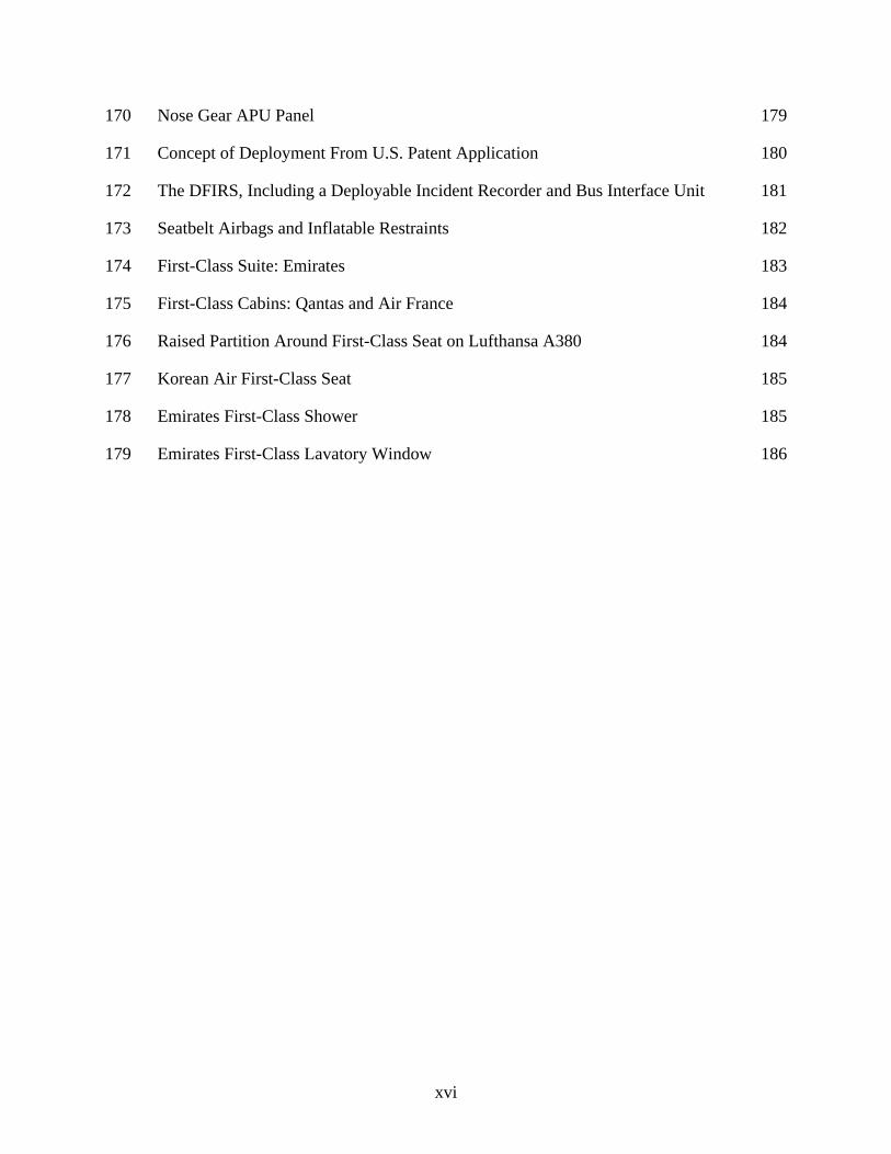
149 Forward Cargo Door Operation 158
150 Aft Cargo Door Operation 158
151 Cargo Door Opening—B-747-8I 160
152 Open Bays in Cargo Floor—B-747-8I 160
153 Cargo Tunnel Floor—A380 161
154 Airbus Guidance for Wheel/Brake Overheat Hazard Areas 163
155 Sample ARFF INFO From Boeing—Guidance for Hot Brakes and Wheel Fires 164
156 Aircraft Tire Safety Areas 166
157 The A380 WLG and BLG—View From Front 167
158 The A380 Landing Gear Numbering System 168
159 Increased Use of Composite Materials 171
160 Construction of B-787 172
161 The ARFF Information on a B-747-8I 172
162 The A350-900 Composite Materials 173
163 Composite Percentages Graphic 173
164 Composite Materials and Locations on the A380 174
165 The GLARE Locations on the A380, Highlighted 175
166 Comparison of GLARE and Aluminum Penetration Forces 176
167 The APU Emergency Shutdown Locations 177
168 Refuel/Defuel Panel 178
169 The APU Emergency Shutdown Controls in the Refuel/Defuel Panel 178
xvi
170 Nose Gear APU Panel 179
171 Concept of Deployment From U.S. Patent Application 180
172 The DFIRS, Including a Deployable Incident Recorder and Bus Interface Unit 181
173 Seatbelt Airbags and Inflatable Restraints 182
174 First-Class Suite: Emirates 183
175 First-Class Cabins: Qantas and Air France 184
176 Raised Partition Around First-Class Seat on Lufthansa A380 184
177 Korean Air First-Class Seat 185
178 Emirates First-Class Shower 185
179 Emirates First-Class Lavatory Window 186

xvii
LIST OF TABLES
Table Page
1 New Large Aircraft Quick Reference 2 2 Airports Serving NLA 3 3 The FAA ARFF Index Comparison to ICAO and NFPA 8 4 Agent/Quantity Comparison 9 5 Category 10 Aircraft–Agent/Chassis Comparison 9 6 Water Quantities and Flow Rates as per NFPA 403 11 7 Summary of Slide Usability 15 8 Slide Failures Listed in the ACRP Study 23 9 Sill Heights 29 10 Fire Classes 81 11 International Comparisons Fire Classes 82 12 Hand Fire Extinguisher Table From 14 CFR 25 85 13 Hose Line Characteristics 121 14 The FAA Studies for Lithium Batteries 131 15 Hydraulic Systems Operation 169 16 The U.S. Airports Authorized for B-747-8 Operations 188

xviii
LIST OF ACRONYMS AND DEFINITIONS AAIS Air Accident Investigation Sector AC Advisory Circular ACRP Airport Cooperative Research Program AES Airport Emergency Services AFFF Aqueous film forming foam ARAC Aviation Rulemaking Advisory Committee ARFF Aircraft Rescue and Firefighting ARFFRWG ARFF Requirements Working Group ASPN Aircraft skin-penetrating nozzle APU Auxiliary power unit ATC Air traffic control BLG Body landing gear BOS Boston Logan International Airport CAG Changi Airport Group CFR Code of Federal Regulations CFRP Carbon fiber-reinforced plastic CVR Cockpit voice recorder DFW Dallas/Fort Worth International Airport DFIRS Deployable flight incident recorder set EASA European Aviation Safety Agency E&E Electronic and equipment (bay) ER Extended Range FAA Federal Aviation Administration FDR Flight data recorder FLIR Forward-looking infrared GCAA General Civil Aviation Authority GLARE Glass-reinforced aluminum laminate gpm Gallons per minute HRET High-reach extendable turret IAP Incident action plan IAV Interior access vehicle ICAO International Civil Aviation Organization IFSTA International Fire Service Training Association IPA Independent Pilots Association JFK John F. Kennedy International Airport LEHGS Local electro-hydraulic generation system LGERS Landing gear extension and retraction system MoS Modification of Standards NFPA National Fire Protection Association NLA New Large Aircraft NLG Nose landing gear nm nautical mile NTSB National Transportation Safety Board OMDB Dubai International Airport OSHA Occupational Safety and Health Administration

xix
PAX Passengers PCA Practical Critical Area PFAS Per- and polyfluoroalkyl substance PPE Personal protection equipment PPV Positive-pressure ventilation Q1 The quantity of water required to obtain a 1-minute control time in
the PCA. Q2 The quantity of water required for continued control of the fire after
the first minute, for complete extinguishment of the fire, or both. Q3 The quantity of water required for interior firefighting. QF Qantas Flight RH Right hand SCBA Self-contained breathing apparatus SDS Safety Data Sheet SIN Singapore Changi Airport SQ Singapore Airlines SOB Souls on board SOG Standard Operating Guidelines TCA Theoretical Critical Area TIC Thermal imaging camera ULD Unit load device UAE United Arab Emirates UPS United Parcel Service U.S. United States USAF United States Air Force WLG Wing landing gear

xx
GLOSSARY OF COMMON TERMS Control—The extent to which the fire is managed. A fire is considered to be controlled when the fire’s intensity is reduced by 90%. Flashover—The nearly simultaneous ignition of combustible materials in an enclosed space. Flashover occurs when the material in an enclosed space is heated to its auto-ignition temperature. Practical Critical Area (PCA)—An area equal to 2/3 the size of the Theoretical Critical Area. Rollover—Often precedes a flashover. As fire gases are heated, the super-heated gases rise to the overhead portion of an enclosed area. As the gases bank off the ceiling, they appear as flames rolling across the ceiling. Rollover often precedes a flashover. Supernumerary—Used to describe occupants in excess of the normal crew. The term is commonly used in descriptions of freighter aircraft. Supernumerary seats may be provided for airline personnel or special handlers for live cargo such as racehorses or exotic animals. Size-up—The initial evaluation of an incident, conducted to develop a determination of immediate hazards to responders, other lives and property, and what additional resources may be needed. Theoretical Critical Area (TCA)—The theoretical area adjacent to an aircraft in which fire must be controlled for the purpose of ensuring temporary fuselage integrity and provide an escape area for its occupants. Ventilation—The exchange of the interior atmosphere of a structure with the outside atmosphere.

xxi
EXECUTIVE SUMMARY
Airport Rescue and Firefighting (ARFF) services personnel at commercial airports worldwide commonly respond to and train for incidents involving large aircraft carrying multiple passengers. The introduction of aircraft with two full decks of passengers has increased the challenges and the stakes presented to aircraft rescue firefighters. Before the introduction into service of the Airbus A380 by Singapore Airlines in the fall of 2007, the only aircraft to have an upper deck was the Boeing (B)-747, and the seating was limited. The full-length, upper-deck passenger compartments allow for a dramatic increase in passenger capacity. New Large Aircraft (NLA) are so categorized due to the increase of passenger capacities, fuel loads, overall size, and the use of advanced materials. NLA being developed today are taller, heavier, and carry more passengers than any aircraft recognized by the International Civil Aviation Organization (ICAO) Rescue Fire Fighting Panel at the time that the Theoretical Critical Area/Practical Critical Area (TCA/PCA) formulas were first developed. These TCA/PCA formulas have never been recalculated to consider the full upper deck and additional height of these NLA. Certain portions of the A380 and B-747-8 commonly referenced under the NLA category are constructed with composite materials. These aircraft have double-deck passenger configurations and increased quantities of fuel and occupants. Much of the information in this report focuses on the A380 because it is the first aircraft with a full upper deck, which means it has the largest passenger capacity and the greatest fuel capacity. Many tactics and strategies described in this report are also applicable to other sizes and types of aircraft. In fact, there are several aircraft, which have entered the market or are currently in development, that offer different passenger cabin configurations, advanced composites, and increased fuel loads. ARFF departments can take applicable information from this report and apply it to other newer aircraft in service at their airports. The A350, B-777, B-787, A380, and B-747-8 are all part of the broader category of New Generation Aircraft, which may be a more appropriate category description for new technologies and challenges to ARFF created by the evolution of these aircraft. Each of these aircraft are discussed in this report. This report provides a discussion of the primary topics pertinent to strategies for NLA firefighting. For each of the five aircraft types discussed, multiple topics are analyzed. These topics include agent quantity, aircraft systems, and components. Information from previous reports, regulatory data, and historical reviews related to NLA firefighting are also presented. In all cases except the A350, members of the Federal Aviation Administration (FAA) ARFF research team conducted site visits hosted by the air carriers and the airport where the subject aircraft were made available. At the time of this research effort, the A350 was not yet flying in the United States, so all A350 information in this report was provided through the courtesy of Airbus. Configurations and aspects of NLA layouts, which require strategic consideration and could influence ARFF tactical decisions and response preplanning are also discussed. Recommendations for best practices in NLA firefighting strategies are offered throughout this report.

xxii
The single most significant piece of guidance for ARFF personnel is related to aircraft configuration. The customization of interior layout and configuration by aircraft manufacturers for air carriers has gone far beyond the traditional configurations of legacy carriers. At that time, firefighters would simply think of the needs of a wide body with two aisles compared to a narrow body with a single aisle. When considering narrow bodies, layout concerns would be simplified into, “3 and 2” or “2 and 2,” indicating 2 or 3 seats on one side or the other. The forward portion of the aircraft simply had larger seats. There were not a lot of options. All the seats faced forward and there were no windows in lavatories. Although each cabin had the look and feel of the carrier, most of the differences were cosmetic. Today, customization of configurations provides options and features for crew rest areas, seating, lounges, shower rooms, and suites. These layouts are not only different amongst carriers, but even within a carrier’s fleet based on the route for which that aircraft is configured. Communications with the air carrier’s local station and hands-on aircraft familiarization are critical to the preparedness of ARFF departments.

1
1. INTRODUCTION
Aircraft Rescue and Firefighting (ARFF) personnel require a great deal of information to make informed tactical decisions during aircraft incidents. Preplanning for such incidents saves precious time in the deployment of firefighting assets and personnel. During preplanning, the differences in aircraft size, composition, passenger loads, fuel quantities, as well as the use of composites and advanced materials, change certain tactics and strategies that may lack the capacity to be equally as effective on New Large Aircraft (NLA). The purpose of this report was to determine what has remained the same from previous generations of aircraft, and what has changed. Changes required further study to determine if modified procedures or new technology may be appropriate to improve tactics and strategies for access to NLA in firefighting evolutions. The development of NLA brings fundamental changes that are different from aircraft that flew previously. These changes are what classify these aircraft as New Generation Aircraft. Educating emergency responders as to how these changes impact existing firefighting tactics and strategies is important to the safety and success of emergency management involving NLA. These factors include: • Increased aircraft size • Increased hydraulic pressures • Increased use of advanced composite materials • Increased passenger loads • Increased fuel loads • Unique uses or configuration of space • Multideck configuration • Sill height for accessing upper decks • Crew rest areas in multiple locations, lower level (below main deck) and overhead New aircraft are beginning flight operations at United States (U.S.) airports every year. The next generation of many aircraft models are currently in the engineering or testing cycle and may present new challenges for ARFF after the Federal Aviation Administration (FAA) certifies them. Table 1 provides a quick reference for many of the latest NLA in service or production at the time of the research effort.

2
Table 1. New Large Aircraft Quick Reference
Aircraft Length Wing Span Height
Typical PAX/Class
Maximum Certified
PAX Range (nm)
FAA Index
A340-600 247′3″ 208′2″ 56′6″ 359 in 2 Classes
475 7900 E
A350-900 219′2″ 212′5″ 55′11″ 315 in 2 Classes
366 7750 E
A380 238′7″ 261′8″ 79′1″ 525 in 3 Classes
853 8500 E
B-747-8I 250′2″ 224′7″ 63′6″ 467 in 3 Classes
605 7760 E
B-777-200ER
209′1″ 199′11″ 60′9″ 314 in 3 Classes
440 7725 E
B-777-200LR
242′4″ 212′7″ 60′8″ 301 in 3 Classes
440 9395 E
B-777-300ER
242′4″ 212′7″ 55′10″ 368 in 3 Classes
550 7825 E
B-787-8 186′8″ 197′4″ 55′6″ 242 in 3 Classes
359 7850 D
B-787-9 206′1″ 197′4″ 55′10″ 290 in 3 Classes
420 8300 E
B-787-10 224′ 197′ 56 330 in 3 Classes
440 7000 E
PAX = passengers nm = nautical miles Table 1 reinforces the need for ARFF departments to maintain communications with the carriers and remain familiar with the aircraft type, models, and configurations with service to the airport. In general terms, a B-777 is simply considered 777. The difference in length from the B-777-200ER to the B-777-300ER is approximately 33 feet. That may constitute a huge difference tactically if it is an unknown. If the hand line lengths and entry points determined during pre-fire planning for an interior were developed with a B-777-200, an interior team could come up short when stretching a hose line into a B-777-300ER. Passenger loads are dynamic. Airlines are constantly adjusting legroom, seat pitch, and cabin configuration to maximize efficiency. New “slim line” seating allows airlines to add an extra row of seating in coach cabins. Although the typical passenger capacities for the B-777-300ER is about 368, the aircraft is certified to carry as many as 550. If a destination market has a surge in demand for additional seats on a route, the airline can reconfigure seating to significantly increase passenger loads. Although possible, it is not likely that the seating would increase to the maximum certified load, as the weight of fuel, additional baggage, etc. all need to be factored into the gross takeoff weight. The number of occupants of an aircraft is referred to as “souls on board” (SOB). This is a total number that includes passengers, crew, and lap children. When an aircraft emergency is declared in flight, the pilot will notify ATC of the nature of the emergency. Included in the report

3
typically is SOB and fuel on board. The fuel quantity may be reported in gallons, kilograms, pounds, or gallons. A fuel weight/volume conversion chart is provided in Appendix A. 2. THE U.S. AIRPORTS SERVING NLA
The list of NLA deliveries continues to grow, as do the routes and destinations. There are hundreds of airports in the world that are in the process of completing modifications to accommodate the NLA. The list in table 2 will continue to evolve as routes are approved and aircraft are delivered, but it includes all FAA-certificated airports with approved Modifications of Standards (MoSs) to accommodate A380 and B-747-8 operations.
Table 2. Airports Serving NLA (FAA, 2019)
U.S. Airport Aircraft Type Ted Stevens Anchorage International Airport (ANC) A380
B-747-8 Hartsfield–Jackson Atlanta International Airport (ATL) A380
B-747-8 Boston Logan International Airport (BOS) A380
B-747-8 Rafael Hernandez Airport (BQN) B-747-8 Cincinnati/Northern Kentucky International Airport (CVG) B-747-8 Denver International Airport (DEN) A380
B-747-8 Dallas/Fort Worth International Airport (DFW) A380
B-747-8 Detroit Metropolitan Wayne County International Airport (DTW) B-747-8 Newark Liberty International Airport (EWR) B-747-8 Greensville-Spartanburg International Airport (GSP) B-747-8 Daniel K. Inouye International Airport (HNL) A380
B-747-8 Huntsville International Airport (HSV) B-747-8 Dulles International Airport (IAD) A380
B-747-8I George Bush Intercontinental Airport (IAH) A380
B-747-8 Indianapolis International Airport (IND) B-747-8 John F. Kennedy International Airport (JFK) A380
B-747-8 Los Angeles International Airport (LAX) A380 Rickenbacker International Airport (LCK) B-747-8 Orlando International Airport (MCO) A380
B-747-8 Memphis International Airport (MEM) A380 Miami International Airport (MIA) A380
B-747-8

4
Table 2. Airports Serving NLA (FAA, 2019) (Continued)
U.S. Airport Aircraft Type O’Hare International Airport (ORD) A380
B-747-8 Portland International Airport (PDX) B-747-8 Chicago Rockford International Airport (RFD) B-747-8 Louisville International Airport (SDF) A380 Seattle-Tacoma International Airport (SEA) B-747-8 San Francisco International Airport (SFO) A380
B-747-8 Toledo Express Airport (TOL) B-747-8
3. UNDERSTANDING AIRCRAFT MAKE AND MODEL NAMES
As new aircraft are introduced in different versions, sizes, and with various fuel capacities, the numbers and identifiers used in the model name provides a great deal of information at a glance. The size and capacity of the aircraft are among the first considerations for ARFF departments upon hearing of an aircraft inbound to the airport with an anomaly or an emergency. More information is usually available in subsequent communications from the air traffic control (ATC) tower, such as the aircraft location or landing runway, the size and capacity of the aircraft (as determined by the aircraft type), and type of problem reported. Only after this information is available can an appropriate dispatch be initiated. Published by the Commercial Aviation Safety Team and International Civil Aviation Organization (ICAO) Common Taxonomy Team, the “International Standards for Aircraft Make Model and Series Grouping” (CICTT, 2012) establishes the international guideline that standardizes the identification system of aircraft types. The identifier is technically derived from the make, model, master series, and series. • Make: The first part of the name is the aircraft manufacturer, or a name chosen by the
aircraft manufacturer. In the case of the two aircraft manufacturers in this study, i.e., Airbus and Boeing, the make of all their respective aircraft are abbreviated as A or B.
• Model: The model is determined by the aircraft manufacturer. For jet air transport aircraft, Boeing chose to use the 700s, i.e., 707, 717, 727, 737, 747, 757, 787. Airbus chose the 300s, i.e., 300, 310, 320, 340, 350, and 380.
• Master Series: The master series is typically numbered from lower to higher numbers starting with the earliest release. Using the B-787-800 as an example, 800 is the master series.

5
• Series: Airbus—A number is used to identify a version within that series. This number is typically of less value to most ARFF firefighters. Airbus uses a three-digit series number, after the model number: the first number identifies the version, the second is a code for the engine type, and the third is a code for a specific engine. For example, an A380-841 would be an A380, 800 version (indicated by the 8) with a Rolls Royce® manufactured engine (indicated by the number 4) and specifically a Trent 970 engine (indicated by the number 1).
• Series: Boeing—With the Boeing system, the three-digit number that follows the model identifies a customer code. For example, a Boeing 747-8I sold to Lufthansa is designated as B-747-8I-430, where the number 4 indicates the model (747), followed by the number 30 identifying Lufthansa as the customer. Some customers are two-digit numbers, while others are a combination of a letter and number. That number stays with the airline for its life, regardless of transfer of ownership.
Much of this information provided by the series number by both manufacturers is not of tremendous value to ARFF and is provided for information purposes. Understanding these numbers in a special configuration would not affect ARFF response or tactics in most cases. Of greater value to ARFF personnel are the letters used to describe the version of the aircraft. There are dozens of these abbreviations, but most are seldom used. Following are the most common abbreviation suffixes. • ER Extended Range—Typically fitted for long-range segments. Larger fuel capacity
and perhaps seating pods rather than standard seats in First and Business Classes.
• ET Extended Tankage or Extra Tankage—Not often used, synonymous with ER.
• NG New Generation or Next Generation—Refers to new technology cockpit and flight controls.
• F Freighter—Primarily configured for carrying freight, smaller passenger (supernumerary) seating area. This designation may also be used for an aircraft that was built as a passenger aircraft and converted to a freighter. This conversion is common and can often be visually confirmed by the outline of the windows and the rivet marks around the frames.
• SCD Side Cargo Door—As seen on freighter aircraft, a side cargo door rather than a
primary cargo door is used in the nose or tail.
• SP Special Performance—Typically related to the shortened B-747 (SP), designed to incorporate the range of a B-747, with reduced passenger capacity and weight, reducing fuel costs.

6
4. FIREFIGHTING AGENT QUANTITY CONSIDERATIONS
The FAA serves as the U.S. Government’s advocate with the ICAO, a United Nations specialized agency created to achieve safe, secure, and sustainable development of civil aviation throughout the world. In that role, the FAA provides significant resources to support the ICAO and its goal to establish a global aviation system through cooperation, partnership, and harmonization of requirements. ICAO Circular 305-AN/177, “Operation of Newer Larger Aeroplanes at Existing Aerodromes,” (ICAO, 2005) was released on March 14, 2005. It is important to understand the relevant information included in the circular and consider applying the intent and approach in any study of NLA. It is interesting to note that the U.S. uses the phrase New Large Aircraft, whereas the ICAO definition is New Larger Aeroplanes. The following quoted text was taken directly from Circular 305. Note that the conversions to feet from meters were not in the original ICAO text.
In the early 1990s, the major aeroplane manufacturers announced that plans were in hand to develop aeroplanes larger than the Boeing B747-400 — currently the largest passenger aeroplane in commercial service — capable of carrying more than 500 passengers. In response to the stated need for appropriate ICAO provisions to facilitate aerodrome development for these new larger aeroplanes (NLAs), ICAO undertook a study with the participation of several States, selected international organizations and aeroplane manufacturers. The results of that study led to Amendment 3 to Annex 14 — Aerodromes, Volume I — Aerodrome Design and Operations, which was adopted by the ICAO Council in March 1999. A new aerodrome reference code letter F to cover aeroplanes with wingspans from 65 m (213.25 feet) up to but not including 80 m (262.46 feet), and an outer main gear wheel span from 14 m (45.93 feet) up to but not including 16 m (52.49 feet) was established. Consequent new specifications on aerodrome physical characteristics for these aeroplanes were also developed. The new code F specifications in Annex 14, Volume I, became applicable from 1 November 1999. Aerodrome rescue and firefighting (RFF) specifications for aeroplanes with maximum fuselage widths in excess of 7 m, (22.96 feet) and lengths greater than 76 m (249.34 feet) RFF category 10, had already been developed and included in the Annex. (ICAO, 2005)
Title 14 of the U.S. Code of Federal Regulations (herein referred to as 14 CFR Part 139) (Certification of Airports, 2004) that provides language for Index determination was not revised. Index E aircraft are aircraft over 200 feet long; therefore, NLA that are over 200 feet long fall into the Index E category. In 2003, the FAA assigned a task to the Aviation Rulemaking Advisory Committee (ARAC). The task was accepted, and the ARFF Requirements Working Group (ARFFRWG) was formed. In 2004, the ARAC ARFFRWG released a report that, among other things, looked at certain issues

7
relative to NLA (ARFFRWG, 2004). Findings and conclusions documented by this working group are integrated throughout this report. Tables 3 through 5 were derived from information provided in the ARAC report (ARFFRWG, 2004). The primary relative points illustrated in this comparison chart are the ICAO Categories as per ICAO Annex 14, “Aerodromes, Volume 1, 8th Edition” (2018) and National Fire Protection Association (NFPA) 403, “Standard for Aircraft Rescue and Fire-Fighting Services at Airports” (2018). Both (ICAO 2018) and (NFPA 2018) identify Category 10 for aircraft longer than 250 feet (ft) (76 meters (m)), up to 295 ft (90 m). In addition, both the ICAO and NFPA use a maximum fuselage width, as well as overall length. The 14 CFR Part 139 (Certification of Airports, 2004) uses only overall length in Index determination, and Index E is for all aircraft longer than 200 ft (61 m).

8
Table 3. The FAA ARFF Index Comparison to ICAO and NFPA
FAA Index
Aircraft Length
(ft) ICAO
Category
Aircraft Length
up to but not
Including (ft)
Aircraft Width
up to but not
Including (ft)
NFPA Category
Aircraft Length
up to but not
Including (ft)
Aircraft Width
up to but not
Including (ft)
Sample Aircraft
GA-1 NA 1 29 (9 m) 6.6 (2 m) 1 30 (9 m) 6.6 (2 m) Cessna 182 GA-1 NA 2 39 (12 m) 6.6 (2 m) 2 39 (12 m) 6.6 (2 m) Cessna Caravan GA-2 NA 3 59 (18 m) 9.8 (3 m) 3 59 (18 m) 9.8 (3 m) Cessna 404 A <90 4 78 (24 m) 13.1 (4 m) 4 78 (24 m) 13.0 (4 m) Embraer
(EMB)120 A <90 5 91 (28 m) 13.1 (4 m) 5 90 (28 m) 13.0 (4 m) Bombardier
Canadair Regional Jet (CRJ)-200, Saab 340
B 90-126 6 127 (39 m) 16.4 (5 m) 6 126 (39 m) 16.4 (5 m) McDonnell Douglas (DC)-9, A320
C 126-159
8 160 (49 m) 16.4 (5 m) 7 160 (49 m) 16.4 (5 m) B-757-200, B-767-200ER
D 159-200
8 200 (61 m) 22.9 (7 m) 8 200 (61 m) 23.0 (7 m) A300, B-757-300
E >200 9 250 (76 m) 22.9 (7 m) 9 250 (76 m) 23.0 (7 m) A340-600; B-777 E >200 10 295 (90 m) 26.2 (8 m) 10 295(90 m) 25.0 (8 m) AN-225, A380

9
Table 4. Agent/Quantity Comparison
Category Index
Water (U.S. Gallons) Quantity for Aqueous Film Forming Foam
Production Example Aircraft ICAO FAA
NFPA Q1 and Q2
NFPA Q1, Q2, and Q3
1 GA-1 61 — 120 120 Cessna 206 2 GA-1 177 — 200 200 Cessna 414 3 GA-2 317 — 370 670 Beech 1900 4 A 634 100 740 1,340 De Havilland
Canada (DHC)-8-100
5 A 1,427 100 1,510 2,760 Regional Transport Airplanes (ATR)-72
6 B 2,087 1,500 2,490 3,740 B-737-300; EMB-145
7 C 3,197 3,000 3,630 4,880 B-757 8 D 4,808 4,000 5,280 7,780 A300;
B-767-300 9 E 6,419 6,000 7,070 9,570 B-747-200;
A340-400 10 E 8,533 6,000 9,260 14,260 Antonov (AN)-
225; A380 Note: Q1 is the quantity of water required to obtain a 1-minute control time in the Practical Critical Area
(PCA). Q2 is the quantity of water required for continued control of the fire after the first minute, or for complete extinguishment of the fire, or for both. Q3 is the quantity of water required for interior firefighting.
Table 5. Category 10 Aircraft–Agent/Chassis Comparison
Reference Gallons for Q1-Q2 Chassis FAA 6000 3 ICAO 8533 3 NFPA 9260 4
Of the three references (Certification of Airports, 2004; ICAO, 2018; and NFPA, 2018), only the FAA does not calculate additional water for aircraft over 250 ft (76 m) long or over 23 ft (7 m) wide. ICAO has increased water quantities for Category 10 aircraft over the quantities required for Category 9 aircraft by 2114 gallons (8002 liters) or 33%. Without factoring in Q3 water for interior firefighting, the NFPA has increased water quantities for Category 10 aircraft over the quantities required for Category 9 aircraft by 2190 gallons (8290 liters) or 31%.

10
The ARAC report points out that accepted formulas for Theoretical Critical Area (TCA) and PCA*, as defined in NFPA 403 (NFPA, 2018), are flawed when used to calculate minimum agent requirements for multideck aircraft. These formulas are based on the aircraft length and width and do not consider the greater aircraft height, larger fuselage surface area, greater fuel quantities, or increased fuselage footprint to accommodate the longer slides. Regulations and guidance for quantities of agents to be carried at airports are found in three primary sources:
1. FAA-certificated airports in the U.S. and its territories are required to maintain at least the
minimum quantities of agents provided in 14 CFR Part 139.317 (Certification of Airports, 2004). Maintaining at least these quantities is a mandatory federal regulation. The FAA is the only authority that mandates minimum quantities. In addition to the minimum quantities required by the FAA, additional guidance on agent types and quantities are found in FAA Advisory Circular (AC) 150/5210-6D, “Aircraft Fire Extinguishing Agents.” (FAA, 2004) The use of ACs is not mandatory and does not constitute a regulation. However, the information contained in the AC provides an acceptable methodology for complying with 14 CFR Part 139. Chapter 1.2 of the AC states: “The following definitions do not include numerical quantities. These can be found in NFPA 403, Table 5.3.1 (NFPA, 2014), as well as additional agent quantities to be carried” (FAA, 2004).
2. NFPA 403, “Standard for Aircraft Rescue and Fire-Fighting Services at Airports,” (NFPA, 2014) is a consensus standard. Table 5.3.1 provides guidance for quantities and discharge rates of agent at airports. The NFPA publishes more than 300 consensus codes and standards intended to minimize the possibility and effects of fire and other risks.
3. ICAO is a specialized agency of the United Nations that was assembled to provide coordination of aviation policy. ICAO Annex 14, Volume I, provides recommendations for quantities and performance levels of agents. Annex 14, Volume I, frequently uses terms such as “recommended,” “should normally be,” “should be,” and “guidance” (ICAO, 2018). There is no force of regulation in the quantities provided by ICAO.
FAA-required minimum quantities for agent do not include agent for interior firefighting (Q3). The FAA-mandatory quantities are intended to protect rescue paths for evacuating passengers. Recommended quantities, which include agent for interior firefighting (Q3), are found in NFPA 403 (NFPA, 2018). The NFPA 403 firefighting agent calculations (Table 5.3.1) for Index E airports (Category 9) provide 2500 gallons for Q3. This is in addition to the 7070 gallons recommended for Q1 and Q2 (NFPA, 2018). In a long-term incident with major fire involvement on an NLA, this may or may not be enough to achieve total extinguishment. It does, however, provide some time to establish water supply at the scene.
* TCA is the area adjacent to an aircraft where fire must be controlled for the purpose of ensuring temporary fuselage integrity and
provide an escape area for its occupants. PCA is an area equal to 2/3 the size of the TCA.

11
Interior tactics are more fully discussed in later sections of this report, but a general discussion of flow rates can be used here to determine what level of interior fire attack can be launched using available gallons of agent. The calculation of water quantities and flow rates for interior and exterior ARFF response has been the topic of many studies. The application of science can determine x quantity based on the test conditions created. Because fires are dynamic, allowances must be made for specific conditions as well as human factors. There will always be a quantity of agent lost or misdirected during firefighting operations. This may be due to wind, grade, or simply undershooting or overshooting of agent streams when being directed at the target. When using master streams (turrets) flowing 1000 gallons per minute (gpm) or more, it only takes 30 seconds to lose (waste) 500 gallons of agent. This factor is not included in any table. It is, however, a reality and should be considered when planning agent quantities and flow rates at airports. NFPA 403 provides recommended water quantities and flow rates for each FAA Index or ICAO Category of airports. All the NLA in this study fall into Index E, Category 9 or 10. The water quantity and flow rates in table 6 are for Q3, which is the water calculated for interior firefighting as per NFPA 403 Table B.6.3. Interior firefighting is not required by 14 CFR Part 139.317 or ICAO Annex 14, hence not included in FAA minimum agent quantity calculations. Based on the quantities indicated in table 5, an Index E airport that may be required to conduct interior firefighting on a Category 10 aircraft should plan on a flow rate of 500 gpm for 10 minutes or 5000 gallons for Q3. There are many more factors required for a risk assessment for an interior fire attack, but the case is clearly made that establishing a water supply on scene is a top priority in any tactical plan that includes interior firefighting. NFPA 403 bases their guidelines for water quantities and flow rates on the original work done by the ICAO Rescue & Fire Fighting Panel (RFFP) II, and on the flow rates provided in NFPA 403 (NFPA, 2018). Table B.6.3 suggests that for a wide-body aircraft, two or more attack lines may be needed. The construction and layout of a two-aisle aircraft is consistent with structural firefighting guidelines, i.e., use of two or more attack lines for interior entry to a cabin involved in fire.
Table 6. Water Quantities and Flow Rates as per NFPA 403
ICAO Airport Category
FAA Index Q3 Equals
1 A* 0 2 A* 0 3 A* 60 gpm x 5 minutes = 300 gallons 4 A 60 gpm x 10 minutes = 600 gallons 5 A 125 gpm x 10 minutes = 1250 gallons 6 B 125 gpm x 10 minutes = 1250 gallons 7 C 125 gpm x 10 minutes = 1250 gallons

12
Table 6. Water Quantities and Flow Rates as per NFPA 403 (Continued)
ICAO Airport Category
FAA Index Q3 Equals
8 D 250 gpm x 10 minutes = 2500 gallons 9 E 250 gpm x 10 minutes = 2500 gallons 10 E 500 gpm x 10 minutes = 5000 gallons
*Index A only if scheduled air carrier with nine passengers or more. The A380 is not significantly longer, nor is the fuselage appreciably wider, than other aircraft in its Index. As a result, the agent requirement for an A380 only increases by 138 gallons when using the current TCA/PCA formulas. The fuel capacity of the A380 is 44% greater than the B-777 and 42% greater than the B-747-400. The larger fuel quantity increases the potential size of a pool fire under the aircraft. Another consideration is the increased area that must be protected on a multideck aircraft for the footprint of the evacuation slide deployment. Since the upper-deck evacuation slides are now higher, their lengths have been increased to achieve a safe sliding angle. The upper-deck evacuation slides touch the ground 12 ft further from the fuselage on each side than those deployed from the main deck of the B-777. The current TCA/PCA formula does not consider the larger footprint of the slides deployed from the upper deck. If pre-fire planning for an event with this aircraft, the actual footprint of the aircraft with all slides deployed should be understood. To protect the area where the slide touches the ground, additional foam would need to be calculated for 12 additional feet on each side, a total of 24 ft for the length of the fuselage, as shown in figure 1.
Figure 1. Upper-Deck Evacuation Slide Deployment Lengths
The rationale recommended by the ARAC ARFFRWG increases the PCA by 12 ft on either side to accommodate safe escape paths for passengers coming down the upper-deck evacuation slides (ARFFRWG, 2004). Using this calculation, 2977 gallons are required for Q1, and 5656 gallons for Q2. Combined water for aqueous film forming foam (AFFF) proportioning for Q1 and Q2 for an A380 is 8633 gallons, using the ARAC ARFFRWG approach (ARFFRWG, 2004). This does

13
not increase the agent quantities to include Q3, but rather to satisfy the FAA-implied goal of maintaining escape paths, or as Cohn and Campbell in “Minimum Needs for Airport Fire Fighting and Rescue Services” described the goal as to “allow ambulatory occupants to exit the aircraft within tolerable heat conditions and move to a safe area” (Cohn & Campbell, 1971).
In July 2012, the FAA published a report authored by Hughes Associates, Inc., “Methodologies for Calculating Firefighting Agent Quantities Needed to Combat Aircraft Crash Fires” (FAA, 2012). This report reviewed the formula to calculate agent quantities, the history behind the formula, and the purpose of each Q quantity and the time when they are to be delivered. It also considered the amount of agent to protect egressing passengers from a pool fire. This report proposes that, based on the justifications for the quantities, those required in NFPA seem most adequate to meet the actual need.
5. EVACUATION SLIDES
The first priority in an aircraft fire or significant incident is to evacuate or deplane passengers and crew. Emergency evacuations of aircraft from heights above 6 ft. from the ground require the use of emergency evacuation slides. FAA certification of an aircraft requires a full-scale demonstration where a full complement of passengers and crew deplane through half of the emergency exits in the dark of night in 90 seconds or less. It is not unusual for slides to fail to operate or become damaged or unusable during an emergency, hence the requirement for the evacuation test using half of the exits.
An understanding of slide deployment and operation is important to ARFF personnel. Slides are designed to deploy in 6 seconds. Evacuation slides are intended to accommodate 70 passengers per lane per minute. The actual rate is subject to human factors and the level of perceived threat to the cabin crew and passengers.
Slides facilitate evacuation of the aircraft when conditions warrant and therefore contribute to the safety of the occupants. The effectiveness of the slides is affected by certain human factors and mechanical shortcomings. The increased number of slides for NLA also adds a level of difficulty and increased tasking for ARFF.
Winds can raise or twist slides, making it more difficult for evacuating passengers to use. Slides can also collect water or foam from firefighting efforts. Foam will make the slide more slippery, which will cause the passengers to slide faster. Accumulated water will change the angle of the slide and may stop passengers during their descent. An example of this is described in the case study presented below for Emirates Flight 521.
A safety study conducted by the National Transportation Safety Board (NTSB) reviewed 46 evacuations involving 2651 passengers from September 1, 1997 through June 1, 1999; in these cases, 6% of the aircraft occupants suffered minor injuries, and 2% suffered serious injuries (NTSB, 2000). Slide technology has evolved with the new aircraft being built. Certain slides onboard the aircraft have the Tribrid Inflation System, which is connected to a sensing system within the door. Activation of this system occurs if the door is opened in the emergency mode at an abnormal attitude. The slide will inflate normally, and several feet of additional slide will inflate to increase the chance for the slide to reach the ground.

14
5.1 CASE STUDY: EMIRATES FLIGHT NO. 521 B-777—“RUNWAY IMPACT DURING ATTEMPTED GO-AROUND”
5.1.1 Case Study Description
There have been a number of aircraft evacuations by means of evacuation slides after the NTSB study cited was published. One notable event occurred on August 3, 2016 at Dubai International Airport (OMDB), the United Arab Emirates. The following facts are found in United Arab Emirates, General Civil Aviation Authority (UAE GCAA), Air Accident Investigation Sector, Accident—Preliminary Report—Air Accident Investigation Sector (AAIS) Case No.: AIFN/008/2016, “Runway Impact During Attempted Go-Around” (UAE GCAA, 2016).
On August 3, 2016 at 0837 hours UTC, Emirates Flight 521, a B-777-31H carrying 282 passengers and 18 crew, impacted the runway during an attempted go-around at OMDB.
The aircraft aft fuselage impacted the runway at 125 knots. This was followed by the impact of the engines with the runway, and the Number 2 engine pylon assembly separated from the right-hand (RH) wing. An intense fuel-filled fire started in the area of the Number 2 engine pylon wing attachment area. The aircraft continued to slide along the runway on the lower fuselage, the outboard RH wing, and the Number 1 engine. An incipient fire started beneath the Number 1 engine. Approximately 1 minute after coming to rest, the Aircraft Commander transmitted a “MAYDAY” call and informed ATC the aircraft was being evacuated.
All 300 passengers and crew evacuated via evacuation slides. A cabin crew member was unable to open the L1 door and requested assistance from the senior cabin crew member. Together they were able to open the door. The evacuation slide deployed, but it detached from the aircraft. Consequently, the cabin crew member blocked the door from passenger use.
A cabin crew member opened the R1 door and the slide deployed automatically. During the deployment, the wind blew the slide upward, and it blocked the exit. As a result, the cabin crew member blocked the door. After the slide settled to the ground, it was used by some passengers and crew. When the slide deflated, a crew member blocked the exit again.
Two crew members were required to open the L2 door. When deployed, the slide did not reach the ground, and a cabin crew member blocked the door. The wind blew the slide upward against the aircraft, preventing anyone from evacuating through the L2 door.
A crew member opened the R2 door and the slide deployed automatically. A cabin crew member directed passengers to another door due to thick smoke around the R2 door. After the smoke cleared, it was used by some passengers and crew members.
No one attempted to open the L3 door due to the smoke outside. Crew members directed passengers in that area to the R2 door.
When a cabin crew member opened the R3 door, they observed fire outside. They blocked the door while two passengers closed it. The passengers in that area were directed aft.

15
The crew member at the R4 door did not hear the evacuation order, but they opened the R4 door after seeing the L4 door being opened. Several passengers evacuated through R4, but they became stuck in the middle of the slide because it was filled with firefighting water. As a result, the R4 crew member directed passengers to the R5 door. A crew member opened the L5 door, and the slide deployed. Some passengers were able to evacuate through L5, but then the wind blew the slide up against the door and blocked the exit. A crew member opened the R5 door, and it automatically deployed. Then, the wind raised the slide off the ground. Seeing this, a crew member directed passengers to the L5 door. A firefighter on the ground held the slide down and passengers used the R5 door to escape. The commander and senior cabin crew member were the last to evacuate. They were still searching for occupants when the center fuel tank exploded, causing the cabin to fill with thick smoke. They made their way to the cockpit, planning to evacuate through the cockpit windows, but could not locate the escape ropes in the smoke. Their only option was to jump out the L1 door. The L1 slide had detached from the aircraft but was in a position whereby they could jump onto the slide on the ground. Table 7, taken from the Preliminary Report—AAIS Case No.: AIFN/008/2016 (UAE GCAA, 2016) indicates that five of the exit slides were not usable, four of the exit slides were only usable for a portion of the evacuation, and the slide that was available for use throughout the evacuation was on the side of the aircraft involved in the fire.
Table 7. Summary of Slide Usability (UAE GCAA, 2016)
Door
Door Open or Closed?
Slide Deployed? (Yes/No) Slide Used or Not Used?
L1 Open Yes Not used (Detached from door sill. Commander and a cabin crew member evacuated from this door.)
R1 Open Yes Used (The slide deflated after several passengers had evacuated.)
L2 Open Yes Not used (Wind affected.) R2 Open Yes Used (Same side as fire.) L3 Closed No Not used (Door was not opened.) R3 Closed No Not used (Door partially opened then closed due the
external fire.) L4 Open Yes Not used (Wind affected.)

16
Table 7. Summary of Slide Usability (UAE GCAA, 2016) (Continued)
Door
Door Open or Closed?
Slide Deployed? (Yes/No) Slide Used or Not Used?
R4 Open Yes Used (Blocked due to passenger congestions. The slide was filled with water as a result of firefighting activity.)
L5 Open Yes Used (Used only at the start of the evacuation. Wind affected.)
R5 Open Yes Used (Temporarily blocked when the slide was wind affected.)
5.1.2 Case Study Injuries and Fatalities
OMDB Airport Civil Defence Force Firefighter Jasim Issa Mohammed Hassan was killed when the center fuel tank exploded. According to a statement from the OMDB Director General of the General Civil Aviation Authority, this firefighter made the ultimate sacrifice after being instrumental in helping passengers evacuate to safety. Of the 300 passengers and crew there were 24 injuries, of which 1 was serious and 23 were considered minor. (UAE GCAA, 2016) 5.2 THE A350 EVACUATION SLIDES
The A350-900 has four evacuation slides on each side of the aircraft, as shown in figure 2. Each slide deploys from a full passenger or service door, and none come from overwing exits. These service doors are safe for entry from the exterior. Even when armed, the slides will not deploy. The slides attached to the L1 and R1 doors are single-lane slides; all other doors are dual-lane evacuation slides. All the slides are detachable and considered slide/rafts, which are available for flotation in water incidents.

17
Figure 2. Emergency Evacuation Slides A350-900 (Courtesy of Airbus)
5.3 THE A380 EVACUATION SLIDES
The A380 has a total of 16 emergency evacuation slides, as shown in figure 3. There are six dual-lane slides (three on each side) from the upper passenger deck. Four more dual-lane slides (eight in total) provide escape routes from the passenger and service doors on the main deck. The overwing exits on each side of the main passenger deck are equipped with off-wing, dual-lane slides. All the slides are detachable and considered slide/rafts, available for flotation in water incidents. A ramp slide is an evacuation slide that services the overwing exit with a small platform or landing between the exit and the slide itself. An A380 ramp slide is shown in figure 3. The ramp slide deploys down the trailing edge of the wing and touches the ground behind the slides from the main deck and upper deck slides. If all slides are deployed, it is likely that the upper-deck slides would block the view from the ground of passengers evacuating down those ramp slides. Ramp slides are installed on aircraft primarily when the proximity of the exit to an engine requires the slide to be angled away from the engine. Ramp slides are used for the overwing exits on A310, A340-60, A380, and B-747 aircraft. For certification of the A380, dual-lane slides are required. These double-width slides can transport up to 70 passengers a minute.

18
Figure 3. The A380 Evacuation Slides (Courtesy of Airbus)
As shown in figure 4, each slide on the A380 is equipped with reentry lines. When standing at the base of the slide facing the aircraft, these lines are typically on the right side of the evacuation slide and are designed to provide a method for ARFF personnel to climb up a slide to gain access to either passenger deck. This is not an ideal method for gaining access to an aircraft. In fact, Boeing recommends not using the slides for entry. Climbing up the slide should never be attempted if it is still being used for evacuation as it will impede evacuating passengers.

19
Figure 4. Re-Entry Lines on A380 Evacuation Slides (Courtesy of Airbus)
5.4 THE B-747-8 EVACUATION SLIDES
The slides from a two-deck aircraft, such as a B-747-8I, block access to most of the forward portion of the fuselage (figure 5). There is no change in the number of exit doors or evacuation slides in the B-747-8I as compared to the B-747-400. As shown in figure 6, there are five main deck emergency exits and one on the upper deck. These slides are detachable and available as rafts for water incidents. The overwing exit includes a ramp slide, which takes evacuating passengers aft over the wing.

20
Figure 5. Forward View of B-747-8I Evacuation Slides (Image courtesy of MikeJamesMedia.com)
Figure 6. The B-747-8I Fuselage With Five Main-Deck Exits and One Upper-Deck Exit on Each
Side (Image courtesy of MikeJamesMedia.com)
The structural support arch shown in figure 7 appears to create a much more stable platform, particularly if the aircraft is at an abnormal angle, causing the additional 12 ft of slide to deploy. It also significantly adds to the structure of the slide, which may need to be cut away

21
to gain access to the portion of the aircraft blocked by that slide and support arch. Once a slide is not functional as an evacuation means, it can become a hindrance to firefighters. When the “additional” 12 ft of slide deploys due to aircraft angle, the wind resistance requirement is reduced by 3 knots. Although deployments of these slides during strong winds are not documented in the NTSB database, the additional arch structure designed to stabilize the slide may also act as a sail.
Figure 7. Structural Support Arch on B-747-8I Upper-Deck Slides (Photograph courtesy of Paine Field Blog 1-5-2012)
5.5 THE B-777 EVACUATION SLIDES
The B-777-200 has four evacuation slides on each side, whereas the B-777-300 has five on each side, including a ramp slide from the overwing exits (figure 8). All the B-777 evacuation slides are double-lane slides. These slides are detachable and available as rafts for water incidents.

22
Figure 8. The B-777-300ER Slide Deployment (Image from B-777-300 Seatback Safety Card)
5.6 THE B-787 EVACUATION SLIDES
The B-787 has four evacuation slides on each side of the aircraft. Doors R and L 1 and 3 are equipped with single-lane slides. As shown in figure 9, doors R and L 2 and 4 are equipped with double-lane slides. These detachable slides are available as rafts for water incidents.
Figure 9. Evacuation Slides Deployed From ANA B-787 (Passenger Photograph courtesy of Japan’s Kyodo News)
5.7 EVACUATION SLIDE ASSISTANCE
There is no FAA requirement for dedication of emergency personnel to staff the base of evacuation slides, steady them in high winds, or assist passengers at the bottom of the slides. Aircraft cabin crews may assign passengers to aid at the base of slides. Most passengers evacuating an aircraft during an emergency are doing so for the first time. The hazards associated with evacuation are complicated by a number of factors, as identified in the NTSB safety study (NTSB, 2000) and the Airport Cooperative Research Program (ACRP) study, “Evaluation and Mitigation of Aircraft

23
Slide Evacuation Injuries” (2008). According to the ACRP study, “Wind had an adverse effect on slide use in 12.4 percent of the accidents. In these cases, the wind blew the inflatable slides up against the sides of the aircraft, preventing slide use. In the evacuation events where the slides were unusable, the mean wind speed varied from 13 to 20 knots” (ACRP, 2008). The ACRP report states, “historical data shows that when the wind’s mean speed does not exceed 25 knots and one individual holds down the slide, the inflatable evacuation slide remains stable (NTSB 2000; Van Es and Post 2004)” (ACRP, 2008). Guidance from Boeing suggests that, if a slide is still attached to the aircraft but is not inflated, firefighters could potentially work the bottom of the slide and pull the slack out of it. This would allow a passenger to use the slide to evacuate. If multiple passengers were to jump on the slide, it could overwhelm the firefighters’ ability to hold the slide taut and maintain a safe evacuation corridor. Certain NLA have reentry lines that make it possible for ARFF to attempt to climb the slide for entry to the cabin. Boeing does not recommend attempting to use the slides for entry. Airbus provides guidance in their ARFF Crash Charts that identify the reentry lines on the slides for ARFF use in gaining access to both passenger decks on the A380. There is a significant danger to firefighters or other personnel working the bottom of the slides. In an overwhelming number of evacuations, passengers and crew have chosen to take their carry-on luggage down the slide with them. The bags can cause injuries to the evacuation passengers and personnel operating in the area of the slides. 5.8 MECHANICAL FACTORS
The NTSB study indicates that 37% (7 of 19) of the evacuations with slide deployments in the study cases had at least 1 slide fail to operate (NTSB, 2000). Redundancy of exits is included in the safety margin, as per the requirement of evacuating 100% of the passengers using 50% of the exits in 90 seconds or less. However, a failed slide adds to passenger anxiety and will delay at least those passengers who were planning on evacuating through the exit with the failed slide. Slide failures occur for a variety of reasons, as presented in table 8, which was extracted from the ACRP study (ACRP, 2008).
Table 8. Slide Failures Listed in the ACRP Study (ACRP, 2008)
Identified Problem
Amount (%)
Slide did not inflate 28.1 Aircraft attitude 15.7 Other 13.5 Wind 12.4 Slide burnt 11.2 Incorrect rigging 7.9 Slide ripped 6.7 Unknown 4.5

24
The ACRP study looked at 142 emergency evacuation events for the period of January 1, 1996 through June 30, 2006. The data illustrated that during this period approximately 50% of emergency evacuations result in injuries, 90% of which were minor (ACRP, 2008). This finding is considered consistent with the NTSB study, which looked at 46 incidents over 21 months (September 1997–June 1999), where the percentage of minor injuries was the same, i.e., 90% (NTSB, 2000). The ACRP study demonstrated that human reactions in situations requiring emergency evacuation include panic and confusion. Some interviews indicated competitive behavior among passengers trying to exit the aircraft. The ACRP made recommendations for the first responders to (1) practice the initial stabilization and proper orientation of the slide, particularly during windy conditions, and (2) realize that continued stabilization may be needed under such conditions. (ACRP, 2008)
5.9 LARGE AIRCRAFT EVACUATION
The ACRP study focused on the emerging issue (at the time of the study) of emergency evacuation of Very Large Transport Aircraft. Recorded evacuations involving B-747 aircraft and the certification test of A380 aircraft were included in the analysis. A mathematical model was developed to study the relative speed at which a passenger travels down an evacuation slide. The conclusion of the analysis shows that the rate and speed of a passenger traveling down an evacuation slide from an upper deck of an A380 is the same as from an upper-deck slide on a B-747. (ACRP, 2008) 5.10 OBSTRUCTION TO ARFF OPERATIONS
Evacuation slides are the primary means of egress of passengers from an aircraft. The protection of these slides, as part of the escape path, is one of the primary concerns during the initial attack response of ARFF. During the critical period of evacuation and until confirmation is received that all occupants are off the aircraft, the slides must be protected and preserved in usable condition. Situations may require an attendant to stand at the base of the slide to maintain a connection with the ground or to assist passengers to their feet and direct them to safety as they exit the slide. Aircraft with two passenger decks have more exits than those with a single deck. Additional slides increase the number of escape paths to protect, as well as the number of attendants that may be required to assist with the slides. Passengers may be assigned by cabin crews or voluntarily position themselves at the base of evacuation slides. In some scenarios, this is a practical solution. In other scenarios, particularly those involving pooled fuel or fire, it is not prudent to allow persons without personal protection equipment (PPE) to remain in the affected area. While deployed, the slides may obstruct ARFF activities and foam streams from being used to control a fuel fire or to cover a fuel spill. The 16 evacuation slides on the A380 create an intricate web; 6 slides are from the upper deck, as shown in figure 10. All slides are two lanes wide. If the slides are intact, and the pool of fire is under control, hand lines will be necessary to apply and reapply a foam blanket. In the case study of the Emirates Flight No. 521 B-777 (UAE GCAA, 2016) described in section 5.1, multiple examples are provided regarding the obstructions created to evacuating occupants by evacuation slides that do no stay in the deployed position, as well as the possible effects of agent discharged by turrets on deployed slides.

25
Figure 10. The A380 TCA/PCA Areas With Evacuation Slides Deployed
Providing ARFF personnel to stabilize slides during an emergency evacuation will likely reduce the number and severity of injuries. It will also likely reduce delays in passengers jumping into the slides, as the anxiety of the event will be decreased at the sight of emergency responders at the bottom of the slides to assist them. If the area is safe, cabin crew members may request able-bodied passengers to assist at the bottom of the slides. There is no way to know how evacuating passengers will react to such a request, but it may contribute to a safer evacuation. With 16 evacuation slides, deployed access is restricted for ARFF operations. The slides from the upper deck extend beyond the PCA, the area by which foam quantity calculations are derived. The slides from a two-deck aircraft, such as an A380, block ground access to most of the occupiable portion of the fuselage, as shown in figure 11. Winds can raise or twist slides. Ramp slides from the A380 wing route passengers under the mid-ship, upper-deck, two-lane slide, putting that evacuation point out of sight from emergency personnel who are outboard of the slides. The ability of ARFF vehicles to approach the points aft of the wing is limited, and the overwing ramp slide disappears from view behind the upper-deck, double-lane slide. Each slide on the A380 is equipped with a reentry line, installed to provide direct access for ARFF crews to both the main and upper decks. This may be a physically challenging and not always practical as a method of access, but it is an available feature. Each evacuation slide is also equipped with three emergency lights.

26
Figure 11. Approach View of A380 With Slides Deployed (Photograph courtesy of Airbus)
5.11 EVACUATION SLIDE REMOVAL
In a life-threatening emergency, a slide could be cut out with a sharp knife. A sharp knife is an important tool to be carried by rescuers that need to remove an obstruction created by a slide or raft. This would be fairly time consuming in a tight space, but certainly achievable. If other entry and exit points are available and suitable, investigators should leave this type of deployment unchanged. As an alternative to the difficult process of cutting away a slide, Boeing suggests removing the slide when it interferes with access and operations. To safely remove the slides, an aerial or safe working platform, such as mobile stairs, is required to reach the slide near the sill attachment point. It may be possible to detach the slide from inside the aircraft at the door. Prudent judgement must be exercised to make this a safe operation. The firefighter leaning out to reach the deflate valves must be tethered to a secure anchor point and assisted by others on the ground and in the aircraft. If the slide or ramp can be detached at the floor by releasing the girt bar, it may be safer to release the slide while still inflated and secured or deflated on the ground.
Although potentially a ground ladder could be used to reach the access point necessary to deflate and detach a slide, traditional ground ladder safety procedures cannot be achieved on an aircraft for several reasons, such as:
• The top of a ladder cannot be secured (dogged) to the airplane. The fuselage is smooth and
slippery, which is made worse by water and foam.

27
• The ladder cannot be put into an opening, as the only opening is the door that is obstructed by the slide.
• Once on the upper portion of the ladder, it is necessary to lean off the ladder and reach onto and under the slide. This puts the ladder and the firefighter at risk for sliding across the fuselage.
• As the slide deflates, it may be affected by the wind. If the aircraft is on a runway, it is likely that the nose is pointed into the wind. This means if the slide is affected by the wind, it could move toward the firefighter on a ladder.
Detaching the slide is preferable over cutting it with respect to cost and perhaps even time. If a safe platform is available to work from, deflating and removing the slide is likely to be the fastest and safest method. If the only method of access to the deflation valves and girt bar is a ground ladder, a risk analysis should be conducted to determine the safest method. Figure 12 offers the basic instruction for detaching the slide. In that case, Boeing recommends deflating the slide from the ladder and then boarding the aircraft to safely release the slide from the girt bar. In a nonemergency, aircraft maintenance personnel will remove the slides or instruct firefighters on the best method of removal. Once the emergency has terminated, nothing should be removed from the aircraft until authorized by the NTSB.
Figure 12. Evacuation Slide Detachment (Image courtesy of Boeing)

28
As shown in figures 13 and 14, both the single- and dual-lane Boeing slides have inflate/deflate valves located near the top. The valves are in essentially the same place for most Boeing slides.
Figure 13. Location of Deflate Valves—Single-Lane Slide (Image courtesy of Boeing)
Figure 14. Location of Deflate Valves—Dual-Lane Slide (Image courtesy of Boeing)

29
6. INTERIOR ACCESS VEHICLES
Mobile stair vehicles (also called air stairs), when correctly deployed, provide a safe and stable platform for enplaning or deplaning passengers. Most airlines or fixed-base operators (FBOs) have such vehicles in their fleet; however, availability during emergency operations cannot be guaranteed. ARFF departments that do not have their own mobile stairs should have a resource list that includes airline or FBO-owned mobile stairs. The list should identify the stairs by its minimum and maximum reach and include a contact number to request the use of the stairs. Ideally, the ARFF department may choose to develop an agreement or memorandum of understanding ahead of time to borrow stairs, when available, during emergencies. By developing these agreements prior to an actual emergency, any concerns regarding legal issues can be handled by attorneys. The majority of stair vehicles are designed to accommodate the sill heights of aircraft ranging from a B-727 (5.5 ft 1.7 m) to an A340 (19 ft 5.8 m.). The A380 upper-deck sill height can be as high as 26.25 ft (8 m) in a normal aircraft attitude. Sill heights for normal, tail-up, or tail-down attitudes are referred to as normal, maximum, or minimum, as shown in table 9.
Table 9. Sill Heights
Sill Height M1 M2 M3 M4 M5 U1, U2, U3 Normal 17.06 ft
(5.2 m) 17.06 ft (5.2 m)
17.06 ft (5.2 m)
17.06 ft (5.2 m)
17.06 ft (5.2 m)
26.25 ft (8.0 m)
Maximum 31.82 ft (9.7 m)
26.25 ft (8.0 m)
-- 20.01 ft (6.1 m)
23.29 ft (7.1 m)
32.48 ft (9.9 m)
Minimum 7.87 ft (2.4 m)
10.50 ft (3.2 m)
-- 8.53 ft (2.6 m)
5.25 ft (1.6 m)
20.34 ft (6.2 m)
Note: M1-M5 refers to main-deck door positions 1-5. U1-U3 refers to upper-deck door positions 1-3.
The FAA ARFF Research Program personnel made use of the FAA Civil Aerospace Medical Institute evacuation simulation programs to study how making closed exits available using an interior access vehicle (IAV) could improve evacuation times. The results of the study indicate that, in a total evacuation, an IAV could significantly impact evacuation times, especially in double-aisle aircraft. (Galea, Wang, Togher, Jia, & Lawrence, 2007) Currently, there are no U.S.-based manufacturers offering IAVs with the ability to reach upper-deck cabin sill heights. Rapid access to the aircraft may be critical to successful mitigation of an onboard incident. Gaining access to emergencies onboard, whether the event is a medical emergency, fire, investigation, or law enforcement incident, is, as a practical matter, the first step upon arrival at the aircraft to deal with the problem. For airports serving multipassenger deck aircraft, having equipment that can reach the sills of upper decks should be a primary consideration when planning a purchase. If the mobile stair vehicle can also be equipped with agent or equipment to better facilitate the ARFF mission and satisfy the Index requirements, the vehicle can be used in the initial mitigation of the aircraft emergency rather than be called out afterward. The FAA ARFF Research Program personnel are working with the aviation community to develop a model for a piece of equipment that can provide immediate access to the aircraft to gain access for emergency responders or to provide a safe exit for passengers. In addition, the IAV may serve as

30
a chassis/platform to provide firefighting agent and equipment to complement agent carried on traditional ARFF vehicles. The IAV has great merit and provides additional important roles to ARFF and the airport community. In November 2009, the FAA conducted tests and practical evolutions to determine the best methods for gaining forcible entry to an aircraft for which the doors are no longer operable. The first challenge in these events is to gain control of a suitable work platform from which to launch such an effort; a wide mobile stair platform has the necessary features. The IAV research should include a chassis with the ground clearance and mobility to reasonably operate off road, as would be the case for an off-pavement aircraft. NFPA 414, “Standard for Aircraft Rescue and Firefighting Vehicles” dedicated Chapter 5 to Aircraft IAVs (NFPA, 2020). Airports that are considering developing specifications for an IAV can find relative guidance therein. In addition, the IAV can serve the airport during weather diversions and events that cause aircraft to be remotely parked with passengers onboard. Access to these aircraft for medical emergencies and other events often are delayed, as the airlines’ equipment and personnel are already in high demand during such events. An IAV controlled by ARFF personnel would be available for such responses, as well as support to law enforcement, thereby minimizing delays in emergency management. Singapore Changi Airport (SIN) was the first airport outside of Europe to host the A380, which arrived in November 2005 for airport compatibility verification tests. The A380’s inaugural commercial flight departed from SIN in 2006. Preparation for A380 service at SIN began in 2003 and included several infrastructure improvements that supported the A380 operations. ICAO Annex 14 (ICAO, 2018) and ICAO Circular 305 (ICAO, 2005), provide the regulatory and guidance material used to prepare for conducting flight operations with NLA. Circular 305 recognizes that the aerodrome infrastructure recommendations made in Annex 14 do not cover all the specific needs to safely accommodate specific aircraft types at airports. In terms of emergency services, SIN Airport Emergency Services (AES) conducted a needs analysis and developed plans to satisfy the ICAO regulations and guidance, as well as to satisfy SIN goals for NLA emergency preparedness. The needs analysis concluded that Emergency Services at SIN needed to have aircraft IAVs to provide immediate access to both decks of the A380 or to be used in deplaning A380 passengers. In 2006, SIN AES procured two Rosenbauer rescue stair vehicles. Each is equipped with a firefighting package, including 264 gallons (1000 liters) of water and a hose connection at the top of the platform for rapid access to either NLA deck for interior firefighting. The standard response for an incident involving an A380 at SIN calls for a response of six ARFF appliances, including AES 2 (rescue stair vehicle).

31
7. HISTORICAL REVIEW—B-747 AND A380 EVACUATIONS
For this study, only evacuations from B-747 and A380 upper decks were researched. 7.1 THE B-747 INCIDENTS
The NTSB lists 271 incidents or accidents involving B-747s. Only eight incident narratives report that an evacuation was conducted. None of the narratives indicate that passengers were evacuated directly from the upper deck. From the 142 slide emergency evacuation events identified for the ACRP study, only 2 of those events involved B-747 aircraft (ACRP, 2008). • August 19, 2005, Agana, Guam. A B-747-200 landed with its nose gear retracted and an
emergency evacuation was initiated. Two minor injuries occurred during the evacuation and no reports of the upper-deck evacuation slides being used.
• May 1998, Tokyo, Japan. This event involved a B-747-400. There were no reports of the
upper-deck evacuation slides being used. An article was published in the July–August 2005 issue of Flight Safety Australia, titled “Evacuate. Evacuate. Evacuate…”. The article describes a B-747-438 slide emergency evacuation event that occurred in Sydney, Australia, on July 2, 2003. The captain ordered the evacuation upon hearing the report that the aircraft’s brakes were smoking. (Evacuate…, 2005) During the B-747-438 evacuation, the L2 and R4 slides did not deploy. The upper-deck, right-slide deployed, but it was reported to be blocked by a vehicle. Ground crews freed vehicle from the slide and turned it to the correct position with respect to the ground. Upper-deck passengers used the stairway to the main deck and evacuated via the main-deck slides. The copilot evacuated from the upper-deck, right-side slide and was carrying a 6.6-lb fire extinguisher. The copilot reported he could not control his ascent, and he let go off the fire extinguisher while sliding. He landed heavily on his shoulder and fractured his collar bone. There was a total of 350 passengers and 14 crew members onboard. Four serious injuries occurred, including one to a crew member during the emergency evacuation. Figures 15 and 16 show the slide deployment after the Sydney evacuation. In figure 16, a deflated ramp slide is visible. The slide deflated 32 seconds after it was inflated. The failure occurred while a woman wearing high-heeled shoes was on the slide. She fractured a vertebra when she landed hard on the concrete apron. The Transportation Research Board was not able to conclusively determine the cause of the slide failure, but it did confirm the slide was used successfully by several passengers before the failure occurred. (Evacuate…, 2005)

32
Figure 15. Slide Emergency Evacuation of a B-747-438—View 1 (Photograph courtesy of Australian Transport Safety Bureau)
Figure 16. Slide Emergency Evacuation of a B-747-438—View 2 (Photograph courtesy of Australian Transport Safety Bureau)
7.2 THE A380 INCIDENTS
Two cases reported a need to evacuate or deplane passengers as a result of an incident or accident involving an A380. Both incidents occurred at SIN, and neither incident involved passengers being

33
deplaned via slides or air stairs directly from the upper deck. In both cases, the passengers came down the interior stairs from the upper deck to the main deck to exit the airplane. 7.2.1 Singapore Airlines Flight 221
The first A380 evacuation on record occurred at SIN on January 10, 2010. Singapore Airlines (SQ) Flight 221 became disconnected prematurely from a push-back tractor, and the aircraft rolled off pavement and into the soft turf adjacent to Terminal 3. The aircraft was deplaned and recovered from the grass strip, as shown in figures 17 and 18. Although the event was called an evacuation, all the passengers were deplaned via the Changi Airport Group (CAG) AES mobile stairs to buses. CAG AES controlled the deplaning to ensure a safe exit. There was no deployment of evacuation slides and no injuries reported.
Figure 17. The SQ Flight 221, A380 Off Pavement
Figure 18. Gear of SQ Flight 221, A380 Off Pavement

34
7.2.2 Qantas Flight 32
The second evacuation of an A380 also occurred at SIN (Australian Transport Safety Bureau (ATSB), 2013). The incident on November 4, 2010, unfolded as Qantas Flight (QF) 32 left Singapore bound for Sydney, Australia. The A380 suffered an uncontained engine failure of its Number 2 engine just 6 minutes into the flight. The flaps and landing-gear doors were inoperable, and the Number 2 engine was on fire. The pilots used gravity to lower the landing gear. During landing, the brake temperature exceeded 1650°F (900°C), causing four flat tires. The possibility of the leaking fuel reaching the hot brakes was a significant threat of fire development. The pilots rolled out the aircraft landing using the full length of the runway, so it would be close to ARFF vehicles to facilitate the application of foam under the aircraft. Upon landing, the crew was unable to shut down the Number 1 engine. SIN AES were forced to discharge high volumes of foam into the engine, which choked the engine and forced it to shut down. The events that unfolded in this incident certainly would have justified the pilot to order evacuation by slides; however, despite the combination of events, he elected to deplane the passengers over air stairs provided by the CAG AES, on the scene, as shown in figures 19 and 20.
Figure 19. Deplaning Passengers From QF 32

35
Figure 20. Number 2 Engine of QF 32
In an event chronology of the QF 32 incident provided to the author by Changi AES, the following media statements were issued:
At 1225 hours on 11/04/10—An A380 Qantas flight, QF 32, bound for Sydney, Australia, departed Singapore Changi Airport at 0956 hours today. For technical reasons, the aircraft turned back to Changi and landed safely at 1146 hours. At 1422 hours on 11/04/10—Changi Airport Group’s Airport Emergency Service (AES) responded with six fire vehicles, in accordance with standard operating procedure for such incidents. In response to the pilot’s request, checks were conducted on the aircraft by AES. Once the checks were completed, passengers and crew began disembarking from the aircraft at Runway 2. Buses were arranged to ferry them to the airport terminal. Disembarkation of all 469 passengers and crew on board was completed by 1340 hours.
SIN AES Emergency Stair Unit (ES2) could reach the upper deck of the A380. When the decision was made to disembark all passengers from the A380, ES2 was positioned at the MR-2 door. During this evacuation, a determination was made to deplane all passengers from the main deck, since there were far fewer passengers on the upper deck (business class) and all could climb down the interior stairs. The main deck had several elderly passengers and children. Had it been necessary, ES2 could have reached the upper deck just as easily. Take note of the diversity in age and physical characteristics of the sampling of passengers in figure 19. An evacuation slide exit, if not required by the situation, puts some passengers at risk more than others. A great deal is known about the frequency of evacuations, percentage and types of injuries, effects of wind, and passenger behavior during evacuations. The ACRP study “focused on slide emergency evacuations from upper decks of very large transport aircraft” (ACRP, 2008). Several initial parameters were changed to see the effect they had on the velocity of an individual as a

36
function of position on the slide. The graphs in this study show and compare the results between sliding down from the upper deck of the A380 versus the B-747. 7.2.3 Finkenwerker Plant A380 Evacuation Test
To achieve certification from the European Aviation Safety Agency (EASA) and the FAA, a prototype aircraft must complete rigorous testing in multiple categories. One test that must be conducted to be granted an “FAA Type Certificate” is an evacuation test. The maximum certified number of passengers that can be carried must demonstrate that the fully loaded aircraft can be evacuated in 90 seconds or less, using half the exits. According to a first-hand account of the evacuation test published in Flight International on April 6, 2006 (Daly, 2006), over 1000 volunteers were assembled at Airbus’s Finkenwerker plant in Hamburg on March 26, 2006, for the A380 evacuation test. Approximately 50% of the volunteers were Airbus employees and 50% were members from a local gym. Prior to being approved to participate, an agility test was conducted, which was designed to cull out the very elderly or clinically infirm. Prior to boarding the aircraft for the evacuation test, warm up exercises were conducted with the group. The passenger loading for the A380 Maximum Capacity Simultaneous Evacuation Trial included 315 passengers and 7 crew on the upper deck, 538 passengers and 11 crew on the main deck, and 2 crew in the cockpit. The FAA issued Type Certificate Sheet Number A58NM on December 12, 2006 to the Airbus A380-800 (FAA, 2006). Maximum eligible seating capacity is 538 on the main deck and 315 on the upper deck for a total of 853 passengers. 7.3 SLIDE FAILURES
7.3.1 Asiana 214 Crash
The NTSB investigated the July 6, 2013 crash of Asiana 214, a B-777-200ER with potential malfunctions of evacuation slides. According to the NTSB Accident Investigation Summary (NTSB, 2014a), the release of the slide/rafts to the interior of the aircraft was the concern. According to the Summary, the following concern relative to slides was among the safety issues to be included in the investigation.
Evaluation of the adequacy of slide/raft inertia load certification testing. The forces experienced by the slide/rafts during the impact sequence far exceeded their certification limits, leading to overload failures of the slide/raft release mechanisms on the 1R and 2R slide/rafts. Given the critical nature of these evacuation devices and their proximity to essential crewmembers, slides and slide/rafts must be certified to sufficient loads so that they will likely function in a survivable accident. Although this exact accident scenario is unlikely to occur again, the data obtained during this accident investigation could prove useful for future slide/raft design. (NTSB, 2014a)

37
The following was also identified in the Summary, Number 22 under Findings:
The release and inflation of the 1R and 2R slide/rafts inside the airplane cabin was a result of the catastrophic nature of the crash, which produced loads far exceeding design certification limits. (NTSB, 2014a)
There are multiple reasons for evacuation slides failing to operate as designed during emergencies. The lessons learned from Asiana 214 regarding slide failure, although not considered by the NTSB to be a recurrent problem, are lessons for ARFF.
ARFF training should include scenarios involving evacuation slides. This is not unique to NLA, but due to increased slide length and width, management of the malfunctioning slide requires a greater effort.
The first rescuers affected by a malfunctioning slide are the flight attendants. They are seated next to the slides and stand in front of the door when initiating an evacuation. During the Asiana 214 evacuation process, the details are provided in the Flight Attendant interviews documented in the NTSB Investigation Report, Docket No. SA-537, Exhibit No. 6C (NTSB, 2013).
The interviews provide a detailed report from the flight attendants. The interior slide deployment blocked escape paths, blocked aisles and trapped flight attendants. The trapped flight attendants were not only in danger, but also removed as members of the team working to evacuate passengers from the burning aircraft. Crew members and the flight attendant’s husband (who was seated nearby) tried to puncture the slide to free the flight attendant but armed with only “cabin-safe” tools, such as ball point pens, it was not possible. Empty beverage bottles were propped between the aircraft floor and the slide to create a space for her under the slide. (NTSB, 2013)
Figure 21 shows the two doors that were blocked by the slide that inflated inside the aircraft (NTSB, 2014a). In these photos, the slides are no longer inflated, but the slide material still represents a serious obstruction and source of entanglement for rescuers. A firefighter doing a hands-and-knees search in a dark, smoked cabin confronted by the inflated, tangled slide would be confused, unless trained for that possibility.

38
Figure 21. Asiana 214 B-777-200ER—Interior Slide Deployment (Image courtesy of NTSB (2014a))
7.3.2 The MD-81 (Obama Campaign Charter Flight)
On July 7, 2008, an MD-81 (owned by Midwest Express) chartered by Presidential Candidate Barack Obama experienced a slide deployment inside the tail cone while in flight. None of the passengers onboard heard the slide deployment. As shown in figure 22, upon landing the slide was found partially inflated in the tail cone with an empty inflation bottle. There was evidence that there was a handrail broken and marks consistent with rubbing on the elevator control cables. The evidence of the inflated slide rubbing on the elevator control cables is consistent with a potential cause of flight control problems. Based on the image provided in figure 22, removal of the tail cone for firefighter access to the passenger cabin or for use as a ventilation point is not likely until the inflated slide can be deflated and removed. (NTSB, 2009)

39
Figure 22. Evacuation Slide Deployment MD-81—Tail Cone (Image courtesy of NTSB)
8. HUMAN FACTORS
Certification requirements are based on a single evacuation trial. The subjects used to conduct the evacuation test were prepared for the evacuation and were properly dressed for an evacuation. The EASA and the FAA regulations require that 35% of the participants must be over age 50, a minimum of 40% must be female, and 15% must be female and over 50. • One common report during emergency evacuations was that passengers insist on retrieving
their personal belongings, such as luggage and briefcases. Injuries have been documented associated with this action (NTSB, 2000).
• There is a noted hesitation by passengers evacuating via upper-deck evacuation slides versus main-deck slides (NTSB, 2000).
• The most serious evacuation-associated injuries occurred when occupants jumped out the exits and off the wings (NTSB, 2000).
8.1 PASSENGER DEMOGRAPHICS AND BEHAVIOR
To use a more diverse profile of age, condition, and health would put the occupants at a higher risk for injuries. From the standpoint of emergency responders, it is unlikely that, with passenger loads anticipated on large aircraft, all passengers would be fit enough to self-evacuate in 90 seconds or less using half the exits. The demographics standardized by the FAA and EASA set a standard for evacuation testing for aircraft certification, but they do not accurately describe the typical passenger load, which would nearly always include infants, small children, elderly, handicapped, and obese passengers. Some passengers or cabin crew members will almost certainly be occupied assisting those unable to evacuate on their own. The delays caused by those who may block an aisle trying to self-evacuate or by those assisting others will contribute to some occupants spending longer periods of time in the aircraft. There are multiple references to human factors in each study evaluated that impact evacuation in actual emergencies. The actions, reactions, and decisions made by each passenger will influence the overall process.

40
The height of the upper-deck slide is likely to cause apprehension in some passengers, thus causing them to turn around once reaching the door and refusing to jump, particularly if the emergency condition prompting the evacuation is not visible to the passenger. Jumping into the slide may seem like a greater danger than staying onboard. This may contribute to the migration of passengers from the upper deck to the main deck using the interior connecting stairway. This action will increase the time to evacuate the upper deck and disrupt the evacuation process underway on the main deck. The cabin crew is responsible to coordinate, communicate, and direct all passengers. The large number of passengers in an A380 or B-747 may increase the anxiety and panic level of the passengers. Beyond the initial certification test, there can be no prediction as to how aircraft crews or passengers will react in an evacuation. 8.2 EMERGENCY RESPONDERS
Emergency responders must be prepared with any combination of scenarios and respond and react to overcome each challenge, regardless of the cause. Whether an evacuation slide malfunctions due to airframe damage or improper packing and installation, the effect on passenger evacuation is the same. The responders’ first priority is the safety of the passengers. The strategy for protecting the passengers may require removing them from the aircraft, or perhaps creating a safe environment inside the aircraft. The condition of doors, evacuation slides, and access or egress points to the aircraft will be taken into consideration in the development of an Incident Action Plan (IAP). Gaining rapid access to the interior of the aircraft is essential to the assessment of interior conditions, assisting with evacuation, treatment of the ill or injured, and mitigation of the emergency condition. Equally important to gaining access is that the entry must never restrict the flow of passengers coming off the aircraft. In the case of the A380 or B-747, additional decks mean additional access points. Fire commanders or entry teams need to quickly assess the aircraft to determine the best location to gain entry. By having an IAV capable of reaching every deck, the greatest number of opportunities is available. The IAV can be used to gain access, to assist passengers left onboard, and to launch interior fire attack. The additional access points on these NLA also create obstructions for gaining access. Deployed evacuation slides block the approach to doors and must be deflated or removed prior to positioning an IAV at a door. Positioning of the IAV should be done with thoughtful consideration to support the greatest number of anticipated missions. If passengers are evacuating through main deck doors only, then positioning the IAV on the upper deck will provide access for rescue or entry teams without obstructing an exit. If passengers are all evacuating through forward doors, positioning the IAV at an accessible rear door follows a similar strategy. Positioning an IAV at a door at which the slide failed to deploy creates an access point or exit not previously available.

41
If an IAV is not capable of reaching the upper deck, the versatility of the device is significantly reduced. Emergency planning for events on aircraft with an upper deck should include a resource list for mobile stairs capable of reaching the upper deck with contact phone numbers to airline or fixed-based operator representatives that can approve deployment of the mobile stairs. 9. VENTILATION
In every aspect of firefighting, ventilation is a key factor in fire development, as well as control. Ventilation is the exchange of the interior atmosphere of a structure with the outside atmosphere. Buildings are designed to breathe, and the exchange is continuous and ongoing. When on the ground, aircraft move air in the same way through open doors and outflow valves. This process is ongoing in all structures and does not normally involve heat, smoke, and toxic products of combustion (gases). When a fire occurs in the fuselage of an aircraft, ventilation involves the supply of air (oxygen) to the fire and exhaust of smoke and hot gases from the fuselage. This description is what is occurring at the fire itself. The scale of this ventilation process is different (scalable) based on the size, fire load, and location. During assessment of a fire in an aircraft, if smoke is observed outside the aircraft, ventilation is taking place. Each time the amount of ventilation or the position of the ventilation changes, it will influence the fire. The change or extent of that effect may occur as a result of tactical steps taken in firefighting, such as opening a door to gain access, removal of a window, or as a result of burnthrough of the fuselage. The operative point is that ventilation will occur if there is a fire. The extent of ventilation and effect will change throughout the event, whether it is done intentionally as part of a ventilation strategy, accidently as a byproduct of intentional tactical operations, or naturally as a result of fire growth. ARFF personnel must be aware of the ventilation occurring and be able to anticipate the effects of ventilation changes incurred by the actions of ARFF crews. 9.1 VENTILATION OBJECTIVES
Before determining the need, strategy, or method of ventilation, the objective for ventilation must be clear. Ventilation is performed for one of the following reasons. • Life—If there are occupants in the aircraft, or if firefighters must make entry, ventilation
is performed to improve conditions in the aircraft by removing heat, smoke, and gases while introducing fresh air.
• Fire—To control fire direction or growth may be used as part of an attack strategy while advancing hand lines or using aircraft skin-penetrating nozzles (ASPNs) by opening doors, windows, or creating openings in the aircraft.
• Safety—Used when the risk analysis indicates that entry is not warranted as part of a defensive firefighting operation.

42
9.2 VENTILATION STRATEGIES
In any aircraft fire, there are two general strategies that may be employed to manage a change in ventilation. • Tactical Ventilation—Planned implementation of methods designed to remove heat,
smoke, and gases while introducing fresh air (such as opening doors and removing windows.)
• Tactical Oxygen Deprivation—Planned implementation of methods designed to trap heat, smoke, and gases while excluding introduction of fresh air (such as closing doors and blocking windows.)
If the change in ventilation is not planned or managed, an unplanned change in ventilation will occur. 9.3 VENTILATION METHODS
Ventilation during aircraft fire attack is necessary regardless of the size of the aircraft. NLA, with multiple decks, more doors, windows, stairways, etc., provides additional opportunities for ventilation as well as complications created by those same opportunities. Sections 9.3.1 through 9.3.6 describe the ventilation methods. 9.3.1 Horizontal Ventilation
On an intact aircraft, horizontal ventilation is the easiest to achieve. To be effective, it may require a combination of opening doors or removing windows or oxygen deprivation (as described in section 9.3.5). If the aircraft has been evacuated, most doors will be open. The airflow provided through the open doors on multiple decks with interior staircases between the main deck and the upper deck on A380 and B-747 aircraft will influence fire behavior. By selecting which doors to open and/or which to close, ventilation can help to control fire behavior. If doors or exits are being used for evacuation, they should never be closed as part of a ventilation strategy. An aircraft door should never be closed if there are still occupants on board. 9.3.2 Vertical Ventilation
On an intact aircraft, vertical ventilation is the most labor intensive. Structural firefighters employ vertical ventilation by opening roof scuttles and skylights or making holes in the roof. It is essential to release superheated smoke and gases that are trapped in the higher floors of a structure, particularly in a stairwell, to reduce the temperatures to a safe level for evacuation and entry to the upper decks. If the aircraft is in normal orientation (on its landing gear or on its belly), there are no hatches or scuttles on the aircraft roof over the main cabin. Roof cuts on the top of a fuselage are difficult and dangerous for firefighters. The level of effectiveness of a roof cut for vertical ventilation will vary based on several factors. If the aircraft is configured for passengers, the roof cut will open into a compartment above the upper-deck passenger compartment, called the attic. In the attic, created between the fuselage and the cabin, there are a number of obstructions including, but not limited to, ventilation ducts, electrical wiring, pressurized lines insulation, and

43
interior finish (ceiling). In most cases, making a roof cut into an aircraft is not a practical method of ventilation on an aircraft. If the ceiling is intact at the time of the roof cut, the majority of heat and smoke may be trapped below the ceiling. In some scenarios, a roof cut may encourage an interior fire to travel toward the source of fresh air being introduced through the roof cuts. If the fire is left unabated, it will eventually breach the overhead and self-ventilate vertically. 9.3.3 Positive Pressure Ventilation
This method involves using mechanical fans to force air into the fuselage and direct the air toward an outlet opening. Positive-pressure ventilation (PPV) methods and strategies are very effective if used correctly. The effectiveness of the PPV is dependent upon the amount of air moved being enough to have the desired effect in the aircraft. The intention is to rapidly release heat and smoke. Many airports mount PPV fans on their mobile stair trucks or IAVs. Some airports have large truck-mounted PPV fans capable of ventilating an entire aircraft deck on a wide-body aircraft. Ventilating a larger space or attempting to move air a greater distance will require larger-capacity PPV fans. An open door, window, or access panel can significantly reduce the effectiveness of a PPV ventilation strategy. These challenges are greater on larger, multideck aircraft. At least one manufacturer of PPVs offers a large capacity mobile ventilation unit that can be raised into position to ventilate an aircraft. As shown in figure 23, Dallas/Fort Worth International Airport (DFW) has a large-capacity mobile ventilation unit. The PPV shown will move 150,000 cubic feet per minute.
Figure 23. The DFW Mobile Ventilation Unit (Image courtesy of DFW Fire Rescue)

44
9.3.4 Hydraulic (or Forced) Ventilation
Hydraulic ventilation is conducted using a handline with a fog nozzle. This method can be used to supplement vertical and horizontal ventilation. As an immediate follow-up to knocking down the fire, forced ventilation can be used to quickly improve the conditions and visibility in the aircraft cabin. Firefighters position themselves inside the cabin near an open door. The hand line is then positioned a few feet from the door opening, and the nozzle is set to a wide fog pattern. The nozzle is opened, and the fog stream is positioned so it covers most of the opening. At this time, heat and smoke are drawn into the stream and forced out of the aircraft. Rotating the nozzle may increase the Venturi effect of the spray and draw out the heat and smoke faster. This method works well through an open window, but the larger door opening is more efficient. This method is not recommended until after the fire is knocked down. If a high-heat condition still exists, this method will produce steam, which can be dangerous to aircraft occupants. 9.3.5 Oxygen Deprivation
This method confines the fire to a given area by closing openings, limiting fire travel paths, and restricting the additional introduction of oxygen. European firefighters have had great success in employing oxygen deprivation methods in structures. There are several factors that determine the long-term effectiveness of oxygen deprivation in an aircraft. However, if there are no occupants, oxygen deprivation is a reasonable method to use if interior attack teams are not immediately available. When interior attack teams are available, oxygen deprivation becomes part of the tactical ventilation strategy. Doors that are selected to be open or closed should be based upon the needs of the attack team and the intent of the tactical ventilation strategy. FAA testing has found that oxygen deprivation by itself was not an effective strategy in live fire testing in a large cargo bay and is not recommended (FAA, 2013b). 9.3.6 Multideck Aircraft Ventilation Design
The unique configuration that includes an upper deck of an A380 or a B-747 aircraft provides a circulation of air between decks on the aircraft. There are no doors to separate or isolate the upper-deck cabin from the main-deck cabin. If the aircraft has power, and the aircraft doors and windows are closed, the A380 ventilation system is designed to pressurize the stairs and cabins in a way that limits any travel of smoke between decks. When the smoke exceeds the capacity of the ventilation system, when power is lost, or when doors are open, smoke from a fire on either deck will enter both cabins. The pressurization system on the A380 is designed for use in flight. Conditions on the ground change quickly. Once the aircraft has “weight on wheels,” the outflow valves will be fully open, allowing the final depressurization on the cabin. If the aircraft is not pressurized, the system will not operate as designed. An understanding of this system is important for fire commanders and firefighters. A report from the pilot in flight may indicate that smoke is contained to one area, passengers have been relocated, and they are perhaps even calm. That condition may change rapidly once the doors are opened. If smoke rushes through the cabin because of the aircraft pressurization system being overcome by conditions, the survivability of the atmosphere, as well as the level of anxiety of the passengers, may dramatically change. The B-747 has 11 exit doors and a crown escape hatch in the cockpit. The B-747 has one passenger stairway connecting the main-deck cabin with the upper-deck cabin. The A380 has 16 door

45
openings and interior stairs connecting the main- and upper-deck cabins located forward and aft, as shown in figures 24 and 25. Both aircraft have operable escape windows in the cockpit. The A380 also has service elevators located in the middle and rear galleys, as shown in figure 26. Ventilation always occurs on these aircraft. Controlling the airflow as part of the ventilation strategy will be an essential component to successful interior firefighting operations.
Figure 24. Forward Stairway Between Decks on Air France A380 (Photograph courtesy of FAA)
Figure 25. Rear Stairway Between Decks on Air France A380 (Photograph courtesy of FAA)

46
Figure 26. Service Elevator on Air France A380 (Photograph courtesy of FAA)
10. AIRCRAFT ACCESS
The best way for ARFF crews to access an aircraft is always through doors, over wing exits and roof hatches. Understanding the location and operation of these normal access points are a critical component to pre-incident planning and aircraft familiarization. Each aircraft type discussed in this report (the A350, A380, B-777, B-787, and B-747-8), is designed so that doors can be opened from the outside with no danger of the slides deploying. NLA are not limited to aircraft with two passenger decks. All aircraft flying into certificated airports are of concern to ARFF crews. NLA warrant special attention, as there are a number of differences that affect the ARFF mission. 10.1 THE A350 ACCESS
According to aircraft door manufacturer Eurocopter of Germany, the A350 is the first commercial aircraft equipped with doors that are made entirely of advance composites (carbon fiber), as shown in figure 27 (Eurocopter, 2012).

47
Figure 27. Carbon Fiber Door Built for A350—Source Eurocopter (Photograph courtesy of Eurocopter (2012))
The four passenger/service doors are all opened by the same method. A “slide-armed” warning indicator is visible through the window on the door. For rescue personnel, this means that if an evacuation is warranted, the door could be opened by the cabin crew, and the slide could deploy without warning. This creates an obvious danger to rescue personnel on mobile stairs, ladders, or the ground because opening the door from the outside automatically disarms the slide. Aircraft doors are located at service areas and serve as separation of classes in many cabin configurations. An illustration of all A350 doors is shown in figure 28. Note that at the time of this research effort, the A350 was not yet flying into the U.S.; therefore, the descriptions in figures 28 through 31 lack specific photographs as used for the other aircraft in the report.

48
Figure 28. The A350 Passenger/Service Doors and Cargo Doors (Courtesy of Airbus)
To open the passenger/service doors from the outside (as shown in figure 29): 1. Check the “residual cabin pressure indicator light.” If the light is flashing, it is an indication
that the cabin is still pressurized. It is unlikely that the door can be opened when that light is flashing.
2. Push in flap and grasp handle.
3. Lift handle fully to the horizontal position.
4. Pull the door out and move it forward.

49
Figure 29. The A350 Passenger Door Operation
(Courtesy of Airbus)
The A350 has two cargo bays, one forward and one aft, both on the right side of the aircraft. Both doors have the same two modes of operation, normal and manual, as shown in figure 30. • Normal Operation
The cargo door control panel is located adjacent to, but forward of, the cargo door. Follow steps 1-4 to open the cargo door under normal operation.
1. Check the pressure warning light. If the light is flashing, it is indicating that the
cabin is still pressurized. It is unlikely that the door can be opened when that light is flashing.
2. Push the locking handle flap and pull the locking handle to the Unlocked position (outward and upward). Make sure you can see all eight indicator flags.
3. Quickly and fully pull the latching handle out and down with one continuous movement.
4. Push the toggle switch on the door operation panel to the Open position and hold it in that position until the green indicator light comes on.

50
• Manual Operation
Note: Two operators are required to manually open the cargo door. Also, either a power hand tool (electric or pneumatic, minimum 600 rpm) or the handle stored on the yellow ground-service panel is required for this operation. Follow steps 1-6 to manually open the cargo door.
1. Check the pressure warning light. If the light is flashing, it is indicating that the
cabin is still pressurized. It is unlikely that the door can be opened when that light is flashing.
2. Push the locking handle flap and pull the locking handle to the Unlocked position.
3. Turn the manual operating device clockwise to the Open position and hold it until the green indicator light comes on.
4. On the yellow ground-service panel, put the hydraulic auxiliary pump gearbox in the position on the hydraulic auxiliary pump and tighten the bolts.
5. Connect the power hand tool or the handle to operate the hydraulic auxiliary pump until the green indicator light comes on indicating the cargo door is fully open and locked.
6. Release the manual operating device.

51
Figure 30. The A350 Cargo Door Controls (Image courtesy of Airbus)
As shown in figure 31, a cockpit escape hatch is also an access point to the aircraft. The escape hatch can be opened from the outside to gain access to the cockpit in an emergency. Follow these three steps to open the cockpit escape hatch. 1. Push the handle to eject it from its housing. 2. Turn the handle counterclockwise to disengage the latches. 3. Push the escape hatch to open it inside the cockpit.

52
Figure 31. Cockpit Escape Hatch A350-900 (Image courtesy of Airbus)
10.2 THE A380 ACCESS
The A380 is equipped with • six Type A upper-deck passenger doors, • eight Type A main-deck passenger doors with slide containers (figure 32), and • two Type A main-deck emergency exits without slide containers.
The designations for the doors have a prefix M for main-deck doors, or U for upper-deck doors. Hence, the forward door on the main deck left side is designated ML1 (figure 33), and the rear door on the upper deck on the right side is designated UR3.

53
Figure 32. The A380 ML4 Door, Interior View: Type A Passenger Door With Slide Container (Photograph courtesy of FAA)
Figure 33. The A380 ML1 Door, Exterior Operation View (Photograph courtesy of FAA)
Follow these steps to operate the A380 exterior door: 1. Verify the cabin pressure status. If the red indicator light is flashing in the window, the
cabin is still pressurized. If the cabin is still pressurized, communications with the cockpit is the best method for depressurization. If the cockpit crew is unresponsive (overcome) the outflow valves can be forcibly opened.
2. Verify the emergency evacuation slide status by looking through the window indicator.
3. Push the outer door flap and grab the door control handle.

54
4. Lift the door control handle. This will lift the door and expose the OPEN/CLOSE buttons.
5. Press and hold the OPEN button. The door will start swiveling.
6. Lift the handle fully and ensure it is aligned with the green bar, as shown in figure 34. The handle should stay in the raised position when released.
7. With the handle raised, the door is unlocked, and the OPEN/CLOSE buttons are fully exposed, as shown in figure 35.
Figure 34. The A380 ML1 Door, Exterior Operation Demonstration—Step 6 (Photograph courtesy of FAA)
Figure 35. The A380 ML1 Door, Exterior Operation Demonstration—Step 7 (Photograph courtesy of FAA)

55
10.3 THE B-777 ACCESS
The B-777-200 series has four passenger/service doors on each side of the aircraft. The B-777-300 series has an additional passenger/service door over the wing on each side, as shown in figure 36. All passenger/service doors operate the same way, as shown in figures 36-38. On the B-777-200, this includes the (R1, L1), (R2, L2), (R3, L3), (R4, L4). The B-777-300 has an additional passenger/service door located at the overwing position. In this version, the overwing exit is designated at (R3, L3) and the doors located aft of the wing beacon (R4, L4) and (R5, L5).
Figure 36. The B-777 Passenger/Service Door Operation (Photograph courtesy of FAA)

56
Figure 37. The B-777 Manual Cargo Door Operation (Photograph courtesy of FAA)
Figure 38. The B-777 Cargo Door Electric Operation (Photograph courtesy of FAA)
10.4 THE B-787 ACCESS
The B-787 series has four entry/service doors on each side of the aircraft. There is also a crew overhead escape hatch above the cockpit. Figure 39 shows operational procedures for the B-787 doors and hatch.

57
Figure 39. The B-787 Doors and Crew Overhead Escape Hatch
10.5 THE B-747-8 ACCESS
The B-747-8I has five entry doors on each side on the main deck level. As shown in figure 40, these 10 entry doors all operate the same way. The B-747-8 also has an emergency exit door on each side on the upper deck. There is also a crew overhead escape hatch (roof crown), which can be opened from the outside. All of these are operated the same way as on the B-747-400.

58
Figure 40. The B-747-8 Doors and Crew Overhead Escape Hatch
11. EXTERIOR FIRES
The greatest risk involving fires on the exterior of any aircraft is fuel. Certainly, there are other areas at risk for fire, but as individual events they are not much different on NLA than on other aircraft. Fires involving engines, auxiliary power units (APUs), wheels, etc., are approached with tactics and strategies similar to those used for the same type of fire on a different type of aircraft. Familiarization of each aircraft providing service to an airport is required for all ARFF members. Aircraft carrying large fuel quantities is not exclusive to the NLA referenced in this report. Other aircraft (listed below) that have been in service for years also can carry large quantities of fuel that raise the risk profile of a ground emergency involving fuels. • B-787—33,528 gallons • A350-900—36,456 gallons • B-777-300 ER—47,890 gallons • A340-600—51,750 gallons • B-747-400—63,500 gallons • B-747-8I (Intercontinental)—64,055 gallons • A380—83,290 gallons The trend in aviation design is toward building larger aircraft with greater carrying capacity and operating range. NLA are being built using increasing quantities of composite materials to reduce

59
weight. Airline economists use the cost per pound per mile to calculate operating costs. By reducing overall weight of the structure, more fuel can be carried, which increases the range. In simple terms, the aircraft configured for the longest routes are designed with greater fuel capacities. From a tactical fire attack standpoint, the B-747 and the A380 offer the greatest challenges. The greatest risk of fire is based on the quantities of fuel carried (see above). Sections 11.1 through 11.3 describe three other important considerations: overall size, passenger capacity, and obstructions to exterior streams. 11.1 OVERALL SIZE
The upper deck of the A380 and the extended length of the upper deck on the B-747-8 have increased the overall height of the aircraft. The height of an aircraft is not factored into traditional TCA/PCA formulas used to calculate minimum agent requirements. The sill height is increased for the upper deck and tends to be beyond the reach of many traditional stair trucks, which is generally less than 20 ft. For example, the upper-deck sill height for the B-747 is 25.60 ft, and for the A380 it is 26.25 ft. This is a tactical consideration when using mobile stairs or IAVs to gain access or assist in deplaning through an upper-deck door. A stable step may be helpful if it is necessary to use a stair truck designed for single-deck aircraft to access an upper deck. The intention is to create a transitional step to reduce the difference between the sill height of the aircraft and the maximum extension of the mobile stairs. Wearing bunker pants as part of a protective ensemble restricts the firefighter’s ability to raise their foot to a high step. The left side of figure 41 shows two off-the-shelf items that may be helpful in reducing the gap for firefighter entry: a folding work platform and an aerobic exercise step. The right side of figure 41 shows a custom step that was built specifically for this purpose and is mounted on the mobile stairs at Boston Logan International Airport (BOS). To further assist firefighter entry, NFPA 414 and, by reference, FAA Advisory Circular 150/5220-10E, “Guide Specifications for Aircraft Rescue and Fire Fighting (ARFF) Vehicles” (FAA, 2011) established a maximum height off the ground for the lowermost steps on ARFF vehicles:
4.13.6.3 The lowermost step(s) shall be no more than 558.8 mm (22 in.) above level ground when the vehicle is fully loaded. (NFPA, 2020)
This is a useful measurement when developing plans for aircraft entry.

60
Figure 41. Commercial “Off-the-Shelf” Steps (left) and Custom Steps (right) Carried on the BOS
Fire Department Stair Truck (Courtesy of Massport Fire Rescue)
When using mobile stairs that may be slightly higher than an aircraft door sill, these steps can be put in the aircraft, providing transition to the upper platform on the stairs. This may occur if the aircraft is no longer sitting on its landing gear. The stairs provide an easier access than a straight ladder, particularly if carrying equipment or assisting a passenger to safety. 11.2 PASSENGER CAPACITY
Compliance with the weight and balance limits of any aircraft is critical to flight safety. Operating an aircraft above the maximum weight limitation compromises its structural integrity and adversely affects its performance. For this reason, the certified maximum number of passengers will never be combined with the maximum fuel capacity. These numbers must be adjusted to satisfy maximum allowable weights for safe flight. On a shorter route, the amount of fuel carried can be reduced, thereby allowing a larger passenger load. As fuel is reduced, the passenger-carrying capacity increases and range decreases. The certified maximum number of passengers for Boeing and Airbus aircraft are listed below: • B-747-400—416 passengers on two decks • B-747-8I—467 passengers on two decks • B-777-200—305 passengers (slightly less in the ER and LR [or long range] version: 301) • B-777-300—386 passengers • B-787-8—242 passengers • B-787-9—280 passengers • B-787-10—323 passengers • A350-800—276 passengers

61
• A350-900—315 passengers • A350-1000—369 passengers • A380—certified maximum of 853 passengers/555 typical maximum Figure 42 provides an overview of the differences in four versions of the B-777. The most obvious difference is in the overall size. The B-777-300 has seating capacity for an additional 80 passengers over the B-777-200. The B-777-300 is 242 ft 4in., which is 33 ft longer than the B-777-200. With most ARFF vehicles carrying 200 ft of preconnected hand lines, this is an important distinction. The entry point for a fire attack team must be selected to allow the hand lines to meet the objective.
Figure 42. Capacity Differences in B-777 (Courtesy of Boeing)
Another difference is the seating configurations between the B-777-200 and the B-777-200ER. When moving into the ER configuration, some customers who choose first and business class are willing to pay more for seats that turn into beds and provide other comforts. The international business - and first-class seats are often referred to as pods. These pods sometimes face in opposite directions and include privacy panels that passengers can raise and lower electronically (figures 43-46). In a darkened, smoke-filled cabin, a firefighter who was expecting standard rows of aircraft seats would find this confusing during a search. To provide perspective, figure 47 presents a firefighter’s typical view from a search position in a traditional cabin.

62
Figure 43. Offset Seating Pods in B-777-ER First-Class Cabin
(Photograph courtesy of FAA)
Each aircraft and each air carrier have multiple offerings and configurations available for seating. These unique configurations are typically only in the business- and first-class cabins.
Figure 44. Opposite-Facing Seats in B-747-8I Business-Class Cabin (Photograph courtesy of FAA)

63
Figure 45. Seats Upright, Privacy Panels Stowed in B-747-8I Business-Class Cabin (Photograph courtesy of FAA)
Figure 46. Privacy Panels Raised in B-747-8I Business-Class Cabin (Photograph courtesy of FAA)

64
Figure 47. Typical Firefighter View in Traditional B-787 Main Cabin Without Smoke (Photograph courtesy of FAA)
Offset seats, pods, and privacy panels are not unique features to Boeing. Similar configurations for cabin layout, particularly in the business- and first-class cabins, are available with most aircraft flying long-range routes. Aircraft familiarization visits for ARFF departments should include a discussion as to how an efficient search would be conducted in a smoke-filled cabin. The main cabin is more straightforward, but it includes lavatories, galleys, and access points to crew rest areas and storage areas. A complete search of a wide-body aircraft with 300 to 550 seats requires a significant level of planning and effort. 11.3 OBSTRUCTIONS TO EXTERIOR STREAMS
Protecting the passenger evacuation path is a primary requirement for ARFF crews. This protection is crucial, especially if fuel has been released under an aircraft or if that released fuel is involved in fire. Burning fuel under the aircraft poses an immediate hazard to the integrity of the aircraft, evacuation slides, and the evacuating passengers and crew. Firefighters apply AFFF from ARFF vehicle-mounted turrets and/or hand lines to knock down, control, and extinguish the fire. Once the fire has been controlled or extinguished, the foam provides a vapor-sealing blanket on the surface of the fuel. It is important to completely cover the spill area during initial application. Reapplication may be required to further prevent fuel vapors from finding an ignition source. The foam and water

65
mixture also cools hot aircraft components that may serve as an ignition source to escaping flammable vapors. Maintaining the integrity of the protective foam blanket is critical to preventing the ignition or reignition of fuel vapors. Although maintaining the integrity of the foam blanket is the priority, common sense must prevail. AFFF contains chemicals called per- and polyfluoroalkyl substances (PFASs). These chemicals have been (and in some cases, are still) used as surfactants to improve the effectiveness of class B foams. PFASs have been found to be contaminants in drinking water supplies. There is also evidence that PFASs may be a health hazard through absorption, inhalation, or ingestion. Based on these potential hazards, releases of foam should be limited to the amount required to maintain a safe condition at the incident. The next generation of foam will be fluorine free. When it is introduced and approved by the FAA, it will most likely be considered safer for people and the environment. Firefighters should handle all chemicals with caution and care, using appropriate levels of PPE. 11.4 OBSTRUCTIONS TO ARFF OPERATIONS WITH AIRCRAFT AT THE GATE
Airport ramps are quite congested when aircraft are at the gate, particularly during aircraft servicing. The goal of an airline is to keep the airplane flying because aircraft do not generate revenue while sitting on the ground. For this reason, whenever possible, the arrival of an aircraft at the gate causes two simultaneous activities for ramp workers. The first set of tasks is associated with the arriving flight. The ramp workers must park the aircraft in the correct position, chock the aircraft, attach jet bridges, and connect ground power supplies and ground heat or air conditioning. Additionally, the workers must pump lavatory tanks and offload the baggage and freight. Aircraft maintenance workers conduct their checks and inspections, fill potable water tanks, clean aircraft interiors, reservice galleys, conduct fueling, load freight and cargo, conduct a cockpit crew walkaround, retract jet bridges, initiate pushback, assign wing walkers, and ready the aircraft is to taxi. All these tasks are considered the “turnaround” of the aircraft. The turnaround of an aircraft is also the period of greatest risk for a ground emergency. During the simultaneous performance of these services, there is a tremendous amount of activity under and around the aircraft. Each service is a time-sensitive event because workers are hurrying, and equipment is moving in a noisy environment in all weather. In addition to the jet bridges, typical service of a large aircraft during a turnaround requires up to 40 vehicles and carts. If the aircraft is being serviced at the gate, and the adjacent gates are occupied, there will be very limited access to the area adjacent to the aircraft for ARFF operations. An NLA at the gate may have additional encumbrances blocking accessibility for ARFF vehicles. The left side of the aircraft may have one to three jet bridges attached to the aircraft. One jet bridge blocks a significant area for access by ARFF vehicles. That blocked area is proportionately increased with the typical A380 boarding arrangement, which uses two jet bridges, one for each deck. Figure 48 shows an example of two jet bridges extended to an A380 at John F. Kennedy International Airport (JFK) and illustrates the restricted access by ARFF to the left side of the aircraft. Several airports in the world already have or plan to have a third jet bridge to certain gates. This number will fluctuate with the number of NLA in service at various airports.

66
Figure 48. Korean A380 With Two Jet Bridges Extended at JFK (Photograph courtesy of FAA)
Figure 49 illustrates the airplane-servicing arrangement for a typical turnaround of a B-747-8I. If a fire occurs at the gate, access to the aircraft is significantly impacted by the ramp vehicles. If the employees abandon the vehicles to escape the fire, additional delays for access are likely. It may be helpful to familiarize ARFF personnel with ramp vehicles during training in case the vehicles need to be moved from the hot zone.

67
Figure 49. Airplane-Servicing Arrangement for a Typical Turnaround B-747-8I (Image courtesy of Boeing)
Interior firefighting operations on NLA offer additional challenges not found on single-deck aircraft. In preplans, numerous factors must be considered. The NLA configuration varies significantly by carrier, and ARFF crews are required to become familiar with each type of aircraft with service to the airport. An understanding of the configuration of each carrier flying that aircraft is essential for ARFF crews since each carrier makes different use of the space. The B-747 has been flying since January 1970, so the concept of a second (upper) deck is something that Index E airports have been dealing with for over 40 years. Over the years, the B-747 has grown, become more sophisticated, and increased its fuel and passenger payload, as well as its use of composite materials. At the time of this research effort, there were 11 air carriers operating B-747-8 aircraft, either cargo or passenger configurations. Those airlines are: • Air Bridge Cargo • Air China • Atlas Air • Cargolux • Cathay Pacific Airways • Korean Air • Lufthansa • Nippon Cargo Airlines

68
• Qatar Airways • Silk Way Airlines • United Parcel Service (UPS) The A380 is the first aircraft to have a full-length, upper-passenger deck. In addition, some carriers use the lower deck (below the main deck) for a crew rest area. The options for lower-deck crew rest area configurations provide more than one rest area. For ARFF firefighters, this means there are potentially three occupied decks on certain A380s. Familiarization of unique carrier configurations will ensure that, during training and prefire planning, ARFF crews know all the areas where occupants may be located, rather than after an incident during search, rescue, and recovery. The cabin crew rest areas are not authorized for occupancy during takeoff and landing. Cockpit crew rest areas that are equipped with seats in addition to beds may be occupied during takeoff and landing. The fact that certain areas are not authorized for occupancy during takeoff and landings is not a guarantee that they are empty. All areas of the aircraft should be included in a search. Gaining safe and rapid access to the aircraft for immediate intervention of the risk or hazard is important. When away from the jet bridge, these large aircraft have no convenient access points; therefore, airline mobile air stairs or IAVs are necessary tools for gaining access with ARFF personnel and equipment. Approaching the aircraft with an IAV, or attempting to board by any other means, must be coordinated and approved by the Pilot in Command. This will also help to coordinate with the cabin crew who, if still onboard, can often assist with opening doors for entry or to assist with evacuation. If the cockpit is unattended, or if the flight crew is no longer in command of the aircraft, it should be ensured that the aircraft is secured in position before approaching to gain access. If appropriate, airline personnel may help by providing wheel chocks or installing pins in the landing gear. 12. INTERIOR FIRES
12.1 COCKPIT ACCESS: SECURING THE AIRCRAFT AND RESCUE
Once ARFF personnel are onboard, if the aircraft is still running but no longer occupied, it may be necessary to make entry to the cockpit to secure the aircraft. Most aircraft training evolutions for ARFF departments include a demonstration of how to quickly secure the cockpit. It is among the most important initial tasks of a serious aircraft incident and, generally, a minimal period is devoted to developing the skill set. When asked how to secure a cockpit, most ARFF personnel will confidently respond, “throttles, bottles, and batteries.” If questioned further, they would add, “Throttles to idle, activate fire handles to fire the fire extinguishing bottles, and find the battery switch to kill power.” A smaller group may report that, after bringing the throttles to idle, the fuel shut-off levers should be secured before firing the bottles. By neglecting to secure the fuel shut-off levers, the engines will continue to run for up to 40 seconds. That may mean 40 more seconds of danger to firefighters working under the aircraft, or a delay in other tactical operations.

69
12.1.1 The Independent Pilots Association ARFF Training
The Independent Pilots Association (IPA) has been conducting ARFF training using the UPS aircraft that they have flown for years at U.S. airports. The cockpit portion of these classes is conducted by pilots and includes practical training in securing the aircraft, extricating the cockpit crew, and using the cockpit escape window. The IPA pilots have refined their ARFF cockpit training after working with over 50 ARFF departments. The IPA’s recommended methods of securing the aircraft are presented here (and in figures 50 and 51) for reference. The following information is provided by UPS Captain Jess Grigg, IPA.
ARFF sits in CAPT seat (if not available, use of FO seat is adequate) Although the training is conducted in a firefighter’s work uniform, consideration is given that during an emergency, this procedure would be conducted in full PPE including SCBA facepiece and gloves. This is a five-step procedure and is taught and emphasized using the five fingers of one hand. For training purposes, the firefighters are required to recite each step verbally as it is performed, as well as visibly counting the steps, using all five fingers of his left hand (if sitting in the CAPT seat) starting with the thumb and progressing across the fingers to the index, middle, and so on to the pinky finger being number 5. The pneumonic is a good method of keeping track of the steps of a skill that an ARFF firefighter will seldom, if ever, complete in fire conditions. It is critical to point out that this method of securing the jet is systematic of a natural flow of direction for the firefighter from step one (1) through and including five (5). Each finger is kept extended from 1 through 5 while progressing through the shutdown/securing procedure. It is recommended that ARFF members involved in the training wear their gloves to develop a feel of each item during practice. 1) Extend the thumb - count out loud “one is -BRAKES”- Meaning set the
parking brakes. IPA teaches that not all jets require use of the rudder pedals to trap hydraulic pressure to set parking brakes. The brake lever comes in differing shapes from a “T” to a lift lever, but location is consistent with Boeing and Airbus positioned beside CAPT’s right leg on center pedestal. However, if one does use the pedals (extend to point the feet to depress the top of the rudder pedals) to trap pressure, then set the brake, then release the handle, one will always accomplish setting the brake-regardless of jet manufacturer, i.e., in the A300 one does not need to use foot pedal brake pressure applications but in the Boeing 757/767 one does. If in setting the brakes on an Airbus, he/she will still accomplish setting the brakes if he uses the Boeing jet methodology of using rudder pedal brake pressure (top of the rudder pedals).

70
2) Extend the index finger- count out loud “two is- THROTTLES”- Meaning retard the throttles aft to the idle stop. Technically, they are thrust levers in a jet. However, universal use of “Throttles” is understood. IPA recommends a one “Wide Hand” similar to a bear paw method to grasp all throttles at one time for 2, 3, and 4 engine jets. One movement aft to the stops accomplishes this. The “Pilots” reiterate that AFT is not STOP, it is idle which can mean traveling at 30-35 knots in a lightly loaded jet taxiing at idle thrust. They relate that the throttles act in a jet like they do in a boat. Figure 50 serves as an example of the four throttle handles in a B-747.
This fact that “idle” engine speed can move the aircraft forward 30-35 knots, reinforces the importance IPA puts on setting the brakes. This has not typically been taught to ARFF. A firefighter will always secure the parking brakes in a car before performing extrication and would never think of running the fire pump on a structural pumper without setting the maxi brake.
Figure 50. The B-747-8I Throttles and Fuel Shutoff Switches (Photograph courtesy of FAA)
3) Extend the middle finger - “three is FUEL SHUTOFFS’’ - Meaning lift the fuel shutoff levers normally located right below the throttles out from its respective detent to the down and OFF position which is also normally a detent position. This shuts fuel off AT the FUEL CONTROLLER for an immediate interruption of fuel supply so that the engine shuts down immediately. These levers can be a variety of shapes and sizes depending on manufacturer. IPA teaches that this is the lever(s) that a captain uses to shut the engine down once ground power has been connected upon arriving

71
to the designated stopping point, which is normally a jetway or parking spot. It is CRITICAL that ARFF practices physically touching and securing EACH fuel shutoff lever during practice, as muscle memory and tactile memory are in play here, i.e., train like you fight - fight like you train!
The “Pilots” have learned through experience that, during an emergency, people revert to their training, (muscle memory). If training was not instilled, the only reaction is fear and confusion. One of the primary instructors of the IPA training is Captain Jess Grigg. He was the flying Pilot of a DC-8 freighter that landed with a cargo fire and a cockpit blacked out with smoke at PHL airport. He followed his training and safely got the airplane on the ground. During training, the sequence ended when the aircraft was safely on the ground and secure. During training, the next step was to take off the oxygen mask and step out of the simulator. During the actual fire, Captain Grigg quickly learned that he should have left the mask on to get as far as the line would allow to his exit point before removing his precious air supply. Pilot training at UPS has been modified since that event. ARFF can learn from the “Pilots’ experience.”
4) Extend the ring finger -“four is FIRE HANDLES”- Meaning pull or push
each of the fire handles - on the center pedestal in a Boeing, pull straight out on the overhead panel on the Airbus, or use an arcing push movement on the overhead panel for a Douglas/Boeing type jet such as DC-8s or MD-10/11s. Additionally, it is imperative that the APU FIRE HANDLE be shut down as well. For Boeing and Airbus, an additional lever or button must be moved to unlock the FIRE HANDLE from its stowed position. IPA emphasizes the operation of these handles task about 20+ items to move manually and electronically to shut down an engine, but the following are the key points. These levers only ARM Engine fire bottles normally armed with Halon gas bottles for engine fires. One must push an additional button or switch to ACTIVATE actual fire bottles, if in fact there is an engine fire. Normally there are two bottles per engine and agent cannot be sent over the centerline of the jet to an opposing side engine. Additionally, firing a bottle if ARFF has already opened the cowling will not produce a desired result. The clean agents used in engine firefighting systems are flooding agents and require an enclosed environment to be effective.

72
Figure 51. The B-747 Fire Handles (Photograph courtesy of IPA)
IPA emphasizes there are four primary functions of a FIRE HANDLE, which affects ARFF directly: 1. Shuts the fire fuel shutoff valve (near the pylon).
2. Shuts down engine driven hydraulic pumps but does not eliminate residual
pressure. 3. Shuts down engine driven pneumatic pumps but does not eliminate pressure. 4. Opens the engine driven generator relay to eliminate engine driven
electrical power production. During IPA ARFF training, each ARFF crewmember recites these items in a verbal pop quiz format during cockpit training. The question will be asked, “Tell me the four primary items affecting ARFF when activating a FIRE HANDLE.” Additionally, the pilots demonstrate an “engine fire test” to show ARFF what the displays and lights look like to a flight crew. Other training scenarios may demonstrate cargo compartment fire indications as seen by flight crews. Practical training includes having each ARFF crewmember physically touch EACH fire handle for tactile and muscle memory. IPA believes that touching one or two then pointing at the APU fire handle does not create muscle memory. 5) Extend the pinky finger - “five is-BATTERIES” - Meaning select battery switch(s) to the OFF position. IPA emphasizes when conducting this fifth item, one may have to lift a clear plastic guard to accomplish it. The button may be a single

73
switch affecting all aircraft batteries or each battery may have its own button or switch. It is important to note that cockpit indications ARFF see in training while connected to external power or on APU power will not be the same indications one will see when utilizing these procedures in an actual event. This means that the battery switches may illuminate the word “OFF” when selected off on a jet hooked to external power or APU, but no indication will be displayed in a “Dead Jet” cockpit. Again, EACH battery switch must be touched and not just pointed at in training.
12.1.2 Cockpit Entry, Doors, and Barricades
The cockpit (figure 52) is not the normal comfort zone for ARFF personnel. On some live fire-training props, ARFF personnel are accustomed to dashing into the cockpit and selecting the only three switches in the cockpit (Throttles – Bottles – Batteries). After a pilot safely gets an aircraft on the ground, they must accomplish an emergency evacuation checklist. This is not taught as a memory item. There are up to 16 steps on modern aircraft. If the cockpit is full of smoke and heat, firefighters need to think about how many items on that checklist that the pilot performed before evacuating from the heat and toxic fumes and gases from which their survival instinct was telling them to escape. For the safety of emergency responders and the scene, it makes good sense for ARFF to learn these few memory items to secure the scene.
Figure 52. Training to Shut Down and Secure the Aircraft
As shown in figure 53, gaining access to the cockpit is not always simple. The accident or incident may have compromised the aircraft structure, blocking access to the cockpit. There are also the intentional obstructions that are designed to keep unauthorized people out of the cockpit. Also shown in figure 53, some aircraft are equipped with physical barricades to separate the passenger cabin from the flight deck. These barricades are routinely retracted and stowed during landing, but awareness of this type of equipment is essential for ARFF.

74
Figure 53. Reinforced Cockpit Barricade and Doors on a B-777
Reinforced cockpit doors have been required on air carrier aircraft cockpits as a result of the high-jackings that occurred on September 11, 2001. These doors continue to evolve and are designed to keep people out. Before rescue personnel can make the cockpit safe or render aid to the occupants, they must first make entry. There has been some debate that suggests that cockpits are too secure. On March 24, 2015, the last flight of Germanwings Flight 9525 terminated when the first officer deliberately locked the captain out of the cockpit and crashed the plane while the captain was banging on the door and trying to gain entry (Bureau d’Enquêtes et d’Analyses, 2016). The security components of the reinforced door kept the captain out, while the first officer flew the aircraft into the side of a mountain. The crash resulted in 150 fatalities. 12.1.3 Cockpit Crew and Controls
Once ARFF personnel are inside the cockpit, several steps may be necessary. The conditions in the cockpit, including darkness, smoke, or physical damage, will only add to the level of difficulty. Working within the confines of the cockpit in full PPE adds another complication. Required actions may include pulling back on the engine throttles, shutting off the battery switches, and setting the parking brake. If the fire involves engines or APUs, ARFF personnel should activate engine fire-suppression systems prior to securing the batteries. Once the batteries have been secured, lighting and powered controls for doors, seat controls, etc., will be inoperable. The cockpit of an air carrier aircraft will have at least two occupants, and there may be additional seats. If the cockpit crew is unconscious or injured, they may still be strapped in their seats and

75
slumped forward. Gaining access to them for primary and secondary surveys or for a rapid removal can be extremely difficult. As shown in figure 54, access from either side of the right and left seat is restricted. While there is still power to the aircraft, care must be taken not to accidentally operate any switches or controls. Working over the center pedestal or reaching over the seated crew will increase the risk of hitting switches on the console or with a helmet overhead.
Figure 54. Examples of the Restrictive Access to the Flight Crew and Controls for a Firefighter in Full PPE
With the assistance of a pilot- or cockpit-certified trainer, learning to operate the seats would be extremely helpful if trying to rescue a member of the cockpit crew. This requires releasing the five-point seatbelt and sliding the seat aft and outboard, as the seats run on a rail system that curves aft and outboard from the flying position for takeoffs and landings. Moving the seat to the aft and outboard position reduces the opportunity of the cockpit crew member’s feet from getting caught on pedals. Understanding how to recline the seat could make removal of a crew member much easier. It will never be easy, especially in a smoke-filled cockpit, but practice will sharpen the skill and develop a realistic understanding of the level of difficulty. When assessing an emergency involving a commercial aircraft that has just landed, it is certain that there are occupants in the cockpit. It is always possible that the aircraft is on a ferry flight with few or no passengers. It could be a freighter with only cargo in the back, but if it is landing at the airport, there is definitely a crew in the cockpit. During a fire or after a crash, once the aircraft comes to a stop, the cockpit crew is eager to complete their checklist and safely get out of the aircraft. If they are unconscious, injured, or otherwise unable to leave the aircraft on their own, rescue crews will enter and may be tasked with extrication or extraction of the cockpit crew. 12.1.4 Cockpit Seat Operation and Movement
On some large aircraft, the seat controls are electric. Other seats may have manual or both electric and manual controls in the event of a power failure or malfunction. If the batteries have been shut

76
down, the electric seat controls will not work. In “flying position,” the captain and first officer are belted into their seats with a five-point restraint. Aircraft familiarization in the cockpit for ARFF must include seat operation and movement. As shown in figure 55, their seats slide inboard and forward to comfortably position their feet on the pedals and be within view and reach of all the necessary gauges and controls. The seats move on tracks, and the controls are designed to be operated by the officer seated in the position, not a rescuer coming in from behind. There are numerous challenges in cockpit rescue. Once in the cockpit and faced with providing medical care, the rescue crew needs to gain access to the patient. As with extrication of a driver following an automobile crash, among the first steps is to slide the seatback. This provides clearance for the chest and gets their feet out from under the pedals. This is also true in getting access to a cockpit crew member, but it may be significantly more difficult.
Figure 55. Example of Essential Aircraft Cockpit Familiarization for ARFF Showing Seat Operation and Movement in a B-777
There are a variety of seat styles, each having different switches and controls. To slide a seat forward, it first follows a track and moves closer to the pedestal (inboard). When the seat slides aft, it also slides outboard slightly, providing just enough room for the pilot to maneuver between the seats. Developing an understanding of seat controls and movement during training will improve the success and reduce the time needed to remove a pilot during an emergency. As shown in figure 56, there are multiple controls for each seat, and each seat is different. Usually, the control that manipulates the seat recline function will be located outboard, on the window side of each seat. The controls used to manipulate the seats along the rail (fore and aft) are on the inboard or throttle quadrant pedestal of each seat.

77
Figure 56. Example of Seat Controls That Vary Among Aircraft and Carriers
Another consideration when training for cockpit rescue is to see how far back the seat can recline. Removing a pilot over the pedestal is difficult, but if there is an obstruction limiting the amount of recline of which the seat is capable (as shown in figure 57), it may be the only option.
Figure 57. Example Showing how Seat Recline Angles Limit Pilot Removal Capability
(FAA Photograph)

78
It is recommended that an incapacitated pilot be kept secure in their five-point restraint until the seat has been moved aft and outboard so they do not slide or slump into a less manageable position. Removal of the cockpit crew seatbelt should be a simple maneuver if the rescuers are familiar. The typical five-point restraints (figure 58) are tied into a center hub buckle. By rotating the release in either direction, four of the belt connection points will release and the fifth stays with the outboard lap belt, releasing the seat’s occupant from the restraint.
Figure 58. Five-Point Restraint (Photograph courtesy of IPA)
12.1.5 Cockpit Window Operation
Aircraft familiarization training in the cockpit should also include window operation, as shown in figure 59. ARFF personnel may need to open or close cockpit windows as part of a ventilation strategy. The cockpit escape equipment associated with the windows should also be reviewed if the firefighter needs an emergency exit point. Not all cockpit windows operate the same way. There will always be a release and an operating handle or lever. A review of the window operating procedures for each aircraft is important.

79
Figure 59. Cockpit Window Operation (Photograph courtesy of FAA)
12.1.6 Cockpit Shutdown and Pilot Extraction
Cockpit familiarization should be completed by all ARFF personnel. Finding switches and controls to secure the aircraft in a dark, smoke-filled cockpit without prior training is time consuming and potentially dangerous. Training evolutions supervised by airline personnel with firefighters in full PPE will not only help develop the necessary skill sets, but also serve as awareness training for rescuers as to the difficulty of this job. Figure 60 shows firefighters in full PPE training on cockpit shutdown and pilot extraction.

80
Figure 60. Cockpit Training and Pilot Extraction (Images courtesy of Jack Kreckie Photographs)
12.1.7 Electrical Equipment
Most interior fires on intact aircraft can be expected to be in avionics, galleys, lavatories, or areas housing electrical equipment. There is a tremendous amount of electrical equipment in the interior cabins of the aircraft, primarily in the personal entertainment system components, as shown in figure 61. The heat generated by normal operation of this equipment on the A380 requires using air conditioning on the upper deck to maintain the comfort levels of passengers.

81
Figure 61. Seatback Electronics in Air France A380 Business-Class Cabin (Photograph courtesy of FAA)
12.1.8 Fire Classes
In the U.S., fires are categorized in four different classes (A–D), as listed in table 10. In a major aircraft fire, water and foam will be used, because the primary fuel for the fire is flammable liquid. In smaller fires affecting individual components, it may be necessary to use specific agents designed for the class of fire being fought.
Table 10. Fire Classes (U.S.)
Fire Class Description
Typical Extinguishing Agent Carried by ARFF Personnel
A Ordinary combustibles, wood, paper, cloth, some plastics
Water
B Flammable liquids (jet fuel, aviation gas)
Foam, dry chemical, Halon 1211, Halotron®
C Electrical equipment CO2, dry chemical, Halon 1211, Halotron D Combustible metals Class D-rated dry powder

82
After securing power to the aircraft or the affected circuit, isolated electrical fires should be fought using Class C agents, and full PPE must be worn. Electrical fires might spread to other areas, including structural components. These changes in fire loads must be evaluated during assessment and firefighting efforts to determine if additional or different classes of agent are required. Many Class C agents are also rated for Class A and B fires. It is important to recognize that fire classes are not universal internationally. It is possible that a fire extinguisher found onboard an aircraft of European, Australian, or Asian origin may be labeled for a class of fire recognized in that country, but different from the classes recognized in the U.S. Table 11 provides a comparison of those fire classes.
Table 11. International Comparisons Fire Classes
U.S. Europe Asia and Australia Type of Fire Class A Class A Class A Ordinary combustibles Class B Class B Class B Flammable liquids
Class C Class C Flammable gases Class C Class F/D Class E Electrical equipment Class D Class D Class D Combustible metals
12.2 AIRCRAFT FIRE PROTECTION SYSTEMS
For ARFF, there are three primary categories of aircraft fires: inflight, post-crash, and ground.
• In-flight fires usually occur because of a system failure or malfunction of a component in flight. An in-flight fire can also occur as a result of an intentional or accidental act. Although smoking on board commercial aircraft has been banned for 25 years, there are still those that try to “sneak a smoke” in the lavatory. This practice adds considerable risk to an accidental fire in a lavatory waste bin. Galley fires, which are usually electrical fires, are also possible. Overheated electrical systems seem to be the most common cause of “smoke in the cockpit” and often originate in the Electronic and Equipment (E&E) bay. In-flight fires are not limited to cabin fires; in fact, engine fires are a more common occurrence than significant cabin fires.
• Post-crash fires usually occur because of released fuel finding an ignition source on the
aircraft.
• Ground incidents most commonly include engine or APU fires, undercarriage fires, vehicle fires under aircraft, fueling accidents that find ignition sources, electrical fires.
Although not unique to NLA, firefighters should be familiar with the fire protection systems and equipment on aircraft. Structural firefighters receive training on various detection and suppression systems at structures within their jurisdiction. ARFF personnel need at least the same understanding regarding aircraft systems. ARFF crews are called to aircraft to investigate odors and to extinguish fires. A good understanding of onboard systems is important.

83
12.3 CABINS MATERIALS, FINISHES, AND MATERIALS
Aircraft cabins have become much more fire safe over the years. Most materials used for the construction of aircraft cabins are required to be self-extinguishing, meaning that after the direct flame is removed, the fire will go out. FAA 14 CFR Part 25 (Airworthiness Standards: Transport Category Airplanes, 2011) established flammability requirements for interior components, including: • Interior ceiling • Interior sidewall panels • Partitions • Galley surfaces and structure • Exposed surfaces of stowed galley carts and standard galley containers • Large cabinets and cabin stowage compartments • Passenger seat material Thermal acoustic insulation and the aircraft skin and structure are now designed to prevent burnthrough of an aircraft for 4 minutes. All these factors are intended to create a more survivable atmosphere for a longer period when an aircraft is involved in fire, regardless of the source. In a major accident involving fire, ARFF personnel do not deal with interior fire protection systems. Fortunately, major crashes and fires are rare. Routine responses by ARFF department for investigations, odors, and activated detection systems on aircraft are more frequent. 12.4 SMOKE AND FIRE DETECTION
The largest portion of a passenger aircraft, the passenger cabin, is not required to have smoke detectors because the cabin crew and passengers are present to smell and observe smoke. For other areas of the aircraft interior, there are three approved types of detection. The interior areas covered by detection are lavatories, crew rest areas, purser workstations, and E&E (avionics) compartments. The cockpit crew has indicators to alert them to an alarm, as well as controls to silence the alarm or activate a suppression system. There are three types of detectors approved for these interior areas: • Ionization-area type—mounted on the ceiling or upper sidewalls of a protected space.
Ionization smoke detectors are built with a trace amount of radioactive material between two magnetized plates. This design creates a steady flow of ionized air in the smoke detector. Even a small quantity of smoke interrupts that air flow and triggers the alarm. Ionization type detectors are known for rapid detection in fast flaming fires.
• Photoelectric-area type—A photoelectric smoke detector makes use of a light source in a light sensitive sensor. The presence of smoke interferes with the light and triggers an alarm. Photoelectric type detectors are known for detecting smoldering fires. An area type

84
photoelectric detector is mounted on the sidewall or ceiling of a protected space, just like the ionization type detector.
• Photoelectric-ducted type—the same as the photoelectric-area type described above, but typically mounted behind the walls of a protected space.
Fire extinguishers and detection and suppression systems are located in the following interior areas: • Turbine engine compartment • APU compartments • Cargo and baggage compartments • Lavatories Aircraft familiarization training for ARFF should include smoke/fire detection and suppression systems on aircraft. 12.5 CABIN FIRE EXTINGUISHERS
When responding to a reported fire, smoke, or odor of smoke onboard an aircraft, firefighters will bring a fire extinguisher or hoseline with them based on the specific incident reported. Although firefighters typically do not depend on using onboard fire extinguishers, it is helpful to know what types are available and where they are located. This knowledge is not intended to change any existing procedure for bringing tools and extinguishing agents to an aircraft fire, but rather to increase firefighters’ knowledge relative to aircraft fire protection. While in flight, this is the only source of agent available for cabin crews to fight a fire. The quantities of agent are small but designed for a fire in the incipient stage. The regulation that covers the type, quantity, and location of fire extinguishers to be carried is found in 14 CFR, Chapter 1, Subchapter C, Part 25, Subpart D §25.851 (Airworthiness Standards: Transport Category Airplanes, 2011):
(a) Hand fire extinguishers.
(1) The following minimum number of hand fire extinguishers must be conveniently located and evenly distributed in passenger compartments. (See table 12.)

85
Table 12. Hand Fire Extinguisher Table From 14 CFR 25 (Airworthiness Standards: Transport Category Airplanes, 2011)
Passenger capacity No. of extinguishers 7 through 30 1 31 through 60 2 61 through 200 3 201 through 300 4 301 through 400 5 401 through 500 6 501 through 600 7 601 through 700 8
Typically, placement follows the following guidance.
• Galley complex—A Halon 1211 or equivalent fire extinguisher is generally located within 8 feet (2.4 meters) of each galley complex.
• Flight deck—A Halon 1211 or equivalent extinguisher is placed for easy access by the flight crew.
• Crew/attendant rest compartments, purser workstations, video control centers, and business centers—At least one Halon 1211 or equivalent fire extinguisher is generally located within 8 feet (2.4 meters) of the compartment.
• Lavatories—Each lavatory waste compartment is equipped with fire protection systems designed to detect and extinguish fires and to prevent hazardous quantities of smoke from entering occupied areas.
As shown in figure 62, compartments containing fire extinguishers and other emergency equipment are labeled with universal symbols to indicate what is in the compartment.

86
Figure 62. Universal Symbols Identifying Fire Extinguishers on B-747-8I (Photograph courtesy of FAA)
As shown in figure 63, usually fire extinguishers are co-located with other pieces of emergency equipment such as first aid kits, flashlights, oxygen, gloves, and defibrillators.
Figure 63. Fire Extinguisher Mounted in Overhead Bin on B-747-8I (Photograph courtesy of FAA)

87
12.6 EMERGENCY EQUIPMENT STORAGE LOCATIONS
Air carriers conducting flight operations at the airport may be able to provide charts identifying emergency equipment storage for an aircraft type with service to the airport. An example of one such resource is shown in figure 64, which was provided by American Airlines for their B-777-300. These resources are updated each time configurations change; therefore, I airlines should be contacted for the most recent versions.
Figure 64. Emergency Equipment Storage for B-777-300 (Courtesy of American Airlines)

88
12.7 LAVATORY FIRE EXTINGUISHING SYSTEMS
As per 14 CFR§25.854, all lavatory trash bins on aircraft designed for 20 passengers or more must have an installed automatic fire-suppression system (Airworthiness Standards: Transport Category Airplanes, 2011).:
§25.854 Lavatory fire protection. For airplanes with a passenger capacity of 20 or more: (a) Each lavatory must be equipped with a smoke detector system or equivalent that provides a warning light in the cockpit, or provides a warning light or audible warning in the passenger cabin that would be readily detected by a flight attendant; and (b) Each lavatory must be equipped with a built-in fire extinguisher for each disposal receptacle for towels, paper, or waste, located within the lavatory. The extinguisher must be designed to discharge automatically into each disposal receptacle upon occurrence of a fire in that receptacle.
The system is not visible to the occupants of the lavatory; it is behind panels under the sink. The trash receptacle has a hinged cover where the trash is deposited. By design, if the trash is pushed all the way into the receptacle, the hinged spring-loaded door closes. This reduces the oxygen available to a smoldering fire in the trash bin. It also serves to keep the agent inside the receptacle when the automatic suppression system is activated. These systems use clean-flooding agents, usually Halon 1301, or in newer models, DuPont™ FM 200™ (heptafluoropropane). Figure 65 provides the basic design/operation of the trash bin smoke-detection/fire-suppression system.
Figure 65. Lavatory Smoke-Detection Fire-Suppression System (Courtesy of Boeing)
Some aircraft may have similar detection/suppression systems in their galley, waste, or trash compactors.

89
12.8 AVIONICS BAYS
Most interior fires on intact aircraft can be expected to be in avionics, galleys, lavatories, or areas housing electrical equipment. There is a tremendous amount of electrical equipment in the interior cabins of the aircraft, primarily in the personal entertainment system components, as shown in figure 66. The installed displays in seatbacks and seating pods are not typical sources of cabin smoke or fire. The display does not generate a great deal of heat; however, the equipment mounted in the E&E compartment that serves as a satellite television receiver and transmitter to the seatback-mounted displays does generate heat. This equipment is a more likely source of an odor or smoke. As shown in figure 67, avionics or E&E compartments are not only full of heat-generating electronics, batteries, and wiring, but they are also extremely restrictive to the movement of firefighters wearing PPE. The low headroom in the compartment requires firefighters to crawl. The mounted equipment provides a number of snag points. This compartment meets the criteria for a “confined space” as defined by the Occupational Safety and Health Administration (OSHA), 29 CFR 1910.146 (OSHA Permit-Required Confined Spaces, 1999). 1. The space has limited openings for entry and exit. 2. The space is not intended for continuous human occupancy. 3. The space is large enough to enter and conduct work.
Before making confined space entry during emergency operations, ARFF must conduct a risk analysis and develop a safety plan. If a firefighter were to get snagged or have their breathing hose compromised, the extraction of the firefighter could be very difficult. A better tactic may be to release clean agent into the compartment and close the door or fight the fire from the access door without making entry.
Figure 66. Business-Class Cabin, Seatback Entertainment Systems (Photograph courtesy of FAA)

90
Figure 67. Avionics Compartments (Photograph courtesy of FAA)
During aircraft familiarization, firefighters should review main deck access points to the E&E bay with airline personnel, as the access doors are sometimes hidden. Cabin configurations do not change the location of the hatch, but they do change the location of landmarks used to locate the hatch. For firefighters, entry to the avionics compartment (or E&E bay) for fires or investigations is nearly always through the access hatch under the aircraft aft of the nose gear (figure 68). This position provides a direct path into E&E with a small ladder. For the NLA described in the report, a folding A-frame ladder, (which is carried on many ARFF trucks) is a perfect access solution. Once the hatch is open, clean agent can be discharged, or physical entry can be made.
Figure 68. Access Hatch to E&E Compartment on B-747-8 (Photograph courtesy of FAA)
If clean agent is being discharged into E&E, it is important to ensure that the deck hatch access (as shown in figure 69) is secure. The deck hatch is very valuable for ventilation. Vertical ventilation of smoke or fumes from E&E through the cabin deck hatch can then be directed through a door with fans.

91
Figure 69. The E&E Access Hatch Through Main Deck on B-777
(Photograph courtesy of FAA)
The A380 has three avionics bays (main, upper, and aft), as shown in figure 70. • The main avionics bay contains most of the aircraft computers and the electrical power
center. This bay can be accessed from three locations: the forward cargo compartment, through the floor hatch in the cockpit, and the exterior of the fuselage. Figure 71 shows the exterior access hatch to the avionics bay.
• The upper avionics bay contains the emergency electrical power center, the network server, and most of the in-flight entertainment systems. The bay is accessible through a locked door in the bulkhead on the upper deck at the top of the forward stairs. In some configurations, a hinged portion of the leaning rail must be lifted to access the space.
• The aft avionics bay is only accessible through a hatch on the outside of the aircraft. Equipment in the aft avionics bay includes the trolley lift control center.
All three avionics bays and the in-flight entertainment centers on the A380 are monitored by smoke detectors but have no automatic suppression systems. All three avionics bays have ventilation systems that take air from the cabins and discharge it through the extract valve or the outflow valve when in flight. On the ground, the air is discharged through the overboard valves.

92
Figure 70. The A380 Avionics Bay Locations (Courtesy of Airbus)
Figure 71. Access Hatch From Forward Fuselage Left Side to Main Avionics Bay (Photograph courtesy of FAA)
The upper avionics bay is large enough for entry, and the entire space is not visible from the locked access door on the upper deck. There are a multitude of systems, lines, and wire bundles that firefighters could easily catch their PPE on while crawling through this space. The space has smoke detection but no suppression. If the ventilation is still operating, it will vent most smoke created in the space outside the aircraft.

93
The access points to the upper avionics bay are always in the same location aboard the aircraft, but due to the different configurations, they are not easily identifiable. The access point is on the right side of the aircraft on the upper deck. When ascending the forward staircase, turn left at the top of the stairs. The space in front of that access door is used for different functions in every configuration. It may be a lounge area, rest room, or detailed for any function that suits the needs of the air carrier. Figures 72 and 73 show the access door in a lounge area. There is a leaning rail around the entire space. This rail is hinged in front of the door and needs to be raised to open the door. There is no method for locking the rail in the open position, so it drops back into place when released. Figure 74 shows the access door in a lounge not equipped with the rail, and figure 75 shows the access door inside a lavatory. Once inside the upper avionics bay, the equipment mounting will be almost identical on all A380s.
Figure 72. Access to the A380 Upper Avionics Bay From the Landing at the Top of the Forward Stairs (Photograph courtesy of FAA)
Figure 73. The A380 Upper Avionics Bay With Leaning Rail Raised, Exposing the Locked Door (Photograph courtesy of FAA)

94
Figure 74. The A380 Access to Upper-Deck Avionics From Lounge/Seating Area (Photograph courtesy of FAA)
Figure 75. Access Point to A380 Upper-Deck Avionics Through the Lavatory (Photograph courtesy of FAA)
12.9 LAVATORY FIRES
All lavatories have smoke detectors, as well as automatic fire-suppression systems in the waste bin. These systems use Halon 1211 or have been updated to DuPont™ FE36™, which is a low toxicity, low ozone-depleting, clean, streaming firefighting agent. Most lavatory fires are caused by a passenger sneaking a cigarette and disposing of it in the waste bin. The waste bin suppression system should handle this type of fire. Cabin crews are trained to use portable fire extinguishers to

95
extinguish lavatory fires. Portable fire extinguishers and smoke hoods are located throughout the cabins, as shown in figure 76.
Figure 76. Typical Labels on Compartments Used to Store Fire Extinguishers and Hoods (Photograph courtesy of FAA)
There are 17 lavatories on the A380: 10 on the main deck, and 7 on the upper deck. Some lavatories that are on an outside wall have a window, as shown in figure 77. This is important to keep in mind for penetration considerations. Emirates Airlines include two showers for their first-class customers, as shown in figure 78. These are located on either side of the forward part of the first-class cabin, but they do not have windows like the lavatories do. If a lavatory fire exceeds the ability of the waste bin suppression system or occurs on the ground when the cabin is not attended, it should be treated as any small interior fire. The size of an aircraft lavatory could be compared to a residential closet, and locking mechanisms are shown in figure 79. As the largest passenger aircraft, the A380 has the greatest number of lavatories. The number of lavatories is scalable to the size of the aircraft and the number of seats. The number and location of the lavatories, the methods of gaining access, direction of door swing, etc., are all training considerations when preparing for interior searches or firefighting. The lavatories on different aircraft types and classes can range from very small to spacious. Some lavatories in first-class cabins may in fact be shower rooms.

96
Figure 77. Upper-Deck Lavatory on Emirates A380
Figure 78. First-Class Lavatory/Shower on Emirates A380
Lavatory doors have privacy locks comparable to residential privacy locks in a home. As shown in figure 79, raise the panel above the indicator to expose the lock release on the A380.

97
Figure 79. Lavatory Door Locks (Photograph courtesy of FAA)
12.10 CREW REST FACILITIES
If a transport category aircraft is capable of augmented flight crew operations, an approved crew rest facility meeting the requirements of FAA AC 117-1 (FAA, 2012, September) is required on the aircraft. Each long-range aircraft type offers crew rest facilities for relief crews. The location of these areas and access points must be known by ARFF personnel. A full search of an aircraft during emergency operations must include all areas that can be occupied. The locations of the crew rest facilities are not necessarily the same for each carrier. Aircraft manufacturers provide the options for crew rest facility configurations available and the individual carriers make decisions that best suit their needs. 12.10.1 Airbus Crew Rest Facility Configurations
Aircraft configuration is based on the choice of the customer buying the aircraft. The configurations vary by carrier, aircraft type, and routes. Several examples are provided as a sampling of configurations currently in use. The unique layout of each aircraft is important to preplanning for emergency responders. Airbus offers a wide variety of A380 configurations. In addition to the main and upper-deck cabins, additional spaces in the lower deck may be occupied. Currently, Qantas and Air France are using the lower-deck cabins for crew rest facilities, as shown in figure 80. While these compartments are not expected to be occupied during takeoff and landing, it is important to note that there have been numerous incidents of aircraft fires at the gate area that require fire departments to do a complete search of the aircraft for occupants. In these situations, it is very possible that crew members or cleaning personnel could be in these crew rest facilities during a fire emergency.

98
Figure 80. Lower-Deck Cabin Crew Rest Facility, Individual Bunk (Air France) (Photograph courtesy of FAA)
As new aircraft are built, this space may be used for additional functions. The crew rest facilities may be crew rest modules installed in the forward portion of the aft cargo compartment, or in the aft portion of the forward cargo compartment. Primary access is from the main deck through a locked door, as shown in figure 81. Inside the door is a steep set of stairs (best if used as a ladder) leading into the crew rest facility, as shown in figure 82.
Figure 81. Access Door From Main Deck to Lower-Deck Crew Rest Facility (FAA Photograph)

99
Figure 82. Access Ladder to A380 Lower-Deck Crew Rest Area (Photograph courtesy of FAA)
Airbus offers a number of options for configuration on each of the three decks. Aircraft familiarization training for each carrier conducting service is the only way for ARFF to understand the layout and the challenges for access, rescue, or firefighting. In preparation for the A380, ARFF crews can check the carriers’ websites to view the use of space. The carriers should also be contacted to get individual crash charts of the A380 in that carrier’s configuration. When the lower-deck crew rest facility is not installed or in use, the airtight hatch door is closed and locked, as shown in figure 83. This access door is opposite M3R door on this aircraft.
Figure 83. Airtight Hatch Door to A380 Lower-Deck Crew Rest Area (Photograph courtesy of FAA)

100
The lower-deck crew rest facility (figure 84) includes 12 sleeping areas, which are protected by 7 smoke detectors and a fixed fire-suppression system. Some lower-deck crew rest areas may be equipped with a small lavatory, as shown in figure 85.
Figure 84. Lower-Deck Crew Rest Area, A380
Figure 85. Lower-Deck Crew Rest Area Lavatory, Lufthansa A380 (Photograph courtesy of FAA)
The secondary exit from the lower-deck crew rest facility is designated by an exit sign, as shown in figure 86. The overhead panels in a designated bunk area are removable to access the escape hatch leading into the main-deck cabin.

101
Figure 86. Secondary Exit From Lower-Deck Crew Rest Facility, Lufthansa A380 (Photograph courtesy of FAA)
To use the emergency exit from the lower-deck crew rest facility, the overhead access panel above a bunk must be removed. These panels and the directions for removal are clearly identified with instructional labels. If the lower-deck crew rest facility is in the forward portion of the aft cargo compartment space, as in the Air France and Korean Air configurations, the access hatch will be in the center seating area. This eliminates one seat to ensure the hatch is accessible. The row numbers will also vary depending on the seating configuration used by each carrier. If the lower-deck crew rest facility is in the aft portion of the forward cargo compartment, as in the Lufthansa configuration, the escape hatch will be in the middle of the left aisle floor. In this example, Lufthansa uses a red outline on the carpet around the hatch to make it more visible, as shown in figure 87.

102
Figure 87. Emergency Escape Hatch From Lower-Deck Crew Rest Facility, Lufthansa A380 (Photograph courtesy of FAA)
The lower-deck crew rest facilities are protected by smoke detectors and a fire-suppression system, as shown in figure 88. A fire in the lower-deck rest area that is not controlled by the fixed suppression system will need to be fought from the inside. Before advancing hand lines down the main access ladder, the escape hatch in the main deck will need to be opened with horizontal ventilation to an open door to relieve smoke in the main cabin. Familiarity with these spaces learned during aircraft pre-fire planning is essential to prepare entry teams.
Figure 88. Lower-Deck Crew Rest Area Fire Detection and Suppression (Photograph courtesy of FAA)

103
It would be impractical to advance a handline larger than 1.75 inches into this area due to the narrow ladder, tight turns, and narrow passageway. Ventilating this space would be critical to relieve the heat and smoke trapped in the space. If the deck hatch in the main cabin is open, and fire and heat are not a factor at the entry door to the lower-deck crew rest facility, advancing a dry handline is much easier and less fatiguing than a charged handline. If heat or fire is evident from the entry point, entry with an uncharged handline is not an option. Firefighters positioned to feed the hose through the main cabin at corners and pinch points would be necessary to allow the fire attack team to do their job in the lower cabin. A backup handline should be positioned to support the attack team operating in the lower cabin. Without an understanding of configurations like this, a search in heavy smoke conditions would be very confusing. This lower-deck crew rest facility has difficult access for firefighters wearing full PPE and carrying equipment, due to the size of the entrance ladder and the limited circulation space. Rescuing up to 12 people from this space would be very challenging. Most carriers flying A380s have their flight crew rest facilities just aft of the cockpit, within the secured area of the secure cockpit door, as shown in figures 89 and 90.
Figure 89. Main-Deck Flight Crew Rest Facility Located Aft of Cockpit (Photograph courtesy of FAA)

104
Figure 90. The A380 Flight Crew Rest Facility (Compartment) Located Immediately Aft of the Flight Deck, in Air France, Qantas, Lufthansa, and Korean Air Configurations
(Courtesy of Airbus)
In the Emirates configuration, both the flight and cabin crew rest facilities on the A380 are together in the aft of the main deck, as shown in figures 91 and 92.
Figure 91. The A380 Cabin Crew Rest Facility (Emirates) (Photograph courtesy of FAA)

105
Figure 92. The A380 Crew Rest Area on Main Deck Aft (Emirates) (Photograph courtesy of FAA)
A crash axe is provided for the crews to use if they are unable to egress through the door. It should also be noted that there is no fixed fire-suppression system in these main deck crew rest facilities, but they do have smoke detectors and a portable fire extinguisher. 12.10.2 Boeing Crew Rest Areas
Boeing offers crew rest facilities, also known as crew rest areas, in the B-777 overhead in the main cabin, as well as below the main deck. Most cockpit crew rest areas are in the forward portion of the aircraft, with an access point near the cockpit door. This is true in the B-777 as shown in figure 93.

106
Figure 93. The B-777 Crew Rest Locations (Image courtesy of Boeing)
It is important for ARFF personnel to recognize that the cockpit crew rest facilities may be occupied even during takeoff and landing. During a search, firefighters are likely to routinely check lavatories and galley areas for survivors even though everyone is supposed to be in their seats during takeoff and landing. The crew rest facilities are not as obvious and are designed to blend in with the cabin. Most passengers on an extended flight have no idea that there are crew members sleeping above or below them. As shown in figure 94, certain qualified crew members are authorized to occupy the crew rest facility during taxi, takeoff, and landing.

107
Figure 94. The B-777 Cockpit Crew Rest Area (Photograph courtesy of FAA)
Crew rest facilities can be positioned in several areas of the aircraft, based on customer (airline) preference. As a rule, the cockpit crew rest facility will be located near the cockpit. It may be on the same deck just outside the cockpit door, or overhead in the same area, with access through a locked door in the cross over aisle at the L-1 door. The example in figure 95 is a typical cockpit crew rest facility on a B-777. Only those qualified to occupy the cockpit are authorized to occupy the cockpit crew rest facilities.

108
Figure 95. Overhead Cabin Crew Rest Area B-777 (Photograph courtesy of FAA)
There are a several different methods used to lock the crew rest doors. Aircraft familiarization by firefighters is the only way to learn how to access these areas during an emergency. The lock types can vary by carrier, aircraft type, and vintage. A few examples are shown in figure 96.

109
Figure 96. Examples of Crew Rest Door Locks (Photograph courtesy of FAA)
The cabin crew rest facilities may be crew rest modules installed in the forward portion of the aft cargo compartment, or in the aft portion of the forward cargo compartment. They can be on the main deck, or in the main deck overhead, as well. Aircraft manufacturers offer several options for location and configuration of crew rest facilities on each of the three levels. Aircraft familiarization training for each carrier conducting service is the only way for ARFF personnel to understand the layout and the challenges for access, rescue, or firefighting. Each crew rest facility that is in the overhead space or below deck will be equipped with a secondary exit. The secondary exit is designated by an exit sign, as shown in figure 97. In lower-deck crew rest facilities, the overhead panels in a designated bunk area are removable to access the escape hatch leading into the main-deck cabin.

110
Figure 97. The B-787 Overhead Crew Rest Emergency Egress
Although there is no label in the cabin indicating that the crew rest emergency egress is in the area, there is a label indicating that there is no storage available (figure 98). Otherwise, it looks like an overhead storage bin.

111
Figure 98. Egress Point Into Cabin From Overhead Crew Rest Facility—B-787 (Photograph courtesy of FAA)
12.11 GALLEYS
There are at least two galleys on each A380, regardless of cabin configuration. Typically, one galley is aft near the rear stairway, and the second is midship. The galleys include trash compactors (figure 99), ovens (figure 100), and refrigerators (figure 101).

112
Figure 99. The A380 Galley Trash Compactor (Photograph courtesy of FAA)
Figure 100. The A380 Midship Galley Ovens (Photograph courtesy of FAA)
Figure 101. The A380 Galley Refrigerators (Photograph courtesy of FAA)

113
Each galley has a service elevator (figure 102) to move carts between decks.
Figure 102. The A380 Galley Service Elevator (Photograph courtesy of FAA)
A galley fire is likely to be electrical. If the aircraft is still energized, there are local power panels (figure 103) in each galley. The emergency power shutoff on the galley electrical panel should be secured before any firefighting effort. Thermal imaging cameras (TICs) or handheld infrared thermometers are excellent tools for identifying the source of an odor or smoke in a galley.
Figure 103. Galley Electrical Panel, Including Emergency Power Shutoff (Photograph courtesy of FAA)
12.12 MAIN-CABIN FIRES
A fire in the main cabin that is confined to an individual space, such as a galley, lavatory, rest area, or lounge is comparable in size to a one-room fire in a commercial structure. Entry teams should receive reports from flight crews or ATC prior to making entry. These reports should be used to perform assessments and make tactical decisions for entry and fire attack. Firefighters should check for fire extension and work with aircraft maintenance to isolate power and other hazards associated with the event. If in service, the aircraft PPV system will handle a good deal of the

114
smoke issues until the aircraft lands and doors are opened. An electrical failure will also cause the PPV system to shut down. Recommended steps for firefighters to take for a reported cabin fire on an NLA would include the following: • If available, establish communications with the aircraft via radio enroute to the aircraft
position.
• If the aircraft is said to be occupied, activate internal and external procedures to provide manpower and equipment necessary to evacuate or deplane passengers and crew as well as for their transportation or safe harbor.
• Upon arrival, establish command and begin populating Command Post.
• Upon arrival, if evacuation or emergency deplaning is in progress, assist in the evacuation/deplaning.
• Upon arrival, establish water supply and ready the attack line.
• With the entry team in full PPE, make entry with firefighting agent or tools sized for the reported threat and intelligence gathered through assessment.
12.13 INITIAL ENTRY
It is not necessary or prudent to drag a fire hose into an aircraft cabin each time an odor or smoke condition is reported. Doing so can delay intervention for the majority of the incidents that occur on aircraft. Frequently, the source of the heat that caused an odor or smoke condition is already secured through a tripped circuit breaker or actions by the aircraft crew. A toolbox, portable fire extinguisher, and a TIC are normally appropriate tools for initial entry for a report of an odor of smoke. An ARFF crew in a vehicle capable of deploying an attack line should be positioned at an appropriate entry point awaiting orders. A reported fire or heavy smoke condition is an entirely different scenario and a handline should be immediately advanced. While the initial entry is in progress, exterior ARFF vehicles should be positioned to protect the aircraft, provide reports of thermal scans conducted using fixed forward-looking infrared (FLIR) cameras on the ARFF vehicles, and be prepared to advance an attack line should the event escalate. If the cabin interior is on fire, the attack will be entirely different. Evacuation and rescue should always be the first consideration. The assessment will determine if ventilation is necessary. This tactic will be based on the number of doors open or closed, their position relative to the fire, and wind direction or other environmental factors. Interior fire loads in the cabin consist of a variety of materials. In many cases, the areas under the seats, as well as the overhead bins, will contain personal belongings. The furnishings, partitions, bulkheads and decorative finishes consist of a great deal of plastics.

115
The cabins are separated by partitions and curtains. All furnishings, partitions, galleys, lavatories, etc., are obstructions for firefighting streams. Conducting a search of these cabins can be extremely labor intensive. Advancing hose lines around all the obstructions is challenging due to the number of things on which the line can get caught. Curtains and gates are used during flight to discourage passengers from passing between decks and classes. Figure 104 depicts a gate that may be installed at the top of the rear stairs. (The A380 rear stairs ascend spirally.) If approaching the stairs from the lower (main) deck, the stairs will turn to the left before reaching the upper deck. As shown in figure 105, looking up the rear stairs from the lower deck will not provide a visual of conditions on the upper deck without climbing the stairs. The rear stairs are primarily used for service, and not intended for passenger use.
Figure 104. Gate at Top of Rear Service Stairs, A380 Upper Deck (Photograph courtesy of FAA)

116
Figure 105. Rear Spiral Stairs, A380 Main Deck Rear Service Stairs (Photograph courtesy of FAA)
The forward stairs are designed for passengers to access the upper deck during boarding and to return to the main deck to deplane. These stairs are also equipped with a gate and a curtain, which are primarily used to discourage passenger movement between decks during flight. As shown in figure 106, when not in use, the gate and curtain are stowed in the open position at the top of the stairs on the right side when looking from the bottom of the stairs. As shown in figure 107, when open, the gate locks securely in place, and the curtain is open to block the view between decks. All gates and curtains should be in the open and secure stowed position during taxi, takeoff, and landing; however, this may not be the case if the aircraft sustained damage during an event.
Figure 106. Gate and Curtain Stowed Position, A380 Main Passenger Stairs (Photograph courtesy of FAA)

117
Figure 107. Gate in Operational Position, A380 Top of Main Passenger Stairs (Photograph courtesy of FAA)
Some A380s might have another curtained area to provide privacy for an ill passenger. Figure 108 shows the Lufthansa configuration where a bed is folded and stored in the overhead compartment over the seats in row 21. The bed can be installed over a row of seats in a designated location. Once installed, a curtain can be pulled to give the person in the bed privacy, as shown in figure 109.
Figure 108. Folded Bed Storage in Lufthansa A380 (Photograph courtesy of FAA)

118
Figure 109. Privacy Curtain in Operational Mode A380 (Photograph courtesy of FAA)
The typical length of an attack line on an ARFF vehicle seldom exceeds 200 ft. The selected entry point for interior attack lines should be carefully selected. If entering through a forward door (which is the most likely position for a jet bridge or stair truck to be positioned during normal aircraft operations), it is quite possible that a 200-ft hose line will not be long enough to reach the opposite end of the cabin. If the attack line is coming from a structural pumper rather than an ARFF vehicle, this may not be a factor. Firefighters should consider using additional lengths of hose, commonly referred to as a “high-rise pack” or “donut rolls,” which could be attached to the penetrating nozzle discharge or other elevated water source at the door to allow for longer reaches inside. As shown in figure 110, the high-reach extendable turret (HRET) boom can be used as a waterway. To protect the larger portion of the cabin, firefighters should enter through the door (or doors) located a safe distance from the area involved in fire while keeping the largest uninvolved portion behind the interior attack team.
Figure 110. Firefighter Using the HRET Boom as a Waterway (Photograph courtesy of FAA)

119
12.14 CONSIDERATIONS FOR INTERIOR FIRE ATTACK
There is no typical fire in any aircraft cabin. The decision to take an offensive or defensive approach is a matter for on-scene incident commanders and safety officers. The command staff must conduct a risk analysis as part of the “size up” or initial assessment to determine if an interior fire attack is appropriate. This approach is not directing a method but rather is serving as guidance, using accepted firefighting tactics if it is determined to be prudent for the incident. The same initial decisions made by structural firefighters every day are present in the decision-making process to establish an IAP. This piece is often omitted during emergency management. After the initial assessment, emergency responders may need to delay the formal planning portion and move directly into actions to mitigate the emergency. This delay is reasonable when considering the conditions at a large-scale aircraft accident in the initial moments. The rapid growth of burning fuel during an aircraft fire requires immediate action to control and eventually extinguish the fire. This requires “all hands” to choreograph and initiate large-scale firefighting efforts. These initial actions are conducted as per the ARFF departments standard operating guidelines. While this initial fire attack is in progress, additional resources should be arriving to populate the command post and establish an Incident Command System (ICS) following the guidelines established by the Federal Emergency Management Agency (FEMA) in the National Incident Management System (NIMS). Under the NIMS ICS organizational chart, the planning section (which falls under Operations) then works on the development of an IAP. Firefighters or Fire Officers assigned to the planning section should include in their IAP, predetermined activities or processes that are repeated in each operational period, thereby providing a constant rhythm and structure to the required, incident management at the scene (FEMA, 2013). Departments should have Standard Operating Guidelines (SOGs) in place to assist crews in this initial action. Safety is always the primary factor in the decision-making process. There are certain fire scenarios (e.g., small fires within easy reach of an accessible entry point) that, if acted upon quickly, could be stopped upon arrival with minimal water, thus minimizing damage. Without such SOGs, preplanning, and training, this type of “fast stop” is less likely. A fire that is beyond that scope, particularly one in a wide-body, multideck aircraft, should not be approached without adequate resources, planning, and training. The determination of what is adequate is the subject of preplanning. A B-747 or an A380 is a multideck structure with up to three decks designed for occupancy. The two primary decks have no suppression systems in the cabins. Each of those decks has multiple obstructions and two aisles. Due to the obstructions of the seats, lavatories, business and first-class seating pods, first-class suites in some configurations, crew rest areas, and the size of the cabins themselves, a single attack hose line is not enough for a well-involved cabin fire, see figure 111. Advancing hose lines through the cabin will require planning for hose line size and personnel to operate the nozzle, as well as to advance lines through pinch points and around corners and bulkheads. The hose line size is a consideration that has been well defined in structural firefighting.

120
Figure 111. Obstructions to Direct Attack Through Entry Doors (Photograph courtesy of FAA)
If an interior fire attack team enters through this door, obstructions eliminate the possibility of an immediate direct attack from the entry door position, unless the fire is in this immediate area. If the fire is accessible for a direct attack from the door position, firefighters should stay low, allowing the smoke and heated gases to escape through the top portion of the open door. Firefighters should base hose line selection on the flow rate required, the reach of the stream required, the size of the space involved, and the size/intensity of the fire. The following guidelines are provided by the International Fire Service Training Association (IFSTA) Essentials of Fire Fighting, 6th edition (IFSTA, 2013), and are modified here to reflect a scenario on a multideck aircraft. On a wide-body aircraft with two aisles, the recommended hose line applies to each aisle, see table 13. If the fire is beyond the “small developing fire” stage or is located a distance from the closest access point, an appropriately sized line should be advanced simultaneously in each aisle. Regardless of the type of attack, ventilation is an essential element to relieve the heat and gases from the space, making it safe for firefighter entry. Opening a door on the end of the aircraft toward which the interior attack teams are advancing, along with the water stream, will help ventilate the fuselage through the open doors. This is known as horizontal ventilation. In figure 112, firefighters demonstrate horizontal ventilation by initiating fire attack through the rear door and forcing the smoke out the front door.

121
Table 13. Hose Line Characteristics (IFSTA, 2013)
Applications on Multideck Aircraft
Size Inches (mm)
gpm (lpm)
Reach Maximum Feet (m) When Used
Effective Area (Estimate)
1.5 (38) 40-125 (160-500)
25-50 (8-15)
Small developing fire. Anticipated to be easy stop.
One to three cabins on same deck. 1.75 (45) 40-175
(160-700) 25-50 (8-15)
Quick attack when ratio of fuel load to area is relatively light.
2 (50) 100-250 (400-1000)
40-70 (12-21)
When intensity or size of fire exceeds capability of smaller line. When larger water volume or longer stream reach are required. Requires adequate manpower and water supply.
One deck or more with heavy fire load.
2.5 (65) 125-350 (500-1400)
50-100 (15-30)
Note: gpm = Gallons per minute. lpm = Liters per minute
Figure 112. Fire Attack Resulting in Horizontal Ventilation During ARFF Training (Photograph courtesy of Jeremy Souza PVD ARFF)

122
The selected method of agent application should be based on the fire conditions, personnel, hose line size, flow rate, and length available. The properties of water are used to cause a change in the properties of fire. Water absorbs heat and therefore cools the fire and the space around it. Water also can isolate or dilute oxygen, which has a smothering effect on a fire. When water has absorbed enough heat to boil, it is converted to steam. When water is heated to its boiling point (212°F), it expands 1700 times. A single drop of water that has expanded 1700 times its original volume occupies 1700 times as much volumetric space, allowing it to displace more hot gases and absorb more heat. This steam conversion and expansion can be very effective in cooling and ventilating a fuselage. It can also be very dangerous to occupants and firefighters in the space. In general, steam conversion is part of fire extinguishment. There is a significant increase in the amount of heat absorbed when the expansion occurs through steam conversion. Firefighters in an interior attack need to possess a thorough understanding of this characteristic of water and how to manage it during an interior fire attack. The heat created by the fire, which is trapped and building in the aircraft cabin, may make entry for firefighters too dangerous. With an enclosed interior fire, thermal layering of gases occurs according to temperature. The hottest gases rise to the highest levels and form the top layer. Cooler gases form the lower layer, making the lower levels safer for firefighters. Improper application of water to unventilated areas disrupts the thermal balance that has been created and causes smoke and steam to circulate in all levels of the space. This disruption creates a significant burn hazard to firefighters. The interior environment must be made tenable for entry teams. If the thermal balance is disrupted, forced ventilation is required to reduce temperatures to safe levels for entry. If the balance has not been disrupted, firefighters may still be able to operate beneath the thermal layering to initiate fire attack, depending on the location of the fire. A direct attack may not be possible, as the fire will likely be shielded by bulkheads, seats, and other obstructions. In this case, if entry crews enter the fuselage, they will be working directly below the hot gas layer. This is extremely dangerous, as the conditions overhead may transition to a flashover or rollover at any time. To make safe entry, gas cooling should be accomplished. From the doorway, firefighters can set their nozzles to a 40- to 60-degree fog pattern, and discharge short, 1- to 2-second bursts into the overhead gas layer. This effort is designed to cool the gases, allowing for safe entry, not to convert large quantities of steam. When water droplets fall from the overhead, it is an indication that the gas layer has been cooled. Firefighters may need to repeat this method as interior attack teams advance into the cabin. In narrow areas, the discharge pattern may need to be tightened, and in open areas, the pattern may need to be widened. A direct attack is considered the most efficient use of water on a fire. Water should be discharged directly into the burning products in short bursts using solid or straight streams. This technique is called “penciling.” The visual indicator that the method is working is when the fire darkens down. Another direct attack method called “painting” can be used to cool the hot surfaces of the fuel by applying a lighter spray over the hot material. This discharge should not be constant, because it tends to produce more steam in the area occupied by firefighters.

123
The cabin of a jumbo aircraft is very long; the length of the aircraft is a long crawl when dragging a hose. During that time, firefighters must remain aware of hazards. If the entry team is conducting a search and rescue, a TIC is highly recommended. Although the straight aisles are easy to follow and maintain direction and orientation, the depth of the rows of seats, particularly the center section shown in figure 113, make a hand search very time consuming, and perhaps beyond the capability of a single self-contained breathing apparatus (SCBA) bottle. If ventilation and other efforts have not improved visibility, a TIC in each aisle will significantly reduce the time required for a full search of the aircraft. The TIC is also helpful in finding hot spots. Due to the depth of each seat row, a search in a smoke-filled environment is very time consuming. Firefighters should conduct a search from both aisles between members who have communications with each other and with the incident commander, with coordinated progression clearing one row at a time. More personnel can be used to coordinate a faster search. In preparing for entry to conduct search and rescue, firefighters must have a pre-determined search plan. As an example, four firefighters are about to enter a B-747-8I to search the economy cabin for occupants. The lead firefighter or officer should announce the configuration. For this aircraft, there are three seats on each side and four in the middle. The verbal description would be 3–4–3, holding up fingers, first three fingers, then four, then three again. There are two aisles and two firefighters would search each aisle. The first firefighter in should announce “Right,” indicating they will search the seats on the right side of the assigned aisle. The firefighter will reach to search three of the four seats on the right. This causes a one-seat overlap in the center section, as it is being searched from both sides. The second firefighter will announce “Left;” this serves as a confirmation that the first firefighter’s announcement was heard and announces their plan to search the three seats on the left. If any of the team find a victim, they should announce, “Got One.” The firefighter working the same aisle will go to the victim and both firefighters will take appropriate actions to determine if the victim is alive. If alive, they should be removed from the aircraft.
Figure 113. Depth of Each Seat Row (Photograph courtesy of FAA)

124
In a dark, smoke-filled cabin, visibility is zero. Figure 114 provides the view of an aircraft cabin in normal visibility. In a fire condition, the same space would simply be black. Figure 115 provides the view of the same cabin through a TIC when blacked out with smoke. When using a TIC, thermal images of anything with a heat signature different from the ambient temperatures become apparent.
Figure 114. Normal Cabin View With Good Visibility (Photograph courtesy of FAA)
Figure 115. Same Normal Cabin View Through a TIC (Photograph courtesy of FAA)
The overhead storage bins are fastened directly to structural components and are designed to carry the weight of the contents, as shown in figure 116. A hard landing, structural damage, weight shift, introduction of additional weight from water, or exposure to fire, may affect the integrity of the mounting system. Firefighters must remain aware of this possibility on any aircraft. If the mounting system fails, the loaded overhead bin will certainly cause injury if it landed on a

125
firefighter or occupant. Fortunately, the design of the cabin builds in a relative level of protection. The seatbacks will likely absorb most of the energy of a falling overhead bin. Contents may spill out and potentially strike a firefighter or occupant. The addition of the bins and the spilled contents will complicate passage in the aircraft. Firefighters in the aisle, particularly in a crawling position, would have a fair amount of protection from a falling bin. An exception is when the compartments are over the center-section seating pods, as in some carriers’ business- and first-class cabins.
Figure 116. Overhead Compartments Located Over Every Seated Position (Photograph courtesy of FAA)
13. LITHIUM-ION BATTERIES
Batteries are used in several places on an aircraft. Primary batteries that are made of lead acid, lithium-ion, or nickel-cadmium may be used for emergency power, ground power, emergency direct current (DC) bus stability, and fault clearing. It is important for ARFF crews to understand battery types and locations on all aircraft. Lithium-ion batteries are the primary batteries for main power and APU on the B-787 and A350. 13.1 THE APU BATTERY FIRE ON JAPAN AIRLINES B-787-8, JA829J
The first significant ARFF event concerning installed lithium-ion aircraft batteries occurred at Boston Logan International Airport (BOS) on January 7, 2013 (figure 117). According to the NTSB accident report detail (NTSB, 2014b), cleaning personnel on the Japan Airlines (JAL) B-787-8 discovered smoke in the aft cabin. At about the same time, a maintenance manager in the cockpit noticed that the APU had shut down automatically. A mechanic then opened the aft E&E bay and found heavy smoke and a fire with two distinct flames at the electrical connection on the front of the battery case. The NTSB states:
The NTSB determines that the probable cause of this incident was an internal short circuit within a cell of the APU lithium-ion battery, which led to thermal runaway that cascaded to adjacent cells, resulting in the release of smoke and fire. (NTSB, 2014b)

126
Figure 117. The JAL B-787 Battery Event at BOS (Photograph courtesy of NTSB (2014b)—Original Source: The Boston Herald)
The NTSB report indicated that the firefighting procedures used by BOS ARFF department were appropriate and consistent with guidance in effect at the time (NTSB, 2014b). This event was significant enough to cause a full investigation and redesign of the battery system and enclosures used on B-787 aircraft, as shown in figure 118.

127
Figure 118. Lithium-ion Battery for B-787 Aircraft (Photograph courtesy of FAA)
Boeing’s 2014 redesign of the battery system and mounting involved placing the redesigned battery into a sealed stainless-steel enclosure connected to a duct that was intended to allow heat, pressure, and gases resulting from a battery failure to vent outside the airplane. Boeing has developed detailed guidance for firefighter response to “Airplane Lithium–ion Battery Events” on Boeing aircraft (Boeing n.d.; 2014a; & 2013, respectively). This guidance is accessible through the links published below. • 787 Lithium-ion Battery Test [Video]
http://www.boeing.com/commercial/airports/battery-test-video.page
• 787 Lithium-ion Battery Events—A Guide for Fire Fighters [Procedures] http://www.boeing.com/assets/pdf/commercial/airports/faqs/787batteryprocedures.pdf
• Airplane 787 Lithium-ion Battery Events—A Guide for Fire Fighters [Presentation] http://www.boeing.com/assets/pdf/commercial/airports/faqs/airplane_lithium_ion_battery_events.pdf

128
The procedure is briefly summarized in the NTSB Report:
As a result of this change, Boeing created and distributed firefighting procedures for events involving the main and APU lithium-ion battery. These procedures advise ARFF personnel to allow a battery undergoing thermal runaway to vent overboard and then stand by to monitor for additional fire. Thus, during active venting of the 787 main or APU battery, it is no longer necessary for ARFF personnel to enter the E/E bay. (NTSB, 2014b)
The area to which the battery box is vented, as well as the area downwind, is a hazard zone. A safety area should be established to ensure the heat and toxic gases do not put someone at the scene at risk. This is a hazard on all aircraft, regardless of the type of batteries. As the result of the B-787 lithium-ion battery design and installation, the stainless-steel housing was designed (Boeing, 2013a) to withstand the effects of the battery event, as shown in figure 119.
Figure 119. Boeing’s Main and APU Batteries in Sealed Enclosures (Photographs courtesy of FAA)
Since the redesign, the battery now vents to the outside of the aircraft. There has been no significant event involving lithium-ion batteries installed on aircraft since the redesign. There was a less serious incident involving a Japan Airlines 787 at Narita International Airport (outside Tokyo) on

129
January 14, 2014. Boeing reported that this incident involved the venting of a single battery cell. It was reported that the fumes and heat vented outside the new aircraft as per the new design. A danger for airport personnel is the discharge of heat, energy, and gases through the battery exhaust port. An aircraft incident on a ramp attracts a lot of people who are not fully protected. The area around these vents during a battery event should be considered part of the hot zone. Scene discipline for this area and the areas downwind are significant safety factors for these events. 13.2 THERMAL RUNAWAY
Any battery can have a thermal runaway. A basic definition of thermal runaway is: “a condition that is caused by a battery charging current or other process which produces more internal heat than the battery can dissipate.” (IEEE 1881, 2016) Lithium-ion batteries are made up of individual cells, and each lithium-ion cell contains flammable electrolytes. If one of the cells has a short circuit or is exposed to high temperatures, it can swell. The adjacent cells are then subjected to high heat and are subject to a chain reaction. A single cell in thermal runaway produces enough heat to cause adjacent cells to go into thermal runaway. Overheating results in thermal runaway, which can release either molten burning lithium or flammable electrolyte. As each cell ruptures, the resulting fire will flare each time a cell releases its contents. Recent events involving lithium-ion and lithium-metal batteries have put a great deal of focus on lithium batteries in general. Until the JAL event at BOS, the greater concern was lithium batteries in tools, laptop computers, and, to a greater degree, in transportation. Rechargeable lithium-ion batteries that are found in laptops, cells phones, etc. can reach 1100°F. Considering that aluminum will melt at 1200°F, a lithium battery fire in an aircraft is significant threat. Lithium-metal batteries burn even hotter than lithium-ion batteries and can reach 4000°F. Beginning on January 23, 2006, the FAA has maintained a list of reported aircraft/airport incidents involving lithium batteries. As of January 22, 2020, there were 268 events with smoke, fire, extreme heat, or explosion involving lithium batteries. (FAA, 2020) On September 3, 2010, UPS Flight 6, a B-747-400, departed Dubai International Airport (DXB) on a scheduled flight to Cologne, Germany (CGN). At 32,000 feet, 22 minutes into the flight, the crew advised Bahrain Area East ATC of an indication of a fire on board on the forward main deck, and “declared an emergency.” The captain attempted to return to DXB but was unable to land due to severe fire damage to the flight control systems and a heavy smoke condition in the cockpit. The aircraft overflew the northern perimeter of the airport at 4,500 feet at approximately 340 knots. ATC personnel then suggested landing at Shajah International Airport (SHJ), 10 nautical miles (nm) out, which would require a hard-left turn. The aircraft entered a shallow, descending, right-hand turn and crashed 9 nm southwest of DXB in United Arab Emirates (UAE). The “Final Air Accident Investigation Report” (AAIS Case Reference 13/2010) was titled “Uncontained Cargo Fire Leading to Loss of Control In-Flight and Uncontrolled Descent into Terrain” (UAE General Civil Aviation Authority [GCAA], 2010). UPS 6 was carrying 19 shipments containing lithium batteries “which were of interest” to the crash investigation. Nearly 80,000 lithium batteries were carried on the aircraft. One shipment alone had 54,800 watch batteries, which were

130
classified as dry battery and lithium-metal battery. Many of the shipments either were not declared properly or did not have proper testing and certification records. The use and demand for lithium batteries in many applications is increasing, as is the use of lithium batteries in aircraft systems. They are currently being used for main and APU batteries, as well as in Emergency Locating Transmitters (ELT). In an occupied aircraft, there are lithium batteries in carry-on bags, seatbacks, and overhead compartments. Lithium batteries are severely restricted by the FAA (Exceptions for Passengers, Crewmembers, and Air Operators, 2014) in checked bags, but there are often several batteries packed in luggage that is undeclared. Lithium batteries are a hazard for which firefighters need to be well trained and prepared. Research continues to find better methods of handling, packaging, and shipping lithium batteries. New technologies are being investigated by freight carriers to control or contain a cargo fire for a long enough time to get the aircraft on the ground. Areas of investigation include the development of new materials for construction of unit load devices (ULDs), on-board fire-suppression systems, and fire-containment bags. Boeing has published guidance to firefighters that suggests using either Halon or Halotron as the recommended agents for an installed lithium-ion battery fire on Boeing jets. If clean agent is not available, Boeing recommends using CO2. (Boeing, 2013b) Using these agents is part of a firefighting tactical plan for E&E bay events involving lithium-ion battery packs. Firefighters should be familiar with the entire plan. Concerns over the risks associated with the transport of lithium batteries as aircraft cargo have prompted several studies and recommendations. The FAA Fire Safety Branch has conducted dozens of tests involving lithium batteries and has published nine studies since 2004 (table 14). The International Air Transport Association (IATA) released a report titled “Lithium Batteries Risk Mitigation Guidance for Operators” (IATA, 2014). This report identified the fact that billions of lithium batteries are shipped annually as air cargo in passenger or freighter aircraft and estimates that on some routes, lithium batteries are present in 25% of cargo shipments (IATA, 2014). This number only reflects declared freight and it is likely that the number of batteries transported without proper declaration is much higher. The guidance provided for air carriers begins with a risk assessment and offers guidance for all levels of the air carrier operation including employee awareness, cargo acceptance and handling, passenger and crew baggage, training and procedures, and future developments.

131
Table 14. The FAA Studies for Lithium Batteries
Month/Year Title Report Number Link 02/2016 Passive Protection of Lithium Battery Shipments DOT/FAA/TC-15/38 www.fire.tc.faa.gov/pdf/TC-15-38.pdf 01/2014 Extinguishment of Lithium-Ion and Lithium
Metal Battery Fires DOT/FAA/TC-13/53 https://www.fire.tc.faa.gov/pdf/TC-13-53.pdf
04/2013 Freighter Airplane Cargo Fire Risk, Benefit and Cost Model (Model Version 5)
DOT/FAA/TC-13/2 https://www.fire.tc.faa.gov/pdf/TC-13-2.pdf
03/2012 Freighter Airplane Cargo Fire Risk and Benefit Cost Model
DOT/FAA/AR-12/3 https://www.fire.tc.faa.gov/pdf/AR12-3.pdf
02/2011 Freighter Airplane Cargo Fire Risk Model DOT/FAA/AR-11/18 https://www.fire.tc.faa.gov/pdf/11-18.pdf 11/2010 Fire Protection for the Shipment of Lithium
Batteries in Aircraft Cargo Compartments DOT/FAA/AR-10/31 https://www.fire.tc.faa.gov/pdf/10-31.pdf
01/2010 Flammability Assessment of Lithium-Ion and Lithium-Ion Polymer Battery Cells Designed for Aircraft Power Usages
DOT/FAA/AR-09/55 https://www.fire.tc.faa.gov/pdf/09-55.pdf
09/2006 Flammability Assessment of Bulk-Packed, Rechargeable Lithium-Ion Cells in Transport Category Aircraft
DOT/FAA/AR-06/38 https://www.fire.tc.faa.gov/pdf/06-38.pdf
06/2004 Flammability Assessment of Bulk-Packed, Non-rechargeable Lithium Primary Batteries in Transport Category Aircraft
DOT/FAA/AR-4/26 https://www.fire.tc.faa.gov/pdf/04-26.pdf

132
In July of 2015, Boeing sent a “multi operator message” to airlines advising against transporting bulk shipments of lithium batteries until safer methods of packaging and shipping are developed. The Boeing memorandum (Boeing, 2015) cited a growing volume of test data, including the FAA testing at the William J. Hughes Technical Center, and suggested that current cargo compartment fire protection systems cannot suppress or extinguish a fire involving large quantities of lithium batteries. A list of these documents as well as a summary from the various FAA research projects relative to lithium batteries is found in FAA Safety Alert for Operators (SAFO) 16001 (FAA, 2016). A great deal of information is available to ARFF departments regarding lithium battery fires. ARFF departments should remain current on the latest information as part of training and should educate incident commanders responsible for developing an IAP at such incidents. 14. THE HRET OPERATIONS
The FAA has published numerous documents and studies relative to HRETs. Advisory Circular 150/5210-23, “ARFF Vehicle and High Reach Extendable Turret (HRET) Operation, Training and Qualifications” (FAA, 2010b) provides operational information, tactical guidance, and training and proficiency guidance. The FAA also released an ARFF Training DVD on HRETs, which was distributed to all certificated airports (FAA, 2010a). The video training series is available for free download at https://www.faa.gov/airports/airport_safety/aircraft_rescue_fire_fighting/arff-videos/. HRETs provide an opportunity to introduce firefighting agent into an aircraft without having firefighters enter a potentially hazardous environment. Interior entry and firefighting are labor intensive and risky. A properly trained and equipped entry team may be able to make a quick stop with an aggressive interior attack. An evaluation of resources available will include a review of the specialized equipment available, as well as personnel and water supply. Interior fire attack may require multiple platforms for boarding, or to open or close doors as part of a ventilation strategy. Incident commanders must make decisions as to each action taken by ARFF crews for each incident. Factors in the decision-making process include knowledge of the aircraft, preplanning experience, SOGs, conditions present, and resources available. If the HRET is to be deployed as the primary method of applying agent, or as part of an interior fire attack strategy, these factors must be considered in the preplanning and in the IAP development. Interior fire attack through an HRET piercing nozzle must be choreographed to include the required method of ventilation and monitoring. In the hands of a skilled operator, the HRET can be deployed quickly. If the area involved in fire is known, and proper tactics are employed, a fast stop of fire progression is possible. There is great value in being able to put agent inside an aircraft without putting firefighters inside. The best use of an HRET is based on a solid foundation of knowledge and skills. Clearly, if an occupied aircraft lands with a fire onboard and the occupants are conscious, an evacuation can be anticipated. When the doors are open, and if all the occupants have evacuated,

133
the HRET can be rapidly deployed to introduce agent, reduce the temperatures, control or extinguish the fire, and perform hydraulic ventilation. If the doors do not open and the heated gases are trapped in the fuselage, the introduction of agent through the ASPN will create steam. In an unoccupied space, steam will be followed by cooling and contribute to creating survivable conditions safe for the entry of firefighters. In a large aircraft like those described in this report, the fire may be isolated at one end of the aircraft with survivable areas elsewhere on the aircraft. Piercing an occupied aircraft with the intention of discharging agent in the fuselage should not be attempted. The basic concept of using water in fire attack requires overcoming the British thermal units (BTUs) with enough cooling to extinguish the fire. In structural firefighting, a common tactic in some areas is called a “blitz attack.” During a blitz attack, a rapid deployment of a master stream is directed at the fire with the hope of a rapid knockdown. For structural firefighters, this means a fire attack that was not delayed by laying supply lines from hydrants to pumpers, extending attack lines and making entry. Instead, it may be a single piece of apparatus with a pre-piped deck gun able to gain proper position for an attack and providing sustained discharge. This blitz attack concept is not much different from ARFF goals for a fast knockdown. The primary differences between ARFF vehicles and structural apparatus are the exact reasons why they are so well suited for a blitz attack.
ARFF vehicles bring their water with them. Larger carrying capacities allow longer periods of sustained fire attack without resupply. ARFF vehicles are capable of pump and roll. The vehicle can flow water from a master stream (turret) while in motion. ARFF vehicles are capable of off-road use.
An ARFF vehicle with an HRET has an additional advantage. The ASPN is only one tool available for firefighting on an HRET. The primary turret, which typically flows 1000 gpm, is mounted at the tip of an extendable boom that can be remotely directed into aircraft doors, windows, and cargo bays. By combining the use of boom-mounted lighting and optics, this tool can be used for an effective blitz attack in the right scenario. Like any tool carried by ARFF crews, the HRET is not the right tool for every fire. When used correctly and combined with ventilation and solid tactics and judgment, it can quickly contribute to survivability. Among the tactical considerations are the ASPN’s limitations; its greatest limitation is its length. The length determines how far into the fuselage the ASPN can reach during piercing. As shown in figure 120, the ASPN’s agent discharge holes are along the shaft. Only those holes that are exposed inside the space can discharge and contribute to cooling and extinguishment. The ASPN length limitations are depicted in figure 121. This figure is of a B-777 cabin, but the representation would be similar in any wide-body aircraft.

134
Figure 120. Agent Discharge Holes on Rosenbauer Stinger ASPN (Photograph courtesy of FAA)
Figure 121. Limitations of the ASPN in a B-777 Main Cabin (Photograph courtesy of FAA)
Traditional consideration and training for selecting the best place to pierce a passenger aircraft suggests choosing an area between the top of the seatbacks and the bottom of the overhead bin. This is because, if piercing in a lower position, up to 50% of the spray pattern would be blocked

135
between the seats. By staying under the bottom of the overhead bin, the danger of piercing into the bin and preventing or obstructing the discharge to enter the cabin is reduced. In general, NLA windows and overhead bins have increased in size. Most of the same issues discussed in the following paragraphs were valid issues before the NLA design changes, but they then became more apparent. Some ARFF training institutions and aircraft manufacturers are now recommending piercing through windows rather than above them. There is a great deal of merit in this suggestion. If the airframe is salvageable after the fire and capable of returning to flight, the cost to repair the damage is far less than if the fuselage has been pierced. It also nearly eliminates the possibility that the HRET operator is going to damage the HRET by attempting to pierce a structural component, such as the window frame. There also may be a benefit to the ventilation opportunity created by opening the entire window area, rather than just a piercing the size of the ASPN, which will not create any ventilation to the outside. The disadvantage to this reverts to the original training and thinking. The discharge pattern is severely restricted by being between the seatbacks. In figure 121, the lower horizontal arrow is positioned at approximately the highest point to pierce through the window. The restriction of the pattern between the seats can easily be visualized. All the discharge holes on the lower side of the horizontal arrow are obstructed. The horizontal arrow in the higher position is in the traditional recommended piercing position. In this position, a good deal of the discharge from the lower discharge holes of the ASPN can circulate between the seats and into the aisle. Much of the pattern created through the top discharge holes on the ASPN are hitting the bottom of the overhead bin and dropping down. As shown on the right side of the cabin in figure 121, the overhead bins extend over the seats by the width of nearly two seats. Each seat is minimally 17 in. wide. There is a small space between the seat and the outside wall of the fuselage. The overhead bin extends approximately 36 in. within the interior. Insulation, structural members, and fuselage skin add approximately another 3 in. The average ASPN is 34 in. or less in useable length, meaning that, in either piercing position, the discharge holes on the ASPN shaft are compromised during piercing operations on a passenger wide-body aircraft. Similar findings were reported during FAA testing on cargo fires on freighter aircraft during live fire research testing conducted primarily in 2012 in the high Mojave Desert. As a result of that research, a number of prototype ASPN nozzle concepts were developed by the FAA to better direct the discharge of the ASPN for more efficient control and extinguishment during cargo fires on freighters (FAA, 2013a). One prototype nozzle in that research caused more agent flow to move forward toward the ASPN (FAA, 2013a). This may be beneficial in wide-body aircraft for the reasons discussed. More research is required. 14.1 THE HRET DESIGN AND CAPABILITY
Piercing technologies have been developed to provide an opportunity for an ARFF vehicle operator to pierce an aircraft fuselage and introduce agent through an ASPN. Currently approved HRETs use an extendable boom mounted on top of an ARFF vehicle. The boom can be controlled and positioned by the driver or the operator in the right-hand seat. HRETs are available in various lengths. The FAA does not differentiate the need for longer or shorter booms, but rather it identifies the performance requirements necessary to pierce the tallest

136
aircraft with service at the airport. There are currently two different types of piercing technology available for use on ARFF vehicles. The first uses boom hydraulics, with the piercing tip aligned with the boom, as shown in figure 122. Once in position, the boom is extended forward and the ASPN pushes through the fuselage. Once fully through the fuselage skin and interior trims, the discharge holes on the ASPN are exposed to the interior of the fuselage and provide a wide spray pattern inside the aircraft to extinguish the fire.
Figure 122. The HRET Using Boom Hydraulics for Penetration (Photograph courtesy of FAA)
The second technology uses hydraulic accumulators, as shown in figure 123. In this application, the boom, which is not as dependent with being aligned with the piercing tip, fires the tip quickly through the skin and interior trims rather than pushing through. The ASPN is stored within a tube prior to firing.
Figure 123. The HRET Using Hydraulic Accumulators for Penetration (Photograph courtesy of FAA)

137
Both types of technology provide a very similar discharge pattern through the ASPN, as shown in figure 124. This pattern inside an enclosed fuselage covers a large area and provides a great deal of cooling.
Figure 124. Discharge Pattern of ASPN on HRET (Photograph courtesy of FAA)
14.2 USING HRET FOR REMOTE ACCESS TO AIRCRAFT CABIN
The HRET can be positioned at an aircraft door for interior firefighting. On certain doors, HRETs can be positioned inside the aircraft using the boom-mounted lighting, optics, and turret for evaluation and interior firefighting, as shown in figure 125. There is currently no requirement to mount the boom-mounted lights and optics on the forward portion of the boom, which is capable of rotating and moving up and down. To use the boom as described here for interior inspection/evaluation, the HRET would need to be set up with lights and cameras mounted on the portion of the HRET that can be remotely directed.
Figure 125. Testing the FAA HRET (Photograph courtesy of FAA)

138
14.3 USING FLIR CAMERAS AND TICs
One of the most valuable tools used in evaluating fire conditions onboard an aircraft is the FLIR camera. The heat created by the fire onboard may present as a hot spot on the FLIR camera’s display. In a freighter aircraft, it is extremely unlikely that the heat created by an interior fire on an intact fuselage will be visible on a FLIR camera. The fuselage skin, insulation, and cargo liner material create a great deal of heat shielding. The interior temperature will be very close to causing burnthrough of the fuselage by the time that it shows up as a hot spot. A hot spot visible on a FLIR camera may be more likely through the window of a passenger aircraft since the window provides less heat shielding. FLIR cameras were originally installed on ARFF vehicles to aid in low-visibility responses. The cameras can see heat signatures at distances up to 1200 ft. This can assist drivers to more safely drive in heavy fog or other periods of restricted visibility by seeing heat signatures of runway lights, vehicles, personnel, and aircraft. FLIR cameras are one of the components of Drivers Enhanced Vision Systems (DEVS), which is a system designed for ARFF response during periods of aircraft operations in poor visibility. FAA AC 150/5210-19A, “Driver’s Enhanced Vision System (DEVS)” (FAA, 2009) provides detailed requirements for FLIR cameras, as well as the other DEVS components. TICs are usually handheld and are designed for portable use during interior operations. These cameras read temperatures at a lower scale and may be able to see heat signatures on the aircraft exterior not visible through a FLIR camera. From the exterior, this technology is more likely to be helpful on passenger aircraft, as the heat is more easily transferred at lower temperatures through the aircraft window than through the solid fuselage of a freighter aircraft. FAA testing has indicated that the shielding of heat through the aircraft skin, insulation, and cargo liner is significant. During FAA testing (FAA, 2017), two aircraft areas that consistently presented as hot spots were the frame members above the aircraft windows and the windows in the test location. These two areas presented an increase in temperature prior to other parts of the exterior. It is suspected that the heat from the quartz panel heater ascended the interior wall and into the area above the overhead bins. These hot spots were visible prior to hot spots in damaged windows and frame members and prior to any major insulation damage, as was observed in test 3. The typical hot spot locations are identified with a red box in figure 126, which shows images from test 3 using five different test cameras.

139
Figure 126. Typical Hot Spots Detected Using (a) Patrol IR, (b) P660, (c) T420, (d) IXR, and (e) M625L Cameras (Photograph courtesy of FAA (2017))
By combining the available technologies of FLIR cameras, TICs, and ASPNs, firefighters can achieve the greatest benefits by identifying the location and relative intensity of the fire inside the aircraft. Using the heat signatures, as well as knowledge of aircraft construction, the ideal piercing location can be selected. FAA testing suggests that the FLIR will not be effective in seeing heat signatures in intact cargo aircraft or closed cargo bays in passenger aircraft (FAA, 2017). In a situation where a heat signature from a fire is visible, perhaps through fuselage openings or windows, FLIR cameras or TICs provide the advantage of monitoring the effectiveness of any action taken. If the image provided through the camera indicates the firefighting efforts are not

140
having the desired effect (the hot spot is not reducing in size despite the agent application), reevaluation will be necessary because it is likely the agent is not reaching the fire. However, if the hot spot is not growing or intensity and/or is diminishing in size or intensity, this may indicate that the action taken is having the desired effect upon the fire. In either case, the inability to see a heat bloom does not mean there is no fire present. A great deal of FAA testing on thermal imaging for ARFF applications has been documented in DOT/FAA/TC-17/27 “Thermal Imaging for Aircraft Rescue and Fire Fighting Applications” (FAA, 2017). Testing determined that glass-reinforced aluminum laminate (GLARE) panels exhibited a tendency to spread heat across the aircraft surface compared to carbon fiber and aluminum. Pretest (unheated) images are shown on the left sides of figures 127 and 128, and the posttest warmed images are shown on the right. The GLARE panel has more consistent warming across the surface of the panel, as shown in its relatively consistent pink hue. The frame is identifiable in the heat signature of the carbon fiber panel as the absence of temperature, identifiable to the right and left of center, which is represented with the white shading. (FAA, 2017)
Figure 127. Hot Spot Identification for GLARE (Photograph courtesy of FAA (2017))
Figure 128. Hot Spot Identification for Carbon Fiber (Photograph courtesy of FAA (2017))

141
A thermal scan of an aircraft will identify all hot spots on the exterior of the aircraft, as shown in figure 129. Also visible in the scan is absorbed heat on the steel mockup, reflective heat on the ground, and heat from the apparatus engine. Training helps develop an understanding of normal heat signatures. As an assessment tool, a thermal scan of a closed compartment may add data to the risk analysis performed prior to decisions to open doors or pierce spaces. On an intact aircraft with an interior fire, it is likely that the only place that a heat signature will be visible through the skin is in areas that insulation has been damaged.
Figure 129. The FLIR Cameras Identifying Heat Signatures (Image courtesy of FAA)
It is important to recognize visual reference points (such as cabin windows) and use the FLIR cameras or TICs to identify heat signatures and possible piercing locations, as shown in figure 130. Neither the FLIR nor the TIC are reliable indicators of recognizing hot spots when used to look at the fuselage from outside; however, in some cases it may be helpful. Hot spots may be more visible when the exterior temperatures are cold or during darkness when the sun is not heating the aircraft. A common strategy when attempting to identify hot spots onboard an aircraft is for firefighters to use an HRET or bumper turret to wet the aircraft. The objective is to cool the areas around the hot spot to allow the heated area to become more easily identifiable.
Sp1
7.6
47.4 °C
10
15
20
25
30
35
40
45

142
Figure 130. The Best Guidance for Piercing Locations (Image Courtesy of Crash Rescue)
As a rule, when piercing into a passenger aircraft fuselage, the operator should try to avoid any rivet lines and be approximately 10″ to 12″ above the top of the window. This location should put the piercing tip above the seatbacks and below the overhead bin. Piercing lower on the passenger aircraft will result in the passenger seats blocking 50% or more of the stream’s available discharged pattern from the ASPN. On newer aircraft, the cabin windows are being designed larger than previous versions. The size and depth of overhead bins may also change. During aircraft familiarization, firefighters should size up the exterior of the fuselage to select optimum piercing locations. Once inside the cabin, firefighters should review that location from the interior view to evaluate the position of the piercing nozzle and consider where the stream pattern will be directed. Piercing into the overhead storage bins will reduce the effectiveness of the spray pattern. In tests conducted by the FAA (FAA, 2010a), piercing into the overhead compartment still introduced agent into the aircraft cabin; however, the pattern and effectiveness were significantly reduced. In each test, the storage compartment door was opened, or partially opened, either by the stream force or by the contents being pushed against the door by the piercing tip, as shown in figure 131.

143
Figure 131. Testing to Understand the Effect of Piercing the Overhead Bin (Photograph courtesy of FAA (2010))
The piercing tip can effectively remove aircraft cabin windows. Positioning the piercing tip and slowly extending the tip and pushing the window will cause the window mounting clips to break, forcing the window to drop into the aircraft cabin. Although the windows can be penetrated rather easily on most aircraft, as shown in figure 132, the seats can block 50% or more of the effective fog spray. A removed window could be used as part of a ventilation strategy or, if deemed appropriate, as a position from which to launch fire attack.
Figure 132. Window Removal Using an HRET (Photograph courtesy of FAA (2010))
14.4 CONCEPTS OF HRET FIRE ATTACK
The concepts presented herein are basic tactical capabilities of an HRET. Prior to performing any interior fire attack, basic firefighting precautions and steps must always be considered. Checking

144
for occupants, site hazards, overhead obstructions, communications, securing the aircraft, and scene safety are required components of every emergency response and IAP. The primary feature of an HRET is the boom itself, which provides firefighters the opportunity to position the discharge in a location that provides tactical advantage for fire attack. Further, the boom serves as a mounting location for spotlights, color video cameras, FLIR cameras, complementary agent discharge, the primary turret, and the ASPN. Each of these tools provides tremendous capabilities in every phase of emergency response and operations. ARFF training for commanders and vehicle operators must include the use of these high-technology tools to increase firefighter safety and proficiency in fighting aircraft fires. For many ARFF departments, the HRET was approved and purchased for its piercing capabilities with little emphasis on the basic capabilities. The increased size of NLA further emphasizes the value in the ability to raise, rotate, and extend the boom to positions difficult to obtain from the ground. The area under an aircraft where released fuel is likely to pool is a primary area requiring the protection of a foam blanket. If that fuel finds an ignition source, direct impingement on the fuselage from the fuel fire would be a great hazard to the aircraft and its occupants. If the aircraft is not sitting on all its gear, or if the slides are deployed, an obstruction is created for foam discharge. The HRET can achieve a down-in-front, low-attack position with the capability of maneuvering the boom 30% to the right and left of center and then rotating the nozzle 180 degrees. On an NLA with over 200 ft of fuselage and up to 16 slides creating obstructions, this capability in the hands of a skilled operator can be extremely effective. When a volume of fire is present inside an aircraft cabin, consideration should be given to the flow rates of the discharge appliance and the best tactic available to make the fuselage tenable for entry. The capabilities of the boom provide the opportunity to begin an interior attack without significantly putting firefighters in harm’s way. In addition to the discharge options, lights and camera at the end of the boom may be used to illuminate and view images not visible from the ground. Once a decision has been made to launch a fire attack, an assessment will help determine which agent or what flow rate is applicable to the situation. The ASPN flow rate is approximately 500 gpm, and the water discharged is, by design, a spray pattern (figure 133). In certain tactical scenarios, this is the perfect tactic to deploy, creating steam and rapidly lowering the interior temperatures. In terms of agent conservation, a flow rate of 250 gpm certainly extends the period that an ARFF vehicle can maintain sustained firefighting operations based on tank capacity. As compared to the flow rate of the HRET-mounted turret discharging 100 gpm, the ASPN can sustain flow from the ARFF vehicle reservoir four times as long.

145
Figure 133. The ASPN Spray Pattern on Rosenbauer Stinger (ASPN) (Photograph courtesy of FAA)
In a different scenario, a direct attack with a high-volume master stream may be the most effective method. The removal of an aircraft window using the ASPN is a relatively simple task. Once removed, the HRET-mounted turret can be directed to discharge 1000 gpm through the opening (figure 134). The operator can position the boom near the window or an opening of the fuselage. This is a much more accurate method of directing a master stream than from a deck gun used in structural firefighting. Although the nozzle reaction will initially move the boom, once flow is constant, the stream can be directed into the target area and maintain position. The HRET does not require deployment of stabilizers or any other delays in deployment. The ability to direct a master stream into an aircraft, even in a high position, can be achieved rather quickly by a trained operator. A fast knockdown is always preferable.

146
Figure 134. The HRET Turret Discharge (1000 gpm) Through Window Removed by ASPN (Photograph courtesy of FAA)
HRETs equipped with complementary agent, such as dry chemical or Halotron, further enhance the capabilities. As aircraft are designed larger, carrying more fuel, passengers, and cargo, each of these tools and capabilities and the proficiency of the operators becomes more important. Regardless of the aircraft size, the most difficult decision is related to when to pierce. There is a great deal of reluctance to pierce an aircraft, for good reasons. In all documented cases of HRETs being used to pierce an aircraft and discharge agent inside, the aircraft was involved in major fire and it was obvious that it would be a total hull loss. An extra hole or series of holes would not contribute to damage, but may contribute to earlier control and extinguishment, and perhaps reduce loss of contents, e.g., cargo, carry-on luggage, and evidence for investigators. For an aircraft with potential occupants, the risk analysis is far different from an unoccupied freighter. ARFF departments must consider the risks associated with discharging agent into potentially occupied aircraft. Although some research has been conducted using HRETs, there is not enough data yet to fully understand the effect to the thermal balance when introducing agent in a wide-angle spray (as created through an ASPN). Concerns about steam generation and the effects of interrupting the thermal balance may affect the survivability of occupants that are still in a survivable atmosphere. Additional research will be conducted by the FAA Technical Center Airport Technology R & D Branch to closely examine the effects that the introduction of water through a piercing tip has on the survivability of an aircraft cabin involved in fire. This research will provide more knowledge to ARFF personnel to assist in decision making at aircraft fires, but there will not be a simple answer as to exactly when to pierce an occupied aircraft.

147
The following guidance for when to pierce serves as a best practice. This guidance may be modified at the conclusion of thermal balance testing. 1. Establish control of pooled fuel fires that impinge, or threaten to impinge, the aircraft, or
compromise escape/rescue routes. 2. Open all available doors/exits for ventilation as soon as possible. 3. Conduct initial interior search of aircraft for occupants and the location of any interior fires. 4. Use risk vs. gain analysis on when and where to deploy HRET ASPN for interior
firefighting operations. 14.5 UPPER-DECK PIERCING
Some HRETs with ASPN can reach the required height, gaining the proper angle, and piercing into upper-deck cabins above the seats and below the overhead bins necessary for NLA. However, this maneuver is much more challenging than piercing a lower deck. The reasons are largely based on visibility and visual perception. For the boom to be within range to reach the required elevation and pierce the upper deck, the ARFF vehicle must be positioned somewhat close to the aircraft. The approximate piercing heights for the three A380 decks are: • Lower deck: 13.6 ft • Main deck: 23 ft • Upper deck: 31 ft These measurements provide representative attack position heights for the three potential NLA decks, when the aircraft is sitting on its landing gear on a hard surface. The standoff position is the distance between the front bumper of the ARFF vehicle and the fuselage, as shown in figure 135. To pierce higher on a fuselage, as may be required for the upper deck of a B-747 or A380, the operator must position the ARFF vehicle closer to the fuselage to have a reduced standoff position. From this reduced standoff position, the operator’s view is significantly reduced. Their reference points for position and alignment are achieved by looking up through the top of the windshield at a 50- to 60-degree angle. The piercing location for upper-deck piercing uses the same reference points as for main-deck cabin piercing. The ideal position is between the top of the seatbacks and the overhead storage bins. The reference point is 10ʺ to 12ʺ above the top of the upper-deck cabin window. This reference point is on the steeper angle of the fuselage curve, and beyond the widest point or midpoint of the fuselage. As the standoff position of the ARFF vehicle reduces, so does the operator’s view of this piercing location. FAA testing has found that not only does the view of that piercing location diminish, but due to the steeper angles of the curve, the driver’s perception to determine when the ASPN is level is severely compromised (FAA, 2010a).

148
Figure 135. Standoff Position and Approach for Upper-Deck Piercing (Photograph courtesy of FAA)
Some ASPNs tend to skip or slide along the fuselage when on the curve. Positioning the ASPN on an angle perpendicular to the surface curve will improve the chances of a successful penetration, but an inadequate angle may impact the effectiveness of the spray pattern. Ideally, when piercing a cabin on a passenger aircraft, regardless of which deck, the ASPN should be level and enter the aircraft between the top of the seats and the bottom of the overhead bin. This position will allow the most effective spray pattern without being blocked by the seats. The view and perception of the ASPN angle is affected by the reduced standoff position and the inability to visually reference beyond the curve of the fuselage. Figures 136 and 137 show the ASPN angle during FAA piercing tests where a skilled operator repeatedly pierced at this angle, although confident that the orientation of the ASPN was level. The downward angle reduced the effectiveness of the pattern, and the seats blocked about 50% of the spray.

149
Figure 136. Piercing an Upper Deck, Angled Down (Photograph courtesy of FAA)
Figure 137. Proper Piercing Angle on Steeper Slope of Fuselage (Photograph courtesy of FAA)
Positioning the ARFF vehicle at the greatest distance from the aircraft that the HRET can be effective increases the driver’s view and accuracy in piercing position and angle. Figure 138 shows an ARFF vehicle with HRET operating at the furthest possible point of the recommended standoff position. The driver has achieved greater safety through distance and a full view of the piercing operation. Developing proficiency in positioning the vehicle in the proper standoff position requires repetitive training.

150
Figure 138. Positioning With Increased Standoff Distance (Photograph courtesy of FAA)
14.6 FIRES IN LOWER-DECK (BELLY) COMPARTMENTS
The tactics for fighting fires in lower-deck (belly) compartments are similar in all air carrier aircraft. However, the layout, configuration, and access points are different in each aircraft type. ARFF departments need to conduct hands-on aircraft familiarization training on each aircraft configuration with service to the airport. The A380 has some unique layouts, which are described in this report in some detail. ARFF departments should contact each carrier at the airport to arrange tours and instruction for each aircraft type including the cargo bays. The lower deck of the A380 is divided into three cargo compartments. The compartments on the lower cargo deck are also referred to as belly bays or cargo holds. The most aft compartment is the bulk cargo compartment (or bay). Loose freight or baggage that is not stored in ULDs is kept in this compartment. The aft compartment begins aft of the main landing gear and ends just forward of the bulk cargo compartment. The forward cargo compartment begins forward of the main gear and ends just aft of the main avionics bay. On some A380s, the aft cargo compartment extends forward into what the airlines refer to as a tunnel. As shown in figure 139, the tunnel is narrower than the aft main cargo compartment. It will accommodate freight pallets, which must be turned sideways on the rollers to fit into the narrower tunnel. Attempts to pierce into the freight tunnel using current ASPNs on HRETs will not be effective. An ARFF vehicle’s approach to that portion of the fuselage will be obstructed by wings and engines and make access nearly impossible. If access could be made, the wing-to-body fairing, the cheek area, and the additional bulkhead in the tunnel create a 74-in. distance from the exterior skin. To effectively penetrate the tunnel with the discharge holes of the ASPN exposed to allow full-rated flow pattern, the piercing tip would need to be 82 to 84 in. long. Cargo containers and cargo pallets are known as unit load devices (ULDs). The forward cargo compartment has a loading door on the right side in the forward third of the cargo compartment.

151
This compartment can carry up to 22 LD-3 cargo containers or 7 cargo pallets. The aft cargo compartment has a loading door on the right side in the aft portion of the cargo compartment. The aft cargo compartment can carry up to 16 LD-3 cargo containers or 6 cargo pallets.
Figure 139. Forward Portion of Aft Cargo Compartment, Known as the Tunnel (Photograph courtesy of FAA)
The bulk cargo compartment is the furthest aft portion of the aft cargo compartment, and it carries hand-loaded cargo, not cargo containers or ULDs. Both the bulk cargo compartment portion and the aft cargo compartment are ventilated with recycled air from the cabin. The temperature in the bulk cargo compartment is also regulated. Access to the bulk cargo compartment is available through the aft cargo compartment and vice versa. There is also a dedicated bulk cargo door located aft of the aft lower-deck cargo door on the right side of the aircraft. The cargo compartments are equipped with smoke detectors that are monitored in the cockpit. The cockpit crew can activate the cargo compartment suppression system controlled by the Cargo Smoke panel in the cockpit. If the affected compartment is a ventilated cargo compartment, the ventilation is automatically isolated. Detection and suppression systems in cargo compartments have largely proven to be effective in suppressing fires in those areas. Typically, the fire-suppression system uses a clean agent to flood the cargo compartment. Opening the cargo door prematurely may provide oxygen to the oxygen-starved fire and allow reignition. FLIR cameras and TICs may be helpful in checking the heat in the compartment before cargo doors are opened. Indications from the cockpit may be a more reliable source of information. The flight crew and the aircraft maintenance group should be involved in the decision making with respect to actions to be taken after the fire-suppression system has been activated in a cargo compartment, unless obvious fire conditions are present. The cargo compartments are isolated from the walls of the fuselage by bulkheads. These bulkheads provide a clean space with vertical walls in a round space, separating the freight area from the

152
fuselage walls and the systems that are attached to them. The voids created between the fuselage and the cargo compartments are called the cheek areas. These cheek areas are relatively deep in large aircraft, i.e., 42 in. at the narrowest point on an A380. The cheek area locations are shown in figure 140. The cheek areas contain wiring, piping, and other aircraft components.
Figure 140. Lower Cargo Compartment Configuration
Piercing through the cheek area for a fire in the lower cargo compartment on a large frame aircraft is not an effective strategy because the ASPN is not long enough to pass through the cheek area and into the cargo compartment. Figure 141 shows a measurement of the cheek area immediately inside the rear cargo compartment door of the A380. At that position, the cheek area is 42 in. at the narrowest point on the A380. However, if the fire is in the cheek area, an HRET with an ASPN may be highly effective. It may be difficult to determine whether a fire is burning in the cargo compartment or in the cheek area. One of the best indications would be blistering paint or other signs of heat on the skin.
Figure 141. Cheek Area Inside Rear Cargo Compartment (42 in.) (Photograph courtesy of FAA)

153
From the position between the rear cargo door and the wing root, the wing fairing flares out on the exterior of the aircraft. This increases the distance between the exterior skin and the open cargo compartment. This is not a suitable area for piercing for three reasons. • The distance is far greater than the length of ASPNs on HRETs.
• The wing box structure is among the strongest components on the aircraft. Piercing through that material is not an option.
• The wings and engines present an obstruction to positioning the ARFF vehicle. The flare of the wing fairing, looking forward from the rear cargo compartment, is shown in figure 142, and the outside view is shown in figure 143.
Figure 142. Flare of Fairing Between Cargo Compartment and Wing (Photograph courtesy of FAA)
Figure 143. Outside View of Wing Fairing Flare (Photograph courtesy of FAA)

154
If the fire is in the lower cargo compartment and the onboard suppression system failed in extinguishing the fire, the ASPN may be used to pierce through the cargo door itself. The thickness of the cargo door is well within the ability of the ASPN to pass through. The edges of the door and the door frame, attachments, and locking mechanisms should be avoided, as they are the most heavily reinforced points on the aircraft. A position should be chosen that is toward the center of the door to avoid rivet lines or door controls. This is the best area to successfully introduce agent into the lower cargo compartment with the ASPN. Access into the lower rear cargo compartment can be achieved through the bulk cargo compartment, which is the furthest aft door on the right side of the aircraft. This compartment is used for hand-loaded luggage, and it is equipped with a door that easily opens manually. Once inside, it may be necessary to remove luggage, but the door and compartment allow direct access into the lower rear cargo compartment. The bulk cargo compartment and the aft cargo compartment are separated by a cargo net, as shown in figure 144.
Figure 144. Aft Cargo Compartment With Cargo Net Separating the Bulk Cargo Compartment (Photograph courtesy of FAA)
For a fire in the cargo compartment, careful consideration must be given to determine if there are benefits in gaining access to the space. Cargo compartments are typically full of freight. The freight is first loaded into ULDs or pallets, which are metal trays equipped with nets that hold the freight in place. There is no circulation space or aisles where firefighters can gain access to a burning ULD. Figure 145 shows a ULD loaded in a lower cargo compartment. Removing the ULDs to gain access to another ULD is not a good option. Maintaining the load and balance of an aircraft is critical to the safety of any operation. Removing a ULD in the wrong order could cause the aircraft to tail tip, jeopardizing the safety of everyone involved. Unloading an aircraft requires specialized equipment and training. Firefighters who have not had special training in unloading aircraft would be endangering themselves, others, and the aircraft. Allowing the airline workers to unload the

155
aircraft would require authorizing them to be in the hot zone. Cargo offloading operations are shown in figure 146.
Figure 145. A ULD in Position in Lower Cargo Compartment (Photograph courtesy of FAA)
Figure 146. Cargo Offloading Operations
Once a decision has been made to access the cargo compartment, options for entry must be considered. The easiest way to gain access to any structure is through the normal entries using the same methods and controls that are used during nonemergency situations. This may be an option depending on what power is still on in the aircraft and what damage has been caused by the fire. Aircraft familiarization and preplanning are the best times to determine the options available for opening doors. Airline representatives can provide technical guidance during the emergency. Aircraft crash charts provided by aircraft manufacturers can provide detailed instructions for

156
opening doors electrically, hydraulically, and manually. For Airbus and Boeing, each of their crash charts can be downloaded for free at the following URLs, respectively. • http://www.airbus.com/aircraft/support-services/airport-operations-and-technical-
data/aircraft-rescue-firefighting-charts.html (Airbus, n.d.)
• http://www.boeing.com/commercial/airports/rescue_fire.page (Boeing, 2019) 14.6.1 Cargo Door Operation
Forcible entry on a cargo door is not an option. The construction, locking mechanisms, and the size and weight of the door make it impractical. In February 2006, firefighters were challenged with forcible entry on the main cargo door on a Douglas DC-8 (UPS 1307), which landed at Philadelphia International Airport (PHL) with a cargo fire onboard. The rescue company’s attempts to force the door by cutting the locking mechanisms proved futile (NTSB, 2007), as shown in figure 147. The A380 door is larger, heavier than, and just as formidable as the DC-8 door.
Figure 147. Philadelphia Firefighters Attempt Forcible Entry on a DC-8 Cargo Door
The doors can be operated hydraulically with the toggle switches available on the cargo door control panel, which is located to the right of the forward and aft cargo door. If the power to the aircraft has been secured, electrical operation of the door is not an option. The bulk cargo door can be manually operated; procedures are shown on the fuselage or adjacent to the door, as shown in figures 148 through 150.

157
Figure 148. Bulk Cargo Door Operation (Photograph courtesy of FAA)
Bulk Cargo Door Operation—Door Opening 1. Press push button to release handle. 2. Move handle to UNLATCHED, and open door partially. 3. Move handle to LATCHED. 4. Open door until latched and push handle into recess.
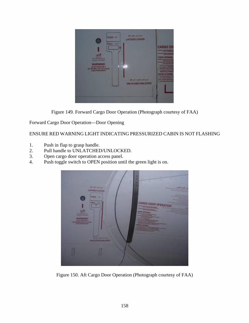
158
Figure 149. Forward Cargo Door Operation (Photograph courtesy of FAA)
Forward Cargo Door Operation—Door Opening ENSURE RED WARNING LIGHT INDICATING PRESSURIZED CABIN IS NOT FLASHING 1. Push in flap to grasp handle. 2. Pull handle to UNLATCHED/UNLOCKED. 3. Open cargo door operation access panel. 4. Push toggle switch to OPEN position until the green light is on.
Figure 150. Aft Cargo Door Operation (Photograph courtesy of FAA)

159
Instructions for operating the aft cargo door are the same as the forward door. ENSURE RED WARNING LIGHT INDICATING PRESSURIZED CABIN IS NOT FLASHING 1. Push in flap to grasp handle. 2. Pull handle to UNLATCHED/UNLOCKED. 3. Open cargo door operation access panel. 4. Push toggle switch to OPEN position until the green light is on. Opening the cargo door on a loaded cargo compartment will only provide access to the cargo containers immediately inside the door. Again, airline representatives should be consulted prior to attempting access to these spaces. If removal of cargo containers is necessary, the aircraft representatives must be present to oversee operations and safety. 14.6.2 Cargo Loading Platforms
A cargo loading platform may provide the best access to a cargo compartment. It provides a safe platform from which to work if access is necessary. A cargo loading platform is designed to span the width of the door, and it can be raised and lowered as needed. Caution must be taken with the rolling casters located on the deck surfaces within the cargo compartments. Airline personnel should be consulted for safe operation. These cargo loading platforms are very large. They move very slowly, having no off-road capability, designed to operate on paved, level surfaces. If the aircraft is on or adjacent to a cargo ramp, these vehicles may be nearby and using them as a work platform may be a viable option. Preplanning would include a plan to safely operate on the multidirectional roller on the loading platform as well as in the cargo bay. If the aircraft is located off the hard surface or at a great distance from the cargo ramp, other options should be explored. 15. CARGO FLOOR HAZARDS FOR FIREFIGHTERS
The floor in an aircraft cargo bay is designed to facilitate the movement of and secure carriage of ULDs loaded with freight. To accomplish that, the floors are equipped with a roller system and locks to allow the ULDs to be manually moved around on the airplane during loading and unloading. In a dark, smoke-filled environment, the obstructions and tripping hazards created are major risks to firefighters and significantly increase the level of difficulty of dragging an attack line into the space. In a lower cargo bay, the hazards to firefighters begin at the threshold, as shown in figure 151. The entry point at the main cargo door has several pieces of hardware that must be stepped over and avoided. At the sill, the fixed portion of the door locking mechanism is the first obstruction that will snag a fire hose being brought into a space. The first section of the floor system (immediately inside the door) is a roller system used to spin ULDs being loaded so they can be pushed into position. These rollers can be extremely dangerous to safe footing. Once inside, there is limited head clearance. Most firefighters wearing a helmet will need to crouch to fit in the space.

160
Figure 151. Cargo Door Opening—B-747-8I (Photograph courtesy of FAA)
Walking across the cargo floor is a very slow process. In addition to rollers and tripping hazards, some cargo floors may even have openings without any walkway (figure 152). Stepping into one of these areas in the dark could be result in a drop of 1 ft or more.
Figure 152. Open Bays in Cargo Floor—B-747-8I (Photograph courtesy of FAA)
In aircraft that do not have the open bays in the floor, a shuffled walk is usually the safest method of maintaining footing. Even in a section of the cargo floor that has a solid floor (figure 153), there are obstructions all over the floor. Preplanning and training in these areas is a critical component of preparedness for operating on an emergency in the cargo bay.

161
Figure 153. Cargo Tunnel Floor—A380 (Photograph courtesy of FAA)
16. LANDING GEAR AND BRAKE HAZARDS
Emergencies involving landing gear, wheels, brakes, and tires on NLA have the same types of concerns as all other large aircraft. There are, however, certain differences that emergency responders should be aware of. This section provides generic information and guidance related to landing gear, brake hazards, and emergencies. Also provided is specific guidance from Boeing and Airbus as it relates to their aircraft. 16.1 BRAKE OVERHEAT
Brake overheats can be caused by the following: • Aborted takeoff • Emergency braking • Frequent use of brakes • Braking system fault • Overweight or short landing 16.1.1 Airbus
Airbus provides guidance for ARFF for each of the Airbus aircraft types at https://www.airbus.com/aircraft/support-services/airport-operations-and-technical-data/aircraft-rescue-firefighting-charts.html

162
The following guidance is provided by Airbus for many of its aircraft types and provided on the aircraft Airbus ARFF charts available on the link above.
WARNING: Be very careful when there is a brake overheat and/or landing gear fire. There is a risk of tire explosion and or wheel rim burst that can cause death or injury. Make sure that you obey the safety precautions that follow. For the cooling of brakes after normal taxi-in, refer to your company (airline) procedures. The procedures that follow give recommendations and safety precautions for the cooling of very hot brakes after abnormal operations such as a rejected take-off or overweight landing. Brake Overheat 1) Get the brake temperature from the cockpit or use a remote measurement
technique. The real temperature of the brakes can be much higher than the temperature on the ECAM. (Electronic centralized aircraft monitor)
NOTE: At high temperatures (>800oC), there is a risk of warping of the landing gear, struts and axles.
2) Approach the landing gear with extreme caution and from an oblique angle in the direction of the tire shoulder. Do not go into the rim hazard area and only go in the hazard area with caution. (Refer to figure, wheel/brake overheat hazard areas) If possible, stay in vehicle.
3) Look at the condition of the tires: f the tires are still inflated (fuse plugs not melted), there is risk of explosion and rim burst. Do not use cooling fans because they can prevent operation of the fuse plugs.
4) Use water mist to decrease the temperature of the complete wheel and brake assembly. Use a technique that prevents the sudden cooling. Sudden cooling can cause wheel cracks or rim burst. Do not apply water, foam or CO2. These cooling agents (and especially CO2, which has a very strong cooling effect) can cause thermal shocks and bursts of hot parts.
Landing Gear Fire: CAUTION: Airbus recommends that you do not use dry powders or dry chemicals on hot brakes or to extinguish landing gear fires. These agents can change into solid or enameled deposits. They can decrease the speed of heat dissipation with a possible risk of permanent structural damage to the brakes, wheels or wheel axles. 1) Immediately stop the fire
a) Approach the landing gear with extreme caution from an oblique angle in the direction of the tire shoulder. Do not go into the rim hazard area

163
and only go in the tire hazard area with caution. If possible, stay in the vehicle.
b) Use large amounts of water, water mist; if the fuel tanks are at risk, use foam. Use a technique that prevents sudden cooling. Sudden cooling can cause wheel cracks or rim burst.
c) Do not use fans or blowers.
CAUTION: Carbon fibers created in the brakes during braking may become airborne when brake fans or PPV are activated. Full PPE, including SCBA, must be worn during these operations. Fan placement and downwind effects of airborne carbon fiber should be considered. (Airbus, n.d.)
Airbus includes guidance for approaching wheel/brake overheat hazards with their crash charts (Airbus, 2018). This guidance is provided in figure 154.
Figure 154. Airbus Guidance for Wheel/Brake Overheat Hazard Areas (Image courtesy of Airbus—Taken from A350 Crash Chart)

164
16.1.2 Boeing
Boeing also provides guidance for hot brakes. All Boeing aircraft are included in Boeing’s: “Airplane Rescue and Firefighting” (Boeing, 2019). As shown in the example in figure 155, the information for firefighters for each aircraft type includes guidance for hot brakes and wheel fires.
Figure 155. Sample ARFF INFO From Boeing—Guidance for Hot Brakes and Wheel Fires (Image courtesy of Boeing (2019))

165
The guidance for most Boeing aircraft is as follows: HOT BRAKES Normal cooling: Move aircraft to a suitable location and allow brakes to cool on their own. Water mist: Can be deployed from turrets or handline. Fans: Placing fans may place fire fighters very close to the hazard zone. WHEEL FIRE Apply large amounts of water initially with turrets. Transition to handline operation to continue and maintain a cooling effect.
Wheels are equipped with fusible plugs designed to melt and deflate the tire when the temperature is excessive. WARNING: Approach landing gear trucks from forward or aft at a 45% angle when approaching hot brakes or fighting a wheel fire, as rims and tires may pose a fragmentation hazard. Firefighters should review the Boeing guidance for fire fighters for each aircraft type in use at the airport for specific information. (Boeing, 2012)
Boeing has published guidance (2012), which includes a graphic called “Aircraft Tire Safety Areas” (figure 156). Upon review, the guidance from both manufacturers recommend the same direction of entry to an incident involving landing gear.

166
Figure 156. Aircraft Tire Safety Areas (Image courtesy of Boeing (2012))

167
16.2 WHEEL FIRES
If wheels are burning, the danger of fire extension exists. ARFF personnel should not wait for tires to deflate if fire attack can be launched safely. The preferred attack is from an ARFF vehicle, which will provide some protection for firefighters in the event the wheel or tire disintegrates. Firefighters should attack the wheel fire by applying a blanket of AFFF using the turrets from a forward or aft position to the aircraft. ARFF vehicle operator training that builds a sense of the turret range is very helpful in this tactic. The goal is to maintain maximum distance from the hazards created by the wheel yet be within range to cool the wheel/gear and extinguish the fire. The guidance provided above for using safe approach paths is valid for an attack from an ARFF vehicle or firefighters on the ground. When using the vehicle’s roof, bumper turret, or HRET turret, not only are the firefighters afforded the physical protection offered by the truck, but the turret provides greater range and standoff distance from the fire and hazards presented. The A380 has 22 wheels, as shown in figure 157, and: • One set of nose landing gear (NLG) • Two sets of wing landing gear (WLG) • Two sets of body landing gear (BLG)
Figure 157. The A380 WLG and BLG—View From Front (Photograph courtesy of FAA—Taken from right side of aircraft)
What firefighters commonly refer to as the main gear are specifically called WLG and BLG. The WLG, BLG, and NLG wheels are numbered for identification, the numbering starts from the left side (just like engines), and then moves aft. NLG are numbered 1 and 2, and the first row of main gear on the A380 is the WLG. From left to right, the wheels are referred to as 1, 2, 3, and 4, as shown in figure 158. The next row of WLG starts with 5 on the left side, followed across as 6, 7, and 8. The BLG rows follow suit, with numbering starting on each row at the left.

168
Figure 158. The A380 Landing Gear Numbering System (Image courtesy of Airbus)
The following systems are associated with the A380 gear: landing gear extension and retraction system (LGERS), braking system, and steering. The tire pressure, brake temperature, and landing gear shock-absorber pressures are monitored from the cockpit. The B-747-8I has 5 sets of landing gear with 2 nose wheels and 16 main wheels. This configuration is unchanged from the B-747-400. Specific information relative to the operation of the landing gear and brakes are important for ARFF personnel, based on the way pilots typically report failures. On the A380, a pilot is likely to report a failure of the GREEN Hydraulic System or the YELLOW Hydraulic System. An understanding of what is controlled hydraulically or electrically better prepares ARFF personnel for potential effects of the reported anomaly. As a quick reference: • GREEN Hydraulic System controls NLG, including steering and WLG, and associated
gear doors.
• YELLOW Hydraulic System controls BLG, including BLG steering and associated gear doors.
Sections 16.3 and 16.4 provide a more detailed description of these systems. Normally, the landing gear on an A380 extends and retracts hydraulically. The unlocking function, which allows it to release from its up and locked position, is controlled electrically. In the event of a failure that does not allow normal use of the LGERS, a gravity-assisted landing gear extension may be performed. This is accomplished electrically through two free-fall control modules.
1 2
5 6
9 10
7 8
11 15 19
12 16 20
13 17 21
14 18 22
3 4

169
16.3 BRAKING SYSTEMS
The A380 has 16 carbon brakes. There is one brake on each WLG wheel, and one brake on each of the four forward-most wheels on each BLG. There are no brakes on NLG or on the rear two wheels on each BLG. In normal braking, the GREEN Hydraulic System powers brakes in the WLG. The YELLOW Hydraulic System powers brakes in the BLG. In addition, there is a local electro-hydraulic generation system (LEHGS), which serves as an independent hydraulic power source. The LEHGS has its own electrically powered hydraulic pump, hydraulic reservoir, and controller. In abnormal braking scenarios, the LEHGS are used as well as the hydraulic accumulators. 16.4 STEERING
The A380 has steering systems for the nose wheels and for the rear four body wheels. Normally, the nose wheel steering is powered by the GREEN Hydraulic System, which is backed up by the LEHGS and nose wheel steering accumulators. The body wheel steering is powered by the YELLOW Hydraulic System. 17. HYDRAULIC AND COOLING SYSTEMS
The B-747-8 and the B-787 use the same new type of hydraulic system that make use of engine-driven and electric pumps that power four separate hydraulic systems. Hydraulics on the Boeing NLA power the primary flight controls (i.e., ailerons, elevators, and rudders) as well as landing gear and brakes. While the B-747-8 Intercontinental still makes use of a 3000-psi hydraulic system, which is the typical hydraulic pressure on aircraft, the A380 includes eight engine-driven hydraulic pumps rated at 5000 psi. There are two hydraulic systems on the A380; they are designated as the GREEN Hydraulic System and the YELLOW Hydraulic System, as shown in table 15. Four engine-driven pumps, two per engine, power each hydraulic system. Two engine-driven pumps are enough to pressurize one hydraulic system. The pumps on the Number 1 and 2 engines power the GREEN Hydraulic System. The pumps on the Number 3 and 4 engines power the YELLOW Hydraulic System.
Table 15. Hydraulic Systems Operation
Number 1 and 2 Engines
Number 3 and 4 Engines
System GREEN YELLOW NLG/doors √ BLG/doors √ WLG brakes √ BLG brakes √ Nose wheel steering √ Body wheel steering √ Slats and flaps (redundant) √ √

170
The hydraulic systems operate constantly and power the landing gear systems, flight controls, and cargo doors. The landing gear system includes braking and steering. During emergency operations, ARFF should avoid cutting pressurized hydraulic lines. The pressure of a rupture in a pressurized hydraulic line is dangerous to personnel. The fluid can cause severe skin and eye irritation and degrade protective clothing properties. Airbus lists three approved hydraulic fluids on their qualified manufacturers list, e.g., ExxonMobil® Mobil™ HyJet™ IV-APlus, HyJet™ V, and Skydrol® LD-4. These are phosphate-based hydraulic fluids. Both hydraulic systems (YELLOW and GREEN) contain 145 gallons (550 liters) each, for a total capacity of 290 gallons (1100 liters) per aircraft. There is a cooling system that runs between both A380 decks to supply the chillers in the galleys. Since it runs as one system between the decks, it too has a high pressure of 5000 psi. The fluid used is Galden® HT135; a Safety Data Sheet (SDS) is available at http://www.synquestlabs.com/msds/2100/2108-2-32.pdf (Synquest Laboratories, 2016). Historically, Airbus has used Galden HT135 in other aircraft besides the A380. At temperatures above 572°F (300°C), this fluid can break down and, after prolonged heating or fire exposure, degrade, liberating hydrogen fluoride (HF) and carbonyl fluoride (COF2). It should be noted that, according to the company, this fluid does have FM Approvals® Standard 6930 (FM Approvals, 2020) approval as having no flash or fire point and no explosion hazards. 18. CONSTRUCTION MATERIALS
To meet the changing demands of the market, the use of advanced materials and technologies in aircraft design has increased. The A350, A380, and B-747 are all excellent examples of the evolution and use of these materials. The materials selected for each component of the aircraft are specifically chosen to satisfy the need of the component, provide high strength, and provide resistance to the typical causes of fatigue, damage, stability, and corrosion. The weight of the material is an important factor, as weight is directly related to the cost of operating the aircraft. Production costs and availability are also factors. For the A380, the proportion of structural materials by weight still shows that aluminum alloys make up the largest proportion (61%). Several new construction practices were engaged on the A380. Some made use of new alloys, while others used different sizes and runs of conventional materials to reduce seams and fasteners to lighten the aircraft without compromising strength. Some of these changes involving metals include: • Aluminum lithium extrusions, used on main deck cross beams
• 7085 aluminum alloy for wing spars and ribs
• Titanium alloys in place of steel. The percentage of titanium by weight on the A380 increased 2% in the A380 over previous Airbus models in the pylons and landing gear alone.

171
A380 construction materials by weight are as follows: • 61% aluminum • 22% composite materials • 10% titanium and steel • 3% GLARE • 2% surface protections • 2% miscellaneous 18.1 COMPOSITE MATERIAL USE
Increased use of composites is not only present on NLAs but is also a part of the evolution of aircraft construction in general. The Boeing Company has significantly increased the quantity of composites in newer aircraft, as shown in figure 159.
Figure 159. Increased Use of Composite Materials (Image courtesy of Boeing)
The B-787 is constructed of 50% composite materials by weight, as shown in figure 160. These advanced materials offer new challenges to ARFF personnel, and a great deal still needs to be learned. The FAA is conducting research to gain a better understanding of these advanced materials and develop best practices for piercing and cutting them. The B-747-8I (Intercontinental) design does not include the same increase in proportion of composite materials. Composites on the B-747-8I are located primarily on control surfaces, pylons, fairings, and cowls, as shown in figure 161.

172
Figure 160. Construction of B-787 (Image courtesy of Boeing)
Figure 161. The ARFF Information on a B-747-8I (Image courtesy of Boeing)
The Airbus Model A350-900 series airplane makes extensive use of composite materials in the fabrication of most of the wing, fuselage skin, stringers, spars, and most other structural elements of all major subassemblies of the airplane. As shown in figures 162 and 163, composites make up 53% of the construction materials on the A350. The fuselage panels, frames, window frames, clips, and doors are made from carbon fiber reinforced plastic (CFRP). The door frame structure is constructed with a new hybrid material made of CFRP and titanium.

173
Figure 162. The A350-900 Composite Materials (Image courtesy of Airbus)
Figure 163. Composite Percentages Graphic (Image courtesy of Airbus)
18.2 ADVANCED COMPOSITE MATERIALS ON THE A380
The increased use of CFRP laminates has allowed the most drastic weight reduction in the A380. The A380 has a CFRP composite center wing box, which is a first in commercial aviation. In

174
addition, the upper-deck floor beams, fin box, rudder, horizontal stabilizer elevators, and rear-pressure bulkhead are made of CFRP. The CFRP has replaced aluminum on lateral panels and secondary ribs. CFRP has also been introduced in mid and outer flaps, flap track fairings, spoilers, and ailerons, as shown in figure 164.
Figure 164. Composite Materials and Locations on the A380 (Image courtesy of Airbus)
Although the A380 includes GLARE fiber metal laminate in the overall construction of the fuselage skin, the skin of the cheek areas for both the forward and aft cargo compartments is aluminum alloy. GLARE is composed of several very thin layers of aluminum interspersed with layers of glass fiber bonded with a resin matrix. GLARE panels are used for 2 sections of the skin, and they cover almost 5400 sq ft of the aircraft fuselage, as shown in figure 165. GLARE has significantly better burnthrough resistance than traditional aluminum used for aircraft skins. According to Eurocopter (2012), tests have shown that the burnthrough time for 0.039-in.-(1-mm)-thick aluminum skin is 30 seconds, but GLARE has resisted burnthrough for over 15 minutes. Where GLARE is not installed on the underside of

175
the aircraft, fire-resistant thermoacoustic insulation is used to meet the 5-minute burnthrough resistance requirement, but the burnthrough time of the skin from direct flame impingement of a pooled fuel fire will not significantly change. Fire exposure from the exterior of the A380 in the GLARE-protected areas may increase the period of survivable temperatures inside the aircraft. The increased burnthrough resistance of GLARE also increases the resistance to breaching the fuselage from a fire burning inside the cabin.
Figure 165. The GLARE Locations on the A380, Highlighted (Image courtesy of Airbus)
Laboratory-scale experiments have compared the force to penetrate GLARE and CFRP to traditional aluminum alloy as used for aircraft skins. Though this work is ongoing, initial results indicate that GLARE takes more force to penetrate, but the force of retraction is greater for aluminum, as shown in figure 166. This force on the ASPN should not cause any operational problems, if the ASPN is withdrawn at the same angle and position as it was during the piercing. A concern has been raised anecdotally that, after piercing a GLARE panel, the GLARE material may tend to bind on the ASPN due to the ASPN changing its angle during penetration. As opposed to aluminum, which will continue to split once penetrated if the ASPN angle changes, the greater strength of the GLARE from the fiber reinforcement prevents that. Planned full-scale tests by the FAA will assess the potential for this to occur once the laboratory-scale experiments are complete. It should be noted that this has not been observed in any of the laboratory-scale experiments, but the ASPN being used travels in a very precisely controlled motion. In the field, the boom has a lot of sway, and the ASPN can shift its angle due to the joints and flexibility built into the system.

176
Figure 166. Comparison of GLARE and Aluminum Penetration Forces
18.3 EFFECTS OF FIRE ON COMPOSITE MATERIALS
A burning aircraft presents the effects of combustion on every aircraft component and the goods being carried. A burning aircraft is a hazardous material incident and must be treated as such. For ARFF personnel, understanding the unique characteristics of each product or material used, both in construction and carried on the aircraft in fire conditions, is an important aspect in emergency management and scene safety. The protection required and firefighting tactics do not significantly differ from those for aircraft without composites. The highest level of protection for firefighters and the exposed population must be employed for all aircraft fires. The components of advanced composite materials are all affected by fire. Resins and epoxy will burn, particularly in the presence of an aviation fuel fire. Whereas aluminum will melt at 1220°F (660°C), generally composites will burn between 572°F (300°C) and 932°F (500°C) but will maintain their structural integrity during burning. Resins will ignite at 400°–600°F (204°–315°C). Products of composite combustion will contribute to the toxicity of the smoke plume. Carbon fibers combust at 1000°F (538°C) and burn with a glowing red color at 1400°F (760°C). Kevlar® fibers combust at 800°–900°F (427°–482°C). Glass fibers do not support combustion, but they will melt and possibly form glass beads. A composite material in a confined space may be difficult to extinguish based on the experiences of the United States Air Force (USAF). Currently, FAA researchers are working to evaluate this evidence. USAF guidance on composite material hazards in their Technical Order 00-105E-09 (USAF, 2006) instructs ARFF to continuously apply water to cool, smoldering composites and to ensure they are cooled below 300°F (149°C). Cooling sufficiently is very important, as is ensuring that all smoldering areas have been adequately overhauled to prevent reignition. Hose-stream attack on smoldering composite structures may cause the release of superheated steam.

177
18.4 EXTINGUISHMENT
Class B foam is the preferred agent to use for composite material fires; however, water can be used to cool deep-seated, smoldering epoxy composites since large volumes may be needed. Pooled fuel fires should be controlled first, then burning composites. Smoldering composites tend to reflash if not sufficiently cooled. 18.5 PROTECTION
Full PPE, including SCBA, is required for extinguishing composite material fires or if composite fibers are airborne. Proper decontamination of PPE is necessary after exposure to these fires or airborne fibers. ARFF should ensure areas downwind are protected from exposures of smoke and airborne fibers. The Boeing Company has provided guidance to the ARFF industry in “Firefighting Practices for New Generation Commercial Composite Structures” (Boeing, 2014). 19. THE APU
The APU is located in the tail of NLA. The APU emergency shutdown switches are located in the cockpit, the maintenance nose gear panel, and the refuel/defuel panel, as shown in figures 167 through 170. The APU fire-suppression system is designed to activate automatically when a fire is detected if no action is taken or if the aircraft is left unattended.
Figure 167. The APU Emergency Shutdown Locations (Image courtesy of Airbus)

178
Figure 168. Refuel/Defuel Panel (Photograph courtesy of FAA)
Figure 169. The APU Emergency Shutdown Controls in the Refuel/Defuel Panel (Photograph courtesy of FAA)

179
Figure 170. Nose Gear APU Panel (Photograph courtesy of FAA)
20. FUEL SYSTEM
According to the A380 ARFF chart provided by Airbus (Airbus, 2015), the A380 has a fuel capacity of up to 83,290 gallons (315,289 liters) of usable fuel. In addition to wing fuel tanks, there is a trim tank, which holds 6,260 gallons (23,700 liters) in the horizontal stabilizer. If the pilot reports that the aircraft must dump fuel prior to landing, fuel can be jettisoned at the rate of 49,254 gallons (186,446 liters) per hour. This information is helpful when considering that the maximum gross takeoff weight for an A380 is 1,234,588 lb (560,000 kg), and that the maximum gross landing weight is 850,984 lb (386,000 kg) for a fully loaded A380 that just departed and needs to return due to a problem. Prior to consuming fuel for taxi and takeoff, that aircraft was 383,604 lb (174,000 kg) above its maximum landing weight. To land within weight restrictions, the A380 may need an hour or more to jettison fuel prior to landing. If there is a fire onboard, an hour is a long time to delay landing. If the aircraft lands at a weight above maximum gross landing weight, a greater risk for damage to the aircraft exists, which will likely result in structural damage and a potential release of fuel upon landing. Fuel released upon heavy landing could potentially find an ignition source in the landing gear. An incident of this nature occurred at JFK on July 30, 1992. (NTSB, 1992) When Trans World Airlines (TWA) Flight 853, a Lockheed L-1011, aborted takeoff, it was loaded to gross departure weight. The aircraft landed hard on the runway causing some structural damage to the aircraft, which resulted in fuel releasing from the wing tanks. The leaking fuel found an ignition source, and the aircraft was consumed by fire after all 292 passengers and crew escaped without serious injury.

180
21. DEPLOYABLE FLIGHT INCIDENT RECORDER SET
Cockpit voice recorders (CVRs) and flight data recorders (FDRs) are also known as “black boxes”. Recovering these devices after an accident is critical to the investigation, but this is not typically a task for ARFF personnel unless the device is in harm’s way. The recovery is conducted by investigators after the fire is extinguished and the scene is secure. These devices are typically mounted within the fuselage, usually near the tail section. Certain military aircraft have been equipped with deployable voice and data recorders since the 1960s. Until recently, deployable CVRs and FDRs have not been installed on commercial aircraft. The concept of data recorders that would deploy from a commercial aircraft and then float received a great deal of attention in the months following the mysterious disappearance of Malaysia Airlines Flight 370. Airbus has announced that they will be installing deployable flight incident data recorder set (DFIRS) on A350 and A380 aircraft. The device is manufactured by DRS Technologies. According to Airbus, the DFIRS is mounted in such a way that its face is integrated to the aircraft skin, flush to the aircraft shape. The release is spring loaded through a crash-activated squib. Once released (as shown in figure 171), there is no ejection option, but rather a release of the DFIRS from its mounting position.
Figure 171. Concept of Deployment From U.S. Patent Application
As shown in figure 172, the orange DFIRS is full of foam, which allows it to remain afloat.

181
Figure 172. The DFIRS, Including a Deployable Incident Recorder and Bus Interface Unit (Image courtesy of DRS Technologies)
22. PASSENGER SEATBELT AIRBAGS
Most aircraft manufacturers offer the installation of seatbelt airbags as an option. The FAA has provided guidance for first responders who encounter airbags at aircraft incidents. This information can be found at http://www.faa.gov/aircraft/gen_av/first_responders/media/mod5/mod5.htm (FAA, n.d.). Airbag systems in aircraft guidance begins on Slide 26. Within this guidance, information is provided to describe aircraft airbag operation, configuration, hazards, and disengagement methods. On their website, seatbelt airbag manufacturer, AmSafe, Inc., indicates that they offer a variety of airbag seatbelt systems, including lap belt, and three-, four-, and five-point restraints (figure 173) (AmSafe, 2009). Aircraft customers can order any configuration for installation. Both Boeing and Airbus offer seatbelt airbags as an option to their customers, and firefighters should be familiar with the equipment and the hazards created.

182
Figure 173. Seatbelt Airbags and Inflatable Restraints (Photographs courtesy of AmSafe (2009))
The seatbelt airbags are not connected to aircraft power but are self-contained. The airbag is designed to deploy automatically when a crash pulse indicating acceleration and impact energy triggers the device. The assembly includes a gas canister containing up to 7400 psi compressed helium to inflate the airbag during a crash event. It is designed to deflate in less than 10 seconds after the crash event. Boeing’s guidance on seatbelt airbags (Boeing, 2016) warns that if the seatbelt airbag system has not been deployed during a crash, each undeployed airbag seatbelt needs to be disarmed to prevent risk of deployment. The guidance also warns that only properly trained aircraft mechanics should attempt to disengage the airplane seatbelt system. According to Boeing’s guidance, in extreme cases, the inflator might become a projectile if the airbag system was damaged and subsequently activated (Boeing, 2016). Although it is unclear how common the installation of aircraft airbag seatbelts will be, they are approved by the FAA for installation on any aircraft.

183
23. CABIN CONFIGURATION
Each operator that purchases an A380 can customize the design of their cabin in terms of both seat style and seating arrangement. Currently, eight carriers operate A380s, and two operate B-747-8s. Each carrier has its own design, layout, and configuration. While economy- and business-class seats are more stylish, and sometimes larger than those on all other passenger aircraft, they are nothing more than new designs of current seats. Where the actual design of the seat is significant to ARFF is in business- and first-class cabins. Airbus has enhanced the upper-class experience so dramatically that passengers do not purchase a seat in upper-class cabins, but a rather a pod that serves as a private suite. These pods provide obstructions to fire streams and increase the level of effort required for search and rescue. ARFF departments that protect airports serving as primary or alternate destinations for A380 service must be familiar with the configurations of each carrier. These pods are not unique to A380 aircraft; they also exist on other aircraft including certain B-777s. Carriers may also reconfigure aircraft at any time. This makes it critical to ARFF to maintain communications with air carriers to stay current on aircraft layout and passenger loads. First-class suites are quite intricate with a variety of detail features to improve comfort and privacy for the passenger. Figure 174 shows the Emirates first-class suite.
Figure 174. First-Class Suite: Emirates
SQ, Lufthansa, and Emirates are among the operators currently using first-class suites with partitions that passengers can close for privacy. This same configuration is used in SQ B-777s employed on longer routes in business- and first-class cabins. By closing the partition and raising a divider that separates adjoining suites, the passenger enjoys what amounts to a personal suite, complete with widescreen television, cold drinks, vanity mirror, fold-out table, bed, and an assortment of comfort controls. On the aircraft visited for this research, Qantas, Korean Air, and Air France chose designs that are closer to the traditional style of first-class seats, as shown in figure 175. These seats convert to beds with many comfort controls and features, but the suites do not have closing partitions and, therefore, are more open. Search and rescue operations may be hampered by the need to reach into each seating pod to check for incapacitated victims. To that end, each partition is electronically controlled, rendering them inoperable if the aircraft power is disconnected. No information is available regarding whether the doors can be forced open with the power off. It is possible to look over the walls of the suite, and this requires the firefighter to stand

184
up into heat and heavy smoke normal to a fire condition. All carrier-specific information is subject to change as airlines modify configurations and update furnishings. Figures 175 through 177 are examples of potential configurations. Aircraft familiarization visits are essential for ARFF crews. Cabin configurations may be unique to each aircraft. In some cases, carriers are using different configurations on like aircraft based on the route and seating class designs for each route. Airlines routinely change their configuration to match customer demand for a seating class on their routes. Figures 175 through 179 highlight the difference in first-class cabins, as well as show the amenities available that would pose considerable hindrance to ARFF crews.
(a) (b)
Figure 175. First-Class Cabins: Qantas (a) and Air France (b)
Figure 176. Raised Partition Around First-Class Seat on Lufthansa A380

185
Figure 177. Korean Air First-Class Seat
Figure 178. Emirates First-Class Shower

186
Figure 179. Emirates First-Class Lavatory Window
Familiarization with each carrier’s configuration will prevent the potential for using an HRET/ASPN into an isolated area, such as a lavatory or a first-class suite, either of which will reduce or eliminate the effectiveness of the penetration and interior fire-suppression effort. SQ, Emirates, Lufthansa, and Qantas have first-class seats and suites that can effectively block the ASPN spray pattern. It is also important to note that while Qantas and SQ have their first-class cabins on the main deck, Emirates and Lufthansa have theirs on the upper deck. Korean Air has 94 business-class seats on the upper deck yet has kept first class on the main deck. There is no such thing as a standard seating configuration on the A380. At the time of this research effort, three carriers (Lufthansa, Korean Air, and Air China) were currently operating the B-747-8 in a passenger configuration, and all three carriers are flying in the U.S. Each carrier has its own design, layout, and configuration. While economy- and business-class seats are more stylish and sometimes larger than those on all other passenger aircraft, they are nothing more than new designs of current seats. The first-class cabin is where the actual design of the seat is significant to ARFF. Passengers do not just purchase a seat in first class, but a rather a pod that serves as a private suite. These pods provide obstructions to fire streams and increase the level of effort required for search and rescue. ARFF departments that protect airports serving as primary or alternate destinations for B-777, B-787, A380, A350, and B-747 service must be familiar with the configurations of each carrier. Carriers may also reconfigure aircraft at any time. This makes it critical for ARFF departments to maintain communications with air carriers to stay current on aircraft layout and passenger loads.

187
First-class suites are quite intricate, with a variety of detail features to improve comfort and privacy for the passenger. The seating configuration varies by aircraft type, carrier, and route. On their website, Skytrax provides links to each airlines seating configuration for each of their aircraft types (Skytrax, n.d.). 24. THE B-747-8 SERIES AIRCRAFT
As of this report publication date, the following carriers are flying B-747-8 aircraft: in one of three models: • B-747-8I • B-747-8F • B-747-8 VIP The carriers who have taken delivery thus far include: • AirBridge Cargo Airlines: B-747-8F • Air China: B-747-8I • Atlas Air (operating for British Airways): B-747-8F • Boeing Business Jets: B-747-8 VIP • Business Jet/VIP Customers: B-747-8I • Cargolux Airlines International: B-747-8F • Cathay Pacific Airways: B-747-8F • DAE Capital: B-747-8F • Korean Air: B-747-8I and B-747-8F • Lufthansa: B-747-8I • Nippon Cargo Airlines: B-747-8F • Silk Way Airlines: B-747-8F • UPS: B-747-8F • Volga-Dnepr UK Ltd.: B-747-8F Currently, B-747-8 freighters have a larger presence at U.S. airports than B-747-8 passenger service. The USAF has announced that the B-747-8 has been selected for the next presidential aircraft (USAF, 2015). The airports listed in table 16 have MoSs in place for B-747-8 operations (FAA, 2019). These airports are authorized to conduct flight operations of B-747-8 aircraft.

188
Table 16. The U.S. Airports Authorized for B-747-8 Operations
Airport (Location Identifier) Anchorage International Airport (ANC) Alaska Atlanta Hartsfield International Airport (ATL) Georgia Boston Logan International Airport (BOS), Massachusetts Rafael Hernandez Airport (BQN) Puerto Rico Chicago O’Hare International Airport (ORD), Illinois Chicago Rockford International Airport (RFD), Illinois Cincinnati/Northern Kentucky International Airport (CVG) Dallas/Fort Worth International Airport (DFW), Texas
Detroit Metropolitan Wayne County Airport (DTW), Michigan
Denver International Airport (DEN), Colorado
Greenville-Spartanburg International Airport, (GSP) S. Carolina Hartsfield-Jackson Atlanta International Airport (ATL), Georgia
Honolulu International Airport (HNL), Hawaii
Houston George Bush Intercontinental Airport (IAH), Texas
Huntsville International Airport (HSV), Alabama
Indianapolis International Airport (IND), Indiana
John F. Kennedy International Airport (JFK), New York
Los Angeles International Airport (LAX), California
Miami International Airport (MIA), Florida
Newark Liberty International Airport (EWR), New Jersey
Orlando International Airport (MCO), Florida
Portland International Airport (PDX) Oregon Rickenbacker International Airport, (LCK) Ohio San Francisco International Airport (SFO), California
Seattle-Tacoma International Airport (SEA), Washington
Ted Stevens Anchorage International Airport (ANC), Alaska Toledo Express Airport (TOL), Ohio
Washington-Dulles International Airport (IAD), Washington D.C.
25. SUMMARY
This report provides an in-depth view into the various challenges, hazards, and unique characteristics of NLA. It is evident that as the world’s aircraft evolve in size, sophistication, and capability, the knowledge base, technology, and skill sets required for ARFF must evolve as well. Knowledge of aircraft differences and the challenges they present is an invaluable tool for ARFF commanders and firefighters. The size, fuel-carrying capacity, passenger loads, cabin configurations, and increased footprint of NLA with evacuation slides deployed are the issues that require the most attention as ARFF crews plan, prepare, and train for NLA incidents. The passenger capacity is the primary reason that the A380 was developed. The current average of 525 passengers in a three-class configuration is already a difficult load to manage during

189
emergency operations. Responders need to plan for this number to increase as airlines look for ways to capitalize on the capability of this aircraft to carry over 800 passengers. Plans for mass casualties, evacuations, transportation, and shelter that were developed for B-747-400s need to be doubled if this aircraft starts flying with the total number of passengers that it is certified to carry. NLA can carry 80,000 gallons of fuel, which is the equivalent of approximately 9 tractor trailer tankers full of jet fuel. This fuel is stored in various locations on the aircraft (i.e., above, below, and alongside the fuselage), which seats hundreds of passengers. Improved fire-resistant qualities of cabin finishes, improved burnthrough times offered by advanced composites, and increasingly sophisticated technology aboard these aircraft certainly increase overall safety for passengers. However, there is still a risk of an incident wherein fuel escapes from the tanks, pools under the aircraft, and finds an ignition source. ARFF personnel need to plan for the worst-case scenario, which would require controlling an 80,000-gallon fuel fire under an aircraft carrying 550 or more passengers. This will require rapid response by qualified ARFF personnel with enough equipment, quantities of foam, water, and techniques to quickly provide protection to the occupants. This must be done before the temperature becomes unbearable, or products of combustion entering the passenger cabin become an immediately dangerous to life and health situation. Most ARFF personnel will never fight an 80,000-gallon fuel fire. An event of this magnitude with an occupied aircraft would be the first in history. However, prudent planning and training are the only tools available to achieve success. Evacuation slides play a vital role by providing passengers and crew a rapid method of escape from a dangerous incident. Master streams from primary turrets and HRETs are needed to quickly make the area safe. ARFF personnel must prioritize and balance the needs of emergency operations. Initial priorities include extinguishing fires in rescue/escape paths and assisting passengers as they evacuate the aircraft. Stabilizing the evacuation slides increases safety during evacuation. Using hand lines to apply a protective blanket of foam under and around the web of slides uses less agent than turrets and allows for a more precise application in the areas where the slides block access to the area under the fuselage. Turrets may damage the slides, which are at risk for being moved by the force of the streams. The slippery foam increases the speed of a person on the slide, as well as increases the risk of falling on the ground. Hand lines provide more precise placement of the foam and do not usually disrupt slides. The lower pressure and volume of the hand lines, the reduced range of the pattern, and the personnel that must be committed to deploy the lines all negatively impact the planning of an efficient operation with finite resources during this critical stage of an emergency. These complications are reality and must be factored into preplans by ARFF departments. The sheer size of these NLA adds a level of difficulty for ARFF personnel during emergency operations. Available technology can reduce the impact of these challenges if available and properly deployed. HRETs can reduce the time and increase the efficiency of an interior attack. Use of cameras on the tip of the device can provide remote monitoring of conditions and increase firefighter safety with the ability to operate the device from outside the aircraft. IAVs can provide a safe work platform, a point of access for firefighters to conduct interior operations, and a means of supporting passenger evacuation and deplaning. Training, maintaining proficiency, and well-thought deployment plans are critical components to the efficient use of these tools.

190
Adequate supplies of firefighting agents with consideration to the increased footprint created by upper-deck slide deployment should be factored into incident planning. Whether the responsibility for interior firefighting falls with ARFF or mutual aid responders, planning and coordination for additional agent and supplies (Q3 quantities) must be determined in planning exercises and drills, not on the fire ground. Preplanning for each NLA configuration is necessary in preparing for mitigation of an incident or accident involving NLA. Areas of these aircraft designed for occupancy vary and will affect planning for fire attack, rescue, and search and recovery. These plans must be dynamic, as airlines may change these configurations based on passenger loads, routes, and the market demands. The challenges created by NLA continue to test the resourcefulness and capabilities of first responders. Along with ARFF professionals who have the primary responsibility to protect these aircraft, mutual aid responders must be included in aircraft familiarization, incident planning, mass casualties’ preparedness, agent resupply, and every task that depends on those off-airport resources for successful operations. 26. REFERENCES
Airbus. (n.d.). Aircraft rescue & firefighting charts. Retrieved from http://www.airbus.com/aircraft/support-services/airport-operations-and-technical-data/aircraft-rescue-firefighting-charts.html Airbus. (2015, December). Aircraft rescue & firefighting charts (ARFC A380800 Dec 2015). Retrieved from http://www.airbus.com/aircraft/support-services/airport-operations-and-technical-data/aircraft-rescue-firefighting-charts.html Airbus. (2018, June). Aircraft rescue & firefighting charts (ARFC A350-900XWB Jun 2018). Retrieved from http://www.airbus.com/aircraft/support-services/airport-operations-and-technical-data/aircraft-rescue-firefighting-charts.html Aircraft Rescue and Firefighting Requirements Working Group (ARFFRWG). (2004). Notice of proposed rulemaking final recommendation to ARAC airport certification issues group, 14 CFR § 139 Subpart D. Retrieved from https://www.faa.gov/regulations_policies/rulemaking/committees/documents/media/APCrfrT1-03222001.pdf Airport Cooperative Research Program (ACRP). (2008). Evaluation and mitigation of aircraft slide evacuation injuries (ACRP Report 2). Retrieved from https://doi.org/10.17226/23103 Airworthiness Standards: Transport Category Airplanes, 14 Code of Federal Regulations (CFR) § 25 (2011). AmSafe. (2009). AmSafe seatbelt airbag first-responder reference guide. Retrieved from https://www.amsafe.com/wp-content/uploads/2017/02/E509944-RevE-First-Responder-Reference-Guide.pdf

191
Australian Transport Safety Bureau (ATSB). (2013, June 27). In-flight uncontained engine failure Airbus A380-842, VH-OQA, overhead Batam Island, Indonesia, 4 November 2010 (ATSB Transport Safety Report, Investigation number AO-2010-089). Retrieved from https://www.atsb.gov.au/publications/investigation_reports/2010/aair/ao-2010-089/ Boeing. (n.d). Airport compatibility: 787 lithium-ion battery test [Video]. Retrieved from http://www.boeing.com/commercial/airports/battery-test-video.page Boeing. (2012). Aircraft tire safety areas. Retrieved from http://www.boeing.com/resources/boeingdotcom/commercial/airports/arff/tire_safety_area.pdf Boeing. (2013a) 787 lithium-ion battery events—a guide for fire fighters. Retrieved from http://www.boeing.com/assets/pdf/commercial/airports/faqs/787batteryprocedures.pdf Boeing. (2013b). Airplane lithium-ion battery events—a guide for fire fighters [Presentation]. Retrieved from http://www.boeing.com/assets/pdf/commercial/airports/faqs/airplane_lithium_ion_battery_events.pdf Boeing. (2014). Firefighting practices for new generation commercial composite structures. Retrieved from http://www.boeing.com/resources/boeingdotcom/commercial/airports/faqs/ffp_newgen_composite_structures.pdf Boeing. (2015, July 17). Multi operator message (MOM-MOM-15-0469-01B). Retrieved from https://www.anac.gov.br/participacao-social/consultas-publicas/audiencias/2015/aud19/anexovi.pdf Boeing (2016). Airplane seatbelt airbags—a guide for fire fighters. Retrieved from http://www.boeing.com/assets/pdf/commercial/airports/faqs/SeatbeltAirbags.pdf Boeing. (2019). Airplane rescue and fire fighting. Retrieved from http://www.boeing.com/commercial/airports/rescue_fire.page Bureau d’Enquêtes et d’Analyses (BEA, aka French Civil Aviation Safety Authority). (2016). Final Report: Accident on 24 March 2015 at Prads-Haute-Bleone (Alpes-de-Haute-Provence, France) to the Airbus A320-211, registered D-AIPX, operated by Germanwings. Retrieved from https://www.bea.aero/uploads/tx_elydbrapports/BEA2015-0125.en-LR.pdf Certification of Airports, 14 CFR § 139 (2004). Cohn, B., & Campbell, J. (Gage-Babcock Associates, Inc. for the FAA). (1971). Minimum needs for airport fire fighting and rescue services (Report No. AS-71-1). Commercial Aviation Safety Team (CAST)/ICAO Taxonomy Team (CICTT). (2012, October). International standards for aircraft make, model and series groupings (Business Rules, Revision 1.3). Retrieved from http://www.intlaviationstandards.org/apex/f?p=240:2:0::NO

192
Daly, K. (2006, April 6). Airbus A380 evacuation trial full report: everybody off in time. Flight International. Retrieved from https://www.flightglobal.com/airbus-a380-evacuation-trial-full-report-everyone-off-in-time/66584.article Defense Aerospace. (2012, May 23). Eurocopter delivers first A350 XWB passenger door [Press release]. Retrieved from http://www.defense-aerospace.com/articles-view/release/3/135445/eurocopter-delivers-first-airbus-a350-door.html Evacuate. evacuate. evacuate. When you need to get out of the aircraft—fast. (2005, July-August). Flight Safety Australia, 9(4). Retrieved from https://webarchive.nla.gov.au/awa/20130530023534/http://pandora.nla.gov.au/pan/140978/20130530-1146/fjul05.pdf. Exceptions for Passengers, Crewmembers, and Air Operators, 14 CFR § 175.10 (2014). FAA. (n.d.). First responder safety at small aircraft or helicopter accident; module 5. accident aircraft response awareness: systems for material hazards for rescue [Adobe Flash Presentation]. Retrieved from http://www.faa.gov/aircraft/gen_av/first_responders/media/mod5/mod5.htm FAA. (2004, July 8). Aircraft fire extinguishing agents (Advisory Circular (AC) 150/5210-6D). Retrieved from https://www.faa.gov/documentLibrary/media/Advisory_Circular/AC_150_5210-6D.pdf FAA. (2006). Type Certificate Data Sheet (No. A58NM). Retrieved from https://rgl.faa.gov/Regulatory_and_Guidance_Library/rgMakeModel.nsf/0/04f08292b8ea9808862581d30070673e/$FILE/A58NM_Rev_7.pdf FAA. (2009, June 12). Driver’s enhanced vision system (DEVS) (AC 150/5210-19A). Retrieved from https://www.faa.gov/documentLibrary/media/Advisory_Circular/AC_150_5210-19A.pdf FAA. (2010a). ARFF: Section 3—Firefighting with the high-reach extendable turret [Video]. Retrieved from https://www.faa.gov/airports/airport_safety/aircraft_rescue_fire_fighting/arff-videos/ FAA. (2010b, September 30). ARFF vehicle and high reach extendable turret (HRET) operation, training and qualifications (AC 150/5210-23). Retrieved from https://www.faa.gov/documentLibrary/media/Advisory_Circular/AC_150_5210-23.pdf FAA. (2011, June 1). Guide specification for aircraft rescue and fire fighting (ARFF) vehicles (AC 150/5220-10E). Retrieved from https://www.faa.gov/documentLibrary/media/Advisory_Circular/150_5220_10e.pdf FAA. (2012, July). Methodologies for calculating firefighting agent quantities needed to combat aircraft crash fires (DOT/FAA/AR-11/29). Retrieved from https://www.airporttech.tc.faa.gov/Products/Airport-Pavement-Papers-Publications/Airport-Pavement-Detail/ArtMID/3684/ArticleID/129/Methodologies-for-Calculating-Firefighting-Agent-Quantities-Needed-to-Combat-Aircraft-Crash-Fires

193
FAA. (2012, September 20). Flight member rest facilities (AC 117-1). Retrieved from https://www.faa.gov/documentLibrary/media/Advisory_Circular/AC_117-1.pdf FAA. (2013a, April). Development of prototype nozzles for freighter aircraft fire applications (DOT/FAA/TC-TN13/11). Retrieved from https://www.airporttech.tc.faa.gov/Products/Airport-Pavement-Software-Programs/Airport-Software-Detail/ArtMID/3708/ArticleID/47/Development-of-Prototype-Nozzles-for-Freighter-Aircraft-Fire-Applications FAA. (2013b, August). Full-scale evaluation of ARFF tactics for cargo fires on freighter aircraft (DOT/FAA/TC-13/30). Retrieved from http://www.tc.faa.gov/its/worldpac/techrpt/tc13-30.pdf FAA. (2016, January 19). Risk of fire or explosion when transporting lithium ion or lithium metal batteries as cargo on passenger and cargo aircraft. Safety Alert for Operators (SAFO) 16001. Retrieved from https://www.faa.gov/other_visit/aviation_industry/airline_operators/airline_safety/safo/all_safos/media/2016/SAFO16001.pdf FAA. (2017, May). Thermal imaging for aircraft rescue and fire fighting applications (DOT/FAA/TC-17/27). Retrieved from http://www.tc.faa.gov/its/worldpac/techrpt/tc17-27.pdf FAA. (2019). Modifications of Standards (MoSs) for A380s/B747-8s/New Large Aircraft. Retrieved from http://www.faa.gov/airports/engineering/nla_mos/ FAA. (2020). Events with smoke, fire, extreme heat or explosion involving lithium batteries. FAA Office of Security and Hazardous Materials Safety. Retrieved from https://www.faa.gov/hazmat/resources/lithium_batteries/media/Battery_incident_chart.pdf Federal Emergency Management Agency (FEMA). (2013). Incident organization chart (ICS 207). Retrieved from https://www.fema.gov/media-library/assets/documents/33533 FM Approvals®. (2020). Approval standard for fire performance of industrial fluids (Approval Standard Class Number 6930). Galea E. R., Wang, Z., Togher, M., Jia, F., & Lawrence, P. (2007, October). Predicting the likely impact of aircraft post-crash fire on aircraft evacuation using fire and evacuation simulation. Paper presented at the International Fire & Cabin Research Conference, Atlantic City, NJ. International Air Transport Association (IATA). (2014). Lithium batteries risk mitigation guidance for operators: Effective 1 January–31 December 2015. (1st ed.). International Air Transport Association: Montreal—Geneva. Retrieved from https://www.prba.org/wp-content/uploads/IATA-lithium-battery-risk-mitigation-guidance-for-operators-1st-ed1.pdf International Civil Aviation Organization (ICAO). (2005). Operation of newer larger aeroplanes at existing aerodromes (Circular 305-AN/177, 4th edition). ICAO. (2018). Annex 14, Volume 1–Aerodrome design and operation. (8th ed.)

194
Institute of Electrical and Electronic Engineers (IEEE). (2016). IEEE standard glossary of stationary battery terminology (Standard 1881-2016). International Fire Service Training Association (IFSTA). (2013). Essentials of fire fighting, (6th ed.). Oklahoma State University, Stillwater, Oklahoma: Fire Protection Publications. National Fire Protection Association (NFPA). (2014). Standard for aircraft rescue and fire-fighting services at airports (2014 ed.) (NFPA Standard 403). NFPA. (2020). Standard for aircraft rescue and fire-fighting vehicles (2020 ed.) (NFPA Standard 414). National Transportation Safety Board (NTSB). (1992). Aborted takeoff shortly after liftoff Trans World Airlines flight 843 Lockheed L-1011, N11002 (Accident Report NTSB/AAR-93-04). Retrieved from http://libraryonline.erau.edu/online-full-text/ntsb/aircraft-accident-reports/AAR93-04.pdf NTSB. (2000, June). Emergency evacuation of commercial airplanes, (Safety Study (SS)-00/01). Retrieved from https://www.ntsb.gov/safety/safety-studies/Documents/SS0001.pdf NTSB. (2007). Inflight cargo fire, United Parcel Service Company Flight 1307, McDonnell Douglas DC-8-71F, N748UP (Accident Report NTSB/AAR-07/07). Retrieved from https://reports.aviation-safety.net/2006/20060208-0_DC87_N748UP.pdf NTSB. (2009, September 21). Brief of incident (Report CHI08IA182). Retrieved from https://www.skybrary.aero/bookshelf/books/1034.pdf NTSB. (2013). Attachment 2—Flight attendant interview summaries (Docket No. SA-537, Exhibit No. 6C). Retrieved from https://dms.ntsb.gov/public/55000-55499/55433/543250.pdf NTSB. (2014a, June 24). Descent below visual glidepath and impact with seawall, Asiana Airlines flight 214, Boeing 777-200ER, HL7742, San Francisco, California, July 6, 2013 (Accident Report NTSB/AAR-14/01, PB2014-105984, Notation 8518). Retrieved from https://dms.ntsb.gov/public/55000-55499/55433/563979.pdf NTSB. (2014b). Auxiliary power unit battery fire, Japan airlines, Boeing 787-8, JA829J (Accident Report AIR-14-01). OSHA Permit-Required Confined Spaces, 29 CFR § 1910.146 (1999). Skytrax. (n.d.). Airplane seating plans. Retrieved from https://www.airlinequality.com/info/airline-seat-plans/ Synquest Laboratories. (2016). Galden® HT135 safety data sheet (SDS 2108232). Retrieved from http://www.synquestlabs.com/msds/2100/2108-2-32.pdf

195/196
United Arab Emirates General Civil Aviation Authority (UAE GCAA). (2010). Uncontained cargo fire leading to loss of control in-flight and uncontrolled descent into terrain (Air Accident Investigation Sector (AAIS) Final Report, Case Reference 13/2010). Retrieved from https://gcaa.gov.ae/en/ePublication/admin/iradmin/Lists/Incidents%20Investigation%20Reports/Attachments/40/2010-2010%20-%20Final%20Report%20-%20Boeing%20747-44AF%20-%20N571UP%20-%20Report%2013%202010.pdf UAE GCAA. (2016). Runway impact during attempted go-around (AAIS Preliminary Report, Case Reference AIFN/008/2016). United States Air Force (USAF). (2006). Aerospace emergency rescue and mishap response information (Emergency services) (Technical Order (TO) 00-105E-9) Retrieved from https://www.0x4d.net/files/AF1/R11%20Segment%201.pdf USAF. (2015, January 28). AF identifies Boeing 747-8 platform for next Air Force One [Press release]. Retrieved from https://www.af.mil/News/Article-Display/Article/562748/af-identifies-boeing-747-8-platform-for-next-air-force-one/ 27. ADDITIONAL DOCUMENTATION
The following documents were specifically used for compiling information during the writing of this report. • Aircraft Characteristics, 10th Edition, Burns & McDonnell, Kansas City, Missouri, 2010.
• “A380-800 Flight Deck and Systems Briefing for Pilots,” Presentation, Airbus Flight
Operations Support and Services, Issue 2, March 2006.
• U.S. Department of Transportation, Federal Aviation Administration, “Flight Standardization Board (FSB) Report—Boeing 787-8 Revision 2,” May 13, 2013. Retrieved from https://fsims.faa.gov/wdocs/fsb/b-787_r2.htm
• Tutson, A., Ferguson, D., and Madden, M., “Fire Protection: Passenger Cabin,” Aeromagazine Quarterly, 2011. Retrieved from https://www.boeing.com/commercial/aeromagazine/articles/2011_q4/pdfs/ AERO_2011q4_article4.pdf
• Airbus Technical Magazine, FAST Special Edition A350XWB, June 2013. Retrieved from https://www.airbus.com/content/dam/corporate-topics/publications/fast/FAST_specialA350.pdf
• Cohn, B. and Campbell, J. (Gage-Babcock Associates for the FAA), “Minimum Needs for
Airport Fire Fighting and Rescue Services,” Report No. AS-71-1, January 1971. • Stilp, T., “Introduction to A380 RFF Characteristics,” Disabled Aircraft Recovery &
Airport Rescue Fire Fighting Workshop, Toulouse, France, April 11-12, 2006.

A-1/A-2
APPENDIX A—FUEL WEIGHT/VOLUME CONVERSION Table A-1 shows fuel weight/volume conversion for pounds (lb) and kilograms (kg) per gallon (gal.) as provided by the Federal Aviation Administration (FAA) Advisory Circular (AC) 150/5210-7D.
Table A-1. Fuel/Weight Volume Conversion
(Conversion Factors: 6.7 lb/gal.—3.04 kg/gal.) (FAA, 2008)
Pounds
(lb) Gallons (gal.)
Kilograms (kg)
Gallons (gal.)
2,000 300 2,000 658 5,000 746 5,000 1,645
10,000 1,492 10,000 3,290 15,000 2,239 15,000 4,934 20,000 2,985 20,000 6,579 25,000 3,731 25,000 8,224 30,000 4,478 30,000 9,868 35,000 5,224 35,000 11,513 40,000 5,970 40,000 13,158 45,000 6,716 45,000 14,803 50,000 7,463 50,000 16,447
100,000 14,925 100,000 32,895 150,000 22,388 150,000 49,342 200,000 29,850 200,000 65,789 250,000 37,313 250,000 82,237
A.1 REFERENCE Federal Aviation Administration (FAA). (2008, April 14). Aircraft rescue and firefighting communications (Advisory Circular [AC] 150/5210-7D). Retrieved from https://www.faa.gov/documentLibrary/media/advisory_circular/150-5210-7D/150_5210_7d.pdf