Polyurethane reinforced ballasted track Review, innovation ...
30
Delft University of Technology Polyurethane reinforced ballasted track Review, innovation and challenge Jing, Guoqing; Qie, Luchao; Markine, Valeri; Jia, Wenli DOI 10.1016/j.conbuildmat.2019.03.031 Publication date 2019 Document Version Accepted author manuscript Published in Construction and Building Materials Citation (APA) Jing, G., Qie, L., Markine, V., & Jia, W. (2019). Polyurethane reinforced ballasted track: Review, innovation and challenge. Construction and Building Materials, 208, 734-748. https://doi.org/10.1016/j.conbuildmat.2019.03.031 Important note To cite this publication, please use the final published version (if applicable). Please check the document version above. Copyright Other than for strictly personal use, it is not permitted to download, forward or distribute the text or part of it, without the consent of the author(s) and/or copyright holder(s), unless the work is under an open content license such as Creative Commons. Takedown policy Please contact us and provide details if you believe this document breaches copyrights. We will remove access to the work immediately and investigate your claim. This work is downloaded from Delft University of Technology. For technical reasons the number of authors shown on this cover page is limited to a maximum of 10.
-
Upload
khangminh22 -
Category
Documents
-
view
2 -
download
0
Transcript of Polyurethane reinforced ballasted track Review, innovation ...

Delft University of Technology
Polyurethane reinforced ballasted trackReview, innovation and challengeJing, Guoqing; Qie, Luchao; Markine, Valeri; Jia, Wenli
DOI10.1016/j.conbuildmat.2019.03.031Publication date2019Document VersionAccepted author manuscriptPublished inConstruction and Building Materials
Citation (APA)Jing, G., Qie, L., Markine, V., & Jia, W. (2019). Polyurethane reinforced ballasted track: Review, innovationand challenge. Construction and Building Materials, 208, 734-748.https://doi.org/10.1016/j.conbuildmat.2019.03.031
Important noteTo cite this publication, please use the final published version (if applicable).Please check the document version above.
CopyrightOther than for strictly personal use, it is not permitted to download, forward or distribute the text or part of it, without the consentof the author(s) and/or copyright holder(s), unless the work is under an open content license such as Creative Commons.
Takedown policyPlease contact us and provide details if you believe this document breaches copyrights.We will remove access to the work immediately and investigate your claim.
This work is downloaded from Delft University of Technology.For technical reasons the number of authors shown on this cover page is limited to a maximum of 10.

Polyurethane reinforced ballasted track: review, innovation and challenge
Jing Guoqing1, Qie Luchao2, Valeri Markine3 Jia Wenli3*
1. School of Civil Engineering, Beijing Jiaotong University, Beijing 100044, China
2. China Academy of Railway Sciences, Beijing 100044, China
3. Faculty of Civil Engineering and Geosciences, Delft University of Technology,
Delft, 2628CN, Netherlands
* Corresponding author
Abstract:
During the development for railway, ballasted track is dominant structure and makes
up more than 95% of the whole track modes. However, its shortage is considerable in
high speed railway and heavy haul system. Regarding to the ballasted railway
track’s defects as particle breakage, settlement, and geometry irregularity which lead
to enormous maintenance and cost, Polyurethane reinforced ballasted track has shown
great application prospect. This reinforcement method can settle several problems,
including stiffness adjustment, ballast flight prevention, and stability in specific zones,
such as curve, tunnel line. This paper presents a comprehensive review of
polyurethane research and application within ballasted track system. Besides,
according to different usage, varies of bonding methods are also introduced in this
paper. However, some challenges still exist such as maintenance and cost, potential
solutions are put forward for further investigated and validated, consequently.
Accordingly, an overall prospect of polyurethane reinforcement in railway system is
presented.
Keyword: polyurethane, ballasted track, stability, maintenance, ballast flight
1. Introduction
During two centuries, railway has experienced great improvement since beginning.
This transportation mode can occupy the higher percentage of railway network
dedicated to both freight and passenger traffic. In recent years, especially after 1970s,
railway industry shows great progress so that a large number of heavy-haul,
high-speed and urban transit railway with different type of structures and new
technologies was constructed through all over the world [1].
However, increasing the speed and load also produces higher stress and greater
deformation, leading to track geometry changes. As a result, more frequent
maintenance and cost will be needed. Consequently, higher demands were made on
substructure which functions consist of bearing the force transferred from sleeper,
keeping rail geometry and providing elasticity.
© 2018 Manuscript version made available under CC-BY-NC-ND 4.0 license https://creativecommons.org/licenses/by-nc-nd/4.0/

Nowadays, two main modes of substructures are used, including ballasted track and
slab track. [1, 2]. Ballasted track is by far the most common track mode in railway
system with a percentage of more than 95% [3]. Ballasted track is a granular layer
which obey a certain particle size distribution. It has several advantages, including
good-elasticity, low cost, easy to construct and maintain [1, 3-4]. On the other hand,
with no confine pressure applied to ballast layer, some disadvantages also emerged,
such as low geometry, ballast degradation, pumping effect and frequent maintenance
[1-5].
Slab track is the latest in railway system compared to ballasted track, however, with
several decades’ development, this kind of mode has also significant effect for
railway evolution, especially in high-speed railway. Slab track consists of concrete
basement and slab. Sleepers are laid on a concrete base and, then concreted into slab,
thus all parts of slab track system are working together as a whole. As a consequence,
slab track has good workability and low maintenance frequency. On the contrary, the
vibration and noise problems occurred due to the high stiffness. In addition, initial
cost is large and maintenance is difficult [6-9].
However, slab track is an improvement in track system, it doesn’t satisfy all kinds of
track requirements. Therefore, the ballasted tracks which contribute to more than 95%
of railway system are irreplaceable. To solve the geometry and durability of ballasted
track, the many researches were carried out on reinforcement method.
The method to improve ballasted track bed performance commonly includes using
rubber pads (or mats) and geogrids. Rail pads have the function which can increase
ballast protection under higher dynamic overloads [10-12]. Under Sleeper Pads (USPs)
can be used to decrease the settlement [13, 14], and Under Ballast Mat (UBM) can be
used to damp vibrations and decrease stress of the ballast layer [15-16]. The usage of
geogrid has a similar function, it can also reduce settlement and increasing capability
[17, 18].
In addition, polyurethane reinforcement was put forward due to the concern which
discussed above. After polyurethane bonding, some parts of ballasted track bed
transfer from aggregate particles to a whole continuous structure, thus contributing
more stability. With respect to different types of polyurethane and bonding method,
polyurethane reinforcement can be applied in tunnel, bridge, station, transition zone
and degraded ballast bed. Polyurethane reinforced ballasted track, which integrates
the advantages of both ballast and slab track. Furthermore, this layer acts as an
advanced track mode.
In China, 12570m polyurethane reinforced ballast tracks have been paved since 2009
to 2018 in 7 lines, In order to meet the stability requirement in special geological
condition (such as geological fault zone), bridge and tunnel, as shown in Table1.

During the operation period, polyurethane reinforcement method performed,
effectively, and through the operation history, a significant increase in the stability and
less maintenance can be seen. Furthermore, 4 lines which are under construction also
adopt polyurethane reinforcement, including 3 high-speed lines (Beijing-Zhangjiakou,
Urumchi-Lianyungang, and Shangqiu-Hefei-Hangzhou), and 1 urban transit line
(Urumchi).
Table1 Polyurethane reinforced ballasted track in China (CARS)
Paving
time
Opening
time Line Type Maintenance history
2009.10 2012.12 Beijing-Guangzhou Bridge
Gauge adjustment 1 time in
2011. Gauge, Profile and
alignment adjustment 1 time
in 2015
2009.12 2010.03 Shanghai-Chengdu Bridge Profile adjustment 1 time in
2015.
2012.03 2012.06 Longyan-Zhangzhou Bridge
Settlement after construction
less than 3mm, 3 times UPS
height adjustment in a small
area.
2013.12 2014.12 Watang-Rizhao
Bridge None
2014.01 Tunnel
2014.11 2015.07 Datong-Xian
Subgrade None
2015.05 Subgrade
2016.07 2016.12 Shanghai-Kunming Bridge None
2018.06 2018.12 Jinan-Qingdao Subgrade None
Due to the advantages and wide usage, several groups research into the characteristics
and behaviors of polyurethane reinforcement, including the polyurethane material, the
function of polyurethane reinforcement, the spraying method and applications. By
summarizing existing works and combining own views, this paper presents a
comprehensive review and put forward the challenge/solution. What should be
mentioned is that this paper firstly releases the research of China Academy of Railway
Sciences (CARS) about polyurethane reinforcement.
2. Polyurethane Materials
2.1 Polyurethane
Polyurethane has a long history in other industries, but the usage in railway system is
relatively short, it was first put forward by the research team of Heriot-Watt
University, The XiTRACK® three-dimensional track reinforcement technique
(Thompson D. and PK Woodward 2004) [19]. Another kind is improved from
Elastocoast® which is produced from BASF’s subsidiary Elastogran, focusing on
reinforcement of stone revetments (Hicks et al., 2008) [20]. Marcus S. Dersch and
Erol Tutumluer (2010) [21] bring this material into the railway, thus put forward
Elastotrack® as a method of polyurethane coating railroad ballast aggregate. China
also focuses on polyurethane reinforcement method, such as CARS and Jing Guoqing
[22,23].
The polyurethane mentioned above is an unfoamed material, performing stiff bonding.
In addition, foamed polyurethane, which is an elastic material, is also used in railway.
Andrew Keene (2012) carried out the research of rigid-polyurethane foam (RPF), thus
creating unconnected monolithic formations of polyurethane-stabilized ballast (PSB)
[24]. CARS also uses foamed polyurethane to reinforce ballasted track.
The Polyurethane material can be divided into two components, part A-Isocyanate and
part B-Polyols which should be mixed 1:1 by volume before using. After mixing,
polyurethane is a liquid and its viscous increases by time. The main chemical
reactions including urea and urethane linkages generating, which chemical equations
are as follows:
(Urea linkage) (1)
(Urethane linkage) (2)
During hardening process, if there is water or foaming agent mixed in polyurethane,
foam reaction will happen, the chemical equation is as follows:
(3)
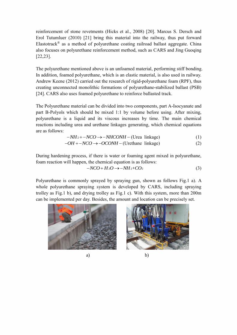
Polyurethane is commonly sprayed by spraying gun, shown as follows Fig.1 a). A
whole polyurethane spraying system is developed by CARS, including spraying
trolley as Fig.1 b), and drying trolley as Fig.1 c). With this system, more than 200m
can be implemented per day. Besides, the amount and location can be precisely set.
a) b)
2NH NCO NHCONH
OH NCO OCONH
2 2 2+NCO H O NH CO

c)
Fig.1 Spraying instruments:
a) spraying gun (Goldschmidt-Thermit-Group);
b) spraying trolley, c) drying trolley (CARS)
While spraying, polyurethane flows through the void of ballast particles, therefore,
ballast particles bond at the contact point as follows Fig.2. With the chemical reaction,
the strength rapidly increases within 15 to 30 minutes. To adjust the time range that to
be shorter or longer catalyzer can be added. It should be noticed that after the first
stage that strength increase, the entire hardening process will continue 7 days or even
longer to 30 days.
Fig.2 The mechanism ballast bonding (Goldschmidt-Thermit-Group)
The aging of polyurethane is tested by CAR. Fig.3 illustrates the tensile
strength-aging curve, under hygrothermal condition (temperature 80℃ and humidity
95%). After 270 days, the tensile strength decreases to 80% of the initial data. Besides,
the foamed polyurethane standard is published by CARS. The key characteristics is
listed as follows Table2 [25].

0 30 60 90 120 150 180 210 240 270 3000.10
0.15
0.20
0.25
0.30
0.35
0.40
Tens
ile
stre
ngth
/MPa
Time/d
Fig. 3 Tensile strength in aging test (CARS)
Table2 Key parameters of foamed polyurethane by CARS
Items Parameter
Free foaming density (kg/m3) ≥130
Compressive strength (10% strain, kPa) ≥8
Tensile strength (MPa) ≥0.2
Elongation at break (%) ≥140
Tear strength (N/m) ≥400
Compressive permanent deformation (50%RH, 70℃, 22h) ≤10%
Dry-heat aging (110℃, 168h) Retention rate of tensile strength ≥70%
Retention rate of elongation at break ≥70%
Damp-heat aging (95%RH, 80℃,
168h)
Retention rate of tensile strength ≥70%
Retention rate of elongation at break ≥70%
UV aging (168h) Retention rate of tensile strength ≥70%
Retention rate of elongation at break ≥70%
Low-temperature recovery
capability (-20℃, 168h)
Retention rate of tensile strength ≥70%
Retention rate of elongation at break ≥70%
Flame retardation
Average burning time (s) ≤30
Average burning height ≤250
Oxygen index ≥26%
In addition, some researchers also use other ballast bonding materials. In this aspect, it
can be extended to various materials which characteristics are similar to polyurethane,
such as ballast bonding resin (AgriTec® EWR-Winter, GREBOPOX®) [26] and
bitumen [27-30].
2.2 Polyurethane-ballast
To qualify the characteristics of polyurethane-ballast, basic mechanic tests are needed.
Marcus S. Dersch and Eros Tutumluer (2010) [21] conduct direct shear test on
polyurethane-ballast cubic specimen with side dimensions of 305 mm and height of
203 mm. Results show that when the confined pressure is by 172KPa and 241KPa, the

ballast before polyurethane bonding has the lowest shear strength at 331 KPa and 400
KPa, respectively. As the strength of polyurethane increases along with time, the
maximum strength, occurred on 14-day cured specimen, reached 726KPa. This data
shows almost a doubling of the strength compared to the result of unbound specimen
which tested at 241KPa. All results can be seen in Fig.4 as follows.
Fig. 4 Shear stress-horizontal displacement of direct shear tests (Marcus S. Dersch
and Eros Tutumluer,2010)
Jing Guoqing prepared polyurethane-ballast cubic specimen with the side length of
300mm. In addition, compression tests were performed according to different
polyurethane usage percentage (by volume). Results show that the axial force increase
positively proportional to polyurethane usage percentage that lead to decrease the
damage deformation. Without bonding, the compressive strength is by 0.073Mpa, and
the elasticity modulus is about 1.039Mpa. After bonding with 2% polyurethane, the
compressive strength is by 0.341Mpa, and the elasticity modulus is as 11.427Mpa.
When it comes up to 4% polyurethane mixing ratio, the compressive strength and
elasticity modulus are as 0.609Mpa and 41.695Mpa, respectively, as shown in Fig.5.
Fig.5 influence of the polyurethane usage (Jing Guoqing)
Jing Guoqing (2018) also did compression test considering two kind of polyurethane
with tensile strength of 5.3Mpa and 14.2Mpa. This series of tests illustrated that the

strength increase according to curing days. For each test group, the maximum strength
occurred on 7-day cured specimen. Fig.6 shows that the maximum compression stress
is as 14.195kN (0.158Mpa) with displacement of 10mm, and 21.026kN (0.234Mpa)
with displacement of 10mm, corresponding to the tensile strength as 5.3Mpa and
14.2Mpa of polyurethane, respectively [23].
a) b)
Fig.6 force-displacement curve of compression test
a) 5.3Mpa polyurethane, b) 14.2Mpa polyurethane (Jing Guoqing, 2017)
For a specific kind of polyurethane, it can be seen that when the strength of
polyurethane increased by days, the damage deformation decreased, consequently. It
is the same trend compared with Jing Guoqing’s research when compression stress
increased by the increase of the usage of the polyurethane ratio. But for the
compression between different polyurethane, it cannot be determined easily, it’s
corresponding to the polyurethane strength and stiffness.
Furthermore, uniaxial compression tests, considering different content of
polyurethane, were carried out by Su Hyung Lee (2017) [31], in this research,
cylinder specimen was used. The strain-stress graphs are illustrated in Fig.7. Similar
to previous researches, when the polyurethane usage percentage increased, the initial
stiffness and strength increased, consequently. Moreover, the abruption is caused by
breakage of bonding that can be seen due to the less polyurethane usage (70 kg/m3).
At the beginning of the curve, there were two linear regions which can be classified
into Linear-I, Linear-II, and Curved regions, as indicated in Fig. 7(b). The Linear-I
region would be related to the initial compaction of the polyurethane mixed ballast.
Subsequently, after slightly more compaction by the initial loading, the specimen
would show more resistance to the applied load. Accordingly, the Linear-II region
would show a steeper slope. In the Curved region, the bond between the aggregates
and polyurethane and/or polyurethane itself would start to break; also, the interlocking
of ballast aggregates would begin to weaken.

Fig.7 Uniaxial test results for polyurethane-mixed ballast (Su Hyung Lee,2017)
The slope of the linear region indicated the stiffness. The Linear-I region had a lower
stiffness than did Linear-II. The slope changed at an approximate strain of 0.5%. The
polyurethane content of 70 kg/m3 showed drops at around 0.4 and 1.2%, and appeared
to behave linearly up to the strain of 2%; thus, three linear regions divided by two
dropped points (i.e., 0.4, 1.2% strain) were fitted by a linear function. Fig. 8(b) plots
the three regions’ linear fitting results. It can be seen that the first block has a slope
different from those of the other two, and that whereas the latter two blocks would
behave similarly to each other. The first block would behave differently from them.
This is supported by the observation of the different polyurethane contents (140, 240
kg/m3). Fig. 8(c) and (d) show that the slope of the Linear-I region differs from that
of the Linear-II region, which is divided by a strain of approximately 0.5%. This
strain level could be considered to be the strain limit of the linear relationship in the
ballast-only tests. In this regard, one can imagine that the initial behavior of
polyurethane-mixed ballast is associated with that of ballast-only. That is to say, under
an initial small strain, the ballast materials would play a role; but then, as the strain
increases, the role of polyurethane would become much more important. Under a
small strain (i.e., less than 0.5%), the initial densification would have an effect on the
initial behavior.

Fig.8 Stiffness by linear fitting
(a) Ballast-only, (b) Polyurethane 70 kg/m3, (c) Polyurethane 140 kg/m3, (d)
Polyurethane 210 kg/m3 (Su Hyung Lee,2017)
The deformation moduli (initial linear slope, i.e., stiffness) are plotted with different
polyurethane contents, in Fig. 9. Considering the confining pressure in the field, two
different stiffness values were used in order to suggest stiffness of
polyurethane-mixed ballast according to the content. The first case shown in Fig. 9(a)
assumes no stiffness under no confining pressure. The second case shown in Fig. 9(b)
assumes confining pressure of 30 kPa is close to field condition. However, one can
believe that the actual condition is between these two cases.
Fig.9 Deformation moduli according to polyurethane contents (Su Hyung Lee, 2017)
Based on this research, a predict relation between deformation modulus and
polyurethane contents is put forward as follows Eq. (4) and (5).
Emixture=0.3149ωurethane for Strain < 0:5%
Emixture=0.5018ωurethane for Strain > 0:5% (4)
Emixture=0.2367ωurethane +12.77 for Strain < 0:5%
Emixture=0.4255ωurethane +12.46 for Strain>0:5% (5)
Where:
Emixture = deformation modulus (MPa) of polyurethane-mixed ballast and
ωurethane= polyurethane contents (kg/m3).
As mentioned above, polyurethane in railway system have two main kinds, besides
the test of unfoamed material, Andrew Keene (2012) using RPF (rigid-polyurethane
foam) prepared polyurethane-ballast beams (i.e. PSB, polyurethane-stabilized ballast)
and performed compression and flexure tests. Results show, comparing flexural test
results, when the average RPF density is 200kg/m3, the average PSB flexural modulus
(274 MPa) is greater than the average RPF flexural modulus (124MPa). However, the
average PSB flexural strength of 938 kPa is less than the average RPF flexural

strength 3652KPa. Greater flexural stiffness of PSB compared to RPF can be
attributed to the stiffness of the ballast particles. The lower flexural strength of PSB
relative to RPF can be attributed to weakness in the bonding interface between the
ballast particles and RPF [24,33-33].
Fig.10 Compression and flexure tests (Andrew Keene, 2012)
Overall, polyurethane reinforcement increases the strength and modulus (stiffness) of
ballast, and the stability grows with the polyurethane strength, curing days and
content.
3. Bonding method and Application
Polyurethane reinforcement can solve several problems in the following aspects,
Lakušić, S (2010) summarized some of the functions, as follows Fig.11 [34].
Fig.11 The main functions of polyurethane reinforcement (Lakušić, S, 2010)
Polyurethane bonding optimizes the contact characteristics between ballast and
sleeper. For unformed polyurethane which as a stiff boding material, mainly works to
improve track stability and durability. the entire functions include ballast flight
prevention, enhancement of lateral resistance in curve, tunnels, and station, the
stability of ballast under rail joint, turnout bridge and crossings, and adjustment of
stiffness in transition zones. Foamed polyurethane as an elastic material, mainly
works to improve track force and energy performance considering dynamic load. In
addition, polyurethane bonding method according to different research varies from
full-section bonding, surface bonding, specific section bonding (by unfoamed

polyurethane) and internal bonding (by foamed polyurethane).
3.1 Ballast flight prevention
When train passes the ballast track at a high-speed (especially above 300km/h) the
great difference of air pressure will apply to the surface of ballasted layer. Under the
air pressure and vibration, ballast have the possibility to fly, and hit the train or rails,
thus affect the safety of train operation [35-38]. Polyurethane can bond the ballast and
make its surface fixed. Particle, especially with small size or density, cannot move
under air pressure and vibration, thus preventing ballast flight. Ding Dong (2017)
demonstrated ballast settlement using polyurethane bonding. A half-structure 1:1
mode is tested in wind tunnel. Results show, after bonding, ballast displacement did
not occur when wind speed adding to 30m/s, corresponding to 350km/h train passing
[39].
In this prospect, full-section bonding is a method in which all ballast of the track bed
are bonded, thus ballast displacement will be restricted. In addition, this method can
maximize the track resistance compared to other bonding methods, because all the
ballast are bonded as an entire structure. Xiao Hong (2017) illustrated that, after
full-section bonding, the lateral resistance can reach to 55.5kN corresponding to 1 mm
displacement [40]. In this research, a simulation model based on DEM is set up and
analyzed. Results show, after full section bonding, the number of sleeper-ballast
contact point is 870, the compression force point is 355 which contributing 72.5% of
lateral resistance. Moreover, the tension force pointis 515, contributing 40.8% of total
lateral resistance.
However, full-section bonding method largely increases lateral resistance, it should be
noticed that this method causes some vital disadvantages, such as large material
consumption that creates great initial cost, and wide spraying range leading to
maintenance unavailability.
Furthermore, Jing Guoqing (2018) used full-section surface bonding in order to
prevent ballast flight, considering maintenance availability, spraying at the surface till
the depth of 60mm, as shown in Fig.12. This method is aiming to settle the ballast
flight problem so that ballast particles on the surface cannot move due to the bonding
method. At the same time, it can increase the lateral resistance by 17%, which is
enough to keep track stability. Test showed that full-section surface bonding does not
influence the tamping maintenance because of the lower bonding depth [23].

Fig. 12 Full-section surface bonding (Jing Guoqing, 2018)
3.2 Stiffness adjustment (transition zone)
Vehicle transition from a section of ballasted track with higher elasticity to a section
of slab track with significantly less elasticity result in vibration amplification effect,
which is destructive to the track system. Polyurethane bonding changes contacts
between ballast particles. Before bonding, particles contact can be described in
occlusal force, friction and pressure. Track elasticity is provided by particle slight
movement due to void existence and free-contact. After bonding, those free-contacts
are fixed thus ballast working together with the stiffness of the unfoamed
polyurethane, the track stiffness is positively related to bonding depth and width
increase. Therefore, using different bonding depth and width can make the stiffness
gradually changes, consequently, the vibration effect can be decreased, details are
shown as follows Fig.13 [34].
Fig.13 Spraying in gradually changing depth at transition zone (Lakušić, S, 2010)
Along with the increase in stiffness, vibration seems to be a problem. CARS tested the
vibration acceleration level after the gradual changing bonding method. Results show
that the characteristic of vibration of polyurethane reinforced ballasted track is better
than slab track, especially in low frequency. Besides, 16.4dB reduction can be found

around 50Hz. As shown in Fig.14.
Fig.14 Vibration acceleration (CARS)
3.3 Track stability
The stability of the ballasted track, in some conditions, is not enough to keep safety,
moreover, increasing track resistance, force and energy performance are importance.
The particular safety problem always occurred in critical area, such astunnels and
station line, where ballast depth or width is lower due to the structural approach limit;
curve, turnouts and crossing, where track bed bear higher lateral force; bridge and
joint, where track faces more frequency vibration. In these sections, elastic and plastic
movements of the track substructure can lead to voiding issues within the ballast and
hence superstructure movements along with high degree of vibration, which increases
the track damage and hence the likelihood of excessive maintenance and/or safety
issues rapidly developing.
P K Woodward(2011)[41] used specific section bonding method in station line,
spraying polyurethane at the shoulder of track bed, forming a continuous beam
(Fig.15 a), thus stabilized the ballasted track. Jing Guoqing (2017) reinforced by
spraying at the end of sleeper and crib, increasing the lateral resistance (Fig.15 b)
[22].
a) b)
Fig. 15 Specific section bonding
a) By P K Woodward, 2011, b) By Jing Guoqing, 2017
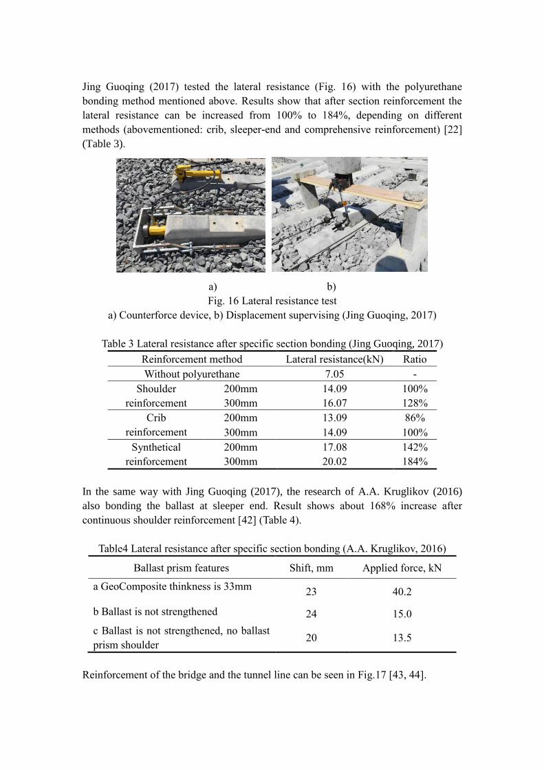
Jing Guoqing (2017) tested the lateral resistance (Fig. 16) with the polyurethane
bonding method mentioned above. Results show that after section reinforcement the
lateral resistance can be increased from 100% to 184%, depending on different
methods (abovementioned: crib, sleeper-end and comprehensive reinforcement) [22]
(Table 3).
a) b)
Fig. 16 Lateral resistance test
a) Counterforce device, b) Displacement supervising (Jing Guoqing, 2017)
Table 3 Lateral resistance after specific section bonding (Jing Guoqing, 2017)
Reinforcement method Lateral resistance(kN) Ratio
Without polyurethane 7.05 -
Shoulder
reinforcement
200mm 14.09 100%
300mm 16.07 128%
Crib
reinforcement
200mm 13.09 86%
300mm 14.09 100%
Synthetical
reinforcement
200mm 17.08 142%
300mm 20.02 184%
In the same way with Jing Guoqing (2017), the research of A.A. Kruglikov (2016)
also bonding the ballast at sleeper end. Result shows about 168% increase after
continuous shoulder reinforcement [42] (Table 4).
Table4 Lateral resistance after specific section bonding (A.A. Kruglikov, 2016)
Ballast prism features Shift, mm Applied force, kN
a GeoComposite thinkness is 33mm 23 40.2
b Ballast is not strengthened 24 15.0
c Ballast is not strengthened, no ballast
prism shoulder 20 13.5
Reinforcement of the bridge and the tunnel line can be seen in Fig.17 [43, 44].

a) b)
Fig. 17 Tack stability:
a) Bridge line (Sadiq Thomas, 2015); b) Tunnel (P K Woodward, 2012)
Sadiq Thomas (2015) studied the XiTRACK reinforced ballasted track on bridge line
by FEM simulation, results show that the maximum displacement contours without
the polymer is 2.1 mm, in contrast, adding a polymer raft with the dimensions as 8m
×3m, at a depth of 300 mm below the sleeper bottom, reduced the contour
displacements to 1.8 mm. Besides, polyurethane reinforcement reduced the stress on
the crown of the arch from 35 kPa at a load of 150 kN to 25 kPa (i.e. a reduction of
approximately 30%). As shown in Fig. 18 [43].
a) b)
Fig. 18 Displacement and vertical stress performance with and without polyurethane
above the arch. a) Plot of displacement distribution b) Plot of vertical stress
Xing Ling (2018), using energy method, analyzed the characteristics of
polyurethane-ballast based on the field tests and DEM simulations. Results show that
there are 4 main forms of energy, including elastic strain energy, viscous strain energy,
friction energy and dashpot energy. The elastic strain energy decreased at power rate
under the quasi-static load, while the remaining forms of energy decayed
exponentially. Four kinds of energy showed exponential attenuation under the
trainload. The friction energy and elastic strain energy had a higher proportion on the
bottom of sleeper. The viscous strain energy and dashpot energy had a higher
proportion on the side of sleeper [45] (Fig. 19).

Fig.19 Energy change diagram (Xing Ling, 2018)
Andrew Keene (2013) use RPF (Rigid-Polyurethane Foam) reinforcement method
with internal injection as Fig.20 [32]. The internal injection needs three-step
construction including the removing ballast above the height of the sleeper bottom,
then polyurethane spraying and ballast backfill.
Fig. 20 Internal injection (Andrew Keene, 2013)
This method also is used by CARS in China railway construction using large spraying
machine in fig.1 (b), and it is already applied in Shanghai to Kunming high-speed
railway construction as a method of ballasted track reinforcement on large-span
bridge. Lateral and longitudinal resistance is tested, as follows Fig. 21.
Fig. 21 Lateral and longitudinal resistance tests (CARS, 2017)

In addition, Andrew Keene (2013) conducted cyclic triaxial tests and simulation of the
track response based on FEM using RPF foam. Polyurethane-stabilized ballast (PSB)
showed a significant reduction in accumulation of plastic strain during cyclic triaxial
tests but also displayed a somewhat lower resilient modulus than the host ballast
modeling [33] (Fig. 22).
Fig.22 FEM simulation (Andrew Keene, 2013)
CARS tested the accumulated deformation influenced by train passage, results show
that after polyurethane reinforcement, the deformation largely decreased, as follows
Fig. 23. After foamed polyurethane reinforcement, the accumulation deformation of
high-speed and heavy haul railway shows similar trend. Whereas, before
reinforcement, the data of heavy haul was much bigger. As a result, polyurethane
increases the transportation capability and prolongs the life of ballasted track.
Fig. 23 Accumulated deformation- total passage curve (CARS)
3.4 Settlement
J. Kennedy (2013) analyzed permanent settlement after foamed polyurethane
reinforcement by dynamic loading test. Results predicted settlement curve which
highlights the significant reduction in track settlement (99% over 500,000 cycles or
18.5MGT) that can be achieved using polymer reinforcement of the ballasted track
[46] (Fig. 24).

a) b)
Fig.24 Dynamic load test
a) GRAFT (Heriot-watt University), b) Settlement test result (J. Kennedy, 2013)
P K Woodward (2014) also using GRAFT which showed a marked increase in track
stiffness when the polymer was applied. It is likely that the improvement was around
40% for the particular polymer, loading level and ballast depth applied [47].
3.5 Others
The usage of polyurethane in railway not just confined to ballasted track, but also in
other application such as Neoballast made by sticking rubber particles on the cover of
ballast by polyurethane. This environmental friendly innovation can reduce ballast
degradation, compared to the normal ballast, about 15% decrease in LAA can be
observed. As a consequence, ballast lifespan is extended. In addition, rubber which is
an elastic material, improving noise and vibration performance of the track [48] (Fig.
25).
Fig.25 Neoballast (by COSMA, MAPEI, UPC, ADIF, 2015)

4. Summary of present research
Table5 Summary of present researches
Organization Author Year Keyword Method
Unfoamed polyurethane reinforcement
Heriot-watt university
(HWU)
P K Woodward
[41,44,47,49,51] 2007-2014
Xi Track three-dimensional track
reinforcement, bridge, station and tunnel line,
crossing and turnouts, shoulder reinforcement,
track response, settlement
FEM simulations, box tests
(GRAFT), Application analysis
Sadiq Thomas [43] 2015 Xi track, masonry arch bridge reinforcement FEM simulations
University of Zagreb Stjepan Lakuši [34] 2010 Reinforcement function, Stiffness adjustment Application analysis
University of Illinois at
Urbana-Champaign (UIUC)
Dersch S. Marcus
[21] 2010
Elastotrack (from BASF), shear strength,
aggregate breakage and degradation Direct shear tests, powdering tests
China Railway 23th Bureau
Group CO,. LTD Yang Jianming [50] 2011 Stiffness adjustment in transition zone Support stiffness test
Beijing Oriental Yuhong
Waterproof Technology
Co.Ltd
Li Hongying [23] 2013 Chemical and solidification characteristics Laboratory tests
Massachusetts Institute of
Technology (MIT)
Sakdirat Kaewunruen
[52] 2014 Dynamic responses, bridge end In-situ vibration suppression
China Academy of Railway
Sciences (CARS)
Industrial standard
[25] 2014
Technical requirements, test method,
inspection criterion, construction, package and
transportation.
Based on tests and operation
Wang Hong [53] 2015 Transition adjustment, bonding effect Application analysis
Qie Luchao 2017
Maintenance method, deformation, stiffness,
lateral resistance, deterioration, bridge line,
spraying machine(train),
Full-scale cyclic loading tests,
lateral and longitudinal resistance
tests, in-situ stiffness tests
Beijing Jiaotong university
(BJTU)
Jing Guoqing [22, 23] 2015-2017
specific section bonding, surface bonding,
tamping availability, ballast flight prevention,
compression strength
Lateral resistance tests, uniaxial
compression tests
Xiao Hong [40] 2017 full-section bonding Lateral resistance tests and DEM
simulations

Xing Ling [45] 2018 energy method Field tests, DEM simulations
Rostov State Transport
University A.A. Kruglikov [42] 2017 Shoulder reinforcement Lateral resistance
Korea Railroad Research
Institute Su Hyung Lee [31] 2017 Strength, stiffness, estimated equations Large-scale triaxial test
Foamed polyurethane reinforcement
University of Wisconsin–
Madison (UW-Madison)
Andrew Keene
[24,32,33] 2012-2013
Rigid Polyurethane Foam (RPF) to, Internal
injection, compression strength, plastic and
elastic deformational Behavior
Compression tests, monotonic and
cyclic flexure tests
University of Pretoria (UP) R F du Plooy
[54,55] 2016-2017 RPF, settlement, resilient modulus Cyclic loading ballast box tests
Other use or material
Goldschmidt-Thermit-Group Company brochure
[26] 2007
GREBOPOX®/ AgriTec® EWR-Winter
(epoxy resin), ballast stabilization Application analysis
COSMA, MAPEI,
Universitat Politècnica de
Catalunya (UPC), ADIF
Consortium report
[48] 2015 Neo-Ballast, recycled rubber Application analysis
The University of
Nottingham G. D’Angelo [27-29] 2016-2017 Bitumen reinforcement Laboratory tests

5. Challenge and Solution
Through present research and application, polyurethane reinforced technique still has
some challenges, mainly in cost, maintenance, drainage, and construction.
5.1 Cost
Polyurethane is a kind of expensive material so that the cost of full-section
reinforcement can equal to the cost of ballast, nearly 150 thousand (EURO) per
kilometer, and its high price restricts to polyurethane ballasted track application.
However, spraying method innovations provided a new thought such as reinforcing
the most variable part instead of whole section. For example, using specific section
bonding by Jing Guoqing, the cost of polyurethane can be reduced more than 70%,
comparing to full-section bonding. Besides, the specific bonding methods are flexible
to select according to construction conditions, thus avoiding the disadvantages of
polyurethane abuse, such as excess stiffness increase.
Secondly, one cost reduction method is prefabrication the polyurethane-ballast unit in
factory, and transported to construction site. The method avoids employing the usage
of special train for polyurethane ballasted track injection, which is quite expensive.
Last, recycled rubber crumb are used into the polyurethane ballasted track with aim to
reduce the volume of polyurethane.
5.2 Maintenance
Maintenance availability or how to carry daily maintenance is a main problem of
polyurethane reinforcement, due to the high bonding strength and wide spraying area,
especially for full-section bonding. In contrast P K Woodward (2011), A.A. Kruglikov
(2016), Jing Guoqing (2017,0218) proposed to use specific section reinforcement
method which already shows its maintenance availability, as mentioned above
[22,23,35,36].
Furthermore, some kinds of methods which can avoid or settle this problem are put
forward. CARS developed a geometry adjust method, as shown in Fig.26. This
maintenance method includes 4 processes. First, lift the rail and sleeper to a designed
height, second, place the model and filling in ballast by ballast-blowing machine,
third, pouring polyurethane, and last, dismantle the model after solidification. Along
with the height adjustment of fasteners, geometry problems in operation can be
settled.

a)
b)
c)
d)
Fig.26 Geometry adjustment method
a) Lift the rail and sleeper to a designed height, b) Place the model and filling in
ballast, c) Pour polyurethane, d) Dismantle the model after solidification
Moreover, the dismantlement in some occasions is needed, especially on how to treat
polyurethane-ballast with no toxic substance waste. However, French researchers
developed a kind of organic ballast polyurethane which can degrades with no poison
residual under natural condition, most of ballast glue materials still made out of
polyurethane.
Lastly, recycling of polyurethane ballasted track. The method used by CARS is
cooperated with chemical industry, after removing polyurethane-ballast form track,
polyurethane-ballast will be sent to the separation equipment, by which big block is
crushed into small particles, then transporting those particles to cycling center (or
mobile equipment), in this process, thermal degraded actions clean the polyurethane
cover of ballast, and gas emissions can be treated by exist chemical method with no
harmful waste. As shown in Fig.27 [56].

Fig. 27 Treatment method of polyurethane-ballast (CURRENTA)
5.3 Drainage
Another problem is drainage of ballasted track. Under dynamic loading, water related
pumping effect which is vital to safety. For unfoamed polyurethane, the bonding
function shown in Fig.2 can prove that this kind of reinforcement does not affect
drainage. At the same time, Jing Guoqing (2012) tested the drainage property of
polyurethane-ballast cubic specimen, and got the same result [3]. However, the
spraying condition should be free of water strictly. As for foamed polyurethane, there
is no research that illustrates its drainage property.
5.4 Construction
Finally, construction time restrict train operation, especially for maintenance. The
hardness process of polyurethane needs approximately 15 to 30 minutes, although
catalyzer can adjust to a shorter time, the spraying instruments do not allow due to the
possibility of pipe get bonded. This means after spraying, speed of passage should be
declined adopted with, thus affects operation. To solve this problem, prefabrication
seems to be a good way. Ballasted track can be constructed by prefabricated
polyurethane-ballast blocks and straightly changing those blocks can be a
maintenance method.
6. Conclusion
Polyurethane reinforced ballasted track has shown great application prospect,
becoming a new kind of track type and attracted researcher’s attention. This paper
concludes current outcomes, analyses the characteristic of polyurethane and
polyurethane-ballast, and introduces the function/application of polyurethane
reinforcement. Besides, challenges and possible solutions are put forward. Main

conclusions are as follows:
(1) Polyurethane used in railway system has two types, i.e. foamed and unfoamed
materials, and both contain two components. When components of A and B mixed 1:1
by volume, chemical reaction occurred, thus bonding ballast particles.
(2) Polyurethane solidification is within 15-30 minutes, but it will take 7-day or
longer to reach the final strength, whereas catalyzer can help speeding up this process.
(3) Polyurethane spraying methods including 4 kinds. full-section bonding can
increase track stability with the maximum ratio between different methods, but
without tamping ability. In contrast, specific section, surface and internal bonding
solve or avoid tamping problem.
(4) polyurethane bonding optimize the contact characteristics between ballast and
sleeper, the entire functions including the ballast flight prevention, enhancement of
lateral resistance in curve, tunnels, and station, stability of ballast under rail joint,
turnout, bridge and crossings, and adjustment of stiffness in transition zones.
(5) By far, challenges about cost, maintenance availability, drainage and construction
restrict the application of the polyurethane reinforcement. However, some of those
problems are settled, further researches are still needed to improve the
polyurethane-ballasted track.
Acknowledgments The paper was supported by the Natural Science Foundation of China (Grant No.
51578051) and China Scholarship Council.

References [1] Indraratna B, Salim W, Rujikiatkamjorn C. Advanced rail geotechnology–ballasted
track. CRC press, 2011.
[2] Sañudo R, Dell'Olio L, Casado JA, Carrascal IA, Diego S. Track transitions in
railways: A review . Construction and Building Materials. 2016;112:140-57.
[3] Jing Guoqing. Railway Ballasted Track. Beijing: CHINA RAILWAY
PUBLISHING HOUSE, 2012. (in Chinese)
[4] M. Sol-Sánchez, D'Angelo G. Review of the design and maintenance technologies
used to decelerate the deterioration of ballasted railway tracks. Construction &
Building Materials, 2017, 157:402-415.
[5] Gautier P. Slab track: Review of existing systems and optimization potentials
including very high speed. Construction and Building Materials. 2015;92:9-15.
[6] G.P. Raymond, D.R. Williams, Repeated load triaxial tests on a dolomite ballast
[J]. Geotech. Eng. Div. ASCE. 104 (1978) 1013–1029.
[7] W.F. Anderson, P. Fair, Behavior of railroad ballast under monotonic and cyclic
loading, J. Geotech. Geoenviron. Eng. 134 (2008) 316–327.
[8] B. Aursudkij, G.R. McDowell, A. Collop, Cyclic loading of railway ballast under
triaxial conditions and in a railway test facility, Granul. Matter. 11 (2009) 391–
401.
[9] C. Chen, G.R. McDowell, N. Thom, Discrete element modelling of cyclic loads of
geogrid-reinforced ballast under confined and unconfined conditions, Geotext.
Geomembr. 35 (2012) 76–86.
[10] M. Sol-Sánchez, F. Moreno-Navarro, M. Rubio-Gámez, The use of deconstructed
tires as elastic elements in railway tracks, Materials (Basel). 7 (2014) 5903–5919,
http://dx.doi.org/10.3390/ma7085903.
[11] M. Sol-Sánchez, F. Moreno-Navarro, M.C. Rubio-Gámez, The use of
deconstructed tire rail pads in railroad tracks: Impact of thickness, Mater. Des. 58
(2015) 198–208.
[12] S. Kaewunruen, A.M. Remennikov, An experimental evaluation of the
attenuation effect of rail pad on flexural behaviour of railway concrete sleeper
under severa impact loads, in: Proceeding 2008 Aust. Struct. Eng. Conf.,
Melbourne, Australia, 2008.
[13] R. Schilder, USP-Under Sleeper Pads. Applications and Benefits of Elastic
Elements in Ballasted Tracks, Paris, 2006.
[14] S. Witt, The Influence of Under Sleeper Pads on Railway Track Dynamics, in:
Proceeding Linköping Univ. Dep. Manag. Eng. Div. Solid Mech., Sweden, 2008.
[15] P.F. Teixeira, State-of-the-Art on the Use of Bituminous Subballast on European
High- Speed Rail Lines, in: Congr. Bear. Capacit. Roads, Railw. Airfiels,
Barcelona, Spain, 2009.
[16] UIC, Code 719-1 Recommendations for the use of under ballast mats, 2011.
[17] C. Atalar, B.M. Das, E.C. Shin, D.H. Kim, Settlement of geogrid-reinforced
railroad bed due to cyclic load, in: Procedings 15th Int. Conf. Soil Mech. Geotech.
Engg., Istanbul, 2001: pp. 2045–2048.

[18] G.R. McDowell, O. Harireche, H. Konietzky, S.F. Brown, N. Thom, Discrete
element modelling of geogrid-reinforced aggregates, Proc. ICE – Geotech. Eng.
159 (2006) 35–48, http://dx.doi.org/10.1680/geng.2006.159.1.35.
[19] Thompson D., PK Woodward. Track stiffness management using the XiTRACK
geocomposite. Permanent Way Institution Journal, 2004, 122, Part 3, 135–138.
[20] Hicks S, Bower D, Leberfinger M. Elastomeric Revetments–An Innovative
Solution for Coastal Protection and Erosion Control. The Center for the
Polyurethane Industry (CPI), 2008.
[21] Dersch MS, Tutumluer E, Peeler CT, Bower DK. Polyurethane coating of
railroad ballast aggregate for improved performance. 2010: Joint Rail Conference.
Urbana, Illinois, USA: 2010.
[22] Jing Guoqing, JIA Wenli, FU Hao. High Speed Ballasted Railway Track Lateral
Resistance Characteristics and Reinforcement. Journal of Southwest Jiaotong
University. 2017. (in Chinese, on line)
[23] Jing Guoqing, JIA Wenli, FU Hao, Li Hongying. Study on the availability of
special polyurethane for high-speed railway ballast flight prevention. Journal of
Railway Engineering Society. 2018. (in Chinese, accepted)
[24] Andrew Keene, Edil TB, JamesTinjum M. Mitigating Ballast Fouling Impact and
Enhancing Rail Freight Capacity. 2012.
[25] TJ/GW 115-2013. Tentative specification of foamed polyurethane cured ballasted
track bed. Beijing: China railway publishing house, 2014
[26] Goldschmidt-Thermit-Group. Product brochure. 2007.
http://www.gt-railservice.com/fileadmin/user_upload/PDF/Gleisservice/Schotters
tabilisierung_DE-EN.pdf
[27] G. D’Angelo, N. Thom, D. Lo, Presti, Bitumen stabilized ballast: a potential
solution for railway track-bed, Construction and Building Materials. 124 (2016)
118–126.
[28] G. D’Angelo, N. Thom, D. Lo Presti, Optimisation of bitumen emulsion
properties for ballast stabilisation, Mater. Construcción. 67 (2017).
[29] G. D’Angelo, M. Sol-Sánchez, N. Thom, D. Lo Presti, M.C. Rubio-Gámez,
Bitumen Stabilized Ballast: A Full-Scale Investigation on its Use for Existing and
Newly Constructed Railway Trackbeds, in: Transp. Res. Board Annual Meeting.
2017.
[30] G. D’Angelo, Miguel S S, Fernando M N, et al. Use of bitumen-stabilised ballast
for improving railway track bed conventional maintenance. Géotechnique, 2017,
68(6).
[31] Su HL, Lee SJ, Park JG, Choi YT. An experimental study on the characteristics
of polyurethane-mixed coarse aggregates by large-scale triaxial test. Construction
and Building Materials. 2017(145):117-25.
[32] Andrew Keene JTTE. Railway Substructure Stabilization with Polyurethane
Injections. 2012.
[33] Andrew Keene, Edil T, Fratta D, Tinjum J. Modeling the Effect of Polyurethane
Stabilization on Rail Track Response. Geo-Congress 2013. San Diego, USA2013.
1410-9. Pages.

[34] Lakušić S, Ahac M, Haladin I. Track stability using ballast bonding method. The
10th Slovenian Road & Transportation Congress. Portoroz, Slovenia2010.
[35] C Baker. A review of train aerodynamics Part 2 – Applications. Aeronautical
Journal -New Series-, 2014,118(1202):345-382.
[36] Kwon H B, Park C S. An experimental study on the relationship between ballast
flying phenomenon and strong wind under high speed train. Proceedings of the
World Congress on Rail Research, Montreal, QC, Canada. 2006.
[37] Kwon H B, Park C S. Substructure flow analysis and experiments of high speed
train for researching the mechanism of ballast dispersion. Proceeding of Korean
Socirty for railway, 2003(3):275-280.
[38] Kaltenbach H J, Portillo I A, Schober M. A generic train-underfloor experiment
for CFD validation. BBAA VI International Colloquium on: Bluff bodies
aerodynamics and applications. 2008: 20-24.
[39] Ding Dong. High Speed Railway Ballasted Track Aerodynamics Research Based
on Wind Tunnel Test and CFD Simulation. Beijing Jiaotong University.2017
[40] Xiao Hong, Ling Xing. Experiment and DEM analysis of lateral resistance of
glued ballast [J]. Journal of Southwest Jiaotong University. 2017;6(52):1046-54.
[41] PK Woodward, Kennedy J, Medero GM, Banimahd M. Application of in situ
polyurethane geocomposite beams to improve the passive shoulder resistance of
railway track. Proceedings of the Institution of Mechanical Engineers Part F
Journal of Rail & Rapid Transit. 2011;3(226):294-304.
[42] Kruglikov AA, Yavna VA, Ermolov YM, Kochur AG, Khakiev ZB.
Strengthening of the railway ballast section shoulder with two-component
polymeric binders. Transportation Geotechnics. 2017(11):133-43.
[43] Sadiq Thomas, PK Woodward, Laghrouche O. Influence of stiffening ballasted
track bed overlying a masonry arch bridge using a polyurethane polymer material
[J]. Construction & Building Materials. 2015(92):111-7.
[44] PK Woodward, Kennedy J, Medero GM, Banimahd M. Maintaining absolute
clearances in ballasted railway tracks using in situ three-dimensional
polyurethane GeoComposites. Proceedings of the Institution of Mechanical
Engineers Part F Journal of Rail & Rapid Transit. 2012(226):257-71.
[45] Ling X, Xiao H, Cui X. Analysis of mechanical properties of polyurethane-mixed
ballast based on energy method. Construction & Building Materials, 2018,
182:10-19.
[46] Kennedy J, PK Woodward, Medero G, Banimahd M. Reducing railway track
settlement using three-dimensional polyurethane polymer reinforcement of the
ballast. Construction & Building Materials. 2013;3(44):615-25.
[47] PK Woodward, Kennedy J, Laghrouche O, Connolly D, Medero G. Study of
railway track stiffness modification by polyurethane reinforcement of the ballast.
Transportation Geotechnics. 2014;4(1):214-24.
[48] COSMA, MAPEI, Universitat Politècnica de Catalunya (UPC), ADIF.
Neo-ballast.2015.
[49] PK Woodward, Thompson D, Banimahd M. Geocomposite technology: reducing
railway maintenance. Proceedings of the Institution of Civil Engineers -

Transport. 2007;160(3):109-15.
[50] Yang Jianming. The application and construction of polyurethane adjustment in
transition zone. Railway engineering. 2011(2):111-113.(in Chinese)
[51] PK Woodward, Kacimi AE, Laghrouche O, Medero G, Banimahd M. Application
of polyurethane geocomposites to help maintain track geometry for high-speed
ballasted railway tracks. Journal of Zhejiang University SCIENCE A.
2012;11(13):836-49.
[52] Kaewunruen S. Dynamic Responses of Railway Bridge Ends: A Systems
Performance Improvement by Application of Ballast Glue/Bond. The Second
International Conference on Railway Technology: Research. Ajaccio, Corsica,
France, 2014.
[53] Wang Hong. The application and development of polyurethane reinforcement in
ballasted track. Railway engineering. 2015(4):135-140. (in Chinese)
[54] Du Plooy RF, Gräbe PJ. characteristion of rigid polyurethane foam reinforced
balloast through cyclic loading box tests. Journal of the South African Institution
of Civil Engineers. 2016;2(59):2-10.
[55] Du Plooy RF, Be PG, Turner C. Laboratory characterisation of rigid polyurethane
foam reinforced ballast. The 10th International Conference on the Bearing
Capacity of Roads. Athens, Greece, 2017.
[56] CURRENTA. Incineration plants brochure.
https://www.currenta.com/tl_files/currenta/medien/currenta/downloads/pdf/CUR_
Verbrennung_d.pdf