Polarization properties of symmetrical and asymmetrical nonreciprocal chiral photonic bandgap...
23
1 Polarization properties of a symmetrical and asymmetrical nonreciprocal chiral photonic bandgap structure with defect Vladimir R. Tuz * Department of Theoretical Radio Physics, Kharkov National University, Svobody Square 4, Ukraine * Corresponding author: [email protected] , [email protected] The polarization properties of perfectly periodical and defective one-dimensional photonic bandgap structures with nonreciprocal chiral (bi-isotropic) layers are studied. The method of solution is based on the 2 2 × -block-representation transfer-matrix formulation. Numerical simulations are carried out for different type of structures (symmetrical or asymmetrical) in order to reveal the dependence of the reflection and transmission coefficients on frequency, chirality, nonreciprocity parameters, and the angle of wave incidence. OCIS code: 160.1585, 230.4170, 260.5430. 1. INTRODUCTION The research on artificial chiral media has been especially intense within microwaves in the past two decades [1-4], and chirality is an example of novel material effects at best. In general, the nonreciprocal chiral (bi-isotropic) media are defined via the following constitutive equations where the electric and the magnetic inductions are related to the electromagnetic field intensity
-
Upload
kharkov-ua -
Category
Documents
-
view
2 -
download
0
Transcript of Polarization properties of symmetrical and asymmetrical nonreciprocal chiral photonic bandgap...

1
Polarization properties of a symmetrical and asymmetrical
nonreciprocal chiral photonic bandgap structure with defect
Vladimir R. Tuz*
Department of Theoretical Radio Physics, Kharkov National University, Svobody Square 4,
Ukraine
*Corresponding author: [email protected], [email protected]
The polarization properties of perfectly periodical and defective one-dimensional photonic
bandgap structures with nonreciprocal chiral (bi-isotropic) layers are studied. The method
of solution is based on the 2 2× -block-representation transfer-matrix formulation.
Numerical simulations are carried out for different type of structures (symmetrical or
asymmetrical) in order to reveal the dependence of the reflection and transmission
coefficients on frequency, chirality, nonreciprocity parameters, and the angle of wave
incidence.
OCIS code: 160.1585, 230.4170, 260.5430.
1. INTRODUCTION
The research on artificial chiral media has been especially intense within microwaves in the past
two decades [1-4], and chirality is an example of novel material effects at best. In general, the
nonreciprocal chiral (bi-isotropic) media are defined via the following constitutive equations
where the electric and the magnetic inductions are related to the electromagnetic field intensity

2
via the permittivity, permeability and magnetoelectric interaction parameters (the gyration
parameters in terms of crystalloptics):
= ε + ξD E H , = μ + ζB H E . (1)
Here iξ = χ + ρ and iζ = χ − ρ ; χ describes the degree of inherent nonreciprocity in the medium
(Tellegen parameter), ρ is a measure for handedness of the material (chirality parameter). As
known, the eigenwaves in homogeneous chiral media are two circularly polarized (right- and
left-handed) waves which exhibit some interesting behaviors [4]. Thus, the real part of the
chirality parameter ρ defines the optical rotatory dispersion, which causes a rotation of
polarization due to different phase velocities of the right- and left-handed circularly polarized
wave. Then, the imaginary part of ρ and Tellegen parameter χ define the circular dichroism,
which modifies the nature of polarization of the propagating wave by causing an ellipticity (due
to a difference between the absorption coefficients of the right- and left-handed circularly
polarized waves and nonorthogonality of electric and magnetic field vectors). The effect of the
optical activity in chiral media can by so strong, that the refractive index becomes negative, even
if the permittivity ε and permeability μ are both positive. Specifically, this negative refraction
may occur for one circularly polarized wave (backward wave), while for the other circular
polarization the refractive index remains positive. These properties have attracted considerable
attention to chiral media and may open new potential applications in optics [5-8].
In the present paper, we consider the chiral media in their application to constructing
photonic bandgap crystals [9-11]. There are a lot of publications where both ideally periodic and
quasi-periodic [12-14] photonic crystals are studied, including the group of chiral photonic
crystals [15-19]. In view of the mentioned above behaviors of chiral media, the chiral photonic
crystals possess rich optical properties and are characterized by the selective reflection in a

3
specific waveband in addition to circular polarization of the reflected and transmitted light. Such
artificial structures are widely used in the modern integrated optics and optoelectronics, laser
techniques, millimeter and submillimeter wave devices, and optical communications.
Nonreciprocal photonic structures are also of special interest. The nonreciprocity is a
comparable effect to the chirality from theoretical point of view, but in terms of manufacturing
real-life samples, nonreciprocal materials are not as advanced [3]. It is known that, externally,
the nonreciprocity can be created by a static magnetic field in ferrites or plasmas, but in those
cases the medium is anisotropic. In recent years, some new mechanisms of obtaining
nonreciprocity have been proposed [20, 21] in addition to natural nonreciprocal materials [22,
23]. In particular, the importance of nonreciprocal photonic crystals is related, to possibility of
creating omnidirectional reflectors, optical diodes, and etc. [24-26]. The optical diode is a device
transmitting light in one direction and blocking it in the reverse direction (i.e., characterized by a
nonreciprocal transmission). Various types of optical diodes have been proposed. The well-
known optical insulator based on linear polarizers and Faraday rotator is characterized by a low
level of losses and a high ratio of the direct transmission to the reverse attenuation. Optical
diodes can also be based on combinations of some other effects [7, 27].
The present paper is devoted to study of both one-dimensional perfectly periodic chiral
photonic structures and those containing a defect, with taking into account the media
nonreciprocity. We also consider an asymmetric defective structure which has two multilayer
sections with the mirror handedness of chirality and nonreciprocity parameters on either sides of
the defective element for the purpose of the optical diodes constructing. The method of solution
is based on the 2 2× -block-representation transfer-matrix formulation proposed earlier in [18].

4
2. PERFECTLY PERIODIC NONRECIPROCAL CHIRAL PHOTONIC
STRUCTURE
Let’s first consider a finite one-dimensional periodic structure of N basic elements (periods)
(Fig. 1). Each of periods includes a homogeneous isotropic (with permittivities 1ε , 1μ ) and bi-
isotropic (with 2ε , 2μ , ξ , ζ ) layers with thicknesses 1d and 2d , respectively. The total length of
structure period is 1 2L d d= + . In general, the material parameters 1ε , 1μ , 2ε , 2μ , χ , ρ are
frequency dependent and complex for lossy media. In a particular case of ρ ≠ 0 , χ = 0 the
structure layers are chiral and reciprocal (the Pasteur layers), when ρ = 0 , χ ≠ 0 they are achiral
and nonreciprocal (the Tellegen layers). The outer half-spaces 0z ≤ and z NL≥ are
homogeneous, isotropic and have permittivities 0ε , 0μ and 3ε , 3μ , respectively.
As the excitation fields, the plane monochromatic waves ( )exp i t− ω⎡ ⎤⎣ ⎦ with perpendicular
( 0||eE x , 0exH = , s e= ) or parallel ( 0||hH x , 0h
xE = , s h= ) polarization are selected. They are
obliquely incident from the region 0z ≤ at an angle 0ϕ to the z axis.
Making use of the transfer-matrix formalism [28], the equation coupling the field
amplitudes at the structure input and output for the incident fields of E type ( s e= ) and H type
( s h= ) is obtained in [18] as
( ) ( )10 1 01 1 01 13 1
N NN N N
−+ + += = =V TV T T T V T T T V , (2)
where { }'0 0 0 00Ts s sA B B=V and { }'
1 1 10 0Ts s
N N NA A+ + +=V are vectors containing the
field amplitudes at the structure input and output, T is the matrix transpose operator, 01T , T , T
are the transfer-matrices of the illuminated boundary, the repeated heterogeneity, and the last
element, which is loaded on the waveguide channel having the admittance 3sY . We denote here

5
sA , 'sA and sB , 'sB as the amplitudes of co-polarized ( s ) and cross-polarized ( 's ) components of
the transmitted and reflected fields, respectively. The elements of the transfer-matrices (2) are
determined from solving the boundary-value problem and are presented in [18, 29].
The algorithm from the matrix polynomial theory [30] for raising the matrix T to the
power N was introduced in [31] to study the structure with a large number of periods ( 1N >> )
4
0 01 13 11
Nn n N
n+
=
⎡ ⎤⎛ ⎞= λ⎢ ⎥⎜ ⎟
⎝ ⎠⎣ ⎦∑V T F T V . (3)
Here nλ are the eigenvalues of the transfer-matrix T , 1n n
−=F PI P , P is the matrix which
columns are the set of independent eigenvectors of T , nI is the matrix with a 1 in the ( , )n n
location and zeros elsewhere.
From (3), the required reflection and transmission coefficients are determined by the
expressions 0 0ss s sR B A= , 1 0
ss s sNA A+τ = and ' '
0 0ss s sR B A= , ' '
1 0ss s s
NA A+τ = for the co-polarized
and cross-polarized waves, respectively.
The parametrical dependences of the reflection and transmission spectra of plane
monochromatic waves of the finite structure with bi-isotropic layers have interleaved areas with
high (the stopbands) and low (the passbands) average level of the reflection (Figs. 2 and 3). Due
to an interference of the reflected waves from outside boundaries of layers 1N − small-scale
oscillations appear in the passbands.
As known, the eigenwaves of an infinite convenient isotropic medium have transverse
magnetic and transverse electric polarizations, or their linear combinations, and, in general, they
have the elliptical polarization. On the other hand, in a bi-isotropic medium, fields can be split
into left- and right-hand circularly polarized eigenwaves which have different propagation
constants ±γ , and each of this eigenwaves sees the medium as if it were an isotropic medium

6
with equivalent parameters ±ε and ±μ [2, 18, 29]. Right- and left-hand circular polarizations are
also the eigenwave polarizations in cholesterics. However, while the photonic band gap in
cholesterics exists only for one circular polarization that coincides with the chirality sign of the
medium, in chiral periodic media both circular polarizations are diffracting polarizations. From
this characteristic of chiral periodic structures follows the independence of their reflection
spectra from the chirality parameter ρ in case of normal wave incidence; a chiral periodic
structure and an achiral one with the same parameters are characterized by identical reflection
and transmission spectra (the stopband and passband positions). The medium chirality causes
only change the rotation of polarization plane of the transmitted wave. The theoretical angle of
the polarization rotation in a chiral medium is given by 0Re( )k zα = − ρ [2, 4], where Re( )ρ is
the real part of the chirality parameter, 0k is the wavenumber in free space, and z is the distance
passed by the wave through chiral layers. The complexity of ρ modifies the nature of the
propagating wave by introducing ellipticity. This is due to the different absorption coefficients
for the right- and left-handed circularly polarized waves. The theoretical ellipticity depends on
the imaginary part of the chirality as follows [4]:
[ ]( ) [ ]( )0 0exp 2 Im( ) 1 exp 2 Im( ) 1k z k zη = ρ + ρ − , where η is the ellipticity defined as the ratio
between the major and minor axes of the ellipse, Im( )ρ is the imaginary part of the chirality
parameter. As follows from our numerical calculation, the cross-polarized components of
reflected and transmitted waves are equal to each other | | | |eh heR R= , | | | |eh he=τ τ for the
structure with reciprocal chiral layers (the Pasteur layers). The nonzero value of the
nonreciprocal (Tellegen) parameter ( 0χ ≠ ) causes | | | |eh heR R≠ , and the cross-polarized
component appears in the reflected field even for normal incidence ( 0 0ϕ = ) of the exciting

7
wave. The additional effects by the media nonreciprocality are the transmission spectra
symmetry breakdown related to ρ = 0 and a disturbance of the amplitude of small-scale
oscillations in the passbands for both the co-polarized and cross-polarized waves (Figs. 2 and 3).
At oblique incidence of the exciting wave, the pattern of the structure reflection and
transmission becomes more complicated. The rotation spectra acquire a pronounced diffraction
character: the rotation and ellipticity are heavily suppressed in the photonic band gap and
strongly oscillate near the band gap boundaries. Here, the angle of rotation increases in one
wavelength range and decreases in another. At large angles of incidence, the cross-polarized
components of the reflected and transmitted fields equal zero ( | | | | | | | | 0eh he eh heR R= = = =τ τ ).
Thus, there appears a possibility for the diffraction control of the polarization rotation.
3. SYMMETRICAL AND ASYMMETRICAL NONRECIPROCAL CHIRAL
PHOTONIC STRUCTURE WITH DEFECT
In this section we consider a nonreciprocal chiral photonic structure with a periodicity defect
which is created via replacing the m-th period of the sequence (Fig. 4). In general, material
parameters of periods of both structure sections, coming before and after of the defective element,
are different. Their difference is defined with some prime substitution above the parameter. Thus,
for the first, the last structure sections and the defect element we have: { /2ε , /
2μ , / / /iξ = χ + ρ ,
}/ / /iζ = χ − ρ , { / /2ε , / /
2μ , / /ξ , }/ /ζ and { / / /2ε , / / /
2μ , / / /ξ , }/ / /ζ , respectively. Without loss of
generality, the material parameters of isotropic slabs and the layer thicknesses are left unchanged,
i.e. / / / / / /1 1 1 1ε = ε = ε = ε , / / / / / /
1 1 1 1μ = μ = μ = μ and / / / / / /j j j jd d d d= = = , 1, 2j = . It is defined that the

8
structure is symmetrical when / / /Re( ) Re( )ρ = ρ , / / /Re( ) Re( )χ = χ , and asymmetrical when
/ / /Re( ) Re( )ρ = − ρ or / / /Re( ) Re( )χ = − χ .
Instead of (2), the equation coupling the field amplitudes at the defective structure input and
output is obtained as
( ) ( ){ } ( )4 41 1/ / / / / / / / / / / / / / /
0 01 13 1 01 13 11 1
m N m m N mN n n n n N
n n
− − − −+ +
= =
⎧ ⎫⎛ ⎞ ⎛ ⎞= = λ (λ )⎨ ⎬⎜ ⎟ ⎜ ⎟⎝ ⎠ ⎝ ⎠⎩ ⎭∑ ∑V T T T T T V T F T F T V , (4)
where /T , / /T and // /T are the transfer-matrices of the period of the first and the last structure
sections and the defective element, respectively. Obviously, due to the non-commutativeness the
matrix product, the spectra of the reflected and transmitted fields depend on the defective element
position within the structure.
It is known that the defects inside a layered isotropic one-dimensional sample produce
additional resonance modes (defective modes) in the stopbands. Such defects are widely used to
produce high-Q laser cavities in vertical-cavity-surface-emitting lasers. In analogy to the
isotropic periodic structures, a defect can be produced in a chiral structure by adding an isotropic
layer in middle of a sample (see [31], and its bibliography). In this case, the defective modes also
exhibit a number of important polarization-related features.
The curves of the reflection and transmission spectra of a symmetrical and asymmetrical
bi-isotropic photonic structure with a defective isotropic layer are presented on Figs. 5 and 6,
respectively. For clarity, we consider separately the spectrum properties of the structure of two
types. The structure of the first type consists of achiral, nonreciprocal layers (the Tellegen layers)
[Figs. 5 (a, b) and 6 (a, b)], and the second type are chiral, reciprocal ones (the Pasteur layers)
[Figs. 5 (c, d) and 6 (c, d)]. As can be seen in figs. 5 and 6, in addition to the mentioned above
defective modes in the stopbands, there are some changes in the magnitude of the high-frequency

9
(small-scale) oscillations in the passbands for both types of structures. Those effects are
determined by the composition of the eigenmodes of the structure sections placed before and
after the defective element, and by additional eigenmodes that appear as a result of the wave
polarization transformation [31]. Especially interesting behavior of the perturbation of the
mentioned small-scale oscillations shows for the structure with the Tellegen layers. In this case,
the frequency bands ( 04.0 4.5k L< < , 09.5 10.0k L< < ) of the high reflection of the cross-
polarized field component appear in the passbands. At the same time, the co-polarized
component dominates in the transmitted fields, and eventually, in these bands, we have the cross-
polarized reflection and the co-polarized transmission | | 0ssR ≈ , '| | 0ssR ≠ and | | 0ss ≠τ ,
'| | 0ss ≈τ .
The spectrum properties of the structure with the Tellegen layers in the stopbands are
practically the same as the properties of the convenient defective isotropic periodic structure.
Note only that there are the defective modes in the stopbands of both co-polarized and cross-
polarized components of the reflected and transmitted fields. The reflection (transmission) level
of the cross-polarized defective modes is much less than the co-polarized ones for the
symmetrical structure [Figs. 5 (a) and 5 (b)], and these cross-polarized modes are practically
absent for the asymmetrical structure, i.e. | | 1ss ≈τ [Figs. 6 (a) and 6 (b)].
The defective mode behavior is more interesting in the structure with the Pasteur layers. As
can be seen in figs. 5 (c) and 5 (d), there is a possibility of obtaining different combinations of
the polarization of the reflected and transmitted fields using the symmetrical structure. For
example, for the chosen structure parameters, we have: | | 0ehR ≠ , | | 0eeR ≈ , | | | |ee ehτ τ at
0 2.6k L ≈ and | | | |ee ehR R≈ , | | | |ee eh≈τ τ at 0 11.6k L ≈ . The particular properties of the
asymmetrical structure is that the cross-polarized component of the transmitted field is practically

10
absent in the passbands and stopbands but the significant polarization transformation occurs on the
band gap boundaries. The first effect is determined by the mutual discharging of the polarization
rotation which provides two structure sections placed before and after the defective element with
equal material parameters and mirror handedness. The oblique incidence of the wave and the
mentioned diffraction character of the rotation near the band gap boundaries explain the second
feature.
The further functionality expansion of the structure under study is connected with using of
an anisotropic material to construct the defect. As is well known, in anisotropic media, uniform
plane waves can be decomposed in two orthogonal polarization states (linear or circular) that
propagate with two different speeds. The two states develop a phase difference as they
propagate, which alters the total polarization of the wave. In the subject being discussed, the
anisotropic defect can provide the difference of the defective mode configuration for the co-
polarized and cross-polarized waves. The other way to complicate the spectrum features is an
introduction of the nonlinear defect. It is very important for the optical diode constructing,
because, as usually, the amplitude-frequency characteristic of the diode is strongly nonlinear.
We also study a finite isotropic periodic structure with the bi-isotropic defect. As above, we
consider the nonreciprocal and chiral defects separately. The curves of the reflection and
transmission spectra of the both structures are presented in Figs. 7 (a, b) and 7 (c, d),
respectively. It is seen that the low level cross-polarized component appears in the reflected and
transmitted fields, except in the level of the transmission for the Pasteur defective layer. On the
other hand, the significant polarization transformation appears within the defective modes both
in reflection and transmission. Note the value of the defective layer permittivity is higher than
those in the structure sections ( / / / /2 2ε > ε , / / /
2 2ε = ε ). This condition provides the shifting of the

11
defective mode frequency from the right (left) boundary of the low-frequency (high-frequency)
stopbands.
We do not discuss here the spectral properties of the defective structure with simultaneous
presence of the nonreciprocity and chirality of layers due to the limited size of the publication. It
is clear that the integrated spectra will contain all the mentioned features in their combinations.
4. CONCLUSION
The polarization properties of both perfectly periodical and defective one-dimensional photonic
bandgap structures are studied. The structure period consists of nonreciprocal, chiral (bi-
isotropic) and isotropic layers. The periodicity defect is created via replacing the m-th period of
the sequence with some element whose optical properties are different from the others. This
defective element can be both isotropic and bi-isotropic. Two types of the structure (symmetrical
and asymmetrical) are considered. They differ in the material parameters of periods of structure
sections coming before and after of the defective element. This difference is defined via the
handedness of the material of layers.
The dependences of the reflection and transmission spectra on the frequency,
nonreciprocity, chirality parameters, and the angle of wave incidence are obtained. It is shown
that the introduction of the media nonreciprocity and chirality changes the pattern of the structure
reflection and transmission and causes the availability the cross-polarized component in the
reflected field for the normal wave incidence, the perturbation of the small-scale oscillations in
the passbands, a change of the defective mode configuration.
The width of photonic band gaps, as well as their spectral position and the distance
between them, depend on the parameters of the problem and, thus, can be controlled. Therefore,
such systems can be used as controllable polarization filters and mirrors, optical diodes,

12
polarization transformers, mode discriminators, multiplexers for circularly or elliptically
polarized waves, and sources of circular (elliptical) polarization.
REFERENCES
1. A. Lakhtakia, V. K. Varadan, and V. V. Varadan, Time-Harmonic Electromagnetic Fields in
Chiral Media, Lecture Notes in Physics (Springer-Verlag, 1989).
2. I. V. Lindell, A. H. Sihvola, S. A. Tretyakov, and A. J. Viitanen, Electromagnetic Waves in
Chiral and Bi-Isotropic Media (Artech House, 1994).
3. A. H. Sihvola, “Electromagnetic modeling of bi-isotropic media,” Prog. Electromagn. Res. 9,
45-86 (1994).
4. A. Grande, I. Barba, A. C. L. Cabeceira, J. Represa, P. P. M. So, and W. J. R. Hoefer,
“FDTD modeling of transient microwave signals in dispersive and lossy bi-isotropic media,”
IEEE Trans. Microwave Theory Techn. 52, 773-783 (2004).
5. M. Wegener and S. Linden, “Giving light yet another new twist,” Physics 2, 3 (2009).
6. Y. K. Pang, J. C. W. Lee, H. F. Lee, W. Y. Tam, C. T. Chan, and P. Sheng, “Chiral
microstructures (spirals) fabrication by holographic lithography,” Opt. Express 13, 7615-
7620 (2005).
7. J.-Y. Chen and L.-W. Chen, “Color separating with integrated photonic bandgap optical
diodes: a numerical study,” Opt. Express 14, 10733-10739 (2006).
8. A. Baev, M. Samoc, P. N. Prasad, M. Krykunov, and J. Autschbach, “A quantum chemical
approach to the design of chiral negative index materials,” Opt. Express 15, 5730-5741
(2007).
9. E. Jablonovitch, “Photonic band-gap structures,” J. Opt. Soc. Am. B. 10, 283-295 (1993).

13
10. J. D. Joannopoulos, R. D. Meade, and J. N. Winn, Photonic Crystals: Molding the Flow of
Light (Princeton, 1995).
11. K. Sakoda, Optical properties of photonic crystals (Springer, 2001).
12. M. Kohmoto, B. Sutherland, and K. Iguchi, “Localization in optics: quasiperiodic media,”
Phys. Rev. Lett. 58, 2436-2438 (1987).
13. A. V. Lavrinenko, S. V. Zhukovsky, K. S. Sandomirski, and S. V. Gaponenko, “Propagation
of classical waves in nonperiodic media: Scaling properties of an optical Cantor filter,” Phys.
Rev. E 65, 036621 (2002).
14. T. Okamoto and A. Fukuyama, “Light amplification from Cantor and asymmetric multilayer
resonators,” Opt. Express. 13, 8122-8127 (2005).
15. K. M. Flood and D. L. Jaggard, “Distributed feedback lasers in chiral media,” IEEE J.
Quantum Electron. 30, 339-345 (1994).
16. J. Li, L. Jin, L. Li and C. Li, “Bandgap separation and optical switching in nonlinear chiral
photonic crystal with layered structure,” IEEE Photon. Technol. Lett. 18, 1261-1263 (2006).
17. M. Thiel, G. von Freymann, and M. Wegener, "Layer-by-layer three-dimensional chiral
photonic crystals," Opt. Lett. 32, 2547-2549 (2007).
18. V. R. Tuz and V. B. Kazanskiy, “Depolarization properties of a periodic sequence of chiral
and material layers,” J. Opt. Soc. Am. A 25, 2704-2709 (2008).
19. V. R. Tuz, “Optical properties of a quasiperiodic generalized Fibonacci structure of chiral
and material layers,” J. Opt. Soc. Am. B 26, 627-632 (2009).
20. L. Poladian, “Resonance mode expansions and exact solutions for nonuniform gratings,”
Phys. Rev. E 54, 2963-2975 (1996).

14
21. A. H. Gevorgyan, “Nonreciprocal waves in absorbing multilayer systems,” Techn. Phys. Lett.
29, 819-823 (2003) (Engl. Transl.).
22. D. N. Astrov, “Magnetoelectric effect in chromium oxide,” Sov. Phys. JETP 13, 729-733
(1961).
23. S. Shtrikman and D. Treves, “Observation of the magnetoelectric effect in 2 3Cr O powders,”
Phys. Rev. 130, 986-988 (1963).
24. J. N. Winn, Y. Fink, S. Fan, and J. D. Joannopoulos, “Omnidirectional reflection from a one-
dimensional photonic crystal,” Opt. Lett. 23, 1573-1575 (1998).
25. M. Scalora, J. P. Dowling, C. M. Bowden, and M. J. Bloemer, “The photonic band edge
optical diode,” J. Appl. Phys. 76, 2023-2029 (1994).
26. A. H. Gevorgyan, “Optical diodes and omnidirectional reflectors based on one-dimensional
quasiperiodic photonic crystals,” Techn. Phys. Lett. 34, 22-25 (2008) (Engl. Transl.).
27. J. Hwang, M. H. Song, B. Park, S. Nishimura, T. Toyooka, J. W. Wu, Y. Takanishi, K.
Ishikawa, and H. Takezoe, “Electro-tunable optical diode based on photonic bandgap liquid-
crystal heterojunctions,” Nature Mater. 4, 383-387 (2005).
28. M. Born and E. Wolf, Principle of Optics ( Pergamon, 1968).
29. V. R. Tuz, “Three-dimensional Gaussian beam scattering from a periodic sequence of bi-
isotropic and material layers,” Prog. Electromagn. Res. B 7, 53-73 (2008).
30. L. J. Dickey, “High powers of matrices,” ACM SIGAPL APL Quote Quad. 18, 96-99,
(1987).
31. V. R. Tuz and V. B. Kazanskiy, “Defect modes in a periodic structure with chiral layers,” J.
Opt. Soc. Am. A 26, 815-819 (2009).

15
List of Figure Caption
V. R. Tuz, Polarization properties of a symmetrical and asymmetrical nonreciprocal chiral
photonic bandgap structure with defect
Figure 1 (color online). Finite photonic bandgap structure of isotropic and bi-isotropic layers.
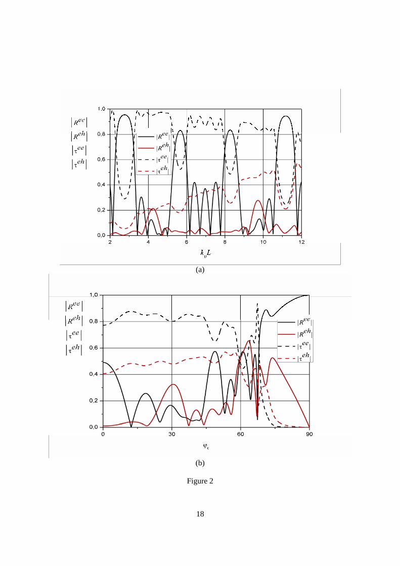
Figure 2 (color online). (a) Frequency and (b) angular dependences of the reflection and
transmission spectra of a finite photonic structure of isotropic and bi-isotropic layers.
1j jε = μ = , 2j ≠ , 2 2ε = , 2 1μ = , 0.1ρ = , 0.05χ = , 1 2 0.5d L d L= = , 5N = . (a) 00 25ϕ = .
(b) 0 10k L = .
Figure 3 (color online). Transmission coefficient magnitude of (a) co-polarized and (b) cross-
polarized waves as function of the frequency 0k L and the chirality parameter ρ for a finite
photonic structure of isotropic and bi-isotropic layers. 1j jε = μ = , 2j ≠ , 2 2ε = , 2 1μ = ,
0.05χ = , 1 2 0.5d L d L= = , 5N = .
Figure 4 (color online). Finite photonic bandgap structure of isotropic and bi-isotropic layers
with periodicity defect.
Figure 5 (color online). (a, c) Reflection and (b, d) transmission spectra of a finite symmetrical
bi-isotropic photonic structure of 19N = periods with the isotropic defect in the middle ( 10m = )
of the structure. 1j jε = μ = , 2j ≠ , / / /2 2 2ε = ε = , / / /
2 1ε = , / / / / / /2 2 2 1μ = μ = μ = , / / / / / / 0ρ = χ = ,
00 25ϕ = , 1 2 0.5d L d L= = . (a, b) The Tellegen layers. / / / 0ρ = ρ = , / / / 0.1χ = χ = . (c, d) The
Pasteur layers. / / / 0.1ρ = ρ = , / / / 0χ = χ = .
Figure 6 (color online). (a, c) Reflection and (b, d) transmission spectra of a finite asymmetrical
bi-isotropic photonic structure of 19N = periods with the isotropic defect in the middle ( 10m = )

16
of the structure. 1j jε = μ = , 2j ≠ , / / /2 2 2ε = ε = , / / /
2 1ε = , / / / / / /2 2 2 1μ = μ = μ = , / / / / / / 0ρ = χ = ,
00 25ϕ = , 1 2 0.5d L d L= = . (a, b) The Tellegen layers. / / / 0ρ = ρ = , / 0.1χ = , / / 0.1χ = − . (c, d)
The Pasteur layers. / 0.1ρ = , / / 0.1ρ = − / / / 0χ = χ = .
Figure 7 (color online). (a, c) Reflection and (b, d) transmission spectra of a finite isotropic
photonic structure of 19N = periods with the bi-isotropic defect in the middle ( 10m = ) of the
structure. 1j jε = μ = , 2j ≠ , / / /2 2 2ε = ε = , / / /
2 3ε = , / / / / / /2 2 2 1μ = μ = μ = , / / / / / / 0ρ = ρ = χ = χ = ,
00 25ϕ = , 1 2 0.5d L d L= = . (a, b) The Tellegen defective layer. / / / 0ρ = , / / / 0.1χ = . (c, d) The
Pasteur defective layer. / / / 0.1ρ = , / / / 0χ = .

17
Figure 1
18
(a)
(b)
Figure 2

19
(a)
(b)
Figure 3

20
Figure 4

21
(a) (b)
(c) (d) Figure 5

22
(a) (b)
(c) (d) Figure 6

23
(a) (b)
(c) (d) Figure 7