Plastics Compounding and Polymer Processing - Hanser ...
84
Sample Pages Plastics Compounding and Polymer Processing Klemens Kohlgrüber, Michael Bierdel, Harald Rust ISBN (Book): 978-1-56990-837-2 ISBN (E-Book): 978-1-56990-838-9 For further information and order see www.hanserpublications.com (in the Americas) www.hanser-fachbuch.de (outside the Americas) © Carl Hanser Verlag, München
-
Upload
khangminh22 -
Category
Documents
-
view
3 -
download
0
Transcript of Plastics Compounding and Polymer Processing - Hanser ...

Sample Pages
Plastics Compounding and Polymer Processing
Klemens Kohlgrüber, Michael Bierdel, Harald Rust
ISBN (Book): 978-1-56990-837-2
ISBN (E-Book): 978-1-56990-838-9
For further information and order see
www.hanserpublications.com (in the Americas)
www.hanser-fachbuch.de (outside the Americas)
© Carl Hanser Verlag, München
The Authors
� The Editors
Klemens Kohlgrüber
Dr. Klemens Kohlgrüber undertook a metalworking appren-ticeship and completed further training as a mechanical en-gineer in Cologne. He studied mechanical engineering in Wuppertal, followed by a diploma and doctorate at RWTH Aachen University. From 1986 to 2015, he worked for Bayer AG, among other things as Head of High Viscosity, Mixing, and Reactor Technology. At the same time, he gave lectures for several years at the University of Dortmund for chemists in the master’s program on polymer processing/preparation. For several years he was head of the High Viscosity Technol-
ogy working group of the Forschungsgesellschaft Verfahrenstechnik (German Re-search Association for Process Engineering) and he is a former member of the Asso ciation of German Engineers (VDI) advisory board for plastics processing technology. Dr. Kohlgrüber also leads annual VDI seminars on extruders.
Michael Bierdel
Dr.-Ing. Michael Bierdel studied process engineering at the University of Stuttgart and received his doctorate in 2001. Since 2001 he has been working in research and develop-ment at Bayer Technology Services GmbH (Bayer AG), now Covestro Deutschland AG (Covestro AG), in the High Viscos-ity Technology group, which he has led since 2012.

VI The Authors
Harald Rust
Dipl.-Ing. Harald Rust (1949–2021) studied mechanical engi-neering in Bochum, Germany. After working in the planning of hydraulic systems from 1976 to 1983, he was head of development for planetary roller extruders, calenders, calan-drettes, and flat film lines at EKK and Battenfeld Extru-sionstechnik at the plant in Bochum. From 1983 to 1985 he was the technical manager in a supplier for the aviation industry where he developed air cargo equipment and trans-port structures for the Ariane 5.
Then, in 1986 ENTEX Rust & Mitschke GmbH was founded. It became the technol-ogy leader in the planetary roller extruder, and was granted numerous patents. Until his passing in January 2021, he was the owner and managing director of ENTEX Rust & Mitschke GmbH, with approximately 150 employees.
� The Coauthors
Section Title Author*3.1 Fundamentals of Devolatilization � Dr.-Ing. Heino Thiele, formerly of BASF3.5 Degassing of Polymers in Purge Bins � Dr.-Ing. Harald Wilms, Wilms-ITC, Bremen
� Dipl.-Ing. Hans Schneider, Zeppelin Systems GmbH, Friedrichshafen
4.1 Compounding Requirements from the Compounder’s Perspective
� Thomas Schuldt, MOCOM Compounds GmbH & Co. KG, Hamburg
4.2 Product Development4.3 Additives for Polymers – From Poly-
mer to Plastic � Hermann Diem
5.2 Tasks and Design of the Processing Zones of a Compounding Extruder
� Dr.-Ing. Reiner Rudolf, Covestro Deutschland AG
� Dr.-Ing. Michael Bierdel, Covestro Deutsch-land AG
5.3 Process and Screw Concepts for Machines with High Throughputs
� Frank Lechner, Coperion
5.4 Screw Designs for Highly Filled Poly-mers (and Dosing Strategies)
� Sebastian Fraas, Leistritz Extrusionstechnik GmbH, Nuremberg
5.5 Compounding of Natural Fiber Rein-forced Plastics
� Dijan Iliew � Dr. Stephen Kroll � Prof. Dr.-Ing. Andrea Siebert-Raths � HS Hannover

VIIThe Authors
Section Title Author*5.6 Fundamentals of Thermoplastic
Foam Extrusion by Means of Parallel Twin-Screw Extruders
� Lukas Vogel, Leistritz Extrusionstechnik GmbH, Nürnberg
5.8 Materials, Coatings, Wear Technology � Dr. Oliver Kayser, Dreistegen GmbH6.2 Single-Screw Extruder � Dr. Gregor Karrenberg, Covestro Deutschland
AG, Leverkusen6.3 The RingExtruder � Dr. Michael Erdmann, Extricom Extrusion
GmbH, Lauffen a.N.6.4 Counter-Rotating Intermeshing Twin
Screws � Dr. Ernst Krüger, Managing Director,
GermanTwinScrews GmbH6.5 Planetary Roller Extruder � Dipl.-Ing. Harald Rust †, Founder and Manag-
ing Director, ENTEX Rust & Mitschke GmbH � Dr. Thomas Birr, Head of Process Engineer-
ing, ENTEX Rust & Mitschke GmbH � Holger Lange, Technical Editor, ENTEX Rust &
Mitschke GmbH6.6 Oscillating Screw Kneader or
Continuous Kneader � Dipl.-Ing. Hans-Ulrich Siegenthaler, Kneading
Experts GmbH, Suhr, Switzerland6.7 Farrel Pomini Continuous Mixers � Peter Gohl
� Roman Kebalo � Joe Pereira � Stuart Sardinskas � Farrel Pomini
6.9 MRS (Multi-Rotations System) � Dr. Axel Hannemann, Gneuss Kunststoff-technik GmbH, Bad Oeynhausen
7.1 High-Viscosity Reactors � Dr.-Ing. Oliver Seck, Buss-SMS-Canzler GmbH, Branch Office Pratteln, Switzerland
7.2 Compounding of Polymers by Means of Calender and Flat Film Lines
� Dipl.-Ing. Harald Rust †, Founder and Manag-ing Director, ENTEX Rust & Mitschke GmbH
� Dr. Stefan Seibel, Brückner Maschinenbau GmbH & Co. KG
7.3.1 Fundamentals: Homogeneous and Dispersive Mixing
� Dr. Jörg Kirchhoff, Arlanxeo Deutschland GmbH, Leverkusen
� Dr. Michael Bierdel, Covestro Deutschland AG, Leverkusen
8.1 Silo Design for Flow and Stability � Dr.-Ing. Harald Wilms, Wilms-ITC, Bremen8.2 Blending Silos for Plastic
Compounding and Processing8.3 Feeding Technology � Dipl.-Ing. Bernhard Hüppmeier, Brabender
Technologie GmbH & Co.KG8.4 High-Intensive Mixing � Dr.-Ing. Harald Wilms, Wilms-ITC, Bremen
� Dipl.-Ing. Henning Kreis, Zeppelin Systems GmbH, Kassel
8.5 Pneumatic Conveying in the Polymer Industry
� Dr.-Ing. Harald Wilms, Wilms-ITC, Bremen � Dipl.-Ing. Guido Winkhardt, Zeppelin Systems
GmbH, Friedrichshafen

VIII The Authors
Section Title Author*9 Gear Pumps for Compounding � Dr. Sven Wieczorek, Gesellschaftender
Geschäftsführer, Witte Pumps & Technology GmbH
10 Filters for (Highly) Viscous Polymer Melts
� Dr. Thomas Grimm-Bosbach, Geschäftsführer, Seebach GmbH, Vellmar
11 Pelletizing and Drying � Dipl.-Ing. Harald Zang � Dr. Horst Müller, Maag Automatik GmbH,
Großostheim12 Measurement Technology � Christoph Kugler
� Johannes Rudloff � Christina Hoffmann � Thomas Hochrein � SKZ – German Plastics Center, Würzburg
* Order according to chapter/section number.

Preface
In plastic manufacturing, plastics compounding and polymer processing constitute an important step on the path towards a final product. For the first time, this pro-duction step was covered in the German-language edition of this book in 2019. Compared to the German edition, the English edition has been very slightly re-vised and updated. Section 6.9 on the MRS (Multi-Rotation System) has been newly included. The preface of the German edition translated into English is appended below.
The editors would like to thank all the section authors, especially for their English translations. In particular, we would like to thank Dr. Smith from Carl Hanser Ver-lag, who supported and managed this English edition extremely well.
Klemens Kohlgrüber, Michael Bierdel, October 2021
� Preface to the German Edition
For plastic products, there are three successive process stages or “value-adding stages” from the monomer to the material, Figure 1. Extensive literature is avail-able on polymer reactions such as polymerization, polycondensation, and polyad-dition in the reaction process stage. This also applies to the final processing stage. Injection molding and extrusion are described in detail in the literature. Universi-ties and seminar providers also offer a wide range of lectures and seminars.
In contrast, the “preparation” polymer processing stage, or more comprehensively polymer processing and plastics compounding, is represented neither in the litera-ture nor in the university landscape − except for its own lecture described below. This “gap” is to be closed by the present book. However, the book is not only aimed at professionals from the polymer and plastics industry, but the content is also relevant to other industries, such as those of food and pharmaceuticals.

XII Preface
Reaction
Plastics manufacturing
Process technology
Polymer processing (preparation)
Plastic processing
Progress towards to the product
Figure 1 Process steps from monomer to plastic material
For many years, the editor Klemens Kohlgrüber has given lectures on polymer processing (preparation) at the Technical University of Dortmund for students in the master’s program. This lecture is now carried out by the editor Michael Bierdel and the established “tradition” of a visit to the company ENTEX in Bochum with the students continues. ENTEX manufactures planetary roller extruders and is a very good example for the students how an innovative company develops and man-ufactures the planetary roller extruder from “steel to saleable product”. Process engineering trials in pilot plants are also visited.
This gave the editors the idea of writing a book on polymer processing and plastics compounding with the associated apparatus and machinery. Due to the lectures of Kohlgrüber and Bierdel and due to the many years of experience of ENTEX founder Harald Rust, a lot of presentation material was available for the basis of the book. On the other hand, there was the wish to enrich the book by contributions of fur-ther authors with special expert knowledge. From the point of view of the editors, this was successful and they would like to take this opportunity to thank all au-thors for their contributions!

XIIIPreface
We would also like to thank Hanser Verlag and especially Ms. Wittmann, who sup-ported us exceptionally well and had an increased workload due to the large num-ber of authors!
The editor Klemens Kohlgrüber thanks his daughter Kristina for reviewing his own manuscripts!
Mr. Rust thanks his secretary Mrs. Wieczorek for the intensive support of the con-tributions of ENTEX.
Klemens Kohlgrüber, Michael Bierdel, Harald Rust, July 2019
For an explanation of the individual chapters of this book, see also Section 1.4.


Contents
The Authors . . . . . . . . . . . . . . . . . . . . . . . . . . . . . . . . . . . . . . . . . . . . . . . . . . . . V
In Memoriam . . . . . . . . . . . . . . . . . . . . . . . . . . . . . . . . . . . . . . . . . . . . . . . . . . . IX
Preface . . . . . . . . . . . . . . . . . . . . . . . . . . . . . . . . . . . . . . . . . . . . . . . . . . . . . . . . . XI
PART A Introduction to the Processing of Polymers . . . . . . . . . . . . . 1
1 Introduction . . . . . . . . . . . . . . . . . . . . . . . . . . . . . . . . . . . . . . . . . . . . . . . . 3Klemens Kohlgrüber, Michael Bierdel
1.1 Plastics and Their Importance . . . . . . . . . . . . . . . . . . . . . . . . . . . . . . . . . . 3
1.2 Processing and Compounding . . . . . . . . . . . . . . . . . . . . . . . . . . . . . . . . . . . 4
1.3 Recycling of Plastics . . . . . . . . . . . . . . . . . . . . . . . . . . . . . . . . . . . . . . . . . . . 5
1.4 Guide to the Individual Chapters of this Book . . . . . . . . . . . . . . . . . . . . . 7
2 Polymer Processing – Process Technology of Polymer Production . . . . . . . . . . . . . . . . . . . . . . . . . . . . . . . . . . . . . . . . . . . . . . . . . 9Klemens Kohlgrüber
2.1 Introduction . . . . . . . . . . . . . . . . . . . . . . . . . . . . . . . . . . . . . . . . . . . . . . . . . 9
2.2 Polymer Processing during the Polymer Synthesis in the Primary Production . . . . . . . . . . . . . . . . . . . . . . . . . . . . . . . . . . . . . . . . . . . . . . . . . . . 14
2.3 Polymer Processing after the Polymer Production – Compounding . . . . 172.3.1 Main Temperature Window when Compounding for
Finish Mixture . . . . . . . . . . . . . . . . . . . . . . . . . . . . . . . . . . . . . . . . 182.3.2 Mixing in the Extruder . . . . . . . . . . . . . . . . . . . . . . . . . . . . . . . . . 192.3.3 Temperature and Time Limits for Compounding . . . . . . . . . . . . . 222.3.4 Challenges when Compounding . . . . . . . . . . . . . . . . . . . . . . . . . . 252.3.5 Energy Requirement when Compounding . . . . . . . . . . . . . . . . . . 282.3.6 Range of Performance of Extruder . . . . . . . . . . . . . . . . . . . . . . . . 322.3.7 Throughput and Performance Density . . . . . . . . . . . . . . . . . . . . . 35

XVI Contents
2.3.8 Performance Density in the Melt Area . . . . . . . . . . . . . . . . . . . . . 392.3.9 Energy Balance and Product Discharge Temperature . . . . . . . . . 402.3.10 Static Mixers . . . . . . . . . . . . . . . . . . . . . . . . . . . . . . . . . . . . . . . . . . 462.3.11 Mixing Performance, Mixing Quality, Cross Mixing,
Longitudinal Mixing . . . . . . . . . . . . . . . . . . . . . . . . . . . . . . . . . . . . 492.3.11.1 Mixing Performance . . . . . . . . . . . . . . . . . . . . . . . . . . . 492.3.11.2 Mixing Performance and Mixing Quality . . . . . . . . . . 512.3.11.3 Cross and Longitudinal Mixing . . . . . . . . . . . . . . . . . . 532.3.11.4 Residence Time Distribution . . . . . . . . . . . . . . . . . . . . 542.3.11.5 Mean Residence Time . . . . . . . . . . . . . . . . . . . . . . . . . . 58
PART B Processing in Polymer Production . . . . . . . . . . . . . . . . . . . . . . 61
3 Devolatilizing Devices . . . . . . . . . . . . . . . . . . . . . . . . . . . . . . . . . . . . . . 633.1 Fundamentals of Devolatilization . . . . . . . . . . . . . . . . . . . . . . . . . . . . . . . . 63
Heino Thiele3.1.1 Phase Equilibrium . . . . . . . . . . . . . . . . . . . . . . . . . . . . . . . . . . . . . 653.1.2 Macroscopic Mass and Energy Balance . . . . . . . . . . . . . . . . . . . . 683.1.3 Quantities Influencing the Change in Concentration . . . . . . . . . 693.1.4 General Conclusions . . . . . . . . . . . . . . . . . . . . . . . . . . . . . . . . . . . . 79
3.2 Polymer Production and Degassing Tasks . . . . . . . . . . . . . . . . . . . . . . . . . 81Klemens Kohlgrüber3.2.1 General Challenges at the Degassing of Volatiles from
Polymers . . . . . . . . . . . . . . . . . . . . . . . . . . . . . . . . . . . . . . . . . . . . . 823.2.2 Special Features at the Degassing of Polymers with
High Content of Volatiles and Limitation of Finish Degassing . . 83
3.3 Overview of Devices and Machines for Compounding with Polymer Degassing . . . . . . . . . . . . . . . . . . . . . . . . . . . . . . . . . . . . . . . . . . . . . . . . . . . 84Klemens Kohlgrüber3.3.1 Introduction . . . . . . . . . . . . . . . . . . . . . . . . . . . . . . . . . . . . . . . . . . . 843.3.2 Devices with Rotating Components and Machines . . . . . . . . . . . 86
3.4 Apparatus-Based Polymer Evaporation . . . . . . . . . . . . . . . . . . . . . . . . . . . 90Klemens Kohlgrüber3.4.1 Tube Evaporator . . . . . . . . . . . . . . . . . . . . . . . . . . . . . . . . . . . . . . . 913.4.2 Process and Devices for Finish Degassing for Very Low
Residual Contents in the Polymer . . . . . . . . . . . . . . . . . . . . . . . . . 983.4.3 General Scheme of an Apparatus-Based Evaporation Stage . . . . 1033.4.4 Product Quality . . . . . . . . . . . . . . . . . . . . . . . . . . . . . . . . . . . . . . . . 104
3.5 Degassing of Polymers in Purge Bins . . . . . . . . . . . . . . . . . . . . . . . . . . . . . 108Harald Wilms, Hans Schneider3.5.1 Introduction . . . . . . . . . . . . . . . . . . . . . . . . . . . . . . . . . . . . . . . . . . . 108

XVIIContents
3.5.2 Process Requirements for Degassing of Solids . . . . . . . . . . . . . . 1093.5.3 Basics of Particle Degasssing . . . . . . . . . . . . . . . . . . . . . . . . . . . . 1103.5.4 Determination of Degassing Process Parameters . . . . . . . . . . . . 112
3.5.4.1 Oven Tests . . . . . . . . . . . . . . . . . . . . . . . . . . . . . . . . . . . . 1143.5.4.2 Batch Trials . . . . . . . . . . . . . . . . . . . . . . . . . . . . . . . . . . . 1143.5.4.3 Pilot Plant Tests . . . . . . . . . . . . . . . . . . . . . . . . . . . . . . . 1143.5.4.4 Criteria for the Gas Flow Rate for Degassing . . . . . . . 116
3.5.5 Design Requirements for the Degassing Silo . . . . . . . . . . . . . . . . 1163.5.6 Heating of Bulk Solids . . . . . . . . . . . . . . . . . . . . . . . . . . . . . . . . . . 1193.5.7 Energy-Efficient Plant Concepts . . . . . . . . . . . . . . . . . . . . . . . . . . 1203.5.8 Comparable Applications . . . . . . . . . . . . . . . . . . . . . . . . . . . . . . . . 1213.5.9 Summary . . . . . . . . . . . . . . . . . . . . . . . . . . . . . . . . . . . . . . . . . . . . . 121
PART C Processing after Polymer Production – Compounding . . . 123
4 Requirements, Product Development, Additives, Sources of Faults . . . . . . . . . . . . . . . . . . . . . . . . . . . . . . . . 125
4.1 Compounding Requirements from the Compounder’s Perspective . . . . 125Thomas Schuldt4.1.1 Introduction . . . . . . . . . . . . . . . . . . . . . . . . . . . . . . . . . . . . . . . . . . . 1254.1.2 Economics . . . . . . . . . . . . . . . . . . . . . . . . . . . . . . . . . . . . . . . . . . . . 1254.1.3 Technical Requirements along the Process Chain . . . . . . . . . . . 127
4.1.3.1 Material Handling . . . . . . . . . . . . . . . . . . . . . . . . . . . . . 1274.1.3.2 Raw Material Pre-Treatment . . . . . . . . . . . . . . . . . . . . . 1294.1.3.3 Premixing . . . . . . . . . . . . . . . . . . . . . . . . . . . . . . . . . . . . 1294.1.3.4 Extruder and Wear . . . . . . . . . . . . . . . . . . . . . . . . . . . . . 1314.1.3.5 Cooling and Pelletizing . . . . . . . . . . . . . . . . . . . . . . . . . 1354.1.3.6 Packaging . . . . . . . . . . . . . . . . . . . . . . . . . . . . . . . . . . . . 136
4.1.4 Quality Control . . . . . . . . . . . . . . . . . . . . . . . . . . . . . . . . . . . . . . . . 1374.1.5 Environmental Aspects . . . . . . . . . . . . . . . . . . . . . . . . . . . . . . . . . 1394.1.6 Conclusions . . . . . . . . . . . . . . . . . . . . . . . . . . . . . . . . . . . . . . . . . . . 139
4.2 Product Development . . . . . . . . . . . . . . . . . . . . . . . . . . . . . . . . . . . . . . . . . . 140Thomas Schuldt4.2.1 Introduction . . . . . . . . . . . . . . . . . . . . . . . . . . . . . . . . . . . . . . . . . . . 1404.2.2 Types of Product Development . . . . . . . . . . . . . . . . . . . . . . . . . . . 1404.2.3 Building Blocks of Product Development . . . . . . . . . . . . . . . . . . . 142
4.2.3.1 Equipment Technology . . . . . . . . . . . . . . . . . . . . . . . . . 1434.2.3.2 Process Technology . . . . . . . . . . . . . . . . . . . . . . . . . . . . 1434.2.3.3 Formulation . . . . . . . . . . . . . . . . . . . . . . . . . . . . . . . . . . 143
4.2.4 Ingredients . . . . . . . . . . . . . . . . . . . . . . . . . . . . . . . . . . . . . . . . . . . 1444.2.4.1 Additives . . . . . . . . . . . . . . . . . . . . . . . . . . . . . . . . . . . . . 144

XVIII Contents
4.2.4.2 Fillers . . . . . . . . . . . . . . . . . . . . . . . . . . . . . . . . . . . . . . . 1454.2.4.3 Pigments . . . . . . . . . . . . . . . . . . . . . . . . . . . . . . . . . . . . . 146
4.2.5 Innovation . . . . . . . . . . . . . . . . . . . . . . . . . . . . . . . . . . . . . . . . . . . . 1484.2.6 Quality Control . . . . . . . . . . . . . . . . . . . . . . . . . . . . . . . . . . . . . . . . 1494.2.7 Scale-up . . . . . . . . . . . . . . . . . . . . . . . . . . . . . . . . . . . . . . . . . . . . . . 150
4.3 Additives for Polymers – From Polymer to Plastic . . . . . . . . . . . . . . . . . . 152Hermann Diem4.3.1 Blends . . . . . . . . . . . . . . . . . . . . . . . . . . . . . . . . . . . . . . . . . . . . . . . 152
4.3.1.1 Definition of Blends . . . . . . . . . . . . . . . . . . . . . . . . . . . . 1524.3.1.2 Classification of Multi-Phase Systems . . . . . . . . . . . . . 153
4.3.1.2.1 Polymer Blends . . . . . . . . . . . . . . . . . . . . . 1534.3.1.2.2 Dry Blends . . . . . . . . . . . . . . . . . . . . . . . . . 155
4.3.2 Additives . . . . . . . . . . . . . . . . . . . . . . . . . . . . . . . . . . . . . . . . . . . . . 1554.3.2.1 Definition of Additives . . . . . . . . . . . . . . . . . . . . . . . . . . 1554.3.2.2 Effects and Mode of Operation of the Additives . . . . . 156
4.3.2.2.1 Plasticizers . . . . . . . . . . . . . . . . . . . . . . . . . 1564.3.2.2.2 Stabilizers . . . . . . . . . . . . . . . . . . . . . . . . . . 156
4.3.2.3 Incorporation of Additives into Polymers . . . . . . . . . . 1584.3.3 Fillers . . . . . . . . . . . . . . . . . . . . . . . . . . . . . . . . . . . . . . . . . . . . . . . . 159
4.3.3.1 Definition of Fillers . . . . . . . . . . . . . . . . . . . . . . . . . . . . 1594.3.3.2 Classification and Properties of Fillers . . . . . . . . . . . . 1594.3.3.3 Aspect Ratio . . . . . . . . . . . . . . . . . . . . . . . . . . . . . . . . . . 160
4.4 Practical Examples Regarding Sources of Fault/Avoidance of Faults during Compounding . . . . . . . . . . . . . . . . . . . . . . . . . . . . . . . . . . . . 161Klemens Kohlgrüber4.4.1 Black Specks . . . . . . . . . . . . . . . . . . . . . . . . . . . . . . . . . . . . . . . . . . 1634.4.2 Sources at Dosing and Mixing . . . . . . . . . . . . . . . . . . . . . . . . . . . . 167
4.4.2.1 Demixing . . . . . . . . . . . . . . . . . . . . . . . . . . . . . . . . . . . . . 1674.4.2.2 Dosing System . . . . . . . . . . . . . . . . . . . . . . . . . . . . . . . . 1684.4.2.3 Mixing of Polymer with Additives . . . . . . . . . . . . . . . . 169
4.4.3 Drive-Measurement Technique . . . . . . . . . . . . . . . . . . . . . . . . . . . 1704.4.4 Faults in Tests with Small Extruders for Scale-up Purposes . . . 172
5 Compounding with Co-Rotating Twin-Screw Extruders . . . . . . . 1775.1 Introduction . . . . . . . . . . . . . . . . . . . . . . . . . . . . . . . . . . . . . . . . . . . . . . . . . 177
Klemens Kohlgrüber5.1.1 Advantages of the Co-Rotating Twin-Screw Extruder . . . . . . . . . 1785.1.2 Disadvantages of the Co-Rotating Twin-Screw Extruder . . . . . . 1805.1.3 Range of Services and Power Density of Co-Rotating
Twin-Screw Extruders . . . . . . . . . . . . . . . . . . . . . . . . . . . . . . . . . . 181

XIXContents
5.1.4 Parameters in Dependence on the Diameter Ratio Da /Di . . . . . . 1835.1.4.1 Strength and Throughput as a Function of Da /Di . . . . 1835.1.4.2 Pressure and Power Characteristic as a Function
of Da /Di . . . . . . . . . . . . . . . . . . . . . . . . . . . . . . . . . . . . . . 1865.1.4.3 Maximum Product Volume . . . . . . . . . . . . . . . . . . . . . . 1885.1.4.4 Inner Surface of the Housing to Maximum
Product Space . . . . . . . . . . . . . . . . . . . . . . . . . . . . . . . . . 1895.1.4.5 Outlook . . . . . . . . . . . . . . . . . . . . . . . . . . . . . . . . . . . . . . 192
5.1.5 Special Types of Construction of the Co-Rotating Extruder . . . . 192
5.2 Tasks and Design of the Processing Zones of a Compounding Extruder 194Reiner Rudolf, Michael Bierdel5.2.1 Melt Conveying Zone . . . . . . . . . . . . . . . . . . . . . . . . . . . . . . . . . . . 1955.2.2 Solids Conveying Zone . . . . . . . . . . . . . . . . . . . . . . . . . . . . . . . . . . 2015.2.3 Plastification Zone . . . . . . . . . . . . . . . . . . . . . . . . . . . . . . . . . . . . . 2045.2.4 Distributive and Dispersive Mixing Zone . . . . . . . . . . . . . . . . . . . 2095.2.5 Devolatilization Zone . . . . . . . . . . . . . . . . . . . . . . . . . . . . . . . . . . . 2145.2.6 Pressure Build-up Zone . . . . . . . . . . . . . . . . . . . . . . . . . . . . . . . . . 2165.2.7 Complete Screw Configuration . . . . . . . . . . . . . . . . . . . . . . . . . . . 2195.2.8 Specific Energy Input . . . . . . . . . . . . . . . . . . . . . . . . . . . . . . . . . . . 2225.2.9 Residence Time Characteristics . . . . . . . . . . . . . . . . . . . . . . . . . . 225
5.3 Process and Screw Concepts for Machines with High Throughputs . . . . 229Frank Lechner5.3.1 Development to High Torques, Volumes, and Rotations . . . . . . . 2295.3.2 Parameters and Process Limits of Co-Rotating
Twin-Screw Kneaders . . . . . . . . . . . . . . . . . . . . . . . . . . . . . . . . . . . 2305.3.3 Process Length and Screw Development . . . . . . . . . . . . . . . . . . . 2335.3.4 Maximum Possible Screw Speed . . . . . . . . . . . . . . . . . . . . . . . . . . 2345.3.5 Torque-Limited Processes . . . . . . . . . . . . . . . . . . . . . . . . . . . . . . . 2355.3.6 Volume-Limited Processes . . . . . . . . . . . . . . . . . . . . . . . . . . . . . . . 2375.3.7 Quality-Limited Processes . . . . . . . . . . . . . . . . . . . . . . . . . . . . . . . 2415.3.8 Process Concept for Economical Compounding . . . . . . . . . . . . . . 2445.3.9 Outlook . . . . . . . . . . . . . . . . . . . . . . . . . . . . . . . . . . . . . . . . . . . . . . . 247
5.4 Screw Designs for Highly Filled Polymers (and Dosing Strategies) . . . . 247Sebastian Fraas5.4.1 Why Filler Compounds? . . . . . . . . . . . . . . . . . . . . . . . . . . . . . . . . . 2475.4.2 Typical Applications . . . . . . . . . . . . . . . . . . . . . . . . . . . . . . . . . . . . 2485.4.3 Material-Specific Influencing Factors . . . . . . . . . . . . . . . . . . . . . . 248
5.4.3.1 Influence of Filler . . . . . . . . . . . . . . . . . . . . . . . . . . . . . . 2485.4.3.1.1 Origin/Mining . . . . . . . . . . . . . . . . . . . . . . 2505.4.3.1.2 Particle Size and Particle Size
Distribution . . . . . . . . . . . . . . . . . . . . . . . . 250

XX Contents
5.4.3.1.3 Coating . . . . . . . . . . . . . . . . . . . . . . . . . . . . 2505.4.3.1.4 Moisture Content . . . . . . . . . . . . . . . . . . . . 251
5.4.3.2 Polymer and Additives . . . . . . . . . . . . . . . . . . . . . . . . . . 2525.4.4 Process Technology . . . . . . . . . . . . . . . . . . . . . . . . . . . . . . . . . . . . . 252
5.4.4.1 Conveying Technology . . . . . . . . . . . . . . . . . . . . . . . . . . 2545.4.4.2 Dosing Equipment . . . . . . . . . . . . . . . . . . . . . . . . . . . . . 2555.4.4.3 Downstream Equipment . . . . . . . . . . . . . . . . . . . . . . . . 2565.4.4.4 Barrel Setup of an Extruder for Highly Filled
Compounds . . . . . . . . . . . . . . . . . . . . . . . . . . . . . . . . . . . 2565.4.4.5 Screw Design . . . . . . . . . . . . . . . . . . . . . . . . . . . . . . . . . 260
5.4.4.5.1 Melting Zone . . . . . . . . . . . . . . . . . . . . . . . 2605.4.4.5.2 Filler Addition and Wetting . . . . . . . . . . . 2615.4.4.5.3 Dispersion Zone . . . . . . . . . . . . . . . . . . . . . 2615.4.4.5.4 Vacuum and Discharge Zone . . . . . . . . . . 262
5.4.4.6 Entire System . . . . . . . . . . . . . . . . . . . . . . . . . . . . . . . . . 262
5.5 Compounding of Natural Fiber Reinforced Plastics . . . . . . . . . . . . . . . . . 263Dijan Iliew, Stephen Kroll, Andrea Siebert-Raths5.5.1 Pre-Knowledge for the Processing of Natural Fibers . . . . . . . . . . 2655.5.2 Design and Parameterization of the Process Unit of a
Co-Rotating Twin-Screw Extruder . . . . . . . . . . . . . . . . . . . . . . . . . 271
5.6 Fundamentals of Thermoplastic Foam Extrusion by Means of Parallel Twin-Screw Extruders . . . . . . . . . . . . . . . . . . . . . . . . . . . . . . . . . . 279Lukas Vogel5.6.1 Definition and Characterization of Foams . . . . . . . . . . . . . . . . . . 2815.6.2 Process Steps for Foam Extrusion . . . . . . . . . . . . . . . . . . . . . . . . . 283
5.6.2.1 Provision of Thermoplastic Melts . . . . . . . . . . . . . . . . . 2845.6.2.2 Addition and Admixing of the Propellant
(Blowing Agent) . . . . . . . . . . . . . . . . . . . . . . . . . . . . . . . 2845.6.2.3 Injecting the Blowing Agent and Conditioning of
the Melt . . . . . . . . . . . . . . . . . . . . . . . . . . . . . . . . . . . . . . 2855.6.2.4 Discharge of the Melt through the Die . . . . . . . . . . . . 2875.6.2.5 Growth of Cells and Stabilization of the Foam
Structure . . . . . . . . . . . . . . . . . . . . . . . . . . . . . . . . . . . . . 2895.6.3 System Components for Foam Extrusion . . . . . . . . . . . . . . . . . . . 293
5.7 Screw Configurations . . . . . . . . . . . . . . . . . . . . . . . . . . . . . . . . . . . . . . . . . . 298Michael Bierdel
5.8 Materials, Coatings, Wear Technology . . . . . . . . . . . . . . . . . . . . . . . . . . . . 313Oliver Kayser5.8.1 Requirements to the Components for Compounding . . . . . . . . . 3135.8.2 Materials and Heat Treatment . . . . . . . . . . . . . . . . . . . . . . . . . . . . 314
5.8.2.1 Tempering Steels and Nitriding Steels . . . . . . . . . . . . 315

XXIContents
5.8.2.2 Hot-Work Steels . . . . . . . . . . . . . . . . . . . . . . . . . . . . . . . 3155.8.2.3 Alloyed Cold-Work Steels . . . . . . . . . . . . . . . . . . . . . . . 3165.8.2.4 High-Speed Steels . . . . . . . . . . . . . . . . . . . . . . . . . . . . . 317
5.8.3 Execution of Components of Twin-Screw Extruders . . . . . . . . . . 3175.8.4 Process of Surface Layer Hardening . . . . . . . . . . . . . . . . . . . . . . . 319
5.8.4.1 Wear Protection by Nitriding . . . . . . . . . . . . . . . . . . . . 3205.8.4.2 Avoidance of Adhesive Wear due to Nitriding . . . . . . . 3235.8.4.3 Avoidance of Pitting Corrosion by Nitriding . . . . . . . . 3245.8.4.4 Special Process for Maintaining Corrosion
Protection. . . . . . . . . . . . . . . . . . . . . . . . . . . . . . . . . . . . . 3245.8.5 Wear Protection by Coatings . . . . . . . . . . . . . . . . . . . . . . . . . . . . . 326
5.8.5.1 Hard Chromium . . . . . . . . . . . . . . . . . . . . . . . . . . . . . . . 3265.8.5.2 Chemical Nickel . . . . . . . . . . . . . . . . . . . . . . . . . . . . . . . 3285.8.5.3 Thin Layers of Hard Material . . . . . . . . . . . . . . . . . . . . 329
5.8.5.3.1 Physical Vapor Deposition . . . . . . . . . . . . 3295.8.5.3.2 Chemical Vapor Deposition . . . . . . . . . . . 333
5.8.6 Recommendations for Application . . . . . . . . . . . . . . . . . . . . . . . . 3365.8.7 Summary and Outlook . . . . . . . . . . . . . . . . . . . . . . . . . . . . . . . . . . 337
6 Compounding and Polymer Processing with Different Extruder Types . . . . . . . . . . . . . . . . . . . . . . . . . . . . . . . . . . . . . . . . . . . . . 341
6.1 Extruder Types – Introduction . . . . . . . . . . . . . . . . . . . . . . . . . . . . . . . . . . 341Klemens Kohlgrüber6.1.1 Compounding and Processing with Different Extruder Types 3416.1.2 Single-Screw Extruders . . . . . . . . . . . . . . . . . . . . . . . . . . . . . . . . . 3446.1.3 Gear Pumps . . . . . . . . . . . . . . . . . . . . . . . . . . . . . . . . . . . . . . . . . . . 3456.1.4 Co-Rotating Twin-Screw Extruders . . . . . . . . . . . . . . . . . . . . . . . . 3466.1.5 Counter-Rotating Twin-Screw Extruders . . . . . . . . . . . . . . . . . . . 3476.1.6 Multi-Screw Extruders: RingExtruders and
Planetary Roller Extruders . . . . . . . . . . . . . . . . . . . . . . . . . . . . . . 3486.1.7 Non-Screw Extruders . . . . . . . . . . . . . . . . . . . . . . . . . . . . . . . . . . . 3496.1.8 High-Viscosity Reactors . . . . . . . . . . . . . . . . . . . . . . . . . . . . . . . . . 350
6.2 Single-Screw Extruder . . . . . . . . . . . . . . . . . . . . . . . . . . . . . . . . . . . . . . . . . 351Gregor Karrenberg6.2.1 Applications in Compounding . . . . . . . . . . . . . . . . . . . . . . . . . . . . 3516.2.2 Design and Function . . . . . . . . . . . . . . . . . . . . . . . . . . . . . . . . . . . . 3536.2.3 Plasticizing Extruder . . . . . . . . . . . . . . . . . . . . . . . . . . . . . . . . . . . 3566.2.4 Melt Extruder . . . . . . . . . . . . . . . . . . . . . . . . . . . . . . . . . . . . . . . . . 3616.2.5 Degassing Extruder . . . . . . . . . . . . . . . . . . . . . . . . . . . . . . . . . . . . 3626.2.6 Mixing Elements for Single-Screw Extruders . . . . . . . . . . . . . . . 3646.2.7 Scale-up Methods . . . . . . . . . . . . . . . . . . . . . . . . . . . . . . . . . . . . . . 367

XXII Contents
6.3 The RingExtruder . . . . . . . . . . . . . . . . . . . . . . . . . . . . . . . . . . . . . . . . . . . . . 369Michael Erdmann6.3.1 Mechanical Setup . . . . . . . . . . . . . . . . . . . . . . . . . . . . . . . . . . . . . . 3706.3.2 Principle of Movement and Distributive Mixing . . . . . . . . . . . . . 3736.3.3 Dispersive Mixing . . . . . . . . . . . . . . . . . . . . . . . . . . . . . . . . . . . . . . 3746.3.4 Degassing Efficiency . . . . . . . . . . . . . . . . . . . . . . . . . . . . . . . . . . . . 3756.3.5 Heat Transfer – Surface/Volume Ratio . . . . . . . . . . . . . . . . . . . . . 3766.3.6 Wear Protection . . . . . . . . . . . . . . . . . . . . . . . . . . . . . . . . . . . . . . . . 3776.3.7 Extruder Series and Scale-up . . . . . . . . . . . . . . . . . . . . . . . . . . . . 3786.3.8 Fields of Application . . . . . . . . . . . . . . . . . . . . . . . . . . . . . . . . . . . . 379
6.3.8.1 PET Recycling . . . . . . . . . . . . . . . . . . . . . . . . . . . . . . . . . 3806.3.8.2 Continuous Production of Rubber Compounds . . . . . . 381
6.4 Counter-Rotating Intermeshing Twin Screws . . . . . . . . . . . . . . . . . . . . . . 387Ernst Krüger6.4.1 Understanding of Gelation of PVC as a Requirement for
Understanding of Twin Screws . . . . . . . . . . . . . . . . . . . . . . . . . . . 3886.4.2 Structure of a PVC Grain . . . . . . . . . . . . . . . . . . . . . . . . . . . . . . . . 3896.4.3 Scheme of PVC Processing . . . . . . . . . . . . . . . . . . . . . . . . . . . . . . . 3906.4.4 Model of PVC Compounding and Processing . . . . . . . . . . . . . . . . 3906.4.5 Level of Gelation and Mechanical Properties . . . . . . . . . . . . . . . . 3916.4.6 Formulation Components . . . . . . . . . . . . . . . . . . . . . . . . . . . . . . . . 3926.4.7 Homogeneity of the Gelation Level . . . . . . . . . . . . . . . . . . . . . . . . 3926.4.8 Homogeneity in PVC Processing . . . . . . . . . . . . . . . . . . . . . . . . . . 3936.4.9 Influence of Temperature on Gelation Homogeneity . . . . . . . . . . 3946.4.10 Temperature inside the 8to0 Adapter . . . . . . . . . . . . . . . . . . . . . . 3946.4.11 Basics of Screw Design . . . . . . . . . . . . . . . . . . . . . . . . . . . . . . . . . . 395
6.4.11.1 Zones of a Counter-Rotating Twin Screw . . . . . . . . . . . 3966.4.11.2 Special Features of the Screw Design of
Counter-Rotating Twin Screws . . . . . . . . . . . . . . . . . . . 3986.4.12 Design and Wear . . . . . . . . . . . . . . . . . . . . . . . . . . . . . . . . . . . . . . . 399
6.5 Planetary Roller Extruder . . . . . . . . . . . . . . . . . . . . . . . . . . . . . . . . . . . . . . 404Harald Rust, Thomas Birr, Holger Lange6.5.1 Introduction . . . . . . . . . . . . . . . . . . . . . . . . . . . . . . . . . . . . . . . . . . . 4046.5.2 Mechanical Principle . . . . . . . . . . . . . . . . . . . . . . . . . . . . . . . . . . . 4056.5.3 Construction . . . . . . . . . . . . . . . . . . . . . . . . . . . . . . . . . . . . . . . . . . 4066.5.4 Characteristics . . . . . . . . . . . . . . . . . . . . . . . . . . . . . . . . . . . . . . . . 4076.5.5 Construction Sizes and Designations . . . . . . . . . . . . . . . . . . . . . . 4086.5.6 Conveying and Working Principle . . . . . . . . . . . . . . . . . . . . . . . . 410
6.5.6.1 Partially and Fully Filled Areas . . . . . . . . . . . . . . . . . . 4116.5.7 Planetary Spindle Configuration . . . . . . . . . . . . . . . . . . . . . . . . . . 412
6.5.7.1 Types of Planetary Spindles . . . . . . . . . . . . . . . . . . . . . 413

XXIIIContents
6.5.7.2 Planetary Spindle Lengths . . . . . . . . . . . . . . . . . . . . . . 4166.5.7.3 Distribution of Planetary Spindles . . . . . . . . . . . . . . . . 418
6.5.8 Intermediate Rings . . . . . . . . . . . . . . . . . . . . . . . . . . . . . . . . . . . . . 4196.5.9 The Modular System . . . . . . . . . . . . . . . . . . . . . . . . . . . . . . . . . . . . 4226.5.10 Feeding of Solids . . . . . . . . . . . . . . . . . . . . . . . . . . . . . . . . . . . . . . . 4236.5.11 Feeding of Liquids . . . . . . . . . . . . . . . . . . . . . . . . . . . . . . . . . . . . . 4276.5.12 Degassing . . . . . . . . . . . . . . . . . . . . . . . . . . . . . . . . . . . . . . . . . . . . 4296.5.13 Sensor System . . . . . . . . . . . . . . . . . . . . . . . . . . . . . . . . . . . . . . . . 4386.5.14 Peripheral Devices . . . . . . . . . . . . . . . . . . . . . . . . . . . . . . . . . . . . . 440
6.6 Oscillating Screw Kneader or Continuous Kneader . . . . . . . . . . . . . . . . . 442Hans-Ulrich Siegenthaler6.6.1 Introduction . . . . . . . . . . . . . . . . . . . . . . . . . . . . . . . . . . . . . . . . . . . 4426.6.2 Historical Background . . . . . . . . . . . . . . . . . . . . . . . . . . . . . . . . . . 4436.6.3 Working Principle . . . . . . . . . . . . . . . . . . . . . . . . . . . . . . . . . . . . . . 4446.6.4 Shear Rate . . . . . . . . . . . . . . . . . . . . . . . . . . . . . . . . . . . . . . . . . . . . 4466.6.5 Residence Time and Residence Time Distribution . . . . . . . . . . . 4486.6.6 Technical Design . . . . . . . . . . . . . . . . . . . . . . . . . . . . . . . . . . . . . . . 450
6.6.6.1 Modularity . . . . . . . . . . . . . . . . . . . . . . . . . . . . . . . . . . . 4506.6.6.2 Liners . . . . . . . . . . . . . . . . . . . . . . . . . . . . . . . . . . . . . . . 4526.6.6.3 Screw Elements . . . . . . . . . . . . . . . . . . . . . . . . . . . . . . . 4546.6.6.4 Kneading Bolts and Teeth . . . . . . . . . . . . . . . . . . . . . . . 4566.6.6.5 Temperature Control . . . . . . . . . . . . . . . . . . . . . . . . . . . 4586.6.6.6 Pressure Build-up Systems . . . . . . . . . . . . . . . . . . . . . . 461
6.6.7 Application Fields . . . . . . . . . . . . . . . . . . . . . . . . . . . . . . . . . . . . . . 4626.6.7.1 Cable Compounds . . . . . . . . . . . . . . . . . . . . . . . . . . . . . 4636.6.7.2 Engineering and High-Performance Plastics . . . . . . . 4646.6.7.3 PVC Applications (Granulating and Calendering) . . . 4656.6.7.4 Thermoset Applications . . . . . . . . . . . . . . . . . . . . . . . . 4666.6.7.5 Powder Coatings and Toners . . . . . . . . . . . . . . . . . . . . . 4666.6.7.6 Anode Masses for Aluminum Production . . . . . . . . . . 4676.6.7.7 Specialties . . . . . . . . . . . . . . . . . . . . . . . . . . . . . . . . . . . . 4676.6.7.8 Food Applications . . . . . . . . . . . . . . . . . . . . . . . . . . . . . 468
6.7 Farrel Pomini Continuous Mixers . . . . . . . . . . . . . . . . . . . . . . . . . . . . . . . . 470Peter Gohl, Roman Kebalo, Joe Pereira, Stuart Sardinskas6.7.1 Introduction . . . . . . . . . . . . . . . . . . . . . . . . . . . . . . . . . . . . . . . . . . . 4706.7.2 General Mechanical Features . . . . . . . . . . . . . . . . . . . . . . . . . . . . 472
6.7.2.1 Mechanical Features: Mixer . . . . . . . . . . . . . . . . . . . . . 4726.7.2.2 Mechanical Features: Extruder . . . . . . . . . . . . . . . . . . . 473
6.7.3 FCM Configuration . . . . . . . . . . . . . . . . . . . . . . . . . . . . . . . . . . . . . 4736.7.3.1 Feed Section . . . . . . . . . . . . . . . . . . . . . . . . . . . . . . . . . . 4736.7.3.2 Mixing Section . . . . . . . . . . . . . . . . . . . . . . . . . . . . . . . . 473

XXIV Contents
6.7.3.3 Apex Zone . . . . . . . . . . . . . . . . . . . . . . . . . . . . . . . . . . . . 4746.7.3.4 Rotor Orientation . . . . . . . . . . . . . . . . . . . . . . . . . . . . . . 475
6.7.4 Principles of Operation . . . . . . . . . . . . . . . . . . . . . . . . . . . . . . . . . 4786.7.4.1 Heating and Cooling . . . . . . . . . . . . . . . . . . . . . . . . . . . 4806.7.4.2 Mixer Body Segments and Mixing Dams . . . . . . . . . . 481
6.7.5 Process Flexibility . . . . . . . . . . . . . . . . . . . . . . . . . . . . . . . . . . . . . . 4826.7.6 Applications . . . . . . . . . . . . . . . . . . . . . . . . . . . . . . . . . . . . . . . . . . . 4846.7.7 Energy Saving . . . . . . . . . . . . . . . . . . . . . . . . . . . . . . . . . . . . . . . . . 4856.7.8 Conclusion . . . . . . . . . . . . . . . . . . . . . . . . . . . . . . . . . . . . . . . . . . . . 487
6.8 Extruder Types – Comparison . . . . . . . . . . . . . . . . . . . . . . . . . . . . . . . . . . 488Klemens Kohlgrüber, Michael Bierdel6.8.1 Questions to Be Asked Prior to a Comparison . . . . . . . . . . . . . . . 4886.8.2 Costs, Operating Figures, Specific Energy . . . . . . . . . . . . . . . . . . 4906.8.3 Characteristic Process Properties of Different Extruder Types 4966.8.4 Descriptive Evaluation of Extruders with Current Throughputs
and Sizes . . . . . . . . . . . . . . . . . . . . . . . . . . . . . . . . . . . . . . . . . . . . . 500
6.9 MRS (Multi-Rotations System) . . . . . . . . . . . . . . . . . . . . . . . . . . . . . . . . . . 510Axel Hannemann6.9.1 Mode of Operation . . . . . . . . . . . . . . . . . . . . . . . . . . . . . . . . . . . . . 510
6.9.1.1 Feeding and Plastification in the MRS . . . . . . . . . . . . . 5106.9.1.2 The Degassing Drum – The Heart of the
MRS Technology . . . . . . . . . . . . . . . . . . . . . . . . . . . . . . . 5116.9.1.3 Conveying and Pumping . . . . . . . . . . . . . . . . . . . . . . . . 514
6.9.2 Continuous Measure and Control of Process Parameters . . . . . . 5146.9.2.1 Importance of Acquisition and Control of the
Process Parameters Melt Pressure, Temperature, and Viscosity . . . . . . . . . . . . . . . . . . . . . . . . . . . . . . . . . 514
6.9.2.2 Control by Means of Online Viscometer VIS . . . . . . . . 5146.9.3 Essential Process-Related Influencing Factors during
PET Processing . . . . . . . . . . . . . . . . . . . . . . . . . . . . . . . . . . . . . . . . 5156.9.3.1 Drying and Extrusion . . . . . . . . . . . . . . . . . . . . . . . . . . 515
6.9.4 Processing of Other Polymers . . . . . . . . . . . . . . . . . . . . . . . . . . . . 5196.9.4.1 Recycling of Polyolefins . . . . . . . . . . . . . . . . . . . . . . . . . 5196.9.4.2 Monomer Removal . . . . . . . . . . . . . . . . . . . . . . . . . . . . . 5216.9.4.3 Decontamination . . . . . . . . . . . . . . . . . . . . . . . . . . . . . . 524
6.9.5 Energy Savings with the MRS System . . . . . . . . . . . . . . . . . . . . . 5256.9.6 Results . . . . . . . . . . . . . . . . . . . . . . . . . . . . . . . . . . . . . . . . . . . . . . . 526

XXVContents
7 Processing of Polymer Melts with Other Devices and Machines . . . . . . . . . . . . . . . . . . . . . . . . . . . . . . . . . . . . . . . . . . . . . . . . . . 529
7.1 High-Viscosity Reactors . . . . . . . . . . . . . . . . . . . . . . . . . . . . . . . . . . . . . . . . 529Oliver Seck7.1.1 Introduction . . . . . . . . . . . . . . . . . . . . . . . . . . . . . . . . . . . . . . . . . . . 5297.1.2 Single-Shaft High-Viscosity Reactors . . . . . . . . . . . . . . . . . . . . . . 5327.1.3 Twin-Shaft High-Viscosity Reactors . . . . . . . . . . . . . . . . . . . . . . . 534
7.1.3.1 Reacom . . . . . . . . . . . . . . . . . . . . . . . . . . . . . . . . . . . . . . 5347.1.3.2 Reasil . . . . . . . . . . . . . . . . . . . . . . . . . . . . . . . . . . . . . . . . 535
7.1.4 Product Transport . . . . . . . . . . . . . . . . . . . . . . . . . . . . . . . . . . . . . . 5367.1.5 Energy Input . . . . . . . . . . . . . . . . . . . . . . . . . . . . . . . . . . . . . . . . . . 5377.1.6 Axial and Radial Mixing Behavior . . . . . . . . . . . . . . . . . . . . . . . . 5387.1.7 Devolatilization . . . . . . . . . . . . . . . . . . . . . . . . . . . . . . . . . . . . . . . . 5417.1.8 Apparatus Design and Scale-up . . . . . . . . . . . . . . . . . . . . . . . . . . 5447.1.9 Summary . . . . . . . . . . . . . . . . . . . . . . . . . . . . . . . . . . . . . . . . . . . . . 546
7.2 Compounding of Polymers by Means of Calender and Flat Film Lines 548Harald Rust, Stefan Seibel7.2.1 History . . . . . . . . . . . . . . . . . . . . . . . . . . . . . . . . . . . . . . . . . . . . . . . 5487.2.2 Continuous Feeding . . . . . . . . . . . . . . . . . . . . . . . . . . . . . . . . . . . . 5507.2.3 The Planetary Roller Extruder for Calender Feeding . . . . . . . . . 5507.2.4 Comparison of Different Compounding Systems . . . . . . . . . . . . . 5517.2.5 Modern Calender Lines . . . . . . . . . . . . . . . . . . . . . . . . . . . . . . . . . 5527.2.6 Types of Pelletizing . . . . . . . . . . . . . . . . . . . . . . . . . . . . . . . . . . . . . 5547.2.7 Roll Mill and Strainer . . . . . . . . . . . . . . . . . . . . . . . . . . . . . . . . . . . 5567.2.8 Roll Mill . . . . . . . . . . . . . . . . . . . . . . . . . . . . . . . . . . . . . . . . . . . . . . 5567.2.9 Strainer . . . . . . . . . . . . . . . . . . . . . . . . . . . . . . . . . . . . . . . . . . . . . . 5567.2.10 Edge Trims . . . . . . . . . . . . . . . . . . . . . . . . . . . . . . . . . . . . . . . . . . . . 5587.2.11 Different Calender Types . . . . . . . . . . . . . . . . . . . . . . . . . . . . . . . . 5597.2.12 Special Designs . . . . . . . . . . . . . . . . . . . . . . . . . . . . . . . . . . . . . . . . 5617.2.13 Differences between Calenders and Calandrettes . . . . . . . . . . . . 5617.2.14 The Task of the Calender and Different Calender Rolls . . . . . . . 5627.2.15 The Setup and Mode of Operation of a Calender . . . . . . . . . . . . . 5647.2.16 Possibilities of Correction . . . . . . . . . . . . . . . . . . . . . . . . . . . . . . . 5657.2.17 Temperature Distributions . . . . . . . . . . . . . . . . . . . . . . . . . . . . . . . 5667.2.18 Comparison of the Temperature Distribution in the
Edge Areas between a Conventional, Peripherally Bored Roll and a Coiled Roll . . . . . . . . . . . . . . . . . . . . . . . . . . . . . . . . . . . . . . . 566
7.2.19 Static and Thermal Comparison of Calender Rolls in Use Today 5677.2.20 Speeds and Sizes . . . . . . . . . . . . . . . . . . . . . . . . . . . . . . . . . . . . . . . 5677.2.21 The Mini Impression Roller . . . . . . . . . . . . . . . . . . . . . . . . . . . . . . 569
XXVI Contents
7.2.22 Thickness Measuring and Inspection Unit for Contamination . 5707.2.23 Winder . . . . . . . . . . . . . . . . . . . . . . . . . . . . . . . . . . . . . . . . . . . . . . . 5717.2.24 Sheet and Film Production . . . . . . . . . . . . . . . . . . . . . . . . . . . . . . . 572
7.2.24.1 Gear Pumps . . . . . . . . . . . . . . . . . . . . . . . . . . . . . . . . . . 5727.2.24.2 Flat Film Dies . . . . . . . . . . . . . . . . . . . . . . . . . . . . . . . . . 573
7.2.24.2.1 Die Construction Always Is a Compromise . . . . . . . . . . . . . . . . . . . . . . . . 573
7.2.24.2.2 Application-Specific Die Equipment . . . . 5747.2.24.2.3 Multi-Layer Extrusion . . . . . . . . . . . . . . . . 574
7.2.25 Chill Roll Line . . . . . . . . . . . . . . . . . . . . . . . . . . . . . . . . . . . . . . . . . 5767.2.26 Flat Film Line . . . . . . . . . . . . . . . . . . . . . . . . . . . . . . . . . . . . . . . . . 5777.2.27 Polishing Rolls . . . . . . . . . . . . . . . . . . . . . . . . . . . . . . . . . . . . . . . . . 5777.2.28 Foam Sheets of 20 mm–200 mm . . . . . . . . . . . . . . . . . . . . . . . . . . 5797.2.29 Vacuum Nap Film Line According to the Film Casting
Principle for Construction Nap Film . . . . . . . . . . . . . . . . . . . . . . . 5807.2.30 TPU Film Line for Direct Embossing between Siliconized Fabric 5817.2.31 Film Stretching Lines . . . . . . . . . . . . . . . . . . . . . . . . . . . . . . . . . . . 5817.2.32 Introduction to the Biax Process Using the Example of BOPP . . 582
7.2.32.1 Raw Material Supply and Extrusion . . . . . . . . . . . . . . 5827.2.32.2 TDO (Transversal Direction Orienter) . . . . . . . . . . . . . 583
7.3 Mixing and Dispersion . . . . . . . . . . . . . . . . . . . . . . . . . . . . . . . . . . . . . . . . 5857.3.1 Fundamentals: Homogeneous and Dispersive Mixing . . . . . . . . 585 Jörg Kirchhoff, Michael Bierdel
7.3.1.1 Overview, Principles, and Experiments . . . . . . . . . . . . 5857.3.1.1.1 Homogeneous Mixing – Mixing in
Laminar Flow . . . . . . . . . . . . . . . . . . . . . . . 5857.3.1.1.2 Dispersive Mixing . . . . . . . . . . . . . . . . . . . 5917.3.1.1.3 Determining the Mixing Quality . . . . . . . 598
7.3.1.2 Three-Dimensional Calculations of Mixing and Residence Time Behavior . . . . . . . . . . . . . . . . . . . . . . . 602
7.3.1.3 Summary . . . . . . . . . . . . . . . . . . . . . . . . . . . . . . . . . . . . 6087.3.2 Static Mixers . . . . . . . . . . . . . . . . . . . . . . . . . . . . . . . . . . . . . . . . . . 609 Klemens Kohlgrüber
7.3.2.1 Introduction, Advantages, and Disadvantages . . . . . . 6097.3.2.2 Construction Types . . . . . . . . . . . . . . . . . . . . . . . . . . . . 6117.3.2.3 Process Technology . . . . . . . . . . . . . . . . . . . . . . . . . . . . 616
7.3.2.3.1 Pressure Loss and Mixer Evaluation . . . . 6167.3.2.3.2 Reduction in Layer Thickness
Depending on the Mixing Length – Distributive Mixing . . . . . . . . . . . . . . . . . . 617
7.3.2.3.3 Residence Time Distribution . . . . . . . . . . 6187.3.2.3.4 Power Input and Temperature . . . . . . . . . 618

XXVIIContents
7.3.2.3.5 Gas Dispersion . . . . . . . . . . . . . . . . . . . . . . 6207.3.2.3.6 Mixing-in of Additives . . . . . . . . . . . . . . . . 6217.3.2.3.7 Heat Transfer . . . . . . . . . . . . . . . . . . . . . . . 6217.3.2.3.8 Scale-up of the Mixing Function . . . . . . . 622
7.3.2.4 Static Mixers with Internal Temperature Control . . . 6247.3.2.4.1 SMR Heat Exchanger . . . . . . . . . . . . . . . . . 6257.3.2.4.2 Compact Heat Exchanger with
Temperature-Controlled X Installations 625
PART D Further Important Components of a Processing Facility 627
8 Bulk Material Technology in Polymer Processing . . . . . . . . . . . . 6298.1 Silo Design for Flow and Stability . . . . . . . . . . . . . . . . . . . . . . . . . . . . . . . . 629
Harald Wilms8.1.1 Silos Discharge Problems . . . . . . . . . . . . . . . . . . . . . . . . . . . . . . . . 629
8.1.1.1 Arching . . . . . . . . . . . . . . . . . . . . . . . . . . . . . . . . . . . . . . 6298.1.1.2 Ratholing . . . . . . . . . . . . . . . . . . . . . . . . . . . . . . . . . . . . . 6308.1.1.3 Erratic Flow . . . . . . . . . . . . . . . . . . . . . . . . . . . . . . . . . . 6318.1.1.4 Flushing . . . . . . . . . . . . . . . . . . . . . . . . . . . . . . . . . . . . . 6318.1.1.5 Segregation . . . . . . . . . . . . . . . . . . . . . . . . . . . . . . . . . . . 6318.1.1.6 Level Control . . . . . . . . . . . . . . . . . . . . . . . . . . . . . . . . . 6338.1.1.7 Residence Distribution . . . . . . . . . . . . . . . . . . . . . . . . . 634
8.1.2 Flow Profiles in Silos . . . . . . . . . . . . . . . . . . . . . . . . . . . . . . . . . . . 6358.1.3 Shear Tests to Determine the Flow Properties . . . . . . . . . . . . . . . 6378.1.4 Silo Design for Flow . . . . . . . . . . . . . . . . . . . . . . . . . . . . . . . . . . . . 641
8.1.4.1 Hopper Wall Inclination for Mass Flow . . . . . . . . . . . . 6428.1.4.2 Outlet Diameter to Avoid Arching in Mass Flow . . . . . 6458.1.4.3 Outlet Diameter to Avoid Ratholing in Funnel Flow . . 6498.1.4.4 Influence of Time Consolidation . . . . . . . . . . . . . . . . . . 6538.1.4.5 Application of Discharge Devices and
Discharge Aids . . . . . . . . . . . . . . . . . . . . . . . . . . . . . . . . 6548.1.5 Structural Aspects of Silo Design . . . . . . . . . . . . . . . . . . . . . . . . . 656
8.1.5.1 Pressures in Silos . . . . . . . . . . . . . . . . . . . . . . . . . . . . . . 6568.1.5.2 Pressure Peaks in Silos . . . . . . . . . . . . . . . . . . . . . . . . . 6578.1.5.3 Asymmetric Flow Channels . . . . . . . . . . . . . . . . . . . . . 658
8.2 Blending Silos for Plastic Compounding and Processing . . . . . . . . . . . . . 662Harald Wilms8.2.1 Introduction . . . . . . . . . . . . . . . . . . . . . . . . . . . . . . . . . . . . . . . . . . . 6628.2.2 Requirements for Blending Silos . . . . . . . . . . . . . . . . . . . . . . . . . . 6648.2.3 Survey on Blending Silo Designs . . . . . . . . . . . . . . . . . . . . . . . . . 666
8.2.3.1 Blending Silos with Mechanical Energy Input . . . . . . 6668.2.3.2 Blending Silos with Pneumatic Energy Input . . . . . . . 667

XXVIII Contents
8.2.3.3 Gravity Flow Blending Silos with Internal Blend Hoppers . . . . . . . . . . . . . . . . . . . . . . . . . 669
8.2.3.4 Gravity Flow Blending Silos with Blending Pipes . . . 6718.2.3.5 Multi-Chamber Blending Silos . . . . . . . . . . . . . . . . . . . 674
8.2.4 Selection Criteria . . . . . . . . . . . . . . . . . . . . . . . . . . . . . . . . . . . . . . 6758.2.5 Summary . . . . . . . . . . . . . . . . . . . . . . . . . . . . . . . . . . . . . . . . . . . . . 677
8.3 Feeding Technology . . . . . . . . . . . . . . . . . . . . . . . . . . . . . . . . . . . . . . . . . . . 678Bernhard Hüppmeier8.3.1 Basics of Feeding Technology . . . . . . . . . . . . . . . . . . . . . . . . . . . . 6798.3.2 Different Feeding Technologies for Solids . . . . . . . . . . . . . . . . . . 6818.3.3 Loss-in-Weight Liquid Feeders . . . . . . . . . . . . . . . . . . . . . . . . . . . 6868.3.4 Loss-in-Weight Feeder . . . . . . . . . . . . . . . . . . . . . . . . . . . . . . . . . . 6878.3.5 Requirements for the Weigh-Feeders . . . . . . . . . . . . . . . . . . . . . . 6888.3.6 Plant Implementation . . . . . . . . . . . . . . . . . . . . . . . . . . . . . . . . . . . 6898.3.7 Refill . . . . . . . . . . . . . . . . . . . . . . . . . . . . . . . . . . . . . . . . . . . . . . . . . 6918.3.8 Venting . . . . . . . . . . . . . . . . . . . . . . . . . . . . . . . . . . . . . . . . . . . . . . . 6938.3.9 ATEX . . . . . . . . . . . . . . . . . . . . . . . . . . . . . . . . . . . . . . . . . . . . . . . . 6948.3.10 Accuracy & Consistency (Namur) . . . . . . . . . . . . . . . . . . . . . . . . . 6958.3.11 Cleaning and Product Change . . . . . . . . . . . . . . . . . . . . . . . . . . . . 6968.3.12 Control and Interfaces . . . . . . . . . . . . . . . . . . . . . . . . . . . . . . . . . . 6968.3.13 Future Outlook . . . . . . . . . . . . . . . . . . . . . . . . . . . . . . . . . . . . . . . . 6968.3.14 Summary . . . . . . . . . . . . . . . . . . . . . . . . . . . . . . . . . . . . . . . . . . . . . 697
8.4 High-Intensive Mixing . . . . . . . . . . . . . . . . . . . . . . . . . . . . . . . . . . . . . . . . . 697Harald Wilms, Henning Kreis8.4.1 Introduction . . . . . . . . . . . . . . . . . . . . . . . . . . . . . . . . . . . . . . . . . . . 6978.4.2 Introduction to Mixing of Solids . . . . . . . . . . . . . . . . . . . . . . . . . . 698
8.4.2.1 Mixing Task . . . . . . . . . . . . . . . . . . . . . . . . . . . . . . . . . . 6988.4.2.2 Classification of Mixers . . . . . . . . . . . . . . . . . . . . . . . . . 6998.4.2.3 Segregation . . . . . . . . . . . . . . . . . . . . . . . . . . . . . . . . . . . 6998.4.2.4 Description of the State of Mixing by
Statistical Means . . . . . . . . . . . . . . . . . . . . . . . . . . . . . . 7008.4.3 Applications for High-Speed Mixers . . . . . . . . . . . . . . . . . . . . . . . 702
8.4.3.1 PVC Processing . . . . . . . . . . . . . . . . . . . . . . . . . . . . . . . 7038.4.3.2 Production of Wood-Plastic Compounds (WPC) . . . . . 7048.4.3.3 Production of Compounds for Powder Injection
Molding (PIM) . . . . . . . . . . . . . . . . . . . . . . . . . . . . . . . . 7048.4.3.4 Production of Compounds for Bonding Applications 704
8.4.4 Mixers Operating in Batch Mode . . . . . . . . . . . . . . . . . . . . . . . . . . 7058.4.4.1 Fluid Mixers . . . . . . . . . . . . . . . . . . . . . . . . . . . . . . . . . . 7058.4.4.2 High-Speed Mixers . . . . . . . . . . . . . . . . . . . . . . . . . . . . . 7068.4.4.3 Heating-Cooling Mixer Combination . . . . . . . . . . . . . 7088.4.4.4 Container Mixer . . . . . . . . . . . . . . . . . . . . . . . . . . . . . . 709

XXIXContents
8.4.5 Mixers for Continuous Operation . . . . . . . . . . . . . . . . . . . . . . . . . 7108.4.6 Summary and Outlook . . . . . . . . . . . . . . . . . . . . . . . . . . . . . . . . . . 712
8.5 Pneumatic Conveying in the Polymer Industry . . . . . . . . . . . . . . . . . . . . 714Harald Wilms, Guido Winkhardt8.5.1 Introduction . . . . . . . . . . . . . . . . . . . . . . . . . . . . . . . . . . . . . . . . . . 7148.5.2 Conveying Modes and Flow Characteristic . . . . . . . . . . . . . . . . . 7158.5.3 Design of Pneumatic Conveying Systems . . . . . . . . . . . . . . . . . . . 7178.5.4 Design and Operation of Pneumatic Conveying Systems . . . . . . 720
8.5.4.1 Concept and Operation of a Dilute-Phase Conveying System . . . . . . . . . . . . . . . . . . . . . . . . . . . . . 721
8.5.4.2 Concept and Operation of Dense-Phase Conveying Systems . . . . . . . . . . . . . . . . . . . . . . . . . . . . 721
8.5.5 Feeding of Solids into the Conveying Line . . . . . . . . . . . . . . . . . . 7268.5.6 Summary . . . . . . . . . . . . . . . . . . . . . . . . . . . . . . . . . . . . . . . . . . . . . 727
9 Gear Pumps for Compounding . . . . . . . . . . . . . . . . . . . . . . . . . . . . . . 731Sven Wieczorek
9.1 Introduction – Gear Pumps . . . . . . . . . . . . . . . . . . . . . . . . . . . . . . . . . . . . . 731
9.2 Mode of Operation of the Gear Pump . . . . . . . . . . . . . . . . . . . . . . . . . . . . . 732
9.3 Gear Pump for Compounding in the Main Flow . . . . . . . . . . . . . . . . . . . . 7339.3.1 Design of the Pump . . . . . . . . . . . . . . . . . . . . . . . . . . . . . . . . . . . . 734
9.3.1.1 Housing and Covers . . . . . . . . . . . . . . . . . . . . . . . . . . . . 7359.3.1.2 Gear Wheels . . . . . . . . . . . . . . . . . . . . . . . . . . . . . . . . . . 7369.3.1.3 Friction Bearing . . . . . . . . . . . . . . . . . . . . . . . . . . . . . . . 7389.3.1.4 Axial Shaft Seal . . . . . . . . . . . . . . . . . . . . . . . . . . . . . . . 7409.3.1.5 Heating . . . . . . . . . . . . . . . . . . . . . . . . . . . . . . . . . . . . . . 741
9.3.2 Influence of the Pumped Medium . . . . . . . . . . . . . . . . . . . . . . . . . 7419.3.2.1 Viscosity . . . . . . . . . . . . . . . . . . . . . . . . . . . . . . . . . . . . . 7419.3.2.2 Solids . . . . . . . . . . . . . . . . . . . . . . . . . . . . . . . . . . . . . . . . 743
9.3.3 Control System . . . . . . . . . . . . . . . . . . . . . . . . . . . . . . . . . . . . . . . . 743
9.4 Gear Pump for Additives . . . . . . . . . . . . . . . . . . . . . . . . . . . . . . . . . . . . . . . 7439.4.1 Design of the Pump . . . . . . . . . . . . . . . . . . . . . . . . . . . . . . . . . . . . 743
9.4.1.1 Housing and Covers . . . . . . . . . . . . . . . . . . . . . . . . . . . . 7449.4.1.2 Gear Wheels . . . . . . . . . . . . . . . . . . . . . . . . . . . . . . . . . . 7449.4.1.3 Friction Bearing . . . . . . . . . . . . . . . . . . . . . . . . . . . . . . . 7459.4.1.4 Axial Shaft Seal . . . . . . . . . . . . . . . . . . . . . . . . . . . . . . . 7459.4.1.5 Heating . . . . . . . . . . . . . . . . . . . . . . . . . . . . . . . . . . . . . . 745
9.4.2 Influence of the Pumped Medium . . . . . . . . . . . . . . . . . . . . . . . . . 7459.4.2.1 Viscosity . . . . . . . . . . . . . . . . . . . . . . . . . . . . . . . . . . . . . 745

XXX Contents
10 Filters for (Highly) Viscous Polymer Melts . . . . . . . . . . . . . . . . . . . 747Thomas Grimm-Bosbach
10.1 Basic Principles of Polymer Filtration . . . . . . . . . . . . . . . . . . . . . . . . . . . . 74710.1.1 Possible Contamination of Polymer Melts . . . . . . . . . . . . . . . . . . 74810.1.2 Usable Filter Media . . . . . . . . . . . . . . . . . . . . . . . . . . . . . . . . . . . . 74910.1.3 Definition of Polymer Melt Filtration . . . . . . . . . . . . . . . . . . . . . . 753
10.2 Filtration Systems . . . . . . . . . . . . . . . . . . . . . . . . . . . . . . . . . . . . . . . . . . . . 75410.2.1 Large-Area Filters . . . . . . . . . . . . . . . . . . . . . . . . . . . . . . . . . . . . . . 754
10.2.1.1 Filter Candles . . . . . . . . . . . . . . . . . . . . . . . . . . . . . . . . . 75510.2.1.2 Filter Discs . . . . . . . . . . . . . . . . . . . . . . . . . . . . . . . . . . . 756
10.2.2 Screen Changers . . . . . . . . . . . . . . . . . . . . . . . . . . . . . . . . . . . . . . . 76010.2.2.1 Piston Screen Changers . . . . . . . . . . . . . . . . . . . . . . . . . 76010.2.2.2 Rotary Screen Changers . . . . . . . . . . . . . . . . . . . . . . . . 763
10.2.3 Modern Filtration Systems – Economic Considerations . . . . . . . 765
10.3 Design Procedure for Melt Filters . . . . . . . . . . . . . . . . . . . . . . . . . . . . . . . . 767
10.4 The “Right” Filtration . . . . . . . . . . . . . . . . . . . . . . . . . . . . . . . . . . . . . . . . . . 777
11 Pelletizing and Drying . . . . . . . . . . . . . . . . . . . . . . . . . . . . . . . . . . . . . . 781Harald Zang, Horst Müller
11.1 Overview of Pelletizing Processes . . . . . . . . . . . . . . . . . . . . . . . . . . . . . . . 781
11.2 Process Engineering Aspects of Pelletizing . . . . . . . . . . . . . . . . . . . . . . . . 783
11.3 Process Engineering Aspects of Drying . . . . . . . . . . . . . . . . . . . . . . . . . . . 786
11.4 Pelletizing and Drying in the Polymer Production . . . . . . . . . . . . . . . . . . 78711.4.1 Typical Application Requirements . . . . . . . . . . . . . . . . . . . . . . . . 78711.4.2 Underwater Pelletizing Technology for Polyolefins . . . . . . . . . . . 78811.4.3 Air-Cooled Pelletizing for PVC . . . . . . . . . . . . . . . . . . . . . . . . . . . . 79211.4.4 Underwater Strand Pelletizing . . . . . . . . . . . . . . . . . . . . . . . . . . . 79311.4.5 Pellet Drying and Process Water Treatment in the
Polymer Production . . . . . . . . . . . . . . . . . . . . . . . . . . . . . . . . . . . . 794
11.5 Pelletizing and Drying in Compounding Processes (Filling, Reinforcing, Additivation, Blending) . . . . . . . . . . . . . . . . . . . . . . . . . . . . . 79611.5.1 Typical Application Requirements . . . . . . . . . . . . . . . . . . . . . . . . 79711.5.2 Underwater Pelletizing and Drying . . . . . . . . . . . . . . . . . . . . . . . 79811.5.3 Strand Dry Cut (Conventional Strand Pelletizing) . . . . . . . . . . . . 80011.5.4 Automatic Strand Dry Cut . . . . . . . . . . . . . . . . . . . . . . . . . . . . . . . 80211.5.5 Special Processes for Special Applications . . . . . . . . . . . . . . . . . 803
11.6 Other Pelletizing and Drying Processes . . . . . . . . . . . . . . . . . . . . . . . . . . . 80411.6.1 Dicers . . . . . . . . . . . . . . . . . . . . . . . . . . . . . . . . . . . . . . . . . . . . . . . . 80411.6.2 Water Ring Pelletizers . . . . . . . . . . . . . . . . . . . . . . . . . . . . . . . . . . 80511.6.3 Alternative Pelletizing Processes . . . . . . . . . . . . . . . . . . . . . . . . . 806

XXXIContents
12 Measurement Technology . . . . . . . . . . . . . . . . . . . . . . . . . . . . . . . . . . 809Christoph Kugler, Johannes Rudloff, Christina Hoffmann, Thomas Hochrein
12.1 Metrological Basics . . . . . . . . . . . . . . . . . . . . . . . . . . . . . . . . . . . . . . . . . . . 809
12.2 Pressure and Temperature Measurement Technology . . . . . . . . . . . . . . . 81012.2.1 Temperature . . . . . . . . . . . . . . . . . . . . . . . . . . . . . . . . . . . . . . . . . . 81112.2.2 Pressure . . . . . . . . . . . . . . . . . . . . . . . . . . . . . . . . . . . . . . . . . . . . . . 813
12.3 Rheological Metrology . . . . . . . . . . . . . . . . . . . . . . . . . . . . . . . . . . . . . . . . . 81512.3.1 Laboratory Rheometers . . . . . . . . . . . . . . . . . . . . . . . . . . . . . . . . . 81512.3.2 Process Rheometers . . . . . . . . . . . . . . . . . . . . . . . . . . . . . . . . . . . . 817
12.4 Optical and Spectroscopic Methods . . . . . . . . . . . . . . . . . . . . . . . . . . . . . . 81812.4.1 Color Measurement . . . . . . . . . . . . . . . . . . . . . . . . . . . . . . . . . . . . 81812.4.2 Infrared Spectroscopy . . . . . . . . . . . . . . . . . . . . . . . . . . . . . . . . . . 81912.4.3 Microscopy and Image Analysis . . . . . . . . . . . . . . . . . . . . . . . . . . 82012.4.4 Optical Sorting System . . . . . . . . . . . . . . . . . . . . . . . . . . . . . . . . . . 820
12.5 Application-Related Tests . . . . . . . . . . . . . . . . . . . . . . . . . . . . . . . . . . . . . . 823
12.6 Filter Pressure Test . . . . . . . . . . . . . . . . . . . . . . . . . . . . . . . . . . . . . . . . . . . 824
12.7 Special Systems . . . . . . . . . . . . . . . . . . . . . . . . . . . . . . . . . . . . . . . . . . . . . . 82712.7.1 Ultrasonic Measurement Technology . . . . . . . . . . . . . . . . . . . . . . 82812.7.2 Model-Predictive Control . . . . . . . . . . . . . . . . . . . . . . . . . . . . . . . . 828
Index . . . . . . . . . . . . . . . . . . . . . . . . . . . . . . . . . . . . . . . . . . . . . . . . . . . . . . . . . . . 831


PART AIntroduction to the
Processing of Polymers


IntroductionKlemens Kohlgrüber, Michael Bierdel
1 � 1.1 Plastics and Their Importance
Regarding the five basic human needs [1]:
� food � health � clothing � home � communication
plastics make considerable and valuable contributions in today’s world. This is ob-vious and will not be further described here.
Compared to other material groups (metal, glass, ceramics, wood, paper), plastic is a very young material. From the mid-1920s onwards, Staudinger laid the ground for understanding polymers (macromolecules). In particular in the IG Farben cor-poration, development of various polymers followed, for example polyurethane in 1937 by O. Bayer. Polycarbonate was invented at Bayer in 1953. The economic production of polymers was accelerated by K. Ziegler and G. Natta and their cata-lysts.
Initially, plastics were produced discontinuously. The economic success of plastics is linked to the success of continuous production methods and, especially in the case of thermoplastics, to the success of extruders. The patent for the basic geom-etry of co-rotating twin-screw extruders was filed in 1944 and granted in 1953 in the Federal Republic of Germany.

4 1 Introduction
� 1.2 Processing and Compounding
In the past, new plastics were created by new base polymers. Today, a (new) ready-to-use plastic material is only created by the processing of a base polymer during and after the polymerization (synthesis) and by compounding, i. e. the subsequent incorporation of additional materials such as additives, fillers, fibers, and colo-rants. Figure 1.1 shows as an example the influences that fillers have on PTFE plastics [2]. Figure 1.2 shows a qualitative estimate of the development of the sig-nificance of “Plastics Compounding and Polymer Processing”, our book title. The blue curve describes the number of newly developed base polymers and the green curve shows the volume of plastics produced.
Figure 1.1 Influence of fillers on the property profile of PTFE plastics [2]. With kind permission of pro-K Industrieverband Halbzeuge und Konsumprodukte aus Kunststoff e. V.
In the broadest sense, compounding means mixing, a process step which occurs frequently in polymer processing and which is one of the main operations. A dis-tinction is made between
� mixing of solids and � mixing in the melt phase of the polymer (melt compounding)
Mixing of solids is either carried out at room temperature, so-called “cold mixing”, or the components are heated, so-called “hot mixing”, whereby polymer granules or polymer powder remain solid while additives can liquefy.

51.3 Recycling of Plastics
Figure 1.2 Importance of processing and compounding for plastics (estimate)
At the beginning of plastics development and production, “batch processes” were used. An overview of the corresponding batch apparatuses and machines is de-scribed in [3] and [4]. Today, especially for the economic production of the most frequently used plastics, thermoplastics, continuous manufacturing processes are used, which are described in this book with the corresponding apparatuses and machines. Melt compounding is normally carried out in extruders and is described in detail in this book.
� 1.3 Recycling of Plastics
Plastics are indispensable materials. Due to their inadequate disposal, especially in some countries, and long shelf life, more and more plastics accumulate in the environment and plastics are increasingly coming under criticism. In Germany we have a good regulatory policy with regard to waste disposal. Figure 1.3 shows the recycling of plastic “waste” in Germany after its usage:
� 53% of waste is used for energy generation; � 46% is recycled materially, often resulting in plastics of poorer quality;

6 1 Introduction
� Only 1 % of the waste is converted back into raw materials that can be used again to produce plastics;
� Also only 1 % of plastics is finally deposited in a landfill.Raw material and material recycling will become more important in the future. In this book, solvent-based recycling and mechanical recycling, the re-compound-ing, are briefly discussed. EU politics also deals with the topic of plastics recycling and demands: “We need less and better plastics” [7]. A change in production is re-quired “as plastics are becoming the greatest environmental hazard”.
Currently, also the media mostly report critically on the material “plastics”. The advantages of this material over other materials must not be overlooked. Advan-tages were presented, for example, in the TV programs [8] and [9]. In the ideal case, of course, the aim should be to achieve a plastic that can be recycled and thus reused an infinite number of times. However, energy recovery of plastics that have already been used in applications is better than direct combustion of the crude oil, Figure 1.3.
The developers of processes for polymer preparation (processing) and of machines and apparatus for plastic compounding will have to face these challenges. Only those processes and machines that are most promising both ecologically and eco-nomically will prevail.
Figure 1.3 Oil as a basis for plastics including recycling of plastic products (according to [5], numbers for recycling according to [6])

7References for Chapter 1
� 1.4 Guide to the Individual Chapters of this Book
This book is divided into four parts.
Book part “A” describes what is meant by polymer processing. Compounding is described in great detail, the path from polymer to ready-to-use plastic.
Part “B”, the processing during the primary production of polymers, focuses on the “degassing” of polymers with the corresponding apparatus and machines.
Book part “C” deals with the extensive topic of compounding. Which additives and other auxiliary materials are used to modify the base polymers and make them ready for use? In “melt compounding”, the additives are mixed in extruders. What types of extruders are available? Which extruders are particularly suitable for compounding and what are the advantages and disadvantages? These questions will be discussed.
Book part “D” deals with further important plant components of a compounding plant. These include topics such as melt filtration, pelletizing as the transition from melt to solid, and the solid processes. Metering and measuring technology are also important components of modern processes.
The editors were able to enlist experts as authors for book parts A to D and coordi-nated the contributions with the authors. Nevertheless, the contributions reflect the opinions and experiences of the authors. In some points they may differ from the experience of the editors. As a whole, all contributions are a valuable enrich-ment for the book and we would like to thank all authors once again at this point!
References for Chapter 1[1] Kaiser, W.: Kunststoffchemie für Ingenieure: Von der Synthese bis zur Anwendung, Hanser Ver-
lag, 4th ed. 2015[2] pro-K Industrieverband Halbzeuge und Konsumprodukte aus Kunststoff e. V.: https://www.
pro-kunststoff.de/fachwissen/ptfe-kunststoffe-fuer-den-einsatz-in-sauerstoffanlagen.html, accessed 9. 5. 2019
[3] White, J. L., Coran, A. Y., Moet, A.: Polymer Mixing, Hanser Verlag, 2001[4] White, J. L., Bumm, S. H.: Encyclopedia of Polymer Blends: Volume 2: Processing, Section 1.2
“Methods of Compounding”, 1st ed. Edited by Avraam I. Isayev. Wiley-VCH, 2011[5] PlasticsEurope, Association of Plastics Manufacturers[6] Consultic: Produktion, Verarbeitung und Verwertung von Kunststoffen in Deutschland 2015 –
Kurzfassung, 2016[7] https://eu-recycling.com/Archive/21436: “Wir brauchen weniger und bessere Kunststoffe”,
accessed 23. 03. 2019[8] NTV: Revolution Kunststoff – Ein Material erobert die Welt, broadcast 13. 11. 2018[9] SWR: Plastik ist toll – Zeitreise der Kunststoffproduktion. https//www.swr.de/odysso/
zeitreise-der-kunststoffproduktion/-/id=1046894/did=20400660/nid=1046894/ƒv9ekk/index.html, broadcast 16. 11. 2017
https://www.pro-kunststoff.de/fachwissen/ptfe-kunststoffe-fuer-den-einsatz-in-sauerstoffanlagen.html


Polymer Processing – Process Technology of Polymer ProductionKlemens Kohlgrüber
2 � 2.1 Introduction
The term processing of polymers is used in various ways in the literature. The term compounding is very common, but it is not as comprehensive as the term processing. The latter also includes the processing at the polymer manufacturer. This second chapter describes the process steps involved in processing in polymer production and in compounding. For this purpose, the polymers and the process steps are first considered in more detail.
The term plastic is understood to mean a separate class of materials. In English usage, the term “plastics” is common for synthetic materials. When biopolymers are included as natural substances, then a classification under the generic term polymers is possible, Figure 2.1.
Proteinspolynucleotides
Polysac-charides
Naturalresins
Elastomers“caoutchouc”
Thermo-plastics
Thermosettingplastics
Naturalmaterials
(biopolymers)
Plastics(syntheticpolymers)
Polymers
Figure 2.1 Classification of polymers by their origin (based on Kaiser [1] Fig. 1.14)
Polymers consist of macromolecules that have a natural or chemical origin.
If a classification is not based on the origin, but on the properties or the usability of the material, a distinction can then be made in the narrow sense between poly-mer and plastic; Bonten [2], page 60:

10 2 Polymer Processing – Process Technology of Polymer Production
“Plastics are materials consisting of polymers and additives.”
This clearly demonstrates that polymers are the raw materials for plastics, as the “pure base polymers” after their production are generally only suitable for use with additives. This is expressed very clearly in the foreword to the “Handbuch Kunststoff-Additive” (Plastics Additives Handbook) [3] (emphases added by the author):
“Without plastic additives no plastics. This statement applies at least as far as the practical and commercial use of plastics is concerned.Additives protect plastics from degradation by manufacturing processes, facili-tate their processability, stabilize them against thermal or UV-induced degradation during use, and extend the property spectrum by modifying material properties.Thus, additives enable the sustainable use of plastics in existing as well as new applications.”
Properties that are influenced by additives are, amongst others:
� Processing stabilization (thermal degradation, oxidative degradation, and appli-cation (use))
� Long-term stabilization (heat, light) � Color � Stability (fillers for mechanical influence) � Inflammability (flame retardant) � Surface effects (lubricants, mold release agents, antistatics) � “Tendency to mold formation” (biocide) � Property improvement by “mixing” with other polymers (blends)
The incorporation of additives into a polymer or plastic/rubber is called com-pounding. An overview of which additives are concretely used for the stabilization and modification of plastics is given in Section 4.3 (Diem). Furthermore, reference is made to the very comprehensive relevant literature, for example [3–5]. The terms additional materials and additives are sometimes used synonymously. For better distinction, additives, blends, and fillers are classified as described in Sec-tion 4.3. Additives are added in small quantities. Specifically, fillers can amount to more than 50 % by mass of the base polymer and are used to modify properties or reduce costs. Regarding the insoluble fillers, the stiffening effect (stability) is sig-nificantly dependent on the type, shape, and orientation of the filler.
A change in the properties of polymers or plastics can be achieved not only by ad-ditives, but also by chemical modifications. Thermoplastics, for example, can be cross-linked subsequently ([1], Section 2.2.6 in that reference).

112.1 Introduction
According to the preceding paragraph, it can therefore be stated: Through the process step compounding, a polymer becomes a plastic. The term compound-ing is expanded in the following to the more comprehensive term polymer processing, which not only describes the incorporation of additives, but also includes further process steps which are particularly important in the prepara-tion of the base polymers. The following Figure 2.2 illustrates the process chain from the monomer to the plastic product.
Reaction
Monomers
Polymer processing/Plastic compounding
Plasticprocessing
Polymer Plastic Plasticproducts
Figure 2.2 Process steps for the production of a plastic product
The term processing has been used by various authors in the past. For example, in 1982 Zettler [22] described the three steps as follows: polymerization, polymer-izate processing, processable thermoplastic. In an article [19] by H. Herrmann, formerly of the company Werner and Pfleiderer, with the subtitle “Die Kunststoff-aufbereitungstechnik 1988” (The Plastic Processing Technology 1988), the term plastic technology was used as a generic term for the three steps shown in Figure 2.2. Furthermore, compounding is not additionally mentioned in the step process-ing. The mention of the processing without the important but contained com-pounding is actually better. Since the term polymer processing has not yet been established in this context and compounding is common worldwide, the term com-pounding is additionally listed as identification in Figure 2.2. The opinion that the term processing in this sense is less well-known is shared by the VDI (The Associa-tion of German Engineers), as the annual conference “Plastic Processing Technol-ogy” (Kunststoff-Aufbereitungstechnik), which has been held for decades, has been renamed “Compounding Conference” (Compoundiertagung).
As already described, the terms polymer and plastic are also often used synony-mously. If it is not a ready-to-use material, a specification by the term “base poly-mer” can also be used as a raw material for plastics. The distinction is important from an application point of view. In terms of process, technology, consistency, and the necessary tasks are in the foreground. After the reaction, the polymer is usu-ally existent as solution, powder, or melt; after processing, as granulate or melt. The polymer processing takes place partly simultaneously to the reaction, for ex-ample in the polycondensation. It can also be achieved partially during plastic pro-cessing (formation of the product part, e. g. via molding), if, for example, there are
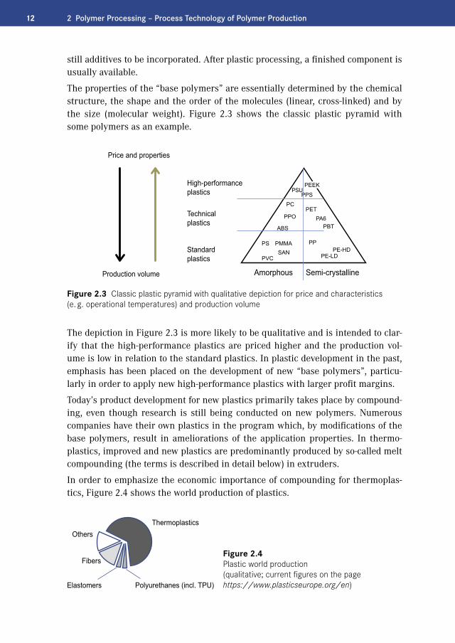
12 2 Polymer Processing – Process Technology of Polymer Production
still additives to be incorporated. After plastic processing, a finished component is usually available.
The properties of the “base polymers” are essentially determined by the chemical structure, the shape and the order of the molecules (linear, cross-linked) and by the size (molecular weight). Figure 2.3 shows the classic plastic pyramid with some polymers as an example.
Price and properties
High-performanceplastics
Technicalplastics
Standardplastics
Amorphous Semi-crystallineProduction volume
PEEKPSU
PPS
PPO
ABS
PS PMMASAN
PVC
PPPE-HD
PE-LD
PETPA6
PBT
PC
Figure 2.3 Classic plastic pyramid with qualitative depiction for price and characteristics (e. g. operational temperatures) and production volume
The depiction in Figure 2.3 is more likely to be qualitative and is intended to clar-ify that the high-performance plastics are priced higher and the production vol-ume is low in relation to the standard plastics. In plastic development in the past, emphasis has been placed on the development of new “base polymers”, particu-larly in order to apply new high-performance plastics with larger profit margins.
Today’s product development for new plastics primarily takes place by compound-ing, even though research is still being conducted on new polymers. Numerous companies have their own plastics in the program which, by modifications of the base polymers, result in ameliorations of the application properties. In thermo-plastics, improved and new plastics are predominantly produced by so-called melt compounding (the terms is described in detail below) in extruders.
In order to emphasize the economic importance of compounding for thermoplas-tics, Figure 2.4 shows the world production of plastics.
Thermoplastics
Polyurethanes (incl. TPU)Elastomers
Fibers
Others
Figure 2.4 Plastic world production (qualitative; current figures on the page https://www.plasticseurope.org/en)

132.1 Introduction
Thermoplastics dominate with more than 50 % of the world production of plastics. They are often used not only because of the price and the application profile. They can be re-melted several times and thus compounded and several times processed (transformed). Of course, the melting causes a thermal stress and can lead to unde-sirable quality losses. The procedural step often occurs twice during the manufac-ture of a plastic product, during compounding and during plastic processing. In a type of recycling of plastics, a so-called recompounding takes place, in which the “plastic waste” is also melted again.
Elastomers and thermoset material are known to be non-meltable and can be trans-formed only once and are not transformable after crosslinking.
The consideration of thermoplastics in this book is therefore of particular impor-tance. Figure 2.5 shows an overview of corresponding process steps.
PelletsMeltPowderPowder
SolutionEmulsionSuspension
PelletsAgglomerateMonomers
Semi-finished productsComponent part
Finished product
PelletsFilmTape
• Blending• Reinforcing, filling• Enhancement of additives• Filtration• Pelletizing
• Washing• Exchange of solvents• Removal of volatiles• Enhancement of additives• Filtration• Pelletizing
Polymer processing
Polymer processingin the primary production
Polyreactionin the primary production
Compounding
Plastic processing
Recycling Further processing
• Polymerization• Polycondensation• Polyaddition
• Thermal• Chemical• Material
• Handling• Joining
• Shaping
Figure 2.5 Polymer-process technology, overview using the example of thermoplastics
According to Figure 2.5, the term polymer processing includes many process steps, such as melting, degassing (solvent monomer removal), mixing and dispersing, conveying, dosing, extruding (pressure build-up), filtration, pelletizing, etc.

14 2 Polymer Processing – Process Technology of Polymer Production
Tasks of Polymer ProcessingHow can the procedural steps of polymer processing be summarized in a shorter way? Following the literature source [1], the essential tasks of the polymer pro-cessing are as follows:
1. Removal of components
2. Incorporation of additives
3. Change of particle size
Kaiser [1] writes: “The purpose of polymer processing is to produce from the plastic raw material a plastic molding compound with the best possible properties for plastic processing and/or application.” The plastic raw material usually is a base polymer.
The definition of reprocessing can also be applied to the production of a base poly-mer, as described in the following Section 2.2 using the example of the thermo-plastics. For elastomers, reference is made to the literature, e. g. [5].
In summary, it should be defined according to [2]: the procedural steps from poly-mer to plastic are collectively called polymer processing. Especially the incorpo-ration of additives takes place in the primary production and in the compounding, partly also during the plastic processing. The term additional materials includes additives (the substances listed previously that are added in small proportional amounts) and other substances such as fillers, whereat the terms are also used synonymously in the literature. Likewise, a distinction is not always made between the terms polymer and plastic. In the past, the term “compounding” was usually not so sharply demarcated from the “polymer processing”.
� 2.2 Polymer Processing during the Polymer Synthesis in the Primary Production
In order to understand the many and different processing steps of the polymers during their production, consideration of the polyreactions is necessary.
The production of polymers is carried out by polyreactions from monomer to the polymer, thus reaction for formation for macromolecules. Instead of polyreactions, the term synthesis reactions or polymer synthesis or, briefly, synthesis is used. Depending on the type of production, a reaction engineering or procedural classifi-cation can take place.

152.2 Polymer Processing during the Polymer Synthesis in the Primary Production
Classification of Production According to Chemical ReactionsThe polyreactions can be classified into three classes ([1] and Figure 2.5):
� Polymerization (chain polymerization) � Polycondensation (condensation polymerization) � Polyaddition (addition polymerization)
The nomenclature has changed over time and instead of the term polyreaction, the generic term polymerization is used, which may lead to confusion [6]. For the present book this is of minor importance, since the procedural aspects are in the foreground.
Classification of Production According to Procedural CharacteristicsFrom the point of view of the process technology, the manufacturing processes can be divided into three groups [7]:
� Polyreactions in substance (mass polymerization) � Polyreactions in solution (solution polymerization) � Polyreactions in dispersion (emulsion, suspension)
The production of a polymer with new properties can also be conducted by mixing different polymers. An example of a polymer blend is ABS.
Polymer reactions in substance are also called mass processes and can take place without solvents or other diluents. Therefore, high viscosities can occur already during the reaction. A reaction in mass may be a polycondensation. This splits off a “by-product” that needs to be removed. For example, polycarbonate can be pre-pared according to the “melt condensation process” or “transesterfication process”, wherein phenol is separated and as completely as possible removed by a vacuum from the reaction mass. Thus, a degassing task is existent.
In the polymer reaction in solution, the viscosity of the reaction mass is greatly reduced by the use of solvents. This facilitates heat and material transport and the pumping. Polycarbonate as an example can also be produced by the “interphase process” and one or more solvents are used. After the reaction, the solvents must be removed again, and the polymer must be “isolated”, Figure 2.5 and Figure 2.6. Again, here a degassing task is needed, which is also referred to as “evaporation”.
In the reaction processes in dispersion, a further subdivision into suspension and emulsion can take place; details are in the literature, for example [1, 6, 7].
In the case of polyreactions in substance, a highly viscous mass is already present during the reaction. In the case of polyreactions in solution and polyreactions in dispersion, the highly viscous phase is avoided during the reaction. Then, high-vis-cosity phases or solid phases occur during the necessary processing. This requires special devices and machinery. At Bayer, Martin Ullrich introduced the term

16 2 Polymer Processing – Process Technology of Polymer Production
high-viscosity technology, which has since become established. The author has made an extension to the high-viscosity, mixing, and reactor technology, in order to create an organizational and personnel basis for targeted advances in process tech-nology with appropriate equipment and machinery.
The above description of the various polymer reactions shows that the processing of a polymer is, depending on the nature of the reaction, very diverse in terms of process technology. By the example of a polyreaction in solution (solution polymer-ization), some process steps of the processing shall be considered.
Directly after the chemically completed polymer reaction, a polymer can be exis-tent e. g. in a solvent or in a solvent mixture. Then the polymer must be “isolated” from the blend. This procedural step of processing to remove the solvent is also called evaporation technology.
Semi-finishedproductFinished product
Startingmaterial
FillersAdditivesPolymer
Reaction,polymerization
Isolation
Compounding
Plasticprocessing
Polymer processingin the primary production
Processing/modification
at the compounder andin primary production
Filtra-tion
Pelletiz-ingM
ixing
Figure 2.6 Polymer processing in the production and modification, example thermoplastic
Figure 2.6 illustrates the processing in primary production at the polymer manu-facturer. In the example, the polymer must be isolated from a polymer-solvent mix-ture. For product stabilization, an additive is mixed in. Impurities are retained by filtration, followed by pelletizing.
Polymer reactions can – as listed above – also be carried out in “mass processes”, i. e. without solvent. The reaction progress of a polycondensation takes place by the removal of the condensation product. In this manufacturing technique, reaction and processing, removal of volatiles (condensation product), are carried out in par-allel.

172.3 Polymer Processing after the Polymer Production – Compounding
After the reaction, a polymer can be in the form of powder. Because of the low bulk density and because of the formation of dust, the powder is usually melted (ther-moplastic) and shaped to pellets. The granulation is an essential task of the pro-cessing and is generalized under the step “change of particle size”. Thermoplastics are usually traded and transported in the form of pellets for further processing, the compounding.
The individual procedural steps in the processing of polymers in their manufactur-ing process are described in detail in various chapters, for example in Chapter 3, polymer degassing.
� 2.3 Polymer Processing after the Polymer Production – Compounding
As described in Section 2.1, only additional substances (additives, etc.) enable the sustainable application of plastics. By blending additives into a polymer and mix-ing different polymers, modifications and new “tailor-made” plastics are created. This processing after the polymer production is called compounding. The com-pounding can be done at the polymer manufacturer or a compounder. The entire compounding plant is complex and this section describes the core task of com-pounding. The “heart” of a compounding plant is the associated extruder as this carries out the main compounding step, the melt compounding.
As thermoplastics are mostly available as pellets, during compounding the poly-mer is melted, has additives mixed in, then possibly degassed, and pelletized again. The central machine in a compounding line is an extruder, Figure 2.7.
Feed of solids Plasticizing Feed offillers
Dispersing Homogenizing Degassing Discharging
Figure 2.7 Compounding extruder with conventional usual steps

18 2 Polymer Processing – Process Technology of Polymer Production
Extruders can melt pellets and mix in additives very economically in a continuous process. The co-rotating twin-screw extruder is mostly used. This type of extruder is described in detail in [8]. An overview of other extruder types is given in Chap-ter 6 with a comparison in Section 6.8. The production of intermediate products, so called masterbatch production, also takes place with compounding extruders.
Compounding extruders are usually externally dosed, i. e. the throughput is deter-mined gravimetrically by external dosing devices, usually differential weigh feed-ers.
2.3.1 Main Temperature Window when Compounding for Finish Mixture
The addition of the additives takes place simultaneously with the pellets or even after the plastification after the melting of the pellets. The real incorporation (mix-ing) of the additives takes place in the melt; that is why we also speak of melt compounding. Figure 2.8 illustrates the melt compounding with the main tem-perature window. In the melt, the finish distribution (by distributive mixing) of the additives takes place.
hard-brittle hard-tough to elastic plastic-viscous
Stability Elongation
Melting
Soaking areaGlass transition area
Flow temperature area
Decomposition(time-dependent)
Main temperature windowcompounding
Temperature
Figure 2.8 Illustration of melt compounding with main temperature window by the example of amorphous thermoplastics

192.3 Polymer Processing after the Polymer Production – Compounding
There are hardly any applications in which a solid mixture of the reactants (poly-mer, additives) is sufficient for the production of a compound. In most cases, a comminution of additives (dispersion) and a fine distribution (distributive mixing) are necessary.
2.3.2 Mixing in the Extruder
Distributive, i. e. distributing mixing takes place in the melt by the very complex flow structure in an extruder. Cross mixing and longitudinal mixing play a deci-sive role here. The differences in effect between the cross mixing and the longitu-dinal mixing are described in more detail in Section 2.3.11.3.
Extruders can also dispersively mix very well, thus split solid matter or drops. The disperse mixing of, for example, solid additives takes place particularly well at high shear stress as described in the following Equation 2.1 [8, Equation 2.14 in the Applications book].
(2.1)
In the lower temperature range of the melt, the viscosity is higher and the dispers-ing effect better. On the left side there is the specific energy input, e. g. in the unit of J/kg. On the right side of the equation, there are the shear stress or melt viscos-ity and the mean dwell time of the melt, two quantities that are very important for disperse mixing. Both quantities must exceed boundary values in order to enable the splitting of particles (or drops of liquid). In other words, the agglomerate dia-meter resulting from disperse mixing depends on the height of the shear stress and the dwell time. For the splitting of agglomerates, a minimum shear stress – depending on the properties of the solid matter – is necessary which cannot be compensated by a longer mixing time. As the splitting of solid additives depends on the melt viscosity, there is also a dependence on the polymer. For example, ABS has a considerably higher viscosity level in the melt area than PA6. Dispersion in a PA6 melt is thus more difficult.
Also below the main temperature window there is a good dispersion, for example in the melting area, Figure 2.9.

20 2 Polymer Processing – Process Technology of Polymer Production
Soaking areaGlass transition area
Flow temperaturearea
Decomposition(time-dependent)
Polymer (generally pellets) and additives
(disperse mixing) due to high shear stress in the polymer and pellet effect and “walls”
Flow temperature area for amorphous polymer corresponds to melting temperature for the partially crystalline polymer
Optimal pre-mixingof solid material
Good splitting of solid material
Melting
(distributive mixing)due to liquid melt
Good distribution
Melt compounding:Main temperature window
Compounding,Amorphous thermoplastics
Temperature
Figure 2.9 Important temperature and mixing ranges during compounding, illustrated by the example of amorphous thermoplastics
Solid matter is comminuted before and in the melting area by the “walls” of hous-ing and screw and by not yet melted pellets by different types of stress. The usual types of stress [23] are illustrated in Figure 2.10.
Pressure Friction Shear Cutting
Figure 2.10 Types of stress for the comminution of solid matter
The polymer is usually existent as pellets. Pellets and additives or only additives can be premixed. A premixing (outside the extruder) may be useful for several reasons. A premixing of solid materials is usually associated with a much lower energy consumption than the mixing in the “viscous” melt area. Furthermore, the number of dosings (generally with differential weigh feeders) can be reduced. On the other hand, for difficult mixing tasks it may be advantageous to implement different addition positions, as the following description shows.
In principle, it is possible to mix distributively and disperse in the compounding extruder from the entry of the substances until the discharge of the compound. Due to the different effectiveness of the mixing effects (e. g. according to Figure 2.9, left, in the pellet and melting area, or right, in the melt area), different dosing concepts can be realized. Example: For compounding, a solid additive is to be in-

212.3 Polymer Processing after the Polymer Production – Compounding
corporated into a polymer, whereby it is not only be mixed in a distributive man-ner, but also to split (diminish) it. According to Figure 2.11 different dosing possi-bilities arise.
Pellets
solid elastic viscous melt
Extruder length
Melting
Pellets
Solidadditives
Solidadditives
Figure 2.11 Compounding extruder: sketch illustrating different dosing concepts for mixing and dispersing additives in the polymer
In variant 1, the polymer pellets and the additive are dosed into the extruder at position 1. In this case, the additive in the pellet/melting area receives a disper-sion through the pellets due to crush and friction processes. Whether a further dispersion of the solid additives takes place downstream in the melt depends amongst other things on the viscosity of the melt. At low viscosity (and thus shear stress = viscosity multiplied by shear rate), the dispersion effect is poor, Equa-tion 2.1. If the viscosity is sufficient for dispersion, the additive can also be added at position 2. To increase the mixing viscosity downstream of position 2, it is also possible to dose only a partial stream of the polymer in position 1 and the additives at position 2. The amount of the remaining polymer needed for the mixture for the correct formulation can be added at position 3 and mixed in downstream.
In addition to the described position displacement of the feed positions due to the dispersion effect, there are other reasons for different feed positions, such as wear in the feed area or volatile matter of (then mostly liquid) additives which should not escape with the disappearing air during melting. Furthermore, small amounts of low-viscosity additives can hinder the formation of melt film necessary for plas-tification.
Finally, a distributive finish mixing in the main temperature window (mixing in the melt) is generally required. The main temperature window during compound-ing is above the flow temperature range for amorphous products or the melt range for partially crystalline polymers and below the decomposition. Example values for a polymer: The flow temperature range starts at PC according to Frank [6, page 98] at approx. 230 °C, also depending on the PC type (injection molding of low viscos-ity or high viscosity extrusion type differ). For the description and modeling of the melting of amorphous polymers (which do not have a sharp melting point) with experiments on single-screw extruders, a critical flow temperature is specified in

22 2 Polymer Processing – Process Technology of Polymer Production
Han [9, Chapter 2], which is 200 °C for polycarbonate. In the following, the flow temperature range is considered again: according to Figure 2.17, 200 °C is a good “average value” for PC.
2.3.3 Temperature and Time Limits for Compounding
Compounding takes place very economically at high throughputs utilizing the specification limits of the compound. A limit is the thermal damage of product. Information in the literature about a temperature at which the chemical damage and finally decomposition begins often refers to longer exposure times. The decom-position depends, among other things, on temperature and time, and is thus not a pure temperature function. Figure 2.12 shows this connection qualitatively.
Figure 2.12 Damage of a polymer melt due to tempera-ture-time stress (qualitative)
The beginning of a damage is given in Frank [6, Fig. 3.3.2], for example, for PC in [6] from about 320 °C. PC would endure this melt temperature for approximately 10 minutes until the beginning of an intolerable damage, as discussed below. For very short periods of time, the PC melt also withstands 400 °C. Therefore, the tem-perature limit of the product damage with the related temporal load should be considered in more detail.
According to a compounding process, the product temperature rises from melting to the main temperature window. In an extruder, the product is subject to a temporal temperature curve T(t). The thermal product load or damage S can be described by an Arrhenius approach with integration over the temporal progress, Equation 2.2.
(2.2)
Where T is the temperature in Kelvin [K] and t is the time.

232.3 Polymer Processing after the Polymer Production – Compounding
To compare the temporal load of a melt for different temperatures, constant tem-peratures TE are considered, Equation 2.3:
(2.3)
For a clear quantitative idea of the temperature-time limit in the main temperature window compounding according to Figure 2.8, the parameters a and S/K should be roughly considered using the example of a polycarbonate type PC. Assuming that the damage of a 10 K higher stressed melt doubles at the same residence time, the parameter a would be, according to Equation 2.3, approx. 27,000 K, when a refer-ence temperature of 350 °C is assumed.
On the other hand, the residence time tE can also be calculated up to a certain dam-age, for example up to a still tolerable damage S, Equation 2.4:
(2.4)
By fixing a point (tE, TE), the pre-factor S/K in Equation 2.4 can be determined. One example for polycarbonate is here S/K = 10−17 s (s = seconds).
Figure 2.13 clearly shows the result of the quantitatively rough calculation for the temperature-time load limit.
Temperature - Time - Load
Tim
e
Sec
ond
sM
inut
es
Temperature [˚C]
Melt
Equivalent load at constant temperature:low temperature with long time corresponds to high temperature with short time
Figure 2.13 Equivalent temperature-time load limit for a polycarbonate example

24 2 Polymer Processing – Process Technology of Polymer Production
In the case of a PC melt at 350 °C, the still tolerable damage limit occurs after one minute as shown in Figure 2.13. At 420 °C, the same damage is achieved after about one second. Normally, the temperature-time window for compounding is be-low the limit specified in Figure 2.13. The average residence times in traditional compounding extruders are today less than half a minute. However, a small pro-portion of polymer in the extruder, for example in gaps with high shear and thus temperature load, can come up to the damage limit. It should be noted that the damage, for example the Yellowness Index, depends not only of the thermal load, but also on the additives, for example the solvent and the solvent portion used. This displaces the damage limit in Figure 2.13. In particular, also a contact of the hot melt with air (oxygen) is to be avoided! Furthermore, it should be noted that the above-mentioned damage limit can change quantitatively due to changed spec-ifications. In practice, due to economic reasons, it will be produced close to the specification limit. High throughputs are generally more economical, as illustrated by the simple principle depiction in Figure 6.7 in Chapter 6. See also Figure 2.14.
Specificcosts
Capacity
Figure 2.14 Schematic relationship between capacity and specific costs
High throughputs usually mean also a higher product temperature as the higher throughputs are usually only attainable at higher speeds. In fully filled extruder sections, the mean residence time falls in fact, and thus the temperature; how-ever, with increasing throughput, with increasing speed, the mean temperature increases disproportionately. This is expressed by Equation 2.1 (t ~ 1/throughput, n ~ γ, T ~ e).
All in all, the temperature window for compounding PC compared to some other plastics is large (see also Figure 2.15). PC is more “stable” than PVC, for example. For PVC, the flow temperature area starts at about 175 °C and the damage range starts at about 210 °C [6]; for the last value, again a load duration applies.
Despite the problem of specifying permissible melt temperatures due to lack of time allocation, literature data on common temperature windows in the melt area [10] are given here, Figure 2.15.
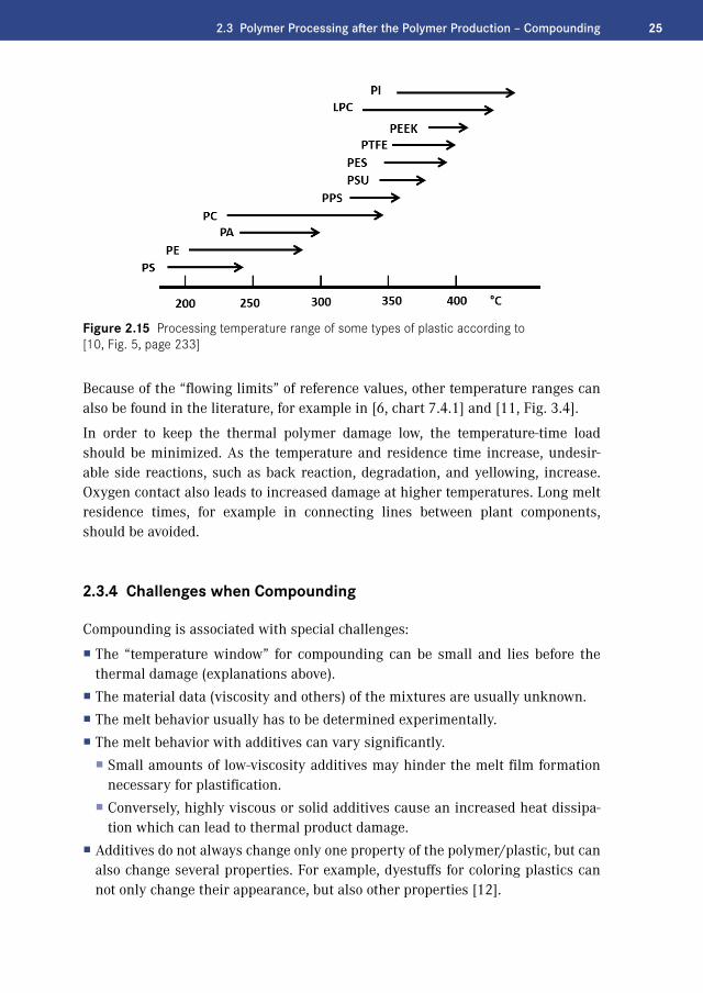
252.3 Polymer Processing after the Polymer Production – Compounding
Figure 2.15 Processing temperature range of some types of plastic according to [10, Fig. 5, page 233]
Because of the “flowing limits” of reference values, other temperature ranges can also be found in the literature, for example in [6, chart 7.4.1] and [11, Fig. 3.4].
In order to keep the thermal polymer damage low, the temperature-time load should be minimized. As the temperature and residence time increase, undesir-able side reactions, such as back reaction, degradation, and yellowing, increase. Oxygen contact also leads to increased damage at higher temperatures. Long melt residence times, for example in connecting lines between plant components, should be avoided.
2.3.4 Challenges when Compounding
Compounding is associated with special challenges:
� The “temperature window” for compounding can be small and lies before the thermal damage (explanations above).
� The material data (viscosity and others) of the mixtures are usually unknown. � The melt behavior usually has to be determined experimentally. � The melt behavior with additives can vary significantly.
� Small amounts of low-viscosity additives may hinder the melt film formation necessary for plastification.
� Conversely, highly viscous or solid additives cause an increased heat dissipa-tion which can lead to thermal product damage.
� Additives do not always change only one property of the polymer/plastic, but can also change several properties. For example, dyestuffs for coloring plastics can not only change their appearance, but also other properties [12].

26 2 Polymer Processing – Process Technology of Polymer Production
� In large extruders, product cooling via the housing is hardly possible. � Not all extruder types are suitable for melting, in particular not for very high throughputs with the required drive energy (Section 6.8, Extruder Types – Com-parison, Figure 6.110).
� Some polymer blends cannot be produced as there are different main tempera-ture windows.
The last two points are explained in more detail: For mixing of polymers (so-called blends), the flow temperature range (Figure 2.8) must be exceeded. The flow tem-perature range can be so high in a polymer where another polymer is already de-composed, thermally damaged. Figure 2.16 shows examples of three products with different temperature windows.
PVC
PA
PC
100
120
150 200 250 270 300
320Temperature [°C]
275235190
Figure 2.16 Melt temperature window for three polymers according to [13, Fig. 10.2]
The flow temperature range of polycarbonate (in the example a low viscosity CD type) begins only at a temperature level at which PVC already decomposes. It is impossible to produce a homogeneous plastic melt from these two polymers.
The temperature range of PVC in Figure 2.16 according to [13] differs from the infor-mation given above for PVC from the source [6], in particular with regard to the start of the flow. It should be noted that the flow, i. e. the viscous area, begins at a higher temperature (at about 175 °C) for rigid PVC and at lower temperature for soft PVC.
How else can the information about a “flow temperature” differ? It must be noted that a flow temperature is physically not exactly defined [6] and amorphous plas-tics always have a flow temperature range. Often, a flow temperature is then indi-cated from the lower area where an extrusion becomes possible. Figure 2.17 shows the flow temperature range for a medium viscosity PC type and the dependence on the measurement frequency [14]. The entropy-elastic range (TF–Tg) increases with increasing frequency, whereby no increase occurs from about 500 Hz. It is also concluded that the flow temperature at faster compression is shifted to signifi-

272.3 Polymer Processing after the Polymer Production – Compounding
cantly higher temperatures [14, page 115]. Therefore, the “melting temperature” TF in extruders during melting of pellets is displaced in direction of higher tem-peratures. It was already referred above to the modeling of the melting in extrud-ers [9, Chapter 2]. The temperature specification of 200 °C is in the range of the limits shown in Figure 2.17.
Loss
mod
ulus
G" [
Pa]
Stor
age
mod
ulus
G‘ [
Pa]
Temperature T [˚C]
at at
energyelastic
entropyelastic visco-elastic
Measurement frequencyStorage modulus G‘Loss modulus G″
Figure 2.17 Glass temperature Tg and flow temperature range TF for a medium-viscosity PC type [14] and change by the measurement frequency (the curves belong to 0.1 Hz)
For partially crystalline plastics, the flow temperature range is distinctly clearer and narrower, and the melting temperature of the crystallites is used as a sharp limit, Figure 2.18.
Sti
ffne
ss
“frozen”brittle
tough/hard
soft as rubberviscous
Crystallinity
free chain sliding:
Mesh deformation:entropy elastic
Valence bond angle deforma-tion: energy elastic
“Solid”
Temperature
“Melt”
Figure 2.18 Deformation behavior of thermoplastics in dependence of temperature [15, Fig. 1.5]

28 2 Polymer Processing – Process Technology of Polymer Production
2.3.5 Energy Requirement when Compounding
The compounding step which is carried out after the primary production can be directly coupled procedurally at the polymer manufacturer. Then the pelletizing and repeated melting of thermoplastics between the two processing steps (Figure 2.5 and Figure 2.6) can be omitted. This is energetically more economic and gentle regarding the product, but means a more complex overall line with low operational safety and flexibility as far as the variety of products is concerned.
Normally, compounders modify the polymers and create their own products with improved properties. The compounder receives the polymers normally as pellets – sometimes as powder – from the polymer manufacturer and therefore thermoplas-tics must be re-melted. Rubbers are not melted. Plasticizing in rubber technology means converting a viscoplastic state at room temperature into a sufficiently flow-able state by converting mechanical drive energy into heat [5].
Required Specific EnergyAs shown in Section 2.3.9, the required drive energy of the extruder shaft(s) PW is expressed with the specific energy:
(2.5)
This means
(2.6)
with
(2.7)
the specific energy of the input flows, thus usually of the base polymer and of the additives. The mass flow is the mass flow of the compound that is discharged by the extruder. Equation 2.6 contains the specific heat capacity cA of the com-pound at the extruder outlet, which consequently is of major importance.
Figure 2.19 shows the specific heat capacity of a polymer with the main tempera-ture window for finish mixing of the additives, which is between T1 and T2. The importance of T1 and T2 is depicted in Figure 2.8. T1 describes the flow temperature range described above, and T2 the area where the damage is noticeable. According to the above descriptions, the temperature range T2 is to be considered together with the temporal stress.

292.3 Polymer Processing after the Polymer Production – Compounding
Main temperature windowcompounding (mixing)
Temperature
Specific heatcapacity
kJ3
2
1
Tg T1 T2
kg KGlass-like
Rubber-like
Melt Start thermal damage in conjunction with a temporal load
Energy requiredfor melting
Figure 2.19 Energy requirement (area) for melting an amorphous thermoplastic [6, Fig. 6.3]
It is apparent that the essential part of compounding extruders is needed for the melting of the polymer. For simplification, only the polymer is considered instead of the mixture of polymer and additives, i. e. only the energy necessary for the tem-perature change from the extruder inlet to the extruder outlet of the base polymer without additives. The required energy input is represented by the area under the curve in Figure 2.19. Enthalpy temperature diagrams are more useful because by means of these the required energy can be read off directly.
As an example, Figure 2.20 shows the specific enthalpy for different types of poly-amide [16].
0
200
400
600
800 0.22 kWh/kg
0.17 kWh/kg
0.11 kWh/kg
0.06 kWh/kg
Spec
ific
enth
alpy
h
kJ/kg
0 2 50 100 150 200 250 300
Temperature
ºC
PA610
PA6-GF 30
PA 6
PA 66
01 kJ/kg = kWh/kg1
360( )
Figure 2.20 Specific enthalpy for different types of polyamides (based on [16, Fig. 3.43])

30 2 Polymer Processing – Process Technology of Polymer Production
The enthalpy change must be introduced into the polymer (proportional to D3) by the extruder via the shafts. An energy portion can also be introduced via the hous-ing walls. For larger extruders, this proportion is low (areas proportional D2).
For the specific drive energy
(2.8)
of extruders, the unit kW divided by kg/h is common. The unit customary for the specific enthalpy is kJ/kg; this can also be expressed in kW/(kg/h):
Figure 2.21 shows this trivial correlation relating to ton/hour [t/h] for production machines. In addition, the performance is given in dependence on the throughput in Figure 2.22, where with the double logarithmic representation small through-puts are easier to read off.
Figure 2.21 Required (minimum) drive energy of extruders for melting or for enthalpy changes (temperature changes) of polymers
Figure 2.21 and Figure 2.22 show the required minimum drive energy of an extruder to melt the polymer. Example: To melt PA6, just under 600 kJ/kg (= 0.17 kWh/kg) is required according to Figure 2.20. For a line with a throughput of 10 t/h, a minimum drive energy of approx. 170 kW ⋅ 10 = 1.7 MW is required according to Figure 2.21.

312.3 Polymer Processing after the Polymer Production – Compounding
Figure 2.22 Required (minimum) drive energy of extruders in dependence on the throughput with the required enthalpy change as parameter
In addition, there are energy inputs, which are given in Equation 2.5, that are intro-duced into the product by the extruder shafts and which, in addition to the enthalpy change (temperature change), lead to further energy release by the product. The energy portion for the pressure build-up is low, however. For a pressure difference of 50 bar between product outlet and inlet, assuming average material data, only about 5 kJ/kg is needed. This is about 1/100 of the proportion of the above numerical ex-ample for the enthalpy change. The energy portion of the cooling via the housing walls is also low in production machines, as shown in an example in Section 5.7 (Bierdel), below 5 %. The proportion ehousing (sum heating minus cooling) is thus small in large compounding extruders compared to the enthalpy change of the product.
To calculate the electrical power, the energy losses of motor and gear (degrees of efficiency) must be added in addition to the required shaft energy.
Corresponding extruders with high drive energy are machines and not lightweight apparatus. Not all extruder types allow high throughputs with simultaneous melt-ing of the polymer. Actual maximum throughputs are given in Section 6.8 (Ex-truder Types – Comparison).
Figure 2.21 and Figure 2.22 can also be used for so-called “melt feed extruders”, i. e. extruders that do not need to melt polymer. These extruders are also called “hot feed extruders”. Then, the enthalpy difference is decisive, which results from the difference between the discharge temperature of the product and the inlet tem-perature. Attention must be paid to mixtures, and, especially for degassing extrud-ers, to the portion of volatile matter (evaporation enthalpy). The equations given in Section 2.3.9 take these proportions into account.

32 2 Polymer Processing – Process Technology of Polymer Production
A comparison of amorphous polymers with partially crystalline ones shows that in partially crystalline polymers on average almost twice the melting energy is needed.
2.3.6 Range of Performance of Extruder
The above describes what drive energy a polymer requires during compounding. Which drive capacities do extruders offer? In order to consider the drive capacity independently of the exact screw diameter, a diameter is chosen as reference value. As described in the introduction to the co-rotating twin-screw extruder (Section 5.1), a reference diameter makes sense from a procedural point of view. As the co-rotating twin-screw extruder is the standard extruder in compounding, this is considered as an example of performance density and compared to a single-screw extruder.
Torque Density, Performance Density For single-screw extruders, the torque of the shaft can be considered in relation to the diameter. The manufacturers of co-rotating twin-screw extruders specify the torque of a shaft related to the center distance.
Neglecting the clearance between the shafts, with the center distance A = (Da + Di)/2 and the torque Md1 of a shaft, the following relationship applies:
(2.9)
The values Md1 /A3 and Da /Di are given by the manufacturers. With the total per-formance P = z ⋅ Md1 ⋅ 2 ⋅ π ⋅ n with z = 2 for two shafts, the following performance density PLD can be defined:
(2.10)
Example:
which results in:

332.3 Polymer Processing after the Polymer Production – Compounding
The performance density is, like the torque density, not dimensionless and has the same unit. A torque density thus corresponds to a performance density. The ex-truder user is primarily interested in what performance is needed for a certain throughput. The performance offered by the extruder can be calculated directly with the performance density. For this purpose, the units are advisably chosen so that the screw diameter can be applied in millimeters and the speed in 1/minute:
The performance density per shaft makes limited comparison possible with sin-gle-screw extruders or with multi-shaft extruders. Limited because the reference diameter can be defined differently. The extruder user is mainly interested in what throughputs can be realized. That is why the attainable speeds are very important.
Example Rubber ExtruderThe permitted finish temperatures for rubbers are generally much lower than for thermoplastics, and the extruder speed and throughputs are correspondingly low. Basic data for so-called cold extruders are described in [5, Fig. 10.13]. Example: For a pin type extruder with a screw diameter of 300 mm, a drive power of 800 kW and a speed of 20/min are specified. The throughput is about 7 t/h (see also Figure 2.22). The speeds for co-rotating twin-screw extruders for thermoplastics are con-siderably higher: On a larger co-rotating twin-screw extruder with 380 mm screw diameter, 130 t/h of polyethylene (LLDPE/HDPE) are processed. It should be noted that the pin type extruder for rubber is a single-screw one, whereas that for poly-ethylene a twin-screw one.
The pin type extruder for the example rubber provides:
This is a value of the same size as the value of the twin-screw extruder (the value for the twin-screw extruder applies for two shafts, which corresponds to the total range of performance).
The twin-screw extruder is used for thermoplastics at higher speeds, in particular small machines can be operated at very high speeds. Figure 2.23 shows the simple connection, the performance P/D3 for the example with Equation 2.10 in depen-dence on the screw speed.

34 2 Polymer Processing – Process Technology of Polymer Production
Figure 2.23 (Offered) performance density of co-rotating twin-screw extruders in dependence on the screw speed with Da/Di as parameter
A numerical example for Figure 2.23: For an extruder with a diameter of 133 mm and Da /Di = 1.55 (Coperion) at 1000 revolutions per minute, a performance value of 1.75 W/mm3 arises. If this value is multiplied by 1333 mm3 this results in a per-formance of 4.1 MW. In a table from Coperion [17], 4.4 MW is stated for the motor performance as, amongst other things, also the dissipation loss of the gear (effi-ciency) is added.
Normally, the permissible torque Md1 /A3 also changes with the diameter ratio. This will be dealt with in Section 5.1, where different diameter ratios are consid-ered under different aspects.
The torque density specified by extruder manufacturers usually is the maximum available. A maximum available torque density Md1 /A3 results in a maximal of-fered performance density PWmax /(n ⋅ D3).
(2.11)
The additional index W indicates that this performance is applied to the shafts. In Section 6.8, Extruder Types – Comparison, further performances of the extruder drive including the electrical drive performance are considered.

352.3 Polymer Processing after the Polymer Production – Compounding
2.3.7 Throughput and Performance Density
The extruder throughput can be formulated dimensionless with the throughput key figure
(2.12)
with the volume flow , the speed n, and a reference diameter. The throughput key figure is discussed in the relevant literature from Kohlgrüber [8] and Pawlowski [21], and is the most important key figure for extruders. Previously, Q was also used as a formula symbol.
For the polymer producer or compounder, the mass throughput is decisive. With the mass throughput and a density , the dimensionless volume flow is
. As the density changes in dependence on, inter alia, temperature, it is also useful to select a reference density = 1 kg/l for comparison purposes. This can be used to define the following throughput key figure.
(2.13)
The performance density according to Equation 2.10 can be expressed with the throughput key figure and the specific performance e.
Neglecting the clearance between shaft and housing, the housing diameter D can be replaced by Da. Together with the specific drive performance, the following arises for the performance density:
(2.14)
Throughput DensityFor example, the polymer blend density changes with the temperature or is un-known. Then, alternatively, as described above, the dimensionless throughput key figure may be used with the reference density. Another possibility is to intro-duce a dimensioned throughput density:
(2.15)

36 2 Polymer Processing – Process Technology of Polymer Production
The throughput density describes clearly the throughput per revolution related to the screw diameter cubed.
(2.16)
The required enthalpy change described above (e. g. for melting) results in the minimal required specific drive performance emin, if the heating performance via the housing is not considered and other emitted energies (cooling, evaporation en-thalpy, etc.) are ignored. This results in the dimensionless throughput key figure, as shown in Equation 2.14:
(2.17)
As a maximum value is the quotient in the equation, Equation 2.17 gives the max-imal throughput density.
Equation 2.17 clearly shows that higher throughput rates are possible in extruders if
� emin is smaller, i. e. the required enthalpy change from the product is lower (e. g. amorphous versus crystalline polymer)
� the torque density Md1 /A3 or Md1 /D3 is greaterAdvantages of the throughput density:
� By standardization, the throughput density is independent of the speed and the actual extruder size. Big and small machines can be compared, which is import-ant for scale-up and scale-down considerations.
� A comparison of single-screw and multi-screw extruders will be made possible.For this the throughput density per screw can be considered:
(2.18)
with z = number of screws and = /z the throughput per screw.
The consideration of the known conveying key figure [8] is also useful.
(2.19)
Here A1 is a conveying parameter which is also called profile parameter as it de-pends only on one special screw geometry.

372.3 Polymer Processing after the Polymer Production – Compounding
It is possible to define a conveying parameter A1,1 that relates to one shaft only.
(2.20)
Applications of the equations to a comparison of extruders:
If the twin-screw (z = 2) is compared with the ring extruder (z = 12), then it follows for the same (total) throughput of both machines:
(2.21)
and with Equation 2.18 and Equation 2.20:
(2.22)
The same operating point is considered for both extruders. The conveying be-havior of a screw geometry is described by the conveying parameter A1,1. It de-scribes the maximum dimensionless throughput of one screw element per shaft. It is known [29] that a twin-screw extruder has a higher inherent throughput due to the gusset than a single-screw extruder with the same geometry (i. e. geometry of the twin-screw), although the eight-shaped cross section of the twin-screw is less than twice the cross section of the twin-screw. In the case of the ring extruder, one gusset is assigned to each shaft, whereas in the case of the twin-screw only one gusset is assigned to two shafts. Thus, it follows that with a > 1. With this, it follows, at the same speed of the machines:
(2.23)
As the value a will be only slightly above 1, the third root is almost 1. Example: Tests and throughputs with the smallest ring extruder of (presently) 19 mm can thus be compared with a twin-screw extruder of approx. 34 mm.
The extruder comparison with the result of Equation 2.23 was carried out with the conveying capacity of the screw geometry. Alternatively, it can also be “demanded” that both extruders shall have the same throughput density per shaft. From this results with Equation 2.18 and Equation 2.20 directly the connection Equation 2.23 without the factor .
Following the above numerical examples of the maximal performance density, the throughput density is considered:

38 2 Polymer Processing – Process Technology of Polymer Production
For the maximal throughput it results in
The number is not clear at first. The dimensionless throughput key figure
is without the reference density a known value [8] for the extruder experts.
Multiplication with a screw speed and the screw diameter cubed produces the maximal throughput. For D = 50 mm and n = 1000/min, the result is 1.25 t/h. For comparison, Figure 2.24 shows realized throughputs when compounding [18] PC with glass fibers for an extruder of the size 50 (more precisely 51.2 mm).
Figure 2.24 Measured throughputs with PC + 40 % GF
The example is only conditionally comparable as with PC + GF a slightly different value for the enthalpy change arises. The magnitude of the specific heat capacity of PC + GF is about 2 kJ/kg at somewhat above 300 °C. The value increases with in-creasing temperature, and decreases with increasing GF content. So, also in this example, about 600 kJ/kg (0.17 kW/kg) is needed for the product.
It should also be noted that even with the same enthalpy change real throughputs are below the maximum throughput of 1.25 t/h, firstly because the maximal torque is not used, and secondly because only the enthalpy of the polymer was taken into account at the specific drive performance for the example. In addition, when the housing is cooled, some of the energy produced by dissipation is not retained in

392.3 Polymer Processing after the Polymer Production – Compounding
the product and the specific drive performance is higher and thus the maximal throughput is lower.
Already in the 1960s, highly productive extruders were expected to produce high specific drive performance of about 1000 kJ/kg (0.28 kWh/kg) (Mink [24, page 159]). According to the considerations of Lechner, Section 5.3, there are limits for the energy requirement of 0.15 to 0.25 kWh/kg for polymer bulk densities of 0.3 to 0.7 g/cm3 for compounding processes.
2.3.8 Performance Density in the Melt Area
As described above, most of the drive energy is needed to melt the polymer. This section specifically considers one melt area and asks, what is the influence of vis-cosity on the performance density? Some extruders, e. g. degassing extruders in polymer manufacture, are charged with melt, i. e. throughout the extruder there is a melt. The viscosity is then a mixed viscosity of polymer with solvents and addi-tives.
For the melt area, a filled screw section is considered, and as a thought experiment a constant viscosity . For this case, the “extruder equations” are known and de-scribed in detail in [8]. Regardless of the extruder size, the dimensionless perfor-mance for the considered screw section of length L is:
(2.24)
Here, is the throughput key figure, Equation 2.12, B1 and B2 are so-called “pro-file parameters”, which only depend on the screw geometry. They are dimension-less and independent of the absolute extruder size. The initially asked question regarding the dependence on the viscosity can be seen from the above equation, but the connection with the torque on the performance density becomes even clearer:
(2.25)
The performance density and the factor
(2.26)

40 2 Polymer Processing – Process Technology of Polymer Production
are therefore directly proportional to the torque. Consequently, in order to utilize fully an available torque, the viscosity, the screw speed, and the dimensionless length L/D are equivalent. In other words, if very high viscosities are present – e. g. in the melting area – then this is “at the expense” of a maximal extruder length. For special applications, extruder lengths of L/D > 100 are available.
According to the definition of the performance density, it is the performance of one extruder per revolution and related to the diameter and dimensioned. The perfor-mance profile parameter B2 is dimensionless. This is discussed in more detail in Section 5.1.
2.3.9 Energy Balance and Product Discharge Temperature
Figure 2.25 shows an “extruder line”, the core of a compounding plant, consisting of an extruder with drive and downstream equipment (pelletizing, optional melt filtration, etc.).
kWh
Wave(s)
Torquecontrol
Inlet flows Degassing flows
Outlet flow(melt)
Outlet flow(throughput)
FinishingTreatment
PHeating QCooling
M = + +E ME1 ME2 M ...E3 M = +G MG1 MG2 MA...
Motor Gear Extruder (also: Extruder 1 + Extruder 2 or Extruder + Pump)
Figure 2.25 Extruder with drive and downstream equipment
For the extruder, an energy balance is set up in accordance with the dotted system limit shown in Figure 2.25. In terms of balance, these can also be two extruders connected in series. Alternatively, it may be one extruder with a downstream gear pump. When applying the energy balance given below, the process factors heating performance, cooling-heating flow, and drive performance must be applied analo-gously in accordance to the imaginary system limit. With the inclusion of an op-tional downstream gear pump, the performances of the extruder and the gear pump are to be used as sum under the drive performance. The balance can also be applied to the gear pump alone. In Section 7.4.2 it is applied to static mixers.
A stationary operation of the line is assumed and the first law of thermodynamics for open systems is applied. Above the audit space in Figure 2.25 the mass flows

412.3 Polymer Processing after the Polymer Production – Compounding
are depicted which can be expressed together with the discharge flow by the en-thalpy flows. The enthalpy flows are thermodynamic state variables in contrast to the heat flow, the drive performance, and the heating performance, which are pro-cess factors. State variables are “path-independent” and are described by their nu-merical values at the system boundary. The extruder can thus be well-balanced like a “black box”. The process factors pass the balance limit at the bottom and left in the figure.
The energy balance provides for the depicted system boundary:
(2.27)
Where:
� is the discharge mass flow (product flow). � is the energetic mean product discharge temperature. � is the specific heat capacity at constant volume at the temperature . For polymers, this differs only very slightly from the specific heat capacity at con-stant pressure. The difference becomes greater at very high pressures and tem-peratures.
� is the density of the discharge flow at the temperature . � is the discharge pressure of the product at the system boundary. This may be the pressure in front of the die, but also the pressure downstream of the die, depending on where the system boundary is set. The discharge temperature changes depending on the system boundary. An example can be found in [8, page 335 in the Fundamentals book].
� is the heat flow delivered or received via the inner screw housing. The value is a process factor and the algebraic sign was chosen so that a delivered heat flow (cooling) is positive. Formally, the heat flow can be expressed as follows [8, page 330 in the Fundamentals book]:
(2.28)
UG is the inner circumference of the housing. Since the course of the variables in the equation is generally unknown, the heat flow can be roughly determined by averaging:
(2.29)

Index
Symbols
3DD mixer 3453-zone screw 3558to0 adapter 394
A
abrasion 132abrasive processing behavior 160ABS 793additional materials 10additive dosing 169additives 10, 144, 155, 743additives for recycling 155advantages of the co-rotating twin-screw
extruder 178aeration bottom 668aeration ring 118aftercooling section 793agglomerate separator 793agglomeration 113air pelletizing 135aluminum bronze 740, 745anisotropy 395antioxidants 157antistatic agents 145apex zone 474apparatus-based evaporation technology
103apparent shear rate 771arch 645arching 629armored flight 317
armoring 326Arrhenius approach 22, 498aspect ratio 160automated batch plants 709automation 126auxiliary dosing 178axial clearance 739axial shaft seal 740axi-symmetric 643
B
back pressure 357back pressure zone 196backward degassing, PRE 431backwashable screen changers 762Bagley correction 771barrel configuration 298barrel cooling 492barrel temperature control 458barrier flight 360barrier screw 360batch mixer 705batchwise degassing 109beads 280, 292bearing – of the screw shafts 342
bearing seizing 742belt type dryer 799bimetal 400bimetal cylinders 318black specks 163blend – polyblend 152

832 Index
blender selection 675blend hopper 670blending pipe 671blending silos 662blowing agent 284, 797blow tank 726Bodenstein number 539bonding 704booster pump 733bore gage 399bridging 629bubble function 79bulk boiling 541bulk density 145, 263, 358, 637, 782bulk heat exchanger 119, 120bulk heat transfer 119bulk materials 629butadiene rubber 385
C
cable compound 463caking 113calcium carbonate 160, 743calcium carbonate (CaCO3) – chalk 249
calender 349, 465, 548calender speeds up to the winder 567calender types 559calibration 810calibration series 146candle filter 756capillary pressure transducers 813carbon 745carbon black 212, 381, 463, 743carbon dioxide balance 160carbon fibers 145cartridge heater 741cascade 57cascade arrangement 398cast iron rolls 566cavity transfer mixer 367cell density 281cell diameter 281cell expansion 289
cell growth 289cells 287cellulose 268centerline distance 370central spindle 405centrifugal dryer 796ceramic 745certification 139chamber conveying effect 400chemical nickel plating 328chill roll lines 576chopper 130chromium oxide coatings 332circulation 103circulation flow with static mixers 621cleaning 708, 709cleaning time 127clearance 355closed-loop system 721closely intermeshing, co-rotating
twin-screw PRE 426coating – calcium carbonate 250 – material 314
coatings – wear protection 326
coefficient of variation 589, 599, 701cohesionless 629co-kneader 345. See also continuous
kneadercold pelletizing 781color 146colorants 146, 157color assessment 138color development 146color measurement 818color samples 147common bulk material densities – compounding 232
compact heat exchanger 625Compact Processor 471comparison single-screw to twin-screw
extruders 353compatibilizers 145, 152compensation zone 397

833Index
competition between screen changer and large-area filter 778
composite material 265compounding 9, 11, 17, 125, 263 – main task 177
compounding challenges 25compounding extruder 194compounding with gear pumps 733compound, thermoset 466compression ratio 355compression test 113compression zone 358, 397compressive strength 283, 639, 646computational fluid dynamics (CFD) 776concentration 599concentration difference 71conical co-rotating extruder 346conical screw mixer 666conical twin screw 398conical twin-screw extruder 346construction sizes, PRE 408container mixer 709continuous 665continuous kneader 442continuous mixer 505, 710continuous operation 109Continuous Processor (FCM) 347continuous screen changer 761control, model-predictive 828control system 743conveyance fluctuations 734conveying and working principle, PRE
410conveying behavior 355conveying element 196, 298, 454, 590conveying elements – free cut 260
conveying gas velocity 716conveying performance 196conveying zone 397convolution integral – residence time distribution cascade 57
cooling air 792cooling air pelletizer 792
cooling capacity on a production scale 44
cooling mixer 708cooling rolls 568cooling zone 295Coperion 346co-rotating twin-screw extruder 263,
346 – advantages 178 – disadvantages 180
corrosion 132, 313, 378cost curve 350counter-rotating twin screw 387counter-rotating twin-screw extruders
347counter-rotating twin screw, zones 396coupling agents 145CRD mixer 365critical outlet diameter 629crosslinking agent 463cross mixing 53, 587cross-mixing 373cumulative frequency distribution of
maximum shear load 608cutter head 790cutting chamber 791cutting circle diameter 790cutting process 781cutting unit 793cylinder assembly 276cylinder segments 372cylinder wall temperature 811
D
Da/Di developments and process sections 233
Da/Di ratio 198, 257. See also diameter ratio
Darcy’s law 768dead corners 165dead zones 346, 655decompression zone 363decontamination 524deficient lubrication 740

834 Index
degassing 108, 263, 277, 375, 470, 481, 492
degassing and reaction module (ERMO), PRE 433
degassing cylinder 437degassing drum 511degassing extruder 362degassing performance 512degassing, PRE 429degassing process 109degassing ring 436degassing silo 108degassing temperature 111degassing time 111degassing via a downstream single-screw
PRE 435degassing zone 214, 303, 397, 510degree of automation 782degree of disaggregation 592degree of dispersion 212degree of filling 145degree of filling, PRE 411degree of freedom 482degree of pump efficiency 188degree of segregation 600demanding heat transfer tasks 624demetallization 129demixing of solids 167density 65, 300, 304density, foam 281depreciation 125design for flow 629design, modular 371devolatilization 63, 78, 541devolatilization number 73, 74, 76, 77, 78devolatilization task 69devolatilization zone 68, 214diameter ratio Da/Di 183die plate 790differential equation, ordinary 300differential pressure 738differential scanning calorimetry 823differential weigh feeder 18diffusion 110diffusion coefficient 69, 110
dimensionless key figures – gas dispersion 620
disadvantages of the co-rotating twin-screw extruder 180
disc filter 758discharge aid 654discharge aids 629discharge devices 629, 654discharge system 461discharge zone 295discoloration – degree of 268
discontinuous 665discontinuous compounding 178discontinuous processing – batch process 341
disk mixer module 615dispersion 304, 591, 820, 824dispersion aid 213dispersion behavior 607dispersion quality 593, 820dispersion ring 276, 420dispersion zone 261dispersive mixing 374, 591dispersive mixing zone 212displacement flow 344displacement pump 731, 732dissipation performance 51distributive mixing zone 210dosage system 743dosing 255, 510, 731, 744dosing of solids 168dosing pump 743double helical gearing 737downpipe evaporator 96drag flow 178, 344drive energy extruder – specific 28
droplet dispersion 595droplet separator 796dryblend 697, 703dry blends 155drying 129, 515, 786drying process 786dunes 717

835Index
dust content 782dwell time range 395dynamic mechanical analysis 823Dynamic Mixing Ring 366
E
eccentric 630economical compounding 244economics 125edge trims as waste product 558effectiveness of extruder cooling 506efficiency 303efficiency of the cooling of the housing
43EJK model 390electrical heating – extruder 42
electric power costs 125elongational flow 374elongational viscosity 295elongation at break 823emission 113energetic mean product discharge
temperature 41energetic mean temperature 621energetic mean temperature increase
619energy 537energy balance 300, 305, 492energy certification 139energy consumption 485energy fluxes 68, 69energy input 479energy input, specific 150, 310energy required for most compounding
processes 0.15 and 0.25 kWh/kg 232energy required for the deformation 283energy requirement when compounding
28energy saving 525energy supply without wall 98engineering thermoplastic 793entrainer 100entrainer dispersion 101
environmental protection 139equilibrium relationship 65equipment technology 142, 148Erdmenger patents – licensed since 1953 229
Erdmenger profile 273erratic flow 631error analysis 401expanding forces 736expansion flow 445extensional flow 587externally dosed 18, 171extraction number 543extruder 471extruder barrels 133extruder diameter 5 mm – co-rotating 193
extruder key figure – most important 172
extruder L/D > 100 193extruder type 488extruder types 341extrusion line 354
F
falling-film devolatilizer 64Farrel Continuous Mixer 470fault sources scale-up 623feed characteristic 588feed cylinder with feed screw, PRE 423Feed Enhancement Technology (FET) – function principle 238
feeders 654feeding 726feeding process 387feeding zone 295, 396feed-limited 223feed part 276feed positions in compounding 21feed section 473feed section, PRE 423feed zone 201, 300, 306, 356fiber balls 266fiber morphology 265
836 Index
fiber-optic sensor 440fiber size distribution 265fields of application PRE 404filler 463, 796filler addition and wetting 261filler contents 145filler load – up to 85% w/w 252
fillers 144, 159, 247filling 130filling degree 300, 304filling level 536film stretching lines 581film take-off machine 582film thicknesses – sheets 572
film unit 349filter candles 755filter discs 756filter elements 755filter housing 755filter media 749filter pressure test 824filter system 755filtration 747flame retardant 145, 157, 463, 797flank gap 398flash evaporation 541flat film dies 573flax 265flexible particles 749flexible PVC 465flight depth 355Flory–Huggins theory 66flowability 113, 392, 782flow behavior 138flow, creeping 586flow factor 647flow function 639, 648flow patterns in laminar flow 586flow power 300, 305flow profile 641flow properties 629, 637flows of the kneading stock – calender 568
flow temperature range 27fluid heating 741fluidized bed 109, 667fluid mixer 699, 706fluorescence analysis 303foam – chemical 284 – physical 284
foam characterization 281foam, closed-celled 282foam density 281foamed polymer 279foam evaporator 101foam extrusion 283foaming agent 284foam morphology 281foam, open-celled 282fogging 108foodstuff 468foreign dosing 59formulation 142, 148formulation components 392formulation problem 401Fourier number 621fracture strain 391free cut 398frequency converter 171friction 721friction bearing 738, 745friction-bearing cooling 734from polymer to plastic 152Froude 699functional zones of extruders 177funnel flow 635, 641, 643, 649
G
“gaps” in the extruder housing 345gas dispersion 620gear mixing elements 132gear pump 296, 572, 731gear pump, mode of operation 732gear pumps 345gear wheels 736gelation 388

837Index
gels 767generalized scale-up 624geometrical quantities – twin-screw extruder 186
glass fiber 299glass fibers 145, 797glass spheres 145grain sizes 743graphite packings 736gravimetric dosing 255gravity flow 663gravity flow blending 669gravity flow blending silo 671grooved barrel extruder 345, 356gusset area – screw-screw 166
H
Hagen-Poiseuille 785hard material coatings 329heat capacity 300, 304heat flow 300, 305, 309 – extruder housing 41
heating 741, 745heating-cooling mixers 263heating duct 735, 741heat resistance 315heat stabilization 145heat stabilizers 156heat transfer 376heat transfer coefficient 785heat-transfer media 441heat transfer oil 741heavy series, PRE 410helical gearing 736Henry coefficient 66Henschel mixer 707herringbone gearing 737high-pressure capillary rheometer 816high-shear screw configuration 303high-speed mixer 699, 704, 706high-speed mixers 698, 702, 703high-speed steels 317high-viscosity reactor 88, 350, 508, 529
high-viscosity technology 16high-viscous evaporation technique 91,
94homogeneous mixing 585homogenization 359hopper wall inclination 643, 649horizontal mixer 706hot die-face pelletizing 781hot-working steel 737hybrid spindle 416hydrodynamic lubrication film 738hydrolysis 515
I
impact dryer 796impact-resistant modifier 391impact strength 823incipient failure 638incorporating fillers – extruder construction 244
increasing throughput with FET – side feeder 240
infrared spectroscopy 819infrared thermometer 812ingredients 144injection bolt 458injection molding machine 344injection point – side-stream addition 620
injection ring 428injection tubes and injection valves, PRE
428injection zone 295inlet temperature 69instable zone 719insulation applications 279interaction parameter 66intermediate ring 420intermediate ring, PRE 419intermediate stop ring 421intermeshing region 178internal friction angle 639internal mixer 385internals 665

838 Index
intrinsic throughput 197inventory control 633invert cone 671investment costs 490involute geometry 409involute toothing 733
J
jet mixer 667jute 265
K
Kenics mixer 611kinematic parameter of flow Λ 185, 197kinematic self-cleaning 179K-level 392kneader 442, 501kneader barrel 451kneader reactor 529kneader shaft 451kneader shaft temperature control 460kneading block 590 – principle of operation 591
kneading blocks 132, 272kneading bolt 456kneading element 298, 454kneading flight 444kneading hooks 529kneading pin 444kneading tooth 444, 456kneading zone 398Kolsterising 326
L
laboratory extruder 304laboratory rheometer 815laboratory three-roll mills 349laminar flow 611large-area filters 754LDPE 501leakage 735level control 634
level of expansion 281light microscopy 820lightweight applications 279limitation of the finish degassing 84loading cycle 592longitudinal mixing 53, 373loop evaporator 101lower explosion limit 110, 111lubricant 267lubricants 145lubrication bore relief 739, 743
M
machine-hour rates 125Maddock mixing section 365magnetic coupling 745maldistribution 98maleic anhydride 269manufacturing costs 125market availability and competition 179martensitic stainless steel 744mass density 66mass flow 68, 74, 109, 113, 629, 635, 641,
643, 665, 669mass flux 70mass fraction 65mass production 140mass transfer 373mass transfer coefficient 71mass transfer resistance 110masterbatch 159, 379, 487, 797material 378material conditions 69material data 300material handling 127materials – shaft Da/Di 183
maximal performance density 34maximum power density 183maximum product volume in the extruder
188mean concentration 70mean residence time – measurement, inner geometry 58
839Index
measurement technology 809measuring pigs 133mechanical blending silo 667melt channel 360melt compounding 12, 18melt distributor 790melt enthalpy 272melt exchange surface 512melt extruder 353, 361melt feed extruder 31melt feed extruders – hot feed extruder 31
melt filter 256melt filtration – influencing factors in 765
melt flow index 741melt flow ratio 815melting 131, 470melting zone 260, 272, 300, 307melt pool 359melt pressure 514melt pump 361melt pump, PRE 441melt temperature 291, 811melt viscosity 272metal fiber fleece 752metal wire mesh 750metering zone 344, 359, 397milling 129minerals 145mini impression roller 569minimum drive energy of an extruder
30minimum drive energy of extruders 30minimum fluidization 667minimum fluidization velocity 112minimum load 593minimum load time 212minimum pressure drop 717minimum residence time 56, 57minimum shear stress 212mis-distribution 98mixed friction range 738mixer 366, 471, 472mixer body segment 481
mixer evaluation – specific effect 616
mixer SMX Plus 614mixer, static 295mixing 585mixing and dispersion 585mixing, axial 450mixing dam 481mixing, dispersive 210, 445, 470, 591mixing, distributive 210, 445, 470mixing effect 373mixing element 298mixing elements 178, 364mixing elements for incorporating glass
fibers 236mixing, homogeneous 585mixing-in of additives into the melt 621mixing-in of small amounts 612mixing intensity 479mixing order 130mixing performance 49, 51, 211mixing performance and mixing quality
51mixing performance of a static mixer
50mixing power 493mixing processes during color change
603mixing quality 174, 364, 493, 598mixing quality and mixing performance
52mixing quality and sample size 623mixing screw 667mixing section 473mixing time 130mixing tool 130, 699, 704, 706mixing zone 209, 285, 295, 303, 307mixture of solids 364modular design 178modular system 450modular system, PRE 422Mohr stress circle 639moisture 795moisture content 518 – chalk 251

840 Index
monomer 541monomer removal 521monomer to the plastic 11Mooney 741most important throughput limits, torque
and volume 231moving bed 719MRS extruder 510multi-chamber blending silo 675multifunctional – co-rotating twin-screw extruder 178
multi-layer extrusion 574multi-process elements 273Multi-Rotations System (MRS) 510multi-screw extruders 348multi-stage 362MVR 137
N
nap spindle 276, 414natural fibers 263, 797Nauta mixer 666neural network 828Newtonian fluid 741Newtonian law of friction 769Newton number 537NIC cylinders – at JSW extruders 346
nickel–silver alloy 740, 745NIR 303nitrided 737nitrided steel 737nitriding 320no-arching criterion 647non-intermeshing extruder 387non-intermeshing screw geometry 347non-screw extruders 349notched impact strength 391notching point 738nucleating agent 284nucleation 287
O
odor 113offer profile 489oligomer 541online measurement 295online process control 138online viscometer VIS 514operating costs 490operating principles of different kneading
blocks 242operating variables 478optimum Da/Di ratio 192order planning 127oscillating screw kneader 442outlet temperature 69, 308oven test 114oversized particles 787
P
PA6 30packaging 128packaging types 136parameters Da/Di 183partial flows 587, 590partial flow sections in a twin-screw
extruder 590partial pressure 65particle cloud 716particle foam 280particle size 110, 630particle size distribution 630, 632particle tracking 604PC + GF 38PC, polycarbonate 24Péclet number 78pellet degassing 109pelletizing 135, 781pelletizing head housing 790pelletizing system 781performance density 32performance density in the melt 39permeability 768personnel costs 125PET 380, 793

841Index
PET processing 515phase boundary interface 542phase interface coordinate 78physical mixtures 152PID controller 743pigments 144, 743pilot plant 113, 114pin extruder 345pin type extruder 33pipe 387pipe forces 717piping 630piston screen changer 760pitch 355pitting corrosion 324PLA 523planetary feed cylinder 276, 424planetary roller extruder 264, 348, 404,
507planetary roller extruder, designation 408planetary spindle configuration 412planetary spindle lengths 416planetary spindles 405plasma nitriding process 322plasma-sprayed screw 400plastic 11plasticizers 156plasticizers for PVC 155plasticizing 359plasticizing extruder 353, 356plasticizing zone 295plastic processing 344plastification zone 204, 272plug conveying 717, 719, 721PMMA 793pneumatic blending 668pneumatic conveying 714pneumatic conveying system 720polishing rolls 577polyamide 299, 793polyamide 6 521polyblend 152polycarbonate 304, 793polycondensation 85, 86, 541polymer 11
polymer blend 15, 152, 379polymer development 140polymer, foamed 279polymerization 541polymer melt 742polymer processing 9polyolefin 267, 304, 379, 463, 487, 788polypropylene 818polyreactions 14polystyrene 793polystyrenic 487porosity 749porosity ε 637powder coating 466powder degassing 109powdered plastics 387powder injection molding 704powder mechanics 113powder mixer 130power consumption 199power density 182, 494power parameter B2 188power performance 196pre-drying 129pre-heating zone 396premix 129premixing of solid matter 20pressure 300, 304pressure and power characteristics of
extruders 186pressure build-up 296, 359, 492pressure build-up capacity 197, 352pressure build-up efficiency 303, 308pressure build-up system 461pressure build-up zone 196, 216, 303, 307pressure drop 113, 718pressure drop minimum 719pressure loss multiple – pressure loss compared to empty pipe 611
pressure measurement technology 813pressure peak 657pressures in silos 656pressure throughput control 346pressure transducers, piezoresistive 814

842 Index
pressurization 486principle of a planetary roller extruder
405processing 11 – term 11
processing length 392processing line 471processing of plastics 349processing zone 194process parameter control 514process parameters 143process rheometer 817process technology 142, 148process volume 529process water 791process zone 371product changes 126product change time 374product development types 141production costs 125, 490production history 149production of polymer blends 152product outlet temperature 492product portfolio 127product quality 134product requirements 140product sensitivity 499product transport 536profile parameter A1 185profile parameters 39propellant 284pulsation behavior 737pulsation-free 737pulsations 736pump design 734pump efficiency 47, 166pumping capacity 180pumping efficiency 218, 296, 344pumping performance 51pumping screw 473pumping zone 397pump performance 51purge bin 108purity 820pushrod pressure transducers 813
PVC 26, 463, 465, 487, 505, 792PVC compounding 390PVC dryblend 387PVC grain 389PVC powder mixture 387PVC processing 703PVD coating 332
Q
quality control 137, 149quality requirements 125, 138quality standards 139
R
radial mixing behavior 539radical chain terminators 158radical scavengers 155RAM extrusion 387random mixing 702range of performance of extruders 32ratholing 630reactive extrusion 379recirculation 665recommendations for application – coatings 336
recompounding 13recyclates 158recycling 82, 108, 303, 380, 466, 519, 662recycling quota 139reference throughput key figure – of extruders 35
reference value – diameter, center distance 182
reinforcement 265reinforcement materials 161representative shear rate 770requirement profile 489requirements for compounding 125residence time 85, 109, 300, 305, 374,
448, 479, 498, 530, 634, 774residence time behavior 538, 606residence time characteristic 225residence time cumulative curve 54

843Index
residence time density 189residence time distribution 56, 225,
448, 663residence times in the gas space 86residence time spectrum 267, 374residual content 108residual moisture 268, 795resistance thermometers 811restriction ring 455revenues 350reverse conveying elements 273Reynolds number 74, 537rheology 815ribbon blender 706rigidity of plastic products 160rigid PVC 465ring disk reactor – disk reactor 88
ring extruder 37, 505RingExtruder 348, 369risk of entrainment – back pressure 166
roller cylinder 405roller extruder 349roller gap 398roll mill 556rotary screen changers 763rotary valve 726rotor 529rotor orientation 475rotor wing 473rubber compound 379, 381rubber extruder 33
S
safety shutdown 743sample 599scale dissimilar 174scale-down 172, 298scale-up 150, 298, 378, 545 – "numbering-up" 623
scale-up and scale-down-considerations 36
scale-up by scaling the dimensions 622
scale-up exponent 172scale-up method 623scale-up static mixers 622scanning electron microscopy 820Schmidt number 74screen pack 826screw, backward conveying 197, 199screw configuration 219, 298, 371screw, conveying 197, 199screw cross sectional area 43screw design 260, 395screw element 196, 447screw machines 65screw, overrun 197, 199screw speed 234S-curve 97sealing line 736sealing point 736secondary air 720, 724segregation 131, 631, 662, 668, 699, 702,
703self-cleaning 373, 529self-regulating backing-up length 106semi-finished product 353sensor system, PRE 438sensor, virtual 828settling velocity 716setup and mode of operation of a
calender 564set-up time 127shaft-hub connections 230shaft power 300, 305, 309shear cell 639shear effects 131shear flow 374, 587shear flow and extensional flow in
extruders 597shearing 741shear load 607shear rate 446, 479, 596shear stress 212, 637shear test 113shear tester 637shear torpedo 365shear viscosity 295

844 Index
shear zone 397sheet pelletizer 804Sherwood number 71side degassing 268side feeder 276side feeder, PRE 417side feeders 258silica 381silicone oil 538silo problems 634silo screw mixer 666similarity, geometrical 379single flight screw elements 166single-screw extruder 351, 500single-screw extruders 344sinter 317slice element 656slow-motion 719smooth barrel extruder 356smoothed particle hydrodynamics 608SMX mixer 611snake tube evaporator 94solidifying 290solid particle in a shear flow 592solids channel 360solids conveying zone 201solid-state friction 739solid-state polycondensation 121solids-to-air ratio 715, 719species transport equation 604specific amount of energy at extruders
42specification limit 24specific drive energy 401specific drive performance 44specific energy 491specific energy input 222, 310specific energy of the input flows 28specific enthalpy 29specific heat capacity 28specks 571spectrophotometer 439SPH 608spheroidal compound rolls 566spinning pump 731
spiral conveyor 135, 787spiral shear part 365spiral tube evaporator 94spot checks 137spray ring 427spreading force 377, 399spur gearing 736stabilizers 156stagnant zone 633standard spindle 414state diagram 717state of mixing 698state of stress 637state variables – process factors 41
static mixer 101, 295, 609 – adjustable 621 – advantages 610 – applications 609 – construction types 611 – demands on 610 – disadvantages 610 – drilled 615 – focal points 609 – heat transfer 621 – limitation of use of 614 – mean product residence time 617 – reduction in layer thickness 617 – scale-up-method with the exponent x 616
– with internal temperature control 624static mixers 46 – pressure loss multiple z of the empty pipe 616
steam 741steam stripping 99stirred-tank reactors 529stochastic homogeneity 702stop ring PRE 406storage time 645strainer 556strand conveying 716strand conveyor belt 803strand extrusion 291strand extrusion die 783

845Index
strand feeding 562strand pelletizer 135, 783strand pelletizing 783, 801strand suction air knife 783strength consideration – shaft Da/Di 183
strength of a material – hardness 314
stress-strain diagram 283stripping agent 215stripping agent dispersion zone 214stroke movement, axial 445structural design of silos 629structural silo design 645structural viscosity 622structural viscous behavior 741stuffing box 735, 740stuffing devices, PRE 417stuffing screw 165suction conveying 715suction scales 727Sulzer mixing reactor SMR 624supercritical gases 100surface chemistry 338surface layer hardening 319surface layer heat treatment 314surface load 774surface-volume ratio – twin-screw 189
surface/volume ratio 151, 375, 377suspension process 389sustainability 139
T
talc 160tandem extrusion 293task of the calender 562tasks of the processing 14temperature 300, 304, 811temperature, average 498temperature control 458, 512, 741temperature-control unit, PRE 440temperature curve 783temperature difference 785
temperature increase 131 – extruder 620 – static mixer 620
temperature increase by shearing 166temperature measurement 457temperature peak 498temperature sensor 741tempering – materials 313
tensile test 137, 823test method 149thermal conductivity 300, 304thermal conductivity of the melt 160thermal damage of product, limit 22thermal diffusivity 785thermal temperature-time load 164thermochromism 819thermocouples 811thermogravimetric analysis 823thermoplastic 265thermoplastic portion 13thermoplastics 12thickness measuring 570threaded shaft seal 735, 740three-dimensional calculations of
mixing and residence time behavior 602
throughput capacity 510throughput density 35, 493 – per shaft, equal 37
throughput density per screw 36throughput key figure 35thrust edge element 272time consolidation 640, 653time flow function 653titanium dioxide 743toner 466toothed disc 366toothed intermediate ring 421torque density 32, 181, 230, 494torque factor 401torque limitation 223torque-limited process 181torque measurement 371torques of shaft and gearing 172

846 Index
total failure – tube bundle heat exchanger 96
total pressure loss 772TPE 463TPU film line 581trace-devolatilization 542tracer 303, 449Transfermix 345transfer systems 128transition element 454transmission electron microscopy 820transport and drying spindle 277transport process 196transversal mixing planetary spindle 415tribological properties 399TT spindle 415tube bundle heat exchanger 93turbine point 199twin rotor mixer 470twin-screw extruder 194twin-screw extruder, co-rotating 503twin-screw extruder, counter-rotating 504types of stress comminution of solid
matter 20
U
ultrasonic measurement technology 828underwater granulation 135underwater granulation unit 276underwater pelletizing 784, 798underwater strand pelletizing 784, 793unique selling point 142, 148universal mixer 130unstable zone 717UV detector 303
V
vacuum chamber 435vacuum conveying 715vacuum degassing 278vacuum dome 268vapor pressure 65variance 700
velocity profile parabola and piston profile 622
venting – forward vs. backward 259
vent opening 215vent stuffer 215viscosity 137, 300, 304, 741volatile component 108volume flow number 76, 77volume fraction 65volume limitation 253volume-limited process 181
W
wall friction angle 640water absorption 794water ring pelletizer 805water slide 135wear 131, 313, 377, 477, 791wear limit 135wear liner 313wear liners 318wear, PRE 409wear protection 277Weber number 594Weber number for breaking up droplets
595welding 292wettability 145winder 571wire mesh laminate 751WLF equation 771wood flour 797wood-plastic compounds 698, 704
Y
Yellonex-Index 24yield locus 638
Z
zero-pellet-loss 139zone spindle 416