
Plastic mechanism analysis of circular tubes under pure bending
27
International Journal of Mechanical Sciences 44 (2002) 1117 – 1143 Plastic mechanism analysis of circular tubes under pure bending M. Elchalakani ∗ , X.L. Zhao, R.H. Grzebieta Department of Civil Engineering, Monash University, Victoria 3800, Australia Received 8 October 2001 Abstract There are a number of solutions available to predict the response of a circular steel tube under pure bending. However, most of these solutions are based on an elasto-plastic treatment, which is complex and dicult to use in any routine design. This paper describes a theoretical treatment to predict the moment-rotation response of circular hollow steel tubes of varying D=t ratios under pure bending. The Mamalis et al. (J. Mech. Sci. 1989;203:411–7) kinematics model for a circular tube under a controlled moment gradient was modied to include the eect of ovalisation along the length of the tube. Inextensional deformation and rigid plastic material behaviour were assumed in the derivation of the deformation energy. The plasticity observed in the tests was assumed to spread linearly along the length of the tube. Two local plastic mechanisms (Star and Diamond shapes) were studied to model the behaviour observed in the tests especially during the unloading stage. The theoretical predictions are compared with the experimental results recently obtained by Elchalakani et al. (Quartral. J. Struct. Eng. 2002;3(3):1–16). Good agreement was found between the theoretical predictions and experimental moment-rotation responses, particularly for the Star shape mechanism. A closed-form solution is presented suitable for spreadsheet programming commonly used in routine design. ? 2002 Elsevier Science Ltd. All rights reserved. Keywords: Plastic bending; Circular tube; Mechanism; Energy 1. Introduction 1.1. General behaviour Circular hollow steel tubular beams and beam columns with low diameter-to-thickness (D=t ) ratios oer signicant advantages in design and construction. Modern, large-scale engineering applications ∗ Corresponding author. E-mail address: [email protected] (M. Elchalakani). 0020-7403/02/$ - see front matter ? 2002 Elsevier Science Ltd. All rights reserved. PII: S0020-7403(02)00017-6
-
Upload
independent -
Category
Documents
-
view
0 -
download
0
Transcript of Plastic mechanism analysis of circular tubes under pure bending
International Journal of Mechanical Sciences 44 (2002) 1117–1143
Plastic mechanism analysis of circular tubesunder pure bending
M. Elchalakani∗, X.L. Zhao, R.H. GrzebietaDepartment of Civil Engineering, Monash University, Victoria 3800, Australia
Received 8 October 2001
Abstract
There are a number of solutions available to predict the response of a circular steel tube under pure bending.However, most of these solutions are based on an elasto-plastic treatment, which is complex and di4cult touse in any routine design. This paper describes a theoretical treatment to predict the moment-rotation responseof circular hollow steel tubes of varying D=t ratios under pure bending. The Mamalis et al. (J. Mech. Sci.1989;203:411–7) kinematics model for a circular tube under a controlled moment gradient was modi8ed toinclude the e9ect of ovalisation along the length of the tube. Inextensional deformation and rigid plasticmaterial behaviour were assumed in the derivation of the deformation energy. The plasticity observed in thetests was assumed to spread linearly along the length of the tube. Two local plastic mechanisms (Star andDiamond shapes) were studied to model the behaviour observed in the tests especially during the unloadingstage. The theoretical predictions are compared with the experimental results recently obtained by Elchalakaniet al. (Quartral. J. Struct. Eng. 2002;3(3):1–16). Good agreement was found between the theoretical predictionsand experimental moment-rotation responses, particularly for the Star shape mechanism. A closed-form solutionis presented suitable for spreadsheet programming commonly used in routine design. ? 2002 Elsevier ScienceLtd. All rights reserved.
Keywords: Plastic bending; Circular tube; Mechanism; Energy
1. Introduction
1.1. General behaviour
Circular hollow steel tubular beams and beam columns with low diameter-to-thickness (D=t) ratioso9er signi8cant advantages in design and construction. Modern, large-scale engineering applications
∗ Corresponding author.E-mail address: [email protected] (M. Elchalakani).
0020-7403/02/$ - see front matter ? 2002 Elsevier Science Ltd. All rights reserved.PII: S 0020-7403(02)00017-6

1118 M. Elchalakani et al. / International Journal of Mechanical Sciences 44 (2002) 1117–1143
Nomenclature
a; b; c; k parameters used in Eq. (5)B parameter de8ned in Eq. (7)D0 outside diameter of the undeformed tubeD mean diameter of undeformed tubeDh outside horizontal Diameter of ovalised tubeDv outside vertical Diameter of ovalised tubeD1; D2 distorted diameters of the tube (see Fig. 8)E modulus of elasticityEu energy dissipated during the testEstar energy predicted using simpli8ed Star modelEwierz energy predicted using simpli8ed Wierzbicki and Sinmao [26] modelEmod energy predicted using Modi8ed Reid and Goudie modelL0 beam length under pure bending‘ plastic hinge length (see Fig. 7)‘h1, ‘h2 inclined plastic hinge lengthsM applied momentHM mean moment (see Appendix A)Mp plastic moment of the cross sectionMovalised predicted ultimate moment capacity of an ovalised tubeMstar predicted ultimate moment capacity using simpli8ed Star modelMwierz maximum moment from simpli8ed Wierzbicki and Sinmao [26] modelMmod maximum moment from Modi8ed Reid and Goudie modelMu ultimate moment obtained in the testsmp full plastic hinge momentm′p reduced plastic hinge moment
R mean radius of tubeRh outside horizontal radius of ovalised tubeRhi inside horizontal radius of ovalised tubeRv outside vertical radius of ovalised tubeRvi inside vertical radius of ovalised tubeSovalised plastic section modulus of an ovalised tubet thickness of the tubeWint internal work dissipated in the mechanismWext external work done by the applied momentx; y; z rectangular coordinates� mechanism angle de8ned in Fig. 8�1 buckling coe4cient de8ned in Fig. 10b�′0; �0 mechanism angles de8ned in Fig. 9
� bending curvature in the longitudinal x-direction (� = �=L0)�u ultimate curvature in the longitudinal x-direction�y measured yield stress
M. Elchalakani et al. / International Journal of Mechanical Sciences 44 (2002) 1117–1143 1119
�u measured ultimate tensile strength� relative rotation of the ends of the constant moment region (see Fig. 5)�ovalised relative rotation of the tube ends at Movalised�M angle of rotation at the formation of plastic hinge (see Fig. 10(a))
such as o9shore pipelines and platforms, land-based pipelines, chemical and nuclear power plants,etc., all have tubes where 15¡D=t ¡ 80. In such cases plastic buckling and energy dissipation char-acteristics are of prime importance. Tubes of low diameter-to-thickness ratios have been successfullyused as energy dissipative devices under axial load. Examples of these devices are invertube [1] andmulti axi-symmetric folds [2,3]. The use of these tubes to dissipate energy through plastic defor-mation under bending loads has not yet Jourished. Nevertheless, design procedures and guidelinesdealing with plastic buckling have already been established [4,5]. A related paper [6] showed thatthese tubes have good energy absorption characteristics under pure bending. In the post bucklingrange, the plasticity is distributed along the length of the tube, therefore a signi8cant amount ofenergy is dissipated.
The collapse of these tubes under bending involves the formation of plastic hinges as those foundfor other open and closed pro8les [7–10]. These plastic hinges are best described as local plasticmechanisms, because they involve large localised plastic deformation with geometrical folding. Mostof the plastic deformations for these sections are concentrated at the plastic hinges. Interestingly,in addition to these concentrated deformations, circular tubes experience signi8cant changes to theircross section pro8le along the tube’s length through what is known as ovalisation [11–13]. Thisphenomenon makes circular tubes under bending have such unique and complex behaviour, whichhas initiated the current research e9ort. Conceptually, ovalisation is caused when curvature in bendingcreates components of bending forces that act in a direction perpendicular to the neutral axis creatingcircumferential bending moments in the tube wall. This process is nonlinear and in turn creates abiaxial stress condition. Eventually the increase in the circumferential bending forces exceeds theability of the ovalised section to resist the bending in the wall and an instability occurs. As bendingcontinues, a star shape mechanism is observed [6]. This paper attempts to extend the work byMamalis et al. [14] in understanding the behaviour of such plastic mechanisms.
1.2. Past theoretical investigations
Much theoretical research has been conducted into the analysis of small amount of ovalisation,i.e. prior to the formation of plastic hinges. Brazier [11] used an elastic energy approach to predictJattening (radial deformation at the neutral axis) of the tube at the limiting load instability. Hefound the Jattening to be 2
9 of the mean diameter. His predictions are mostly applicable to materialshaving a low modulus of elasticity. Precise formulation of the same problem by Karam [15] resultedin approximately 85% of Brazier’s value. Kogakusi [16] extended Brazier’s analysis to the caseof combined bending and external pressure. A method of analysis of the ovalisation process in theplastic range was 8rst introduced by Ades [17]. He was able to obtain the limit load of elastic-plasticlong tubes under pure bending by assuming that the cross section ovalises into an elliptical shape.
1120 M. Elchalakani et al. / International Journal of Mechanical Sciences 44 (2002) 1117–1143
The theoretical moment-curvature and ovalisation-curvature are determined using minimum potentialenergy approach in an iterative numerical method well suited for computer applications. Tugco andSchroeder [18] used the deformation theory of plasticity with a linear, hardening material modeladopting a similar assumption used by Ades [17] for an elliptical deformation shape. Their the-oretical moment-displacement responses were typically lying higher than the experimental values,particularly for larger section slenderness. Kyriakides and Shaw [19] used the deformation theory ofplasticity with Ramberg–Osgood nonlinear material model to obtain a numerical solution for longaluminium tubes under pure bending and combined bending and external pressure. They obtained95% and 96% of Brazier’s limit load and critical curvature, respectively. They measured 5% di9er-ence between their results and Ades’ values [17]. Their theoretical results were 5–10% higher thantheir corresponding experimental values. They extended their theory [20] to determine the growth ofovalisation under cyclic pure bending. Munz and Mattheck [21] used a nonlinear elastic approachto obtain a closed-form solution for the through thickness stress–strain distribution of an ovalisedtube. Prinja and Chitkara [22] derived theoretical solutions for the post-collapse bending moment andsection fattening of a tube due to plastic bending using four stationary hinges. Ueda [23] derivedmoment-curvature relationship by considering the strains developed at the surface of tubes undera constant-moment. Zhang and Yu [24] studied the ovalisation of a tube with an arbitrary crosssection and one symmetric plane to obtain a full moment-curvature response. Their analysis showedthat the Jattening increases nonlinearly as the longitudinal curvature increases up to a limiting max-imum value (�u). Yu et al. [25] proposed a theoretical model to predict the hardening-softeningbehaviour of a tubular cantilever beam using a stress–strain relationship obtained from experiments.In the above-mentioned studies, predictions of the ovalisation e9ects compares well with experi-mental data. However, these analyses are restricted to small degree of ovalisation. Large degree ofovalisation has so far received little attention. Wierzbicki and Sinmao [26] developed a closed-formrelationship for the moment-curvature response using four travelling hinges to model ovalisation forvery large deformations. Mamalis et al. [14] considered large ovalisation at the plastic hinge regionbut did not consider ovalisation away from this region. They developed a closed-form solution forthe mean collapse moment, HM (see Fig. 2 (a) and Appendix A).
1.3. Scope
The main objective of this paper is to develop a closed-form solution for the moment-rotationresponse for tubes where 20¡D=t ¡ 40 under pure bending using a rigid plastic mechanism analysis.The Mamalis et al. [14] mechanism for a circular tube under a controlled moment gradient wasmodi8ed to include the e9ect of ovalisation along the entire length of the tube. Ovalisation after theformation of the plastic hinge is modelled by using additional yield lines, which separate Jattenedand circular regions across the circumference of the tube. Inextensional deformation and perfectplastic material behaviour were assumed in the derivation of the deformation energy. The plasticityobserved in the tests was assumed to spread linearly along the length of the tube. Two local plasticmechanisms (star and diamond shapes) were studied to model the behaviour observed in the tests. Aclosed-form solution is presented suitable for spreadsheet programming used in routine designs. Inaddition, a number of other available closed-form solutions are assessed against the newly derivedsolution and experimental data recently obtained and described in a related paper [6].

M. Elchalakani et al. / International Journal of Mechanical Sciences 44 (2002) 1117–1143 1121
2. Experimental observations of collapse mode
2.1. Deformation regimes
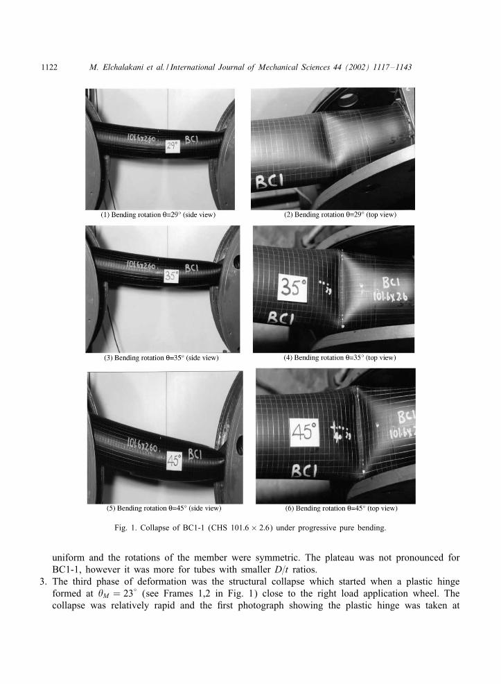
The deformed shape of cold-formed circular hollow sections made from grade C350 material(nominal yield stress is 350 MPa) observed during the plastic bending tests was already discussedin a previous paper [6]. The measured mechanical properties of the specimens that exhibited localbuckling are given in Table 1. Other specimens with D=t ¡ 20 are excluded from this study. Thetypical behaviour and relevant observations are discussed here by considering the progressive bendingof specimen BC1. Note, specimen BC1 (CHS 101:6 × 2:6 with a nominal D=t = 39:1) was testedtwice in the pure bending rig. The term BC1-1 is used to identify the specimen which had ende9ects while the term BC1-2 is used to identify the specimen which is free from end e9ects. Otherspecimens (BC2 to BC7) were all free from end e9ects, where the plastic hinge occurred towardsthe middle of the tube. Fig. 1 shows the deJected shape of BC1-1 when progressively loaded in thepure bending rig. Fig. 2(a) and (b) show the moment-rotation response of BC1-2 and ovalisationdata for BC1-1, respectively. Fig. 3 shows the deformations of BC1-2 after testing. Observationsand measurements of BC1-1 (with end e9ects) at various stages indicated that there are three phases(regimes) of deformations.
1. The 8rst is the elastic regime up to a yield bending rotation of �y = 1:67◦. The deformations inthe tube were not obvious during this regime.
2. The second phase is the ovalisation regime where 1:67◦6�623◦. The load was fairly constantas the bending rotation � was progressively increased. The extent of this plateau (measured as aninelastic rotation) was larger for smaller D=t ratios. Fig. 2(b) shows the variation in the outsidevertical (Dv) and horizontal (Dh) diameters of BC1-1 with the rotation angle � at the middlesection of the tube. The maximum measured vertical ovalisation (normal to the neutral axis) forBC1-1 at � = 45◦ was (Dv − D)=D = 10:8% (see Fig. 2(b)). D is the mean diameter of theundeformed tube. The maximum measured horizontal ovalisation (parallel to the neutral axis) atthe same angle was (Dh − D)=D = 8:7%. The radial deformations of the tube cross section were
Table 1Mechanical properties of test specimens
Specimen Diameter Thickness D=t �1 L=D Yield �u=�y Yield Ovalization Theoretical HingeNo. D t stress rotation rotation ultimate moment
(mm) (mm) �y �y �ovalised Mp mp
(MPa) (deg) (deg) (kN m) (kN m=m)
BC1-2 101.60 2.60 39.08 14.02 7.87 365 1.28 1.67 2.00 9.11 0.58BC2 88.90 2.60 34.19 13.54 9.00 432 1.24 2.13 2.62 8.89 0.84BC3 76.10 2.30 33.09 14.57 10.51 415 1.29 2.28 2.78 5.55 0.62BC4 88.90 3.20 27.78 17.47 9.00 412 1.22 1.96 2.45 10.19 1.16BC5 60.30 2.30 26.22 17.62 13.27 433 1.17 3.04 2.80 3.58 0.64BC6 76.10 3.20 23.78 18.44 10.51 456 1.20 2.56 3.26 7.87 1.20BC7 60.30 2.90 20.79 23.57 13.27 408 1.23 3.04 3.69 4.09 0.92
1122 M. Elchalakani et al. / International Journal of Mechanical Sciences 44 (2002) 1117–1143
Fig. 1. Collapse of BC1-1 (CHS 101:6× 2:6) under progressive pure bending.
uniform and the rotations of the member were symmetric. The plateau was not pronounced forBC1-1, however it was more for tubes with smaller D=t ratios.
3. The third phase of deformation was the structural collapse which started when a plastic hingeformed at �M = 23◦ (see Frames 1,2 in Fig. 1) close to the right load application wheel. Thecollapse was relatively rapid and the 8rst photograph showing the plastic hinge was taken at

M. Elchalakani et al. / International Journal of Mechanical Sciences 44 (2002) 1117–1143 1123
(a)
(b)
0
2
4
6
8
10
0 10 20 30 40 50 60 70
θ (Deg.)
M (
kN.m
)
BC1-CHS 101.6x2.6 (D/t=39.1)
Mamalis et al. (1989)
85
90
95
100
105
110
115
0 10 20 30 40 50
θ (Deg.)
Dh,
Dv
(mm
) Horizontal Diameter, Dh
Vertical Diameter, Dv
Fig. 2. (a) Moment-rotation response for BC1-2; and (b) ovalisation data for BC1-1.
� = 29◦. The longitudinal curvature reached its maximum limiting value �u at this point. Thistype of instability is termed “limiting curvature instability” [11,19,20]. Frames 3 to 6 in Fig. 1show the development of the plastic hinge with increasing bending rotation up to � = 45◦. It isseen that the tube distorts horizontally as it kinks about a central plastic hinge (A′C ′ in Fig. 3).
2.2. Collapse mode
Immediately after the formation of the plastic hinge the tube (BC1-1) collapsed and the loaddecreased rapidly. This collapse phase is characterised by large global rotations of the ends of the
1124 M. Elchalakani et al. / International Journal of Mechanical Sciences 44 (2002) 1117–1143
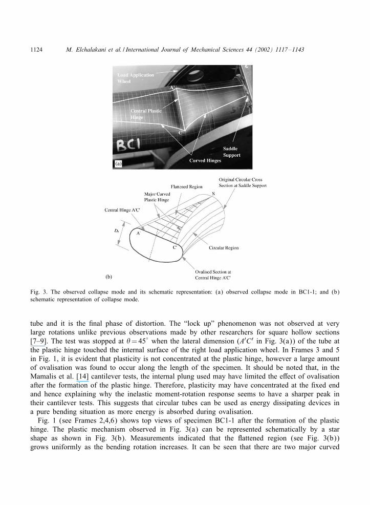
Fig. 3. The observed collapse mode and its schematic representation: (a) observed collapse mode in BC1-1; and (b)schematic representation of collapse mode.
tube and it is the 8nal phase of distortion. The “lock up” phenomenon was not observed at verylarge rotations unlike previous observations made by other researchers for square hollow sections[7–9]. The test was stopped at �=45◦ when the lateral dimension (A′C ′ in Fig. 3(a)) of the tube atthe plastic hinge touched the internal surface of the right load application wheel. In Frames 3 and 5in Fig. 1, it is evident that plasticity is not concentrated at the plastic hinge, however a large amountof ovalisation was found to occur along the length of the specimen. It should be noted that, in theMamalis et al. [14] cantilever tests, the internal plung used may have limited the e9ect of ovalisationafter the formation of the plastic hinge. Therefore, plasticity may have concentrated at the 8xed endand hence explaining why the inelastic moment-rotation response seems to have a sharper peak intheir cantilever tests. This suggests that circular tubes can be used as energy dissipating devices ina pure bending situation as more energy is absorbed during ovalisation.
Fig. 1 (see Frames 2,4,6) shows top views of specimen BC1-1 after the formation of the plastichinge. The plastic mechanism observed in Fig. 3(a) can be represented schematically by a starshape as shown in Fig. 3(b). Measurements indicated that the Jattened region (see Fig. 3(b))grows uniformly as the bending rotation increases. It can be seen that there are two major curved
M. Elchalakani et al. / International Journal of Mechanical Sciences 44 (2002) 1117–1143 1125
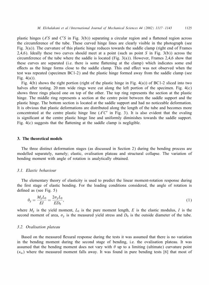
plastic hinges (A′S and C ′S in Fig. 3(b)) separating a circular region and a Jattened region acrossthe circumference of the tube. These curved hinge lines are clearly visible in the photograph (seeFig. 3(a)). The curvature of this plastic hinge reduces towards the saddle clamp (right end of Frames2,4,6). Ideally these two curves should meet at a point (such as point S in Fig. 3(b)) across thecircumference of the tube where the saddle is located (Fig. 3(a)). However, Frames 2,4,6 show thatthese curves are separated (i.e. there is some Jattening at the clamp) which indicates some ende9ects as the hinge forms close to the saddle clamp. This end e9ect was not observed when thetest was repeated (specimen BC1-2) and the plastic hinge formed away from the saddle clamp (seeFig. 4(a)).
Fig. 4(b) shows the right portion (right of the plastic hinge in Fig. 4(a)) of BC1-2 sliced into twohalves after testing. 20 mm wide rings were cut along the left portion of the specimen. Fig. 4(c)shows three rings placed one on top of the other. The top ring represents the section at the plastichinge. The middle ring represents a section at the centre point between the saddle support and theplastic hinge. The bottom section is located at the saddle support and had no noticeable deformation.It is obvious that plastic deformations are distributed along the length of the tube and becomes moreconcentrated at the centre plastic hinge line (A′C ′ in Fig. 3). It is also evident that the ovalingis signi8cant at the centre plastic hinge line and uniformly diminishes towards the saddle support.Fig. 4(c) suggests that the Jattening at the saddle clamp is negligible.
3. The theoretical models
The three distinct deformation stages (as discussed in Section 2) during the bending process aremodelled separately, namely; elastic, ovalisation plateau and structural collapse. The variation ofbending moment with angle of rotation is analytically obtained.
3.1. Elastic behaviour
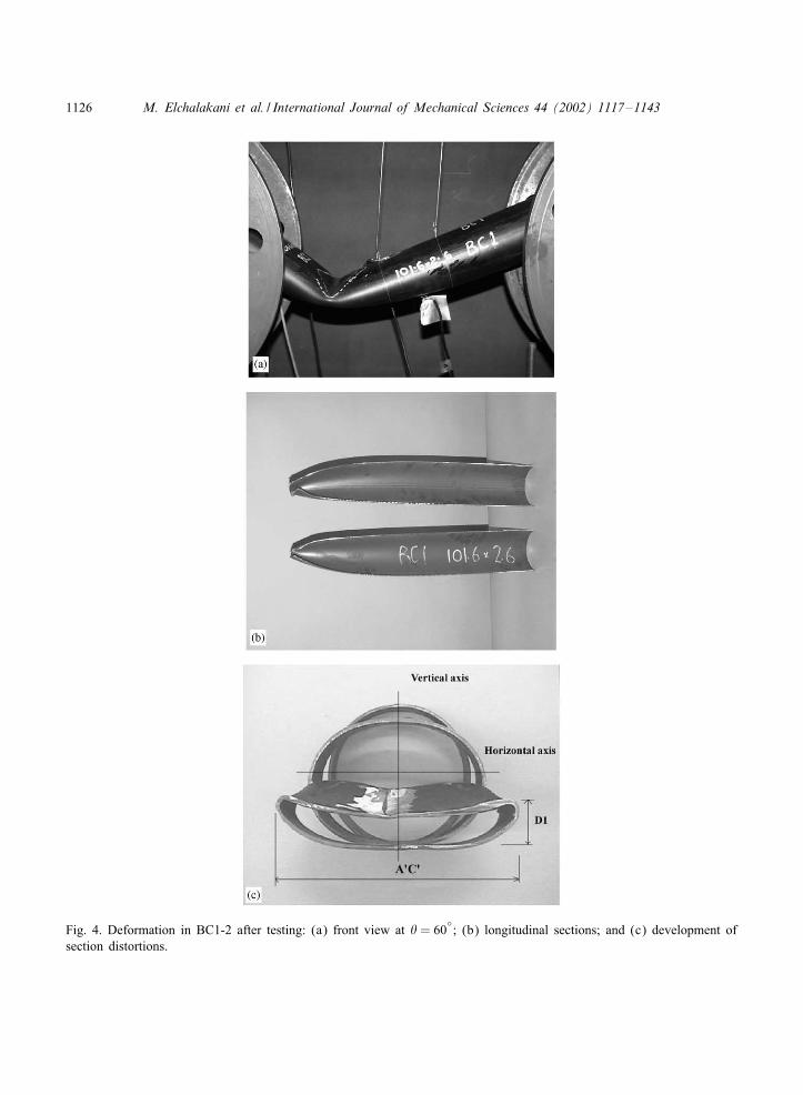
The elementary theory of elasticity is used to predict the linear moment-rotation response duringthe 8rst stage of elastic bending. For the loading conditions considered, the angle of rotation isde8ned as (see Fig. 5)
�y =MyL0EI
=2�yL0ED0
; (1)
where My is the yield moment, L0 is the pure moment length, E is the elastic modulus, I is thesecond moment of area, �y is the measured yield stress and D0 is the outside diameter of the tube.
3.2. Ovalisation plateau
Based on the measured Jexural response during the tests it was assumed that there is no variationin the bending moment during the second stage of bending, i.e. the ovalisation plateau. It wasassumed that the bending moment does not vary with � up to a limiting (ultimate) curvature point(�u) where the measured moment falls away. It was found in pure bending tests [6] that most of
1126 M. Elchalakani et al. / International Journal of Mechanical Sciences 44 (2002) 1117–1143
Fig. 4. Deformation in BC1-2 after testing: (a) front view at � = 60◦; (b) longitudinal sections; and (c) development of
section distortions.
M. Elchalakani et al. / International Journal of Mechanical Sciences 44 (2002) 1117–1143 1127
A B
θ
Saddle Support
Load ApplicationWheel
Specimen
Fig. 5. Large deformations of tubes under pure bending.
LO
D
A
C
S
F2
F1
E2
E1
U
h1 h2
ll
l l
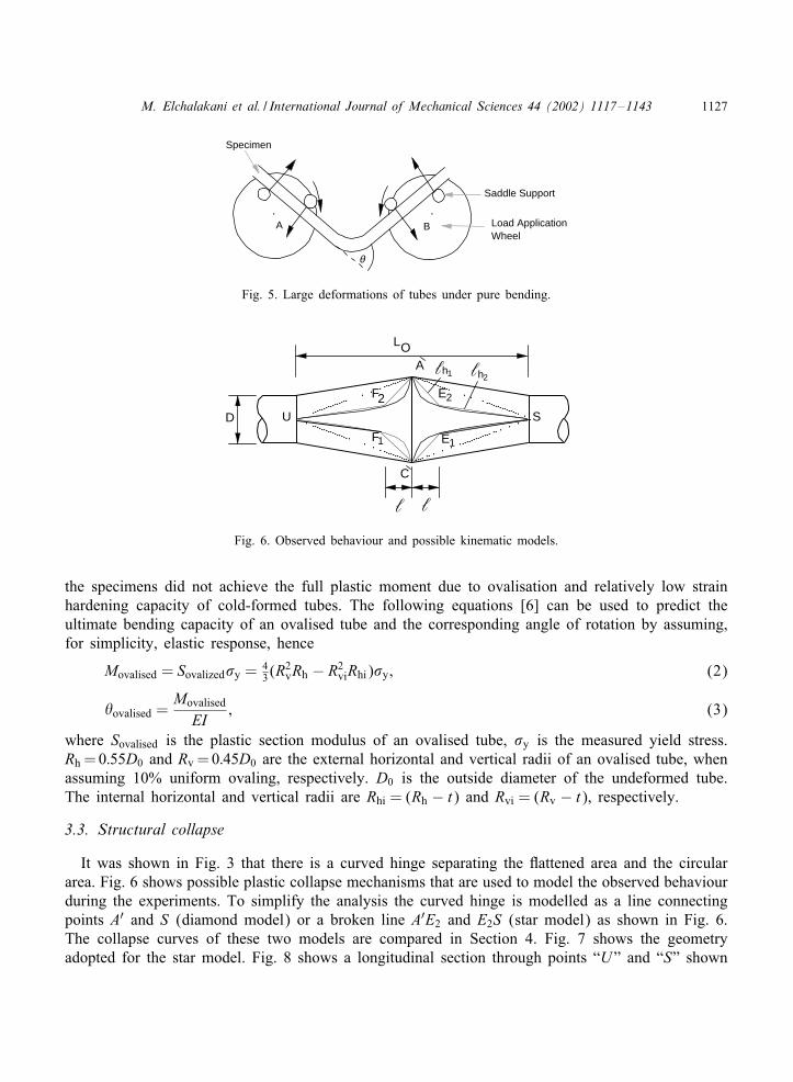
Fig. 6. Observed behaviour and possible kinematic models.
the specimens did not achieve the full plastic moment due to ovalisation and relatively low strainhardening capacity of cold-formed tubes. The following equations [6] can be used to predict theultimate bending capacity of an ovalised tube and the corresponding angle of rotation by assuming,for simplicity, elastic response, hence
Movalised = Sovalized�y = 43(R
2vRh − R2
viRhi)�y; (2)
�ovalised =Movalised
EI; (3)
where Sovalised is the plastic section modulus of an ovalised tube, �y is the measured yield stress.Rh =0:55D0 and Rv =0:45D0 are the external horizontal and vertical radii of an ovalised tube, whenassuming 10% uniform ovaling, respectively. D0 is the outside diameter of the undeformed tube.The internal horizontal and vertical radii are Rhi = (Rh − t) and Rvi = (Rv − t), respectively.
3.3. Structural collapse
It was shown in Fig. 3 that there is a curved hinge separating the Jattened area and the circulararea. Fig. 6 shows possible plastic collapse mechanisms that are used to model the observed behaviourduring the experiments. To simplify the analysis the curved hinge is modelled as a line connectingpoints A′ and S (diamond model) or a broken line A′E2 and E2S (star model) as shown in Fig. 6.The collapse curves of these two models are compared in Section 4. Fig. 7 shows the geometryadopted for the star model. Fig. 8 shows a longitudinal section through points “U” and “S” shown
1128 M. Elchalakani et al. / International Journal of Mechanical Sciences 44 (2002) 1117–1143
LO
D
A
C
S
F2
F1
E2
E1
U
h1 h2
O- 2
h2
h1
(AC/4)
(AC/2)
LO
A
E2
S
L
/2I
IIIII
I
II III
ll
ll
l
l
ll
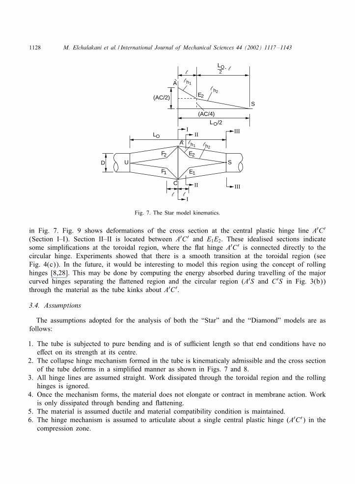
Fig. 7. The Star model kinematics.
in Fig. 7. Fig. 9 shows deformations of the cross section at the central plastic hinge line A′C ′(Section I–I). Section II–II is located between A′C ′ and E1E2. These idealised sections indicatesome simpli8cations at the toroidal region, where the Jat hinge A′C ′ is connected directly to thecircular hinge. Experiments showed that there is a smooth transition at the toroidal region (seeFig. 4(c)). In the future, it would be interesting to model this region using the concept of rollinghinges [8,28]. This may be done by computing the energy absorbed during travelling of the majorcurved hinges separating the Jattened region and the circular region (A′S and C ′S in Fig. 3(b))through the material as the tube kinks about A′C ′.
3.4. Assumptions
The assumptions adopted for the analysis of both the “Star” and the “Diamond” models are asfollows:
1. The tube is subjected to pure bending and is of su4cient length so that end conditions have noe9ect on its strength at its centre.
2. The collapse hinge mechanism formed in the tube is kinematicaly admissible and the cross sectionof the tube deforms in a simpli8ed manner as shown in Figs. 7 and 8.
3. All hinge lines are assumed straight. Work dissipated through the toroidal region and the rollinghinges is ignored.
4. Once the mechanism forms, the material does not elongate or contract in membrane action. Workis only dissipated through bending and Jattening.
5. The material is assumed ductile and material compatibility condition is maintained.6. The hinge mechanism is assumed to articulate about a single central plastic hinge (A′C ′) in the
compression zone.
M. Elchalakani et al. / International Journal of Mechanical Sciences 44 (2002) 1117–1143 1129
S
T
G HI
F1,2 E1,2C,A
LO /2
U
V
D
G HI
F1,2
E1,2
C,Aρ D2
x
y
D1
y
x
-D2sin ρ
α
θ
γ = θ/2−ζ
ζ
l
l
l l
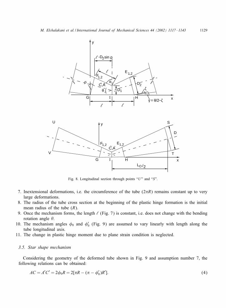
Fig. 8. Longitudinal section through points “U” and “S”.
7. Inextensional deformations, i.e. the circumference of the tube (2 R) remains constant up to verylarge deformations.
8. The radius of the tube cross section at the beginning of the plastic hinge formation is the initialmean radius of the tube (R).
9. Once the mechanism forms, the length ‘ (Fig. 7) is constant, i.e. does not change with the bendingrotation angle �.
10. The mechanism angles �0 and �′0 (Fig. 9) are assumed to vary linearly with length along the
tube longitudinal axis.11. The change in plastic hinge moment due to plane strain condition is neglected.
3.5. Star shape mechanism
Considering the geometry of the deformed tube shown in Fig. 9 and assumption number 7, thefollowing relations can be obtained:
AC = A′C ′ = 2�0R= 2[ R− ( − �′0)R
′]: (4)
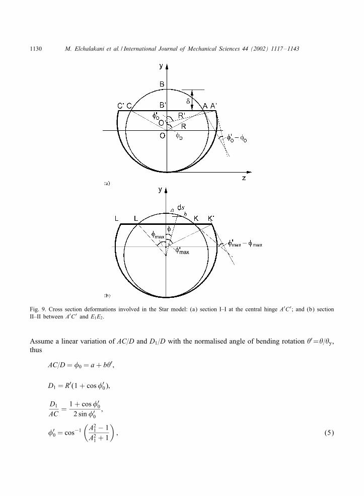
1130 M. Elchalakani et al. / International Journal of Mechanical Sciences 44 (2002) 1117–1143
Fig. 9. Cross section deformations involved in the Star model: (a) section I–I at the central hinge A′C′; and (b) sectionII–II between A′C′ and E1E2.
Assume a linear variation of AC=D and D1=D with the normalised angle of bending rotation �′=�=�y,thus
AC=D = �0 = a+ b�′;
D1 = R′(1 + cos�′0);
D1
AC=
1 + cos�′0
2 sin�′0;
�′0 = cos−1
(A21 − 1
A21 + 1
); (5)
M. Elchalakani et al. / International Journal of Mechanical Sciences 44 (2002) 1117–1143 1131
where
A1 = 2(c + k�′
a+ b�′
):
Empirical values of the parameters a; b; c and k were obtained from measurements of the mecha-nism dimensions A′C ′ and D1. Constant values of a=0:6541, b=0:0244 and c=1:259 were foundsuitable to represent the linear relationship between �0 and �′
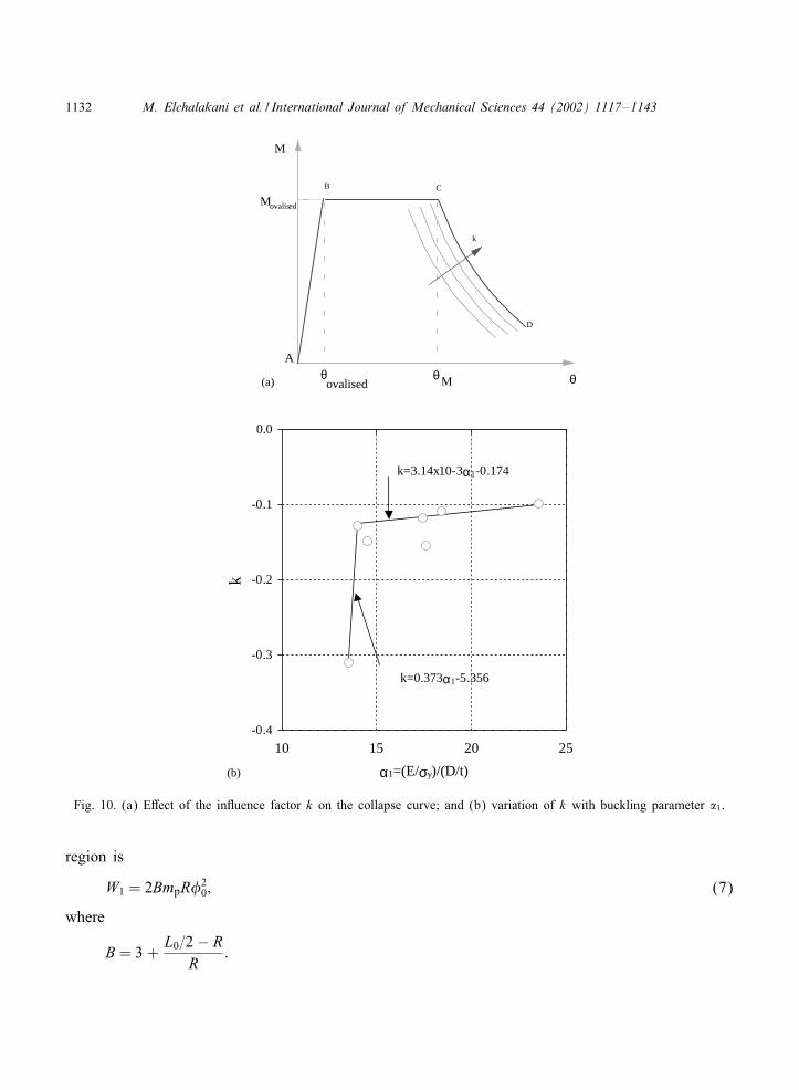
0 with �′ for all D=t ratios tested inRef. [6]. The ordinates and slope of the collapse curve were strongly dependent on the parameterk (see Fig. 10(a)) which is called the inJuence factor in this paper. Note the arrow in Fig. 10(a)indicates the direction of increase of k. Point C in Fig. 10(a) represents the intersection of the pre-dicted ovalisation plateau (Eq. (2)) with the experimental collapse curve. Suitable values of k wereselected to have the predicted collapse curve (segment CD in Fig. 10(a)) cutting the segment BC atC. This was performed using a parameteric study. The values of k obtained in this study are plottedagainst the buckling parameter �1 and shown in Fig. 10(b) (scatter points). A bilinear regressionbetween k and �1 is shown in the inset. This relationship is used to derive a closed-form solution inSection 3.6. It is clearly seen (see Fig. 10(b)) that the trend is very similar to the variation of therotation capacity and �1 given in Ref. [6]. Previous research by Wilkinson [29] on RHS (rectangularhollow section) beams under 4-point bending showed that the collapse curve dependent heavily ongeometrical imperfections. Fig. 10(b) indicates that the larger D=t is, the smaller is the inJuencefactor k and the earlier is the collapse point (see Fig. 10(a)). It seems that the inJuence factor krepresents, to some extent, the e9ect of geometrical imperfection, ovalisation and section slendernessof CHS beams.
The internal work dissipated during crushing of the tube laterally Wint is composed of four majorcomponents, namely, work dissipated in the Jattening of the star shape region (W1), work dissipatedin the Jattening of the circular region (W2), work dissipated in the plastic deformation over thecentral hinge (W3) and work dissipated during bending over the eight oblique hinge lines (W4).These four components are now analysed separately.
3.5.1. Work dissipated in the 6attening of the star shape regionThe increment of plastic work per unit length dissipated in yielding and complete Jattening of an
arc ds= ab as shown in Fig. 9(b) is [14,30]
dW1 = 2�mp ds; (6)
where mp =�yt2=4 is the full plastic moment of a unit length of the tube. Integrating over the wholearc KL
W1 = 2∫ s
02mp� ds= 2
∫ �max
02mpR� d�= 2mpR�2
max:
The y-axis is considered at a distance x = ‘ (Fig. 8) from the central hinge A′C ′. It is assumedthat the angle �max varies linearly from zero to �0=2 over the length ‘ and also varies linearlyfrom �0=2 to �0 over the remaining length L0=2− ‘. If we assume an average ratio of A′C ′=R= 2during the collapse phase, the total plastic work dissipated through Jattening of the star shape
1132 M. Elchalakani et al. / International Journal of Mechanical Sciences 44 (2002) 1117–1143
M
θovalisedθMθ
Movalised
k
A
B C
D
-0.4
-0.3
-0.2
-0.1
0.0
10 15 20 25
α1=(E/σy)/(D/t)
k
k=0.373α1-5.356
k=3.14x10⁻³α1-0.174
(a)
(b)
Fig. 10. (a) E9ect of the inJuence factor k on the collapse curve; and (b) variation of k with buckling parameter �1.
region is
W1 = 2BmpR�20; (7)
where
B= 3 +L0=2− R
R:
M. Elchalakani et al. / International Journal of Mechanical Sciences 44 (2002) 1117–1143 1133
3.5.2. Work dissipated in the 6attening of the circular regionThe work required to partially Jatten an arc ds of initial central angle � to a deformed arc, where
the angular di9erence in the tangent is V�; is
dW2 = 2mp dsV� (8)
W2 = 2∫
�max
mpR d�∫ �′
max−�max
0V�= 2mpR( − �max)(�′
max − �max): (9)
Introducing similar assumptions for the variation of �′max with length as those made for Jattening
of the star region, the total plastic work dissipated throughout the pure bending length L0 is equalto
W2 = 2BmpR( − �0)(�′0 − �0): (10)
3.5.3. Work dissipated in the plastic deformation over the central hinge (A′C ′)Rotation of the tube through an angle �=2# (see Fig. 8) creates a relative angle of rotation over
the plastic hinge line A′C ′ equal to − 2�, where
�= sin−1
(1− D2
‘sin #
)(11)
and
D2 = �0R(1 + cos�′
0=22 sin�′
0=2
):
The corresponding dissipated plastic work is thus
W3 = AC mp( − 2�) = 2�0Rmp( − 2�): (12)
3.5.4. Work dissipated during bending over the eight oblique hinge lines A′E2; A′F2; F2U; E2S; CE1;CF1; F1U and E1SWithin the length 2‘, the plastic work per unit length dissipated at hinge K ′ (see Fig. 9(b)) is
mp times the change of angle before and after the hinge (V�′ = �′max − 0 = �′
max).
dw4 = mp�′max: (13)
It is assumed that the angle �′max varies linearly over the length ‘h1 and equals �′
0=2 at x = 0 and�′0 at x = ‘. Thus
�′max(x) = �′
0=2 + x�′0=2‘:
Therefore after integrating
W4 = 4∫ ‘h1
0mp
(x�′
0
2‘+
�′0
2
)dx = 2mp�′
0
(‘2h12‘
+ ‘h1
); (14)
where ‘h1 =√‘2 + AC2=4.
1134 M. Elchalakani et al. / International Journal of Mechanical Sciences 44 (2002) 1117–1143
Over the remaining part of the tube (L0 − 2‘), the angle �′max varies linearly over the length ‘h2
and equals �′0=2 at x = L0=2− ‘ and zero at x = 0. Following the same procedure, the plastic work
dissipated along the length ‘h2
W5 = 4∫ ‘h2
0mp
x�′0
2(L0=2− ‘)dx = mp�′
0‘2h2
(L0=2− ‘); (15)
where ‘h2 =√
(L0=2− ‘)2 + AC2=4.The total internal plastic work dissipated during lateral crushing of the tube is
Wint(�) =5∑1
Wi(�): (16)
The external plastic work is
Wext(�) =M d�: (17)
Equating the external work to the internal work, the instantaneous bending moment is
M (�) =dd�
5∑i=1
Wint(�) (18)
3.6. Simpli9ed star model
Eq. (18) provides a closed-form solution for the moment-rotation response for the star model.However, the resulting equation may be too complex to use in routine design. Therefore, to obtaina simpli8ed version, a number of assumptions have been made in addition to those already noted inthe previous section. The e9ects of these assumptions are examined in Section 4. When calculatingthe angle �, it can be assumed that D2 =D. Also, it can be assumed the sum of lengths ‘h1 and ‘h2can be approximated by the hinge length ‘h = AS (Fig. 7), thus
�= sin−1
(1− D
‘sin #
); (19a)
‘h = AS =√(L0=2)2 + AC2=4: (19b)
Hence the total work dissipated within the length ‘h is
W4;5 = 4∫ ‘h
0mp
x�′0
L0=2dx = 4mp�′
0‘2hL0: (20)
Measurements during the test showed that the length ‘ varies with the angle of rotation �. However,to simplify the analysis ‘ was taken as the mean radius of the tube R during lateral crushing of thetube.
The components of the instantaneous bending moment can be written after di9erentiation usingthe following relationship:
Mi =dd�′
d�′
d�Wi:
M. Elchalakani et al. / International Journal of Mechanical Sciences 44 (2002) 1117–1143 1135
LO
A
C
SU
h
D
l
Fig. 11. The diamond model.
The total bending moment is the algebraic sum of the above components, i.e.
M =M1 +M2 +M3 +M4;5: (21)
Appendix B gives full details of Eq. (21). To determine the collapse curve, Eqs. (19) and (20)were used in lieu of Equations (11), (14) and (15).
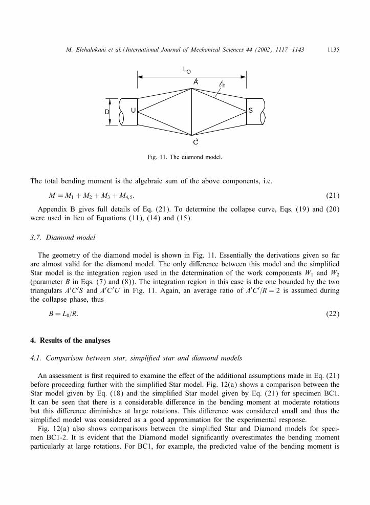
3.7. Diamond model
The geometry of the diamond model is shown in Fig. 11. Essentially the derivations given so farare almost valid for the diamond model. The only di9erence between this model and the simpli8edStar model is the integration region used in the determination of the work components W1 and W2
(parameter B in Eqs. (7) and (8)). The integration region in this case is the one bounded by the twotriangulars A′C ′S and A′C ′U in Fig. 11. Again, an average ratio of A′C ′=R = 2 is assumed duringthe collapse phase, thus
B= L0=R: (22)
4. Results of the analyses
4.1. Comparison between star, simpli9ed star and diamond models
An assessment is 8rst required to examine the e9ect of the additional assumptions made in Eq. (21)before proceeding further with the simpli8ed Star model. Fig. 12(a) shows a comparison between theStar model given by Eq. (18) and the simpli8ed Star model given by Eq. (21) for specimen BC1.It can be seen that there is a considerable di9erence in the bending moment at moderate rotationsbut this di9erence diminishes at large rotations. This di9erence was considered small and thus thesimpli8ed model was considered as a good approximation for the experimental response.
Fig. 12(a) also shows comparisons between the simpli8ed Star and Diamond models for speci-men BC1-2. It is evident that the Diamond model signi8cantly overestimates the bending momentparticularly at large rotations. For BC1, for example, the predicted value of the bending moment is
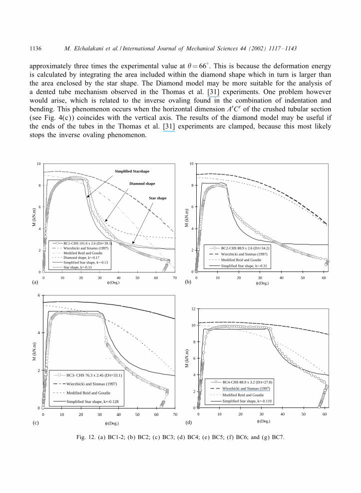
1136 M. Elchalakani et al. / International Journal of Mechanical Sciences 44 (2002) 1117–1143
approximately three times the experimental value at �=66◦. This is because the deformation energyis calculated by integrating the area included within the diamond shape which in turn is larger thanthe area enclosed by the star shape. The Diamond model may be more suitable for the analysis ofa dented tube mechanism observed in the Thomas et al. [31] experiments. One problem howeverwould arise, which is related to the inverse ovaling found in the combination of indentation andbending. This phenomenon occurs when the horizontal dimension A′C ′ of the crushed tubular section(see Fig. 4(c)) coincides with the vertical axis. The results of the diamond model may be useful ifthe ends of the tubes in the Thomas et al. [31] experiments are clamped, because this most likelystops the inverse ovaling phenomenon.
0
2
4
6
8
10
0 10 20 30 40 50 60 70θ (Deg.)
BC1-CHS 101.6 x 2.6 (D/t=39.1)Wierzbicki and Sinamo (1997)Modified Reid and GoudieDiamond shape, k=-0.17Simplified Star shape, k=-0.13Star shape, k=-0.13
Simplified Starshape
Diamond shape
Star shape
0
2
4
6
8
10
0 10 20 30 40 50 60
θ (Deg.)
BC2-CHS 88.9 x 2.6 (D/t=34.2)
Wierzbicki and Sinmao (1997)
Modified Reid and Goudie
Simplified Star shape, k=-0.31
0
2
4
6
0 10 20 30 40 50 60 70
θ (Deg.)
BC3- CHS 76.3 x 2.45 (D/t=33.1)
Wierzbicki and Sinmao (1997)
Modified Reid and Goudie
Simplified Star shape, k=-0.128
` `̀
0
2
4
6
8
10
12
0 10 20 30 40 50 60
θ (Deg.)
(a) (b)
(c) (d)
M (
kN.m
)
M (
kN.m
) M
(kN
.m)
M (
kN.m
)
BC4-CHS 88.9 x 3.2 (D/t=27.8)
Wierzbicki and Sinmao (1997)
Modified Reid and Goudie
Simplified Star shape, k=-0.119
Fig. 12. (a) BC1-2; (b) BC2; (c) BC3; (d) BC4; (e) BC5; (f) BC6; and (g) BC7.
M. Elchalakani et al. / International Journal of Mechanical Sciences 44 (2002) 1117–1143 1137
0
1
2
3
4
0 10 20 30 40 50 60 70
θ (Deg.)
M (
kN.m
)
BC5-CHS 60.3 x 2.30 (D/t=26.2)
Wierzbicki and Sinmao (1997)
Modified Reid and Goudie
Simplified Star shape, k=-0.119
0
2
4
6
8
10
0 10 20 30 40 50 60 70
θ (Deg.)
θ (Deg.)
BC6-CHS 76.1 x 3.20 (D/t=23.8)
Wierzbicki and Sinmao (1997)
Modified Reid and Goudie
Simplified Star shape, k=-0.11
0
1
2
3
4
5
0 10 20 30 40 50 60 70
BC7-CHS 60.3 x 2.9 (D/t=20.8)Wierzbicki and Sinmao (1997)Modified Reid and GoudieSimplified Star shape, k=-0.10
(e) (f)
(g)
M (
kN.m
)
M (
kN.m
)
Fig. 12. Continued.
4.2. Comparison with experimental results
Since the simpli8ed star model gave satisfactory agreement with the measured moment-rotationresponse for specimen BC1-2 [6], it was used to predict the response of the other specimens.
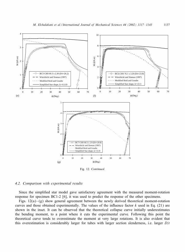
Figs. 12(a)–(g) show general agreement between the newly derived theoretical moment-rotationcurves and those obtained experimentally. The values of the inJuence factor k used in Eq. (21) areshown in the inset. It can be observed that the theoretical collapse curve initially underestimatesthe bending moment, to a point where it cuts the experimental curve. Following this point thetheoretical curve tends to overestimate the moment at very large rotations. It is also evident thatthis overestimation is considerably larger for tubes with larger section slenderness, i.e. larger D=t
1138 M. Elchalakani et al. / International Journal of Mechanical Sciences 44 (2002) 1117–1143
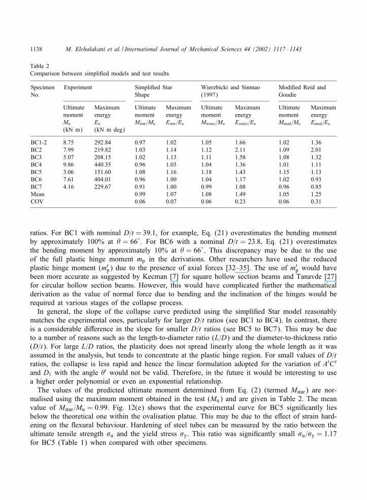
Table 2Comparison between simpli8ed models and test results
Specimen Experiment Simpli8ed Star Wierzbicki and Sinmao Modi8ed Reid andNo. Shape (1997) Goudie
Ultimate Maximum Ultimate Maximum Ultimate Maximum Ultimate Maximummoment energy moment energy moment energy moment energyMu Eu Mstar=Mu Estar=Eu Mwierz=Mu Ewierz=Eu Mmod=Mu Emod=Eu
(kN m) (kN m deg)
BC1-2 8.75 292.84 0.97 1.02 1.05 1.66 1.02 1.36BC2 7.99 219.82 1.03 1.14 1.12 2.11 1.09 2.01BC3 5.07 208.15 1.02 1.13 1.11 1.58 1.08 1.32BC4 9.86 440.35 0.96 1.03 1.04 1.36 1.01 1.11BC5 3.06 151.60 1.08 1.16 1.18 1.43 1.15 1.13BC6 7.61 404.01 0.96 1.00 1.04 1.17 1.02 0.93BC7 4.16 229.67 0.91 1.00 0.99 1.08 0.96 0.85Mean 0.99 1.07 1.08 1.49 1.05 1.25COV 0.06 0.07 0.06 0.23 0.06 0.31
ratios. For BC1 with nominal D=t = 39:1, for example, Eq. (21) overestimates the bending momentby approximately 100% at � = 66◦. For BC6 with a nominal D=t = 23:8, Eq. (21) overestimatesthe bending moment by approximately 10% at � = 66◦. This discrepancy may be due to the useof the full plastic hinge moment mp in the derivations. Other researchers have used the reducedplastic hinge moment (m′
p) due to the presence of axial forces [32–35]. The use of m′p would have
been more accurate as suggested by Kecman [7] for square hollow section beams and Tanavde [27]for circular hollow section beams. However, this would have complicated further the mathematicalderivation as the value of normal force due to bending and the inclination of the hinges would berequired at various stages of the collapse process.
In general, the slope of the collapse curve predicted using the simpli8ed Star model reasonablymatches the experimental ones, particularly for larger D=t ratios (see BC1 to BC4). In contrast, thereis a considerable di9erence in the slope for smaller D=t ratios (see BC5 to BC7). This may be dueto a number of reasons such as the length-to-diameter ratio (L=D) and the diameter-to-thickness ratio(D=t). For large L=D ratios, the plasticity does not spread linearly along the whole length as it wasassumed in the analysis, but tends to concentrate at the plastic hinge region. For small values of D=tratios, the collapse is less rapid and hence the linear formulation adopted for the variation of A′C ′and D1 with the angle �′ would not be valid. Therefore, in the future it would be interesting to usea higher order polynomial or even an exponential relationship.
The values of the predicted ultimate moment determined from Eq. (2) (termed Mstar) are nor-malised using the maximum moment obtained in the test (Mu) and are given in Table 2. The meanvalue of Mstar=Mu = 0:99. Fig. 12(e) shows that the experimental curve for BC5 signi8cantly liesbelow the theoretical one within the ovalisation platue. This may be due to the e9ect of strain hard-ening on the Jexural behaviour. Hardening of steel tubes can be measured by the ratio between theultimate tensile strength �u and the yield stress �y. This ratio was signi8cantly small �u=�y = 1:17for BC5 (Table 1) when compared with other specimens.
M. Elchalakani et al. / International Journal of Mechanical Sciences 44 (2002) 1117–1143 1139
4.3. Comparison with other simpli9ed theories
Figs. 12(a)–(g) show comparisons between experimental data and the newly derived simpli8edStar model (Eq. (21)), and available models such as Wierzbicki and Sinmao model [26] and Modi8edReid and Goudie model [36]. The equations used in these models are shown in Appendix A. Table 2shows a summary of the bending strength and absorbed energy measured in Ref. [6] and predictedusing available models [26,36] and the newly derived Star model. The energy was determined asthe area under moment-rotation curve up to �= 60◦. Figs. 12(a)–(g) show that the Wierzbicki andSinmao curve typically lies above the experimental curve. Their model overestimates the energyabsorbed for tubes with large D=t ratios. This is mainly because their model does not consider thesoftening due to the formation of the plastic hinge (kink). It only considers the reduction in strengthdue to signi8cant ovaling. Wierzbicki and Suh [37] analysed the star model using the velocity 8eldmethod for the case of combined bending, axial force and lateral indentation. They included thesoftening in their model due to the formation of the plastic hinge at the concentrated lateral load. Itwould be interesting to extend their analysis for pure bending condition. The simpli8ed star modelaccurately predicts the bending strength, but overestimates the energy consumed during deformationsby 7%. The simpli8ed Wierzbicki and Sinmao model overestimates the bending strength by 8% andthe absorbed energy by 49%. Figs. 12(a)–(g) show that the Modi8ed Reid and Goudie [36] curvetypically lies above the experimental one for small rotations, while it is located below it for largerotations. Their model overestimates the bending strength by 5% and the absorbed energy by 25%.
An examination of the Mamalis et al. [14] model revealed that neglecting the ovalisation duringcollapse signi8cantly underestimates the bending moments. It was found that if one only consideredthe energy dissipated within the central plastic hinge, identi8ed by the length ‘ (as it was assumedin Mamalis et al. [14]), and neglected the energy absorbed in the remaining length of the tube dueto ovalisation, Eq. (21) predicted only approximately 25% of the experimental bending moment.
5. Conclusions
This paper described a theoretical study of the behaviour of cold-formed circular hollow steel tubessubjected to pure bending where 20¡D=t ¡ 40. Two kinematic models were analysed, a diamondand a star shape plastic mechanisms. In general, the simpli8ed Star model was found to be in goodagreement with test results. The results of the plastic pure bending tests [6] were compared withthe simpli8ed Star model, simpli8ed Wierzbicki and Sinmao [26] model, and the Modi8ed Reid andGoudie model [36] commonly used in the analysis of dented tubular members. It was found that:
1. The predicted slope of the collapse curve using the simpli8ed Star model matches the experimentalcurve reasonably well. It seems that the collapse curve depends heavily on the inJuence factor k,which represents the e9ect of geometrical imperfection, ovalisation and section slenderness. Thismodel predicts the bending strength accurately, but overestimates the energy dissipated duringdeformation by 7%.
2. The Diamond model signi8cantly overestimates the bending moments at large rotations.3. The simpli8ed Wierzbicki and Sinmao [26] model overestimates the bending strength by 8% and
the energy dissipated during deformation by 49%.
1140 M. Elchalakani et al. / International Journal of Mechanical Sciences 44 (2002) 1117–1143
4. The Modi8ed Reid and Goudie [36] model overestimates the bending strength by 5% and theenergy dissipated during deformation by 25%.
5. The Mamalis et al. [14] kinematics model is not suitable for predicting the moment-rotationresponse of low diameter-to-thickness ratio tubes subjected to pure bending.
Acknowledgements
The writers are grateful to the Australian Research Council and Monash University for their 8nan-cial assistance for the project. Thanks are given to Palmer Tube Mills for providing the steel tubes.The experiments were carried out in the Civil Engineering Laboratory at Monash University and thetechnical assistance of Mr. Graham Rundle and Mr. Geo9 Doddrell is gratefully acknowledged.
Appendix A. Available closed-form solutions
All terms are de8ned in Figs. 8–11.
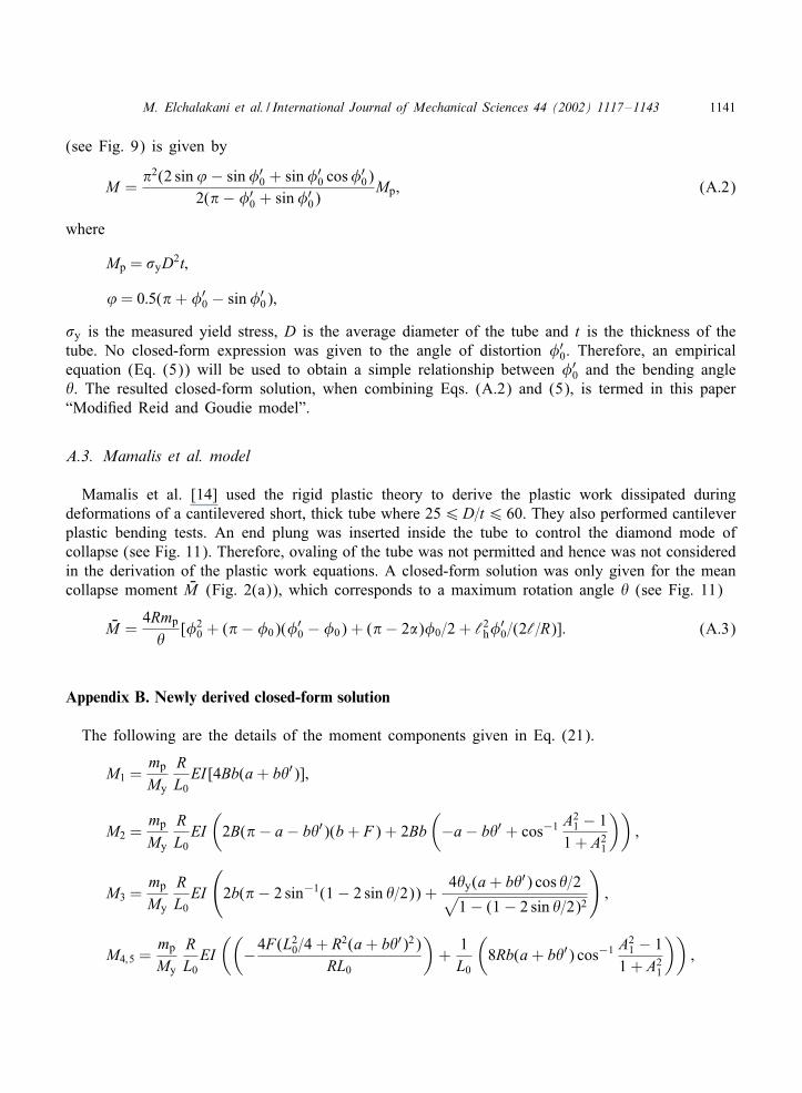
A.1. Wierzbicki and Sinmao model
Wierzbicki and Sinmao [26] used the velocity 8eld method under the assumption of inextensi-ble deformations to derive a simpli8ed closed-form solution for moment-curvature response of athick-walled tube under pure bending. Two closed form solutions were presented in their paper. The8rst solution (simpli8ed model) was based on a perfect plastic behaviour of the material at largebending rotations. In the second solution corrections were applied to the 8rst model to account forstrain hardening. The simpli8ed model for the moment-curvature response is given by
MMp
= (1− 0:533R2�=t)(1:011 + 0:644R2�=t); (A.1)
where � is the bending curvature in the longitudinal (x-direction), t is the thickness of the tube,R is the mean radius of the tube, Mp is the full plastic bending strength of the undeformed tubecross section. Eq. (A.1) is examined in Section 5. In the current paper the curvature was taken as�=�=L0, where � is the relative rotation of the ends of the pure moment region and L0 is the lengthof this region.
A.2. Reid and Goudie model
Reid and Goudie [31] used a simpli8ed approach to determine the capacity of a dented tube crosssection. This problem often arises in process and power plants and o9shore structures where there isa risk of collision [29,30]. The plastic deformations developed due to indentation are very similar tothose obtained under pure bending. In their analysis, they assumed uniform yield stress (in tensionand compression regions) along the depth of the cross section and from statics the moment wasdetermined by simple integration. The resulted plastic bending strength at the central dented section
M. Elchalakani et al. / International Journal of Mechanical Sciences 44 (2002) 1117–1143 1141
(see Fig. 9) is given by
M = 2(2 sin’− sin�′
0 + sin�′0 cos�
′0)
2( − �′0 + sin�′
0)Mp; (A.2)
where
Mp = �yD2t;
’= 0:5( + �′0 − sin�′
0);
�y is the measured yield stress, D is the average diameter of the tube and t is the thickness of thetube. No closed-form expression was given to the angle of distortion �′
0. Therefore, an empiricalequation (Eq. (5)) will be used to obtain a simple relationship between �′
0 and the bending angle�. The resulted closed-form solution, when combining Eqs. (A.2) and (5), is termed in this paper“Modi8ed Reid and Goudie model”.
A.3. Mamalis et al. model
Mamalis et al. [14] used the rigid plastic theory to derive the plastic work dissipated duringdeformations of a cantilevered short, thick tube where 256D=t6 60. They also performed cantileverplastic bending tests. An end plung was inserted inside the tube to control the diamond mode ofcollapse (see Fig. 11). Therefore, ovaling of the tube was not permitted and hence was not consideredin the derivation of the plastic work equations. A closed-form solution was only given for the meancollapse moment HM (Fig. 2(a)), which corresponds to a maximum rotation angle � (see Fig. 11)
HM =4Rmp
�[�2
0 + ( − �0)(�′0 − �0) + ( − 2�)�0=2 + ‘2h�
′0=(2‘=R)]: (A.3)
Appendix B. Newly derived closed-form solution
The following are the details of the moment components given in Eq. (21).
M1 =mp
My
RL0EI [4Bb(a+ b�′)];
M2 =mp
My
RL0EI(2B( − a− b�′)(b+ F) + 2Bb
(−a− b�′ + cos−1 A
21 − 1
1 + A21
));
M3 =mp
My
RL0EI
(2b( − 2 sin−1(1− 2 sin �=2)) +
4�y(a+ b�′) cos �=2√1− (1− 2 sin �=2)2
);
M4;5 =mp
My
RL0EI((
−4F(L20=4 + R2(a+ b�′)2)RL0
)+
1L0
(8Rb(a+ b�′) cos−1 A
21 − 1
1 + A21
));
1142 M. Elchalakani et al. / International Journal of Mechanical Sciences 44 (2002) 1117–1143
where
F =
(−2bA21
a+ b�′+
2kA1
c + k�′
)(A2
1 − 1)
(1 + A21)2
+
(−2bA21
a+ b�′+
2kA1
c + k�′
)1 + A2
1√1− (A2
1 − 1)2
(1 + A21)2
;
mp =�yt2
4:
References
[1] Calladine CR. Analysis of large plastic deformations in shell structures. In: Inelastic behaviour of plates and shells.Cambridge, 1985. p. 1–101.
[2] Alexander JM. An approximate analysis of the collapse of thin cylindrical shells under axial loading. QuarterlyJournal of Mechanics and Applied Mathematics 1960;13:1–9.
[3] Grzebieta RH. On the equilibrium approach for predicting the crush response of thin-walled mild steel structures.Ph.D. thesis, Monash University, Melbourne, 1990.
[4] DNV, Rules for Submarine Pipelines Systems, Det Norske Veritas, Norway, 1996.[5] Frieze PA, Birkinshaw M. International tubular member strength formulations-a common basis. In: Grundy P, Holgate
A, Wong B, editors. Tubular structures, vol. VI, Melbourne, Australia, December 1994. Rotterdam, The Netherlands:Balkema, 1994. p. 199–206.
[6] Elchalakani M, Zhao XL, Grzebieta RH. Plastic slenderness limit for cold-formed circular steel hollow sections.Australian Journal of Structural Engineering “Steel Issue” 2002;3(3):1–16.
[7] Kecman D. Bending collapse of rectangular and square section tubes. International Journal of Mechanical Sciences1983;25(9–10):623–36.
[8] White GJ. The collapse modelling of thin-walled square tubes subjected to combined bending and torsion. Ph.D.thesis, Monash University, Australia, 1999.
[9] Cimpoeru SJ. The modelling of collapse during roll-over of bus frames consisting of square thin-walled tubes. Ph.D.thesis, Monash University, Australia, 1992.
[10] Gioncu V, Mateescu G, Orasteanu S. Theoretical and experimental research regarding the ductility of weldedI-sections subjected to bending, stability of metal structures. Proceedings of the Fourth international Colloquiumon Structural Stability, Asian Session, Beijing, China, 1989. p. 289–98.
[11] Brazier LG. On the Jexural of thin cylindrical shells and other “Thin Sections”. Proceedings of the Royal Society,London (Series A) 1927;116:104–14.
[12] Calladine CR. Theory of shell structures. Cambridge: Cambridge University Press, 1988. p. 763.[13] Sherman DR. In: Pavlovic M, Budva M, editors. Inelastic Jexural buckling of cylinders, “steel structures”, recent
research advances and their applications to design. Proceedings of the invited papers for the International Conference,Yugoslavia, 1986. p. 339–57.
[14] Mamalis AG, Manolakas DE, Baldoukas AK, Viegelahn GL. Deformation characteristics of crashworthy thin walledsteel tubes subjected to bending. Proceedings of Institute of Mechanical Engineers. Journal of Mechanical Science1989;203:411–7.
[15] Karam GN. On the ovalisation in bending of nylon and plastic tubes. International Journal of Pressure Vessels andPiping 1994;58:147–9.
[16] Kogakusi KI. Failure of thin circular tubes under combined bending and internal or external pressure. Journal ofJapanese Society of Aerospace Engineers 1940;7:1109.
[17] Ades CS. Bending strength of tubing in the plastic range. Journal of Aerospace Science 1957;24:605–10.
M. Elchalakani et al. / International Journal of Mechanical Sciences 44 (2002) 1117–1143 1143
[18] Tugocu P, Schroeder J. Plastic deformation and stability of pipes exposed to external couples. International Journalof Solids and Structures 1979;15:643–58.
[19] Kyriakides S, Shaw PK. Response and stability of elasto-plastic circular pipes under combined bending and externalpressure. International Journal of Solids and Structures 1982;18:957–73.
[20] Shaw PK, Kyriakides S. Inelastic analysis of thin-walled tubes under cyclic bending. International Journal of Solidsand Structures 1985;21(11):1073–100.
[21] Munz D, Mattheck C. Cross-sectional Jattening of pipes subjected to bending. International Journal of PressureVessels and Piping 1982;10:421–9.
[22] Prinja NK, Chitkara NR. Post-collapse cross-sectional Jattening of thick pipes in plastic bending. Nuclear EngineeringDesign 1984;83:113–21.
[23] Ueda S. Moment-rotation relationship considering Jattening of pipe due to pipe whip loading. Nuclear EngineeringDesign 1985;85:251–9.
[24] Zhang LC, Yu TX. An investigation of the Brazier e9ect of a cylindrical tube under pure elastic plastic bending.International Journal of Pressure Vessels and Piping 1987;30:77–86.
[25] Yu TX, Reid SR, Wang B. Hardening-softening behaviour of tubular cantilever beams. International Journal ofMechanical Sciences 1993;35:1021–33.
[26] Wierzbicki T, Sinmao MV. A simpli8ed model for Brazier e9ect in plastic bending of cylindrical tubes. InternationalJournal of Pressure Vessels and Piping 1997;71:19–28.
[27] Tanavde AS. Elasto-plastic local buckling of fabricated steel tubes in Jexural. D.Eng. thesis, University ofWisconsin-Milwaukee, 1985.
[28] Wierzbicki T, Abramowicz W. On the crushing mechanics of thin-walled structures. Journal of Applied Mechanics1983;50:727–34.
[29] Wilkinson T. The plastic behaviour of cold-formed rectangular hollow sections. Ph.D. thesis, University of Sydney,1999.
[30] Watson AR, Reid SR, Johnson W, Thomas SG. Large deformations of thin-walled tubes under transverse loading (I),experimental study of the crushing of circular tubes by centrally applied opposed wedge-shaped indentor. InternationalJournal of Mechanical Sciences 1976;18:387–97.
[31] Thomas SG, Reid SR, Johnson W. Large deformations of thin-walled tubes under transverse loading (II), anexperimental survey of the bending of simply supported tubes under a central load. International Journal ofMechanical Sciences 1976;18:325–33.
[32] Rhodes J. In: Zhao XL, Grzebieta RH, editors. Buckling of thin plates and thin-plate members-some points ofinterest, structural failure and plasticity. Melbourne, 2000. Oxford, UK: Elsevier Science Ltd, 2000. p. 443–9.
[33] Murray NW, Khoo PS. Some basic plastic mechanisms in thin-walled structures. International Journal of MechanicalSciences 1981;23(12):703–13.
[34] Zhao XL, Hancock GJ. A theoretical analysis of the plastic-moment capacity of an inclined yield line under axialforce. Journal of Thin-Walled Structures 1993;15:185–207.
[35] Zhao XL, Hancock GJ. Experimental veri8cation of the theory of plastic-moment capacity of an inclined yield lineunder axial force. Journal of Thin-Walled Structures 1993;15:209–33.
[36] Reid SR, Goudie K. In: Wierzbicki T, Jones N, editors. Denting and bending of tubular beams under local loads,in structural failure. New York: Wiley, 1989. p. 331–64.
[37] Wierzbicki T, Suh MS. Indentation of tubes under combined loading. International Journal of Mechanical Sciences1988;30(3/4):229–48.