A new method for immunosensor preparation: Atmospheric plasma torch

The Archimedes FilterJohn R Gilleland

2PRIVILEGED AND CONFIDENTIAL
Document may not be reproduced in whole or in part without express written permission. MIT / October 3, 2005
Hanford Site Location
WTP

3PRIVILEGED AND CONFIDENTIAL
Document may not be reproduced in whole or in part without express written permission. MIT / October 3, 2005
Potential Location of Archimedes Filter Plant at Hanford

4PRIVILEGED AND CONFIDENTIAL
Document may not be reproduced in whole or in part without express written permission. MIT / October 3, 2005
Hanford Tank Waste is Extremely Challenging to Process
• Hanford tanks hold 53 million gallons of Defense Waste:
– 26 wt% sludge– 44 wt% saltcake– 30 wt% supernatant
• Archimedes is focused on the sludge fraction, the most challenging to process
– chemical complexity with different past operations and subsequent mixing
– significant variability from batch to batch
• Hanford has planned an aggressive campaign to chemically separate this material in order to reduce the volume of waste that must be vitrified as High Level Waste (HLW) glass.
• There is great uncertainty and practical limits to the effectiveness of chemical separations due to:
– waste inventory uncertainty– batch sampling uncertainty– chemical processing times– processing temperatures required– unintended chemical reactions– recycle streams– additional waste generated from added agents, etc.

5PRIVILEGED AND CONFIDENTIAL
Document may not be reproduced in whole or in part without express written permission. MIT / October 3, 2005
Hanford ORP Solids Dissolution Targets Result in IHLW Reduction
Archimedes Offers an Alternative for Even Greater Reduction
• Hanford’s baseline targets dissolution of ~90% of the tank HLW oxides to yield an inventory of 9,860 MT solids to be sent to vitrification, producing 34,676 MT of HLW glass and take 22 years to process.2
*Notes: (1) HLW glass production assumes ORP’s “relaxed” glass model.(2) Assumes 6 MTG/day with 70% utilization for HLW Vit and 1.1 MT oxide/day per Archimedes Filter with 70% utilization.
HLW Glass*: 272,000 MT 73,000 MT 46,100 MT 34,676 MT (ORP “revised target”)
0
100,000
200,000
300,000
Tank Inventory Estimate Water Washing Caustic Washing Oxidative Leaching
HLW Glass Estimates (MT)1
HLW Solids: 84,403 MT 17,553 MT 10,100 MT 9,858 MT

6PRIVILEGED AND CONFIDENTIAL
Document may not be reproduced in whole or in part without express written permission. MIT / October 3, 2005
Archimedes Approaches the Problem from a Physics Perspective
Separating HLW Oxides Based on Atomic Mass
Heavy Fraction
Radioactivity
LightFraction
Waste Mass
10%
99.9%
90%
• Archimedes Filter Separates “heavy” from “light” ions.
• This effectively separates radioactive from non-radioactive elements.
• The Filter could isolate 99.9% of the radioactivity in just 10% of sludge mass.
• Thus, deployment of Archimedes at Hanford enables up to 90% of the HLW sludge to be treated as Low Activity Waste.
• Separation of ions in plasma is relatively indifferent to the chemical complexity of waste feed.
Hanford HLW Solids(17,553 MT “Water Washed Solids”
Inventory)
0.1%
AMU 89

7PRIVILEGED AND CONFIDENTIAL
Document may not be reproduced in whole or in part without express written permission. MIT / October 3, 2005
Company Mission
• From the time of its founding in 1998 Archimedes’ primary corporate mission has been the development of a breakthrough separations technology for treatment of high level waste from nuclear weapons production.
• A new invention, called the “Archimedes Filter,” promises to reduce the required number of HLW canisters at Hanford by up to 85%.
• Archimedes has raised $100 million dollars of private funds to insure speed, flexibility and IP ownership necessary to support this mission.
• An international team of 12 institutions supports the Filter technology development as well as associated systems development, plant design and licensing work for US waste site applications.
• Archimedes now believes that our development of plasma based separation represents a platform technology that may be applied to commercial endeavors such as spent fuel recycling.

8PRIVILEGED AND CONFIDENTIAL
Document may not be reproduced in whole or in part without express written permission. MIT / October 3, 2005
• Archimedes has attracted a world-class team of physicists, chemists, and engineers, including:
Tihiro Ohkawa Chairman Vice Chairman, General Atomics Company John Gilleland CEO Chief Scientist and VP Commercial Programs, BechtelLarry Papay Senior VP SVP, SAIC, Bechtel and Southern California EdisonRichard Freeman VP Science & Tech. Dev. General Atomics Company, RF PhysicsLeigh Sevier VP Engineering General Atomics, Princeton, Plasma SystemsStephen Agnew Senior Chemist Los Alamos Chemical Sciences DivisionSergei Putvinski Senior Physicist International Thermonuclear Experimental Reactor
• Government Relations- David Gerson, Vice Chairman of Archimedes is also Executive Vice President of the American Enterprise
Institute and a former Associate Director of the White House Office of Management and Budget (OMB)- Daniel Evans, Director of Archimedes, former United States Senator and Governor of the State of Washington- John Wagoner, Vice President of Archimedes, former DOE Hanford Site Manager (1990-1999)
• Business- Scott Tierney, President and Chief Operating Officer, former Morgan Stanley investment banker
• Industry Consultants- Harold Forsen, former VP Bechtel, member National Academy of Engineering - David McAlees, former President Siemens Nuclear Fuels- Harry Harmon, former Hanford tank waste manager- Greg Choppin, Professor of Nuclear Chemistry, Florida State University
• Archimedes has also attracted prominent scientists as investors in the Company- Ted Geballe, Stanford University, Professor Emeritus in Applied Physics- Daniel Koshland, UC – Berkeley, Professor Emeritus, past Manhattan Project scientist- Ken Fowler, former Associate Director Lawrence Livermore National Labs
Archimedes Team Has Deep Domain Expertise

9PRIVILEGED AND CONFIDENTIAL
Document may not be reproduced in whole or in part without express written permission. MIT / October 3, 2005
Demonstration Program
CommercialPlant Collaboration / Role in the Archimedes Process
UC San Diego Physics tests and diagnostics equipment; Start-up electrode
UC Berkeley Physics tests and diagnostics equipment
Univ. of Texas Physics tests and diagnostics equipment; Plunge probe
St Petersburg Univ. Russia Torch used to vaporize waste into Filter; Studies on molten NaOH
Budker Institute Novosibirsk, Russia
Electrode/ Light Collector Design and fabrication; Electrode power supply design and component fabrication
CEA, France Calcination of HLW and LAW waste; Glass studies; Off-gas
EDF, French Utility Two visiting scientists/engineers
Oak Ridge Nat’l Lab RF Antenna Modeling; Conceptual Design: Remote Maintenance
Battelle/PNWD Pacific Northwest Division. Hanford process flow; Archimedes integration and cost savings analysis; chemical engineers
Westinghouse SMS Criticality Safety analysis for commercial plant design
Jacobs Engineering Hanford Teaming Agreement Partner (Plant Design); Conceptual Design: AFP Design Balance of Plant
Cogema/SGN Conceptual Design: Off-gas treatment; Waste removal; Systems design
Nuvotec Filter plant detailed process flow model
BWXT Hanford Teaming Agreement Partner (Plant Operator)
Archimedes Has Created a Global R&D Effort
Key Partnerships Have Helped us Meet Technical Milestones
10PRIVILEGED AND CONFIDENTIAL
Document may not be reproduced in whole or in part without express written permission. MIT / October 3, 2005
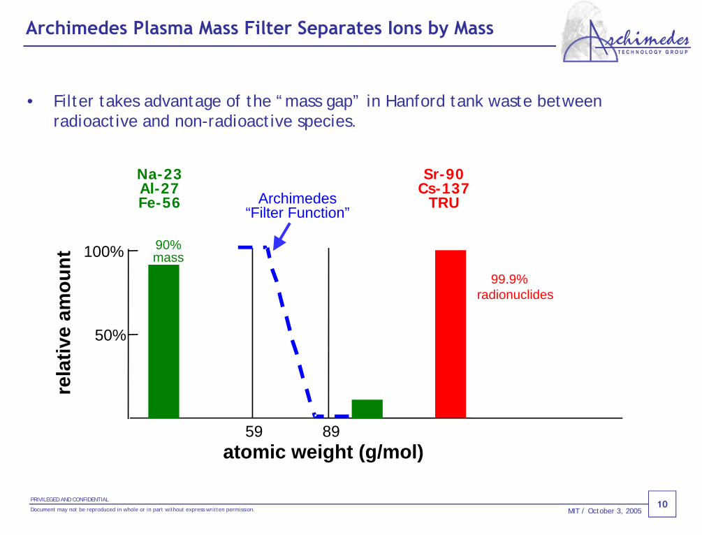
Archimedes Plasma Mass Filter Separates Ions by Mass
• Filter takes advantage of the “mass gap” in Hanford tank waste between radioactive and non-radioactive species.
atomic weight (g/mol)
rela
tive
amou
nt
90%mass
99.9% radionuclides
59 89
Archimedes“Filter Function”
100%
50%
Na-23Al-27Fe-56
Sr-90Cs-137
TRU

11PRIVILEGED AND CONFIDENTIAL
Document may not be reproduced in whole or in part without express written permission. MIT / October 3, 2005
Filter Subsystems
RF Antennas(Ionize Waste)
Sub-Micron Powder Injector
Electrodes(Rotate Plasma)
Heavy Collector
Light Collector

12PRIVILEGED AND CONFIDENTIAL
Document may not be reproduced in whole or in part without express written permission. MIT / October 3, 2005
The Archimedes Two Filter Plant is Small and has Modest
Infrastructure Needs
Licensing and Permitting Power Grid (average power
need of 38MW, 55MW peak)
“Valve Pit” connections with
Tank FarmProduct Feed and
Receipt Requirements
Basic Infrastructure Requirements (water, steam, sample testing, security, etc)
3.4 acres Land Area(~6% of WTP Site)
Archimedes Filter Plant

13PRIVILEGED AND CONFIDENTIAL
Document may not be reproduced in whole or in part without express written permission. MIT / October 3, 2005
HLW Glass*: 272,000 MT 73,000 MT 46,100 MT 34,676 MT (ORP “revised target”)
Hanford ORP Solids Dissolution Targets Result in IHLW Reduction
Archimedes Offers an Alternative for Even Greater Reduction
• Hanford’s baseline targets dissolution of ~90% of the tank HLW oxides to yield an inventory of 9,860 MT solids to be sent to vitrification, producing 34,676 MT of HLW glass and take 22 years to process.2
• Deployment of a 2-Unit Archimedes Filter Plant could process ~50% of the W.W. Solids inventory would yield a total reduction of ~17,000MT HLW glass produced by WTP.
– provides WTP operational flexibility as an alternative pre-treatment path for HLW solids*Notes: (1) HLW glass production assumes ORP’s “relaxed” glass model.
(2) Assumes 6 MTG/day with 70% utilization for HLW Vit and 1.1 MT oxide/day per Archimedes Filter with 70% utilization.
0
100,000
200,000
300,000
Tank Inventory Estimate Water Washing Caustic Washing Oxidative Leaching
HLW Glass Estimates (MT)1
HLW Solids: 84,403 MT 17,553 MT 10,100 MT 9,858 MT
Archimedes Filter Plant
Reduction of ~17,000MT HLW
Glass
~50% of W.W Solids

14PRIVILEGED AND CONFIDENTIAL
Document may not be reproduced in whole or in part without express written permission. MIT / October 3, 2005
Integration of Archimedes offers Broad Technical and
Operational Benefits for Hanford and the WTP
• Provides an alternate pretreatment path for HLW solids to HLW vitrification operations
• Reduced burden on the HLW melter performance and utilization requirements due to significant reduction of solids inventory and removal of key elements that limit waste loading in the HLW glass, such as chrome, sulfate and phosphate
• Filter separation process is less vulnerable to waste batch uncertainty and variability
• Could eliminate need for Oxidative Leaching process
• Net reduction of ILAW glass due to reduction of caustic leaching and sodium added
• Reduces residual environmental impact by directing 99Tc and 129I to IHLW rather than ILAW
• Reduces burden on HLW interim storage, transportation and repository requirements

15PRIVILEGED AND CONFIDENTIAL
Document may not be reproduced in whole or in part without express written permission. MIT / October 3, 2005
Archimedes Filter Plant Deployment Analysis
Waste Inventory Based on ORP Refined Target Case, RPP-23412
• Deployment of 2-Filter Archimedes Filter Plant (AFP) would:– treat selected batches (~46% of water-washed solids mass) over 14 years– reduces overall IHLW glass production by 50%– reduces estimated WTP processing time by 8 years
Notes[1] Estimated 17,550 MT HLW water washed solids in 590 batches[2] Assumes DOE "relaxed" glass model[3] Assumes 6 MTG/day with 70% utilization for HLW Vit and 1.1 MT oxide/day per Archimedes Filter with 70% utilization.[4] Assumes startup in 2013 plus 2 years commissioning (no production)
WW Solids Treatment Path [1] WTP Only WTP with 2-Filter AFP
Archimedes Filter Plant 0% 46%
WW Solids Pretreatment by WTP 100% 54%
IHLW MT Glass Produced [2] 34,000 17,000
Processing Years [4]
WTP Operations [3] 22 14
Completion [4] 2037 2029

How the Archimedes Filter Works

17PRIVILEGED AND CONFIDENTIAL
Document may not be reproduced in whole or in part without express written permission. MIT / October 3, 2005
How the Filter Works
Electrodes
Waste injected as sub-micron
powder
RF Antenna
Elec
tric
fie
ld
Light ions
Heavy ions
Electrodes
Electric field
RF Antenna
Magnet Coils
Magnetic field
Side view of the plasma column

18PRIVILEGED AND CONFIDENTIAL
Document may not be reproduced in whole or in part without express written permission. MIT / October 3, 2005
Filter Physics – Ions are Guided by Electric and Magnetic Fields
BE
E
Radial force balance on ions of mass m and charge Ze rotating with speed vθ:
02
=++r
mvBZevZeE θ
θ
Heavy ions are expelled if their mass exceeds the “cutoff mass” mc
02,8 2
0
0
22
>==a
rVE
VaZeB
mc
Axial magnetic field (B) confine light ions (blue)Radial electric field (E) expels heavy ions (red)
B
electric magnetic centrifugal
side view end view

19PRIVILEGED AND CONFIDENTIAL
Document may not be reproduced in whole or in part without express written permission. MIT / October 3, 2005
Effects of Collisions Simulated with Monte-Carlo Model
• Design of Archimedes Filter Plant requires a high throughput: 0.26 ion-mol/s.
• Collisions between ions and other plasma particles can degrade separation.
• Monte-Carlo computer simulation tracks ion trajectories in Filter E and B fields, including collisions with background plasma and neutrals.
• Good separation at high density with reasonable electric and magnetic fields
Side View End View
Heavy Elements
LightElements
Each curve shows the trajectory of an ion in the plasma
LightElements
Na yellowAl blueFe green
Cr cyanSr Cs Pu red

20PRIVILEGED AND CONFIDENTIAL
Document may not be reproduced in whole or in part without express written permission. MIT / October 3, 2005
Archimedes Filter Process
plasma formation
rotation / separation
collection / removal
feed preparation
LAW
IHLW
injection

21PRIVILEGED AND CONFIDENTIAL
Document may not be reproduced in whole or in part without express written permission. MIT / October 3, 2005
Photo of DEMO − the Archimedes DEMOnstration Unit
Magnetic Field Coils
Vacuum pumps
Vacuum Vessel
Electrodes
RF Transmission Lines

22PRIVILEGED AND CONFIDENTIAL
Document may not be reproduced in whole or in part without express written permission. MIT / October 3, 2005
MicrowaveInterferometer
Bolometer
Plunge Probew/4 Point Tip
LIBS-L
Light CouponSystem
(Both Sides)
GattlingGun
(Heavy Coupons)
Boroscope
Optical Arrays
Heavy Collector
LightCollector
IR InspectionPeriscope
Light Coupon and Handler
LIBS-H
Demo Diagnostics

So How Is It Working So Far?
24PRIVILEGED AND CONFIDENTIAL
Document may not be reproduced in whole or in part without express written permission. MIT / October 3, 2005
Filter Demonstration
Overview
• Six steps will separate waste into LAW and HLW streams:
– Feed preparation: receive water-washed slurry from waste tanks; calcine and convert to powder for injection into Filter
– Injection: deliver waste to Filter in a form that plasma can digest
– Plasma formation: convert injected waste to plasma ions
– Rotation/Separation: rotate waste plasma to separate heavy ions from light ions
– Collection: Accumulate distinct light and heavy waste deposits at collectors
– Removal: Clean collectors to remove heavy and light waste deposits
• This talk will give results for each step to date, and describe the objectives to demonstrate each step on Hanford surrogates

25PRIVILEGED AND CONFIDENTIAL
Document may not be reproduced in whole or in part without express written permission. MIT / October 3, 2005
aqueousslurry
Feed Preparation Process Will Convert Water Slurry to
Calcined Powder
feed receiptinitial sizing / milling
spray drying to < 50 μm powder
sizingparticle / gas separation
ICPcalcination, submicron powder production Filter
Feed
pre
para
tion
LAW
HLW

26PRIVILEGED AND CONFIDENTIAL
Document may not be reproduced in whole or in part without express written permission. MIT / October 3, 2005
Calcination and Conversion of Surrogate to Dry Powder has
been Demonstrated
Spray Dryer System to be tested with Niro Inc. Plasma Calcination System tested with CEA
• Niro Inc. has successfully completed feasibility testing with Hanford surrogate elements, and is ready to perform a pilot study on the full surrogate
• Plasma calcination from slurry to dry powder has been demonstrated with Hanford Envelope D surrogate at CEA’s Marcoule facility in France.

27PRIVILEGED AND CONFIDENTIAL
Document may not be reproduced in whole or in part without express written permission. MIT / October 3, 2005
Generation of Sub-Micron Powders from Hanford Surrogate
has been Demonstrated On-Site
• Conversion of waste surrogate (representative of AZ-101) from spray-dried dimensions to sub-micron scale has been demonstrated on-site
• Optimization of vapor condensation conditions will allow control of conversion efficiency and powder size
• Calcination efficiency of this process needs to be characterized
ICP input:
waste surrogate powder with typical dimension ~ 20 μm
ICP output:
surrogate powder with typical dimension < 1 μm

28PRIVILEGED AND CONFIDENTIAL
Document may not be reproduced in whole or in part without express written permission. MIT / October 3, 2005
Direct Powder Injection System is Installed at the Demo Filter
• A fluidized bed delivery system is currently installed on the Demo Filter. 0.05 μm powders have been radially injected into the Filter with low driving gas flow rates
• Injection rates up to 2 g/s have been reached (target is 5 g/s)
• Modeling of particle trajectories in the Filter plasma predicts full evaporation of 0.20 μm alumina particles
Injection Nozzle
Powder Plume
Powder Injection in Plasma
Evaporation Model
Powder Injection Nozzle

29PRIVILEGED AND CONFIDENTIAL
Document may not be reproduced in whole or in part without express written permission. MIT / October 3, 2005
Waste Throughput is Maximized by Control of Plasma Shape
• The RF power deposition profile is controlled by phasing of currents in each antenna strap
• Flat density profiles will maximize waste throughput and ionization efficiency
0.0E+00
5.0E+18
1.0E+19
1.5E+19
0 10 20 30 40
Filter Radius (cm)
Elec
tron
Den
sity
(m
-3)
Plas
ma
cent
er
30PRIVILEGED AND CONFIDENTIAL
Document may not be reproduced in whole or in part without express written permission. MIT / October 3, 2005
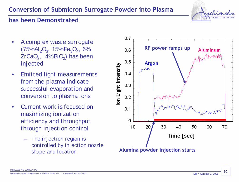
Conversion of Submicron Surrogate Powder into Plasma
has been Demonstrated
• A complex waste surrogate (75% Al2O3, 15% Fe3O4, 6% ZrCaO3, 4% BiO2) has been injected
• Emitted light measurements from the plasma indicate successful evaporation and conversion to plasma ions
• Current work is focused on maximizing ionization efficiency and throughput through injection control
– The injection region is controlled by injection nozzle shape and location
Ion
Ligh
t In
tens
ity
Alumina powder injection starts
RF power ramps up

31PRIVILEGED AND CONFIDENTIAL
Document may not be reproduced in whole or in part without express written permission. MIT / October 3, 2005
Separation Demonstration Geometry
• Separation experiments were performed with edge injection of AZ-101 surrogate by laser evaporation
– Major constituents in AZ-101 target: Si, Al, Fe, Zr, Bi
• Spectroscopic measurements (red lines) and surface coupon measurements (red arrows) are used to study injected surrogates
Heavy Collector
Light Collector
SurrogateVapor

32PRIVILEGED AND CONFIDENTIAL
Document may not be reproduced in whole or in part without express written permission. MIT / October 3, 2005
Plasma Profiles are Ideal for Separation
• Source control in sodium plasma maintains filled profiles in rotating plasma
• A parabolic electric potential applied to the light collectors causes the plasma to rotate
• Probe measurements in the plasma show that the applied potential penetrates along the magnetic field
0.E+00
2.E+18
4.E+18
6.E+18
8.E+18
0 10 20 30 40Radius (cm)
Elec
tron
Den
sity
(m-3
)
0
20
40
60
80
0 10 20 30 40Radius (cm)
Elec
tric
Pot
entia
l (V)
Measured by ProbeApplied at ElectrodesPl
asm
a ce
nter
Plas
ma
cent
er

33PRIVILEGED AND CONFIDENTIAL
Document may not be reproduced in whole or in part without express written permission. MIT / October 3, 2005
Doppler Measurements Confirm Rigid Body Rotation at
E x B Velocity
• Doppler spectroscopy measures plasma rotation speed in the Heavy Collector region for Bi and Fe from injected Hanford AZ-101 Surrogate
• Rotation scales with applied electric field
Plas
ma
cent
er

34PRIVILEGED AND CONFIDENTIAL
Document may not be reproduced in whole or in part without express written permission. MIT / October 3, 2005
Applying Cutoff Electric Field Sends Heavy Elements to the
Heavy Collector
Material Accumulated at Light Collector
0
0.5
1
1.5
2
2.5
Si Ca Fe BiElement
Tota
l Mas
s (g
)
Without CutoffWith Cutoff
Material Accumulated at Heavy Collector
0
0.5
1
1.5
2
2.5
Si Ca Fe BiElement
Tota
l Mas
s (g
)
Without CutoffWith Cutoff
• Battelle AZ-101 tank waste surrogate injected into sodium background plasma by laser evaporation
• 100 V bias at 900 Gauss (cutoff mass = 134 AMU) used to separate bismuth (208 AMU) from lighter elements

35PRIVILEGED AND CONFIDENTIAL
Document may not be reproduced in whole or in part without express written permission. MIT / October 3, 2005
Surface Measurements at Light and Heavy Collectors Show
Cutoff of Bismuth at Expected Voltage
No cut-off 99% of collected sodium is on the light collector
Below cut-off 99% Bismuth -> light collector
Above cut-off 85% Bismuth -> heavy collector 15% Bismuth -> light collector
Bi Vc=63.6V
0
0.2
0.4
0.6
0.8
1
-20 0 20 40 60 80Electrode Voltage [V]
Bism
uth
Frac
tion
0
0.2
0.4
0.6
0.8
1
-20 0 20 40 60 80Electrode Voltage [V]
Sodi
um F
ract
ion
Light Collector Light Collector
Heavy Collector Heavy Collector

36PRIVILEGED AND CONFIDENTIAL
Document may not be reproduced in whole or in part without express written permission. MIT / October 3, 2005
Filter Function Matches Numerical Simulation for Edge
Injection
0%
20%
40%
60%
80%
100%
0 50 100 150 200 250
Atomic Mass (AMU)
Ligh
t Co
llect
or F
ract
ion,
%
Coupons: ICP-AES Coupons: XRF
Simulation: Monte Carlo
Bi
Fe
Zr
Si
• ICP and XRF diagnostics give similar results
• Edge injection of vapor leads to scrape-off effect
• Monte Carlo simulations using measured plasma parameters are inquantitative agreement with the data
Cutoff mass 150 AMU

37PRIVILEGED AND CONFIDENTIAL
Document may not be reproduced in whole or in part without express written permission. MIT / October 3, 2005
0
20
40
60
80
100
0 50 100 150 200 250Atomic Mass, AMU
Ligh
t Co
llect
or F
ract
ion,
%
Full Throughput Demonstration Filter Simulation Shows Good
Cutoff of Heavy Elements
BiDF=400
Cs DF=900
SrDF=30
• Monte Carlo simulation at full Filter density, magnetic field, and electric field show high decontamination factors for heavy elements
• Injection for this simulation is at radii less than 20 cm
Fe
Cr
AlNa
Cutoff = 84 AMU

38PRIVILEGED AND CONFIDENTIAL
Document may not be reproduced in whole or in part without express written permission. MIT / October 3, 2005
Higher Density and Magnetic Field of AFP Improves Filter
Function
• The AFP Filter will operate at slightly higher density and magnetic field, and has a different collector geometry
0
20
40
60
80
100
0 50 100 150 200 250 300Atomic Mass, AMU
Ligh
t Co
llect
or F
ract
ion,
%
Bi DF>1000
Cs DF>1000
Sr DF= 50
Fe
Tc DF>100
AlNa
Cutoff = 80 AMU
Cr
Ca
Pu DF>1000

39PRIVILEGED AND CONFIDENTIAL
Document may not be reproduced in whole or in part without express written permission. MIT / October 3, 2005
Hanford Test Program
High Throughput Separation Optimization
• The tests will confirm that the Filter can:
– Separate Hanford waste at high throughput rates and achieve separation decontamination factors matching those specified below
Radionuclides
Percent of HLW Batches
Percent of WTP Contract Allowance for On-site Disp.
MinimumRequiredAFP DF
AFP Target DF
Hanford Test Program Target DF
TRU 95%Class C
Requirement 76 >>100 >>100
Sr-90 100% 20% 50 ~100 ~30 - 60
Cs-137 100% 4% 60 >>100 >>100

40PRIVILEGED AND CONFIDENTIAL
Document may not be reproduced in whole or in part without express written permission. MIT / October 3, 2005
Light Ion Collection
Conical Electrode/light Collector Design
• Water-cooled copper rings can
withstand full throughput heat loads
• Collector surface intercepts all ion orbits
• Insulating stand-offs and feed-throughs are protected from the plasma heat
• Collection rate
~ 5 mm per hour at full demo throughput
• Access ports available for coupon surface sampling of collected deposits

41PRIVILEGED AND CONFIDENTIAL
Document may not be reproduced in whole or in part without express written permission. MIT / October 3, 2005
Heavy Ion Collector
Paddlewheel Design
• Collector surface intercepts heavy ion orbits
• Tilted paddles minimize plasma refuelling by sputtered heavy particles
• Open geometry allows neutral gas pumping
• Collection rates– less than 0.15 mm/hr at full Demo
throughput – Up to 1.5 mm/hr on the plasma
edge due to radial electric currents – Extended operation without
cleaning is possible
• Cooling allows steady state operation at full throughput
heavy ion orbit

42PRIVILEGED AND CONFIDENTIAL
Document may not be reproduced in whole or in part without express written permission. MIT / October 3, 2005
Demo Status
Summary
• Filter separation physics demonstrated
– Plasma rotates at required velocity for separation– Expected decontamination factors are measured for heavy elements– Separation scales with electrode voltage and magnetic field
• Basic technology solutions demonstrated
– Surrogate preparation: calcination and conversion to powder– Injection: delivery of surrogate into the plasma– RF heating: conversion of injected surrogate into plasma– Electrodes: plasma rotation and separation– Collectors: collection and recovery of separated surrogate

43PRIVILEGED AND CONFIDENTIAL
Document may not be reproduced in whole or in part without express written permission. MIT / October 3, 2005
DEMO Parameters are Near Target for Full Throughput
Separation Tests
Parameter Engineering Maximum Value Achieved
Hanford Test Program Goal
Plasma Radius (m) 0.4 0.4
Plasma Length (m) 3.9 3.9
Magnetic Field (Gauss) 1600 1500
RF Frequency (MHz) 4 4
RF Power (MW) 3 3
Plasma Density (1e19 m-3) 2.0 2.0
Throughput (ion-mol/s) 0.04 0.1
Electrode Voltage (Volts) 300 500
Ion Temperature (eV) 7 13
Discharge Duration (s) 600 Steady State

Plasma Based Separations: 21st Century Technology Solution for Nuclear Waste and a Proliferation Resistant Commercial Fuel Cycle

45PRIVILEGED AND CONFIDENTIAL
Document may not be reproduced in whole or in part without express written permission. MIT / October 3, 2005
• Currently the National Waste Policy Act (NWPA) of 1982, as amended, limits Yucca Mt. to 70,000 MT of spent nuclear fuel
– 7,000 MT is reserved for DOE defense waste
– Remaining 63,000 MT is adequate for spent fuel from existing fleet of reactors if all plants are shut down by 2010
– 120,000 MT is required if all operating reactors are granted 20 yr extensions
– Geologic exploration indicates Yucca Mt could expand to 119,000 MT with NWPA amendment
• The DOE must report to Congress on the need for a second repository in 2010
• Future repository strategy is likely to incorporate ‘actinide burning’ in advanced reactors to reduce storage capacity demands
Background

46PRIVILEGED AND CONFIDENTIAL
Document may not be reproduced in whole or in part without express written permission. MIT / October 3, 2005
Expected U.S. Repository Needs in 2100 (AFCI Source)

47PRIVILEGED AND CONFIDENTIAL
Document may not be reproduced in whole or in part without express written permission. MIT / October 3, 2005
Reprocessing Technologies for Spent Nuclear Fuel
• Reprocessing to recycle Pu in MOX reactor fuel (PUREX)– Similar to French La Hague Plant in technology, capacity & cost
700 acre, 6000 employees, 1700 MT/year capacityFP & actinide waste immobilized in borosilicate glassAfter MOX recycle, Pu is separated and stored for future reactors
• Reprocessing to extract uranium (UREX) and chemically separate FP from actinides (UREX+)– Requires U extraction and FP separation, but no Pu extraction
Uranium recycle or disposal as low-level waste (LLW)Cs & Sr stored in surface repository for ~300 years, then disposal as LLWActinides immobilized in glass with disposal in Yucca Mt or stored for future use as nuclear fuel
• Hybrid reprocessing with UREX and Archimedes Filter– UREX uranium extraction followed by Filter separation of FP & actinides
U extraction (UREX) is the same, but FP & Pu/actinide separation by physical processAchieves same objectives as chemical reprocessing plant with much less by-product radioactive wasteOffers cost and schedule advantages

48PRIVILEGED AND CONFIDENTIAL
Document may not be reproduced in whole or in part without express written permission. MIT / October 3, 2005
Comparison of UREX, UREX+ and UREX-AFP Process Streams
Storage
CuttingDissolution
Clarification
Spent Fuel
UREXU Tc
insoluble streamif not treated
CCD-PEG Cs, Sr
AFP Fissionproducts
Actinides
NPEX Pu, Np, U
TRUEX Am, Cm,Rare Earths
CYANEX 301Am, Cm
Fission products
Xe, I, Kr
45GWd/MT, 10y cooling
UREX+
100 wt%
0.6 wt%
0.07 wt%72.02 wt%
22.74 wt%
3.25 wt%
1.32 wt%
0.32 wt%
.96 wt%
0.07 wt%
1.35 wt%
UREX-AFP
Insoluble stream
Fission Products 1.58 wt%
Actinides 0.29 wt%
Cladding (Zircaloy, Steel)

49PRIVILEGED AND CONFIDENTIAL
Document may not be reproduced in whole or in part without express written permission. MIT / October 3, 2005
Archimedes Filter Function Spent for Commercial Fuel
Group Separation
100
0
Br 81
Se 82
Rb 87Y 89Sr 9
0Zr 9
6Mo 9
8Ru 104Rh 103Pd 1
08Ag 1
09Cd 116Sb 1
23Sn 1
26Tr 1
30Cs 1
37Ba 1
38La
139
Ce 142Pr 1
41Nd 150Pm 14
7Sm 15
4Eu 1
54Gd 1
58
Np 237Pu 2
42Am 24
3Cm 24
5
isotopes
%
0
2
4
6
8
10
12
kg/ s
pent
fuel
ton
% of isotope separated by heavy collector

50PRIVILEGED AND CONFIDENTIAL
Document may not be reproduced in whole or in part without express written permission. MIT / October 3, 2005
UREX-AFP Mission and High Level Requirements
• Mission:
– The hybrid UREX pretreatment and Archimedes Filter Plant mass separation process will enable expansion of Yucca Mt capacity to ~250,000 MT of spent nuclear fuel.
• Requirements:
– Process 2000 MT of spent nuclear fuel per year
– Separation of FP from Pu/actinides sufficient to achieve desired repository capacity
– Provide least environmental impact of all alternative technologies
– Plant startup consistent with first shipments to Yucca Mt
– Provide option to extract Pu if desired

51PRIVILEGED AND CONFIDENTIAL
Document may not be reproduced in whole or in part without express written permission. MIT / October 3, 2005
UREX-AFP Simplified Flow Sheet (45GWd/MT, 10y Cooling)
Extraction
UraniumRe-extraction
UraniumStripping
Uranium936 kg
Tc1 kg
RaffinateStream35 kg
Feed1300 kg
Cladding294 kg
CuttingDissolution
InsolubleStream24 kg
Pre-treatment
ARCHIMEDESFilter
FissionProducts(42– x)
kg
Actinides
17 kg
GasTreatment
Gas 8.5 kg
Gas x kg
UREX
AFPSurface Repository
Storage or recycle

52PRIVILEGED AND CONFIDENTIAL
Document may not be reproduced in whole or in part without express written permission. MIT / October 3, 2005
Summary of Process Stream Contents
NB : 8.51 kg of gas and 294 kg or metal cladding are removed after rod cutting and dissolution
ElementsSpent fuel
input(45GWd/MT,10 y cooling)
Removed by UREX
Raffinate stream
Insoluble stream
Processed by ARCHIMEDES
filter
U (kg/MT)940.75 936.05 0.94 3.76 4.70
Pu (kg/MT)11.00 0.00 10.89 0.04 10.93
Minor Actinides (kg/Mt)
1.56 0.00 1.55 0.01 1.55
Fission Produc ts minus Tc
45.34 0.00 21.75 14.61 36.36
Metal cladding (kg/MT)
300.00 0.00 0.00 6.00 6.00
Tc (kg/MT)1.03 0.98 0.05 0.00 0.05
Total (kg/MT)1299.68 937.03 35.18 24.42 59.60
% 100.00 72.10 2.71 1.88 4.59

53PRIVILEGED AND CONFIDENTIAL
Document may not be reproduced in whole or in part without express written permission. MIT / October 3, 2005
Implementation Comparison of Alternative Technologies
• Reprocessing with MOX fuel recycle– High cost and schedule– LWR plants may opt to not use MOX fuel– Does not expand repository capacity
• Reprocessing with UREX+ radio-chemical plant– Highest cost and schedule– Environmental impact greater than UREX-AFP– Significantly expands repository capacity
• Reprocessing with hybrid UREX and AFP plant– Lowest cost and shortest schedule– Same repository benefits as UREX+ radio-chemical plant– Least environmental impact

54PRIVILEGED AND CONFIDENTIAL
Document may not be reproduced in whole or in part without express written permission. MIT / October 3, 2005
BACKUP SLIDES
Copyright © 2022 FDOKUMEN