modified specification for battery operated led based torch ...
13
Page 1 of 11 MODIFIED SPECIFICATION FOR BATTERY OPERATED LED BASED TORCH LIGHT CUM FLASHING HAND SIGNAL LAMP SPECIFICATION NO: RDSO/SPN/195/2008 Rev. 2.2 Version3 0 FOREWORDS: 0.1 This specification is issued under the fixed serial number RDSO/SPN/195/2008 Rev. 2.2 Version3. This specification is meant for specifying general & technical requirements of LED based torch light cum flashing hand signal lamp (also referred as HS lamp in this specification). It also specifies various tests to ensure consistency of quality of equipment. The flashing hand signal lamp unit must have the highest reliability under severe environmental conditions of operation i.e. water ingress, dust, humidity, high ambient temperature, shocks and vibrations. This specification supersedes earlier specifications on flashing hand signal lamp. 0.3 The customized lamp shall be manufactured to principal conceptual dimensions in accordance with conceptual sketch and dimensions indicated therein as per Annexure-I. 0.4 The other relevant specifications are: - (a) IS: 6303/1984 for dry cell batteries. (b) Specification IEC 86-1/86-2 for alkaline cells. (c) Standard BS: 1376 of 1974 for colors of light signals. (d) IS-2083 for flashlights. 0.5 Wherever in this specification, any specification is referred to by number only without mentioning the year of issue, the latest issue of the specification is implied, otherwise the particular issue referred to is meant. 0.6 This specification is intended to cover the technical provisions and it does not include all the necessary provisions of a contract. 1.0 SCOPE 1.1 This user requirement based specification includes in its ambit all components required to be assembled into the ultimate product named Battery operated LED Based Torch Lightcum-Hand Signal Lamp. 1.2 The purpose of this specification is to develop a lightweight, rugged, maintainable and user-friendly Battery operated LED Based Torch Light-cum-Hand Signal Lamp which is IP-65 54 compliant. 1.3 Battery operated LED Based Torch Light-cum-Hand Signal Lamp shall be powered by four commercially available leak proof dry cell batteries type R-20 or LR-20 HP-2 size D (Duracell or equivalent) of 1.5V each 4 nos. of AA type R6/LR6 batteries of 1.5 V each. 2.0 TECHNICAL REQUIREMENTS: 2.1 Color Co-ordinates: Red Aspect: Class „C‟ of BS: 1376 Green Aspect: Class „C‟ of BS: 1376 White light for torch mode: Class „C‟ of BS: 1376. Deviation from the specified class may be agreed provided the light is suitable for torch light and is comfortable for reading and visibility in the dark. Colour co-ordinates graph as per BS: 1376 is given in Annexure-II. 2.2.1.1 In white light mode, the H.S. Lamp shall function as a normal 4 cell torch with white LEDs. The design of the torch should comply with the following parameters: Rated Voltage 6 Volts Illumination (min.) measured at 1.5 m in axial direction (in 40 Lux. 150 Lux Lux) in operating voltage range. (as per Annexure III) 13
-
Upload
khangminh22 -
Category
Documents
-
view
5 -
download
0
Transcript of modified specification for battery operated led based torch ...

Page 1 of 11
MODIFIED SPECIFICATION FOR BATTERY OPERATED LED BASED TORCH
LIGHT CUM FLASHING HAND SIGNAL LAMP
SPECIFICATION NO: RDSO/SPN/195/2008 Rev. 2.2 Version3
0 FOREWORDS: 0.1 This specification is issued under the fixed serial number RDSO/SPN/195/2008 Rev. 2.2
Version3. This specification is meant for specifying general & technical requirements of LED based torch light cum flashing hand signal lamp (also referred as HS lamp in this specification). It also specifies various tests to ensure consistency of quality of equipment. The flashing hand signal lamp unit must have the highest reliability under severe environmental conditions of operation i.e. water ingress, dust, humidity, high ambient temperature, shocks and vibrations. This specification supersedes earlier specifications on flashing hand signal lamp.
0.3 The customized lamp shall be manufactured to principal conceptual dimensions in accordance with conceptual sketch and dimensions indicated therein as per Annexure-I.
0.4 The other relevant specifications are: - (a) IS: 6303/1984 for dry cell batteries. (b) Specification IEC 86-1/86-2 for alkaline cells.
(c) Standard BS: 1376 of 1974 for colors of light signals. (d) IS-2083 for flashlights. 0.5 Wherever in this specification, any specification is referred to by number only without
mentioning the year of issue, the latest issue of the specification is implied, otherwise the particular issue referred to is meant.
0.6 This specification is intended to cover the technical provisions and it does not include all the necessary provisions of a contract.
1.0 SCOPE 1.1 This user requirement based specification includes in its ambit all components required to
be assembled into the ultimate product named Battery operated LED Based Torch Lightcum-Hand Signal Lamp.
1.2 The purpose of this specification is to develop a lightweight, rugged, maintainable and user-friendly Battery operated LED Based Torch Light-cum-Hand Signal Lamp which is IP-65 54 compliant.
1.3 Battery operated LED Based Torch Light-cum-Hand Signal Lamp shall be powered by four
commercially available leak proof dry cell batteries type R-20 or LR-20 HP-2 size D
(Duracell or equivalent) of 1.5V each 4 nos. of AA type R6/LR6 batteries of 1.5 V each.
2.0 TECHNICAL REQUIREMENTS:
2.1 Color Co-ordinates:
Red Aspect: Class „C‟ of BS: 1376
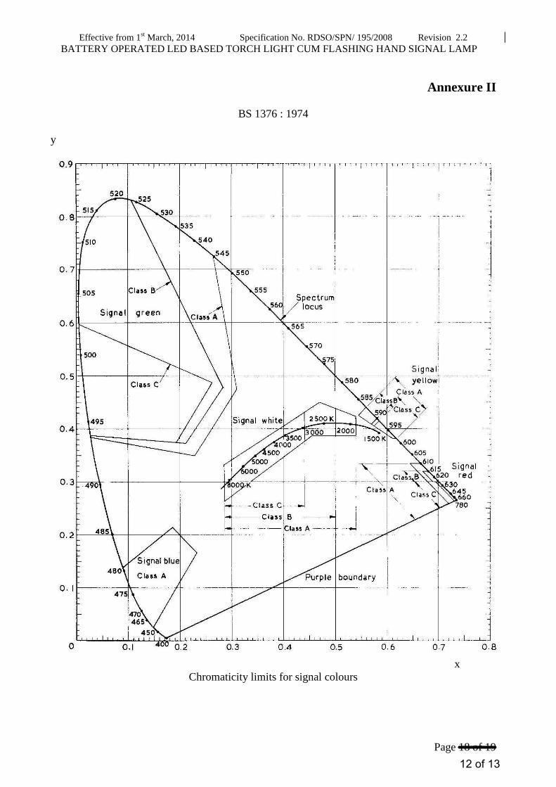
Green Aspect: Class „C‟ of BS: 1376 White light for torch mode: Class „C‟ of BS: 1376. Deviation from the specified class may be agreed provided the light is suitable for torch light and is comfortable for reading and visibility in the dark. Colour co-ordinates graph as per BS: 1376 is given in Annexure-II.
2.2.1.1 In white light mode, the H.S. Lamp shall function as a normal 4 cell torch with white
LEDs. The design of the torch should comply with the following parameters:
Rated Voltage 6 Volts
Illumination (min.) measured at 1.5 m in axial direction (in 40 Lux. 150 Lux
Lux) in operating voltage range.
(as per Annexure III)
13

Page 2 of 11
Dispersion Angle at 50% power points (as per Annexure 4° to 15°
III)
Note: Use of SMD LED for white light may be considered.
2.2.1.2 The LED based colour display shall meet the under mentioned working parameters:
Parameter Quasi-static Green Aspect
Quasi-static Red Aspect
Rated Voltage (Volts) 6 6
No. of flashing pulses per minute 220 to 270 220 to 270
Illumination (min.) at 1.5m measured in axial direction (in Lux) in operating voltage range. (as per Annexure III)
60 40
Dispersion Angle at 50% power points (as per Annexure III)
4o to 10
o
2.2.1.3 Variation in dispersion angle may be agreed provided visibility and other requirements of
this specification are complied. 2.2.1.4 Illumination shall be measured in steady mode. To enable the measurement in steady mode
for colour aspects, suitable provision shall be provided inside the lamp which shall not be visible or accessible to the user. Normally lamps shall be provided with flashing colour aspects and steady mode shall be operated for measurement only.
2.2.2 Cell Life Requirement:
2.2.2.1 For white light mode:
Minimum normal cell life on continuous
discharge basis up to low battery
40
hrs. 14 hrs
indicator (LBI)
Min. operating battery life after low
battery indicator (LBI) 6 hrs. 2 hrs.
2.2.2.2 For colour light mode:
Parameter Quasi-static Quasi-static
Green Aspect Red Aspect
Minimum normal cell life on continuous 150 hrs.
60 hrs
150 hrs.
60 hrs
discharge basis up to LBI
Min. operating battery life after low 12 hrs. 3 hrs. 12 hrs. 3 hrs.
battery indicator (LBI)
Note:-Extra set of batteries 4 nos. shall be kept in spare for replacement in case of batteries
discharge.
2.2.2.3 Cell life shall be measured individually for white light mode and every aspect of colour
light mode. New cells should live the specified life of a particular mode/aspect when HS
lamp is continuously lit in that mode/aspect. No deterioration in illumination is permitted
13

Page 3 of 11
during normal cell life. For specified minimum battery life after low battery indicator
(LBI), 25% fall in illumination from its original value is permitted.
2.3 Visibility:
Light from the lamp in colour aspects should be visible and discernable from a distance of
1.0 Km. along the longitudinal axis of the lamp and from 100 meters distance at six degrees
angular displacement from longitudinal axis. For carrying out the test, H.S. lamp should
be kept at 1.1 meter above rail level and viewed at local sun set time under conditions of
clear weather and against the sun.
3.0 Design Criteria:
3.1 The external appearance of the lamp shall be of BLACK colour and in matt finish.
3.2 The battery operated flashing Hand Signal Lamp shall be manufactured out of materials of
highest grade and purity to meet required parameters and be free from defects of workmanship,
material or design. The components & materials used in the manufacture of the equipment
shall be screened and should be of high quality. The switches, connectors, PCB and electronic
components used shall be of industrial grade and as per relevant Indian Standard Specification
(IS). The vendor shall indicate specification / particulars in this regard. The rating of all
electronic components used shall be marked and be readable clearly on components or in the
relevant datasheet. As the hand signal lamp is to be used out- door under all weather
conditions, it shall not employ ferrous components. All metallic electrical contacts shall be
made of phosphorous bronze, brass or copper. Screws, nuts and other metallic components
provided in the equipment should be of brass or stainless steel. The screws should be of
adequate thickness and ruggedness.
3.3 The lamp shall comprise of light module and battery compartment. Light module shall have white light for torch and red & green colour light.
The body of the lamp shall be made of industrial grade plastic like ABS. A guarantee shall be
given by the manufacturer that no re-constituted or recovered material has been used for the manufacture of modules. The body shall be in a single mould except the moving parts like
battery doors etc.
A conceptual sketch of the lamp is enclosed as Annexure-I. Minor variations in the
dimensions may be accepted. HS Lamp with body in cylindrical shape Rectangular shape with cross sectional area not exceeding to that in sketch at Annex-I may also be considered
depending upon the merits of design.
3.3.1 Light module shall comprise of LEDs and UV stabilized polycarbonate clear lense/cover to
give concentric beam of light. Polycarbonate clear lense/cover shall be surrounded by a projection protruding for few millimeters. No electronic component except LEDs shall be
visible from the lens.
3.3.2 Red and Green colour light shall be quasi static i.e. with 220 to 270 pulses per minute. It shall
not be feasible to have more than one of the red, green or white light simultaneously by operating their switches or otherwise.
3.3.3 The Battery compartment shall be so designed as to accept either 4 Nos. R-20 dry cells or 4
nos. LR-20 alkaline 4 nos. of AA type (R6/LR6) cells. The battery compartment should have isolation from light module and its electric circuitry so that leakage of dry cell does not
affect the electric circuit/ components.
13

Page 4 of 11
3.3.4 The HS lamp shall be provided with a group of FOUR individual sealed type TACT switches
with suitable cover or cap in which each switch can be independently pressed to switch-ON
the desired aspect (RED, GREEN or WHITE torch) or keep the torch in STANDBY mode.
The purpose of the standby mode is to keep the lamp in OFF mode while in service. Tact
switches shall be of high performance and able to withstand at least 100000 operations.
Switches shall be robust in nature to withstand jerks etc. Tact switches of NKK and, Knitter
and OMRON makes are preferable. Switches should be located near the handle. Switches of
other reputed makes may be agreed if fulfilling the requirements of this specification to the
RDSO‟s satisfaction. Colour of cover/ cap of the switches should be same as that of their
respective aspect. Location of switches should be such that these can be easily operated when
the lamp is held in the hand.
The cover label, if used over the tact switches should be of polycarbonate and should be so pasted that looks uniform and cannot be peeled off even under adverse weather.
3.4 HS Lamp shall be provided with an appropriate ergonomic handle integral with the body. Lamp should have provision of two buckles and a good quality nylon strap of 1-meter length
fastened with these buckles for hanging the lamp on shoulders. Shape & thickness of the handle should be such that it provides comfortable grip easy to hold with comfortable grip.
Suitable provision of one nylon strap should be provided.
3.6 Weight: The complete lamp shall be designed to weigh as minimum as feasible but it should not be more than 600 250 grams excluding weight of batteries.
3.7 Light from HS lamp, when projected on a white target at 1.5 m from LED signal lighting unit,
shall illuminate the target uniformly without any dark circles within half power points.
3.8 The transparent cover/ lenses, as applicable, shall be of polycarbonate material having
minimum thickness of 1.5 mm.
3.9 The HS lamp shall have insulation resistance of more than 100-M ohms. The insulation
resistance shall be measured between the body of lamp and the current carrying terminals
looped together at a potential of 500 V DC.
3.10 LEDs used shall be of high performance quality and from NICHIA/Japan or AVAGO/USA.
The minimum junction temperature of a LED shall not be less than 100 deg. LEDs of other
reputed makes may be agreed subject to compliance of the requirements of this
specification. SMD type LEDs may be used if operating requirements of the HS lamp are
met.
3.11 Normally LEDs of the LED based hand signal lamps shall be driven within average drive
current range recommended by the LED manufacturer and in no circumstances LEDs shall
be driven by current more than the maximum current recommended by the LED
manufacturer.
3.11.1 Components including number of LEDs and their part no. shall not be changed without prior
approval of RDSO.
3.12 The following shall be ensured while designing the Hand Signal Lamp:
3.12.1 Reverse polarity protection shall be suitably provided. Design shall be such that it does not
employ fuses.
3.12.2 The lamp shall be free from interference from radio frequencies. It shall not malfunction in
the vicinity of any walkie – talkie set working on VHF range.
13
Page 5 of 11
3.12.3 Steady Green/Red mode of the H. S. Lamp should not be possible for the user.
3.12.4 The switches for RED & GREEN shall be at extreme ends.
3.12.5 An ON/OFF switch of PUSH to ON (clause 3.3.4) type shall be used for cutting the power
supply when the lamp is not in use for long periods. Switch shall withstand at least 10000 operations. Switches shall be robust in nature to withstand jerks etc. NKK, Knitter and
OMRON makes switches are preferable.
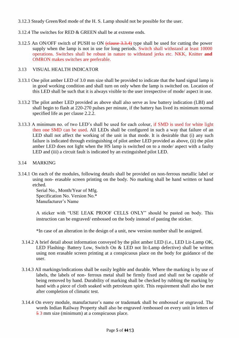
3.13 VISUAL HEALTH INDICATOR
3.13.1 One pilot amber LED of 3.0 mm size shall be provided to indicate that the hand signal lamp is
in good working condition and shall turn on only when the lamp is switched on. Location of
this LED shall be such that it is always visible to the user irrespective of mode/ aspect in use.
3.13.2 The pilot amber LED provided as above shall also serve as low battery indication (LBI) and
shall begin to flash at 220-270 pulses per minute, if the battery has lived its minimum normal
specified life as per clause 2.2.2.
3.13.3 A minimum no. of two LED‟s shall be used for each colour, if SMD is used for white light
then one SMD can be used. All LEDs shall be configured in such a way that failure of an
LED shall not affect the working of the unit in that mode. It is desirable that (i) any such
failure is indicated through extinguishing of pilot amber LED provided as above, (ii) the pilot
amber LED does not light when the HS lamp is switched on to a mode/ aspect with a faulty
LED and (iii) a circuit fault is indicated by an extinguished pilot LED.
3.14 MARKING
3.14.1 On each of the modules, following details shall be provided on non-ferrous metallic label or
using non- erasable screen printing on the body. No marking shall be hand written or hand
etched. Serial No., Month/Year of Mfg.
Specification No. Version No.*
Manufacturer‟s Name
A sticker with “USE LEAK PROOF CELLS ONLY” should be pasted on body. This
instruction can be engraved/ embossed on the body instead of pasting the sticker.
*In case of an alteration in the design of a unit, new version number shall be assigned.
3.14.2 A brief detail about information conveyed by the pilot amber LED (i.e., LED Lit-Lamp OK, LED Flashing- Battery Low, Switch On & LED not lit-Lamp defective) shall be written
using non erasable screen printing at a conspicuous place on the body for guidance of the user.
3.14.3 All markings/indications shall be easily legible and durable. Where the marking is by use of
labels, the labels of non- ferrous metal shall be firmly fixed and shall not be capable of
being removed by hand. Durability of marking shall be checked by rubbing the marking by hand with a piece of cloth soaked with petroleum spirit. This requirement shall also be met
after completion of climatic test.
3.14.4 On every module, manufacturer‟s name or trademark shall be embossed or engraved. The words Indian Railway Property shall also be engraved /embossed on every unit in letters of 5 3 mm size (minimum) at a conspicuous place.
13

Page 6 of 11
4.0 TESTS
The HS lamp is normally required to be used outdoor as well as on board locos/coaches
traveling up to 160 KMPH, under all weather conditions ranging from damp coastal to hot
dry climate and subject to rain, dust and vibrations that accompany such service and from
mean sea level (MSL) up to 1500 meter above MSL. The unit shall employ non- ferrous
components to withstand corrosion effects of nature. Environment parameters/ tests that the
unit shall be designed to withstand are given below.
4.1 Ambient temperature severities: -100C to +60
0C
Test for above will be conducted in energized condition for 4 hours each at minus 100C (-
30C, +0
0C) and plus 60
0C (+3
0C, -0
0C) separately for red and green aspects and white
torch light. During and after each of these tests, no LED shall fail & there should not be any damage in the unit or visual change in colour. After 1 hour of recovery period of each of these tests, deterioration in illumination, if any, shall not be more than 5% of original value subject to compliance of minimum illumination criteria as per clause 2.2.
4.2 Climatic tests: A total of 6 HS lamps having 2 HS lamps each lit individually for red aspect, green aspect and white light shall be able to withstand following environmental/climatic tests:
SN Name of test Reference Specification Recovery
period
1 Change of temperature test at lower temp. – Part-XIV/Section 2 of IS: 2 hours
10 ± 30C and upper temp +70±2
0C (2 Cycles 9000
and duration of exposure 3 hrs. after the
stability in chamber has been reached)
2. Damp heat cyclic test (one cycle of 12 + 12 = Part-V/Section 2 of IS: 2 hours
24 hours), (Upper temperature 55°C + 2°C, 9000
relative humidity at all times shall not be less
than 98%)
3. Salt Atmosphere test Part-XI/ Procedure 3 of 4 hours
(3 cycles of 22 hours) IS: 9000
4. Driving rain water spary test for two hours
Part-XVI (Test condition’C”, cl 7.1.3) As per IS:9000 4 hours.
5. Dust Test at 40 ± 3°C for the period of 1 Part-XII 2 hours
hour.
6. Vibration test 5 to 150 Hz, -
Acceleration: 5g,
20 sweep cycles on 3 axes
(IS: 9001 Pt. XIII)
All tests shall be conducted in energized condition of the unit. During and after each of
these tests, no LED shall fail & there should not be any damage in the unit or visual change
in colour. After recovery period of each of these tests, deterioration in illumination, if any,
will not be more than 5 % of original value subject to compliance of minimum illumination
criteria as per clause 2.2. Insulation resistance shall not be less than 100-M.ohms. After
completion of all tests, colour co-ordinates shall remain within specified values.
13

Page 7 of 11
4.2.1 Climatic tests shall be conducted with either specified cells or a separate power supply.
During any climatic test, malfunction or leakage of cells shall not be considered as failure
of the HS lamp. In such case, that test shall be repeated with new cells after properly
cleaning the battery compartment from inside.
4.2.2 Test report for IP-65 54 complaint housing shall be submitted at the time of type tests.
4.3 Dispersion Angle test: This shall be measured as per Annexure III in for every Red
& Green colour and white light.
4.4 Burning in test: The HS lamp shall be kept continuously ON at 60 °C at rated voltage for
minimum 24 hrs for each for red, green aspects and white torch light. There shall not be
any difference in performance parameters before and after burning in test. The test shall be
conducted with either specified cells or a separate power supply.
4.5 Drop Test: The HS lamp shall withstand free drop from a height of 1.5 meters above an
RCC platform of 75mm thickness or on a steel plate 12 mm thick. For the purpose of the
drop test, the units shall be powered with 4 numbers of R-20 AA Type (R6/LR26) cells.
Lamp shall continue to function effectively, satisfy all parameters after ensuring two drops.
Appearance of cracks on the body may not be deemed as disqualification as long as lamp
continues to function. The lamp, however, shall not disintegrate.
4.4 Burning in test: The HS lamp shall be kept continuously ON at 60 °C. at rated voltage for minimum 24 hrs. for each for red, green aspects and white torch light. There shall not be
any difference in performance parameters before and after burning in test. The test shall be conducted with either specified cells or a separate power supply.
4.5 Drop Test: The HS lamp shall withstand free drop from a height of 1.5 meters above an
RCC platform of 75mm thickness or on a steel plate 12 mm thick. For the purpose of the
drop test, the units shall be powered with 4 numbers of R-20 R6 cells. Lamp shall continue
to function effectively, satisfy all parameters after ensuring two drops. Appearance of
cracks on the body may not be deemed as disqualification as long as lamp continues to
function. The lamp, however, shall not disintegrate.
4.6 Life test for switch: This test shall be performed on one sample, loaded with cells. Every switch position shall be operated for at least 10,000 operations in type test at the rate of 25
to 35 operations per minute. There should not be any problem in switch operation or its functioning after the test.
4.7 VHF Interference test: The working of the H. S. Lamp shall be checked for any interference
by keeping a VHF transmitting set (5 Watt) at a distance of 10cm from the H.S. Lamp. The functioning of the H.S. Lamp shall not be affected at any of the VHF frequencies.
5.0 TEST PLAN
5.1 Type test
Type test shall be performed on six samples. Burning-in test shall be conducted first.
Colour co-ordinates. climatic, ambient temperature severities, dispersion angle, vibration,
visual alarm, current drain & design parameters, durability of marking (Cl. 3.13.2) and cell
life tests shall be conducted for each colour aspect and white light on two samples each.
Cell life requirement test will be conducted with Both LR-20 and R-20 cells 4 no‟s of AA
type ( R6/LR6) batteries. Visibility test shall be performed on two samples each for red and
green aspects. Rest tests shall be performed on all samples, unless specified otherwise in
the relevant test clause. Cell life test shall be conducted with new cells after climatic,
ambient temperature severities and vibration tests. All samples shall individually pass the
type tests.
13
Page 8 of 11
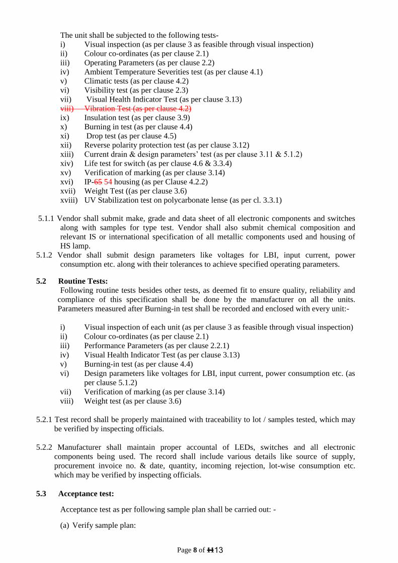
The unit shall be subjected to the following tests-
i) Visual inspection (as per clause 3 as feasible through visual inspection)
ii) Colour co-ordinates (as per clause 2.1)
iii) Operating Parameters (as per clause 2.2)
iv) Ambient Temperature Severities test (as per clause 4.1)
v) Climatic tests (as per clause 4.2)
vi) Visibility test (as per clause 2.3)
vii) Visual Health Indicator Test (as per clause 3.13)
viii) Vibration Test (as per clause 4.2)
ix) Insulation test (as per clause 3.9)
x) Burning in test (as per clause 4.4)
xi) Drop test (as per clause 4.5)
xii) Reverse polarity protection test (as per clause 3.12)
xiii) Current drain & design parameters‟ test (as per clause 3.11 & 5.1.2)
xiv) Life test for switch (as per clause 4.6 & 3.3.4)
xv) Verification of marking (as per clause 3.14)
xvi) IP-65 54 housing (as per Clause 4.2.2)
xvii) Weight Test ((as per clause 3.6)
xviii) UV Stabilization test on polycarbonate lense (as per cl. 3.3.1)
5.1.1 Vendor shall submit make, grade and data sheet of all electronic components and switches
along with samples for type test. Vendor shall also submit chemical composition and
relevant IS or international specification of all metallic components used and housing of
HS lamp.
5.1.2 Vendor shall submit design parameters like voltages for LBI, input current, power
consumption etc. along with their tolerances to achieve specified operating parameters.
5.2 Routine Tests:
Following routine tests besides other tests, as deemed fit to ensure quality, reliability and
compliance of this specification shall be done by the manufacturer on all the units.
Parameters measured after Burning-in test shall be recorded and enclosed with every unit:-
i) Visual inspection of each unit (as per clause 3 as feasible through visual inspection)
ii) Colour co-ordinates (as per clause 2.1)
iii) Performance Parameters (as per clause 2.2.1)
iv) Visual Health Indicator Test (as per clause 3.13)
v) Burning-in test (as per clause 4.4)
vi) Design parameters like voltages for LBI, input current, power consumption etc. (as
per clause 5.1.2)
vii) Verification of marking (as per clause 3.14)
viii) Weight test (as per clause 3.6)
5.2.1 Test record shall be properly maintained with traceability to lot / samples tested, which may
be verified by inspecting officials.
5.2.2 Manufacturer shall maintain proper accountal of LEDs, switches and all electronic
components being used. The record shall include various details like source of supply,
procurement invoice no. & date, quantity, incoming rejection, lot-wise consumption etc.
which may be verified by inspecting officials.
5.3 Acceptance test:
Acceptance test as per following sample plan shall be carried out: -
(a) Verify sample plan:
13

Page 9 of 11
Lot Size Sample Size
Up to 20 Nos. 3 Nos
Between 21-50 Nos. 6 Nos.
Between 51 –100 Nos. 9 Nos
Between 101-150 Nos. 12 Nos.
More than 151 15 Nos.
(b) Following shall constitute acceptance test:
i. Visual inspection (as per clause 3 as feasible through visual inspection)
ii. Colour coordinates (as per clause 2.1)
iii. Performance parameters (as per clause 2.2.1)
iv. Ambient Temperature Severities test (as per clause 4.1) A unit may not be tested for
each type of colour and white light. At least one third of samples should be subjected
to each type of colour and white light.
v. Visual Health Indicator Test (as per clause 3.13.1 & 3.13.2)
vi. Insulation test (as per clause 3.9)
vii. Burning-in test (as per clause 4.4) (Burn- in test shall be performed for min. 50% of
time duration for every colour and white light)
viii. Drop test on one sample – performance test to ensure proper functioning after the
drop test (as per clause 4.5) (In case lamp develops cracks but passes the test, vendor
shall replace the respective unit for supply.)
ix. Reverse polarity protection test (as per clause 3.12)
x. Verification of design parameters (as per clause 5.1.2)
xi. Weight test (as per clause 3.6)
xii. Verification of marking (as per clause 3.14) (Clause 3.14.3 shall be tested on
one sample.)
5.3.1 Burn-in, visual inspection and verification of marking / embossing tests shall be
performed on all samples. Rest tests shall be performed in each mode on one third of
sample size if not specified otherwise in the relevant clauses. Parameters shall be
measured after Burn-in test.
5.4 For type test and acceptance test, both R-20 and LR-20 cells R6 and LR6 AA type cells
shall be provided by the vendor.
6.0 DOCUMENTATION A pocket sized laminated card containing operational instructions,
indications communicated through pilot amber LED, purpose of stand, battery
replacement procedure and Do‟s and Don‟ts shall be provided with every unit.
7.0 SCOPE OF SUPPLY
13

Page 10 of 11
HS lamps may be procured either with 4 nos. of leak proof R -20 cells 04 nos. of R6 or
LR6 AA type cells or without cells as per purchaser‟s requirement which should be clearly
mentioned in the purchase order. If lamps are procured with cells, cells should not be older
than three months at the time of supply.
8.0 PACKING
8.1 Each lamp shall be individually wrapped in bubble sheet and packed in individual card
board boxes. Cells in their original packing shall be kept separately in the box. The empty
spaces shall be filled with suitable filling material. Alternatively, these may be packed in
thermocole boxes. The units shall be finally packed in a wooden case or card boxes of
sufficient strength so that it can withstand bumps and jerks encountered in a road/ rail
journey. Final packing cases shall not contain more than 100 lamps, each individually
packed.
8.2 Every box shall be marked with code numbers, contents and name of manufacturer. The
upside shall be indicated with an arrow. Boxes should have standard signage to indicate
the correct position and precaution “Handle with Care‟‟ with necessary instructions.
8.3 The units and their sub- assemblies shall be so packed as to permit convenient handling
and to protect against loss or damage during transit and storage.
9.0 WARRANTEE
The supplier shall give a warrantee of 24 months for HS lamp excluding cells from the
date of supply.
10.0 INFRINGEMENT OF PATENT RIGHTS:
Indian Railway shall not be responsible for infringement of patent rights due to similarity
in design, manufacturing process, use of components used in design, development &
manufacturing of Battery operated LED based torch light cum flashing hand signal lamp
and any other factors which may cause such dispute.
……………..x………x…………….
13

Page 11 of 11
ANNEXURE-1
05 CM
07 CM
10 CM 01 CM 06 CM
05 CM
07 CM
Conceptual sketch of proposed light weight small size HS Lamp
Note:- Annexure-II and Annexure-III are same as Annexure-II and Annexure-III of the RDSO/SPN/195/2008/Rev 2.2
13
Effective from 1st March, 2014 Specification No. RDSO/SPN/ 195/2008 Revision 2.2
BATTERY OPERATED LED BASED TORCH LIGHT CUM FLASHING HAND SIGNAL LAMP
Page 18 of 19
Annexure II
BS 1376 : 1974
y
x
Chromaticity limits for signal colours
12 of 13

Effective from 1st March, 2014 Specification No. RDSO/SPN/ 195/2008 Revision 2.2
BATTERY OPERATED LED BASED TORCH LIGHT CUM FLASHING HAND SIGNAL LAMP
Page 19 of 19
ANNEXURE - III
Measurement procedure for Optical parameters (i.e., Dispersion Angle, illumination &
Colour co-ordinates)-
1. Light up the aspect at the nominal voltage on 6 V and place it on the test bench.
2. The Dispersion Angle shall be calculated by measuring the half intensity points of the
dominant wavelength at 1.5 m from LED signal lighting unit in axial direction on both the
sides and taking average of the distances, d1 & d2 in meters
(d = (d1 + d2) / 2)
3. The half intensity, point is where half of the normal illumination at rated voltage falls. The
Dispersion Angle shall be calculated using the formula tan-1
d – r = Ø/2 1.5
4. ‘r’ is the distance from center of the unit to the outer most LED provided in the unit.
d1 C d2
Ø/2 1.5 m
Lense
Ø/2
5. Dispersion Angle = Ø 6. Illumination shall be measured at 1.5 m from LED signal lighting unit in axial direction
(i.e. at point C). 7. Colour co-ordinates shall be measured at 1.5 m from LED signal lighting unit in axial
direction (i.e. at point C).
Note-
All measurements shall be done in a dark room with spectrometer or Chromometer suitable for
measurement of colour co-ordinates & illumination of LEDs.
r
1313 of
shekhar
Cross-Out
shekhar
Inserted Text