HyPro2000™ Quick Disconnect MAX200 Torch Upgrade
30
HyPro2000 ™ Quick Disconnect MAX200 Torch Upgrade Field Service Bulletin 807510 – Revision 1 – September 2013
-
Upload
khangminh22 -
Category
Documents
-
view
5 -
download
0
Transcript of HyPro2000™ Quick Disconnect MAX200 Torch Upgrade

HyPro2000
™ Quick Disconnect
MAX200 Torch Upgrade
Field Service Bulletin807510 – Revision 1 – September 2013

Hypertherm, Inc.
Etna Road, P.O. Box 5010Hanover, NH 03755 USA603-643-3441 Tel (Main Office)603-643-5352 Fax (All Departments)[email protected] (Main Office Email)800-643-9878 Tel (Technical Service)
[email protected] (Technical Service Email)800-737-2978 Tel (Customer Service)
[email protected] (Customer Service Email)866-643-7711 Tel (Return Materials Authorization)
877-371-2876 Fax (Return Materials Authorization)
[email protected] (RMA email)
Hypertherm Plasmatechnik GmbH
Technologiepark HanauRodenbacher Chaussee 6 D-63457 Hanau-Wolfgang, Deutschland49 6181 58 2100 Tel49 6181 58 2134 Fax49 6181 58 2123 (Technical Service)
Hypertherm (S) Pte Ltd.
82 Genting LaneMedia CentreAnnexe Block #A01-01Singapore 349567, Republic of Singapore65 6841 2489 Tel65 6841 2490 Fax 65 6841 2489 (Technical Service)
Hypertherm (Shanghai) Trading Co., Ltd.
Unit 301, South Building 495 ShangZhong RoadShanghai, 200231PR China86-21-60740003 Tel86-21-60740393 Fax
Hypertherm Europe B.V.
Vaartveld 94704 SE Roosendaal, Nederland31 165 596907 Tel31 165 596901 Fax31 165 596908 Tel (Marketing)31 165 596900 Tel (Technical Service)
00 800 4973 7843 Tel (Technical Service)
Hypertherm Japan Ltd.
Level 9, Edobori Center Building2-1-1 Edobori, Nishi-kuOsaka 550-0002 Japan81 6 6225 1183 Tel81 6 6225 1184 Fax
Hypertherm Brasil Ltda.
Rua Bras Cubas, 231 – Jardim MaiaGuarulhos, SP - BrasilCEP 07115-03055 11 2409 2636 Tel55 11 2408 0462 Fax
Hypertherm México, S.A. de C.V.
Avenida Toluca No. 444, Anexo 1,Colonia Olivar de los PadresDelegación Álvaro ObregónMéxico, D.F. C.P. 0178052 55 5681 8109 Tel52 55 5683 2127 Fax
Hypertherm Korea Branch
#3904 Centum Leaders Mark B/D,1514 Woo-dong, Haeundae-gu, BusanKorea, 612-88982 51 747 0358 Tel82 51 701 0358 Fax
© 2013 Hypertherm, Inc. All rights reserved.
HyPro2000 and Hypertherm are trademarks of Hypertherm, Inc. and may be registered in the United States and/or other countries. All other trademarks are the property of their respective holders.

Field Service Bulletin 1
HyPro2000 — MAX200 TORCH UPGRADE
Introduction
Purpose
This document describes the steps necessary to upgrade a MAX200 system with the HyPro2000 torch.
Required tools
5/16 inch, 3/8 inch, 7/16 inch(2), 1/2 inch, open end wrench, 2 inch spanner wrench, and electrical tape.
Noise levels
Acceptable noise levels as defined by national and local codes may be exceeded by this plasma system. Always wear proper ear protection when cutting or gouging. Any noise measurements taken are dependant on the specific environment in which the system is used. See also Noise can damage hearing in the Safety section of this manual. Specific information by product can be found in the Hypertherm downloads library at:
https://www.hypertherm.com/Xnet/library/DocumentLibrary.jsp
Select the product you are looking for from the Product Type drop down menu, choose “Regulatory” from the Category drop down menu, and choose “Acoustical Noise Data Sheets” from the Sub Category drop down menu. Hit Submit.
The Hypro2000 machine torch specifications:
Maximum cutting thickness......................................... ..................................................2 inchesMaximum current at 100% duty cycle.................. ......................................................200 ampsPlasma Gas Flows:Air ..........................30 lpm (64 scfh)N2 ...........................36 lpm (76 scfh) O2 ..........................23 lpm (49 scfh)Shield Gas Flow................................................... ...........................................................200 scfh (Air)Water Coolant Flow Rate..............................................................................................0.8 gpmWeight (torch with consumables and quick disconnect receptacle)...... ............1.32 kg (2.9 lbs)Torch Voltage Rating.............................................. ........................................................300 VMaximum Torch Lead Length................................... ....................................................100 ft
Note: This torch conforms to the requirements referenced in IEC 60974-7
DANGER
ELECTRIC SHOCK CAN KILL
Disconnect electrical power before performing any maintenance.
All work requiring removal of the power supply cover must be performed by a
qualified technician.
See the Safety Section of the system’s Manual for more safety precautions.

2 Field Service Bulletin
HyPro2000 — MAX200 TORCH UPGRADE
HyPro2000 torch retrofi t kit/ MAX200
Part Number Description Quantity
024888 Hose: Plasma extension 1
026009 O-ring: 0.208 in x 0.070 in 10
027055 Silicone lubricant 1
044026 O-ring: 1.239 in x 0.070 in 2
046065 Insulator: pilot arc insulator 1
024249 Insulator: coolant line 1
058224 O-ring: 1.734 in x 0.139 in 1
104119 Consumable tool 1
220052 Seal: torch quick-disconnect 1
420044 Nozzle: 200 amp 2
220913 Quick-disconnect receptacle 1
228907 Torch assembly (with 200 amp consumables installed) 1
220937 Electrode: 200 amp 2
220942 Torch mounting sleeve: 1-3/4 in outside diameter 1
220943 Torch mounting sleeve: 2 in outside diameter 1
807510 Field service bulletin: HyPro2000, MAX200 Torch Upgrade 1
880850 Torch brochure: HyPro2000, MAX200 Torch Upgrade 1
Kit contents — 228908

Field Service Bulletin 3
HyPro2000 — MAX200 TORCH UPGRADE
Torch and quick-disconnect receptacle Installation
Remove the old MAX200 torch
1. Remove the existing torch and mounting sleeve from the lifter.
2. Unscrew the mounting sleeve and slide it up to expose the hose fittings.
Mounting sleeve
Pilot arc lead insulator
3. Disconnect all the hoses and the pilot arc connection from the old torch and remove the sleeve. Always use 2 wrenches to loosen or tighten the fittings.
4. Remove and discard the mounting sleeve and the pilot arc lead insulator.
5. Inspect all hoses and wires for damage.

4 Field Service Bulletin
HyPro2000 — MAX200 TORCH UPGRADE
HyPro2000 torch installation
1. Slide the HyPro2000 torch mounting sleeve over the leads (with the threaded end closest to the torch) and install the pilot arc lead insulator onto the pilot arc lead (dark blue hose).
Threaded end of the torch mounting sleeve
2. Install the plasma gas line extension to the red plasma hose (Note: Left handed threads).
Pilot arc lead insulator
Plasma gas line extension
3. Connect the torch quick-disconnect receptacle to the torch leads.
3a. The coolant hose insulator is on the coolant return (red) line of the torch quick disconnect when shipped. Make sure it is in place before making any connections.
Coolant hose insulator

Field Service Bulletin 5
HyPro2000 — MAX200 TORCH UPGRADE
Coolant hoses
3b. Connect the green and red coolant hoses to the fitting on the torch quick-disconnect receptacle with thecorresponding color.
Plasma gas hose
Cap sensor leadShield gas hose/pilot arc lead
3c. Connect the cap senor lead, the plasma gas hose, and the shield gas/pilot arc lead to the torchquick-disconnect assembly.
4. Slide the pilot arc lead insulator over the blue shield gas/pilot arc lead until it contacts the bottom of the torchquick-disconnect receptacle.
Pilot arc lead insulator
Torchquick-disconnectreceptacle

6 Field Service Bulletin
HyPro2000 — MAX200 TORCH UPGRADE
Torch mounting sleeve
5. Slide the coolant hose insulator over the fittings.
6. Secure the coolant hose insulator in place by wrapping electrical tape around the lead set.
7. Slide the torch mounting sleeve over the fittings and screw it onto the torch quick-disconnect receptacle.

Field Service Bulletin 7
HyPro2000 — MAX200 TORCH UPGRADE
Alignment dots
Threaded collar
8. Install the torch mounting sleeve onto the lifter.
9. Install the torch onto the quick-disconnect receptacle.
9a. Align any of the matching dots on the torch and quick-disconnect receptacle, and slide the torch into the receptacle. 3 triangular dots are shown below, but there are also single dots that match and double dots that match.
9b. Turn the threaded collar on the torch clockwise until it is tight.
10. Verify that there are no leaks at any of the connections.

8 Field Service Bulletin
HyPro2000 — MAX200 TORCH UPGRADE
Daily start-up
Prior to start-up, ensure that your cutting environment and that your clothing meet the safety requirements outlined in the Safety section of the system’s instruction manual.
Check torch
1. Turn OFF the main disconnect switch to the power supply.
2. Remove the consumables from the torch and check for worn or damaged parts. Always place the
consumables on a clean, dry, oil-free surface after removing. Dirty consumables can cause the
torch to malfunction.
• Refer to Install consumables on the next page for details.• Refer to the Cut charts to choose the correct consumables for your cutting needs.
3. Ensure that the torch is perpendicular to the workpiece.
TorchWater tubeElectrodeSwirl ringNozzleShield Nozzle retaining cap
WARNING
Before operating this system, you must read the Safety section thoroughly! Turn OFF the power supply’s
main disconnect switch before proceeding with the following steps.

Field Service Bulletin 9
HyPro2000 — MAX200 TORCH UPGRADE
Install consumables
Wipe the internal and external surfaces of the torch with a clean cloth or paper towel.
Apply a thin film of silicone lubricant on each o-ring.The o-ring should look shiny, but there should not be any excess or built-up grease.
1. Install the electrode into the torch head
2. Install the swirl ring into the nozzle
3. Install the nozzle andswirl ring into the nozzleretaining cap
4. Install the nozzleretaining cap onto the torch head
5. Install the shield onto the nozzleretaining cap
Install consumables
Check the consumable parts daily for wear before cutting. Before removing consumables, bring the torch to the edge of the cutting table, with the torch lifter raised to its highest point to prevent the consumables from dropping into the water of the water table.
Note: Do not overtighten parts! Only tighten until mating parts are seated.
Tool: 104119
WARNING
Always disconnect power to the power supply before inspecting or changing torch consumable
parts. Use gloves when removing consumables. The torch might be hot.

10 Field Service Bulletin
HyPro2000 — MAX200 TORCH UPGRADE
Preventive Maintenance
The following torch, torch leads, torch coolant and power supply preventive maintenance checks are suggested to keep your system in top running condition:
Interlocks
All interlocks should function correctly. Inspect all interlocks to be sure none have been jumped/bypassed.
Torch and Torch Leads
Always inspect the torch consumable parts and torch main body before cutting. Worn or damaged parts can cause gas and water leaks which can affect the cut quality. Check for pitting and burn marks on the consumable parts and replace if necessary. See Changing Consumable Parts on the previous page of this document.
The torch leads should be checked weekly for cracking and damage.
Torch Coolant
A standard mixture of propylene glycol (30%), deionized water (69.9%) and benzotriazole (0.1 %) is recommended. See Appendix B in your MAX200 Instruction manual (800980) for Torch Coolant Requirements and the Material Safety Data Sheets on propylene glycol and benzotriazole for data on safety, handling, and storage.
Gas system
Check incoming pressures and all fittings for leaks.
Power Supply
Inspect the power supply regularly. How often the following maintenance occurs is dependent on multiple factors, but all of the maintenance items should be done annually at a minimum.
• Check the exterior for any damage. If there is damage, ensure it does not affect safe operation of thepower supply.
• Remove covers and inspect the interior. Check wiring harnesses and connections for wear and damage. Check for loose connections and look for areas of discoloration due to overheating.
• Inspect the coolant fi lter element at the rear of the power supply. The fl ow of coolant will slow down if the fi lter element becomes excessively dirty. Low coolant fl ow will cause the fl ow switch to open (turn off) and make the coolant fl ow interlock LED illuminate. The fi lter becomes a brownish color when dirty. Replace the fi lter element (027005) when it starts to change color.
• For power supplies manufactured after June 1996: Inspect the air fi lter in the front panel of the power supply regularly by removing the access cover and lifting the fi lter out. How often the fi lter is inspected depends on the conditions of the particular work site. Replace the fi lter (027441) when it is dirty.
• Every 6 months, fl ush the power supply of its torch coolant and replace with new coolant (028872).
Note: See the parts replacement schedule on the next page

Field Service Bulletin 11
HyPro2000 — MAX200 TORCH UPGRADE
MAX200 Service Parts Replacement Schedule
Time line Component Part number Quantity
Every 6 months or300 arc hours
Coolant filter elementCoolant solution 70/30
027005028872
18
Every 12 months or600 arc hours
Coolant filter elementCoolant solution 70/30Main contactorHyPro2000 quick disconnect torchPilot arc relayDC ON lamp lensBulb: DC ON lampKit: HyPro torch (includes o-rings, bullet plugs, and a water tube)
027005028872003248220921003021005089005168228780
18111111
228956 – annual preventive maintenance parts kit. The kit includes all the parts in the shaded boxes below.

12 Field Service Bulletin
HyPro2000 — MAX200 TORCH UPGRADE
Arc voltage
The arc voltage settings (v) shown in the cut charts may need to be adjusted to produce the correct cutting height. Physically measuring the height after stopping the torch is preferred, but visual inspection during a cut is acceptable. Over the life of a consumable set it will also be necessary to periodically adjust the arc voltage (v) up 1 to 2 volts at a time to maintain the proper torch height and to achieve the maximum life from the consumables.
Cut charts
The following Cut charts show the consumable parts, cutting speeds, gas pressures, and the current settings required for each process.
The numbers shown in the Cut charts are recommended to provide high-quality cuts with minimal dross. Because of differences between installations and material composition, adjustments may be required to obtain desired results.
Digital remote
Hypertherm has produced a few versions of the digital remote. Some versions increase and decrease in 10 amp increments, and some increase and decrease in 20 amp increments. If you have a digital remote that increases and decreases by 20 amps, set the digital remote to 40 amps for the 50 amp process and 120 amps for the 130 amp process and reduce cut speeds by approximately 10%.
Flow rate tables
Flow rate tables are provided for each cutting process. The data in the tables can be used to estimate gas usage. Examples and definitions are provided below.
Flow rates – lpm/scfh
N2 AirTest 26 / 56 123 / 220Run 31 / 65 123 / 220
31 = lpm (liters per minute) 65 = scfh (standard cubic feet per hour)

Field Service Bulletin 13
HyPro2000 — MAX200 TORCH UPGRADE
Estimated kerf width compensation
The widths in the chart below are for reference. Differences between installations and material composition may cause actual results to vary from those shown in the tables.
Metric
Process Thickness (mm)
Mild steel 3 4 6 8 10 12 15 20 25 32 38 44 50
50 A Air/Air 1.2 1.4 – – – – – – – – – – –
130 A O2/Air 1.9 2.0 2.3 2.6 2.8 3.1 3.5 4.1 4.7 – – – –
130 A Air/Air 2.0 – 2.2 – 2.4 2.5 2.7 3.0 3.3 – – – –
200 A O2/Air – – 3.0 3.2 3.4 3.6 3.9 4.4 4.9 5.6 6.2 6.8 7.4
200 A Air/Air – – 2.2 – 2.9 3.1 3.4 3.9 4.4 5.1 5.7 – 6.8
Stainless steel
50 A Air/Air 1.7 1.6 – – – – – – – – – – –
200 A N2/Air – – 2.7 2.8 2.9 3.0 3.2 3.4 3.6 4.0 4.2 4.4 –
Aluminum
50 A Air/Air 1.7 1.7 – – – – – – – – – – –
200 A N2/Air – – 3.7 3.8 3.8 3.9 40 4.2 4.5 4.8 5.0 – –
English
Process Thickness (in.)
Mild steel 0.135 0.25 0.375 0.5 0.625 0.75 1.0 1.25 1.5 2.0
50 A Air/Air 0.051 0.056 – – – – – – – –
130 A O2/Air 0.078 0.092 0.108 0.125 0.141 0.157 0.189 – – –
130 A Air/Air 0.081 0.087 0.084 0.102 0.109 0.116 0.130 – – –
200 A O2/Air – 0.120 0.133 0.145 0.158 0.170 0.195 0.220 0.245 0.295
200 A Air/Air – 0.088 0.114 0.126 0.138 0.150 0.175 0.199 0.223 0.272
Stainless steel
50 A Air/Air 0.064 0.061 – – – – – – – –
200 A N2/Air – – 0.114 0.120 0.126 0.132 0.143 0.155 0.167 –
Aluminum
50 A Air/Air 0.065 0.065 – – – – – – – –
200 A N2/Air – – 0.150 0.155 0.160 0.166 0.176 0.187 0.198 –

14 Field Service Bulletin
HyPro2000 — MAX200 TORCH UPGRADE
Mild steel
Air Plasma / Air Shield50 A Cutting
220532 220528220529220890220936220935
(No IHS tab)
Metric
English
Plasma Gas (psi) Shield Gas (psi)
Material
Thickness
Arc Voltage
Torch-to-Work Distance
Cutting Speed Initial Pierce Height Pierce Delay
Time
Test Run mm Volts mm mm/m mm factor % seconds
60 75 40
0.5120
1.59525
1.5
100
0.00.8 8635
0.11.0 115 82551.2 125
1.87620
1.81.5 108 73652.0 110 6985
0.22.5 1122.0
45702.0
3.0 118 27954.0 122 2.3 1905 3.5
1500.3
6.0 125 2.5 1525 3.8 0.5
Plasma Gas (psi) Shield Gas (psi)
Material
Thickness
Arc Voltage
Torch-to-Work Distance
Cutting Speed Initial Pierce Height Pierce Delay
Time
Test Run in Volts in ipm in factor % seconds
60 75 40
0.018 120
0.06
375
0.06
100
0.00.024 125 3500.030 120 340
0.10.036 115 3250.048 125
0.07300
0.070.060 108 2900.075 110 275
0.20.105 1120.08
1800.08
0.135 118 1100.188 122 0.09 75 0.14
1500.3
0.250 125 0.10 60 0.15 0.5
Flow rates – lpm/scfh
Air (Plasma) Air (Shield)Test 25 / 53 86 / 182Run 19 / 40 86 / 182
If the torch leads are longer than 50 feet, increase the plasma test and the shield pressures by 5 psi (0.35 bar) for every 25 feet of added length.

Field Service Bulletin 15
HyPro2000 — MAX200 TORCH UPGRADE
Mild steel
Air Plasma / Air Shield130 A Cutting
220536 220487220936220935
(No IHS tab)
220488220892
Metric
English
Plasma Gas (psi) Shield Gas (psi)
Material
Thickness
Arc Voltage
Torch-to-Work Distance
Cutting Speed Initial Pierce Height Pierce Delay
Time
Test Run mm Volts mm mm/m mm factor % seconds
45 65 36
3140 3.0
50806.0
200
0.2
4 3810 0.3
6 143 3.6 3430 7.2
0.510 1484.1
25408.2
12 150 1905
15 155
4.6
1145 9.2 0.8
20 158 890 10.6 230 1.2
25 169 380Edge Start
32 176 5.1 255
Plasma Gas (psi) Shield Gas (psi)
Material
Thickness
Arc Voltage
Torch-to-Work Distance
Cutting Speed Initial Pierce Height Pierce Delay
Time
Test Run in Volts in ipm in factor % seconds
45 65 36
10 Ga140 0.12
2000.24
200
0.23/16 150 0.31/4 143 0.14 135 0.28
0.53/8 1480.16
1000.32
1/2 150 755/8 155
0.1845 0.36 0.8
3/4 158 35 0.41 230 1.21.0 169 15
Edge Start1-1/4 176 0.20 10
Flow rates – lpm/scfh
Air (Plasma) Air (Shield)Test 41 / 87 78 / 165Run 35 / 74 78 / 165
If the torch leads are longer than 50 feet, increase the plasma test and the shield pressures by 5 psi (0.35 bar) for every 25 feet of added length.

16 Field Service Bulletin
HyPro2000 — MAX200 TORCH UPGRADE
Mild steel
O2 Plasma / Air Shield130 A Cutting
220536 220487220488220892220936220935
(No IHS tab)
Flow rates – lpm/scfh
O2 AirTest 20 / 43 84 / 178Run 19 / 41 84 / 178
Metric
English
Plasma Gas (psi) Shield Gas (psi)
Material
Thickness
Arc Voltage
Torch-to-Work Distance
Cutting Speed Initial Pierce Height Pierce Delay
Time
Test Run mm Volts mm mm/m mm factor % seconds
18 43 41
3 123 2.5 5080 5.0
200
0.3
4 1242.8
38105.6 0.4
6 125 3430
10 1283.0
22856.0
0.5
12 132 1905 0.6
15 1353.8
11457.6
0.9
20 142 890 1.1
25 158 4.1 380 8.2 2.0
32 161 4.6 255 Edge Start
Plasma Gas (psi) Shield Gas (psi)
Material
Thickness
Arc Voltage
Torch-to-Work Distance
Cutting Speed Initial Pierce Height Pierce Delay
Time
Test Run in Volts in ipm in factor % seconds
18 43 41
10 Ga 122 0.10 200 0.20
200
0.33/16 123
0.11150
0.22 0.41/4 127 1353/8 130
0.1290
0.240.5
1/2 133 75 0.65/8 140
0.1545
0.300.9
3/4 142 35 1.11.0 154 0.16 15 0.32 2.0
1-1/4 158 0.18 10 Edge Start
If the torch leads are longer than 50 feet, increase the plasma test and the shield pressures by 2 psi (0.14 bar) for every 25 feet of added length.

Field Service Bulletin 17
HyPro2000 — MAX200 TORCH UPGRADE
Mild steel
Air Plasma / Air Shield200 A Cutting
220937220488220936220935 (No IHS tab)
Metric
English
Plasma Gas (psi) Shield Gas (psi)
Material
Thickness
Arc Voltage
Torch-to-Work Distance
Cutting Speed Initial Pierce Height Pierce Delay
Time
Test Run mm Volts mm mm/m mm factor % seconds
30 48 45
6 133 1.0 4825 3.0300
0.4
8 136 1.3 4570 3.9 0.6
10 140 2.5 3050 5.0
200
0.9
12 145 3.3 2540 6.6 1.2
15 1504.8
17809.6
1.3
20 154 1525 1.5
25 162
6.4
890 11.5 180 2.2
32 168 635
Edge Start38 174 455
44 182 255
50 194 150
Plasma Gas (psi) Shield Gas (psi)
Material
Thickness
Arc Voltage
Torch-to-Work Distance
Cutting Speed Initial Pierce Height Pierce Delay
Time
Test Run in Volts in ipm in factor % seconds
30 48 45
1/4 133 0.04 190 0.12300
0.4
5/16 136 0.05 180 0.15 0.6
3/8 140 0.10 120 0.20
200
0.9
1/2 145 0.13 100 0.26 1.25/8 150
0.1970
0.381.3
3/4 154 60 1.57/8 158 50 1.71.0 162
0.25
35 0.45 180 2.21-1/4 168 25
Edge Start1-1/2 174 181-3/4 182 102.0 194 6
Flow rates – lpm/scfh
Air (Plasma) Air (Shield)Test 30 / 64 94 / 200Run 30 / 64 94 / 200
If the torch leads are longer than 50 feet, increase the plasma test and the shield pressures by 5 psi (0.35 bar) for every 25 feet of added length.
420045 420044
18 Field Service Bulletin
HyPro2000 — MAX200 TORCH UPGRADE
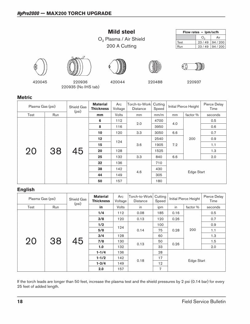
Mild steel
O2 Plasma / Air Shield200 A Cutting
Flow rates – lpm/scfh
O2 AirTest 23 / 49 94 / 200Run 23 / 49 94 / 200
220937220488220936220935 (No IHS tab)
Metric
English
Plasma Gas (psi) Shield Gas (psi)
Material
Thickness
Arc Voltage
Torch-to-Work Distance
Cutting Speed Initial Pierce Height Pierce Delay
Time
Test Run mm Volts mm mm/m mm factor % seconds
20 38 45
6 1122.0
47004.0
200
0.5
8 116 3950 0.6
10 120 3.3 3050 6.6 0.7
12124
3.6
2540
7.2
0.9
15 1905 1.1
20 128 1525 1.3
25 132 3.3 840 6.6 2.0
32 136
4.6
710
Edge Start38 142 430
44 149 305
50 157 180
Plasma Gas (psi) Shield Gas (psi)
Material
Thickness
Arc Voltage
Torch-to-Work Distance
Cutting Speed Initial Pierce Height Pierce Delay
Time
Test Run in Volts in ipm in factor % seconds
20 38 45
1/4 112 0.08 185 0.16
200
0.5
3/8 120 0.13 120 0.26 0.71/2
1240.14
1000.28
0.95/8 75 1.13/4 128 60 1.37/8 130
0.1350
0.261.5
1.0 132 33 2.01-1/4 136
0.18
28
Edge Start1-1/2 142 171-3/4 149 122.0 157 7
If the torch leads are longer than 50 feet, increase the plasma test and the shield pressures by 2 psi (0.14 bar) for every 25 feet of added length.
420045 420044

Field Service Bulletin 19
HyPro2000 — MAX200 TORCH UPGRADE
Mild steel – 3 inch under water
O2 Plasma / Air Shield200 A Cutting
220937220488220936220935 (No IHS tab)
Flow rates – lpm/scfh
O2 AirTest 23 / 49 94 / 200Run 23 / 49 94 / 200
Metric
English
Plasma Gas (psi) Shield Gas (psi)
Material
Thickness
Arc Voltage
Torch-to-Work Distance
Cutting Speed Initial Pierce Height Pierce Delay
Time
Test Run mm Volts mm mm/m mm factor % seconds
20 38 45
6 1122.0
41904.0
200
0.5
8 116 3600 0.6
10 120 3.3 2795 6.6 0.7
12 124
3.6
2290
7.2
0.9
15 124 1525 1.1
20 128 380 1.5
25 132 3.3 510 6.6 2.0
Plasma Gas (psi) Shield Gas (psi)
Material
Thickness
Arc Voltage
Torch-to-Work Distance
Cutting Speed Initial Pierce Height Pierce Delay
Time
Test Run in Volts in ipm in factor % seconds
20 38 45
1/4 112 0.08 165 0.16
200
0.5
3/8 120 0.13 110 0.26 0.71/2 124
0.1490
0.280.9
5/8 124 60 1.13/4 128 15 1.57/8 130 0.13 17 0.26 1.81.0 132 0.12 20 0.24 2.0
If the torch leads are longer than 50 feet, increase the plasma test and the shield pressures by 2 psi (0.14 bar) for every 25 feet of added length.
420045 420044

20 Field Service Bulletin
HyPro2000 — MAX200 TORCH UPGRADE
Stainless steel
Air Plasma / Air Shield50 A Cutting
220532 220528220529220890220936220935
(No IHS tab)
Metric
English
Plasma Gas (psi) Shield Gas (psi)
Material
Thickness
Arc Voltage
Torch-to-Work Distance
Cutting Speed Initial Pierce Height Pierce Delay
Time
Test Run mm Volts mm mm/m mm factor % seconds
60 75 40
0.5 103
1.5
7620
1.5
100
0.0
0.8 104 6730
0.1
1.0 105 6350
1.2 106
1.8
5715
1.81.5 107 4825
2.0 109 4190
2.5118 2.0
31752.0
0.2
3.0 2160 0.3
4.0 121 2.3 1400 3.5150
0.4
6.0 125 2.5 1145 3.8 0.5
Plasma Gas (psi) Shield Gas (psi)
Material
Thickness
Arc Voltage
Torch-to-Work Distance
Cutting Speed Initial Pierce Height Pierce Delay
Time
Test Run in Volts in ipm in factor % seconds
60 75 40
0.018103
0.06
300
0.06
100
0.00.024 275
0.1
0.030 104 2650.036 105 2500.048 106
0.07225
0.070.060 107 1900.075 109 1650.105 118
0.08125
0.080.2
0.135 119 85 0.30.188 124 0.09 55 0.14
1500.4
0.250 126 0.10 45 0.15 0.5
Flow rates – lpm/scfh
Air (Plasma) Air (Shield)Test 25 / 53 86 / 182Run 19 / 40 86 / 182
If the torch leads are longer than 50 feet, increase the plasma test and the shield pressures by 5 psi (0.35 bar) for every 25 feet of added length.

Field Service Bulletin 21
HyPro2000 — MAX200 TORCH UPGRADE
Stainless steel
Air Plasma / Air Shield130 A Cutting
220536 220487220936220935
(No IHS tab)
220488220892
Metric
English
Plasma Gas (psi) Shield Gas (psi)
Material
Thickness
Arc Voltage
Torch-to-Work Distance
Cutting Speed Initial Pierce Height Pierce Delay
Time
Test Run mm Volts mm mm/m mm factor % seconds
45 65 366
1483.6 2540 7.2
2000.5
104.1
17808.2
12 150 1270 0.8
15 1604.6
760Edge Start
20 162 510
Plasma Gas (psi) Shield Gas (psi)
Material
Thickness
Arc Voltage
Torch-to-Work Distance
Cutting Speed Initial Pierce Height Pierce Delay
Time
Test Run in Volts in ipm in factor % seconds
45 65 361/4
1480.14 100 0.28
2000.5
3/80.16
700.32
1/2 150 50 0.85/8 160
0.1830
Edge Start3/4 162 20
Flow rates – lpm/scfh
Air (Plasma) Air (Shield)Test 41 / 87 78 / 165Run 35 / 74 78 / 165
If the torch leads are longer than 50 feet, increase the plasma test and the shield pressures by 5 psi (0.35 bar) for every 25 feet of added length.

22 Field Service Bulletin
HyPro2000 — MAX200 TORCH UPGRADE
Stainless steel
Air Plasma / Air Shield200 A Cutting
220937220936220935
(No IHS tab)
220488
Metric
English
Plasma Gas (psi) Shield Gas (psi)
Material
Thickness
Arc Voltage
Torch-to-Work Distance
Cutting Speed Initial Pierce Height Pierce Delay
Time
Test Run mm Volts mm mm/m mm factor % seconds
30 48 45
5 140 2.8 5840 4.2
1500.4
6142
3.0 5080 4.5
103.3
4065 5.0 0.5
12 143 2795 6.6
2000.8
15 148 4.1 2160 8.2
20 152 4.8 1525 9.6 1.0
25 160
5.6
1015
Edge Start32 168 510
38 186 305
Plasma Gas (psi) Shield Gas (psi)
Material
Thickness
Arc Voltage
Torch-to-Work Distance
Cutting Speed Initial Pierce Height Pierce Delay
Time
Test Run in Volts in ipm in factor % seconds
30 48 45
3/16 140 0.11 230 0.17
1500.4
1/4142
0.12 200 0.18
3/80.13
160 0.20 0.5
1/2 143 110 0.26
2000.8
5/8 148 0.16 85 0.323/4 152 0.19 60 0.38 1.07/8 158 0.21 50 0.42 1.21.0 160
0.2240
Edge Start1-1/4 168 201-1/2 186 12
Flow rates – lpm/scfh
Air (Plasma) Air (Shield)Test 30 / 64 94 / 200Run 30 / 64 94 / 200
If the torch leads are longer than 50 feet, increase the plasma test and the shield pressures by 5 psi (0.35 bar) for every 25 feet of added length.
420045 420044

Field Service Bulletin 23
HyPro2000 — MAX200 TORCH UPGRADE
Stainless steel
N2 Plasma / Air Shield200 A Cutting
020415220936220935
(No IHS tab)
220529
Flow rates – lpm/scfh
N2 AirTest 36 / 76 94 / 200Run 36 / 76 94 / 200
Metric
English
Plasma Gas (psi) Shield Gas (psi)
Material
Thickness
Arc Voltage
Torch-to-Work Distance
Cutting Speed Initial Pierce Height Pierce Delay
Time
Test Run mm Volts mm mm/m mm factor % seconds
45 59 45
5 143 2.8 5840 4.2
1500.4
6 145 3.0 5080 4.5
10 1473.3
4065 5.0 0.5
12 150 2795 6.6
200
0.815 155 4.1 1905 8.2
20 160 4.8 1525 9.6 1.0
25 172
6.4
890 12.8 1.3
32 176 635Edge Start
38 178 380
Plasma Gas (psi) Shield Gas (psi)
Material
Thickness
Arc Voltage
Torch-to-Work Distance
Cutting Speed Initial Pierce Height Pierce Delay
Time
Test Run in Volts in ipm in factor % seconds
45 59 45
3/16 143 0.11 230 0.17
1500.4
1/4 145 0.12 200 0.18
3/8 1470.13
160 0.20 0.5
1/2 150 110 0.26
200
0.85/8 155 0.16 75 0.323/4 160
0.1960
0.381.0
7/8 168 40 1.21.0 172
0.2535 0.50 1.3
1-1/4 176 25Edge Start
1-1/2 178 15
If the torch leads are longer than 50 feet, increase the plasma test and the shield pressures by 5 psi (0.35 bar) for every 25 feet of added length.
420045 420044

24 Field Service Bulletin
HyPro2000 — MAX200 TORCH UPGRADE
Aluminum
Air Plasma / Air Shield50 A Cutting
220532 220528220529220890220936220935
(No IHS tab)
Metric
English
Plasma Gas (psi) Shield Gas (psi)
Material
Thickness
Arc Voltage
Torch-to-Work Distance
Cutting Speed Initial Pierce Height Pierce Delay
Time
Test Run mm Volts mm mm/m mm factor % seconds
60 75 40
0.5108 1.5
80003.0
200
0.0
0.8 74950.1
1.0 111
1.8
7110
3.61.2 112 5840
0.21.5 115 4955
2.0 118
2.0
4065
4.02.5 120 30500.3
3.0 122 2540
4.0 124 2.3 1905 4.6 0.4
6.0 132 2.5 1270 5.0 0.5
Plasma Gas (psi) Shield Gas (psi)
Material
Thickness
Arc Voltage
Torch-to-Work Distance
Cutting Speed Initial Pierce Height Pierce Delay
Time
Test Run in Volts in ipm in factor % seconds
60 75 40
0.018
1080.06
325
0.12
200
0.00.020 3150.024 3050.030 110 295
0.10.036 111
0.07280
0.140.048 112 2300.20.060 115 195
0.075 1180.08
1600.160.105 120 120
0.30.125 123 1000.188 125 0.09 75 0.18 0.4
0.250 132 0.10 50 0.20 0.5
Flow rates – lpm/scfh
Air (Plasma) Air (Shield)Test 25 / 53 86 / 182Run 19 / 40 86 / 182
If the torch leads are longer than 50 feet, increase the plasma test and the shield pressures by 5 psi (0.35 bar) for every 25 feet of added length.

Field Service Bulletin 25
HyPro2000 — MAX200 TORCH UPGRADE
Aluminum
Air Plasma / Air Shield130 A Cutting
220536 220487220936220935
(No IHS tab)
220488220892
Metric
English
Plasma Gas (psi) Shield Gas (psi)
Material
Thickness
Arc Voltage
Torch-to-Work Distance
Cutting Speed Initial Pierce Height Pierce Delay
Time
Test Run mm Volts mm mm/m mm factor % seconds
45 65 36
6 151 2.8 2285 5.6
200
0.2
10 1553.0
15256.0
0.3
12 157 1145 0.5
15 161 3.3 1015 6.6 0.8
20 165 3.6 760 7.2 1.3
25 173 4.0 510 Edge Start
Plasma Gas (psi) Shield Gas (psi)
Material
Thickness
Arc Voltage
Torch-to-Work Distance
Cutting Speed Initial Pierce Height Pierce Delay
Time
Test Run in Volts in ipm in factor % seconds
45 65 36
1/4 151 0.11 90 0.22
200
0.23/8 155
0.1260
0.240.3
1/2 157 45 0.55/8 161 0.13 40 0.26 0.8
3/4 165 0.14 30 0.28 1.31.0 173 0.16 20 Edge Start
Flow rates – lpm/scfh
Air (Plasma) Air (Shield)Test 41 / 87 78 / 165Run 35 / 74 78 / 165
If the torch leads are longer than 50 feet, increase the plasma test and the shield pressures by 5 psi (0.35 bar) for every 25 feet of added length.

26 Field Service Bulletin
HyPro2000 — MAX200 TORCH UPGRADE
Aluminum
Air Plasma / Air Shield200 A Cutting
220937220936220935
(No IHS tab)
220488
Metric
English
Plasma Gas (psi) Shield Gas (psi)
Material
Thickness
Arc Voltage
Torch-to-Work Distance
Cutting Speed Initial Pierce Height Pierce Delay
Time
Test Run mm Volts mm mm/m mm factor % seconds
30 48 45
5 143 2.5 5840 5.0
200
0.56 145
3.35080
6.610 147 4065
12 152 3.8 3175 7.6
15 158 4.1 2415 8.2 0.8
20 163 4.8 1780 9.6 1.0
25 176
5.6
1015
Edge Start32 184 510
38 192 305
Plasma Gas (psi) Shield Gas (psi)
Material
Thickness
Arc Voltage
Torch-to-Work Distance
Cutting Speed Initial Pierce Height Pierce Delay
Time
Test Run in Volts in ipm in factor % seconds
30 48 45
3/16 143 0.10 230 0.20
200
0.51/4 145
0.13200
0.263/8 147 1601/2 152 0.15 125 0.30
5/8 158 0.16 95 0.32 0.83/4 163 0.19 70 0.38 1.07/8 170 0.21 50 0.42 1.21.0 176
0.2240
Edge Start1-1/4 184 201-1/2 192 12
Flow rates – lpm/scfh
Air (Plasma) Air (Shield)Test 30 / 64 94 / 200Run 30 / 64 94 / 200
If the torch leads are longer than 50 feet, increase the plasma test and the shield pressures by 5 psi (0.35 bar) for every 25 feet of added length.
420045 420044

Field Service Bulletin 27
HyPro2000 — MAX200 TORCH UPGRADE
Aluminum
N2 Plasma / Air Shield200 A Cutting
020415220936220935
(No IHS tab)
220529
Flow rates – lpm/scfh
N2 AirTest 36 / 76 94 / 200Run 36 / 76 94 / 200
Metric
English
Plasma Gas (psi) Shield Gas (psi)
Material
Thickness
Arc Voltage
Torch-to-Work Distance
Cutting Speed Initial Pierce Height Pierce Delay
Time
Test Run mm Volts mm mm/m mm factor % seconds
45 59 45
5 148
3.3
5840
5.0 1500.5
6150
5080
10 4065
12 157 2795 6.6
20015 163 4.1 2415 8.2 0.8
20 172 4.8 1525 9.6 1.0
25 184
6.4
1015
Edge Start32 194 510
38 198 305
Plasma Gas (psi) Shield Gas (psi)
Material
Thickness
Arc Voltage
Torch-to-Work Distance
Cutting Speed Initial Pierce Height Pierce Delay
Time
Test Run in Volts in ipm in factor % seconds
45 59 45
3/16 148
0.13
2300.20 150
0.51/4
150200
3/8 1601/2 157 110 0.26
2005/8 163 0.16 95 0.32 0.83/4 172 0.19 60 0.38 1.07/8 178
0.25
50 0.50 1.21.0 184 40
Edge Start1-1/4 194 201-1/2 198 12
If the torch leads are longer than 50 feet, increase the plasma test and the shield pressures by 5 psi (0.35 bar) for every 25 feet of added length.
420045 420044

28 Field Service Bulletin
HyPro2000 — MAX200 TORCH UPGRADE