D S Low Voltage Disconnect Switches - Mersen
24
D S Low Voltage Disconnect Switches THE SAFEST WAY TO SWITCH POWER ON AND OFF IN YOUR INDUSTRIAL CONTROL PANELS • UL 508 Non-Fusible Disconnect Switches DS 2 • UL 98 Non-Fusible Disconnect Switches DS 5 • UL 98 Fusible Disconnect Switches DS 10 • PV-Rated UL and IEC Disconnect Switches DS 15 • Enclosed Disconnect Switches DS 19 Your problem: You need a range of disconnect switches for your industrial control requirements ranging from “Service Entrance Rated” to motor isolation You need DIN-rail and direct mountable disconnect switches that conform to “finger-safe” standards You need a flexible range of handles, shafts, and accessories to select from Our solution: Mersen offers an extensive line of compact UL 98 fusible and non- fusible disconnect switches ranging from 30 to 1200A We also offer a full range of compact UL 508 disconnect switches ranging from 16 to 80A In addition, you can find handle, shaft and accessory options that you require for all of your applications Want more information fast? For more technical or application-specific information, please call our Disconnect Switch experts at 978-465-4853 or visit our website at ep.mersen.com.
-
Upload
khangminh22 -
Category
Documents
-
view
2 -
download
0
Transcript of D S Low Voltage Disconnect Switches - Mersen
DS
Low Voltage DisconnectSwitchesT H E S A F E S T WAY TO SW I TC H P OW E R O N A N D O F F I N YO U R I N D U S T R I A L C O N T R O L PA N E L S
• UL 508 Non-Fusible
Disconnect Switches . . . . . . . . DS 2
• UL 98 Non-Fusible
Disconnect Switches . . . . . . . . DS 5
• UL 98 Fusible
Disconnect Switches . . . . . . . DS 10
• PV-Rated UL and IEC
Disconnect Switches . . . . . . . DS 15
• Enclosed
Disconnect Switches . . . . . . . DS 19
Your problem: You need a range of
disconnect switches for your industrial
control requirements ranging from
“Service Entrance Rated” to motor
isolation . You need DIN-rail and direct
mountable disconnect switches that
conform to “finger-safe” standards . You
need a flexible range of handles, shafts,
and accessories to select from .
Our solution: Mersen offers an extensive
line of compact UL 98 fusible and non-
fusible disconnect switches ranging from
30 to 1200A . We also offer a full range
of compact UL 508 disconnect switches
ranging from 16 to 80A . In addition, you
can find handle, shaft and accessory
options that you require for all of your
applications .
Want more information fast? For
more technical or application-specific
information, please call our Disconnect
Switch experts at 978-465-4853 or visit
our website at ep.mersen.com.
EP.MERSEN.COMDS 2
DS
© 2018 Mersen. All rights reserved. Mersen reserves the right to change, update, or correct, without notice, any information contained in this datasheet.
UL 508 Non-Fusible Disconnect Switches
DISCONNECT SWITCHES
M163 – M803
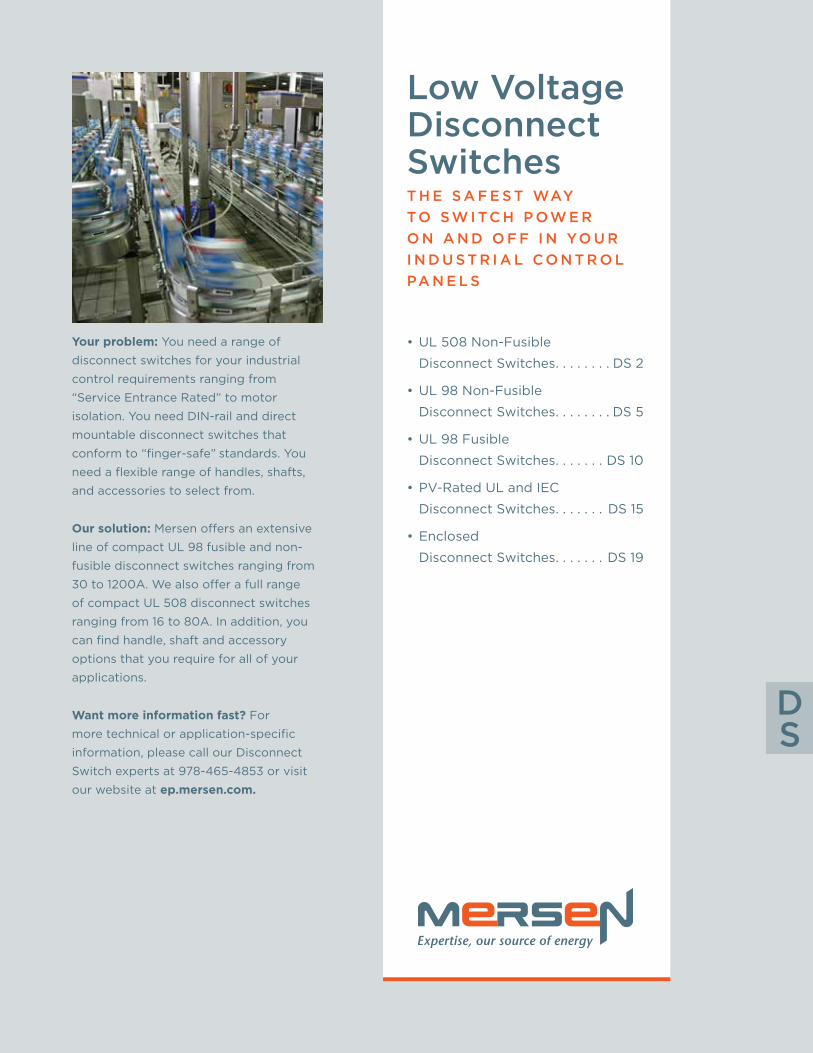
The M-series Load Break Switch is the most compact industrial-grade
switch on the market . Capable of making or breaking loads up to
600V (UL), it is suitable as a motor disconnect . Extremely compact
and robust, these switches have a variety of mounting options
including DIN-rail, base, or door-mounting . A wide assortment of
handles, shafts and accessories is available to accommodate any
installation requirement .
A P P L I C AT I O N S :• Line-of-sight disconnect
• Electrical isolation
• Branch-circuit switch
• Motor disconnect
R AT I N G S ( U L ) :
• Volts: 600VAC
• Amps: 20, 30, 40, 63, and 80A . Suitable as motor disconnect up to 40hp .
F E AT U R E S / B E N E F I T S :• Compact
• Robust
• DIN-rail, base, or door mounting
• Choice of handles and shafts
• Padlockable
• Side-mount auxiliary contacts and additional poles
• Double-break, silver-plated, contacts
A P P R OVA L S :• UL 508 listed E196672
• IEC 60947-3
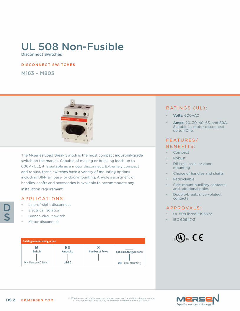
Catalog number designation
MSwitch
M = Mersen AC Switch
80Ampacity
16-80
3Number of Poles
________Special Configurations
DM: Door Mounting
EP.MERSEN.COM DS 3
LOW VOLTAGE D ISCONNECT SWITCHES
DS
UL 508 NON-FUSIBLEDisconnect Switches (M163 – M803)
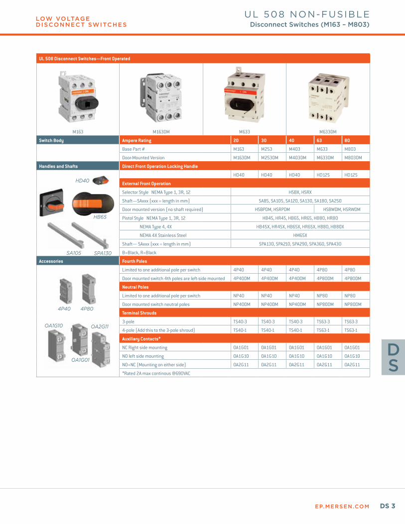
UL 508 Disconnect Switches—Front Operated
M163 M163DM M633 M633DM
Switch Body Ampere Rating 20 30 40 63 80
Base Part # M163 M253 M403 M633 M803
Door-Mounted Version M163DM M253DM M403DM M633DM M803DM
Handles and Shafts Direct Front Operation Locking Handle
HD40 HD40 HD40 HD125 HD125
External Front Operation
Selector Style NEMA Type 1, 3R, 12 HSBX, HSRX
Shaft—SAxxx (xxx = length in mm) SA85, SA105, SA120, SA130, SA180, SA250
Door mounted version (no shaft required) HSBPDM, HSRPDM HSBWDM, HSRWDM
Pistol Style NEMA Type 1, 3R, 12 HB45, HR45, HB65, HR65, HB80, HR80
NEMA Type 4, 4X HB45X, HR45X, HB65X, HR65X, HB80, HB80X
NEMA 4X Stainless Steel HM65X
Shaft— SAxxx (xxx = length in mm) SPA130, SPA210, SPA290, SPA360, SPA430
B=Black, R=Black
Accessories Fourth Poles
Limited to one additional pole per switch 4P40 4P40 4P40 4P80 4P80
Door mounted switch 4th poles are left-side mounted 4P40DM 4P40DM 4P40DM 4P80DM 4P80DM
Neutral Poles
Limited to one additional pole per switch NP40 NP40 NP40 NP80 NP80
Door mounted switch neutral poles NP40DM NP40DM NP40DM NP80DM NP80DM
Terminal Shrouds
3-pole TS40-3 TS40-3 TS40-3 TS63-3 TS63-3
4-pole (Add this to the 3-pole shroud) TS40-1 TS40-1 TS40-1 TS63-1 TS63-1
Auxiliary Contacts*
NC Right side mounting OA1G01 OA1G01 OA1G01 OA1G01 OA1G01
NO left side mounting OA1G10 OA1G10 OA1G10 OA1G10 OA1G10
NO+NC (Mounting on either side) OA2G11 OA2G11 OA2G11 OA2G11 OA2G11
*Rated 2A max continous @690VAC
4P40 4P80
OA1G10
OA1G01
OA2G11
SA105 SPA130
HB65
HD40
EP.MERSEN.COMDS 4
LOW VOLTAGE D ISCONNECT SWITCHES
DS
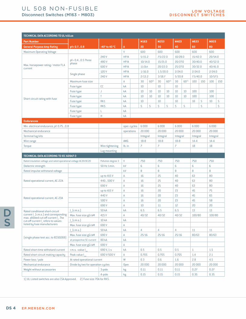
TECHNICAL DATA ACCORDING TO UL/cULus
Part Number M163 M253 M403 M633 M803
General Purpose Amp Rating pf= 0.7...0.8 -40° to 40 °C A 20 30 40 60 80
Maximum Operating Voltage V 600 600 600 600 600
Max. horsepower rating / motor FLA current
pf= 0.4...0.5 Three phase
240 V HP/A 5/15.2 7.5/22.0 10/28.0 15/42.0 20/54.0
480 V HP/A 10/14.0 15/21.0 20/27.0 30/40.0 40/52.0
600 V HP/A 11-Oct 20/22.0 25/27.0 30/32.0 40/41.0
Single phase120 V HP/A 1/16.0 1.5/20.0 2/24.0 2/24.0 2/24.0
240 V HP/A 2/13.2 3/18.7 5/30.8 7.5/40.0 10/57.5
Short circuit rating with fuse
Maximum fuse size A 30 602) 30 602) 30 602) 100 150 100 150
Fuse type CC kA 10 10 10
Fuse type J kA 10 10 10 10 10 10 100 100
Fuse type T kA 10 10 10 10 10 10 100 100
Fuse type RK1 kA 10 10 10 10 5 10 5
Fuse type RK5 kA 5 5 5 5 5 5 5 5
Fuse type L kA
Fuse type H kA
Endurances
Min. electrical endurance, pf. 0.75...0.8 oper. cycles 6 000 6 000 6 000 6 000 6 000
Mechanical endurance operations 20 000 20 000 20 000 20 000 20 000
Terminal lug kits Integral Integral Integral Integral Integral
Wire range AWG 18-8 18-8 18-8 14-4 14-4
Torque Wire tightening lb. in 7 7 7 18 18
Lug mounting
TECHNICAL DATA ACCORDING TO IEC 60947-3
Rated insulation voltage and rated operational voltage AC20/DC20 Pollution degree 3 V 750 750 750 750 750
Dielectric strength 50 Hz 1min. kV 6 6 6 6 6
Rated impulse withstand voltage kV 8 8 8 8 8
Rated operational current, AC-22A
up to 415 V A 16 25 40 63 80
440...500 V A 16 25 40 63 80
690 V A 16 25 40 63 80
Rated operational current, AC-23A
up to 415 V A 16 20 23 45 75
440 V A 16 20 23 45 65
500 V A 16 20 23 45 58
690 V A 10 11 12 20 20
Rated conditional short-circuit current Ip (r.m.s.) and corresponding max. allowed cut-off current îc. The cut-off current îc refers to values listed by fuse manufacturers
Ip (r.m.s.) 50 kA kA 6.5 6.5 6.5 13 13
Max. fuse size gG/aM 415 V A 40/32 40/32 40/32 100/80 100/80
Ip (r.m.s.) 10 kA kA
Max. fuse size gG/aM 690 V A
(single phase test acc. to IEC60269)
Ip (r.m.s.) 50 kA kA 4 4 4 11 11
Max. fuse size gG/aM 690 V A 25/16 25/16 25/16 80/63 80/63
at prospective SC-current 80 kA kA
Max. fuse size gG/aM 690 V A
Rated short-time withstand current r.m.s. -value Icw 690 V, 1 s kA 0.5 0.5 0.5 1 1.5
Rated short circuit making capacity Peak value Icm 690 V/500 V A 0.705 0.705 0.705 1.4 2.1
Power loss / pole At rated operational current W 0.3 0.6 1.6 2.8 4.5
Mechanical endurance Divide by two for operation cycles Oper. 20 000 20 000 20 000 20 000 20 000
Weight without accessories 3-pole kg 0.11 0.11 0.11 0.27 0.27
4-pole kg 0.15 0.15 0.15 0.35 0.351) UL Listed switches are also CSA Approved. 2) Fuse size 70A for RK5.
UL 508 NON-FUSIBLEDisconnect Switches (M163 – M803)

EP.MERSEN.COM DS 5
DS
© 2018 Mersen. All rights reserved. Mersen reserves the right to change, update, or correct, without notice, any information contained in this datasheet.
Mersen’s non-fusible disconnect switches are listed to UL 98 and
bear the CE mark as conformance to IEC 60947-3 . They are “service
entrance” devices that are capable of fully rated load-break and
load-make . All switches over 100A have windows to provide visual
indication of the contact status . Engineered to have the smallest
footprint, these switches also employ a modular design that enables
the handle to be placed amongst the poles or at the ends .
A wide range of ergonomic handles and accessories is available to
accommodate multiple applications .
C O N F I G U R AT I O N S :
R AT I N G S ( U L ) :• Volts: 600VAC
• Amps: 30A, 60A, 100A, 200A, 400A, 600A, 800A, 1200A
• Short-Circuit Current Rating (SCCR): Up to 200kA with fuses . Suitable as motor disconnect .
F E AT U R E S /B E N E F I T S :• Service entrance rated
• Front operation
• Most compact size
• Internally mounted auxiliary contacts
• Flange mounting accessories
• Flexible mounting
• Adjustable shaft depth
A P P R OVA L S :• All UL switches meet the
requirements of UL and CSA
• UL listed guide WHTY, File E191605 for UL 98 (ratings from 30 A to 1200 A)
• IEC 60947-3
*Not all configurations are available
Catalog number designation
MSwitch
M = Mersen AC Switch
200Ampacity
16-1200
UType
U = non-fused UL 98
3Number of Poles/Left of handle
1-3
0Number of
Poles/Right of handle
Blank = < 200A
non-fused, 0, 2, 3
_____Revision
Blank = 0
_____Special
Configuration
F = Flange-mount
ActuationDM = Door mounted
Gearbox on the side Gearbox in the middle
UL 98 Non-Fusible Disconnect Switches
DISCONNECT SWITCHES
*Not all configurations are available.
EP.MERSEN.COMDS 6
LOW VOLTAGE D ISCONNECT SWITCHES
DS
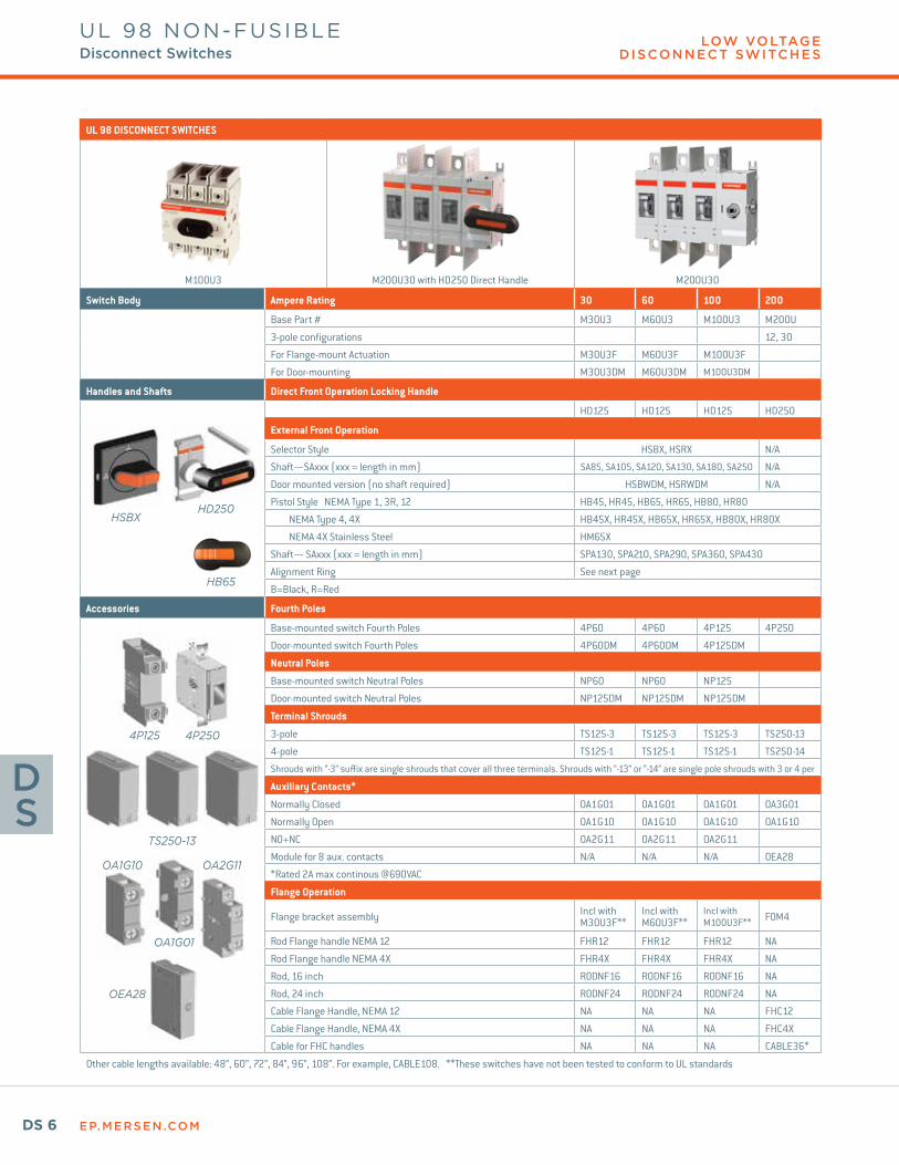
UL 98 DISCONNECT SWITCHES
M100U3 M200U30 with HD250 Direct Handle M200U30
Switch Body Ampere Rating 30 60 100 200
Base Part # M30U3 M60U3 M100U3 M200U
3-pole configurations 12, 30
For Flange-mount Actuation M30U3F M60U3F M100U3F
For Door-mounting M30U3DM M60U3DM M100U3DM
Handles and Shafts Direct Front Operation Locking Handle
HD125 HD125 HD125 HD250
External Front Operation
Selector Style HSBX, HSRX N/A
Shaft—SAxxx (xxx = length in mm) SA85, SA105, SA120, SA130, SA180, SA250 N/A
Door mounted version (no shaft required) HSBWDM, HSRWDM N/A
Pistol Style NEMA Type 1, 3R, 12 HB45, HR45, HB65, HR65, HB80, HR80
NEMA Type 4, 4X HB45X, HR45X, HB65X, HR65X, HB80X, HR80X
NEMA 4X Stainless Steel HM65X
Shaft— SAxxx (xxx = length in mm) SPA130, SPA210, SPA290, SPA360, SPA430
Alignment Ring See next page
B=Black, R=Red
Accessories Fourth Poles
Base-mounted switch Fourth Poles 4P60 4P60 4P125 4P250
Door-mounted switch Fourth Poles 4P60DM 4P60DM 4P125DM
Neutral Poles
Base-mounted switch Neutral Poles NP60 NP60 NP125
Door-mounted switch Neutral Poles NP125DM NP125DM NP125DM
Terminal Shrouds
3-pole TS125-3 TS125-3 TS125-3 TS250-13
4-pole TS125-1 TS125-1 TS125-1 TS250-14
Shrouds with “-3” suffix are single shrouds that cover all three terminals. Shrouds with “-13” or “-14” are single pole shrouds with 3 or 4 per
Auxiliary Contacts*
Normally Closed OA1G01 OA1G01 OA1G01 OA3G01
Normally Open OA1G10 OA1G10 OA1G10 OA1G10
NO+NC OA2G11 OA2G11 OA2G11
Module for 8 aux. contacts N/A N/A N/A OEA28
*Rated 2A max continous @690VAC
Flange Operation
Flange bracket assembly Incl with M30U3F**
Incl with M60U3F**
Incl with M100U3F** FOM4
Rod Flange handle NEMA 12 FHR12 FHR12 FHR12 NA
Rod Flange handle NEMA 4X FHR4X FHR4X FHR4X NA
Rod, 16 inch RODNF16 RODNF16 RODNF16 NA
Rod, 24 inch RODNF24 RODNF24 RODNF24 NA
Cable Flange Handle, NEMA 12 NA NA NA FHC12
Cable Flange Handle, NEMA 4X NA NA NA FHC4X
Cable for FHC handles NA NA NA CABLE36*
Other cable lengths available: 48”, 60”, 72”, 84”, 96”, 108”. For example, CABLE108. **These switches have not been tested to conform to UL standards
4P125 4P250
TS250-13
OA1G10
OA1G01
OA2G11
OEA28
HSBX
HB65
HD250
UL 98 NON-FUSIBLEDisconnect Switches
EP.MERSEN.COM DS 7
LOW VOLTAGE D ISCONNECT SWITCHES
DS
UL 98 NON-FUSIBLEDisconnect Switches
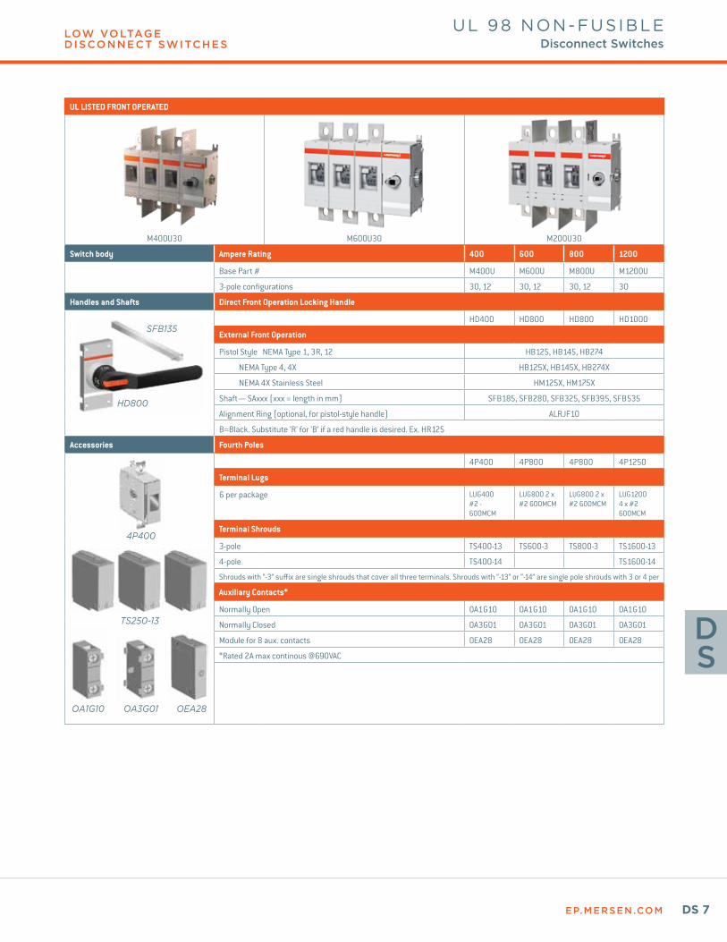
UL LISTED FRONT OPERATED
M400U30 M600U30 M200U30
Switch body Ampere Rating 400 600 800 1200
Base Part # M400U M600U M800U M1200U
3-pole configurations 30, 12 30, 12 30, 12 30
Handles and Shafts Direct Front Operation Locking Handle
HD400 HD800 HD800 HD1000
External Front Operation
Pistol Style NEMA Type 1, 3R, 12 HB125, HB145, HB274
NEMA Type 4, 4X HB125X, HB145X, HB274X
NEMA 4X Stainless Steel HM125X, HM175X
Shaft— SAxxx (xxx = length in mm) SFB185, SFB280, SFB325, SFB395, SFB535
Alignment Ring (optional, for pistol-style handle) ALRJF10
B=Black. Substitute ‘R’ for ‘B’ if a red handle is desired. Ex. HR125
Accessories Fourth Poles
4P400 4P800 4P800 4P1250
Terminal Lugs
6 per package LUG400 #2 - 600MCM
LUG800 2 x #2 600MCM
LUG800 2 x #2 600MCM
LUG1200 4 x #2 600MCM
Terminal Shrouds
3-pole TS400-13 TS600-3 TS800-3 TS1600-13
4-pole TS400-14 TS1600-14
Shrouds with “-3” suffix are single shrouds that cover all three terminals. Shrouds with “-13” or “-14” are single pole shrouds with 3 or 4 per
Auxiliary Contacts*
Normally Open OA1G10 OA1G10 OA1G10 OA1G10
Normally Closed OA3G01 OA3G01 OA3G01 OA3G01
Module for 8 aux. contacts OEA28 OEA28 OEA28 OEA28
*Rated 2A max continous @690VAC
HD800
SFB135
4P400
TS250-13
OA1G10 OA3G01 OEA28
EP.MERSEN.COMDS 8
LOW VOLTAGE D ISCONNECT SWITCHES
DS
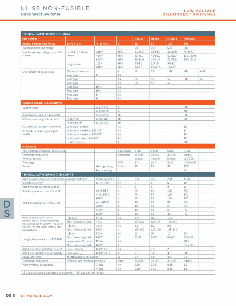
TECHNICAL DATA ACCORDING TO UL/cULus
Part Number M30U3 M60U3 M100U3 M200Uxx
General Purpose Amp Rating pf= 0.7...0.8 -5° to 40 °C A 30 60 100 200Maximum Operating Voltage V 600 600 600 600
Max. horsepower rating / motor FLA current
pf= 0.4...0.5 Three phase
240 V HP/A 10/28.0 20/54.0 30/80.0 75/192.0480 V HP/A 20/27.0 40/52.0 50/65.0 150/180.0600 V HP/A 30/32.0 40/41.0 50/52.0 200/192.0
Single phase 120 V HP/A 2/24.0 3/34.0 5/56.0240 V HP/A 5/28.0 7.5/40.0 15/68.0
Short circuit rating with fuse Maximum fuse size A 60 150 150 200 400Fuse type CC kA Fuse type J kA 50 50 50 200 65Fuse type T kA 50 50 50Fuse type RK1 kAFuse type RK5 kAFuse type L kAFuse type H kA
Maximum General Use, DC Ratings
Current rating at 250 VDC A 200at 600 VDC A 100
DC horsepower rating for 4-pole switch at 600 VDC HP 50DC horsepower rating for 2-pole switch In open air at 125 VDC HP 20
In enclosure2) at 250 VDC HP -DC short circuit rating for 4-pole switch with circuit breaker kA 10
DC short circuit rating for 2-pole switch
with circuit breaker at 250 VDC kA 14with circuit breaker at 600 VDC kA 10with class J fuse at 250 VDC kA 100... with fuse size A 200
endurancesMin. electrical endurance, pf. 0.75...0.8 oper. cycles 6 000 6 000 6 000 6 000Mechanical endurance operations 20 000 20 000 20 000 20 000Terminal lug kits Integral Integral Integral LUG-200Wire range AWG 14-4 14-4 8-1/0 4-300MCMTorque Wire tightening lb. in 55 55 55 275
Lug mounting 72TECHNICAL DATA ACCORDING TO IEC 60947-3Rated insulation voltage and rated operational voltage AC20/DC20 Pollution degree 3 V 750 750 750 1 000Dielectric strength 50 Hz 1min. kV 6 6 6 10Rated impulse withstand voltage kV 8 8 8 12
Rated operational current, AC-22A up to 415 V A 40 63 100 250440...500 V A 40 63 100 250690 V A 40 63 100 250
Rated operational current, AC-23A up to 415 V A 40 63 80 250440 V A 40 63 65 250500 V A 40 63 60 250690 V A 40 63 40 250
Rated conditional short-circuit current Ip (r.m.s.) and corresponding max. allowed cut-off current îc. The cut-off current îc refers to values listed by fuse manufacturers
Ip (r.m.s.) 50 kA kA 16.5 16.5 16.5Max. fuse size gG/aM 415 V A 125/125 125/125 125/125Ip (r.m.s.) 10 kA kA 8.2 8.2 8.2Max. fuse size gG/aM 690 V A 125/100 125/100 125/100
(single phase test acc. to IEC60269)
Ip (r.m.s.) 50 kA kA 10 10 10 35Max. fuse size gG/aM 690 V A 63/63 63/63 63/63 355/315at prospective SC-current 80 kA kA 40.5Max. fuse size gG/aM 690 V A 355/315
Rated short-time withstand current r.m.s. -value Icw 690 V, 1 s kA 2.5 2.5 2.5 8Rated short circuit making capacity Peak value Icm 690 V/500 V A 3.6 3.6 3.6 30Power loss / pole At rated operational current W 0.7 1.6 4.0 6.5Mechanical endurance Divide by two for operation cycles Oper. 20 000 20 000 20 000 20 000Weight without accessories 3-pole kg 0.36 0.36 0.36 1.2
4-pole kg 0.50 0.50 0.50 1.51) UL Listed switches are also CSA Approved. 2) Fuse size 70A for RK5.
UL 98 NON-FUSIBLEDisconnect Switches

EP.MERSEN.COM DS 9
LOW VOLTAGE D ISCONNECT SWITCHES
DS
UL 98 NON-FUSIBLEDisconnect Switches
TECHNICAL DATA ACCORDING TO UL/cULus
Part Number M400U M600U M800U M1200U
General Purpose Amp Rating pf= 0.7...0.8 -5° to 40 °C A 400 600 800 1200Maximum Operating Voltage V 600 600 600 600
Max. horsepower rating / motor FLA current
pf= 0.4...0.5 Three phase
240 V HP/A 125/312.0 200/480.0 200/602 200/602480 V HP/A 250/302.0 450/515.0 500/590 500/590600 V HP/A 350/338.0 500/472.0 500/472 500/472
Single phase120 V HP/A 240 V HP/A
Short circuit rating with fuse
Maximum fuse size A 600 600 800 800 1200Fuse type CC kA Fuse type J kA 100 100Fuse type T kA 100Fuse type RK1 kAFuse type RK5 kA 100 100 100Fuse type L kAFuse type H kA
Maximum General Use, DC Ratings
Current ratingat 250 VDC A 400 600at 600 VDC A 200 200
DC horsepower rating for 4-pole switch at 600 VDC HP 50 -
DC horsepower rating for 2-pole switchIn open air at 125 VDC HP 40 -In enclosure2) at 250 VDC HP 50 50
DC short circuit rating for 4-pole switch with circuit breaker kA 10 10
DC short circuit rating for 2-pole switch
with circuit breaker at 250 VDC kA 14 18with circuit breaker at 600 VDC kA 10 10with class J fuse at 250 VDC kA 100 100... with fuse size A 400 500
EndurancesMin. electrical endurance, pf. 0.75...0.8 oper. cycles 1 000 1 000 500 500Mechanical endurance operations 16 000 10 000 6000 6000Terminal lug kits LUG400 LUG800 LUG800 LUG1200Wire range AWG 2 - 600MCM 2 x 2 - 600MCM 2 x 2 - 600MCM 4 x 2 - 600MCM
Torque Wire tightening lb. in 375 55 500 500Lug mounting 240 480 480 450-670
TECHNICAL DATA ACCORDING TO IEC 60947-3Rated insulation voltage and rated operational voltage AC20/DC20 Pollution degree 3 V 1 000 1 000 1 000 1 000Dielectric strength 50 Hz 1min. kV 10 10 10 10Rated impulse withstand voltage kV 12 12 12 12
Rated operational current, AC-22Aup to 415 V A 400 800 1600 1600440...500 V A 400 800 1600 1600690 V A 400 800 1600 1600
Rated operational current, AC-23A
up to 415 V A 400 800 1250 1250440 V A 400 800 1250 1250500 V A 400 800 1250 1250690 V A 400 800 1250 1250
Rated conditional short-circuit current Ip (r.m.s.) and corresponding max. allowed cut-off current îc. The cut-off current îc refers to values listed by fuse manufacturers
Ip (r.m.s.) 50 kA kAMax. fuse size gG/aM 415 V AIp (r.m.s.) 50 kA kAMax. fuse size gG/aM 690 V A
(single phase test acc. to IEC60269)
Ip (r.m.s.) 50 kA kA 50.5 71.5Max. fuse size gG/aM 690 V A 500/500 800/1 000at prospective SC-current 80 kA kA 59 83.5Max. fuse size gG/aM 690 V A 500/500 800/1 000
Rated short-time withstand current r.m.s. -value Icw 690 V, 1 s kA 15 20 50 50Rated short circuit making capacity Peak value Icm 690 V/500 V A 65 80 110 110Power loss / pole At rated operational current W 10 40 29 48Mechanical endurance Divide by two for operation cycles Oper. 26 000 10 000Weight without accessories 3-pole kg 2.2 5.2 15.2 15.2
4-pole kg 2.8 6.41) UL Listed switches are also CSA Approved. 2) Fuse size 70A for RK5.
EP.MERSEN.COMDS 10
DS
© 2018 Mersen. All rights reserved. Mersen reserves the right to change, update, or correct, without notice, any information contained in this datasheet.
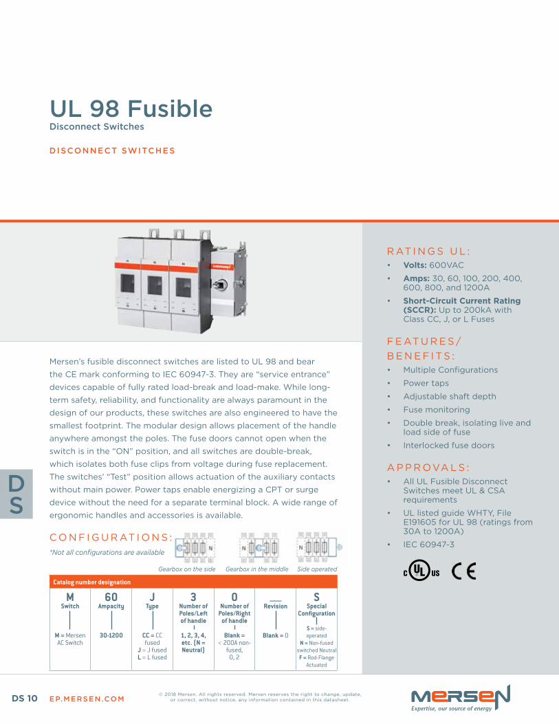
Mersen’s fusible disconnect switches are listed to UL 98 and bear
the CE mark conforming to IEC 60947-3 . They are “service entrance”
devices capable of fully rated load-break and load-make . While long-
term safety, reliability, and functionality are always paramount in the
design of our products, these switches are also engineered to have the
smallest footprint . The modular design allows placement of the handle
anywhere amongst the poles . The fuse doors cannot open when the
switch is in the “ON” position, and all switches are double-break,
which isolates both fuse clips from voltage during fuse replacement .
The switches’ “Test” position allows actuation of the auxiliary contacts
without main power . Power taps enable energizing a CPT or surge
device without the need for a separate terminal block . A wide range of
ergonomic handles and accessories is available .
C O N F I G U R AT I O N S :
R AT I N G S U L :• Volts: 600VAC
• Amps: 30, 60, 100, 200, 400, 600, 800, and 1200A
• Short-Circuit Current Rating (SCCR): Up to 200kA with Class CC, J, or L Fuses
F E AT U R E S / B E N E F I T S :• Multiple Configurations
• Power taps
• Adjustable shaft depth
• Fuse monitoring
• Double break, isolating live and load side of fuse
• Interlocked fuse doors
A P P R OVA L S :• All UL Fusible Disconnect
Switches meet UL & CSA requirements
• UL listed guide WHTY, File E191605 for UL 98 (ratings from 30A to 1200A)
• IEC 60947-3
Catalog number designation
MSwitch
M = Mersen AC Switch
60Ampacity
30-1200
JType
CC = CC fused
J = J fusedL = L fused
3Number of Poles/Left of handle
1, 2, 3, 4, etc. (N = Neutral)
0Number of
Poles/Right of handle
Blank = < 200A non-
fused, 0, 2
_____Revision
Blank = 0
SSpecial
Configuration
S = side-operated
N = Non-fused switched Neutral
F = Rod-Flange Actuated
UL 98 Fusible Disconnect Switches
DISCONNECT SWITCHES
Gearbox on the side Gearbox in the middle Side operated
*Not all configurations are available
EP.MERSEN.COM DS 11
LOW VOLTAGE D ISCONNECT SWITCHES
DS
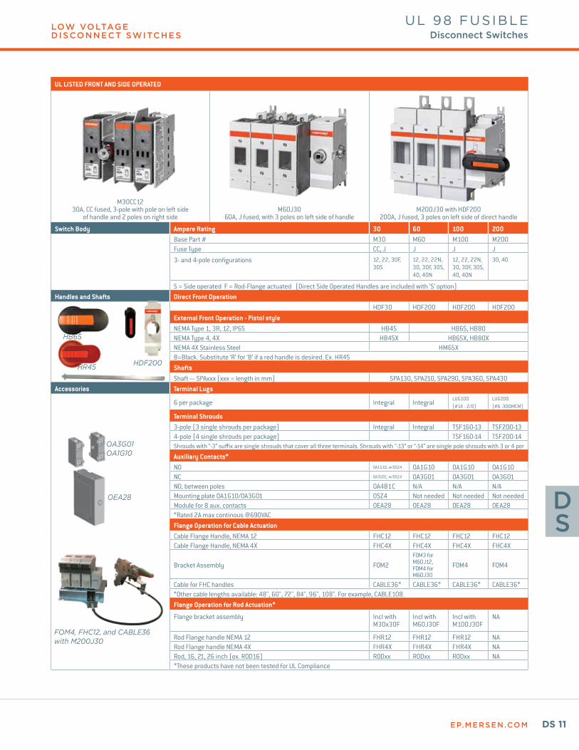
UL LISTED FRONT AND SIDE OPERATED
M30CC1230A, CC fused, 3-pole with pole on left side
of handle and 2 poles on right sideM60J30
60A, J fused, with 3 poles on left side of handleM200J30 with HDF200
200A, J fused, 3 poles on left side of direct handle
Switch Body Ampere Rating 30 60 100 200Base Part # M30 M60 M100 M200Fuse Type CC, J J J J
3- and 4-pole configurations 12, 22, 30F, 30S
12, 22, 22N, 30, 30F, 30S, 40, 40N
12, 22, 22N, 30, 30F, 30S, 40, 40N
30, 40
S = Side operated F = Rod-Flange actuated (Direct Side Operated Handles are included with ‘S’ option)Handles and Shafts Direct Front Operation
HDF30 HDF200 HDF200 HDF200External Front Operation - Pistol styleNEMA Type 1, 3R, 12, IP65 HB45 HB65, HB80NEMA Type 4, 4X HB45X HB65X, HB80XNEMA 4X Stainless Steel HM65XB=Black. Substitute ‘R’ for ‘B’ if a red handle is desired. Ex. HR45ShaftsShaft— SPAxxx (xxx = length in mm) SPA130, SPA210, SPA290, SPA360, SPA430
Accessories Terminal Lugs
6 per package Integral IntegralLUG100 (#14 - 2/0)
LUG200 (#6 -300MCM)
Terminal Shrouds3-pole (3 single shrouds per package) Integral Integral TSF160-13 TSF200-134-pole (4 single shrouds per package) TSF160-14 TSF200-14Shrouds with “-3” suffix are single shrouds that cover all three terminals. Shrouds with “-13” or “-14” are single pole shrouds with 3 or 4 per
Auxiliary Contacts*NO OA1G10, w/OSZ4 OA1G10 OA1G10 OA1G10NC OA3G01, w/OSZ4 OA3G01 OA3G01 OA3G01NO, between poles OA4B1C N/A N/A N/AMounting plate OA1G10/OA3G01 OSZ4 Not needed Not needed Not neededModule for 8 aux. contacts OEA28 OEA28 OEA28 OEA28*Rated 2A max continous @690VACFlange Operation for Cable Actuation Cable Flange Handle, NEMA 12 FHC12 FHC12 FHC12 FHC12Cable Flange Handle, NEMA 4X FHC4X FHC4X FHC4X FHC4X
Bracket Assembly FOM2FOM3 for M60J12, FOM4 for M60J30
FOM4 FOM4
Cable for FHC handles CABLE36* CABLE36* CABLE36* CABLE36**Other cable lengths available: 48", 60", 72", 84", 96", 108". For example, CABLE108.Flange Operation for Rod Actuation*
Flange bracket assembly Incl with M30x30F
Incl with M60J30F
Incl with M100J30F
NA
Rod Flange handle NEMA 12 FHR12 FHR12 FHR12 NARod Flange handle NEMA 4X FHR4X FHR4X FHR4X NARod, 16, 21, 26 inch (ex. ROD16) RODxx RODxx RODxx NA*These products have not been tested for UL Compliance
OA3G01OA1G10
OEA28
FOM4, FHC12, and CABLE36 with M200J30
HDF200HR45
HB65
UL 98 FUSIBLEDisconnect Switches
EP.MERSEN.COMDS 12
LOW VOLTAGE D ISCONNECT SWITCHES
DS
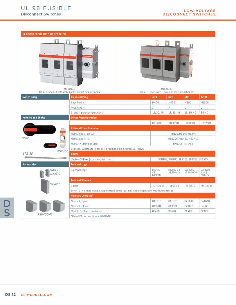
UL LISTED FRONT AND SIDE OPERATED
M400J30400A, J fused, 3-pole with 3 poles on left side of handle
M800L30800A, L fused, with 3 poles on left side of handle
Switch Body Ampere Rating 400 600 800 1200
Base Part # M400 M600 M800 M1200
Fuse Type J J L L
3- and 4-pole configurations 12, 30, 40 12, 30, 40 12, 30, 40 30, 40
Handles and Shafts Direct Front Operation
HDF400 HDF800T HDF800T HD1250T
External Front Operation
NEMA Type 1, 3R, 12 HB125, HB145, HB274
NEMA Type 4, 4X HB125X, HB145X, HB274X
NEMA 4X Stainless Steel HM125X, HM175X
B=Black. Substitute ‘R’ for ‘B’ if a red handle is desired. Ex. HR125
Shafts
Shaft— SFBxxx (xxx = length in mm) SFB185, SFB280, SFB325, SFB395, SFB535
Accessories Terminal Lugs
6 per package LUG400 #2 - 600MCM
LUG800 2 x #2 600MCM
LUG800 2 x #2 600MCM
LUG1200 4 x #2 600MCM
Terminal Shrouds
3-pole TSF400-13 TSF600-3 TSF600-3 TSF1250-13
Suffix “-3” indicates a single 3-pole shroud; Suffix “-13” indicates 3 single pole shrouds per package
Auxiliary Contacts*
Normally Open OA1G10 OA1G10 OA1G10 OA1G10
Normally Closed OA3G01 OA3G01 OA3G01 OA3G01
Module for 8 aux. contacts OEA28 OEA28 OEA28 OEA28
*Rated 2A max continous @690VAC
OA1G01OA1G10
OEA28
TSF400-13
HB125
HDF400SFB135
UL 98 FUSIBLEDisconnect Switches
EP.MERSEN.COM DS 13
LOW VOLTAGE D ISCONNECT SWITCHES
DS
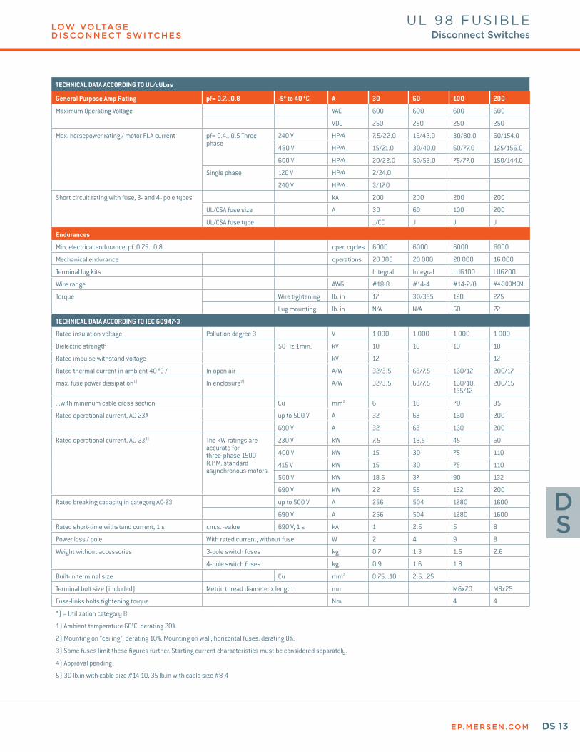
UL 98 FUSIBLEDisconnect Switches
TECHNICAL DATA ACCORDING TO UL/cULus
General Purpose Amp Rating pf= 0.7...0.8 -5° to 40 °C A 30 60 100 200
Maximum Operating Voltage VAC 600 600 600 600
VDC 250 250 250 250
Max. horsepower rating / motor FLA current pf= 0.4...0.5 Three phase
240 V HP/A 7.5/22.0 15/42.0 30/80.0 60/154.0
480 V HP/A 15/21.0 30/40.0 60/77.0 125/156.0
600 V HP/A 20/22.0 50/52.0 75/77.0 150/144.0
Single phase 120 V HP/A 2/24.0
240 V HP/A 3/17.0
Short circuit rating with fuse, 3- and 4- pole types kA 200 200 200 200
UL/CSA fuse size A 30 60 100 200
UL/CSA fuse type J/CC J J J
Endurances
Min. electrical endurance, pf. 0.75...0.8 oper. cycles 6000 6000 6000 6000
Mechanical endurance operations 20 000 20 000 20 000 16 000
Terminal lug kits Integral Integral LUG100 LUG200
Wire range AWG #18-8 #14-4 #14-2/0 #4-300MCM
Torque Wire tightening lb. in 17 30/355 120 275
Lug mounting lb. in N/A N/A 50 72
TECHNICAL DATA ACCORDING TO IEC 60947-3
Rated insulation voltage Pollution degree 3 V 1 000 1 000 1 000 1 000
Dielectric strength 50 Hz 1min. kV 10 10 10 10
Rated impulse withstand voltage kV 12 12
Rated thermal current in ambient 40 °C / In open air A/W 32/3.5 63/7.5 160/12 200/17
max. fuse power dissipation1) In enclosure2) A/W 32/3.5 63/7.5 160/10, 135/12
200/15
...with minimum cable cross section Cu mm2 6 16 70 95
Rated operational current, AC-23A up to 500 V A 32 63 160 200
690 V A 32 63 160 200
Rated operational current, AC-233) The kW-ratings are accurate for three-phase 1500 R.P.M. standard asynchronous motors.
230 V kW 7.5 18.5 45 60
400 V kW 15 30 75 110
415 V kW 15 30 75 110
500 V kW 18.5 37 90 132
690 V kW 22 55 132 200
Rated breaking capacity in category AC-23 up to 500 V A 256 504 1280 1600
690 V A 256 504 1280 1600
Rated short-time withstand current, 1 s r.m.s. -value 690 V, 1 s kA 1 2.5 5 8
Power loss / pole With rated current, without fuse W 2 4 9 8
Weight without accessories 3-pole switch fuses kg 0.7 1.3 1.5 2.6
4-pole switch fuses kg 0.9 1.6 1.8
Built-in terminal size Cu mm2 0.75...10 2.5...25
Terminal bolt size (included) Metric thread diameter x length mm M6x20 M8x25
Fuse-links bolts tightening torque Nm 4 4
*) = Utilization category B
1) Ambient temperature 60°C: derating 20%
2) Mounting on “ceiling”: derating 10%. Mounting on wall, horizontal fuses: derating 8%.
3) Some fuses limit these figures further. Starting current characteristics must be considered separately.
4) Approval pending
5) 30 lb.in with cable size #14-10, 35 lb.in with cable size #8-4
EP.MERSEN.COMDS 14
LOW VOLTAGE D ISCONNECT SWITCHES
DS
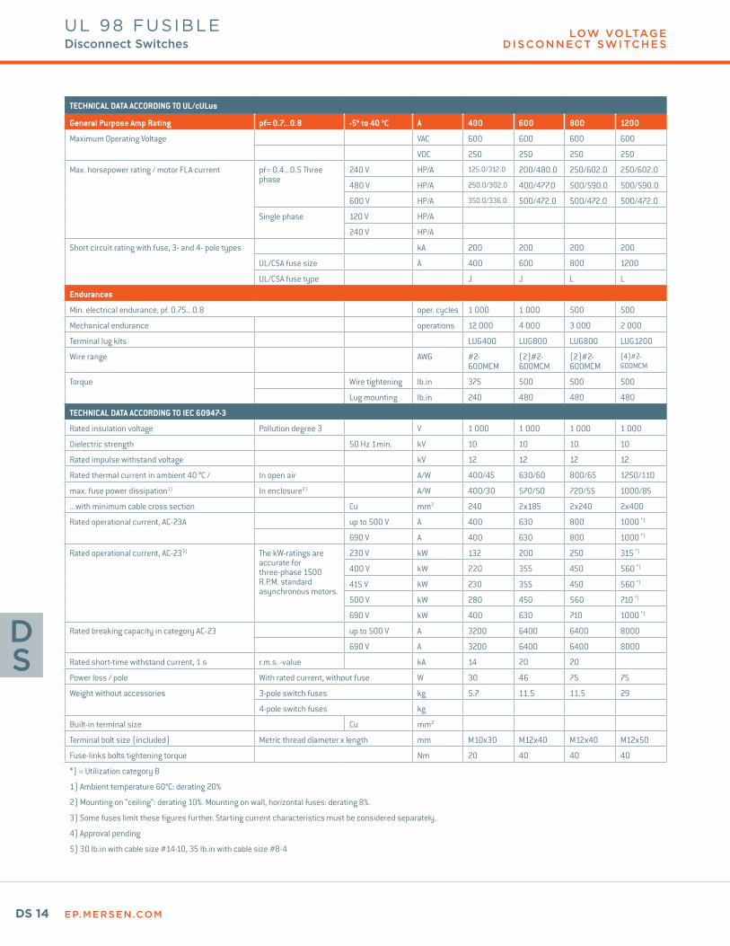
TECHNICAL DATA ACCORDING TO UL/cULus
General Purpose Amp Rating pf= 0.7...0.8 -5° to 40 °C A 400 600 800 1200
Maximum Operating Voltage VAC 600 600 600 600
VDC 250 250 250 250
Max. horsepower rating / motor FLA current pf= 0.4...0.5 Three phase
240 V HP/A 125.0/312.0 200/480.0 250/602.0 250/602.0
480 V HP/A 250.0/302.0 400/477.0 500/590.0 500/590.0
600 V HP/A 350.0/336.0 500/472.0 500/472.0 500/472.0
Single phase 120 V HP/A
240 V HP/A
Short circuit rating with fuse, 3- and 4- pole types kA 200 200 200 200
UL/CSA fuse size A 400 600 800 1200
UL/CSA fuse type J J L L
Endurances
Min. electrical endurance, pf. 0.75...0.8 oper. cycles 1 000 1 000 500 500
Mechanical endurance operations 12 000 4 000 3 000 2 000
Terminal lug kits LUG400 LUG800 LUG800 LUG1200
Wire range AWG #2-600MCM
(2)#2-600MCM
(2)#2-600MCM
(4)#2-600MCM
Torque Wire tightening lb.in 375 500 500 500
Lug mounting lb.in 240 480 480 480
TECHNICAL DATA ACCORDING TO IEC 60947-3
Rated insulation voltage Pollution degree 3 V 1 000 1 000 1 000 1 000
Dielectric strength 50 Hz 1min. kV 10 10 10 10
Rated impulse withstand voltage kV 12 12 12 12
Rated thermal current in ambient 40 °C / In open air A/W 400/45 630/60 800/65 1250/110
max. fuse power dissipation1) In enclosure2) A/W 400/30 570/50 720/55 1000/85
...with minimum cable cross section Cu mm2 240 2x185 2x240 2x400
Rated operational current, AC-23A up to 500 V A 400 630 800 1000 *)
690 V A 400 630 800 1000 *)
Rated operational current, AC-233) The kW-ratings are accurate for three-phase 1500 R.P.M. standard asynchronous motors.
230 V kW 132 200 250 315 *)
400 V kW 220 355 450 560 *)
415 V kW 230 355 450 560 *)
500 V kW 280 450 560 710 *)
690 V kW 400 630 710 1000 *)
Rated breaking capacity in category AC-23 up to 500 V A 3200 6400 6400 8000
690 V A 3200 6400 6400 8000
Rated short-time withstand current, 1 s r.m.s. -value kA 14 20 20
Power loss / pole With rated current, without fuse W 30 46 75 75
Weight without accessories 3-pole switch fuses kg 5.7 11.5 11.5 29
4-pole switch fuses kg
Built-in terminal size Cu mm2
Terminal bolt size (included) Metric thread diameter x length mm M10x30 M12x40 M12x40 M12x50
Fuse-links bolts tightening torque Nm 20 40 40 40
*) = Utilization category B
1) Ambient temperature 60°C: derating 20%
2) Mounting on “ceiling”: derating 10%. Mounting on wall, horizontal fuses: derating 8%.
3) Some fuses limit these figures further. Starting current characteristics must be considered separately.
4) Approval pending
5) 30 lb.in with cable size #14-10, 35 lb.in with cable size #8-4
UL 98 FUSIBLEDisconnect Switches
EP.MERSEN.COM DS 15
DS
© 2018 Mersen. All rights reserved. Mersen reserves the right to change, update, or correct, without notice, any information contained in this datasheet.
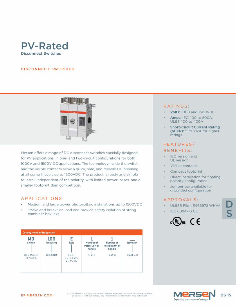
Mersen offers a range of DC disconnect switches specially designed
for PV applications, in one- and two-circuit configurations for both
1000V and 1500V DC applications . The technology inside the switch
and the visible contacts allow a quick, safe, and reliable DC breaking
at all current levels up to 1500VDC . The product is ready and simple
to install independent of the polarity, with limited power losses, and a
smaller footprint than competition .
A P P L I C AT I O N S :• Medium and large power photovoltaic installations up to 1500VDC
• “Make and break” on load and provide safety isolation at string combiner box level
R AT I N G S :• Volts: 1000 and 1500VDC
• Amps: IEC: 100 to 500A, UL98: 100 to 400A
• Short-Circuit Current Rating (SCCR): 5 to 10kA for higher ratings
F E AT U R E S / B E N E F I T S :• IEC version and
UL version
• Visible contacts
• Compact footprint
• Direct installation for floating polarity configuration
• Jumper bar available for grounded configuration
A P P R OVA L S :• UL98B File #E466972 WHVA
• IEC 60947-3 CE
Catalog number designation
MDSwitch
MD = Mersen DC Switch
100Ampacity
100-500A
EType
E = IECU = UL-listed
V = 1500V
1Number of
Poles/Left of handle
1, 2, 3
1Number of
Poles/Right of handle
1, 2, 3
_____Revision
Blank = 0
PV-Rated Disconnect Switches
DISCONNECT SWITCHES
EP.MERSEN.COMDS 16
LOW VOLTAGE D ISCONNECT SWITCHES
DS
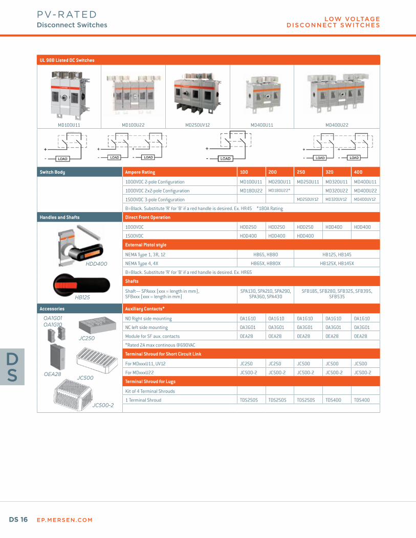
UL 98B Listed DC Switches
MD100U11 MD100U22 MD250UV12 MD400U11 MD400U22
Switch Body Ampere Rating 100 200 250 320 400
1000VDC 2-pole Configuration MD100U11 MD200U11 MD250U11 MD320U11 MD400U11
1000VDC 2x2-pole Configuration MD180U22 MD180U22* MD320U22 MD400U22
1500VDC 3-pole Configuration MD250UV12 MD320UV12 MD400UV12
B=Black. Substitute ‘R’ for ‘B’ if a red handle is desired. Ex. HR45 *180A Rating
Handles and Shafts Direct Front Operation
1000VDC HDD250 HDD250 HDD250 HDD400 HDD400
1500VDC HDD400 HDD400 HDD400
External Pistol style
NEMA Type 1, 3R, 12 HB65, HB80 HB125, HB145
NEMA Type 4, 4X HB65X, HB80X HB125X, HB145X
B=Black. Substitute ‘R’ for ‘B’ if a red handle is desired. Ex. HR65
Shafts
Shaft— SPAxxx (xxx = length in mm), SFBxxx (xxx = length in mm)
SPA130, SPA210, SPA290, SPA360, SPA430
SFB185, SFB280, SFB325, SFB395, SFB535
Accessories Auxiliary Contacts*
NO Right side mounting OA1G10 OA1G10 OA1G10 OA1G10 OA1G10
NC left side mounting OA3G01 OA3G01 OA3G01 OA3G01 OA3G01
Module for SF aux. contacts OEA28 OEA28 OEA28 OEA28 OEA28
*Rated 2A max continous @690VAC
Terminal Shroud for Short Circuit Link
For MDxxxU11, UV12 JC250 JC250 JC500 JC500 JC500
For MDxxxU22 JC500-2 JC500-2 JC500-2 JC500-2 JC500-2
Terminal Shroud for Lugs
Kit of 4 Terminal Shrouds
1 Terminal Shroud TDS250S TDS250S TDS250S TDS400 TDS400
HDD400
HB125
OA1G01OA1G10
OEA28
JC250
JC500
JC500-2
PV-RATEDDisconnect Switches

EP.MERSEN.COM DS 17
LOW VOLTAGE D ISCONNECT SWITCHES
DS
IEC-RATED DC SWITCHES
MD100E11 MD100E22 MD400EV12 MD400E22 MD400EV12 MD315EV33
Switch Body Ampere Rating 100 160 200 250 315 400 500
1000VDC 2-pole Configuration MD100E11 MD160E11 MD200E11 MD250E11 MD315E11 MD400E11 MD500E11
1000VDC 2x2-pole Config. MD100E22 MD160E22 MD200E22 MD250E22 MD315E22 MD400E22 MD500E22
1500VDC 3-pole Configuration MD315EV12 MD400EV12 MD500EV12
1500VDC 2x3-pole Config. MD315EV33 MD400EV33 MD500EV33
Handles and Shafts Direct Front Operation
HDD250 HDD250 HDD250 HDD250 HDD400 HDD400 HDD400
External Pistol Style
NEMA Type 1, 3R, 12 HB65, HB80 HB125, HB145
NEMA Type 4, 4X HB65X, HB80X HB125X, HB125X
B=Black. Substitute ‘R’ for ‘B’ if a red handle is desired. Ex. HR65
Shafts
Shaft— SPAxxx (xxx = length in mm)
SPA130, SPA210, SPA290, SPA360, SPA430 SFB185, SFB280, SFB325, SFB395, SFB535
Accessories Auxiliary Contacts*
NO Right side mounting OA1G10 OA1G10 OA1G10 OA1G10 OA1G10 OA1G10 OA1G10
NC left side mounting OA3G01 OA3G01 OA3G01 OA3G01 OA3G01 OA3G01 OA3G01
Module for SF aux. contacts OEA28 OEA28 OEA28 OEA28 OEA28 OEA28 OEA28
*Rated 2A max continous @690VAC
Short Circuit Link
For MDxxxE22 and EV33 JUMP500-2 JUMP500-2 JUMP500-2
For MDxxxE11, E22, EV12** JUMP250 JUMP250 JUMP250 JUMP250 JUMP500 JUMP500 JUMP500
**Shipped with one link per circuit
Terminal Shroud for Short Circuit Link
For JUMP500-2 JC500-2 JC500-2 JC500-2
For JUMP250, JUMP500 JC250 JC250 JC250 JC250 JC500 JC500 JC500
Terminal Shrouds for Lugs
Kit of 4 Terminal Shrouds TS250-14 TS250-14 TS250-14 TS250-14
1 Terminal Shroud TDS400 TDS400 TDS400
A shorter version is available for DC Switches up to 250A. 1 piece per package: TDS250S
HDD250
HB125
OA1G01OA1G10
OEA28
JC250JUMP250
JUMP500
JUMP500-2
JC500
JC500-2
PV-RATEDDisconnect Switches
EP.MERSEN.COMDS 18
LOW VOLTAGE D ISCONNECT SWITCHES
DS
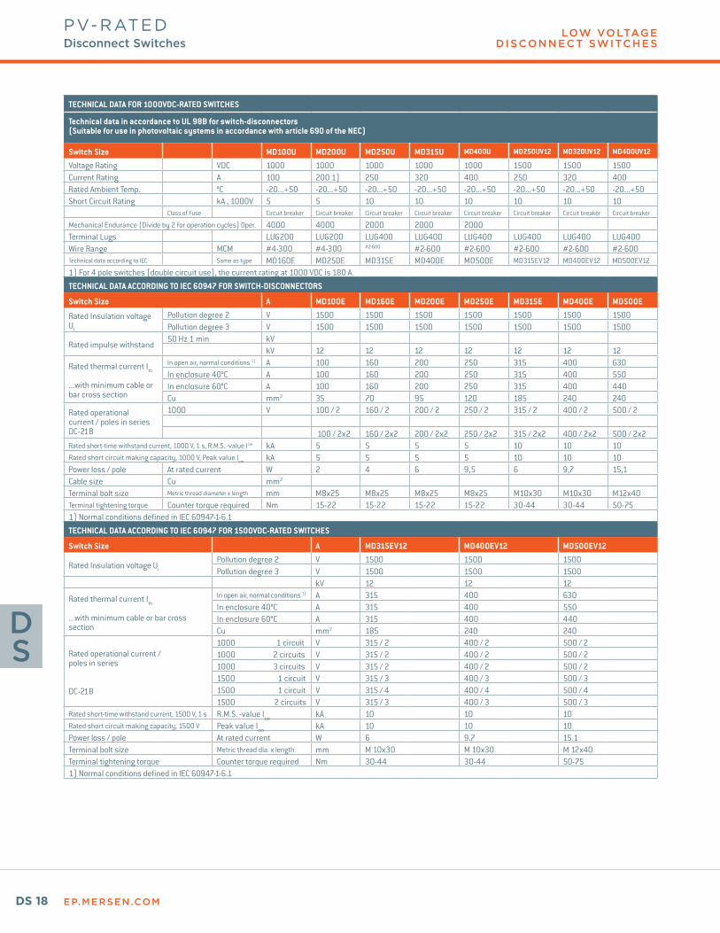
TECHNICAL DATA FOR 1000VDC-RATED SWITCHES
Technical data in accordance to UL 98B for switch-disconnectors (Suitable for use in photovoltaic systems in accordance with article 690 of the NEC)
Switch Size MD100U MD200U MD250U MD315U MD400U MD250UV12 MD320UV12 MD400UV12
Voltage Rating VDC 1000 1000 1000 1000 1000 1500 1500 1500Current Rating A 100 200 1) 250 320 400 250 320 400Rated Ambient Temp. °C -20...+50 -20...+50 -20...+50 -20...+50 -20...+50 -20...+50 -20...+50 -20...+50Short Circuit Rating kA , 1000V 5 5 10 10 10 10 10 10
Class of Fuse Circuit breaker Circuit breaker Circuit breaker Circuit breaker Circuit breaker Circuit breaker Circuit breaker Circuit breaker
Mechanical Endurance (Divide by 2 for operation cycles) Oper. 4000 4000 2000 2000 2000Terminal Lugs LUG200 LUG200 LUG400 LUG400 LUG400 LUG400 LUG400 LUG400Wire Range MCM #4-300 #4-300 #2-600 #2-600 #2-600 #2-600 #2-600 #2-600Technical data according to IEC Same as type MD160E MD250E MD315E MD400E MD500E MD315EV12 MD400EV12 MD500EV12
1) For 4 pole switches (double circuit use), the current rating at 1000 VDC is 180 A.
TECHNICAL DATA ACCORDING TO IEC 60947 FOR SWITCH-DISCONNECTORS
Switch Size A MD100E MD160E MD200E MD250E MD315E MD400E MD500E
Rated Insulation voltage UI
Pollution degree 2 V 1500 1500 1500 1500 1500 1500 1500Pollution degree 3 V 1500 1500 1500 1500 1500 1500 1500
Rated impulse withstand50 Hz 1 min kV
kV 12 12 12 12 12 12 12
Rated thermal current Ith
...with minimum cable or bar cross section
In open air, normal conditions 1) A 100 160 200 250 315 400 630In enclosure 40°C A 100 160 200 250 315 400 550In enclosure 60°C A 100 160 200 250 315 400 440Cu mm2 35 70 95 120 185 240 240
Rated operational current / poles in seriesDC-21B
1000 V 100 / 2 160 / 2 200 / 2 250 / 2 315 / 2 400 / 2 500 / 2
100 / 2x2 160 / 2x2 200 / 2x2 250 / 2x2 315 / 2x2 400 / 2x2 500 / 2x2Rated short-time withstand current, 1000 V, 1 s, R.M.S. -value Icw kA 5 5 5 5 10 10 10Rated short circuit making capacity, 1000 V, Peak value Icm kA 5 5 5 5 10 10 10Power loss / pole At rated current W 2 4 6 9,5 6 9,7 15,1Cable size Cu mm2
Terminal bolt size Metric thread diameter x length mm M8x25 M8x25 M8x25 M8x25 M10x30 M10x30 M12x40Terminal tightening torque Counter torque required Nm 15-22 15-22 15-22 15-22 30-44 30-44 50-751) Normal conditions defined in IEC 60947-1-6.1
TECHNICAL DATA ACCORDING TO IEC 60947 FOR 1500VDC-RATED SWITCHES
Switch Size A MD315EV12 MD400EV12 MD500EV12
Rated Insulation voltage UI
Pollution degree 2 V 1500 1500 1500Pollution degree 3 V 1500 1500 1500
kV 12 12 12
Rated thermal current Ith
...with minimum cable or bar cross section
In open air, normal conditions 1) A 315 400 630In enclosure 40°C A 315 400 550In enclosure 60°C A 315 400 440Cu mm2 185 240 240
Rated operational current / poles in series
DC-21B
1000 1 circuit V 315 / 2 400 / 2 500 / 21000 2 circuits V 315 / 2 400 / 2 500 / 21000 3 circuits V 315 / 2 400 / 2 500 / 21500 1 circuit V 315 / 3 400 / 3 500 / 31500 1 circuit V 315 / 4 400 / 4 500 / 41500 2 circuits V 315 / 3 400 / 3 500 / 3
Rated short-time withstand current, 1500 V, 1 s R.M.S. -value Icw kA 10 10 10Rated short circuit making capacity, 1500 V Peak value Icm kA 10 10 10Power loss / pole At rated current W 6 9.7 15.1Terminal bolt size Metric thread dia. x length mm M 10x30 M 10x30 M 12x40Terminal tightening torque Counter torque required Nm 30-44 30-44 50-751) Normal conditions defined in IEC 60947-1-6.1
PV-RATEDDisconnect Switches
EP.MERSEN.COM DS 19
DS
© 2018 Mersen. All rights reserved. Mersen reserves the right to change, update, or correct, without notice, any information contained in this datasheet.
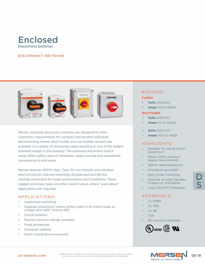
Mersen enclosed disconnect switches are designed to meet
customer’s requirements for compact and durable individual
disconnecting means . Both fusible and non-fusible versions are
available in a variety of enclosures types resulting in one of the largest
available ranges in the industry . The enclosed disconnect switch
range offers safety, ease of installation, space savings and operational
convenience to end-users .
Mersen features NEMA style, Type 4X non-metallic and stainless
steel enclosures that are extremely durable and provide the
ultimate protection for harsh environments and conditions . These
rugged enclosure types are often used in areas where “wash down”
applications are required .
A P P L I C AT I O N S :• Load break switching
• Separate disconnect means within sight of all motor loads to comply with NEC® Article 430
• Circuit isolation
• Service entrance ratings available
• Food processing
• Conveyor systems
• Harsh industrial environments
R AT I N G S :Fusible• Volts: 600VAC
• Amps: 30 to 800A
Non-Fusible• Volts: 600VAC
• Amps: 16 to 1200A
• Volts: 600VDC
• Amps: 100 to 400A
H I G H L I G H T S :• Suitable for use as motor
disconnect
• Meets OSHA lockout/tagout requirements
• NEMA rated enclosures
• Knockouts provided
• Easy screw mounting
• Selector or pistol handles in black or red/yellow
• Clear ON/OFF indication
A P P R OVA L S : • UL 508A
• UL 508
• UL 98
• CSA
• IEC versions available
Enclosed Disconnect Switches
DISCONNECT SWITCHES
EP.MERSEN.COMDS 20
LOW VOLTAGE D ISCONNECT SWITCHES
DS
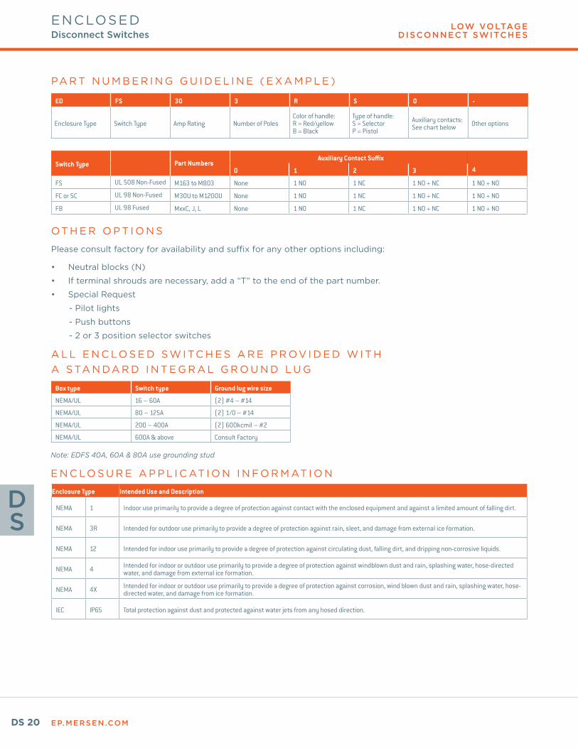
ED FS 30 3 R S 0 -
Enclosure Type Switch Type Amp Rating Number of PolesColor of handle: R = Red/yellowB = Black
Type of handle:S = SelectorP = Pistol
Auxiliary contacts: See chart below Other options
Switch Type Part NumbersAuxiliary Contact Suffix
0 1 2 3 4
FS UL 508 Non-Fused M163 to M803 None 1 NO 1 NC 1 NO + NC 1 NO + NO
FC or SC UL 98 Non-Fused M30U to M1200U None 1 NO 1 NC 1 NO + NC 1 NO + NO
FB UL 98 Fused MxxC, J, L None 1 NO 1 NC 1 NO + NC 1 NO + NO
Box type Switch type Ground lug wire size
NEMA/UL 16 – 60A (2) #4 – #14
NEMA/UL 80 – 125A (2) 1/0 – #14
NEMA/UL 200 – 400A (2) 600kcmil – #2
NEMA/UL 600A & above Consult Factory
Enclosure Type Intended Use and Description
NEMA 1 Indoor use primarily to provide a degree of protection against contact with the enclosed equipment and against a limited amount of falling dirt.
NEMA 3R Intended for outdoor use primarily to provide a degree of protection against rain, sleet, and damage from external ice formation.
NEMA 12 Intended for indoor use primarily to provide a degree of protection against circulating dust, falling dirt, and dripping non-corrosive liquids.
NEMA 4 Intended for indoor or outdoor use primarily to provide a degree of protection against windblown dust and rain, splashing water, hose-directed water, and damage from external ice formation.
NEMA 4X Intended for indoor or outdoor use primarily to provide a degree of protection against corrosion, wind blown dust and rain, splashing water, hose-directed water, and damage from ice formation.
IEC IP65 Total protection against dust and protected against water jets from any hosed direction.
PA R T N U M B E R I N G G U I D E L I N E ( E X A M P L E )
OT H E R O P T I O N S
Please consult factory for availability and suffix for any other options including:
• Neutral blocks (N)
• If terminal shrouds are necessary, add a “T” to the end of the part number .
• Special Request
- Pilot lights
- Push buttons
- 2 or 3 position selector switches
A L L E N C LO S E D S W I TC H E S A R E P R OV I D E D W I T H A S TA N DA R D I N T E G R A L G R O U N D L U G
Note: EDFS 40A, 60A & 80A use grounding stud
E N C LO S U R E A P P L I C AT I O N I N F O R M AT I O N
ENCLOSED Disconnect Switches
EP.MERSEN.COM DS 21
LOW VOLTAGE D ISCONNECT SWITCHES
DS
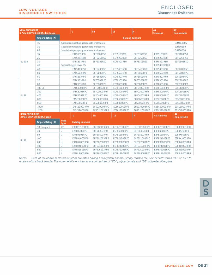
NEMA ENCLOSURE3 Pole, 600V 30-1200A, Non-fused 1 3R 12 4 4X
Stainless4X Non-Metallic
Ampere Rating (A) Catalog Numbers
16 Special compact polycarbonate enclosures EJM16BSOS
UL 508
30 Special compact polycarbonate enclosures EJM30BS060 Special compact polycarbonate enclosures EJM60BS016 EAFS163RS0 EFFS163RS0 ECFS163RS0 EHFS163RS0 EBFS163RS0 EDFS163RS025 EAFS253RS0 EFFS253RS0 ECFS253RS0 EHFS253RS0 EBFS253RS0 EDFS253RS030 EAFS303RS0 EFFS303RS0 ECFS303RS0 EHFS303RS0 EBFS303RS0 EDFS303RS040 Special hinged cover, SS EBFS403RS0-H
40 EAFS403RS0 EFFS403RS0 ECFS403RS0 EHFS403RS0 EBFS403RS0 EDFS403RS060 EAFS603RP0 EFFS603RP0 ECFS603RP0 EHFS603RP0 EBFS603RP0 EDFS603RP080 EAFS803RP0 EFFS803RP0 ECFS803RP0 EHFS803RP0 EBFS803RP0 EGFS803RP0
UL 98
30 EAFC303RP0 EFFC303RP0 ECFC303RP0 EHFC303RP0 EBFC303RP0 EGFC303RP0 60 EAFC603RP0 EFFC603RP0 ECFC603RP0 EHFC603RP0 EBFC603RP0 EGFC603RP0100 50 EAFC1003RP0 EFFC1003RP0 ECFC1003RP0 EHFC1003RP0 EBFC1003RP0 EGFC1003RP0200 EAFC2003RP0 EFFC2003RP0 ECFC2003RP0 EHFC2003RP0 EBFC2003RP0 EGFC2003RP0 400 EAFC4003RP0 EFFC4003RP0 ECFC4003RP0 EHFC4003RP0 EBFC4003RP0 EGFC4003RP0600 EASC6003RP0 EFSC6003RP0 ECSC6003RP0 EHSC6003RP0 EBSC6003RP0 EGSC6003RP0800 EASC8003RP0 EFSC8003RP0 ECSC8003RP0 EHSC8003RP0 EBSC8003RP0 EGSC8003RP01000 EASC10003RP0 EFSC10003RP0 ECSC10003RP0 EHSC10003RP0 EBSC10003RP0 EGSC10003RP01200 EASC12003RP0 EFSC12003RP0 ECSC12003RP0 EHSC12003RP0 EBSC12003RP0 EGSC12003RP0
NEMA ENCLOSURE3 Pole, 600V 30-800A, Fused 1 3R 12 4 4X Stainless 4X
Non-Metallic
Ampere Rating (A) Fuse Type Catalog Numbers
UL 98
30, compact CC EAFBCC303RP0 EFFBCC303RP0 ECFBCC303RP0 EHFBCC303RP0 EBFBCC303RP0 EGFBCC303RP030 J EAFBX303RP0 EFFBX303RP0 ECFBX303RP0 EHFBX303RP0 EBFBX303RP0 EGFBX303RP060 J EAFBX603RP0 EFFBX603RP0 ECFBX603RP0 EHFBX603RP0 EBFBX603RP0 EGFBX603RP0100 J EAFBX1003RP0 EFFBX1003RP0 ECFBX1003RP0 EHFBX1003RP0 EBFBX1003RP0 EGFBX1003RP0200 J EAFBX2003RP0 EFFBX2003RP0 ECFBX2003RP0 EHFBX2003RP0 EBFBX2003RP0 EGFBX2003RP0400 J EAFBJ4003RP0 EFFBJ4003RP0 ECFBJ4003RP0 EHFBJ4003RP0 EBFBJ4003RP0 EGFBJ4003RP0600 J EAFBJ6003RP0 EFFBJ6003RP0 ECFBJ6003RP0 EHFBJ6003RP0 EBFBJ6003RP0 EGFBJ6003RP0800 L EAFBL8003RP0 EFFBL8003RP0 ECFBL8003RP0 EHFBL8003RP0 EBFBL8003RP0 EGFBL8003RP0
Notes: Each of the above enclosed switches are listed having a red/yellow handle. Simply replace the “RS” or “RP” with a “BS” or “BP” to receive with a black handle. The non-metallic enclosures are comprised of “ED” polycarbonate and “EG” polyester fiberglass.
ENCLOSED Disconnect Switches
EP.MERSEN.COMDS 22
LOW VOLTAGE D ISCONNECT SWITCHES
DS
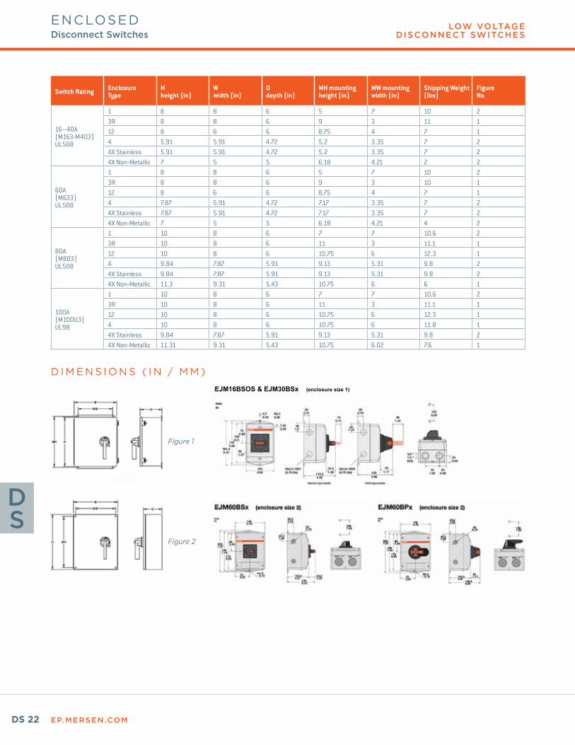
Switch Rating EnclosureType
Hheight (in)
Wwidth (in)
Ddepth (in)
MH mountingheight (in)
MW mountingwidth (in)
Shipping Weight (lbs)
FigureNo.
16–40A(M163-M403)UL508
1 8 8 6 5 7 10 23R 8 8 6 9 3 11 112 8 6 6 8.75 4 7 14 5.91 5.91 4.72 5.2 3.35 7 24X Stainless 5.91 5.91 4.72 5.2 3.35 7 24X Non-Metallic 7 5 5 6.18 4.21 2 2
60A(M633)UL508
1 8 8 6 5 7 10 23R 8 8 6 9 3 10 112 8 6 6 8.75 4 7 14 7.87 5.91 4.72 7.17 3.35 7 24X Stainless 7.87 5.91 4.72 7.17 3.35 7 24X Non-Metallic 7 5 5 6.18 4.21 4 2
80A(M803)UL508
1 10 8 6 7 7 10.6 23R 10 8 6 11 3 11.1 112 10 8 6 10.75 6 12.3 14 9.84 7.87 5.91 9.13 5.31 9.8 24X Stainless 9.84 7.87 5.91 9.13 5.31 9.8 24X Non-Metallic 11.3 9.31 5.43 10.75 6 6 1
100A(M100U3)UL98
1 10 8 6 7 7 10.6 23R 10 8 6 11 3 11.1 112 10 8 6 10.75 6 12.3 14 10 8 6 10.75 6 11.8 14X Stainless 9.84 7.87 5.91 9.13 5.31 9.8 24X Non-Metallic 11.31 9.31 5.43 10.75 6.02 7.6 1
D I M E N S I O N S ( I N / M M )
Figure 1
Figure 2
ENCLOSED Disconnect Switches
EJM16BSOS & EJM30BSx (enclosure size 1)
EP.MERSEN.COM DS 23
LOW VOLTAGE D ISCONNECT SWITCHES
DS
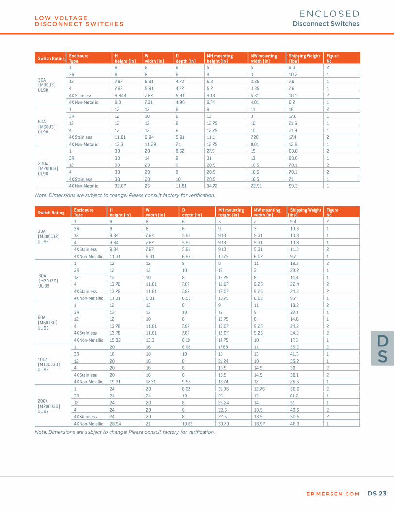
Switch Rating EnclosureType
Hheight (in)
Wwidth (in)
Ddepth (in)
MH mountingheight (in)
MW mountingwidth (in)
Shipping Weight (lbs)
FigureNo.
30A(M30U3)UL98
1 8 8 6 5 5 9.3 23R 8 8 6 9 3 10.2 112 7.87 5.91 4.72 5.2 3.35 7.6 14 7.87 5.91 4.72 5.2 3.35 7.6 14X Stainless 9.844 7.87 5.91 9.13 5.31 10.1 24X Non-Metallic 9.3 7.31 4.96 8.74 4.01 6.2 1
60A(M60U3)UL98
1 12 12 6 9 11 16 23R 12 10 6 13 3 17.6 112 12 12 6 12.75 10 21.6 14 12 12 6 12.75 10 21.9 14X Stainless 11.81 9.84 5.91 11.1 7.28 17.4 24X Non-Metallic 13.3 11.29 7.1 12.75 8.01 12.9 1
200A(M200U3)UL98
1 30 20 8.62 27.5 15 68.6 23R 30 14 8 31 13 88.6 112 30 20 8 28.5 18.5 70.1 24 30 20 8 28.5 18.5 70.1 24X Stainless 30 20 10 28.5 18.5 71 14X Non-Metallic 32.87 25 11.81 34.72 22.91 59.3 1
Note: Dimensions are subject to change! Please consult factory for verification.
ENCLOSED Disconnect Switches
Switch Rating EnclosureType
Hheight (in)
Wwidth (in)
Ddepth (in)
MH mountingheight (in)
MW mountingwidth (in)
Shipping Weight (lbs)
FigureNo.
30A(M30CC12) UL 98
1 8 8 6 5 7 9.4 23R 8 8 6 9 3 10.3 112 9.84 7.87 5.91 9.13 5.31 10.8 14 9.84 7.87 5.91 9.13 5.31 10.8 14X Stainless 9.84 7.87 5.91 9.13 5.31 11.3 24X Non-Metallic 11.31 9.31 6.93 10.75 6.02 9.7 1
30A(M30J30) UL 98
1 12 12 8 9 11 18.3 23R 12 12 10 13 3 23.2 112 12 10 8 12.75 8 14.4 14 13.78 11.81 7.87 13.07 9.25 22.4 24X Stainless 13.78 11.81 7.87 13.07 9.25 24.3 24X Non-Metallic 11.31 9.31 6.93 10.75 6.02 9.7 1
60A(M60J30)UL 98
1 12 12 8 9 11 18.2 23R 12 12 10 13 5 23.1 112 12 10 8 12.75 8 14.6 14 13.78 11.81 7.87 13.07 9.25 24.2 24X Stainless 13.78 11.81 7.87 13.07 9.25 24.2 24X Non-Metallic 15.32 13.3 8.19 14.75 10 17.5 1
100A(M100J30)UL 98
1 20 16 8.62 17.88 11 35.2 23R 18 18 10 19 13 41.3 112 20 16 8 21.24 10 35.2 14 20 16 8 18.5 14.5 39 24X Stainless 20 16 8 18.5 14.5 38.1 24X Non-Metallic 19.31 17.31 9.58 18.74 12 25.6 1
200A(M200J30)UL 98
1 24 20 8.62 21.96 12.76 56.6 23R 24 24 10 25 13 61.2 112 24 20 8 25.24 14 51 14 24 20 8 22.5 18.5 49.5 24X Stainless 24 20 8 22.5 18.5 50.5 24X Non-Metallic 28.94 21 10.63 30.79 18.97 46.3 1
Note: Dimensions are subject to change! Please consult factory for verification.