
Planning Guide Introduction to Mirantis OpenStack and Fuel 2
53
version 5.0 Planning Guide
-
Upload
independent -
Category
Documents
-
view
5 -
download
0
Transcript of Planning Guide Introduction to Mirantis OpenStack and Fuel 2

version 5.0
Planning Guide

Mirantis OpenStack v5.0Planning Guide
©2014, Mirantis Inc. Page i

ContentsPreface 1
Intended Audience 1
Documentation History 1
Introduction to Mirantis OpenStack and Fuel 2
System Requirements 3
Master Node Hardware Recommendations 3
Node Server Hardware Recommendations 3
Supported Software 4
Planning Summary 6
Choose Network Topology 7
Linux Distribution for Nodes 8
Nodes and Roles 9
Planning a Sahara Deployment 11
Preparing for vSphere Integration 12
vSphere Installation 12
ESXi Host Networks Configuration 13
Limitations 14
Calculate hardware requirements 16
Example of Hardware Requirements Calculation 17
Calculating CPU 17
Calculating Memory 18
Calculating Storage 18
Throughput 19
Remote storage 20
Object storage 20
Calculating Network 20
Scalability and oversubscription 21
Hardware for this example 21
Summary 21
Reference configuration of hardware switches 22
Tagged ports 22
Mirantis OpenStack v5.0Planning Guide
©2014, Mirantis Inc. Page ii

Untagged ports 22
Example 1: HA + Nova-network FlatDHCP manager 24
Detailed Port Configuration 25
Nova-network Switch configuration (Cisco Catalyst 2960G) 27
Nova-network Switch configuration (Juniper EX4200) 30
Example 2: HA + Neutron with GRE 37
Detailed port configuration 38
Neutron Switch configuration (Cisco Catalyst 2960G) 38
Neutron Switch configuration (Juniper EX4200) 42
Index 49
Mirantis OpenStack v5.0Planning Guide
©2014, Mirantis Inc. Page iii

PrefaceThis documentation provides information on how to use Mirantis Fuel to deploy OpenStack environment. Theinformation is for reference purposes and is subject to change.
Intended AudienceThis documentation is intended for OpenStack administrators and assumes that you have experience withnetwork and cloud concepts.
Documentation HistoryThe following table lists the released revisions of this documentation:
Revision Date Description
May, 2014 5.0 GA
Mirantis OpenStack v5.0Planning Guide Preface
©2014, Mirantis Inc. Page 1

Introduction to Mirantis OpenStack and FuelOpenStack is an extensible, versatile, and flexible cloud management platform. It is a portfolio of cloudinfrastructure services – compute, storage, networking and other core resources — that are exposed throughReST APIs. It enables a wide range of control over these services, both from the perspective of an IntegratedInfrastructure as a Service (IaaS) controlled by applications and as a set of tools that enable automatedmanipulation of the infrastructure itself.
Mirantis OpenStack is a productized snapshot of the open source technologies. It includes Fuel, a graphical webtool that helps you to quickly deploy your cloud environment. Fuel includes scripts that dramatically facilitateand speed up the process of cloud deployment, without requiring you to completely familiarize yourself with theintricate processes required to install the OpenStack environment components.
This guide provides details to get you started with Mirantis OpenStack and Fuel on a set of physical servers("bare-metal installation") See the User Guide for detailed instructions about how to download and install Fuel onthe Fuel Master Node and then how to use the Fuel interface to deploy your OpenStack environment.
Further reading is available in the following documents:
• Terminology Reference is an alphabetical listing of technologies and concepts that serves as both a glossaryand a master index of information in the Mirantis docs and the open source documentation.
• Operations Guide gives information about advanced tasks required to maintain the OpenStack environmentafter it is deployed. Most of these tasks are done in the shell using text editors and command line tools.
• Reference Architecture provides background information about how Mirantis OpenStack and its supportingHA architecture is implemented.
You can also run Fuel to deploy a Mirantis OpenStack Environment on Oracle VirtualBox. VirtualBox deploymentis useful for demonstrations and is a good way to begin your exploration of the tools and technologies. It isdiscussed in Running Fuel on VirtualBox. However, it is worth noting that deployments on top of VirtualBox do notgenerally meet the performance and robustness requirements of most production environments.
For community members or partners looking to take Fuel even further, see the developer documentation forinformation about the internal architecture of Fuel, instructions for building the project, information aboutinteracting with the REST API and other topics of interest to more advanced developers. You can also visit theFuel project for more detailed information and become a contributor.
Mirantis OpenStack v5.0Planning Guide Introduction to Mirantis OpenStack and Fuel
©2014, Mirantis Inc. Page 2

System RequirementsBefore you begin installation of Fuel, make sure your hardware meets or exceeds the following minimumrequirements.
Master Node Hardware RecommendationsTo install the Fuel Master Node, you should base your hardware on the anticipated load of your server. Logically,deploying more node servers in your environment requires more CPU, RAM, and disk performance.
Suggested minimum configuration for installation in production environment:
• Quad-core CPU
• 4GB RAM
• 1 gigabit network port
• 128GB SAS Disk
• IPMI access through independent management networkSuggested minimum configuration for installation in lab environment:
• Dual-core CPU
• 2GB RAM
• 1 gigabit network port
• 50GB disk
• Physical console access
Node Server Hardware RecommendationsTo help determine the correct sizing for OpenStack Node servers, use the Mirantis Hardware Bill of Materialscalculator.
For more information on the logic used in the utility and basic directions, see: “How do you calculate how muchhardware you need for your OpenStack cloud?”.
Mirantis OpenStack v5.0Planning Guide System Requirements
©2014, Mirantis Inc. Page 3

Supported Software
• Operating Systems
• CentOS 6.5 (x86_64 architecture only)
• Ubuntu 12.04.4 (x86_64 architecture only)• Puppet (IT automation tool) 3.4.2
• MCollective 2.3.3
• Cobbler (bare-metal provisioning tool) 2.2.3
• OpenStack Core Projects
• Icehouse release 2014.1
• Nova (OpenStack Compute)
• Swift (OpenStack Object Storage)
• Glance (OpenStack Image Service)
• Keystone (OpenStack Identity)
• Horizon (OpenStack Dashboard)
• Neutron (OpenStack Networking)
• Cinder (OpenStack Block Storage service)• OpenStack Core Integrated Projects
• Icehouse release 2014.1
• Ceilometer (OpenStack Telemetry)
• Heat (OpenStack Orchestration)• OpenStack Incubated Projects
• Icehouse release 2014.1
• Sahara (OpenStack Data Processing)• OpenStack Related Projects
• Murano v0.5• Hypervisor
• KVM
• QEMU
• vCenter• Open vSwitch 1.10.2
• HA Proxy 1.4.24
• Galera 23.2.2
Mirantis OpenStack v5.0Planning Guide Supported Software
©2014, Mirantis Inc. Page 4

• RabbitMQ 3.2.3
• Pacemaker 1.1.10
• Corosync 1.4.6
• Keepalived 1.2.4
• MongoDB 2.4.6
• Ceph (v0.67.5 "Dumpling")
• MySQL 5.5.28 (CentOS), 5.5.37 (Ubuntu)
Mirantis OpenStack v5.0Planning Guide Supported Software
©2014, Mirantis Inc. Page 5

Planning SummaryBefore installation, determine the deployment type that is appropriate for you configuration needs. You may wantto print this list and make notes indicating your selection so you can be sure you have planned your deploymentcorrectly.
The following table provides a list of configuration steps that you must complete to plan the Mirantis OpenStackdeployment.
Step Description Additional Information
Select a network topology See Choose Network Topology
Choose the Linux distro to use on yournodes
See Linux Distribution for Nodes
Determine how many nodes to deployand which roles to assign to each and thehigh-availability to implement.
See Nodes and Roles
Calculate the server and networkhardware needed
See Calculate hardware requirements
Prepare an IP address management planand network association.
Identify the network addresses and VLAN IDs for your Public,floating, Management, Storage, and virtual machine (fixed)networks. Prepare a logical network diagram.
Mirantis OpenStack v5.0Planning Guide Planning Summary
©2014, Mirantis Inc. Page 6

Choose Network TopologyOpenStack supports two network modes, each of which supports two topologies. For architectural descriptions ofthe four topologies, see:
• Neutron with VLAN segmentation and OVS
• Neutron with GRE segmentation and OVS
• Nova-network FlatDHCP Manager
• Nova-network VLAN ManagerNova-network is a simple legacy network manager. It can operate with predefined Private IP spaces only.
• If you do not want to split your VMs into isolated groups (tenants), you can choose the Nova-network withFlatDHCP topology. In this case, you will have one big tenant for all VMs.
• If you want use multiple tenants and all of them contain approximately the same number of VMs, you canuse the Nova-network with VLANManager topology. In this case, the number of the tenants is predefinedand all the tenants have equal amount of Private IP space. You must decide about these two numbers (maxnumber of tenants and Private IP space size) before starting deployment. Also, you must set up appropriateVLANs on your underlying network equipment.
Neutron is a modern and more complicated network manager. It can not only separate tenants but it decreasesthe requirements for the underlying network (physical switches and topology) and gives a great deal of flexibilityfor manipulating Private IP spaces. You can create Private IP spaces with different sizes and manipulate them onthe fly.
• The Neutron with VLAN topology, like Nova-network with VLANManager, requires a predefined maximumnumber of tenants value and underlying network equipment configuration.
• The Neutron with GRE topology does not restrict the maximum number of VLANs and you can spawn a verylarge number of tenants. But GRE encapsulation decreases the speed of communication between the VMsand decreases the CPU utilization of the Compute and Controller nodes. So, if you do not need really fastinterconnections between VMs, do not want to predetermine the maximum number of tenants, and do notwant to configure your network equipment, you can choose the Neutron + GRE topology.
Some other considerations when choosing a network topology:
• OVS (Open vSwitch) and Bonding can only be implemented on Neutron.
• VMWare vCenter can only be implemented on Nova-network.
• Murano is supported only on Neutron.
Mirantis OpenStack v5.0Planning Guide Choose Network Topology
©2014, Mirantis Inc. Page 7

Linux Distribution for NodesFuel allows you to deploy either the CentOS or Ubuntu Linux distribution as the Host O/S on the nodes. All nodesin the environment must run the same Linux distribution. Often, the choice is made based on personalpreference; many administrative tasks on the nodes must be performed at shell level and many people choosethe distribution with which they are most comfortable.
Some specific considerations:
• Each distribution has some hardware support issues. See release-notes for details about known issues.
• In particular, the CentOS version used for OpenStack does not include native support for VLANs while theUbuntu version does. In order to use VLANs on CentOS based nodes, you must configure VLAN splinters.
• CentOS supports .rpm packages; Ubuntu supports .deb packages.
Mirantis OpenStack v5.0Planning Guide Linux Distribution for Nodes
©2014, Mirantis Inc. Page 8
Nodes and RolesYour OpenStack environment contains a set of specialized nodes and roles; see OpenStack EnvironmentArchitecture for a description. When planning your OpenStack deployment, you must determine the proper mix ofnode types and what roles will be installed on each. When you create your OpenStack environment, you willassign a role or roles to each node server.
All production environments should be deployed for high availability although you can deploy your environmentwithout the replicated servers required for high availability and then add the replicated servers later. But part ofyour Nodes and Roles planning is to determine the level of HA you want to implement and to plan for adequatehardware.
Some general guiding principles:
• When deploying a production-grade OpenStack environment, it is best to spread the roles (and, hence, theworkload) over as many servers as possible in order to have a fully redundant, highly-available OpenStackenvironment and to avoid performance bottlenecks.
• For demonstration and study purposes, you can deploy OpenStack on VirtualBox; see Running Fuel onVirtualBox for more information. This option has the lowest hardware requirements
• OpenStack can be deployed on smaller hardware configurations by combining multiple roles on the nodesand mapping multiple Logical Networks to a single physical NIC.
This section provides information to help you decide how many nodes you need and which roles to assign toeach.
The absolute minimum requirement for a highly-available OpenStack deployment is to allocate 4 nodes:
• 3 Controller nodes, combined with Storage
• 1 Compute nodeIn production environments, it is highly recommended to separate storage nodes from controllers. This helpsavoid resource contention, isolates failure domains, and allows to optimize hardware configurations for specificworkloads. To achieve that, you will need a minimum of 5 nodes when using Swift and Cinder storage backends,or 7 nodes for a fully redundant Ceph storage cluster:
• 3 Controller nodes
• 1 Cinder node or 3 Ceph OSD nodes
• 1 Compute node
Note
You do not need Cinder storage nodes if you are using Ceph RBD as storage backend for Cinder volumes.
Of course, you are free to choose how to deploy OpenStack based on the amount of available hardware and onyour goals (such as whether you want a compute-oriented or storage-oriented environment).
For a typical OpenStack compute deployment, you can use this table as high-level guidance to determine thenumber of controllers, compute, and storage nodes you should have:
Mirantis OpenStack v5.0Planning Guide Nodes and Roles
©2014, Mirantis Inc. Page 9

# of Nodes Controllers Computes Storages
4-10 3 1-7 3 (on controllers)
11-40 3 3-32 3+ (swift) + 2 (proxy)
41-100 4 29-88 6+ (swift) + 2 (proxy)
>100 5 >84 9+ (swift) + 2 (proxy)
Mirantis OpenStack v5.0Planning Guide Nodes and Roles
©2014, Mirantis Inc. Page 10

Planning a Sahara DeploymentWhen deploying an OpenStack Environment that includes Sahara for running Hadoop you need to consider a fewspecial conditions.
Floating IPs
Fuel configures Sahara to use floating IPs to manage the VMs. This means that you must provide a Floating IPpool in each Node Group Template you define.
A special case is if you are using Nova-Network and you have set the auto_assign_floating_ip parameter to trueby checking the appropriate box on the Fuel UI. In this case, a floating IP is automatically assigned to each VMand the "floating ip pool" dropdown menu is hidden in the OpenStack Dashboard.
In either case, Sahara assigns a floating IP to each VM it spawns so be sure to allocate enough floating IPs.
Security Groups
Sahara does not configure OpenStack Security Groups so you must manually configure the default security groupin each tenant where Sahara will be used. See Ports Used by Sahara for a list of ports that need to be opened.
VM Flavor Requirements
Hadoop requires at least 1G of memory to run. That means you must use flavors that have at least 1G of memoryfor Hadoop cluster nodes.
Communication between virtual machines
Be sure that communication between virtual machines is not blocked.
Mirantis OpenStack v5.0Planning Guide Planning a Sahara Deployment
©2014, Mirantis Inc. Page 11

Preparing for vSphere IntegrationFuel 5.0 and later can deploy a Mirantis OpenStack environment that boots and manages virtual machines inVMware vSphere. VMware provides a vCenter driver for OpenStack that enables the Nova-compute service tocommunicate with a VMware vCenter server that manages one or more ESX host clusters. The vCenter drivermakes management convenient from both the OpenStack Dashboard (Horizon) and from vCenter, where advancedvSphere features can be accessed.
This section summarizes the planning you should do and other steps that are required before you attempt todeploy Mirantis OpenStack with vCenter intergration.
For more information:
• See VMware vSphere Integration for information about how vCenter support is implemented in MirantisOpenStack;
• vSphere deployment notes gives instructions for creating and deploying a Mirantis OpenStack environmentthat is integrated with VMware vSphere.
• For background information about VMware vSphere support in OpenStack, see the VMware vSphere -OpenStack Manuals.
• The official vSphere installation guide can be found here: vSphere Installation and Setup.
vSphere InstallationBefore installing Fuel and using it to create a Mirantis OpenStack environment that is integrated with VMwarevSphere, the vSphere installation must be up and running. Please check that you completed the following steps:
• Install vSphere
• Install vCenter
• Install ESXi
• Configure vCenter
• Create DataCenter
• Create vCenter cluster
• Add ESXi host(s)
Mirantis OpenStack v5.0Planning Guide Preparing for vSphere Integration
©2014, Mirantis Inc. Page 12
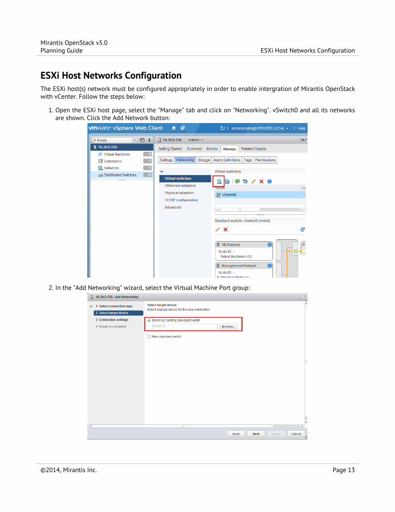
ESXi Host Networks ConfigurationThe ESXi host(s) network must be configured appropriately in order to enable intergration of Mirantis OpenStackwith vCenter. Follow the steps below:
1. Open the ESXi host page, select the "Manage" tab and click on "Networking". vSwitch0 and all its networksare shown. Click the Add Network button:
2. In the "Add Networking" wizard, select the Virtual Machine Port group:
Mirantis OpenStack v5.0Planning Guide ESXi Host Networks Configuration
©2014, Mirantis Inc. Page 13

3. On the next page, select the "Virtual Machine Port Group" option to ensure that the network will be createdin vSwitch0:
4. Always name the network br100; this is the only value that works with Fuel; type a VLAN Tag in the VLANID field; (the value must be equal to the VLAN Tag at VM Fixed on Fuel’s Network settings tab):
Limitations
• Only Nova Network with flatDHCP mode is supported in the current version of the integration.
Mirantis OpenStack v5.0Planning Guide Limitations
©2014, Mirantis Inc. Page 14

• OpenStack Block Storage service (Cinder) with VMware VMDK datastore driver is not supported; you canonly use Cinder with the LVM over iSCSI option as the Cinder backend.
• Each OpenStack environment can support one vCenter cluster.
• VMware vCenter can be deployed on Mirantis OpenStack with or without high-availability (HA) configured.Note, however, that the vCenter Nova plugin runs on only one Controller node, even if that Controller nodeis replicated to provide HA. See LP1312653.
For background information about how vCenter support is integrated into Mirantis OpenStack, see VMwarevSphere Integration.
Follow the instructions in vSphere deployment notes to deploy your Mirantis OpenStack environment with vCentersupport.
Mirantis OpenStack v5.0Planning Guide Limitations
©2014, Mirantis Inc. Page 15

Calculate hardware requirementsYou can use the Fuel Hardware Calculator to calculate the hardware required for your OpenStack environment.
When choosing the hardware on which you will deploy your OpenStack environment, you should think about:
• CPU -- Consider the number of virtual machines that you plan to deploy in your cloud environment and theCPU per virtual machine. Also consider how the environment will be used: environments used for heavycomputational work may require more powerful CPUs than environments used primarily for storage, forexample.
• Memory -- Depends on the amount of RAM assigned per virtual machine and the controller node.
• Storage -- Depends on the local drive space per virtual machine, remote volumes that can be attached to avirtual machine, and object storage.
• Networking -- Depends on the Choose Network Topology, the network bandwidth per virtual machine, andnetwork storage.
See Example of Hardware Requirements Calculation for some specific calculations you can make when choosingyour hardware.
Mirantis OpenStack v5.0Planning Guide Calculate hardware requirements
©2014, Mirantis Inc. Page 16

Example of Hardware Requirements CalculationWhen you calculate resources for your OpenStack environment, consider the resources required for expandingyour environment.
The example described in this section presumes that your environment has the following prerequisites:
• 100 virtual machines
• 2 x Amazon EC2 compute units 2 GHz average
• 16 x Amazon EC2 compute units 16 GHz maximum
Calculating CPUUse the following formula to calculate the number of CPU cores per virtual machine:
max GHz /(number of GHz per core x 1.3 for hyper-threading)
Example:
16 GHz / (2.4 x 1.3) = 5.12
Therefore, you must assign at least 5 CPU cores per virtual machine.
Use the following formula to calculate the total number of CPU cores:
(number of VMs x number of GHz per VM) / number of GHz per core
Example:
(100 VMs * 2 GHz per VM) / 2.4 GHz per core = 84
Therefore, the total number of CPU cores for 100 virtual machines is 84.
Depending on the selected CPU you can calculate the required number of sockets. Use the following formula:
total number of CPU cores / number of cores per socket
For example, you use Intel E5 2650-70 8 core CPU:
84 / 8 = 11
Therefore, you need 11 sockets. To calculate the number of servers required for your deployment, use thefollowing formula:
total number of sockets / number of sockets per server
Mirantis OpenStack v5.0Planning Guide Example of Hardware Requirements Calculation
©2014, Mirantis Inc. Page 17
Round the number of sockets to an even number to get 12 sockets. Use the following formula:
12 / 2 = 6
Therefore, you need 6 dual socket servers. You can calculate the number of virtual machines per server using thefollowing formula:
number of virtual machines / number of servers
Example:
100 / 6 = 16.6
Therefore, you can deploy 17 virtual machines per server.
Using this calculation, you can add additional servers accounting for 17 virtual machines per server.
The calculation presumes the following conditions:
• No CPU oversubscribing
• If you use hyper-threading, count each core as 1.3, not 2.
• CPU supports the technologies required for your deployment
Calculating MemoryContinuing to use the example from the previous section, we need to determine how much RAM will be requiredto support 17 VMs per server. Let's assume that you need an average of 4 GBs of RAM per VM with dynamicallocation for up to 12GBs for each VM. Calculating that all VMs will be using 12 GBs of RAM requires that eachserver have 204 GBs of available RAM.
You must also consider that the node itself needs sufficient RAM to accommodate core OS operations as well asRAM for each VM container (not the RAM allocated to each VM, but the memory the core OS uses to run the VM).The node's OS must run it's own operations, schedule processes, allocate dynamic resources, and handle networkoperations, so giving the node itself at least 16 GBs or more RAM is not unreasonable.
Considering that the RAM we would consider for servers comes in 4 GB, 8 GB, 16 GB and 32 GB sticks, we wouldneed a total of 256 GBs of RAM installed per server. For an average 2-CPU socket server board you get 16-24RAM slots. To have 256 GBs installed you would need sixteen 16 GB sticks of RAM to satisfy your RAM needs forup to 17 VMs requiring dynamic allocation up to 12 GBs and to support all core OS requirements.
You can adjust this calculation based on your needs.
Calculating StorageWhen it comes to disk space there are several types that you need to consider:
• Ephemeral (the local drive space for a VM)
• Persistent (the remote volumes that can be attached to a VM)
• Object Storage (such as images or other objects)
Mirantis OpenStack v5.0Planning Guide Calculating Memory
©2014, Mirantis Inc. Page 18

As far as local drive space that must reside on the compute nodes, in our example of 100 VMs we make thefollowing assumptions:
• 150 GB local storage per VM
• 5 TB total of local storage (100 VMs * 50 GB per VM)
• 500 GB of persistent volume storage per VM
• 50 TB total persistent storageReturning to our already established example, we need to figure out how much storage to install per server. Thisstorage will service the 17 VMs per server. If we are assuming 50 GBs of storage for each VMs drive container,then we would need to install 2.5 TBs of storage on the server. Since most servers have anywhere from 4 to 322.5" drive slots or 2 to 12 3.5" drive slots, depending on server form factor (i.e., 2U vs. 4U), you will need toconsider how the storage will be impacted by the intended use.
If storage impact is not expected to be significant, then you may consider using unified storage. For this examplea single 3 TB drive would provide more than enough storage for seventeen 150 GB VMs. If speed is really not anissue, you might even consider installing two or three 3 TB drives and configure a RAID-1 or RAID-5 forredundancy. If speed is critical, however, you will likely want to have a single hardware drive for each VM. In thiscase you would likely look at a 3U form factor with 24-slots.
Don't forget that you will also need drive space for the node itself, and don't forget to order the correctbackplane that supports the drive configuration that meets your needs. Using our example specifications andassuming that speed is critical, a single server would need 18 drives, most likely 2.5" 15,000 RPM 146 GB SASdrives.
ThroughputAs far as throughput, that's going to depend on what kind of storage you choose. In general, you calculate IOPSbased on the packing density (drive IOPS * drives in the server / VMs per server), but the actual drive IOPS willdepend on the drive technology you choose. For example:
• 3.5" slow and cheap (100 IOPS per drive, with 2 mirrored drives)
• 100 IOPS * 2 drives / 17 VMs per server = 12 Read IOPS, 6 Write IOPS• 2.5" 15K (200 IOPS, four 600 GB drive, RAID-10)
• 200 IOPS * 4 drives / 17 VMs per server = 48 Read IOPS, 24 Write IOPS• SSD (40K IOPS, eight 300 GB drive, RAID-10)
• 40K * 8 drives / 17 VMs per server = 19K Read IOPS, 9.5K Write IOPSClearly, SSD gives you the best performance, but the difference in cost between SSDs and the less costlyplatter-based solutions is going to be significant, to say the least. The acceptable cost burden is determined bythe balance between your budget and your performance and redundancy needs. It is also important to note thatthe rules for redundancy in a cloud environment are different than a traditional server installation in that entireservers provide redundancy as opposed to making a single server instance redundant.
In other words, the weight for redundant components shifts from individual OS installation to server redundancy.It is far more critical to have redundant power supplies and hot-swappable CPUs and RAM than to haveredundant compute node storage. If, for example, you have 18 drives installed on a server and have 17 drivesdirectly allocated to each VM installed and one fails, you simply replace the drive and push a new node copy. The
Mirantis OpenStack v5.0Planning Guide Calculating Memory
©2014, Mirantis Inc. Page 19

remaining VMs carry whatever additional load is present due to the temporary loss of one node.
Remote storageIOPS will also be a factor in determining how you plan to handle persistent storage. For example, consider theseoptions for laying out your 50 TB of remote volume space:
• 12 drive storage frame using 3 TB 3.5" drives mirrored
• 36 TB raw, or 18 TB usable space per 2U frame
• 3 frames (50 TB / 18 TB per server)
• 12 slots x 100 IOPS per drive = 1200 Read IOPS, 600 Write IOPS per frame
• 3 frames x 1200 IOPS per frame / 100 VMs = 36 Read IOPS, 18 Write IOPS per VM• 24 drive storage frame using 1TB 7200 RPM 2.5" drives
• 24 TB raw, or 12 TB usable space per 2U frame
• 5 frames (50 TB / 12 TB per server)
• 24 slots x 100 IOPS per drive = 2400 Read IOPS, 1200 Write IOPS per frame
• 5 frames x 2400 IOPS per frame / 100 VMs = 120 Read IOPS, 60 Write IOPS per frameYou can accomplish the same thing with a single 36 drive frame using 3 TB drives, but this becomes a singlepoint of failure in your environment.
Object storageWhen it comes to object storage, you will find that you need more space than you think. For example, thisexample specifies 50 TB of object storage.
Object storage uses a default of 3 times the required space for replication, which means you will need 150 TB.However, to accommodate two hands-off zones, you will need 5 times the required space, which actually means250 TB. The calculations don't end there. You don't ever want to run out of space, so "full" should really be morelike 75% of capacity, which means you will need a total of 333 TB, or a multiplication factor of 6.66.
Of course, that might be a bit much to start with; you might want to start with a happy medium of a multiplier of4, then acquire more hardware as your drives begin to fill up. That calculates to 200 TB in our example. So howdo you put that together? If you were to use 3 TB 3.5" drives, you could use a 12 drive storage frame, with 6servers hosting 36 TB each (for a total of 216 TB). You could also use a 36 drive storage frame, with just 2 servershosting 108 TB each, but its not recommended due to the high cost of failure to replication and capacity issues.
Calculating NetworkPerhaps the most complex part of designing an OpenStack environment is the networking.
An OpenStack environment can involve multiple networks even beyond the Public, Private, and Internalnetworks. Your environment may involve tenant networks, storage networks, multiple tenant private networks,and so on. Many of these will be VLANs, and all of them will need to be planned out in advance to avoidconfiguration issues.
In terms of the example network, consider these assumptions:
Mirantis OpenStack v5.0Planning Guide Calculating Network
©2014, Mirantis Inc. Page 20

• 100 Mbits/second per VM
• HA architecture
• Network Storage is not latency sensitiveIn order to achieve this, you can use two 1 Gb links per server (2 x 1000 Mbits/second / 17 VMs = 118Mbits/second).
Using two links also helps with HA. You can also increase throughput and decrease latency by using two 10 Gblinks, bringing the bandwidth per VM to 1 Gb/second, but if you're going to do that, you've got one more factor toconsider.
Scalability and oversubscriptionIt is one of the ironies of networking that 1 Gb Ethernet generally scales better than 10Gb Ethernet -- at leastuntil 100 Gb switches are more commonly available. It's possible to aggregate the 1 Gb links in a 48 port switch,so that you have 48 x 1 Gb links down, but 4 x 10 Gb links up. Do the same thing with a 10 Gb switch, however,and you have 48 x 10 Gb links down and 4 x 100b links up, resulting in oversubscription.
Like many other issues in OpenStack, you can avoid this problem to a great extent with careful planning.Problems only arise when you are moving between racks, so plan to create "pods", each of which includes bothstorage and compute nodes. Generally, a pod is the size of a non-oversubscribed L2 domain.
Hardware for this exampleIn this example, you are looking at:
• 2 data switches (for HA), each with a minimum of 12 ports for data (2 x 1 Gb links per server x 6 servers)
• 1 x 1 Gb switch for IPMI (1 port per server x 6 servers)
• Optional Cluster Management switch, plus a second for HABecause your network will in all likelihood grow, it's best to choose 48 port switches. Also, as your networkgrows, you will need to consider uplinks and aggregation switches.
SummaryIn general, your best bet is to choose a 2 socket server with a balance in I/O, CPU, Memory, and Disk that meetsyour project requirements. Look for a 1U R-class or 2U high density C-class servers. Some good options from Dellfor compute nodes include:
• Dell PowerEdge R620
• Dell PowerEdge C6220 Rack Server
• Dell PowerEdge R720XD (for high disk or IOPS requirements)You may also want to consider systems from HP (http://www.hp.com/servers) or from a smaller systems builderlike Aberdeen, a manufacturer that specializes in powerful, low-cost systems and storage servers(http://www.aberdeeninc.com).
Mirantis OpenStack v5.0Planning Guide Summary
©2014, Mirantis Inc. Page 21

Reference configuration of hardware switchesThis section describes reference configuration for Cisco and Juniper network switches.
Tagged portsCisco Catalyst
interface [Ten]GigabitEthernet[interface number] description [port description] switchport trunk encapsulation dot1q switchport trunk allowed vlan [vlan IDs for specific networks] switchport mode trunk spanning-tree portfast trunk switchport trunk native vlan [vlan ID] - if necessary one untagged VLAN
Cisco Nexus/ Arista
interface ethernet[interface number] description [port description] switchport switchport mode trunk switchport trunk allowed vlan [vlan IDs for specific networks] switchport trunk native vlan [vlan ID] - if necessary one untagged VLAN
Juniper
interfaces { [interface_name]-[interface_number] { unit 0 { family ethernet-switching { port-mode trunk; vlan { members [ vlan IDs or names of specificnetworks]; } native-vlan-id [vlan ID] if necessary one untagged VLAN } } }}
Untagged portsCisco Catalyst
Mirantis OpenStack v5.0Planning Guide Reference configuration of hardware switches
©2014, Mirantis Inc. Page 22

interface [Ten]GigabitEthernet[interface number] description [port description] switchport access [vlan ID for specific network] switchport mode accessspanning-tree portfast
Cisco Nexus/Arista
interface ethernet[interface number] description [port description] switchport switchport access vlan [vlan ID for specific network]
Juniper
interfaces { [interface_name]-[interface_number] { unit 0 { family ethernet-switching { port-mode access; vlan { members [vlan ID or name for specific network]; } } } }}
Mirantis OpenStack v5.0Planning Guide Reference configuration of hardware switches
©2014, Mirantis Inc. Page 23

Example 1: HA + Nova-network FlatDHCP managerAs a model example, the following configuration is used:
• Deployment mode: Multi-node HA
• Networking model: Nova-network FlatDHCP managerHardware and environment:
• 7 servers with two 1Gb/s Ethernet NIC and IPMI
• 1 Cisco Catalyst 2960G switch
• Independent out of band management network for IPMI
• Connection to the Internet or/and DC network via a router called Gateway and IP 172.16.1.1Node Server roles:
• 1 server as Fuel Node
• 3 servers as Controller Node
• 1 server as Cinder Node
• 2 servers as Compute NodeNetwork configuration plan:
• Public network 172.16.1.0/24
• Floating network 172.16.0.0/24 in VLAN 100
• Management network 192.168.0.0/24 in VLAN 101
• Storage network 192.168.1.0/24 in VLAN 102
• Private (Fixed) network 10.0.0.0/24 in VLAN 103
• Administrative network (for Fuel) 10.20.0.0/24 in VLAN 104Network Parameters:
• Fuel server IP: 10.20.0.2/24
• Default gateway: 10.20.0.1
• DNS 10.20.0.1
Note
The Internet and rest of DC access is available through the Public network (for OpenStack Nodes) andAdministrative network (Fuel server)
From the server node side, ports with the following VLAN IDs for networks are used:
• eth0 - Management VLAN 101 (tagged), Storage VLAN 102(tagged) and Administrative VLAN 104 (untagged)
Mirantis OpenStack v5.0Planning Guide Example 1: HA + Nova-network FlatDHCP manager
©2014, Mirantis Inc. Page 24

• eth1 - Public/Floating VLAN 100 (tagged), Private VLAN 103 (tagged)
Detailed Port ConfigurationThe following table describes the detailed port configuration and VLAN assignment.
SwitchPort Server name
ServerNIC
tagged /untagged VLAN ID
G0/1 Fuel eth0 untagged 104
G0/2 Fuel eth1 untagged 100
G0/3 Compute Node 1 eth0 tagged 101, 102, 104 (untagged)
G0/4 Compute Node 1 eth1 tagged 100, 103
G0/5 Compute Node n eth0 tagged 101, 102, 104 (untagged)
G0/6 Compute Node n eth1 tagged 100, 103
G0/7 Controller Node 1 eth0 tagged 101, 102, 104(untagged)
G0/8 Controller Node 1 eth1 tagged 100, 103
G0/9 Controller Node 2 eth0 tagged 101, 102, 104 (untagged)
G0/10 Controller Node 2 eth1 tagged 100, 103
G0/11 Controller Node 3 eth0 tagged 101, 102, 104 (untagged)
G0/12 Controller Node 3 eth1 tagged 100, 103
G0/13 Cinder Node eth0 tagged 101, 102, 104 (untagged)
G0/14 Cinder Node eth1 tagged 100, 103
G0/24 Router (default gateway) --- untagged 100
Connect the servers to the switch as in the diagram below:
Mirantis OpenStack v5.0Planning Guide Detailed Port Configuration
©2014, Mirantis Inc. Page 25

The following diagram describes the network topology for this environment.
Mirantis OpenStack v5.0Planning Guide Detailed Port Configuration
©2014, Mirantis Inc. Page 26

Nova-network Switch configuration (Cisco Catalyst 2960G)Use the following configuration to deploy Mirantis OpenStack using a Cisco Catalyst 2960G network switch.:
service timestamps debug datetime msec localtime show-timezoneservice timestamps log datetime msec localtime show-timezoneservice password-encryptionservice sequence-numbers!hostname OpenStack\_sw1!logging countlogging buffered 64000 informationallogging rate-limit console 100 except errorslogging console informationalenable secret r00tme!username root privilege 15 secret r00tme!no aaa new-modelaaa session-id commonip subnet-zeroip domain-name domain.ltdip name-server [ip of domain name server]!
Mirantis OpenStack v5.0Planning Guide
Nova-network Switch configuration (Cisco Catalyst2960G)
©2014, Mirantis Inc. Page 27

spanning-tree mode rapid-pvstspanning-tree loopguard defaultspanning-tree etherchannel guard misconfigspanning-tree extend system-id!ip ssh time-out 60ip ssh authentication-retries 2ip ssh version 2!vlan 100 name Publicvlan 101 name Managementvlan 102 name Storagevlan 103 name Privatevlan 104 name Admin !interface GigabitEthernet0/1 description Fuel Node eth0 switchport access vlan 104 switchport mode access spanning-tree portfast !interface GigabitEthernet0/2 description Fuel Node eth1 (optional to have direct access to Public net) switchport access vlan 100 switchport mode access spanning-tree portfastinterface GigabitEthernet0/3 description Compute Node 1 eth0 switchport trunk native vlan 104 switchport trunk encapsulation dot1q switchport trunk allowed vlan 101, 102, 104 switchport mode trunk spanning-tree portfast trunkinterface GigabitEthernet0/4 description Compute Node 1 eth1 switchport trunk encapsulation dot1q switchport trunk allowed vlan 100, 103 switchport mode trunk spanning-tree portfast trunkinterface GigabitEthernet0/5 description Compute Node 2 eth0 switchport trunk native vlan 104 switchport trunk encapsulation dot1q
Mirantis OpenStack v5.0Planning Guide
Nova-network Switch configuration (Cisco Catalyst2960G)
©2014, Mirantis Inc. Page 28

switchport trunk allowed vlan 101, 102, 104 switchport mode trunk spanning-tree portfast trunkinterface GigabitEthernet0/6 description Compute Node 2 eth1 switchport trunk encapsulation dot1q switchport trunk allowed vlan 100, 103 switchport mode trunk spanning-tree portfast trunkinterface GigabitEthernet0/7 description Controller Node 1 eth0 switchport trunk native vlan 104 switchport trunk encapsulation dot1q switchport trunk allowed vlan 101, 102, 104 switchport mode trunk spanning-tree portfast trunkinterface GigabitEthernet0/8 description Controller Node 1 eth1 switchport trunk encapsulation dot1q switchport trunk allowed vlan 100, 103 switchport mode trunk spanning-tree portfast trunkinterface GigabitEthernet0/9 description Controller Node 2 eth0 switchport trunk native vlan 104 switchport trunk encapsulation dot1q switchport trunk allowed vlan 101, 102, 104 switchport mode trunk spanning-tree portfast trunkinterface GigabitEthernet0/10 description Controller Node 2 eth1 switchport trunk encapsulation dot1 switchport trunk allowed vlan 100, 103 switchport mode trunk spanning-tree portfast trunkinterface GigabitEthernet0/11 description Controller Node 3 eth0 switchport trunk native vlan 104 switchport trunk encapsulation dot1q switchport trunk allowed vlan 101, 102, 104 switchport mode trunk spanning-tree portfast trunkinterface GigabitEthernet0/12 description Controller Node 3 eth1 switchport trunk encapsulation dot1q switchport trunk allowed vlan 100, 103 switchport mode trunk spanning-tree portfast trunk
Mirantis OpenStack v5.0Planning Guide
Nova-network Switch configuration (Cisco Catalyst2960G)
©2014, Mirantis Inc. Page 29

interface GigabitEthernet0/13 description Cinder Node eth0 switchport trunk native vlan 104 switchport trunk encapsulation dot1q switchport trunk allowed vlan 101, 102, 104 switchport mode trunk spanning-tree portfast trunk
interface GigabitEthernet0/14 description Cinder Node eth1 switchport trunk encapsulation dot1q switchport trunk allowed vlan 100, 103 switchport mode trunk spanning-tree portfast trunkinterface GigabitEthernet0/24 description Connection to default gateway switchport access vlan 100 switchport mode access!interface Vlan100 ip address 172.16.1.254 255.255.255.0 ip address 172.16.0.254 255.255.255.0 secondary no shutdown!ip route 0.0.0.0 0.0.0.0 172.16.1.1!ip classlessno ip http serverno ip http secure-server!line con 0 session-timeout 15 privilege level 15 login local password r00tme!line vty 0 15 session-timeout 15 login local password r00tme!ntp server [ntp_server1] preferntp server [ntp_server2]
Nova-network Switch configuration (Juniper EX4200)Use the following configuration to deploy Mirantis OpenStack using Juniper EX4200 network switch.:
Mirantis OpenStack v5.0Planning Guide Nova-network Switch configuration (Juniper EX4200)
©2014, Mirantis Inc. Page 30

system { host-name OpenStack_sw1; domain-name domain.ltd; authentication-order [ password ]; root-authentication { encrypted-password "xxxxxxxxxxxxxxxxxxx"; }}services { ssh; } ntp { server [ntp_server1] prefer; server [ntp_server2]; }}
interfaces { ge-0/0/0 { description Fuel Node eth0; unit 0 { family ethernet-switching { port-mode access; vlan { members vlan_104; } } } } ge-0/0/1 { description Fuel Node eth1 (optional to have direct access to Publicnet); unit 0 { family ethernet-switching { port-mode access; vlan { members vlan_100; } } } } ge-0/0/2 { description Compute Node 1 eth0; unit 0 { family ethernet-switching { port-mode trunk; vlan { members vlan_101, vlan_102;
Mirantis OpenStack v5.0Planning Guide Nova-network Switch configuration (Juniper EX4200)
©2014, Mirantis Inc. Page 31

} native-vlan-id vlan_104; } } } ge-0/0/3 { description Compute Node 1 eth1; unit 0 { family ethernet-switching { port-mode trunk; vlan { members vlan_100, vlan_103; } } } } ge-0/0/4 { description Compute Node 2 eth0; unit 0 { family ethernet-switching { port-mode trunk; vlan { members vlan_101, vlan_102; } native-vlan-id vlan_104; } } } ge-0/0/5 { description Compute Node 2 eth1; unit 0 { family ethernet-switching { port-mode trunk; vlan { members vlan_100, vlan_103; } } } } ge-0/0/6 { description Controller Node 1 eth0; unit 0 { family ethernet-switching { port-mode trunk; vlan { members vlan_101, vlan_102; } native-vlan-id vlan_104;
Mirantis OpenStack v5.0Planning Guide Nova-network Switch configuration (Juniper EX4200)
©2014, Mirantis Inc. Page 32

} } } ge-0/0/7 { description controller Node 1 eth1; unit 0 { family ethernet-switching { port-mode trunk; vlan { members vlan_100, vlan_103; } } } } ge-0/0/8 { description Controller Node 2 eth0; unit 0 { family ethernet-switching { port-mode trunk; vlan { members vlan_101, vlan_102; } native-vlan-id vlan_104; } } } ge-0/0/9 { description Controller Node 2 eth1; unit 0 { family ethernet-switching { port-mode trunk; vlan { members vlan_100, vlan_103; } } } } ge-0/0/10 { description Controller Node 3 eth0; unit 0 { family ethernet-switching { port-mode trunk; vlan { members vlan_101, vlan_102; } native-vlan-id vlan_104; } }
Mirantis OpenStack v5.0Planning Guide Nova-network Switch configuration (Juniper EX4200)
©2014, Mirantis Inc. Page 33

} ge-0/0/11 { description Controller Node 3 eth1; unit 0 { family ethernet-switching { port-mode trunk; vlan { members vlan_100, vlan_103; } } } } ge-0/0/12 { description Cinder Node 1 eth0; unit 0 { family ethernet-switching { port-mode trunk; vlan { members vlan_101, vlan_102; } native-vlan-id vlan_104; } } } ge-0/0/13 { description Cinder Node 1 eth1; unit 0 { family ethernet-switching { port-mode trunk; vlan { members vlan_100, vlan_103; } } } } ge-0/0/23 { description Connection to default gateway; unit 0 { family ethernet-switching { port-mode access; vlan { members vlan_100; } } } } vlan { unit 100 {
Mirantis OpenStack v5.0Planning Guide Nova-network Switch configuration (Juniper EX4200)
©2014, Mirantis Inc. Page 34

family inet { address 172.16.1.254/24; address 172.16.0.254/24; } } }}routing-options { static { route 0.0.0.0/0 next-hop 172.16.1.1; }}protocols { dcbx { interface all; } rstp { bridge-priority 32k; interface ge-0/0/0.0 { edge; } interface ge-0/0/1.0 { edge; } interface ge-0/0/23.0 { edge; } bpdu-block-on-edge; } lldp { interface all; }}vlans { vlan_1; vlan_100 { description Public; vlan-id 100; l3-interface vlan.100; } vlan_101 { description Management; vlan-id 101; } vlan_102 { description Storage; vlan-id 102; }
Mirantis OpenStack v5.0Planning Guide Nova-network Switch configuration (Juniper EX4200)
©2014, Mirantis Inc. Page 35

vlan_103 { description Private; vlan-id 103; } vlan_104 { description Admin; vlan-id 104; }}
Mirantis OpenStack v5.0Planning Guide Nova-network Switch configuration (Juniper EX4200)
©2014, Mirantis Inc. Page 36

Example 2: HA + Neutron with GREAs a model example, the following configuration is used:
• Deploying mode: Multi-node HA
• Networking model: Neutron with GREHardware and environment:
• 7 servers with two 1Gb/s ethernet NIC and IPMI
• 1 Cisco Catalyst 3750 switch
• Independent out of band management network for IPMI
• Connection to the Internet or/and DC network via a router called Gateway and IP 172.16.1.1Node servers roles:
• 1 server as Fuel Node
• 3 servers as Controller Node
• 1 server as Cinder Node
• 2 servers as Compute NodeNetwork Configuration Plan:
• Floating/Public network 172.16.0.0/24 in VLAN 100 (untagged on servers)
• Floating IP range 172.16.0.130 - 254
• Internal network (private) 192.168.111.0/24
• Gateway 192.168.111.1
• DNS 8.8.4.4, 8.8.8.8
• Tunnel ID range 2 - 65535
• Management network 192.168.0.0/24 in VLAN 101
• Storage network 192.168.1.0/24 in VLAN 102
• Administrative network (for Fuel) 10.20.0.0/24 in VLAN 103Network Parameters
• Fuel server: IP 10.20.0.2/24
• Default gateway: 10.20.0.1
• DNS: 10.20.0.1
Note
The Internet and rest of DC access via Public network (for OpenStack Nodes) and Administrative network(Fuel server).
Mirantis OpenStack v5.0Planning Guide Example 2: HA + Neutron with GRE
©2014, Mirantis Inc. Page 37

From server side, ports with following VLAN IDs are used:
• eth0 - Administrative VLAN 103 (untagged)
• eth1 - Public/Floating VLAN 100 (untagged), Management VLAN 101 (tagged), Storage VLAN 102 (tagged)
Detailed port configurationThe following table describes port configuration for this deployment.
SwitchPort Server name
ServerNIC
tagged /untagged VLAN ID
G0/1 Fuel eth0 untagged 103
G0/2 Fuel eth1 untagged 100
G0/3 Compute Node 1 eth0 untagged 103
G0/4 Compute Node 1 eth1 tagged 100(untagged), 101, 102
G0/5 Compute Node n eth0 tagged 103
G0/6 Compute Node n eth1 tagged 100(untagged), 101, 102
G0/7 Controller Node 1 eth0 tagged 103
G0/8 Controller Node 1 eth1 tagged 100(untagged), 101, 102
G0/9 Controller Node 2 eth0 tagged 103
G0/10 Controller Node 2 eth1 tagged 100(untagged), 101, 102
G0/11 Controller Node 3 eth0 tagged 103
G0/12 Controller Node 3 eth1 tagged 100(untagged), 101, 102
G0/13 Cinder Node eth0 tagged 103
G0/14 Cinder Node eth1 tagged 100(untagged), 101, 102
G0/24 Router (default gateway)•
untagged 100
Neutron Switch configuration (Cisco Catalyst 2960G)Use the following configuration to deploy Mirantis OpenStack using a Cisco Catalyst 2960G network switch.
service timestamps debug datetime msec localtime show-timezoneservice timestamps log datetime msec localtime show-timezoneservice password-encryptionservice sequence-numbers!hostname OpenStack_sw1!logging count
Mirantis OpenStack v5.0Planning Guide Detailed port configuration
©2014, Mirantis Inc. Page 38
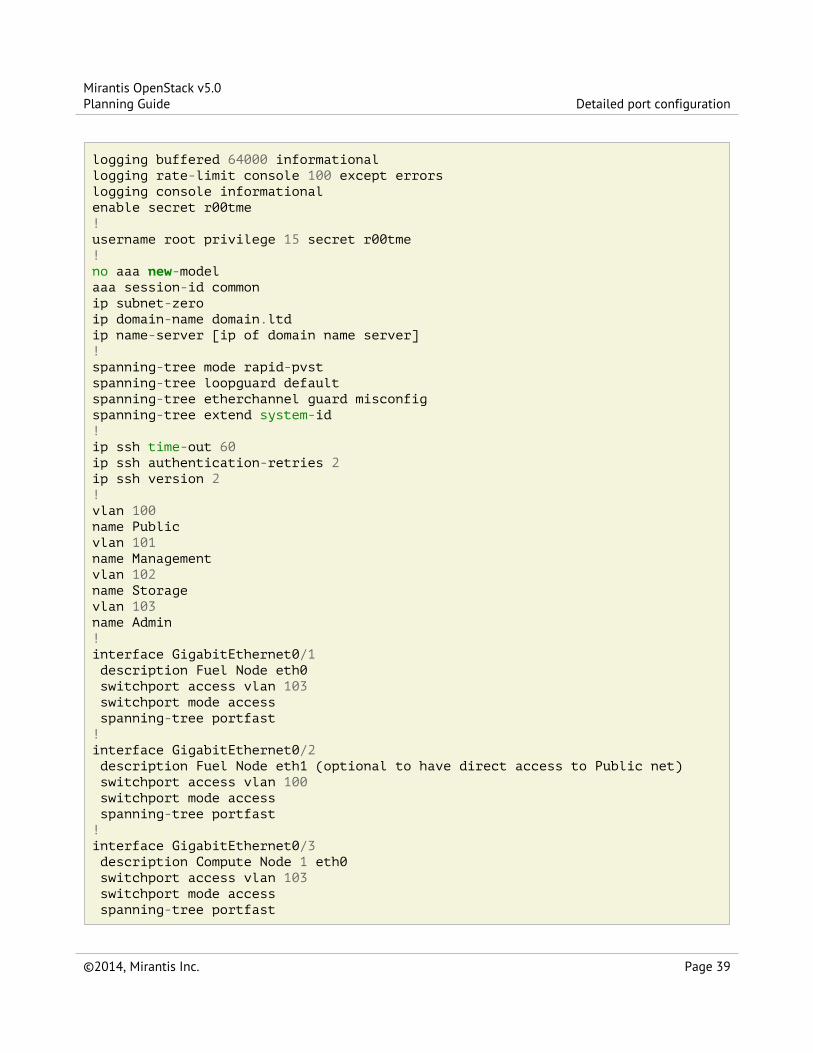
logging buffered 64000 informationallogging rate-limit console 100 except errorslogging console informationalenable secret r00tme!username root privilege 15 secret r00tme!no aaa new-modelaaa session-id commonip subnet-zeroip domain-name domain.ltdip name-server [ip of domain name server]!spanning-tree mode rapid-pvstspanning-tree loopguard defaultspanning-tree etherchannel guard misconfigspanning-tree extend system-id!ip ssh time-out 60ip ssh authentication-retries 2ip ssh version 2!vlan 100name Publicvlan 101name Managementvlan 102name Storagevlan 103name Admin!interface GigabitEthernet0/1 description Fuel Node eth0 switchport access vlan 103 switchport mode access spanning-tree portfast!interface GigabitEthernet0/2 description Fuel Node eth1 (optional to have direct access to Public net) switchport access vlan 100 switchport mode access spanning-tree portfast!interface GigabitEthernet0/3 description Compute Node 1 eth0 switchport access vlan 103 switchport mode access spanning-tree portfast
Mirantis OpenStack v5.0Planning Guide Detailed port configuration
©2014, Mirantis Inc. Page 39
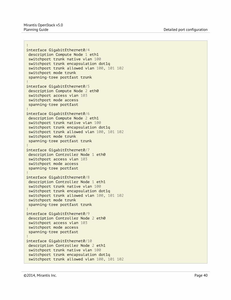
!interface GigabitEthernet0/4 description Compute Node 1 eth1 switchport trunk native vlan 100 switchport trunk encapsulation dot1q switchport trunk allowed vlan 100, 101 102 switchport mode trunk spanning-tree portfast trunk!interface GigabitEthernet0/5 description Compute Node 2 eth0 switchport access vlan 103 switchport mode access spanning-tree portfast!interface GigabitEthernet0/6 description Compute Node 2 eth1 switchport trunk native vlan 100 switchport trunk encapsulation dot1q switchport trunk allowed vlan 100, 101 102 switchport mode trunk spanning-tree portfast trunk!interface GigabitEthernet0/7 description Controller Node 1 eth0 switchport access vlan 103 switchport mode access spanning-tree portfast!interface GigabitEthernet0/8 description Controller Node 1 eth1 switchport trunk native vlan 100 switchport trunk encapsulation dot1q switchport trunk allowed vlan 100, 101 102 switchport mode trunk spanning-tree portfast trunk!interface GigabitEthernet0/9 description Controller Node 2 eth0 switchport access vlan 103 switchport mode access spanning-tree portfast!interface GigabitEthernet0/10 description Controller Node 2 eth1 switchport trunk native vlan 100 switchport trunk encapsulation dot1q switchport trunk allowed vlan 100, 101 102
Mirantis OpenStack v5.0Planning Guide Detailed port configuration
©2014, Mirantis Inc. Page 40

switchport mode trunk spanning-tree portfast trunk!interface GigabitEthernet0/11 description Controller Node 3 eth0 switchport access vlan 103 switchport mode access spanning-tree portfast!interface GigabitEthernet0/12 description Controller Node 3 eth1 switchport trunk native vlan 100 switchport trunk encapsulation dot1q switchport trunk allowed vlan 100, 101 102 switchport mode trunk spanning-tree portfast trunk!interface GigabitEthernet0/13 description Cinder Node eth0 switchport access vlan 103 switchport mode access spanning-tree portfast!interface GigabitEthernet0/14 description Cinder Node eth1 switchport trunk native vlan 100 switchport trunk encapsulation dot1q switchport trunk allowed vlan 100, 101 102 switchport mode trunk spanning-tree portfast trunk!interface GigabitEthernet0/24 description Connection to default gateway switchport access vlan 100 switchport mode access!interface Vlan100 ip address 172.16.1.254 255.255.255.0 ip address 172.16.0.254 255.255.255.0 secondary no shutdown!ip route 0.0.0.0 0.0.0.0 172.16.1.1!ip classlessno ip http serverno ip http secure-server!line con 0
Mirantis OpenStack v5.0Planning Guide Detailed port configuration
©2014, Mirantis Inc. Page 41

session-timeout 15privilege level 15login localpassword r00tme!line vty 0 15session-timeout 15login localpassword r00tme!ntp server [ntp_server1] preferntp server [ntp_server2]
Neutron Switch configuration (Juniper EX4200)Use the following configuration to deploy Mirantis OpenStack using Juniper EX4200 network switch.
system { host-name OpenStack_sw1; domain-name domain.ltd; authentication-order [ password ]; root-authentication { encrypted-password "xxxxxxxxxxxxxxxxxxx"; }}services { ssh; } ntp { server [ntp_server1] prefer; server [ntp_server2]; }}
interfaces { ge-0/0/0 { description Fuel Node eth0; unit 0 { family ethernet-switching { port-mode access; vlan { members vlan_103; } } } } ge-0/0/1 {
Mirantis OpenStack v5.0Planning Guide Neutron Switch configuration (Juniper EX4200)
©2014, Mirantis Inc. Page 42
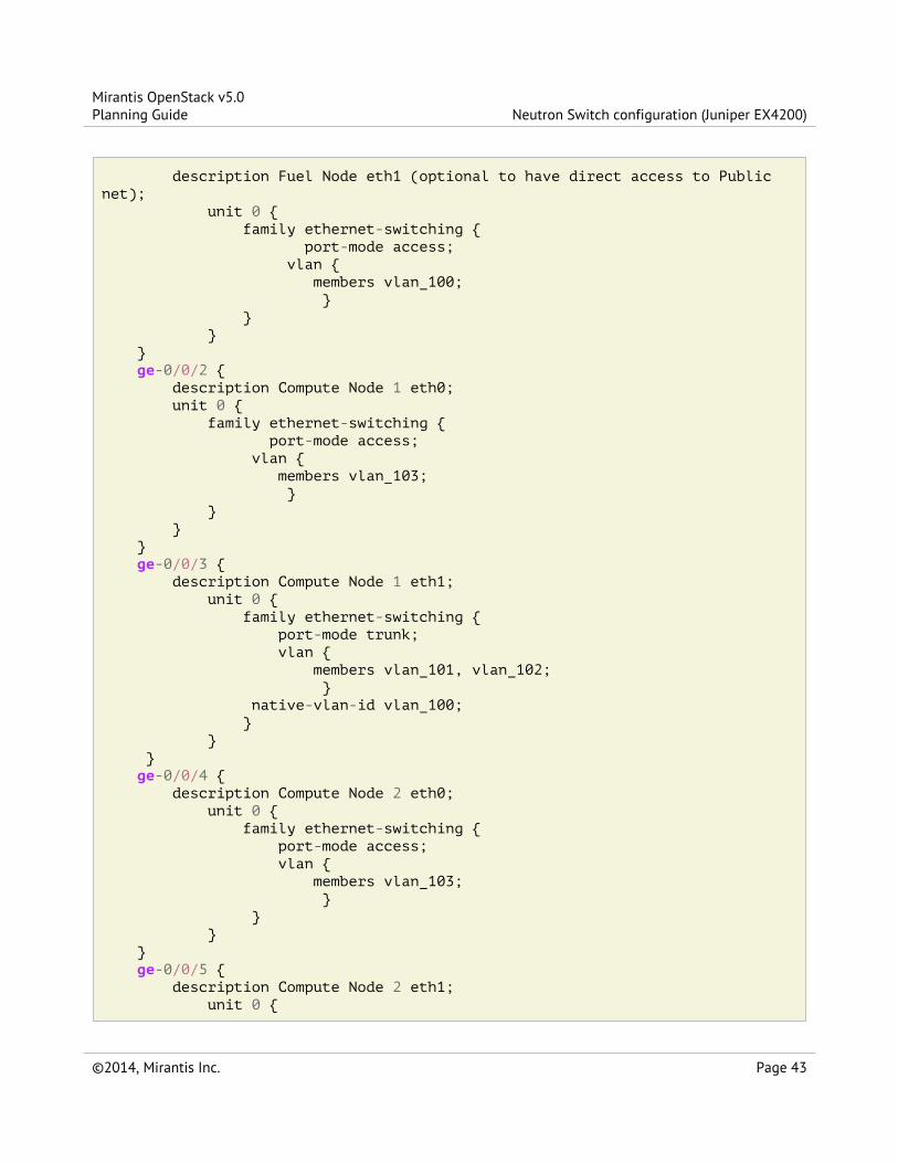
description Fuel Node eth1 (optional to have direct access to Publicnet); unit 0 { family ethernet-switching { port-mode access; vlan { members vlan_100; } } } } ge-0/0/2 { description Compute Node 1 eth0; unit 0 { family ethernet-switching { port-mode access; vlan { members vlan_103; } } } } ge-0/0/3 { description Compute Node 1 eth1; unit 0 { family ethernet-switching { port-mode trunk; vlan { members vlan_101, vlan_102; } native-vlan-id vlan_100; } } } ge-0/0/4 { description Compute Node 2 eth0; unit 0 { family ethernet-switching { port-mode access; vlan { members vlan_103; } } } } ge-0/0/5 { description Compute Node 2 eth1; unit 0 {
Mirantis OpenStack v5.0Planning Guide Neutron Switch configuration (Juniper EX4200)
©2014, Mirantis Inc. Page 43

family ethernet-switching { port-mode trunk; vlan { members vlan_101, vlan_102; } native-vlan-id vlan_100; } } } ge-0/0/6 { description Controller Node 1 eth0; unit 0 { family ethernet-switching { port-mode access; vlan { members vlan_103; } } } } ge-0/0/7 { description controller Node 1 eth1; unit 0 { family ethernet-switching { port-mode trunk; vlan { members vlan_101, vlan_102; } native-vlan-id vlan_100; } } } ge-0/0/8 { description Controller Node 2 eth0; unit 0 { family ethernet-switching { port-mode access; vlan { members vlan_103; } } } } ge-0/0/9 { description Controller Node 2 eth1; unit 0 { family ethernet-switching { port-mode trunk;
Mirantis OpenStack v5.0Planning Guide Neutron Switch configuration (Juniper EX4200)
©2014, Mirantis Inc. Page 44

vlan { members vlan_101, vlan_102; } native-vlan-id vlan_100; } } } ge-0/0/10 { description Controller Node 3 eth0; unit 0 { family ethernet-switching { port-mode access; vlan { members vlan_103; } } } } ge-0/0/11 { description Controller Node 3 eth1; unit 0 { family ethernet-switching { port-mode trunk; vlan { members vlan_101, vlan_102; } native-vlan-id vlan_100; } } } ge-0/0/12 { description Cinder Node 1 eth0; unit 0 { family ethernet-switching { port-mode access; vlan { members vlan_103; } } } } ge-0/0/13 { description Cinder Node 1 eth1; unit 0 { family ethernet-switching { port-mode trunk; vlan { members vlan_101, vlan_102;
Mirantis OpenStack v5.0Planning Guide Neutron Switch configuration (Juniper EX4200)
©2014, Mirantis Inc. Page 45

} native-vlan-id vlan_100; } } } ge-0/0/23 { description Connection to default gateway; unit 0 { family ethernet-switching { port-mode access; vlan { members vlan_100; } } } } vlan { unit 100 { family inet { address 172.16.1.254/24; address 172.16.0.254/24; } } }
}routing-options { static { route 0.0.0.0/0 next-hop 172.16.1.1; }}protocols { dcbx { interface all; } rstp { bridge-priority 32k; interface ge-0/0/0.0 { edge; } interface ge-0/0/1.0 { edge; } interface ge-0/0/2.0 { edge; } interface ge-0/0/4.0 { edge;
Mirantis OpenStack v5.0Planning Guide Neutron Switch configuration (Juniper EX4200)
©2014, Mirantis Inc. Page 46

} interface ge-0/0/6.0 { edge; } interface ge-0/0/8.0 { edge; } interface ge-0/0/10.0 { edge; } interface ge-0/0/12.0 { edge; } interface ge-0/0/23.0 { edge; } bpdu-block-on-edge; } lldp { interface all; }}vlans { vlan_1; vlan_100 { description Public; vlan-id 100; l3-interface vlan.100; } vlan_101 { description Management; vlan-id 101; } vlan_102 { description Storage; vlan-id 102; } vlan_103 { description Admin; vlan-id 103; }}
Mirantis OpenStack v5.0Planning Guide Neutron Switch configuration (Juniper EX4200)
©2014, Mirantis Inc. Page 47


IndexP
Preparing for the Mirantis OpenStack Deployment
S
System Requirements
Mirantis OpenStack v5.0Planning Guide Index
©2014, Mirantis Inc. Page 49