FUEL OIL SYSTEM (ALCO)
33
FUEL OIL SYSTEM (ALCO) INTRODUCTION:- The Fuel Oil System is designed to introduce fuel oil into the engine cylinders at the correct time, at correct pressure, at correct quantity and in correctly atomised form. The system injects correctly metered amount of fuel into the cylinder in highly atomised form. High pressure of fuel in the system is required to lift the nozzle valve and for better penetration of fuel into the combustion chamber. High pressure also helps in proper atomisation; as a result smaller droplets of fuel come in better contact with the fresh air in the combustion chamber, resulting in better combustion. As the locomotive engine is a variable speed and variable load engine with variable requirement of fuel, thus proper metering of fuel quantity is very important. Time of fuel injection is also important for better combustion. The fuel oil system consists of two integrated system:- Fuel Feed System Fuel Injection System Fuel feed system comprising of following major components :- (i) Fuel oil tank (ii) Dirt Collector / Trap Filter (iii) Fuel Primary Filter (iv) Fuel Booster Pump (v) Fuel Relief valve (vi) Fuel Secondary Filter (vii) Fuel regulating Valve (viii) Associated pipe lines, T-Jumpers, FOP Gauge etc. Fuel Injection system comprising of following major components:- (i) Fuel Injection Pump (ii) High Pressure Tubes (iii) Fuel Injection Nozzle FUEL FEED SYSTEM:-
-
Upload
khangminh22 -
Category
Documents
-
view
3 -
download
0
Transcript of FUEL OIL SYSTEM (ALCO)

FUEL OIL SYSTEM (ALCO)
INTRODUCTION:-
The Fuel Oil System is designed to introduce fuel oil into the engine cylinders at the correct time, at correct pressure, at correct quantity and in correctly atomised form. The system injects correctly metered amount of fuel into the cylinder in highly atomised form. High pressure of fuel in the system is required to lift the nozzle valve and for better penetration of fuel into the combustion chamber. High pressure also helps in proper atomisation; as a result smaller droplets of fuel come in better contact with the fresh air in the combustion chamber, resulting in better combustion. As the locomotive engine is a variable speed and variable load engine with variable requirement of fuel, thus proper metering of fuel quantity is very important. Time of fuel injection is also important for better combustion.
The fuel oil system consists of two integrated system:-
Fuel Feed System
Fuel Injection System
Fuel feed system comprising of following major components:-
(i) Fuel oil tank
(ii) Dirt Collector / Trap Filter
(iii) Fuel Primary Filter
(iv) Fuel Booster Pump
(v) Fuel Relief valve
(vi) Fuel Secondary Filter
(vii) Fuel regulating Valve
(viii) Associated pipe lines, T-Jumpers, FOP Gauge etc.
Fuel Injection system comprising of following major components:-
(i) Fuel Injection Pump
(ii) High Pressure Tubes
(iii) Fuel Injection Nozzle
FUEL FEED SYSTEM:-

After switching “ON”, the fuel booster pump (1.5 HP with motor of 72 Volts) starts sucking oil from the fuel tank, filtered through a primary filter. The capacity of the fuel tank depends upon the type of locomotives – it is 4500 Ltrs for WDS6, 5000 Ltrs for WDM2 locomotives and 6000 Ltrs for WDG2, WDM3A, WDP3A,WDG3A, WDM3D. The primary filter can restrict pollutants or contaminants of above 45 micron sizes. Baffle walls are there inside the tank to arrest surge of oil during movement of loco. A strainer filter, an indirect vent, drain plug and glow rod type oil level indication are also provided in the fuel tank. The filter is provided with paper type filter element.
Because of variable consumption by the engine, the delivery pressure of the pump may rise. It will increase load on the pump and its drive motor. A spring loaded relief valve is provided for by-passing the excess oil back to the fuel tank, thus releasing the excess load on pump and motor. It is adjusted to a pressure of 5.5 Kg/cm2. The oil passes through the paper type secondary filter and proceeds to right side fuel header. The secondary filter generally restricts the contaminants of above 18 micron sizes. The fuel header is connected to eight numbers of Fuel Injection Pumps (FIPs) on the right bank of the engine and a steady oil supply is maintained to the pump at 4.5 Kg/cm2.
The fuel then passes on the left side header through a fuel cross over pipe and reaches eight FIPs on the left bank. The regulating valve after the left side header takes care of the excess pressure of 4.5 Kg/cm2 by by-passing the extra oil back to the tank. A gauge connection is taken from here to the driver’s cabin for indicating fuel oil pressure (FOP).
FUEL INJECTION PUMP:-
1. Fuel Injection Pump: - Pumps used in the diesel locos are of single acting, constant stroke and plunger type with the effective working stroke; however being adjustable. The pump consists of housing, delivery valve and spring delivery valve holder, element (plunger & barrel assembly), plunger spring, a geared control sleeve and control rack (rod) assembly. The pump element comprises a barrel and a plunger, which are match assembled to a very close tolerance.
The fuel injection pump has three functions-
(i) To raise the fuel oil pressure to a value, that will effectively atomize the fuel.
(ii) To supply the correct quantity of fuel to the injection nozzle commensurate with the power & speed requirement of the engine.
(iii) To accurately time the delivery of the fuel for the efficient and economical operation of engine.
2. High Pressure Tubes: - The high pressure tube is then passed on to respective fuel injector nozzles.
Snubber Valve: - A snubber Valve is fitted on the fuel injection pump at the top of the delivery valve holder using a tubing union sleeve and nut.

It is basically a check valve that restricts fuel flow in the reverse direction through a small orifice. It’s function is to dampen shock waves travelling through the high pressure line resulting from sudden closure of the delivery valve and the nozzle valve.
3. Fuel Injection Nozzle:- The fuel injection nozzles are the closed, hydraulically operated, differential type consisting of two parts- nozzle body and nozzle valve (pin).
At the tip of the nozzle body, there are 9 spray holes (330 microns in size) through which fuel passes into the combustion chamber. The spring loaded nozzle valve controls the flow. The fuel which enters into the combustion chamber is in highly atomized form and attains high velocity to penetrate most of the pressurized hot air to have complete combustion. The discharge pressure range is from 3800 PSI to 4050 PSI.
Efficiency checking of Fuel Feed System – Orifice Test.
Orifice test is conducted to ascertain the efficiency of the fuel feed system by simulating the full load condition. The procedure of testing is as under
An orifice plate of 1/8 inch is fitted in the system before the regulating valve.
(i) A container to be placed under the orifice to collect the oil that would leak through it during the test.
(ii) The fuel booster pump to be switched ON for 60 second.
The rate of leakage should be about 9 ltrs. of fuel per minute through the orifice (with the engine in stopped condition). The system should be able to maintain 3.7 – 3.8 Kg/cm2 pressure with this rate of leakage, which simulates approximately the full load consumption by the engine

In the event of drop in pressure, the rate of leakage would also be less indicating some defect in the system reducing its efficiency to meet the full requirement of fuel during peak load.
This test is very easy, reliable and saves time as well as fuel.
Cross-Over Pipe
Inj.Nozzle
LEFT FUEL HEADER
RIGHT FUEL HEADER
Injection Pump
PRESSURE GAUGE
Regulating Valve (Set at 4.5 Kg/cm2)
Relief Valve (Set at 5.5 Kg/cm2)
PumpSec. Filter
Booster Pump Motor
Vacuum Gauge for
TestingTrap Filter
Vent
Glow Rod Level Gauge
DRAIN PLUG MAIN HOLE
Suction LineFilling
Primary Filter
H.P. Tube
FUEL OIL SYSTEM

plate 30468
FUEL OIL SYSTEM (HHP)
DESCRIPTION
The basic engine fuel system, Figure 11-1, consists of the fuel injectors, the engine mounted fuel filter, fuel supply and return manifolds, and engine mounted fuel lines.
Components external to the engine such as the motor driven fuel pump, fuel tank, fuel suction strainer, the primary fuel filter, and connecting fuel lines complete the system.
In operation, fuel from the fuel tank is drawn up by the fuel pump through a suction strainer and primary fuel filter for delivery to the engine mounted (secondary) filter. It then passes through the filter elements to the engine fuel supply lines and injector inlet filter at each cylinder - into the injector. A small portion of the fuel supplied to each injector is pumped into the cylinder, at a very high pressure, through the needle valve and spray tip of the injector.
Figure 11-1. Basic Fuel System (Governor Controlled Engine Shown)
With governor controlled engines, the quantity of fuel injected by the Mechanical Unit Injector (MUI) depends upon the rotative position of its plunger as set by the injector rack and governor. With EMDEC controlled engines, the quanity of fuel injected by the Electronic Unit Injector (EUI) is determined by its integral solenoid operated poppet valve which is controlled by the master Electronic Control Module (ECM).
The excess fuel not used by the injector flows through the injector, serving to lubri- cate and cool the working parts. The fuel leaves the injector through the return fuel
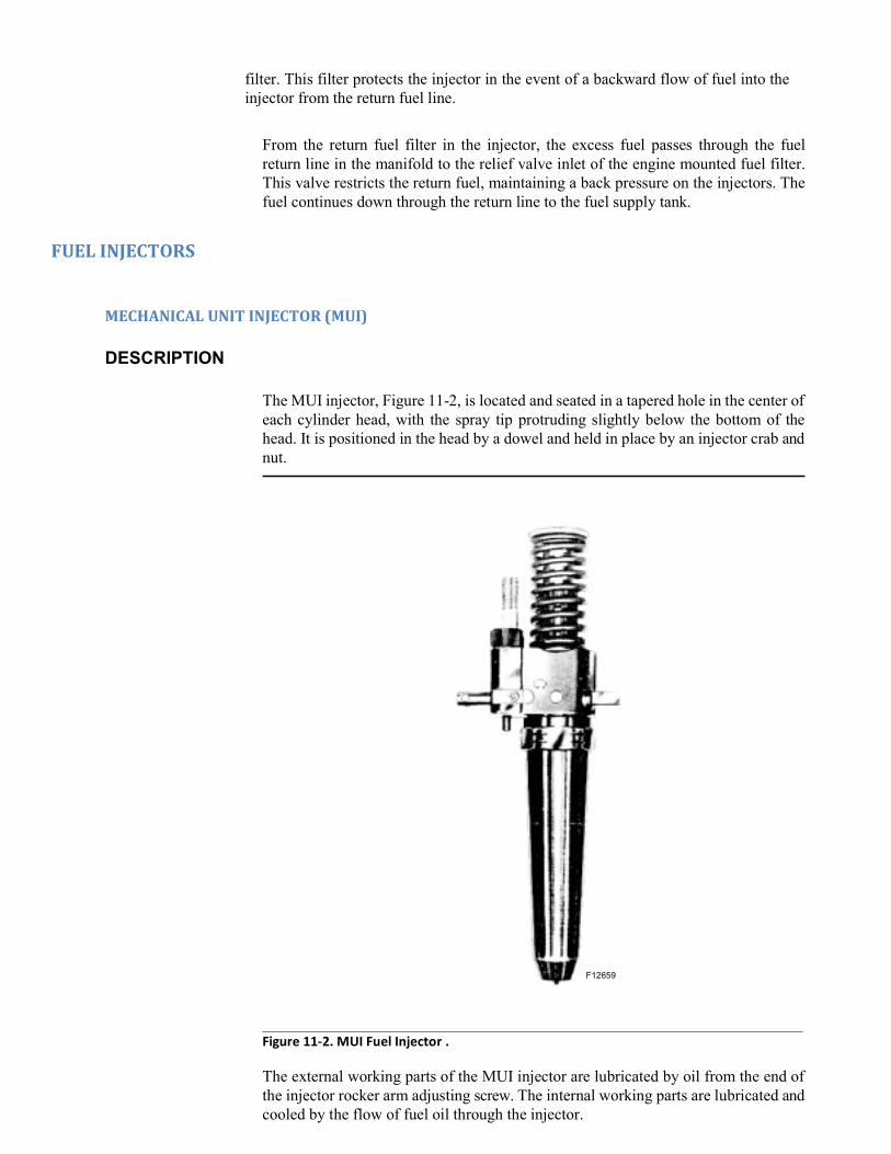
plate 12659
F12659
filter. This filter protects the injector in the event of a backward flow of fuel into the injector from the return fuel line.
From the return fuel filter in the injector, the excess fuel passes through the fuel return line in the manifold to the relief valve inlet of the engine mounted fuel filter. This valve restricts the return fuel, maintaining a back pressure on the injectors. The fuel continues down through the return line to the fuel supply tank.
FUEL INJECTORS
MECHANICAL UNIT INJECTOR (MUI)
DESCRIPTION
The MUI injector, Figure 11-2, is located and seated in a tapered hole in the center of each cylinder head, with the spray tip protruding slightly below the bottom of the head. It is positioned in the head by a dowel and held in place by an injector crab and nut.
Figure 11-2. MUI Fuel Injector .
The external working parts of the MUI injector are lubricated by oil from the end of the injector rocker arm adjusting screw. The internal working parts are lubricated and cooled by the flow of fuel oil through the injector.

plate 10173
A cross-section of the MUI injector and names of the various parts are shown in Fig- ure 11-3.
FOLLOWER SPRING
FUEL LINE
FUEL CONNECTION
FILTER CAP
GASKET
FILTER SPRING
FILTER
RACK
PLUG
LOCATING DOWEL
IDENTIFICATION GROOVES
NUT
SPILL DEFLECTOR
VALVE SPRING VALVE SPRING CAGE VALVE SPRING SEAT
FOLLOWER
STOP PIN
RETAINER
STOP PIN SPRING
BODY
GEAR
SEAL
GEAR RETAINER
GUIDE PIN
PLUNGER
BUSHING
SPACER
CHECK VALVE
CHECK VALVE CAGE
NEEDLE VALVE
SPRAY TIP
ORIFICE
F10173
Figure 11-3. MUI Fuel Injector, Cross-Section .
The plunger is given a constant stroke reciprocating motion by the injector cam act- ing through the rocker arm and plunger follower. The timing of the injection period during the plunger stroke is set by an adjusting screw at the end of the rocker arm. Figure 11-4., “MUI Injector Fuel Flow” on page 11-5 shows flow of fuel through the injector during one downward stroke. Rotation of the plunger, by means of the rack and gear, controls the quantity of fuel injected into the cylinder during each stroke. Rack position is controlled by the governor through the injector control lever and linkage. The gear is keyed to and is a sliding fit on the plunger to allow plunger ver- tical movement.

Figure 11-4. MUI Injector Fuel Flow
The helices near the bottom of the plunger control the opening and closing of both fuel ports of the plunger bushing. Rotation of the plunger regulates the time that both ports are closed during the downward stroke, thus controlling the quantity of fuel injected into the cylinder, as shown in Figure 11-5. As the plunger is rotated from idling position to full load position, the pumping part of the stroke is lengthened, injection is started earlier, and more fuel is injected.
Upper Port
NO INJECTION RACK CLEAR OUT
NO INJECTION RACK 0.88” IN
IDLE HALF LOAD FULL LOAD
QUANTITY OF FUEL INJECTED IS CONTROLLED BY ROTATING PLUNGER WITH RACK
F37622
Figure 11-5. Plunger Fuel Control
Proper atomization of the fuel is accomplished by the high pressure created during the downward stroke of the plunger, which forces fuel past the needle valve and out through the spray holes in the tip of the injector.
The MUI injectors have an adjustable calibrating slide mounted on the side of the injector body, adjacent to the rack. This slide is incorporated solely as a means of adjusting injector output on the calibrating stand.
Filters at the fuel inlet and outlet connections protect the working parts of the injec- tor.
Effective Stroke
Lower
Port
Effective
Stroke
Effective
Stroke

NOTE
The MUI injector cannot be timed if the overspeed has been tripped. It must first be
plate 14457
MAINTENANCE
MUI INJECTOR INSTALLATION
1. When installing an MUI injector in an engine, make sure it is the correct injector for the engine in which it is to be applied.
2. See that injector body and tapered hole in cylinder head are clean.
3. Install injector and apply injector crab, spherical washer, and nut. Torque nut to specified value.
4. Connect injector rack to lever assembly.
5. Install and tighten fuel supply and return lines to injector and engine fuel mani- fold.
6. Install rocker arm shaft and rocker arms. Loosen injector rocker arm locknut and back off on adjusting screw before tightening rocker arm shaft nuts. Injector is now ready for timing.
TIMING THE MUI INJECTOR
With the injector installed, make timing adjustment as follows:
NOTE
1. Bar engine over in the normal direction of rotation until flywheel pointer indi- cates the correct crankshaft position in degrees relative to top dead center of the cylinder being timed. Refer to setting instructions on Injector Timing Plate (located on right rear side of engine crankcase) and see Table 1 in Section 7 for top dead center settings.
2. Insert injector timing gauge into the hole provided for it in the injector body, Fig- ure 11-6.
Figure 11-6. Timing MUI Injector .

3. Loosen locknut and turn the rocker arm adjusting screw until the shoulder of the gauge just passes over the injector follower guide.
4. Tighten adjusting screw locknut while holding adjusting screw in position with screwdriver.
5. Recheck setting.
STICKING MUI INJECTORS
Engines may encounter sticking MUI injectors due to fuel, lube oil, or filter mainte- nance conditions. Since these conditions very often are momentary, injector removal may be minimized by utilizing alcohol to free up injectors while installed. This is done by applying ordinary commercial methanol to the injectors through a hole opposite the timing tool hole, and “popping” the injectors with an injector pressure testing tool or motoring the engine. This sticking condition usually occurs on injec- tors which are held with the plungers down when the engine is stopped. Should injector racks show signs of sticking, they should be checked for gum or varnish deposits. If present, the rack should be cleaned with alcohol and rechecked. If stick- ing persists, the injectors should be removed and replaced with operational injectors. In no case should injectors be “crutched out” or cut out and the engine operated. If injectors operating unsatisfactorily cannot be remedied or replaced, the engine should be shut down until corrective action has been taken.
SERVICING MUI INJECTORS
When servicing injectors, clean working conditions must be maintained. Dust or dirt in any form is a frequent cause of injector failure. When an injector is in an engine it is protected against dirt, dust, and other foreign materials by the various filters employed. When the injector is in storage, it is protected against harmful material by the filters sealing the body openings, which are in turn protected by shipping blocks.
However, an entirely different set of conditions is encountered when it becomes nec- essary to disassemble an injector for repair or overhaul. These conditions necessitate special shops, equipment, and trained personnel. It is recommended that non-opera- tional injectors be returned to Electro-Motive for rebuild or unit exchange.
MUI INJECTOR TESTER
In order to ensure efficient engine performance, MUI injectors should be tested whenever removed from an engine, regardless of the reason for removal. It is advis- able to test the complete engine set during each annual inspection. It is recom- mended that injectors be tested with the same oil used for protection against rust as given under “Storing Injectors.”
It is important that the individual doing the testing understands the basic principles of injector operation and testing procedures in order to prevent acceptance of defec- tive injectors and rejection of good ones. Instructions in the use of the injector tester and an outline of each separate test procedure along with a basic explanation of oper- ation follows:
These instructions cover the testing of all needle valve injectors using the tester shown in Figure 11-7., “MUI Injector Tester” on page 11-8. The procedures are not applicable to other types of testing equipment, since injector leakoff rates vary greatly in proportion to the volume of fuel contained in the high pressure portion of the tester.

plate 28226
Figure 11-7. MUI Injector Tester .
SETTING UP TESTER
Basically, the tester consists of a fuel reservoir, filter, high pressure pump, pressure gauge, manual relief valve and necessary connecting lines and fittings to supply fuel to the injector under test. The tester should be set up as instructed by the manufac- turer. Inspect carefully for dirt or foreign material in the tank and lines. Fill the tank with clean fuel and operate the pump to purge all free air from the system.
Investigation has shown that the viscosity of the fuel oil used in the tester has a marked effect on the test results obtained. Regular fuel oil may be used provided the viscosity is not less than 32 S.S.U. at 38C (100F). Do not reuse fuel oil which has been pumped through the injectors into the plastic bowl.
CHECKING AND OPERATING TESTER
Install the test block in place, or an MUI injector, in the tester and pump up pressure to 13 790 kPa (2000 psi), as indicated by the gauge. After five minutes, the pressure should not have dropped below 13 618 kPa (1975 psi). Release the block and recheck at 3 448 kPa (500 psi) and 6 895 kPa (1000 psi). These pressures should hold one minute with no apparent gauge drop. Make these tests with the manual relief valve, Figure 11-7, open all the way. If the tests are satisfactory, all injector tests may be made without using the relief valve. If the preceding tests indicate leakage, repeat the tests, closing the relief valve before timing the leakoff rates. If the tests are satis- factory with the relief valve closed, it will be necessary to use the manual relief valve when making the injector holding pressure test.

When placing a new tester in operation, or after removing and replacing the gauge, fuel tank, filter, or pump (for any reason), the test block should be installed and pres- sure raised to 17 238 kPa (2500 psi) and vented at least six more times before mak- ing an operational check.
The operator must consider the tester as an instrument, rather than a tool. Every effort should be made to make the manual operation of repeated tests the same. The following general information is provided to help in obtaining uniform operation.
GENERAL INFORMATION:
1. When operating the pump, use a rate of 40 strokes per minute. This provides a fuel rate to operate the check valve smoothly and to circulate fuel within the injector.
2. When using the popping lever, do not use such force as to damage either the injector or the lever. Do NOT permit the lever to fly up freely.
3. In making holding tests, do NOT pump the stand above 17 238 kPa (2500 psi).
4. Testers regularly in use should be checked daily for leaks, using the test blocks.
5. Fuel oil used for testing should not be reused.
MUI INJECTOR TESTS
PREPARATION:
1. Install the injector in the tester.
2. Fill the injector with fuel oil, but do not connect the fuel line from pump to injec- tor at this time.
3. Set the injector rack at maximum fuel output position (minimum rack length).
4. “Pop” the injector with the popping lever, Figure 11-7., “MUI Injector Tester” on page 11-8, using approximately 40 smooth even strokes per minute. A finely atomized spray should show at each of the holes in the tip. Rapid closing of the needle valve should produce a sharp “chatter.”
If the valve opens without producing a finely atomized spray or the valve seats without producing a sharp “chatter,” make several rapid strokes with the lever to dislodge any foreign material on the valve seat. If the needle valve still fails to function properly, a stuck needle, dirt on the valve seat, or a defective valve seat may be the cause.
HOLDING PRESSURE AND LEAK TEST:
1. All MUI injectors lose pressure due to leakage at any of several points, but this leakage must be controlled during injector manufacture to prevent engine lube oil dilution. The holding pressure test will qualify injectors having specified leak off rates, providing this leakage is at the proper point and is satisfactorily con- trolled.
2. Manually hold the tester fuel line block on the injector. Pump until fuel is dis- charged from filter cap on opposite side, to remove air. Once injector is full of fuel, clamp tester line to injector with clamping wrench, as shown in Figure 11- 7., on page 11-8. Apply 12 411 kPa (1800 psi) to 13 790 kPa (2000 psi) pressure to the injector.

No leakage is permitted at the nut to body seal, filter cap gasket, body plugs, or between spray tip and injector nut.
3. MUI injectors should be qualified on the pressure test by timing the interval for a drop in pressure from 13 790 kPa (2000 psi) to 10 342 kPa(1500 psi). If this interval is less than 20 seconds (used) or 30 seconds (new or reconditioned), repeat the test, but close the manual relief valve immediately after establishing the 13 790 kPa (2000 psi) pressure. This is to ensure that the leakdown time is not being affected by the possible leakage in the tester itself. If the timed interval for the pressure drop from 13 790 kPa (2000 psi) to 10 342 kPa (1500 psi) is still less than 20 seconds (used) or 30 seconds (new or reconditioned), the injector should be rejected. To relieve the pressure before removing the injector from the tester, wrap a cloth around the injector fuel line connections and back off on the clamping wrench, Figure 11-7., on page 11-8.
RACK FREENESS TEST:
1. The rack engages with a small pinion on the injector plunger and serves to rotate the plunger with respect to two ports in the injector bushing, which regulates the amount of fuel injected with each stroke of the plunger. Binding of the rack is generally caused by damaged gear teeth, scored plunger and bushing, or galling of rack itself. A binding rack may cause sluggish or erratic speed changes and overspeed trip action.
2. To be considered satisfactory, the rack must fall in and out through full travel by its own weight when injector is held horizontally and rotated about its axis.
BINDING PLUNGER TEST:
1. Failure of the injector plunger to move up and down freely indicates scoring of the plunger and bushing or weak or broken spring. A binding plunger will cause erratic cylinder firing and, in extreme cases, overspeed trip action.
2. Place injector in tester, but do not attach the fuel line. Place rack in the full fuel position and pump all the fuel out of the injector with injector popping lever, Figure 11-7., on page 11-8. When all of the fuel has been removed, depress the injector plunger to the full extent of its travel. Slowly release popping lever and simultaneously move injector rack repeatedly in and out through its full travel.
REPLACING MUI INJECTOR FILTERS
MUI injector filters should not be disturbed or removed except during injector recon- ditioning (when all parts are completely washed), or in the event of fuel stoppage to the injector.
STORING MUI INJECTORS
When MUI injectors are not to be used for a considerable length of time, they should be protected against rust by using a stable, non-corrosive straight-run petroleum dis- tillate in the kerosene volatility range. It is also recommended that injectors be tested using this oil. If this is done, treatment will be taken care of at time of injector test.
After treatment, the injectors should be stored in a protective container until needed. This container should accommodate an injector holding rack similar to that shown in Figure 11-8., “Injector Holding Rack” on page 11-11.

Figure 11-8. Injector Holding Rack .
MUI INJECTOR LINKAGE
DESCRIPTION
The MUI injector linkage, Figure 11-9., on page 11-12, consists of the mechanical arrangement between the governor and the injector permitting all injector rack posi- tions to be changed simultaneously when the governor terminal shaft is rotated. Two injector control rods connect the lever on the governor terminal shaft to the injector control shafts. The injector control shafts, one for each bank, extend the length of the cylinder banks under the cylinder head cover frames. At each cylinder location, a lever is pinned to the control shaft. An adjusting link connects the control shaft lever to an injector control lever mounted on the cylinder head, one end of which straddles the ball at the end of the injector rack.

Locknut
F28231
Injector Control Shaft
Injector Control Lever
Adjusting Link
Injector Control Rod
Injector Rack
Injector Control Shaft
Adjusting Nut
Figure 11-9. MUI Injector Linkage .
MAINTENANCE
Before attempting to set injector racks, all racks and linkage should be checked for binding, sticking, or wear which would affect operation.

plate 28231 & 29034NOTE
Every time a governor is installed on an engine, the injector rack setting should be
checked. Due to manufacturing tolerances in governor mounting bolt holes, the position of the governor in relation to the injector linkage can change the rack
plate 18441
SETTING MUI INJECTOR RACKS
MUI injector racks should be set with the engine at operating temperature. If racks are set when engine is not at operating temperature, the settings should be rechecked when operating temperature is reached. As engine temperature increases, the right bank rack length shortens and the left bank rack length increases. The change on the left bank is insignificant, but the change on right bank may shorten the racks beyond the minus 0.40 mm (1/64") tolerance.
NOTE
Set the injector rack on the engine as follows:
1. Install the injector linkage setting jack, Figure 11-10.
Figure 11-10. MUI Injector Rack Positioning .
2. Adjust the setting jack until the pointer on the governor aligns with governor ter- minal shaft scale at the 1.00" mark.

plate 29531
3. Use the injector rack gauge, Figure 11-11, to set the racks within the setting range marks on the gauge.
The rack setting gauge is an 8 to 1 multiplying gauge which indicates the 0.40 mm (1/64") tolerance by marks 3.18 mm (1/8") each side of the center mark on the gauge scale.
Figure 11-11.MUI Injector Rack Gauge .
It is important that the proper rack gauge be used, as previous model rack gauges will measure the rack length from the body of the injector instead of from the face of the calibrating slide. The correct gauge for setting injectors with calibrat- ing slides can be readily identified by a single locating button on the front face of the gauge. This gauge can be used for all injectors.

plate 28232
4. Place the gauge over the injector rack and hold the gauge firmly against the face of the calibrating slide on the injector, Figure 11-12, and check the gauge pointer. If the pointer is at the short (“S”) end of gauge scale, outside of the set- ting range, the rack is not extending out far enough from the injector. Loosen the locknut on the adjusting link, Figure 11-9., on page 11-12, and turn adjusting nut on link until pointer is at the long (“L”) end of the scale; then reverse pointer travel until it is within the scale setting range. Hold the adjusting nut and tighten the locknut. The reason for exceeding the setting range when making adjustment is so that, in setting all the racks, the backlash will be taken up in the same direc- tion.
Figure 11-12. MUI Injector Rack Gauge Application .

plate 29532
5. When pointer is at the long (“L”) end of scale, set pointer within the setting range. The accuracy of the injector rack gauge can be checked by inserting the master block in the gauge body, Figure 11-13. Pointer should align with center mark on the scale.
Figure 11-13. Checking MUI Injector Rack Gauge.
ELECTRONIC UNIT INJECTORS (EUI)
DESCRIPTION
The EUI injector, Figure 11-14., on page 11-17, is located and seated using an adapter collar within the tapered hole in the center of each cylinder head, with the spray tip protruding slightly below the bottom of the head. It is positioned in the head by a dowel and held in place by an injector crab and nut.
The external working parts of the EUI injector are lubricated by oil from the end of the injector rocker arm adjusting screw. The internal working parts are lubricated and cooled by the flow of fuel oil through the injector. A cross-section diagram of the EUI injector is shown in Figure 11-15., on page 11-18.

plate
Figure 11-14. Typical Electronic Unit Injector (EUI).
The functions of the EUI injector are both electrical and mechanical. The metering and timing of the fuel supply is done electrically, while the pressurizing and atomiz- ing of the fuel are done mechanically.
The metering and timing functions are controlled by the EMDEC system Electronic Control Modules (ECM) based on inputs received from the locomotive control com- puter through an interface. The primary input from the control computer is throttle position, while other inputs come from various engine sensors and feedback from the EUI itself. The ECM energizes the injector solenoid which causes a slight upward movement of the hollow poppet valve at a synchronized time and duration, based on inputs used to calculate the next injection event. Spring pressure acts to move the valve downward when the solenoid de-energizes. The movement of the poppet valve causes the fuel to flow into the injector’s fuel delivery and bypass system.
The injector plunger is given a constant stroke reciprocating motion by the injector cam acting through the rocker arm and plunger follower. The initial pressurization of approximately 13 790 kPa (2,000 psi) causes the needle valve inside the injector spray tip to lift. This lifting action allows the fuel to flow around the needle valve and through the spray tip where it is atomized into the cylinder combustion chamber at 110 320 to 124 110 kPa (16,000 to 18,000 psi). The timing (duration) of injector

plunger stroke is set by an adjusting screw at the end of the injector rocker arm.
Figure 11-15. Typical EUI Injector Cross-Section Diagram
MAINTENANCE
EUI INJECTOR INSTALLATION
1. When installing an EUI injector in an engine, make sure it is the correct injector for the engine in which it is to be applied.
2. See that injector body and tapered hole in cylinder head are clean.
3. Install injector into adapter collar in the cylinder head. Check that the locating dowel is properly seated.
4. Lubricate the threads on the injector stud and nut, then apply injector crab, spherical washer and nut. Torque nut to specified value.
5. Connect fuel supply and return jumper lines from the injector to ther fuel mani- fold. Use new “O” rings at the manifold ends and apply as follows:
A. Apply a light coat of silicon based lubricant to the new “O” rings and place one in each “O” ring land of the supply and return fittings of the fuel mani- fold. The grease will prevent binding of the “O” ring and hold it in place dur-
RECTANGULAR “O” RING FUEL TO INJECTOR FUEL RETURN TO TANK
ARMATURE
SPRING
FUEL RETURN LINE TYPICAL
NEEDLE VALVE
NOTE:
*THIS DRAWING IS NOT TO SCALE AND IS ONLY A MECHANICAL REPRESENTATION OF THE EUI.
F37624
INJECTOR
BLEED PASS
RETURN
FUEL
ENLARGED VIEWS OF HOLLOW POPPET VALVE FUELING ACTUATION
FUELING AND
CIRCULATION CYCLE
INJECTION CYCLE
SOLENOID ACTUATED
EUI CYLINDER
HEAD ADAPTER
DIRECTION OF
BACKPRESSURE FROM THE INJECTION
FILTER FUEL
FLOW
POPPET VALVE
SPOOL CHAMBER BALANCED SURFACE TO INSURE SEAL
INJECTOR SOLENOID ACTUATION OF POPPET VALVE
SPRING ACTION WITH SOLENOID
SOLENOID
“E” COIL
SP
RIN
G M
OV
EM
EN
T
CAUTION
Mismatching the fuel jumper lines will result in injector failure. Clearance
between jumper lines and all operating mechanisms must be maintained at a minimum of 3.2 mm (1/8”). If any clearance is found to be less, jumper
NOTE
Carefully observe CAUTION note above regarding clearance between fuel
jumper lines and operating mechanisms when applying rocker arm shaft
NOTE
If injector rocker arm was assembled for use with Mechanical Unit Injector
(MUI), adjusting screw will have an injector button attached with a spring clip. Before application with Electronic Unit Injector (EUI), remove and dis-
ing jumper line installation.
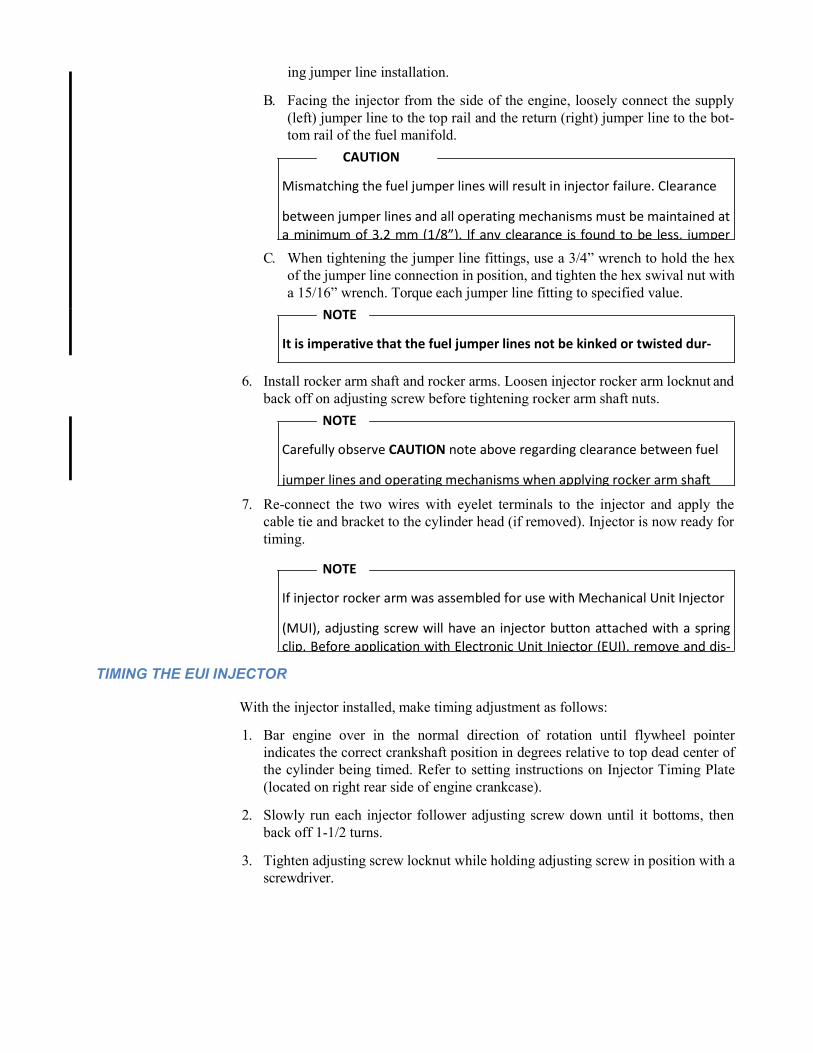
B. Facing the injector from the side of the engine, loosely connect the supply (left) jumper line to the top rail and the return (right) jumper line to the bot- tom rail of the fuel manifold.
C. When tightening the jumper line fittings, use a 3/4” wrench to hold the hex of the jumper line connection in position, and tighten the hex swival nut with a 15/16” wrench. Torque each jumper line fitting to specified value.
6. Install rocker arm shaft and rocker arms. Loosen injector rocker arm locknut and back off on adjusting screw before tightening rocker arm shaft nuts.
7. Re-connect the two wires with eyelet terminals to the injector and apply the cable tie and bracket to the cylinder head (if removed). Injector is now ready for timing.
TIMING THE EUI INJECTOR
With the injector installed, make timing adjustment as follows:
1. Bar engine over in the normal direction of rotation until flywheel pointer indicates the correct crankshaft position in degrees relative to top dead center of the cylinder being timed. Refer to setting instructions on Injector Timing Plate (located on right rear side of engine crankcase).
2. Slowly run each injector follower adjusting screw down until it bottoms, then back off 1-1/2 turns.
3. Tighten adjusting screw locknut while holding adjusting screw in position with a screwdriver.
NOTE
It is imperative that the fuel jumper lines not be kinked or twisted dur-

STICKING EUI INJECTORS
Engines may encounter sticking EUI injectors due to fuel, lube oil, or filter mainte- nance conditions. Since these conditions very often are momentary, injector removal should not be required. This sticking condition usually occurs on injectors which are held with the plungers down while the engine is stopped. If sticking persists, the injectors should be removed and replaced with operational injectors. In no case should injectors be “crutched out” or cut out and the engine operated. If injectors operating unsatisfactorily cannot be remedied or replaced, the engine should be shut down until corrective action has been taken.
SERVICING EUI INJECTORS
When servicing injectors, clean working conditions must be maintained. Dust or dirt in any form is a frequent cause of injector failure. When an injector is in an engine it is protected against dirt, dust, and other foreign materials by the various filters employed. When the injector is in storage, it is protected against harmful material by the filters and caps sealing the body openings, which are in turn protected by ship- ping blocks.
However, an entirely different set of conditions is encountered when it becomes nec- essary to disassemble an injector for repair or overhaul. These conditions necessitate special shops, equipment, and trained personnel. It is recommended that non-opera- tional injectors be returned to Electro-Motive for rebuild or unit exchange.
REPLACING EUI INJECTOR FILTERS
EUI injector filters should not be disturbed or removed except during injector recon- ditioning (when all parts are completely washed), or in the event of fuel stoppage to the injector.
STORING EUI INJECTORS
When EUI injectors are not to be used for a considerable length of time, they should be protected against rust by using a stable, non-corrosive straight-run petroleum dis- tillate in the kerosene volatility range.
Injectors should be stored in a protective container until needed. This container should accommodate an injector holding rack similar to that shown for Mechanical Unit Injectors (MUI) in Figure 11-8., on page 11-11.
EMDEC FUEL SYSTEM
DESCRIPTION
The fuel delivery system used on EMDEC equipped engines is essentially the same as that used on governor equipped engines up to the engine mounted (secondary) fuel filters. Beyond this point the commonality ends, as shown in schematic dia- grams in Figure 11-16, page 11-21 and Figure 11-17, page 11-22.

Figure 11-16. EMDEC Fuel Flow Schematic Diagram (Early Model 8, 12, and 16-Cylinder Engines)
TOP FUEL LINE TO FEED EUI’s FUEL MANIFOLD (RIGHT BANK)
FUEL MANIFOLD BLOCK AT CL
OF ENGINE,
BELOW CAMSHAFT COLD PLATE SENDING (MASTER) ECM LEFT BANK
25 100
NOTE:
*ALL FLEXIBLE HOSE CONNECTIONS ARE FLARED FITTINGS.
*ALL COMPONENTS ARE SHOWN TO DEPICT AN APPROXIMATE LOCATION
FUEL SUPPLY FROM:
* 13 PRIMARY FUEL FILTER(S) * FUEL PUMP F37625
BLUE STEEL REINFORCED
FLEXIBLE FUEL LINES TYPICAL AS SHOWN
100 PSI FUEL RETURN
TO TANK
FUEL SUPPLY FROM
ECM SIDE
OF COOLING
25 PSI FUEL RETURN
EXISTING HARD PIPED
CONNECTION (MUI/EUI)
35 PSI FUEL SYSTEM
BOTTOM
MANIFOLD INJECTOR RETURN LINE
ECM SIDE
OF COOLING
COLD PLATE FOR
RECEIVING ECM RIGHT BANK
TOP FUEL LINE
TO FEED EUI’s FUEL MANIFOLD

Figure 11-17.EMDEC Fuel Flow Schematic Diagram (All Current Model Engines w/ EUI Injectors))
The engine mounted filter assembly incorporates a number of different features for the EMDEC system, all of which are discussed later in this section under “FUEL FILTER ASSEMBLY”.
Fuel exiting the filter assembly manifold runs through a network of steel and/ or rein- forced flexible hose fuel lines which connect the fuel distribution block of the assem- bly manifold to the left bank and right bank engine fuel manifolds. Return fuel is routed by the network back through the distribution block to the ECM “cooling plate(s)” at either the sides or front of the engine, and through the fuel return section of the filter assembly manifold. A second fuel return line from the distribution block, with a 241 kPa (35 psi) pressure relief valve, may be used on some applications to relieve excess pressure during engine idle conditions.
MAINTENANCE
When any steel fuel lines or flexible hoses need to be removed or replaced, the fol- lowing guidelines should be observed:
• All fitting connections must be cleaned prior to removal. This is to help pre- vent contaminents and debris from entering the exposed internal fuel pas- sages during removal and reassembly.

CAUTION
Do NOT kink, twist or crush flexible fuel hoses. If a hose gets damaged, it
must be replaced before completing the installation. Always use two (2) wrenches to tighten fuel hose connections; one to tighten the nut, and one
All replacement fuel lines, fittings and components must be checked to be certain they are free of internal debris or other contaminents prior to installa- tion. Failure to do so may result in damage to the fuel injectors.
• Depending on working conditions, it may be advantageous to pre-assemble the fuel distriution lines on the filter assembly manifold with its respective internal pressure relief (check) valves.
IMPORTANT: Make certain that the check valves are installed in the proper “free-flow” orientation as shown on the original system application drawing.
• All components must be reassembled following the arrangement shown on the original system application drawing. Do NOT substitute components or their locations. Follow proper shop practices when installing steel fuel lines or flexible hoses.
• Use of supplementary sealing compounds on any fittings or on special edge- molded gaskets used on fuel manifold applications is NOT recommended.
• The fitting adaptors used on fuel hose assemblies are supplied pre-assembled with “O” rings made from a fuel resistant elastomer. If an “O” ring becomes damaged or defective, it must be replaced by a new one. See listing of “O” rings typically used on fuel line connections in the Service Data.
• All fitting threads and seats are to be lubricated with a light coating of clean engine oil prior to final assembly. Excess oil must NOT be allowed to con- taminate the internal fuel passages. Wet all “O” rings with fuel oil to prevent tearing.
• There are two recommended methods for tightening fuel fittings (non-flare type) and adaptors; the Torquing and the F.F.F.T. (Flats From Finger Tight) Methods. The torquing method must be done using a properly calibrated torquing device. The torque specification for all non-flare type fittings and adaptors is 81 3 Nm (60 2 ft-lbs). The F.F.F.T. specification for all fit- tings and adaptors is 1-1/2 to 2 flats, which may be done as follows:
1. Hand-tighten the joint so that it is snug (no more than 3.4 Nm (30 in- lbs) of torque.
2. Make a longitudinal mark on one of the flats of the hex (fitting to be turned to tighten) and continue it in a line onto the body hex (fitting being tightened on).
CAUTION
Do NOT substitute conventional paper gaskets for special edge-molded
(“metal”) gaskets. Conventional paper gaskets are prone to compression set which can lead to flange bolt torque loss and subsequent fuel leaks. As always, avoid surface damage to the flanges on which the edge-molded

WARNING
UNDER NO CIRCUMSTANCES ARE FLEXIBLE FUEL HOSES TO BE
USED AS “GRAB HANDLES” OR “STEPS” TO CLIMB ONTO THE ENGINE. FLEXIBLE FUEL HOSES ARE NOT DESIGNED TO BEAR ANY LOAD. IF THE HOSES ARE DAMAGED IN ANY WAY DURING SERVICE, THEY MUST BE REPLACED IMMEDIATELY - OTHERWISE SAFETY HAZARDS CAN RESULT.
NOTE
On elbow assembly fittings #40046718 and 40046719, both the lock-nut and
backing washer must be fully backed-off in the counterclockwise (CCW) direction prior to installation. These fittings are to be threaded into their
3. Tighten the joint further with a wrench according to the specified num- ber of hex Flats From Finger Tight (1-1/2 to 2 F.F.F.T.).
4. Make a “displacement” mark on the body hex (fitting being tightened on) in a line with the mark on the hex (fitting turned to tighten) to pro- vide a visual indication that the joint has been tightened.
• When the installation of all components is completed, prime the fuel system as recommended in the Operator or Service Manual. Check for leaks at all connections and from flexible fuel hoses. Perform an established fuel system leak-down test. If any leaks are found, determine the cause and repair them in a permanent manner.
The following warning must be heeded at all times in conjunction with Flexible Fuel Hose applications:
WARNING
FUEL FILTER ASSEMBLY
DESCRIPTION (Current Model Engines W/ EUI Injectors)
The engine mounted (secondary) fuel filter assembly on current model 8, 12, and 16- cylinder engines with EUI injectors, Figure 11-18., on page 11-25, mounts in the conventional position at the right front of the engine. A similar filter assembly used on 20-cylinder engines with EUI injectors, Figure 11-19., on page 11-26, functions in the same manner as the assembly used on 8, 12, and 16-cylinder engines, however, it is located at the front of the engine, immediately below the center of the counter- weight housing. The flow diagram, Figure 11-17., on page 11-22, indicates fuel flow through this type of filter assembly.
CAUTION
Do NOT attempt any temporary fixes to the fuel system connections

Fuel returning from the injectors passes through the “return fuel” section of the filter assembly manifold (block). A relief valve at the inlet establishes a fuel back pressure at the injectors for improved operation. The “return fuel” relief valve is rated at 276 kPa (40 psi).
As the elements of the filter assembly become dirty, the fuel pressure will increase. When fuel pressure in the filter assembly manifold reaches the cracking pressure of the “by-pass” relief valve, the valve will open allowing fuel to return to the fuel tank, starving the engine. The “by-pass” relief valve is rated at 827 kPa (120 psi) .
Figure 11-18.Typical Fuel Filter Assembly (8, 12, and 16-Cyl. Engines w/ EUI Injectors)
.

Figure 11-19.Typical Fuel Filter Assembly (20-Cyl. Engines w/ EUI Injectors)
DESCRIPTION (Early Model 8, 12, and 16-Cylinder Engines W/ EUI Injectors)
The engine mounted (secondary) fuel filter assembly on ealy model 8, 12, and 16- cyliner engines w/ EUI injectors, Figure 11-20., on page 11-27, is located at the right front of the engine. Two sight glasses are provided on top of the filter housing to provide a visual indication of the condition of the fuel system. The flow diagram, Figure 11-21., on page 11-27, indicates fuel flow through this type filter assembly.
Fuel returning from the injectors passes through the “return fuel” sight glass (nearest the engine) and returns to the fuel tank. Under normal operation, this glass is full of fuel. A relief valve at the inlet to the “return fuel” sight glass establishes a fuel back pressure at the injectors for improved operation. The valve is rated at 35 kPa (5 psi) for engines equipped with MUI injectors, and at 172 kPa (25 psi) for engines with EUI injectors.

Figure 11-20. Typical Fuel Filter Assembly (Early Model 8, 12, and 16-Cylinder Engines w/ EUI Injectors) .
igure 11-21. Fuel Flow Through Filter Assembly (Early Model 8, 12, and 16-Cylinder Engines w/ EUI Injectors).
NOTICE
The following paragraph concerning air bubbles in the “return fuel”
sight glass is still valid for governor controlled engines equipped with MUI injectors. EMDEC controlled engines with EUI injectors operate with a greater fuel supply pressure and will inherently display a certain amount of fuel turbulance in the “return fuel” sight glass during fuel prime and normal operation. Operators are advised to IGNORE BUB- BLES IN THE RETURN FUEL SIGHT GLASS on engines equipped with EUI

CAUTION
The filter elements used on EUI injector equipped engines are larger
and of a different composition than those used on MUI injector engines.
Air or gas in the fuel system will appear in the “return fuel” sight glass as bubbles. Air entering the fuel at any place in the suction line may cause the engine to misfire or stop. Bubbles in the “return fuel” sight glass with the fuel pump running and the engine stopped, indicates air entering the suction side of the pump. If bubbles appear only when the engine is running, it indicates leaky valves in the fuel injectors, allow- ing combustion gases to get into the fuel. Little or no fuel in the “return fuel” sight glass, with the “bypass” sight glass empty, indicates insufficient fuel supply to the engine.
During normal operation, the “bypass” sight glass (farthest from the engine) should be empty of fuel. As the elements of the filter become dirty, the fuel pressure in the filter will increase. When fuel pressure in the element housing reaches the cracking pressure of the relief valve under the glass, the valve will open, fuel will enter and fill the “bypass” sight glass, and then return to the fuel tank, starving the engine. The relief valve is rated at 414 kPa (60 psi) for engines equipped with MUI injectors, and at 690 kPa (100 psi) for engines with EUI injectors (except 20-cylinder).
The disposable filter elements are mounted directly to the filter body. The element consists of pleated paper around a perforated metal tube. The case is an enameled steel shell capable of withstanding internal pressures in excess of 1 034 kPa (150 psi). A neoprene gasket attached to the top of each element ensures sealing
.
On all EMDEC equipped engines, the two pipe plugs installed in pressure tap pas- sages in the filter assembly manifold (block) used with MUI injector engines are replaced by fuel system diagnostic sensors:
• The Fuel Pressure Sensor (FPS), located in the upper tap, uses a pressure trans- ducer to sense the fuel pressure at a point immediately before the “bypass” relief valve and the filter elements. The EMDEC master Electronic Control Module (ECM) uses the input signal from the FPS to monitor the fuel supply pressure for advance warning of an impending power loss.
• The Fuel Temperature Sensor (FTS), located in the lower tap, uses a thermal sen- sor to measure fuel supply temperatures at a point immediately after the filter elements. The EMDEC master ECM uses the input signal from the FTS to calcu- late fuel consumption and make fuel input metering compensations.
MAINTENANCE
The filter elements should be removed and new ones installed at interval(s) specified in the applicable Scheduled Maintenance Program.
At the time of element replacement, the filter body (and sight glasses, if applied) should be cleaned.
1. Shut down the engine and the engine fuel supply.
2. Unscrew the elements, using a strap wrench if necessary, and discard them.
3. Apply a film of oil to the gasket of a new element and apply element to filter assembly manifold (block).

4. Hand tighten until the gasket contacts the manifold, then tighten 1/2 turn.
5. Check the condition of the sight glasses (if applied), and clean if necessary.
6. Check for leaks when the engine is started.
Refer to Troubleshooting Section 15 for detailed information to check EMDEC sys- tem operation (including FPS and FTS sensors, wiring harness, and ECM modules).
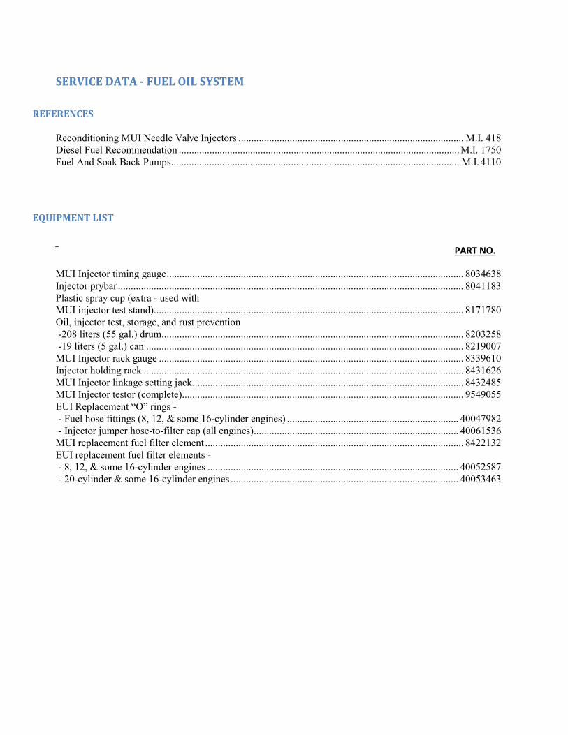
SERVICE DATA - FUEL OIL SYSTEM
REFERENCES
Reconditioning MUI Needle Valve Injectors ........................................................................................ M.I. 418 Diesel Fuel Recommendation .............................................................................................................. M.I. 1750 Fuel And Soak Back Pumps................................................................................................................. M.I. 4110
EQUIPMENT LIST
PART NO.
MUI Injector timing gauge .................................................................................................................... 8034638 Injector prybar ....................................................................................................................................... 8041183 Plastic spray cup (extra - used with MUI injector test stand) ......................................................................................................................... 8171780 Oil, injector test, storage, and rust prevention -208 liters (55 gal.) drum ...................................................................................................................... 8203258 -19 liters (5 gal.) can ............................................................................................................................ 8219007
MUI Injector rack gauge ....................................................................................................................... 8339610 Injector holding rack ............................................................................................................................. 8431626 MUI Injector linkage setting jack .......................................................................................................... 8432485 MUI Injector testor (complete) .............................................................................................................. 9549055 EUI Replacement “O” rings - - Fuel hose fittings (8, 12, & some 16-cylinder engines) ................................................................... 40047982 - Injector jumper hose-to-filter cap (all engines) ................................................................................ 40061536 MUI replacement fuel filter element ..................................................................................................... 8422132 EUI replacement fuel filter elements - - 8, 12, & some 16-cylinder engines .................................................................................................. 40052587 - 20-cylinder & some 16-cylinder engines ......................................................................................... 40053463