Dual fuel kerosene and gas oil/gas burner - Riello Burners
60
20036861 (6) - 09/2012 Installation, use and maintenance instructions Dual fuel kerosene and gas oil/gas burner Progressive two stage or modulating operation CODE MODEL TYPE 20034252 RLS 800/M MX 1301 T GB
-
Upload
khangminh22 -
Category
Documents
-
view
5 -
download
0
Transcript of Dual fuel kerosene and gas oil/gas burner - Riello Burners

Installation, use and maintenance instructions
Dual fuel kerosene and gas oil/gas burner
Progressive two stage or modulating operation
CODE MODEL TYPE
20034252 RLS 800/M MX 1301 T
GB
20036861 (6) - 09/2012


Contents
1 Declarations................................................................................................................................................................................ 3
2 Information and general instructions....................................................................................................................................... 42.1 Information about the instruction manual .................................................................................................................... 4
2.1.1 Introduction.................................................................................................................................................................. 42.1.2 General dangers.......................................................................................................................................................... 42.1.3 Danger: live components............................................................................................................................................. 4
2.2 Guarantee and responsibility....................................................................................................................................... 5
2.3 Guidance for the use of bio fuel blends up to 10%...................................................................................................... 52.3.1 Information and general instructions ........................................................................................................................... 62.3.2 Product Disclaimer Statement..................................................................................................................................... 6
3 Safety and prevention................................................................................................................................................................ 73.1 Introduction.................................................................................................................................................................. 7
3.2 Safety warnings........................................................................................................................................................... 7
3.3 Basic safety rules ........................................................................................................................................................ 7
3.4 Personnel training ....................................................................................................................................................... 7
4 Technical description of the burner ......................................................................................................................................... 84.1 Burner designation ...................................................................................................................................................... 8
4.2 Models available.......................................................................................................................................................... 8
4.3 Burner categories - Countries of destination ............................................................................................................... 8
4.4 Technical data ............................................................................................................................................................. 9
4.5 Electrical data............................................................................................................................................................ 10
4.6 Burner weight ............................................................................................................................................................ 10
4.7 Overall dimensions.................................................................................................................................................... 11
4.8 Firing rate .................................................................................................................................................................. 124.8.1 Modulation ratio......................................................................................................................................................... 124.8.2 Test boiler.................................................................................................................................................................. 12
4.9 Burner description ..................................................................................................................................................... 13
4.10 Description of panel board ........................................................................................................................................ 14
4.11 Burner equipment...................................................................................................................................................... 14
5 Installation ................................................................................................................................................................................ 155.1 Notes on safety for the installation ............................................................................................................................ 15
5.2 Handling .................................................................................................................................................................... 15
5.3 Preliminary checks .................................................................................................................................................... 15
5.4 Installer/Servicer notes for the use of Gas oil with Bio blends up to 10% ................................................................. 16
5.5 Operation position ..................................................................................................................................................... 16
5.6 Removal of the locking screws from the shutter........................................................................................................ 16
5.7 Boiler plate ................................................................................................................................................................ 16
5.8 Blast tube length........................................................................................................................................................ 17
5.9 Securing the burner to the boiler ............................................................................................................................... 17
5.10 Accessibility to the interior of the combustion head .................................................................................................. 17
5.11 Nozzle ....................................................................................................................................................................... 185.11.1 Recommended nozzle............................................................................................................................................... 185.11.2 Nozzle assembly ....................................................................................................................................................... 18
5.12 Position of electrodes ................................................................................................................................................ 19
5.13 Combustion head setting........................................................................................................................................... 19
5.14 Gas oil supply............................................................................................................................................................ 205.14.1 Double-pipe circuit..................................................................................................................................................... 205.14.2 The loop circuit .......................................................................................................................................................... 205.14.3 Single-pipe circuit ...................................................................................................................................................... 21
5.15 Hydraulic system layout ............................................................................................................................................ 21
5.16 Hydraulic connections ............................................................................................................................................... 21
5.17 Pump ......................................................................................................................................................................... 22
1 20036861GB

Contents
5.17.1 Technical data............................................................................................................................................................225.17.2 Pump priming.............................................................................................................................................................22
5.18 Pressure regulator .....................................................................................................................................................23
5.19 Gas supply .................................................................................................................................................................245.19.1 Gas train ....................................................................................................................................................................245.19.2 Gas line......................................................................................................................................................................245.19.3 Gas pressure .............................................................................................................................................................255.19.4 Gas train - pilot connection ........................................................................................................................................265.19.5 Ignition pilot ................................................................................................................................................................26
5.20 Electrical wiring ..........................................................................................................................................................275.20.1 Notes on safety for the electrical wiring .....................................................................................................................275.20.2 Entry for power cables and external leads.................................................................................................................27
5.21 Calibration of the thermal relay ..................................................................................................................................27
6 Start-up, calibration and operation of the burner ..................................................................................................................286.1 Notes on safety for the first start-up...........................................................................................................................28
6.2 Burner firing ...............................................................................................................................................................28
6.3 Adjustment before first firing (gas oil opration) ..........................................................................................................28
6.4 Fuel change ...............................................................................................................................................................28
6.5 Adjustments before first firing (gas opration) .............................................................................................................29
6.6 Burner starting ...........................................................................................................................................................29
6.7 Burner firing ...............................................................................................................................................................29
6.8 Servomotor ................................................................................................................................................................29
6.9 Fuel/combustion air adjustment .................................................................................................................................306.9.1 Maximum output ........................................................................................................................................................306.9.2 Minimum output .........................................................................................................................................................306.9.3 Intermediate outputs ..................................................................................................................................................30
6.10 Air/fuel ratio adjustment .............................................................................................................................................316.10.1 Procedures for setting the burner ..............................................................................................................................31
6.11 Adjustment pressure switches ...................................................................................................................................326.11.1 Air pressure switch - CO check..................................................................................................................................326.11.2 Max. gas pressure switch ..........................................................................................................................................326.11.3 Min. gas pressure switch ...........................................................................................................................................32
6.12 Operation sequence of the burner .............................................................................................................................336.12.1 Burner starting ...........................................................................................................................................................336.12.2 Steady state operation ...............................................................................................................................................336.12.3 Undesired shutdown during operation .......................................................................................................................336.12.4 Firing failure ...............................................................................................................................................................33
6.13 Final checks (with the burner working) ......................................................................................................................34
7 Maintenance ..............................................................................................................................................................................357.1 Notes on safety for the maintenance .........................................................................................................................35
7.2 Maintenance programme ...........................................................................................................................................357.2.1 Maintenance frequency..............................................................................................................................................357.2.2 Checking and cleaning...............................................................................................................................................35
7.3 Opening the burner ....................................................................................................................................................37
7.4 Closing the burner......................................................................................................................................................37
8 Faults - Possible causes - Solutions.......................................................................................................................................38
A Appendix - Accessories ...........................................................................................................................................................42
B Appendix - Electrical panel layout...........................................................................................................................................43
20036861 2 GB

Declarations
1 Declarations
Declaration of conformity in accordance with ISO / IEC 17050-1
Manufacturer: RIELLO S.p.A.
Address: Via Pilade Riello, 737045 Legnago (VR)
Product: Dual fuel kerosene and gas oil/ gas burner
Model: RLS 800/M MX
These products are in compliance with the following Technical Standards:
EN 676
EN 267
EN 12100
and according to the European Directives:
GAD 2009/142/EC Gas Devices Directive
MD 2006/42/EC Machine Directive
LVD 2006/95/EC Low Voltage Directive
EMC 2004/108/EC Electromagnetic Compatibility
Such products are marked as follows:
The quality is guaranteed by a quality and management system certified in accordance with UNI EN ISO 9001.
Manufacturer's Declaration
RIELLO S.p.A. declares that the following products comply with the NOx emission limits specified by German standard “1. BImSchV release 26.01.2010”.
Product Type Model Power
Dual fuel kerosene and gas oil/ gas burner 1301 T RLS 800/M MX 1750 - 8000 kW
Legnago, 04.09.2012
Burners Division DepartmentRIELLO S.p.A.
Eng. I. Zinna Eng. R. Cattaneo
CE-0085CL0422
3 20036861GB

Information and general instructions
2.1 Information about the instruction manual
2.1.1 IntroductionThe instruction manual supplied with the burner:
is an integral and essential part of the product and must notbe separated from it; it must therefore be kept carefully forany necessary consultation and must accompany the burnereven if it is transferred to another owner or user, or toanother system. If the manual is lost or damaged, anothercopy must be requested from the Technical AssistanceService of the area;is designed for use by qualified personnel;offers important indications and instructions relating to theinstallation safety, start-up, use and maintenance of theburner.
Symbols used in the manualIn some parts of the manual you will see triangular DANGERsigns. Pay great attention to these, as they indicate a situation ofpotential danger.
2.1.2 General dangersThe dangers can be of 3 levels, as indicated below.
2.1.3 Danger: live components
Other symbols
Abbreviations usedCh. ChapterFig. FigurePage PageSec. SectionTab. Table
Delivery of the system and the instruction manualWhen the system is delivered, it is important that:
the instruction manual is delivered to the user by the systemmanufacturer, with the recommendation to keep it in theroom where the heat generator is to be installed.The instruction manual shows:– the serial number of the burner;
– the address and telephone number of the nearest Assist-ance Centre.
The system supplier must carefully inform the user about:– the use of the system; – any further tests that may be required before activating the
system; – maintenance, and the need to have the system checked at
least once a year by a representative of the manufactureror another specialised technician.To ensure a periodic check, the manufacturer recom-mends the drawing up of a Maintenance Contract.
2 Information and general instructions
DANGER
Maximum danger level!This symbol indicates operations which, if not car-ried out correctly, cause serious injury, death orlong-term health risks.
WARNING
This symbol indicates operations which, if not car-ried out correctly, may cause serious injury, deathor long-term health risks.
CAUTION
This symbol indicates operations which, if not car-ried out correctly, may cause damage to the ma-chine and/or injury to people.
DANGER
This symbol indicates operations which, if not car-ried out correctly, lead to electric shocks with le-thal consequences.
ENVIRONMENTAL PROTECTIONThis symbol gives indications for the use of themachine with respect for the environment.
This symbol indicates a list.
.........................................................................................
.........................................................................................
.........................................................................................
.........................................................................................
20036861 4 GB

Information and general instructions
2.2 Guarantee and responsibility
The manufacturer guarantees its new products from the installa-tion date, in accordance with the regulations in force and/or thesales contract. At the moment of the first start-up, check that theburner is integral and complete.
In particular, the rights to the guarantee and the responsibility willno longer be valid, in the event of damage to things or injury topeople, if such damage/injury was due to any of the followingcauses:
incorrect installation, start-up, use and maintenance of theburner;improper, incorrect or unreasonable use of the burner;intervention of unqualified personnel;carrying out of unauthorised modifications on the equipment;use of the burner with safety devices that are faulty, incor-rectly applied and/or not working;installation of untested supplementary components on theburner;powering of the burner with unsuitable fuels;faults in the fuel supply system;continuation of use of the burner when a fault has occuredrepairs and/or overhauls incorrectly carried out;modification of the combustion chamber with inserts thatprevent the regular development of the structurally estab-lished flame;insufficient and inappropriate surveillance and care of thoseburner components most likely to be subject to wear andtear;the use of non-original components, including spare parts,kits, accessories and optional;force majeure.
The manufacturer furthermore declines any and every re-sponsibility for the failure to observe the contents of thismanual.Riello warranty is subject to correct burner, appliance and appli-cation matching, and set up in line with Riello's instructions andguidelines. All components within the hydraulic circuit suitable forbio fuel use and supplied by Riello will be identified as Bio com-patible. No warranty is given in relation to the use of componentswhich are not so identified with bio fuel blends. If in any doubtplease contact Riello for further advice.
If any Riello burners are used with fuel with a bio content >10%then the components within the hydraulic circuit maybe affectedand are not covered under warranty. The hydraulic circuit con-sists of;
– Pump– Hydraulic ram (where applicable)– Valve block– Flexible oil lines (considered as a consumable component)
1. Irrespective of any warranty given by Riello in relation tonormal use and manufacturing defects, when fuels notmeeting the relevant standards are used, or where fuel stor-age issues have not been addressed correctly, or the equip-ment used is not compatible, if failures occur which aredirectly or indirectly attributed to such issues and/or to thenon-observance of this guidance, then no warranty or liabil-ity is implied or accepted by Riello.
2. Riello have carefully chosen the specification of the biocompatible components including the flexible oil lines toprotect the pump, safety value and nozzle. The Riello war-ranty is dependent upon the use of Riello genuine compo-nents including the oil lines, being used.
3. Riello warranty does not cover defects arising from incorrectcommissioning or servicing by non Riello employed serviceengineers, and any issues impacting the burner arising fromexternal site related issues.
2.3 Guidance for the use of bio fuel blends up to 10%
BackgroundWith increasing focus on renewable and sustainable energy re-quirements, Bio fuel usage is set to increase. Riello is committedto promoting energy conservation and the use of renewable en-ergy from sustainable resources including liquid bio fuels, howev-er there are some technical aspects that must be considered atthe planning stage of using such fuels to reduce the potential forequipment failure or the risks of fuel leakage.
Liquid Bio fuel is a generic description used for oil that can comefrom numerous feed stocks including recycled cooking oils.These types of oils have to be considered and treated differentlyfrom standard mineral or fossil fuels, as they are generally moreacidic, hydroscopic and less stable.
Due to this, a holistic approach is needed from the specificationof the liquid Bio fuel, the storage of the fuel, its oil supply line andancillary equipment, and very importantly the oil filtration and theburner itself. The specification for FAME (Fatty Acids Methyl Es-ter) liquid Bio fuel is critical to reliable equipment operation.
It is a minimum requirement that the fuel blend (up to 10% Bio) isobtained with gasoil in accordance with the relevant EN stand-ards, regional regulations and FAME in accordance with EN14214. It is also important that the fuel blends meet the require-
ments related to operational environment conditions within therelevant EN standards.
When choosing your Riello oil products where you know Bio fuelswill be in use, please make sure that a Bio compatible burner and/or components have been supplied. If an existing burner is to beused with a liquid Bio fuel then a kit may be required to make itcompatible and the guidance notes enclosed concerning oil stor-age and filtration must be adhered to. The end user is responsiblefor the thorough verification of the potential risks associated withthe introduction of a bio fuel blend and the suitability of the appli-ances and installation applicable.
Irrespective of any warranty given by Riello in relation to normaluse and manufacturing defects, when fuels not meeting the rele-vant standards are used, or where fuel storage issues have notbeen addressed correctly, or the equipment used is not compat-ible, if failures occur which are directly or indirectly attributed tosuch issues and/or to the non-observance of this guidance, thenno warranty or liability is implied or accepted by Riello.
WARNING
Failure to observe the information given in thismanual, operating negligence, incorrect installa-tion and carrying out of non authorised modifica-tions will result in the annulment by themanufacturer of the guarantee that it supplies withthe burner.
5 20036861GB

Information and general instructions
2.3.1 Information and general instructionsTo ensure consistency, the supplier of the fuel must be able todemonstrate compliance with a recognised Quality Control andmanagement system to ensure high standards are maintainedwithin the storage, blending and delivery processes. The installa-tion oil storage tank and its ancillaries must also be prepared BE-FORE liquid Bio fuel is introduced. Checks and preparationshould include;
For new installations, make sure that all materials and sealsin the oil storage and supply line to the burner are compati-ble with Bio fuels. For all installations, there must be a goodquality bio compatible oil filter at the tank and then a sec-ondary filter of 100 Microns protecting the burner from con-tamination.If an existing oil storage tank is to be used then in addition tothe materials checks as detailed above, it will be essentialthat the tank is first inspected for condition and checked forwater or other contamination. Riello strongly recommendsthat the tank is cleaned and oil filters replaced prior to Biofuel delivery. If this is not completed then due to the hydro-scopic nature of Bio fuel, it will effectively clean the tank,absorb water present which in turn will result in equipmentfailure that is not covered by the manufacturer's warranty. Depending on the capacity of the oil storage tank and oilusage, fuels may remain static within the tank for some con-siderable time and so Riello recommends that the oil distrib-utor is consulted regarding the use of additional Biocideswithin the fuel to prevent microbial growth from occurringwithin the tank. Riello suggests that fuel suppliers and orservice companies are contacted for guidance on fuel filtra-tion. Special attention should be applied to duel fuel applica-tions where oil may be stored for long periods of time. The burner must be set according to the appliance applica-tion and commissioned checking that all combustion param-eters are as recommended in the appliance technicalmanual. Riello recommends that the in line and burner oil pump filtersare inspected and if required replaced at least every 4months during burner use, before the burner start-up follow-ing a long period of discontinue operation and even morefrequently where contamination has occurred. Particularattention is needed when inspecting and checking for fuelleakages from seals, gaskets and hoses.
2.3.2 Product Disclaimer StatementCAREFULLY READ THE FOLLOWING DISCLAIMER. YOUACCEPT AND AGREE TO BE BOUND BY THIS DISCLAIMERBY PURCHASING RIELLO BIO COMPATIBLE BURNERSAND/OR COMPONENTS.Although the information and recommendations (hereinafter "In-formation") in this guidance is presented in good faith, believed tobe correct and has been carefully checked, Riello (and its subsid-iaries) makes no representations or warranties as to the com-pleteness or accuracy of the Information. Information is suppliedupon the condition that the persons receiving same will maketheir own determination as to its suitability for their purposes priorto use. In no event will Riello (and its subsidiaries) be responsiblefor damages of any nature whatsoever resulting from the use ofor reliance upon Information.
Other than set forth herein, Riello (and its subsidiaries) makes noadditional warranties with respect to the bio compatible burner,either express or implied, including that of merchantability or fit-ness for a particular purpose or use.
In no event shall Riello (and its subsidiaries) be liable for any in-direct, incidental, special or consequential damages including,without limitation, loss of profits, damages for loss of businessprofits, business interruption, loss of business information, loss ofequipment, or other pecuniary loss or compensation for serviceswhether or not it is advised of the possibility of such damages.
With the exception of injuries to persons, Riello's liability is limitedto the customer's right to return defective/non-conforming prod-ucts as provided by the relevant product warranty.
20036861 6 GB

Safety and prevention
3.1 Introduction
The burners have been designed and built in compliance withcurrent regulations and directives, applying the known technicalrules of safety and envisaging all the potential danger situations.
It is necessary, however, to bear in mind that the imprudent andclumsy use of the equipment may lead to situations of death risk forthe user or third parties, as well as the damaging of the burner or oth-er items. Inattention, thoughtlessness and excessive confidence of-ten cause accidents; the same applies to tiredness and sleepiness.
It is a good idea to remember the following:The burner must only be used as expressly described. Any otheruse should be considered improper and therefore dangerous.
In particular:
it can be applied to boilers operating with water, steam, diather-mic oil, and to other uses expressly named by the manufacturer;
the type and pressure of the fuel, the voltage and frequency of theelectrical power supply, the minimum and maximum deliveries forwhich the burner has been regulated, the pressurisation of thecombustion chamber, the dimensions of the combustion cham-ber and the room temperature must all be within the values indi-cated in the instruction manual.
Modification of the burner to alter its performance and desti-nations is not allowed.The burner must be used in exemplary technical safety con-ditions. Any disturbances that could compromise safety mustbe quickly eliminated.Opening or tampering with the burner components is notallowed, apart from the parts requiring maintenance.Only those parts detailed as available as spare parts by theManufacturer can be replaced.
3.2 Safety warnings
The dimension of the boiler’s combustion chamber must respondto specific values, in order to guarantee a combustion with thelowest polluting emissions rate.
The Technical Service Personnel will be glad to give you all theimformation for a correct matching of this burner to the boiler.
This burner must only be used for the application it was designedfor.
The manufacturer accepts no liability within or without the con-tract for any damage caused to people, animals and property dueto installation, adjustment and maintenance errors or to improperuse.
3.3 Basic safety rules
Children or inexpert persons must not use the appliance.Under no circumstances must the intake grids, dissipationgrids and ventilation vents in the installation room be cov-ered up with cloths, paper or any other material.Unauthorised persons must not attempt to repair the appli-ance.It is dangerous to pull or twist the electric leads.Cleaning operations must not be performed if the applianceis not disconnected from the main power supply.
Do not clean the burner or its parts with inflammable sub-stances (e.g. petrol, alcohol, etc.). The cover must becleaned with soapy water.Do not place anything on the burner.Do not block or reduce the size of the ventilation vents in theinstallation room.Do not leave containers and inflammable products or com-bustible materials in the installation room.
3.4 Personnel training
The user is the person, body or company that has acquired themachine and intends to use it for the specific purpose. He is re-sponsible for the machine and for the training of the people work-ing around it.
The user:undertakes to entrust the machine exclusively to suitablytrained and qualified personnel;must take all the measures necessary to prevent unauthor-ised people gaining access to the machine;undertakes to inform his personnel in a suitable way aboutthe application and observance of the safety instructions.With that aim, he undertakes to ensure that everyone knowsthe use and safety instructions for his own duties;
must inform the manufacturer if faults or malfunctioning ofthe accident prevention systems are noticed, along with anypresumed danger situation.Personnel must always use the personal protective equip-ment envisaged by legislation and follow the indicationsgiven in this manual.Personnel must observe all the danger and caution indica-tions shown on the machine.Personnel must not carry out, on their own initiative, opera-tions or interventions that are not within their province.Personnel must inform their superiors of every problem ordangerous situation that may arise.The assembly of parts of other makes, or any modifications,can alter the characteristics of the machine and hence com-promise operating safety. The manufacturer thereforedeclines any and every responsibility for any damage thatmay be caused by the use of non-original parts.
3 Safety and prevention
7 20036861GB

Technical description of the burner
4.1 Burner designation
4.2 Models available
4.3 Burner categories - Countries of destination
4 Technical description of the burner
Designation Electrical supply Starting CodeRLS 800/M MX TC 3/400/50 Star/Delta 20034252
Series : R
Size
Fuel : Natural gas
Gas oil
Gas oil / Methane
Setting :
Flame control system :FS1FS2
Standard (1 stop every 24 h)Continuos working (1 stop every 72 h)
Electrical supply to the system :3/400/503/230/50
Auxiliary voltage :230/50/60110/50/60
R LS 800 M TC
Emission : ... Class 1 EN267 - EN676MY Class 1 EN267 - Class 3 EN676
BLU Class 3 EN267 - EN676
MXClass 2 EN267Class 3 EN676
FS1 3/400/50 230/50/60BASIC DESIGNATION
EXTENDED DESIGNATION
MX
3N / 400V / 50Hz3 / 230V / 50Hz
230V / 50-60Hz110V / 50-60Hz
Heavy oil
E Electronic camEV Variable speed (with Inverter)P Air/gas proportioning valve
BP Two-stage (gas oil) / Proportioning valve (gas)
M Mechanical cam
S
L
LS
N
Head : TC Standard headTL Extended head
Country of destination Gas categorySE - FI - AT - GR - DK - ES - GB - IT - IE - PT - IS - CH - NO I2H
DE I2ELL
NL I2L
FR I2Er
BE I2E(R)B
LU - PL I2E
20036861 8 GB

Technical description of the burner
4.4 Technical data
Tab. A
(1) Reference conditions: Ambient temperature 20°C - Gas temperature 15°C - Barometric pressure 1013 mbar - Altitude 0 m a.s.l.
(2) Pressure at test point 5)(Fig. 5) with zero pressure in the combustion chamber and maximum burner output.
(3) Noise emission tests carried out as specified in EN 15036-1 with measurement accuracy σ = ± 1.5 dB, in the manufacturer’s com-bustion chamber with burner operating on test boiler at maximum output.
Model RLS 800/M MXType 1301 T
Output (1)Delivery (1)
MIN - MAXkWkg/h
1750/3500 ÷ 8000147/295 ÷ 674
FuelGas oil and Blends of gas oil and bio fuel (FAME in accordance with EN14214) up to 10%
Kerosene net calorific value
densityviscosity at 20 °C
kWh/kgMcal/kgkg/dm3
mm2/s max
11.9710.3 (10.300 kcal/kg)
0.77 - 0.836 (1.5 °E - 6 cSt)
Gas oil net calorific value
densityviscosity at 20 °C
kWh/kgMcal/kgkg/dm3
mm2/s max
11.8610.2 (10.200 kcal/kg)
0.82 - 0.856 (1.5 °E - 6 cSt)
Natural gas - G20 (methane) - G21 - G22 - G23 - G25 - GPL: G31 - PCI 26 kWh/Nm3
Gas pressure at maximum delivery (2) - Gas: G20/G25
mbar 50.6/75.4
Operation- Intermittent (min. 1 stop in 24 hours)- Progressive two-stage or modulating by kit (see accessoires)
Nozzles number 1
Standard applications Boilers: water, steam, diathermic oil
Room temperature °C 0 - 50
Combustion air temperature °C max 60
Pump delivery (at 16,5 bar)pressure rangefuel temperature
kg/hbar
°C max
5606 - 30140
Noise level (3) Sound pressureSound power
dB (A)89,6103,9
9 20036861GB

Technical description of the burner
4.5 Electrical data
Motor IE1
Motor IE2
Tab. B
4.6 Burner weight
The weight of the burner complete with its packaging is shown intable.
Electrical supply 3N ~ 400V +/-10% 50 Hz
Electric motors rpm 2940
Fan motorV
kWA
400 / 69021
39.6 - 23
Pump motorV
kWA
220 / 3801.5
6.4 / 3.7
Ignition transformerV1 - V2I1 - I2
230 V - 1 x 5 kV1 A - 20 µA
Electrical power consumption (Gas oil) kW max 26.3
Electrical power consumption (Gas) kW max 24.4
Protection level IP 54
Electrical supply 3N ~ 400V +/-10% 50 Hz
Electric motors rpm 2964
Fan motorV
kWA
400 / 69021
41.8 - 24.2
Pump motorV
kWA
220 / 3801.5
5.9 / 3.4
Ignition transformerV1 - V2I1 - I2
230 V - 1 x 5 kV1 A - 20 µA
Electrical power consumption (Gas oil) kW max 24.8
Electrical power consumption (Gas) kW max 23
Protection level IP 54
Model kgRLS 800/M MX 320
Fig. 120055028
20036861 10 GB

Technical description of the burner
4.7 Overall dimensions
The maximum dimensions of the burner are given in Fig. 2.
Bear in mind that inspection of the combustion head requires theburner to be opened by rotating the rear part on the hinge.
The overall dimensions of the burner when open are indicated byL and R.
Position I is a reference for the thickness of the boiler door re-fractory fettling.
Tab. C
mm A B C D E F G H I L R SRLS 800/M MX 1325 575 164 428 630 DN80 940 937 405 1190 1055 320
Fig. 220055033
11 20036861GB

Technical description of the burner
4.8 Firing rate
Maximum output must be selected in the hatched area of the di-agram (Fig. 3).
Minimum output must not be lower than the minimum limitshown in the diagram:RLS 800/M MX = 1750 kW
4.8.1 Modulation ratioThe modulation ratio, determined using test boilers according tostandard (EN 676 for gas, EN 267 for gas oil), is 2.4 : 1.
4.8.2 Test boilerThe burner/boiler matching does not pose any problems if theboiler is CE type-approved and its combustion chamber dimen-sions are similar to those indicated in diagram (Fig. 4).
If the burner must be combined with a boiler that has not been CEtype-approved and/or its combustion chamber dimensions areclearly smaller than those indicated in diagram (Fig. 4), consultthe manufacturer.
The firing rates were set in relation to special test boilers, accord-ing to EN 676 regulations.
Fig. 4 indicates the diameter and length of the test combustionchamber.
Example: Output 7000 kW - diameter 120 cm - length 6m.
WARNING
The firing rate area values (Fig. 3) have been ob-tained considering a surrounding temperature of20 °C, and an atmospheric pressure of 1013 mbar(approx. 0 m above sea level) and with the com-bustion head adjusted as shown on page 19.
Fig. 3
Pre
ssur
e in
com
bust
ion
cham
ber
- m
bar
Thermal output - kW
D10725
400 1200 2000 2800 3600 44000
2
4
6
8
10
12
14
16
18
20
5200 6000 6800 7600 8400
22
Class 3 EN676Class 1 EN267
Class 3 EN676Class 2 EN267
Fig. 4
Com
bust
ion
cham
ber
m
D2448
20036861 12 GB

Technical description of the burner
4.9 Burner description
1 Lifting eyebolts2 Fan3 Fan motor4 Servomotor5 Gas pressure test point6 Combustion head7 Ignition pilot8 Flame stability disk9 Electric panel board - cover10 Hinge for opening burner11 Air inlet to fan12 Manifold13 Thermal insulation screen for securing burner to boiler14 Gas train flange15 Shutter16 Lever for movement of combustion head17 Gears for movement of air damper18 Air pressure switch (differential operating type)19 Air pressure test point20 Maximum gas pressure switch with pressure test point21 UV photocell22 Air pressure test point pressure test point “+”23 Pump24 Pump motor25 Minimum oil pressure switch26 Maximum oil pressure switch
27 Pressure gauge for pressure on nozzle return28 Nozzle delivery pressure gauge29 Oil modulator30 Pressure gauge attachment31 Pilot gas train
Fig. 5
20055022
CAUTION
The burner can be opened either on the right orleft sides, irrespective of the side from which fuelis supplied.
When the burner is closed, the hinge can be re-positioned on the opposite side.
13 20036861GB

Technical description of the burner
4.10 Description of panel board
1 Terminal strip for kits2 Relay outlet - clean contacts3 Ignition transformer4 Bracket for mounting the power regulator RWF405 Stop push-button6 Dial for off - automatic - manual7 Power dial for increase - decrease of power8 Start enabled light9 Motor thermal cutout tripped warning light10 Signal light for burner failure and lock-out reset button11 Control box12 Star-powered/delta-powered starter13 Timer14 Air pressure switch15 Main supply terminal strip16 Entry for power cables and external leads17 Fuel selector and remote fuel selector enabling18 Auxiliary circuits fuse
19 Servomotor plug/socket20 Plug-socket valve /Pump motor21 Fan motor thermal cut-out22 Pump motor contactor and thermal cut-out23 Oil/gas selection relay24 Plug-socket maximum gas pressure switch25 Plug-socket flame sensor
NOTETwo types of burner failure may occur:
Control box lock-out: if the control box 11)(Fig. 6) pushbut-ton (red led) and the reset button 10)(Fig. 6) light up, it indi-cates that the burner is in lock-out.To reset, press the pushbutton 10)(Fig. 6).Motors trip: release by pressing the push button on ther-mal.
4.11 Burner equipment
Flange gasket. . . . . . . . . . . . . . . . . . . . . . . . . . . . . . . . . . . . N. 1
Flange fixing screws M 16 x 50 . . . . . . . . . . . . . . . . . . . . . . N. 8
Thermal screen . . . . . . . . . . . . . . . . . . . . . . . . . . . . . . . . . . N. 1
Screws to secure the burner flange to the boiler:M 18 x 70 . . . . . . . . . . . . . . . . . . . . . . . . . . . . . . . . . . . . . . . N. 4
Spacers (see Fig. 16). . . . . . . . . . . . . . . . . . . . . . . . . . . . . . N. 2
Instruction. . . . . . . . . . . . . . . . . . . . . . . . . . . . . . . . . . . . . . . N. 1
Spare parts. . . . . . . . . . . . . . . . . . . . . . . . . . . . . . . . . . . . . No. 1
1
2 3
4
56
717
8 9 10 11
151612
21
132318161920
22
242514
1213
14
1516
16 1819
20
21
22
23
2425
D9144Fig. 6
WARNING
In case of use with gas oil containing up to 10%Bio blend, it will be essential to use flexible oillines suitable for bio fuel use. Please contact Riello for further information.
20036861 14 GB

Installation
5.1 Notes on safety for the installation
After carefully cleaning all around the area where the burner willbe installed, and arranging the correct lighting of the environ-ment, proceed with the installation operations.
5.2 Handling
The packaging of the burner includes a wooden platform, so it ispossible to move the burner (still packaged) with a transpallettruck or fork lift truck.
5.3 Preliminary checks
Checking the consignment
Checking the characteristics of the burner Check the identification label of the burner, showing:
the model (A)(Fig. 7) and type of burner (B);the year of manufacture, in cryptographic form (C);the serial number (D);the data for electrical supply and the protection level (E);the electrical input power (F);the types of gas used and the relative supply pressures (G);the data of the burner’s minimum and maximum output pos-sibilities (H) (see Firing rate)Warning. The output of the burner must be within theboiler’s firing rate;the category of the device/countries of destination (I).gas oil (L) max. viscosity.
5 Installation
DANGER
All the installation, maintenance and disassemblyoperations must be carried out with the electricitysupply disconnected.
WARNING
The installation of the burner must be carried outby qualified personnel, as indicated in this manualand in compliance with the standards and regula-tions of the laws in force.
WARNING
The handling operations for the burner can behighly dangerous if not carried out with the great-est attention: keep any unauthorised people at adistance; check the integrity and suitableness ofthe available means of handling.Check also that the area in which you are workingis empty and that there is an adequate escapearea (i.e. a free, safe area to which you can quick-ly move if the burner should fall).During the handling, keep the load at not morethan 20-25 cm from the ground.
CAUTION
After positioning the burner near the installationpoint, correctly dispose of all residual packaging,separating the various types of material.Before proceeding with the installation operations,carefully clean all around the area where the burn-er will be installed.
CAUTION
After removing all the packaging, check the integ-rity of the contents. In the event of doubt, do notuse the burner; contact the supplier.
The packaging elements (wooden cage or card-board box, nails, clips, plastic bags, etc.) must notbe abandoned as they are potential sources ofdanger and pollution; they should be collected anddisposed of in the appropriate places.
WARNING
A burner label that has been tampered with, re-moved or is missing, along with anything else thatprevents the definite identification of the burnermakes any installation or maintenance work diffi-cult.
R.B.L.
GAS-KAASUGAZ-AEPIO
0085RIELLO S.p.A.I-37045 Legnago (VR) CE
HEIZÖL FUEL
Fig. 7D9243
A B CED F
HGG H
I
L
15 20036861GB

Installation
5.4 Installer/Servicer notes for the use of Gas oil with Bio blends up to 10%
During the burner installation, check that the gasoil and biofuel blends are in accordance with Riello specifications(please refer to the chapters "Technical Data" and "Guid-ance for the use of bio fuel blends up to 10%" within theburner technical manual).If a Bio blend is in use the installer must seek informationfrom the end user that their fuel supplier can evidence thatthe blends of fuel conform to the relevant standards.Check that the materials used in the construction of the oiltank and ancillary equipment are suitable for bio fuels, If notthese must be upgraded or replaced with Bio compatibleparts.Particular attention should be given to the oil storage tankand supply to the burner. Riello recommends that existingoil storage tanks are cleaned, inspected and any traces ofwater are removed BEFORE bio fuel is introduced (Contactthe tank manufacturer or oil supplier for further advice). Ifthese recommendations are not respected this will increasethe risk of contamination and possible equipment failure.In line oil filters should be replaced making sure that they areBio compatible. Riello recommends a good quality bio com-
patible oil filter at the tank and a secondary 100 micron filterare used to protect the burner pump and nozzle from con-tamination.The burner hydraulic components and flexible oil lines mustbe suitable for bio fuel use (check with Riello if in doubt).Riello have carefully chosen the specification of the biocompatible components including the flexible oil lines toprotect the pump, safety value and nozzle. The Riello war-ranty is dependent upon the use of Riello genuine compo-nents including the oil lines, being used. The burner mustbe commissioned and combustion parameters set to appli-ance manufacturer's recommendations.Regularly check visually for any signs of oil leakage fromseals, gaskets and hoses.It is strongly recommended that with Bio fuel use, oil filtersare inspected and replaced every 4 months. More regularlywhere contamination is experienced.During extended periods of non operation and/or whereburners are using oil as a standby fuel, it is strongly recom-mended that the burner is put into operation for shorts peri-ods at least every three months.
5.5 Operation position
The burner is designed to work only in the positions 1, 2, 3 and 4.
Installation 1 is preferable, as it is the only one that allows per-forming maintenance operations as described in this manual.
Installations 2, 3 and 4 permit operation but make maintenanceand inspection of the combustion head difficult.
5.6 Removal of the locking screws from the shutter
5.7 Boiler plate
Drill the combustion chamber locking plate as shown in (Fig. 10).
The position of the threaded holes can be marked using the ther-mal screen supplied with the burner.
Tab. D
WARNING
Any other position could compromise the correctworking of the appliance.
Installation 5 is prohibited for safety reasons.
2 3 4 51
D7739
Fig. 8
WARNING
Remove the screws and the nuts 1)-2)(Fig. 9), be-fore installing the burner on the boiler.
Replace them with the screws 3) M12 X 25 sup-plied with the burner.
1
2
1
2
3
3
Fig. 9
D12015
mm A B CRLS 800/M MX 440 495 M 18
Fig. 10D455
20036861 16 GB

Installation
5.8 Blast tube length
The length of the blast tube must be selected according to the in-dications provided by the manufacturer of the boiler, and in anycase it must be greater than the thickness of the boiler door com-plete with its fettling.
For boilers with front flue passes 1)(Fig. 11) or flame inversionchambers, protective fettling in refractory material 5) must be in-serted between the boiler fettling 2) and the blast tube 4).
This protective fettling must not compromise the extraction of theblast tube.
For boilers having a water-cooled front the refractory fettling 2)-5)(Fig. 11) is not required unless it is expressly requested by theboiler manufacturer.
5.9 Securing the burner to the boiler
Prepare an adequate system of hoisting by hooking onto therings 3)(Fig. 11).
Slip the thermal protection (standard equipment) onto theblast tube 4)(Fig. 11).Place entire burner on the boiler hole arranged previously,(Fig. 10), and fasten with the screws given as standardequipment.
5.10 Accessibility to the interior of the combustion head
In order to reach inside the combustion head proceed as follows:disconnect the electrical wiring related to oil pump/servomo-tor, air servomotor and gas pressure switch;disconnect the leverages related to air damper and headmovement;unscrew the 4 x fixing screws 1)(Fig. 12); Release the cable of the electrode 2);Disconnect the oil pipes by unscrewing the two connectors3).
Release the ignition pilot retainer;Remove the screw/gas pressure test point 6) of the combu-stion head;unscrew the under part of the elbow until it comes free of itsslot;Extract the internal part 5) of the combustion head.
WARNING
The burner-boiler seal must be airtight.
1
1
Fig. 1120055015
WARNING
While unscrewing, some fuel may leak out.
1
1
3
4
526
Fig. 12
D9337
17 20036861GB
Installation
5.11 Nozzle
The burner complies with the emission requirements of theEN 267 standard.
In order to guarantee that emissions do not vary, recommendedand/or alternative nozzles specified by Riello in the Instructionand warning booklet should be used.
5.11.1 Recommended nozzle• Bergonzo type B5 45°• Fluidics type N4 45°Intermediate flow rates may be obtained by choosing the nozzlewith a nominal flow rate slightly higher than that actually required.
Complete range of nozzles:Bergonzo type B5 45°:350 - 375 - 400 - 425 - 450 - 475 - 500 - 525 - 550 - 575 -600 - 650 - 700 - 750. We normally recommend 45° anglesof pulverisation.
Tab. EFluidics type N4 45°: 375 - 400 - 450 - 500 - 550 - 600 - 650 - 700 - 750. We nor-mally recommend 45° angles of pulverisation.
Tab. F
5.11.2 Nozzle assemblyFit the nozzle with the box spanner, fitting the spanner throughthe central hole in the flame stability disk (Fig. 13).
Nozzles with no fuel shutoff needle must be fitted on the nozzleholder.To set the delivery range within which the nozzle must work, noz-zle return line fuel pressure must be adjusted according toTab. E and Tab. F.
WARNING
It is advisable to replace nozzles every yearduring regular maintenance operations.
CAUTION
The use of nozzles other than those specified byRiello S.p.A. and inadequate regular maintenancemay result into emission limits non-conforming tothe values set forth by the regulations in force, andin extremely serious cases, into potential hazardsto people and objects.
The manufacturing company shall not be liable forany such damage arising from nonobservance ofthe requirements contained in this manual.
kg/hDeliverypressure
bar
Returnpressure
barkg/h kW
37520 11.5 147 1750
20 17 295 3500
55020 10 170 200020 17 421 5000
65020 8 180 2150
20 16.5 565 6650
75025 11.5 227 2700
25 20.5 675 8000
kg/hDelivery pressure
bar
Returnpressure
barkg/h kW
37520 12 147 1750
20 18.5 295 3500
55020 7 170 200020 16 421 5000
65020 6 180 2150
20 17 565 6650
75025 17 227 2700
25 22 675 8000
WARNING
Do not use any sealing products such as gas-kets, sealing compound, or tape.Be careful to avoid damaging the nozzle seal-ing seat.The nozzles must be screwed into placetightly but not to the maximum torque valueprovided by the wrench.
40 mm
Fig. 13D9248
20036861 18 GB

Installation
5.12 Position of electrodes
5.13 Combustion head setting
In addition to varying air flow depending on the output requested,the air gate valve servomotor 4) (Fig. 5) by means of a lifting as-sembly - varies the setting of the combustion head.
This system allows an optimal setting even at a minimum firingrate.
For the same servomotor rotation, combustion head openingcan be varied by moving the tie rod onto holes 1-2-3) (Fig. 15).
The choice of the hole (1-2-3) to be used is decided on the basisof diagram (Fig. 17) against the required maximum output.
Setting is pre-arranged in the plant for the maximum run (hole 3,Fig. 15).
If combustion requirements require you to move spacer 1)(Fig. 16) onto the 1st or 2nd hole of the gear and, at the sametime, the hinge is on the right, you need to fit the spacers 4)(Fig. 16) supplied with the burner.
Proceed as follows (Fig. 16):unscrew nuts 2) and remove tie rod 3);unscrew spacer 1) and position it on the hole you want;screw the spacers 4) onto spacer 1) and screw 5) respec-tively;refit the tie rod and nuts.
WARNING
Place the electrode on the ignition pilot observingthe dimensions specified in Fig. 14.
Fig. 14
18.5 0- 2
71.5 ± 1
Diffuser Electrode
D9218
012
34
6
3
2
14
Fig. 15D3093
D3409
Fig. 16
3
2
1
02400 2800 3200 3600 4400 4800 52001200 1600 2000800 5600 6000 6400 6800 7200 7600 80004000
Fig. 17
D9244N° holes
Max burner output - kW
19 20036861GB

Installation
5.14 Gas oil supply
5.14.1 Double-pipe circuitThe burner is equipped with a self-priming pump which is capableof feeding itself within the limits listed in the table at the side.
The tank higher than the burner A (Fig. 18)The distance "P" must not exceed 10 meters in order to avoidsubjecting the pump’s seal to excessive strain; the distance "V"must not exceed 4 meters in order to permit pump self-primingeven when the tank is almost completely empty.
The tank lower than the burner B (Fig. 18)Pump depression values higher than 0.45 bar (35 cm Hg) mustnot be exceeded because at higher levels gas is released fromthe fuel, the pump starts making noise and its working life-span decreases.It is good practice to ensure that the return and suction lines enterthe burner from the same height; in this way it will be less proba-ble that the suction line fails to prime or stops priming.
5.14.2 The loop circuitA loop circuit consists of a loop of piping departing from and re-turning to the tank with an auxiliary pump that circulates the fuelunder pressure.
A branch connection from the loop goes to feed the burner.
This circuit is extremely useful whenever the burner pump doesnot succeed in self-priming because the tank distance and/orheight difference are higher than the values listed in the Tab. G.
H Pump/Foot valve height differenceL Piping lengthø Inside pipe diameter1 Burner2 Pump3 Filter4 Manual on/off valve5 Suction line6 Foot valve7 Rapid closing manual valve remote controlled (only Italy)8 On/off solenoid valve (only Italy)9 Return line10 Check valve (only Italy)11 Tank filter
Tab. G
WARNING
Where gas oil containing bio diesel is in use, it isrecommended to avoid over oxygenation of theblended fuels. Where at all possible avoid the use of two pipesystems where the circulated fuel is returned tothe tank. If this cannot be avoided make sure that the returnpipe is normally below the surface of the fuel levelwithin the storage tank.
WARNING
In case of use with gas oil containing up to 10%Bio blend, it will be essential to use flexible oillines suitable for bio fuel use.
Please contact Riello for further information.
DANGER
It is strongly recommended a periodic check ofthe pump pressure operation (annually or betterevery six months, if the burner operation is contin-uous).
CAUTION
You are advised to use additional filters on the fuelsupply line. Riello recommends a good quality fuel filter at thetank (Fig. 18 - Fig. 19) and a secondary filter(100 µ for gas oil and 15 µ for kerosene) are usedto protect the burner pump and nozzle from con-tamination. In case of Biodiesel use, pay attention to installBiocompatible filters.
+/- H (meters)
L (meters)
Ø 10 (mm) Ø 12 (mm) Ø 14 (mm) Ø 16 (mm)
4 14 30 55 95
3.5 13 28 52 89
3 12 26 48 82
2.5 11 24 44 76
2 10 22 41 70
1.5 9 20 37 63
1 8 18 33 57
0.5 7 16 29 51
0 6 14 26 44
-0.5 5 12 22 38
-1 4 10 18 32
-1.5 3 8 15 25
-2 6 11 19
-2.5 4 7 13
-3 4 7
10
c
m
V
235
9
4
8
5910
7
6
6
7
1A
B
11
11
H+
P
H-
D11168 Fig. 18
20036861 20 GB

Installation
5.14.3 Single-pipe circuitIn order to obtain single-pipe working it is necessary to unscrewthe return hose, remove the by-pass screw 3)(Fig. 20) and thenscrew the plug 7).
The distance “P” must not exceed 10 meters in order to avoidsubjecting the pump's seal to excessive strain; the distance "V"must not exceed 4 meters.
For the priming pump loosen the screw 4)(Fig. 21) in order tobleed off the air contained in the suction line and wait until the fuelflows out.
Key (Fig. 19)H Pump/Foot valve height differenceL Piping lengthø Inside pipe diameter1 Burner2 Pump3 Filter4 Manual on/off valve5 Suction line6 Foot valve7 Rapid closing manual valve remote controlled (only Italy)8 On/off solenoid valve (only Italy)11 Tank filter
Tab. H
5.15 Hydraulic system layout
Key (Fig. 20)1 Pump suction2 Pump and nozzle return3 By-pass screw in pump4 Pump pressure governor5 Safety solenoid6 Safety solenoid7 Nozzle delivery8 Nozzle without interception pin9 Nozzle return10 Pressure regulator on nozzle return11 Servomotor12 Pressure switch on nozzle return13 Safety valve on nozzle return14 Safety valve on nozzle return15 Pressure switch on pump deliveryB Oil valve assembly and pressure variatorM Pressure gaugeV Vacuometer
OPERATION– Pre-purging phase: of closed valves 5), 6), 13) and 14).– Firing phase and operation: of opened valves 5), 6), 13)
and 14).– Halt: all the valves closed.
5.16 Hydraulic connections
The pumps are equipped with a by-pass that connects return linewith suction line. The pumps are installed on the burner with the by-pass closed byscrew 6)(Fig. 21).It is therefore necessary to connect both hoses to the pump.The pump will break down immediately if it is run with the returnline closed and the by-pass screw inserted.
Remove the plugs from the suction and return connections of thepump.Insert the hose connections with the supplied seals into the con-nections and screw them down.
+/- H (meters)
L (meters)
Ø 10 (mm) Ø 12 (mm) Ø 14 (mm) Ø 16 (mm)
4 14 30 55 95
3.5 13 28 52 89
3 12 26 48 82
2.5 11 24 44 76
2 10 22 41 70
1.5 9 20 37 63
1 8 18 33 57
0.5 7 16 29 511
0
cm
VH
+
P
235
4
8
5
7
6
1
11
Fig. 19D11169
B
10
P
5
M
1
13
6
2
M
4
V
M
12
3
P15
9
87
14
SM
11
SM
Fig. 20D8362
21 20036861GB

Installation
Install the hoses where they cannot be stepped on or come intocontact with hot surfaces of the boiler and where they do nothamper the opening of the burner.Now connect the other end of the hoses to the suction and returnlines by using the supplied nipples.
5.17 Pump
Key (Fig. 21)1 Suction G 1/2"2 Return G 1/2"3 Pressure switch attachment G 1/4"4 Vacuum meter connection G 1/4"5 Pressure governor6 Screw for by-pass7 Pressure gauge connection G 1/4"
5.17.1 Technical data
Tab. I
5.17.2 Pump priming
In order for self-priming to take place, one of the screw 4)(Fig. 21) of the pump must be loosened in order to bleed offthe air contained in the suction line.Start the burner by closing the remote controls. Check thefan wheel rotation direction as soon as the burner starts.The pump can be considered primed when the gas oil startscoming out of the screw 4). Stop the burner and screw screw4) in.
The time required for this operation depends upon the diameterand length of the suction tubing. If the pump fails to prime at the first starting of the burner and theburner locks out, wait approx. 15 seconds, reset the burner, as often as required. After 5 or 6 starting operations allow 2 or 3minutes for the transformer to cool.
Do not illuminate the UV photocell or the burner will lock out; theburner should lock out anyway about 10 seconds after it starts.
WARNING
Take care that the hoses are not stretched ortwisted during installation.
WARNING
In case of use with gas oil containing up to 10%Bio blend, it will be essential to use flexible oillines suitable for bio fuel use. Please contact Riello for further information.
Suntec TA5Min. delivery rate at 16.5 bar pressure kg/h 1450Delivery pressure range bar 7 - 30Max. suction depression bar 0.45
Viscosity range mm2/s (cSt) 3 - 75
Max. gas oil temperature °C 140Max. suction and return pressure bar 5Pressure calibration in the factory bar 30Filter mesh width mm 0.17
Fig. 21D9249
WARNING
Before starting the burner, make sure that thetank return line is not clogged. Obstructions in the line could cause the seal-ing organ located on the pump shaft to break.(The pump leaves the factory with the by-passclosed).
WARNING
The a.m. operation is possible because the pumpis already full of fuel when it leaves the factory. Ifthe pump has been drained, fill it with fuel throughthe opening on the vacuum meter 4)(Fig. 21) priorto starting; otherwise, the pump will seize.
Whenever the length of the suction piping ex-ceeds 20-30 meters, the supply line must be filledusing a separate pump.
20036861 22 GB

Installation
5.18 Pressure regulator
Calibration pressure on return lineWith a servomotor position of 20°, the nut and the correspondinglock nut 6)(Fig. 22), are fixed in contact with the eccentric 8).
During the rotation towards 130° of the servomotor, the eccentricwill push the modulator shaft, taking the pressure, read on thepressure gauge 3)(Fig. 22), to the desired value. To calibrate the eccentric, proceed as follow:
loosen the screws 7), and act on the screw 4) to obtain thedesired eccentricity. Turn clockwise (+) the screw 4) to increase the eccentricity,increasing the difference between the min. and max. capac-ity of the nozzle.Turn anticlockwise (-) to decrease the eccentricity and, con-sequently the difference between the min. and max. capacityof the nozzle.
Calibration pressure on delivery lineTo adjust the delivery pressure, operate on the pump as de-scribed on page 22.
Example:if you use a 650 kg/h nozzle and you want to obtain power of6650 kW, the pressure on the pressure gauge 3)(Fig. 22) (maxi-mum pressure on return circuit) must be about 16.5 bar. Relevant delivery pressure read on the pressure gauge 2), mustbe 20 bar (see Table E on page 18).
IMPORTANTThe proper setting of the eccentric 8) is possible when itsoperation field follows the servomotor operation field (20° -130°): so, that every variation of the servomotor position cor-responds to a pressure variation.Never let the piston batter: the stop ring 5) determines themax. stroke.If you wish to check the delivery capacity of the nozzle, pro-ceed as follows:open the burner according to instructions at page 17, placethe nozzle, simulate the start-up and then proceed with theweighing at the maximum and minimum pressures.If at maximum capacity of the nozzle (maximum pressure inthe return line) pressure fluctuations are detected on themanometer 3), slightly decrease the pressure till their com-plete elimination.
NOTE:the burner is calibrated from factory with maximum pressure onthe return line of approximately 16.5 bar and delivery pressure ofapproximately 20 bar.
Key (Fig. 22)1 Maximum oil pressure switch2 Manometer for pressure in delivery line3 Manometer for pressure in return line4 Eccentric adjusting screw5 Ring for piston stop6 Nut and lock-nut for piston setting7 Eccentric locking screws8 Variable eccentric
4
6 5
7
23
8
1
Fig. 22
D8369
23 20036861GB

Installation
5.19 Gas supply
5.19.1 Gas trainIt is type-approved according to EN 676 Standards and is sup-plied separately from the burner with the code indicated in Tab. J.
Tab. J
5.19.2 Gas lineThe gas train is to be connected on the right of the burner, byflange 1)(Fig. 23).
If it is necessary to connect it on the left of the burner, loosen nutsand screws 3) and 4), remove blind flange 2) together with itsgasket and fit them to flange 1) tightening the nuts and screws.
Key (Fig. 24)1 - Gas input pipe2 - Manual valve3 - Vibration damping joint4 - Pressure gauge with pushbutton cock5 - Filter6 A - Threaded” Multibloc including:
– filter (replaceable)– safety solenoid– operation solenoid– pressure governor
6 B - Flanged Multibloc including:– safety solenoid– operation solenoid– pressure governor
7 - Minimum gas pressure switch8 - Kit for leak detection control, supplied separately with the
code indicated in Tab. J.In accordance with EN 676 Standards, gas valve leak de-tection control devices are compulsory for burners withmaximum outputs of more than 1200 kW.
9 - Gasket10 - Butterfly for gas setting 11 - Gas train/burner adaptor, supplied separately with the
code indicated in Tab. J12 - Maximum gas pressure switchP1 - Gas pressure at combustion headP2 - Pressure up-line from the valves/pressure governorP3 - Pressure up-line from the filterP4 - Air pressure at combustion head (Fig. 23)L - Gas train supplied separately with the code indicated in
Tab. JL1 - The responsability of the installer
Gas train 8 11 type A 11 type BCode Model Ø Code Code L3 Code L3
3970221 MBC 1200/1 2” 3010367 3000826 300 - -
3970225 MBC 1200/1 CT 2” - 3000826 300 - -
3970222 MBC 1900/1 DN 65 3010367 3010221 400 3010369 10
3970226 MBC 1900/1 CT DN 66 - 3010221 400 3010369 10
3970223 MBC 3100/1 DN 80 3010367 3010222 400 - -
3970227 MBC 3100/1 CT DN 80 - 3010222 400 - -
3970224 MBC 5000/1 DN 100 3010367 3010223 400 3010370 50
3970228 MBC 5000/1 CT DN 100 - 3010223 400 3010370 50
WARNING
Once assembled the gas train, check for leaks.
P1P4
Fig. 23
D3095
10
LL1
L1 L
P25 6B
7
9
8
6A
9
P2
7
4
P3321
4
P3321
8
BA
P1
12
11
L3L3
Fig. 24D10635
20036861 24 GB

Installation
5.19.3 Gas pressureThe Tab. K shows minimum pressure losses along the gas sup-ply line depending on the maximum burner output operation.
The values shown in the Tab. K refer to:
• natural gas G 20 PCI 9.45 kWh/Sm3 (8.2 Mcal/Sm3)• natural gas G 25 PCI 8.13 kWh/Sm3 (7.0 Mcal/Sm3)
Column 1
Pressure loss at combustion head.Gas pressure measured at the test point 1)(Fig. 25), with:• Combustion chamber at 0 mbar;• Burner working at maximum output;• Combustion head adjusted as in the diagram of Fig. 17.
Column 2Pressure loss at gas butterfly valve 2) (Fig. 25) with maximumopening: 90°.
Calculate the approximate maximum output of the burner in thisway:– subtract the combustion chamber pressure from the gas
pressure measured at test point 1) (Fig. 25).– Find, in the Tab. K relating to the burner concerned, the pres-
sure value closest to the result of the subtraction.– Read off the corresponding output on the left.
Example with natural gas G 20:Maximum output operationGas pressure at test point 1) (Fig. 25) = 32,2 mbarPressure in combustion chamber = 2 mbar
32,2 - 2 = 30,2 mbar
A pressure of 30,2 mbar, column 1, corresponds in the Tab. K toan output of 6000 kW.
This value serves as a rough guide, the effective delivery must bemeasured at the gas meter.
To calculate the required gas pressure at test point 1) (Fig. 25),set the maximum output required from the burner operation:– find the nearest output value in the Tab. K for the burner in
question.– Read off the pressure at test point 1) (Fig. 25) on the right in
column 1.– Add this value to the estimated pressure in the combustion
chamber.
Example with natural gas G 20:Required burner maximum output operation: 6000 kWPressure of the gas at an output of 6000 kW = 30,2 mbarPressure in combustion chamber = 2 mbar
30,2 + 2 = 32,2 mbarpressure required at test point 1) (Fig. 25).
Tab. K
kW1
∆p (mbar)2
∆p (mbar)
G 20 G 25 G 20 G 25
3500 11.5 16.5 2.7 3.5
4000 15.2 22.3 3.6 4.6
4500 19.0 28.1 4.5 5.8
5000 22.7 33.9 5.5 7.2
5500 26.4 39.7 6.7 8.7
6000 30.2 45.5 8.0 10.3
6500 35.4 51.3 9.4 12.1
7000 38.9 57.9 10.9 14.0
7500 44.8 66.6 12.5 16.1
8000 50.6 75.4 14.2 18.3
Fig. 25
MBC 1200 SE
MBC 1900-3100-5000 SE
D3734
25 20036861GB

Installation
5.19.4 Gas train - pilot connectionThe burner is fitted with a dedicated gas train that is fixed to thepipe coupling.
It should be connected to the main train downstream the fil-ter or the pressure regulator (depending on configuration).
Oil burners (with LPG pilot) can be directly connected to the LPGcylinder.
5.19.5 Ignition pilotFor proper operation, adjust gas pressure (measured at pressuretest point) to 16 mbar (7.3 Nm3/h).
Check pilot flame stability before starting up the main burner.
In case of ignition problems, verify:the correct positioning of the ignition electrode;the gas pressure according to the indications.
WARNING
Gas supply pressure 68 - 500 mbar.
1Fig. 26
D9266
20036861 26 GB

Installation
5.20 Electrical wiring
5.20.1 Notes on safety for the electrical wiring
Before carrying out any maintenance, cleaning or checking oper-ations:
If the cover is still present, remove it and proceed with the electri-cal wiring according to the wiring diagrams.
5.20.2 Entry for power cables and external leadsUse flexible cables according to standard EN 60 335-1.
All the cables to be connected to the burner are fed through thegrommets, as shown in Fig. 27.
Key (Fig. 27)1 Electrical supply2 Fan motor3 Minimum gas pressure switch4 Pressure switch for gas leak detection control device VPS5 Gas train6 Triggering / Safety devices7 Available
5.21 Calibration of the thermal relay
The thermal relay (Fig. 28) is used to avoid damage to the motorowing to a strong increase in absorption or the lack of a phase.
For the calibration 2), refer to the table given in electrical layout(Electrical connections set by installer).
To reset, in the case of an intervention of the thermal relay, pressthe button “RESET” 1).
The button “STOP” 3) opens the NC (95-96) contact and stopsthe motor.
To test the thermal relay, insert a screwdriver in the window“TEST/TRIP” 4) and move it in the sense of the arrow (towardsright)
DANGER
The electrical wiring must be carried out with the electrical supply disconnected.Electrical wiring must be carried out by qualified personnel and in compliance with the regulations currently inforce in the country of destination. Refer to the wiring diagrams.The manufacturer declines all responsibility for modifications or connections different from those shown in the wir-ing diagrams.Do not invert the neutral with the phase in the electrical supply line. Any inversion would cause a lockout due to fir-ing failure.Check that the electrical supply of the burner corresponds to that shown on the identification label and in this manual.The burners have been set for intermittent operation. This means they should compulsorily be stopped at leastonce every 24 hours to enable the control box to perform checks of its own start-up efficiency. Normally theboiler's thermostat/pressure switch ensures the stopping of the burner.If this is not the case, it is necessary to apply in series with IN a timer switch that turns off the burner at least onceevery twenty-four hours. Refer to the wiring diagrams.The electrical safety of the device is obtained only when it is correctly connected to an efficient earthing system,made according to current standards. It is necessary to check this fundamental safety requirement. In the eventof doubt, have the electrical system checked by qualified personnel.The electrical system must be suitable for the maximum input power of the device, as indicated on the label and inthe manual, checking in particular that the section of the cables is suitable for the input power of the device.For the main power supply of the device from the electricity mains:- do not use adapters, multiple sockets or extensions;- use an omnipolar switch, as indicated by the current safety standards.Do not touch the device with wet or damp body parts and/or in bare feet.Do not pull the electric cables.
DANGER
disconnect the electrical supply from the burner bymeans of the main system switch;
DANGER
isolate the fuel supply. Fig. 27
2
6 6 3 6
4 7 5
1
7
D8788
7
7
S8068
WARNING
Automatic resetting can be dangerous. This action is not provided for the burner op-eration. Fig. 28
12
3MAN A
UTO
STOP
NO
98
97
96
95RESET NC
4
TEST/TRIP
D8685
27 20036861GB

Start-up, calibration and operation of the burner
6.1 Notes on safety for the first start-up
6.2 Burner firing
Set the switch 1)(Fig. 29) to “MAN” position. During the first firing, the burner must generate a noise similar tothe noise generated during operation.
6.3 Adjustment before first firing (gas oil opration)
It is advisable to first set the burner for operating on oil and thenfor gas.
The optimum calibration of the burner requires an analysis of theflue gases at the boiler outlet and interventions on the followingpoints. Adjust successively:
NozzlesSee the information listed on page 18.
Combustion headThe adjustment of the combustion head already carried out(page 19) need not be altered unless the 2nd stage delivery ofthe burner is changed.
Pump pressure25 bar: In order to adjust pump pressure, use the relevant screw5)(Fig. 21).
Fan air gate valveSee servomotor adjustment page 29.
6.4 Fuel change
There are two possible options for changing fuel: 1 using selector 3)(Fig. 30);2 using a remote selector connected to the main terminal
board.
By setting selector 3)(Fig. 30) to “EXT”, you activate the remotefuel selection facility.
In this position, if no remote selector is fitted, the display showsthe priority fuel.
6 Start-up, calibration and operation of the burner
WARNING
The first start-up of the burner must be carried outby qualified personnel, as indicated in this manualand in compliance with the standards and regula-tions of the laws in force. WARNING
Check the correct working of the adjustment, com-mand and safety devices.
Fig. 29
1 2
0 AUTO MAN - +
D3108
WARNING
Execute the fuel exchange when the burner isoff.
D3531
3
Fig. 30
20036861 28 GB

Start-up, calibration and operation of the burner
6.5 Adjustments before first firing (gas opration)
Adjustment of the combustion head has been illustrated onpage 19.
In addition, the following adjustments must also be made:Slowly open the manual valves situated upstream of the gastrain.Adjust the minimum gas pressure switch to the start of thescale.Adjust the maximum gas pressure switch to the start of thescale.Adjust the air pressure switch to the zero position of thescale.Purge the air from the gas line. Continue to purge the air (werecommend using a plastic tube routed outside the building)until gas is smelt.Fit a U-type manometer or a differential pressure gauge(Fig. 31), with the (+) fitting on the header gas pressure tapand (-) fitting in the combustion chamber. The manometerreadings are used to calculate MAX. burner power using theTab. K on page 25.Connect two lamps or testers to the two gas line solenoidvalves to check the exact moment at which voltage is sup-plied. This operation is unnecessary if each of the two sole-noid valves is equipped with a pilot light that signals voltagepassing through.
6.6 Burner starting
Close load controls and set the switch 1)(Fig. 29) to “MAN” posi-tion.
Make sure that the lamps or testers connected to the solenoids,or pilot lights on the solenoids themselves, indicate that no volt-age is present.
If voltage is present, then immediately stop the burner and checkelectrical connections.
6.7 Burner firing
Having completed the checks indicated in the previous heading,the burner should fire. If the motor starts but the flame does not appear and the controlbox goes into lock-out, reset and wait for a new firing attempt.If firing is still not achieved, it may be that gas is not reaching thecombustion head within the safety time period of 3 seconds.
In this case increase gas firing delivery.The arrival of gas at the sleeve is indicated by the U-type manom-eter (Fig. 31). After burner firing a complete burner adjustmentshould be performed.
6.8 Servomotor
The servomotor (Fig. 32) simultaneously regulates, through atransmission system, air delivery and pressure and delivery of thefuel in use.It is fitted with adjustable cams which drive a similar number ofselector switches.Cam 1: Sets the servomotor limit switch to max. posi-
tion (130° ca.) (Oil operation).Cam 2: Sets the servomotor limit switch to 0° position.
When the burner is off, the air damper is com-pletely closed (Oil and gas operation).
Cam 3: Regulates minimum modulation delivery. It is factory calibrated in the 45°. (Oil operationat minimum).
Cam 4: Sets the servomotor limit switch to max. posi-tion (130° ca.) (Gas operation).
Cam 5: Regulates minimum modulation delivery. It isfactory calibrated in the 45°. (Gas operation).
Rem. cam: No utilized.Lever 7: Servomotor release.
CAUTION
Before starting up the burner it is good practice toadjust the gas train so that ignition takes place inconditions of maximum safety, i.e. with gas deliv-ery at the minimum.
+
Fig. 31D8367
Fig. 32
D1384
29 20036861GB

Start-up, calibration and operation of the burner
6.9 Fuel/combustion air adjustment
Fuel/combustion air is synchronised by means of a servomotorconnected to two variable-profile cams which operate the air de-livery 1)(Fig. 33) and fuel delivery 2) dampers and, by means ofsuitable leverages, the combustion head.To reduce pressure loss and to have a wider adjustment range,it is best to set the servomotor to the maximum output used, asnear to maximum opening (130°) as possible.On the gas butterfly valve, the fuel’s partial setting adjustmentbased on required output, with the servomotor fully open, is madeby using the pressure stabilizer on the train.
The value reported in the Tab. L and Tab. M can be a referencefor a good combustion setting.
Tab. L
Tab. M
6.9.1 Maximum outputSet the servomotor to maximum opening so that the air dampersare fully open.
6.9.2 Minimum outputMax output of the burner must be set within the firing rate rangeshown on page 12.
Turn the "decrease output" selector 2)(Fig. 29) and keep it turnedtowards "-" until the servomotor has closed the air damper andthe gas butterfly valve is at 35° (factory setting).
Adjustment of air deliveryProgressively adjust the starting profile of cam 1)(Fig. 34) by turn-ing the screws 2)(Fig. 34).
It is preferable not to turn the first screw since this is used to setthe air gate valve to its fully-closed position.
6.9.3 Intermediate outputsOnce you have adjusted the burner’s maximum and minimumoutput, the next step is to adjust air and gas at the various inter-mediate servomotor positions.
You can switch from one position to the next by holding selector2)(Fig. 29) on the (+) or (-) symbol.
For improved adjustment repeatability, make sure you stop rota-tion of the cam assembly when the upper bearing running on theprofile 4)(Fig. 34) is aligned with one of the adjusting screws 2)(Fig. 34).
Tighten or loosen the preselected screw 2)(Fig. 34) to increase ordecrease airflow so as to adapt it to the corresponding gas flow.
Once output adjustments (maximum, medium and intermediate)have been carried out, it is important you secure all the air regu-lation screws 2)(Fig. 34) with the locking screws 3)(Fig. 34) so asto prevent possible shifting of air-gas setting positions.
Key (Fig. 34)1 Cam2 Adjustment screws3 Fixing screws4 Variable profile
EN 267Excess air
Max outputλ ≤ 1.2
Min outputλ ≤ 1.3
Theoretical max. CO20 % O2
Calibration CO2 % COmg/kWhλ = 1.2 λ = 1.3
15.2 12.6 11.5 ≤ 100
EN 676Excess air
Max outputλ ≤ 1.2
Min outputλ ≤ 1.3
GASTheoretical max.
CO20 % O2
Calibration CO2 % COmg/kWhλ = 1.2 λ = 1.3
G 20 11.7 9.7 9.0 ≤ 100
G 25 11.5 9.5 8.8 ≤ 100
G 30 14.0 11.6 10.7 ≤ 100
G 31 13.7 11.4 10.5 ≤ 100
12
D8368
Fig. 33 Fig. 34
1
2
3
4
D1499
20036861 30 GB

Start-up, calibration and operation of the burner
6.10 Air/fuel ratio adjustment
When setting the air/fuel ratio for oil burners, the following adjust-ments must be made:
A Delivery pressure of the oil pump:turn the screw 5)(Fig. 21), on the pump.
B Air cam:turn the threaded regulators 2)(Fig. 34) after loosening thescrews 3)(Fig. 34).
C Gas cam:adjust set screws 2)(Fig. 34) after loosening the screws 3)(Fig. 34).
D Oil cam:change eccentricity by turning the screw 4)(Fig. 35) afterloosening the screws 7)(Fig. 35). By tightening the screw 4)(Fig. 35) eccentricity increases, inthis way the difference increases between maximum andminimum return pressure to the nozzle.
6.10.1 Procedures for setting the burnerFit the suitable nozzle to obtain the maximum required deliv-ery.Check that the eccentricity of the oil cam is sufficient for arun of approx. 8 mm for the oil modulator shaft. Normally, with an 8 mm run for the shaft, the pressure varia-tion required for modulating the output from minimum tomaximum is obtained. To carry out this control, manually turn the cam after releas-ing the servomotor using the lever 7)(Fig. 32), so that theshaft run is not excessive or insufficient. When the control isterminated, remember to block the servomotor.Ignite the burner with the selector switch on the control panelin the manual position 1)(Fig. 29). At this point, after the pre-ventilation phase, the servomotorwill stop at approx. 20°.Adjust the pump delivery pressure as given in point A (deliv-ery pressure of the oil pump), to obtain a delivery pressureof 24 - 25 bar.Adjust the return pressure to a minimum of approx. 6 bar. To do this, the length of the shaft 5)(Fig. 35) must beadjusted, by turning the nut 6)(Fig. 35).Proceed with setting the air delivery by adjusting the variableprofile cam, by turning the screws 2)(Fig. 34).After this first adjustment, increase supply output using theautomatic return selection switch on the control panel. Stopwhen the servomotor has turned by 15° and then effect anew adjustment using the variable profile air cam.We recommend sufficient setting so as not to create asmoky flame and to reach maximum output as soon as pos-sible (maximum run for the servomotor 130°): set the returnpressure on the eccentric (screw 4, Fig. 35) to obtain theoutput required by the nozzle and then continue with settingthe intermediate levels.Check the levels of the combustion parameters at the vari-ous modulation outputs and adjust if necessary.Move selector 3)(Fig. 30) to GAS and check the correctoperation on gas at the desired power. If operation was not correct, calibrate gas cam according tothe above mentioned point C (Gas cam).When perfect adjustment has been reached, remember toblock the adjustment screws of the cam profiles by tighten-ing the screws 3)(Fig. 34).
Key (Fig. 35)1 Maximum oil pressure switch2 Manometer for pressure in delivery line3 Manometer for pressure in return line4 Eccentric adjusting screw5 Ring for piston stop6 Nut and lock-nut for piston setting7 Eccentric locking screws8 Variable eccentric
WARNING
When setting the cams, do not exceed the servo-motor run limits 0° ÷ 130°, to avoid crawling.Check, by effecting a manual movement of thecam of 0-130°, that there are no mechanicalblocks before the micro-switches 1-2 on the ser-vomotor trigger.
4
6 5
7
23
8
1
D8369
Fig. 35
31 20036861GB

Start-up, calibration and operation of the burner
6.11 Adjustment pressure switches
6.11.1 Air pressure switch - CO checkAdjust the air pressure switch after having performed all otherburner adjustments with the air pressure switch set to the start ofthe scale (Fig. 36).
With the burner operating at minimum output, increase adjust-ment pressure by slowly turning the relative knob clockwise untilthe burner locks out.
Then turn the knob anti-clockwise by about 20% of the set pointand repeat burner starting to ensure it is correct.
If the burner locks out again, turn the knob anti-clockwise a littlebit more.
The air pressure switch is fitted in an "absolute" mode, that is,connected only to the pressure test point “+” 22)(Fig. 5).
6.11.2 Max. gas pressure switchAdjust the maximum gas pressure switch after having performedall the other burner adjustments with the pressure switch set atthe end of the scale (Fig. 37).
With the burner operating at maximum output, decrease adjust-ment pressure by slowly turning the relative knob anti-clockwiseuntil the burner locks out.
Then turn the knob clockwise by 2 mbar and repeat burner star-ting to ensure it is uniform.
If the burner locks out again, turn the knob anti-clockwise againby 1 mbar.
6.11.3 Min. gas pressure switchAdjust the minimum gas pressure switch after having performedall the other burner adjustments with the pressure switch set atthe start of the scale (Fig. 38).
With the burner operating at maximum output, increase adjust-ment pressure by slowly turning the relative knob clockwise untilthe burner locks out.
Then turn the knob anti-clockwise by 2 mbar and repeat burnerstarting to ensure it is uniform.
If the burner locks out again, turn the knob anti-clockwise againby 1 mbar.
WARNING
As a rule, the air pressure switch must prevent theair pressure from lowering below 80% of the adju-stment value as well as preventing the CO in thefumes from exceeding 1% (10,000 ppm).
To check this, insert a combustion analyser intothe chimney, slowly close the fan suction inlet (forexample with cardboard) and check that the bur-ner locks out, before the CO in the fumes exceeds1%.
Fig. 36D3854
Fig. 37D3856
Fig. 38D3855
20036861 32 GB

Start-up, calibration and operation of the burner
6.12 Operation sequence of the burner
6.12.1 Burner starting• 0s Thermostat/pressure switch TL closes.
Fan motor starts.
• 6s Motor starts. Servomotor starts: 130° rotation to right,until contact is made on cam 1) with gas oil operation,or cam 4) with gas operation.
• 48s The air gate valve is positioned on MAX. output. Pre-purge stage with air delivery at MAX. output.
• 80s Servomotor rotates to left up to the angle set on cam 3). with gas oil operation, or cam 5) with gas operation.
• 109s The air gate valve and the gas butterfly are positionedto MIN. output.
• 113 s Ignition electrode strikes a spark.
• 116s Pilot valve VP1 and VP2 open. The flame is ignited at a low output level point A(Fig. 39).
• 119 s The spark goes out.
• 130s Safety valve VS and adjustment valve VR (rapidstroke) open. Delivery is then progressively in-creased, with the valve opening slowly up to MIN out-put, point B (Fig. 39).
• 143s The control box starting cycle ends.
6.12.2 Steady state operationBurner without output regulator RWF40
At the end of the starting cycle, the servomotor control then pass-es to the thermostat/pressure switch TR for boiler pressure ortemperature point C (Fig. 39). (The control box continues, however, to check that the flame ispresent and that the air and gas max. pressure switches are inthe correct position).– If the temperature or pressure is low (and the thermostat/
pressure switch TR is consequently closed), the burner pro-gressively increases its output to the MAX. value, (section C-D).
– If subsequently the temperature or pressure increases untilthermostat/pressure switch TR opens, the burner progres-sively decreases its output to the MIN. value (section E-F).And so on.
– The burner locks out when demand for heat is less than theheat supplied by the burner at min. output (section G-H). Thermostat/pressure switch TL opens. The servomotor re-turns to the 0° angle limited by contact with cam 2). The gate valve closes completely to reduce thermal disper-sion to a minimum.
Every time output is changed, the servomotor automatically mod-ifies gas delivery (gas butterfly valve), air delivery (fan gate valve)and air pressure (2 shutters in the combustion head).
Burner with output regulator RWF40See the handbook enclosed with the regulator.
6.12.3 Undesired shutdown during operationIf the flame should accidentally go out during operation, the burn-er will lock out within 1s.
6.12.4 Firing failureIf the burner does not fire, it goes into lock-out within (Fig. 40) 3s of the opening of the gas solenoid valve and 119 s after theclosing of control device TL.
TLTRM
M
VP1VP2
VSVR
Fig. 39
NORMAL FIRING
D9333
TLTRM
M
VP1VP2
VSVR
Fig. 40D9334
NO FIRING
33 20036861GB

Start-up, calibration and operation of the burner
6.13 Final checks (with the burner working)
Open the thermostat/pressure switch TL:Open the thermostat/pressure switch TS:
the burner must stop.Rotate the maximum gas pressure switch knob to the mini-mum end-of-scale position.Rotate the air pressure switch knob to the maximum end-of-scale position.
the burner must stop in lockout.Switch off the burner and disconnect the voltage.Disconnect the minimum gas pressure switch connector.
the burner must not startDisconnect the UV probe wire.
the burner must stop in lockout due to firing failureMake sure that the mechanical locking systems on the differ-ent adjustment devices are fully tightened.
20036861 34 GB

Maintenance
7.1 Notes on safety for the maintenance
The periodic maintenance is essential for the good operation,safety, yield and duration of the burner.
It allows you to reduce consumption and polluting emissions andto keep the product in a reliable state over time.
Before carrying out any maintenance, cleaning or checking oper-ations:
7.2 Maintenance programme
7.2.1 Maintenance frequencyThe combustion system should be checked at least once ayear by a representative of the manufacturer or anotherspecialised technician.
7.2.2 Checking and cleaning
CombustionThe optimum calibration of the burner requires an analysis of theflue gases. Significant differences with respect to the previous measure-ments indicate the points where more care should be exercisedduring maintenance.
Combustion headOpen the burner and make sure that all components of thecombustion head are in good condition, not deformed by thehigh temperatures, free of impurities from the surroundingsand correctly positioned.
Current to the UV photocell Clean the glass cover from any dust that may have accumulated. Photocell is held in position by a pressure fit and can therefore beremoved by pulling it outward forcefully (Fig. 41).Min value for a good work: 70 µA. If the value is lower, it can depend on:– exhausted photocell – ow current (lower than 187 V) – bad regulation of the burner. In order to measure the current, use a microammeter of 100 µAc.c., connected to the photocell, as in the scheme, with a capac-itor of 100 µF - 1V c.c. at the same level of the instrument.
BurnerCheck for excess wear or loose screws, especially on cams. Clean the outside of the burner.Clean and grease the cam variable profile.
FanCheck to make sure that no dust has accumulated inside the fanor on its blades, as this condition will cause a reduction in the airflow rate and provoke polluting combustion.
BoilerClean the boiler as indicated in its accompanying instructions inorder to maintain all the original combustion characteristics in-tact, especially the flue gas temperature and combustion cham-ber pressure.
FiltersCheck the filtering baskets on line and at nozzle present in thesystem. Clean or replace if necessary. If rust or other impurities are observed inside the pump, use aseparate pump to lift any water and other impurities that mayhave deposited on the bottom of the tank.
PumpThe delivery pressure must be stable. The depression must beless than 0.4 bar. Unusual noise must not be evident during pumpoperation.
If the pressure is found to be unstable or if the pump runs noisily,the flexible hose must be detached from the line filter and the fuelmust be sucked from a tank located near the burner. This meas-ure permits the cause of the anomaly to be traced to either thesuction piping or the pump.
If the pump is found to be responsible, check to make sure thatthe filter is not dirty. The vacuometer is installed upstream fromthe filter and consequently will not indicate whether the filter isclogged or not. Contrarily, if the problem lies in the suction line,check to make sure that the filter is clean and that air is not enter-ing the piping.Please check that the supply line and filters are clear. The use ofa pump vacuum gauge will assist in this. This measure permitsthe cause of the anomaly to be traced to either the suction line orthe pump.If the problem lies in the suction line, check to make sure that thefilter is clean and that air is not entering the piping.
7 Maintenance
DANGER
The maintenance interventions and the calibrationof the burner must only be carried out by qualified,authorised personnel, in accordance with the con-tents of this manual and in compliance with thestandards and regulations of current laws.
DANGER
disconnect the electricity supply from the burnerby means of the main switch of the system;
DANGER
close the fuel interception tap.
Fig. 41D1143
GAS OIL OPERATION
35 20036861GB

Maintenance
HosesCheck periodically the flexible pipes conditions. They haveto be replaced at least every 2 years. In case of use of gas oil and bio fuel blends, it is strongly rec-ommended to inspect even more frequently the hoses andreplace them where contamination has occurred.Check to make sure that the hoses are still in good condi-tion.
NozzlesDo not clean the nozzle openings; do not even open them.The nozzle filters however may be cleaned or replaced as re-quired.It is advisable to replace nozzles every year during regular main-tenance operations.Combustion must be checked after the nozzles have beenchanged.
Fuel tankIf water or contamination is present within the fuel tank, it is es-sential that this is removed before the equipment is to be used.This is extremely important when gas oil containing Bio diesel isin use. If in doubt about how to achieve this then please contactthe fuel or oil tank supplier.
CombustionIn case the combustion values found at the beginning of the inter-vention do not respect the standards in force or, in any case, donot correspond to a proper combustion, contact the TechnicalAssistant and have him carry out the necessary adjustments.
Gas leaksMake sure that there are no gas leaks on the pipework betweenthe gas meter and the burner.
Gas filterChange the gas filter when it is dirty.
CombustionIn case the combustion values found at the beginning of the inter-vention do not respect the standards in force or, in any case, donot correspond to a proper combustion, consult the under men-tioned table, contact the Technical Assistant and have him carryout the necessary adjustments.
EN 267Excess air
Max outputλ ≤ 1.2
Min outputλ ≤ 1.3
Theoretical max. CO20 % O2
Calibration CO2 % COmg/kWhλ = 1,2 λ = 1,3
15.2 12.6 11.5 ≤ 100
GAS OPERATION
EN 676Excess air
Max outputλ ≤ 1.2
Min outputλ ≤ 1.3
GASTheoretical max.
CO20 % O2
Calibration CO2 % COmg/kWhλ = 1.2 λ = 1.3
G 20 11.7 9.7 9.0 ≤ 100
G 25 11.5 9.5 8.8 ≤ 100
G 30 14.0 11.6 10.7 ≤ 100
G 31 13.7 11.4 10.5 ≤ 100
20036861 36 GB

Maintenance
7.3 Opening the burner
Remove the tie rods 1) and 6)(Fig. 42) of the head move-ment and damper opening lever by loosening nuts 2).
Disconnect servomotor socket 3).Disconnect derivation unit socket 7).Disconnect the gas pressure switch socket 4).Remove screws 5).
At this point it is possible to open the burner at the hinge.
7.4 Closing the burner
Refit following the steps described but in reverse order; refit allburner components as they were originally assembled.
DANGER
Disconnect the electrical supply from theburner.
Fig. 42
20055036
37 20036861GB

Faults - Possible causes - Solutions
Find a list of faults, causes and possible solutions for a set of failures that may occur and result in irregular burner operation or nofunctioning at all.
If a burner malfunction is detected, first of all:• check that the electrical wiring is adequately connected;• check whether fuel is delivered;• check that every adjustment parameter is adequately set.
8 Faults - Possible causes - Solutions
GAS OPERATION
SYMBOL (1) FAULT PROBABLE CAUSE SUGGESTED REMEDYThe burner does not start
No electrical power supplyClose all switches and check con-nections
A limiter or safety control device is open Adjust or replaceControl box lock-out Reset control boxControl box fuse blown Replace (2)
Erroneous electrical connections CheckDefective control box Replace
No gas supplyOpen the manual valves between meter and train
Mains gas pressure insufficient Contact your GAS COMPANYMinimum gas pressure switch fails to close Adjust or replaceAir pressure switch in operating position Adjust or replaceContact (locking cam) of servomotor does not operate
Adjust locking cam or replace servomotor
The burner does not start and a function lock-out occurs
Flame simulation Replace control boxDefective motor command control device ReplaceDefective electrical motor ReplaceMotor protection tripped Reset thermal cut-out
The burner starts but stops at maximum air damper setting
Contact of servomotor does not operate(Cam-max. opening)
Adjust cam (max.) or replace servomotor
The burner starts and then goes into lock-out
Air pressure switch inoperative due to insufficient air pressure:Air pressure switch adjusted badly Adjust or replacePressure switch pressure point pipe blocked CleanPoorly adjusted head AdjustDirty fan CleanHigh negative draft in chamber Ask our technical office
The burner starts and then goes into lock-out
Fault in flame detection circuit Replace control box
The burner remains in pre-purging phase
Contact servomotor does not operate(Minimum cam)
Adjust cam (minimum)or replace servomotor
After pre-purge and the safety time, the burner goes to lock-out and the flame does not appear
The solenoid VP1 allows little gas through IncreaseSolenoid valves VP1 or VP2 fail to open Renew the coil or rectifier panelGas pressure too low Increase pressure at governorIgnition electrode wrongly adjusted AdjustGrounded electrode due to broken insulation ReplaceHigh voltage cable defective or grounded ReplaceHigh voltage cable deformed by high tempera-ture
Replace and protect
Ignition transformer defective ReplaceErroneous valves or transformer electrical con-nections
Repeat connection
Defective control box ReplaceA cock down-line of the gas train is closed OpenAir in pipework Bleed air
The burner goes to lock-outright after flame appearance
The solenoid VP1 or VP2 allows little gas through IncreaseDirty flame sensor Check, replace flame sensorDefective connection Check, replace flame sensor
Insufficient defection current (min.70 µA)Measure current, replace flame sensor
Exhausted, defective flame sensor ReplaceMax. gas pressure switch operates Adjust or replaceDefective control box Replace
P
1
20036861 38 GB
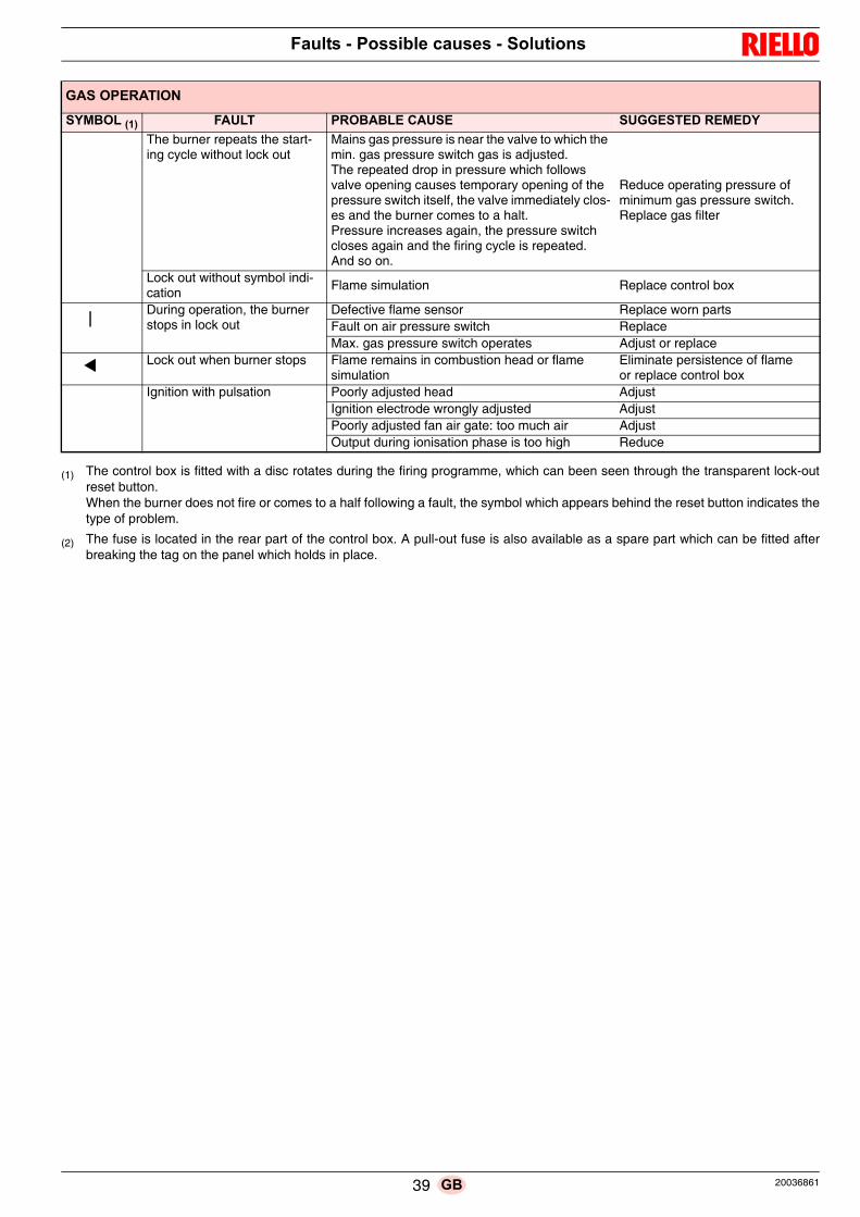
Faults - Possible causes - Solutions
(1) The control box is fitted with a disc rotates during the firing programme, which can been seen through the transparent lock-outreset button. When the burner does not fire or comes to a half following a fault, the symbol which appears behind the reset button indicates thetype of problem.
(2) The fuse is located in the rear part of the control box. A pull-out fuse is also available as a spare part which can be fitted afterbreaking the tag on the panel which holds in place.
The burner repeats the start-ing cycle without lock out
Mains gas pressure is near the valve to which the min. gas pressure switch gas is adjusted. The repeated drop in pressure which follows valve opening causes temporary opening of the pressure switch itself, the valve immediately clos-es and the burner comes to a halt. Pressure increases again, the pressure switch closes again and the firing cycle is repeated.And so on.
Reduce operating pressure of minimum gas pressure switch.Replace gas filter
Lock out without symbol indi-cation
Flame simulation Replace control box
During operation, the burner stops in lock out
Defective flame sensor Replace worn partsFault on air pressure switch ReplaceMax. gas pressure switch operates Adjust or replace
Lock out when burner stops Flame remains in combustion head or flame simulation
Eliminate persistence of flameor replace control box
Ignition with pulsation Poorly adjusted head AdjustIgnition electrode wrongly adjusted AdjustPoorly adjusted fan air gate: too much air AdjustOutput during ionisation phase is too high Reduce
GAS OPERATION
SYMBOL (1) FAULT PROBABLE CAUSE SUGGESTED REMEDY
39 20036861GB

Faults - Possible causes - Solutions
GAS OIL OPERATION
SYMBOL (1) FAULT PROBABLE CAUSE SUGGESTED REMEDYThe burner does not start A limit or safety control device is open Adjust or replace
Control box lock-out Reset
Fan motor blocked Reset thermal cut-out
Oil pressure switch intervenesAdjust pressure switch or eliminate overpressure
No electrical power supplyClose all switches - Check connec-tions
No gas oil Check the gas oil supply circuit
Control box fuse blown Replace
Pump is jammed Replace
Defective motor command control device Replace
Defective control box Replace
Defective electrical motor Replace
The pilot burner does not work Check
Defective safety solenoid valve Replace
Defective oil modulator Recondition or replace
The burner does not start and a function lock-out occurs
Flame simulation Replace control box
Photocell short-circuit Replace photocell
2-phase power supply thermal relay tripsReset thermal cut-out when third phase is re-connected
The burner starts but stops at maximum air damper setting
Contact 1 of servomotor does not operate control box terminals 9-8
Adjust cam I or replace servo-mo-tor
The burner starts and then goes into lock-out
Air pressure switch adjusted badly Adjust
Pressure switch pressure point pipe blocked Clean
The burner starts and then goes into lock-out
Fault in flame detection circuit Replace control box
The burner remains in pre-purging phase
Contact III of servomotor does not operate con-trol box terminals 10-8
Adjust cam III or replace servo-motor
After pre-purge and the safety time, the burner goes to lock-out and the flame does not appear
The solenoid VP1 allows little gas through Increase
Solenoid valves VP1 or VP2 fail to open Renew the coil or rectifier panel
No fuel in tank; water on tank bottom Top up fuel level or suck up water
Inappropriate head and air gate valve adjust-ments
Adjust
High voltage cable defective or grounded Replace
High voltage cable deformed by high tempera-ture
Replace and protect
Erroneous valves or transformer electrical con-nections
Check
Pump unprimed Prime
Pump suction line connected to return line Correct connection
Filters dirty (on line 1 at the nozzle) Clean
Valves up-line from pump closed Open
Incorrect motor rotation directionChange motor electrical connec-tions
Gas oil solenoid valves fail to openCheck the connections and the so-lenoid valves
Nozzle clogged, dirty, or deformed Clean or replace
The pilot burner does not work Check
Defective control box Replace
Ignition electrode wrongly adjusted Adjust
Grounded electrode due to broken insulation Replace
Pump/motor coupling broken Replace
Ignition transformer defective Replace
The flame ignites normally but the burner locks out when the safety time has elapsed
Defective photocell or control box Replace photocell or control box
Dirty photocell Clean
P
1
20036861 40 GB

Faults - Possible causes - Solutions
(1) The control box is fitted with a disc rotates during the firing programme, which can been seen through the transparent lock-outreset button. When the burner does not fire or comes to a half following a fault, the symbol which appears behind the reset button indicates thetype of problem.
Smoke in flame - dark Bachar-ach
Not enough air Adjust head and fan gate
Erroneous pump pressure Adjust
Nozzle filter clogged Clean or replace
Boiler room air vents insufficient Increase
Nozzle worn or dirty Replace
Flame disk dirty, loose, or deformed Clean, tighten in place, or replace
Smoke in flame (yellow Bacharach)
Too much air Adjust head and air gate
Firing with pulsations or flame detachment, delayed firing
Poorly adjusted head Adjust
Poorly adjusted fan air gate: too much air Adjust
Nozzle unsuited for burner or boiler See Nozzle Table
Defective nozzle Replace
Inappropriate pump pressure Adjust
Poorly adjusted or dirty firing electrodes Adjust
Output during ionisation phase is too high Reduce
The burner does not pass to 2nd stage
Control device TR does not close Adjust or replace
Defective control box Replace
Uneven fuel supply Check if cause is in pump or in the fuel supply system
Feed the burner from a tank located nearby
Rusty pump internal partsWater in tank
Suck water from tank bottom with separate pump
Noisy pump, unstable pres-sure
Air has entered the suction line Tighten connectors
Depression value too high (higher than 35 cm Hg):
Tank/burner height difference too great Feed burner with loop circuit
Piping diameter too small Increase
Suction filters clogged Clean
Suction valves closed Open
Paraffin solidified due to low temperature Add additive to gas oil
Pump unprimes after pro-longed pause
Return pipe not immersed in fuelBring to same height as suction pipe
Air enters suction piping Tighten connectors
Pump leaks gas oil Leakage from sealing organ Replace pump
Dirty combustion head Nozzle or filter dirty Replace
Unsuitable nozzle delivery or angle See recommended nozzles
Loose nozzle Tighten
Impurities on flame stability disk Clean
Erroneous head adjustment or not enough air Adjust, open air damper
Blast tube length unsuited to boiler Contact boiler manufacturer
During operation, the burner stops in lock out
Dirty or defective photocell Clean or replace
Defective air pressure switch Replace
GAS OIL OPERATION
SYMBOL (1) FAULT PROBABLE CAUSE SUGGESTED REMEDY
41 20036861GB

Appendix - Accessories
OUTPUT POWER REGULATOR KIT FOR MODULATING OPERATION With the modulating operation, the burner continually adapts thepower to the request for heat, ensuring great stability for theparameter controlled: temperature or pressure.
Two components should be ordered: • the output regulator to install on the burner • the probe to install on the heat generator
OUTPUT POWER REGULATOR WITH SIGNAL 4-20 µA, 0-10VTwo components should be ordered: • the Analogic signal converter;• the Potentiometer
SOUND PROOFING BOXIf noise emission needs reducing even further, sound-proofingboxes is available.
DEGASSING UNITIt may occur that a certain amount of air is contained in the fuelsucked up by the pump.This air may originate from the fuel itself as a consequence of de-pressurisation or air leaking past imperfect seals. In double-pipe systems, the air returns to the tank from the returnpipe; in single-pipe systems, the air remains in circulation causingpressure variations in the pump and burner malfunctions.For this reason, we advise installing a degassing unit near theburner in single-pipe installations. Degassing units are provided in two versions:
FUEL REMOTE SELECTION KIT
SPACER KITIf burner head penetration into the combustion chamber needsreducing, varying thickness spacers are available, as given in thefollowing table.
GAS TRAINS APPROVED ACCORDING TO EN 676Refer to the instruction manual.
A Appendix - Accessories
Parameter to control Probe Output power regulatorRange Type Code Type Code
Temperature - 100...+ 500°C PT 100 3010110RWF40 BASICRWF40 HIGH
30103563010357Pressure
0...2.5 bar0...16 bar
Probe with output4...20 µA
30102133010214
Potentiometer Analogic signal converterType Code Type Code
ASZ... 3010402 E5202 3010390
Burner Box type
Average noise
reduction [dB(A)]
Code
RLS 800/M MX C7 10 3010376
Burner Code
RLS 800/M MX (without filter) 20034277
RLS 800/M MX (with filter) 20034281
Degassing unit characteristicsBurner output 80 kg/h max
Fuel pressure 0.7 bar maxAmbient temperature 40 °C max
Fuel temperature 40 °C max
Attachment connectors(without filter)
FF G 1/4 tank sideFM G 3/8 conic burner side
Attachment connectors(with filter)
FF G 3/8 tank sideFM G3/8 conic burner side
Burner Code
RLS 800/M MX 3010372
Burner Code
RLS 800/M MX 20008903
20036861 42 GB

Appendix - Electrical panel layout
B Appendix - Electrical panel layout
Index of layouts
2 References layout
3 Layout of unifilar output
4 Operational layout star-powered starter/delta-powered starter
5 Operational layout LFL 1...
6 Operational layout LFL 1...
7 Operational layout LFL 1...
8 Operational layout LFL 1...
9 Operational layout
10 Electrical connections set by installer
11 Electrical connections for internal RWF40 kit
12 Electrical connections for external RWF40 kit
1
2
Sheet no.
/1.A1
Coordinates
Reference layout
43 20036861GB
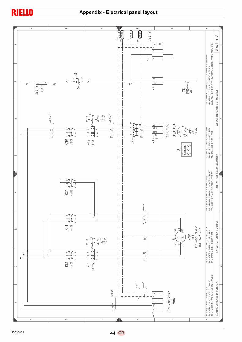
Appendix - Electrical panel layout
����
�����
�� �
��
���
�
� ��
���
��
���
��
���
���
����
���
���
���
���
��
�����
��
��
��� �
�
�����
�
��
��
��
�
��
��
��
� � ! " �
� � ! " �
� �
"����
#�#��$"�!#��%�"
&�
��'%���%
���#�#��$�%
�����
"#!$���#("�
��"#���(�� �
"��
� �
"����
#�#��#$"�!"���#��� "
��
����
����
�) **+
�"�"
�**+
**+
��,!�
�
�
��
�
�� �
� �
� -��
�
��,��
��,�
.� .�
.� .�
�
/
�
�
�� /�
��
�" 0��
$��
��
�����1/
$��
���
�����,�1/
�
/
�"
��,!�
�
�
��
�
��
/�
��
�)�*
*+
��,!�
�
�
��
�
�
��, �
�
�
��
�
�� �
� �
�-��
��,��
��, �
.� .�
.� .�
,��1/
��
/�
��
�"
0��
0�
�
��,!�
�"
�� �
�� � �
�)�2�*
*+
�)�2�*
*+
�"
���
�,��
��
��
�
�
����
0�
���
�"
��,!�
�"��,!
��,�
��
���3��
����
����
"����
�"���
����
�
���3�
"$%��
����
���
�%#$��
�� �
/�$&
'"�3�(#���
%��
�'"�
�%/��
�4��"���(
"��
(�3��
"$!"���(
$""
��
��"$
���
�($5
$!�3�$
%��%��
�$"!
���$
%�("���$
%�
/��3��
#� %
���/
�#�"����
�� ���/
"#��
%(3��$� #%��
�%$�("���%
$�("���%
$�("
��3��#%�"
��%��
��#%�"
���
��#%�"
���
��#%�"
��
('3�($#(#%��
�($"'
���(
$#���
�($��
��3�$%����
��#���
�$%�"���$
%��
(!3�%$%��
�(%�!
���%
$��
�(%�!
�63���$ �
"�"����
�$6�%#�"����
�$6�%#�"����
�$�#����
�
�$3��$("
�%��
��#��"$
����
$("
���
��#��"$
('"3
�(#���
%��"$
!"���'
"��%
/�($""
��
�4��"�
�"$
���
�("�
��($�
��3��
�$$%"����
$%/��
���$$%��
��$��
�
/
�
�"
��
/�
��
�"
/�
��
��
�
�
/
20036861 44 GB

Appendix - Electrical panel layout
��
��
���
��
��
�
��
�
��
�
��
�
�
�
� �
�
�
��
�
�
�
� �
�
�
�
�
� �
�
�
�
��
�
�
��
�
�
� �
�
�
� �
�
��
��
�
�
� �
�
�
� �
�
�
��
��
��
�
��
��
��
� � � � � �
� � � � � �
��
�
��
���
��
��
��
���
!!
��
�"
���
��
��
�#
�"
��
��
��
��
�"
#�
��
��
���
�"
��
"��
$�
"�
� �
��
���
�%
��
��
��
" �
��
��
�
��
���
��
���
�"
��
�"
� �
�
��
��
��
�"
��
�
��
���
��
��
��
��
���
��
�"
"�
�"
���
� �
�#
�"
��
��
�
#
�&�
�
�#
�&�
#�
&��
'�
'�
��
�
��
��
� �
�
��
��
��
��
�� �
��
��
��
��
��
�
��
��
�
��
#�
&��
#�
&��
#�
&��
#�
&��
� � �
� � � �
��
�
��
�
�
�� ��
��
�
��
��
�
��
#�
&��
#�
&��
#�
&��
��
� � �
� � � �
��
�
��
��
��
� �
��
�
��
#�
&��
#�
&��
#�
&��
��
� � �
� � � �
#�
&��
��
��
��
� �
#�
&��
'�
'�
��
�!
�"
��
��
���
�
$�
�$
���
��
"
"�
� ��
#�
&��
'�
'�
�
�
��
#�
&��
�
'
#�
&��
� �
(
#�
&��
� �
#�
&��
� �
�
�(
�
�
��
#�
&��
� �
#�
&��
��
��
�
�(�� �
� �
�
� �
�((����
��
��
��
��
�(�����
$�
�
��
#�
&��
� �
�(
��
�
��
#�
&��
�
'
#�
&��
� �
(
#�
&��
� �
#�
&��
� �
�#
�&�
�
#�
&��
�#
�&�
�
��
�)��
��
�#��
��
��#
���
��
�#��
��
�
�
�)��
�"
��#
���
��
�#
���
"�#
���
*
�"
�
%�
�)��
��
��
�#�%
��
��
*�#
�+�
��
��#
���
��
��
�)�!
�"
��
�#��
"�
��
�#�!
�"
��#
��"
,�
"�
�)�"
��
��
�#�"
��
�#�"
��
��
�#�"
��
*
�)��
��
��
�#�*
�
��#
���
��
��#
�*�
��
��
)��
"�
��
��#
��"
��
��
�#��
"�
��
��#
��"
��
��
!�
)�!
��
��
��
�#�!
��
��
�#�!
��
��
�#�!
��
��
�
�%
)��
" �
��#
��"
�%
�#��
" �
�#��
"�
�
$
)�"
��
��#
�$ �
�#
�"�
��
�#�"
��
�
��
)��
"�
�#��
��
��#
��"
�#��
��
�
�-
)��
�"
�
��
��#
���
"-
��
��
�#��
�"
-�
� �
��#
���
"
��
��
�
�"
)��
"�
��
��
�#��
�!
�"
�#��
"�
��
��#
�� �
��
"
��
%�
)��
��
��
#!
�"
��
�#�%
��
��
*#
�"
��
��#
�+�
��
�#
!�
"�
�#��
��
�#
�"
��
��
�)��
�"
"�
��
�#��
"�
*�
�#��
�"
"�
��#
��"
��
�
� �
���(
��
��
���
��
"�
��
��
��
��
�"
� �
���
45 20036861GB

Appendix - Electrical panel layout
���������
��
��
�� ��
� ��
�� ���
� �
���
�� �
��
��
���
� ��
���
���
��
���
���
�� ��
��
��
��
��
��
��
��
��
� � � � � �
� � � � � �
���������� !��������"""
���"""�� �#��!�����$���
���#!�������������"""
������������!��������"""
�%�"���
%�"�� �
%�"��
��"""
�%�"��
���
����
��
�
���
%�"��
��
��
����
� �� �
&��
&��
��
�
�
�
'
���
�
��� ���
�� ���"
�
��
(
��
&��
��
��
��%�"��
%�"��
)
�� ���
������
���
%�"��
)
�� ���
������
���
���
�
&��
�����
�����
�
&��
'
���
�
���
��#��#���
��
�� ��
��
%�"��
%�"��
�*
�� ���
%�"��
�� ��
���
%�"��
)�
)�
���
��
��
%�"��
%�"��
%�"��
%�"��
� � � ��
� � � ��
��%�"��
��%�"��
�%�"��
�%�"��
�%�"��
��%)"��
���+����%�����%�����%����
��+���#��%�����%���!#�%����,�#
$��+��!���%�$��,�%�-�����%����
���+�.�#���%��#����%�.�#��%��#/�
#��+�#�����%�#���%�#�����%�#��
,��+��!�����%�,
�!���%������%�,
�!��
��+��#���!��%��#�����%��#�����%��#����
.�+�.!������%�.!����%�.!����%�.!����
�$+��#!�!��%��#�$�%��#!��%��#��
+�#����%� !��%�#����%�#���
��+��#��%�����%��#�%����
�0+���#������%���#0��!���%���#0��!���%���#!����
�#+��#������%��!.�#�%��#�����%��!��#
��$�+��!��%.�#���%�$��,%�#����%�-����%.�#��%����%�#��
���+���##����%��#�,��%���##���%��#���
�
��
��
��
�
20036861 46 GB

Appendix - Electrical panel layout
���������
��
��
��
�� �
�
�
���
���
���
���
���
���
���
���
��
�
��
��
��
�
��
��
��
� � � � � �
� � � � � �
�����
����� ! ��"��"�"�###
"�"�###� ����$! ��"�"�
% �$
��$�!��������
��"�"�###
�����
��� ��$! ���"�"�"�###
��&�#��
��
&�#��
&�#��
�&�#��
��
&�#��
�
�%���
'��
�%
��
��
��
�
�
��
'��
'��
��
��
�
�(
���)*
+�,
+�,
�
���
��
&�#��
-
��
�
��
"�"####
&�#�
.�
�
��
&�#��
� �
�� &�#��
��
�
'��
&�#��
� � ��
��� �
'��
'��
'��
'��
��
��
��
�
�
�
'��
��
��!��
��!���
��
&���
��
'��
�(
�
�&�#�
&.#�
�&�#�
��&�#�
���/��"��&��"���&��"���&��"�
�
��/���� �&��"�
��&�� !��&����0��
%��/��!�"" �&�%�"" 0�&�1�����&���"�
���/�������&�������&����$�&���2�
���/�� �� �&�����&�� ����&�� $
0��/��!��� �&�0
�!$��&��"�
���&�0
�!��
�/������! �&� ������&� ������&� �����
�$/��! "�$$ �&��! "�$�&��! "�$�&��! "�$$
�%/���!�! �&����%
�&���!��&�����
�/�� ���&��!��&�� ���&�� ��
��/� � �&�� "��&� ��&�� "�
$3/�$��������&�$��3� !���&�$��3� !���&�$��!��"�
�
��/������$ �&��!"����&������$�&��!"���
��%�/��!�"" &������&�%�"" 0&������&�1����&
���$�&���"�&����
���/����� ���&��� 0��&����� ��&������
$�
$�
�
�
�
� �
$�
$�
$�
��
���
"
��
��
��
�
��
��
� �
��
��
��
47 20036861GB

Appendix - Electrical panel layout
��
��
���
��
��
�
�
�
�
�
�
�
�
�
��
�
��
��
�
��
���
� ��
�
��
��
�
�
��
�
��
��
��
��
��
��
��
��
��
��
��
��
��
��
� � � � � �
� � � � � �
��
��
��
��
��
!�
�"
��"
�"
��##
#"
�"
��##
#�!
��
��
!
��
"�"
�$
!
�
�
� �
��
��
��
��
�"�
"��
###
��
��
��
��!
��
!
��
�"
�"�
"��
###
�%
�#�
�
��
%�
#��
��%
�#�
�
"�
"�#
###
%�
#��
��
��
��
���
���
�
&�
�
���
�� �!�#
�
��
��
'�
�(
�
��
���
�
&�
�&
��
�
��
� �
��
��
��
��
��
�� ��
��
� �
���
�
������
&�
����
���
%�
#��
��
����
! "
�!�
��
�
!�
)���
)����
%�
#��
��
����
*�
��!
��
��
!
�
)���
)����
��
��
����
�
��
��
"!
��
�!
)���
)����
%�
#��
��
����
�
��
��
�!�
)����
%�
#��
��
%�
#�� )���
�
�&
�
�+��
"
�%��
"
��%
��"
�
�%��
"�
��
�+��
��
!�%
��"
��
��%
��!
��%
���
�,
��
�
$�
�+�*
�"
"!
�%�$
�"
"!
,�%
�-�
�
��%
�*�
"�
*�
�+��
��
��
�%�*
��
��
�%��
��
�%
�*�
.�
��
�+��
!�
�!
�%��
��
�%��
!
*�
�%��
!
,�
�+��
��
�!
�%�,
�
��%
��"
��
��%
�,�
��
!*
+��
��
��
!�%
�!�
��
*�
�%�!
��
�*
��%
�!�
��
*�
�
+��
!"
�
!
�%��
!"
�
�%��
!"
�
�%��
!"
�
*$
+�*
� *
!�%
�*�
�$
�%�*
� �
�%�*
��
��
+��
!�
��%
�� �
��%
��!
��
�%��
!�
�
*�
+�!
�!
�%�*
!"
��%
�!�
�%�*
!"
�
/
+�
�
��
��
��%
�
�/
!
��
�%�
�
/
! �
��%
�
��
��
"�
��
+��
�*
��
!
�%��
"�
��
�%��
�*
��
�%
�� "
��
�
*�
$�
+�*
�"
"!
%�
��
��
�%�$
�"
"!
,%
*�
��
��%
�-�
�
�%
��
�
�%�*
�"
�%
*�
�
��
�+��
��
�!
��
�%��
�!
,�
�%��
��
�!
��%
���
�
�
��
��
��
20036861 48 GB

Appendix - Electrical panel layout
���������
���
�
�
��
�
��
���
��
��
����
���
�
���
�����
���
���
���
��� �
�
��
�
��
��
��
�
��
��
� � � � �
� � � � �
�� ����!"
#��"
$��$�$��%%%
$�$��%%%���
�����"
$�$
&�!
�����
����
�� ���$�$��%%%
�� �����"
����""
�$�$�$��%%%
�'�%
"'�%��
��'�%��
( � �
� �
�
$�$�%%%%
'�%�
�()
�(�
��
�(� �
�
�
�
�"�(���"
��
�(��
'%��
��
�� �(��
'%��
��
� �(�
�(� �(�
'%��
��
� )��
'%��
�
�
)�
)�
���
�(�
�(��
���
)�
)�����
� � � � � � ��
"
(*
���
�� �(�
�(
�� )
�����$
(*��"���$
��� �
��"� �
)�
���
���
��
���
���
����
��
���
����
�����
�(��
��
)� �(�
�(�� ��
���
"�"� �
�(� ��
)� ����
�(�')%��
�')%��
)')%��
�(')%��
"')%�
��')%�
+
�!�,��$!�'��$!��'��$�!�'��$
!��
�,�"����'��$
���'�"����'��� -�#
&��,� �$$��'�&�$$�-�'�.!"
��'� �$�
"�,�������'� ���"�'������'� �/
"��
�,����
���'�����'���!
��'����
- �,���"���'�-
����'��$
"��'�-
����
� ,��
"����'���
" ��'���
" ��'���
" �
��,����$���
��'����$���'����$���'����$���
&,� �
� ���'� ��&�'� ����'� �
!��
,���
��'���"��'����
��'����
�
,���
��'� �$��'����'� �$�
�0,��!
�� ����'��!�
0!�
����'��!�
0!�
����'��!�
����
$!
��,��
�"��
�'���$����'��
�"��'���$���
"&�,� �$$�'
������'�&�$$�-' �
��"�'�.!"
�'�����'� �$�'
�!"
�"�,����
�"��'����
-"�'����
�"�'���
!"
(!���"
1�2
34567
8�449:
����
����
��
���
���
�
����
����
��
�����
49 20036861GB

Appendix - Electrical panel layout
���������
��
��
�� ������������������� �� ��� ������������������
�� ���������������� ��� ����������������
��� ��� � ������������
�� ������ �������� ���������������
���
�
!"
#$
%&
�
!"
#$
%&
' ( ) � �
' ( ) � �
�(*�+'��,-
./0-
'1�
0��2'3/0-
'1�1'
40,
3�32
/��
�(*�+'
�(*�+'��0-
(3/0--
�1
-5&6)&
�5$6(&
��5&6�&
�75&6)&
�5&6)&
7(
5&6)&
"5&6)&
"!5#6)&
��
�+
/��� ���
1-
8�!8�"84�4/�+�9�:,�
��:���+$�$�,$9:9�('((9)�)
9-)�+�
/��+��9�:� ,�
'� ��:� ���� +$��$� �,$� 9:� 9�
�
/�+�9�:,�
��:���+$�$�,$9:9�
,�;�1,�5�1,��5�1�,�5�1'
,<
�;�-�20�5�1'
(<�5�-0/2�5��(*='2.
4��;�9/'110�5�4�110=�5�>',-
��5�9�1
9-�;�?�2)��5�92��-�5�?�23�5�92@
-2)
�;�20�
�0�5�2�)�5�20,
9��5�203
=*�;�/'-(0�5�=
*/3��5�1'
-(�5�=
�/��
09;�'2'
-(/0�5�02'
-9��5�02'
-9��5�02'
-9�
?3;�?/01�33
0�5�?/01�3�5�?/01�3�5�?/01�33
94;�92
/9/0�5�92�4�5�92/��5�92'
,�<
;�20
�'�5��/-<�5�20�
��5�20�
'9)
;�02
0�5�901)�5�02�5�901)
38;�3,
2(*����5�3,2
8,0
/���5�3,2
8,0
/���5�3,2
</�
1',
�2;�'29
�-30
�5��/1?�2�5�'29
�-3�5��/1�2
9-4�;�9/'1105
?�2)��5�4�110=592
��-�5�>',-
�5?�23�5�9�15
92,-
-�;�+'22
0-��5�20
=-�5�+'22
0-�5�2'
,-
2=�"76666
3�
1�
-
8�!
8�"
8
4�
4
/�
+�
9�:
,�
��:
���
+$
�$
�,$
9:
9�
('
(
(9
)�
)
9-)
�
+�
20036861 50 GB

Appendix - Electrical panel layout
����������
��
�� ������
����
��
� � �� ��
��������
�
���
������
�������
���
�������
�!���
�� ����"�#��������
����$���
�
���
����%���
�
���
��
��� �� ��
�
����
�
��� ����
���
���&
�#��
����
��
���
��� �
�
�������� '������
�����
���
������
����
����
���
��
��#���
����
��������
����
()*����
�����������
()*������������
���
�'������
������������
��
�$
+%
��
�$
+%
� , � # � �
� , � # � �
����� ������������
��������'�
��#���-����
�������
��������
���������
������
������,&
����
������
���"��
����
���.��
�����
����
�������'�
��'�
/'�.��
����
����
#������
�0������1'
��������'0������-����
�������'�
����
��
����
��
����
�
�((2
�
�&���
!,�
�&
���
����
�
��
��
!,�
!,�
,'
,�
,"
�3�
�45
6�7
67
������
���#��������
'���
����� �
����
������
��� ���������������
��������� �
������
��������
����
����
����&����
�
��
��
���)�
����8
� ��
$�((2
�������#-����
���'
���'���� �
0���
����
�1'�
������������&����
����������������� �
����
����
������
����
�������&
�����9����
��
���)�
$��8
��
���((2
����)�
$��8
�
���((2
����
����
���#����
��/���
�������������'��������
������,���������������'����
����
�����������"
������
����
�����0���'��#���
���,��
��'�
��������'������'
��':
�����,���"'
� ��.�
�#������/;
����
��"�
���
������
!,�
�
!,,
����
����
���#����
��/���
�������������'���� �
�������,������� �
������'����
����
�����������"
������
����
�����0���'��#���
���,��
��'�
��������'��� �
/�':
�����,���"'
� ��.�
�#��� ���
����
"����
��� �����
!,�
����
� �
��������
�$ ���
'�����
����
����
���'
����
�����
�����������
�����'�
���
���/;��,�����,������������������'�
�<���)8�
�+ �
����
!,�
�������������� �'�/��������������
�% ���<���)8� ���,�����,
��������������� �/ ������������
�'�/���������� ��
����
������
��������
�����
�'�
��
��.�
�����"
����
"��
��;��,������'� �#���,�������
��������
�"��
�����
�/���
�����,'
���,���
���&
�����������
��
����
����'���"��
,���� ��,�'��'�,'��������"��'�
��� � ,������,�'�������$
���
�� ������
��������������������'�0���������� ��
�� + �������������%
�
,'�=�,�'���,�'����,��'���,��
',"
�=��������,��
�"����������������/
&��=� ��������&��������>�'�
���� ��,
��=����#���� �������������� �.
��#
�=����
�������#�����'
�������
���=�,���������
�������,��
������
����
� =����
����������
� �������
� �������
� �
��=��������
�����������������������������
&=� �
� ����� ��&��� ������ ��
'�"
=���
��������"������
�������
� #
=���
���� ��#�������� ��#
�1=��'
����������'�
1'��������'�
1'��������'�
"��,
��'
��=���
����
��������������
���������,��
�&�=� ������
���#����&������ �
������>�'�
��������� ��,�
�'�
,��=�����
������,��
���������
�����,��
'�
�%
�$
�
�
�
��
�%�+
�$,�
���
��
�� '�
'� ��
��
��
�� '�
'� ��
��
��
�� '�
'� ��
��
��
��
�'��������
��
��������
���
��
51 20036861GB

Appendix - Electrical panel layout
����
����
��
��
�� ��
��
����
���
�
����
�
���
����
���
�
���
���
����
���
��
����
���
����
���
���
����
���
���
���
���
����
����
����
����
���
���
��
����
��
��!
���
��
��" �
��
��
����
���
��#
�� �
���
����
���
��
��
����
���
��#
�� �
����
���
����
����
����
����
����
����
���
�
���
��
��
�
��
��
����
���
��#
�� �
����
����
����
����
����
����
����
���
�
�
!"
$�
%&
�
!"
$�
%&
� � � �
� � � �
����
�'�
���
����
����
����
�(��
���
"��
����
���
����
����
���
����
����
����
���
����
���
����
"��
(��
���(
����
����
�)��
����
����
����
(���
�� "
���
���
����
����
��*�
����
����
�(��
���
"��
���*
����
�
�+�,
-./�
01�-
2231,
-41/
+��0
�3�(
1���
� "
�1+
��5+
/��/
631�
5��1
3�2/
+���
-�71
3/��
�!��
�"0-
33-�8
/5.�
��1�
5-��
�8�
-33�
��1+
�5��
+9�+
0:+6
�0�.
�1+�
�5+�
+�(1
�.��
"��
01��
�5-�
�;<�
5<5;
,=:+
6���
!���
">/
8�(
3�8
8�+
<5��
���
��+
�7�5
+�+
���
+�-2
23?1
+6��
���1
+��5
+-3�
�� "
��=1
�@5�
8/>
��9
15��
A:8
2�5�
��!�
��"
75/8
���5
81+
-3�<
/-50
��
�+�,
-.�0
B�-2
231,
-�1/
+�0:
�=1�
���
"��
1+�C
51�:
5�+
3�>�
5�3�
�2/+
��0�
�8�.
:5�
D�71
3���
!���
"�0:
�</5
+1�5
��
��
��
����
�
�/0
:3-�
1+6�
/:�2
:��E
"F��
��8
���
�EF
����
���
�
��!��" ���
�#�#
���� ��
�G��G���
'����
����
�G��G���
��51
-3��
+��5
7-,�
���"
&$
�����
����� �'
'��
'�'�����'��
'��
'��H
�2�5
-�1+
6�>/
3�-6
��7/
5��5
-+.0
:,�5
���
"��I
�!�8
�
�H
'�
��
�H
���H
��
'�
��
�
���
���
'�
�I��
�'�'��
� ��
��
��
��
�
��
'��
��
'��
��
�
��
"
�8
���
����
��
��
����
��
��
� ��
���
8�
��"�
�8
���
�
��
���
8�
��"�
�8
���
�
����
����
��'�
���
����
����
���
���
��
����
����
���
���
'�
����
��
�
��
�
��
��J
���
�I�
����
I�
����
I�
���
(�J
����
��I
���
�(�I
����
��I
����
��
�K#
��J�
'��
����
I�#
����
��I
�L�
����
I�'
��
'��J
����
���I
�'��
���I
����
��I
�'�)
���
�J��
����
�I��
���I
����
'��I
����
���
J��
���
��I
����
���I
���
���I
����
���'
J��
����
���I
����
�'��
I��
���'
��I
����
�'�
��J
����
����
��I
����
����
I��
����
��I
����
����
'#J�
'��'
���I
�'��
#�I
�'��
��I
�'��
��(
J���
���I
����
(�I
����
��I
����
�'�
J���
��I
�'��
��I
����
I�'
���
��J�
����
����
�I��
����
����
�I��
����
����
�I��
��(�
���
���
J��
�'��
���I
����
���
�I��
�'��
��I
����
��
'�#
�J�'
����
�I�
����
�I�#
����
�I
'���
��I
�L�
���I
���
��I
�'��
I'�
���
�J��
���
����
I�
���
��I
���
����
�I�
����
��
�� "
�
��
�
��!
�
��"
#�
#
��
��
'��
��
���
���
��
��
���
'�
'�
��
�
�'
��
�
'��
H
�H
���5
8/,
/:23
�
�:�.
10��
��8
2�5-
�:5�
��.1
.�-+
,���
��58
/8��
�51+
��9
15��
,15,
:1�
��.1
.�-+
,��/
��+�
1/8
���5
��.1
.�-+
,���
��58
/8��
�51+
�!�9
15��
,15,
:1�
��>1
,��9
1���
,:55
�+��
/:�2
:�
�5/<
��9
1���
,:55
�+��
/:�2
:�
��>1
,��9
1���
>/3�
-6��
/:�2
:�
�5/<
��9
1���
>/3�
-6��
/:�2
:�
20036861 52 GB

Appendix - Electrical panel layout
����
������
��
��
�� ���
����
���
��� ������
� �
������������
�����
�����������������
�������� ��!"���
��#��
����� !��$��
%�����������
������
�������������
�� ��!�����
� !#
#���&�'��������$��
����(�(�����!)
���
��!�����
���#�
��(�
!
�����$���#�!
�����*������
���
�
%+��&�����
���+
�� ���
����'
�� !
����
����,
��
��
-.
/0
12
��
-.
/0
12
� 3 4 � %
� 3 4 � %
35��
�6����
� ����
��� 3 �,
���
7%.
8999���
����
5��
�3��
3���35
���3
� 5�
��%5
���
����
����7
%.8999�, �
���,
��5�
��3:
�;��
���
����
����, ��
�7%.
8999
��33
5�4�
���
����<�
�3��
=��
�, ���
7%.
8999��
�<� ��
�
>3
�������0�2�1
��?�
���@
���
��@�
����
@�
���
,�?��
��5�
@�
��3,
�@��
5 ��
@��
3:7��A
���?�6 ���
5�@��
���5
7�@
�B���
��@�6
��
6��?�C
��4�
�@�6
����
�@�C
����
@�6
�;�
�4�?��
5��5
�@��
�4�@
��5�
6��@
��5�
7:�
?� ��3
5�@�7
: ��
�@�
���3
�@�7
� ��
56?����
�3 5�@
�5��
�6��@�5
���6
��@�5
���6
�C�?
�C 5��
��5�
@�C
5��
��@�C
5��
��@�C
5��
��
6�?�6�
6 5�@
�6��
��@
�6� ��
@�6
���
�,?��5
���@
�� �,�
@��
5���@��
5��
64?�5�
5�@�6
5�4�
@�5
��@�6
5�4
�=?���
�3:�
���@
����
=�5 ��
�@��
��=�
5 ��
�@��
��, �
���
��?���6
���5
�@��
�C��
�@��
�6��
��@��
��
�6�
��?
�6 ���
5@C��
4��@
����
�57@6�
����
@�B���
�@C��
��@�6
��@
6���
��?��
���
5���@�
�57��
@��
���
5��@
���
��
��
�7%.
8999
��
�
=�-
=
=�.
��
��
�
��
6�>
��
�>
��
�0
0
�0
6>
6�
3�
3
36
4�
4�
6�4
D
�D
53 20036861GB

Appendix - Electrical panel layout
Wiring layout keyA Control box
B1 Internal output power regulator RWF40
B2 External output power regulator RWF40
BA Probe with current output
BA1 Device with current output for editing remote setpoint
BP Pressure probe
BP1 Pressure probe
BR Remote setpoint voltage divider
BT1 Thermocouple probe
BT2 Probe Pt100 with 2 wires
BT3 Probe Pt100 with 3 wires
BT4 Probe Pt100 with 3 wires
BTEXT External probe for the climatic compensation of thesetpoint
BV Probe with voltage output
BV1 Device with voltage output for editing remote setpoint
F1 Fan motor thermal cut-out
F2 Pump motor thermal cut-out
F3 Auxiliary fuse
H1 Signal light for burner on
H2 Signal light for fan and pump motors trip
KL1 Direct start and star/delta starter line contactor
KMP Pump motor contactor
KT1 Star-powered/delta-powered starter /delta contactor
KS1 Star-powered/delta-powered starter /star-poweredcontactor
KST1 Star-powered/delta -powered starter timer
K3 Burner lock-out voltage free contact relay
K4 Gas oil operation voltage free contact relay
K5 Gas operation voltage free contact relay
K6 Fuelled burner ON clean contacts output relay
KG Gas operation relay
KO Gas oil operation relay
MP Pump motor
MV Fan motor
PA Air pressure switch
PE Burner ground (earth) connection
PGM Maximum gas pressure switch
PGMin Minimum gas pressure switch
PO Oil pressure switch
PO1 High-limit oil pressure switch on return line
RS Remote lock-out reset button
S1 Emergency stop push-button
S2 Dial for off - automatic - manual
S4 Power dial for increase - decrease of power
S5 Fuel selector and remote fuel selector enabling
SH3 Burner reset button and lockout warning
SM Servomotor
TA Ignition transformer
TL Limit pressure switch/thermostat
TR Control pressure switch/thermostat
TS Safety pressure switch/thermostat
UV Flame sensor
Y Gas adjustment valve + gas safety valve
YVPS Gas valve leak detection control device
X1 Main supply terminal strip
X2 RWF40 terminal strip
X4 Gas oil assembly terminal block
XAUX Auxiliary terminal strip
XM Light oil assembly connector
XPGM Maximum gas pressure switch connection plug
XPGM1 Minimum gas pressure switch connection plug
XRWF Output power regulator RWF40 terminal strip
XS Flame detectors connector
XSM Air and gas servomotors connector
VF Gas oil operation valve
VP1 Pilot valve 1
VP2 Pilot valve 2
VR Gas oil return valve
VR1 Gas oil return valve
VS Gas oil safety valve
20036861 54 GB


Subject to modifications
RIELLO S.p.A.
I-37045 Legnago (VR)
Tel.: +39.0442.630111
http:// www.riello.it
http:// www.rielloburners.com