
Heat Transfer Analysis of Thermal Oil Plant on Fuel ... - Iptek ITS
10
International Journal of Marine Engineering Innovation and Research, Vol. 2(2), Mar. 2018. 161-170 (pISSN: 2541-5972, eISSN: 2548-1479 161 Heat Transfer Analysis of Thermal Oil Plant on Fuel Oil Tanks of 17500 LTDW Product Oil Tanker Taufik Fajar Nugroho 1 , Wolfgang Busse 2 , Ede Mehta Wardhana 3 Juda Imanuel Osvaldo Panggabean 4 Abstract The thermal oil system is one type of heater that widely used on ships. The system is an important system used to heat fuel that will be used for the operation of the main engine, auxiliary engine, and boiler. This system has been installed on 17500 LTDW Product Oil Tanker, MT. Parigi, but not yet tested so that it does not know whether the system is able or not to transfer heat from heating equipment (boiler and economizer) to each fuel tank in accordance with the desired value. Therefore, this research performs an engineering evaluation in term of heat transfer analysis to ensure that the heat transfer process of thermal oil from heating equipment to the fuel tanks is already meeting the required temperature or not. This analysis is done by using thermodynamic equation, namely heat balance equation and heat loss equation. The result shows that the heat transfer of thermal oil to each fuel tank corresponds to the desired value, namely 180 o C for the thermal oil inlet temperature to each fuel tank and 140 o C for the thermal oil re-enter temperature to the heating equipment. KeywordsHeating System, MT. Parigi, Thermodynamic, Heat Balance, Heat Loss. I. INTRODUCTION 1 Fuel heating system is one of the most important systems on the ship. This system is intended to maintain the temperature of fuel oil that will be used for the operation of the main engine, auxiliary engine, and boiler. The heating process of fuel is generally done by several types of heating, namely by using steam, electric, and thermal oil. MT. Parigi (17500 LTDW Product Oil Tanker) uses the thermal oil heating system as its fuel heating system. The thermal oil heating system on MT. Parigi is done by using two kinds of heating equipment, namely boiler and exhaust gas economizer. In the operating scenario, the system will use boiler as its heating equipment when the ship sails in the territorial sea, while the exhaust gas economizer will be used when the ship sails at high sea (minimum 85% MCR of the main engine). This system is already installed on board, but not yet tested so that it does not know whether the system is able or not to transfer heat from the heating equipment to the each fuel tank in accordance with the desired value. This system is designed to operate at working pressure of 5kgf/cm 2 , working temperature of 180 o C for the thermal oil inlet temperature to each fuel tank and 140 o C for the thermal oil re-enter temperature to the heating equipment. If the system is not evaluated, consequently the fuel can not be pumped to the next tank or process. Therefore, it is needed an analysis to ensure that the heat transfer of thermal oil heating system is appropriate with the designed value, namely heat transfer analysis. This research will conduct an engineering evaluation in term of heat transfer analysis in solving the problem Taufik Fajar Nugroho, Department of Marine Engineering, Institut Teknologi Sepuluh Nopember, Surabaya, 60111, Indonesia. E-mail: [email protected] Wolfgang Busse, Department of Marine Engineering, Institut Teknologi Sepuluh Nopember, Surabaya, 60111, Indonesia. E-mail: [email protected] statement. This analysis will use some thermodynamic equations, namely heat balance equation and heat loss equation. The analysis is done on two scenarios, namely boiler scenario and exhaust gas economizer scenario. II. METHOD The analysis is divided into several stages, which will be explained as follows. A. Data Collection In doing the analysis, there are several data must be known, as follows. ISO Exhaust Gas Data of Main Engine The following table shows the ISO exhaust gas data of the main engine used on MT. Parigi, namely MAN 6S35MC7.1-TRII with 1 MAN TCR22-21. Shop Trial Record of Main Engine The following table 2 will show the result of shop trial record of the main engine. Exhaust Gas Properties Properties of exhaust gas depending on their temperature, which can be seen in the following table. 3 Technical Data of Economizer The following table 4 will show the technical data of exhaust gas economizer that has been installed on board. Ede Mehta Wardhana, Department of Marine Engineering, Institut Teknologi Sepuluh Nopember, Surabaya, 60111, Indonesia. E-mail: [email protected] Juda Imanuel Osvaldo Panggabean, Department of Marine Engineering, Institut Teknologi Sepuluh Nopember, Surabaya, 60111, Indonesia. E-mail: [email protected]
-
Upload
khangminh22 -
Category
Documents
-
view
3 -
download
0
Transcript of Heat Transfer Analysis of Thermal Oil Plant on Fuel ... - Iptek ITS
International Journal of Marine Engineering Innovation and Research, Vol. 2(2), Mar. 2018. 161-170(pISSN: 2541-5972, eISSN: 2548-1479 161
Heat Transfer Analysis of Thermal Oil Plant onFuel Oil Tanks of 17500 LTDW Product Oil
TankerTaufik Fajar Nugroho1, Wolfgang Busse 2, Ede Mehta Wardhana3 Juda Imanuel Osvaldo Panggabean4
Abstract The thermal oil system is one type of heater that widely used on ships. The system is an important system usedto heat fuel that will be used for the operation of the main engine, auxiliary engine, and boiler. This system has been installedon 17500 LTDW Product Oil Tanker, MT. Parigi, but not yet tested so that it does not know whether the system is able or notto transfer heat from heating equipment (boiler and economizer) to each fuel tank in accordance with the desired value.Therefore, this research performs an engineering evaluation in term of heat transfer analysis to ensure that the heat transferprocess of thermal oil from heating equipment to the fuel tanks is already meeting the required temperature or not. Thisanalysis is done by using thermodynamic equation, namely heat balance equation and heat loss equation. The result showsthat the heat transfer of thermal oil to each fuel tank corresponds to the desired value, namely 180oC for the thermal oil inlettemperature to each fuel tank and 140oC for the thermal oil re-enter temperature to the heating equipment.
KeywordsHeating System, MT. Parigi, Thermodynamic, Heat Balance, Heat Loss.
I. INTRODUCTION1
Fuel heating system is one of the most importantsystems on the ship. This system is intended to maintainthe temperature of fuel oil that will be used for theoperation of the main engine, auxiliary engine, and boiler.The heating process of fuel is generally done by severaltypes of heating, namely by using steam, electric, andthermal oil. MT. Parigi (17500 LTDW Product OilTanker) uses the thermal oil heating system as its fuelheating system.
The thermal oil heating system on MT. Parigi is done byusing two kinds of heating equipment, namely boiler andexhaust gas economizer. In the operating scenario, thesystem will use boiler as its heating equipment when theship sails in the territorial sea, while the exhaust gaseconomizer will be used when the ship sails at high sea(minimum 85% MCR of the main engine).
This system is already installed on board, but not yettested so that it does not know whether the system is ableor not to transfer heat from the heating equipment to theeach fuel tank in accordance with the desired value. Thissystem is designed to operate at working pressure of5kgf/cm2, working temperature of 180oC for the thermaloil inlet temperature to each fuel tank and 140oC for thethermal oil re-enter temperature to the heating equipment.If the system is not evaluated, consequently the fuel cannot be pumped to the next tank or process. Therefore, it isneeded an analysis to ensure that the heat transfer ofthermal oil heating system is appropriate with thedesigned value, namely heat transfer analysis.
This research will conduct an engineering evaluation interm of heat transfer analysis in solving the problem
Taufik Fajar Nugroho, Department of Marine Engineering, InstitutTeknologi Sepuluh Nopember, Surabaya, 60111, Indonesia. E-mail:[email protected]
Wolfgang Busse, Department of Marine Engineering, InstitutTeknologi Sepuluh Nopember, Surabaya, 60111, Indonesia. E-mail:[email protected]
statement. This analysis will use some thermodynamicequations, namely heat balance equation and heat lossequation. The analysis is done on two scenarios, namelyboiler scenario and exhaust gas economizer scenario.
II. METHODThe analysis is divided into several stages, which will be
explained as follows.
A. Data CollectionIn doing the analysis, there are several data must be
known, as follows.
ISO Exhaust Gas Data of Main EngineThe following table shows the ISO exhaust gas data
of the main engine used on MT. Parigi, namely MAN6S35MC7.1-TRII with 1 MAN TCR22-21.
Shop Trial Record of Main EngineThe following table 2 will show the result of shop
trial record of the main engine.
Exhaust Gas PropertiesProperties of exhaust gas depending on their
temperature, which can be seen in the following table.3
Technical Data of EconomizerThe following table 4 will show the technical data of
exhaust gas economizer that has been installed onboard.
Ede Mehta Wardhana, Department of Marine Engineering, InstitutTeknologi Sepuluh Nopember, Surabaya, 60111, Indonesia. E-mail:[email protected]
Juda Imanuel Osvaldo Panggabean, Department of MarineEngineering, Institut Teknologi Sepuluh Nopember, Surabaya, 60111,Indonesia. E-mail: [email protected]

162International Journal of Marine Engineering Innovation and Research, Vol. 2(2), Mar. 2018. 161-170(pISSN: 2541-5972, eISSN: 2548-1479)
TABLE 1.ISO EXHAUST GAS DATA OF MAIN ENGINE USED ON MT. PARIGI
Load(%MCR)
Power(kW)
Speed(r/min)
Exh. GasAmount(kg/h)
Exh. GasTemp.(oC)
100 4440 173 37200 26595 4218 170.1 35900 25890 3996 167 34600 25385 3774 163.9 33300 24980 3552 160.6 31900 24675 3330 157.2 30400 24570 3108 153.6 28800 24565 2886 149.9 27200 24760 2664 145.9 25500 250
TABLE 2.SHOP TRIAL RECORD OF MAIN ENGINE
Load(%)
EngineSpeed(rpm)
EngineOutput(kW)
ExhaustT/C Inlet
(oC)
ExhaustT/C Outlet
(oC)110 178,6 4884 455 265100 173 4440 420 24085 163,9 3774 380 22575 157,2 3330 365 22550 137,3 2220 385 24025 109 1110 290 240
TABLE 3.EXHAUST GAS DATA PROPERTIES
Temp.(K)
Density(kg/m3)
Enthalpy(kJ/kg)
SpecificHeat
(kJ/kgK)
ThermalCond.
(W/mK)260 1,34 260 1,006 0,0231280 1,245 280,2 1,006 0,0247300 1,161 300,3 1,007 0,0263350 0,995 350,7 1,009 0,0301400 0,871 401,2 1,014 0,0336450 0,774 452,1 1,021 0,0371500 0,696 503,4 1,030 0,0404600 0,58 607,5 1,051 0,0466800 0,435 822,5 1,099 0,0577
1000 0,348 1046,8 1,141 0,06811200 0,290 1278 1,175 0,07831400 0,249 1515 1,207 0,0927
TABLE 4.TECHNICAL DATA OF ECONOMIZER
Economizer SpecificiationType Aalborg EXV632 46 48.3
900DDQuantity 23,7 m3/h
Inlet Temperature 140oCOutlet Tempearature 180oC
Flow Resistance 17,5 m.l.cDiameter Without Insulation 1664 mm
Weight (Empty) 6200 kgLiquid Contents 1190 Litres
TABLE 5.TECHNICAL DATA OF THERMAL OIL FLUID
Thermal Oil Fluid SpecificationType Therminol 66
Composition Hydrogenated TerphenylKinematic Viscosity (40oC) 29,64 cSt
Density (15oC) 1011 kg/m3
Flash Point 170 oCFire Point 216 oC
Total Acidity <0,02 mgKOH/gPour Point -32 oC

163International Journal of Marine Engineering Innovation and Research, Vol. 2(2), Mar. 2018. 161-170(pISSN: 2541-5972, eISSN: 2548-1479) Thermal Oil Fluid
From the shipyard, it is stated that the thermal oilfluid to be used in the system has not been determined.In the catalog of thermal oil heater from Alfa Laval,there are several types of thermal oil fluidrecommended by the manufacturer. One of them isTherminol 66 with the following specifications thatcould be seen on Table 5.
B. Heat Transfer AnalysisAfter collecting the data as mentioned above, the
analysis will be carried out in the following severalstages.
Exhaust Gas Flow RateThis analysis will be done by using shop trial record
data of main engine, not ISO data. The flow rate ofexhaust gas in shop trial record data is not measured.Therefore, must be defined first the value of exhaustgas flow rate in accordance with the data in table 2, byusing this following formula.
Mexh = 1 + ∆ % 1 + ∆ % 1 + ∆ % %(1)
Where, ML1 is Exhaust gas amount at nominal inkg/h; PM is power at SMCR point in kW; PL1 is powerat desired value in kW; ∆mM% is specific gas amount atnominal MCR in %; ∆Mamb% is change in exhaust gasamount in %; Ps% is continuous service rating ofengine in kW; and ∆ms% is specific gas amount at MCRpoin in %.
The value of ∆mM% can be found by using thefollowing formula.
∆mM% = (14 ( )) − (24 ( )) (2)
The value of ∆Mamb% can be found by using thefollowing formula.
∆Mamb% = −0,41 ( − 25) + ( − 1000) + 0,19 ( −25) − 0,011 (∆ − 300) (3)
The value of Ps% can be found by using the followingformula.
Ps% = 100% (4)
The value of ∆ms% can be found by using thefollowing formula.
∆ms% = 37 ( ) − 87 ( ) + 31 + 19(5)
Economizer AnalysisThis analysis is intended to determine the outlet
temperature of exhaust gas from the economizer. Theanalysis can be done by using heat balance equation asfollows.
∆ = ∆ (6)
Where, m1 and m2 are mass flow rate of each fluid inkg/s, respectively; Cp1 and Cp2 are specific heat ofeach fluid in kJ/kgK, respectively; and ∆T1 and ∆T2 aretemperature difference of each fluid in K, respectively.
Heat Loss AnalysisHeat loss analysis is performed to find out how much
heat loss occurs along the distribution path of thermaloil, namely from boiler or economizer to each fuel oiltank and from each fuel oil tank going back to theboiler or economizer. All types of pipes used alongdistribution path are JIS G3454 STPG 370S withSchedule of 80. The analysis can be done by using heatbalance equation as follows.
QLoss = (7)
Where, T∞1 and T∞2 are fluid temperature in area 1 and2 in K, respectively; and Rtotal is total resistance of thesystem in K/W.
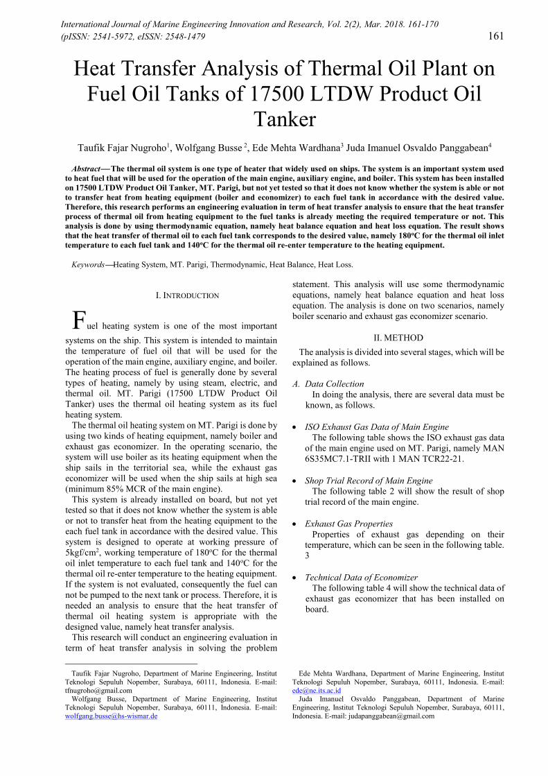
The following figure is an example in calculating thetotal resistance of thermal resistance network equation.
Based on figure 1., the total resistance formula canbe arranged as the following equation.
Rtotal = + + (8)
Where, h1 and h2 are convection heat transfercoefficient in W/m2K, respectively; L is length of theobject in m; K is thermal conductivity in W/m2K; andA is area of the object in m2.
The heat losses that occur along distribution line aredefined in each section of the pipe. The initial scenarioof the distribution path for all tanks is the same, that is,starting from distribution line to consumer line. Rightafter that, the pipe will be branched off according tothe position of each tank. Return path scenario ofthermal oil after passing the fuel tank is the same asthe line of thermal oil distribution.
Time Needed to Heat Fuel OilThis analysis is intended to determine how long
time needed to heat fuel in each fuel tanks, namelystorage tank portside, storage tank starboard, settlingtank, service tank portside, and service tank starboardin two scenarios, by using boiler and economizer.
164International Journal of Marine Engineering Innovation and Research, Vol. 2(2), Mar. 2018. 161-170(pISSN: 2541-5972, eISSN: 2548-1479)
Figure 1. Thermal Resistance Network
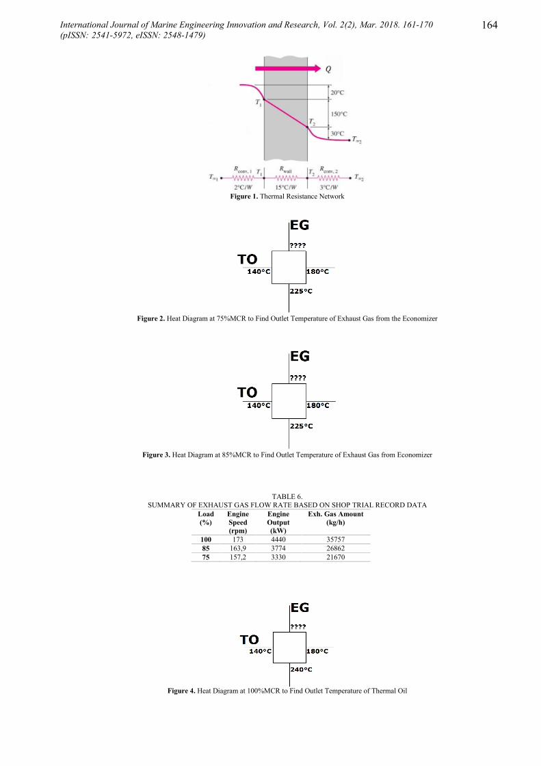
Figure 2. Heat Diagram at 75%MCR to Find Outlet Temperature of Exhaust Gas from the Economizer
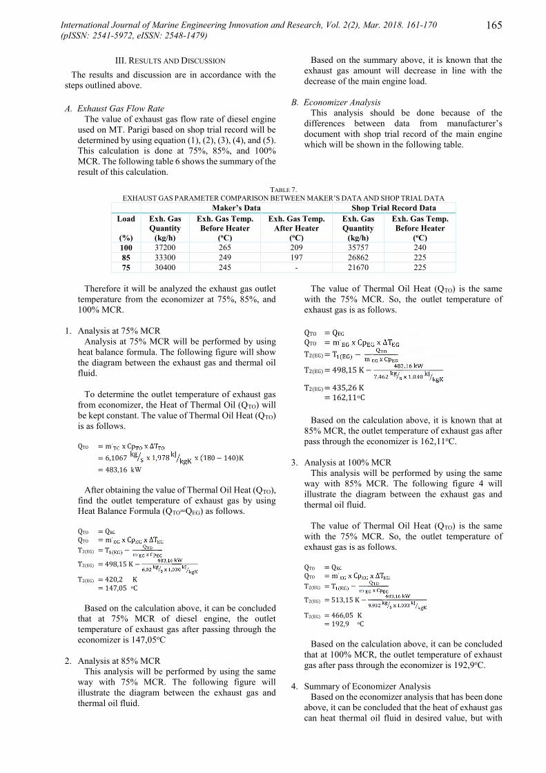
Figure 3. Heat Diagram at 85%MCR to Find Outlet Temperature of Exhaust Gas from Economizer
TABLE 6.SUMMARY OF EXHAUST GAS FLOW RATE BASED ON SHOP TRIAL RECORD DATA
Load(%)
EngineSpeed(rpm)
EngineOutput(kW)
Exh. Gas Amount(kg/h)
100 173 4440 3575785 163,9 3774 2686275 157,2 3330 21670
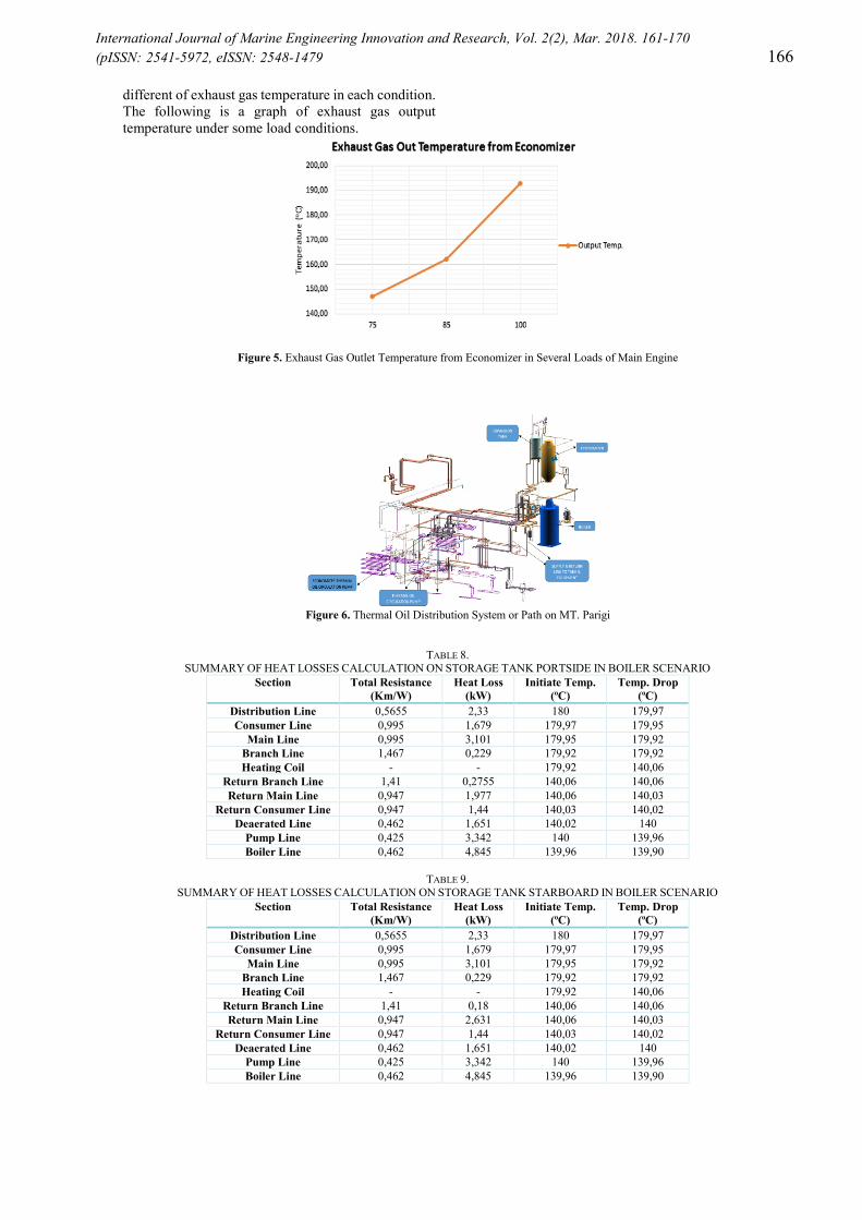
Figure 4. Heat Diagram at 100%MCR to Find Outlet Temperature of Thermal Oil
165International Journal of Marine Engineering Innovation and Research, Vol. 2(2), Mar. 2018. 161-170(pISSN: 2541-5972, eISSN: 2548-1479)
III. RESULTS AND DISCUSSION
The results and discussion are in accordance with thesteps outlined above.
A. Exhaust Gas Flow RateThe value of exhaust gas flow rate of diesel engine
used on MT. Parigi based on shop trial record will bedetermined by using equation (1), (2), (3), (4), and (5).This calculation is done at 75%, 85%, and 100%MCR. The following table 6 shows the summary of theresult of this calculation.
Based on the summary above, it is known that theexhaust gas amount will decrease in line with thedecrease of the main engine load.
B. Economizer AnalysisThis analysis should be done because of the
differences between data from manufacturer’sdocument with shop trial record of the main enginewhich will be shown in the following table.
TABLE 7.EXHAUST GAS PARAMETER COMPARISON BETWEEN MAKER’S DATA AND SHOP TRIAL DATA
Maker’s Data Shop Trial Record DataLoad
(%)
Exh. GasQuantity
(kg/h)
Exh. Gas Temp.Before Heater
(oC)
Exh. Gas Temp.After Heater
(oC)
Exh. GasQuantity
(kg/h)
Exh. Gas Temp.Before Heater
(oC)100 37200 265 209 35757 24085 33300 249 197 26862 22575 30400 245 - 21670 225
Therefore it will be analyzed the exhaust gas outlettemperature from the economizer at 75%, 85%, and100% MCR.
1. Analysis at 75% MCRAnalysis at 75% MCR will be performed by using
heat balance formula. The following figure will showthe diagram between the exhaust gas and thermal oilfluid.
To determine the outlet temperature of exhaust gasfrom economizer, the Heat of Thermal Oil (QTO) willbe kept constant. The value of Thermal Oil Heat (QTO)is as follows.QTO = m∙ x Cp x ∆T= 6,1067 kg s x 1,978 kJ kgK x (180 − 140)K= 483,16 kW
After obtaining the value of Thermal Oil Heat (QTO),find the outlet temperature of exhaust gas by usingHeat Balance Formula (QTO=QEG) as follows.QTO = QEGQTO = m∙ x Cp x ∆TT2(EG) = T ( ) − ∙T2(EG) = 498,15 K − ,, ,T2(EG) = 420,2 K= 147,05 oC
Based on the calculation above, it can be concludedthat at 75% MCR of diesel engine, the outlettemperature of exhaust gas after passing through theeconomizer is 147,05oC
2. Analysis at 85% MCRThis analysis will be performed by using the same
way with 75% MCR. The following figure willillustrate the diagram between the exhaust gas andthermal oil fluid.
The value of Thermal Oil Heat (QTO) is the samewith the 75% MCR. So, the outlet temperature ofexhaust gas is as follows.QTO = QEGQTO = m∙ x Cp x ∆TT2(EG) = T ( ) − ∙T2(EG) = 498,15 K − ,, ,T2(EG) = 435,26 K= 162,11oC
Based on the calculation above, it is known that at85% MCR, the outlet temperature of exhaust gas afterpass through the economizer is 162,11oC.
3. Analysis at 100% MCRThis analysis will be performed by using the same
way with 85% MCR. The following figure 4 willillustrate the diagram between the exhaust gas andthermal oil fluid.
The value of Thermal Oil Heat (QTO) is the samewith the 75% MCR. So, the outlet temperature ofexhaust gas is as follows.QTO = QEGQTO = m∙ x Cp x ∆TT2(EG) = T ( ) − ∙T2(EG) = 513,15 K − ,, ,T2(EG) = 466,05 K= 192,9 oC
Based on the calculation above, it can be concludedthat at 100% MCR, the outlet temperature of exhaustgas after pass through the economizer is 192,9oC.
4. Summary of Economizer AnalysisBased on the economizer analysis that has been done
above, it can be concluded that the heat of exhaust gascan heat thermal oil fluid in desired value, but with
International Journal of Marine Engineering Innovation and Research, Vol. 2(2), Mar. 2018. 161-170(pISSN: 2541-5972, eISSN: 2548-1479 166
different of exhaust gas temperature in each condition.The following is a graph of exhaust gas outputtemperature under some load conditions.
Figure 5. Exhaust Gas Outlet Temperature from Economizer in Several Loads of Main Engine
Figure 6. Thermal Oil Distribution System or Path on MT. Parigi
TABLE 8.SUMMARY OF HEAT LOSSES CALCULATION ON STORAGE TANK PORTSIDE IN BOILER SCENARIO
Section Total Resistance(Km/W)
Heat Loss(kW)
Initiate Temp.(oC)
Temp. Drop(oC)
Distribution Line 0,5655 2,33 180 179,97Consumer Line 0,995 1,679 179,97 179,95
Main Line 0,995 3,101 179,95 179,92Branch Line 1,467 0,229 179,92 179,92Heating Coil - - 179,92 140,06
Return Branch Line 1,41 0,2755 140,06 140,06Return Main Line 0,947 1,977 140,06 140,03
Return Consumer Line 0,947 1,44 140,03 140,02Deaerated Line 0,462 1,651 140,02 140
Pump Line 0,425 3,342 140 139,96Boiler Line 0,462 4,845 139,96 139,90
TABLE 9.SUMMARY OF HEAT LOSSES CALCULATION ON STORAGE TANK STARBOARD IN BOILER SCENARIO
Section Total Resistance(Km/W)
Heat Loss(kW)
Initiate Temp.(oC)
Temp. Drop(oC)
Distribution Line 0,5655 2,33 180 179,97Consumer Line 0,995 1,679 179,97 179,95
Main Line 0,995 3,101 179,95 179,92Branch Line 1,467 0,229 179,92 179,92Heating Coil - - 179,92 140,06
Return Branch Line 1,41 0,18 140,06 140,06Return Main Line 0,947 2,631 140,06 140,03
Return Consumer Line 0,947 1,44 140,03 140,02Deaerated Line 0,462 1,651 140,02 140
Pump Line 0,425 3,342 140 139,96Boiler Line 0,462 4,845 139,96 139,90

International Journal of Marine Engineering Innovation and Research, Vol. 2(2), Mar. 2018. 161-170(pISSN: 2541-5972, eISSN: 2548-1479 167
From the graph above, it can be concluded that the outlettemperature of exhaust gas is directly proportional to theengine load. So, when the engine load decreases, the outlettemperature of exhaust gas from economizer will go downas well. It can happen because the exhaust gas temperatureof the engine decreases in accordance with the engine loadat 75%, 85%, and 100% MCR.
C. Heat Loss AnalysisHeat loss analysis is done in two scenarios, namely
boiler scenario and economizer scenario. This analysisis performed by using equation (6), (7), and (8). The
following figure shows the distribution line or path ofthermal oil system on MT. Parigi.
Boiler ScenarioBoiler scenario is equipped with two pumps with the
same capacity of 163,5 m3/h. The following tablessummarize the calculation of heat losses in eachsection for storage tank portside, storage tankstarboard, settling tank, service tank portside, andservice tank starboard in boiler scenario.
TABLE 10.SUMMARY OF HEAT LOSSES CALCULATION ON SETTLING TANK IN BOILER SCENARIO
Section Total Resistance(Km/W)
Heat Loss(kW)
Initiate Temp.(oC)
Temp. Drop(oC)
Distribution Line 0,5655 2,33 180 179,97Consumer Line 0,995 1,679 179,97 179,95
Main Line 0,995 1,642 179,95 179,93Branch Line 2,071 0,74 179,93 179,93Heating Coil - - 179,93 140,06
Return Branch Line 2,292 0,491 140,06 140,05Return Main Line 0,947 2,040 140,05 140,03
Return Consumer Line 0,947 1,44 140,03 140,02Deaerated Line 0,462 1,651 140,02 140
Pump Line 0,425 3,342 140 139,96Boiler Line 0,462 4,845 139,96 139,90
TABLE 11.SUMMARY OF HEAT LOSSES CALCULATION ON SERVICE TANK PORTSIDE IN BOILER SCENARIO
Section Total Resistance(Km/W)
Heat Loss(kW)
Initiate Temp.(oC)
Temp. Drop(oC)
Distribution Line 0,5655 2,33 180 179,97Consumer Line 0,995 1,679 179,97 179,95
Main Line 0,995 1,683 179,95 179,93Branch Line 2,071 0,796 179,93 179,93Heating Coil - - 179,93 140,06
Return Branch Line 2,292 0,535 140,06 140,05Return Main Line 0,947 2,073 140,05 140,03
Return Consumer Line 0,947 1,44 140,03 140,02Deaerated Line 0,462 1,651 140,02 140
Pump Line 0,425 3,342 140 139,96Boiler Line 0,462 4,845 139,96 139,90
TABLE 12.SUMMARY OF HEAT LOSSES CALCULATION ON SERVICE TANK STARBOARD IN BOILER SCENARIO
Section Total Resistance(Km/W)
Heat Loss(kW)
Initiate Temp.(oC)
Temp. Drop(oC)
Distribution Line 0,5655 2,33 180 179,97Consumer Line 0,995 1,679 179,97 179,95
Main Line 0,995 2,676 179,95 179,92Branch Line 2,071 0,732 179,92 179,91Heating Coil - - 179,91 140,06
Return Branch Line 2,292 0,433 140,06 140,05Return Main Line 0,947 2,091 140,05 140,03
Return Consumer Line 0,947 1,44 140,03 140,02Deaerated Line 0,462 1,651 140,02 140
Pump Line 0,425 3,342 140 139,96Boiler Line 0,462 4,845 139,96 139,90
Based on the tables above, it is known that the inlettemperature of thermal oil into each fuel tank is around179,92oC and the outlet temperature of thermal oilfrom each fuel tank are 140,06oC. Then, thermal oilwill re-enter the boiler with the temperature of139,90oC.
Economizer ScenarioEconomizer scenario is equipped with two pumps
with the same capacity of 23,7 m3/h. The heat lossesthat happened is the same with the boiler scenario. Thefollowing tables summarize the calculation of heatlosses in each section for storage tank portside, storagetank starboard, settling tank, service tank portside, andservice tank starboard in economizer scenario.

International Journal of Marine Engineering Innovation and Research, Vol. 2(2), Mar. 2018. 161-170(pISSN: 2541-5972, eISSN: 2548-1479 168
TABLE 13.SUMMARY OF HEAT LOSSES CALCULATION ON STORAGE TANK PORTSIDE IN ECONOMIZER SCENARIO
Section Total Resistance(Km/W)
Heat Loss(kW)
Initiate Temp.(oC)
Temp. Drop(oC)
Distribution Line (65A) 0,995 1,979 180 179,84Distribution Line (125A) 0,659 0,066 179,84 179,84Distribution Line (150A) 0,565 1,144 179,84 179,75
Consumer Line 0,995 1,676 179,75 179,61Main Line 0,995 2,491 179,61 179,41
Branch Line 1,467 0,357 179,41 179,39Heating Coil - - 179,39 140,71
Return Branch Line 1,41 0,277 140,71 140,69Return Main Line 0,947 1,989 140,69 140,52
Return Consumer Line 0,947 1,448 140,52 140,40Deaerated Line 0,462 1,658 140,40 140,27
Pump Line 0,822 2,308 140,27 140,07Economizer Line 0,947 1,398 140,07 139,96
TABLE 14.SUMMARY OF HEAT LOSSES CALCULATION ON STORAGE TANK STARBOARD IN ECONOMIZER SCENARIO
Section Total Resistance(Km/W)
Heat Loss(kW)
Initiate Temp.(oC)
Temp. Drop(oC)
Distribution Line (65A) 0,995 1,979 180 179,84Distribution Line (125A) 0,659 0,066 179,84 179,84Distribution Line (150A) 0,565 1,144 179,84 179,75
Consumer Line 0,995 1,676 179,75 179,61Main Line 0,995 3,093 179,61 179,37
Branch Line 1,467 0,229 179,37 179,35Heating Coil - - 179,35 140,74
Return Branch Line 1,41 0,181 140,74 140,72Return Main Line 0,947 2,645 140,72 140,51
Return Consumer Line 0,947 1,448 140,51 140,40Deaerated Line 0,462 1,658 140,40 140,27
Pump Line 0,822 2,308 140,27 140,07Economizer Line 0,947 1,398 140,07 139,96
TABLE 15.SUMMARY OF HEAT LOSSES CALCULATION ON SETTLING TANK IN ECONOMIZER SCENARIO
Section Total Resistance(Km/W)
Heat Loss(kW)
Initiate Temp.(oC)
Temp. Drop(oC)
Distribution Line (65A) 0,995 1,979 180 179,84Distribution Line (125A) 0,659 0,066 179,84 179,84Distribution Line (150A) 0,565 1,144 179,84 179,75
Consumer Line 0,995 1,676 179,75 179,61Main Line 0,995 1,638 179,61 179,48
Branch Line 2,071 0,737 179,48 179,42Heating Coil - - 179,42 140,68
Return Branch Line 2,292 0,494 140,68 140,64Return Main Line 0,947 2,052 140,64 140,47
Return Consumer Line 0,947 1,448 140,47 140,40Deaerated Line 0,462 1,658 140,40 140,27
Pump Line 0,822 2,308 140,27 140,07Economizer Line 0,947 1,398 140,07 139,96
TABLE 16.SUMMARY OF HEAT LOSSES CALCULATION ON SERVICE TANK PORTSIDE IN ECONOMIZER SCENARIO
Section Total Resistance(Km/W)
Heat Loss(kW)
Initiate Temp.(oC)
Temp. Drop(oC)
Distribution Line (65A) 0,995 1,979 180 179,84Distribution Line (125A) 0,659 0,066 179,84 179,84Distribution Line (150A) 0,565 1,144 179,84 179,75
Consumer Line 0,995 1,676 179,75 179,61Main Line 0,995 1,679 179,61 179,48
Branch Line 2,071 0,793 179,48 179,42Heating Coil - - 179,42 140,68
Return Branch Line 2,292 0,539 140,68 140,64Return Main Line 0,947 2,086 140,64 140,46
Return Consumer Line 0,947 1,448 140,46 140,40Deaerated Line 0,462 1,658 140,40 140,27
Pump Line 0,822 2,308 140,27 140,07Economizer Line 0,947 1,398 140,07 139,96

International Journal of Marine Engineering Innovation and Research, Vol. 2(2), Mar. 2018. 161-170(pISSN: 2541-5972, eISSN: 2548-1479 169
TABLE 17.SUMMARY OF HEAT LOSSES CALCULATION ON SERVICE TANK STARBOARD IN ECONOMIZER SCENARIO
Section Total Resistance(Km/W)
Heat Loss(kW)
Initiate Temp.(oC)
Temp. Drop(oC)
Distribution Line (65A) 0,995 1,979 180 179,84Distribution Line (125A) 0,659 0,066 179,84 179,84Distribution Line (150A) 0,565 1,144 179,84 179,75
Consumer Line 0,995 1,676 179,75 179,61Main Line 0,995 2,669 179,61 179,40
Branch Line 2,071 0,729 179,40 179,34Heating Coil - - 179,34 140,76
Return Branch Line 2,292 0,436 140,76 140,72Return Main Line 0,947 2,105 140,72 140,55
Return Consumer Line 0,947 1,448 140,55 140,40Deaerated Line 0,462 1,658 140,40 140,27
Pump Line 0,822 2,308 140,27 140,07Economizer Line 0,947 1,398 140,07 139,96
Based on the tables above, it is known that ineconomizer scenario, the inlet temperature of thermaloil into each fuel tank is around 179,40oC and theoutlet temperature of thermal oil from each fuel tankare around 140,70oC. Then, thermal oil will re-enterthe economizer with the temperature of 139,96oC.
D. Time Needed to Heat Fuel
Time needed to heat fuel is divided into twoscenarios, by using boiler scenario and economizerscenario. It can be done by using the same formula aseconomizer analysis, namely compare the heat of fueloil with the heat produced by thermal oil circulationinside the heating coil. The following table shows thesummary of heating duration by using both scenarios.
TABLE 18.HEATING DURATION SUMMARY OF THERMAL OIL SYSTEM ON MT. PARIGI
Fuel Oil Tanks Heating Duration(hours)
BoilerScenario
EconomizerScenario
Storage Tank P/S 0,673 4,706Storage Tank S/B 0,701 4,907
Settling Tank 0,053 0,369Service Tank P/S 0,105 0,730Service Tank S/B 0,105 0,732
TABLE 19.SUMMARY OF TEMPERATURE INLET, OUTLET, AND RE-ENTERED HEATING EQUIPMENTS
Fuel Oil Tanks Temperatures(oC)
Boiler Scenario Economizer ScenarioInput Output Re-entered Input Output Re-entered
Storage Tank P/S 179,92 140,06 139,90 179,39 140,71 139,96Storage Tank S/B 179,92 140,06 139,90 179,35 140,74 139,96
Settling Tank 179,93 140,06 139,90 179,42 140,68 139,96Service Tank P/S 179,93 140,06 139,90 179,42 140,68 139,96Service Tank S/B 179,91 140,06 139,90 179,34 140,76 139,96
From the table above, it is known that the longest andshortest time needed to heat fuel in boiler scenario isstorage tank starboard and settling tank, namely 0,701and 0,053 hours respectively. Then, the longest andshortest time needed to heat fuel in economizerscenario is storage tank starboard and settling tank,namely 4,907 and 0,369 hours respectively.
IV. CONCLUSION
Based on data analyses, results, and discussion whichhave been done above, there are several conclusion can bemade as follows.1. The exhaust gas flow rates based on shop test result
are as follows. 75% MCR of Main Engine, exhaust gas flow
rate is 21670 kg/h; 85% MCR of Main Engine, exhaust gas flow
rate is 26862 kg/h; 100% MCR of Main Engine, exhaust gas
flow rate is 35757 kg/h.
International Journal of Marine Engineering Innovation and Research, Vol. 2(2), Mar. 2018. 161-170(pISSN: 2541-5972, eISSN: 2548-1479 170
2. The exhaust gas outlet temperatures from the exhaustgas economizer on MT. Parigi based on shop testresult are as follow. 75% MCR of Main Engine, exhaust gas
outlet temperature from economizer is147,05oC;
85% MCR of Main Engine, exhaust gasoutlet tempearature from economizer is162,11oC;
100% MCR of Main Engine, exhaust gasoutlet temperature from economizer is192,9oC.
3. Thermal oil heating system on MT. Parigi is able todistribute heat to each fuel oil tank in accordance withthe design value in order to increase the fuel oiltemperature inside each fuel tanks, both using boilerscenario and economizer scenario, as follows.
From the table above, it is known that the re-enteredtemperature of the thermal oil to the heatingequipment in boiler scenario is lower than economizerscenario. It happens because the pump capacity inboiler scenario is bigger than the pump capacity ineconomizer. Bigger the capacity of the pump, thevalue of temperature decrease also become bigger.
4. Based on the summary of heating duration in table 18,it is known that boiler scenario has faster heatingduration than economizer scenario in full pumpcapacity. It can happen because the pump capacity ofboiler scenario is bigger than the pump capacity ofeconomizer scenario. The bigger pump capacity, thefaster the duration of heating will take place.
REFERENCES
[1] M. Diesel, MAN B&W S35MC7-TII Project GuideCamshaft Controlled Two-Stroke Engines,Copenhagen, 2010.
[2] John H. Lienhard IV , John H. Lienhard V, A HeatTransfer Textbook 4th Edition, Houston,Cambridge: Phlogiston Press, 2017.
[3] S. P. Fitri, Heat Transfer Modes & Conduction HeatTransfer, Surabaya, 2014.
[4] A. Hitam, "Flow Diagram Thermal Oil MainSystem & Flow Diagram Heat Consumers," Batam.