Pier 2013 Meng
16
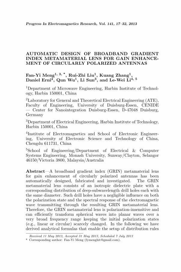
Progress In Electromagnetics Research, Vol. 141, 17–32, 2013 AUTOMATIC DESIGN OF BROADBAND GRADIENT INDEX METAMATERIAL LENS FOR GAIN ENHANCE- MENT OF CIRCULARLY POLARIZED ANTENNAS Fan-Yi Meng 1, 3, * , Rui-Zhi Liu 1 , Kuang Zhang 1 , Daniel Erni 2 , Qun Wu 1 , Li Sun 3 , and Le-Wei Li 4, 5 1 Department of Microwave Engineering, Harbin Institute of Technol- ogy, Harbin 150001, China 2 Laboratory for General and Theoretical Electrical Engineering (ATE), Faculty of Engineering, University of Duisburg-Essen, CENIDE — Center for Nanointegration Duisburg-Essen, D-47048 Duisburg, Germany 3 Department of Electrical Engineering, Harbin Institute of Technology, Harbin 150001, China 4 Institute of Electromagnetics and School of Electronic Engineer- ing, University of Electronic Science and Technology of China, Chengdu 611731, China 5 School of Engineering/Department of Electrical & Computer Systems Engineering, Monash University, Sunway/Clayton, Selangor 46150/Victoria 3800, Malaysia/Australia Abstract—A broadband gradient index (GRIN) metamaterial lens for gain enhancement of circularly polarized antennas has been automatically designed, fabricated and investigated. The GRIN metamaterial lens consists of an isotropic dielectric plate with a corresponding distribution of deep-subwavelength drill holes each with the same diameter. Such drill holes have a negligible influence on both the polarization state and the spectral response of the electromagnetic wave transmitting through the resulting GRIN metamaterial lens. Therefore, the GRIN metamaterial lens is polarization-insensitive and can efficiently transform spherical waves into planar waves over a very broad frequency range keeping the initial polarization states (e.g., linear or circular) scarcely changed. In the following we have derived analytical formulas that enable the setup of distribution rules Received 11 May 2013, Accepted 31 May 2013, Scheduled 7 July 2013 * Corresponding author: Fan-Yi Meng ([email protected]).
-
Upload
independent -
Category
Documents
-
view
0 -
download
0
Transcript of Pier 2013 Meng
Progress In Electromagnetics Research, Vol. 141, 17–32, 2013
AUTOMATIC DESIGN OF BROADBAND GRADIENTINDEX METAMATERIAL LENS FOR GAIN ENHANCE-MENT OF CIRCULARLY POLARIZED ANTENNAS
Fan-Yi Meng1, 3, *, Rui-Zhi Liu1, Kuang Zhang1,Daniel Erni2, Qun Wu1, Li Sun3, and Le-Wei Li4, 5
1Department of Microwave Engineering, Harbin Institute of Technol-ogy, Harbin 150001, China2Laboratory for General and Theoretical Electrical Engineering (ATE),Faculty of Engineering, University of Duisburg-Essen, CENIDE— Center for Nanointegration Duisburg-Essen, D-47048 Duisburg,Germany3Department of Electrical Engineering, Harbin Institute of Technology,Harbin 150001, China4Institute of Electromagnetics and School of Electronic Engineer-ing, University of Electronic Science and Technology of China,Chengdu 611731, China5School of Engineering/Department of Electrical & ComputerSystems Engineering, Monash University, Sunway/Clayton, Selangor46150/Victoria 3800, Malaysia/Australia
Abstract—A broadband gradient index (GRIN) metamaterial lensfor gain enhancement of circularly polarized antennas has beenautomatically designed, fabricated and investigated. The GRINmetamaterial lens consists of an isotropic dielectric plate with acorresponding distribution of deep-subwavelength drill holes each withthe same diameter. Such drill holes have a negligible influence on boththe polarization state and the spectral response of the electromagneticwave transmitting through the resulting GRIN metamaterial lens.Therefore, the GRIN metamaterial lens is polarization-insensitive andcan efficiently transform spherical waves into planar waves over avery broad frequency range keeping the initial polarization states(e.g., linear or circular) scarcely changed. In the following we havederived analytical formulas that enable the setup of distribution rules
Received 11 May 2013, Accepted 31 May 2013, Scheduled 7 July 2013* Corresponding author: Fan-Yi Meng ([email protected]).
18 Meng et al.
for the drill holes on the plate. Based on these formulas, theGRIN metamaterial lens can be automatically designed and easilyfabricated using circuit board engraving machines. The proposedGRIN metamaterial lens has been tested by placing it on the apertureof a circularly polarized conical horn antenna. The agreement betweensimulation and measurement results shows that the gain of the hornantenna has been significantly increased within the whole X-band (i.e.,from 8 GHz to 12 GHz) and the largest gain enhancement reaches upto 5.7 dB. In particular, the axial ratio of the horn antenna with theGRIN metamaterial lens is less than 1.6 dB.
1. INTRODUCTION
Lens antennas have attracted extensive attention owing to theirexcellent directional radiation performance. The most important partin any lens antenna design lies in the proper definition of the microwavelens, where the latter provides a direct access to the performanceparameters such as bandwidth, gain and efficiency.
In reality, lenses have already been proposed decades ago —namely in the 1940s — as a highly efficient measure to improve theperformance of antennas. In these early stages metallic lens antennassuch as metal-lens antennas and wire-grid lens antennas [1], reflectorlens antennas [2], spherical antennas [3], dual lens antennas [4], as wellas dielectric lens antennas [5], and substrate lens antennas [6] weresuccessfully investigated. Virtually all of these lens designs delicatelyrely on non-planar structures, which are difficult to fabricate especiallybecause of the required machining accuracy. Planar antenna lensessuch as artificial dielectric lenses [7] and dipole array lenses [8] maysolve the problem to some extent. However, the underlying multilayerstructures of artificial dielectric lenses tend to increase the transmissionlosses, whereas the area of the dipole array lenses is usually much largerthan the aperture of the feeding horn antenna.
As research of artificial electromagnetic materials continues,metamaterials, which were first realized by Pendry [9] and Smith [10],are applied to design novel antenna lenses such as zero-indexmetamaterial (ZIM) lenses and GRIN metamaterials lenses. However,for most ZIM lenses, the impedance mismatch turns out to bea vital problem [11, 12]. Even though anisotropic ZIM lenseswith appropriately designed constitutive tensors can provide goodimpedance matching to free space [13], at present, the realizedanisotropic ZIM lenses are either limited in bandwidth or extremelydifficult to fabricate. In [13], a planar two-dimensional anisotropicZIM lens has been realized to increase the gain of a Vivaldi antenna
Progress In Electromagnetics Research, Vol. 141, 2013 19
within a considerably large bandwidth, but such ZIM lenses arebarely applicable to three-dimensional antennas such as horns. GRINlenses, however, based, e.g., on properly graded metamaterials haveattracted increasing attention over recent years because they are easyto fabricate (even for optical frequencies), and offer much betterimpedance matching to free space compared to ZIM lenses.
The initial concept of GRIN metamaterials was actually proposedby Smith et al. [14] just before the first GRIN metamaterial lens,which possessed a negative refractive index, was realized for free-space microwave focusing by Driscoll et al. [15]. Recently, GRINmetamaterial lenses consisting of resonant metamaterials with apositive index of refraction were designed to transform cylindrical orspherical waves into planar waves, yielding antennas with an increaseddirectivity [16–25]. In particular a highly-sophisticated broadband,dual-linear-polarized, and high-directivity lens horn antenna usingGRIN metamaterials, composed of multi-layer microstrip square-ringarrays, was presented in [24]. However, there are still some openissues left in the recent studies of GRIN metamaterial lenses. Onone hand, all GRIN metamaterial lenses presented so far are highlypolarization sensitive. Their characteristic electromagnetic response isonly supported for predefined linear polarization states. Polarization-insensitive GRIN metamaterial lenses would be highly desirable formany applications, such as, e.g., satellite communications, where it isnecessary to work with circularly polarized waves. For all these cases,the implementation of GRIN metamaterial lenses requires polarization-independent design concepts.
On the other hand — similar to metamaterial cloaks — idealGRIN metamaterial lenses rely on a continuous distribution of the(effective) refractive index that is achieved by a proper grading ofthe unit cells in the underlying metamaterial structure. Hence,any continuous index distribution has to be approximated by adiscrete set of various metamaterial sections where each of themcontains unit cells either of correspondingly altered shape or with asubstantially different topology. In general, the geometric parametersof the metamaterial unit cells are obtained through extensive full-wavenumerical simulation with no regard for the potential applicability ofany approximate analytical synthesis methodology. In this case thedesign procedure of GRIN metamaterial lenses may become extremelyarduous, let alone the resulting high manufacturing costs.
In response to these issues, we propose a simple and highly efficientautomatic design and fabrication method for broadband polarization-insensitive GRIN metamaterial lenses. The GRIN metamaterial lensencompasses a non-resonant metamaterial layer that is represented
20 Meng et al.
by an isotropic dielectric slab accordingly perforated with drill holesof deep-subwavelength dimensions, where the desired polarizationinsensitivity is already fostered by the non-resonant nature of theunderlying metamaterial. We also derive analytical formulas describingthe proper distribution rules of the drill holes mimicking the intendedgrading of the GRIN lens. The fabricated lens structure is then bothnumerically and experimentally validated by placing it on the apertureof a circularly polarized conical horn antenna.
2. AUTOMATIC DESIGN METHOD OF GRINMETAMATERIAL LENS
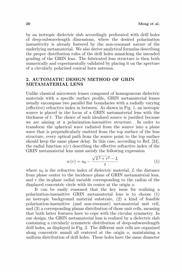
Unlike classical microwave lenses composed of homogeneous dielectricmaterials with a specific surface profile, GRIN metamaterial lensesusually encompass two parallel flat boundaries with a radially varying(effective) refractive index in between. As shown in Fig. 1, an isotropicsource is placed in the focus of a GRIN metamaterial lens with thethickness of t. The choice of such idealized source is justified becausewe are aiming at a polarization-insensitive structure. In order totransform the spherical wave radiated from the source into a planewave that is perpendicularly emitted from the top surface of the lensstructure, every optical path from the source point to the top surfaceshould keep the same phase delay. In this case, according to Ref. [24],the radial function n(r) describing the effective refractive index of theGRIN metamaterial lens must satisfy the following expression
n (r) = n0 −√
L2 + r2 − L
t(1)
where n0 is the refractive index of dielectric material, L the distancefrom phase center to the incidence plane of GRIN metamaterial lens,and r the in-plane radial variable corresponding to the radius of thedisplayed concentric circle with its center at the origin o.
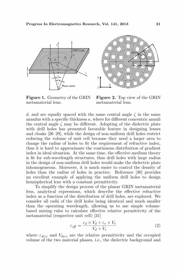
It can be easily reasoned that the key issue for realizing apolarization-insensitive GRIN metamaterial lens is to choose (1)an isotropic background material substrate, (2) a kind of feasiblepolarization-insensitive (and non-resonant) metamaterial unit cell,and (3) a corresponding planar distribution of those unit cells, meaningthat both latter features have to cope with the circular symmetry. Inour design, the GRIN metamaterial lens is realized by a dielectric slabcontaining a circularly symmetric distribution of deep-subwavelengthdrill holes, as displayed in Fig. 2. The different unit cells are organizedalong concentric annuli all centered at the origin o, maintaining auniform distribution of drill holes. These holes have the same diameter
Progress In Electromagnetics Research, Vol. 141, 2013 21
Figure 1. Geometry of the GRINmetamaterial lens.
y
zx
Figure 2. Top view of the GRINmetamaterial lens.
d, and are equally spaced with the same central angle ζ in the sameannulus with a specific thickness a, where for different concentric annulithe central angle ζ may be different. Adopting of the dielectric platewith drill holes has presented favorable feature in designing lensesand cloaks [26–29], while the design of non-uniform drill holes restrictreducing the volume of unit cell because they need a larger area tochange the radius of holes to fit the requirement of refractive index,thus it is hard to approximate the continuous distribution of gradientindex in ideal situation. At the same time, the effective medium theoryis fit for sub-wavelength structures, thus drill holes with large radiusin the design of non-uniform drill holes would make the dielectric plateinhomogeneous. Moreover, it is much easier to control the density ofholes than the radius of holes in practice. Reference [30] providesan excellent example of applying the uniform drill holes to designhemispherical lens with a constant permittivity.
To simplify the design process of the planar GRIN metamateriallens, analytical expressions, which describe the effective refractiveindex as a function of the distribution of drill holes, are explored. Weconsider all radii of the drill holes being identical and much smallerthan the operating wavelength, allowing us to use simple volume-based mixing rules to calculate effective relative permittivity of themetamaterial (respective unit cell) [31]
εeff =εd × Vd + εv × Vv
Vd + Vv(2)
where εd(v) and Vd(v) are the relative permittivity and the occupiedvolume of the two material phases, i.e., the dielectric background and
22 Meng et al.
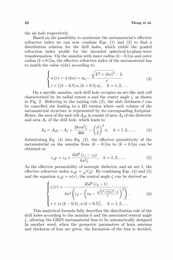
the air hole respectively.Based on the possibility to synthesize the metamaterial’s effective
refractive index we can now combine Eqs. (1) and (2) to find adistribution relation for the drill holes, which yields the gradedrefraction index profile for the intended spherical-to-plane-wavetransformation. On the annulus with inner radius (k−0.5)a and outerradius (k+0.5)a, the effective refractive index of the metamaterial hasto match the value n(ka) according to
n (r) = n (ka) = n0 −
�L2 + (ka)2 − L
tr ∈ ((k − 0.5) a, (k + 0.5) a] , k = 1, 2, . . .
. (3)
On a specific annulus, each drill hole occupies an arc-like unit cellcharacterized by its radial extent a and the center angle ζ as shownin Fig. 2. Referring to the mixing rule (2), the slab thickness t canbe cancelled out leading to a 2D version where each volume of themetamaterial structure is represented by its corresponding footprint.Hence, the area of the unit cell Aall is consist of area Ad of the dielectricand area Av of the drill hole, which leads to
Ad = Aall −Av =2kπa2ζ
360−
�d
2
�2
π, k = 1, 2, . . . . (4)
Substituting Eq. (4) into Eq. (2), the effective permittivity of themetamaterial on the annulus from (k − 0.5)a to (k + 0.5)a can beobtained as
εeff = εd +45d2 (εv − εd)
ka2ζ, k = 1, 2, . . . . (5)
As the effective permeability of isotropic dielectric and air are 1, theeffective refractive index neff = √
εeff . By combining Eqs. (4) and (5)and the equation neff = n(r), the central angle ζ can be derived as
ζ (r) =45d2 (εd − 1)
ka2
�εd −
�n0 −
√L2+(ka)2−L
t
�2�
r ∈ (a (k − 0.5) , a (k + 0.5)] , k = 1, 2, . . .
. (6)
This analytical formula fully describes the distribution rule of thedrill holes according to the annulus k and the associated central angleζ, allowing the GRIN metamaterial lens to be automatically designedIn another word, when the geometric parameters of horn antennaand thickness of lens are given, the formation of the lens is decided,
Progress In Electromagnetics Research, Vol. 141, 2013 23
which means that to antennas with different parameters, we can getthe construction of lens only by substituting the geometrical withoutreconsidering the distribution of holes.
It is worth noting that, utilizing the VBA macro programminglanguage in the CST MW STUDIO software package, the setup of thesimulation model for the designed GRIN metamaterial lens antennacan be fully automated.
3. NUMERICAL SIMULATION
In order to validate the automatic design method of the GRINmetamaterial lens, a prototype is designed based on the Eq. (6) andnumerical simulations with CST Microwave Studio software packagehave been carried out. As shown in Fig. 3, the simulation modelconsists of the GRIN metamaterial lens prototype placed in the frontof a conical horn antenna.
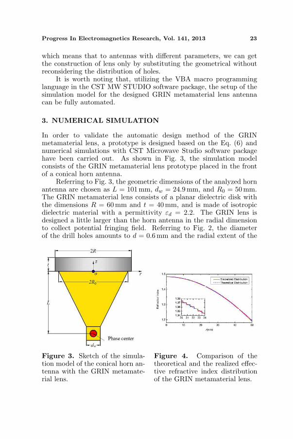
Referring to Fig. 3, the geometric dimensions of the analyzed hornantenna are chosen as L = 101 mm, dw = 24.9mm, and R0 = 50 mm.The GRIN metamaterial lens consists of a planar dielectric disk withthe dimensions R = 60 mm and t = 40 mm, and is made of isotropicdielectric material with a permittivity εd = 2.2. The GRIN lens isdesigned a little larger than the horn antenna in the radial dimensionto collect potential fringing field. Referring to Fig. 2, the diameterof the drill holes amounts to d = 0.6mm and the radial extent of the
Figure 3. Sketch of the simula-tion model of the conical horn an-tenna with the GRIN metamate-rial lens.
Figure 4. Comparison of thetheoretical and the realized effec-tive refractive index distributionof the GRIN metamaterial lens.
24 Meng et al.
annulus is chosen to be a = 0.65mm leading to total 92 annuli including77 annuli positioned insider the horn antenna aperture (r ≤ 50mm)and 15 annuli outside the aperture (50 mm < r ≤ 60mm). Theconical horn antenna operates in the X-band from 8 GHz to 12 GHz.Substituting the above values into Eq. (6), the central angle ζ(r) ofthe corresponding annulus k = 1, 2, . . . , 77 is calculated according to
ζ (r) =46.0118
k
�2.2−
�4.005−
√6.3756 + 0.0264k2
�2�
r ∈ (0.0065 (k − 0.5) , 0.0065 (k + 0.5)] , k = 1, 2, . . . , 77
(7)
As for the distribution rule of the drill holes outside the horn antennaaperture (annulus k = 78, 79, . . . , 92), we roughly design it the sameas that on the annulus 77.
For visualization and comparison purposes the resulting effectiverefractive index profile of the GRIN metamaterial lens is calculatedby Eq. (5) and neff = √
εeff using the geometric parameters above.As depicted in Fig. 4, the given theoretical index profile [cf. Eq. (1)]is accurately approximated by the discrete effective refractive indexvalues of the synthesized GRIN metamaterial lens. And the radialextent of the annulus insures the high accuracy of approximation,which leads to better performance of beam converging.
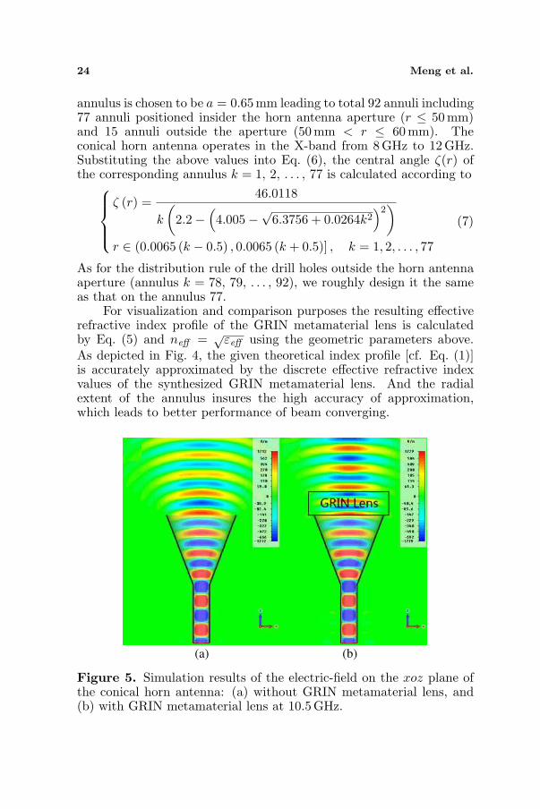
(a) (b)
Figure 5. Simulation results of the electric-field on the xoz plane ofthe conical horn antenna: (a) without GRIN metamaterial lens, and(b) with GRIN metamaterial lens at 10.5 GHz.
Progress In Electromagnetics Research, Vol. 141, 2013 25
Figure 5 compares the simulated electric field distribution in theradiative near-field region of the circularly polarized conical antennawith and without the designed GRIN metamaterial lens at 10.5 GHz.In particular, Fig. 5(a) shows that the E-field distribution of theordinary horn antenna gradually diverges; and an associated decreasein the field amplitude is observed in the radiation direction along theantenna axis. After placing the GRIN metamaterial lens in front of thehorn antenna, the E-field distribution improves as expected, namelya transversally confined quasi-plane wave with virtually uniformamplitude (along the antenna axis) appears in the radiation area asshown in Fig. 5(b). All these effects are represented by a considerablyreduced width of the main radiation lobe, which is tantamount toenhanced radiation directivity, and thus to an increased gain, whileunderpinning the intended transformation performance of the GRINmetamaterial lens.
The simulated normalized far-field radiation patterns in the yoz
and xoz plane are displayed in Fig. 6 for both cases, namely thehorn antenna with and without the GRIN metamaterial lens at the
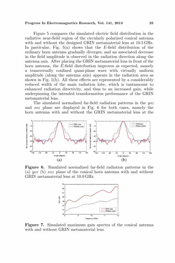
(a) (b)
Figure 6. Simulated normalized far-field radiation patterns in the(a) yoz (b) xoz plane of the conical horn antenna with and withoutGRIN metamaterial lens at 10.0 GHz.
Figure 7. Simulated maximum gain spectra of the conical antennawith and without GRIN metamaterial lens.
26 Meng et al.
operation frequency 10.0 GHz. From inspection one can easily deducethat the mainlobe beamwidth of the horn antenna are considerablyreduced just due to the presence of the GRIN metamaterial lens.
The spectral behavior of the maximum gain is given in Fig. 7,where the simulated gain spectra of the horn antenna with and withoutGIRN metamaterial lens clearly indicate that the GRIN metamateriallens can efficiently enhance the gain of the horn antenna over a verybroad bandwidth ranging from 8 GHz to 12GHz.
4. FABRICATION AND MEASUREMENT
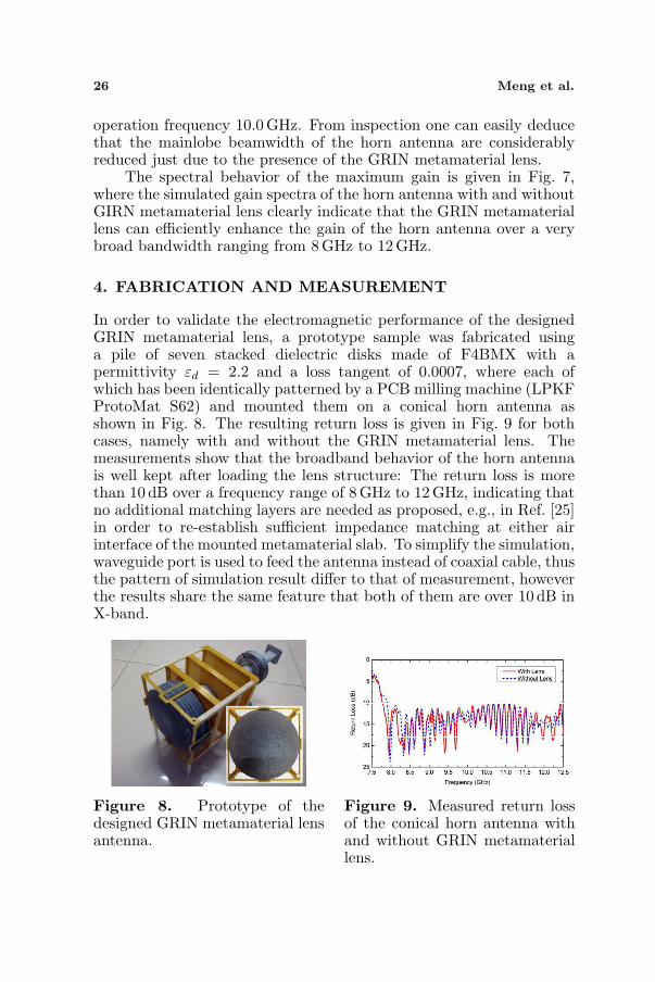
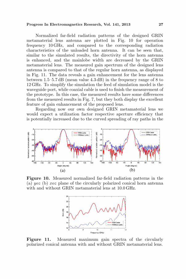
In order to validate the electromagnetic performance of the designedGRIN metamaterial lens, a prototype sample was fabricated usinga pile of seven stacked dielectric disks made of F4BMX with apermittivity εd = 2.2 and a loss tangent of 0.0007, where each ofwhich has been identically patterned by a PCB milling machine (LPKFProtoMat S62) and mounted them on a conical horn antenna asshown in Fig. 8. The resulting return loss is given in Fig. 9 for bothcases, namely with and without the GRIN metamaterial lens. Themeasurements show that the broadband behavior of the horn antennais well kept after loading the lens structure: The return loss is morethan 10 dB over a frequency range of 8 GHz to 12 GHz, indicating thatno additional matching layers are needed as proposed, e.g., in Ref. [25]in order to re-establish sufficient impedance matching at either airinterface of the mounted metamaterial slab. To simplify the simulation,waveguide port is used to feed the antenna instead of coaxial cable, thusthe pattern of simulation result differ to that of measurement, howeverthe results share the same feature that both of them are over 10 dB inX-band.
Figure 8. Prototype of thedesigned GRIN metamaterial lensantenna.
Figure 9. Measured return lossof the conical horn antenna withand without GRIN metamateriallens.
Progress In Electromagnetics Research, Vol. 141, 2013 27
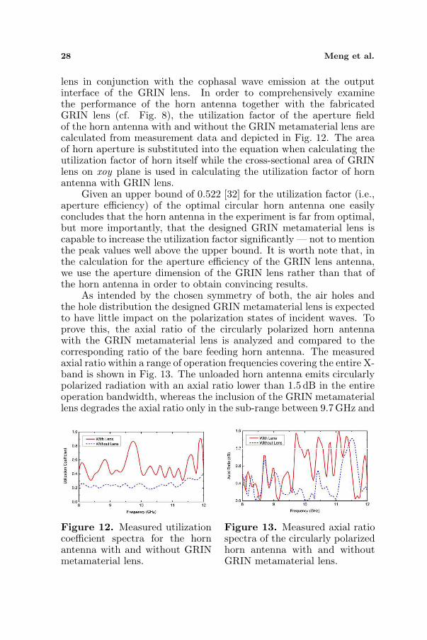
Normalized far-field radiation patterns of the designed GRINmetamaterial lens antenna are plotted in Fig. 10 for operationfrequency 10GHz, and compared to the corresponding radiationcharacteristics of the unloaded horn antenna. It can be seen that,similar to the simulated results, the directivity of the horn antennais enhanced, and the mainlobe width are decreased by the GRINmetamaterial lens. The measured gain spectrum of the designed lensantenna is compared to that of the regular horn antenna, as displayedin Fig. 11. The data reveals a gain enhancement for the lens antennabetween 1.5–5.7 dB (mean value 4.3 dB) in the frequency range of 8 to12GHz. To simplify the simulation the feed of simulation model is thewaveguide port, while coaxial cable is used to finish the measurement ofthe prototype. In this case, the measured results have some differencesfrom the measured results in Fig. 7, but they both display the excellentfeature of gain enhancement of the proposed lens.
Regarding now our own designed GRIN metamaterial lens wewould expect a utilization factor respective aperture efficiency thatis potentially increased due to the curved spreading of ray paths in the
(a) (b)
Figure 10. Measured normalized far-field radiation patterns in the(a) yoz (b) xoz plane of the circularly polarized conical horn antennawith and without GRIN metamaterial lens at 10.0 GHz.
Figure 11. Measured maximum gain spectra of the circularlypolarized conical antenna with and without GRIN metamaterial lens.
28 Meng et al.
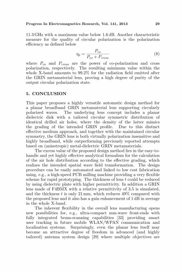
lens in conjunction with the cophasal wave emission at the outputinterface of the GRIN lens. In order to comprehensively examinethe performance of the horn antenna together with the fabricatedGRIN lens (cf. Fig. 8), the utilization factor of the aperture fieldof the horn antenna with and without the GRIN metamaterial lens arecalculated from measurement data and depicted in Fig. 12. The areaof horn aperture is substituted into the equation when calculating theutilization factor of horn itself while the cross-sectional area of GRINlens on xoy plane is used in calculating the utilization factor of hornantenna with GRIN lens.
Given an upper bound of 0.522 [32] for the utilization factor (i.e.,aperture efficiency) of the optimal circular horn antenna one easilyconcludes that the horn antenna in the experiment is far from optimal,but more importantly, that the designed GRIN metamaterial lens iscapable to increase the utilization factor significantly — not to mentionthe peak values well above the upper bound. It is worth note that, inthe calculation for the aperture efficiency of the GRIN lens antenna,we use the aperture dimension of the GRIN lens rather than that ofthe horn antenna in order to obtain convincing results.
As intended by the chosen symmetry of both, the air holes andthe hole distribution the designed GRIN metamaterial lens is expectedto have little impact on the polarization states of incident waves. Toprove this, the axial ratio of the circularly polarized horn antennawith the GRIN metamaterial lens is analyzed and compared to thecorresponding ratio of the bare feeding horn antenna. The measuredaxial ratio within a range of operation frequencies covering the entire X-band is shown in Fig. 13. The unloaded horn antenna emits circularlypolarized radiation with an axial ratio lower than 1.5 dB in the entireoperation bandwidth, whereas the inclusion of the GRIN metamateriallens degrades the axial ratio only in the sub-range between 9.7 GHz and
Figure 12. Measured utilizationcoefficient spectra for the hornantenna with and without GRINmetamaterial lens.
Figure 13. Measured axial ratiospectra of the circularly polarizedhorn antenna with and withoutGRIN metamaterial lens.
Progress In Electromagnetics Research, Vol. 141, 2013 29
11.3GHz with a maximum value below 1.6 dB. Another characteristicmeasure for the quality of circular polarization is the polarizationefficiency as defined below
ηp =Pco
Pco + Pcross(8)
where Pco and Pcross are the power of co-polarization and crosspolarization, respectively. The resulting minimum value within thewhole X-band amounts to 99.2% for the radiation field emitted afterthe GRIN metamaterial lens, proving a high degree of purity of theoutput circular polarization state.
5. CONCLUSION
This paper proposes a highly versatile automatic design method fora planar broadband GRIN metamaterial lens supporting circularlypolarized waves. The underlying lens concept includes a planardielectric disk with a tailored circular symmetric distribution ofidentical drilled air holes, where the density of the latter mimicsthe grading of the intended GRIN profile. Due to this distincteffective medium approach, and together with the maintained circularsymmetry, the GRIN lens is both virtually polarization insensitive andhighly broadband, while outperforming previously reported attemptsbased on (anisotropic) metal-dielectric GRIN metamaterials.
The excess value of the proposed design method lies in the easy-to-handle and yet highly effective analytical formalism for the calculationof the air hole distribution according to the effective grading, whichrealizes the intended spatial wave field transformation. The designprocedure can be easily automated and linked to low cost fabricationusing, e.g., a high-speed PCB milling machine providing a very flexiblescheme for rapid prototyping. The thickness of lens t could be reducedby using dielectric plate with higher permittivity. In addition a GRINlens made of F4BMX with a relative permittivity of 3.5 is simulated,and the thickness t is only 21 mm, which reduces 49% compared withthe proposed lens and it also has a gain enhancement of 1 dB in averagein the whole X-band.
The inherent flexibility in the overall lens manufacturing opensnew possibilities for, e.g., ultra-compact mm-wave front-ends withfully integrated beam-scanning capabilities [33] providing smartuser tracking in future mobile WLAN/WPAN communication andlocalization systems. Surprisingly, even the planar lens itself maybecome an attractive degree of freedom in advanced (and highlytailored) antenna system design [29] where multiple objectives are
30 Meng et al.
usually at stake, for example in advanced (cognitive) MIMO systemswhere bandwidth, angular/spatial diversity and far-field gain are allsubject to optimization.
REFERENCES
1. Kock, W. E., “Metal-lens antennas,” Proceedings of the IRE,Vol. 34, 828–836, 1946.
2. Yaokun, Q., “Dielectric lens antenna with scan reflector,” IEEE
Transactions on Aerospace and Electronic Systems, Vol. 33, 98–101, 1997.
3. Free, W., F. Cain, C. Ryan, Jr., C. Burns, and E. Turner,“High-power constant-index lens antennas,” IEEE Transactions
on Antennas and Propagation, Vol. 22, 582–584, 1974.4. Tang, C., “A dual lens antenna for limited electronic scanning,”
IEEE Antennas and Propagation Society International Sympo-
sium, 117–120, Urbana, IL, 1975.5. Olver, A. D. and B. Philips, “Integrated lens with dielectric horn
antenna,” Electronics Letters, Vol. 29, 1150–1152, 1993.6. Pavacic, A. P., D. L. del Rio, J. R. Mosig, and G. V. Eleftheriades,
“Three-dimensional ray-tracing to model internal reflections inoff-axis lens antennas,” IEEE Transactions on Antennas and
Propagation, Vol. 54, 604–612, 2006.7. Abella, C., M. Marin, J. Vazquez, J. Peces, J. A. Romera,
R. Graham, et al., “Artificial dielectric lens antennas: Assessmentof their potential for space applications,” 23rd European
Microwave Conference, 896–898, Madrid, Spain, 1993.8. Al-Joumayly, M. A. and N. Behdad, “Wideband planar microwave
lenses using sub-wavelength spatial phase shifters,” IEEE
Transactions on Antennas and Propagation, Vol. 59, 4542–4552,2011.
9. Pendry, J. B., A. J. Holden, D. J. Robbins, and W. J. Stewart,“Magnetism from conductors and enhanced nonlinear phenom-ena,” IEEE Transactions on Microwave Theory and Techniques,Vol. 47, 2075–2084, Nov. 1999.
10. Shelby, R. A., D. R. Smith, and S. Schultz, “Experimentalverification of a negative index of refraction,” Science, Vol. 292,77–79, Apr. 2001.
11. Enoch, S., G. Tayeb, P. Sabouroux, N. Guerin, and P. Vincent,“A metamaterial for directive emission,” Physical Review Letters,Vol. 89, 213902(4), 2002.
Progress In Electromagnetics Research, Vol. 141, 2013 31
12. Wu, Q., P. Pan, F. Y. Meng, L. W. Li, and J. Wu, “A novelflat lens horn antenna designed based on zero refraction principleof metamaterials,” Applied Physics A — Materials Science and
Processing, Vol. 87, 151–156, 2007.13. Zhou, B., H. Li, X. Y. Zou, and T. J. Cui, “Broadband
and high-gain planar Vivaldi antennas based on inhomogeneousanisotropic zero-index metamaterials,” Progress In Electromagnet-
ics Research, Vol. 120, 235–247, 2011.14. Smith, D. R., J. J. Mock, A. F. Starr, and D. Schurig, “Gradient
index metamaterials,” Physical Review E, Vol. 71, Mar. 2005.15. Driscoll, T., D. N. Basov, A. F. Starr, P. M. Rye, S. Nemat-Nasser,
D. Schurig, et al., “Free-space microwave focusing by a negative-index gradient lens,” Applied Physics Letters, Vol. 88, 081101(3),2006.
16. Goldflam, M. D., T. Driscoll, B. Chapler, O. Khatib,N. M. Jokerst, S. Palit, et al., “Reconfigurable gradient index usingVO2 memory metamaterials,” Applied Physics Letters, Vol. 99,044103(3), Jul. 25, 2011.
17. Paul, O., B. Reinhard, B. Krolla, R. Beigang, and M. Rahm,“Gradient index metamaterial based on slot elements,” Applied
Physics Letters, Vol. 96, 241110(3), Jun. 14, 2010.18. Ruopeng, L., C. Qiang, J. Y. Chin, J. J. Mock, C. Tie Jun, and
D. R. Smith, “Broadband gradient index microwave quasiopticalelements based on non-resonant metamaterials,” Optics Express,Vol. 17, 21030–21041, 2009.
19. Ruopeng, L., Y. Xin Mi, J. G. Gollub, J. J. Mock, C. Tie Jun,and D. R. Smith, “Gradient index circuit by waveguidedmetamaterials,” Applied Physics Letters, Vol. 94, 073506(3),Feb. 16, 2009.
20. Smith, D. R., Y.-J. Tsai, and S. Larouche, “Analysis of a gradientindex metamaterial blazed diffraction grating,” IEEE Antennas
and Wireless Propagation Letters, Vol. 10, 1605–1608, 2011.21. Yang, X. M., X. Y. Zhou, Q. Cheng, H. F. Ma, and T. J. Cui,
“Diffuse reflections by randomly gradient index metamaterials,”Optics Letters, Vol. 35, 808–810, Mar. 15, 2010.
22. Liu, Z.-G., R. Qiang, and Z.-X. Cao, “A novel broadbandFabry-Perot resonator antenna with gradient index metamaterialsuperstrate,” IEEE International Symposium Antennas and
Propagation and CNC-USNC/URSI Radio Science Meeting, 1–4,Toronto, 2010.
23. Lei, M. Z. and C. T. Jun, “Experimental realization of a
32 Meng et al.
broadband bend structure using gradient index metamaterials,”Optics Express, Vol. 17, 18354–18363, Sep. 28, 2009.
24. Chen, X., H. F. Ma, X. Y. Zou, W. X. Jiang, and T. J. Cui,“Three-dimensional broadband and high-directivity lens antennamade of metamaterials,” Journal of Applied Physics, Vol. 110,044904(8), Aug. 15, 2011.
25. Ma, H. F., X. Chen, H. S. Xu, X. M. Yang, W. X. Jiang,and T. J. Cui, “Experiments on high-performance beam-scanningantennas made of gradient-index metamaterials,” Applied Physics
Letters, Vol. 95, 094107(3), Aug. 31, 2009.26. Mei, Z. L., J. Bai, and T. J. Cui, “Gradient index metamaterials
realized by drilling hole arrays,” Journal of Physics D — Applied
Physics, Vol. 43, 055404(6), Feb. 10, 2010.27. Ma, H. F. and T. J. Cui, “Three-dimensional broadband and
broad-angle transformation-optics lens,” Nature Communications,Vol. 1, 124(6), Nov. 2010.
28. Zhou, B., Y. Yang, H. Li, and T. J. Cui, “Beam-steeringVivaldi antenna based on partial Luneburg lens constructedwith composite materials,” Journal of Applied Physics, Vol. 110,084908(6), 2011.
29. Ma, H. F. and T. J. Cui, “Three-dimensional broadband ground-plane cloak made of metamaterials,” Nature Communications,Vol. 1, 21(6), 06/01/online, 2010.
30. Liu, Z. J., S. W. Yang, and Z. P. Nie, “A dielectric lens antennadesign by using the effective medium theories,” International
Symposium on Intelligent Signal Processing and Communication
Systems (ISPACS), 1–4, Chendu, China, 2010.31. Petosa, A., A. Ittipiboon, and S. Thirakoune, “Investigation on
arrays of perforated dielectric fresnel lenses,” IEE Proceedings
Microwaves, Antennas and Propagation, Vol. 153, 270–276, 2006.32. Teshirogi, T. and T. Yoneyama, Modern Millimeter-wave
Technologies, IOS Press, Burke, VA, USA, 2001.33. Artemenko, A., A. Mozharovskiy, A. Maltsev, R. Maslennikov,
A. Sevastyanov, and V. Ssorin, “2D electronically beam steerableintegrated lens antennas for mm-wave applications,” 42nd
European Microwave Conference (EuMC), 213–216, Amsterdam,the Netherlands, 2012.