The uplift load capacity of an enlarged base pier embedded in dry sand
12
ORIGINAL PAPER The uplift load capacity of an enlarged base pier embedded in dry sand Ramli Nazir & Hossein Moayedi & A. Pratikso & Mansour Mosallanezhad Received: 28 April 2014 /Accepted: 17 November 2014 # Saudi Society for Geosciences 2014 Abstract The purpose of this research is to determine the capability of (and the factors which affect the performance of) an enlarged base pier in resisting uplift capacity. Experiments were conducted in the reinforced bin box of an enlarged base pier with a shaft diameter ranging from 30 to 50 mm, base diameters between 75 and 150 mm and base angles of α = 30°, α = 45° and α = 60°. Tests were conducted in both loose and dense sand packing. A failure mechanism was studied in a glass box for loose and dense sand packing. A dry sand with a unit weight of γ d = 14.80 kN/m 3 and γ d = 17. 0 kN/m 3 was achieved for loose and dense packing, respectively. Increasing the bell angle and shaft diameter would result in a decrease of the net uplift capacity and failure displacement. This is due to the reduction in the amount of the sand column above the bell that resists the uplift of the pile. Failure displacements at a constant base diameter generally increased considerably with the increase of the embedment ratio but decreased with the increment of the sand density. It is thus apparent that the shaft diameter, bell diameter and bell angle are geometric factors which, together with the embedment ratio and the sand den- sity, should be taken into account in the design of enlarged base piers. Keywords Embedment ratio . Enlarged based pier . Large-scale modelling . Sand . Uplift capacity . Belled pile Abbreviations D s Shaft diameter D b Base diameter α Base angle W Weight P ul Uplift load γ ' Effective unit weight of soil γ Bulk unit weight N Porosity φ Internal friction angle I d Density index A b Area of the soil N u Breakout factor L Depth of embedment Q u Bearing resistance L/D b Embedment ratio Introduction Over the past five decades, a wide variety of foundation anchor systems (belled pile, plate and pier, grillage, pedestal, pyramid, single and multi-helical anchor, grouted anchor, flute anchor, suction anchor) have been developed in order to satisfy the increasing demand for foundations with ever higher pull-out resistance (Ilamparuthi and Dickin 2001a, b). En- larged base pier (belled piers) foundations for transmission line towers, with a slim high-rise structure, have proven to be an economical foundation type in providing resistance to extensive uplift load. They provide both compressive and uplift resistance (Hamza 1994). R. Nazir Department of Geotechnics & Transportation, Faculty of Civil Engineering, Universiti Teknologi Malaysia, Skudai, Johor, Malaysia H. Moayedi (*) Department of Civil Engineering, Kermanshah University of Technology, Kermanshah, Iran e-mail: [email protected] A. Pratikso Universitas Islam Sultan Agung, Semarang, Indonesia M. Mosallanezhad Department of Civil and Environmental Engineering, Shiraz University, Shiraz, Iran Arab J Geosci DOI 10.1007/s12517-014-1721-3
Transcript of The uplift load capacity of an enlarged base pier embedded in dry sand

ORIGINAL PAPER
The uplift load capacity of an enlarged base pier embeddedin dry sand
Ramli Nazir & Hossein Moayedi & A. Pratikso &
Mansour Mosallanezhad
Received: 28 April 2014 /Accepted: 17 November 2014# Saudi Society for Geosciences 2014
Abstract The purpose of this research is to determine thecapability of (and the factors which affect the performance of)an enlarged base pier in resisting uplift capacity. Experimentswere conducted in the reinforced bin box of an enlarged basepier with a shaft diameter ranging from 30 to 50 mm, basediameters between 75 and 150mm and base angles ofα = 30°,α = 45° and α = 60°. Tests were conducted in both loose anddense sand packing. A failure mechanism was studied in aglass box for loose and dense sand packing. A dry sand with aunit weight of γd = 14.80 kN/m3 and γd = 17. 0 kN/m3 wasachieved for loose and dense packing, respectively. Increasingthe bell angle and shaft diameter would result in a decrease ofthe net uplift capacity and failure displacement. This is due tothe reduction in the amount of the sand column above the bellthat resists the uplift of the pile. Failure displacements at aconstant base diameter generally increased considerably withthe increase of the embedment ratio but decreased with theincrement of the sand density. It is thus apparent that the shaftdiameter, bell diameter and bell angle are geometric factorswhich, together with the embedment ratio and the sand den-sity, should be taken into account in the design of enlargedbase piers.
Keywords Embedment ratio . Enlarged based pier .
Large-scale modelling . Sand . Uplift capacity . Belled pile
AbbreviationsDs Shaft diameterDb Base diameterα Base angleW WeightPul Uplift loadγ' Effective unit weight of soilγ Bulk unit weightN Porosityφ Internal friction angleId Density indexAb Area of the soilNu Breakout factorL Depth of embedmentQu Bearing resistanceL/Db Embedment ratio
Introduction
Over the past five decades, a wide variety of foundationanchor systems (belled pile, plate and pier, grillage, pedestal,pyramid, single andmulti-helical anchor, grouted anchor, fluteanchor, suction anchor) have been developed in order tosatisfy the increasing demand for foundations with ever higherpull-out resistance (Ilamparuthi and Dickin 2001a, b). En-larged base pier (belled piers) foundations for transmissionline towers, with a slim high-rise structure, have proven to bean economical foundation type in providing resistance toextensive uplift load. They provide both compressive anduplift resistance (Hamza 1994).
R. NazirDepartment of Geotechnics & Transportation, Faculty of CivilEngineering, Universiti TeknologiMalaysia, Skudai, Johor, Malaysia
H. Moayedi (*)Department of Civil Engineering, Kermanshah University ofTechnology, Kermanshah, Irane-mail: [email protected]
A. PratiksoUniversitas Islam Sultan Agung, Semarang, Indonesia
M. MosallanezhadDepartment of Civil and Environmental Engineering, ShirazUniversity, Shiraz, Iran
Arab J GeosciDOI 10.1007/s12517-014-1721-3
Many studies have been conducted on the ultimateuplift capacity of single piles in sand (Gaaver 2013; Nazirand Nasr 2013), the physical modelling of helical screwpiles in sand (Tsuha and Aoki 2010) and the numericalsimulations of reinforced foundations under uplift loading(Dickin 2002). The ultimate uplift capacities have alsobeen investigated for different soils types. Researcherssuch as Hsu and Liao (1998), Al-Mhaidib and Edil(1998) and Niroumand et al. (2013) have investigatedthe uplift capacity of sandy soil. Wang et al. (2013) havealso worked extensively on the pull-out capacity anduplift of clayey soils by using both large-scale experimen-tal laboratory tests and/or numerical analysis.
Ilamparuthi and Dickin (2001a, b) predicted the upliftresponse of model belled piles in geogrid cell-reinforced sand.They established a hyperbolic relationship between displace-ment and the pull-out load, which helps to determine soilstiffness for use in nonlinear analyses. Honda et al. (2011)investigated the uplift capacity of belled and multi-belled pilesin dense sand. Accordingly, they applied a two-dimensionaldistinct element (DE) analysis in pull-out tests on single piles.As a result, a continuity equation was proposed for predictingthe uplift capacity of actual piles under axisymmetricconditions.
There are several studies in the technical literaturewhich deal with large-scale enlarged base piers or belledpiers resisting the uplift load in sand (Choi et al. 2013;Gaaver 2013). They stated that the breakout factors insand are function of the anchor shape, embedment ratioand the shearing resistance of the soil. However, many ofthe existing design methods, such as those determiningthe uplift capacity of enlarged base piers, are based onresults obtained from small laboratory-scale model testson anchor type foundations (Kumar and Bhoi 2008). Themain objective of this research is to investigate the be-haviour of an uplift-loaded enlarged base pier embeddedin dry loose and dense sand. The experimental work inthis study is devoted to a laboratory large-scale modeltest. The effect of the embedment ratio, base diameter,shaft diameter, base angle and sand density on the upliftcapacity of the enlarged base pier are presented anddiscussed in detail.
Material and methods
Soil properties
Sand was used as an embedment medium in this work. Inorder to obtain two different criteria for the index density,dense and loose packings were used. Thus, the experienceof the model of the enlarged base pier could be observedfor both conditions. A loose packing was achieved with
sand raining methods while the dense packing wasachieved through compaction via an electrical vibrator.
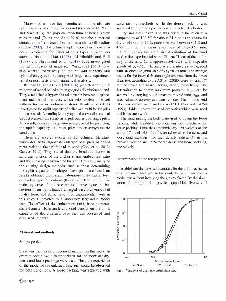
Dry and clean river sand was dried in the oven at atemperature of 100 °C for about 24 h so as to ensure itsdry condition. Its 90 % grain size was between 0.212 and4.75 mm, with a mean grain size of D50=0.60 mm.Figure 1 shows the grain size distribution of the sandused in the experimental work. The coefficient of the unifor-mity of the sand, Cu, is approximately 3.53, with a specificgravity of Gs=2.68. The sand was classified as well-gradedwith an effective grain size of D10=0.20 mm. The averageresults for the internal friction angle obtained from the directshear test, according to the ASTM D3080, were 44° and 35°for the dense and loose packing sands, respectively. Thedetermination to obtain maximum porosity, nmax, can beachieved by carrying out the maximum void ratio, emax, andused values of porosity and density index. The limiting voidratio was carried out based on ASTM D4253 and D4254(1993). Table 1 shows the sand properties which were usedin this research work.
The sand raining methods were used to obtain the loosepacking, while hand-held vibration was used to achieve thedense packing. From these methods, dry unit weights of thesoil of 17.0 and 14.8 kN/m3 were achieved in the dense andloose sand packings. The used density indices (Id) in thisresearch were 85 and 35 % for the dense and loose packings,respectively.
Determination of the test parameters
In establishing the physical quantities for the uplift resistanceof an enlarged base pier in the sand, the author assumed amodel test without involving the gravity factor. By the simu-lation of the appropriate physical quantities, five sets of
0
25
50
75
100
0.01 0.1 1 10
Perc
enta
ge P
assi
ng (
%)
Size of material (mm)
Series1 Series2 Series3
Fig. 1 Variations of grain size distribution sand
Arab J Geosci

dimensionless products were developed based uponBuckingham’s non-dimensionless pi theorem:
π1 ¼ Nu=γAbL ð1Þ
π2 ¼ L=Db ð2Þ
π3 ¼ n ð3Þ
π4 ¼ Id ð4Þ
π5 ¼ ϕ ð5Þ
From Eqs. (1–5), the set of π terms can be expressed in thefollowing functional relation:
N u
γAbL¼ f
L
Db; Id;ϕ; n
� �¼ f Quð Þ ð6Þ
For ease of analysis, the net uplift capacity is expressed interms of a dimensionless breakout factor:
Qu ¼N u
γ 0AbLð7Þ
where γ' = the effective unit weight of the soil and
Ab the area of the soilQu the breakout factorL the depth of embedmentNu the bearing resistanceDb the base diameter of the enlarged base pierId the density indexn the porosityϕ the soil friction angle
Significantly, the results of the belled pile’s uplift capacity(Pul) were obtained directly from the experimental work.
Pile materials
The geometric parameters for the enlarged base pier used inthis research are shown in Fig. 2. A pulling framewas attachedon top of an enlarged base pier in order to pull the tested pilethrough both a reinforced bin and a glass box. The frame wasattached to the loading cable by using a screw and connectedto mounted load cells with 3 and 5 kN loading capacities andlifted up to a desirable force (Fig. 3). The enlarged base pierswere made from concrete and massive mild steel with a shaftdiameter ofDs=30, 40 and 50 mm (Fig. 4), a base diameter ofDb=75, 100, 125 and 150mm (Fig. 5), a base angle ofα=30°,45° and 60° (Fig. 6), and various heights ranging between 300and 750 mm (Fig. 7).
Table 1 The parameters of soilsample Soil parameters Abbreviation Standard Units
Specific gravity Gs ASTM D854 2.68
Minimum void ratio emin ASTM D4253 0.575
Maximum void ratio emax ASTM D4254 0.810
Minimum dry unit weight of soil γd min ASTM D4254 14.8 kN/m3
Maximum dry unit weight of soil γd max ASTM D4253 17.0 kN/m3
Minimum porosity nmin 0.366
Maximum porosity nmax 0.455
Coefficient of uniformity Cu=D60/D10 ASTM D2487 3.53
Effective size, D10 D10 ASTM D2487 0.20 mm
Effective size, D50 D50 ASTM D2487 0.60 mm
Fig. 2 a Geometrical dimension for enlarged base pier. b Enlarged basepier solid steel model pile
Arab J Geosci

Testing programme
The tests were conducted on a large model pile with anenlarged base with a shaft diameter of Ds=30, 40 and50 mm. In addition, a base diameter of Ds=75, 100, 125 and150 mmwith a base angle of α=30°, 45° and 60° was used inboth loose and dense sand packing conditions. The piles werealso modelled with the same enlarged base but a differentembedment ratio, L/Db ranging between 1 and 5. To consider
the scale effect, the scale of 10 is selected for all elements thatwere used through the experimental programme.
Reinforced bin test arrangement
The reinforced bin is simply a relatively large container mea-suring 1,800 mm in width, 1,800 mm in length and 1,600 mmin depth. It was fabricated using a reinforced steel angle150 mm×150 mm×6 mm as a frame and enclosed by aplywood of 25 mm in thickness, which was then laminatedby a Formica layer inside to reduce the friction effect. For
Fig. 3 Detail of mounted loadcell
Fig. 4 Enlarged base pier model pile with shaft diameter Ds=30 mm,Ds=40 mm and Ds=50 mm
Fig. 5 Enlarged base pier model pile with base diameter Db=75 mm,Db=100 mm, Db=125 mm and Db=150 mm
Arab J Geosci

levelling purposes and reducing the influence of humidityfrom the floor, the bin was supported by a C channel of200 mm in size, as shown in Fig. 8. A customized fabricatedelectrical motor gearing was installed outside the box. On twosides of the box, a vertical steel angle of size 80mm×80mm×5 mmwas attached to ease the installation of the pulling cablevia a pulley. The loading imposed by the motorized winchpulled a 2-mm-diameter cable incorporated with a load cellthrough the pulley system at a constant rate of displacement of0.6 mm/min to perform quasi-static movement in eliminatingany rapid stress development. Load cells of 3 and 5 kNcapacity were mounted on a pulling arm, as shown inFig. 8a. A linear variable displacement transducer (LVDT)capable of measuring vertical movement to a maximum of25mmwas fixed just above the sample. This arrangement waspurposely done to ensure that the error in calculating thevertical displacement of the pile was minimized. The cross-beam was attached to the side and clamped the pile to reduce
the influence of vibration during the compaction of the sand.The view elevation of the glass box is shown in Fig. 8b.
Reinforced bin box testing procedure
Initially, a sand layer of 600-mm thickness was placed in areinforced bin. The sand was packed in both dense and loosepackings. The loose and dense packings were produced byraining sand from a height of about 330 mm on top of thereinforced bin, as shown in Fig. 9, with the result of an averageunit weight of γd=14.8 kN/m3 and γd=17.0 kN/m3,respectively. In order to achieve a particular density from theraining procedure, the method presented by Khari et al. (2014)is used. Khari et al. (2014) studied sand samples’ preparationusing the Mobile Pluviator apparatus. In doing so, a widerange for Id (relative density), ranging from 10 to 98 %, canbe achieved.
Prior to the placement of the sand, a pile which wasinstalled with a pulling arm was placed in the centre of thereinforced bin, and its vertical position was maintained by aspirit level. To secure the verticality and vibration duringpreparation, the pile was attached to a steel ring of 15 mm×2 mm using a screw. A steel plate of 10 mm×2 mm wasattached to the pulling arm to incorporate with LVDT’s at-tachment. The sand was then flushed to the top of the pile. Itwas achieved by placing a sand layer at every 75 mm ofthickness. The process was repeated until the model was fullyembedded (Fig. 8). For the loose packing procedure, a backfillwas achieved by raining sand until the sand level was flushedwith the design level of the pile. The load cell and LVDTwerethen placed into position. The loading was mounted on thepulling arm. A 2-mm cable diameter incorporating the 3- and5-kN capacity load cells was connected to the loading gear viathe loading arm.
Since the pulling arm has a circular cross section, flatreference plates had to be fixed to the arm to ensure that thespindles of the LVDT did not slip during the movement of thepile as well as to ensure accuracy during the measurement ofvertical displacement. The LVDT was mounted and clampedinto position on the plate with screws at vertical intervals of125 mm. A nine-channel data logger was connected to theload cell and LVDT for the data acquisition process. TheLVDT was then connected to channel 1, while channel 2was linked to the load cell. Data readings were then printedthrough the data logger counter. Vertical load was appliedwhen the gearing mechanism was engaged using the auto-control speed through a potentiometer. The loading imposedby the motorized winch pulled a 2-mm-diameter cablethrough the pulley system at a constant rate at 0.6 mm/min.Interval readings were taken every 10 s. The uplift capacity ismeasured as a peak value from load–displacement relation-ship. Generally, each pile test was completed between 20 and40 min.
Fig. 6 Enlarged base pier model pile with base angles α=30°, α=45°and α=60°
Fig. 7 Enlarged base pier with height ranging from 30 to 75 cm
Arab J Geosci

Arrangement of the glass box test
A two-dimensional failure test was implemented using a glassbox. A glass box 650 mm in length, 300 mm in width and400 mm in depth was furnished with a steel angle of 15 mm×15mm×2 mm and a steel plate of 10 mm×2 mm, as shown inFig. 8. A glass plate of 10-mm thickness was placed on bothsides of the frame, while a steel plate with a thickness of 2 mmwas placed at the front and back of the frame. An electrical
motor gearing systemwas installed outside the box. At the endof the box, a vertical steel angle of dimensions 80 mm×80 mm×5 mm was attached to ease the installation of thepulling height cable via the pulley. A system of re-adjustablepulleys was then attached to this channel for height adjust-ment. Loading was imposed by the motorized winch pulleywith a 2-mm-diameter cable incorporated with a load cellthrough the pulley system at a constant rate of displacementof 0.6 mm/min, as shown in Fig. 8b.
Results and discussion
Enlarged base piers with a base diameter of Db=75, 100, 125and 150 mm, a shaft diameter of Ds=30, 40 and 50 mm and abase angle of α=30°, 45° and 60° were tested. The factorsinvolving the determination of the uplift load were observed.The embedment ratio L/Db, sand density γ, shaft diameter Ds,base diameterDb and base angle αwere all correlated with theuplift capacity. A model of the enlarged base pier wasFig. 9 Sand raining procedure for reinforced bin box
Fig. 8 a View elevation for two-dimensional testing in the glassbox. b View elevation of glassbox
Arab J Geosci

implemented in the reinforced bin box. The factors affectingthe limiting uplift capacity were determined and their correla-tions were then identified.
The effect of the embedment ratio
Generally, the maximum model uplift load increases with anyincrease in the embedment ratio, L/Db. The maximum modelof the uplift load Pul shows a similar trend. Figures 10, 11 and12 illustrate the influence of the embedment ratio L/Db for ashaft diameter of Ds=30 mm and a base angle α=45°(Fig. 10), a shaft diameter Ds=40 mm and a base angle α=45° (Fig. 11), and a shaft diameter Ds=50 mm and a baseangle α=45° (Fig. 12) and a base diameter (Db) ranging from75 to 150 mm in loose sand. For the embedment ratio L/Db≥2,the maximum model uplift load Pul increases rapidly. Mean-while, for a embedment ratio ≤2, the maximum model upliftload Pul shows a slow increment. The maximum model upliftload increases with any increase in the embedment ratio. Theresults also show that pile’s base diameter, Db, has an impor-tant effect on the uplift load capacity of the belled pile. Forinstance, in the tested belled pile having Ds=30 mm and L/Db=4, the uplift load capacity forDb equal to 75, 100, 125 and150 mm were 0.197, 0.472, 0.94 and 1.57 kN, respectively.The pile diameter, Ds, was also a key on the uplift loadcapacity of the mentioned piles. The uplift capacity of testedbelled pile (L/Db=4, Db=150 mm, α=45°) with Ds equal to30, 40 and 50 mm was 1.57, 1.51 and 1.46 kN, respectively.This shows a slight decrease in the uplift capacity of pile whenthe pile diameter increases. This is because the total weight ofsoils that is placed on the space above the belled pier slightlydecreased. Noteworthy, all the values are based on model
values that were taken directly from the tests in the reinforcedbin box.
Figures 13, 14 and 15 show variations in the maximummodel uplift load Pul with the influence of the embedmentratio L/Db for a shaft diameter Ds=30 mm and a base angleα=45°, a shaft diameter Ds=40 mm and a base angle α=45°,a shaft diameterDs=50mm and a base angle of 45° and a basediameterDb ranging from 75 to 150 mm for a model base pierin dense sand packing. Similar to the case in Figs. 10, 11 and12, the model uplift load increased with an increase in theembedment ratio. However, the model uplift load Pul washigher in the dense sand than in loose sand, as expected. Theevidence shows that the embedment ratio L/Db has a signifi-cant effect on the contribution of any increasing uplift load.Gaaver (2013) has stated that the net uplift capacity of a pile
0.0
0.4
0.8
1.2
1.6
2.0
0 1 2 3 4 5 6
Upl
ift L
oad,
Pul
(kN
)
Embedment Ratio, L/Db
Db=150mm Db=125mm
Db=100mm Db=75mm
Fig. 10 Variations of uplift load Pul with embedment ratio L/Db for Ds=30 mm and α=45°, in loose sand
0.0
0.4
0.8
1.2
1.6
2.0
0 1 2 3 4 5 6
Upl
ift L
oad,
Pul
(kN
)
Embedment Ratio, L/Db
Db=150mm Db=125mmDb=100mm Db=75mm
Fig. 11 Variations of uplift load Pul with embedment ratio L/Db for Ds=40 mm and α=45°, in loose sand
0.0
0.4
0.8
1.2
1.6
2.0
0 1 2 3 4 5 6
Upl
ift L
oad,
Pul
(kN
)
Embedment Ratio, L/Db
Db=150mm Db=125mm
Db=100mm Db=75mm
Fig. 12 Variations of uplift load Pul with embedment ratio L/Db for Ds=50 mm and α=45°, in loose sand
Arab J Geosci

improves significantly with any increase in both the relativedensity of the soil and the L/db ratio. For a single pile with aplate anchor in loose and dense sand, Zhang and Yue (2011)have noted that the critical embedment ratios (L/db), amountof L/db which the failure surface was developed, are deter-mined as 4 and 6, respectively.
The effect of the base angle
The variation of the model uplift load Pul with an embedmentratio L/Db for model enlarged base pier shafts with diametersDs=30 mm and Ds=40 mm, a base diameter Db=75 mm andbase angles α=30°, α=45° and α=60°, respectively, in loosesand packing are illustrated in Figs. 16 and 17. The model
uplift load increased significantly with increments in the em-bedment ratio L/Db. As expected, it would decrease with anyincrease in the base angle α. The model uplift load Pul for theenlarged base pier with a base angle α=60° was 6 % lowerthan the base angle α=45° in loose sand packing. Meanwhile,Figs. 18 and 19 illustrate the model uplift load Pul with anembedment ratio L/Db for an enlarged base pier in dense sandpacking. The model uplift load increases significantly withany increase in the embedment ratio L/Db but as expecteddecreased with any increase in the base angle α. The modeluplift loadwith a base angleα=45° was 5% lower than that ofthe base angle α=30° in dense sand packing.
The effect of sand density
The influence of sand density on uplift loading was studied inthis work. Variations in the uplift load Pul with different
0
1
2
3
4
0 1 2 3 4 5 6
Upl
ift L
oad,
Pul
(kN
)
Embedment Ratio, L/Db
Db=150mm Db=125mmDb=100mm Db=75mm
Fig. 13 Variations of uplift load Pul with embedment ratio L/Db for Ds=30 mm and α=45°, in dense sand
0
1
2
3
4
0 1 2 3 4 5 6
Upl
ift L
oad,
Pul
(kN
)
Embedment Ratio, L/Db
Db=150mm Db=125mm
Db=100mm Db=75mm
Fig. 14 Variations of uplift load Pul with embedment ratio L/Db for Ds=40 mm and α=45°, in dense sand
0
1
2
3
4
0 1 2 3 4 5 6
Upl
ift L
oad,
Pul
(kN
)
Embedment Ratio, L/Db
Db=150mm Db=125mm
Db=100mm Db=75mm
Fig. 15 Variations uplift load Pul with embedment ratio L/Db for Ds=50 mm and α=45°, in dense sand
0.00
0.10
0.20
0.30
0.40
0 1 2 3 4 5 6
Upl
ift L
oad,
Pul
(kN
)
Embedment Ratio, L/Db
α=30
α=45
α=60
Fig. 16 Variations of uplift load Pul with embedment ratio L/Db fordifferent base angles, (α=30°, α=45°, α=60°), and Ds=30 mm andDb=75 mm, in loose sand
Arab J Geosci
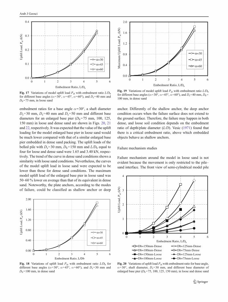
embedment ratios for a base angle α=30°, a shaft diameterDs=30 mm, Ds=40 mm and Ds=50 mm and different basediameters for an enlarged base pier (Db=75 mm, 100, 125,150 mm) in loose and dense sand are shown in Figs. 20, 21and 22, respectively. It was expected that the value of the upliftloading for the model enlarged base pier in loose sand wouldbe much lower compared with that of a similar enlarged basepier embedded in dense sand packing. The uplift loads of thebelled pile with Ds=30 mm, Db=150 mm and L/Db equal tofour for loose and dense sand were 1.65 and 3.40 kN, respec-tively. The trend of the curve in dense sand conditions shows asimilarity with loose sand conditions. Nevertheless, the curvesof the model uplift load in loose sand were expected to belower than those for dense sand conditions. The maximummodel uplift load of the enlarged base pier in loose sand was50–60 % lower on average than that of its equivalent in densesand. Noteworthy, the plate anchors, according to the modesof failure, could be classified as shallow anchor or deep
anchor. Differently of the shallow anchor, the deep anchorcondition occurs when the failure surface does not extend tothe ground surface. Therefore, the failure may happen in bothdense, and loose soil condition depends on the embedmentratio of depth/plate diameter (L/D). Vesic (1971) found thatthere is a critical embedment ratio, above which embeddedobjects behave as shallow anchors.
Failure mechanism studies
Failure mechanism around the model in loose sand is notevident because the movement is only restricted to the pile–sand interface. The front view of semi-cylindrical model pile
0.0
0.1
0.2
0.3
0.4
0 1 2 3 4 5 6
Upl
ift L
oad,
Pul
(kN
)
Embedment Ratio, L/Db
α=30
α=45
α=60
Fig. 17 Variations of model uplift load Pul with embedment ratio L/Db
for different base angles (α=30°, α=45°, α=60°), and Ds=40 mm andDb=75 mm, in loose sand
0.00
0.40
0.80
1.20
1.60
2.00
0 1 2 3 4 5 6
Upl
ift L
oad,
Pul
(kN
)
Embedment Ratio, L/Db
α=30
α=45
α=60
Fig. 18 Variations of uplift load Pul with embedment ratio L/Db fordifferent base angles (α=30°, α=45°, α=60°), and Ds=30 mm andDb=100 mm, in dense sand
0.0
0.4
0.8
1.2
1.6
2.0
0 1 2 3 4 5 6
Max
imum
Upl
ift L
oad,
Pul
(kN
)
Embedment Ratio, L/Db
α=30
α=45
α=60
Fig. 19 Variations of model uplift load Pul with embedment ratio L/Db
for different base angles (α=30°, α=45°, α=60°), and Ds=40 mm, Db=100 mm, in dense sand
0
1
2
3
4
0 1 2 3 4 5 6
Upl
ift L
oad,
Pul
(kN
)
Embedment Ratio, L/Db
Db=150mm-Dense Db=125mm-DenseDb=100mm-Dense Db=75mm-DenseDb=150mm-Loose Db=125mm-LooseDb=100mm-Loose Db=75mm-Loose
Fig. 20 Variations of uplift load Pul with embedment ratio for base angle,α=30°, shaft diameter, Ds=30 mm, and different base diameter ofenlarged base pier (Db=75, 100, 125, 150 mm), in loose and dense sand
Arab J Geosci
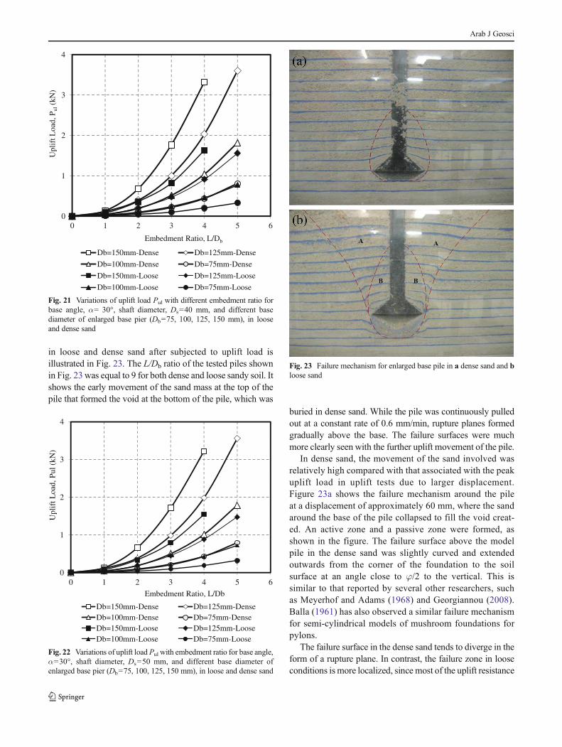
in loose and dense sand after subjected to uplift load isillustrated in Fig. 23. The L/Db ratio of the tested piles shownin Fig. 23 was equal to 9 for both dense and loose sandy soil. Itshows the early movement of the sand mass at the top of thepile that formed the void at the bottom of the pile, which was
buried in dense sand. While the pile was continuously pulledout at a constant rate of 0.6 mm/min, rupture planes formedgradually above the base. The failure surfaces were muchmore clearly seen with the further uplift movement of the pile.
In dense sand, the movement of the sand involved wasrelatively high compared with that associated with the peakuplift load in uplift tests due to larger displacement.Figure 23a shows the failure mechanism around the pileat a displacement of approximately 60 mm, where the sandaround the base of the pile collapsed to fill the void creat-ed. An active zone and a passive zone were formed, asshown in the figure. The failure surface above the modelpile in the dense sand was slightly curved and extendedoutwards from the corner of the foundation to the soilsurface at an angle close to φ/2 to the vertical. This issimilar to that reported by several other researchers, suchas Meyerhof and Adams (1968) and Georgiannou (2008).Balla (1961) has also observed a similar failure mechanismfor semi-cylindrical models of mushroom foundations forpylons.
The failure surface in the dense sand tends to diverge in theform of a rupture plane. In contrast, the failure zone in looseconditions is more localized, since most of the uplift resistance
0
1
2
3
4
0 1 2 3 4 5 6
Upl
ift L
oad,
Pul
(kN
)
Embedment Ratio, L/Db
Db=150mm-Dense Db=125mm-Dense
Db=100mm-Dense Db=75mm-Dense
Db=150mm-Loose Db=125mm-Loose
Db=100mm-Loose Db=75mm-Loose
Fig. 21 Variations of uplift load Pul with different embedment ratio forbase angle, α= 30°, shaft diameter, Ds=40 mm, and different basediameter of enlarged base pier (Db=75, 100, 125, 150 mm), in looseand dense sand
0
1
2
3
4
0 1 2 3 4 5 6
Upl
ift L
oad,
Pul
(kN
)
Embedment Ratio, L/Db
Db=150mm-Dense Db=125mm-DenseDb=100mm-Dense Db=75mm-DenseDb=150mm-Loose Db=125mm-LooseDb=100mm-Loose Db=75mm-Loose
Fig. 22 Variations of uplift load Pul with embedment ratio for base angle,α=30°, shaft diameter, Ds=50 mm, and different base diameter ofenlarged base pier (Db=75, 100, 125, 150 mm), in loose and dense sand
Fig. 23 Failure mechanism for enlarged base pile in a dense sand and bloose sand
Arab J Geosci

is contributed by skin friction. The pull-out resistance of thepile in dense sand is not governed by skin friction, as is thecase for loose sand. The collapse of the sand below the base indense conditions (when the void was created due to continu-ous vertical displacement) is not as evident as was the case inloose conditions. This is because of the close contact (andsmaller void) between the sand particles. The model pile in thedense sand was subjected to a higher uplift load compared tothe loose sand and took longer to have a failure mechanismdevelop around it.
The failure mechanism around the model in the loose sandcannot be clearly seen, as the movement is only restricted tothe pile–sand interface. The front view of a semi-cylindricalmodel pile in loose sand subjected to uplift load is illustratedin Fig. 23b. It shows the movement of the sand at the top of thepile corresponding to the successive vertical displacement ofthe model. Once the running motor started to pull out the pile,a passive zone was formed above the enlarged base due to thecompression of the sand. Arrows 1, 2 and 3 show the upwardmovement of the sand above the base. A void was formed atthe bottom of the enlarged base with subsequent uplift move-ment. The further uplift movement of the pile pushed the sandmass upwards, as shown in Fig. 23b.
The sand around the base of the pile collapsed to fillthe void created underneath the pile. This can be seen inFig. 23b. It is clear that the pull-out resistance is governedmore by skin friction than the shear resistance of the sand.However, the height of the skin friction affected is onlyabout two to three times the shaft diameter above the bell.Due to the loose conditions, the low density of the sandreduces the uplift resistance contributed by the weight ofthe soil within the failure zone above the base. As a result,the peak uplift capacity of the enlarged base pile in loosesand is lower than that in dense sand.
Conclusions
The main purpose of this research was to determine the upliftload capacity for an enlarged base pier. Various experimentaltests were carried out on model belled piles with a shaftdiameter of Ds=30, 40 and 50 mm. In addition, they had abase diameter of Ds=75, 100, 125 and 150 mm, with a baseangle of α=30°, 45° and 60° in both loose and dense sandpacking conditions. After reviewing the tests that wereemployed in the reinforced bin, it can be concluded that thelimiting uplift load capacity of the enlarged base pier wasinfluenced by the embedment ratio, the shaft diameter, thebase diameter, the base angle and the soil density. Based onthe laboratory investigations, the following main conclusionsare drawn:
& The evidence shows that the embedment ratio L/Db has asignificant effect on the contribution of any increasinguplift load. It was observed that the maximum uplift loadincreases with an increase in the embedment ratio L/Db.The results obtained for L/Db=5 in loose and dense sandconditions show a normal trend for shallow foundations.
& Increases in the base angle and shaft diameter both resultin a slight decrease in the net uplift capacity and failuredisplacement. This appears to account for the observeddifferences in the uplift capacity between enlarged basepiers and anchor slabs. In dense sand packing, the modeluplift load with a base angle α=45° was 5 % lower thanthat for a base angle α=30°.
& The model uplift load Pul was higher in dense sand than inloose sand, as expected. The maximum model uplift loadof the belled piles in dense sand is 60 % higher on averagethan that of the equivalent in loose sand.
& Compared to loose sand, the model pile in dense sand wassubjected to a higher uplift load and took longer for thefailure mechanism to develop.
Acknowledgments The authors would like to thank the ResearchManagement Centre of Universiti Teknologi Malaysia (UTM) and Min-istry of Science Technology and Innovation for providing financial sup-port through research vote: R.J130000.7822.4S bringing the idea intofruition.
Please kindly be informed that the funding is received from theResearch Management Centre of Universiti Teknologi Malaysia (UTM)and Ministry of Science Technology.
References
Al-Mhaidib AI, Edil TB (1998)Model tests for uplift resistance of piles insand. Geotech Test J 21(3):213–221
Balla A (1961) The resistance to breaking out of mushroom foundationsfor pylons. Proc 5th Int Conf Soil Mech Found Eng 1(1):569–576
Choi HY, Lee SR, Park H, Kim DH (2013) Evaluation of lateral loadcapacity of bored piles in weathered granite soil. J GeotechGeoenviron 139(9):1477–1489
Dickin EA (2002) Numerical and centrifuge modelling of the uplift behav-iour of piles in cohesionless soil. Proc., Proc third Int Conf EngComput Technol, 137–138
Gaaver KE (2013) Uplift capacity of single piles and pile groups embed-ded in cohesionless soil. Alex Eng J 52(3):365–372
GeorgiannouVN (2008)Unstable behaviour ofmodel Jamunamicaceoussand. Geotechnique 58(10):825–829
Hamza AH (1994) Transmission line tower representation and its effecton the tower surge response calculation. Energy Convers Manag35(12):1087–1096
Honda T, Hirai Y, Sato E (2011) Uplift capacity of belled and multi-belledpiles in dense sand. Soils Found 51(3):483–496
Hsu ST, Liao HJ (1998) Uplift behaviour of cylindrical anchors in sand.Can Geotech J 35(1):70–80
Ilamparuthi K, Dickin E (2001a) The influence of soil reinforcement onthe uplift behaviour of belled piles embedded in sand. GeotextGeomembr 19(1):1–22
Arab J Geosci

Ilamparuthi K, Dickin EA (2001b) Predictions of the uplift response ofmodel belled piles in geogrid-cell-reinforced sand. GeotextGeomembr 19(2):89–109
Khari M, Kassim KA and Adnan A (2014) Sand samples’ preparationusing mobile pluviator. Arab J Sci Eng, In press 1-10
Kumar J, Bhoi MK (2008) Interference of multiple strip footings onsand using small scale model tests. Geotech Geol Eng 26(4):469–477
Meyerhof GG, Adams JI (1968) Ultimate uplift capacity of foundations.Can Geotech J 5(4):225–244
Nazir A, Nasr A (2013) Pullout capacity of batter pile in sand. J Adv Res4(2):147–154
Niroumand H, Kassim KA, Nazir R (2013) The influence of soil rein-forcement on the uplift response of symmetrical anchor plate em-bedded in sand. Measurement 46(8):2608–2629
Tsuha C, Aoki N (2010) Relationship between installation torque anduplift capacity of deep helical piles in sand. Can Geotech J 47(6):635–647
Vesic AS (1971) Breakout resistance of objects embedded in oceanbottom. J Soil Mech Found Div 97(9):1183–1205
Wang D, Merifield RS, Gaudin C (2013) Uplift behaviour of helicalanchors in clay. Can Geotech J 50(6):575–584
Zhang X, Yue JC (2011) Experimental study on the uplift resistance ofplate anchor in sand. Adv Mater Res 250:1371–1374
Arab J Geosci