Electrochromics for smart windows: thin films of tungsten oxide ...
Upload
independentCategory
view
0download
0
Solar Energy Materials & Solar Cells 100 (2012) 27–32
Contents lists available at ScienceDirect
Solar Energy Materials & Solar Cells
0927-02
doi:10.1
n Corr
E-m1 Pr
journal homepage: www.elsevier.com/locate/solmat
Photoelectrochromic performance of tungsten oxide based devices withPEG–titanium complex as solvent-free electrolytes
L. Hechavarrıa a,1, N. Mendoza a,b, M.E. Rincon a, J. Campos a, H. Hu a,n
a Centro de Investigacion en Energıa, UNAM, Priv.Xochicalco S/N, Temixco, Morelos 62580, Mexicob Centro de Investigacion en Materiales Avanzados, Chihuahua, Chihuahua, Mexico
a r t i c l e i n f o
Available online 8 June 2011
Keywords:
Solvent-free polymeric electrolytes
Polyethylene glycol–titanium composite
Photoelectrochromic cells
48/$ - see front matter & 2011 Elsevier B.V. A
016/j.solmat.2011.05.004
esponding author. Tel: þ52 55 5622 9747; fa
ail addresses: [email protected] (L. Hechavarrıa)
esent affiliation: Universidad del ITSMO, Teh
a b s t r a c t
Photoelectrochromic (PEC) devices were assembled with an electrochemically deposited tungsten
oxide (WO3) thin film on transparent conductive glass (ITO) substrates, a composite polymeric
electrolyte (PE), and a Ruthenium 535 sensitized TiO2 sol–gel film deposited on ITO substrates. The
polymeric electrolyte was prepared by the sol–gel method using a viscous polyethylene glycol (PEG,
MW 600) and titanium isopropoxide as precursors in an acidic medium. A lithium salt (LiI) was added
to the PEG–Ti complex for photoelectrochemical purposes. The color change of WO3 based PEC devices
under 100 mW/cm2 illumination at short circuit conditions indicates that the introduction of titanium
complex inside the polymeric electrolyte accelerates the coloring speed from 26 to 9 s. Electrochemical
impedance spectroscopy analyses of PEC devices show that the presence of titanium complex in PE
reduces the charge transfer resistance and increases the charge storage capacity of the cells. This
improvement could come from the oxidation of iodides and reduction of titanium ions inside the
composite electrolytes that increase the lithium ion’s mobility.
& 2011 Elsevier B.V. All rights reserved.
1. Introduction
Control of solar radiation into the buildings and the search fornew fabrication technologies for photovoltaic cells are twoimportant issues to be considered in the research and develop-ment of energy saving and renewable energy resources. Smartwindows, consisting of laminated glasses that can change theircolor on applying a small electrical potential, were conceived fordynamical radiation control. They selectively reflect the incidentsolar radiation on the building windows, reducing the radiationheating inside the buildings during summer seasons, ensuringadequate levels of illumination and sufficient solar protectionagainst overheating [1]. The active component in the switchableglazing is an electrochromic thin film, usually made of a metaloxide material, which can change color during the reduction–oxidation (redox) processes induced by an electrical potential.According to Faughnan et al. [2], the color change in porous WO3
thin films during redox reactions can be explained by the modelof intervalence transition. In the formation of tungsten bronze(blue), the tungsten ion changes its oxidation state from W6þ toW5þ . The addition of one electron to WO3 via an external circuit,
ll rights reserved.
x: þ52 55 5622 9742.
, [email protected] (H. Hu).
uantepec, Oaxaca.
with the consequent intercalation of a counter ion such as Liþ
from the electrolyte, leads to the redistribution of energetic levelsin the oxide. The presence of Liþ ions increases the number ofcolor centers or W5þ ions, and the co-existence of mixed valencestates allows the electron transfer from sites of lower energy(W5þ) to sites of higher energy (W6þ) via light absorption. Thenew energy level introduced by the formation of tungsten bronzeduring the reduction of WO3 films was clearly observed by UV–visspectroscopy in our previous work [3].
To make the smart windows energetically self-sufficient, aphotoelectrochromic cell (PEC) was demonstrated in 1996 [4,5].In these devices, the voltage required to induce a change in colorin the electrochromic material is provided by the electromagneticradiation; during illumination the film transmittance decreasesand can be increased again under dark or in short circuit con-dition. PEC cell is a combination of a Gratzel photovoltaic cell(or dye-sensitized solar cells, DSSCs) and an electrochromicelectrode sharing an electrolyte containing reducible salts, wherethe cation species (Liþ , for example) is used for charge compen-sation in the electrochromic material, and the anion species is aredox couple (I�/I3
�) used for dye regeneration during the processof photovoltage production [6]. Under illumination in short circuitcondition the device operation is based on the injection of photo-generated electrons from the dye sensitizer to the conductionband of a semiconductor, and from here to the WO3 electrode,where Liþ ions intercalate to keep the charge balanced.
L. Hechavarrıa et al. / Solar Energy Materials & Solar Cells 100 (2012) 27–3228
The electrons injected to WO3 cause change in color from transparentto blue and regenerate I� . A chemical-energy balance of all theseprocesses can be represented by the following equations:
1)
dye excitation (T) by photons and generation of electrons:3T*-3Tþ þ3e� ð1Þ
2)
dye regeneration:2Tþ þ3I�-I�3 þ2T ð2Þ
3)
iodide regeneration:I�3 þ2e�-3I� ð3Þ
4)
reduction of tungsten oxideWVIO3ðtransparentÞþe�-LixWVO3ðblueÞ ð4Þ
5)
fi
Lamp
PEC sample
Photodiode
balance
Tþ þWV-TþWVIð5Þ
The PEC configuration proposed in 1996 is similar to that ofDSSCs, except that the platinum counter electrode is replaced bythe WO3 coated one. The absence of Pt slows down chargeregeneration in PEC cells, and consequently the bleaching rate.Different configurations have been introduced to accelerate thebleaching process from one day to about 10 min [7,8]. In one ofthem the WO3 layer was placed between the transparent con-ducting oxide (TCO) and the dye-sensitized TiO2 coating consti-tuting the photoanode, and Pt–TCO was used again as counterelectrode: TCO/WO3/TiO2-dye/electrolyte/Pt/TCO. Another config-uration is an optimization of the first-reported PEC cell, using apatterned WO3/Pt/TCO electrochromic electrode [9]. Fast bleach-ing by about 4 s under illumination is achieved by the positivepotential on the WO3/Pt electrode and the WO3–Pt-electrolytechannel, which facilitates the discharge of Liþ ions and electrons,respectively, from the colored LixWO3 to the electrolyte [2].
An increasing interest in PEC devices is also exhibited in theresearch reports about the use of other electrochromic materialsfor photoelectrochromic devices, such as TiO2�xNx/NiO [10], orpoly(3,4-alkylenedioxythiophene) (PEDOT) [11]. However, all thereported PEC cells use liquid electrolytes. As in the case of DSSCs,liquid electrolytes aid the high photocurrent of the cells but require arigorous sealing to prevent solvent leakage especially at high tem-perature [12–16]. Solid or solvent-free viscous electrolytes, on theother hand, improve cell stability, although cell efficiency is low.Based on previous work, where we report the performance ofelectrochromic devices using polyethylene glycol–titanium complexas an electrolyte [17], the objective of this work is to demonstratethat this polymeric electrolyte can also improve the performance of aPEC cell, and to explain this improvement by electrochemicalimpedance spectroscopy analysis.
PC
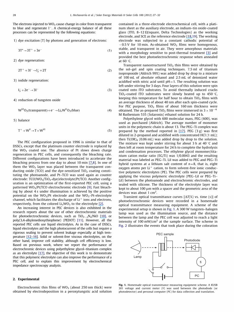
Fig. 1. Homemade optical transmittance measuring equipment scheme. A KUSB
301 voltage and current meter (V) was used between the photodiode (or
photodetector) and personal computer (PC) for data collection and translation.
2. Experimental
Electrochromic thin films of WO3 (about 250 nm thick) wereobtained by electrodeposition in a peroxytungstic acid solution
contained in a three-electrode electrochemical cell, with a plati-num sheet as the auxiliary electrode, an indium–tin oxide-coatedglass (ITO, 8–12 O/square, Delta Technologies) as the workingelectrode, and SCE as the reference electrode [18,19]. The workingelectrode was subjected to a constant cathodic potential of�0.5 V for 10 min. As-obtained WO3 films were homogenous,stable, and transparent in air. They were amorphous materialswith a morphology sensitive to post-thermal treatment [3] andprovided the best photoelectrochromic response when annealedat 60 1C.
Transparent nanostructured TiO2 thin films were obtained bythe sol–gel and spin coating techniques. 7.5 ml of titaniumisopropoxide (Aldrich 99%) was added drop by drop to a mixtureof 100 mL of absolute ethanol and 2.5 mL of deionized wateracidified with nitric acid until pH¼1. The resulting solution wasleft under stirring for 3 days. Four layers of this solution were spincoated onto ITO substrates. To avoid thermally induced cracksTiO2-coated ITO substrates were slowly heated up to 450 1C,keeping this temperature for half hour to obtain TiO2 films withan average thickness of about 40 nm after each spin-coated cycle.For PEC purpose, TiO2 films of about 160 nm thickness wereobtained. The as-prepared TiO2 films were immersed in 3�10�4
M Ruthenium 535 (Solaronix) ethanol solution for 24 h.Polyethylene glycol with 600 molecular mass, PEG (600), was
used as purchased (Aldrich). The average number of monomerunits in the polymeric chain is about 13. The PEG–Ti complex wasprepared by the method reported in [17]. PEG (3 g) was firstdiluted in 2-propanol and acidified with concentrated HCl (1 mL);then Ti(OR)4 (0.06 mL) was added drop by drop to the solution.The mixture was kept under stirring for about 3 h at 40 1C andthen left at room temperature for 24 h to complete the hydrolysisand condensation processes. The ethylene glycol monomer/tita-nium cation molar ratio (EG/Ti) was 1/0.0043 and the resultingmaterial was labeled as PEG–Ti. LiI was added to PEG and PEG–Tihybrid systems at a lithium salt content of n¼8, that is, eightoxygen atoms per Liþ cation, to form solvent-free ionic conduc-tive polymeric electrolytes (PE). The PEC cells were prepared byapplying the viscous polymeric electrolyte (PEG–LiI or PEG–Ti–LiI) between the photoanode and electrochromic electrodes, andsealed with silicone. The thickness of the electrolyte layer waskept to about 100 mm with a spacer and the geometric area of thedevices was about 1 cm2.
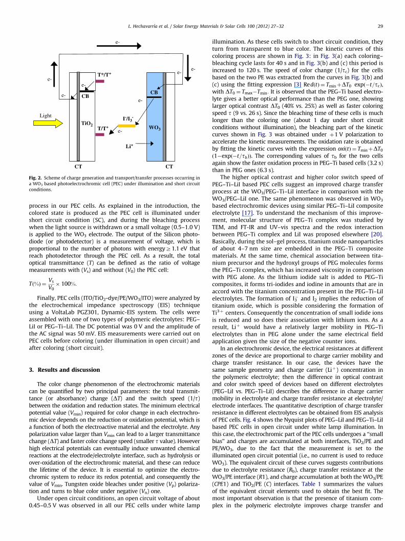
Transient optical transmittance curves [DT(%) vs. time (s)] ofphotoelectrochromic devices were recorded in a homemadeoptical transmittance measuring equipment. A scheme of theexperimental setup is shown in Fig. 1. A 300 W tungsten–halogenlamp was used as the illumination source, and the distancebetween the lamp and the PEC cell was adjusted to reach a lightintensity of 100 mW/cm2 at the sample surface. The scheme inFig. 2 illustrates the events that took place during the coloration
Li+
T*/T+
I-/I3-
T/T+
e-
CB
WO3
CT
TiO2
CBe-
e-
e-
e-e-
e-
e-
CT
Light
Fig. 2. Scheme of charge generation and transport/transfer processes occurring in
a WO3 based photoelectrochromic cell (PEC) under illumination and short circuit
conditions.
L. Hechavarrıa et al. / Solar Energy Materials & Solar Cells 100 (2012) 27–32 29
process in our PEC cells. As explained in the introduction, thecolored state is produced as the PEC cell is illuminated undershort circuit condition (SC), and during the bleaching processwhen the light source is withdrawn or a small voltage (0.5–1.0 V)is applied to the WO3 electrode. The output of the Silicon photo-diode (or photodetector) is a measurement of voltage, which isproportional to the number of photons with energyZ1.1 eV thatreach photodetector through the PEC cell. As a result, the totaloptical transmittance (T) can be defined as the ratio of voltagemeasurements with (Vs) and without (V0) the PEC cell:
Tð%Þ ¼Vs
V0� 100%:
Finally, PEC cells (ITO/TiO2-dye/PE/WO3/ITO) were analyzed bythe electrochemical impedance spectroscopy (EIS) techniqueusing a VoltaLab PGZ301, Dynamic-EIS system. The cells wereassembled with one of two types of polymeric electrolytes: PEG–LiI or PEG–Ti–LiI. The DC potential was 0 V and the amplitude ofthe AC signal was 50 mV. EIS measurements were carried out onPEC cells before coloring (under illumination in open circuit) andafter coloring (short circuit).
3. Results and discussion
The color change phenomenon of the electrochromic materialscan be quantified by two principal parameters: the total transmit-tance (or absorbance) change (DT) and the switch speed (1/t)between the oxidation and reduction states. The minimum electricalpotential value (Vmin) required for color change in each electrochro-mic device depends on the reduction or oxidation potential, which isa function of both the electroactive material and the electrolyte. Anypolarization value larger than Vmin can lead to a larger transmittancechange (DT) and faster color change speed (smaller t value). Howeverhigh electrical potentials can eventually induce unwanted chemicalreactions at the electrode/electrolyte interface, such as hydrolysis orover-oxidation of the electrochromic material, and these can reducethe lifetime of the device. It is essential to optimize the electro-chromic system to reduce its redox potential, and consequently thevalue of Vmin. Tungsten oxide bleaches under positive (Vp) polariza-tion and turns to blue color under negative (Vn) one.
Under open circuit conditions, an open circuit voltage of about0.45–0.5 V was observed in all our PEC cells under white lamp
illumination. As these cells switch to short circuit condition, theyturn from transparent to blue color. The kinetic curves of thiscoloring process are shown in Fig. 3: in Fig. 3(a) each coloring–bleaching cycle lasts for 40 s and in Fig. 3(b) and (c) this period isincreased to 120 s. The speed of color change (1/tc) for the cellsbased on the two PE was extracted from the curves in Fig. 3(b) and(c) using the fitting expression [3] RedðtÞ ¼ TminþDT0 expð�t=tcÞ,with DT0 ¼ Tmax�Tmin: It is observed that the PEG–Ti based electro-lyte gives a better optical performance than the PEG one, showinglarger optical contrast DT0 (40% vs. 25%) as well as faster coloringspeed t (9 vs. 26 s). Since the bleaching time of these cells is muchlonger than the coloring one (about 1 day under short circuitconditions without illumination), the bleaching part of the kineticcurves shown in Fig. 3 was obtained under þ1 V polarization toaccelerate the kinetic measurements. The oxidation rate is obtainedby fitting the kinetic curves with the expression oxiðtÞ ¼ TminþDT0
ð1�expð�t=tbÞÞ. The corresponding values of tb for the two cellsagain show the faster oxidation process in PEG–Ti based cells (3.2 s)than in PEG ones (6.3 s).
The higher optical contrast and higher color switch speed ofPEG–Ti–LiI based PEC cells suggest an improved charge transferprocess at the WO3/PEG–Ti–LiI interface in comparison with theWO3/PEG–LiI one. The same phenomenon was observed in WO3
based electrochromic devices using similar PEG–Ti–LiI compositeelectrolyte [17]. To understand the mechanism of this improve-ment, molecular structure of PEG–Ti complex was studied byTEM, and FT-IR and UV–vis spectra and the redox interactionbetween PEG–Ti complex and LiI was proposed elsewhere [20].Basically, during the sol–gel process, titanium oxide nanoparticlesof about 4–7 nm size are embedded in the PEG–Ti compositematerials. At the same time, chemical association between tita-nium precursor and the hydroxyl groups of PEG molecules formsthe PEG–Ti complex, which has increased viscosity in comparisonwith PEG alone. As the lithium iodide salt is added to PEG–Ticomposites, it forms tri-iodides and iodine in amounts that are inaccord with the titanium concentration present in the PEG–Ti–LiIelectrolytes. The formation of I3
� and I2 implies the reduction oftitanium oxide, which is possible considering the formation ofTi3þ centers. Consequently the concentration of small iodide ionsis reduced and so does their association with lithium ions. As aresult, Liþ would have a relatively larger mobility in PEG–Tielectrolytes than in PEG alone under the same electrical fieldapplication given the size of the negative counter ions.
In an electrochromic device, the electrical resistances at differentzones of the device are proportional to charge carrier mobility andcharge transfer resistance. In our case, the devices have thesame sample geometry and charge carrier (Liþ) concentration inthe polymeric electrolyte; then the difference in optical contrastand color switch speed of devices based on different electrolytes(PEG–LiI vs. PEG–Ti–LiI) describes the difference in charge carriermobility in electrolyte and charge transfer resistance at electrolyte/electrode interfaces. The quantitative description of charge transferresistance in different electrolytes can be obtained from EIS analysisof PEC cells. Fig. 4 shows the Nyquist plots of PEG–LiI and PEG–Ti–LiIbased PEC cells in open circuit under white lamp illumination. Inthis case, the electrochromic part of the PEC cells undergoes a ‘‘smallbias’’ and charges are accumulated at both interfaces, TiO2/PE andPE/WO3, due to the fact that the measurement is set to theilluminated open circuit potential (i.e., no current is used to reduceWO3). The equivalent circuit of these curves suggests contributionsdue to electrolyte resistance (Rb), charge transfer resistance at theWO3/PE interface (R1), and charge accumulation at both the WO3/PE(CPE1) and TiO2/PE (C) interfaces. Table 1 summarizes the valuesof the equivalent circuit elements used to obtain the best fit. Themost important observation is that the presence of titanium com-plex in the polymeric electrolyte improves charge transfer and

0 20 40 600
20
40
60
CPE1
CRb R1
CPE1
C
0.1 Hz
PE (PEG-LiI)PE (PEG-Ti-LiI)
-Z'' (
kΩ)
0.1 Hz
100 kHz
Z' (kΩ)
Fig. 4. Electrochemical impedance spectra of PEC cells under white lamp illumi-
nation and open circuit conditions. Inset: representative electrical circuit.
0 20 40 60 80 100 12030
40
50
60
70
80
90
30
40
50
60
70
80
90
PE (PEG-Ti-LiI)PE (PEG-LiI)
Tra
nsm
ittan
ce (
%)
30
40
50
60
70
80
90
Tra
nsm
ittan
ce (
%)
1V
0 20 40 60 80 100 120
Red = 40.13+28.75exp(-t/26.39)
Oxi = 40.13+28.75(1-exp(-t/6.33))
Tra
nsm
ittan
ce (
%) Experimental
Fitting
Illumination
1 V
Red = 34.32+
ExperimentalFitting
1V
Time (s)
0 20 40 60 80 100 120
Time (s)
Time (s)
Oxi = 34.22+
43.74(1-exp(-t/3.24))
43.74exp (-t/9.30)
Illumination
Illumination
Fig. 3. Transmittance transients of PECs cells using PEG–LiI and PEG–Ti–LiI as electrolytes. Measurements were taken under white lamp illumination (100 mW/cm2) and
short circuit condition (coloration process), and under 1 V polarization without illumination (bleaching process). (a) Cycling time of 40 s for two types of PE. Experimental
and fitting curves for cycling time of 120 s using PEG–LiI (b), and PEG–Ti–LiI (c) as electrolytes.
L. Hechavarrıa et al. / Solar Energy Materials & Solar Cells 100 (2012) 27–3230
charge accumulation processes, as well as carrier mobility: R1decreases from 1.049�105 to 2.253�104 O, C increases from1.064�10�4 to 2.135�10�4 F, and Rb (proportional to carriermobility) decreases from 137 to 116 O. R1 could be related to iodide
regeneration (Eq. (3)), since no coloring was observed in WO3 filmsunder open circuit conditions. In dye-sensitized solar cells, theiodide regeneration is fast because of the platinum particles at thecounter electrode. In our PEC the iodide regeneration process isquite slow, suggesting that the concentration of tri-iodide species atthe WO3/PE interface is relatively high.
EIS spectra of colored PEC cells were measured at rest potentialafter illumination, to analyze some of the phenomena related to thebleaching processes (i.e., reoxidation of WO3 films accompanied bythe de-intercalation of lithium ions). The Nyquist plots measuredunder these conditions are shown in Fig. 5, and the best-fit values ofthe equivalent circuit elements were summarized in Table 1. Hereagain the lower electrolyte and charge transfer resistances of devicesbased on PEG–Ti–LiI electrolytes, and the overall decrease of thesevalues when compared to those measured under illumination arenoticed. The diminished R1 values agree with the lower bleachingtimes (tb) of devices exposed to positive polarization (consider thatthe open circuit potential measured under dark is more positivethan the open circuit potential measured under illumination).Moreover, the values of n1 closer to 0.5 than to 1 agree with Liþ
de-intercalation process accompanying discoloration of WO3 films.It is clear that at the WO3/PE interface the presence of titaniumcomplex in polymeric electrolytes significantly improves the chargetransfer and Liþ diffusion processes, showing the lowest R1 andlargest CPE1 values, which are directly related to a fast color changeas indicated in Fig. 3.
Comparing the equivalent circuit exhibited in Fig. 5 with that inFig. 4 shows that the new component is the diffusive Warburgelement (n¼0.5) in parallel to a capacitor related to charge accu-mulation at the TiO2/PE interface. It appears at high frequencies

Table 1EIS parameters for PEC devices under 0 V polarization.
PEC:y/PE/y Bulk Charge transfer at WO3/PE interface Charge accumulation/diffusion at
TiO2/PE interface
Rb (O) R1 (O) CPE1 (O s�n1) n1 C (F) W (O s�0.5)
Before coloring (under illumination at open circuit)
PEG–LiI 137 1.049�105 3.301�10�5 0.91 1.064�10�4 –
PEG–Ti–LiI 116 2.253�104 4.063�10�5 0.91 2.135�10�4 –
After coloring (at rest potential)
PEG–LiI 124 2.223�103 6.372�10�5 0.66 5.411�10�5 4.053�10�5
PEG–TI–LiI 100 794 1.581�10�4 0.63 2.012�10�4 1.154�10�4
0 50
5
10
15
20
0 1 20
1
2
-Z'' (
kΩ)
Z' (kΩ)
100 kHz
CPE1
W
C
Rb R1
1
PEG-LiIPEG-Ti-LiI
-Z'' (
kΩ)
0.1 Hz
Z' (kΩ)201510
0.1 Hz
Fig. 5. Electrochemical impedance spectra of PECs cells after illumination under
short circuit conditions. Inset: representative electrical circuit.
L. Hechavarrıa et al. / Solar Energy Materials & Solar Cells 100 (2012) 27–32 31
during the de-intercalation of lithium ions in WO3 films. Thecombination of C and W resembles the T circuit element (boundedWarburg), which is characteristic of films that contain a fixedamount of electroactive substance. Therefore its appearance incolored PEC cells at rest potential should be related to the depletionof tri-iodide species by electrons accumulated during illumination. Itis also important to comment on the larger W constant of devicesbased on PEG–Ti–LiI electrolytes. W is inversely proportional to theelectrode surface area and surface roughness of TiO2, and inverselyproportional to the square root of the tri-iodide and iodide diffusioncoefficients (D); therefore a more viscous electrolyte such as PEG–Ti–LiI leads to a lower diffusion coefficient, as shown in its correspond-ing Warburg number (Table 1).
4. Conclusion
WO3 based photoelectrochromic devices with PEG–LiI andPEG–Ti–LiI as electrolytes were constructed and characterizedby the transient optical transmittance and electrochemical impe-dance spectroscopy (EIS) methods. The presence of titaniumcomplex inside the polymeric electrolyte gives a larger opticalcontrast as well as faster coloring speed, which is correlated to afaster reduction of WO3 films. EIS analyses under illumination inopen circuit and after illumination at rest potential indicate that
the presence of titanium oxide complex in polymer electrolytesreduces significantly the charge transfer resistance and increasesLiþ intercalation capacity in WO3/PE interface. The better perfor-mance of PEG–Ti–LiI electrolyte should come from increasedlithium ion mobility inside the PEG–Ti composite materials underan applied electrical field.
Acknowledgements
The authors thank Rogelio Moran for technical support.L.H. and N.M. thank UNAM and CONACyT for scholarships duringtheir Ph.D. studies. This work was financially supported by PAPIIT-UNAM (IN101110) and CONACyT-Mexico (79827 and 123122).
References
[1] P.M.S. Monk, R.J. Mortimer, D.R. Rosseinsky, Electrochromism: Fundamentalsand Applications, VCH, New York, 1995, pp. 43–44.
[2] B.W. Faughnan, R.S. Crandall, P.M. Heyman, Electrochromism in WO3 amor-phous films, RCA Review 36 (1975) 177–197.
[3] L. Hechavarrıa, H. Hu, M. Miranda, M.E. Nicho, Electrochromic responses oflow-temperature-annealed tungsten oxide thin films in contact with a liquidand a polymeric gel electrolyte, Journal of Solid State Electrochemistry 13(2009) 687–695.
[4] C. Bechinger, S. Ferrere, A. Zaban, J. Sprague, B.A. Gregg, Photoelectrochromicwindows and displays, Nature 383 (1996) 608–610.
[5] B.A. Gregg, Photoelectrochromic cells and their applications, Endeavour 21(1997) 52–55.
[6] M. Gratzel, Photoelectrochemical cells, Nature 414 (2001) 338–344.[7] A. Hauch, A. Georg, U.O. Krasovec, B. Orel, Comparison of photoelectrochro-
mic devices with different layer configurations, Journal of the Electrochemi-cal Society 149 (2002) H159–H163.
[8] A. Georg, A. Georg, U.O. Krasovec, Photoelectrochromic window with Ptcatalyst, Thin Solid Films 502 (2006) 246–251.
[9] J.-J. Wu, M.-d. Hsieh, W.-P. Liao, W.-T. Wu, J.-S. Chen, Fast-switching photo-voltachromic cells with tunable transmittance, ASC Nano 3 (2009) 2297–2303.
[10] H. Huang, L. Jiang, W.K. Zhang, Y.P. Gan, X.Y. Tao, H.F. Chen, Photoelec-trochromic properties and energy storage of TiO2�xNx/NiO bilayer thin films,Solar Energy Materials and Solar Cells 94 (2010) 355–359.
[11] C.-Y. Hsu, K.-M. Lee, J.-H. Huang, K.R.J. Thomas, J.T. Lin, K.-C. Ho, A novelphotoelectrochromic device with dual application based on poly(3,4-alkyle-nedioxythiophene) thin films and an organic dye, Journal of Power Sources185 (2008) 1505–1508.
[12] F. Li, F. Cheng, J. Shi, F. Cai, M. Liang, J. Chen, Novel quasi-solid electrolyte fordye-sensitized solar cells, Journal of Power Sources 165 (2007) 911–915.
[13] M.-A. De Paoli, A.F. Nogueira, D.A. Machado, C. Longo, All-polymeric electro-chromic and photoelectrochemical devices: new advances, ElectrochimicaActa 46 (2001) 4243–4249.
[14] M. Li, S. Feng, S. Fang, X. Xiao, X. Li, X. Zhou, Y. Lin, The use of poly(vinylpyr-idine-co-acrylonitrile) in polymer electrolytes for quasi-solid dye-sensitizedsolar cells, Electrochimica Acta 52 (2007) 4858–4863.
[15] M. Biancardo, K. West, C. Krebs, Quasi-solid-state dye-sensitized solar cells:Pt and PEDOT:PSS counter electrodes applied to gel electrolyte assemblies,Journal of Photochemistry and Photobiology A: Chemistry 187 (2007)395–401.
[16] A.F. Nogueira, M.-A. De Paoli, I. Montanari, R. Monkhouse, J. Nelson,J.R. Durrant, Electron transfer dynamics in dye sensitized nanocrystallinesolar cells using a polymer electrolyte, Journal of Physical Chemistry B 105(2001) 7517–7524.
[17] L. Hechavarrıa, N. Mendoza, P. Altuzar, H. Hu, In-situ formation of poly-ethylene glycol–titanium complexes as solvent-free electrolytes for

L. Hechavarrıa et al. / Solar Energy Materials & Solar Cells 100 (2012) 27–3232
electrochromic device application, Journal of Solid State Electrochemistry 14(2010) 323–330.
[18] E. Meulenkamp, Mechanism of WO3 electrodeposition from peroxy-tungstatesolution, Journal of the Electrochemical Society 144 (1997) 1664–1671.
[19] K.J. Stevenson, G.J. Hurtt, J.T. Hupp, High resolution assembly of patternedmetal oxide thin films via microtransfer molding and electrochemical
deposition techniques, Electrochemical and Solid-State Letters 2 (1999)175–177.
[20] N. Mendoza, F. Paraguay-Delgado, L. Hechavarrıa, M.E.Nicho and H. Hu,Nanostructured polyethylene glycol–titanium oxide composites as solvent-free viscous electrolytes for electrochromic devices, Solar Energy Materialsand Solar Cells, in press, doi:10.1016/j.solmat.2011.04.035.
Copyright © 2022 FDOKUMEN