
Thermal Study of Three-Phase Squirrel Cage Induction Motor ...
Upload
khangminh22Category
view
3download
0
A COMPARISON OF THE RATINGS OF SINGLE-PHASE AND THREE
PHASE INDUCTION MOTORS
By
A.RTHUR Co THIGPEN
Bachelor of Science
Louisiana Polytechnic Institute
Ruston., Louisiana
Submitted to the Faculty of the Graduate School of
the Oklahoma Agricultural and Mechanical College
in Partial Fulfillment of the Requirements
for the Degree of
MASTER OF SCIENCE
1950
i
AGRJCIJL TIIRAL OKLAHOMA L I B& MECIIANICAL COUECE
RA Ry DEC 20 1950
A COMPARISON OF THE RATINGS OF SINGLE-PHASE AND THREE
PHASE INDUCTION MOTORS
ARTHUR C" THIGPEN
MASTER OF SCIENCE
1950
THESIS AND ABSTRACT APPROVED:
~~~ Thesis Adviser
Q_;f~ Faculty Representative
!Ar~~
ii
iii
PREFACE
Since its practical inception by Nikoli Tesla in 1888, no
one part of our electrical industry has enjoyed so gr~at an
industrial and domestic expansion and application as has the
principle of the induction motor. Yet with this tremendous
expansion and development, much is to be learned and recorded
with respect to its ultimate design and the predetermination of
its operating characteristics.
That this is true is most vividly brought out in a paper
by Messrs. To Co Lloyd, Po Ho Trickey, W.R. Hough, and C. P.
Potter entitled, "Is there a Doctor in the House?" (Unsolved
motor design problems suggested for Postgraduate Theses)
published in the September, 1949, issue of Electrical Engineering.
Q.uoting in part from this paper, the electrical machinery field
as a whole is reviewed as follows:
One sometimes hears the statement that the electric machinery field is so well established that relatively few opportunities exist for further investigations and developmentso Nothing could be further from the truth. In the electric motor business alone., many problems appear which are not solved rigorously but are by-passed by estimates based on experienced judgment; or they are solved by empirical data in use in design offices, but not generally available in the literature. In either ease, further study is justifiedo
Specifically, with respect to comparisons of single-phase
and polyphase motors, the authors further state:
Comparisons. The following comparisons are for single and polyphase motorso
iv
lo A single-phase motor is built in exactly the same stator and rotor laminations and with the same stack and rotor cage as a polyphase motoro Suppose each is designed with the same flux per poleo What are the relative values of maximum torque obtained from each? (Some assumptions must be made concerning relative conductor length and winding factor•so) On the basis of these maximum torques., what relative horsepower ratings should be assigned to each?
Because of the increased magnetizing currents of singlephase motors, the circular mils per ampere of the two will differo On the basis of equal copper loading in both., what full-load horsepower ratings should be assigned to each?
2o Suppose the foregoing single-phase motors were built as capacitor-start induction-run typeso Does good design result from the use of the same rotor resistances in both cases? If not 9 what should be the relative resistances of squirrel cages for single-phase and polyphase motors built in the same laminations and stacks?
3o It seems to be accepted as more or less axiomatic that double-layer lap windings are best for polyphase and concentric type are best for single-phase motorso For singlephase motors what are the relative merits of concentric and lap windings? This could be investigated on the bases of relative winding parameters, copper weights, and resulting performanceo
It is with respect to the first comparison that this paper
is concerned, namely the relative horsepower ratings of single
phase and polyphase induction motors designed with the same
stator and rotor and with the same flux per poleo
It is obvious at the outset that any conclusions that may
be drawn by the writer must of necessity be very general in as
much as each particular design may have innumerable possibilitieso
ACKNOWLEDGEMENT
The writer wishes to ~xpress his sincere appreciation to
Professor Charles Fo Cameron for his expert guidance and
suggestions in the preparation of this thesiso
V
vi
TABLE OF CONTENTS
CHAPTER I
Interpretation of the Problem and General D~sign. • • 1
CHAPTER II
Explanation and Derivation of Design Factors • • • • • 15 CHAPTER III
Exciting Current of Single-Phase and Three-Phase
Induction Motors
CHAPTER IV
• 0 ~ 0 0 0 0 e • • 0
Comparison of Horsepower Rating of Single-Phase and
Polyphase Induction Motors on the Basis of Equal Copper
43
Loading. • . • . • . . . • • . . • • • • . . . . . . • 58
CHAPTER V
Comparison of Horsepower Ratings on the Basis of
Maximum Torque .
CONCLUSION. .
BIBLIOGRAPHY ..
64 77
79
1
CHAPTER I
IN'rERPRETATION OF THE PROBLEM AND GENERAL DESIGN
In attempting to analyze a problem of this type it would be
well to first state the problem and to then g ive an interpre
tationo The probleml is as follows;
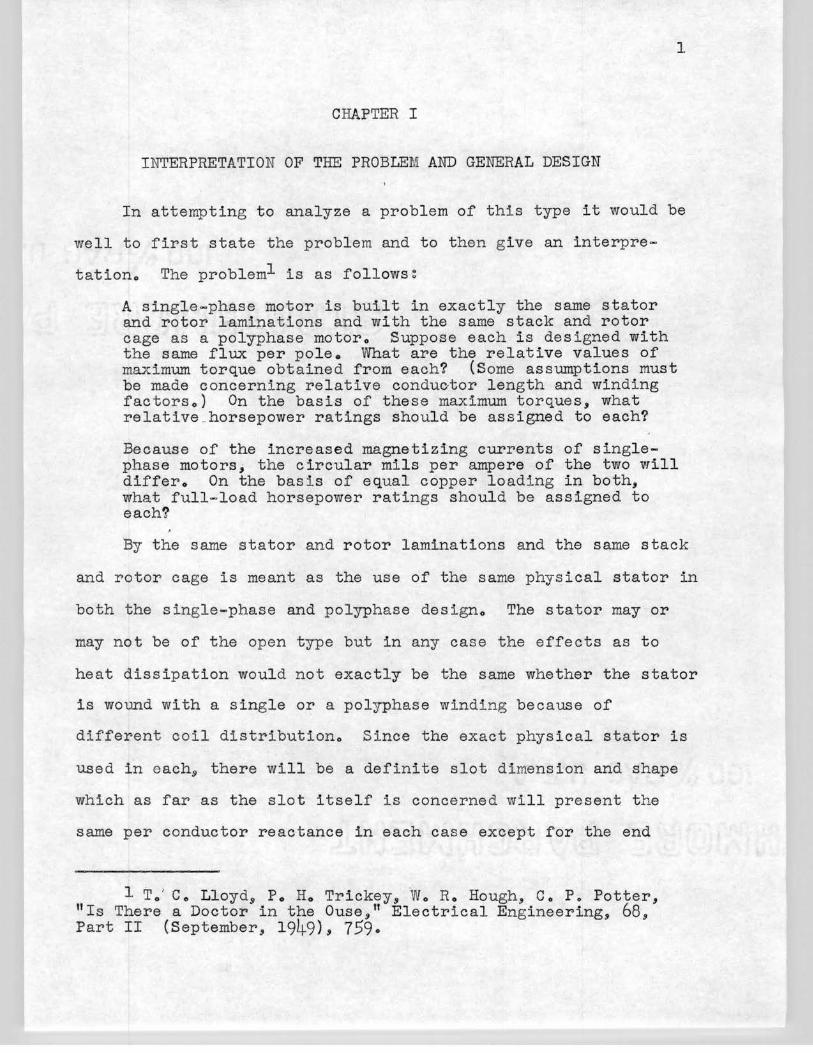
A single-phase motor is built in exactly the same stator and rotor laminations and with the same stack and rotor cage as a polyphase motoro Suppose each is designed with the same flux per poleo vVhat are the relative values of maximum torque obtained from each? (Some assumptions must be made concerning relative conduc,tor length and winding factorso) On the basis of these maximum torques, what relative ._ horsepower ratings should be assigned to each?
Because of the increased magnetizing currents of singlephase motors, the circular mils per ampere of the two will differo On the basis of equal copper loading in both, what full-load horsepower ratings should be assigned to each?
By the same stator and rotor laminations and the same stack
and rotor cage is meant as the use of the same physical stator in
both the single-phase and polyphase designo The stator may or
may not be of the open type but in any case the effects as to
heat dissipation would not exactly be the same whether the stator
is wound with a single or a polyphase winding because of
different coil distributiono Since the exact physical stator is
used in each9 there will be a definite slot dimension and shape
which as far as the slot itself is concerned will present the
same per conductor reactance in each case except for the end
1 To' Ce Lloyd9 Po Ho Trickey, We Ro Hough., Co Po Potter, "Is There a Doctor in the Ouse, 11 Electrical Engineering., 68, Part II (September, 1949), 759.
turnso
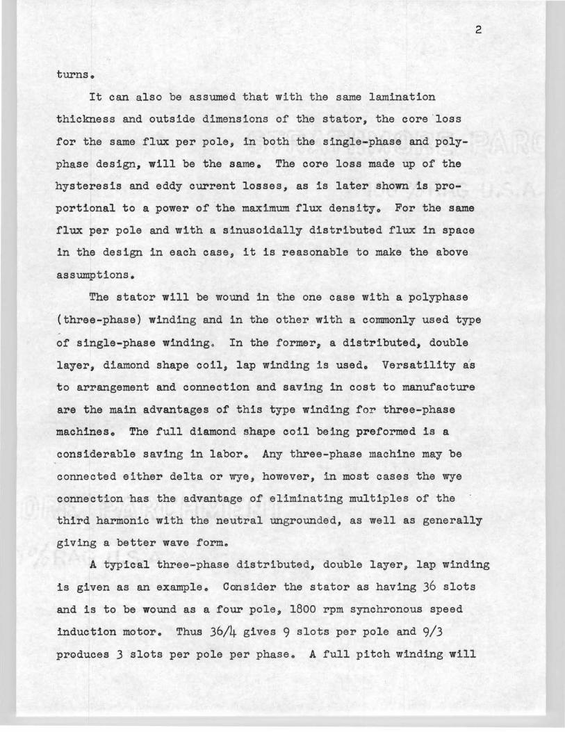
It can also be assumed that with t he same lamination
thickness and outside dimensions of the stator, the core .loss
for the same flux per pole, in both the single-phase and poly
phase design, will be the sameo The core loss made up of the
hysteresis and eddy current losses, as is later shown is pro
portional to a power of the. maximum flux densityo For the same
flux per pole and with a sinusoidally distributed flux in space
in the design in each case, it is reasonable to make the above
assumptions.
2
The stator will be wound in the one case with a polyphase
(three-phase) winding and in the other with a commonly used type
of single-phase winding o In the former, a distributed, double
layer, diamond shape coil, lap winding is usedo Versatility as
to arrangement and connection and saving in cost to manufacture
are the main advantages of this type winding for three-phase
machineso The full diamond shape coil being preformed is a
considerable saving in iaboro Any three-phase machine may be
connected either delta or wye, however, in most cases the wye
connection has the advantage of eliminating multiples of the
third harmonic with the neutral ungrounded, as well as generally
giving a better wave formo
A typical three- phase distributed, double layer, lap winding
is given as an example. Consider the stator as having 36 slots
and is to be wound as a four pole, 1800 rpm synchronous speed
induction motor. Thus 36/4 gives 9 slots per pole and 9/3
produces 3 slots per pole per phase. A full pitch winding will
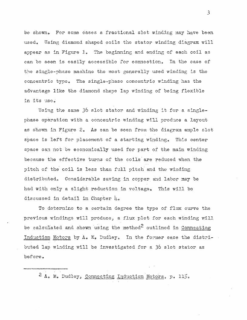
3
be showno For some cases a fractional slot winding may have been
usedo Using diamond shaped coils the stator winding diagram will
appear as in Figure lo The beginning and ending of each coil as
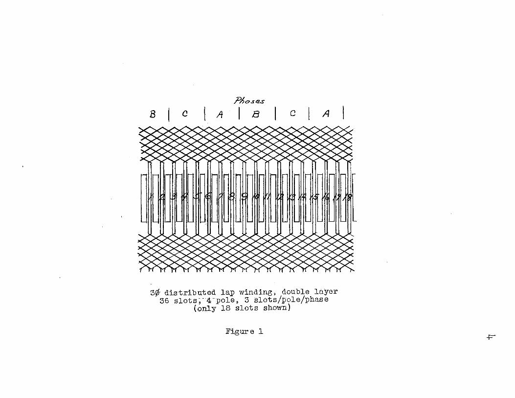
can be seen is easily accessible for connectiono In the case of
the single-phase machine the most generally used winding is the
concentric typeo The single-phase concentric winding has the
advantage like the diamond shape lap winding of being flexible
in its USe 0
Using the same 36 slot stator and winding it for a single
phase operation with a concentric winding will produce a layout
as sliown in Figure 2o As can be seen from the diagram ample slot
space is left for placement of a starting windingo This center
space can not be economically used for part of the main winding
because the effective turns of the coils· are reduced when the
pitch of the coil is less than full pitch and the winding
distributedo Considerable saving in coppeP and labor may be
had with only a slight reduction in voltageo This will be
discussed in detail in Chapter 4o To determine to a certain degree the type of flux curve the
previous windings will produce 9 a flux plot for each winding will
be calculated and shown using the method2 outlined in Connecting
Induction Motors by Ao Mo Dudleyo In the former case the distri
buted lap winding will be investigated for a 36 slot stator as
bef'or~o
2 At1 Mo Dudley9 Connecting Induction Motors., Po 1150
?Ao.se.s
B C A I B C A
3¢ -distributed lap winding ll double layer 36 slots;-4-pole, 3 slots/pole/phase
(only 18 slots shown)
Figure 1 ..p-·
G H ~
·~f}U ·n 'ff P"" -. ~ ~
... - - -\...
\.
'-- \.
.... -u- - - - - .... - - -~ ~ ! 1,(1 ~ ) ~ ~ ~ g ~II ~~ ~ ~r - - .... - - .... .... .... -
'-.. \.
\... '-
'-
Si ngle =Phase Concentric Winding
36 slot s 4 poles f 4 coils/pole
I
Figure 2
~
- - - .., ,- .... - - - - - -
~ i , ~ ~ ~ 3' u ~ ~~ s " .. i,
- - - - - .... - - ... ... .... -'-..
\...
\.._
\Jl.
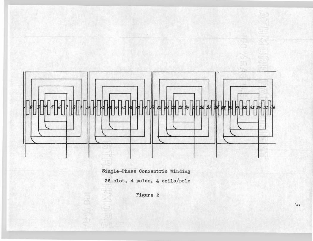
In order to plot the flux~ one particular instant of time
must be chosen and the relative values of the currents in the
three-phase determinedo It also must be noted that in laying
out the winding of the motors one phase must be reversed so as
to produce the rotating field o Assume the three synnnetrical
currents Ia, Ibs Ic as shown in Figure 3s are flowing in the
three respective phases of the motor as steady state valueso
If the time t1 is chosen for the flux plot 9 the instantaneous
value of the phase currents will be Ia equal plus I maximum,
Ib equal minus one - half I maximum and Ic equal minus one-half
I maximumo These values are obvious since the algebraic sum of
the currents of a balanced three - phase system will always be
zeroo
Ia
Balanced Three-Phase Currents
Figur~ 3
6
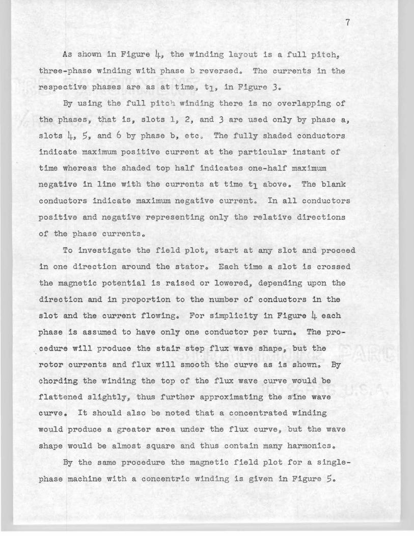
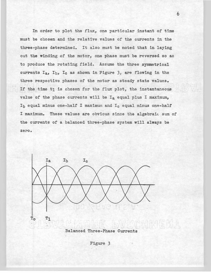
As shown in Figure 4j the winding layout is a full pitch,
three-phase winding with phase b reversedo The currents in the
respective phases are as at time 9 t1j in Figure 3o
7
By using the full pitc h winding there is no overlapping of
the phases, that is, slots 1 9 2, and 3 are used only by phase a,
slots 4, 5, and 6 by phase b, etc o The fully shaded conductors
indicate maximum positive current at the particular instant of
time whereas the shaded top half indicates one-half maximum
nega1Uve in line with the currents at time t1 aboveo The blank
conductors indicate maximum negative currento In all conductors
positive and negative representing only the relative directions
of the phase currentso
To investigate the field plot, start at any slot and proceed
in one direction around the statoro Each time a slot is crossed
the magnetic potential is raised or lowered 9 dependi~g upon the
direction and in proportion to the number of conductors in the
slot and the current flowingo For simplicity in Figure 4 each
phase is assumed to have only one conductor per turno The pro-
··. cedure will produce the stair step flux wave shape, but the
rotor currents and flux will smooth the curve as is showno By
chording the winding the top of the flux wave curve would be
flattened slightly,~ thus further approximating the sine wave
curveo It should also be noted that a concentrated winding
would produce a greater area under the flux curve.ii but the wave
shape would be almost square and thus contain many harmonicso
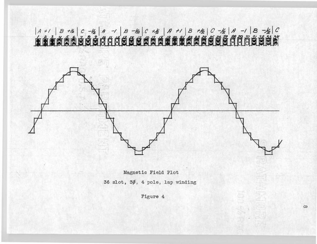
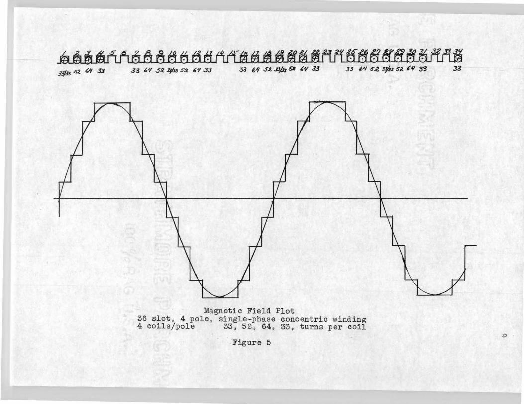
By the same procedure the magnetic field plot for a single
phase machine with a concentric winding is given in Figure 5o
', Magnetic Field Plot
36 slot, 3¢ 9 4 pole 9 lap winding
Figure 4
r~ IC-~ I }t - -~
-1 IB -~I e ~ 'f
~~-..+'""I
co
3$3 Q '" 33 33 {,9 S~ ¢, S:l 69 J.J 33 l,.1/ S.t .DA, &I ~¥ 3.3 33 '1'1 S-,2 3PJ SJ. ~'I 33
Magnetic Field Plot 36 slot s 4 pole , singl·e-phase concentric wi nding 4 coils/pole 33 , 52 , 64 , 33, turns per coil
Figure 5
33
.0
10
The concentric winding in this figure is an actual winding taken
from a Robbins and Meyers 1/4 HP 9 4 pole 9 36 slot 9 single-phase,
capacitor start, induction run9 induction motor with 33s 52, 64,
and 33 turns per coilo While the turns are not exactly sinu
~oidally distributed in space the resulting flux wave is a very
good approximation of the sine waveo As in the polyphase machine
winding the stair step flux plot would smooth to approximately
the curve of the sine wave as showno
Of general significance at this point is the fact that the
windings of the polyphase winding as shown in Figure 1 are ex
cited by a three-phase voltage source with balanced voltages 120
electrical degrees out of phaseo This coupled with the fact that
the phase belts of the winding have 120 degrees space separation
in the stator will produce a very nearly constant flux value
rotating at synchronous speed around the periphery of the statoro
In contrast, however 9 the single~phase windings of Figure 2 are
placed 180 degrees apart in space and excited by a single-phase
voltage sourceo It is obvious 9 therefore, that the stator
winding alone 5 when excited, will produce only a pulsating flux 9
stationary with respect to the statoro Such is not the case with
the rotor in place and r9tating at synchronous speedo By means
of the cross-field theory9 which will not be discussed here 9 it
is shown that a quadrature flux will be set up by the induced
currents in the rotoro This flux will be in both space and time
quadrature with respect to the main winding flux and will thus
produce a synchronously rotating fluxo At synchronous speed of
the rotor 9 the main field flux and the quadrature flux will have
11
very nearly the same magnitude. When this resultant flux wave
is equal to the resultant flux of the three-phase machine, it is
assumed that the two machines will have the same flux per pole.
In connection with the problem as a whole it is assumed the
rotor is of the squirrel-cage type.
In both the three-phase and single-phase windings as just
discussed, the effective value of the voltage3 that would be
induced per phase is
volts (1)
where
e = the effective value of voltage f = frequency in cycles per second kb = form factor kw = winding distribution factor kc = chord factor w = number of turns in series per phase ¢ = flux per pole
With the same flux per pole in each motor the hypothetical total
fluxL~ of the machines will be;
where
¢t equals~ lines
it p kd
-· = = =
total flux of motors flux per pole of motors number of poles air gap flux distribution factor
( 2)
Solving for¢ gives ¢ = ¢t kd p
3 John Ho Kuhlmann, Design of Electrical Apparatus, p. 167.
4 Ibid. ·., p. 167.
Substituting this value of¢ in Equation 1 and solving for
¢t5 gives
1 E · 10-8 ¢t = 4 E
f kb kc kw kd w I
The frequency6 of the voltage generated is f = ¥2~
where n is the synchronous rpmo
w equals~ where N equals the total number of conductors per
phaseo
12
Substituting their va lues in Equation (3t-a.nd solving for
E7 gives
E = ¢t n N kc kb kw kd 60 X 108
volts
The horsepower8 output and thus the rating of any polyphase
induction motor is;
where
HP= m EI PF eff
746 _
HP = horsepower output of the motor m = number of phases E = phase voltage I = · line current PF · -· power factor of the motor eff = efficiency
This above equat ion will hold for single~pha~e motors ;
5 Ibido, Po 1670
6 Ibido, p., 1680
7 Ibid., ., Po 1680
8 I'oido , Po 168.,
{4)
{ 5)
where
m = 1 E - line voltage I = line c:urrent PF - power factor eff = efficiency
Sul?s,tituting the 1ralue of E in Equation (4) in Equation (5)
gives g
HP = ¢t nm N kc kb kw kd I PF eff .. 60 X 108·x·746 : . •
or
¢'t nm N kc kb.kw I PF eff HP=~~~~~--~~~~~~~
4~476·x·1012 ·
In terms of the air ga:p flux density9 and stato·r dimensions
where
D ·- inside diameter of stator lg =·length of sta·tor air gap section Bi::r =air-gap flux density
0
The total number of ampere conductors per inch of stator gap
circumference10 Q is equal. to
n ·r N kc· --··wb
Substituting the values of ¢tin Equation (7) gives;
9 Ibidoil Po i68o
10 Ibido, Po 1680
13
(6)
(7)
1~-
Bg m n 1::f (8)
Equation ( 8) will hold for s ingle-·phase induction motors
where
m = 1. I= line current N = single•=phase conductors
Substituting Q. in the above equation and solving the equation in
terms of D and 1g will yield~
n2 I. :~ -~~lit~.f) .x 1912 -g n2 q Bg n kb kw kd PJ? e.ff
(9)
Thus equations (8) and (9) give a basis upon ·which a comparison
of the s i:n.g1e=phase and pol-;yphase induction motor may be made o
15
CHAPTER II
EXPLANATION AND DERIVATION OF DESIGN FACTORS
In considering the horsepower output Equation (8) in Chapter
I 9 it immediately becomes apparent that the winding factors of
the stator winding~ distribution factor., pitch factor., flux
distribution factor., and £orm factor have a direct effect on the
output of the motoro Not evident from Equation (8), however., is
the winding connection factor of the stator and the skew factor
of the rotor$ both of which slightly effect the motor outputo
A brief discussion of these factors follows in order to be able
to determine their relative contribution to induction motor
performancec
Distribution Factor
In the polyphase winding the distribution or breadth factor
is commonly defin.ed1 as the ratio of the resultant voltage of
the coils per phase per pole to the arithmetic sum of the ef
fective values of the individual coil voltages o (Each of 't;he
latter being displaced electrically, depending upon the number
of slots per poleo) It may be further defined as the ratio of
the actual voltage to the voltage that would have resulted from
the total turns., had they been located in one pair of slotso
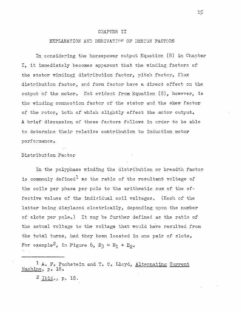
For example2., in Figure 6., E3 = E1 + E20
1 Ao .Fe Puchstein and To Co Lloyd9 Alternating Current Machine., ·Po 180
2 Ibidog Po 180
Where a= the electrical phase difference between slots E1 = voltage generated in first slot E2 = voltage generated in adjacent slot
Effect of ·Distributed Winding on Wave Shape
Figure 6
from definition
E;, Kw= distribution factor= El+ E2
and the electrical phase difference (a) 180 degrees = slots per pole
16
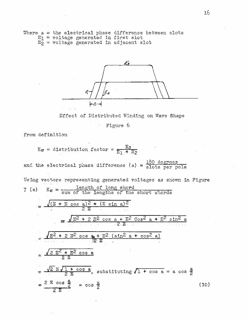
Using vectors representing generated voltages as shown in Figure
7 ( ) K = length of long chord a w sum of the lengths of the short chords
= ~(E·+ E cos a)2 + (E sin a)2 . ,. . . 2 E . . . "·.
=J E2 + 2· ,E2 cos a +· E2 Cos2 a +· E2 sin2 a ' .. 2.E. """
_ /E2 + 2 E2 cos ~+EE2 (sin2 a+ cos2 a)
(2 E2 + E2 cos a = 2 E
\/2E il + cos a substituting {1 a + cos ·- 2 E fi) cos a = a 2
2 E cos a §... ·- 2 -· cos 2 (10)
2 E
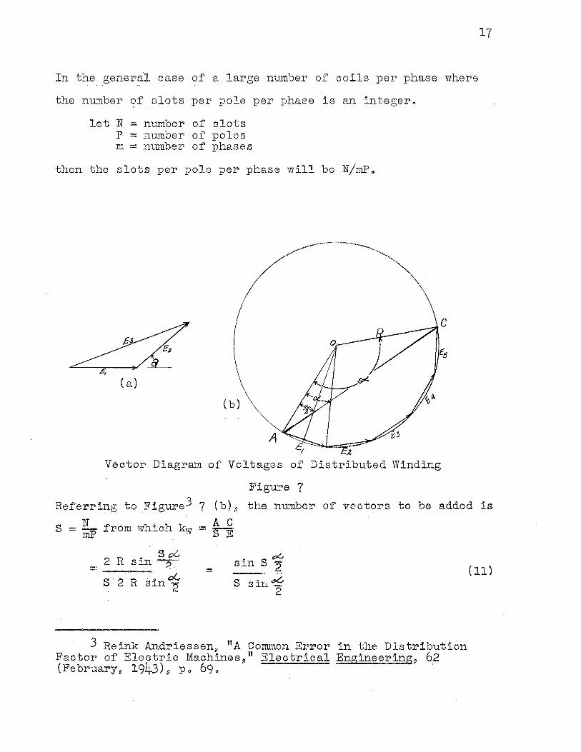
In the general case of a large number of coils per phase where
the number of slots per pole per phase is an integero
let N = number of slots P = number of poles m = number of phases
then the slots per pole per phase will be N/niPo
-----C
( a)
(b)
:.e Vector Diagram of Voltages of Distributed Winding
Figure 7
17
Referring to Figure3 7 (b) 8 the number of vectors to be added is N AC S = iiiP from which kw= SE
s oG 2 R sin-... = ,, ~ -s-· 2-.-R-s in 1
. s ,PG sin· -__ .. _,,, ?. $ ..• tX.; . sin -
' 2
3 Reink Andriessen~ ''A Common Error in the Distribution Factor of Electric Machines 9 « Electrical Engineering9 62 (February., 1943) 8 Po 690 ·
(11)
18
This equationLJ- is true for any nuxnber of phases when S is an
integer 21 L,e., 21 there is a whole number of slots per pole 9 the
coils for all phases and poles being identicalo The winding may
be single layer9 but all phases are symmetrical with respect to
each other and with respect to the poleso It can be seen from
Equation (11) that the limits of the distribution factor can be
determined by substituting a minim1.un of two coils per phase per
pole to a theoretical maximum of an infinite number of coils per
phase per poleo (For one coil per phase per pole the distri
bution factor is 1mi tyo) In so doing it is found that for three
phase windings the distribution factor for integral slot windings
has as its limiting minimum value Oo95.5o In the case of an
infinite nmnber, of slots per pole per phase, the polygon will
approach a circle and the distribution factor will be equal to a
chord divided by an a.rco The net effect of distributing the
winding in the phases of an induction motor is to produce a
sinusoidal resultant flux wave,, thus reducing the relative effect
of ha.rmonicso Chording the winding reduces leakage reactance
and gives better heat dist1..,ibution in the coils o It will further
reduce the coil axial length thus helping to eliminate end
bracketso The above 9 plus a reduetion in overall resistance and
reactance produce better toJ?que 9 power factor and efficiency in
the polyphase machineo
Using the above method of determinlng the distribution
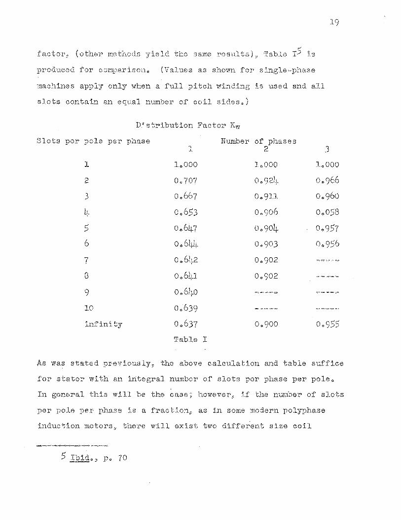
.facto:r•s ( other methods yi.eld the same results) 9 Ta.ble I5 is
produced for· co:rrrparisono (Values as shown for single=phase
19
machines apply only when a full pitch winding is used and all
slots contain an equal number of coil sideso)
D~stribution Factor Kw
Slots per pole per phase Number of.phases l 2 3
1 11)000 11>000 loOOO
2 00707 Oo 92L~ 00966
3 00667 00911 00960
4 Oo653 00906 Oo058
5 01)647 00904 00957
6 Oo644 00903 00956
7 00642 00902 -~~=-,~
8 Oo64J. 00902 Cll}OQ"""'l:IIQl..::J
9 Oo64o r;,~ ""'' '"°"""'(...:I l'".::.i=r:">IO'"""';,,,:::;i
10 00639 t=,...,,,~,.o<)il>Q C.;Ju,,ou.:.:,,"""'~
infinity 00637 00900 00955
Table I
J,,.s was stated previously9 the above calculation and table suffice
for stator with an in:.tegral number of slots per phase per poleQ
In general this will be the case; however 8 if the number of slots
per pole per phase is a frac·tion 9 a.s in some moder0n polyphase
induction motors 9 there will exist two different size coil
grol:1p;s 9 the larger group contain:1.ng one or n1ore coils than the
smallero Such a winding adds vectorially a lar•ge number• of coil
voltages which are slightly out of phase., The higher harmonics
in the coil voltages will have a much gr·eater phase difference
resulting in closer approximation to the sine wave of voltage
th.an would exist when the number of slots per- phase per pole is
an int;eger o This 9 of course .9 is the ideal case 9 such ideal cone.,
ditions being assumed for later calculationso In many polyphase
i.nduc tion mo s 31 the nmnber of slots per pole is not an integer
in which case it is called a fractional slot windingo Such a
fractional slot wi.nding 9 in order to give a balanced polyphase
voltage must be such as to be divisible into as many identical
belts as there are phases, these belts being displaced in the
case of a three,00 phase winding,~ 120 electrical degrees aparto
The fractional slot vdnding6 improves vrnve for'm and locked
torque as well as having the advantage of behaving like a winding
with many slots per pole per' phase, thus reducing the distri=
bution factor of the harmonics.,
To deter·mine if a fractional slot machine is capable of
producing a balanced three,=phase 111rinding9 the ratio of the number
oi' slots t;o the :numbe:l'." o.f pol.es is red.uced to :lts lowest terms,,
The rn:ure:rator will give the nmnber of belts per pole in a re,
peatabll, section and it must be divisi.ble by the number of phases
in order to give the nrnnber of belts per phase per pole 3 other0 "
6 Ro R., LsJ,'lfrence 31 Principles of AlteI'nating Cut•rent, Tvlachinery ,,~ po 4-7.. ·
21
vll'ise the machine is incapable of pro due ing a balanced three=
phase winding. The denominator reduced to its.lowest term
g:i.ves the numoer of poles after which the belt is repeated.,
As in the case of the integral slot windings the voltage
in the different belts are not in pha.se 9 consequently51 the ratio
of the vectorial sum of the voltages to the algebraic swn21 or the
distribution i'ac.tor 9 must be determinedo Since all the belts are
not identical9 a weighted average distribution factor is deter·=
mined 9 taking :into account the different nu.1:nber · of coils in some
belts. The phase voltage of a fractional slot winding can also
be dete1"'mined. by an equivalent w:i.nding,, 'I'he coil sides of such
a winding will be separ•ated by small angles equal to the angle
between belts :'Ln a fractional slot win.dingo A vectoJ? diagram
repr'esentlng these voltag(::1S w:111 form the spokes of' a f'a.."l from
v1rhich the phase voltage may be determined"
The following eJrample 7 will be used to clarify the above
discussion~ A thr•ee=phase machine has 20 poles and a total of'
84 slots o As 84 is not exactly divisible by the number· of phases 9
1 t is read:t.ly El<.:.en that an integr,al slot wlnding is not possible.,
The ratio of the total s1ots to the number of poles reduced to
its lowest terms i:s 21/~a Thus 21 is d:1.visib1e by 39 and a
balanced fractional slot winding is possible with 7 slots per
phase per pole,, The winding will be repeated every fif'th pole.,
For> these five poles there must be five belts with a total of'
seven slots per poleo Th:ls will be acc.ompl:tshed with two belts
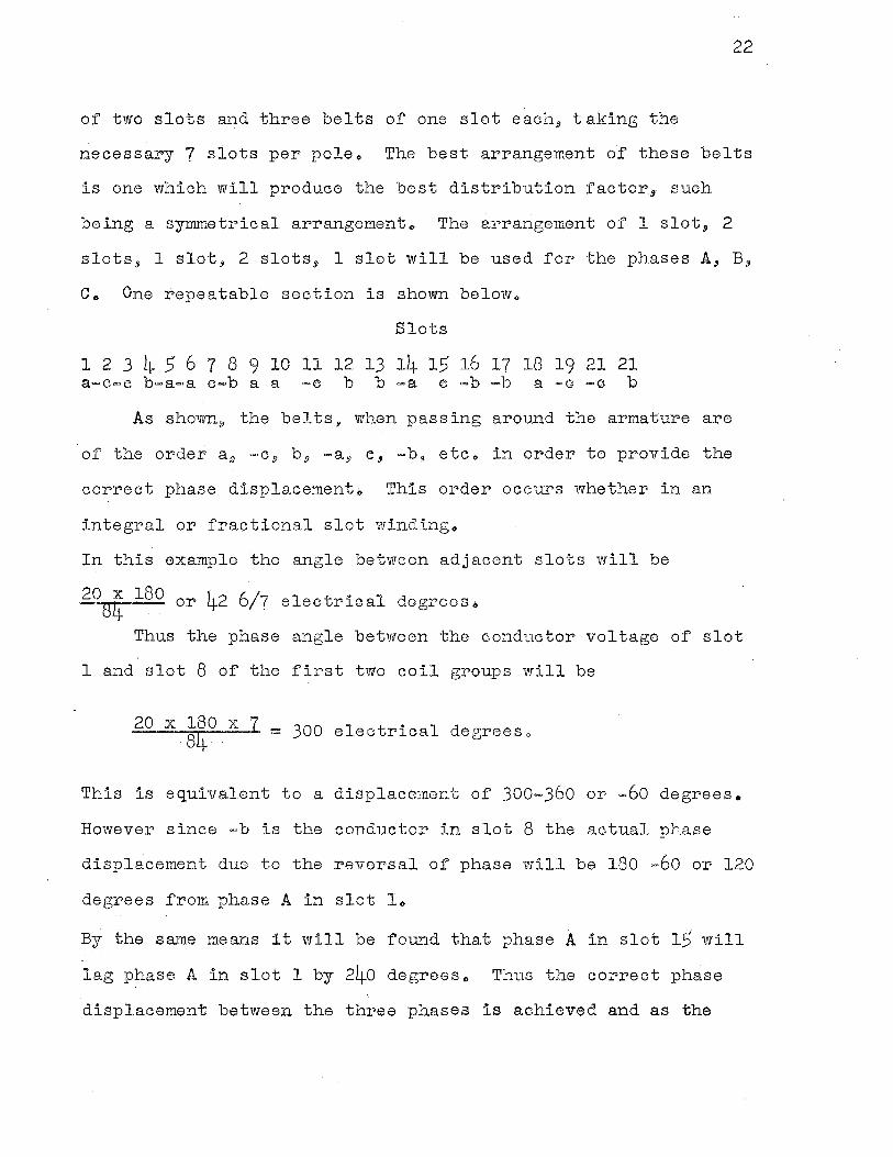
22
of two slots and three belts of one slot each, taking the
necessary 7 slots per pole,. The best arrangement of these belts
is one which will produce the best distribution factor, such
being a symmetrical arrangement .. The arrangement of 1 slot., 2
slots, 1 slot, 2 slots, 1 slot will be used for the phases A, B,
Co One repeatable section is shown below ..
Slots
1 2 3 4 5 6 7 8 9 10 11121j 14 15 16 17 18 19 21 21 a-c-c b-a-a e-b a a -e b b -a e -b -b a -a -a b
As shown, the belts, when passing around the armature are
of the order a 9 =C.9 b, -a, e, -b,9 etc .. in order to provide the
correct phase displacemento This order occurs whether in an
integral or fractional slot winding ..
In this example the angle between adjacent slots will be
2084 lSO or 42 6/7 electrical degreeso
Thus the phase angle between the conductor voltage of slot
1 and slot 8 of the first two coil groups will be
20 X 180 X 7 . -84·. - 300 electrical degrees o
This is equivalent to a displacement of 300-360 or -60 degrees.
However since-bis the conductor in slot 8 the actual phase
displacement due to the reversal of phase will be 180 -60 or 120
degrees from phase A in slot L,
By the same means it will be found that phase A in slot 15 will
lag phase A in slot 1 by 240 degreeso Thus the correct phase
displacement between the three phases is achieved and as the
23
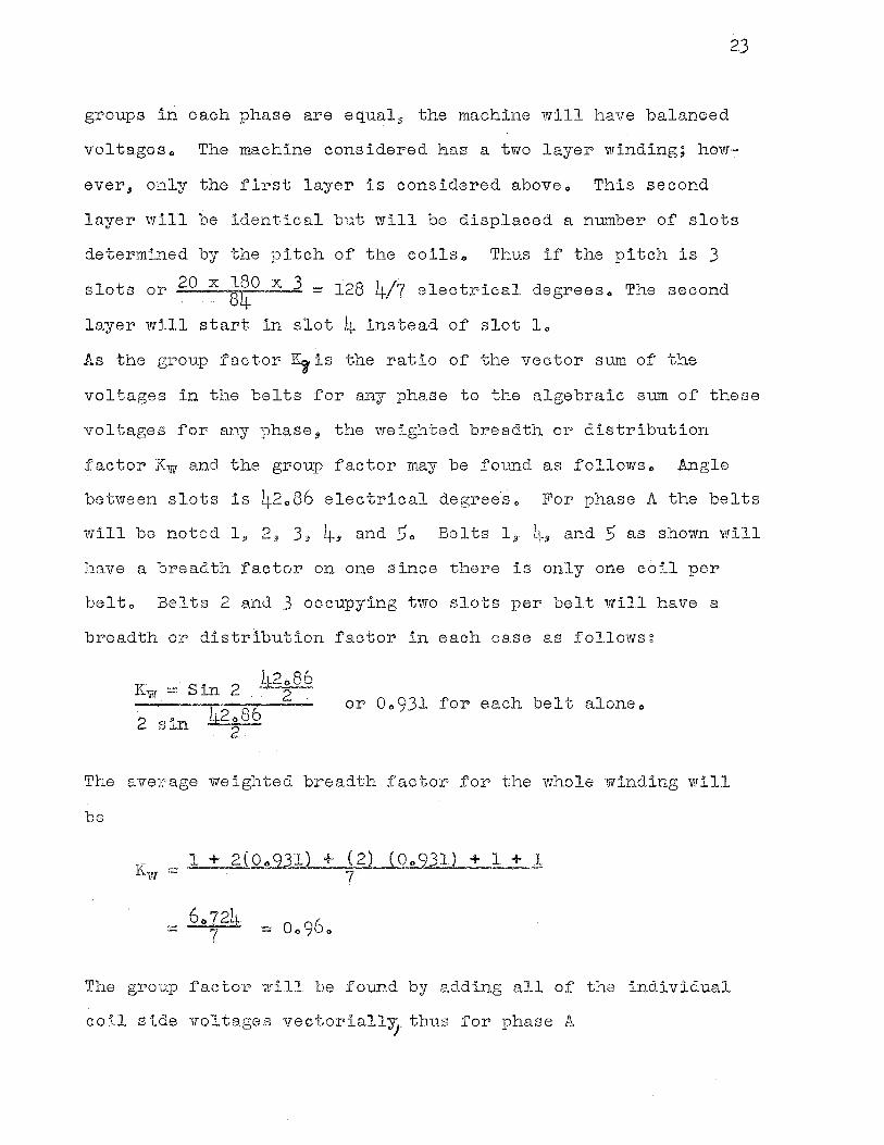
groups in each phase are equal 9 the machine will have balanced
voltageso The machine considered has a two layer winding; how-
ever 3 only the first layer is considered aboveo This second
layer will be identical but will be displaced a number of slots
deter•mined by the pitch of the coils<> Thus if the pitch is 3
slots or 20 X ~aO X 3 ~ 128 4/7 electrical degreeso The second
layer will start in slot Li- instead of slot lo
As the group factor I~ is the ratio of the vector sum of the
voltages in the belts for any phase to the algebraic sum of these
voltages for any phase 9 the weighted breadth or distribution
factor Kw and the group factor may be found as follows .. Angle
between slots is 42 .. 86 electrical degrees .. For phase A the belts
Will be noted l;i 2 ~ 3:. q_, and 5'o Belts 19 l1-,, and 5 as shown will
have a breadth factor on one since there is only one coil per
belto Bel·ts 2 and 3 occupying two slots pe:r belt will have a
breadth or distribution factor in each oase as follows:
Kw= Sin 2 or 00931 for each belt aloneo
2 sin
The average vveight;ed breadth factor for t,he whole winding will
be
·~ ~ 2( Oq2JJL ±_ ( 2) ( Oo__231) + 1 + 1 7
The gPoup f'actor' ·will be four:i.d by adding all of the individual
coil side voltages vectoriall~. thus for phase A
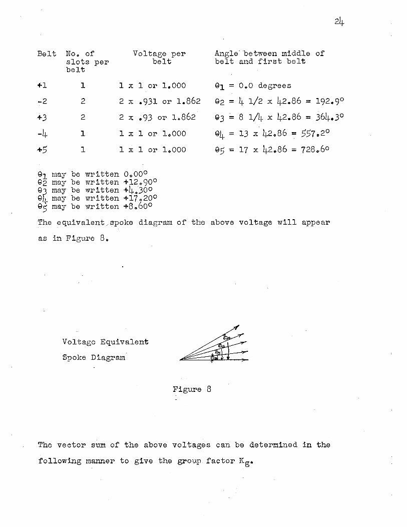
Belt No. of Voltage per slots per belt belt
+1 1 1 X 1 or i.ooo -2 2 2 X .931 or 1.862
+3 2 2 X ~93 or 1.862
-4 1 1 X 1 or
+5 1 1 X 1 or
G1 may be written 0.000 Q2 may be written +12.90° Q3 may be written +4_.,300 G4 may be written +17.200 95 may be written +8.600
1.000
1.000
Angle-between middle of' belt and first belt
91 = o.o degrees
Q2 = 4 1/2 X 42.86 = 192.9°
Q3 = 8 1/4 X 42.86 = 364.3o
e4 = 13 x· 42.86 = 557.2°
95 = 17 X 42086 = 728060
The equivalent,~poke diagram of the above voltage will appear
a.s in Figure 8.
Volt9:ge __ Equivalent
Spoke Diagram
Figure 8
The vector sum of the above voitages can be determined in the
following m~nner to give the group factor Kg•
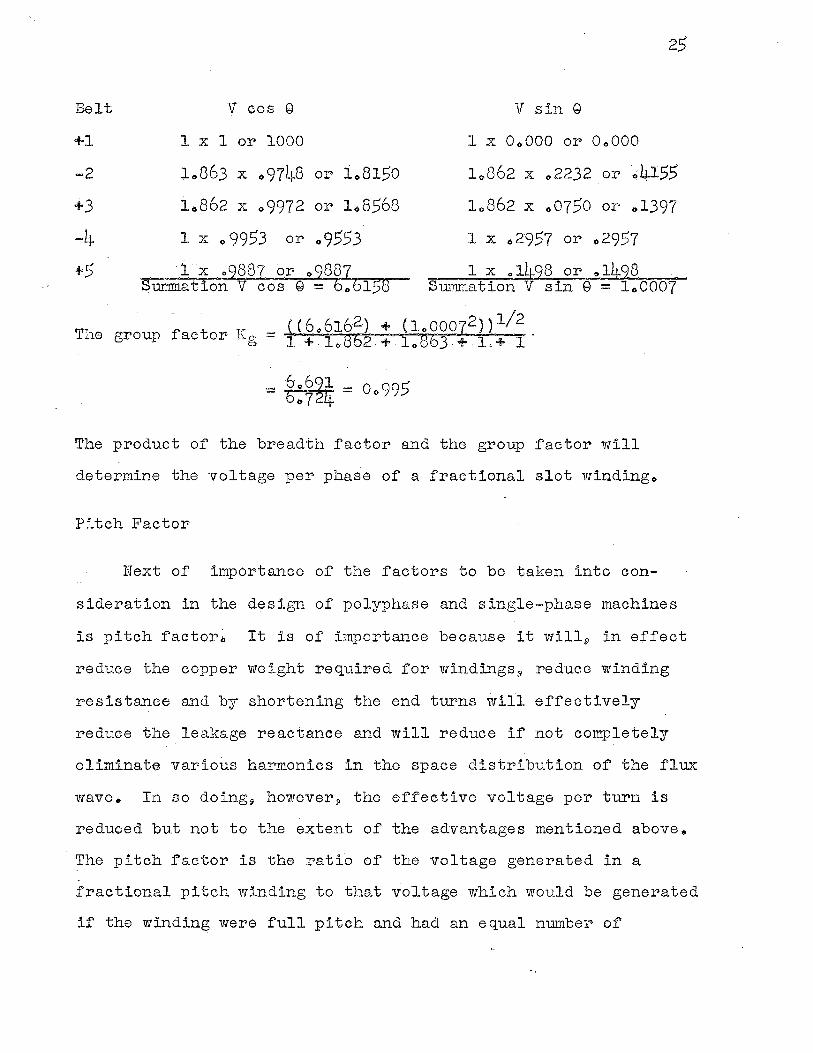
Belt
+1
-2
+3
-4 +.5
V cos G
l x 1 or 1000
10863 x .,9748 or 1081.50
10862 x 09972 or 1.8.568
l x o 9953 or o 9.553
·ix 09887 or 09887 Sunm1ation V cos Q = 6.,6158
25
V sin Q
l x OoOOO or OoOOO
10862 x .,2232 or·~4J...55
10862 x .,0750 or 01397
1 x 029.57 or 02957
1 x 01498 or 01498 Summation V sin 9 = 100007
( ( 606162) + ( lo00072)) l/2 The group factor Ka - --6- - · O - l +-loB-2 + loBbJ.+ l,+ 1
= ~-=~~~ = 00995
The product of the breadth factor and the group factor will
determine the voltage per phase of a fractional slot windingo
Pitch Factor
Next of importance of the factors to be taken into con-
sideration in the design of polyphase and single=phase machines
is pitch factor., It is of importance because it will9 in effect
reduce the copper weight required for windings 3 reduce winding
resistance and by shortening the end turns will effectively
reduce the leakage reactance and will reduce if not completely
eliminate various harmonics in the space distribution of the flux
wave. In so doing9 however., the effective voltage per turn is
reduced but not to the extent of the advantages mentioned above.
The pitch factor is the ratio of the voltage generated in a
fractional pitch winding to that voltage which would be generated
if the winding were full pitch and had an equal number of
26
Windingso
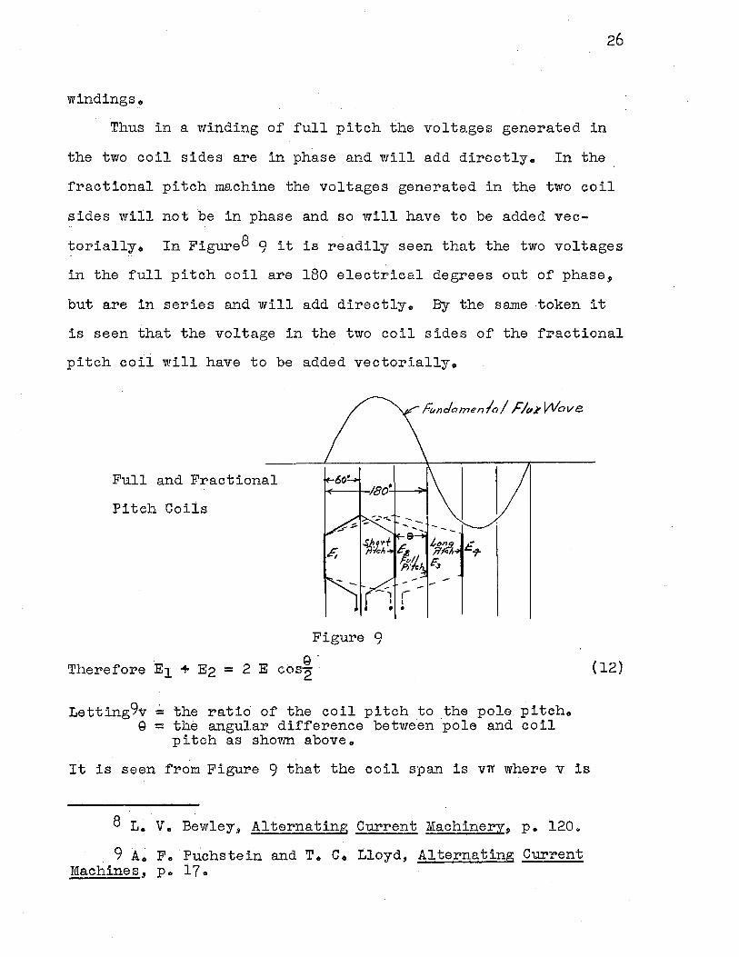
Thus in a winding of full pitch the voltages generated in
the two coil sides are in phase and will add directlyo In the
fractional pitch machine the voltages generated in the two coil
sides will not be in phase and so will have to be added vec
torially., In Figure8 9 it is readily seen that the two voltages
in the full pitch coil are 180 electrical degrees out of phase,
but are in series and will add directly .. By the same token it
is seen that the voltage in the two coil sides of the fractional
pitch coil will have to be added vectorially.
Full and Fractional
Pitch Coils
Figure 9 (;)
Therefore E1 + E2 = 2 E cos2
Letting9v = the ratio of the coil pitch to the pole pitcho Q = the angular difference between pole and coil
pitch as shown aboveo
It is seen from Figure 9 that the coil span is vrr where vis
8 L. V., Bewley3 Alternating Current Machinery, p. 1200
9 A. F., Puchstein and T. C., Lloyd., Alternating Current Machines, Po 170
(12)
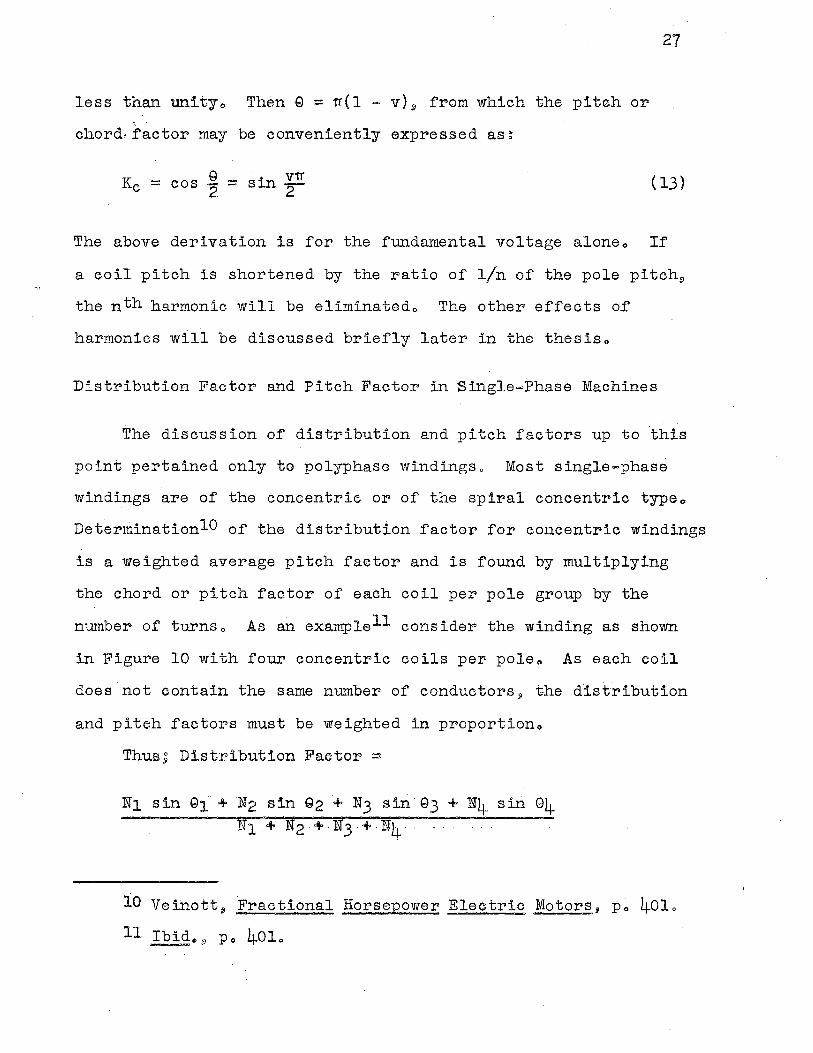
less than unityo Then Q = ~(l = v) 9 from which the pitch or
. chord,r~ctor may be conveniently expressed as~
27
Kc = cos ~ = sin f! ( 13) ·
The above derivation is for the fundamental voltage aloneo If
a coil pitch is shortened by the ratio of 1/n of the pole pitch9
the nth harmonic will be eliminatedo The other effects o.f
harmonics will be discussed briefly later in the thesiso
Distribution Factor and Pitch Factor in Single-Phase Machines
The discussion of distribution and pitch factors up to ·this
point pertained only to polyphase windingso Most single-phase
windings are of the concentric or of the spiral concentric typeo
DeterminationlO of the distribution factor for concentric windings
is a weighted average pitch factor and is found by multiplying
the chord or pitch factor of each coil per pole group by the
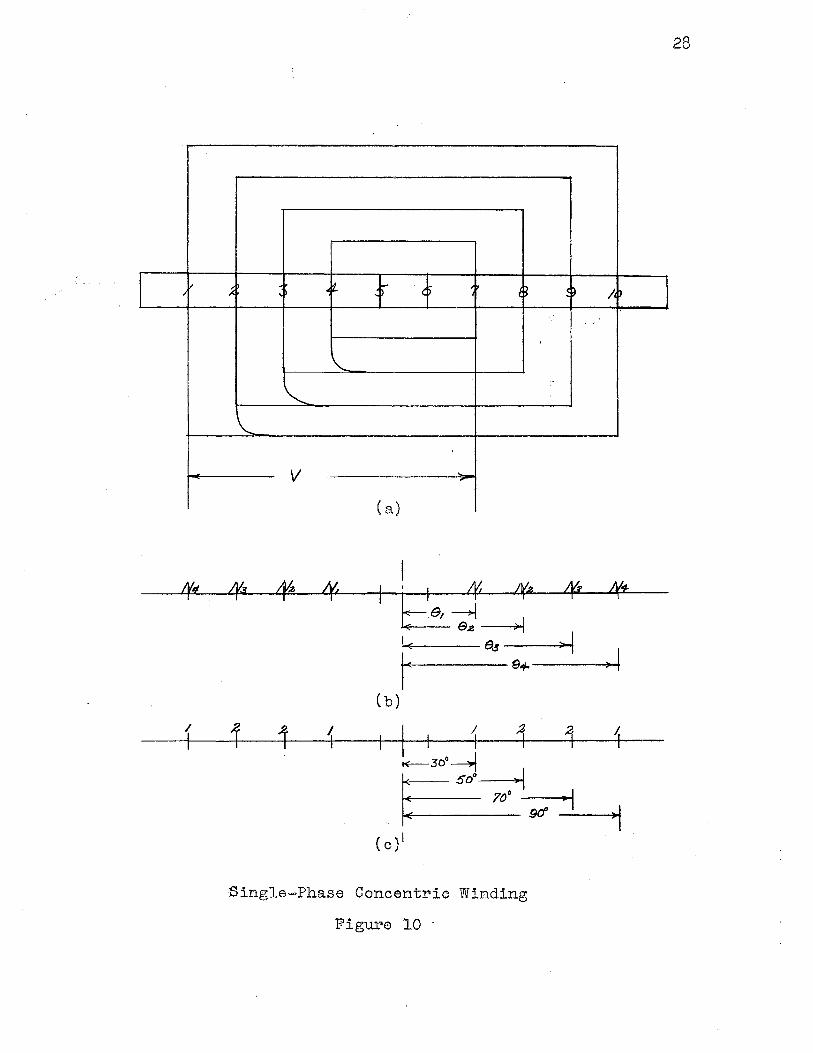
number of turnso As an examplell consider the winding as shown
in Figure 10 with four concentric coils per poleo As each coil
does.not contain the same number of conductors, the distribution
and pitch factors must be weighted in proportiono
Thus, Distribution Factor=
N1 sin G1. + N2 sin G2 + N3 sin· G3 + N4 sin 94 Nt + N2 +.N3.+·N4 ...
10 Veinott 8 Fractional Horsepower Electric Motors, Po 401 ..
11 Ibido9 Po 40lo
I I/ '
t¥• . '
;I· • t. f f ' . e '~ .
'
\..
"-\.
V .
( a)
I 4t 4(5 44 ~ I I ~ l'(A Ee,~
=> I . e.s >-4 ~ ,. S+
(b)
1 I I i i 4
Single-Phase Concentric Winding
Figure 10 ·
28
.M l ; .....
4'1:
~ I
.. ; ·~
29
Referring to Figure 10 c,I) the numerical solution for a con=
ductor ratio of l = 2 2 l, per pole is as follows;
Distribution Factor 1 sin 30 + 2 sin 50 + 2 sin 70 + 1 sin 90 = 1 + 2 + 2 + l '
= o .. 8185
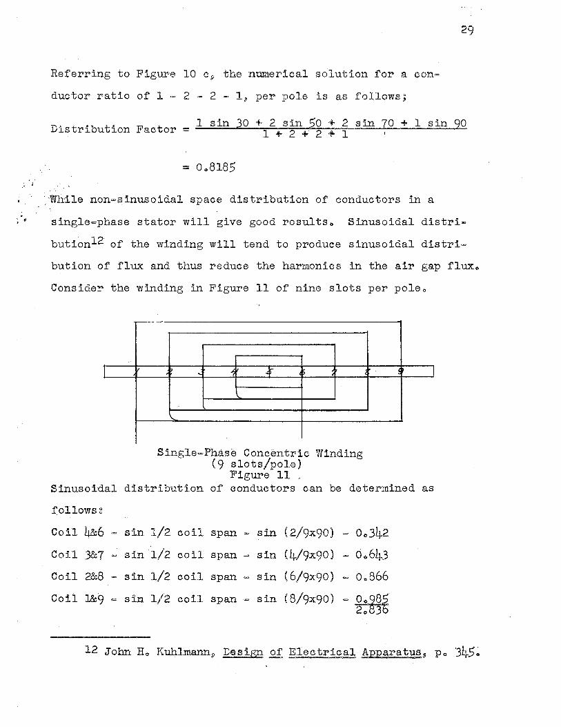
·_ :While non-sinusoidal space distribution of conductors in a
single-phase stator will give good results .. Sinusoidal distri
butionl2 of the winding will tend to produce sinusoidal distri
bution of flux and thus reduce the harmonics in the air gap flux ..
Consider the winding in Figure 11 of nine slots per poleo
I / ' "! ' 4 j) ' ' '
'-
'
'\...
Single-Phase Concentric Winding (9 slots/pole)
Figure 11 _
C !' I
Sinusoidal distribution of eonductors can be determined as
f'.ollowsg
Coil 4&6 = sin 1/2 coil span= sin (2/9x90) = 0.,342
Coil 3&7 = sin 1/2 coil span= sin (4/9:x:90) - 0 .. 643
Coil 2&8 - sin 1/2 coil span - sin (6/9x.90) = o .. s66
Coil 1&9 = sin 1/2 coil span = sin (8/9:x:90) -~ 2o 3
12 John Ho Kuh,lmann9 De.sign of Electrical Apparatus 9 Po 3li-5 ..
Percent turns per pole in coil 4-6 o.,3L~2/2 .. s36 X 100 12.10
Percent turns per pole in coil 3-7 o .. 6L~3/2 .. 836 X 100 22.70
Percent turns per pole in coil 2-8 0.,866/20836 X 100 30 .. 60
Percent turns per pole in coil 1-9 ·0 .. 985/2 .. 836 X 100 34.60
With this winding the mm.f produced would be a close approximation
to the sine wave and thus contain only negligible harmonics.,
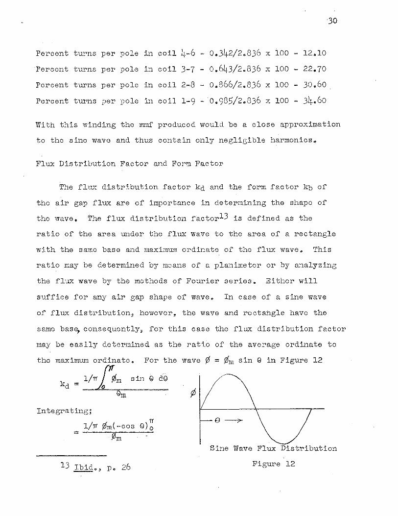
Flux Distribution Factor and Form Factor
The flux distribution factor kd and the form factor kb of
the air gap flux are of importance in determining the shape of
the wave., The flux distribution factorl3 is defined as the
ratio of the area under the flux wave to the area of a rectangle
with the same base and maximum ordinate of the flux wave .. This
ratio may be determined by means of a planimeter or by analyzing
the flux wave by the methods of Fourier serieso Either will
suffice for any air gap shape of waveo In case of a sine wave
of flux distribution.9 however, the wave arid rectangle have the
same base, consequently9 for this case the flux distribution factor
may be easily determined as the ratio of the average ordinate to
the maximum ordinateo For the wave¢'= ¢'m sin Qin Figure 12 ..,,
= 1/rr fbm sin Q d@
¢
In te g1"a ting;
Sine Wave Flux Distribution
Figure 12
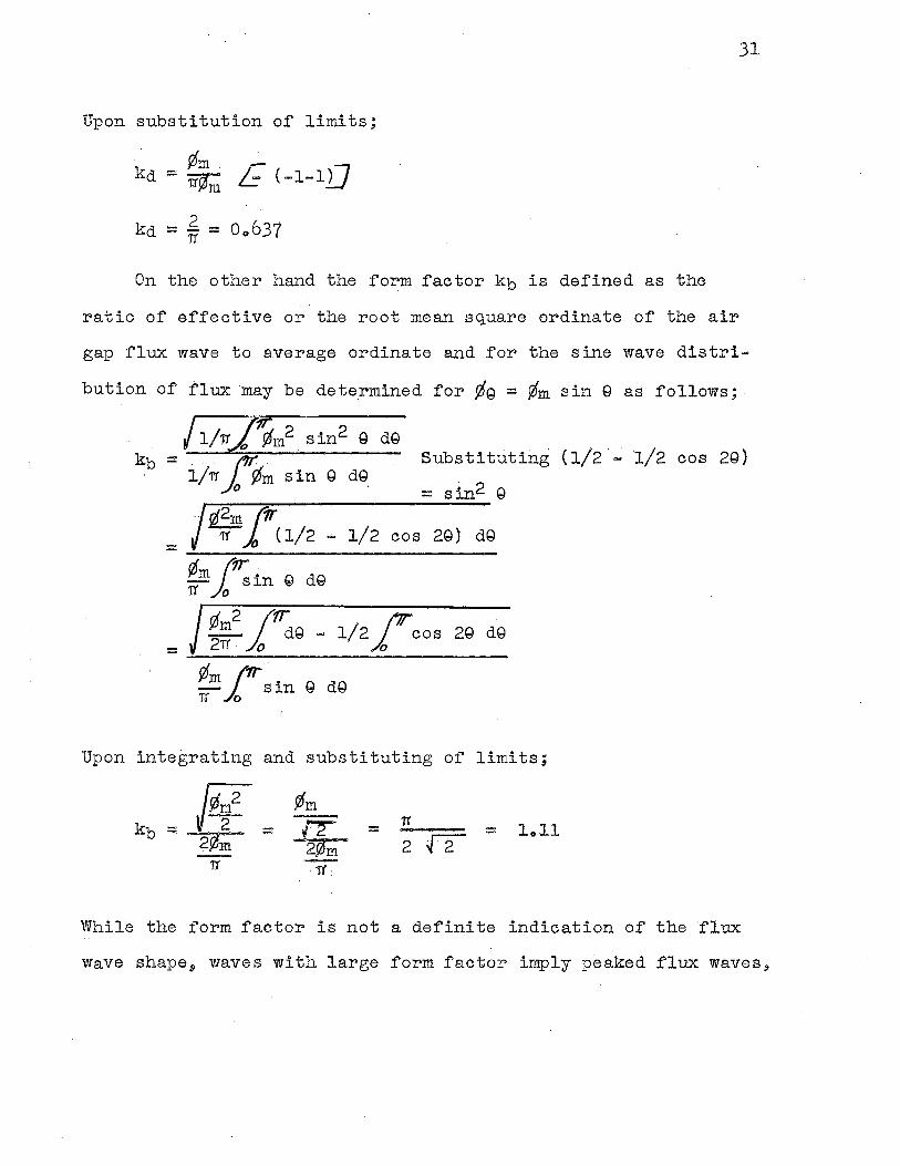
Upon substitution of limits;
· Wm . - ,, kd = 1t¢m ~ (-1-ll.J
kd = 2 = Oo637 11
On the other hand the form factor kb is defined as the
ratio of effective or the root mean square ordinate of the air
31
gap flux wave to average ordinate and for the sine wave distri
bution o:r flux may be determined for ¢g = ¢m sin Q as follows;
/1/~~m2 sin2 Q dQ kb = i/rr fwm sin. Q
Substituting (1/2 _; l/2 cos 29) dQ
= sin2 Q /fi 11T . 1/2 cos 29) dQ = rt (1/2 -
¢mJ.~in Q dQ 1}' D
J <Jm2 J~Q -1/2'0 (Jr cos 29 dQ = 2TJ'. 0 j, .
Upon integrating and substituting of limits;
:::: 11 = loll
While the form factor is not a definite indication of the ·r1ux
wave shapea waves with large form factor imply peaked flux waves,
32
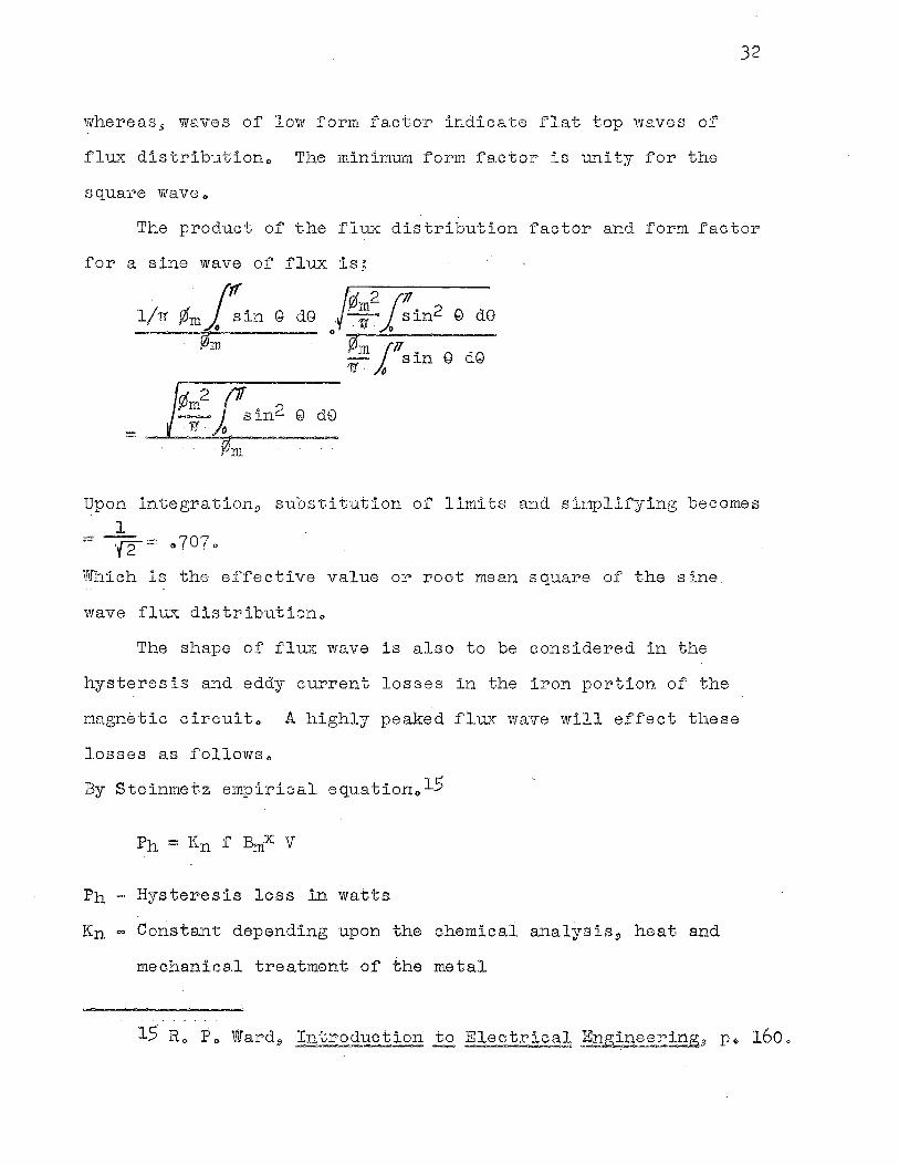
whereas, waves of low form factor indicate flat top ·waves of
flux distributiono The minimum form factor is unity for the
square waveo
The product of the f1ux distribution factor and form factor
for a sine wave of flux is;
f!m2J'll . --.·· sin2 Q d0 . 1J' . 0
0
¢•. 111 1· 17 • . - {"\ df"I - sin eo le) ·']J'. ~
m
Upon integration9 substitution of limits and simplifying becomes 1
= ·(2= 0 707 0
Which is the effective value or root mean square of the sine
wave flux distributiono
The shape of flux wave is also to be considered in the
hysteresis and eddy current losses in the iron portion of the
mo.gnetic circuit,, A highly peaked flux wave will effect these
losses as followso
By Steinmetz empirical equation 0 15'
Ph Hysteresis loss in watts
Kn.= Constant depending upon the chemical analysist heat and
mechanical treatment of the metal
f - Frequency in cycles per second
Bm = Maximum flux density in kilolines per square inch
x - Exponent., depends upon material (1.06 being average for
most materials)
Flu.,-sc densities
V = Volume of material in cubic inches
Eddy current 1ossesl6 may be determined by~
P: K r2 c2 ~ 2 V e ~
P = Eddy current loss in watts
Ke= Constant., depending upon the resistivity of the material
f = Frequency in cycles per second
c Lamination thickness in inches
Bm Maximum flu..."'C density in kilolines per square inch
V =· Volume of material in cubic inches
In each case the losses are proportional to a power of the
33
maximum flux densityo Peaked flux waves therefore., will increase
the hysteresi.s and eddy current losses and not necessarily in-·
crease the effective value of the generated voltageo
As the writer· is assuming a sine wave distribution of flux
in this thesis 9 both the flux distribution factor and the forrn
factor will appear as a·constant in both polyphase and single=
phase calculationso
The Skewing of Rotor Bars
This factor, of slight importance, in the design of
induction machines must be taken into accounto ·The magnitude . "' ..
of the skewing of the rotor bars will affect the maximum to:rque
as well as the starting torque" Other effects of skewing the
rotor slots are as follows, and each may or may not be to the
advantage of the designer, depending upon the specific design.
lo Eliminates noise and reduces motor frame vibration.
2 •. Results in smooth torque curve for differ.ant positions
of the rotor (reduces cogging).
3. Increased rotor resistance due to increased length of
barso
4. !ncrease in the·effective ratio·or transformation
between stator and rotor·.
5o Increased machine impedance at a given slip.-
6. Increased slip for a given torque.
7. Indiscriminate skew, especiallt in machines of many
poles leads to a reduction in short circuit crurrent,
starting torque, and to?'que at high slips.·
Bo Increase in skew angle has an effect similar in respect
to decrease in voitage., -and. this 'the output is reduced
by the square of the skew factor~
9. Reduces space harmonies in air gap fluxo
The increase in rot·or resistancel7, due to skewing of rotor
17 Ao.Po Puohstein and T~ Co Lloyd, Alternating Current Machines, Po 288~
.J
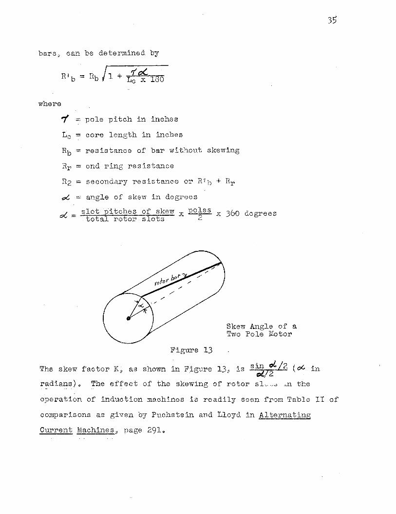
bars, can be determined by
where
7 = pole pitch in inches
Le = core length in inches
Rb = resistance of bar without skewing
Rr - end ring resistance
R2 = secondary resistance or Rib + Rr
e:;t,, = angle of skew in degrees
oC, = slot pitches of skew x £Oles .x 360 degrees total rotor slots · 2
Figure 13
Skew Angle of' a Two ~ole Motor
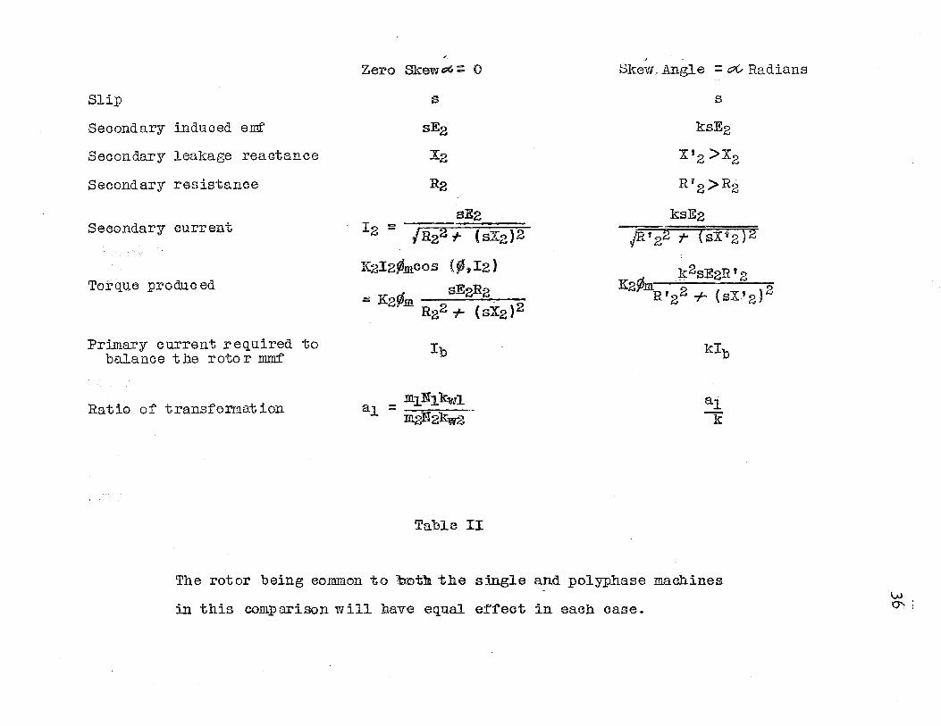
The skew factor K9 as shown in Figure 13.9
radians)" The ef'feot of the skewing of' rotor slu "'"' .. ~n ·the
35
operation of induction machines is readily seen from Table II of
comparisons as given by Puchstein and Lloyd in Alternating
Current Machines 9 page 2910
Slip
Secondary induced emf
Secondary leakage reactance
Secondary resistance
Secondary current
Torque pro due ed
Primary current required to balance the rotor mmf'
Ratio of transformation
Zero Skew oG. :: 0
s
sE2
::X:2
R2
sE2 I - --;=:::::=:====-
2 - /R22 r (sX2)2
K2I2¢meos (9',I2)
:a: K2¢m . sE2R2 R22 +- (sXz)2
Ib
IDJ.N1kw1 a1:;;: m2'f2kw2
Table II
.·~
Skew, Angle = oC- Radians
s
ksE2
X'z >X2
R'2>R2
ksE2 JR, 22 -;- ( s:X: f,2 ) 2
k2sE2R'2 9' . . 2 K2 mR '2 2 + ( sX' 2 )
kib
al k
The rotor being eo:m:mon to b.©th the single and _polyphase machines
in this comparison Vi ill hav,e equal ef':fect in each case. w m
.37
Harmonics
In the pr•esent day design of induction machines the effects
of applied harmonlc voltages and of the induced harmonic currents
must be considered as they will indeed affect the operational
characteristics of the machineo Even though commerical power
line voltages are a fairly close approximation to sine wave
volta:ges., it is almost impossible to have a perfect sine wave
varying voltage for a s~urce of powero
As actual tests., as well. as theory 9 have shown that a sine
wave input o.f voltage virill give smoother operating character-" ,.
istlcs 9 designersj) by means of certain ha:cmonic reduction factors
are able to reduce and in some cases eomplete1y ellminate cer•tain
harmonic effects in induction machinr::;s o
Harmoni.cs18 as f'ou..."'1.d in the air gap .flux. of induction m.ot::·,r8
a.re of two types i lo ·rime harmonlc,:1 occur,ing in the flux due
to the harmonics in the applied volta.ge and cu:crent varying with
respect to time o It is easily 13een that time harrnoni.c components
wil1 have the same nu:mber of ·poles as doGs the fundamental in
the induction motoro 2o Space harmonic,s of flux whieh may be
caused by the stator· wlndlngD .slots of the rotor and statorJ9 non-
uniform air gap or sa.tu.r-at:'Lon of' the magnetic r:dr.cui t are likely
to be of more tr'oub1e since the space harmonics of flu.,~ 1J1rill have
a greater r:n.,unbe:r: of poles in induction :motors o irhe nth space
harmonic will have k times aEi 'many poles as the fundamental and
38
its torque-speed curve will pass through zero at 1/k of syncho=
nous speedo Both types of harmonic components of flux will in
crease iron losses and the latter will affect the torque of the
motor due to the larger number of poles.I) some of which may rotate
in a direction opposite to that of the fundamentalo
If the air gap flux is non-sinusoidally distributed in space,
as is the case in all motors because of the limit on stator and
rotor slots, all odd space harmonics may be presento Because of
the symmetry of the machine the even harmonics are absent or
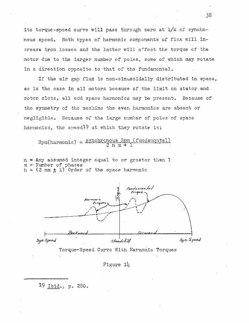
negligibleo Because of the large number of poles of space
harmonics 9 the speedi9 at which they rotate is.,
Rpm(harmonic) = synchrcnous Rpm (fundamental) 2nm+1
n = Any assumed integer equal to or greater than 1 m = N.umber of phases h = (2 nm± 1) Order of the space harmonic
, , .. , ,
Sf.,n./st1/
Tor,que-'Speed Curve With Harmonic Torques
Figure 1.4
39
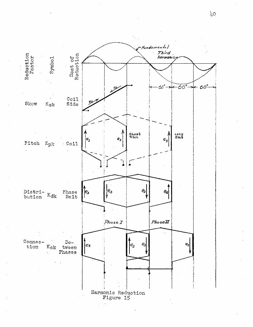
It is seen, therefore, that if the harmonic or parasit torques
is s:tgnificant magnitude it may cause the torque=speed curve
of an induction motor to appear as shown in I<'igur,e 140
The induction motor designer has at his disposal four har-
monic reduc,tion fae:tors which are capable of suppressing certain
harmonics and may eliminate or reverse the sequence of specific
harmonics o In each case the harmonic reduction fac:tors, skew 9
pitch9 di.stribution.5) and connection suppress harmonics in es=
sentially the same mannero That is 1 by arranging the windings
such that induced harmonic, voltages in the same conductors as
well as in series conductors are in par•tial or complete opposition
and therefore partially, or completely cancel each othero
'Figure21 15 is an example of each reduct:ion facto::r in the case
of suppression of the third harmonlco
As in F::lgure 1.5 9 it the rotor' bars are skewed' such that one
half the bar is cutting the positive loop of' flux and the other
half is cutting the negative loop of flux 9 the induced voltages
will be in direct opposition and will eancelo It is obvious
that only the hi.ghe2: frequencies can be eliminated in this mannero
It is only practical to eliminate the eleventh harmonic and above.
It is not pr,actica1 for reducing the lower harmonics because o:f'
circuit complic11tion and the cost of' material and :manuf'acturlngo
By either short or long pitch cer•tain harmonics may be
suppressedo Both s:i.des of the coil ar,e cutting a positbre loop
20 lbid 09 Do 2810 ~ ..... :.
Skew Ksk
Pitch Kpk
Distribution Kdk
·connection K:ck
Coll Side
Coil 1-·
Phase te.1 Belt r
Be= tween.
Phases
rundo.menla I
--e,j ShoY..\-
'Pifc.h
Harmonic Reduction Figure 15
71,,',.cJ' ho1-mo1'11c.-'--
-e,t
I.on~ P,'k
4.0
of flux 9 but are in opposition as shown in Figure 15 .. The distributed·winding reduces certain harmonics by placing
the coil sides in a belt such that the harmonic voltages induced
will be in oppositiono
By connecting the phases of polyphase machines in series~
all harmonics which are odd multiples of the number of machine
phases may be suppressedo For this reason most commercial three
phase systems have negligible 31•d harmonics and odd multiples of
the 3rd harmonicso The even harmonics being absent because of
symmetry ..
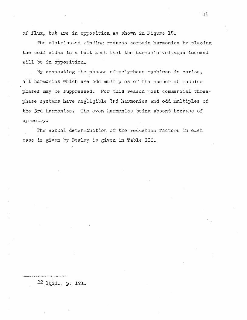
The actual determination of the reduction factors in each
case is given by Bewley is given in Table III ..
22 . · Ib:1.d., 9 Po 121~
Reduction factor
SkENv factor
Pitch factor
Distribution factor of belt
Ksk :;;a sin (K;i /2) k.A. 2
Kpk ~ si n!fL_ 2
Kdk sin (k 11 q 6 /2r)
= q sin (K7T6 /2r)
Connection factor Kck := /(2.._sin ltGr)2 (~ cos kGr)2
K g Order of' :;he space harmonic A ~ l11tan0(.. /~ ~ skew coefficient P ~ Pitch q g;. Slots per phase belt e g Slot pitch in inches '(g Pole pitch in inches
Gr g Phase angle c ~ Phases connected in series
C
Table III
Seat of the reduction
In the coil side
Between coil sides of the coil ·
Between coils of the :phase belt
Between phases
f;•
CHAPTER III
EXCITING CURRENT OF SINGLE-PHASE AND THR:g'E-PHASE INDUCTION MOTORS
Mentioned briefly in Chapter I, yet of importance in the
comparison of the three-phase and single-phase induction motor:;1,
is the relative magnetizing currents in eacho It is of conse
quence, because it has a decided effect .. upon the power factor
and efficiency of the two machineso
It is the purpose of this chapter to show how the magnet
.izing current in both the single-phase and the three-phase motor
sets up the rotating flux field and to compare the over all per-
formance of the two motorso
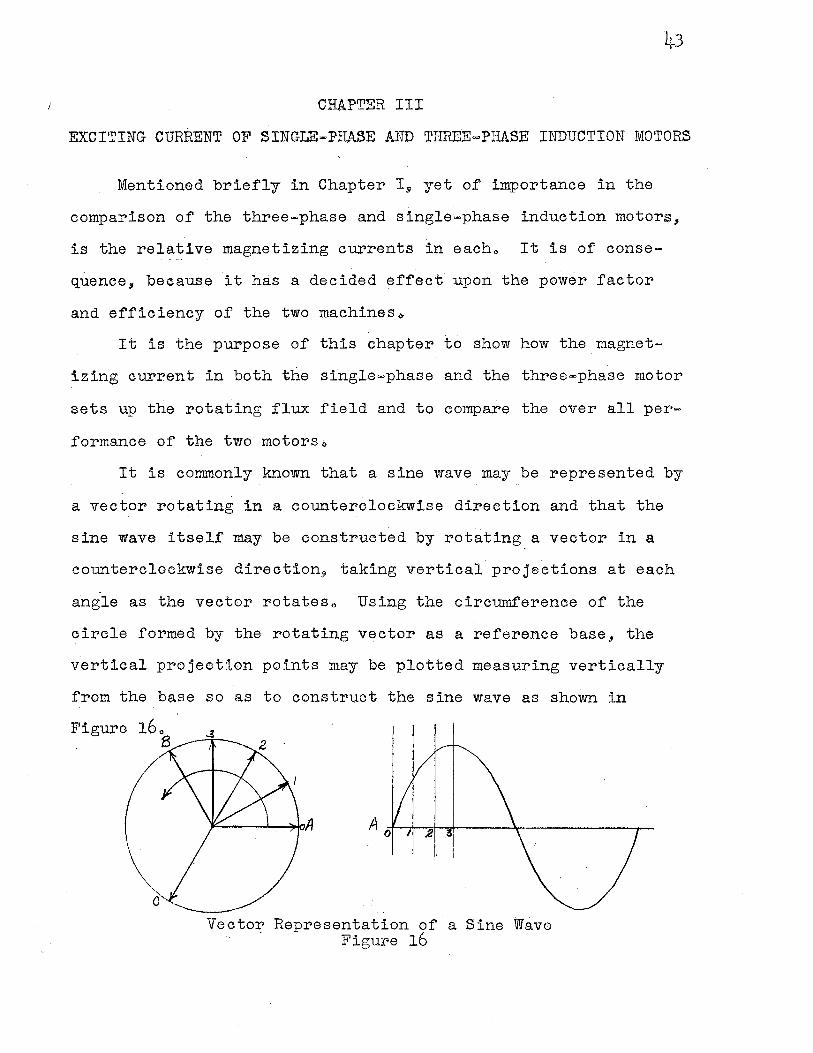
It is commonly known that a sine wave may be represented by
a vector rotating in a counterclockwise direction and that the
sine wave itself may be.constructed by rotating a vector in a
counterclockwise direction, taking vertical projections at each
angle as the vector rotateso Using the circumference of the
circle formed by the rotating vector as a reference base, the
v·ertical projection points may be plotted measuring vertically
from the base so as to construct the sine wave as shown in
Figure
Vector Representation of a Sine Wave Figure 16
The sine wave will also represent in magnitude and space a
flux wave similar to that shown in Figure 5 of Chapter I 9 the
base being the space distribution around the stator itself and
the magnitude of the wave representing the magnitude and polarity
of the flux at any point on the stator circumferenceo
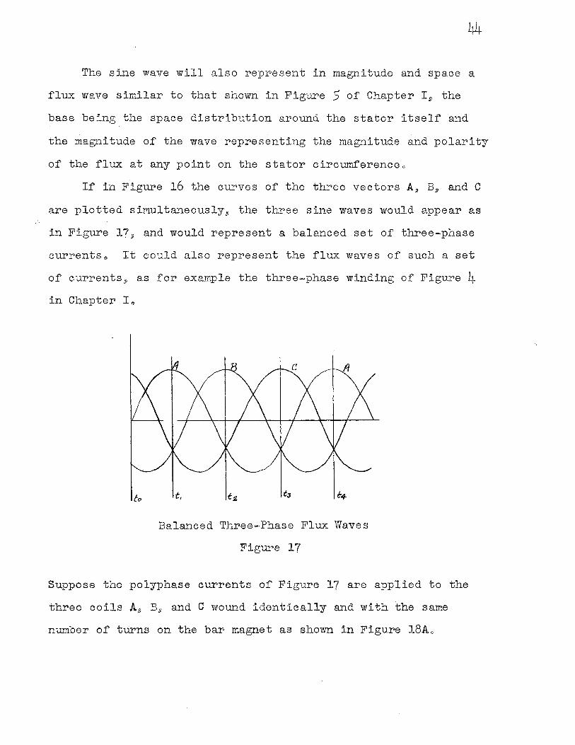
If in Figure 16 the curves of the three vectors A, B., and C
are plotted simultaneously, the three sine waves would appear as
in Figure 17/j) and would represent a balanced set of three-phase
currentso It could also represent the flux waves of such a set
of currentss as for example the three-phase winding of Figure 4 in Chapter Io
6, t,
Balanced Three-Phase Flux Waves
Figure 17
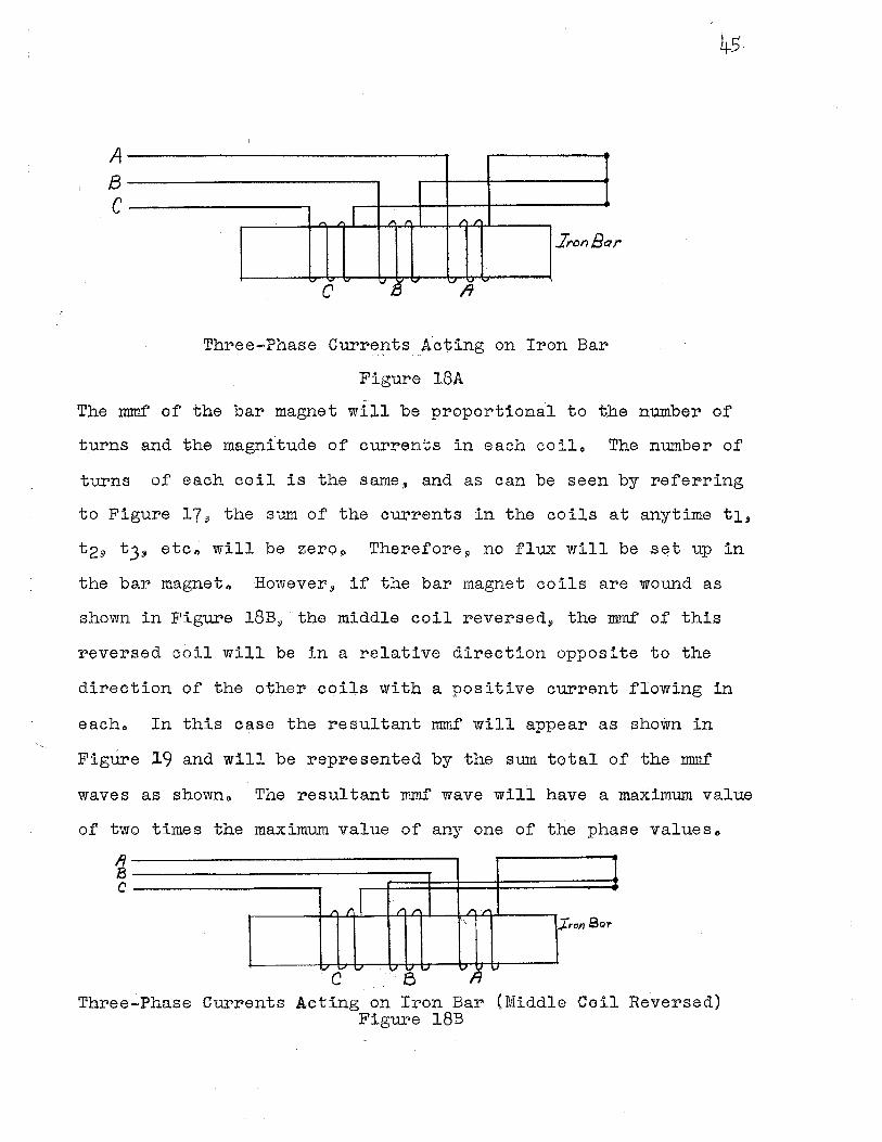
Suppose the polyphase currents of Figure 17 are applied to the
three coils A/j) B,i and C wound identically and with the same
number of turns on the bar magnet as shown in Figure 18Ao
A B C
~ I , , , ,
.Iron Ba
6 - ., 13 .., A -
Three-Pb,ase Curr~~ts __ Acting on Iron Bar
Figure 18A
45.
r
The :mmf of the bar magnet will be proportional to the number of
t.urns and the magnitude of currents in each coilo The number of
turns of each coil is the same, and as can be seen by referring
to Figure 17, the sum of the currents in the coils at anytime t1,
t29 t3, etc~ will be zeroo Therefore, no flux will be set up in
the bar magneto However, if the bar magnet coils are wound as
shown in Figure 18B,· the middle coil reversed, the :mmf of this
reversed coil will be in a relative direction opposite to the
direction of the o'\;her coils with a positive current flowing in
eacho In this case the resultant mmf will appear as shown in
Figure 19 and will be represented by the sum total of the mm..f
waves as shownq, The resultant mmf wave will have a maximum value
of two times the maximum value of any one of the phase valueso
1 i
, r l -r r ,. .,.
' ron Sar
., - .., .., .., ., V ~ V
C Three-Phase Currents Aeting on Iron Bar (Middle Coil Reversed)
Figure 18B
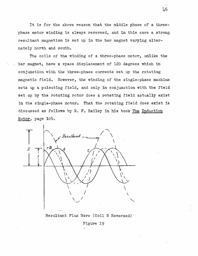
It is for the above reason that the middle phase of a three-
phase motor winding is always reversed, and in this case a strong
resultant magnetism is set up in the bar magnet varying alter
nately north and southo
The coils of the winding of a three-phase motor, unlike the
bar magnet, have a space displacement of 120 degrees which in
conjunction with the three-phase currents set up the rotating
magnetic fieldo However, the winding of the single-phase machine
sets up a pulsating field, and only in conjunction with the field
set up by the rotating rotor does a rotating field actually exist
in the single-phase motor~ That the rotating field does exist is
discussed as follows by Bo Fo Bailey in his book~ Induction
Motor, page 1060
\ \ I
-./ '--
Resultant Flux Wave {Coil B Reversed)
Figure 19
47
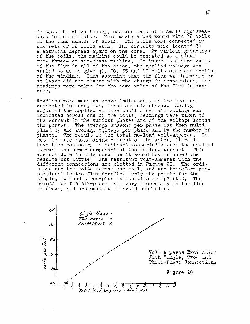
1f!o test the above theory 9 use was made of a small squirrelcage induction motor" This machine was wound with 72 coils in the same mJ1nber of slots" The coils were connected in six sets of 12 coils each" The circuits were located 30 electrical degrees apart on the coreo By various groupings of the coils~ the machine could be operated as a single, two- three- or six-phase machine" To insure the same value of the flux in all of the cases., the applied voltage was varied so as to give 40,j) 50, 55 and 60 volts over one section of the winding" Thus assuming that the flux was harmonic or at lea.st did not change with the change in connections,9 the readings were taken for the same value of the fl1.,;_x in each case,.
Readings were made as above indicated with the m2chine connected .f'or one:, two.,, three and six phases" Having ad.justed the app1ied voltage until a certain voltage was indicated a.dross one of the coils, readings were taken of the current in the various phases and of the voltage acros8 the phaseso The average current. per phase was then multi= plied by the average voltage per phase and by the number of phases. The r·esult is the total no=load vol t=amperes o To get the true magnet::izing current of the motor,j) it would have been necessary to subtract vectorially from the no~load current the power component of the no,-load current,, This was not done in this case, as it would have changed the results but little., The resultant volt-amperes with the different connections are plotted in Figure 20,, The ordi= nates are the volts across one coil, and are therefore proportional to the flux densityo Only the points for the single!) two and three=phase connection are plot·ted,, The points for the six,=phase fall very accurately on the line as drawn"' and are omitted to a.void confusion 0
60
.S1;,.:/e. ?l?c,.se • /We, ?Aase o
7bree~o..se X
Volt Amperes Excitation With Single 9 Two- and Three·=·Phase Connections
Figure 20
48
It will be seen that the total volt-amperes are practically the same in all of the caseso It is true that tbe voltamperes seem a little more in the case of the two-phase winding, and a little less in the case of the ~ingle phaseo The difference between the two and three phase is possibly on account of wave shape, although the wave in both cases approximated a sine shapeo The connections in the case of the two·~phase and the single.,..phase readings was the same, one of the two circuits being merely openedo Operating single-phase, as will appear later, the flux ceases to be of exactly constant value in the different; positions., being somewhat weaker when at right angles to the position of the stator windingo Hence on the whole a slightly lower voltampere excitation will be requiredo
From Mro BaileyRs discussion, it is seen that a field
rotating at synchronous speed does actually existo From the
facts as given in the above quotation and further information to
follow.~ the single-,phase operation of the three=phase induction
motor can be analyzedo
Suppose for instance that a three-phase wye connected
induction motor operated at 220 volts line voltage, and that the
magnetizing current for no·-load operation is 5 amperes (neglecting
losses of the m.achine)o Since the flux set up per phase is
directly proportional to the current 9 it might be satd that each
phase will set up a flux whose maximum value is 5 (on a relative
basis)o From induction motor theory9 a constant rotating mag
netic field of one and one half maximum phase value or 7o5 will
rotate at synchronous speed around the ci.rcum.ference of the
statoro .The line voltage being 220j the phase voltage is
200/J-"'f"= 127~ and the total voltamperes applied to the motor is
200/ J3 x 5 x .3 or 190.50
Now if one phase of the motor is disconnected the motor will
run as a single-phase machineo In compliance with the experiment
oonduet~d by Mro Bailey, the Single-phase magnetizing current
will be;
!~g5 = 8066 amperes
~9
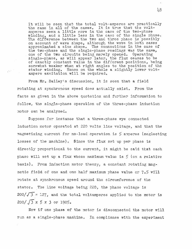
Since there is a rotating magnetic field, the back voltage
generated in each of the two excited phase of the three-phase
machine operating single-phase will be 120 de~rees out of phase.
Thus to oppose the applied voltage o:f 220 volts 9 the baek
voltage must be at a rate of 127 volts per phase winding, This
can be seen in Figure 210
' ' VRa-;; '4e-Vo,4 ' = ff Epl,o.se ' II /
/ /
/
Vector Addition .of Phase Voltages
Figure 21
-Thus I .3 x 12.7 equals 220· or the line voltage o It is seen that I
the magnitude of the rotating flux of the three-phase machine
operating as such and operating as a single-phase motor is in
each case the same·value 9 7o5
Discussing the method of establishing a rotating flux in
the single-phase induction motor9 Mro Bailey f'urthel" states:
50
The single-phase induction motor may be considered as a special case of the polyphase motor., If a two-phase motor is operating without load and one of the phases is opened9
the motor continues to run at almost exactly the same speed as beforeo The only apparent change is that the nature of the hum emitted by the motor changes slightly in charactero If an ammeter is used to measure the current taken by the machine (in this case principally magnetizing current) it will be found that the current in the phase still connected has approximately doubled, as h~s likewise the power taken by this phaseo The total current and t"he total power are nearly unchangedo
If when operating in this manner, a voltmeter be applied to the idle phase it will be found that nearly tbe full line voltage is present there, and a further investigation will show that this eomofo differs 90 degrees in phase from the line voltageo The application of test coils at various angles with the active phase would show the presence of nearly the same eomofo regardless of the position of the coil, and an angular difference of phase corresponding to the angle of tbs coil with the stator windingo ~his experiment proves the existence of a rotating magnetic f:teld 9 and a fuller investigation would show that this field is harmonic in its space distribution and rotates with uniform angular velocityo
In the light of what has previously been said$ it is al~ost self-evident that this will be the caseo The flux tends to assume such a distribution and value that the minimum cutting of the rotor conductors and consequently the minimum e,r. penditure of power will take place., Each change of flux sets up a rotor current in such a position and phase as ,,., ..,1:, ___ ....._
to prevent the change of fluxo With a rotor operating at synchronism.I) a uniform flux rotating at uniform velocity would not cut the rotor bars at allo Hence the flux tends to assume this distribution and velocityo
However$ to produce the rotating magnetic fieldj in a single-phase induction motor it is evident that there must_ exist a component of momofo at right angles to the axis of. the stator windingo Since the stator can not carry a current in the proper position to produce this it must exist in the rotoro To produce this rotor current requires a change in the stator flux., Hence the field can not; be of absolutely constant value at all timeso The change however is sllght.,
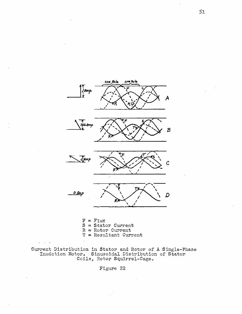
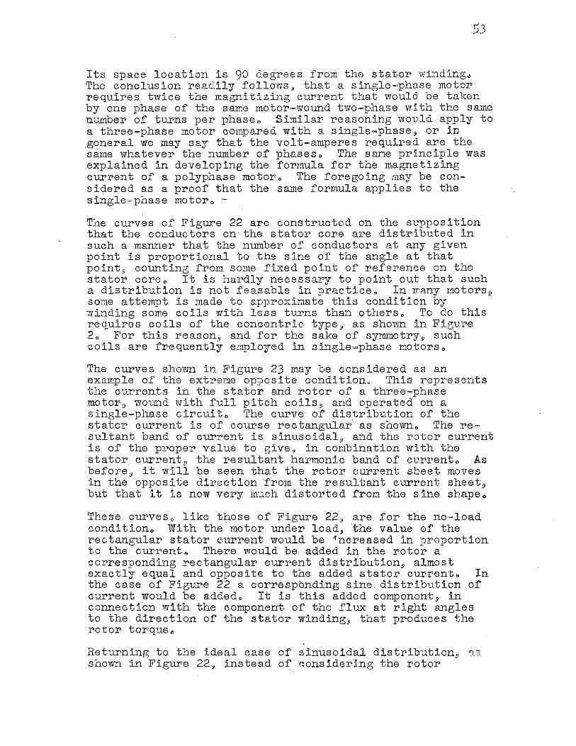
The nature of the current required in the rotor to produce with the stator current a rotating magnetic field in the motor.11 will be apparent from Figure 220 The four diagrams are drawn for successive values of the current taken at intervals of 30 degreeso The flux. is shown displaced 30 degrees to the left for each change of 30 degrees in the
o /Im,; I I
I
one Fble
, I
F = Flux
ono R,/e.
S - .Stator Current R = Rotor Current; T = Resultant Current,
A
C
D
Current Distribution in Stator and Rotor of A S:ingle-Phase Inudction Motoro Sinusoidal Distribution of Stator
Coils, Rotor Squirrel=Cageo
Figure 22
5.1
currento
The solid line marked stator current represents the distribution of the stator current over the stator surfaceo The conductors are assumed to be arranged on the stator core in such a manner that the number of conductors at any given point is proportional to the sine of the angle corresponding to the point .. The are between two poles is of course taken as 180 electrical space degreeso The current is the sa~e in all of the conductors and hence the sinusoidal curve represents the distribution of the current over the stator coreo The curve of distribution is stationary in. space 5
but variable in magnitude, changing from a positive to a negative maximum, in accordance with the change in the currento
In order that an harmonic.11 uniformly rotating magnetic flux be maintained5 it is necessary that a resultant harmonic band of current rotate uniformly around the statoro This resultant is due to currents in both the stator and the rotoro It is shown as a ,dotted line in each of the figures and is drawn 90 degrees ahead of the fluxo The resultant band of current is due to the algebraic sum of the current sheets in both the stator and rotor at any given pointo The rotor current is then the difference between the resultant current and the stator currento It is shown by the curve marked rotor eurrento In order that the required rotor current may circulate 9 it is necessary that the rotor be of the squirrel~cage variety with many·barso With a phase-·wound rotor 9 the current could not assume the exact values required at all points and the resulting rotating flux would not have exactly harmonic distributiono
A study of the construction of the diagrams will reveal the following facts~ ·
Ao The flux has harmonic distribution.11 is consta.nt in magnitude and rotates uniformly in the direction of rotation of the rotoro
Bo The stator current sheet .is stationary in"·$.pace distribution9 and has harmonic variation in magnitudeo
I
Co The rotor current sheet is harmonic in space distribution, of constant maximum value, and rotates backward9
ioeo» opposite to the direction of rotation of the rotor at synchronous spee.do Its maximum value is llalf that of the stator current sheeto
It is apparent that at the time shown in Figure D9 the rotor current sheet must be sufficient to force the total flu."C across the gapo Hence its value is the same as would be required in a second phase of the stator if one were presento
Its space location is 90 degrees from the stator windingo The conclusion readily follows 1 that a single-phase motor requires twice the magnitizing current that would be taken by one phase of the same motor-wound two-phase with the same number of turns per phaseo Similar reasoning would apply to a three-phase motor compared with a s:tngle-phase 1 or in general we may say that the volt-amperes required are the same whatever the number of phaseso The same principle was explained in developing the formula for the magnetizing current of a polyphase motoro The foregoing may be considered as a proof that the same formula applies to the single,~,phase motoro -
The curves of Figure 22 are constructed on the supposition that the conductors on the stator core are distributed in such a manner that the number of conductors at any given point is proportional to the sine of the angle at that point 9 counting from some fixed point of reference on the stator coreo It is hardly necessary to point out that such a distribution is not feasable in practice" In 1rany motors 9
some attempt is made to approximate this condition by winding some coils with less turns than others., To do this requires coils of the concentric type 9 as shown in Figure ,2o For this reason,i and for the sake of syrmnetry 91 such coils are frequently employed in single=phase motorso
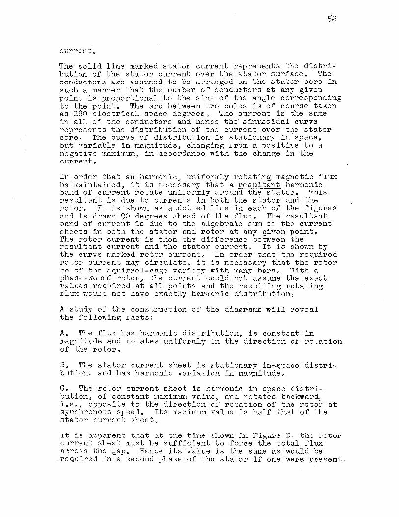
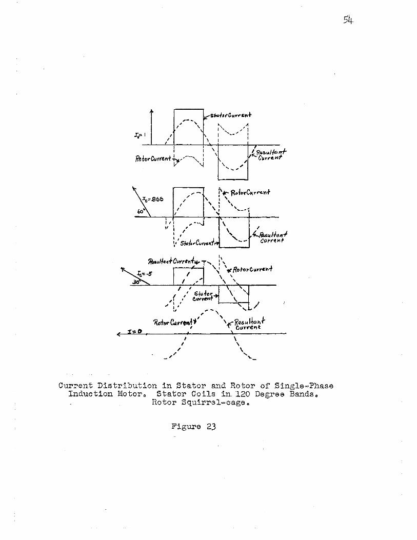
The curves shown in Figure 23 may be considered as an example of the extreme opposite condition" This represents the currents in the stator and rotor of a thr,ee~phase motor 9 wound with full. pitch co:tls 9 and operated on a single-phase circui.to The .curve of distribution of the stator current is of course rectangular·as showno The re= sultant band of current is sinusoidal 9 and the rotor current i.s of the proper value to give, in combination with the stator current 9 the resultant harmoni.c band of currento As before 9 it will be seen that the rotor current sheet moves in the opposite direction from the resultant current sheet 8
but that it is now very much distorted from the sine shapeo
These curves 9 like those of Figure 22 9 are for the no,-load condition., With the motor under load, the value of the rectangular stator current would be ~ncreased in proportion t,o the currento There would be added in the rotor a corresponding rectangular current distribution, almost exactly equal and opposite to the added stator cur·rento In the case of Figure 22 a correspo.nding sine distribution of current would be addedo It is this added component, in connection with the component of the flux at right angles to the direction of the statcir winding, that produces the rotor torqueo
Returning to the ideal qase of sinusoidal distribution9 qs shown in Figure 22jl instead of consider:i.ng the rotor
.~ ~66':1-l,f01AV',. .. ~ ... ,- .. , ' h " I \ I ',, ; I I \
I ' ', I .. __ ; I
/ \ I r '
I I l \
_, f~~1A//t1
iorCurf&nf-h,..,.,--"""- : ',
I\\ C11,..-c,., ,
I, '"'
< ;t:=-0.
' I I
, ,,,
I I I ,. -,-..J 11 I ,
I f ' , \'' 51o./. .. Cu'l';l11.J.
I ' . ( ,' s+a-lo'i.
, I C..W~T I I
., I I .,
, ....... ,,
\
\. ,_., ..._ __ _,
\ \
'
'
I \ I \ , \
,,,
,, '~-
Current Distribution in Stator and Rotor of Single-Phase Induction lVIotoro Stator Coils in. 120 Degree Bandso
Rotor Squirrel-c·age o
Figure 23
55
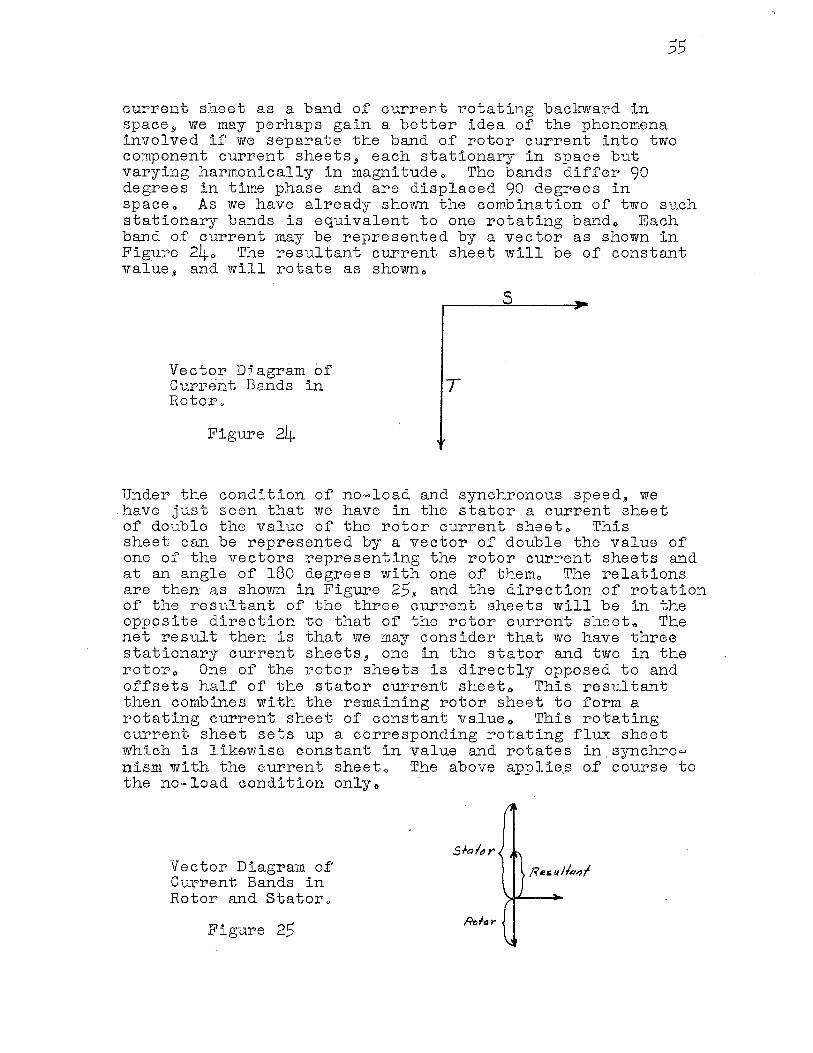
current sheet as a band of current rotating backward in spaces we may perhaps gain a better idea of the phenomena involved if we separate the band of rotor current into two component current sheets., each stationary in space but varying harmonically in magnitudeo The bands differ 90 degrees in time phase and are displaced 90 degrees in spaceo As we have already shown the combination of two such stationary bands is equivalent to one rotating bando Each band of current may be represented by a vector as shown in Figure 240 The resultant current sheet will be of constant value, and will rotate as showno
Vector D5.agram of Current Bands in Rotor.
Figure 24
T
Under the condition of no-load and synchronous speed, we have just seen that we have in the stator a current sheet of double the value of the rotor current sheeto This sheet can be represe~ted by a· vector of double the value of one of the vectors representing the rotor current sheets and at an angle of 180 degrees with one of themo The relations are then as shown in Figure 25, and the direction of rotation of the resultant of the three current sheets will be in the opp9site direction to that of the rotor current sheeto The net result then is that we may consider that we have three stationary current sheets, one in the stator and two in the rotoro One of the rotor sheets is directly opposed to and offsets half of the stator current sheeto This resultant then combines with the remaining rotor sheet to form a rotating current sheet of constant valueo This rotating current sheet sets up a corresponding rotating flux sheet which is likewise constant in value and rotates in_synchro= nism with the current sheet., The above a.pplie.s of course to
· the no,-load cond1tion onlyo
Vector Diagram of' Current Bands in Rotor and Statoro
Figure 25 Ro.Jo..-
56
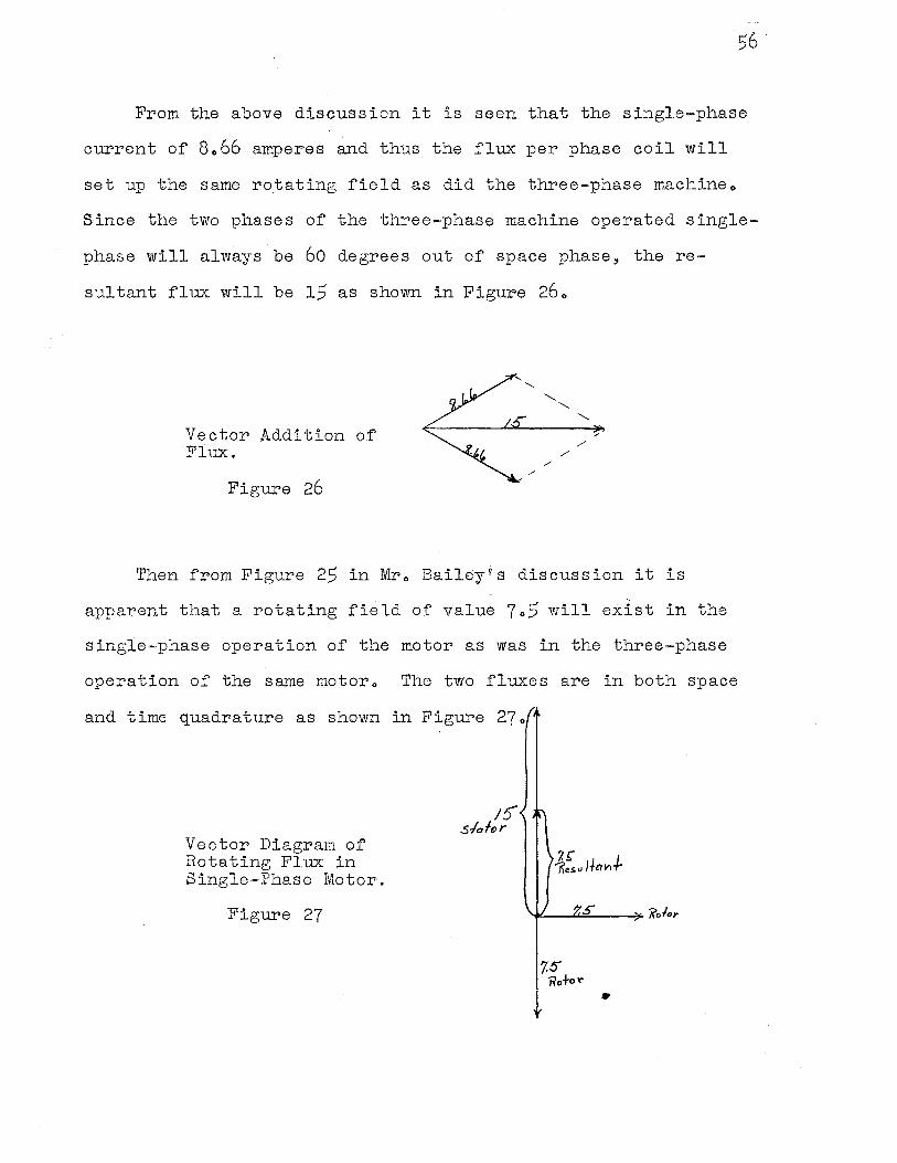
From the above discussion it is seen that the single-phase
current of 8066 amperes and thus the flux per phase coil will
set up the same rotating field as did the three-phase machineo
Since the two phases of the three-phase machine operated single
phase will always be 60 degrees out of space phase, the re
sultant flux will be 15 as shown in Figure 260
Vector Addition of Flux.
Figure 26 /
"
/
' ' .,. /
/
Then from Figure 25 in Mro Baileyis discussion it is
apparent that a rotating field of value 7o5 will exist in the
single-phase operation of the motor as was in the three-phase
operation of the same motoro The two fluxes are in both space
and time quadrature as shown in Figure 270
Vector Diagram of Rotating Flux in Single-Phase Motor.
Figure 27
15' s./afor
•
57
It is therefore apparent that the magnetizing current in
the single=phase induction motor is nearly twice that of the same
size three-phase induction motor~ effectively reducing the power
factor and efficiency of the single-phase machinec
CHAPTER IV
COMPARISON OF HORSEPOWER RATING OF SINGLE-PHASE AND POLYPHASE INDVQTIQN.MO~OR$ QN THE.BASIS OF EQUAL_ COPPER.LOADING
58
In generals the back voltage at no load of single-phase and
polyphase induction motor will be of the order of 95% of the
terminal voltageo This is not exactly true however, because of
the higher magnetizing current necessary for single-phase
machine in comparable ratings to polyphase machineso The higher
magnetizing current in the single-phase machine is due to the
retarding effect and the cross=axis field losses of the single=
phase machineo The result being that the single-phase induction
motor does not run at, or very close to 9 synchronous speed at no
load as does the pol.yphase induction motor and consequently the
single-phase motor has greater power losseso It might be assumed
without much error8 however.9 that the baek voltage of both
machines will be 95% of terminal v9ltage.11 and that the variation
due to load will be approximately the same in each motor up to
full loado Making the above assumption an examp1el·or a stator
of six slots per pole will be utilized to show the effect ~f
economical and efficient design for, equal copper loading on the
three-phase, two=phase 1 and single, .. phase induction motors o
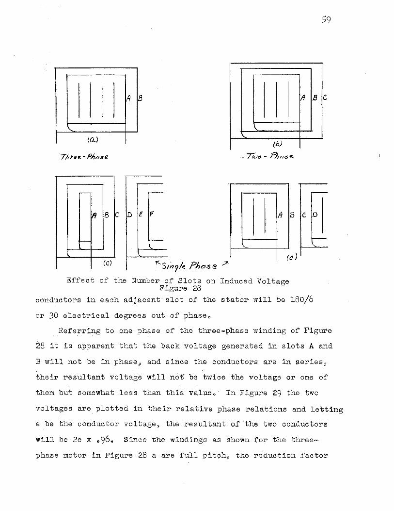
Shown in Figure 28 are the winding diagrams for three-phase 51
~wo-phase., arid single-phase induction mo-tors 51 all having six
slots per poleo The same stator is assumed to be used in each
caseo With six slots per pole the back voltage generated in the
1 Alexander Gray9 Electrical Machine !2_~sig:g8 Po 1870
~ 8
\.. \.
(Q..) \.
{b)
.--
lfl B C D E F ff
-\..
(C) "S/119/~ Pha.s e .:;f.
(
Effect of the Number of Slots on Induced Voltage Figure 28
II a
B C D
d)
conductors in each adjacent-slot of the stator will be 180/6
or 30 electrical degrees out of phaseo
59
Referring to one phase of the three-phase winding of Figure
28 it is apparent that the back voltage generated in slots A and
B will not be in phase 9 and since the conductors are in series 8
their resultant voltage will not· be twice the voltage or one of
them but somewhat less than this valueo· In Figure 29 the two
voltages are plotted in their relative. phase relations and letting
e be the conductor voltage 9 the resultant of ·the two conductors
will be 2e x o96o Since the windings as shown for the three
phase motor in Figure 28 a are full pitch~ the reduction factor
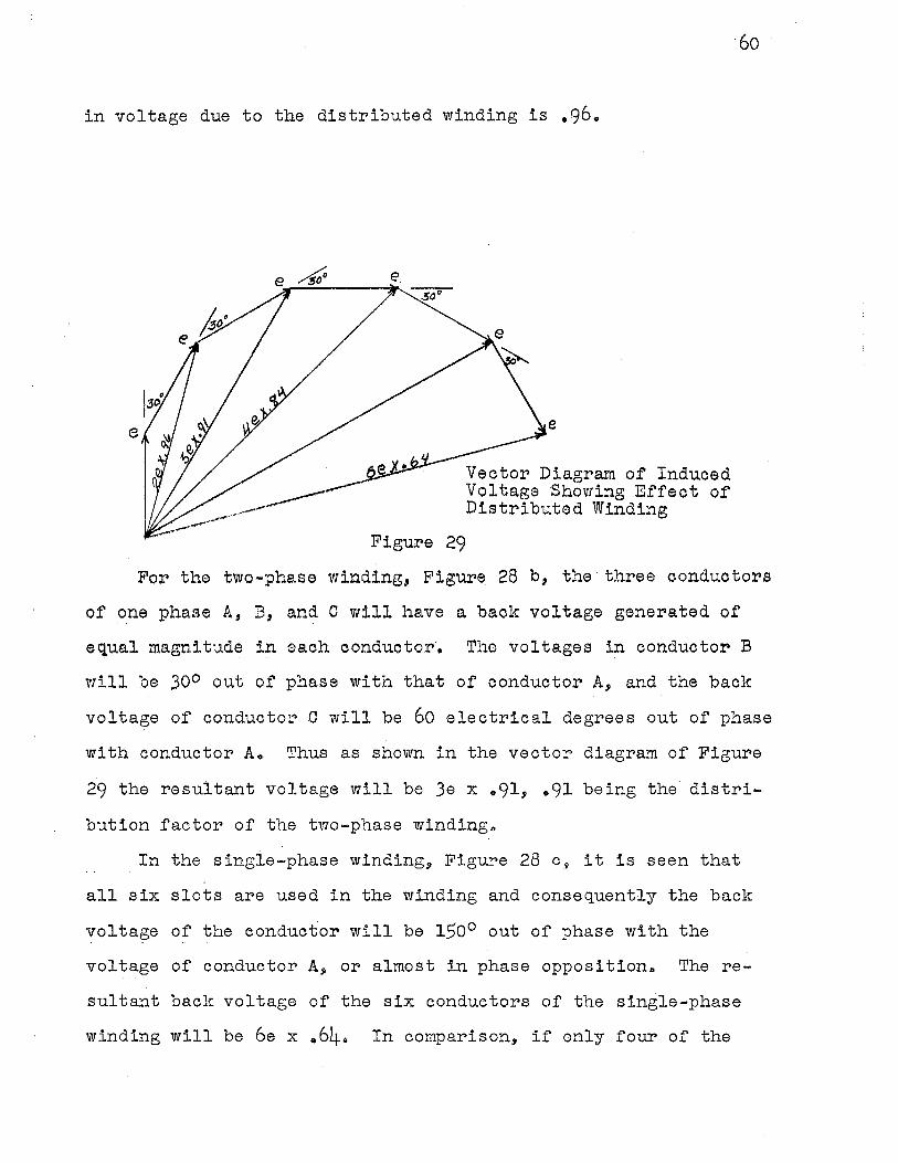
in voltage due to the distributed winding is .96.
e.
e
Figure 29
e
Vector Diagram of Induced Voltage Showing Effect of Distributed Winding
60
For the two-phase winding, Figure 28 b, the three conductors
of one phase A, B, and C will have a back voltage generated of
equal magnitude in each conductor·. The voltages in conductor B
will be 300 out of phase with that of conductor A, and the back
voltage of conductor C will be 60 electrical degrees out of phase
with conductor A. Thus as shown in the vector diagram of Figure
29 the resultant voltage will be 3e x .91, .91 being the distri-
bution factor of the two-phase windingo
In the single-phase winding, Figure 28 c., it is seen that
all six slots are used in the winding and consequently the back
voltage of the conductor will be 150° out of phase with the . .
voltage of' conductor A, or almost in phase opposition. The re
sultant back voltage of the six conductors of' the single-phase
winding will be 6e x .64. In comparison, if only four of the
61
slots are used for the single-phase winding as in Figure 28 do
The resultant back voltage is 4e X e84 or only about 10% less
than when all six slots of the stator are used for the windingo
Therefore, by a 50% increase in the amount of copper.!/ there is
a. 10% increase in voltageo For reasons of economy as well as
the fact that all single-phase induction motors of the capacitor
start 9 induction run and the split phase start, induction run
types will require about 1/3 of the winding slots for the
starting windingo About 2/3 of the slots are generally used for
the main windingo E·ven for commutator start single-phase
induction motors, the middle slots are usually not used so as
to take advantage of the saving of coppero Using the concentric
type winding makes it expedient to leave out these windingso
In the four windings of Figure 28 9 if the conductors in
each slot or the group of conducto.rs in each sl:it.11 as the case
may be.!/ were to have the same current per ci.rcular mil of copper
cross section.11 a comparison on the basis of equal copper ·;loading
could be made.., It is true that the s ingle-·phase coils would not
all have the same numbe.r of turns.11 more being concentrated i.n
some slots than in other·s<> This would effectiv·ely reduce the
back voltage, but the equal copper loading c.~ould remain the same o
This slight decrease in voltage would occu:r• because arranging the
coils so as to approach sine wave space distribution will de
crease the distribution and pitch factor of the s ingle,-pha.se
machine windingso Unequal grouping of the conductors will cause
the hot spot temperature to further limit the current ..
The three induction motors with windings of diagrams as
62
shown in Figure 28 a, b, d, having the same number of conductors
and equal loading, will have generated back voltages 2 per phase
as shown:
Single,~phase ( 2/3 slots used) K x 4e x 084
Two,mphase
Three-phase
K x 3e x 091
K x 2e x ·.96
Under the conditions of equal copper loadmg and the same
number of conductors, the voit ampere rating of the different
machines will be determined by the temperature rise and the hot
spot temperatureo This rating3 would be the product of the
terminal voltage per phase, the phase current, and the number of
phases, or as shown for the different machines·o
Single-phase (2/3 slots used)
Two,.·phase
Three.:..phase
K X 4e X 084 XIX 1 = 056 K
K x 3e x 091 x Ix 2 = .91 K
K X 2e X 096 XIX 3 = 096 K
I is the stator conductor current which is the same 1in each
motor. The flux per pole being the same in eac.h case, e is the
conductor voltageo
From the above and under the conditions assumed, the rating
of the s ingle,-phase motor will be only about 60% of the rating
of the three-phase machineo As po~nted out in Chapter IV, the
single-phase motor inherently has a lower power factor and
2 Ibid • ., Po 188.
3 Ibido, Po 1880
efficiency 9 this plus a reduction i.n distribution and pitch
factor will thus tend to reduce the rating of the single=phase
induction to nearer So% of the three-phase ratingo
63
64
CHAPTER V
COMPARISON OF HORSE POWER RATINGS ON THE BASIS OF MAXIMUM TORQUE
The minimum breakdownl or maximum torque for polyphase
induction motors 8 set by NEMA, is to be at least 200% of the
rated full load torqueo Recent commercial publications by
different manufacturers: however.9 indicate that the breakdown
torque of most general purpose polyphase induction motors will
be in the neighborhood of 250% of rated torqueo
For single-phase induction motors 9 values of breakdown
torque vary widely with the different types of motorso Tables2
IV and V give a comparison of the general characteristics and
application of single-phase and polyphase induction motorso The
average breakdown torque required of the general purpose single
phase induction motor will 9 like the polyphase motor 9 be near
200% of full load torqueo
As is seen.!) the table for single-phase motors shows break-
down. torque only for fractional horsepower motorso These
fractional horsepower motors represent by far the major portion
of single-phase motor production.,. Al though single-·phase in=
duction motors are built in standard sizes up to and including
10 horsepower.!) only a few are used in special. caseso The ne
cessity of special starti.ng devices, poor power factor and low
efficiency make the polyphase·machine advantageous, and, in some
1 Puchstein and Lloyds Alternati:g,g Current Machines, Po 293 .. 2 Liwschita-Garik and Whipple 8 Electric Machinery, Volume II,
PPo 438=439 and 453-4540 ·
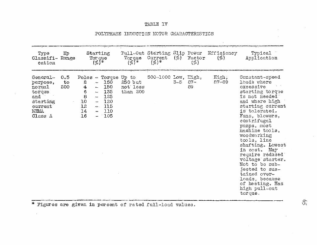
Type Hp Classifi= Range
cation
General.;, purpose;i normal torque and starting current lif.EMA Class A
Oo5 to
200
TABLE IV
POLYPHASE INDUCTION MOTOR CtLl'illACTERISTICS
Starting Torque
(%}*
Poles= 2 4 6 8
10 12 14 16
Torque 150 150 135 125 120 115 110 105
Pu11~out Starting Slip Power Efficiency Torque Current {%) Factor (%}
(%)* (%)* (%)
Up to 250 but not less than 200
500=1000 Low~ High, 3=5 87=
89
High; 817=89
* Figures are given in percent of rated full=load values"
Typical AP.Plication
Constant~speed loads where excessive starting to rq•.1e is not needed and where high starting current is tolerated" Fans 8 blowers~ centrifugal pumps g most machine too ls s
woodworking toolsj line shafting" Lowest in cost" . May require reducea· voltage startero Not to be subjected to sustained over= loads; because· of heating" ·:a:as high pull=out torque.
0-\Jl.
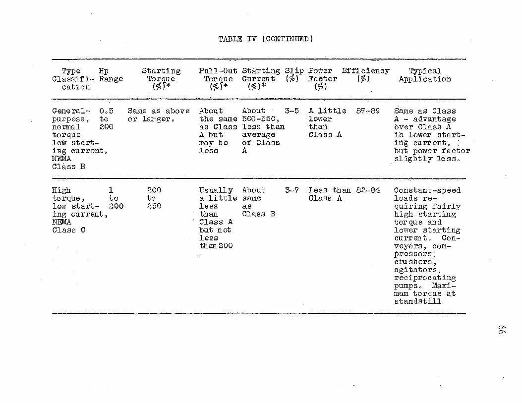
Type Hp Classif i- Range
eat ion
General= Oo5 purposell to normal 200 torque low start= ing eurrent, NEMA Class B
High: 1 torque, to low start- 200 ing current , NEMA. Class C
Starting
T(%f~e
Same as above or largero
200 to 250
TABLE IV (CONTINUED)
Pull=Out _Starting Slip Power Efficiency Torg_ue eu.rrent (%} Faetor (%)
(%}* (%)* (%)
About the same as Glass A but may be less
About 3=5 500=550;; less than average· of Class A
A little lower than Class A
87=89
Usually About 3='7 Less than 82=84 a little same Class A less as than Class B Class A but not less than.200
· Typical Application
Same as Class A= advantage over Class A is lower starting current j) but power factor slightly less ..
Constant-speed loads re=· quiring fairly high starting torque and lower starting eurrento Con= veyors 9 compressors; eru shers -~ · agitators, reciprocating pumps o Maximum torque at standstill
0"-0"-
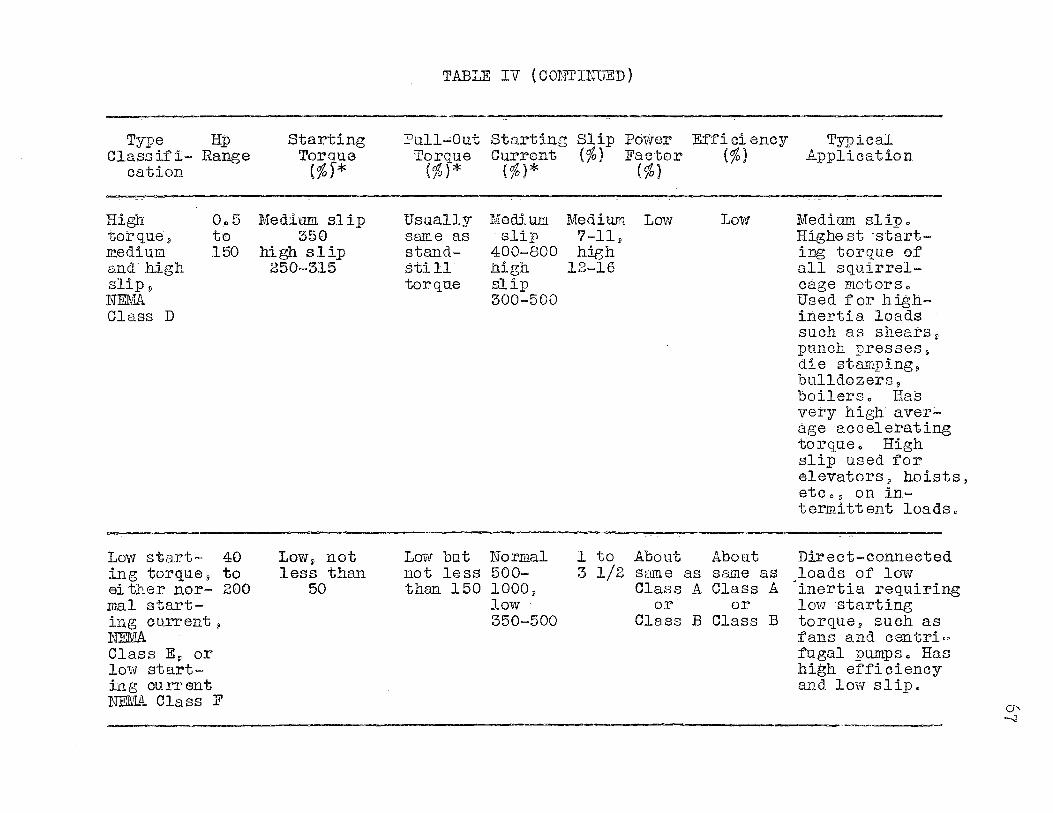
TABLE IV {COlITINlJED)
Type Hp Starting Pu11~out Starting Slip Power Efficiency Typical Class if i= Range Torque Torque Current (%) Factor (%) .Application
cation {%)* (%)* (%)* (%}
High 0.,5 J,iedium. slip Usually Medium :Medium Low Low Medium slip o torquei to 350 same as slip 7=11~ Highest -start= m.ea_ium 150 high slip stand= 400=800 high ing torque of and high 250=315 still high 12=16 all squirrel= Slip V torque slip cage motors o
NEMA 300=500 Used for high= Class D inertia loads
such as shears~ punch presses, die stamping~ bulldozers~ boilersc Has very high aver~ age accelerating torqueo High sli:p used for elevators, hoists, etc o s on in= termittent loadso
Low start- 40 LOWi not Low but Norm.al l to .About About Direct=connected ing torque~ to less than not less 500= 3 1/2 same as same as loads of low either nor= 200 50 than 150 1000, Class A Class A inertia requiring mal start= low or or low starting ing current j 350=500 Class B Class B torque$ such as N'.EMA fans and centri= Class Ev or fugal pumps~ Has low start= high efficiency ing current and lmv slip. NEMA Class F
O" --J
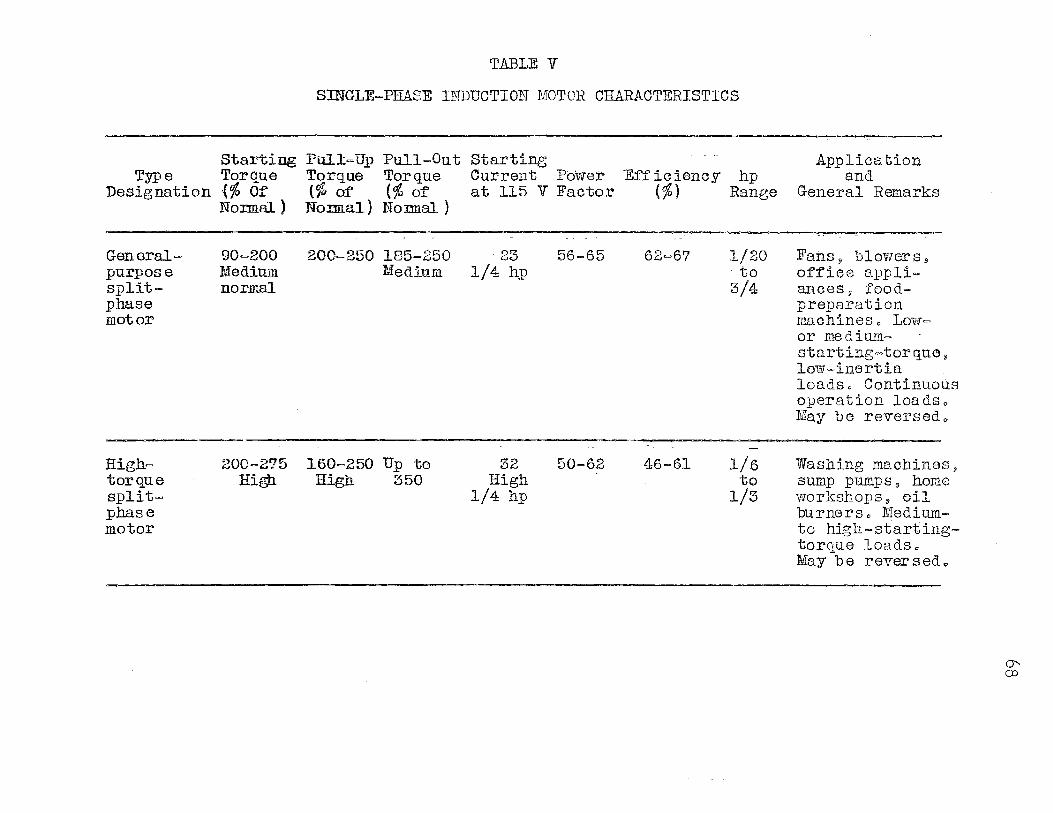
TABLE V
SINGLE=PHASE INDUCTION MOTOR CHARACTERISTICS
Starting Pull=Up Pull=Out Type Torque Torque Torque
Designation {% Of' (% of' (% of
General= purpose splitphase motor
High= torque splitphase motor
Normal ) Nonnal) NomJ.al )
90=200 Medium normal
200=2'75 High
200=250 185=250 Medium
160=250 Up to High 350
Starting Current Power Efficiency hp at 115 V Factor (%) Range
· 23 1/4 hp
32 High
1/4 hp
56-65
50=62
62=6'7
46=61
1/20 to
3/4
1/6 to
1/3
Appliea tion and
General Remarks
Fansj blowerss off'iee appli= ances, foodpreparation machineso LOW= or medium.starting-torque, low-inertia loads. Continuous operation loads .. May be reversedo
Washing machiness sump pumps, home workshops, oil burners o Medium= to high-starting= torque loads. May be reversedo
0-,. ():)
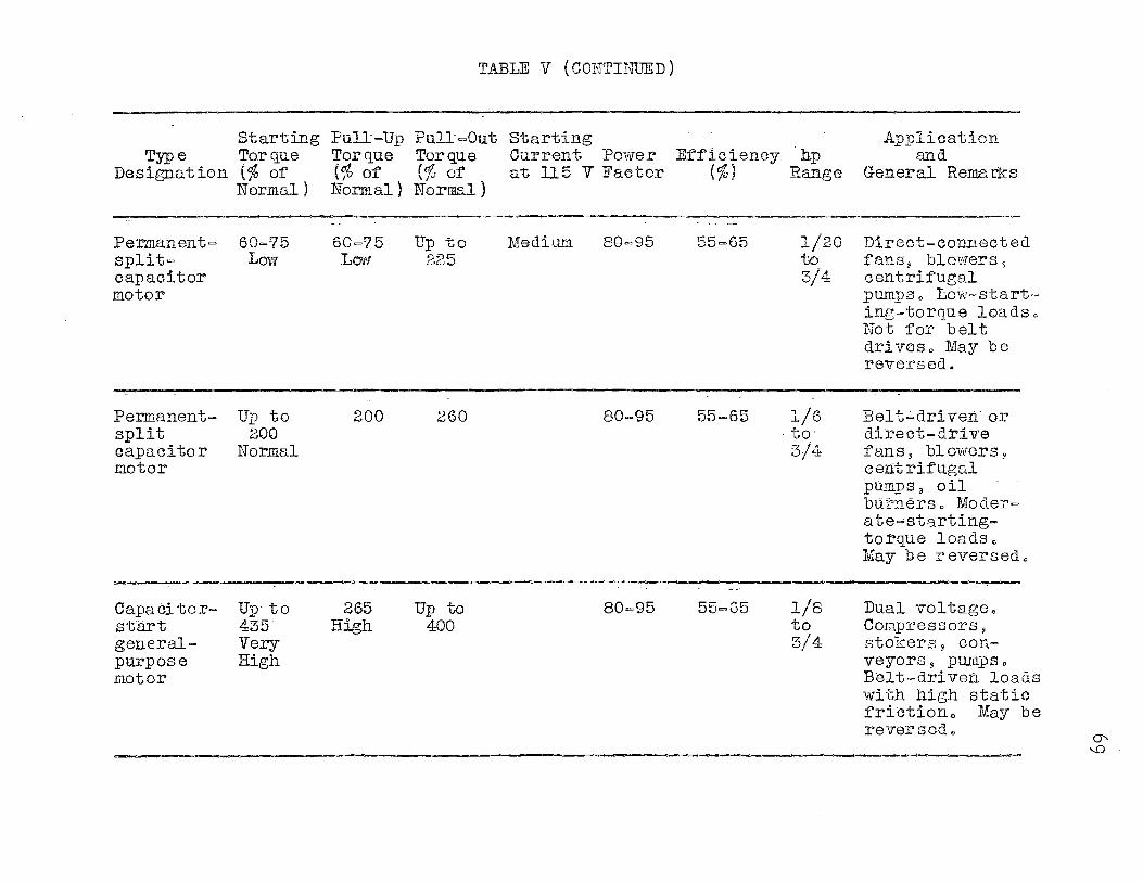
TABLE V (CONTINUED)
Starting Pull=Up Pull=Out Starting Applieation Typ e Torque Torque Torque Current Power Efficiency hp and
Designation(% of {% of' (% of at ll5 V Faetor (%) Range General Rema rn:s Normal) Norm.al ) Normal )
--·
Permanent= 60=?5 60=?5 Up to Medium 80=95 55=65 1/20 Direct-eonnected split= Low Low 225 to f'ansjj blowers 9
capacitor 3/4 centrif'ugal motor pumpso Low-start-
ing-torque loadso Not for belt drives., :May be reversed.
Permanent= Up to 200 260 80-95 55=65 1/6 Belt.;,drivenor split 200 to· direct-drive capacitor Normal 3/4 fans, bl ow-ers ~ motor cent rif'ugal
pumps 11 oil burnerso Moder= ate.,,.starting-torque loads., May be reversedc
Capacitor- Up- to 255 Up to 80=95 55=65 1/8 Dual voltagec start 435 High 400 to Compressors, general- Very 3/4 stokers, con= purpose High veyors, pur11ps o-
motor Belt-driven loads with high static frictiono May be reversed.,
CJ'
'°
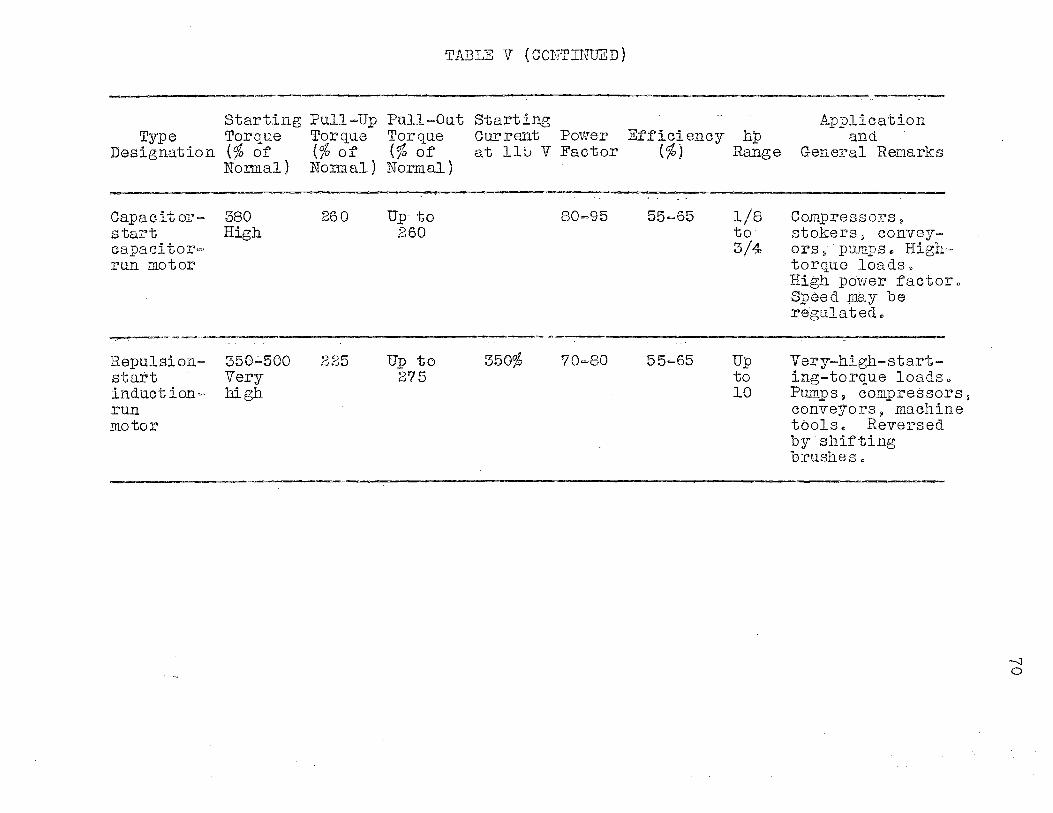
TABLE V (CONTINUED)
Starting Pull-Up Pull=Out Starting Type Torque Torque Torque Current Power Efficiency hp
Designation(% of {% o:t' (% o:t' at 11!:J V Factor (%) Range Nonnal) Nonnal) Normal)
Capacitor= 380 260 Up-to 80=95 55=65 l/8 start High 260 to capacitor= 3/4 run motor
Repulsion= 350.;;.500 225 Up to 350% 70=80 55=65 Up start Very 275 to induction- high 10 run motor
Application and
General Remarks
Compressors, stokers, convey= ors 'j- · pumps e High-torque loads .. · High power factoro Speed may be regulatedo
Very=high-start-ing-torque loadso Pumps, compressorsj conveyorsj machine toolso Reversed by· shifting brushes o
-..J 0
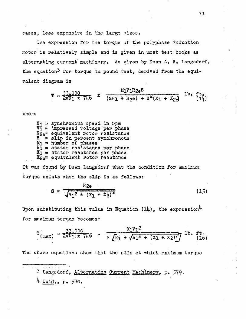
cases., less expensive i.n the large sizes.,
The expression for the torque of the polyphase induction
motor is relatively simple and is given in most test books e.s
71
al terns.ting c,urrent ma.chineryo As given by Dean Ao So Langsdor:f',
the equation3 for torque in pound :f'eet, derived :f'rom the equi
val~nt diagram is
where
Ni= synchronous speed in rpm V1 = impressed voltage per phase R2e= equ1ve..lent .rotor resistance S = slip in pe~cent synoru:»onous M1 = number ot phases R1 ~ stator resistance per phase X1 ::!I stntor r~B.otanoe per phase X2e=1 equivalent rotor rea,otm.noe
It was round by Dean L~nisdo~f that the condition for m~xim'U.tl1
torque exist1 when the slip 1s as follows:
R2e (15)
Upon substituting this value in Equation (14)~ the expression4
for max1m1.llll torque becomese
0
The above equations show that the slip at which maximum torque
3 tangsdor.f' 9 A,lternatin__g Current Machinecr.9 Pe 579.
4 Ibid~s, Po 5800
72
occurs is directlr proportional to the rotor resistance, whereas
the maximum torque itself' is independent of rotor resistanceo
This is not true in the case of' the single-phase machineo F·rom
Equations (15) and (16) it is seen that maximum torque may be
made to occur at any.speed by varying the rotor resistanceo
In general.\) the stator resistance will be very small as
compared to the stator leakage reacta.nce and may be neglected
f'or comparison purposes without excessive error. In so doing the
above equation will reduce to:
T(max) 2. Jcx1. +. X2) 2 (17)
Letting (X1 + X2) = X - the total leakage reactance of the motor$
the maximum torque is
Tmax = KM\72 2X
where K ( 332000 ' ) = 2TJ'n1-.x.746
(i8)
Thus the maximum torque of a polyphase induction motor is directly
proportional to the applied voltage squared and inversely pro-
portional to the motor leakage reactanceo
Contrary to the above expressions the maximum torque equation
for the single-phase induction motor is not quite so simpleo
The equation5 for maximum torque in the single-phase induction
motor is given as foll.ows:
· · 5 Puchstein and Lloyds "Single-Phrise Induction Motor Performance 9 " Electrical Engineering.\) 56 (October, 1937}, P• 1277~
where
T = ll. 2 .....L. Lyg, tr ~ - (F + Fe( c)7 OZo rt~ N · Spo X . QJ. . _ -.:.J
V = applied voltage r1 = stator winding resistance r2 = rotor resistance in stator terms X1 = stator winding leakage reactance X2 = rotor leakage reactance
73
(19)
. Xm = mutual reac:tance in stator ·terms Xo -· Xm + X1 = magnetizing rea.ctance for air gap and primary
leakage fluxes Kr = Xo + X
x - -X -· X1 + X2 = x1 + J Kr1 .A.2 F = watts$ friction~ and windage loss Fe= •atts core loss I1 = primary current S = percent synchronous speed Spo= percent synchronous speed at which pull out torque
occurs
2( · ) 27 f: . p2 ( 2 m Kr) 2 P l = Kr ~ L l ... (P2+1)li+p2( lmKr)~
Q1 = LTi + P1trJ2 + (P101r)'g
1 =---1 +.a
1 L- {· Kr ) 0 r= 1 - • 5 2- ..,. Kr
A total secon0~ry losses
-~- output + F =/- Fe ( c) 1 ... s2 ----+ s2
+ P(l ..r..r]
C = series conductor of stator windingo
It is thus apparent that a comparison of the maximum torque
equation of single-phase and polyphase induction motors as
74
shown in Equations (18) and (19) would require extensive study
and ane.lysisc. However a. partial comparison :may be made from the
equation for torque6 in terms of air gap flux as follows;
Where
~ z I kp kd cos
It
Q
is
=- number of poles . = effective flux per pole = total conductors of stator = stator current in amperes = pitch factor of stator winding = distribution factor of stator winding = angle betwee:p stator current and rotating flux
brought: out by Messrs,, Puchstein and Lloyd and by
(20)
Messrso Liwschi tz~.Ga.rik and Whipple that the above equation
applies for single-phase as well as polypha.se machines1; The
equation may be applied in terms of the stator or rotor,, Equation
(20) is the developed torque exclusive of friotion and windage
and core losseso
In examining Equation (20) maximum torque will depend upon
the winding factors kp and kd, the current density of the
cond,;i.cto!"s and upon 00s Qo The number of poles, and flux per
pole is the same in both the s:i.ngle"·phase and polyphase machines.,
It is assumed that the single-phase motor will have only approxi
mately 2/3 the number of series conductors as has the polyphase
induction. machine, the remainder of the slots being used for the
starting windingso
6Pilchstein and Lloyd, AJ:ternati:Qg Current Machines, P• 2560 Liwschitz-Ga:rik and Whipple, Electric.Ma.chine:ry, Volume.II., Po 179•
75
It can be seen from the above di.scussio:n and from Equation
(18) that maximum torque will also depend upon the leakage
reactance of the windings of both stator and rotoro The total
leakage reacta.nce7 is made up of (1) slot reactance., (2) zigzag
reactance, (3) belt reactance and (L~) end-connection leakage
reactanceo The slot and end-connection leakage reactances are
functions of the number o:f conductors., type of windings winding
facto:i:··s~ and physical dimensions ·of the ma.chine., whereas the
zigzag leakage reaetance is a function of the applied voltage,
magnetizing currerit 9 winding., and machine d:lmensionso In
indue·tion motors with squirrel-cage rotors the belt leakage
reactanoe is zeroo The total lea.k~ge reactance of the induction
motor directly affects the maximum torque and should be kept as
low as is possibleo In the three-pha.se motor the maximum torque
is independent of rotor resistance, but in the single-phase
ma.chines the ro·tor resistance is instrumental in determining
pull out torque and should be kept lowo If the assumption is
made that 'the total leakage reactance and rotor resistance are
approximately the same in both the single-phase and three-phase
mo tort> then the cur•ren t density and s ta. tor winding will be the
de te:rmining .factors o
In general the single=phase induction motor will have ap
proximately 10 per cent greater current density8 than does the
7 Kuhlmann 9 Design of Electrical Appara.tus 9 Po 31L~-31.5o
8 Ibido.9 Po 291-3310
polyphase machineo This is because of the relatively fewer
conductors and thus more heat dissipating surface of the statoro
Under the a.hove circumstances, the winding factors will
greatly affect the maximum torque, as was the conclusion in
Chapter lJ.o Taking into account the winding factors, current
density9 number of stator conductors, power factor 8 and effieien
cy9 the maximum torque of a single-phase machine will be less
than 2/3 that of a polyphase induction motoro On the basis of
pull out torque being 200 per cent of full load torque, the
horsepower rating of the single-phase induction motor will be
between 1/2 and 2/3 the rating of the polyphase induction motoro
77
CONCLUSION
· As stated in the preface, any conclusion drawn by the writer · . '.
would necessarily be ot a VG'r7' general nature~ !here are many
different t1Pes or motors and all are designed tor a partioular
operation or a part1oula:ca tn,e of' jobo There:t.'ore oertain design
features are· sa:crif'iced so as to emphasize othe:ca design features.
Thus there is no definite set design procedure tor either the
single-phase or polyphase induction motors. . . '\'
Too, there are many
empirical equations as well as various data gained from experi
ence, not generally available in the literature on the subject.
In studying the different windings of the stators or both
single-phase and. pol7phase maohines, the writer finds that the
winding :f'aotors, distribution f'actor and pitch factor, have an
important effect upon the eoonomr of manufacture, efficiency
and performance of the machines. Since it is assumed 1n'th1s
thesis that the same rotor~ same stator and same .t'lu·pe:tt pole
are used in both the single-phase and polyphase machines, the
winding factors of the stator of the two machines are most
1mpo:t'tanto
It is true that if the single-phase motor were designed,
using all the stator slots and having as high current densitr
as possible, then the :caating will be a little less than the
ra~ing of a polyphase induction motor with the same stator,
rotor and flux per pole.
In the 1nte:t"est of good motor design (reduetion of harmonies,

78
sine wave of flux, e·tc.,.}, economy of manufacture, and economy
of material, it is the.opinion of the writer that the rating of
the single-phase induction motor will be approximately one-half
that of the three-phase machine.
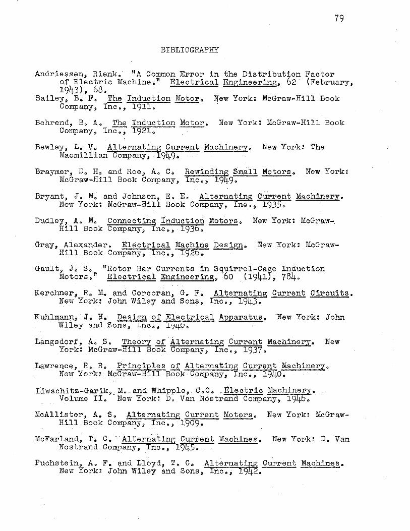
79
BIBLIOGRAPHY
Andriesseri$ Rienko · "A Common Error in the Distribution Factor of Electric Machineo" Electrical Engineering, 62 (February, 19L~3}, 68.. ·
Bailey9 Bo F .. The Induction Motor., Wew York: McGraw-Hill Book Company, Inco, 19110
Behrend, Bo A .. The Induction Motoro New York: McGraw-Hill Book Company, Inc .. , 1921.,
Bewley, L., Vo Alternating .Current Machineryo New York: The Macmillian Company, 191:j:9., · · · · ·
Braymer, D" Ho and Roe 9 A,, Co. Rewindinf Small Motors., McGraw-Hill Book Company, Inc.,, 199,,
New York:
Bryant, J., M., and Johnson, E .. E., Alterna~ing Current Machinery .. New York: McGraw-Hill Book Company, Inc., 1935.,
Dudley, Ao M., Connecting Induction Motors.. New York: McGraw-. Hill Book Company9 Inco, .19360
Gray, Alexander., Electrical Machine Design .. New York: McGrawHill Book Company, Inc.,, 1926 ..
Gaul h Jo s.. "Rotor Bar Currents in Squirrel-Case Induction Motors.,'' Electrical Engineering., 60 (1941) 9 784 ..
Kerchner, R .. M., and Corcoran, Ge, Fo Alternating Current Cireuitso . New York: John Wiley and Sons, Inc o, 191.j:3 o
Kuhlman:µ..i:,·J., H. Desi&n ..2.f. Electrical Apparatuso New York: John Wiley and Sons, lnco, l~~Uo
Langsdorf, Ao S., Theory of Alternating Current Machinery .. New York: McGraw-Hill Book Company, Inc .. , 1937 .. ·
Lawrence:i R., R .. Principles of Alternating Current Machinery .. New York~ McGraw-Hill Book Company, Inc .. , .194-0 ..
tiwschitz~Garik.,,. M ... -and Whipple!!. CoC o , Electric Machinery., _,, .. . Volume II.. New York~ Do_ Van Nostrand Company., 1940.,
McAllister, A. S., Alternating Current Motors., New York: McGrawHill Book Company, Inc .. , 1909.,
McFarland, T., c .. Alternating Current Machines., New York: D .. Van Nostrand Company., Inc .. , 191:j:5.,
Puchstein, A .. F .. and Lloyd, T., C., Alternating Current Machines<> New York~ John Wiley and Sons., Inc.,, 1942 ..
80
Puchstein., Ao Fo and·t1oyd, To Co "Single Phase Induction Motor ~erformanoeo" Electrical Engineering 17 56 (October 1937), 12770 ' .. ' ''.'
Tang, Ko Yo Alternating Owr~nt. C·ircuitso. Scranton., Pennsylvania: The Internationa.l Textbook Company., 1940.
Tarboux., Jo Go' Alternating Current Machinery., Scranton, Pennsylvania~ The ~nternational-Textoook Company., 1947.
Ward, Ro Po Introducti~n to Eleotrica.1 Engineerin50' New York: Prent~ce-Hall, !noo., 19470 ·
Veinot'.f;, Co Go Fractional Horse;eower Electric, Motorso New York: McGraw-Hill Book Company., Inoo, 19~o ..

~ Patty McAffrey Howell~
Copyright © 2022 FDOKUMEN