PH 222-2A Spring 2015
28
PH 222-2A Spring 2015 Magnetic Field Lecture 12 Chapter 28 (Halliday/Resnick/Walker, Fundamentals of Physics 8 th edition) 1
-
Upload
khangminh22 -
Category
Documents
-
view
0 -
download
0
Transcript of PH 222-2A Spring 2015
PH 222-2A Spring 2015
Magnetic Field
Lecture 12
Chapter 28(Halliday/Resnick/Walker, Fundamentals of Physics 8th edition)
1

Chapter 28Magnetic Fields
In this chapter we will cover the following topics:
Magnetic field vector, Magnetic force on a moving charge, Magnetic field lines Motion of a moving charge particle in a uniform magnetic field Magnetic force on a current-carrying wire Magnetic torque on a wire loop Magnetic dipole, magnetic dipole moment Hall effect Cyclotron particle accelerator
B
BF
2

One can generate a magnetic field using one of the following methods:
Pass a current through a wire and thus form what is known as an "electromagnet."
Use a "permanent" ma
What Produces a Magnetic Field
gnet.
Empirically we know that both types of magnets attract small pieces of iron. Also, if suspended so that they canrotate freely they align themselves along the north-southdirection. We can thus say that these magnets create in
the surrounding space a " " , which
manifests itself by exerting a magnetic force .We will use the magnetic force to define precisely
the magnetic fi
B
B
F
magnetic field
eld vector . B
3
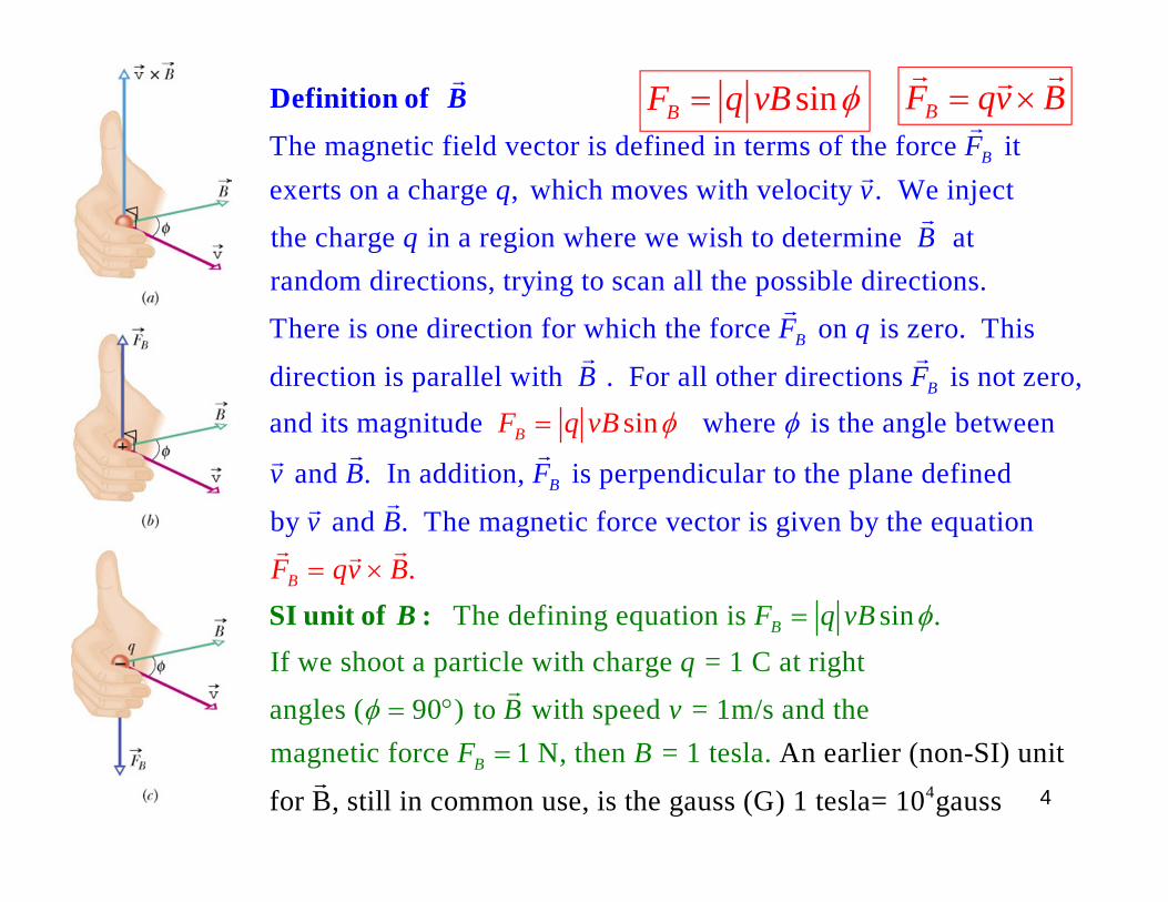
The magnetic field vector is defined in terms of the force itexerts on a charge , which moves with velocity . We inject
the charge in a region where we wish to determine
BFq v
q
Definition of
B
at random directions, trying to scan all the possible directions.
There is one direction for which the force on is zero. This
direction is parallel with . For all other directions is B
B
B
F q
B F
not zero,
and its magnitude where is the angle between
and . In addition, is perpendicular to the plane defined
by and . The magnetic force vector is
s
given by the equatio
i
n
n
B
B
v B F
F q
B
vB
v
The defining equation is sin .If we shoot a particle with charge = 1 C at right
angles ( 90 ) to with speed = 1m/s and the magnetic force 1 N, then = 1 te
.
sl
B
B
B
F qv BF q vB
q
B vF B
SI unit of :
B
4
An earlier (non-SI) unit
for B, still in common use, is the gauss (G) 1 tesla= 10 g s
a.
aus
BF qv B sinBF q vB
4

The vector product of the vectors and is a vector . The magnitude of is given by the equation
The direction of is perpendicularsin .c a
c a b a bc
c
cb
The Vector Product of Two Vectors
to the plane defined
by the vectors and .The sense of the vector is given by the :
Place the vectors and tail to tail. Rotate in the plane along the shortest
P
a bc
a ba P
right - hand rule
a.b.
angle
so that it coincides with . Rotate the fingers of the right hand in the same direction. The thumb of the right hand gives the sense of .
The vector product of two vectors is also kno
b
cc.d.
wn as the " " product.cross
5
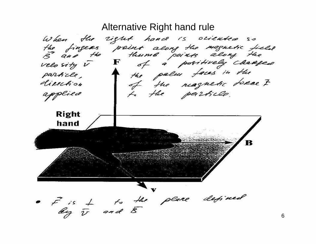
6
Alternative Right hand rule

The vector components of vector are given by the equations ,
ˆ ˆ ˆˆ ˆ ˆ ˆ ˆ ˆ, ,
x y z z y y
x y z x y z x y z
c a b a b c
a a i a j a k b b i b j b k c c i c j c kc
= ×The Vector Product in Terms of Vector Components
c a b
Those familiar with the use of determinants ca
,
The order of the two vectors in the cross pro
n us
du
e the expressio
ct is important
n
:
z x x z z x y y
x z
x y z
x
y
i j ka b a
a b a b c a b a b
b
a ab b b
a
No
N
te :
ote :
.a b
7
8
N
S
B
+
-
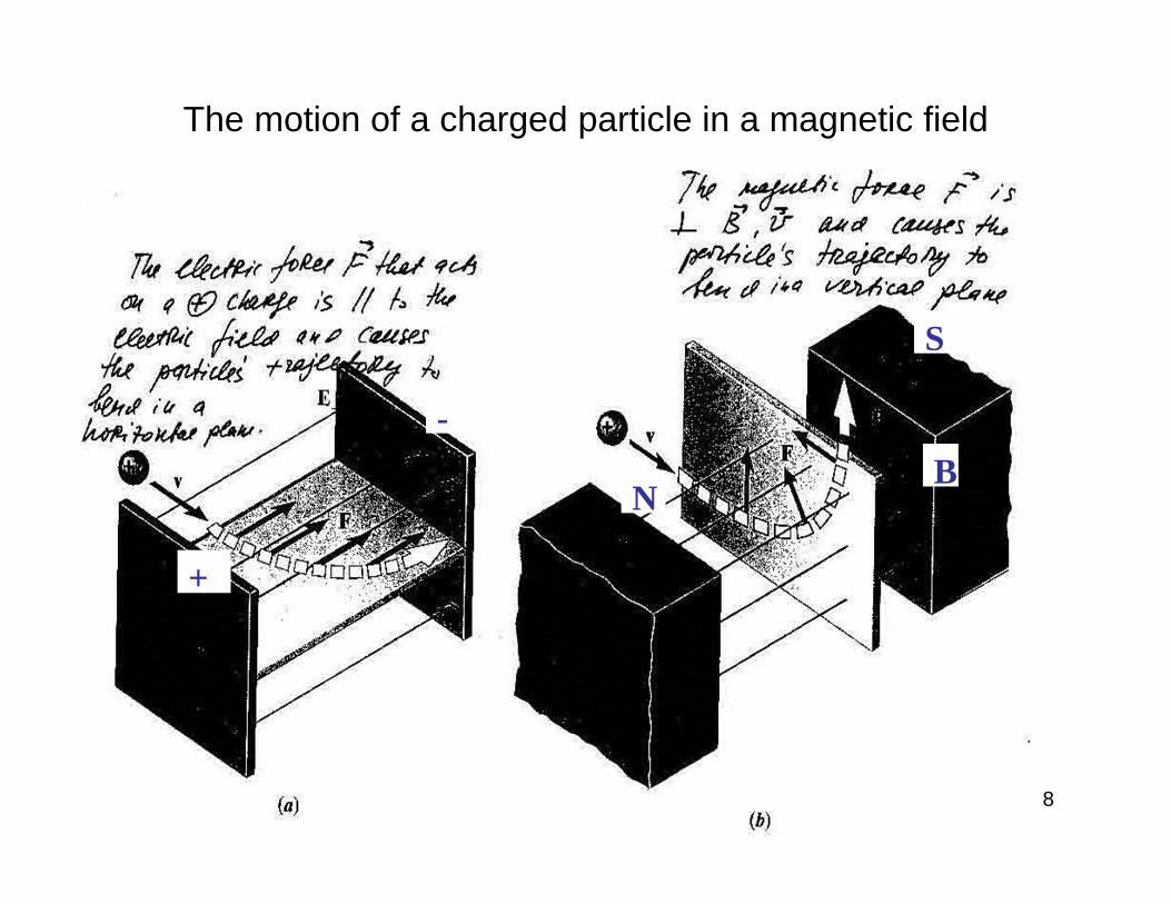
The motion of a charged particle in a magnetic field

In analogy with the electric field lines weintroduce the concept of magnetic field lines, which help visualize
the magnetic field vector without using equations.
In the relati
B
Magnetic Field Lines :
on between the magnetic field lines and : B
1. At any point the magnetic field vector is tangent to the magnetic field lines.
P B
PPB
magnetic field line
2. The magnitude of the magnetic field vector is proportional to the density of the magnetic field lines.
B
magnetic field linesPQ
PB
QB
P QB B
9

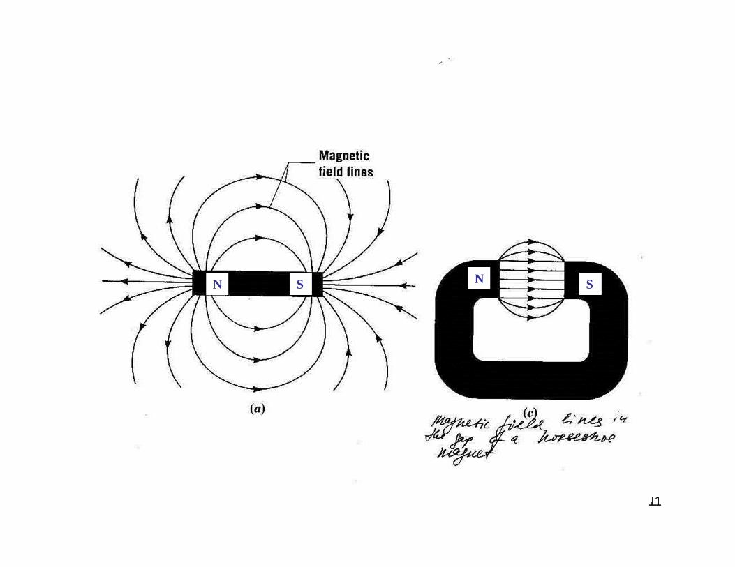
The magnetic field lines of a permanent magnet are shownin the figure. The lines pass through the body of the magnetand form loops. This is in contr
Magnetic Field Lines of a Permanent Magn
d
et
close ast to the electric fieldlines that originate and terminate on electric charges. The closed magnetic field lines enter one point of the magnetand exit at the other end. The end of the magnet from whichthe lines emerge is known as the of the magnet. The other end where the lines enter is called the of the magnet. The two poles of the magnet cannot beseparated. Together they
north polesouth pole
form what is known as a " "magnetic dipole.
10
11
N NS S

12
N N
N
N
S S
S
S

13
Magnetic Forces

14
EF
BF
Cathode
AnodeEF qE
BF qv B
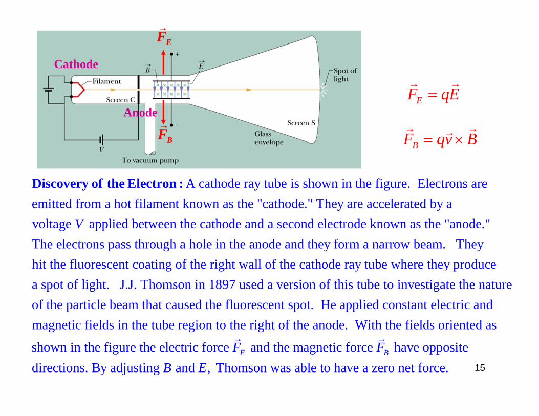
A cathode ray tube is shown in the figure. Electrons areemitted from a hot filament known as the "cathode." They are accelerated by a voltage applied between the cathode aV
Discovery of the Electron :
nd a second electrode known as the "anode."The electrons pass through a hole in the anode and they form a narrow beam. They hit the fluorescent coating of the right wall of the cathode ray tube where they produce a spot of light. J.J. Thomson in 1897 used a version of this tube to investigate the natureof the particle beam that caused the fluorescent spot. He applied constant electric and magnetic fields in the tube region to the right of the anode. With the fields oriented as
shown in the figure the electric force and the magnetic force have opposite directions. By adjusting an
E BF FB
d , Thomson was able to have a zero net force.E 15

16
Example: A velocity selector
Fmag=qvBsin
.
.electron
B
v
F
Cr
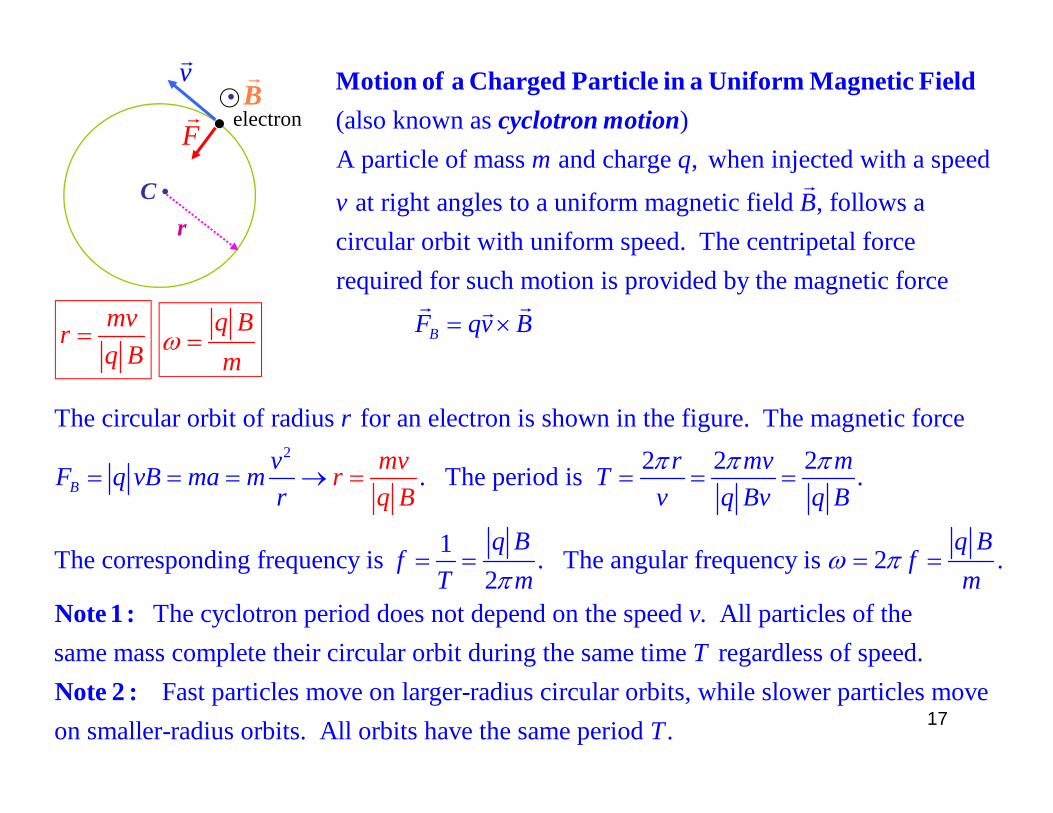
(also known as )A particle of mass and charge , when injected with a speed
at right angles to a uniform magnetic field , f
m q
v B
Motion of a Charged Particle in a Uniform Magnetic Field
cyclotron motion
ollows acircular orbit with uniform speed. The centripetal forcerequired for such motion is provided by the magnetic force
BF qv B
2
The circular orbit of radius for an electron is shown in the figure. The magnetic force 2 2 2. The period is .
1The corresponding frequency is . Th2
B
rv r mv mF q vB mvrma m Tr v q Bv q B
q Bf
T
q B
m
e angular frequency is 2 .
The cyclotron period does not depend on the speed . All particles of thesame mass complete their circular orbit during the same time regardless of speed.
q Bf
mvT
Note 1 :
N Fast particles move on larger-radius circular orbits, while slower particles moveon smaller-radius orbits. All orbits have the same period .T
ote 2 :
mvrq B
q Bm
17

We now consider the motion ofa charge in a uniform magnetic
field when its initial velocity
forms an angle with .We decompose into twocomponents.
B
v Bv
Helical Paths
||
||
One component is parallel to and the other is perpendicular to (see fig. ):
cos sin The particle executes two independent motions.
One, the cyclotron motion, is in
v B v B a
v v v v
the plane perpendicular to that we have 2analyzed on the previous page. Its radius is . Its period is .
The second motion is along the direction of and it is linear motion with
Bmv mr Tq B q B
B
||
||
constantspeed . The combination of the two motions results in a helical path (see fig. ).
2 cosThe pitch of the helix is given by .
v b
mvp p Tvq B
mvrq B
2 mTq B
18

19
The mass-spectrometerHelps to identify unknown molecules produced in chemical reaction.
22qBmVr
BF
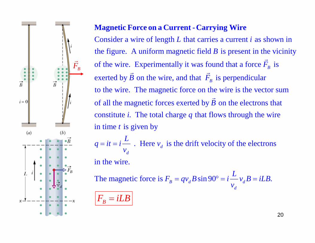
Consider a wire of length that carries a current as shown inthe figure. A uniform magnetic field is present in the vicinity
of the wire. Experimentally
L iB
Magnetic Force on a Current - Carrying Wire
it was found that a force is
exerted by on the wire, and that is perpendicularto the wire. The magnetic force on the wire is the vector sum
of all the magnetic forces exerted by on the
B
B
F
B F
B
electrons that
constitute . The total charge that flows through the wire in time is given by
. Here is the drift velocity of the electrons
in the wire.
The magnetic force is si
dd
B d
i qt
Lq it i vv
F qv B
n 90 .dd
Li v B iLBv
BF iLB
20
. dL
B
dF
i
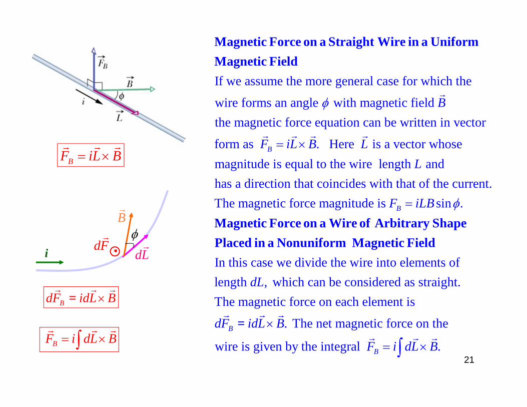
If we assume the more general case for which the
wire forms an angle with magnetic field the magnetic force equation can be written in
B
Magnetic Force on a Straight Wire in a Uniform Magnetic Field
vector
form as . Here is a vector whose magnitude is equal to the wire length and has a direction that coincides with that of the current.The magnetic force magnitude is sin .
B
B
F iL B LL
F iLB
In this case we divide the wire into elements oflength , which can be considered as straight.The magnetic force on e
dL
Magnetic Force on a Wire of Arbitrary ShapePlaced in a Nonuniform Magnetic Field
ach element is
. The net magnetic force on the
wire is given by the integral .B
B
dF idL B
F i dL B
=
BF iL B
BdF idL B=
BF i dL B
21

C
C
Top viewSide view
Consider the rectangular loop in fig. with sides of lengths and and that carriesˆa current . The loop is placed in a magnetic field so that the normal to th
a a bi n
Magnetic Torque on a Current Loop
1 3
2 4
e loop
forms an angle with . The magnitude of the magnetic force on sides 1 and 3 issin 90 . The magnetic force on sides 2 and 4 is sin(90 ) cos . These forces cancel
BF F iaB iaBF F ibB ibB
net
2 4
1 3
in pairs and thus 0.The torque about the loop center of and is zero because both forces passthrough point . The moment arm for and is equal to ( / 2)sin . The twotorques tend to
FC F F
C F F b
1 3
rotate the loop in the same (clockwise) direction and thus add up.The net torque + =( / 2)sin ( / 2)sin sin sin .iabB iabB iabB iAB
net siniAB
net 0F
22
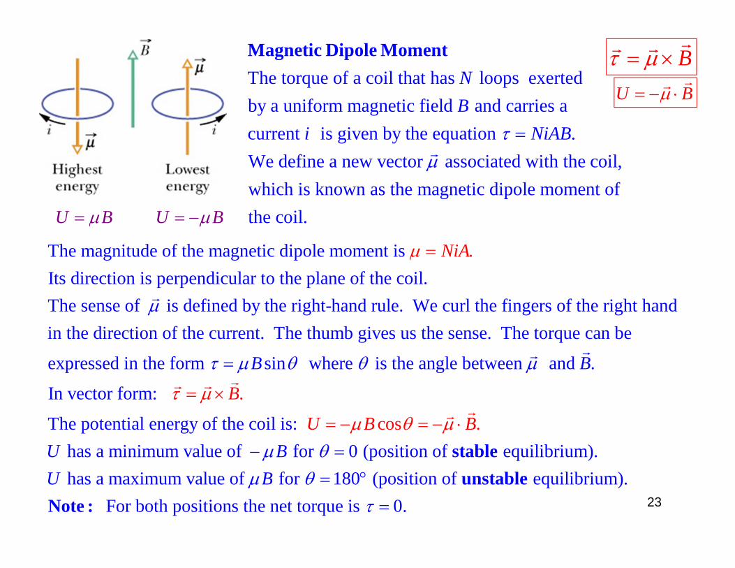
U B U B
The torque of a coil that has loops exertedby a uniform magnetic field and carries a current is given by the equation .We define a new vector associated with the
NB
i NiAB
Magnetic Dipole Moment
coil,which is known as the magnetic dipole moment of the coil.
The magnitude of the magnetic dipole moment is Its direction is perpendicular to the plane of the coil.The sense of is defined by the right-hand rule. We curl the fingers of the right ani
.
h d
NiA
n the direction of the current. The thumb gives us the sense. The torque can be
expressed in the form sin where is the angle between and .
In vector form:
The potential energy
.
B
B
B
of the coil is: has a minimum value of for 0 (position of equilibrium). has a maximum value of for 180 (position of equilib
cos
rium). For both posit
.U BU
B B
B
U
stable
unstableNote :
ions the net torque is 0.
B
U B
23

24
The torque on a current loop pivoted on an axis and placed in a strong magnetic field is exploited in electric motors
S

25
L L
L
R R
R
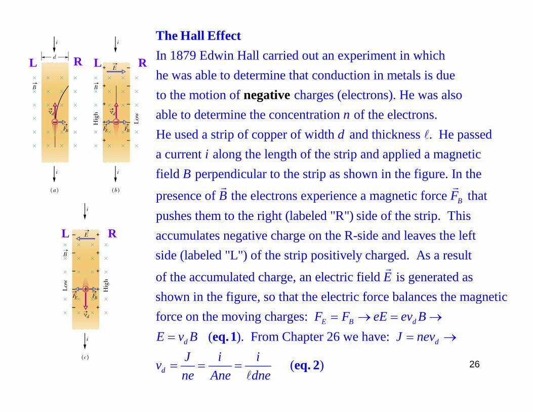
In 1879 Edwin Hall carried out an experiment in whichhe was able to determine that conduction in metals is dueto the motion of charges (electrons). He was also able to determin
ne
The Hall
gat
E t
ive
ffec
e the concentration of the electrons.He used a strip of copper of width and thickness . He passeda current along the length of the strip and applied a magneticfield perpendicular to the stri
nd
iB
p as shown in the figure. In the
presence of the electrons experience a magnetic force thatpushes them to the right (labeled "R") side of the strip. Thisaccumulates negative charge on the R-sid
BB F
e and leaves the leftside (labeled "L") of the strip positively charged. As a result
of the accumulated charge, an electric field is generated as shown in the figure, so that the electric force bal
E
ances the magnetic force on the moving charges:
( ). From Chapter 26 we have:
( )
E B d
d d
d
F F eE ev BE v B J nev
J i ivne Ane dne
eq. 1
eq. 2
26
L L
L
R R
R
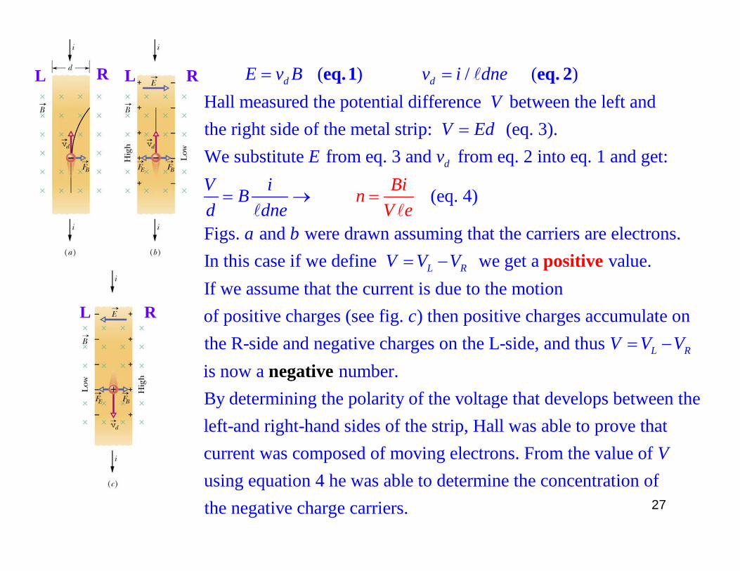
( ) / ( )Hall measured the potential difference between the left andthe right side of the metal strip: (eq. 3).We substitute from eq. 3 and
d dE v B v i dneV
V EdE
eq. 1 eq. 2
from eq. 2 into eq. 1 and get:
(eq. 4)
Figs. and were drawn assuming that the carriers are electrons.In this case if we define we get a value.I
f w
d
L R
vV iBd dne
a bV
ie
V
BV
V
n
positi e v
e assume that the current is due to the motionof positive charges (see fig. ) then positive charges accumulate on the R-side and negative charges on the L-side, and thus is now a numb
L R
cV V V
negative er.By determining the polarity of the voltage that develops between the left-and right-hand sides of the strip, Hall was able to prove that current was composed of moving electrons. From the value of using equation 4 he was able to determine the concentration of the negative charge carriers.
V
27
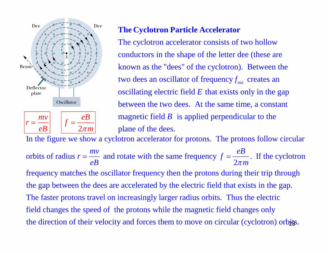
The cyclotron accelerator consists of two hollow conductors in the shape of the letter dee (these are known as the "dees" of the cyclotron). Between thetwo dees an o
The Cyclotron Particle Accelerator
oscscillator of frequency creates anoscillating electric field that exists only in the gapbetween the two dees. At the same time, a constant magnetic field is applied perpendicular to theplane
fE
B of the dees.
mvreB
2eBf
m
In the figure we show a cyclotron accelerator for protons. The protons follow circular
orbits of radius and rotate with the same frequency . If the cyclotron2
frequency matches the oscil
mv eBr feB m
lator frequency then the protons during their trip through the gap between the dees are accelerated by the electric field that exists in the gap.The faster protons travel on increasingly larger radius orbits. Thus the electric field changes the speed of the protons while the magnetic field changes onlythe direction of their velocity and forces them to move on circular (cyclotron) orbits.28


![Crítica à Execução Penal [2a edição]](https://static.fdokumen.com/doc/165x107/631ae641d43f4e176304a750/critica-a-execucao-penal-2a-edicao.jpg)