PH-BSP - Elektrobock
14
Wireless control unit Two-way radio communication on 433.92 MHz Comfortable solution of room heating Energy cost saving during holiday Control of room temperature according to preset requirements PH-BSP Operating instructions PH-BSP Version 11.08 WIRELESS CONTROL UNIT FOR CONTROL OF ELECTRIC HEATING DEVICES (WITHIN ONE ROOM) Possibility of integration in the PocketHome ® system, in which it becomes a subordinate element of the central unit PH-CJ37 / PH-CJ37 Plus Predictive system (providing for the given temperature at the required time, in autonomous mode only)
-
Upload
khangminh22 -
Category
Documents
-
view
0 -
download
0
Transcript of PH-BSP - Elektrobock

Wireless control unit
Two-way radio communication on 433.92 MHz
Comfortable solution of room heating
Energy cost saving during holiday
Control of room temperature according to preset requirements
PH-BSP
Operating instructions PH-BSP
Version 11.08
WIRELESS CONTROL UNITFOR CONTROL OF ELECTRIC HEATING DEVICES
(WITHIN ONE ROOM)
Possibility of integration in the PocketHome® system, in which it becomes a subordinate element of the central unit PH-CJ37 / PH-CJ37 Plus
Predictive system (providing for the given temperature at the required time, in autonomous mode only)

SYSTEM FUNCTIONS
PH-BSP Wireless control unit - measures temperature in the room and switches the individual heating devices centrally as
required (functions as a room thermostat);- able to control up to 255 switching elements (PH-SP1, PH-SP2, PH-SP3) from one place;- switches the elements stepwise (at 1 s), thus preventing current surges in the network;- suitable for controlling electric heaters in one room;- for control by means of a mobile phone, you just need to connect the GST1 / GST2 module
(page 9, 12, 13);- can be integrated in the PocketHome® system, in which in becomes a subordinate element of
the central unit PH-CJ37/ PH-CJ37 Plus and meets its requirements.
PH-SP1 Wireless switch – under the switch- switches the heating device on the basis of information received;- sends back confirmation of the change made;- simple installation into the installation box;- receiver states are indicated by LEDs on the front panel;- after short-time voltage failure, it activates automatically into the system (E-EPROM memory)
2
SYSTEM COMPONENTS
PH-SP2 Wireless switch – wall-mounted- switches the heating device on the basis of information received;- sends back confirmation of the change made;- simple installation on the installation box;- receiver states are indicated by LEDs on the front panel;- after short-time voltage failure, it activates automatically into the system (E-EPROM memory).
PH-SP3 Wireless switch – socket-mounted
- switches the heating device on the basis of information received;- sends back confirmation of the change made;- simple installation in the socket directly;- device connected by simply inserting it into the socket (suitable for heaters with plug outlet);- receiver states are indicated by LEDs on the front panel;- after short-time voltage failure, it activates automatically into the system (E-EPROM memory).
This wireless two-way system is primarily designed for the regulation of electric heating in a single room. Here, the control unit fulfils the of a wireless room thermostat. According to the temperature in the reference room, in which it is located, it controls the heat source (for
example, a heating panel) and regulates the whole heating system according to the preset program. It enables control of up to 255 RECEIVERS (switching elements) from one place. The control unit sends information on the required temperature to individual components;on the basis of this information, each component controls the heating appliance to which it is connected. PH-BSP switches the elementsstepwise (at approx. 1s) to prevent current surges in the network!
In order to prevent interference and affecting of the systems, each of them is protected by its own unique code which is stored in thecontrol unit PH-BSP by the manufacturer!
Correct communication of all system components with the control unit PH-BSP requires code learning - ACTIVATION of each componentadded to the system!
!!
As the whole system works at bidirectional radio frequency of 433.92 MHz, observe the instructions for installation and location of eachsystem component according to the given manual!!
PERMEABILITY OF VARIOUS MATERIALS FOR RF SIGNAL 433.92 MHz
wall
plasterboard
glass reinforced concrete
iron
Note: The above mentioned values are only approximate; they may vary because of specific conditions at the location of signal transmission and reception!

3
LOCATION OF BATTERIES AND THEIR REPLACEMENT
control buttons
battery compartment
- Open the battery compartment cover and remove the protective paper; now PH-BSP is functional.- When replacing batteries, pay attention to correct polarity, as shown in the battery compartment.- Low battery is indicated by the symbol flashing on the display. - Use solely alkaline pencil-type batteries 2x1.5 V, AA type!
Dispose of old batteries in compliance with the regulations related to the handling of dangerous waste!!
DESCRIPTION OF PH-BSP
stand installation
1.
2.3.
Note: The standis supplied withPH-BSP
character display
connector forGST module
Connector for external source (5 to 12V/ DC min. 150 mA)
0 V
5 to 12 V
internal antenna
We recommend youto use the externalsource (AD05) if thesystem contains morethan 10 elements!
GSM modules
Note: The external sourceand GSM modules are notincluded in PH-BSP!

4
DESCRIPTION OF CONTROLS ON PH-BSP
change of temperature change in the setting of clock and constants browsing in the course of function selection
enter (confirmation) display of information on required temperature and operating hours
change of time (in PROG mode)setting the date and time (in holiday mode “ ” ) browsing among elements (in ACTIV and INFO mode) shift for setting the constant 17 – phone. No. (inCONST mode)
selection of program for boiler (in AUTO mode) switching between programs (in PROG mode) switching between constants (in CONST mode) switching between temperatures “ and ” (in MANUmode) component adding (in ACTIV mode)
reset of operating hours component deactivation (in ACTIV mode) switching all components off (in AUTO, MANU mode)
copying of days (in PROG mode)
holiday (in this mode, info cannot be displayed)selection of EVEN/ODD week (in PROG mode)
change of day (in PROG mode) testing of correct connection (of receiver, GSMmodule); testing of individual components (in ACTIV,INFO modes
selection of function (mode), see p.6 AUTO, MANU, CLOCK, PROG, CONST, ACTIV, INFO,UAdr
reset
H
+ --
T
+--
i
P+
--
Off
Copy
Day Test
F R
DESCRIPTION OF THE PH-BSP DISPLAY
current day indication
switch-on indication
symbol of current date and time setting, see page 6
indication of active communication
variable part of the display, indication of current time and required temperature / program number, indication of otherinformation is explained in detail with every modeeconomy temperature indication (in MANU mode)
summer mode symbol, see page 8
comfortable temperature indication (in MANU mode)
error message, error notice
anti-freeze mode symbol, see page 11
holiday mode symbol, see page 11
low battery indication
signal transmission / reception indication
variable part of the display, indication of current temperatureand selected mode (OFF, AUTO, MANU, PROG), indication ofother information is explained in detail with every mode
program interval indication (max. 6 intervals per day)

5
ACTIVATION PROCEDURE IN THE PocketHome® SYSTEM
After PH-BSP activation in the PocketHome® system, the control unit will be controlled by the central unit PH-CJ37(Plus). On the basis of the temperature measured in the room and the information received (on the temperaturerequired) from the central unit, switching elements will be controlled (of the PH-SP1/PH-SP2/PH-SP3 receivers). Note: The activation can also be done via a PC. Connect the PH-CJ37(Plus) to the PC and start the PocketHome® software; followthe instructions for the software.
1. PH-BSP ACTIVATION - Add the new bSP element in the central unit PH-CJ37(Plus) (ACTIV, page 12,
in the central unit instructions), including the temperature program.- Press the button on the PH-BSP unit, and choose the UAdr mode with
the buttons and confirm by button.- Press the button on PH-CJ37(Plus); the central unit sends a signal to PH-BSP- After correct signal is received, PH-BSP displays the unique number of the central
unit and the address allocated.- Within 2 minutes, the central unit sends repeated signals to PH-BSP; or if you
press the button to speed up the communication.- PH-BSP displays the bEZ:dr message and the unit is fully controlled by
the PH-CJ-37(Plus) central unit.
Test
Testi+/- T
F
Unique num-ber of the
central unit
Allocated address of the
central unit
Indication of the BSP unit state in the PocketHome® system
ON
VYPNUTO
State** DescriptionAUTO and MANU are simultaneously shown on the display
AUTO and MANU are simultaneously flashing on the display
1)TIME - If the time is changed in PH-CJ37(Plus), it will automatically be transmitted; PH-CJ37(Plus) shows the “bSP” message shortly, and the time will be synchronized.
2) PROGRAMS - programs are not set on PH-BSP, since you can choose it on PH-CJ37(Plus) directly.Other automatic functions:3) Boiler state message – twice an hour, PH-CJ37(Plus) sends information on the boiler state to all elements
(“bSP” is displayed again), and the “t : Hr“ message (e.g. general test) appears on PH-BSP.
2. SETTING OF PH-BSP CONTANTS
Follow the instructions on page 8. CONST3, CONST17 to CONST19 will not be displayed in this mode (they are setin the central unit PH-CJ37(Plus).
3. ACTIVATION OF SWITCHING ELEMENTSFollow the instructions on page 10. Do not set the program for switching elements, the required temperatureis transferred from PH-CJ37(Plus).
WHAT YOU NEED NOT SET?
ACTIVATION PROCEDURE IN THE AUTONOMOUS MODE
PH-BSP can work as an independent control unit which controls switching elements within one room. This mode isautonomous – independent of the central unit PH-CJ37(Plus). This mode is suitable for heating within one room. Forthe setting, see below.
In connection with the central unit, PH-BSP is a subordinate element. The required temperature is received from thecentral unit (the AUTO mode is not accessible on PH-BSP). A short-time temperature change in the room in which PH-BSP is located can be made with the buttonon PH-BSP directly, but only until the next program change in the central unit!
+/- T

6
DESCRIPTION OF PH-BSP FUNCTIONS AND THEIR SETTING
Make sure you have carefully studied the introductory part of the instructions with the description of the unit, batterylocation, functions of buttons and symbols on the display (LCD)!The next part is focused on explanation of basic modes and setting of important parameters for correct function ofthe entire system.Press the button and by means of the buttons browse the individual modes, confirm the mode selectionby pressing the button.i
+/- TF
AUTOThe system functions in automatic mode according to the program preset.Change of the program is made by pressing the button. Following information is displayed when button is pressed:- required temperature; short-term change of the temperature can be made bypressing the button (page 11)- operating hours; pressing the button resets the counter Off
+/- T
i
+/- P
Display options on LCD:line 1 - current day line 3 - from the left: current time or error states, required temperature or program number line 5 - current temperature and selected mode line 6 - program interval
MANU
The system functions in the manual mode.VWithin this mode, two required temperatures may be set: the economy and comfortable . Selection and setting are made with the and buttons.+/- T+/- P
Display options on LCD:line 1 - current day line 3 - from the left: current time or error states, required temperature line 4 - selected temperature: economy or comfortable line 5 - current temperature and selected mode
CLOCK
automatic mode (not accessible in the PH system)
manual mode
setting of current time and date By means of the buttons, successively set hours, confirm by pressing button; minutes, confirm by pressing button;seconds, confirm by pressing button;day, confirm by pressing button;month, confirm by pressing button;and year, confirm by pressing button.
ii
ii
i
i+/- T
PROG programmingThe control unit fulfils the functions of a room thermostat and enables setting of up to 9different weekly programs. For each day, up to 6 time intervals can be set with various temperatures. Upon first activation, programs 3-9 are set by default (can also be changed).In program 1 and 2, you can set even and odd weeks, which will change automaticallyaccording to requirements (page 7).
! After activation of PH-BSP in the PocketHome® system, programs cannot bechanged; requirements are directly sent from the central unit PH-CJ37(Plus).
l.1
l.2
l.3
l.4
l.5
l.6

7
Direct programming on PH-BSP
- Press the button and select the PROG mode by means of the buttons; confirm bypressing the button.
- By pressing the buttons, select the program, which should be set (1.P to 9.P).- Press buttons to set the beginning of the temperature change, with the minimum step
of 10 minutes.- Assign the required temperature to the given time by pressing the buttons by steps
of 0.5 °C.- After setting the first time and temperature, press the button to confirm.- You are automatically shifted to setting of the second time and temperature for the same day,
as indicated by symbol on the last, sixth line of the display.- Continue in the same way until you set the last (sixth) interval. - By pressing the button, you will automatically move to the setting of the next day, where
you can proceed in the same way.
i
i
2
i
+/- T
+/- H+/- P
+/- TF
Copying of days in PROG mode
- The day indicator must be on the day which you want to copy to the next day. - Press the button, the program will copy itself automatically to the next day and the day indicator (line 1 of
the display) moves to the next day.
Copy
Selection of even or odd week in PROG modeIf you have set programs 1.P and 2.P, you can define which one will be active in odd or even weeks. When this option is selected, the programs will alternate each week in the AUTO mode automatically (suitable for work inshifts).
- Press the button and select the PROG mode by means of the buttons; confirm by pressing the button.
- By pressing the buttons, select program 1.P- Press the button and specify the week in which the program will be
active: L = odd, U = even, 1= not defined - program 2.P will be defined automatically.
i
+/- P
+/- TF
Pre-set factory programsPrograms 3.P to 9.P are factory pre-set, but can be changed as necessary like 1.P and 2.P. (example: item 5/21 means that at 5 o'clock, the required temperature is 21°C )
Info: If not all of the 6 settings for one day are needed, it is possible to move to the next day by successively pressing the button or the button.Dayi
ODD
EVEN
This function accelerates programming. Program for one day can be copied to the next day by simply pressing thebutton.Copy
Note: When changing the preset programs, check all of the 6 time intervals!
MondayTuesdayWednesdayThursdayFridaySaturdaySunday
program No.3
MondayTuesdayWednesdayThursdayFridaySaturdaySunday
program No.4
MondayTuesdayWednesdayThursdayFridaySaturdaySunday
program No.5
MondayTuesdayWednesdayThursdayFridaySaturdaySunday
program No.6
MondayTuesdayWednesdayThursdayFridaySaturdaySunday
program No.7
MondayTuesdayWednesdayThursdayFridaySaturdaySunday
program No.8
MondayTuesdayWednesdayThursdayFridaySaturdaySunday
program No.9

8
CONSTFor correct thermostat function of the control unit, you must set the following constantswhich define, for example, the temperature limits or method of control (hysteresis or PI regulation).
setting the constants
- press button and by means of select CONST mode, confirm by pressing .- press buttons to display individual constants (see below).- set by pressing buttons, again confirm by button.i+/- T
+/- P
i+/- TF
1. MINIMUM REGULATED TEMPERATURE
2. MAXIMUM REGULATED TEMPERATURE
Here you set the limits of the minimum adjustable temperature.You can select in the range from 2° C to 10 °C.Make the setting and press the button to move to the next constant setting automatically.
i
Here you set the limits of the maximum adjustable temperature.You can select in the range from 15° C to 39 °C.Make the setting and press the button to move to the next constant setting automatically.
i
9. MINIMUM SWITCH-ON TIME OF THE HEATING APPLIANCE AT HYSTERESIS
Here you set the minimum time of switching the boiler on athysteresis.Select according to the type of the heating system used, seethe table.
10. SELECTION OF HYSTERESIS OR PI REGULATION
Type of heating
Minimal period of source activation
electrical heating
panel radiators
cast-iron radiators
floor heating
2 (3)
By pressing the buttons, set the hysteresis from 0,1°C to 1,5°C.If hysteresis is selected, the constants (11, 12, 13), related to the settings of PI regulationparameters, are omitted automatically.If you select three horizontal dashes with the buttons, PI regulation is active. +/- T
+/- T
11. TIME INTERVAL OF PI REGULATION
This can be set in the range from 5 to 20 minutes. The length of this interval is given bythermal inertia of the room.The optimum setting is 10 to 15 minutes.
3. EARLY SWITCH-ON OF THE HEATING SYSTEM / SUMMER MODE
By pressing buttons, select one of the following modes and confirm by pressing thebutton (! If PH-BSP is controlled by the central unit, this constant is not shown). i
+/- T
Option 0 = normal modeNormal operation of the heating system, without early switch-on of the heating.
Option 1 = early switch-on of the heatingThis function guarantees you the required temperature at the required time.You need not guess when to switch the heating on in order to have the adequate temperature in the morning when getting up without heating long in advance unnecessarily. You only program the time of the required temperature. In two days of operation, PH-BSP establishes the thermal constants of the room and then switches the heating on at the required time in advance. The early switch-on period is limited to 2 hours.
Option 2 = summer modeIn this mode, the heating cannot be switched on. It is useful especially in the summer period, when heating is not necessary. When thismode is activated, the " " symbol appears on the display. Note: The anti-freeze protection (3°C) is still functional. In this mode, it is not possible to change the temperature and set the holiday mode!
(in autonomous mode only)
9
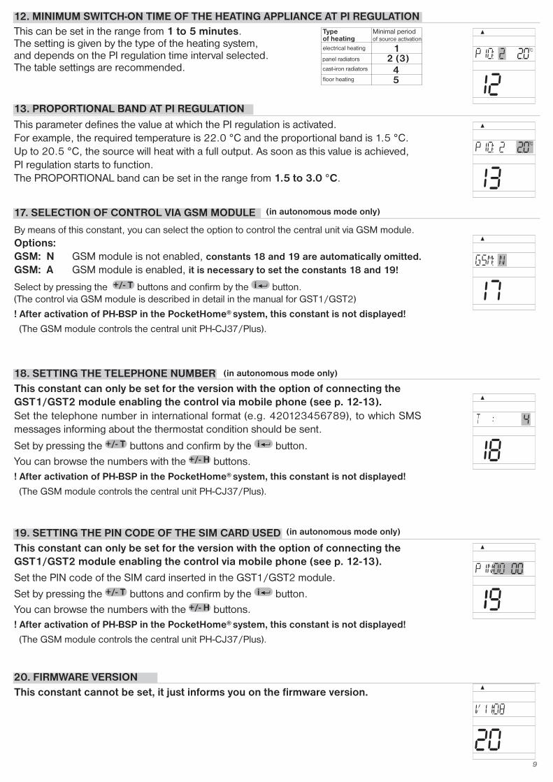
12. MINIMUM SWITCH-ON TIME OF THE HEATING APPLIANCE AT PI REGULATIONThis can be set in the range from 1 to 5 minutes. The setting is given by the type of the heating system, and depends on the PI regulation time interval selected.The table settings are recommended.
Type of heating
Minimal period of source activation
electrical heating
panel radiators
cast-iron radiators
floor heating
2 (3)
13. PROPORTIONAL BAND AT PI REGULATIONThis parameter defines the value at which the PI regulation is activated. For example, the required temperature is 22.0 °C and the proportional band is 1.5 °C. Up to 20.5 °C, the source will heat with a full output. As soon as this value is achieved, PI regulation starts to function.The PROPORTIONAL band can be set in the range from 1.5 to 3.0 °C.
18. SETTING THE TELEPHONE NUMBER This constant can only be set for the version with the option of connecting theGST1/GST2 module enabling the control via mobile phone (see p. 12-13).
19. SETTING THE PIN CODE OF THE SIM CARD USEDThis constant can only be set for the version with the option of connecting theGST1/GST2 module enabling the control via mobile phone (see p. 12-13).
Set the telephone number in international format (e.g. 420123456789), to which SMSmessages informing about the thermostat condition should be sent.
Set by pressing the buttons and confirm by the button.You can browse the numbers with the buttons.! After activation of PH-BSP in the PocketHome® system, this constant is not displayed!
(The GSM module controls the central unit PH-CJ37/Plus).
+/- H
+/- T i
Set the PIN code of the SIM card inserted in the GST1/GST2 module.
Set by pressing the buttons and confirm by the button.You can browse the numbers with the buttons.! After activation of PH-BSP in the PocketHome® system, this constant is not displayed!
(The GSM module controls the central unit PH-CJ37/Plus).
+/- H
i+/- T
20. FIRMWARE VERSION This constant cannot be set, it just informs you on the firmware version.
17. SELECTION OF CONTROL VIA GSM MODULE
By means of this constant, you can select the option to control the central unit via GSM module.Options:GSM: N GSM module is not enabled, constants 18 and 19 are automatically omitted.GSM: A GSM module is enabled, it is necessary to set the constants 18 and 19!
Select by pressing the buttons and confirm by the button.(The control via GSM module is described in detail in the manual for GST1/GST2)
! After activation of PH-BSP in the PocketHome® system, this constant is not displayed!
(The GSM module controls the central unit PH-CJ37/Plus).
+/- T i
(in autonomous mode only)
(in autonomous mode only)
(in autonomous mode only)

10
ACTIV activation of switching elements This mode enables you to add (activate) successively the system components andassign temperature programs to them.The maximum number of all the system components is 255!
- Press the button and select the ACTIV mode by pressing the buttons; confirm by pressing the button.
- The option for program selection for the switching element PROGR appears on the LCD.- Assign the 1.P to 9.P program with the buttons and confirm with the button.- In the next step, activate step-by-step the SP1 to SP255 switching elements.
i+/- T
i+/- TF
You can browse the individual elements with the button.+/- H
total numberof active elements
- Press the button, in which way you define the address of the first switching element (SP : 1) (the number in line 5 informs you about the total number of active elements).
- Press the FUNCTION BUTTON on the switching element (receiver) (for approx. 5 s); thus you enter the code learning mode (see the pertinent receiver instructions).
- Press the button on PH-BSP (the signal transmission symbol appears as well as the symbol of communication with the element).
- Two diodes flash simultaneously on the switching element; thus the element is ENABLED! If Err appears on the display of PH-BSP, you must check the connection and repeat the procedure!
- Add the next element with the button; the button defines the address of the second element (SP : 2); then repeat the procedure as during the activation of the first element.
If the UCENI message appears on PH-BSP, some of the elements have not been enabledcorrectly! Choose the switching elements step-by-step and test them with the button. Ifthe Err message appears with an element, enable it again according to the above procedure.
Test
+/- P+/- H
+/- P
Test
You can disable the element with the button. Off
elementaddress
(sequence number)
total numberof elements
INFO information on individual components activated within the system
In this mode, you can obtain information on the condition of individual systemcomponents. total number
of componentsof the whole
system- Press the button and select the INFO mode with the buttons;
confirm by pressing the button.- Information on the selected program PROGR (*) appears on the display
1. By pressing the button, you can change the temperature for the given mode.- If you press the button, information on the SP: 1 switching component appears on the
display1. required temperature;2. selected mode (AUTO, MANU);3. preset program.
- By pressing the button, you can check the device condition - HEATING/ NOT HEATING.- Information on other components can be obtained by pressing the button.
* If PH-BSP is activated in the PocketHome® system, the program number is notdisplayed (the required temperature from the central unit is displayed).
+/- H
i+/- T
Test
i+/- TF
BROWSING the elements
DISABLING of an element
!!
UAdr activation in the PocketHome® system (see page 5)central unit
uniquenumber
address assigned by
the central unit
- Add the new BSP component in PH-CJ37/Plus (ACTIV, page 12 in the central unit instructions).
- On the PH-BSP unit, press the button and select the UAdr mode with the buttons.
- Confirm with the button.- Press the button on PH-CJ37.If the activation was correct, the unique number and assignedaddress appear on PH-BSP. PH-BSP becomes a subordinateunit, waiting for orders from the central unit!
Testi
+/- TF
11
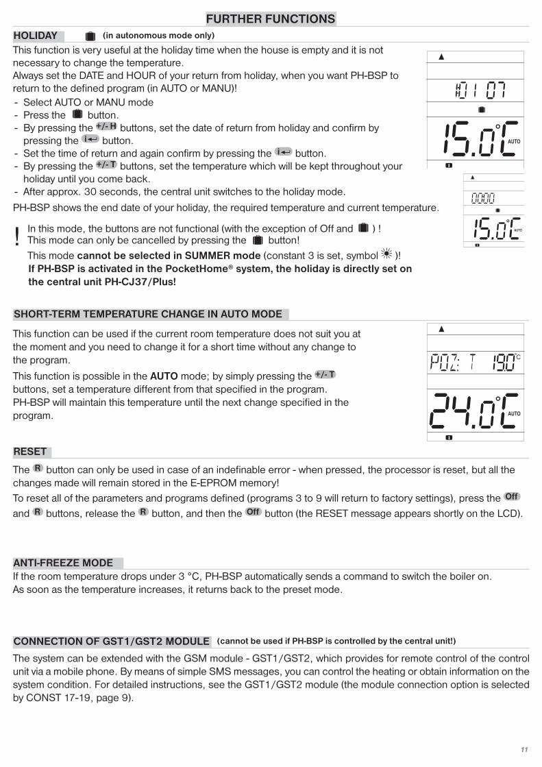
FURTHER FUNCTIONSHOLIDAYThis function is very useful at the holiday time when the house is empty and it is not necessary to change the temperature. Always set the DATE and HOUR of your return from holiday, when you want PH-BSP toreturn to the defined program (in AUTO or MANU)!- Select AUTO or MANU mode- Press the button. - By pressing the buttons, set the date of return from holiday and confirm by
pressing the button.- Set the time of return and again confirm by pressing the button.- By pressing the buttons, set the temperature which will be kept throughout your
holiday until you come back.- After approx. 30 seconds, the central unit switches to the holiday mode.
+/- Ti
i+/- H
In this mode, the buttons are not functional (with the exception of Off and ) !! This mode can only be cancelled by pressing the button!This mode cannot be selected in SUMMER mode (constant 3 is set, symbol )!If PH-BSP is activated in the PocketHome® system, the holiday is directly set onthe central unit PH-CJ37/Plus!
SHORT-TERM TEMPERATURE CHANGE IN AUTO MODE
This function is possible in the AUTO mode; by simply pressing the buttons, set a temperature different from that specified in the program.PH-BSP will maintain this temperature until the next change specified in theprogram.
+/- T
RESET
The button can only be used in case of an indefinable error - when pressed, the processor is reset, but all thechanges made will remain stored in the E-EPROM memory!To reset all of the parameters and programs defined (programs 3 to 9 will return to factory settings), press the and buttons, release the button, and then the button (the RESET message appears shortly on the LCD).OffR
Off
R
R
This function can be used if the current room temperature does not suit you atthe moment and you need to change it for a short time without any change tothe program.
ANTI-FREEZE MODEIf the room temperature drops under 3 °C, PH-BSP automatically sends a command to switch the boiler on.As soon as the temperature increases, it returns back to the preset mode.
CONNECTION OF GST1/GST2 MODULE
The system can be extended with the GSM module - GST1/GST2, which provides for remote control of the controlunit via a mobile phone. By means of simple SMS messages, you can control the heating or obtain information on thesystem condition. For detailed instructions, see the GST1/GST2 module (the module connection option is selectedby CONST 17-19, page 9).
(cannot be used if PH-BSP is controlled by the central unit!)
PH-BSP shows the end date of your holiday, the required temperature and current temperature.
(in autonomous mode only)

12
DESCRIPTION OF SETTINGS IF THE GSM MODULE IS USEDFOR CORRECT PUTTING INTO OPERATION, THE FOLLOWING PROCEDURE MUST BE OBSERVED!
1. Make installation and setting of the control unit according to the instructions.
2. Constants 17, 18 and 19 must be set on the control unit as follows:
SETTING THE TELEPHONE NUMBER - CONST 18
Set the telephone number, in the international format (e.g. 420123456789), to whichSMS return messages informing about the thermostat condition should be sent.
Set by pressing buttons and confirm with the button.You can browse the numbers set with the buttons.+/- H
+/- T i
SETTING THE PIN CODE OF THE SIM CARD - CONST 19
Set the PIN code of the SIM card inserted in the GST1/GST2 module.Set by pressing the buttons and confirm with the button.You can browse the numbers with the button.+/- H
+/- T i
Thanks to this function, you need not remember the PIN code of the SIM card inserted in themodule connected to control unit. After entering the PIN code (according to the below procedure) in the control unit, connect the module and then connect it to the mains. Within approx. 3 minutes, the PIN code is automatically sent from the control unit to the module, thusthe module becomes active (to accelerate the activation, use the button on the controlunit).
Test
3. Insert the activated SIM card into the GST1/GST2 module. For more details, see the GST1/GST2 instructions.
4. Interconnect the control unit and the module by means of a data cable (included in the GST1/GST2 packing), and then connect the module supply unit to the 230 V / 50 Hz mains (the orange LED is flashing)!
5. As soon as the orange diode on GST1 is alight, test the correct connection by pressing the button on the control unit. One of the following messages appears on the display of the control unit (the connection is always automatically established within 3 minutes):
Test
Signalizes correct connection of the module. Signalizes correct connection of the module andPIN code setting.
The module is not connected, incorrect connection of the module!
Signalizes correct connection of the module, butincorrect PIN code setting! It is necessary to
disconnect the module, RESET the control unitand set the correct PIN code!
SELECTION OF CONTROL VIA GSM MODULE - CONST 17
By pressing the buttons, select the GSM: A option and confirm with the button.+/- T i

WORDING OF MESSAGES SENT
Info SP
Off SP
Temp xx SP
Call
Information on the control unit condition
Switching the SP components off. To abolish the function, use the Temp xx SPmessage (if in the AUTO mode, the state is valid until the next program change).
Change of the required temperature (where xx must be an integerwithin the range of admissible maximum and minimum temperatures).
Back call
xx = temperature value in°C (always a two-digit number, e.g. 05)
Any type of mobile phone can be used for sending and receiving of return messages!! If font size (format) can be adjusted in the phone, always use the MEDIUM size for messages (whenthree sizes are available) or the LARGE (when two sizes are available).!
13
WORDING OF RETURN MESSAGES FROM THE CONTROL UNIT
Requir: xx.x
Act: xx.x
On
Sig: x
required temperature (entered by the user)
current temperature in the room
heating system on
defines signal strength at the place of the module location; where x are values ranging from 0 to 5:0..cannot be determined or no signal detected1..the worst strength5..the best signal strength
Off heating system off
AUTO automatic mode AUTO
MANU manual mode MANU
Battery! signalizes a discharged battery in the central unit
incorrect SMS message or communication errorIncorrect SMS or can not beidentified selected device
xx.x = temperature in°C
Note: If the min/max room temperature is exceeded (as set by CONST1 and 2, see the PH-BSP manual, page 9),the "WARNING" SMS message same as Info is automatically sent immediately.
Info: If a pre-paid card is used, it is necessary to make a paid call once in three months. This call is made automatically (every 80 days, between 16 and 21 o'clock) to the number entered in the controlunit (CONST 18), and after 20 s, the call is terminated automatically. By means of the “Call” SMS message, youcan execute the function sooner.
RETURN MESSAGES ARE SENT WITHIN 3 MINUTES!

Power supply 2 x 1,5 V alkaline pencil-type batteries AACommunication type two-way Frequency 433,92 MHzHF output < 10 mWNumber of temperature changes 6 different temperature changes per every dayHysteresis 0,1 to 1,5°C in steps of 0,1°CMinimum programmable time 10 minutesRange of adjustable temperatures 3 to 39°CTemperature setting step of 0,5°CMinimum indication step 0,1°CMeasurement accuracy ±0,5°CBattery life 1 to 3 years according to the battery type used
Protection class IP20Operating temperature 0°C to +40°C
TECHNICAL PARAMETERS
In case of guarantee or post-guarantee service, send the unit to the manufacturer’s address.
DECLARATION OF CONFORMITYWe, ELEKTROBOCK CZ s.r.o., herewith declare that our product PH-BSP is in conformity with the basic requirements and other respective provisions ofthe directive 1999/5/EC. Issued: 1.09.2008 on www.elbock.cz
EXPLANATION OF THE PZT FUNCTION (CONST 3)
The PI regulation principle consists in comparison of the current room temperaturewith the required temperature. The Fce 11 option: when setting the time interval, heed theroom thermal inertia. The optimum setting is 10-15 minutes. However, in case of frequent temperature fluctuations in the room, we recommend you to use a shorter time period. The proportional band defines the value at which the PI regulation is activated (Fce 13).
EXPLANATION OF PI REGULATION FUNCTION (CONST 11,12,13)
The PZT (preliminary heating switch-on) function provides for the required temperature at the required time. Within two days, BPT-SP ascertains the room temperature constants, and then automaticallyswitches the heating in the required advance. The preliminary switch-on time is automatically limited to 2 hours.
Difference between the required and real temperature.The hysteresis can be set in the range from 0.1 to 1.5°C. If the hysteresis is set to 1°C and therequired temperature to 20°C, PH-BSP will switch off at 20°C and on again at 19 °C (see thediagram).
EXPLANATION OF HYSTERESIS (CONST 10)
CERTIFICATE OF GUARANTEE(guarantee period for the product amounts to 2 years)
product No.: date of sale:
stamp of shop:
examined by:
MADE IN CZECH REPUBLIC
ELEKTROBOCK CZ s.r.o.Blanenská 1763Kuřim 664 34 Tel./fax: +420 541 230 216
http:// www.elbock.cz
in compliance with RoHS
PbLEAD FREE
Intelligent timer
Switching on of common timer 1 hour before the required temperature
Switching on of common timer 2 hours before the required temperature
unnecessary consumptionfeeling of cold
ON
OFF
ideal course of required temperaturesreal course of required temperaturesadaptive
thermostat
commonthermostat
unnecessary consumption
feeling of cold * Approximate value – the real value is calculated by the thermostat
Temperature set
Proportional band
Of operatingcycleto 100% of
operating cycle
Heating switched