ALMEMO® 2590-2A/-4AS - Ahlborn
80
____________________________ Operating instructions English Universal measuring instruments and data loggers ALMEMO ® 2590-2A/-4AS V3.5 12.01.2022 www.ahlborn.com
-
Upload
khangminh22 -
Category
Documents
-
view
4 -
download
0
Transcript of ALMEMO® 2590-2A/-4AS - Ahlborn
____________________________
Operating instructions
English
Universal measuring instruments and data loggers
ALMEMO® 2590-2A/-4AS
V3.5
12.01.2022
www.ahlborn.com

2
1. OPERATING CONTROLS (1) Measuring inputs M0 to M3 (depending on type) M0 ... M3 Suitable for all ALMEMO® sensors M10 ... M34 up to 16 additional chann.
(2) Output sockets A1, A2 A1 V24 interface (ZA 1909-DK5) Optic fiber (ZA 1909-DKL) USB (ZA 19019-DKU) Ethernet (ZA 1945-DK) RS 422 (ZA 5099-NVL/NVB) Trigger input (ZA 1000-ET/EK) Relay outputs (ZA 1006-EGK) Analog output 1 (ZA 1601-RK) A2 Network cable (ZA1999-NK5/NKL) SD card connector (ZA1904-SD) Trigger input (ZA 1000-ET/EK) Relay outputs (ZA 1006-EKG) Analog output 2 (ZA 1601-RK)
(3) Socket, DC, 12V Mains adapter (ZA1312-NAx, 12V,minimum 1A) Cable, electr. isolated (ZA 2690-UK, 10-30V)
(4) Sleep LED
(5) LCD, graphics display 7 lines for functions 1 line for softkeys F1,◄,▲,►, F2 Shown in brackets : <MEM> , <FCT>
(6) Operating keys ON To switch device ON. To switch device OFF, press and hold down. F1 , F2 Function keys (softkeys) ▲, ▼ ... M: To select measuring point ▲, ▼, ► F: To select menu PROG , ▼...F: Function selection ◄ ... To return to menu selection < M◄◄ > To go directly to meas. menu PROG Programming ▲, ▼, ►... Data input
Rear of device (7) Battery compartment 3 AA alkaline-manganese batteries

3
2. CONTENTS 1. Operating controls .............................................................................. 2
2. Contents ............................................................................................. 3
3. General .............................................................................................. 7
3.1 Warranty ............................................................................................. 7
3.2 Scope of delivery ............................................................................... 7
3.3 Waste disposal ................................................................................... 8
4. Safety instructions .............................................................................. 9
4.1 Special notes on use .......................................................................... 9
4.2 Handling batteries / rechargeable batteries correctly ...................... 10
5. Introduction ...................................................................................... 11
5.1 Functions.......................................................................................... 11
5.1.1 Sensor programming ................................................................... 11
5.1.2 Measuring operations .................................................................. 13
5.1.3 Process control ............................................................................ 14
6. Initial commissioning ........................................................................ 16
7. Power supply ................................................................................... 17
7.1 Battery operation and supply voltage monitoring ............................ 17
7.2 Mains operation ............................................................................... 17
7.3 External DC voltage supply.............................................................. 17
7.4 Sensor supply .................................................................................. 17
7.5 Switching ON / OFF, reinitialization ................................................. 18
7.6 Data buffering................................................................................... 18
8. Connecting the sensors / transducers ............................................. 19
8.1 Sensors / transducers ...................................................................... 19
8.2 Measuring inputs and additional channels ....................................... 19
8.3 Potential separation ......................................................................... 20
9. Display and keypad .......................................................................... 22
9.1 Display and menu selection ............................................................. 22
9.2 Measured value display and status symbols ................................... 22
9.3 Function keys ................................................................................... 23
9.4 Function selection ............................................................................ 24

2. Contents
4
9.5 Data input ......................................................................................... 24
9.6 Keypad locking ................................................................................. 25
10. Menu selection ................................................................................. 26
11. Measuring menus ............................................................................ 27
11.1 Menu Sensor display ....................................................................... 27
11.1.1 Selecting a measuring point..................................................... 27
11.2 Measured value correction and compensation ................................ 27
11.2.1 Set measured value to zero ..................................................... 28
11.2.2 Sensor adjustment for dynamic pressure probes .................... 28
11.2.3 Sensor adjustment for chemical sensors and probes .............. 28
11.2.4 Temperature compensation ..................................................... 29
11.2.5 Atmospheric pressure compensation ...................................... 30
11.2.6 Cold junction compensation ..................................................... 31
11.3 Differential measurement ................................................................. 31
11.4 Measuring points list ........................................................................ 31
11.5 User measuring menu U1 data logger ............................................. 32
11.6 User menus ...................................................................................... 33
11.6.1 Functions.................................................................................. 34
11.6.2 Menu configuration .................................................................. 35
12. Function menus ............................................................................... 36
12.1 Maximum, minimum, individual values memory .............................. 36
12.2 Averaging ......................................................................................... 37
12.2.1 Smoothing meas values by means of a sliding average ......... 37
12.2.2 Averaging over individual manual meas operations ................ 38
12.2.3 Averaging over time ................................................................. 39
12.2.4 Averaging over the cycle .......................................................... 39
12.2.5 Averaging over measuring points ............................................ 40
12.2.6 Volume flow measurement....................................................... 40
12.2.7 Array measuring Option VN ..................................................... 41
12.3 Two-point adjustment with setpoint entry ......................................... 43
12.4 Scaling ............................................................................................. 44
12.5 Data logger functions ....................................................................... 44

2. Contents
5
12.5.1 Internal data memory ............................................................... 45
12.5.2 Memory connector with SD-card ............................................. 45
12.5.3 Date and time-of-day ............................................................... 46
12.5.4 Once-only output / saving of all measuring points ................... 46
12.5.5 Cyclic output / saving of all measuring points .......................... 46
12.5.6 Numbering of measuring operations ........................................ 47
12.5.7 Memory space, memory output, clearing the memory ............ 47
12.5.8 Scanning configuration ............................................................ 48
12.5.9 Starting and stopping measuring operations ........................... 51
13. Sensor programming ....................................................................... 53
13.1 Selecting the input channel .............................................................. 53
13.2 Measuring point designation ............................................................ 53
13.3 Averaging mode ............................................................................... 54
13.4 Locking the sensor programming .................................................... 54
13.5 Limit values ...................................................................................... 54
13.6 Scaling, Decimal point setting .......................................................... 55
13.7 Correction values ............................................................................. 55
13.8 Changing the units ........................................................................... 56
13.9 Selecting the measuring range ........................................................ 56
13.10 Function channels ............................................................................ 59
13.11 Special meas. ranges ,Linearization ,Multi-point calibration ............ 60
13.12 Special functions .............................................................................. 60
13.12.1 Print cycle factor ...................................................................... 61
13.12.2 Actions in the event of a limit value being exceeded ............... 61
13.12.3 Analog start and analog end .................................................... 62
13.12.4 Minimum sensor supply voltage .............................................. 62
13.12.5 Output function ......................................................................... 63
13.12.6 Reference channel 1 ................................................................ 63
13.12.7 Reference channel 2 or multiplexer ......................................... 63
13.12.8 Element flags ........................................................................... 64
14. Device configuration ........................................................................ 65
14.1 Device designation ........................................................................... 65

2. Contents
6
14.2 Language ......................................................................................... 65
14.3 Illumination and contrast .................................................................. 65
14.4 Interface, device address, and networking ...................................... 66
14.5 Baud rate, Data format ..................................................................... 66
14.6 Atmospheric pressure compensation and temperature compensation ................................................................................... 66
14.7 Hysteresis ........................................................................................ 67
14.8 Operating parameters ...................................................................... 67
15. Output modules ................................................................................ 68
15.1 Data cables ...................................................................................... 68
15.2 Relay-trigger modules ...................................................................... 68
15.3 Analog outputs ................................................................................. 70
16. Trouble-shooting .............................................................................. 72
17. Declaration of conformity ................................................................. 74
18. Appendix .......................................................................................... 75
18.1 Technical data .................................................................................. 75
18.2 Product overview ............................................................................. 76
19. Index ................................................................................................ 77

7
3. GENERAL Congratulations on your purchase of this new and innovative ALMEMO® data logger. Thanks to the patented ALMEMO® connector the device configures itself automatically and thanks to the menus and context-sensitive help windows its operation should be fairly straightforward. The device can, however, be used with such a wide range of sensors and peripherals and offers many different special functions. You are advised therefore to properly familiarize yourself with the way the sensors function and with the device's numerous possibilities and take the time to carefully read these operating instructions and the appropriate sections in the ALMEMO® Manual. This is absolutely necessary to avoid oper-ating and measuring errors and to prevent damage to the device. To help you find the answers to your questions quickly and easily there is a comprehensive index at the end both of these operating instructions and of the Manual.
3.1 Warranty Each and every device, before leaving our factory, undergoes numerous quality tests. We provide a guarantee, lasting two years from delivery date, that your device will function trouble-free. Before you send your device to us, please ob-serve the advisory notes in Chapter 16. Trouble-shooting In the unlikely event that the device proves defective and you need to return it please wherever pos-sible use the original packaging material for dispatch and enclose a clear and informative description of the fault and of the conditions in which it occurs.
This guarantee will not apply in the following cases :
⚫ The customer attempts any form of unauthorized tampering and alteration inside the device.
⚫ The device is used in environments and conditions for which it is not suited.
⚫ The device is used with unsuitable power supply equipment and peripherals.
⚫ The device is used for any purpose other than that for which it is intended.
⚫ The device is damaged by electrostatic discharge or lightning.
⚫ The user fails to observe and comply with the operating instructions.
The manufacturer reserves the right to change the product's characteristics in the light of technical progress or to benefit from the introduction of new compo-nents.
3.2 Scope of delivery When you unpack the device check carefully for any signs of transport damage and ensure that delivery is complete.
Measuring instrument ALMEMO® 2590A with 3 AA alkaline batteries These operating instructions
In the event of transport damage please retain the packaging material and in-form your supplier immediately.

3. General
8
3.3 Waste disposal
The pictogram showing a waste bin crossed through means that the product is subject to European Union regulations on segregated waste disposal. This applies both to the product itself and to any accessories marked with the same symbol. Disposal of any such item as unsorted domestic waste is strictly forbidden
• Please dispose of all packaging materials according to the applicable national waste management regulations.
• Please dispose of cardboard boxes, protective plastic packaging materials, and all preservative substances separately and in the proper manner.
• The disposal of the device itself (also of device parts, accessories, and con-sumables) is subject to the applicable national and local waste management regulations and to the environmental protection legislation in force in the coun-try of use.
• Please dispose of all waste in the proper manner; this applies in particular to all parts and substances that constitute a hazard for the environment. This includes inter alia plastics, batteries, and rechargeable battery packs .
• When disposing of goods, please wherever possible use the original packag-ing materials.

9
4. SAFETY INSTRUCTIONS
DANGER
Danger to life and limb, risk of damage to equipment
Read the instructions carefully before starting to operate the device.
Please ensure that you comply with all general safety advice and the special safety instructions included in other chap-ters.
Such risks may occur in the following circumstances :
• Failure to heed the operating instructions and all the safety notes these contain
• Any form of unauthorized tampering or alteration inside the device
• Use of the device in environments or conditions for which it is not suited
• Use of the device with an unsuitable power supply and / or in conjunction with unsuitable peripheral equipment
• Use of the device for any purpose other than that for which it is intended
• Damage caused by electrostatic discharge or lightning.
DANGER
Risk of fatal injury caused by dangerously high voltage
Such risks may occur in the following circumstances :
• Use of the device with an unsuitable power supply and / or in conjunction with unsuitable peripheral equipment
• Damage caused by electrostatic discharge or lightning
• Do not run sensor lines in the vicinity of high-voltage power cables.
• Before you touch any sensor lines, ensure that all static electricity has been discharged.
DANGER Warning - explosive atmospheres or substances
In the vicinity of various fuels or chemicals there is a risk of ex-plosion.
Do not use the device in the close vicinity of blasting work or filling stations!
4.1 Special notes on use • If the device is brought into the work-room from a cold environment

4. Safety instructions
10
there is a risk that condensation might form on the electronics. In meas-uring operations involving thermocouples pronounced changes in tem-perature may cause substantial measuring errors. You are advised therefore to wait until the device has adjusted to the ambient tempera-ture before starting to use it.
• Before using the mains adapter make sure that the mains voltage is suitable.
• Be sure to observe the maximum load capacity of the sensor power supply.
• Sensors with their own integrated power supply are not electrically iso-lated from one another
4.2 Handling batteries / rechargeable batteries cor-rectly
When inserting batteries / rechargeable batteries ensure that these are correctly polarized.
If the device will probably not be needed for a relatively long pe-riod of time or if the batteries are empty, remove the batteries; this will prevent battery acid leaking onto the device and damaging it.
Rechargeable batteries should be recharged as and when nec-essary.
You should never attempt to recharge an ordinary (non-recharge-able) battery; it may explode !
Batteries / rechargeable batteries must never be short-circuited or thrown onto the fire.
Batteries / rechargeable batteries are special waste and must not be discarded together with normal domestic waste.

11
5. INTRODUCTION
The ALMEMO® 2590A series is a new member in our family of unique measur-
ing devices - all equipped with Ahlborn's patented ALMEMO® connector sys-
tem. The intelligent ALMEMO® connector offers decisive advantages when con-necting sensors and peripherals because all parameters are stored in an EEPROM located on the connector itself; repeat programming is thus no longer necessary.
All sensors and output modules can be connected to all ALMEMO® measuring instruments in the same way. Programming and functioning are identical for all
units. The following points apply to all devices in the ALMEMO® measuring sys-
tem; these are described in detail in the ALMEMO® Manual which is included in delivery with each device.
Detailed explanation of the ALMEMO® system (Manual Ch 1) Overview of the device functions and measuring ranges (Manual Ch 2) Basic principles, operation, and technical data for all sensors (Manual Ch 3) Options for connecting your own existing sensors (Manual Ch 4) All analog and digital output modules (Manual Section 5.1) Interface modules RS232, USB, Ethernet, optic fiber (Manual Section 5.2)
The whole ALMEMO® networking system (Manual Section 5.3) All functions and their operation via the interface (Manual Ch 6) Complete list of interface commands with all the printouts (Manual Ch 7)
The operating instructions you are now reading cover only those features and controls that are specific to this device. Many sections therefore also refer to the more detailed description in the Manual; (see Manual, Section xxx).
5.1 Functions The ALMEMO® 2590A series devices have 2 or 4 electrically isolated measur-
ing inputs suitable for all ALMEMO® sensors. The measuring possibilities are virtually unlimited; there are 8 to 16 channels in the sensor connectors and 4 device-internal function channels - with over 70 measuring ranges. For opera-tion purposes the device incorporates an LCD graphics display and a softkey keypad with cursor block. The display can via sensor-specific menus (user-con-figurable) adapt ideally to all applications. A memory connector (SD card) or 500-KB EEPROM can be used to implement a data logger function (type -4AS only). There are two output sockets which can be used to connect any AL-
MEMO® output modules, e.g. analog output, digital interface, trigger input, or alarm contacts. Several devices can be networked by simply connecting them with network cables.
5.1.1 Sensor programming The measuring channels are programmed, completely and automatically, by the
ALMEMO® connectors. However, the user can easily supplement or modify this

5. Introduction
12
programming via the keypad or via the interface.
Measuring ranges Appropriate measuring ranges are available for all sensors with a non-linear characteristic, e.g. 10 thermocouple types, NTC and PT100 probes, infrared sensors, and flow transducers (rotating vanes, thermoanemometers, Pitot tubes). For humidity sensors additional function channels are available for cal-culating humidity variables such as dew point, mixture ratio, vapor pressure, and enthalpy. Even complex chemical sensors are supported. Measured values from other sensors can also be acquired using the voltage, current, and resistance ranges with individual scaling in the connector. Existing sensors can also be
used - so long as the appropriate ALMEMO® connector is connected via its screw terminals. For digital input signals, frequencies, and pulses, adapter con-nectors are available with an integrated microcontroller. It is thus possible to
connect virtually any sensor to any ALMEMO® measuring instrument and to change sensors without the need for any extra settings.
Function channels Maximum, minimum, average, and differential values from certain measuring points can be programmed as function channels, also internal channels, and can be processed out like normal measuring points. There are also function channels available for special measuring tasks, e.g. to determine the tempera-ture coefficient Q/T and wet bulb globe temperature.
Units The 2-character units display can be adapted for each measuring channel so that the display always indicates the correct units, e.g. when a transmitter is connected. Conversion between °C (Centigrade) and °F (Fahrenheit) is per-formed automatically.
Measured value designation Each sensor is identified by means of a 10-character alphanumeric name. It is entered via the keypad or the interface and appears in the display, or on the computer screen.
Correction of measured values The measured value on each measuring channel can be corrected both in terms of zero-point and gain; this means that even sensors usually requiring initial ad-justment (e.g. expansion, force, pH) can be freely interchanged. Zero-point cor-rection and, partly at least, gain adjustment can be performed at the touch of a button. Sensors with multi-point calibration can also be connected; (see Manual Section 6.3.13).
Scaling The corrected measured value on each measuring channel can also be further scaled in terms of zero-point and gain - using the base value and factor. The dec-imal point position can be set by means of the exponent function. The scaling values can be calculated automatically by setting to zero and entering the nominal setpoint or via the scaling menu.

5. Introduction
13
Limit values and alarm Per measuring channel two limit values can be set (1 maximum and 1 minimum). In the event of one of these limit values being exceeded an alarm signal is output and relay output modules actuate the associated alarm contacts; these can be allocated individually to specific limit values. Hysteresis is set by default to 10 digits but this can be adjusted to any number between 0 and 99. The exceeding of a limit value can also be used to automatically start or stop measured value recording.
Sensor locking All sensor data stored in the connector EEPROM can be protected by means of a graduated locking function against undesired access.
5.1.2 Measuring operations For each transducer 4 measuring channels are available; i.e. it is also possible to evaluate double sensors, individually scaled sensors, and sensors with func-tion channels. You can move forwards or backwards from one measuring chan-nel to the next using the keypad. The selected measuring point is by default assigned preferred status and is scanned at half the measuring rate; all other active channels are also scanned but in the background (semi-continuous mode). The data is output on the display and, if available, to an analog output. To shorten the response time when there are many measuring points the meas-uring rate can be set to continuous and increased accordingly.
Measured values The measured values can be indicated on the display using a variety of menus, some user-configurable, in 2 font sizes, or in the form of a bar chart. Measured values are acquired automatically with auto-zero and self-calibration; however, they can also be corrected and scaled arbitrarily as required. With most sensors a sensor breakage is detected automatically.
Analog output and scaling Each measuring point can be scaled by means of analog start and analog end in such a way that the measuring range thus defined covers the full range of the bar chart or of an analog output (2 V, 10 V, or 20 mA). At the analog output the device can output the measured value from any measuring point or a pro-grammed value.
Measuring functions With some sensors, to achieve optimal measured value acquisition, certain spe-cial measuring functions are required. Cold junction compensation is provided for thermocouples; temperature compensation is provided for dynamic pres-sure, pH, and conductivity probes; and atmospheric pressure compensation is provided for humidity sensors, dynamic pressure sensors, and O2 sensors. On infrared sensors the gain correction parameter is used as emissivity factor.
Measured value smoothing Measured values of an unstable or strongly fluctuating nature can be smoothed by means of a sliding average over a number of values programmable from 2 to 99.
5. Introduction
14
Maximum and minimum values For each measuring operation the maximum value and minimum value are ac-quired and saved to memory. These values can then be displayed, or deleted from memory.
Average value Manual averaging is available per channel over a certain period or cycle or over a series of individual measuring operations. Networked measuring (Option VN)permits a standardized volume flow measurement.
Measured value memory Up to 100 measured values can be saved manually. This data can then be shown on the display or output via the interface.
5.1.3 Process control To record the measured values from all connected sensors in digital form meas-uring point scanning is performed continuously with measured value output ac-cording to a time-based process control. This may be per output cycle or, if really rapid results are required, at the measuring rate itself. In data logger mode a measuring operation can be started and stopped by means of the keyboard, the interface, an external trigger signal, the real-time clock, or by a specified limit value being exceeded.
Date and time-of-day All measuring operations can be accurately logged using the real-time clock with date function or in terms of the pure measuring time. For the purposes of starting / stopping a measuring operation, the start / stop date and time-of-day can be programmed.
Cycle The cycle can be programmed to any value between 00:00:01 (1 second) and 59:59:59 hh:mm:ss. This function permits cyclic output of measured values to the interfaces or to the memory and provides cyclic calculation of the average value.
Print cycle factor The print cycle factor can be used to limit data output from particular channels; this may be necessary in order to reduce excessive data flow especially while data is being saved.
Averaging over measuring point scans The measured values from measuring point scans can be averaged either over the whole measuring duration or over the specified cycle. These average values can then be output and saved on a cyclic basis to function channels provided for this purpose.
Measuring rate The measuring points are continuously scanned at the measuring rate (2.5 or 10 mops). Recording can be accelerated if all measured values are stored to memory and / or output to the interface at the measuring rate.
Measured value memory On data logger 2590-4AS all measured values can be saved to an EEPROM

5. Introduction
15
either manually or automatically per cycle. Standard memory capacity is 500KB - sufficient for up to 100,000 measured values. The memory can be organized and configured in linear or ring form. Output is via the interface. Selection can be specified according to a time interval or number.
All devices in the ALMEMO® 2590A series can, by fitting an external memory connector with a micro SD card, be upgraded to a high-capacity data logger. With an external memory connector, available as an accessory, files can be read out very quickly via any standard card reader.
Numbering of measuring operations By entering a number single scans or entire series of measuring operations can be identified and selectively read out from the memory.
Control ports A relay trigger analog adapter can be used to provide up to 10 output relays, and, as option, up to 4 analog outputs and 2 trigger inputs.
Operation All measuring and function values can be displayed in different menus on the dot matrix LCD screen. User menus can be individually configured from a range of nearly 50 functions for your specific applications. You can use texts, lines, and blank lines to arrange and format the layout in a style suited to your appli-cation. Six keys (four of them softkeys) can be used to operate the device. This system also allows you to fully program the sensors, the device and the process control.
Output All data logs, menu functions, saved measured values, and stored program pa-rameters can be output to any peripheral equipment. RS232, RS422, USB, and Ethernet interfaces are available using the appropriate interface cables. Meas-ured data can be output in list, column, or table format. Files in table format can be processed directly using any standard spreadsheet software. The print header can be programmed to refer specifically to your company or to your ap-plication.
Networking
All ALMEMO® devices can be addressed and can be easily networked by simply linking them together via network cable or for longer distances via RS422 network distributors.
Software
Each ALMEMO® Manual is accompanied by the ALMEMO®-Control software package, which can be used to configure the measuring instrument and user menus, to program the sensors, and to read out from the measured value memory. Using the integrated terminal, measuring operations can also be per-
formed online. The WINDOWS® software package WINControl is provided for the purposes of measured value acquisition via networked devices, for graphical presentation, and for more complex data processing.

16
6. INITIAL COMMISSIONING Sensor connection Connect the sensor to any socket M0 to M3 (1); see Ch 8. Power supply via batteries or mains adapter to DC (3) ; see 7.1, 7.2 To switch ON press the ON / PROG key (6) ; see 7.5
Automatic display of last measuring menu see Ch 11.
To call up menu selection press key(s) : <MENU>
To activate / deactivate display illumination : <*ON>
To select measuring menu Sensor display ; see 9.1
press key(s) : <F> : ▲ / ▼ ...
To call up the menu press key(s) : ► or PROG
To select a measuring point (see 11.1.1)
press key(s) : <M> : ▲ / ▼ ...
All channels on the connector or those functions needed for measured value calculation are displayed.
To call up the functions menu list : < FCT >
To select the functions menu (see 9.4) press key(s) : <F> : ▲ / ▼ ...
To call up the menu press key(s) : ► or PROG
e.g. Functions menu Data logger functions : (only possible if storage medium available) Once-only saving : see 12.5.4 < MANU > Cyclic saving : see 12.5.5
To select cycle timer press key(s) : PROG , ▲ / ▼ ... Entering the cycle (hh:mm:ss) PROG , ▲ , PROG .. To set the output format : < FORM> ...
To terminate programming mode : < ESC>
To start a measuring operation <START>
To stop a measuring operation <STOP>
Memory output via interface to computer : - Connect peripheral device via data cable to socket A1 (2); see Manual, Section 5.2
To select free memory press key(s) : PROG , ...
Output memory ; see 12.5.7 < PMEM> or command ´P04´ from the computer
Clear the memory ; see 12.5.7 < CMEM > or command ´C04´ from the computer
Important keys : To return as far back as menu selection, press key(s) : ◄ ..., To go to the measuring menu : < M◄◄ >

17
7. POWER SUPPLY Power can be supplied to the measuring instrument in any of the following ways :
3 AA alkaline batteries (included in delivery) Mains adapter 12V, minimum 1A with ALMEMO® connector ZA 1312-NAx Electrically isolated power supply cable (10 to 30 VDC, 0.25 A) ZA 2690-UK USB Data Cable Supply (9V, 0.2A) ZA-1919-DKUV Our product spectrum includes all the appropriate accessories.
7.1 Battery operation and supply voltage monitoring Power is supplied to the measuring instrument as delivered by 3 Alkaline-Mignon batteries. At a current consumption of approx. 12 mA the operating time will be approx. 200 hours. If the illumination is constantly switched on, this operating pe-riod is reduced to approx. 60 hours. To prolong the operating time for the purposes of long-term recording the device can be left in SLEEP mode; (see 12.5.8.2). The operating voltage can be checked in the Info menu (see 10); this gives you a basis for estimating the remaining operating time. As soon as the remaining bat-
tery capacity drops to approx. 10% the ¶ symbol in the status bar of the display will start to flash. If the batteries are completely discharged, the device will switch off at 3 V but measured data already acquired and the time-of-day will be retained; (see 7.6). To replace old batteries first unscrew the battery compartment cover (7) on the rear of the device.
7.2 Mains operation To power the device from an external source preferably use the mains adapter (ZA 1312-NAx) (12V/minimum 1A); connect this to the DC socket (3). Please ensure that the mains voltage is correct. The sensor voltage rises to approx. 12 V.
7.3 External DC voltage supply The DC socket (3) can also be used to connect another DC voltage, 6 to 13 V (minimum 200 mA). This is connected via an ALMEMO® connector (ZA 1312-FS8). If, however, the power supply has to be electrically isolated from the trans-ducers or if a larger input voltage range (10 to 30 V) is required, then electrically isolated supply cable ZA 2690-UK must be used. It will then be possible to use the measuring instrument in a 12-volt or 24-volt on-board supply system. As a practical alternative, a USB data supply cable ZA 1919-DKUV is usable at the same time an interface connects to the computer.
7.4 Sensor supply At the terminals + (plus) and - (minus) in the ALMEMO® connector a 6.9 or 12-volt sensor supply voltage is available (self-healing fuse, total current 500 mA). In the case of an external supply the voltage rises to 12 V. Other voltages (15, or 24 V or references for a potentiometer and strain gauge) can also be obtained using special connectors; (see Manual 4.2.5 and 4.2.6).

7. Power supply
18
7.5 Switching ON / OFF, reinitialization To switch ON press key(s) : ON PROGr (6) located in the middle of the cursor block. The measuring menu most recently selected always appears first in the display. To switch OFF press and hold down the same key(s) ON PROGr. After the device is switched off the real-time clock continues to run and all saved values data and settings are retained intact; (see 7.6).
If interference (e.g. electrostatic) or a malfunction (e.g. battery failure) causes the device to behave abnormally, the device can be reinitialized. To activate Re-set press F1 r when switching on. To restore all device programming (including device designation, user menus, process control, etc.) to the factory default set-tings press F2 when switching on. In so doing many parameters will be lost or be restored to their defaults : Date, Time-of-day, Language = German, Illumina-tion = off, Device address = 00, Atmospheric pressure = 1013 mbar, Tempera-ture compensation = 25°C, Hysteresis =10, Measuring rate = 2.5 mops semi-continuous. Only the programming of the sensors in the ALMEMO® connectors remains unaffected.
7.6 Data buffering The sensor's programming is stored in the EEPROM on the sensor connector; the internal data memory and the device's calibration and programmed param-eters are stored in the EEPROM on the instrument itself, all on a fail-safe basis. Date and time-of-day settings and the individual values memory are retained intact if the device is just switched off but are lost when the device is reset or the batteries are replaced.

19
8. CONNECTING THE SENSORS / TRANS-DUCERS An die Any ALMEMO® sensor can be connected to any of the input sockets M0 to M1/M2/M3 (1) (depending on device type) on the ALMEMO® measuring in-strument. To connect your own existing sensors you simply need the appropriate ALMEMO® connector.
8.1 Sensors / transducers The ALMEMO® Manual includes detailed descriptions of the comprehensive
ALMEMO® range of sensors (see Manual Ch 3) and instructions for connecting
your own existing sensors to ALMEMO® instruments (see Manual Ch 4). All
standard sensors with an ALMEMO® connector usually have the measuring range and units already programmed and can thus be connected to any input socket without further adjustment. A mechanical coding system ensures that sensors and output modules can only be connected to the correct sockets. All
ALMEMO® connectors incorporate two snap-lock levers; these snap into posi-tion as soon as the connector is inserted into the socket, thus preventing unin-tended disconnection if the cable is accidentally pulled. To withdraw the con-nector, both these levers must be pressed in at the sides.
Splash-proof variants of devices in the ALMEMO® 2590A series are also avail-able as options. For this purpose a number of new sensors are now available
with spray-coated ALMEMO® connectors incorporating a double sealing lip spe-cially designed to protect the socket unit against the effects of penetration by splashing water. For any unused sockets protective stoppers are available.
8.2 Measuring inputs and additional channels The ALMEMO® 2590-2A/4A measuring instruments incorporate respectively 2 or 4 input sockets (1) to which initially measuring channels M0 to M1/M2/M3 are
allocated. However, ALMEMO® sensors can, if required, provide up to 4 chan-nels with 4 input sockets each so that altogether 16 channels are available. The additional channels can be used in particular for humidity sensors with 4 meas-uring variables (temperature / humidity / dew point / mixture ratio) or for function channels. Each sensor can if necessary be programmed with several measuring ranges or scaling settings; and 2 or 3 sensors, if pin assignment so permits, can be combined in a single connector (e.g. rH / NTC, mV / V, mA / V, etc.). The additional measuring channel numbers per connector go up in steps of 10 (e.g. the first sensor has channels M0, M10, ... and the second sensor has channels M1, M11, .... etc.).
Device-internal channels A further innovation on devices in this series is the 4 additional device-internal channels, these are the next after the last available socket. The first of these is

8. Connecting the sensors / transducers
20
programmed by default as differential channel M1 – M0. This only applies, how-ever, if there are two sensors with the same units and same decimal point posi-tion connected at measuring points M0 and M1. The fourth (M32/M34, depend-ing on type) is used temporarily for the purposes of averaging (see 12.2). How-ever, all 4 channels can be programmed with any other function channels (e.g. U-Bat, cold junction compensation, averages, volume flow, etc.); (see 13.10, Manual Section 6.3.4). The advantage of device-internal channels is that when using several sensors for the same application these sensors do not have to be reprogrammed and can be exchanged without losing the function channels. However, if the whole application operates with just one sensor, then programming on the sensor itself makes more sense. This, depending on device type, gives the following channel assignments :
8.3 Potential separation When organizing a properly functioning measuring setup it is very important to ensure that no equalizing current can flow between sensors, power supply, and peripherals. All points must therefore lie at the same potential and / or any une-qual potentials must be electrically isolated.
The analog inputs are electrically isolated by means of photovoltaic relays; the maximum potential difference permitted between them is 50 VDC or 60 VAC. Sensors combined within one connector and sensors with their own power sup-ply, however, are electrically interconnected and must therefore be operated in

8. Connecting the sensors / transducers
21
isolation. The voltage at the measuring inputs themselves must not exceed 5 volts (between B, C, D, A and - ). The power supply is isolated by the transformer in the mains adapter or by a DC/DC converter in connecting cable ZA2690-UK. Data and trigger cables are equipped with optocouplers. If analog output cables are not electrically isolated the recording device or the sensors must be zero-potential.

22
9. DISPLAY AND KEYPAD
9.1 Display and menu selection The display (5) incorporated in the ALMEMO 2590A series consists of a dot matrix LCD display with 128x64 pixels, or 8 rows of 8 pixels each.
Menu selection (see 10) provides the following :
3 measuring menus for acquiring measured values,
Additional function menus (see 12), also accessible from any measuring menu by pressing key <FCT> ,
3 programming menus for programming sensors (see 13), device parameters (see 14), and output modules (see 15),
Info menu (see 10) for device information, sensor in-formation
To call up menu selection, depending on menu : ◄ ... or <MENU>
To switch on display illumination (see 14.3) < * ON >
To switch device OFF press and hold down key(s) : ON
To select menus press key(s) : or ...
To call up the selected menu press key(s) : or PROG
To view the most important device information: < INFO>
9.2 Measured value display and status symbols The Sensor display menu will show the selected measuring point, the measured value, and in some cases the functions of importance for this measured value, plus any further measuring channels assigned to the connector in question.
For the meas. value a row of status symbols is available : Symbol : No sensor, measuring point deactivated ´- - - - -´ Relative measuring with respect to a reference value REL
Measured value modified with sensor correction or scaling
Averaging in progress Output function Diff, Hi, Lo, M(t), Alarm (see 13.12.5) D , H , L , M , A C Compensation T Temperature, P Atmospheric pressure, . continuous CT. P. (. flashes)
Limit value exceeded, maximum or minimum or flashes Overshoots measuring range Maximum value O flashes Undershoots measuring range Minimum value U flashes

9. Display and keypad
23
Sensor breakage / sensor voltage Lo : Display ´-.-.-´ B flashes / L flashes
Battery voltage <3.8 V, remaining capacity <10% flashes
The data logger menus (see below) will also show in the menu's top status row the following symbols for checking the device status : Continuous measuring point scan C Measuring operation stopped or started Measuring point scan started with data saving REC Measuring point scan started with data output via interface COM Start time or end time of measuring operation programmed Status of the relays (external output module) open / closed R-- or R01 Display illumination activated or on pause * or * Battery status : full / half / empty flashes
9.3 Function keys The way in which the function keys (6) F1 , F2 , and the cursor keys ◄ , ► operate may differ in each menu. The function is indicated as an abbre-viation in the bottom line of the display (softkeys). In the instructions and documentation these soft-key abbreviations are shown in angle brackets, e.g. <START> .
All measuring menus will initially provide the following key functions : To select the measuring point press cursor keys : or ... Help is provided by the softkey symbol which lights up in the middle : <M> To call up function menu selection < FCT > or F2 Navigation through several function menus : < ►F > or < F◄ > Navigation through several programming menus : < ►P > or < P◄ > To return to menu selection : < MENU > or ◄ To return to the last measuring menu : < M◄◄ > The following softkeys only appear when the user selects a function menu or a programming menu (e.g. sensor programming) : To return from the measuring menu to the function menu : < ►►F > or ► To return from the measuring menu to the last programming menu press key(s) : < P◄◄ > or F1

9. Display and keypad
24
9.4 Function selection Each menu comprises a number of functions; these may have to be activated or programmed during operation.
In conjunction with certain functions a context- sensitive help window will appear :
e.g.
To select functions press key(s) : PROG
The first changeable parameter is highlighted in inverse font : 25.45
Help is provided by the softkey symbol : <F> for function selection
To jump forward to the next function press key(s) : or ...
Depending on function the keys F1 , F2 or ◄ , ► are assigned the desired meaning, e.g.
Set measured value to zero <ZERO>
Measured value adjustment (pH, LF, O2) <ADJ>
Clear maximum value and minimum value <CLR>
Clear memory <CMEM>
Set parameter directly <SET>
Cancel function <ESC>
9.5 Data input When a programmable parameter is selected (see 9.4) you can clear or repro-gram the current value directly.
To clear the programmed values press key(s) : < CLR >
To program press key(s) : PROG
You are now in programming mode : <P> in the middle of the softkey row
the cursor flashes below the first input position Temp comp : °C
To increment the selected digit press key(s) : ...
To decrement the selected digit press key(s) : ...
To change the arithmetic sign of a numeric value : < +/- >
To select the next position press key(s) :
the cursor flashes below the second digit Temp comp : °C
To move back to the previous digit
Each position is programmed like the first / ...,
To terminate data input : PROG
To cancel programming : <ESC>
0025.0
0025.0

9. Display and keypad
25
When entering alphanumeric characters select the group :
upper case characters by pressing key(s) : <ABC>
upper case characters by pressing key(s) : < abc >
numbers only by pressing key(s) : < 123 >
arithmetic signs by pressing key(s) : < + - >
When entering certain parameters, e.g. measuring range, relay variant, etc. this procedure can be used to select and program not only characters but also whole designations.
9.6 Keypad locking In order to protect all the settings for a measuring operation against unauthor-ized tampering it is possible not only to lock the sensor itself (see 13.4) but also to restrict access to the rest of the programming and the process control via the interface (see Manual, 6., 6.1.3) by assigning a locking code (password). The locked status can then only be canceled by entering this password code or by re-initializing (s. 7.5)
V24 command Entry Acknowledgement message Locking ON c xxxx c xxxx CR LF Locked CR LF ETX OFF c xxxx c xxxx CR LF Unlocked CR LF ETX Incorrect password c xyzx c xyzx CR LF ERROR CR LF ETX

26
10. MENU SELECTION Via menu selection (see 9.1) it is also possible to select3 measuring menus 1. M Sensor display see 11.1 2. M Measuring points list see 11.4 3. M U1 Data logger see 11.5, 11.6 plus 4. F Function menus see 12 and 3 programming menus : 5. P Sensor programming see 13 6. P Device configuration see 14 7. P Output modules see 15 (if available) To obtain the most important device data press key(s) : INFO
Here, if you have any questions, you can find the exact device type together with its firmware ver-sion, options, and serial number. Here, you can select any sensor by pressing key(s) ▲ / ▼ and identify it on the basis of its order number (if avail-able). To determine the power supply require-ments both the battery voltage and the sensor volt-age can be called up. You can also obtain help at our WEB address.
27
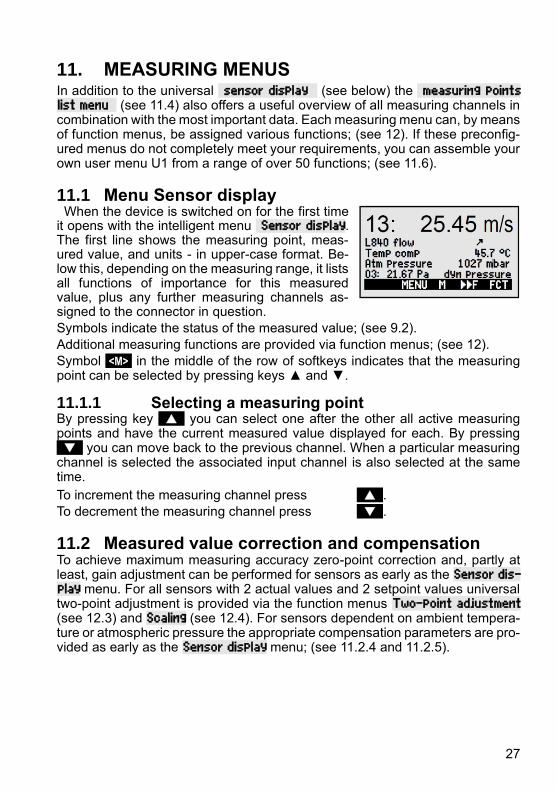
11. MEASURING MENUS In addition to the universal sensor display (see below) the measuring points list menu (see 11.4) also offers a useful overview of all measuring channels in combination with the most important data. Each measuring menu can, by means of function menus, be assigned various functions; (see 12). If these preconfig-ured menus do not completely meet your requirements, you can assemble your own user menu U1 from a range of over 50 functions; (see 11.6).
11.1 Menu Sensor display When the device is switched on for the first time it opens with the intelligent menu Sensor display. The first line shows the measuring point, meas-ured value, and units - in upper-case format. Be-low this, depending on the measuring range, it lists all functions of importance for this measured value, plus any further measuring channels as-signed to the connector in question.
Symbols indicate the status of the measured value; (see 9.2).
Additional measuring functions are provided via function menus; (see 12).
Symbol <M> in the middle of the row of softkeys indicates that the measuring point can be selected by pressing keys ▲ and ▼.
11.1.1 Selecting a measuring point By pressing key you can select one after the other all active measuring points and have the current measured value displayed for each. By pressing you can move back to the previous channel. When a particular measuring channel is selected the associated input channel is also selected at the same time.
To increment the measuring channel press .
To decrement the measuring channel press .
11.2 Measured value correction and compensation To achieve maximum measuring accuracy zero-point correction and, partly at least, gain adjustment can be performed for sensors as early as the Sensor dis-play menu. For all sensors with 2 actual values and 2 setpoint values universal two-point adjustment is provided via the function menus Two-point adjustment (see 12.3) and Scaling (see 12.4). For sensors dependent on ambient tempera-ture or atmospheric pressure the appropriate compensation parameters are pro-vided as early as the Sensor display menu; (see 11.2.4 and 11.2.5).

11. Measuring menus
28
11.2.1 Set measured value to zero One very useful function is to zero the measured value at certain locations or at certain times as a reference value in order then to observe only the subsequent deviations. Having selected the measured value function the softkey <ZERO> will appear. Press this key to save the measured value displayed as base value (see 13.6) and re-set to zero.
Select measured value function (see 9.4) : 00: 23.4 °C To select the zero-set measured value function press <ZERO>.
The measured value will then show : 00: 00.0 °C and the symbol REL. The base value is then assigned the measured value : base value: 23.4 °C.
To cancel zero-set, then after pressing : <ZERO> hold the key down.
If the function is locked (see 13.4) the base value is not saved on the connector but only temporarily to RAM where it is retained until the device is next switched off. This status is indicated in the display by the symbol REL ; in other cases the symbol º appears.
If you prefer to disable the zero-set function completely, the channel in question must be locked at level 6.
11.2.2 Sensor adjustment for dynamic pressure probes Dynamic pressure probes FDA602Sx must un-dergo zero-point adjustment before each measur-ing operation by withdrawing the hoses. The zero-point error is always written to the calibration off-set temporarily, i.e. until the device is next switched off, irrespective of locking level - thus en-suring that linearization is not falsified.
To select the measured value function press key(s) : PROG ... (see 9.4).
To perform zero-point adjustment press key(s) : <ADJ>
11.2.3 Sensor adjustment for chemical sensors and probes The following chemical sensors need to be ad-justed at least once or at regular intervals to com-pensate for various instabilities. In the measured value function pressing key <ADJ> can be used to automatically perform a two-point adjustment of the zero-point and the gain. As and when adjust-ment is performed the appropriate calibration set-points appear; these can also be modified as re-quired:
00: 23.4 °C
NiCr Temperatur REL
ZERO ESC F

11. Measuring menus
29
Probe Type Zero
point
Gain
pH probe ZA 9610-AKY: 7.00 4.00 pH or 10.00 pH
Conductivity FY A641-LF: 0.0 2.77 mS/cm
FY A641-LF2: 0.0 147.0 uS/cm
FY A641-LF3: 0.0 111.8 mS/cm
O2 saturation FY A640-O2: 0 101 %
O2 probe FY A600-O2: - 20.9 % in fresh air
Two-point adjustment
1. To select the measured value function press key(s) : PROG ... (see 9.4).
2. Setting up a means of calibration for the zero point.
Measured value shows e.g.: 00: 07.13 pH To initiate zero-point adjustment press key(s) : <ADJ>
Context-sensitive help window with setpoint appears.
To perform zero-point adjustment press key(s) < OK >
Measured value shows : 00: 07.00 pH
In the case of pH probes you can by pressing <CLR> restore the default values, namely base value 7.00 and gain -0.1689.
3. Setting up a means of calibration for the slope. To select the measured value function press key(s) PROG
Measured value shows e.g. 00: 04.45 pH
To initiate gain adjustment press key(s) <ADJ>
Context-sensitive help window with setpoint appears.
To modify the setpoint, if necessary, press key(s) PROG ... (see 9.5).
To perform gain adjustment press key(s) < OK >
On pH probes the gain error shows the the deviation from the rated value and thus
the status of the probe. Gain error 9 %
11.2.4 Temperature compensation Sensors whose measured values are heavily de-pendent on the temperature of the measuring me-dium usually incorporate their own temperature sensor and perform temperature compensation automatically; (see Section 13.9 Measuring range list ´with TC´). However, dynamic pressure probes and pH probes are also available without their own temperature sensor.
Sensor adjustment to Setpoint 7.00 pH
Sensor adjustment to Setpoint 4.00 pH

11. Measuring menus
30
If the temperature of the medium deviates from 25°C the following measuring errors must be considered :
e.g. Errors per 10 °C Compensation range Sensor Dynamic pressure approx. 1.6% -50 to 700 °C NiCr-Ni pH probe approx. 3.3% 0 to 100 °C Ntc or Pt100
For temperature compensation of these sensors there are 2 possibilities :
Enter compensation temperature in function Temp. comp. CT 31.0°C
Both in this function and in the measured value the symbol ´CT´ appears.
Continuous temperature compensation with external temperature sensors can be activated either via the reference channel (see 13.12.6) of the sensor to be compensated or by configuring any temperature sensor as reference sensor with a ´*T´ in the designation (see 13.2).
While the temperature is being measured, a point flashes behind the symbol ´CT´ temp. comp. CT. 23.5°C
Flow values (velocity or volume flow) acquired with temperature com-pensation can by means of ´#N´ in the designation (see 13.2) be con-verted to standard conditions of 20°C (see Manual 6.7.5).
11.2.5 Atmospheric pressure compensation Measured variables dependent on the ambient atmospheric pressure (see Sec-tion 13.9 Measuring range list ´with PC´) may, in the event of large deviations from normal pressure (1013 mbar), involve certain measuring errors. e.g. Error per 100 mbar Compensation range Rel.humidity psychrometer approx. 2% 500 to 1500 mbar Mixture ratio, capacitive approx. 10 % Vapor pressure VP up to 8 bar Dynamic pressure approx. 5% 800 to 1250 mbar (error < 2%) O2 saturation approx. 10% 500 to 1500 mbar It is advisable therefore, especially when taking measurements at appreciable heights above sea level to take due account of the atmospheric pressure (ap-prox. -11 mbar / 100 meters above mean sea level, MSL). On all sensors requir-ing atmospheric pressure compensation the sensor display includes the function atmospheric pressure : atm pressure: CP 1013 mbar. The appropriate atmospheric pressure can be entered either in sensor display or in device programming (see 14.6) or it can be measured using an atmos-pheric pressure sensor (reference sensor with designation ´*P´, see 13.2, Man-ual 6.7.2). While the atmospheric pressure is being used for compensation both in the function atmospheric pressure and at the measured value the symbol CP appears; if it is being measured a point flashes behind CP.
Please note that as soon as a reference sensor is disconnected nor-mal pressure, 1013 mbar, is used. Flow values (also volume flow with rotating vanes) acquired with at-

11. Measuring menus
31
mospheric pressure compensation can by means of ´#N´ in the des-ignation (see 13.2) be converted to standard conditions of 1013 mbar.
11.2.6 Cold junction compensation Cold junction compensation for thermocouples is normally performed automati-cally by means of an NTC sensor in measuring socket M2. This cold junction temperature is displayed in the device configuration as an operating parameter (see 14.8). This can if necessary be incorporated in measured data acquisition as device temperature with function channel ´CJ´ (see 13.10). Instead of this form of cold junction temperature measurement it is also possible to use an ex-ternal measuring sensor (Pt100 or NTC) in an isothermal block (see Manual 6.7.3); this must be positioned upstream from the thermocouples and ´*J´ must have been programmed in the first two positions in the designation (see 13.2). For especially exacting requirements (e.g. for thermocouples for which there is no connector with thermo-contacts or for large temperature differences caused by thermal irradiation) special connectors are available, each with its own inte-grated temperature sensor (ZA-9400-FSx) for cold junction compensation. These can be used for all thermocouple types; however, they require 2 measur-ing channels. Having ”#J” programmed in the first two positions in the designa-tion for the thermocouple ensures that the temperature sensor integrated in the connector is indeed used for cold junction compensation.
11.3 Differential measurement If two sensors with the same units and same decimal point position are con-nected at measuring points M0 and M1, the difference M1 - M0 appears auto-matically below device-internal measuring point M2/M3/M4 (see 8.2). If the dif-ferential channel is not required, it must be explicitly deleted; (see 13.9). If fur-ther differential channels are needed, these can also be created using the ap-propriate reference channels (see 13.12.6).
11.4 Measuring points list The best overview of all measuring points with measured values and function values is obtained via the menu Measuring points list.
This menu cannot be configured by the user; it can only be combined with certain selected functions.
Initially the list appears with maximum 12 entries. Measuring points list 12 meas-
ured values Measured values 00: 23.12°C ...
To select further measuring points press key(s) < F ►> ...
The measured value can be linked to a series of

11. Measuring menus
32
functions by pressing key(s) <F> : or ... This reduces the maximum number of channels to 6.
To advance to the next function press key (s) <F> :
Measured value with designation Meas points list designation
00: 23.12°C temperature Measured value with maximum value Meas points list Max. value 00: 23.12 °C 32.67 °C Measured value with minimum value Meas points list Min. value 00: 23.12 °C 19.34 °C Measured value with average value Meas points list Aver. value 00: 23.12 °C 25.45 °C Measured value with limit value, maximum Meas points list Limit val max. 00: 23.12 °C 32.67 °C Measured value with limit value, minimum Meas. points list Limit val min 00: 23.12 °C 19.34 °C Measuring range only (also maximum 12 channels) Meas. points list Range 00: NTC °C
For more than 6 measuring points select the next page by pressing key(s) PROG , <M▲> or <M▼> ...
11.5 User measuring menu U1 data logger User menu U1 can be freely configured by the user using the ALMEMO®-Control software (see 11.6). A data logger menu is provided as standard. This menu can be used either on its own or just like any measuring menu in conjunction with the function menu Data logger functions (see 12.5).
The device status is displayed by certain symbols in the status bar (see 9.2). Data acquisition can be set to cyclic via the cycle timer. The available memory is displayed in the function memory capacity free . This is omitted if neither internal memory nor a memory connector is available. The menu can then be used for output via the interface to a computer.
To start a cyclic measuring operation (if cycle >0) : <START> see 12.5.5
To initiate manual measured value scanning (if cycle =0) : <MANU> see 12.5.4
Example of a configured user measuring menu Bar chart Or alternatively e.g. a user menu Bar chart could be configured using the ALMEMO®-Control soft-ware (see 12.5). With the functions ´measured value, small´ and ´bar chart´ 2 channels with measured value and bar chart diagram can be shown.

11. Measuring menus
33
Measuring point selection The 1st measuring channel is always the selected measuring point. This can be selected directly as in any menu by means of or ...
To change the other channels, the measuring point PROG and must be selected as function by pressing key(s) : or ...
The selected measuring point can now be changed : < M ▲> , < M ▼> ...
To cancel the process of measuring point selection press : <ESC>
To set the display range the functions analog start and analog end in the special functions menu should be used; (see 13.12.3). Having selected these functions they can be entered by pressing key(s) PROG and ... or they can be entered directly on the appropriate axis; (see 9.5).
11.6 User menus Despite these flexible combinations of measuring menus and function menus (see 12) there are still certain applications where an individual collection of func-tions would be desirable. This is the purpose of user menu U1 Data log-ger which can be also be assembled and configured completely freely using the ALMEMO®-Control software. You can choose the functions you require from the following list and arrange these on the display exactly as you wish; the only restriction is the available space, namely 7 rows.

11. Measuring menus
34
11.6.1 Functions Functions Display Keys Com-
mand Measured value - small 00: 234.5 °C Temperature ZERO ADJ o 15
Measured value - medium
3 rows 00: 1234.5 °C
ZERO
ADJ o 16
Measured value - bar chart 2 rows
o 34
Limit value - maximum (see 13.5) Limit value max 1234.5°C OFF ON o 00
Limit value - minimum Limit value min -0123.4°C OFF ON o 01
Base value (see 13.6) Base value ------°C OFF ON o 02
Factor Factor 1.12345 OFF ON o 03
Exponent Exponent 0 OFF ON o 48
Zero-point (see 13.7) Zero-point ------°C OFF ON o 04
Gain Gain ------ OFF ON o 05
Analog start (see 13.12.3) Analog start 0.0 °C OFF ON o 06
Analog end Analog end 100.0°C OFF ON o 07
Range (see 13.9) Range NiCr CLR o 08
Maximum value (see 12.1) Maximum value 1122.3 °C CLR CLRA o 09
Minimum value Minimum value 19.3 °C CLR CLRA o 10
Average value (see 12.2.3) Average value ------ CLR CLRA o 11
Cycle (see 12.5.8.1) Cycle 00:00:00 Un CLR FORM o 12
Date, time-of-day (see 12.5.3) Time: 12:34:56 Date: 01.02.00 CLR o 14
Averaging mode Averaging mode CONT CLR o 18
Measuring rate (see 12.5.8.4) Meas. rate : 10 mops Cont: - OFF ON o 19
Cycle timer (see 12.5.5) Cycle timer: 00:00:00 Un CLR FORM o 20
Mean number (see 12.2.2) Number 00000 o 22
Number (see 12.5.6) Number 123-56 OFF ON o 23
Range, designation NiCr Temperature o 24
Diameter mm (see 12.2.6) Diameter 0000 mm CLR o 25
Cross-section cm2 (see 12.2.6) Diameter 0000 cm2 CLR o 26
Maximum, date and time-of-day Maximum time 12:34 01.02. o 28
Minimum, date and time-of-day Minimum time 13:45 01.02. o 29
Empty line o 30
Line ______________________ o 31
Smoothing (see 12.2.1) Smoothing 10 CLR o 32
Memory capacity free (see 12.5.7) Memory free 502.1 KB CMEM PMEM o 33
Device designation (see.14.1) Company name - A Specimen CLR o 36
Text 1: 1: Designation line CLR o 37
Tex t2 2: Designation line CLR o 38
Text 3: (see 11.6) Menu title U1 CLR o 39
11. Measuring menus
35
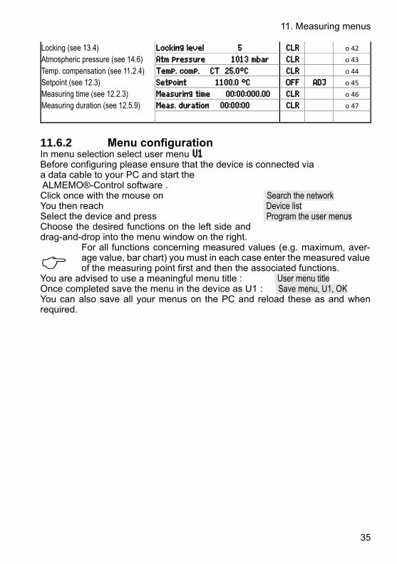
Locking (see 13.4) Locking level 5 CLR o 42
Atmospheric pressure (see 14.6) Atm pressure 1013 mbar CLR o 43
Temp. compensation (see 11.2.4) Temp. comp. CT 25.0°C CLR o 44
Setpoint (see 12.3) Setpoint 1100.0 °C OFF ADJ o 45
Measuring time (see 12.2.3) Measuring time 00:00:000.00 CLR o 46
Measuring duration (see 12.5.9) Meas. duration 00:00:00 CLR o 47
11.6.2 Menu configuration In menu selection select user menu U1 Before configuring please ensure that the device is connected via a data cable to your PC and start the ALMEMO®-Control software . Click once with the mouse on Search the network You then reach Device list Select the device and press Program the user menus Choose the desired functions on the left side and drag-and-drop into the menu window on the right.
For all functions concerning measured values (e.g. maximum, aver-age value, bar chart) you must in each case enter the measured value of the measuring point first and then the associated functions.
You are advised to use a meaningful menu title : User menu title Once completed save the menu in the device as U1 : Save menu, U1, OK You can also save all your menus on the PC and reload these as and when required.

36
12. FUNCTION MENUS To manage individual tasks each measuring menu can be assigned a function menu from the adjacent list. For each measuring operation you can at any time toggle between measuring menu and function menu.
To call up function menu selection in menu selection see 10
or in measuring menus and function menus press key(s) : < FCT >
To select function menu press key(s) : and or PROG
To clear the function menu press key(s) : < CLR >
Navigation through several function menus : < ►F > or < F◄ >
To toggle between function menu and measuring menu: < M◄◄ > and < ►►F >
12.1 Maximum, minimum, individual values memory The function menu max, min, individual values memory shows not only the measured value but also the continuously acquired maximum and min-imum values for the selected measuring point plus a memory for 100 individual values.
Maximum value, minimum value : Function Min and Max : Min: 25.37 Max: 31.34 To clear select the function (see 9.4): Min: 25.37 Max: 31.34 To clear maximum, minimum, and average values for all channels press : <CLRA>
As soon as you clear the memory, the current measured value will appear (be-cause measuring is continuous). Each time a measuring operation starts, if the device has been so configured, the peak values will be cleared ; (for default setting see 14.8).
Individual values memory Each measured value can be saved at the touch of a button. The measured value is displayed together with its units and position number in the memory function. Either just the last value or the whole memory can be cleared. All saved data can be shown on the display or output as a list to the interface.
To continuously save the measured value press key : <MEM>
Memory display with position : Memory: P12: 25.45 °C To clear the last position after function selection press key : <CLRP>
To clear all saved values press key : <CLRM>
To display all saved values press key(s) : <LISTM> and <F ►>
To output all saved values press key : <PRINT>

12. Function menus
37
Interface commands: response: store a measurement value: S-4 output of data storage: P-04 Memory: P01: 00: +022.12 °C P02: 00: +022.12 °C P03: 10: +0039.9 %H P04: 10: +0039.9 %H P05: 20: +0007.6 °C Clearing the memory: C-04
12.2 Averaging The average value for a measured value is needed for various applications e.g. smoothing a widely fluctuating measured value (wind, pressure etc.). Average flow velocity in a ventilation channel Hourly or daily average values for weather data (temperature, wind, etc.) Also for consumption values (electric current, water, gas, etc.)
M̅ = (∑i Mi) N⁄ The average value M̅for a measured var-iable is obtained by totaling a whole series of measured values Mi and then dividing by the number of measured values N.
If, in function selection, averaging is selected a new selection menu will appear listing the various averaging modes.
These include measured value smoothing for the selected channel with a sliding averaging window, averaging over individual measuring operations selected by place or time, averaging over time, over cycles, or over specified measuring points. For flow sensors a special menu for array meas-uring as per VDE is provided.
To select the averaging menu press key(s) : and or PROG
To clear averaging for the selected channel press : <CLR>
12.2.1 Smoothing meas values by means of a sliding av-erage The first method for averaging applies exclusively to the measured value of the selected channel; it is used to smooth measured values of an unstable or strongly fluctuating nature, e.g. especially tur-bulent flows, by means of a sliding average over a specified time frame. The level of smoothing can be set in the Smoothing function; here you specify the number of measured values to be averaged (possible range 0 to 99). The smoothed measured value can thus also be used in all subsequent evaluation functions in combination with averaging over individual measured values (see

12. Function menus
38
12.2.2) or for networked measuring (see 12.2.7).
Measured value smoothing over e.g. 15 values : Smoothing: 15
Continuous measuring point scanning should be disabled because this would at many measuring points reduce the measuring rate too strongly : Meas rate : 10 mops Cont : -
Time constant (s) = smoothing / measuring rate · 2
How the averaging menus function : The following averaging menus use some of the standard functions such as averaging mode, cycle, measuring rate - appropriately repro-grammed. Data output to the interface and memory is possible but this must be configured. To also display the average value acquired as it is being output a function channel M(t) must be activated on channel M32/33/34 (see 8.2). This will stop any data logger recording currently running; this will subsequently have to be reinitialized.
12.2.2 Averaging over individual manual meas opera-tions To obtain the average of individual measuring op-erations at particular locations or times select the menu average value over measuring operations. Here the individual manual measuring point scans Ei can be performed.
1. To select an average value (see 9.4) and to clear it press : PROG , <CLR> Function average value shows : average value : ----- m¡ Function number over measuring operations shows : number : 00000 U To set memory activation, output format : <MON/MOFF> , <FORM> see 12.5.5
2. Acquire individual measured values Ex manually : <MANU> Function average value shows : average value : 12.34 m¡ Function number shows : number: 00001 3. Repeat step 2 for each measuring point.

12. Function menus
39
For flow probes call up the volume menu by pressing : <VOL ►> see 12.2.6
12.2.3 Averaging over time To determine average values over a certain dura-tion there are 2 possibilities - either by pressing the Start and Stop keys accordingly or by entering a du-ration for averaging which is started manually but stops automatically. A measuring point scan is al-ways performed at start and stop in order to record to memory the start value, end value, and average value - each with the applicable time-of-day (see 12.5).
To clear the average value and measuring duration automatically on Start (see 14.8) or having selected the average value by pressing : <CLR> The measuring duration can be read out : meas duration : 00:01:23.40 U To set memory activation, output format : <MON/MOFF> , <FORM> To start averaging press : <START> Verification : » To stop averaging press : <STOP>
Alternatively Enter a certain averaging duration in seconds, Select and program the function Measuring duration , The function changes to : averaging duration : 020 U To start averaging press : <START> Verification : » To stop averaging after expiry of averaging duration
The average value can be read out in function: average value : 13.24 m¡
For flow probes call up the volume menu by pressing : < VOL ►> see 12.2.6
12.2.4 Averaging over the cycle To determine hourly or daily average values the
average values must be acquired at cyclic inter-
vals. A cycle is programmed to ensure that the av-
erage value, maximum value, and minimum value
are cleared after each cycle but continue to appear
in the display throughout the following cycle.

12. Function menus
40
Program the cycle (see 12.5.5) and set cycle timer : 00:15:00 Un To set memory activation, output format : <MON/MOFF> , <FORM> Start measuring operation, averaging runs : <START> Verification : »
Stop measuring operation : <STOP> The average value of the last cycle can be read out : average value : 13.24 mls The average value is also output or saved in function channel M32/33/34 with the range M(t).
12.2.5 Averaging over measuring points The average value can also be determined over a number of associated measuring points. In menu
average value over measuring points you can set the start channel (Bk2) with the measuring point in the 1st row and having selected the function to channel : also the end channel (Bk1). The average value M(n) is programmed automatically to function channel M32/33/34 (see13.9). Measuring point scanning is continuous (see 12.5.8.4).
Average value M(n) from M01 (Bk2) to M03 (Bk1) :
12.2.6 Volume flow measurement To determine volume flow VF in flow channels the average flow velocity must be v̅multiplied by the cross-section area CS :
VF =v̅. CS . 0.36 VF = m3/h, v̅= m/s, CS = cm2
With Pitot tubes, to calculate the actual velocity in the sensor display, tempera-ture compensation and atmospheric pressure compensation are provided (see 11.2.4, 11.2.5).
To acquire the average flow velocity v̅there are the following possibilities :
1. Averaging over individual measuring operations (see 12.2.2)
2. Averaging over time (see 12.2.3) For rough air volume measurements at air vents and gratings apply the flow
sensor at one end, start averaging, and proceed uniformly over the whole cross-section; on reaching the other end of the cross-section stop averaging.
3. Networked measuring as per VDE (see 12.2.7)
If the average value is assigned m/s as units, it is possible, for the purposes of determining the volume flow, to call up the volume flow menu di

12. Function menus
41
rectly from the average value menu by pressing VOL ►> .
This lists the following functions Cross-section calculation ready :
Channel type: Rectangular with width and depth, Channel type Tubular k:1.00 Tubular with diameter or diameter : 00175 mm Surface with cross-section : cross-section : 02345 cm²
inclusive correction factor (k-factor)
Display of volume flow in m3/h: volume flow 1934. m3/h
Display of standardized volume (20°C, 1013 mbar): standardized : see 12.2.7 Save data in a volume flow file : <STORE> see 12.2.7
12.2.7 Array measuring Option VN Average velocity in a flow channel is calculated as per DIN EN 12599, namely by performing measuring operations at particular array points in a cross-sec-tion vertical to the pipe axis (see Manual 3.5.5). To ensure that all individual values are logged in standardized form a menu combination Array measuring specially conceived for flow sensors (m/s) is provided. In the 1st menu the channel data and a measuring point designation are en-tered. If a memory connector with SD-card is available, channel data already acquired selected with PROG , FIRST , NEXT and can be loaded from an existing file by means of LOAD . Channel type with k-factor, dimensions, and number of holes are all prescribed by the chan-nel; the number of measuring depths and grav-ity lines are used to calculate the actual meas-uring depths (3.5.5). Entering the averaging duration in seconds ensures uniform data acquisition per point by averaging over a fixed time. If the averaging duration is deleted, its start and stop are prescribed by the measuring duration. To select the 2nd menu press key(s) < ►F > It is thus possible to acquire all measuring points from the 1st hole right through to the last hole at all precalculated depths. The measuring operation is initiated by pressing the <MEAS> key; then each point is acquired one after the other with <START> key. Any point can subsequently be reselected for correction by means of the cursor keys.

12. Function menus
42
ALMEMO - Flow array measuring Meas. device:;2590-4S VN;Serial no.:;H10120757;Calibration date :;01.01.2013 Sensor:;FDA602SK1;Serial no:;11070123;Calibration date :;01.01.2013 Measuring:;;File:;WH7.V02;meas. location:;Hall7; Creation:;;Date:;09.01.2013;Time:;14:50; Measuring:;;Date:;09.01.2013;Time:;15:37; Channel type:;rectangle/circle;Width/diameter mm:;200;Depth mm:;100 k-factor:;1;number of holes:;3;Number of meas. depths:;2 measuring points:;b1:33mm;b2: 100mm;b3: 166mm;b4;b5 ... .... t2: 75mm;24,0;34,6;25,6;; t2: 25mm;24,0;24,1;27,0;; cross-section cm2:;200;average velocity. m/s:;26,6;Flow m3/h:;1912 Normalized:;yes;meas. temperature °C:;14,0;Air pressure mbar:;922 Standard temp. °C:;20;Standard velocity. m/s:;24,7;Standard flow m3/h:;1776
ALMEMO - Flow array measuring Meas. device: 2590-4S VN Serial no.: H10120757 Calibration date : 01.01.2013
Sensor: FDA602SK1 Serial no: 11070123 Calibration date : 01.01.2013 Measuring: File: WH7.V02 meas. location: Hall7
Creation: Date: 09.01.2013 Time: 14:50
Measuring: Date: 09.01.2013 Time: 15:37
Channel type: rectangle Width/diam. mm: 200 Depth mm: 100
k-factor: 1 number of holes: 3 Number of meas. : 2 measuring points: b1:33mm b2: 100mm b3: 166mm
t2: 75mm 24,0 34,6 25,6 t2: 25mm 24,0 24,1 27,0 cross-section cm2: 200 average velocity m/s: 26,6 Flow m3/h: 1912
Normalized: yes meas. temp. °C: 14,0 Air pressure mbar: 922
Standard temp. °C: 20 Standard velocity. m/s: 24,7 Standard flow m3/h: 1776

12. Function menus
43
To clear all measured values, if necessary, press key < CLRA > The average value of the array is displayed continuously: average val : 15.11 m¡ To cancel the measuring operation press key : < ESC > To proceed to the 3rd menu press key : < VOL ►> Display of volume flow in m3/h = Average value of flow [m/s] x cross-section [cm2] It is possible to display the standardized volume referred to 20°C and 1013mbar if the temperature and atmospheric pressure are measured at the measuring point in question; (see temperature compensation 11.2.4 and atmospheric pressure compensation 11.2.5).
Select the function standardized and activate : standardized : Save data and output If a SD-card memory connector connected, all data can be saved to a special vol-ume flow file by pressing key : <STORE> The tabular format of the data is shown on the previous page. The data can command 'P49' (s. manual sec. 6) can also be read through the interface, and then imported for processing in an Excel spreadsheet.
12.3 Two-point adjustment with setpoint entry For universal error correction at any 2 points the function menu two-point adjustment is provided. If the actual values at 2 points are known , these can be written with the appropriate setpoints. If not, 2 setpoint states must be created and ad-justed online. Usually, for the 1st measuring point, a zero-point adjustment is performed; however, any other setpoint is equally possible. For the 2nd measuring point, a gain adjustment i per-formed and all correction values are recalculated; (see 13.7).
Two-point adjustment : (actual values are cleared) 1. Measuring point Place the sensor in 1st status 00: 0.4 °C (e.g. icy water, unpressurized, etc.), actual value 1: ----- Select setpoint 1 and enter : setpoint 1: 0.0 Adjust measured value to setpoint 1 by pressing : <ADJ> Measured value should now display setpoint 1 : 00: 0.0 °C
2. Measuring point Place the sensor in 2nd status 00: 99.45 °C (boiling water, known weight, etc.) 2: ----- For the 2nd measuring point enter setpoint 2 : 2: 100.0 Adjust gain in function setpoint 2 by pressing : <ADJ> Measured value should now display setpoint 2 : 00: 100.0 °C
Correction value calculation

12. Function menus
44
Also enter known actual values in function : actual value 1: 0.4 2: 100.0 and calculate correction in function setpoint 2 by pressing : <ADJ>
If the sensor is locked, a confirmation request will appear asking whether adjustment should indeed be performed.
12.4 Scaling Sensors or transmitters with standardized signal output will usually have to be scaled to be able to display the physical variable. If 2 actual values and 2 setpoints have been entered, the menu SCALING will, as described previously (see 12.3), perform the task of calculating the scaling values, base value and factor (see 13.6). The desired units and the decimal point position must also be entered.
Calculating the scaling values After entering all the necessary parameters the scaling values are calculated in function setpoint 2 by pressing : < ADJ >
Scaling by means of a two-point adjustment Sensors which are adjusted via the factor, e.g. force transducers and displace-ment transducers, can also be adjusted online, as described previously in 12.3.
Simulate, select, and enter 1st setpoint 1 : setpoint 1: -100.0 Adjust in setpoint 1 by pressing : <ADJ>
2. Simulate setpoint 2 For ALMEMO force transducers (see Manual 3.6.2) Simulate the control value Calibration resistance ON/OFF : <S-ON> or <S-OFF>
Select and enter setpoint 2 : 2: 400.0
Two-point adjustment in setpoint 2 by pressing : <ADJ>
Force transducer with calibration resistance are adjustable also in the sensor display. It is also possible to adjust the end value only - without changing the zero-point.
12.5 Data logger functions The 3 function menus Data logger functions can be used to acquire the measured values for all measuring points either manually at certain times or cyclically over a certain duration and to record these either to the internal data memory (type 4AS) or to an external memory card; (see Manual 6.5). In the absence of all such storage media these menus are not available.

12. Function menus
45
The device status can be checked by means of the appropriate symbols (see9.2) appearing in the top status bar of the menu.
12.5.1 Internal data memory Data loggers ALMEMO 2590-4AS incorporate an internal 500-KB EEPROM data memory, , sufficient for 60000 to 100000 measured values (depending on the number of channels). In the event of a failure in the supply voltage the meas-ured data is retained intact. The total memory capacity and the free memory available are indicated in functions Internal memory and Free memory . The EEPROM can be configured either as linear memory or ring memory; (see 12.5.8.5, Manual 6.10.13.2). The basic information on saving data in ALMEMO® devices is provided in the Manual, Section 6.9.
PLEASE NOTE !The first time the device is started only one sensor configuration is saved to the internal memory; however, with effect from the next start this can be supplemented by additional sensors. However, if other sensors are con-nected the memory must be read out and then cleared before the next recording session.
12.5.2 Memory connector with SD-card On devices without internal memory or if memory capacity proves insufficient or if the data needs to be evaluated elsewhere, you can, as additional external memory, use a memory connector (ZA 1904-SD) with a SD-card, available from our range of accessories. The measured data is written to it via the memory connector in table mode and in standard FAT16 format. The SD-card can be formatted and its contents can be read and deleted via any normal PC using any card reader. Measured data can be imported into MS-Excel or into Win-Control (the accompanying measured value software). The memory connector with the additional memory card can be connected at socket A2; it is recognized automatically. You can check that this has succeeded in the function External memory by the now increased memory capacity and a file name in the function File name. If the external memory is connected at the start of any measuring operation, it will be used. However, in the course of the measuring operation it must not be unplugged; this would cause temporarily buffered measured values to be lost.
Memory capacity available, external External memory: 128.00 MB Memory capacity free Memory free : 21.75 MB File name (max. 8 characters, and index) File name: ALMEMO.001 Before starting any measuring operation you can, in the function File name enter an 8-character file name. In the absence of a user-assigned file name, the de-fault name ´ALMEMO.001´ or the name most recently used will be suggested au-tomatically. So long as the connector configuration is not altered, you can save several measuring operations, either manually or cyclically, also with numerical assignment, all in the same file (see 12.5.6). If, however, the connector configuration has been changed since the last measuring operation and if no new file name has been programmed, then a new file is always created and in so doing the index in the file name extension is

12. Function menus
46
automatically incremented by 1, e.g. . ´ALMEMO.002´. Similarly, if the file name entered already exists, then a new file will be created with the same file name prefix but with a new index.
To check that the memory connector is functioning properly there is an LED incorporated in the end of the handle; this indicates the following states :
● No memory card detected : LED flashes once long and then three times short.
● Data is being recorded : LED flashes in the same rhythm as the cycle.
● Data is being read out : LED lights up continuously for the duration of data output When plugging in the connector make sure that the card remains latched in position ! The ring memory mode is not supported by memory cards!
12.5.3 Date and time-of-day For logging data recordings a real-time clock with date is provided. This real-time clock is buffered by means of the device battery; in the event of battery replacement date and time-of-day are lost. The first line contains the time-of-day on the left and the date on the right; by selecting this function (see 9.4) these can be programmed in the format indicated (see 9.5).
Function time-of-day / date : Time : 12:34:56 Date :01.05.07 Format of time-of-day and date: hh:mm:ss dd.mm.yy
12.5.4 Once-only output / saving of all measuring points Once-only manual measuring point scans for acquiring the current measured values from all active measuring points (see Manual 6.5.1.1) can be initiated by pressing <MANU> . The output format can be set in the function Cycle timer (see 12.5.5, 12.5.8.3).
Once-only manual measuring point scan : <MANU>
The following symbols will be displayed briefly as verification in the status bar (s. 9.2) :
The start arrow will light up briefly and then go out again ´ ´
Lights up when data is being output via the interface (short) ´COM´
Appears when measured values are saved (short) ´REC ´
Each time the key is pressed again after this the measured values will be pro-cessed with the associated measuring time.
12.5.5 Cyclic output / saving of all measuring points For cyclic recording and output of measured values (see Manual 6.5.1.2) the cycle and the output format must be programmed accordingly. The measuring operation can be started by pressing <START> and stopped by pressing <STOP> . Each time a measuring operation starts, if the device has been so configured, the maximum, minimum, and average values of all measuring points will be cleared (for standard setting see 14.8).
So long as no measuring operation has been started the cycle timer function displays the cycle set. Once the function has been selected (see 9.4) the cycle

12. Function menus
47
can be entered directly (see 9.5). Once started the timer counts down to the next cycle.
Function Cycle timer : Cycle timer : 00:02:00 S Cycle (hh:mm:ss), Saving ON, List format
Switch memory activation ON / OFF by pressing : <MON/MOFF>
The output format in which measured values are output via the interface can be set by pressing <FORM> or in function Output format (see. 12.5.8.3). (Print layouts see Manual 6.6.1)
Modify format by pressing <FORM>
Format, adjacent columns ´n´: Cycle timer: 00:02:00Sn
To modify format <FORM> Format, table ´t´: Cycle timer: 00:02:00St
To start cyclic measuring point scan press <START>
The following symbols will be displayed as verification in the status bar contin-uously, i.e. so long as the measuring operation is running. (see 9.2) :
The start arrow lights up (continual) ´ ´ Lights up when data is being output via the interface (continual) ´COM´ Appears when measured values are saved (continual) ´REC ´
To stop cyclic measuring point scan : <STOP> ´ll ´
12.5.6 Numbering of measuring operations To identify measuring operations or series of measuring operations these can be individually numbered before starting. This number is output or saved when the next measuring point scan starts. In this way individual measuring opera-tions can be assigned to certain types of measurement or certain measuring points (see Manual 6.7).
After selecting the function Number the 6-digit number is entered as normal (see 9.5). You can use digits 0 to 9 and also the characters A, F, N, P, and - or _ (space). The number is activated as soon as it has been entered; it will then
be followed by the letter ´A´ until the next cyclic or manual measuring operation
is saved.
Number function : (e.g. room 12, measuring point 1) Number: 12-001 A To zero-set and deactivate the number press <CLR>
To activate and deactivate the number press : <ON> , <OFF>
To increment and activate the number press < +1 >
12.5.7 Memory space, memory output, clearing the memory When measured values are being recorded the Memory capacity free function continuously displays the memory capacity still available. Selecting this function enables two softkeys, one for direct memory output and one for memory clear-ing. The output format is as set in the cycle (see 12.5.5, 12.5.8.1, and Manual 6.6.1).

12. Function menus
48
Function Memory free e.g.: Memory free : 38.4 KB
To output the memory : <PMEM>
To clear the memory : <CMEM>
Using the keypad the contents of the measured value memory can only be out-put to the serial interface as a complete whole. Only by software can certain sections of the memory be specified for output - either by stipulating the start time and end time or by selecting the numbers defining the measuring opera-tions in question. With each output from the internal memory any one of the three output formats may be used “list”, “columns”, or “table”.
With external SD-cards (see 12.5.2) the device itself can only read out in table mode the measured data contained in the file most recently used. The LED in the end of the handle lights up continuously for the duration of memory output. The most sensible approach is to remove the memory card and copy the files via a USB card reader directly onto the PC. These can then be imported either into MS-Excel or into Win-Control (as of V.4.8.1).
During memory output the Remaining output function continuously updates and displays in KB the amount still to be output.
Remaining amount of memory to be output Remaining output : 12.5 KB
12.5.8 Scanning configuration In the following menu, reached by pressing <►F>, the general conditions for measuring point scans can be set in even greater detail.
12.5.8.1 Cycle with saving to memory activated To ensure that measured values are saved and output to the interface on a cyclic basis use the Cycle function. Saving per cycle, i.e. cyclic recording of data to the memory, is automatically activated after each reinitialization but can be de-activated as and when required. Pressing <MIN> sets the highest recording speed. The minimum cycle then displayed represents the highest measuring rate (10 mops) and continuous saving (see 12.5.8.4).
Enter the cycle in the format ´hh:mm:ss´ see 9.5: Cycle: 00:15:00 To clear the cycle and end the current scan press <CLR> Minimum cycle with 10 mops, in accordance with channel number : <MIN> 00:00:00.30
Memory activation function in the cycle Saving
Saving to memory activated (default setting): <ON>
Saving to memory deactivated <OFF> -
12.5.8.2 Scanning mode For automatic data logger operation and / or measured value scanning by the computer there are 4 scan modes available : Normal : Internal cycle or cyclic scan by the computer

12. Function menus
49
Sleep : Internal cycle only, automatically switching off for long-term moni-toring Monitor : Internal cycle, not disturbed by computer scanning activity Fail-safe : Cyclic scanning by the PC; after any failure, internal cycle re-sumes
Scanning mode function : Mode : Normal Set scanning mode by pressing : <SET>
Sleep mode For long-term monitoring involving large measuring cycles the device can also be operated in sleep mode. In energy-saving sleep mode the measuring instrument is completely switched off after each measuring point scan (please note when using sensors with own power supply) and switched on again automatically after the cycle expires ready for the next measuring point scan. In this way with just one set of batteries or one battery recharge up to 15000 measuring point scans can be performed; for a cycle lasting 10 minutes this represents a measuring ca-pability of over 100 days.
With the selection of the Sleep mode after confirmation of a query display all necessary parameters are possibly configured!
For data recording in sleep mode please perform the following steps :
1. Enter a cycle lasting at least 2 minutes Cycle : 00:05:00 S 2. Activate saving in this cycle : Saving to memory : Mode:Normal 3. Select scan mode : Saving to memory : Mode::Normal 4. Sleep mode program (see 9.5):
5. In the menu Data logger start measuring operation by pressing : <START> The device should then display Sleep On. It should then switch off again and as verification the LED ´SLEEP´ (4) flashes. Only the red lamp ´SLEEP´ at the top of the window flashes rhythmically.
6. In the specified cycle the instrument switches on automatically, performs one measuring point scan, and then switches off again.
7. To quit sleep mode press <STOP>
8. To cancel the measuring operation press <STOP>
A measuring operation can be started in sleep mode using the start time (see 12.5.9); however, in sleep mode it cannot be stopped using the end time and measuring duration.
Monitor mode: If a data logger being operated on a cyclic basis is to be monitored occasionally by computer the new ´monitor mode´ should be used. Internal cyclic scanning is not influenced in any way by software scanning; (in Win-Control ´safe initiali-zation´ must be deactivated). The internal cycle is started with the software start; it may also have been started previously. Scanning by the internal cycle outputs no data to the interface. To accept data the memory must have been activated.
Sleep

12. Function menus
50
In the function Mode program the variant Monitor : Mode:Monitor
Fail-safe mode: Fail-safe mode is suitable where purely software-based scanning is used merely to ensure in the event of computer failure that scanning continues on an internal cyclic basis. In this mode the cycle programmed in the device must be larger than that needed for software scanning (e.g. device cycle 20s, software cycle 10s). Software scanning keeps resetting the internal cycle with the effect that this cycle is only actually used as and when software scanning fails; (here too in Win-Control ´safe initialization´ must be deactivated). The internal cycle is started with the start of the Win-Control software; it may also have been started previously. Scanning by the internal cycle outputs no data to the interface. To accept data the memory must have been activated.
In the function Mode program the variant Fail-safe : Mode:Fail-safe
12.5.8.3 Output format The output format (see Manual 6.6.1) defines the print layout for measuring point scans and for output of the memory. This output format can be pro-grammed in the function Output form . There is the default format ´List´ in which all measured values are listed one below the other; there is also the ´Columns´ format listing them next to one another; this provides a clear, easy-to-under-stand, and space-saving printout. The Table format is suitable for further pro-cessing using a spreadsheet program; (see print layouts, Manual 6.1). Output format ´ ´ List meas values one below the other : Output form : List Output format ´n´ Columns next to one another : Output form: Columns
Output format ´t´ Table, semi-colon separated : Output form: Table In the data logger menu behind the cycle for memory activation ´S´, if not ´U´ The format is indicated by an abbreviation ´n´ or ´t´: Cycle timer: 00:15:00 Sn
12.5.8.4 Measuring rate, continuous measuring point scan As and when necessary the measuring rate (conversion rate) for measuring point scans can be raised in the Measuring rate function from 2.5 to 10 mops (measuring operations per second) (see Manual 6.5). Semi-continuous measuring point scan The measuring rate for measuring points is by default semi-continuous; i.e. all measuring points are continuously scanned but the selected measuring point is as-signed preferred status and is rescanned every 2nd time. This ensures a constant scanning rate (= half the measuring rate) irrespective of the number of measuring channels; this is an advantage for analog output or measured value smoothing but when averaging (M(n) it may lead to incorrect results.
Continuous measuring point scan If continuous measuring point scanning is set, all active measuring channels are scanned equally often at the chosen measuring rate and uninterruptedly one

12. Function menus
51
after the other; (see Manual 6.5.1.3). This almost doubles the measuring rate / channel. In both modes all measured values can be saved and output at any time. With both the following functions continuous saving to memory and con-tinuous output of measured values can be activated at the measuring rate. Function Meas. rate, to modify press key : <SET> Meas. rate: 10 mops Semi-continuous measuring point scan (standard): <OFF> Cont: -
Continuous measuring point scan <ON> Cont: Continuous saving to memory OFF Saving to memory: -
Continuous saving to memory, activate <ON> Continuous output OFF Output: -
Continuous output, activate : <ON>
12.5.8.5 Memory time An important parameter for data recording is the available memory time. This depends on the free memory capacity available, the measuring rate set, the scanning mode, and the number of active measuring channels. All these varia-bles are clearly shown via the menu described.
Active channels for minimum cycle and memory time : Meas chan. : 12 Active :5 Available memory time : Memory time: 24d 13h The ALMEMO 2590-4AS with its internal memory can continue recording infi-nitely, so long as in the next menu (see 12.5.9) the parameter Ring memory is activated. In this mode, as soon as the memory is full, the oldest data is simply overwritten; the most recent data is always available; (see Manual 6.10.13.2). Linear memory Data is not overwritten : Ring memory : -
Ring memory Data is overwritten : <ON>
12.5.9 Starting and stopping measuring operations A measuring operation can be started and stopped not only by pressing the ap-propriate keys but also using numerous other methods; these are described the the Manual, Section 6.6.
These operating instructions, in the 3rd data logger menu, describe the start time and end time, the measuring duration, and the actions in the event of a limit value being exceeded (see Section 13.12.2) and the relay and trigger variants (see Section 15.2).
Start time Start date, End time End date A measuring series can be started and stopped au-tomatically at specified times. For this purpose the start time and start date, and the end time and end date must be programmed. If no particular date has been programmed, the measuring operation will be performed every day within the set period. Or, alternatively, instead of specifying the end time the measuring duration itself can

12. Function menus
52
be programmed. The total measuring time since starting can be seen in the func-tion Measuring time.
This is assuming of course that the current time-of-day has been programmed. Sleep mode takes no account of end time or measuring duration.
To select the menu press key : < ►F >
Function Measuring duration (format hh:mm:ss):Meas duration : 00:10:00 Start time function (format hh:mm:ss): Start time : 07:00:00 End time function (format hh:mm:ss): End time : ------ Start date function (format dd:mm:yy): Start date : 01.05.07 End date function (format dd:mm:yy): End date : ------ Measuring time since start (format hh:mm:ss.hh):Meas time : 00:01:23.45
These values can be cleared after selecting the function by pressing : <OFF>
If the start time for a measuring operation has been programmed, the following symbol appears in the status bar : ´ ´
If the end time or the measuring duration for a measuring operation has been programmed, the following symbol appears in the status bar : ́ ´

53
13. SENSOR PROGRAMMING Since on ALMEMO® devices all sensor programming is stored in the ALMEMO® connector itself, the user will not normally need to reprogram each time. Pro-gramming will only be necessary e.g. if sensor errors are corrected, if your own sensors are scaled, or if certain limit values are stipulated; in these circum-stances there are comprehensive programming functions available.
In the SENSOR PROGRAMMING menus all parame-ters for a channel can be entered, viewed, checked, and modified via the keypad - providing the appropriate sensor connector is plugged in. Please note that series sensors featuring the lock-ing mode can be protected against unintended al-teration; therefore, if modification is required this
locking mode must first be lowered to an appropriate level (see 13.4). Functions can only be selected if the locking mode allows.
To select all 4 menus for sensor programming : < ►P > ... and < P ◄ > …
13.1 Selecting the input channel To view or edit a sensor's parameters you must first of all select the menu SEN-SOR PROGRAMMING and then set the required input channel by pressing or . Only sensors actually connected and channels actually activated can be processed. To activate new channels first press the key <MALL> to select all channels. Then press <MACT> to reduce this selection again to only those that are active. For each input channel the associated connector number is dis-played.
Menu SENSOR PROGRAMMING : Display of connector number and channel Connector : 0 Channel : 00 To select next input channel press To select previous input channel press To accept the selection of all possible channels press <MALL> To reduce selection to all active channels press <MACT>
13.2 Measuring point designation Each measuring point can be assigned a 10-character alphanumerical designa-tion denoting as clearly as possible the type of sensor, measuring location, and / or purpose. This designation is included in all standard measured value dis-plays. In an output via the interface the measuring point designation appears in
the program header as ´DESIGNATION´ and also in the measured value list (see
Manual 6.6.1).
Input in the Designation function (see 9.5) Designation : Temperature
Certain control characters at the beginning of the designation have special functions :
´*J´ This defines a temperature sensor (NTC, PT100) as reference for external cold junction compensation (see 11.2.6).

13. Sensor programming
54
´#J´ This means that a cold junction sensor is to be used in the connector for a thermocouple (e.g. connector ZA9400-FSx with Ntc); s. 11.2.6, Manual 6.7.3).
´*T´ This defines a temperature sensor (Ntc, Pt100) as reference for temperature compensation (see 11.2.4).
´*P´ This defines an atmospheric pressure sensor as reference for atmospheric pres-sure compensation (see 11.2.5).
´#N´ This ensures on flow sensors whose measured values (velocity or volume flow) are acquired with temperature compensation (see 11.2.4) and atmospheric pres-sure compensation (see 11.2.5) that these values are converted to standard con-ditions (20°C and 1013 mbar); (see Manual 6.7.5).
The remaining 8 characters can be used for the user’s own descriptions.
´!´ at the end automatically indicates a specific linearization or multi-point cali-bration (see 13.11). This cannot be overwritten.
13.3 Averaging mode For a description of the various averaging modes that can be defined via the function Averaging mode see Manual, Section 6.7.4.
Function - No averaging : Averaging mode : ----- Averaging start to stop or over individual measuring operations : CONT Averaging over all scans in a cycle : CYCL Setting the averaging mode, see 9.5: Averaging mode: CONT
13.4 Locking the sensor programming The functional parameters for each measuring point are protected by means of the locking mode; this can be set to the desired locking level (see Manual 6.3.12). Before programming you must lower the locking mode to an appropriate level. If you see a dot in the display after the locking mode, this means that this cannot be modified.
Locking level Locked functions 0 None 1 Measuring range + element flags + output mode 3 + units 4 + zero-point correction + gain correction 5 + base value + factor + exponent 6 + analog output, start and end + zero-point adjustment, temporary 7 + limit values, maximum and minimum
Function Locking mode : Locking level : 5
In the SENSOR PROGRAMMING menu the functions are listed from top to bottom in such a way that the locked functions cannot be selected.
13.5 Limit values Two limit values (MAXIMUM and MINIMUM) can be programmed per measuring channel. Exceeding one of these limit values is treated as a fault (in the same
CONT

13. Sensor programming
55
way as exceeding a measuring range limit or as sensor breakage). In the dis-play, in front of the measured value affected, the appropriate arrow or ap-pears and the alarm relays connected by relay cable are triggered (see 15.2). Limit values can also have relays assigned to them (see 13.12.2). This alarm status remains effective until the measured value returns within the prescribed limit value by the amount set as hysteresis. Hysteresis is normally set to 10 digits but this can be adjusted to any number between 0 and 99 (see 14.7). The event of a limit value being exceeded can also be used to start or stop a meas-uring operation (see 13.12.2).
Function Enter limit value, maximum (see 9.5): 7 Limit value, maximum: 123.4°C Limit value, minimum : 7 Limit value, minimum : -----°C To disable limit values : <OFF>
To enable limit values : <ON>
13.6 Scaling, Decimal point setting To display the electrical signal of a sensor as a measured value in its physical size it is nearly always necessary to perform a zero-point shift and multiplication by a factor. To perform these steps the functions BASE and FACTOR are pro-vided. For a detailed description of scaling, with an example, please refer to the Manual, Section 6.3.11.
Displayed value = (corrected measured value - BASE) x FACTOR m The FACTOR can be programmed within the range -2.0000 to +2.0000. For factors below 0.2 or above 2.0 an appropriate decimal point setting should be used by entering the EXPONENT. Us-ing EXPONENT the decimal point can be shifted as far to the left (-) or to the right (+) as the display permits. An exponential view of measured values is not possible.
To calculate the scaling values automatically :
5 Base value: ------ 5 Factor, Exponent : ------E0
the function menus (see 12.4) include, derived from the actual values and setpoints, a special menu SCALING .
Once the scaling values have been programmed and the actual measured value thus modified the correction arrow appears indicating the measured value status (see 9.2).
13.7 Correction values Sensors can be corrected by means of the correction values ZERO-POINT and GAIN; (see Manual 6.3.10). Corrected measured value = (measured value - ZERO-POINT ) x GAIN

13. Sensor programming
56
Function Zero-point correction: 4 Zero-point : -----°C Gain correction: 4 Gain : -----°C To switch on and off press : <OFF> or <ON> Once the scaling values have been programmed and the actual measured value thus modified the correction arrow appears indicating the measured value status (see 9.2).
To reach maximum accuracy multi-point calibration of sensors is now also possible - with option KL (see 13.11).
13.8 Changing the units For each measuring channel the default units for the measuring range can be replaced with any two-character units; (see Manual 6.3.5). All upper-case and lower-case letters, special characters °, , %, !, [, ], *, -, =, ~ and space (_) can be used. The units are shown as two characters after the measured value or programming value. To change the units use the function: 1 Range, Unit: NiCr °C
If you enter °F as units the temperature value will be converted automat-ically from degrees Celsius to degrees Fahrenheit. If you enter !C cold junction compensation will be disabled. If you enter the appropriate two characters the following units are generated automatically; for mls enter
ms, for m3lh enter mh, for Wlm2 enter Wm, and for glk enter gk.
13.9 Selecting the measuring range If you want to program the connectors yourself or if you often need to change the measuring range you will have to disable the locking mode for the connect-ors in question by setting the locking level to 0 (see 13.4); please note also that for certain transducers a special connector is required (e.g. thermo, shunt, di-vider, etc., see the table). To activate a new measuring channel first press <MALL> to activate all channels, then select the required input channel (see 13.1), and then enter the measuring range. When the input for the new meas-uring range is confirmed all programming values for that input channel will be deleted. Function - Measuring range selection 1 Range, Unit: NiCr °C To accept the selection of all possible measuring channels press <MALL> To deactivate a channel press <CLR> To reactivate a channel press PROG , PROG Programming the range is as for data input (see 9.5 ) PROG ,... , PROG In the input window all the abbreviations listed in the following table appear
one after the other : 1 RANGE and an appropriate help window for identifying the sensors
FECO

13. Sensor programming
57
Sensors / transducers Connector /
cable / sensor Measuring range Units Display
Pt100-1 ITS90 ZA 9000-FS -200.0... +850.0 °C P104 Pt100-2 ITS90 ZA 9000-FS -200.00...+400.00 °C P204 Pt1000-1 ITS90 (Element flag 1) ZA 9000-FS -200.0... +850.0 °C P104 Pt1000-2 ITS90 (Element flag 1) ZA 9000-FS -200.00...+400.00 °C P204
Ni100 ZA 9000-FS -60.0... +240.0 °C N104 NiCr-Ni (K) ITS90 ZA 9020-FS -200.0...+1370.0 °C NiCr NiCr-Ni (K) ITS90 ++ ZA 9020-SS2 -100.00...+500.00 °C NiC2 NiCroSil-NiSil (N) ITS90 ZA 9020-FS -200.0...+1300.0 °C NiSi Fe-CuNi (L) ZA 9021-FSL -200.0... +900.0 °C FeCo Fe-CuNi (J) ITS90 ZA 9021-FSJ -200.0...+1000.0 °C IrCo Cu-CuNi (U) ZA 9000-FS -200.0... +600.0 °C CuCo Cu-CuNi (T) ITS90 ZA 9021-FST -200.0... +400.0 °C CoCo PtRh10-Pt (S) ITS90 ZA 9000-FS 0.0...+1760.0 °C Pt10 PtRh13-Pt (R) ITS90 ZA 9000-FS 0.0...+1760.0 °C Pt13 PtRh30-PtRh6 (B) ITS90 ZA 9000-FS +400.0...+1800.0 °C EL18 Au-FeCr ZA 9000-FS -270.0... +60.0 °C AuFe W5Re-W26Re (C) ++ ZA 9000-SSC 0.0...+2320.0 °C WR26 NTC type N ZA 9000-FS -30.00...+125.00 °C NTC NTC type N ++ ZA 9040-SS3 0.000...+45.000 °C NTC3 PTC type Kty84 ++ ZA 9040-SS4 -0.0...+200.0 °C KTY Millivolt 1 ZA 9000-FS -26.000...+26.000 mV mV 1 Millivolt ZA 9000-FS -10.000...+55.000 mV mV Millivolt 2 ZA 9000-FS -260.00...+260.00 mV mV 2 Volt ZA 9000-FS -2.0000...+2.6000 V Volts Difference - millivolt 1 ZA 9000-FS -26.000...+26.000 mV D 26 Difference - millivolt ZA 9000-FS -10.000...+55.000 mV D 55 Difference - millivolt 2 ZA 9000-FS -260.00...+260.00 mV D260 Difference - volt ZA 9000-FS -2.6000...+2.6000 V D2.6 Sensor voltage any 0.00...20.00 V Battery Milliampere ZA 9601-FS -26.000...+26.000 mA mA Percent (4 to 20 mA) ZA 9001-FS 0.00... 100.00 % % Ohms ZA 9000-FS 0.00... 400.00 Ohms Kilohms ++ ZA 9003-SS4 0.00... 110.00 k Ohm4 Frequency ZA 9909-AK 0... 25000 Hz Freq Pulses ZA 9909-AK 0... 65000 pulses
Digital input ZA 9000-EK2 0.0... 100.0 % Input
Digital interface ZA 9919-AKxx -65000... +65000 DIGI
Sensors / transducers Connector /
cable / sensor Measuring range Units Display
Rotating vane, normal 20 FV A915-S120 0.30... 20.00 m/s S120 Rotating vane, normal 40 FV A915-S140 0.40... 40.00 m/s S140 Rotating vane, micro 20 FV A915-S220 0.50... 20.00 m/s S220

13. Sensor programming
58
Rotating vane, micro 40 FV A915-S240 0.60... 40.00 m/s S240 Rotating vane, macro FV A915-MA1 0.10... 20.00 m/s L420 Water turbine, micro FV A915-WM1 0.00... 5.00 m/s L605 Dyn. pressure 40 m/s with TC and PC FD A612-M1 0.50... 40.00 m/s L840 Dyn. pressure 90 m/s with TC and PC FD A612-M6 1.00... 90.00 m/s L890 Flow sensor SS20 ++ ZA9602-SSS 0.50... 20.00 m/s L920 Relative atm. humidity, capacitive FH A646 0.0... 100.0 %H % rH Rel. atm humidity, capacitive, with TC FH A646-C 0.0... 100.0 %H HcrH Rel. atm. humidity, capacitive, with TC FH A646-R 0.0... 100.0 %H H rH Humid temperature HT FN A846 -30.00...+125.00 °C P HT Conductivity probe with TC FY A641-LF 0.0 ...20.000 mS LF
CO2 sensor FY A600-CO2 0.0 ... 2.500 % CO2
O2 saturation with TC and PC FY A640-O2 0 ... 260 % O2-S
O2 concentration with TC FY A640-O2 0 ... 40.0 mg/l O2-C
Function channels (see 13.10) Function parameters : * Mixture ratio, with PC FH A646 0.0 ... 500.0 g/kg H AH * Dew-point temperature FH A646 -25.0... 100.0 °C H DT * Partial vapor pressure FH A646 0.0...1050.0 mbar H VP * Enthalpy with PC FH A646 0.0 ... 400.0 kJ/kg H En * Rel. humidity, psychrometric, with PC FN A846 0.0 ... 100.0 %H P RH * Mixture ratio, with PC FN A846 0.0 ... 500.0 g/kg P AH * Dew-point temperature, with PC FN A846 -25.0 ... +100.0 °C P DT * Partial vapor pressure, with PC FN A846 0.0 ...1050.0 mbar P VP * Enthalpy with PC FN A846 0.0 ... 400.0 kJ/kg P En
Measured value (Mb1) any f(Mb1) Meas Difference (Mb1 - Mb2) any f(Mb1) Diff
Maximum value (Mb1) any f(Mb1) Max
Minimum value (Mb1) any f(Mb1) Min
Average value over time (Mb1) any f(Mb1) M(t)
Number of values averaged (Mb1) any n(t)
Average val. over meas. pts (Mb2...Mb1) any f(Mb1) M(n)
Total from measuring points (Mb2...Mb1) any f(Mb1) S(n)
Total number of pulses (Mb1) ZA 9909-AK s. Man 6.7.1 0...65000 S(t)
Number of pulses / print cycle (Mb1) ZA 9909-AK s. Man 6.7.1 0...65000 S(P)
Alarm value (Mb1) any see 13.12.5 0/100 % Alarm
Thermal coefficient q̅ (M01 −M00)̅̅ ̅̅ ̅̅ ̅̅ ̅̅ ̅̅ ̅̅ ̅̅ ̅̅⁄ ZA 9000-FS see Manual 3.2.1 W/m2K q/dT
Wet bulb globe temperature ZA 9000-FS °C WBGT
Cold junction temperature any see 12.5.3 °C CJ
Sensors / transducers Connector / cable / sensor
Measuring range Units Display
Volume flow m3/h Mb1̅̅ ̅̅ ̅̅ · Q any see 12.2.6 m3/h Flow
Timer 1 any 0...65000 s Time
Timer 2 (Exponent -1) any 0.0...6500.0 s Time
Temperature, refrigerant R22 ° FDA602Lx -90.0...+79.0 °C R22

13. Sensor programming
59
Temperature, refrigerant R23 ° FDA602Lx -100.0...+26.0 °C R23
Temperature, refrigerant R134a ° FDA602Lx -75.0...+101.0 °C R134
Temperature, refrigerant R404a ° FDA602Lx -60.0...+65.0 °C R404
Temperature, refrigerant R407c ° FDA602Lx -50.0...+86.0 °C R407
Temperature, refrigerant R410 ° FDA602Lx -70.0...+70.0 °C R410
Temperature, refrigerant R417a ° FDA602Lx -50.0...+70.0 °C R417
Temperature, refrigerant R507 ° FDA602Lx -70.0...+70.0 °C R507
TC = temperature compensation,PC = atmospheric pressure compensation, Mbx = reference channels * Humidity variables (Mb1 = temperature, Mb2 = humidity / humid temperature) ++ only via special connectors with internal characteristic (see 13.11, others by request) ° 10 measuring ranges for refrigerants, only with device option R (Mb1=pressure in mbar)
13.10 Function channels At the end of the table of measuring ranges and units (see above) under the sub-heading function channels there is a group of ranges that can be used to represent function parameters for measured value processing or for calculated results obtained by linking certain measured values on measuring channels (see Manual 6.3.4). Reference to the actual measuring channels is provided by one or two reference channels. For all function channels there are preferred channels on the appropriate connector; reference channel programming is not required because these values are referred to by standard reference channels Mb1 and Mb2.
Function Function channel Reference chan-nel 1
Reference channel 2
* Humidity variables, capacitive on channel 3 or 4 Mb1 = temperature Mb2 = humidity * Humidity variables, psychrometric on channel 3 or 4 Mb1 = TT Mb2 = HT Function parameter (Mb1) on channel 2, 3, or 4 Mb1 = channel 1 Difference (Mb1 - Mb2) on channel 2, 3, 4 (Mb1) Mb1 = channel 1 Mb2=M00
Average value over Mb2...Mb1 on channel 2, 3, 4 (Mb1) Mb1 = channel 1 Mb2=M00
Total value of Mb2...Mb1 on channel 2, 3, 4 (Mb1) Mb1 = channel 1 Mb2=M00
q̅ (M01 − M00)̅̅ ̅̅ ̅̅ ̅̅ ̅̅ ̅̅ ̅̅ ̅̅ ̅̅⁄ on channel 2, 3, 4 (q) Mb1 = channel 1 Mb2=M05
WBGT on channel 2 (GT) Mb1 = channel 1 Mb2=M00
Arrangement of channels on the connectors Once the range has been programmed the standard reference channels can be used. Settings for the reference channels are described in Section 13.12.6.

13. Sensor programming
60
A new feature is the presence of 4 device-internal channels. The first (M2/M4) is programmed by default as differential channel M1 – M0 (see 11.3), if two sensors with the same units and same decimal point position are connected at measuring points M0 and M1; the fourth is used for average values (see 12.2). However, all four channels can be used in conjunction with any function chan-nels with standard reference channels Mb1 = M1 and Mb2 = M0; i.e. if you want to program a function parameter without reference channel on a device-internal basis, the sensor must be connected to M1.
Advantage of device-internal channels If several sensors are being used for the same application, they do not have to be reprogrammed and can be freely exchanged without losing their function channel assignment. However, if the whole application operates with just one sensor, then programming on the sensor itself makes more sense.
13.11 Special meas. ranges ,Linearization ,Multi-point calibration Thanks to the new ALMEMO® special connectors with extra memory for addi-tional data (bigger EEPROM, code E4) the following tasks can now be per-formed for the first time with great elegance :
1. Provision of special measuring ranges with internal characteristic (see 13.9) 2. Linearization of signals for voltage, current, resistance, or frequency - set by the user 3. Multi-point calibration of all sensors
The ALMEMO® 2590A as standard can evaluate all appropriately programmed connectors. On leaving the factory any device as of ALMEMO® 2690-8 with the special KL variant can, using the ALMEMO®-Control software, program meas-uring signals as per a characteristic of up to 36 support values to the EEPROM on the ALMEMO® connector. During a measuring operation the measured val-ues between these points are interpolated on a linear basis. When correcting sensors with linearization in their standard measuring range (e.g. with PT100 or thermocouple sensors) initially the original characteristics are considered; only then are the deviations interpolated on a linear basis and inserted.
If a channel with a characteristic is deactivated or programmed with a different range, the characteristic can subsequently be reactivated by programming the special range ´Lin ´ using the keypad or command ´B99´.
13.12 Special functions On the 2590A measuring instrument, in the 2 SPECIAL FUNCTIONS menus, all sensor parame-ters can be accessed; these may be needed only occasionally in routine operation but may be very useful in many applications (see Manual 6.10). Some of these functions are highly complex and should only be used if you are fully aware of how they work and what effect they have.
These 2 special functions menus can be reached

13. Sensor programming
61
after sensor programming by pressing key(s) : < ►P > ... or ► ...
To return to the last menu - back as far as menu selection : < P◄ > ... or ◄ ...
13.12.1 Print cycle factor To adapt data recording to the speed of modification at individual measuring points a print cycle factor can be programmed to between 00 and 99; this will cause certain measuring points to be output less frequently or not at all (see Manual 6.10.6). Only faulty measuring points, e.g. in the event of a limit value being exceeded, will always be output. This print cycle factor is by default com-pletely disabled or set to 01 for all measuring points; i.e. all activated measuring points are output in each cycle. If some other factor e.g. 10 is entered the meas-uring point in question will only be output every 10th cycle; if 00 is entered it will not be output at all. With data saving similarly it is possible to suppress meas-ured values that are unnecessary and to thus save on memory capacity.
Enter print cycle factor (see 9.5) in function: Print cycle factor : 01 To clear the print cycle factor press <CLR>
13.12.2 Actions in the event of a limit value being ex-ceeded Relay assignment Alarm reporting by default uses both limit values for all a device's measuring points (see 13.5); i.e. if at any measuring point just one limit value is exceeded, this will trigger any appropriately programmed relay connected via an alarm re-lay cable or relay adapter (see Manual 5.2/3). This relay remains energized until all measured values return to within the prescribed limit values by the amount set as hysteresis. If no limit value has been set the measuring range limit is used as limit value. A sensor breakage always triggers an alarm.
To ensure that disturbances can be reliably recognized and selectively evaluated it is possible, in the functions Action, maximum and Action, minimum to assign individual relays to specific limit values. A relay can be assigned more than one limit value. For this purpose the relay cables offer 2 relays; the new relay adapter (ZA 8006-RTA3) offers up to 10 relays. Variant 2 (assigned internally) must be set as mode in the output module for the relay; (see 15.2, Manual 6.10.9).
To activate relay "xx" in the event of overshooting limit value maximum : 7 Action, maximum : ----- Rxx
To activate relay "xy" in the event of undershooting limit value minimum : 7 Action, minimum : ----- Rxy
To clear relay assignment press <CLR>
To program the output module (see 15, 15.2): Socket A2 ZA8006RTA3 To select relay port : Port: 20 Relay: normally open, 0.5A Set variant 2 (assigned internally) 2 : assigned internally

13. Sensor programming
62
Controlling a measuring operation The exceeding of a limit value can be used not only for reporting an alarm but also for controlling a measuring operation (see Manual 6.6.3). Commands can be assigned to a limit value by means of the functions :
Action, maximum and Action, minimum Rxx Start measuring operation at limit value, maximum : 7 Action, max : Start R-- Stop measuring operation at limit value, minimum : 7 Action, min : Stop R--
Manual inquiry at limit value, maximum : 7 Action, max : Manu R--
Zero-setting timer 2 at limit value, maximum : 7 Action, max : TZero R-- Execute macro 5...9 at limit value, maximum : 7 Action, max : Macro 5 R-- To set the action press : <SET>
To clear the action press <CLR>
13.12.3 Analog start and analog end The analog output of measured values to the analog output modules (see Man-ual Ch 5) or to the display as a bar chart must in most cases be scaled to a particular subrange. You can do this by simply stipulating the start value and end value of the range you want displayed. This range will then be mapped to the analog range 2 V, 10 V, 20 mA or for the display with 100 pixels.
Program the analog output start 6 Analog start : 0.0 °C Program the analog output end : 6 Analog end: 100.0°C
These two parameters, "analog output start" and "analog output end", are also saved in the sensor EEPROM and can thus be individually programmed for each channel; i.e. when channels are switched through manually each measurable variable can be individually scaled.
The flag for toggling from 0 - 20 mA to 4 - 20 mA is programmed via the element flags (see 13.12.8, 15.3).
13.12.4 Minimum sensor supply voltage As with all ALMEMO® devices the sensor supply voltage on the 2590A is monitored. The sensor supply voltage is displayed in the INFO menu (see 10). Some sensors, however, will only operate properly with their own supply voltage; this may require e.g. a mains unit. To prevent measuring er-rors the minimum sensor voltage needed by each individual sensor can be entered in Sensor programming. If the voltage drops below this value the measured value will be treated as a sensor breakage and display ´L´ flashes (see 9.2).
To enter the minimum sensor supply voltage : Sensor voltage, min : 12.0 V To disable voltage monitoring, to delete the value : <CLR> Sensor voltage, min : ---- V

13. Sensor programming
63
13.12.5 Output function If the current measured value of the measuring point (Mxx) is not actually needed but only the maximum, minimum, average, or alarm value, this function can be programmed as output function (see Manual 6.10.4). Saving, analog output, and digital output will then only process the specified function value. As verification for the output function being thus changed the measured value is shown with the symbols listed below (see 9.2).
Examples 1. If measured values are being averaged over the cycle the only output value
of interest is the average value itself, not the last measured value. With a data logger this saves memory capacity.
2. The analog measured value from dew sensor FH A946-1 is not really signif-icant. I you set limit value, maximum to approx. 0.5 V and program the "alarm value" function, you will then only receive the values 0.0% for dry and 100.0% for dew.
Output function Verification symbols Menu Measured value (Mxx) Output function: Meas Difference (Mxx - M00) D Output function : Diff Maximum value (Mxx) H Output function : Max Minimum value (Mxx) L Output function : Min Average value (Mxx) M Output function : M(t) Alarm value (Mxx) A Output function : Alrm
13.12.6 Reference channel 1 The calculating functions of the function channels usually refer to one (or two) particular measuring channel(s) (see 13.10, Manual 6.3.4). When programming a function channel the reference channel Mb1 is is provided automatically by the 1st channel of the associated sensor connector Mxx1. The 2nd reference chan-nel Mb2 (for differential value, average value M(n), etc.) is provided initially by measuring point M00. In the function Reference channel 1 you can also set another measuring point as reference channel - either one specified measuring point or an unspecified measuring point chosen according to the distance rela-tive to the function channel (where -01 is the channel in front of the function channel).
Programming reference channel 1, absolute : 1 Reference channel 1: 01 Programming reference channel 1, relative : 1 Reference channel 1: -10
13.12.7 Reference channel 2 or multiplexer With those function channels needing a 2nd reference channel (see above) Reference channel 1 is followed automatically by the function Reference channel 2. In all other normal measuring ranges the Multiplexer function can be used to change the input multiplexer and thus the pin assignment in the con-nector (see Manual 6.10.2). Programming reference channel 2, absolute : 1 Reference channel 2: 00 Programming reference channel 2, relative : 1 Reference chan. 2: -01

13. Sensor programming
64
Measuring inputs B+ and A-, GND-referred 1 Multiplexer: B-A Measuring inputs C+ and A-, GND-referred 1 Multiplexer: C-A Measuring inputs D+ and A-, GND-referred 1 Multiplexer: D-A Differential measuring inputs C+ and B- 1 Multiplexer: C-B Differential measuring inputs D+ and B- 1 Multiplexer: D-B
13.12.8 Element flags Element flags can be activated per measuring channel to implement additional functions specific to each sensor (see Manual 6.10.3).
1. 1/10 measuring current for Pt1000, 5000 3. Measuring bridge with switch for end-value simulation 4. Measuring channel, cyclic evaluation only 7. Disable sensor breakage detection 8. Analog output 4-20 mA instead of 0-20 mA
On the ALMEMO 2590A element flags 2, 5, 6 have no function.
Function Element flags : Element flags: 87654321 To program element flags : PROG Element flags:
To select element flags : ► and ◄
To enable / disable element flags : ▲ and ▼
8-------

65
14. DEVICE CONFIGURATION In the menu DEVICE CONFIGURATION a number of basic settings can be made, e.g. time-of-day, date (see 12.5.3), language, and illumination. The device designation can be used as print header in a log printout or to facilitate assignment in a a net-work. In network operation the device address is indispensable. The baud rate can be adapted for interoperation with external devices. The atmospheric pressure setting can be adjusted to compensate cer-tain sensors in particular at different altitudes. The default value for hysteresis for alarm relays can also be modified. The number of channels and the cold junction temperature are displayed for the purposes of device monitoring.
14.1 Device designation In the Device designation FUNCTION (see Manual 6.2.4) you can enter any text up to maximum 40 characters in length (see 9.5). This text will then appear in the INFO menu, in the print header for a measuring operation, and in device lists (software). Function Device designation : Device designation : Ahlborn, Holzkirchen
14.2 Language The user can choose between German / English / French as the language for function labeling; (other languages are available on request). The softkeys are international; these cannot be changed. To select the language press <SET> in function: Language : German
14.3 Illumination and contrast Display illumination can be enabled / disabled in the selection menu by pressing <* ON> or in device configuration in function Illumination; (please note that enabling will double the current consumption). If illumination is enabled but no mains adapter is connected, the backlighting will go out again automatically on expiry of a settable illumination duration; this starts with each pause in key op-eration and restarts as soon as any key is pressed. The Contrast function can be used to set the contrast of the display to any one of 10 levels.
To enable illumination : Illumination : To set illumination duration (20 seconds to 10 minutes) : <SET> : Duration : 20sec If backlighting is enabled, the status bar will display the symbol: * Backlighting on If backlighting is temporarily disabled, the status bar will display :* Pause To re-enable without function press : ◄ To set the contrast (5 ... 100 %) press < - > or < + > : Contrast : 50%

14. Device configuration
66
14.4 Interface, device address, and networking Via the serial interface you can output cyclic data logs, all function values from the measuring menus, and all the programming details for the de-vice and for the sensors to a computer (see Man-ual, Ch 6). For connecting to the various Interfaces we have a series of data cables available; (see 15.1, Manual 5.2). All ALMEMO® devices can also be networked together very easily thus enabling the user to centrally acquire and record measured values from several measuring instruments - even if these are located far apart (see Manual 5.3). To communicate with net-worked devices it is absolutely indispensable that each device should have its own baud rate setting and its own dedicated address; this is because only one device should respond per command. Before starting network operation ensure therefore that all the measuring instruments involved are assigned different de-vice addresses. For this purpose use the function Device address. On leaving the factory address 00 is normally set. This can be modified as desired by means of the usual data entry procedure (see 9.5).
14.5 Baud rate, Data format On leaving the factory the baud rate for all interface modules is programmed to 9600 baud. In order to avoid unnecessary problems when networking several devices together the baud rate should not be altered; rather the computer should be set to match. If this is for some reason not possible you can, in the Baud rate function, enter the values 1200, 2400, 4800, 9600 baud or 57.6, 115.2 kbaud (paying attention not to exceed the maximum baud rate for the interface module in question). The baud rate setting is saved in the EEPROM on the interface module and thus applies when used with any other ALMEMO device. To set the baud rate in function (see 9.5): Baud rate: 9600 bd Data format: (setting cannot be changed) 8 data bits, 1 stop bit, no parity
14.6 Atmospheric pressure compensation and tempera-ture compensation Atmospheric pressure and temperature can both be set to compensate certain sensors (see 11.2.5, 11.2.4). If these parameters are measured, the correspond-ing measured values are also shown here : Enter atmospheric pressure in function (see 9.5): Atm pressure : 1013 mbar Enter compensation temperature in function : Temp comp : CT 31.0°C The cold junction temperature is used to compensate thermocouple meas-urement : Cold junction temperature = socket temperature : CJ temperature :25.4°C

14. Device configuration
67
14.7 Hysteresis The hysteresis for an alarm triggered in the event of a limit value being exceeded can be set generally for all sensors from 0 to 99 digits (default 10 digits) in the Hysteresis function (see 13.5 and Manual 6.2.7). To modify hysteresis (0 ... 99) see 9.5: Hysteresis : 10
14.8 Operating parameters Certain operating parameters can be configured by the user as software options in the function; (see Manual 6.10.13.2). Change mains frequency noise suppression from 50Hz to 60Hz Configuration: F------- To delete all meas. values at the start of a measuring operation Configuration: -C------ Ring memory Configuration: --R----- Immediate output via the interface, oversampling Configuration: ----A--- Switch signal transmitter off Configuration: -----S-- To program the configuration press : PROG Configuration: To select parameters press : ► or ◄ To enable / disable parameters press : ▲ or ▼
-C------
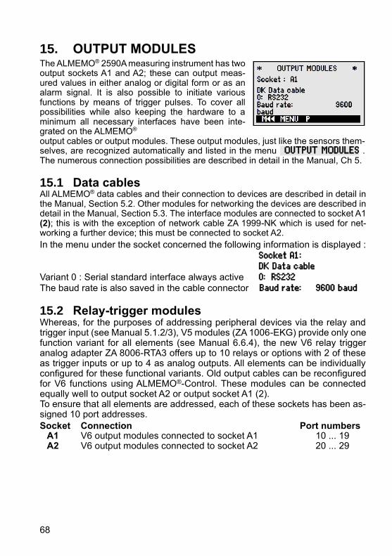
68
15. OUTPUT MODULES The ALMEMO® 2590A measuring instrument has two output sockets A1 and A2; these can output meas-ured values in either analog or digital form or as an alarm signal. It is also possible to initiate various functions by means of trigger pulses. To cover all possibilities while also keeping the hardware to a minimum all necessary interfaces have been inte-grated on the ALMEMO® output cables or output modules. These output modules, just like the sensors them-selves, are recognized automatically and listed in the menu OUTPUT MODULES . The numerous connection possibilities are described in detail in the Manual, Ch 5.
15.1 Data cables All ALMEMO® data cables and their connection to devices are described in detail in the Manual, Section 5.2. Other modules for networking the devices are described in detail in the Manual, Section 5.3. The interface modules are connected to socket A1 (2); this is with the exception of network cable ZA 1999-NK which is used for net-working a further device; this must be connected to socket A2.
In the menu under the socket concerned the following information is displayed : Socket A1: DK Data cable Variant 0 : Serial standard interface always active 0: RS232 The baud rate is also saved in the cable connector Baud rate: 9600 baud
15.2 Relay-trigger modules Whereas, for the purposes of addressing peripheral devices via the relay and trigger input (see Manual 5.1.2/3), V5 modules (ZA 1006-EKG) provide only one function variant for all elements (see Manual 6.6.4), the new V6 relay trigger analog adapter ZA 8006-RTA3 offers up to 10 relays or options with 2 of these as trigger inputs or up to 4 as analog outputs. All elements can be individually configured for these functional variants. Old output cables can be reconfigured for V6 functions using ALMEMO®-Control. These modules can be connected equally well to output socket A2 or output socket A1 (2). To ensure that all elements are addressed, each of these sockets has been as-signed 10 port addresses.
Socket Connection Port numbers A1 V6 output modules connected to socket A1 10 ... 19 A2 V6 output modules connected to socket A2 20 ... 29

15. Output modules
69
In the menu OUTPUT MODULES the elements of the output modules can be individually selected and functions programmed as follows :
First select the port by pressing : <P> : ▲ or ▼ e.g. port 0 at socket A2 (port address 20): Port: 20
The element concerned is recognized : Relay Relay type NO (normally open) : Relay : NO (normally open) Relay type NC (normally closed) : Relay : NC (normally closed) Relay type (changeover): Relay : Changeover
The relay switching mode can be configured on the following variants;see 9.5 :
0: Alarm, if one channel of all is faulty 0: Summated alarm 2: Alarm of a programmable channel 2: Assigned internally 3: Alarm, if one limit value - max of all is overshot 3: Summated alarm - max 4: Alarm, if one limit value - min of all is undershot 4: Summated alarm - min 8: Relay driven via interface or keypad 8: Driven externally
Variant 2 ´Assigned internally´ also requires the assignment of relays to cer-tain limit values; (see 13.12.2).
For the purposes of detecting power failure it is an advantage if relays are driven on an inverted basis; without current an alarm status applies automati-cally. The function variants are therefore also provided on an inverted basis.
Inverted relay control : e.g. variant 2 inverted : -2: Assigned internally - Inverted
The activation mode and actual contact status resulting from relay type and driv-ing mode are displayed in the next line.
Activation mode and relay contact status : Status : active open
Relay variant 8 ´Driven externally´ permits manual activation via the keypad or via the interface; (see Manual 6.10.10).
Relay variant 8: 8: Driven externally For manual activation of relays press : <ON> or <OFF>
Trigger inputs For the purpose of controlling the measuring se-quence 2 trigger inputs are provided at ports 8 and 9 (keypad or optocoupler). The trigger source "key" and / or "optocoupler" can be configured ini-tially by pressing keys PROG , ▲ / ▼ and PROG or the trigger function can, for safety purposes, be switched off altogether by means of "OFF".

15. Output modules
70
The following trigger functions can be programmed as variants :
0: Start / stop a measuring operation 0: Start - Stop 1: Once-only manual measuring point scan 1: Once-only scan 2: Clear all maximum values and min values 2: Clear max and min values 3: Print measured value 3: Print 4: Start / stop a measuring operation on level-controlled basis 4: Start - Stop, Level-con-trolled 8: Zero-set a measured value 8: Zero-set meas. value -5: Execute macro 5 (see manual 6.6.5) -5: Macro 5 -6: Execute macro 6 -6: Macro 6 -7: Execute macro 7 -7: Macro 7 -8: Execute macro 8 -8: Macro 8 -9: Execute macro 9 -9: Macro 9
15.3 Analog outputs V5 output modules For the purposes of analog recording of measured values it is still possible, at sockets A1 and / or A2 (2), to connect V5 output modules with an analog output controlled by the device, e.g. recording cable ZA1601-RK (see Manual 5.1.1). To select the socket press : <P> : ▲ or ▼
The following output modes can be programmed as variants :
0: Measured value of selected measuring channel : 0: Selected meas channel M00
2: Measured value of a programmed channel : 2: Assigned internally M01
8: Programmed analog output (see below) : 8: Driven externally
The analog value appears below this in digits : Analog value : 08345
This gives, depending on the analog output, the following output signals : Voltage output -1.2 ... +2.00 V 0.1 mV / digit Voltage output -6.0 ... +10.0 V 0.5 mV / digit Current output 0.0 ... 20.0 mA 1 µA / digit
In variant 2 ´Assigned internally´, after selecting the Mxx function, it is possible to program the measuring point to be output : 2: Assigned internally M V6 output modules The new V6 relay trigger analog adapter ZA8006-RTA3 (see Manual 5.1.3) offers the option at ports 4 to 7 of up to 4 in the output signal separately configurable external analog outputs.
02

15. Output modules
71
To select the port press key(s) : <P> : ▲ or ▼ e.g. port 6 at socket A2 (port address 26): Port: 26
The analog module appears with type and output signal 10V or 20mA: Analog output (D/A converter external in module) : Analog output external 10V Reprogrammable via keys : Analog output internal 20mA
The same output modes can be programmed as variants as with V5 :
0: Measured value of selected measuring channel : 0: Select meas channel M00
2: Measured value of a programmed channel : 2: Assigned internally M01
8: Programmed analog output (see above) : 8: Driven externally With V6 the analog value appears with the appropriate units : Analog value : +08.345 V
Programmed analog value output (see Manual 6.10.7) If the analog value is to be controlled individually either manually or via the in-terface then variant 8 ´Driven externally´ must be set : 8: Driven externally
Program the output of 2.5V with 10V output; (see above and 8.5) : Analog value : 05000
Scaling the analog output
In a special sub-menu that part of the measuring range assigned to the measuring point concerned that is actually used by the selected channel can, with functions Analog start and Analog end, be spread over the 10 V or 20 mA; (see 13.12.3)
Program the analog output start 6 Analog start : 0.0 °C Program the analog output end (see 9.5) : 6 Analog end : 100.0°C
For 20 mA analog outputs only Choose between 0 - 20 mA and 4 - 20 mA output : Current output : 4-20 mA

72
16. TROUBLE-SHOOTING The ALMEMO® 2590A measuring instrument can be configured and pro-grammed in many versatile ways. It is suitable for connecting a wide variety of different sensors, additional measuring instruments, alarm signaling devices, and peripheral equipment. Given these numerous possibilities the device may in certain circumstances not behave quite as expected. The cause of such un-expected behavior is only very rarely a device defect; more usually it is incorrect operation by the user, an invalid setting, or unsuitable cabling. In such event try to pinpoint and clear the problem with the aid of the following tests. Error No display, display malfunction, keys do not react Remedy: Check the power supply; replace the batteries; switch off and then on
again; if necessary re-initialize (see 7.5). Error: Measured values are incorrect. Remedy: Check all the channel programming very carefully, especially the base
value and zero-point (sensor programming and special functions menu).
Error: Fluctuating measured values or the system hangs in mid-operation. Remedy: Check the cabling for any inadmissible electrical connections. Unplug any suspicious sensors. Connect hand-held sensors in air or phantoms (for thermocouples
short-circuit AB, for PT100 sensors use 100) and check. Then connect the sensors again one at a time and check succes-
sively; if a fault persists for any one connection check the wiring; if necessary, insulate the sensor and eliminate interference by using shielded or twisted wiring.
Error: Data transmission via the interface does not function. Remedy: Check interface module, connections, and settings. Are both devices set to the same baud rate and transmission mode ?
(see 14.5) Is the correct COM interface on the computer being addressed ?
To check the data flow a small interface tester with LEDs comes in very handy; (in ready-to-operate status the data lines TXD, RXD carry negative potential of approx. -9V and the LEDs light up green, whereas the handshake lines DSR, DTR, RTS, CTS carry positive voltage of approx. +9V and the LEDs light up red. For the duration of data transmission the data LEDs should flash red. Check data transmission by means of a terminal (ALMEMO®-Control, WIN-Control, WINDOWS-Terminal).
Address the device using its assigned device number´Gxy´ (see Man-ual 6.2.1).
Enter <ctrl Q> for XON, if the device is in the XOFF status. Check the programming by means of ´P15´ (see Manual 6.2.3). Test the transmit line by entering a cycle using command ´Z123456´
and check in the display. Test the receive line by pressing <MANU> and check in the display.

16. Trouble-shooting
73
Error: Data transmission in the network does not function. Remedy: Check to ensure that all devices are set to different addresses. Ad-
dress all devices individually via the terminal using command ´Gxy´. Addressed device is OK if at least ´y CR LF´ is returned as echo. If transmission is still not possible, unplug the networked devices. Check all devices individually on the data cable to the computer; (see
above). Check the wiring for short-circuit or crossed wires. Are all network distributors supplied with power ? Network the devices again one at a time and check successively; (see
above). If, after performing the above-listed checks and remedial steps, the device still fails to behave as described in the operating instructions, it must be returned to our factory in Holzkirchen, accompanied by an explanatory note, error descrip-tion, and if available test printouts. With the ALMEMO®-Control software you can print out screen-shots with the relevant programming and save and / or print out a comprehensive ´Function test´ in the device list or terminal operation.

74
17. DECLARATION OF CONFORMITY

75
18. APPENDIX
18.1 Technical data Measuring inputs : 2590-2A/4AS 2/4 ALMEMO® sockets for ALMEMO® connectors Measuring channels : 2/4 primary channels, electrically isolated, 3 additional channels per input for double sensors and function channels A/D converter : Delta-sigma, 16-bit, 2.5/10mops, Reinforcement 1.38 Sensor power supply : 6V/9V12V, 0.4A (with mains adapter : 12 V)
Outputs : 2 ALMEMO® sockets for all output modules
Standard equipment : Display: Graphics, 128 x 64 pixels, 8 rows of 4 mm Operation : 7 keys (of which 4 softkeys) Memory : 100 measured values in RAM, MMC memory connector (2590-4S only): 500-KB EEPROM (60000 to 100000 meas. values) Date and time-of-day : Real-time clock buffered (10ppm) with device battery
Power supply : External 6 ... 13 VDC ALMEMO® socket DC Batteries : 3 AA alkaline batteries Mains adapter : ZA 1312-NAx 230 VAC to 12 VDC, minimum 1 A Adapter cable, electr. isol. ZA2690-UK 10...30 VDC to 12 VDC, 0.25 A USB Data Cable Supply ZA1919-DKU9 9V, 0.2A Current consumption without Active mode : approx. 12 mA (at 4.5V) input and output modules : With illumination : approx. 42 mA (at 4.5V) Sleep mode approx. 0.05 mA
Housing : (LxWxH) 127 x 83 x 42 mm ABS, weight : approx. 260 g
Suitable conditions Operating temperature -10 ... +50 °C (storage temperature -20 to +60 °C) Ambient relative humidity : 10 ... 90 % rH (non-condensing)
(see Manual 2.3)

18. Appendix
76
18.2 Product overview Universal measuring instrument with data logger function ALMEMO® 2590-2A
Order no. 2 inputs, maximum 12 channels, 2 outputs, cascadable interface, 7 keys, LCD graphics display, real-time clock MA 2590-2A
Universal measuring instrument and data logger ALMEMO® 2590-4AS Like the ALMEMO® 2590-2 but 4 inputs and 500-KB EEPROM memory MA 2590-4AS
Options Measuring ranges for temperature display of 10 refrigerants SB 0000-R Volume flow with array measuring in the flow channel per VDI2080 OA2590VN Accessories Memory connector including SD-card, minimum 128 MB ZA 1904-SD Mains adapter with ALMEMO connector 12V, minimum 1 A ZA 1312-NAx ALMEMO®-connector for ext. power supply 12V, 1A ZA 1312-FS8 DC adapter cable, 10 to 30 VDC, 12 V / 0.25 A, electrically isolated ZA 2690-UK ALMEMO® data cable, with USB interface, electr. isol., max. 115.2 KB ZA 1919-DKU ALMEMO® data-9V supply cable, USB interface, max. 115.2kBd ZA1919-DKUV ALMEMO® data cable, with V24-interface, electr. isol., max. 115.2 KB ZA 1909-DK5 ALMEMO® network cable, electrically isolated, maximum 115.2 KB ZA 1999-NK5 ALMEMO® recording cable, -1.25 to 2.00 V not electr. isol. ZA 1601-RK ALMEMO® V6 input / output cable for triggering and limit value alarm ZA 1006-EGK ALMEMO®-V6-Relay-Trigger-Adapter (4 relays, 2 trigger inputs) ZA 8006-RTA3 Option 2 Analog outputs electr. isol., configurable 10V or 20mA OA 8006-R02

77
19. INDEX Accessories ................................ 76 Action, maximum and Action, minimum .................................... 62 Actions in the event of a limit value being exceeded.......................... 61 activation mode .......................... 69 Active ......................................... 51 additional channels .................... 19 alarm relay cable........................ 61 ALMEMO®-Control ........ 15, 32, 35 Analog outputs ........................... 70 Analog start and analog end ...... 62 Analog-Anfang und -Ende ......... 71 Array measuring Option VN ....... 41 Atmospheric pressure compensation ............................. 66 Atmospheric pressure compensation ............................. 30 Averaging ................................... 37 averaging duration ..................... 41 Averaging mode ......................... 54 Averaging over individual manual meas operations ........................ 38 Averaging over measuring points ................................................... 40 Averaging over the cycle............ 39 Averaging over time ................... 39 Base value ................................. 55 Battery operation........................ 17 Baud rate ................................... 66 Calibration resistance ................ 44 Changing the units ..................... 56 channel data .............................. 41 Channel type .............................. 41 CJ temperature .......................... 66 Cold junction compensation ....... 31 cold junction temperature .......... 31 Cold junction temperature .......... 66 compensation ............................. 27 Configuration .............................. 67 Connecting the sensors / transducers ................................ 19 contact status ............................. 69
continuous measuring point scan ................................................... 50 contrast ....................................... 65 control value ............................... 44 conversion rate ........................... 50 Correction values ....................... 55 cross-section .............................. 41 Current output ............................ 71 Cyclic output ............................... 46 Data buffering ............................. 18 Data cables ................................ 68 Data format................................. 66 Data input ................................... 24 data logger ................................. 32 Data logger functions ................. 44 Date ............................................ 46 Decimal point setting .................. 55 Declaration of conformity ........... 74 depth .......................................... 41 Designation ................................ 53 device address ........................... 66 Device configuration ................... 65 Device designation ..................... 65 Device-internal channels ............ 19 diameter ..................................... 41 differential channel ..................... 20 Differential measurement ........... 31 Display ........................................ 22 Element flags ............................. 64 End time ..................................... 51 External DC voltage supply ........ 17 Factor ......................................... 55 Fail-safe mode ........................... 50 File name.................................... 45 force transducers ....................... 44 Function channels ...................... 59 Function keys ............................. 23 Function menus .......................... 36 Function selection ...................... 24 Functions .................................... 11 Gain correction ........................... 56 Housing ...................................... 75 hysteresis ................................... 55

Index
78
Hysteresis .................................. 67 illumination ................................. 22 Illumination ................................. 65 Initial commissioning .................. 16 Interface ..................................... 66 Internal data memory ................. 45 Introduction ................................. 11 Inverted relay control ................. 69 keypad ....................................... 22 Language ................................... 65 level of smoothing ...................... 37 Limit values ................................ 54 Linearization ............................... 60 Locking the sensor programming ................................................... 54 Mains operation ......................... 17 manual measuring point scan .... 46 Maximum, minimum, individual values memory ........................... 36 Meas chan. ................................ 51 Measured value correction ........ 27 Measured value display and status symbols ...................................... 22 measuring depths ...................... 41 measuring duration .................... 39 Measuring duration .................... 52 Measuring inputs........................ 19 Measuring inputs........................ 75 Measuring menus ...................... 27 Measuring operations ................ 13 Measuring point designation ...... 53 Measuring points list .................. 31 Measuring rate ........................... 50 Memory connector ..................... 45 memory output ........................... 47 Memory space ........................... 47 Memory time .............................. 51 menu selection ........................... 22 Monitor mode ............................. 49 multiplexer .................................. 63 Multi-point calibration ................. 60 networking .................................. 66 Numbering of measuring operations .................................. 47
OFF ............................................ 22 ON .............................................. 22 Once-only output ........................ 46 Operating parameters ................ 67 Options ....................................... 76 Order no. .................................... 76 output format .............................. 47 Output format ............................. 50 Output function ........................... 62 Output modules .......................... 68 Potential separation ................... 20 Power supply ........................ 17, 75 Print cycle factor ......................... 61 Process control .......................... 14 Product overview ........................ 76 Programmed analog value output ................................................... 71 programming menus .................. 26 Reference channel 1 .................. 63 Reference channel 2 .................. 63 refrigerants ................................. 59 reinitialization ............................. 18 relay adapter .............................. 61 Relay assignment ....................... 61 Relay-trigger modules ................ 68 Ring memory .............................. 51 Safety instructions ........................ 9 saving to memory activated ....... 48 Scaling ........................................ 55 Scaling ........................................ 44 Scaling the analog output........... 71 Scanning configuration ............... 48 Scanning mode .......................... 48 Scope of delivery .......................... 7 SD-card ...................................... 45 Selecting a measuring point ....... 27 Selecting the input channel ........ 53 Selecting the measuring range .. 56 Semi-continuous measuring point scan ............................................ 50 Sensor adjustment ..................... 28 Sensor breakage ........................ 23 Sensor display ............................ 27 Sensor programming ............ 11, 53

Index
79
Sensor supply ............................ 17 sensor supply voltage ................ 62 Sensor voltage, min ................... 62 Sensors / transducers ................ 19 Set measured value to zero ....... 28 setpoint entry ............................. 43 Sleep mode ................................ 49 sliding average ........................... 37 Smoothing meas values ............ 37 Software ..................................... 15 Special functions ........................ 60 Special meas. ranges ................ 60 Standard equipment .................. 75 standardized volume .................. 43 Start time .................................... 51 Starting and stopping measuring operations .................................. 51 Suitable conditions ..................... 75 supply voltage monitoring .......... 17 Surface ....................................... 41 Switch memory activation .......... 47
switch OFF ................................. 18 Switching ON / OFF ................... 18 Technical data ............................ 75 temperature compensation ........ 66 Temperature compensation........ 29 Time constant ............................. 38 time-of-day ................................. 46 Trigger inputs ............................. 69 Trouble-shooting ........................ 72 Two-point adjustment ................. 43 User measuring menu ................ 32 user measuring menu Bar chart . 32 user menu .................................. 35 User menus ................................ 33 Volume flow measurement ......... 40 Warranty ....................................... 7 Waste disposal ............................. 8 width ........................................... 41 WINControl ................................. 15 Zero-point correction .................. 56

Your contact AHLBORN Mess- und Regelungstechnik GmbH Eichenfeldstraße 1 83607 Holzkirchen Germany
internet : http://www.ahlborn.com e-mail : [email protected]
Despite great care, incorrect information cannot be ruled out. Technical changes are reserved.


![Crítica à Execução Penal [2a edição]](https://static.fdokumen.com/doc/165x107/631ae641d43f4e176304a750/critica-a-execucao-penal-2a-edicao.jpg)