
RCA Type BN-2A Portable Remote Amplifier Manual
16
www.SteamPoweredRadio.Com
-
Upload
khangminh22 -
Category
Documents
-
view
3 -
download
0
Transcript of RCA Type BN-2A Portable Remote Amplifier Manual

~ • • I BROADCAST. AUDIO EQUIPMENT ~------------------• I • -• • . ~ ' • • • • • • ' • • ! '' ;~
= • • • • •
INSTRUCTIONS
Type BN-2A Portable Remote Amplifier
(Ml-11230)
RAD. IQ CORPORATION OF AMERICA
lt ~"~'~' lu~ ~ E R I N G P R O D U C T S DEPARTMENT, CAMDEN, N. J. . ~-
• • www.SteamPoweredRadio.Com
wigfi
Stolen 2 Line Transparent

t • • • • • • • • • • • • • • • • • • • • • I • • • • • • • • • • • • • • • • • • • •
2
--
I
Figure 1-Type BN-2A Portable Remote A mplifi er, panel cover removed
a,• --...... ---·=-
7
e
IJ·'
l
-··---~ www.SteamPoweredRadio.Com
wigfi
Stolen 2 Line Transparent

• • • • :(t • • • • • : lt
• • • • • • • • llt • • • • • • :(t • ' • • • • • :(t • • ' •
DESCRIPTION
Application The Type BN-2A Portable Remote • Amplifier (MI-
112 3 0) is a high-fidelity unit for a-m and f-m broadcast audio applications. It, is designed to amplify lowlevel signals for transmission over a telephone line to the studio. The ·amplifier provides complete pickup facilities for programs remote from the studio such as sports events, street programs, political and social meetings, park concerts and similar gatherings. It may also be employed for semi-permanent installations such as in department stores, night clubs and restaurants, or may be used in a small studio for regular use or as standby equipment .
Components The .amplifier is a four-stage resistance-coupled unit
including three preamplifiers in the first stage for separate microphone or turntable inputs. A switch is provided to permit switching a fourth input into channel three. Each · preamplifier has its own mixer. A master
. 3
gain control is provided as part of the three-stage program amplifier section. Output terminals on the front panel may be used for simultane-0usly feeding the signal to a public address amplifier and a telphone, line. The public address output has its own balanced volume control. Cueing and monitoring facilities are provided. A control permits switching the public address input to ·•cue", "amplifier output" or "off". A meter with an
associated switch is used for checking level to the line and also for giving an indication of the condition of the amplifying tubes. A switch is provided for controlling the amount of meter illumination.
All electrical components in the amplifier arc precision made with close tolerances. Step-type attenuators are used. The 1620 tubes ue especially designed for broadc:ut applications where a minimum of noise and microphonics are required. The three preamplifier tubes and the first program amplifier tube are shockmounted to insure low microphonics and maximum pro
tection from vibrations which are often experienced
during remote broadcasts.
TECHNICAL DATA
Power Required .A.-C Oper11lion
117 volts, SO to 60 cps, 2 f w•tts D-C Optralion
"A" Supply-6.3 volts, 2.1 amperu mu.
"B" Supply-271 volts, 10 milliamperes
Fuse A-C line, 1 amper,
Tube Kit (Ml-11269) 4 RCA 1620 2 RCA 6]7•
RCA 6XfGT
•1620·, m•y be used in place of 6J7's
Optional Tube Kit (Ml-11269-A) 6 RCA 6J7
1 RCA 6XlGT
Note: 6J7'• m•y be substituted for RCA 1620's when
maximum uniformity of characterinic:1 and minimum
o{ microphonics, hum snd di1tortion are not required .
Source Impedance llO or ;o ohms balanced. :M•y be used with 210-ohm
microphone, on I JO-ohm tap. May •lso be uxd with an unb•lanced source. See text .
ln_put Impedance Unloaded transformer
Moxiinum Input Level -)0 dbl1\
Mixing High level, alter prumpli6cr ch•nncls
Load Impedance l00/600 ohms
Power Output +u dbm for distortion of Jen than t.O'}"o u JO 10
I J,000 cps
Goin 92 db ( 1 JO-ohm source on I JO-ohm input t-O 600--0hm
load)
Frequency Response ± I db from ) 0 co I l ,000 cps (lig. 2)
Noise Level Single channel, gain maximum: -30 dbm
Si~gle channel, gain 68 db (m•sccr gain control set at
12, mixer gain control set at 16): -12 dbm. This
corraponds to a signal-1.0-noise ratio of 70 db at rated
power output.
Dimensions and Weight Length-14 ½ inches
Depth-9 ½ inches Height-IO inchc,
Wcight-29 pounds
Panel Slope IO degrees_
www.SteamPoweredRadio.Com

• • • • • a • • • • • • • • • • • • • • : = • • • • • • • • • • • • • • • • • • •
4
' · 2
(D 0
z 0 IJJ (/) z -2 0
.... V
i,.--- "" a. (/) IJJ
S-8850911 a::
20 100 1,000 FREQUENCY IN CYCLES PER SECOND
10,000
Figure 2- Frequency response
Construction The back and bottom cover of the amplifier is made
removable for ease of servicing. The top cover, which is also removable for replacement of tubes, has a curying strap which fits into a recess on the cover when not in use. If a screwdriver is not available, a. coin may be · used to loosen the twist-lock fasteners which hold the covers in place. Two tube sockets and a fuse clip are provided on the bottom side of the top for carrying spare tubes and a spare fuse. Only two spare tubes are ,required (6X5GT and 1620 or 6J7). The amplifier is designed wit.h a sloping panel for maximum ease of operation. A removable panel cover protects the control knobs and meter. A protective cover, MI-11277, is available as an accessory for transporting the amplifier during inclement weather or to preserve its appearance .
Power Requirements The power cord and plug of the · amplifier is intended
to be connected to an a-c power line of the voltage and frequency specified under Technical Data. When desired, an MI-11214 Battery Box and MI-11255 Battery Kit may be used to furnish power. The batteries in this kit are described under Battery Connections. The power cord assembly for a-c line operation is supplied with the amplifier, and the power cord assemi?ly for d-c operation is supplied with the MI-11214 Battery Box. Each of these power cords i6 equipped with a 12-terminal plug which mates with the power receptacle on the amplifier
chassis .
CIRCUIT
Input The input circuit to each of the three preamplifier
channels consists of a transformer (T-1,2,3) normally connected for operation from a 150-ohm balanced source. Other possible input connections are described under Imtallation. An RCA 1620 (or 6J7) connected
as a triode (V-1,2,3) is used in each of the three preamplifier channels. Three step-type attenuators (R-5, 11,17) marked MIC-I, MIC-2, MIC-3 & 4, which are connected in the coupling circuits to the first program amplifier stage, serve as the mixers to control the levels in each of the preamplifier channels.
First Stage of Program Amplifier An RCA 1620 (or 6]7) is connected as a pentode
(V-4) in the first program amplifier stage. The MASTER gain control (R-37) is a step type attenuator in the coupling circuit between the· first and second program amplifier stages. Negative feedback is applied
Figure 3-Panel and top covers
-'
www.SteamPoweredRadio.Com
wigfi
Stolen 2 Line Transparent
• • • • :lt • • • • • :~ • • • • • • • -t \t • • • • • • • .~ I • • • • • • :lt • • •
from this control through R-19 to the grid of the first program amplifier stage.
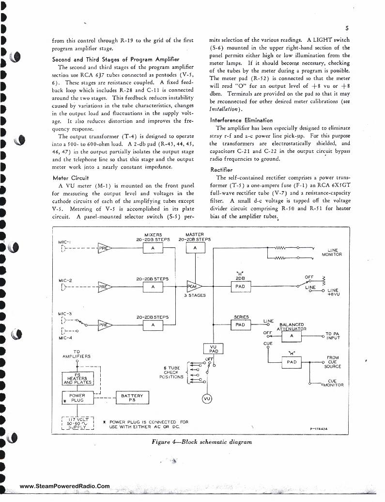
Second and Third Stages of Program Amplifier The second and third stages of the program amplifier
section use RCA 6]7 tubes connected as pentodes (V-5, 6). These stages are resistance coupled. A fixed feedback loop which includes R-2 8 and C- 11 is connected around the two stages. This feedback reduces instability caused by variations in the tube characteristics, changes in the output load and fluctuations in the supply voltage. It also reduces distortion and improves the frequency response.
The output transformer (T-4) is designed to operate into a 500- to 600-ohm load. A 2-db pad (R-43 , 44, 45, 46, 47) in the output partially isolates the output stage and the telephone line so that this stage and the output meter work into a nearly constant impedance.
Meter Circuit A VU meter ( M-1) is mounted on the front panel
for measuring the output level and voltages in the cathode circuits of each of the amplifying tubes except V-5. Metering of V-5 is accomplished in its plate circuit. A panel-mounted selector switch (S-5) per-
MIXERS MASTER
5
rnits selection of the various readings. A LIGHT switch ( S-6) mounted in the upper right-hand section of the panel permits either high . or l!)w illumination from the meter lamps. If it should become necessary, checking of the tubes by the meter during a program is possible . The meter pad (R- 5 2) is connected so chat the meter will read "O" for an output level of +s vu or +s dbm. Terminals are provided on the pad so that it may be reconnected for other desired meter calibrations ( see Installation).
Interference Elimination The amplifier has been especially designed to eliminate
stray r-f and a-c power line pick-,up. For this purpose the transformers are electrostatically shielded, and capacitors C-21 and C-22 in the output circ.uit bypass radio frequencies to ground.
Rectifier The self-contained rectifier comprises a power trans
former (T-5) a one-ampere fuse (F-1) an RCA 6X5GT full -wave rectifier tube (V-7) and a resistance-capacity filter. A small d-c voltage is tapped off the voltage divider circuit comprising R-50 and R-51 for heater bias of the amplifier tubes.
•
MIC- I 20-208 STEPS 20- 208 STEPS
I '------- PR~------< c'
A A
MIC-2
[ ;- - - ---- - PRE'>------1
20- 200 STEPS
A f-------<PGIM>--+---i
MIC - 3
[)---,... I \.. -- -o V
MIC- 4
TO AMPLIFIERS
I I
'-----'
20-208 STEPS
A
3 STAGES
~
-----oor 6 TUBE ~ CHECK
POSITIONS L~o
'--~-__, :~~-4L_a_A_T_P_\_E_R_v__,
• POWER PLUG IS CONNECTED FOR USE WITH EITHER AC OR DC.
SERIES
PAD
Figure 4--Block schematic diagram
PAD
OF'F'
LINE MONITOR
LINE 0--0 LINE
+avu
FROM 1-----0 CUE
SOURCE
CUE MON ITOR
P-174434
www.SteamPoweredRadio.Com

• • • • • • • • • • • • • • • • • • • • • • • • • • • • • • • • • • • • • • • • • • •
6
INSTALLATION
Audio Input Connections Audio input conne~tions are made through four
standard Cannon female receptacles marked MIC-1,2,3
and 4 at tlie rear of the amplifier. The m:iting plugs (RCA Ml-4630-B or Cannon P3-CG-12S) are not
furnished with the amplifier. The MIC-I and MIC-2
receptacles are each connected to the input transformers
T-1 and T-2 respectively. The MIC-3 and MIC-4
receptacles .ire connected through switch S-1 to input
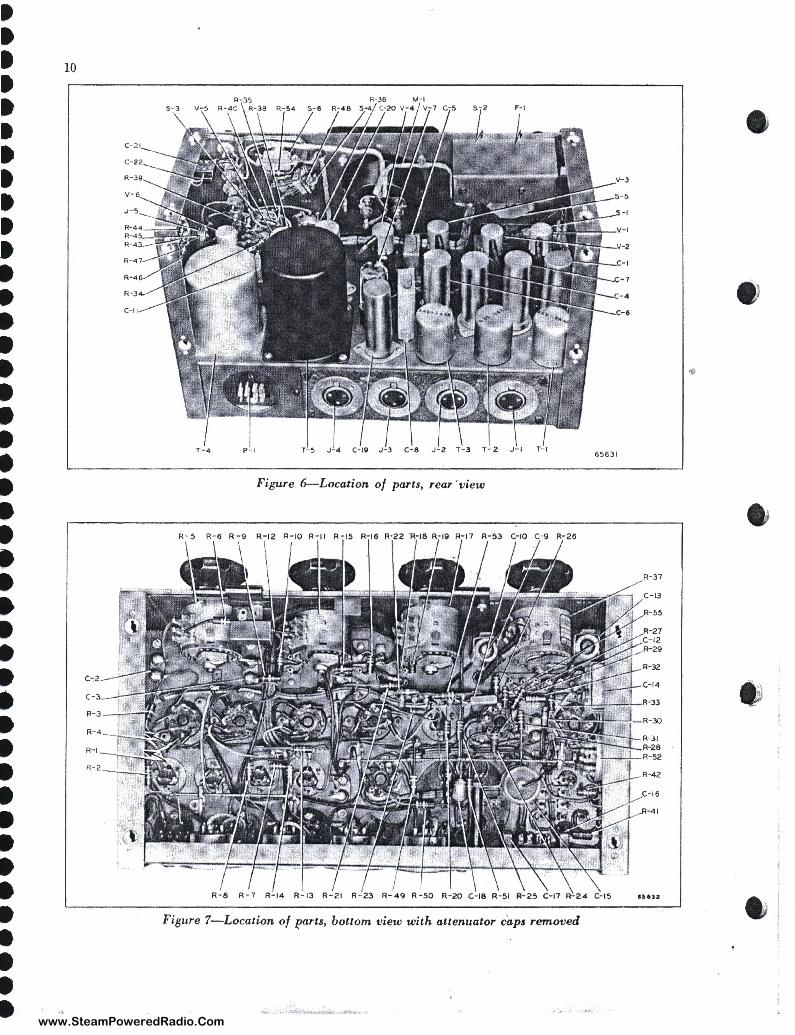
transformer T-3. Refer to figures 6 and 8. To change the wiring on the input transformers as described below, first remove the bottom and back cover assembly
by loosening the eight twist-lock fasteners which hold
it in place. Each fastener need only be turned ¼ of
a revolution with a coin or screwdriver .
Connections to Balanc&d Source Each of the amplifier input transformers is connected
for operation from a 150-ohm balanced source. If desired, a 250-ohm balanced source may be connected
to this tap.
If it is desired to use one or more 30-ohm sources,
change the wiring to ~he taps on the primary windings
of the associated input transformers as follows:
a. Remove the black lead connected to terminal num
ber 1 and connect it to terminal number 2 . b. Remove the red lead connected to terminal num
ber 4 and connect it to terminal number 3.
On all balanced inputs, connect the audio leads from
the source to terminals number 2 and 3 on the input
plug used and connect the shield lead to terminal num
ber 1.
Connections to Unbalanced Source For connection to a 150-ohm or 2 5 0-ohm unbalanced
source, first remove the jumper connecting terminal number 5 to terminal number 6 on the associated input transformers; then connect terminal number 5 to
terminal number 1. To connect a 30-ohm unbalanced source proceed as
follows: a. Remove the jumper connecting terminal number
5 to terminal number 6 on the associated input trans
formers . b. Connect terminal number 5 to terminal number
2. c. Disconnect the black lead from terminal number
1 and connect it to terminal number 2 . d. Disconnect the red lead from terminal number 4
and connect it to terminal number 3 •
When connecting an unbalanced source which uses the
shield as one of the audio leads, connect the shield lead
to terminal number 3 on the input plug and connect
the other audio lead to terminal number 2 . For an unbalanced input having two audio leads and
an electrostatic shield, connect the low side of the line to terminal number 3 on the input plug, the high
side to terminal number 2, and the shield lead to terminal
number I .
Output Conneetions · Remove the panel cover by pressing the two spring
buttons on the sides of the amplifier. Output connec
tions are made as follows: a. Connect the telephone line to the LINE binding
posts .
b. Connect the PA binding posts to the input of the
public address amplifier. c. Connect the leads from the cue source to the CUE
binding posts.
Ground Connection Connect the GND binding post to a suitable ground .
The amplifier may be operated without an external ground when none is available, however best operation
is obtained when the amplifier is grounded .
Headphone Jaeh Headphones may be used for monitoring, however
none are supplied with the amplifier'. Insert the plug from the output monitoring headphones into one of the
telephone-type jacks marked LINE MON (J-6 or J-7) on t_he right-hand side of the amplifier. Insert the plug
,from the cue-monitoring headphones into the jack
marked CUE MON (J-5) on the same side.
Meter Pad Connections The meter pad R-52 and the associated meter circuit
arc conn«:tcd so that the meter indicates O vu for a line
level of +s dbm or +s vu when the meter switch is
in the +s VU position. To obtain a 0-vu indication for any other integral line level in the range of +2 to + 18 dbm, it is necessary to reconnect the terminals on the meter pacl for different amounts of attenuation. A convenient method of determining the amount of attenuation is as follows: The amount of attenuation in
the p.td is 2 db less (numerically) th.in the line level
corresponding to 0-vu indication on the meter. For
example, the pad has its 2-db apd 4-db sections con
nected in series to give a 6-db attenuation, and thus the meter reads O vu for + 8 dbm or + 8 vu line level. The pad has sections for 1, 2, 4, 8 and 12 db of attenuation. The two terminals for each of these sections are clearly indicated by stencilled designations on the rear of the
pad between each pair. If necessary to reconnect the pad, indicate in some manner near the met.er-switch
panel-marking the new value to be used instead of the
+s VU designation.
www.SteamPoweredRadio.Com

• • • • ." • • • • -!~ • I • • • • • :c. • • • • • • 1~ • • • • • • :~ • • • •-
A-C Power Connections The amplifier is connected for a-c operation from a
115- to 125-volt, 5 0- co 60-cycle power line. For operation from a 105- to 11 S-volt line, it is necessary to disconnect the black/red lead from terminal number 12 of transformer T-5 and connect this lead to terminal
number 11 ofT-5. The a-c power cord is clamped to the inside 0£ the
front panel cover for convenience in transporting. Remove this cord from beneath the clamps and insert the 12-terminal plug on one end of the cord into' the receptacle on the rear of the amplifier. Insert the twoprong plug on the other end of the cord into a suitable
a-c outlet.
Tubes Loosen the four twist-lock fasteners on the top cover
and remove this cover. Markings on the chassis indicate the correct tube type for each socket. Place the tubes in the sockets. Place the grid caps and grid-cap shields on all of the amplifying tubes. Each shield must make a good electrical connection to the shell of the tube for noise-free operation.
Battery Connections Six RCA Type VS012 "B" Batteries or equivalent,
and 1 0 RCA Type VS004 "A" Batteries or equivalent may be used to supply the d-c power requirements listed under Technical Data. A kit of the above listed batteries may be ordered as Ml-112 5 5. The use of 15 "A" batteries will increase the battery life. The MI-11214 Battery Box may be used with the Type BN-2A Amplifier. The battery box contains space for 15 "A" batteries and 6 "B" batteries of the types listed above.
The Ml-11214 Battery Box is wired with plugs ready to be inserted into the batteries and is supplied with a power cord for direct connection to the receptacle on the amplifier. The battery connector plug is wired as 'shown in the lower-left corner of the schematic diagram, figure 8.
The expected battery life for an average amplifier operation of six hours per day is as per the table below. If the amplifier is used less than six hours per day, the expected life of the battery in hours will be increased. If the amplifier is to be used continuously the life of the battery will be materially decreased.
EXPECTED LIFE IN HOURS (APPROXIMATE)
Q11anlity HA" or "B" Typ, Li/, in Hours
15
10
6
A VS004 8.J
A VS004 4
B VS0l2 12f
NOTE: For maximum battery life remove alt battery
plugs when che battery supply is not to be used . for
24 hours or more.
7
OPERATION
Set the LIGHT switch for the desired meter illumination (LO or HI). (The meter lamps also serve as power-on-off indicators.) Set this switch in "LO" position when using batteries to reduce drain on the batteries. Turn the POWER swi\cb ON and allow ah'out 30 seconds for tube warm-up. Before broadcasting has begun, turn all volume controls to maximum and check carefully for extraneous noises in the output which may be due to faulty location of the microphones and cables. When using the MIC-3 or MIC-4 input, set the MIC switch to the corresponding number. Rotate the METER switch to the "+s VU" position. Output level to .the telephone line should be +s vu. Adjust the gain controls so that the peaks of modulation swing the needle of the meter to zer~ on the upper scale ( for an average line level of + 8 vu). This zero reading will represent a different line level if the connections to the meter pad have been changed as indicated under Installation. For the best signal-to-noise ratio the MASTER gain control should be set at a fixed. position somewhere between number IO and number 16 and the mixer controls (MIC 1, 2, 3 & 4) should be adjusted for the zero reading on the meter. This arrangement permits varying the mixers from number Oto number 16 without adding more than 2 db to the noise level of the amplifier. The MASTER and MIC controls also control the level at the output-monitoring jacks.
Switching to Telephone Line To switch the output of the amplifier into the tele
phone line, turn the AMP OUTPUT control to LINE.
To switch the output of the amplifier off the telephone
line, turn the AMP OUTPUT control to OFF .
Switching to PA Amplifier To switch the output of the amplifier into the input
of a connected public address amplifier, turn the PA INPUT switch to AMP. To switch the input at the CUE terminals to the input of the public address amplifier, set the PA INPUT switch to CUE. Adjust the PA VOLUME control for the desired output from the public address system. To switch both amplifier and cue inputs off the public address amplifier, turn the PA INPUT switch to OFF.
SERVICE
Tube Checking with VU Meter To check the tubes, rotate the METER control
through posidons 1 through 6 and observe the VU meter
at each step. These meter positions check V-1 through ..
www.SteamPoweredRadio.Com
wigfi
Stolen 2 Line Transparent

' • • • • • • • • • • • • • • • t. • • • • • • • • • • • I • • • • • I I •• • • • • • •
8
RCA 1620
1 f I r CHASSIS CiR OUNO
RCA 162 0
RCA 1620
~ ~
I 1 I t 1
RCA 1620
I i I I 1 g
! 0 2 ~
l 11 .. ., ~ !'!
l l 1 ALL VOLTAGES O C UNLESS OTHERWISE NOTEO
12.0- V0 L U OH 120-V0LT UP
lr'C V0LTAGC$ MfA$UR(0 WllH 20.000 0 HM$/YOL.T METER .
Figure 5-Tube socket voltages
V-6 respectively ( fig. 8). The meter readings are each an indication of the emission of the tubes., The normal meter reading for each tube should be O ±2 (on VU scale). Note that two spare tube sockets are provided on the bottom side of the top cover for carrying spare tubes .
Cleaning Volume Controls Remove the bottom and re,ar covci: ass~mbly of the
amplifier. Press the spring fasteners on the rear covers of the volume controls and remove the covers. Apply Davcnoil, which is furnished with the amplifier, to the contacts, and rotate the knobs. If any dark streaks appear, wipe off the contacts. Repeat this procedure until the contacts are clean, and then apply a thin film of Davenoil for lubrication. The Davenoil is provided for cleaning and lubricating the volume controls and no other cleaning agent ·should be used.
Operating Voltages Refer to figure 5 for the tube operating voltages.
The voltages listed are approximate,- but readings should not vary more than about 20 % of the values given. If
the voltmeter used has a meter resistance of less than 20,000 ohms-per-volt, most readings taken will vary accordingly, the amount of variation depending upon the circuit across which the meter is connected .
Fuse Replacement When replacing a fuse, make sure that the replace
ment fuse is of the same type and rating ( 1 ampere) as the one furnished with the amplifier. To use a fuse of higher rating for replac~ment purposes will needlessly end,rnger the windings of the power transformer. Note that a spare fuse mounting is provided on the bottom side of the top cover for carrying a spare fuse.
Replacement Parts The following parts list is included to provide identi
fication when ordering r~placement parts. Order from
RCA Replacement Parts Department, Camden, New Jersey, giving the Stock Number and Description of the
parts wanted. Replacement parts supplied may be
slightly diffe.rent in form or size from the original parts
but will be completely interchangeable with them.
LIST OF PARTS
Symbol Stock. Symbol Slock. No . Dc,criptio,z No. No. Drscription No.
C-1 Capacitpr, elec, 3 sections : "A" C-2,3 Capacitor, oil filled, 0.25 mf 40 mf - 25 v, "B" & "C" 15 ±10%, 400 V 55811 mf - 450 V 34150 c~ Same as C-1
•
www.SteamPoweredRadio.Com
wigfi
Stolen 2 Line Transparent

' : • Jlt t • -' • ~
: \I • • ~ • • I • M • -• • ' • .l\t • • • = • • • lt • • •
Symbol
No.
C-5 C-6,7 C-8
C-9
C-10
C-11
C-12 C-13 C-14 C-15
C-16,17
C-18
C-19,20 C-21,22 F-1 J-1,2,3,4
}-5,6,7 M-1
P-1 R-1
R-Z
R-3
R-4
R-5
R -6
R -7 R-8 R-9 R-10 R -11 R-12 R-13 R-14 R-15 R-16 R-17 R-18
L I S T O F P A R T S (Continued)
De,crif,tion
Same as C-2 Same as c : 1 Capacitor, oil filled, 0.5 mf
± 20%, 400 V
Capacitor, paper, oil impreg-
Stock
No ,
55812
nated, 0.05 mf ± 10%, 600 v 55g13 €1.pacitot, mica, !lOO 1m1rf C-/1:,
iil.>10%, !iO!h•S11.M~ ·IIS -4&rn Capacitor, oil filled, 0.05 mf
± 10%, 400 V 55814 Same as C-2 Same as C-9 Same as C-Z Capacitor, paper, oil impreg
nated, O.~ mf ± 10%, 400 v Capacitor, molded, paper,
0.0015 mf, 600 V
Capacitor, metalized paper, 0.25 mf, 200 V
Capacitor, elec, 40 mf, 450 v Same as C-16 Fuse, 1 amp Connector, female, 3 contacts,
chassis mounting J ack, open circuit phone jack Meter, VU volume level indi
cator, illuminated, scale "A" calibrated for .047" steel panel, panel angle 10 degrees, black
Connector, male, 12 contacts Resis tor, comp, 1800 ohms
± 5%, 1 w Resistor, comp, 680 ohms
::±: 5%, 1 w Resistot, comp, 100,000 ohms
± IO%, 1 w Resistor, comp, 27,000 ohms
± 10%, 1 w Resistor, attenuator, carbon,
20 steps of 2 db each to infinity, 100,000 ohms
Resistor, comp, 220,000 ohms ± 10%, 1 w
Same as R-1 Same as R-2 Same as R -.3 Same as R-4 Same as R-5 Same as R-6 Same as R-1 Same as R-2 Same as R-3 Same as R-4 Same a$ R-5 Same as R-6
..
55815
55816
55817 37308
14133
25598 43921
55818 19679
55819
Symbol
No.
R-19
R-20
R-21
R-22 R-23 R -24
R-2S
R-26
R-27
R-28
R-29
R-30
R-31
R-32
R -33
R-34,3S
R-36
R-37
R-38,39 R-40
R-41,42
R-43,44
R-4S R-46,47 R-48 R-49
R-50 R-51
R-52
Dc,cri ption
Resistor, comp, 1.2 meg ±10%, 1 w
Resistor, comp, 1100 ohms ± 5%, l w
Resistor, comp, S6,000 ohms ± 10%, 1 w
Same as R-19 Same as R -6 Resistor, comp, 3300 ohms
± 5%, l w Resistor, comp, 2700 ohms
~-s%, 1 w Resistor, comp, 2,7 meg
± 10%, l w Resistor , comp, 470,000 ohms
± 10%, 1 w Resistor, comp, S60,000 ohms
± S%, l w Resistor, comp, 12,000 ohms
± 10%, 1 w Resistor, comp, 1 meg
± 10%, 1 w Resistor, comp, 130 ohms
± 5%, 1 w
Resistor, comp, 360 ohms ± 5%, 1 w
Resistor, comp, 120,000 ohms ± 5%, 1 w
Resistor, comp, 4700 ohms ± 10%, 1 w
• Resistor, variable, dual, 300 ohms per section ± 20%, shaft ,249" diam x ¾" including ¼" bushing fiat nr" body 1 rtr" diam x 1 fa"
Resistor, attenuator, ladder pad
Same as R-34 Resistor, comp, 560 ohms
± 10%, l w Resistor, comp, 2200 ohms
±10%, l w Resistor, comp, 39 ohms · ± 10%, 1 w
Same as R-25 Same as R-43 Same as R-40 Resistor, comp, 3900 ohms
± 10%, 1 w Same as R-27 Resistor, cod;p, 22,000 ohms
±10%, 1 w Resistor, attenuator, multiple
pad, impedance 7100 / 3900 ohms, maximum attenuation 27 db
1
9
Stock
No .
54667
43115
I 19328
www.SteamPoweredRadio.Com
• • • • • • • • • • • • • • • • • • • • • • • • • • • • • • • • • • • • • • • • • • •
IO
v-
c~2
R-1
V-3
S-5
S·t
V- 1
V-2
c-1
Figure 6-Location of parts, rear 'view
R- 37
R-42
C-16
:.:;.y-41
....-.::=-=::~p.=-,=:-:-::,,--=:p=--.::::::~=1=-:-:J::=:::;l=::=r-:-\-\-\-~~~~"'"~J
R- 8 R - 7 R-1 4 R-13 R-21 R-23 R-49 R-50 R-20 C-18 R- 51 R-25 C-17 R-24 C-15 auu
Figure 7-Location of /?arts, bottom view with attenuator caps removed
•
www.SteamPoweredRadio.Com
wigfi
Stolen 2 Line Transparent

• • • • • • • • • • • • • • I • • • • • • • • • • • • • • • • • • • • • • • • • • • •
1'" !
55·3/>.
MIC- 3
MIC 4-
eArrERY
CONNECTOR
.,. FROl./r VIEWS
'O u
A . C. CONNG'CTOR
.Q. C LINE
RJ7
I_ our
C/7
/500MMF
Pl
TS
www.SteamPoweredRadio.Com
wigfi
Stolen 2 Line Transparent

• t • • • • • • • • C:
... 0 No Ci"'
"'
C II
.OSMF'O
Cl:!:>
.O!SMf"O
CIG
.5MFD
V•',
r- ------' a I I I I I
I t; I
4700-ll.
0 0
S·3
cu
C I 4 I
• ----i-+--+--;cior:-h,+,;.-~~~~~----+ti:__ +-_j __ '-...l- - - - - - - - _J
• • • • • • • • • • • •
t§
ro 1ol.O ( "J 1 ;.;EIJTt.11'.S
7 2
,-,a
R5+ 22 .I\.
S·6
S-5 ... i ~
.:le • OFF'
1. • +av.lJ.
A
Ill.
_ {_ J
B
• e OFf
~41 azoo..n..
VO\.:.UMC INOICA,-OFI.
=
T-1042O1- 1
,.)ti,
v 7
Figure 8--Schematic diag
www.SteamPoweredRadio.Com
wigfi
Stolen 2 Line Transparent

12
Symbol No.
R-53
R-54
R-55
S-1
S-2
S-3
S-4 S-5
S-6
L I S T O F P A R T S (Continued)
DttcriJ,llon
Resistor, comp, 430 ohms ±5¾, 1 w
Resisto'r, comp, 22 ohms ±10¾, l w
Resistor, comp, 5600 ohms ±5¾, 1 w
Switch, rotary, DPDT, locking
Switch, toggle, DPST, rated 2 amp, 250 V
Switch, rotary, 2 section, 3 position
Same as S-1 Switch, rotary, 2 section,
8 position Same as S-2
Stoc:lc. No.
55820
43281
55821
55822
Symbol No.
T-1,2,3
T-4
T-S
X-1,2,3,4 X-5,6,7 X -8
Dtsc:rlj,lion
Transformer, input, ratio full pri to sec 1 :18.2, pri taps to sec 1:40.8
Pack, comprising output transformer ratio pri to sec 7-9 17.85:1, and reactor 200 h
Transformer, power, pri 60 eye 120/110 v, plate 230-0-230 v .014 amp, filament 6.3 v, center tap, 2.7 amp
Socket, tube, 8 contacts Socket, tube, 8 contacts Holder, fuse Catch, front cover Knob, for S-1,3,4,5 and R-36 Knob, for R-5,11,17 and 37 Mountin , fuse mounting clip
Stacie. No.
55823
55824
55834 28413 31319 48894 28687 30075 17269 13526
-
www.SteamPoweredRadio.Com