PERFORMANCE TESTS OF THE PUMP, DRIVE MOTOR ...
16
t t .. UNITED STATES DEPARTMENT OF THE INTERIOR BUREAU OF RECLAMATION PERFORMANCE TESTS OF THE PUMP, DRIVE MOTOR, AND SPEED CONTROLS FOR THE LABORATORY 8-INCH HIGH-HEAD TEST FACILITIES- -HYDRAULICS BRANCH, DENVER Hydraulics Branch Report No. Hyd-522 Division of Research OFFICE OF CHIEF ENGINEER DENVER, COLORADO October 31, 1963
-
Upload
khangminh22 -
Category
Documents
-
view
1 -
download
0
Transcript of PERFORMANCE TESTS OF THE PUMP, DRIVE MOTOR ...

t
t ..
UNITED STATES DEPARTMENT OF THE INTERIOR
BUREAU OF RECLAMATION
PERFORMANCE TESTS OF THE PUMP, DRIVE MOTOR, AND SPEED CONTROLS FOR THE
LABORATORY 8-INCH HIGH-HEAD TEST FACILITIES- -HYDRAULICS BRANCH, DENVER
Hydraulics Branch Report No. Hyd-522
Division of Research
OFFICE OF CHIEF ENGINEER DENVER, COLORADO
October 31, 1963

The information contained in this report may not be used in any publication, advertising, or other promotion in such a 1nanner as to constitute an endorsement by the Government or the Bureau of Reclamation, either explicit or implicit, of any material, product, device, or process that may-be ref erred to in the report.

CONTENTS
Purpose . ............................................. . Conclusions .......................................... . Acknowledgment ...................................... . Introduction ............................. ., ............ . Test Equipment ....................................... . Tests ................................................ .
1 1 2 2 3 4
Figure
Arrangement and Location in Hydraulic Laboratory....... 1 Instrumentation used in Acceptance Tests . . . . . . . . . . . . . . . 2 Typical Data and Computation Sheet. . . . . . . . . . . . . . . . . . . . . 3 Performance Characteristics and Speed Regulation....... 4
Sam Peng
Sticky Note
None set by Sam Peng
Sam Peng
Sticky Note
MigrationNone set by Sam Peng
Sam Peng
Sticky Note
Unmarked set by Sam Peng
Sam Peng
Sticky Note
None set by Sam Peng
Sam Peng
Sticky Note
MigrationNone set by Sam Peng
Sam Peng
Sticky Note
Unmarked set by Sam Peng

UNITED STATES DEPARTMENT OF THE INTERIOR
BUREAU OF RECLAMATION
Office of Chief Engineer Division of Research Hydraulics Branch Denver, Colorado October 31, 1963
Hydraulics Branch Report No. Hyd-522
Compiled by: W. P. Simmons Reviewed by: W. E. Wagner Submitted by: H. M. Martin
Subject: Performance tests of the pump, drive motor, and speed controls for the laboratory 8-inch high-head test facilities-Hydraulics Branch, Denver
PURPOSE
Tests were made to determine the operating characteristics of the pump, motor, and power supply, and to determine if performance requirements of Specifications No. (D) 22-1964-A and Supplemental Notice No. 1 were achieved.
CONCLUSIONS
1. The minimum design requirement of 1, 800 gallons per minute (4. 02 cubic feet per second) at a 400-foot head with a pump speed of 1, 800 rpm was easily exceeded (Figure 4A). The pump capacity at the rated speed was found to be 1, 997 gallons per minute (4. 46 cubic feet per second) at the 400-foot head.
2. The overall efficiency, based on total electrical input to the power supply and the water horsepower output of the pump, was 68, 5 percent (Figure 4A). This exceeds the 68.0 percent requirement of the specifications.
3. The speed regulation at any constant pump load setting was within plus or minus 3 rpm of the set speed {Figure 4B). Changes in electrical load produced by turning on and turning off other large motors in the building did not affect the speed control. A speed deviation not to exceed plus or minus 13. 5 rpm was required.
4. The speed control selector was simple to operate, stable, and sufficiently sensitive to permit speed changes as small as 3 or 4 rpm.
I
5. The pump discharge was relatively steady and no difficulty was encountered in measuring the rates of flow.
Sam Peng
Sticky Note
None set by Sam Peng
Sam Peng
Sticky Note
MigrationNone set by Sam Peng
Sam Peng
Sticky Note
Unmarked set by Sam Peng
Sam Peng
Sticky Note
None set by Sam Peng
Sam Peng
Sticky Note
MigrationNone set by Sam Peng
Sam Peng
Sticky Note
Unmarked set by Sam Peng

6. The motor and pump operated smoothly and almost vibrationlessly.
7. The noise level near the 250-horsepower drive motor was higher than desirable, but not excessive.
ACKNOWLEDGMENT
The selection, installation, calibration, and reading of the various test instruments, and the interpretation of the test data involved a number of engineers and technicians within the Hydraulics, Electrical Power, and Research Services Branches of the Division of Research, and the Electrical and Hydraulic Machinery Branches of the Division of Design. The cooperation of these people and their respective organizations produced the orderly and precise test program reported here.
INTRODUCTION
To keep abreast of current high-head design problems and to be prepared for designing future high-head control structures, the Bureau of Reclamation is conducting a sustained test program on control systems and energy dissipators. In previous years this program has been limited by the lack of adequate pump capacity in the Denver laboratories at heads in the range of .300 to 500 feet. The high-head and much larger discharge facilities available for the laboratory's use at Estes Powerplant have the desired capacity and afford the opportunity for making fairly large scale tests. However, the much greater amounts of time required for preparing and conducting tests at this. site 73 miles from Denver, and the additional coordination needed with Region 7 and the plant operating personnel makes the use of the Estes facilities cumbersome for extensive test programs. Its best use appears to be for final stages of test programs where a few fairly large scale tests will bridge the gap between the performance of laboratory models and the fullsized prototype structures.
To provide the greater pumping capacity needed in the Denver laboratories for making tests on reasonably sized structures at heads of 300 to 500 feet, a. new test facility was designed and procured (Figure 1). It consists of a seven-stage vertical turbine pump driven by a 250-horsepower, direct-current motor. A rectifying unit and moto:['. speed control converts alternating-current power in~o the direct-current input needed for the motor. A feedback system receiving signals from a tachometer mounted on top of the motor provides speed regulation, and a manually operated rheostat provides
2
Sam Peng
Sticky Note
None set by Sam Peng
Sam Peng
Sticky Note
MigrationNone set by Sam Peng
Sam Peng
Sticky Note
Unmarked set by Sam Peng
Sam Peng
Sticky Note
None set by Sam Peng
Sam Peng
Sticky Note
MigrationNone set by Sam Peng
Sam Peng
Sticky Note
Unmarked set by Sam Peng

.,
speed selection. The speed selection is essentially infinite from about 200 to 1, 800 rpm.
The pump, drive motor, and power supply system were purchased under Specification No. (D) 22-1964-A. Excerpts from these specifications and its supplemental notice are contained in the Appendix. These excerpts state the minimum performance requirements of the equipment, and that final testing will be done with the equipment assembled in the Denver laboratories. This report discusses the equipment used for these acceptance tests and the results obtained.
TEST EQUIPMENT
The electrical input to the power supply and speed control unit was measured by the two-wattmeter method. Instrument transformers of precision quality were used in the 460-volt, 3-phase power supply, and were connected in a suitable manner to measure the total power input including the cooling fans in the cabinets (Figure 2A). These instruments included two 4 60 / 115-volt potential transformers connected in open delta, and two 800 / 5-ampere current transformers (in parallel for 400 / 5-ampere operation). connected in each of the two phases being used in the two-wattmeter scheme.
As a check, two single-phase watt-hour meters were read, together with elapsed time, for each test. The average watts determined in this manner agreed closely with the wattmeter readings. The electrodynamometer-type wattmeters were considered the more accurate because of the lower power factor and current wave form distortion which prevailed.
The rotational speed of the pump and motor was determined by a photoelectric pickup head, and an electronic decade counter (Figure 2B). For most of the tests the counter gate was set to total over a 10-second period. Readout was directly in rpm.
Rate of flow was determined by an 8. 00- by 4. 45-inch venturi meter permanently installed 10 feet (15D) downstream from the pump outlet. A 2. 5-foot-long flow straightener was provided in the pipe at the pump outlet to reduce spiralling of the flow and provide better approach conditions to the meter. The meter was calibrated in place by pumping into the laboratory's volumetric calibration tank .
Pressure head in the 8-inch discharge pipe was measured 40. 5 inches (5D) from the pump outlet with a precision 300-pounds-persquare-inch-capacity fluid pressure scale. The lift from the pool wat_er surface to the centerline of the discharge pipe was measured with a point gage.
3
Sam Peng
Sticky Note
None set by Sam Peng
Sam Peng
Sticky Note
MigrationNone set by Sam Peng
Sam Peng
Sticky Note
Unmarked set by Sam Peng
Sam Peng
Sticky Note
None set by Sam Peng
Sam Peng
Sticky Note
MigrationNone set by Sam Peng
Sam Peng
Sticky Note
Unmarked set by Sam Peng
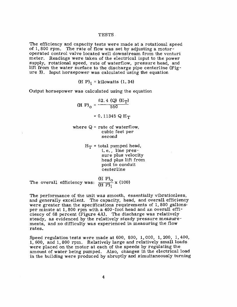
TESTS-
The efficiency and capacity tests were made at a rotational speed of 1, 800 rpm. The rate of flow was set by adjusting a motoroperated control valve located well downstream from the venturi meter. Readings were taken of the electrical input to the power supply, rotational speed, ·rate of waterflow, pressure head, and lift from the water surface to the discharge pipe centerline (Figure 3). Input horsepower was calculated using the equation
(H P)i = kilowatts (1. 34)
Output horsepower was calculated using the equation
62. 4 (Q) (HT) (H P)o = 550
= O. 11345 Q HT
where Q = rate of waterflow, cubic feet per second
HT = total pumped head, i.e., line pressure plus velocity head plus lift from pool to conduit centerline
(H P) 0 The overall efficiency was: (H P)· x (100)
l
The performance of the unit was smooth, essentially vibrationless, and generally excellent. The capacity, head, and overall efficiency were greater than the specifications requirements of 1, 800 gallons, per minute at 1,800 rpm with a 400-foot head and an overall efficiency of 68 percent (Figure 4A)'. The discharge was relatively steady, as evidenced by the relatively steady pressure measurements, and no difficulty was experienced in measuring the flow rates.
Speed regulation tests were made at 600, 800, 1, 000, 1, 200, 1, 400, 1, 600, and 1,800 rpm. Relatively large and relatively small loads were placed on the motor. at each of the speeds by regulating the amount of water being pumped. Also, changes in the electrical load in the building were produced by abruptly and simultaneously turning
4
Sam Peng
Sticky Note
None set by Sam Peng
Sam Peng
Sticky Note
MigrationNone set by Sam Peng
Sam Peng
Sticky Note
Unmarked set by Sam Peng
Sam Peng
Sticky Note
None set by Sam Peng
Sam Peng
Sticky Note
MigrationNone set by Sam Peng
Sam Peng
Sticky Note
Unmarked set by Sam Peng

on or turning off three 100-horsepower motors. The pump speeds. as measured over 10-second periods, never varied more than plus or minus 3 rpm from the set speed (Figure 4B). The speed control selector was simple to operate and sensitive enough to allow speed changes as small as 3 or 4 rpm. The performance was considered excellent and entirely acceptable in all respects.
Three temperature measurements were made on the outside of the motor casing. One was located near the upper bearing and the other two were over the field windings. The temperatures were well within normal operating limits and indicated only a 25. 5° C rise. No measurements were made on the interior of the field or armature windings.
Noise level at the higher speeds was somewhat objectionable, although it is not believed to be unusual for this size pump and motor .
5
Sam Peng
Sticky Note
None set by Sam Peng
Sam Peng
Sticky Note
MigrationNone set by Sam Peng
Sam Peng
Sticky Note
Unmarked set by Sam Peng
Sam Peng
Sticky Note
None set by Sam Peng
Sam Peng
Sticky Note
MigrationNone set by Sam Peng
Sam Peng
Sticky Note
Unmarked set by Sam Peng
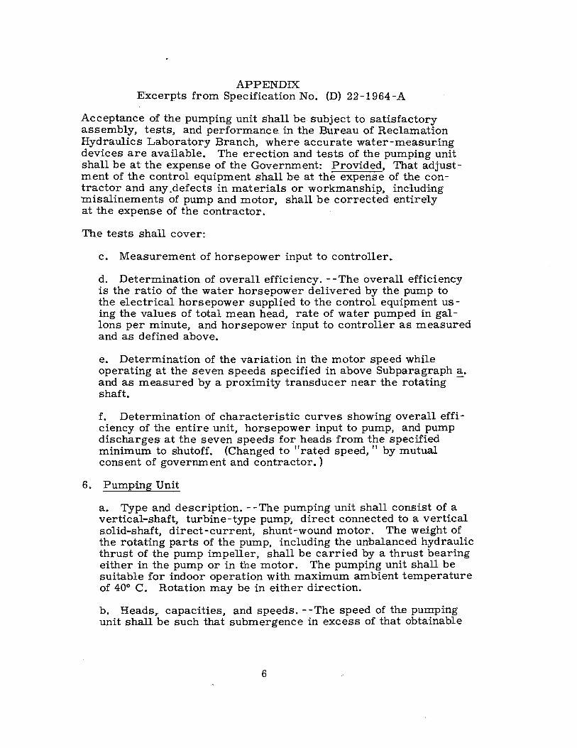
APPENDIX Excerpts from Specification No. (D) 22-1964-A
Acceptance of the pumping unit shall be subject to satisfactory assembly, tests, and performance. in the Bureau of Reclamation Hydraulics Laboratory Branch, where accurate water-measuring devices are available. The erection and tests of the pumping unit shall be at the expense of the Government: Provided, That adjustment of the control equipment shall be at the expense of the contractor and any .defects in materials or workmanship, including misalinements of pump and motor, shall be corrected entirely at the expense of the contractor.
The tests shall cover:
c. Measurement of horsepower input to controller.
d. Determination of overall efficiency. --The overall efficiency is the ratio of the water horsepower delivered by the pump to the electrical horsepower supplied to the control equipment us -ing the values of total mean head, rate of water pumped in gallons per minute, and horsepower input to controller as measured and as defined above.
e. Determination of the variation in the motor speed while operating at the seven speeds specified in above Subparagraph a. and as measured by a proximity transducer near the rotating -shaft.
f. Determination of characteristic curves showing overall efficiency of the entire unit, horsepower input to pump, and pump discharges at the seven speeds for heads from the specified minimum to shutoff. (Changed to "rated speed, " by mutual consent of government and contractor. )
6. Pumping Unit
a. Type and description. - -The pumping unit shall consist of a vertical-shaft, turbine-type pump:, direct connected to a vertical solid-shaft, direct-current, shunt-wound motor. The weight of the rotating parts of the pump, including the unbalanced hydraulic thrust of the pump impeller, shall be ·Carried by a thrust bearing either in the pump or in the motor. The pumping unit shall be suitable for indoor operation with maximum ambient temperature of 40° C. Rotation may be in either direction.
b. Heads,, capacities, and speeds. - -The speed of the pumping unit shall be such that submergence in excess of that obtainable
6
Sam Peng
Sticky Note
None set by Sam Peng
Sam Peng
Sticky Note
MigrationNone set by Sam Peng
Sam Peng
Sticky Note
Unmarked set by Sam Peng
Sam Peng
Sticky Note
None set by Sam Peng
Sam Peng
Sticky Note
MigrationNone set by Sam Peng
Sam Peng
Sticky Note
Unmarked set by Sam Peng

with limiting elevations shown on the drawings will not be necessary and high efficiency will be secured. The brake horsepower of the pump at any operating head and discharge shall not exceed 250 horsepower. The required minimum capacity at the rated total head, the rated total head, the expected range of capacities, and heads, the maximum allowable speed and brake horsepower and the overall efficiency for the pumping unit are listed in the following tabulations:
Expected Overall range of efficiency operating at rated
Minimum Rated conditions Maximum speed No. rated total Capac- Total allowable Pump Controls of capacity head ity head Speed Brake and motor
units gpm feet gpm feet rpm hp motor and pump
1 1,800 400 600- 50- 1,800 250 75% 68 1,800 400
The pumping unit shall be designed to withstand full shutoff head at the rated speed and to operate satisfactorily at total heads ranging from the expected minimum total head shown to the full shutoff head obtainable by throttling the discharge at rated speed. The unit also shall operate satisfactorily at speeds ranging from 33 to 100 percent of rated speed.
5. Failure to Meet Requirements
d. Failure to meet performance requirements. - -If the Government elects to accept materials or equipment which does not meet any performance requirements of these specifications, as determined by factory tests, field tests, or operation under service conditions, appropriate adjustment will be made of the contract price for such materials or equipment: Provided, That no such adjustment will be made until after the contractor has been given an opportunity to repair or replace defective equipment wherever applicable. Because of the impossibility of determining the actual loss to the Government due to such failure to meet performance requirements, the following adjustment of price in the form of liquidated damages shall be final and con -elusive with respect to both the contractor and the Government, and neither shall have any claims against the other on any further basis whatsoever.
(1) The schedule lump-sum price for furnishing the complete unit will be reduced by fifty dollars ($50) for each 1 / 10 of 1 percent that the actual overall efficiency (pump, motor, and
7
Sam Peng
Sticky Note
None set by Sam Peng
Sam Peng
Sticky Note
MigrationNone set by Sam Peng
Sam Peng
Sticky Note
Unmarked set by Sam Peng
Sam Peng
Sticky Note
None set by Sam Peng
Sam Peng
Sticky Note
MigrationNone set by Sam Peng
Sam Peng
Sticky Note
Unmarked set by Sam Peng

controls) of the unit is less than the overall efficiency spec -ified in Subparagraph 6~. at the rated total heads listed.
(2) Also. the schedule lump-sum price for furnishing the complete unit will be further reduced by fifty dollars ($-50) for each 1/10 of 1 percent that the actual capacity of the unit furnished is below the required :rated capacity specified in Subparagraph 6~. at the rated total head listed.
(3) Also. the schedule lump-sum price for furnishing the complete unit will be furthe:r reduced by five hundred dollars ($500) for each 1 / 10 of 1 percent that the maximum pump speed variation at one or more of the seven speeds · specified in Subparagraph 8a. is above the maximum allowable as specified in Subparagraph 6k. and as determined in Subparagraph 8~. -
Excerpt from Supplemental Notice to Specification No. (D) 22-1964-A
2. On page VII of the Specifications, under Subparagraph 6k .• Motor, change last sentence of second paragraph to read: "The voltage rating of the motor shall be between 250 and 600 volts.". also change last sentence of third paragraph to read:''The characteristics of the motor, in conjunction with its power supply and controls, shall be such that for any setting of speed, within the speed range required, the speed will remain constant within O. 75 percent of the rated fullload speed when the load remains constant and the alternating-current power supply does not vary more than 10 percent."
8
Sam Peng
Sticky Note
None set by Sam Peng
Sam Peng
Sticky Note
MigrationNone set by Sam Peng
Sam Peng
Sticky Note
Unmarked set by Sam Peng
Sam Peng
Sticky Note
None set by Sam Peng
Sam Peng
Sticky Note
MigrationNone set by Sam Peng
Sam Peng
Sticky Note
Unmarked set by Sam Peng

FIGURE I REPORT HYD. 522
------- ? ---- 44' ,; "----------------~-- t -/5!.0 11- --~+---------- ---30'-0"--------- ~,;~d' f
- CHASE
1!.1§. II
8
I
Venturi meter gage; ----,t+of---________ _ .¾A <-' ---@ B
,controls __ ,_ ____ -;.- Waste chute, Weir... /
' \ I
I I I I
&;;;;;;;~iJr-L~-~_~c:...;o_n_c_r_e71itr,=e=b=Q=S=e==============;;;;;;;;==;Qlr I(
Existing steel frame,
---... ,,,
654
PLAN
3'x 4' Steel tail box ...
S EG. A-A
\
' Valved } outlet" _Cha'!_nel
' \ I I I
SEG. B-B
B" HIGH HEAD TEST FACILITIES ARRANGEMENT AND LOCATION IN HYDRAULIC LABORATORY
Sam Peng
Sticky Note
None set by Sam Peng
Sam Peng
Sticky Note
MigrationNone set by Sam Peng
Sam Peng
Sticky Note
Unmarked set by Sam Peng
Sam Peng
Sticky Note
None set by Sam Peng
Sam Peng
Sticky Note
MigrationNone set by Sam Peng
Sam Peng
Sticky Note
Unmarked set by Sam Peng

Figure 2 Report Hyd. 522
B.
A .. · Voltmeters, ammeters, and watt-hour meters were connected to the incoming power lines.
Rotational speed was measured with C. photoelectric pick-up head and an electronic counter.
Pressure head in the pump dischargline was measured with a 300 psi capacity, fluid pressure scale.
8 11 HIGH HEAD TEST FACILITIES
Instrumentation Used in Acceptance Tests
Sam Peng
Sticky Note
None set by Sam Peng
Sam Peng
Sticky Note
MigrationNone set by Sam Peng
Sam Peng
Sticky Note
Unmarked set by Sam Peng
Sam Peng
Sticky Note
None set by Sam Peng
Sam Peng
Sticky Note
MigrationNone set by Sam Peng
Sam Peng
Sticky Note
Unmarked set by Sam Peng

en UI .,.
-i -< ,:i
C')
l> r
0 l> -i l>
l> 2 0
C') 0 s: ,:i C -i l> -i -0 2
CJ)
:c l'TI l'TI -i
CX>
:I: G')
:I:
:I: ITI l> 0
-i ITI CJ) -;
,.. l> 0
r --; -ITI CJ)
U. S. B. R. - AC C E P T A N C E TEST RECORDS 811
- 7 STAGE PUMP WITH 250 H.P. D.C. MOTOR AND STATI FLEX DRIVE (ALLIS - CHAMBERS)
Q=0.8604 "ll'tiH' TESTERS __ ~L~Q:?_<2..~~_,__f§_q_~§j~_rJ_~_y_~f!l.tni~J-i~-P~~-~n.,-~J~_q__~~lE...n..Q ____ DATEA~~_!_~_j953
REA DING NO. I 2 3 4 5 6 7 8 9 10 II 12 13 14
LI NE PRESSURE 15.4 /23 . ., 147.2 172.4 /85.2 /98'.4- 203.1 209.'I- 223,{, 241. 7 Cb0.3 Z63.I 153. 7 !5.3.7 PS I LINE PRESSURE 2/5.fK 285.4, 340.24 393.49 426".07 45i'.53 47I.Z9 4?-+.0/ 5/6.!3 SSf.67 60/. 66 {,t)f: /3 355.26 355.Z6 FT. H 20
LIFT FROM POOL 4./'1 3. &;4 3.'10 3.86 3.8'6 3. 5'6 3.86 4. /3 4 .. 13 4.30 4.20 4.IK 4.18' 4-.17 FT. H20 VELOCIT-.;/ HEAD
8.071 I.D. "~ 13/4.33 I~ ".3.67 l~.3./6 1~40 I~ ~ .2 ~ '!½ ~ ~ 'I¼ ~ ~ 7 I~ TOTAL HEAD 224.40 29.E.07 347. 30 'i404. 75 433.95 463. 9t 47t.33 4~1.04 521.59 563.33 60S.95 61?. 3/ 3hc_ 3/ 362.29 FT. H 20 VENTURI GAGE 47.58 40.25 34.70 26.35 22.15 /6.75 12.88 '1.8Z G.o/0 3. "17 .,7 0 31.52 3/.40 READING
DISCHARGE CFS 5.93 5.46 5.07 4.42 4.05 3.62 3.09 2.70 2.26 I. 7 I .85 0 4. f/3 4.82
OUTPUT H.P. 150. 97 /8/.54 /99. 76 202. 96 /99. 39 l.?5.2~ /66.98 141. 30 /33. 73 /09.29 52.43 0 l'T8.53 /'78./1
RPM /800 /800 /802 /'irtJ5 1902 /300 /803 /7'78 17'18 /799 /900 /800 /799 /799
VOLTS
AMPS
K WATTS 206.4 216.6 Z21.6 22/.3 Z/7. r 210.6 201.4 191. 7 184.8 18?.5 /67. 8 153.4 22(). 0 21$'. 9
WATT HOURS
INPUT H.P. 276.58 Z9tJ.24 29t.94 29t.S4 291. 99 282.20 269.88 256.89 247.~3 244.55 224.95 205.56 294.80 293.33
OVER A LL E FF. 54.58 62.55 ~7.27 ~8.44 68.29 b5.{,6 C./. S7 58.32 54.oo 44.t't' 25. 'f9 0 ~7.34 67.54
,
TIME START
REMARKS-Resull's CQ/cu/dl~cl .by des.k ct1IC&//Q/tJr
SHEET / OF
:0 rrr "D o-,, :0 --I Ci)
C :c ::0 ~l'TI
u,tJ.I N N
Sam Peng
Sticky Note
None set by Sam Peng
Sam Peng
Sticky Note
MigrationNone set by Sam Peng
Sam Peng
Sticky Note
Unmarked set by Sam Peng
Sam Peng
Sticky Note
None set by Sam Peng
Sam Peng
Sticky Note
MigrationNone set by Sam Peng
Sam Peng
Sticky Note
Unmarked set by Sam Peng

FIGURE 4 REPORT HYO. 522
>-0 z
70
60
50
~ 40
!2 ... ... w
j 30 <>: a: w > 0
a:: w ><>:
700
600
500
~ 400 ... 0
>-w w ... I 300
0 <>: w :,: --
0. ---~--------
~/
/ / '
I I
{, ~a
I o_"--~
- ,? OVERALL EFFICIENCY---~ ~a
~ 0
'-Vo.....- :,i
""o 0:
k .. 0 0 0
"'
400
300
0: w
-o.-._ 0. ---~~ --PUMPING HEAD
o.o........_ e,...._/\
~~ '~ P-........_ I:,'
--INPUT HORSEPOWER TO CONTROLS ·r-.......-..... / I 0-,;a· •U i...,=-u:;;;;;:;-:io--w
~D 0--1 _o_ o-~ ~
0 20 200 200 0.. w
L/a-I/ ,_
10
0
- l..----- -INPUT HORSEPOWER TO MOTOR
100 100 I - (From previous doto)
V 0.5 1.5 2.5 3 3.5 4 4.5 5.5
0 6
z 0
30
~ 20 > w 0
..Ji
.: il; 10 0 a: >- -
0
-10
DISCHARGE - C. F. S.
A. EFFICIENCY, PUMPING HEAD, AND HORSEPOWERS
I
I
:E - -- -- --- ----- - - -- -- -- -- - - ALLOWABLE DEVIATION --- -- -- -- ---------- --~: u.. . + 101------l---+-+---+--+--+--l----+-+---l---+--+-+---+--+-+---1----l----+--+---+--+--+---l---+--+---I a:: z-2o >- w
<tw F~~~~~~~~~~~~~~~~~~~~~~~$~~~~~w$~f~~,~r~~~ > a. 0 I-- 1-t---------w (/) 0 a.
~ ~ :; a. X ~ -10
~ en -- --1---1--- -- -- -- --~--1---f--- ALLOWABLE DEVIATION -- --r--- -- -- ---- -- --
- 20 '---6-'-o-o-'----'---...J_-eo.1...o_-'----'----'--10-'o-o-+---'---'---12-'-o-o--+---'---...J_-1_4.1...oo--'----'---'---16-'o-o--'---+--'---1e...1.o_o_.___,
ROTATIONAL SPEED R.P.M.
8. SPEED REGULATION CHARACTERISTICS -AVERAGE OVER 10 SECOND PERIODS
8 11 HIGH HEAD TEST FACILITIES PERFORMANCE CHARACTERISTICS AND SPEED REGULATION
(/)
0:. 0 :r:
••• GPO 838- 280
Sam Peng
Sticky Note
None set by Sam Peng
Sam Peng
Sticky Note
MigrationNone set by Sam Peng
Sam Peng
Sticky Note
Unmarked set by Sam Peng
Sam Peng
Sticky Note
None set by Sam Peng
Sam Peng
Sticky Note
MigrationNone set by Sam Peng
Sam Peng
Sticky Note
Unmarked set by Sam Peng