PERFORMANCE OF RIGHT ANGLED REINFORCED ...
12
PERFORMANCE OF RIGHT ANGLED REINFORCED CONCRETE CORNER JOINTS SUBJECT TO OPENING MOMENTS by Dr. W.P.S. Dias and D.G. Nimal Priyantha Abstract An experimental investigation on the performance of right angled slab to slab corner joints was carried out, using a horizontal portal type specimen, with the load being applied in a self-reacting fashion. A comparison of various detailing arrangements at the corner indicated that confinement of the concrete in the corner was essential if the corner was to develop the full strength of the members framing into it, and that inclined reinforcement at the inside corner was effective in reducing corner crack widths at service loads. There was also some evidence for the distance from the outside corner to the diagonal crack being an index of the joint efficiency for confined corner joints. 1.0 Introduction Since forces in structural elements have to change direction at joints, they have to be carefully detailed. Right angled corner joints are very common in reinforced concrete construction. Some common examples are beam-column joints on framed structures and portal frames. While the above are instances of connections between line elements (i.e. beams and columns), connections between slab elements also abound. Some examples are the joints between retaining walls and then- bases and also between the walls and bases of water tanks (see Figure 1). Such joints are more commonly subjected to moments that tend to open as opposed to close them. Furthermore, especially where water retaining structures are concerned, it is important to restrict the width of the surface crack at service moments as well. ^.0 Behaviour of Opening Corner Joints 2.1. Stress State and Potential Cracks The forces in an opening corner (1) are depicted in Figure 2(a), and the strains in Figure 2(b). Two types of cracks can therefore form under these conditions. (i)The tensile strains along the diagonal AB can tend to "push off the outer corner (i.e. corner A) of the joint, after the formation of a diagonal crack. (ii)The tensile strains perpendicular to the diagonal AB can cause a corner crack at B. The above crack types are shown in Figure 2(c), while Figure 2(d) shows the elastic stress distribution in the corner (2), 2.2. Detailing for Arresting Cracks There have been broadly two strategies for arresting diagonal cracks. (i)The provision of reinforcement along the diagonal AB (see Figure 2), generally in the form of links. Although this is theoretically a direct and efficient approach, there are practical difficulties in its implementation, especially in slab-slab connections. (ii)The confinement of the concrete in the corner by appropriate detailing of reinforcement. Such confinement will increase the resistance of the corner to diagonal cracking, but the efficiency of the confinement will depend on the detailing arrangement used. Dr. W.P.S. Dias, BSc(Eng)Hons, PhD(Lond), DIC, CEng, MIE(SL) is a Senior Lecturer in the Department of Civil Engineering .at the University of Moratuwa. His current research interests are in the area of Concrete Structures and Materials. > Mr. D.G. Nimal Priyantha, BSc(Eng)Hons, graduated from the University of Moratuwa with First Class Honours in 1991. He is presently an Assistant Lecturer in Civil Engineering at the same University. 'Engineer 1 , December 1993 3
-
Upload
khangminh22 -
Category
Documents
-
view
0 -
download
0
Transcript of PERFORMANCE OF RIGHT ANGLED REINFORCED ...
PERFORMANCE OF RIGHT ANGLED REINFORCED CONCRETE CORNER JOINTS SUBJECT TO
OPENING MOMENTS by
Dr. W.P.S. Dias and D.G. Nimal Priyantha
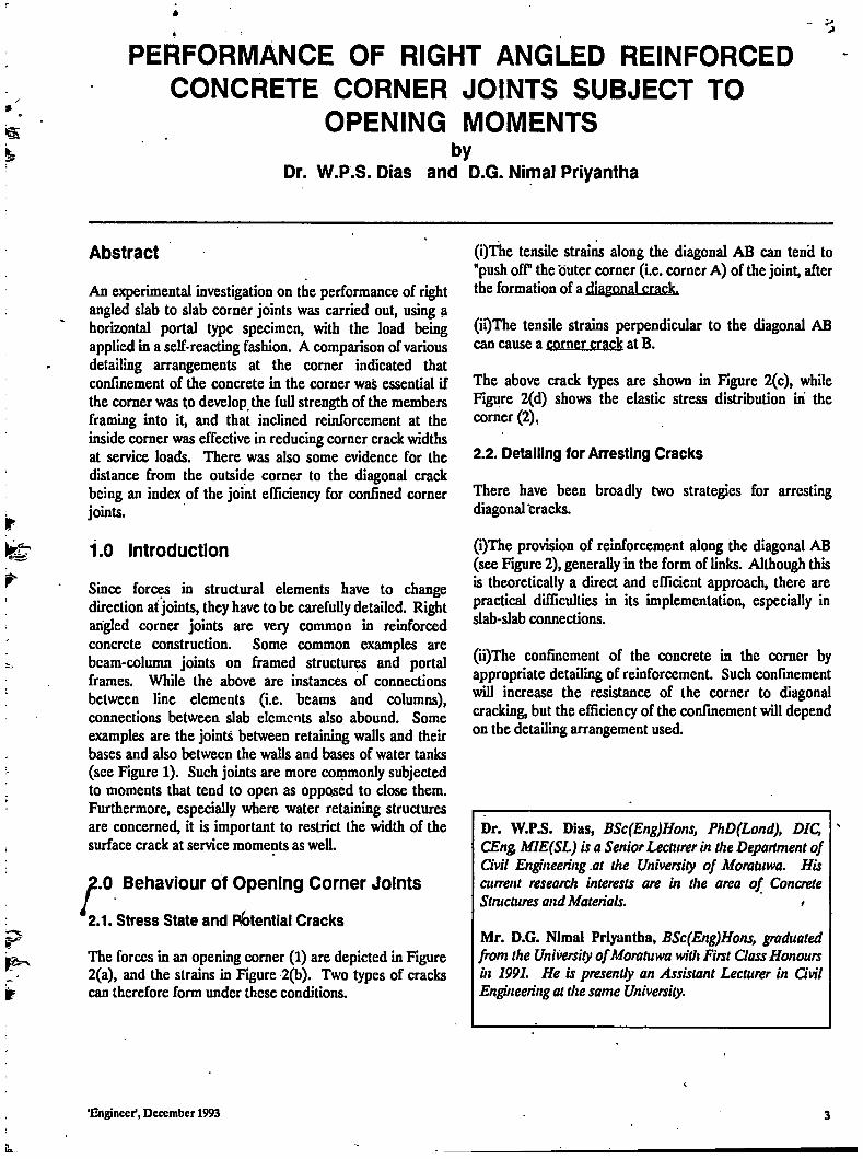
Abstract An experimental investigation on the performance of right angled slab to slab corner joints was carried out, using a horizontal portal type specimen, with the load being applied in a self-reacting fashion. A comparison of various detailing arrangements at the corner indicated that confinement of the concrete in the corner was essential if the corner was to develop the full strength of the members framing into it, and that inclined reinforcement at the inside corner was effective in reducing corner crack widths at service loads. There was also some evidence for the distance from the outside corner to the diagonal crack being an index of the joint efficiency for confined corner joints.
1.0 Introduction
Since forces in structural elements have to change direction at joints, they have to be carefully detailed. Right angled corner joints are very common in reinforced concrete construction. Some common examples are beam-column joints on framed structures and portal frames. While the above are instances of connections between line elements (i.e. beams and columns), connections between slab elements also abound. Some examples are the joints between retaining walls and then-bases and also between the walls and bases of water tanks (see Figure 1). Such joints are more commonly subjected to moments that tend to open as opposed to close them. Furthermore, especially where water retaining structures are concerned, it is important to restrict the width of the surface crack at service moments as well.
^.0 Behaviour of Opening Corner Joints
2.1. Stress State and Potential Cracks
The forces in an opening corner (1) are depicted in Figure 2(a), and the strains in Figure 2(b). Two types of cracks can therefore form under these conditions.
(i)The tensile strains along the diagonal AB can tend to "push off the outer corner (i.e. corner A) of the joint, after the formation of a diagonal crack.
(ii)The tensile strains perpendicular to the diagonal AB can cause a corner crack at B.
The above crack types are shown in Figure 2(c), while Figure 2(d) shows the elastic stress distribution in the corner (2),
2.2. Detailing for Arresting Cracks
There have been broadly two strategies for arresting diagonal cracks.
(i)The provision of reinforcement along the diagonal AB (see Figure 2), generally in the form of links. Although this is theoretically a direct and efficient approach, there are practical difficulties in its implementation, especially in slab-slab connections.
(ii)The confinement of the concrete in the corner by appropriate detailing of reinforcement. Such confinement will increase the resistance of the corner to diagonal cracking, but the efficiency of the confinement will depend on the detailing arrangement used.
Dr. W.P.S. Dias, BSc(Eng)Hons, PhD(Lond), DIC, CEng, MIE(SL) is a Senior Lecturer in the Department of Civil Engineering .at the University of Moratuwa. His current research interests are in the area of Concrete Structures and Materials. >
Mr. D.G. Nimal Priyantha, BSc(Eng)Hons, graduated from the University of Moratuwa with First Class Honours in 1991. He is presently an Assistant Lecturer in Civil Engineering at the same University.
'Engineer1, December 1993 3
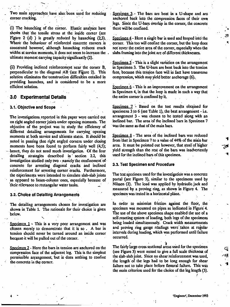
Two main approaches have also: been used for reducing corner, cracking. '
(i) The haunching of the corner. Elastic analyses have shown that the tensile stress at the inside corner (see Figure 2 (d) ) is greatly reduced by haunching (2,3).. Where the behaviour of reinforced concrete corners is concerned however, although haunching reduces crack widths at service moments, it does not seem to increase the . ultimate moment carrying capacity significantly (2).
(ii) Providing inclined reinforcement near the corner B, perpendicular to the diagonal AB (see Figure 2). This solution eliminates the'construction difficulties entailed in providing haunches, and is considered to be a more efficient solution.
3.0 Experimental Details
3.1. Objective and Scope
The investigations reported in this paper were carried out on right angled corner joints under opening moments. The objective of the project was to study the efficiency of different detailing arrangements for carrying opening moments at both service and ultimate states. It should be noted in passing that right angled corners under closing moments have been found to perform fairly well (4,5); hence, they do not need much investigation. Of the four detailing strategies described in' section 2.2, this investigation studied only two - namely the confinement of-concrete for arresting diagonal cracks and inclined reinforcement for arresting corner cracks. Furthermore, the experiments were intended to simulate slab-slab joints as opposed to beam-column'ones, especially because of their relevance to rectangular water tanks. ^
3.2. Choice of Detailing Arrangements
The detailing arrangements chosen for investigation are shown in. Table 1. The rationale for their choice is given below.
s Specimen 1 > This is a very poor arrangement and was chosen merely to demonstrate that it is so . A bar in tension should never be turned around an inside corner because it will be pulled out of the corner.
Specimen 2 - Here the bars in tension are anchored on the compression face of the adjacent leg. This is the simplest permissible arrangement, but is does nothing to confine the concrete in the corner.
: Specimen 3 . - The bars are bent in a U-shape and arc anchored back into the compression faces of their own legs. Since the U-bars overlap in the corner, the concrete there will be confined.
Specimen 4 - Here a single bar is used and looped into the corner. This too will confine the corner, but the loop does not cover the entire area of the corner, especially when the slabs framing into the joint are of different thicknesses.
Specimen 5 - This is a slight variation on the arrangement in Specimen 3. The U-bars are bent back into the tension face, because this tension face will in fact have transverse compression, which may yield better anchorage (6)..
Specimen 6 - This is an improvement on the arrangement in Specimen 4, in that the loop is made in such a way that the entire corner is confined by it.
Specimen 7 - Based on the test results obtained for specimens 3.to 6 (see Table 1), the best arrangement - i.e. arrangement 3 - was chosen to be tested along with an inclined bar. The area of the inclined bars in Specimen 7 was the same as that of the main bars.
Specimen 8 - The area of the inclined bars was reduced from'that in Specimen 7 to a value of 44% of the main bar area. It must be pointed out however, that steel'of higher yield strength than the rest -of the bars was inadvertently used for the inclined bars of this specimen.
3.3. Test Specimen and Procedure
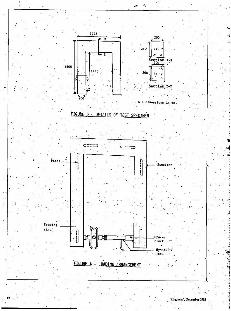
The test specimen used for the investigation was a concrete portal (see Figure 3), similar to the specimens used by Nilssen (2). The load was applied by hydraulic jack and measured by a proving ring, as shown in Figure 4. The specimen was tested in a horizontal plane.
In order to minimise friction against the floor, the specimen was mounted on pipes as indicated in Figure 4. The use of the above specimen shape enabled the use of a self-reacting system of loading, both legs of the specimens being loaded simultaneously. Crack width measurements and proving ring gauge readings were'taken at regular intervals during loading, which was performed until failure occurred.
b The fairly large-cross sectional areas used for the specimen (see Figure 3) were meant to give a full scale thickness of the sjab-slab joint. Since no shear reinforcement was used, the length of the legs had to be long enough for shear failure not to take place before flexural failure. This was the main criterion used for the choice of the leg length (3).
/
'Engineer', December 1993
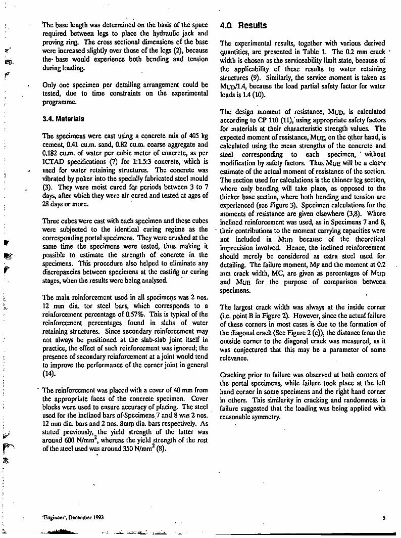
The base length was determined on the basis of the space required between legs to place the hydraulic jack and proving ring. The cross sectional dimensions of the base were increased slightly over those of the legs (2), because the- base would experience both bending and tension during loading.
Only one specimen per detailing arrangement could be tested, due to time constraints on the experimental programme.
3.4. Materials
The specimens were cast using a concrete mix of 405 kg cement, 0.41 cu.m. sand, 0.82 cu.m. coarse aggregate and 0.182 cu.m. of water per cubic meter of concrete, as per ICTAD specifications (7) for 1:1.5:3 concrete, which is used for water retaining structures. The concrete was vibrated by poker into the specially fabricated steel mould (3). They were moist cured for- periods between 3 to 7 days, after which they were air cured and tested at ages of 28 days or more.
Three cubes were cast with each specimen and these cubes were subjected to the identical curing regime as the corresponding portal specimens. They were crushed at the same time the specimens were tested, thus making it possible to estimate the strength of concrete in the specimens. This procedure also helped to eliminate any discrepancies between specimens at the casting or curing stages, when the results were being analysed.
The main reinforcement used in all specimens was 2 nos. 12 mm dia. tor steel bars, which corresponds to a reinforcement percentage of 0.57%. This is typical of the reinforcement percentages found in slabs of water retaining structures. Since secondary reinforcement may not always be positioned at the slab-slab joint itself in practice, the effect of such reinforcement was ignored; the presence of secondary reinforcement at a joint would tend to improve the performance of the corner joint in general (14).
The reinforcement was placed with a cover of 40 mm from the appropriate faces of the concrete specimen. Cover blocks were used to ensure accuracy of placing. The steel used for the inclined bars of-Spccimcns.7 and 8 was 2 nqs. 12 mm dia. bars and 2 nos. 8mm dia. bars respectively. As stated' previously, the yield strength of the latter was around 600 N/mm2, whereas the yield strength of the rest of the steel used was around 350 N/mm2 (8).
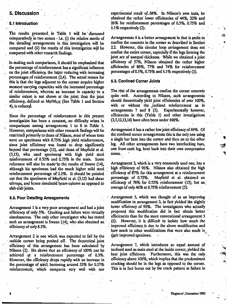
4.0. Results The experimental results, together with various derived quantities, are presented in Table 1. The 0.2 mm crack width is chosen as the serviceability limit state, because of the applicability of these results to water retaining structures (9). Similarly, the service moment is taken as MUD/1.4, because the load partial safety factor for water loads is 1.4 (10).
The design moment of resistance, M U D , is calculated according to CP 110 (11), using appropriate safety factors for materials al their characteristic strength values. The expected moment of resistance, M U E , on the other hand, is calculated using the mean strengths of the concrete and steel corresponding to each specimen, ' without modification by safety factors. Thus M U E will be a closer estimate of the actual moment of resistance of the section. The section used for calculations is the thinner leg section, where only bending will take place, as opposed to the thicker base section, where both bending and tension are experienced (see Figure 3). Specimen calculations for the moments of resistance are given elsewhere (3,8). Where inclined reinforcement was used, as in Specimens 7 and 8,
' their contributions to the moment carrying capacities were not included in M U D because of the theoretical imprecision involved. Hence, the inclined reinforcement should merely be considered as extra steel used for detailing. The failure moment, M F and the moment at 0.2 mm crack width, MC, are given as percentages of M U D and M U E for the purpose of comparison between specimens.
The largest crack width was always at the inside corner (i.e. point B in Figure 2). However, since the actual failure of these corners in most cases is due to the formation of the diagonal crack (See Figure 2 (c)), the distance from the outside corner to the diagonal crack was measured, as it was conjectured that this may be a parameter of some relevance.
Cracking prior to failure was observed at both corners of the portal specimens, while failure took place at the left hand corner in some specimens and the right hand corner in others. This similarity in cracking and randomness in failure suggested that the loading was being applied with reasonable symmetry.
'Engineer', December 1993 5
5. Discussion
5.1 Introduction
The results presented, in Table 1 will be discussed comparatively in two senses - i.e. (i) the relative merits of the detailing arrangements in this investigation will be compared and (ii) the results of this investigation will be compared with other, research findings.
In making such comparisons, it should be emphasised that the percentage of reinforcement has a significant influence on the joint efficiency, the latter reducing with increasing, percentages of reinforcement (2,4). The actual reason for this is that the legs adjacent to the corner acquire higher moment'carrying capacities with the increased percentage of reinforcement, whereas an increase in capacity to a similar extent is not shown at the joint; thus the joint efficiency, defined as M F / M U E (See Table 1 and Section 4), is reduce^.
Since the percentage of reinforcement in this present investigation has been a constant, .no difficulty arises in comparisons among arrangements 1 to 8 in Table 1. However, comparisons with other research findings will be restricted primarily to those of Nilsson, most of whose tests were on specimens with 0.75% h'gh yield reinforcement, since joint efficiency was found to drop significantly beyond that percentage (12), arid those of Mayficld et al. (5,13), who used specimens with high yield steel reinforcement of 0.52% and 0.75% in the main. Some reference will also be madeltD the results of Swann (14), although his specimens had.the much higher mild steel reinforcement percentage of 2.5%. It should be pointed out that the specimens of Mayfield et al. (5,13) had shear stirrups, and hence simulates1 beam-column as opposed to slab-slab joints.
5.2. Poor Detailing Arrangements
Arrangement 1 is a very poor arrangement and had a joint efficiency of only 5%; Qacking and failure were virtually simultaneous. The only other investigator who has tested such an arrangement is Swann (14), who also obtained an efficiency of only 8.3%.
Arrangement 2 is one which was expected to fail by the ' outside corner being pushed off. The theoretical joint
efficiency of this arrangement has been calculated' by Nilsson (2). He shows that an efficiency of 100% can be achieved at a reinforcement percentage of 0.3%. However, the efficiency drops rapidly with an increase in the. percentage of steel, becoming around 52% for 0.57% reinforcement, which compares very well with our
experimental result oL58%. In Nilsson's own tests, he obtained the rather lower efficiencies of 44%, 32% and 26% for reinforcement percentages of 0.5%, 0.75% and 1.1% respectively (2). -
Arrangements 4 is a better arrangement in that is Seeks to confine the concrete in the corner as described in Section 2.2. However, this circular loop arrangement does not. confine the entire corner, especially if the legs forming the joint are of unequal thickness. While we obtained a joint efficiency of 57%, Nilsson obtained the rather higher efficiencies of 88%, 77% and 74% for reinforcement percentages of 0.5%, 0.75% and 1.1% respectively (2).
5.3. Confined Corner Joints
The rest of the arrangements confine the corner concrete quite well. According to Nilsson, such arrangements should theoretically yield joint efficiencies of over 100%, with or without the ^inclined reinforcement as in arrangements 7 and 8 (2). Experimentally however, efficiencies in this (Table 1) and other investigations (2,5,12,13,14) have often been under 100%.
Arrangement 6 has a rather low joint efficiency of 69%. Of the confined corner arrangements this is the only one using a single bar bent into the corner and then on to the other leg. All other arrangements have two interlocking bars, one from each leg, bent back into their own compression zones.
Arrangement 3, which, is a very commonly used one, has a high efficiency of 96%. Nilsson also obtained the high efficiency of 87% for this arrangement at a reinforcement percentage of 0.75%. Mayfield et al. obtained an efficiency of 78%. for 0.52% reinforcement (13), but an. average bf only. 46% at 0.75% reinforcement (5).
Arrangement 5, which was thought of as an improving modification to arrangement 3, in fact-yielded the slightly lower efficiency of 92%. The investigators who actually proposed this modification did in fact obtain better efficiencies than for the more conventional arrangement 3 (6). However, it is. difficult to isolate how much'the improved efficiency.is due to the above modification and how much to other modifications, that were also made in , their improved specimen.
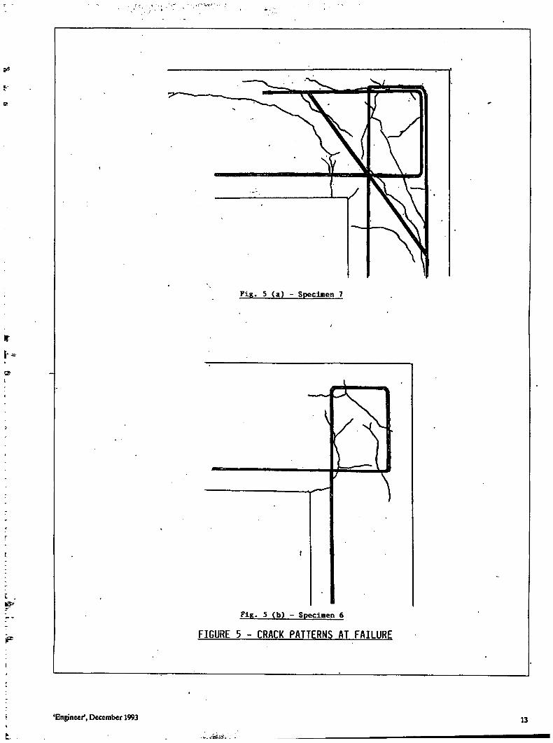
Arrangement 7, which introduces an equal amount of inclined steel as main steel at the inside corner, yielded the best joint efficiency. Furthermore, this was the only. efficiency above 100%, which implies that the predominant cracking should be in the legs as opposed to the corner. This is in fact borne out by the crack pattern at failure in
6 'Engineer*, December 1993

Figure 5(a). This can be compared with Figure 5(b), which shows cracking only in the corner for arrangement 6 (which had an efficiency of 69%). Nilsson also obtained joint efficiencies of 114-123% when introducing inclined reinforcement to arrangement 3 (12).
Tt is not clear why arrangement 8, which had 45% of the main reinforcement as inclined reinforcement, yielded an efficiency of only 83%. It must be remembered that this inclined steel was subsequently found to have a much higher yield strength than the main steel (See Section 3.4). As such, too much reliance should not be placed on this result. It is better to be guided by the more reliable trend indicated by Nilsson's specimens where inclined reinforcement percentages down to 45% of the main reinforcement were found to be as good or better than 100% inclined reinforcement for joint efficiency (2,12).
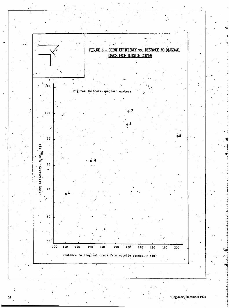
5.4. Diagonal Cracking and Confinement Efficiency
The failure of corner joints under opening moments is due to the formation of diagonal cracks. If a corner is not confined or poorly confined (i.e. arrangements 1,2 and 4), the concrete in the corner will get pushed out quickly and the distance from the outside corner to the diagonal crack will depend on the reinforcement arrangement.
On the other hand, if a corner is well confined, the formation of the diagonal crack will be delayed. It was conjectured that the distance from the outside corner to the diagonal crack may be related to the confinement efficiency for confined corners (i.e. arrangements 3 and 5 to 8). Figure 6 shows that such a relationship may indeed exist, with the joint efficiency (i.e. M P / M U E ) increasing as the distance to the diagonal crack from the outside corner increases.
The above phenomenon is merely presented as an experimental observation in this paper. An explanation for this can be properly attempted only if further numerical and experimental studies are carried out to determine the stress distributions in the corner. Such studies were beyond the scope of the present investigation.
5.5. Serviceability Considerations
Since the serviceability performance would be related to design as opposed to actual failure moments, the crack widths that could be expected at service loads are given as the crack widths at a moment of MUD/1.4 (as opposed to MUE/1.4), although many authors have used the latter or similar criteria (5,12,13,14).
The above crack width values are available only for specimens 4 to 8, although it is clear that the corresponding crack width for arrangements 2 and 3 would be under- 0.2 mm, as MUD/1.4 would be less than the recorded moment Mc - i.e. the moment at which the crack width was 0.2 mm. Apart from arrangements 1,5 and 6 therefore, the other arrangements will satisfy the 0.2 mm crack width required for the service condition of water retaining structures (9). The beneficial effect of using inclined steel for restricting the corner crack width is amply demonstrated in that arrangements 7 and 8 show a crack width of only 0.1 mm.
The beneficial effect of inclined steel for restricting the corner crack width has been demonstrated by Nilsson (2,12) as well as by Swann (14). Nilsson showed that these widths can be further reduced by haunching the corner (2,12). The achievements of corner crack widths which are limited to 0.1 mm would have applications in water retaining structures where aesthetic considerations are also important (9).
Table 2 indicates the ratios of the moment at 0.2 mm crack width (i.e. the serviceability limit state) to that at failure (i.e. the ultimate limit slate). If the above ratio, M C / M F , is too low, it would mean that the joint becomes unserviceable at too low a fraction of its full strength. On the other hand, if it is too high, it means that failure takes place soon after the serviceability limit state, implying sudden failure. Ideally M C / M F should be in the range 0.6 to 0.7.
The high ratios for arrangements 1,2 and 4 could have been expected, because the concrete in the corners were not properly confined, as described beforehand. There would probably be no yielding of steel prior to failure, which would consequently be sudden.
On the other hand, arrangements that have confined corners without inclined steel reinforcement would have low ratios, since the specimens would continue to carry increasing loads even after cracking; Arrangements 3, 5 and 6 yield ratios of 0.53, 0.43 and 0.63 respectively. It should be pointed out that the ratio of 0.63 for arrangement 6 is quite good, falling as it does between 0.6 and 0.7; however, the other two ratios arc too low, in that the serviceability limit state will be exceeded too quickly, compared to the ultimate limit state.
The best (i.e. intermediate) ratios are given by arrangements 7 and 8, which not only have confined corners, but also inclined steel to control corner crack widths. The ratio M C / M F for both ihese cases is 0.67.
'Engineer', December 1993 7
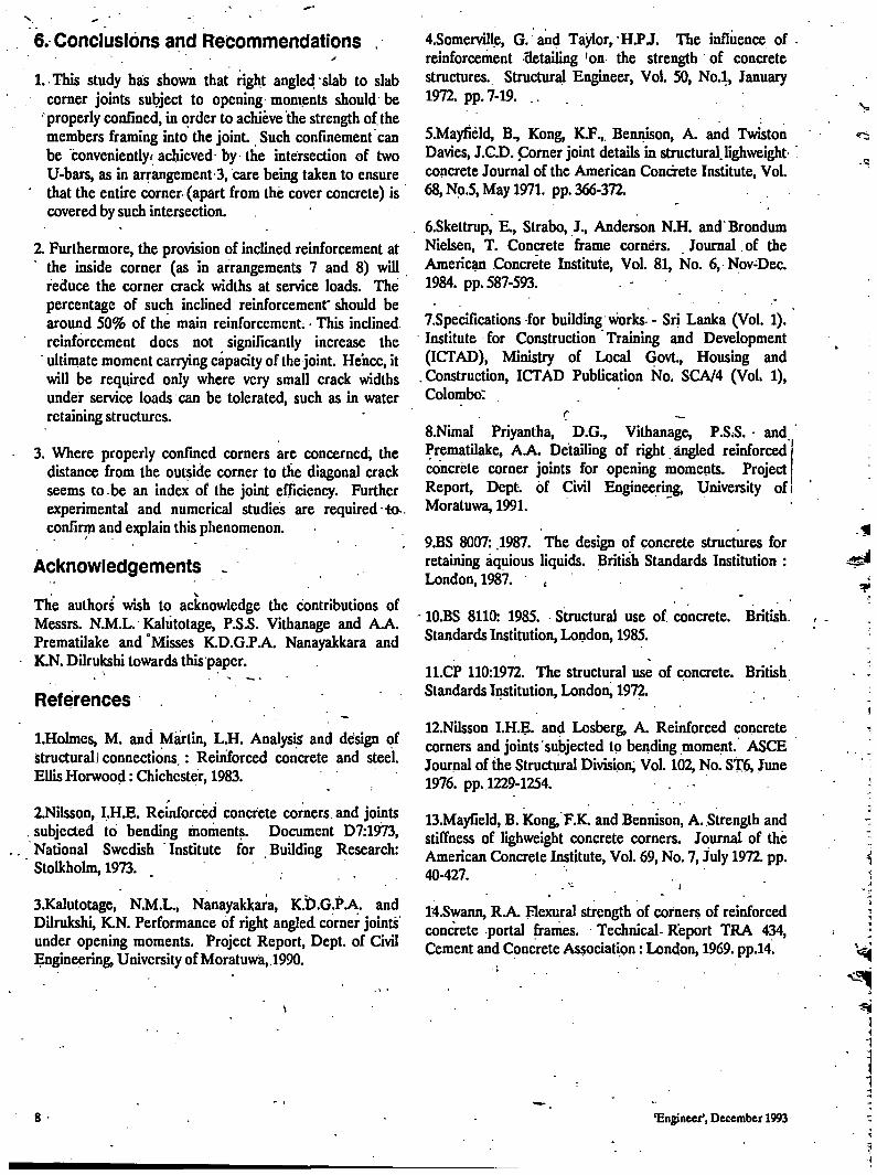
6. Conclusions and Recommendations .
1. This study has shown that right angled slab to slab corner joints subject to opening moments should be properly confined, in order to achieve the strength of the members framing into the joint. Such confinement can be conveniently achieved- by the intersection of two U-bars, as in arrangement 3, care being taken to ensure that the entire corner (apart from the cover concrete) is covered by such intersection.
2. Furthermore, the provision of inclined reinforcement at the inside corner (as in arrangements 7 and 8) will reduce the corner crack widths at service loads. The percentage of such inclined reinforcement" should be around 50% of the main reinforcement. • This inclined reinforcement does not significantly increase the
' ultimate moment carrying capacity of the joint. Hence, it will be required only where very small crack widths under service loads can be tolerated, such as in water retaining structures.
3. Where properly confined corners are concerned, the distance from the outside corner to the diagonal crack seems to be an index of the joint efficiency. Further experimental and numerical studies are required -to-confirm and explain this phenomenon.
Acknowledgements -
The authors wish to acknowledge the contributions of Messrs. N.M.L. Kaliitotage, P.S.S. Vithanage and A.A. Prematilake and 'Misses K.D.G.P.A. Nanayakkara and K.N. Dilrukshi towards this paper.
References
l.Holmes, M. and Martin, L.H. Analysis and design of structural! connections.: Reinforced concrete and steel. Ellis Horwood: Chichester, 1983.
2.Nilsson, I.H.E. Reinforced concrete corners, and joints . subjected to bending moments. Document D7:1973, National Swedish Institute for Building Research: Stolkholm, 1973.
3.Kalutotage, N.M.L., Nanayakkara, K.D.G.P.A. and Dilrukshi, K.N. Performance of right angled, corner joints under opening moments. Project Report, Dept. of Civil Engineering, University of Moratuwa,.1990.
4.Somerville, G. and Taylor, H.PJ. The influence of reinforcement detailing 'on the strength of concrete structures. Structural Engineer, Vol. 50, No.l, January 1972. pp. 7-19. . . .
5.Mayfield, B., Kong, K.F., Bennison, A. and Twiston Davies, J.C.D. Corner joint details in structural, lighweight' concrete Journal of the American Concrete Institute, Vol. 68, Np.5, May 1971. pp. 366-372.
6.Skettrup, E., Strabo, J., Anderson N.H. and Brondum Nielsen, T. Concrete frame corners. Journal .of the American Concrete Institute, Vol. 81, No. 6, Nov-Dec. 1984. pp. 587-593.
7.Specifications for building works-- Sri Lanka (Vol. 1). Institute for Construction Training and Development (ICTAD), Ministry of Local Govt., Housing and Construction, ICTAD Publication No. SCA/4 (Voh 1), Colombo:
c — 8.Nimal Priyantha, D.G., Vithanage, P.S;S. - and. Prematilake, A.A. Detailing of right angled reinforced j concrete corner joints for opening moments. Project! Report, Dept. of Civil Engineering, University of! Moratuwa, 1991.
9.BS 8007: .1987. The design of concrete structures for retaining aquious liquids. British Standards Institution : London, 1987. «
- 10.BS 8110: 1985. Structural use of concrete. British. Standards Institution, London, 1985.
11.CP 110:1972. The structural use of concrete. British Standards Institution, London, 1972.
12.Nilsson I.H.E. and Losberg, A. Reinforced concrete corners and joints subjected to bending moment. ASCE Journal of the Structural Division, Vol. 102, No. ST6, June 1976. pp. 1229-1254.
13.Mayfield, B. Kong, F.K. and Bennison, A. Strength and stiffness of lighweight concrete corners. Journal of the American Concrete Institute, Vol. 69, No. 7, July 1972. pp. 40-427.
14.Swann, R.A. Flexural strength of corners of reinforced concrete -portal frames. - Technical- Report TRA 434, Cement and Concrete Association: London, 1969. pp.14
8 'Engineer', December 1993
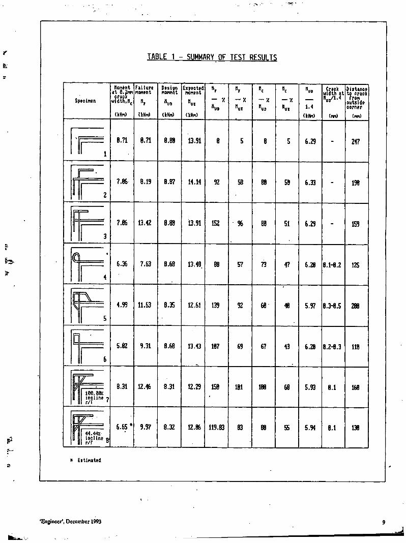
TABLE 1 - SUMMARY OF TEST RESULTS
Specifier.
TLOMENT AT to.2m CRACK
WIDTH, FI
(INM)
FAILURE MOFIENT
»i (kNrt)
DESIGN NONENT
EXPECTED MORIENT
(KHN)
— 7. — Z " U B
1 . 4
(KNM)
CRACK WIDTH AT « U B / 1 . 4
DISTANCE TO CRAOK (ton OUTSIDE CORNER
(m)
8.71 8.71 13.91 6.29 247
7.86 .19 B.87 14.14 92 58 58 6.33 198
7.86 13.42 13.91 152 96 51 6.29 159
Q 6.36 7.63 8.68 13.48 57 73 47 6.28 B.H.2 125
4.99 11.63 8.35 12.61 139 92 68 5.97 8.3-8.5 288
5.82 9.31 8.68 13.43 187 69 67 43 6.28 8.2-8.3 118
8.31 12.46 8.31 lee.aex I N C L I N E 7 R/F '
12.29 158 181 68 5.93 8.1 168
6.65 9.97 8.32 12.86 4 4 . 4 4 Z I N C L I N E o R/F 8
119.83 83 55 5.94 8.1 138
ft ESTINATED
'ENGINEER', DECEMBER 1 9 9 3 9
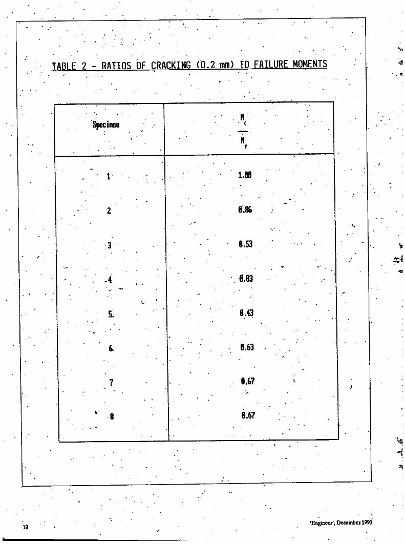
TABLE 2 - RATIOS OF CRACKING ( 0 . 2 mm) TO FAILURE MOMENTS
Spectaen t
H c
H t
, " ' 1- • • 1.88
2 8.86
3 8.53 • -
~ " - 4 . . • ; .. \ 8.83
8.43
6 8.63 f
7 8.67
8 8.67
4
J
10 'Engineer', December-1993
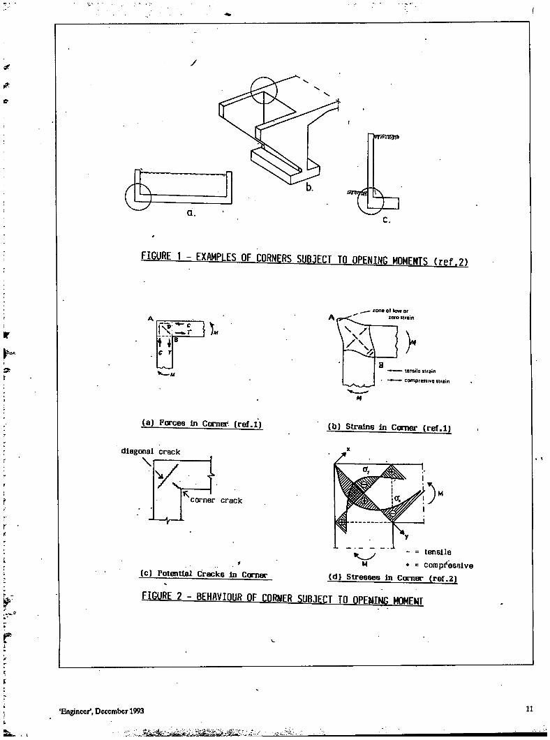
FIGURE 1 - EXAMPLES OF HflRKIFRS SUBJECT Tfl OPENING MDMFMTS ( r p f 91
14 *' C T
S
— l o n e o f l o w or
- tens i le s t r a i n
• c o m p r e s s i v e s t r a i n
( a ) F o r c e s i n Corner , ( r e f . l )
d i a g o n a l c r a c k \ f
c o r n e r c r a c k
( b ) S t r a i n s i n C o r n e r ( r e f . l )
- = t e n s i l e M + = c o m p r e s s i v e
( d ) S t r e s s e s I n C o m e r ( r e f . 2 ) ( c ) P o t e n t i a l C r a c k s i n C o r n e r
FIGURE 2 - BFHAVIOUR flF PORTER SUB.1FPT TFL QPEMIMG MOMFMT
Engineer', December 1993
1275
1800
f> X
UAO
< — V
200
250
200
2Y-12
<y o Section x-x
. 200 ,
200 ,| o
2Y-12 o
Section Y-Y
All dimensions in mm.
F I G U R E 3 - D E T A I L S OF TFST SPECIMFN
Pipes
Proving r ing .
1 1
-4i
1 1 1 1 1 1 1 1
V
Specimen
.Spacer block —
. Hydraulic jack
F I G U R E k - LOADING ARRAMHFMFMT
1 2 • »' 'Engineer', December 1993
'Engineer', December 1993 13
3 I
110
100
90
u 3
u c 80
5 . 70 o
60
SO
FIGURE 6 - JOINT EFFICIENCY vs . DISTANCE TO DIAGONAL CRACK FROM OUTSIDE CORNER
Figures indicate•specimen numbers
•© 7
e 8
©5
100 110 120 1'30 UO 150 160 ' 170" 180 190 200
Distance to diagonal crack from outside corner, x (mm)