Comparative Study of Seismic Performance of Reinforced Concrete ...
305
-
Upload
khangminh22 -
Category
Documents
-
view
0 -
download
0
Transcript of Comparative Study of Seismic Performance of Reinforced Concrete ...
Comparative Study of Seismic Performance of Reinforced
Concrete Buildings designed in accordance with the Seismic
Provisions of ASCE 7-10 and IS 1893-2002
A thesis submitted to the
Graduate school of
University of Cincinnati
in partial fulfillment of the requirements for the degree of
Master of Science
in the School of Advanced Structures of
The College of Engineering and Applied Science
By
Sagar M Jadhav
Bachelor of Engineering (Civil), 2006, V.J.T.I, University of Mumbai, India.
Committee Chair: Dr. Bahram M. Shahrooz
Committee Members:
Dr. Gian A. Rassati
Dr. Richard A. Miller
ii
Abstract
The study focuses on the comparison of the American and Indian standards in relation to
seismic design and analysis of reinforced concrete structures. Seismic provisions of the current
versions of ASCE 7 and IS 1893 are compared on the basis of the type of allowable analysis
procedures, zoning system, site classification, fundamental time period of the structure, response
reduction factor, importance factor, minimum design lateral force, allowable story drifts, and
design response spectra. Two geometrically similar commercial reinforced concrete buildings
were designed in high seismic regions of USA and India as per the respective seismic provisions
in ASCE 7 and IS 1893. The member dimensions, reinforcement sizes, and detailing were
determined per guidelines of the respective codes.
A mathematical model of the structure is created in Ruaumoko 3D for nonlinear response
history analysis (RHA). Inelastic properties in terms of cross-sectional properties of members
and hysteretic behavior are reflected in the modeling of the individual members. Design response
spectrum compatible artificial and scaled recorded ground motions were chosen for each
structure based on the current code methods. Both structures were subjected to a pair of ground
motions applied orthogonally. The analytical results from RHA were synthesized in terms of
overall structural performance, i.e., roof displacements and inter-story drifts, and performance of
individual members, i.e., beam flexural demands and column biaxial axial load-moment
demands. Thus, it was possible to examine the seismic performance of the members and the
structure as a whole. The response of both the buildings is compared in an effort to explore
potential differences in the seismic performance of buildings per ASCE 7 and IS 1893 codes.

iii

iv
Acknowledgement
First and foremost, I would like to thank Dr. Bahram Shahrooz for his support, and being
always available to help me with all my doubts and queries. His immense patience and valuable
guidance has helped me in completing my research work. The opportunity to work with him has
helped me gain thorough knowledge in my field and learn a variety of tools that will help me in
my future career. I would also like to thank my thesis committee members Dr. Gian Rassati and
Dr. Richard Miller for their valuable comments during the course of this research work.
The past few years have been a good learning experience at the University of Cincinnati.
I will take this opportunity to thank my friends from V.J.T.I, my office colleagues from L&T and
my friends here at UC (especially Allakh Kulkarni and Sagar Bhamare), who in some way or
other have helped me in my journey. I shall thank my close friends Himanshu, Sanyog, and
Sachin who have been a very important part throughout my life. I thank my fiancée Sonia and
my sisters Madhavi and Manali in believing in me and keeping me focused in both happy and
tough times in my life. Finally and most importantly, I would like to thank my parents Mr.
Moreshwar Jadhav and Mrs. Asha Jadhav who have sacrificed a lot for me; I would not have
reached here so far without their support. I dedicate this thesis to them.
v
Table of Contents
List of Tables ................................................................................................................................ ix
List of Figures ............................................................................................................................... xi
List of Symbols and Abbreviations .......................................................................................... xiv
Chapter 1 Introduction................................................................................................................. 1
1.1 Background ........................................................................................................................... 1
1.2 Objective and Scope ............................................................................................................. 2
1.2.1 Objective ........................................................................................................................ 2
1.2.2 Scope and Outline .......................................................................................................... 2
Chapter 2 Review of the U.S. and Indian seismic design standards ........................................ 4
2.1 Review of the seismic design codes...................................................................................... 4
2.1.1 ASCE-7 (2010) .............................................................................................................. 4
2.1.2 IS 1893(2002) ................................................................................................................ 4
2.1.3 Common features of ASCE 7and IS 1893 ..................................................................... 5
Chapter 3 Analysis and Design of structure per ASCE 7-10 seismic provisions (Case 1) ... 11
3.1 Structural Geometry and Occupancy .................................................................................. 11
3.2 Site Location and Site Class ............................................................................................... 11
3.3 Loads and Load Combinations ........................................................................................... 12
3.3.1 Gravity Loads............................................................................................................... 12
3.3.2 Seismic Loads and Analysis Procedure ....................................................................... 12
3.3.3 Load Combinations ...................................................................................................... 13
3.4 Modeling and Analysis of Structure ................................................................................... 13
3.5 Design of Structure ............................................................................................................. 14
vi
Chapter 4 Analysis and Design as per IS 1893(2002) seismic provisions (Case 2) ............... 21
4.1 Structural Geometry and Occupancy .................................................................................. 21
4.2 Site Location and Site Class ............................................................................................... 21
4.3 Loads and Load Combinations ........................................................................................... 22
4.3.1 Gravity Loads............................................................................................................... 22
4.3.2 Seismic Loads and Analysis Procedure ....................................................................... 22
4.3.3 Load Combinations ...................................................................................................... 23
4.4 Modeling and Analysis of Structure ................................................................................... 24
4.5 Design of Structure ............................................................................................................. 25
Chapter 5 Nonlinear Response History Analysis of the designed structures ........................ 30
5.1 Modeling of Structure in Ruaumoko 3D ............................................................................ 30
5.2 Modeling of Nonlinear Sectional Properties in Ruaumoko 3D .......................................... 31
5.2.1 P-Mzz-Myy capacity check columns in MATLAB ....................................................... 33
5.3 Lumped Masses .................................................................................................................. 35
5.4 Gravity Loads...................................................................................................................... 35
5.5 Selection of Artificial and Recorded Ground Motions ....................................................... 35
5.5.1 Artificial Ground Motion ............................................................................................. 36
5.5.2 Recorded ground motions ............................................................................................ 36
5.6 Nonlinear Analysis Output in Ruaumoko 3D ..................................................................... 39
Chapter 6 Results and Conclusions ........................................................................................... 57
6.1 Case 1 (Structure designed per ASCE 7) ............................................................................ 57
6.1.1 GM-1 (Artificial ground motion compatible with ASCE 7 design spectrum)............. 57
6.1.2 GM-2 (Scaled recorded ground motion, Event-Imperial Valley-06) ........................... 58
vii
6.1.3 GM-3 (Scaled recorded ground motion, Event-Loma Prieta) ..................................... 58
6.2 Case 2 (Structure designed per IS 1893)............................................................................. 59
6.2.1 GM-4 (Artificial ground motion compatible with IS 1893 design spectrum) ............. 59
6.2.2 GM-5 (Scaled recorded ground motion, Event-Superstition Hills) ............................. 60
6.2.3 GM-6 (Scaled recorded ground motion, Event-Bhuj) ................................................. 60
Chapter 7 Summary, Discussion, Conclusions and Future Research .................................... 72
7.1 Summary and Relative Comparison ................................................................................... 72
7.1.1 Performance of structure designed as per ASCE 7 seismic provisions (Case 1) ......... 72
7.1.2 Performance of structure designed as per IS 1893 seismic provisions (Case 2) ......... 72
7.1.3 Relative comparison of performance of Case1 and Case 2 structures ......................... 73
7.2 Discussion ........................................................................................................................... 73
7.3 Conclusion .......................................................................................................................... 74
7.4 Recommendations for future research ................................................................................ 75
References .................................................................................................................................... 76
Appendix A Analysis and Design of Structure as per American Standards ......................... 79
A.1 Load calculation as per ASCE 7(Spreadsheet) .................................................................. 79
A.2 Load combination in ETABS ............................................................................................. 91
A.3 Design and detailing of beams ........................................................................................... 92
A.4 Design and detailing of columns ........................................................................................ 98
Appendix B Analysis and Design of Structure as per Indian Standards ............................. 116
B.1 Load calculation as per IS 1893, IS 875(Spreadsheet)..................................................... 116
B.2 Load combinations in ETABS ......................................................................................... 125
B.3 Design and detailing of beam ........................................................................................... 126
viii
B.4 Design and detailing of columns ...................................................................................... 132
Appendix C Nonlinear Response History analysis of the structures ................................... 147
C.1 Material models used in XTRACT .................................................................................. 147
C.2 Bilinear Approximation from M- diagram (Sample Calculation) .................................. 152
C.3 Ground Motions-Scaling .................................................................................................. 155
C.4 Ground Motions-Orthogonal Transformation .................................................................. 157
C.5 P-Mzz-Myy capacity surface generation for columns (MATLAB code) ........................ 161
C.6 Ruaumoko 3D Input file ................................................................................................... 164
C.6.1 Input file for structure designed as per ASCE 7 seismic provisions (Case 1) .......... 164
C.6.2 Input file for structure designed as per IS 1893 seismic provisions (Case 2) ........... 218
C.7 Detailed results of nonlinear response history analysis (RHA) ....................................... 275
ix
List of Tables
Table 2-1 Common-terms in seismic provisions of ASCE7-10 and IS 1893(2002) ...................... 7
Table 2-2 Zone Factor (Z), IS 1893(2002) ................................................................................... 10
Table 2-3 Site Class classification in IS 1893(2002) and ASCE 7-10 ......................................... 10
Table 3-1 Lateral forces from ELF analysis: Case 1 .................................................................... 15
Table 3-2 X Direction story drifts: Case 1 .................................................................................... 15
Table 3-3 Y Direction story drifts: Case 1 .................................................................................... 16
Table 3-4 Sectional dimensions and reinforcement of designed members: Case 1 ...................... 17
Table 4-1 Modal mass participation ratios from analysis in ETABS: Case 2 .............................. 26
Table 4-2 X direction story drifts: Case 2 ..................................................................................... 26
Table 4-3 Y direction story drifts: Case 2 ..................................................................................... 27
Table 4-4 Sectional dimensions and reinforcements: Case 2 ....................................................... 27
Table 5-1 Bilinear factors(r) for flexure: Case 1 .......................................................................... 40
Table 5-2 Bilinear factors(r) for flexure: Case 2 .......................................................................... 40
Table 5-3 Sectional response properties of columns and beams: Case 1 ..................................... 41
Table 5-4 Sectional response properties of columns and beams: Case 2 ..................................... 42
Table 5-5 Elastic sectional properties of columns and beams: Case 1 ......................................... 43
Table 5-6 Elastic sectional properties of columns and beams: Case 2 ......................................... 43
Table 5-7 Modified Takeda hysteresis rule parameters ................................................................ 43
Table 5-8 Ground motions for Response History Analysis: Case 1 ............................................. 44
Table 5-9 Ground motions for Response History Analysis: Case 2 ............................................. 44
Table 6-1 Results: Maximum base shear, roof displacements and inter-story drifts .................... 62
Table 6-2 Results: Number of members yielding (%) .................................................................. 63
x
Table C-1 Confining reinforcement details in XTRACT ........................................................... 147
Table C-2 Axial Compressive Loads for M-relationships. ...................................................... 154
Table C-3 Results: Performance of beams and columns, Case 1- GM 1 .................................... 276
Table C-4 Results: Performance of beams and columns, Case 1- GM 2 .................................... 277
Table C-5 Results: Performance of beams and columns, Case 1- GM 3 .................................... 278
Table C-6 Results: Performance of beams and columns, Case 2- GM 4 .................................... 279
Table C-7 Results: Performance of beams and columns, Case 2- GM 5 .................................... 280
Table C-8 Results: Performance of beams and columns, Case 2- GM 6 .................................... 281
xi
List of Figures
Figure 2-1 Seismic zoning in India ................................................................................................. 6
Figure 2-2 Design response spectrums for 5% damping ................................................................ 6
Figure 3-1 Plan and Side Elevation of the structural frame .......................................................... 18
Figure 3-2 Side Elevation and Isometric view of the structural frame ......................................... 19
Figure 3-3 Sectional details of the designed members: Case 1 .................................................... 20
Figure 4-1 Design response spectra for 5% damping as per IS 1893(2002): Case 2 .................... 28
Figure 4-2 Sectional details of the designed members: Case 2 .................................................... 29
Figure 5-1 Model of the structure in Ruaumoko 3D..................................................................... 45
Figure 5-2 Global and Local Axes in Ruaumoko 3D ................................................................... 45
Figure 5-3 Grouping of columns as per design axial load for a typical story ............................... 46
Figure 5-4 Hysteresis model (Modified Takeda) .......................................................................... 46
Figure 5-5 P-M diagram for principal bending axis at 0o to 45
o, w.r.t z-z axis (for Col30x30,
Story 1 to 6, Case 1) ...................................................................................................................... 47
Figure 5-6 P-Mzz-Myy capacity surface (for Col 30x30, Story 1 to 6, Case 1) ........................... 48
Figure 5-7 Response spectrums for Nonlinear Analysis: Case 1 (Mode 1 time period = 1.75 sec)
....................................................................................................................................................... 49
Figure 5-8 Response spectrums for Nonlinear Analysis: Case 2 (Mode 1 time period = 2.79 sec)
....................................................................................................................................................... 49
Figure 5-9 Principal axes and rotated orthogonal horizontal components ................................... 50
Figure 5-10 Artificial ground motion (GM-1) .............................................................................. 51
Figure 5-11 Recorded uncorrelated ground motion component pair (GM-2) .............................. 52
Figure 5-12 Recorded uncorrelated ground motion component pair (GM-3) .............................. 53
xii
Figure 5-13 Artificial Ground Motion (GM-4) ............................................................................. 54
Figure 5-14 Recorded uncorrelated ground motion component pair (GM-5) .............................. 55
Figure 5-15 Recorded uncorrelated ground motion component pair (GM-6) .............................. 56
Figure 6-1 Base shear (kips) vs. Time (sec): Case 1..................................................................... 64
Figure 6-2 Base shear (kips) vs. Time (sec): Case 2..................................................................... 65
Figure 6-3 Roof displacement (in.) vs. Time (sec): Case 1 .......................................................... 66
Figure 6-4 Roof displacement (in.) vs. Time (sec): Case 2 .......................................................... 67
Figure 6-5 Maximum inter-story drifts: Case 1 ............................................................................ 68
Figure 6-6 Maximum inter-story drifts: Case 2 ............................................................................ 68
Figure 6-7 Results: Member Yielding, Case 1-GM 1 ................................................................... 69
Figure 6-8 Results: Member Yielding, Case 1-GM 2 ................................................................... 69
Figure 6-9 Results: Member Yielding, Case 1-GM 3 ................................................................... 70
Figure 6-10 Results: Member Yielding, Case 2-GM 4 ................................................................. 70
Figure 6-11 Results: Member Yielding, Case 2-GM 5 ................................................................. 71
Figure 6-12 Results: Member Yielding, Case 2-GM 6 ................................................................. 71
Figure A-1 Load application in ETABS: Case 1 .......................................................................... 84
Figure B-1 Load application in ETABS: Case 2 ........................................................................ 121
Figure C-1 Material Models in XTRACT (Unconfined Concrete and Reinforcement): Case 1 148
Figure C-2 Material Models in XTRACT (Confined Concrete): Case 1 .................................... 149
Figure C-3 Material Models in XTRACT (Unconfined Concrete and Reinforcement): Case 2 150
Figure C-4 Material Models in XTRACT (Confined Concrete): Case 2 .................................... 151
Figure C-5 Bilinear Approximation (Sample Calculation) ......................................................... 152
Figure C-6 Scaling of individual recorded ground motions (GM-2) .......................................... 156

xiii
Figure C-7 Orthogonal transformation-ground Motion (GM-3) ................................................ 160
Figure C-8 Yielding of beams and columns, Case 1: GM-1 ....................................................... 282
Figure C-9 Yielding of beams and columns, Case 1: GM-2 ....................................................... 283
Figure C-10 Yielding of beams and columns, Case 1: GM-3..................................................... 284
Figure C-11 Yielding of beams and columns, Case 2: GM-4..................................................... 285
Figure C-12 Yielding of beams and columns, Case 2: GM-5..................................................... 286
Figure C-13 Yielding of beams and columns, Case 2: GM-6..................................................... 287
xiv
List of Symbols and Abbreviations
A = Cross-sectional area of the member section
Ah = Design spectral acceleration coefficient
Asz, Asy = Effective shear area of the member section in z and y local axis direction
a1(t), a2(t) = Pair of orthogonal acceleration time histories in the as-recorded directions,
a1,(t), a2,(t) = Rotated components of the as-recorded orthogonal acceleration time histories at a
clockwise rotation angle
bw = Width of the member
Cd = Deflection amplification factor
D = Dead load (ASCE 7)
DL = Dead Load (IS 1893)
E = Elastic (Young's) Modulus of member material
ELF = Equivalent lateral force analysis
EQX = Earthquake load in X-direction
EQY = Earthquake load in Y-direction
Fa = Short-period site coefficient (at 0.2 s-period)
fc’ = Specified compressive strength of concrete (ACI 318)
fck = Characteristic cube compressive strength of concrete (IS 456)
Fv = Long-period site coefficient (at 1.0 s-period)
fy = Specified yield stress of steel reinforcement (ACI 318)-Chapter 2
fy = Characteristic strength of steel reinforcement (IS 456)-Chapter 3
G = Shear Modulus of member material
h = Depth of the member

xv
hn = Height of the structure
hsx = Height of story of level xth
level
Hstorey = Story height (Chapter 1)
I = Importance factors (IS 1893)
Ia = Arias intensity
Ie =Seismic Importance factor (ASCE 7)
Ig = Gross moment of inertia
IL = Imposed Loads (IS 1893)
IMRF = Intermediate Moment Resisting Frame
Izz, Iyy = Moment of Inertia of the section in z-z and y-y direction
Jxx = Torsional second moment of area of the section in x-x axis
L = Live load (ASCE 7)
Lr = Roof live load (ASCE 7)
M- = Moment-Curvature
MBz = Moment about z-z local axis at balance point
MBy = Moment about y-y local axis at balance point
MCE = Maximum considered earthquake
Mzz (demand), Myy (demand) = Moment demand about local zz and yy axis for a column
MYy = Yield moments about minor y-y local axis
MYz = Yield moments about major z-z local axis
M0y = Yield moment about y-y local axis when axial force is zero
M0z = Yield moment about z-z local axis when axial force is zero
N = Standard penetration value (IS 1893)
xvi
= Average field standard penetration resistance (ASCE 7)
OMRF = Ordinary Moment Resisting Frame
P-M = Axial load-Moment
PBy = Axial force at balance point corresponding to moment about y-y local axis
PBz = Axial force at balance point corresponding to moment about z-z local axis
PC,PYC = Axial force for compression yield
Pdemand = Axial load demand for a column
PT,PYT = Axial force for tensile yield
r = Bilinear factor
R = Response reduction factor
SFX, SFY = Scale factor for design response spectrum for X and Y direction
S1 = Mapped MCER, 5 percent damped, spectral response acceleration parameter at period of 1s
Sa/g = Average spectral response acceleration coefficient for the site in terms of acceleration due
to gravity for 5% damping (IS 1893)
SD1 = Design, 5 percent damped, spectral response acceleration parameter at a period of 1s
SDS = Design, 5 percent damped, spectral response acceleration parameter at short periods
SM1 = the MCER, 5 percent damped, spectral response acceleration parameter at a period of 1s
adjusted for site class effects
SMS = the MCER, 5 percent damped, spectral response acceleration parameter at short periods
adjusted for site class effects
SMRF = Special Moment Resisting Frame
SS = Mapped MCER, 5 percent damped, spectral response acceleration parameter at short
periods

xvii
= Undrained shear strength
T = Time
Ta = Approximate fundamental time period of the building
te = Time at which maximum moment demand exceed moment capacity
TL = Long-period transition period
tn = Duration of ground motion
V = Design lateral force calculated from static analysis
VB = Base shear calculated as per seismic coefficient method
= Average shear wave velocity
Vs30 = Shear wave velocity
Vt = Modal base shear
VX, VY = Base shear as per response spectrum analysis in X and Y direction
WGT = Weight per unit length of the member
W = Seismic weight of the structure
Z = Seismic zone factor
β = Ratio of shear demand to shear capacity for the story between level x and x–1
x,y = Calculated inelastic displacements of the center of mass of a story in X and Y direction
xe, ye = Elastic displacements of the center of mass of a story in X and Y direction
= Diameter of reinforcement bar (Chapter 3)
= clockwise angle of rotation for horizontal orthogonal transformation (Chapter 4)
Stability coefficient (ASCE 7)
= Redundancy factor
X, Y = Design story drift calculated in X and Y direction
1
Chapter 1 Introduction
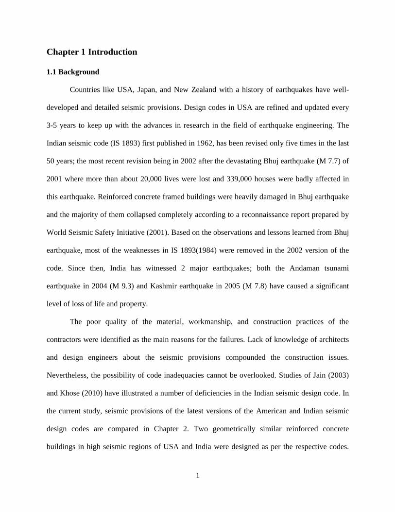
1.1 Background
Countries like USA, Japan, and New Zealand with a history of earthquakes have well-
developed and detailed seismic provisions. Design codes in USA are refined and updated every
3-5 years to keep up with the advances in research in the field of earthquake engineering. The
Indian seismic code (IS 1893) first published in 1962, has been revised only five times in the last
50 years; the most recent revision being in 2002 after the devastating Bhuj earthquake (M 7.7) of
2001 where more than about 20,000 lives were lost and 339,000 houses were badly affected in
this earthquake. Reinforced concrete framed buildings were heavily damaged in Bhuj earthquake
and the majority of them collapsed completely according to a reconnaissance report prepared by
World Seismic Safety Initiative (2001). Based on the observations and lessons learned from Bhuj
earthquake, most of the weaknesses in IS 1893(1984) were removed in the 2002 version of the
code. Since then, India has witnessed 2 major earthquakes; both the Andaman tsunami
earthquake in 2004 (M 9.3) and Kashmir earthquake in 2005 (M 7.8) have caused a significant
level of loss of life and property.
The poor quality of the material, workmanship, and construction practices of the
contractors were identified as the main reasons for the failures. Lack of knowledge of architects
and design engineers about the seismic provisions compounded the construction issues.
Nevertheless, the possibility of code inadequacies cannot be overlooked. Studies of Jain (2003)
and Khose (2010) have illustrated a number of deficiencies in the Indian seismic design code. In
the current study, seismic provisions of the latest versions of the American and Indian seismic
design codes are compared in Chapter 2. Two geometrically similar reinforced concrete
buildings in high seismic regions of USA and India were designed as per the respective codes.

2
Using nonlinear response analyses, the seismic performance of buildings was accessed. These
analyses allowed an in-depth comparison of the overall performance as well as member
responses.
1.2 Objective and Scope
1.2.1 Objective
The main objective of this research is to study and compare the seismic performance of
reinforced concrete buildings that are designed in USA and India according to the seismic
provisions of the codes, ASCE 7-10 and IS 1893(2002), respectively. Nonlinear response history
analysis was used as the tool to generate the necessary responses to allow for an in-depth
comparison of these two codes. The primary deliverables of this study are: (1) an evaluation of
the seismic performance of a commercial building in the US, designed as per the seismic
provisions of ASCE 7-10, (2) an evaluation of the seismic performance of a commercial
building, which is geometrically identical to the U.S. building, located in India, designed as per
seismic provisions of IS 1893(2002), (3) development of a MATLAB program to check for the
bidirectional-moment-axial capacity of any reinforced concrete cross-section, and (4)
comparison of the performance of the two buildings.
1.2.2 Scope and Outline
In the current study three major tasks were performed.
1) Design and detail a 12-story symmetrical commercial building, located in San Francisco,
which is a high seismic region. The structural system consists of moment-resting frames.
The commercial analysis and design software ETABS Version 9.6 (2009) was used for this
purpose. The seismic provisions of ASCE 7-10 (2010) and ACI 318 (2011) were used to
design and detail the members. The design process as well as the final member sizes and
3
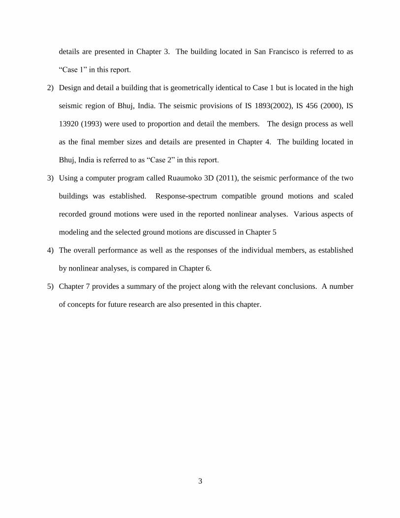
details are presented in Chapter 3. The building located in San Francisco is referred to as
“Case 1” in this report.
2) Design and detail a building that is geometrically identical to Case 1 but is located in the high
seismic region of Bhuj, India. The seismic provisions of IS 1893(2002), IS 456 (2000), IS
13920 (1993) were used to proportion and detail the members. The design process as well
as the final member sizes and details are presented in Chapter 4. The building located in
Bhuj, India is referred to as “Case 2” in this report.
3) Using a computer program called Ruaumoko 3D (2011), the seismic performance of the two
buildings was established. Response-spectrum compatible ground motions and scaled
recorded ground motions were used in the reported nonlinear analyses. Various aspects of
modeling and the selected ground motions are discussed in Chapter 5
4) The overall performance as well as the responses of the individual members, as established
by nonlinear analyses, is compared in Chapter 6.
5) Chapter 7 provides a summary of the project along with the relevant conclusions. A number
of concepts for future research are also presented in this chapter.
4
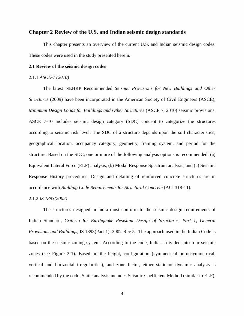
Chapter 2 Review of the U.S. and Indian seismic design standards
This chapter presents an overview of the current U.S. and Indian seismic design codes.
These codes were used in the study presented herein.
2.1 Review of the seismic design codes
2.1.1 ASCE-7 (2010)
The latest NEHRP Recommended Seismic Provisions for New Buildings and Other
Structures (2009) have been incorporated in the American Society of Civil Engineers (ASCE),
Minimum Design Loads for Buildings and Other Structures (ASCE 7, 2010) seismic provisions.
ASCE 7-10 includes seismic design category (SDC) concept to categorize the structures
according to seismic risk level. The SDC of a structure depends upon the soil characteristics,
geographical location, occupancy category, geometry, framing system, and period for the
structure. Based on the SDC, one or more of the following analysis options is recommended: (a)
Equivalent Lateral Force (ELF) analysis, (b) Modal Response Spectrum analysis, and (c) Seismic
Response History procedures. Design and detailing of reinforced concrete structures are in
accordance with Building Code Requirements for Structural Concrete (ACI 318-11).
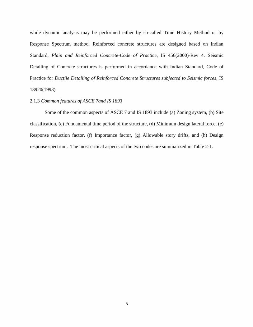
2.1.2 IS 1893(2002)
The structures designed in India must conform to the seismic design requirements of
Indian Standard, Criteria for Earthquake Resistant Design of Structures, Part 1, General
Provisions and Buildings, IS 1893(Part-1): 2002-Rev 5. The approach used in the Indian Code is
based on the seismic zoning system. According to the code, India is divided into four seismic
zones (see Figure 2-1). Based on the height, configuration (symmetrical or unsymmetrical,
vertical and horizontal irregularities), and zone factor, either static or dynamic analysis is
recommended by the code. Static analysis includes Seismic Coefficient Method (similar to ELF),
5
while dynamic analysis may be performed either by so-called Time History Method or by
Response Spectrum method. Reinforced concrete structures are designed based on Indian
Standard, Plain and Reinforced Concrete-Code of Practice, IS 456(2000)-Rev 4. Seismic
Detailing of Concrete structures is performed in accordance with Indian Standard, Code of
Practice for Ductile Detailing of Reinforced Concrete Structures subjected to Seismic forces, IS
13920(1993).
2.1.3 Common features of ASCE 7and IS 1893
Some of the common aspects of ASCE 7 and IS 1893 include (a) Zoning system, (b) Site
classification, (c) Fundamental time period of the structure, (d) Minimum design lateral force, (e)
Response reduction factor, (f) Importance factor, (g) Allowable story drifts, and (h) Design
response spectrum. The most critical aspects of the two codes are summarized in Table 2-1.
6
Figure 2-1 Seismic zoning in India
(Source: IS 1893(Part 1): 2002)
Figure 2-2 Design response spectrums for 5% damping
(Source: IS 1893(Part I): 2002 and ASCE 7-10)
7
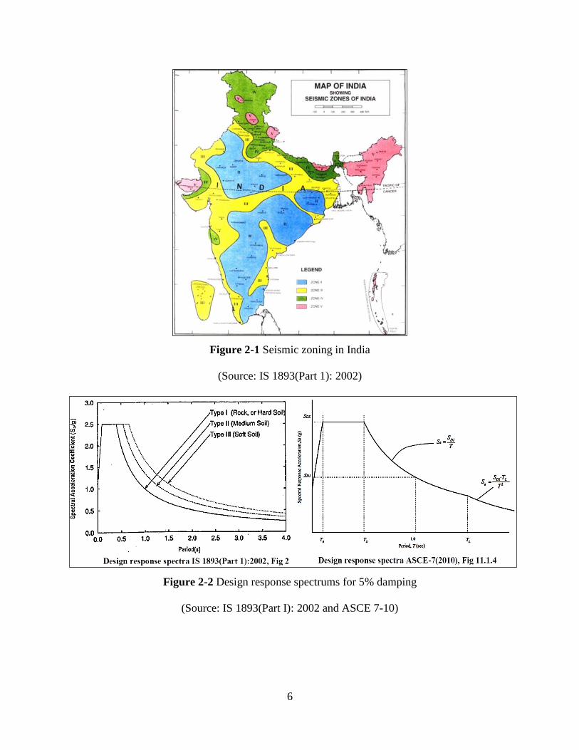
Table 2-1 Common-terms in seismic provisions of ASCE 7 (2010) and IS 1893 (2002)
ASCE 7 (2010) IS 1893 (2002)
1) Zoning System:
i. Each region is assigned a location
specific mapped spectral acceleration
parameter (SS, short period and S1,
1second).
ii. SS & S1 are modified for Site Class
effects to get Maximum Considered
Earthquake (MCE) spectral response
acceleration parameters (SMS and SM1).
iii. The design spectral acceleration SDS
and SD1 parameters can be obtained by
dividing SMS and SM1 parameters by
1.5.
iv. Refer Fig.22-1 through 22-6, ASCE 7-
10 for maps showing S1 and SS values
in USA.
1) Zoning System:
i. The country is divided into 4 zones (II,
III, IV and V).
ii. Each Zone is assigned a zone factor
(Z), which is used to obtain the
response spectrum depending upon the
perceived seismic hazard in that zone
corresponding to MCE.
iii. Refer Figure 2-1 and Table 2-2.
2) Site Classification:
i. Average shear wave velocity ( ),
average field standard penetration
resistance ( ), and average undrained
shear strength ( ) for the top 100ft are
used to classify different sites.
ii. Refer Table 2-3.
2) Site Classification:
i. Site classification depends only on the
standard penetration value (N).
ii. Refer Table 2-3.
8
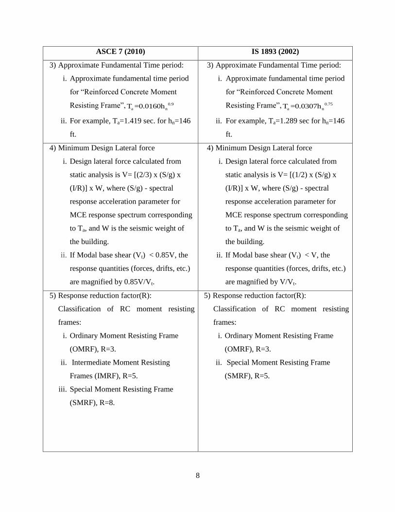
ASCE 7 (2010) IS 1893 (2002)
3) Approximate Fundamental Time period:
i. Approximate fundamental time period
for “Reinforced Concrete Moment
Resisting Frame”, 0.9
a nT =0.0160h
ii. For example, Ta=1.419 sec. for hn=146
ft.
3) Approximate Fundamental Time period:
i. Approximate fundamental time period
for “Reinforced Concrete Moment
Resisting Frame”, 0.75
a nT =0.0307h
ii. For example, Ta=1.289 sec for hn=146
ft.
4) Minimum Design Lateral force
i. Design lateral force calculated from
static analysis is V= [(2/3) x (S/g) x
(I/R)] x W, where (S/g) - spectral
response acceleration parameter for
MCE response spectrum corresponding
to Ta, and W is the seismic weight of
the building.
ii. If Modal base shear (Vt) < 0.85V, the
response quantities (forces, drifts, etc.)
are magnified by 0.85V/Vt.
4) Minimum Design Lateral force
i. Design lateral force calculated from
static analysis is V= [(1/2) x (S/g) x
(I/R)] x W, where (S/g) - spectral
response acceleration parameter for
MCE response spectrum corresponding
to Ta, and W is the seismic weight of
the building.
ii. If Modal base shear (Vt) < V, the
response quantities (forces, drifts, etc.)
are magnified by V/Vt.
5) Response reduction factor(R):
Classification of RC moment resisting
frames:
i. Ordinary Moment Resisting Frame
(OMRF), R=3.
ii. Intermediate Moment Resisting
Frames (IMRF), R=5.
iii. Special Moment Resisting Frame
(SMRF), R=8.
5) Response reduction factor(R):
Classification of RC moment resisting
frames:
i. Ordinary Moment Resisting Frame
(OMRF), R=3.
ii. Special Moment Resisting Frame
(SMRF), R=5.
9
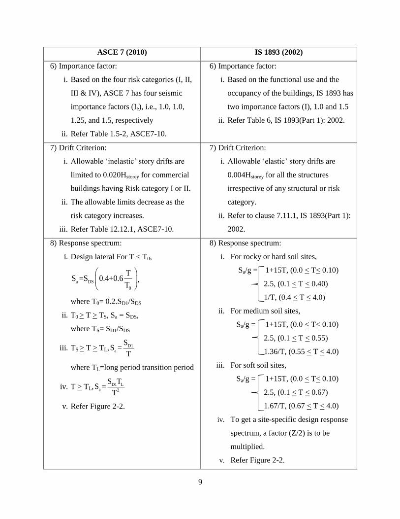
ASCE 7 (2010) IS 1893 (2002)
6) Importance factor:
i. Based on the four risk categories (I, II,
III & IV), ASCE 7 has four seismic
importance factors (Ie), i.e., 1.0, 1.0,
1.25, and 1.5, respectively
ii. Refer Table 1.5-2, ASCE7-10.
6) Importance factor:
i. Based on the functional use and the
occupancy of the buildings, IS 1893 has
two importance factors (I), 1.0 and 1.5
ii. Refer Table 6, IS 1893(Part 1): 2002.
7) Drift Criterion:
i. Allowable ‘inelastic’ story drifts are
limited to 0.020Hstorey for commercial
buildings having Risk category I or II.
ii. The allowable limits decrease as the
risk category increases.
iii. Refer Table 12.12.1, ASCE7-10.
7) Drift Criterion:
i. Allowable ‘elastic’ story drifts are
0.004Hstorey for all the structures
irrespective of any structural or risk
category.
ii. Refer to clause 7.11.1, IS 1893(Part 1):
2002.
8) Response spectrum:
i. Design lateral For T < T0,
a DS
0
TS =S 0.4+0.6
T
,
where T0= 0.2.SD1/SDS
ii. T0 > T > TS, Sa = SDS,
where TS= SD1/SDS
iii. TS > T > TL, D1a
SS =
T
where TL=long period transition period
iv. T > TL, D1 La 2
S TS =
T
v. Refer Figure 2-2.
8) Response spectrum:
i. For rocky or hard soil sites,
Sa/g = 1+15T, (0.0 < T< 0.10)
2.5, (0.1 < T < 0.40)
1/T, (0.4 < T < 4.0)
ii. For medium soil sites,
Sa/g = 1+15T, (0.0 < T< 0.10)
2.5, (0.1 < T < 0.55)
1.36/T, (0.55 < T < 4.0)
iii. For soft soil sites,
Sa/g = 1+15T, (0.0 < T< 0.10)
2.5, (0.1 < T < 0.67)
1.67/T, (0.67 < T < 4.0)
iv. To get a site-specific design response
spectrum, a factor (Z/2) is to be
multiplied.
v. Refer Figure 2-2.
10
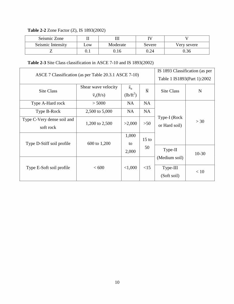
Table 2-2 Zone Factor (Z), IS 1893(2002)
Seismic Zone II III IV V
Seismic Intensity Low Moderate Severe Very severe
Z 0.1 0.16 0.24 0.36
Table 2-3 Site Class classification in ASCE 7-10 and IS 1893(2002)
ASCE 7 Classification (as per Table 20.3.1 ASCE 7-10) IS 1893 Classification (as per
Table 1 IS1893(Part 1):2002
Site Class Shear wave velocity
(ft/s)
(lb/ft2)
Site Class N
Type A-Hard rock > 5000 NA NA
Type-I (Rock
or Hard soil) > 30
Type B-Rock 2,500 to 5,000 NA NA
Type C-Very dense soil and
soft rock 1,200 to 2,500 >2,000 >50
Type D-Stiff soil profile 600 to 1,200
1,000
to
2,000
15 to
50 Type-II
(Medium soil) 10-30
Type E-Soft soil profile < 600 <1,000 <15 Type-III
(Soft soil) < 10
11
Chapter 3 Analysis and Design of structure per ASCE 7-10 seismic provisions
(Case 1)
This chapter presents the analysis and design of the structure according to seismic
guidelines of ASCE 7-10. The major design steps are: (a) finalizing structural geometry and
occupancy; (b) selection of site location; (c) calculation of anticipated dead loads, live loads, and
seismic loads; (d) modeling of structure for analysis; (e) identifying type of analysis, and (d)
design and detailing of the members for the worst load combinations in accordance with design
provisions of ASCE 7-10 and ACI 318-11.
3.1 Structural Geometry and Occupancy
For the reported study, a 12-story, 4-bay by 6-bay reinforced concrete special moment
resisting frame is considered. The height of the bottom story is 14’ and the remaining stories are
12’ each. The width of the structure is 72’ (c/c grid distance is 24’), the length is 120’ (c/c grid
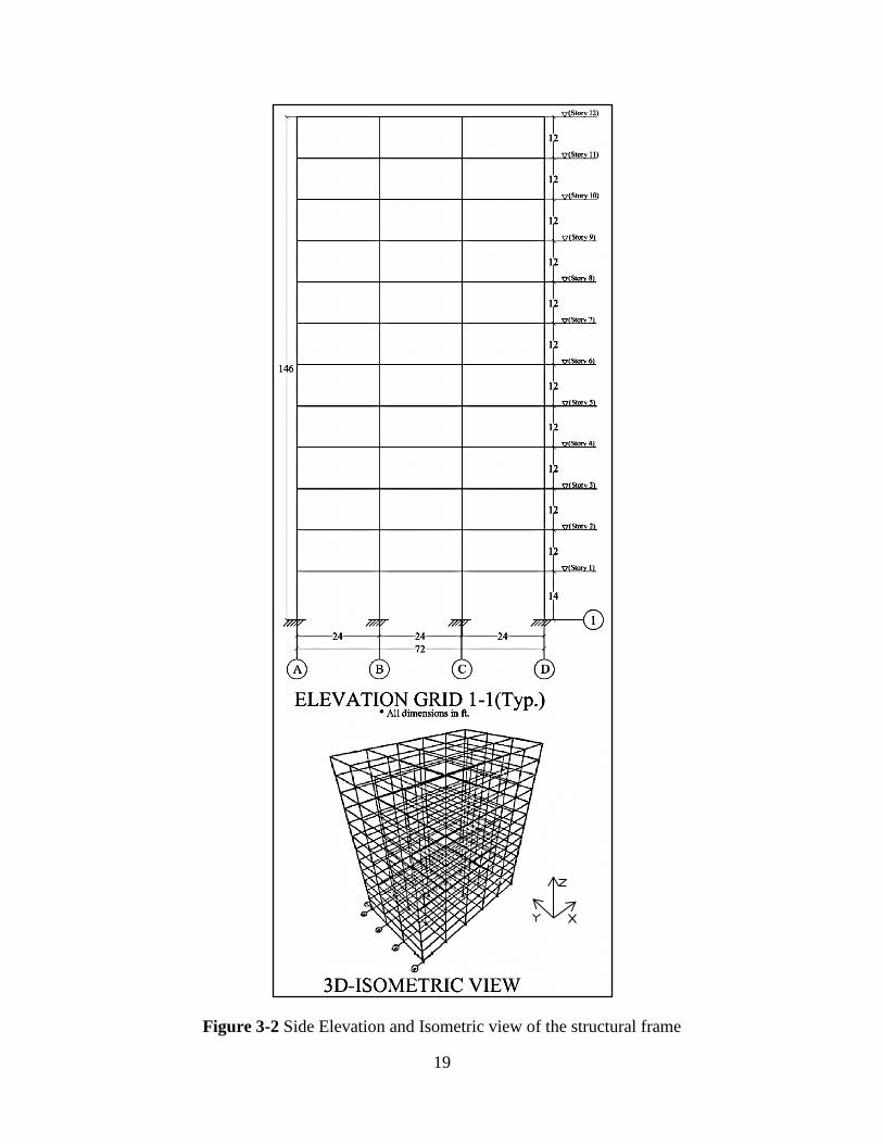
distance is 24’), and the height of the structure is 146’ (see Figure 3-1 & Figure 3-2). The
structure chosen is a commercial/office structure. The category of the structure for determination
of seismic load based on the associated risk is Risk Category II per Table 1.5-1, ASCE 7-10.
Seismic Importance Factor (Ie) for the building, according to the code based on the risk category,
is 1.00 (refer Table 1.5-2, ASCE 7-10).
3.2 Site Location and Site Class
The site for the building is chosen to be San Francisco, which is in a high seismic region
with Latitude (37.75) & Longitude (-122.46). For site class classification, a standard penetration
resistance of =25 is assumed, and, hence, the site is classified as site class D: Stiff Soil (refer to
Table 2-3). Based on the geographic location of the site, the spectral response acceleration
12
parameters, SS and S1 are 1.829 and 0.85, respectively. These values can be easily found from
the URL https://geohazards.usgs.gov/designmaps/us or ASCE 7-10 (Chapter 22).
3.3 Loads and Load Combinations
3.3.1 Gravity Loads
The dead load consists of the self-weight of members, floors, roof, built-in partitions,
cladding, and mechanical loadings. The quantities taken are in compliance with Chapter 3,
ASCE 7-10. The live load for floor and roof is taken as per Table 4-1, ASCE 7-10. For detailed
calculations of dead and live loads refer Appendix A.1.
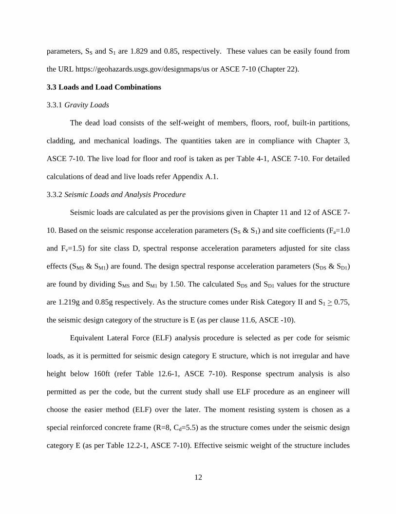
3.3.2 Seismic Loads and Analysis Procedure
Seismic loads are calculated as per the provisions given in Chapter 11 and 12 of ASCE 7-
10. Based on the seismic response acceleration parameters (SS & S1) and site coefficients (Fa=1.0
and Fv=1.5) for site class D, spectral response acceleration parameters adjusted for site class
effects (SMS & SM1) are found. The design spectral response acceleration parameters (SDS & SD1)
are found by dividing SMS and SM1 by 1.50. The calculated SDS and SD1 values for the structure
are 1.219g and 0.85g respectively. As the structure comes under Risk Category II and S1 > 0.75,
the seismic design category of the structure is E (as per clause 11.6, ASCE -10).
Equivalent Lateral Force (ELF) analysis procedure is selected as per code for seismic
loads, as it is permitted for seismic design category E structure, which is not irregular and have
height below 160ft (refer Table 12.6-1, ASCE 7-10). Response spectrum analysis is also
permitted as per the code, but the current study shall use ELF procedure as an engineer will
choose the easier method (ELF) over the later. The moment resisting system is chosen as a
special reinforced concrete frame (R=8, Cd=5.5) as the structure comes under the seismic design
category E (as per Table 12.2-1, ASCE 7-10). Effective seismic weight of the structure includes

13
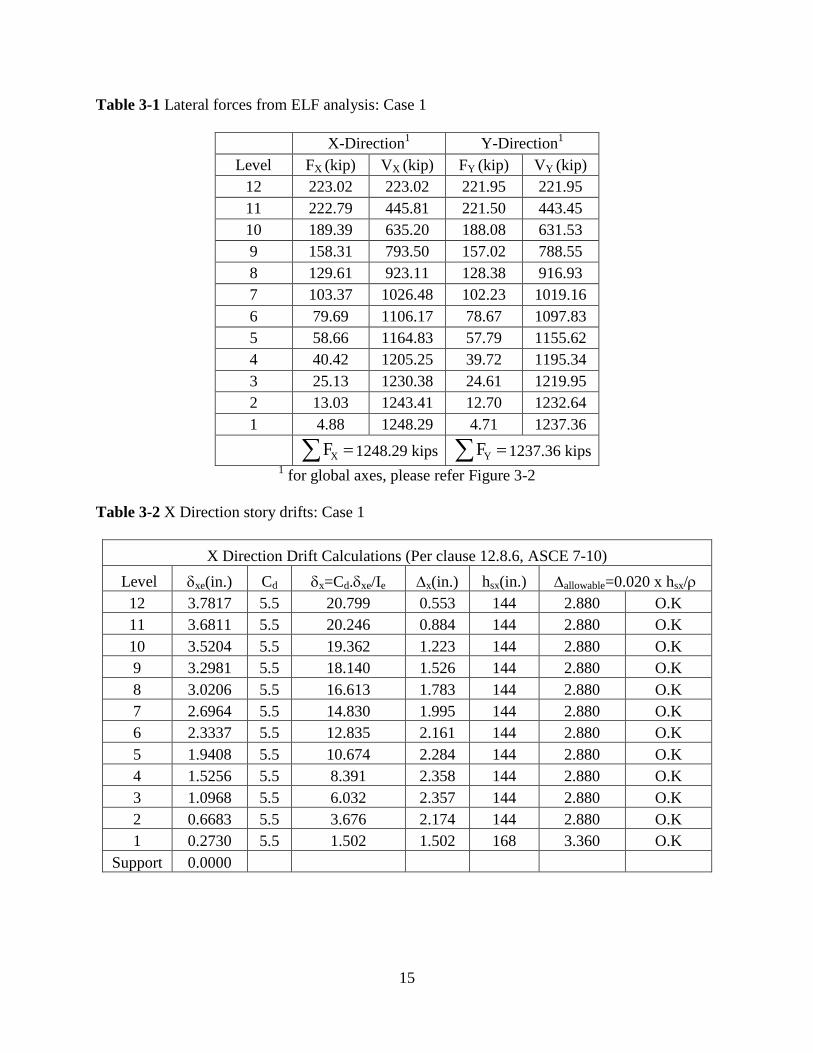
only dead load (as per clause 12.7.2, ASCE 7-10). Lateral forces from ELF method are shown in
Table 3-1. Design base shear in X direction is 1248.29 kips and in Y direction is 1225.25 kips.
For detailed calculations of seismic loads refer Appendix A.1
3.3.3 Load Combinations
The structure is analyzed for all the load combinations involving dead loads, live loads and
seismic loads. The load combinations are taken as per Chapter 2 and 12 of ASCE 7-10.The
following primary load combinations are used,
1) 1.4D
2) 1.2D+1.6L+0.5Lr
3) 1.2D+1.6Lr+0.5L
4) (1.2+0.2SDS)D+(EQX+0.3EQY)+0.5L, i.e. 1.44D+(EQX+0.3EQY)+0.5L
5) (1.2+0.2SDS)D+(EQY+0.3EQX)+0.5L, i.e. 1.44D+(EQY+0.3EQX)+0.5L
6) (0.9+0.2SDS)D+(EQX+0.3EQY), i.e. 0.66D+(EQX+0.3EQY)
7) (0.9+0.2SDS)D+(EQY+0.3EQX), i.e. 0.66D+(EQY+0.3EQX),where (redundancy
factor)=1.0(as per clause 12.3.4.2, ASCE 7-10).
3.4 Modeling and Analysis of Structure
The structure is modeled in 3D in the commercial structural analysis and design software
ETABS NL (Version 9.6). X and Y axis are the global horizontal axis and Z is the global vertical
axis. Refer to Figure 3-2 for 3D view and global axes of the structure modeled in ETABS. The
bases of the columns are assumed to be fixed. Rigid diaphragm action of the slab is simulated on
each floor. The column and the beam members are modeled with a reduced gross moment of
inertia so as to account for cracking of the reinforced concrete (0.7Ig for columns and 0.35Ig for
beams) as per clause 10.10.4.1, ACI 318-11. Dead load, Live load and Seismic loads are applied
14
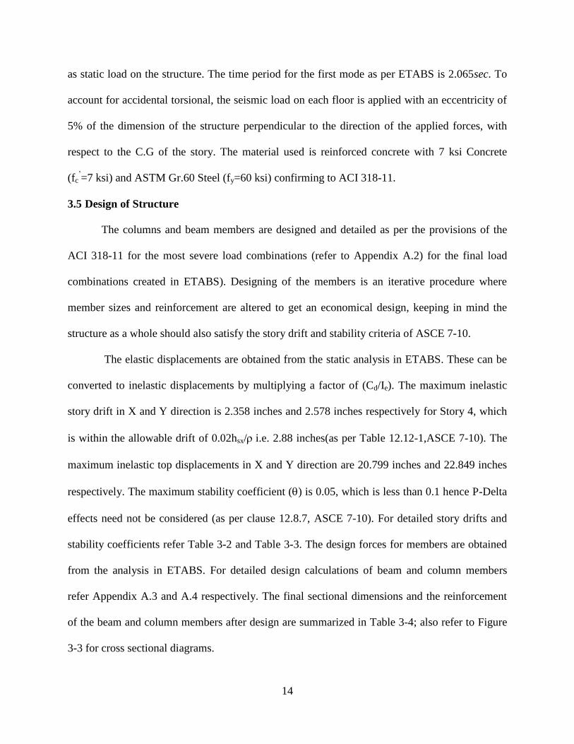
as static load on the structure. The time period for the first mode as per ETABS is 2.065sec. To
account for accidental torsional, the seismic load on each floor is applied with an eccentricity of
5% of the dimension of the structure perpendicular to the direction of the applied forces, with
respect to the C.G of the story. The material used is reinforced concrete with 7 ksi Concrete
(fc’=7 ksi) and ASTM Gr.60 Steel (fy=60 ksi) confirming to ACI 318-11.
3.5 Design of Structure
The columns and beam members are designed and detailed as per the provisions of the
ACI 318-11 for the most severe load combinations (refer to Appendix A.2) for the final load
combinations created in ETABS). Designing of the members is an iterative procedure where
member sizes and reinforcement are altered to get an economical design, keeping in mind the
structure as a whole should also satisfy the story drift and stability criteria of ASCE 7-10.
The elastic displacements are obtained from the static analysis in ETABS. These can be
converted to inelastic displacements by multiplying a factor of (Cd/Ie). The maximum inelastic
story drift in X and Y direction is 2.358 inches and 2.578 inches respectively for Story 4, which
is within the allowable drift of 0.02hsx/ i.e. 2.88 inches(as per Table 12.12-1,ASCE 7-10). The
maximum inelastic top displacements in X and Y direction are 20.799 inches and 22.849 inches
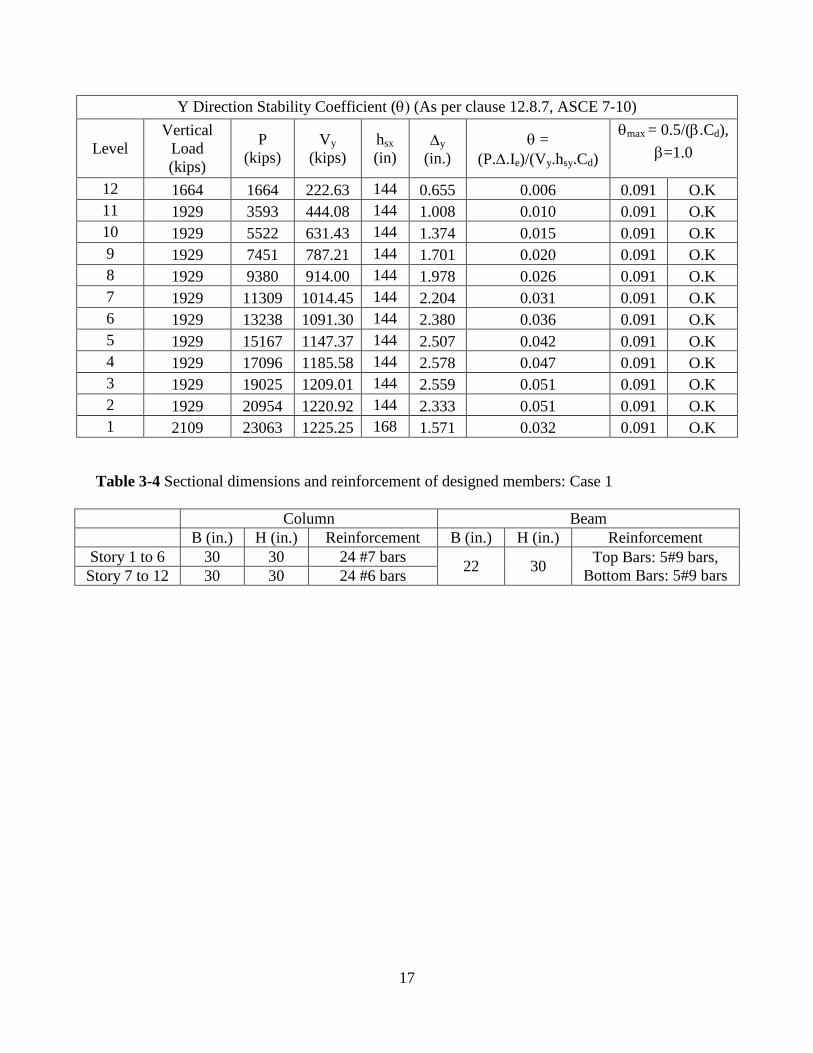
respectively. The maximum stability coefficient () is 0.05, which is less than 0.1 hence P-Delta
effects need not be considered (as per clause 12.8.7, ASCE 7-10). For detailed story drifts and
stability coefficients refer Table 3-2 and Table 3-3. The design forces for members are obtained
from the analysis in ETABS. For detailed design calculations of beam and column members
refer Appendix A.3 and A.4 respectively. The final sectional dimensions and the reinforcement
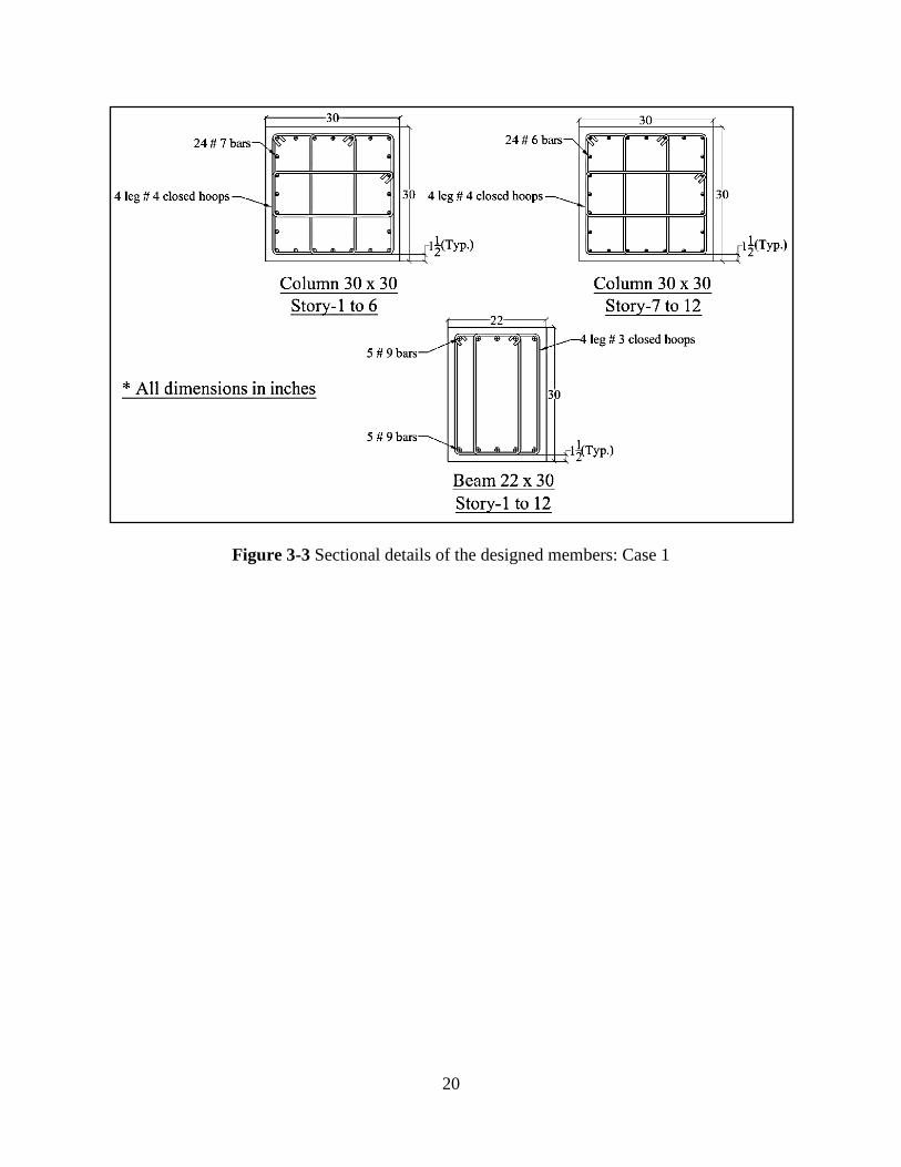
of the beam and column members after design are summarized in Table 3-4; also refer to Figure
3-3 for cross sectional diagrams.
15
Table 3-1 Lateral forces from ELF analysis: Case 1
X-Direction
1 Y-Direction
1
Level FX (kip) VX (kip) FY (kip) VY (kip)
12 223.02 223.02 221.95 221.95
11 222.79 445.81 221.50 443.45
10 189.39 635.20 188.08 631.53
9 158.31 793.50 157.02 788.55
8 129.61 923.11 128.38 916.93
7 103.37 1026.48 102.23 1019.16
6 79.69 1106.17 78.67 1097.83
5 58.66 1164.83 57.79 1155.62
4 40.42 1205.25 39.72 1195.34
3 25.13 1230.38 24.61 1219.95
2 13.03 1243.41 12.70 1232.64
1 4.88 1248.29 4.71 1237.36
XF 1248.29 kips YF 1237.36 kips 1 for global axes, please refer Figure 3-2
Table 3-2 X Direction story drifts: Case 1
X Direction Drift Calculations (Per clause 12.8.6, ASCE 7-10)
Level xe(in.) Cd x=Cd.xe/Ie x(in.) hsx(in.) allowable=0.020 x hsx/
12 3.7817 5.5 20.799 0.553 144 2.880 O.K
11 3.6811 5.5 20.246 0.884 144 2.880 O.K
10 3.5204 5.5 19.362 1.223 144 2.880 O.K
9 3.2981 5.5 18.140 1.526 144 2.880 O.K
8 3.0206 5.5 16.613 1.783 144 2.880 O.K
7 2.6964 5.5 14.830 1.995 144 2.880 O.K
6 2.3337 5.5 12.835 2.161 144 2.880 O.K
5 1.9408 5.5 10.674 2.284 144 2.880 O.K
4 1.5256 5.5 8.391 2.358 144 2.880 O.K
3 1.0968 5.5 6.032 2.357 144 2.880 O.K
2 0.6683 5.5 3.676 2.174 144 2.880 O.K
1 0.2730 5.5 1.502 1.502 168 3.360 O.K
Support 0.0000

16
X Direction Stability Coefficient ((Per clause 12.8.7, ASCE 7-10)
Level
Vertical
Load
(kips)
P
(kips)
Vx
(kips)
hsx
(in) x
(in.)
=
(P..Ie)/(Vx.hsx.Cd)
max = 0.5/(.Cd),
=1.0
12 1664 1664 223.02 144 0.553 0.005 0.091 O.K
11 1929 3593 445.81 144 0.884 0.009 0.091 O.K
10 1929 5522 635.20 144 1.223 0.013 0.091 O.K
9 1929 7451 793.50 144 1.526 0.018 0.091 O.K
8 1929 9380 923.11 144 1.783 0.023 0.091 O.K
7 1929 11309 1026.48 144 1.995 0.028 0.091 O.K
6 1929 13238 1106.17 144 2.161 0.033 0.091 O.K
5 1929 15167 1164.83 144 2.284 0.038 0.091 O.K
4 1929 17096 1205.25 144 2.358 0.042 0.091 O.K
3 1929 19025 1230.38 144 2.357 0.046 0.091 O.K
2 1929 20954 1243.41 144 2.174 0.046 0.091 O.K
1 2109 23063 1248.29 168 1.502 0.030 0.091 O.K
Table 3-3 Y Direction story drifts: Case 1
Y Direction Drift Calculations (Per clause 12.8.6, ASCE 7-10)
Level ye (in.) Cd x=Cd.ye/Ie y (in.) hsx (in.) allowable=0.020 x hsx/
12 4.1543 5.5 22.849 0.655 144 2.880 O.K
11 4.0352 5.5 22.194 1.008 144 2.880 O.K
10 3.8519 5.5 21.185 1.374 144 2.880 O.K
9 3.6021 5.5 19.812 1.701 144 2.880 O.K
8 3.2928 5.5 18.110 1.978 144 2.880 O.K
7 2.9331 5.5 16.132 2.204 144 2.880 O.K
6 2.5323 5.5 13.928 2.380 144 2.880 O.K
5 2.0995 5.5 11.547 2.507 144 2.880 O.K
4 1.6436 5.5 9.040 2.578 144 2.880 O.K
3 1.1749 5.5 6.462 2.559 144 2.880 O.K
2 0.7097 5.5 3.903 2.333 144 2.880 O.K
1 0.2856 5.5 1.571 1.571 168 3.360 O.K
Support 0.0000
17
Y Direction Stability Coefficient ((As per clause 12.8.7, ASCE 7-10)
Level
Vertical
Load
(kips)
P
(kips)
Vy
(kips)
hsx
(in) y
(in.)
=
(P..Ie)/(Vy.hsy.Cd)
max = 0.5/(.Cd),
=1.0
12 1664 1664 222.63 144 0.655 0.006 0.091 O.K
11 1929 3593 444.08 144 1.008 0.010 0.091 O.K
10 1929 5522 631.43 144 1.374 0.015 0.091 O.K
9 1929 7451 787.21 144 1.701 0.020 0.091 O.K
8 1929 9380 914.00 144 1.978 0.026 0.091 O.K
7 1929 11309 1014.45 144 2.204 0.031 0.091 O.K
6 1929 13238 1091.30 144 2.380 0.036 0.091 O.K
5 1929 15167 1147.37 144 2.507 0.042 0.091 O.K
4 1929 17096 1185.58 144 2.578 0.047 0.091 O.K
3 1929 19025 1209.01 144 2.559 0.051 0.091 O.K
2 1929 20954 1220.92 144 2.333 0.051 0.091 O.K
1 2109 23063 1225.25 168 1.571 0.032 0.091 O.K
Table 3-4 Sectional dimensions and reinforcement of designed members: Case 1
Column Beam
B (in.) H (in.) Reinforcement B (in.) H (in.) Reinforcement
Story 1 to 6 30 30 24 #7 bars 22 30
Top Bars: 5#9 bars,
Bottom Bars: 5#9 bars Story 7 to 12 30 30 24 #6 bars

18
Figure 3-1 Plan and Side Elevation of the structural frame
19
Figure 3-2 Side Elevation and Isometric view of the structural frame
20
Figure 3-3 Sectional details of the designed members: Case 1
21
Chapter 4 Analysis and Design as per IS 1893(2002) seismic provisions (Case
2)
This chapter presents the analysis and design of the structure per seismic guidelines of IS
1893(2002). Structural design involves the same general steps as those followed in Chapter 3,
such as finalizing structural geometry and occupancy; site location, calculation of anticipated
dead loads, live loads, and seismic loads; modeling of structure for analysis; identifying type of
analysis; and design of the members for the worst load combinations while satisfying the seismic
design provisions of IS 1893(2002), IS 456(2000), and IS 13920(1993).
4.1 Structural Geometry and Occupancy
For the current study, the structure chosen has the same geometry as the one described in
Chapter 3 (see Figure 3-1 & Figure 3-2). The structure is a commercial/office structure. The
importance factor (I) for the building according to the code is 1.00 (refer Table 6, IS 1893(Part
1): 2002).
4.2 Site Location and Site Class
The site for the building is selected in the Bhuj district of Gujarat, India, which is a high-
seismic prone area that witnessed a devastating earthquake in year 2001. The Indian code
follows a zoning system and the zone factor (Z) for Bhuj is 0.36 as it lies in the Seismic Zone V,
which comes in very severe category (as per Annex E, IS 1893(Part 1): 2002). In order to have a
similar soil type, a standard penetration value of N=25, which is similar to the one taken for Case
1 is assumed. The site for the building is, thus, classified as a Type II: Medium Soils as per Table
2-3.
22
4.3 Loads and Load Combinations
4.3.1 Gravity Loads
The dead loads consist of the self-weight of members, floors, roof, built-in partitions,
cladding, and mechanical loadings. The quantities taken are in compliance with (IS 875(Part 1)-
1987). The live loads for floor and roof are taken as per Table 1, IS 875(Part 2)-1987. Appendix
B provides detailed calculations of dead and live loads refer Appendix B.1.
4.3.2 Seismic Loads and Analysis Procedure
According to IS code regular buildings of height greater than 131.2ft (40m) in Zone IV or
V shall be analyzed by dynamic analysis (as per clause 7.8.1, IS 1893(Part 1): 2002). Dynamic
analyses in IS 1893 refers to either of Response Spectrum method or Time History Method, of
which guidelines to only the former is provided in the code. The code defined design spectrum
for medium soil site is shown in Figure 2-2. Design spectral acceleration value at any point is
given by
ah
Z.I SA =
g2.R
(4.1)
As per IS code, for all structures located in Zone IV and V, a special moment resisting
frame (R=5) should be used (refer Table 7-Note 6, IS 1893(Part 1): 2002). The structure is
analyzed for the design response spectrum in ETABS. The square root of sum of squares (SRSS)
method is used (as per clause 7.8.4.4, IS 1893(Part 1): 2002). The first 8 modes contribute to
more than 90% of mass participation. The modal mass participation ratios are shown in Table
4-1. The base shear calculated in both global axes (X & Y) as per response spectrum analysis in
ETABS is VX=317.86 kips and VY=303.80 kips.
Approximate fundamental natural time period for the building is
0.75
aT =0.075h (in S.I units) (4.2)
23
Where h is in meters, for the current study for h=146ft (44.5m), Ta=1.292sec.
For Ta = 1.292 sec, Sa/g = 1.0524
h
0.36 x 1A = 1.0524 =0.03789
2 x 5
As per seismic coefficient method, total design seismic base shear (VB) along any principal
direction is
B hV =A .W (4.3)
The seismic weight of the structure is dead load and 25% of the imposed load (as per clause
7.4.1, IS 1893(Part 1): 2002). Seismic weight (W) as per calculations is 21325 kips.
VB = Ah.W = 0.03789 x 21325 = 808.01 kips.
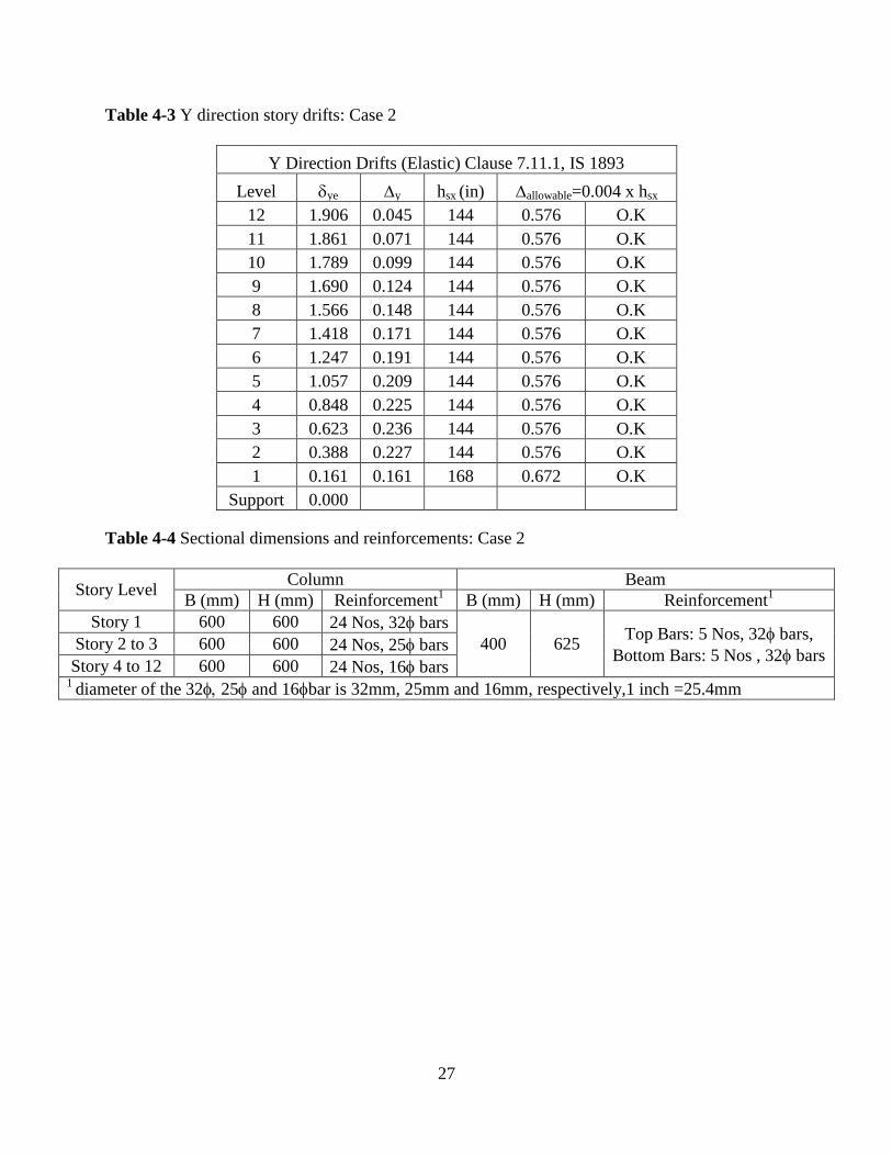
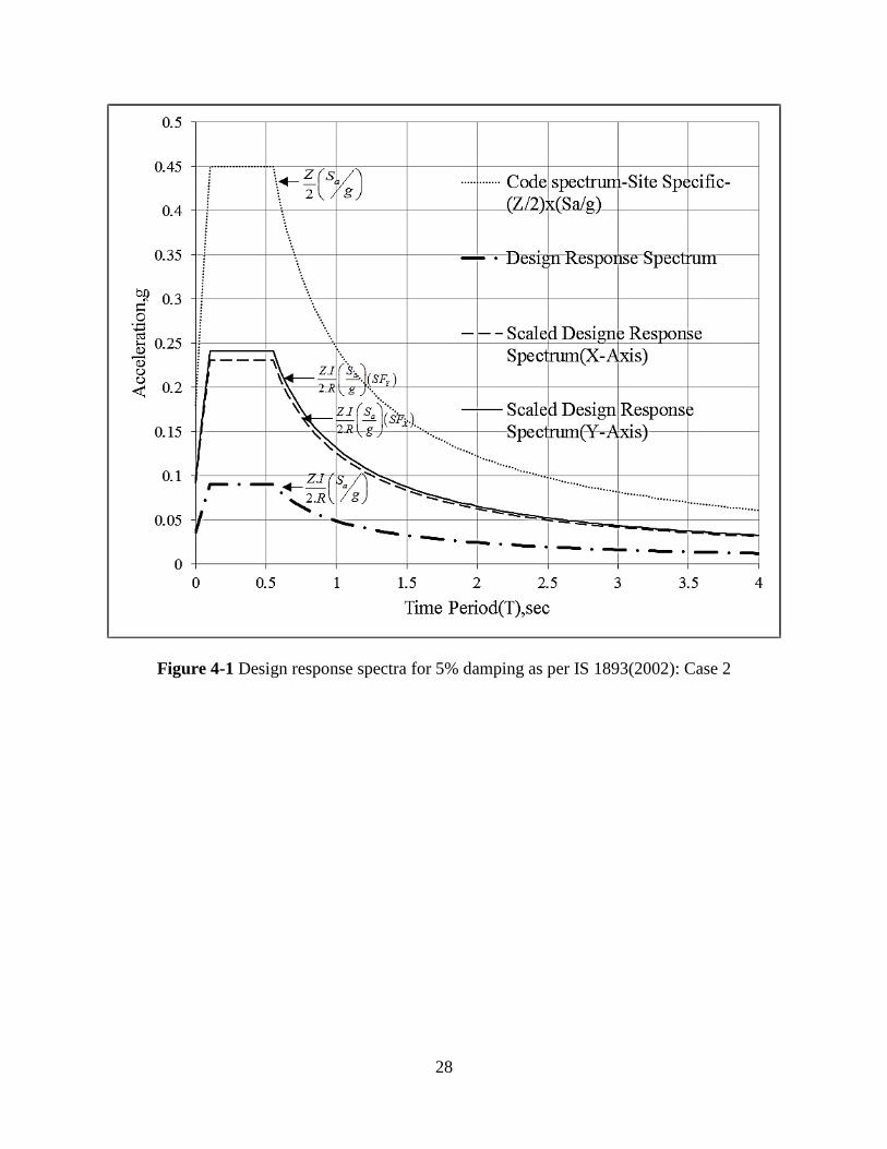
As per clause 7.8.2 IS 1893, if the base shear calculated from response spectrum method is less
than VB, the response quantities should be multiplies by a scale factor of (VB/VX) and (VB/VY) to
get the final design quantities in X and Y direction, respectively. Scale factor of response
spectrum in X direction is 808.01/315.55=2.56 and in Y direction is 808.01/301.48=2.68.
Hence, the design response spectrum is scaled up (as shown in Figure 4-1) and used to get the
design responses. Refer Appendix B.1 for detailed calculations.
4.3.3 Load Combinations
The structure is analyzed for all the load combinations involving dead loads, live loads,
and seismic loads. The load combinations are taken as per clause 6.3.1.2 and 6.3.4 of IS
1893(Part 1): 2002. The following primary load combinations are used.
1) 1.5(DL+IL)
2) 1.2(DL+IL)+1.2(EQX+0.3EQY)
3) 1.2(DL+IL)+1.2(EQY+0.3EQX)
24
4) 1.5DL+1.5(EQx+0.3EQY)
5) 1.5DL+1.5(EQY+0.3EQX)
6) 0.9DL+1.5(EQX+0.3EQY)
7) 0.9DL+1.5(EQY+0.3EQX)
IL is reduced to 0.25IL (as per clause 7.3.1, IS 1893(Part 1): 2002) where induced load is
combined with seismic loads. Induced load does not include roof live load for the combinations
(2) to (7).
4.4 Modeling and Analysis of Structure
The structure is modeled three dimensionally in the commercial structural analysis and
design software ETABS NL (Version 9.6). The bases of the columns are taken as fixed supports.
Rigid floor diaphragm is assumed for the floors. The column and the beam members are
modeled with a reduced gross moment of inertia in order to account for cracking of the
reinforced concrete (0.7Ig for columns and 0.35Ig for beams) even though specific guidelines are
not given in Indian code as for modeling of cracked section. Dead load and live load are applied
as static load on the structure, while seismic load is applied as per Response Spectrum method.
The first mode as computed by ETABS is 3.054sec. To account for accidental eccentricity, the
seismic load on each floor is applied with an eccentricity of 5% of the dimension of the structure
perpendicular to the direction of the applied forces, with respect to the C.G of the story as per
clause 7.9.2, IS 1893(Part 1): 2002. The material used is reinforced concrete with M50 Concrete
(fck=50 N/mm2) confirming to IS 456-2000 and Fe 415 Grade Steel (fy=415 N/mm
2) confirming
to IS 1768(2008).

25
4.5 Design of Structure
The columns and beam members were designed and detailed as per the provisions of the
IS 456(2000) and IS 13920(1993) for the most severe load combinations. Refer to Appendix B.2
for the final load combinations created in ETABS. The sizes of columns and beams were
adjusted to ensure sufficient stiffness in order to satisfy the drift criterion. For the current
structure the strength criterion the member sizes. The columns chosen are of size 600mmx600mm
so that the longitudinal reinforcement ratio does not exceed the maximum specified value of 6%
as per IS 456(2000) and keeping the reinforcement spacing within limits. The story drifts for all
floors are well within the limits. The maximum elastic story drift in X and Y direction is 0.226
inches and 0.236 inches respectively for Story 3, both which are within the allowable drift of
0.004hsx, i.e., 0.576 inches (as per clause 7.11.1, IS 1893(Part 1): 2002). The maximum elastic
top displacements in X and Y direction are 1.819 inches and 1.906 inches, respectively. IS
1893(2002) only limits the elastic story drifts and hence the factor is as low as 0.4% of story
height.
The design forces for members were obtained from the analyses conducted in ETABS.
The members were designed for these forces per IS 456(2000) and IS 13920(1993). For detailed
design calculations of beam and column members, refer to Appendix B.3 and B.4, respectively.
The story drifts are shown in Table 4-2 and Table 4-3. The final cross-sectional dimensions and
the reinforcement of the members are summarized in Table 4-4; Additionally, the cross sections
of various members are summarized in Figure 4-2.

26
Table 4-1 Modal mass participation ratios from analysis in ETABS: Case 2
Mode
No.
Time Period
(T),sec
% Mass
Participation
in X direction
% Mass
Participation
in Y direction
1 3.054 0.00 80.92
2 2.916 81.24 80.92
3 2.658 81.24 80.92
4 0.982 81.24 90.73
5 0.942 90.93 90.73
6 0.859 90.93 90.73
7 0.552 90.93 94.49
8 0.533 94.64 94.49
Table 4-2 X-direction story drifts: Case 2
X Direction Drifts (Elastic) Clause 7.11.1, IS 1893
Level xe x hsx(in) allowable=0.004 x hsx
12 1.819 0.040 144 0.576 O.K
11 1.778 0.066 144 0.576 O.K
10 1.713 0.092 144 0.576 O.K
9 1.620 0.117 144 0.576 O.K
8 1.503 0.140 144 0.576 O.K
7 1.363 0.162 144 0.576 O.K
6 1.201 0.181 144 0.576 O.K
5 1.020 0.199 144 0.576 O.K
4 0.821 0.215 144 0.576 O.K
3 0.606 0.226 144 0.576 O.K
2 0.380 0.220 144 0.576 O.K
1 0.159 0.159 168 0.672 O.K
Support 0.000
27
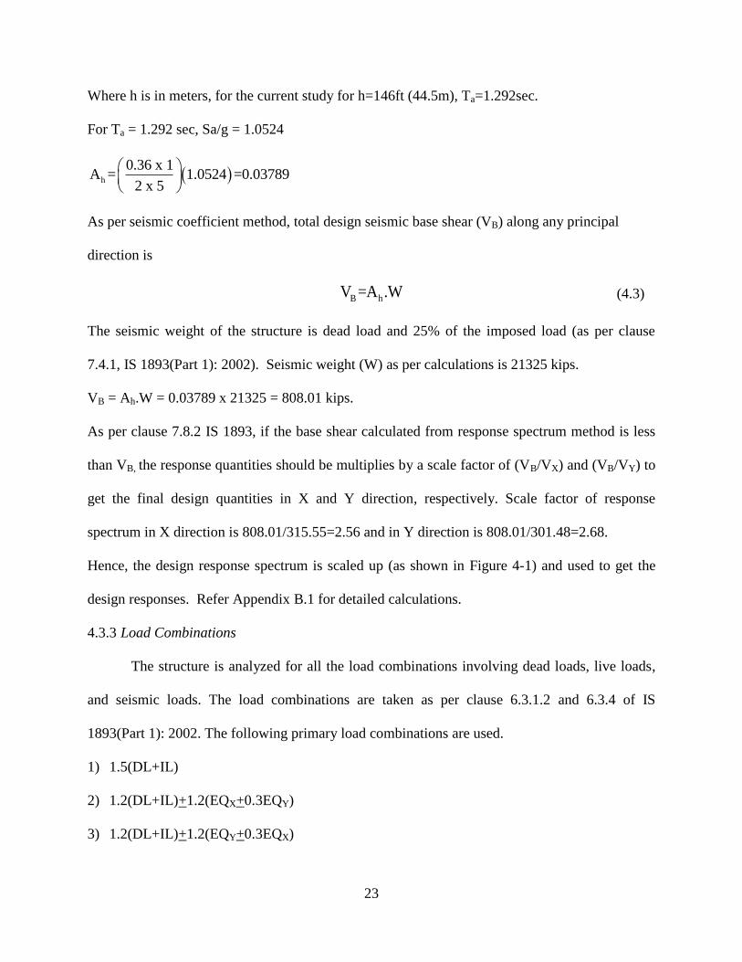
Table 4-3 Y direction story drifts: Case 2
Y Direction Drifts (Elastic) Clause 7.11.1, IS 1893
Level ye y hsx (in) allowable=0.004 x hsx
12 1.906 0.045 144 0.576 O.K
11 1.861 0.071 144 0.576 O.K
10 1.789 0.099 144 0.576 O.K
9 1.690 0.124 144 0.576 O.K
8 1.566 0.148 144 0.576 O.K
7 1.418 0.171 144 0.576 O.K
6 1.247 0.191 144 0.576 O.K
5 1.057 0.209 144 0.576 O.K
4 0.848 0.225 144 0.576 O.K
3 0.623 0.236 144 0.576 O.K
2 0.388 0.227 144 0.576 O.K
1 0.161 0.161 168 0.672 O.K
Support 0.000
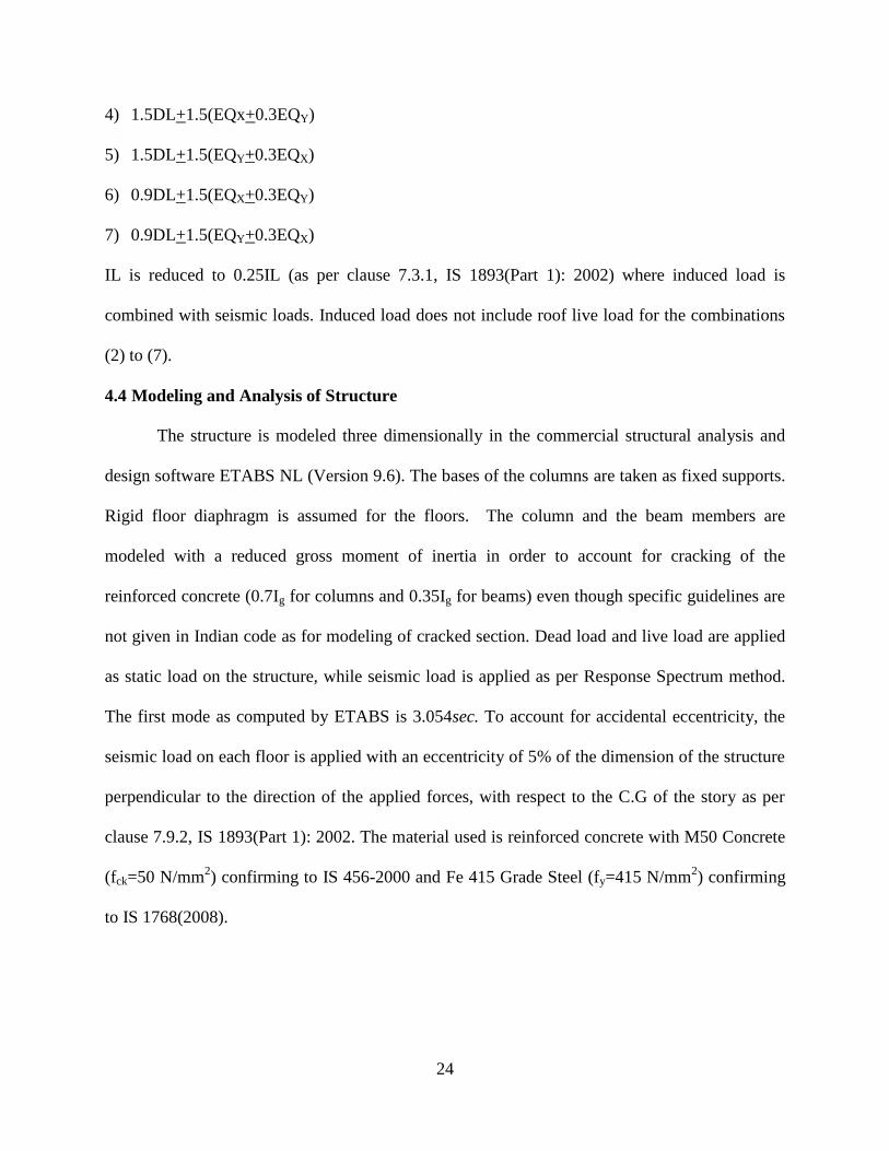
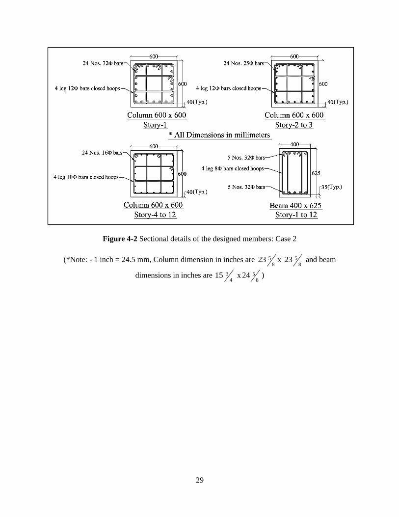
Table 4-4 Sectional dimensions and reinforcements: Case 2
Story Level Column Beam
B (mm) H (mm) Reinforcement1 B (mm) H (mm) Reinforcement
1
Story 1 600 600 24 Nos, 32 bars
400 625 Top Bars: 5 Nos, 32 bars,
Bottom Bars: 5 Nos , 32 bars Story 2 to 3 600 600 24 Nos, 25 bars
Story 4 to 12 600 600 24 Nos, 16 bars 1
diameter of the 3225and16bar is 32mm, 25mm and 16mm, respectively,1 inch =25.4mm
28
Figure 4-1 Design response spectra for 5% damping as per IS 1893(2002): Case 2
29
Figure 4-2 Sectional details of the designed members: Case 2
(*Note: - 1 inch = 24.5 mm, Column dimension in inches are 5
823 x 5
823 and beam
dimensions in inches are 3
415 x 5
824 )
30
Chapter 5 Nonlinear Response History Analysis of the designed structures
This chapter describes the nonlinear response history analysis (RHA) performed on the
structures designed in Chapter 3 and Chapter 4. A powerful tool is required to perform the
nonlinear dynamic analysis. Ruaumoko Nonlinear Dynamic Analysis program is a suite of
applications specifically designed for the dynamic inelastic analysis of structures subjected to
earthquake loading. Ruaumoko 3D, which is a core program of Ruaumoko suite, is used for
current study. After nonlinear RHA, the performance of the members and the global response of
structure are studied.
The nonlinear RHA of the structure involves the following major steps: (a) modeling of
the structure, (b) calculation of inelastic sectional responses of reinforced concrete sections, (c)
selection of hysteresis model, (d) static load application, (e) selection of a suite of spectrum
compatible artificial ground motions as well as recorded ground motions, and (f) analysis of the
structure subjected to the selected ground motions.
5.1 Modeling of Structure in Ruaumoko 3D
The structure is modeled by creating an input text file according to the syntax that is
accepted by the Ruaumoko 3D execution file (refer to Appendix C.6). To achieve the desired
geometry of the structure (see Figure 3-1 and Figure 3-2), a total of 312 nodes and 744 members
(456 beams and 288 columns) are needed. Figure 5-1 shows the model of the structure in
Ruaumoko 3D. X and Z are the global horizontal axes, and Y is the global vertical direction (see
Figure 5-2). Boundary condition for the column base is fixed based on the assumption that the
foundation system is adequate and does not fail when subjected to seismic loading. For this
purpose, all the 6 DOFs of the columns at their base are restrained. To simulate rigid floor
diaphragm action, all the horizontal degrees of freedom in a given floor are slaved to a single
31
node; hence, all the nodes in a given floor have identical horizontal displacements in the X and Z
directions. P-delta effects are included allowing for the effects of large displacements, even
though secondary moments are not anticipated to be significant. Ruaumoko 3D offers a range of
element types to best represent the expected inelastic behavior of the beams and columns. The
column members are modeled by “FRAME” elements. Specifically, “Reinforced concrete
BEAM-COLUMN (type 3) member” is used for columns in order to capture the P-Mzz-Myy
interaction surface. Two-component “BEAM” elements, which do not include axial force-
moment interaction, are used to represent the beams. This element type is justified as the design
analyses by ETABS indicate that the beams carry zero axial force, and, moreover, selection of
rigid floor diaphragm precludes axial load in the beams. Detailed descriptions of the selected
elements are provided in the Ruaumoko user manual (Carr, 2009).
5.2 Modeling of Nonlinear Sectional Properties in Ruaumoko 3D
Inelastic sectional response of a member depends not only on the geometry of the section
but also upon the nonlinear material models of unconfined concrete, confined concrete, and steel
reinforcement. In order to get the sectional responses of individual sections, sectional analysis
software, XTRACT (version 3.0.5) is used. Using XTRACT, sectional responses like moment-
curvature relationship (M- diagram) and axial load-moment interaction diagram (P-M diagram)
can be generated. The following material models were selected.
1) Hognestad (1951) stress-strain model for unconfined concrete
2) Mander, Priestly, and Park model (1988) for confined concrete
3) Bilinear stress-strain curve with strain hardening for reinforcing steel
The details of the material models used in XTRACT are summarized in Appendix C.1.
The following properties are determined for the beams.
32
1) Axial force for tensile and compression yield (PT, PC)
2) The positive and negative yield moments about the major and minor local axes (+MYz, +MYy)
3) M- diagram for the major and minor local axes
For the columns, the following results are obtained.
1) Axial force for tensile and compression yield (PT, PC)
2) Axial force at the balanced point along with the corresponding moments about the minor and
major local axes (PBz, MBz, PBy, MBy)
3) Yield moments when axial force is zero (M0z, M0y)
4) M- diagram for both major and minor local axes
5) P-M diagram of the sections for various inclinations of principal bending axes (0o to 360
o) to
generate the P-Mzz-Myy interaction surface
The generated moment-curvature (M-) relationship is idealized as a bilinear curve, from
which the bilinear factor (r), which is the ratio of the stiffness post yield to the stiffness before
yield, is obtained. Appendix C.2 provides a sample calculation that illustrates the procedure for
idealizing the moment-curvature as a bilinear curve, and computation of the bilinear factor. The
moment-curvature relationship changes as a function of the axial load in the columns. Hence, the
columns in a given story were grouped according to their maximum axial load capacity; four
groups were identified. Figure 5-3 shows grouping of the columns are grouped per story. The
calculated bilinear factors for the beams and columns are shown in Table 5-1 and Table 5-2.
Various capacities needed as input data for the beam and column elements in Ruaumoko 3D are
summarized in Table 5-3 and Table 5-4. The elastic modulus, shear modulus, cross sectional
area, moment of inertia about both the minor and major local axes, and effective shear area (all
of which are also necessary input data) are tabulated in Table 5-5 and 5-6.
33
Modified Takeda model (Otani, 1981) is used to model the hysteretic characteristics of
the beams and columns. The various parameters in the model are shown in Figure 5-4. The
bilinear factors from sectional analysis are used as one of the input parameters. Table 5-7
summarizes the selected parameters used herein.
5.2.1 P-Mzz-Myy capacity check columns in MATLAB
The capacity of the columns subjected to bi-directional moments can be found by
generating a P-Mzz-Myy capacity surface. The axes z-z and y-y are the local major and minor
axes, respectively; and the axial load acts in the local x-x direction for a column section in
Ruaumoko 3D. Columns in current study are square columns; hence, the moment capacities
about z-z and y-y direction are the same.
The capacity surface is an ensemble of slices of the P-M capacity diagrams about the full
range of principal bending axes (0o to 180
o). Consider the 30x30 column for stories 1 to 6 in
structure designated as Case 1. The P-Mprincipal values are calculated from XTRACT for principal
bending axis ranging from 0o to 180
o (with respect to the z-z axes) with a small increment of say
5o. Sample P-M diagrams for 0
o to 45
o are shown in Figure 5-5. To obtain all the desired points,
the P-M values for 0 to 180 degrees are produced from XTRACT. As the column section is
square and the distribution of reinforcement is symmetrical, the P-M diagram for the 50o bending
axis is identical to that for 40o, the P-M diagram for the bending axis at 55
o is the same as that for
35o, and so on. Each point represents an axial load, bending moment about the principal axis, and
an angle with respect to the z-z axis. The bending moment (M) can be converted into
components as Mzz = Mcos and Myy = Msin. Hence, a set of data consisting of P, Mzz, and Myy
can be obtained for all the points on the capacity surface.
34
A MATLAB code was written to construct the capacity surface. Figure 5-6 shows the
capacity surface for the 30x30 column in the first 6 floors of the structure designated as Case 1.
The columns are subjected to the axial and bidirectional moment demands during an earthquake.
The demand points for a column, in the form of axial load and moments in the z-z and y-y
directions, can be extracted from the Ruaumoko analysis output file. The MATLAB code checks
whether the demands (Pdemand, Mzz (demand), Myy (demand)) are within the surface or fall outside the
surface, which correspond to having adequate capacity or yielding, respectively. The conceptual
algorithm for the MATLAB code is as follows.
1) Consider a demand point ‘A’ with coordinates (Pdemand, Mzz (demand), Myy (demand)). Angle
demand can be found as yy(demand)-1
demand
zz(demand)
Mθ =tan
M
.
.
2) If demand is say 48.25o, the code pulls up the values of P-M diagrams for the principal
bending axes of 45o and 50
o and interpolates for the value for 48.25
o to find a new set of P-M
diagram points corresponding to demand = 48.25o.
3) Now the coordinates of point ‘A’ in the P-M diagram can be written as (Pdemand, Mdemand),
where 2 2
demand zz(demand) yy(demand)M = M + M .
4) The coordinate of (Pdemand, Mdemand) is checked to see if it is within this newly calculated P-M
diagram points corresponding to demand. For this purpose, the moment M’ corresponding to
Pdemand in the P-M diagram is found. If M’ < Mdemand, the point ‘A’ lies inside the capacity
surface, i.e., the column capacity has not been exceeded; and if M’>Mdemand, the point ‘A’
lies outside the capacity surface, which indicates yielding.
5) The percentage of capacity exceedance is computed as '
demand
'
M -Mx100
M
.
35
The aforementioned procedure is followed for all the demand points for a particular
column. The MATLAB code also establishes the time at which a point goes outside of the
interaction surface, i.e., the time at which a particular column yields. All instances when a point
falls outside of the interaction surface are obtained by the code. The MATLAB code is shown in
Appendix C.5.
5.3 Lumped Masses
A lumped mass model was used, i.e., the masses were lumped and applied to the beam-
column joints. The masses were determined based on the building seismic weight that had been
employed for design. For structure designated as Case 1, the seismic weight includes dead loads;
while for the second structure (designated as Case 2); the seismic weight includes dead load and
25% of the live load (excluding roof live load). The weight of the structure except for the weight
of the beams and columns is distributed as lumped mass. Ruaumoko 3D calculates the weights
of the beams and columns based on the unit weights specified in the input file.
5.4 Gravity Loads
The response of the structures under the combined actions of gravity loads and
earthquake loading was determined. The full dead load and 25% of the live load (except for roof
live load) was considered. In accordance with Ruaumoko format, the gravity loads are
represented as uniformly distributed loads.
5.5 Selection of Artificial and Recorded Ground Motions
Three different ground motions (one artificial and two recorded ground motions) were
considered. The selection of the ground motions is described in the following subsection.
36
5.5.1 Artificial Ground Motion
The program SIMQKE, which is a part of Ruaumoko software suite, was used to generate
the artificial ground motions. Generation of an artificial ground motion is based on matching a
target response spectrum as closely as possible. In the reported study, the code specified design
response spectrum was selected. The design response spectrum for structure in Case 1 is
calculated as per Section 11.4.5 ASCE 7-10 (see Figure 2-2). Structure in Case 2 is designed for
a design response spectrum which is scaled up so that the base shear is equal to the minimum
calculated base shear. This spectrum is further multiplied by a value (R/I) to get the target
response spectra for the artificial ground motion which is independent of response reduction
factor and importance factor.
The generated ground motion corresponds to one of the two orthogonal components of
the acceleration record. According to both the U.S. and Indian design codes, the other
component is taken as 30% of the primary ground motion. The response spectra for the artificial
ground motions are shown in Figure 5-7 and Figure 5-8 for the structures designated in Case 1
and Case 2, respectively. The corresponding ground motion accelerograms (named GM-1 and
GM-4) are shown in Figure 5-10 and Figure 5-13.
5.5.2 Recorded ground motions
The recorded ground motions were selected with the help of Pacific Earthquake
Engineering Research (PEER) center Ground Motion Database web application (2011). In the
current study, the ground motions were established based on the magnitude of the earthquake
and shear wave velocity (Vs30). The selected range of the magnitude was between 6.0 and 9.0;
this range corresponds to a typical Modified Mercalli Intensity Scale of VIII and higher
according to USGS. Shear wave velocity ranging between 600ft/s (182.88m/s) and 1200ft/s
37
(365.76m/s) was chosen in the reported research. Finally, the most important criterion of
choosing a scaled ground motion is to match its response spectrum with the design spectrum,
which is defined by design codes.
5.5.2.1 Scaling of ground motions
The procedure described in Chapter 16 of ASCE 7-10 was used to scale the earthquakes.
The IS code doesn’t specifically mention a particular procedure and leaves the selection based on
the experience and judgment of the engineer. Hence, the same procedure as per ASCE7-10 was
followed.
According to Section 16.1.3.2 in ASCE 7-10, “For each pair of horizontal ground motion
components, a square root of sum of squares (SRSS) spectrum shall be considered by taking
SRSS of the 5-percent-damped response spectra for the scaled components (where an identical
scale factor is applied to both components of a pair). Each pair of motions shall be scaled such
that for a period between 0.2T and 1.5T, the average of SRSS spectra from all horizontal
component pair does not fall below the corresponding ordinate of the response spectrum used for
design …”
Individual as-recorded ground motions are scaled such that the average of the SRSS
spectra of two scaled as-recorded and one artificial ground motion satisfies the criterion
mentioned above. A sample procedure of scaling of individual ground motion is shown in
Appendix C.3.
5.5.2.2 Uncorrelated principal (as- recorded) ground motion components
Penizien and Watabe (1975) defined a set of principal axes for three-translational
components of a ground motion. The three translational components of ground motion are major,
intermediate, and minor principal axes along which the components of the ground motion are
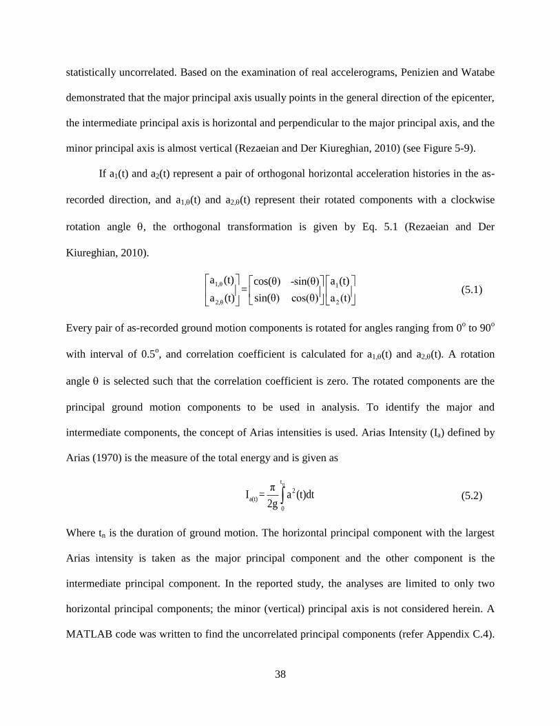
38
statistically uncorrelated. Based on the examination of real accelerograms, Penizien and Watabe
demonstrated that the major principal axis usually points in the general direction of the epicenter,
the intermediate principal axis is horizontal and perpendicular to the major principal axis, and the
minor principal axis is almost vertical (Rezaeian and Der Kiureghian, 2010) (see Figure 5-9).
If a1(t) and a2(t) represent a pair of orthogonal horizontal acceleration histories in the as-
recorded direction, and a1,(t) and a2,(t) represent their rotated components with a clockwise
rotation angle , the orthogonal transformation is given by Eq. 5.1 (Rezaeian and Der
Kiureghian, 2010).
1,θ 1
2,θ 2
a (t) a (t)cos(θ) -sin(θ)=
a (t) sin(θ) cos(θ) a (t)
(5.1)
Every pair of as-recorded ground motion components is rotated for angles ranging from 0o to 90
o
with interval of 0.5o, and correlation coefficient is calculated for a1,(t) and a2,(t). A rotation
angle is selected such that the correlation coefficient is zero. The rotated components are the
principal ground motion components to be used in analysis. To identify the major and
intermediate components, the concept of Arias intensities is used. Arias Intensity (Ia) defined by
Arias (1970) is the measure of the total energy and is given as
nt
2
a(t)
0
πI = a (t)dt
2g (5.2)
Where tn is the duration of ground motion. The horizontal principal component with the largest
Arias intensity is taken as the major principal component and the other component is the
intermediate principal component. In the reported study, the analyses are limited to only two
horizontal principal components; the minor (vertical) principal axis is not considered herein. A
MATLAB code was written to find the uncorrelated principal components (refer Appendix C.4).
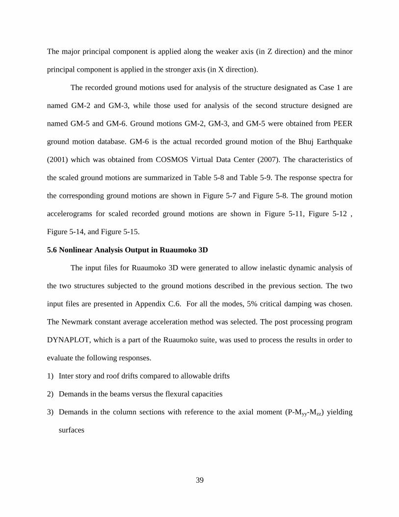
39
The major principal component is applied along the weaker axis (in Z direction) and the minor
principal component is applied in the stronger axis (in X direction).
The recorded ground motions used for analysis of the structure designated as Case 1 are
named GM-2 and GM-3, while those used for analysis of the second structure designed are
named GM-5 and GM-6. Ground motions GM-2, GM-3, and GM-5 were obtained from PEER
ground motion database. GM-6 is the actual recorded ground motion of the Bhuj Earthquake
(2001) which was obtained from COSMOS Virtual Data Center (2007). The characteristics of
the scaled ground motions are summarized in Table 5-8 and Table 5-9. The response spectra for
the corresponding ground motions are shown in Figure 5-7 and Figure 5-8. The ground motion
accelerograms for scaled recorded ground motions are shown in Figure 5-11, Figure 5-12 ,
Figure 5-14, and Figure 5-15.
5.6 Nonlinear Analysis Output in Ruaumoko 3D
The input files for Ruaumoko 3D were generated to allow inelastic dynamic analysis of
the two structures subjected to the ground motions described in the previous section. The two
input files are presented in Appendix C.6. For all the modes, 5% critical damping was chosen.
The Newmark constant average acceleration method was selected. The post processing program
DYNAPLOT, which is a part of the Ruaumoko suite, was used to process the results in order to
evaluate the following responses.
1) Inter story and roof drifts compared to allowable drifts
2) Demands in the beams versus the flexural capacities
3) Demands in the column sections with reference to the axial moment (P-Myy-Mzz) yielding
surfaces
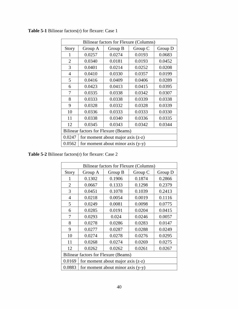
40
Table 5-1 Bilinear factors(r) for flexure: Case 1
Bilinear factors for Flexure (Columns)
Story Group A Group B Group C Group D
1 0.0257 0.0274 0.0193 0.0683
2 0.0340 0.0181 0.0193 0.0452
3 0.0401 0.0214 0.0252 0.0208
4 0.0410 0.0330 0.0357 0.0199
5 0.0416 0.0409 0.0406 0.0289
6 0.0423 0.0413 0.0415 0.0395
7 0.0335 0.0338 0.0342 0.0307
8 0.0333 0.0338 0.0339 0.0338
9 0.0328 0.0332 0.0328 0.0339
10 0.0336 0.0333 0.0333 0.0330
11 0.0338 0.0340 0.0336 0.0335
12 0.0345 0.0343 0.0342 0.0344
Bilinear factors for Flexure (Beams)
0.0247 for moment about major axis (z-z)
0.0562 for moment about minor axis (y-y)
Table 5-2 Bilinear factors(r) for flexure: Case 2
Bilinear factors for Flexure (Columns)
Story Group A Group B Group C Group D
1 0.1302 0.1906 0.1874 0.2866
2 0.0667 0.1333 0.1298 0.2379
3 0.0451 0.1078 0.1039 0.2413
4 0.0218 0.0054 0.0019 0.1116
5 0.0249 0.0081 0.0098 0.0775
6 0.0285 0.0191 0.0204 0.0415
7 0.0293 0.024 0.0246 0.0057
8 0.0278 0.0286 0.0283 0.0147
9 0.0277 0.0287 0.0288 0.0249
10 0.0274 0.0278 0.0276 0.0295
11 0.0268 0.0274 0.0269 0.0275
12 0.0262 0.0262 0.0261 0.0267
Bilinear factors for Flexure (Beams)
0.0169 for moment about major axis (z-z)
0.0883 for moment about minor axis (y-y)
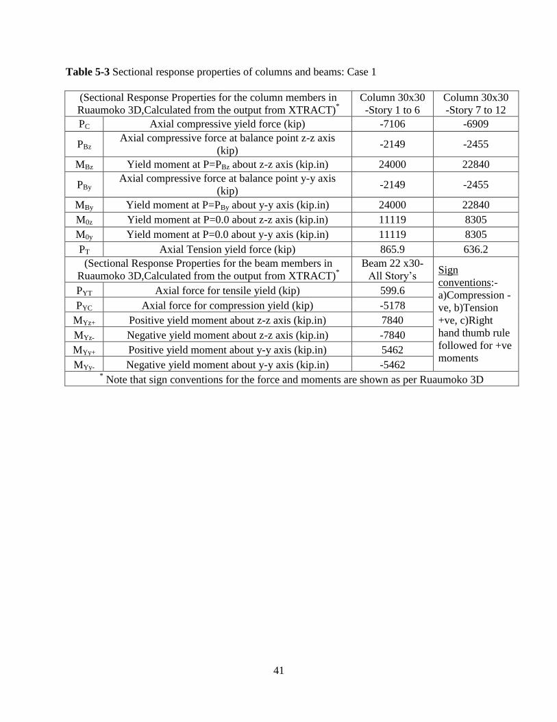
41
Table 5-3 Sectional response properties of columns and beams: Case 1
(Sectional Response Properties for the column members in
Ruaumoko 3D,Calculated from the output from XTRACT)*
Column 30x30
-Story 1 to 6
Column 30x30
-Story 7 to 12
PC Axial compressive yield force (kip) -7106 -6909
PBz Axial compressive force at balance point z-z axis
(kip) -2149 -2455
MBz Yield moment at P=PBz about z-z axis (kip.in) 24000 22840
PBy Axial compressive force at balance point y-y axis
(kip) -2149 -2455
MBy Yield moment at P=PBy about y-y axis (kip.in) 24000 22840
M0z Yield moment at P=0.0 about z-z axis (kip.in) 11119 8305
M0y Yield moment at P=0.0 about y-y axis (kip.in) 11119 8305
PT Axial Tension yield force (kip) 865.9 636.2
(Sectional Response Properties for the beam members in
Ruaumoko 3D,Calculated from the output from XTRACT)*
Beam 22 x30-
All Story’s Sign
conventions:-
a)Compression -
ve, b)Tension
+ve, c)Right
hand thumb rule
followed for +ve
moments
PYT Axial force for tensile yield (kip) 599.6
PYC Axial force for compression yield (kip) -5178
MYz+ Positive yield moment about z-z axis (kip.in) 7840
MYz- Negative yield moment about z-z axis (kip.in) -7840
MYy+ Positive yield moment about y-y axis (kip.in) 5462
MYy- Negative yield moment about y-y axis (kip.in) -5462 * Note that sign conventions for the force and moments are shown as per Ruaumoko 3D
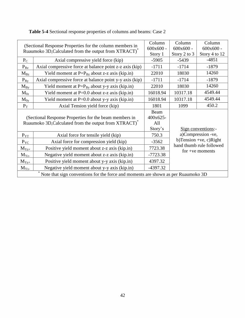
42
Table 5-4 Sectional response properties of columns and beams: Case 2
(Sectional Response Properties for the column members in
Ruaumoko 3D,Calculated from the output from XTRACT)*
Column
600x600 -
Story 1
Column
600x600 -
Story 2 to 3
Column
600x600 -
Story 4 to 12
PC Axial compressive yield force (kip) -5905 -5439 -4851
PBz Axial compressive force at balance point z-z axis (kip) -1711 -1714 -1879
MBz Yield moment at P=PBz about z-z axis (kip.in) 22010 18030 14260
PBy Axial compressive force at balance point y-y axis (kip) -1711 -1714 -1879
MBy Yield moment at P=PBy about y-y axis (kip.in) 22010 18030 14260
M0z Yield moment at P=0.0 about z-z axis (kip.in) 16018.94 10317.18 4549.44
M0y Yield moment at P=0.0 about y-y axis (kip.in) 16018.94 10317.18 4549.44
PT Axial Tension yield force (kip) 1801 1099 450.2
(Sectional Response Properties for the beam members in
Ruaumoko 3D,Calculated from the output from XTRACT)*
Beam
400x625-
All
Story’s Sign conventions:-
a)Compression -ve,
b)Tension +ve, c)Right
hand thumb rule followed
for +ve moments
PYT Axial force for tensile yield (kip) 750.3
PYC Axial force for compression yield (kip) -3562
MYz+ Positive yield moment about z-z axis (kip.in) 7723.38
MYz- Negative yield moment about z-z axis (kip.in) -7723.38
MYy+ Positive yield moment about y-y axis (kip.in) 4397.32
MYy- Negative yield moment about y-y axis (kip.in) -4397.32 * Note that sign conventions for the force and moments are shown as per Ruaumoko 3D
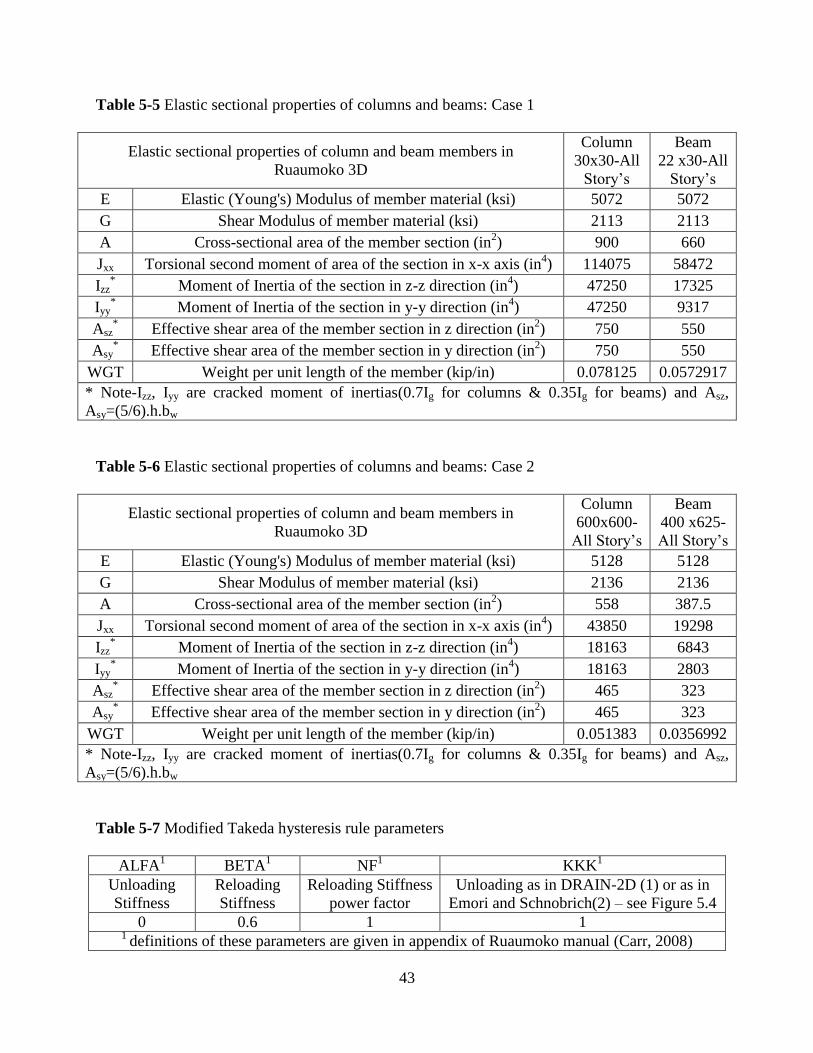
43
Table 5-5 Elastic sectional properties of columns and beams: Case 1
Elastic sectional properties of column and beam members in
Ruaumoko 3D
Column
30x30-All
Story’s
Beam
22 x30-All
Story’s
E Elastic (Young's) Modulus of member material (ksi) 5072 5072
G Shear Modulus of member material (ksi) 2113 2113
A Cross-sectional area of the member section (in2) 900 660
Jxx Torsional second moment of area of the section in x-x axis (in4) 114075 58472
Izz* Moment of Inertia of the section in z-z direction (in
4) 47250 17325
Iyy* Moment of Inertia of the section in y-y direction (in
4) 47250 9317
Asz* Effective shear area of the member section in z direction (in
2) 750 550
Asy* Effective shear area of the member section in y direction (in
2) 750 550
WGT Weight per unit length of the member (kip/in) 0.078125 0.0572917
* Note-Izz, Iyy are cracked moment of inertias(0.7Ig for columns & 0.35Ig for beams) and Asz,
Asy=(5/6).h.bw
Table 5-6 Elastic sectional properties of columns and beams: Case 2
Elastic sectional properties of column and beam members in
Ruaumoko 3D
Column
600x600-
All Story’s
Beam
400 x625-
All Story’s
E Elastic (Young's) Modulus of member material (ksi) 5128 5128
G Shear Modulus of member material (ksi) 2136 2136
A Cross-sectional area of the member section (in2) 558 387.5
Jxx Torsional second moment of area of the section in x-x axis (in4) 43850 19298
Izz* Moment of Inertia of the section in z-z direction (in
4) 18163 6843
Iyy* Moment of Inertia of the section in y-y direction (in
4) 18163 2803
Asz* Effective shear area of the member section in z direction (in
2) 465 323
Asy* Effective shear area of the member section in y direction (in
2) 465 323
WGT Weight per unit length of the member (kip/in) 0.051383 0.0356992
* Note-Izz, Iyy are cracked moment of inertias(0.7Ig for columns & 0.35Ig for beams) and Asz,
Asy=(5/6).h.bw
Table 5-7 Modified Takeda hysteresis rule parameters
ALFA1 BETA
1 NF
1 KKK
1
Unloading
Stiffness
Reloading
Stiffness
Reloading Stiffness
power factor
Unloading as in DRAIN-2D (1) or as in
Emori and Schnobrich(2) – see Figure 5.4
0 0.6 1 1 1
definitions of these parameters are given in appendix of Ruaumoko manual (Carr, 2008)

44
Table 5-8 Ground motions for Response History Analysis: Case 1
Ground
Motion Description
GM-1 Artificial ground motion generated from SIMQKE, ASCE 7-10 Design Spectrum (PGA =0.491g),
Duration 25secs
Ground
Motion
Description
PEER
Database
No.
Event Station/
Duration Year Magnitude
Vs30
(m/s) Mechanism
Scale
Factor PGA (g)
GM-2 NHA#184
Imperial
Valley-
06
El-Centro/
38.955 sec 1979 6.53 202.3 Strike-Slip 1.34 0.636
GM-3 NHA#778 Loma
Prieta
Hollister
Diff Array/
39.635sec
1989 6.93 215.5 Reverse-
Oblique 1.74 0.474
Table 5-9 Ground motions for Response History Analysis: Case 2
Ground
Motion Description
GM-4 Artificial ground motion generated from SIMQKE, IS 1893 Design Spectrum (PGA =0.496g), Duration
25secs
Ground
Motion
Description
PEER
Database
No.
Event Station/
Duration Year Magnitude
Vs30
(m/s) Mechanism
Scale
Factor
PGA
(g)
GM-5 NHA#719 Superstition
Hills
Brawley
Airport/
21.96 sec
1987 6.54 208.7 Strike-Slip 4.85 0.758
Ground
Motion
Description
COSMOS
Database. Event
Station/
Duration Year Magnitude
Scale
Factor PGA (g)
GM-6 BHUJ Bhuj Ahmedabad/
133.525 sec 2001 7.7 4.4 0.4796
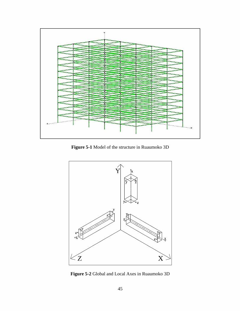
45
Figure 5-1 Model of the structure in Ruaumoko 3D
Figure 5-2 Global and Local Axes in Ruaumoko 3D
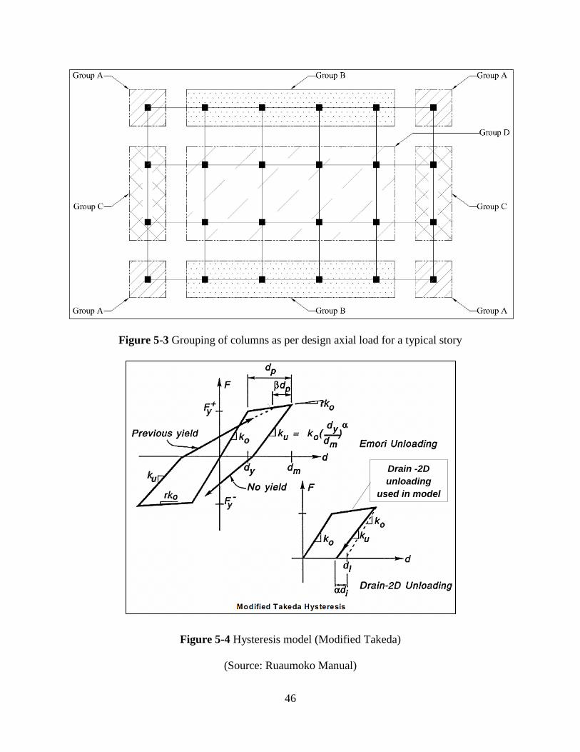
46
Figure 5-3 Grouping of columns as per design axial load for a typical story
Figure 5-4 Hysteresis model (Modified Takeda)
(Source: Ruaumoko Manual)
Drain -2D
unloading
used in model
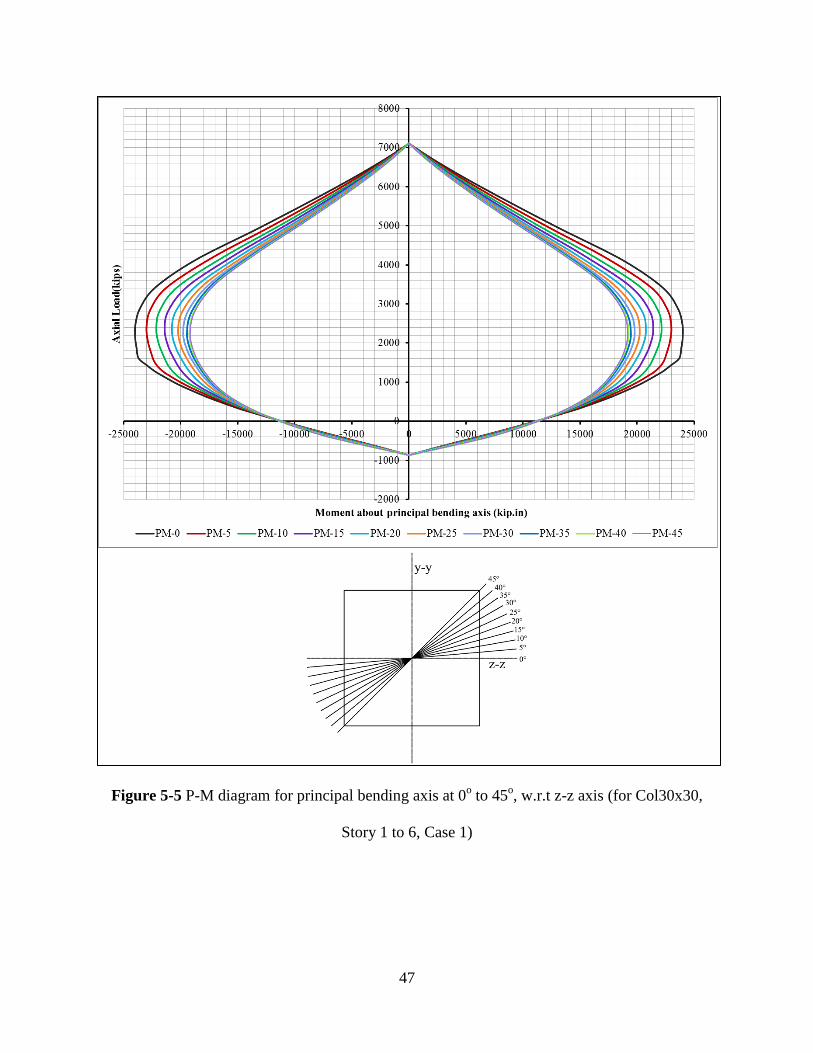
47
Figure 5-5 P-M diagram for principal bending axis at 0o to 45
o, w.r.t z-z axis (for Col30x30,
Story 1 to 6, Case 1)
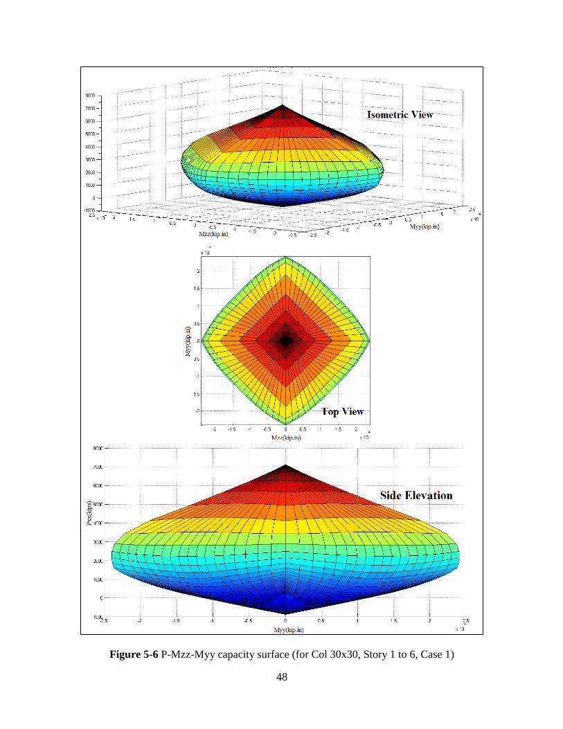
48
Figure 5-6 P-Mzz-Myy capacity surface (for Col 30x30, Story 1 to 6, Case 1)
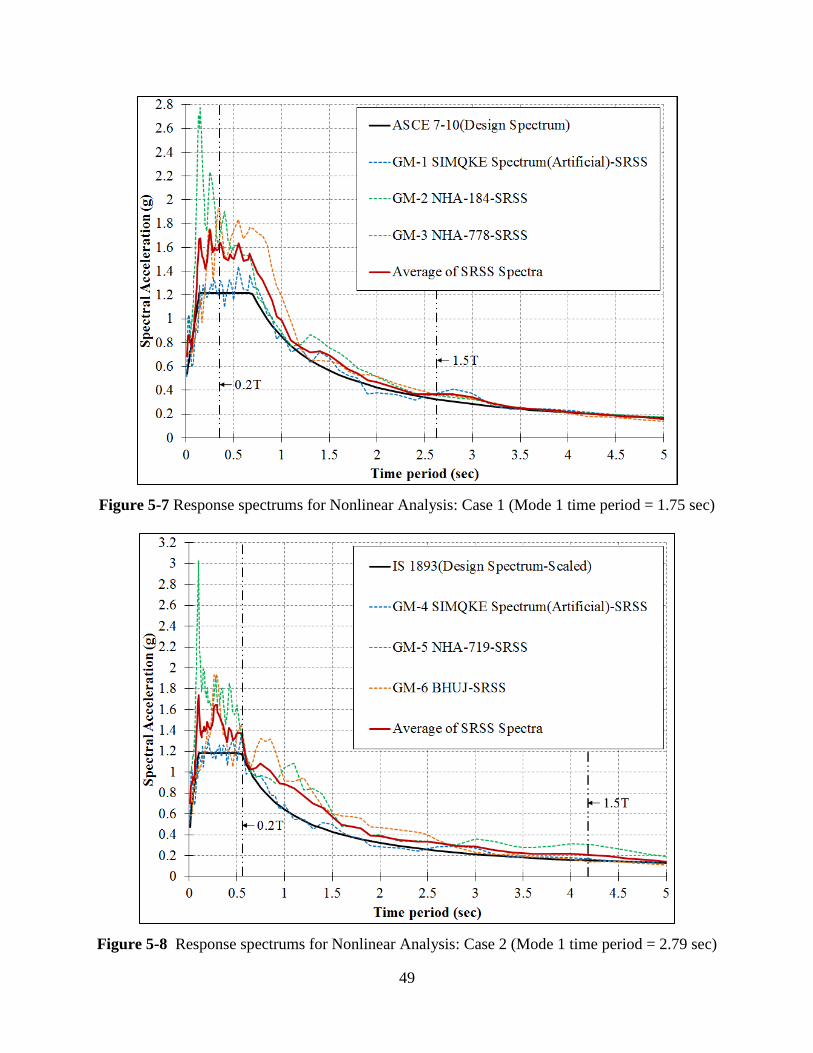
49
Figure 5-7 Response spectrums for Nonlinear Analysis: Case 1 (Mode 1 time period = 1.75 sec)
Figure 5-8 Response spectrums for Nonlinear Analysis: Case 2 (Mode 1 time period = 2.79 sec)
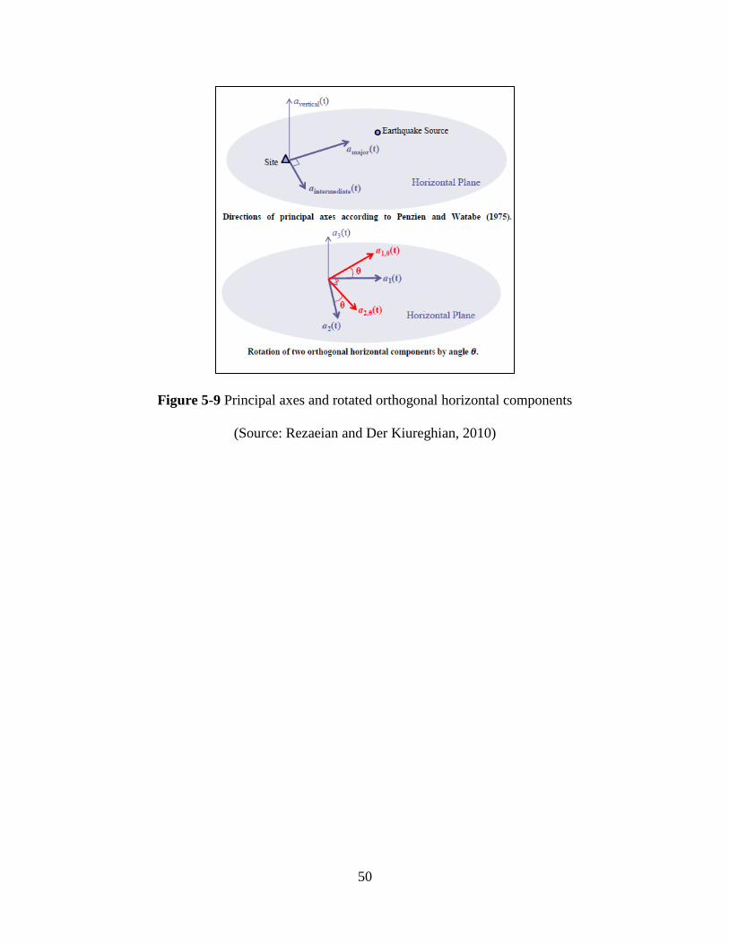
50
Figure 5-9 Principal axes and rotated orthogonal horizontal components
(Source: Rezaeian and Der Kiureghian, 2010)
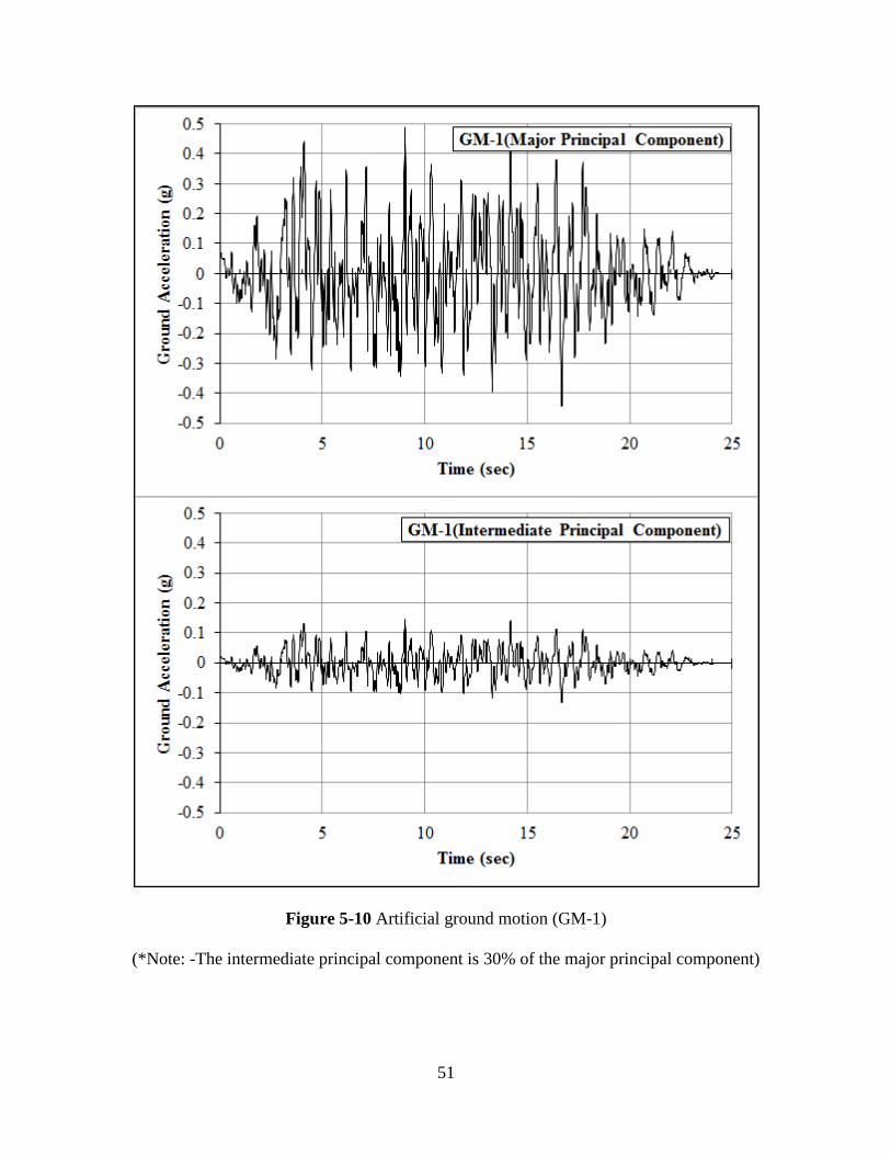
51
Figure 5-10 Artificial ground motion (GM-1)
(*Note: -The intermediate principal component is 30% of the major principal component)
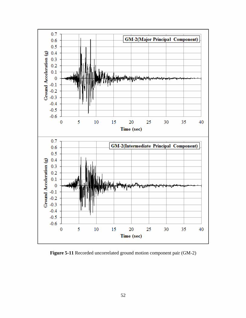
52
Figure 5-11 Recorded uncorrelated ground motion component pair (GM-2)
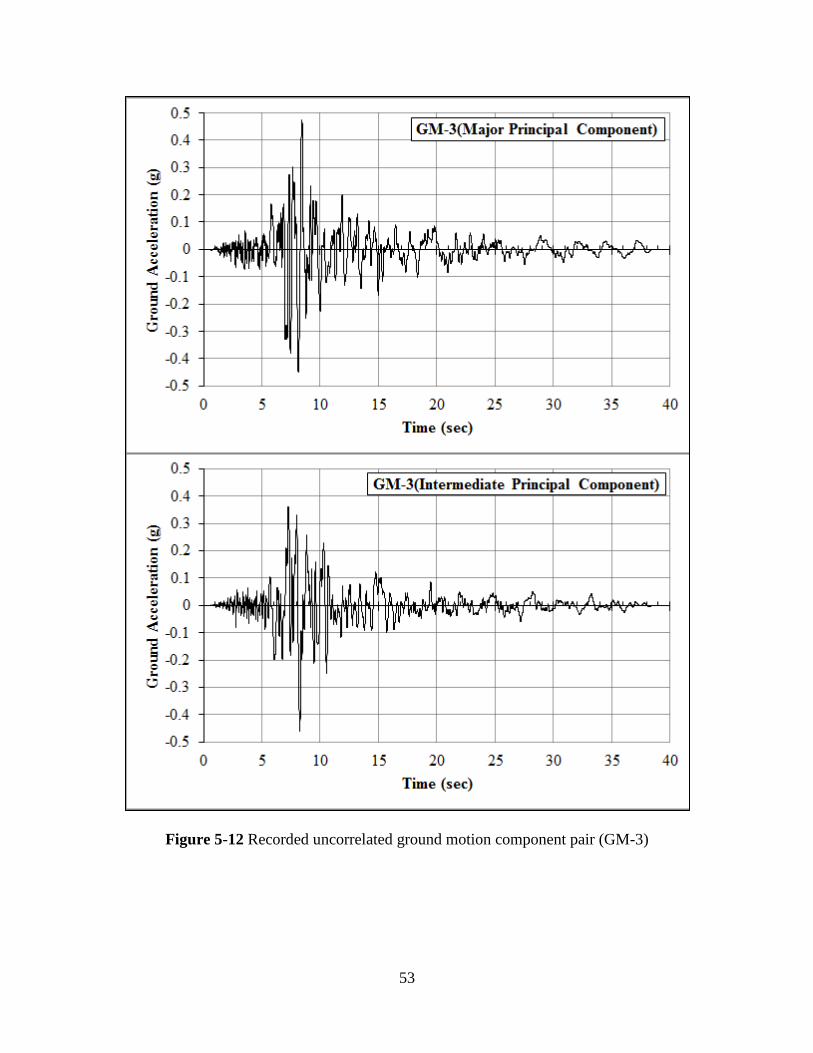
53
Figure 5-12 Recorded uncorrelated ground motion component pair (GM-3)

54
Figure 5-13 Artificial Ground Motion (GM-4)
(*Note:-The intermediate principal component is 30% of the major principal component)
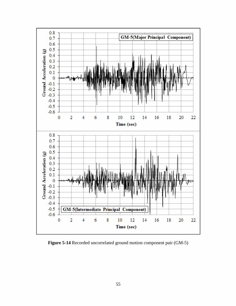
55
Figure 5-14 Recorded uncorrelated ground motion component pair (GM-5)
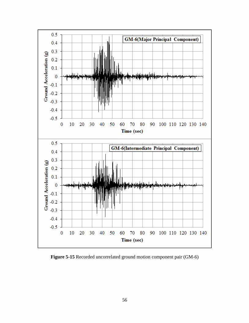
56
Figure 5-15 Recorded uncorrelated ground motion component pair (GM-6)

57
Chapter 6 Results and Conclusions
This chapter presents the results from the analyses as follows.
Table 6-1: The values of the base shear, roof displacement and inter-story drifts
Table 6-2: The number of member yielded for both the structures
Figure 6-1 and Figure 6-2: Base shear vs. time diagrams
Figure 6-3 and Figure 6-4: Roof displacements vs. time diagrams
Figure 6-5 and Figure 6-6: Maximum inter-story drifts diagram
Figure 6-7 to Figure 6-12: Graphical representation of the maximum moment demand-to-
capacity ratio of the members, number of members yielding (%), and the time during the
earthquake records corresponding to the maximum moment demand-to-capacity ratio
Appendix C.7 provides a detailed summary of the performance of beams and columns in
each level of the two structures. Using the presented results, the performance of the two
structures designated as Case 1 and Case 2 is evaluated.
6.1 Case 1 (Structure designed per ASCE 7)
6.1.1 GM-1 (Artificial ground motion compatible with ASCE 7 design spectrum, duration-
25secs)
The maximum base shear occurred at about 4.925sec into the earthquake in the Z
direction (i.e., the weaker axis). The peak base shear generated is about 186% greater than the
design base shear. The maximum roof displacement of 12.66in occurs in the Z direction; this
drift is less than 2% of the total height of the structure. The maximum inter-story drift of 1.46%
occurs for level 3 in the Z direction, and is less than 2% of the story height. Beams in levels 1 to
9 started to yield before the maximum base shear occurred. About 56% of the beams yielded
between 1.25sec and 20.725sec into the earthquake. The maximum beam moment demand-to-
58
capacity ratio was found to be approximately 1.14. The beams in levels 10 to 12 did not yield
over the course of the event. All the columns in levels 1 yielded between 2.775sec and
23.425sec into the earthquake. The maximum column moment demand-to-capacity ratio was
5.54, which occurred for a corner column. The columns in levels 2 to 12 did not yield over the
course of the event.
6.1.2 GM-2 (Scaled recorded ground motion, Event-Imperial Valley-06, duration-38.995sec)
The maximum base shear occurred at about 6.1sec into the earthquake in the X direction
(i.e., the strong axis). The peak base shear generated is about 228% greater than the design base
shear. The maximum roof displacement of 14.72in occurs in the X direction; this drift is less than
2% of the total height of the structure. The maximum inter-story drift of 1.9% occurs for level 2
in the X direction, and is less than 2% of the story height. Beams in levels 1 to 10 started to yield
before the maximum base shear occurred. About 70% of the beams yielded between 5.025sec
and 8.15sec into the earthquake. The maximum beam moment demand-to-capacity ratio was
found to be 1.11. The beams in levels 11 and 12 did not yield over the course of the event. All
the columns in levels 1 and levels 3 to 7 yielded between 5.425sec and 8.625sec into the
earthquake. The maximum column moment demand-to-capacity ratio was 1.5, which occurred
for an outer column in level 1. The columns in levels 2 and levels 8 to 12 did not yield over the
course of the event.
6.1.3 GM-3 (Scaled recorded ground motion, Event-Loma Prieta, duration-39.635sec)
The maximum base shear occurred at about 7.9sec into the earthquake in the X direction
(i.e., the strong axis). The peak base shear generated is about 229% greater than the design base
shear. The maximum roof displacement of 17.73in occurs in the X direction; this drift is less than
2% of the total height of the structure. The maximum inter-story drift of 2.5% occurs for level 2
59
in the X direction, and is more than 2% of the story height. Beams in levels 1 to 9 started to yield
just before the maximum base shear occurred. About 68% of beams yielded between 6.4sec and
21.375sec into the earthquake. The maximum beam moment demand-to-capacity ratio was found
to be 1.15. The beams in levels 11 and 12 did not yield over the course of the event. The majority
of the columns in levels 1 and levels 3 to 7 yielded between 6.55sec and 29.775sec into the
earthquake. The maximum column moment demand-to-capacity ratio was 1.46, which occurred
in one of the inside columns in level 1. The columns in levels 2 and levels 8 to 12 did not yield
over the course of the event.
6.2 Case 2 (Structure designed per IS 1893)
6.2.1 GM-4 (Artificial ground motion compatible with IS 1893 design spectrum, duration-
25secs)
The maximum base shear occurred at about 4.325sec into the earthquake in the Z
direction (i.e., the weak axis). The peak base shear generated is about 287% greater than the
design base shear. IS 1893 only specifies the limit for elastic inter-story drifts of structure; hence,
in order to keep common grounds in comparison, the 2% criterion for the roof displacements and
the inter-story drifts is used for the structures designed in Case 2. The maximum roof
displacement of 18.88in occurs in the Z direction; this drift is less than 2% of the total height of
the structure. The maximum inter-story drift of 2.12% occurs for level 3 in the Z direction, and is
more than 2% of the story height. Beams in levels 1 to 4, in the Z direction, started to yield
before the maximum base shear occurred. Beams in levels 5 to 8 in the Z direction, started to
yield after the maximum base shear occur. Beams in the X direction on any level do not yield.
About 33% of the beams yielded between 4.15sec and 14.025sec into the earthquake. The
maximum beam moment demand-to-capacity ratio was found to be approximately 1.02. The
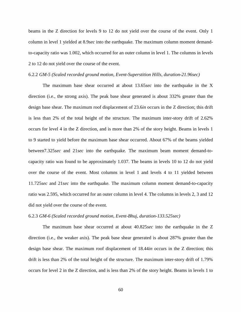
60
beams in the Z direction for levels 9 to 12 do not yield over the course of the event. Only 1
column in level 1 yielded at 8.9sec into the earthquake. The maximum column moment demand-
to-capacity ratio was 1.002, which occurred for an outer column in level 1. The columns in levels
2 to 12 do not yield over the course of the event.
6.2.2 GM-5 (Scaled recorded ground motion, Event-Superstition Hills, duration-21.96sec)
The maximum base shear occurred at about 13.65sec into the earthquake in the X
direction (i.e., the strong axis). The peak base shear generated is about 332% greater than the
design base shear. The maximum roof displacement of 23.6in occurs in the Z direction; this drift
is less than 2% of the total height of the structure. The maximum inter-story drift of 2.62%
occurs for level 4 in the Z direction, and is more than 2% of the story height. Beams in levels 1
to 9 started to yield before the maximum base shear occurred. About 67% of the beams yielded
between7.325sec and 21sec into the earthquake. The maximum beam moment demand-to-
capacity ratio was found to be approximately 1.037. The beams in levels 10 to 12 do not yield
over the course of the event. Most columns in level 1 and levels 4 to 11 yielded between
11.725sec and 21sec into the earthquake. The maximum column moment demand-to-capacity
ratio was 2.595, which occurred for an outer column in level 4. The columns in levels 2, 3 and 12
did not yield over the course of the event.
6.2.3 GM-6 (Scaled recorded ground motion, Event-Bhuj, duration-133.525sec)
The maximum base shear occurred at about 40.825sec into the earthquake in the Z
direction (i.e., the weaker axis). The peak base shear generated is about 287% greater than the
design base shear. The maximum roof displacement of 18.44in occurs in the Z direction; this
drift is less than 2% of the total height of the structure. The maximum inter-story drift of 1.79%
occurs for level 2 in the Z direction, and is less than 2% of the story height. Beams in levels 1 to
61
8 started to yield before the maximum base shear occurred. About 68% of the beams yielded
between 35.4sec and 48.95sec into the earthquake. The maximum beam moment demand-to-
capacity ratio was found to be approximately 1.019. The beams in levels 10 to 12 did not yield
over the course of the event. Some columns in levels 1, 4 to 6, and 8 to 11 yielded between
37.175sec and 47.5sec into the earthquake. The maximum column moment demand-to-capacity
ratio was 1.203, which occurred for an outer column in level 4. The columns in levels 2, 3 and 7
did not yield over the course of the event.

62
Table 6-1 Results: Maximum base shear, roof displacements and inter-story drifts
1. Maximum Base Shear
Case 1
(ASCE 7)
GM-1
(Duration-25 sec)
GM-2
(Duration-38.995 sec)
GM-3
(Duration-39.635 sec)
Direction Direction Direction
Z X Z X Z X
3545kips
@4.925sec
2550kips
@19sec
3147kips
@7.65sec
4097kips
@6.1sec
3329kips
@7.225sec
4103kips
@7.9sec
Case 2
(IS 1893)
GM-4
(Duration-25 sec)
GM-5
(Duration-21.96 sec)
GM-6
(Duration-133.525 sec)
Direction Direction Direction
Z X Z X Z X
3127kips
@4.325sec
1520kips
@11.575sec
3324kips
@16.175sec
3498kips
@13.65sec
3127kips
@40.825sec
2957kips
@44.525sec
2. Maximum Roof Displacement, 2%hn=35.04in.
Case 1
(ASCE 7)
GM-1 GM-2 GM-3
Direction Direction Direction
Z X Z X Z X
12.66in.
@3.2sec
4.732in.
@19.05sec
11.86in.
@6.125sec
14.72in.
@6.575sec
10.21in.
@7.65sec
17.73in.
@8.2sec
Case 2
(IS 1893)
GM-4 GM-5 GM-6
Direction Direction Direction
Z X Z X Z X
18.88in.
@4.75sec
6.345in.
@11.475sec
23.6in.
@18.675sec
15.33in.
@12.425sec
18.44in.
@41.375sec
14.72in.
@39sec
3. Maximum Inter-Story drift
Case 1
(ASCE 7)
GM-1 GM-2 GM-3
Direction Direction Direction
Z X Z X Z X
1.46%
@Story 3
0.43%
@Story 3
1.26%
@Story 5 1.9%
@Story 2 1.09%
@Story 3 2.5%
@Story 2
Case 2
(IS 1893)
GM-4 GM-5 GM-6
Direction Direction Direction
Z X Z X Z X
2.12%
@Story 3
0.58%
@Story 2
2.62%
@Story 4
1.77%
@Story 3
1.79%
@Story 2
1.61%
@Story 3
*Note: (1) Design base shear, Case 1: 1237.36 kips in Z direction and 1248.29 kips in X
direction; (2) Design base shear, Case 2: 808.01 kips for both Z and X directions; (3) Z-axis is
along weaker direction of structure while X-axis is along stronger direction of the structure
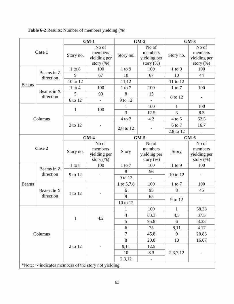
63
Table 6-2 Results: Number of members yielding (%)
Case 1
GM-1 GM-2 GM-3
Story no.
No of
members
yielding per
story (%)
Story no.
No of
members
yielding per
story (%)
Story no.
No of
members
yielding per
story (%)
Beams
Beams in Z
direction
1 to 8 100 1 to 9 100 1 to 9 100
9 67 10 67 10 44
10 to 12 - 11,12 - 11 to 12 -
Beams in X
direction
1 to 4 100 1 to 7 100 1 to 7 100
5 90 8 15 8 to 12 -
6 to 12 - 9 to 12 -
Columns
1 100 1 100 1 100
3 12.5 3 8.3
2 to 12 -
4 to 7 4.2 4 to 5 62.5
2,8 to 12 - 6 to 7 16.7
2,8 to 12 -
Case 2
GM-4 GM-5 GM-6
Story no.
No of
members
yielding per
story (%)
Story
No of
members
yielding per
story (%)
Story
No of
members
yielding per
story (%)
Beams
Beams in Z
direction
1 to 8 100 1 to 7 100 1 to 9 100
9 to 12 - 8 56
10 to 12 - 9 to 12 -
Beams in X
direction 1 to 12 -
1 to 5,7,8 100 1 to 7 100
6 95 8 45
9 65 9 to 12 -
10 to 12 -
Columns
1 4.2
1 100 1 58.33
4 83.3 4,5 37.5
5 95.8 6 8.33
6 75 8,11 4.17
2 to 12 -
7 45.8 9 20.83
8 20.8 10 16.67
9,11 12.5
2,3,7,12 - 10 8.3
2,3,12 -
*Note: ‘-‘indicates members of the story not yielding.
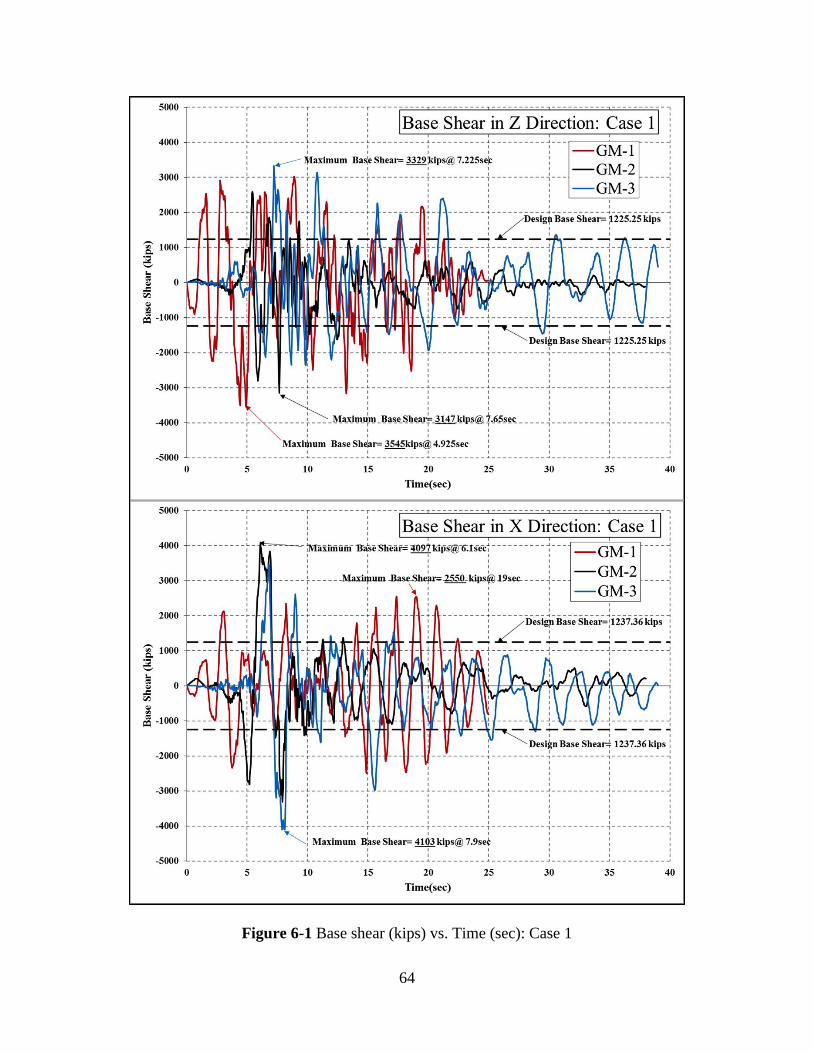
64
Figure 6-1 Base shear (kips) vs. Time (sec): Case 1
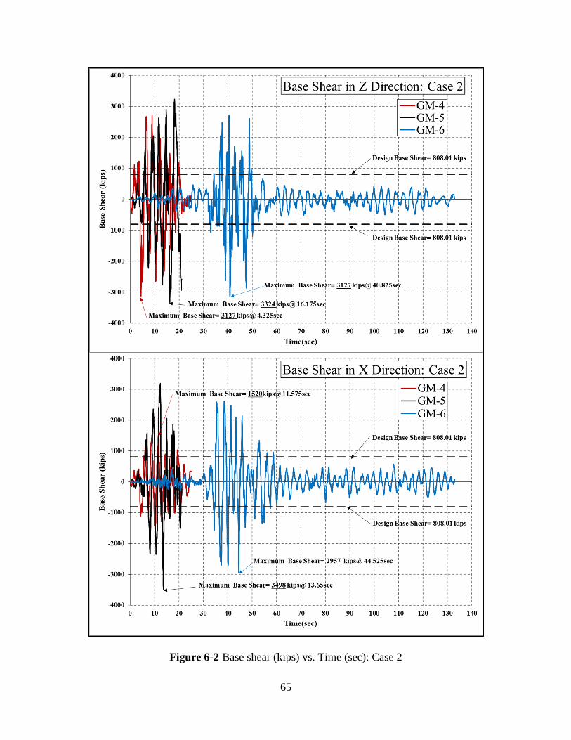
65
Figure 6-2 Base shear (kips) vs. Time (sec): Case 2
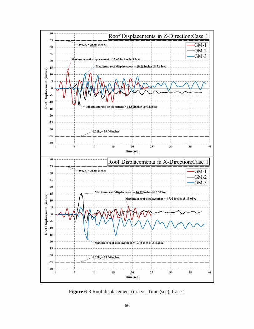
66
Figure 6-3 Roof displacement (in.) vs. Time (sec): Case 1
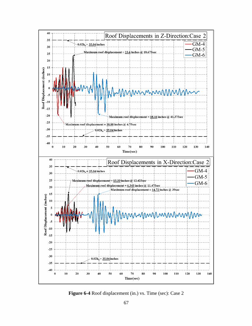
67
Figure 6-4 Roof displacement (in.) vs. Time (sec): Case 2
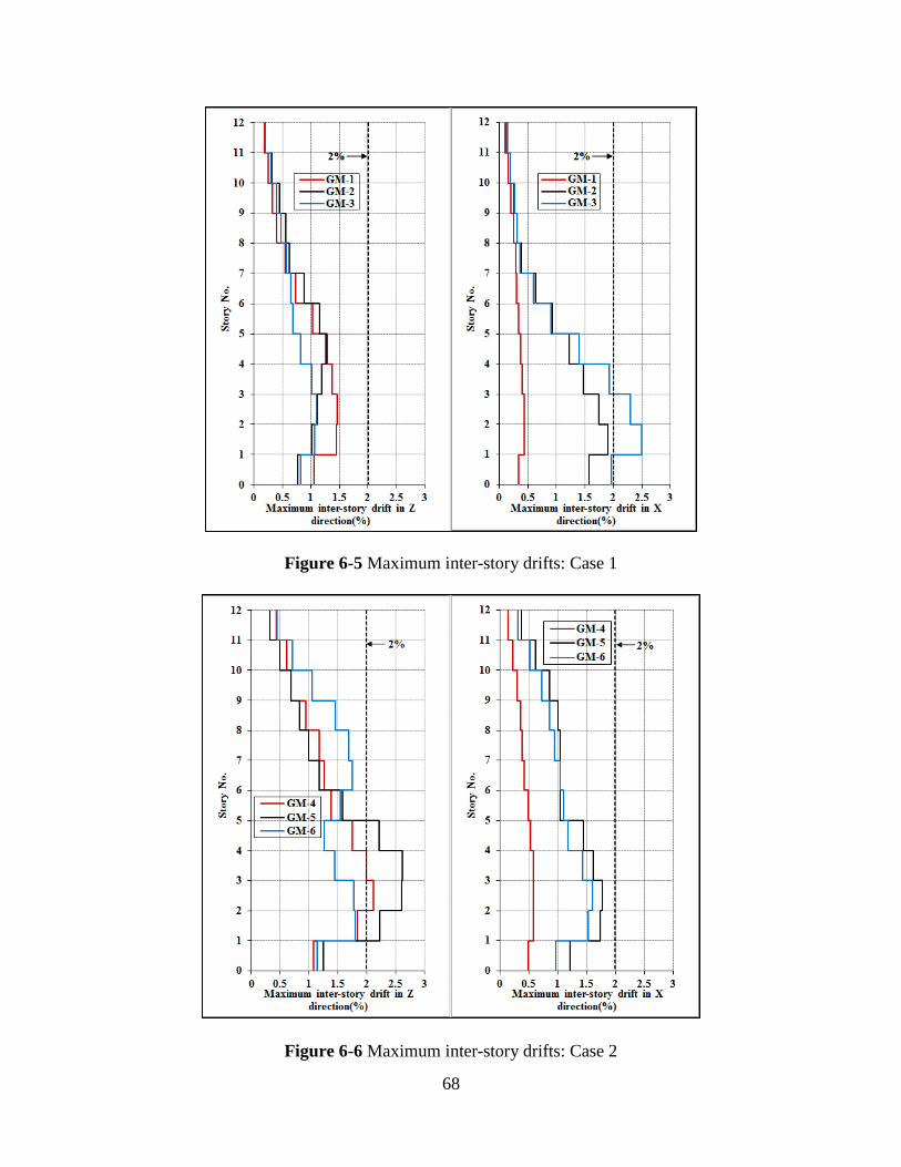
68
Figure 6-5 Maximum inter-story drifts: Case 1
Figure 6-6 Maximum inter-story drifts: Case 2
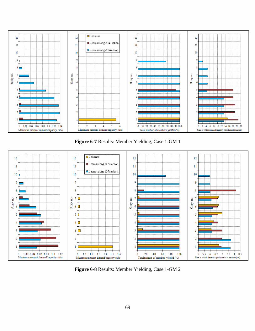
69
Figure 6-7 Results: Member Yielding, Case 1-GM 1
Figure 6-8 Results: Member Yielding, Case 1-GM 2
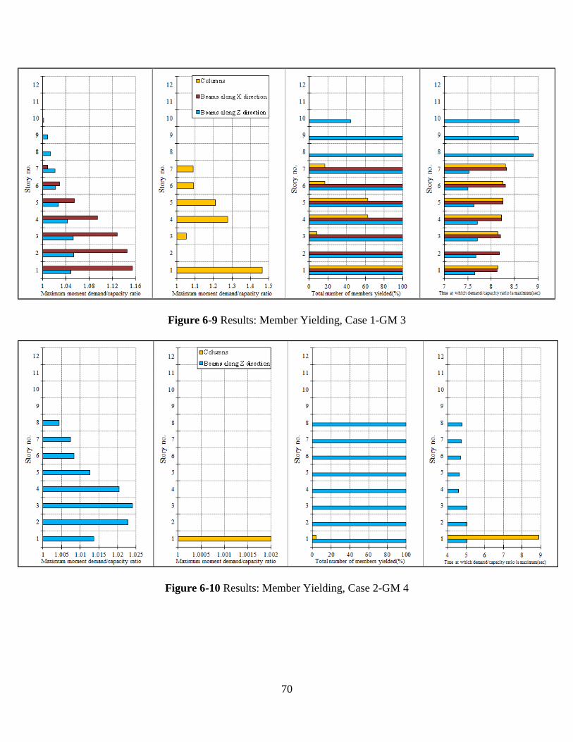
70
Figure 6-9 Results: Member Yielding, Case 1-GM 3
Figure 6-10 Results: Member Yielding, Case 2-GM 4
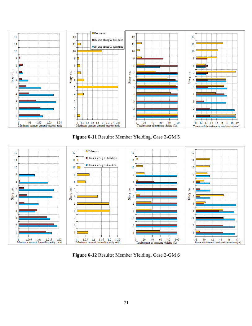
71
Figure 6-11 Results: Member Yielding, Case 2-GM 5
Figure 6-12 Results: Member Yielding, Case 2-GM 6
72
Chapter 7 Summary, Discussion, Conclusions and Future Research
7.1 Summary and Relative Comparison
7.1.1 Performance of structure designed as per ASCE 7 seismic provisions (Case 1)
The roof displacement for the structure is less than 2% of the total height of the structure
for all the ground motions. The maximum roof displacement is observed for ground motion GM-
3. Inter-story drifts for the structure are less than 2% for the first two ground motions, GM-1 and
GM-2, but exceed 2% for ground motion GM-3. The maximum moment demand on the beams is
as high as 1.16 times the moment capacity for ground motion GM-3. The highest number of
beam yielding is 69.5% when the building is subjected to ground motion GM-2. When subjected
to ground motion GM-1, the lowest number of columns (8.33%) yield but the moment demand
for the columns is very high (5.54 times the capacity). The highest number of column yielding
(22.22%) occurs under GM-3; however, the moment demand for the columns is relatively lower
than GM-1 (1.47 times the capacity).
7.1.2 Performance of structure designed as per IS 1893 seismic provisions (Case 2)
The roof displacement for the structure is less than 2% of the total height of the structure
for all ground motions. The maximum roof displacement is observed for ground motion GM-5.
Inter-story drifts for the structure is less than 2% for the ground motion GM-6, but exceed 2% for
ground motions GM-4 and GM-5. The maximum demand moment on the beams is as high as
1.04 times the moment capacity for ground motion GM-5. The highest number of beam yielding
is 68.2%, which occurs for ground motion GM-6. When subjected to GM-4 the lowest number of
columns (0.35%) yield. For the same ground motion, the moment demand for the columns is
lowest (1.002 times the capacity). Ground motion GM-5 results in the highest number of
columns (37.2%) to yield, with a relatively high demand/capacity ratio of 2.59.
73
7.1.3 Relative comparison of performance of Case1 and Case 2 structures
Both structures perform well in terms of roof displacement, which is less than 2% of
building height. However, both structures fail to comply with inter-story drift limit of 2% of
story height; structure one (i.e., Case 1) fails for ground motion GM-3, and the second structure
does not meet this limit for ground motions GM-4 and GM-5. In both structures, the majority of
beams started to yield before yielding in the columns; hence, the design objective of strong
column-weak beam is satisfied. The total number of yielding in the beams is nearly identical for
both structures; however, the level of yielding is higher in the first structure (Case 1). More
columns in building two (Case 2) experienced yielding, but the columns in the first building
(Case 1) yield to a higher level, i.e., the demand/capacity ratio was larger.
7.2 Discussion
The structure in Case 1 is designed as per ELF method and has a design base shear of
1248 kips and 1237 kips in X and Z direction respectively. The lateral load distribution is based
upon the empirical formula and not on the more accurate response spectrum method in the
current study. The members designed satisfy the provisions of ASCE 7 and ACI 318. The drift
criterion governs the fixing of member sizes over the strength criteria. In Ruaumoko analysis, the
number of member yielding and the maximum moment demand/capacity ratio for beams and
columns is comparatively higher than Case 2. Dynamic analysis of Case 1 could have produced
better design results though.
Structure designed is Case 2 is designed as per response spectrum method and for a
design base shear of 808 kips in both X and Z direction. The lateral load here is distributed based
on the modal behavior (mode shapes). The members for the Case 2 structure are comparatively
smaller but the reinforcement ratios in the members are comparatively higher. The load factor for
74
seismic load in the load combinations is higher in Case 2 (1.2 vs. 1.0 and 1.5 vs. 1.0). The
strength criterion governs the fixing of member sizes over the drift criteria.
Seismic mass of both the structures differs by just by 7.5% (23063kips (Case 1) vs.
21324kips (Case 2)), but the stiffness differs a lot as Case 2 structure is more flexible, due to
which the fundamental time period for structure in Case 2 is more than Case 1 as per Ruaumoko
analysis (2.79 vs. 1.75 sec).
7.3 Conclusion
The design methods, design base shears, and earthquake load factors in the load
combinations are different for both the cases. Despite these differences, the allowable elastic
inter-story drift limits are fairly close to each other, 0.0036Hstorey vs. 0.004Hstorey.
Both structures meet the 2% roof drift limit but not the 2% inter-story drift limit. The
inter-story drifts and roof displacement of the Case 2 structure is higher as it is a more flexible
structure. In terms of the number of beams yielding (i.e., 68.2% vs. 69.5%) and maximum
demand/capacity ratio (1.04 vs.1.16), the beams in the second structure (Case 2) perform better
than those in Case 1. The columns in both the structures yield heavily (demand exceeds capacity
by more than 100%). Even though the maximum number of columns yielding in Case 2 is more
than that in Case 1 (i.e., 37.2% vs. 22.2%), the maximum demand/capacity ratio (2.59 vs. 5.54) is
less; hence, the columns in second structure (Case 2) perform ‘relatively’ better than those in
Case 1. The performance of beams and columns in Case 2 is ‘relatively’ better in terms of
strength. Response spectrum method produces better analysis results for Case 2 than ELF
method does for Case 1; hence, the use of response spectrum for design is recommended over
ELF method.

75
7.4 Recommendations for future research
The current study is limited to the comparison of the performances of building that are
symmetrical in plan and elevation. The performance of the buildings with plan and elevation
irregularities needs to be accessed and compared. Current study focused on flexural behavior of
members. Future studies should evaluate shear and torsional behaviors.
76
References
ACI Committee 318 (2011), ACI 318-11/ACI 318R-11, Building Code Requirements for
Structural Concrete and Commentary, American Concrete Institute, Farmington Hills, MI.
ASCE/SEI 7-10 (2010), Minimum Design Loads for Buildings and Other Structures, American
Society of Civil Engineers, Reston, VA.
Arias A (1970), “A measure of earthquake intensity in seismic design for nuclear power plants”,
Hansen RJ (ed.), MIT Press: Cambridge, MA, 438-483.
Carr, A.J (2009), “Volume3: User Manual for the 3: Dimensional Version Ruaumoko 3D”,
University of Canterbury, Christchurch, New Zealand.
Carr, A.J (2008), “Volume5: Appendices, Ruaumoko Manual”, University of Canterbury,
Christchurch, New Zealand.
Consortium of Organizations for Strong-Motion Observation Systems (2007), COSMOS Virtual
Data Center, <http://db.cosmos-eq.org>
ETABS Nonlinear version 9.6, copyright 1984-2009, Computers and Structures Inc. Berkeley,
CA. Computer Program.
Hognestad, E. (1951). "A Study of Combined Bending and Axial Load in Reinforced Concrete
Members".University of Illinois Engineering Experiment Station, Bulletin Series No. 399,
Bulletin No. 1.
IS 1893 Part 1 (2002), Criteria for Earthquake Resistant Design of Structures, Part 1, General
Provisions and Buildings, Rev 5,Bureau of Indian Standards, Manak Bhawan, New Delhi, India.
IS 13920 (1993), Code of Practice for Ductile Detailing of Reinforced Concrete Structures
subjected to Seismic forces, Bureau of Indian Standards, Manak Bhawan, New Delhi, India.
77
IS 875 Part 1 (1987), Code of Practice for design loads(other than earthquake)for buildings and
structures, Part 1: Dead Loads - Unit weights of building materials and stored materials, Rev 2,
Bureau of Indian Standards, Manak Bhawan, New Delhi.
IS 875 Part 2 (1987), Code of Practice for design loads(other than earthquake)for buildings and
structures, Part 2 Imposed Loads, Rev 2, Bureau of Indian Standards, Manak Bhawan, New
Delhi.
IS 456 (2000), Plain and Reinforced Concrete-Code of Practice, Rev 4, Bureau of Indian
Standards, Manak Bhawan, New Delhi.
Jain, S.K., (2003). “Review of Indian seismic code, IS 1893(Part 1):2002”, The Indian Concrete
Journal, 1414-1422.
Khose, V.N., Singh, Y., Lang, D. (2010). “Limitations of Indian and seismic design codes for
RC buildings”.14th
Symposium on Earthquake Engineering, Department of Earthquake
Engineering, IIT Roorkee, Roorkee, India
Mander, J.B., Priestley, M.J.N., and Park, R., (1988).“Theoretical Stress-Strain Model for
Confined Concrete”, Journal of Structural Engineering, ASCE, Vol.114, No.8, 1894-1826.
MATLAB version R2012a, copyright 1984-2012, The Math Works Inc., Natick, MA. Computer
Program.
Mistry R., Dong W., Shah H. (2001). “Interdisciplinary Observations on the January 2001, Bhuj,
Gujarat Earthquake”, World Seismic Safety Initiative and Earthquakes and Megacities Initiative,
Nanyang Technological Institute, Singapore,127 pp.
Otani S, (1981), “Hysteresis Models of Reinforced Concrete for Earthquake Response Analysis”,
Journal of Faculty of Engineering, University of Tokyo, Vol 36, No.2, 407-441.
78
Pacific Earthquake Engineering Research Center (2011), “PEER Ground Motion Database Web
Application”, <http://peer.berkeley.edu/peer_ground_motion_database>
Penzien J, Watabe M ,(1975), “Characteristics of 3-dimensional earthquake ground motions”,
Earthquake Engineering and Structural Dynamics, 365-375.
Rezaeian S, Der Kiureghian A.(2010), “ Stochastic modeling and simulation of ground motions
for performance-based earthquake engineering”, PEER Report 2010/02,Pacific Earthquake
Engineering Research Center, University of California Berkeley,2010,201pp
Ruaumoko-The Maori God of Earthquakes and Volcanoes, copyright 1981-2011,A.J.Carr,
University of Canterbury, Christchurch, New Zealand. Computer Program.
United States Geological Survey (2011), U.S. Seismic “Design Maps” Web Application,
<https://geohazards.usgs.gov/secure/designmaps/us>.
XTRACT - Cross-sectional structural analysis of components version 3.0.5, copyright 2006,
IMBSEN Software Systems, CA. Computer Program.
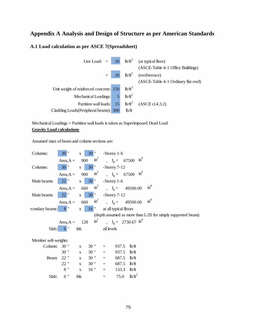
79
Appendix A Analysis and Design of Structure as per American Standards
A.1 Load calculation as per ASCE 7(Spreadsheet)
Load calculations(ASCE 7-10)
Live Load: = 50 (at typical floor)
(ASCE-Table 4-1 Office Buildings)
= 20 (roof/terrace)
(ASCE-Table 4-1 Ordinary flat roof)
Unit weight of reinforced concrete: 150
Mechanical Loadings: 5
Partition wall loads: 15 (ASCE cl.4.3.2)
Cladding Loads(Peripheral beams): 300
Mechanical Loadings + Partition wall loads is taken as Superimposed Dead Load
Gravity Load calculations
Assumed sizes of beam and column sections are:
Columns: 30 " x 30 " -Storey 1-6
Area,A = in2
, Ig = in4
Columns: 30 " x 30 " -Storey 7-12
Area,A = in2
, Ig = in4
Main beams: 22 " x 30 " -Storey 1-6
Area,A = in2
, Ig = in4
Main beams: 22 " x 30 " -Storey 7-12
Area,A = in2
, Ig = in4
Secondary beams: 8 " x 16 " at all typical floors
(depth assumed as more than L/20 for simply supported beam)
Area,A = in2
, Ig = in4
Slab: 6 " thk all levels
Member self-weights:
Column: 30 " x 30 " = lb/ft
30 " x 30 " = lb/ft
Beam: 22 " x 30 " = lb/ft
22 " x 30 " = lb/ft
8 " x 16 " = lb/ft
Slab: 6 " thk = lb/ft2
lb/ft2
lb/ft
660
128
lb/ft2
lb/ft2
lb/ft3
900
660
900
lb/ft2
67500
67500
2730.67
49500.00
49500.00
937.5
75.0
133.3
687.5
687.5
937.5
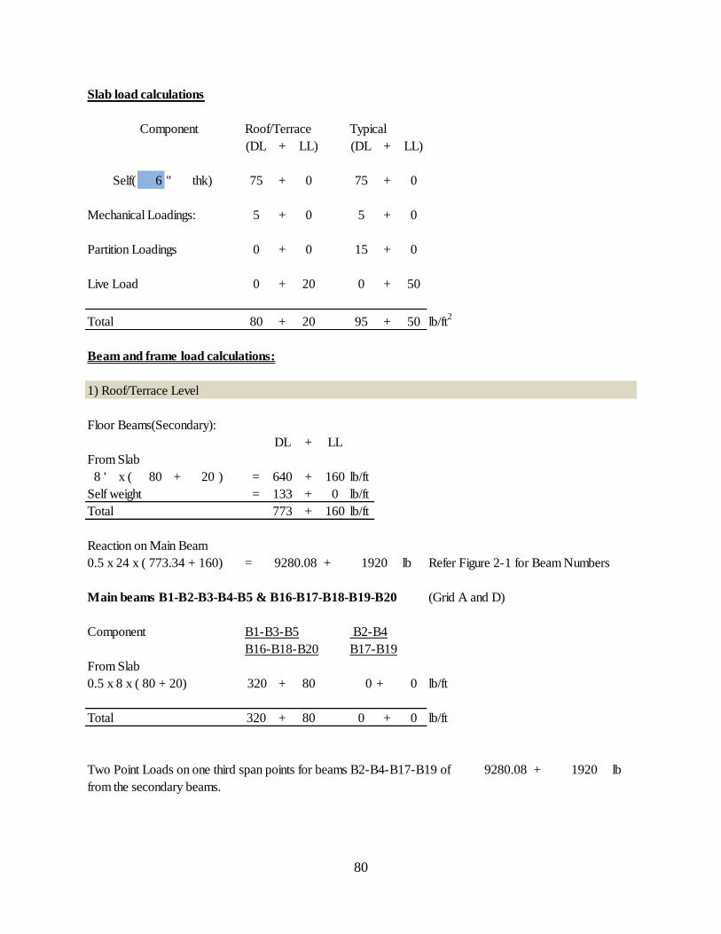
80
Slab load calculations
Component Roof/Terrace Typical
(DL + LL) (DL + LL)
Self( 6 " thk) 75 + 0 75 + 0
Mechanical Loadings: 5 + 0 5 + 0
Partition Loadings 0 + 0 15 + 0
Live Load 0 + 20 0 + 50
Total 80 + 20 95 + 50 lb/ft2
Beam and frame load calculations:
1) Roof/Terrace Level
Floor Beams(Secondary):
DL + LL
From Slab
8 ' x ( 80 + 20 ) = 640 + 160 lb/ft
Self weight = 133 + 0 lb/ft
Total 773 + 160 lb/ft
Reaction on Main Beam
0.5 x 24 x ( 773.34 + 160) = + lb Refer Figure 2-1 for Beam Numbers
Main beams B1-B2-B3-B4-B5 & B16-B17-B18-B19-B20 (Grid A and D)
Component B1-B3-B5 B2-B4
B16-B18-B20 B17-B19
From Slab
0.5 x 8 x ( 80 + 20) 320 + 80 0 + 0 lb/ft
Total 320 + 80 0 + 0 lb/ft
Two Point Loads on one third span points for beams B2-B4-B17-B19 of + lb
from the secondary beams.
1920
1920
9280.08
9280.08
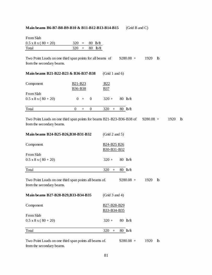
81
Main beams B6-B7-B8-B9-B10 & B11-B12-B13-B14-B15 (Grid B and C)
From Slab
0.5 x 8 x ( 80 + 20) 320 + 80 lb/ft
Total 320 + 80 lb/ft
Two Point Loads on one third span points for all beams of + lb
from the secondary beams.
Main beams B21-B22-B23 & B36-B37-B38 (Grid 1 and 6)
Component B21-B23 B22
B36-B38 B37
From Slab
0.5 x 8 x ( 80 + 20) 0 + 0 320 + 80 lb/ft
Total 0 + 0 320 + 80 lb/ft
Two Point Loads on one third span points for beams B21-B23-B36-B38 of + lb
from the secondary beams.
Main beams B24-B25-B26,B30-B31-B32 (Grid 2 and 5)
Component B24-B25 B26
B30-B31-B32
From Slab
0.5 x 8 x ( 80 + 20) 320 + 80 lb/ft
Total 320 + 80 lb/ft
Two Point Loads on one third span points all beams of. + lb
from the secondary beams.
Main beams B27-B28-B29,B33-B34-B35 (Grid 3 and 4)
Component B27-B28-B29
B33-B34-B35
From Slab
0.5 x 8 x ( 80 + 20) 320 + 80 lb/ft
Total 320 + 80 lb/ft
Two Point Loads on one third span points all beams of. + lb
from the secondary beams.
9280.08
1920
9280.08
9280.08
9280.08
1920
1920
1920
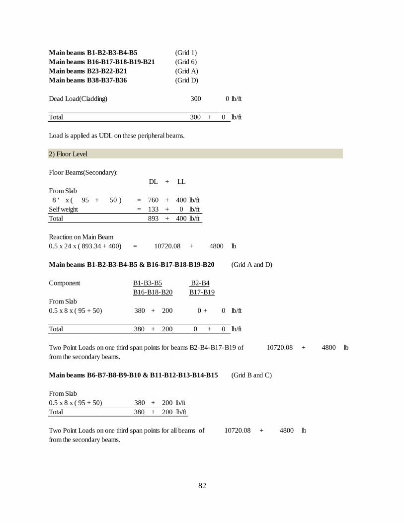
82
Main beams B1-B2-B3-B4-B5 (Grid 1)
Main beams B16-B17-B18-B19-B21 (Grid 6)
Main beams B23-B22-B21 (Grid A)
Main beams B38-B37-B36 (Grid D)
Dead Load(Cladding) 300 0 lb/ft
Total 300 + 0 lb/ft
Load is applied as UDL on these peripheral beams.
2) Floor Level
Floor Beams(Secondary):
DL + LL
From Slab
8 ' x ( 95 + 50 ) = 760 + 400 lb/ft
Self weight = 133 + 0 lb/ft
Total 893 + 400 lb/ft
Reaction on Main Beam
0.5 x 24 x ( 893.34 + 400) = + lb
Main beams B1-B2-B3-B4-B5 & B16-B17-B18-B19-B20 (Grid A and D)
Component B1-B3-B5 B2-B4
B16-B18-B20 B17-B19
From Slab
0.5 x 8 x ( 95 + 50) 380 + 200 0 + 0 lb/ft
Total 380 + 200 0 + 0 lb/ft
Two Point Loads on one third span points for beams B2-B4-B17-B19 of + lb
from the secondary beams.
Main beams B6-B7-B8-B9-B10 & B11-B12-B13-B14-B15 (Grid B and C)
From Slab
0.5 x 8 x ( 95 + 50) 380 + 200 lb/ft
Total 380 + 200 lb/ft
Two Point Loads on one third span points for all beams of + lb
from the secondary beams.
4800
10720.08
480010720.08
10720.08
4800
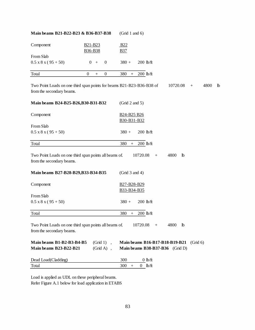
83
Main beams B21-B22-B23 & B36-B37-B38 (Grid 1 and 6)
Component B21-B23 B22
B36-B38 B37
From Slab
0.5 x 8 x ( 95 + 50) 0 + 0 380 + 200 lb/ft
Total 0 + 0 380 + 200 lb/ft
Two Point Loads on one third span points for beams B21-B23-B36-B38 of + lb
from the secondary beams.
Main beams B24-B25-B26,B30-B31-B32 (Grid 2 and 5)
Component B24-B25 B26
B30-B31-B32
From Slab
0.5 x 8 x ( 95 + 50) 380 + 200 lb/ft
Total 380 + 200 lb/ft
Two Point Loads on one third span points all beams of. + lb
from the secondary beams.
Main beams B27-B28-B29,B33-B34-B35 (Grid 3 and 4)
Component B27-B28-B29
B33-B34-B35
From Slab
0.5 x 8 x ( 95 + 50) 380 + 200 lb/ft
Total 380 + 200 lb/ft
Two Point Loads on one third span points all beams of. + lb
from the secondary beams.
Main beams B1-B2-B3-B4-B5 (Grid 1) , Main beams B16-B17-B18-B19-B21 (Grid 6)
Main beams B23-B22-B21 (Grid A) , Main beams B38-B37-B36 (Grid D)
Dead Load(Cladding) 300 0 lb/ft
Total 300 + 0 lb/ft
Load is applied as UDL on these peripheral beams.
Refer Figure A.1 below for load application in ETABS
4800
4800
4800
10720.08
10720.08
10720.08

84
Figure A-1 Load application in ETABS: Case 1
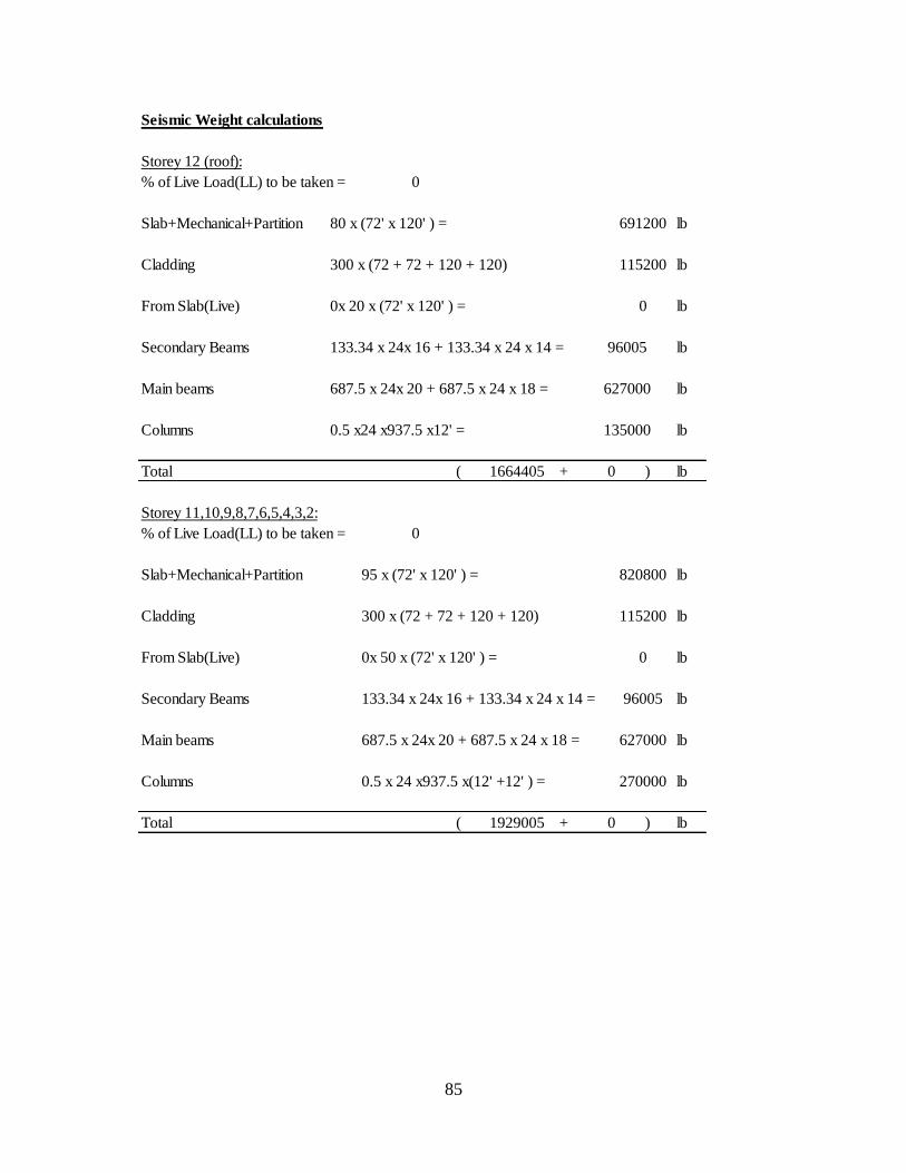
85
Seismic Weight calculations
Storey 12 (roof):
% of Live Load(LL) to be taken = 0
Slab+Mechanical+Partition 80 x (72' x 120' ) = lb
Cladding 300 x (72 + 72 + 120 + 120) lb
From Slab(Live) 0x 20 x (72' x 120' ) = lb
Secondary Beams 133.34 x 24x 16 + 133.34 x 24 x 14 = lb
Main beams 687.5 x 24x 20 + 687.5 x 24 x 18 = lb
Columns 0.5 x24 x937.5 x12' = lb
Total ( + ) lb
Storey 11,10,9,8,7,6,5,4,3,2:
% of Live Load(LL) to be taken = 0
Slab+Mechanical+Partition 95 x (72' x 120' ) = lb
Cladding 300 x (72 + 72 + 120 + 120) lb
From Slab(Live) 0x 50 x (72' x 120' ) = lb
Secondary Beams 133.34 x 24x 16 + 133.34 x 24 x 14 = lb
Main beams 687.5 x 24x 20 + 687.5 x 24 x 18 = lb
Columns 0.5 x 24 x937.5 x(12' +12' ) = lb
Total ( + ) lb1929005
270000
0
96005
1664405
115200
0
691200
0
820800
627000
135000
0
627000
115200
96005
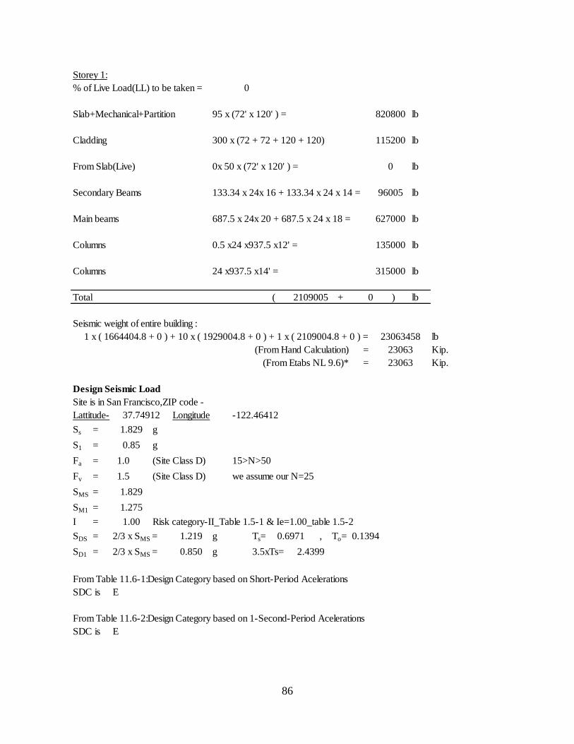
86
Storey 1:
% of Live Load(LL) to be taken = 0
Slab+Mechanical+Partition 95 x (72' x 120' ) = lb
Cladding 300 x (72 + 72 + 120 + 120) lb
From Slab(Live) 0x 50 x (72' x 120' ) = lb
Secondary Beams 133.34 x 24x 16 + 133.34 x 24 x 14 = lb
Main beams 687.5 x 24x 20 + 687.5 x 24 x 18 = lb
Columns 0.5 x24 x937.5 x12' = lb
Columns 24 x937.5 x14' = lb
Total ( + ) lb
Seismic weight of entire building :
1 x ( 1664404.8 + 0 ) + 10 x ( 1929004.8 + 0 ) + 1 x ( 2109004.8 + 0 ) = lb
(From Hand Calculation) = Kip.
(From Etabs NL 9.6)* = Kip.
Design Seismic Load
Site is in San Francisco,ZIP code -
Lattitude- Longitude
Ss = g
S1 = g
Fa = 1.0 (Site Class D) 15>N>50
Fv = 1.5 (Site Class D) we assume our N=25
SMS =
SM1 =
I = Risk category-II_Table 1.5-1 & Ie=1.00_table 1.5-2
SDS = 2/3 x SMS = g Ts= , To=
SD1 = 2/3 x SMS = g 3.5xTs=
From Table 11.6-1:Design Category based on Short-Period Acelerations
SDC is E
From Table 11.6-2:Design Category based on 1-Second-Period Acelerations
SDC is E
0
37.74912
2109005
820800
0
0.6971
2.4399
0.1394
23063
0.85
1.829
1.275
-122.46412
1.829
1.00
1.219
23063458
23063
627000
135000
315000
115200
96005
0.850
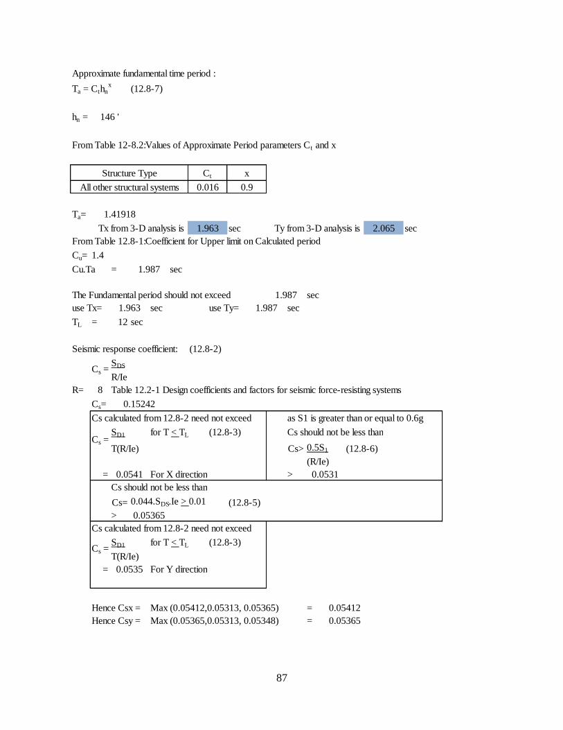
87
Approximate fundamental time period :
Ta = Cthnx
(12.8-7)
hn =
From Table 12-8.2:Values of Approximate Period parameters Ct and x
Ta=
Tx from 3-D analysis is sec Ty from 3-D analysis is sec
From Table 12.8-1:Coefficient for Upper limit on Calculated period
Cu=
Cu.Ta = sec
The Fundamental period should not exceed sec
use Tx= sec use Ty= sec
TL = 12 sec
Seismic response coefficient: (12.8-2)
SDS
R/Ie
R= 8 Table 12.2-1 Design coefficients and factors for seismic force-resisting systems
Cs=
Cs calculated from 12.8-2 need not exceed as S1 is greater than or equal to 0.6g
SD1 for T < TL (12.8-3) Cs should not be less than
T(R/Ie) Cs> 0.5S1 (12.8-6)
(R/Ie)
= For X direction >
Cs should not be less than
Cs= 0.044.SDS.Ie > 0.01 (12.8-5)
>
Cs calculated from 12.8-2 need not exceed
SD1 for T < TL (12.8-3)
T(R/Ie)
= For Y direction
Hence Csx = Max (0.05412,0.05313, 0.05365) =
Hence Csy = Max (0.05365,0.05313, 0.05348) =
1.4
1.963
0.9
1.987
0.016
1.963
Ct x
2.065
0.05365
0.05412
0.0531
0.05365
146 '
Cs =
0.0541
Cs =
Structure Type
All other structural systems
1.41918
0.15242
1.987
0.0535
Cs =
1.987
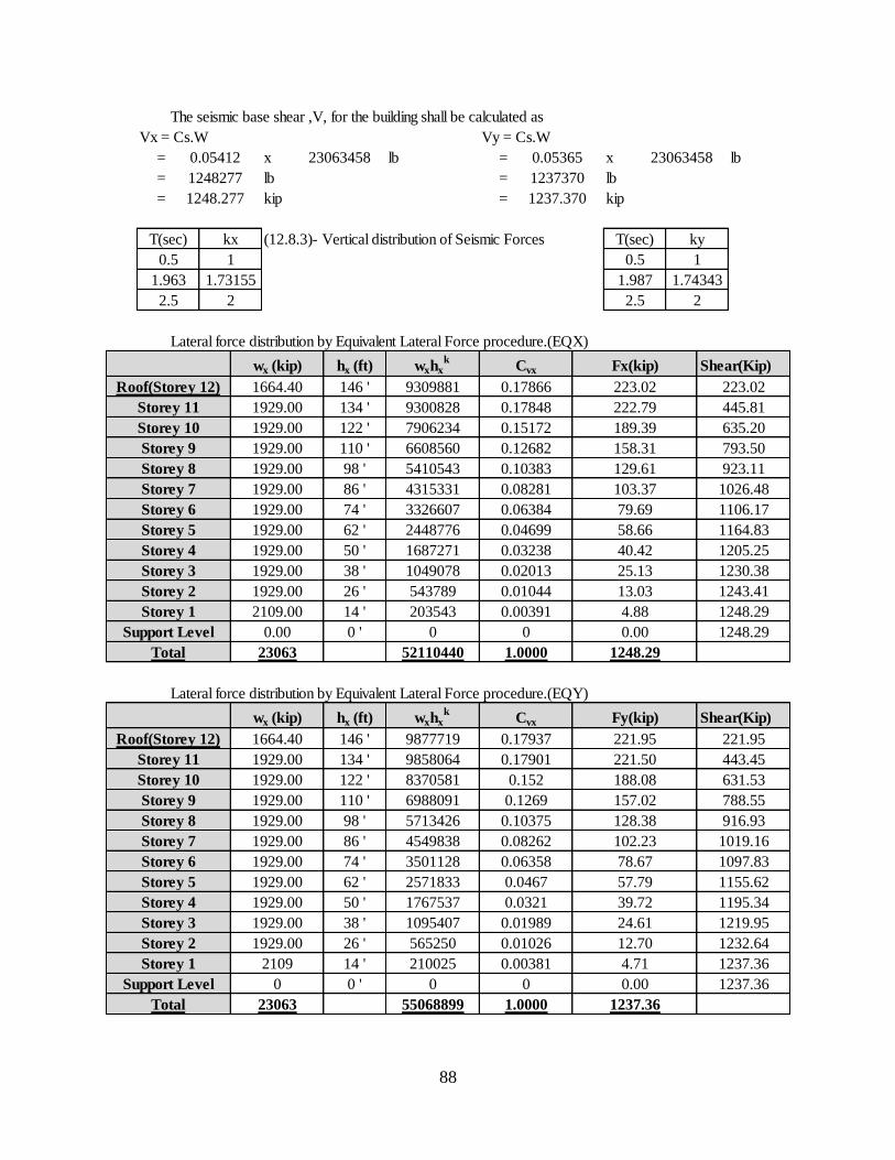
88
The seismic base shear ,V, for the building shall be calculated as
Vx = Cs.W Vy = Cs.W
= x lb = x lb
= lb = lb
= kip = kip
(12.8.3)- Vertical distribution of Seismic Forces
Lateral force distribution by Equivalent Lateral Force procedure.(EQX)
Storey Shear(Kip)
Lateral force distribution by Equivalent Lateral Force procedure.(EQY)
Storey Shear(Kip)
1232.64
1237.36
1237.36
443.45
631.53
788.55
916.93
1019.16
1097.83
1155.62
1195.34
1219.95
1106.17
1164.83
1205.25
1230.38
1243.41
1248.29
1248.29
221.95
74 '
86 '
98 '
1248.29
4.88
13.03
25.13
40.42
58.66
79.69
1.0000
3326607
4315331
Cvx Fy(kip)
0.10383
0.08281
543789
1049078
1687271
62 '
0
0.00391
0.01044
0.02013
2448776
0 '
1929.00
1929.00
14 '
26 '
38 '
50 '
0
203543
hx (ft)
146 '
1248277
1248.277
23063458 23063458
1237370
1237.370
223.02
Cvx
0.04699
0.03238
103.37
129.61
0.00
635.20
445.81
793.50
923.11
1026.48
0.12682 158.31
189.39
ky
0.5 1
1.987 1.74343
2
T(sec)
0.05365
Fx(kip)
223.02
222.79
2.5
0.15172
9309881
0.06384
0.05412
wx (kip)
1929.00
1929.00
1929.00
1929.00
1929.00
Roof(Storey 12)
Storey 7
Storey 6
Storey 5
Storey 2
Storey 1
Support Level
Storey 3
1929.00
Storey 8
1664.40
1929.00
wxhxk
5410543
6608560
7906234
0.5
T(sec)
2.5
1.963
kx
1
1.73155
2
Storey 9
Storey 11
110 '
122 '
134 '
Storey 10
0.17848
0.17866
9300828
wx (kip) hx (ft) wxhxk
1929.00
2109.00
0.00
23063
Storey 4
52110440Total
Roof(Storey 12) 1664.40 146 ' 9877719 0.17937 221.95
Storey 11 1929.00 134 ' 9858064 0.17901 221.50
Storey 10 1929.00 122 ' 8370581 0.152 188.08
Storey 9 1929.00 110 ' 6988091 0.1269 157.02
Storey 8 1929.00 98 ' 5713426 0.10375 128.38
Storey 7 1929.00 86 ' 4549838 0.08262 102.23
Storey 6 1929.00 74 ' 3501128 0.06358 78.67
Storey 5 1929.00 62 ' 2571833 0.0467 57.79
Storey 4 1929.00 50 ' 1767537 0.0321 39.72
Storey 3 1929.00 38 ' 1095407 0.01989 24.61
Storey 2 1929.00 26 ' 565250 0.01026 12.70
Storey 1 2109 14 ' 210025 0.00381 4.71
Support Level 0 0 ' 0 0 0.00
Total 23063 55068899 1.0000 1237.36
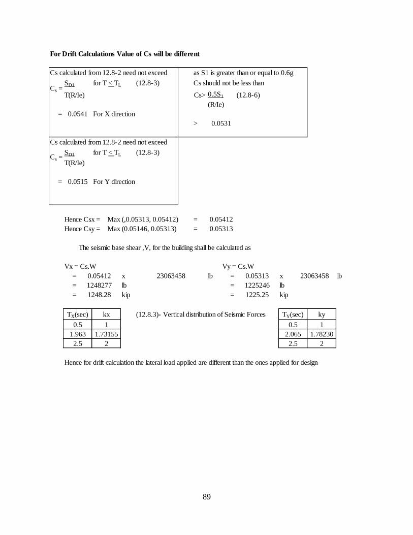
89
For Drift Calculations Value of Cs will be different
Cs calculated from 12.8-2 need not exceed as S1 is greater than or equal to 0.6g
SD1 for T < TL (12.8-3) Cs should not be less than
T(R/Ie) Cs> 0.5S1 (12.8-6)
(R/Ie)
= For X direction
>
Cs calculated from 12.8-2 need not exceed
SD1 for T < TL (12.8-3)
T(R/Ie)
= For Y direction
Hence Csx = Max (,0.05313, 0.05412) =
Hence Csy = Max (0.05146, 0.05313) =
The seismic base shear ,V, for the building shall be calculated as
Vx = Cs.W Vy = Cs.W
= x lb = x lb
= lb = lb
= kip = kip
(12.8.3)- Vertical distribution of Seismic Forces
Hence for drift calculation the lateral load applied are different than the ones applied for design
0.0531
0.05412
0.05313
Cs =
0.0541
Cs =
0.0515
0.05412 23063458 0.05313
1248277
23063458
1225246
1225.25
TX(sec) kx TY(sec) ky
0.5 1 0.5 1
1248.28
1.963 1.73155 2.065 1.78230
2.5 2 2.5 2
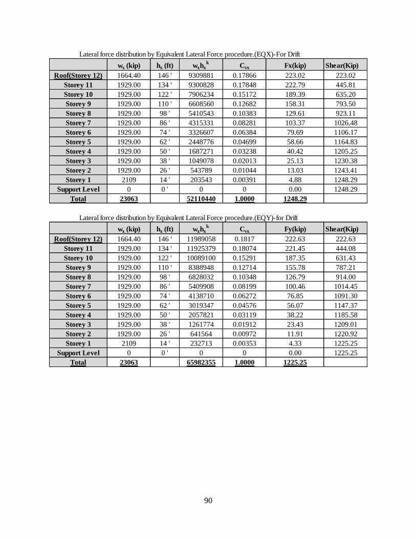
90
Lateral force distribution by Equivalent Lateral Force procedure.(EQX)-For Drift
Storey Shear(Kip)
Lateral force distribution by Equivalent Lateral Force procedure.(EQY)-for Drift
Storey Shear(Kip)
1220.92
1225.25
1225.25
444.08
222.63
631.43
787.21
914.00
1014.45
1091.30
1147.37
1185.58
1209.01
223.02
1248.29
1248.29
1243.41
1230.38
1205.25
1164.83
1106.17
1026.48
923.11
793.50
635.20
445.81
wx (kip) hx (ft) wxhxk
Cvx Fx(kip)
Roof(Storey 12) 1664.40 146 ' 9309881 0.17866 223.02
Storey 11 1929.00 134 ' 9300828 0.17848 222.79
Storey 10 1929.00 122 ' 7906234 0.15172 189.39
Storey 9 1929.00 110 ' 6608560 0.12682 158.31
Storey 8 1929.00 98 ' 5410543 0.10383 129.61
Storey 7 1929.00 86 ' 4315331 0.08281 103.37
Storey 6 1929.00 74 ' 3326607 0.06384 79.69
Storey 5 1929.00 62 ' 2448776 0.04699 58.66
Storey 4 1929.00 50 ' 1687271 0.03238 40.42
Storey 3 1929.00 38 ' 1049078 0.02013 25.13
Storey 2 1929.00 26 ' 543789 0.01044 13.03
Storey 1 2109 14 ' 203543 0.00391 4.88
Support Level 0 0 ' 0 0 0.00
Total 23063 52110440 1.0000 1248.29
wx (kip) hx (ft) wxhxk
Cvx Fy(kip)
Roof(Storey 12) 1664.40 146 ' 11989058 0.1817 222.63
Storey 11 1929.00 134 ' 11925379 0.18074 221.45
Storey 10 1929.00 122 ' 10089100 0.15291 187.35
Storey 9 1929.00 110 ' 8388948 0.12714 155.78
Storey 8 1929.00 98 ' 6828032 0.10348 126.79
Storey 7 1929.00 86 ' 5409908 0.08199 100.46
Storey 6 1929.00 74 ' 4138710 0.06272 76.85
Storey 5 1929.00 62 ' 3019347 0.04576 56.07
Storey 4 1929.00 50 ' 2057821 0.03119 38.22
Storey 3 1929.00 38 ' 1261774 0.01912 23.43
Storey 2 1929.00 26 ' 641564 0.00972 11.91
Total 23063 65982355 1.0000 1225.25
Storey 1 2109 14 ' 232713 0.00353 4.33
Support Level 0 0 ' 0 0 0.00

91
A.2 Load combination in ETABS
Load type and factors for primary loads
Static Static Static Static Static
Load Combination
Abbreviation and
Number
DEAD LLR LL EQX EQY
UDCON1 1.4
UDCON2 1.2 0.5 1.6
UDCON3 1.2 1.6 0.5
UDCON4 1.44
0.5 1 0.3
UDCON5 1.44
0.5 1 -0.3
UDCON6 1.44
0.5 -1 0.3
UDCON7 1.44
0.5 -1 -0.3
UDCON8 1.44
0.5 0.3 1
UDCON9 1.44
0.5 -0.3 1
UDCON10 1.44
0.5 0.3 -1
UDCON11 1.44
0.5 -0.3 -1
UDCON12 0.66
1 0.3
UDCON13 0.66
1 -0.3
UDCON14 0.66
-1 0.3
UDCON15 0.66
-1 -0.3
UDCON16 0.66
0.3 1
UDCON17 0.66
-0.3 1
UDCON18 0.66
0.3 -1
UDCON19 0.66
-0.3 -1
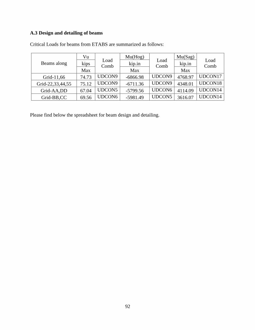
92
A.3 Design and detailing of beams
Critical Loads for beams from ETABS are summarized as follows:
Beams along
Vu Load
Comb
Mu(Hog) Load
Comb
Mu(Sag) Load
Comb kips kip.in kip.in
Max Max Max
Grid-11,66 74.73 UDCON9 -6866.98 UDCON9 4768.97 UDCON17
Grid-22,33,44,55 75.12 UDCON9 -6711.36 UDCON9 4348.01 UDCON18
Grid-AA,DD 67.04 UDCON5 -5799.56 UDCON6 4114.09 UDCON14
Grid-BB,CC 69.56 UDCON6 -5981.49 UDCON5 3616.07 UDCON14
Please find below the spreadsheet for beam design and detailing.
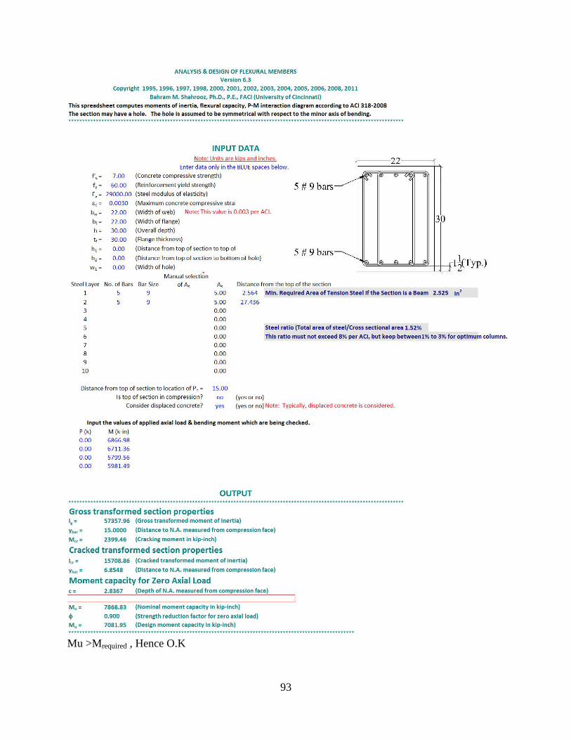
93
Mu >Mrequired , Hence O.K
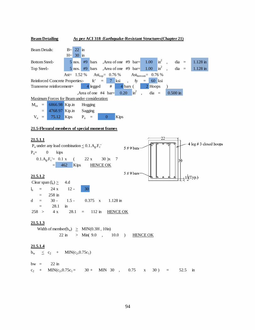
94
Beam Detailing As per ACI 318 :Earthquake-Resistant Structures(Chapter 21)
Beam Details: B= 22 in
H= 30 in
Bottom Steel:- 5 nos. #9 bars ,Area of one #9 bar= in2
, dia =
Top Steel:- 5 nos. #9 bars ,Area of one #9 bar= in2
, dia =
Ast= Asttop= Astbottom=
Reinforced Concrete Properties:- fc' = 7 ksi , fy = 60 ksi
Transverse reinforcement= 4 legged # 4 bars ( 2 Hoops )
,Area of one #4 bar= in2
, dia =
Maximum Forces for Beam under consideration:
Mzz = Kip.in Hogging
= Kip.in Sagging
Vu = Kips Pu = Kips
21.5-Flexural members of special moment frames
21.5.1.1
Pu under any load combination < 0.1.Ag.Fc'
Pu= kips
0.1.Ag.Fc'= 0.1 x ( 22 x 30 )x 7
= Kips HENCE OK
21.5.1.2
Clear span (ln) > 4.d
ln = 24 x 12 - 30
= 258 in
d = 30 - 1.5 - x
= in
258 > 4 x = 112 in HENCE OK
21.5.1.3
Width of member(bw) > MIN(0.3H , 10in)
22 in > Min( 9.0 , ) HENCE OK
21.5.1.4
bw < c2 + MIN(c2,0.75c1)
bw = 22 in
c2 + MIN(c2,0.75c1)= 30 + MIN( 30 , x 30 ) = in
0.375
1.52 %
1.128 in
1.128 in
0.76 % 0.76 %
1.00
1.00
0.500 in
75.12
0
462
0
1.128 in
6866.98
4768.97
0.20
28.1
28.1
10.0
0.75 52.5
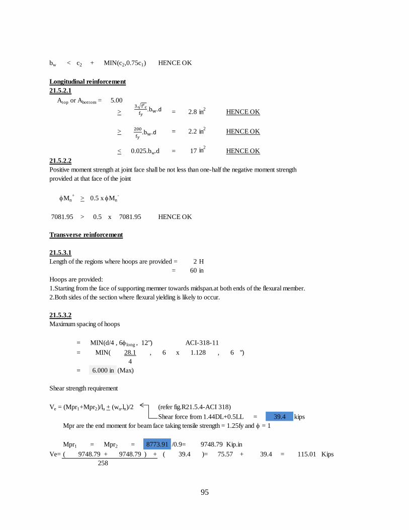
95
bw < c2 + MIN(c2,0.75c1) HENCE OK
Longitudinal reinforcement
21.5.2.1
Atop or Abottom =
> = 2.8 in2
HENCE OK
> = 2.2 in2
HENCE OK
< 0.025.bw.d = 17 in2
HENCE OK
21.5.2.2
Mn+
> 0.5 xMn-
> 0.5 x HENCE OK
Transverse reinforcement
21.5.3.1
Length of the regions where hoops are provided = 2 H
= 60 in
Hoops are provided:
1.Starting from the face of supporting memner towards midspan.at both ends of the flexural member.
2.Both sides of the section where flexural yielding is likely to occur.
21.5.3.2
Maximum spacing of hoops
= MIN(d/4 , 6long , 12") ACI-318-11
= , 6 x , 6 ")
= (Max)
Shear strength requirement
Ve = (Mpr1+Mpr2)/lu + (wu.ln)/2 (refer fig.R21.5.4-ACI 318)
Shear force from 1.44DL+0.5LL = kips
Mpr are the end moment for beam face taking tensile strength = 1.25fy and = 1
Mpr1 = Mpr2 = /0.9= Kip.in
Ve= ( + ) + ( )= + = Kips
5.00
MIN( 28.1
4
1.128
75.57
Positive moment strength at joint face shall be not less than one-half the negative moment strength
provided at that face of the joint
7081.95 7081.95
9748.79 9748.79
258
9748.79
115.01
6.000 in
8773.91
39.4
39.4 39.4
. .d
. .d
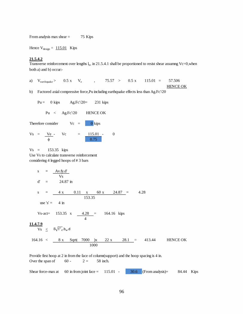
96
From analysis max shear = 75 Kips
Hence Vdesign = Kips
21.5.4.2
a) Vearthquake > 0.5 x Ve , > 0.5 x =
HENCE OK
b) Factored axial compressive force,Pu including earthquake effects less than Ag.Fc'/20
Pu = 0 kips Ag.Fc'/20= 231 kips
Pu < Ag.Fc'/20 HENCE OK
Therefore consider Vc = 0 kips
Vs = Ve - Vc = - 0
Vs = kips
Use Vs to calculate transverse reinforcement
considering 4 legged hoops of # 3 bars
s =
d' = in
s = 4 x x 60 x =
use 's' = 4 in
Vs-act= x = kips
11.4.7.9
Vs <
< 8 x Sqrt( )x 22 x = HENCE OK
Provide first hoop at 2 in from the face of column(support) and the hoop spacing is 4 in.
Over the span of 60 - 2 = 58 inch.
Shear force-max at 60 in from joint face = - (From analysis)= Kips
4.28
4
28.1
1000
30.6 84.44
115.01
Transverse reinforcement over lengths ln, in 21.5.4.1 shall be proportioned to resist shear assumng Vc=0,when
both a) and b) occur:-
75.57 115.01 57.506
115.01
0.75
153.35
0.11
153.35
Av.fy.d'
Vs
24.87
24.87
115.01
4.28
153.35 164.16
164.16 7000 413.44
.bw.d
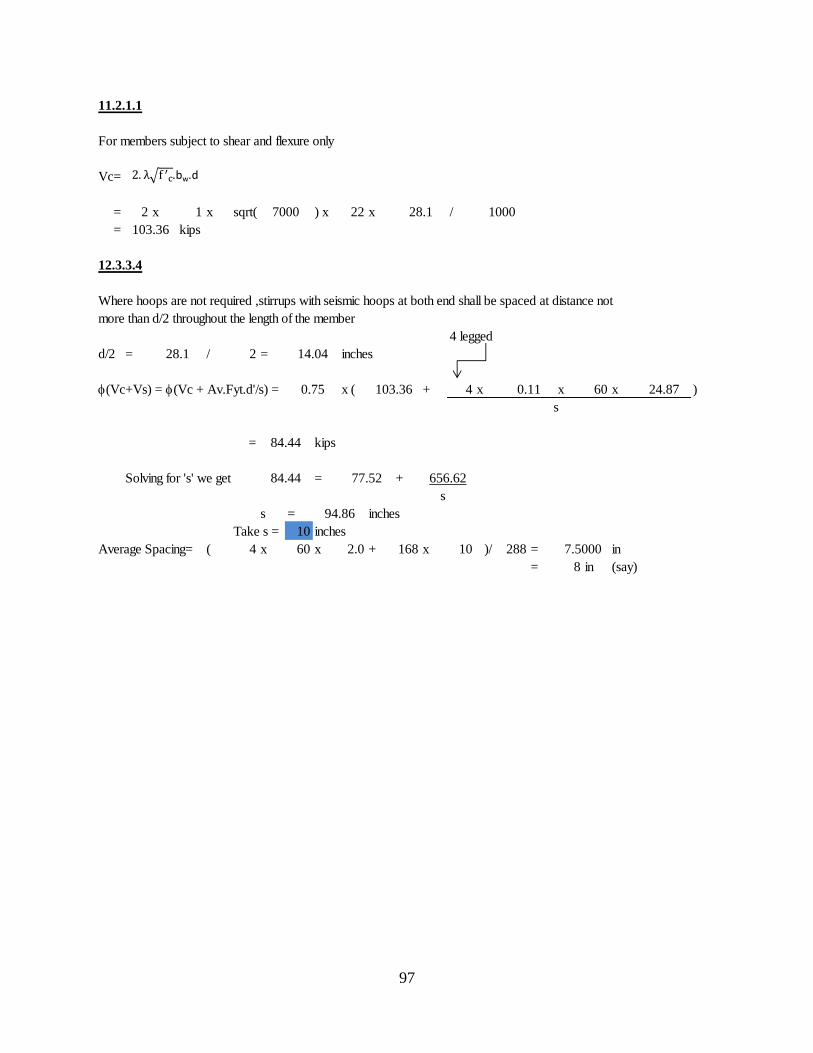
97
11.2.1.1
For members subject to shear and flexure only
Vc=
= 2 x 1 x sqrt( ) x 22 x /
= kips
12.3.3.4
4 legged
d/2 = / 2 = inches
(Vc+Vs) = (Vc + Av.Fyt.d'/s) = x ( + 4 x x 60 x )
= kips
Solving for 's' we get = +
s
s = inches
Take s = 10 inches
Average Spacing= ( 4 x 60 x 2.0 + 168 x 10 )/ 288 = in
= 8 in (say)
7.5000
84.44 77.52 656.62
0.75
94.86
Where hoops are not required ,stirrups with seismic hoops at both end shall be spaced at distance not
more than d/2 throughout the length of the member
14.04
103.36 24.87
s
84.44
28.1
103.36
10007000 28.1
0.11
.bw.d
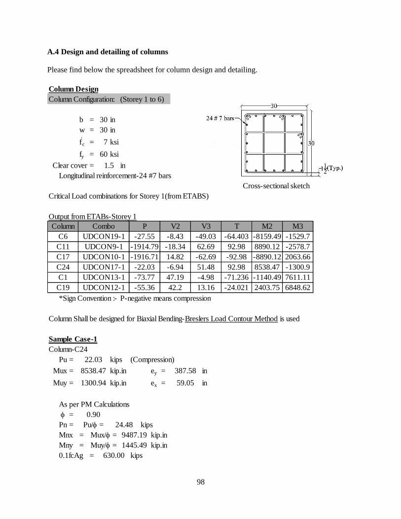
98
A.4 Design and detailing of columns
Please find below the spreadsheet for column design and detailing.
Column Design
Column Configuration: (Storey 1 to 6)
b = 30 in
w = 30 in
f'c = 7 ksi
fy = 60 ksi
Clear cover = in
Longitudinal reinforcement-24 #7 bars
Cross-sectional sketch
Critical Load combinations for Storey 1(from ETABS)
Output from ETABs-Storey 1
*Sign Convention :- P-negative means compression
Column Shall be designed for Biaxial Bending-Breslers Load Contour Method is used
Sample Case-1
Column-C24
Pu = kips (Compression)
Mux = kip.in ey = in
Muy = kip.in ex = in
As per PM Calculations
=
Pn = kips
Mnx = kip.in
Mny = kip.in
0.1fcAg = kips
1.5
C19
Combo
UDCON19-1
Column
C6
C11
C17
C24
C1
UDCON9-1
UDCON10-1
UDCON17-1
UDCON13-1
UDCON12-1
P
-27.55
-1914.79
-1916.71
-22.03
-73.77
-55.36
V2
-8.43
-18.34
14.82
-6.94
47.19
42.2
92.98
-71.236
-24.021
V3
-49.03
62.69
-62.69
51.48
-4.98
22.03
8538.47
1300.94
Pu/ = 24.48
2403.75
M3
-1529.7
-2578.7
2063.66
-1300.9
7611.11
6848.62
M2
-8159.49
8890.12
-8890.12
8538.47
-1140.49
13.16
T
-64.403
92.98
-92.98
630.00
Mux/ =
Muy/ =
9487.19
1445.49
387.58
59.05
0.90
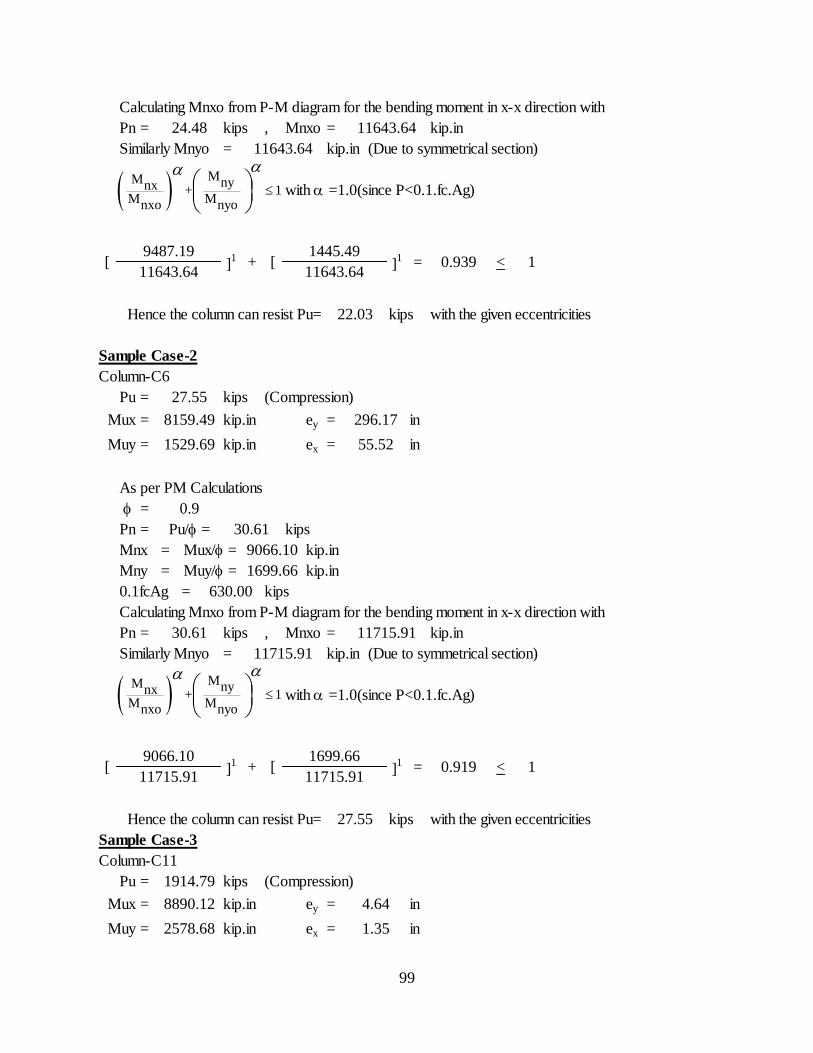
99
Calculating Mnxo from P-M diagram for the bending moment in x-x direction with
Pn = kips , Mnxo = kip.in
Similarly Mnyo = kip.in (Due to symmetrical section)
with a =1.0(since P<0.1.fc.Ag)
Hence the column can resist Pu= kips with the given eccentricities
Sample Case-2
Column-C6
Pu = kips (Compression)
Mux = kip.in ey = in
Muy = kip.in ex = in
As per PM Calculations
=
Pn = kips
Mnx = kip.in
Mny = kip.in
0.1fcAg = kips
Calculating Mnxo from P-M diagram for the bending moment in x-x direction with
Pn = kips , Mnxo = kip.in
Similarly Mnyo = kip.in (Due to symmetrical section)
with a =1.0(since P<0.1.fc.Ag)
Hence the column can resist Pu= kips with the given eccentricities
Sample Case-3
Column-C11
Pu = kips (Compression)
Mux = kip.in ey = in
Muy = kip.in ex = in
[ ]1
11643.64
9487.19+
11643.64
11643.64
24.48
< 1
22.03
27.55
[1445.49
]1
11643.64= 0.939
Mux/ = 9066.10
Muy/ = 1699.66
630.00
30.61
8159.49 296.17
1529.69 55.52
Pu/ = 30.61
11715.91
0.9
11715.91
[9066.10
]1 + [
1699.66]1 =
1914.79
8890.12 4.64
2578.68 1.35
0.919 < 111715.91 11715.91
27.55
MM nynx + 1
M Mnxo nyo
aa
MM nynx + 1
M Mnxo nyo
aa
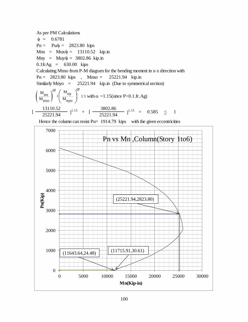
100
As per PM Calculations
=
Pn = kips
Mnx = kip.in
Mny = kip.in
0.1fcAg = kips
Calculating Mnxo from P-M diagram for the bending moment in x-x direction with
Pn = kips , Mnxo = kip.in
Similarly Mnyo = kip.in (Due to symmetrical section)
with a =1.15(since P>0.1.fc.Ag)
Hence the column can resist Pu= kips with the given eccentricities
[13110.52
+ [3802.86
Pu/ = 2823.80
Mux/ =
Muy/ = 3802.86
1914.79
13110.52
0.6781
]1.15
]1.15 = 0.585 < 1
25221.94 25221.94
630.00
2823.80 25221.94
25221.94
MM nynx + 1
M Mnxo nyo
aa
0
1000
2000
3000
4000
5000
6000
7000
0 5000 10000 15000 20000 25000 30000
Pn(K
ip)
Mn(Kip-in)
Pn vs Mn ,Column(Story 1to6)
(25221.94,2823.80)
(11643.64,24.48)(11715.91,30.61)
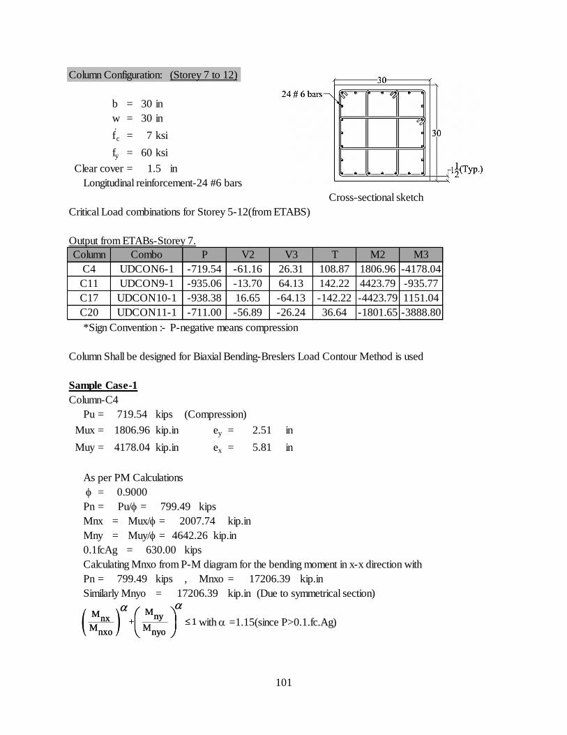
101
Column Configuration: (Storey 7 to 12)
b = 30 in
w = 30 in
f'c = 7 ksi
fy = 60 ksi
Clear cover = in
Longitudinal reinforcement-24 #6 bars
Cross-sectional sketch
Critical Load combinations for Storey 5-12(from ETABS)
Output from ETABs-Storey 7.
*Sign Convention :- P-negative means compression
Column Shall be designed for Biaxial Bending-Breslers Load Contour Method is used
Sample Case-1
Column-C4
Pu = kips (Compression)
Mux = kip.in ey = in
Muy = kip.in ex = in
As per PM Calculations
=
Pn = kips
Mnx = kip.in
Mny = kip.in
0.1fcAg = kips
Calculating Mnxo from P-M diagram for the bending moment in x-x direction with
Pn = kips , Mnxo = kip.in
Similarly Mnyo = kip.in (Due to symmetrical section)
with a =1.15(since P>0.1.fc.Ag)
0.9000
2007.74
Muy/ = 4642.26
630.00
799.49 17206.39
17206.39
1806.96 2.51
4178.04 5.81
Pu/ = 799.49
Mux/ =
719.54
C20 UDCON11-1 -711.00 -56.89 -26.24 36.64 -1801.65 -3888.80
C11 UDCON9-1 -935.06 -13.70 64.13 142.22 4423.79 -935.77
C17 UDCON10-1 -938.38 16.65 -64.13 -142.22 -4423.79 1151.04
M3
C4 UDCON6-1 -719.54 -61.16 26.31 108.87 1806.96 -4178.04
1.5
Column Combo P V2 V3 T M2
MM nynx + 1
M Mnxo nyo
aa
MM nynx + 1
M Mnxo nyo
aa
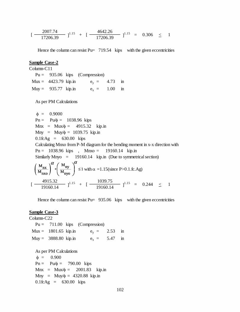
102
Hence the column can resist Pu= kips with the given eccentricities
Sample Case-2
Column-C11
Pu = kips (Compression)
Mux = kip.in ey = in
Muy = kip.in ex = in
As per PM Calculations
=
Pn = kips
Mnx = kip.in
Mny = kip.in
0.1fcAg = kips
Calculating Mnxo from P-M diagram for the bending moment in x-x direction with
Pn = kips , Mnxo = kip.in
Similarly Mnyo = kip.in (Due to symmetrical section)
with a =1.15(since P>0.1.fc.Ag)
Hence the column can resist Pu= kips with the given eccentricities
Sample Case-3
Column-C22
Pu = kips (Compression)
Mux = kip.in ey = in
Muy = kip.in ex = in
As per PM Calculations
=
Pn = kips
Mnx = kip.in
Mny = kip.in
0.1fcAg = kips
Muy/ = 4320.88
630.00
711.00
1801.65 2.53
3888.80 5.47
0.900
Pu/ = 790.00
Mux/ = 2001.83
117206.39
4915.32
]1.15 [
1039.75]1.15 = 0.244 < 1
19160.14
0.306 <
935.06
]1.15 [
4642.26]1.15 =
4915.32
935.77 1.00
Pu/ = 1038.96
Muy/ = 1039.75
630.00
1038.96 19160.14
19160.14
+
Mux/ =
[
935.06
4423.79 4.73
0.9000
17206.39
719.54
[2007.74
+
19160.14
MM nynx + 1
M Mnxo nyo
aa
MM nynx + 1
M Mnxo nyo
aa
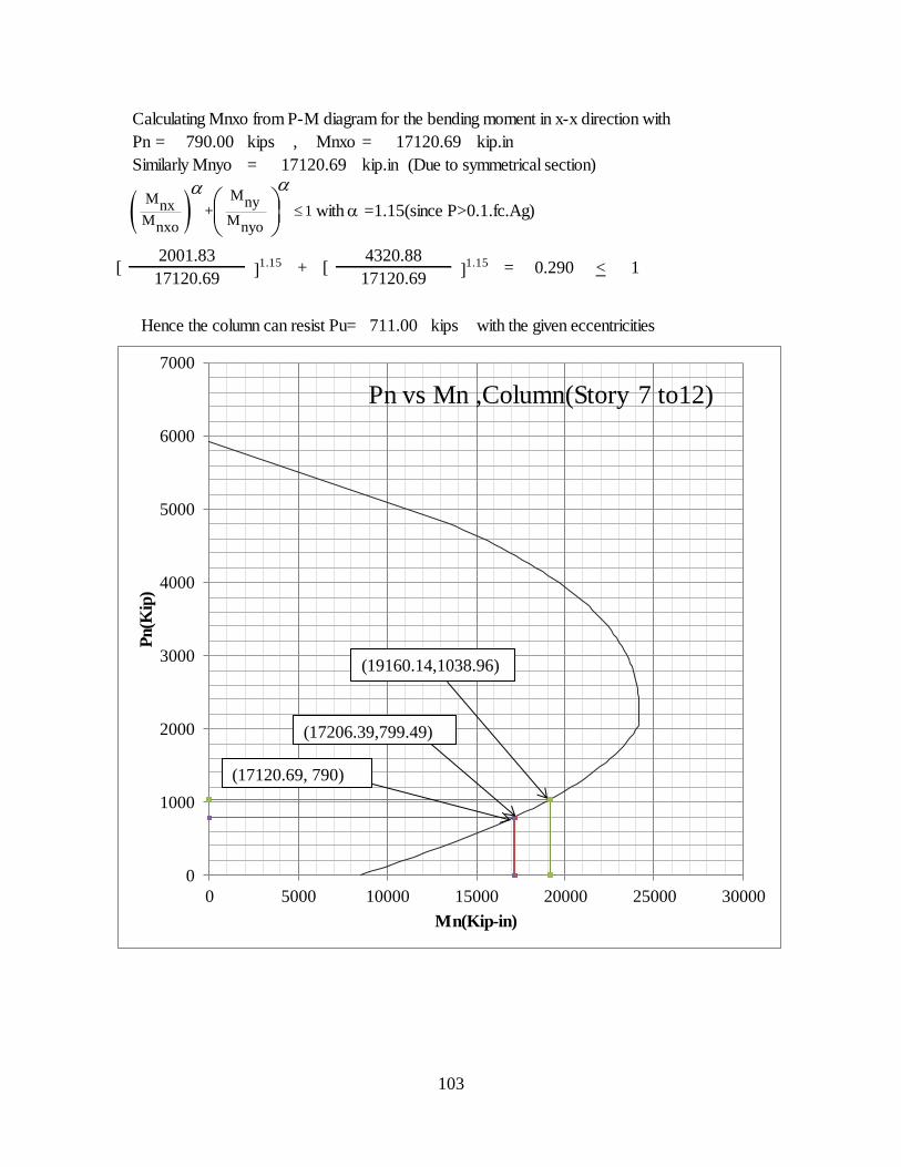
103
Calculating Mnxo from P-M diagram for the bending moment in x-x direction with
Pn = kips , Mnxo = kip.in
Similarly Mnyo = kip.in (Due to symmetrical section)
with a =1.15(since P>0.1.fc.Ag)
Hence the column can resist Pu= kips with the given eccentricities
= 0.290 < 117120.69 17120.69
711.00
790.00 17120.69
17120.69
[2001.83
]1.15 + [
4320.88]1.15
MM nynx + 1
M Mnxo nyo
aa
0
1000
2000
3000
4000
5000
6000
7000
0 5000 10000 15000 20000 25000 30000
Pn(K
ip)
Mn(Kip-in)
Pn vs Mn ,Column(Story 7 to12)
(19160.14,1038.96)
(17120.69, 790)
(17206.39,799.49)
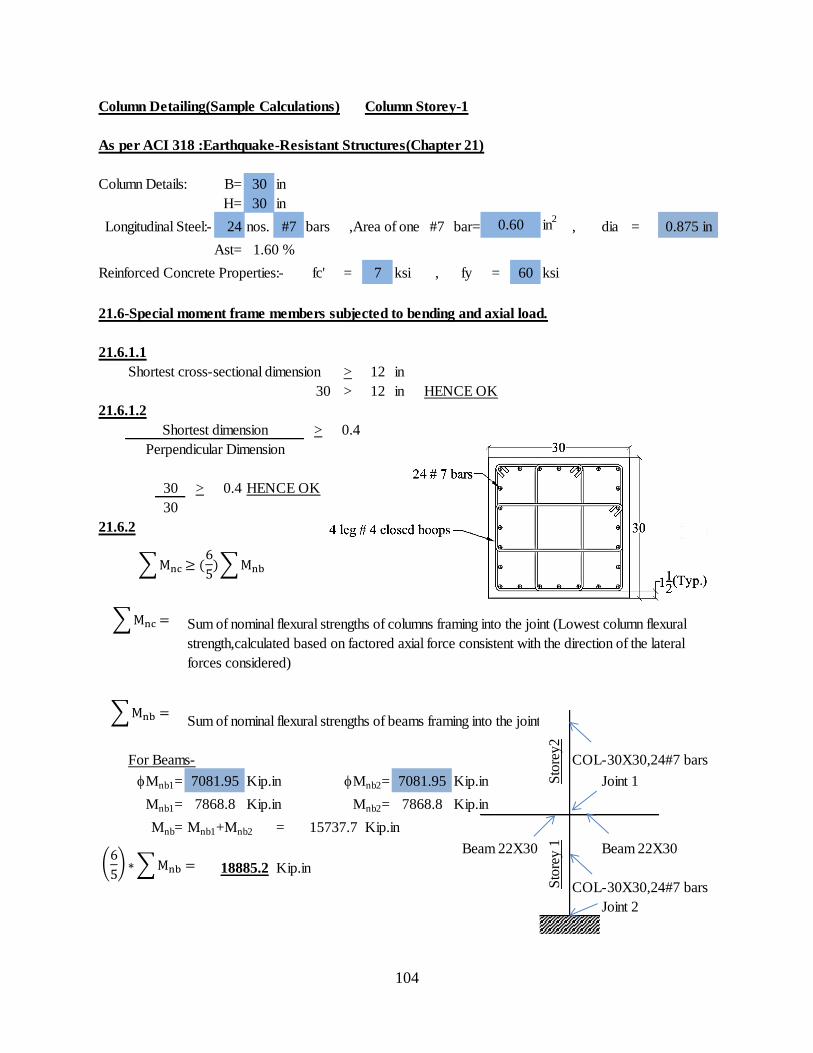
104
Column Detailing(Sample Calculations) Column Storey-1
As per ACI 318 :Earthquake-Resistant Structures(Chapter 21)
Column Details: B= 30 in
H= 30 in
Longitudinal Steel:- 24 nos. #7 bars ,Area of one #7 bar= in2
, dia =
Ast=
Reinforced Concrete Properties:- fc' = 7 ksi , fy = 60 ksi
21.6-Special moment frame members subjected to bending and axial load.
21.6.1.1
Shortest cross-sectional dimension > 12 in
30 > 12 in HENCE OK
21.6.1.2
> 0.4
30 > 0.4 HENCE OK
30
21.6.2
Sum of nominal flexural strengths of beams framing into the joint
For Beams- COL-30X30,24#7 bars
Mnb1= Kip.in Mnb2= Kip.in Joint 1
Mnb1= Kip.in Mnb2= Kip.in
Mnb= Mnb1+Mnb2 = Kip.in
Beam 22X30 Beam 22X30
Kip.in
COL-30X30,24#7 bars
Joint 2
7081.95
7868.8
7081.95
7868.8
18885.2
Sum of nominal flexural strengths of columns framing into the joint (Lowest column flexural
strength,calculated based on factored axial force consistent with the direction of the lateral
forces considered)
Shortest dimension
Perpendicular Dimension
1.60 %
0.875 in0.60
Sto
rey
1S
tore
y2
15737.7
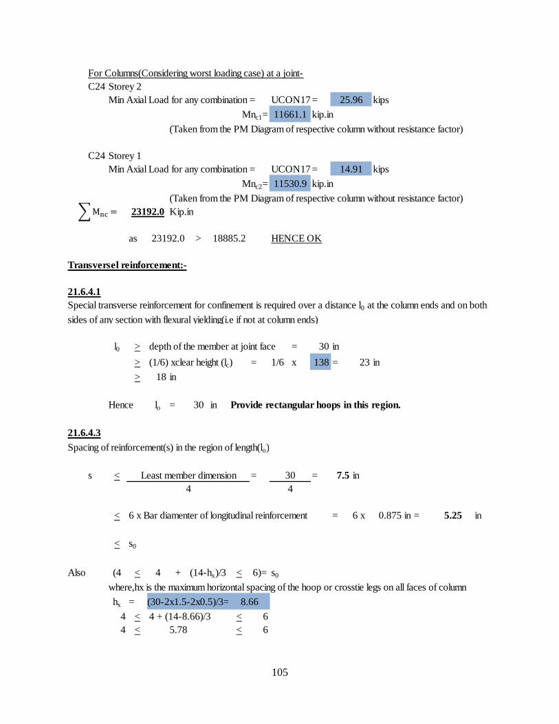
105
For Columns(Considering worst loading case) at a joint-
C24 Storey 2
Min Axial Load for any combination = UCON17 = kips
Mnc1= kip.in
(Taken from the PM Diagram of respective column without resistance factor)
C24 Storey 1
Min Axial Load for any combination = UCON17 = kips
Mnc2= kip.in
(Taken from the PM Diagram of respective column without resistance factor)
Kip.in
as > HENCE OK
Transversel reinforcement:-
21.6.4.1
l0 > depth of the member at joint face = 30 in
> (1/6) xclear height (lc) = 1/6 x 138 = 23 in
> 18 in
Hence lo = 30 in Provide rectangular hoops in this region.
21.6.4.3
Spacing of reinforcement(s) in the region of length(lo)
s < = = 7.5 in
< 6 x Bar diamenter of longitudinal reinforcement = 6 x = in
< s0
Also (4 < 4 + (14-hx)/3 < 6)= s0
where,hx is the maximum horizontal spacing of the hoop or crosstie legs on all faces of column
hx =
4 < 4 + (14-8.66)/3 < 6
4 < < 65.78
(30-2x1.5-2x0.5)/3=
23192.0
23192.0 18885.2
Special transverse reinforcement for confinement is required over a distance l0 at the column ends and on both
sides of any section with flexural yielding(i.e if not at column ends)
Least member dimension
4
5.25
8.66
30
4
0.875 in
25.96
14.91
11661.1
11530.9
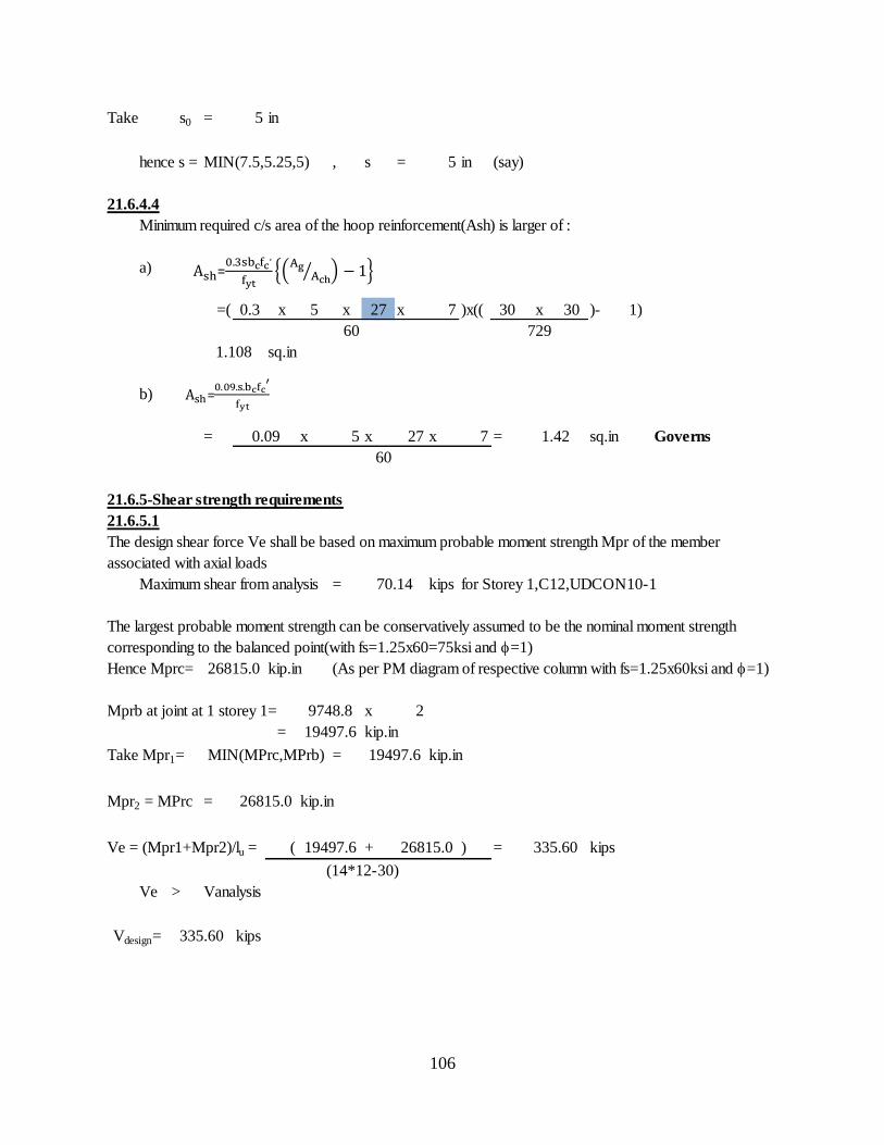
106
Take s0 = 5 in
hence s = MIN(7.5,5.25,5) , s = 5 in (say)
21.6.4.4
Minimum required c/s area of the hoop reinforcement(Ash) is larger of :
a)
=( 0.3 x 5 x 27 x 7 )x(( 30 x 30 )- 1)
60
sq.in
b)
= x 5 x 27 x 7 = sq.in Governs
60
21.6.5-Shear strength requirements
21.6.5.1
Maximum shear from analysis = kips for Storey 1,C12,UDCON10-1
Hence Mprc= kip.in (As per PM diagram of respective column with fs=1.25x60ksi and =1)
Mprb at joint at 1 storey 1= x 2
= kip.in
Take Mpr1= = kip.in
Mpr2 = MPrc = kip.in
Ve = (Mpr1+Mpr2)/lu = ( + ) = kips
Ve > Vanalysis
kips335.60
0.09
Vdesign=
MIN(MPrc,MPrb)
26815.0
19497.6
The design shear force Ve shall be based on maximum probable moment strength Mpr of the member
associated with axial loads
The largest probable moment strength can be conservatively assumed to be the nominal moment strength
corresponding to the balanced point(with fs=1.25x60=75ksi and =1)
26815.0
9748.8
19497.6
(14*12-30)
729
1.108
1.42
19497.6
26815.0
70.14
335.60
=
=
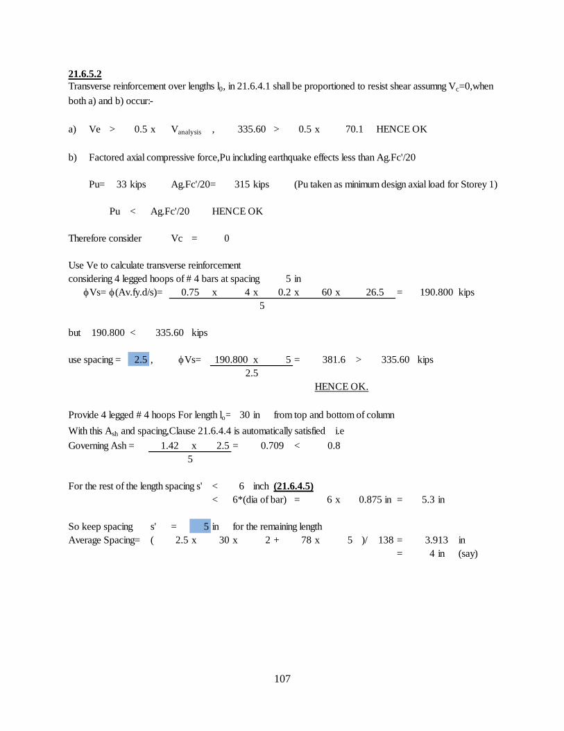
107
21.6.5.2
a) Ve > 0.5 x Vanalysis , > 0.5 x HENCE OK
b) Factored axial compressive force,Pu including earthquake effects less than Ag.Fc'/20
Pu= 33 kips Ag.Fc'/20= 315 kips (Pu taken as minimum design axial load for Storey 1)
Pu < Ag.Fc'/20 HENCE OK
Therefore consider Vc = 0
Use Ve to calculate transverse reinforcement
considering 4 legged hoops of # 4 bars at spacing 5 in
Vs= (Av.fy.d/s)= x 4 x 0.2 x 60 x = kips
but < kips
use spacing = 2.5 , x 5 = > kips
HENCE OK.
Provide 4 legged # 4 hoops For length lo= 30 in from top and bottom of column
With this Ash and spacing,Clause 21.6.4.4 is automatically satisfied i.e
Governing Ash = x 2.5 = <
For the rest of the length spacing s' < 6 inch (21.6.4.5)
< 6*(dia of bar) = 6 x = 5.3 in
So keep spacing s' = 5 in for the remaining length
Average Spacing= ( 2.5 x 30 x 2 + 78 x 5 )/ 138 = in
= 4 in (say)
26.50.75
0.875 in
Vs= 190.800
2.5
381.6 335.60
1.42
5
0.709 0.8
70.1
Transverse reinforcement over lengths l0, in 21.6.4.1 shall be proportioned to resist shear assumng Vc=0,when
both a) and b) occur:-
335.60
3.913
5
190.800
190.800 335.60
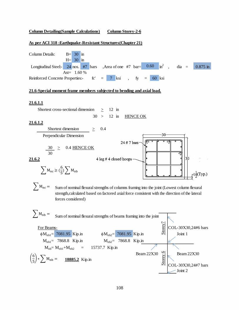
108
Column Detailing(Sample Calculations) Column Storey-2-6
As per ACI 318 :Earthquake-Resistant Structures(Chapter 21)
Column Details: B= 30 in
H= 30 in
Longitudinal Steel:- 24 nos. #7 bars ,Area of one #7 bar= in2
, dia =
Ast=
Reinforced Concrete Properties:- fc' = 7 ksi , fy = 60 ksi
21.6-Special moment frame members subjected to bending and axial load.
21.6.1.1
Shortest cross-sectional dimension > 12 in
30 > 12 in HENCE OK
21.6.1.2
> 0.4
30 > 0.4 HENCE OK
30
21.6.2
Sum of nominal flexural strengths of beams framing into the joint
For Beams- COL-30X30,24#6 bars
Mnb1= Kip.in Mnb2= Kip.in Joint 1
Mnb1= Kip.in Mnb2= Kip.in
Mnb= Mnb1+Mnb2 = Kip.in
Beam 22X30 Beam 22X30
Kip.in
COL-30X30,24#7 bars
Joint 2
Sto
rey7
1.60 %
Shortest dimension
Perpendicular Dimension
Sum of nominal flexural strengths of columns framing into the joint (Lowest column flexural
strength,calculated based on factored axial force consistent with the direction of the lateral
forces considered)
7081.95 7081.95
7868.8 7868.8
Sto
rey 6
15737.7
18885.2
0.60 0.875 in
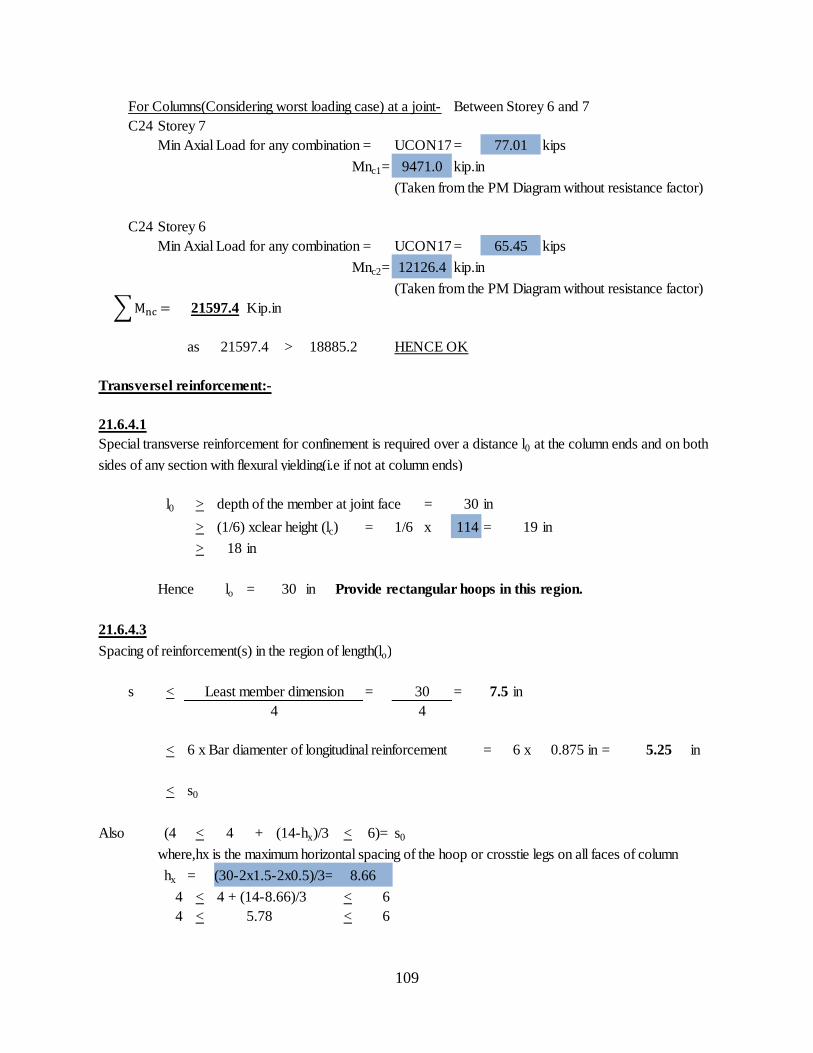
109
For Columns(Considering worst loading case) at a joint- Between Storey 6 and 7
C24 Storey 7
Min Axial Load for any combination = UCON17 = kips
Mnc1= kip.in
(Taken from the PM Diagram without resistance factor)
C24 Storey 6
Min Axial Load for any combination = UCON17 = kips
Mnc2= kip.in
(Taken from the PM Diagram without resistance factor)
Kip.in
as > HENCE OK
Transversel reinforcement:-
21.6.4.1
l0 > depth of the member at joint face = 30 in
> (1/6) xclear height (lc) = 1/6 x 114 = 19 in
> 18 in
Hence lo = 30 in Provide rectangular hoops in this region.
21.6.4.3
Spacing of reinforcement(s) in the region of length(lo)
s < = = 7.5 in
< 6 x Bar diamenter of longitudinal reinforcement = 6 x = in
< s0
Also (4 < 4 + (14-hx)/3 < 6)= s0
where,hx is the maximum horizontal spacing of the hoop or crosstie legs on all faces of column
hx =
4 < 4 + (14-8.66)/3 < 6
4 < < 6
Least member dimension 30
4 4
0.875 in 5.25
(30-2x1.5-2x0.5)/3= 8.66
5.78
21597.4
21597.4 18885.2
Special transverse reinforcement for confinement is required over a distance l0 at the column ends and on both
sides of any section with flexural yielding(i.e if not at column ends)
12126.4
77.01
9471.0
65.45
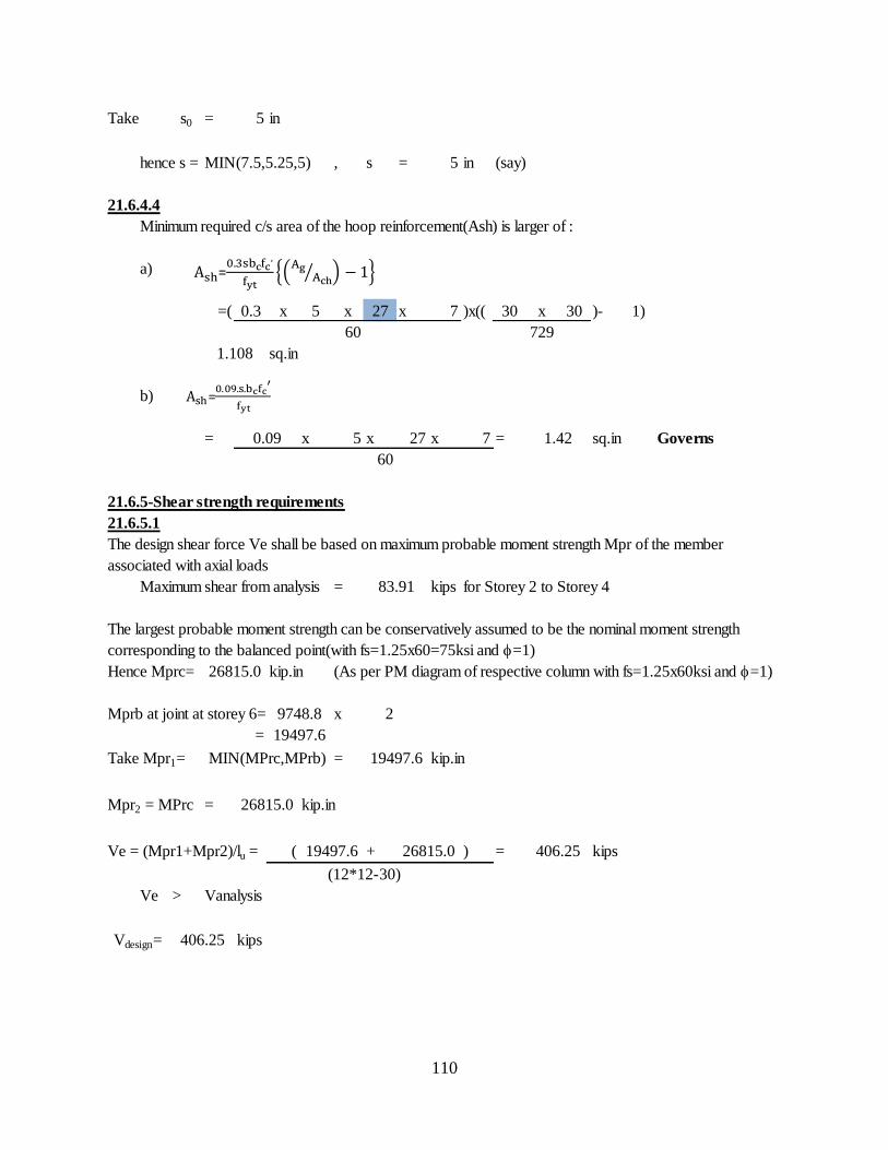
110
Take s0 = 5 in
hence s = MIN(7.5,5.25,5) , s = 5 in (say)
21.6.4.4
Minimum required c/s area of the hoop reinforcement(Ash) is larger of :
a)
=( 0.3 x 5 x 27 x 7 )x(( 30 x 30 )- 1)
60
sq.in
b)
= x 5 x 27 x 7 = sq.in Governs
60
21.6.5-Shear strength requirements
21.6.5.1
Maximum shear from analysis = kips for Storey 2 to Storey 4
Hence Mprc= kip.in (As per PM diagram of respective column with fs=1.25x60ksi and =1)
Mprb at joint at storey 6= x 2
=
Take Mpr1= = kip.in
Mpr2 = MPrc = kip.in
Ve = (Mpr1+Mpr2)/lu = ( + ) = kips
Ve > Vanalysis
kipsVdesign= 406.25
83.91
The largest probable moment strength can be conservatively assumed to be the nominal moment strength
corresponding to the balanced point(with fs=1.25x60=75ksi and =1)
26815.0
9748.8
19497.6
MIN(MPrc,MPrb) 19497.6
26815.0
19497.6 26815.0 406.25
(12*12-30)
The design shear force Ve shall be based on maximum probable moment strength Mpr of the member
associated with axial loads
729
1.108
0.09 1.42
=
=
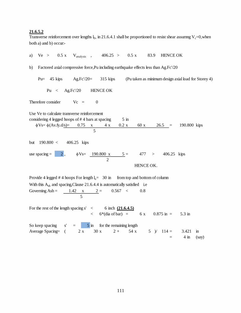
111
21.6.5.2
a) Ve > 0.5 x Vanalysis , > 0.5 x HENCE OK
b) Factored axial compressive force,Pu including earthquake effects less than Ag.Fc'/20
Pu= 45 kips Ag.Fc'/20= 315 kips (Pu taken as minimum design axial load for Storey 4)
Pu < Ag.Fc'/20 HENCE OK
Therefore consider Vc = 0
Use Ve to calculate transverse reinforcement
considering 4 legged hoops of # 4 bars at spacing 5 in
Vs= (Av.fy.d/s)= x 4 x 0.2 x 60 x = kips
but < kips
use spacing = 2 , x 5 = > kips
HENCE OK.
Provide 4 legged # 4 hoops For length lo= 30 in from top and bottom of column
With this Ash and spacing,Clause 21.6.4.4 is automatically satisfied i.e
Governing Ash = x 2 = <
For the rest of the length spacing s' < 6 inch (21.6.4.5)
< 6*(dia of bar) = 6 x = 5.3 in
So keep spacing s' = 5 in for the remaining length
Average Spacing= ( 2 x 30 x 2 + 54 x 5 )/ 114 = in
= 4 in (say)
0.875 in
3.421
406.25
2
1.42 0.567 0.8
5
477
5
190.800 406.25
Vs= 190.800
Transverse reinforcement over lengths l0, in 21.6.4.1 shall be proportioned to resist shear assumng Vc=0,when
both a) and b) occur:-
406.25 83.9
190.8000.75 26.5
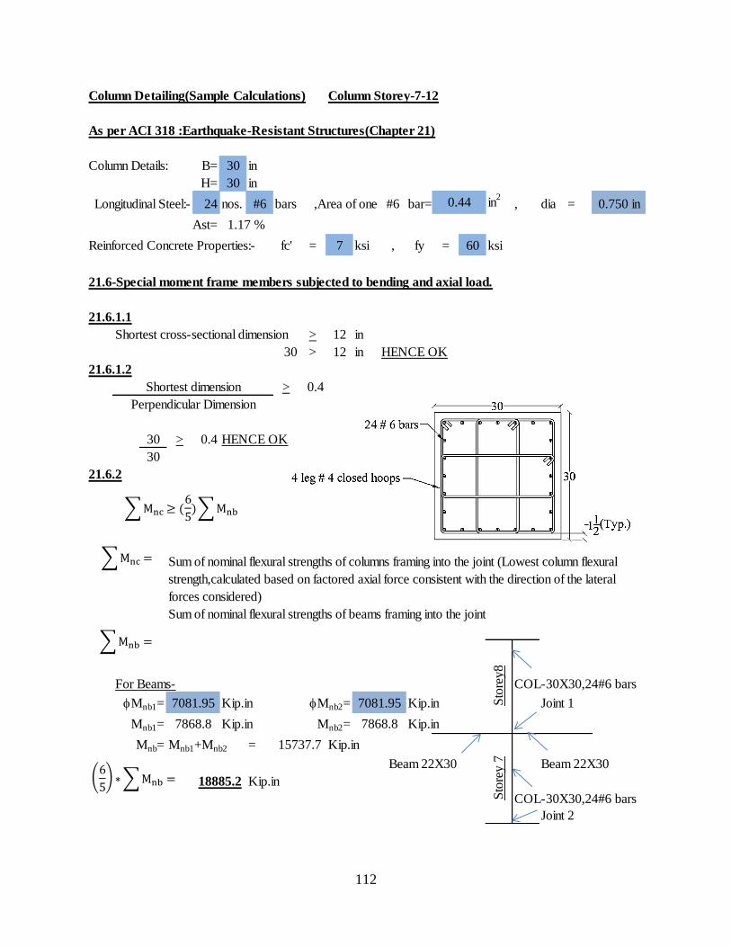
112
Column Detailing(Sample Calculations) Column Storey-7-12
As per ACI 318 :Earthquake-Resistant Structures(Chapter 21)
Column Details: B= 30 in
H= 30 in
Longitudinal Steel:- 24 nos. #6 bars ,Area of one #6 bar= in2
, dia =
Ast=
Reinforced Concrete Properties:- fc' = 7 ksi , fy = 60 ksi
21.6-Special moment frame members subjected to bending and axial load.
21.6.1.1
Shortest cross-sectional dimension > 12 in
30 > 12 in HENCE OK
21.6.1.2
> 0.4
30 > 0.4 HENCE OK
30
21.6.2
Sum of nominal flexural strengths of beams framing into the joint
For Beams- COL-30X30,24#6 bars
Mnb1= Kip.in Mnb2= Kip.in Joint 1
Mnb1= Kip.in Mnb2= Kip.in
Mnb= Mnb1+Mnb2 = Kip.in
Beam 22X30 Beam 22X30
Kip.in
COL-30X30,24#6 bars
Joint 2
Shortest dimension
Perpendicular Dimension
Sum of nominal flexural strengths of columns framing into the joint (Lowest column flexural
strength,calculated based on factored axial force consistent with the direction of the lateral
forces considered)
7081.95 7081.95
7868.8 7868.8
Sto
rey
7
15737.7
18885.2
0.44 0.750 in
1.17 %
Sto
rey
8

113
For Columns(Considering worst loading case) at a joint- Between Storey 7 and 8
C24 Storey 8
Min Axial Load for any combination = UCON17 = kips
Mnc1= kip.in
(Taken from the PM Diagram without resistance factor)
C24 Storey 7
Min Axial Load for any combination = UCON17 = kips
Mnc2= kip.in
(Taken from the PM Diagram without resistance factor)
Kip.in
as > HENCE OK
Transversel reinforcement:-
21.6.4.1
l0 > depth of the member at joint face = 30 in
> (1/6) xclear height (lc) = 1/6 x 114 = 19 in
> 18 in
Hence lo = 30 in Provide rectangular hoops in this region.
21.6.4.3
Spacing of reinforcement(s) in the region of length(lo)
s < = = 7.5 in
< 6 x Bar diamenter of longitudinal reinforcement = 6 x = in
< s0
Also (4 < 4 + (14-hx)/3 < 6)= s0
where,hx is the maximum horizontal spacing of the hoop or crosstie legs on all faces of column
hx =
4 < 4 + (14-8.66)/3 < 6
4 < < 6
4 4
0.750 in 4.5
(30-2x1.5-2x0.5)/3= 8.66
5.78
18887.7
18887.7 18885.2
Special transverse reinforcement for confinement is required over a distance l0 at the column ends and on both
sides of any section with flexural yielding(i.e if not at column ends)
Least member dimension 30
9397.6
78.54
9490.2
71.14

114
Take s0 = 5 in
hence s = MIN(7.5,4.5,5)
s = 4.5 in
21.6.4.4
Minimum required c/s area of the hoop reinforcement(Ash) is larger of :
a)
=( 0.3 x 4.5 x 27 x 7 )x(( 30 x 30 )- 1)
60
sq.in
b)
= x 4.5 x 27 x 7 = sq.in Governs
60
21.6.5-Shear strength requirements
21.6.5.1
Maximum shear from analysis = kips for Storey 5-12
Hence Mprc= kip.in
Mprb at joint at storey 1= x 2
=
Take Mpr1= = kip.in
Mpr2 = MPrc = kip.in
Ve = (Mpr1+Mpr2)/lu = ( + ) = kips
Ve > Vanalysis
kipsVdesign= 388.20
78.1
The largest probable moment strength can be conservatively assumed to be the nominal moment strength
corresponding to the balanced point(with fs=1.25x60=75ksi and =1)
24757.5
9748.8
19497.6
MIN(MPrc,MPrb) 19497.6
24757.5
19497.6 24757.5 388.20
(12*12-30)
The design shear force Ve shall be based on maximum probable moment strength Mpr of the member
associated with axial loads
729
0.998
0.09 1.28
=
=
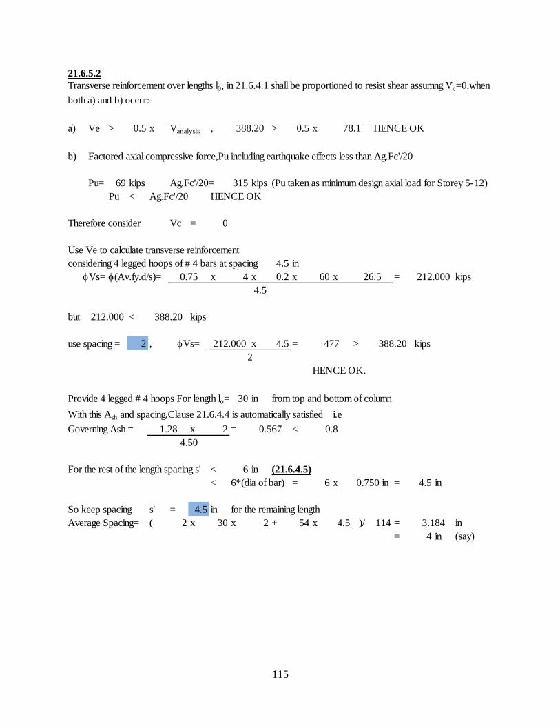
115
21.6.5.2
a) Ve > 0.5 x Vanalysis , > 0.5 x HENCE OK
b) Factored axial compressive force,Pu including earthquake effects less than Ag.Fc'/20
Pu= 69 kips Ag.Fc'/20= 315 kips (Pu taken as minimum design axial load for Storey 5-12)
Pu < Ag.Fc'/20 HENCE OK
Therefore consider Vc = 0
Use Ve to calculate transverse reinforcement
considering 4 legged hoops of # 4 bars at spacing 4.5 in
Vs= (Av.fy.d/s)= x 4 x 0.2 x 60 x = kips
but < kips
use spacing = 2 , x 4.5 = > kips
HENCE OK.
Provide 4 legged # 4 hoops For length lo= 30 in from top and bottom of column
With this Ash and spacing,Clause 21.6.4.4 is automatically satisfied i.e
Governing Ash = x 2 = <
For the rest of the length spacing s' < 6 in (21.6.4.5)
< 6*(dia of bar) = 6 x = 4.5 in
So keep spacing s' = 4.5 in for the remaining length
Average Spacing= ( 2 x 30 x 2 + 54 x 4.5 )/ 114 = in
= 4 in (say)
0.750 in
3.184
388.20
2
1.28 0.567 0.8
4.50
477
4.5
212.000 388.20
Vs= 212.000
Transverse reinforcement over lengths l0, in 21.6.4.1 shall be proportioned to resist shear assumng Vc=0,when
both a) and b) occur:-
388.20 78.1
212.0000.75 26.5
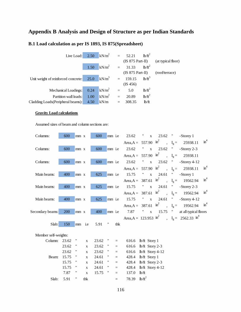
116
Appendix B Analysis and Design of Structure as per Indian Standards
B.1 Load calculation as per IS 1893, IS 875(Spreadsheet)
Live Load: kN/m2
=
(IS 875 Part-II) (at typical floor)
kN/m2
=
(IS 875 Part-II) (roof/terrace)
Unit weight of reinforced concrete: kN/m3
=
(IS 456)
Mechanical Loadings: kN/m2
=
Partition wall loads: kN/m2
=
Cladding Loads(Peripheral beams): kN/m =
Gravity Load calculations
Assumed sizes of beam and column sections are:
Columns: mm x mm i.e " x " -Storey 1
Area,A = in2
, Ig = in4
Columns: mm x mm i.e " x " -Storey 2-3
Area,A = in2
, Ig =
Columns: mm x mm i.e " x " -Storey 4-12
Area,A = in2
, Ig = in4
Main beams: mm x mm i.e " x " -Storey 1
Area,A = in2
, Ig = in4
Main beams: mm x mm i.e " x " -Storey 2-3
Area,A = in2
, Ig = in4
Main beams: mm x mm i.e " x " -Storey 4-12
Area,A = in2
, Ig = in4
Secondary beams: mm x mm i.e " x " at all typical floors
Area,A = in2
, Ig = in4
Slab: mm i.e " thk
Member self-weights:
Column: " x " = lb/ft Story 1
" x " = lb/ft Story 2-3
" x " = lb/ft Story 4-12
Beam: " x " = lb/ft Story 1
" x " = lb/ft Story 2-3
" x " = lb/ft Story 4-12
" x " = lb/ft
Slab: " thk = lb/ft2
23.62 23.62
557.90 25938.11
400 625 15.75 24.61
387.61 19562.94
5.91
15.75
24.61
24.61
23.62
23.62
137.0
428.4
428.4
616.6
616.6
78.39
23.62 616.6
15.75 24.61 428.4
200 400 7.87 15.75
150 5.91
23.62
7.87
15.75
15.75
23.62
23.62
600
600 600
400 625
19562.94
19562.94
400 625 15.75 24.61
23.62 23.62
25938.11
23.62 23.62
25938.11
15.75 24.61
600
557.90
557.90
600 600
4.50
lb/ft2
lb/ft2
lb/ft
5.0
20.89
31.33
52.21
159.15
lb/ft2
2.50
lb/ft2
1.50
lb/ft3
25.0
0.24
1.00
308.35
387.61
387.61
123.953 2562.33
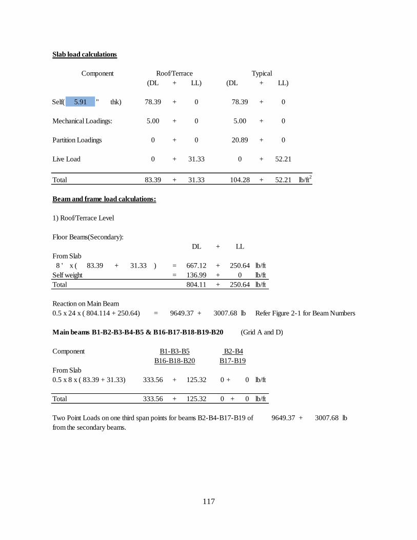
117
` Slab load calculations
Component
+ +
Self( " thk) + +
Mechanical Loadings: + +
Partition Loadings + +
Live Load + +
Total + + lb/ft2
Beam and frame load calculations:
1) Roof/Terrace Level
Floor Beams(Secondary):
+
From Slab
8 ' x ( + ) = + lb/ft
Self weight = + lb/ft
Total + lb/ft
Reaction on Main Beam
0.5 x 24 x ( 804.114 + 250.64) = + lb Refer Figure 2-1 for Beam Numbers
Main beams B1-B2-B3-B4-B5 & B16-B17-B18-B19-B20 (Grid A and D)
Component
From Slab
0.5 x 8 x ( 83.39 + 31.33) + 0 + 0 lb/ft
Total + 0 + 0 lb/ft
Two Point Loads on one third span points for beams B2-B4-B17-B19 of + lb
from the secondary beams.
3007.68
3007.68
9649.37
5.91 78.39
5.00
0
0
0
0
0
31.33
(DL LL)
Roof/Terrace
(DL LL)
Typical
78.39
0
20.89
5.00
52.21
0
0
0
83.39 31.33 104.28 52.21
DL
667.12
136.99
804.11
LL
250.64
0
250.64
83.39 31.33
333.56
333.56
125.32
125.32
9649.37
B2-B4
B17-B19
B1-B3-B5
B16-B18-B20
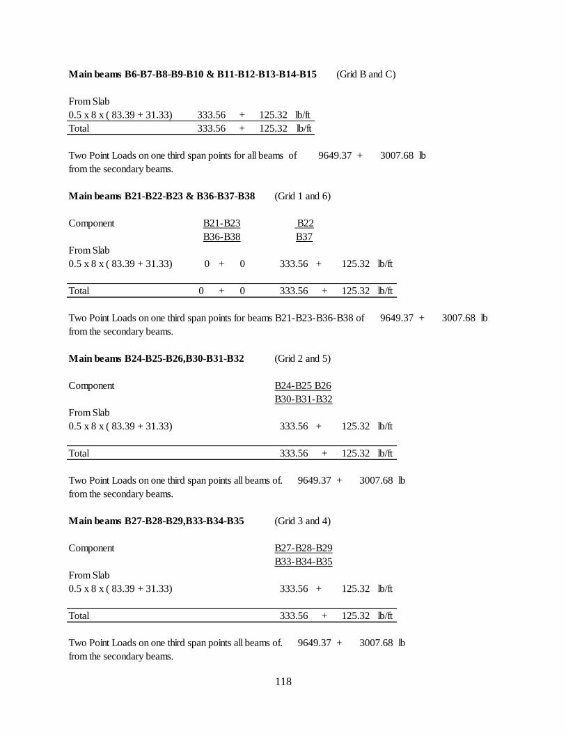
118
Main beams B6-B7-B8-B9-B10 & B11-B12-B13-B14-B15 (Grid B and C)
From Slab
0.5 x 8 x ( 83.39 + 31.33) + lb/ft
Total + lb/ft
Two Point Loads on one third span points for all beams of + lb
from the secondary beams.
Main beams B21-B22-B23 & B36-B37-B38 (Grid 1 and 6)
Component
From Slab
0.5 x 8 x ( 83.39 + 31.33) 0 + 0 + lb/ft
Total 0 + 0 + lb/ft
Two Point Loads on one third span points for beams B21-B23-B36-B38 of + lb
from the secondary beams.
Main beams B24-B25-B26,B30-B31-B32 (Grid 2 and 5)
Component B24-B25 B26
B30-B31-B32
From Slab
0.5 x 8 x ( 83.39 + 31.33) + lb/ft
Total + lb/ft
Two Point Loads on one third span points all beams of. + lb
from the secondary beams.
Main beams B27-B28-B29,B33-B34-B35 (Grid 3 and 4)
Component B27-B28-B29
B33-B34-B35
From Slab
0.5 x 8 x ( 83.39 + 31.33) + lb/ft
Total + lb/ft
Two Point Loads on one third span points all beams of. + lb
from the secondary beams.
333.56
333.56
B36-B38
B21-B23 B22
B37
125.32
333.56
333.56
125.32
125.32
9649.37 3007.68
9649.37 3007.68
9649.37 3007.68
9649.37
125.32
125.32
333.56
333.56
333.56
333.56
125.32
125.32
125.32
3007.68
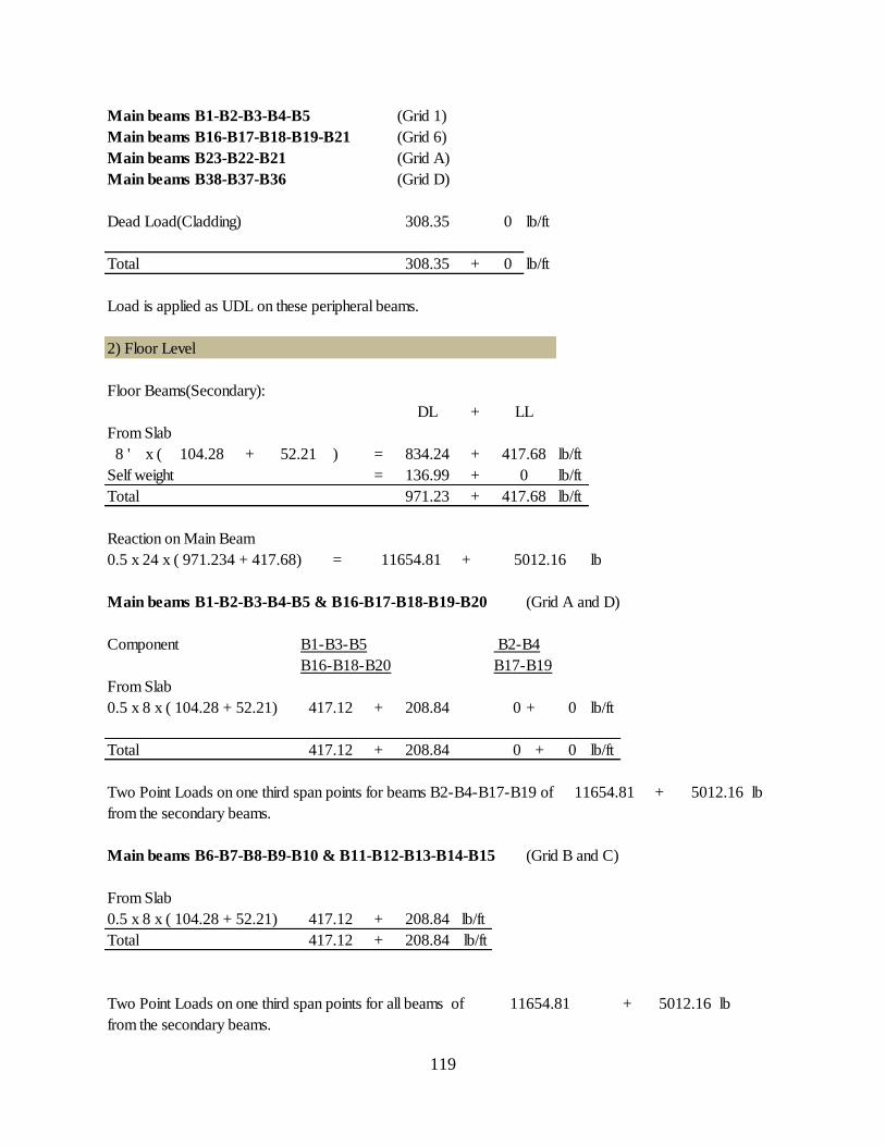
119
Main beams B1-B2-B3-B4-B5 (Grid 1)
Main beams B16-B17-B18-B19-B21 (Grid 6)
Main beams B23-B22-B21 (Grid A)
Main beams B38-B37-B36 (Grid D)
Dead Load(Cladding) 0 lb/ft
Total + 0 lb/ft
Load is applied as UDL on these peripheral beams.
2) Floor Level
Floor Beams(Secondary):
+
From Slab
8 ' x ( + ) = + lb/ft
Self weight = + lb/ft
Total + lb/ft
Reaction on Main Beam
0.5 x 24 x ( 971.234 + 417.68) = + lb
Main beams B1-B2-B3-B4-B5 & B16-B17-B18-B19-B20 (Grid A and D)
Component B1-B3-B5 B2-B4
B16-B18-B20 B17-B19
From Slab
0.5 x 8 x ( 104.28 + 52.21) + 0 + 0 lb/ft
Total + 0 + 0 lb/ft
Two Point Loads on one third span points for beams B2-B4-B17-B19 of + lb
from the secondary beams.
Main beams B6-B7-B8-B9-B10 & B11-B12-B13-B14-B15 (Grid B and C)
From Slab
0.5 x 8 x ( 104.28 + 52.21) + lb/ft
Total + lb/ft
Two Point Loads on one third span points for all beams of + lb
from the secondary beams.
417.12
5012.16
11654.81
208.84
208.84
417.12
417.12
11654.81
308.35
308.35
104.28 52.21
DL LL
417.68
0
971.23
136.99
417.68834.24
11654.81 5012.16
208.84417.12
208.84
5012.16
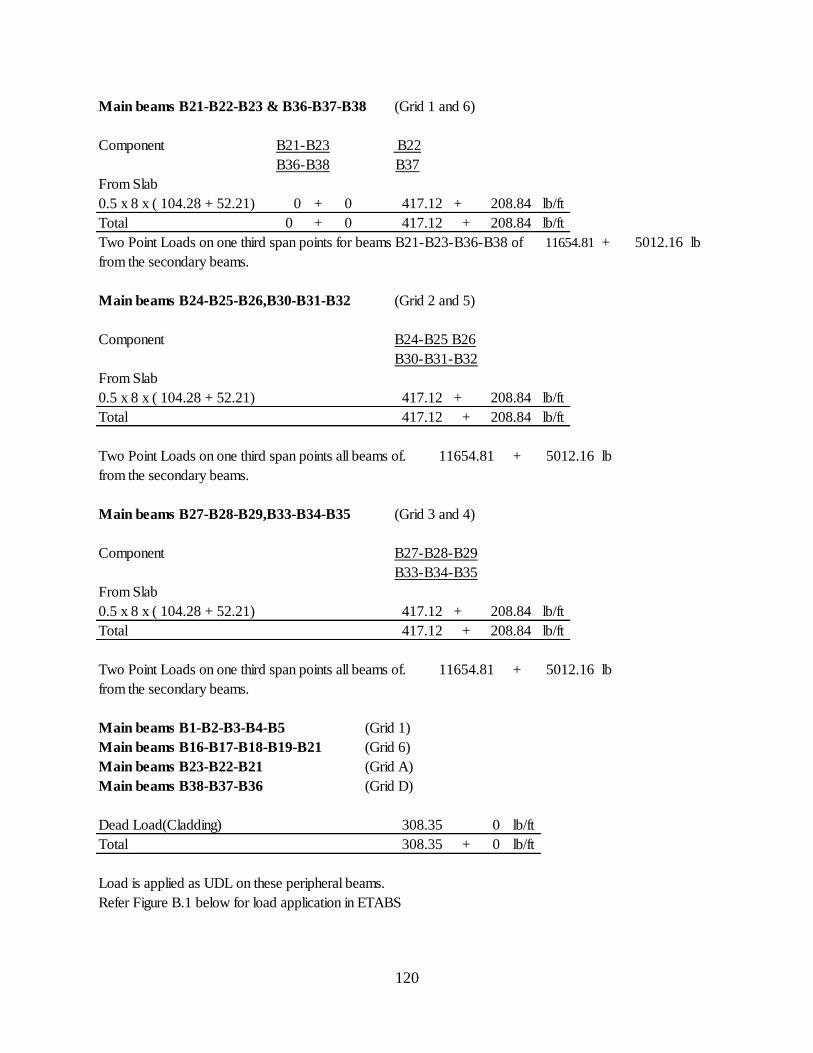
120
Main beams B21-B22-B23 & B36-B37-B38 (Grid 1 and 6)
Component B21-B23 B22
B36-B38 B37
From Slab
0.5 x 8 x ( 104.28 + 52.21) 0 + 0 + lb/ft
Total 0 + 0 + lb/ft
Two Point Loads on one third span points for beams B21-B23-B36-B38 of + lb
from the secondary beams.
Main beams B24-B25-B26,B30-B31-B32 (Grid 2 and 5)
Component B24-B25 B26
B30-B31-B32
From Slab
0.5 x 8 x ( 104.28 + 52.21) + lb/ft
Total + lb/ft
Two Point Loads on one third span points all beams of. + lb
from the secondary beams.
Main beams B27-B28-B29,B33-B34-B35 (Grid 3 and 4)
Component B27-B28-B29
B33-B34-B35
From Slab
0.5 x 8 x ( 104.28 + 52.21) + lb/ft
Total + lb/ft
Two Point Loads on one third span points all beams of. + lb
from the secondary beams.
Main beams B1-B2-B3-B4-B5 (Grid 1)
Main beams B16-B17-B18-B19-B21 (Grid 6)
Main beams B23-B22-B21 (Grid A)
Main beams B38-B37-B36 (Grid D)
Dead Load(Cladding) 0 lb/ft
Total + 0 lb/ft
Load is applied as UDL on these peripheral beams.
Refer Figure B.1 below for load application in ETABS
5012.16
208.84
5012.16
5012.16
417.12
11654.81
308.35
308.35
417.12
208.84417.12
11654.81
11654.81
208.84417.12
208.84417.12
208.84
208.84417.12
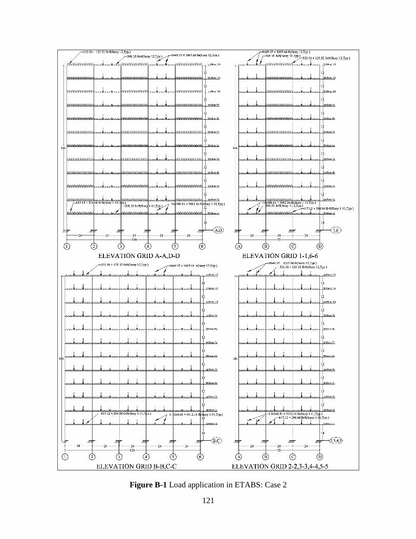
121
Figure B-1 Load application in ETABS: Case 2
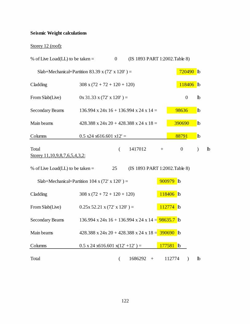
122
Seismic Weight calculations
Storey 12 (roof):
% of Live Load(LL) to be taken = 0 (IS 1893 PART 1:2002.Table 8)
Slab+Mechanical+Partition 83.39 x (72' x 120' ) = lb
Cladding 308 x (72 + 72 + 120 + 120) lb
From Slab(Live) 0x 31.33 x (72' x 120' ) = lb
Secondary Beams 136.994 x 24x 16 + 136.994 x 24 x 14 = lb
Main beams 428.388 x 24x 20 + 428.388 x 24 x 18 = lb
Columns 0.5 x24 x616.601 x12' = lb
Total ( + ) lb
Storey 11,10,9,8,7,6,5,4,3,2:
% of Live Load(LL) to be taken = 25 (IS 1893 PART 1:2002.Table 8)
Slab+Mechanical+Partition 104 x (72' x 120' ) = lb
Cladding 308 x (72 + 72 + 120 + 120) lb
From Slab(Live) 0.25x 52.21 x (72' x 120' ) = lb
Secondary Beams 136.994 x 24x 16 + 136.994 x 24 x 14 = lb
Main beams 428.388 x 24x 20 + 428.388 x 24 x 18 = lb
Columns 0.5 x 24 x616.601 x(12' +12' ) = lb
Total ( + ) lb
1417012 0
112774
118406
88791
177581
1686292
900979
112774
98635.7
390690
118406
720490
0
98636
390690

123
Storey 1:
% of Live Load(LL) to be taken = 25 (IS 1893 PART 1:2002.Table 8)
From Slab(Dead) 104.28 x (72' x 120' ) = lb
Cladding 308 x (72 + 72 + 120 + 120) lb
From Slab(Live) 0.25x 52.21 x (72' x 120' ) = lb
Secondary Beams 136.994 x 24x 16 + 136.994 x 24 x 14 = lb
Main beams 428.388 x 24x 20 + 428.388 x 24 x 18 = lb
Columns 0.5 x24 x616.601 x12' = lb
Columns 24 x616.601 x14' = lb
Total ( + ) lb
Seismic weight of entire building :
1 x ( 1417012.08 + 0 ) + 10 x ( 1686292.224 + 112773.6 ) + 1 x ( 1804679.616 + 112773.6 ) =
lb
(by hand calculation) = Kip.
(by Etabs NL 9.6) = Kip.
900979
1804680
21325124
21325.124
118406
390690
21324.060
207178
112774
112774
98635.7
88790.5
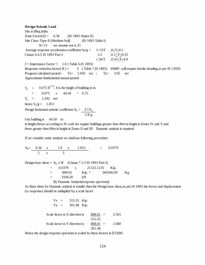
124
Design Seismic Load
Site in Bhuj,India
Zone Factor(Z) = (IS 1893 Annex E)
Site Class-Type-II (Medium Soil) (IS 1893 Table I)
N>15 we assume our is 25
Average response acceleration coefficient Sa/g = 1+15T ,0<T<0.1
Clause 6.4.5 IS 1893 Part-I 2.5 ,0.1<T<0.55
1.36/T ,0.55<T<4.0
I = Importance Factor = 1.0 ( Table 6,IS 1893)
Response reduction factor( R ) = 5 ( Table 7,IS 1893) SMRF ,will require ductile detailing as per IS 13920
Program calculated period:- Tx= sec ; Ty= sec
Approximate fundamental natural period:
Ta = 0.075 h0.75
, h is the height of building in m.
= x ^
Ta = sec
hence Sa/g =
Design horizontal seiemic coefficient Ah =
Our building is m
in height,Hence according to IS code for regular buildings greater than 40m in height in Zones IV and V,and
those greater than 90m in height in Zones II and III. Dynamic analysis is required.
If we consider static analysis we shall use following procedure;
Ah= x x =
x
Design base shear = Ah x W (Clause 7.5.3 IS 1893 Part-I)
= x Kip.
= Kip. = Kg.
= kN
By Dynamic Analysis(response spectrum)
As Base shear by Dynamic analysis is smaller than the Design base shear,as per IS 1893 the forces and displacement
(i.e response) should be multiplied by a scale factor
Vx = Kip.
Vy = Kip.
Scale factor in X direction is =
Scale factor in Y direction is =
Hence the design response spectrum is scaled by these factors in ETABS.
44.50
301.48
808.01
44.50
5
0.0379
2
2 R g
0.075
1.053
2.916
315.55
0.75
Z I Sa
21325.1235
808.01
3594.20
366506.69
0.36
3.05
1.292
0.36 1.0 1.053
301.48
315.55
2.561
808.01 2.680
0.0379
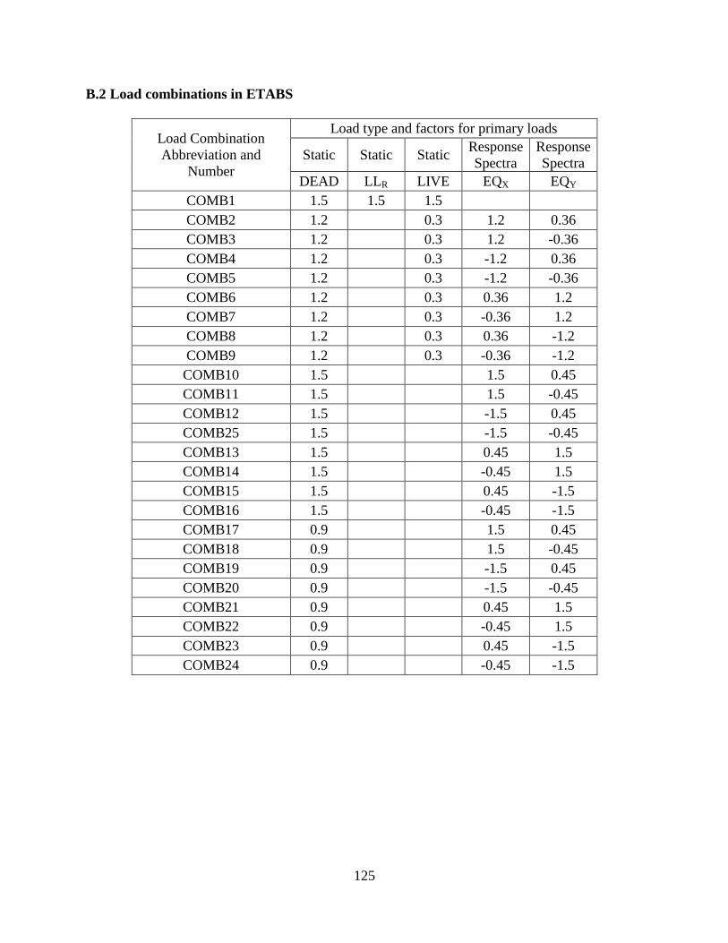
125
B.2 Load combinations in ETABS
Load Combination
Abbreviation and
Number
Load type and factors for primary loads
Static Static Static Response
Spectra
Response
Spectra
DEAD LLR LIVE EQX EQY
COMB1 1.5 1.5 1.5
COMB2 1.2
0.3 1.2 0.36
COMB3 1.2
0.3 1.2 -0.36
COMB4 1.2
0.3 -1.2 0.36
COMB5 1.2
0.3 -1.2 -0.36
COMB6 1.2
0.3 0.36 1.2
COMB7 1.2
0.3 -0.36 1.2
COMB8 1.2
0.3 0.36 -1.2
COMB9 1.2
0.3 -0.36 -1.2
COMB10 1.5
1.5 0.45
COMB11 1.5
1.5 -0.45
COMB12 1.5
-1.5 0.45
COMB25 1.5
-1.5 -0.45
COMB13 1.5
0.45 1.5
COMB14 1.5
-0.45 1.5
COMB15 1.5
0.45 -1.5
COMB16 1.5
-0.45 -1.5
COMB17 0.9
1.5 0.45
COMB18 0.9
1.5 -0.45
COMB19 0.9
-1.5 0.45
COMB20 0.9
-1.5 -0.45
COMB21 0.9
0.45 1.5
COMB22 0.9
-0.45 1.5
COMB23 0.9
0.45 -1.5
COMB24 0.9
-0.45 -1.5
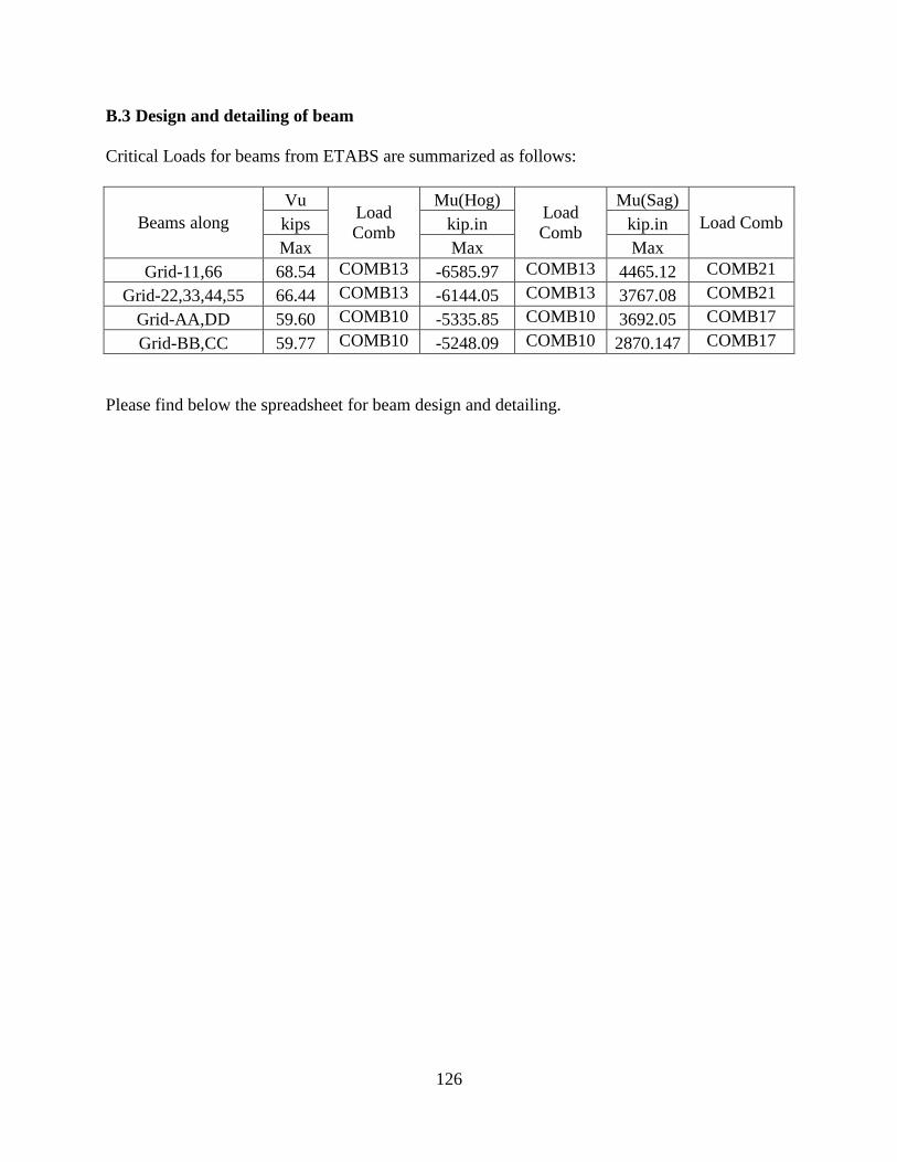
126
B.3 Design and detailing of beam
Critical Loads for beams from ETABS are summarized as follows:
Beams along
Vu Load
Comb
Mu(Hog) Load
Comb
Mu(Sag)
Load Comb kips kip.in kip.in
Max Max Max
Grid-11,66 68.54 COMB13 -6585.97 COMB13 4465.12 COMB21
Grid-22,33,44,55 66.44 COMB13 -6144.05 COMB13 3767.08 COMB21
Grid-AA,DD 59.60 COMB10 -5335.85 COMB10 3692.05 COMB17
Grid-BB,CC 59.77 COMB10 -5248.09 COMB10 2870.147 COMB17
Please find below the spreadsheet for beam design and detailing.
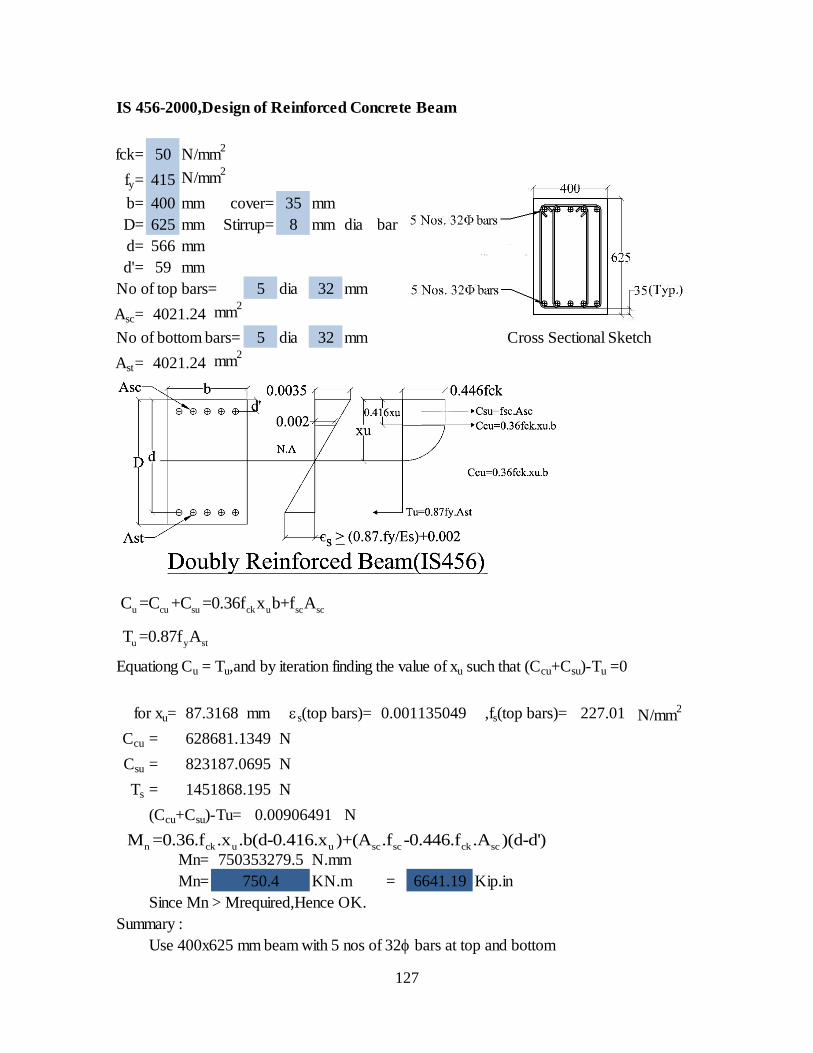
127
IS 456-2000,Design of Reinforced Concrete Beam
fck= 50 N/mm2
fy= 415 N/mm2
b= 400 mm cover= 35 mm
D= 625 mm Stirrup= 8 mm dia bar
d= 566 mm
d'= 59 mm
No of top bars= 5 dia 32 mm
Asc= mm2
No of bottom bars= 5 dia 32 mm Cross Sectional Sketch
Ast= mm2
Equationg Cu = Tu,and by iteration finding the value of xu such that (Ccu+Csu)-Tu =0
for xu= mm es(top bars)= ,fs(top bars)= N/mm2
Ccu = N
Csu = N
Ts = N
(Ccu+Csu)-Tu= N
Mn= N.mm
Mn= KN.m = Kip.in
Since Mn > Mrequired,Hence OK.
Summary :
Use 400x625 mm beam with 5 nos of 32 bars at top and bottom
1451868.195
0.00906491
6641.19
227.01
750353279.5
750.4
4021.24
4021.24
87.3168 0.001135049
628681.1349
823187.0695
u cu su ck u sc scC =C +C =0.36f x b+f A
u y stT =0.87f A
n ck u u sc sc ck scM =0.36.f .x .b(d-0.416.x )+(A .f -0.446.f .A )(d-d')
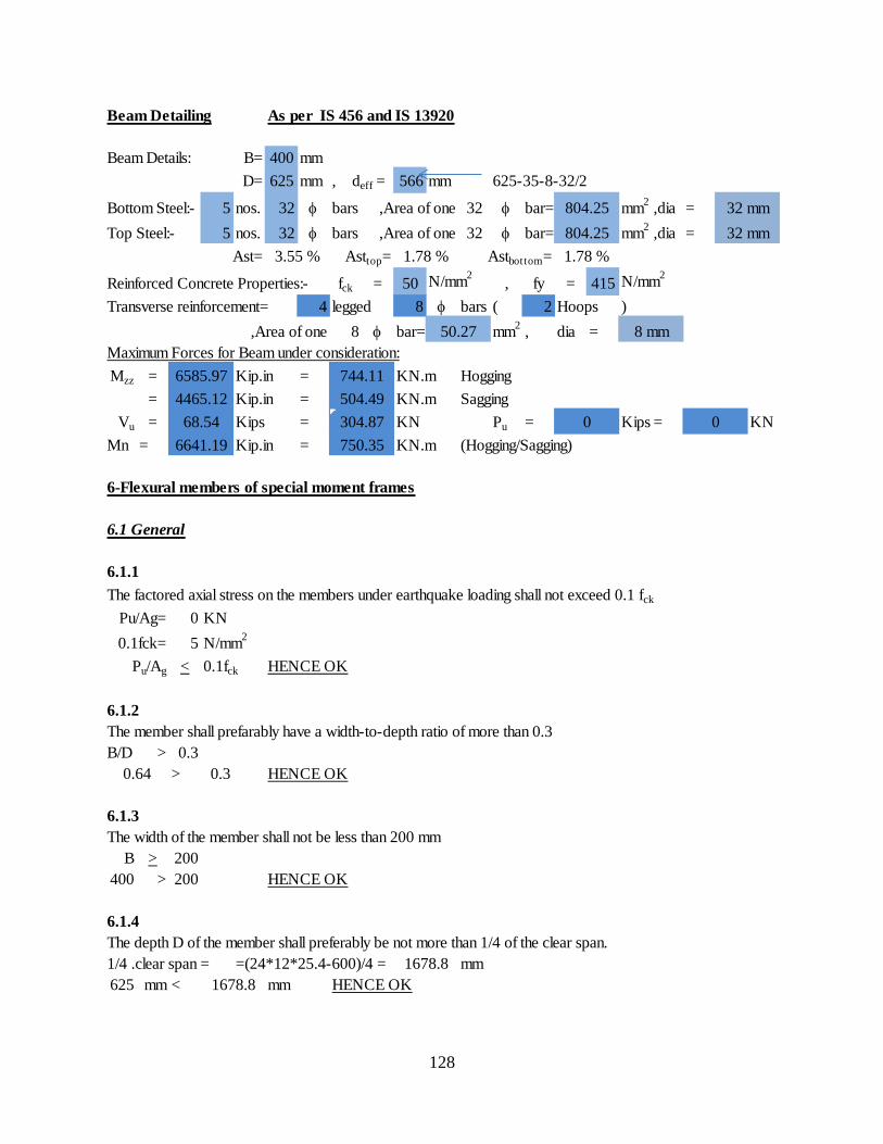
128
Beam Detailing As per IS 456 and IS 13920
Beam Details: B= 400 mm
D= 625 mm , deff = 566 mm 625-35-8-32/2
Bottom Steel:- 5 nos. 32 bars ,Area of one 32 bar= mm2
,dia =
Top Steel:- 5 nos. 32 bars ,Area of one 32 bar= mm2
,dia =
Ast= Asttop= Astbottom=
Reinforced Concrete Properties:- fck = 50 N/mm2
, fy = 415 N/mm2
Transverse reinforcement= 4 legged 8 bars ( 2 Hoops )
,Area of one 8 bar= mm2
, dia =
Maximum Forces for Beam under consideration:
Mzz = Kip.in = KN.m Hogging
= Kip.in = KN.m Sagging
Vu = Kips = KN Pu = Kips = KN
Mn = Kip.in = KN.m (Hogging/Sagging)
6-Flexural members of special moment frames
6.1 General
6.1.1
The factored axial stress on the members under earthquake loading shall not exceed 0.1 fck
Pu/Ag= 0 KN
0.1fck= 5 N/mm2
Pu/Ag < 0.1fck HENCE OK
6.1.2
The member shall prefarably have a width-to-depth ratio of more than 0.3
B/D > 0.3
> 0.3 HENCE OK
6.1.3
The width of the member shall not be less than 200 mm
B > 200
400 > 200 HENCE OK
6.1.4
The depth D of the member shall preferably be not more than 1/4 of the clear span.
1/4 .clear span = =(24*12*25.4-600)/4 = mm
625 mm < mm HENCE OK
3.55 % 1.78 % 1.78 %
304.87
6641.19 750.35
0
804.25 32 mm
804.25 32 mm
0
50.27 8 mm
744.11
504.49
1678.8
1678.8
6585.97
4465.12
0.64
68.54
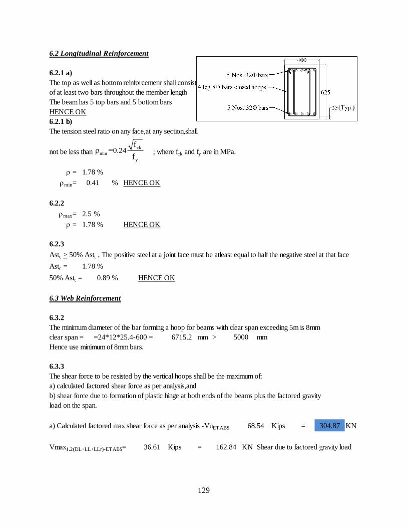
129
6.2 Longitudinal Reinforcement
6.2.1 a)
The top as well as bottom reinforcemenr shall consist
of at least two bars throughout the member length
The beam has 5 top bars and 5 bottom bars
HENCE OK
6.2.1 b)
The tension steel ratio on any face,at any section,shall
not be less than ; where fck and fy are in MPa.
=
min= % HENCE OK
6.2.2
max= 2.5 %
= HENCE OK
6.2.3
Astc > 50% Astt , The positive steel at a joint face must be atleast equal to half the negative steel at that face
Astc =
50% Astt = HENCE OK
6.3 Web Reinforcement
6.3.2
The minimum diameter of the bar forming a hoop for beams with clear span exceeding 5m is 8mm
clear span = =24*12*25.4-600 = mm > mm
Hence use minimum of 8mm bars.
6.3.3
The shear force to be resisted by the vertical hoops shall be the maximum of:
a) calculated factored shear force as per analysis,and
b) shear force due to formation of plastic hinge at both ends of the beams plus the factored gravity
load on the span.
a) Calculated factored max shear force as per analysis -VuETABS Kips = KN
Vmax1.2(DL+LL+LLr)-ETABS= Kips = KN Shear due to factored gravity load
1.78 %
304.87
1.78 %
0.41
1.78 %
0.89 %
6715.2 5000
36.61 162.84
68.54
ck
min
y
0.24f
ρ =f
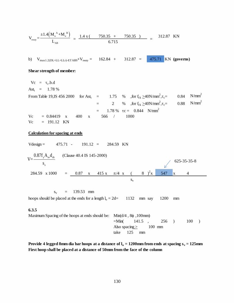
130
1.4 x ( + ) KN
b) Vmax1.2(DL+LL+LLr)-ETABS+Vsway = + = KN (governs)
Shear strength of member:
Vc = tc.b.d
Astt =
From Table 19,IS 456 2000 for Astt = % ,for fck >40N/mm2,tc= N/mm
2
= % ,for fck >40N/mm2,tc= N/mm
2
= tc = N/mm2
Vc = x x /
Vc = KN
Calculation for spacing at ends
Vdesign = - = KN
(Clause 40.4 IS 145-2000)
x 1000 = x 415 x p/4 x ( 8 )2x x 4
sv
sv = mm
hoops should be placed at the ends for a length lo = 2d= mm say mm
6.3.5
Maximum Spacing of the hoops at ends should be: Min(d/4 , 8,100mm)
=Min( , ) )
Also spacing > 100 mm
take mm
Provide 4 legged 8mm dia bar hoops at a distance of lo = 1200mm from ends at spacing sv = 125mm
First hoop shall be placed at a distance of 50mm from the face of the column
625-35-35-8
750.35
162.84 312.87 475.71
750.35
6.715
312.87
0.84
0.88
125
284.59 0.87
=
1.78 %
191.12
475.71 191.12
=
1.75
2
1.78 % 0.844
0.84419 400 566 1000
100
547
139.53
1132 1200
141.5 256
284.59
A B
u u
sway
AB
±1.4 M +MV =
L
y sv sh
v
0.87f A dV=
s

131
Calculation for spacing at the remaining length
Vdesign = - = KN
, Assuming 4 legged 8bars
x 1000 = x 415 x p/4 x ( 8 )2x x 4
sv
sv = mm
6.3.5
Maximum Spacing of the hoops at ends should be: d/2 i.e 274 mm
take mm
Provide 4 legged 8mm dia bar hoops at remaining length sv = 250mm
Average Spacing= ( 2 x 125 x + x )/
= mm
= in(Say)
Summary
4 legged 8 bar hoops for lo = mm ,spacing = mm
First hoop shall be at a distance < 50 mm
Spacing for the rest of the length = 250 mm
Take average spacing for XTRACT = 205 mm
1251200
312.87 191.12
121.75 0.87
121.75
547
326.16
6715.2
9.00
250
205.33
1200 4315.2 250
y sv sh
v
0.87f A dV=
s
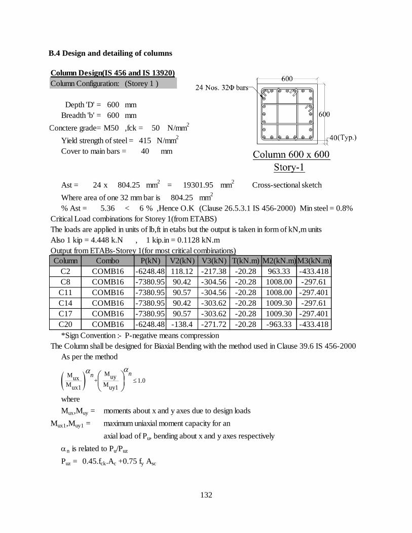
132
B.4 Design and detailing of columns
Column Design(IS 456 and IS 13920)
Column Configuration: (Storey 1 )
Depth 'D' = mm
Breadth 'b' = mm
Conctere grade= M50 ,fck = N/mm2
Yield strength of steel = N/mm2
Cover to main bars =
Ast = 24 x mm2
= mm2
Cross-sectional sketch
Where area of one 32 mm bar is mm2
% Ast = < 6 % ,Hence O.K (Clause 26.5.3.1 IS 456-2000) Min steel = 0.8%
Critical Load combinations for Storey 1(from ETABS)
The loads are applied in units of lb,ft in etabs but the output is taken in form of kN,m units
Also 1 kip = 4.448 k.N , 1 kip.in = 0.1128 kN.m
Output from ETABs-Storey 1(for most critical combinations)
*Sign Convention :- P-negative means compression
The Column shall be designed for Biaxial Bending with the method used in Clause 39.6 IS 456-2000
As per the method
where
Mux,Muy = moments about x and y axes due to design loads
Mux1,Muy1 = maximum uniaxial moment capacity for an
axial load of Pu, bending about x and y axes respectively
an is related to Pu/Puz
Puz = 0.45.fck.Ac +0.75 fy Asc
5.36
600
600
50
415
mm40
804.25
804.25
19301.95
-963.33
M3(kN.m)
-433.418
-297.61
-297.401
-297.61
-297.401
-433.418
M2(kN.m)
963.33
1008.00
1008.00
1009.30
1009.30
-271.72
T(kN.m)
-20.28
-20.28
-20.28
-20.28
-20.28
-20.28
V3(kN)
-217.38
-304.56
-304.56
-303.62
-303.62
-6248.48
-7380.95
-7380.95
-7380.95
-7380.95
-6248.48
V2(kN)
118.12
90.42
90.57
90.42
90.57
-138.4C20
Combo
COMB16
Column
C2
C8
C11
C14
C17
COMB16
COMB16
COMB16
COMB16
COMB16
P(kN)
MM uyux + 1.0
M Mux1 uy1
nnaa
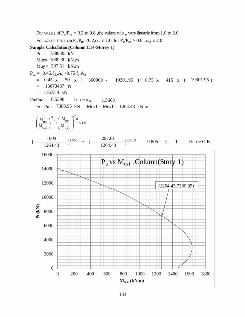
133
For values of Pu/Puz = 0.2 to 0.8 ,the values of an vary linearly from 1.0 to 2.0
For values less than Pu/Puz <0.2,an is 1.0; for Pu/Puz > 0.8 , an is 2.0
Sample Calculation(Column C14-Storey 1)
Pu = kN
Mux= kN.m
Muy = kN.m
Puz = 0.45.fck.Ac +0.75 fy Asc
= x x ( - )+ x x ( )
= N
= kN
Pu/Puz = hence an =
For Pu = kN, Mux1 = Muy1 = kN.m
< 11264.43 1264.43
]1.5663
]1.5663 Hence O.K[
1009+ [
297.61= 0.806
13673437
13673.4
7380.95
1009.30
297.61
0.5398 1.5663
7380.95 1264.43
0.45 50 360000 0.75 415 19301.9519301.95
MM uyux + 1.0
M Mux1 uy1
nnaa
0
2000
4000
6000
8000
10000
12000
14000
16000
0 200 400 600 800 1000 1200 1400 1600 1800
Pu(k
N)
Mux1(kN.m)
Pu vs Mux1 ,Column(Story 1)
(1264.43,7380.95)
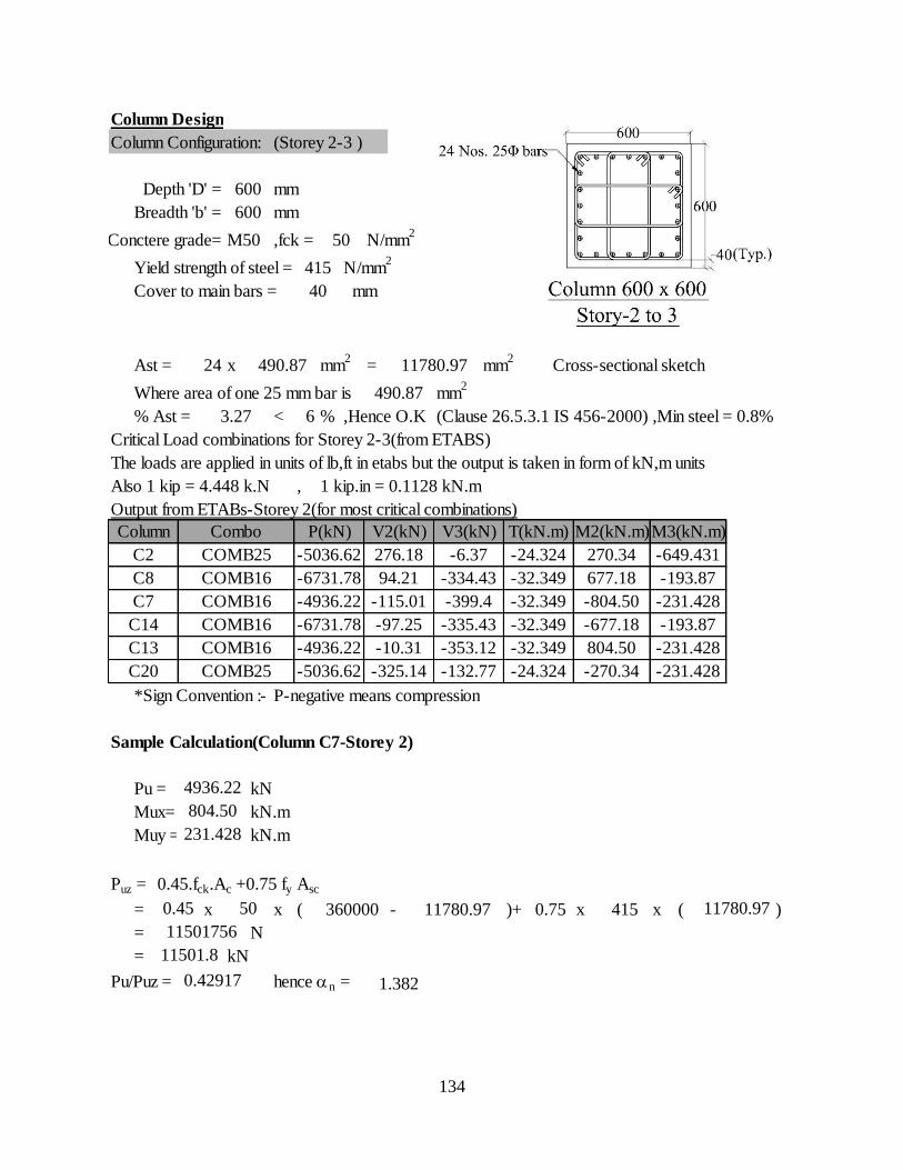
134
Column Design
Column Configuration: (Storey 2-3 )
Depth 'D' = mm
Breadth 'b' = mm
Conctere grade= M50 ,fck = N/mm2
Yield strength of steel = N/mm2
Cover to main bars =
Ast = 24 x mm2
= mm2
Cross-sectional sketch
Where area of one 25 mm bar is mm2
% Ast = < 6 % ,Hence O.K (Clause 26.5.3.1 IS 456-2000) ,Min steel = 0.8%
Critical Load combinations for Storey 2-3(from ETABS)
The loads are applied in units of lb,ft in etabs but the output is taken in form of kN,m units
Also 1 kip = 4.448 k.N , 1 kip.in = 0.1128 kN.m
Output from ETABs-Storey 2(for most critical combinations)
*Sign Convention :- P-negative means compression
Sample Calculation(Column C7-Storey 2)
Pu = kN
Mux= kN.m
Muy = kN.m
Puz = 0.45.fck.Ac +0.75 fy Asc
= x x ( - )+ x x ( )
= N
= kN
Pu/Puz = hence an =
11501756
11501.8
0.42917 1.382
804.50
231.428
0.45 50 360000 11780.97 0.75 415 11780.97
C20 COMB25 -5036.62 -325.14 -132.77 -24.324 -270.34 -231.428
4936.22
C14 COMB16 -6731.78 -97.25 -335.43 -32.349 -677.18 -193.87
C13 COMB16 -4936.22 -10.31 -353.12 -32.349 804.50 -231.428
C8 COMB16 -6731.78 94.21 -334.43 -32.349 677.18 -193.87
C7 COMB16 -4936.22 -115.01 -399.4 -32.349 -804.50 -231.428
M3(kN.m)
C2 COMB25 -5036.62 276.18 -6.37 -24.324 270.34 -649.431
490.87
3.27
Column Combo P(kN) V2(kN) V3(kN) T(kN.m) M2(kN.m)
600
600
50
415
40 mm
490.87 11780.97
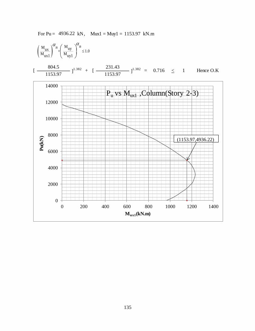
135
For Pu = kN, Mux1 = Muy1 = kN.m
= 0.716 < 1 Hence O.K1153.97 1153.97
4936.22 1153.97
[804.5
]1.382 + [
231.43]1.382
MM uyux + 1.0
M Mux1 uy1
nnaa
0
2000
4000
6000
8000
10000
12000
14000
0 200 400 600 800 1000 1200 1400
Pu
(kN
)
Mux1(kN.m)
Pu vs Mux1 ,Column(Story 2-3)
(1153.97,4936.22)
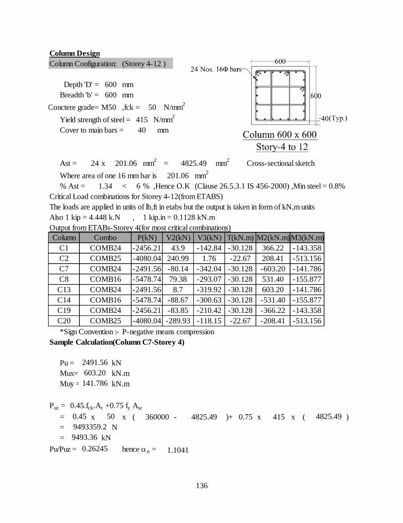
136
Column Design
Column Configuration: (Storey 4-12 )
Depth 'D' = mm
Breadth 'b' = mm
Conctere grade= M50 ,fck = N/mm2
Yield strength of steel = N/mm2
Cover to main bars =
Ast = 24 x mm2
= mm2
Cross-sectional sketch
Where area of one 16 mm bar is mm2
% Ast = < 6 % ,Hence O.K (Clause 26.5.3.1 IS 456-2000) ,Min steel = 0.8%
Critical Load combinations for Storey 4-12(from ETABS)
The loads are applied in units of lb,ft in etabs but the output is taken in form of kN,m units
Also 1 kip = 4.448 k.N , 1 kip.in = 0.1128 kN.m
Output from ETABs-Storey 4(for most critical combinations)
*Sign Convention :- P-negative means compression
Sample Calculation(Column C7-Storey 4)
Pu = kN
Mux= kN.m
Muy = kN.m
Puz = 0.45.fck.Ac +0.75 fy Asc
= x x ( - )+ x x ( )
= N
= kN
Pu/Puz = hence an =
C19 COMB24 -2456.21 -83.85 -210.42 -30.128 -366.22 -143.358
C20 COMB25 -4080.04 -289.93 -118.15 -22.67 -208.41 -513.156
-300.63 -30.128 -531.40 -155.877
2491.56
603.20
0.45 50 360000 4825.49 0.75 415 4825.49
-30.128 531.40 -155.877
C13 COMB24 -2491.56 8.7 -319.92 -30.128 603.20 -141.786
-22.67 208.41 -513.156
C7 COMB24 -2491.56 -80.14 -342.04 -30.128 -603.20 -141.786
M3(kN.m)
C1 COMB24 -2456.21 43.9 -142.84 -30.128 366.22 -143.358
600
50
415
40 mm
201.06 4825.49
201.06
600
0.26245
9493359.2
9493.36
1.1041
141.786
1.34
Combo P(kN) V2(kN) V3(kN) T(kN.m) M2(kN.m)
COMB25 -4080.04 240.99 1.76
Column
C2
C8 COMB16 -5478.74 79.38 -293.07
C14 COMB16 -5478.74 -88.67
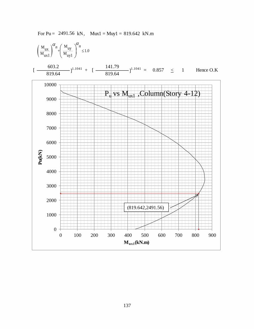
137
For Pu = kN, Mux1 = Muy1 = kN.m
= 0.857 < 1 Hence O.K819.64 819.64
[603.2
]1.1041 + [
141.79]1.1041
2491.56 819.642
MM nynx + 1
M Mnxo nyo
aa
MM uyux + 1.0
M Mux1 uy1
nnaa
0
1000
2000
3000
4000
5000
6000
7000
8000
9000
10000
0 100 200 300 400 500 600 700 800 900
Pu(k
N)
Mux1(kN.m)
Pu vs Mux1 ,Column(Story 4-12)
(819.642,2491.56)
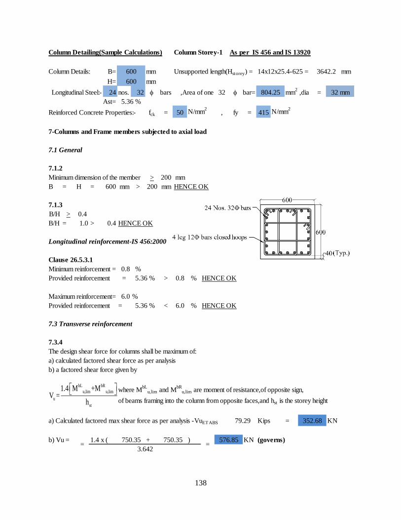
138
Column Detailing(Sample Calculations) Column Storey-1 As per IS 456 and IS 13920
Column Details: B= mm Unsupported length(Hstorey) = 14x12x25.4-625 = mm
H= mm
Longitudinal Steel:- 24 nos. 32 bars ,Area of one 32 bar= mm2
,dia =
Ast=
Reinforced Concrete Properties:- fck = 50 N/mm2
, fy = 415 N/mm2
7-Columns and Frame members subjected to axial load
7.1 General
7.1.2
Minimum dimension of the member > 200 mm
B = H = 600 mm > 200 mm HENCE OK
7.1.3
B/H > 0.4
B/H = 1.0 > 0.4 HENCE OK
Longitudinal reinforcement-IS 456:2000
Clause 26.5.3.1
Minimum reinforcement = 0.8 %
Provided reinforcement = > 0.8 % HENCE OK
Maximum reinforcement= 6.0 %
Provided reinforcement = < 6.0 % HENCE OK
7.3 Transverse reinforcement
7.3.4
The design shear force for columns shall be maximum of:
a) calculated factored shear force as per analysis
b) a factored shear force given by
where MbL
u,lim and MbR
u,lim are moment of resistance,of opposite sign,
of beams framing into the column from opposite faces,and hst is the storey height
a) Calculated factored max shear force as per analysis -VuETABS Kips = KN
b) Vu = 1.4 x ( + ) KN (governs)
3642.2
79.29 352.68
600
600
750.35=
576.85
3.642
804.25
5.36 %
5.36 %
5.36 %
=750.35
32 mm
bL bR
u,lim u,lim
u
st
1.4 M +MV =
h
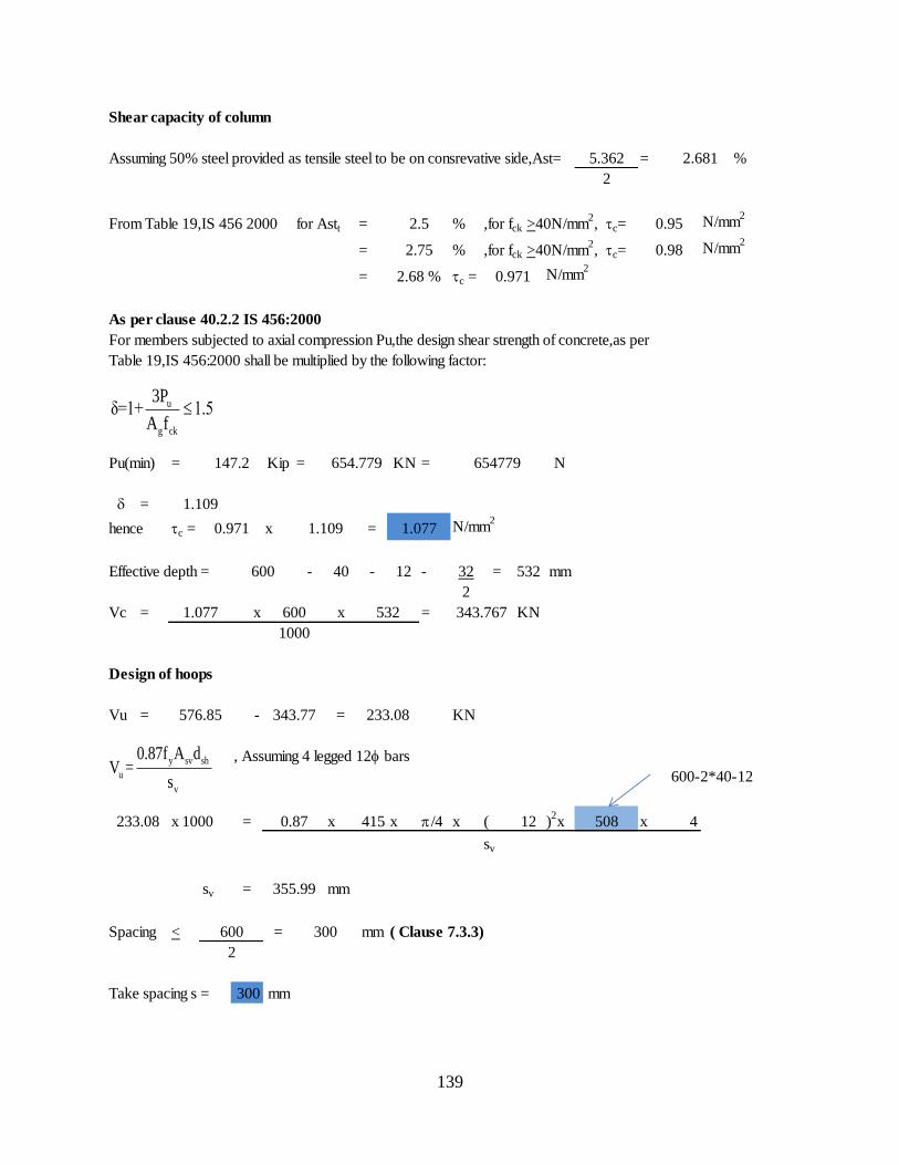
139
Shear capacity of column
Assuming 50% steel provided as tensile steel to be on consrevative side,Ast= = %
From Table 19,IS 456 2000 for Astt = % ,for fck >40N/mm2, tc= N/mm
2
= % ,for fck >40N/mm2, tc= N/mm
2
= tc = N/mm2
As per clause 40.2.2 IS 456:2000
For members subjected to axial compression Pu,the design shear strength of concrete,as per
Table 19,IS 456:2000 shall be multiplied by the following factor:
Pu(min) = Kip = KN = N
=
hence tc = x = N/mm2
Effective depth = - 40 - 12 - 32 = 532 mm
2
Vc = x x = KN
Design of hoops
Vu = - = KN
, Assuming 4 legged 12bars
600-2*40-12
x 1000 = x 415 x p/4 x ( 12 )2x x 4
sv
sv = mm
Spacing < = mm ( Clause 7.3.3)
Take spacing s = 300 mm
576.85 343.77 233.08
654779
1.109
0.971 1.109 1.077
600
147.2
233.08 0.87 508
355.99
600 300
5.362
2
2.681
0.952.5
654.779
2.75 0.98
2.68 % 0.971
1000
343.767
2
1.077 600 532
u
g ck
3Pδ=1+ 1.5
A f
y sv sh
u
v
0.87f A dV =
s
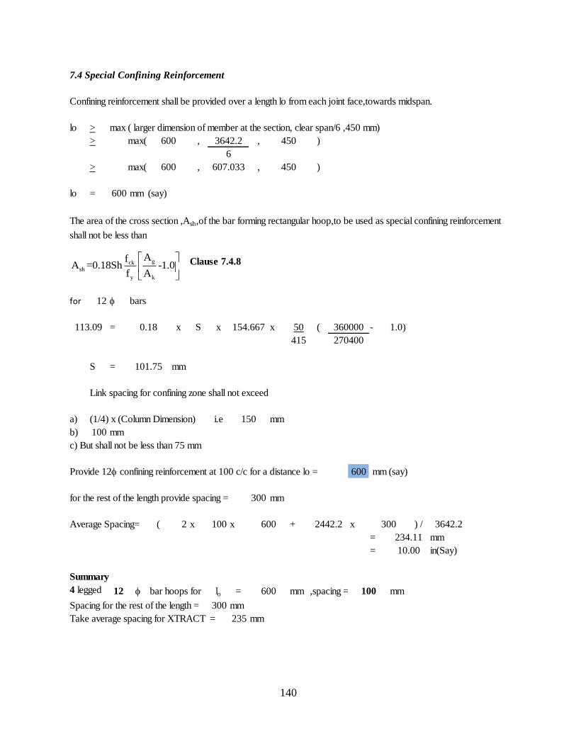
140
7.4 Special Confining Reinforcement
Confining reinforcement shall be provided over a length lo from each joint face,towards midspan.
lo > max ( larger dimension of member at the section, clear span/6 ,450 mm)
> max( , , )
> max( , , )
lo = 600 mm (say)
The area of the cross section ,Ash,of the bar forming rectangular hoop,to be used as special confining reinforcement
shall not be less than
Clause 7.4.8
for 12 bars
= x S x x 50 ( - 1.0)
415
S = mm
Link spacing for confining zone shall not exceed
a) (1/4) x (Column Dimension) i.e mm
b) 100 mm
c) But shall not be less than 75 mm
Provide 12 confining reinforcement at 100 c/c for a distance lo = 600 mm (say)
for the rest of the length provide spacing = 300 mm
Average Spacing= ( 2 x 100 x + x ) /
= mm
= in(Say)
Summary
4 legged 12 bar hoops for lo = mm ,spacing = mm
Spacing for the rest of the length = 300 mm
Take average spacing for XTRACT = 235 mm
100600
300
101.75
150
600 3642.2
234.11
10.00
270400
2442.2
360000
607.033 450
113.09 0.18 154.667
600 3642.2
6
450
600
gcksh
y k
AfA =0.18Sh -1.0
f A
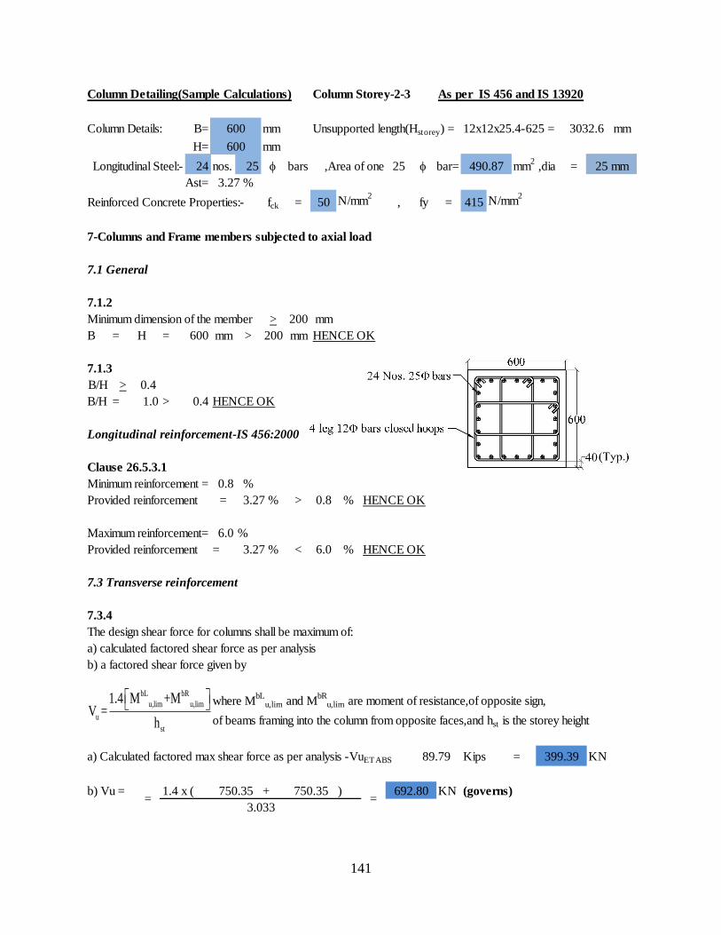
141
Column Detailing(Sample Calculations) Column Storey-2-3 As per IS 456 and IS 13920
Column Details: B= mm Unsupported length(Hstorey) = 12x12x25.4-625 = mm
H= mm
Longitudinal Steel:- 24 nos. 25 bars ,Area of one 25 bar= mm2
,dia =
Ast=
Reinforced Concrete Properties:- fck = 50 N/mm2
, fy = 415 N/mm2
7-Columns and Frame members subjected to axial load
7.1 General
7.1.2
Minimum dimension of the member > 200 mm
B = H = 600 mm > 200 mm HENCE OK
7.1.3
B/H > 0.4
B/H = 1.0 > 0.4 HENCE OK
Longitudinal reinforcement-IS 456:2000
Clause 26.5.3.1
Minimum reinforcement = 0.8 %
Provided reinforcement = > 0.8 % HENCE OK
Maximum reinforcement= 6.0 %
Provided reinforcement = < 6.0 % HENCE OK
7.3 Transverse reinforcement
7.3.4
The design shear force for columns shall be maximum of:
a) calculated factored shear force as per analysis
b) a factored shear force given by
where MbL
u,lim and MbR
u,lim are moment of resistance,of opposite sign,
of beams framing into the column from opposite faces,and hst is the storey height
a) Calculated factored max shear force as per analysis -VuETABS Kips = KN
b) Vu = 1.4 x ( + ) KN (governs)
3.27 %
600 3032.6
600
490.87 25 mm
3.27 %
3.27 %
89.79 399.39
=750.35 750.35
=692.80
3.033
bL bR
u,lim u,lim
u
st
1.4 M +MV =
h
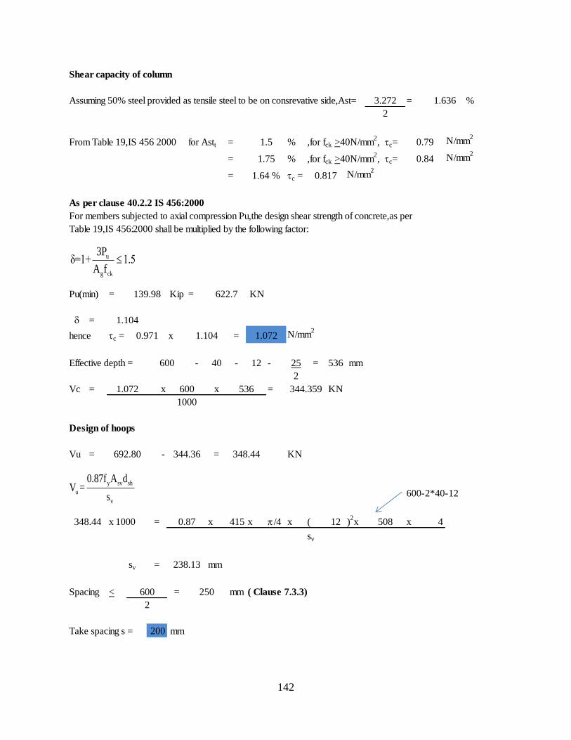
142
Shear capacity of column
Assuming 50% steel provided as tensile steel to be on consrevative side,Ast= = %
From Table 19,IS 456 2000 for Astt = % ,for fck >40N/mm2, tc= N/mm
2
= % ,for fck >40N/mm2, tc= N/mm
2
= tc = N/mm2
As per clause 40.2.2 IS 456:2000
For members subjected to axial compression Pu,the design shear strength of concrete,as per
Table 19,IS 456:2000 shall be multiplied by the following factor:
Pu(min) = Kip = KN
=
hence tc = x = N/mm2
Effective depth = - 40 - 12 - 25 = 536 mm
2
Vc = x x = KN
Design of hoops
Vu = - = KN
600-2*40-12
x 1000 = x 415 x p/4 x ( 12 )2x x 4
sv
sv = mm
Spacing < = mm ( Clause 7.3.3)
Take spacing s = 200 mm
1.64 % 0.817
3.272 1.636
2
1.5 0.79
1.75 0.84
139.98 622.7
1.104
0.971 1.104 1.072
508
600
1.072 600 536 344.359
1000
692.80 344.36 348.44
348.44 0.87
238.13
600 250
2
u
g ck
3Pδ=1+ 1.5
A f
y sv sh
u
v
0.87f A dV =
s
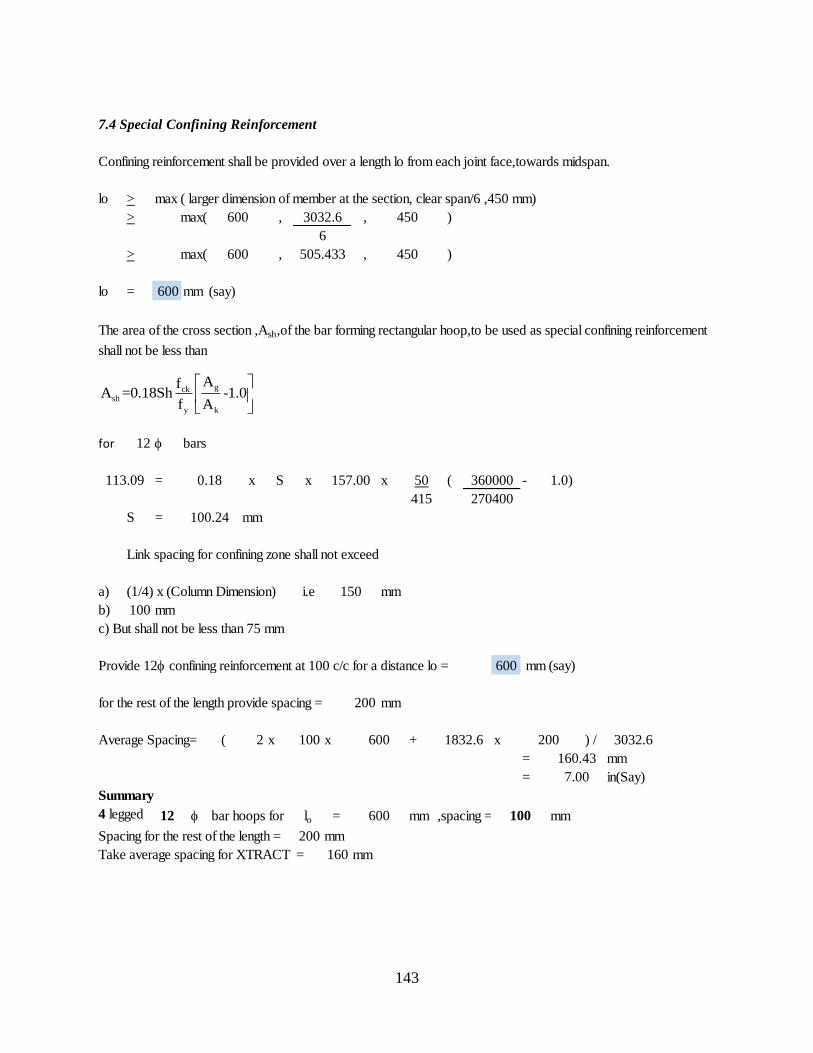
143
7.4 Special Confining Reinforcement
Confining reinforcement shall be provided over a length lo from each joint face,towards midspan.
lo > max ( larger dimension of member at the section, clear span/6 ,450 mm)
> max( , , )
> max( , , )
lo = 600 mm (say)
The area of the cross section ,Ash,of the bar forming rectangular hoop,to be used as special confining reinforcement
shall not be less than
for 12 bars
= x S x x 50 ( - 1.0)
415
S = mm
Link spacing for confining zone shall not exceed
a) (1/4) x (Column Dimension) i.e mm
b) 100 mm
c) But shall not be less than 75 mm
Provide 12 confining reinforcement at 100 c/c for a distance lo = 600 mm (say)
for the rest of the length provide spacing = 200 mm
Average Spacing= ( 2 x 100 x + x ) /
= mm
= in(Say)
Summary
4 legged 12 bar hoops for lo = mm ,spacing = mm
Spacing for the rest of the length = 200 mm
Take average spacing for XTRACT = 160 mm
600 100
113.09 0.18 157.00
600 3032.6
100.24
150
600 1832.6
450
6
600 505.433 450
200 3032.6
160.43
7.00
360000
270400
gcksh
y k
AfA =0.18Sh -1.0
f A
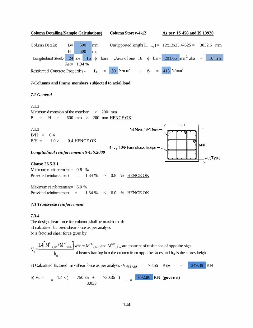
144
Column Detailing(Sample Calculations) Column Storey-4-12 As per IS 456 and IS 13920
Column Details: B= mm Unsupported length(Hstorey) = 12x12x25.4-625 = mm
H= mm
Longitudinal Steel:- 24 nos. 16 bars ,Area of one 16 bar= mm2
,dia =
Ast=
Reinforced Concrete Properties:- fck = 50 N/mm2
, fy = 415 N/mm2
7-Columns and Frame members subjected to axial load
7.1 General
7.1.2
Minimum dimension of the member > 200 mm
B = H = 600 mm > 200 mm HENCE OK
7.1.3
B/H > 0.4
B/H = 1.0 > 0.4 HENCE OK
Longitudinal reinforcement-IS 456:2000
Clause 26.5.3.1
Minimum reinforcement = 0.8 %
Provided reinforcement = > 0.8 % HENCE OK
Maximum reinforcement= 6.0 %
Provided reinforcement = < 6.0 % HENCE OK
7.3 Transverse reinforcement
7.3.4
The design shear force for columns shall be maximum of:
a) calculated factored shear force as per analysis
b) a factored shear force given by
where MbL
u,lim and MbR
u,lim are moment of resistance,of opposite sign,
of beams framing into the column from opposite faces,and hst is the storey height
a) Calculated factored max shear force as per analysis -VuETABS Kips = KN
b) Vu = 1.4 x ( + ) KN (governs)
1.34 %
600 3032.6
600
201.06 16 mm
1.34 %
1.34 %
78.55 349.39
=750.35 750.35
=692.80
3.033
bL bR
u,lim u,lim
u
st
1.4 M +MV =
h
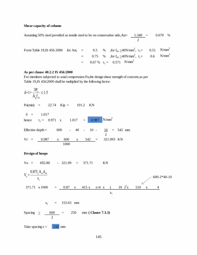
145
Shear capacity of column
Assuming 50% steel provided as tensile steel to be on consrevative side,Ast= = %
From Table 19,IS 456 2000 for Astt = % ,for fck >40N/mm2, tc= N/mm
2
= % ,for fck >40N/mm2, tc= N/mm
2
= tc = N/mm2
As per clause 40.2.2 IS 456:2000
For members subjected to axial compression Pu,the design shear strength of concrete,as per
Table 19,IS 456:2000 shall be multiplied by the following factor:
Pu(min) = Kip = KN
=
hence tc = x = N/mm2
Effective depth = - 40 - 10 - 16 = 542 mm
2
Vc = x x = KN
Design of hoops
Vu = - = KN
600-2*40-10
x 1000 = x 415 x p/4 x ( 10 )2x x 4
sv
sv = mm
Spacing < = mm ( Clause 7.3.3)
Take spacing s = 150 mm
0.67 % 0.571
1.340 0.670
2
0.5 0.51
0.75 0.6
22.74 101.2
1.017
0.971 1.017 0.987
510
600
0.987 600 542 321.093
1000
692.80 321.09 371.71
371.71 0.87
155.63
600 250
2
u
g ck
3Pδ=1+ 1.5
A f
y sv sh
u
v
0.87f A dV =
s
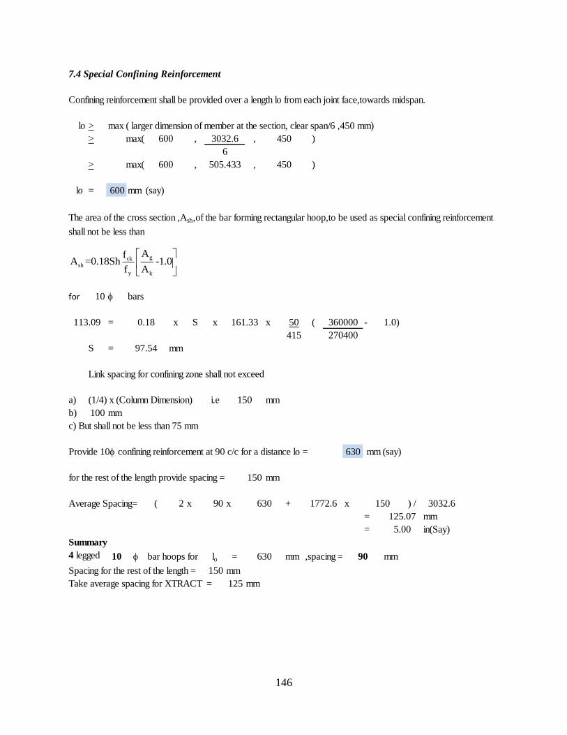
146
7.4 Special Confining Reinforcement
Confining reinforcement shall be provided over a length lo from each joint face,towards midspan.
lo > max ( larger dimension of member at the section, clear span/6 ,450 mm)
> max( , , )
> max( , , )
lo = 600 mm (say)
The area of the cross section ,Ash,of the bar forming rectangular hoop,to be used as special confining reinforcement
shall not be less than
for 10 bars
= x S x x 50 ( - 1.0)
415
S = mm
Link spacing for confining zone shall not exceed
a) (1/4) x (Column Dimension) i.e mm
b) 100 mm
c) But shall not be less than 75 mm
Provide 10 confining reinforcement at 90 c/c for a distance lo = 630 mm (say)
for the rest of the length provide spacing = 150 mm
Average Spacing= ( 2 x 90 x + x ) /
= mm
= in(Say)
Summary
4 legged 10 bar hoops for lo = mm ,spacing = mm
Spacing for the rest of the length = 150 mm
Take average spacing for XTRACT = 125 mm
630 90
113.09 0.18 161.33
600 3032.6
97.54
150
630 1772.6
450
6
600 505.433 450
150 3032.6
125.07
5.00
360000
270400
gcksh
y k
AfA =0.18Sh -1.0
f A
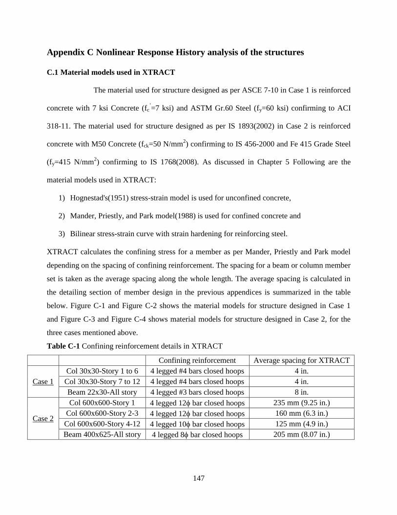
147
Appendix C Nonlinear Response History analysis of the structures
C.1 Material models used in XTRACT
The material used for structure designed as per ASCE 7-10 in Case 1 is reinforced
concrete with 7 ksi Concrete (fc’=7 ksi) and ASTM Gr.60 Steel (fy=60 ksi) confirming to ACI
318-11. The material used for structure designed as per IS 1893(2002) in Case 2 is reinforced
concrete with M50 Concrete (fck=50 N/mm2) confirming to IS 456-2000 and Fe 415 Grade Steel
(fy=415 N/mm2) confirming to IS 1768(2008). As discussed in Chapter 5 Following are the
material models used in XTRACT:
1) Hognestad's(1951) stress-strain model is used for unconfined concrete,
2) Mander, Priestly, and Park model(1988) is used for confined concrete and
3) Bilinear stress-strain curve with strain hardening for reinforcing steel.
XTRACT calculates the confining stress for a member as per Mander, Priestly and Park model
depending on the spacing of confining reinforcement. The spacing for a beam or column member
set is taken as the average spacing along the whole length. The average spacing is calculated in
the detailing section of member design in the previous appendices is summarized in the table
below. Figure C-1 and Figure C-2 shows the material models for structure designed in Case 1
and Figure C-3 and Figure C-4 shows material models for structure designed in Case 2, for the
three cases mentioned above.
Table C-1 Confining reinforcement details in XTRACT
Confining reinforcement Average spacing for XTRACT
Case 1
Col 30x30-Story 1 to 6 4 legged #4 bars closed hoops 4 in.
Col 30x30-Story 7 to 12 4 legged #4 bars closed hoops 4 in.
Beam 22x30-All story 4 legged #3 bars closed hoops 8 in.
Case 2
Col 600x600-Story 1 4 legged 12 bar closed hoops 235 mm (9.25 in.)
Col 600x600-Story 2-3 4 legged 12 bar closed hoops 160 mm (6.3 in.)
Col 600x600-Story 4-12 4 legged 10 bar closed hoops 125 mm (4.9 in.)
Beam 400x625-All story 4 legged 8 bar closed hoops 205 mm (8.07 in.)
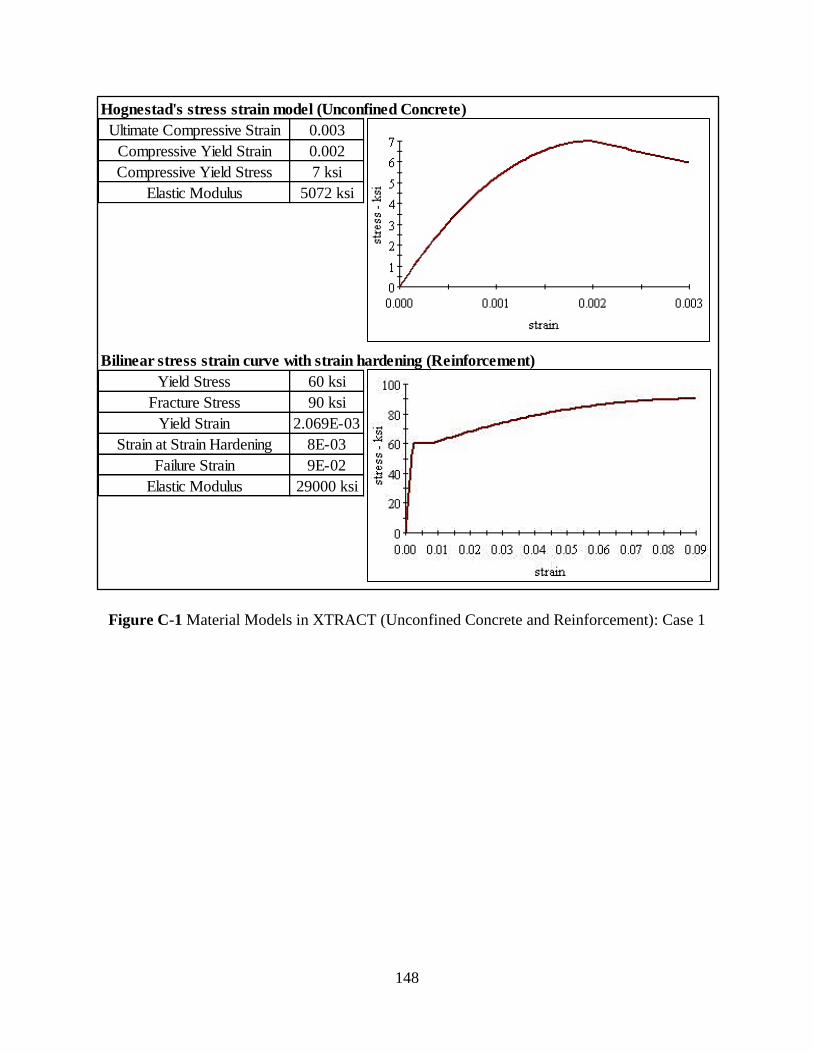
148
Figure C-1 Material Models in XTRACT (Unconfined Concrete and Reinforcement): Case 1
Hognestad's stress strain model (Unconfined Concrete)
0.003
0.002
7 ksi
5072 ksi
Bilinear stress strain curve with strain hardening (Reinforcement)
60 ksi
90 ksi
2.069E-03
8E-03
9E-02
29000 ksi
Elastic Modulus
Strain at Strain Hardening
Failure Strain
Elastic Modulus
Ultimate Compressive Strain
Compressive Yield Strain
Compressive Yield Stress
Yield Stress
Fracture Stress
Yield Strain
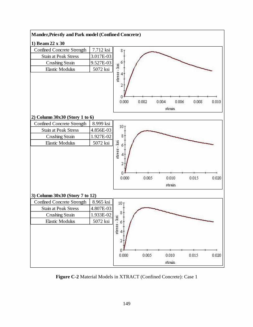
149
Figure C-2 Material Models in XTRACT (Confined Concrete): Case 1
Mander,Priestly and Park model (Confined Concrete)
1) Beam 22 x 30
7.712 ksi
3.017E-03
9.527E-03
5072 ksi
2) Column 30x30 (Story 1 to 6)
8.999 ksi
4.856E-03
1.927E-02
5072 ksi
3) Column 30x30 (Story 7 to 12)
8.965 ksi
4.807E-03
1.933E-02
5072 ksiElastic Modulus
Elastic Modulus
Confined Concrete Strength
Stain at Peak Stress
Confined Concrete Strength
Stain at Peak Stress
Crushing Strain
Crushing Strain
Elastic Modulus
Confined Concrete Strength
Stain at Peak Stress
Crushing Strain
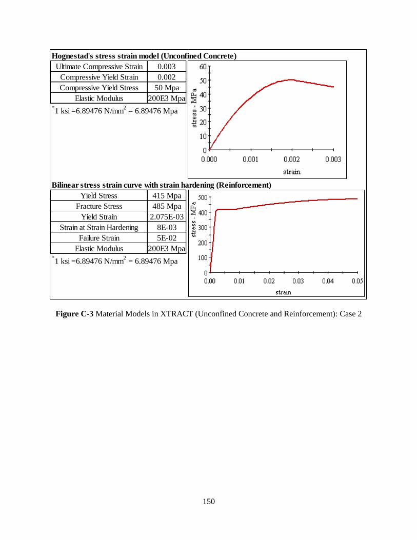
150
Figure C-3 Material Models in XTRACT (Unconfined Concrete and Reinforcement): Case 2
Hognestad's stress strain model (Unconfined Concrete)
0.003
0.002
50 Mpa
200E3 Mpa*1 ksi =6.89476 N/mm
2 = 6.89476 Mpa
Bilinear stress strain curve with strain hardening (Reinforcement)
415 Mpa
485 Mpa
2.075E-03
8E-03
5E-02
200E3 Mpa*1 ksi =6.89476 N/mm
2 = 6.89476 Mpa
Yield Strain
Strain at Strain Hardening
Failure Strain
Elastic Modulus
Ultimate Compressive Strain
Compressive Yield Strain
Compressive Yield Stress
Elastic Modulus
Yield Stress
Fracture Stress
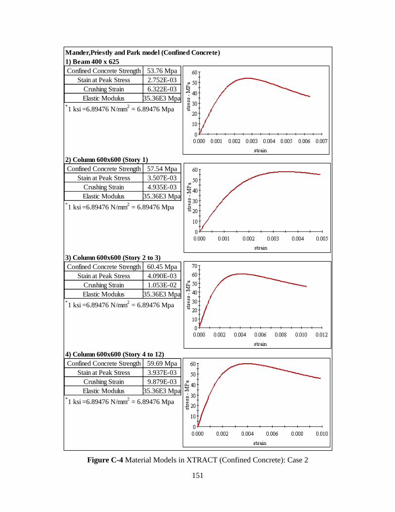
151
Figure C-4 Material Models in XTRACT (Confined Concrete): Case 2
Mander,Priestly and Park model (Confined Concrete)
1) Beam 400 x 625
53.76 Mpa
2.752E-03
6.322E-03
35.36E3 Mpa*1 ksi =6.89476 N/mm
2 = 6.89476 Mpa
2) Column 600x600 (Story 1)
57.54 Mpa
3.507E-03
4.935E-03
35.36E3 Mpa*1 ksi =6.89476 N/mm
2 = 6.89476 Mpa
3) Column 600x600 (Story 2 to 3)
60.45 Mpa
4.090E-03
1.053E-02
35.36E3 Mpa*1 ksi =6.89476 N/mm
2 = 6.89476 Mpa
4) Column 600x600 (Story 4 to 12)
59.69 Mpa
3.937E-03
9.879E-03
35.36E3 Mpa*1 ksi =6.89476 N/mm
2 = 6.89476 Mpa
Crushing Strain
Elastic Modulus
Confined Concrete Strength
Stain at Peak Stress
Crushing Strain
Elastic Modulus
Confined Concrete Strength
Stain at Peak Stress
Crushing Strain
Elastic Modulus
Confined Concrete Strength
Stain at Peak Stress
Crushing Strain
Elastic Modulus
Confined Concrete Strength
Stain at Peak Stress
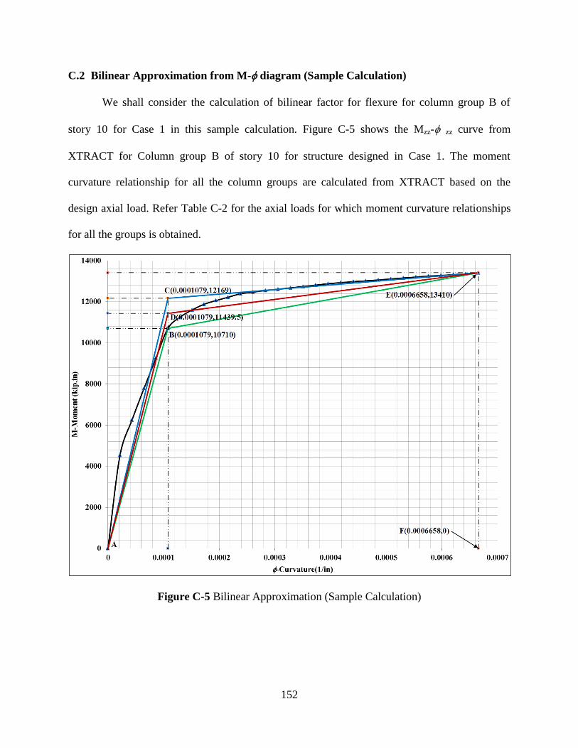
152
C.2 Bilinear Approximation from M- diagram (Sample Calculation)
We shall consider the calculation of bilinear factor for flexure for column group B of
story 10 for Case 1 in this sample calculation. Figure C-5 shows the Mzz- zz curve from
XTRACT for Column group B of story 10 for structure designed in Case 1. The moment
curvature relationship for all the column groups are calculated from XTRACT based on the
design axial load. Refer Table C-2 for the axial loads for which moment curvature relationships
for all the groups is obtained.
Figure C-5 Bilinear Approximation (Sample Calculation)
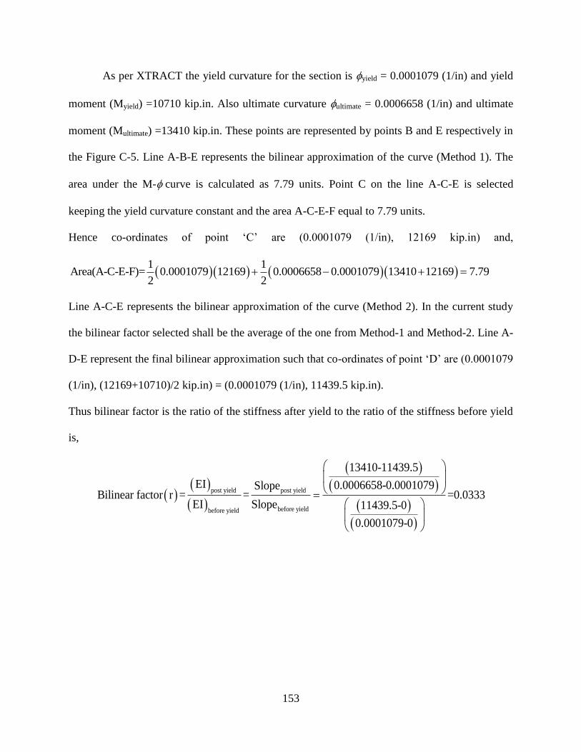
153
As per XTRACT the yield curvature for the section is yield = 0.0001079 (1/in) and yield
moment (Myield) =10710 kip.in. Also ultimate curvature ultimate = 0.0006658 (1/in) and ultimate
moment (Multimate) =13410 kip.in. These points are represented by points B and E respectively in
the Figure C-5. Line A-B-E represents the bilinear approximation of the curve (Method 1). The
area under the M-curve is calculated as 7.79 units. Point C on the line A-C-E is selected
keeping the yield curvature constant and the area A-C-E-F equal to 7.79 units.
Hence co-ordinates of point ‘C’ are (0.0001079 (1/in), 12169 kip.in) and,
1 1
Area(A-C-E-F)= 0.0001079 12169 0.0006658 0.0001079 13410 12169 7.792 2
Line A-C-E represents the bilinear approximation of the curve (Method 2). In the current study
the bilinear factor selected shall be the average of the one from Method-1 and Method-2. Line A-
D-E represent the final bilinear approximation such that co-ordinates of point ‘D’ are (0.0001079
(1/in), (12169+10710)/2 kip.in) = (0.0001079 (1/in), 11439.5 kip.in).
Thus bilinear factor is the ratio of the stiffness after yield to the ratio of the stiffness before yield
is,
post yield post yield
before yieldbefore yield
13410-11439.5
EI 0.0006658-0.0001079SlopeBilinear factor r = = =0.0333
EI Slope 11439.5-0
0.0001079-0
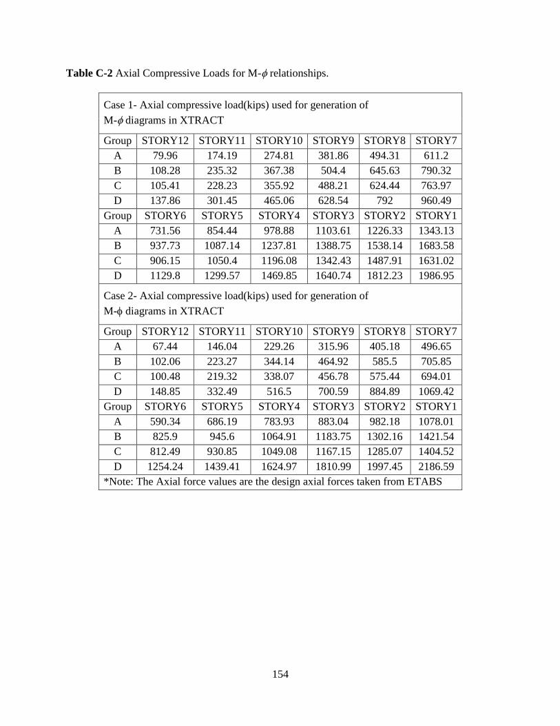
154
Table C-2 Axial Compressive Loads for M-relationships.
Case 1- Axial compressive load(kips) used for generation of
M-diagrams in XTRACT
Group STORY12 STORY11 STORY10 STORY9 STORY8 STORY7
A 79.96 174.19 274.81 381.86 494.31 611.2
B 108.28 235.32 367.38 504.4 645.63 790.32
C 105.41 228.23 355.92 488.21 624.44 763.97
D 137.86 301.45 465.06 628.54 792 960.49
Group STORY6 STORY5 STORY4 STORY3 STORY2 STORY1
A 731.56 854.44 978.88 1103.61 1226.33 1343.13
B 937.73 1087.14 1237.81 1388.75 1538.14 1683.58
C 906.15 1050.4 1196.08 1342.43 1487.91 1631.02
D 1129.8 1299.57 1469.85 1640.74 1812.23 1986.95
Case 2- Axial compressive load(kips) used for generation of
M-diagrams in XTRACT
Group STORY12 STORY11 STORY10 STORY9 STORY8 STORY7
A 67.44 146.04 229.26 315.96 405.18 496.65
B 102.06 223.27 344.14 464.92 585.5 705.85
C 100.48 219.32 338.07 456.78 575.44 694.01
D 148.85 332.49 516.5 700.59 884.89 1069.42
Group STORY6 STORY5 STORY4 STORY3 STORY2 STORY1
A 590.34 686.19 783.93 883.04 982.18 1078.01
B 825.9 945.6 1064.91 1183.75 1302.16 1421.54
C 812.49 930.85 1049.08 1167.15 1285.07 1404.52
D 1254.24 1439.41 1624.97 1810.99 1997.45 2186.59
*Note: The Axial force values are the design axial forces taken from ETABS

155
C.3 Ground Motions-Scaling
We shall consider the scaling of recorded ground motion GM-2 in Case 1. GM-2 is a
ground motion from PEER ground motion database no. NHA#184.Response spectrums for the
un-scaled ground motion component pairs are calculated. The SRSS of the response spectrum for
these un-scaled components is shown as a red line in Figure C-6.The ASCE 7-10 design
spectrum for the structure is also shown in the figure. The fundamental time period for the
structure designed in Case 1, as per Ruaumoko 3D is T=1.75 sec (Mode 1). The ordinates of the
SRSS un-scaled response spectrum are multiplied by a scale factor such that all the ordinates of
the scaled SRSS response spectrum are greater than the corresponding ordinates on ASCE 7
design spectrum for a range of time period (0.2T to 1.5T to be specific). This is an iterative
procedure and a ‘minimum’ scale factor is arrived such that all points on scaled SRSS spectrum
are above the corresponding points on ASCE 7 spectrum between time period 0.2T=0.35sec to
1.5T=2.625sec(refer Figure C-6). In case of GM-2, the scale factor calculated is 1.34. The final
ground motion component pair to be applied in Ruaumoko for GM-2 is obtained by multiplying
the accelerograms with a single scale factor of 1.34.
Further in Case 1, three ground motions are considered GM-1(Artificial) and GM-
2, 3(Recorded-Scaled).The same procedure for scaling described as above is considered and a we
arrive at a scaled SRSS response spectrum for GM-3.SRSS response spectrum for the artificial
ground motion GM-1 is obtained by taking the SRSS of the response spectrum of the orthogonal
component pair. The average of the three SRSS spectra’s of the three ground motion is
calculated for all the ordinates and checked if greater than the corresponding ordinate on ASCE 7
design spectrum between time range of 0.2T to 1.5T secs. If the average ordinate falls below the
corresponding ordinate for ASCE 7 spectrum the scale factor for individual ground motions can
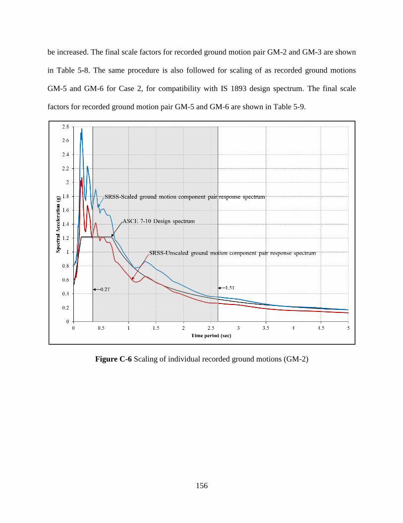
156
be increased. The final scale factors for recorded ground motion pair GM-2 and GM-3 are shown
in Table 5-8. The same procedure is also followed for scaling of as recorded ground motions
GM-5 and GM-6 for Case 2, for compatibility with IS 1893 design spectrum. The final scale
factors for recorded ground motion pair GM-5 and GM-6 are shown in Table 5-9.
Figure C-6 Scaling of individual recorded ground motions (GM-2)
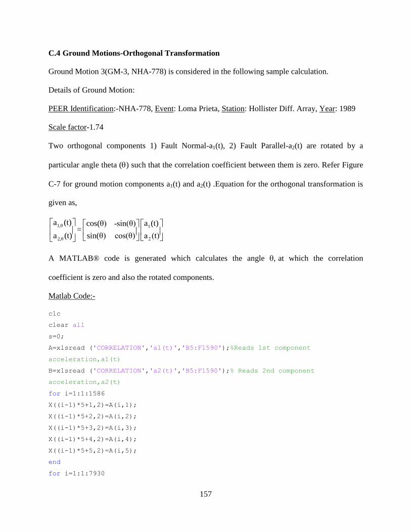
157
C.4 Ground Motions-Orthogonal Transformation
Ground Motion 3(GM-3, NHA-778) is considered in the following sample calculation.
Details of Ground Motion:
PEER Identification:-NHA-778, Event: Loma Prieta, Station: Hollister Diff. Array, Year: 1989
Scale factor-1.74
Two orthogonal components 1) Fault Normal-a1(t), 2) Fault Parallel-a2(t) are rotated by a
particular angle theta () such that the correlation coefficient between them is zero. Refer Figure
C-7 for ground motion components a1(t) and a2(t) .Equation for the orthogonal transformation is
given as,
1,θ 1
2,θ 2
a (t) a (t)cos(θ) -sin(θ)=
a (t) sin(θ) cos(θ) a (t)
A MATLAB® code is generated which calculates the angle at which the correlation
coefficient is zero and also the rotated components.
Matlab Code:-
clc
clear all
s=0;
A=xlsread ('CORRELATION','a1(t)','B5:F1590');%Reads 1st component
acceleration,a1(t)
B=xlsread ('CORRELATION','a2(t)','B5:F1590');% Reads 2nd component
acceleration,a2(t)
for i=1:1:1586
X((i-1)*5+1,2)=A(i,1);
X((i-1)*5+2,2)=A(i,2);
X((i-1)*5+3,2)=A(i,3);
X((i-1)*5+4,2)=A(i,4);
X((i-1)*5+5,2)=A(i,5);
end
for i=1:1:7930
158
X(i,1)=0.005*(i-1);
end
for i=1:1:1586
Y((i-1)*5+1,2)=B(i,1);
Y((i-1)*5+2,2)=B(i,2);
Y((i-1)*5+3,2)=B(i,3);
Y((i-1)*5+4,2)=B(i,4);
Y((i-1)*5+5,2)=B(i,5);
end
for i=1:1:7930
Y(i,1)=0.005*(i-1);
end
P=X;
Q=Y;
for a=0:0.25:90%Loop for transformation for all angles (0 to 90 degrees)
P(:,2)=X(:,2)*cos(a*pi/180)+Y(:,2)*sin(a*pi/180);
Q(:,2)=-X(:,2)*sin(a*pi/180)+Y(:,2)*cos(a*pi/180);
r=corr2(P(:,2),Q(:,2));
s=s+1;
R(s,1)=a;
R(s,2)=r;
end
R(:,3)=abs(R(:,2));
min(R(:,3));
for i=0:0.25:90
if R((i/0.25+1),3)-min(R(:,3))==0
R((i/0.25+1),4)=min(R(:,3));
else
R((i/0.25+1),4)=0;
end
end
W=xlsread('CORRELATION','a,theta(t)','J2');%Reads scale factor
a=R(find(R(:,4)),1);%Reads angle corresponding to correlation coefficient-
zero
P(:,2)=X(:,2)*cos(a*pi/180)+Y(:,2)*sin(a*pi/180);
P(:,2)=W*P(:,2%Array P stores a1,theta(t) for correlation coefficient=0
Q(:,2)=-X(:,2)*sin(a*pi/180)+Y(:,2)*cos(a*pi/180);
Q(:,2)=W*Q(:,2); );%Array Q stores a2,theta(t) for correlation coefficient=0
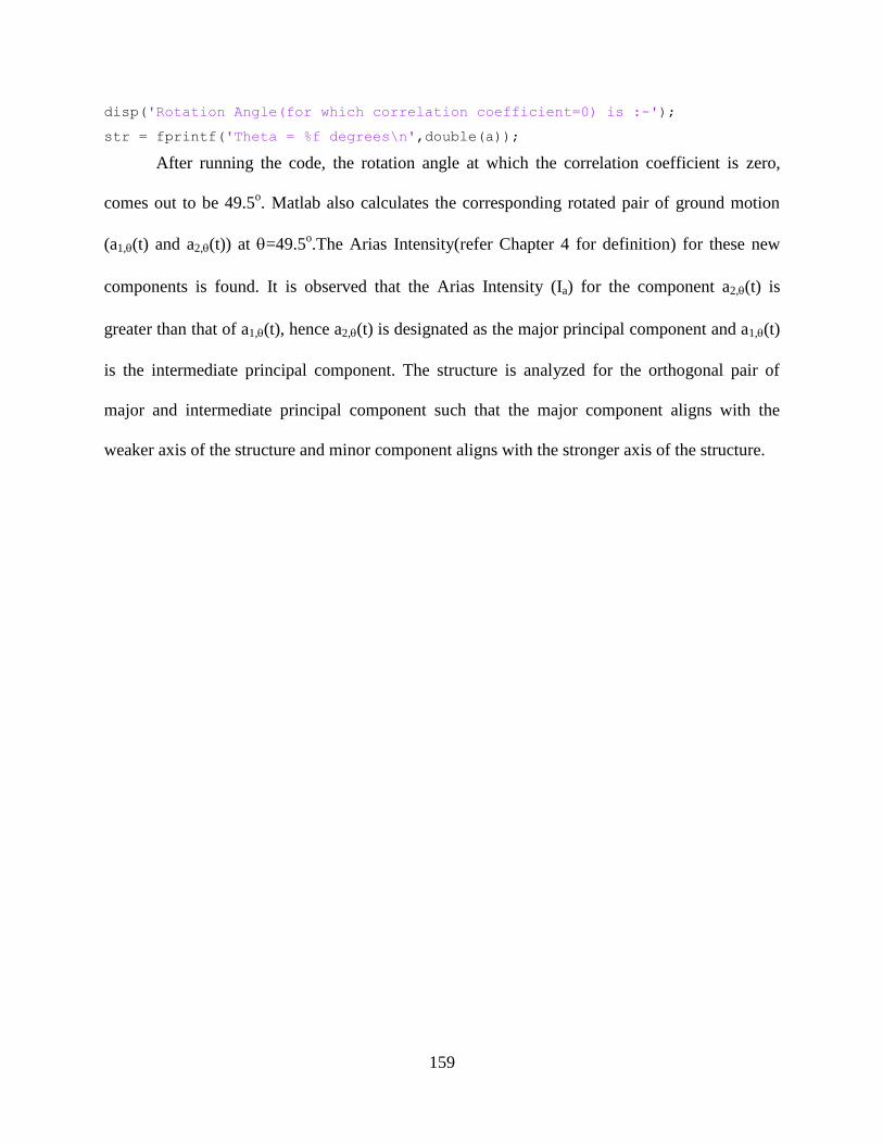
159
disp('Rotation Angle(for which correlation coefficient=0) is :-');
str = fprintf('Theta = %f degrees\n',double(a));
After running the code, the rotation angle at which the correlation coefficient is zero,
comes out to be 49.5o. Matlab also calculates the corresponding rotated pair of ground motion
(a1,(t) and a2,(t)) at =49.5o.The Arias Intensity(refer Chapter 4 for definition) for these new
components is found. It is observed that the Arias Intensity (Ia) for the component a2,(t) is
greater than that of a1,(t), hence a2,(t) is designated as the major principal component and a1,(t)
is the intermediate principal component. The structure is analyzed for the orthogonal pair of
major and intermediate principal component such that the major component aligns with the
weaker axis of the structure and minor component aligns with the stronger axis of the structure.
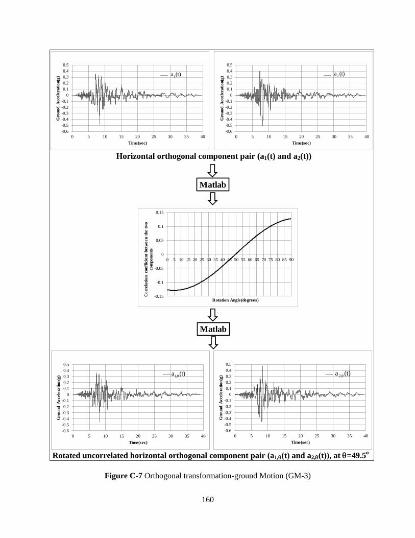
160
Figure C-7 Orthogonal transformation-ground Motion (GM-3)
-0.6
-0.5
-0.4
-0.3
-0.2
-0.1
0
0.1
0.2
0.3
0.4
0.5
0 5 10 15 20 25 30 35 40
Gro
und A
ccele
rati
on(g
)
Time(sec)
1a (t)
-0.6
-0.5
-0.4
-0.3
-0.2
-0.1
0
0.1
0.2
0.3
0.4
0.5
0 5 10 15 20 25 30 35 40
Gro
und A
ccele
rati
on(g
)
Time(sec)
2a (t)
-0.15
-0.1
-0.05
0
0.05
0.1
0.15
0 5 10 15 20 25 30 35 40 45 50 55 60 65 70 75 80 85 90
Corr
ela
tion co
eff
icie
nt
betw
een t
he t
wo
com
ponents
Rotation Angle(degrees)
-0.6
-0.5
-0.4
-0.3
-0.2
-0.1
0
0.1
0.2
0.3
0.4
0.5
0 5 10 15 20 25 30 35 40
Gro
und A
ccele
rati
on(g
)
Time(sec)
Horizontal orthogonal component pair (a1(t) and a2(t))
-0.6
-0.5
-0.4
-0.3
-0.2
-0.1
0
0.1
0.2
0.3
0.4
0.5
0 5 10 15 20 25 30 35 40
Gro
und A
ccele
rati
on(g
)
Time(sec)
1,θa (t) 2,θa (t)
Matlab
Matlab
Rotated uncorrelated horizontal orthogonal component pair (a1,(t) and a2,(t)), at =49.5o
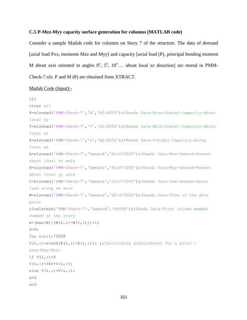
161
C.5 P-Mzz-Myy capacity surface generation for columns (MATLAB code)
Consider a sample Matlab code for columns on Story 7 of the structure. The data of demand
[axial load Pxx, moments Mzz and Myy] and capacity [axial load (P), principal bending moment
M about axis oriented in angles 0o, 5
o, 10
o…. about local zz direction] are stored in PMM-
Check-7.xls. P and M () are obtained from XTRACT.
Matlab Code (Input):-
clc
clear all
X=xlsread('PMM-Check-7','X','A2:BU52');%Reads Data-Mcos(theta)-Capacity-About
local yy
Y=xlsread('PMM-Check-7','Y','A2:BU52');%Reads Data-Msin(theta)-Capacity-About
local zz
Z=xlsread('PMM-Check-7','Z','A2:BU52');%Reads Data-P(kips)-Capacity-Along
local xx
A=xlsread('PMM-Check-7','Demand','A2:A73009');%Reads Data-Mzz-Demand-Moment
about local zz axis
B=xlsread('PMM-Check-7','Demand','B2:B73009');%Reads Data-Myy-Demand-Moment
about local yy axis
C=xlsread('PMM-Check-7','Demand','C2:C73009');%Reads Data-Pxx-Demand-Axial
load along xx axis
W=xlsread('PMM-Check-7','Demand','d2:d73009');%Reads Data-Time of the data
point
c1=xlsread('PMM-Check-7','Demand','G4:G4');%Reads Data-First column member
number of the story
w=(max(W)/(W(2,1)-W(1,1)))+1;
S=0;
for i=1:1:73008
V(i,:)=atand(B(i,:)/A(i,:)); );%Calculates angle(theta) for a point =
atan(Myy/Mzz)
if V(i,:)<0
V(i,:)=360+V(i,:);
else V(i,:)=V(i,:);
end
end

162
for i=1:1:73008
t(i,1)=floor(V(i,:)/5)+1;
if t(i,1)-72==0
t(i,1)=71;
else
t(i,1)=t(i,1);
end
t(i,2)=t(i,1)+1;
end
for i=1:1:73
for j=1:1:51
M(j,i)=sqrt(X(j,i)^2+Y(j,i)^2);
end
end
for i=1:73008
N(i,:)=sqrt(A(i,:)^2+B(i,:)^2);
end
for i=1:1:73008
a=t(i,1)*5-5;
c=t(i,2)*5-5;
b=V(i,:);
for j=1:1:51
Z1(j,:)=(Z(j,t(i,1))*(b-c)+Z(j,t(i,2))*(a-b))/(a-c);
M1(j,:)=(M(j,t(i,1))*(b-c)+M(j,t(i,2))*(a-b))/(a-c);
end
for j=1:1:51
p1=C(i,:);
m1=N(i,:); %Demand moment for a point with axial load p1
temp(j,:)=abs(p1-Z1(j,:));
end
[temp2(:,1) temp2(:,2)]=sort(temp);
a=Z1(temp2(1,2),1);
c=Z1(temp2(2,2),1);
b=p1;
l=M1(temp2(1,2),1);
n=M1(temp2(2,2),1);
m=(l*(b-c)+n*(a-b))/(a-c); %capacity moment for a point with axial load p1
if m1<m
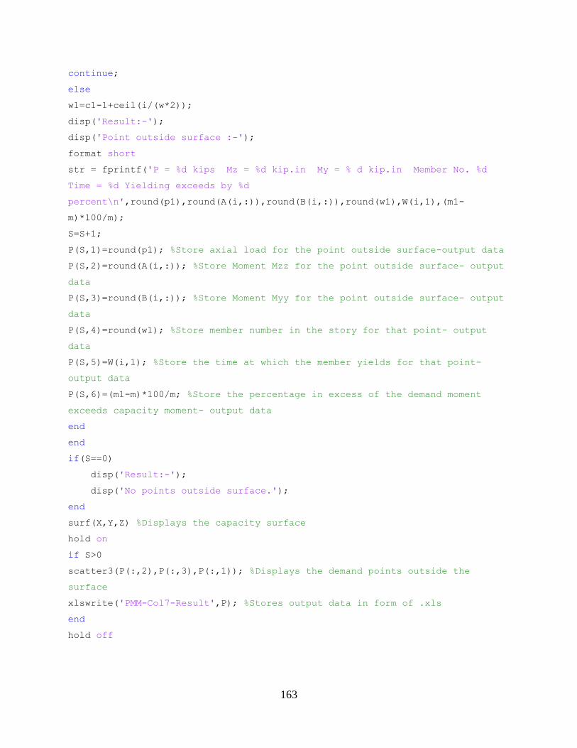
163
continue;
else
w1=c1-1+ceil(i/(w*2));
disp('Result:-');
disp('Point outside surface :-');
format short
str = fprintf('P = %d kips Mz = %d kip.in My = % d kip.in Member No. %d
Time = %d Yielding exceeds by %d
percent\n',round(p1),round(A(i,:)),round(B(i,:)),round(w1),W(i,1),(m1-
m)*100/m);
S=S+1;
P(S,1)=round(p1); %Store axial load for the point outside surface-output data
P(S,2)=round(A(i,:)); %Store Moment Mzz for the point outside surface- output
data
P(S,3)=round(B(i,:)); %Store Moment Myy for the point outside surface- output
data
P(S,4)=round(w1); %Store member number in the story for that point- output
data
P(S,5)=W(i,1); %Store the time at which the member yields for that point-
output data
P(S,6)=(m1-m)*100/m; %Store the percentage in excess of the demand moment
exceeds capacity moment- output data
end
end
if(S==0)
disp('Result:-');
disp('No points outside surface.');
end
surf(X,Y,Z) %Displays the capacity surface
hold on
if S>0
scatter3(P(:,2),P(:,3),P(:,1)); %Displays the demand points outside the
surface
xlswrite('PMM-Col7-Result',P); %Stores output data in form of .xls
end
hold off

164
C.6 Ruaumoko 3D Input file
C.6.1 Input file for structure designed as per ASCE 7 seismic provisions (Case 1)
Presented below is the input file for nonlinear response history analysis for structure,
subjected to GM-2 ground motion for Case 1.The file is analyzed in RUAUMOKO3D.exe
Ruaumoko Input:
ASCE7 12 STOREY OFFICE BUILDING ! Description of analysis (Units Kip,in)
2 1 1 2 2 2 0 0 0 0 ! Analysis Options
1 0 0 0 0 1 ! Earthquake Excitation Component in X and Z
312 744 54 10 1 10 386.088 5 5 0.005 25 1 ! Frame Control Parameters
5 5 5 10 23 23 23 0 13 2 1 0 ! Output intervals and Plotting Control
Parameters
0.8666 0 -0.8666 -0.177 1 -0.177 ! Plot Axes Transformation
100 2 0.00001 0.0 0.0 0.0 0.0 0.0 0.0 0.0 ! Iteration Control and Wave
Velocities
Nodes
1 0 0 0 1 1 1 1 1 1 0 0
2 288 0 0 1 1 1 1 1 1 0 0
3 576 0 0 1 1 1 1 1 1 0 0
4 864 0 0 1 1 1 1 1 1 0 0
5 1152 0 0 1 1 1 1 1 1 0 0
6 1440 0 0 1 1 1 1 1 1 0 0
7 0 0 288 1 1 1 1 1 1 0 0
8 288 0 288 1 1 1 1 1 1 0 0
9 576 0 288 1 1 1 1 1 1 0 0
10 864 0 288 1 1 1 1 1 1 0 0
11 1152 0 288 1 1 1 1 1 1 0 0
12 1440 0 288 1 1 1 1 1 1 0 0
13 0 0 576 1 1 1 1 1 1 0 0
14 288 0 576 1 1 1 1 1 1 0 0
15 576 0 576 1 1 1 1 1 1 0 0
16 864 0 576 1 1 1 1 1 1 0 0
17 1152 0 576 1 1 1 1 1 1 0 0
18 1440 0 576 1 1 1 1 1 1 0 0
19 0 0 864 1 1 1 1 1 1 0 0
20 288 0 864 1 1 1 1 1 1 0 0
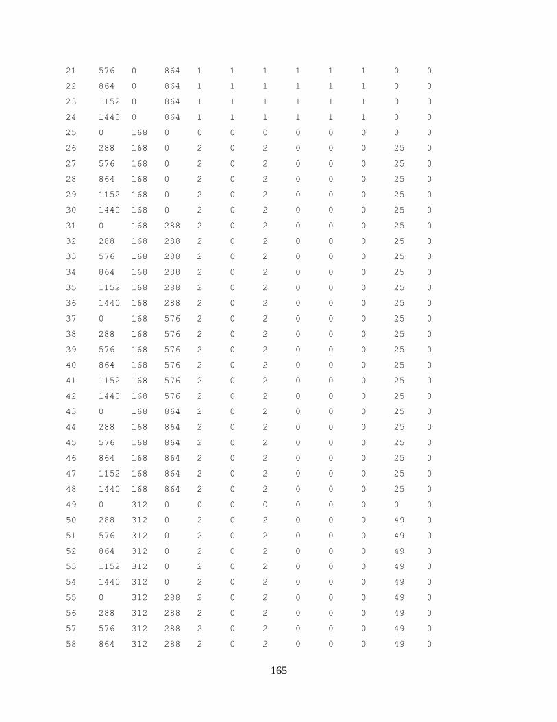
165
21 576 0 864 1 1 1 1 1 1 0 0
22 864 0 864 1 1 1 1 1 1 0 0
23 1152 0 864 1 1 1 1 1 1 0 0
24 1440 0 864 1 1 1 1 1 1 0 0
25 0 168 0 0 0 0 0 0 0 0 0
26 288 168 0 2 0 2 0 0 0 25 0
27 576 168 0 2 0 2 0 0 0 25 0
28 864 168 0 2 0 2 0 0 0 25 0
29 1152 168 0 2 0 2 0 0 0 25 0
30 1440 168 0 2 0 2 0 0 0 25 0
31 0 168 288 2 0 2 0 0 0 25 0
32 288 168 288 2 0 2 0 0 0 25 0
33 576 168 288 2 0 2 0 0 0 25 0
34 864 168 288 2 0 2 0 0 0 25 0
35 1152 168 288 2 0 2 0 0 0 25 0
36 1440 168 288 2 0 2 0 0 0 25 0
37 0 168 576 2 0 2 0 0 0 25 0
38 288 168 576 2 0 2 0 0 0 25 0
39 576 168 576 2 0 2 0 0 0 25 0
40 864 168 576 2 0 2 0 0 0 25 0
41 1152 168 576 2 0 2 0 0 0 25 0
42 1440 168 576 2 0 2 0 0 0 25 0
43 0 168 864 2 0 2 0 0 0 25 0
44 288 168 864 2 0 2 0 0 0 25 0
45 576 168 864 2 0 2 0 0 0 25 0
46 864 168 864 2 0 2 0 0 0 25 0
47 1152 168 864 2 0 2 0 0 0 25 0
48 1440 168 864 2 0 2 0 0 0 25 0
49 0 312 0 0 0 0 0 0 0 0 0
50 288 312 0 2 0 2 0 0 0 49 0
51 576 312 0 2 0 2 0 0 0 49 0
52 864 312 0 2 0 2 0 0 0 49 0
53 1152 312 0 2 0 2 0 0 0 49 0
54 1440 312 0 2 0 2 0 0 0 49 0
55 0 312 288 2 0 2 0 0 0 49 0
56 288 312 288 2 0 2 0 0 0 49 0
57 576 312 288 2 0 2 0 0 0 49 0
58 864 312 288 2 0 2 0 0 0 49 0
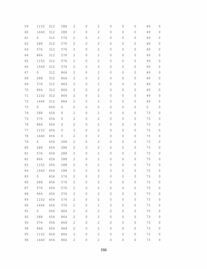
166
59 1152 312 288 2 0 2 0 0 0 49 0
60 1440 312 288 2 0 2 0 0 0 49 0
61 0 312 576 2 0 2 0 0 0 49 0
62 288 312 576 2 0 2 0 0 0 49 0
63 576 312 576 2 0 2 0 0 0 49 0
64 864 312 576 2 0 2 0 0 0 49 0
65 1152 312 576 2 0 2 0 0 0 49 0
66 1440 312 576 2 0 2 0 0 0 49 0
67 0 312 864 2 0 2 0 0 0 49 0
68 288 312 864 2 0 2 0 0 0 49 0
69 576 312 864 2 0 2 0 0 0 49 0
70 864 312 864 2 0 2 0 0 0 49 0
71 1152 312 864 2 0 2 0 0 0 49 0
72 1440 312 864 2 0 2 0 0 0 49 0
73 0 456 0 0 0 0 0 0 0 0 0
74 288 456 0 2 0 2 0 0 0 73 0
75 576 456 0 2 0 2 0 0 0 73 0
76 864 456 0 2 0 2 0 0 0 73 0
77 1152 456 0 2 0 2 0 0 0 73 0
78 1440 456 0 2 0 2 0 0 0 73 0
79 0 456 288 2 0 2 0 0 0 73 0
80 288 456 288 2 0 2 0 0 0 73 0
81 576 456 288 2 0 2 0 0 0 73 0
82 864 456 288 2 0 2 0 0 0 73 0
83 1152 456 288 2 0 2 0 0 0 73 0
84 1440 456 288 2 0 2 0 0 0 73 0
85 0 456 576 2 0 2 0 0 0 73 0
86 288 456 576 2 0 2 0 0 0 73 0
87 576 456 576 2 0 2 0 0 0 73 0
88 864 456 576 2 0 2 0 0 0 73 0
89 1152 456 576 2 0 2 0 0 0 73 0
90 1440 456 576 2 0 2 0 0 0 73 0
91 0 456 864 2 0 2 0 0 0 73 0
92 288 456 864 2 0 2 0 0 0 73 0
93 576 456 864 2 0 2 0 0 0 73 0
94 864 456 864 2 0 2 0 0 0 73 0
95 1152 456 864 2 0 2 0 0 0 73 0
96 1440 456 864 2 0 2 0 0 0 73 0
167
97 0 600 0 0 0 0 0 0 0 0 0
98 288 600 0 2 0 2 0 0 0 97 0
99 576 600 0 2 0 2 0 0 0 97 0
100 864 600 0 2 0 2 0 0 0 97 0
101 1152 600 0 2 0 2 0 0 0 97 0
102 1440 600 0 2 0 2 0 0 0 97 0
103 0 600 288 2 0 2 0 0 0 97 0
104 288 600 288 2 0 2 0 0 0 97 0
105 576 600 288 2 0 2 0 0 0 97 0
106 864 600 288 2 0 2 0 0 0 97 0
107 1152 600 288 2 0 2 0 0 0 97 0
108 1440 600 288 2 0 2 0 0 0 97 0
109 0 600 576 2 0 2 0 0 0 97 0
110 288 600 576 2 0 2 0 0 0 97 0
111 576 600 576 2 0 2 0 0 0 97 0
112 864 600 576 2 0 2 0 0 0 97 0
113 1152 600 576 2 0 2 0 0 0 97 0
114 1440 600 576 2 0 2 0 0 0 97 0
115 0 600 864 2 0 2 0 0 0 97 0
116 288 600 864 2 0 2 0 0 0 97 0
117 576 600 864 2 0 2 0 0 0 97 0
118 864 600 864 2 0 2 0 0 0 97 0
119 1152 600 864 2 0 2 0 0 0 97 0
120 1440 600 864 2 0 2 0 0 0 97 0
121 0 744 0 0 0 0 0 0 0 0 0
122 288 744 0 2 0 2 0 0 0 121 0
123 576 744 0 2 0 2 0 0 0 121 0
124 864 744 0 2 0 2 0 0 0 121 0
125 1152 744 0 2 0 2 0 0 0 121 0
126 1440 744 0 2 0 2 0 0 0 121 0
127 0 744 288 2 0 2 0 0 0 121 0
128 288 744 288 2 0 2 0 0 0 121 0
129 576 744 288 2 0 2 0 0 0 121 0
130 864 744 288 2 0 2 0 0 0 121 0
131 1152 744 288 2 0 2 0 0 0 121 0
132 1440 744 288 2 0 2 0 0 0 121 0
133 0 744 576 2 0 2 0 0 0 121 0
134 288 744 576 2 0 2 0 0 0 121 0
168
135 576 744 576 2 0 2 0 0 0 121 0
136 864 744 576 2 0 2 0 0 0 121 0
137 1152 744 576 2 0 2 0 0 0 121 0
138 1440 744 576 2 0 2 0 0 0 121 0
139 0 744 864 2 0 2 0 0 0 121 0
140 288 744 864 2 0 2 0 0 0 121 0
141 576 744 864 2 0 2 0 0 0 121 0
142 864 744 864 2 0 2 0 0 0 121 0
143 1152 744 864 2 0 2 0 0 0 121 0
144 1440 744 864 2 0 2 0 0 0 121 0
145 0 888 0 0 0 0 0 0 0 0 0
146 288 888 0 2 0 2 0 0 0 145 0
147 576 888 0 2 0 2 0 0 0 145 0
148 864 888 0 2 0 2 0 0 0 145 0
149 1152 888 0 2 0 2 0 0 0 145 0
150 1440 888 0 2 0 2 0 0 0 145 0
151 0 888 288 2 0 2 0 0 0 145 0
152 288 888 288 2 0 2 0 0 0 145 0
153 576 888 288 2 0 2 0 0 0 145 0
154 864 888 288 2 0 2 0 0 0 145 0
155 1152 888 288 2 0 2 0 0 0 145 0
156 1440 888 288 2 0 2 0 0 0 145 0
157 0 888 576 2 0 2 0 0 0 145 0
158 288 888 576 2 0 2 0 0 0 145 0
159 576 888 576 2 0 2 0 0 0 145 0
160 864 888 576 2 0 2 0 0 0 145 0
161 1152 888 576 2 0 2 0 0 0 145 0
162 1440 888 576 2 0 2 0 0 0 145 0
163 0 888 864 2 0 2 0 0 0 145 0
164 288 888 864 2 0 2 0 0 0 145 0
165 576 888 864 2 0 2 0 0 0 145 0
166 864 888 864 2 0 2 0 0 0 145 0
167 1152 888 864 2 0 2 0 0 0 145 0
168 1440 888 864 2 0 2 0 0 0 145 0
169 0 1032 0 0 0 0 0 0 0 0 0
170 288 1032 0 2 0 2 0 0 0 169 0
171 576 1032 0 2 0 2 0 0 0 169 0
172 864 1032 0 2 0 2 0 0 0 169 0
169
173 1152 1032 0 2 0 2 0 0 0 169 0
174 1440 1032 0 2 0 2 0 0 0 169 0
175 0 1032 288 2 0 2 0 0 0 169 0
176 288 1032 288 2 0 2 0 0 0 169 0
177 576 1032 288 2 0 2 0 0 0 169 0
178 864 1032 288 2 0 2 0 0 0 169 0
179 1152 1032 288 2 0 2 0 0 0 169 0
180 1440 1032 288 2 0 2 0 0 0 169 0
181 0 1032 576 2 0 2 0 0 0 169 0
182 288 1032 576 2 0 2 0 0 0 169 0
183 576 1032 576 2 0 2 0 0 0 169 0
184 864 1032 576 2 0 2 0 0 0 169 0
185 1152 1032 576 2 0 2 0 0 0 169 0
186 1440 1032 576 2 0 2 0 0 0 169 0
187 0 1032 864 2 0 2 0 0 0 169 0
188 288 1032 864 2 0 2 0 0 0 169 0
189 576 1032 864 2 0 2 0 0 0 169 0
190 864 1032 864 2 0 2 0 0 0 169 0
191 1152 1032 864 2 0 2 0 0 0 169 0
192 1440 1032 864 2 0 2 0 0 0 169 0
193 0 1176 0 0 0 0 0 0 0 0 0
194 288 1176 0 2 0 2 0 0 0 193 0
195 576 1176 0 2 0 2 0 0 0 193 0
196 864 1176 0 2 0 2 0 0 0 193 0
197 1152 1176 0 2 0 2 0 0 0 193 0
198 1440 1176 0 2 0 2 0 0 0 193 0
199 0 1176 288 2 0 2 0 0 0 193 0
200 288 1176 288 2 0 2 0 0 0 193 0
201 576 1176 288 2 0 2 0 0 0 193 0
202 864 1176 288 2 0 2 0 0 0 193 0
203 1152 1176 288 2 0 2 0 0 0 193 0
204 1440 1176 288 2 0 2 0 0 0 193 0
205 0 1176 576 2 0 2 0 0 0 193 0
206 288 1176 576 2 0 2 0 0 0 193 0
207 576 1176 576 2 0 2 0 0 0 193 0
208 864 1176 576 2 0 2 0 0 0 193 0
209 1152 1176 576 2 0 2 0 0 0 193 0
210 1440 1176 576 2 0 2 0 0 0 193 0
170
211 0 1176 864 2 0 2 0 0 0 193 0
212 288 1176 864 2 0 2 0 0 0 193 0
213 576 1176 864 2 0 2 0 0 0 193 0
214 864 1176 864 2 0 2 0 0 0 193 0
215 1152 1176 864 2 0 2 0 0 0 193 0
216 1440 1176 864 2 0 2 0 0 0 193 0
217 0 1320 0 0 0 0 0 0 0 0 0
218 288 1320 0 2 0 2 0 0 0 217 0
219 576 1320 0 2 0 2 0 0 0 217 0
220 864 1320 0 2 0 2 0 0 0 217 0
221 1152 1320 0 2 0 2 0 0 0 217 0
222 1440 1320 0 2 0 2 0 0 0 217 0
223 0 1320 288 2 0 2 0 0 0 217 0
224 288 1320 288 2 0 2 0 0 0 217 0
225 576 1320 288 2 0 2 0 0 0 217 0
226 864 1320 288 2 0 2 0 0 0 217 0
227 1152 1320 288 2 0 2 0 0 0 217 0
228 1440 1320 288 2 0 2 0 0 0 217 0
229 0 1320 576 2 0 2 0 0 0 217 0
230 288 1320 576 2 0 2 0 0 0 217 0
231 576 1320 576 2 0 2 0 0 0 217 0
232 864 1320 576 2 0 2 0 0 0 217 0
233 1152 1320 576 2 0 2 0 0 0 217 0
234 1440 1320 576 2 0 2 0 0 0 217 0
235 0 1320 864 2 0 2 0 0 0 217 0
236 288 1320 864 2 0 2 0 0 0 217 0
237 576 1320 864 2 0 2 0 0 0 217 0
238 864 1320 864 2 0 2 0 0 0 217 0
239 1152 1320 864 2 0 2 0 0 0 217 0
240 1440 1320 864 2 0 2 0 0 0 217 0
241 0 1464 0 0 0 0 0 0 0 0 0
242 288 1464 0 2 0 2 0 0 0 241 0
243 576 1464 0 2 0 2 0 0 0 241 0
244 864 1464 0 2 0 2 0 0 0 241 0
245 1152 1464 0 2 0 2 0 0 0 241 0
246 1440 1464 0 2 0 2 0 0 0 241 0
247 0 1464 288 2 0 2 0 0 0 241 0
248 288 1464 288 2 0 2 0 0 0 241 0
171
249 576 1464 288 2 0 2 0 0 0 241 0
250 864 1464 288 2 0 2 0 0 0 241 0
251 1152 1464 288 2 0 2 0 0 0 241 0
252 1440 1464 288 2 0 2 0 0 0 241 0
253 0 1464 576 2 0 2 0 0 0 241 0
254 288 1464 576 2 0 2 0 0 0 241 0
255 576 1464 576 2 0 2 0 0 0 241 0
256 864 1464 576 2 0 2 0 0 0 241 0
257 1152 1464 576 2 0 2 0 0 0 241 0
258 1440 1464 576 2 0 2 0 0 0 241 0
259 0 1464 864 2 0 2 0 0 0 241 0
260 288 1464 864 2 0 2 0 0 0 241 0
261 576 1464 864 2 0 2 0 0 0 241 0
262 864 1464 864 2 0 2 0 0 0 241 0
263 1152 1464 864 2 0 2 0 0 0 241 0
264 1440 1464 864 2 0 2 0 0 0 241 0
265 0 1608 0 0 0 0 0 0 0 0 0
266 288 1608 0 2 0 2 0 0 0 265 0
267 576 1608 0 2 0 2 0 0 0 265 0
268 864 1608 0 2 0 2 0 0 0 265 0
269 1152 1608 0 2 0 2 0 0 0 265 0
270 1440 1608 0 2 0 2 0 0 0 265 0
271 0 1608 288 2 0 2 0 0 0 265 0
272 288 1608 288 2 0 2 0 0 0 265 0
273 576 1608 288 2 0 2 0 0 0 265 0
274 864 1608 288 2 0 2 0 0 0 265 0
275 1152 1608 288 2 0 2 0 0 0 265 0
276 1440 1608 288 2 0 2 0 0 0 265 0
277 0 1608 576 2 0 2 0 0 0 265 0
278 288 1608 576 2 0 2 0 0 0 265 0
279 576 1608 576 2 0 2 0 0 0 265 0
280 864 1608 576 2 0 2 0 0 0 265 0
281 1152 1608 576 2 0 2 0 0 0 265 0
282 1440 1608 576 2 0 2 0 0 0 265 0
283 0 1608 864 2 0 2 0 0 0 265 0
284 288 1608 864 2 0 2 0 0 0 265 0
285 576 1608 864 2 0 2 0 0 0 265 0
286 864 1608 864 2 0 2 0 0 0 265 0
172
287 1152 1608 864 2 0 2 0 0 0 265 0
288 1440 1608 864 2 0 2 0 0 0 265 0
289 0 1752 0 0 0 0 0 0 0 0 0
290 288 1752 0 2 0 2 0 0 0 289 0
291 576 1752 0 2 0 2 0 0 0 289 0
292 864 1752 0 2 0 2 0 0 0 289 0
293 1152 1752 0 2 0 2 0 0 0 289 0
294 1440 1752 0 2 0 2 0 0 0 289 0
295 0 1752 288 2 0 2 0 0 0 289 0
296 288 1752 288 2 0 2 0 0 0 289 0
297 576 1752 288 2 0 2 0 0 0 289 0
298 864 1752 288 2 0 2 0 0 0 289 0
299 1152 1752 288 2 0 2 0 0 0 289 0
300 1440 1752 288 2 0 2 0 0 0 289 0
301 0 1752 576 2 0 2 0 0 0 289 0
302 288 1752 576 2 0 2 0 0 0 289 0
303 576 1752 576 2 0 2 0 0 0 289 0
304 864 1752 576 2 0 2 0 0 0 289 0
305 1152 1752 576 2 0 2 0 0 0 289 0
306 1440 1752 576 2 0 2 0 0 0 289 0
307 0 1752 864 2 0 2 0 0 0 289 0
308 288 1752 864 2 0 2 0 0 0 289 0
309 576 1752 864 2 0 2 0 0 0 289 0
310 864 1752 864 2 0 2 0 0 0 289 0
311 1152 1752 864 2 0 2 0 0 0 289 0
312 1440 1752 864 2 0 2 0 0 0 289 0
DRIFT ! Inter-storey Drift Input
1 25 49 73 97 121 145 169 193 217 241 265 289 ! Column 1 all nodes till roof
ELEMENTS
1 49 25 26 0 0 Z 0
2 51 26 27 0 0 Z 0
3 49 27 28 0 0 Z 0
4 51 28 29 0 0 Z 0
5 49 29 30 0 0 Z 0
6 50 31 32 0 0 Z 0
7 50 32 33 0 0 Z 0
8 50 33 34 0 0 Z 0
9 50 34 35 0 0 Z 0
173
10 50 35 36 0 0 Z 0
11 50 37 38 0 0 Z 0
12 50 38 39 0 0 Z 0
13 50 39 40 0 0 Z 0
14 50 40 41 0 0 Z 0
15 50 41 42 0 0 Z 0
16 49 43 44 0 0 Z 0
17 51 44 45 0 0 Z 0
18 49 45 46 0 0 Z 0
19 51 46 47 0 0 Z 0
20 49 47 48 0 0 Z 0
21 51 25 31 0 0 -X 0
22 49 26 32 0 0 -X 0
23 51 27 33 0 0 -X 0
24 50 28 34 0 0 -X 0
25 50 29 35 0 0 -X 0
26 50 30 36 0 0 -X 0
27 50 31 37 0 0 -X 0
28 50 32 38 0 0 -X 0
29 50 33 39 0 0 -X 0
30 50 34 40 0 0 -X 0
31 50 35 41 0 0 -X 0
32 50 36 42 0 0 -X 0
33 50 37 43 0 0 -X 0
34 50 38 44 0 0 -X 0
35 50 39 45 0 0 -X 0
36 51 40 46 0 0 -X 0
37 49 41 47 0 0 -X 0
38 51 42 48 0 0 -X 0
39 49 49 50 0 0 Z 0
40 51 50 51 0 0 Z 0
41 49 51 52 0 0 Z 0
42 51 52 53 0 0 Z 0
43 49 53 54 0 0 Z 0
44 50 55 56 0 0 Z 0
45 50 56 57 0 0 Z 0
46 50 57 58 0 0 Z 0
47 50 58 59 0 0 Z 0
174
48 50 59 60 0 0 Z 0
49 50 61 62 0 0 Z 0
50 50 62 63 0 0 Z 0
51 50 63 64 0 0 Z 0
52 50 64 65 0 0 Z 0
53 50 65 66 0 0 Z 0
54 49 67 68 0 0 Z 0
55 51 68 69 0 0 Z 0
56 49 69 70 0 0 Z 0
57 51 70 71 0 0 Z 0
58 49 71 72 0 0 Z 0
59 51 49 55 0 0 -X 0
60 49 50 56 0 0 -X 0
61 51 51 57 0 0 -X 0
62 50 52 58 0 0 -X 0
63 50 53 59 0 0 -X 0
64 50 54 60 0 0 -X 0
65 50 55 61 0 0 -X 0
66 50 56 62 0 0 -X 0
67 50 57 63 0 0 -X 0
68 50 58 64 0 0 -X 0
69 50 59 65 0 0 -X 0
70 50 60 66 0 0 -X 0
71 50 61 67 0 0 -X 0
72 50 62 68 0 0 -X 0
73 50 63 69 0 0 -X 0
74 51 64 70 0 0 -X 0
75 49 65 71 0 0 -X 0
76 51 66 72 0 0 -X 0
77 49 73 74 0 0 Z 0
78 51 74 75 0 0 Z 0
79 49 75 76 0 0 Z 0
80 51 76 77 0 0 Z 0
81 49 77 78 0 0 Z 0
82 50 79 80 0 0 Z 0
83 50 80 81 0 0 Z 0
84 50 81 82 0 0 Z 0
85 50 82 83 0 0 Z 0
175
86 50 83 84 0 0 Z 0
87 50 85 86 0 0 Z 0
88 50 86 87 0 0 Z 0
89 50 87 88 0 0 Z 0
90 50 88 89 0 0 Z 0
91 50 89 90 0 0 Z 0
92 49 91 92 0 0 Z 0
93 51 92 93 0 0 Z 0
94 49 93 94 0 0 Z 0
95 51 94 95 0 0 Z 0
96 49 95 96 0 0 Z 0
97 51 73 79 0 0 -X 0
98 49 74 80 0 0 -X 0
99 51 75 81 0 0 -X 0
100 50 76 82 0 0 -X 0
101 50 77 83 0 0 -X 0
102 50 78 84 0 0 -X 0
103 50 79 85 0 0 -X 0
104 50 80 86 0 0 -X 0
105 50 81 87 0 0 -X 0
106 50 82 88 0 0 -X 0
107 50 83 89 0 0 -X 0
108 50 84 90 0 0 -X 0
109 50 85 91 0 0 -X 0
110 50 86 92 0 0 -X 0
111 50 87 93 0 0 -X 0
112 51 88 94 0 0 -X 0
113 49 89 95 0 0 -X 0
114 51 90 96 0 0 -X 0
115 49 97 98 0 0 Z 0
116 51 98 99 0 0 Z 0
117 49 99 100 0 0 Z 0
118 51 100 101 0 0 Z 0
119 49 101 102 0 0 Z 0
120 50 103 104 0 0 Z 0
121 50 104 105 0 0 Z 0
122 50 105 106 0 0 Z 0
123 50 106 107 0 0 Z 0
176
124 50 107 108 0 0 Z 0
125 50 109 110 0 0 Z 0
126 50 110 111 0 0 Z 0
127 50 111 112 0 0 Z 0
128 50 112 113 0 0 Z 0
129 50 113 114 0 0 Z 0
130 49 115 116 0 0 Z 0
131 51 116 117 0 0 Z 0
132 49 117 118 0 0 Z 0
133 51 118 119 0 0 Z 0
134 49 119 120 0 0 Z 0
135 51 97 103 0 0 -X 0
136 49 98 104 0 0 -X 0
137 51 99 105 0 0 -X 0
138 50 100 106 0 0 -X 0
139 50 101 107 0 0 -X 0
140 50 102 108 0 0 -X 0
141 50 103 109 0 0 -X 0
142 50 104 110 0 0 -X 0
143 50 105 111 0 0 -X 0
144 50 106 112 0 0 -X 0
145 50 107 113 0 0 -X 0
146 50 108 114 0 0 -X 0
147 50 109 115 0 0 -X 0
148 50 110 116 0 0 -X 0
149 50 111 117 0 0 -X 0
150 51 112 118 0 0 -X 0
151 49 113 119 0 0 -X 0
152 51 114 120 0 0 -X 0
153 49 121 122 0 0 Z 0
154 51 122 123 0 0 Z 0
155 49 123 124 0 0 Z 0
156 51 124 125 0 0 Z 0
157 49 125 126 0 0 Z 0
158 50 127 128 0 0 Z 0
159 50 128 129 0 0 Z 0
160 50 129 130 0 0 Z 0
161 50 130 131 0 0 Z 0
177
162 50 131 132 0 0 Z 0
163 50 133 134 0 0 Z 0
164 50 134 135 0 0 Z 0
165 50 135 136 0 0 Z 0
166 50 136 137 0 0 Z 0
167 50 137 138 0 0 Z 0
168 49 139 140 0 0 Z 0
169 51 140 141 0 0 Z 0
170 49 141 142 0 0 Z 0
171 51 142 143 0 0 Z 0
172 49 143 144 0 0 Z 0
173 51 121 127 0 0 -X 0
174 49 122 128 0 0 -X 0
175 51 123 129 0 0 -X 0
176 50 124 130 0 0 -X 0
177 50 125 131 0 0 -X 0
178 50 126 132 0 0 -X 0
179 50 127 133 0 0 -X 0
180 50 128 134 0 0 -X 0
181 50 129 135 0 0 -X 0
182 50 130 136 0 0 -X 0
183 50 131 137 0 0 -X 0
184 50 132 138 0 0 -X 0
185 50 133 139 0 0 -X 0
186 50 134 140 0 0 -X 0
187 50 135 141 0 0 -X 0
188 51 136 142 0 0 -X 0
189 49 137 143 0 0 -X 0
190 51 138 144 0 0 -X 0
191 49 145 146 0 0 Z 0
192 51 146 147 0 0 Z 0
193 49 147 148 0 0 Z 0
194 51 148 149 0 0 Z 0
195 49 149 150 0 0 Z 0
196 50 151 152 0 0 Z 0
197 50 152 153 0 0 Z 0
198 50 153 154 0 0 Z 0
199 50 154 155 0 0 Z 0

178
200 50 155 156 0 0 Z 0
201 50 157 158 0 0 Z 0
202 50 158 159 0 0 Z 0
203 50 159 160 0 0 Z 0
204 50 160 161 0 0 Z 0
205 50 161 162 0 0 Z 0
206 49 163 164 0 0 Z 0
207 51 164 165 0 0 Z 0
208 49 165 166 0 0 Z 0
209 51 166 167 0 0 Z 0
210 49 167 168 0 0 Z 0
211 51 145 151 0 0 -X 0
212 49 146 152 0 0 -X 0
213 51 147 153 0 0 -X 0
214 50 148 154 0 0 -X 0
215 50 149 155 0 0 -X 0
216 50 150 156 0 0 -X 0
217 50 151 157 0 0 -X 0
218 50 152 158 0 0 -X 0
219 50 153 159 0 0 -X 0
220 50 154 160 0 0 -X 0
221 50 155 161 0 0 -X 0
222 50 156 162 0 0 -X 0
223 50 157 163 0 0 -X 0
224 50 158 164 0 0 -X 0
225 50 159 165 0 0 -X 0
226 51 160 166 0 0 -X 0
227 49 161 167 0 0 -X 0
228 51 162 168 0 0 -X 0
229 49 169 170 0 0 Z 0
230 51 170 171 0 0 Z 0
231 49 171 172 0 0 Z 0
232 51 172 173 0 0 Z 0
233 49 173 174 0 0 Z 0
234 50 175 176 0 0 Z 0
235 50 176 177 0 0 Z 0
236 50 177 178 0 0 Z 0
237 50 178 179 0 0 Z 0
179
238 50 179 180 0 0 Z 0
239 50 181 182 0 0 Z 0
240 50 182 183 0 0 Z 0
241 50 183 184 0 0 Z 0
242 50 184 185 0 0 Z 0
243 50 185 186 0 0 Z 0
244 49 187 188 0 0 Z 0
245 51 188 189 0 0 Z 0
246 49 189 190 0 0 Z 0
247 51 190 191 0 0 Z 0
248 49 191 192 0 0 Z 0
249 51 169 175 0 0 -X 0
250 49 170 176 0 0 -X 0
251 51 171 177 0 0 -X 0
252 50 172 178 0 0 -X 0
253 50 173 179 0 0 -X 0
254 50 174 180 0 0 -X 0
255 50 175 181 0 0 -X 0
256 50 176 182 0 0 -X 0
257 50 177 183 0 0 -X 0
258 50 178 184 0 0 -X 0
259 50 179 185 0 0 -X 0
260 50 180 186 0 0 -X 0
261 50 181 187 0 0 -X 0
262 50 182 188 0 0 -X 0
263 50 183 189 0 0 -X 0
264 51 184 190 0 0 -X 0
265 49 185 191 0 0 -X 0
266 51 186 192 0 0 -X 0
267 49 193 194 0 0 Z 0
268 51 194 195 0 0 Z 0
269 49 195 196 0 0 Z 0
270 51 196 197 0 0 Z 0
271 49 197 198 0 0 Z 0
272 50 199 200 0 0 Z 0
273 50 200 201 0 0 Z 0
274 50 201 202 0 0 Z 0
275 50 202 203 0 0 Z 0
180
276 50 203 204 0 0 Z 0
277 50 205 206 0 0 Z 0
278 50 206 207 0 0 Z 0
279 50 207 208 0 0 Z 0
280 50 208 209 0 0 Z 0
281 50 209 210 0 0 Z 0
282 49 211 212 0 0 Z 0
283 51 212 213 0 0 Z 0
284 49 213 214 0 0 Z 0
285 51 214 215 0 0 Z 0
286 49 215 216 0 0 Z 0
287 51 193 199 0 0 -X 0
288 49 194 200 0 0 -X 0
289 51 195 201 0 0 -X 0
290 50 196 202 0 0 -X 0
291 50 197 203 0 0 -X 0
292 50 198 204 0 0 -X 0
293 50 199 205 0 0 -X 0
294 50 200 206 0 0 -X 0
295 50 201 207 0 0 -X 0
296 50 202 208 0 0 -X 0
297 50 203 209 0 0 -X 0
298 50 204 210 0 0 -X 0
299 50 205 211 0 0 -X 0
300 50 206 212 0 0 -X 0
301 50 207 213 0 0 -X 0
302 51 208 214 0 0 -X 0
303 49 209 215 0 0 -X 0
304 51 210 216 0 0 -X 0
305 49 217 218 0 0 Z 0
306 51 218 219 0 0 Z 0
307 49 219 220 0 0 Z 0
308 51 220 221 0 0 Z 0
309 49 221 222 0 0 Z 0
310 50 223 224 0 0 Z 0
311 50 224 225 0 0 Z 0
312 50 225 226 0 0 Z 0
313 50 226 227 0 0 Z 0
181
314 50 227 228 0 0 Z 0
315 50 229 230 0 0 Z 0
316 50 230 231 0 0 Z 0
317 50 231 232 0 0 Z 0
318 50 232 233 0 0 Z 0
319 50 233 234 0 0 Z 0
320 49 235 236 0 0 Z 0
321 51 236 237 0 0 Z 0
322 49 237 238 0 0 Z 0
323 51 238 239 0 0 Z 0
324 49 239 240 0 0 Z 0
325 51 217 223 0 0 -X 0
326 49 218 224 0 0 -X 0
327 51 219 225 0 0 -X 0
328 50 220 226 0 0 -X 0
329 50 221 227 0 0 -X 0
330 50 222 228 0 0 -X 0
331 50 223 229 0 0 -X 0
332 50 224 230 0 0 -X 0
333 50 225 231 0 0 -X 0
334 50 226 232 0 0 -X 0
335 50 227 233 0 0 -X 0
336 50 228 234 0 0 -X 0
337 50 229 235 0 0 -X 0
338 50 230 236 0 0 -X 0
339 50 231 237 0 0 -X 0
340 51 232 238 0 0 -X 0
341 49 233 239 0 0 -X 0
342 51 234 240 0 0 -X 0
343 49 241 242 0 0 Z 0
344 51 242 243 0 0 Z 0
345 49 243 244 0 0 Z 0
346 51 244 245 0 0 Z 0
347 49 245 246 0 0 Z 0
348 50 247 248 0 0 Z 0
349 50 248 249 0 0 Z 0
350 50 249 250 0 0 Z 0
351 50 250 251 0 0 Z 0

182
352 50 251 252 0 0 Z 0
353 50 253 254 0 0 Z 0
354 50 254 255 0 0 Z 0
355 50 255 256 0 0 Z 0
356 50 256 257 0 0 Z 0
357 50 257 258 0 0 Z 0
358 49 259 260 0 0 Z 0
359 51 260 261 0 0 Z 0
360 49 261 262 0 0 Z 0
361 51 262 263 0 0 Z 0
362 49 263 264 0 0 Z 0
363 51 241 247 0 0 -X 0
364 49 242 248 0 0 -X 0
365 51 243 249 0 0 -X 0
366 50 244 250 0 0 -X 0
367 50 245 251 0 0 -X 0
368 50 246 252 0 0 -X 0
369 50 247 253 0 0 -X 0
370 50 248 254 0 0 -X 0
371 50 249 255 0 0 -X 0
372 50 250 256 0 0 -X 0
373 50 251 257 0 0 -X 0
374 50 252 258 0 0 -X 0
375 50 253 259 0 0 -X 0
376 50 254 260 0 0 -X 0
377 50 255 261 0 0 -X 0
378 51 256 262 0 0 -X 0
379 49 257 263 0 0 -X 0
380 51 258 264 0 0 -X 0
381 49 265 266 0 0 Z 0
382 51 266 267 0 0 Z 0
383 49 267 268 0 0 Z 0
384 51 268 269 0 0 Z 0
385 49 269 270 0 0 Z 0
386 50 271 272 0 0 Z 0
387 50 272 273 0 0 Z 0
388 50 273 274 0 0 Z 0
389 50 274 275 0 0 Z 0
183
390 50 275 276 0 0 Z 0
391 50 277 278 0 0 Z 0
392 50 278 279 0 0 Z 0
393 50 279 280 0 0 Z 0
394 50 280 281 0 0 Z 0
395 50 281 282 0 0 Z 0
396 49 283 284 0 0 Z 0
397 51 284 285 0 0 Z 0
398 49 285 286 0 0 Z 0
399 51 286 287 0 0 Z 0
400 49 287 288 0 0 Z 0
401 51 265 271 0 0 -X 0
402 49 266 272 0 0 -X 0
403 51 267 273 0 0 -X 0
404 50 268 274 0 0 -X 0
405 50 269 275 0 0 -X 0
406 50 270 276 0 0 -X 0
407 50 271 277 0 0 -X 0
408 50 272 278 0 0 -X 0
409 50 273 279 0 0 -X 0
410 50 274 280 0 0 -X 0
411 50 275 281 0 0 -X 0
412 50 276 282 0 0 -X 0
413 50 277 283 0 0 -X 0
414 50 278 284 0 0 -X 0
415 50 279 285 0 0 -X 0
416 51 280 286 0 0 -X 0
417 49 281 287 0 0 -X 0
418 51 282 288 0 0 -X 0
419 52 289 290 0 0 Z 0
420 54 290 291 0 0 Z 0
421 52 291 292 0 0 Z 0
422 54 292 293 0 0 Z 0
423 52 293 294 0 0 Z 0
424 53 295 296 0 0 Z 0
425 53 296 297 0 0 Z 0
426 53 297 298 0 0 Z 0
427 53 298 299 0 0 Z 0
184
428 53 299 300 0 0 Z 0
429 53 301 302 0 0 Z 0
430 53 302 303 0 0 Z 0
431 53 303 304 0 0 Z 0
432 53 304 305 0 0 Z 0
433 53 305 306 0 0 Z 0
434 52 307 308 0 0 Z 0
435 54 308 309 0 0 Z 0
436 52 309 310 0 0 Z 0
437 54 310 311 0 0 Z 0
438 52 311 312 0 0 Z 0
439 54 289 295 0 0 -X 0
440 52 290 296 0 0 -X 0
441 54 291 297 0 0 -X 0
442 53 292 298 0 0 -X 0
443 53 293 299 0 0 -X 0
444 53 294 300 0 0 -X 0
445 53 295 301 0 0 -X 0
446 53 296 302 0 0 -X 0
447 53 297 303 0 0 -X 0
448 53 298 304 0 0 -X 0
449 53 299 305 0 0 -X 0
450 53 300 306 0 0 -X 0
451 53 301 307 0 0 -X 0
452 53 302 308 0 0 -X 0
453 53 303 309 0 0 -X 0
454 54 304 310 0 0 -X 0
455 52 305 311 0 0 -X 0
456 54 306 312 0 0 -X 0
457 1 1 25 0 0 X 0
458 2 2 26 0 0 X 0
459 2 3 27 0 0 X 0
460 2 4 28 0 0 X 0
461 2 5 29 0 0 X 0
462 1 6 30 0 0 X 0
463 3 7 31 0 0 X 0
464 4 8 32 0 0 X 0
465 4 9 33 0 0 X 0
185
466 4 10 34 0 0 X 0
467 4 11 35 0 0 X 0
468 3 12 36 0 0 X 0
469 3 13 37 0 0 X 0
470 4 14 38 0 0 X 0
471 4 15 39 0 0 X 0
472 4 16 40 0 0 X 0
473 4 17 41 0 0 X 0
474 3 18 42 0 0 X 0
475 1 19 43 0 0 X 0
476 2 20 44 0 0 X 0
477 2 21 45 0 0 X 0
478 2 22 46 0 0 X 0
479 2 23 47 0 0 X 0
480 1 24 48 0 0 X 0
481 5 25 49 0 0 X 0
482 6 26 50 0 0 X 0
483 6 27 51 0 0 X 0
484 6 28 52 0 0 X 0
485 6 29 53 0 0 X 0
486 5 30 54 0 0 X 0
487 7 31 55 0 0 X 0
488 8 32 56 0 0 X 0
489 8 33 57 0 0 X 0
490 8 34 58 0 0 X 0
491 8 35 59 0 0 X 0
492 7 36 60 0 0 X 0
493 7 37 61 0 0 X 0
494 8 38 62 0 0 X 0
495 8 39 63 0 0 X 0
496 8 40 64 0 0 X 0
497 8 41 65 0 0 X 0
498 7 42 66 0 0 X 0
499 5 43 67 0 0 X 0
500 6 44 68 0 0 X 0
501 6 45 69 0 0 X 0
502 6 46 70 0 0 X 0
503 6 47 71 0 0 X 0
186
504 5 48 72 0 0 X 0
505 9 49 73 0 0 X 0
506 10 50 74 0 0 X 0
507 10 51 75 0 0 X 0
508 10 52 76 0 0 X 0
509 10 53 77 0 0 X 0
510 9 54 78 0 0 X 0
511 11 55 79 0 0 X 0
512 12 56 80 0 0 X 0
513 12 57 81 0 0 X 0
514 12 58 82 0 0 X 0
515 12 59 83 0 0 X 0
516 11 60 84 0 0 X 0
517 11 61 85 0 0 X 0
518 12 62 86 0 0 X 0
519 12 63 87 0 0 X 0
520 12 64 88 0 0 X 0
521 12 65 89 0 0 X 0
522 11 66 90 0 0 X 0
523 9 67 91 0 0 X 0
524 10 68 92 0 0 X 0
525 10 69 93 0 0 X 0
526 10 70 94 0 0 X 0
527 10 71 95 0 0 X 0
528 9 72 96 0 0 X 0
529 13 73 97 0 0 X 0
530 14 74 98 0 0 X 0
531 14 75 99 0 0 X 0
532 14 76 100 0 0 X 0
533 14 77 101 0 0 X 0
534 13 78 102 0 0 X 0
535 15 79 103 0 0 X 0
536 16 80 104 0 0 X 0
537 16 81 105 0 0 X 0
538 16 82 106 0 0 X 0
539 16 83 107 0 0 X 0
540 15 84 108 0 0 X 0
541 15 85 109 0 0 X 0
187
542 16 86 110 0 0 X 0
543 16 87 111 0 0 X 0
544 16 88 112 0 0 X 0
545 16 89 113 0 0 X 0
546 15 90 114 0 0 X 0
547 13 91 115 0 0 X 0
548 14 92 116 0 0 X 0
549 14 93 117 0 0 X 0
550 14 94 118 0 0 X 0
551 14 95 119 0 0 X 0
552 13 96 120 0 0 X 0
553 17 97 121 0 0 X 0
554 18 98 122 0 0 X 0
555 18 99 123 0 0 X 0
556 18 100 124 0 0 X 0
557 18 101 125 0 0 X 0
558 17 102 126 0 0 X 0
559 19 103 127 0 0 X 0
560 20 104 128 0 0 X 0
561 20 105 129 0 0 X 0
562 20 106 130 0 0 X 0
563 20 107 131 0 0 X 0
564 19 108 132 0 0 X 0
565 19 109 133 0 0 X 0
566 20 110 134 0 0 X 0
567 20 111 135 0 0 X 0
568 20 112 136 0 0 X 0
569 20 113 137 0 0 X 0
570 19 114 138 0 0 X 0
571 17 115 139 0 0 X 0
572 18 116 140 0 0 X 0
573 18 117 141 0 0 X 0
574 18 118 142 0 0 X 0
575 18 119 143 0 0 X 0
576 17 120 144 0 0 X 0
577 21 121 145 0 0 X 0
578 22 122 146 0 0 X 0
579 22 123 147 0 0 X 0
188
580 22 124 148 0 0 X 0
581 22 125 149 0 0 X 0
582 21 126 150 0 0 X 0
583 23 127 151 0 0 X 0
584 24 128 152 0 0 X 0
585 24 129 153 0 0 X 0
586 24 130 154 0 0 X 0
587 24 131 155 0 0 X 0
588 23 132 156 0 0 X 0
589 23 133 157 0 0 X 0
590 24 134 158 0 0 X 0
591 24 135 159 0 0 X 0
592 24 136 160 0 0 X 0
593 24 137 161 0 0 X 0
594 23 138 162 0 0 X 0
595 21 139 163 0 0 X 0
596 22 140 164 0 0 X 0
597 22 141 165 0 0 X 0
598 22 142 166 0 0 X 0
599 22 143 167 0 0 X 0
600 21 144 168 0 0 X 0
601 25 145 169 0 0 X 0
602 26 146 170 0 0 X 0
603 26 147 171 0 0 X 0
604 26 148 172 0 0 X 0
605 26 149 173 0 0 X 0
606 25 150 174 0 0 X 0
607 27 151 175 0 0 X 0
608 28 152 176 0 0 X 0
609 28 153 177 0 0 X 0
610 28 154 178 0 0 X 0
611 28 155 179 0 0 X 0
612 27 156 180 0 0 X 0
613 27 157 181 0 0 X 0
614 28 158 182 0 0 X 0
615 28 159 183 0 0 X 0
616 28 160 184 0 0 X 0
617 28 161 185 0 0 X 0
189
618 27 162 186 0 0 X 0
619 25 163 187 0 0 X 0
620 26 164 188 0 0 X 0
621 26 165 189 0 0 X 0
622 26 166 190 0 0 X 0
623 26 167 191 0 0 X 0
624 25 168 192 0 0 X 0
625 29 169 193 0 0 X 0
626 30 170 194 0 0 X 0
627 30 171 195 0 0 X 0
628 30 172 196 0 0 X 0
629 30 173 197 0 0 X 0
630 29 174 198 0 0 X 0
631 31 175 199 0 0 X 0
632 32 176 200 0 0 X 0
633 32 177 201 0 0 X 0
634 32 178 202 0 0 X 0
635 32 179 203 0 0 X 0
636 31 180 204 0 0 X 0
637 31 181 205 0 0 X 0
638 32 182 206 0 0 X 0
639 32 183 207 0 0 X 0
640 32 184 208 0 0 X 0
641 32 185 209 0 0 X 0
642 31 186 210 0 0 X 0
643 29 187 211 0 0 X 0
644 30 188 212 0 0 X 0
645 30 189 213 0 0 X 0
646 30 190 214 0 0 X 0
647 30 191 215 0 0 X 0
648 29 192 216 0 0 X 0
649 33 193 217 0 0 X 0
650 34 194 218 0 0 X 0
651 34 195 219 0 0 X 0
652 34 196 220 0 0 X 0
653 34 197 221 0 0 X 0
654 33 198 222 0 0 X 0
655 35 199 223 0 0 X 0

190
656 36 200 224 0 0 X 0
657 36 201 225 0 0 X 0
658 36 202 226 0 0 X 0
659 36 203 227 0 0 X 0
660 35 204 228 0 0 X 0
661 35 205 229 0 0 X 0
662 36 206 230 0 0 X 0
663 36 207 231 0 0 X 0
664 36 208 232 0 0 X 0
665 36 209 233 0 0 X 0
666 35 210 234 0 0 X 0
667 33 211 235 0 0 X 0
668 34 212 236 0 0 X 0
669 34 213 237 0 0 X 0
670 34 214 238 0 0 X 0
671 34 215 239 0 0 X 0
672 33 216 240 0 0 X 0
673 37 217 241 0 0 X 0
674 38 218 242 0 0 X 0
675 38 219 243 0 0 X 0
676 38 220 244 0 0 X 0
677 38 221 245 0 0 X 0
678 37 222 246 0 0 X 0
679 39 223 247 0 0 X 0
680 40 224 248 0 0 X 0
681 40 225 249 0 0 X 0
682 40 226 250 0 0 X 0
683 40 227 251 0 0 X 0
684 39 228 252 0 0 X 0
685 39 229 253 0 0 X 0
686 40 230 254 0 0 X 0
687 40 231 255 0 0 X 0
688 40 232 256 0 0 X 0
689 40 233 257 0 0 X 0
690 39 234 258 0 0 X 0
691 37 235 259 0 0 X 0
692 38 236 260 0 0 X 0
693 38 237 261 0 0 X 0
191
694 38 238 262 0 0 X 0
695 38 239 263 0 0 X 0
696 37 240 264 0 0 X 0
697 41 241 265 0 0 X 0
698 42 242 266 0 0 X 0
699 42 243 267 0 0 X 0
700 42 244 268 0 0 X 0
701 42 245 269 0 0 X 0
702 41 246 270 0 0 X 0
703 43 247 271 0 0 X 0
704 44 248 272 0 0 X 0
705 44 249 273 0 0 X 0
706 44 250 274 0 0 X 0
707 44 251 275 0 0 X 0
708 43 252 276 0 0 X 0
709 43 253 277 0 0 X 0
710 44 254 278 0 0 X 0
711 44 255 279 0 0 X 0
712 44 256 280 0 0 X 0
713 44 257 281 0 0 X 0
714 43 258 282 0 0 X 0
715 41 259 283 0 0 X 0
716 42 260 284 0 0 X 0
717 42 261 285 0 0 X 0
718 42 262 286 0 0 X 0
719 42 263 287 0 0 X 0
720 41 264 288 0 0 X 0
721 45 265 289 0 0 X 0
722 46 266 290 0 0 X 0
723 46 267 291 0 0 X 0
724 46 268 292 0 0 X 0
725 46 269 293 0 0 X 0
726 45 270 294 0 0 X 0
727 47 271 295 0 0 X 0
728 48 272 296 0 0 X 0
729 48 273 297 0 0 X 0
730 48 274 298 0 0 X 0
731 48 275 299 0 0 X 0

192
732 47 276 300 0 0 X 0
733 47 277 301 0 0 X 0
734 48 278 302 0 0 X 0
735 48 279 303 0 0 X 0
736 48 280 304 0 0 X 0
737 48 281 305 0 0 X 0
738 47 282 306 0 0 X 0
739 45 283 307 0 0 X 0
740 46 284 308 0 0 X 0
741 46 285 309 0 0 X 0
742 46 286 310 0 0 X 0
743 46 287 311 0 0 X 0
744 45 288 312 0 0 X 0
PROPS
1 FRAME 1-COLUMN30x30
8 0 0 2 4 0 0 0 0
5072 2113 900 114075.005 47250 47250 750 750 0 0 0.078125
!E,G,A,Jxx,Izz,Iyy,Asz,Asy,Sy,Sz,WGT
0 15 0 15 0 0 0 0 !Rigid End Block Length
0 0 0.0257 0.0257 !Bilinear Factors Axial,Torsion,Flexure-ZZ,Flexure-YY
30 30 30 30 !Plastic Hinge length
-0.078125 0 0 0 0 0 !UDLx,UDLy,UDLz,Torque/length,Axial,Prestress
3447.6 -3447.6 1.25 1.25 0 !+ve Yield Torque,-ve Yield Torque,alfa,beta,iend
-7106 -2149 24000 -2149 24000 11119 11119 865.9
!Pc,Pbz,Mbz,Pby,Mby,Mz0,My0,Pt
0 0.6 1 1 !Takeda(IHYST=4),alFa,beta,NF,kkk
2 FRAME 2-COLUMN30x30
8 0 0 2 4 0 0 0 0
5072 2113 900 114075.005 47250 47250 750 750 0 0 0.078125
!E,G,A,Jxx,Izz,Iyy,Asz,Asy,Sy,Sz,WGT
0 15 0 15 0 0 0 0 !Rigid End Block Length
0 0 0.0274 0.0274 !Bilinear Factors Axial,Torsion,Flexure-ZZ,Flexure-YY
30 30 30 30 !Plastic Hinge length
-0.078125 0 0 0 0 0 !UDLx,UDLy,UDLz,Torque/length,Axial,Prestress
3447.6 -3447.6 1.25 1.25 0 !+ve Yield Torque,-ve Yield Torque,alfa,beta,iend
193
-7106 -2149 24000 -2149 24000 11119 11119 865.9
!Pc,Pbz,Mbz,Pby,Mby,Mz0,My0,Pt
0 0.6 1 1 !Takeda(IHYST=4),alFa,beta,NF,kkk
3 FRAME 3-COLUMN30x30
8 0 0 2 4 0 0 0 0
5072 2113 900 114075.005 47250 47250 750 750 0 0 0.078125
!E,G,A,Jxx,Izz,Iyy,Asz,Asy,Sy,Sz,WGT
0 15 0 15 0 0 0 0 !Rigid End Block Length
0 0 0.0193 0.0193 !Bilinear Factors Axial,Torsion,Flexure-ZZ,Flexure-YY
30 30 30 30 !Plastic Hinge length
-0.078125 0 0 0 0 0 !UDLx,UDLy,UDLz,Torque/length,Axial,Prestress
3447.6 -3447.6 1.25 1.25 0 !+ve Yield Torque,-ve Yield Torque,alfa,beta,iend
-7106 -2149 24000 -2149 24000 11119 11119 865.9
!Pc,Pbz,Mbz,Pby,Mby,Mz0,My0,Pt
0 0.6 1 1 !Takeda(IHYST=4),alFa,beta,NF,kkk
4 FRAME 4-COLUMN30x30
8 0 0 2 4 0 0 0 0 0
5072 2113 900 114075.005 47250 47250 750 750 0 0 0.078125
!E,G,A,Jxx,Izz,Iyy,Asz,Asy,Sy,Sz,WGT
0 15 0 15 0 0 0 0 !Rigid End Block Length
0 0 0.0683 0.0683 !Bilinear Factors Axial,Torsion,Flexure-ZZ,Flexure-YY
30 30 30 30 !Plastic Hinge length
-0.078125 0 0 0 0 0 !UDLx,UDLy,UDLz,Torque/length,Axial,Prestress
3447.6 -3447.6 1.25 1.25 0 !+ve Yield Torque,-ve Yield Torque,alfa,beta,iend
-7106 -2149 24000 -2149 24000 11119 11119 865.9
!Pc,Pbz,Mbz,Pby,Mby,Mz0,My0,Pt
0 0.6 1 1 !Takeda(IHYST=4),alFa,beta,NF,kkk
5 FRAME 5-COLUMN30x30
8 0 0 2 4 0 0 0 0
5072 2113 900 114075.005 47250 47250 750 750 0 0 0.078125
!E,G,A,Jxx,Izz,Iyy,Asz,Asy,Sy,Sz,WGT
15 15 15 15 0 0 0 0 !Rigid End Block Length
0 0 0.034 0.034 !Bilinear Factors Axial,Torsion,Flexure-ZZ,Flexure-YY
30 30 30 30 !Plastic Hinge length
-0.078125 0 0 0 0 0 !UDLx,UDLy,UDLz,Torque/length,Axial,Prestress
194
3447.6 -3447.6 1.25 1.25 0 !+ve Yield Torque,-ve Yield Torque,alfa,beta,iend
-7106 -2149 24000 -2149 24000 11119 11119 865.9 !Pc;Pb,Mbz,Pby,Mby,Mz0,My0,Pt
0 0.6 1 1 !Takeda(IHYST=4),alFa,beta,NF,kkk
6 FRAME 6-COLUMN30x30
8 0 0 2 4 0 0 0 0
5072 2113 900 114075.005 47250 47250 750 750 0 0 0.078125
!E,G,A,Jxx,Izz,Iyy,Asz,Asy,Sy,Sz,WGT
15 15 15 15 0 0 0 0 !Rigid End Block Length
0 0 0.0181 0.0181 !Bilinear Factors Axial,Torsion,Flexure-ZZ,Flexure-YY
30 30 30 30 !Plastic Hinge length
-0.078125 0 0 0 0 0 !UDLx,UDLy,UDLz,Torque/length,Axial,Prestress
3447.6 -3447.6 1.25 1.25 0 !+ve Yield Torque,-ve Yield Torque,alfa,beta,iend
-7106 -2149 24000 -2149 24000 11119 11119 865.9 !Pc;Pb,Mbz,Pby,Mby,Mz0,My0,Pt
0 0.6 1 1 !Takeda(IHYST=4),alFa,beta,NF,kkk
7 FRAME 7-COLUMN30x30
8 0 0 2 4 0 0 0 0
5072 2113 900 114075.005 47250 47250 750 750 0 0 0.078125
!E,G,A,Jxx,Izz,Iyy,Asz,Asy,Sy,Sz,WGT
15 15 15 15 0 0 0 0 !Rigid End Block Length
0 0 0.0193 0.0193 !Bilinear Factors Axial,Torsion,Flexure-ZZ,Flexure-YY
30 30 30 30 !Plastic Hinge length
-0.078125 0 0 0 0 0 !UDLx,UDLy,UDLz,Torque/length,Axial,Prestress
3447.6 -3447.6 1.25 1.25 0 !+ve Yield Torque,-ve Yield Torque,alfa,beta,iend
-7106 -2149 24000 -2149 24000 11119 11119 865.9 !Pc;Pb,Mbz,Pby,Mby,Mz0,My0,Pt
0 0.6 1 1 !Takeda(IHYST=4),alFa,beta,NF,kkk
8 FRAME 8-COLUMN30x30
8 0 0 2 4 0 0 0 0
5072 2113 900 114075.005 47250 47250 750 750 0 0 0.078125
!E,G,A,Jxx,Izz,Iyy,Asz,Asy,Sy,Sz,WGT
15 15 15 15 0 0 0 0 !Rigid End Block Length
0 0 0.0452 0.0452 !Bilinear Factors Axial,Torsion,Flexure-ZZ,Flexure-YY
30 30 30 30 !Plastic Hinge length
-0.078125 0 0 0 0 0 !UDLx,UDLy,UDLz,Torque/length,Axial,Prestress
3447.6 -3447.6 1.25 1.25 0 !+ve Yield Torque,-ve Yield Torque,alfa,beta,iend
-7106 -2149 24000 -2149 24000 11119 11119 865.9 !Pc;Pb,Mbz,Pby,Mby,Mz0,My0,Pt
195
0 0.6 1 1 !Takeda(IHYST=4),alFa,beta,NF,kkk
9 FRAME 9-COLUMN30x30
8 0 0 2 4 0 0 0 0
5072 2113 900 114075.005 47250 47250 750 750 0 0 0.078125
!E,G,A,Jxx,Izz,Iyy,Asz,Asy,Sy,Sz,WGT
15 15 15 15 0 0 0 0 !Rigid End Block Length
0 0 0.0401 0.0401 !Bilinear Factors Axial,Torsion,Flexure-ZZ,Flexure-YY
30 30 30 30 !Plastic Hinge length
-0.078125 0 0 0 0 0 !UDLx,UDLy,UDLz,Torque/length,Axial,Prestress
3447.6 -3447.6 1.25 1.25 0 !+ve Yield Torque,-ve Yield Torque,alfa,beta,iend
-7106 -2149 24000 -2149 24000 11119 11119 865.9 !Pc;Pb,Mbz,Pby,Mby,Mz0,My0,Pt
0 0.6 1 1 !Takeda(IHYST=4),alFa,beta,NF,kkk
10 FRAME 10-COLUMN30x30
8 0 0 2 4 0 0 0 0
5072 2113 900 114075.005 47250 47250 750 750 0 0 0.078125
!E,G,A,Jxx,Izz,Iyy,Asz,Asy,Sy,Sz,WGT
15 15 15 15 0 0 0 0 !Rigid End Block Length
0 0 0.0214 0.0214 !Bilinear Factors Axial,Torsion,Flexure-ZZ,Flexure-YY
30 30 30 30 !Plastic Hinge length
-0.078125 0 0 0 0 0 !UDLx,UDLy,UDLz,Torque/length,Axial,Prestress
3447.6 -3447.6 1.25 1.25 0 !+ve Yield Torque,-ve Yield Torque,alfa,beta,iend
-7106 -2149 24000 -2149 24000 11119 11119 865.9 !Pc;Pb,Mbz,Pby,Mby,Mz0,My0,Pt
0 0.6 1 1 !Takeda(IHYST=4),alFa,beta,NF,kkk
11 FRAME 11-COLUMN30x30
8 0 0 2 4 0 0 0 0
5072 2113 900 114075.005 47250 47250 750 750 0 0 0.078125
!E,G,A,Jxx,Izz,Iyy,Asz,Asy,Sy,Sz,WGT
15 15 15 15 0 0 0 0 !Rigid End Block Length
0 0 0.0252 0.0252 !Bilinear Factors Axial,Torsion,Flexure-ZZ,Flexure-YY
30 30 30 30 !Plastic Hinge length
-0.078125 0 0 0 0 0 !UDLx,UDLy,UDLz,Torque/length,Axial,Prestress
3447.6 -3447.6 1.25 1.25 0 !+ve Yield Torque,-ve Yield Torque,alfa,beta,iend
-7106 -2149 24000 -2149 24000 11119 11119 865.9 !Pc;Pb,Mbz,Pby,Mby,Mz0,My0,Pt
0 0.6 1 1 !Takeda(IHYST=4),alFa,beta,NF,kkk
196
12 FRAME 12-COLUMN30x30
8 0 0 2 4 0 0 0 0
5072 2113 900 114075.005 47250 47250 750 750 0 0 0.078125
!E,G,A,Jxx,Izz,Iyy,Asz,Asy,Sy,Sz,WGT
15 15 15 15 0 0 0 0 !Rigid End Block Length
0 0 0.0208 0.0208 !Bilinear Factors Axial,Torsion,Flexure-ZZ,Flexure-YY
30 30 30 30 !Plastic Hinge length
-0.078125 0 0 0 0 0 !UDLx,UDLy,UDLz,Torque/length,Axial,Prestress
3447.6 -3447.6 1.25 1.25 0 !+ve Yield Torque,-ve Yield Torque,alfa,beta,iend
-7106 -2149 24000 -2149 24000 11119 11119 865.9 !Pc;Pb,Mbz,Pby,Mby,Mz0,My0,Pt
0 0.6 1 1 !Takeda(IHYST=4),alFa,beta,NF,kkk
13 FRAME 13-COLUMN30x30
8 0 0 2 4 0 0 0 0
5072 2113 900 114075.005 47250 47250 750 750 0 0 0.078125
!E,G,A,Jxx,Izz,Iyy,Asz,Asy,Sy,Sz,WGT
15 15 15 15 0 0 0 0 !Rigid End Block Length
0 0 0.041 0.041 !Bilinear Factors Axial,Torsion,Flexure-ZZ,Flexure-YY
30 30 30 30 !Plastic Hinge length
-0.078125 0 0 0 0 0 !UDLx,UDLy,UDLz,Torque/length,Axial,Prestress
3447.6 -3447.6 1.25 1.25 0 !+ve Yield Torque,-ve Yield Torque,alfa,beta,iend
-7106 -2149 24000 -2149 24000 11119 11119 865.9 !Pc;Pb,Mbz,Pby,Mby,Mz0,My0,Pt
0 0.6 1 1 !Takeda(IHYST=4),alFa,beta,NF,kkk
14 FRAME 14-COLUMN30x30
8 0 0 2 4 0 0 0 0
5072 2113 900 114075.005 47250 47250 750 750 0 0 0.078125
!E,G,A,Jxx,Izz,Iyy,Asz,Asy,Sy,Sz,WGT
15 15 15 15 0 0 0 0 !Rigid End Block Length
0 0 0.033 0.033 !Bilinear Factors Axial,Torsion,Flexure-ZZ,Flexure-YY
30 30 30 30 !Plastic Hinge length
-0.078125 0 0 0 0 0 !UDLx,UDLy,UDLz,Torque/length,Axial,Prestress
3447.6 -3447.6 1.25 1.25 0 !+ve Yield Torque,-ve Yield Torque,alfa,beta,iend
-7106 -2149 24000 -2149 24000 11119 11119 865.9 !Pc;Pb,Mbz,Pby,Mby,Mz0,My0,Pt
0 0.6 1 1 !Takeda(IHYST=4),alFa,beta,NF,kkk
15 FRAME 15-COLUMN30x30
8 0 0 2 4 0 0 0 0
197
5072 2113 900 114075.005 47250 47250 750 750 0 0 0.078125
!E,G,A,Jxx,Izz,Iyy,Asz,Asy,Sy,Sz,WGT
15 15 15 15 0 0 0 0 !Rigid End Block Length
0 0 0.0357 0.0357 !Bilinear Factors Axial,Torsion,Flexure-ZZ,Flexure-YY
30 30 30 30 !Plastic Hinge length
-0.078125 0 0 0 0 0 !UDLx,UDLy,UDLz,Torque/length,Axial,Prestress
3447.6 -3447.6 1.25 1.25 0 !+ve Yield Torque,-ve Yield Torque,alfa,beta,iend
-7106 -2149 24000 -2149 24000 11119 11119 865.9 !Pc;Pb,Mbz,Pby,Mby,Mz0,My0,Pt
0 0.6 1 1 !Takeda(IHYST=4),alFa,beta,NF,kkk
16 FRAME 16-COLUMN30x30
8 0 0 2 4 0 0 0 0
5072 2113 900 114075.005 47250 47250 750 750 0 0 0.078125
!E,G,A,Jxx,Izz,Iyy,Asz,Asy,Sy,Sz,WGT
15 15 15 15 0 0 0 0 !Rigid End Block Length
0 0 0.0199 0.0199 !Bilinear Factors Axial,Torsion,Flexure-ZZ,Flexure-YY
30 30 30 30 !Plastic Hinge length
-0.078125 0 0 0 0 0 !UDLx,UDLy,UDLz,Torque/length,Axial,Prestress
3447.6 -3447.6 1.25 1.25 0 !+ve Yield Torque,-ve Yield Torque,alfa,beta,iend
-7106 -2149 24000 -2149 24000 11119 11119 865.9 !Pc;Pb,Mbz,Pby,Mby,Mz0,My0,Pt
0 0.6 1 1 !Takeda(IHYST=4),alFa,beta,NF,kkk
17 FRAME 17-COLUMN30x30
8 0 0 2 4 0 0 0 0
5072 2113 900 114075.005 47250 47250 750 750 0 0 0.078125
!E,G,A,Jxx,Izz,Iyy,Asz,Asy,Sy,Sz,WGT
15 15 15 15 0 0 0 0 !Rigid End Block Length
0 0 0.0416 0.0416 !Bilinear Factors Axial,Torsion,Flexure-ZZ,Flexure-YY
30 30 30 30 !Plastic Hinge length
-0.078125 0 0 0 0 0 !UDLx,UDLy,UDLz,Torque/length,Axial,Prestress
3447.6 -3447.6 1.25 1.25 0 !+ve Yield Torque,-ve Yield Torque,alfa,beta,iend
-7106 -2149 24000 -2149 24000 11119 11119 865.9 !Pc;Pb,Mbz,Pby,Mby,Mz0,My0,Pt
0 0.6 1 1 !Takeda(IHYST=4),alFa,beta,NF,kkk
18 FRAME 18-COLUMN30x30
8 0 0 2 4 0 0 0 0
5072 2113 900 114075.005 47250 47250 750 750 0 0 0.078125
!E,G,A,Jxx,Izz,Iyy,Asz,Asy,Sy,Sz,WGT
198
15 15 15 15 0 0 0 0 !Rigid End Block Length
0 0 0.0409 0.0409 !Bilinear Factors Axial,Torsion,Flexure-ZZ,Flexure-YY
30 30 30 30 !Plastic Hinge length
-0.078125 0 0 0 0 0 !UDLx,UDLy,UDLz,Torque/length,Axial,Prestress
3447.6 -3447.6 1.25 1.25 0 !+ve Yield Torque,-ve Yield Torque,alfa,beta,iend
-7106 -2149 24000 -2149 24000 11119 11119 865.9 !Pc;Pb,Mbz,Pby,Mby,Mz0,My0,Pt
0 0.6 1 1 !Takeda(IHYST=4),alFa,beta,NF,kkk
19 FRAME 19-COLUMN30x30
8 0 0 2 4 0 0 0 0
5072 2113 900 114075.005 47250 47250 750 750 0 0 0.078125
!E,G,A,Jxx,Izz,Iyy,Asz,Asy,Sy,Sz,WGT
15 15 15 15 0 0 0 0 !Rigid End Block Length
0 0 0.0406 0.0406 !Bilinear Factors Axial,Torsion,Flexure-ZZ,Flexure-YY
30 30 30 30 !Plastic Hinge length
-0.078125 0 0 0 0 0 !UDLx,UDLy,UDLz,Torque/length,Axial,Prestress
3447.6 -3447.6 1.25 1.25 0 !+ve Yield Torque,-ve Yield Torque,alfa,beta,iend
-7106 -2149 24000 -2149 24000 11119 11119 865.9 !Pc;Pb,Mbz,Pby,Mby,Mz0,My0,Pt
0 0.6 1 1 !Takeda(IHYST=4),alFa,beta,NF,kkk
20 FRAME 20-COLUMN30x30
8 0 0 2 4 0 0 0 0
5072 2113 900 114075.005 47250 47250 750 750 0 0 0.078125
!E,G,A,Jxx,Izz,Iyy,Asz,Asy,Sy,Sz,WGT
15 15 15 15 0 0 0 0 !Rigid End Block Length
0 0 0.0289 0.0289 !Bilinear Factors Axial,Torsion,Flexure-ZZ,Flexure-YY
30 30 30 30 !Plastic Hinge length
-0.078125 0 0 0 0 0 !UDLx,UDLy,UDLz,Torque/length,Axial,Prestress
3447.6 -3447.6 1.25 1.25 0 !+ve Yield Torque,-ve Yield Torque,alfa,beta,iend
-7106 -2149 24000 -2149 24000 11119 11119 865.9 !Pc;Pb,Mbz,Pby,Mby,Mz0,My0,Pt
0 0.6 1 1 !Takeda(IHYST=4),alFa,beta,NF,kkk
21 FRAME 21-COLUMN30x30
8 0 0 2 4 0 0 0 0
5072 2113 900 114075.005 47250 47250 750 750 0 0 0.078125
!E,G,A,Jxx,Izz,Iyy,Asz,Asy,Sy,Sz,WGT
15 15 15 15 0 0 0 0 !Rigid End Block Length
0 0 0.0423 0.0423 !Bilinear Factors Axial,Torsion,Flexure-ZZ,Flexure-YY

199
30 30 30 30 !Plastic Hinge length
-0.078125 0 0 0 0 0 !UDLx,UDLy,UDLz,Torque/length,Axial,Prestress
3447.6 -3447.6 1.25 1.25 0 !+ve Yield Torque,-ve Yield Torque,alfa,beta,iend
-7106 -2149 24000 -2149 24000 11119 11119 865.9 !Pc;Pb,Mbz,Pby,Mby,Mz0,My0,Pt
0 0.6 1 1 !Takeda(IHYST=4),alFa,beta,NF,kkk
22 FRAME 22-COLUMN30x30
8 0 0 2 4 0 0 0 0
5072 2113 900 114075.005 47250 47250 750 750 0 0 0.078125
!E,G,A,Jxx,Izz,Iyy,Asz,Asy,Sy,Sz,WGT
15 15 15 15 0 0 0 0 !Rigid End Block Length
0 0 0.0413 0.0413 !Bilinear Factors Axial,Torsion,Flexure-ZZ,Flexure-YY
30 30 30 30 !Plastic Hinge length
-0.078125 0 0 0 0 0 !UDLx,UDLy,UDLz,Torque/length,Axial,Prestress
3447.6 -3447.6 1.25 1.25 0 !+ve Yield Torque,-ve Yield Torque,alfa,beta,iend
-7106 -2149 24000 -2149 24000 11119 11119 865.9 !Pc;Pb,Mbz,Pby,Mby,Mz0,My0,Pt
0 0.6 1 1 !Takeda(IHYST=4),alFa,beta,NF,kkk
23 FRAME 23-COLUMN30x30
8 0 0 2 4 0 0 0 0
5072 2113 900 114075.005 47250 47250 750 750 0 0 0.078125
!E,G,A,Jxx,Izz,Iyy,Asz,Asy,Sy,Sz,WGT
15 15 15 15 0 0 0 0 !Rigid End Block Length
0 0 0.0415 0.0415 !Bilinear Factors Axial,Torsion,Flexure-ZZ,Flexure-YY
30 30 30 30 !Plastic Hinge length
-0.078125 0 0 0 0 0 !UDLx,UDLy,UDLz,Torque/length,Axial,Prestress
3447.6 -3447.6 1.25 1.25 0 !+ve Yield Torque,-ve Yield Torque,alfa,beta,iend
-7106 -2149 24000 -2149 24000 11119 11119 865.9 !Pc;Pb,Mbz,Pby,Mby,Mz0,My0,Pt
0 0.6 1 1 !Takeda(IHYST=4),alFa,beta,NF,kkk
24 FRAME 24-COLUMN30x30
8 0 0 2 4 0 0 0 0
5072 2113 900 114075.005 47250 47250 750 750 0 0 0.078125
!E,G,A,Jxx,Izz,Iyy,Asz,Asy,Sy,Sz,WGT
15 15 15 15 0 0 0 0 !Rigid End Block Length
0 0 0.0395 0.0395 !Bilinear Factors Axial,Torsion,Flexure-ZZ,Flexure-YY
30 30 30 30 !Plastic Hinge length
-0.078125 0 0 0 0 0 !UDLx,UDLy,UDLz,Torque/length,Axial,Prestress
200
3447.6 -3447.6 1.25 1.25 0 !+ve Yield Torque,-ve Yield Torque,alfa,beta,iend
-7106 -2149 24000 -2149 24000 11119 11119 865.9 !Pc;Pb,Mbz,Pby,Mby,Mz0,My0,Pt
0 0.6 1 1 !Takeda(IHYST=4),alFa,beta,NF,kkk
25 FRAME 25-COLUMN30x30
8 0 0 2 4 0 0 0 0
5072 2113 900 114075.005 47250 47250 750 750 0 0 0.078125
!E,G,A,Jxx,Izz,Iyy,Asz,Asy,Sy,Sz,WGT
15 15 15 15 0 0 0 0 !Rigid End Block Length
0 0 0.0335 0.0335 !Bilinear Factors Axial,Torsion,Flexure-ZZ,Flexure-YY
30 30 30 30 !Plastic Hinge length
-0.078125 0 0 0 0 0 !UDLx,UDLy,UDLz,Torque/length,Axial,Prestress
3447.6 -3447.6 1.25 1.25 0 !+ve Yield Torque,-ve Yield Torque,alfa,beta,iend
-6909 -2455 22840 -2455 22840 8305 8305 636.2 !Pc;Pb,Mbz,Pby,Mby,Mz0,My0,Pt
0 0.6 1 1 !Takeda(IHYST=4),alFa,beta,NF,kkk
26 FRAME 26-COLUMN30x30
8 0 0 2 4 0 0 0 0
5072 2113 900 114075.005 47250 47250 750 750 0 0 0.078125
!E,G,A,Jxx,Izz,Iyy,Asz,Asy,Sy,Sz,WGT
15 15 15 15 0 0 0 0 !Rigid End Block Length
0 0 0.0338 0.0338 !Bilinear Factors Axial,Torsion,Flexure-ZZ,Flexure-YY
30 30 30 30 !Plastic Hinge length
-0.078125 0 0 0 0 0 !UDLx,UDLy,UDLz,Torque/length,Axial,Prestress
3447.6 -3447.6 1.25 1.25 0 !+ve Yield Torque,-ve Yield Torque,alfa,beta,iend
-6909 -2455 22840 -2455 22840 8305 8305 636.2 !Pc;Pb,Mbz,Pby,Mby,Mz0,My0,Pt
0 0.6 1 1 !Takeda(IHYST=4),alFa,beta,NF,kkk
27 FRAME 27-COLUMN30x30
8 0 0 2 4 0 0 0 0
5072 2113 900 114075.005 47250 47250 750 750 0 0 0.078125
!E,G,A,Jxx,Izz,Iyy,Asz,Asy,Sy,Sz,WGT
15 15 15 15 0 0 0 0 !Rigid End Block Length
0 0 0.0342 0.0342 !Bilinear Factors Axial,Torsion,Flexure-ZZ,Flexure-YY
30 30 30 30 !Plastic Hinge length
-0.078125 0 0 0 0 0 !UDLx,UDLy,UDLz,Torque/length,Axial,Prestress
3447.6 -3447.6 1.25 1.25 0 !+ve Yield Torque,-ve Yield Torque,alfa,beta,iend
-6909 -2455 22840 -2455 22840 8305 8305 636.2 !Pc;Pb,Mbz,Pby,Mby,Mz0,My0,Pt
201
0 0.6 1 1 !Takeda(IHYST=4),alFa,beta,NF,kkk
28 FRAME 28-COLUMN30x30
8 0 0 2 4 0 0 0 0
5072 2113 900 114075.005 47250 47250 750 750 0 0 0.078125
!E,G,A,Jxx,Izz,Iyy,Asz,Asy,Sy,Sz,WGT
15 15 15 15 0 0 0 0 !Rigid End Block Length
0 0 0.0307 0.0307 !Bilinear Factors Axial,Torsion,Flexure-ZZ,Flexure-YY
30 30 30 30 !Plastic Hinge length
-0.078125 0 0 0 0 0 !UDLx,UDLy,UDLz,Torque/length,Axial,Prestress
3447.6 -3447.6 1.25 1.25 0 !+ve Yield Torque,-ve Yield Torque,alfa,beta,iend
-6909 -2455 22840 -2455 22840 8305 8305 636.2 !Pc;Pb,Mbz,Pby,Mby,Mz0,My0,Pt
0 0.6 1 1 !Takeda(IHYST=4),alFa,beta,NF,kkk
29 FRAME 29-COLUMN30x30
8 0 0 2 4 0 0 0 0
5072 2113 900 114075.005 47250 47250 750 750 0 0 0.078125
!E,G,A,Jxx,Izz,Iyy,Asz,Asy,Sy,Sz,WGT
15 15 15 15 0 0 0 0 !Rigid End Block Length
0 0 0.0333 0.0333 !Bilinear Factors Axial,Torsion,Flexure-ZZ,Flexure-YY
30 30 30 30 !Plastic Hinge length
-0.078125 0 0 0 0 0 !UDLx,UDLy,UDLz,Torque/length,Axial,Prestress
3447.6 -3447.6 1.25 1.25 0 !+ve Yield Torque,-ve Yield Torque,alfa,beta,iend
-6909 -2455 22840 -2455 22840 8305 8305 636.2 !Pc;Pb,Mbz,Pby,Mby,Mz0,My0,Pt
0 0.6 1 1 !Takeda(IHYST=4),alFa,beta,NF,kkk
30 FRAME 30-COLUMN30x30
8 0 0 2 4 0 0 0 0
5072 2113 900 114075.005 47250 47250 750 750 0 0 0.078125
!E,G,A,Jxx,Izz,Iyy,Asz,Asy,Sy,Sz,WGT
15 15 15 15 0 0 0 0 !Rigid End Block Length
0 0 0.0338 0.0338 !Bilinear Factors Axial,Torsion,Flexure-ZZ,Flexure-YY
30 30 30 30 !Plastic Hinge length
-0.078125 0 0 0 0 0 !UDLx,UDLy,UDLz,Torque/length,Axial,Prestress
3447.6 -3447.6 1.25 1.25 0 !+ve Yield Torque,-ve Yield Torque,alfa,beta,iend
-6909 -2455 22840 -2455 22840 8305 8305 636.2 !Pc;Pb,Mbz,Pby,Mby,Mz0,My0,Pt
0 0.6 1 1 !Takeda(IHYST=4),alFa,beta,NF,kkk

202
31 FRAME 31-COLUMN30x30
8 0 0 2 4 0 0 0 0
5072 2113 900 114075.005 47250 47250 750 750 0 0 0.078125
!E,G,A,Jxx,Izz,Iyy,Asz,Asy,Sy,Sz,WGT
15 15 15 15 0 0 0 0 !Rigid End Block Length
0 0 0.0339 0.0339 !Bilinear Factors Axial,Torsion,Flexure-ZZ,Flexure-YY
30 30 30 30 !Plastic Hinge length
-0.078125 0 0 0 0 0 !UDLx,UDLy,UDLz,Torque/length,Axial,Prestress
3447.6 -3447.6 1.25 1.25 0 !+ve Yield Torque,-ve Yield Torque,alfa,beta,iend
-6909 -2455 22840 -2455 22840 8305 8305 636.2 !Pc;Pb,Mbz,Pby,Mby,Mz0,My0,Pt
0 0.6 1 1 !Takeda(IHYST=4),alFa,beta,NF,kkk
32 FRAME 32-COLUMN30x30
8 0 0 2 4 0 0 0 0
5072 2113 900 114075.005 47250 47250 750 750 0 0 0.078125
!E,G,A,Jxx,Izz,Iyy,Asz,Asy,Sy,Sz,WGT
15 15 15 15 0 0 0 0 !Rigid End Block Length
0 0 0.0338 0.0338 !Bilinear Factors Axial,Torsion,Flexure-ZZ,Flexure-YY
30 30 30 30 !Plastic Hinge length
-0.078125 0 0 0 0 0 !UDLx,UDLy,UDLz,Torque/length,Axial,Prestress
3447.6 -3447.6 1.25 1.25 0 !+ve Yield Torque,-ve Yield Torque,alfa,beta,iend
-6909 -2455 22840 -2455 22840 8305 8305 636.2 !Pc;Pb,Mbz,Pby,Mby,Mz0,My0,Pt
0 0.6 1 1 !Takeda(IHYST=4),alFa,beta,NF,kkk
33 FRAME 33-COLUMN30x30
8 0 0 2 4 0 0 0 0
5072 2113 900 114075.005 47250 47250 750 750 0 0 0.078125
!E,G,A,Jxx,Izz,Iyy,Asz,Asy,Sy,Sz,WGT
15 15 15 15 0 0 0 0 !Rigid End Block Length
0 0 0.0328 0.0328 !Bilinear Factors Axial,Torsion,Flexure-ZZ,Flexure-YY
30 30 30 30 !Plastic Hinge length
-0.078125 0 0 0 0 0 !UDLx,UDLy,UDLz,Torque/length,Axial,Prestress
3447.6 -3447.6 1.25 1.25 0 !+ve Yield Torque,-ve Yield Torque,alfa,beta,iend
-6909 -2455 22840 -2455 22840 8305 8305 636.2 !Pc;Pb,Mbz,Pby,Mby,Mz0,My0,Pt
0 0.6 1 1 !Takeda(IHYST=4),alFa,beta,NF,kkk
34 FRAME 34-COLUMN30x30
8 0 0 2 4 0 0 0 0
203
5072 2113 900 114075.005 47250 47250 750 750 0 0 0.078125
!E,G,A,Jxx,Izz,Iyy,Asz,Asy,Sy,Sz,WGT
15 15 15 15 0 0 0 0 !Rigid End Block Length
0 0 0.0332 0.0332 !Bilinear Factors Axial,Torsion,Flexure-ZZ,Flexure-YY
30 30 30 30 !Plastic Hinge length
-0.078125 0 0 0 0 0 !UDLx,UDLy,UDLz,Torque/length,Axial,Prestress
3447.6 -3447.6 1.25 1.25 0 !+ve Yield Torque,-ve Yield Torque,alfa,beta,iend
-6909 -2455 22840 -2455 22840 8305 8305 636.2 !Pc;Pb,Mbz,Pby,Mby,Mz0,My0,Pt
0 0.6 1 1 !Takeda(IHYST=4),alFa,beta,NF,kkk
35 FRAME 35-COLUMN30x30
8 0 0 2 4 0 0 0 0
5072 2113 900 114075.005 47250 47250 750 750 0 0 0.078125
!E,G,A,Jxx,Izz,Iyy,Asz,Asy,Sy,Sz,WGT
15 15 15 15 0 0 0 0 !Rigid End Block Length
0 0 0.0328 0.0328 !Bilinear Factors Axial,Torsion,Flexure-ZZ,Flexure-YY
30 30 30 30 !Plastic Hinge length
-0.078125 0 0 0 0 0 !UDLx,UDLy,UDLz,Torque/length,Axial,Prestress
3447.6 -3447.6 1.25 1.25 0 !+ve Yield Torque,-ve Yield Torque,alfa,beta,iend
-6909 -2455 22840 -2455 22840 8305 8305 636.2 !Pc;Pb,Mbz,Pby,Mby,Mz0,My0,Pt
0 0.6 1 1 !Takeda(IHYST=4),alFa,beta,NF,kkk
36 FRAME 36-COLUMN30x30
8 0 0 2 4 0 0 0 0
5072 2113 900 114075.005 47250 47250 750 750 0 0 0.078125
!E,G,A,Jxx,Izz,Iyy,Asz,Asy,Sy,Sz,WGT
15 15 15 15 0 0 0 0 !Rigid End Block Length
0 0 0.0339 0.0339 !Bilinear Factors Axial,Torsion,Flexure-ZZ,Flexure-YY
30 30 30 30 !Plastic Hinge length
-0.078125 0 0 0 0 0 !UDLx,UDLy,UDLz,Torque/length,Axial,Prestress
3447.6 -3447.6 1.25 1.25 0 !+ve Yield Torque,-ve Yield Torque,alfa,beta,iend
-6909 -2455 22840 -2455 22840 8305 8305 636.2 !Pc;Pb,Mbz,Pby,Mby,Mz0,My0,Pt
0 0.6 1 1 !Takeda(IHYST=4),alFa,beta,NF,kkk
37 FRAME 37-COLUMN30x30
8 0 0 2 4 0 0 0 0
5072 2113 900 114075.005 47250 47250 750 750 0 0 0.078125
!E,G,A,Jxx,Izz,Iyy,Asz,Asy,Sy,Sz,WGT
204
15 15 15 15 0 0 0 0 !Rigid End Block Length
0 0 0.0336 0.0336 !Bilinear Factors Axial,Torsion,Flexure-ZZ,Flexure-YY
30 30 30 30 !Plastic Hinge length
-0.078125 0 0 0 0 0 !UDLx,UDLy,UDLz,Torque/length,Axial,Prestress
3447.6 -3447.6 1.25 1.25 0 !+ve Yield Torque,-ve Yield Torque,alfa,beta,iend
-6909 -2455 22840 -2455 22840 8305 8305 636.2 !Pc;Pb,Mbz,Pby,Mby,Mz0,My0,Pt
0 0.6 1 1 !Takeda(IHYST=4),alFa,beta,NF,kkk
38 FRAME 38-COLUMN30x30
8 0 0 2 4 0 0 0 0
5072 2113 900 114075.005 47250 47250 750 750 0 0 0.078125
!E,G,A,Jxx,Izz,Iyy,Asz,Asy,Sy,Sz,WGT
15 15 15 15 0 0 0 0 !Rigid End Block Length
0 0 0.0333 0.0333 !Bilinear Factors Axial,Torsion,Flexure-ZZ,Flexure-YY
30 30 30 30 !Plastic Hinge length
-0.078125 0 0 0 0 0 !UDLx,UDLy,UDLz,Torque/length,Axial,Prestress
3447.6 -3447.6 1.25 1.25 0 !+ve Yield Torque,-ve Yield Torque,alfa,beta,iend
-6909 -2455 22840 -2455 22840 8305 8305 636.2 !Pc;Pb,Mbz,Pby,Mby,Mz0,My0,Pt
0 0.6 1 1 !Takeda(IHYST=4),alFa,beta,NF,kkk
39 FRAME 39-COLUMN30x30
8 0 0 2 4 0 0 0 0
5072 2113 900 114075.005 47250 47250 750 750 0 0 0.078125
!E,G,A,Jxx,Izz,Iyy,Asz,Asy,Sy,Sz,WGT
15 15 15 15 0 0 0 0 !Rigid End Block Length
0 0 0.0333 0.0333 !Bilinear Factors Axial,Torsion,Flexure-ZZ,Flexure-YY
30 30 30 30 !Plastic Hinge length
-0.078125 0 0 0 0 0 !UDLx,UDLy,UDLz,Torque/length,Axial,Prestress
3447.6 -3447.6 1.25 1.25 0 !+ve Yield Torque,-ve Yield Torque,alfa,beta,iend
-6909 -2455 22840 -2455 22840 8305 8305 636.2 !Pc;Pb,Mbz,Pby,Mby,Mz0,My0,Pt
0 0.6 1 1 !Takeda(IHYST=4),alFa,beta,NF,kkk
40 FRAME 40-COLUMN30x30
8 0 0 2 4 0 0 0 0
5072 2113 900 114075.005 47250 47250 750 750 0 0 0.078125
!E,G,A,Jxx,Izz,Iyy,Asz,Asy,Sy,Sz,WGT
15 15 15 15 0 0 0 0 !Rigid End Block Length
0 0 0.033 0.033 !Bilinear Factors Axial,Torsion,Flexure-ZZ,Flexure-YY
205
30 30 30 30 !Plastic Hinge length
-0.078125 0 0 0 0 0 !UDLx,UDLy,UDLz,Torque/length,Axial,Prestress
3447.6 -3447.6 1.25 1.25 0 !+ve Yield Torque,-ve Yield Torque,alfa,beta,iend
-6909 -2455 22840 -2455 22840 8305 8305 636.2 !Pc;Pb,Mbz,Pby,Mby,Mz0,My0,Pt
0 0.6 1 1 !Takeda(IHYST=4),alFa,beta,NF,kkk
41 FRAME 41-COLUMN30x30
8 0 0 2 4 0 0 0 0
5072 2113 900 114075.005 47250 47250 750 750 0 0 0.078125
!E,G,A,Jxx,Izz,Iyy,Asz,Asy,Sy,Sz,WGT
15 15 15 15 0 0 0 0 !Rigid End Block Length
0 0 0.0338 0.0338 !Bilinear Factors Axial,Torsion,Flexure-ZZ,Flexure-YY
30 30 30 30 !Plastic Hinge length
-0.078125 0 0 0 0 0 !UDLx,UDLy,UDLz,Torque/length,Axial,Prestress
3447.6 -3447.6 1.25 1.25 0 !+ve Yield Torque,-ve Yield Torque,alfa,beta,iend
-6909 -2455 22840 -2455 22840 8305 8305 636.2 !Pc;Pb,Mbz,Pby,Mby,Mz0,My0,Pt
0 0.6 1 1 !Takeda(IHYST=4),alFa,beta,NF,kkk
42 FRAME 42-COLUMN30x30
8 0 0 2 4 0 0 0 0
5072 2113 900 114075.005 47250 47250 750 750 0 0 0.078125
!E,G,A,Jxx,Izz,Iyy,Asz,Asy,Sy,Sz,WGT
15 15 15 15 0 0 0 0 !Rigid End Block Length
0 0 0.034 0.034 !Bilinear Factors Axial,Torsion,Flexure-ZZ,Flexure-YY
30 30 30 30 !Plastic Hinge length
-0.078125 0 0 0 0 0 !UDLx,UDLy,UDLz,Torque/length,Axial,Prestress
3447.6 -3447.6 1.25 1.25 0 !+ve Yield Torque,-ve Yield Torque,alfa,beta,iend
-6909 -2455 22840 -2455 22840 8305 8305 636.2 !Pc;Pb,Mbz,Pby,Mby,Mz0,My0,Pt
0 0.6 1 1 !Takeda(IHYST=4),alFa,beta,NF,kkk
43 FRAME 43-COLUMN30x30
8 0 0 2 4 0 0 0 0
5072 2113 900 114075.005 47250 47250 750 750 0 0 0.078125
!E,G,A,Jxx,Izz,Iyy,Asz,Asy,Sy,Sz,WGT
15 15 15 15 0 0 0 0 !Rigid End Block Length
0 0 0.0336 0.0336 !Bilinear Factors Axial,Torsion,Flexure-ZZ,Flexure-YY
30 30 30 30 !Plastic Hinge length
-0.078125 0 0 0 0 0 !UDLx,UDLy,UDLz,Torque/length,Axial,Prestress
206
3447.6 -3447.6 1.25 1.25 0 !+ve Yield Torque,-ve Yield Torque,alfa,beta,iend
-6909 -2455 22840 -2455 22840 8305 8305 636.2 !Pc;Pb,Mbz,Pby,Mby,Mz0,My0,Pt
0 0.6 1 1 !Takeda(IHYST=4),alFa,beta,NF,kkk
44 FRAME 44-COLUMN30x30
8 0 0 2 4 0 0 0 0
5072 2113 900 114075.005 47250 47250 750 750 0 0 0.078125
!E,G,A,Jxx,Izz,Iyy,Asz,Asy,Sy,Sz,WGT
15 15 15 15 0 0 0 0 !Rigid End Block Length
0 0 0.0335 0.0335 !Bilinear Factors Axial,Torsion,Flexure-ZZ,Flexure-YY
30 30 30 30 !Plastic Hinge length
-0.078125 0 0 0 0 0 !UDLx,UDLy,UDLz,Torque/length,Axial,Prestress
3447.6 -3447.6 1.25 1.25 0 !+ve Yield Torque,-ve Yield Torque,alfa,beta,iend
-6909 -2455 22840 -2455 22840 8305 8305 636.2 !Pc;Pb,Mbz,Pby,Mby,Mz0,My0,Pt
0 0.6 1 1 !Takeda(IHYST=4),alFa,beta,NF,kkk
45 FRAME 45-COLUMN30x30
8 0 0 2 4 0 0 0 0
5072 2113 900 114075.005 47250 47250 750 750 0 0 0.078125
!E,G,A,Jxx,Izz,Iyy,Asz,Asy,Sy,Sz,WGT
15 15 15 15 0 0 0 0 !Rigid End Block Length
0 0 0.0345 0.0345 !Bilinear Factors Axial,Torsion,Flexure-ZZ,Flexure-YY
30 30 30 30 !Plastic Hinge length
-0.078125 0 0 0 0 0 !UDLx,UDLy,UDLz,Torque/length,Axial,Prestress
3447.6 -3447.6 1.25 1.25 0 !+ve Yield Torque,-ve Yield Torque,alfa,beta,iend
-6909 -2455 22840 -2455 22840 8305 8305 636.2 !Pc;Pb,Mbz,Pby,Mby,Mz0,My0,Pt
0 0.6 1 1 !Takeda(IHYST=4),alFa,beta,NF,kkk
46 FRAME 46-COLUMN30x30
8 0 0 2 4 0 0 0 0
5072 2113 900 114075.005 47250 47250 750 750 0 0 0.078125
!E,G,A,Jxx,Izz,Iyy,Asz,Asy,Sy,Sz,WGT
15 15 15 15 0 0 0 0 !Rigid End Block Length
0 0 0.0343 0.0343 !Bilinear Factors Axial,Torsion,Flexure-ZZ,Flexure-YY
30 30 30 30 !Plastic Hinge length
-0.078125 0 0 0 0 0 !UDLx,UDLy,UDLz,Torque/length,Axial,Prestress
3447.6 -3447.6 1.25 1.25 0 !+ve Yield Torque,-ve Yield Torque,alfa,beta,iend
-6909 -2455 22840 -2455 22840 8305 8305 636.2 !Pc;Pb,Mbz,Pby,Mby,Mz0,My0,Pt
207
0 0.6 1 1 !Takeda(IHYST=4),alFa,beta,NF,kkk
47 FRAME 47-COLUMN30x30
8 0 0 2 4 0 0 0 0
5072 2113 900 114075.005 47250 47250 750 750 0 0 0.078125
!E,G,A,Jxx,Izz,Iyy,Asz,Asy,Sy,Sz,WGT
15 15 15 15 0 0 0 0 !Rigid End Block Length
0 0 0.0342 0.0342 !Bilinear Factors Axial,Torsion,Flexure-ZZ,Flexure-YY
30 30 30 30 !Plastic Hinge length
-0.078125 0 0 0 0 0 !UDLx,UDLy,UDLz,Torque/length,Axial,Prestress
3447.6 -3447.6 1.25 1.25 0 !+ve Yield Torque,-ve Yield Torque,alfa,beta,iend
-6909 -2455 22840 -2455 22840 8305 8305 636.2 !Pc;Pb,Mbz,Pby,Mby,Mz0,My0,Pt
0 0.6 1 1 !Takeda(IHYST=4),alFa,beta,NF,kkk
48 FRAME 48-COLUMN30x30
8 0 0 2 4 0 0 0 0
5072 2113 900 114075.005 47250 47250 750 750 0 0 0.078125
!E,G,A,Jxx,Izz,Iyy,Asz,Asy,Sy,Sz,WGT
15 15 15 15 0 0 0 0 !Rigid End Block Length
0 0 0.0344 0.0344 !Bilinear Factors Axial,Torsion,Flexure-ZZ,Flexure-YY
30 30 30 30 !Plastic Hinge length
-0.078125 0 0 0 0 0 !UDLx,UDLy,UDLz,Torque/length,Axial,Prestress
3447.6 -3447.6 1.25 1.25 0 !+ve Yield Torque,-ve Yield Torque,alfa,beta,iend
-6909 -2455 22840 -2455 22840 8305 8305 636.2 !Pc;Pb,Mbz,Pby,Mby,Mz0,My0,Pt
0 0.6 1 1 !Takeda(IHYST=4),alFa,beta,NF,kkk
49 BEAM 49-BEAM22x30
2 1 0 0 2 4 0 0 0 0
5072 2113 660 58471.831 17325 9317 550 550 0 0 0.0572917
!E,G,A,Jxx,Izz,Iyy,Asz,Asy,Sy,Sz,WGT
15 15 15 15 0 0 0 0 !Rigid End Block Length
0 0 0.0247 0.0562 !Bilinear Factors Axial,Torsion,Flexure-ZZ,Flexure-YY
60 60 60 60 !Plastic Hinge length
0 -0.15396 0 0 0 !UDLx,UDLy,UDLz,Torque/length,Axial,Prestress
599.6 -5178 1396.13 -1396.13 2.4 0 !Pyt,pyc,Ty+,Ty-,alfa,iend
7840 -7840 5462 -5462 !Myz+,Myz-,Myy+,Myy-
0 0.6 1 1 !Takeda(IHYST=4),alFa,beta,NF,kkk
208
50 BEAM 50-BEAM22x30
2 1 0 0 2 4 0 0 0 0
5072 2113 660 58471.831 17325 9317 550 550 0 0 0.0572917
!E,G,A,Jxx,Izz,Iyy,Asz,Asy,Sy,Sz,WGT
15 15 15 15 0 0 0 0 !Rigid End Block Length
0 0 0.0247 0.0562 !Bilinear Factors Axial,Torsion,Flexure-ZZ,Flexure-YY
60 60 60 60 !Plastic Hinge length
0 -0.21544 0 0 0 !UDLx,UDLy,UDLz,Torque/length,Axial,Prestress
599.6 -5178 1396.13 -1396.13 2.4 0 !Pyt,pyc,Ty+,Ty-,alfa,iend
7840 -7840 5462 -5462 !Myz+,Myz-,Myy+,Myy-
0 0.6 1 1 !Takeda(IHYST=4),alFa,beta,NF,kkk
51 BEAM 51-BEAM22x30
2 1 0 0 2 4 0 0 0 0
5072 2113 660 58471.831 17325 9317 550 550 0 0 0.0572917
!E,G,A,Jxx,Izz,Iyy,Asz,Asy,Sy,Sz,WGT
15 15 15 15 0 0 0 0 !Rigid End Block Length
0 0 0.0247 0.0562 !Bilinear Factors Axial,Torsion,Flexure-ZZ,Flexure-YY
60 60 60 60 !Plastic Hinge length
0 -0.16877 0 0 0 !UDLx,UDLy,UDLz,Torque/length,Axial,Prestress
599.6 -5178 1396.13 -1396.13 2.4 0 !Pyt,pyc,Ty+,Ty-,alfa,iend
7840 -7840 5462 -5462 !Myz+,Myz-,Myy+,Myy-
0 0.6 1 1 !Takeda(IHYST=4),alFa,beta,NF,kkk
52 BEAM 52-BEAM22x30
2 1 0 0 2 4 0 0 0 0
5072 2113 660 58471.831 17325 9317 550 550 0 0 0.0572917
!E,G,A,Jxx,Izz,Iyy,Asz,Asy,Sy,Sz,WGT
15 15 15 15 0 0 0 0 !Rigid End Block Length
0 0 0.0247 0.0562 !Bilinear Factors Axial,Torsion,Flexure-ZZ,Flexure-YY
60 60 60 60 !Plastic Hinge length
0 -0.13563 0 0 0 !UDLx,UDLy,UDLz,Torque/length,Axial,Prestress
599.6 -5178 1396.13 -1396.13 2.4 0 !Pyt,pyc,Ty+,Ty-,alfa,iend
7840 -7840 5462 -5462 !Myz+,Myz-,Myy+,Myy-
0 0.6 1 1 !Takeda(IHYST=4),alFa,beta,NF,kkk
53 BEAM 53-BEAM22x30
2 1 0 0 2 4 0 0 0 0
209
5072 2113 660 58471.831 17325 9317 550 550 0 0 0.0572917
!E,G,A,Jxx,Izz,Iyy,Asz,Asy,Sy,Sz,WGT
15 15 15 15 0 0 0 0 !Rigid End Block Length
0 0 0.0247 0.0562 !Bilinear Factors Axial,Torsion,Flexure-ZZ,Flexure-YY
60 60 60 60 !Plastic Hinge length
0 -0.17877 0 0 0 !UDLx,UDLy,UDLz,Torque/length,Axial,Prestress
599.6 -5178 1396.13 -1396.13 2.4 0 !Pyt,pyc,Ty+,Ty-,alfa,iend
7840 -7840 5462 -5462 !Myz+,Myz-,Myy+,Myy-
0 0.6 1 1 !Takeda(IHYST=4),alFa,beta,NF,kkk
54 BEAM 54-BEAM22x30
2 1 0 0 2 4 0 0 0 0
5072 2113 660 58471.831 17325 9317 550 550 0 0 0.0572917
!E,G,A,Jxx,Izz,Iyy,Asz,Asy,Sy,Sz,WGT
15 15 15 15 0 0 0 0 !Rigid End Block Length
0 0 0.0247 0.0562 !Bilinear Factors Axial,Torsion,Flexure-ZZ,Flexure-YY
60 60 60 60 !Plastic Hinge length
0 -0.15044 0 0 0 !UDLx,UDLy,UDLz,Torque/length,Axial,Prestress
599.6 -5178 1396.13 -1396.13 2.4 0 !Pyt,pyc,Ty+,Ty-,alfa,iend
7840 -7840 5462 -5462 !Myz+,Myz-,Myy+,Myy-
0 0.6 1 1 !Takeda(IHYST=4),alFa,beta,NF,kkk
WEIGHTS
1 0 0 0 0 0 0
2 0 0 0 0 0 0
3 0 0 0 0 0 0
4 0 0 0 0 0 0
5 0 0 0 0 0 0
6 0 0 0 0 0 0
7 0 0 0 0 0 0
8 0 0 0 0 0 0
9 0 0 0 0 0 0
10 0 0 0 0 0 0
11 0 0 0 0 0 0
12 0 0 0 0 0 0
13 0 0 0 0 0 0
14 0 0 0 0 0 0
15 0 0 0 0 0 0
210
16 0 0 0 0 0 0
17 0 0 0 0 0 0
18 0 0 0 0 0 0
19 0 0 0 0 0 0
20 0 0 0 0 0 0
21 0 0 0 0 0 0
22 0 0 0 0 0 0
23 0 0 0 0 0 0
24 0 0 0 0 0 0
25 22.48 22.48 22.48 0 0 0
26 37.76 37.76 37.76 0 0 0
27 37.76 37.76 37.76 0 0 0
28 37.76 37.76 37.76 0 0 0
29 37.76 37.76 37.76 0 0 0
30 22.48 22.48 22.48 0 0 0
31 37.76 37.76 37.76 0 0 0
32 61.12 61.12 61.12 0 0 0
33 61.12 61.12 61.12 0 0 0
34 61.12 61.12 61.12 0 0 0
35 61.12 61.12 61.12 0 0 0
36 37.76 37.76 37.76 0 0 0
37 37.76 37.76 37.76 0 0 0
38 61.12 61.12 61.12 0 0 0
39 61.12 61.12 61.12 0 0 0
40 61.12 61.12 61.12 0 0 0
41 61.12 61.12 61.12 0 0 0
42 37.76 37.76 37.76 0 0 0
43 22.48 22.48 22.48 0 0 0
44 37.76 37.76 37.76 0 0 0
45 37.76 37.76 37.76 0 0 0
46 37.76 37.76 37.76 0 0 0
47 37.76 37.76 37.76 0 0 0
48 22.48 22.48 22.48 0 0 0
49 22.48 22.48 22.48 0 0 0
50 37.76 37.76 37.76 0 0 0
51 37.76 37.76 37.76 0 0 0
52 37.76 37.76 37.76 0 0 0
53 37.76 37.76 37.76 0 0 0

211
54 22.48 22.48 22.48 0 0 0
55 37.76 37.76 37.76 0 0 0
56 61.12 61.12 61.12 0 0 0
57 61.12 61.12 61.12 0 0 0
58 61.12 61.12 61.12 0 0 0
59 61.12 61.12 61.12 0 0 0
60 37.76 37.76 37.76 0 0 0
61 37.76 37.76 37.76 0 0 0
62 61.12 61.12 61.12 0 0 0
63 61.12 61.12 61.12 0 0 0
64 61.12 61.12 61.12 0 0 0
65 61.12 61.12 61.12 0 0 0
66 37.76 37.76 37.76 0 0 0
67 22.48 22.48 22.48 0 0 0
68 37.76 37.76 37.76 0 0 0
69 37.76 37.76 37.76 0 0 0
70 37.76 37.76 37.76 0 0 0
71 37.76 37.76 37.76 0 0 0
72 22.48 22.48 22.48 0 0 0
73 22.48 22.48 22.48 0 0 0
74 37.76 37.76 37.76 0 0 0
75 37.76 37.76 37.76 0 0 0
76 37.76 37.76 37.76 0 0 0
77 37.76 37.76 37.76 0 0 0
78 22.48 22.48 22.48 0 0 0
79 37.76 37.76 37.76 0 0 0
80 61.12 61.12 61.12 0 0 0
81 61.12 61.12 61.12 0 0 0
82 61.12 61.12 61.12 0 0 0
83 61.12 61.12 61.12 0 0 0
84 37.76 37.76 37.76 0 0 0
85 37.76 37.76 37.76 0 0 0
86 61.12 61.12 61.12 0 0 0
87 61.12 61.12 61.12 0 0 0
88 61.12 61.12 61.12 0 0 0
89 61.12 61.12 61.12 0 0 0
90 37.76 37.76 37.76 0 0 0
91 22.48 22.48 22.48 0 0 0
212
92 37.76 37.76 37.76 0 0 0
93 37.76 37.76 37.76 0 0 0
94 37.76 37.76 37.76 0 0 0
95 37.76 37.76 37.76 0 0 0
96 22.48 22.48 22.48 0 0 0
97 22.48 22.48 22.48 0 0 0
98 37.76 37.76 37.76 0 0 0
99 37.76 37.76 37.76 0 0 0
100 37.76 37.76 37.76 0 0 0
101 37.76 37.76 37.76 0 0 0
102 22.48 22.48 22.48 0 0 0
103 37.76 37.76 37.76 0 0 0
104 61.12 61.12 61.12 0 0 0
105 61.12 61.12 61.12 0 0 0
106 61.12 61.12 61.12 0 0 0
107 61.12 61.12 61.12 0 0 0
108 37.76 37.76 37.76 0 0 0
109 37.76 37.76 37.76 0 0 0
110 61.12 61.12 61.12 0 0 0
111 61.12 61.12 61.12 0 0 0
112 61.12 61.12 61.12 0 0 0
113 61.12 61.12 61.12 0 0 0
114 37.76 37.76 37.76 0 0 0
115 22.48 22.48 22.48 0 0 0
116 37.76 37.76 37.76 0 0 0
117 37.76 37.76 37.76 0 0 0
118 37.76 37.76 37.76 0 0 0
119 37.76 37.76 37.76 0 0 0
120 22.48 22.48 22.48 0 0 0
121 22.48 22.48 22.48 0 0 0
122 37.76 37.76 37.76 0 0 0
123 37.76 37.76 37.76 0 0 0
124 37.76 37.76 37.76 0 0 0
125 37.76 37.76 37.76 0 0 0
126 22.48 22.48 22.48 0 0 0
127 37.76 37.76 37.76 0 0 0
128 61.12 61.12 61.12 0 0 0
129 61.12 61.12 61.12 0 0 0
213
130 61.12 61.12 61.12 0 0 0
131 61.12 61.12 61.12 0 0 0
132 37.76 37.76 37.76 0 0 0
133 37.76 37.76 37.76 0 0 0
134 61.12 61.12 61.12 0 0 0
135 61.12 61.12 61.12 0 0 0
136 61.12 61.12 61.12 0 0 0
137 61.12 61.12 61.12 0 0 0
138 37.76 37.76 37.76 0 0 0
139 22.48 22.48 22.48 0 0 0
140 37.76 37.76 37.76 0 0 0
141 37.76 37.76 37.76 0 0 0
142 37.76 37.76 37.76 0 0 0
143 37.76 37.76 37.76 0 0 0
144 22.48 22.48 22.48 0 0 0
145 22.48 22.48 22.48 0 0 0
146 37.76 37.76 37.76 0 0 0
147 37.76 37.76 37.76 0 0 0
148 37.76 37.76 37.76 0 0 0
149 37.76 37.76 37.76 0 0 0
150 22.48 22.48 22.48 0 0 0
151 37.76 37.76 37.76 0 0 0
152 61.12 61.12 61.12 0 0 0
153 61.12 61.12 61.12 0 0 0
154 61.12 61.12 61.12 0 0 0
155 61.12 61.12 61.12 0 0 0
156 37.76 37.76 37.76 0 0 0
157 37.76 37.76 37.76 0 0 0
158 61.12 61.12 61.12 0 0 0
159 61.12 61.12 61.12 0 0 0
160 61.12 61.12 61.12 0 0 0
161 61.12 61.12 61.12 0 0 0
162 37.76 37.76 37.76 0 0 0
163 22.48 22.48 22.48 0 0 0
164 37.76 37.76 37.76 0 0 0
165 37.76 37.76 37.76 0 0 0
166 37.76 37.76 37.76 0 0 0
167 37.76 37.76 37.76 0 0 0

214
168 22.48 22.48 22.48 0 0 0
169 22.48 22.48 22.48 0 0 0
170 37.76 37.76 37.76 0 0 0
171 37.76 37.76 37.76 0 0 0
172 37.76 37.76 37.76 0 0 0
173 37.76 37.76 37.76 0 0 0
174 22.48 22.48 22.48 0 0 0
175 37.76 37.76 37.76 0 0 0
176 61.12 61.12 61.12 0 0 0
177 61.12 61.12 61.12 0 0 0
178 61.12 61.12 61.12 0 0 0
179 61.12 61.12 61.12 0 0 0
180 37.76 37.76 37.76 0 0 0
181 37.76 37.76 37.76 0 0 0
182 61.12 61.12 61.12 0 0 0
183 61.12 61.12 61.12 0 0 0
184 61.12 61.12 61.12 0 0 0
185 61.12 61.12 61.12 0 0 0
186 37.76 37.76 37.76 0 0 0
187 22.48 22.48 22.48 0 0 0
188 37.76 37.76 37.76 0 0 0
189 37.76 37.76 37.76 0 0 0
190 37.76 37.76 37.76 0 0 0
191 37.76 37.76 37.76 0 0 0
192 22.48 22.48 22.48 0 0 0
193 22.48 22.48 22.48 0 0 0
194 37.76 37.76 37.76 0 0 0
195 37.76 37.76 37.76 0 0 0
196 37.76 37.76 37.76 0 0 0
197 37.76 37.76 37.76 0 0 0
198 22.48 22.48 22.48 0 0 0
199 37.76 37.76 37.76 0 0 0
200 61.12 61.12 61.12 0 0 0
201 61.12 61.12 61.12 0 0 0
202 61.12 61.12 61.12 0 0 0
203 61.12 61.12 61.12 0 0 0
204 37.76 37.76 37.76 0 0 0
205 37.76 37.76 37.76 0 0 0
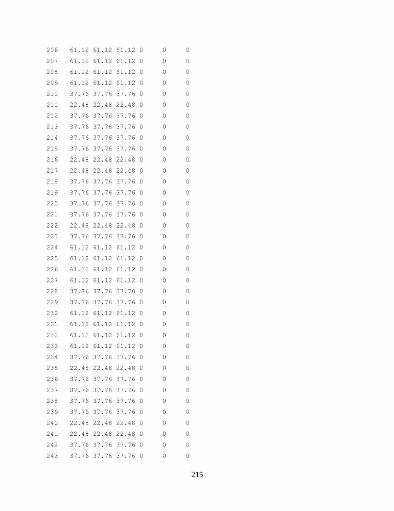
215
206 61.12 61.12 61.12 0 0 0
207 61.12 61.12 61.12 0 0 0
208 61.12 61.12 61.12 0 0 0
209 61.12 61.12 61.12 0 0 0
210 37.76 37.76 37.76 0 0 0
211 22.48 22.48 22.48 0 0 0
212 37.76 37.76 37.76 0 0 0
213 37.76 37.76 37.76 0 0 0
214 37.76 37.76 37.76 0 0 0
215 37.76 37.76 37.76 0 0 0
216 22.48 22.48 22.48 0 0 0
217 22.48 22.48 22.48 0 0 0
218 37.76 37.76 37.76 0 0 0
219 37.76 37.76 37.76 0 0 0
220 37.76 37.76 37.76 0 0 0
221 37.76 37.76 37.76 0 0 0
222 22.48 22.48 22.48 0 0 0
223 37.76 37.76 37.76 0 0 0
224 61.12 61.12 61.12 0 0 0
225 61.12 61.12 61.12 0 0 0
226 61.12 61.12 61.12 0 0 0
227 61.12 61.12 61.12 0 0 0
228 37.76 37.76 37.76 0 0 0
229 37.76 37.76 37.76 0 0 0
230 61.12 61.12 61.12 0 0 0
231 61.12 61.12 61.12 0 0 0
232 61.12 61.12 61.12 0 0 0
233 61.12 61.12 61.12 0 0 0
234 37.76 37.76 37.76 0 0 0
235 22.48 22.48 22.48 0 0 0
236 37.76 37.76 37.76 0 0 0
237 37.76 37.76 37.76 0 0 0
238 37.76 37.76 37.76 0 0 0
239 37.76 37.76 37.76 0 0 0
240 22.48 22.48 22.48 0 0 0
241 22.48 22.48 22.48 0 0 0
242 37.76 37.76 37.76 0 0 0
243 37.76 37.76 37.76 0 0 0
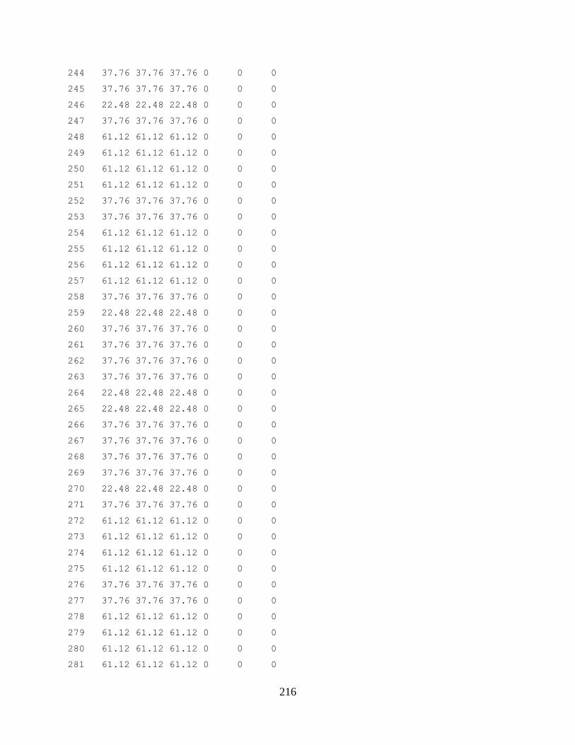
216
244 37.76 37.76 37.76 0 0 0
245 37.76 37.76 37.76 0 0 0
246 22.48 22.48 22.48 0 0 0
247 37.76 37.76 37.76 0 0 0
248 61.12 61.12 61.12 0 0 0
249 61.12 61.12 61.12 0 0 0
250 61.12 61.12 61.12 0 0 0
251 61.12 61.12 61.12 0 0 0
252 37.76 37.76 37.76 0 0 0
253 37.76 37.76 37.76 0 0 0
254 61.12 61.12 61.12 0 0 0
255 61.12 61.12 61.12 0 0 0
256 61.12 61.12 61.12 0 0 0
257 61.12 61.12 61.12 0 0 0
258 37.76 37.76 37.76 0 0 0
259 22.48 22.48 22.48 0 0 0
260 37.76 37.76 37.76 0 0 0
261 37.76 37.76 37.76 0 0 0
262 37.76 37.76 37.76 0 0 0
263 37.76 37.76 37.76 0 0 0
264 22.48 22.48 22.48 0 0 0
265 22.48 22.48 22.48 0 0 0
266 37.76 37.76 37.76 0 0 0
267 37.76 37.76 37.76 0 0 0
268 37.76 37.76 37.76 0 0 0
269 37.76 37.76 37.76 0 0 0
270 22.48 22.48 22.48 0 0 0
271 37.76 37.76 37.76 0 0 0
272 61.12 61.12 61.12 0 0 0
273 61.12 61.12 61.12 0 0 0
274 61.12 61.12 61.12 0 0 0
275 61.12 61.12 61.12 0 0 0
276 37.76 37.76 37.76 0 0 0
277 37.76 37.76 37.76 0 0 0
278 61.12 61.12 61.12 0 0 0
279 61.12 61.12 61.12 0 0 0
280 61.12 61.12 61.12 0 0 0
281 61.12 61.12 61.12 0 0 0
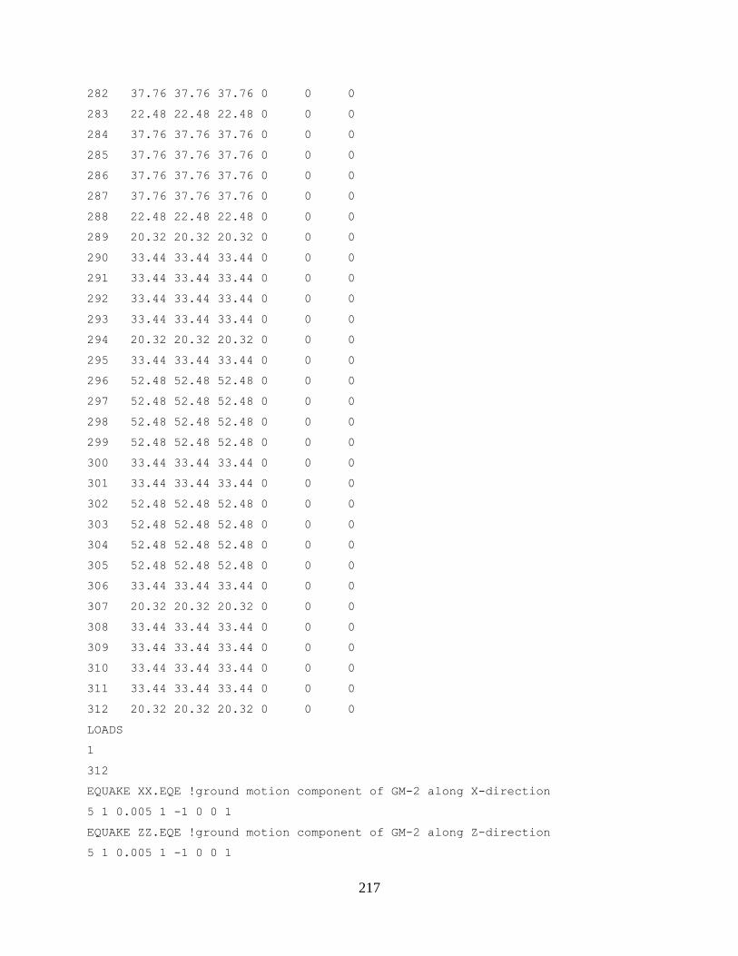
217
282 37.76 37.76 37.76 0 0 0
283 22.48 22.48 22.48 0 0 0
284 37.76 37.76 37.76 0 0 0
285 37.76 37.76 37.76 0 0 0
286 37.76 37.76 37.76 0 0 0
287 37.76 37.76 37.76 0 0 0
288 22.48 22.48 22.48 0 0 0
289 20.32 20.32 20.32 0 0 0
290 33.44 33.44 33.44 0 0 0
291 33.44 33.44 33.44 0 0 0
292 33.44 33.44 33.44 0 0 0
293 33.44 33.44 33.44 0 0 0
294 20.32 20.32 20.32 0 0 0
295 33.44 33.44 33.44 0 0 0
296 52.48 52.48 52.48 0 0 0
297 52.48 52.48 52.48 0 0 0
298 52.48 52.48 52.48 0 0 0
299 52.48 52.48 52.48 0 0 0
300 33.44 33.44 33.44 0 0 0
301 33.44 33.44 33.44 0 0 0
302 52.48 52.48 52.48 0 0 0
303 52.48 52.48 52.48 0 0 0
304 52.48 52.48 52.48 0 0 0
305 52.48 52.48 52.48 0 0 0
306 33.44 33.44 33.44 0 0 0
307 20.32 20.32 20.32 0 0 0
308 33.44 33.44 33.44 0 0 0
309 33.44 33.44 33.44 0 0 0
310 33.44 33.44 33.44 0 0 0
311 33.44 33.44 33.44 0 0 0
312 20.32 20.32 20.32 0 0 0
LOADS
1
312
EQUAKE XX.EQE !ground motion component of GM-2 along X-direction
5 1 0.005 1 -1 0 0 1
EQUAKE ZZ.EQE !ground motion component of GM-2 along Z-direction
5 1 0.005 1 -1 0 0 1
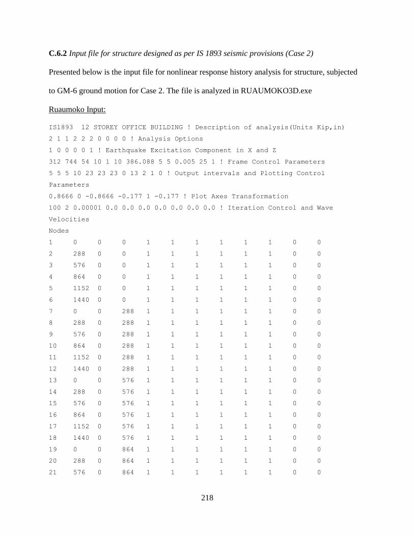
218
C.6.2 Input file for structure designed as per IS 1893 seismic provisions (Case 2)
Presented below is the input file for nonlinear response history analysis for structure, subjected
to GM-6 ground motion for Case 2. The file is analyzed in RUAUMOKO3D.exe
Ruaumoko Input:
IS1893 12 STOREY OFFICE BUILDING ! Description of analysis(Units Kip,in)
2 1 1 2 2 2 0 0 0 0 ! Analysis Options
1 0 0 0 0 1 ! Earthquake Excitation Component in X and Z
312 744 54 10 1 10 386.088 5 5 0.005 25 1 ! Frame Control Parameters
5 5 5 10 23 23 23 0 13 2 1 0 ! Output intervals and Plotting Control
Parameters
0.8666 0 -0.8666 -0.177 1 -0.177 ! Plot Axes Transformation
100 2 0.00001 0.0 0.0 0.0 0.0 0.0 0.0 0.0 ! Iteration Control and Wave
Velocities
Nodes
1 0 0 0 1 1 1 1 1 1 0 0
2 288 0 0 1 1 1 1 1 1 0 0
3 576 0 0 1 1 1 1 1 1 0 0
4 864 0 0 1 1 1 1 1 1 0 0
5 1152 0 0 1 1 1 1 1 1 0 0
6 1440 0 0 1 1 1 1 1 1 0 0
7 0 0 288 1 1 1 1 1 1 0 0
8 288 0 288 1 1 1 1 1 1 0 0
9 576 0 288 1 1 1 1 1 1 0 0
10 864 0 288 1 1 1 1 1 1 0 0
11 1152 0 288 1 1 1 1 1 1 0 0
12 1440 0 288 1 1 1 1 1 1 0 0
13 0 0 576 1 1 1 1 1 1 0 0
14 288 0 576 1 1 1 1 1 1 0 0
15 576 0 576 1 1 1 1 1 1 0 0
16 864 0 576 1 1 1 1 1 1 0 0
17 1152 0 576 1 1 1 1 1 1 0 0
18 1440 0 576 1 1 1 1 1 1 0 0
19 0 0 864 1 1 1 1 1 1 0 0
20 288 0 864 1 1 1 1 1 1 0 0
21 576 0 864 1 1 1 1 1 1 0 0
219
22 864 0 864 1 1 1 1 1 1 0 0
23 1152 0 864 1 1 1 1 1 1 0 0
24 1440 0 864 1 1 1 1 1 1 0 0
25 0 168 0 0 0 0 0 0 0 0 0
26 288 168 0 2 0 2 0 0 0 25 0
27 576 168 0 2 0 2 0 0 0 25 0
28 864 168 0 2 0 2 0 0 0 25 0
29 1152 168 0 2 0 2 0 0 0 25 0
30 1440 168 0 2 0 2 0 0 0 25 0
31 0 168 288 2 0 2 0 0 0 25 0
32 288 168 288 2 0 2 0 0 0 25 0
33 576 168 288 2 0 2 0 0 0 25 0
34 864 168 288 2 0 2 0 0 0 25 0
35 1152 168 288 2 0 2 0 0 0 25 0
36 1440 168 288 2 0 2 0 0 0 25 0
37 0 168 576 2 0 2 0 0 0 25 0
38 288 168 576 2 0 2 0 0 0 25 0
39 576 168 576 2 0 2 0 0 0 25 0
40 864 168 576 2 0 2 0 0 0 25 0
41 1152 168 576 2 0 2 0 0 0 25 0
42 1440 168 576 2 0 2 0 0 0 25 0
43 0 168 864 2 0 2 0 0 0 25 0
44 288 168 864 2 0 2 0 0 0 25 0
45 576 168 864 2 0 2 0 0 0 25 0
46 864 168 864 2 0 2 0 0 0 25 0
47 1152 168 864 2 0 2 0 0 0 25 0
48 1440 168 864 2 0 2 0 0 0 25 0
49 0 312 0 0 0 0 0 0 0 0 0
50 288 312 0 2 0 2 0 0 0 49 0
51 576 312 0 2 0 2 0 0 0 49 0
52 864 312 0 2 0 2 0 0 0 49 0
53 1152 312 0 2 0 2 0 0 0 49 0
54 1440 312 0 2 0 2 0 0 0 49 0
55 0 312 288 2 0 2 0 0 0 49 0
56 288 312 288 2 0 2 0 0 0 49 0
57 576 312 288 2 0 2 0 0 0 49 0
58 864 312 288 2 0 2 0 0 0 49 0
59 1152 312 288 2 0 2 0 0 0 49 0
220
60 1440 312 288 2 0 2 0 0 0 49 0
61 0 312 576 2 0 2 0 0 0 49 0
62 288 312 576 2 0 2 0 0 0 49 0
63 576 312 576 2 0 2 0 0 0 49 0
64 864 312 576 2 0 2 0 0 0 49 0
65 1152 312 576 2 0 2 0 0 0 49 0
66 1440 312 576 2 0 2 0 0 0 49 0
67 0 312 864 2 0 2 0 0 0 49 0
68 288 312 864 2 0 2 0 0 0 49 0
69 576 312 864 2 0 2 0 0 0 49 0
70 864 312 864 2 0 2 0 0 0 49 0
71 1152 312 864 2 0 2 0 0 0 49 0
72 1440 312 864 2 0 2 0 0 0 49 0
73 0 456 0 0 0 0 0 0 0 0 0
74 288 456 0 2 0 2 0 0 0 73 0
75 576 456 0 2 0 2 0 0 0 73 0
76 864 456 0 2 0 2 0 0 0 73 0
77 1152 456 0 2 0 2 0 0 0 73 0
78 1440 456 0 2 0 2 0 0 0 73 0
79 0 456 288 2 0 2 0 0 0 73 0
80 288 456 288 2 0 2 0 0 0 73 0
81 576 456 288 2 0 2 0 0 0 73 0
82 864 456 288 2 0 2 0 0 0 73 0
83 1152 456 288 2 0 2 0 0 0 73 0
84 1440 456 288 2 0 2 0 0 0 73 0
85 0 456 576 2 0 2 0 0 0 73 0
86 288 456 576 2 0 2 0 0 0 73 0
87 576 456 576 2 0 2 0 0 0 73 0
88 864 456 576 2 0 2 0 0 0 73 0
89 1152 456 576 2 0 2 0 0 0 73 0
90 1440 456 576 2 0 2 0 0 0 73 0
91 0 456 864 2 0 2 0 0 0 73 0
92 288 456 864 2 0 2 0 0 0 73 0
93 576 456 864 2 0 2 0 0 0 73 0
94 864 456 864 2 0 2 0 0 0 73 0
95 1152 456 864 2 0 2 0 0 0 73 0
96 1440 456 864 2 0 2 0 0 0 73 0
97 0 600 0 0 0 0 0 0 0 0 0
221
98 288 600 0 2 0 2 0 0 0 97 0
99 576 600 0 2 0 2 0 0 0 97 0
100 864 600 0 2 0 2 0 0 0 97 0
101 1152 600 0 2 0 2 0 0 0 97 0
102 1440 600 0 2 0 2 0 0 0 97 0
103 0 600 288 2 0 2 0 0 0 97 0
104 288 600 288 2 0 2 0 0 0 97 0
105 576 600 288 2 0 2 0 0 0 97 0
106 864 600 288 2 0 2 0 0 0 97 0
107 1152 600 288 2 0 2 0 0 0 97 0
108 1440 600 288 2 0 2 0 0 0 97 0
109 0 600 576 2 0 2 0 0 0 97 0
110 288 600 576 2 0 2 0 0 0 97 0
111 576 600 576 2 0 2 0 0 0 97 0
112 864 600 576 2 0 2 0 0 0 97 0
113 1152 600 576 2 0 2 0 0 0 97 0
114 1440 600 576 2 0 2 0 0 0 97 0
115 0 600 864 2 0 2 0 0 0 97 0
116 288 600 864 2 0 2 0 0 0 97 0
117 576 600 864 2 0 2 0 0 0 97 0
118 864 600 864 2 0 2 0 0 0 97 0
119 1152 600 864 2 0 2 0 0 0 97 0
120 1440 600 864 2 0 2 0 0 0 97 0
121 0 744 0 0 0 0 0 0 0 0 0
122 288 744 0 2 0 2 0 0 0 121 0
123 576 744 0 2 0 2 0 0 0 121 0
124 864 744 0 2 0 2 0 0 0 121 0
125 1152 744 0 2 0 2 0 0 0 121 0
126 1440 744 0 2 0 2 0 0 0 121 0
127 0 744 288 2 0 2 0 0 0 121 0
128 288 744 288 2 0 2 0 0 0 121 0
129 576 744 288 2 0 2 0 0 0 121 0
130 864 744 288 2 0 2 0 0 0 121 0
131 1152 744 288 2 0 2 0 0 0 121 0
132 1440 744 288 2 0 2 0 0 0 121 0
133 0 744 576 2 0 2 0 0 0 121 0
134 288 744 576 2 0 2 0 0 0 121 0
135 576 744 576 2 0 2 0 0 0 121 0
222
136 864 744 576 2 0 2 0 0 0 121 0
137 1152 744 576 2 0 2 0 0 0 121 0
138 1440 744 576 2 0 2 0 0 0 121 0
139 0 744 864 2 0 2 0 0 0 121 0
140 288 744 864 2 0 2 0 0 0 121 0
141 576 744 864 2 0 2 0 0 0 121 0
142 864 744 864 2 0 2 0 0 0 121 0
143 1152 744 864 2 0 2 0 0 0 121 0
144 1440 744 864 2 0 2 0 0 0 121 0
145 0 888 0 0 0 0 0 0 0 0 0
146 288 888 0 2 0 2 0 0 0 145 0
147 576 888 0 2 0 2 0 0 0 145 0
148 864 888 0 2 0 2 0 0 0 145 0
149 1152 888 0 2 0 2 0 0 0 145 0
150 1440 888 0 2 0 2 0 0 0 145 0
151 0 888 288 2 0 2 0 0 0 145 0
152 288 888 288 2 0 2 0 0 0 145 0
153 576 888 288 2 0 2 0 0 0 145 0
154 864 888 288 2 0 2 0 0 0 145 0
155 1152 888 288 2 0 2 0 0 0 145 0
156 1440 888 288 2 0 2 0 0 0 145 0
157 0 888 576 2 0 2 0 0 0 145 0
158 288 888 576 2 0 2 0 0 0 145 0
159 576 888 576 2 0 2 0 0 0 145 0
160 864 888 576 2 0 2 0 0 0 145 0
161 1152 888 576 2 0 2 0 0 0 145 0
162 1440 888 576 2 0 2 0 0 0 145 0
163 0 888 864 2 0 2 0 0 0 145 0
164 288 888 864 2 0 2 0 0 0 145 0
165 576 888 864 2 0 2 0 0 0 145 0
166 864 888 864 2 0 2 0 0 0 145 0
167 1152 888 864 2 0 2 0 0 0 145 0
168 1440 888 864 2 0 2 0 0 0 145 0
169 0 1032 0 0 0 0 0 0 0 0 0
170 288 1032 0 2 0 2 0 0 0 169 0
171 576 1032 0 2 0 2 0 0 0 169 0
172 864 1032 0 2 0 2 0 0 0 169 0
173 1152 1032 0 2 0 2 0 0 0 169 0
223
174 1440 1032 0 2 0 2 0 0 0 169 0
175 0 1032 288 2 0 2 0 0 0 169 0
176 288 1032 288 2 0 2 0 0 0 169 0
177 576 1032 288 2 0 2 0 0 0 169 0
178 864 1032 288 2 0 2 0 0 0 169 0
179 1152 1032 288 2 0 2 0 0 0 169 0
180 1440 1032 288 2 0 2 0 0 0 169 0
181 0 1032 576 2 0 2 0 0 0 169 0
182 288 1032 576 2 0 2 0 0 0 169 0
183 576 1032 576 2 0 2 0 0 0 169 0
184 864 1032 576 2 0 2 0 0 0 169 0
185 1152 1032 576 2 0 2 0 0 0 169 0
186 1440 1032 576 2 0 2 0 0 0 169 0
187 0 1032 864 2 0 2 0 0 0 169 0
188 288 1032 864 2 0 2 0 0 0 169 0
189 576 1032 864 2 0 2 0 0 0 169 0
190 864 1032 864 2 0 2 0 0 0 169 0
191 1152 1032 864 2 0 2 0 0 0 169 0
192 1440 1032 864 2 0 2 0 0 0 169 0
193 0 1176 0 0 0 0 0 0 0 0 0
194 288 1176 0 2 0 2 0 0 0 193 0
195 576 1176 0 2 0 2 0 0 0 193 0
196 864 1176 0 2 0 2 0 0 0 193 0
197 1152 1176 0 2 0 2 0 0 0 193 0
198 1440 1176 0 2 0 2 0 0 0 193 0
199 0 1176 288 2 0 2 0 0 0 193 0
200 288 1176 288 2 0 2 0 0 0 193 0
201 576 1176 288 2 0 2 0 0 0 193 0
202 864 1176 288 2 0 2 0 0 0 193 0
203 1152 1176 288 2 0 2 0 0 0 193 0
204 1440 1176 288 2 0 2 0 0 0 193 0
205 0 1176 576 2 0 2 0 0 0 193 0
206 288 1176 576 2 0 2 0 0 0 193 0
207 576 1176 576 2 0 2 0 0 0 193 0
208 864 1176 576 2 0 2 0 0 0 193 0
209 1152 1176 576 2 0 2 0 0 0 193 0
210 1440 1176 576 2 0 2 0 0 0 193 0
211 0 1176 864 2 0 2 0 0 0 193 0
224
212 288 1176 864 2 0 2 0 0 0 193 0
213 576 1176 864 2 0 2 0 0 0 193 0
214 864 1176 864 2 0 2 0 0 0 193 0
215 1152 1176 864 2 0 2 0 0 0 193 0
216 1440 1176 864 2 0 2 0 0 0 193 0
217 0 1320 0 0 0 0 0 0 0 0 0
218 288 1320 0 2 0 2 0 0 0 217 0
219 576 1320 0 2 0 2 0 0 0 217 0
220 864 1320 0 2 0 2 0 0 0 217 0
221 1152 1320 0 2 0 2 0 0 0 217 0
222 1440 1320 0 2 0 2 0 0 0 217 0
223 0 1320 288 2 0 2 0 0 0 217 0
224 288 1320 288 2 0 2 0 0 0 217 0
225 576 1320 288 2 0 2 0 0 0 217 0
226 864 1320 288 2 0 2 0 0 0 217 0
227 1152 1320 288 2 0 2 0 0 0 217 0
228 1440 1320 288 2 0 2 0 0 0 217 0
229 0 1320 576 2 0 2 0 0 0 217 0
230 288 1320 576 2 0 2 0 0 0 217 0
231 576 1320 576 2 0 2 0 0 0 217 0
232 864 1320 576 2 0 2 0 0 0 217 0
233 1152 1320 576 2 0 2 0 0 0 217 0
234 1440 1320 576 2 0 2 0 0 0 217 0
235 0 1320 864 2 0 2 0 0 0 217 0
236 288 1320 864 2 0 2 0 0 0 217 0
237 576 1320 864 2 0 2 0 0 0 217 0
238 864 1320 864 2 0 2 0 0 0 217 0
239 1152 1320 864 2 0 2 0 0 0 217 0
240 1440 1320 864 2 0 2 0 0 0 217 0
241 0 1464 0 0 0 0 0 0 0 0 0
242 288 1464 0 2 0 2 0 0 0 241 0
243 576 1464 0 2 0 2 0 0 0 241 0
244 864 1464 0 2 0 2 0 0 0 241 0
245 1152 1464 0 2 0 2 0 0 0 241 0
246 1440 1464 0 2 0 2 0 0 0 241 0
247 0 1464 288 2 0 2 0 0 0 241 0
248 288 1464 288 2 0 2 0 0 0 241 0
249 576 1464 288 2 0 2 0 0 0 241 0
225
250 864 1464 288 2 0 2 0 0 0 241 0
251 1152 1464 288 2 0 2 0 0 0 241 0
252 1440 1464 288 2 0 2 0 0 0 241 0
253 0 1464 576 2 0 2 0 0 0 241 0
254 288 1464 576 2 0 2 0 0 0 241 0
255 576 1464 576 2 0 2 0 0 0 241 0
256 864 1464 576 2 0 2 0 0 0 241 0
257 1152 1464 576 2 0 2 0 0 0 241 0
258 1440 1464 576 2 0 2 0 0 0 241 0
259 0 1464 864 2 0 2 0 0 0 241 0
260 288 1464 864 2 0 2 0 0 0 241 0
261 576 1464 864 2 0 2 0 0 0 241 0
262 864 1464 864 2 0 2 0 0 0 241 0
263 1152 1464 864 2 0 2 0 0 0 241 0
264 1440 1464 864 2 0 2 0 0 0 241 0
265 0 1608 0 0 0 0 0 0 0 0 0
266 288 1608 0 2 0 2 0 0 0 265 0
267 576 1608 0 2 0 2 0 0 0 265 0
268 864 1608 0 2 0 2 0 0 0 265 0
269 1152 1608 0 2 0 2 0 0 0 265 0
270 1440 1608 0 2 0 2 0 0 0 265 0
271 0 1608 288 2 0 2 0 0 0 265 0
272 288 1608 288 2 0 2 0 0 0 265 0
273 576 1608 288 2 0 2 0 0 0 265 0
274 864 1608 288 2 0 2 0 0 0 265 0
275 1152 1608 288 2 0 2 0 0 0 265 0
276 1440 1608 288 2 0 2 0 0 0 265 0
277 0 1608 576 2 0 2 0 0 0 265 0
278 288 1608 576 2 0 2 0 0 0 265 0
279 576 1608 576 2 0 2 0 0 0 265 0
280 864 1608 576 2 0 2 0 0 0 265 0
281 1152 1608 576 2 0 2 0 0 0 265 0
282 1440 1608 576 2 0 2 0 0 0 265 0
283 0 1608 864 2 0 2 0 0 0 265 0
284 288 1608 864 2 0 2 0 0 0 265 0
285 576 1608 864 2 0 2 0 0 0 265 0
286 864 1608 864 2 0 2 0 0 0 265 0
287 1152 1608 864 2 0 2 0 0 0 265 0
226
288 1440 1608 864 2 0 2 0 0 0 265 0
289 0 1752 0 0 0 0 0 0 0 0 0
290 288 1752 0 2 0 2 0 0 0 289 0
291 576 1752 0 2 0 2 0 0 0 289 0
292 864 1752 0 2 0 2 0 0 0 289 0
293 1152 1752 0 2 0 2 0 0 0 289 0
294 1440 1752 0 2 0 2 0 0 0 289 0
295 0 1752 288 2 0 2 0 0 0 289 0
296 288 1752 288 2 0 2 0 0 0 289 0
297 576 1752 288 2 0 2 0 0 0 289 0
298 864 1752 288 2 0 2 0 0 0 289 0
299 1152 1752 288 2 0 2 0 0 0 289 0
300 1440 1752 288 2 0 2 0 0 0 289 0
301 0 1752 576 2 0 2 0 0 0 289 0
302 288 1752 576 2 0 2 0 0 0 289 0
303 576 1752 576 2 0 2 0 0 0 289 0
304 864 1752 576 2 0 2 0 0 0 289 0
305 1152 1752 576 2 0 2 0 0 0 289 0
306 1440 1752 576 2 0 2 0 0 0 289 0
307 0 1752 864 2 0 2 0 0 0 289 0
308 288 1752 864 2 0 2 0 0 0 289 0
309 576 1752 864 2 0 2 0 0 0 289 0
310 864 1752 864 2 0 2 0 0 0 289 0
311 1152 1752 864 2 0 2 0 0 0 289 0
312 1440 1752 864 2 0 2 0 0 0 289 0
DRIFT ! Inter-storey Drift Input
1 25 49 73 97 121 145 169 193 217 241 265 289 ! Column 1 all nodes till roof
ELEMENTS
1 49 25 26 0 0 Z 0
2 51 26 27 0 0 Z 0
3 49 27 28 0 0 Z 0
4 51 28 29 0 0 Z 0
5 49 29 30 0 0 Z 0
6 50 31 32 0 0 Z 0
7 50 32 33 0 0 Z 0
8 50 33 34 0 0 Z 0
9 50 34 35 0 0 Z 0
10 50 35 36 0 0 Z 0
227
11 50 37 38 0 0 Z 0
12 50 38 39 0 0 Z 0
13 50 39 40 0 0 Z 0
14 50 40 41 0 0 Z 0
15 50 41 42 0 0 Z 0
16 49 43 44 0 0 Z 0
17 51 44 45 0 0 Z 0
18 49 45 46 0 0 Z 0
19 51 46 47 0 0 Z 0
20 49 47 48 0 0 Z 0
21 51 25 31 0 0 -X 0
22 49 26 32 0 0 -X 0
23 51 27 33 0 0 -X 0
24 50 28 34 0 0 -X 0
25 50 29 35 0 0 -X 0
26 50 30 36 0 0 -X 0
27 50 31 37 0 0 -X 0
28 50 32 38 0 0 -X 0
29 50 33 39 0 0 -X 0
30 50 34 40 0 0 -X 0
31 50 35 41 0 0 -X 0
32 50 36 42 0 0 -X 0
33 50 37 43 0 0 -X 0
34 50 38 44 0 0 -X 0
35 50 39 45 0 0 -X 0
36 51 40 46 0 0 -X 0
37 49 41 47 0 0 -X 0
38 51 42 48 0 0 -X 0
39 49 49 50 0 0 Z 0
40 51 50 51 0 0 Z 0
41 49 51 52 0 0 Z 0
42 51 52 53 0 0 Z 0
43 49 53 54 0 0 Z 0
44 50 55 56 0 0 Z 0
45 50 56 57 0 0 Z 0
46 50 57 58 0 0 Z 0
47 50 58 59 0 0 Z 0
48 50 59 60 0 0 Z 0
228
49 50 61 62 0 0 Z 0
50 50 62 63 0 0 Z 0
51 50 63 64 0 0 Z 0
52 50 64 65 0 0 Z 0
53 50 65 66 0 0 Z 0
54 49 67 68 0 0 Z 0
55 51 68 69 0 0 Z 0
56 49 69 70 0 0 Z 0
57 51 70 71 0 0 Z 0
58 49 71 72 0 0 Z 0
59 51 49 55 0 0 -X 0
60 49 50 56 0 0 -X 0
61 51 51 57 0 0 -X 0
62 50 52 58 0 0 -X 0
63 50 53 59 0 0 -X 0
64 50 54 60 0 0 -X 0
65 50 55 61 0 0 -X 0
66 50 56 62 0 0 -X 0
67 50 57 63 0 0 -X 0
68 50 58 64 0 0 -X 0
69 50 59 65 0 0 -X 0
70 50 60 66 0 0 -X 0
71 50 61 67 0 0 -X 0
72 50 62 68 0 0 -X 0
73 50 63 69 0 0 -X 0
74 51 64 70 0 0 -X 0
75 49 65 71 0 0 -X 0
76 51 66 72 0 0 -X 0
77 49 73 74 0 0 Z 0
78 51 74 75 0 0 Z 0
79 49 75 76 0 0 Z 0
80 51 76 77 0 0 Z 0
81 49 77 78 0 0 Z 0
82 50 79 80 0 0 Z 0
83 50 80 81 0 0 Z 0
84 50 81 82 0 0 Z 0
85 50 82 83 0 0 Z 0
86 50 83 84 0 0 Z 0
229
87 50 85 86 0 0 Z 0
88 50 86 87 0 0 Z 0
89 50 87 88 0 0 Z 0
90 50 88 89 0 0 Z 0
91 50 89 90 0 0 Z 0
92 49 91 92 0 0 Z 0
93 51 92 93 0 0 Z 0
94 49 93 94 0 0 Z 0
95 51 94 95 0 0 Z 0
96 49 95 96 0 0 Z 0
97 51 73 79 0 0 -X 0
98 49 74 80 0 0 -X 0
99 51 75 81 0 0 -X 0
100 50 76 82 0 0 -X 0
101 50 77 83 0 0 -X 0
102 50 78 84 0 0 -X 0
103 50 79 85 0 0 -X 0
104 50 80 86 0 0 -X 0
105 50 81 87 0 0 -X 0
106 50 82 88 0 0 -X 0
107 50 83 89 0 0 -X 0
108 50 84 90 0 0 -X 0
109 50 85 91 0 0 -X 0
110 50 86 92 0 0 -X 0
111 50 87 93 0 0 -X 0
112 51 88 94 0 0 -X 0
113 49 89 95 0 0 -X 0
114 51 90 96 0 0 -X 0
115 49 97 98 0 0 Z 0
116 51 98 99 0 0 Z 0
117 49 99 100 0 0 Z 0
118 51 100 101 0 0 Z 0
119 49 101 102 0 0 Z 0
120 50 103 104 0 0 Z 0
121 50 104 105 0 0 Z 0
122 50 105 106 0 0 Z 0
123 50 106 107 0 0 Z 0
124 50 107 108 0 0 Z 0
230
125 50 109 110 0 0 Z 0
126 50 110 111 0 0 Z 0
127 50 111 112 0 0 Z 0
128 50 112 113 0 0 Z 0
129 50 113 114 0 0 Z 0
130 49 115 116 0 0 Z 0
131 51 116 117 0 0 Z 0
132 49 117 118 0 0 Z 0
133 51 118 119 0 0 Z 0
134 49 119 120 0 0 Z 0
135 51 97 103 0 0 -X 0
136 49 98 104 0 0 -X 0
137 51 99 105 0 0 -X 0
138 50 100 106 0 0 -X 0
139 50 101 107 0 0 -X 0
140 50 102 108 0 0 -X 0
141 50 103 109 0 0 -X 0
142 50 104 110 0 0 -X 0
143 50 105 111 0 0 -X 0
144 50 106 112 0 0 -X 0
145 50 107 113 0 0 -X 0
146 50 108 114 0 0 -X 0
147 50 109 115 0 0 -X 0
148 50 110 116 0 0 -X 0
149 50 111 117 0 0 -X 0
150 51 112 118 0 0 -X 0
151 49 113 119 0 0 -X 0
152 51 114 120 0 0 -X 0
153 49 121 122 0 0 Z 0
154 51 122 123 0 0 Z 0
155 49 123 124 0 0 Z 0
156 51 124 125 0 0 Z 0
157 49 125 126 0 0 Z 0
158 50 127 128 0 0 Z 0
159 50 128 129 0 0 Z 0
160 50 129 130 0 0 Z 0
161 50 130 131 0 0 Z 0
162 50 131 132 0 0 Z 0
231
163 50 133 134 0 0 Z 0
164 50 134 135 0 0 Z 0
165 50 135 136 0 0 Z 0
166 50 136 137 0 0 Z 0
167 50 137 138 0 0 Z 0
168 49 139 140 0 0 Z 0
169 51 140 141 0 0 Z 0
170 49 141 142 0 0 Z 0
171 51 142 143 0 0 Z 0
172 49 143 144 0 0 Z 0
173 51 121 127 0 0 -X 0
174 49 122 128 0 0 -X 0
175 51 123 129 0 0 -X 0
176 50 124 130 0 0 -X 0
177 50 125 131 0 0 -X 0
178 50 126 132 0 0 -X 0
179 50 127 133 0 0 -X 0
180 50 128 134 0 0 -X 0
181 50 129 135 0 0 -X 0
182 50 130 136 0 0 -X 0
183 50 131 137 0 0 -X 0
184 50 132 138 0 0 -X 0
185 50 133 139 0 0 -X 0
186 50 134 140 0 0 -X 0
187 50 135 141 0 0 -X 0
188 51 136 142 0 0 -X 0
189 49 137 143 0 0 -X 0
190 51 138 144 0 0 -X 0
191 49 145 146 0 0 Z 0
192 51 146 147 0 0 Z 0
193 49 147 148 0 0 Z 0
194 51 148 149 0 0 Z 0
195 49 149 150 0 0 Z 0
196 50 151 152 0 0 Z 0
197 50 152 153 0 0 Z 0
198 50 153 154 0 0 Z 0
199 50 154 155 0 0 Z 0
200 50 155 156 0 0 Z 0
232
201 50 157 158 0 0 Z 0
202 50 158 159 0 0 Z 0
203 50 159 160 0 0 Z 0
204 50 160 161 0 0 Z 0
205 50 161 162 0 0 Z 0
206 49 163 164 0 0 Z 0
207 51 164 165 0 0 Z 0
208 49 165 166 0 0 Z 0
209 51 166 167 0 0 Z 0
210 49 167 168 0 0 Z 0
211 51 145 151 0 0 -X 0
212 49 146 152 0 0 -X 0
213 51 147 153 0 0 -X 0
214 50 148 154 0 0 -X 0
215 50 149 155 0 0 -X 0
216 50 150 156 0 0 -X 0
217 50 151 157 0 0 -X 0
218 50 152 158 0 0 -X 0
219 50 153 159 0 0 -X 0
220 50 154 160 0 0 -X 0
221 50 155 161 0 0 -X 0
222 50 156 162 0 0 -X 0
223 50 157 163 0 0 -X 0
224 50 158 164 0 0 -X 0
225 50 159 165 0 0 -X 0
226 51 160 166 0 0 -X 0
227 49 161 167 0 0 -X 0
228 51 162 168 0 0 -X 0
229 49 169 170 0 0 Z 0
230 51 170 171 0 0 Z 0
231 49 171 172 0 0 Z 0
232 51 172 173 0 0 Z 0
233 49 173 174 0 0 Z 0
234 50 175 176 0 0 Z 0
235 50 176 177 0 0 Z 0
236 50 177 178 0 0 Z 0
237 50 178 179 0 0 Z 0
238 50 179 180 0 0 Z 0
233
239 50 181 182 0 0 Z 0
240 50 182 183 0 0 Z 0
241 50 183 184 0 0 Z 0
242 50 184 185 0 0 Z 0
243 50 185 186 0 0 Z 0
244 49 187 188 0 0 Z 0
245 51 188 189 0 0 Z 0
246 49 189 190 0 0 Z 0
247 51 190 191 0 0 Z 0
248 49 191 192 0 0 Z 0
249 51 169 175 0 0 -X 0
250 49 170 176 0 0 -X 0
251 51 171 177 0 0 -X 0
252 50 172 178 0 0 -X 0
253 50 173 179 0 0 -X 0
254 50 174 180 0 0 -X 0
255 50 175 181 0 0 -X 0
256 50 176 182 0 0 -X 0
257 50 177 183 0 0 -X 0
258 50 178 184 0 0 -X 0
259 50 179 185 0 0 -X 0
260 50 180 186 0 0 -X 0
261 50 181 187 0 0 -X 0
262 50 182 188 0 0 -X 0
263 50 183 189 0 0 -X 0
264 51 184 190 0 0 -X 0
265 49 185 191 0 0 -X 0
266 51 186 192 0 0 -X 0
267 49 193 194 0 0 Z 0
268 51 194 195 0 0 Z 0
269 49 195 196 0 0 Z 0
270 51 196 197 0 0 Z 0
271 49 197 198 0 0 Z 0
272 50 199 200 0 0 Z 0
273 50 200 201 0 0 Z 0
274 50 201 202 0 0 Z 0
275 50 202 203 0 0 Z 0
276 50 203 204 0 0 Z 0

234
277 50 205 206 0 0 Z 0
278 50 206 207 0 0 Z 0
279 50 207 208 0 0 Z 0
280 50 208 209 0 0 Z 0
281 50 209 210 0 0 Z 0
282 49 211 212 0 0 Z 0
283 51 212 213 0 0 Z 0
284 49 213 214 0 0 Z 0
285 51 214 215 0 0 Z 0
286 49 215 216 0 0 Z 0
287 51 193 199 0 0 -X 0
288 49 194 200 0 0 -X 0
289 51 195 201 0 0 -X 0
290 50 196 202 0 0 -X 0
291 50 197 203 0 0 -X 0
292 50 198 204 0 0 -X 0
293 50 199 205 0 0 -X 0
294 50 200 206 0 0 -X 0
295 50 201 207 0 0 -X 0
296 50 202 208 0 0 -X 0
297 50 203 209 0 0 -X 0
298 50 204 210 0 0 -X 0
299 50 205 211 0 0 -X 0
300 50 206 212 0 0 -X 0
301 50 207 213 0 0 -X 0
302 51 208 214 0 0 -X 0
303 49 209 215 0 0 -X 0
304 51 210 216 0 0 -X 0
305 49 217 218 0 0 Z 0
306 51 218 219 0 0 Z 0
307 49 219 220 0 0 Z 0
308 51 220 221 0 0 Z 0
309 49 221 222 0 0 Z 0
310 50 223 224 0 0 Z 0
311 50 224 225 0 0 Z 0
312 50 225 226 0 0 Z 0
313 50 226 227 0 0 Z 0
314 50 227 228 0 0 Z 0
235
315 50 229 230 0 0 Z 0
316 50 230 231 0 0 Z 0
317 50 231 232 0 0 Z 0
318 50 232 233 0 0 Z 0
319 50 233 234 0 0 Z 0
320 49 235 236 0 0 Z 0
321 51 236 237 0 0 Z 0
322 49 237 238 0 0 Z 0
323 51 238 239 0 0 Z 0
324 49 239 240 0 0 Z 0
325 51 217 223 0 0 -X 0
326 49 218 224 0 0 -X 0
327 51 219 225 0 0 -X 0
328 50 220 226 0 0 -X 0
329 50 221 227 0 0 -X 0
330 50 222 228 0 0 -X 0
331 50 223 229 0 0 -X 0
332 50 224 230 0 0 -X 0
333 50 225 231 0 0 -X 0
334 50 226 232 0 0 -X 0
335 50 227 233 0 0 -X 0
336 50 228 234 0 0 -X 0
337 50 229 235 0 0 -X 0
338 50 230 236 0 0 -X 0
339 50 231 237 0 0 -X 0
340 51 232 238 0 0 -X 0
341 49 233 239 0 0 -X 0
342 51 234 240 0 0 -X 0
343 49 241 242 0 0 Z 0
344 51 242 243 0 0 Z 0
345 49 243 244 0 0 Z 0
346 51 244 245 0 0 Z 0
347 49 245 246 0 0 Z 0
348 50 247 248 0 0 Z 0
349 50 248 249 0 0 Z 0
350 50 249 250 0 0 Z 0
351 50 250 251 0 0 Z 0
352 50 251 252 0 0 Z 0
236
353 50 253 254 0 0 Z 0
354 50 254 255 0 0 Z 0
355 50 255 256 0 0 Z 0
356 50 256 257 0 0 Z 0
357 50 257 258 0 0 Z 0
358 49 259 260 0 0 Z 0
359 51 260 261 0 0 Z 0
360 49 261 262 0 0 Z 0
361 51 262 263 0 0 Z 0
362 49 263 264 0 0 Z 0
363 51 241 247 0 0 -X 0
364 49 242 248 0 0 -X 0
365 51 243 249 0 0 -X 0
366 50 244 250 0 0 -X 0
367 50 245 251 0 0 -X 0
368 50 246 252 0 0 -X 0
369 50 247 253 0 0 -X 0
370 50 248 254 0 0 -X 0
371 50 249 255 0 0 -X 0
372 50 250 256 0 0 -X 0
373 50 251 257 0 0 -X 0
374 50 252 258 0 0 -X 0
375 50 253 259 0 0 -X 0
376 50 254 260 0 0 -X 0
377 50 255 261 0 0 -X 0
378 51 256 262 0 0 -X 0
379 49 257 263 0 0 -X 0
380 51 258 264 0 0 -X 0
381 49 265 266 0 0 Z 0
382 51 266 267 0 0 Z 0
383 49 267 268 0 0 Z 0
384 51 268 269 0 0 Z 0
385 49 269 270 0 0 Z 0
386 50 271 272 0 0 Z 0
387 50 272 273 0 0 Z 0
388 50 273 274 0 0 Z 0
389 50 274 275 0 0 Z 0
390 50 275 276 0 0 Z 0
237
391 50 277 278 0 0 Z 0
392 50 278 279 0 0 Z 0
393 50 279 280 0 0 Z 0
394 50 280 281 0 0 Z 0
395 50 281 282 0 0 Z 0
396 49 283 284 0 0 Z 0
397 51 284 285 0 0 Z 0
398 49 285 286 0 0 Z 0
399 51 286 287 0 0 Z 0
400 49 287 288 0 0 Z 0
401 51 265 271 0 0 -X 0
402 49 266 272 0 0 -X 0
403 51 267 273 0 0 -X 0
404 50 268 274 0 0 -X 0
405 50 269 275 0 0 -X 0
406 50 270 276 0 0 -X 0
407 50 271 277 0 0 -X 0
408 50 272 278 0 0 -X 0
409 50 273 279 0 0 -X 0
410 50 274 280 0 0 -X 0
411 50 275 281 0 0 -X 0
412 50 276 282 0 0 -X 0
413 50 277 283 0 0 -X 0
414 50 278 284 0 0 -X 0
415 50 279 285 0 0 -X 0
416 51 280 286 0 0 -X 0
417 49 281 287 0 0 -X 0
418 51 282 288 0 0 -X 0
419 52 289 290 0 0 Z 0
420 54 290 291 0 0 Z 0
421 52 291 292 0 0 Z 0
422 54 292 293 0 0 Z 0
423 52 293 294 0 0 Z 0
424 53 295 296 0 0 Z 0
425 53 296 297 0 0 Z 0
426 53 297 298 0 0 Z 0
427 53 298 299 0 0 Z 0
428 53 299 300 0 0 Z 0
238
429 53 301 302 0 0 Z 0
430 53 302 303 0 0 Z 0
431 53 303 304 0 0 Z 0
432 53 304 305 0 0 Z 0
433 53 305 306 0 0 Z 0
434 52 307 308 0 0 Z 0
435 54 308 309 0 0 Z 0
436 52 309 310 0 0 Z 0
437 54 310 311 0 0 Z 0
438 52 311 312 0 0 Z 0
439 54 289 295 0 0 -X 0
440 52 290 296 0 0 -X 0
441 54 291 297 0 0 -X 0
442 53 292 298 0 0 -X 0
443 53 293 299 0 0 -X 0
444 53 294 300 0 0 -X 0
445 53 295 301 0 0 -X 0
446 53 296 302 0 0 -X 0
447 53 297 303 0 0 -X 0
448 53 298 304 0 0 -X 0
449 53 299 305 0 0 -X 0
450 53 300 306 0 0 -X 0
451 53 301 307 0 0 -X 0
452 53 302 308 0 0 -X 0
453 53 303 309 0 0 -X 0
454 54 304 310 0 0 -X 0
455 52 305 311 0 0 -X 0
456 54 306 312 0 0 -X 0
457 1 1 25 0 0 X 0
458 2 2 26 0 0 X 0
459 2 3 27 0 0 X 0
460 2 4 28 0 0 X 0
461 2 5 29 0 0 X 0
462 1 6 30 0 0 X 0
463 3 7 31 0 0 X 0
464 4 8 32 0 0 X 0
465 4 9 33 0 0 X 0
466 4 10 34 0 0 X 0
239
467 4 11 35 0 0 X 0
468 3 12 36 0 0 X 0
469 3 13 37 0 0 X 0
470 4 14 38 0 0 X 0
471 4 15 39 0 0 X 0
472 4 16 40 0 0 X 0
473 4 17 41 0 0 X 0
474 3 18 42 0 0 X 0
475 1 19 43 0 0 X 0
476 2 20 44 0 0 X 0
477 2 21 45 0 0 X 0
478 2 22 46 0 0 X 0
479 2 23 47 0 0 X 0
480 1 24 48 0 0 X 0
481 5 25 49 0 0 X 0
482 6 26 50 0 0 X 0
483 6 27 51 0 0 X 0
484 6 28 52 0 0 X 0
485 6 29 53 0 0 X 0
486 5 30 54 0 0 X 0
487 7 31 55 0 0 X 0
488 8 32 56 0 0 X 0
489 8 33 57 0 0 X 0
490 8 34 58 0 0 X 0
491 8 35 59 0 0 X 0
492 7 36 60 0 0 X 0
493 7 37 61 0 0 X 0
494 8 38 62 0 0 X 0
495 8 39 63 0 0 X 0
496 8 40 64 0 0 X 0
497 8 41 65 0 0 X 0
498 7 42 66 0 0 X 0
499 5 43 67 0 0 X 0
500 6 44 68 0 0 X 0
501 6 45 69 0 0 X 0
502 6 46 70 0 0 X 0
503 6 47 71 0 0 X 0
504 5 48 72 0 0 X 0
240
505 9 49 73 0 0 X 0
506 10 50 74 0 0 X 0
507 10 51 75 0 0 X 0
508 10 52 76 0 0 X 0
509 10 53 77 0 0 X 0
510 9 54 78 0 0 X 0
511 11 55 79 0 0 X 0
512 12 56 80 0 0 X 0
513 12 57 81 0 0 X 0
514 12 58 82 0 0 X 0
515 12 59 83 0 0 X 0
516 11 60 84 0 0 X 0
517 11 61 85 0 0 X 0
518 12 62 86 0 0 X 0
519 12 63 87 0 0 X 0
520 12 64 88 0 0 X 0
521 12 65 89 0 0 X 0
522 11 66 90 0 0 X 0
523 9 67 91 0 0 X 0
524 10 68 92 0 0 X 0
525 10 69 93 0 0 X 0
526 10 70 94 0 0 X 0
527 10 71 95 0 0 X 0
528 9 72 96 0 0 X 0
529 13 73 97 0 0 X 0
530 14 74 98 0 0 X 0
531 14 75 99 0 0 X 0
532 14 76 100 0 0 X 0
533 14 77 101 0 0 X 0
534 13 78 102 0 0 X 0
535 15 79 103 0 0 X 0
536 16 80 104 0 0 X 0
537 16 81 105 0 0 X 0
538 16 82 106 0 0 X 0
539 16 83 107 0 0 X 0
540 15 84 108 0 0 X 0
541 15 85 109 0 0 X 0
542 16 86 110 0 0 X 0

241
543 16 87 111 0 0 X 0
544 16 88 112 0 0 X 0
545 16 89 113 0 0 X 0
546 15 90 114 0 0 X 0
547 13 91 115 0 0 X 0
548 14 92 116 0 0 X 0
549 14 93 117 0 0 X 0
550 14 94 118 0 0 X 0
551 14 95 119 0 0 X 0
552 13 96 120 0 0 X 0
553 17 97 121 0 0 X 0
554 18 98 122 0 0 X 0
555 18 99 123 0 0 X 0
556 18 100 124 0 0 X 0
557 18 101 125 0 0 X 0
558 17 102 126 0 0 X 0
559 19 103 127 0 0 X 0
560 20 104 128 0 0 X 0
561 20 105 129 0 0 X 0
562 20 106 130 0 0 X 0
563 20 107 131 0 0 X 0
564 19 108 132 0 0 X 0
565 19 109 133 0 0 X 0
566 20 110 134 0 0 X 0
567 20 111 135 0 0 X 0
568 20 112 136 0 0 X 0
569 20 113 137 0 0 X 0
570 19 114 138 0 0 X 0
571 17 115 139 0 0 X 0
572 18 116 140 0 0 X 0
573 18 117 141 0 0 X 0
574 18 118 142 0 0 X 0
575 18 119 143 0 0 X 0
576 17 120 144 0 0 X 0
577 21 121 145 0 0 X 0
578 22 122 146 0 0 X 0
579 22 123 147 0 0 X 0
580 22 124 148 0 0 X 0
242
581 22 125 149 0 0 X 0
582 21 126 150 0 0 X 0
583 23 127 151 0 0 X 0
584 24 128 152 0 0 X 0
585 24 129 153 0 0 X 0
586 24 130 154 0 0 X 0
587 24 131 155 0 0 X 0
588 23 132 156 0 0 X 0
589 23 133 157 0 0 X 0
590 24 134 158 0 0 X 0
591 24 135 159 0 0 X 0
592 24 136 160 0 0 X 0
593 24 137 161 0 0 X 0
594 23 138 162 0 0 X 0
595 21 139 163 0 0 X 0
596 22 140 164 0 0 X 0
597 22 141 165 0 0 X 0
598 22 142 166 0 0 X 0
599 22 143 167 0 0 X 0
600 21 144 168 0 0 X 0
601 25 145 169 0 0 X 0
602 26 146 170 0 0 X 0
603 26 147 171 0 0 X 0
604 26 148 172 0 0 X 0
605 26 149 173 0 0 X 0
606 25 150 174 0 0 X 0
607 27 151 175 0 0 X 0
608 28 152 176 0 0 X 0
609 28 153 177 0 0 X 0
610 28 154 178 0 0 X 0
611 28 155 179 0 0 X 0
612 27 156 180 0 0 X 0
613 27 157 181 0 0 X 0
614 28 158 182 0 0 X 0
615 28 159 183 0 0 X 0
616 28 160 184 0 0 X 0
617 28 161 185 0 0 X 0
618 27 162 186 0 0 X 0
243
619 25 163 187 0 0 X 0
620 26 164 188 0 0 X 0
621 26 165 189 0 0 X 0
622 26 166 190 0 0 X 0
623 26 167 191 0 0 X 0
624 25 168 192 0 0 X 0
625 29 169 193 0 0 X 0
626 30 170 194 0 0 X 0
627 30 171 195 0 0 X 0
628 30 172 196 0 0 X 0
629 30 173 197 0 0 X 0
630 29 174 198 0 0 X 0
631 31 175 199 0 0 X 0
632 32 176 200 0 0 X 0
633 32 177 201 0 0 X 0
634 32 178 202 0 0 X 0
635 32 179 203 0 0 X 0
636 31 180 204 0 0 X 0
637 31 181 205 0 0 X 0
638 32 182 206 0 0 X 0
639 32 183 207 0 0 X 0
640 32 184 208 0 0 X 0
641 32 185 209 0 0 X 0
642 31 186 210 0 0 X 0
643 29 187 211 0 0 X 0
644 30 188 212 0 0 X 0
645 30 189 213 0 0 X 0
646 30 190 214 0 0 X 0
647 30 191 215 0 0 X 0
648 29 192 216 0 0 X 0
649 33 193 217 0 0 X 0
650 34 194 218 0 0 X 0
651 34 195 219 0 0 X 0
652 34 196 220 0 0 X 0
653 34 197 221 0 0 X 0
654 33 198 222 0 0 X 0
655 35 199 223 0 0 X 0
656 36 200 224 0 0 X 0
244
657 36 201 225 0 0 X 0
658 36 202 226 0 0 X 0
659 36 203 227 0 0 X 0
660 35 204 228 0 0 X 0
661 35 205 229 0 0 X 0
662 36 206 230 0 0 X 0
663 36 207 231 0 0 X 0
664 36 208 232 0 0 X 0
665 36 209 233 0 0 X 0
666 35 210 234 0 0 X 0
667 33 211 235 0 0 X 0
668 34 212 236 0 0 X 0
669 34 213 237 0 0 X 0
670 34 214 238 0 0 X 0
671 34 215 239 0 0 X 0
672 33 216 240 0 0 X 0
673 37 217 241 0 0 X 0
674 38 218 242 0 0 X 0
675 38 219 243 0 0 X 0
676 38 220 244 0 0 X 0
677 38 221 245 0 0 X 0
678 37 222 246 0 0 X 0
679 39 223 247 0 0 X 0
680 40 224 248 0 0 X 0
681 40 225 249 0 0 X 0
682 40 226 250 0 0 X 0
683 40 227 251 0 0 X 0
684 39 228 252 0 0 X 0
685 39 229 253 0 0 X 0
686 40 230 254 0 0 X 0
687 40 231 255 0 0 X 0
688 40 232 256 0 0 X 0
689 40 233 257 0 0 X 0
690 39 234 258 0 0 X 0
691 37 235 259 0 0 X 0
692 38 236 260 0 0 X 0
693 38 237 261 0 0 X 0
694 38 238 262 0 0 X 0
245
695 38 239 263 0 0 X 0
696 37 240 264 0 0 X 0
697 41 241 265 0 0 X 0
698 42 242 266 0 0 X 0
699 42 243 267 0 0 X 0
700 42 244 268 0 0 X 0
701 42 245 269 0 0 X 0
702 41 246 270 0 0 X 0
703 43 247 271 0 0 X 0
704 44 248 272 0 0 X 0
705 44 249 273 0 0 X 0
706 44 250 274 0 0 X 0
707 44 251 275 0 0 X 0
708 43 252 276 0 0 X 0
709 43 253 277 0 0 X 0
710 44 254 278 0 0 X 0
711 44 255 279 0 0 X 0
712 44 256 280 0 0 X 0
713 44 257 281 0 0 X 0
714 43 258 282 0 0 X 0
715 41 259 283 0 0 X 0
716 42 260 284 0 0 X 0
717 42 261 285 0 0 X 0
718 42 262 286 0 0 X 0
719 42 263 287 0 0 X 0
720 41 264 288 0 0 X 0
721 45 265 289 0 0 X 0
722 46 266 290 0 0 X 0
723 46 267 291 0 0 X 0
724 46 268 292 0 0 X 0
725 46 269 293 0 0 X 0
726 45 270 294 0 0 X 0
727 47 271 295 0 0 X 0
728 48 272 296 0 0 X 0
729 48 273 297 0 0 X 0
730 48 274 298 0 0 X 0
731 48 275 299 0 0 X 0
732 47 276 300 0 0 X 0
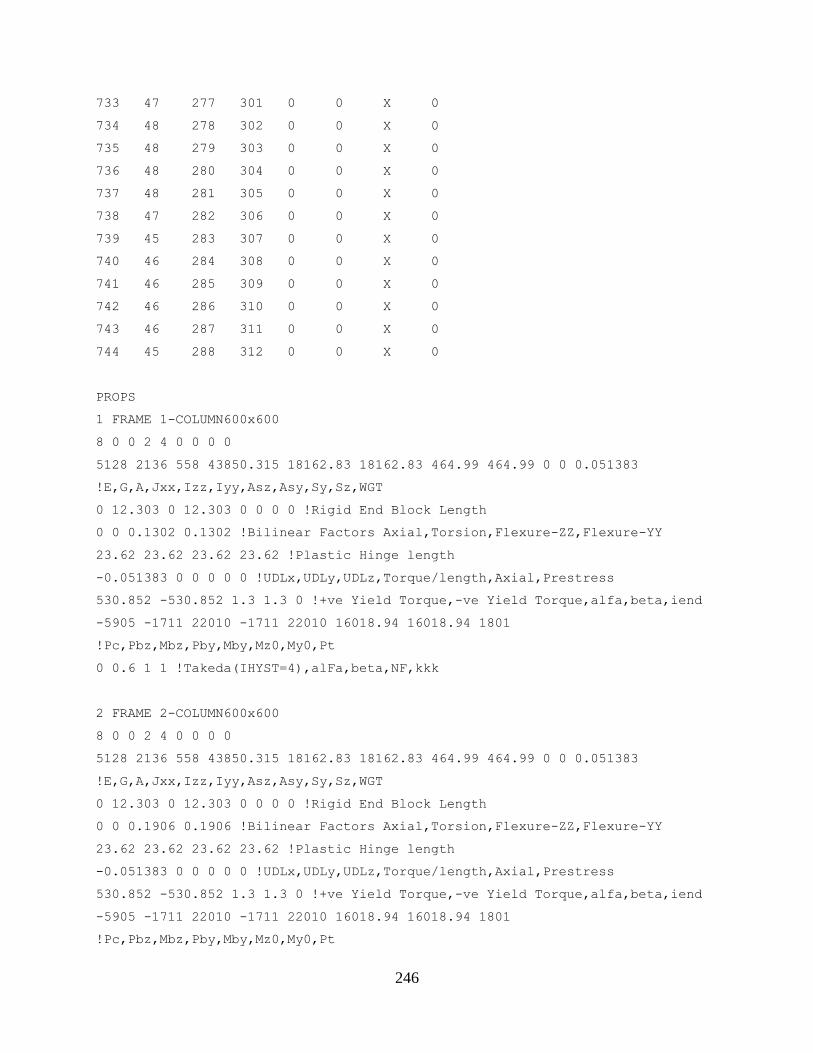
246
733 47 277 301 0 0 X 0
734 48 278 302 0 0 X 0
735 48 279 303 0 0 X 0
736 48 280 304 0 0 X 0
737 48 281 305 0 0 X 0
738 47 282 306 0 0 X 0
739 45 283 307 0 0 X 0
740 46 284 308 0 0 X 0
741 46 285 309 0 0 X 0
742 46 286 310 0 0 X 0
743 46 287 311 0 0 X 0
744 45 288 312 0 0 X 0
PROPS
1 FRAME 1-COLUMN600x600
8 0 0 2 4 0 0 0 0
5128 2136 558 43850.315 18162.83 18162.83 464.99 464.99 0 0 0.051383
!E,G,A,Jxx,Izz,Iyy,Asz,Asy,Sy,Sz,WGT
0 12.303 0 12.303 0 0 0 0 !Rigid End Block Length
0 0 0.1302 0.1302 !Bilinear Factors Axial,Torsion,Flexure-ZZ,Flexure-YY
23.62 23.62 23.62 23.62 !Plastic Hinge length
-0.051383 0 0 0 0 0 !UDLx,UDLy,UDLz,Torque/length,Axial,Prestress
530.852 -530.852 1.3 1.3 0 !+ve Yield Torque,-ve Yield Torque,alfa,beta,iend
-5905 -1711 22010 -1711 22010 16018.94 16018.94 1801
!Pc,Pbz,Mbz,Pby,Mby,Mz0,My0,Pt
0 0.6 1 1 !Takeda(IHYST=4),alFa,beta,NF,kkk
2 FRAME 2-COLUMN600x600
8 0 0 2 4 0 0 0 0
5128 2136 558 43850.315 18162.83 18162.83 464.99 464.99 0 0 0.051383
!E,G,A,Jxx,Izz,Iyy,Asz,Asy,Sy,Sz,WGT
0 12.303 0 12.303 0 0 0 0 !Rigid End Block Length
0 0 0.1906 0.1906 !Bilinear Factors Axial,Torsion,Flexure-ZZ,Flexure-YY
23.62 23.62 23.62 23.62 !Plastic Hinge length
-0.051383 0 0 0 0 0 !UDLx,UDLy,UDLz,Torque/length,Axial,Prestress
530.852 -530.852 1.3 1.3 0 !+ve Yield Torque,-ve Yield Torque,alfa,beta,iend
-5905 -1711 22010 -1711 22010 16018.94 16018.94 1801
!Pc,Pbz,Mbz,Pby,Mby,Mz0,My0,Pt
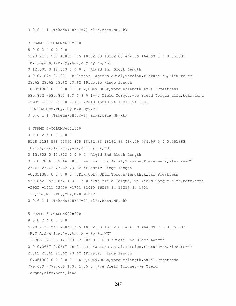
247
0 0.6 1 1 !Takeda(IHYST=4),alFa,beta,NF,kkk
3 FRAME 3-COLUMN600x600
8 0 0 2 4 0 0 0 0
5128 2136 558 43850.315 18162.83 18162.83 464.99 464.99 0 0 0.051383
!E,G,A,Jxx,Izz,Iyy,Asz,Asy,Sy,Sz,WGT
0 12.303 0 12.303 0 0 0 0 !Rigid End Block Length
0 0 0.1874 0.1874 !Bilinear Factors Axial,Torsion,Flexure-ZZ,Flexure-YY
23.62 23.62 23.62 23.62 !Plastic Hinge length
-0.051383 0 0 0 0 0 !UDLx,UDLy,UDLz,Torque/length,Axial,Prestress
530.852 -530.852 1.3 1.3 0 !+ve Yield Torque,-ve Yield Torque,alfa,beta,iend
-5905 -1711 22010 -1711 22010 16018.94 16018.94 1801
!Pc,Pbz,Mbz,Pby,Mby,Mz0,My0,Pt
0 0.6 1 1 !Takeda(IHYST=4),alFa,beta,NF,kkk
4 FRAME 4-COLUMN600x600
8 0 0 2 4 0 0 0 0 0
5128 2136 558 43850.315 18162.83 18162.83 464.99 464.99 0 0 0.051383
!E,G,A,Jxx,Izz,Iyy,Asz,Asy,Sy,Sz,WGT
0 12.303 0 12.303 0 0 0 0 !Rigid End Block Length
0 0 0.2866 0.2866 !Bilinear Factors Axial,Torsion,Flexure-ZZ,Flexure-YY
23.62 23.62 23.62 23.62 !Plastic Hinge length
-0.051383 0 0 0 0 0 !UDLx,UDLy,UDLz,Torque/length,Axial,Prestress
530.852 -530.852 1.3 1.3 0 !+ve Yield Torque,-ve Yield Torque,alfa,beta,iend
-5905 -1711 22010 -1711 22010 16018.94 16018.94 1801
!Pc,Pbz,Mbz,Pby,Mby,Mz0,My0,Pt
0 0.6 1 1 !Takeda(IHYST=4),alFa,beta,NF,kkk
5 FRAME 5-COLUMN600x600
8 0 0 2 4 0 0 0 0
5128 2136 558 43850.315 18162.83 18162.83 464.99 464.99 0 0 0.051383
!E,G,A,Jxx,Izz,Iyy,Asz,Asy,Sy,Sz,WGT
12.303 12.303 12.303 12.303 0 0 0 0 !Rigid End Block Length
0 0 0.0667 0.0667 !Bilinear Factors Axial,Torsion,Flexure-ZZ,Flexure-YY
23.62 23.62 23.62 23.62 !Plastic Hinge length
-0.051383 0 0 0 0 0 !UDLx,UDLy,UDLz,Torque/length,Axial,Prestress
779.689 -779.689 1.35 1.35 0 !+ve Yield Torque,-ve Yield
Torque,alfa,beta,iend
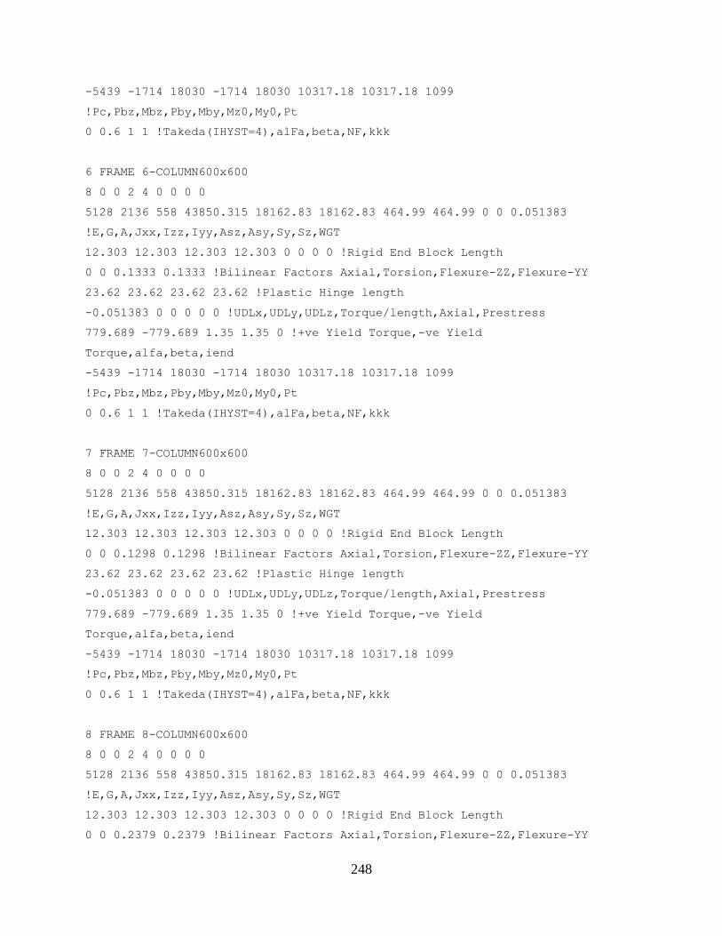
248
-5439 -1714 18030 -1714 18030 10317.18 10317.18 1099
!Pc,Pbz,Mbz,Pby,Mby,Mz0,My0,Pt
0 0.6 1 1 !Takeda(IHYST=4),alFa,beta,NF,kkk
6 FRAME 6-COLUMN600x600
8 0 0 2 4 0 0 0 0
5128 2136 558 43850.315 18162.83 18162.83 464.99 464.99 0 0 0.051383
!E,G,A,Jxx,Izz,Iyy,Asz,Asy,Sy,Sz,WGT
12.303 12.303 12.303 12.303 0 0 0 0 !Rigid End Block Length
0 0 0.1333 0.1333 !Bilinear Factors Axial,Torsion,Flexure-ZZ,Flexure-YY
23.62 23.62 23.62 23.62 !Plastic Hinge length
-0.051383 0 0 0 0 0 !UDLx,UDLy,UDLz,Torque/length,Axial,Prestress
779.689 -779.689 1.35 1.35 0 !+ve Yield Torque,-ve Yield
Torque,alfa,beta,iend
-5439 -1714 18030 -1714 18030 10317.18 10317.18 1099
!Pc,Pbz,Mbz,Pby,Mby,Mz0,My0,Pt
0 0.6 1 1 !Takeda(IHYST=4),alFa,beta,NF,kkk
7 FRAME 7-COLUMN600x600
8 0 0 2 4 0 0 0 0
5128 2136 558 43850.315 18162.83 18162.83 464.99 464.99 0 0 0.051383
!E,G,A,Jxx,Izz,Iyy,Asz,Asy,Sy,Sz,WGT
12.303 12.303 12.303 12.303 0 0 0 0 !Rigid End Block Length
0 0 0.1298 0.1298 !Bilinear Factors Axial,Torsion,Flexure-ZZ,Flexure-YY
23.62 23.62 23.62 23.62 !Plastic Hinge length
-0.051383 0 0 0 0 0 !UDLx,UDLy,UDLz,Torque/length,Axial,Prestress
779.689 -779.689 1.35 1.35 0 !+ve Yield Torque,-ve Yield
Torque,alfa,beta,iend
-5439 -1714 18030 -1714 18030 10317.18 10317.18 1099
!Pc,Pbz,Mbz,Pby,Mby,Mz0,My0,Pt
0 0.6 1 1 !Takeda(IHYST=4),alFa,beta,NF,kkk
8 FRAME 8-COLUMN600x600
8 0 0 2 4 0 0 0 0
5128 2136 558 43850.315 18162.83 18162.83 464.99 464.99 0 0 0.051383
!E,G,A,Jxx,Izz,Iyy,Asz,Asy,Sy,Sz,WGT
12.303 12.303 12.303 12.303 0 0 0 0 !Rigid End Block Length
0 0 0.2379 0.2379 !Bilinear Factors Axial,Torsion,Flexure-ZZ,Flexure-YY
249
23.62 23.62 23.62 23.62 !Plastic Hinge length
-0.051383 0 0 0 0 0 !UDLx,UDLy,UDLz,Torque/length,Axial,Prestress
779.689 -779.689 1.35 1.35 0 !+ve Yield Torque,-ve Yield
Torque,alfa,beta,iend
-5439 -1714 18030 -1714 18030 10317.18 10317.18 1099
!Pc,Pbz,Mbz,Pby,Mby,Mz0,My0,Pt
0 0.6 1 1 !Takeda(IHYST=4),alFa,beta,NF,kkk
9 FRAME 9-COLUMN600x600
8 0 0 2 4 0 0 0 0
5128 2136 558 43850.315 18162.83 18162.83 464.99 464.99 0 0 0.051383
!E,G,A,Jxx,Izz,Iyy,Asz,Asy,Sy,Sz,WGT
12.303 12.303 12.303 12.303 0 0 0 0 !Rigid End Block Length
0 0 0.0451 0.0451 !Bilinear Factors Axial,Torsion,Flexure-ZZ,Flexure-YY
23.62 23.62 23.62 23.62 !Plastic Hinge length
-0.051383 0 0 0 0 0 !UDLx,UDLy,UDLz,Torque/length,Axial,Prestress
779.689 -779.689 1.35 1.35 0 !+ve Yield Torque,-ve Yield
Torque,alfa,beta,iend
-5439 -1714 18030 -1714 18030 10317.18 10317.18 1099
!Pc,Pbz,Mbz,Pby,Mby,Mz0,My0,Pt
0 0.6 1 1 !Takeda(IHYST=4),alFa,beta,NF,kkk
10 FRAME 10-COLUMN600x600
8 0 0 2 4 0 0 0 0
5128 2136 558 43850.315 18162.83 18162.83 464.99 464.99 0 0 0.051383
!E,G,A,Jxx,Izz,Iyy,Asz,Asy,Sy,Sz,WGT
12.303 12.303 12.303 12.303 0 0 0 0 !Rigid End Block Length
0 0 0.1078 0.1078 !Bilinear Factors Axial,Torsion,Flexure-ZZ,Flexure-YY
23.62 23.62 23.62 23.62 !Plastic Hinge length
-0.051383 0 0 0 0 0 !UDLx,UDLy,UDLz,Torque/length,Axial,Prestress
779.689 -779.689 1.35 1.35 0 !+ve Yield Torque,-ve Yield
Torque,alfa,beta,iend
-5439 -1714 18030 -1714 18030 10317.18 10317.18 1099
!Pc,Pbz,Mbz,Pby,Mby,Mz0,My0,Pt
0 0.6 1 1 !Takeda(IHYST=4),alFa,beta,NF,kkk
11 FRAME 11-COLUMN600x600
8 0 0 2 4 0 0 0 0
250
5128 2136 558 43850.315 18162.83 18162.83 464.99 464.99 0 0 0.051383
!E,G,A,Jxx,Izz,Iyy,Asz,Asy,Sy,Sz,WGT
12.303 12.303 12.303 12.303 0 0 0 0 !Rigid End Block Length
0 0 0.1039 0.1039 !Bilinear Factors Axial,Torsion,Flexure-ZZ,Flexure-YY
23.62 23.62 23.62 23.62 !Plastic Hinge length
-0.051383 0 0 0 0 0 !UDLx,UDLy,UDLz,Torque/length,Axial,Prestress
779.689 -779.689 1.35 1.35 0 !+ve Yield Torque,-ve Yield
Torque,alfa,beta,iend
-5439 -1714 18030 -1714 18030 10317.18 10317.18 1099
!Pc,Pbz,Mbz,Pby,Mby,Mz0,My0,Pt
0 0.6 1 1 !Takeda(IHYST=4),alFa,beta,NF,kkk
12 FRAME 12-COLUMN600x600
8 0 0 2 4 0 0 0 0
5128 2136 558 43850.315 18162.83 18162.83 464.99 464.99 0 0 0.051383
!E,G,A,Jxx,Izz,Iyy,Asz,Asy,Sy,Sz,WGT
12.303 12.303 12.303 12.303 0 0 0 0 !Rigid End Block Length
0 0 0.2413 0.2413 !Bilinear Factors Axial,Torsion,Flexure-ZZ,Flexure-YY
23.62 23.62 23.62 23.62 !Plastic Hinge length
-0.051383 0 0 0 0 0 !UDLx,UDLy,UDLz,Torque/length,Axial,Prestress
779.689 -779.689 1.35 1.35 0 !+ve Yield Torque,-ve Yield
Torque,alfa,beta,iend
-5439 -1714 18030 -1714 18030 10317.18 10317.18 1099
!Pc,Pbz,Mbz,Pby,Mby,Mz0,My0,Pt
0 0.6 1 1 !Takeda(IHYST=4),alFa,beta,NF,kkk
13 FRAME 13-COLUMN600x600
8 0 0 2 4 0 0 0 0
5128 2136 558 43850.315 18162.83 18162.83 464.99 464.99 0 0 0.051383
!E,G,A,Jxx,Izz,Iyy,Asz,Asy,Sy,Sz,WGT
12.303 12.303 12.303 12.303 0 0 0 0 !Rigid End Block Length
0 0 0.0218 0.0218 !Bilinear Factors Axial,Torsion,Flexure-ZZ,Flexure-YY
23.62 23.62 23.62 23.62 !Plastic Hinge length
-0.051383 0 0 0 0 0 !UDLx,UDLy,UDLz,Torque/length,Axial,Prestress
698.125 -698.125 1.45 1.45 0 !+ve Yield Torque,-ve Yield
Torque,alfa,beta,iend
-4851 -1879 14260 -1879 14260 4549.44 4549.44 450.2
!Pc,Pbz,Mbz,Pby,Mby,Mz0,My0,Pt
251
0 0.6 1 1 !Takeda(IHYST=4),alFa,beta,NF,kkk
14 FRAME 14-COLUMN600x600
8 0 0 2 4 0 0 0 0
5128 2136 558 43850.315 18162.83 18162.83 464.99 464.99 0 0 0.051383
!E,G,A,Jxx,Izz,Iyy,Asz,Asy,Sy,Sz,WGT
12.303 12.303 12.303 12.303 0 0 0 0 !Rigid End Block Length
0 0 0.0054 0.0054 !Bilinear Factors Axial,Torsion,Flexure-ZZ,Flexure-YY
23.62 23.62 23.62 23.62 !Plastic Hinge length
-0.051383 0 0 0 0 0 !UDLx,UDLy,UDLz,Torque/length,Axial,Prestress
698.125 -698.125 1.45 1.45 0 !+ve Yield Torque,-ve Yield
Torque,alfa,beta,iend
-4851 -1879 14260 -1879 14260 4549.44 4549.44 450.2
!Pc,Pbz,Mbz,Pby,Mby,Mz0,My0,Pt
0 0.6 1 1 !Takeda(IHYST=4),alFa,beta,NF,kkk
15 FRAME 15-COLUMN600x600
8 0 0 2 4 0 0 0 0
5128 2136 558 43850.315 18162.83 18162.83 464.99 464.99 0 0 0.051383
!E,G,A,Jxx,Izz,Iyy,Asz,Asy,Sy,Sz,WGT
12.303 12.303 12.303 12.303 0 0 0 0 !Rigid End Block Length
0 0 0.0019 0.0019 !Bilinear Factors Axial,Torsion,Flexure-ZZ,Flexure-YY
23.62 23.62 23.62 23.62 !Plastic Hinge length
-0.051383 0 0 0 0 0 !UDLx,UDLy,UDLz,Torque/length,Axial,Prestress
698.125 -698.125 1.45 1.45 0 !+ve Yield Torque,-ve Yield
Torque,alfa,beta,iend
-4851 -1879 14260 -1879 14260 4549.44 4549.44 450.2
!Pc,Pbz,Mbz,Pby,Mby,Mz0,My0,Pt
0 0.6 1 1 !Takeda(IHYST=4),alFa,beta,NF,kkk
16 FRAME 16-COLUMN600x600
8 0 0 2 4 0 0 0 0
5128 2136 558 43850.315 18162.83 18162.83 464.99 464.99 0 0 0.051383
!E,G,A,Jxx,Izz,Iyy,Asz,Asy,Sy,Sz,WGT
12.303 12.303 12.303 12.303 0 0 0 0 !Rigid End Block Length
0 0 0.1116 0.1116 !Bilinear Factors Axial,Torsion,Flexure-ZZ,Flexure-YY
23.62 23.62 23.62 23.62 !Plastic Hinge length
-0.051383 0 0 0 0 0 !UDLx,UDLy,UDLz,Torque/length,Axial,Prestress
252
698.125 -698.125 1.45 1.45 0 !+ve Yield Torque,-ve Yield
Torque,alfa,beta,iend
-4851 -1879 14260 -1879 14260 4549.44 4549.44 450.2
!Pc,Pbz,Mbz,Pby,Mby,Mz0,My0,Pt
0 0.6 1 1 !Takeda(IHYST=4),alFa,beta,NF,kkk
17 FRAME 17-COLUMN600x600
8 0 0 2 4 0 0 0 0
5128 2136 558 43850.315 18162.83 18162.83 464.99 464.99 0 0 0.051383
!E,G,A,Jxx,Izz,Iyy,Asz,Asy,Sy,Sz,WGT
12.303 12.303 12.303 12.303 0 0 0 0 !Rigid End Block Length
0 0 0.0249 0.0249 !Bilinear Factors Axial,Torsion,Flexure-ZZ,Flexure-YY
23.62 23.62 23.62 23.62 !Plastic Hinge length
-0.051383 0 0 0 0 0 !UDLx,UDLy,UDLz,Torque/length,Axial,Prestress
698.125 -698.125 1.45 1.45 0 !+ve Yield Torque,-ve Yield
Torque,alfa,beta,iend
-4851 -1879 14260 -1879 14260 4549.44 4549.44 450.2
!Pc,Pbz,Mbz,Pby,Mby,Mz0,My0,Pt
0 0.6 1 1 !Takeda(IHYST=4),alFa,beta,NF,kkk
18 FRAME 18-COLUMN600x600
8 0 0 2 4 0 0 0 0
5128 2136 558 43850.315 18162.83 18162.83 464.99 464.99 0 0 0.051383
!E,G,A,Jxx,Izz,Iyy,Asz,Asy,Sy,Sz,WGT
12.303 12.303 12.303 12.303 0 0 0 0 !Rigid End Block Length
0 0 0.0081 0.0081 !Bilinear Factors Axial,Torsion,Flexure-ZZ,Flexure-YY
23.62 23.62 23.62 23.62 !Plastic Hinge length
-0.051383 0 0 0 0 0 !UDLx,UDLy,UDLz,Torque/length,Axial,Prestress
698.125 -698.125 1.45 1.45 0 !+ve Yield Torque,-ve Yield
Torque,alfa,beta,iend
-4851 -1879 14260 -1879 14260 4549.44 4549.44 450.2
!Pc,Pbz,Mbz,Pby,Mby,Mz0,My0,Pt
0 0.6 1 1 !Takeda(IHYST=4),alFa,beta,NF,kkk
19 FRAME 19-COLUMN600x600
8 0 0 2 4 0 0 0 0
5128 2136 558 43850.315 18162.83 18162.83 464.99 464.99 0 0 0.051383
!E,G,A,Jxx,Izz,Iyy,Asz,Asy,Sy,Sz,WGT
253
12.303 12.303 12.303 12.303 0 0 0 0 !Rigid End Block Length
0 0 0.0098 0.0098 !Bilinear Factors Axial,Torsion,Flexure-ZZ,Flexure-YY
23.62 23.62 23.62 23.62 !Plastic Hinge length
-0.051383 0 0 0 0 0 !UDLx,UDLy,UDLz,Torque/length,Axial,Prestress
698.125 -698.125 1.45 1.45 0 !+ve Yield Torque,-ve Yield
Torque,alfa,beta,iend
-4851 -1879 14260 -1879 14260 4549.44 4549.44 450.2
!Pc,Pbz,Mbz,Pby,Mby,Mz0,My0,Pt
0 0.6 1 1 !Takeda(IHYST=4),alFa,beta,NF,kkk
20 FRAME 20-COLUMN600x600
8 0 0 2 4 0 0 0 0
5128 2136 558 43850.315 18162.83 18162.83 464.99 464.99 0 0 0.051383
!E,G,A,Jxx,Izz,Iyy,Asz,Asy,Sy,Sz,WGT
12.303 12.303 12.303 12.303 0 0 0 0 !Rigid End Block Length
0 0 0.0775 0.0775 !Bilinear Factors Axial,Torsion,Flexure-ZZ,Flexure-YY
23.62 23.62 23.62 23.62 !Plastic Hinge length
-0.051383 0 0 0 0 0 !UDLx,UDLy,UDLz,Torque/length,Axial,Prestress
698.125 -698.125 1.45 1.45 0 !+ve Yield Torque,-ve Yield
Torque,alfa,beta,iend
-4851 -1879 14260 -1879 14260 4549.44 4549.44 450.2
!Pc,Pbz,Mbz,Pby,Mby,Mz0,My0,Pt
0 0.6 1 1 !Takeda(IHYST=4),alFa,beta,NF,kkk
21 FRAME 21-COLUMN600x600
8 0 0 2 4 0 0 0 0
5128 2136 558 43850.315 18162.83 18162.83 464.99 464.99 0 0 0.051383
!E,G,A,Jxx,Izz,Iyy,Asz,Asy,Sy,Sz,WGT
12.303 12.303 12.303 12.303 0 0 0 0 !Rigid End Block Length
0 0 0.0285 0.0285 !Bilinear Factors Axial,Torsion,Flexure-ZZ,Flexure-YY
23.62 23.62 23.62 23.62 !Plastic Hinge length
-0.051383 0 0 0 0 0 !UDLx,UDLy,UDLz,Torque/length,Axial,Prestress
698.125 -698.125 1.45 1.45 0 !+ve Yield Torque,-ve Yield
Torque,alfa,beta,iend
-4851 -1879 14260 -1879 14260 4549.44 4549.44 450.2
!Pc,Pbz,Mbz,Pby,Mby,Mz0,My0,Pt
0 0.6 1 1 !Takeda(IHYST=4),alFa,beta,NF,kkk

254
22 FRAME 22-COLUMN600x600
8 0 0 2 4 0 0 0 0
5128 2136 558 43850.315 18162.83 18162.83 464.99 464.99 0 0 0.051383
!E,G,A,Jxx,Izz,Iyy,Asz,Asy,Sy,Sz,WGT
12.303 12.303 12.303 12.303 0 0 0 0 !Rigid End Block Length
0 0 0.0191 0.0191 !Bilinear Factors Axial,Torsion,Flexure-ZZ,Flexure-YY
23.62 23.62 23.62 23.62 !Plastic Hinge length
-0.051383 0 0 0 0 0 !UDLx,UDLy,UDLz,Torque/length,Axial,Prestress
698.125 -698.125 1.45 1.45 0 !+ve Yield Torque,-ve Yield
Torque,alfa,beta,iend
-4851 -1879 14260 -1879 14260 4549.44 4549.44 450.2
!Pc,Pbz,Mbz,Pby,Mby,Mz0,My0,Pt
0 0.6 1 1 !Takeda(IHYST=4),alFa,beta,NF,kkk
23 FRAME 23-COLUMN600x600
8 0 0 2 4 0 0 0 0
5128 2136 558 43850.315 18162.83 18162.83 464.99 464.99 0 0 0.051383
!E,G,A,Jxx,Izz,Iyy,Asz,Asy,Sy,Sz,WGT
12.303 12.303 12.303 12.303 0 0 0 0 !Rigid End Block Length
0 0 0.0204 0.0204 !Bilinear Factors Axial,Torsion,Flexure-ZZ,Flexure-YY
23.62 23.62 23.62 23.62 !Plastic Hinge length
-0.051383 0 0 0 0 0 !UDLx,UDLy,UDLz,Torque/length,Axial,Prestress
698.125 -698.125 1.45 1.45 0 !+ve Yield Torque,-ve Yield
Torque,alfa,beta,iend
-4851 -1879 14260 -1879 14260 4549.44 4549.44 450.2
!Pc,Pbz,Mbz,Pby,Mby,Mz0,My0,Pt
0 0.6 1 1 !Takeda(IHYST=4),alFa,beta,NF,kkk
24 FRAME 24-COLUMN600x600
8 0 0 2 4 0 0 0 0
5128 2136 558 43850.315 18162.83 18162.83 464.99 464.99 0 0 0.051383
!E,G,A,Jxx,Izz,Iyy,Asz,Asy,Sy,Sz,WGT
12.303 12.303 12.303 12.303 0 0 0 0 !Rigid End Block Length
0 0 0.0415 0.0415 !Bilinear Factors Axial,Torsion,Flexure-ZZ,Flexure-YY
23.62 23.62 23.62 23.62 !Plastic Hinge length
-0.051383 0 0 0 0 0 !UDLx,UDLy,UDLz,Torque/length,Axial,Prestress
698.125 -698.125 1.45 1.45 0 !+ve Yield Torque,-ve Yield
Torque,alfa,beta,iend

255
-4851 -1879 14260 -1879 14260 4549.44 4549.44 450.2
!Pc,Pbz,Mbz,Pby,Mby,Mz0,My0,Pt
0 0.6 1 1 !Takeda(IHYST=4),alFa,beta,NF,kkk
25 FRAME 25-COLUMN600x600
8 0 0 2 4 0 0 0 0
5128 2136 558 43850.315 18162.83 18162.83 464.99 464.99 0 0 0.051383
!E,G,A,Jxx,Izz,Iyy,Asz,Asy,Sy,Sz,WGT
12.303 12.303 12.303 12.303 0 0 0 0 !Rigid End Block Length
0 0 0.0293 0.0293 !Bilinear Factors Axial,Torsion,Flexure-ZZ,Flexure-YY
23.62 23.62 23.62 23.62 !Plastic Hinge length
-0.051383 0 0 0 0 0 !UDLx,UDLy,UDLz,Torque/length,Axial,Prestress
698.125 -698.125 1.45 1.45 0 !+ve Yield Torque,-ve Yield
Torque,alfa,beta,iend
-4851 -1879 14260 -1879 14260 4549.44 4549.44 450.2
!Pc,Pbz,Mbz,Pby,Mby,Mz0,My0,Pt
0 0.6 1 1 !Takeda(IHYST=4),alFa,beta,NF,kkk
26 FRAME 26-COLUMN600x600
8 0 0 2 4 0 0 0 0
5128 2136 558 43850.315 18162.83 18162.83 464.99 464.99 0 0 0.051383
!E,G,A,Jxx,Izz,Iyy,Asz,Asy,Sy,Sz,WGT
12.303 12.303 12.303 12.303 0 0 0 0 !Rigid End Block Length
0 0 0.024 0.024 !Bilinear Factors Axial,Torsion,Flexure-ZZ,Flexure-YY
23.62 23.62 23.62 23.62 !Plastic Hinge length
-0.051383 0 0 0 0 0 !UDLx,UDLy,UDLz,Torque/length,Axial,Prestress
698.125 -698.125 1.45 1.45 0 !+ve Yield Torque,-ve Yield
Torque,alfa,beta,iend
-4851 -1879 14260 -1879 14260 4549.44 4549.44 450.2
!Pc,Pbz,Mbz,Pby,Mby,Mz0,My0,Pt
0 0.6 1 1 !Takeda(IHYST=4),alFa,beta,NF,kkk
27 FRAME 27-COLUMN600x600
8 0 0 2 4 0 0 0 0
5128 2136 558 43850.315 18162.83 18162.83 464.99 464.99 0 0 0.051383
!E,G,A,Jxx,Izz,Iyy,Asz,Asy,Sy,Sz,WGT
12.303 12.303 12.303 12.303 0 0 0 0 !Rigid End Block Length
0 0 0.0246 0.0246 !Bilinear Factors Axial,Torsion,Flexure-ZZ,Flexure-YY
256
23.62 23.62 23.62 23.62 !Plastic Hinge length
-0.051383 0 0 0 0 0 !UDLx,UDLy,UDLz,Torque/length,Axial,Prestress
698.125 -698.125 1.45 1.45 0 !+ve Yield Torque,-ve Yield
Torque,alfa,beta,iend
-4851 -1879 14260 -1879 14260 4549.44 4549.44 450.2
!Pc,Pbz,Mbz,Pby,Mby,Mz0,My0,Pt
0 0.6 1 1 !Takeda(IHYST=4),alFa,beta,NF,kkk
28 FRAME 28-COLUMN600x600
8 0 0 2 4 0 0 0 0
5128 2136 558 43850.315 18162.83 18162.83 464.99 464.99 0 0 0.051383
!E,G,A,Jxx,Izz,Iyy,Asz,Asy,Sy,Sz,WGT
12.303 12.303 12.303 12.303 0 0 0 0 !Rigid End Block Length
0 0 0.0057 0.0057 !Bilinear Factors Axial,Torsion,Flexure-ZZ,Flexure-YY
23.62 23.62 23.62 23.62 !Plastic Hinge length
-0.051383 0 0 0 0 0 !UDLx,UDLy,UDLz,Torque/length,Axial,Prestress
698.125 -698.125 1.45 1.45 0 !+ve Yield Torque,-ve Yield
Torque,alfa,beta,iend
-4851 -1879 14260 -1879 14260 4549.44 4549.44 450.2
!Pc,Pbz,Mbz,Pby,Mby,Mz0,My0,Pt
0 0.6 1 1 !Takeda(IHYST=4),alFa,beta,NF,kkk
29 FRAME 29-COLUMN600x600
8 0 0 2 4 0 0 0 0
5128 2136 558 43850.315 18162.83 18162.83 464.99 464.99 0 0 0.051383
!E,G,A,Jxx,Izz,Iyy,Asz,Asy,Sy,Sz,WGT
12.303 12.303 12.303 12.303 0 0 0 0 !Rigid End Block Length
0 0 0.0278 0.0278 !Bilinear Factors Axial,Torsion,Flexure-ZZ,Flexure-YY
23.62 23.62 23.62 23.62 !Plastic Hinge length
-0.051383 0 0 0 0 0 !UDLx,UDLy,UDLz,Torque/length,Axial,Prestress
698.125 -698.125 1.45 1.45 0 !+ve Yield Torque,-ve Yield
Torque,alfa,beta,iend
-4851 -1879 14260 -1879 14260 4549.44 4549.44 450.2
!Pc,Pbz,Mbz,Pby,Mby,Mz0,My0,Pt
0 0.6 1 1 !Takeda(IHYST=4),alFa,beta,NF,kkk
30 FRAME 30-COLUMN600x600
8 0 0 2 4 0 0 0 0

257
5128 2136 558 43850.315 18162.83 18162.83 464.99 464.99 0 0 0.051383
!E,G,A,Jxx,Izz,Iyy,Asz,Asy,Sy,Sz,WGT
12.303 12.303 12.303 12.303 0 0 0 0 !Rigid End Block Length
0 0 0.0286 0.0286 !Bilinear Factors Axial,Torsion,Flexure-ZZ,Flexure-YY
23.62 23.62 23.62 23.62 !Plastic Hinge length
-0.051383 0 0 0 0 0 !UDLx,UDLy,UDLz,Torque/length,Axial,Prestress
698.125 -698.125 1.45 1.45 0 !+ve Yield Torque,-ve Yield
Torque,alfa,beta,iend
-4851 -1879 14260 -1879 14260 4549.44 4549.44 450.2
!Pc,Pbz,Mbz,Pby,Mby,Mz0,My0,Pt
0 0.6 1 1 !Takeda(IHYST=4),alFa,beta,NF,kkk
31 FRAME 31-COLUMN600x600
8 0 0 2 4 0 0 0 0
5128 2136 558 43850.315 18162.83 18162.83 464.99 464.99 0 0 0.051383
!E,G,A,Jxx,Izz,Iyy,Asz,Asy,Sy,Sz,WGT
12.303 12.303 12.303 12.303 0 0 0 0 !Rigid End Block Length
0 0 0.0283 0.0283 !Bilinear Factors Axial,Torsion,Flexure-ZZ,Flexure-YY
23.62 23.62 23.62 23.62 !Plastic Hinge length
-0.051383 0 0 0 0 0 !UDLx,UDLy,UDLz,Torque/length,Axial,Prestress
698.125 -698.125 1.45 1.45 0 !+ve Yield Torque,-ve Yield
Torque,alfa,beta,iend
-4851 -1879 14260 -1879 14260 4549.44 4549.44 450.2
!Pc,Pbz,Mbz,Pby,Mby,Mz0,My0,Pt
0 0.6 1 1 !Takeda(IHYST=4),alFa,beta,NF,kkk
32 FRAME 32-COLUMN600x600
8 0 0 2 4 0 0 0 0
5128 2136 558 43850.315 18162.83 18162.83 464.99 464.99 0 0 0.051383
!E,G,A,Jxx,Izz,Iyy,Asz,Asy,Sy,Sz,WGT
12.303 12.303 12.303 12.303 0 0 0 0 !Rigid End Block Length
0 0 0.0147 0.0147 !Bilinear Factors Axial,Torsion,Flexure-ZZ,Flexure-YY
23.62 23.62 23.62 23.62 !Plastic Hinge length
-0.051383 0 0 0 0 0 !UDLx,UDLy,UDLz,Torque/length,Axial,Prestress
698.125 -698.125 1.45 1.45 0 !+ve Yield Torque,-ve Yield
Torque,alfa,beta,iend
-4851 -1879 14260 -1879 14260 4549.44 4549.44 450.2
!Pc,Pbz,Mbz,Pby,Mby,Mz0,My0,Pt
258
0 0.6 1 1 !Takeda(IHYST=4),alFa,beta,NF,kkk
33 FRAME 33-COLUMN600x600
8 0 0 2 4 0 0 0 0
5128 2136 558 43850.315 18162.83 18162.83 464.99 464.99 0 0 0.051383
!E,G,A,Jxx,Izz,Iyy,Asz,Asy,Sy,Sz,WGT
12.303 12.303 12.303 12.303 0 0 0 0 !Rigid End Block Length
0 0 0.0277 0.0277 !Bilinear Factors Axial,Torsion,Flexure-ZZ,Flexure-YY
23.62 23.62 23.62 23.62 !Plastic Hinge length
-0.051383 0 0 0 0 0 !UDLx,UDLy,UDLz,Torque/length,Axial,Prestress
698.125 -698.125 1.45 1.45 0 !+ve Yield Torque,-ve Yield
Torque,alfa,beta,iend
-4851 -1879 14260 -1879 14260 4549.44 4549.44 450.2
!Pc,Pbz,Mbz,Pby,Mby,Mz0,My0,Pt
0 0.6 1 1 !Takeda(IHYST=4),alFa,beta,NF,kkk
34 FRAME 34-COLUMN600x600
8 0 0 2 4 0 0 0 0
5128 2136 558 43850.315 18162.83 18162.83 464.99 464.99 0 0 0.051383
!E,G,A,Jxx,Izz,Iyy,Asz,Asy,Sy,Sz,WGT
12.303 12.303 12.303 12.303 0 0 0 0 !Rigid End Block Length
0 0 0.0287 0.0287 !Bilinear Factors Axial,Torsion,Flexure-ZZ,Flexure-YY
23.62 23.62 23.62 23.62 !Plastic Hinge length
-0.051383 0 0 0 0 0 !UDLx,UDLy,UDLz,Torque/length,Axial,Prestress
698.125 -698.125 1.45 1.45 0 !+ve Yield Torque,-ve Yield
Torque,alfa,beta,iend
-4851 -1879 14260 -1879 14260 4549.44 4549.44 450.2
!Pc,Pbz,Mbz,Pby,Mby,Mz0,My0,Pt
0 0.6 1 1 !Takeda(IHYST=4),alFa,beta,NF,kkk
35 FRAME 35-COLUMN600x600
8 0 0 2 4 0 0 0 0
5128 2136 558 43850.315 18162.83 18162.83 464.99 464.99 0 0 0.051383
!E,G,A,Jxx,Izz,Iyy,Asz,Asy,Sy,Sz,WGT
12.303 12.303 12.303 12.303 0 0 0 0 !Rigid End Block Length
0 0 0.0288 0.0288 !Bilinear Factors Axial,Torsion,Flexure-ZZ,Flexure-YY
23.62 23.62 23.62 23.62 !Plastic Hinge length
-0.051383 0 0 0 0 0 !UDLx,UDLy,UDLz,Torque/length,Axial,Prestress
259
698.125 -698.125 1.45 1.45 0 !+ve Yield Torque,-ve Yield
Torque,alfa,beta,iend
-4851 -1879 14260 -1879 14260 4549.44 4549.44 450.2
!Pc,Pbz,Mbz,Pby,Mby,Mz0,My0,Pt
0 0.6 1 1 !Takeda(IHYST=4),alFa,beta,NF,kkk
36 FRAME 36-COLUMN600x600
8 0 0 2 4 0 0 0 0
5128 2136 558 43850.315 18162.83 18162.83 464.99 464.99 0 0 0.051383
!E,G,A,Jxx,Izz,Iyy,Asz,Asy,Sy,Sz,WGT
12.303 12.303 12.303 12.303 0 0 0 0 !Rigid End Block Length
0 0 0.0249 0.0249 !Bilinear Factors Axial,Torsion,Flexure-ZZ,Flexure-YY
23.62 23.62 23.62 23.62 !Plastic Hinge length
-0.051383 0 0 0 0 0 !UDLx,UDLy,UDLz,Torque/length,Axial,Prestress
698.125 -698.125 1.45 1.45 0 !+ve Yield Torque,-ve Yield
Torque,alfa,beta,iend
-4851 -1879 14260 -1879 14260 4549.44 4549.44 450.2
!Pc,Pbz,Mbz,Pby,Mby,Mz0,My0,Pt
0 0.6 1 1 !Takeda(IHYST=4),alFa,beta,NF,kkk
37 FRAME 37-COLUMN600x600
8 0 0 2 4 0 0 0 0
5128 2136 558 43850.315 18162.83 18162.83 464.99 464.99 0 0 0.051383
!E,G,A,Jxx,Izz,Iyy,Asz,Asy,Sy,Sz,WGT
12.303 12.303 12.303 12.303 0 0 0 0 !Rigid End Block Length
0 0 0.0274 0.0274 !Bilinear Factors Axial,Torsion,Flexure-ZZ,Flexure-YY
23.62 23.62 23.62 23.62 !Plastic Hinge length
-0.051383 0 0 0 0 0 !UDLx,UDLy,UDLz,Torque/length,Axial,Prestress
698.125 -698.125 1.45 1.45 0 !+ve Yield Torque,-ve Yield
Torque,alfa,beta,iend
-4851 -1879 14260 -1879 14260 4549.44 4549.44 450.2
!Pc,Pbz,Mbz,Pby,Mby,Mz0,My0,Pt
0 0.6 1 1 !Takeda(IHYST=4),alFa,beta,NF,kkk
38 FRAME 38-COLUMN600x600
8 0 0 2 4 0 0 0 0
5128 2136 558 43850.315 18162.83 18162.83 464.99 464.99 0 0 0.051383
!E,G,A,Jxx,Izz,Iyy,Asz,Asy,Sy,Sz,WGT

260
12.303 12.303 12.303 12.303 0 0 0 0 !Rigid End Block Length
0 0 0.0278 0.0278 !Bilinear Factors Axial,Torsion,Flexure-ZZ,Flexure-YY
23.62 23.62 23.62 23.62 !Plastic Hinge length
-0.051383 0 0 0 0 0 !UDLx,UDLy,UDLz,Torque/length,Axial,Prestress
698.125 -698.125 1.45 1.45 0 !+ve Yield Torque,-ve Yield
Torque,alfa,beta,iend
-4851 -1879 14260 -1879 14260 4549.44 4549.44 450.2
!Pc,Pbz,Mbz,Pby,Mby,Mz0,My0,Pt
0 0.6 1 1 !Takeda(IHYST=4),alFa,beta,NF,kkk
39 FRAME 39-COLUMN600x600
8 0 0 2 4 0 0 0 0
5128 2136 558 43850.315 18162.83 18162.83 464.99 464.99 0 0 0.051383
!E,G,A,Jxx,Izz,Iyy,Asz,Asy,Sy,Sz,WGT
12.303 12.303 12.303 12.303 0 0 0 0 !Rigid End Block Length
0 0 0.0276 0.0276 !Bilinear Factors Axial,Torsion,Flexure-ZZ,Flexure-YY
23.62 23.62 23.62 23.62 !Plastic Hinge length
-0.051383 0 0 0 0 0 !UDLx,UDLy,UDLz,Torque/length,Axial,Prestress
698.125 -698.125 1.45 1.45 0 !+ve Yield Torque,-ve Yield
Torque,alfa,beta,iend
-4851 -1879 14260 -1879 14260 4549.44 4549.44 450.2
!Pc,Pbz,Mbz,Pby,Mby,Mz0,My0,Pt
0 0.6 1 1 !Takeda(IHYST=4),alFa,beta,NF,kkk
40 FRAME 40-COLUMN600x600
8 0 0 2 4 0 0 0 0
5128 2136 558 43850.315 18162.83 18162.83 464.99 464.99 0 0 0.051383
!E,G,A,Jxx,Izz,Iyy,Asz,Asy,Sy,Sz,WGT
12.303 12.303 12.303 12.303 0 0 0 0 !Rigid End Block Length
0 0 0.0295 0.0295 !Bilinear Factors Axial,Torsion,Flexure-ZZ,Flexure-YY
23.62 23.62 23.62 23.62 !Plastic Hinge length
-0.051383 0 0 0 0 0 !UDLx,UDLy,UDLz,Torque/length,Axial,Prestress
698.125 -698.125 1.45 1.45 0 !+ve Yield Torque,-ve Yield
Torque,alfa,beta,iend
-4851 -1879 14260 -1879 14260 4549.44 4549.44 450.2
!Pc,Pbz,Mbz,Pby,Mby,Mz0,My0,Pt
0 0.6 1 1 !Takeda(IHYST=4),alFa,beta,NF,kkk
261
41 FRAME 41-COLUMN600x600
8 0 0 2 4 0 0 0 0
5128 2136 558 43850.315 18162.83 18162.83 464.99 464.99 0 0 0.051383
!E,G,A,Jxx,Izz,Iyy,Asz,Asy,Sy,Sz,WGT
12.303 12.303 12.303 12.303 0 0 0 0 !Rigid End Block Length
0 0 0.0268 0.0268 !Bilinear Factors Axial,Torsion,Flexure-ZZ,Flexure-YY
23.62 23.62 23.62 23.62 !Plastic Hinge length
-0.051383 0 0 0 0 0 !UDLx,UDLy,UDLz,Torque/length,Axial,Prestress
698.125 -698.125 1.45 1.45 0 !+ve Yield Torque,-ve Yield
Torque,alfa,beta,iend
-4851 -1879 14260 -1879 14260 4549.44 4549.44 450.2
!Pc,Pbz,Mbz,Pby,Mby,Mz0,My0,Pt
0 0.6 1 1 !Takeda(IHYST=4),alFa,beta,NF,kkk
42 FRAME 42-COLUMN600x600
8 0 0 2 4 0 0 0 0
5128 2136 558 43850.315 18162.83 18162.83 464.99 464.99 0 0 0.051383
!E,G,A,Jxx,Izz,Iyy,Asz,Asy,Sy,Sz,WGT
12.303 12.303 12.303 12.303 0 0 0 0 !Rigid End Block Length
0 0 0.0274 0.0274 !Bilinear Factors Axial,Torsion,Flexure-ZZ,Flexure-YY
23.62 23.62 23.62 23.62 !Plastic Hinge length
-0.051383 0 0 0 0 0 !UDLx,UDLy,UDLz,Torque/length,Axial,Prestress
698.125 -698.125 1.45 1.45 0 !+ve Yield Torque,-ve Yield
Torque,alfa,beta,iend
-4851 -1879 14260 -1879 14260 4549.44 4549.44 450.2
!Pc,Pbz,Mbz,Pby,Mby,Mz0,My0,Pt
0 0.6 1 1 !Takeda(IHYST=4),alFa,beta,NF,kkk
43 FRAME 43-COLUMN600x600
8 0 0 2 4 0 0 0 0
5128 2136 558 43850.315 18162.83 18162.83 464.99 464.99 0 0 0.051383
!E,G,A,Jxx,Izz,Iyy,Asz,Asy,Sy,Sz,WGT
12.303 12.303 12.303 12.303 0 0 0 0 !Rigid End Block Length
0 0 0.0269 0.0269 !Bilinear Factors Axial,Torsion,Flexure-ZZ,Flexure-YY
23.62 23.62 23.62 23.62 !Plastic Hinge length
-0.051383 0 0 0 0 0 !UDLx,UDLy,UDLz,Torque/length,Axial,Prestress
698.125 -698.125 1.45 1.45 0 !+ve Yield Torque,-ve Yield
Torque,alfa,beta,iend

262
-4851 -1879 14260 -1879 14260 4549.44 4549.44 450.2
!Pc,Pbz,Mbz,Pby,Mby,Mz0,My0,Pt
0 0.6 1 1 !Takeda(IHYST=4),alFa,beta,NF,kkk
44 FRAME 44-COLUMN600x600
8 0 0 2 4 0 0 0 0
5128 2136 558 43850.315 18162.83 18162.83 464.99 464.99 0 0 0.051383
!E,G,A,Jxx,Izz,Iyy,Asz,Asy,Sy,Sz,WGT
12.303 12.303 12.303 12.303 0 0 0 0 !Rigid End Block Length
0 0 0.0275 0.0275 !Bilinear Factors Axial,Torsion,Flexure-ZZ,Flexure-YY
23.62 23.62 23.62 23.62 !Plastic Hinge length
-0.051383 0 0 0 0 0 !UDLx,UDLy,UDLz,Torque/length,Axial,Prestress
698.125 -698.125 1.45 1.45 0 !+ve Yield Torque,-ve Yield
Torque,alfa,beta,iend
-4851 -1879 14260 -1879 14260 4549.44 4549.44 450.2
!Pc,Pbz,Mbz,Pby,Mby,Mz0,My0,Pt
0 0.6 1 1 !Takeda(IHYST=4),alFa,beta,NF,kkk
45 FRAME 45-COLUMN600x600
8 0 0 2 4 0 0 0 0
5128 2136 558 43850.315 18162.83 18162.83 464.99 464.99 0 0 0.051383
!E,G,A,Jxx,Izz,Iyy,Asz,Asy,Sy,Sz,WGT
12.303 12.303 12.303 12.303 0 0 0 0 !Rigid End Block Length
0 0 0.0262 0.0262 !Bilinear Factors Axial,Torsion,Flexure-ZZ,Flexure-YY
23.62 23.62 23.62 23.62 !Plastic Hinge length
-0.051383 0 0 0 0 0 !UDLx,UDLy,UDLz,Torque/length,Axial,Prestress
698.125 -698.125 1.45 1.45 0 !+ve Yield Torque,-ve Yield
Torque,alfa,beta,iend
-4851 -1879 14260 -1879 14260 4549.44 4549.44 450.2
!Pc,Pbz,Mbz,Pby,Mby,Mz0,My0,Pt
0 0.6 1 1 !Takeda(IHYST=4),alFa,beta,NF,kkk
46 FRAME 46-COLUMN600x600
8 0 0 2 4 0 0 0 0
5128 2136 558 43850.315 18162.83 18162.83 464.99 464.99 0 0 0.051383
!E,G,A,Jxx,Izz,Iyy,Asz,Asy,Sy,Sz,WGT
12.303 12.303 12.303 12.303 0 0 0 0 !Rigid End Block Length
0 0 0.0262 0.0262 !Bilinear Factors Axial,Torsion,Flexure-ZZ,Flexure-YY
263
23.62 23.62 23.62 23.62 !Plastic Hinge length
-0.051383 0 0 0 0 0 !UDLx,UDLy,UDLz,Torque/length,Axial,Prestress
698.125 -698.125 1.45 1.45 0 !+ve Yield Torque,-ve Yield
Torque,alfa,beta,iend
-4851 -1879 14260 -1879 14260 4549.44 4549.44 450.2
!Pc,Pbz,Mbz,Pby,Mby,Mz0,My0,Pt
0 0.6 1 1 !Takeda(IHYST=4),alFa,beta,NF,kkk
47 FRAME 47-COLUMN600x600
8 0 0 2 4 0 0 0 0
5128 2136 558 43850.315 18162.83 18162.83 464.99 464.99 0 0 0.051383
!E,G,A,Jxx,Izz,Iyy,Asz,Asy,Sy,Sz,WGT
12.303 12.303 12.303 12.303 0 0 0 0 !Rigid End Block Length
0 0 0.0261 0.0261 !Bilinear Factors Axial,Torsion,Flexure-ZZ,Flexure-YY
23.62 23.62 23.62 23.62 !Plastic Hinge length
-0.051383 0 0 0 0 0 !UDLx,UDLy,UDLz,Torque/length,Axial,Prestress
698.125 -698.125 1.45 1.45 0 !+ve Yield Torque,-ve Yield
Torque,alfa,beta,iend
-4851 -1879 14260 -1879 14260 4549.44 4549.44 450.2
!Pc,Pbz,Mbz,Pby,Mby,Mz0,My0,Pt
0 0.6 1 1 !Takeda(IHYST=4),alFa,beta,NF,kkk
48 FRAME 48-COLUMN600x600
8 0 0 2 4 0 0 0 0
5128 2136 558 43850.315 18162.83 18162.83 464.99 464.99 0 0 0.051383
!E,G,A,Jxx,Izz,Iyy,Asz,Asy,Sy,Sz,WGT
12.303 12.303 12.303 12.303 0 0 0 0 !Rigid End Block Length
0 0 0.0267 0.0267 !Bilinear Factors Axial,Torsion,Flexure-ZZ,Flexure-YY
23.62 23.62 23.62 23.62 !Plastic Hinge length
-0.051383 0 0 0 0 0 !UDLx,UDLy,UDLz,Torque/length,Axial,Prestress
698.125 -698.125 1.45 1.45 0 !+ve Yield Torque,-ve Yield
Torque,alfa,beta,iend
-4851 -1879 14260 -1879 14260 4549.44 4549.44 450.2
!Pc,Pbz,Mbz,Pby,Mby,Mz0,My0,Pt
0 0.6 1 1 !Takeda(IHYST=4),alFa,beta,NF,kkk
49 BEAM 49-BEAM400x625
2 1 0 0 2 4 0 0 0 0
264
5128 2136 387.5 19298.15 6842.82 2802.88 322.92 322.92 0 0 0.0356992
!E,G,A,Jxx,Izz,Iyy,Asz,Asy,Sy,Sz,WGT
11.81 11.81 11.81 11.81 0 0 0 0 !Rigid End Block Length
0 0 0.0169 0.0883 !Bilinear Factors Axial,Torsion,Flexure-ZZ,Flexure-YY
47.24 47.24 47.24 47.24 !Plastic Hinge length
0 -0.13962 0 0 0 !UDLx,UDLy,UDLz,Torque/length,Axial,Prestress
750.3 -3562 187.127 -187.127 2.4 0 !Pyt,pyc,Ty+,Ty-,alfa,iend
7723.38 -7723.38 4397.32 -4397.32 !Myz+,Myz-,Myy+,Myy-
0 0.6 1 1 !Takeda(IHYST=4),alFa,beta,NF,kkk
50 BEAM 50-BEAM400x625
2 1 0 0 2 4 0 0 0 0
5128 2136 387.5 19298.15 6842.82 2802.88 322.92 322.92 0 0 0.0356992
!E,G,A,Jxx,Izz,Iyy,Asz,Asy,Sy,Sz,WGT
11.81 11.81 11.81 11.81 0 0 0 0 !Rigid End Block Length
0 0 0.0169 0.0883 !Bilinear Factors Axial,Torsion,Flexure-ZZ,Flexure-YY
47.24 47.24 47.24 47.24 !Plastic Hinge length
0 -0.20736 0 0 0 !UDLx,UDLy,UDLz,Torque/length,Axial,Prestress
750.3 -3562 187.127 -187.127 2.4 0 !Pyt,pyc,Ty+,Ty-,alfa,iend
7723.38 -7723.38 4397.32 -4397.32 !Myz+,Myz-,Myy+,Myy-
0 0.6 1 1 !Takeda(IHYST=4),alFa,beta,NF,kkk
51 BEAM 51-BEAM400x625
2 1 0 0 2 4 0 0 0 0
5128 2136 387.5 19298.15 6842.82 2802.88 322.92 322.92 0 0 0.0356992
!E,G,A,Jxx,Izz,Iyy,Asz,Asy,Sy,Sz,WGT
11.81 11.81 11.81 11.81 0 0 0 0 !Rigid End Block Length
0 0 0.0169 0.0883 !Bilinear Factors Axial,Torsion,Flexure-ZZ,Flexure-YY
47.24 47.24 47.24 47.24 !Plastic Hinge length
0 -0.15484 0 0 0 !UDLx,UDLy,UDLz,Torque/length,Axial,Prestress
750.3 -3562 187.127 -187.127 2.4 0 !Pyt,pyc,Ty+,Ty-,alfa,iend
7723.38 -7723.38 4397.32 -4397.32 !Myz+,Myz-,Myy+,Myy-
0 0.6 1 1 !Takeda(IHYST=4),alFa,beta,NF,kkk
52 BEAM 52-BEAM400x625
2 1 0 0 2 4 0 0 0 0
5128 2136 387.5 19298.15 6842.82 2802.88 322.92 322.92 0 0 0.0356992
!E,G,A,Jxx,Izz,Iyy,Asz,Asy,Sy,Sz,WGT
265
11.81 11.81 11.81 11.81 0 0 0 0 !Rigid End Block Length
0 0 0.0169 0.0883 !Bilinear Factors Axial,Torsion,Flexure-ZZ,Flexure-YY
47.24 47.24 47.24 47.24 !Plastic Hinge length
0 -0.11699 0 0 0 !UDLx,UDLy,UDLz,Torque/length,Axial,Prestress
750.3 -3562 187.127 -187.127 2.4 0 !Pyt,pyc,Ty+,Ty-,alfa,iend
7723.38 -7723.38 4397.32 -4397.32 !Myz+,Myz-,Myy+,Myy-
0 0.6 1 1 !Takeda(IHYST=4),alFa,beta,NF,kkk
53 BEAM 53-BEAM400x625
2 1 0 0 2 4 0 0 0 0
5128 2136 387.5 19298.15 6842.82 2802.88 322.92 322.92 0 0 0.0356992
!E,G,A,Jxx,Izz,Iyy,Asz,Asy,Sy,Sz,WGT
11.81 11.81 11.81 11.81 0 0 0 0 !Rigid End Block Length
0 0 0.0169 0.0883 !Bilinear Factors Axial,Torsion,Flexure-ZZ,Flexure-YY
47.24 47.24 47.24 47.24 !Plastic Hinge length
0 -0.16211 0 0 0 !UDLx,UDLy,UDLz,Torque/length,Axial,Prestress
750.3 -3562 187.127 -187.127 2.4 0 !Pyt,pyc,Ty+,Ty-,alfa,iend
7723.38 -7723.38 4397.32 -4397.32 !Myz+,Myz-,Myy+,Myy-
0 0.6 1 1 !Takeda(IHYST=4),alFa,beta,NF,kkk
54 BEAM 54-BEAM400x625
2 1 0 0 2 4 0 0 0 0
5128 2136 387.5 19298.15 6842.82 2802.88 322.92 322.92 0 0 0.0356992
!E,G,A,Jxx,Izz,Iyy,Asz,Asy,Sy,Sz,WGT
11.81 11.81 11.81 11.81 0 0 0 0 !Rigid End Block Length
0 0 0.0169 0.0883 !Bilinear Factors Axial,Torsion,Flexure-ZZ,Flexure-YY
47.24 47.24 47.24 47.24 !Plastic Hinge length
0 -0.13221 0 0 0 !UDLx,UDLy,UDLz,Torque/length,Axial,Prestress
750.3 -3562 187.127 -187.127 2.4 0 !Pyt,pyc,Ty+,Ty-,alfa,iend
7723.38 -7723.38 4397.32 -4397.32 !Myz+,Myz-,Myy+,Myy-
0 0.6 1 1 !Takeda(IHYST=4),alFa,beta,NF,kkk
WEIGHTS
1 0 0 0 0 0 0
2 0 0 0 0 0 0
3 0 0 0 0 0 0
4 0 0 0 0 0 0
5 0 0 0 0 0 0
266
6 0 0 0 0 0 0
7 0 0 0 0 0 0
8 0 0 0 0 0 0
9 0 0 0 0 0 0
10 0 0 0 0 0 0
11 0 0 0 0 0 0
12 0 0 0 0 0 0
13 0 0 0 0 0 0
14 0 0 0 0 0 0
15 0 0 0 0 0 0
16 0 0 0 0 0 0
17 0 0 0 0 0 0
18 0 0 0 0 0 0
19 0 0 0 0 0 0
20 0 0 0 0 0 0
21 0 0 0 0 0 0
22 0 0 0 0 0 0
23 0 0 0 0 0 0
24 0 0 0 0 0 0
25 25.94 25.94 25.94 0 0 0
26 44.48 44.48 44.48 0 0 0
27 44.48 44.48 44.48 0 0 0
28 44.48 44.48 44.48 0 0 0
29 44.48 44.48 44.48 0 0 0
30 25.94 25.94 25.94 0 0 0
31 44.48 44.48 44.48 0 0 0
32 74.16 74.16 74.16 0 0 0
33 74.16 74.16 74.16 0 0 0
34 74.16 74.16 74.16 0 0 0
35 74.16 74.16 74.16 0 0 0
36 44.48 44.48 44.48 0 0 0
37 44.48 44.48 44.48 0 0 0
38 74.16 74.16 74.16 0 0 0
39 74.16 74.16 74.16 0 0 0
40 74.16 74.16 74.16 0 0 0
41 74.16 74.16 74.16 0 0 0
42 44.48 44.48 44.48 0 0 0
43 25.94 25.94 25.94 0 0 0
267
44 44.48 44.48 44.48 0 0 0
45 44.48 44.48 44.48 0 0 0
46 44.48 44.48 44.48 0 0 0
47 44.48 44.48 44.48 0 0 0
48 25.94 25.94 25.94 0 0 0
49 25.94 25.94 25.94 0 0 0
50 44.48 44.48 44.48 0 0 0
51 44.48 44.48 44.48 0 0 0
52 44.48 44.48 44.48 0 0 0
53 44.48 44.48 44.48 0 0 0
54 25.94 25.94 25.94 0 0 0
55 44.48 44.48 44.48 0 0 0
56 74.16 74.16 74.16 0 0 0
57 74.16 74.16 74.16 0 0 0
58 74.16 74.16 74.16 0 0 0
59 74.16 74.16 74.16 0 0 0
60 44.48 44.48 44.48 0 0 0
61 44.48 44.48 44.48 0 0 0
62 74.16 74.16 74.16 0 0 0
63 74.16 74.16 74.16 0 0 0
64 74.16 74.16 74.16 0 0 0
65 74.16 74.16 74.16 0 0 0
66 44.48 44.48 44.48 0 0 0
67 25.94 25.94 25.94 0 0 0
68 44.48 44.48 44.48 0 0 0
69 44.48 44.48 44.48 0 0 0
70 44.48 44.48 44.48 0 0 0
71 44.48 44.48 44.48 0 0 0
72 25.94 25.94 25.94 0 0 0
73 25.94 25.94 25.94 0 0 0
74 44.48 44.48 44.48 0 0 0
75 44.48 44.48 44.48 0 0 0
76 44.48 44.48 44.48 0 0 0
77 44.48 44.48 44.48 0 0 0
78 25.94 25.94 25.94 0 0 0
79 44.48 44.48 44.48 0 0 0
80 74.16 74.16 74.16 0 0 0
81 74.16 74.16 74.16 0 0 0

268
82 74.16 74.16 74.16 0 0 0
83 74.16 74.16 74.16 0 0 0
84 44.48 44.48 44.48 0 0 0
85 44.48 44.48 44.48 0 0 0
86 74.16 74.16 74.16 0 0 0
87 74.16 74.16 74.16 0 0 0
88 74.16 74.16 74.16 0 0 0
89 74.16 74.16 74.16 0 0 0
90 44.48 44.48 44.48 0 0 0
91 25.94 25.94 25.94 0 0 0
92 44.48 44.48 44.48 0 0 0
93 44.48 44.48 44.48 0 0 0
94 44.48 44.48 44.48 0 0 0
95 44.48 44.48 44.48 0 0 0
96 25.94 25.94 25.94 0 0 0
97 25.94 25.94 25.94 0 0 0
98 44.48 44.48 44.48 0 0 0
99 44.48 44.48 44.48 0 0 0
100 44.48 44.48 44.48 0 0 0
101 44.48 44.48 44.48 0 0 0
102 25.94 25.94 25.94 0 0 0
103 44.48 44.48 44.48 0 0 0
104 74.16 74.16 74.16 0 0 0
105 74.16 74.16 74.16 0 0 0
106 74.16 74.16 74.16 0 0 0
107 74.16 74.16 74.16 0 0 0
108 44.48 44.48 44.48 0 0 0
109 44.48 44.48 44.48 0 0 0
110 74.16 74.16 74.16 0 0 0
111 74.16 74.16 74.16 0 0 0
112 74.16 74.16 74.16 0 0 0
113 74.16 74.16 74.16 0 0 0
114 44.48 44.48 44.48 0 0 0
115 25.94 25.94 25.94 0 0 0
116 44.48 44.48 44.48 0 0 0
117 44.48 44.48 44.48 0 0 0
118 44.48 44.48 44.48 0 0 0
119 44.48 44.48 44.48 0 0 0
269
120 25.94 25.94 25.94 0 0 0
121 25.94 25.94 25.94 0 0 0
122 44.48 44.48 44.48 0 0 0
123 44.48 44.48 44.48 0 0 0
124 44.48 44.48 44.48 0 0 0
125 44.48 44.48 44.48 0 0 0
126 25.94 25.94 25.94 0 0 0
127 44.48 44.48 44.48 0 0 0
128 74.16 74.16 74.16 0 0 0
129 74.16 74.16 74.16 0 0 0
130 74.16 74.16 74.16 0 0 0
131 74.16 74.16 74.16 0 0 0
132 44.48 44.48 44.48 0 0 0
133 44.48 44.48 44.48 0 0 0
134 74.16 74.16 74.16 0 0 0
135 74.16 74.16 74.16 0 0 0
136 74.16 74.16 74.16 0 0 0
137 74.16 74.16 74.16 0 0 0
138 44.48 44.48 44.48 0 0 0
139 25.94 25.94 25.94 0 0 0
140 44.48 44.48 44.48 0 0 0
141 44.48 44.48 44.48 0 0 0
142 44.48 44.48 44.48 0 0 0
143 44.48 44.48 44.48 0 0 0
144 25.94 25.94 25.94 0 0 0
145 25.94 25.94 25.94 0 0 0
146 44.48 44.48 44.48 0 0 0
147 44.48 44.48 44.48 0 0 0
148 44.48 44.48 44.48 0 0 0
149 44.48 44.48 44.48 0 0 0
150 25.94 25.94 25.94 0 0 0
151 44.48 44.48 44.48 0 0 0
152 74.16 74.16 74.16 0 0 0
153 74.16 74.16 74.16 0 0 0
154 74.16 74.16 74.16 0 0 0
155 74.16 74.16 74.16 0 0 0
156 44.48 44.48 44.48 0 0 0
157 44.48 44.48 44.48 0 0 0
270
158 74.16 74.16 74.16 0 0 0
159 74.16 74.16 74.16 0 0 0
160 74.16 74.16 74.16 0 0 0
161 74.16 74.16 74.16 0 0 0
162 44.48 44.48 44.48 0 0 0
163 25.94 25.94 25.94 0 0 0
164 44.48 44.48 44.48 0 0 0
165 44.48 44.48 44.48 0 0 0
166 44.48 44.48 44.48 0 0 0
167 44.48 44.48 44.48 0 0 0
168 25.94 25.94 25.94 0 0 0
169 25.94 25.94 25.94 0 0 0
170 44.48 44.48 44.48 0 0 0
171 44.48 44.48 44.48 0 0 0
172 44.48 44.48 44.48 0 0 0
173 44.48 44.48 44.48 0 0 0
174 25.94 25.94 25.94 0 0 0
175 44.48 44.48 44.48 0 0 0
176 74.16 74.16 74.16 0 0 0
177 74.16 74.16 74.16 0 0 0
178 74.16 74.16 74.16 0 0 0
179 74.16 74.16 74.16 0 0 0
180 44.48 44.48 44.48 0 0 0
181 44.48 44.48 44.48 0 0 0
182 74.16 74.16 74.16 0 0 0
183 74.16 74.16 74.16 0 0 0
184 74.16 74.16 74.16 0 0 0
185 74.16 74.16 74.16 0 0 0
186 44.48 44.48 44.48 0 0 0
187 25.94 25.94 25.94 0 0 0
188 44.48 44.48 44.48 0 0 0
189 44.48 44.48 44.48 0 0 0
190 44.48 44.48 44.48 0 0 0
191 44.48 44.48 44.48 0 0 0
192 25.94 25.94 25.94 0 0 0
193 25.94 25.94 25.94 0 0 0
194 44.48 44.48 44.48 0 0 0
195 44.48 44.48 44.48 0 0 0
271
196 44.48 44.48 44.48 0 0 0
197 44.48 44.48 44.48 0 0 0
198 25.94 25.94 25.94 0 0 0
199 44.48 44.48 44.48 0 0 0
200 74.16 74.16 74.16 0 0 0
201 74.16 74.16 74.16 0 0 0
202 74.16 74.16 74.16 0 0 0
203 74.16 74.16 74.16 0 0 0
204 44.48 44.48 44.48 0 0 0
205 44.48 44.48 44.48 0 0 0
206 74.16 74.16 74.16 0 0 0
207 74.16 74.16 74.16 0 0 0
208 74.16 74.16 74.16 0 0 0
209 74.16 74.16 74.16 0 0 0
210 44.48 44.48 44.48 0 0 0
211 25.94 25.94 25.94 0 0 0
212 44.48 44.48 44.48 0 0 0
213 44.48 44.48 44.48 0 0 0
214 44.48 44.48 44.48 0 0 0
215 44.48 44.48 44.48 0 0 0
216 25.94 25.94 25.94 0 0 0
217 25.94 25.94 25.94 0 0 0
218 44.48 44.48 44.48 0 0 0
219 44.48 44.48 44.48 0 0 0
220 44.48 44.48 44.48 0 0 0
221 44.48 44.48 44.48 0 0 0
222 25.94 25.94 25.94 0 0 0
223 44.48 44.48 44.48 0 0 0
224 74.16 74.16 74.16 0 0 0
225 74.16 74.16 74.16 0 0 0
226 74.16 74.16 74.16 0 0 0
227 74.16 74.16 74.16 0 0 0
228 44.48 44.48 44.48 0 0 0
229 44.48 44.48 44.48 0 0 0
230 74.16 74.16 74.16 0 0 0
231 74.16 74.16 74.16 0 0 0
232 74.16 74.16 74.16 0 0 0
233 74.16 74.16 74.16 0 0 0
272
234 44.48 44.48 44.48 0 0 0
235 25.94 25.94 25.94 0 0 0
236 44.48 44.48 44.48 0 0 0
237 44.48 44.48 44.48 0 0 0
238 44.48 44.48 44.48 0 0 0
239 44.48 44.48 44.48 0 0 0
240 25.94 25.94 25.94 0 0 0
241 25.94 25.94 25.94 0 0 0
242 44.48 44.48 44.48 0 0 0
243 44.48 44.48 44.48 0 0 0
244 44.48 44.48 44.48 0 0 0
245 44.48 44.48 44.48 0 0 0
246 25.94 25.94 25.94 0 0 0
247 44.48 44.48 44.48 0 0 0
248 74.16 74.16 74.16 0 0 0
249 74.16 74.16 74.16 0 0 0
250 74.16 74.16 74.16 0 0 0
251 74.16 74.16 74.16 0 0 0
252 44.48 44.48 44.48 0 0 0
253 44.48 44.48 44.48 0 0 0
254 74.16 74.16 74.16 0 0 0
255 74.16 74.16 74.16 0 0 0
256 74.16 74.16 74.16 0 0 0
257 74.16 74.16 74.16 0 0 0
258 44.48 44.48 44.48 0 0 0
259 25.94 25.94 25.94 0 0 0
260 44.48 44.48 44.48 0 0 0
261 44.48 44.48 44.48 0 0 0
262 44.48 44.48 44.48 0 0 0
263 44.48 44.48 44.48 0 0 0
264 25.94 25.94 25.94 0 0 0
265 25.94 25.94 25.94 0 0 0
266 44.48 44.48 44.48 0 0 0
267 44.48 44.48 44.48 0 0 0
268 44.48 44.48 44.48 0 0 0
269 44.48 44.48 44.48 0 0 0
270 25.94 25.94 25.94 0 0 0
271 44.48 44.48 44.48 0 0 0
273
272 74.16 74.16 74.16 0 0 0
273 74.16 74.16 74.16 0 0 0
274 74.16 74.16 74.16 0 0 0
275 74.16 74.16 74.16 0 0 0
276 44.48 44.48 44.48 0 0 0
277 44.48 44.48 44.48 0 0 0
278 74.16 74.16 74.16 0 0 0
279 74.16 74.16 74.16 0 0 0
280 74.16 74.16 74.16 0 0 0
281 74.16 74.16 74.16 0 0 0
282 44.48 44.48 44.48 0 0 0
283 25.94 25.94 25.94 0 0 0
284 44.48 44.48 44.48 0 0 0
285 44.48 44.48 44.48 0 0 0
286 44.48 44.48 44.48 0 0 0
287 44.48 44.48 44.48 0 0 0
288 25.94 25.94 25.94 0 0 0
289 21.05 21.05 21.05 0 0 0
290 34.70 34.7 34.7 0 0 0
291 34.70 34.7 34.7 0 0 0
292 34.70 34.7 34.7 0 0 0
293 34.70 34.7 34.7 0 0 0
294 21.05 21.05 21.05 0 0 0
295 34.70 34.7 34.7 0 0 0
296 54.61 54.61 54.61 0 0 0
297 54.61 54.61 54.61 0 0 0
298 54.61 54.61 54.61 0 0 0
299 54.61 54.61 54.61 0 0 0
300 34.70 34.7 34.7 0 0 0
301 34.70 34.7 34.7 0 0 0
302 54.61 54.61 54.61 0 0 0
303 54.61 54.61 54.61 0 0 0
304 54.61 54.61 54.61 0 0 0
305 54.61 54.61 54.61 0 0 0
306 34.70 34.7 34.7 0 0 0
307 21.05 21.05 21.05 0 0 0
308 34.70 34.7 34.7 0 0 0
309 34.70 34.7 34.7 0 0 0

274
310 34.70 34.7 34.7 0 0 0
311 34.70 34.7 34.7 0 0 0
312 21.05 21.05 21.05 0 0 0
LOADS
1
312
EQUAKE XX.EQE !ground motion component of GM-6 along X-direction
5 1 0.005 1 -1 0 0 1
EQUAKE ZZ.EQE !ground motion component of GM-6 along Z-direction
5 1 0.005 1 -1 0 0 1
275
C.7 Detailed results of nonlinear response history analysis (RHA)
The performance of the beams and columns in a structure can be assessed for a ground
motion by knowing the percentage of number beams and columns which have yielded in a story,
extent to which members have yielded, time of maximum yielding, displacements and the inter-
story drifts at the time of maximum yielding. The detailed results for the structures designed as
per Case 1 and Case 2, each subjected to three ground motions is presented in Table C-3 to Table
C-8. The time at which yielding of members in a story, start or ends is a useful piece of
information, especially when analyzing if the beams of a particular story yield before the
columns yield. This information is pictorially represented for all the 6 cases in Figure C-8 to
Figure C-13.
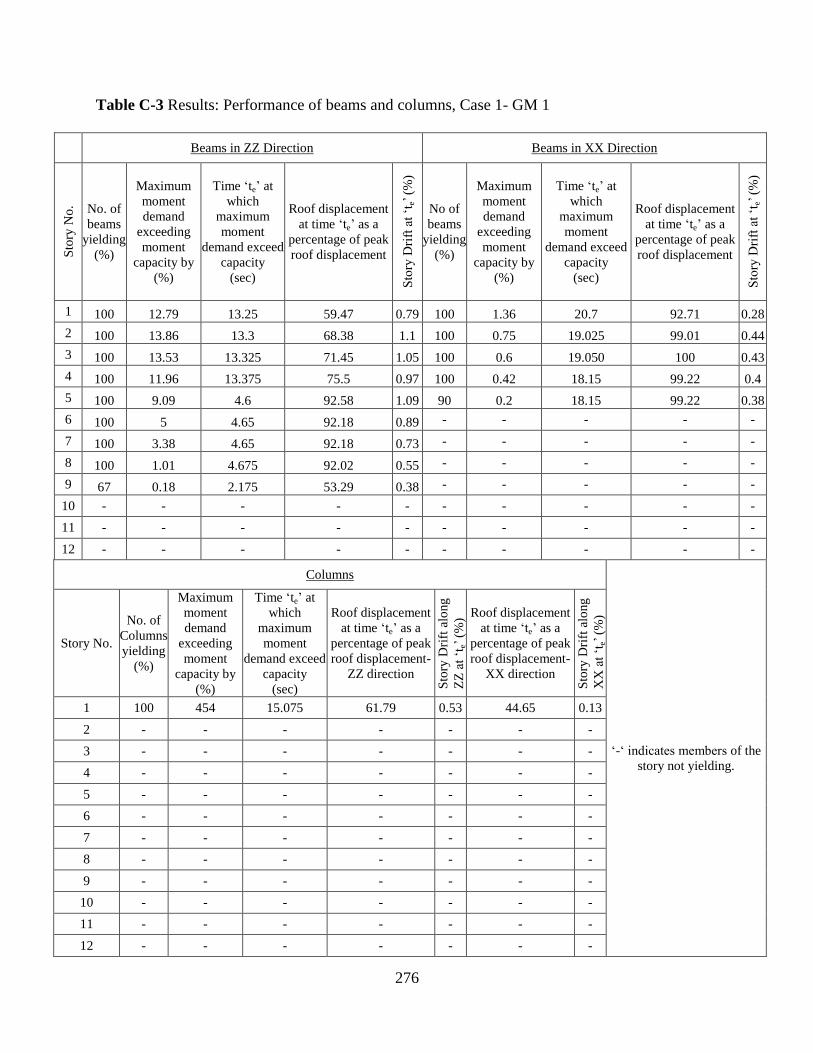
276
Table C-3 Results: Performance of beams and columns, Case 1- GM 1
Beams in ZZ Direction Beams in XX Direction
Sto
ry N
o. No. of
beams
yielding
(%)
Maximum
moment
demand
exceeding
moment
capacity by
(%)
Time ‘te’ at
which
maximum
moment
demand exceed
capacity
(sec)
Roof displacement
at time ‘te’ as a
percentage of peak
roof displacement
Sto
ry D
rift
at
‘te’
(%
)
No of
beams
yielding
(%)
Maximum
moment
demand
exceeding
moment
capacity by
(%)
Time ‘te’ at
which
maximum
moment
demand exceed
capacity
(sec)
Roof displacement
at time ‘te’ as a
percentage of peak
roof displacement
Sto
ry D
rift
at
‘te’
(%
)
1 100 12.79 13.25 59.47 0.79 100 1.36 20.7 92.71 0.28
2 100 13.86 13.3 68.38 1.1 100 0.75 19.025 99.01 0.44
3 100 13.53 13.325 71.45 1.05 100 0.6 19.050 100 0.43
4 100 11.96 13.375 75.5 0.97 100 0.42 18.15 99.22 0.4
5 100 9.09 4.6 92.58 1.09 90 0.2 18.15 99.22 0.38
6 100 5 4.65 92.18 0.89 - - - - -
7 100 3.38 4.65 92.18 0.73 - - - - -
8 100 1.01 4.675 92.02 0.55 - - - - -
9 67 0.18 2.175 53.29 0.38 - - - - -
10 - - - - - - - - - -
11 - - - - - - - - - -
12 - - - - - - - - - -
Columns
‘-‘ indicates members of the
story not yielding.
Story No.
No. of
Columns
yielding
(%)
Maximum
moment
demand
exceeding
moment
capacity by
(%)
Time ‘te’ at
which
maximum
moment
demand exceed
capacity
(sec)
Roof displacement
at time ‘te’ as a
percentage of peak
roof displacement-
ZZ direction
Sto
ry D
rift
alo
ng
ZZ
at
‘te’
(%
) Roof displacement
at time ‘te’ as a
percentage of peak
roof displacement-
XX direction
Sto
ry D
rift
alo
ng
XX
at
‘te’
(%
)
1 100 454 15.075 61.79 0.53 44.65 0.13
2 - - - - - - -
3 - - - - - - -
4 - - - - - - -
5 - - - - - - -
6 - - - - - - -
7 - - - - - - -
8 - - - - - - -
9 - - - - - - -
10 - - - - - - -
11 - - - - - - -
12 - - - - - - -

277
Table C-4 Results: Performance of beams and columns, Case 1- GM 2
Beams in ZZ Direction Beams in XX Direction
Sto
ry N
o. No. of
beams
yielding
(%)
Maximum
moment
demand
exceeding
moment
capacity by
(%)
Time ‘te’ at
which
maximum
moment
demand exceed
capacity
(sec)
Roof displacement
at time ‘te’ as a
percentage of peak
roof displacement
Sto
ry D
rift
at
‘te’
(%
)
No of
beams
yielding
(%)
Maximum
moment
demand
exceeding
moment
capacity by
(%)
Time ‘te’ at
which
maximum
moment
demand exceed
capacity
(sec)
Roof displacement
at time ‘te’ as a
percentage of peak
roof displacement
Sto
ry D
rift
at
‘te’
(%
)
1 100 5.17 7.675 66.08 0.76 100 11.44 6.925 94.02 1.58
2 100 6.24 7.725 71.16 1.02 100 10.84 6.95 94.43 1.91
3 100 5.37 6.125 100.00 0.99 100 9.23 7 94.16 1.74
4 100 6.57 6.15 99.92 1.19 100 7.31 6.625 99.39 1.48
5 100 6.35 6.15 99.92 1.26 100 5.29 6.625 99.39 1.22
6 100 4.99 6.175 99.92 1.15 100 3.06 6.6 99.73 0.92
7 100 2.77 6.1 99.92 0.83 100 1.05 6.6 99.73 0.63
8 100 1.86 6 88.11 0.61 15 0.04 8.15 38.87 0.33
9 100 1.22 5.98 82.18 0.55 - - - - -
10 67 0.26 5.95 75.22 0.43 - - - - -
11 - - - - - - - - - -
12 - - - - - - - - - -
Columns
‘-‘ indicates members of the
story not yielding.
Story No.
No. of
Columns
yielding
(%)
Maximum
moment
demand
exceeding
moment
capacity by
(%)
Time ‘te’ at
which
maximum
moment
demand exceed
capacity
(sec)
Roof displacement
at time ‘te’ as a
percentage of peak
roof displacement-
ZZ direction
Sto
ry D
rift
alo
ng
ZZ
at
‘te’
(%
) Roof displacement
at time ‘te’ as a
percentage of peak
roof displacement-
XX direction
Sto
ry D
rift
alo
ng
XX
at
‘te’
(%
)
1 100 50.1 6.725 14.49 0.28 97.62 1.40
2 - - - - - - -
3 12.5 3.6 6.1 99.92 0.84 55.65 0.83
4 4.2 2.4 6.25 96.88 0.92 74.59 0.92
5 4.2 1.2 7 27.01 0.17 94.16 0.98
6 4.2 2.2 6.7 20.02 0.15 98.23 0.76
7 4.2 2.8 6.7 20.02 0.15 98.23 0.51
8 - - - - - - -
9 - - - - - - -
10 - - - - - - -
11 - - - - - - -
12 - - - - - - -

278
Table C-5 Results: Performance of beams and columns, Case 1- GM 3
Beams in ZZ Direction Beams in XX Direction
Sto
ry N
o. No. of
beams
yielding
(%)
Maximum
moment
demand
exceeding
moment
capacity by
(%)
Time ‘te’ at
which
maximum
moment
demand exceed
capacity
(sec)
Roof displacement
at time ‘te’ as a
percentage of peak
roof displacement
Sto
ry D
rift
at
‘te’
(%
)
No of
beams
yielding
(%)
Maximum
moment
demand
exceeding
moment
capacity by
(%)
Time ‘te’ at
which
maximum
moment
demand exceed
capacity
(sec)
Roof displacement
at time ‘te’ as a
percentage of peak
roof displacement
Sto
ry D
rift
at
‘te’
(%
)
1 100 4.86 7.65 100 0.82 100 15.47 8.125 97.69 1.97
2 100 5.33 7.675 98.92 1.06 100 14.55 8.175 99.83 2.49
3 100 5.28 7.7 96.98 1.1 100 12.81 8.2 100 2.29
4 100 4.23 7.7 96.98 1.01 100 9.46 8.225 99.44 1.93
5 100 2.72 7.625 99.9 0.77 100 5.46 8.25 98.03 1.4
6 100 2.23 7.5 86.19 0.65 100 2.84 8.3 92.89 0.91
7 100 2.1 7.525 89.2 0.65 100 0.87 8.325 89.23 0.58
8 100 1.36 8.9 25.32 0.52 - - - - -
9 100 0.83 8.58 45.63 0.47 - - - - -
10 44 0.15 8.6 41.43 0.39 - - - - -
11 - - - - - - - - - -
12 - - - - - - - - - -
Columns
‘-‘ indicates members of the
story not yielding.
Story No.
No. of
Columns
yielding
(%)
Maximum
moment
demand
exceeding
moment
capacity by
(%)
Time ‘te’ at
which
maximum
moment
demand exceed
capacity
(sec)
Roof displacement
at time ‘te’ as a
percentage of peak
roof displacement-
ZZ direction
Sto
ry D
rift
alo
ng
ZZ
at
‘te’
(%
) Roof displacement
at time ‘te’ as a
percentage of peak
roof displacement-
XX direction
Sto
ry D
rift
alo
ng
XX
at
‘te’
(%
)
1 100 46.5 8.15 8.81 0.46 98.98 1.96
2 - - - - - - -
3 8.3 5.2 8.15 8.81 0.25 98.98 2.26
4 62.5 27.6 8.225 10.49 0.24 99.44 1.93
5 62.5 21 8.25 13.2 0.05 98.03 1.4
6 16.7 9.3 8.25 13.2 0.18 98.03 0.89
7 16.7 8.9 8.3 20.92 0.2 92.89 0.6
8 - - - - - - -
9 - - - - - - -
10 - - - - - - -
11 - - - - - - -
12 - - - - - - -
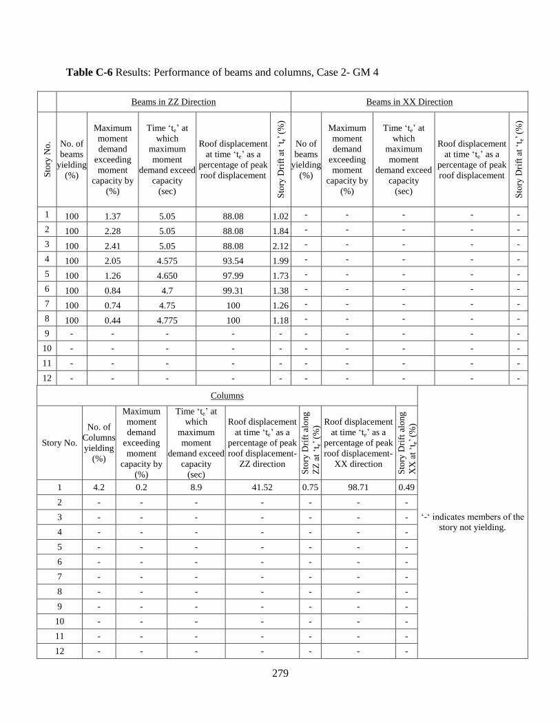
279
Table C-6 Results: Performance of beams and columns, Case 2- GM 4
Beams in ZZ Direction Beams in XX Direction
Sto
ry N
o. No. of
beams
yielding
(%)
Maximum
moment
demand
exceeding
moment
capacity by
(%)
Time ‘te’ at
which
maximum
moment
demand exceed
capacity
(sec)
Roof displacement
at time ‘te’ as a
percentage of peak
roof displacement
Sto
ry D
rift
at
‘te’
(%
)
No of
beams
yielding
(%)
Maximum
moment
demand
exceeding
moment
capacity by
(%)
Time ‘te’ at
which
maximum
moment
demand exceed
capacity
(sec)
Roof displacement
at time ‘te’ as a
percentage of peak
roof displacement
Sto
ry D
rift
at
‘te’
(%
)
1 100 1.37 5.05 88.08 1.02 - - - - -
2 100 2.28 5.05 88.08 1.84 - - - - -
3 100 2.41 5.05 88.08 2.12 - - - - -
4 100 2.05 4.575 93.54 1.99 - - - - -
5 100 1.26 4.650 97.99 1.73 - - - - -
6 100 0.84 4.7 99.31 1.38 - - - - -
7 100 0.74 4.75 100 1.26 - - - - -
8 100 0.44 4.775 100 1.18 - - - - -
9 - - - - - - - - - -
10 - - - - - - - - - -
11 - - - - - - - - - -
12 - - - - - - - - - -
Columns
‘-‘ indicates members of the
story not yielding.
Story No.
No. of
Columns
yielding
(%)
Maximum
moment
demand
exceeding
moment
capacity by
(%)
Time ‘te’ at
which
maximum
moment
demand exceed
capacity
(sec)
Roof displacement
at time ‘te’ as a
percentage of peak
roof displacement-
ZZ direction
Sto
ry D
rift
alo
ng
ZZ
at
‘te’
(%
) Roof displacement
at time ‘te’ as a
percentage of peak
roof displacement-
XX direction
Sto
ry D
rift
alo
ng
XX
at
‘te’
(%
)
1 4.2 0.2 8.9 41.52 0.75 98.71 0.49
2 - - - - - - -
3 - - - - - - -
4 - - - - - - -
5 - - - - - - -
6 - - - - - - -
7 - - - - - - -
8 - - - - - - -
9 - - - - - - -
10 - - - - - - -
11 - - - - - - -
12 - - - - - - -
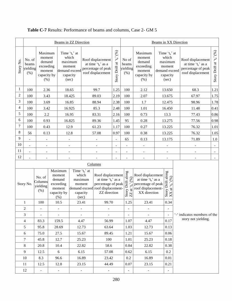
280
Table C-7 Results: Performance of beams and columns, Case 2- GM 5
Beams in ZZ Direction Beams in XX Direction
Sto
ry N
o. No. of
beams
yielding
(%)
Maximum
moment
demand
exceeding
moment
capacity by
(%)
Time ‘te’ at
which
maximum
moment
demand exceed
capacity
(sec)
Roof displacement
at time ‘te’ as a
percentage of peak
roof displacement
Sto
ry D
rift
at
‘te’
(%
)
No of
beams
yielding
(%)
Maximum
moment
demand
exceeding
moment
capacity by
(%)
Time ‘te’ at
which
maximum
moment
demand exceed
capacity
(sec)
Roof displacement
at time ‘te’ as a
percentage of peak
roof displacement
Sto
ry D
rift
at
‘te’
(%
)
1 100 2.36 18.65 99.7 1.25 100 2.12 13.650 68.3 1.21
2 100 3.43 18.425 89.03 2.19 100 2.07 13.675 67.97 1.75
3 100 3.69 16.85 88.94 2.38 100 1.7 12.475 98.96 1.78
4 100 3.42 16.925 85.3 2.48 100 1.01 16.450 11.48 0.41
5 100 2.2 16.95 83.31 2.16 100 0.73 13.3 77.43 0.86
6 100 0.93 16.825 89.36 1.45 95 0.28 13.275 77.56 0.98
7 100 0.43 12.9 61.23 1.17 100 0.27 13.225 76.32 1.01
8 56 0.13 12.8 57.08 0.97 100 0.38 13.225 76.32 1.05
9 - - - - - 65 0.13 13.175 71.89 1.0
10 - - - - - - - - - -
11 - - - - - - - - - -
12 - - - - - - - - - -
Columns
‘-‘ indicates members of the
story not yielding.
Story No.
No. of
Columns
yielding
(%)
Maximum
moment
demand
exceeding
moment
capacity by
(%)
Time ‘te’ at
which
maximum
moment
demand exceed
capacity
(sec)
Roof displacement
at time ‘te’ as a
percentage of peak
roof displacement-
ZZ direction
Sto
ry D
rift
alo
ng
ZZ
at
‘te’
(%
) Roof displacement
at time ‘te’ as a
percentage of peak
roof displacement-
XX direction
Sto
ry D
rift
alo
ng
XX
at
‘te’
(%
)
1 100 10.5 23.41 99.70 1.25 23.41 0.34
2 - - - - - - -
3 - - - - - - -
4 83.3 159.5 4.47 56.99 1.07 4.47 0.17
5 95.8 28.69 12.73 63.64 1.03 12.73 0.13
6 75.0 27.5 15.67 89.45 1.21 15.67 0.06
7 45.8 12.7 25.23 100 1.01 25.23 0.18
8 20.8 10.4 22.82 58.6 0.84 22.82 0.38
9 12.5 6 6.15 57.08 0.62 6.15 0.2
10 8.3 96.6 16.89 23.42 0.2 16.89 0.01
11 12.5 12.8 23.15 44.49 0.07 23.15 0.21
12 - - - - - - -
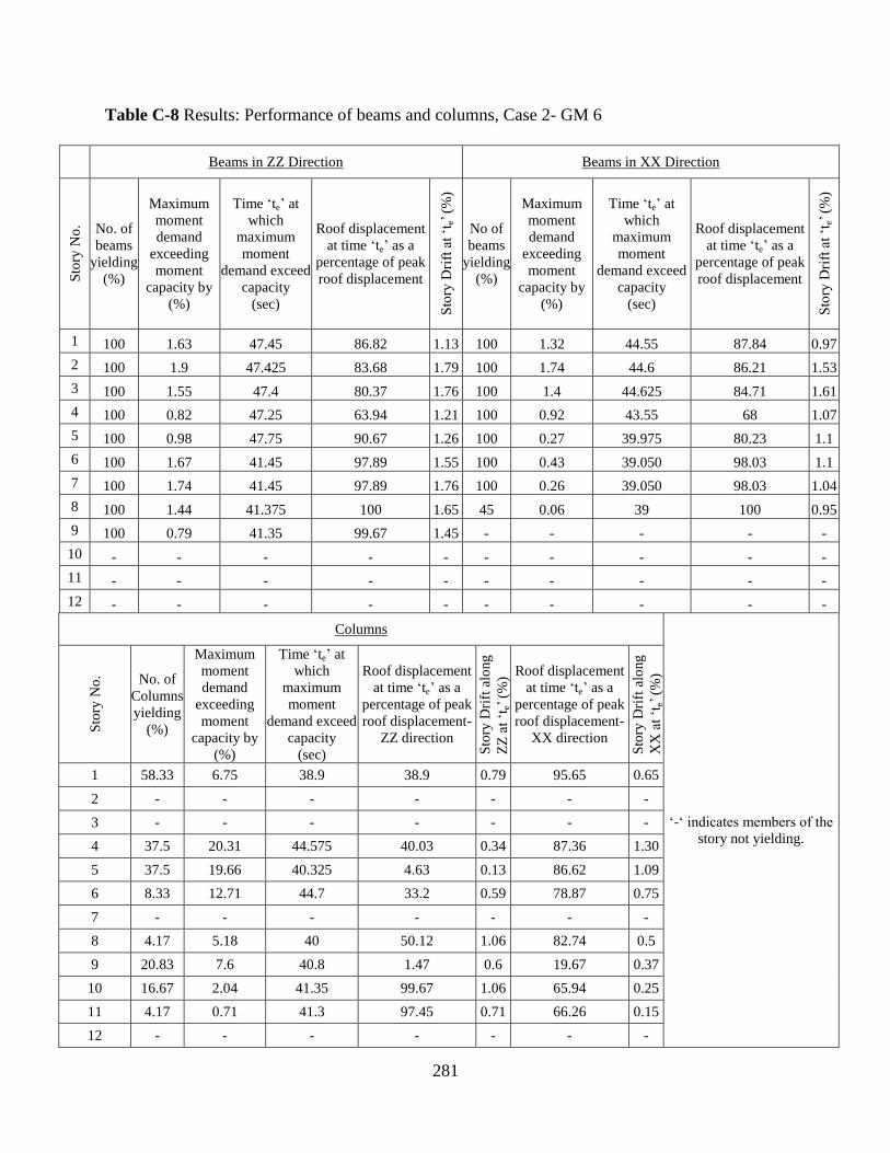
281
Table C-8 Results: Performance of beams and columns, Case 2- GM 6
Beams in ZZ Direction Beams in XX Direction
Sto
ry N
o. No. of
beams
yielding
(%)
Maximum
moment
demand
exceeding
moment
capacity by
(%)
Time ‘te’ at
which
maximum
moment
demand exceed
capacity
(sec)
Roof displacement
at time ‘te’ as a
percentage of peak
roof displacement
Sto
ry D
rift
at
‘te’
(%
)
No of
beams
yielding
(%)
Maximum
moment
demand
exceeding
moment
capacity by
(%)
Time ‘te’ at
which
maximum
moment
demand exceed
capacity
(sec)
Roof displacement
at time ‘te’ as a
percentage of peak
roof displacement
Sto
ry D
rift
at
‘te’
(%
)
1 100 1.63 47.45 86.82 1.13 100 1.32 44.55 87.84 0.97
2 100 1.9 47.425 83.68 1.79 100 1.74 44.6 86.21 1.53
3 100 1.55 47.4 80.37 1.76 100 1.4 44.625 84.71 1.61
4 100 0.82 47.25 63.94 1.21 100 0.92 43.55 68 1.07
5 100 0.98 47.75 90.67 1.26 100 0.27 39.975 80.23 1.1
6 100 1.67 41.45 97.89 1.55 100 0.43 39.050 98.03 1.1
7 100 1.74 41.45 97.89 1.76 100 0.26 39.050 98.03 1.04
8 100 1.44 41.375 100 1.65 45 0.06 39 100 0.95
9 100 0.79 41.35 99.67 1.45 - - - - -
10 - - - - - - - - - -
11 - - - - - - - - - -
12 - - - - - - - - - -
Columns
‘-‘ indicates members of the
story not yielding.
Sto
ry N
o. No. of
Columns
yielding
(%)
Maximum
moment
demand
exceeding
moment
capacity by
(%)
Time ‘te’ at
which
maximum
moment
demand exceed
capacity
(sec)
Roof displacement
at time ‘te’ as a
percentage of peak
roof displacement-
ZZ direction
Sto
ry D
rift
alo
ng
ZZ
at
‘te’
(%
) Roof displacement
at time ‘te’ as a
percentage of peak
roof displacement-
XX direction
Sto
ry D
rift
alo
ng
XX
at
‘te’
(%
)
1 58.33 6.75 38.9 38.9 0.79 95.65 0.65
2 - - - - - - -
3 - - - - - - -
4 37.5 20.31 44.575 40.03 0.34 87.36 1.30
5 37.5 19.66 40.325 4.63 0.13 86.62 1.09
6 8.33 12.71 44.7 33.2 0.59 78.87 0.75
7 - - - - - - -
8 4.17 5.18 40 50.12 1.06 82.74 0.5
9 20.83 7.6 40.8 1.47 0.6 19.67 0.37
10 16.67 2.04 41.35 99.67 1.06 65.94 0.25
11 4.17 0.71 41.3 97.45 0.71 66.26 0.15
12 - - - - - - -
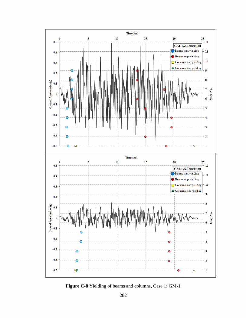
282
Figure C-8 Yielding of beams and columns, Case 1: GM-1

283
Figure C-9 Yielding of beams and columns, Case 1: GM-2
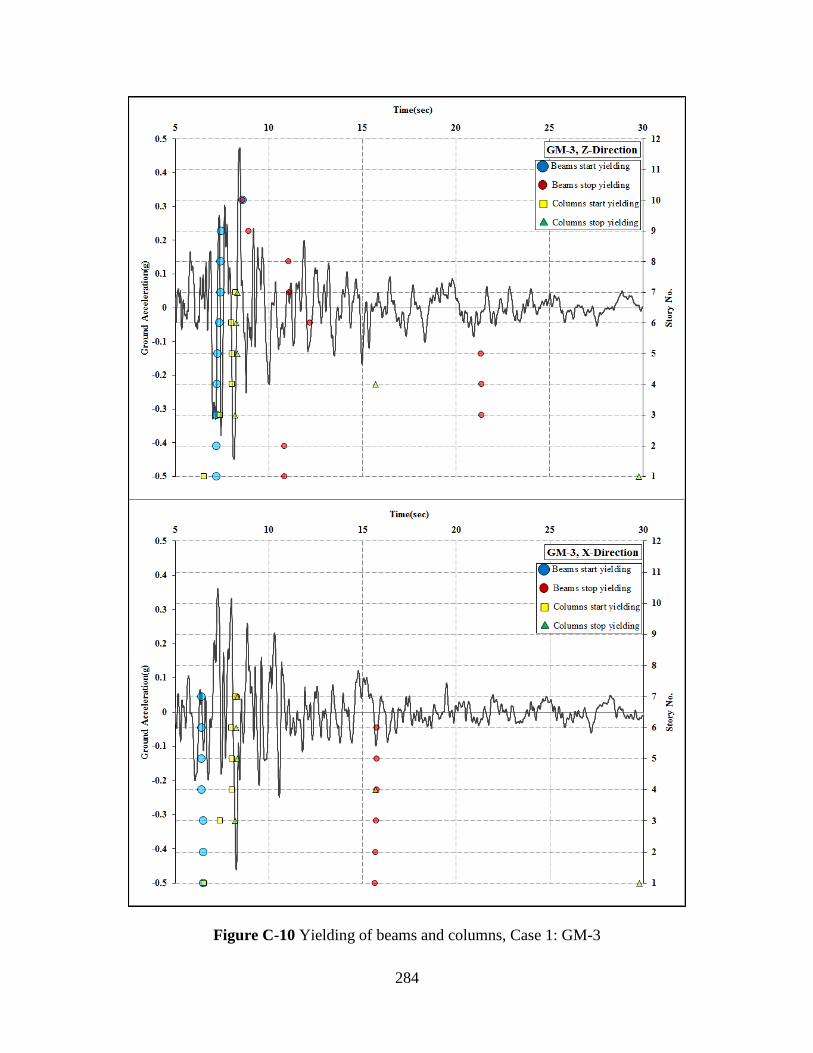
284
Figure C-10 Yielding of beams and columns, Case 1: GM-3
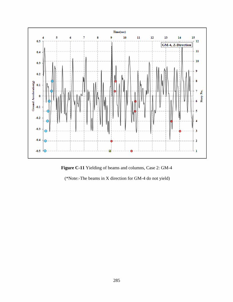
285
Figure C-11 Yielding of beams and columns, Case 2: GM-4
(*Note:-The beams in X direction for GM-4 do not yield)
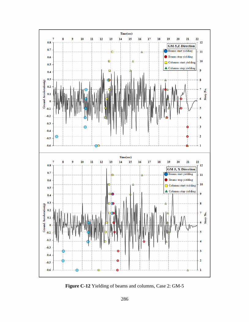
286
Figure C-12 Yielding of beams and columns, Case 2: GM-5
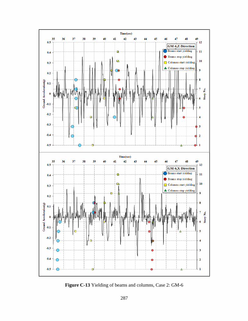
287
Figure C-13 Yielding of beams and columns, Case 2: GM-6