
Performance of Hydrogen Storage Tanks of Type IV in a Fire
13
Article Performance of Hydrogen Storage Tanks of Type IV in a Fire: Effect of the State of Charge Sergii Kashkarov *, Dmitriy Makarov and Vladimir Molkov Citation: Kashkarov, S.; Makarov, D.; Molkov, V. Performance of Hydrogen Storage Tanks of Type IV in a Fire: Effect of the State of Charge. Hydrogen 2021, 2, 386–398. https:// doi.org/10.3390/hydrogen2040021 Academic Editor: George E. Marnellos Received: 22 July 2021 Accepted: 7 September 2021 Published: 23 September 2021 Publisher’s Note: MDPI stays neutral with regard to jurisdictional claims in published maps and institutional affil- iations. Copyright: © 2021 by the authors. Licensee MDPI, Basel, Switzerland. This article is an open access article distributed under the terms and conditions of the Creative Commons Attribution (CC BY) license (https:// creativecommons.org/licenses/by/ 4.0/). Hydrogen Safety Engineering and Research Centre (HySAFER), University of Ulster, Newtownabbey BT37 0QB, UK; [email protected] (D.M.); [email protected] (V.M.) * Correspondence: [email protected] Abstract: The use of hydrogen storage tanks at 100% of nominal working pressure (NWP) is expected only after refuelling. Driving between refuellings is characterised by the state of charge SoC <100%. There is experimental evidence that Type IV tanks tested in a fire at initial pressures below 1/3 NWP, leaked without rupture. This paper aims at understanding this phenomenon. The numerical research has demonstrated that the heat transfer from fire through the composite overwrap at storage pressures below NWP/3 is sufficient to melt the polymer liner. This melting initiates hydrogen microleaks through the composite before it loses the load-bearing ability. The fire-resistance rating (FRR) is defined as the time to rupture in a fire of a tank without or with blocked thermally activated pressure relief device. The dependence of a FRR on the SoC is demonstrated for the tanks with defined material properties and volumes in the range of 36–244 L. A composite wall thickness variation is shown to cause a safety issue by reducing the tank’s FRR and is suggested to be addressed by tank manufacturers and OEMs. The effect of a tank’s burst pressure ratio on the FRR is investigated. Thermal parameters of the composite wall, i.e., decomposition heat and temperatures, are shown in simulations of a tank failure in a fire to play an important role in its FRR. Keywords: hydrogen storage tank; state of charge; fire-resistance rating; burst pressure ratio; decom- position temperature and heat; liner melting 1. Introduction It was demonstrated previously that the risk of using hydrogen vehicles on London roads is acceptable if an onboard tank’s fire-resistance rating (FRR), i.e., time to its rupture in a fire if a thermally activated pressure relief device (TPRD) is not triggered in a localised fire or blocked from the fire, is above 50 min [1]. The assessment was performed for scenarios when onboard hydrogen storage was tank filled to 100% of the nominal working pressure (NWP). The pressure of the compressed hydrogen storage system (CHSS) is not always the NWP, i.e., the state of charge (SoC) is below 100%. SAE J2601 defines the SoC as the “ratio of CHSS hydrogen density to the density at NWP rated at the standard temperature 15 ◦ C”: SoC = [ρ(P, T)/ρ(NWP, 15 ◦ C)] × 100 [2]. Normative documents define the “normal boundary conditions” during the fuelling of NWP = 70 MPa tanks from 0.5 MPa to a maximum of 87.5 MPa, i.e., 1.25 of NWP [2,3]. In our study, we consider scenarios with NWP = 70 MPa rather than the maximum allowable fuelling pressure of 87.5 MPa. The use of hydrogen tank capacity at NWP or SoC = 100% is characteristic for a period immediately after tank refuelling only. Figure 1 plots the tank SoC as a function of hydrogen pressure calculated for different temperatures inside the tank: 20 ◦ C, 30 ◦ C and 85 ◦ C. The last temperature is the currently regulated upper limit during fuelling [2,3]. The above curves were built as a result of calculations of the ratio of hydrogen densities at the selected temperatures, i.e., 20 ◦ C, 30 ◦ C and 85 ◦ C, and different SoCs and the density of hydrogen at NWP = 70 MPa and 15 ◦ C. Let us analyse the experimental results of CHSS fire testing at different SoC. In the experimental work [4], NWP = 70 MPa Type IV tanks of 36 L were tested in localised and Hydrogen 2021, 2, 386–398. https://doi.org/10.3390/hydrogen2040021 https://www.mdpi.com/journal/hydrogen
-
Upload
khangminh22 -
Category
Documents
-
view
5 -
download
0
Transcript of Performance of Hydrogen Storage Tanks of Type IV in a Fire

Article
Performance of Hydrogen Storage Tanks of Type IV in a Fire:Effect of the State of Charge
Sergii Kashkarov *, Dmitriy Makarov and Vladimir Molkov
�����������������
Citation: Kashkarov, S.; Makarov, D.;
Molkov, V. Performance of Hydrogen
Storage Tanks of Type IV in a Fire:
Effect of the State of Charge.
Hydrogen 2021, 2, 386–398. https://
doi.org/10.3390/hydrogen2040021
Academic Editor: George
E. Marnellos
Received: 22 July 2021
Accepted: 7 September 2021
Published: 23 September 2021
Publisher’s Note: MDPI stays neutral
with regard to jurisdictional claims in
published maps and institutional affil-
iations.
Copyright: © 2021 by the authors.
Licensee MDPI, Basel, Switzerland.
This article is an open access article
distributed under the terms and
conditions of the Creative Commons
Attribution (CC BY) license (https://
creativecommons.org/licenses/by/
4.0/).
Hydrogen Safety Engineering and Research Centre (HySAFER), University of Ulster,Newtownabbey BT37 0QB, UK; [email protected] (D.M.); [email protected] (V.M.)* Correspondence: [email protected]
Abstract: The use of hydrogen storage tanks at 100% of nominal working pressure (NWP) is expectedonly after refuelling. Driving between refuellings is characterised by the state of charge SoC <100%.There is experimental evidence that Type IV tanks tested in a fire at initial pressures below 1/3NWP, leaked without rupture. This paper aims at understanding this phenomenon. The numericalresearch has demonstrated that the heat transfer from fire through the composite overwrap at storagepressures below NWP/3 is sufficient to melt the polymer liner. This melting initiates hydrogenmicroleaks through the composite before it loses the load-bearing ability. The fire-resistance rating(FRR) is defined as the time to rupture in a fire of a tank without or with blocked thermally activatedpressure relief device. The dependence of a FRR on the SoC is demonstrated for the tanks with definedmaterial properties and volumes in the range of 36–244 L. A composite wall thickness variation isshown to cause a safety issue by reducing the tank’s FRR and is suggested to be addressed by tankmanufacturers and OEMs. The effect of a tank’s burst pressure ratio on the FRR is investigated.Thermal parameters of the composite wall, i.e., decomposition heat and temperatures, are shown insimulations of a tank failure in a fire to play an important role in its FRR.
Keywords: hydrogen storage tank; state of charge; fire-resistance rating; burst pressure ratio; decom-position temperature and heat; liner melting
1. Introduction
It was demonstrated previously that the risk of using hydrogen vehicles on Londonroads is acceptable if an onboard tank’s fire-resistance rating (FRR), i.e., time to its rupturein a fire if a thermally activated pressure relief device (TPRD) is not triggered in a localisedfire or blocked from the fire, is above 50 min [1]. The assessment was performed forscenarios when onboard hydrogen storage was tank filled to 100% of the nominal workingpressure (NWP). The pressure of the compressed hydrogen storage system (CHSS) is notalways the NWP, i.e., the state of charge (SoC) is below 100%. SAE J2601 defines theSoC as the “ratio of CHSS hydrogen density to the density at NWP rated at the standardtemperature 15 ◦C”: SoC = [ρ(P, T)/ρ(NWP, 15 ◦C)] × 100 [2]. Normative documentsdefine the “normal boundary conditions” during the fuelling of NWP = 70 MPa tanks from0.5 MPa to a maximum of 87.5 MPa, i.e., 1.25 of NWP [2,3]. In our study, we considerscenarios with NWP = 70 MPa rather than the maximum allowable fuelling pressure of87.5 MPa. The use of hydrogen tank capacity at NWP or SoC = 100% is characteristic for aperiod immediately after tank refuelling only. Figure 1 plots the tank SoC as a function ofhydrogen pressure calculated for different temperatures inside the tank: 20 ◦C, 30 ◦C and85 ◦C. The last temperature is the currently regulated upper limit during fuelling [2,3].
The above curves were built as a result of calculations of the ratio of hydrogen densitiesat the selected temperatures, i.e., 20 ◦C, 30 ◦C and 85 ◦C, and different SoCs and the densityof hydrogen at NWP = 70 MPa and 15 ◦C.
Let us analyse the experimental results of CHSS fire testing at different SoC. In theexperimental work [4], NWP = 70 MPa Type IV tanks of 36 L were tested in localised and
Hydrogen 2021, 2, 386–398. https://doi.org/10.3390/hydrogen2040021 https://www.mdpi.com/journal/hydrogen

Hydrogen 2021, 2 387
engulfing fires without TRPD at different SoCs to define their FRR. The initial pressureswere 70.3, 70.6, 35.6 and 17.8 MPa. The fire source was a heptane pan of an area of 0.96 m2.Tanks filled at 70.3 MPa and 70.6 MPa ruptured after 6 min 32 s and 5 min 20 s respectively.The first fire test was an engulfing fire and the second tank was tested in a localised(“partial”) fire. The first important conclusion from these experiments is that the time totank rupture depends on neither the engulfing nor the localised fire it is subject to. Thesecond conclusion is that the tank would not withstand the 10 min localised portion ofthe fire test following GTR#13, as the tank will rupture in less than 10 min in the heptanefire. The authors recommended that the “cylinder as a whole needs to be protected fromlocalised fire impact” [4].
Figure 1. Tank SoC as a function of storage pressure at temperatures 20 ◦C, 30 ◦C and 85 ◦C.
These experiments also demonstrated that when one of the NWP = 70 MPa tankswas filled at 35.6 MPa (51% NWP) and underwent the same engulfing fire, it rupturedlater—after 9 min 49 s (the FRR almost 1.5 times longer than the FRR of the first tank filledat almost NWP, i.e., at 70.3 MPa). This can be explained when the original composite tankfailure in a fire mechanism developed at Ulster University is applied (see for example [5]).It states that when the resin decomposition front propagating inward inside the compositetank overwrap encounters an outward expanding load-bearing fraction of the compositewall thickness, Sload b., a tank ruptures. In this test, with reduced initial pressure, thethinner Sload b. is required to bear this pressure. Thus, a longer time is required for the resindecomposition front to travel through the remaining or virgin wall depth to encounter it.
Finally, in the experiments with the tank filled at lower pressure of 17.8 MPa (25%NWP), the hydrogen leak without tank rupture was observed at 11 min 4 s. In this case,the thermally degradable virgin wall thickness fraction was larger, thus it allowed for theheat transferred inside which had melted the liner. The authors state that hydrogen “wasleaking across its entire surface with slightly more leakages at the ends” and that duringthe test “epoxy resin seems to have disappeared but the carbon fibres did not burn” [4].
There is another experimental study on fire testing of NWP = 70 MPa 36 L Type IVtanks at different initial pressures [6]. There were no hydrogen gas temperature measure-ments, but the composite in-depth integrated thermocouples showed the initial temper-atures to be about 42 ◦C (315 K). The fire source was represented as a hydrogen-oxygenpremixed burner consisting of 4 pipes directed at tanks from two opposite sides. The tanks’filling pressures were 70 MPa (NWP), 52.5 MPa (75% NWP), 25 MPa (36% NWP) and10 MPa (14% NWP). The first two tanks, one at pressure 70 MPa and another at 52.5 MPa,ruptured after 3 min 58 s and 5 min 11 s respectively. The other two tanks, filled at lowerpressures, i.e., 25 MPa and 10 MPa respectively, did not rupture but leaked after 6 min 40 sand 8 min 10 s respectively. These experiments had even been performed with a different

Hydrogen 2021, 2 388
fire source, confirming the conclusions of the previous study [4]. Indeed, the lowered initialpressures in the tank would avail the larger virgin wall thickness portion to be decomposedwithout causing a rupture, while the liner would be melted and could allow hydrogen toescape through the hydrogen non-tight composite wall.
The liner material, e.g., high density polyethylene (HDPE), being a thermoplasticpolymer, may have a melting temperature of 118 ◦C [7] up to 135 ◦C [8]. Before the meltingpoint, the polymer undergoes its property alterations as a solid body, such as an elasticmodulus, known to be obtained at a heat distortion temperature [9]. Afterwards, as thetemperature elevates, the polymer becomes softer until it becomes a liquid at the meltingpoint. The assumption is that when the tank is in a fire, the hydrogen leak starts whenthe entire liner thickness reached the minimum of the polymer melting temperature. Thisimplies that the liner in that spot starts flowing plastically, being unable to perform a barrierfunction to hydrogen, thus allowing it to escape and permeate/leak through the composite(that is not tight to hydrogen). Some tank manufacturers tend to use other thermoplasticsfor the liners, such as Nylon, i.e., polyamide (PA). PA has a higher melting temperature,e.g., 129 ◦C [10].
The UN Global technical regulation on hydrogen and fuel cell vehicles No. 13 (GTR#13) [3],the EC No. 406/2010 implementing the Regulation No. 79/2009 [11] establish the minimumburst pressure, Pb.min., for tanks overwrapped with carbon fibre reinforced polymer (CFRP)to be 2.25 times NWP, i.e., the burst pressure ratio (BPR). This means that for the 70 MPatank, its wall will be able to withstand up to 2.25 × 70 MPa = 157.5 MPa. It should benoted that the BPR is different to the tank safety factor (SF) and is defined as the ratioof Pb.min. to the maximum allowable pressure during the fuelling P = 87.5 MPa. Hence,the SF for a CFRP overwrapped 70 MPa tank with Pb.min. = 157.5 MPa would be SF =157.5 MPa/87.5 MPa = 1.8. There are discussions at UN ECE GTR#13 IWG SGS on thereduction of this burst pressure ratio from BPR = 2.25 to BPR = 2.00. This is only theminimum requirement and any higher value is accepted, especially if the safety, and notonly the availability of carbon fibre is at stake, e.g., BPR = 2.5, which is quite common. Tothe best of the authors’ knowledge, the effect of the BPR on the FRR of tanks has not beenstudied and published.
The original tank failure in a fire mechanism suggested at Ulster University hasbeen proven to work well in predicting the tank’s FRR. For the entire tank wall thickness,SCFRP, withstanding 157.5 MPa, only its fraction of 1/2.25 = 0.44 is sufficient to withstandNWP = 70 MPa. The remainder of the fraction 1 − 0.44 = 0.56 would be as called here“load+”, which can be thermally decomposed by heat flux from a fire without tank rupture(thus reducing burst pressure ratio to BPR = 1). If the tank pressure increases aboveNWP = 70 MPa, e.g., due to increasing temperature because of heat transfer from a fire, theSload b. increases proportionally and thus, the “load+” fraction decreases. Thus, for instance,for the tank of NWP = 70 MPa and current pressure, Pcurrent = 70 MPa too, the load-bearingwall fraction will be as Sload b. = Pcurrent/(NWP × BPR) = 70 MPa/(70 MPa × 2.25) = 0.44.The higher the current pressure in the tank is, Pcurrent, the thinner the fraction “load+” isand the faster it will degrade, causing tank rupture. If the tank pressure decreases, e.g.,due to blowdown in a fire through TPRD, Sload b. will decrease respectively. It will allowfor more heat transfer through the tank wall and for a longer time, with subsequent linermelting. This is the mechanism behind the “no rupture but a leak” of tanks in fire testswith lower pressure compared to the NWP initial hydrogen pressure in a tank observedexperimentally in [4,6].
The above-described tank failure in a fire mechanism implies that a tank with avarying wall thickness will rupture when it loses the load-bearing ability in the thinnestwall location, which is usually the dome area. The wall thickness non-uniformity issuein the state-of-the-art designs of composite hydrogen tanks was raised by the authorspreviously. Composite-overwrapped tanks are usually manufactured by the filamentwinding process. During the winding process, a combination of helical and hoop layersin the cylindrical/sidewall region usually provides a thicker wall. The thinnest regions,

Hydrogen 2021, 2 389
mostly wound as helical layers, are the domes, especially midways between the cylindricalpart end and the boss neck. These thinnest regions nevertheless are sufficient to providemechanical strength to the tank up to Pb.min., which it is designed for. Due to the reducedthickness, the dome is more vulnerable to a fire. The tank’s FRR will be defined byresin thermal degradation and the composite failure in the dome region rather than inthe sidewall [5,12]. Figure 2 schematically demonstrates the tank composite overwrapperformance in a fire in the sidewall (left) and the dome (right) regions at the same moment.
Figure 2. Wall thickness SCFRP of the overwrap in the cylindrical/sidewall region (left) and in the dome region (right)and positions of load-bearing and decomposed fractions of wall thickness at the same time: no rupture conditions for thesidewall and rupture conditions for the dome [12].
The manufacturers focus mainly on the mechanical strength of the composite over-wrap, rather than its thermal performance in a fire. Carbon fibres would either be thelast component of the composite to degrade thermally in a fire or would be not degradedat all, as noted in the experimental study [4]. The worst-case scenario of tank rupturemay occur due to TPRD malfunction or a localised fire when TPRD is not affected. Theloss of the composite overwrap’s strength will be determined by the resin degradation,as per the above-described tank failure in a fire mechanism [5,12]. The speed of the resindecomposition front in-depth progression is affected by the heat flux from the fire to thetank surface, resin decomposition temperature range, Td, the heat of decomposition, Hd,etc. Variations of these parameters affect the tank FRR.
Data on the Td of the resins found elsewhere shows that these usually range within300–400 ◦C (573–673 K). The relatively low decomposition temperatures can be 592 K, asper 10% of mass loss, as obtained by the thermogravimetric analysis [13]. In [14] it wasstated that the first stage of decomposition (resin oxidative decomposition) occurs between496–730 K. The resin Td published in [15,16] are 623 K and 633 K respectively. Paper [17]provides data on Td varying 569–639 K. Some applications have epoxy resins with Td = 713K [18]. In paper [19], the Td of the epoxy resins in composites with polypropylene contentwere analysed; Td varied 553–648 K. The work [20] provides Td = 647 K. In our study weshall investigate the effect of resin Td on the tank FRR, using the values that are close to orwithin the above-reviewed ranges of 554–683 K [21] and 643–653 K [17,20].
The resin Hd varies depending on the literature source. For instance, study [22]recommends Hd = 3.50 × 10⁵ J/kg. Another differential scanning calorimetry study [21]of CFRP in a nitrogen atmosphere helped to “isolate” resin decomposition from carbonwith two peaks at 652 K and 810 K respectively. The first temperature peak agrees withmost of those met in literature values of Td, where the mass loss is the highest, and wherewe assume the mechanical strength of the composite was lost (due to the loss of fibres’bonding). The second peak agrees well with that mentioned in another study temperaturemeasurement (813 K) [23] when the resin is degraded completely. The cumulative for thesetwo stages Hd = 3.48 × 10⁴ J/kg + 3.04 × 10⁴ J/kg = 6.52 × 10⁴ J/kg.

Hydrogen 2021, 2 390
This study aims to investigate the effect of the state of charge (SoC), burst pressureratio (BPR) and thermal properties of a resin in a composite tank overwrap, i.e., Hd andTd, on tank FRR. The issue of the tank wall thickness non-uniformity on FRR is addressedalso. The study will be performed using the validated non-adiabatic blowdown in a firemodel [5,12].
2. The Model and Parameters of Studied Tanks
The non-adiabatic blowdown in a fire model, including the mechanism of a compositehydrogen tank failure in a fire, is described in detail in [5,12]. The under-expanded jettheory is used to describe this model. It was developed further and included the tankperformance in fire conditions. The thermal degrading of the resin in a composite andthe melting of the liner due to the unsteady heat transfer from the surroundings throughthe tank wall and liner are accounted for. The blowdown experiment and destructive firetest for a tank with no TPRD were used to validate the model. The thermal characteristicsof hydrogen and tank materials, heat flow from a fire to the tank, diameter of TPRD thatthe tank is equipped with, and the TPRD activation time delay in a fire, are among themodel inputs. Experimentally obtained hydrogen temperature and pressure dynamics,depressurization time and tank fire-resistance rating, i.e., time to rupture in a fire (when noTPRD installed), are all correctly reproduced in the model.
Here, the model is applied to simulate the pressure dynamics inside the tank, temper-ature distribution inside the composite wall, liner, and hydrogen temperature during thefire. The dependence of the FRR as a function of the HRR/A [5] demonstrates that FRRpractically does not change at HRR/A ≥ 1 MW/m2. The absence of a further decrease inFRR with the increase of HRR/A above 1–2 MW/m2, which are typical values for gaso-line/diesel spill fires, can be explained by the flame length increase above the tank locationfor this fire test protocol. Hence, the fire with HRR/A = 1 MW/m2 and correspondingtransient heat flux to the tank surface is selected here to study the thermal behaviour oftanks in the fire at different initial pressures below the NWP. The heat flux to the tank q′′from the fire at a specific heat release rate HRR/A = 1 MW/m2 was extracted from 3Dsimulations of the tank in a fire. The heat flux as a function of time used in our simulationsis: q′′ = (−11.81· ln(t) + 113.97) × 103 [5]. This heat flux was applied throughout all oursimulations for consistency. Table 1 represents the properties of the investigated threetanks, including thermal decomposition temperature and heat of decomposition.
Table 1. Tank material properties.
Parameter Value References
HDPE linerSHDPE, mm 5.27 [24]λ, W/m/K 0.4 at 293 K, 0.2 at 423 K
[25]cp, J/kg/K 2000 at 293 K, 2600 at 423 Kρ, kg/m3 940
CFRP structural layerSCFRP, mm 22.26 [24]λ, W/m/K Correlation
[21]cp, J/kg/K Correlationρ, kg/m3 1360 [26]
Hd, J/kg6.52 × 104 * [21]3.50 × 10⁵ [22]7 × 10⁵ **
Td, K 554–683 [21]643–653 [17,20]
Notes: *—Sum of two degradation stages Hd = 3.48 × 10⁴ J/kg + 3.04 × 10⁴ J/kg = 6.52 × 10⁴ J/kg [21]; **—Hypothetical value two times larger than the value referenced in this table of 2 × 3.50 × 105 J/kg = 7 × 10⁵ J/kg(this is for demonstration purpose, i.e., how the FRR changes if the tank manufacturer chooses the resin with thehigher Hd).

Hydrogen 2021, 2 391
Table 2 shows the difference in parameters of the three tanks studied in this paper.
Table 2. Parameters of three 70 MPa tanks.
Parameters Tank#1 [24,27,28] Tank#2 [29] Tank#3 [6]
V, L 36 62.4 244PNWP, MPa 70 70 70
Burst pressure ratio (BPR) 2.25 ** 2.25 ** 2.25 **Dext, mm * 325 437 530
L, mm 909 748 2154SCFRP, mm * 27.75 24.3 33.36 [5] **SHDPE, mm * 3.8 3 3 [5] **
Notes: *—Sidewall (cylindrical) part; **—assumption.
It is assumed in our study that all composite overwraps are made of the same CFRPand the liners are the same HDPE in all tanks, to be consistent in comparison to the tests.The initial tank and hydrogen gas temperature are 293.15 K, giving 70 MPa calculatedSoC = 99% (it is 100% for hydrogen T = 288.15 K at 70 MPa).
3. Effect of Tank SoC on Fire-Resistance Rating
Figure 3 shows the dynamics of the inward propagation of the resin decompositionfront and outward propagation of the load-bearing wall thickness fraction for three initialpressures, i.e., NWP = 70 MPa and two reduced initial pressures 24 MPa and 17.8 MPa, ina 36 L volume tank. Therefore, 3 different load-bearing wall thicknesses were obtained,i.e., about 2.6 mm, 3.4 mm and 9.9 mm (excluding liner) for 17.8 MPa, 24 MPa and 70 MParespectively. The dependence of the load-bearing wall thickness on the tank SoC wasdescribed as a part of the tank failure mechanism in the Introduction. The simulationsshow that for the initial pressure equal to NWP = 70 MPa, the tank ruptures after 402 s inthe fire (when the two fronts meet).
Figure 3. Performance of tank V = 36 L, NWP = 70 MPa in a fire with HRR/A = 1 MW/m2: ruptureat initial pressure NWP = 70 MPa (SoC = 99%) and no rupture at initial pressures 24 MPa (SoC = 43%)and 17.8 MPa (SoC = 32.6%).
The decrease in pressure to 17.8 MPa (in NWP = 70 MPa, 36 L tank), the same as inthe experiment [4], excludes the tank rupture in the fire due to melting of the liner after700 s. Instead, the hydrogen leakage through the wall would be initiated (see Figure 3).
Hydrogen 2021, 2 392
The tank’s SoC = 32.6% was calculated as follows. Hydrogen density at NWP = 70 MPaand T = 15 ◦C (288.15 K) is ρ = 40.54 kg/m3 (calculated by Abel-Noble equation of statefor real gas). Hydrogen density at 17.8 MPa and T = 20 ◦C (293.15 K) is ρ = 13.22 kg/m3.For 17.8 MPa we obtain SoC = [13.22 kg/m3/40.54 kg/m3] × 100% = 32.6%. It should beunderlined that the ratio of initial pressure to NWP is less, i.e., 17.8/70 × 100% = 25.4%.
The simulated 70 MPa tank with the initial pressure of 17.8 MPa in the fire with norupture but leakage, is the accurate reproduction of the result observed in fire tests with thesame tanks at an initial pressure of 17.8 MPa [4]. Afterwards, in the simulation, we increasethe pressure to the maximum upper bound value, above which the tank will rupture. Theinitial pressure of 24 MPa (SoC = 42.5%) was found to be “on the border” between ruptureand leak and this is very close to the experimental value of 25 MPa [6] (only 4% difference),where the leak without burst was observed. It is seen that with the decrease in the tankSoC, the “load plus” thickness (everything above the load-bearing wall thickness blackcurves), enabling for a longer time for the resin decomposition front to travel and therefore,increasing the tank FRR or allowing for the liner to melt and provide leak initiation.
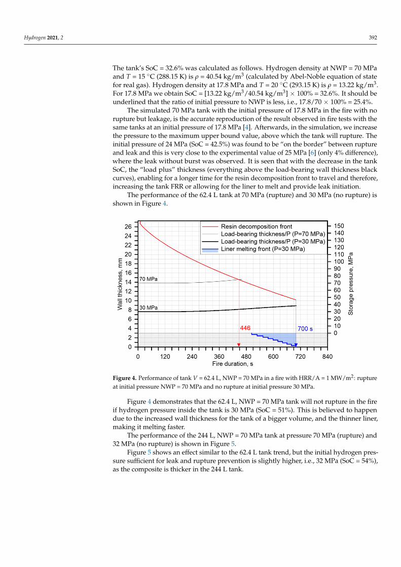
The performance of the 62.4 L tank at 70 MPa (rupture) and 30 MPa (no rupture) isshown in Figure 4.
Figure 4. Performance of tank V = 62.4 L, NWP = 70 MPa in a fire with HRR/A = 1 MW/m2: ruptureat initial pressure NWP = 70 MPa and no rupture at initial pressure 30 MPa.
Figure 4 demonstrates that the 62.4 L, NWP = 70 MPa tank will not rupture in the fireif hydrogen pressure inside the tank is 30 MPa (SoC = 51%). This is believed to happendue to the increased wall thickness for the tank of a bigger volume, and the thinner liner,making it melting faster.
The performance of the 244 L, NWP = 70 MPa tank at pressure 70 MPa (rupture) and32 MPa (no rupture) is shown in Figure 5.
Figure 5 shows an effect similar to the 62.4 L tank trend, but the initial hydrogen pres-sure sufficient for leak and rupture prevention is slightly higher, i.e., 32 MPa (SoC = 54%),as the composite is thicker in the 244 L tank.

Hydrogen 2021, 2 393
Figure 5. Performance of tank V = 244 L, NWP = 70 MPa in a fire with HRR/A = 1 MW/m2: ruptureat initial pressure NWP = 70 MPa and no rupture at initial pressure 32 MPa.
4. Effect of Tank Wall Thickness Non-Uniformity on the FRR
Let us assume that both the dome and the sidewall of the tank are subject to a fire.Figure 6 shows the performance of both these parts in a fire for 36 L, NWP = 70 MPa tankcausing a rupture and lowered pressure preventing rupture by causing hydrogen leak.
Figure 6. Performance of tank V = 36 L, NWP = 70 MPa in a fire with HRR/A = 1 MW/m2: effect of thinner wall thicknessin the dome (top) and thicker sidewall (bottom) for two initial pressures, i.e., NWP = 70 MPa and the pressure below whichthe liner melts and the tank rupture is excluded (17.8 MPa and 29 MPa respectively).

Hydrogen 2021, 2 394
In the considered example (36 L and NWP = 70 MPa tank), the dome part has a linerthickness of 5.27 mm and a CFRP thickness of 22.26 mm while the sidewall has 3.81 mm and27.75 mm for a liner and CFRP respectively. Moreover, the load-bearing wall thicknesses(excluding liner) are 9.9 mm and 11.4 mm for pressure 70 MPa for dome and sidewallrespectively. The thickened liner in the dome region is probably the manufacturer’stechnical necessity as it is near the liner-flange connection.
Figure 6 demonstrates that, as expected, at NWP = 70 MPa the increase of compositewall thickness by 20% from 22.26 mm (dome) to 27.75 mm (sidewall) results in an increaseof FRR by 34%, i.e., from 402 s (6 min 42 s) to 540 s (9 min).
The initial pressure that prevents rupture should be higher, if we consider the com-posite failure location in the sidewall, i.e., the SoC should not be decreased as much asfor the sidewall region. This is due to the thinner liner requiring less energy for melting,hence the “load plus” may be thinner to maintain wall integrity. The liner melts in thesidewall at an initial pressure of 29 MPa with SoC = 50% (Figure 6 bottom). Assumingthe failure location in the dome region, the required reduced pressure is only 17.8 MPawith SoC = 32.6% (Figure 6 top). In the engulfing fire, the tank would rupture after 402 sif failed in the dome area, while the sidewall can still bear the load. This is an apparentdisadvantage in the current design of composite storage tanks that should be addressed bytank manufacturers and OEMs.
5. Effect of the Burst Pressure Ratio on the FRR
In this section, the effect of BPR on FRR for NWP = 70 MPa tanks will be assessed. Theminimum regulated BPR for CFRP is currently 2.25. The increase in the BPR by a manufacturerdoes not violate the regulations. Let us use the described above 36 L, NWP = 70 MPa tank andalter the BPR by altering the composite wall thickness proportionally to the burst pressure.Thus, BPR = 2.25 bears the pressure 70 MPa × 2.25 = 157.5 MPa, whereas BPR = 2 bears140 MPa and BPR = 2.5 bears 175 MPa respectively. As the tank wall thickness in the dome areafor BPR = 2.25 is 22.26 mm, then we calculate the wall thickness for BPR = 2 as 22.26 mm/2.25× 2 = 19.78 mm and BPR = 2.5 as 22.26 mm/2.25 × 2.5 = 24.73 mm respectively.
The higher BPR decreases the fraction of Sload b. and hence increases the “load+”faction and the tank FRR. Figure 7 shows the effect of different BPR of 36 L, NWP = 70 MPatank on its FRR and time to leak.
Figure 7. Performance of tank V = 36 L, NPW = 70 MPa in a fire with HRR/A = 1 MW/m2. (Left): tank with BPR = 2.(Right): tank with BPR = 2.5.
Figure 7 demonstrates an increase in the tank FRR with the increase of its BPR. TheFRR increases by 43% for the BPR increase from 2 to 2.5, i.e., from 296 s (4 min 56 s) to519 s (8 min 39 s). The increase in the BPR from 2 to 2.5 allows exclusion of tank ruptureat higher pressure, i.e., 23 MPa (BPR = 2.5) instead of 17 MPa (BPR = 2). The decrease ofcurrently regulated BPR = 2.25 (see Figure 3 above) to the proposed BPR = 2 (see Figure 7left) would decrease the FRR from 402 s (6 min 42 s) to 296 s (4 min 56 s), i.e., by 26%.

Hydrogen 2021, 2 395
6. Effect of Resin Thermal Properties, Td and Hd, on the FRR
According to our tank failure mechanism, the fraction of the composite wall thickness,e.g., a layer, becomes non-load-bearing after the resin decomposition front reaches thislayer and passes it. The resin decomposition front is described by the resin decompositiontemperature range between Td1 and Td2 and the resin heat of decomposition, Hd, energyconsumed to decompose the resin polymer when the temperature in the layer is withinT ≥ Td1 and T ≤ Td2. Let us study how the parameters of resin in composite, such as Hdand Td, affect the resin decomposition front propagation and hence the tank FRR.
First, we shall fix Hd = 3.5 × 10⁵ J/kg and change the decomposition temperatureranges to see the effect of Td on the FRR. Let us take Td range as 554–683 K (as in all previoussimulations) and a higher one of 643–653 K (initial Td increased by 89 K), as per referencesin Table 1. We shall look at FRR for 36 L at NWP = 70 MPa and lower pressures sufficientto make the liner melt and prevent tank rupture (see Figure 8).
Figure 8. Performance of tank V = 36 L, NWP = 70 MPa in a fire with HRR/A = 1 MW/m2: effect of resin Td on the tankFRR at fixed Hd = 3.5 × 10⁵ J/kg. (Left): effect of Td on FRR. (Right): effect of Td on the upper-pressure limit that excludestank rupture and time to leak.
Figure 8 left demonstrates that a higher Td (by 16%) increases the tank FRR from 402 s(6 min 42 s) to 511 s (8 min 31 s), i.e., by 27%. It also allows prevents tank rupture bymelting the liner at a significantly higher hydrogen pressure inside the tank of 35 MPa(SoC = 58%) instead of 17.8 MPa (SoC = 32.6%), as shown in Figure 8 right.
Figure 9 shows the effect of three different Hd on tank FRR at the fixed Td range554–683 K.
Figure 9. Performance of tank V = 36 L, NWP = 70 MPa in a fire with HRR/A = 1 MW/m2: effect of different resin Hd onthe tank FRR at fixed Td range 554–683 K at 70 MPa (left) and other different SoC (right).

Hydrogen 2021, 2 396
The increase in the resin Hd increases the tank FRR (Figure 9 left). For instance,the previously used 3.5 × 10⁵ J/kg compared to hypothetical value 7 × 10⁵ J/kg (100%increase) raises the tank FRR to 496 s (8 min 16 s), i.e., by 23%. In this respect, we see thatdoubling of resin Hd gives a relatively small FRR increase. It can be concluded that theeffect of Td is stronger compared to Hd, resulting in an increase of FRR with Td (27% and16% respectively).
Figure 9 right shows that the higher the resin Hd is, the higher the upper limit ofpressure inside the tank, which prevents tank rupture due to the liner melting, i.e., 12.5 MPa(SoC = 24%), 17.8 MPa (SoC = 32.6%) and 27.5 MPa (SoC = 48%).
7. Conclusions
The effect of 70 MPa Type IV tank SoC on the FRR is studied using a previouslyvalidated model of non-adiabatic tank blowdown in fire conditions with our originalmechanism of a composite tank failure in a fire. The experimentally observed phenomenonof tank leaking instead of rupture in a fire at initial pressures below about NWP/3 isaccurately reproduced in the simulations and underlying physics is discussed. The effectof tank wall non-uniformity on the reduction of the tank FRR is studied. It is concludedthat tank manufacturers should address this issue to provide a higher level of life safetyand property protection by increasing the FRR. The effect of composite properties such asthe resin heat of decomposition, Hd, and a range of decomposition temperature, Td, as wellas the burst pressure ratio (BPR) on the tank FRR is investigated and understood. The FRRincreases with the increase of Td and Hd, yet the effect of Td is more pronounced. Thesefindings define the originality of this work.
The significance of the study is in the closure of knowledge gaps in understandinga tank performance in a fire at different SoCs, the expansion of the validation domainof the physical model that can reproduce the experimental data. It is demonstrated thatthe tanks with selected material properties, NWP = 70 MPa and volumes 36 L, 62.4 Land 244 L do not rupture in a fire at SoC = 43% corresponding to hydrogen pressure of24 MPa, SoC = 51% (30 MPa) and SoC = 54% (32 MPa) respectively. The wall thicknessand non-uniformity of the selected industrial 36 L tank demonstrated the difference inFRR of 34%. The increase in the tank FRR by 43% was found for the BPR increase from2 to 2.5. It was shown that the increase in resin Td has a stronger effect than Hd on theFRR increase. The avoidance of a catastrophic tank rupture in a fire at a decreased SoCdue to melted liner and hydrogen release is only possible for Type IV tanks, and not forType III tanks, where the liner is metallic. This is a safety advantage of Type IV tanks. Thesafety “feature” achieved through “no rupture but a leak” phenomenon may open a strandof safety questions to be answered, such as what would be the effect of liner polymertype, e.g., thermoset vs. thermoplastic? How would the leak react in the event of a firetermination, e.g., when a hydrogen-powered car is rapidly towed out of a fire, or evenwhen fire extinction with water is applied? The leak behaviour depending on a fibre andresin in the composite overwrap is also an open question.
The rigour of this study is in the reproduction of the experimentally observed phe-nomenon of leaking of tanks at hydrogen pressures below about NWP/3, due to the useof referenced thermal parameters in simulations. The numerical tests performed for theindustrial 36 L, NWP = 70 MPa tank and the decreased initial pressure of 24 MPa (andbelow) demonstrated the prevention of tank rupture due to the liner melting and follow-upleakage of hydrogen through the tank wall. This pressure is in line with the experimentallydetermined pressure of 25 MPa [6] (4% difference) when the tank leakage was observedinstead of rupture. A further pressure decrease to 17.8 MPa, matching with equivalentexperimental pressure [4], also provided the rupture avoidance due to liner melting, asobserved in the corresponding experiment [4] with another fire source. The rigour of thework is also underpinned in the range of studied parameters that affect the FRR. Theseinclude the SoC below 100%, including the limits of SoC below which the tanks leak in thefire instead of rupture; the wide range of tanks’ volumes, i.e., 36 L, 62.4 L and 244 L, etc.

Hydrogen 2021, 2 397
Author Contributions: Conceptualization, V.M. and S.K.; methodology, V.M. and D.M.; software,S.K.; validation, V.M., D.M. and S.K.; formal analysis, S.K. and V.M.; investigation, S.K. and V.M.;resources, S.K. and V.M.; data curation, S.K., V.M. and D.M.; writing—original draft preparation, S.K.;writing—review and editing, S.K., V.M. and D.M.; visualization, S.K.; supervision, V.M. and D.M.;project administration, V.M. and D.M.; funding acquisition, V.M. All authors have read and agreed tothe published version of the manuscript.
Funding: This research was funded by Fuel Cells and Hydrogen 2 Joint Undertaking (FCH2 JU)through the SH2APED project. The SH2APED project has received funding from the FCH2 JUunder grant agreement No. 101007182. This Joint Undertaking receives support from the Euro-pean Union’s Horizon 2020 research and innovation programme, Hydrogen Europe and HydrogenEurope Research.
Conflicts of Interest: The authors declare no conflict of interest.
References1. Dadashzadeh, M.; Kashkarov, S.; Makarov, D.; Molkov, V. Risk assessment methodology for onboard hydrogen storage. Int. J.
Hydrogen Energy 2018, 43, 6462–6475. [CrossRef]2. SAE J2601. Surface Vehicle Standard. In Fueling Protocols for Light Duty Gaseous Hydrogen Surface Vehicles; SAE International:
Warrendale, PE, USA, 2016.3. United Nations Economic Commission for Europe. Global Registry. Addendum 13: Global Technical Regulation No. 13. Global
Technical Regulation on Hydrogen and Fuel Cell Vehicles. Available online: http://www.unece.org/trans/main/wp29/wp29wgs/wp29gen/wp29glob_registry.html (accessed on 4 October 2020).
4. Ruban, S.; Heudier, L.; Jamois, D.; Proust, C.; Bustamante-Valencia, L.; Jallais, S.; Kremer-Knobloch, K.; Maugy, C.; Villalonga, S.Fire risk on high-pressure full composite cylinders for automotive applications. Int. J. Hydrogen Energy 2012, 37, 17630–17638.[CrossRef]
5. Molkov, V.; Dadashzadeh, M.; Kashkarov, S.; Makarov, D. Performance of hydrogen storage tank with TPRD in an engulfing fire.Int. J. Hydrogen Energy 2021, in press. [CrossRef]
6. Blanc-Vannet, P.; Jallais, S.; Fuster, B.; Fouillen, F.; Halm, D.; van Eekelen, T.; Welch, S.; Breuer, P.; Hawksworth, S. Fire testscarried out in FCH JU Firecomp project, recommendations and application to safety of gas storage systems. Int. J. HydrogenEnergy 2019, 44, 9100–9109. [CrossRef]
7. Overview of Materials for High Density Polyethylene (HDPE), Injection Molded. Available online: http://www.matweb.com/search/DataSheet.aspx?MatGUID=fce23f90005d4fbe8e12a1bce53ebdc8 (accessed on 1 September 2021).
8. High Density Polyethylene. Available online: http://wwwcourses.sens.buffalo.edu/ce435/Polyethylene/CE435Kevin.htm(accessed on 1 September 2021).
9. Overview of Materials for High Density Polyethylene (HDPE), Rotational Molding Grade. Available online: http://www.matweb.com/search/DataSheet.aspx?MatGUID=ff49b807fe9243cf820fdcca1d0dc911 (accessed on 1 September 2021).
10. Lanxess. Durethan BC550Z 900116 DUSXBL, Data Sheet; Lanxess: Cologne, Germany, 2017.11. European Commission. Commission Regulation No 406/2010 Implementing Regulation (EC) No 79/2009 of the Parliament and of the
Council on Type-Approval of Hydrogen-Powered Vehicles; The Publications Office of the European Union: Luxembourg, 2010.12. Dadashzadeh, M.; Makarov, D.; Kashkarov, S.; Molkov, V. Non-adiabatic under-expanded jet theory for blowdown and fire
resistance rating of hydrogen tank; Paper ID 182. In Proceedings of the International Conference on Hydrogen Safety (ICHS2019), Adelaide, Australia, 24–26 September 2019.
13. Liu, W.; Varley, R.J.; Simon, G.P. Understanding the decomposition and fire performance processes in phosphorus and nanomodi-fied high performance epoxy resins and composites. Polymer 2007, 48, 2345–2354. [CrossRef]
14. Branca, C.; Di Blasi, C.; Galgano, A.; Milella, E. Thermal and kinetic characterization of a toughened epoxy resin reinforced withcarbon fibers. Thermochim. Acta 2011, 517, 53–62. [CrossRef]
15. Merino-Pérez, J.L.; Hodzic, A.; Merson, E.; Ayvar-Soberanis, S. On the temperatures developed in CFRP drilling using uncoatedWC-Co tools Part II: Nanomechanical study of thermally aged CFRP composites. Compos. Struct. 2015, 123, 30–34. [CrossRef]
16. Pan, C.T.; Hocheng, H. Evaluation of anisotropic thermal conductivity for unidirectional FRP in laser machining. Compos. Part AAppl. Sci. Manuf. 2001, 32, 1657–1667. [CrossRef]
17. Régnier, N.; Fontaine, S. Determination of the thermal degradation kinetic parameters of carbon fibre reinforced epoxy using TG.J. Therm. Anal. Calorim. 2001, 64, 89–799. [CrossRef]
18. PerkinElmer Inc. Characterization of Polymers Using TGA. Available online: http://www.perkinelmer.com/CMSResources/Images/44-132088APP_CharacterizationofPolymersUsingTGA.pdf (accessed on 23 March 2021).
19. Prabhu, T.N.; Hemalatha, Y.J.; Harish, V.; Prashantha, K.; Iyengar, P. Thermal Degradation of Epoxy Resin Reinforced withPolypropylene Fibers. Available online: www.interscience.wiley.com (accessed on 23 March 2021).
20. Chiang, C.-L.; Chang, R.-C.; Chiu, Y.-C. Thermal stability and degradation kinetics of novel organic/inorganic epoxy hybridcontaining nitrogen/silicon/phosphorus by sol-gel method. Thermochim. Acta 2007, 453, 97–104. [CrossRef]

Hydrogen 2021, 2 398
21. Welch, S.; Hadden, R.; Hidalgo-Medina, J.; Pironi, P. Thermal Properties and Thermal Modelling of Composite Materials Exposed toFires; Supergen Challenge Project Meeting: Bath, UK, 2017.
22. Hu, J.; Chen, J.; Sundararaman, S.; Chandrashekhara, K.; Chernicoff, W. Analysis of composite hydrogen storage cylinderssubjected to localized flame impingements. Int. J. Hydrogen Energy 2008, 33, 2738–2746. [CrossRef]
23. Yatim, N.M.; Shamsudin, Z.; Shaaban, A.; Sani, N.A.; Jumaidin, R.; Shariff, E.A. Thermal analysis of carbon fibre reinforcedpolymer decomposition. Mater. Res. Express 2020, 7, 015615. [CrossRef]
24. Heggem, P.; Hexagon Composites, Alesund, Norway. Private communication, 2013.25. Kashkarov, S.; Makarov, D.; Molkov, V. Model of 3D conjugate heat transfer and mechanism of compressed gas storage failure
in a fire; Paper ID 125. In Proceedings of the International Conference on Hydrogen Safety (ICHS 2017), Hamburg, Germany,11–13 September 2017.
26. Monde, M.; Kosaka, M. Understanding of Thermal Characteristics of Fueling Hydrogen High Pressure Tanks and GoverningParameters. SAE Int. J. Altern. Powertrains 2013, 2, 61–67. [CrossRef]
27. Kashkarov, S.; Makarov, D.; Molkov, V. Effect of a heat release rate on reproducibility of fire test for hydrogen storage cylinders.Int. J. Hydrogen Energy 2018, 43, 10185–10192. [CrossRef]
28. Saldi, Z.; Wen, J. Modeling thermal response of polymer composite hydrogen cylinders subjected to external fires. Int. J. HydrogenEnergy 2017, 42, 7513–7520. [CrossRef]
29. Mattelaer, V.; Toyota Motor Europe, Brussels, Belgium. Private communication, 2018.