
SEISMIC RESPONSE OF LARGE CYLINDRICAL TANKS FOR OIL STORAGE WITH FLEXIBLE WALLS
10
1 First European Conference on Earthquake Engineering and Seismology (a joint event of the 13 th ECEE & 30 th General Assembly of the ESC) Geneva, Switzerland, 3-8 September 2006 Paper Number: 1411 SEISMIC RESPONSE OF LARGE CYLINDRICAL TANKS FOR OIL STORAGE WITH FLEXIBLE WALLS Hector A. SANCHEZ SANCHEZ 1 and Carlos CORTES SALAS 2 SUMMARY In Mexico, PEMEX manage different terminals of storage of oil in all country. Therefore, structural integrity of the aboveground storage tanks must be carefully assessed. Consequently, the storage tanks have been placed in high seismic risk areas. As a result, this research has focused on the behaviour and seismic response of already existing steel storage tanks of large capacity of 500, 200, 150, 100 and 55 thousands barrels, located in high risk zones. In this work it has been proposed a procedure based on a numeric modelling where the mechanical characteristics of the materials and the real geometrical have been considered. The FEM has been used to carry out such analysis, the numeric analysis has been used for different conditions and the fluid-structure interaction modelling is considered for the flexible walls. Seismic records originated in the subduction Mexican Pacific Ocean zone have been used for the seismic excitation at the base of the structures in order to take into account the pressure distribution of the liquid. Finally, the numerical results obtained and those estimated analytically are compared observing a good correlation in the majority of the cases between both approaches, this represents a tool for the revision and new designs and to improve the present criteria of design. 1. INTRODUCTION The damages reported due to seismic actions in the past in unanchored aboveground storage tanks have been observed principally at the base in the fond and the walls. Then, these damages could be producing the structural loss of the tanks. It can be classified in four general categories: • Buckling at the bottom plates of the wall tanks, where it is attending the maximal axial compression stresses due to overturning moment. In this region the buckling of the plates appear with long deformations as elephant foot. • Damage of the roof near to the end wall hoop and the internal columns is due to sloshing effect of the liquid. • Damage in pipes and others accessories linking to the wall tanks during the seismic movement of the soil. • Damage due to fails of the foundation or intense seismic loads. In Mexico in the last years the growing need to satisfy the national oil industry demand has continually required the evaluation and retrofits of the existing above ground storage tanks, as well as creates new oil terminals for distribution and oil products. As a consequence, some storage tanks have been placed in high seismic risk areas. As result, this research has focused on the structural behaviour, under seismic conditions, of already existing steel storage tanks of large capacity, of 500, 200, 150, 100 and 55 thousands barrels, located in high risk zones. 1 SEPI – ESIA - UZ, Instituto Politécnico Nacional, U. P. Adolfo López Mateos, Gustavo A. Madero, 07738, México, D. F., Phone: 5-729- 6000 Ext. 46183; E-mail: [email protected] , [email protected] 2 Instituto Mexicano del Petróleo, Eje Lázaro Cárdenas No. 152, Apto. Postal 14-805, 07730 México, D. F., Phone: 9175-8663, Fax. 9175- 8667; E-mail: [email protected]
Transcript of SEISMIC RESPONSE OF LARGE CYLINDRICAL TANKS FOR OIL STORAGE WITH FLEXIBLE WALLS
1
First European Conference on Earthquake Engineering and Seismology (a joint event of the 13th ECEE & 30th General Assembly of the ESC)
Geneva, Switzerland, 3-8 September 2006 Paper Number: 1411
SEISMIC RESPONSE OF LARGE CYLINDRICAL TANKS FOR OIL STORAGE WITH FLEXIBLE WALLS
Hector A. SANCHEZ SANCHEZ1 and Carlos CORTES SALAS2
SUMMARY
In Mexico, PEMEX manage different terminals of storage of oil in all country. Therefore, structural integrity of the aboveground storage tanks must be carefully assessed. Consequently, the storage tanks have been placed in high seismic risk areas. As a result, this research has focused on the behaviour and seismic response of already existing steel storage tanks of large capacity of 500, 200, 150, 100 and 55 thousands barrels, located in high risk zones. In this work it has been proposed a procedure based on a numeric modelling where the mechanical characteristics of the materials and the real geometrical have been considered. The FEM has been used to carry out such analysis, the numeric analysis has been used for different conditions and the fluid-structure interaction modelling is considered for the flexible walls. Seismic records originated in the subduction Mexican Pacific Ocean zone have been used for the seismic excitation at the base of the structures in order to take into account the pressure distribution of the liquid. Finally, the numerical results obtained and those estimated analytically are compared observing a good correlation in the majority of the cases between both approaches, this represents a tool for the revision and new designs and to improve the present criteria of design.
1. INTRODUCTION The damages reported due to seismic actions in the past in unanchored aboveground storage tanks have been observed principally at the base in the fond and the walls. Then, these damages could be producing the structural loss of the tanks. It can be classified in four general categories:
• Buckling at the bottom plates of the wall tanks, where it is attending the maximal axial compression stresses due to overturning moment. In this region the buckling of the plates appear with long deformations as elephant foot.
• Damage of the roof near to the end wall hoop and the internal columns is due to sloshing effect of the liquid.
• Damage in pipes and others accessories linking to the wall tanks during the seismic movement of the soil.
• Damage due to fails of the foundation or intense seismic loads. In Mexico in the last years the growing need to satisfy the national oil industry demand has continually required the evaluation and retrofits of the existing above ground storage tanks, as well as creates new oil terminals for distribution and oil products. As a consequence, some storage tanks have been placed in high seismic risk areas. As result, this research has focused on the structural behaviour, under seismic conditions, of already existing steel storage tanks of large capacity, of 500, 200, 150, 100 and 55 thousands barrels, located in high risk zones. 1 SEPI – ESIA - UZ, Instituto Politécnico Nacional, U. P. Adolfo López Mateos, Gustavo A. Madero, 07738, México, D. F., Phone: 5-729-6000 Ext. 46183; E-mail: [email protected], [email protected] 2 Instituto Mexicano del Petróleo, Eje Lázaro Cárdenas No. 152, Apto. Postal 14-805, 07730 México, D. F., Phone: 9175-8663, Fax. 9175-8667; E-mail: [email protected]
2
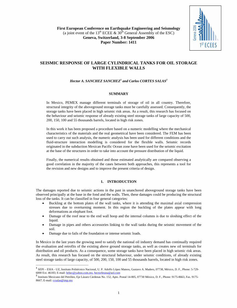
As is known, the developments and early studies about the dynamic and seismic behaviour in tanks have considered the rigid wall hypothesis. This hypothesis has been considered in the statements of Housner, however, experimental works and subsequent researchers have shown that the flexibility of the walls of the tanks has an important influence on response due to these excitations. That is seen represented by the multi - modal shapes and by the dynamic stresses which can be greater to those obtained from rigid tanks. Then, the objective of this work is to show through a numerical analysis of fluid- structure interaction, the structural behaviour of this type tanks with flexible walls, that represent to the real structures selected for this investigation. Consequently, it is studied the structural behaviour of tanks through of dynamic and seismic analysis by fluid - structure system. It is identified the sloshing effect and its interaction with the walls (shell) of the tank, as well as its typical modal configurations of the axisymmetric structures of thin wall. Thin cylindrical shells may vibrate in a variety of ways depending on the particular stress involved. The present work is focused to study of the vibration of the shell. Some of the vibration forms, which are possible under such conditions, are illustrated in figure 1.a and b. The modal vibration consists of both axial and tangential shapes formed around the circumference and height of the cylindrical tanks. The form of vibration increases in complexity with the number of modes, but theoretically there is no limit to the number, which may be present. Further complication, however, may result due to the superposition of waves in the axial direction. The combination of both modal shapes lead to a multi-modal shapes which are consequences of different parameters such as: thickness t, geometrical and mechanical characteristics, seismic actions and liquid pressure and boundary conditions. These modal shapes are solutions of theoretical problems of vibrations and they are employed to study the seismic behaviour of real structures of the steel storage tanks. Large axial compressive stresses due to bending of the tank wall can cause “elephant-foot” buckling of the wall.
Figure 1.a Circumferential mode shapes
Figure 1.b: Axial mode shapes
2. MODEL AND ASSUMPTIONS
2.1 Statement of the problem The structures selected are typical structures employed in the oil national industry; consequently it has been used real values of the geometric and mechanical properties that constitute it. The research is developed in the following way, the storage tanks are modelled through a fine mesh composed by finite shells and fluid elements, and they are analyzed applying the finite element method (FEM), considering different thickness t of wall that contribute to modify the dynamic behaviour. It is studied with the flexibility of the shell walls and the sloshing effect generated by the seismic action of the fluid on the steel walls. 2.1.1 General considerations The walls of the cylindrical shells are considered as thin curve plates with an elastic behaviour. The vessels are submitted to vibrations due to dynamic excitations. The seismic behaviour of these structures is studied by fluid – structure interaction system. The general hypotheses employed in the analysis are:
m = 1 m = 2 m= 3
3
• the cylindrical steel tanks are constituted by different constant thickness t of the wall, that change along of the height H
• the walls of the curve plates are thin, the thickness t of the shell is least than 10% of the radius R • the material is isotropic homogenous and elastic • exist loads applied on the curve plates and it is considered also the own weight (mass)
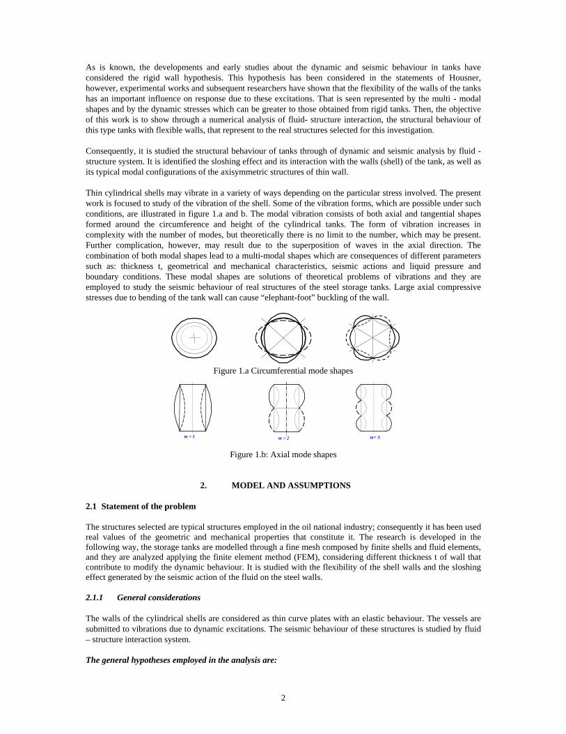
2.1.2 Geometrical and mechanical characteristics of the tanks To known the seismic behaviour of the cylindrical storage tanks, it was studied the metallic cylindrical tank geometries of 500, 200, 150, 100 and 55 thousands barrels of capacity, constituted by rings welded mutually of the shells, with variable thickness t along of the height H, see figures 2.a, 2.b and tables 1 and 2.
Table 1: Mechanical characteristics of materials of circular cylindrical steel storage tanks
Es 206,000 Young modulus of steel Mpa ν 0.3 Poisson’s ratio of material γs 76,910.4 Weight per unit volume of the steel N/m3 ρs 7,840 Mass per unit volume of the steel
(N/m3)/g γl 9,810 Weight per unit volume of the liquid
N/m3 ρl 1,000 Mass per unit volume of the liquid
(N/m3)/g γ 2,206 Bulk of compressibility of the fluid Mpa
Figure 2: Geometrical characteristics of the cylindrical storage tanks studied
Table 2: Geometrical characteristics
Tank (thousands barrels) 55 100 150 200 500 Stiffening
ring t (mm) H (m) 12.192 14.630 14.630 15.79 15.79 1.2 h (m) 10.992 13.563 13.563 14.63 14.63 R (m) 15.240 20.400 22.847 27.42 42.68
t1 (mm) 16 22 25 32.16 38.36 12.7 t2 (mm) 16 16 22 27.60 34.75 t3 (mm) 13 13 19 22.53 25.43 t4 (mm) 10 8 16 15.85 21.02 t5 (mm) 6 8 13 10.78 14.50 t6 (mm) - 8 10 8.22 9.47 t7 (mm) - - - 8.22 9.47
2.1.3 Shell walls and base of the tank
4
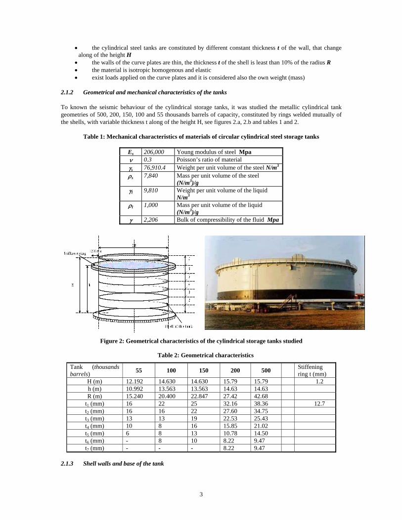
To study of the seismic behaviour of the shell walls and the base of the tanks, shell 63 element was selected to analyze then. This element has six degree of freedom in each node, and it is well suited to take into account the membrane and bending effects, allowing to apply normal pressures on internal surface, normal loads in its plane, as soon as efforts on theirs nodes. This element includes within the law of behaviour of the material the hardening capacity and the non-linearity such as large deformation assumptions are permit. 2.1.4 Fluid element Fluid of the vessel was modelled with fluid 80 (3D) with eight nodes having three degrees of freedom at each node, this element is particularly well suited for calculating hydrostatic pressures, fluid-solid interaction and accelerations effects, such as sloshing problem. 2.1.5 Boundary conditions at the base of the tanks
Base of the tanks is modelled considering contact elements 52, to represent unanchored tanks and simple supported base, considering the stiffness of the soil (see fig.3).
Figure 3: Numerical model of the cylindrical steel storage tank of 200 thousands barrels
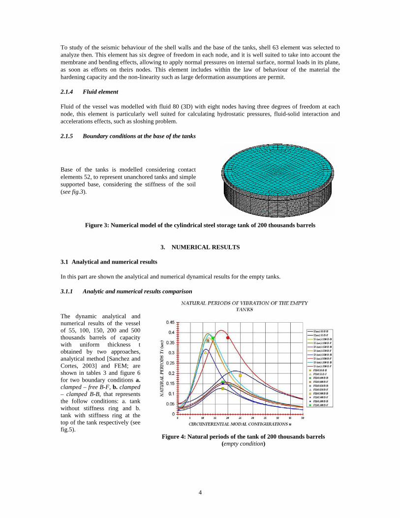
3. NUMERICAL RESULTS 3.1 Analytical and numerical results In this part are shown the analytical and numerical dynamical results for the empty tanks. 3.1.1 Analytic and numerical results comparison
The dynamic analytical and numerical results of the vessel of 55, 100, 150, 200 and 500 thousands barrels of capacity with uniform thickness t obtained by two approaches, analytical method [Sanchez and Cortes, 2003] and FEM; are shown in tables 3 and figure 6 for two boundary conditions a. clamped – free B-F, b. clamped – clamped B-B, that represents the follow conditions: a. tank without stiffness ring and b. tank with stiffness ring at the top of the tank respectively (see fig.5).
Figure 4: Natural periods of the tank of 200 thousands barrels
(empty condition)
5
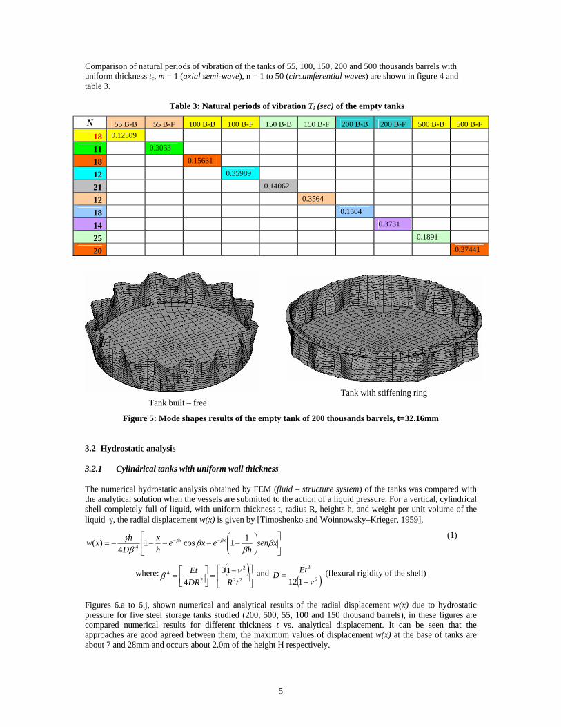
Comparison of natural periods of vibration of the tanks of 55, 100, 150, 200 and 500 thousands barrels with uniform thickness tc, m = 1 (axial semi-wave), n = 1 to 50 (circumferential waves) are shown in figure 4 and table 3.
Table 3: Natural periods of vibration Ti (sec) of the empty tanks
N 55 B-B 55 B-F 100 B-B 100 B-F 150 B-B 150 B-F 200 B-B 200 B-F 500 B-B 500 B-F 18 0.12509
11 0.3033
18 0.15631
12 0.35989
21 0.14062
12 0.3564
18 0.1504
14 0.3731
25 0.1891
20 0.37441
Tank built – free
Tank with stiffening ring
Figure 5: Mode shapes results of the empty tank of 200 thousands barrels, t=32.16mm
3.2 Hydrostatic analysis 3.2.1 Cylindrical tanks with uniform wall thickness The numerical hydrostatic analysis obtained by FEM (fluid – structure system) of the tanks was compared with the analytical solution when the vessels are submitted to the action of a liquid pressure. For a vertical, cylindrical shell completely full of liquid, with uniform thickness t, radius R, heights h, and weight per unit volume of the liquid γ, the radial displacement w(x) is given by [Timoshenko and Woinnowsky–Krieger, 1959],
⎥⎦
⎤⎢⎣
⎡⎟⎟⎠
⎞⎜⎜⎝
⎛−−−−−= −− xsen
hexe
hx
Dhxw xx β
ββ
βγ ββ 11cos1
4)( 4
(1)
where: ( )⎥⎦
⎤⎢⎣
⎡ −=⎥⎦
⎤⎢⎣⎡= 22
2
24 13
4 tRDREt νβ and
( )2
3
112 ν−=
EtD (flexural rigidity of the shell)
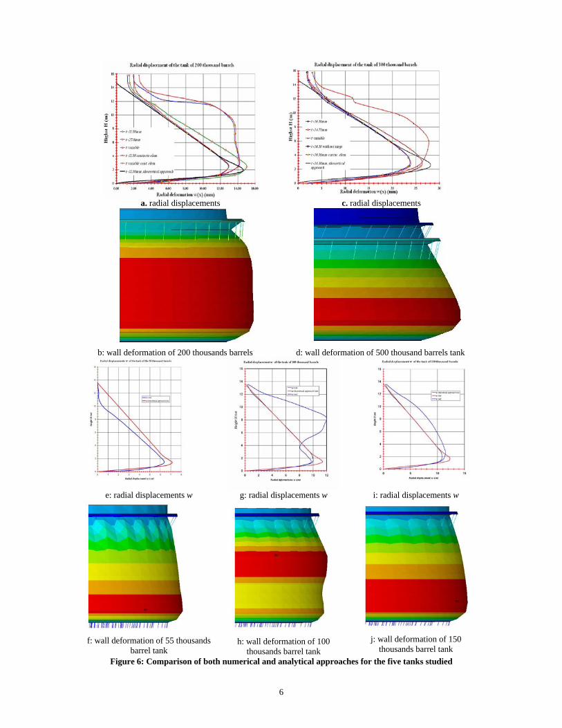
Figures 6.a to 6.j, shown numerical and analytical results of the radial displacement w(x) due to hydrostatic pressure for five steel storage tanks studied (200, 500, 55, 100 and 150 thousand barrels), in these figures are compared numerical results for different thickness t vs. analytical displacement. It can be seen that the approaches are good agreed between them, the maximum values of displacement w(x) at the base of tanks are about 7 and 28mm and occurs about 2.0m of the height H respectively.
6
a. radial displacements c. radial displacements
b: wall deformation of 200 thousands barrels d: wall deformation of 500 thousand barrels tank
e: radial displacements w g: radial displacements w i: radial displacements w
f: wall deformation of 55 thousands
barrel tank
h: wall deformation of 100
thousands barrel tank
j: wall deformation of 150
thousands barrel tank Figure 6: Comparison of both numerical and analytical approaches for the five tanks studied
7
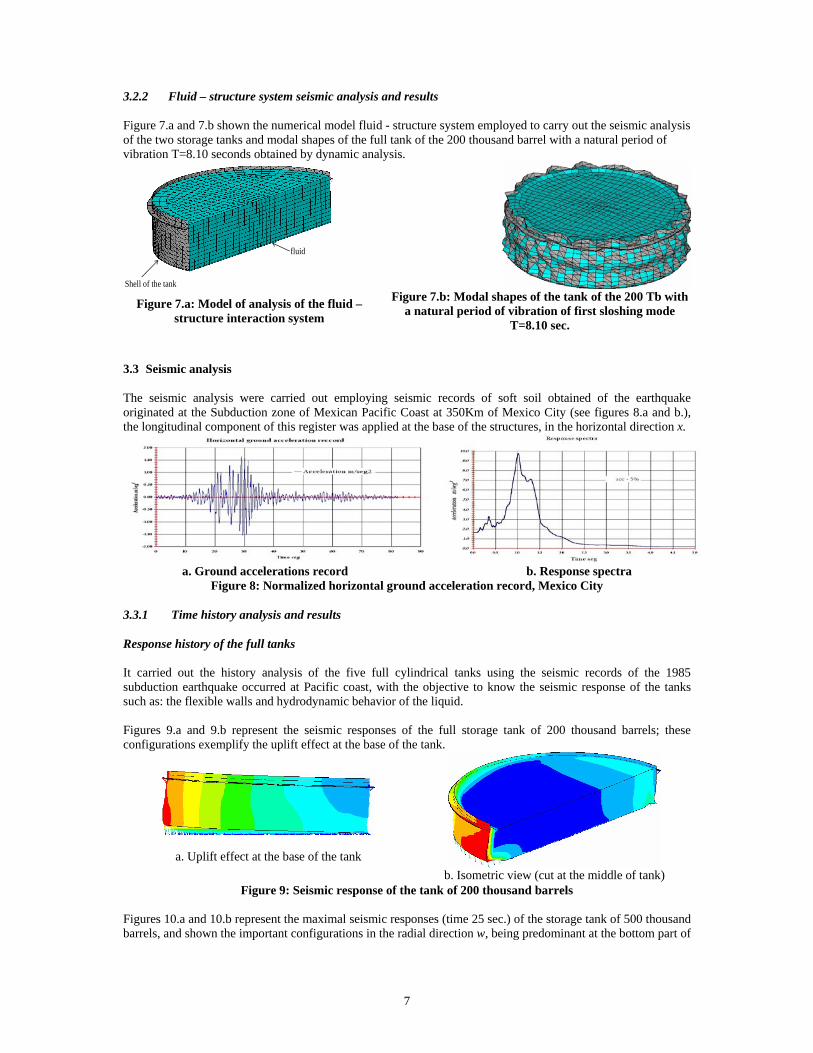
3.2.2 Fluid – structure system seismic analysis and results Figure 7.a and 7.b shown the numerical model fluid - structure system employed to carry out the seismic analysis of the two storage tanks and modal shapes of the full tank of the 200 thousand barrel with a natural period of vibration T=8.10 seconds obtained by dynamic analysis.
Shell of the tank
fluid
Figure 7.a: Model of analysis of the fluid –
structure interaction system
Figure 7.b: Modal shapes of the tank of the 200 Tb with a natural period of vibration of first sloshing mode
T=8.10 sec. 3.3 Seismic analysis The seismic analysis were carried out employing seismic records of soft soil obtained of the earthquake originated at the Subduction zone of Mexican Pacific Coast at 350Km of Mexico City (see figures 8.a and b.), the longitudinal component of this register was applied at the base of the structures, in the horizontal direction x.
a. Ground accelerations record b. Response spectra
Figure 8: Normalized horizontal ground acceleration record, Mexico City 3.3.1 Time history analysis and results Response history of the full tanks It carried out the history analysis of the five full cylindrical tanks using the seismic records of the 1985 subduction earthquake occurred at Pacific coast, with the objective to know the seismic response of the tanks such as: the flexible walls and hydrodynamic behavior of the liquid. Figures 9.a and 9.b represent the seismic responses of the full storage tank of 200 thousand barrels; these configurations exemplify the uplift effect at the base of the tank.
a. Uplift effect at the base of the tank b. Isometric view (cut at the middle of tank)
Figure 9: Seismic response of the tank of 200 thousand barrels Figures 10.a and 10.b represent the maximal seismic responses (time 25 sec.) of the storage tank of 500 thousand barrels, and shown the important configurations in the radial direction w, being predominant at the bottom part of
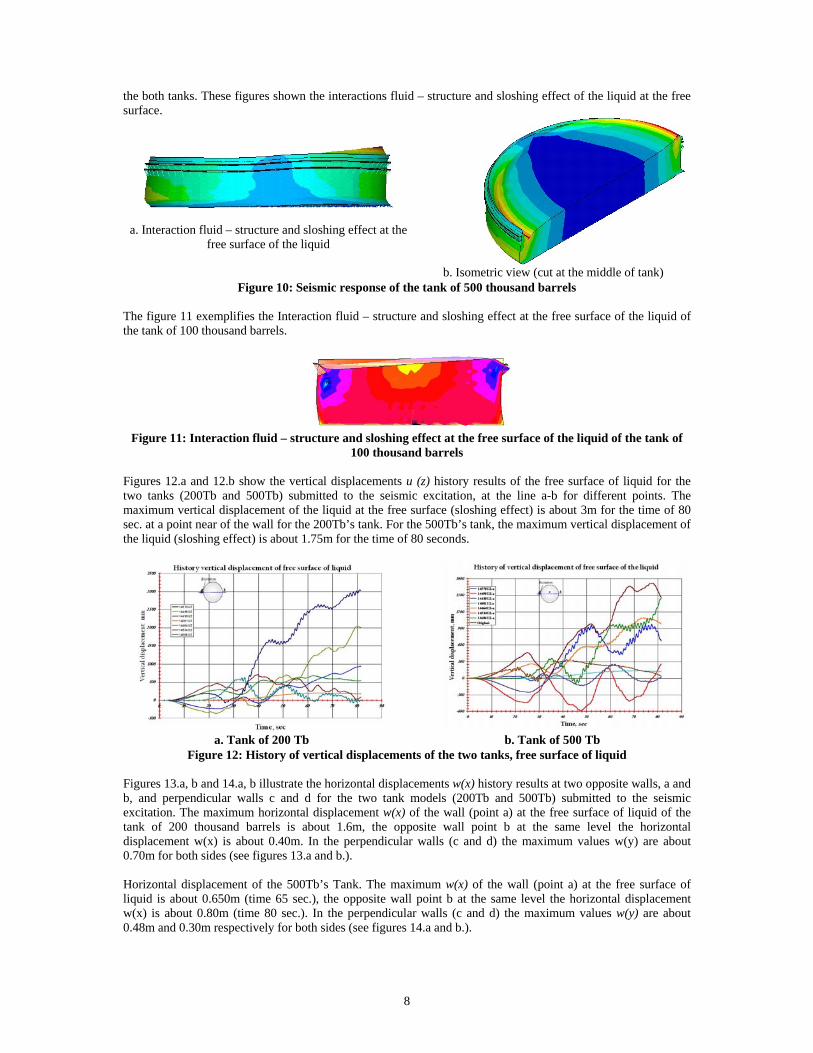
8
the both tanks. These figures shown the interactions fluid – structure and sloshing effect of the liquid at the free surface.
a. Interaction fluid – structure and sloshing effect at the free surface of the liquid
b. Isometric view (cut at the middle of tank)
Figure 10: Seismic response of the tank of 500 thousand barrels The figure 11 exemplifies the Interaction fluid – structure and sloshing effect at the free surface of the liquid of the tank of 100 thousand barrels.
Figure 11: Interaction fluid – structure and sloshing effect at the free surface of the liquid of the tank of
100 thousand barrels Figures 12.a and 12.b show the vertical displacements u (z) history results of the free surface of liquid for the two tanks (200Tb and 500Tb) submitted to the seismic excitation, at the line a-b for different points. The maximum vertical displacement of the liquid at the free surface (sloshing effect) is about 3m for the time of 80 sec. at a point near of the wall for the 200Tb’s tank. For the 500Tb’s tank, the maximum vertical displacement of the liquid (sloshing effect) is about 1.75m for the time of 80 seconds.
a. Tank of 200 Tb b. Tank of 500 Tb
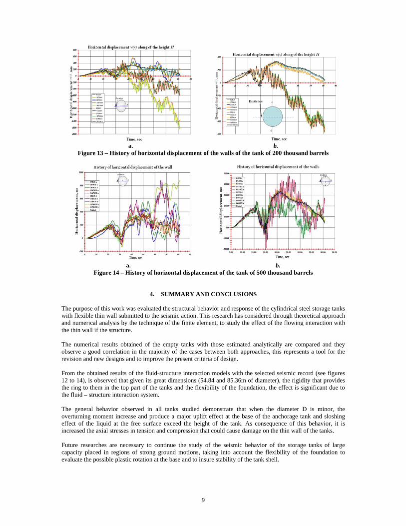
Figure 12: History of vertical displacements of the two tanks, free surface of liquid Figures 13.a, b and 14.a, b illustrate the horizontal displacements w(x) history results at two opposite walls, a and b, and perpendicular walls c and d for the two tank models (200Tb and 500Tb) submitted to the seismic excitation. The maximum horizontal displacement w(x) of the wall (point a) at the free surface of liquid of the tank of 200 thousand barrels is about 1.6m, the opposite wall point b at the same level the horizontal displacement w(x) is about 0.40m. In the perpendicular walls (c and d) the maximum values w(y) are about 0.70m for both sides (see figures 13.a and b.). Horizontal displacement of the 500Tb’s Tank. The maximum w(x) of the wall (point a) at the free surface of liquid is about 0.650m (time 65 sec.), the opposite wall point b at the same level the horizontal displacement w(x) is about 0.80m (time 80 sec.). In the perpendicular walls (c and d) the maximum values w(y) are about 0.48m and 0.30m respectively for both sides (see figures 14.a and b.).
9
a. b.
Figure 13 – History of horizontal displacement of the walls of the tank of 200 thousand barrels
a. b.
Figure 14 – History of horizontal displacement of the tank of 500 thousand barrels
4. SUMMARY AND CONCLUSIONS The purpose of this work was evaluated the structural behavior and response of the cylindrical steel storage tanks with flexible thin wall submitted to the seismic action. This research has considered through theoretical approach and numerical analysis by the technique of the finite element, to study the effect of the flowing interaction with the thin wall if the structure. The numerical results obtained of the empty tanks with those estimated analytically are compared and they observe a good correlation in the majority of the cases between both approaches, this represents a tool for the revision and new designs and to improve the present criteria of design. From the obtained results of the fluid-structure interaction models with the selected seismic record (see figures 12 to 14), is observed that given its great dimensions (54.84 and 85.36m of diameter), the rigidity that provides the ring to them in the top part of the tanks and the flexibility of the foundation, the effect is significant due to the fluid – structure interaction system. The general behavior observed in all tanks studied demonstrate that when the diameter D is minor, the overturning moment increase and produce a major uplift effect at the base of the anchorage tank and sloshing effect of the liquid at the free surface exceed the height of the tank. As consequence of this behavior, it is increased the axial stresses in tension and compression that could cause damage on the thin wall of the tanks. Future researches are necessary to continue the study of the seismic behavior of the storage tanks of large capacity placed in regions of strong ground motions, taking into account the flexibility of the foundation to evaluate the possible plastic rotation at the base and to insure stability of the tank shell.
10
5. REFERENCES
API STANDAR 650, (1998), Welded steel tanks for oil storage, Tenth Edition, API, Washington, D.C., USA. API STANDAR 653, (1995), Tank inspection, repair, alteration, and reconstruction, Second Edition, API,
Environmental Mission and Guiding Environmental Principles, Washington, D.C., USA. Arnold, R.N. and G.B. Warburton, (1949), Flexural vibrations of the walls of thin cylindrical shells having freely
supported ends, Department of Engineering, University of Edinburgh, Proc. Roy. Soc. London, Reprinted from, Ser. A, pp. 238-256.
Haroum, M.A., and Housner, W.G., (1981), Seismic design of liquid storage tanks, ASCE, Proceedings J. of Technical Councils, Vol. 107, No TC1, pp. 191-345
Haroum, M.A., (1983), Vibration studies and tests of liquid storage tanks, Earthquake Engineering and Structural Dynamics, Vol. II, pp. 179-206
Sanchez-Sanchez, H. y Vargas, O.S., (1999), Estudio del comportamiento sísmico de tanques de almacenamiento mediante diferentes métodos propuestos, Memorias del XII Congreso Nacional de Ingeniería Sísmica, Morelia, Mich.
Sanchez-Sanchez, H. y Vargas, O.S, (2000), Análisis sísmico de tanques cilíndricos de almacenamiento, Memorias del XII Congreso Nacional de Ingeniería Estructural, León Gto.
Sanchez-Sanchez, H. y Cortés S.C., (2000), Influencia de la rigidez de fondo en el comportamiento de estructuras cilíndricas de pared delgada, Memorias del XII Congreso Nacional de Ingeniería Estructural, León Gto.
Sanchez-Sanchez, H., Urrutia, J.L., Minchaca, M, E. y Avelino, R.J., (2001,) Comportamiento y estabilidad en estructuras cilíndricas de pared delgada, Reporte del Proyecto de Investigación CGPI, Núm. 2000668, IPN 2000-01.
Sanchez-Sanchez, H. y Cortés S. C., (2003), Comportamiento dinámico de tanques de almacenamiento con cubierta fija tipo cúpula, Memorias del XIV Congreso Nacional de Ingeniería Estructural, León Gto.
Sanchez-Sanchez, H. y Cortes S.C., (2004), Structural behaviour of liquid filled storage tanks of large capacity placed in seismic zones of high risk in Mexico, Proceedings 13th World Conference on Earthquake Engineering, Paper 2665, Vancouver, B.C., Canada.
Timoshenko, S. and Woinnowsky-Krieger, S., (1959), Theory of plates and shells, 2nd ed., McGraw-Hill, New York, pp. 466-488
Warburton, G.B., (1976), The dynamical behaviour of structures, 2nd ed., Pergamon Press, Great Britain. Wozniak, R.S., and Mitchell, 1978, Basis of seismic design provision for welded steel oil storage tanks,
Proceedings – Refining Department, Vol. 57, API, Washington, D.C., pp. 485-501