Investigation of Stresses in Cylindrical Flat Bottom Tanks with Ring Shaped Foundation due to Uneven...
45
Investigation of Stresses in Cylindrical Flat Bottom Tanks with Ring Shaped Foundation due to Uneven Settlement Diploma thesis of Axel Volkwein University of Sydney University of Karlsruhe Australia Germany
Transcript of Investigation of Stresses in Cylindrical Flat Bottom Tanks with Ring Shaped Foundation due to Uneven...

Investigation of Stresses in Cylindrical
Flat Bottom Tanks with Ring Shaped
Foundation due to Uneven Settlement
Diploma thesis of
Axel Volkwein
University of Sydney University of Karlsruhe
Australia Germany
Lehrstuhl fiir Stahl- und Leichtmetallbau Kaiserstraße 12 Universität Fridericiana Karlsruhe 76131 Karlsruhe
Univ.-Professor Dr.-Ing. Helmut Saal Telefon: (0721) 608 - 2215 Telefax: (0721) 608 - 4078
DIPLOMA THESIS
for
Mr. cand.-ing. Axel Volkwein
"Investigation of stresses in cylindrical
flat bottom tanks with ring shaped foundation
due to uneven settlement"
It is common praxis today to measure the settlement of a flat bottom tank during testing at the tank shell or
eventually at the surface of the foundation. The displacement measured in this way may not be the settlement
of the soil. For unanchored tanks due to the large stiffness of the tank shell in the longitudinal direction the
variation of the deformations of the tank shell along the circumference will be much smaller than that of the
settlement of the soil. By a ring shaped foundation the deformation at the lower boundary of the tank shell
will be reduced compared to the unevenness of the settlement. High membrane stress resultants will occur
due to settlement if the tank is anchored. This anchorage for operation conditions including wind requires
heavy foundation rings or thick concrete bottom plates. The stiffness of these types of foundation will reduce
the variation of the deformation that has to be used when calculating the stresses in the tank shell.
Scope:
1.) The influence of a ring shaped foundation on the stresses in flat bottom tanks shall be
investigated by a finite element calculation. The finite element model shall include tank
(shell, bottom and boundary conditions at the roof), ring foundation and soil. In addition
to the stress calculation the deflections of the soil, the upper surface of the foundation
ring and of the tank shell shall be compared.
2.) The stresses calculated for tanks with foundation calculated according to 1.) shall be
compared with those for the same tanks without foundation ring.
3.) Models for the hand calculation and results from former investigations shall be compared with the results
obtained under 1.) and 2.) and if possible extended to include the influence of the foundation ring.
4.) The relevant parameters shall be defined and the results shall be clearly presented.
Period of performance: 8 weeks.
Start time:
Date of delivery:
April 03rd 1998 shall: May 29th 1998 is:
Supervisor:
U. Hornung
Karlsruhe, March 25th 1998
(Univ.-Prof. Dr.-Ing. H. Saal)
Preface
I would like to state that I wrote this thesis on my own, and I did not use any other
sources except those listed in the references.
Sydney, 19/06/1998
Acknowledgements
I am grateful to Prof. H. Saal and Prof. P. Ansourian for allowing me to write
my Diploma thesis at the University of Sydney. I would like to thank also my
supervisor Mr. U. Hornung, in Karlsruhe, for his valuable and helpful advice
despite the long distance.
For their assistance in preparing my thesis and their help during my stay at the
University of Sydney, I especially thank Cynthia Caballes, Tim Wilkinson,
Danny Kim, Hadi Helbawi and Mohammad Jonaidi.

CONTENTS
1
0 CONTENTS
0 Contents ..............................................................................................................................1
1 Introduction........................................................................................................................2
2 Summary of results from previous research ...................................................................4
3 Geometry of tanks and applied loads...............................................................................7
3.1 Model geometry ............................................................................................................7
3.2 Static loads ....................................................................................................................7
3.3 Settlement......................................................................................................................9
4 Finite Element Modeling .................................................................................................10
4.1 Model ..........................................................................................................................10
4.2 Contact Modeling ........................................................................................................12
4.3 Fixed Boundary Conditions ........................................................................................13
4.4 Materials......................................................................................................................14
4.5 Loading........................................................................................................................14
4.6 Mesh fineness ..............................................................................................................15
5 FE-Calculation Results....................................................................................................20
5.1 Overview of single components of the tank................................................................20
5.2 Effect of foundation ....................................................................................................22
6 Sketch of an analytical model .........................................................................................32
7 Conclusion ........................................................................................................................36
8 References.........................................................................................................................37
9 Appendix...........................................................................................................................38

INTRODUCTION
2
1 INTRODUCTION
In building a steel tank as economically as possible, one attempts to use the minimum number
of components for the desired application. The simplest scenario consists only of a tankshell,
tankbase and sometimes a roof. It is important to have a soil with uniform consistency and
stiffness so that a uniform settlement of the entire building when the tank is filled e.g. with
water. This, however, is not always possible in regions with subterranean mining or poor
ground preparation. Also, tankshell because of the weight of shell and roof there is a
concentrated pressure under the tank shell and therefore a larger settlement there.
The best protection against uneven settlement is a continuous concrete foundation plate.
However, this requires a lot of extra material and added costs. Therefore, only a foundation
ring is used under the tankshell. Schneider showed in [15] that the unfounded part of the
tankbase is quite insensitive against axisymmetric settlement and that the failure results more
in the tensile strength than in the stability of the tank.
While handling an open top tank there are almost no significant stresses in the tank shell,
however, large displacements of the tank top result. To avoid them –e.g. for tanks with a
swimming roof-, the top is fixed to a circular girder. This constraint results in high axial
stresses especially at the lower bound of the tank shell. Palmer [14] developed an analytical
model for getting the axial stresses in empty, cylindrical tank shells with a constant thickness
in dependence to the girder stiffness and the settlement shape. Hofmann [5] expanded the
model for several thicknesses. He considered also the tank base and water filled tanks. The
investigations in the following thesis are made with fixed roof tanks, which can be compared
with an open top tank and a primary wind girder having an infinite moment of inertia.
Palmer's efforts are confined to anchored tanks, which means that the tank follows exactly the
applied settlement. Hofmann [5] compared the anchored and unanchored tanks. Würfel [16]
produced a parameter study about the behavior of unanchored tanks. This thesis is to broaden
the knowledge about this behavior and the difference between anchored and unanchored
tanks.
INTRODUCTION
3
In addition, the thesis will investigate the effect of a foundation ring. In the previous research,
the foundation ring is supposed to exist for the tanks – whether anchored or not. However, the
displacements applied in these treatises describe the shape of the deformed foundation under
the tank shell. In this thesis, the settlement is applied to the underground and the special
behavior of foundation ring and the tank shell is to be investigated.
Because of the complexity of the FE-model and the use of new features for modeling more
attention was paid to the parts relating the handling of the FE-calculation.
SUMMARY OF RESULTS FROM PREVIOUS RESEARCH
4
2 SUMMARY OF RESULTS FROM PREVIOUS RESEARCH
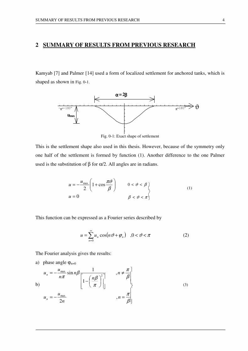
Kamyab [7] and Palmer [14] used a form of localized settlement for anchored tanks, which is
shaped as shown in Fig. 0-1.
umax
ϑπ=180°-π=-180°
αααα = 2ββββ
Fig. 0-1: Exact shape of settlement
This is the settlement shape also used in this thesis. However, because of the symmetry only
one half of the settlement is formed by function (1). Another difference to the one Palmer
used is the substitution of β for α/2. All angles are in radians.
0
cos12
max
=
+−=
u
uu
β
πϑ
<<
<<
πϑβ
βϑ0 (1)
This function can be expressed as a Fourier series described by
( )∑∞
=
<<+=0
0,cosn
nn nuu πϑϕϑ (2)
The Fourier analysis gives the results:
a) phase angle ϕn=0
b)
=−=
≠
−
−=
β
π
β
π
π
ββ
π
nn
uu
nn
nn
uu
n
n
,2
,
1
1sin
max
2
max
(3)
SUMMARY OF RESULTS FROM PREVIOUS RESEARCH
5
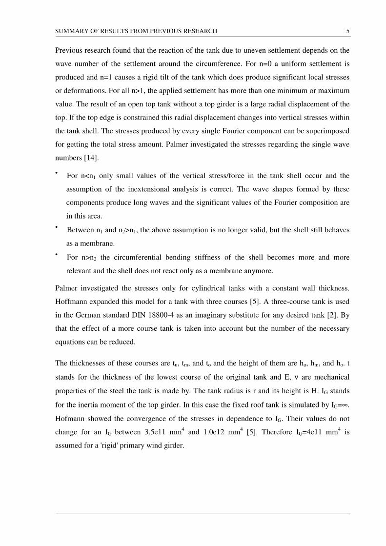
Previous research found that the reaction of the tank due to uneven settlement depends on the
wave number of the settlement around the circumference. For n=0 a uniform settlement is
produced and n=1 causes a rigid tilt of the tank which does produce significant local stresses
or deformations. For all n>1, the applied settlement has more than one minimum or maximum
value. The result of an open top tank without a top girder is a large radial displacement of the
top. If the top edge is constrained this radial displacement changes into vertical stresses within
the tank shell. The stresses produced by every single Fourier component can be superimposed
for getting the total stress amount. Palmer investigated the stresses regarding the single wave
numbers [14].
• For n<n1 only small values of the vertical stress/force in the tank shell occur and the
assumption of the inextensional analysis is correct. The wave shapes formed by these
components produce long waves and the significant values of the Fourier composition are
in this area.
• Between n1 and n2>n1, the above assumption is no longer valid, but the shell still behaves
as a membrane.
• For n>n2 the circumferential bending stiffness of the shell becomes more and more
relevant and the shell does not react only as a membrane anymore.
Palmer investigated the stresses only for cylindrical tanks with a constant wall thickness.
Hoffmann expanded this model for a tank with three courses [5]. A three-course tank is used
in the German standard DIN 18800-4 as an imaginary substitute for any desired tank [2]. By
that the effect of a more course tank is taken into account but the number of the necessary
equations can be reduced.
The thicknesses of these courses are tu, tm, and to and the height of them are hu, hm, and ho. t
stands for the thickness of the lowest course of the original tank and E, ν are mechanical
properties of the steel the tank is made by. The tank radius is r and its height is H. IG stands
for the inertia moment of the top girder. In this case the fixed roof tank is simulated by IG=∞.
Hofmann showed the convergence of the stresses in dependence to IG. Their values do not
change for an IG between 3.5e11 mm4 and 1.0e12 mm
4 [5]. Therefore IG=4e11 mm
4 is
assumed for a 'rigid' primary wind girder.
SUMMARY OF RESULTS FROM PREVIOUS RESEARCH
6
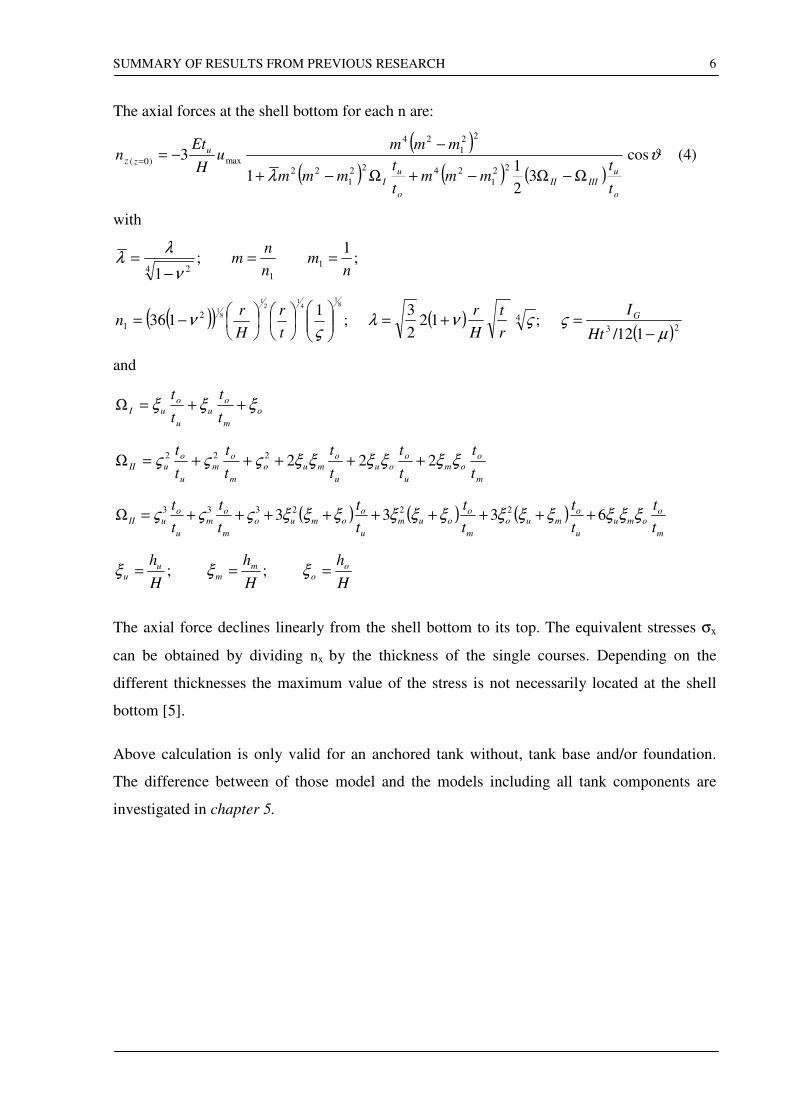
The axial forces at the shell bottom for each n are:
( )
( ) ( ) ( )ϑ
λ
cos
32
11
322
1
2422
1
22
22
1
24
max)0(
o
u
IIIII
o
u
I
u
zz
t
tmmm
t
tmmm
mmmu
H
Etn
Ω−Ω−+Ω−+
−−=
= (4)
with
;1
;1
1
14 2 n
mn
nm ==
−=
ν
λλ
( )( ) ;1
136
81
41
21
81
2
1
−=
ςν
t
r
H
rn ( ) ;12
2
34 ςνλ
r
t
H
r+=
( )23 112/ µς
−=
Ht
IG
and
o
m
o
u
u
o
uIt
t
t
tξξξ ++=Ω
m
o
om
u
o
ou
u
o
muo
m
o
m
u
o
uIIt
t
t
t
t
t
t
t
t
tξξξξξξςςς 222222 +++++=Ω
( ) ( ) ( )m
oomu
u
omuo
m
ooum
u
oomuo
m
om
u
ouII
t
t
t
t
t
t
t
t
t
t
t
tξξξξξξξξξξξξςςς 6333 222333 +++++++++=Ω
;H
hu
u =ξ ;H
hm
m =ξH
ho
o =ξ
The axial force declines linearly from the shell bottom to its top. The equivalent stresses σx
can be obtained by dividing nx by the thickness of the single courses. Depending on the
different thicknesses the maximum value of the stress is not necessarily located at the shell
bottom [5].
Above calculation is only valid for an anchored tank without, tank base and/or foundation.
The difference between of those model and the models including all tank components are
investigated in chapter 5.

GEOMETRY OF TANKS AND APPLIED LOADS
7
3 GEOMETRY OF TANKS AND APPLIED LOADS
This chapter will describe the used tanks and the applied loads as well as the shape of the
settlement. The used units are [N] for forces and [mm] for length declarations. If the angle α
of the settlement area is used one must be aware that this angle means the opening of the
whole settled area. In this thesis is only one half of the tank modeled. Therefore the angle β
which appears in the diagrams is half of α.
3.1 Model geometry
Three tanks are selected, each distinguished by the ratio between radius and height. This is
supposed to show the difference in the investigated behavior in dependence to the axial
bending stiffness of the tank shell.
The tank base is composed of two parts. The inner part with no intended stability is 6mm
thick. The outer ring is supposed to allow the shell to submit bending moment. For this its
thickness is about 70% of the lowest course thickness. The size of the outer part is chosen to
lie completely over the foundation ring.
The foundation depth is set to 0.8m, which is the frost relating depth for foundations in
Germany. Its width is 1.50m. The foundation is not used for all models since a comparison
between tanks with and without foundation is required. For other investigations the outer part
of the tank base is connected with the top nodes of the foundation ring.
Both foundation ring and outer base ring overhang the tank shell about 0.5m
For a detailed overview of the model geometry see the tab 0-1.
3.2 Static loads
3.2.1 Roof load
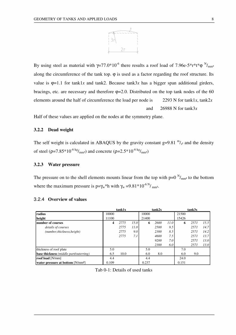
API Standard 620 gives the lowest limit for the roof skin thickness at 4.7mm and thicker
values have to be chosen for tanks with different radius [1]. The radius of the dome is chosen
to be triple the tank radius.
GEOMETRY OF TANKS AND APPLIED LOADS
8
By using steel as material with γ=77.0*10-6
there results a roof load of 7.96e-5*r*t*ϕ N/mm³
along the circumference of the tank top. ϕ is used as a factor regarding the roof structure. Its
value is ϕ=1.1 for tank1x and tank2. Because tank3x has a bigger span additional girders,
bracings, etc. are necessary and therefore ϕ=2.0. Distributed on the top tank nodes of the 60
elements around the half of circumference the load per node is 2293 N for tank1x, tank2x
and 26988 N for tank3x
Half of these values are applied on the nodes at the symmetry plane.
3.2.2 Dead weight
The self weight is calculated in ABAQUS by the gravity constant g=9.81 m
/s² and the density
of steel (ρ=7.85*10-6 kg
/mm³) and concrete (ρ=2.5*10-6 kg
/mm³)
3.2.3 Water pressure
The pressure on to the shell elements mounts linear from the top with p=0 N/mm² to the bottom
where the maximum pressure is p=γw*h with γw =9.81*10-6 N
/ mm³.
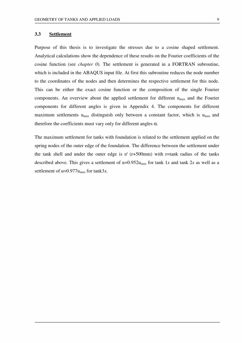
3.2.4 Overview of values
radius 10000 10000 21500
height 11100 21400 15426
number of courses 4 2775 15.0 6 2600 11.0 6 2571 15.5
details of courses 2775 11.0 2500 9.5 2571 14.7
(number,thickness,height) 2775 9.0 2300 8.5 2571 14.2
2775 7.1 4600 7.5 2571 13.7
9200 7.0 2571 13.0
2300 6.0 2571 13.0
thickness of roof plate 5.0 5.0 7.0
base thickness (middle part/outerring) 6.5 10.0 6.0 8.0 6.0 9.0
roof load [N/mm] 4.4 4.4 24.0
water pressure at bottom [N/mm²] 0.109 0.237 0.151
tank1x tank2x tank3x
Tab 0-1: Details of used tanks
GEOMETRY OF TANKS AND APPLIED LOADS
9
3.3 Settlement
Purpose of this thesis is to investigate the stresses due to a cosine shaped settlement.
Analytical calculations show the dependence of these results on the Fourier coefficients of the
cosine function (see chapter 0). The settlement is generated in a FORTRAN subroutine,
which is included in the ABAQUS input file. At first this subroutine reduces the node number
to the coordinates of the nodes and then determines the respective settlement for this node.
This can be either the exact cosine function or the composition of the single Fourier
components. An overview about the applied settlement for different nmax and the Fourier
components for different angles is given in Appendix 4. The components for different
maximum settlements umax distinguish only between a constant factor, which is umax and
therefore the coefficients must vary only for different angles α.
The maximum settlement for tanks with foundation is related to the settlement applied on the
spring nodes of the outer edge of the foundation. The difference between the settlement under
the tank shell and under the outer edge is r/ (r+500mm) with r=tank radius of the tanks
described above. This gives a settlement of u=0.952umax for tank 1x and tank 2x as well as a
settlement of u=0.977umax for tank3x.
FINITE ELEMENT MODELING
10
4 FINITE ELEMENT MODELING
The following chapter will show the constellation, loading and features of the Finite Element
Model. It will also discuss the plausibility of the results are.
The finite element calculation was done by the program ABAQUS v5.6.
4.1 Model
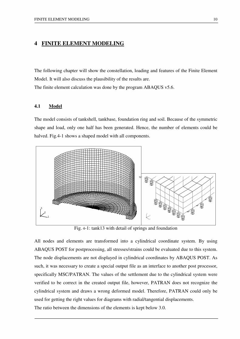
The model consists of tankshell, tankbase, foundation ring and soil. Because of the symmetric
shape and load, only one half has been generated. Hence, the number of elements could be
halved. Fig.4-1 shows a shaped model with all components.
1
2
3
1
2
3
1
2
3
Fig. 4-1: tank13 with detail of springs and foundation
All nodes and elements are transformed into a cylindrical coordinate system. By using
ABAQUS POST for postprocessing, all stresses/strains could be evaluated due to this system.
The node displacements are not displayed in cylindrical coordinates by ABAQUS POST. As
such, it was necessary to create a special output file as an interface to another post processor,
specifically MSC/PATRAN. The values of the settlement due to the cylindrical system were
verified to be correct in the created output file, however, PATRAN does not recognize the
cylindrical system and draws a wrong deformed model. Therefore, PATRAN could only be
used for getting the right values for diagrams with radial/tangential displacements.
The ratio between the dimensions of the elements is kept below 3.0.
FINITE ELEMENT MODELING
11
4.1.1 Tank
The element used for the tankshell is a shell element for finite strain applications. The element
S4R is a 4-node, double curved element for thin and thick shells. The average characteristic
element length in the models lays about 450mm. By a shell thickness between 6 and 16mm,
there results a ratio of 1/28. The criterion in ABAQUS for thin or thick shells is a ratio of
1/15, so a thin shell can be assumed.
This element uses a reduced integration and offers hourglass control. At every node, there are
6 degrees of freedom. The membrane strains are finite and suitable for large strain analysis.
The shell thickness can change according to the Poisson ratio. Concerning the reduced
integration (i.e. one Gauss integration point in each direction less than necessary for exact
integration), a softer behavior of the structure in compare to the exact integration is expected.
The tankshell consists of several courses with different thicknesses. The difference of the
radius because of the thickness change between two courses is neglected. The element size
within one course is constant whereby the size changed between the single courses. The
lowest course got the smallest elements because of the expected biggest change of stresses.
The other courses are adapted intending a mesh refinement towards the lowest course. The
highest course got more elements because of the roof load and the top boundary conditions.
The same shell element is used for the tankbase. In the centre, it is necessary to use a triangle
element (S3R) instead of a 4-node element, which is full compatible to the element S4R. The
base is composed of a thin plate in its inner part and a thicker ring outside over the
foundation. The elements over the foundation ring have a more or less constant size. The size
of those in the middle part decreased from the tank centre towards the inner foundation edge
by a constant factor. Hence, a continuous refinement towards the expected higher
displacements close to the foundation is achieved.
4.1.2 Foundation
The foundation ring is modeled by the element C3D8, which is a 8-node linear brick element.
Its nodes are connected with 3 degrees of freedom each (ur, uϑ, uz). The difference to a 20-
node solid elements appears only for very high stresses where the quadratic brick element is
more accurate regarding the Poisson ratio. As you can see later, the stresses in the foundation
FINITE ELEMENT MODELING
12
and its displacement stay on a level, which does not affect big changes in thickness of the
elements. So this effect due to the Poisson ratio can be neglected.
4.1.3 Soil
There are a few possibilities of generating a soil in ABAQUS. Creating a soil by using solid
elements is only meaningful, if one is interested in the results of the underground but for any
other purpose too many variables are wasted for unneeded results. There is an element option
for defining an elastic foundation onto an element face. This is recommended, if one is
interested in the different settlement due to an uneven E-modulus of the soil.
Concerning a proper defining of the uneven settlement, the ground is built with the spring
element SPRING1. This element simulates a spring acting between one node and the ground
in a fixed direction. Its stiffness is calculated by k=EA/l. E stands for the E-modulus of the
ground and l is an imaginary length. For the supported area A of one spring, it is assumed that
half the distance to the next spring in each direction counts/belongs to it. The stiffness varies
with the radius. Without a foundation it would have been possible to use an average stiffness.
Schneider showed in [15] that the axisymmetric difference of settlement and therefore the
different stiffnesses are not very significant for the stability of the tank. Besides, the stiffness
directly under the shell would be constant. However, by the use of a foundation and a constant
average stiffness there would be –depending on radius of the tank and the dimensions of the
foundation- a deviation of about 5.. 9%. Springs with the same stiffness are arranged in circles
around the centre of the tankbase. Because of the same radius, all springs in one row support
the same area. The springs at the symmetry axis got the half stiffness.
4.2 Contact Modeling
The purpose of this work is to examine the different settlement of ground, foundation and
tank. Therefore, it is necessary to manage the contact in that way that only pressure can be
submitted and the single components of the model are able to separate from each other. For
this, six surfaces have been generated. Two at the top and at the bottom of the foundation ring
as well as two for the middle part and the outer ring of the tankbase. The nodes of the springs
underneath the base and the foundation form the last two surfaces. It is not necessary that the
nodes of the master- and the slave surface fit exactly together, but ABAQUS performs better
FINITE ELEMENT MODELING
13
if it is so because ABAQUS handles the contact relations by creating internal contact
elements between a pair of corresponding nodes of the two contact surfaces.
For the sake of completeness, I would like to mention the disadvantages over the use of GAP-
elements. The opening of the gaps must be calculated by the user from the coordinates/
displacements of the nodes of the two surfaces while postprocessing with ABAQUS POST. It
is possible to get the opening e.g. with MSC PATRAN, if a special output file is generated
during the analysis. The presentation of the pressure/forces on the surfaces is not very suitable
for evaluating and creating diagrams. For generating an anchored tank it is not possible to
connect only the tank shell with the corresponding nodes of the foundation ring. The reason
herefore is an overlaying of constraints and the internal contact elements at the same nodes.
This would cause zero-pivots during the FE-calculation instead of creating two separated
surfaces beside the tank shell the whole outer base ring is connected to the top nodes of the
foundation.
4.3 Fixed Boundary Conditions
The tanks used in this thesis are fixed roof tanks. A fixed roof can be simulated by a top
girder with an infinite moment of inertia or fixed boundary conditions at the top of the tank.
The latter method was chosen. Hence, all top nodes are constrained in the radial and
tangential direction. The vertical movement of the tank is controlled by the springs.
The foundation ring has to be constrained against free moving into any direction and rotating
around any axis. The vertical direction is also supported by the springs. The remaining
degrees of freedom could have been fixed by constraining two points in radial and tangential
direction. The analysis showed that this was not sufficient. There appeared negative
eigenvalues and numerical singularities. It was necessary to constrain the foundation ring as
followed: It is left unconstrained between ϑ=0°.. 90° and has radial constraints for ϑ=90°..
180° at every edge node of the bottom. For applying a larger settlement area or increasing the
maximum settlement, it was necessary to constrain above nodes even in the tangential
direction. These constraints are not too far from the reality. Those radials can be compared
with the resistant of the soil around the ring. The change of length due to normal force is
negligible because of low tangential forces and the influence of the tensional stiffness is small
FINITE ELEMENT MODELING
14
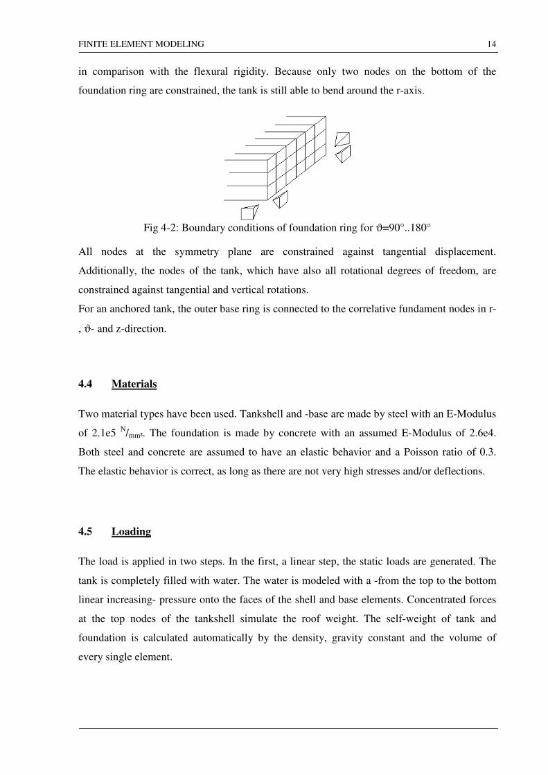
in comparison with the flexural rigidity. Because only two nodes on the bottom of the
foundation ring are constrained, the tank is still able to bend around the r-axis.
Fig 4-2: Boundary conditions of foundation ring for ϑ=90°..180°
All nodes at the symmetry plane are constrained against tangential displacement.
Additionally, the nodes of the tank, which have also all rotational degrees of freedom, are
constrained against tangential and vertical rotations.
For an anchored tank, the outer base ring is connected to the correlative fundament nodes in r-
, ϑ- and z-direction.
4.4 Materials
Two material types have been used. Tankshell and -base are made by steel with an E-Modulus
of 2.1e5 N/mm². The foundation is made by concrete with an assumed E-Modulus of 2.6e4.
Both steel and concrete are assumed to have an elastic behavior and a Poisson ratio of 0.3.
The elastic behavior is correct, as long as there are not very high stresses and/or deflections.
4.5 Loading
The load is applied in two steps. In the first, a linear step, the static loads are generated. The
tank is completely filled with water. The water is modeled with a -from the top to the bottom
linear increasing- pressure onto the faces of the shell and base elements. Concentrated forces
at the top nodes of the tankshell simulate the roof weight. The self-weight of tank and
foundation is calculated automatically by the density, gravity constant and the volume of
every single element.
FINITE ELEMENT MODELING
15
In the second step, the settlement has been applied by using a FORTRAN-subroutine. It could
be chosen between a settlement composed of a single cosine function or several Fourier-
coefficients of this cosine function. The settlement increases from 0 mm at the centre to its
maximum value at the outer edge of the foundation. All nodes covered by the user subroutine,
even those with no settlement, are constrained by ABAQUS in the vertical direction.
Therefore, the springs cannot act anymore as springs. Therefore, two different areas are used.
For the settlement composed of the single cosine function the area the user subroutine is
applied on is limited. The limit is the maximum angle of the settlement. For the Fourier
variant, the subroutine constrains all spring nodes of the model.
The procedure for the second step is a nonlinear static analysis. The iteration is performed by
the Newton method. Depending on the convergence of the single increments at one step
ABAQUS changes automatically between Newton-Raphson (for every increment there is one
stiffness matrix) and the modified Newton-Raphson method (one global stiffness matrix for
all increments).
For finding the equilibrium of forces and moments, ABAQUS calculates as much iteration as
necessary or as maximal defined. Especially for the first increment, ABAQUS needs many
iteration because of severe discontinuities. Those can be avoided by changing the default
values of the size of the first increment and the maximum allowed number of iterations. The
smallest first increment used was 1e-7 out of 1.0. All following increments converged after
1or 2 iterations. For a faster calculation, the factor for the automatic increasing of the
increments was enlarged from its default value 1.5 to 5. Obviously, the more elements have
been used the more iterations were necessary and the smaller was the first increment. The
same effect appeared for a larger settlement area, maximum value of the settlement or only a
few components of the Fourier analysis.
4.6 Mesh fineness
The precision depends a lot on the grade of the mesh fineness. However, more nodes/elements
require a longer time for calculation and heavy demand on the system resources and
capability. For getting some results about convergence, I ran jobs with different fineness by
doubling the number of variables. The difference between tank10 and tank13 is the number of
elements within a cross section. Tank14 has twice the number of elements as tank13 along the
FINITE ELEMENT MODELING
16
circumference. In tank13 and tank10 every element covers an angle of ϑ=3°. Hence, the
accordant angle of tank14 was ϑ=1.5°.For details of the partitioning of the cross section of
these three tanks see [Appendix 1].
The problems in ABAQUS had following sizes:
Number of nodes Number of elements Total number of variables
tank10 4333 4612 14646
tank13 8725 9457 29835
tank14 17308 18877 ca. 60000
In the number of nodes and elements are also those included, which are created internal by
ABAQUS e.g. for modeling the contact problem. The total number of variables includes all
nodes, elements and LaGrange multipliers. The applied settlement is a single cosine function
with umax=50 mm and α=100° (for the description of the settlement shape see Chapter 2)
4.6.1 Assessment of results
-1.0
-0.8
-0.6
-0.4
-0.2
0.0
0.2
0.4
0.6
0 15 30 45 60 75 90 105 120 135 150 165 180
angle in degree
tank10
tank13
tank14
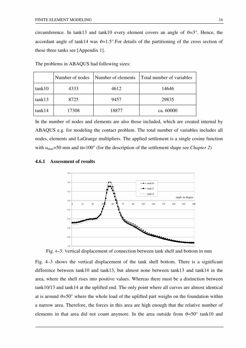
Fig. 4–3: Vertical displacement of connection between tank shell and bottom in mm
Fig. 4–3 shows the vertical displacement of the tank shell bottom. There is a significant
difference between tank10 and tank13, but almost none between tank13 and tank14 in the
area, where the shell rises into positive values. Whereas there must be a distinction between
tank10/13 and tank14 at the uplifted end. The only point where all curves are almost identical
at is around ϑ=50° where the whole load of the uplifted part weighs on the foundation within
a narrow area. Therefore, the forces in this area are high enough that the relative number of
elements in that area did not count anymore. In the area outside from ϑ≈50° tank10 and
FINITE ELEMENT MODELING
17
tank13 indicate always a smaller displacement than tank14 does. Those models behave more
stiffly than tank14. Their maximum possible change of gradient (curvature=δ²uz/(δϑ)²) of the
displacement shape is always less because of fewer elements along the circumference,.
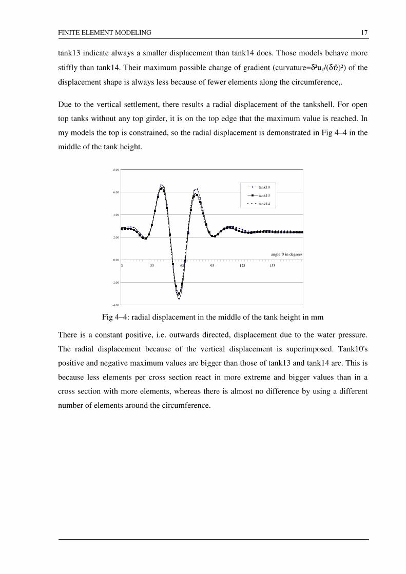
Due to the vertical settlement, there results a radial displacement of the tankshell. For open
top tanks without any top girder, it is on the top edge that the maximum value is reached. In
my models the top is constrained, so the radial displacement is demonstrated in Fig 4–4 in the
middle of the tank height.
-4.00
-2.00
0.00
2.00
4.00
6.00
8.00
3 33 63 93 123 153
angle ϑ in degrees
tank10
tank13
tank14
Fig 4–4: radial displacement in the middle of the tank height in mm
There is a constant positive, i.e. outwards directed, displacement due to the water pressure.
The radial displacement because of the vertical displacement is superimposed. Tank10's
positive and negative maximum values are bigger than those of tank13 and tank14 are. This is
because less elements per cross section react in more extreme and bigger values than in a
cross section with more elements, whereas there is almost no difference by using a different
number of elements around the circumference.
FINITE ELEMENT MODELING
18
- 4 0 . 0 0
- 3 5 . 0 0
- 3 0 . 0 0
- 2 5 . 0 0
- 2 0 . 0 0
- 1 5 . 0 0
- 1 0 . 0 0
- 5 . 0 0
0 . 0 0
5 . 0 0
1 0 . 0 0
0 3 0 6 0 9 0 1 2 0 1 5 0 1 8 0
a n g l e ϑ i n d e g r e e s
t a n k 1 0
t a n k 1 3
t a n k 1 4
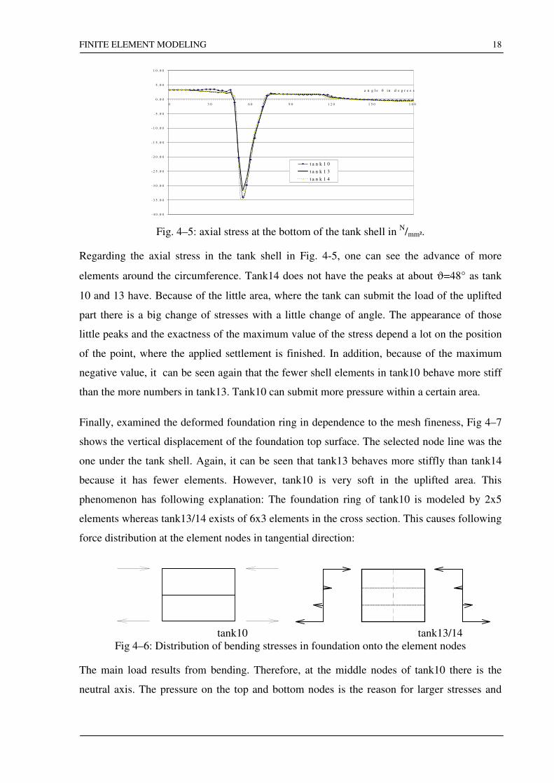
Fig. 4–5: axial stress at the bottom of the tank shell in
N/mm².
Regarding the axial stress in the tank shell in Fig. 4-5, one can see the advance of more
elements around the circumference. Tank14 does not have the peaks at about ϑ=48° as tank
10 and 13 have. Because of the little area, where the tank can submit the load of the uplifted
part there is a big change of stresses with a little change of angle. The appearance of those
little peaks and the exactness of the maximum value of the stress depend a lot on the position
of the point, where the applied settlement is finished. In addition, because of the maximum
negative value, it can be seen again that the fewer shell elements in tank10 behave more stiff
than the more numbers in tank13. Tank10 can submit more pressure within a certain area.
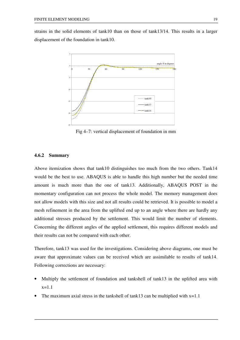
Finally, examined the deformed foundation ring in dependence to the mesh fineness, Fig 4–7
shows the vertical displacement of the foundation top surface. The selected node line was the
one under the tank shell. Again, it can be seen that tank13 behaves more stiffly than tank14
because it has fewer elements. However, tank10 is very soft in the uplifted area. This
phenomenon has following explanation: The foundation ring of tank10 is modeled by 2x5
elements whereas tank13/14 exists of 6x3 elements in the cross section. This causes following
force distribution at the element nodes in tangential direction:
tank10 tank13/14
Fig 4–6: Distribution of bending stresses in foundation onto the element nodes
The main load results from bending. Therefore, at the middle nodes of tank10 there is the
neutral axis. The pressure on the top and bottom nodes is the reason for larger stresses and
FINITE ELEMENT MODELING
19
strains in the solid elements of tank10 than on those of tank13/14. This results in a larger
displacement of the foundation in tank10.
-25
-20
-15
-10
-5
0
5
0 30 60 90 120 150 180
angle ϑ in degrees
tank10
tank13
tank14
Fig 4–7: vertical displacement of foundation in mm
4.6.2 Summary
Above itemization shows that tank10 distinguishes too much from the two others. Tank14
would be the best to use. ABAQUS is able to handle this high number but the needed time
amount is much more than the one of tank13. Additionally, ABAQUS POST in the
momentary configuration can not process the whole model. The memory management does
not allow models with this size and not all results could be retrieved. It is possible to model a
mesh refinement in the area from the uplifted end up to an angle where there are hardly any
additional stresses produced by the settlement. This would limit the number of elements.
Concerning the different angles of the applied settlement, this requires different models and
their results can not be compared with each other.
Therefore, tank13 was used for the investigations. Considering above diagrams, one must be
aware that approximate values can be received which are assimilable to results of tank14.
Following corrections are necessary:
• Multiply the settlement of foundation and tankshell of tank13 in the uplifted area with
x=1.1
• The maximum axial stress in the tankshell of tank13 can be multiplied with x=1.1
FE-CALCULATION RESULTS
20
5 FE-CALCULATION RESULTS
The following will show the effects of single components on the tank, in particular its stresses
and deformations. Despite the fact that some of those are already investigated in the literature
they will be raised as a general overview.
In most cases only the axial force instead of the axial stress is shown. The difference is the
constant factor 1/t with t=thickness of the lowest course. In comparisons where different
thicknesses are used, the axial stress is used instead. Most of the following diagrams are
created by using tank1x, which is described in Chapter 3. All given axial forces/stresses will
be always shown at the lower end of the tank shell.
5.1 Overview about single components of the tank
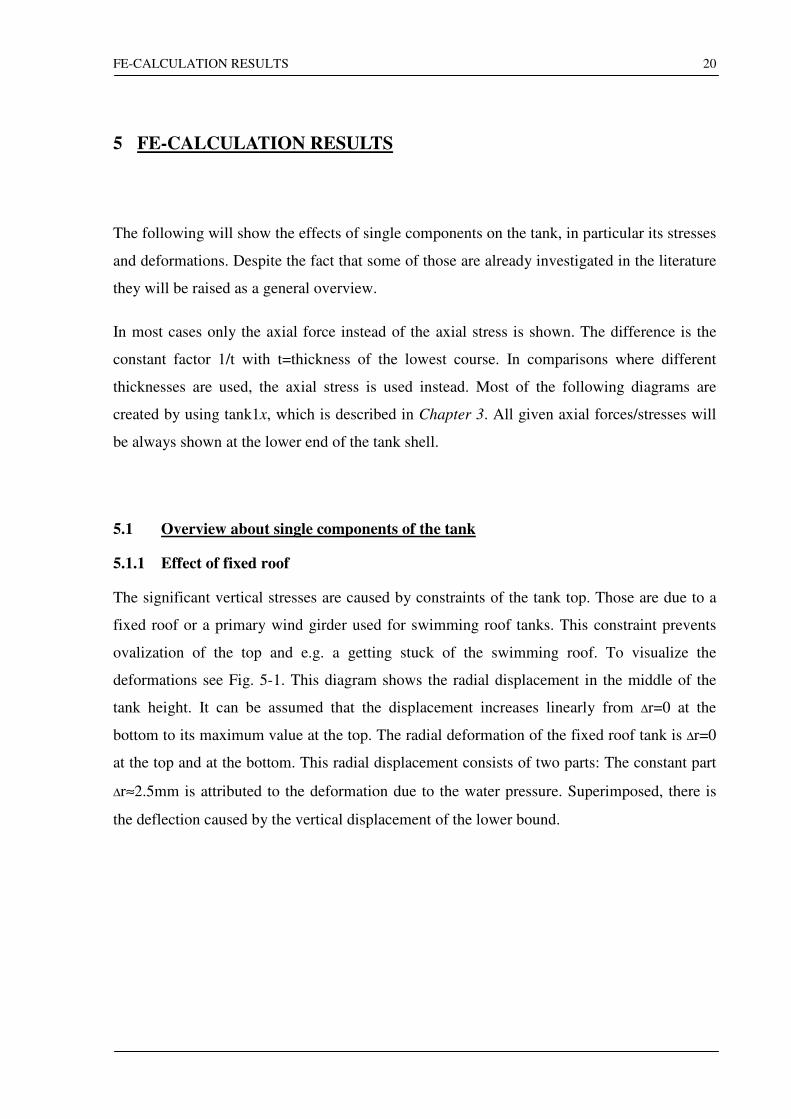
5.1.1 Effect of fixed roof
The significant vertical stresses are caused by constraints of the tank top. Those are due to a
fixed roof or a primary wind girder used for swimming roof tanks. This constraint prevents
ovalization of the top and e.g. a getting stuck of the swimming roof. To visualize the
deformations see Fig. 5-1. This diagram shows the radial displacement in the middle of the
tank height. It can be assumed that the displacement increases linearly from ∆r=0 at the
bottom to its maximum value at the top. The radial deformation of the fixed roof tank is ∆r=0
at the top and at the bottom. This radial displacement consists of two parts: The constant part
∆r≈2.5mm is attributed to the deformation due to the water pressure. Superimposed, there is
the deflection caused by the vertical displacement of the lower bound.
FE-CALCULATION RESULTS
21
-10.00
0.00
10.00
20.00
30.00
40.00
50.00
60.00
70.00
80.00
90.00
0 30 60 90 120 150 180angle
fixed roof tank
open top tank
Fig. 5-1: radial displacement of an open top and a fixed roof tank
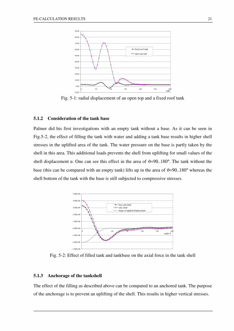
5.1.2 Consideration of the tank base
Palmer did his first investigations with an empty tank without a base. As it can be seen in
Fig.5-2, the effect of filling the tank with water and adding a tank base results in higher shell
stresses in the uplifted area of the tank. The water pressure on the base is partly taken by the
shell in this area. This additional loads prevents the shell from uplifting for small values of the
shell displacement u. One can see this effect in the area of ϑ=90..180°. Τhe tank without the
base (this can be compared with an empty tank) lifts up in the area of ϑ=90..180° whereas the
shell bottom of the tank with the base is still subjected to compressive stresses.
-3.00E+00
-2.00E+00
-1.00E+00
0.00E+00
1.00E+00
2.00E+00
3.00E+00
4.00E+00
5.00E+00
0 30 60 90 120 150 180
angle ϑ
base and shell
only shell
shape of applied displacement
Fig. 5-2: Effect of filled tank and tankbase on the axial force in the tank shell
5.1.3 Anchorage of the tankshell
The effect of the filling as described above can be compared to an anchored tank. The purpose
of the anchorage is to prevent an uplifting of the shell. This results in higher vertical stresses.
FE-CALCULATION RESULTS
22
-100
-50
0
50
100
150
0 30 60 90 120 150 180
angle
axia
l fo
rce
in n
/mm
-0.7
-0.6
-0.5
-0.4
-0.3
-0.2
-0.1
0
0.1
ver
tica
l dis
pla
cem
ent
in m
m
tank not anchored
tank anchored
applied settlement
vertical displacement ofunanchored tank
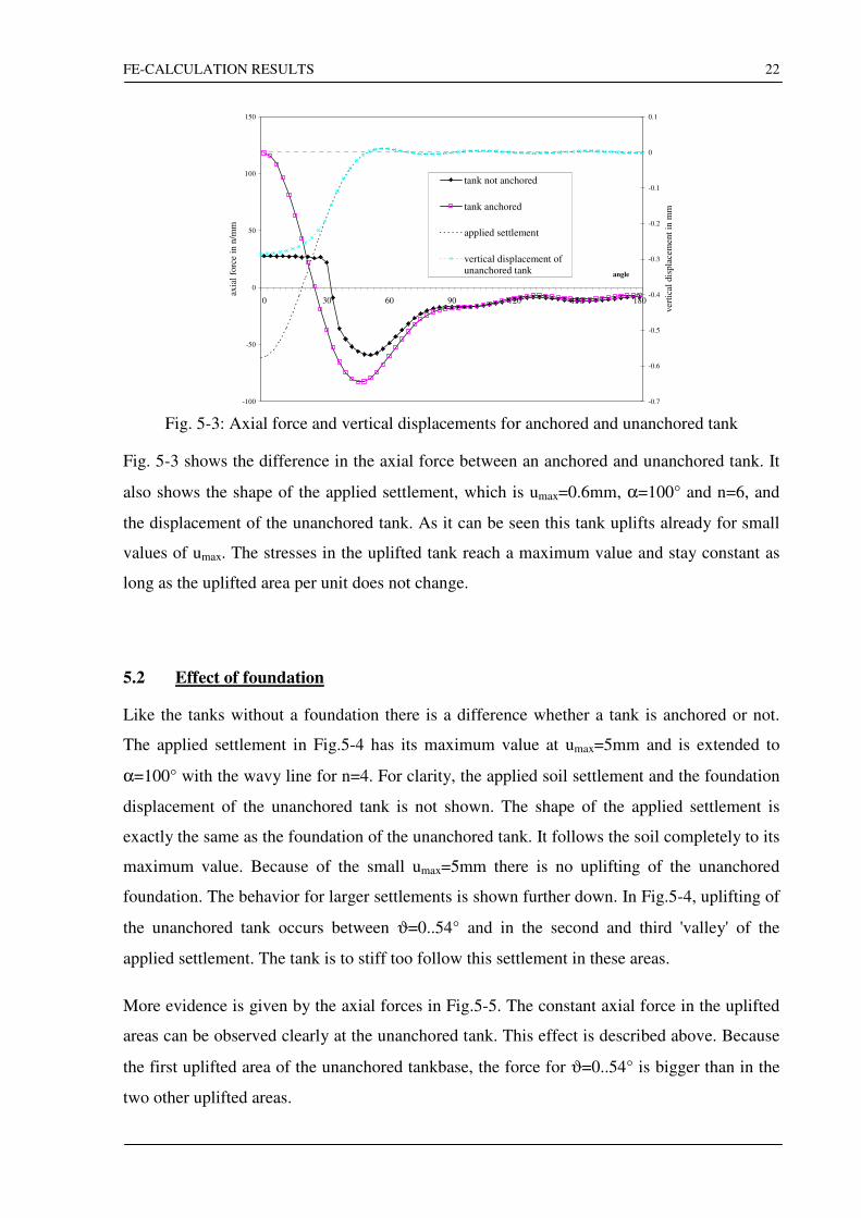
Fig. 5-3: Axial force and vertical displacements for anchored and unanchored tank
Fig. 5-3 shows the difference in the axial force between an anchored and unanchored tank. It
also shows the shape of the applied settlement, which is umax=0.6mm, α=100° and n=6, and
the displacement of the unanchored tank. As it can be seen this tank uplifts already for small
values of umax. The stresses in the uplifted tank reach a maximum value and stay constant as
long as the uplifted area per unit does not change.
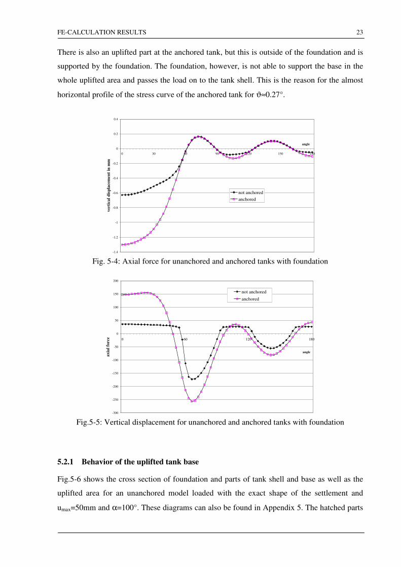
5.2 Effect of foundation
Like the tanks without a foundation there is a difference whether a tank is anchored or not.
The applied settlement in Fig.5-4 has its maximum value at umax=5mm and is extended to
α=100° with the wavy line for n=4. For clarity, the applied soil settlement and the foundation
displacement of the unanchored tank is not shown. The shape of the applied settlement is
exactly the same as the foundation of the unanchored tank. It follows the soil completely to its
maximum value. Because of the small umax=5mm there is no uplifting of the unanchored
foundation. The behavior for larger settlements is shown further down. In Fig.5-4, uplifting of
the unanchored tank occurs between ϑ=0..54° and in the second and third 'valley' of the
applied settlement. The tank is to stiff too follow this settlement in these areas.
More evidence is given by the axial forces in Fig.5-5. The constant axial force in the uplifted
areas can be observed clearly at the unanchored tank. This effect is described above. Because
the first uplifted area of the unanchored tankbase, the force for ϑ=0..54° is bigger than in the
two other uplifted areas.
FE-CALCULATION RESULTS
23
There is also an uplifted part at the anchored tank, but this is outside of the foundation and is
supported by the foundation. The foundation, however, is not able to support the base in the
whole uplifted area and passes the load on to the tank shell. This is the reason for the almost
horizontal profile of the stress curve of the anchored tank for ϑ≈0.27°.
-1.4
-1.2
-1
-0.8
-0.6
-0.4
-0.2
0
0.2
0.4
0 30 60 90 120 150 180
angle
ver
tica
l d
isp
lace
men
t in
mm
not anchored
anchored
Fig. 5-4: Axial force for unanchored and anchored tanks with foundation
-300
-250
-200
-150
-100
-50
0
50
100
150
200
0 60 120 180
angle
ax
ial
forc
e
not anchored
anchored
Fig.5-5: Vertical displacement for unanchored and anchored tanks with foundation
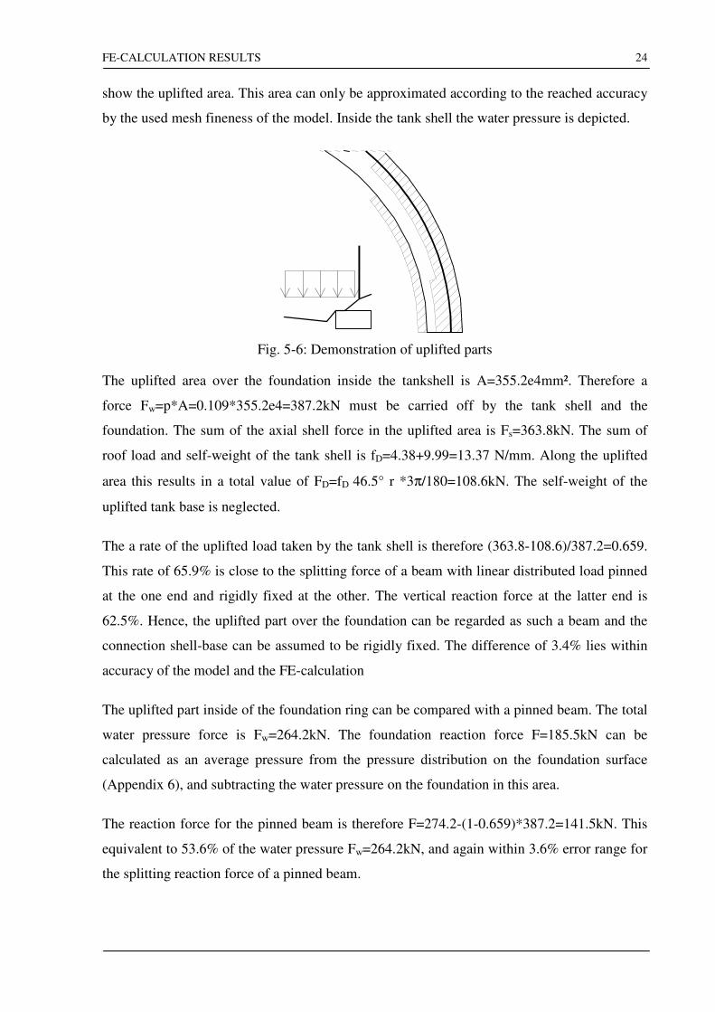
5.2.1 Behavior of the uplifted tank base
Fig.5-6 shows the cross section of foundation and parts of tank shell and base as well as the
uplifted area for an unanchored model loaded with the exact shape of the settlement and
umax=50mm and α=100°. These diagrams can also be found in Appendix 5. The hatched parts
FE-CALCULATION RESULTS
24
show the uplifted area. This area can only be approximated according to the reached accuracy
by the used mesh fineness of the model. Inside the tank shell the water pressure is depicted.
Fig. 5-6: Demonstration of uplifted parts
The uplifted area over the foundation inside the tankshell is A=355.2e4mm². Therefore a
force Fw=p*A=0.109*355.2e4=387.2kN must be carried off by the tank shell and the
foundation. The sum of the axial shell force in the uplifted area is Fs=363.8kN. The sum of
roof load and self-weight of the tank shell is fD=4.38+9.99=13.37 N/mm. Along the uplifted
area this results in a total value of FD=fD 46.5° r *3π/180=108.6kN. The self-weight of the
uplifted tank base is neglected.
The a rate of the uplifted load taken by the tank shell is therefore (363.8-108.6)/387.2=0.659.
This rate of 65.9% is close to the splitting force of a beam with linear distributed load pinned
at the one end and rigidly fixed at the other. The vertical reaction force at the latter end is
62.5%. Hence, the uplifted part over the foundation can be regarded as such a beam and the
connection shell-base can be assumed to be rigidly fixed. The difference of 3.4% lies within
accuracy of the model and the FE-calculation
The uplifted part inside of the foundation ring can be compared with a pinned beam. The total
water pressure force is Fw=264.2kN. The foundation reaction force F=185.5kN can be
calculated as an average pressure from the pressure distribution on the foundation surface
(Appendix 6), and subtracting the water pressure on the foundation in this area.
The reaction force for the pinned beam is therefore F=274.2-(1-0.659)*387.2=141.5kN. This
equivalent to 53.6% of the water pressure Fw=264.2kN, and again within 3.6% error range for
the splitting reaction force of a pinned beam.
FE-CALCULATION RESULTS
25
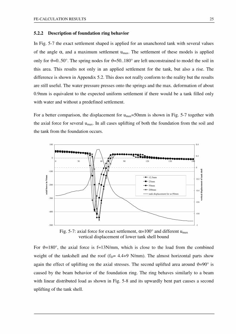
5.2.2 Description of foundation ring behavior
In Fig. 5-7 the exact settlement shaped is applied for an unanchored tank with several values
of the angle α, and a maximum settlement umax. The settlement of these models is applied
only for ϑ=0..50°. The spring nodes for ϑ=50..180° are left unconstrained to model the soil in
this area. This results not only in an applied settlement for the tank, but also a rise. The
difference is shown in Appendix 5.2. This does not really conform to the reality but the results
are still useful. The water pressure presses onto the springs and the max. deformation of about
0.9mm is equivalent to the expected uniform settlement if there would be a tank filled only
with water and without a predefined settlement.
For a better comparison, the displacement for umax=50mm is shown in Fig. 5-7 together with
the axial force for several umax. In all cases uplifting of both the foundation from the soil and
the tank from the foundation occurs.
-500
-400
-300
-200
-100
0
100
0 30 60 90 120 150 180
axia
l fo
erce
in
N/m
m
-1
-0.8
-0.6
-0.4
-0.2
0
0.2
0.4
ver
tica
l d
isp
lace
men
t of
tan
k s
hel
l
12.5mm
25mm
50mm
200mm
tank displacement for u=50mm
Fig. 5-7: axial force for exact settlement, α=100° and different umax
vertical displacement of lower tank shell bound
For ϑ=180°, the axial force is f≈13N/mm, which is close to the load from the combined
weight of the tankshell and the roof (fD= 4.4+9 N/mm). The almost horizontal parts show
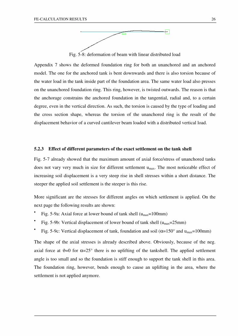
again the effect of uplifting on the axial stresses. The second uplifted area around ϑ=90° is
caused by the beam behavior of the foundation ring. The ring behaves similarly to a beam
with linear distributed load as shown in Fig. 5-8 and its upwardly bent part causes a second
uplifting of the tank shell.
FE-CALCULATION RESULTS
26
Fig. 5-8: deformation of beam with linear distributed load
Appendix 7 shows the deformed foundation ring for both an unanchored and an anchored
model. The one for the anchored tank is bent downwards and there is also torsion because of
the water load in the tank inside part of the foundation area. The same water load also presses
on the unanchored foundation ring. This ring, however, is twisted outwards. The reason is that
the anchorage constrains the anchored foundation in the tangential, radial and, to a certain
degree, even in the vertical direction. As such, the torsion is caused by the type of loading and
the cross section shape, whereas the torsion of the unanchored ring is the result of the
displacement behavior of a curved cantilever beam loaded with a distributed vertical load.
5.2.3 Effect of different parameters of the exact settlement on the tank shell
Fig. 5-7 already showed that the maximum amount of axial force/stress of unanchored tanks
does not vary very much in size for different settlement umax. The most noticeable effect of
increasing soil displacement is a very steep rise in shell stresses within a short distance. The
steeper the applied soil settlement is the steeper is this rise.
More significant are the stresses for different angles on which settlement is applied. On the
next page the following results are shown:
• Fig. 5-9a: Axial force at lower bound of tank shell (umax=100mm)
• Fig. 5-9b: Vertical displacement of lower bound of tank shell (umax=25mm)
• Fig. 5-9c: Vertical displacement of tank, foundation and soil (α=150° and umax=100mm)
The shape of the axial stresses is already described above. Obviously, because of the neg.
axial force at ϑ=0 for α=25° there is no uplifting of the tankshell. The applied settlement
angle is too small and so the foundation is stiff enough to support the tank shell in this area.
The foundation ring, however, bends enough to cause an uplifting in the area, where the
settlement is not applied anymore.

FE-CALCULATION RESULTS
27
-700
-600
-500
-400
-300
-200
-100
0
100
0 30 60 90 120 150 180
25 deg
75 deg
100 deg
125 deg
Fig. 5-9a: Axial force at lower bound of tank shell (umax=100mm)
-1.2
-1
-0.8
-0.6
-0.4
-0.2
0
0.2
0 30 60 90 120 150 180
25 deg
50 deg
75 deg
100 deg
125 deg
Fig. 5-9b: Vertical displacement of lower bound of tank shell (umax=25mm)
-2
-1.5
-1
-0.5
0
0.5
1
0 6
12
18
24
30
36
42
48
54
60
66
72
78
84
90
96
102
108
114
120
126
132
138
144
150
156
162
168
174
180
tank shell displacement
soil settlement
foundation displacement
Fig. 5-9c: Vertical displacement of tank, foundation and soil (α=150° andumax=100mm)
FE-CALCULATION RESULTS
28
Another peculiarity appears for α=125°. The foundation is bent downwards by the water
pressure on the tank base in the uplifted area. The tankshell is sitting on the foundation like a
seesaw. The tensional axial force caused by the uplifted base shows also an uplifting up to
ϑ=180°. The shell is therefore fully supported for ϑ≈60.. 87°.
This is also confirmed by the displacements in Fig. 5-9b. The curve for α=25° reaches the
maximum displacement relating to the chosen soil stiffness. However, although there is no
shell uplifting for α=125° and umax=25°, the shell does not reach the full settlement of
us≈0.9mm. With umax=25mm, the applied settlement is very small, and as such, so is the
settlement of the foundation. This means that the foundation ring supports almost all of the
uplifted base, and so, the tensional force in the shell stays at a low level. Additionally, the
shell is not bent as it is for umax=100mm (Fig. 5-9c) where also an uplifting of the foundation
from the soil occurs at ϑ=102..174°.
Fig. 5-9c shows the different displacement of foundation and tankshell together with the
applied exact settlement. For the sake of clarity the displacement of soil and foundation is not
shown for ϑ=0..60°. The foundation is separated from the soil for ϑ=0..60° (uplifting).
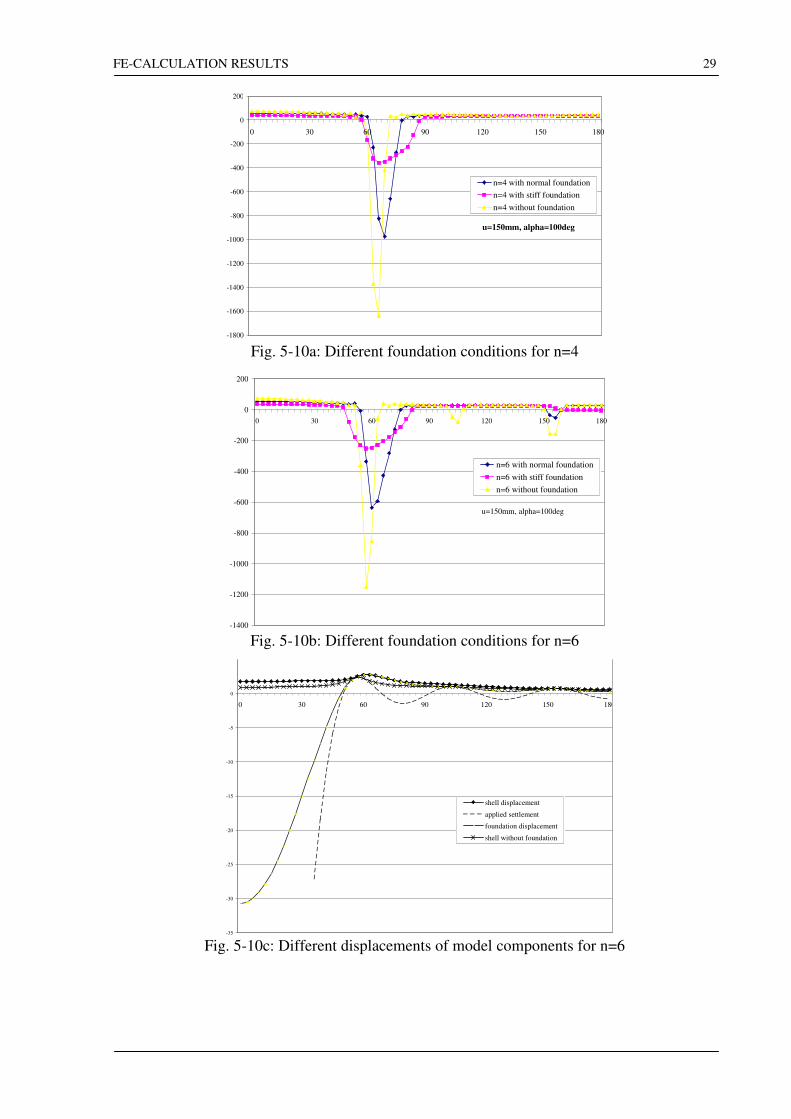
5.2.4 Comprehension of Fourier composed settlement
In the following the difference in the results due to different foundation conditions is
examined. The cases investigated by previous research assumed the existence of a foundation
but the displacement of the shell, as described above, is given by a deformed foundation. This
deformation, however, is not equivalent to the deformations of the underground. The
following diagrams show the axial forces of a tank without a foundation and with two
different foundation rings. The stiffness of the foundation ring depends on its E*I, where E is
the E-modulus and I the moment of inertia. The E-Modulus of a concrete foundation is
generally constant because only the minimum required reinforcement is used and this amount
is normally not changed. Another E*I is usually achieved by a change of the cross section size
of the foundation, however, this would require a new FE-Model. To circumvent this, the E-
modulus was changed from original E=2.6e4N/mm to E=50e4. This corresponds to an
enlargement of the foundation height from h=0.8m to h=2.14m.
FE-CALCULATION RESULTS
29
-1800
-1600
-1400
-1200
-1000
-800
-600
-400
-200
0
200
0 30 60 90 120 150 180
u=150mm, alpha=100deg
n=4 with normal foundation
n=4 with stiff foundation
n=4 without foundation
Fig. 5-10a: Different foundation conditions for n=4
-1400
-1200
-1000
-800
-600
-400
-200
0
200
0 30 60 90 120 150 180
n=6 with normal foundation
n=6 with stiff foundation
n=6 without foundation
u=150mm, alpha=100deg
Fig. 5-10b: Different foundation conditions for n=6
-35
-30
-25
-20
-15
-10
-5
0
0 30 60 90 120 150 180
shell displacement
applied settlement
foundation displacement
shell without foundation
Fig. 5-10c: Different displacements of model components for n=6
FE-CALCULATION RESULTS
30
The settlement in Fig. 5-10a-c is applied with α=100° and umax=150mm. The effect can be
clearly observed. The foundation lowers the maximum stresses and distributes the pressure
onto a bigger area. With the foundation the area, where the pressure is submitted, is enlarged.
Normally the edge of the applied settlement is too steep such that the tank shell can follow it.
The settlement is also too steep for the foundation, however, because the foundation moment
of inertia is less then the axial bending stiffness of the tank shell, the foundation compensates
for the stress peaks. In the calculated models the maximum axial stress amounts to 60% of the
stresses without the foundation, and 21%, if the calculation was done with the stiff
foundation. As already shown, the foundation ring does not support the shell in the area
between the settlement peaks because it is too soft in comparison to the tank shell. The base,
however, is still supported by the foundation ring.
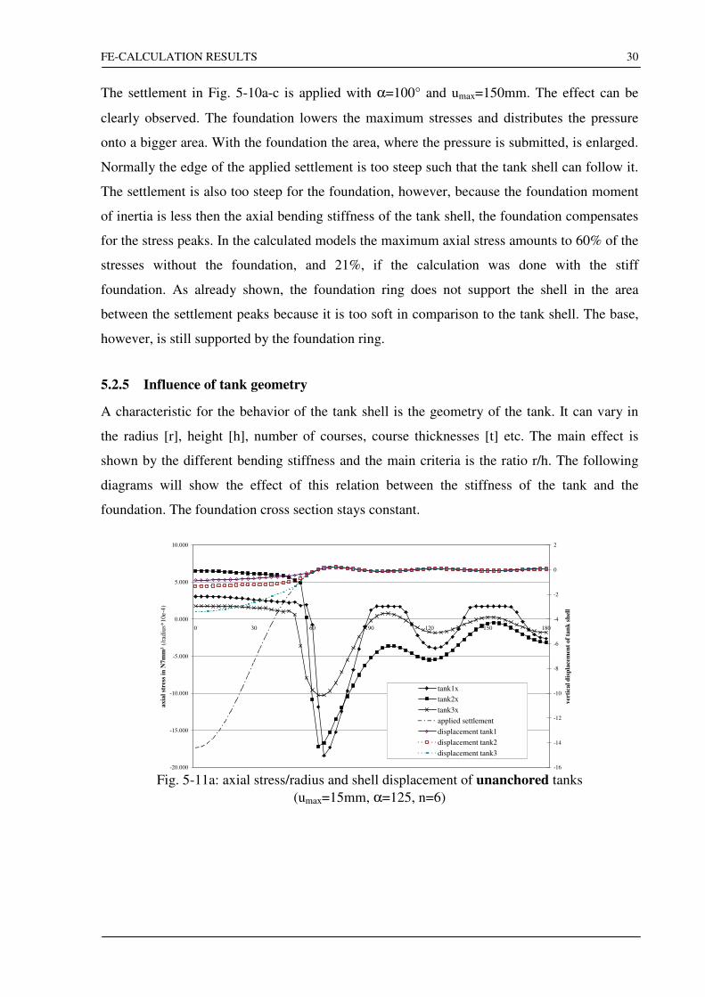
5.2.5 Influence of tank geometry
A characteristic for the behavior of the tank shell is the geometry of the tank. It can vary in
the radius [r], height [h], number of courses, course thicknesses [t] etc. The main effect is
shown by the different bending stiffness and the main criteria is the ratio r/h. The following
diagrams will show the effect of this relation between the stiffness of the tank and the
foundation. The foundation cross section stays constant.
-20.000
-15.000
-10.000
-5.000
0.000
5.000
10.000
0 30 60 90 120 150 180
ax
ial
stre
ss i
n N
7m
m²
(/ra
diu
s*1
0e-
4)
-16
-14
-12
-10
-8
-6
-4
-2
0
2
ver
tica
l d
isp
lace
men
t o
f ta
nk
sh
ell
tank1x
tank2x
tank3x
applied settlement
displacement tank1
displacement tank2
displacement tank3
Fig. 5-11a: axial stress/radius and shell displacement of unanchored tanks
(umax=15mm, α=125, n=6)
FE-CALCULATION RESULTS
31
-30.000
-20.000
-10.000
0.000
10.000
20.000
30.000
40.000
0 30 60 90 120 150 180
axia
l st
ress
for
dif
fere
nt
geo
met
ry i
n N
/mm
² (/r
adiu
s*10e-
4m
m)
-16
-14
-12
-10
-8
-6
-4
-2
0
2
dis
pla
cem
ent
in m
m
tank1x
tank2x
tank3x
applied settlement
displacement of tank1
displacement of tank2
displacement of tank3
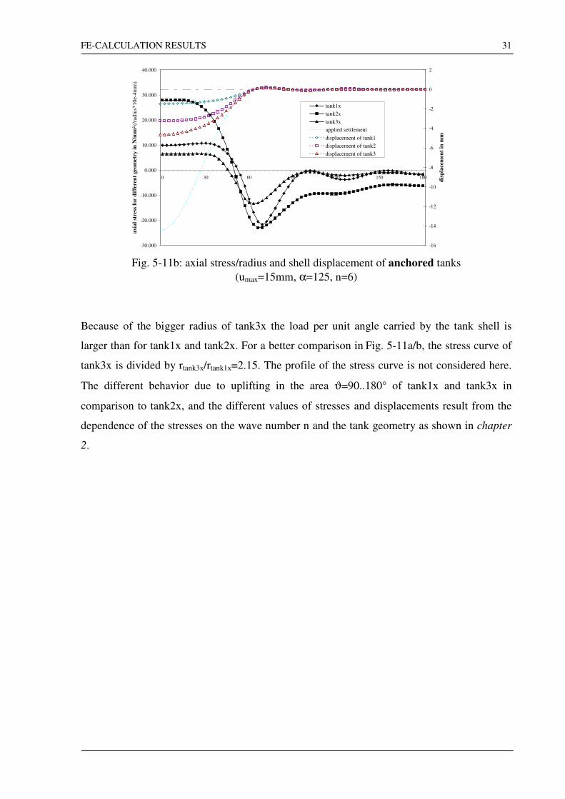
Fig. 5-11b: axial stress/radius and shell displacement of anchored tanks
(umax=15mm, α=125, n=6)
Because of the bigger radius of tank3x the load per unit angle carried by the tank shell is
larger than for tank1x and tank2x. For a better comparison in Fig. 5-11a/b, the stress curve of
tank3x is divided by rtank3x/rtank1x=2.15. The profile of the stress curve is not considered here.
The different behavior due to uplifting in the area ϑ=90..180° of tank1x and tank3x in
comparison to tank2x, and the different values of stresses and displacements result from the
dependence of the stresses on the wave number n and the tank geometry as shown in chapter
2.
SKETCH OF AN ANALYTICAL MODEL
32
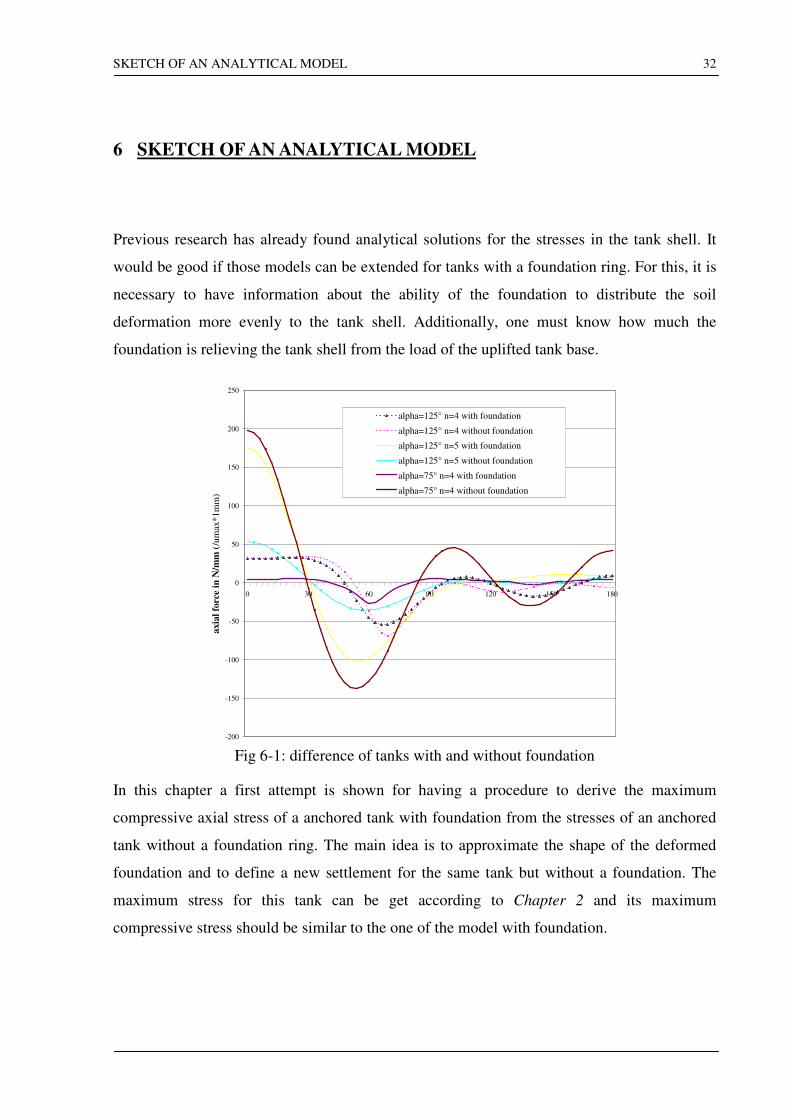
6 SKETCH OF AN ANALYTICAL MODEL
Previous research has already found analytical solutions for the stresses in the tank shell. It
would be good if those models can be extended for tanks with a foundation ring. For this, it is
necessary to have information about the ability of the foundation to distribute the soil
deformation more evenly to the tank shell. Additionally, one must know how much the
foundation is relieving the tank shell from the load of the uplifted tank base.
-200
-150
-100
-50
0
50
100
150
200
250
0 30 60 90 120 150 180
axia
l fo
rce
in N
/mm
(/u
max
*1m
m)
alpha=125° n=4 with foundation
alpha=125° n=4 without foundation
alpha=125° n=5 with foundation
alpha=125° n=5 without foundation
alpha=75° n=4 with foundation
alpha=75° n=4 without foundation
Fig 6-1: difference of tanks with and without foundation
In this chapter a first attempt is shown for having a procedure to derive the maximum
compressive axial stress of a anchored tank with foundation from the stresses of an anchored
tank without a foundation ring. The main idea is to approximate the shape of the deformed
foundation and to define a new settlement for the same tank but without a foundation. The
maximum stress for this tank can be get according to Chapter 2 and its maximum
compressive stress should be similar to the one of the model with foundation.
SKETCH OF AN ANALYTICAL MODEL
33
For this first draft following assumptions are made:
• The tank is anchored, i.e. the tank shell is connected to the foundation.
• The contact area between soil and foundation ring is concentrated at the high points of the
applied settlement. The foundation is assumed to be too stiff to follow the applied
settlement. The
• The foundation ring is able to give the shell the necessary support in the uplifted area.
• The curvature of the foundation is small enough, that the curvature radius of the
foundation middle is approximate the curvature radius of the foundation top surface.
The settlement is given as ( )∑=
<<=n
n
n nuu0
0,cos πϑϑ (equation (2) in chapter 2 with n
coefficients).
Its maxima can be found by equating the first derivation to zero:
( ) 0sin0
=−=∂
∂∑
=
n
n
n nnuu
ϑϑ
(5)
The assumed positions of the maxima are ϑ=ϑk.
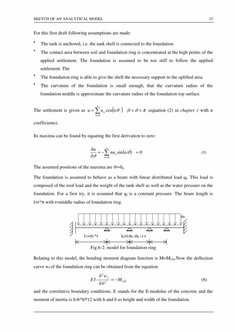
The foundation is assumed to behave as a beam with linear distributed load qf. This load is
composed of the roof load and the weight of the tank shell as well as the water pressure on the
foundation. For a first try, it is assumed that qf is a constant pressure. The beam length is
l=r*π with r=middle radius of foundation ring.
l1=ϑ1*r
qn
lk=(ϑk-ϑk-1) r
Fig.6-2: model for foundation ring
Relating to this model, the bending moment diagram function is M=M(ϑ).Now the deflection
curve wf of the foundation ring can be obtained from the equation
( )ϑϑ
Mw
IEf
−=∂
∂2
2
(6)
and the correlative boundary conditions. E stands for the E-modulus of the concrete and the
moment of inertia is I=b*h³/12 with h and b as height and width of the foundation.

SKETCH OF AN ANALYTICAL MODEL
34
The deflection curve wf describes the vertical displacement of the foundation centre and, as
assumed above, the displacement of the foundation top. This curve can be seen as a
composition of Fourier components. The appropriate coefficients can be obtained by a Fourier
analysis. For getting the maximum compressive stress in the shell, a settlement composed of
the new Fourier components must be taken. The tank is calculated due to this new settlement
as described in chapter 2.
Fig.6-3 shows an approximation for the derivation described above. At first a calculation was
done for an anchored tank with foundation and umax=15mm, α=125° and n=5. The first
maximum of the applied settlement is found to be located at ϑ=72°. The maximum
foundation deflection is wf (ϑ=0°)=1.478mm. This value is not calculated due to above static
foundation model but it is taken from the FE-calculation of the founded tank. As it can be
seen, uplifting occurs in the calculation of the tank with foundation and, therefore, qf is not a
constant pressure anymore. For a better comparison, the FE-calculated value is taken to show
the general working of above described idea.
With the displacement wf (ϑ=0°)=1.478mm and α=144° two calculations were done. One with
a tank including the water filling and the other only consisting of the tank shell. The applied
settlement for the foundationless tanks is shaped as shown in equation (1). All models are
anchored.
-400
-300
-200
-100
0
100
200
300
400
0 30 60 90 120 150
axia
l fo
rce
in N
/mm
curve1: 125° 15mm n=5 with foundation
curve 2: 144° 1.65mm exact shaped settlement without foundation
curve 3: 144° 1.65mm exact settlement only tank shell
Fig. 6-3: Comparison of anchored tanks with and without foundation

SKETCH OF AN ANALYTICAL MODEL
35
As it can be seen the maximal axial compressive stress can be compared quite well. The
maximum stress of the model without a base is closer to the stress of the founded tank. This
effect is described in chapter 5. Additionally, the analytical solution described in Chapter 2 is
valid for a tank shell without a base.

CONCLUSION
36
7 CONCLUSION
This thesis dealt with the effect of a foundation ring on a cylindrical flat bottom tank due to
uneven circumferential settlement. By the use of a foundation the tank behaves in general
similar to a tank without a foundation. The foundation ring reduces the maximum strains and
stresses and takes parts of the uplifted tank base.
Previous FE-models were extended to a tank model closer to the reality. It includes soil, tank
shell, tank base and a foundation ring. The tank is assumed to be a fixed roof tank. For further
investigations the boundary condition for this roof can be replaced by a circular primary wind
girder.
A first idea was shown for getting the maximum compressive stress of the founded tank from
the unfounded tank. Main problem for future investigations might be finding the point where
the foundation is not able to support all loads from base and shell anymore. In the area where
foundation and base are hanging on the shell the pressure qd on the foundation must be
replaced by a tensional linear distributed load.
REFERENCES
37
8 REFERENCES
[1] API Standard 650 – Welded Steel Tanks for Oil Storage, 1993
[2] DIN 18800-4, Stahlbauten, Schalenbeulen, 1994
[3] Brandes, K. – Verformungen großer Tankbehälter durch unterschiedliche
Fundamentsetzungen während der Montage
Bauingenieur 55, Springer Verlag, 1980
[4] Flügge, W., Stresses in shells – 2ndedition, Springer, New York, Heidelberg, Berlin,
1973
[5] Hoffmann, A. – Untersuchung zweier besonderer Beanspruchungssituationen für
zylindrische, oberirdische Flachbodentanks
Vertieferarbeit at Lehrstuhl für Stahl- und Leichtmetallbau at University of Karlsruhe,
1995
[6] Hornung, U. and Saal, H. – Stresses in Tank Shells due to Settlement taking into account
local uplift
Advances in Steel Structures, Proc. ICASS'06, Hong Kong , 1996
[7] Hornung, U. and Saal, H. – Stresses in Unanchored Tank Shells due to Settlement of the
Tank Foundation
Carrying Capacity of Steel Shell Structures, Proc. ECCS, Brno(Czech), 1997
[8] Jonaidi, M. and Ansourian,P. – Effects of Differential Settlement on Storage Tank Shells
Advances in Steel Structures, Proc. ICASS'96, Hong Kong, Dec. 1996
[9] Kamyab, H. and Palmer, S.C. – Displacements in Oil Storage Tanks caused by
Localized Differential Settlement
Journal of Pressure Vessel Technology Vol. 113, Feb. 1991
[10] Malik, Z., Morton, J., Ruiz, C. – Ovalization of cylindrical tanks as a result of
foundation settlement
Journal of Strain Analysis Vol. 12 No. 4, 1977
[11] Marr, W.A. et al. – Criteria for Settlement of Tanks
Journal of the Geotechnical Engineering Division Vol. 108 No. GT8, 1982
[12] Mousa, E.A., Ruiz, C. – Stresses in cylindrical tanks due to uneven circumferential
settlement
"Strain", Jan 1979
[13] Palmer, S.C. – Structural effects of foundation tilt on storage tanks
Proc. Instn. Mech. Engrs. Vol. 206, 1992
[14] Palmer, S.C. – Stresses in storage tanks caused by differential settlement
Proc. Instn. Mech. Engrs Vol. 208, 1994
[15] Schneider, P. – Zusätzliche Beanspruchungen vertikaler Lagertanks durch
ungleichmäßige rotationssymmetrische Fundamentabsenkungen
Stahlbau 62 Heft 9,1993
[16] Würfel, T. – Ermittlung der Längsspannungen in unverankerten oberirdischen
zylindrischen Tankbauwerken infolge Setzung
Diplomarbeit at Lehrstuhl für Stahl-und Leichtmetallbau at University of Karlsruhe,1996
APPENDIX
38
9 APPENDIX
FE-Mesh of tank10, tank13 and tank14 Appendix 1.1 .. 1.3
Spring stiffnesses of tank10,tank13 and tank14 Appendix 2.1
Input model of tank13 Appendix 3.1 .. 3.13
Settlement composed of Fourier components Appendix 4.1 .. 4.2
Axial force and vertical displacements for umax=50mm, α=100° Appendix 5.1 .. 5.2
Pressure on top of foundation for umax=50mm, α=100° Appendix 6.1 .. 6.2
Deformed foundation ring of anchored and unanchored tank Appendix 7.1
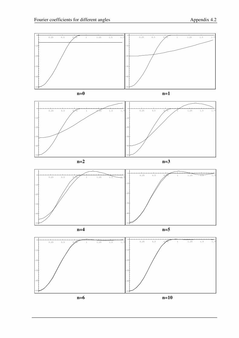
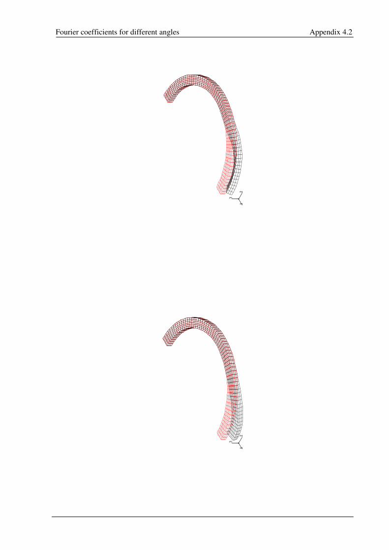
Fourier coefficients for different angles Appendix 4.2
0.25 0.5 0.75 1 1.25 1.5 1.75
-50
-40
-30
-20
-10
0.25 0.5 0.75 1 1.25 1.5 1.75
-50
-40
-30
-20
-10
n=0 n=1
0.25 0.5 0.75 1 1.25 1.5 1.75
-50
-40
-30
-20
-10
0.25 0.5 0.75 1 1.25 1.5 1.75
-50
-40
-30
-20
-10
n=2 n=3
0.25 0.5 0.75 1 1.25 1.5 1.75
-50
-40
-30
-20
-10
0.25 0.5 0.75 1 1.25 1.5 1.75
-50
-40
-30
-20
-10
n=4 n=5
0.25 0.5 0.75 1 1.25 1.5 1.75
-50
-40
-30
-20
-10
0.25 0.5 0.75 1 1.25 1.5 1.75
-50
-40
-30
-20
-10
n=6 n=10
Fourier coefficients for different angles Appendix 4.2
12
3
12
3
12
3
12
3