Steel Water-Storage Tanks
122
Steel Water-Storage Tanks MANUAL OF WATER SUPPLY PRACTICES-M42, First Edition AWWA MANUAL M42 First Edition I "y8F @ A \ American Water Works Association Copyright (C) 1998 American Water Works Association All Rights Reserved
-
Upload
khangminh22 -
Category
Documents
-
view
4 -
download
0
Transcript of Steel Water-Storage Tanks

Steel Water-Storage Tanks
MANUAL OF WATER SUPPLY PRACTICES-M42, First Edition
AWWA MANUAL M42
First Edition
I " y 8 F @ A\
American Water Works Association
Copyright (C) 1998 American Water Works Association All Rights Reserved
MANUAL OF WATER SUPPLY PRACTICES-M42, First Edition
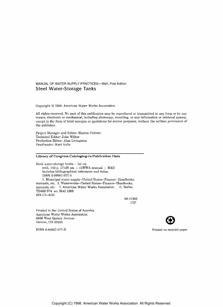
Steel Water-Storage Tanks
Copyright 0 1998 American Water Works Association
All rights reserved. No part of this publication may be reproduced or transmitted in any form or by any means, electronic or mechanical, including photocopy, recording, or any information or retrieval system, except in the form of brief excerpts or quotations for review purposes, without the written permission of the publisher.
Project Manager and Editor: Sharon Pellowe Technical Editor: John Wilber Production Editor: Alan Livingston Proofreader: Mart Kelle
L ib ra ry of Congress Cataloging-in-Publication Da ta
Steel water-storage tanks -- 1st ed. xviii, 142 p. 17x25 cm. -- (AWWA manual ; M42) Includes bibliographical references and index.
1. Municipal water supply--United States--Finance--Handbooks, ISBN 0-89867-977-X
manuals, etc. 2. Waterworks--United States--Finance--Handbooks, manuals, etc. I. American Water Works Association. 11. Series. TD489.S74 no. M42 1998 628.1'3--dc21
98-41256 CIP
Printed in the United States of America American Water Works Association 6666 West Quincy Avenue Denver, CO 80235
ISBN 0-89867-977-X Printed on recycled paper
Copyright (C) 1998 American Water Works Association All Rights Reserved
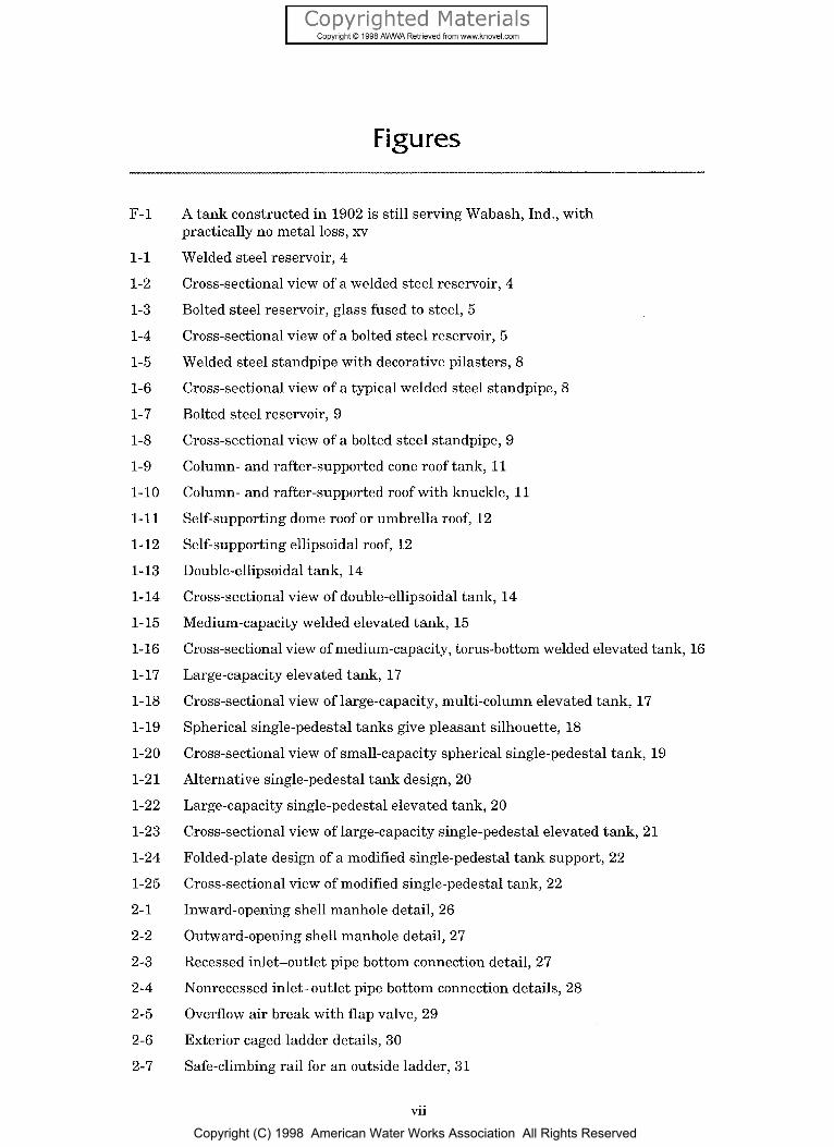
Figures
F- 1
1-1
1-2
1-3
1-4
1-5
1-6
1-7
1-8
1-9
1-10
1-11
1-12
1-13
1-14
1-15
1-16
1-17
1-18
1-19
1-20
1-2 1
1-22
1-23
1-24
1-25
2-1
2-2
2-3
2-4
2-5
2-6
2-7
A tank constructed in 1902 is still serving Wabash, Ind., with practically no metal loss, xv
Welded steel reservoir, 4
Cross-sectional view of a welded steel reservoir, 4
Bolted steel reservoir, glass fused to steel, 5
Cross-sectional view of a bolted steel reservoir, 5
Welded steel standpipe with decorative pilasters, 8
Cross-sectional view of a typical welded steel standpipe, 8
Bolted steel reservoir, 9
Cross-sectional view of a bolted steel standpipe, 9
Column- and rafter-supported cone roof tank, 11
Column- and rafter-supported roof with knuckle, 11
Self-supporting dome roof or umbrella roof, 12
Self-supporting ellipsoidal roof, 12
Double-ellipsoidal tank, 14
Cross-sectional view of double-ellipsoidal tank, 14
Medium-capacity welded elevated tank, 15
Cross-sectional view of medium-capacity, torus-bottom welded elevated tank, 16
Large-capacity elevated tank, 17
Cross-sectional view of large-capacity, multi-column elevated tank, 17
Spherical single-pedestal tanks give pleasant silhouette, 18
Cross-sectional view of small-capacity spherical single-pedestal tank, 19
Alternative single-pedestal tank design, 20
Large-capacity single-pedestal elevated tank, 20
Cross-sectional view of large-capacity single-pedestal elevated tank, 21
Folded-plate design of a modified single-pedestal tank support, 22
Cross-sectional view of modified single-pedestal tank, 22
Inward-opening shell manhole detail, 26
Outward-opening shell manhole detail, 27
Recessed inlet-outlet pipe bottom connection detail, 27
Nonrecessed inlet-outlet pipe bottom connection details, 28
Overflow air break with flap valve, 29
Exterior caged ladder details, 30
Safe-climbing rail for an outside ladder, 31
vii
Copyright (C) 1998 American Water Works Association All Rights Reserved
2-8
2-9
2-10
2-11
2-12
3-1
3-2
3-3
3-4
5- 1
5-2
5-3
5-4
6- 1
6-2
7-1
7-2
7-3
7-4
9- 1
9-2
9-3
9-4
9-5
9-6
10-1
10-2
10-3
10-4
10-5
10-6
Roof guardrail details, 32
Roof manhole assembly details, 33
Double 90" elbow roof vent detail, 34
Pan deck vent detail, 34
Typical clog-resistant vent detail, 35
Schematic diagram of a battery, 38
Corrosion of steel in water, 39
Tank corrosion protection-vertically suspended anodes, 42
Tank corrosion protection-horizontally suspended anodes, 43
Typical daily flow at constant pumping rate, 54
Typical daily flow with variable-rate pumping, 55
Relative cost by type of steel tank for 500,000-gal(1.9-ML) tanks, 56
Relative cost by type of elevated steel tank, 57
Soil-testing operations, 62
Example of tank supported on granular berm foundation, 64
Tank foundation construction, 75
Typical welding operation in the field, 77
Reviewing a weld radiograph, 78
Newly erected elevated tank, 79
Experienced riggers evaluate hard-to-reach areas on tower tanks, 93
Active corrosion penetrated this %-in. (6-mm) steel tank bottom in 9 years. Periodic inspections and washouts would have revealed and prevented this problem well in advance of failure, 95
Measuring shell thickness with ultrasonic equipment, 96
Washing out tanks allows easier inspection and keeps tanks sanitary, 97
Inspection of the degree of abrasive blast cleaning, 102
An abrasive blast-cleaning operation, 102
A frozen water tank, 106
Isothermal lines for lowest one-day mean temperatures and normal daily minimum 30°F (-1°C) temperature line for January, United States and Southern Canada, 110
Double-seating, internal-closing drain valve, 112
Tank riser bubbler system, 115
Pumped circulation system for small riser pipes, 116
Tank-thawing operation, 118
viii
Copyright (C) 1998 American Water Works Association All Rights Reserved

1- 1
1-2
1-3
1-4
1-5
1-6
1- 7
1-8
1-9
6- 1
6-2
10-1
Typical welded steel water-storage reservoir sizes, 6
Glass-coated, bolted steel reservoirs and standpipes (capacity in thousand gallons), 7
Typical welded steel water storage standpipe sizes, 10
Typical double-ellipsoidal steel elevated tank sizes, 15
Typical medium-capacity welded steel elevated tank sizes, 16
Typical large-capacity welded steel elevated tank sizes, 18
Typical small-capacity single-pedestal steel elevated tank sizes, 19
Typical large-capacity single-pedestal steel elevated tank sizes, 21
Typical modified single-pedestal steel elevated tank sizes, 23
Typical soil investigation requirements, 61
Tank site selection considerations, 65
Thousands of British thermal units (Btu) lost per hour from elevated steel tanks, 109
ix
Copyright (C) 1998 American Water Works Association All Rights Reserved
Introduction
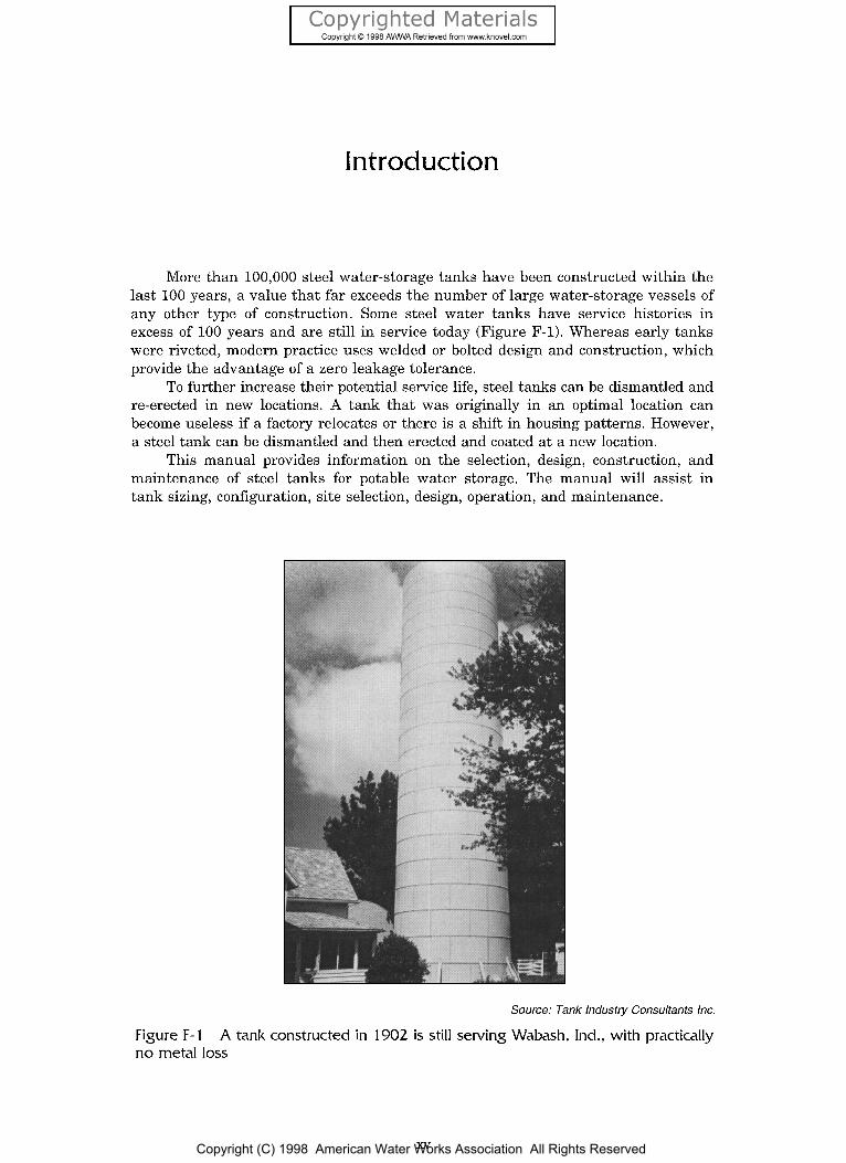
More than 100,000 steel water-storage tanks have been constructed within the last 100 years, a value that far exceeds the number of large water-storage vessels of any other type of construction. Some steel water tanks have service histories in excess of 100 years and are still in service today (Figure F-1). Whereas early tanks were riveted, modern practice uses welded or bolted design and construction, which provide the advantage of a zero leakage tolerance.
To further increase their potential service life, steel tanks can be dismantled and re-erected in new locations. A tank that was originally in an optimal location can become useless if a factory relocates or there is a shift in housing patterns. However, a steel tank can be dismantled and then erected and coated at a new location.
This manual provides information on the selection, design, construction, and maintenance of steel tanks for potable water storage. The manual will assist in tank sizing, configuration, site selection, design, operation, and maintenance.
Source: Tank Industry Consulfants Inc.
A tank constructed in 1902 is still serving Wabash, Ind., with practically Figure F-1 n o metal loss
Copyright (C) 1998 American Water Works Association All Rights Reserved

D EFI N IT10 NS The following definitions apply in this manual:
The water level in the tank when the tank is emptied through the specified discharge fittings (unless otherwise specified by the purchaser). In an elevated tank, the elevation of the bottom capacity levelk) is as given by the purchaser and is determined by the design features of the tank configuration.
Capacity The net volume in gallons (litres) that may be removed from a tank emptied t o its bottom capacity level after being filled to its top capacity level.
Constructor The party that furnishes the work and materials for placement and installation.
Elevated tank A container or storage tank supported on one or more columns. Engineer An employee of the purchaser or, more commonly, a professional
engineering firm engaged by the purchaser to perform specification and inspection services.
Head range The difference between the lower and upper capacity levels of a tank.
Manufacturer The person or company that furnishes the tank components. Owner The person or firm that will own and operate the completed tank.
The owner may designate agents, such as an engineer, purchaser, or inspector, for specific project responsibilities.
Bottom capacity level (BCL)
Purchaser The person, company, or organization that purchases the tank. Reservoir A ground-supported, flat-bottom cylindrical tank with a shell
height less than or equal to its diameter. Standpipe A ground-supported, flat-bottom cylindrical tank with a shell
height greater than its diameter. Tank An elevated tank, standpipe, or reservoir used for water storage. Top capacity level (TCL) The maximum operating level of water in a tank,
as dictated by the elevation at which water discharges from the tank through the overflow pipe entrance. In a standpipe or reservoir, the top capacity level is as given by the purchaser. In an elevated tank, the elevation of the top andlor bottom capac- ity levelb) is as given by the purchaser.
AWWA STANDARDS The majority of all steel potable water-storage tanks constructed in the United States adhere to specifications that reference the following American Water Works Association (AWWA) steel tank standards:
AWWA D100, Standard for Welded Steel Tanks for Water Storage.
AWWA D102, Standard for Coating Steel Water Storage Tanks.
AWWA D103, Standard for Factory-Coated Bolted Steel Tanks for Water Storage.
AWWA D104, Standard for Automatically Controlled, Impressed-Current Cathodic Protection for the Interior of Steel Water Tanks.
AWWA C652, Standard for Disinfection of Water-Storage Facilities.
These standards (except AWWA C652) are developed and maintained by task forces under the direction of the AWWA Standards Committee on Steel Elevated Tanks, Standpipes, and Reservoirs, which is composed of members representing
xvi Copyright (C) 1998 American Water Works Association All Rights Reserved
consumer (utility), general interest (academic and consulting engineering), and pro- ducer (constructor and manufacturer) groups. AWWA C652 was developed and is maintained by the Standards Committee on Disinfection of Facilities.
Once a draft standard or revision is approved by a standards committee, it is forwarded t o the AWWA Standards Council for review and approval. If approved by the council, it is offered for public review and then presented to the AWWA Board of Directors for final approval. AWWA D100, AWWA D102, and AWWA D103 have also been approved as standards by the American National Standards Institute (ANSI). AWWA D101-53 (R86) is to be withdrawn upon publication of this manual.
WELDED TANKS Welded tanks have been used for water storage since the 1930s. Welded construction had totally replaced riveted construction by the 1950s. This 20-year transition period from riveted to welded design and construction was necessary because time was needed to train enough skilled welders and because contractors wanted to keep their skilled riveting crews working as long as possible. Today, design and construction of welded tanks are usually performed under the guidelines of ANSUAWWA D100. This standard was first published in the November 1935 edition of Journal AWWA as “Standard Specifications for Riveted Steel Tanks and Standpipes” and has undergone several revisions since then.
Advantages The advent of welded tanks provided opportunities for new tank configurations, but the greatest advantage over riveted tanks was the development of smooth structures with much lower maintenance costs than was possible with lapped, riveted seams. Manual, semiautomatic, and automatic welding processes have constantly been improved, offering increased economy and strength.
Thicknesses and Capacities Thicknesses of welded tank shells vary from 3/16 in. (4.76 mm) to 2 in. (50 mm) or more. AWWA DlOO discusses elevated tank capacities ranging from 5,000 to 3,000,000 gal (19,000 L t o 11 ML); and standpipe and reservoir capacities ranging from 50,000 to 5,000,000 gal (0.2 to 19 ML). As of the writing of this manual, the largest welded steel water-storage tank constructed had a capacity of 34 mil gal (130 ML). Elevated tanks have been constructed with capacities up to 4 mil gal (15 ML), and designs are available for greater capacities.
BOLTED TANKS Factory-coated bolted steel storage tanks were developed in the early 1900s to serve as crude-oil and brine containment vessels. In the late 1970s, this tank design gained acceptance for potable water containment through the release of Standard AWWA D103, which allows the use of lighter-gauge steel in the production of tank sheets.
Construction Bolted steel tanks are made of uniformly sized panels (usually 5 ft wide by 8 ft high o r 9 ft wide by 5 ft high [1.5 m x 2.4 m or 2.7 m x 1.5 ml), which can be readily transported and assembled a t the tank site. Organic gaskets or sealants are used to achieve a watertight seal at the bolted joints. Thicknesses of bolted tank panels vary
xvii
Copyright (C) 1998 American Water Works Association All Rights Reserved

from a minimum of 0.073 in. (1.85 mm) to 0.375 in. (9.53 mm). Since the panels are bolted together, the tanks can be dismantled and relocated with relative ease.
Capacities Bolted tanks are currently offered in incremental sizes depending on the tank manufacturer’s panel size. Capacities offered range from 4,000 gal (15,000 L) to approximately 2.5 mil gal (6.8 ML). Bolted tanks are available in reservoir and standpipe configurations. Maximum tank heights and capacities are limited by the manufacturer’s steel fabrication facility, as well as by AWWA D103.
Coating and Life of Tank Bolted tanks are factory coated for long-term corrosion protection. There are four coating systems presently available for bolted tanks: galvanized, glass, thermoset liquid suspension epoxy, and thermoset powder epoxy. According t o the foreword of AWWA D103, the anticipated life of a bolted tank is usually limited by the effective life of the protective coating and cathodic protection system. If the coatings are not abused or damaged, the anticipated life expectancy of bolted tanks is more than 30 years.
xviii
Copyright (C) 1998 American Water Works Association All Rights Reserved

Copyrighted Materials Copyright &, 1998 A W A Retrieved from wwwknovel.com
Contents
List of Figures, vii
List of Tables, ix
Foreword, xi
Acknowledgments, xiii
Introduction, xv Definitions, xvi AWWA Standards, xvi Welded Tanks, xvii Bolted Tanks, xvii
Part I Elements of Steel Water Tanks
Chapter 1 Typical Capacities and Configurations . . . . . . . . . 3 Reservoirs, 3 Standpipes, 3 Roof Designs for Reservoirs and Standpipes, 10 Elevated Tanks, 13 Multiple-Column Elevated Tanks, 13 Pedestal Elevated Tanks, 18
Chapter 2 Appurtenances . . . . . . . . . . . . . . . . . 25
Shell Manholes, 25 Pipe Connections, 26 Overflow, 28 Ladders and Safety Devices, 29 Roof Openings, 32 Vents, 33 Devices for Indicating Water Level, 35 Emergency Fill~Withdraw Connections, 36
Chapter 3 Cathodic Protection . . . . . . . . . . . . . . . 37
Nature of Corrosion, 37 Principles of Cathodic Protection, 39 Cathodic Protection Design, 40 Maintenance, 41
Chapter 4 Coating Systems . . . . . . . . . . . . . . . . . 45
Interior Coatings, 45 Exterior Coatings, 47 Inspection and Quality Control, 48 Removing Coating by Abrasive Blasting, 49
Copyright (C) 1998 American Water Works Association All Rights Reserved

Part I1 The New Tank Project
Chapter 5 Selecting and Sizing Water Storage Tanks . . . . . . 53
Peak Demand, 53 Fire Flow, 54 Top and Bottom Capacity Levels, 54 Energy Costs, 55 Future Needs, 55 Environmental Impact, 56 Tank Costs, 56
Chapter 6 Construction Considerations . . . . . . . . . . . . 59
Design Standards, 59 Contract Documents, 60 Constructor Capabilities, 60 Guarantees, 60 Soil Investigations, 60 Reservoir and Standpipe Foundations, 63 Elevated Tank Foundations, 64 Tank Site, 65 Tank Coating-Welded Steel Tanks, 67 Tank Coating-Bolted Steel Tanks, 68 Tank Water Testing and Disinfection, 68 Engineer's Role, 69 Bidding Documents, 70
Chapter 7 Inspecting New Tank Construction . . . . . . . . . 73
Responsibility for Quality, 73 The Foundation, 74 Fabrication, 76 Steel Delivery, 76 Tank Erection, 76 Field Cleaning and Coating, 79 Mechanical and Electrical Appurtenances, 81
Part I11 Existing Tanks
Chapter 8 Routine Operation and Maintenance . . . . . . . . . 85
Energy Management, 85 Controls, 86 Periodic Operator Inspection, 86 Tank Washouts, 88
Chapter 9 Professional Examination and Renovation . . . . . . 91
Tank Maintenance Engineer's Functions and Qualifications, 92
Pre-Bid Inspection, 94 Preparing Specifications, 99 Monitoring the Constructor's Progress, 101 Periodic Reinspection, 104
Copyright (C) 1998 American Water Works Association All Rights Reserved
Chapter 10 Cold-Weather Operation . . . . . . . . . . . . . 105
Causes and Results of Freezing, 105 Quantitative Data Related to Freezing, 108 Designing Tanks for Cold Weather, 108 Cold-Weather Operating Procedures, 113 Systems to Prevent Freezing, 114 Dealing With Frozen Tanks, 116
Appendix A Bibliography . . . . . . . . . . . . . . . . . 119
Appendix B Steel Water Tank Industry Standards Organizations and Information Sources . . . . . . . . . . 121
Appendix C Inspecting and Repairing Steel Water Tanks, Standpipes, Reservoirs, and Elevated Tanks for Water Storage . . . . . . . . . . . . . . . . . . . . . . . 129
Index, 139
Copyright (C) 1998 American Water Works Association All Rights Reserved

Part I
Typical Capacities and Configurations
Appurtenances
Cathodic Protection
Coating Systems
Copyright (C) 1998 American Water Works Association All Rights Reserved
Chapter 1
AWWA MANUAL M42
Steel tanks may be configured as reservoirs, standpipes, or elevated tanks. The configuration selected depends primarily on the required capacity and elevation, as well as on cost. Appearance is also an important consideration.
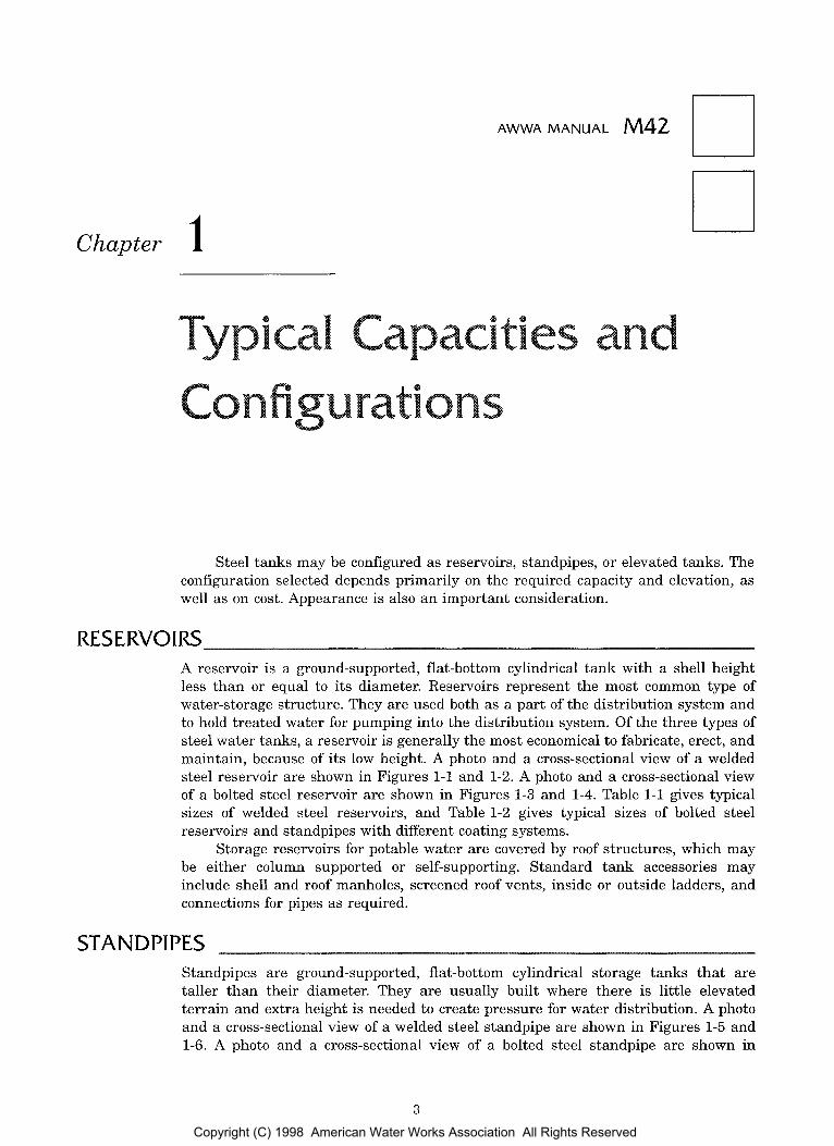
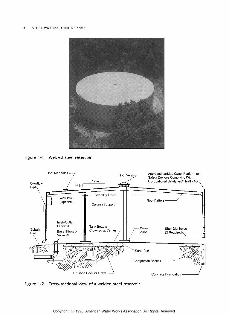
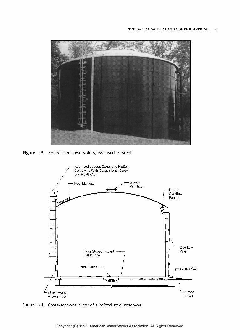
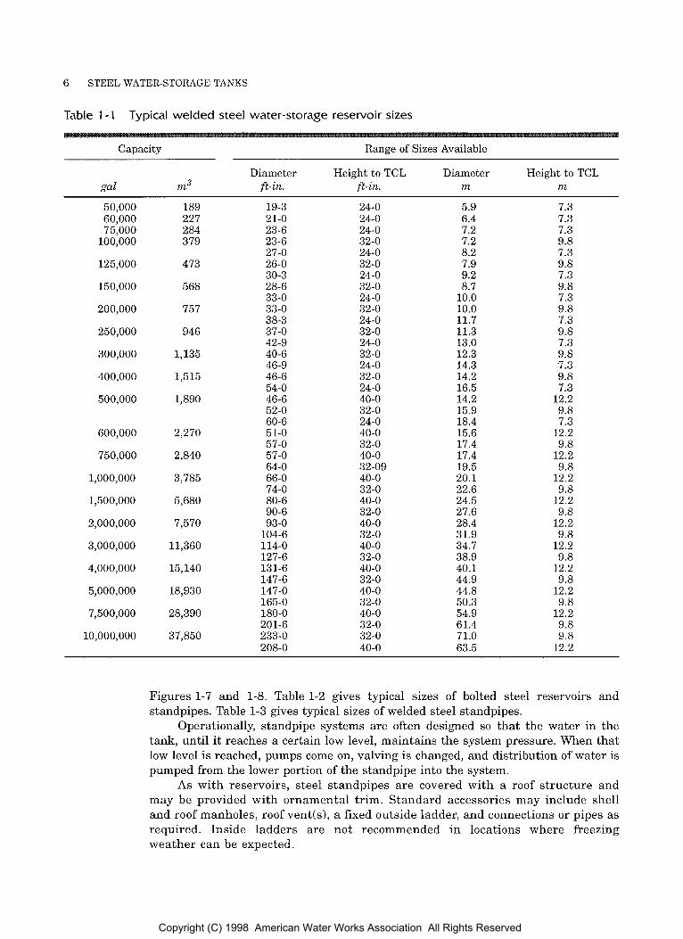
RESERVOIRS A reservoir is a ground-supported, flat-bottom cylindrical tank with a shell height less than or equal to its diameter. Reservoirs represent the most common type of water-storage structure. They are used both as a part of the distribution system and to hold treated water for pumping into the distribution system. Of the three types of steel water tanks, a reservoir is generally the most economical to fabricate, erect, and maintain, because of its low height. A photo and a cross-sectional view of a welded steel reservoir are shown in Figures 1-1 and 1-2. A photo and a cross-sectional view of a bolted steel reservoir are shown in Figures 1-3 and 1-4. Table 1-1 gives typical sizes of welded steel reservoirs, and Table 1-2 gives typical sizes of bolted steel reservoirs and standpipes with different coating systems.
Storage reservoirs for potable water are covered by roof structures, which may be either column supported or self-supporting. Standard tank accessories may include shell and roof manholes, screened roof vents, inside or outside ladders, and connections for pipes as required.
STAN D PI P ES Standpipes are ground-supported, flat-bottom cylindrical storage tanks that are taller than their diameter. They are usually built where there is little elevated terrain and extra height is needed to create pressure for water distribution. A photo and a cross-sectional view of a welded steel standpipe are shown in Figures 1-5 and 1-6. A photo and a cross-sectional view of a bolted steel standpipe are shown in
3
Copyright (C) 1998 American Water Works Association All Rights Reserved
4 STEEL WATER-STORAGE TANKS
Figure 1 - 1 Welded steel reservoir
-7 Roof Manholes Approved Ladder, Cage, Platform or """7 Safety Devices Complying With
Crushed Rock or Gravel 1
Figure 1-2 Cross-sectional view of a welded steel reservoir
Concrete Foundation
Copyright (C) 1998 American Water Works Association All Rights Reserved
TYPICAL CAPACITIES AND CONFIGURATIONS 5
Figure 1-3 Bolted steel reservoir, glass fused to steel
Approved Ladder, Cage, and Platform Complying With Occupational Safety and Health Act
Figure 1 -
Access Door Level
.4 Cross-sectional view of a bolted steel reservoir
Copyright (C) 1998 American Water Works Association All Rights Reserved
6 STEEL WATER-STORAGE TANKS
Table 1 - 1 Typical welded steel water-storage reservoir sizes
Capacity Range of Sizes Available
Diameter Height to TCL Diameter Height to TCL gal m3 ft-in. ft-in. m m
50,000 60,000 75,000
100,000
125,000
150,000
200,000
250,000
300,000
400,000
500,000
600,000
750,000
1,000,000
1,500,000
2,000,000
3,000,000
4,000,000
5,000,000
7,500,000
10,000,000
189 227 284 3 79
473
568
757
946
1,135
1,515
1,890
2,270
2,840
3,785
5,680
7,570
11,360
15,140
18,930
28,390
37,850
19-3 21-0 23-6 23-6 27-0 26-0 30-3 28-6 33-0 33-0 38-3 37-0 42-9 40-6 46-9 46-6 54-0 46-6 52-0 60-6 51-0 57-0 57-0 64-0 66-0 74-0 80-6 90-6 93-0
104-6 114-0 127-6 131-6 147-6 147-0 165-0 180-0 201-6 233-0 208-0
24-0 24-0 24-0 32-0 24-0 32-0 24-0 32-0 24-0 32-0 24-0 32-0 24-0 32-0 24-0 32-0 24-0 40-0 32-0 24-0 40-0 32-0 40-0 32-09 40-0 32-0 40-0 32-0 40-0 32-0 40-0 32-0 40-0 32-0 40-0 32-0 40-0 32-0 32-0 40-0
5.9 6.4 7.2 7.2 8.2 7.9 9.2 8.7
10.0 10.0 11.7 11.3 13.0 12.3 14.3 14.2 16.5 14.2 15.9 18.4 15.6 17.4 17.4 19.5 20.1 22.6 24.5 27.6 28.4 31.9 34.7 38.9 40.1 44.9 44.8 50.3 54.9 61.4 71.0 63.5
7.3 7.3 7.3 9.8 7.3 9.8 7.3 9.8 7.3 9.8 7.3 9.8 7.3 9.8 7.3 9.8 7.3
12.2 9.8 7.3
12.2 9.8
12.2 9.8
12.2 9.8
12.2 9.8
12.2 9.8
12.2 9.8
12.2 9.8
12.2 9.8
12.2 9.8 9.8
12.2
Figures 1-7 and 1-8. Table 1-2 gives typical sizes of bolted steel reservoirs and standpipes. Table 1-3 gives typical sizes of welded steel standpipes.
Operationally, standpipe systems are often designed so that the water in the tank, until it reaches a certain low level, maintains the system pressure. When that low level is reached, pumps come on, valving is changed, and distribution of water is pumped from the lower portion of the standpipe into the system.
As with reservoirs, steel standpipes are covered with a roof structure and may be provided with ornamental trim. Standard accessories may include shell and roof manholes, roof vent(s), a fixed outside ladder, and connections o r pipes as required. Inside ladders are not recommended in locations where freezing weather can be expected.
Copyright (C) 1998 American Water Works Association All Rights Reserved

Table 1-2 Glass-coated, bolted steel reservoirs and standpipes (capacity in thousand gallons)*
Nominal Nominal Height Diameter ft
15 19 24 28 33 38 43 47 52 57 61 66 70 75 79 84 89 93 98 102 107 112 116 121
14 16 22 27 32 37 44 49 54 59 65 70 75 80 86 91 96 101 107 112 117 122 128 133 139 17 24 31 39 47 54 63 70 78 86 93 101 108 116 123 131 139 146 154 161 169 177 184 192 199 20 33 43 53 64 74 86 96 106 117 122 137 148 158 168 179 189 199 210 220 230 241 251 261 272 25 54 71 88 105 122 142 159 176 193 210 227 244 261 278 296 313 330 347 364 31 81 107 132 158 183 212 238 263 289 320 340 365 391 416 442 36 114 149 185 220 256 292 327 363 398 434 469 505 42 151 199 246 294 341 388 436 483 531 578 50 218 286 355 423 491 559 628 696 62 326 326 428 530 632 734 836 70 421 553 685 816 948 r-3
90 691 906 1,122 1,337 n
120 1,247 1,637 P
ft
81 567 744 921 1,099 2 10 1 874 1,147 1,420 $
*To convert feet to meters, multiply by 0.3048; t o convert gallons to m3, multiply by 0.0037854. F 2 2 M cn
Copyright (C) 1998 American Water Works Association All Rights Reserved

8 STEEL WATER-STORAGE TANKS
Figure 1-5 Welded steel standpipe with decorative pilasters
--- Capacity Level - -- Weir BOX
Painter’s Trolley Rail
Approved Ladder, Cage, Platform or Safety Devices Complying With Occupational Safety and Health Act
Tank Bottom Crowned at Center
Base Elbow or Valve Pit I Shell Manholes
Crushed Rock or Gravel 1 Compacted Backfill or Undisturbed Soil
Figure 1-6 Cross-sectional view of a typical welded steel standpipe
Copyright (C) 1998 American Water Works Association All Rights Reserved

TYPICAL CAPACITIES AND CONFIGURATIONS 9
Figure 1-7 Bolted steel reservoir
Approved Ladder, Cage, and Platform Complying With Occupational Safety and Health Act
,-- Roof Walkway and / Guard Rail
ftptw L G r a v i t y Ventilator
Roof Access
Floor Sloped Toward
Internal Overflow Funnel
/ I L24 in. (0.6 m) Round
Access Door L Grade
Level
Figure 1-8 Cross-sectional view of a bolted steel standpipe
Copyright (C) 1998 American Water Works Association All Rights Reserved
10 STEEL WATER-STORAGE TANKS
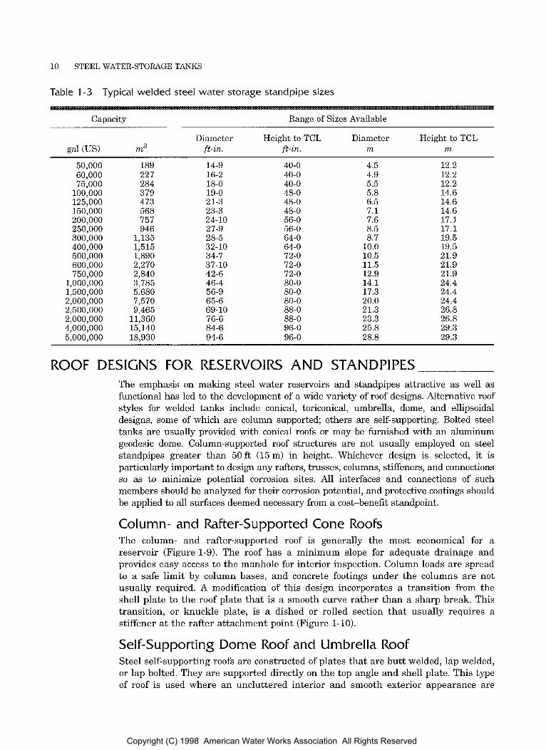
Table 1-3 Typical welded steel water storage standpipe sizes
Capacity Range of Sizes Available
Diameter Height to TCL Diameter Height to TCL gal (US) m3 ft-in. ft-in. m m
50,000 189 14-9 40-0 4.5 12.2 60,000 227 16-2 40-0 4.9 12.2 75,000 284 18-0 40-0 5.5 12.2
100,000 379 19-0 48-0 5.8 14.6 125,000 473 21-3 48-0 6.5 14.6 150,000 568 23-3 48-0 7.1 14.6 200,000 757 24-10 56-0 7.6 17.1 250,000 946 27-9 56-0 8.5 17.1 300,000 1,135 28-5 64-0 8.7 19.5 400,000 1,515 32-10 64-0 10.0 19.5 500,000 1,890 34-7 72-0 10.5 21.9 600,000 2,270 37-10 72-0 11.5 21.9 750,000 2,840 42-6 72-0 12.9 21.9
1,000,000 3,785 46-4 80-0 14.1 24.4 1,500,000 5,680 56-9 80-0 17.3 24.4 2,000,000 7,570 65-6 80-0 20.0 24.4 2,500,000 9,465 69-10 88-0 21.3 26.8 2,000,000 11,360 76-6 88-0 23.3 26.8 4,000,000 15,140 84-6 96-0 25.8 29.3 5,000,000 18,930 94-6 96-0 28.8 29.3
ROOF DESIGNS FOR RESERVOIRS AND STANDPIPES The emphasis on making steel water reservoirs and standpipes attractive as well as hct ional has led to the development of a wide variety of roof designs. Alternative roof styles for welded tanks include conical, toriconical, umbrella, dome, and ellipsoidal designs, some of which are column supported; others are self-supporting. Bolted steel tanks are usually provided with conical roofs or may be furnished with an aluminum geodesic dome. Column-supported roof structures are not usually employed on steel standpipes greater than 50 ft (15 m) in height. Whichever design is selected, it is particularly important to design any rafters, trusses, columns, stiffeners, and connections so as to minimize potential corrosion sites. All interfaces and connections of such members should be analyzed for their corrosion potential, and protective coatings should be applied to all surfaces deemed necessary from a cost-benefit standpoint.
Column- and Rafter-Supported Cone Roofs The column- and rafter-supported roof is generally the most economical for a reservoir (Figure 1-9). The roof has a minimum slope for adequate drainage and provides easy access t o the manhole for interior inspection. Column loads are spread to a safe limit by column bases, and concrete footings under the columns are not usually required. A modification of this design incorporates a transition from the shell plate to the roof plate that is a smooth curve rather than a sharp break. This transition, or knuckle plate, is a dished or rolled section that usually requires a stiffener at the rafter attachment point (Figure 1-10].
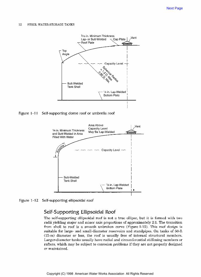
Self-supporting Dome Roof and Umbrella Roof Steel self-supporting roofs are constructed of plates that are butt welded, lap welded, or lap bolted. They are supported directly on the top angle and shell plate. This type of roof is used where an uncluttered interior and smooth exterior appearance are
Copyright (C) 1998 American Water Works Association All Rights Reserved

TYPICAL CAPACITIES AND CONFIGURATIONS 11
Channel Rafters
Butt-Welded Tank Shell
Top Angle 3/4 in. 7
Girders Are .- Required When More Than One Column Is Used
Column Base
I
Figure 1-9 Column- a n d rafter-supported cone roof tank
\ Rad.
- Butt-Welded Tank Shell
c
Knuckle Plate 12 in. 3/4 in.
3/16 in. Lap-Welded Roof Plate
Capacity Level
- One or More Supporting Columns
I
l/4 in. Lap-Welded Bottom Plate
3/16 in. Lap-Welded Roof Plate S . - - -
Level
- One or More Supporting Columns
l/4 in. Lap-Welded Bottom Plate
Figure 1 - 10 Column- and rafter-supported roof with Itnuclde
desired. Dome roof sections are pressed to form a spherical shape. Umbrella roofs are formed to a radius in one direction only, forming chords like the cloth between the spines of an umbrella (Figure 1-11).
Structural stiffeners may be used internally on large-diameter roofs t o avoid excessive plate thickness on welded or bolted tanks. Sometimes steel trusses may be used to support the roof, but these should be avoided if possible because they may create corrosion problems. In addition, the trusses should be kept above the water line to avoid damage by ice and accelerated rates of corrosion.
A modification of the self-supporting dome is the toriconical roof, which consists of a rolled or pressed knuckle and a higher-pitched self-supporting center.
Aluminum dome roofs are sometimes erected on bolted o r welded steel tanks. These aluminum domes are usually constructed of triangulated space truss (geodesic) panels. The dead weight of these domes is usually 3 lb/ft2 (143 N/m2) or less, as compared with 3.8 lb/ft2 (181 N/m2) for a bolted steel roof and 7.6 lb/ft2 (364 N/m2) for a welded steel roof.
Copyright (C) 1998 American Water Works Association All Rights Reserved
12 STEEL WATER-STORAGE TANKS
in. Minimum Thickn or Butt-Welded
Figure 1 - 1 1 Self-supporting dome roof or umbrella roof
Area Above Capacity Level
and 1/4 in. Butt-Welded Minimum Thickness in>* May Be Lap-Welded
Filled With Water
i/ Butt-Welded I Tank Shell
I I --- Capacity Level --
I 1/4 in. Lap-Welded I
1 6 Bottom Plate
Figure 1-1 2 Self-supporting ellipsoidal roof
Self-supporting Ellipsoidal Roof The self-supporting ellipsoidal roof is not a true ellipse, but it is formed with two radii yielding major and minor axis proportions of approximately 2:l. The transition from shell to roof is a smooth unbroken curve (Figure 1-12). This roof design is suitable for large- and small-diameter reservoirs and standpipes. On tanks of 50-ft (15-m) diameter or less, the roof is usually free of internal structural members. Larger-diameter tanks usually have radial and circumferential stiffening members or rafters, which may be subject to corrosion problems if they are not properly designed o r maintained.
Next Page
Copyright (C) 1998 American Water Works Association All Rights Reserved
Chapter 2
AWWA MANUAL M42
This chapter briefly describes the construction and function of common appurtenances for steel water-storage tanks. Appurtenances are covered in separate sections of AWWAD100, Standard for Welded Steel Tanks for Water Storage, and AWWA D103, Standard for Factory-Coated Bolted Steel Tanks for Water Storage. The majority of the appurtenances and attachments described for steel water-storage tanks are required by law, code, and industry standards to make the tank a safe and functional facility. Other accessories are optional and may be specified by the owner to improve the facility’s function or appearance.
SHELL MANHOLES ~
A minimum of two opposing shell manholes are required on welded ground-supported tanks for ventilation during interior coating operations, for safety, and for ease of interior access during construction activities and maintenance inspections. On tanks more than 100 ft (30.5 m) in diameter, it may be desirable to have three or more shell manholes. AWWA D103 requires only one shell manhole on bolted tanks because a tank panel can be removed t o provide additional ventilation.
Sizes and Types Normal manhole sizing is 24 or 30 in. (610 o r 760 mm) in diameter to accommodate ventilating equipment and allow easy egress (Figures 2-1 and 2-2). Outward-opening, hinged covers or single-bolt, inward-opening manholes are standard. Outward- opening covers may require reinforcing plates on the shell, whereas inward-opening manholes usually accomplish their reinforcement through heavy plate necks. The heavy plate neck also provides the gasket surface t o the cover. The inward-opening cover must be hinged to ensure proper operation. If a tank will be subject to severe icing conditions, an inward-opening manhole may not be desirable.
Bolted Tank Manholes The shell manholes for bolted tanks can be circular, 24 in. (610 mm) in diameter; square, 24 by 24 in. (610 by 610 mm); or elliptical, 18 by 22 in. (460 by 560 mm),
25 Copyright (C) 1998 American Water Works Association All Rights Reserved

26 STEEL WATER-STORAGE TANKS
Exploded Side Elevation
L 4
fA
I Front Elevation
Section A-A TYP.
Figure 2-1 Inward-opening shell manhole detail
minimum size. One manhole, unless otherwise specified, shall be provided in the first ring of the tank at a location designated by the purchaser. If the manhole cover weighs more than 50 lb (23 kg), a hinged cover should be provided.
Flush Manholes Flush rectangular manholes (rectangular manholes mounted flush with the bottom of the tank) having a minimum length of 24 in. (610 mm) in the shortest direction and a maximum length of 48 in. (1,220 mm) in the longest direction are also available. Such manholes are useful when a tank interior is being cleaned. Refer to AWWA DlOO and American Petroleum Institute Standard 650 for details and design requirements.
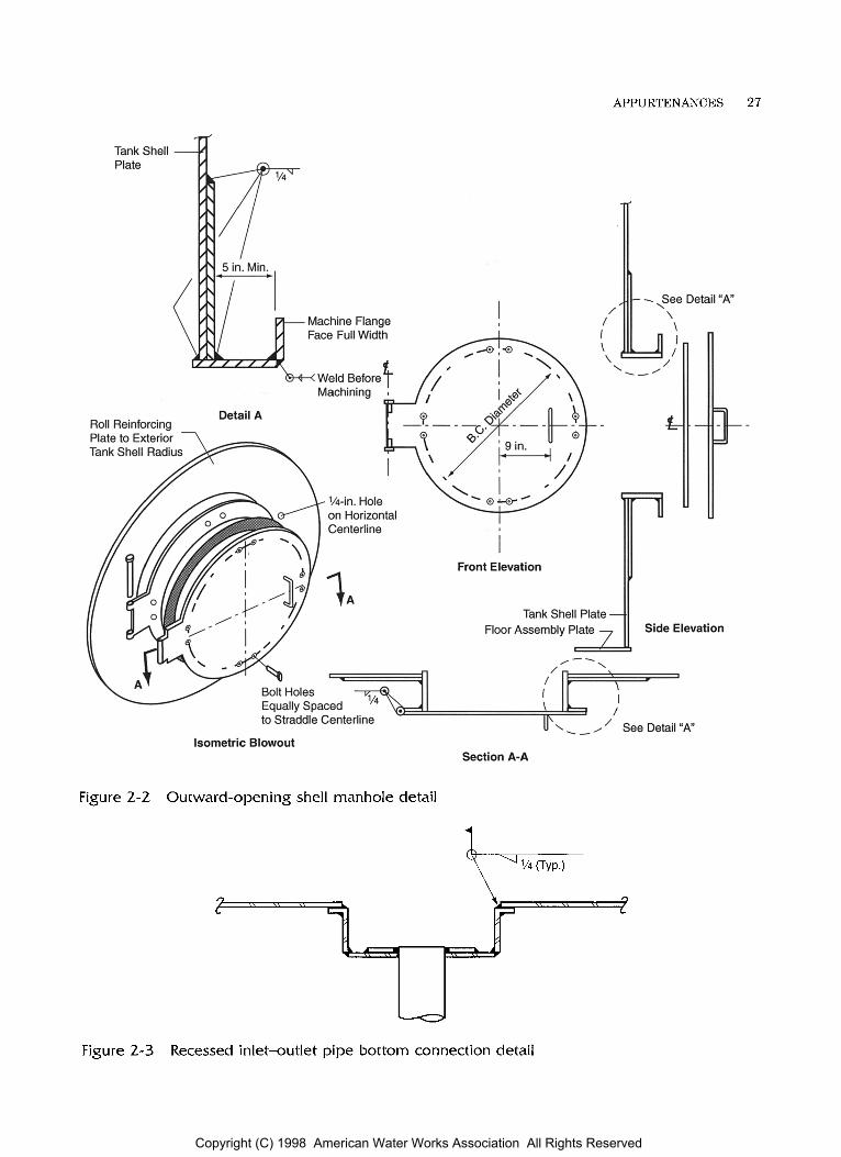
PIPE CONNECTIONS The number of tank-bottom or shell-piping connections should be kept to a minimum. The usual practice is to use a common inlet-outlet drain connection through the tank bottom or on the tank shell (Figures 2-3 and 2-4). If a bottom connection is used, a removable section of pipe 6-8 in. (150-200 mm) long may extend above the drain at floor level to serve as a silt stop. Recent requirements concerning minimum and maximum detention that the water remains in the tank may require separate inlet and outlet connections. Baffles and flow diverters are also used to control tank water detention time.
Piping connections through the tank bottom or shell are normally furnished in steel pipe, welded or bolted to the shell or bottom. Ductile iron or cast iron pipe connections must pass through a mechanical-joint type connection which is welded or bolted to the steel tank bottom.
Copyright (C) 1998 American Water Works Association All Rights Reserved
APPURTENANCES 27
Tankshell 3
Isometric Blowout Section A-A
Figure 2-2 Outward-opening shell manhole detail
Figure 2-3 Recessed inlet-outlet pipe bottom connection detail
Copyright (C) 1998 American Water Works Association All Rights Reserved

28 STEEL WATER-STORAGE TANKS
- Plan
Elevation
Ld
Figure 2-4 Nonrecessed inlet-outlet pipe bottom connection details
The piping connections to the tank should be constructed to have a flexible coupling outside the tank to allow for differential movement. If piping connections through the shell are required, provisions must be made to protect this piping from freezing and vandalism. Adequate precautions must be made in this piping to allow for differential movement when the tank is filled and drained. Special flexible, extendable connections are necessary for tanks subject to seismic movement. AWWA DlOO defines the distance from the shell intersection that through-the-tank-bottom piping connec- tions may be located on unanchored tanks designed for seismic conditions.
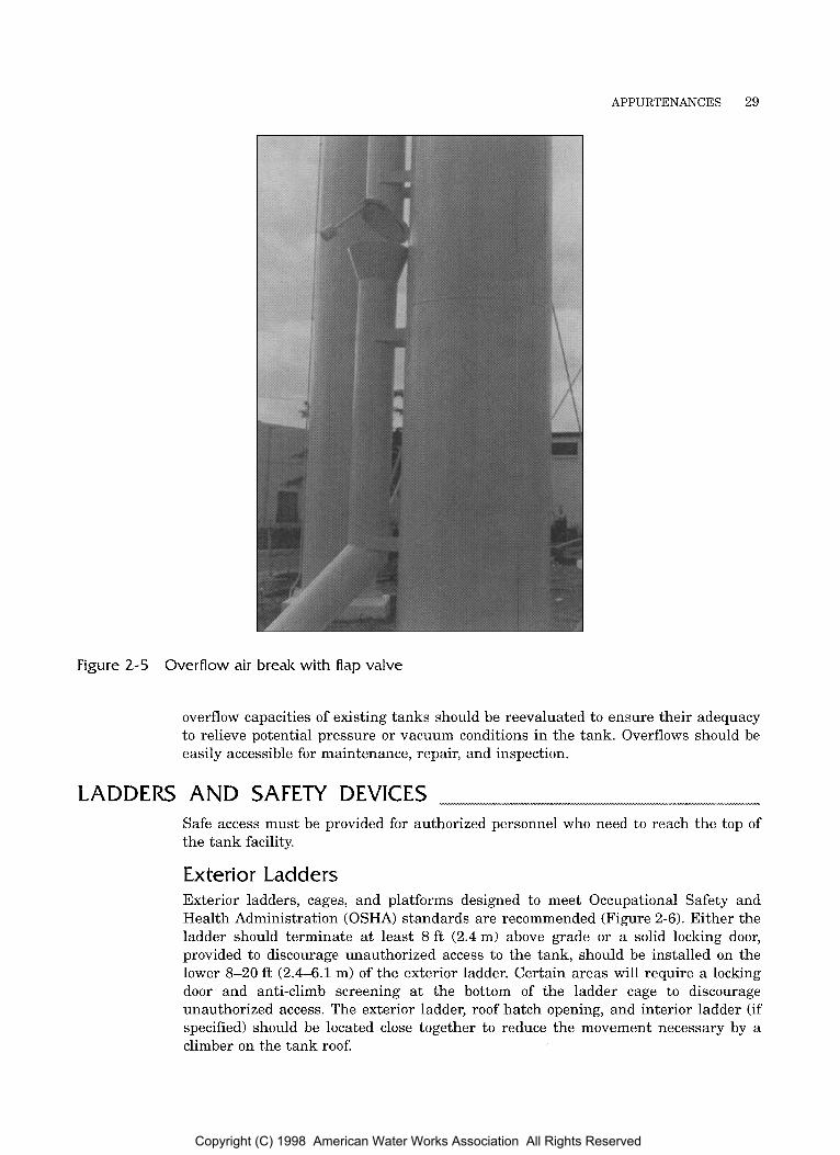
OVERFLOW A properly sized overflow is essential to protect the tank structure from excessive water levels caused by rapid variations in distribution system conditions. Exterior overflows are recommended. In colder climates, ice buildup on an internal overflow may become a problem and eventually break the overflow pipe. Overflow waters should be directed beyond the tank exterior perimeter to avoid damage to the tank grade or foundation during overflow. Most state standards recommend that the overflow on elevated tanks be extended down the side of the tank to within approximately 12 to 24in. (305 to 610 mm) above grade. Extending the overflow prevents water discharged from the pipe from freezing on the tower structure and causing damage to the structure. In addition, most governing agencies require an air gap between the overflow tank piping and final drainage system in order to protect against backflow. Figure 2-5 shows one type of overflow-pipe air gap. Most states require a screening or flap-gate arrangement over the end of the pipe connected to the tank. As distribution systems and pumping capacities are increased, the vent and
Copyright (C) 1998 American Water Works Association All Rights Reserved
APPURTENANCES 29
Figure 2-5 Overflow air break with flap valve
overflow capacities of existing tanks should be reevaluated to ensure their adequacy to relieve potential pressure or vacuum conditions in the tank. Overflows should be easily accessible for maintenance, repair, and inspection.
LADDERS AND SAFETY DEVICES Safe access must be provided for authorized personnel who need to reach the top of the tank facility.
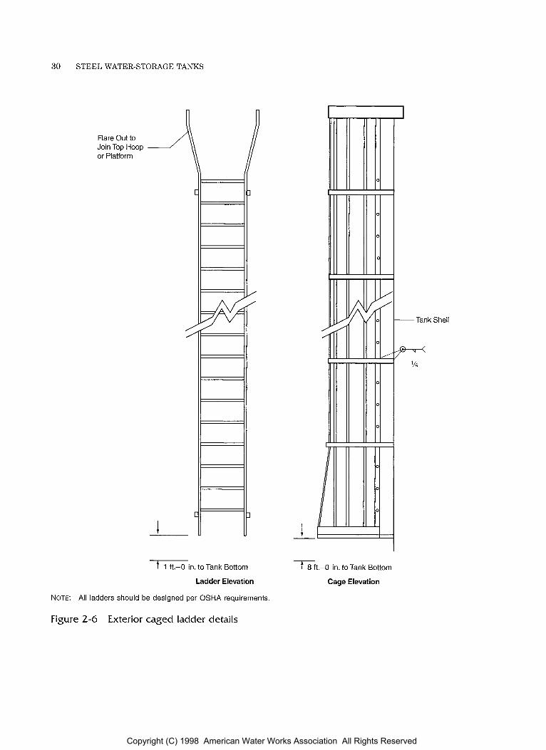
Exterior Ladders Exterior ladders, cages, and platforms designed to meet Occupational Safety and Health Administration (OSHA) standards are recommended (Figure 2-6). Either the ladder should terminate at least 8 f t (2.4m) above grade or a solid locking door, provided to discourage unauthorized access to the tank, should be installed on the lower 8-20 ft (2.4-6.1 m) of the exterior ladder. Certain areas will require a locking door and anti-climb screening at the bottom of the ladder cage to discourage unauthorized access. The exterior ladder, roof hatch opening, and interior ladder (if specified) should be located close together to reduce the movement necessary by a climber on the tank roof
Copyright (C) 1998 American Water Works Association All Rights Reserved
30 STEEL WATER-STORAGE TANKS
Flare Out to Join Top Hoop or Platform
t 1 ft.-0 in. to Tank Bottom
Ladder Elevation
NOTE: All ladders should be designed per OSHA requirements.
1
t f t - 0 in. to Tank Bottom
Cage Elevation
-Tank Shell
F ‘/4
Figure 2-6 Exterior caged ladder details
Copyright (C) 1998 American Water Works Association All Rights Reserved
APPURTENANCES 31
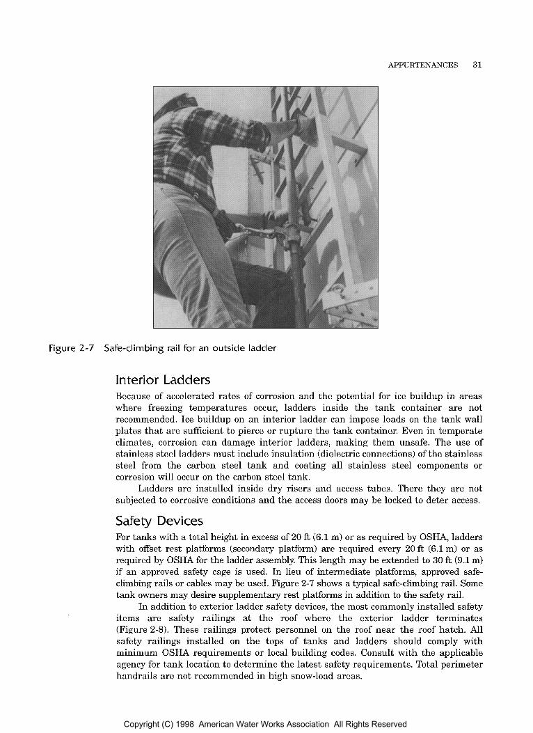
Figure 2-7 Safe-climbing rail for an outside ladder
Interior Ladders Because of accelerated rates of corrosion and the potential for ice buildup in areas where freezing temperatures occur, ladders inside the tank container are not recommended. Ice buildup on an interior ladder can impose loads on the tank wall plates that are sufficient to pierce or rupture the tank container. Even in temperate climates, corrosion can damage interior ladders, making them unsafe. The use of stainless steel ladders must include insulation (dielectric connections) of the stainless steel from the carbon steel tank and coating all stainless steel components or corrosion will occur on the carbon steel tank.
Ladders are installed inside dry risers and access tubes. There they are not subjected to corrosive conditions and the access doors may be locked to deter access.
Safety Devices For tanks with a total height in excess of 20 ft (6.1 m) or as required by OSHA, ladders with offset rest platforms (secondary platform) are required every 20 ft (6.1 m) or as required by OSHA for the ladder assembly. This length may be extended to 30 ft (9.1 m) if an approved safety cage is used. In lieu of intermediate platforms, approved safe- climbing rails or cables may be used. Figure 2-7 shows a typical safe-climbing rail. Some tank owners may desire supplementary rest platforms in addition to the safety rail.
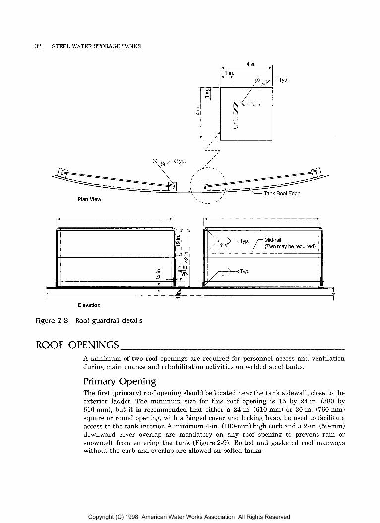
In addition to exterior ladder safety devices, the most commonly installed safety items are safety railings at the roof where the exterior ladder terminates (Figure 2-8). These railings protect personnel on the roof near the roof hatch. All safety railings installed on the tops of tanks and ladders should comply with minimum OSHA requirements or local building codes. Consult with the applicable agency for tank location t o determine the latest safety requirements. Total perimeter handrails are not recommended in high snow-load areas.
Copyright (C) 1998 American Water Works Association All Rights Reserved
32 STEEL WATER-STORAGE TANKS
4 in. .
,
I Elevation
Figure 2-8 Roof guardrail details
ROOF OPENINGS A minimum of two roof openings are required for personnel access and ventilation during maintenance and rehabilitation activities on welded steel tanks.
Primary Opening The first (primary) roof opening should be located near the tank sidewall, close to the exterior ladder. The minimum size for this roof opening is 15 by 24in. (380 by 610 mm), but it is recommended that either a 24-in. (610-mm) or 30-in. (760-mm) square or round opening, with a hinged cover and locking hasp, be used to facilitate access to the tank interior. A minimum 4-in. (100-mm) high curb and a 2-in. (50-mm) downward cover overlap are mandatory on any roof opening to prevent rain or snowmelt from entering the tank (Figure 2-9). Bolted and gasketed roof manways without the curb and overlap are allowed on bolted tanks.
Copyright (C) 1998 American Water Works Association All Rights Reserved
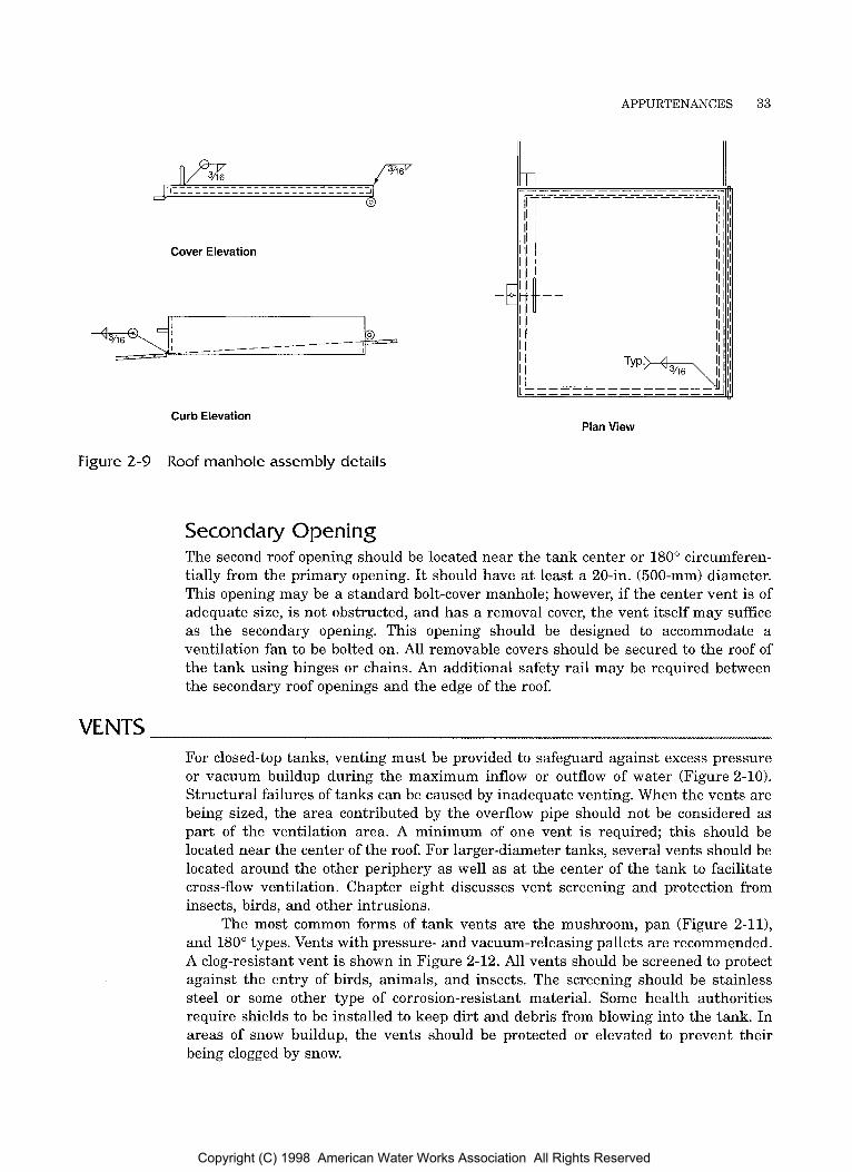
APPURTENANCES 33
Cover Elevation
Curb Elevation Plan View
Figure 2-9 Roof manhole assembly details
Secondary Opening The second roof opening should be located near the tank center or 180" circumferen- tially from the primary opening. I t should have at least a 20-in. (500-mm) diameter. This opening may be a standard bolt-cover manhole; however, if the center vent is of adequate size, is not obstructed, and has a removal cover, the vent itself may suffice as the secondary opening. This opening should be designed to accommodate a ventilation fan to be bolted on. All removable covers should be secured to the roof of the tank using hinges or chains. An additional safety rail may be required between the secondary roof openings and the edge of the roof.
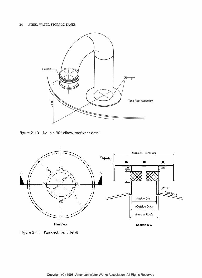
VENTS For closed-top tanks, venting must be provided to safeguard against excess pressure or vacuum buildup during the maximum inflow or outflow of water (Figure 2-10). Structural failures of tanks can be caused by inadequate venting. When the vents are being sized, the area contributed by the overflow pipe should not be considered as part of the ventilation area. A minimum of one vent is required; this should be located near the center of the roof. For larger-diameter tanks, several vents should be located around the other periphery as well as at the center of the tank to facilitate cross-flow ventilation. Chapter eight discusses vent screening and protection from insects, birds, and other intrusions.
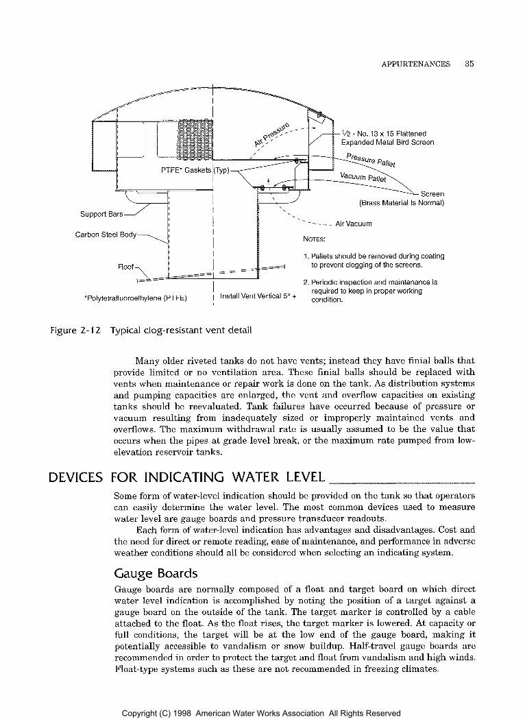
The most common forms of tank vents are the mushroom, pan (Figure 2-11), and 180" types. Vents with pressure- and vacuum-releasing pallets are recommended. A clog-resistant vent is shown in Figure 2-12. All vents should be screened to protect against the entry of birds, animals, and insects. The screening should be stainless steel or some other type of corrosion-resistant material. Some health authorities require shields t o be installed t o keep dirt and debris from blowing into the tank. In areas of snow buildup, the vents should be protected or elevated to prevent their being clogged by snow.
Copyright (C) 1998 American Water Works Association All Rights Reserved
34 STEEL WATER-STORAGE TANKS
Figure 2-10 Double 90" e l b o w roof v e n t detail
I
I
Plan View
t (Outside Diameter) t
\I m m m
(Outside Dia.) I- (Hole in Roof) 1 - - ,
Section A-A
Figure 2-1 1 Pan deck v e n t detail
Copyright (C) 1998 American Water Works Association All Rights Reserved
APPURTENANCES 35
1/2 - No. 13 x 15 Flattened Expanded Metal Bird Screen
. - - - - - Air Vacuum Carbon Steel Body
1. Pallets should be removed during coating to prevent clogging of the screens.
2. Periodic inspection and maintenance is required to keep in proper working
*Polytetrafluoroethylene (PTFE) I Install Vent Vertical 5" + condition,
Figure 2-12
DEVICES
Typical clog-resistant vent detail
Many older riveted tanks do not have vents; instead they have finial balls that provide limited or no ventilation area. These finial balls should be replaced with vents when maintenance or repair work is done on the tank. As distribution systems and pumping capacities are enlarged, the vent and overflow capacities on existing tanks should be reevaluated. Tank failures have occurred because of pressure or vacuum resulting from inadequately sized or improperly maintained vents and overflows. The maximum withdrawal rate is usually assumed to be the value that occurs when the pipes at grade level break, or the maximum rate pumped from low- elevation reservoir tanks.
FOR INDICATING WATER LEVEL Some form of water-level indication should be provided on the tank so that operators can easily determine the water level. The most common devices used to measure water level are gauge boards and pressure transducer readouts.
Each form of water-level indication has advantages and disadvantages. Cost and the need for direct or remote reading, ease of maintenance, and performance in adverse weather conditions should all be considered when selecting an indicating system.
Gauge Boards Gauge boards are normally composed of a float and target board on which direct water level indication is accomplished by noting the position of a target against a gauge board on the outside of the tank. The target marker is controlled by a cable attached to the float. As the float rises, the target marker is lowered. At capacity or full conditions, the target will be at the low end of the gauge board, making it potentially accessible to vandalism or snow buildup. Half-travel gauge boards are recommended in order to protect the target and float from vandalism and high winds. Float-type systems such as these are not recommended in freezing climates.
Copyright (C) 1998 American Water Works Association All Rights Reserved
36 STEEL WATER-STORAGE TANKS
Remote Readings A pressure transducer in the tank can indicate the water level at a remote readout some distance from the tank facility. The pressure transducer must be installed so that it is completely isolated from all inlet and outlet openings. Pressure transducers are sensitive enough t o sense pressure changes created by water movement through a line which would cause a false reading. The pressure transducer can also control flow in and out of the tank by actuating pumps or valves.
Pressure Gauges If freeze protection is provided, economical bourdon pressure gauges may be connected directly to the tank or riser.
Inlet Stop/Start Controls A water utility may install a probe or transducer system to control the water level and to advise operators of low water levels. Probes require waterproof flanged entries at the top of the tank. In addition, for radio or wired telemetry equipment, an insulated conduit from the tank top to ground level must be installed to carry the electrical signal. If probes are used in tanks subject to icing conditions, the probe system should be designed to prevent damage from freezing.
Sampling Points A sampling point near the tank bottom will allow the storage facility’s water quality to be tested directly. Direct testing may be practical in low-usage tanks where the stored water may remain in the tank for a long time and water quality may deteriorate. Sampling points should be protected from freezing and vandalism.
EMERGENCY FILL/WITHDRAW CONNECTIONS Some tanks may require provisions for emergency filling or emergency withdrawal. Typically, such provisions are needed when tanks are located in remote areas where fire protection groups may withdraw directly from the tank to fill pumper trucks or use stored water directly during fire fighting. Where required, the emergency valving and connections should be designed t o match the emergency facilities of the agency that will use them. The design must avoid cross-connections between the emergency system and the potable water system. Connections should be protected from freezing and vandalism, and the tank venting and overflow systems should be sized for these unusual fillings and withdrawals.
Copyright (C) 1998 American Water Works Association All Rights Reserved

Chapter 3
AWA MANUAL M42
This chapter covers the theory, design, operation, and maintenance of cathodic protection systems. Corrosion of metals in contact with water is a natural process. Variables associated with a specific tank will determine how severe the corrosion activity will be. A properly designed, installed, and maintained cathodic protection system, used in conjunction with appropriate coatings, will provide economical and effective corrosion control for the interior submerged surfaces of a water-storage tank. For specific design details of cathodic protection systems, refer t o AWWA D104, Standard for Automatically Controlled, Impressed-Current Cathodic Protection for the Interior of Steel Water Tanks, NACE, International Standard RP0388, Impressed Current Cathodic Protection of Internal Submerged Surfaces of Steel Water Storage Tanks, and NACE Standard RP00196, Galvanic Anode Protection of Internal Submerged Surfaces of Steel Water Storage Tanks.
Cathodic protection is a method of corrosion control that can be used with all recommended American Water Works Association (AWWA) coating systems to prevent metal loss at any void in the coating below the water level. The design, costs, and potential benefits of using cathodic protection with coatings in an overall corrosion control program can be evaluated by qualified utility staff members, outside consultants, or cathodic protection equipment manufacturers.
NATURE OF CORROSION The corrosion of steel in aqueous solutions is an electrochemical process in which a current flows and a chemical reaction occurs. A corrosion cell has four basic elements: anode, cathode, electrolyte, and closure path. The anode is the metal that will corrode; that is, metal ions leave its surface and enter the electrolyte solution. The cathode is a metal from which no metal ions enter the solution. The electrolyte may be any solution, such as drinking water, that is capable of conducting electricity. The closure path, also called the return current path, is the electrical conductor, usually metal, that connects the anode and cathode together. If any one of these elements is missing, corrosion does not occur. For example, coating stops corrosion from occurring by providing a barrier to the current flowing between the metal and the electrolyte.
37
Copyright (C) 1998 American Water Works Association All Rights Reserved

38 STEEL WATER-STORAGE TANKS
Bulb \ I /
Dry cell batteries generate a current flow (e ) that illuminates the bulb. This current flow is the result of a potential difference (voltage) between the zinc (anode) and carbon (cathode). The bulb will stay lit until the zinc is consumed during the corrosion process.
- Zinc (Anode)
Conductive Depolarizing Agent (Keep Cathode From Polarizing to Open Circuit Potential of Anode)
L Figure 3-1 Schematic diagram of d battery
A dry-cell battery is a corrosion cell (Figure 3-1). When the battery’s anode (zinc) and cathode (carbon) are connected through a closure path (the lightbulb), the potential difference between the zinc and carbon produces a current flow. The current will continue to flow until the zinc anode is consumed by the corrosion process.
I t is important to consider why the current flows in the direction it does. The direction of flow is determined by the metals selected for the battery’s case and center post. If the center post was magnesium instead of carbon, the current flow would be reversed. In this case, the magnesium center post would be the anode (which corrodes) and the zinc case would be the cathode (which does not corrode).
The current can also be forced t o flow in the opposite direction if the standard carbon-zinc battery is connected to an outside current source (in place of the lightbulb). In this situation, the anode and cathode would also be reversed-that is, the battery case would become the cathode and would be protected from corrosion.
In a steel water-storage tank, some portion of the metal will be the anode and some portion will be the cathode. Which area takes on each function will be the result of impurities in the metal, surface conditions, oxygen concentrations in the water, the presence of any dissimilar metals, stresses caused by manufacturing, heat, or concentrated structural loads, and a number of other factors. Corrosion of steel in water is diagrammed in Figure 3-2. At the anode, metal ions leave the surface, enter the water, and combine with oxygen to form rust. Electrons released from the anode travel through the metal to the cathode. At the cathode, an ion exchange occurs but no metal is lost and no corrosion occurs.
Copyright (C) 1998 American Water Works Association All Rights Reserved

CATHODIC PROTECTION 39
Corrosion Products Formed
Ferrous Hydroxide - Fe(OH), - Initial Stage Ferric Hydroxide - Fe(OH), - Rust, Final Stage
- Pit (Anode)
-Closure Path At the anode metal ions leave the surface entering the water and combine with other ions in the vicinity of the
(Steel Tank)
anode to form rust. At the cathode no rust forms. In neutral waters, oxygen has the greatest influence on the corrosion rate of steel by determining the rate at which the cathode depolarizes.
- Pit (Anode)
Figure 3-2 Corrosion of steel in water
The presence of ladders, floats, or other accessories made of stainless steel will cause steel exposed at holidays (voids) in the coating to corrode at a higher than normal rate. In such cases, the stainless-steel components are the cathodes, and the exposed steel is the anode.
For more detailed descriptions of corrosion chemistry, see AWWA Manual M27, External Corrosion-Introduction to Chemistry and Control.
PRINCIPLES OF CATHODIC PROTECTION Cathodic protection systems are used to prevent or retard the corrosion that would naturally occur in a steel water tank. These systems prevent or slow corrosion by altering the electrochemical environment so that the submerged tank shell becomes the cathode of a corrosion cell. Since the cathode of a cell does not corrode, the submerged metallic tank shell is protected. There are two basic types of cathodic protection systems: galvanic and impressed-current systems.
Galvanic Systems In a galvanic system, a block of specially selected metal, called a sacrificial anode, is immersed in the electrolyte and electrically connected to the metal of the tank. The metal of the sacrificial anode is selected so that it will become the anode of the corrosion cell, with the steel tank being the cathode. When blocks of magnesium are attached to steel structures and immersed in a conductive electrolyte (the water in the tank), the magnesium corrodes and the steel is protected. Galvanic protection systems have had limited application to water-storage tanks, although they may be used in climates that do not cause ice to form in the water stored in the tank. (A description of the installation and performance is published in Materials Perfor- mance, September 1996, Volume 35, Number 9, pages 13-17, “Cathodic Protection of 32 Steel Reservoir Interiors.”)
Copyright (C) 1998 American Water Works Association All Rights Reserved
40 STEEL WATER-STORAGE TANKS
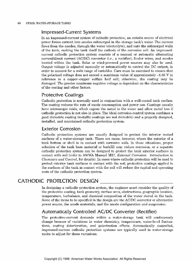
Impressed-Current Systems In an impressed-current system of cathodic protection, an outside source of electrical power forces current into anodes submerged in the storage tank's water. The current flows from the anodes, through the water (electrolyte), and onto the submerged walls of the tank, making the tank itself the cathode of the corrosion cell. An impressed- current cathodic protection system consists of a manual o r automatic alternating current/direct current (AC/DC) converter (i.e., a rectifier), feeder wires, and anodes located within the tank. Solar or wind-powered power sources may also be used. Output voltage is adjusted manually or automatically t o control the DC output, in order to account for a wide range of variables. Care must be exercised t o ensure that the polarized voltage does not exceed a maximum value of approximately -1.05 V in reference to a copper-copper sulfate half cell; otherwise, the coating may be damaged. The precise maximum negative voltage is dependent on the characteristics of the coating and other factors.
Protective Coatings Cathodic protection is normally used in conjunction with a well-coated tank surface. The coating reduces the rate of anode consumption and power use. Coatings usually have microscopic voids, which expose the metal to the water and allow metal loss if cathodic protection is not also in place. The ideal corrosion-control system combines a good dielectric coating (metallic coatings are not dielectric) and a properly designed, installed, and maintained cathodic protection system.
Exterior Corrosion Cathodic protection systems are usually designed to protect the interior wetted surfaces of a water-storage tank. There are cases, however, where the exterior of a tank bottom or shell is in contact with corrosive soils. In those situations, proper selection of the tank base material or backfill may reduce corrosion, or a separate cathodic protection system can be designed to protect the tank exterior surfaces in contact with soil (refer to AWWA Manual M27, External Corrosion-Introduction to Chemistry and Control, for details). In cases where cathodic protection will be used to protect exterior tank surfaces in contact with the soil, protective coatings applied to the surfaces of the tank in contact with the soil will reduce the capital and operating costs of the cathodic protection system.
CATHODIC PROTECTION DESIGN In designing a cathodic protection system, the engineer must consider the quality of the protective coating, tank geometry, surface area, obstructions, geographic location, temperature, turbulence, and chemical composition of the water stored in the tank. Some of the items to be specified in the design are the AC/DC converter or alternative power source, the anode materials, and the anode configuration and suspension.
Automatically Controlled AC/DC Converter (Rectifier) The protective-current demands within a water-storage tank will continuously change because of variations in water chemistry, temperature, water-level fluctua- tions, coating deterioration, and polarization effects. Automatically controlled, impressed-current cathodic protection systems are typically used in water-storage tanks to adjust for these variations.
Copyright (C) 1998 American Water Works Association All Rights Reserved

CATHODIC PROTECTION 41
Reference electrodes are used to continuously monitor the protective level and control the amount of cathodic protection current delivered to the structure by the system. Separate control circuits are used for riser pipes and other areas of the tank that may have different localized conditions.
Anode Materials and Design Life Impressed-current anodes may be made of aluminum, which usually has a design life of 1 t o 2 years; or they may be made of high-silicon cast iron, platinum, mixed metal oxide, or other long-life anode materials that can provide a nominal 10- to 20-year life. The design life of the anode system is based on the anticipated protective-current requirements and the known consumption rates for the selected anode material. The approximate consumption rates for selected anode materials are
Aluminum 14 lb/year (6.4 kg/year)
High-silicon cast iron 1.0 lb/year (0.45 kg/year)
Platinized niobium, platinized titanium, or mixed metal oxides on titanium
0.00008 to 0.0013 lb/year (0.036 to 0.59 g/year)
Anode Configuration and Suspension Current distribution from any anode configuration is affected by the geometric shape of the tank, obstructions within the tank, interior coating, and chemical characteris- tics of the water.
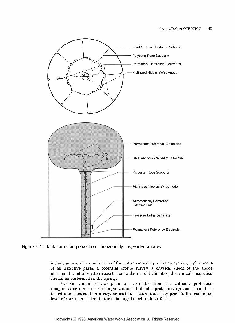
The anode system may be installed vertically or horizontally. Vertically suspended anodes are installed by hanging the anode from an electrically insulated device at the tank roof, adjacent to holes cut in the roof (Figure 3-3). Horizontally suspended anodes are positioned below the normal water level, attached to the tank shell or access tube (Figure 3-4). In elevated tanks with an inlet-outlet riser pipe of 30-in. (76-cm) diameter or larger, a vertically suspended anode is used to provide protection within the riser.
When holes are cut in the roof, the finished installation must be watertight to eliminate openings for insects and runoff t o enter the tank.
For tanks subject to icing, either vertical anode systems with extensible elements or horizontal suspension systems designed to minimize ice damage to the anodes should be considered. These suspension systems can provide year-round protection and may eliminate the need for annual anode replacement due to ice damage.
MAINTENANCE Following the installation of a cathodic protection system, a post-installation tank-to- water potential profile is performed to ensure that the system is providing optimal corrosion control. The level of corrosion control achieved by the cathodic protection system can be determined through electrical testing. Corrosion is under control when a copper-copper sulfate reference electrode is placed adjacent to, but not touching, the submerged tank surface and a polarized tank-to-water potential of -0.85 V or more negative is measured.
Copyright (C) 1998 American Water Works Association All Rights Reserved

42 STEEL WATER-STORAGE TANKS
6 in.
St. Steel Hardware
Under Roof Feeder Located Above H.W.L.
Access Hand-hole and Suspension Insulator (See Detail)
1
Hand-hole Suspension
* Type, quantity, length, and location of the anodes and reference electrodes are determined by engineering design to suit individual applications.
Typical anode materials used for icing and nonicing climates: platinum niobium, high-silicon cast iron.
Figure 3-3 Tank corrosion protection-vertically suspended anodes
Manually controlled rectifiers require periodic adjustment to maintain the system within an optimal protective range. The manufacturer’s instructions describe how to adjust rectifiers. The cathodic protection designer will establish the range of operation most suitable for each application based on a tank-to-water potential survey.
Automatic rectifiers will continuously monitor the tank-to-water potential being maintained by the system and make adjustments t o control corrosion. Personnel responsible for operating and maintaining the cathodic protection system should refer to the designer’s instructions to fully understand their responsibilities. They should consult with the manufacturer if necessary regarding the equipment’s operation and make certain that all responsible personnel are familiar with its operation. A successful cathodic protection corrosion-control system will continuously operate within the established criteria.
Annual inspection of the cathodic protection system by the manufacturer or by a qualified corrosion engineer is recommended. At a minimum, this inspection should
Copyright (C) 1998 American Water Works Association All Rights Reserved
CATHODIC PROTECTION 43
Steel Anchors Welded to Sidewall
Polyester Rope Supports
Permanent Reference Electrodes
Platinized Niobium Wire Anode
Permanent Reference Electrodes
Steel Anchors Welded to Riser Wall
Polyester Rope Supports
Platinized Niobium Wire Anode
Automatically Controlled Rectifier Unit
Pressure Entrance Fitting
Permanent Reference Electrode
Figure 3-4 Tank corrosion protection-horizontally suspended anodes
include an overall examination of the entire cathodic protection system, replacement of all defective parts, a potential profile survey, a physical check of the anode placement, and a written report. For tanks in cold climates, the annual inspection should be performed in the spring.
Various annual service plans are available from the cathodic protection companies or other service organizations. Cathodic protection systems should be tested and inspected on a regular basis to ensure that they provide the maximum level of corrosion control t o the submerged steel tank surfaces.
Copyright (C) 1998 American Water Works Association All Rights Reserved
Chapter 4
AWWA MANUAL M42
When exposed t o the environment, steel oxidizes and deteriorates. This is especially true when the environment includes both oxygen and moisture. For steel water tanks, paints and other protective coatings are used to prevent such deterioration. This chapter covers coating systems used to protect the interior and exterior of steel water-storage tanks.
A protective coating is a material that, when applied to a structure, will isolate the structure from its environment. Properly applied protective coatings are a cost- effective way to protect both exterior and interior tank surfaces. A coating applied to the interior surfaces of a tank is also called a lining.
Both exterior and interior coating systems must be carefully selected to provide the best protective value for the money based on coating life, effectiveness of protection, ease of application, and ease of adding coats t o the system in future years. Protective coating systems have become much more complex than the single- component materials that were prevalent prior to 1970.
Safety precautions and special equipment such as safety belts, safety lines, protective clothing, and air-supplied face masks are required to protect workers. Poor visibility and substrate access difficulties make abrasive blast cleaning and coating application on tank interiors extremely difficult. The storage structure’s design may also include inaccessible areas, stitch welds, lapped roof sections, or other configura- tions that make it more difficult t o obtain a proper coating application. A coating system that requires ideal conditions to achieve proper application may not be appropriate, no matter how effective the final coating would be if properly applied.
INTERIOR COATINGS Protective coating systems intended for use on the interior surfaces of potable water storage tanks must be able to withstand the following:
constant immersion in water
varying water temperatures
alternate wetting and drying periods
45
Copyright (C) 1998 American Water Works Association All Rights Reserved
46 STEEL WATER-STORAGE TANKS
An additional requirement for such materials to be applied successfully in the field is application latitude-that is, the suitability of the material to be applied under extremely adverse conditions.
ice abrasion in cold climate areas
high humidity and heat in the zones above the high water level
chlorine and mineral content of the water
Approval by Regulatory Agencies Coating and lining materials intended for use in contact with potable water must not impose a health risk on the general public and must be approved for such use by the appropriate state o r federal regulatory agency. Although some state health depart- ments evaluate and approve tank-lining materials themselves, the majority of state health departments have relied on specific product approval by either the US Environmental Protection Agency (USEPA) or the US Food and Drug Administration (USFDA), since the American Water Works Association (AWWA) does not test or approve individual products.
Because most states had placed the burden of approval on the federal government, the backlog of materials waiting for approval had increased substantial- ly. In response to this problem, the USEPA solicited proposals from nonprofit organizations to implement a testing and evaluation program for materials in contact with potable water. A consortium of organizations led by NSF International reached an agreement with USEPA and developed this program, resulting in the publication of Drinking Water Additives Standard 61, Drinking Water Systems Components- Health Effects. Other approved testing laboratories may test and certify products for compliance with ANSINSF Standard 61. Contact ANSI for a list of approved labs.
Field-Applied Interior Coating Systems for Welded Steel Tanks AWWA D102 recognizes general types of interior coating systems: epoxies, vinyls, enamels, and coal-tars. Each of these systems has provided satisfactory service when correctly applied. As a result of differing climates, governmental regulations, and other variables, no one type of coating system can be considered best. Epoxy and vinyl systems are currently the most popular. New developments in coatings, including plural-component urethane materials, are also being used.
Epoxy coatings. A variety of epoxy coatings are available. The epoxies used by municipal water utilities are usually two-component polyamide cured products.
Epoxy coatings are popular because of their outstanding impermeability to water migration through the membrane, resistance to ionic transfer, outstanding adhesion, high film build, and resistance to cathodic disbondment. Additionally, the high solids and low volatile organic compound (VOC) content of many of the epoxy formulations may comply with current government regulations regarding both air pollution during application and VOCs in potable water during operation.
Two-component epoxies have several limitations. Cold temperatures may retard or stop their curing action if special cold-weather formulations are not used. The two components must be mixed correctly. And, finally, most thoroughly cured epoxy coatings develop very hard films that require scarification prior to recoating.
Vinyl coatings. Vinyl coatings have been used extensively for protection against salt and potable water since the late 1940s. They are one of the few coating materials that dry solely by solvent evaporation. Further, the vinyl film can always be
Copyright (C) 1998 American Water Works Association All Rights Reserved
COATING SYSTEMS 47
returned to solution by the addition or application of the appropriate solvent. As a result, a vinyl coating, if clean and in sound condition, can be recoated at any time during its life with good adhesion between the newly applied coating and the original.
Vinyl coatings are likewise highly impermeable. In cold weather, the vinyls will dry if the ambient temperature is high enough t o cause the solvents to evaporate. Like epoxy coatings, when properly applied, the effective service life of vinyls can be up t o 20 years.
Interior vinyl coating systems have several disadvantages. Their low film build necessitates multiple coats. They have only moderate abrasion resistance. Their application latitude during hot weather is poor, and they are intolerant of poor surface preparation. They also have poor resistance to high operating temperatures. Solvent-based vinyl coatings do not comply with VOC regulations in many parts of the United States.
Other coating systems have been successfully used in various parts of the country. These include, but are not necessarily limited to, coal tar, chlorinated rubber, plural-component urethanes and metalizing with anodic material.
Other coating systems.
Factory-Applied Interior Coating Systems for Bolted Steel Tanks The interior surfaces of factory-coated, bolted tanks may be coated with one of the following: thermoset epoxy, galvanizing, or fused glass. Factory coating systems are uniformly applied and fully cured under controlled conditions. The thermoset liquid epoxy coatings are two-component systems applied in two coats, then baked on at approximately 425OF-525"F (218"C-274"C). The thermoset powder coatings are applied in one coat and baked in accordance with the manufacturer's instructions. Galvanized coatings are applied in accordance with the American Hot Dip Galvanizers Association in compliance with ASTM A123 and ASTM A153. Fused silica glass coatings are achieved by spraying a ground-glass-and-water slurry onto the steel panels, then firing the panels in a furnace at approximately 1,600"F (870°C). Coating systems for factory-coated bolted steel tanks are discussed in more detail in AWWA D103.
EXTERIOR COATINGS Factors to consider in selecting a coating system for the exterior surfaces of a tank include
the type of atmosphere in which the tank will be located
the area surrounding the tank
the expected ambient temperatures and prevailing winds during the time of year when the coating project is scheduled t o be performed
appearance of coating
Appearance and aesthetic value are particularly difficult t o evaluate. Nonethe- less, the tank's appearance is of great importance to people living or working near it. A tank is also a widely visible statement of a municipality's prosperity, cleanliness, and spirit.
Copyright (C) 1998 American Water Works Association All Rights Reserved

48 STEEL WATER-STORAGE TANKS
Field- Ap pl ied Exterior Coating Sys tems for Welded Steel Tanks The coating specifier should consider the characteristics of the various exterior coating systems. For example, elevated water-storage tanks in congested areas need coating materials that can be roller applied or will dry in the time it takes overspray particles to fall from the tank to the ground. Another special case is coastal environments that require coating materials that are more resistant to the salt-laden atmosphere and provide a higher film build than is provided by some of the conventional coating systems.
Coating systems and colors can be combined on different portions of a tank to achieve good corrosion protection while creating an attractive tank.
Coating is not recommended for the undersides of welded steel reservoir and standpipe tank bottoms. Coating applied prior t o or during installation will not be continuous and will therefore promote corrosion at the bare areas. A totally bare tank bottom in uniform contact with the supporting material will be more corrosion- resistant than one that is coated, but has voids in the coating. Refer to the section on exterior corrosion in chapter 3 for information concerning cathodic protection and coatings on the soil contact surfaces.
Factory-Applied Exterior Coating Systems The exterior surfaces of factory-coated, bolted tanks may be coated with one of the following: galvanizing, fused glass, thermoset liquid coatings, or thermoset powder coatings. In all cases, the steel panels are coated following roll forming and bolt-hole punching. Galvanized coatings are applied with zinc metal in compliance with ASTM A123 and ASTM A153 after the parts have been fabricated. Silica glass coatings are fused to the steel tank panels by furnace firing at 1,600"F (870°C). Liquid baked-on coating systems combine an epoxy primer with either an acrylic enamel or acrylic urethane topcoat. Baked-on powder coatings are epoxy, acrylic, o r urethane composition. The exterior colors should be selected when the tank is ordered.
INSPECTION AND QUALITY CONTROL ___
Although defective coating material can cause the protective coating system to fail, it is rarely the reason a protective coating system fails. More common reasons for failure include
inadequate surface preparation
improper application procedures
inadequate cure
improper mixing
unacceptable ambient conditions
A complete list of causes for coating failures is quite extensive and includes a number of items that would not be intuitively suspected. For example, the depth of the surface profile (roughness of substrate) can affect the amount of shear force a coating can withstand, which will then affect the integrity of the coating system.
incorrect system chosen for a service
inadequate ventilation during application, drying, and curing
Copyright (C) 1998 American Water Works Association All Rights Reserved
COATING SYSTEMS 49
Because special knowledge is needed to evaluate the job and failed coatings can be costly, a qualified third-party firm should inspect the coating application on the owner’s behalf. The firm selected should be trained and experienced in tank coating. He or she must also be willing and able to climb and use rigging equipment to reach the work area. Owners can hire qualified independent inspection firms to perform periodic maintenance inspections of existing tanks and for quality assurance inspections of any work in progress. Competing coating contractors or coating suppliers may have a conflict of interest and are not recommended as inspectors.
REMOVING COATING BY ABRASIVE B LAST1 NG The removal of lead-based paints from water-storage tanks has long been a concern. The use of silica sand as an abrasive has been restricted in some areas of the country due to the health risks caused by the release of free silica into the atmosphere. In addition, many of the coatings on water storage tanks contain lead. State and local USEPA regulations restrict the levels of lead and silica t o which the public can be exposed. New blast abrasives and creative methods of containing abrasive blast residue have been necessary t o comply with these restrictions.
At the time of this writing, most states typically have “nuisance” regulations, several states have implemented tighter restrictions on the abrasive blasting of steel structures such as water tanks. These restrictions include the Clean Air Act, which currently does not allow more than 1.5 pg/M3 of lead per day to be released into the atmosphere over a 90-day period. In addition, the National Ambient Air Quality Standard currently does not allow more than 450 pgM3 of particulate matter that is less than 10 microns in size to be released into the atmosphere over an 8-hour work day. Enforcement of these regulations will not allow open blasting to be performed as has been done in the past.
Although some governing entities may rely only on their “nuisance” regulations, the owners, specifiers, and contractors are still responsible for protecting the environment and personal property. I t should be noted that lead or other hazardous materials do not have to be present in the coating system for compliance with present regulations to be required. Many states are now enforcing “nuisance” regulations, the Clean Air Act, or other regulations which, in the past, had not been considered or any requirements made for compliance. It is still necessary to control nuisance dust as well as particulate matter. The presence of lead or other hazardous materials increases the potential for contaminating public o r private property and adds to the liability of each recoating project. Therefore, sound engineering judgment must be used to determine the best method to remove the existing coating, and each project must be researched to determine the regulations that will affect the project.
Waste Disposal At the conclusion of an abrasive blasting project, the blasting debris must be tested t o determine whether o r not it is hazardous. A specified number of random samples must be taken and tested in accordance with the USEPA’s Toxicity Characteristics Leaching Procedure (TCLP) test. The sampling procedure requires mapping the debris containers and using a random method of determining the locations where the samples will be taken. USEPA has requirements for sampling techniques, and these techniques are recommended.
After the TCLP tests have been performed, the leaching characteristics of the blast debris can be determined. Often the debris from a lead paint removal project has to be disposed of as potentially hazardous waste. The implementation of USEPA’s Land Ban restrictions prohibits the disposal of much of the abrasive blast residue in
Copyright (C) 1998 American Water Works Association All Rights Reserved
50 STEEL WATER-STORAGE TANKS
hazardous waste dump sites. The Land Ban requires that debris that is tested and found to contain more than the allowable levels of leachable lead must, in many cases, be stabilized or have the lead extracted prior to disposing of the materials. These added restrictions on disposal of the abrasive blast residue further escalate the already high costs of removing lead-based coatings from water-storage tanks (see RCRA regulations 40 CFR 240 through 280).
Many states o r political governing agencies have imposed restrictions on handling and disposing of materials that are more stringent than federal regulations require. Additionally, the owner, engineer, and constructor must be aware of transportation restrictions affecting the hauling of hazardous wastes to treatment facilities and waste sites. All manifests and other documentation must be in order to keep a “paper trail” of the waste material, because the owner is responsible for the debris forever. The owner will significantly reduce his or her potential liability by properly documenting every step.
Several methods are available to minimize the amount of hazardous or potentially hazardous waste materials to be disposed. These methods include the use of recyclable abrasives, chemical stripping, water jetting, and abrasive additives; many more technologies are being developed.
Copyright (C) 1998 American Water Works Association All Rights Reserved

Part I1
Selecting and Sizing Water-Storage Tanks
Construction Considerations
Inspecting New Tank Construction
Copyright (C) 1998 American Water Works Association All Rights Reserved
Chapter 5
AWWA MANUAL M42
The selection and sizing of a water-storage tank involves a number of engineering considerations and generally requires a detailed analysis of water demands, supply sources, and the distribution system. The purpose of this chapter is to discuss these design parameters and develop a checklist of factors to consider in selecting and sizing a steel tank. A detailed treatment of each factor has not been attempted.
PEAK DEMAND Peak demand is usually the first factor to consider when sizing a distribution system tank. Most water supply sources are best operated on a 24-hour production basis and produce a quantity of water in 24 hours that is equal to the 24-hour demand. Although clearwells offer a cushion between production and demand, clearwell capacity is usually considered production reserve rather than distribution reserve. If distribution system supply sources are operated with a relatively constant pumping rate equal to the daily demand rate, any water in excess of the hourly demand must be stored in elevated tanks (whether the elevation is natural or structural). The usual curves for demand are lowest in the early morning hours, and the tanks are filled during this period. As the day progresses, demand increases and usually peaks in late afternoon; the tanks feed back into the system during this period. A tank functioning in this manner helps maintain a relatively constant pressure in the system.
Figure 5-1 shows a typical daily demand curve. In this example, the maximum consumption rate is 200 percent of the average daily rate, and the quantity stored to achieve a level pumping rate is 20 percent of the daily consumption. This 20 percent of daily consumption is not necessarily the optimal ratio of storage to consumption, because most water regulatory agencies require more storage o r emergency sources.
53 Copyright (C) 1998 American Water Works Association All Rights Reserved
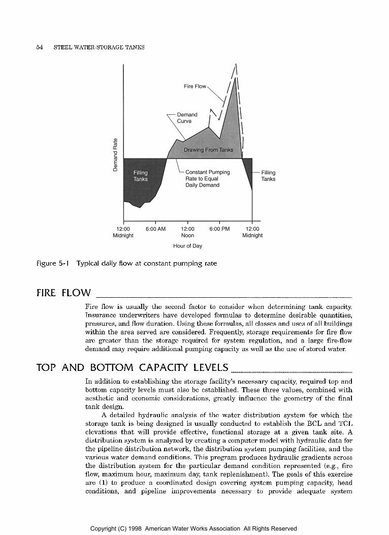
54 STEEL WATER-STORAGE TANKS
Constant Pumping Rate to Equal Daily Demand
Filling Tanks
I I I I I 12:oo 6:OO AM 12:OO 6:OO PM 12:oo
Midnight Noon Midnight
Hour of Day
Figure 5-1 Typical daily flow at constant pumping rate
FIRE F L O W Fire flow is usually the second factor to consider when determining tank capacity. Insurance underwriters have developed formulas to determine desirable quantities, pressures, and flow duration. Using these formulas, all classes and uses of all buildings within the area served are considered. Frequently, storage requirements for fire flow are greater than the storage required for system regulation, and a large fire-flow demand may require additional pumping capacity as well as the use of stored water.
TOP AND BOTTOM CAPACITY LEVELS In addition to establishing the storage facility’s necessary capacity, required top and bottom capacity levels must also be established. These three values, combined with aesthetic and economic considerations, greatly influence the geometry of the final tank design.
A detailed hydraulic analysis of the water distribution system for which the storage tank is being designed is usually conducted t o establish the BCL and TCL elevations that will provide effective, functional storage at a given tank site. A distribution system is analyzed by creating a computer model with hydraulic data for the pipeline distribution network, the distribution system pumping facilities, and the various water demand conditions. This program produces hydraulic gradients across the distribution system for the particular demand condition represented (e.g., fire flow, maximum hour, maximum day, tank replenishment). The goals of this exercise are (1) to produce a coordinated design covering system pumping capacity, head conditions, and pipeline improvements necessary to provide adequate system
Copyright (C) 1998 American Water Works Association All Rights Reserved
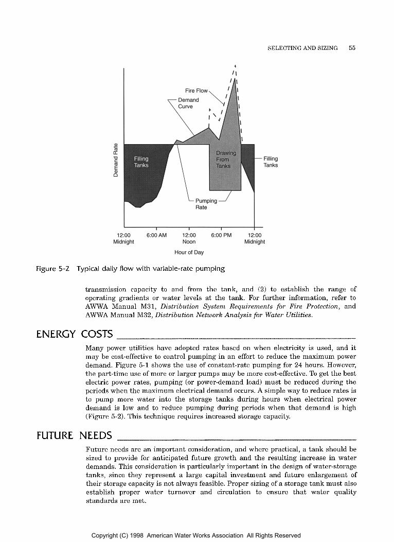
SELECTING AND SIZING 55
Fire Flow, 7i 1
a, m LT -0 c m
c
s n
Filling Tanks
I I I I
12:OO 6:OOAM 12:OO 6:OO PM 12:oo Midnight Noon Midnight
Hour of Day
Figure 5-2 Typical daily flow with variable-rate pumping
transmission capacity to and from the tank, and (2) to establish the range of operating gradients or water levels at the tank. For further information, refer to AWWA Manual M3 1, Distribution System Requirements for Fire Protection, and AWWA Manual M32, Distribution Network Analysis for Water Utilities.
ENERGY COSTS Many power utilities have adopted rates based on when electricity is used, and it may be cost-effective to control pumping in an effort to reduce the maximum power demand. Figure 5-1 shows the use of constant-rate pumping for 24 hours. However, the part-time use of more or larger pumps may be more cost-effective. To get the best electric power rates, pumping (or power-demand load) must be reduced during the periods when the maximum electrical demand occurs. A simple way to reduce rates is to pump more water into the storage tanks during hours when electrical power demand is low and to reduce pumping during periods when that demand is high (Figure 5-2). This technique requires increased storage capacity.
FUTURE NEEDS Future needs are an important consideration, and where practical, a tank should be sized to provide for anticipated future growth and the resulting increase in water demands. This consideration is particularly important in the design of water-storage tanks, since they represent a large capital investment and future enlargement of their storage capacity is not always feasible. Proper sizing of a storage tank must also establish proper water turnover and circulation to ensure that water quality standards are met.
Copyright (C) 1998 American Water Works Association All Rights Reserved
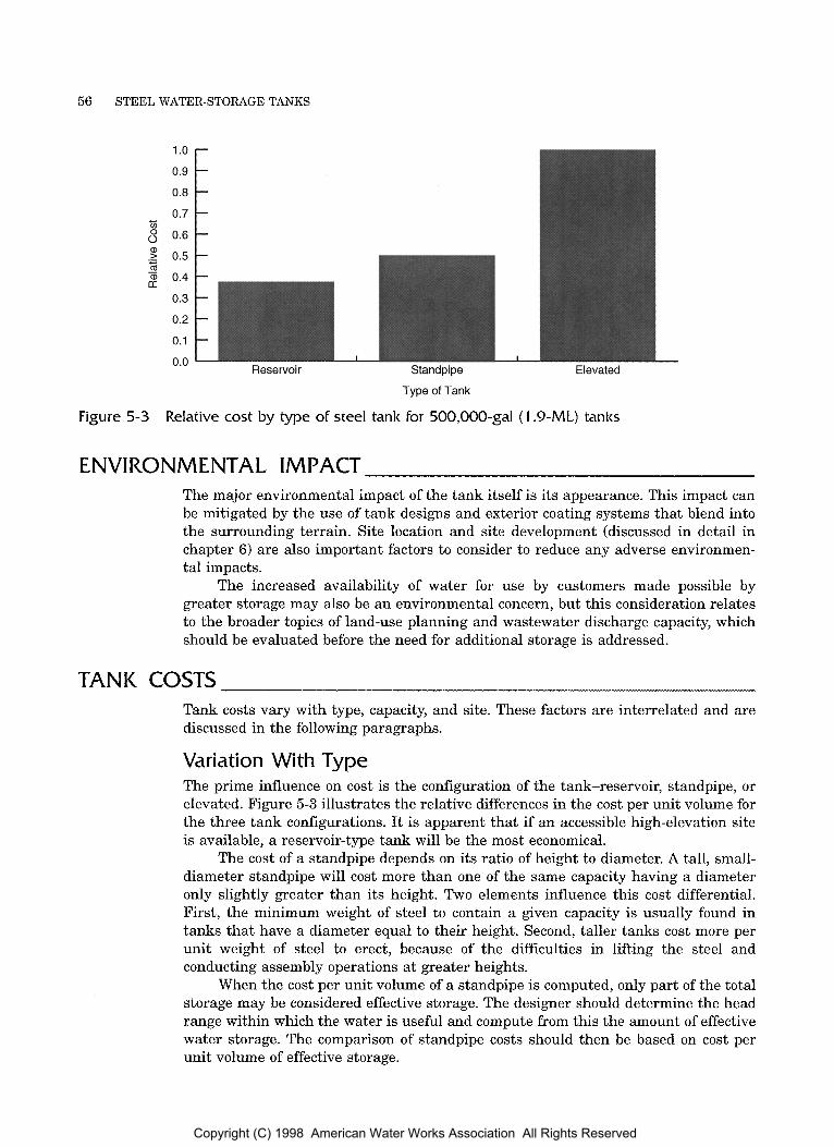
56 STEEL WATER-STORAGE TANKS
c In 0.7
0.4
0.3
0.2
0.1
0.0 Reservoir Standpipe
Type of Tank
I Elevated
Figure 5-3 Relative cost by type of steel tank for 500,000-gal (1.9-ML) tanks
ENVIRONMENTAL IMPACT The major environmental impact of the tank itself is its appearance. This impact can be mitigated by the use of tank designs and exterior coating systems that blend into the surrounding terrain. Site location and site development (discussed in detail in chapter 6) are also important factors to consider to reduce any adverse environmen- tal impacts.
The increased availability of water for use by customers made possible by greater storage may also be an environmental concern, but this consideration relates to the broader topics of land-use planning and wastewater discharge capacity, which should be evaluated before the need for additional storage is addressed.
TANK COSTS Tank costs vary with type, capacity, and site. These factors are interrelated and are discussed in the following paragraphs.
Variation With Type The prime influence on cost is the configuration of the tank-reservoir, standpipe, or elevated. Figure 5-3 illustrates the relative differences in the cost per unit volume for the three tank configurations. It is apparent that if an accessible high-elevation site is available, a reservoir-type tank will be the most economical.
The cost of a standpipe depends on its ratio of height to diameter. A tall, small- diameter standpipe will cost more than one of the same capacity having a diameter only slightly greater than its height. Two elements influence this cost differential. First, the minimum weight of steel t o contain a given capacity is usually found in tanks that have a diameter equal to their height. Second, taller tanks cost more per unit weight of steel to erect, because of the difficulties in lifting the steel and conducting assembly operations at greater heights.
When the cost per unit volume of a standpipe is computed, only part of the total storage may be considered effective storage. The designer should determine the head range within which the water is useful and compute from this the amount of effective water storage. The comparison of standpipe costs should then be based on cost per unit volume of effective storage.
Copyright (C) 1998 American Water Works Association All Rights Reserved
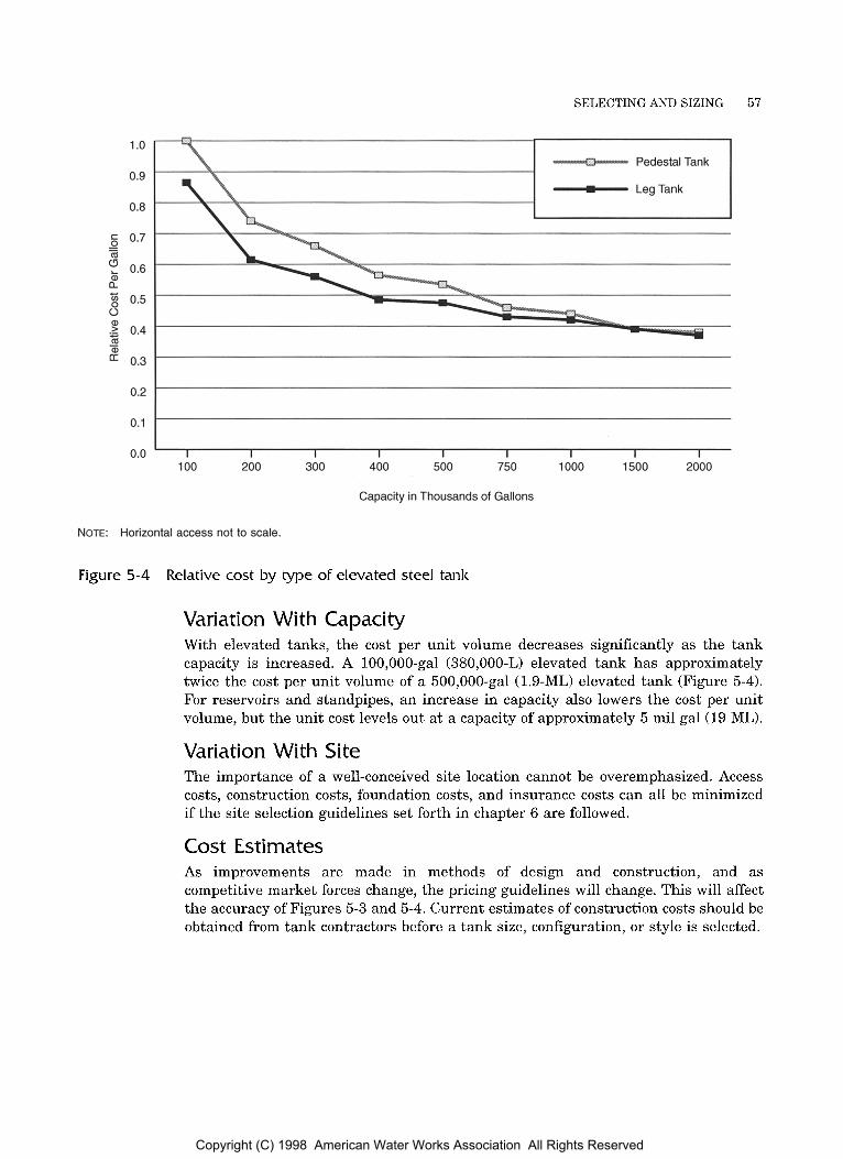
SELECTING AND SIZING 57
1 .o
0.9
0.8
%i 0.5 s a,
m & 0.4
0.3 -
- LegTank
I
0.2
0.1
0.0 I I I I I I I I I
100 200 300 400 500 750 1000 1500 2000
Capacity in Thousands of Gallons
NOTE: Horizontal access not to scale.
Figure 5-4 Relative cost by type of elevated steel tank
Variation With Capacity With elevated tanks, the cost per unit volume decreases significantly as the tank capacity is increased. A 100,000-gal (380,000-L) elevated tank has approximately twice the cost per unit volume of a 500,000-gal (1.9-ML) elevated tank (Figure 5-4). For reservoirs and standpipes, an increase in capacity also lowers the cost per unit volume, but the unit cost levels out at a capacity of approximately 5 mil gal (19 ML).
Variation With Site The importance of a well-conceived site location cannot be overemphasized. Access costs, construction costs, foundation costs, and insurance costs can all be minimized if the site selection guidelines set forth in chapter 6 are followed.
Cost Estimates As improvements are made in methods of design and construction, and as competitive market forces change, the pricing guidelines will change. This will affect the accuracy of Figures 5-3 and 5-4. Current estimates of construction costs should be obtained from tank contractors before a tank size, configuration, or style is selected.
Copyright (C) 1998 American Water Works Association All Rights Reserved

Chapter 0
AWA MANUAL M42
This chapter includes general discussions of each of the topics to be investigated and detailed in the specifications for a new steel water-storage tank. It also describes the content and purpose of each of the documents involved in bidding a tank, and it notes the duties of the owner, the engineer, and the constructor with respect to specifications, bidding, and design.
DESIGN STANDARDS AWWA D100, Standard for Welded Steel Tanks for Water Storage, and AWWA D103, Standard for Factory-Coated Bolted Steel Tanks for Water Storage, assign specific responsibilities t o the owner (or the owner’s engineer) and the constructor for the construction of steel tanks. The requirements for the design, water, snow, wind, and live loads in both tank standards are the minimum allowable values. The engineer is expected to be aware of all local codes and ordinances and should provide the required loading, information, design information, or both to the constructor if local requirements are more stringent than those found in the applicable AWWA standards.
Standards for seismic design are constantly changing. Therefore, the specifier must refer t o the latest editions of AWWA standards and local building codes to properly specify the appropriate seismic design criteria for the tank to be purchased. There are different approaches for determining allowable loads for the buckling of conical and dished sections, and the approaches used may be limited by the owner or engineer. New standards and clarifications to the design approaches are being used. Design methods must consider construction tolerances.
59
Copyright (C) 1998 American Water Works Association All Rights Reserved
60 STEEL WATER-STORAGE TANKS
CONTRACT DOCUMENTS The contract documents should include sufficient data to allow all qualified constructors an equal opportunity to bid for the tank. The completed soil survey should be accomplished by a qualified geotechnical engineer so that all bidders are using identical data. After the contract is awarded, the manufacturer or constructor should prepare foundation plans and detailed steel tank drawings, which should be submitted to the owner for review before any fabrication begins.
CONSTRUCTOR CAPA B I L IT1 ES Tank constructors specialize in the design, fabrication, and erection of welded or bolted steel storage tanks; they must rely on specialty constructors to provide specialized equipment. A local supplier may be able to provide appurtenances (for example, electrical level-control systems); however, a tank constructor may select a familiar supplier located a considerable distance from the project. Dividing portions of the main contract into specialty work functions encourages the interest and participation of local suppliers. Using local suppliers provides employment in the area and reduces costs by minimizing the required travel. Any portions of the new tank construction project that require cutting and welding on the tank should be done by the tank constructor’s own forces or with the tank constructor’s written approval.
Often a piece of equipment that needs to be installed on the tank must interface with another piece of operating equipment in a water system (for example, telemetering systems). One constructor should provide the entire electrical or mechanical system in order to minimize coordination between constructors and interface problems with different equipment.
GUARANTEES A guarantee for a specific time after the work is completed should be given on the structure, coatings, appurtenances, and other work, as specified by the purchaser. Normally a one-year period in which all workmanship and materials are warranted is included in the owner’s specifications.
SO I L INVESTIGATIONS The soil investigation on which the foundation design is based is critical to the long- term stability of the foundation. Soil loadings vary with the type of tank. A 100-ft (30.5-m) high standpipe, for example, exerts a contact pressure of 6,240 lb/ft2 (229 kPa), whereas a 1-mil gal (4-mL) capacity elevated tank and its contents produce a total load of approximately 10 million lb (45 MN) that must be transmitted to the soil. The forewords of AWWA DlOO and AWWA D103 suggest that the owner have a soil investigation conducted to provide the data necessary t o design the tank foundation. The soil investigation should be completed prior to the taking of bids, so that all constructors will have the same design criteria available and better competition will prevail. Table 6-1 lists the typical requirements for soil investiga- tions, and Figure 6-1 shows a soil-testing operation. Unusual site conditions may dictate the need for additional soil investigation.
A certified engineering report of the soil investigation must include
1. A detailed boring log complete with blow count records.
2. Record of any undisturbed samples.
Copyright (C) 1998 American Water Works Association All Rights Reserved
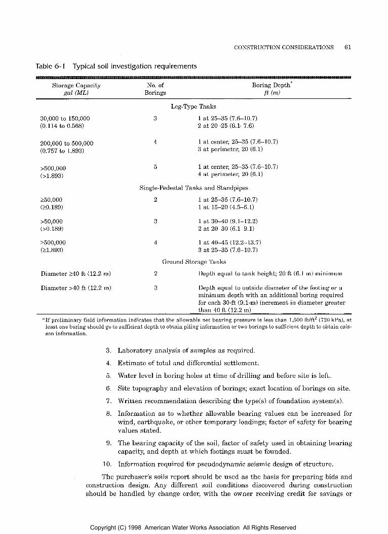
CONSTRUCTION CONSIDERATIONS 61
Table 6- 1 Typical soil investigation requirements
Storage Capacity gal (ML)
No. of Borings
Boring Depth:' ft (rn)
30,000 to 150,000 (0.114 to 0.568)
200,000 to 500,000 (0.757 to 1.893)
>500,000 b1.893)
250,000 (20.189)
>50,000 (>0.189)
2500,000 (21.893)
Diameter 240 R (12.2 m)
Diameter >40 ft (12.2 m)
Leg-Type Tanks
3 1 at 25-35 (7.6-10.7) 2 at 20-25 (6.1-7.6)
4 1 a t center, 25-35 (7.6-10.7) 3 at perimeter, 20 (6.1)
5 1 at center, 25-35 (7.6-10.7) 4 at perimeter, 20 (6.1)
Single-Pedestal Tanks and Standpipes
2 1 at 25-35 (7.6-10.7) 1 at 15-20 (4.5-6.1)
3 1 at 3 0 4 0 (9.1-12.2) 2 at 20-30 (6.1-9.1)
4 1 at 4 0 4 5 (12.2-13.7) 3 at 25-35 (7.6-10.7)
Ground Storage Tanks
2
3
Depth equal to tank height; 20 ft (6.1 m) minimum
Depth equal to outside diameter of the footing or a minimum depth with an additional boring required for each 30-ft (9.1-m) increment in diameter greater
"If preliminary field information indicates that the allowable net bearing pressure is less than 1,500 lb/ft2 (720 kPa), a t least one boring should go to sufficient depth to obtain piling information or two borings to sufficient depth to obtain cais- son information.
3.
4.
5.
6.
7.
8.
9.
10.
Laboratory analysis of samples as required.
Estimate of total and differential settlement.
Water level in boring holes at time of drilling and before site is left.
Site topography and elevation of borings; exact location of borings on site.
Written recommendation describing the typeb) of foundation system(s).
Information as to whether allowable bearing values can be increased for wind, earthquake, or other temporary loadings; factor of safety for bearing values stated.
The bearing capacity of the soil, factor of safety used in obtaining bearing capacity, and depth at which footings must be founded.
Information required for pseudodynamic seismic design of structure.
The purchaser's soils report should be used as the basis for preparing bids and construction design. Any different soil conditions discovered during construction should be handled by change order, with the owner receiving credit for savings or
Copyright (C) 1998 American Water Works Association All Rights Reserved
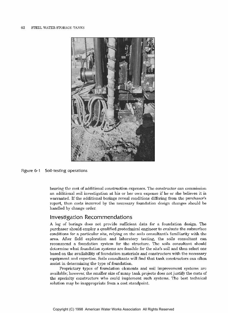
62 STEEL WATER-STORAGE TANKS
Figure 6-1 Soil-testing operations
bearing the cost of additional construction expenses. The constructor can commission an additional soil investigation at his or her own expense if he or she believes it is warranted. If the additional borings reveal conditions differing from the purchaser’s report, then costs incurred by the necessary foundation design changes should be handled by change order.
Investigation Recommendations A log of borings does not provide sufficient data for a foundation design. The purchaser should employ a qualified geotechnical engineer to evaluate the subsurface conditions for a particular site, relying on the soils consultant’s familiarity with the area. After field exploration and laboratory testing, the soils consultant can recommend a foundation system for the structure. The soils consultant should determine what foundation systems are feasible for the site’s soil and then select one based on the availability of foundation materials and constructors with the necessary equipment and expertise. Soils consultants will find that tank constructors can often assist in determining the type of foundation.
Proprietary types of foundation elements and soil improvement systems are available; however, the smaller size of many tank projects does not justify the costs of the specialty constructors who could implement such systems. The best technical solution may be inappropriate from a cost standpoint.
Copyright (C) 1998 American Water Works Association All Rights Reserved

CONSTRUCTION CONSIDERATIONS 63
Responsibility for a Foundation Design The project soil investigation, AWWA standards, and the technical sections of the project specification serve as a basis for foundation design by the constructor. With this information, the constructor can design the most economical foundation for the tank in compliance with recognized design methods and building codes. The tank supplier or constructor is ultimately responsible for the design of the foundation. Although some constructors prefer that the owner provide the foundation, others prefer to control and administer all activities that significantly influence the success of their project. These firms see the need to control construction of the foundation, since adverse foundation behavior could precipitate structural failure of the tank.
When a foundation has been designed by others for a particular project, the constructor must be allowed to review the design and make changes deemed necessary to ensure that the foundation will adequately support the tank both dimensionally and structurally. Variations will necessitate revisions of purchaser’s drawings and possibly cause confusion and errors in administering and constructing the foundation.
RESERVOIR AND STANDPIPE FOUNDATIONS AWWA DlOO allows five alternative types of foundations for flat-bottomed, welded steel tanks: type 1, tanks supported on ringwalls; type 2, tanks supported on concrete slabs; type 3, tanks within ringwalls; type 4, tanks supported on granular berms; and type 5, tanks supported on granular berms with steel retainer rings. AWWA D103 adds a sixth alternative for bolted steel tanks: type 6, tanks with sidewall embedded in concrete slab. This last type uses a reinforced concrete slab for the tank bottom in lieu of steel plate.
Foundation types 1, 3, 4, and 5 use a fine grade aggregate (usually clean sand) which is placed immediately under the tank bottom. For many years this sand cushion was saturated with light oil or diesel fuel to add cohesive properties and to serve as a corrosion deterrent. Regulatory agencies have been concerned that the oil from the sand might leach into the earth beyond the tank foundation. Where this potential leaching is a concern, the purity of the sand should be controlled and hydrated lime may be added to enhance the corrosion resistance of the sand cushion. This modification of the sand cushion is discussed in AWWA D100.
Granular Berm Foundation If the tank need not be anchored to resist wind or earthquake forces, the most economical type of foundation is a granular berm. This type of foundation (Figure 6-2) has been used successfully for many years.
When the unrestrained granular berm foundation is chosen, attention must be paid to the choice of berm material and drainage around the tank to ensure against foundation washout. A 1-in. (25 mm) rainfall on a tank of a radius of R feet (m) will produce a sheet of water 1 in. (25 mm) wide and R/2 ft (m) high washing down the sides of the tank. Therefore, any type of flat-bottom tank foundation must be designed carefully. Steel retainer rings may be installed to ensure berm stability.
Ringwall Foundation The most common type of water-reservoir foundation is one for which the tank shell rests on a concrete ringwall and the tank bottom rests on well-drained, noncorrosive, compacted fill. This type of foundation does not have the tendency to wash out like the granular berm foundation. Tanks may be placed within the ringwall. If
Copyright (C) 1998 American Water Works Association All Rights Reserved
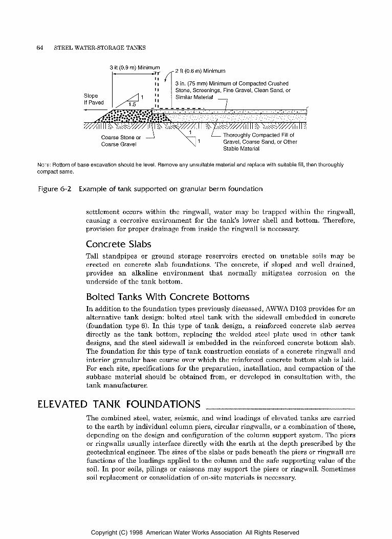
64 STEEL WATER-STORAGE TANKS
3 ft (0.9 m) Minimum 1- ,,- 2 ft (0.6 m) Minimum
3 in. (75 mm) Minimum of Compacted Crushed Stone. Screeninas. Fine Gravel. Clean Sand. or I I
L Thoroughly Compacted Fill of Gravel, Coarse Sand, or Other Stable Material
Coarse Stone or 1 Coarse Gravel
NOTE: Bottom of base excavation should be level. Remove any unsuitable material and replace with suitable fill, then thoroughly compact same.
Figure 6-2 Example of tank supported o n granular berm foundation
settlement occurs within the ringwall, water may be trapped within the ringwall, causing a corrosive environment for the tank's lower shell and bottom. Therefore, provision for proper drainage from inside the ringwall is necessary.
Concrete Slabs Tall standpipes or ground storage reservoirs erected on unstable soils may be erected on concrete slab foundations. The concrete, if sloped and well drained, provides an alkaline environment that normally mitigates corrosion on the underside of the tank bottom.
Bolted Tanks With Concrete Bottoms In addition to the foundation types previously discussed, AWWA D103 provides for an alternative tank design: bolted steel tank with the sidewall embedded in concrete (foundation type 6). In this type of tank design, a reinforced concrete slab serves directly as the tank bottom, replacing the welded steel plate used in other tank designs, and the steel sidewall is embedded in the reinforced concrete bottom slab. The foundation for this type of tank construction consists of a concrete ringwall and interior granular base course over which the reinforced concrete bottom slab is laid. For each site, specifications for the preparation, installation, and compaction of the subbase material should be obtained from, or developed in consultation with, the tank manufacturer.
ELEVATED TANK FOUNDATIONS The combined steel, water, seismic, and wind loadings of elevated tanks are carried to the earth by individual column piers, circular ringwalls, or a combination of these, depending on the design and configuration of the column support system. The piers or ringwalls usually interface directly with the earth at the depth prescribed by the geotechnical engineer. The sizes of the slabs or pads beneath the piers or ringwall are functions of the loadings applied to the column and the safe supporting value of the soil. In poor soils, pilings or caissons may support the piers or ringwall. Sometimes soil replacement or consolidation of on-site materials is necessary.
Copyright (C) 1998 American Water Works Association All Rights Reserved
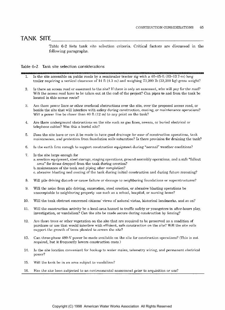
CONSTRUCTION CONSIDERATIONS 65
TANK SITE Table 6-2 lists tank site selection criteria. Critical factors are discussed in the following paragraphs.
Table 6-2 Tank site selection considerations
1.
2.
3.
4.
5.
6.
7.
8.
9.
10.
11.
12.
13.
14.
15.
16.
Is the site accessible on public roads by a semitrailer tractor rig with a 40-45-ft (12-13.7-m) long trailer requiring a vertical clearance of 14 ft (4.3 m) and weighing 73,200 lb (33,200 kg) gross weight?
Is there an access road or easement to the site? If there is only an easement, who will pay for the road? Will the access road have to be taken out a t the end of the project? Can pipes to and from the tank be located in this access route?
Are there power lines or other overhead obstructions over the site, over the proposed access road, or beside the site that will interfere with safety during construction, coating, or maintenance operations? Will a power line be closer than 40 ft (12 m) to any point on the tank?
Are there underground obstructions on the site such as gas lines, sewers, or buried electrical or telephone cables? Was this a burial site?
Does the site have or can it be made to have good drainage for ease of construction operations, tank maintenance, and protection from foundation soils saturation? Is there provision for draining the tank?
Is the earth firm enough to support construction equipment during “normal” weather conditions?
Is the site large enough for a. erection equipment, steel storage, staging operations, ground assembly operations, and a safe “fallout
b. maintenance of the tank and piping after completion? c. abrasive blasting and coating of the tank during initial construction and during future recoating?
Will pile driving disturb or cause failure or damage to neighboring foundations or superstructures?
area” for items dropped from the tank during erection?
Will the noise from pile driving, excavation, steel erection, or abrasive blasting operations be unacceptable to neighboring property use such as a school, hospital, or nursing home?
Will the tank obstruct concerned citizens’ views of natural vistas, historical landmarks, and so on?
Will the construction activity be a local-area hazard to traffic safety or youngsters in after-hours play, investigation, or vandalism? Can the site be made secure during construction by fencing?
Are there trees or other vegetation on the site that are required to be preserved as a condition of purchase or use that would interfere with efficient, safe construction on the site? Will the site soils support the growth of trees planted to screen the site?
Can three-phase 480-V power be made available on the site for construction operations? (This is not required, but it frequently lowers construction costs.)
Is the site location convenient for hookup to water mains, telemetry wiring, and permanent electrical power?
Will the tank be in an area subject to vandalism?
Has the site been subjected to an environmental assessment prior to acquisition or use?
Copyright (C) 1998 American Water Works Association All Rights Reserved
66 STEEL WATER-STORAGE TANKS
Location The likelihood that a proposed tank site will be marginal or unacceptable increases as the cost of land increases, as the availability of land declines, and as public opinion places more stringent requirements on the location of water-storage facilities. The forewords of AWWA DlOO and AWWA D103 require the owner to provide the site. This site should be graded to accommodate the proposed tank and should have sufficient room to allow the structure to be built by customary methods. The site should be located away from buildings, heavily traveled public thoroughfares, parking lots, and livestock at a distance sufficient to limit potential damage or injury to third parties resulting from construction activities. The site should also take advantage of the local terrain. However, in high-vandalism areas, remote locations tend to be a great source of concern and expense to owners. The tank site should be free of all overhead and underground obstructions and utility lines. Power lines located on the perimeter of the site must be a minimum of 40 ft (12.2 m) from the edge of the tank o r the tank foundation, whichever is closer to the power lines.
Size Final property lines should be located sufficiently far from the foundation to facilitate maintenance of the tank and site. At a minimum, the outer extremities of the foundation should be at least 20 ft (6.1 m) inside the permanent tank site boundaries. Additional clearance will be necessary for construction operations and tank component storage and subassembly. If a permanent site of adequate size is not available, the owner should provide an adequate temporary construction easement. With elevated tanks and standpipes it is preferable, when the space is available, to have a site clearance from the center of the tank to the site extremities equal to the height of the tank.
Drainage The tank site should have good drainage. A site with good drainage will minimize or prevent possible foundation subsidence due t o the long-term intrusion of surface water. It will also minimize possible corrosive conditions under the tank bottom and will probably result in lower construction costs. The site design should also include provisions for draining the tank contents and the discharge from the tank overflow without damaging the tank site or neighboring properties.
Access The owner should provide a suitable right-of-way for access from the nearest public road t o the tank site. The access should be able t o handle tandem tractor trailers with legal loads under ordinary weather conditions, and it should be free of underground and overhead obstructions that would be damaged by the traffic. If the right-of-way is permanent, a permanent roadway should be installed once the tank project is completed.
Other Siting Considerations Since construction and maintenance of tall tanks involve procedures that may disturb neighboring property, it is frequently advantageous to locate the tank on a relatively large area of undeveloped, dedicated open space or greenbelt. A minimum clear distance of approximately 100 yd (90 m) between the tank and the open space boundaries will greatly reduce future maintenance costs.
Copyright (C) 1998 American Water Works Association All Rights Reserved

CONSTRUCTION CONSIDERATIONS 67
TANK
When tanks are to be constructed in conjunction with other water utility facilities such as a treatment plant, the problems associated with scheduling the simultaneous operations of multiple constructors must be considered during the tank site selection process.
COATING-WELDED STEEL TANK Chapter 4 discusses tank coating in detail. The following material relates t o the specification of interior and exterior coating of newly constructed tanks. The decision to shop clean and prime or totally field-clean and coat should be based on the size and configuration of the tank, the tank site location, environmental regulations, and the climate anticipated during the cleaning and coating processes.
Selection of Coating Initial coating of field-welded tanks represents approximately 10 to 15 percent of the total cost of a new tank (including foundations). Two-coat systems are used on the tank; both are critical. Foremost in the eyes of the community is the exterior finish color and its aesthetic appeal. However, the interior surface (which few see) is far more critical; the interior is where the most aggressive and detrimental conditions of corrosion can occur undetected.
The coating system should be selected based on information provided by tank and coating constructors and the coating manufacturer’s representatives, local ordinances, the engineer’s preference, and the owner’s preference.
Interior Coating An interior coating in the lower areas of the tank must withstand constant immersion; it must be able to resist alternate wetting and drying in the upper portion of the operating range and high humidity above the high water level; it must be resistant to the actions of ice abrasion in cold climates and it must be able to adequately withstand local temperature extremes and water characteristics. The system must be receptive to the conditions of application (primarily temperature and humidity) in order to be cost-effective.
Interior coating systems must meet the minimum requirements of ANSUNSF Drinking Water Additives Standard 61 with regard to acceptable extraction levels of the constituent materials.
The integrity of the tank‘s inside coating system is only as good as the quality of coating materials, cleaning, application, and curing. Adequate inspection during construction is necessary to confirm the quality of cleaning and coating operations. Inspection of the interior surfaces helps to detect minor coating deficiencies, which can then be corrected, preventing the propagation of coating failures.
The maximum interval for periodic inspection of the tank interior should normally be 3 years. It is usually advisable to wash out the tank at the time of inspection. The owner should keep accurate records of the inspection and maintenance functions performed on the tank. This record should include copies of specifications, contracts, and inspection reports and coating manufacturers’ product numbers and product data sheets.
Rafter-supported roofs. For maximum corrosion protection, roof support beams and their intersections with the roof plates on ground storage tanks should be shop- or field-coated prior to erection; otherwise, these areas will not be protected from corrosion. Although coating of these areas is highly desirable, it is not standard industry practice. Therefore, the purchaser must specify this precoating requirement in the bid documents; otherwise coating prior to erection will not normally be performed.
Inspection.
Copyright (C) 1998 American Water Works Association All Rights Reserved
68 STEEL WATER-STORAGE TANKS
Exterior Coating Exterior coating systems normally attract more attention and cause more concern than any other aspect of a tank project. Prior to 1980, alkyds and silicone alkyds were most commonly used on the exteriors of new tanks. The urethane-based coating systems are now found on an increasing number of tank exteriors. The alkyds have been the most popular coating system in the past because they are easy to apply and generally accepted by owners. The silicone alkyd materials have better gloss and color retention than the straight alkyd materials. A purchaser desiring a bright color may select a urethane system for its superior color and gloss retention; however, there are additional costs and site restraints associated with these materials. The tank location plays an important part in the selection of an exterior coating system, since some materials (particularly the urethanes and long-oil alkyds) tend to produce more overspray and damage to surrounding property than other materials.
Artwork Decorative artwork and lettering schemes can be added t o the tank within the constraints of the tank's geometry. A rule of thumb is that a tank sign or logo should be no longer than three-fourths of the tank diameter for it to be viewed from one vantage point. The maximum height of a tank sign should also be limited, if possible, so that the letters in the sign do not arch around the curved upper portion of the tank and appear distorted.
TANK COATING-BOLTED STEEL TANKS AWWA D103 requires that tank parts receive a near-white (SSPC-SP10) blast or, as an alternative when fused-glass coatings are used, pickling (SSPC-SPS) and a coating by one of the systems listed in Sec. 10 of that standard. The standard also requires that the critical interior surface receive a USEPA-accepted, amine-cured, thermoset liquid or powder epoxy coating; a fused-glass coating; or galvanizing. This require- ment helps ensure that the tank is able t o provide safe, long-term storage under a wide range of temperatures, humidity conditions, and water types.
Aesthetically pleasing, long-lasting performance is a major consideration in choosing an exterior coating system. Either (1) an epoxy primer with a baked acrylic o r acrylic-urethane topcoat; (2) a thermoset powder coating of epoxy, acrylic, urethane, or a hybrid; o r (3) a fused-glass coating can provide this performance. Galvanizing is also an option for exterior corrosion protection.
TANK WATER TESTING AND DISINFECTION
Concurrent Versus Separate Tank disinfection procedures are normally performed in accordance with AWWA C652 or the more stringent requirements of local health agencies. AWWA DlOO requires that the tank be tested prior t o coating and that the owner furnish the water to fill the tank and provide a means of disposal following testing. AWWA DlOO permits the coating t o be performed before water-testing the tank if specifically agreed on between the tank constructor and the purchaser. Water testing and disinfection phases of the project could then be concurrent, thus saving the owner the cost of producing and disposing of a large quantity of water. However, water testing the welded tank prior to coating has the following advantages:
Copyright (C) 1998 American Water Works Association All Rights Reserved

CONSTRUCTION CONSIDERATIONS 69
It allows identification and correction of any distortions caused by anticipated or unanticipated foundation settlements prior to coating.
I t allows the identification and correction of any leaks that might have been temporarily covered by the interior coating system.
Valves and piping should be tested in accordance with AWWA C600. The constructor may be required by contract to provide and dispose of the
testing and disinfection water. However, the purchaser will ultimately bear these costs, plus the constructor’s overhead and profit.
ENGINEERS ROLE Water-storage tanks are generally classified as engineered construction, in which the engineer is not a party to the contract between the owner and constructor but rather is employed by the owner to prepare the construction plans and contract documents, interpret the contract, judge performance, and observe the construction. Under the contract between the engineer and the owner, the engineer agrees to provide a specified set of plans and specifications and a package of services. The drawings included in the plans show the extent and arrangement of the components on the project. Tank projects generally require a limited number of drawings, usually consisting of an elevation drawing, an orientation of the tank accessories, and detailed information regarding site access and related site work. The forewords of AWWA DlOO and AWWA D103 each contain a list of information t o be furnished by the owner or engineer concerning elevated tanks, standpipes, or reservoirs.
Accessory Detail Accessory items on the tank structure should be located where they are readily accessible from a fixed ladder or platform surface. An exception to this is the location of stub overflows, which when used are purposely located away from ladders to avoid ladder icing. Specific tank accessories required by AWWA standards should be shown but not detailed on the bid drawings, since each manufacturer has proprietary components that fulfill the intent of the standards. Such details may cause problems if bidders are required to provide another constructor’s proprietary apparatus. Accessory details and orientation should be developed and included in the shop drawing submittals after the contract is awarded. The governing requirement should be that the accessories meet the minimum requirements of the referenced AWWA standards and the intent of the specifications. If the owner elects to include apparatuses and operating systems in excess of those specified by AWWA standards, the engineer should provide specifications and details that clearly define the components required and the scope of related work. A more thorough description of appurtenances and accessories on steel tanks is given in chapter 3.
Federal Aviation Administration The owner or his or her engineer should file notification of construction with the Federal Aviation Administration (FAA) prior t o construction of tall standpipes or elevated tanks, in order t o determine the requirements for temporary and permanent tank markings and lighting.
Copyright (C) 1998 American Water Works Association All Rights Reserved

70 STEEL WATER-STORAGE TANKS
BIDDING DOCUMENTS This section discusses documentation and other issues related to the bidding process.
Technical Specifications The project specifications describe the materials and work required to construct the tank. These documents are a basis for bidding and negotiation, and they serve as instruments by which the contract may be administered.
Because the initial purpose of the plans and specifications is to inform prospective bidders about the project, these documents should help the constructor become familiar with local conditions and local building requirements. Competitive bidding is effective only when the project plans and specifications are complete and accurate and when duly qualified constructors are given sufficient time to bid on the project. The engineer can obtain valuable assistance from constructors and tank manufacturers when writing specifications.
When the engineer incorporates the requirements of AWWA DlOO or AWWA D103 into the project specifications, he or she is working on the premise of a design type specification that describes the kinds of materials to be provided by established standards and assures performance by specified inspections and tests. It should be noted that AWWA D103 contains the coatings standards necessary for factory-coated tanks.
Alternative Bid Items In preparing the bidding documents, the purchaser must carefully evaluate the needs of the system and aesthetic considerations. Ultimately, the type of tank that will best satisfy the owner’s needs will be determined primarily by economic considerations, since many designs can equally satisfy the intended function of storing some quantity of water at a given elevation. To help determine the best tank value for the money, the owner may consider specifying certain features as alternative bid items. In the best interest of the owner, the engineer, and the constructors, only realistic alternative bid items should be considered.
Documents Related to Used Tanks One potential advantage of steel tanks is that they can be relocated or possibly sold if the level of system demand changes. However, caution should be exercised in evaluating a used tank that is bid as an alternative to a new tank. The initial cost should not be the only consideration. Total life cycle maintenance costs should be projected. If a used tank is considered, the owner should require (1) a copy of an up- to-date inspection report of the structure provided by a qualified engineer, (2) a signed document from the present owner stating that the tank is available for sale, and (3) a detailed proposal of any remedial coating or repair work that will be done to bring the structure to the equivalent state of the proposed new tank. It is also important to know the specifications and standards under which the tank was originally built, as well as the wind and seismic loadings for which it was designed and constructed. One additional caution concerns the possibility of lead or other hazardous materials being in the coating of the tank being considered for reuse.
It should be noted that used tanks designed and used for fuel oil or other non- potable water use will likely have been designed to contain a less dense liquid and consequently will not be of adequate thickness for water storage. Additional problems in converting a tank from hydrocarbon storage to potable water use have to do with the cleanliness of the steel that can be achieved aRer such service and the effect this will have on the adhesion and the purity of the coatings applied to the water contact surfaces.
Copyright (C) 1998 American Water Works Association All Rights Reserved
CONSTRUCTION CONSIDERATIONS 71
Before purchasing a tank that has previously been used for purposes other than potable water storage, check with local, state, and federal authorities, as many authorities prohibit such reuse.
Foundation Unit Prices The contract price of a tank structure of specified size and design is normally well defined and is not subject to wide variations as construction progresses. Foundation costs, however, tend to be difficult to estimate accurately and may be subject to change because of possible variations in subsurface conditions. Bidding documents should recognize this fact and provide a means to adjust work and material quantities to meet the conditions found during construction. If the engineer anticipates changes, then he or she should provide information regarding any additional labor or materials that may be required. Most constructors prefer an a d d deduct unit-price adjustment to be an integral part of the bid. The basis for the bid should be the constructor’s design, based on adequate information provided by the project plans and specifications. For example, pile foundations have sometimes been bid on a lump-sum basis. However, it is difficult or impossible to determine the exact length of piling required for a given site. There are a number of factors that influence the actual length of the piling, and a fixed-price, lump-sum contract can create a difficult and inequitable situation for either the constructor or the owner.
Constructor Assistance Generally, tank constructors and manufacturers are more than willing to discuss individual tankage needs and to assist the owner and the engineer by providing standard design information for a project. For an elevated tank of a given capacity, each constructor and manufacturer will have different geometric parameters. These dimensions normally do not vary enough to cause difficulty on a system if one constructor is selected for a project based on the information supplied by another constructor.
The purchaser is advised to contact prospective bidders and discuss a project prior t o issuing an invitation t o bid, in order to familiarize the purchaser with current industry standards and practices. Most constructors and manufacturers are willing to provide copies of preliminary specifications that have been developed for water tanks of different styles and capacities. The purchaser must be careful to make every effort to write a specification that is open and does not exclude bidding by any qualified manufacturer o r supplier. In particular, a given manufacturer’s proprietary design details should not be included in a project’s contract documents; this would create an inequitable bidding situation for other qualified suppliers or manufacturers.
Copyright (C) 1998 American Water Works Association All Rights Reserved

Chapter 7
AWWA MANUAL M42
The purchaser should inspect the tank's construction as it proceeds to ensure that the structure complies with specifications, both in form and in quality. This chapter discusses specific items to be checked by the purchaser and items that are the responsibility of the constructor.
On the job, the purchaser and constructor should keep in mind that a quality structure is the result of the cooperation and affirmative efforts of all parties. If the relationship between the purchaser and constructor is combative or antagonistic, the project is likely to be completed late, with a quality that is adequate at best. On the other hand, a purchaser with a sound knowledge of specifications, standards, and trade practices can work with the constructor to complete a high-quality project on schedule.
RESPONSIBILITY FOR QUALITY In general, tank constructors are responsible for maintaining the quality of their work. AWWA D100, Standard for Welded Steel Tanks for Water Storage, and AWWA D103, Standard for Factory-Coated Bolted Steel Tanks for Water Storage, give the constructor the responsibility for designing and conducting a welding or bolting quality program. According to the provisions of AWWA D103, the constructor is responsible for selecting a factory-coated bolted tank (manufactured in accordance with that same standard) given the capacity and height or diameter requirements of the owner. This is a logical assignment of responsibility, because the designing and building of tanks is a specialized field and requires specialized equipment and knowledge t o conduct a total quality control program. Nonetheless, the owner or the owner's engineer, as well as third-party consultants where needed, should monitor the work for inevitable human errors and misunderstandings.
Even before construction begins, shop drawings should be checked by the owner or engineer to ensure that the special requirements of the job are met. The constructor is usually responsible for the structural design of the tank but the
73
Copyright (C) 1998 American Water Works Association All Rights Reserved
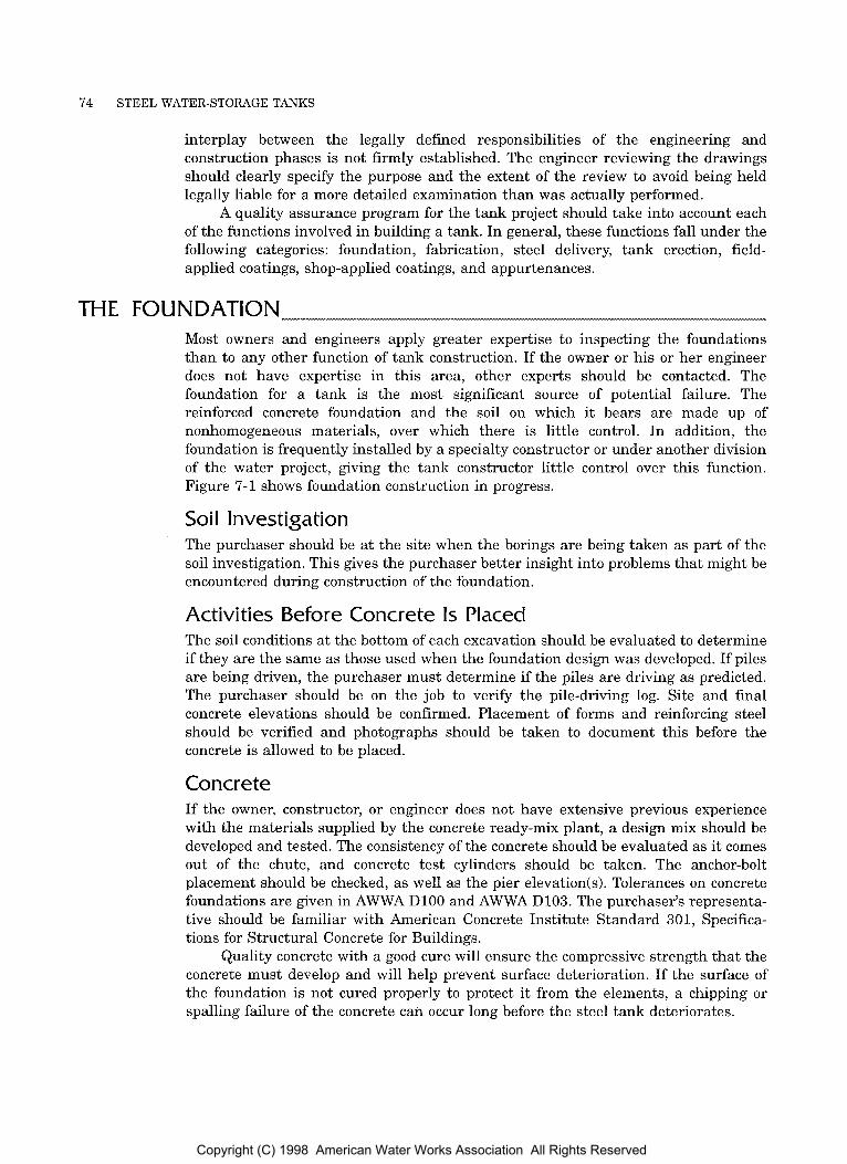
74 STEEL WATER-STORAGE TANKS
interplay between the legally defined responsibilities of the engineering and construction phases is not firmly established. The engineer reviewing the drawings should clearly specify the purpose and the extent of the review to avoid being held legally liable for a more detailed examination than was actually performed.
A quality assurance program for the tank project should take into account each of the functions involved in building a tank. In general, these functions fall under the following categories: foundation, fabrication, steel delivery, tank erection, field- applied coatings, shop-applied coatings, and appurtenances.
THE FOUNDATION Most owners and engineers apply greater expertise to inspecting the foundations than to any other function of tank construction. If the owner or his or her engineer does not have expertise in this area, other experts should be contacted. The foundation for a tank is the most significant source of potential failure. The reinforced concrete foundation and the soil on which it bears are made up of nonhomogeneous materials, over which there is little control. In addition, the foundation is frequently installed by a specialty constructor or under another division of the water project, giving the tank constructor little control over this function. Figure 7- 1 shows foundation construction in progress.
Soil Investigation The purchaser should be at the site when the borings are being taken as part of the soil investigation. This gives the purchaser better insight into problems that might be encountered during construction of the foundation.
Activities Before Concrete Is Placed The soil conditions at the bottom of each excavation should be evaluated to determine if they are the same as those used when the foundation design was developed. If piles are being driven, the purchaser must determine if the piles are driving as predicted. The purchaser should be on the job to verify the pile-driving log. Site and final concrete elevations should be confirmed. Placement of forms and reinforcing steel should be verified and photographs should be taken to document this before the concrete is allowed to be placed.
Concrete If the owner, constructor, or engineer does not have extensive previous experience with the materials supplied by the concrete ready-mix plant, a design mix should be developed and tested. The consistency of the concrete should be evaluated as it comes out of the chute, and concrete test cylinders should be taken. The anchor-bolt placement should be checked, as well as the pier elevatiods). Tolerances on concrete foundations are given in AWWA DlOO and AWWA D103. The purchaser’s representa- tive should be familiar with American Concrete Institute Standard 301, Specifica- tions for Structural Concrete for Buildings.
Quality concrete with a good cure will ensure the compressive strength that the concrete must develop and will help prevent surface deterioration. If the surface of the foundation is not cured properly to protect it from the elements, a chipping or spalling failure of the concrete can occur long before the steel tank deteriorates.
Copyright (C) 1998 American Water Works Association All Rights Reserved
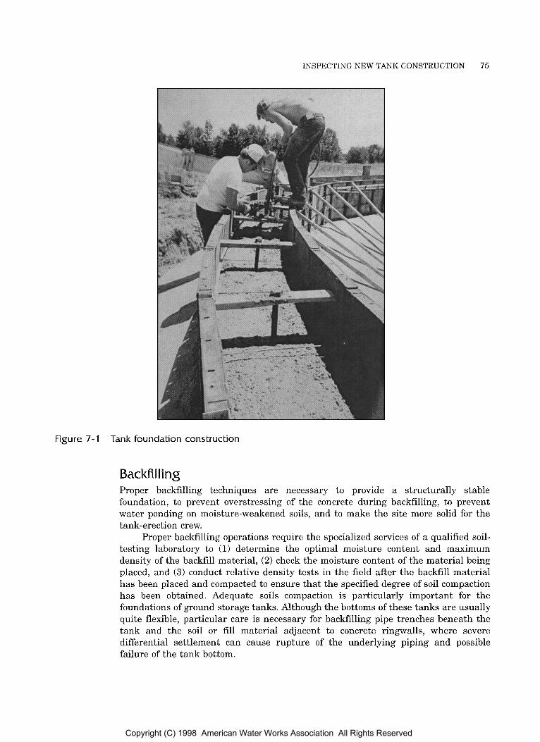
INSPECTING NEW TANK CONSTRUCTION 75
Figure 7- 1 Tank Foundation construction
Backfilling Proper backfilling techniques are necessary to provide a structurally stable foundation, t o prevent overstressing of the concrete during backfilling, to prevent water ponding on moisture-weakened soils, and to make the site more solid for the tank-erection crew.
Proper backfilling operations require the specialized services of a qualified soil- testing laboratory to (1) determine the optimal moisture content and maximum density of the backfill material, (2) check the moisture content of the material being placed, and (3) conduct relative density tests in the field after the backfill material has been placed and compacted to ensure that the specified degree of soil compaction has been obtained. Adequate soils compaction is particularly important for the foundations of ground storage tanks. Although the bottoms of these tanks are usually quite flexible, particular care is necessary for backfilling pipe trenches beneath the tank and the soil or fill material adjacent to concrete ringwalls, where severe differential settlement can cause rupture of the underlying piping and possible failure of the tank bottom.
Copyright (C) 1998 American Water Works Association All Rights Reserved
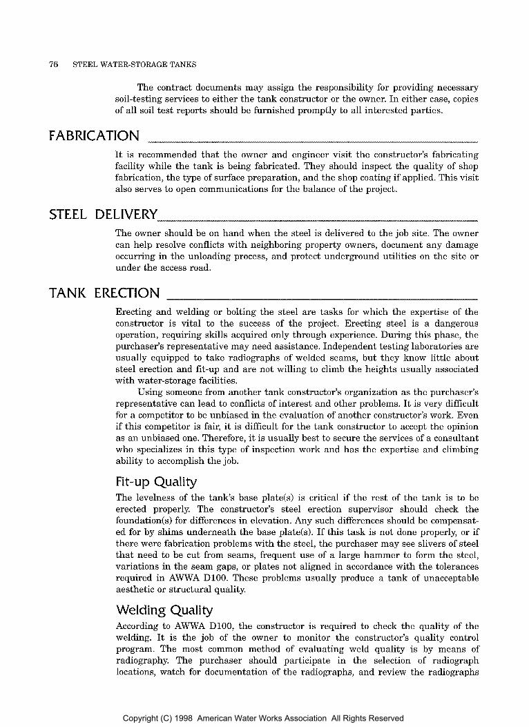
76 STEEL WATER-STORAGE TANKS
The contract documents may assign the responsibility for providing necessary soil-testing services to either the tank constructor or the owner. In either case, copies of all soil test reports should be furnished promptly to all interested parties.
FABRICATION It is recommended that the owner and engineer visit the constructor’s fabricating facility while the tank is being fabricated. They should inspect the quality of shop fabrication, the type of surface preparation, and the shop coating if applied. This visit also serves to open communications for the balance of the project.
STEEL DELIVERY The owner should be on hand when the steel is delivered to the job site. The owner can help resolve conflicts with neighboring property owners, document any damage occurring in the unloading process, and protect underground utilities on the site or under the access road.
TANK ERECTION Erecting and welding or bolting the steel are tasks for which the expertise of the constructor is vital to the success of the project. Erecting steel is a dangerous operation, requiring skills acquired only through experience. During this phase, the purchaser’s representative may need assistance. Independent testing laboratories are usually equipped to take radiographs of welded seams, but they know little about steel erection and fit-up and are not willing to climb the heights usually associated with water-storage facilities.
Using someone from another tank constructor’s organization as the purchaser’s representative can lead to conflicts of interest and other problems. It is very difficult for a competitor to be unbiased in the evaluation of another constructor’s work. Even if this competitor is fair, it is difficult for the tank constructor t o accept the opinion as an unbiased one. Therefore, it is usually best to secure the services of a consultant who specializes in this type of inspection work and has the expertise and climbing ability to accomplish the job.
Fit-up Quality The levelness of the tank’s base plate(s) is critical if the rest of the tank is to be erected properly. The constructor’s steel erection supervisor should check the foundation(s) for differences in elevation. Any such differences should be compensat- ed for by shims underneath the base plate(s). If this task is not done properly, or if there were fabrication problems with the steel, the purchaser may see slivers of steel that need to be cut from seams, frequent use of a large hammer to form the steel, variations in the seam gaps, or plates not aligned in accordance with the tolerances required in AWWA D100. These problems usually produce a tank of unacceptable aesthetic or structural quality.
Welding Quality According to AWWA D100, the constructor is required to check the quality of the welding. It is the job of the owner to monitor the constructor’s quality control program. The most common method of evaluating weld quality is by means of radiography. The purchaser should participate in the selection of radiograph locations, watch for documentation of the radiographs, and review the radiographs
Copyright (C) 1998 American Water Works Association All Rights Reserved

INSPECTING NEW TANK CONSTRUCTION 77
Figure 7-2 Typical welding operation in the field
with the constructor’s quality assurance expert. AWWA DlOO has radiograph inspection standards that must be used for evaluating discontinuities and defects present in radiograph film. It is vital for the tank constructor and purchaser to visually inspect all welds to ensure the removal of all weld splatter, sharp surfaces, overlaps, and unacceptable undercuts that will be detrimental t o the coating life. Welds do not need t o be perfectly smooth, but they do need to have sharp edges removed. Ground storage tanks erected under the Alternative Design Basis (Sec. 14 of AWWA D100) require many more radiographs than standard tanks. Figure 7-2 shows a typical welding operation in the field; Figure 7-3 shows a weld radiograph review; and Figure 7-4 shows an almost completely erected elevated tank.
Bolting Assembly Bolted steel tanks require the proper placing of steel sheets, gaskets, and sealants. Some erection methods may also require pretensioning the sheets and tightening the bolts to a prescribed torque. These details are covered by the manufacturer’s erection instructions and drawings. The engineer or purchaser may require that a set of these instructions be included with the shop drawing package that is submitted.
Tank Appearance Tank appearance is of great importance to many owners. Problems with appearance are difficult for the purchaser to notice until it is too late because the final appearance often is not known until the tank is coated. I t is then that the dents and buckles become apparent and the owner expresses dissatisfaction. Determining how well the tank complies with the specifications and applicable codes and negotiating a settlement for poor appearance is a time-consuming and stressful procedure. Usually these problems will be avoided if the constructor checks to see that the tank is level, round, and plumb as it is being built. Incorporating
Copyright (C) 1998 American Water Works Association All Rights Reserved
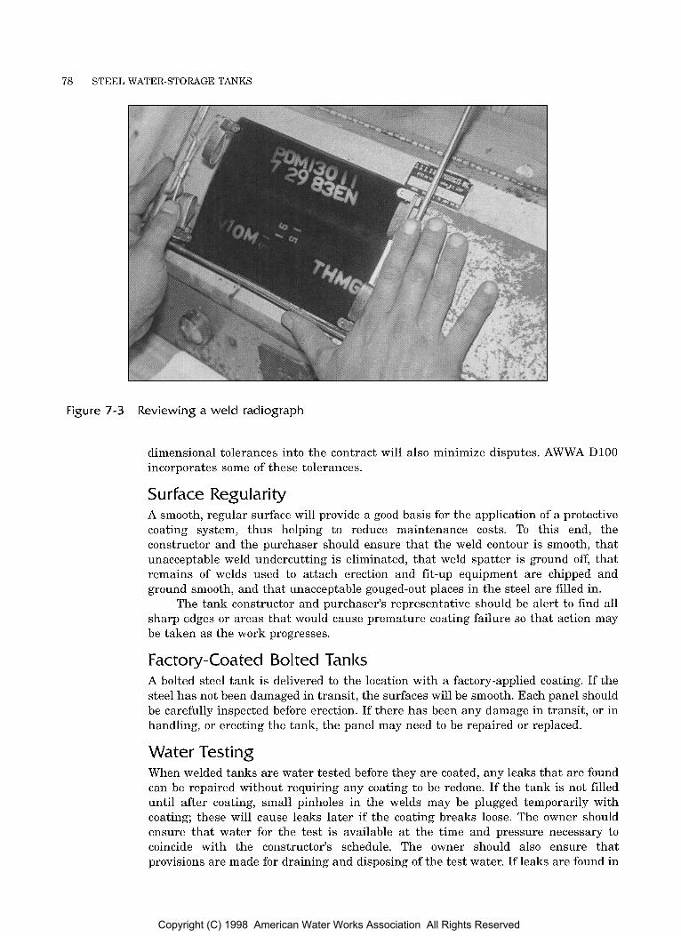
78 STEEL WATER-STORAGE TANKS
Figure 7-3 Reviewing a weld radiograph
dimensional tolerances into the contract will also minimize disputes. AWWA DlOO incorporates some of these tolerances.
Surface Regularity A smooth, regular surface will provide a good basis for the application of a protective coating system, thus helping to reduce maintenance costs. To this end, the constructor and the purchaser should ensure that the weld contour is smooth, that unacceptable weld undercutting is eliminated, that weld spatter is ground off, that remains of welds used to attach erection and fit-up equipment are chipped and ground smooth, and that unacceptable gouged-out places in the steel are filled in.
The tank constructor and purchaser’s representative should be alert t o find all sharp edges or areas that would cause premature coating failure so that action may be taken as the work progresses.
Factory-Coated Bolted Tanks A bolted steel tank is delivered to the location with a factory-applied coating. If the steel has not been damaged in transit, the surfaces will be smooth. Each panel should be carefully inspected before erection. If there has been any damage in transit, or in handling, or erecting the tank, the panel may need to be repaired or replaced.
Water Testing When welded tanks are water tested before they are coated, any leaks that are found can be repaired without requiring any coating to be redone. If the tank is not filled until after coating, small pinholes in the welds may be plugged temporarily with coating; these will cause leaks later if the coating breaks loose. The owner should ensure that water for the test is available a t the time and pressure necessary to coincide with the constructor’s schedule. The owner should also ensure that provisions are made for draining and disposing of the test water. If leaks are found in
Copyright (C) 1998 American Water Works Association All Rights Reserved
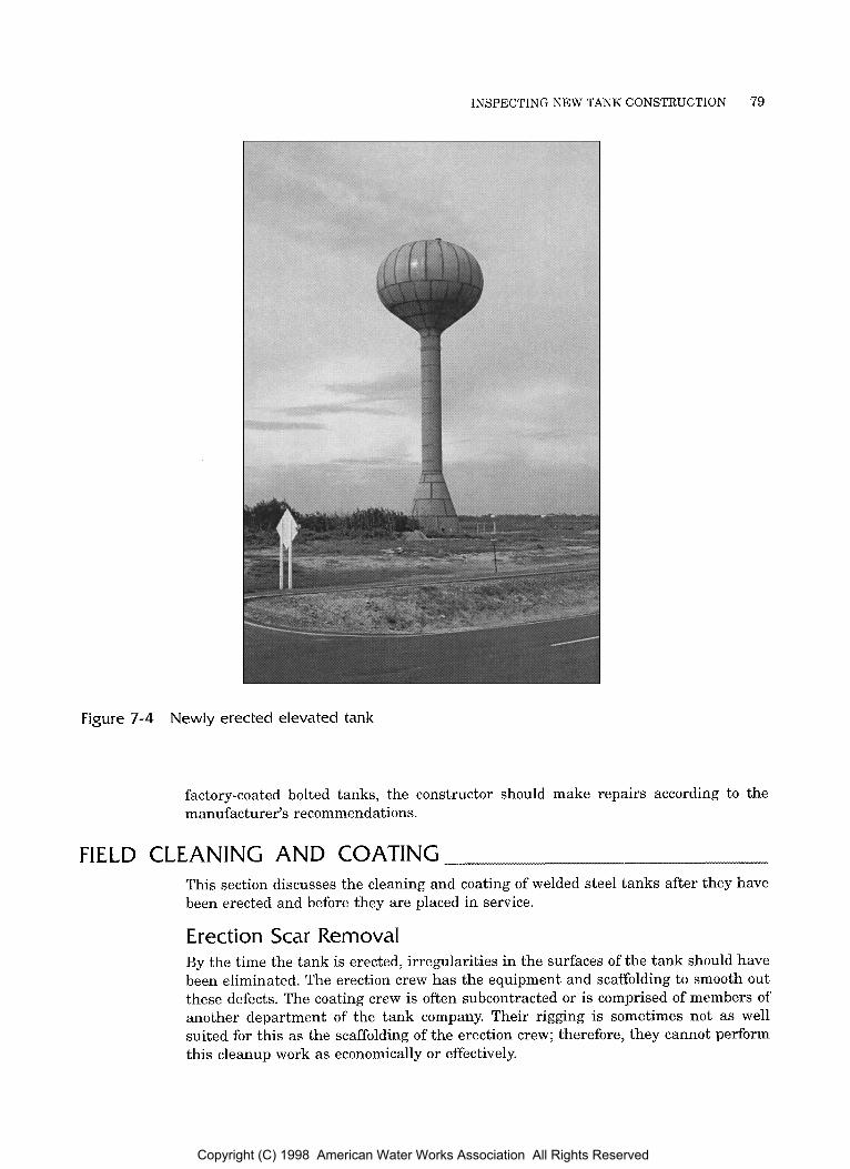
INSPECTING NEW TANK CONSTRUCTION 79
Figure 7-4 Newly erected elevated tank
factory-coated bolted tanks, the constructor should make repairs according to the manufacturer’s recommendations.
FIELD CLEANING AND COATING This section discusses the cleaning and coating of welded steel tanks after they have been erected and before they are placed in service.
Erection Scar Removal By the time the tank is erected, irregularities in the surfaces of the tank should have been eliminated. The erection crew has the equipment and scaffolding to smooth out these defects. The coating crew is often subcontracted or is comprised of members of another department of the tank company. Their rigging is sometimes not as well suited for this as the scaffolding of the erection crew; therefore, they cannot perform this cleanup work as economically or effectively.
Copyright (C) 1998 American Water Works Association All Rights Reserved
80 STEEL WATER-STORAGE TANKS
Occasionally, small laminations in the steel plate will be revealed by abrasive blasting. If these are not removed completely by blasting and remain large enough to produce holidays in the coating system, they should be removed by grinding. Occasionally, deeper laminations may require welding or further testing.
Steel Cleanliness The first requirement for a good coating is a clean surface. The steel should be free from dirt and oil, both of which may accumulate during construction. All weld seams, abraded areas, scratches, shop or field markings, or poorly adhering shop primer should be removed by abrasive blast cleaning. The areas cleaned by abrasive blasting should blend well into the adjoining undisturbed shop primer. Some shop-applied primers must be scarified or otherwise prepared before ensuing coat(s) are applied.
The purchaser should also be aware that welding or cutting activity on one side of a plate will likely damage the coating bonding on the opposite side of the plate. This is especially important if shop priming is used. The areas opposite welding or cutting operations should be examined for coating damage resulting from the heat induced by the cutting or welding process.
The manuals Good Painting Practice and Systems and Specifications, visual standards, and an inspection manual available from the Society for Protective Coatings (SSPC) give good guidelines for inspecting coating.
Inspection Instruments Instruments needed to inspect coating include at a minimum a wet-film thickness gauge, a calibrated dry-film thickness gauge, equipment for measuring air tempera- ture and humidity, a steel-temperature thermometer, a surface-profile measuring device, and a wet-sponge-type holiday detector. The holiday detector is used to inspect the coating for voids that will cause premature coating failure. If full-time inspection is not conducted, a Tooke Gage or other destructive-type testing will be necessary to evaluate the thickness of each coat and to obtain an indication of the cleanliness of the substrate.
Inspection Planning The purchaser should plan work to aid in the timely completion of the tank field coating. This will require open lines of communication with the coating company and an understanding of the effects of weather on coating progress. The constructor will also need t o work efficiently in good weather.
The purchaser should state requirements for the number of locations to be tested according to the total plate surface area. Minimizing testing is unwise, but an excessive number of testing locations places an unreasonable burden on the constructor and can substantially delay the progress of the tank coating. SSPC PA-2 delineates procedures for measuring coating dry film thicknesses. Large tanks may require more than one purchaser’s representative to conduct the required field tests in order to avoid excessively delaying the coating progress.
Technical Aspects of Coatings Today’s coatings require exactness in measuring and mixing components and thinners. The appropriate application equipment must be used, and the proper combination of humidity and dew point, air temperature, and steel temperature are critical during both application and curing.
The tank interior must be ventilated to ensure the safety of workers and the proper curing of the field-applied coatings. Fans or air horns are usually required to
Copyright (C) 1998 American Water Works Association All Rights Reserved
INSPECTING NEW TANK CONSTRUCTION 81
move air through the tank. Even with forced-air ventilation, proper breathing equip- ment is necessary for the safety of the workers and the purchaser’s representativek.).
Bolted tank panels are coated at the factory under controlled conditions. AWWA D103 requires that the panels be grit-blasted to near-white metal (SSPC SP10) and coated within 15 min. of cleaning to prevent rust from starting. The coating is then either baked on or fused on. These operations may be observed by the purchaser at the time of the shop inspection if desired.
MECHANICAL AND ELECTRICAL APPURTENANCES The mechanical and electrical items that need t o be checked will vary with the equipment specified for a particular project. The following should be checked on every project:
Electrical wiring should meet applicable codes.
Conduits, fixtures, pipes, valves, or other items should not interfere with the safety of the ladders o r platforms.
Cathodic protection anodes and hand-hole covers should be properly placed, and the purchaser’s representative should witness the potential profile being conducted.
All hatches should be locked.
Safety belts and sleeves should be furnished for the ladder safety devices. Safety sleeves should be checked for proper operation along the full height of the rails or cables. Any coating, deviations, or obstructions that prevent the free operation of the sleeve should be removed.
Copyright (C) 1998 American Water Works Association All Rights Reserved

Part I11
Routine Operation and Maintenance
Professional Examination and Renovation
Cold-Weather Operation
Copyright (C) 1998 American Water Works Association All Rights Reserved
Chapter 8
AWA MANUAL M42
Tanks need to be operated properly and maintained and inspected on a regular basis to maintain their structural and sanitary integrity. This chapter covers routine operation and maintenance performed by water system operators which represents a crucial complement to the professional tank inspections discussed in chapter 9. Routine tank operation typically consists of the daily monitoring of the automated systems designed to level out supply and demand. Tanks fill when supply exceeds demand and empty into the system when demand exceeds supply, typically maintaining water pressure between 35 and 100 psi (240 to 690 kPa). However, many other factors must be taken into account in the day-to-day operation of a water distribution system.
Another important aspect of tank operation is the prevention of freezing problems in tanks. For a complete description of freezing problems and their solutions, see chapter 10.
ENERGY MANAGEMENT A significant amount of energy can be saved by proper management of the distribution system, including storage. Since pumps are generally more efficient when they pump against lower head levels, it is more efficient to allow tank levels to fluctuate rather than to always keep the tanks full. A water utility can also achieve significant savings by using the most efficient pumps first and by replacing worn parts that may decrease the pump efficiency. Variable-rate pumps should be used at the highest possible speed, at which their efficiencies are usually greatest.
Another consideration involves maximizing energy cost savings by avoiding peak rate charges. If the storage capacity is sufficient, the pumping times can be modified to take advantage of off-peak energy charges. Chapter 5 includes a further discussion of this cost-saving factor.
85
Copyright (C) 1998 American Water Works Association All Rights Reserved
86 STEEL WATER-STORAGE TANKS
CONTROLS The controls used in automated distribution systems require periodic inspection and maintenance to ensure trouble-free operation. Without regular inspection of the controls, potential breakdowns would not be discovered and more emergency repairs would be required.
Altitude Valves Altitude valves are used to maintain a range of acceptable water levels in the tank. The control mechanism on an altitude valve is called a pilot valve.
Maintenance of the altitude valve should be conducted as the valve manufacturer recommends, and additional maintenance of the altitude valve should include the following:
The pilot valve should be tested and lubricated.
Valves should be exercised. Planned exercising of valves keeps them clean and operable, extends their life, and pinpoints problem valves, allowing repairs or replacements t o be scheduled before an emergency occurs.
It is important to check for leakage, keeping the valve port open at all times; leakage at this location indicates a worn piston face or a scored piston or liner surface. Constant leakage from pilot valve waste lines indicates a defective pressure valve, which must be reground or replaced. Leakage through the main valve indicates worn seatings.
More involved maintenance of the altitude valve, including dismantling and examining the piston and cylinder walls, should be performed if any evidence of wear is found. The valve manufacturer should be contacted for maintenance and repair procedures.
PERIODIC OPERATOR INSPECTION Although it is important that the periodic professional inspections described in chapter9 be performed on tanks, some critical portions of the tanks should be inspected by the water system operators. The factors in the following paragraphs should be checked at least once a month, or weekly if possible; however, any elevated inspection should be conducted only by experienced climbers equipped with the proper safety equipment.
Found at i o n s The foundations and surrounding earth should be examined for any signs of settlement. The concrete should also be observed for crumbling, deep cracking, and exposed reinforcing steel. If any of these conditions is found, the tank should be professionally inspected at the earliest opportunity.
Leaks The exterior of the water-bearing surfaces should be examined, and any leaks-or rust streaking that could have been caused by tank leaks-should be reported. (Corrosion products often seal leaks, leaving only rust streaks as evidence of the leak.) The tank should be inspected by a professional structural engineer familiar with water tank construction as soon as possible after the leak is discovered.
Copyright (C) 1998 American Water Works Association All Rights Reserved
ROUTINE OPERATION AND MAINTENANCE 87
Although some leaks may not cause structural problems, potential catastrophic tank failures can be avoided if the visible leaks are properly investigated and repaired.
Cathodic Protection If the tank has been equipped with an automatic impressed-current cathodic protection system, the system’s supplier should inform the tank owner of what meter readings are acceptable. The operator should check these meters and inform the supplier of any significant changes.
Exterior Corrosion Any exterior corrosion, especially where metal loss is apparent, should be evaluated by a professional engineer familiar with the construction of water-storage tanks. If the operator notices a change or severe worsening of the exterior corrosion patterns, he or she should bring this to the attention of the engineer. Special areas t o observe are anchor bolts and nuts, rods, and rod pins and clevises.
Vandalism
Ladders, Platforms, and Lighting
The locks on ladders and access doors should be checked to prevent vandalism.
As the tank is accessed, the ladders and any ladder platforms should be inspected for noticeable metal loss. Any such metal loss should be inspected professionally.
If the ladder extends up an “interior dry” area, such as is found on single- pedestal elevated tanks and on some large-capacity multiple-column tanks, the access door to the area should be kept locked, and the interior dry area should be sufficiently lighted. Broken or missing lightbulbs should be replaced.
If the ladder extends up the exterior of the tank, the ladder should be equipped with a locked guard t o prevent unauthorized access to the tank exterior and roof.
Overflow, Manholes, and Vents The items that most directly affect how sanitary the tank is are the overflow, manholes, and vents. In 1993, a Salmonella outbreak in a public water system was traced to contamination (bird droppings and feathers) entering a tank through an improperly designed and constructed manhole and improperly maintained vent screens.
In order to keep insects, birds, and animals from entering the tank, the overflow screen, flap gate, or both, must be in place and must seal tightly. Overflow pipes should not extend directly into storm sewers or streams without an adequate air gap to prevent a possible cross-connection or backflow.
The overflow brackets should also be inspected to uncover any broken or cracked brackets or welds. Overflow pipes on tanks are intended for occasional use only. Tanks should not be regularly overflowed, and the overflow should not be used as a visual control for pumps and valves. Extreme overuse of the overflow pipe may damage the pipe or brackets. Trickling overflowing water can freeze and obstruct the overflow pipe.
Roof manholes should be equipped with locks to prohibit unautho- rized entry into the tank. Tanks that have access tubes leading t o the roof should have their roof manholes properly latched to prevent them from blowing open in a strong wind, and any access doors to the tank ladders should be locked. Shell manholes should be properly sealed to prevent leakage.
Overflow.
Manholes.
Copyright (C) 1998 American Water Works Association All Rights Reserved
88 STEEL WATER-STORAGE TANKS
Vents. Vent screens should also be in place and fit properly t o prohibit the entry of insects and birds. Special vent designs may be necessary to prevent vents from clogging or freezing over. If an operator suspects that the tank vents have a tendency to become clogged or frozen over, the problem should be addressed by an engineer familiar with water tank vent design.
Wind or Earthquake Damage If any tornado, major windstorm, or earthquake hits a tank, the tank should be professionally inspected to ensure that no damage occurred to the structure. In addition, operators should routinely look for possible wind or earthquake damage. Such damage on tower-supported tanks may be indicated by cracked coating or welds at the tower connections; broken, bent, or sagging rods; buckled struts; dented or twisted columns; or missing or loose rod pins. If any of these conditions is observed, the tank should be professionally inspected. In addition, it should be noted that tanks in areas at high risk for wind or earthquake damage should be inspected more frequently (every 1 t o 3 years) than tanks in low-risk areas.
TANK WASHOUTS As water is held in the tank, suspended solids settle out of the water into the tank bottom. Without regular washouts, tanks may accumulate large amounts of sediment. Sediment and deposits on tank walls decrease the effectiveness of disinfectant use. In addition, proper inspections cannot be conducted if sediment covers the bottom of the tank. Tanks should be washed out and inspected at least once every 3 years, and where water supplies have sediment problems, annual washouts are recommended. These washouts can be performed by the tank owner’s personnel or a maintenance company.
Draining the Tank Draining a tank may not be as easy as it first appears. Many times the valves are difficult to find; or once found, they may be inoperable. Therefore, before work crews are scheduled t o wash out a tank, it is a good idea not only to map the valves in the distribution system, but also to physically find and turn the necessary valves to block the tank off from the system and then drain the tank. Some tanks may be equipped with drain valves located in the wall or riser of the tank to facilitate tank drainage. These valves should be specially designed to prevent freezing.
Operating While the Tank Is Out of Service Many cities, towns, and municipalities neglect to inspect their tanks because of a fear of operating without the tank. Proper operation while the tank is out of service usually requires that a relief valve be installed on a hydrant so that pressure fluctuations do not cause portions of the distribution system to become overpressur- ized. In addition, local businesses and individuals may need to be notified when a tank is going out of service so that temporary large uses of water (e.g., lawn watering or equipment washing) can be scheduled for other days, leaving the municipality with fire protection capacity. In some areas, portable pressure tanks may be available for limited storage.
Washing Out the Tank The tank can be washed out with low-volume, moderate-pressure (2,400 psi f16.5 MPal) pumps, fire-fighting equipment, or other means. The water should be
Copyright (C) 1998 American Water Works Association All Rights Reserved
ROUTINE OPERATION AND MAINTENANCE 89
sprayed on all surfaces to remove as much residue as possible. In areas where water pollution due to sedimentation is a problem or where strict local environmental regulations apply, it may be desirable t o isolate the sediment and washout water and properly dispose of it, instead of allowing it to enter a storm sewer or nearby streams. In addition, care should be taken to prevent large amounts of sediment from entering the tank piping because pipes could be clogged, leading to valve damage.
If the tank is equipped with aluminum cathodic protection anodes, it is possible for many of these anodes t o fall and remain in the tank. These anodes should also be removed at the time of the washout.
Disinfecting the Tank The disinfection of water-storage facilities should be done in accordance with AWWA C652, Standard for the Disinfection of Water-Storage Facilities. This standard offers three chlorination methods by which the disinfection can be accomplished.
Copyright (C) 1998 American Water Works Association All Rights Reserved
Chapter 9
0 AWA MANUAL M42
0
This chapter discusses professional examination and renovation of steel water- storage tanks. Maintaining steel water-storage facilities is increasingly important in view of rising replacement costs and the growing difficulty of obtaining rate increases or other funding for large-scale construction projects. Although maintenance costs are also increasing, small outlays for maintenance can substantially delay or even eliminate the need to replace a utility’s large capital investment in tanks.
Residents and businesses located near tanks are concerned with the tank’s appearance; and local, state, and federal agencies are now issuing new rules and regulations, policy statements, and directives that exert more stringent control over the maintenance and sanitary conditions of stored potable water. Of primary concern are the removal, transportation, and disposal of lead or chromate-based coatings.
The inspection and maintenance of the sanitary integrity of tanks has been largely ignored in the past. It was not mentioned or alluded to in AWWA D101. Water storage tanks can be a major source of contamination or recontamination in a water distribution system. With the increased concern for and the increased regulation of drinking water, the maintenance of the sanitary integrity of water storage tanks demands special attention.
Maintenance needs apply equally to both a new steel water-storage tank and the rehabilitation of an existing tank. When renovation of an existing tank is being considered, the cost required to renovate the existing tank and its estimated remaining life must be evaluated; then the cost must be amortized and compared to that of a new tank to determine if the renovation is economically justifiable. A good, comprehensive preventive maintenance program can extend the life of an existing tank (as well as that of a new tank) indefinitely.
Many thousands of dollars can be saved and complaints from citizens can be eliminated if a planned approach t o tank maintenance is adopted. This approach requires the expertise of experienced personnel to supervise the continuing inspection and maintenance of the utility’s tanks. This individual may be one of the
91
Copyright (C) 1998 American Water Works Association All Rights Reserved

92 STEEL WATER-STORAGE TANKS
utility’s own employees or someone employed by a professional inspection firm or other third-party firm. The role of the tank maintenance engineer is discussed in this chapter.
TANK MAINTENANCE ENGINEER’S FUNCTIONS AND QUALIFICATIONS
The general functions and qualifications of a tank maintenance engineer are the same, regardless of whether that person is a utility employee o r a third-party consultant. In either case, qualified personnel are essential to a successful maintenance program.
Functions A tank engineer/purchaser’s representative is used during three distinct phases of the maintenance effort:
1. An engineer/purchaser’s representative performs an evaluation or pre-bid inspection to indicate the condition of the tank and, if necessary, t o serve as a basis for preparing maintenance specifications and bid documents.
2. Using the findings and recommendations of the engineer/purchaser’s representative (from phase l), an engineer prepares complete and definitive detailed technical specifications and bid documents. This identi- fies potential problems and reduces the need for change orders during construction.
3. An engineer/purchaser’s representative performs competent, full-time inspection of the work being done by the maintenance constructor to ensure strict compliance with the detailed technical specifications, draw- ings, and bid documents.
A maintenance engineering program will be most effective when all three phases are completed by the same individual or organization. If the three functions cannot be performed by the same firm, all parties must understand each other’s responsibilities and keep communication lines open. A weakness in any one of the phases can reduce the effectiveness of the program and the quality of work for the money spent.
Qua1 ifications The tank maintenance engineer should have knowledge of the traditional engineer- ing disciplines and have specialized training and practical experience in the design, fabrication, erection, inspection, sanitary integrity, coating, and maintenance of steel water-storage facilities. Engineers and purchaser’s representatives must be experi- enced in the safe use of specialized rigging and other equipment to investigate the condition of the tank surfaces and to perform related functions required for tank maintenance. The owner should evaluate the purchaser representative’s or engineer’s qualifications in several areas.
Knowledge. The most important qualification for a purchaser’s representa- tive is up-to-date knowledge of the industry standards and requirements for work being done. The purchaser’s representative must have a working knowledge of rigging, steel fitting and welding, surface-cleaning techniques, coating materials, coating application methods, cleaning and coating standards, and testing and inspection methods used t o evaluate repair, cleaning, and coating operations. The
Copyright (C) 1998 American Water Works Association All Rights Reserved

PROFESSIONAL EXAMINATION AND RENOVATION 93
Figure 9- 1 Experienced riggers evaluate hard-to-reach areas on tower tanks
purchaser’s representatives must also be familiar with the relevant AWWA standards and standards of SSPC, American Society for Testing and Materials (ASTM), and NACE International as well as all regulatory agencies’ rules and regulations and other recent industry standards. It is important for the engineer to understand the sanitary implications of the lack of screens and other openings in the top of tanks.
Effective communication skills. The purchaser’s representative must be able to communicate effectively. These communication skills will be used to interpret and discuss the project specifications, as well as to resolve possible problems presented by concerned neighboring residents or businesses. The job of the purchaser’s representative is to help the project run smoothly by noting problems and making constructive suggestions. A purchaser’s representative who only points out deficiencies without facilitating solutions does not help achieve a timely completion of a quality project.
Climbing ability. The third main qualification is that the engineer is able to climb high structures. A purchaser’s representative must closely monitor all parts of a constructor’s work. The purchaser’s representative must know proper rigging and safety practices and must maintain respect for the height at which he or she is working (Figure 9-1).
Copyright (C) 1998 American Water Works Association All Rights Reserved

94 STEEL WATER-STORAGE TANKS
Equipment. At a minimum, the purchaser’s representative should have and use the following equipment:
camera
tape recorder
SSPC written and visual standards for blast cleaning
surface-profile measuring equipment
wet-film gauge
dry-film gauge
certified calibration standards (for dry-film gauge)
a minimum of two steel surface-temperature gauges
psychrometer and psychrometric tables
wet-sponge holiday detector
Tooke Gage (for spot inspection)
coating manufacturer data sheets
flashlight
weather radio
safety equipment
project specifications
Other items required may include equipment and instructions for dye-penetrant testing, vacuum-box testing, and radiographic or ultrasonic evaluation.
PRE-BID INSPECTION The pre-bid (initial) inspection is the first phase of the maintenance program. The purpose of this inspection is to gather data needed to estimate the work required and develop a budget for future expenditures. If the structure is in need of major renovation, the pre-bid report should provide information needed to make an informed decision on whether to maintain the tank or replace it. A secondary purpose might be to define the condition of the tank if the owner is contemplating relocating it or selling it. The inspection report should inform the owner what degree of rehabilitation is necessary. The purchaser’s representative should gather all informa- tion necessary t o prepare drawings and specifications for recoating and repairs in the event that a decision is made to keep the tank in service.
The findings of the pre-bid inspection should be presented in such a manner that the condition of the tank is evident regardless of the reader’s background. One of the most important functions of this report is to convince those in charge of allocating funds that recommended repairs and maintenance expenses are necessary. Many small utility owners have a limited knowledge of tanks. Color photographs keyed to the observations are an excellent method of describing the condition of a particular portion of the tank.
Copyright (C) 1998 American Water Works Association All Rights Reserved
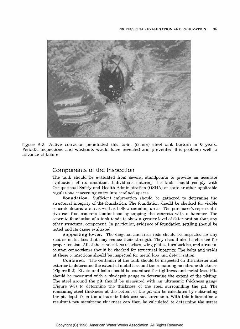
PROFESSIONAL EXAMINATION AND RENOVATION 95
Figure 9-2 Active corrosion penetrated this M-in. (6-mm) steel tank bottom in 9 years. Periodic inspections and washouts would have revealed and prevented this problem well in advance of failure
Components of the Inspection The tank should be evaluated from several standpoints to provide an accurate evaluation of its condition. Individuals entering the tank should comply with Occupational Safety and Health Administration (OSHA) or state or other applicable regulations concerning entry into confined spaces.
Foundation. Sufficient information should be gathered to determine the structural integrity of the foundation. The foundation should be checked for visible concrete deterioration as well as hollow-sounding areas. The purchaser’s representa- tive can find concrete laminations by tapping the concrete with a hammer. The concrete foundation of a tank tends to show a greater level of deterioration than any other structural component. In particular, evidence of foundation settling should be noted and its cause evaluated.
Supporting tower. The diagonal and riser rods should be inspected for any rust or metal loss that may reduce their strength. They should also be checked for proper tension. All of the connections (clevises, wing plates, turnbuckles, and strut-to- column connections) should be checked for structural integrity. The bolts and welds at these connections should be inspected for metal loss and deterioration.
Container. The container of the tank should be inspected on the interior and exterior to determine the extent of metal loss and the remaining membrane thickness (Figure 9-2). Rivets and bolts should be examined for tightness and metal loss. Pits should be measured with a pit-depth gauge to determine the extent of the pitting. The steel around the pit should be measured with an ultrasonic thickness gauge (Figure 9-3) to determine the thickness of the steel surrounding the pit. The remaining steel thickness at the bottom of the pit can be calculated by subtracting the pit depth from the ultrasonic thickness measurements. With this information a resultant net membrane thickness can then be calculated to determine the stress
Copyright (C) 1998 American Water Works Association All Rights Reserved

96 STEEL WATER-STORAGE TANKS
Figure 9-3 Measuring shell thickness with ultrasonic equipment
levels in the remaining steel. When the steel has experienced general metal loss across a large area, multiple ultrasonic thickness measurements should be taken to determine the membrane thickness.
Coating. The condition of the coating on the tank should be evaluated. To accurately determine a coating or recoating schedule, it is necessary to estimate the remaining effective life of the coating system. The owner should define the criteria for effective life based on both aesthetics and corrosion protection. Factors to consider might include amount of rust, peeling, chalking, or graffiti. Once the criteria have been defined, one can project the coating life by monitoring the deterioration of the coating based on the selected criteria. The thickness, type, and adhesion of old coatings should be evaluated prior to preparing specifications for recoating. Adhesion tests, dry-film thickness, and estimation of percent coating failure t o rust and primer all are factored into estimating the effective remaining life. Tests should also be performed to identify the generic type of coating presently on the tank, in order to determine the possibility of topcoating and the potential need t o dispose of any removed coatings as hazardous waste. For example, lead-based coatings will quite likely be considered hazardous waste.
Sanitary conditions. The sanitary integrity of various components of water tanks have come under increasing scrutiny in the past several years. The tank piping (including drain and overflow) should be checked for possible cross-connections. All of the manholes, hatches, vents and openings should be checked for compliance with AWWA standards and local, state, and federal regulations. One of the environmental regulations drawing public attention lately deals with coatings that contain lead and chromates. These coatings are considered a health threat if they are in contact with potable water or if they are cleaned from the tank and allowed to escape into the atmosphere or onto the ground. The container’s interior should be washed out on a regular basis to clean it of debris and make it easier to inspect (Figure 9-4).
Copyright (C) 1998 American Water Works Association All Rights Reserved

PROFESSIONAL EXAMINATION AND RENOVATION 97
Figure 9-4 Washing out tanks allows easier inspection and keeps tanks sanitary
Vent and overflow. Look for missing, damaged, rusted, or warped screens and check that screen sizes can prevent birds and insects from entering the tank. Check that screens are properly located so that debris on the screen will not drop into the tank. If frost is a possibility, ensure that there is provision for pressure and vacuum release in the vent or by means of an auxiliary relief device.
Also check the vent and overflow for proper size if there has been a significant increase in water usage and a corresponding increase in the filVwithdraw rates of the tank.
Access hatches. Ensure that they are properly installed, fit snug, can be easily secured, and have a 4-in. (100-mm) curb or neck and 2-in. (50-mm) downward overlap, or are tightly gasketed, bolted, and sealed.
Finial balls. Check that they are effectively screened. Finial balls are notorious for allowing birds and insects into the tank and are difficult to screen. In most cases, they should be replaced with a more acceptable vent.
Check for holes cut by coating companies or cathodic protection installers or formed by rust or popped rivets and of any other openings that may allow rainwater to drain into the tank.
Check for gaps between the roof and vertical wall. This is normally not a sealed connection in older tanks and warping from uneven expansion and contractions will result in large gaps.
Cathodic protection. A cathodic protection system, if installed, should be evaluated and properly maintained. Systems with manual controls and temporary anodes require yearly maintenance to adjust the potential and replace deteriorated anodes. Newer, impressed-current systems with automatic controls and long-life anodes require less maintenance and are therefore more easily forgotten. However, these systems should also be checked periodically during the year by water system personnel to make sure that they are operating, and they should be checked every year by a corrosion specialist for proper operation.
Holes in the roof.
Roof overhang.
Next Page
Copyright (C) 1998 American Water Works Association All Rights Reserved
Chapter 10
AWWA MANUAL M42
A frozen water-storage tank can cause more problems than no tank at all. Fortunately, proper specification of appurtenances and operating procedures will eliminate most tank freezing problems. This chapter discusses ways to prevent cold- weather problems associated with elevated tanks, standpipes, and ground storage reservoirs. The chapter also gives suggestions on dealing with these problems if they do occur. Figure 10-1 shows an extreme example of a frozen tank.
CAUSES A N D RESULTS OF FREEZING In general, water freezes when the atmospheric conditions cause heat t o escape faster from the water than it can be replaced. The following material discusses conditions that can cause freezing and problems that can result.
Causes of Freezing There are three general categories of problems that may cause freezing and, subsequently, ice damage to water-storage tanks. The first category is improper specification. The second and third categories, static water conditions and overflow, are essentially operational problems.
Improper specification. The first general cause of freezing is improper specification of the tank or the control systems. Specification elements that can influence freezing problems include
piping arrangement and size
vent design
inadequate amount of freeboard between the overflow and the roof structure
structural members, piping, ladders, or other protrusions below the high water level
heat-conducting projections or narrow gratings across riser piping
105 Copyright (C) 1998 American Water Works Association All Rights Reserved
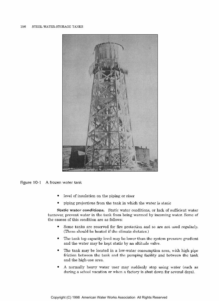
106 STEEL WATER-STORAGE TANKS
Figure 10-1 A frozen water tank
Static water conditions.
level of insulation on the piping or riser
piping projections from the tank in which the water is static
Static water conditions, or lack of sufficient water turnover, prevent water in the tank from being warmed by incoming water. Some of the causes of this condition are as follows:
Some tanks are reserved for fire protection and so are not used regularly. (These should be heated if the climate dictates.)
The tank top capacity level may be lower than the system pressure gradient and the water may be kept static by an altitude valve.
The tank may be located in a low-water consumption area, with high pipe friction between the tank and the pumping facility and between the tank and the high-use area.
A normally heavy water user may suddenly stop using water (such as during a school vacation o r when a factory is shut down for several days).
Copyright (C) 1998 American Water Works Association All Rights Reserved

COLD-WEATHER OPERATION 107
Pumps supplying the system may be of a variable-output, constant-pressure type and may have a capacity equal to the peak demand.
The water main serving the tank may freeze solid.
The tank may be valved off for winter with water in it.
The controls for the pumps or altitude valve may become frozen or damaged by ice.
The tank may be too large for the present system.
Tank overflows. Freezing problems may also occur when the tank is allowed to overflow at a trickling or slow rate that permits freezing in the overflow pipe. In freezing weather, the escaping water will immediately freeze. Causes of overflow include
leaky valves
improper control specification or adjustment
frozen controls for the pump or altitude valve
telemetering conductors damaged by ice o r wind
tanks designed to float on a system with other tanks (these will occasionally overflow because of pressure variations)
Results of Freezing When a tank freezes, one or more of the following conditions usually results and causes leakage:
Inside overflow or other piping breaks occur.
Ladders or other attachments to the container are pulled out by ice, making a hole at the point of attachment.
Ice pressure can expand and place hoop stress loads on the steel and seams, which may cause the tank wall t o yield o r burst.
Leaks due t o corrosion become apparent.
Overflow through overflow pipes. When tanks overflow in freezing weather, several problems can develop. An overflow-to-grade may freeze solid, especially where there is a trickling overflow or where screens are plugged or flap valves are stuck on the discharge. If water continues t o be pumped into the tank after the overflow pipe is frozen solid, the tank may overflow for a while through the roof hatch, then through the vent; the tank will then freeze solid, build up pressure, and burst.
Overflow through the roof hatch or vent. When water overflows through the hatch and vent, it invariably forms a large icicle, weighing tons, on the tank exterior. The same problem can be caused by normal overflow through a stub overflow (one extending only a few feet from the shell of the tank). This places a large eccentric load on the structure, which in the case of water towers, can exceed the structure’s design stress. The icicle usually forms on the side of the tower that is away from the prevailing wind, and the wind and icicle together create additive loadings. Even if the structure is not damaged by the ice load, it may be damaged when the ice thaws or breaks off and falls. Eccentric ice loadings or tower members damaged by falling ice have caused water towers to fall.
Copyright (C) 1998 American Water Works Association All Rights Reserved
108 STEEL WATER-STORAGE TANKS
Frosting over tank vents. A unique freezing problem may occur when frost freezes solid over the fine screen in the vent and overflow. This type of freezing will usually occur on the fine screen designed to keep insects out of the tank. Such freezing prevents the exchange of air into the tank, resulting in a vacuum in the tank that can collapse (implode) the tank until there is a structural rupture t o break the vacuum. Preliminary research indicates that fiberglass screen material is resistant to freezing.
QUANTITATIVE DATA RELATED TO FREEZING Weather data and heat-loss data are both significant in relation to tank freezing.
Weather Data The most scientific data available concerning weather conditions are the lowest one- day mean temperatures (LODMTs), as recorded by the United States Weather Bureau. These temperatures have been charted on isothermal lines in Figure 10-2. Of course, weather conditions are very erratic, and a given location may experience temperatures lower than those exhibited on the LODMT chart.
Experience has shown that tanks located in areas with the LODMT warmer than -5°F (-15°C) normally will not experience cold-weather operational problems, with the following exceptions:
elevated tanks with small (less than 36 in. 10.9 ml) diameter uninsulated risers
tanks with uninsulated and unheated appendages that experience no flow (for example, a drain valve at the end of a nipple)
tanks experiencing overflow problems because of frozen or otherwise malfunctioning controls for valves or pumps
tanks with abnormally static water conditions
tanks with inadequate vents or overflows
Heat-Loss Data The National Bureau of Fire Underwriters publishes tables giving the heat loss per hour from various types of tanks. Table 10-1 presents this data for small elevated tanks. For example, a 250,000-gal (0.95-ML) elevated tank located in an area having a -10°F (-23°C) LODMT loses 1 million Btdh (293 kJ/s) in a 12-mph (19-kmh) wind. In a -40°F (-40°C) location, the heat loss almost doubles.
DESIGNING TANKS FOR COLD WEATHER Proper design of a tank will prevent most freezing problems and will allow personnel to follow operating procedures to deal easily with any that do occur.
Inside Appurtenances Tanks located in an area where the LODMT is -5°F (-15°C) or colder should not be equipped with inside ladders or overflow pipes. As ice forms and moves up and down, it can exert tons of force on ladders and pipes, tearing them loose from their supports and possibly ripping or punching holes in the container. The resulting leak will occur at a very inopportune time. If an inside overflow pipe is broken, the tank will rapidly lose all water down to the break, creating a large icy area on the ground below. If the
Copyright (C) 1998 American Water Works Association All Rights Reserved
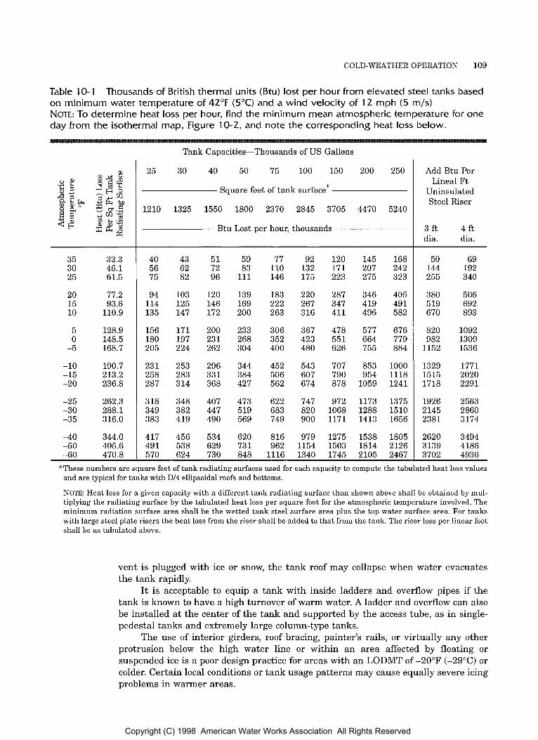
COLD-WEATHER OPERATION 109
Table 10-1 Thousands of British thermal units (Btu) lost per hour from elevated steel tanks based on minimum water temperature of 42°F (5°C) and a wind velocity of 12 mph (5 m/s) NOTE: To determine heat loss per hour, Find the minimum mean atmospheric temperature for one day from the isothermal map, Figure 10-2, and note the corresponding heat loss below.
35 32.3 30 46.1 25 61.5
20 77.2 15 93.6 10 110.9
5 128.9 0 148.5
-5 168.7
-10 190.7 -15 213.2 -20 236.8
-25 262.3 -3 0 288.1 -35 316.0
4 0 344.0 -5 0 405.6 -60 470.8
Tank Capacities-Thousands of US Gallons
25 30 40 50 75 100 150 200 250
Square feet of tank surface*
1210 1325 1550 1800 2370 2845 3705 4470 5240
B t u Lost per hour, thousands
40 56 75
94 114 135
156 180 205
231 258 287
3 18 349 383
417 491
43 62 82
103 125 147
171 197 224
253 283 3 14
348 382 419
456 538
51 72 96
120 146 172
200 23 1 262
296 33 1 368
407 447 490
534 629
59 83
111
139 169 200
233 268 304
344 384 42 7
473 519 569
620 73 1
77 110 146
183 222 263
306 352 400
452 506 562
622 683 749
816 962
92 132 175
220 267 3 16
367 423 480
543 607 674
747 820 900
979 1154
120 171 223
287 347 411
478 551 626
707 790 878
972 1068 1171
1275 1503
145 207 275
346 419 496
577 664 755
853 954
1059
1173 1288 1413
1538 1814
168 242 323
405 49 1 582
676 779 884
1000 1118 1241
1375 1510 1656
1805 2126
570 624 730 848 1116 1340 1745 2105 2467
Add B t u Per Lineal Ft
Uninsulated Steel Riser
3 f t 4 f t dia. dia.
50 144 255
380 5 19 670
820 982
1152
1329 1515 1718
1926 2 145 2381
2620 3139
69 192 340
506 692 893
1092 1309 1536
1771 2020 2291
2563 2860 3174
3494 4186
3702 4936 *These numbers are square feet of tank radiating surfaces used for each capacity to compute the tabulated heat loss values
and are typical for tanks with D/4 ellipsoidal roofs and bottoms.
NOTE: Heat loss for a given capacity with a different tank radiating surface than shown above shall be obtained by mul- tiplying the radiating surface by the tabulated heat loss per square foot for the atmospheric temperature involved. The minimum radiation surface area shall be the wetted tank steel surface area plus the top water surface area. For tanks with large steel plate risers the heat loss from the riser shall be added to that from the tank. The riser loss per linear foot shall be as tabulated above.
vent is plugged with ice or snow, the tank roof may collapse when water evacuates the tank rapidly.
It is acceptable to equip a tank with inside ladders and overflow pipes if the tank is known to have a high turnover of warm water. A ladder and overflow can also be installed at the center of the tank and supported by the access tube, as in single- pedestal tanks and extremely large column-type tanks.
The use of interior girders, roof bracing, painter’s rails, o r virtually any other protrusion below the high water line or within an area affected by floating or suspended ice is a poor design practice for areas with an LODMT of -20°F (-29°C) or colder. Certain local conditions or tank usage patterns may cause equally severe icing problems in warmer areas.
Copyright (C) 1998 American Water Works Association All Rights Reserved

110 STEEL WATER-STORAGE TANKS
I 125' 1200 115' 110° 105' 1000
Figure 10-2 30°F (-1°C) temperature line for January, United States and Southern Canada
Isothermal lines for lowest one-day mean temperatures and normal daily minimum
Copyright (C) 1998 American Water Works Association All Rights Reserved

COLD-WEATHER OPERATION 111
Figure 10-2 continued
Copyright (C) 1998 American Water Works Association All Rights Reserved
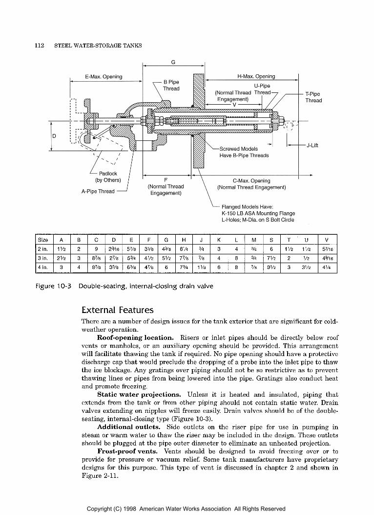
112 STEEL WATER-STORAGE TANKS
I_ G
c
H-Max. Opening
Screwed Models Have B-Pipe Threads
Padlock (by Others)
(Normal Thread A-Pipe Thread Engagement)
I C-Max. Opening
(Normal Thread Engagement)
Flanged Models Have: K-150 LB ASA Mounting Flange L-Holes; M-Dia. on S Bolt Circle
Va
Figure 10-3 Double-seating, internal-closing drain valve
External Features There are a number of design issues for the tank exterior that are significant for cold- weather operation.
Risers or inlet pipes should be directly below roof vents o r manholes, or an auxiliary opening should be provided. This arrangement will facilitate thawing the tank if required. No pipe opening should have a protective discharge cap that would preclude the dropping of a probe into the inlet pipe to thaw the ice blockage. Any gratings over piping should not be so restrictive as to prevent thawing lines or pipes from being lowered into the pipe. Gratings also conduct heat and promote freezing.
Static water projections. Unless it is heated and insulated, piping that extends from the tank or from other piping should not contain static water. Drain valves extending on nipples will freeze easily. Drain valves should be of the double- seating, internal-closing type (Figure 10-3).
Additional outlets. Side outlets on the riser pipe for use in pumping in steam or warm water to thaw the riser may be included in the design. These outlets should be plugged at the pipe outer diameter to eliminate an unheated projection.
Frost-proof vents. Vents should be designed to avoid freezing over or to provide for pressure or vacuum relief. Some tank manufacturers have proprietary designs for this purpose. This type of vent is discussed in chapter 2 and shown in Figure 2-11.
Roof-opening location.
Copyright (C) 1998 American Water Works Association All Rights Reserved
COLD-WEATHER OPERATION 113
Dark tank color. If a dark color for the tank exterior is aesthetically agreeable and will not keep the water too warm in the summer, the owner should consider using one to absorb radiant heat from the sun.
Riser Pipes Riser pipes should be properly sized or insulated. For instance, steel water-storage tanks in an area where the LODMT is -20°F (-29°C) usually have small (less than 12 in. [0.3 ml) diameter risers insulated with at least 4 in. (0.1 m) of polyurethane foam insulation. Large steel-plate risers (36 in. [0.9 ml or larger) have traditionally relied on ice for insulation, but this is no longer recommended. Large risers (48 in. [1.2 m] and 60 in. [1.5 m]) diameter have been used successfully in areas with the LODMT as low as -20°F (-29°C).
COLD-WEATHER OPERATING PROCEDURES Even a properly designed tank may freeze under extreme conditions if it is not operated carefully. Water turnover, altitude valves, ground cover, and overflows must all be considered.
Maintaining Water Turnover With proper pumping management and piping, the heat needed t o prevent freezing can theoretically be added to the tank by fresh well water. If 222,000 gal (0.84 ML) of 45°F (7°C) water were pumped in 1 day through the 250,000-gal (0.95-ML) tank mentioned earlier in this chapter (see the Heat-Loss Data section), the heat added would replace the heat lost t o the 12-mph (19-kmh) wind in -10°F (-23°C) weather.
Although it is possible to replace most of the water in a tank with warmer water, it is often not the way the tank is operated. Water-storage tanks, particularly elevated tanks and standpipes, because they are connected to the main only by the riser pipe, usually float on the system. As a result, it is possible that a tank can serve a system that uses several times more water per day than the tank capacity yet still receive only a small percentage of fresh water daily. The operating procedures discussed in the following paragraphs will allow a tank to make optimal use of the heat available in incoming water.
Forcing circulation through the tank. If the tank is located near a pump- ing facility, the tank can be piped so that the new warmer water will be pumped into the tank through one pipe while water is withdrawn from a separate pipe. Ideally, the new water should enter the tank above the capacity midpoint to ensure no short- circuiting of water within the tank. However, this piping arrangement violates a rule of good design practice: any piping extending inside the tank container may be broken off by ice cakes if ice does form. This practice not only minimizes the potential for freezing problems but assures better water quality by reducing stagnation.
Pumpingmanagement. In the small community or in sections of a large water system, effective water turnover can usually be achieved by pumping manage- ment. If the system is automated, a timer can be integrated with the pump controller. In that situation, the controller is set to turn pumps on during the day only when needed to maintain the minimum emergency reserve level. The tank is then pumped to the high level at night. This procedure ensures flow during the normal periods of low demand, and it adds heat at night, when the heat loss is greatest.
If a lower-than-normal water level will still maintain sufficient water for power-outage reserve and fire flow, then during winter the high water level may be lowered about 10 ft (3 m), into the vertical
Lowering the high water level.
Copyright (C) 1998 American Water Works Association All Rights Reserved
114 STEEL WATER-STORAGE TANKS
portion of a curved-side tank. This minimizes the probability of ice forming on the upper curved portion or roof support structure. It also minimizes the probability of inadvertently overflowing the tank, thus eliminating the problems cited earlier when tanks overflow.
In large systems, pumps are usually sequenced cumulatively to meet the demand (that is, only one pump turns on or off at a given time). In winter, system pressure can be allowed t o drop a little more; several pumps can then be switched on at nearly the same time. This will cause the water levels in the tanks to fluctuate more than with normal control.
Timing and sequencing the pumps.
Altitude Valves In many water distribution systems, altitude valves are used to control the water level in tanks for which the high water level is at a lower elevation than the pressure gradient of the system. Even some small one-tank systems have been designed with an altitude valve on the tank inlet-outlet line. Both of these are examples of improper use of altitude valves. Altitude-control systems can be designed and installed with timers that force the altitude valve t o open, allowing water to flow into and out of the tank and ensuring more frequent turnover.
Altitude valves may malfunction even in good weather. Freezing weather increases the likelihood of malfunction, with frozen pressure-sensing lines giving the altitude valve false signals. This usually causes the tank to overflow, but it may also cause the valve t o remain closed, keeping the water in the tank static. Providing electrical heat tape and insulation on the control piping or heating the altitude valve enclosure will minimize these problems.
Ground Cover o n the Connection Piping A common cause of tank freezing is inadequate cover over the pipe leading to the tank. Sometimes soil conditions preclude installing the tank foundation deep enough to provide adequate frost cover; in such cases, fill should be brought in for the cover, or other means should be devised to insulate the pipe.
Some tower-type elevated tanks have the riser foundation built higher than the column foundations. The site should be graded higher in the center to prevent the inlet-outlet piping from being exposed to the atmosphere between the concrete riser foundation tunnel roof and the earth.
If the earth over the connecting piping is not compacted properly, it will settle during the first few years of operation. The ensuing lack of adequate cover, combined with moisture saturation of the depression, creates a potential trouble area for freezing.
Supervising the covering. The base of the tank is usually the location of the interface between constructors, and may become a “no man’s land.” Unless properly supervised and inspected, the piping may not even get backfilled before the first winter of operation.
Site grade.
Compacting fill.
SYSTEMS TO PREVENT FREEZING Different types of systems or equipment can be used to prevent tank freezing.
Heating Heating a community water supply tank is usually not economically feasible, though industrial sprinkler tanks for fire protection have been heated for many years. However, new insurance rate structures and better community water supply systems have allowed
Copyright (C) 1998 American Water Works Association All Rights Reserved

COLD-WEATHER OPERATION 115
1 I ,--Aeration Line /
I , 4 V
r Riser Aeration Line
Figure 10-4 Tank riser bubbler system
many factories either to dismantle the fire protection tank or to discontinue heating it. In many cases, the insurance savings no longer offset the heating energy costs.
Air Bubblers Air bubbler systems have been used successfully in ground storage tanks and in elevated tanks with large risers. A bubbler system is shown in Figure 10-4. Research on the use of these systems indicates that the compressor used should be one of high volume, with just enough pressure to overcome air-line friction, orifice friction, and the hydrostatic head due to the water depth. There must also be an influx of warmer water, because the bubbling action tends to remove all the heat from a confined volume of water. The compressor should be equipped with an air filter and water and oil traps to minimize pumping contaminants into the tank.
Circulating Pumps Circulating pumps that do not heat the water have been successful on tanks with small (6-12 in. [150-300 mm]) diameter riser pipes in Iowa, Minnesota, North Dakota, and South Dakota. A circulating system is shown in Figure 10-5. A relatively small (1.5 hp [1.1 kW1) pump draws water from the base elbow, pulling water down the insulated riser or from the connecting pipe. The pump discharges water into a
Copyright (C) 1998 American Water Works Association All Rights Reserved

116 STEEL WATER-STORAGE TANKS
Bowl of Tank m miii'--- Drip Ring
'cil Insulated Riser
I y C i r c u l a t i n g Line fl. I1
/-- Foundation
Circulating Pump
Figure 10-5 Pumped circulation system for small riser pipes
1-in. (25-mm) diameter line entering the riser at the base of the tank and discharging into the tank container. This creates a circulation in the riser.
Insulation As discussed earlier in the context of tank design, it is a common practice to insulate riser pipes. Many ground storage tanks and a few elevated tanks have also been sprayed with urethane foam to insulate them. This yields a rough appearance, however, and there may be problems maintaining adhesion between the foam and the steel. No matter how thick the insulation, if there is no heat input to the stored water, that water will eventually freeze.
DEALING WITH FROZEN TANKS Despite all efforts, a tank may freeze. When this happens, there are two ways to thaw the tank: thaw the tank artificially, or wait for warm weather. If in doubt, it is good practice to get advice from a tank company or structural consultant proficient in tank design concerning the dangers presented by a frozen tank.
Copyright (C) 1998 American Water Works Association All Rights Reserved
COLD-WEATHER OPERATION 117
Piping Damage If ruptures or leaks are apparent in the inlet or riser piping, it usually is best to wait for warmer weather, or even take additional measures to keep the damaged piping frozen. This will keep water in the tank while things are still frozen overhead.
Damage From Draining If it is suspected that a tank is frozen, no attempt should be made to drain the tank. Draining could cause damage in three ways:
1. The ice may fall inside the tank, damaging the tank or piping.
2. The vent may be plugged or frozen over, and the roof may collapse (implode) from the vacuum formed by the draining water.
3. The ice may thaw in the tank on only one side (the one facing the sun). This uneven thawing will allow the water t o drain off one side of the tank only, producing an eccentric load for which the structure was not designed. In the case of a single pedestal tank, this can cause the support cylinder to fail by bending.
Fa1 I i ng- Ice Hazards Once ice or icicles form on the tank exterior, they create a danger for people and objects below. If it appears that the ice will cause a structural failure, a distance greater than the height of the tank should be roped off. If the danger appears to be only due t o falling ice, an area at least 20 ft (6 m) larger in radius than the tank base should be roped off. If the stability of the structure is in doubt, all precautions should be taken and a structural expert should be called t o analyze the situation.
Thawing Thawing piping. If piping is frozen where it enters the tank or riser pipe at
ground level, and it is acceptable to let the water flow again, a tarpaulin o r polyethylene film tent can be erected around the base and a gas- or oil-fired portable heater used t o heat the area. Similarly, if the tank is of single-pedestal type or other design with a large dry riser, heat may be applied in that portion of the tank.
Thawing tanks. The municipality may attempt to thaw the tank with its own equipment, but constructors are often engaged for the job. A common technique is to lift a %-in. (19-mm) diameter heavy-duty hose from the ground up over the top of the tank. The end of the hose terminates with a % -in. (12-mm) diameter pipe about 10-ft (3-m) long. This pipe is dropped through the tank vent or manhole that is located directly over the inlet or riser pipe. It must be kept slightly off the ice to keep it from sticking to it. Warm water from a fire department tank truck is pumped through the hose, parting the ice as the probe drops down (refer to Figure 10-6). The water must be used judiciously. Stopping in the middle of the process could allow the thawing pipe t o freeze in the tank and may require leaving the equipment in the tank for the remainder of the winter.
When the tank truck is empty, it must be refilled from utility mains. However, the refill water will not be as warm as the original water in the truck, which was taken from the heated fire station. Steam generators have been attached to this type of probe, but the warm-water method seems to work best, is cheaper, and creates fewer safety hazards.
Copyright (C) 1998 American Water Works Association All Rights Reserved
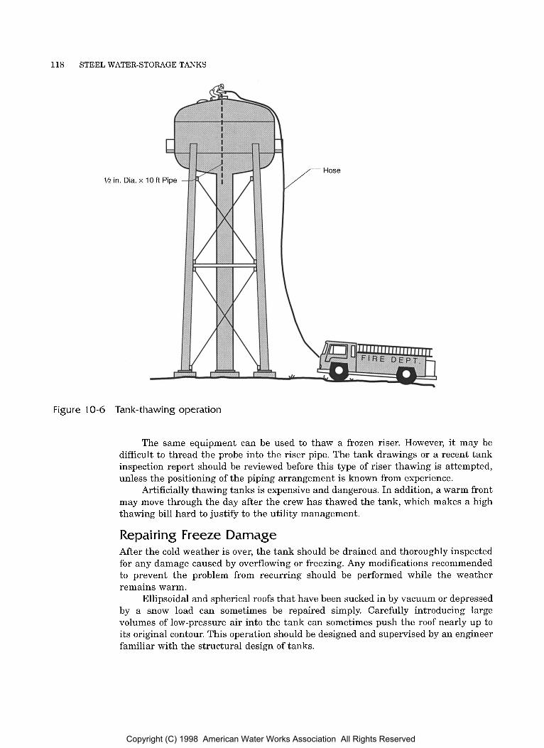
118 STEEL WATER-STORAGE TANKS
1/2 in. Dia. X I/// Hose
Figure 10-6 Tank-thawing operation
The same equipment can be used to thaw a frozen riser. However, it may be difficult to thread the probe into the riser pipe. The tank drawings or a recent tank inspection report should be reviewed before this type of riser thawing is attempted, unless the positioning of the piping arrangement is known from experience.
Artificially thawing tanks is expensive and dangerous. In addition, a warm front may move through the day after the crew has thawed the tank, which makes a high thawing bill hard to justify t o the utility management.
Repairing Freeze Damage After the cold weather is over, the tank should be drained and thoroughly inspected for any damage caused by overflowing or freezing. Any modifications recommended to prevent the problem from recurring should be performed while the weather remains warm.
Ellipsoidal and spherical roofs that have been sucked in by vacuum or depressed by a snow load can sometimes be repaired simply. Carefully introducing large volumes of low-pressure air into the tank can sometimes push the roof nearly up to its original contour. This operation should be designed and supervised by an engineer familiar with the structural design of tanks.
Copyright (C) 1998 American Water Works Association All Rights Reserved

Appendix A
AWWA MANUAL M42
AWWA C652-92, Standard for Disinfection of Water-Storage Facilities. Denver, Colo.: American Water Works Association.
AWWA D100-96, Standard for Welded Steel Tanks for Water Storage. Denver, Colo.: American Water Works Association.
AWWA D102-97, Standard for Coating Steel Water-Storage Tanks. Denver, Colo.: American Water Works Association.
AWWA D103-97, Standard for Factory- Coated Bolted Steel Tanks for Water Storage. Denver, Colo.: American Water Works Association.
AWWA D104-97, Standard for Automatically C o n t r o l l e d , I m p r e s s e d - C u r r e n t Cathodic Protection for the Interior of Steel Water Tanks. Denver, Colo.: Amer- ican Water Works Association.
Beebe, D.G. 1985. Rigging and Ventilation in Tank Painting. Jour. Prot. Ctgs. & Lngs., 2(3): 18.
Bushman, J.B. 1983. Cathodic Protection of Water Storage Tanks. In Steel Water Storage Tanks: What Engi- neers and Utilities Need to Know. Sem. Proc. AWWA Annual Conference. Denver, Colo.: American Water Works Association.
Buzek, J.R. 1983. Design of Welded Steel Tanks for Water Storage. In Steel Water Storage Tanks: What Engineers and Utilities Need to Know. Sem. Proc. AWWA Annual Conference. Denver, Colo.: American Water Works Association.
Campbell, D.E. 1983. Tank Paint Systems- Selection, Application and Inspection. In Steel Water Storage Tanks: What Engineers and Utilities Need to Know. Sem. Proc. AWWA Annual Conference. Denver, Colo.: American Water Works Association.
Christiansen, K.L. 1983. Factory Coated Bolted Steel Tanks. In Steel Water Stor- age Tanks: What Engineers and Utilities Need to Know. Sem. Proc. AWWA Annual Conference. Denver, Colo.: American Water Works Association.
Cull, D.G. 1983. Specifylng AWWA Steel Water Storage Tanks. In Steel Water Storage Tanks: What Engineers and Utilities Need to Know. Sem. Roc. AWWA Annual Conference. Denver, Colo.: American Water Works Association.
Ellis, C., and J.A. Williams. 1983. Selecting and Sizing Tanks. In Steel Water Storage Tanks: What Engineers and Utilities Need to Know. Sem. Proc. AWWA Annual Conference. Denver, Colo.: American Water Works Association.
Ellrich, J. 1983. The Use of Glass Coated Steel Tanks for the Containment of Potable Water. Paper presented at AquaTech of Americas, March 14, at Hershey, Pa.
Knoy, E.C. 1982. Inspection, Evaluation, and Design of Tanks to Minimize Cold Weather Problems. In Proc. AWWA DSS. Denver, Colo.: American Water Works Association.
119
Copyright (C) 1998 American Water Works Association All Rights Reserved
120 STEEL WATER-STORAGE TANKS
. 1983. Inspecting New Tank Con- struction. In Steel Water Storage Tanks: What Engineers and Utilities Need to Know. Sem. Proc. AWWA Annual Conference. Denver, Colo.: American Water Works Association. . 1982. Maintenance Engineering for
Steel Water Storage Tanks. In Proc. SSPC Symposium. Pittsburgh) Pa.: Steel Structures Painting Council. . 1983. What You Should Know About
Tank Maintenance. In Proc. AWWA DSS. Denver, Colo.: American Water Works Association. . 1986. Wax-Grease Coatings in Pota-
ble Water Storage Tanks. In Proc. AWWA DSS. Denver) Colo.: American Water Works Association.
Visual Standard for Abrasive Blast Cleaned Steel. 1989. SSPC-Vis 1-89. Pitts- burgh, Pa.: Society for Protective Coatings.
Roetter, S.P. 1986. Rehabilitation and Maintenance of Steel Water Storage Tanks. In Water Supply System Reha- bilitation. New York: American Soci- ety of Civil Engineers.
Steel Plate Engineering Data. Vol. 1, Steel Tanks for Liquid Storage. Washington, D.C.: American Iron and Steel Institute/ Steel Plate Fabricators Association.
Steel Plate Engineering Data. Vol. 2, Design of Plate Structures. Washington, D.C.: American Iron and Steel Institute/ Steel Plate Fabricators Association.
Steel Water Storage. 1984. Cincinnati) Ohio: Steel Plate Fabricators Association.
Good Painting Practice. Vol. 1, Steel Struc- tures Painting Manual. 1993. Pitts- burgh, Pa.: Steel Structures Painting Council.
Systems and Specifications. Vol. 2, Steel Structures Painting Manuals. Pitts- burgh, Pa.: Steel Structures Painting Council.
Copyright (C) 1998 American Water Works Association All Rights Reserved
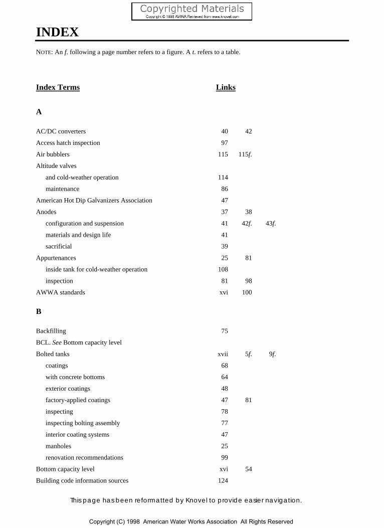
This page has been reformatted by Knovel to provide easier navigation.
INDEX NOTE: An f. following a page number refers to a figure. A t. refers to a table.
Index Terms Links
A
AC/DC converters 40 42
Access hatch inspection 97
Air bubblers 115 115f.
Altitude valves
and cold-weather operation 114
maintenance 86
American Hot Dip Galvanizers Association 47
Anodes 37 38
configuration and suspension 41 42f. 43f.
materials and design life 41
sacrificial 39
Appurtenances 25 81
inside tank for cold-weather operation 108
inspection 81 98
AWWA standards xvi 100
B
Backfilling 75
BCL. See Bottom capacity level
Bolted tanks xvii 5f. 9f.
coatings 68
with concrete bottoms 64
exterior coatings 48
factory-applied coatings 47 81
inspecting 78
inspecting bolting assembly 77
interior coating systems 47
manholes 25
renovation recommendations 99
Bottom capacity level xvi 54
Building code information sources 124
Copyright (C) 1998 American Water Works Association All Rights Reserved
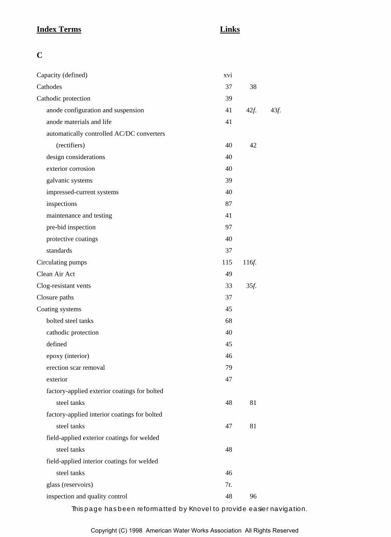
Index Terms Links
This page has been reformatted by Knovel to provide easier navigation.
C
Capacity (defined) xvi
Cathodes 37 38
Cathodic protection 39
anode configuration and suspension 41 42f. 43f.
anode materials and life 41
automatically controlled AC/DC converters
(rectifiers) 40 42
design considerations 40
exterior corrosion 40
galvanic systems 39
impressed-current systems 40
inspections 87
maintenance and testing 41
pre-bid inspection 97
protective coatings 40
standards 37
Circulating pumps 115 116f.
Clean Air Act 49
Clog-resistant vents 33 35f.
Closure paths 37
Coating systems 45
bolted steel tanks 68
cathodic protection 40
defined 45
epoxy (interior) 46
erection scar removal 79
exterior 47
factory-applied exterior coatings for bolted
steel tanks 48 81
factory-applied interior coatings for bolted
steel tanks 47 81
field-applied exterior coatings for welded
steel tanks 48
field-applied interior coatings for welded
steel tanks 46
glass (reservoirs) 7t.
inspection and quality control 48 96
Copyright (C) 1998 American Water Works Association All Rights Reserved

Index Terms Links
This page has been reformatted by Knovel to provide easier navigation.
Coating systems (Cont.)
inspection instruments and planning 80
interior 45
regulatory standards 46
removal by abrasive blasting 49
renovation recommendations and
specifications 98
safety considerations 80
and steel cleanliness 80
technical considerations 80
vinyl (interior) 46
waste disposal (from abrasive blasting) 49
and water testing and disinfection 68
welded steel tanks 67
Cold-weather operation
additional outlets 112
and altitude valves 114
causes of freezing 105
dark tank color 113
designing for 108
double-seating, internal-closing drain
valves 112 112f.
external features for 112
forcing circulation through the tank 113
frost-proof vents 112
frozen tank 106f.
ground cover on connection piping 114
inside appurtenances 108
location of roof openings 112
lowering high water level 113
maintaining water turnover 113
pump timing and sequencing 114
pumping management 113
results of freezing 107
riser pipes 113
static water projections 112
systems to prevent freezing 114
Column- and rafter-supported cone roofs 10 11f.
Copyright (C) 1998 American Water Works Association All Rights Reserved
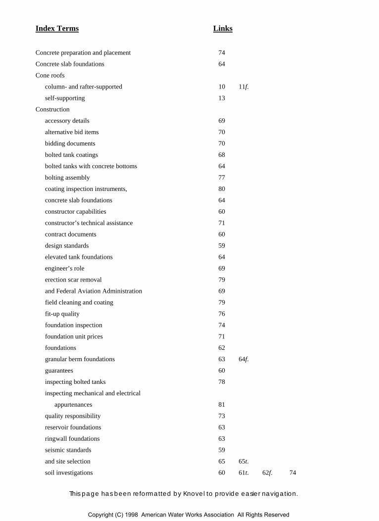
Index Terms Links
This page has been reformatted by Knovel to provide easier navigation.
Concrete preparation and placement 74
Concrete slab foundations 64
Cone roofs
column- and rafter-supported 10 11f.
self-supporting 13
Construction
accessory details 69
alternative bid items 70
bidding documents 70
bolted tank coatings 68
bolted tanks with concrete bottoms 64
bolting assembly 77
coating inspection instruments, 80
concrete slab foundations 64
constructor capabilities 60
constructor’s technical assistance 71
contract documents 60
design standards 59
elevated tank foundations 64
engineer’s role 69
erection scar removal 79
and Federal Aviation Administration 69
field cleaning and coating 79
fit-up quality 76
foundation inspection 74
foundation unit prices 71
foundations 62
granular berm foundations 63 64f.
guarantees 60
inspecting bolted tanks 78
inspecting mechanical and electrical
appurtenances 81
quality responsibility 73
reservoir foundations 63
ringwall foundations 63
seismic standards 59
and site selection 65 65t.
soil investigations 60 61t. 62f. 74
Copyright (C) 1998 American Water Works Association All Rights Reserved

Index Terms Links
This page has been reformatted by Knovel to provide easier navigation.
Construction (Cont.)
specifications 70
standpipe foundations 63
steel delivery 76
surface regularity 78
tank appearance 77
tank erection 76
and used tanks 70
visiting constructor’s fabricating facility 76
water testing and disinfection 68 78
welded tank coatings 67
welding quality 76 77f. 78f.
Container inspection 95 95f. 96f.
Control inspections 86
Corrosion 37
exterior 40
inspections 87
Constructor (defined) xvi
Cost considerations 56 56f. 57f.
D
Definitions of pertinent terminology xvi
Design standards 59
Dome roofs 10 12f.
Double-seating, internal-closing drain valves 112 112f.
Drain valves 112 112f.
Dry-cell batteries 38 38f.
E
Electrolytes 37
Elevated tanks 13 79f.
alternative single-pedestal 19 20f.
cost considerations 56 56c 57f.
defined xvi
and Federal Aviation Administration 69
foundations 64
inspection and repair procedure (AWWA
Standard D101-53[R86]) 129
Copyright (C) 1998 American Water Works Association All Rights Reserved
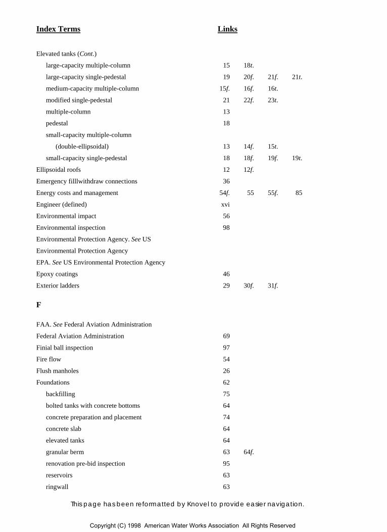
Index Terms Links
This page has been reformatted by Knovel to provide easier navigation.
Elevated tanks (Cont.)
large-capacity multiple-column 15 18t.
large-capacity single-pedestal 19 20f. 21f. 21t.
medium-capacity multiple-column 15f. 16f. 16t.
modified single-pedestal 21 22f. 23t.
multiple-column 13
pedestal 18
small-capacity multiple-column
(double-ellipsoidal) 13 14f. 15t.
small-capacity single-pedestal 18 18f. 19f. 19t.
Ellipsoidal roofs 12 12f.
Emergency filllwithdraw connections 36
Energy costs and management 54f. 55 55f. 85
Engineer (defined) xvi
Environmental impact 56
Environmental inspection 98
Environmental Protection Agency. See US
Environmental Protection Agency
EPA. See US Environmental Protection Agency
Epoxy coatings 46
Exterior ladders 29 30f. 31f.
F
FAA. See Federal Aviation Administration
Federal Aviation Administration 69
Finial ball inspection 97
Fire flow 54
Flush manholes 26
Foundations 62
backfilling 75
bolted tanks with concrete bottoms 64
concrete preparation and placement 74
concrete slab 64
elevated tanks 64
granular berm 63 64f.
renovation pre-bid inspection 95
reservoirs 63
ringwall 63
Copyright (C) 1998 American Water Works Association All Rights Reserved

Index Terms Links
This page has been reformatted by Knovel to provide easier navigation.
Foundations (Cont.)
routine inspections 86
soil investigation 74
standpipes 63
unit prices 71
Freezing. See also Cold-weather operation
and air bubblers 115 115f.
artificial thawing vs. waiting for warm
weather 116
causes 105
and circulating pumps 115 116f.
due to improper specification 105
due to static water conditions 106
due to tank overflows 107
and falling-ice hazards 117
and heating of tanks 114
and insulation 116
and lowest one-day mean temperatures 108 110f.
and piping damage 117
and possible damage from draining 117
repairing damage from 118
resulting in frosting over tank vents 108
resulting in overflow through overflow
pipes 107
resulting in overflow through roof hatch or
vent 107
results 107
systems to prevent 114
and tank heat-loss data 108 109t.
thawing piping 117
thawing tanks 117 118f.
Future needs 55
G
Galvanic cathodic protection systems 39
Gauge boards 35
Government information sources 125
Granular berm foundations 63 64f.
Copyright (C) 1998 American Water Works Association All Rights Reserved
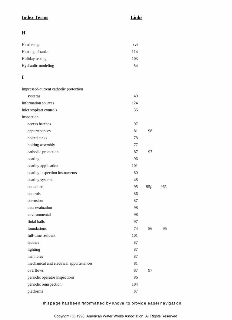
Index Terms Links
This page has been reformatted by Knovel to provide easier navigation.
H
Head range xvi
Heating of tanks 114
Holiday testing 103
Hydraulic modeling 54
I
Impressed-current cathodic protection
systems 40
Information sources 124
Inlet stopkart controls 36
Inspection
access hatches 97
appurtenances 81 98
bolted tanks 78
bolting assembly 77
cathodic protection 87 97
coating 96
coating application 101
coating inspection instruments 80
coating systems 48
container 95 95f. 96f.
controls 86
corrosion 87
data evaluation 98
environmental 98
finial balls 97
foundations 74 86 95
full-time resident 101
ladders 87
lighting 87
manholes 87
mechanical and electrical appurtenances 81
overflows 87 97
periodic operator inspections 86
periodic reinspection, 104
platforms 87
Copyright (C) 1998 American Water Works Association All Rights Reserved

Index Terms Links
This page has been reformatted by Knovel to provide easier navigation.
Inspection (Cont.)
procedure (AWWA Standard D101-53[R86]) 129
renovation pre-bid inspection 94
Spot 103
supporting towers 95
surface profile 101
tank repair 101
vents 88 97
welding quality 76 77f. 78f.
Insulation 116
Interior ladders 31
L
Ladders 29
inspections 87
Leak checks 86
Lighting inspections 87
LODMTs. See Lowest one-day mean
temperatures
Lowest one-day mean temperatures 108 110f.
M
Maintenance engineer
climbing ability 93 93f.
communication skills 93
equipment 94
functions 92
knowledge qualifications 92
qualifications 92
Maintenance. See Operation and
maintenance
Manholes 25 26f. 27f.
inspections 87
Manufacturer (defined) xvi
Multiple-column tanks. See Elevated tanks
Copyright (C) 1998 American Water Works Association All Rights Reserved

Index Terms Links
This page has been reformatted by Knovel to provide easier navigation.
N
National Ambient Air Quality Standard 49
National Bureau of Fire Underwriters 108
NSF International 46
O
Occupational Safety and Health
Administration 29 31 95
Operation and maintenance
See also Cold-weather operation
abrasive blast cleaning 101 102f.
access hatch inspection 97
altitude valve maintenance 86
appearance 91
appurtenance inspection 98
atmospheric conditions and coating
renovation 103
cathodic protection inspections 87 97
coating application inspection 101
coating batch numbers 103
coating inspection 96
constructor monitoring 101
container inspection 95 95f. 96f.
control inspections 86
corrosion inspections 87
energy management 85
environmental inspection 98
finial ball inspection 97
foundation inspections 86 95
holiday testing 103
inspection data evaluation 98
ladder inspections 87
leak checks 86
lighting inspections 87
maintenance engineer 92
manhole inspections 87
overflow inspections 87
Copyright (C) 1998 American Water Works Association All Rights Reserved
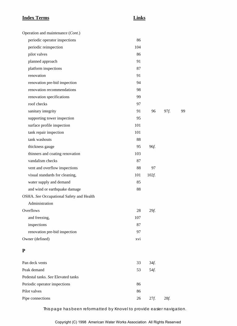
Index Terms Links
This page has been reformatted by Knovel to provide easier navigation.
Operation and maintenance (Cont.)
periodic operator inspections 86
periodic reinspection 104
pilot valves 86
planned approach 91
platform inspections 87
renovation 91
renovation pre-bid inspection 94
renovation recommendations 98
renovation specifications 99
roof checks 97
sanitary integrity 91 96 97f. 99
supporting tower inspection 95
surface profile inspection 101
tank repair inspection 101
tank washouts 88
thickness gauge 95 96f.
thinners and coating renovation 103
vandalism checks 87
vent and overflow inspections 88 97
visual standards for cleaning, 101 102f.
water supply and demand 85
and wind or earthquake damage 88
OSHA. See Occupational Safety and Health
Administration
Overflows 28 29f.
and freezing, 107
inspections 87
renovation pre-bid inspection 97
Owner (defined) xvi
P
Pan deck vents 33 34f.
Peak demand 53 54f.
Pedestal tanks. See Elevated tanks
Periodic operator inspections 86
Pilot valves 86
Pipe connections 26 27f. 28f.
Copyright (C) 1998 American Water Works Association All Rights Reserved

Index Terms Links
This page has been reformatted by Knovel to provide easier navigation.
Platform inspections 87
Pressure gauges 36
Pressure transducers 36
Primary roof openings 32 33f.
Professional societies 123
Pumping
and cold-weather operation 113 114
and energy costs 54f. 55 55f.
Purchaser (defined) xvi
R
Rectifiers 40 42
Remote level readings 36
Renovation
constructor monitoring 101
full-time resident inspection 101
pre-bid inspection 94
procedure (AWWA Standard D101-53[R86]) 129
recommendations 98
specifications 99
spot inspection 103
Reservoirs 3 4f.
column- and rafter-supported cone roofs 10 11f.
cost considerations 56 56f.
cross-sectional views 4f. 5f.
defined xvi
foundations 63
glass-coated (capacities) 7t.
inspection and repair procedure (AWWA
Standard D101-53[R86]) 129
roof designs 10
self-supporting cone roofs 13
self-supporting dome roofs 10 12f.
self-supporting ellipsoidal roofs 12 12f.
typical sizes 6t.
umbrella roofs 10 12f.
Return current paths. See Closure paths
Ringwall foundations 63
Copyright (C) 1998 American Water Works Association All Rights Reserved
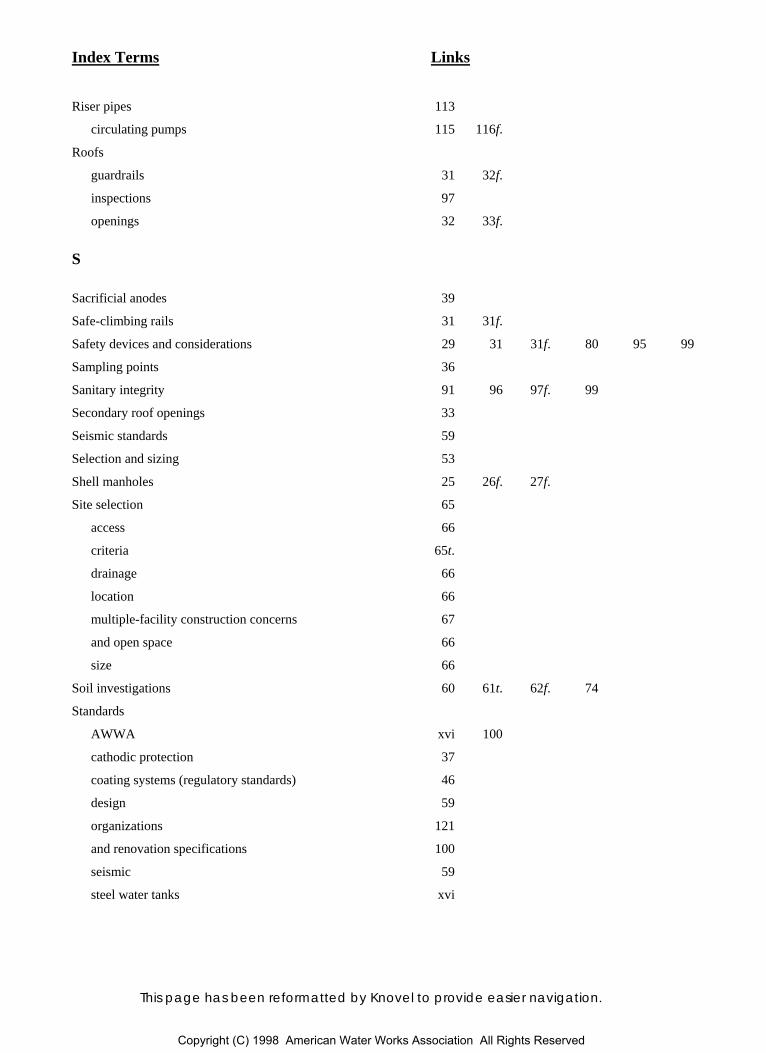
Index Terms Links
This page has been reformatted by Knovel to provide easier navigation.
Riser pipes 113
circulating pumps 115 116f.
Roofs
guardrails 31 32f.
inspections 97
openings 32 33f.
S
Sacrificial anodes 39
Safe-climbing rails 31 31f.
Safety devices and considerations 29 31 31f. 80 95 99
Sampling points 36
Sanitary integrity 91 96 97f. 99
Secondary roof openings 33
Seismic standards 59
Selection and sizing 53
Shell manholes 25 26f. 27f.
Site selection 65
access 66
criteria 65t.
drainage 66
location 66
multiple-facility construction concerns 67
and open space 66
size 66
Soil investigations 60 61t. 62f. 74
Standards
AWWA xvi 100
cathodic protection 37
coating systems (regulatory standards) 46
design 59
organizations 121
and renovation specifications 100
seismic 59
steel water tanks xvi
Copyright (C) 1998 American Water Works Association All Rights Reserved
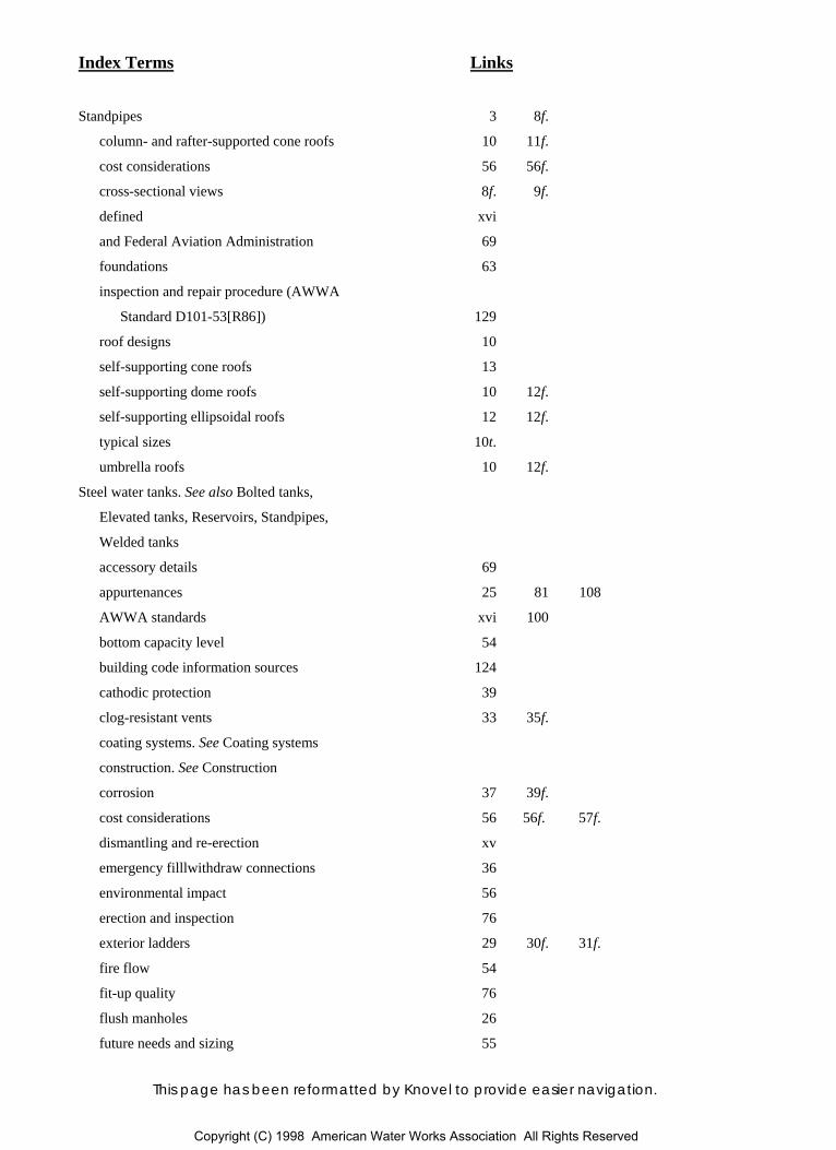
Index Terms Links
This page has been reformatted by Knovel to provide easier navigation.
Standpipes 3 8f.
column- and rafter-supported cone roofs 10 11f.
cost considerations 56 56f.
cross-sectional views 8f. 9f.
defined xvi
and Federal Aviation Administration 69
foundations 63
inspection and repair procedure (AWWA
Standard D101-53[R86]) 129
roof designs 10
self-supporting cone roofs 13
self-supporting dome roofs 10 12f.
self-supporting ellipsoidal roofs 12 12f.
typical sizes 10t.
umbrella roofs 10 12f.
Steel water tanks. See also Bolted tanks,
Elevated tanks, Reservoirs, Standpipes,
Welded tanks
accessory details 69
appurtenances 25 81 108
AWWA standards xvi 100
bottom capacity level 54
building code information sources 124
cathodic protection 39
clog-resistant vents 33 35f.
coating systems. See Coating systems
construction. See Construction
corrosion 37 39f.
cost considerations 56 56f. 57f.
dismantling and re-erection xv
emergency filllwithdraw connections 36
environmental impact 56
erection and inspection 76
exterior ladders 29 30f. 31f.
fire flow 54
fit-up quality 76
flush manholes 26
future needs and sizing 55
Copyright (C) 1998 American Water Works Association All Rights Reserved
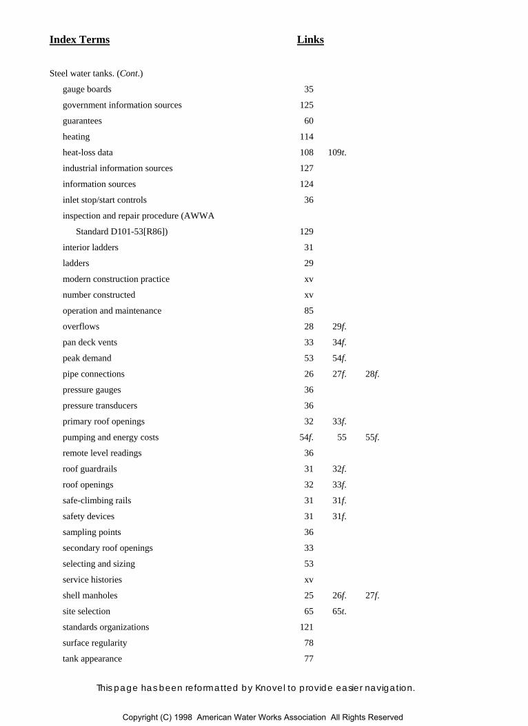
Index Terms Links
This page has been reformatted by Knovel to provide easier navigation.
Steel water tanks. (Cont.)
gauge boards 35
government information sources 125
guarantees 60
heating 114
heat-loss data 108 109t.
industrial information sources 127
information sources 124
inlet stop/start controls 36
inspection and repair procedure (AWWA
Standard D101-53[R86]) 129
interior ladders 31
ladders 29
modern construction practice xv
number constructed xv
operation and maintenance 85
overflows 28 29f.
pan deck vents 33 34f.
peak demand 53 54f.
pipe connections 26 27f. 28f.
pressure gauges 36
pressure transducers 36
primary roof openings 32 33f.
pumping and energy costs 54f. 55 55f.
remote level readings 36
roof guardrails 31 32f.
roof openings 32 33f.
safe-climbing rails 31 31f.
safety devices 31 31f.
sampling points 36
secondary roof openings 33
selecting and sizing 53
service histories xv
shell manholes 25 26f. 27f.
site selection 65 65t.
standards organizations 121
surface regularity 78
tank appearance 77
Copyright (C) 1998 American Water Works Association All Rights Reserved
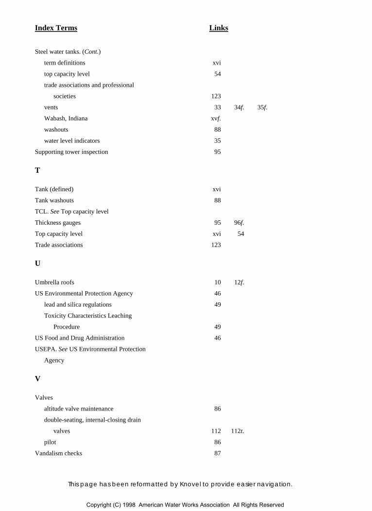
Index Terms Links
This page has been reformatted by Knovel to provide easier navigation.
Steel water tanks. (Cont.)
term definitions xvi
top capacity level 54
trade associations and professional
societies 123
vents 33 34f. 35f.
Wabash, Indiana xvf.
washouts 88
water level indicators 35
Supporting tower inspection 95
T
Tank (defined) xvi
Tank washouts 88
TCL. See Top capacity level
Thickness gauges 95 96f.
Top capacity level xvi 54
Trade associations 123
U
Umbrella roofs 10 12f.
US Environmental Protection Agency 46
lead and silica regulations 49
Toxicity Characteristics Leaching
Procedure 49
US Food and Drug Administration 46
USEPA. See US Environmental Protection
Agency
V
Valves
altitude valve maintenance 86
double-seating, internal-closing drain
valves 112 112t.
pilot 86
Vandalism checks 87
Copyright (C) 1998 American Water Works Association All Rights Reserved
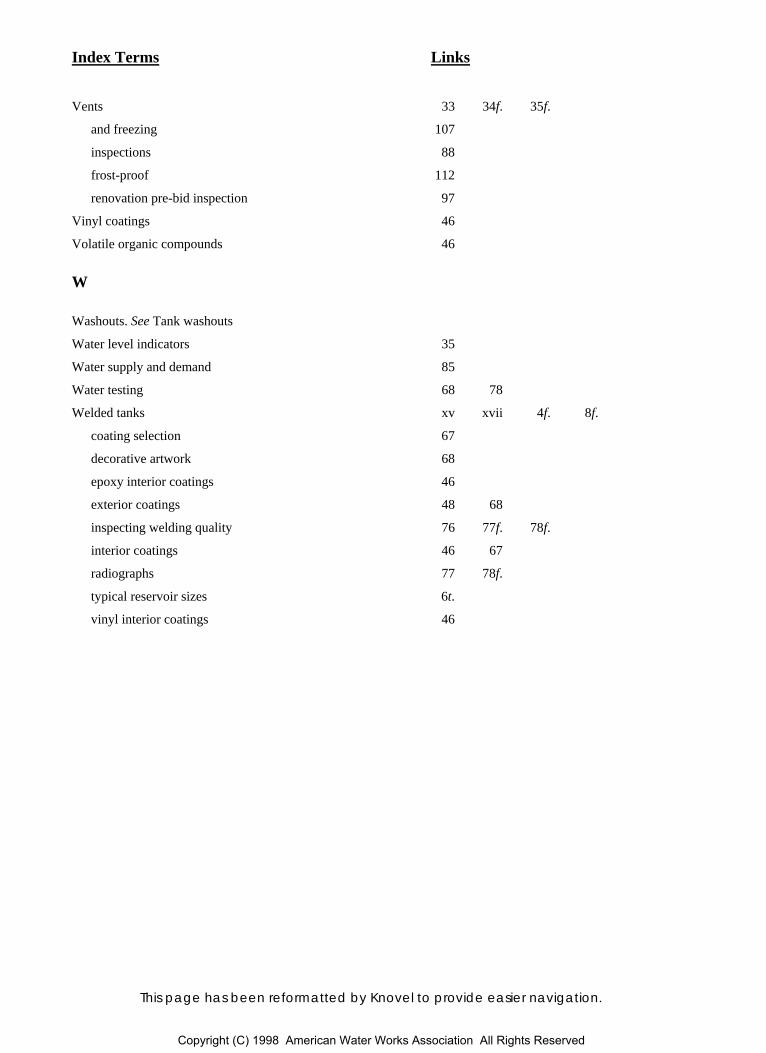
Index Terms Links
This page has been reformatted by Knovel to provide easier navigation.
Vents 33 34f. 35f.
and freezing 107
inspections 88
frost-proof 112
renovation pre-bid inspection 97
Vinyl coatings 46
Volatile organic compounds 46
W
Washouts. See Tank washouts
Water level indicators 35
Water supply and demand 85
Water testing 68 78
Welded tanks xv xvii 4f. 8f.
coating selection 67
decorative artwork 68
epoxy interior coatings 46
exterior coatings 48 68
inspecting welding quality 76 77f. 78f.
interior coatings 46 67
radiographs 77 78f.
typical reservoir sizes 6t.
vinyl interior coatings 46
Copyright (C) 1998 American Water Works Association All Rights Reserved